silabs.com | Building a more connected world. Copyright © 2023 by Silicon Laboratories Rev. 0.5
UG491: Zigbee Application Framework
Developer’s Guide for SDK 7.0 and Higher
The Zigbee Application Framework is a body of embedded C code
that can be configured by project configuration tools to implement
any Zigbee Cluster Library (ZCL) application. This guide covers
the structure and usage of the Zigbee Application Framework in
SDK 7.x.
KEY POINTS
• Provides a reference for all aspects of
the Zigbee Application Framework, in-
cluding callbacks, the API, and the Com-
mand Line Interface (CLI).
• Offers guidelines for designing an appli-
cation with Project Configuration tools.
• Discusses how to extend the ZCL.

UG491: Zigbee Application Framework Developer's Guide for SDK 7.0 and Higher
Table of Contents
silabs.com | Building a more connected world. Rev. 0.5
silabs.com | Building a more connected world. Rev. 0.5 | 1
Table of Contents
1 Introduction ............................................................................................................................................................................... 1
2 Application Framework Architecture ........................................................................................................................................... 2
3 Project Files .............................................................................................................................................................................. 3
3.1 Project Configuration File ................................................................................................................................................... 3
3.2 Application Source Files..................................................................................................................................................... 3
3.3 Makefiles ........................................................................................................................................................................... 3
3.4 ZCL-Generated Files ......................................................................................................................................................... 3
4 Zigbee Application Framework API and Directory Structure ........................................................................................................ 4
5 ZCL Concepts and Definitions ................................................................................................................................................... 5
5.1 Clusters............................................................................................................................................................................. 5
5.2 Devices ............................................................................................................................................................................. 5
5.3 Profile ID ........................................................................................................................................................................... 5
5.4 More About Clusters and Attributes .................................................................................................................................... 5
5.4.1 Example: The Identify Cluster ..................................................................................................................................... 6
5.4.2 Example: The Temperature Measurement Cluster....................................................................................................... 7
6 Zigbee Application Framework Callback Interface ...................................................................................................................... 8
6.1 Implementing Callbacks ..................................................................................................................................................... 8
6.2 Callback Types .................................................................................................................................................................. 8
6.3 Global Callbacks................................................................................................................................................................ 9
6.3.1 Global Callback Example ........................................................................................................................................... 9
6.4 ZCL Command Handling Callbacks .................................................................................................................................... 9
6.5 Component-Specific Callbacks ......................................................................................................................................... 10
6.6 Stack Callbacks ............................................................................................................................................................... 10
6.7 Callback Flow for Message Processing ............................................................................................................................ 11
6.8 Command Callbacks Implementation Notes...................................................................................................................... 12
6.8.1 Command Callback Context ..................................................................................................................................... 12
6.8.2 Array Handling in Command Callbacks ..................................................................................................................... 13
7 Time Handling ......................................................................................................................................................................... 14
8 Events .................................................................................................................................................................................... 15
8.1 Creating Application Events ............................................................................................................................................. 15
8.1.1 Event Struct and Event Handler ................................................................................................................................ 15
8.1.2 Application Event Example ....................................................................................................................................... 15
8.2 How Cluster Events Are Created ...................................................................................................................................... 15

UG491: Zigbee Application Framework Developer's Guide for SDK 7.0 and Higher
Table of Contents
silabs.com | Building a more connected world. Rev. 0.5
silabs.com | Building a more connected world. Rev. 0.5 | 2
8.3 How Cluster Events Are Scheduled .................................................................................................................................. 16
8.3.1 sl_zigbee_zcl_schedule_cluster_tick ......................................................................................................................... 16
8.3.2 sl_zigbee_zcl_deactivate_cluster_tick ....................................................................................................................... 16
9 Attribute Management ............................................................................................................................................................. 18
9.1 ZCL Attribute Configuration .............................................................................................................................................. 18
9.1.1 Attribute Storage Endianness ................................................................................................................................... 18
9.1.2 Implications of Attribute Storage Endianness ............................................................................................................ 18
9.1.3 External Attributes .................................................................................................................................................... 18
9.1.4 Persistent Memory Storage ...................................................................................................................................... 19
9.1.5 Singleton ................................................................................................................................................................. 19
9.1.6 Attribute Bounding ................................................................................................................................................... 19
9.2 Interacting with ZCL Attributes ......................................................................................................................................... 19
9.2.1 ZCL String Attributes ................................................................................................................................................ 20
10 Command Handling and Generation .................................................................................................................................... 21
10.1 Sending Commands and Command Responses ............................................................................................................... 21
10.2 ZCL Command Processing .............................................................................................................................................. 21
10.2.1 app/framework/util/process-global-message.c ........................................................................................................... 22
10.2.2 app/framework/util/process-cluster-message.c .......................................................................................................... 22
10.3 Sending a Default Response ............................................................................................................................................ 22
11 The Command Line Interface (CLI) ...................................................................................................................................... 23
12 The Debug Printing Interface ............................................................................................................................................... 24
13 Multi-Network Support ......................................................................................................................................................... 25
13.1 Configuration ................................................................................................................................................................... 25
14 Sleepy Devices ................................................................................................................................................................... 26
14.1 Introduction ..................................................................................................................................................................... 26
14.2 Polling ............................................................................................................................................................................. 26
14.2.1 The SHORT_POLL Interval ...................................................................................................................................... 26
14.2.2 The LONG_POLL Interval ........................................................................................................................................ 27
14.2.3 Setting Values for the SHORT_POLL and LONG_POLL Intervals .............................................................................. 27
14.2.4 Forcing Fast Polling ................................................................................................................................................. 27
14.2.5 Using Fast Polling to Complete a Complex Transaction ............................................................................................. 28
14.2.6 Difference in Polling on SoC and Host+NCP Models ................................................................................................. 28
14.3 Sleeping and the Event Mechanism ................................................................................................................................. 28
14.3.1 Never Use Ticks on a Sleepy End Device ................................................................................................................. 28
14.4 End Device Parent Rediscovery ....................................................................................................................................... 29
14.5 Sleepy End Devices and the CLI ...................................................................................................................................... 29

UG491: Zigbee Application Framework Developer's Guide for SDK 7.0 and Higher
Table of Contents
silabs.com | Building a more connected world. Rev. 0.5
silabs.com | Building a more connected world. Rev. 0.5 | 3
14.6 Processor Idling and the Zigbee Application Framework ................................................................................................... 29
15 Zigbee Application Framework Components ......................................................................................................................... 30
15.1 Introduction ..................................................................................................................................................................... 30
15.2 Over-the-Air Upgrade Components .................................................................................................................................. 30
15.2.1 Architecture ............................................................................................................................................................. 30
15.2.2 Component Architecture ........................................................................................................................................... 32
15.2.3 ZCL Framework Core ............................................................................................................................................... 32
15.2.4 OTA Bootload Cluster Common Code Component .................................................................................................... 33
15.2.5 OTA Bootload Cluster Server Component ................................................................................................................. 33
15.2.6 OTA Bootload Cluster Server Policy Component ....................................................................................................... 33
15.2.7 OTA Bootload Cluster Client Component .................................................................................................................. 33
15.2.8 OTA Bootload Cluster Client Policy Component ........................................................................................................ 34
15.2.9 OTA Storage Components ....................................................................................................................................... 34
15.2.10 OTA Cluster Platform Bootloader Component ....................................................................................................... 36
15.2.11 OTA Cluster Command Line Interface ................................................................................................................... 37
15.2.12 OTA Client State Machine .................................................................................................................................... 39
15.2.13 Example Client and Server Setup ......................................................................................................................... 40
15.3 Reporting Component ...................................................................................................................................................... 40
15.3.1 Reporting Command Line Interface .......................................................................................................................... 40
15.3.2 Reporting Connection Setup through CLI .................................................................................................................. 41
15.3.3 Reporting for External Attributes ............................................................................................................................... 42
16 Extending the Zigbee Cluster Library.................................................................................................................................... 43
16.1 Steps for Adding Custom Clusters and Commands Overview............................................................................................ 43
16.2 Manufacturer-Specific Commands and Clusters ............................................................................................................... 43
16.3 Limitations to Consider .................................................................................................................................................... 43
16.4 Defining ZCL Extensions within the Zigbee Application Framework and Project Configurator ............................................. 44
16.5 Manufacturer-Specific Attribute APIs ................................................................................................................................ 44
16.5.1 Attribute Read and Write .......................................................................................................................................... 44

UG491: Zigbee Application Framework Developer's Guide for SDK 7.0 and Higher
Introduction
silabs.com | Building a more connected world. Rev. 0.5
silabs.com | Building a more connected world. Rev. 0.5 | 1
1 Introduction
The Zigbee Application Framework (also known as the ZCL Application Framework) is a body of embedded C code that can be config-
ured by the Project Configuration Tools to implement any Zigbee Cluster Library (ZCL) application. Beginning with SDK version 7.0.0,
Zigbee applications are configured through a component-based architecture using the Simplicity Studio 5 Project Configurator rather
than a plugin-based architecture using the legacy AppBuilder tool. This guide covers the structure and usage of the Zigbee Application
Framework.
This document assumes that you are familiar with using Simplicity Studio 5’s project configuration tools to create and configure Zigbee
projects. For more information, see:
• Simplicity Studio 5 User’s Guide
• QSG180: Zigbee EmberZNet Quick-Start Guide for SDK 7.x and Higher
• AN1325: Zigbee Cluster Configurator User's Guide
If you have been using earlier versions of the Zigbee EmberZNet SDK, see AN1301: Transitioning from Zigbee EmberZNet SDK 6.x to
SDK 7.x for a detailed description of differences between the two versions.
UG491: Zigbee Application Framework Developer's Guide for SDK 7.0 and Higher
Application Framework Architecture
silabs.com | Building a more connected world. Rev. 0.5
silabs.com | Building a more connected world. Rev. 0.5 | 2
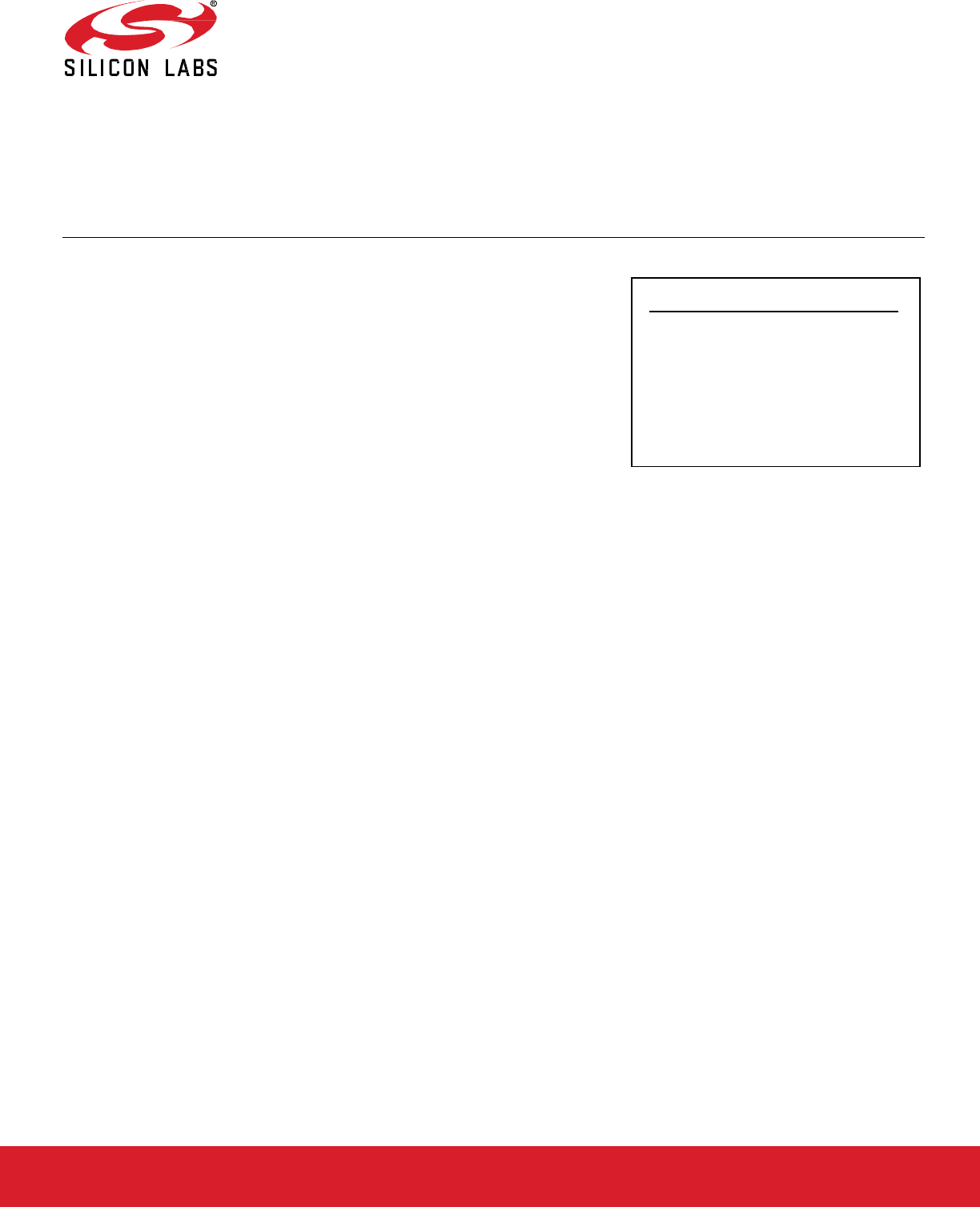
2 Application Framework Architecture
The Zigbee Application Framework sits on top of the Zigbee stack, consumes the stack “handler” interfaces, and exposes its own more
highly abstracted and application-specific interface to the developer.
One of the main features of the Zigbee Application Framework is its ability to separate user-created and Silicon Labs-created code.
While Silicon Labs provides all the source code for the Zigbee Application Framework, user-created code should live outside the frame-
work and should interact with the framework through the Zigbee Application Framework API exposed by the framework utilities and
callbacks. The block diagram in the following figure shows a high-level overview of the Zigbee Application Framework architecture and
how the two code bases are separated.
Figure 2.1. Zigbee Application Framework Architecture
Each application has its own main.c which implements the
main() function and the main loop.
The Silicon Labs GSDK is based on a component structure, where a component describes a software module (files, defines, and so on)
with a well-defined function. The Zigbee Application Framework Common component included in
app/framework/common con-
sumes the Zigbee Stack handler interface and integrates the Zigbee Application Framework into the Zigbee EmberZNet PRO stack.
This component provides a compile-time subscription mechanism for other Zigbee components. When a component subscribes to one
of the stack handlers, a function call to the component callback is generated and will be invoked every time the stack handler is invoked.
In addition, two main files are located in the app/framework/util directory, one (af-soc.c) for a System-on-Chip (SoC) and the other (af-
host.c) for a host micro-processor paired with a Network Co-Processor (NCP).
For example, the sample application projects subscribe to the
emberIncomingMessageHandler() stack handler and pass all
incoming messages off to the Zigbee Application Framework for command processing. Once incoming messages are processed, they
are passed off to the appropriate cluster for handling.
The application can choose to implement any of the public Application Framework level stack callbacks by simply declaring such
callbacks in the application code. Every sample application included in the Silicon Labs Gecko SDK Suite (GSDK) implements a subset
of callbacks in the application-specific app.c file. Application Framework-level stack callbacks are documented in the
Zigbee Application
Framework API reference.

UG491: Zigbee Application Framework Developer's Guide for SDK 7.0 and Higher
Project Files
silabs.com | Building a more connected world. Rev. 0.5
silabs.com | Building a more connected world. Rev. 0.5 | 3
3 Project Files
This section lists various files that are created in and used by a Zigbee application project.
3.1 Project Configuration File
<project_name>.slcp
This is the top-level project configuration file.
3.2 Application Source Files
Any number of C files in the project’s top directory can be created. The only requirement is that an implementation of
main() must be
present in one of these files.
3.3 Makefiles
Makefiles are generated into the project directory by the Project Configurator when using the GCC compiler. Wth IAR, an .ewp project
file is generated instead of makefiles.
3.4 ZCL-Generated Files
Generated files reside in the project’s autogen directory. You should never modify them manually because manual changes are erased
with every re-generation. ‘zap’ stands for ZCL Advanced Platform. This partial list discusses the generated files that you might need to
refer to for various definitions and declarations:
• zap-command.h: Generated macros for producing client-side command payloads prior to sending them out over the air; also contains
prototypes for the server-side command handlers.
• zap-config.h: A generated file that configures the Zigbee Application Framework's static data structures. This allows attribute
metadata to be shared across endpoints and each endpoint to have its own space for attribute storage. The #defines in the zap-
config.h file are used by the app/framework/util/attribute-storage.c file to configure all the application’s attribute-related data. It also
contains information about command discovery, based on the selection of incoming and outgoing for commands in the Zigbee Cluster
Configurator. See AN1325: Zigbee Cluster Configurator User's Guide for more information.
• zap-id.h: This file contains all the static IDs for various ZCL entities such as cluster IDs, attribute IDs, and others.
• zap-tokens.h: If you are including any attributes in tokens (persistent memory) for a platform that supports tokens, this file is gener-
ated by Project Configurator to configure your token storage.
• zap-type.h: This file contains all the type definitions for the ZCL—enums, structs, and other entities that are created from XML files.

UG491: Zigbee Application Framework Developer's Guide for SDK 7.0 and Higher
Zigbee Application Framework API and Directory Structure
silabs.com | Building a more connected world. Rev. 0.5
silabs.com | Building a more connected world. Rev. 0.5 | 4
4 Zigbee Application Framework API and Directory Structure
The Zigbee Application Framework’s API declarations are provided in app/framework/include/af.h. The Application Framework API Ref-
erence is provided with your installation as well as online at https://docs.silabs.com/zigbee/latest/zigbee-af-api/appframework
.
APIs for getting information about endpoints and attributes are included in app/framework/util/attribute-storage.h. For instance, to deter-
mine if an endpoint contains a certain attribute, use the function
emberAfContainsAttribute(). It returns a Boolean indicating
if the requested attribute and cluster are implemented on the specific endpoint.
Directories named in this section are found in the Simplicity Studio Zigbee protocol SDK folder (<GSDK location>\protocol\zigbee) as
follows:
• app/framework: All the Zigbee Application Framework code is in app/framework. Major portions of the code have been broken out
into their own directories.
• app/framework/common: Zigbee Application Framework common code that provide basic infrastructure for every Zigbee application,
such as seamless integration with OS, integration with the Power Manager, application-level event system APIs, implementation of
stack handlers and corresponding application and component dispatching.
• app/framework/cli: Code related to the Zigbee Application Framework’s implementation of the CLI.
• app/framework/include: All of the external APIs for the Zigbee Application Framework. This directory mirrors the use of the include
directory in the stack. It is intended to be the single location for all externally-facing application interfaces.
• app/framework/plugin, app/framework/plugin-host, app/framework/plugin-soc: All application framework component code resides
here, including all the Silicon Labs ZCL cluster implementations.
• app/framework/scenarios: Includes all sample application scenarios that use the Zigbee Application Framework. You can open these
sample scenarios within Project Configurator by starting a new project.
• app/framework/security: All utility code related to Zigbee security.
• app/framework/util: Includes message processing and any other utility code used by the Zigbee Application Framework. This direc-
tory contains the most important features of the Zigbee Application Framework. Attribute storage files that manage attributes for
multiple endpoint support are included in this directory. In addition, the API used for accessing, reading, and writing attributes is
included in the attribute-table.h, and attribute-storage.h files.
• <GSDK location>\app\zcl Includes configuration and template files used by Project Configurator. When you point Project Configurator
at a stack installation, it looks into this directory to load XML descriptions of the most current ZCL implementation as of the release
of that stack. You may load your custom cluster .xml files into your project by clicking Add Custom ZCL in Zigbee Cluster Configu-
rator.

UG491: Zigbee Application Framework Developer's Guide for SDK 7.0 and Higher
ZCL Concepts and Definitions
silabs.com | Building a more connected world. Rev. 0.5
silabs.com | Building a more connected world. Rev. 0.5 | 5
5 ZCL Concepts and Definitions
5.1 Clusters
Each Zigbee cluster defines an application-level protocol. A set of these protocols (or clusters) defines the functionality of a particular
Zigbee device. Anyone with a networking background can think of a cluster as an application protocol that has been encapsulated within
the Zigbee specification.
The Zigbee Cluster Library (ZCL) is a document that specifies the clusters used by Zigbee devices. The original ZCL document had 30
clusters, most of which were specified as required or optional by at least one device in the Zigbee application profile. The Smart Energy
(SE) application profile uses some of the clusters specified in the ZCL but also specifies new clusters that are unique to SE.
5.2 Devices
A Zigbee device can be thought of as a collection of clusters. For example, an on/off light switch and an on/off light are two devices in
the Zigbee 3.0 specification. All the devices within a profile must use the same type of security. There are recommendations on polling
rates, start-up parameters, what kind of ZDO messages should be implemented, and so on, with the idea being that these devices must
interoperate on the same network. If devices have different security settings, they cannot join together. If a user buys a Zigbee 3.0 device
from company A and buys another Zigbee 3.0 device from company B, because they use the same application profile, the devices
should be able to join work together.
If two Zigbee devices are on a certified Zigbee stack, they can route for each other. In other words, they can exchange messages at the
application level. Interoperability at the application level is not guaranteed until devices use an application profile. These standard appli-
cation profiles enable Project Configurator to generate Zigbee- compliant applications.
The Zigbee 3.0 on/off light has the following implementations:
• Identify server (required by all)
• Groups server
• Scenes server
• On/Off server
The Zigbee 3.0 on/off light switch has the following implementations:
• Identify client
• Groups client
• Scenes client
• On/Off client
The on/off light switch can send an on/off or toggle message that the on/off light is required to understand and accept.
5.3 Profile ID
When configuring an endpoint, you must specify a Profile ID. If you are developing a Zigbee 3.0 application, you must specify the profile
ID 0x0104. When developing an SE application, you must specify the profile ID 0x0109.
5.4 More About Clusters and Attributes
Clusters specify two things: attributes and commands. Attributes are well-defined pieces of data that are stored on a device and can be
read (and sometimes written) by external devices. Commands specify Over-The-Air (OTA) messages that are exchanged. Each com-
mand defined by the ZCL is unidirectional in the sense that it is sent by one side (either the client or server) and received by the other.
A device can implement only one side of a cluster, or it can implement both sides of a cluster.
For instance, a Zigbee On/Off Light implements the server side of the “on/off” cluster, while the Zigbee On/Off Light Switch implements
the client side of the “on/off” cluster. This defines that the Light Switch sends “on”, “off”, and “toggle” commands that the Light can receive
(and understand). It also defines that the Light stores a Boolean attribute called “on/off” representing the current state of the device.
UG491: Zigbee Application Framework Developer's Guide for SDK 7.0 and Higher
ZCL Concepts and Definitions
silabs.com | Building a more connected world. Rev. 0.5
silabs.com | Building a more connected world. Rev. 0.5 | 6
Note: Zigbee often uses the terms “in-cluster-list” and “out-cluster-list” instead of server and client. An “in-cluster-list” is the list of
supported server clusters, and the “out-cluster-list” is the list of supported client clusters.
In most cases, the server side of a cluster contains all the attributes, and the client side is the side that initiates an OTA exchange. For
the most part, the client sends a message and the server answers that message.
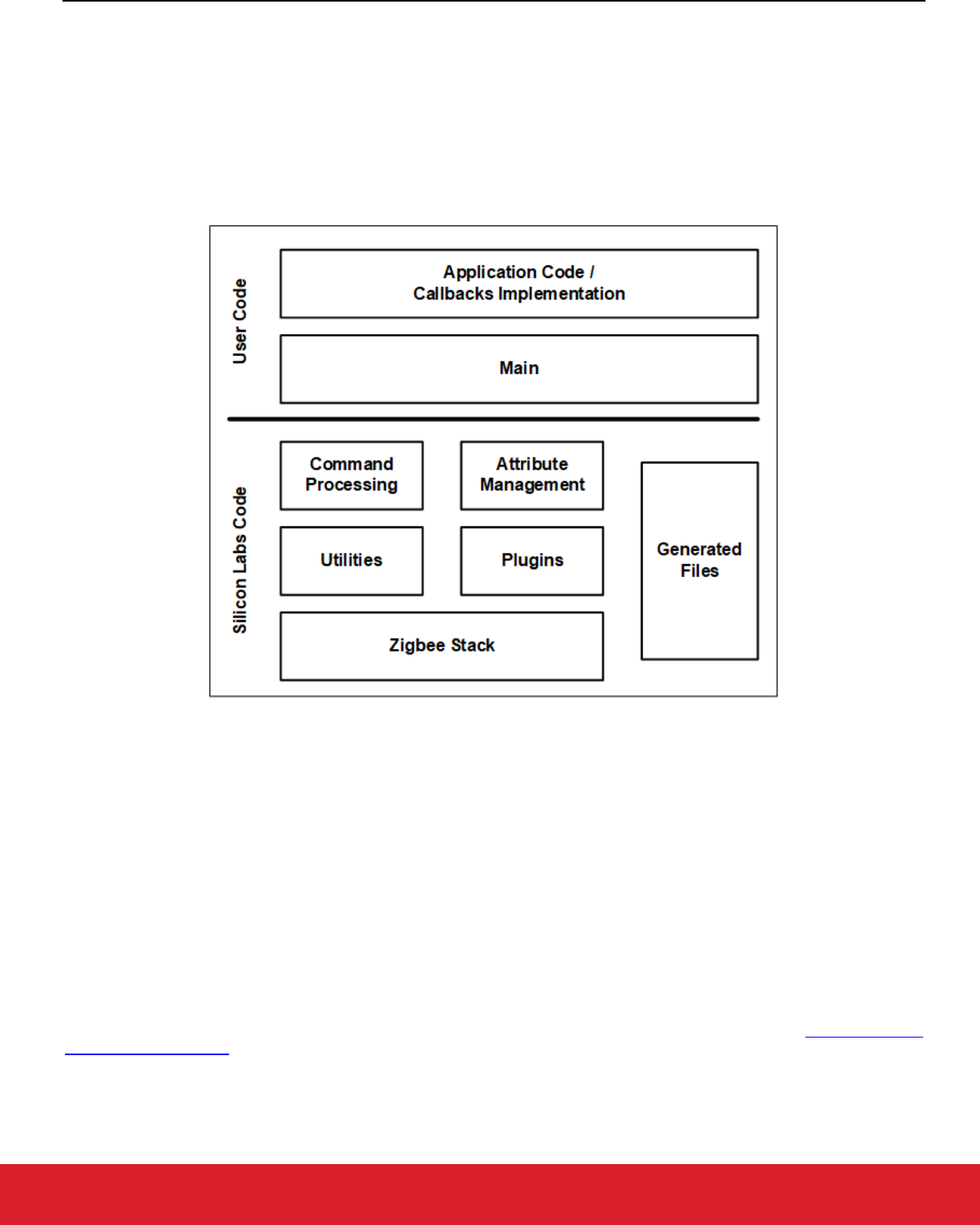
5.4.1 Example: The Identify Cluster
The client/server interaction defined by the ZCL is illustrated in the Identify example shown in the following figure.
Figure 6.1. Identify Cluster Example
Like many clusters, the Identify cluster is a simple cluster. The lower right corner shows the single attribute—identify time.
5.4.1.1 Identify Cluster Use Case
A user is provisioning a network of 12 lights in one room and must connect six of those lights to a single switch. The MAC address of
each light is used to associate it with the switch. The MAC addresses for all 12 lights can be discovered by using a provisioning tool and
a low power broadcast or by using a token (set when they were installed) on each light indicating room or location. The “Identify”
functionality can be used to figure out which six MAC addresses correspond to the six physical lights that the user wants bound to a
switch. Using the Identify cluster, the user can tell each light individually to “identify” itself (for example, blink so that it can be seen).
The Identify cluster defines the protocol for how devices are put into and taken out of identify mode. In the above example, the provi-
sioning tool implements the client side of the identify cluster and the light or the device that needs to be identified implements the server
side.
When the client wants to tell a device to “start identifying,” it sends the “Identify” command and specifies a period of time in seconds for
which to continue identifying. The device stops identifying when the identify time attributes (decremented each second) reaches 0 or if
the device receives an “Identify” command with identify time value of 0.
The first message in the above figure turns on “identify.” When identify is turned on, a time period is also included in the message. For
example, suppose identify is turned on for 30 seconds. The second message shows the client (provisioning device) querying the server
(light) to find out how much time is left in the identify process.
Because a query message can be sent to a group, it is possible to put a device into a mode where it is identifying, and then use a PC
or provisioning tool and figure out which device in the group is identifying. This is useful if a device supports a physical cue to start
identifying. Then a device can be poked (button press, magnet wand, and so on) to start identifying, and a group message can be sent
to map the MAC address to the physical device.
UG491: Zigbee Application Framework Developer's Guide for SDK 7.0 and Higher
ZCL Concepts and Definitions
silabs.com | Building a more connected world. Rev. 0.5
silabs.com | Building a more connected world. Rev. 0.5 | 7
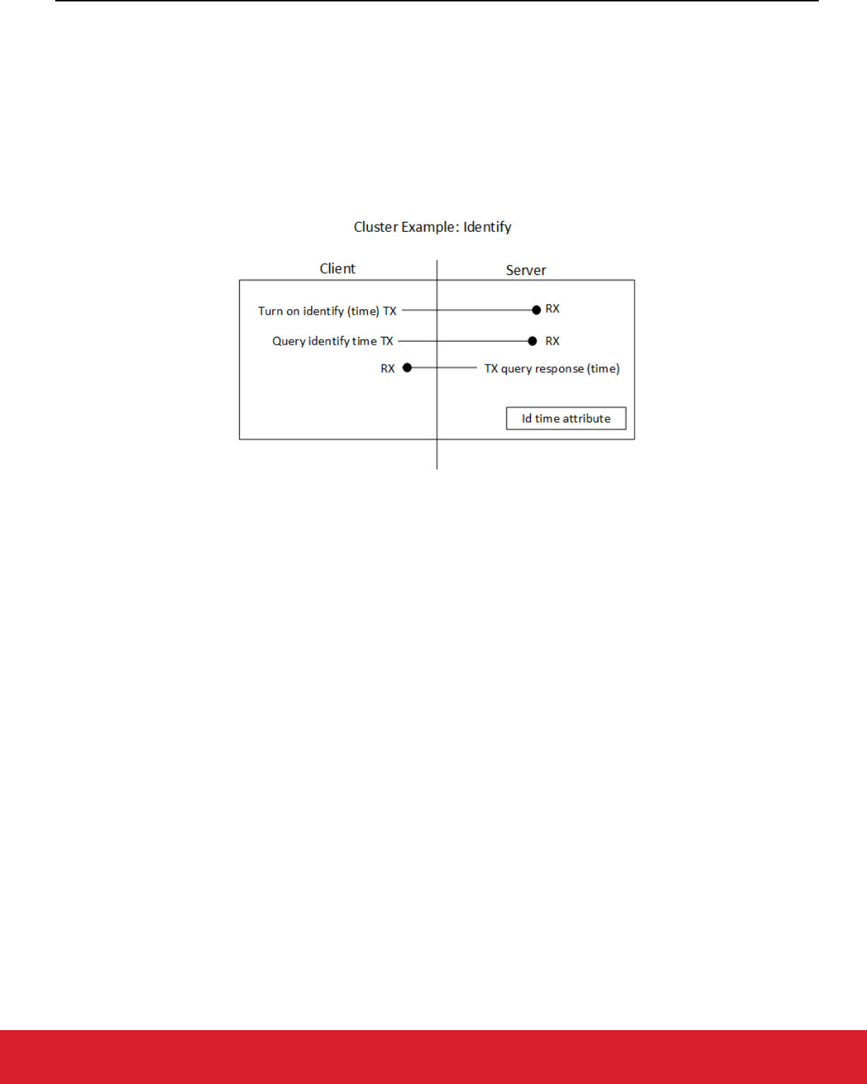
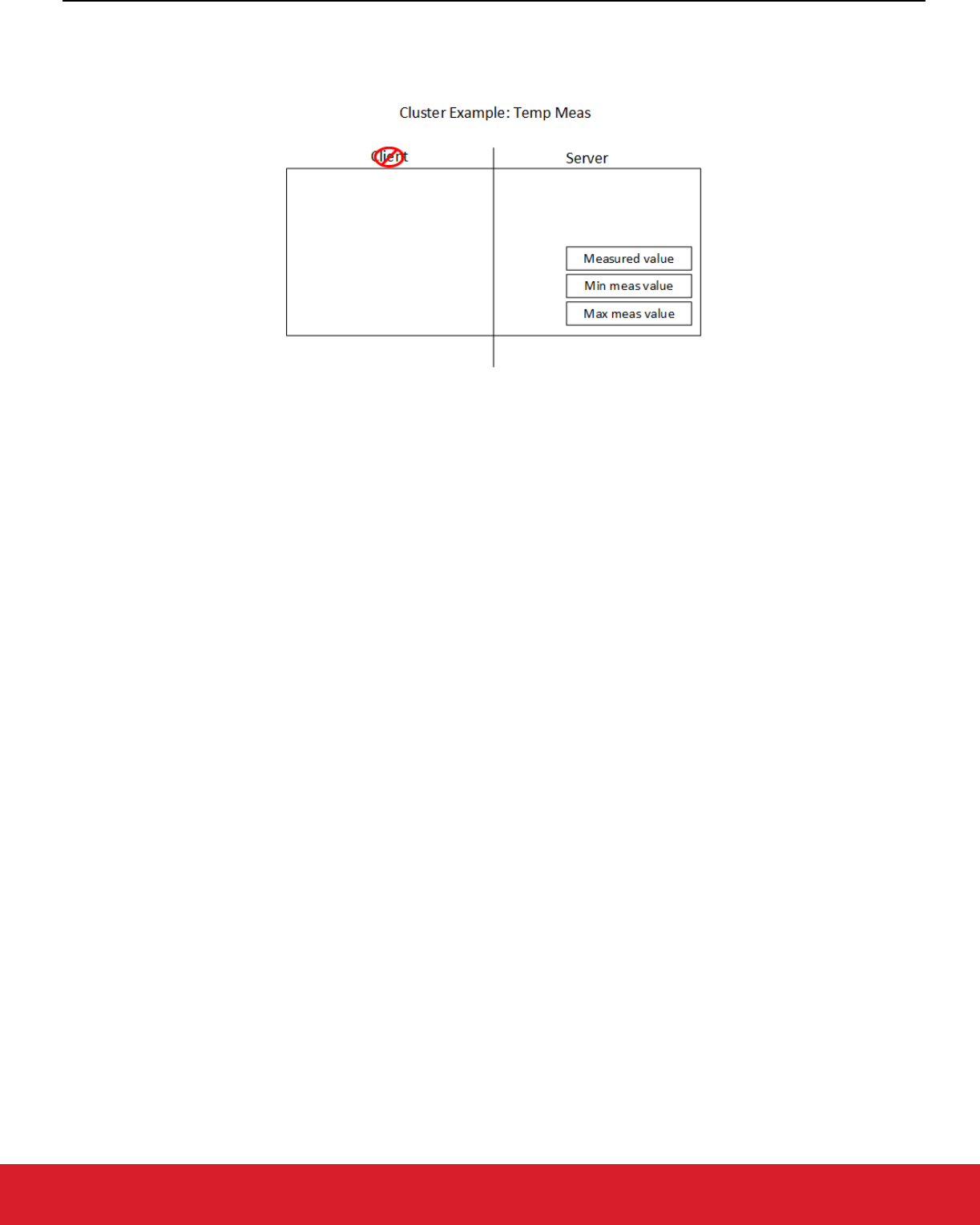
5.4.2 Example: The Temperature Measurement Cluster
The following figure illustrates another example of a temperature measurement cluster.
Figure 6.2. Temperature Measurement Cluster Example
Notice that this cluster has no commands, it only has attributes. In this case, the device implements measurements of temperature, such
as a thermostat. This example includes a measured value, a minimum measured value, and a maximum measured value. With no
commands, this cluster relies on the global commands defined in the ZCL. The global commands define messages for reading, writing,
discovering, and reporting attributes.
Note: Fourteen global commands such as read attributes, write attributes, configure attribute reporting, discover attributes, and report
attribute values are included in this cluster. Clusters that only include attributes are simple to understand and implement be-
cause the global commands are already implemented.
To read the value of an attribute of this cluster, a global read attributes command is used. This message contains the attribute ID of the
attribute to read. In combination, the cluster and the attribute ID provide unique identification. On the embedded side, this makes it
possible to centralize all the attributes in a single table. All the code for those attributes is generic, shared code.
As a result, for example, when adding four of the temperature-measuring-sensing clusters, the impact on flash is minimal because there
are no additional commands. The impact on RAM depends on the number of attributes added per cluster.
The application-level protocol provided by the ZCL makes it possible for two companies to develop products separately and have them
work together without having to test them together.
UG491: Zigbee Application Framework Developer's Guide for SDK 7.0 and Higher
Zigbee Application Framework Callback Interface
silabs.com | Building a more connected world. Rev. 0.5
silabs.com | Building a more connected world. Rev. 0.5 | 8
6 Zigbee Application Framework Callback Interface
The Zigbee Application Framework callbacks are intended to be used as a means to remove all customer code from the Zigbee Appli-
cation Framework. Generally, when a callback is called, the Zigbee Application Framework gives the application code a first opportunity
at an incoming message or requesting some piece of application data. Within the callback API, some callbacks return a Boolean value
indicating that the message has been handled and no further processing will be done. If your application is doing something that conflicts
with the Zigbee Application Framework’s handling of a particular message, return TRUE to indicate that the message was handled. This
ensures that the Zigbee Application Framework does not interfere with your application’s handling of the message.
6.1 Implementing Callbacks
A callback is a C function that gets invoked by the Application Framework when certain conditions are met. A basic weak implementation
of all callbacks is provided by the Application Framework. The application can override each of these weak definitions by simply adding
a callback implementation to some application-level source file. For example, you may create my_callbacks.c file by clicking New in
Simplicity Studio's Project Explorer focused on a given project, add a callback implementation to this file, and save it. The file automati-
cally becomes a compilation unit in the project and the callback implementation will be compiled and linked during subsequent builds.
6.2 Callback Types
The Zigbee Application Framework utilizes the following callback types:
• Global Callbacks
• ZCL command handling callbacks
• Component-Specific Callbacks
• Stack Callbacks
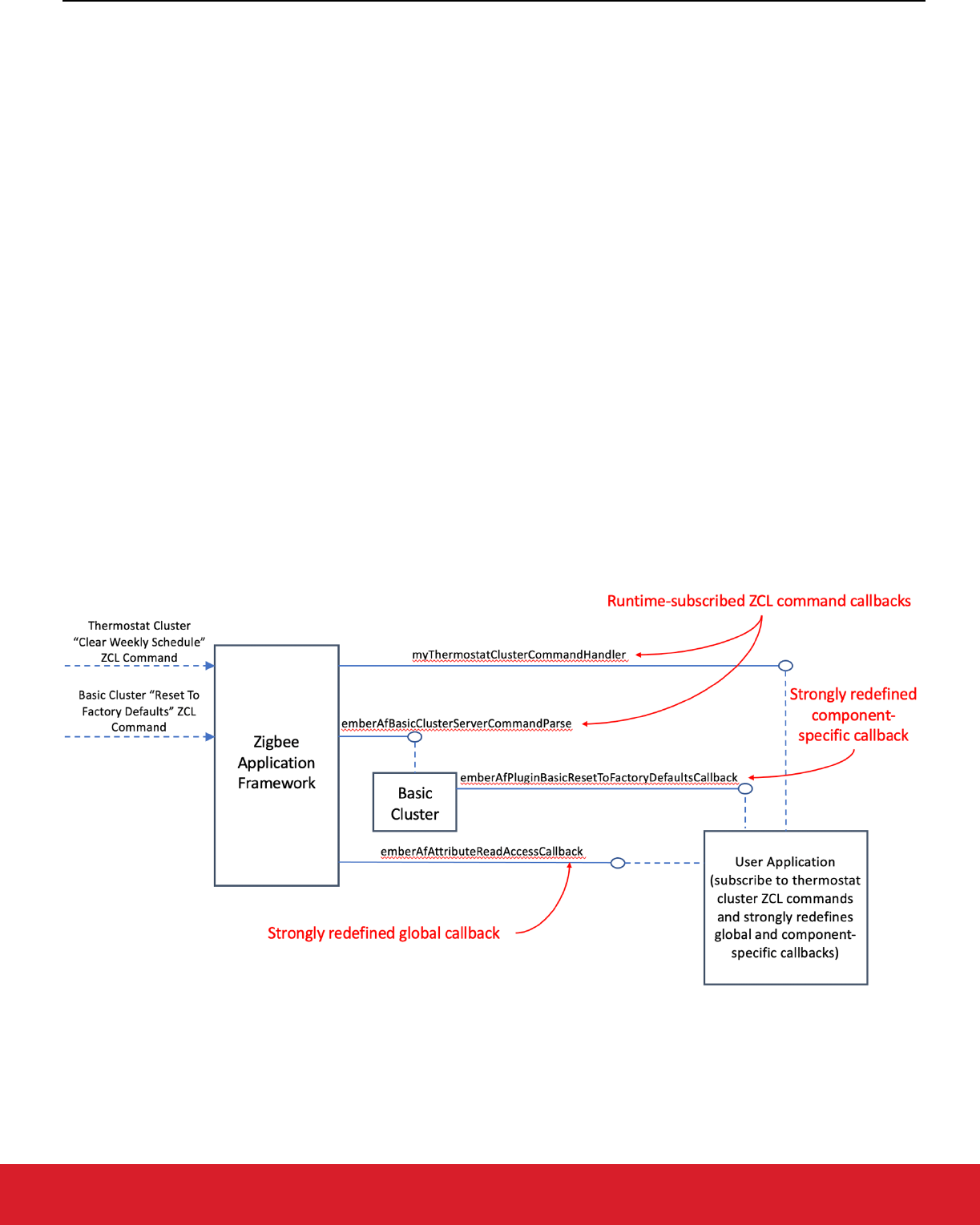
The following figure illustrates an example of Zigbee Application Framework callback types.
Figure 5.1. Zigbee Application Framework Callback Types
The above figure illustrates a project where:
• ZCL Basic Cluster implementation is provided by the GSDK, which uses runtime subscription mechanism to subscribe the ember-
AfBasicClusterServerCommandParse function to the Basic Cluster ZCL commands (server side).

UG491: Zigbee Application Framework Developer's Guide for SDK 7.0 and Higher
Zigbee Application Framework Callback Interface
silabs.com | Building a more connected world. Rev. 0.5
silabs.com | Building a more connected world. Rev. 0.5 | 9
• ZCL Thermostat Cluster is not implemented in the GSDK but is implemented in the application. The application uses a runtime
subscription mechanism to subscribe myThermostatClusterCommandHandler to the Thermostat Cluster ZCL commands as de-
scribed in section 5.4.
• Application implements a component-specific callback emberAfPluginBasicResetToFactoryDefaultsCallback by strongly redefining
it.
• Application implements a global callback emberAfAttributeReadAccessCallback by strongly redefining it.
6.3 Global Callbacks
All global commands fall into this category. The Zigbee Application Framework contains handling code for global ZCL commands. If any
global command callback returns TRUE, this indicates that the command has been handled by the application and no further command
handling should take place. If the callback returns FALSE, then the Zigbee Application Framework continues to process the command
normally.
You can find a full list of Global callbacks at https://docs.silabs.com/zigbee/latest/zigbee-af-api/global-callback
.
6.3.1 Global Callback Example
The pre-command received callback (emberAfPreCommandReceivedCallback(EmberAfClusterCommand* cmd) is called after a ZCL
command has been received but has not yet been processed by the Zigbee Application Framework’s command handling code. The
command is parsed into a useful struct EmberAfClusterCommand that provides an easy way to access relevant data about the command
including its EmberApsFrame, message type, source, buffer, length, and any relevant flags for the command. This callback also returns
a Boolean value indicating if the command has been handled. If the callback returns TRUE, then it is assumed that the command has
been handled by the application and no further action is taken.
6.4 ZCL Command Handling Callbacks
The Zigbee Application Framework provides a runtime mechanism that enables the application to subscribe to ZCL commands related
to a certain ZCL cluster. Specifically:
sl_status_t sl_zigbee_subscribe_to_zcl_commands(uint16_t cluster_id,
uint16_t manufacturer_id,
uint8_t direction,
sl_service_function_t service_function)
This API enables the application to subscribe to incoming ZCL commands related to a specific cluster ID, a specific manufacturer ID (if
not present, simply pass 0xFFFF), a direction (either
ZCL_DIRECTION_CLIENT_TO_SERVER or ZCL_DIREC-
TION_SERVER_TO_CLIENT
) and the actual callback to be invoked whenever a matching ZCL command is received. Such a callback
must return a value of
EMBER_ZCL_STATUS_SUCCESS if the command was handled, and a value of EMBER_ZCL_STATUS_UN-
SUP_COMMAND
if the callback did not handle the passed command.
Below is an example of a runtime-subscribed ZCL command callback that handles the “stop” command for the “level control” cluster:
uint32_t my_command_handler(sl_service_opcode_t opcode,
sl_service_function_context_t *context)
{
assert(opcode == SL_SERVICE_FUNCTION_TYPE_ZCL_COMMAND);
EmberAfClusterCommand *cmd = (EmberAfClusterCommand *)context->data;
switch (cmd->commandId) {
case ZCL_STOP_COMMAND_ID:
{
// ZCL command structs and parsing functions are implemented in the
// generated zap-cluster-command-parser.[c,h] files.
sl_zcl_level_control_cluster_stop_command_t cmd_data;
if (zcl_decode_level_control_cluster_stop_command(cmd, &cmd_data)
!= EMBER_ZCL_STATUS_SUCCESS) {
return EMBER_ZCL_STATUS_UNSUP_COMMAND;

UG491: Zigbee Application Framework Developer's Guide for SDK 7.0 and Higher
Zigbee Application Framework Callback Interface
silabs.com | Building a more connected world. Rev. 0.5
silabs.com | Building a more connected world. Rev. 0.5 | 10
}
// Handle the command here
// Send a default response back to the client
emberAfSendDefaultResponse(EMBER_ZCL_STATUS_SUCCESS);
// handle the command here
return EMBER_ZCL_STATUS_SUCCESS;
}
}
return EMBER_ZCL_STATUS_UNSUP_COMMAND;
}
The application must subscribe to the Level Control cluster commands (server side), by invoking the following – typically at initialization
time:
void app_init(void)
{
sl_zigbee_subscribe_to_zcl_commands(ZCL_LEVEL_CONTROL_CLUSTER_ID,
0xFFFF,
ZCL_DIRECTION_SERVER_TO_CLIENT,
my_command_handler);
}
Notice that in the previous example, the application chose to implement a single command and used the ZCL command parsing functions
that are generated in the
zap-cluster-command-parser.[c,h]. When such a command is received (and handled), the
callback returns EMBER_ZCL_STATUS_SUCCESS while, when other commands belonging to the same cluster are received, the callback
returns EMBER_ZCL_STATUS_UNSUP_COMMAND.
Finally, multiple software modules can subscribe to the same cluster, though every command belonging to a ZCL cluster should be
handled by a single software module. If a cluster is not enabled in the ZCL Configurator tool, the application framework responds with a
default response with status
EMBER_ZCL_STATUS_UNSUPPORTED_CLUSTER. If the cluster is enabled in the ZCL Configurator
tool, but no software module is handling the command, the application framework responds with status
EMBER_ZCL_STATUS_UN-
SUP_COMMAND
.
6.5 Component-Specific Callbacks
Callbacks of this type are calls into the application code from the internal component logic. The full list of component-specific callbacks
can be found at https://docs.silabs.com/zigbee/latest/zigbee-af-api/af-callback
. Additionally, a link to the list of callbacks offered by each
component appears in the component’s tile in the Project Configurator. You can implement these callbacks as described in 5.1 Imple-
menting Callbacks.
For example, the Basic Server Cluster software component exposes the emberAfPluginBasicResetToFactoryDefaultsCallback callback
(as displayed in the Zigbee Cluster Library Common component), which you may choose to implement by simply adding an implemen-
tation of this function to one of the C files in the project.
6.6 Stack Callbacks
The Application Framework also provides stack-level callbacks that enable the application to react to stack-specific events. Typically,
these stack callbacks match the stack handlers provided by the Zigbee stack libraries that are consumed by the Application Framework.
For example:
• void emberAfStackStatusCallback(EmberStatus status)
• void emberAfEnergyScanResultCallback(uint8_t channel,int8_t maxRssiValue)
• void emberAfNetworkFoundCallback(EmberZigbeeNetwork *networkFound, uint8_t lqi, int8_t rssi)
• and so on.
A full list of these stack callbacks can be found at https://docs.silabs.com/zigbee/latest/zigbee-af-api/stack-callback
.
UG491: Zigbee Application Framework Developer's Guide for SDK 7.0 and Higher
Zigbee Application Framework Callback Interface
silabs.com | Building a more connected world. Rev. 0.5
silabs.com | Building a more connected world. Rev. 0.5 | 11
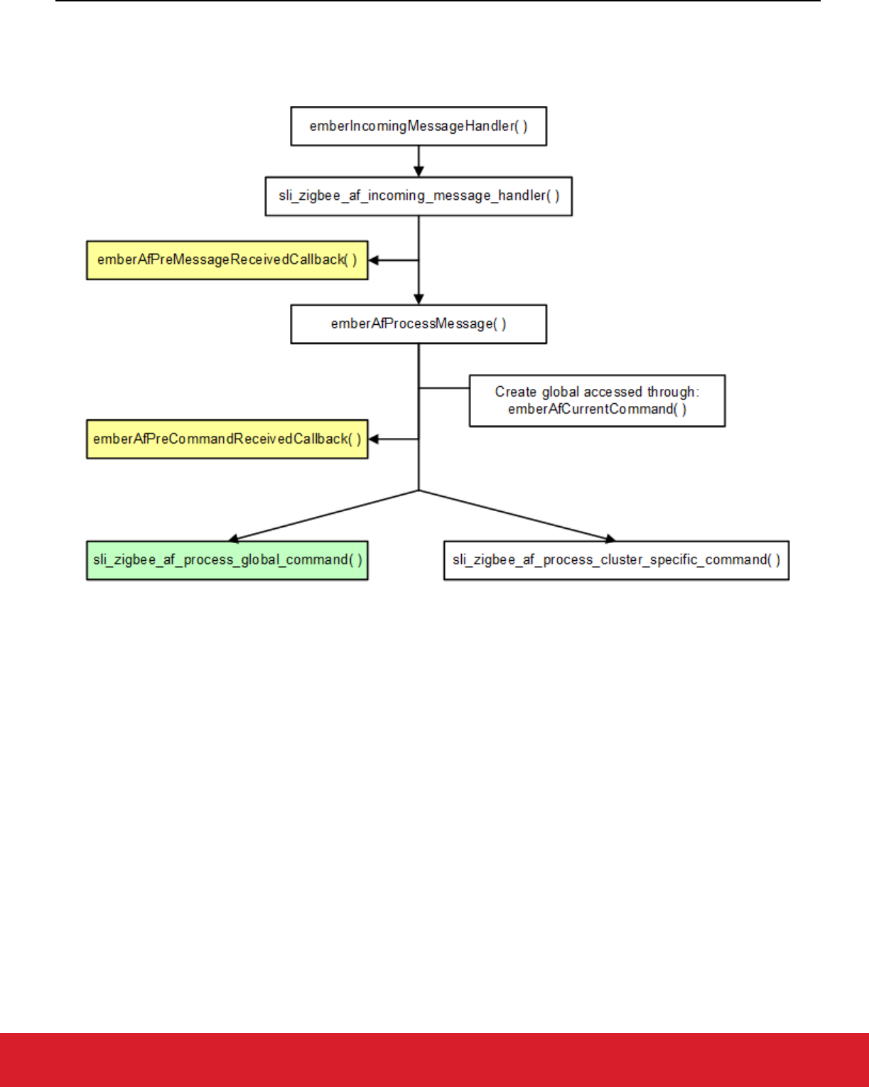
6.7 Callback Flow for Message Processing
The following figure shows how a message received by the Zigbee Application Framework’s implementation of
emberIncoming-
MessageHandler
is processed and flows through the framework code and out to the application implemented callbacks.
Figure 5.2. Incoming Message Flow
UG491: Zigbee Application Framework Developer's Guide for SDK 7.0 and Higher
Zigbee Application Framework Callback Interface
silabs.com | Building a more connected world. Rev. 0.5
silabs.com | Building a more connected world. Rev. 0.5 | 12
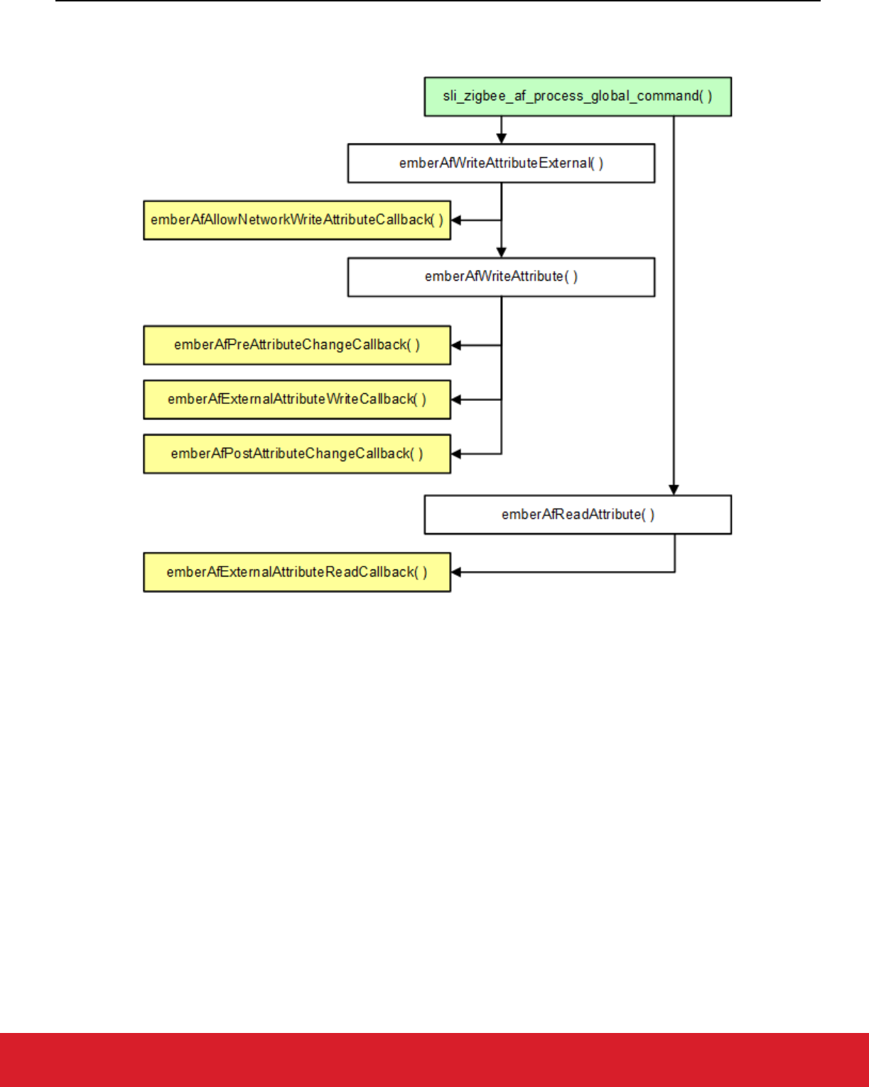
Once the incoming message is determined to be an incoming global command, it is passed off to the global command handling for
processing, as shown in the following figure.
Figure 5.3. Global Command Handling
Otherwise, if it is found to be a cluster-specific command, it is passed off to the cluster-specific command processing.
6.8 Command Callbacks Implementation Notes
6.8.1 Command Callback Context
All command-related callbacks are called from within the context of the
emberIncomingMessageHandler. This means that Zigbee
APIs that are available to the application within that context are available within the command handling callbacks as well. These APIs
are listed in the stack API file located at stack/include/message.h. The stack APIs that are available in the command callbacks are listed
in the stack message header located at stack/include/message.h and include:
emberGetLastHopLqi()
emberGetLastHopRssi()
emberGetSender()
emberGetSenderEui64()
emberGetBindingIndex()
emberSetReplyBinding()
emberNoteSendersBinding()

UG491: Zigbee Application Framework Developer's Guide for SDK 7.0 and Higher
Zigbee Application Framework Callback Interface
silabs.com | Building a more connected world. Rev. 0.5
silabs.com | Building a more connected world. Rev. 0.5 | 13
6.8.2 Array Handling in Command Callbacks
Any Zigbee message that contains an array of arguments is passed as an int8u* pointer to the beginning of the array. This is done even
when the Zigbee Application Framework knows that the arguments in the array may be of another type, such as an uint16_t or uint32_t,
because of byte alignment issues on the various processors on which the Zigbee Application Framework may run. Developers imple-
menting the callback must parse the array and cast its elements appropriately for their hardware.

UG491: Zigbee Application Framework Developer's Guide for SDK 7.0 and Higher
Time Handling
silabs.com | Building a more connected world. Rev. 0.5
silabs.com | Building a more connected world. Rev. 0.5 | 14
7 Time Handling
The Zigbee Application Framework provides a single API for accessing the current time on the system—int32u emberAfGetCur-
rentTime()
—which is described in app/framework/util/time-util.h. This section describes how the function is implemented in
app/framework/util/time-util.c.
If the ZCL time cluster server is implemented on the system, then this function retrieves the time from the server through the function
call
int32u emberAfTimeClusterServerGetCurrentTime(). In this case, the time is read from the time cluster server’s
time attribute and returned. If the time cluster server is not implemented, then
emberAfGetCurrentTime calls emberAfGetCur-
rentTimeCallback.
If your device needs to know the current time but does not implement the time cluster server component, it is responsible for maintaining
its own time somewhere on the system and returning that time through the emberAfGetCurrentTimeCallback when it is requested. This
is especially important for SE devices that do not implement the time cluster server like an In-Premise Display (IPD). Essentially the IPD
is on its own when it comes to time management. It would be outside the ZCL specification (as currently interpreted) for a non-Energy
Service Portal to implement the time cluster server. Therefore, the IPD must maintain its own knowledge of time and provide it to the
Zigbee Application Framework when requested through the emberAfGetCurrentTimeCallback.
If your application includes the time cluster server, the time cluster server code always tries to initialize and update the time server’s time
attribute through the emberAfGetCurrentTimeCallback. If the emberAfGetCurrentTimeCallback returns 0, then the time cluster server
increments the stored attribute once per second. Thus, you can use the time cluster server to store and maintain real time on the system
without implementing the emberAfGetCurrentTimeCallback, if the actual time value can be synced from another device on the system
and written into the time server’s time attribute. For more information on how time is handled by the bundled implementation of the time
cluster server, see app/framework/plugin/time-server/time-server.c.

UG491: Zigbee Application Framework Developer's Guide for SDK 7.0 and Higher
Events
silabs.com | Building a more connected world. Rev. 0.5
silabs.com | Building a more connected world. Rev. 0.5 | 15
8 Events
The Zigbee Application Framework and its associated cluster code use the Zigbee Stack event mechanism to schedule events on both
the SoC and the host. Use of the Zigbee event mechanism saves code and RAM and works better with sleepy devices.
At a high level, the event mechanism provides a central location where all periodic actions taken by the device can be activated and
deactivated based on either some user input, an OTA command, or device initialization. The event mechanism is superior to the constant
tick mechanism it replaces because it allows the Zigbee Application Framework to know precisely when the next action is going to occur
on the device. This is extremely important for sleepy devices that need to know exactly when they must wake up to take some action or
more importantly that they cannot go to sleep because some event is in progress. The application can create and use its own events.
8.1 Creating Application Events
The Zigbee Application Framework uses the Zigbee standard event mechanism to control and run application events within the Zigbee
Application Framework. The stack’s event mechanism is documented in the zigbee_app_framework_event.h header file located at
app/framework/common.
An application can create a new event by simply declaring a new variable of sl_zigbee_event_t type. Such variable should be initialized
before being used by invoking the
sl_zigbee_event_init() API. Once the event is initialized, the following APIs can be invoked:
• void sl_zigbee_event_set_active(sl_zigbee_event_t *event)
• void sl_zigbee_event_set_inactive(sl_zigbee_event_t *event)
• bool sl_zigbee_event_is_scheduled(sl_zigbee_event_t *event)
• uint32_t sl_zigbee_event_get_remaining_ms(sl_zigbee_event_t *event)
• void sl_zigbee_event_set_delay_ms(sl_zigbee_event_t *event, uint32_t delay)
• void sl_zigbee_event_set_delay_qs(sl_zigbee_event_t *event, uint32_t delay)
• void sl_zigbee_event_set_delay_minutes(sl_zigbee_event_t *event, uint32_t delay)
8.1.1 Event Struct and Event Handler
An application event consists of two parts:
• The event handler, called when the event fires.
• The sl_zigbee_event_t struct which is used to schedule the event. Scheduled events end up in the Zigbee Application Framework
event queue which the Zigbee Application Framework uses to keep track of when the next event will occur for the purposes of
sleeping.
8.1.2 Application Event Example
The Z3Light sample application uses a custom event to manage its state. The event consists of two parts:
• The sl_zigbee_event_t struct called commissioning_led_event.
• The event handler which is called each time the event fires. The event handler is called the
commissioning_led_event_han-
dler
. The event handler and event struct are included in the app.c file shipped with the sample application.
8.2 How Cluster Events Are Created
Every cluster includes a server and a client “tick” callback. The Zigbee Cluster Configurator generates a declaration of a
sl_zigbee_event_t struct for each cluster server or client on each endpoint. The actual declarations are generated in the zap_event.h
header which is included and used in the Zigbee Application Framework’s event code in app/framework/util/af-event.c.
Initialization of endpoint-specific events must be accomplished using the dedicated API
sl_zigbee_endpoint_event_init().

UG491: Zigbee Application Framework Developer's Guide for SDK 7.0 and Higher
Events
silabs.com | Building a more connected world. Rev. 0.5
silabs.com | Building a more connected world. Rev. 0.5 | 16
8.3 How Cluster Events Are Scheduled
The component or application code can manage cluster-related events in the event table by using the Zigbee Application Framework’s
event management API. This API consists of two functions:
sl_zigbee_zcl_schedule_cluster_tick and
sl_zigbee_zcl_deactivate_cluster_tick.
A tick is the basic unit of time used in the event system. The duration of a tick depends on the platform that is being used. Using the
current Zigbee platform, one tick is approximately equal to:
( )
_
__
=
= .9765625 milliseconds per second
where MILLISECOND_TICKS_PER_SECOND is the number of clock ticks per second. Therefore, when
sl_zigbee_zcl_schedule_cluster_tick is called with a value of t for the delayMs argument, the event will be run in no
less than
( )
_
_
_
=
.9765625
milliseconds.
Of course, the empirical error in this value depends on the reliability of the clock source.
8.3.1 sl_zigbee_zcl_schedule_cluster_tick
sl_zigbee_zcl_schedule_cluster_tick uses the endpoint, cluster id, and client/server identity to find the associated event
in the sl_zigbee_event_context_t event context table. This table is generated by the Zigbee Cluster Configurator into zap-event.h. If it
cannot find the event table entry, sl_zigbee_zcl_schedule_cluster_tick returns the EmberStatus EMBER_BAD_ARGU-
MENT to the caller. If it finds the event table entry, then it schedules the event to take place in the number of milliseconds requested by
the caller and it returns EMBER_SUCCESS.
EmberStatus sl_zigbee_zcl_schedule_cluster_tick (int8u endpoint,
int16u clusterId,
boolean isClient,
int32u timeMs,
EmberAfEventSleepControl sleepControl);
The EmberAfEventSleepControl argument allows the caller to indicate what the device may do while the event is active in the event
table. This value is only relevant for sleepy devices; it has no effect for devices that do not go to sleep. The possible values for Ember-
AfEventSleepControl are enumerated in app/framework/include/af-types.h, as follows:
• EMBER_AF_OK_TO_HIBERNATE means that the application may go into prolonged deep sleep until the event needs to be called.
Use this sleep control value if the scheduling code does not care what the device does up to the point when the event is called.
• EMBER_AF_OK_TO_NAP means that the device should sleep for the nap period and should wake up to poll between naps until the
event is called. Use this sleep control value if the scheduling code wants the device to poll periodically until the event is called. This
is particularly useful if the scheduled event is a timeout waiting for some reply from another device on the network. If the event is a
timeout, you do not want the device to go into hibernation until the timeout is called because it will never hear the message it is
waiting for, thereby guaranteeing that the timeout will be called.
• EMBER_AF_STAY_AWAKE means that the device should not sleep at all but should stay awake until the event is called. Use this
event if you are scheduling a very frequent event and do not want the device to nap for a very short period of time because the
device will poll each time it wakes up. If the device is held out of sleep entirely, it will poll once per second.
8.3.2 sl_zigbee_zcl_deactivate_cluster_tick
The deactivation function is used to turn off an event. This function should be called when the scheduled event is called to ensure that
the event code does not continue to call the event. It may also be called before the event is called if the event is no longer necessary.
Note: In the Zigbee Application Framework sl_zigbee_zcl_deactivate_cluster_tick is automatically called before
the event fires to ensure that the event will not continue to be called on every tick.

UG491: Zigbee Application Framework Developer's Guide for SDK 7.0 and Higher
Events
silabs.com | Building a more connected world. Rev. 0.5
silabs.com | Building a more connected world. Rev. 0.5 | 17
deactivate_cluster_tick is like schedule_cluster_tick in that it takes most of the same arguments, but it also has to
locate the correct event in the event context table before shutting it off.
EmberStatus sl_zigbee_zcl_deactivate_cluster_tick (int8u endpoint,
int16u clusterId,
boolean isClient);

UG491: Zigbee Application Framework Developer's Guide for SDK 7.0 and Higher
Attribute Management
silabs.com | Building a more connected world. Rev. 0.5
silabs.com | Building a more connected world. Rev. 0.5 | 18
9 Attribute Management
9.1 ZCL Attribute Configuration
In the Zigbee Application Framework , attribute storage is managed by two .c files—app/framework/util attribute-storage.c and attribute-
table.c)—as well as a single header file zap-config.h which Project Configurator generates from the application configuration. The end-
point configuration header file sets up the attribute metadata and the actual attribute storage.
You have several options for attribute storage:
• External Attributes
• Persistent Memory Storage
• Singleton
• Attribute Bounding
• Attribute Reporting
9.1.1 Attribute Storage Endianness
All attributes that are not a ZCL string type are expected to be stored with the same endianness as the platform on which the application
is being run. On the EFR32, this means that attributes with a non-string type are expected to be stored with the least significant byte first
(LSB, little endian).
9.1.2 Implications of Attribute Storage Endianness
The Zigbee protocol demands that all values that are not a string or byte array type be sent over the air in a Little Endian or LSB format.
The implication of this for the EFR32 and other little-endian platforms is that no byte swapping needs to be done with attributes when
they are pulled from attribute storage and sent over the air. Conversely, when the Zigbee Application Framework is run a big-endian
processor, like certain UNIX host systems for EZSP-UART, it will perform byte swapping on integer type attributes before they are sent
over the air so that they are sent in the LSB format.
The previous section says that attributes are expected to be stored in the proper format because no byte swapping is done on local
writes into the attribute table from native types or from byte arrays. Therefore, it is up to the user to ensure that byte arrays which
represent Zigbee integer types but do not map directly to a native type like the int16u or int32u are represented in the byte order of the
application platform.
If you are writing an application that may be run on several platforms with different endianness, you may check the endianness of the
platform by using the #define BIGENDIAN_CPU provided in the platform header platform/common/inc/sl_endianness.h.
Example: Consider the simple-meter-server component’s test code located at app/framework/plugin/simple-metering-server/simple-me-
tering-test.c. This test code pulls the simple metering daily summation attribute from the attribute table, updates it, and puts it back into
the attribute table. Unfortunately, the daily summation is a Zigbee 48-bit unsigned integer, which is not a native data type.
The Zigbee platform for the EFR32 family of processors has no native data type like an int48u into which the daily summation attribute
can be read and simply manipulated. As a result, the attribute must be read into a byte array and the byte array must be manipulated
before it is written back into the attribute table. During this manipulation it is important for the developer to remember that on the EFR32
the attribute is stored LSB, so the manipulation must be done LSB. Otherwise, the value will be stored and sent over the air in the wrong
format when it is read by another device on the network.
Note: For EZSP host applications, since all attributes are stored on the host processor in an NCP + Host design, it is the endianness
of the host that counts for attribute storage.
9.1.3 External Attributes
You may wish to store the values for some attributes in a location external to the Zigbee application framework. This type of storage
makes the most sense for attributes that must be read from the hardware each time they are requested. In a case like this, no real
reason exists to store a copy of the attribute in some wasted RAM space within the Zigbee application framework.

UG491: Zigbee Application Framework Developer's Guide for SDK 7.0 and Higher
Attribute Management
silabs.com | Building a more connected world. Rev. 0.5
silabs.com | Building a more connected world. Rev. 0.5 | 19
Mark an attribute as externally located by editing the cluster in Zigbee Cluster Configurator, editing the attribute, and selecting External
in the attribute’s Storage Option menu. The attribute’s metadata will be tagged to indicate that the Zigbee Application Framework should
not reserve memory for the storage of that attribute. Instead, when that attribute is to be read or written, the Zigbee Application Frame-
work accesses it by calling
emberAfExternalAttributeReadCallback and emberAfExternalAttribute-
WriteCallback
.
The application is expected to respond to the request immediately. No state machine is currently associated with accessing external
attributes that would be able to, for example, start a read and then callback again in a minute to see how the data read is going.
Any attribute that cannot be returned or updated in a timely manner is not currently a candidate for externalization. For attributes of this
type, Silicon Labs suggests that you include Zigbee Application Framework storage and update the value in the Zigbee Application
Framework on a specific interval within the emberAfMainTickCallback.
9.1.4 Persistent Memory Storage
Silicon Labs System-on-Chip (SoC) chips can store attributes in persistent memory (SIMEEPROM or NVM3). Mark an attribute for
persistent memory storage by editing the cluster in Zigbee Cluster Configurator, editing the attribute, and selecting NVM in the attribute’s
Storage Option menu. This automatically adds the necessary header file code to the generated zap-tokens.h file and marks the attribute
as persisted in flash within the attribute’s metadata.
Because each host chip has its own way of storing persistent data, the Zigbee Application Framework and Project Configurator do not
have a way of persisting attributes on the host. However, you can mark any attribute you wish to persist as ‘External’ and then handle
the data persistence yourself within
emberAfExternalAttributeReadCallback and emberAfExternalAttribute-
WriteCallback
.
9.1.5 Singleton
While ZCL clusters and attributes can be spread across multiple endpoints, it does not make sense to have multiple instances of many
of these attributes. For instance, the Basic Cluster may be implemented on three different endpoints, but it does not make sense to store
three versions of the mandatory ‘ZCL Version’ attribute, since each endpoint will likely have the same version. Mark an attribute as a
singleton by editing the cluster in Zigbee Cluster Configurator, editing the attribute, and selecting the Singleton checkbox. As a conven-
ience, the Zigbee Application Framework provides a default ‘Singleton’ modifier for many of the obvious cases. This default modifier can
be overridden if you choose.
Attributes marked as singleton are stored in a special singleton storage area in memory. A read or write to any endpoint for one of these
attributes resolves to an access of the same location in memory.
9.1.6 Attribute Bounding
Attributes which contain min and max values defined by the Zigbee ZCL specification can be bounded within the Zigbee Application
Framework. Mark an attribute as bounded by editing the cluster in Zigbee Cluster Configurator, editing the attribute, selecting the
Bounded checkbox. When an attribute is bounded, the min and max values defined by the ZCL specification are included in the gener-
ated zap-config.h file. When the application attempts to write one of these attributes, the attribute write succeeds only if its value falls
within the bounds defined by the ZCL specification.
9.2 Interacting with ZCL Attributes
The Zigbee Application Framework attributes table exposes several APIs that help you do things like read, write, and verify that certain
attributes are included on a given endpoint. The prototypes for functions used to interact with the attribute tables are conveniently located
in app/framework/include/af.h. The API includes:
emberAfLocateAttributeMetadata: Retrieves the metadata for a given attribute
Use this function to determine if the attribute exists or is implemented on a given endpoint. You can use the emberAfAttributeMetadata
pointer returned to access more information about the attribute in question including its type, size, defaultValue and any internal settings
for the attribute contained in its mask.
EmberAfAttributeMetadata *emberAfLocateAttributeMetadata(int8u endpoint, EmberAfClusterId cluster,
EmberAfAttributeId attribute);

UG491: Zigbee Application Framework Developer's Guide for SDK 7.0 and Higher
Attribute Management
silabs.com | Building a more connected world. Rev. 0.5
silabs.com | Building a more connected world. Rev. 0.5 | 20
The Zigbee Application Framework stores metadata for all the attributes that it contains in CONST memory. It does this for all attributes,
including those that may have values stored externally or singletons.
9.2.1 ZCL String Attributes
The String data type is a special case in the ZCL. All strings are MSB with the first byte being the length byte for the string. There is no
null terminator or similar concept in the ZCL. Therefore a 5-byte string is 6 bytes long, with the first byte indicating the length of the
proceeding string. For example, “05 68 65 6C 6C 6F” is a ZCL string that says “hello.”

UG491: Zigbee Application Framework Developer's Guide for SDK 7.0 and Higher
Command Handling and Generation
silabs.com | Building a more connected world. Rev. 0.5
silabs.com | Building a more connected world. Rev. 0.5 | 21
10 Command Handling and Generation
10.1 Sending Commands and Command Responses
The Zigbee Application Framework API includes many useful macros for sending and responding to ZCL commands. All of the macros
are defined in the file zap-command.h. This file is generated for each project. For example, after building project Z3Light the file can be
found in <user workspace>/Z3Light/zap-command.h.
To send a command, do the following.
Sending a command:
1. Construct a command using a fill macro from the zap-command.h file:
For example:
emberAfFillCommandIdentifyClusterIdentify(identifyTime);
identifyTime is an int16u defined in the spec as the number of seconds the device should continue to identify itself.
This macro fills the command buffer with the appropriate values.
2. Retrieve a pointer to the command EmberApsFrame and populate it with the appropriate source and destination endpoints for your
command. Other values in the ApsFrame such as sequence number are handled by the framework, so you do not need to worry
about them.
3. Once the command has been constructed, the command can be sent as a unicast, multicast, or broadcast using one of the following
functions:
EmberStatus emberAfSendCommandMulticast(int16u multicastId);
EmberStatus emberAfSendCommandUnicast(EmberOutgoingMessageType type, int16u indexOrDes-
tination);
EmberStatus emberAfSendCommandBroadcast(int16u destination);
Sending a response to an incoming command:
Use a similar mechanism to send a response to an incoming command.
1. Fill the response command buffer using the command response macros included in autogen/zap-command.h such as:
emberAfFillCommandIdentifyClusterIdentifyQueryResponse(timeout)
Timeout is an int16u representing the number of seconds the device will continue to identify itself.
2. You do not need to worry about the endpoints set in the response EmberApsFrame since these are handled by the framework.
3. Send the response command by calling emberAfSendResponse().
10.2 ZCL Command Processing
When the Zigbee Application Framework receives a ZCL command, it is passed off for command processing inside the utility function
emberAfProcessMessage, located within app/framework/util/util.c. The process message function parses the command and pop-
ulates a local struct of the type
EmberAfClusterCommand. Once this struct is populated, it is assigned to the global pointer
sli_zigbee_af_current_command so that it is available to every function called during command processing.
emberAfProcessMessage first calls emberAfPreCommandReceivedCallback to give the application a chance to handle
the command. If the command is a global command, it is passed to process-global-message.c for processing; otherwise, it is passed to
process-cluster-message.c for processing.
Note: For more information on command processing flow, see the message flowcharts in section 5.7
Callback Flow for Message
Processing. Also, for more information on ZCL command runtime subscription, refer to section 5.4 ZCL Command Handling
Callbacks

UG491: Zigbee Application Framework Developer's Guide for SDK 7.0 and Higher
Command Handling and Generation
silabs.com | Building a more connected world. Rev. 0.5
silabs.com | Building a more connected world. Rev. 0.5 | 22
10.2.1 app/framework/util/process-global-message.c
process-global-message.c handles all global commands, such as reading and writing attributes. Global commands do not currently have
associated command callbacks the way cluster-specific commands do.
10.2.2 app/framework/util/process-cluster-message.c
process-cluster-message.c handles all cluster-specific commands and passes them on to software modules that have subscribed to a
specific cluster using the
sl_zigbee_subscribe_to_zcl_commands() API. The subscribed callback is passed the actual
ZCL command in the form of an
EmberAfClusterCommand struct. The zap-cluster-command-parser.[c,h] generated files provide
command-specific structs and APIs to further parse the ZCL command into a specific ZCL command. For example, for the “stop” com-
mand provided by the “level control” cluster, the following struct contains the exact fields of such command:
sl_zcl_level_control_cluster_stop_command_t cmd_data;
The following API can be invoked to parse out the specific ZCL command into the corresponding struct:
zcl_decode_level_control_cluster_stop_command(cmd, &cmd_data);
Where cmd is a pointer to a EmberAfClusterCommand struct passed to the subscribed callback.
Note: Since the cluster-specific command callbacks are called within the command handling context, all of the metadata associated
with any command handled in one of these callbacks is available from the global pointer sli_zigbee_af_current_com-
mand
.
Always access the global pointer sli_zigbee_af_current_command by using the convenient macro provided in app/frame-
work/include/af.h called
emberAfCurrentCommand().
10.3 Sending a Default Response
The Zigbee Application Framework does not automatically send a default response for command handled by the application. In order to
improve system reliability and flexibility, Silicon Labs has handed all the default response handling over to the application. This means
that, while you now have complete control over sending default responses for commands that you handle, you also are responsible for
sending default responses for all those commands. A default response must be sent for any unicast message that does not have a
specific response and is not itself a default response. For more information on when default response should and should not be sent,
please refer to the Zigbee documentation.
The Zigbee-created components handle sending default responses for all the commands that they handle. Any commands that the
components do not handle automatically return EMBER_ZCL_STATUS_UNSUP_COMMAND, or something like it. Your application
needs to do the same for all the commands it handles that do not themselves have a specific command response.
Silicon Labs has created a default response API to make this is simple as possible. The
emberAfSendDefaultResponse com-
mand takes two arguments: the current command, and the status byte. The current command can be retrieved from the Zigbee Appli-
cation Framework using emberAfCurrentCommand(). The ZCL status bytes used for default response are enumerated in
app/framework/gen/enum.h.
void emberAfSendDefaultResponse(EmberAfClusterCommand *cmd, EmberAfStatus status);
A typical use of this function looks like:
emberAfSendDefaultResponse( emberAfCurrentCommand(), EMBER_ZCL_STATUS_SUCCESS );

UG491: Zigbee Application Framework Developer's Guide for SDK 7.0 and Higher
The Command Line Interface (CLI)
silabs.com | Building a more connected world. Rev. 0.5
silabs.com | Building a more connected world. Rev. 0.5 | 23
11 The Command Line Interface (CLI)
The CLI commands are generated in a project based on the set of ZCL clusters and software components selected in the project. To
use the CLI functionality in a Zigbee application the following components must be installed in the project:
• Zigbee ZCL CLI
• Zigbee Core CLI
The Services->CLI: Command Line Interface component is also required for the CLI to function. However, it does not need to be enabled
explicitly as it pulled as a dependency by the Zigbee CLI components.
Any software component may carry with it some CLI commands. Installing a component in the project makes its CLI commands available
to the application.
You can also define your own CLI commands. See the Gecko Platform Command Line Interface documentation
for more information.

UG491: Zigbee Application Framework Developer's Guide for SDK 7.0 and Higher
The Debug Printing Interface
silabs.com | Building a more connected world. Rev. 0.5
silabs.com | Building a more connected world. Rev. 0.5 | 24
12 The Debug Printing Interface
Debug printing in a Zigbee application is controlled by the Debug Print component. enable/disable debug printing for various code areas
(stack, core, application, zcl).
The API for debug printing in the application code is the
sl_zigbee_app_debug_print(…) API. This function accepts the stand-
ard
printf() arguments and format flags. Settings are controlled through the application print area in the Debug Print component.

UG491: Zigbee Application Framework Developer's Guide for SDK 7.0 and Higher
Multi-Network Support
silabs.com | Building a more connected world. Rev. 0.5
silabs.com | Building a more connected world. Rev. 0.5 | 25
13 Multi-Network Support
Multi-network and multi-PAN features allow a device to operate on two Zigbee networks using the same radio. These Zigbee networks
may have different security settings or network parameters, such as short ID, PAN ID, extended PAN ID, or radio power. The only
parameter that stays the same on all networks is the node's EUI64. While the multi-network feature allows the two networks to be on
different radio channels, the multi-PAN feature requires that this setting matches.
The EmberZNet SDK greatly simplifies network context maintenance in application callbacks and network specific stack status handlers.
For more details on this and API descriptions, see AN724: Designing for Multiple Networks on a Single Zigbee Chip. This section
discusses how the feature may be enabled and configured on a sample application.
13.1 Configuration
Multi-network / Multi-PAN functionality may be enabled by editing the Zigbee Device Config component. These are the high-level steps:
1. Find and click Configure on “Zigbee device config” component.
2. Enable the secondary network.
3. Select the device type and network security for the secondary network.
4. Select the default network. Default is set to primary. You can set this to secondary, if required.
5. Select the Tx power mode.
6. Make cluster and endpoint selections for each network using Zigbee Cluster Configurator.
By default, all endpoints are assigned to a network named “Primary” whose network index shows as 0. To assign endpoints to the
secondary network, you will need to set the network index to the value 1. Note that each endpoint belongs to one network and its value
must be unique across networks. Each network may contain multiple endpoints.

UG491: Zigbee Application Framework Developer's Guide for SDK 7.0 and Higher
Sleepy Devices
silabs.com | Building a more connected world. Rev. 0.5
silabs.com | Building a more connected world. Rev. 0.5 | 26
14 Sleepy Devices
14.1 Introduction
The Zigbee Application Framework contains support for sleepy end devices. A sleepy end device is a device on the Zigbee network that
spends most of its life in a low-power mode and only wakes up the processor when it needs to do something specific such as to interpret
a GPIO interrupt or poll its parent to see if there are any messages waiting for it on the network.
14.2 Polling
Sleepy end devices do not receive data directly from other devices on the network. Instead, they must poll their parent for data and
receive the data from their parent. The parent acts as a surrogate for the sleepy device, staying awake and buffering messages while
the child sleeps. As a result, the sleep/wake cycle of the sleepy end device is governed by two important timeouts on the Zigbee network:
the APS retry timeout (7.8 seconds) and the End Device Poll timeout (defined by the parent defaults to 5 minutes). These two timeouts
correspond to two polling intervals on the sleepy end device: the SHORT_POLL and the LONG_POLL intervals. These intervals are
sometimes referred to as the “nap duration” and “hibernation duration” respectively. So, when a device is in a state where it is continually
sending polls out on the SHORT_POLL interval, it is considered to be “napping,” due to the fact that it is continually waking up after a
very short period to poll. When a device is sending out polls on the LONG_POLL interval, it is said to be “hibernating,” since it is sleeping
for a longer interval.
When a device needs to be responsive to messages being sent to it from the network, it goes into a state where it polls its parent on the
SHORT_POLL interval (napping). This ensures that any messages received by its parent will immediately be retrieved by the sleepy
end device and processed. When the device no longer needs to be as responsive on the network, it returns to a state where it polls its
parent on the LONG_POLL interval (hibernating) which ensures that the child will remain alive in its parent’s child table but will not be
responsive to the network.
The time during which the sleepy end device is polling at an augmented rate based on the SHORT_POLL interval is referred to as the
“Short Poll Mode,” “Fast Poll Mode,” or simply “Napping.” All these terms mean the same thing. The sleepy device is polling its parent
faster than the 7.68 seconds allowed for an end devices parent to hold onto a message for the end device. Generally, the SHORT_POLL
interval will be something less than one second to ensure that all messages sent to the parent are processed in an orderly fashion,
because the parent is only required to hold onto a single message. If the messages are not retrieved from the parent quickly enough,
they may be overwritten by other incoming messages for the same child or some other child. For more information on Fast Polling, see
section 14.2.4 Forcing Fast Polling.
14.2.1 The SHORT_POLL Interval
The SHORT_POLL interval is the amount of time that an end device may wait before polling its parent when it is in the process of
sending or receiving a message. This interval must be shorter than the Indirect Transmission Timeout (standardized at 7.68 seconds for
Zigbee networks). This is because the end device must send an APS ACK back to the sending device before the sending device decides
to resend the message. The result is that, in order for sleepy end devices to reliably communicate with other devices on the network,
they must know when they are in the process of sending or receiving a message and must wake and poll their parent for data within the
short poll interval until the message transaction is complete.
14.2.1.1 Setting at Compile Time
The SHORT_POLL interval is configurable in one-second increments and may be modified at compile-time by configuring the End device
support component. This sets the define EMBER_AF_PLUGIN_END_DEVICE_SUPPORT_SHORT_POLL_INTERVAL_SECONDS in
code.
14.2.1.2 Setting at Run Time
You can also modify the SHORT_POLL interval at runtime using the callbacks
emberAfSetShortPollIntervalMsCallback
or
emberAfSetShortPollIntervalQsCallback.

UG491: Zigbee Application Framework Developer's Guide for SDK 7.0 and Higher
Sleepy Devices
silabs.com | Building a more connected world. Rev. 0.5
silabs.com | Building a more connected world. Rev. 0.5 | 27
14.2.2 The LONG_POLL Interval
The LONG_POLL interval is the amount of time that an end device may wait before polling its parent when it is otherwise inactive. This
interval should, but is not required to, be shorter than the End Device Poll Timeout, which is the amount of time a parent device will wait
to hear from its child before removing it from its child tables. The default end device poll timeout for Zigbee devices is set to 256 minutes.
Note: The Zigbee protocol does not offer a standard way to timeout entries in a child table. In place of this, several heuristic mecha-
nisms exist for aging entries in a child table. For instance, if a parent hears a device that it thinks is its child interacting with
another parent or being represented by another parent, it may remove the entry from its child table. Silicon Labs has developed
a more deterministic mechanism for child aging called the End Device Poll Timeout. A parent expects that children will “check
in” with their parents within the end device poll timeout. If they do not, it assumes that they have gone away and removes them
from its child tables. The End Device Poll Timeout may be modified from its default value by configuring the Zigbee stack or
leaf components, depending on the local device type.
The end device does not get to configure the end device poll timeout on its parent and there is no agreed upon protocol for communi-
cating the End Device Poll Timeout value between parent and child. In place of this, Silicon Labs has configured an assumed end device
poll timeout on both parent and child.
Depending on its sleep characteristics and battery life considerations, the child may wish to sleep past the assumed end device poll
timeout. It is free to do this. However, if it does, it must repair the network connection by performing a network rejoin operation before
interacting with the network again. Generally, a device that is likely to do this should check the state of the network when it wakes up to
see if any repair is necessary before sending data. A sleepy device should never wake and assume that its parent is still there, unless
it knows for certain that its parent is configured with a mutually agreed upon End Device Poll Timeout that it is obeying. For more
information on the end device poll timeout see the configuration header file located at stack/include/ember-configuration-defaults.h.
14.2.2.1 Setting at Compile Time
The LONG_POLL interval is configurable in one-second increments and may be modified at compile-time by configuring the End device
support component. This sets the define EMBER_AF_PLUGIN_END_DEVICE_SUPPORT_LONG_POLL_INTERVAL_SECONDS in
code.
14.2.2.2 Setting at Run Time
You can modify the _LONG_POLL at runtime using the callbacks
emberAfSetLongPollIntervalMsCallback or emberAf-
SetLongPollIntervalQsCallback
.
14.2.3 Setting Values for the SHORT_POLL and LONG_POLL Intervals
The SHORT_POLL Interval should be less than the Indirect Transmission Timeout of the parent to prevent lost data/ACKs (< 7.8 sec-
onds). The LONG_POLL Interval should be less than the End Device Poll Timeout of the parent (assuming the parent implements an
End Device Poll Timeout) to prevent the parent from aging out the end device due to inactivity. By default, the Zigbee stack ships with
a 256-minute End Device Poll Timeout. The manufacturer can change the End Device Poll Timeout as they wish. There is no standard
way for routers to report their chosen End Device Poll Timeout to their children and it is not required for routers to implement child aging
in the Zigbee specification. As a result, if a device implements a LONG_POLL_INTERVAL that is longer than 256 minutes, Silicon Labs
recommends that the device check its network status before spontaneously sending messages through its parent. You want the device
to make sure that the connection to the parent is up before it sends a message. If the network is not up, the device should perform a
network rejoin to make sure that it has a parent before sending any message out over the air.
14.2.4 Forcing Fast Polling
Fast Polling is the state during which the stack actively polls its parent device faster than the 7.68 second child message timeout interval.
The Zigbee Application Framework polls at the rate defined by the SHORT_POLL interval when it is in this mode. The Zigbee Application
Framework automatically keeps the stack in the fast poll mode during the sending and ACKing of an APS message. When a device
sends a message that is part of a series of application-level request/responses—as is the case in Smart Energy Registration—it must
keep the device in fast poll mode until the entire transaction is completed.
The Zigbee Application Framework can ensure that the application stays in short poll mode for as long as the application requires by
setting a flag in the
emberAfCurrentAppTasks mask. To do this, create your own flag for the emberAfCurrentAppTasks

UG491: Zigbee Application Framework Developer's Guide for SDK 7.0 and Higher
Sleepy Devices
silabs.com | Building a more connected world. Rev. 0.5
silabs.com | Building a more connected world. Rev. 0.5 | 28
that fits in with what is available according to the named masks in app/framework/include/af.h. The top 16 bits of the emberAfCur-
rentAppTasks
mask are reserved for customer use. Once you have chosen a flag for your application, you may use the emberA-
fAddToCurrentAppTasks
and emberAfRemoveFromCurrentAppTasks functions to add and remove your flag. If the flag
is present in the
emberAfCurrentAppTasks global bitmask, the application does not allow the stack to back into hibernation mode
and the stack stays in short poll mode, during which it uses the SHORT_POLL interval to determine how quickly to poll the parent. The
usage of this API is also documented in app/framework/include/af.h.
14.2.5 Using Fast Polling to Complete a Complex Transaction
Sometimes a sleepy device needs to stay in fast poll mode while sending a complex series of messages that constitute a complete
application-level transaction with another device. The general strategy for this type of interaction on a sleepy end device is as follows:
1. Sleepy end device A needs to perform a series of messages with device B, called a transaction.
2. Sleepy end device A creates an event that will serve as a timeout for the application-level transaction, called the transaction timeout
event.
3. Sleepy end device A starts the event and sends the first message to device B.
4. If the message is an APS message, sleepy end device A will automatically stay in short poll mode until the APS Ack comes back
from the responding device.
5. If the message is a ZCL command, sleepy end device A will also automatically stay in short poll mode long enough to give device B
a chance to send any application-level command response required by the ZCL
6. Sleepy end device A continues with its series of messages back and forth to device B until the whole transaction is complete.
7. When the final message of the transaction is completed with device B, Sleepy end device A removes the flag from
emberAfCur-
rentAppTasks
thereby allowing the device to naturally go back to using the hibernate or LONG_POLL period for sleeping.
8. If device A and B are not able to complete their transaction as expected, Sleepy End Device A removes the flag from
emberAf-
CurrentAppTasks
when the transaction timeout event set up in step 1 fires.
14.2.6 Difference in Polling on SoC and Host+NCP Models
The requirements of polling result in different sleep patterns for the System-On-Chip (SoC) and the Host + NCP models. In the Host +
NCP model, it is the NCP that is responsible for polling at the SHORT_POLL and LONG_POLL intervals. The only responsibility of the
host processor is to tell the NCP how frequently to poll. Other than that, the host may sleep indefinitely or until there is some internal
event, a GPIO interrupt, or the NCP receives a message that it passes to the host for processing. Conversely, the SoC itself is respon-
sible for polling its parent, so it must be sure to wake within the SHORT_POLL and LONG_POLL intervals in order to do so. The Zigbee
Application Framework uses the internal event mechanism on the SoC to schedule polling. On the host, it sends a message down to the
NCP to tell it when to poll.
14.3 Sleeping and the Event Mechanism
The Zigbee Application Framework automatically checks with the event mechanism to see when the next application event is scheduled.
The Zigbee Application Framework never sleeps through an event. The sleep period is always shorter than the amount of time to the
next application event within the framework. On the SoC, the amount of time that a device will sleep is generally governed by the
SHORT_POLL and LONG_POLL intervals, because the polling event is also an event within the Zigbee Application Framework. On the
host, the processor will attempt to sleep until the next application event.
14.3.1 Never Use Ticks on a Sleepy End Device
All application events should be scheduled through the event mechanism using either custom or cluster events on a sleepy end device.
This is because the event mechanism provides a central repository for the sleep handling code so that it knows how long it can sleep. If
you rely on the emberAfMainTickCallback to fire frequently enough to handle application events on your sleepy end device, you will be
forced to wake the sleepy end device on an artificially short interval so that the emberAfMainTickCallback can be serviced.

UG491: Zigbee Application Framework Developer's Guide for SDK 7.0 and Higher
Sleepy Devices
silabs.com | Building a more connected world. Rev. 0.5
silabs.com | Building a more connected world. Rev. 0.5 | 29
14.4 End Device Parent Rediscovery
If an end device loses contact with its parent, it will automatically begin to rejoin the network either with the existing parent or a new
parent by calling
emberAfStartMove. The emberAfStartMove function schedules a “move” event in the Zigbee Application
Framework’s event scheduling mechanism with the following characteristics:
• When the move event fires, the device calls
emberFindAndRejoinNetwork.
• The move event is automatically rescheduled so that a network rejoin will be attempted every 10 seconds until EMBER_AF_RE-
JOIN_ATTEMPTS_MAX is reached.
• If EMBER_AF_REJOIN_ATTEMPTS_MAX is set to 0xff (default) the rejoin will be attempted every 10 seconds until a network is
found.
• The first attempt to rejoin the network is always performed with security on. Each subsequent attempt is performed with security off.
This orphan behavior can obviously have an impact on the life of a battery-powered device. By default, an end device will attempt a
maximum of three rejoin attempts before giving up. This and other related configuration options may be found in the end device support
config component.
14.5 Sleepy End Devices and the CLI
It is very difficult to interact with a sleepy end device on the CLI when it is sleeping. If you would like your sleepy end device to stay
awake when it is not connected to a network, you can do so by enabling the "Stay awake when NOT joined" option in the Application
Framework Common config component.
The other alternative is to provide a button Interrupt Service Routine (ISR) handler that toggles the device between a default wake and
sleep state. A sample implementation may be enabled by enabling the “Use button to force wakeup or enable sleep” option in the
Application Framework Common config component.
14.6 Processor Idling and the Zigbee Application Framework
The Zigbee Application Framework implements processor idling for sleepy devices. This feature augments power savings for sleepy
devices by idling the processor during times that there are no events happening. This means that a sleepy device will not continually run
through the application’s main loop when it is awake. Instead, the processor will idle until it receives an interrupt either from an external
line or a scheduled event. Once each event has been handled, it is marked as ready to idle. The processor will then wait until the next
internal or external interrupt before running through the application’s main loop again.
Some typical examples of when a sleepy device can save energy by idling include:
• While a packet—such as a data poll—is being transmitted from a sleepy device, the CPU is usually just waiting for the transmission
to finish and can idle.
• While waiting for the crystal to stabilize, the CPU eventually runs out of initialization and calibration operations to do, so it can idle.
While waiting for the ACK to a transmitted packet. The radio still needs to be on in receive mode, so the processor cannot deep sleep
but can safely idle.

UG491: Zigbee Application Framework Developer's Guide for SDK 7.0 and Higher
Zigbee Application Framework Components
silabs.com | Building a more connected world. Rev. 0.5
silabs.com | Building a more connected world. Rev. 0.5 | 30
15 Zigbee Application Framework Components
15.1 Introduction
The Zigbee Application Framework contains support for components. A component is an implementation of a piece of functionality within
the framework. Components are installed and configured through the Component Editor. Zigbee Application Framework ships with
default implementations of many of the ZCL clusters packaged as components. This section describes a subset of these components.
15.2 Over-the-Air Upgrade Components
The Over-the-Air (OTA) Bootload cluster is a large piece of functionality in the Smart Energy 1.1 specification. It involves a number of
modules to support software implementations on different platforms and for both the client and server. This section details each of the
different pieces and describes their function in the Zigbee Application Framework.
15.2.1 Architecture
This section explains the architecture of the cluster and where developer code fits into the Zigbee Application Framework.
The Zigbee OTA cluster provides a common way for all devices to have a manufacturer-independent method to upgrade devices in the
field. The Zigbee OTA cluster only supports application bootloaders where a device has the capability to download and store the entire
image in external storage while still running in the Zigbee network.
The Zigbee OTA cluster defines the protocol by which client devices query for new upgrade images and download the data, and how
the server devices manage the downloads and determine when devices shall upgrade after downloading images.
Silicon Labs provides all the cluster code for both client and server to correctly process and respond to all Zigbee OTA messages. In
addition, it provides code for managing the stored image(s) and bootloading the target chip.
A number of decisions have to be made about the architecture of the upgrade and how it will be handled. Below are several key questions
to answer.
1. What external storage device will be used for the OTA upgrade image?
1. Silicon Labs provides a few EEPROM driver implementations as well as a POSIX file system (for UART host only).
2. If a different driver or method is desired, then this code must be provided.
2. Does a client device require multiple upgrade files to bootload?
1. If so, the multiple upgrade files can be co-located within the same Zigbee OTA file transferred OTA. However, this requires a
storage device that can hold all the upgrade files at the same time.
2. The Zigbee OTA cluster also supports requesting multiple files, but the client must manage this.
3. How will upgrade files be labeled?
1. Each OTA file has a manufacturer ID, an image type ID, and a version number. Zigbee assigns the value for the manufacturer
ID, but the manufacturer controls the other two values, which can be set to whatever values the manufacturer wants. The choice
of what values to use depends on the versioning scheme used by the developer and how products from the same manufacturer
are differentiated.
4. Will image signing and verification be used by client devices?
1. Although the choice to support the Zigbee OTA cluster is optional for SE devices, if devices do support the cluster, then man-
ufacturers must digitally sign upgrade images and their devices must verify the authenticity and integrity of those images.
2. Manufacturers that use image signing must obtain signing certificates and embed the EUI64s of allowed signers within the soft-
ware so downloaded images can be validated.
5. How will bootloading be handled by clients?
1. Bootloading is device specific, although Silicon Labs provides sample code to bootload both its SOC and NCP chips. But it is
likely the developer will have to provide additional specific code to support their own device.
6. How will the server receive the images to be distributed to clients?
1. The Zigbee implementation provides a POSIX server that can serve up OTA files that reside on a file system. If the server is
an EEPROM-based system, then some other mechanism must be created to transfer the images to the server so they can be
served to Zigbee OTA clients.
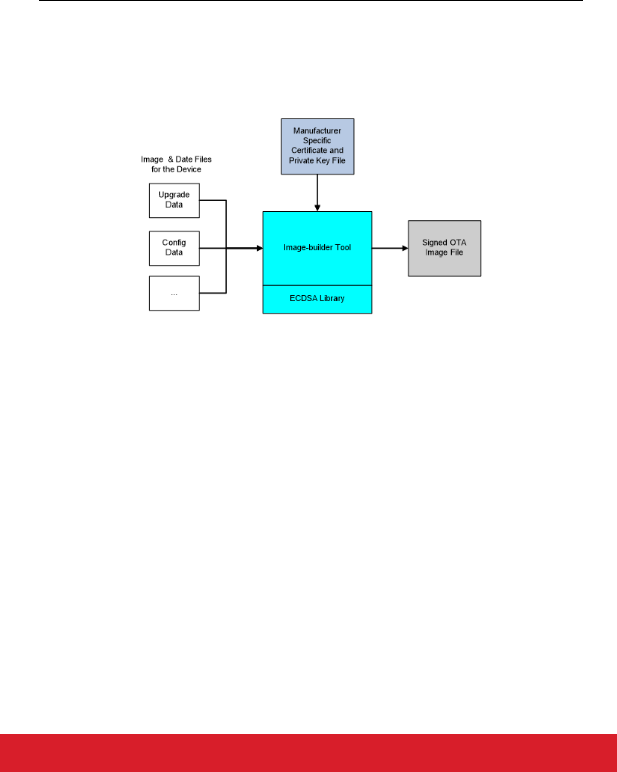
UG491: Zigbee Application Framework Developer's Guide for SDK 7.0 and Higher
Zigbee Application Framework Components
silabs.com | Building a more connected world. Rev. 0.5
silabs.com | Building a more connected world. Rev. 0.5 | 31
15.2.1.1 Generating Zigbee OTA Images
Silicon Labs provides a tool called Image-builder that can generate correctly formatted Zigbee OTA images. This tool takes in bootloader
files (such as a GBL file) and generates the correct format according to the command-line input, as illustrated in the following figure. The
tool can also sign the images using the Elliptic Curve Digital Signature Algorithm (ECDSA) signature algorithm as dictated by the Zigbee
OTA cluster specification.
For more information on using Image-builder, see AN716: Instructions for Using Image-Builder.
Figure 15.1. OTA Image Generation
15.2.1.2 Image Signing
The Zigbee SE Profile requires that OTA files be signed by the manufacturer. Downloaded files must be validated by the OTA client
prior to installation. When images are signed, the signer’s certificate is included automatically as a tag in the file and a signature tag is
added as the last tag in the file.
The EUI of the authorized signing certificates must be embedded in the client’s current software image so it can validate that only the
certificates pertaining to the manufacturer of the device can sign update images.
For development and or test deployments that want to use signing and OTA images a test certificate can be used from the Certicom
Test CA to sign images. Image-builder has a test certificate embedded in it for this purpose and by default Project Configurator includes
the EUI of that test certificate as an authorized signer.
Note: For generation of production images to be shipped to deployed devices, it is highly recommended that manufacturers use their
own certificates issued from the Certicom Production CA to sign images and specify only these EUIs as authorized signers.
The certificates and private keys used for signing are the same type as certificates and private keys used by SE devices. However, their
use and storage should be handled differently. These are the differences:
1. Certificates and private keys used for signing should only be used for signing. They should never be put on devices as device-
specific certificates and keys. This holds true regardless of whether the device is a test device or a production device.
2. The EUI used for the signing certificate should NOT be used for by any other device or for any other purpose. That EUI should NOT
be part of a general pool of EUIs used for production devices.
3. It is recommended that at least three signing certificates with private keys be generated with three different EUIs. Multiple signing
certificates allows for deprecating an expired or compromised private key.
4. Devices should be set up to accept all of those EUIs as authorized signers of images. If a single key or certificate is compromised,
it can be deprecated through a software update and devices will not accept images signed by that entity. In that case, a new signing
certificate should be created to replace the compromised one and subsequent software releases should set it up to be an authorized
signer. In the interim, one of the other two alternative signing certificates can be used to sign software updates.
5. Signer private keys should be stored in a secure location with limited access.
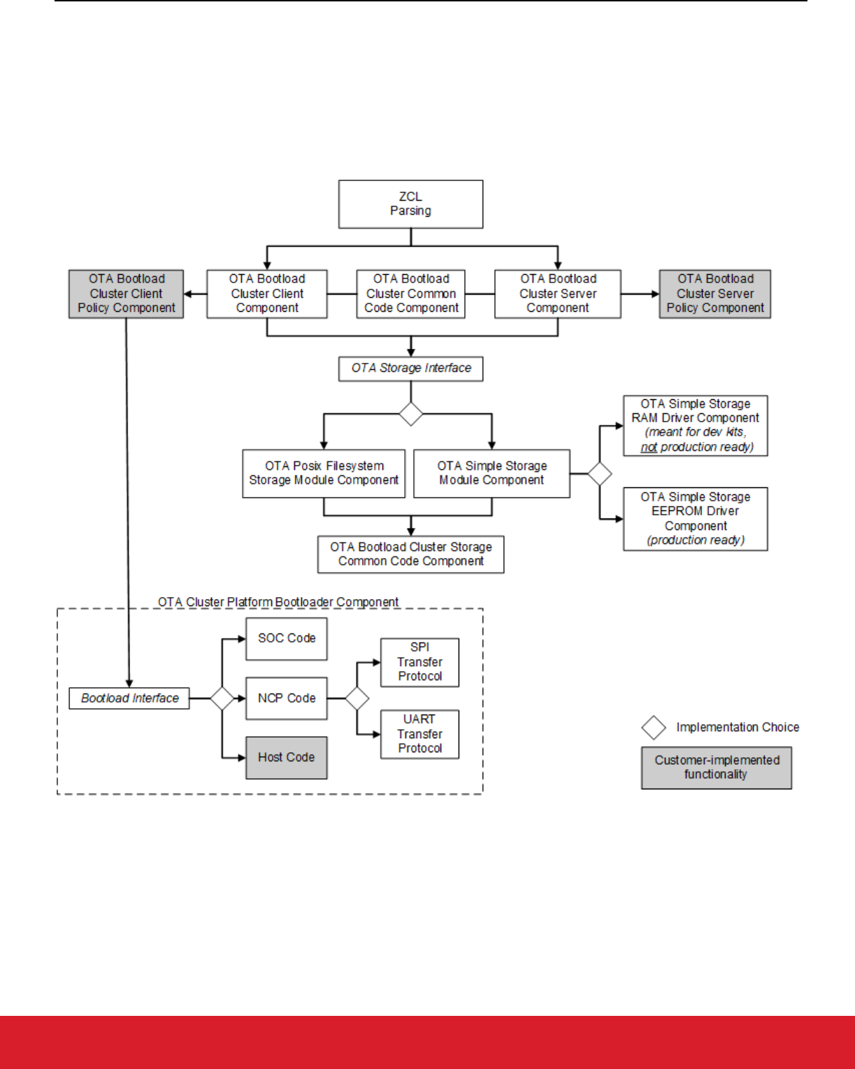
UG491: Zigbee Application Framework Developer's Guide for SDK 7.0 and Higher
Zigbee Application Framework Components
silabs.com | Building a more connected world. Rev. 0.5
silabs.com | Building a more connected world. Rev. 0.5 | 32
6. Lastly, it should be noted that mixing production device certificates with a test certificate signer (and vice versa) does not work. In
other words, if a device has a production certificate from the Certicom Production CA, then it can only validate images signed with a
production certificate. Similarly, devices with test certificates can only accept signers that have certificates issued from the Certicom
Test CA.
15.2.2 Component Architecture
A diagram of the architecture of the OTA components is shown in the following figure.
Figure 15.2. OTA Component Architecture
15.2.3 ZCL Framework Core
This code is provided by the core Zigbee Application Framework and performs the basic parsing and verification of incoming and out-
going messages using the ZCL.
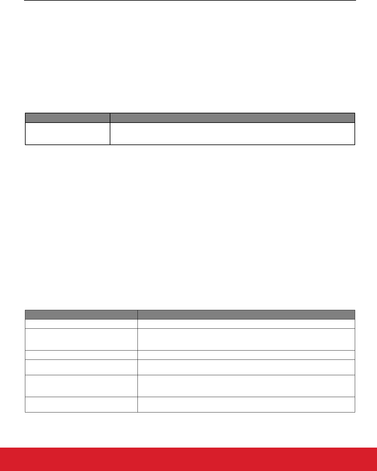
UG491: Zigbee Application Framework Developer's Guide for SDK 7.0 and Higher
Zigbee Application Framework Components
silabs.com | Building a more connected world. Rev. 0.5
silabs.com | Building a more connected world. Rev. 0.5 | 33
15.2.4 OTA Bootload Cluster Common Code Component
This component provides common code to the OTA client and server cluster components. It must be enabled if either the OTA Bootload
Cluster Server Component or the OTA Bootload Cluster Client Component is enabled. This component has no configurable options.
15.2.5 OTA Bootload Cluster Server Component
The OTA Server cluster performs the message parsing of OTA Bootload cluster client commands sent to the server and generates
server commands sent to the clients. It does not handle storage of the OTA files, but instead relies upon an external module for that
support. Its role is simply to validate the incoming messages and generate the correct replies based on its own supported functionality
and the OTA specification.
Silicon Labs provides a Zigbee Application Framework component that implements the server cluster.
Options
Description
Page Request Support
The OTA Server Cluster component can support the optional Page Request feature of the
Zigbee OTA cluster. If this option is enabled, the server will answer page requests and send
multiple blocks of the download image back to the client.
15.2.6 OTA Bootload Cluster Server Policy Component
This module defines how the OTA server reacts when it receives certain requests from the client. The server cluster code calls into this
module to ask how certain operations should be handled. For example, when a client is finished downloading a file, it sends an upgrade
end request to the server to ask when it can upgrade to the new image. The server cluster code parses the message and then calls into
the server policy code to determine the answer.
Other examples of policies handled by this module include how to respond when a query for the next OTA image to download is received
and how to respond when receiving an image block request.
This component has no configurable options.
15.2.7 OTA Bootload Cluster Client Component
The OTA client cluster performs the message parsing of OTA Bootload cluster server commands sent to the client and generation of
client commands sent to the server. It does not handle storage of the OTA files, but instead relies upon an external module for that
support. Its role is simply to validate the incoming messages and generate the correct replies based on its own supported functionality.
Silicon Labs provides a Zigbee Application Framework component that implements the client cluster. The component has optional sup-
port for the signature verification feature. When enabled, this checks the ECDSA signature on received OTA files before generating the
upgrade end message sent back to the server.
Options
Description
Query OTA Server Delay (minutes) How often the client queries the OTA server for a new upgrade image.
Download Delay (ms)
How often a new block of data (or page) is requested during a download by the client.
A value of 0 means the client requests the blocks (or pages) as fast as the server
responds.
Download Error Threshold How many sequential errors cause a download to be cancelled.
Upgrade Wait Threshold
How many sequential, missed responses to an upgrade end request cause a
download to be applied anyway.
Server Discovery Delay (minutes)
How often a client looks for an OTA server in the network when it did not successfully
discover one. Once a client discovers the server, it remembers that server until it
reboots.
Run Upgrade Delay Request (minutes)
How often the client will ask the server to apply a previously downloaded upgrade
when the server has previously told the client to wait.
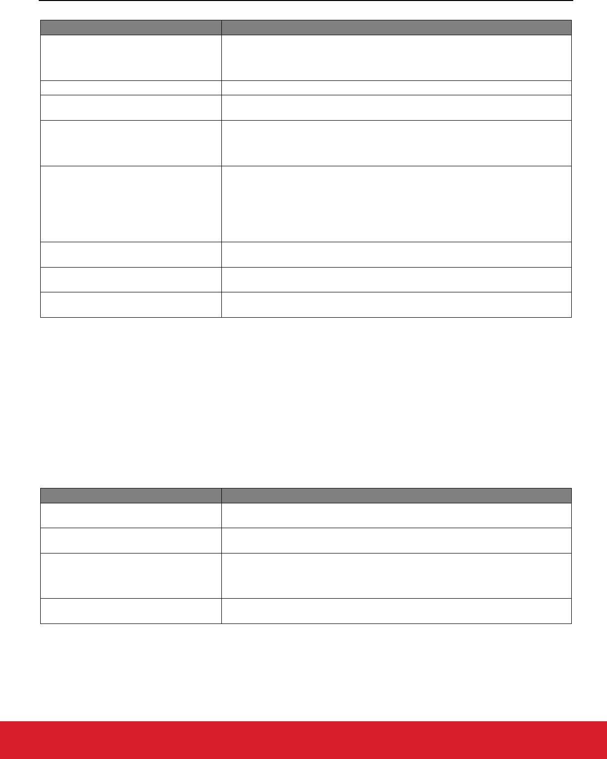
UG491: Zigbee Application Framework Developer's Guide for SDK 7.0 and Higher
Zigbee Application Framework Components
silabs.com | Building a more connected world. Rev. 0.5
silabs.com | Building a more connected world. Rev. 0.5 | 34
Options
Description
Use Page Request
Selecting this option causes the client device to use an OTA Page Request command
to ask for a large block of data all at once, rather than use individual image block
requests for each block. If the server does not support this optional feature, then the
client falls back to using individual block requests.
Page Request Size The size of the page to request from the server.
Page Request Timeout (seconds)
The length of time to wait for all blocks from a page request to come in. After this time
has expired, missed packets are requested individually with image block requests.
Signature Verification Support
This requires all received images to be signed with an ECDSA signature and verifies
the signature once the download has completed. If an image fails verification, it is
discarded. This verification occurs prior to any custom verification that might verify the
contents.
Verification Delay (ms)
This controls how often an ongoing verification process executes. When signature
verification is enabled, this controls how often digest calculation is executed. Digest
calculation can take quite a long time for an OTA image. Other processing for the
system may be deemed more important and therefore Silicon Labs adds delays
between calculations. This also controls how often custom verification written by the
application developer is executed. A value of 0 means the calculations run to
completion.
Image Signer EUI64 0
The big endian EUI64 address of a device authorized to sign OTA images for this
client. A value of all 0s is ignored.
Image Signer EUI64 1
The big endian EUI64 address of a device authorized to sign OTA images for this
client. A value of all 0s is ignored.
Image Signer EUI64 2
The big endian EUI64 address of a device authorized to sign OTA images for this
client. A value of all 0s is ignored.
Note: The default value for the Image Signer EUI64 0 option is the EUI64 of the test certificate embedded within the Image-builder
provided by Silicon Labs. Using this default will allow customers to test image signing and verification prior to obtaining produc-
tion signing certificates from Certicom.
15.2.8 OTA Bootload Cluster Client Policy Component
This module controls the OTA cluster client’s behavior. It dictates what image information it uses in the query, what custom verification
of the image is done by the device, and what happens when the client receives a command to upgrade to the new image.
Silicon Labs provides a component that provides a simple implementation of the OTA client policy.
Note: The Manufacturer ID is not set in this component, but in the top tab of the Zigbee Cluster Configurator.
Options
Description
Image Type ID
The device's OTA image identifier used for querying the OTA server about the next
image to use for an upgrade.
Firmware Version
The device's current firmware version used when querying the OTA server about the
next image to use for an upgrade.
Hardware Version
Devices may have a hardware version that limits what images they can use. OTA
images may be configured with minimum and maximum hardware versions on which
they are supported. If the device is not restricted by hardware version, then this value
should be 0xFFFF.
Perform EBL Verification (SOC only)
This option uses the application bootloader routines to verify the EBL image after
signature verification passes.
15.2.9 OTA Storage Components
The OTA cluster requires a storage device for files received by the OTA clients or served up by the OTA server. This storage varies
based on the device’s hardware and design. Therefore, this functionality is separated from the core cluster code and accessed through

UG491: Zigbee Application Framework Developer's Guide for SDK 7.0 and Higher
Zigbee Application Framework Components
silabs.com | Building a more connected world. Rev. 0.5
silabs.com | Building a more connected world. Rev. 0.5 | 35
a set of APIs. The interface supports managing multiple files, retrieving arbitrary blocks of data from the files, and performing basic
validation on the file format.
Silicon Labs currently provides two main components that implement the OTA storage module, the OTA Storage POSIX Filesystem
component and the OTA Simple Storage component.
15.2.9.1 OTA Storage POSIX File System Component
This implementation uses a POSIX file system as the storage module to store and retrieve data for OTA files. It can handle any number
of files. This component is used with an EZSP-based platform (such as EFR32 NCP) where the host is connected to the NCP through
UART. This component has no configurable options.
15.2.9.2 OTA Simple Storage Module Component
This implementation provides a simple storage module that stores only one file. It uses an OTA storage driver to perform the actual
storage of the data in a hardware or software device accessible by the OTA cluster code. When enabled, the developer must also select
either the OTA Simple Storage RAM Driver Component or the OTA Simple Storage EEPROM Driver Component.
This component can be used by either an EZSP- or an SOC-based platform. This component has no configurable options.
15.2.9.3 OTA Simple Storage RAM Driver Component
This driver provides a RAM storage device for storing files. It is intended only as a test implementation for development on WSTKs; it is
not intended as production ready code. Prior to integrating external storage hardware into a device, this driver can be useful for examining
the basic behavior of the OTA cluster. The storage device has a pre-built OTA image already in place that can be used for downloading
but does not actually perform an upgrade. This component has no configurable options.
15.2.9.4 OTA Simple Storage EEPROM Driver Component
This driver uses the platform routines to read and write data from an EEPROM. For SOC platforms, this module handles the details of
re-mapping the image so that it can be read by the bootloader. Existing bootloaders require that the GBL header be the first bytes at the
top the storage device so the code must relocate the OTA header to another location while at the same time providing an interface to
the storage code that accesses the OTA file in a linear manner.
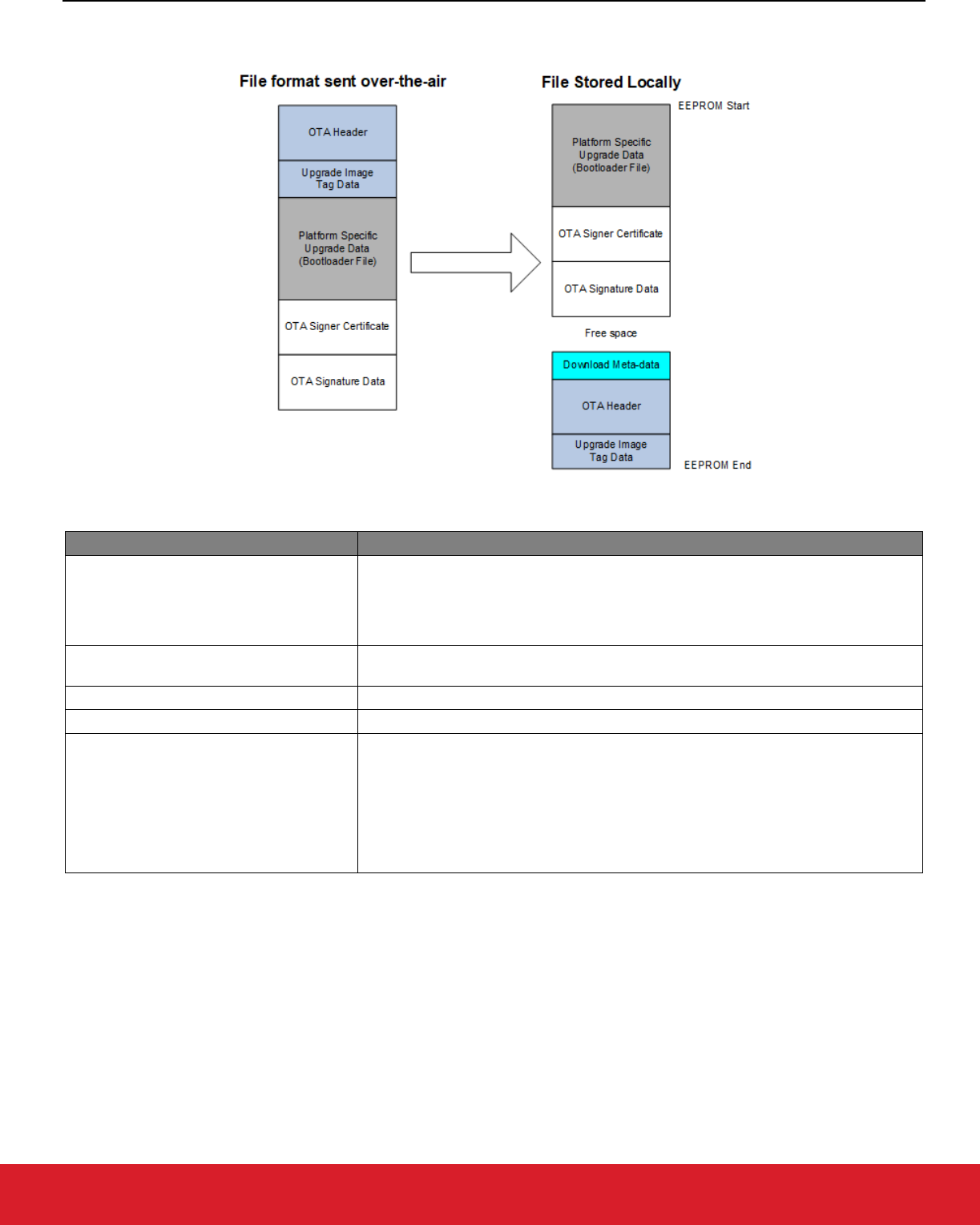
UG491: Zigbee Application Framework Developer's Guide for SDK 7.0 and Higher
Zigbee Application Framework Components
silabs.com | Building a more connected world. Rev. 0.5
silabs.com | Building a more connected world. Rev. 0.5 | 36
The following figure illustrates a change in the OTA image on disk.
Figure 15.3. OTA Image Change
Options
Description
SOC Bootloading Support
This option enables bootloading support for SOC devices. When enabled, it will re-
map the OTA image file so that the bootloader data is at the top of the EEPROM and
therefore can be accessed by all existing Ember bootloaders. It requires that the
bootloader portion of the image is the first TAG in the file. The OTA storage starting
offset should be 0 when this is enabled.
Frequency for Saving Download Offset to
Non-Volatile Memory (bytes)
How often the current download offset is stored to NVM, in bytes. If set to 0, it will
always be written to NVM.
OTA Storage Start Offset The starting offset for the OTA image storage location in the NVM.
OTA Storage End Offset The last offset for the OTA image storage location in the NVM.
EEPROM Device Read-modify-write
Support
This checkbox indicates whether the underlying EEPROM storage driver has support
for read-modify-write, where a portion of a page of flash can be rewritten without
erasing the entire page. If the driver requires a page erase before writing any data,
this box should not be selected. Before EmberZNet 4.6.2 read-modify-write support
was required by the underlying flash driver. EmberZNet 4.6.2 introduced the ability to
use parts where a page-erase is required. When designing software for the
development boards this checkbox should remain selected because the EEPROM
parts require read-modify-write support.
15.2.9.5 OTA Bootload Cluster Storage Common Code Component
This component provides code common to all the OTA storage components and must be enabled when one of those components is
enabled. This component has no configurable options.
15.2.10 OTA Cluster Platform Bootloader Component
When the client has a completed file downloaded and ready to upgrade, it waits for a command from the server to apply the upgrade.
Upon receipt of the command to upgrade, the OTA client cluster code calls into the OTA client policy code to perform the next steps to
apply the upgrade.
UG491: Zigbee Application Framework Developer's Guide for SDK 7.0 and Higher
Zigbee Application Framework Components
silabs.com | Building a more connected world. Rev. 0.5
silabs.com | Building a more connected world. Rev. 0.5 | 37
Silicon Labs provides a single component to handle bootloading. The behavior differs depending on the platform on which it is being
used. The OTA Client Policy component calls into this component to perform the actual bootloading.
For the SoC, the bootload code simply calls the platform routine to execute the application bootloader. The application bootloader then
reads from the data stored in external EEPROM, copies that data into the chip’s internal flash, and then reboots.
For the NCP, Silicon Labs provides an implementation that bootloads the NCP through serial UART or SPI bus. This implementation
works only with the Ember NCP bootloader provided as part of the EZSP NCP firmware delivery. The implementation executes the
bootloader on the NCP, transfers the file from the storage device on the host to the NCP by XModem, then reboots the NCP.
For the host, developers are expected to write their own code for bootloading a host system connected to an NCP.
15.2.11 OTA Cluster Command Line Interface
15.2.11.1 Client Commands
Table 15-1. OTA Cluster Client Commands
Command
Description
zcl ota client printImages Prints all images that are stored in the OTA storage module along with their index.
zcl ota client info
Prints the Manufacturer ID, Image Type ID, and Version information that are used
when a query next image is sent to the server by the client.
zcl ota client status Prints information on the current state of the OTA client download.
zcl ota client verify <index> Performs signature verification on the image at the specified index.
zcl ota client bootload <index> Bootloads the image at the specified index by calling the OTA bootload callback.
zcl ota client delete <index> Deletes the image at the specified index from the OTA storage device.
zcl ota client start
Starts the OTA client state machine. The state machine discovers the OTA server,
queries for new images, download the images, and waits for the server command to
upgrade.
zcl ota client stop Stops the OTA client state machine.
zcl ota client page-request <boolean>
Dynamically enables or disables the use of page request if the client turned on
support in Project Configurator. By default, if the client enabled page request support
in Project Configurator, then the client uses the page request command when
downloading a file.
zcl ota client block-test
Test harness command. Sends an invalid block request to the client’s previously
discovered OTA server to verify that the server sends back the correct command.
15.2.11.2 Server Commands
Table 15-2. OTA Cluster Server Commands
Command
Description
zcl ota server printImages Prints all images that are stored in the OTA storage module along with their index.
zcl ota server policy print Prints the policies used by the OTA Server Policy component.
zcl ota server delete <index> Deletes the image at the specified index from the OTA storage device.
zcl ota server policy query <int>
Sets the policy used by the OTA Server Policy component when it receives a query
request from the client. The policy values are:
0: Upgrade if server has newer (default).
1: Downgrade if server has older.
2: Reinstall if server has same.
3: No next version (no next image is available for download).
UG491: Zigbee Application Framework Developer's Guide for SDK 7.0 and Higher
Zigbee Application Framework Components
silabs.com | Building a more connected world. Rev. 0.5
silabs.com | Building a more connected world. Rev. 0.5 | 38
Command
Description
zcl ota server policy blockRequest <int>
Sets the policy used by the OTA Server Policy component when it receives an image
block request. The policy values are:
0: Send block (default)
1: Delay download once for 2 minutes
2: Always abort download after first block
zcl ota server policy upgrade <int>
Sets the policy used by the OTA Server Policy component when it receives an
upgrade end request. The policy values are:
0: Upgrade Now (default)
1: Upgrade in 2 minutes
2: Ask me later to upgrade
zcl ota server notify <dest>
<payload type>
<jitter>
<manuf-id>
<device-id>
<version>
This command sends an OTA Image Notify message to the specified destination
indicating a new version of an image is available for download. The payload type field
values are:
0: Include only jitter field
1: Include jitter and manuf-id
2: Include jitter, manuf-id, and device-id
3: Include jitter, manuf-id, device-id, and version
All fields in the CLI command must be specified. However, if the payload type is less
than 3, those values will be ignored and not included in the message.
zcl ota server page-req-miss <modulus>
Test harness command. Sets a module’s value that tells the OTA server to artificially
skip certain image block responses sent in response to an image page request. This
simulates missed blocks that the client will have to request later after the page
request has completed. If the number of the block sent by the server is a multiple of
the modulus value, then it will be skipped.
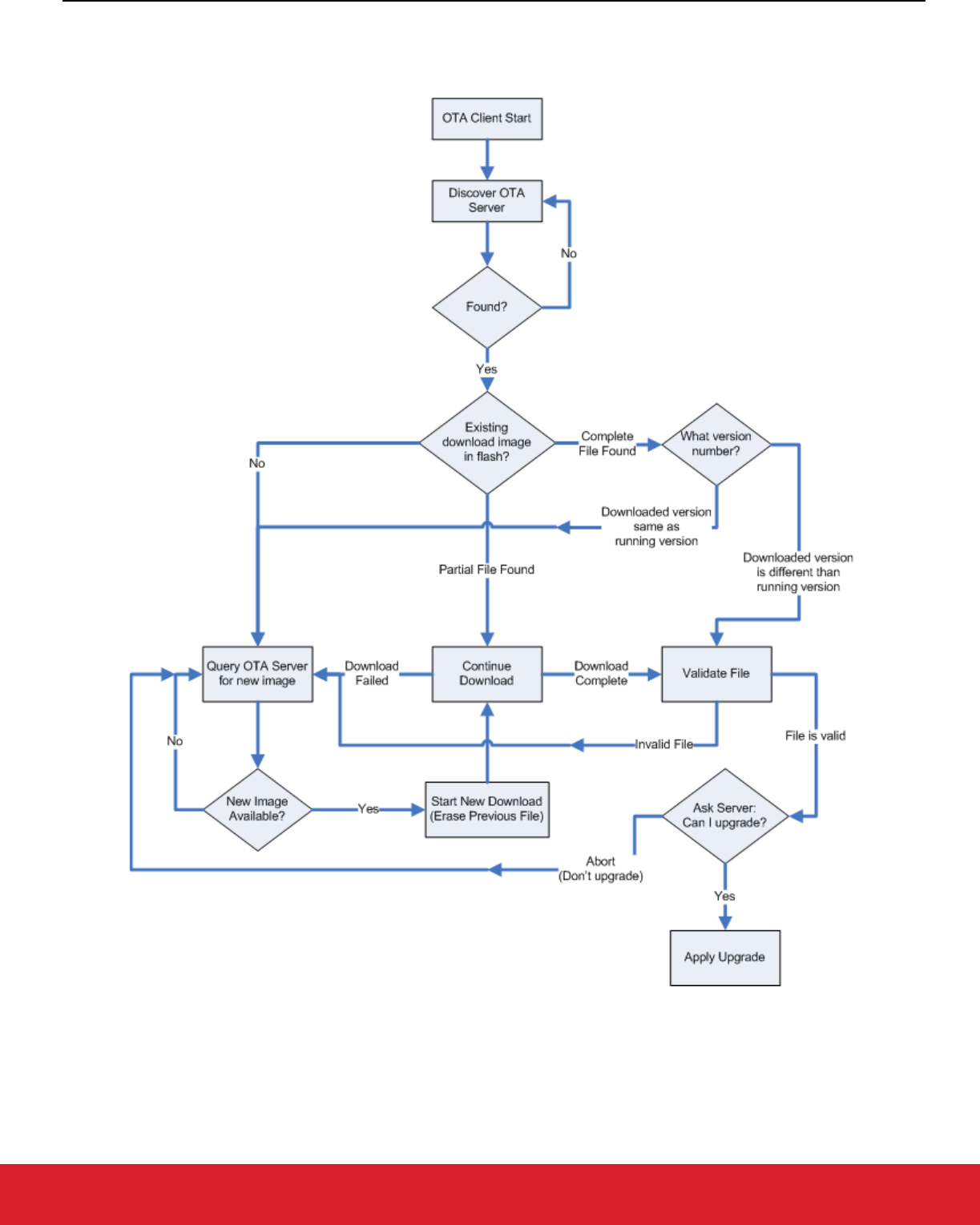
UG491: Zigbee Application Framework Developer's Guide for SDK 7.0 and Higher
Zigbee Application Framework Components
silabs.com | Building a more connected world. Rev. 0.5
silabs.com | Building a more connected world. Rev. 0.5 | 39
15.2.12 OTA Client State Machine
The following figure illustrates how the OTA Bootload Cluster client component code will behave from start to finish.
Figure 15.4. OTA Bootload Cluster Client Component Behavior

UG491: Zigbee Application Framework Developer's Guide for SDK 7.0 and Higher
Zigbee Application Framework Components
silabs.com | Building a more connected world. Rev. 0.5
silabs.com | Building a more connected world. Rev. 0.5 | 40
15.2.13 Example Client and Server Setup
A separate application note (AN1384: Over-the-Air Bootload Server and Client Setup for Zigbee SDK 7.0 and Higher) describes a
complete client and server setup using plugins and Silicon Labs development kits.
15.3 Reporting Component
ZCL reporting can be setup on a device when the device is required to periodically send out reports. ZCL reports rely on bindings. Each
report is an asynchronous message sent out from the reporting device, when a local ZCL attribute has changed, to corresponding entries
in the binding table. Either the node sending the reports, the node receiving the reports, or another third-party configuration device may
create the binding table entry(s) on the reporting node. This component supports both requesting reports from another device and
sending out attribute reports when the device has been configured to do so. If the application will receive reports from multiple sources,
the device should be configured as a concentrator.
15.3.1 Reporting Command Line Interface
The Zigbee Application Framework provides CLI commands for creating and managing reporting table entries directly on the device,
requesting reports from another device, and configuring device to send out reports from another device.
15.3.1.1 Local Commands
•
plugin reporting print: Print the report table.
•
plugin reporting clear: Print the report table.
•
plugin reporting remove [index:1]: Remove an entry from the report table.
•
index: Index of the report to be removed (1 byte).
•
plugin reporting add [endpoint:1] [clusterId:2] [attributeId:2] [mask:1] [minInterval:2]
[maxInterval:2] [reportableChange:4]
: Add a new entry to the report table.
•
endpoint: Local endpoint from which the attribute is reported (1 byte).
•
clusterId: Cluster where the attribute is located (2 bytes).
•
attributeId: ID of the attribute being reported (2 bytes).
•
mask: 0 for client-side attributes or 1 for server-side attributes (1 byte).
•
minInterval: Minimum reporting interval, measured in seconds (2 bytes).
•
maxInterval: Maximum reporting interval, measured in seconds (2 bytes).
•
reportableChange: Minimum change to the attribute that will result in a report being sent (4 bytes).
15.3.1.2 Remote Commands
•
zcl global report [endpoint:1] [clusterId:2] [attributeId:2] [direction:1]: Creates a report
with the specified cluster, attribute, and server/client direction.
•
endpoint: Source endpoint ID to read from (2 bytes).
•
clusterId: Cluster ID to read from (2 bytes).
•
attributeId: Attribute ID to read from (2 bytes).
•
direction: 0 for client-to-server, 1 for server-to-client (1 byte).
•
zcl global report-read [cluster:2] [attributeId:2] [direction:1]: Creates a global read reporting
command for the associated cluster, attribute, and server/client direction.
•
cluster: Cluster ID to read from (2 bytes).
•
attributeId: Attribute ID to read from (2 bytes).
•
direction: 0 for client-to-server, 1 for server-to-client (1 byte).

UG491: Zigbee Application Framework Developer's Guide for SDK 7.0 and Higher
Zigbee Application Framework Components
silabs.com | Building a more connected world. Rev. 0.5
silabs.com | Building a more connected world. Rev. 0.5 | 41
• zcl global send-me-a-report [cluster:2] [attributeId:2] [dataType:1] [minReportTime:2]
[maxReportTime:2] [reportableChange:-2147483648]
: creates a global send me a report command for the asso-
ciated values.
•
cluster: Cluster ID of the requested report (2 bytes).
•
attributeId : Attribute ID for requested report (2 bytes).
•
datatype: Zigbee type value for the requested report (1 byte).
•
minReportTime: Minimum number of seconds between reports (2 bytes).
•
maxReportTime: Maximum number of seconds between reports (2 bytes).
•
reportableChange: Amount of change to trigger a report.
•
zcl global expect-report-from-me [cluster:2] [attributeId:2] [timeout:2]: Create an expect-
report-from-me message with associated values.
•
cluster: Cluster ID of the requested report (2 bytes).
•
attributeid: Attribute ID for requested report (2 bytes).
•
timeout: maximum amount of time between reports.
15.3.2 Reporting Connection Setup through CLI
The following CLI example assumes these application configurations:
• The report sender application should implement the Basic Cluster on endpoint 6.
• The report receiver application should implement the Basic Cluster on endpoint 1.
• Both applications should have debugging messages turned on. It is also assumed that both devices have joined the same network
with the report sender node as the creator of the network.
1. Clear all bindings on the sender node since reports are sent via bindings.
report_sender_cli> option binding-table clear
2. Request reports of the application version (cluster 0x0000, attribute 0x0001) of the sender to receiver node by receiving node.
report_receiver_cli> zcl global send-me-a-report 0x0000 0x0001 0x20 10 20 {00}
report_receiver_cli> send 0 1 6
3. Following outputs should be observed:
report_sender_cli> CFG_RPT: (Basic) - direction:00, attr:0000 type:20, min:000A, max:0014
change:00
report_receiver_cli> CFG_RPT_RESP: (BASIC) – status: 00
4. After successfully send the report request (status – 00), an actual report can be read by the receiver node using following command:
report_receiver_cli> zcl global report-read 0x0000 0x0000 0x00
report_receiver_cli> send 0 1 6
5. Following outputs should be observed:
report_receiver_cli> READ_RPT_CFG_RESP: (Basic) - status:00, direction:00, attr:0000 type:20,
min:000A, max:0014 change:00
6. Find node field ID or IEEEAddr from receiver node.
report_receiver_cli> info
7. Create binding on sending node to start sending reports to the receiver.
report_sender_cli> option binding-table set 0 0x0000 0x06 0x01 {EUI64 node ID from previous step}
8. Following outputs should be observed:
“set bind 0: 0x00”
9. The receiver node should start getting reports as follow:
report_receiver_cli> RPT_ATTR: (Basic) - attr:0000 type:20, val:01

UG491: Zigbee Application Framework Developer's Guide for SDK 7.0 and Higher
Zigbee Application Framework Components
silabs.com | Building a more connected world. Rev. 0.5
silabs.com | Building a more connected world. Rev. 0.5 | 42
10. Cancel report (by setting the maximum interval to 0xFFFF)
report_receiver_cli> zcl global send-me-a-report 0x0000 0x0000 0x20 0x0000 0xFFFF {00}
report_receiver_cli> send 0 1 6
11. Following outputs should be observed:
report_sender_cli> CFG_RPT: (Basic) - direction:00, attr:0000 type:20, min:0000, max:FFFF
change:00
report_receiver_cli> CFG_RPT_RESP: (Basic) – status: 00
15.3.3 Reporting for External Attributes
The Zigbee Application Framework automatically notifies the component whenever attributes that it manages are changed. Customers
who use external attributes must notify the Reporting component when those attributes change. Failure to notify the component will
result in incorrect reporting behavior. Any applications that will be reporting external attributes must call
emberAfReport-
ingAttributeChangeCallback
whenever external attributes change.

UG491: Zigbee Application Framework Developer's Guide for SDK 7.0 and Higher
Extending the Zigbee Cluster Library
silabs.com | Building a more connected world. Rev. 0.5
silabs.com | Building a more connected world. Rev. 0.5 | 43
16 Extending the Zigbee Cluster Library
16.1 Steps for Adding Custom Clusters and Commands Overview
These are the high-level steps for adding custom clusters and commands:
1. Create an XML file with custom cluster and command definitions, using app/zcl/sample-extensions.xml as a template; put the XML
file in your project directory.
2. In the Zigbee Cluster Configurator in the top bar click ZCL EXTENSIONS… and select the XML file from step 1.
3. The custom clusters should now be selectable in the Zigbee Cluster Configurator GUI along with the standard clusters. The custom
clusters will appear under the domain name specified in the XML file—for example, <domain name="Ember"/>.
4. Implement custom cluster callbacks the same way as ZCL Command Handling callbacks. See section 6.4 ZCL Command Handling
Callbacks for detailed instructions.
16.2 Manufacturer-Specific Commands and Clusters
Developers may extend the Zigbee application layer using any of the following techniques:
• Private Profile: The profile ID is a two-byte value passed in Zigbee messages in the Zigbee APS frame. For two Zigbee devices to
interact at the application layer, they must have the same profile ID. If they do not, they will drop each other’s messages. A private
profile is used to completely protect all interaction within a given system. If you are planning to use Zigbee for your network and link
layers but in other respects are planning to have a closed system, you may wish to create a private Zigbee Profile. If you use a
private profile, your devices will not be interoperable with any other Zigbee devices using other profiles.
• Manufacturer-Specific Clusters: Any clusters with cluster IDs in the range 0xfc00 – 0xffff are considered manufacturer-specific and
must have an associated two-byte manufacturer code. All commands and attributes within a manufacturer-specific cluster are also
considered manufacturer-specific.
Example: In the sample-extensions.xml file included with the Zigbee Application Framework, Silicon Labs has defined a sample
manufacturer-specific cluster with Cluster ID 0xfc00 and manufacturer code 0x1002 (Silicon Labs’ manufacturer code).
• Manufacturer-Specific Commands: You can augment a standard Zigbee cluster by adding manufacturer-specific commands to that
cluster. Manufacturer-specific commands within a standard Zigbee cluster may use the entire range of command IDs 0x00 – 0xff. A
two-byte manufacturing code must be provided for the manufacturer-specific command so that the command can be distinguished
from the standard Zigbee commands in that cluster.
Example: In the sample-extensions.xml file included with the application framework, Silicon Labs has defined three commands to
extend the On/Off cluster: OffWithTransition, OnWithTransition, and ToggleWithTransition. These commands share the same com-
mand IDs as the standard Off, On, and Toggle commands in that cluster. However, they also include the manufacturer code 0x1002
indicating that they are Silicon Labs’ manufacturer-specific commands.
• Manufacturer-Specific Attributes: Standard Zigbee clusters can be extended by adding manufacturer-specific attributes to your ap-
plication. Manufacturer-specific attributes within a standard Zigbee cluster may use the entire attribute ID address space from 0x0000
to 0xffff. A two-byte manufacturer code must be included for each manufacturer-specific attribute so that it can be distinguished from
non-manufacturer-specific attributes.
Example: In the sample-extensions.xml file included with the Zigbee Application Framework, Silicon Labs has defined a single at-
tribute Transition Time which shares the same attribute ID with the on/off state in the on/off cluster 0x0000. However, the transition
time attribute also contains the manufacturer code 0x1002 indicating that it is Silicon Labs’ manufacturer-specific attribute.
Note: Silicon Labs’ manufacturer code 0x1002 is defined by the Connectivity Standards Alliance and is included in the Manufacturer
Code database (Zigbee document #053874). Manufacturer codes are required for the implementation of manufacturer-specific
clusters, attributes, and commands. Unique manufacturer codes are provided by the Connectivity Standards Alliance for each
requesting organization. To get a manufacturer code for your organization contact the Connectivity Standards Alliance at
https://csa-iot.org/.
16.3 Limitations to Consider
There are two notable limitations to consider when extending the Zigbee Application Framework with manufacturer-specific clusters,
attributes, and commands:

UG491: Zigbee Application Framework Developer's Guide for SDK 7.0 and Higher
Extending the Zigbee Cluster Library
silabs.com | Building a more connected world. Rev. 0.5
silabs.com | Building a more connected world. Rev. 0.5 | 44
• All cluster IDs including those of manufacturer-specific clusters MUST be unique within a single device. The Zigbee Application
Framework does not currently support overlapping manufacturer-specific cluster IDs within a single device. In other words, you
cannot implement cluster 0xFC00 with manufacturer code 0xFEED AND cluster 0xFC00 with manufacturer code 0xBEEF on the
SAME device. The Zigbee Application Framework assumes that ALL cluster IDs are unique regardless of the manufacturer code
associated with them.
• All attribute and command IDs within a manufacturer-specific cluster MUST be unique and are assumed to have the same manufac-
turer code as the cluster they are in. The Zigbee protocol does not support overlapping manufacturer-specific attributes or command
IDs (with different manufacturer codes) WITHIN a manufacturer-specific cluster. The reason is simply that only a single manufacturer
code is passed in the Zigbee application header. If the cluster addressed is in the manufacturer-specific range 0xFC00 – 0xFFFF,
then the manufacturer code is assumed to apply to the cluster. This makes it impossible to address, for instance, Attribute 0x0000
with manufacturer code 0xFEED inside cluster 0x0000 with manufacturer code 0xBEEF. The Zigbee Application Framework does
not even bother to store individual manufacturer codes for attributes within a manufacturer-specific cluster because the manufacturer
code of the cluster is assumed to apply to all the attributes within it.
16.4 Defining ZCL Extensions within the Zigbee Application Framework and Project Configurator
The entire ZCL is defined in XML format in the /SiliconLabs/SimplicityStudio/<version>/developer/sdks/gecko_sdk_suite/<ver-
sion>/app/zcl directory. In addition to expected XML files such as general.xml or ha.xml that describe the clusters, commands and
attributes associated with standard ZCL used by the Zigbee Application Framework, there is a sample extension file called, unsurpris-
ingly, sample-extensions.xml. This XML file contains several sample Zigbee extensions including a custom cluster, custom attributes
added to the on/off cluster, and custom commands added to the on/off cluster.
To extend the ZCL, you must create a similar extension file for your extensions and load them in the Zigbee Cluster Configurator as
described in 16.1 Steps for Adding Custom Clusters and Commands Overview. Additional documentation about extending the Zigbee
Application Framework is included in the sample-extensions.xml file.
Note: Any multi-byte numeric constant values specified in the XML file should specify the full number of digits as hexadecimal, such
as "0x000000000000" (for an int48u) rather than simply "0x00" or "0". This ensures that the proper default value will be added
to the GENERATED_DEFAULTS define during generation.
16.5 Manufacturer-Specific Attribute APIs
Some APIs in Zigbee Application Framework used to interact with attributes have been modified to take a manufacturer code as an
argument.
16.5.1 Attribute Read and Write
All of the read and write attribute functions have additional functions that take a manufacturer code along with the rest of the attribute-
addressing information. When you read and write to a manufacturer-specific attribute, you must supply the manufacturer code for the
attribute you wish to read or write so that it can be found in the attribute table. For example, you may read a standard Zigbee attribute
using the function
emberAfReadServerAttribute. However, if you call this function for a manufacturer-specific attribute no
manufacturer Code argument allows you to properly identify your manufacturer-specific attribute, so the read will fail. If you wish to read
a manufacturer-specific attribute, you must use the manufacturer-specific functions
emberAfReadManufacturerSpecif-
icServerAttribute
and emberAfReadManufacturerSpecificClientAttribute. Both functions take a manufac-
turer code, which they pass on to the general function
emberAfReadOrUpdateAttribute.
Separating the manufacturer-specific APIs into their own interface eliminates the need for code that is non-manufacturer-specific to pass
around false manufacturer codes. This would be a waste of code space given the large number of attribute interactions that exist in the
application framework.
16.5.1.1 Attribute Changed Callbacks
Silicon Labs has also added manufacturer-specific attribute changed callbacks into the Zigbee Application Framework so that standard
attribute callbacks do not need to waste code space checking a non-existent manufacturer code.
Silicon Laboratories Inc.
400 West Cesar Chavez
Austin, TX 78701
USA
www.silabs.com
IoT Portfolio
www.silabs.com/IoT
SW/HW
www.silabs.com/simplicity
Quality
www.silabs.com/quality
Support & Community
www.silabs.com/community
Simplicity Studio
One-click access to MCU and wireless
tools, documentation, software,
source code libraries & more. Available
for Windows, Mac and Linux!
Disclaimer
Silicon Labs intends to provide customers with the latest, accurate, and in-depth documentation of all peripherals and modules available for system and software imple-
menters using or intending to use the Silicon Labs products. Characterization data, available modules and peripherals, memory sizes and memory addresses refer to each
specic device, and “Typical” parameters provided can and do vary in dierent applications. Application examples described herein are for illustrative purposes only. Silicon
Labs reserves the right to make changes without further notice to the product information, specications, and descriptions herein, and does not give warranties as to the
accuracy or completeness of the included information. Without prior notication, Silicon Labs may update product rmware during the manufacturing process for security or
reliabilit y reasons. Such changes will not alter the specications or the per formance of the produc t. Silicon Labs shall have no liability for the consequences of use of the infor-
mation supplied in this document. This document does not imply or expressly grant any license to design or fabricate any integrated circuits. The products are not designed or
authorized to be used within any FDA Class III devices, applications for which FDA premarket approval is required or Life Support Systems without the specic written consent
of Silicon Labs. A “Life Support System” is any product or system intended to support or sustain life and/or health, which, if it fails, can be reasonably expected to result in
signicant personal injury or death. Silicon Labs products are not designed or authorized for military applications. Silicon Labs products shall under no circumstances be used
in weapons of mass destruction including (but not limited to) nuclear, biological or chemical weapons, or missiles capable of delivering such weapons. Silicon Labs disclaims
all express and implied warranties and shall not be responsible or liable for any injuries or damages related to use of a Silicon Labs product in such unauthorized applications.
Note: This content may contain o ensive terminolog y that is now obsolete . Silicon L abs is replacing these terms with inclusive language wherever possible. For more
information, visit www.silabs.com/about-us/inclusive-lexicon-project
Trademark Information
Silicon Laboratories Inc.
®
, Silicon Laboratories
®
, Silicon Labs
®
, SiLabs
®
and the Silicon Labs logo
®
, Bluegiga
®
, Bluegiga Logo
®
, EFM
®
, EFM32
®
, EFR, Ember
®
, Energy Micro, Energy
Micro logo and combinations thereof, “the world’s most energy friendly microcontrollers”, Redpine Signals
®
, WiSeConnect , n-Link, ThreadArch
®
, EZLink
®
, EZRadio
®
, EZRadioPRO
®
,
Gecko
®
, Gecko OS, Gecko OS Studio, Precision32
®
, Simplicity Studio
®
, Telegesis, the Telegesis Logo
®
, USBXpress
®
, Zentri, the Zentri logo and Zentri DMS, Z-Wave
®
, and others
are trademarks or registered trademarks of Silicon Labs. ARM, CORTEX, Cortex-M3 and THUMB are trademarks or registered trademarks of ARM Holdings. Keil is a registered
trademark of ARM Limited. Wi-Fi is a registered trademark of the Wi-Fi Alliance. All other products or brand names mentioned herein are trademarks of their respective holders.
