
1
U.S. EPA Class VI Carbon Dioxide Injection Permit
Salient Features and Guidelines
Introduction
The Class VI injection permit is the latest in a line of permits issued by the U.S. Environmental
Protection Agency (EPA) for waste disposal. It is geared toward regulating injection of carbon
dioxide for geologic sequestration purposes. It was necessary to establish this new injection
class due to the buoyant nature of CO
2
. The requirements associated with permitting, operating,
and monitoring for this class are more stringent than any previous injection class. Obtaining the
Class VI permit is a multiyear process, requiring significant investment of time and capital. The
objective of this paper is to document the salient features of the permit and provide guidelines for
expediting the permitting process for future applicants based on lessons learned from the
Wellington, Kansas, demonstration project sponsored by the U.S. Department of Energy (DOE)
The site is located in south-central Kansas. The Cambrian-Ordovician Arbuckle aquifer at a
depth of approximately 5,000 feet has been identified for commercial-scale storage of CO
2
in
Kansas. The Wellington permit application was the first application for a new injection well
submitted since promulgation of the Class VI rule
1
in 2010 and can serve as a template for future
applications.
The primary interest of the EPA is to ensure containment of the injected CO
2
within the
injection zone to prevent contamination of drinking water aquifers. Key requirements are
demonstration of the following:
• An injection zone(s) of sufficient areal extent, thickness, porosity, permeability, and total
dissolved solids (TDS) concentration of less than 10,000 mg/l to receive the total
anticipated volume of the carbon dioxide stream.
• A confining zone(s) free of transmissive faults and fractures and of sufficient areal extent
and integrity to contain the injected carbon dioxide stream and displaced formation fluids
1
U.S. Federal Registration Citation: 76 FR 56982 , Code of Federal Regulations 40 CFR 12, 144, 145, Docket
Number: EPA-HQ-OW-2008-0390, FRL-9465-1.
2
and allow injection at proposed maximum pressures and volumes without initiating or
propagating fractures in the confining zone(s).
• Identification of all underground sources of drinking water (USDW) in which the
concentration of TDS is less than 10,000 mg/l to ensure that CO
2
from the injection zone
will not migrate into any USDW.
• Maintenance of pore pressures in the injection zone at less than 90% of the fracture
gradient.
The Class VI permit consists of the following nine plans, referred to as attachments:
Attachment A – Summary of Operating and Reporting Requirements
Attachment B – Area of Review and Corrective Action Plan
Attachment C – Testing and Monitoring Plan
Attachment D – Well Plugging Plan
Attachment E – Post Injection Site Care and Site Closure Plan
Attachment F – Emergency and Remedial Response Plan
Attachment G – Construction Details
Attachment H – Financial Assurance Demonstration
Attachment I – Stimulation Plan
The salient features and requirements of each attachment are discussed below. The nine
Wellington project attachments are provided in Appendix B. The Class VI rule, however, is
codified in a 74-page document with no references to attachments. The specific requirements
and articles of the Class VI rule that need to be fulfilled are listed in tabular form in Appendix A
along with a cross reference to the relevant attachments now required by the EPA.

3
Attachment A – Summary of Operating and Reporting Requirements
The key injection well operating requirements and the project reporting requirements are specified in this
attachment and summarized below.
Table A-1. Injection Well Operating Condition
Parameter
Permitted Values
Maximum Injection Pressure
Surface
(Bottom hole pressure necessary to inject
CO
2
into the formation) + (specific gravity of
CO
2
* injection depth * 0.433) – atmospheric
pressure
Bottom hole
90% of fracture gradient
Minimum Annulus Pressure
As necessary to prevent “burst” or “collapse”
of tubing
1
Minimum Annulus Pressure/Tubing
Differential
100–1,200 psig
1
Collapse Pressure = depth*(pressure gradient of formation) + (pressure gradient of cement) – (pressure
gradient of water). Burst Pressure = depth*(pressure gradient of injectate) + surface pressure.
Table A-2. Class VI Reporting Frequencies.
ACTIVITY
MINIMUM REPORTING FREQUENCY
CO
2
stream characterization
Semi-annually
Pressure, flow, rate, volume, pressure on the
annulus, annulus fluid level, and temperature
Semi-annually
Corrosion monitoring
Semi-annually
External MIT (Mechanical Integrity Test)
Within 30 days of completion of test
Pressure fall-off testing
In the next semi-annual report
Groundwater quality monitoring
Semi-annually
Plume and pressure front tracking
In the next semi-annual report
Monitoring well MITs
Within 30 days of completion of test
Financial responsibility updates pursuant to H.2
and H.3(a) of this permit
Within 60 days of update
Note: All testing and monitoring frequencies and methodologies are included in Attachment C (the
Testing and Monitoring Plan) of this permit.
4
Startup and Shutdown Monitoring and Reporting Procedures: Special procedures related to startup
of operations, monitoring, and reporting during the first several months also are specified in this section.
The injection rates are to be gradually increased to the planned rate over a period of one week. The
applicant may be required to provide interpretation of microseismic and operating data on a monthly basis
during the startup period.
5
Attachment B – Area of Review and Corrective Action Plan
Relevant Class VI Rule Articles: 40 CFR 146.
Key Challenges: Detailed characterization of the injection and confining zones, delineating all
underground sources of drinking water, and implementing corrective action on existing wells
within the Area of Review.
B.1 Introduction
This plan deals with delineating the Area of Review (AoR) and the corrective action that needs
to be implemented in wells that penetrate the upper confining zone within the AoR. The AoR
refers to the extent of the area on the surface within which the injected CO
2
can potentially
escape from the injection zone into overlying formations or the atmosphere. The AoR is defined
as the larger of the maximum extent of a) the free-phase CO
2
plume or b) the pressure boundary
within which brines from the injection zone can migrate into overlying USDW via leaky wells,
faults, or breaches of the confining zone.
Both AoRs are to be determined with a multiphase CO
2
-brine transport model, which is
constructed from a sophisticated geologic model that accounts for site-specific hydrogeology.
The EPA’s methods for delineating the AoR are defined below, followed by the methods and
approaches required to develop the complex multiphase simulation model.
B.2 Delineation of the Area of Review (AoR)
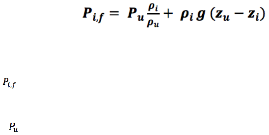
The pressure-based AoR is defined by the pore pressure (P
i,f
) isoline of the following magnitude
within which brines in the injection zone have a higher pressure than the lowermost USDW or
the USDW with the lowest pressure:
Where,
= Minimum pressure (MPa) within the injection zone necessary to cause vertical
flow
from
the injection interval into the USDW
= Pressure (MPa) within the lowermost USDW (MPa)
6
=
Fluid density (kg/m3) within the USDW
= Fluid density (kg/m3) in the injection zone
= Injection depth (m)
= depth of lowermost USDW (m)
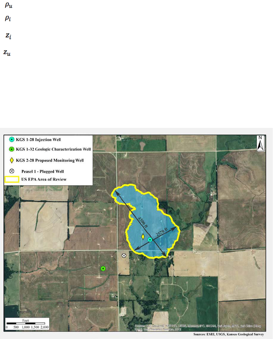
There are no firm guidelines in the Class VI rule as to what constitutes the plume-based AoR.
However, the EPA has accepted the AoR as the area within which the free-phase plume has a
CO
2
concentration of greater than 0.5%. The final AoR for a site is the larger of the pressure- or
plume-based AoR. For the Wellington site, the larger AoR was obtained for the plume criteria
and is presented in figure B-1.
Figure B-1. Maximum extent of plume migration at the end of the model period for the 40,000 MT scenario, resulting in the
accepted AoR delineated in yellow.
7
B.3 Site-Wide Geology and Hydrogeology
Projects are required to establish the site-wide geology and hydrogeology to satisfy 40 CFR Part
146.82 (a)(3)(vi), which requires that prior to issuance of a permit to construct a Class VI well,
the following information must be provided:
Information about the geologic structure and hydrogeologic properties of the proposed
storage site and overlying formations, including the following:
• Maps and cross sections of the area of review;
• The location, orientation, and properties of known or suspected faults and
fractures that may transect the confining zone(s) in the area of review and a
determination that they would not interfere with containment;
• Data about the depth, areal extent, thickness, mineralogy, porosity, permeability,
and capillary pressure of the injection and confining zone(s), including
geology/facies changes based on field data, which may include geologic cores,
outcrop data, seismic surveys, well logs, and names and lithologic descriptions;
• Geomechanical information about fractures, stress, ductility, rock strength, and in
situ fluid pressures within the confining zone(s);
• Information about the seismic history, including the presence and depth of seismic
sources and a determination that the seismicity would not interfere with
containment; and
• Geologic and topographic maps and cross sections illustrating regional geology,
hydrogeology, and the geologic structure of the local area.
Maps and stratigraphic cross sections indicating the general vertical and lateral limits of all
USDWs, water wells, and springs within the area of review, their positions relative to the
injection zone(s), and the direction of water movement, where known;
Baseline geochemical data on subsurface formations, including all USDWs in the area of
review.

8
On a regional basis, the above-mentioned hydrogeologic and geologic data requirements can
generally be fulfilled from information contained in publications and archives of state geological
surveys and the United States Geological Survey. The localized site data, however, will need to
be acquired by drilling test holes at the site; test holes are also necessary to develop injection and
monitoring wells.
B.4 Data Acquisition
To fulfill the above requirements, the EPA requires at a minimum the acquisition of site-specific
data at the injection and monitoring wells. These data are to be used in conjunction with existing
regional maps and other hydrogeologic data for developing a 3-D hydrogeologic model. The
characterization wells should at least penetrate the injection zone (and preferably into the
basement) to acquire logs, collect formation samples, and conduct tests. The preferred set of
logs, tests, and other data are summarized in table B.1, along with the key properties that were
derived from the datasets. A detailed explanation of how the acquired site data were used to
characterize the formation and estimate various hydrogeologic properties is presented in the
attached document “Advanced Geologic Characterization to Fulfill EPA Class VI CO
2
Sequestration Requirements.”
Table B.1 Summary of localized datasets required for hydrogeologic characterization of a Class
VI injection site.
Geophysical Logs
Purpose
Gamma Ray
Stratigraphy, estimate porosity
Resistivity
Identify USDW, estimate porosity
Magnetic Resonance Image
Estimate porosity, permeability, caprock entry pressure
Geochemical
Array Compensated True Resistivity
Differentiate connected/unconnected pores, estimate salinity
Temperature
Brine resistivity, solubility, phase behavior
Compensated Spectral Gamma Ray
Mineral composition, geologic characterization
Microlog
Micro-resistivity, formation characterization

9
B.5 Determination of USDWs
The Class VI permit requires identification of all USDWs within the AoR, especially the
lowermost USDW, which is most likely closest to the injection zone. The USDW is defined
strictly on the basis of water quality (TDS < 10,000 mg/l). The permeablity of the formation,
which may affect the ability to draw water from a formation, is not a factor for consideration.
Therefore, even an ultra-low permeability shale formation would be classified as a USDW if the
TDS concentration in the unit was less than 10,000 mg/l. Water-quality information is generally
available for shallow formations. Estimating TDS in deeper formations to the satisfaction of the
EPA can be more challenging. A two-step approach involving a) estimating NaCl content from
resistivity logs and b) using known TDS-NaCl relationships from swab samples to estimate TDS
was implemented for the Wellington project, as described below and approved by the EPA.
The salinity (NaCl, mg/l) can be calculated using a variant of Archie’s equation (Archie, 1942):
= . 0123 +
.
.
.
.
=> = ( (
3647.5
0.0123
)
.
)
where,
Spectral Density Dual Spaced
Neutron
Estimate porosity, mineralogical characterization
Annular Hole Volume Log
Identify borehole enlargement
Extended Range Micro Imager
Correlation Plot
Fracture characterization
Core Samples
Porosity and permeability, mineralogy and soil
characterization, CO
2
compatibility
Drill-Stem Test
Geochemistry, permeability, pressure
Leak-Off Test
Estimate fracture gradient
Swab Samples
Geochemistry
Injection Test
Estimate hydrogeologic properties, identify faults
Seismic Data
Structure and impedance mapping

10
R
w
= Resistivity of water (ohm – m)
T = Formation temperature (F)
The water resistivity, R
w
, is computed from a version of Archie’s equation for 100% saturated
pores:
=
(
)
Where,
= porosity
= formation resistivity
= cementation exponent —assumed to be 2 for cemented limestone
= proportionality constant—assumed to be 1 (Maute et al., 1992)
The subsurface water in deep formation is generally of similar type. In Kansas, the TDS (by
weight) in the Arbuckle is 1.045 times NaCl (by weight), suggesting that Na and Cl are the
dominant minerals in this formation. Therefore, knowing the TDS/Cl relationship of the
formation, and the NaCL caluclated from resistivity logs, it can be estimated as
TDS
(mg/l)
= (TDS/Cl)
ratio
NaCl
(mg/l)
The estimated TDS concentration from near land surface to the basement at the Wellington site
is shown in fig. B-2.
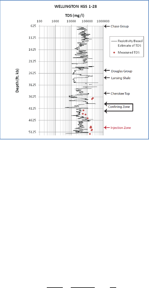
11
Figure B-2. TDS (mg/l) estimated from resistivity logs at the Wellington site.
B.6 Fracture Gradient
As per Class VI rule, the pore pressures in the injection zone cannot exceed 90% of the fracture
gradient. The fracture gradient can be derived by conducting a leak-off test. In the absence of
such test data, the EPA will consider an analytical-based estimate of this parameter using a valid
approach for permitting purposes. In a tectonically relaxed region such as Kansas, the fracture
gradient can be estimated by Eaton’s equation (Eaton, 1969), which is a function of the
overburden pressure, pore pressure, and Poisson’s ratio:
=
1
+
Where:
• F = fracture gradient (psi)
• = Poisson ratio
•
= overburden pressure (psi)
•
= pore pressure of formation fluid (psi)
• D = depth (ft)
12
B.7 Hydrogeologic Properties at Well Sites
Sensitivity studies indicated that due to the buoyant nature of the injectate, the plume and the
pressure fronts are highly influenced by the vertical resolution of petrophysical properties. Using
a layered-cake model can provide misleading results. Consequently, a high level of effort was
expended to characterize the injection and confining zones at high resolution and to develop
methodologies to extrapolate (upscale) the hydrogeologic properties throughout the model
domain. The procedures implemented and the results of the characterization for the Wellington
project are documented in the attached document (Advanced Geologic Characterization to Fulfill
EPA Class VI CO
2
Sequestration Requirements). Spectral gamma ray, triple combo log suite,
magnetic resonance image (MRI), and dipole sonic were used to characterize pore volume. The
permeability was calculated by relating core-based Flow Zone Indicator (FZI) to the function
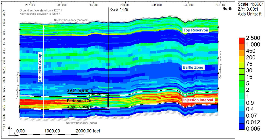
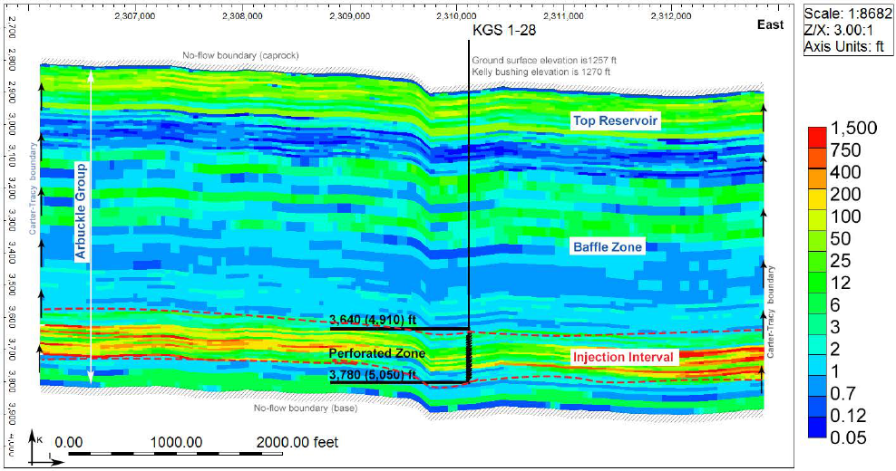
1/(Swir*Phi) using the technique suggested by Fazelalavi et al. (2013). The effort revealed a
complex injection zone with baffle zones (fig. B-3) which may be present in Cambrian-Ordivician
rocks in the mid-continent United States.
Figure B-3. Upscaled vertical permeability distribution (mD) in an E-W orientation through the injection well.
13
B.8 3D Geologic Model
Development of the geologic model involves a complicated orchestration of well logs, core
analysis, seismic surveys, literature, depositional analogs and statistics, seismic data, step-rate
test and drill-stem test information. Sophisticated geostatistical software such as Schlumberger's
Petrel™ is required to produce the model. In contrast to well data, the seismic data are extensive
over the reservoir and are, therefore, of great value for constraining facies and porosity trends
within the geomodel. Petrel’s volume attribute processing (i.e., genetic inversion) was used at the
Wellington site to derive a porosity attribute from the Pre-Stack Depth Migration (PSDM) volume
along with the neural network processing and upscaling features of the package. Similarly, the
permeability model was constructed using Sequential Gaussian Simulation (SGS). Isotropic
semi-variogram ranges were set to 3,000 ft horizontally and 10 ft vertically. The permeability
was collocated and co-kriged to the porosity model using the calculated correlation coefficient
(~0.70). The resulting SGS-based horizontal and vertical permeability distributions are presented
in figures B-3 and B-4.
Figure B-4. Upscaled horizontal permeability distribution (mD) in an E-W through the injection well.

14
B.9 Multiphase Flow and Transport Model
A multiphase model capable of simulating brine and CO
2
transport in the supercritical, liquid, or
gaseous phases is required for delineating the AoR. Presently, the CMG (Computer Modeling
Group, www.cmgl.ca/software), Eclipse (Schlumberger,
www.software.slb.com/products/eclipse), and Tough
(http://esd1.lbl.gov/research/projects/tough/software/) are common modeling software options
used in the oil and gas industry. As part of the permitting process, the EPA will validate the AoR
using the PNNL’s STOMP modeling software (https://stomp.pnnl.gov). Therefore, all input data
will need to be transferred into STOMP format. If the applicant is not using STOMP, it is
recommended that the applicant convert the data into STOMP and ensure that the simulation
results are comparable to expedite the permitting process. Also, since STOMP can only use a
uniform structured grid, it is advisable that a non-structured mesh be avoided to expedite the
model data file conversion process.
To efficiently account for the capillary pressure and relative permeability/saturation relationship,
rock types should be established based on reservoir quality index (RQI) ranges and assigned
throughout the model grid using the following relationship:
= 0.0314
For the Wellington model, nine rock types were included and nine sets of relative permeability
curves for both drainage and imbibition were established based on a recently patented formula
(SMH reference No: 1002061-0002) that relates end points to RQI. The simulated pressure and
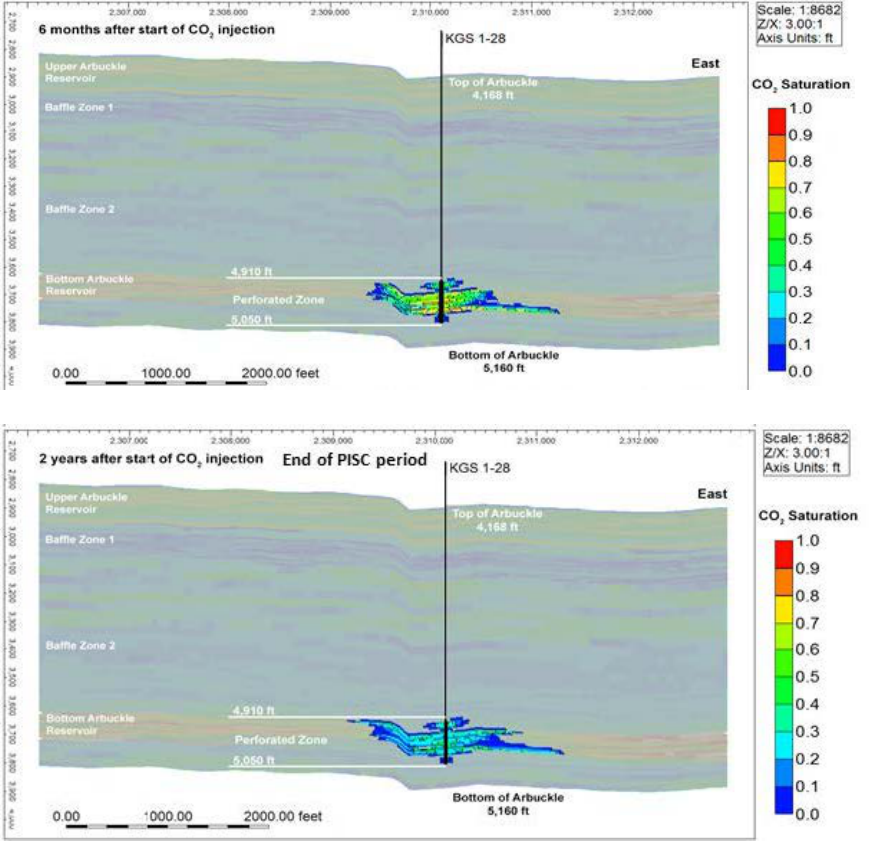
plume distributions for the Wellington project are presented in figures B-5 and B-6.
15

16
Figure B-5. E-W cross section showing vertical and lateral separate-phase plume migration at selected operational
milestones for 40,000 tons injection (continued from the previous page).
17
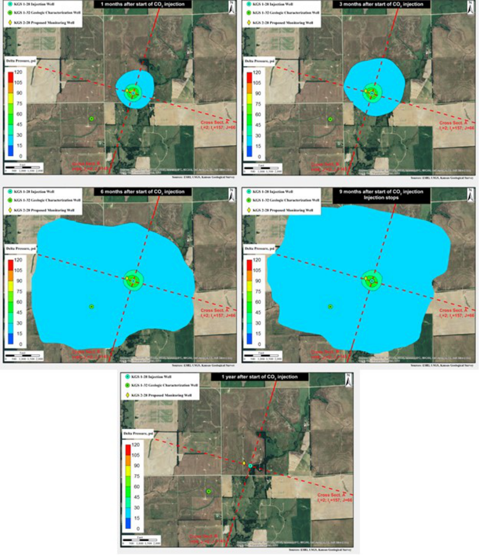
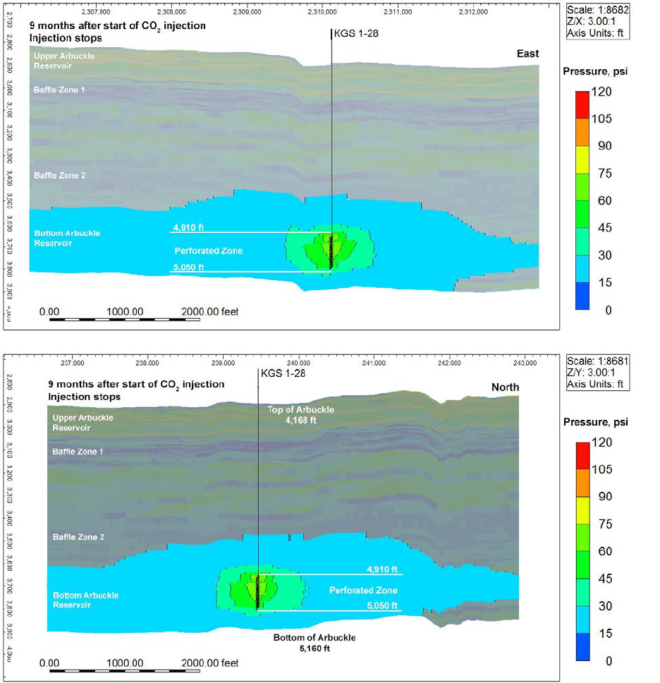
Figure B-6a. Evolution of the simulated pressure front over time for the 40,000 MT scenario.
18
Figure B-6b. Maximum extent of the pressure front in the E-W (top) and N-S (bottom) orientations at the end of the injection
period for the 40,000 MT scenario.
B.10 Corrective Action
Class VI applicants must evaluate well bore integrity at all operational and abandoned wells that
penetrate the confining zone within the AoR to ensure that these wells do not form a pathway for
migration of gaseous-phase CO
2
or brines from the injection zone. This can be an expensive
19
process involving a review of operational and testing data at existing wells, review of well
plugging information at abandoned wells, and field evaluation of plugs at abandoned wells
without plugging records.
B.11 AoR Reevaluation
By default, the AoR is to be reevaluated at the following times:
• Every 5 years
• At termination of injection
• Prior to site closure.
The AoR is also required to be reevaluated if the following events occur, which could suggest
the potential for material change in the projected plume and pressure front:
a. Initiation of competing injection projects within the same formation at close
proximity of the injection well;
b. A significant deviation of wellhead operational data, formation pressure, or the
CO
2
plume and pressure front;
c. Seismic events or other emergency events that trigger an AoR reevaluation as
specified in the Emergency and Remedial Response Plan;
d. Newly acquired data at the site deemed to significantly alter the hydrogeologic
properties specified in the reservoir model.
If the monitored data suggest a significant deviation from the model-predicted path and
movement rate of the plume and pressure front, then the reevaluation process will involve the
following:
• Revising the site conceptual model based on new site characterization, operational, or
monitoring data,
• Recalibrating the model and redelineating the AoR,
• Applying corrective action to any deficient wells in the newly delineated AOR.

20
Attachment C – Testing and Monitoring
Relevant Class VI Articles: 40 CFR 146.88, 146.89, and 146.90, 146.91
C.1 Overview
This plan describes how the monitoring and testing data will be used to demonstrate that the injection
well is operating safely, that the CO
2
plume and pressure front are moving as predicted, and that there is
no endangerment to USDWs. Deviations from the predicted results may prompt a recalibration of the
model or trigger a remedial response according to the AoR and Corrective Action Plan, the Emergency
and Remedial Response Plan, and other permit conditions. A brief explanation of the required monitoring
activities and associated frequencies is provided in the following sections.
C.2 Carbon Dioxide Source Analysis
The objective of this activity is to ensure that the injectate does not contain any hazardous waste
chemicals that can react in a manner that may hinder the sequestration processes. The test samples can be
collected either at the CO
2
source site or at the sequestration site. The complete list of parameters to be
tested will depend on the source of the anthropogenic CO
2
(coal, ethanol, etc.). Table C-1 lists a
summary of the typical analytical parameters to be tested and the testing methods. Table C-2 specifies the
EPA’s preferred sampling frequency.
Table C-1. Summary of analytical parameters for CO
2
gas stream.
Parameters
Analytical Methods
Oxygen
ISBT 4.0 (GC/DID)
Nitrogen
ISBT 4.0 (GC/DID)
Carbon monoxide
ISBT 5.0 (GC/DID)
Oxides of nitrogen
ISBT 7.0 (DT)
Total hydrocarbons
ISBT 10.0
Methane
ISBT 10.1 (GC)
Acetaldehyde
ISBT 11.0 (GC)
Sulfur dioxide
ISBT 14.0 (GC)
Hydrogen sulfide
ISBT 14.0
CO
2
purity
ISBT 2.0
Ethanol (if source)
ISBT 11.0 (GC/FID)
Table C-2. Sampling and testing frequency for CO
2
stream analysis.

21
Class VI Rule
Requirement
Activity
Frequency -
Pre-Injection
Phase
Frequency -
Injection Phase
Frequency -
Post-Injection
Phase
CO
2
stream analysis
Direct CO
2
stream
sampling
One sample at
each supply plant
Quarterly
N/A
C.3 Injection Well Monitoring and Testing
The monitoring and testing activities to be conducted at the injection well are specified in table C-3,
followed by a brief description of key EPA requirements for the activities.
Table C-3. Summary of testing and monitoring requirements for the injection well and monitoring
wells in the injection zone.
Class VI Rule
Requirement
Activity
Frequency -
Pre-Injection
Phase
Frequency -
Injection Phase
Frequency -
Post-Injection
Phase
Continuous recording of
injection
pressure/rate/volume and
annular pressure
Injection rate and
volume (via flow
meter)
N/A
Continuous, every
5–30 secs
N/A
Wellhead injection
pressure (via
pressure gauge)
N/A
Continuous, every
5–30 secs
N/A
Annular pressure
(via pressure gauge)
Continuous
Continuous, every
5–30 secs
Continuous
Corrosion monitoring
Corrosion coupons,
and potentially
multiple fingers
caliper or
ultrasonic/electro-
magnetic tools
N/A
Quarterly to
annually
N/A
External mechanical
integrity testing
Temperature and/or
radioactive tracer,
noise, oxygen
activation, or
Pulsed-Neutron
Capture Log
1
One test
Annually
Annually
Internal mechanical
integrity testing, in
addition to continuous
monitoring
Annular pressure test
(via pressure gauge)
One test
Annually
Annually
Pressure fall-off testing
Pressure fall-off test
(via pressure gauge)
One test
Several tests to be
decided by EPA
Director
One test
1
The PNC logging tool is to be run twice during each event: once in the gas-view mode to detect CO
2
and
once in the oxygen-activation mode to detect water.

22
C.3.1 Flow Rate
The injection rate can be measured with either a mass or flow meter. If a flow meter, such as an Orifice-
Plate differential meter, is used, then the density needs to be first estimated using equations of state and
pressure temperature readings to calculate the mass flow rate. Even if a mass meter is used, the density
needs to be estimated to determine the weight of the CO
2
in the tubing for reporting and verification
purposes. The density can be estimated using the correlation developed by Ouyang (2011).
C.3.2 Corrosion Monitoring
The applicant will be required to monitor well materials during the operation period for loss of mass,
thickness, cracking, pitting, and other signs of corrosion to ensure that the well components meet the
minimum standards for material strength and performance. The applicant is required to monitor corrosion
using corrosion coupons of material used in the pipeline, casing, tubing, wellhead, and packer. The
coupons should be clamped in the line between the CO
2
storage tank and the injection well. Table C-4
lists the methods to be used for analyzing the corrosion coupons. A corrosion rate of greater than 0.3
mils/year will likely initiate more frequent sampling and corrective action. In addition to the corrosion
coupons, the EPA may require the permittee to monitor corrosion in the tubing and casings using caliper,
ultrasonic, or electromagnetic logs.
Table C-4. Summary of analytical parameters for corrosion coupons.
Parameters
Analytical Methods
Detection Limit
Typical Precisions
Mass
NACE RP0775-2005
(or equivalent)
0.05 mg ± 3%
Thickness
NACE RP0775-2005
(or equivalent)
0.01 mm ± 0.05 mm
C.3.3 External Mechanical Integrity Testing (MIT)
The MIT is to be conducted not only in the injection well but also in all monitoring wells in the injection
zone. The well is to be shut during the injection phase for a period of 36 hours before obtaining the
temperature log.
C.3.4 Pressure Fall-Off Testing
The EPA’s specific guidelines for conducting the pressure fall-off test are defined in the Quality
Assurance and Surveillance Plan (Appendix C). A successful test will be confirmed when casing pressure
holds for one hour with less than 3% loss or gain in pressure.
C.4 Injection Zone Monitoring
The permittee is required to employ direct and indirect methods to track the CO
2
plume and
pressure front in the injection zone. The methods acceptable to the EPA to achieve these goals
are discussed below.

23
C.4.1 Pressure-Front Monitoring
Table C-5 lists the direct and indirect methods for monitoring the pressure front and typical
monitoring frequencies preferred by the EPA.
Table C-5. Pressure-front monitoring of the injection zone.
Type
Activity
Monitoring Location(s)
Frequency -
Pre-Injection
Phase
Frequency -
Injection Phase
Frequency -
Post-Injection
Phase
Direct
Downhole
pressure/
temperature gauge
(temperature can
also be recorded
with a fiber-optic
Distributed
Temperature
Sensor)
Injection and monitoring wells in
the injection zone
A minimum of 1
week of reading
(every 30
seconds)
Continuous (every
30 seconds)
Continuous (every
30 seconds)
Indirect
Interferometric
synthetic aperture
radar (InSAR) with
continuous GPS
(cGPS)
Radar data acquired in the imaging
mode: StripMap—up to 3 m
resolution, scene size should extend
well beyond the AoR
GPS station: adjacent to injection
site
InSAR—
monthly, cGPS
(sampling
frequency of 15
sec. averaged into
a daily location)
InSAR—monthly,
cGPS (sampling
frequency of 15
sec. averaged into
a daily location)
InSAR—monthly,
cGPS (sampling
frequency of 15
sec. averaged into
a daily location)
Passive seismic
Seismometer network at surface
and/or borehole seismic station.
Continuous (1
year preferred)
Continuous
(downloaded
monthly)
Continuous
(downloaded
monthly)
Tiltmeter
Site wide within the AoR
Continuous (1
year preferred)
Continuous
(downloaded
monthly)
Continuous
(downloaded
monthly)
C.4.2 CO
2
Plume Monitoring
Direct measurement involves collecting fluid samples using a sampler that can retain the CO
2
phases at the screen perforation, such as Lawrence Berkley Laboratories U-tube (Freifeld et al.,
2005) or Schlumberger’s Westbay multilevel monitoring system
(http://www.westbay.com/technology). Table C-6 lists commonly used plume monitoring
techniques and the EPA’s preferred monitoring frequency. The EPA Director may require one
or more indirect methods to be used for the project. Table C-7 lists chemical constituents to be
tested for the direct sample.
Table C-6. Direct and indirect methods of plume monitoring.

24
Type
Activity
Monitoring Location(s)
Frequency -
Pre-Injection
Phase
Frequency -
Injection Phase
Frequency -
Post-Injection
Phase
Direct
Direct sampling
using a device
that retains CO
2
phase in the
injection zone.
Injection well and monitoring wells
in the injection zone
A minimum of
one sampling
event
Variable
frequency after
commencement of
injection until
plume arrives at
the monitoring
well(s).
Thereafter,
quarterly and
decreasing to
annually.
Quarterly to
annually.
Indirect
CASSM
(Continuous
Active Source
Seismic
Monitoring)
Injection well and monitoring wells
in the injection zone
A minimum of 1
week of reading
Continuous
(approx. 24-hr
temporal
resolution), until
plume arrival at
monitoring
well(s).
At the discretion
of the EPA.
Crosswell seismic
Injection well and monitoring wells
in the injection zone
One survey
One or more
during injection
None
2-D seismic
survey
Multiple seismic lines
Once
One or more
during injection
Once
3-D seismic
survey
Site wide
Once
One or more
during injection
One survey
Pulsed Neutron
Capture/Reservoir
Saturation Tool
Monitoring wells
Once
Quarterly to
annually
Discretion of the
EPA
Time lapse 3-D
Vertical seismic
profile (VSP)
survey
Cover plume-based AoR
Once
Discretion of the
EPA
Discretion of the
EPA
Time-lapse
gravity
Gravity stations located site wide
within the AoR.
Quarterly to
annually
Table C-7. Summary of parameters for groundwater samples.
Parameters
Analytical Methods
Upper Wellington
Cations: Al, Ba, Mn, As, Cd, Cr, Cu, Pb, Sb, Se, and Tl
ICP-MS, EPA Method 6020

25
Parameters
Analytical Methods
Cations: Ca, Fe, K, Mg, Na, Si
ICP-OES, EPA Method 6010B
Anions: Br, Cl, F, NO
3
, SO
4
Ion Chromatography, EPA Method 300.0
Cyanide (Cn-)
SW846 9012A/B
Mercury
CVAA SW846 7470A
Dissolved CO
2
Coulometric titration, ASTM D513-11
Total dissolved solids
Gravimetry; APHA 2540C
Alkalinity
APHA 2320B
pH (field)
SM 2450
Specific conductance (field)
APHA 2510
Temperature (field)
Thermocouple
Oxidation-reduction potential (field)
SESDPROC-113-R1
Sulfur hexaflouride
Busenberg and Plummer, 2000
(http://water.usgs.gov/lab/sf6/)
Hydrogen sulfide
SM4500-S2D
Acetaldehyde
EPA Method 8315A
Total Inorganic Carbon (TIC)
SW846 9060A
Total Organic Carbon (TOC)
SW846 9060A
Volatile Organic Analysis (VOA)
SW846 8260B
Stable Carbon Isotope
Gas Bench for
13/12
C
Gravimetric Total Dissolved Solids (TDS)
Gravimetric Method Standard Methods 2540C
C.5 Above Confining Zone Monitoring
C.5.1 Direct Monitoring
The permittee is required to monitor groundwater quality and geochemical changes above the
confining zone. Typically, monitoring is required in all USDWs and reservoirs that may be used
for oil and gas extraction. The acquired samples will be tested for all constituents listed in table
C-7, at the frequencies specified in table C-8.

26
Table C-8. Monitoring activities and frequency above the confining zone.
Class VI Rule
Requirement
Activity
Frequency -
Pre-Injection
Phase
Frequency -
Injection Phase
Frequency -
Post-Injection
Phase
Groundwater monitoring
above the confining zone
Direct monitoring –
All USDWs and
other productive
formative
formations
A minimum of 2
samplings at
different dates
Quarterly to
annually
Every 6 months to
a year
C.5.2 Monitoring Related to Enhanced Oil Recovery Operations
If CO
2
-based Enhanced Oil Recovery (EOR) is occurring in another formation at the site, then
the EPA will require the addition of a tracer in the CO
2
stream. A suitable tracer is sulfur
hexafluoride (SF
6
), a trace anthropogenic gas found in the atmosphere at 7-8 parts per trillion
(ppt). SF
6
is a conservative gas that does not sorb onto the matrix or react/decompose into
daughter products. Only minute quantities of this tracer are required as the detection limit in the
dissolved phase is 0.1 Fentamoles/liter, which equates to a concentration of 1.5E
-08
micrograms/liter.
C.6 Earthquake Monitoring
Monitoring for seismicity is required for Class VI wells. The EPA may require the installation
of a ring of seismometers around the injection well(s). The data from the seismometer are to be
downloaded and analyzed monthly. The primary goal is to ensure that an earthquake of
magnitude 2.5 or larger is not caused by injection activities related to either sequestration or
EOR. The seismometers should be capable of detecting earthquakes of magnitude 1.0 or greater
at the site.
C.7 Quality Assurance and Surveillance Plan (QASP)
An extensive quality assurance protocol is required by the EPA to ensure validity of the
monitored data and to derive statistically defensible conclusions. The QASP details standard
operating procedures and methods related to sample acquisition, handling, preservation, testing,
and reporting. Appendix C contains the QASP prepared for the Wellington project.
C.8 Reporting
The results of all testing and monitoring are to be described in a semi-annual report and
submitted to the EPA.
27
Attachment D – Injection Well Plugging Plan
Relevant Class Articles: 40 CFR 146.92
A key plugging requirement of the Class VI rule is that the interval within the injection zone and USDWs
be filled with CO
2
-resistant cement. External MITs are to be performed before plugging using a
temperature, noise, or oxygen activation log, and the well is to be flushed with brine to force CO
2
into the
formation.
Attachment E – Post Injection Site Care and Site Closure
Relevant Class VI articles: 40 CFR 146.93
E.1 Overview
The Post-Injection Site Care (PISC) and Site Closure Plan describes the activities that the
applicant will perform to monitor groundwater quality and track the position of the carbon
dioxide plume and pressure front after cessation of injection. These activities are to continue
until it can be demonstrated that no additional monitoring is needed to ensure that the project
does not pose a danger to any USDWs.
E.2 Default and Alternative Monitoring Periods
The default post-injection site care period is 50 years. The EPA, however, allows for a
reduction of this period if the applicant can demonstrate through modeling and other means that
the plume and pressure fronts will stabilize in a shorter duration.
E.3 Non-Endangerment Demonstration Criteria
Prior to authorization of site closure, the permittee is required to submit a report, which
includes the following components, to demonstrate non-endangerment of USDWs.
E.3.1 Summary of Existing Monitoring Data
A summary of all previous monitoring data collected at the site is to be submitted to support a
demonstration of non-endangerment. Data submittals will include a narrative explanation of
monitoring activities, including the dates of all monitoring events, changes to the monitoring
program over time, and an explanation of all monitoring infrastructure that has existed at the site.
Data will be compared with baseline data collected during site characterization and duration of
the project.
E.3.2 Summary of Computational Modeling History
A summary of the computational modeling conducted for the project will be submitted to
support a demonstration of non-endangerment. The summary should include a narrative
explanation of the computational modeling history, such as verification and validation
activities, modifications to the modeling approach, and changes in the AoR delineation over the
life of the project.

28
E.3.3 Evaluation of Carbon Dioxide Plume
The permittee is to demonstrate non-endangerment to USDWs by showing that the carbon
dioxide plume is behaving as predicted and not migrating to unintended areas. A good
correlation between the observed data and the values predicted by the model will provide
evidence of the model’s ability to represent the system.
E.3.4 Evaluation of Reservoir Pressure
The permittee is to submit all direct and non-direct data to demonstrate that the pressures within
the injection zone have decreased as predicted by the model. A good agreement between the
actual and predicted values will help validate the accuracy of the model and support a
demonstration of non-endangerment.
E.3.5 Evaluation of Unanticipated Events
As part of the non-endangerment report, the permittee is to summarize any emergencies or
other unanticipated events that occurred during the injection and post-injection phases and
explain how they have been resolved such that there is no further endangerment of USDWs.
Such events may include (but are not limited to) the scenarios presented in table E-1.
Table E-1. Examples of unanticipated events at a sequestration site.
Scenario
Example of Activities Used to Demonstrate
Resolution
Identification of previously unidentified well(s) within
the AoR that penetrate the confining zone
Documentation of the determination of whether the
well(s) require corrective action and, if applicable,
records of any corrective action completed
Detection of CO
2
or other unanticipated
parameters/levels of parameters above the confining zone
Documentation of associated monitoring activities (e.g.,
groundwater samples, 2-D seismic surveys) and data
analysis, an explanation of the cause of the anomalous
results and any impacts, and any follow-up actions taken
Any divergence from planned operational parameters
Documentation of the divergence/change (e.g., pressure,
total volume) and data analysis, an explanation of any
impacts, and any follow-up actions taken
Indication that any fault(s) in the AoR is affecting CO
2
containment
Documentation of associated monitoring activities (e.g.,
pressure monitoring, passive seismic monitoring) and
data analysis, an explanation of any impacts, and any
follow-up actions taken
Evidence of induced seismic event(s)
Documentation of associated monitoring activities (e.g.,
passive seismic monitoring) and data analysis, an
explanation of any impacts, and any follow-up actions
taken

29
Scenario
Example of Activities Used to Demonstrate
Resolution
Non-compliance with any other Class VI permit
condition, any event that triggers an unscheduled AoR
reevaluation according to the AoR and Corrective Action
Plan, or any event that triggers action according to the
approved Emergency and Remedial Response Plan
A description of how the approved Emergency and
Remedial Response Plan was implemented (including
references to relevant reporting) and the actions taken to
return to compliance
E.4 Monitoring Activities
Tables C-1 to C-8 of Attachment C – Testing and Monitoring Plan document a summary of the
monitoring and testing activities to be conducted during the post-injection phase.
E.5 Site Closure Plan
After the EPA’s approval of non-endangerment demonstration and authorization of site closure,
a site closure report is to be prepared and submitted within 90 days, documenting the following:
• Plugging of all injection and monitoring wells,
• Details of site restoration activities,
• Location of sealed injection well on a plat survey that has been submitted to the local
zoning authority,
• Notifications to state and local authorities,
• Records regarding the nature, composition, and volume of the injected CO
2
,
• Pre-injection, injection, and post-injection monitoring records, and
• Certifications that all injection and storage activities have been completed.
The permittee is to record a notation on the deed for the property on which the injection well was
located that indicates the following:
• That the property was used for carbon dioxide sequestration,
• The name of the local agency to which a plat survey with injection well location was
submitted,
• The volume of fluid injected,
• The formation into which the fluid was injected, and
• The period over which the injection occurred.

30
Attachment F – Emergency and Remedial Response Plan
Relevant Class VI Rule Articles: 40 CFR 146.93, 146.94
F.1 Overview
The Emergency and Remedial Response Plan (ERRP) describes actions that the permittee shall
take to address movement of injection or formation fluids that may endanger a USDW/injection
well or safe functioning of infrastructure at the site. Table F-1 lists the potential emergency
scenarios identified by the EPA.
Table F-1. Emergency scenarios for Class VI project identified by the EPA.
Emergency Scenario Requiring Remedial Response
Well integrity failure, including annulus pressure failure
Equipment failure, including damage to the wellhead or a well blowout
Water-quality changes, USDW endangerment, migration of CO
2
out of the
injection zone, or release of CO
2
to the surface
Natural disaster
Induced seismicity event
Each scenario constitutes an emergency and triggers the ERRP. The response activities for each
scenario, however, will depend on the nature of the failure and the severity of the event, as
described in table F-2.

31
TABLE F-2. DEGREES OF RISK FOR EMERGENCY EVENTS
Emergency Condition Definition
Major Emergency
Event poses immediate substantial risk to human health,
resources, or infrastructure. Emergency actions should be
initiated in coordination with local authorities.
Serious Emergency
Event poses potential serious (or significant) near-term risk to
human health, resources, or infrastructure if conditions worsen or
no response actions are taken.
Minor Emergency
Event poses no immediate risk to human health, resources, or
infrastructure.
F.2 Common Response Action
For all emergency scenarios, the following steps are to be implemented:
• Notify the UIC Program Director within 24 hours of the emergency event.
• Determine the severity of the event, based on the information available, within 24 hours
of notification.
• For a major or serious emergency (i.e., release):
Initiate immediate shutdown.
Evaluate the cause of the violation, characterize the release, and mitigate if
necessary.
If contamination is detected, identify and implement appropriate remedial actions
specified for each scenario discussed below.
• For a minor emergency:
Conduct an assessment to determine whether there has been a loss of
mechanical integrity.
If there has been a loss of mechanical integrity, initiate gradual shutdown plan.
• Confirm well integrity before restarting injection
F.3 Response Action for Emergency Scenarios
The emergency response for each of scenarios listed in table F-1 is described below.
F.3.1 Well Integrity Failure
A loss of integrity in the injection well and/or monitoring well may endanger a USDW. Integrity
loss may have occurred if the following events occur:
• Automatic shutdown devices are activated, i.e., if:
32
o Wellhead pressure exceeds the specified shutdown pressure specified in the permit;
o Annulus pressure indicates a loss of external or internal well containment.
• Mechanical integrity test results identify a loss of mechanical integrity.
Based on the severity of the event, implement the steps specified in Section F.2.
F.3.2 Equipment Failure
This scenario includes equipment failure, damage to the wellhead, or a well blowout.
For a major or serious emergency (i.e., release):
• Review downhole, wellhead, and annulus pressure data.
• If contamination is detected, identify and implement appropriate remedial actions:
o Isolate the nearby area, if needed; establish a safe distance and perimeter
using a hand-held air-quality monitor.
o Perform a well log to detect CO
2
movement outside of casing.
Evaluate the cause of the failure, and mitigate, if necessary (i.e., repair equipment).
• In the event of a well blowout, “kill” the well by pumping fluid to stop the well from
flowing.
• If there is damage to the wellhead, repair the damage and conduct a survey to ensure
wellhead leakage has ceased.
• If a shut off is triggered by mechanical or electrical malfunctions, repair faulty
components.
F.3.3 Water-Quality Changes/USDW Endangerment/Migration of CO
2
Out of the Injection Zone
or Release of CO
2
to the Surface
Activities to be undertaken for these scenarios may include the following:
• Conduct Hall Plot analysis;
• Sample and test water quality in monitoring wells above confining zone;
• Conduct pressure fall-off test;
• Validate plume detection with U-Tube sampling;
• Obtain InSAR scene and analyze for caprock breach (if necessary and deemed feasible).
• Arrange for an alternate potable water supply if the event caused an exceedance of
drinking water standards to any water supplies.
33
• If the presence of CO
2
or indicator parameters is confirmed, evaluate the cause and
extent of the violation and implement the following measures.
If water-quality changes or CO
2
migration is determined to be a consequence of
well failure, attempt to identify the source location in the wellbore. This may involve
obtaining a suite of wireline logs to pinpoint the source location. Remediate using
appropriate methods. On completion of the remedial work, acquire a new set of logs and
perform a pressure test to evaluate well integrity before restarting injection.
If water-quality changes or CO
2
migration is determined to be due to confining
zone failure or flow along structural features, develop a plan to identify the extent of the
problem and perform remedial measures. This may involve installing additional wells
near the affected groundwater well(s) to delineate the extent of contamination, and
conducting additional modeling to predict the fate of the CO
2
and/or brine. If CO
2
is
detected above the confining zone, then the modeling will involve predicting the impacts
to any surrounding wells and water resources.
• Continue groundwater remediation and monitoring on a frequent basis until unacceptable
adverse impacts have been fully addressed.
• If CO
2
is detected in a reservoir other than the injection zone, then available wells in
those formations will be used to release CO
2
.
• A 2-D seismic survey may also be required to identify the extent of plume migration.
F.3.4 Natural Disaster
Well problems (integrity loss, leakage, or malfunction) may arise as a result of a natural disaster
such as earthquake, tornado, or lightning strike that may affect normal operations of the
injection well.
For a major or serious emergency:
• Shut in well (close flow valve).
• Vent CO
2
from surface facilities.
• Monitor well pressure, temperature, and annulus pressure to verify well status and
determine the cause and extent of any failure.
• Determine whether any leaks to USDW or surface water have occurred.
• Identify and, if necessary, implement appropriate remedial actions (in consultation with
the UIC Program Director.
F.3.5 Induced Seismicity Event

34
Responses to seismic events are to be implemented according to an agreed-upon Seismic Action
Plan (SAP), which lists remedial actions that are to be initiated if certain seismic threshold levels
are exceeded. These limits and the associated response action for the Wellington project are
specified in table F-3. The response items are to be implemented only if the epicenter of the
seismic event is within an agreed-upon distance from the injection well.
TABLE F-3. SAP THRESHOLD LIMITS AND CORRESPONDING RESPONSE ACTION PLAN FOR
WELLINGTON PROJECT
Seismic Event
Magnitude
Threshold
Condition
1
Response Action Plan
Seismic event
greater than
M2.0 and less
than M2.5
2
and
no felt report
3
1. Continue site activities per permit conditions.
2. Document event for reporting to the EPA in semi-annual reports.
Seismic event
greater than
M2.5
2
and no felt
report
3
1. Continue site activities per permit conditions.
2. Within 24 hours of the incident, notify UIC Program Director of the operating status of
the facility. If it is determined that gradual shutdown of the well is appropriate, reduce
injection rate such that the downhole pressure does not exceed 80% of the maximum
pressure observed during a 24-hour period preceding the seismic event.
3. Review seismic and operational data.
4. Report findings to the UIC Program Director and perform corrective action, if necessary.
Seismic event
greater than
M2.5
2
or local
observation or
felt report
3
1. Initiate immediate shutdown.
2. Within 24 hours of the incident, notify UIC Program Director of the operating status of
the facility.
3. Monitor well pressure, temperature, and annulus pressure to verify well status and
determine the cause and extent of any failure; identify and implement appropriate
remedial actions (in consultation with the UIC Program Director).
4. Determine whether leaks to groundwater or surface water occurred.
5. If a leak is detected:
a. Notify the UIC Program Director within 24 hours of the determination.
b. Identify and implement appropriate remedial actions (in consultation with the UIC
Program Director).
6. Review seismic and operational data.
7. Report finding to UIC Program Director and perform corrective actions.
4
1 Seismic event within an agreed-upon distance from the injection well.
2 Determined by a local seismometer network or USGS seismic monitoring stations or reported by the USGS NEIC
using the national seismic network.
3 Confirmed by local reports of felt ground motion within an agreed-upon distance from the injection well or
reported on the USGS “Did You Feel It?” reporting system.
4 Within 30 days of change in operating status.
35
Monitoring-Based Rapid-Response Plan
In addition to defining measures to be implemented for various emergency scenarios, the EPA also
prefers the existence of a monitoring-based rapid-response plan to proactively deal with deviations from
expected conditions in the monitored data.
This first-of-a-kind plan was developed for the
Wellington project (table F-4) and is designed to provide early warning of CO
2
plume and pressure
front deviations. The warnings trigger an analysis to identify the cause(s) of the deviation, potentially
revise the expected trajectory of the plume based on the revised modeling, and execute a set of enhanced
monitoring activities to ensure safe injection.

36
Table F-4. Monitoring-Based Rapid-Response Plan.
Activity
Monitoring
Objective
(Frequency of
Evaluation)
Deviation
Triggering
Reevaluation
Potential
Causes of
Deviation
Level 1 Response (Actions)
Level 2 Response
(Actions)
CASSM—
Early
detection of
plume at
monitoring
wells
Determine
plume
front/validate
CO
2
-brine
model
(Weekly)
Plume arrival early
at monitoring
well(s)
Presence of
preferential
flow pathway(s)
•
Validate plume detection with U-Tube sampling
• Conduct Hall Plot analysis
• Conduct pressure fall-off test
• If necessary, recalibrate model
• Revise projections of plume and pressure front
• Recalculate AoR
• Determine whether corrective action is required
• Report finding to EPA Director.
CASSM—
Non-
detection of
plume at
monitoring
well(s)
Determine
plume
front/validate
CO
2
-brine
model
(Weekly)
Plume not
detected within
agreed-upon days
of commencement
of injection
Non-radial
migration of
CO
2
through
preferential
pathway(s),
escape of CO
2
into basement,
breach of
caprock, well
integrity failure
• Conduct Hall Plot analysis
• Conduct pressure fall-off test
• Review annulus pressure data
• Sample monitoring wells above confining zone
• Conduct MIT
• If necessary, recalibrate model
• Revise projections of plume and pressure front
• Recalculate AoR
• Determine whether corrective action is required
• Report finding to EPA Director.
Sudden loss
of downhole
and/or
wellhead
pressure at
injection well
Monitor for
leakage from
well or
caprock
(Continuously)
> 25% drop in
pressure (over
average of past 5
minutes, except
during start and
stoppage of
injection)
Potential
leakage from
well, breach of
caprock, or
formation of
new fracture(s)
• Pause injection (immediate shutdown)
• Review downhole, wellhead, and annulus pressure data.
• Determine whether loss of pressure is due to CO
2
supply. If
positive, rectify problem, report findings to EPA Director, and
resume injection.
• Conduct Hall Plot analysis.
• Sample and test water quality in the Mississippian and shallow
monitoring wells
• Conduct MIT
• Use all available monitoring data to calibrate model and predict
plume extent
• Conduct
pressure fall-off
test (to
determine
whether loss of
pressure is due
to formation
enhancement
• Obtain InSAR
scene and
analyze for

37
• If necessary, implement Level 2 response
• Report finding to EPA Director.
caprock breach
(if deemed
feasible)
Unexpected
increase of
downhole or
wellhead
pressure
gradients at
injection well
Monitor for
interception of
barrier
boundary, well
plugging,
reduced
formation
permeability
(Continuously)
Unexpected
increase in
pressure gradient
over time
Interception of
barrier
boundary, well
plugging,
reduced
formation
permeability
due to chemical
reactions,
reduction of
permeability
due to lower
downhole
temperature
•
Review downhole and wellhead temperature and pressure data.
• Conduct Hall Plot analysis.
• Determine whether increase in pressure is due to cooling effect of
CO
2
, formation plugging, or geochemical reactions. If positive,
continue pumping but closely monitor pressures so as to not
exceed operational limits.
• If pressure buildup is due to interception of barrier boundary,
revise conceptual model, if necessary.
• Recalibrate model and make fresh projections of plume and
pressure front
• Recalculate AoR
• Determine whether corrective action is required
• Report finding to EPA Director.
Felt
earthquake
of magnitude
2.5 or greater
with
epicenter
within
agreed-upon
distance of
injection well
Provide early
warning of
major
earthquake
(Continuously)
Felt magnitude >
2.5
Presence of
unknown
fault(s)
Implement Seismic Action Plan
InSAR—
surface
deformation
not
detectable
Estimate
subsurface
pressure
distribution in
the injection
zone based on
land surface
uplift
Unable to quantify
any surface
deformation
within 120 days of
commencement of
pumpage
Experimental
nature of InSAR
technology
Make estimate of land surface deformation based on pressures
measured at injection and monitoring wells. If sub-mm deformation
projected, then continue monitoring since deformations less than 1
mm are not easily identifiable. If > 1 mm deformation estimated, then
rely on downhole pressure controls for safe injection.

38
estimated by
InSAR
interferograms
(Monthly)
2-D seismic—
detection of
plume above
injection
zone
Confirm plume
location
(One
approximately
midway during
injection, and
one post-
injection)
CO
2
suspected
above injection
zone
Potential breach
of confining
zone
Pause injection (immediate shutdown)
Implement Emergency and Remedial Response Plan
3-D seismic—
detection of
plume above
injection
zone
Confirm plume
location
(One post-
injection
survey)
CO
2
suspected
above injection
zone
Potential breach
of confining
zone
Pause injection (immediate shutdown)
Implement Emergency and Remedial Response Plan
2-D seismic—
non-
detection of
plume
Confirm plume
location
(One
approximately
midway during
injection, and
one post-
injection)
Non-detection of
CO
2
along seismic
line
Plume escape
along
preferential
pathway(s) in
plane(s) out of
the seismic line
If plume is detected by other monitoring technologies:
• Pause injection (immediate shutdown)
• Conduct Hall Plot analysis.
• Use all available monitoring data to calibrate model and predict
plume extent
• Recalibrate model and make fresh projections of plume and
pressure front
• Recalculate AoR
• Determine whether corrective action is required
• Report finding to EPA Director.
If non-detection of plume by other monitoring technologies, also:
• Pause injection (immediate shutdown)
• Conduct water-quality testing of monitoring wells above the
confining zone
• Conduct MIT
•
Discuss path forward with EPA Director
Budget allowing,
conduct additional
seismic survey(s) if
CO
2
plume cannot
be detected by
other monitoring
technologies.

39
Attachment G – Construction Details
Relevant Class VI Articles: 146.86, 146.87
G.1 Special Construction Requirements
The casing and tubing of the injection and monitoring wells in the injection zone should be
constructed of J-55 (or better) material with corrosion resistant lining in the tube (Duoline,
Tubocope’s TK-70XT, or similar). The EPA prefers that the packer have hydrogenated nitrile
seals with chrome-plated carbon steel. Borehole deviation checks are to be recorded every 1,000
feet.
G.2 Data Acquisition and Testing Plan
At new well sites, a pre-operational formation testing program is required to obtain an analysis
of the chemical and physical characteristics of the injection zone and confining zone(s). The
program should include a combination of logging, coring, formation hydrogeologic testing
(e.g., a pump test and/or injectivity tests), and other activities during drilling and construction
of the CO
2
injection well, monitoring well(s), and any stratigraphic characterization well(s).
The pre-operational testing program should determine or verify the depth, thickness,
mineralogy, lithology, porosity, permeability, and geomechanical information of the injection
zone, the overlying confining zone, and other relevant geologic formations. In addition,
formation fluid characteristics are to be obtained from the injection zone to establish baseline
data against which future measurements may be compared after the start of injection
operations. Table G-1 lists the wireline logs and tests that are typically required by the EPA.
Table G-1. Wireline logs and tests of interest for Class VI wells
Geophysical Logs
Purpose
Gamma Ray
Stratigraphy, estimate porosity
Resistivity
Identify USDW, estimate porosity
Magnetic Resonance Image
Estimate porosity, permeability, caprock entry pressure
Geochemical
Array Compensated True Resistivity
Differentiate connected/unconnected pores, estimate salinity
Temperature
Brine resistivity, solubility, phase behavior
Compensated Spectral Gamma Ray
Mineral composition, geologic characterization
Microlog
Micro-resistivity, formation characterization
Spectral Density Dual Spaced
Neutron
Estimate porosity, mineralogical characterization
Annular Hole Volume Log
Identify borehole enlargement
Extended Range Micro Imager
Correlation Plot
Fracture characterization

40
G.3 Demonstration of Mechanical Integrity
Table G-2 summarizes the tests that need to be conducted at the injection well before injection.
Table G-2. Summary of pre-injection testing at an injection well site.
Rule Description
Test Description
Annulus Pressure Test
MIT—Internal
Temperature Log
MIT—External
Pressure Fall-Off Test
Formation and well testing
The EPA requires that specific procedures be followed for the tests listed in table G-2. Those
procedures are documented in the attached QASP. For the fall-off test, the EPA recommends
continuing the test three to five times beyond the beginning of radial flow so that a well-
developed semi-log straight line occurs.
Radial Cement Bond
Well casing integrity
Annular Hole Volume
Caliper volume estimation
Core Samples
Porosity and permeability, mineralogy and soil
characterization, CO
2
compatibility
Drill-Stem Test
Geochemistry, permeability, pressure
Leak-Off Test
Estimate fracture gradient
Swab Samples
Geochemistry
Injection Test
Estimate hydrogeologic properties, identify faults
Seismic Data
Structure and impedance mapping

41
Attachment H - Financial Assurance Demonstration
Relevant Class VI Rules: 40CFR 146.85
The Class VI rule requires that the applicant demonstrate financial ability to successfully complete all
tasks associated with performing well corrective action, well plugging, post-injection site care, site
closure, and implementation of the emergency remedial plan at the periods specified in Table H-1.
Table H-1. List of project activities that require financial assurance.
Activity
Period of Performance
Performing corrective action
As needed
Plugging injection and
monitoring wells
One time
Post-injection site care
Throughout the post-injection phase
Site closure
One time
Emergency/remedial
response
As needed
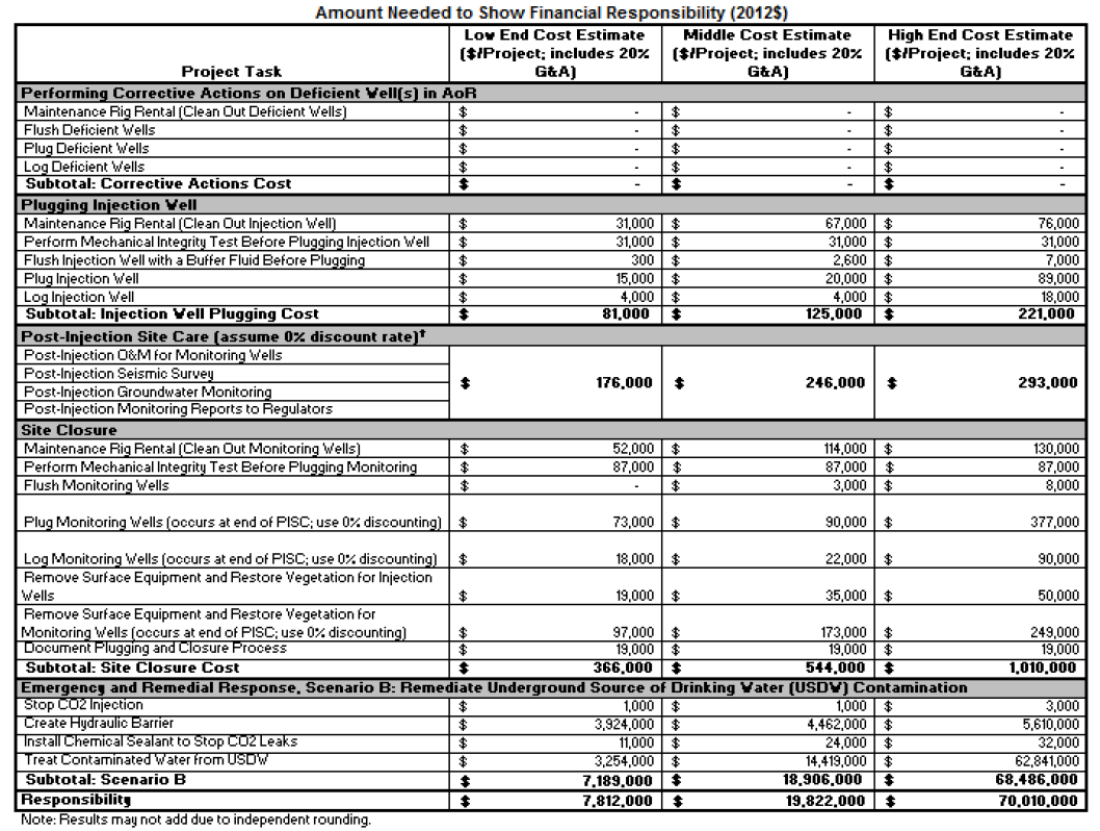
For each of these activities, the applicant needs to prepare a cost estimate, which should be in close
agreement with the range of costs estimated by the EPA. Table H-2 lists the costs initially estimated by
the EPA for the Wellington project. The largest cost component (ranging between $3.2M and $62.8M) is
associated with treating a USDW that may be accidentally contaminated due to sequestration operations
at the site. Therefore, if the applicant can successfully demonstrate the absence of a USDW, it can
significantly reduce the financial burden. The second largest cost ($3.9M–$5.6M) is associated with
creating and maintaining a hydraulic barrier to prevent CO
2
from escaping the injection zone due to a
breach in the confining zone, reactivation of fault(s), or escape through leaky well(s).
42
Table H-2. Initial cost estimate by the EPA for Wellington activities requiring demonstration of
financial responsibility.

43
The applicant has the option of choosing one (or a combination) of the following instruments to
meet financial responsibility:
• Surety bond
• Commercial insurance
• Trust fund
• Self-insurance
The cost of using a bond, insurance, or trust fund can be expensive and approach 3% of the face
value annually. For coverage of $70M, the cost can approach $2M annually. Because the
applicant has to demonstrate the ability to meet financial obligations from the injection phase to
site closure, which can span a period of 50 years (the default), the overall cost of coverage can be
quite high. The EPA, however, allows for self-insurance if the applicant can demonstrate that it
has the financial strength to meet all financial obligations. To qualify for self-insurance, several
financial thresholds specified in table H-3 must be met. Additionally, the applicant must be
capable of satisfying the financial ratio tests listed in table H-4.
Table H-3. EPA financial coverage criteria.
Financial Indicator
Description
Requirement at 40 CFR 146.85(a)(6)(v)
Net Working Capital
(NWC)
Short-term
financial
health
(Current assets minus
cur
rent liabilities)
NWC must be at least six times the
sum of the current cost estimates for
all required geosequestration (GS)
activities.
Total Assets
Combined value of
economic resources and all
items
of
monetary value
owned by a firm
Assets in the United States must
either
a)
amount to at least 90 percent
of
total
assets or b) amount to at least
six times the sum of the current cost
estimates
for
all required GS
activities.
Tangible Net
W
orth
(TNW)
Measures the value of a
company
that is
liquefiable,
i.e., total
assets
(not
includ
ing
intangible assets) minus
liabilities.
Although the rule does not specify a
minimum TNW
amount
,
based on a
review of recent EPA documents a
TNW of at least six times the sum of
the current cost estimates for all
required sequestration activities.

44
Table H-4. Financial ratios criteria and thresholds for self-insurance.
Type of
ratio
Financial Ratio
Threshold
Debt -
Equity
Total Liabilities/Net Worth
< 2.0
Assets -
Liabilities
Current Assets/Current Liabilities
>1.5
Cash
Return on
Liabilities
(Net Income + Depreciation + Depletion +
Amortization)/Total Liabilities
>0.10
Liquidity
(Current assets – Current Liability)/(Total Assets)
>-0.10
Net profit
Net profit
>0
45
Attachment I – Stimulation Plan
Relevant Class VI Articles: 40 CFR 146.82(9), 156.88(a)
There are no particular Class VI requirements for well stimulation as injectivity enhancement
can be accomplished using conventional means and fluids.

46
References
Archie, G. E., 1942, The electrical resistivity log as an aid in determining some reservoir
characteristics: Petro-leum Technology, v. 146, no. 1, p. 54–62.
Busenberg E., and Plummer, L.N., 2000, Dating young ground water with sulfur hexafluoride:
Natural and anthropogenic sources of sulfur hexafluoride. Water Resources Research, v. 36(10),
3011-3030.
Eaton, B. A., 1969, Fracture gradient prediction and its application in oilfield operations: Journal
of Petroleum Technology, v. 21, p. 1,353–1,360.
Fazelalavi et al., 2013. IPTC-17429-MS, Determination of Reservoir Permeability Based on
Irreducible Water Saturation and Porosity from Log Data and Flow Zone Indicator (FZI) from
Core Data P. 16-32.
Guidance, U.S. EPA (https://www.epa.gov/sites/production/files/2015-
07/documents/epa816r11020.pdf).
Freifeld, B.M., Trautz, R.C., Kharaka, Y.K., Phelps, T.J., Myer, L.R., Hovorka, S.D., and
Collins, D.J., The U-tube: a novel system for acquiring borehole fluid samples from a deep
geologic CO
2
sequestration experiment. Journal of Geophysical Research: Solid Earth, v. 110
(B10).
Maute, R. E., Lyle, W. D., and Sprunt, E. S., 1992, Improved data-analysis method Archie
parameters from core data: Supplement to SPE 19399, SPE paper 24223.
Ouyang, L., 2011, New Correlations for Predicting the Density and Viscosity of Supercritical
Carbon Dioxide Under Conditions Expected in Carbon Capture and Sequestration Operations,
The Open Petroleum Engineering Journal, vol 5.
Soreide, I., and Whitson, C. H., 1992, Peng-Robinson predictions for hydrocarbons, CO2, N2,
and H2S with pure water and NaCl brine: Fluid Phase Equilibria, Vol. 77, p. 217-240.
Tang, J.S. and Harker B., 1991. Intrawell tracer test to determine residual oil saturation in a
gassaturated reservoir. Part II: field applications. Reservoir Engineering, Volume 30, No. 4.

47
Appendix A
Cross-Reference Table Relating Class VI Rule Requirement with Attachments in Permit
Class VI Well Regulatory Requirements
Attachments
Where
Requirements
Are Addressed
Sec. 146.82 Required Class VI permit information.
(a) Prior to the issuance of a permit for the construction of a new Class VI well or the
conversion of an existing Class I, Class II, or Class V well to a Class VI well, the owner or
operator shall submit, pursuant to § 146.91(e), and the Director shall consider the
following:
(2) A map showing the injection well for which a permit is sought and the applicable area of
review consistent with § 146.84. Within the area of review, the map must show the number
or name, and location of all injection wells, producing wells, abandoned wells, plugged
wells or dry holes, deep stratigraphic boreholes, State- or EPA-approved subsurface
cleanup sites, surface bodies of water, springs, mines (surface and subsurface), quarries,
water wells, other pertinent surface features including structures intended for human
occupancy. The map should also show faults, if known or suspected. Only information of
public record is required to be included on this map;
B
(3) Information on the geologic structure and hydrogeologic properties of the proposed
storage site and overlying formations, including:
(i) Maps and cross sections of the area of review;
(ii) The location, orientation, and properties of known or suspected faults and fractures
that may transect the confining zone(s) in the area of review and a determination that
they would not interfere with containment;
(iii) Data on the depth, areal extent, thickness, mineralogy, porosity, permeability, and
capillary pressure of the injection and confining zone(s); including geology/facies
changes based on field data which may include geologic cores, outcrop data, seismic
surveys, well logs, and names and lithologic descriptions;
(iv) Geomechanical information on fractures, stress, ductility, rock strength, and in situ
fluid pressures within the confining zone(s);
(v) Information on the seismic history including the presence and depth of seismic
sources and a determination that the seismicity would not interfere with containment;
and
(vi) Geologic and topographic maps and cross sections illustrating regional geology,
hydrogeology, and the geologic structure of the local area.
B
(4) A tabulation of all wells within the area of review which penetrate the injection or
confining zone(s). Such data must include a description of each well’s type, construction,
B

48
date drilled, location, depth, record of plugging and/ or completion, and any additional
information the Director may require;
(5) Maps and stratigraphic cross sections indicating the general vertical and lateral limits of
all USDWs, water wells and springs within the area of review, their positions relative to the
injection zone(s), and the direction of water movement, where known;
B
(6) Baseline geochemical data on subsurface formations, including all USDWs in the area
of review;
C
(7) Proposed operating data for the proposed geologic sequestration site:
(i) Average and maximum daily rate and volume and/or mass and total anticipated
volume and/or mass of the carbon dioxide stream;
(ii) Average and maximum injection pressure;
(iii) The source(s) of the carbon dioxide stream; and
(iv) An analysis of the chemical and physical characteristics of the carbon dioxide
stream.
A, C
(8) Proposed pre-operational formation testing program to obtain an analysis of the
chemical and physical characteristics of the injection zone(s) and confining zone(s) and
that meets the requirements at § 146.87;
C
(9) Proposed stimulation program, a description of stimulation fluids to be used and a
determination that stimulation will not interfere with containment;
I
(10) Proposed procedure to outline steps necessary to conduct injection operation;
A
(11) Schematics or other appropriate drawings of the surface and subsurface construction
details of the well;
G
(12) Injection well construction procedures that meet the requirements of § 146.86;
G
(13) Proposed area of review and corrective action plan that meets the requirements under
§ 146.84;
B
(14) A demonstration, satisfactory to the Director, that the applicant has met the financial
responsibility requirements under § 146.85;
H
(15) Proposed testing and monitoring plan required by § 146.90;
C
(16) Proposed injection well plugging plan required by § 146.92(b);
D
(17) Proposed post-injection site care and site closure plan required by § 146.93(a);
E
(18) At the Director’s discretion, a demonstration of an alternative post-injection site care
timeframe required by § 146.93(c);
E
(19) Proposed emergency and remedial response plan required by § 146.94(a);
H
(20) A list of contacts, submitted to the Director, for those States, Tribes, and Territories
identified to be within the area of review of the Class VI project based on information
provided in paragraph (a)(2) of this section; and
F

49
§ 146.83 Minimum criteria for siting.
(a) Owners or operators of Class VI wells must demonstrate to the satisfaction of the
Director that the wells will be sited in areas with a suitable geologic system. The owners or
operators must demonstrate that the geologic system comprises:
(1) An injection zone(s) of sufficient areal extent, thickness, porosity, and permeability to
receive the total anticipated volume of the carbon dioxide stream;
(2) Confining zone(s) free of transmissive faults or fractures and of sufficient areal extent
and integrity to contain the injected carbon dioxide stream and displaced formation fluids
and allow injection at proposed maximum pressures and volumes without initiating or
propagating fractures in the confining zone(s).
B
(b) The Director may require owners or operators of Class VI wells to identify and
characterize additional zones that will impede vertical fluid movement, are free of faults
and fractures that may interfere with containment, allow for pressure dissipation, and
provide additional opportunities for monitoring, mitigation, and remediation.
B
§ 146.84 Area of review and corrective action.
(a) The area of review is the region surrounding the geologic sequestration project where
USDWs may be endangered by the injection activity. The area of review is delineated
using computational modeling that accounts for the physical and chemical properties of all
phases of the injected carbon dioxide stream and is based on available site
characterization, monitoring, and operational data.
B
(b) The owner or operator of a Class VI well must prepare, maintain, and comply with a
plan to delineate the area of review for a proposed geologic sequestration project,
periodically reevaluate the delineation, and perform corrective action that meets the
requirements of this section and is acceptable to the Director. As a part of the permit
application for approval by the Director, the owner or operator must submit an area of
review and corrective action plan that includes the following information:
B
(1) The method for delineating the area of review that meets the requirements of paragraph
(c) of this section, including the model to be used, assumptions that will be made, and the
site characterization data on which the model will be based;
B
(2) A description of:
(i) The minimum fixed frequency, not to exceed five years, at which the owner or operator
proposes to reevaluate the area of review;
(ii) The monitoring and operational conditions that would warrant a reevaluation of the
area of review prior to the next scheduled reevaluation as determined by the minimum
fixed frequency established in paragraph (b)(2)(i) of this section.
(iii) How monitoring and operational data (e.g., injection rate and pressure) will be used to
inform an area of review reevaluation; and
B, C, E, F

50
(iv) How corrective action will be conducted to meet the requirements of paragraph (d) of
this section, including what corrective action will be performed prior to injection and
what, if any, portions of the area of review will have corrective action addressed on a
phased basis and how the phasing will be determined; how corrective action will be
adjusted if there are changes in the area of review; and how site access will be
guaranteed for future corrective action.
(c) Owners or operators of Class VI wells must perform the following actions to delineate
the area of review and identify all wells that require corrective action:
(1) Predict, using existing site characterization, monitoring and operational data, and
computational modeling, the projected lateral and vertical migration of the carbon dioxide
plume and formation fluids in the subsurface from the commencement of injection activities
until the plume movement ceases, until pressure differentials sufficient to cause the
movement of injected fluids or formation fluids into a USDW are no longer present, or until
the end of a fixed time period as determined by the Director. The model must:
(i) Be based on detailed geologic data collected to characterize the injection zone(s),
confining zone(s) and any additional zones; and anticipated operating data, including
injection pressures, rates, and total volumes over the proposed life of the geologic
sequestration project;
(ii) Take into account any geologic heterogeneities, other discontinuities, data quality, and
their possible impact on model predictions; and
(iii) Consider potential migration through faults, fractures, and artificial penetrations.
B
(2) Using methods approved by the Director, identify all penetrations, including active and
abandoned wells and underground mines, in the area of review that may penetrate the
confining zone(s), and
B
(3) Determine which abandoned wells in the area of review have been plugged in a
manner that prevents the movement of carbon dioxide or other fluids that may endanger
USDWs, including use of materials compatible with the carbon dioxide stream.
B
(d) Owners or operators of Class VI wells must perform corrective action on all wells in the
area of review that are determined to need corrective action, using methods designed to
prevent the movement of fluid into or between USDWs, including use of materials
compatible with the carbon dioxide stream, where appropriate.
B
(e) At the minimum fixed frequency, not to exceed five years, as specified in the area of
review and corrective action plan, or when monitoring and operational conditions warrant,
owners or operators must:
(1) Reevaluate the area of review in the same manner specified in paragraph (c)(1) of this
section;
(2) Identify all wells in the reevaluated area of review that require corrective action in the
same manner specified in paragraph (c) of this section;
(3) Perform corrective action on wells requiring corrective action in the reevaluated area of
review in the same manner specified in paragraph (d) of this section; and
B

51
(4) Submit an amended area of review and corrective action plan or demonstrate to the
Director through monitoring data and modeling results that no amendment to the area of
review and corrective action plan is needed. Any amendments to the area of review and
corrective action plan must be approved by the Director, must be incorporated into the
permit, and are subject to the permit modification requirements at §§ 144.39 or 144.41 of
this chapter, as appropriate.
(f) The emergency and remedial response plan (as required by § 146.94) and the
demonstration of financial responsibility (as described by § 146.85) must account for the
area of review delineated as specified in paragraph (c)(1) of this section or the most
recently evaluated area of review delineated under paragraph (e) of this section,
regardless of whether or not corrective action in the area of review is phased.
B, F
§ 146.85 Financial responsibility.
(a) The owner or operator must demonstrate and maintain financial responsibility as
determined by the Director that meets the following conditions: …
(b) The requirement to maintain adequate financial responsibility and resources is directly
enforceable regardless of whether the requirement is a condition of the permit.
(c) The owner or operator must have a detailed written estimate, in current dollars, of the
cost of performing corrective action on wells in the area of review, plugging the injection
well(s), post-injection site care and site closure, and emergency and remedial response.
(d) The owner or operator must notify the Director by certified mail of adverse financial
conditions such as bankruptcy that may affect the ability to carry out injection well plugging
and post-injection site care and site closure.
(e) The owner or operator must provide an adjustment of the cost estimate to the Director
within 60 days of notification by the Director, as required by § 146.84, if the Director
determines during the annual evaluation of the qualifying financial instrument(s) that the
most recent demonstration is no longer adequate to cover the cost of corrective action (as
required by § 146.84), injection well plugging (as required by § 146.92), post-injection site
care and site closure (as required by § 146.93), and emergency and remedial response (as
required by § 146.94).
(f) The Director must approve the use and length of pay-in-periods for trust funds or escrow
accounts.
H
§ 146.86 Injection well construction requirements.
(a) General. The owner or operator must ensure that all Class VI wells are constructed and
completed to:
(1) Prevent the movement of fluids into or between USDWs or into any unauthorized
zones;
(2) Permit the use of appropriate testing devices and workover tools; and
G

52
(3) Permit continuous monitoring of the annulus space between the injection tubing and
long string casing.
(b) Casing and Cementing of Class VI Wells.
(1) Casing and cement or other materials used in the construction of each Class VI well
must have sufficient structural strength and be designed for the life of the geologic
sequestration project. The casing and cementing program must be designed to prevent the
movement of fluids into or between USDWs. In order to allow
the Director to determine and specify casing and cementing requirements, the owner or
operator must provide the following information:
(i) Depth to the injection zone(s);
(ii) Injection pressure, external pressure, internal pressure, and axial loading;
(iii) Hole size;
(iv) Size and grade of all casing strings (wall thickness, external diameter, nominal weight,
length, joint specification, and construction material);
(v) Corrosiveness of the carbon dioxide stream and formation fluids;
(vi) Down-hole temperatures;
(vii) Lithology of injection and confining zone(s);
(viii) Type or grade of cement and cement additives; and
(ix) Quantity, chemical composition, and temperature of the carbon dioxide stream.
G
(2) Surface casing must extend through the base of the lowermost USDW and be
cemented to the surface through the use of a single or multiple strings of casing and
cement.
G
(3) At least one long string casing, using a sufficient number of centralizers, must extend to
the injection zone and must be cemented by circulating cement to the surface in one or
more stages.
G
(4) Circulation of cement may be accomplished by staging. The Director may approve an
alternative method of cementing in cases where the cement cannot be recirculated to the
surface, provided the owner or operator can demonstrate by using logs that the cement
does not allow fluid movement behind wellbore.
G
(5) Cement and cement additives must be compatible with the carbon dioxide stream and
formation fluids and of sufficient quality and quantity to maintain integrity over the design
life of the geologic sequestration project. The integrity and location of the cement shall be
verified using technology capable of evaluating cement quality radially and identifying the
location of channels to ensure that USDWs are not endangered.
C, G
(c) Tubing and packer.
(1) Tubing and packer materials used in the construction of each Class VI well must be
compatible with fluids with which the materials may be expected to come into contact.
G

53
(2) All owners or operators of Class VI wells must inject fluids through tubing with a packer
set at a depth opposite a cemented interval at the location approved by the Director.
G
(3) In order for the Director to determine and specify requirements for tubing and packer,
the owner or operator must submit the following information:
(i) Depth of setting;
(ii) Characteristics of the carbon dioxide stream (chemical content, corrosiveness,
temperature, and density) and formation fluids;
(iii) Maximum proposed injection pressure;
(iv) Maximum proposed annular pressure;
(v) Proposed injection rate (intermittent or continuous) and volume and/or mass of the
carbon dioxide stream;
(vi) Size of tubing and casing; and
(vii) Tubing tensile, burst, and collapse strengths.
G
§ 146.87 Logging, sampling, and testing prior to injection well operation.
(a) During the drilling and construction of a Class VI injection well, the owner or operator
must run appropriate logs, surveys and tests to determine or verify the depth, thickness,
porosity, permeability, and lithology of, and the salinity of any formation fluids in all relevant
geologic formations to ensure conformance with the injection well construction
requirements under § 146.86 and to establish accurate baseline data against which future
measurements may be compared. The owner or operator must submit to the Director a
descriptive report prepared by a knowledgeable log analyst that includes an interpretation
of the results of such logs and tests. At a minimum, such logs and tests must include:
(1) Deviation checks during drilling on all holes constructed by drilling a pilot hole which is
enlarged by reaming or another method. Such checks must be at sufficiently frequent
intervals to determine the location of the borehole and to ensure that vertical avenues for
fluid movement in the form of diverging holes are not created during drilling; and
(2) Before and upon installation of the surface casing:
(i) Resistivity, spontaneous potential, and caliper logs before the casing is installed;
and
(ii) A cement bond and variable density log to evaluate cement quality radially, and a
temperature log after the casing is set and cemented.
(3) Before and upon installation of the long string casing:
(i) Resistivity, spontaneous potential, porosity, caliper, gamma ray, fracture finder logs,
and any other logs the Director requires for the given geology before the casing is
installed; and
(ii) A cement bond and variable density log, and a temperature log after the casing is
set and cemented.
G

54
(4) A series of tests designed to demonstrate the internal and external mechanical integrity
of injection wells, which may include:
(i) A pressure test with liquid or gas;
(ii) A tracer survey such as oxygen-activation logging;
(iii) A temperature or noise log;
(iv) A casing inspection log; and
(5) Any alternative methods that provide equivalent or better information and that are
required by and/or approved of by the Director.
(b) The owner or operator must take whole cores or sidewall cores of the injection zone
and confining system and formation fluid samples from the injection zone(s), and must
submit to the Director a detailed report prepared by a log analyst that includes: Well log
analyses (including well logs), core analyses, and formation fluid sample information. The
Director may accept information on cores from nearby wells if the owner or operator can
demonstrate that core retrieval is not possible and that such cores are representative of
conditions at the well. The Director may require the owner or operator to core other
formations in the borehole.
G
(c) The owner or operator must record the fluid temperature, pH, conductivity, reservoir
pressure, and static fluid level of the injection zone(s).
G
(d) At a minimum, the owner or operator must determine or calculate the following
information concerning the injection and confining zone(s):
(1) Fracture pressure;
(2) Other physical and chemical characteristics of the injection and confining zone(s); and
(3) Physical and chemical characteristics of the formation fluids in the injection zone(s).
G
(e) Upon completion, but prior to operation, the owner or operator must conduct the
following tests to verify hydrogeologic characteristics of the injection zone(s):
(1) A pressure fall-off test; and,
(2) A pump test; or
(3) Injectivity tests.
G
§ 146.88 Injection well operating requirements.
(a) Except during stimulation, the owner or operator must ensure that injection pressure
does not exceed 90 percent of the fracture pressure of the injection zone(s) so as to
ensure that the injection does not initiate new fractures or propagate existing fractures in
the injection zone(s). In no case may injection pressure initiate fractures in the confining
zone(s) or cause the movement of injection or formation fluids that endangers a USDW.
G
(b) Injection between the outermost casing protecting USDWs and the well bore is
prohibited.
G

55
(c) The owner or operator must fill the annulus between the tubing and the long string
casing with a non-corrosive fluid approved by the Director. The owner or operator must
maintain on the annulus a pressure that exceeds the operating injection pressure, unless
the Director determines that such requirement might harm the integrity of the well or
endanger USDWs.
G
(d) Other than during periods of well workover (maintenance) approved by the Director in
which the sealed tubing-casing annulus is disassembled for maintenance or corrective
procedures, the owner or operator must maintain mechanical integrity of the injection well
at all times.
C
(e) The owner or operator must install and use:
(1) Continuous recording devices to monitor: The injection pressure; the rate, volume
and/or mass, and temperature of the carbon dioxide stream; and the pressure on the
annulus between the tubing and the long string casing and annulus fluid volume; and
(2) Alarms and automatic surface shut-off systems or, at the discretion of the Director,
down-hole shutoff systems (e.g., automatic shut-off, check valves) for onshore wells or,
other mechanical devices that provide equivalent protection; and
(3) Alarms and automatic down-hole shut-off systems for wells located offshore but within
State territorial waters, designed to alert the operator and shut-in the well when operating
parameters such as annulus pressure, injection rate, or other parameters diverge beyond
permitted ranges and/or gradients specified in the permit.
A, C, G, F
(f) If a shutdown (i.e., down-hole or at the surface) is triggered or a loss of mechanical
integrity is discovered, the owner or operator must immediately investigate and identify as
expeditiously as possible the cause of the shutoff. If, upon such investigation, the well
appears to be lacking mechanical integrity, or if monitoring required under paragraph (e) of
this section otherwise indicates that the well may be lacking mechanical integrity, the
owner or operator must:
(1) Immediately cease injection;
(2) Take all steps reasonably necessary to determine whether there may have been a
release of the injected carbon dioxide stream or formation fluids into any unauthorized
zone;
(3) Notify the Director within 24 hours;
(4) Restore and demonstrate mechanical integrity to the satisfaction of the Director prior to
resuming injection; and
(5) Notify the Director when injection can be expected to resume.
F
§ 146.89 Mechanical Integrity.
(a) A Class VI well has mechanical integrity if:
(1) There is no significant leak in the casing, tubing, or packer; and

56
(2) There is no significant fluid movement into a USDW through channels adjacent to the
injection well bore.
(b) To evaluate the absence of significant leaks under paragraph (a)(1) of this section,
owners or operators must, following an initial annulus pressure test, continuously monitor
injection pressure, rate, injected volumes; pressure on the annulus between tubing and
long-string casing; and annulus fluid volume as specified in § 146.88 (e);
C
(c) At least once per year, the owner or operator must use one of the following methods to
determine the absence of significant fluid movement under paragraph (a)(2) of this section:
(1) An approved tracer survey such as an oxygen-activation log; or
(2) A temperature or noise log.
C
(d) If required by the Director, at a frequency specified in the testing and monitoring plan
required at § 146.90, the owner or operator must run a casing inspection log to determine
the presence or absence of corrosion in the long-string casing.
C
(e) The Director may require any other test to evaluate mechanical integrity under
paragraphs (a)(1) or (a)(2) of this section. Also, the Director may allow the use of a test to
demonstrate mechanical integrity other than those listed above with the written approval of
the Administrator. To obtain approval for a new mechanical integrity test, the Director must
submit a written request to the Administrator setting forth the proposed test and all
technical data supporting its use. The Administrator may approve the request if he or she
determines that it will reliably demonstrate the mechanical integrity of wells for which its
use is proposed. Any alternate method approved by the Administrator will be published in
the Federal Register and may be used in all States in accordance with applicable State law
unless its use is restricted at the time of approval by the Administrator.
C
(f) In conducting and evaluating the tests enumerated in this section or others to be
allowed by the Director, the owner or operator and the Director must apply methods and
standards generally accepted in the industry. When the owner or operator reports the
results of mechanical integrity tests to the Director, he/she shall include a description of the
test(s) and the method(s) used. In making his/her evaluation, the Director must review
monitoring and other test data submitted since the previous evaluation.
C
(g) The Director may require additional or alternative tests if the results presented by the
owner or operator under paragraphs (a) through (d) of this section are not satisfactory to
the Director to demonstrate that there is no significant leak in the casing, tubing, or packer,
or to demonstrate that there is no significant movement of fluid into a USDW resulting from
the injection activity as stated in paragraphs (a)(1) and (2) of this section.
C
§ 146.90 Testing and monitoring requirements.
The owner or operator of a Class VI well must prepare, maintain, and comply with a testing
and monitoring plan to verify that the geologic sequestration project is operating as
permitted and is not endangering USDWs. The requirement to maintain and implement an
approved plan is directly enforceable regardless of whether the requirement is a condition
of the permit. The testing and monitoring plan must be submitted with the permit
application, for Director approval, and must include a description of how the owner or
C

57
operator will meet the requirements of this section, including accessing sites for all
necessary monitoring and testing during the life of the project. Testing and monitoring
associated with geologic sequestration projects must, at a minimum, include:
(a) Analysis of the carbon dioxide stream with sufficient frequency to yield data
representative of its chemical and physical characteristics;
C
(b) Installation and use, except during well workovers as defined in § 146.88(d), of
continuous recording devices to monitor injection pressure, rate, and volume; the pressure
on the annulus between the tubing and the long string casing; and the annulus fluid volume
added;
C
(c) Corrosion monitoring of the well materials for loss of mass, thickness, cracking, pitting,
and other signs of corrosion, which must be performed on a quarterly basis to ensure that
the well components meet the minimum standards for material strength and performance
set forth in § 146.86(b), by:
(1) Analyzing coupons of the well construction materials placed in contact with the carbon
dioxide stream; or
(2) Routing the carbon dioxide stream through a loop constructed with the material used in
the well and inspecting the materials in the loop; or
(3) Using an alternative method approved by the Director;
C
(d) Periodic monitoring of the ground water quality and geochemical changes above the
confining zone(s) that may be a result of carbon dioxide movement through the confining
zone(s) or additional identified zones including:
(1) The location and number of monitoring wells based on specific information about the
geologic sequestration project, including injection rate and volume, geology, the presence
of artificial penetrations, and other factors; and
(2) The monitoring frequency and spatial distribution of monitoring wells based on baseline
geochemical data that has been collected under § 146.82(a)(6) and on any modeling
results in the area of review evaluation required by § 146.84(c).
C
(e) A demonstration of external mechanical integrity pursuant to § 146.89(c) at least once
per year until the injection well is plugged; and, if required by the Director, a casing
inspection log pursuant to requirements at § 146.89(d) at a frequency established in the
testing and monitoring plan;
C
(f) A pressure fall-off test at least once every five years unless more frequent testing is
required by the Director based on site-specific information;
C
(g) Testing and monitoring to track the extent of the carbon dioxide plume and the
presence or absence of elevated pressure (e.g., the pressure front) by using:
(1) Direct methods in the injection zone(s); and,
(2) Indirect methods (e.g., seismic, electrical, gravity, or electromagnetic surveys and/or
down-hole carbon dioxide detection tools), unless the Director determines, based on site-
specific geology, that such methods are not appropriate;
C

58
(h) The Director may require surface air monitoring and/or soil gas monitoring to detect
movement of carbon dioxide that could endanger a USDW.
(1) Design of Class VI surface air and/ or soil gas monitoring must be based on potential
risks to USDWs within the area of review;
(2) The monitoring frequency and spatial distribution of surface air monitoring and/or soil
gas monitoring must be decided using baseline data, and the monitoring plan must
describe how the proposed monitoring will yield useful information on the area of review
delineation and/or compliance with standards under § 144.12 of this chapter;
(3) If an owner or operator demonstrates that monitoring employed under §§ 98.440 to
98.449 of this chapter (Clean Air Act, 42 U.S.C. 7401 et seq.) accomplishes the goals of
paragraphs (h)(1) and (2) of this section, and meets the requirements pursuant to §
146.91(c)(5), a Director that requires surface air/soil gas monitoring must approve the use
of monitoring employed under §§ 98.440 to 98.449 of this chapter. Compliance with §§
98.440 to 98.449 of this chapter pursuant to this provision is considered a condition of the
Class VI permit;
C
(i) Any additional monitoring, as required by the Director, necessary to support, upgrade,
and improve computational modeling of the area of review evaluation required under §
146.84(c) and to determine compliance with standards under § 144.12 of this chapter;
B, C
(j) The owner or operator shall periodically review the testing and monitoring plan to
incorporate monitoring data collected under this subpart, operational data collected under §
146.88, and the most recent area of review reevaluation performed under § 146.84(e). In
no case shall the owner or operator review the testing and monitoring plan less often than
once every five years. Based on this review, the owner or operator shall submit an
amended testing and monitoring plan or demonstrate to the Director that no amendment to
the testing and monitoring plan is needed. Any amendments to the testing and monitoring
plan must be approved by the Director, must be incorporated into the permit, and are
subject to the permit modification requirements at §§ 144.39 or 144.41 of this chapter, as
appropriate. Amended plans or demonstrations shall be submitted to the Director as
follows:
(1) Within one year of an area of review reevaluation;
(2) Following any significant changes to the facility, such as addition of monitoring wells or
newly permitted injection wells within the area of review, on a schedule determined by the
Director; or
(3) When required by the Director.
C
(k) A quality assurance and surveillance plan for all testing and monitoring requirements.
C
§ 146.91 Reporting requirements.
The owner or operator must, at a minimum, provide, as specified in paragraph (e) of this
section, the following reports to the Director, for each permitted Class VI well:
C

59
(a) Semi-annual reports containing:
(1) Any changes to the physical, chemical, and other relevant characteristics of the carbon
dioxide stream from the proposed operating data;
(2) Monthly average, maximum, and minimum values for injection pressure, flow rate and
volume, and annular pressure;
(3) A description of any event that exceeds operating parameters for annulus pressure or
injection pressure specified in the permit;
(4) A description of any event which triggers a shut-off device required pursuant to §
146.88(e) and the response taken;
(5) The monthly volume and/or mass of the carbon dioxide stream injected over the
reporting period and the volume injected cumulatively over the life of the project;
(6) Monthly annulus fluid volume added; and
(7) The results of monitoring prescribed under § 146.90.
(b) Report, within 30 days, the results of:
(1) Periodic tests of mechanical integrity;
(2) Any well workover; and,
(3) Any other test of the injection well conducted by the permittee if required by the
Director.
C
(c) Report, within 24 hours:
(1) Any evidence that the injected carbon dioxide stream or associated pressure front may
cause an endangerment to a USDW;
(2) Any noncompliance with a permit condition, or malfunction of the injection system,
which may cause fluid migration into or between USDWs;
(3) Any triggering of a shut-off system (i.e., down-hole or at the surface);
(4) Any failure to maintain mechanical integrity; or.
(5) Pursuant to compliance with the requirement at § 146.90(h) for surface air/soil gas
monitoring or other monitoring technologies, if required by the Director, any release of
carbon dioxide to the atmosphere or biosphere.
C
(d) Owners or operators must notify the Director in writing 30 days in advance of:
(1) Any planned well workover;
(2) Any planned stimulation activities, other than stimulation for formation testing
conducted under § 146.82; and
(3) Any other planned test of the injection well conducted by the permittee.
C

60
(e) Regardless of whether a State has primary enforcement responsibility, owners or
operators must submit all required reports, submittals, and notifications under subpart H of
this part to EPA in an electronic format approved by EPA.
C
(f) Records shall be retained by the owner or operator as follows:
(1) All data collected under § 146.82 for Class VI permit applications shall be retained
throughout the life of the geologic sequestration project and for 10 years following site
closure.
(2) Data on the nature and composition of all injected fluids collected pursuant to §
146.90(a) shall be retained until 10 years after site closure. The Director may require the
owner or operator to deliver the records to the Director at the conclusion of the retention
period.
(3) Monitoring data collected pursuant to § 146.90(b) through (i) shall be retained for 10
years after it is collected.
(4) Well plugging reports, post-injection site care data, including, if appropriate, data and
information used to develop the demonstration of the alternative post-injection site care
timeframe, and the site closure report collected pursuant to requirements at §§ 146.93(f)
and (h) shall be retained for 10 years following site closure.
(5) The Director has authority to require the owner or operator to retain any records
required in this subpart for longer than 10 years after site closure.
C
§ 146.92 Injection well plugging.
(a) Prior to the well plugging, the owner or operator must flush each Class VI injection well
with a buffer fluid, determine bottomhole reservoir pressure, and perform a final external
mechanical integrity test.
D
(b) Well plugging plan. The owner or operator of a Class VI well must prepare, maintain,
and comply with a plan includes the following information:
(1) Appropriate tests or measures for determining bottomhole reservoir pressure;
(2) Appropriate testing methods to ensure external mechanical integrity as specified in §
146.89;
(3) The type and number of plugs to be used;
(4) The placement of each plug, including the elevation of the top and bottom of each plug;
(5) The type, grade, and quantity of material to be used in plugging. The material must be
compatible with the carbon dioxide stream; and
(6) The method of placement of the plugs.
D
(c) Notice of intent to plug. The owner or operator must notify the Director in writing
pursuant to § 146.91(e), at least 60 days before plugging of a well. Any amendments to the
injection well plugging plan must be approved by the Director, must be incorporated into
D

61
the permit, and are subject to the permit modification requirements at §§ 144.39 or 144.41
of this chapter, as appropriate.
(d) Plugging report. Within 60 days after plugging, the owner or operator must submit,
pursuant to § 146.91(e), a plugging report to the Director. The owner or operator shall
retain the well plugging report for 10 years following site closure.
D
§ 146.93 Post-injection site care and site closure.
(a) The owner or operator of a Class VI well must prepare, maintain, and comply with a
plan for postinjection site care and site closure that meets the requirements of paragraph
(a)(2) of this section and is acceptable to the Director.
(1) The owner or operator must submit the post-injection site care and site closure plan as
a part of the permit application to be approved by the Director.
E
(2) The post-injection site care and site closure plan must include the following information:
(i) The pressure differential between pre-injection and predicted post-injection pressures in
the injection zone(s);
(ii) The predicted position of the carbon dioxide plume and associated pressure front at site
closure as demonstrated in the area of review evaluation required under § 146.84(c)(1);
(iii) A description of post-injection monitoring location, methods, and proposed frequency;
(iv) A proposed schedule for submitting post-injection site care monitoring results to the
Director pursuant to § 146.91(e); and,
(v) The duration of the post-injection site care timeframe and, if approved by the Director,
the demonstration of the alternative post-injection site care timeframe that ensures
nonendangerment of USDWs.
E
(3) Upon cessation of injection, owners or operators of Class VI wells must either submit
an amended post-injection site care and site closure plan or demonstrate to the Director
through monitoring data and modeling results that no amendment to the plan is needed.
Any amendments to the post-injection site care and site closure plan must be approved by
the Director, be incorporated into the permit, and are subject to the permit modification
requirements at §§ 144.39 or 144.41 of this chapter, as appropriate.
E
(4) At any time during the life of the geologic sequestration project, the owner or operator
may modify and resubmit the post-injection site care and site closure plan for the Director’s
approval within 30 days of such change.
E
(b) The owner or operator shall monitor the site following the cessation of injection to show
the position of the carbon dioxide plume and pressure front and demonstrate that USDWs
are not being endangered.
(1) Following the cessation of injection, the owner or operator shall continue to conduct
monitoring as specified in the Director-approved post-injection site care and site closure
plan for at least 50 years or for the duration of the alternative timeframe approved by the
Director pursuant to requirements In paragraph (c) of this section, unless he/she makes a
E

62
demonstration under (b)(2) of this section. The monitoring must continue until the geologic
sequestration project no longer poses an endangerment to USDWs and the demonstration
under (b)(2) of this section is submitted and approved by the Director.
(2) If the owner or operator can demonstrate to the satisfaction of the Director before 50
years or prior to the end of the approved alternative timeframe based on monitoring and
other site-specific data, that the geologic sequestration project no longer poses an
endangerment to USDWs, the Director may approve an amendment to the post-injection
site care and site closure plan to reduce the frequency of monitoring or may authorize site
closure before the end of the 50-year period or prior to the end of the approved alternative
timeframe, where he or she has substantial evidence that the geologic sequestration
project no longer poses a risk of endangerment to USDWs.
(3) Prior to authorization for site closure, the owner or operator must submit to the Director
for review and approval a demonstration, based on monitoring and other site-specific data,
that no additional monitoring is needed to ensure that the geologic sequestration project
does not pose an endangerment to USDWs.
(4) If the demonstration in paragraph (b)(3) of this section cannot be made (i.e., additional
monitoring is needed to ensure that the geologic sequestration project does not pose an
endangerment to USDWs) at the end of the 50-year period or at the end of the approved
alternative timeframe, or if the Director does not approve the demonstration, the owner or
operator must submit to the Director a plan to continue post-injection site care until a
demonstration can be made and approved by the Director.
(c) Demonstration of alternative post-injection site care timeframe. At the Director’s
discretion, the Director may approve, in consultation with EPA, an alternative post-injection
site care timeframe other than the 50 year default, if an owner or operator can demonstrate
during the permitting process that an
alternative post-injection site care timeframe is appropriate and ensures non-
endangerment of USDWs The demonstration must be based on significant, site-specific
data and information including all data and information collected pursuant to §§ 146.82 and
146.83, and must contain substantial evidence that the geologic sequestration project will
no longer pose a risk of endangerment to USDWs at the end of the alternative post-
injection site care timeframe.
(1) A demonstration of an alternative post-injection site care timeframe must include
consideration and documentation of:
(i) The results of computational modeling performed pursuant to delineation of the area
of review under § 146.84;
(ii) The predicted timeframe for pressure decline within the injection zone, and any
other zones, such that formation fluids may not be forced into any USDWs; and/or
the timeframe for pressure decline to pre-injection pressures. The predicted rate of
carbon dioxide plume migration within the injection zone, and the predicted
timeframe for the cessation of migration;
B, C, E

63
(iii) A description of the site-specific processes that will result in carbon dioxide
trapping including immobilization by capillary trapping, dissolution, and
mineralization at the site;
(iv) The predicted rate of carbon dioxide trapping in the immobile capillary phase,
dissolved phase, and/or mineral phase;
(v) The results of laboratory analyses, research studies, and/or field or site-specific
studies to verify the information required in paragraphs (iii) and (iv) of this section;
(vi) A characterization of the confining zone(s) including a demonstration that it is free
of transmissive faults, fractures, and micro-fractures and of appropriate thickness,
permeability, and integrity to impede fluid (e.g., carbon dioxide, formation fluids)
movement;
(vii) The presence of potential conduits for fluid movement including planned injection
wells and project monitoring wells associated with the proposed geologic
sequestration project or any other projects in proximity to the predicted/modeled,
final extent of the carbon dioxide plume and area of elevated pressure;
(viii)A description of the well construction and an assessment of the quality of plugs of
all abandoned wells within the area of review;
(ix) The distance between the injection zone and the nearest USDWs above and/ or
below the injection zone; and
(x) Any additional site-specific factors required by the Director.
(2) Information submitted to support the demonstration in paragraph (c)(1) of this section
must meet the following criteria:
(i) All analyses and tests performed to support the demonstration must be accurate,
reproducible, and performed in accordance with the established quality assurance
standards;
(ii) Estimation techniques must be appropriate and EPA-certified test protocols must
be used where available;
(iii) Predictive models must be appropriate and tailored to the site conditions,
composition of the carbon dioxide stream and injection and site conditions over the
life of the geologic sequestration project;
(iv) Predictive models must be calibrated using existing information (e.g., at Class I,
Class II, or Class V experimental technology well sites) where sufficient data are
available;
(v) Reasonably conservative values and modeling assumptions must be used and
disclosed to the Director whenever values are estimated on the basis of known,
historical information instead of site-specific measurements;
(vi) An analysis must be performed to identify and assess aspects of the alternative
post-injection site care timeframe demonstration that contribute significantly to
uncertainty. The owner or operator must conduct sensitivity analyses to determine
the effect that significant uncertainty may contribute to the modeling demonstration.

64
(vii) An approved quality assurance and quality control plan must address all aspects
of the demonstration; and,
(vii) Any additional criteria required by the Director
(d) Notice of intent for site closure. The owner or operator must notify the Director in
writing at least 120 days before site closure. At this time, if any changes have been made
to the original post-injection site care and site closure plan, the owner or operator must
also provide the revised plan. The Director may allow for a shorter notice period.
E
(e) After the Director has authorized site closure, the owner or operator must plug all
monitoring wells in a manner which will not allow movement of injection or formation fluids
that endangers a USDW.
E
(f) The owner or operator must submit a site closure report to the Director within 90 days of
site closure, which must thereafter be retained at a location designated by the Director for
10 years. The report must include:
(1) Documentation of appropriate injection and monitoring well plugging as specified in §
146.92 and paragraph (e) of this section. The owner or operator must provide a copy of a
survey plat which has been submitted to the local zoning authority designated by the
Director. The plat must indicate the location of the injection well relative to permanently
surveyed benchmarks. The owner or operator must also submit a copy of the plat to the
Regional Administrator of the appropriate EPA Regional Office;
(2) Documentation of appropriate notification and information to such State, local and
Tribal
authorities that have authority over drilling activities to enable such State, local, and Tribal
authorities to impose appropriate conditions on subsequent drilling activities that may
penetrate the injection and confining zone(s); and
(3) Records reflecting the nature, composition, and volume of the carbon dioxide stream.
E
(g) Each owner or operator of a Class VI injection well must record a notation on the deed
to the facility property or any other document that is normally examined during title search
that will in perpetuity provide any potential purchaser of the property the following
information:
(1) The fact that land has been used to sequester carbon dioxide;
(2) The name of the State agency, local authority, and/or Tribe with which the survey plat
was filed, as well as the address of the Environmental Protection Agency Regional Office
to which it was submitted; and
(3) The volume of fluid injected, the injection zone or zones into which it was injected, and
the period over which injection occurred.
E
(h) The owner or operator must retain for 10 years following site closure, records collected
during the post-injection site care period. The owner or operator must deliver the records to
the Director at the conclusion of the retention period, and the records must thereafter be
retained at a location designated by the Director for that purpose.
E

65
§ 146.94 Emergency and remedial response.
(a) As part of the permit application, the owner or operator must provide the Director with
an emergency and remedial response plan that describes actions the owner or operator
must take to address movement of the injection or formation fluids that may cause an
endangerment to a USDW during construction, operation, and post-injection site care
periods. The requirement to maintain and implement an approved plan is directly
enforceable regardless of whether the requirement is a condition of the permit.
F
(b) If the owner or operator obtains evidence that the injected carbon dioxide stream and
associated pressure front may cause an endangerment to a USDW, the owner or operator
must:
(1) Immediately cease injection;
(2) Take all steps reasonably necessary to identify and characterize any release;
(3) Notify the Director within 24 hours; and
(4) Implement the emergency and remedial response plan approved by the Director.
F
(d) The owner or operator shall periodically review the emergency and remedial response
plan developed under paragraph (a) of this section. In no case shall the owner or operator
review the emergency and remedial response plan less often than once every five years.
Based on this review, the owner or operator shall submit an amended emergency and
remedial response plan or demonstrate to the Director that no amendment to the
emergency and remedial response plan is needed. Any amendments to the emergency
and remedial response plan must be approved by the Director, must be incorporated into
the permit, and are subject to the permit modification requirements at §§ 144.39 or
144.41 of this chapter, as appropriate. Amended plans or demonstrations shall be
submitted to the Director as follows:
(1) Within one year of an area of review reevaluation;
(2) Following any significant changes to the facility, such as addition of injection or
monitoring wells, on a schedule determined by the Director; or
(3) When required by the Director.
F
