VMware Cloud Foundation on Dell EMC
VxRail Guide
VMware Cloud Foundation 4.3
You can find the most up-to-date technical documentation on the VMware website at:
https://docs.vmware.com/
VMware, Inc.
3401 Hillview Ave.
Palo Alto, CA 94304
www.vmware.com
Copyright
©
2019-2021 VMware, Inc. All rights reserved. Copyright and trademark information.
VMware Cloud Foundation on Dell EMC VxRail Guide
VMware, Inc. 2
Contents
1 About VMware Cloud Foundation on Dell EMC VxRail 9
2 VMware Cloud Foundation on Dell EMC VxRail 11
3
Prepare a VxRail Environment for Cloud Builder Appliance Deployment 12
Imaging the VxRail Management Nodes 12
VxRail First Run for the Management Cluster 12
4 Deploy VMware Cloud Builder Appliance 14
5 Deploy the Management Domain Using VMware Cloud Builder 17
Download and Complete the Deployment Parameter Workbook 17
About the Deployment Parameter Workbook 18
Credentials Worksheet 18
Hosts and Networks Worksheet 20
Deploy Parameters Worksheet: Existing Infrastructure Details 24
Deploy Parameters Worksheet: VxRail Manager Details 25
Deployment Parameters Worksheet: License Keys 25
Deploy Parameters Worksheet: vSphere Infrastructure 25
Deploy Parameters Worksheet: NSX-T Data Center 26
Deploy Parameters Worksheet: SDDC Manager 27
Upload the Deployment Parameter Workbook and Deploy the Management Domain 27
Upgrade VMware vCenter Server Appliance for VMware Cloud Foundation 4.3 29
6 Troubleshooting VMware Cloud Foundation Deployment 30
Using the SoS Utility on VMware Cloud Builder 30
VMware Cloud Builder Log Files 34
7
Getting Started with SDDC Manager 36
Log in to the SDDC Manager User Interface 36
Tour of the SDDC Manager User Interface 37
Log out of the SDDC Manager User Interface 39
8 Configuring Customer Experience Improvement Program 40
9 Certificate Management 42
View Certificate Information 43
Configure VMware Cloud Foundation to Use Microsoft CA-Signed Certificates 43
VMware, Inc.
3
Prepare Your Microsoft Certificate Authority to Enable SDDC Manger to Manage Certificates
44
Install Microsoft Certificate Authority Roles 44
Configure the Microsoft Certificate Authority for Basic Authentication 45
Create and Add a Microsoft Certificate Authority Template 45
Assign Certificate Management Privileges to the SDDC Manager Service Account 47
Configure a Microsoft Certificate Authority in SDDC Manager 48
Install Microsoft CA-Signed Certificates using SDDC Manager 49
Configure VMware Cloud Foundation to Use OpenSSL CA-Signed Certificates 51
Configure OpenSSL-signed Certificates in SDDC Manager 51
Install OpenSSL-signed Certificates using SDDC Manager 51
Install Third-Party CA-Signed Certificates 53
Remove Old or Unused Certificates from SDDC Manager 56
Configure Certificates for a Shared Single Sign-On Domain 56
10 License Management 59
Add a License Key 59
Edit License Description 60
Delete License Key 60
11 ESXi Lockdown Mode 61
12 Storage Management 62
vSAN Storage with VMware Cloud Foundation 63
Fibre Channel Storage with VMware Cloud Foundation 63
Sharing Remote Datastores with HCI Mesh for VI Workload Domains 64
13 Workload Domain Management 66
Adding Virtual Machines to the Management Domain 67
About VI Workload Domains 67
Prerequisites for a Workload Domain 68
Creating VxRail VI Workload Domains 69
Create a VxRail VI Workload Domain in the SDDC Manager UI 70
Adding the Primary VxRail Cluster to a VI Workload Domain 70
Deploying a VI Workload Domain with a Remote Cluster 75
Delete a VI Workload Domain 77
View Workload Domain Details 78
Expand a Workload Domain 79
Adding a VxRail Cluster to a Workload Domain 79
Add a VxRail Cluster to a Workload Domain Using the SDDC Manager UI 79
Add a VxRail Cluster to a Workload Domain Using the MultiDvsAutomator Script 81
Expand the VxRail Cluster 83
VMware Cloud Foundation on Dell EMC VxRail Guide
VMware, Inc. 4
Add the VxRail Hosts to the Cluster in VMware Cloud Foundation 84
Reduce a Workload Domain 85
Remove a Host from a Cluster in a Workload Domain 85
Delete a VxRail Cluster 85
Using the Workflow Optimization Script to Create a VxRail VI Workload Domain or Add a VxRail
Cluster 86
Create a VxRail VI Workload Domain Using the Workflow Optimization Script 86
Add a VxRail Cluster Using the Workflow Optimization Script 87
Change the VxRail Manager IP Address 88
Update the VxRail Manager Certificate 89
Rename a Workload Domain 89
vSphere Cluster Management 89
View vSphere Cluster Details 90
Rename a Cluster 90
NSX Edge Cluster Management 91
Prerequisites for an NSX Edge Cluster 92
Deploy an NSX Edge Cluster 92
Add Edge Nodes to an NSX Edge Cluster 97
Remove Edge Nodes from an NSX Edge Cluster 101
14 Workload Management 103
Sizing Compute and Storage Resources for Workload Management 103
Create a Subscribed Content Library 104
Enable Workload Management 105
View Workload Management Cluster Details 106
Update Workload Management License 107
15 Working with vRealize Suite Lifecycle Manager 108
vRealize Suite Lifecycle Manager Implementation 109
Deploy Application Virtual Networks for vRealize Suite Components 110
Deploy Overlay-Backed NSX Segments 111
Deploy VLAN-Backed NSX Segments 112
Deploy vRealize Suite Lifecycle Manager 113
Replace the Certificate of the vRealize Suite Lifecycle Manager Instance 115
Update vRealize Suite Lifecycle Manager to vSphere Integration 116
Create a vCenter Single Sign-On User 116
Configure Service Account Permissions in vSphere for Integration with vRealize Suite
Lifecycle Manager 116
Create New Password Alias in the vRealize Suite Lifecycle Manager Locker 117
Reconfigure Data Centers and vCenter Server in vRealize Suite Lifecycle Manager 118
Configure Data Center and vCenter Server in vRealize Suite Lifecycle Manager 118
Clustered Workspace ONE Access Implementation 119
VMware Cloud Foundation on Dell EMC VxRail Guide
VMware, Inc. 5
Import the Clustered Workspace ONE Access Certificate to vRealize Suite Lifecycle Manager
120
Add Clustered Workspace ONE Access Passwords to vRealize Suite Lifecycle Manager 121
Deploy Clustered Workspace ONE Access Instance Using vRealize Suite Lifecycle Manager
122
Configure an Anti-Affinity Rule and a Virtual Machine Group for the Clustered Workspace
ONE Access Instance 124
Configure NTP on the Clustered Workspace ONE Access Instance 125
Configure Identity Source for the Clustered Workspace ONE Access Instance 126
Add the Clustered Workspace ONE Access Cluster Nodes as Identity Provider Connectors
127
Assign Roles to Active Directory Groups for the Clustered Workspace ONE Access Instance
128
Assign Roles to Active Directory Groups for vRealize Suite Lifecycle Manager 129
16 Multi-Instance Management 130
About the Multi-Instance Management Dashboard 132
Create a Federation 135
Invite an SDDC Manager Instance to Join a Federation 137
Join a Federation 138
Join a Federation by Clicking an Invitation 138
Join a Federation through the Multi-Instance Management Dashboard 139
Leave a Federation 140
Dismantle a Federation 140
17 Stretching Clusters 142
About Availability Zones and Regions 142
VxRail Stretched Cluster Requirements 143
Deploy and Configure vSAN Witness Host 145
Deploy vSAN Witness Host 146
Configure the Management Network on the vSAN Witness Host 146
Configure NTP and SSH on the Witness Host 147
Configure the VMkernel Adapters on the vSAN Witness Host 148
Stretch a VxRail Cluster 149
NSX-T Data Center Configuration for Availability Zone 2 153
Configure IP Prefixes in the Tier-0 Gateway for Availability Zone 2 153
Configure Route Maps in the Tier-0 Gateway for Availability Zone 2 154
Configure BGP in the Tier-0 Gateway for Availability Zone 2 155
Configure Witness Traffic Separation for VMware Cloud Foundation on Dell EMC VxRail 157
Create Distributed Port Groups for Witness Traffic 158
Delete Routes to the Witness Host 158
Add VMkernel Adapters for Witness Traffic 159
Configure the VMkernel Adapters for Witness Traffic 159
VMware Cloud Foundation on Dell EMC VxRail Guide
VMware, Inc. 6
Expand a Stretched VxRail Cluster 160
Replace a Failed Host in a Stretched VxRail Cluster 161
18 Monitoring Capabilities in the VMware Cloud Foundation System 163
Viewing Tasks and Task Details 163
19 Updating VMware Cloud Foundation DNS and NTP Servers 165
Update DNS Server Configuration 165
Update NTP Server Configuration 167
20
Supportability and Serviceability (SoS) Utility
169
SoS Utility Options 169
Collect Logs for Your VMware Cloud Foundation System 174
Component Log Files Collected by the SoS Utility 177
21 User and Group Management 179
Add a User or Group to VMware Cloud Foundation 180
Remove a User or Group 180
Create a Local Account 181
Create an Automation Account 182
22 Manage Passwords 186
Rotate Passwords 186
Manually Update Passwords 188
Remediate Passwords 190
Look Up Account Credentials 191
Updating SDDC Manager Passwords 192
Update SDDC Manager Root and Super User Passwords 192
Update SDDC Manager Local Account Password 193
Update Expired SDDC Manager Root Password 194
23 Backing Up and Restoring SDDC Manager and NSX Manager 195
Reconfigure SFTP Backups for SDDC Manager and NSX-T Data Center 196
File-Based Backups for SDDC Manager and vCenter Server 196
Back Up SDDC Manager 197
Configure a Backup Schedule for vCenter Server 198
Manually Back Up vCenter Server 199
Export the Configuration of the vSphere Distributed Switches 200
File-Based Restore for SDDC Manager, vCenter Server, and NSX-T Data Center 201
Restore SDDC Manager 201
Prepare for Restoring SDDC Manager 202
VMware Cloud Foundation on Dell EMC VxRail Guide
VMware, Inc. 7
Restore SDDC Manager from a File-Based Backup 203
Validate the Status of SDDC Manager 205
Restore vCenter Server 206
Prepare for Restoring vCenter Server 207
Restore a vCenter Server Instance from a File-Based Backup 209
Move the Restored vCenter Server Appliance to the Correct Folder 212
Validate the vCenter Server State 213
Validate the SDDC Manager State After a vCenter Server Restore 213
Restore the Configuration of a vSphere Distributed Switch 214
Restore an NSX Manager Cluster Node 215
Prepare for Restoring an NSX Manager Cluster Node 216
Restore the First Node of a Failed NSX Manager Cluster 218
Deactivate the NSX Manager Cluster 221
Restore an NSX Manager Node to an Existing NSX Manager Cluster 222
Update or Recreate the VM Anti-Affinity Rule for the NSX Manager Cluster Nodes 229
Validate the SDDC Manager Inventory State 230
Restoring NSX Edge Cluster Nodes 231
Prepare for Restoring NSX Edge Cluster Nodes 231
Replace the Failed NSX Edge Node with a Temporary NSX Edge Node 233
Replace the Temporary NSX Edge Node with the Redeployed NSX Edge Node 237
Image-Based Backup and Restore of VMware Cloud Foundation 242
24 Lifecycle Management 243
Download VMware Cloud Foundation on Dell EMC VxRail Bundles 243
Download VMware Cloud Foundation on Dell EMC VxRail Bundles from SDDC Manager 244
Download VMware Cloud Foundation on Dell EMC VxRail Bundles with a Proxy Server 245
Download Bundles for VMware Cloud Foundation on Dell EMC VxRail with the Bundle
Transfer Utility 246
View VMware Cloud Foundation on Dell EMC VxRail Bundle Download History 249
Upgrade to VMware Cloud Foundation 4.3 on Dell EMC VxRail 249
Upgrade Prerequisites for VMware Cloud Foundation on Dell EMC VxRail 250
Upgrade the Management Domain for VMware Cloud Foundation on Dell EMC on VxRail
251
Upgrade a VI Workload Domain for VMware Cloud Foundation on Dell EMC on VxRail 254
Upgrade vSAN Witness Host for VMware Cloud Foundation 258
VMware Cloud Foundation on Dell EMC VxRail Guide
VMware, Inc. 8
About VMware Cloud Foundation
on Dell EMC VxRail
1
The
VMware Cloud Foundation on Dell EMC VxRail Guide
provides information on managing the
integration of VMware Cloud Foundation and Dell EMC VxRail. As this product is an integration of
VMware Cloud Foundation and Dell EMC VxRail, the expected results are obtained only when the
configuration is done from both the products. This guide covers all the information regarding the
VMware Cloud Foundation workflows. For the instructions on configuration to be done on Dell
EMC VxRail, this guide provides links to the Dell EMC VxRail documentation.
Intended Audience
The
VMware Cloud Foundation on Dell EMC VxRail Guide
is intended for the system
administrators of the VxRail environments who want to adopt VMware Cloud Foundation. The
information in this document is written for experienced data center system administrators who
are familiar with:
n Concepts of virtualization, software-defined data centers, and virtual infrastructure (VI).
n VMware virtualization technologies, such as VMware ESXi
™
, the hypervisor
n Software-defined networking using VMware NSX-T
™
Data Center
n Software-defined storage using VMware vSAN
™
n IP networks
Additionally, you should be familiar with these software products, software components, and
their features:
n Dell EMC VxRail Manager
n VMware vSphere
®
n VMware vCenter Server
®
and VMware vCenter Server
®
Appliance
™
n VMware vRealize
®
Log Insight
™
n VMware vSphere
®
with VMware Tanzu
™
Related Publications
The
Planning and Preparation Workbook
provides detailed information about the software, tools,
and external services that are required to deploy VMware Cloud Foundation on Dell EMC VxRail.
VMware, Inc.
9
The
VMware Cloud Foundation on Dell EMC Release Notes
provide information about each
release, including:
n What's new in the release
n Software components and versions included in the Bill of Materials (BOM)
n Resolved issues
n Known issues
The
VMware Cloud Foundation on Dell EMC VxRail API Reference Guide
provides information
about using the API.
VMware Cloud Foundation on Dell EMC VxRail Guide
VMware, Inc. 10
VMware Cloud Foundation on Dell
EMC VxRail
2
VMware Cloud Foundation on Dell VMC VxRail enables VMware Cloud Foundation on top of the
Dell EMC VxRail platform.
An administrator of a VMware Cloud Foundation on Dell EMC VxRail system performs tasks such
as:
n Deploy VMware Cloud Foundation on Dell EMC VxRail.
n Manage certificates.
n Add capacity to your system.
n Configure and provision workload domains.
n Manage provisioned workload domains.
n Monitor alerts and the health of the system.
n Troubleshoot issues and prevent problems across the physical and virtual infrastructure.
n Perform life cycle management on the software components.
VMware, Inc.
11
Prepare a VxRail Environment
for Cloud Builder Appliance
Deployment
3
Before you can deploy the VMware Cloud Builder Appliance on the VxRail cluster, you must
complete the following tasks.
Procedure
1 Imaging the VxRail Management Nodes
Image the VxRail management nodes by using Dell EMC RASR (Rapid Appliance Self
Recovery) process. Ensure that you update the RASR image in each server node SD card
before you start the imaging process.
2 VxRail First Run for the Management Cluster
Imaging the VxRail Management Nodes
Image the VxRail management nodes by using Dell EMC RASR (Rapid Appliance Self Recovery)
process. Ensure that you update the RASR image in each server node SD card before you start
the imaging process.
For detailed information about how to image the VxRail management nodes, contact Dell EMC
Support.
VxRail First Run for the Management Cluster
The VxRail first run for the management cluster consists of the following tasks:
n The discovery of the VxRail Nodes occurs. All the nodes that were imaged are detected.
n Upload the JSON configuration file. Trigger the validation.
n All the configuration inputs are validated.
The following components are deployed and enabled:
n vCenter
n VSAN
n VxRail Manager
Click Manage VxRail to log in to the VMware vCenter server.
VMware, Inc.
12
For information on VxRail First Run, contact Dell EMC Support.
VMware Cloud Foundation on Dell EMC VxRail Guide
VMware, Inc. 13
Deploy VMware Cloud Builder
Appliance
4
The VMware Cloud Builder appliance is a VM that you use to deploy and configure the
management domain and transfer inventory and control to SDDC Manager. During the
deployment process, the VMware Cloud Builder validates network information you provide in
the deployment parameter workbook such as DNS, network (VLANS, IPs, MTUs), and credentials.
This procedure describes deploying the VMware Cloud Builder appliance to the cluster that was
created during the VxRail first run.
Prerequisites
The VMware Cloud Builder requires the following resources.
Component
Requirement
CPU 4 vCPUs
Memory 4 GB
Storage 150 GB
The VMware Cloud Builder appliance must be on the same management network as the hosts to
be used. It must also be able to access all required external services, such as DNS and NTP.
Procedure
1 Download the VMware Cloud Builder appliance OVA.
2 Log in to vCenter Server using the vSphere Client.
3 In the navigator, select the cluster that was created during the VxRail first run.
4 Click Actions > Deploy OVF Template.
5 Select Local file and click Upload Files.
6 Browse to the VMware Cloud Builder appliance OVA, select it, and click Open.
7 Click Next.
8 Enter a name for the virtual machine, select a target location, and click Next.
9 Select the cluster you created during the VxRail first run and click Next.
10 Review the details and click Next.
11 Accept the license agreement and click Next.
VMware, Inc.
14

12 On the Select Storage page, select the storage for the VMware Cloud Builder appliance and
click Next.
13 On the Select networks dialog box, select the management network and click Next.
14 On the Customize template page, enter the following information for the VMware Cloud
Builder appliance and click Next:
Setting Details
Admin Username The admin user name cannot be one of the following pre-defined user
names:
n root
n bin
n daemon
n messagebus
n systemd-bus-proxy
n systemd-journal-gateway
n systemd-journal-remote
n systemd-journal-upload
n systemd-network
n systemd-resolve
n systemd-timesync
n nobody
n sshd
n named
n rpc
n tftp
n ntp
n smmsp
n cassandra
Admin Password/Admin Password
confirm
The admin password must be a minimum of 8 characters and include at least
one uppercase, one lowercase, one digit, and one special character.
Root password/Root password
confirm
The root password must be a minimum of 8 characters and include at least
one uppercase, one lowercase, one digit, and one special character.
Hostname Enter the hostname for the VMware Cloud Builder appliance.
Network 1 IP Address Enter the IP address for the VMware Cloud Builder appliance.
Network 1 Subnet Mask For example, 255.255.255.0.
Default Gateway Enter the default gateway for the VMware Cloud Builder appliance.
DNS Servers IP address of the primary and secondary DNS servers (comma separated).
Do not specify more than two servers.
DNS Domain Name For example, vsphere.local.
DNS Domain Search Paths Comma separated. For example vsphere.local, sf.vsphere.local.
NTP Servers Comma separated.
VMware Cloud Foundation on Dell EMC VxRail Guide
VMware, Inc. 15

15 Review the deployment details and click Finish.
Note Make sure your passwords meet the requirements specified above before clicking
Finish or your deployment will not succeed.
16 After the VMware Cloud Builder appliance is deployed, SSH in to the VM with the admin
credentials provided in step 14.
17 Ensure that you can ping the ESXi hosts.
18 Verify that the VMware Cloud Builder appliance has access to the required external services,
such as DNS and NTP by performing forward and reverse DNS lookups for each host and the
specified NTP servers.
VMware Cloud Foundation on Dell EMC VxRail Guide
VMware, Inc. 16
Deploy the Management Domain
Using VMware Cloud Builder
5
The VMware Cloud Foundation deployment process is referred to as bring-up. You specify
deployment information specific to your environment such as networks, hosts, license keys, and
other information in the deployment parameter workbook and upload the file to the VMware
Cloud Builder appliance to initiate bring-up.
During bring-up, the management domain is created on the ESXi hosts specified in the
deployment parameter workbook. The VMware Cloud Foundation software components are
automatically deployed, configured, and licensed using the information provided.
The following procedures describe how to perform bring-up of the management domain using
the deployment parameter workbook. You can also perform bring-up using a custom JSON
specification. See the VMware Cloud Foundation API Reference Guide for more information.
Externalizing the vCenter Server that gets created during the VxRail first run is automated as part
of the bring-up process.
Download and Complete the Deployment Parameter
Workbook
The deployment parameter workbook provides a mechanism to specify infrastructure
information specific to your environment. This includes information about your networks, hosts,
license keys, and other information.
The deployment parameter workbook is downloaded from the VMware Cloud Builder appliance
and the completed workbook is uploaded back to the VM. The deployment parameter workbook
can be reused to deploy multiple VMware Cloud Foundation instances of the same version.
Procedure
1 In a web browser, log in to the VMware Cloud Builder appliance administration interface:
https://Cloud_Builder_VM_FQDN.
2 Enter the admin credentials you provided when you deployed the VMware Cloud Builder
appliance and then click Log In.
3 On the End-User License Agreement page, select the I Agree to the End User License
Agreement check box and click Next.
4 On the Select Platform page, select VMware Cloud Foundation on VxRail and click Next.
VMware, Inc.
17

5 On the Review Prerequisites page, review the checklist to ensure the requirements are met,
and click Next.
If there are any gaps, ensure they are fixed before proceeding to avoid issues during the
bring-up process. You can download or print the prerequisite list for reference.
6 On the Prepare Configuration page, in the Download Workbook step, click Download.
7 Complete the deployment parameter workbook. See About the Deployment Parameter
Workbook.
About the Deployment Parameter Workbook
The deployment parameter workbook contains worksheets categorizing the information required
for deploying VMware Cloud Foundation. The information provided is used to create the
management domain using the VMware Cloud Builder appliance.
The fields in yellow contain sample values that you should replace with the information for your
environment. If a cell turns red, the required information is missing, or validation input has failed.
Important The deployment parameter workbook is not able to fully validate all inputs due
to formula limitations of Microsoft Excel. Some validation issues may not be reported until you
upload the deployment parameter workbook to the VMware Cloud Builder appliance.
Note Do not copy and paste content between cells in the deployment parameter workbook,
since this may cause issues.
The Introduction worksheet in the deployment parameter workbook contains an overview of
the workbook and guidance on how to complete it. For information about the prerequisites for
deploying the management domain, see the
Planning and Preparation Workbook
.
VxRail Prerequistes
n The VxRail first run is completed and vCenter Server and VxRail Manager VMs are deployed.
n The vCenter Server version matches the build listed in the Cloud Foundation Bill of Materials
(BOM). See the
VMware Cloud Foundation Release Notes
for the BOM.
Credentials Worksheet
The Credentials worksheet details the accounts and initial passwords for the VMware Cloud
Foundation components. You must provide input for each yellow box. A red cell may indicate
that validations on the password length has failed.
Input Required
Update the Default Password field for each user (including the automation user in the last row).
Passwords can be different per user or common across multiple users. The tables below provide
details on password requirements.
VMware Cloud Foundation on Dell EMC VxRail Guide
VMware, Inc. 18

Table 5-1. Password Complexity
Password Requirements
VxRail Manager root account Standard
VxRail Manager service account (mystic) Standard. The service account password must be different than the
VxRail Manager root account password.
ESXi Host root account This is the password which you configured on the hosts during ESXi
installation.
Default Single-Sign on domain
administrator user
1 Length 8-20 characters
2 Must include:
n mix of upper-case and lower-case letters
n a number
n a special character, such as @ ! # $ % ^ or ?
3 Must not include * { } [ ] ( ) / \ ' " ` ~ , ; : . < >
vCenter Server virtual appliance root
account
1 Length 8-20 characters
2 Must include:
n mix of upper-case and lower-case letters
n a number
n a special character, such as @ ! # $ % ^ or ?
3 Must not include: * { } [ ] ( ) / \ ' " ` ~ , ; : . < >
NSX-T virtual appliance root account 1 Length 12-127 characters
2 Must include:
n mix of uppercase and lowercase letters
n a number
n a special character, such as @ ! # $ % ^ or ?
n at least five different characters
3 Must not include: * { } [ ] ( ) / \ ' " ` ~ , ; : . < >
NSX-T user interface and default CLI admin
account
1 Length 12-127 characters
2 Must include:
n mix of uppercase and lowercase letters
n a number
n a special character, such as @ ! # $ % ^ or ?
n at least five different characters
3 Must not include: * { } [ ] ( ) / \ ' " ` ~ , ; : . < >
NSX-T audit CLI account 1 Legnth 12-127 characters
2 Must include:
n mix of uppercase and lowercase letters
n a number
n a special character, such as @ ! # $ % ^ or ?
n at least five different characters
3 Must not include: * { } [ ] ( ) / \ ' " ` ~ , ; : . < >
VMware Cloud Foundation on Dell EMC VxRail Guide
VMware, Inc. 19

Table 5-1. Password Complexity (continued)
Password Requirements
SDDC Manager appliance root account 1 Length 8-20 characters
2 Must include:
n mix of uppercase and lowercase letters
n a number
n a special character, such as @ ! # $ % ^ or ?
3 Must not include: * { } [ ] ( ) / \ ' " ` ~ , ; : . < >
SDDC Manager super user (vcf) 1 Length 8-20 characters
2 Must include:
n mix of uppercase and lowercase letters
n a number
n a special character, such as @ ! # $ % ^ or ?
3 Must not include: * { } [ ] ( ) / \ ' " ` ~ , ; : . < >
SDDC Manager local account (admin@local) 1 Length 12-20 characters
2 Must include:
n mix of uppercase and lowercase letters
n a number
n a special character, such as @ ! # $ % ^ or ?
3 Must not include: * { } [ ] ( ) / \ ' " ` ~ , ; : . < >
Hosts and Networks Worksheet
The Hosts and Networks worksheet specifies the details for all networks and hosts. This
information is configured on the appropriate VMware Cloud Foundation components.
Management Domain Networks
This section covers the VLANs, gateways, MTU, and expected IP ranges and subnet mask for
each network you have configured on the Top of Rack switches in your environment.
VMware Cloud Foundation on Dell EMC VxRail Guide
VMware, Inc. 20

Network Type VLAN Portgroup Name CIDR Notation Gateway MTU
Management
Network
Enter the VLAN
ID.
The VLAN ID can
be between 0
and 4094.
Note Enter 0 for
the management
VLAN if you
imaged the
servers with VIA.
VLAN 0 means
the management
network is
untagged.
Note The VLAN
ID for Uplink 1
and Uplink 2
Networks must
be unique and
not used by any
other network
type.
Enter a
portgroup name.
Enter the CIDR
notation for the
network.
Enter the
gateway IP for
network.
Enter MTU
for management
network.
The MTU can
be between 1500
and 9000.
vMotion Network
vSAN Network
System vSphere Distributed Switch Used for NSX-T Overlay Traffic
In VxRail Manager, you can choose to create one or two vSphere Distributed Switches (vDS)
for system traffic and to map physical NICs (pNICs) to those vSphere Distributed Switches. The
following fields are used to specify which system vDS and vmnics to use for overlay traffic (Host
Overlay, Edge Overlay, and Uplink networks). You can also choose to create a new vDS to use
for overlay traffic.
System vSphere Distributed Switch - Name
Enter the name of the vDS to use for overlay traffic.
System vSphere Distributed Switch - vmnics to be used for
overlay traffic
Enter the vmnics to use for overlay traffic.
Create Separate vSphere Distributed Switch for NSX-T Overlay Traffic
If you want to use one of the system vSphere Distributed Switches that you created in VxRail
Manager for overlay traffic (Host Overlay, Edge Overlay, and Uplink networks), choose No.
Choose Yes to create a new vDS for overlay traffic.
Secondary vSphere Distributed Switch - Name
Enter a name for the secondary vSphere Distributed Switch
(vDS).
Secondary vSphere Distributed Switch - vmnics Enter the vmnics to assign to the secondary vDS. For
example: vmnic4, vmnic5
Secondary vSphere Distributed Switch - MTU Size Enter the MTU size for the secondary vDS. Default value is
9000.
VMware Cloud Foundation on Dell EMC VxRail Guide
VMware, Inc. 21
Management Domain ESXi Hosts
Specify the IP addresses of the ESXi hosts for the management domain. In a standard
deployment, only four hosts are required in the management domain. VMware Cloud Foundation
can also be deployed with a consolidated architecture. In a consolidated deployment, all
workloads are deployed in the management domain instead of to separate workload domains. As
such, additional hosts may be required to provide the capacity needed. In this section, only enter
values for the number of hosts desired in the management domain.
Host Name IP Address
Enter host names for each of the four ESXi hosts. Enter IP Address for each of the four ESXi hosts.
ESXi Host Security Thumbprints
If you want bring-up to validate the SSH fingerprints of the ESXi hosts and the SSH fingerprint
and SSL thumbprint of the vCenter Server and VxRail Manager to reduce the chance of Man In
The Middle (MiTM) attack, select Yes in the Validate Thumbprints field.
If you set Validate Thumbprints to Yes, follow the steps below.
1 Connect to the VMware Cloud Builder appliance using an SSH client such as Putty.
2 Enter the admin credentials you provided when you deployed the VMware Cloud Builder
appliance.
3 Retrieve the SSH fingerprint by entering the following command replacing
hostname
with the
FQDN of the first ESXi host:
ssh-keygen -lf <(ssh-keyscan hostname 2>/dev/null)
4 Repeat for the remaining ESXi hosts, vCenter Server, and VxRail Manager and then enter the
information in the deployment parameter workbook.
5 Retrieve the SSL thumbprint by entering the following command replacing
hostname
with the
FQDN of your vCenter Server:
openssl s_client -connect hostname:443 < /dev/null 2> /dev/null | openssl x509 -sha256
-fingerprint -noout -in /dev/stdin
6 Repeat to retrieve the SSL thumbprint for the VxRail Manager and then enter the information
in the deployment parameter workbook.
VMware Cloud Foundation on Dell EMC VxRail Guide
VMware, Inc. 22

NSX-T Host Overlay Network
By default, VMware Cloud Foundation uses DHCP for the management domain Host Overlay
Network TEPs. For this option, a DHCP server must be configured on the NSX-T host overlay
(Host TEP) VLAN of the management domain. When NSX creates TEPs for the VI workload
domain, they are assigned IP addresses from the DHCP server.
Caution For L3 aware or stretch clusters, DHCP is required for Host Overlay Network TEP IP
assignment.
For the management domain and VI workload domains with uniform L2 clusters, you can choose
to use static IP addresses instead. Make sure the IP range includes enough IP addresses for the
number of hosts that will use the static IP Pool. The number of IP addresses required depends
on the number of pNICs on the ESXi hosts that are used for the vSphere Distributed Switch that
handles host overlay networking. For example, a host with four pNICs that uses two pNICs for
host overlay traffic requires two IP addresses in the static IP pool..
Caution If you use static IP addresses for the management domain Host Overlay Network TEPs,
you cannot stretch clusters in the management domain or any VI workload domains.
Table 5-2. DHCP Settings
Parameter Value
VLAN ID Enter a VLAN ID for the NSX-T host overlay network. The
VLAN ID can be between 0 and 4094.
Configure NSX-T Host Overlay Using a Static IP Pool Select No to use DHCP.
Table 5-3. Static IP Pool Settings
Parameter Value
VLAN ID Enter a VLAN ID for the NSX-T host overlay network. The
VLAN ID can be between 0 and 4094.
Configure NSX-T Host Overlay Using a Static IP Pool Select Yes to use a static IP pool.
Pool Description Enter a description for the static IP pool.
Pool Name Enter a name for the static IP pool.
CIDR Notation Enter CIDR notation for the NSX-T Host Overlay network.
Gateway Enter the gateway IP address for the NSX-T Host Overlay
network.
NSX-T Host Overlay Start IP Enter the first IP address to include in the static IP pool.
NSX-T Host Overlay End IP Enter the last IP address to include in the static IP pool.
VMware Cloud Foundation on Dell EMC VxRail Guide
VMware, Inc. 23
Deploy Parameters Worksheet: Existing Infrastructure Details
Your existing DNS infrastructure is used to provide forward and reverse name resolution for all
hosts and VMs in the VMware Cloud Foundation SDDC. External NTP sources are also utilized to
synchronize the time between the software components.
Table 5-4. Infrastructure
Parameter Value
DNS Server #1 Enter IP address of first DNS server.
DNS Server #2 Enter IP address of second DNS server.
Note If you have only one DNS server, enter n/a in this cell.
NTP Server #1 Enter IP address or FQDN of first NTP server.
NTP Server #2 Enter IP address or FQDN of second NTP server.
Note If you have only one NTP server, enter n/a in this cell.
Table 5-5. DNS Zone
Parameter Value
DNS Zone Name Enter root domain name for your SDDC management components.
Note VMware Cloud Foundation expects all components to be part of the same DNS zone.
Table 5-6. Customer Experience Improvement Program
Parameter Value
Enable Customer
Experience
Improvement
Program (“CEIP”)
Select an option to enable or disable CEIP across vSphere, NSX-T Data Center, and vSAN
during bring-up.
Table 5-7. Enable FIPS Security Mode on SDDC Manager
Parameter Value
Enable FIPS Security
Mode on SDDC
Manager
Select an option to enable or disable FIPS security mode during bring-up. VMware Cloud
Foundation supports Federal Information Processing Standard (FIPS) 140-2. FIPS 140-2
is a U.S. and Canadian government standard that specifies security requirements for
cryptographic modules. When you enable FIPS compliance, VMware Cloud Foundation
enables FIPS cipher suites and components are deployed with FIPS enabled.
To learn more about support for FIPS 140-2 in VMware products, see https://
www.vmware.com/security/certifications/fips.html.
Note This option is only available for new VMware Cloud Foundation installations and the
setting you apply during bring-up will be used for future upgrades. You cannot change the
FIPS security mode setting after bring-up.
VMware Cloud Foundation on Dell EMC VxRail Guide
VMware, Inc. 24

Deploy Parameters Worksheet: VxRail Manager Details
The VxRail Manager Details section of the Deploy Parameters Worksheet specifies the details for
VxRail Manager.
VxRail Manager Details
Enter a host name and an IP address for VxRail Manager.
Deployment Parameters Worksheet: License Keys
Enter license keys for the VMware Cloud Foundation components.
In the License Keys section, update the red fields with your license keys. Ensure the license
key matches the product listed in each row and that the license key is valid for the version of
the product listed in the VMware Cloud Foundation BOM. The license key audit during bring-up
validates both the format of the key entered and the validity of the key.
During the bring-up process, you can provide the following license keys:
n ESXi
n vSAN
n vCenter Server
n NSX-T Data Center
n SDDC Manager
Note The ESXi license key is the only mandatory key. If the other license keys are left blank,
then VMware Cloud Builder applies a temporary OEM license for vSAN, vCenter Server, and
NSX-T Data Center.
Important If you do not enter license keys for these products, you will not be able to create or
expand VI workload domains.
Deploy Parameters Worksheet: vSphere Infrastructure
The vSphere infrastructure section of the Deploy Parameters Worksheet details how you want to
configure the vCenter Server and its related objects.
This section of the deployment parameter workbook contains sample configuration information,
but you can update them with names that meet your naming standards.
Note All host names entries within the deployment parameter workbook expect the short name.
VMware Cloud Builder takes the host name and the DNS zone provided to calculate the FQDN
value and performs validation prior to starting the deployment. The specified host names and IP
addresses must be resolvable using the DNS servers provided, both forward (hostname to IP)
and reverse (IP to hostname), otherwise the bring-up process will fail.
VMware Cloud Foundation on Dell EMC VxRail Guide
VMware, Inc. 25
Table 5-8. Management Cluster
Parameter Host Name IP Address
vCenter Server Enter a host name for the vCenter
Server.
Enter the IP address for the
vCenter Server that is part of the
management VLAN.
Note This is the same VLAN and
IP address space where the ESXi
management VMKernels reside.
Table 5-9. vCenter Datacenter and Cluster
Parameter Value
Datacenter Name Enter a name for the management datacenter.
Cluster Name Enter a name for the management cluster.
Note Enhanced vMotion Compatibility (EVC) is automatically enabled on the VxRail
management cluster.
Select the architecture model you plan to use. If you choose Consolidated, specify the names for
the vSphere resource pools. You do not need to specify resource pool names if you are using the
standard architecture model. See
Introducing VMware Cloud Foundation
for more information
about these architecture models.
Table 5-10. vSphere Resource Pools
Parameter Value
Resource Pool SDDC Management Specify the vSphere resource pool name for management
VMs.
Resource Pool SDDC Edge Specify the vSphere resource pool name for NSX-T VMs.
Resource Pool User Edge Specify the vSphere resource pool name for user
deployed NSX-T VMs in a consolidated architecture.
Resource Pool User VM Specify the vSphere resource pool name for user
deployed workload VMs.
Table 5-11. vSphere Datastore
Parameter Value
vSAN Datastore Name Enter vSAN datastore name for your management
components.
Deploy Parameters Worksheet: NSX-T Data Center
The NSX-T Data Center section of the Deploy Parameters Worksheet specifies the details you
want to use for deploying NSX-T Data Center components.
VMware Cloud Foundation on Dell EMC VxRail Guide
VMware, Inc. 26
Table 5-12. NSX-T Management Cluster
Parameter Value
NSX-T Management Cluster VIP Enter the host name and IP address for the NSX Manager
VIP.
The host name can match your naming standards but
must be registered in DNS with both forward and reverse
resolution matching the specified IP.
Note This is the same VLAN and IP address space where
the vCenter and ESXi management VMKernels reside.
NSX-T Virtual Appliance Node #1 Enter the host name and IP address for the first node in
the NSX Manager cluster.
NSX-T Virtual Appliance Node #2 Enter the host name and IP address for the second node
in the NSX Manager cluster.
NSX-T Virtual Appliance Node #3 Enter the host name and IP address for the third node in
the NSX Manager cluster.
NSX-T Virtual Appliance Size Select the size for the NSX Manager virtual appliances.
The default is medium.
Deploy Parameters Worksheet: SDDC Manager
The SDDC Manager section of the Deploy Parameters Worksheet specifies the details for
deploying SDDC Manager.
Table 5-13. SDDC Manager
Parameter Value
SDDC Manager Hostname Enter a host name for the SDDC Manager VM.
SDDC Manager IP Address Enter an IP address for the SDDC Manager VM.
Cloud Foundation Management Domain Name Enter a name for the management domain. This name will
appear in Inventory > Workload Domains in the SDDC
Manager UI.
Upload the Deployment Parameter Workbook and Deploy
the Management Domain
After you populate all the required configuration values in the Deployment Parameters
Workbook, you upload it to the VMware Cloud Builder appliance to start the deployment of
the management domain.
Procedure
1 On the Prepare Configuration page, in the Download Workbook step click Next.
2 On the Prepare Configuration page, in the Complete Workbook step, click Next.
VMware Cloud Foundation on Dell EMC VxRail Guide
VMware, Inc. 27
3 On the Prepare Configuration page, in the Upload File step, click Select File. Navigate to
your completed deployment parameters workbook and click Open.
4 After the file is uploaded, click Next to begin validation of the uploaded file. You can
download or print the validation list.
To access the bring-up log file, SSH to the VMware Cloud Builder appliance as admin and
open the /opt/vmware/bringup/logs/vcf-bringup-debug.log file.
If there is an error during the validation and the Next button is grayed out, you can either
make corrections to the environment or edit the deployment parameter workbook and
upload it again. Then click Retry to perform the validation again.
If any warnings are displayed and you want to proceed, click Acknowledge and then click
Next.
5 Click Deploy SDDC.
During the bring-up process, the following tasks are completed. After bring-up is completed,
a green bar is displayed indicating that bring-up was successful. A link to the SDDC Manager
UI is also displayed. If there are errors during bring-up, see
During the bring-up process, the vCenter Server, NSX-T Data Center and SDDC Manager
appliances are deployed and the management domain is created. The status of the bring-up
tasks is displayed in the UI.
After bring-up is completed, a green bar is displayed indicating that bring-up was successful.
A link to the SDDC Manager UI is also displayed. If there are errors during bring-up, see
Chapter 6 Troubleshooting VMware Cloud Foundation Deployment.
6 Click Download to download a detailed deployment report. This report includes information
on assigned IP addresses and networks that were configured in your environment.
7 After bring-up is completed, click Finish.
8 In the SDDC Deployment Completed dialog box, click Launch SDDC Manager.
9 Power off the VMware Cloud Builder appliance.
The VMware Cloud Builder appliance includes the VMware Imaging Appliance service, which
you can use to install ESXi on additional servers after bring-up is complete. You can delete
the VMware Cloud Builder appliance to reclaim its resources or keep it available for future
server imaging.
What to do next
If you have multiple instances of SDDC Manager that are joined to the same Single Sign-On (SSO)
domain, you must take steps to ensure that certificates are installed correctly. See Configure
Certificates for a Shared Single Sign-On Domain.
VMware Cloud Foundation on Dell EMC VxRail Guide
VMware, Inc. 28
Upgrade VMware vCenter Server Appliance for VMware
Cloud Foundation 4.3
After you deploy the management domain, you must upgrade the VMware vCenter Server
Appliance to the version that is supported with VMware Cloud Foundation 4.3.
During the VxRail first run, VxRail Manager 7.0.202 deploys vCenter Server 7.0 Update 2b (build
17958471). However, the VMware Cloud Foundation 4.3 BOM requires vCenter Server 7.0 Update
2c (build 18356314). Until you upgrade vCenter Server, you will not be able to deploy a VI
workload domain.
Procedure
u Download and apply the upgrade bundle for vCenter Server. See Download VMware Cloud
Foundation on Dell EMC VxRail Bundles.
VMware Cloud Foundation on Dell EMC VxRail Guide
VMware, Inc. 29

Troubleshooting VMware Cloud
Foundation Deployment
6
During the deployment stage of VMware Cloud Foundation you can use log files and the
Supportability and Serviceability (SoS) Tool to help with troubleshooting.
Read the following topics next:
n Using the SoS Utility on VMware Cloud Builder
n VMware Cloud Builder Log Files
Using the SoS Utility on VMware Cloud Builder
You can run the Supportability and Serviceability (SoS) Utility on the VMware Cloud Builder
appliance to generate a support bundle, which you can use to help debug a failed bring-up of
VMware Cloud Foundation.
Note After a successful bring-up, you should only run the SoS Utility on the SDDC Manager
appliance. See Supportability and Serviceability (SoS) Tool in the
VMware Cloud Foundation
Operations and Administration Guide
.
The SoS Utility is not a debug tool, but it does provide health check operations that can facilitate
debugging a failed deployment.
To run the SoS Utility in VMware Cloud Builder, SSH in to the VMware Cloud Builder appliance
using the admin administrative account, then enter su to switch to the root user, and navigate to
the /opt/vmware/sddc-support directory and type ./sos followed by the options required for
your desired operation.
./sos --option-1 --option-2 ... --option-n
SoS Utility Help Options
Use these options to see information about the SoS tool itself.
VMware, Inc.
30
Option Description
--help
-h
Provides a summary of the available SoS tool options
--version
-v
Provides the SoS tool's version number.
SoS Utility Generic Options
These are generic options for the SoS Utility.
Option Description
--configure-sftp Configures SFTP for logs.
--debug-mode Runs the SoS tool in debug mode.
--force Allows SoS operations from theVMware Cloud Builder appliance after bring-
up.
Note In most cases, you should not use this option. Once bring-up is
complete, you can run the SoS Utility directly from the SDDC Manager
appliance.
--history Displays the last twenty SoS operations performed.
--log-dir LOGDIR Specifies the directory to store the logs.
--log-folder LOGFOLDER Specifies the name of the log directory.
--setup-json SETUP_JSON Custom setup-json file for log collection.
SoS prepares the inventory automatically based on the environment where
it is running. If you want to collect logs for a pre-defined set of components,
you can create a setup.json file and pass the file as input to SoS. A sample
JSON file is available on the
VMware Cloud Builder in the /opt/vmware/
sddc-support/ directory.
--skip-known-host-check Skips the specified check for SSL thumbprint for host in the known host.
--zip Creates a zipped tar file for the output.
SoS Utility Log File Options
Option
Description
--api-logs Collects output from APIs.
--cloud-builder-logs Collects Cloud Builder logs.
--esx-logs Collects logs from the ESXi hosts only.
Logs are collected from each ESXi host available in the deployment.
VMware Cloud Foundation on Dell EMC VxRail Guide
VMware, Inc. 31
Option Description
--no-clean-old-logs Use this option to prevent the tool from removing any output from a
previous collection run.
By default, before writing the output to the directory, the tool deletes
the prior run's output files that might be present. If you want to retain
the older output files, specify this option.
--no-health-check Skips the health check executed as part of log collection.
--nsx-logs Collects logs from the NSX Manager instances only.
--rvc-logs Collects logs from the Ruby vSphere Console (RVC) only. RVC is an
interface for ESXi and vCenter.
Note If the Bash shell is not enabled in vCenter, RVC log collection will
be skipped .
Note RVC logs are not collected by default with ./sos log collection.
--sddc-manager-logs Collects logs from the SDDC Manager only.
--test Collects test logs by verifying the files.
--vc-logs Collects logs from the vCenter Server instances only.
Logs are collected from each vCenter server available in the
deployment.
--vm-screenshots Collects screen shots from all VMs.
SoS Utility JSON Generator Options
The JSON generator options within the SoS Utility provide a method to execute the creation of
the JSON file from a completed deployment parameter workbook. To run the JSON generator,
you must provide, as a minimum, a path to the deployment parameter workbook and the design
type using the following syntax:
./sos --jsongenerator --jsongenerator-input JSONGENERATORINPUT --jsongenerator
JSONGENERATORDESIGN
Option
Description
--jsongenerator Invokes the JSON generator utility.
--jsongenerator-input
JSONGENERATORINPUT
Specify the path to the input file to be used by the JSON generator utility.
For example: /tmp/vcf-ems-deployment-parameter.xlsx.
--jsongenerator-design
JSONGENERATORDESIGN
Use vcf-vxrail for VMware Cloud Foundation on Dell EMC VxRail.
--jsongenerator-supress Supress confirmation to force cleanup directory. (optional)
--jsongenerator-logs
JSONGENERATORLOGS
Set the directory to be used for logs. (optional)
VMware Cloud Foundation on Dell EMC VxRail Guide
VMware, Inc. 32
SoS Utility Health Check Options
The SoS Utility can be used to perform health checks on various components or services,
including connectivity, compute, and storage.
Note The health check options are primarily designed to run on the SDDC Manager appliance.
Running them on the VMware Cloud Builder appliance requires the --force parameter, which
instructs the SoS Utility to identify the SDDC Manager appliance deployed by VMware Cloud
Builder during the bring-up process, and then execute the health check remotely. For example:
./sos --health-check --force
Option Description
--certificate-health Verifies that the component certificates are valid (within the expiry
date).
--connectivity-health Performs a connectivity health check to inspect whether the different
components of the system such as the ESXi hosts, vCenter Servers, NSX
Manager VMs, and SDDC Manager VM can be pinged.
--compute-health Performs a compute health check.
--general-health Verifies ESXi entries across all sources, checks the Postgres DB
operational status for hosts, checks ESXi for error dumps, and gets NSX
Manager and cluster status.
--get-host-ips Returns server information.
--health-check Performs all available health checks.
--ntp-health Verifies whether the time on the components is synchronized with the
NTP server in the VMware Cloud Builder appliance.
--services-health Performs a services health check to confirm whether services are
running
--run-vsan-checks Runs proactive vSAN tests to verify the ability to create VMs within the
vSAN disks.
Sample Output
The following text is a sample output from an --ntp-health operation.
root@cloud-builder [ /opt/vmware/sddc-support ]# ./sos --ntp-health --skip-known-host --force
Welcome to Supportability and Serviceability(SoS) utility!
User passed --force flag, Running SOS from Cloud Builder VM, although Bringup is completed
and SDDC Manager is available. Please expe ct failures with SoS operations.
Health Check : /var/log/vmware/vcf/sddc-support/healthcheck-2020-02-11-23-03-53-24681
Health Check log : /var/log/vmware/vcf/sddc-support/healthcheck-2020-02-11-23-03-53-24681/
sos.log
SDDC Manager : sddc-manager.vrack.vsphere.local
NTP : GREEN
VMware Cloud Foundation on Dell EMC VxRail Guide
VMware, Inc. 33

+-----+-----------------------------------------+------------+-------+
| SL# | Area | Title | State |
+-----+-----------------------------------------+------------+-------+
| 1 | ESXi : esxi-1.vrack.vsphere.local | ESX Time | GREEN |
| 2 | ESXi : esxi-2.vrack.vsphere.local | ESX Time | GREEN |
| 3 | ESXi : esxi-3.vrack.vsphere.local | ESX Time | GREEN |
| 4 | ESXi : esxi-4.vrack.vsphere.local | ESX Time | GREEN |
| 5 | vCenter : vcenter-1.vrack.vsphere.local | NTP Status | GREEN |
+-----+-----------------------------------------+------------+-------+
Legend:
GREEN - No attention required, health status is NORMAL
YELLOW - May require attention, health status is WARNING
RED - Requires immediate attention, health status is CRITICAL
Health Check completed successfully for : [NTP-CHECK]
The following text is sample output from a --vm-screenshots log collection operation.
root@cloud-builder [ /opt/vmware/sddc-support ]# ./sos --vm-screenshots
--skip-known-host --force
Welcome to Supportability and Serviceability(SoS) utility!
User passed --force flag, Running SOS from Cloud Builder VM, although Bringup is completed
and SDDC Manager is available. Please expect failures with SoS operations.
Logs : /var/log/vmware/vcf/sddc-support/sos-2018-08-24-10-50-20-8013
Log file : /var/log/vmware/vcf/sddc-support/sos-2018-08-24-10-50-20-8013/sos.log
Log Collection completed successfully for : [VMS_SCREENSHOT]
VMware Cloud Builder Log Files
VMware Cloud Builder contains various log files for different components of the system.
VMware Cloud Builder has a number of components which are used during the bring-up process,
each component generates a log file which can be used for the purpose of troubleshooting. The
components and their purpose are:
n JsonGenerator: Used to convert the deployment parameter workbook into the required
configuration file (JSON) that is used by the Bringup Validation Service and Bringup Service.
n Bringup Service: Used to perform the validation of the configuration file (JSON), the ESXi
hosts and infrastructure where VMware Cloud Foundation will be deployed, and to perform
the deployment and configuration of the management domain components and the first
cluster.
n Supportability and Serviceability (SoS) Utility: A command line utility for troubleshooting
deployment issues.
The following table describes the log file locations:
VMware Cloud Foundation on Dell EMC VxRail Guide
VMware, Inc. 34
Component Log Name Location
JsonGenerator
jsongenerator-timestamp /var/log/vmware/vcf/sddc-support/
Bringup Service
vcf-bringup.log /var/log/vmware/vcf/bringup/
vcf-bringup-debug.log /var/log/vmware/vcf/bringup/
rest-api-debug.log /var/log/vmware/vcf/bringup/
SoS Utility
sos.log /var/log/vmware/vcf/sddc-support/
sos-timestamp/
VMware Cloud Foundation on Dell EMC VxRail Guide
VMware, Inc. 35
Getting Started with SDDC
Manager
7
You use SDDC Manager to perform administration tasks on your VMware Cloud Foundation
instance. The SDDC Manager UI provides an integrated view of the physical and virtual
infrastructure and centralized access to manage the physical and logical resources.
You work with the SDDC Manager UI by loading it in a web browser. For the list of supported
browsers and versions, see the
Release Notes
.
Read the following topics next:
n Log in to the SDDC Manager User Interface
n Tour of the SDDC Manager User Interface
n Log out of the SDDC Manager User Interface
Log in to the SDDC Manager User Interface
Connect to the SDDC Manager appliance by logging into the SDDC Manager UI using a
supported web browser.
Prerequisites
To log in, you need the SDDC Manager IP address or FQDN and the password for the single-
sign on user (for example [email protected]). You added this information to the
deployment parameter workbook before bring-up.
Procedure
1 In a web browser, type one of the following.
n https://
FQDN
where
FQDN
is the fully-qualified domain name of the SDDC Manager
appliance.
n https://
IP_address
where
IP_address
is the IP address of the SDDC Manager appliance.
2 Log in to the SDDC Manager UI with vCenter Server Single Sign-On user credentials.
Results
You are logged in to SDDC Manager UI and the Dashboard page appears in the web browser.
VMware, Inc.
36

Tour of the SDDC Manager User Interface
The SDDC Manager UI provides a single point of control for managing and monitoring your
VMware Cloud Foundation instance and for provisioning workload domains.
You use the navigation bar to move between the main areas of the user interface.
Navigation Bar
The navigation bar is available on the left side of the interface and provides a hierarchy for
navigating to the corresponding pages.
Category Functional Areas
Dashboard The Dashboard provides the high-level administrative
view for SDDC Manager in the form of widgets. There are
widgets for Solutions; Workload Domains; Host Types and
Usage; Ongoing and Scheduled Updates; Update History;
CPU, Memory, Storage Usage; and Recent Tasks.
You can control the widgets that are displayed and how
they are arranged on the dashboard.
n To rearrange widgets, click the heading of the widget
and drag it to the desired position.
n To hide a widget, hover the mouse anywhere over the
widget to reveal the X in the upper-right corner, and
click the X.
n To add a widget, click the three dots in the upper right
corner of the page and select Add New Widgets. This
displays all hidden widgets. Select a widget and click
Add.
Solutions Solutions include the following section:
n Kubernetes - Workload Management enables you to
start a Workload Management deployment and view
Workload Management cluster details.
VMware Cloud Foundation on Dell EMC VxRail Guide
VMware, Inc. 37

Category Functional Areas
Inventory Inventory includes the following sections:
n Workload Domains takes you to the Workload
Domains page, which displays and provides access to
all workload domains.
This page includes summary information about all
workload domains, including domain type, storage
usage, configuration status, owner, clusters, hosts and
update availability. It also displays CPU, memory, and
storage utilization for each workload domain, and
collectively across all domains.
n Hosts takes you to the Hosts page, which displays
and provides access to current hosts and controls for
managing hosts.
This page includes detailed information about all
hosts, including FQDN, host IP, network pool,
configuration status, host state, cluster, and storage
type. It also displays CPU and memory utilization for
each host, and collectively across all hosts.
Lifecycle Management Lifecycle Management includes the following sections:
Bundle Management displays the available install, update,
and upgrade bundles for your environment, and your
bundle download history.
Note To access bundles, you must be logged in to
your My VMware account through the Administration >
Repository Settings page.
VMware Cloud Foundation on Dell EMC VxRail Guide
VMware, Inc. 38

Category Functional Areas
Administration Administration includes the following sections:
n Licensing enables you to manage VMware product
licenses. You can also add licenses for the component
products in your VMware Cloud Foundation
deployment.
n Users enables you to manage VMware Cloud
Foundation users and groups, including adding users
and groups and assigning roles.
n Repository Settings enables you to log in to your My
VMware and Dell EMC accounts.
n vRealize Suite enables you to deploy vRealize Suite
Lifecycle Manager.
n Security enables you to integrate with your Microsoft
Certificate Authority Server and perform password
management actions, such as rotation, updates and
remediation.
n Backup enables you to register an external SFTP
server with SDDC Manager for backing up SDDC
Manager and NSX Managers. You can also configure
the backup schedule for SDDC Manager.
n VMware CEIP to join or leave the VMware Customer
Experience Improvement Program.
Developer Center
The VMware Cloud Foundation Developer Center includes
the following sections:
n Overview: API reference documentation. Includes
information and steps for all the Public APIs supported
by VMware Cloud Foundation.
n API Explorer: Lists the APIs and allows you to invoke
them directly on your VMware Cloud Foundation
system.
n Code Samples: Sample code to manage a VMware
Cloud Foundation instance.
Log out of the SDDC Manager User Interface
Log out of the SDDC Manager UI when you have completed your tasks.
Procedure
1 In the SDDC Manager UI, click the logged-in account name in the upper right corner.
2 Click Log out.
VMware Cloud Foundation on Dell EMC VxRail Guide
VMware, Inc. 39
Configuring Customer Experience
Improvement Program
8
VMware Cloud Foundation participates in the VMware Customer Experience Improvement
Program (CEIP). You can choose to enable or disable CEIP for your VMware Cloud Foundation
instance.
The Customer Experience Improvement Program provides VMware with information that enables
VMware to improve its products and services, to fix problems, and to advise you on how best to
deploy and use our products. As part of the CEIP, VMware collects technical information about
your organization’s use of the VMware products and services regularly in association with your
organization’s VMware license keys. This information does not personally identify any individual.
For additional information regarding the CEIP, refer to the Trust & Assurance Center at
http://
www.vmware.com/trustvmware/ceip.html.
You can enable or disable CEIP across all the components deployed in VMware Cloud Foundation
by the following methods:
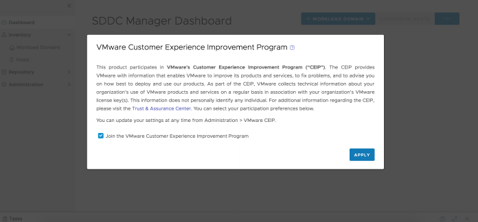
n When you log into SDDC Manager for the first time, a pop-up window appears. The Join the
VMware Customer Experience Program option is selected by default. Deselect this option if
you do not want to enable CEIP. Click Apply.
n You can enable or disable CEIP from the Administration tab in the SDDC Manager UI.
Procedure
1 In the navigation pane, click Administration > VMware CEIP.
VMware, Inc.
40
2 To enable CEIP, select the Join the VMware Customer Experience Improvement Program
option.
3 To disable CEIP, deselect the Join the VMware Customer Experience Improvement Program
option.
VMware Cloud Foundation on Dell EMC VxRail Guide
VMware, Inc. 41

Certificate Management
9
You can manage certificates for all user interface and API endpoints in a VMware Cloud
Foundation instance, including integrating a certificate authority, generating and submitting
certificate signing requests (CSR) to a certificate authority, and downloading and installing
certificates.
This section provides instructions for using either:
n OpenSSL as a certificate authority, which is a native option in SDDC Manager.
n Integrating with Microsoft Active Directory Certificate Services.
n Providing signed certificates from another external Certificate Authority.
You can manage the certificates for the following components.
n vCenter Server
n NSX Manager
n SDDC Manager
n VxRail Manager
n vRealize Suite Lifecycle Manager
Note Use vRealize Suite Lifecycle Manager to manage certificates for the other vRealize
Suite components.
You replace certificates for the following reasons:
n A certificate has expired or is nearing its expiration date.
n A certificate has been revoked by the issuing certificate authority.
n You do not want to use the default VMCA-signed certificates.
n Optionally, when you create a new workload domain.
It is recommended that you replace all certificates after completing the deployment of the
VMware Cloud Foundation management domain. After you create a new VI workload domain,
you can replace certificates for the appropriate components as needed.
Read the following topics next:
n View Certificate Information
VMware, Inc.
42
n Configure VMware Cloud Foundation to Use Microsoft CA-Signed Certificates
n Configure VMware Cloud Foundation to Use OpenSSL CA-Signed Certificates
n Install Third-Party CA-Signed Certificates
n Remove Old or Unused Certificates from SDDC Manager
n Configure Certificates for a Shared Single Sign-On Domain
View Certificate Information
You can view details of an applied certificate for a resource directly through the SDDC Manager
UI.
Procedure
1 In the navigation pane, click Inventory > Workload Domains.
2 On the Workload Domains page, from the table, in the domain column click the domain you
want to view.
3 On the domain summary page, click the Security tab.
This tab lists the certificates for each resource type associated with the workload domain. It
displays the following details:
n Resource type
n Issuer, the certificate authority name
n Resource hostname
n Valid From
n Valid Until
n Certificate status: Active, Expiring (will expire within 15 days), or Expired.
n Certificate operation status
4 To view certificate details, expand the resource next to the Resource Type column.
Configure VMware Cloud Foundation to Use Microsoft CA-
Signed Certificates
VMware Cloud Foundation supports the ability to manage certificates by integrating with
Microsoft Active Directory Certificate Services (Microsoft CA). Before you can perform certificate
operations using the SDDC Manager UI you must ensure that the Microsoft Certificate Authority
is configured correctly.
Complete the below tasks to manage Microsoft CA-Signed certificates using SDDC Manager.
VMware Cloud Foundation on Dell EMC VxRail Guide
VMware, Inc. 43
Prepare Your Microsoft Certificate Authority to Enable SDDC Manger
to Manage Certificates
To ensure secure and operational connectivity between the SDDC components, you apply signed
certificates provided by a Microsoft Certificate Authority for the SDDC components.
You use SDDC Manager to generate the certificate signing request (CSRs) and request a signed
certificate from the Microsoft Certificate Authority. SDDC Manager is then used to install the
signed certificates to SDDC components it manages. In order to achieve this the Microsoft
Certificate Authority must be configured to enable integration with SDDC Manager.
Install Microsoft Certificate Authority Roles
Install the Certificate Authority and Certificate Authority Web Enrollment roles on the Microsoft
Certificate Authority server to facilitate certificate generation from SDDC Manager.
Note When connecting SDDC Manager to Microsoft Active Directory Certificate Services, ensure
that Web Enrollment role is installed on the same machine where the Certificate Authority role
is installed. SDDC Manager can't request and sign certificates automatically if the two roles
(Certificate Authority and Web Enrollment roles) are installed on different machines.
Procedure
1 Log in to the Microsoft Certificate Authority server by using a Remote Desktop Protocol
(RDP) client.
FQDN
Active Directory Host
User Active Directory administrator
Password
ad_admin_password
2 Add roles to Microsoft Certificate Authority server.
a Click Start > Run, enter ServerManager, and click OK.
b From the Dashboard, click Add roles and features to start the Add Roles and Features
wizard.
c On the Before you begin page, click Next.
d On the Select installation type page, click Next.
e On the Select destination server page, click Next.
f On the Select server roles page, under Active Directory Certificate Services, select
Certification Authority and Certification Authority Web Enrollment and click Next.
g On the Select features page, click Next.
h On the Confirm installation selections page, click Install.
VMware Cloud Foundation on Dell EMC VxRail Guide
VMware, Inc. 44

Configure the Microsoft Certificate Authority for Basic Authentication
Configure the Microsoft Certificate Authority with basic authentication to allow SDDC Manager
the ability to manage signed certificates.
Procedure
1 Log in to the Active Directory server by using a Remote Desktop Protocol (RDP) client.
FQDN
Active Directory Host
User Active Directory administrator
Password
ad_admin_password
2 Add Basic Authentication to the Web Server (IIS).
a Click Start > Run, enter ServerManager, and click OK.
b From the Dashboard, click Add roles and features to start the Add Roles and Features
wizard.
c On the Before you begin page, click Next.
d On the Select installation type page, click Next.
e On the Select destination server page, click Next.
f On the Select server roles page, under Web Server (IIS) > Web Server > Security, select
Basic Authentication and click Next.
g On the Select features page, click Next.
h On the Confirm installation selections page, click Install.
3 Configure the certificate service template and CertSrv web site, for basic authentication.
a Click Start > Run, enter Inetmgr.exe and click OK to open the Internet Information
Services Application Server Manager.
b Navigate to
your_server
> Sites > Default Web Site > CertSrv.
c Under IIS, double-click Authentication.
d On the Authentication page, right-click Basic Authentication and click Enable.
e In the navigation pane, select Default Web Site.
f In the Actions pane, under Manage Website, click Restart for the changes to take effect.
Create and Add a Microsoft Certificate Authority Template
You must set up a certificate template in the Microsoft Certificate Authority. The template
contains the certificate authority attributes for signing certificates for the VMware Cloud
VMware Cloud Foundation on Dell EMC VxRail Guide
VMware, Inc. 45

Foundation components. After you create the template, you add it to the certificate templates of
the Microsoft Certificate Authority.
Procedure
1 Log in to the Active Directory server by using a Remote Desktop Protocol (RDP) client.
FQDN
Active Directory Host
User Active Directory administrator
Password
ad_admin_password
2 Click Start > Run, enter certtmpl.msc, and click OK.
3 In the Certificate Template Console window, under Template Display Name, right-click Web
Server and select Duplicate Template.
4 In the Properties of New Template dialog box, click the Compatibility tab and configure the
following values.
Setting Value
Certification Authority Windows Server 2008 R2
Certificate recipient Windows 7 / Server 2008 R2
5 In the Properties of New Template dialog box, click the General tab and enter a name for
example, VMware in the Template display name text box.
6 In the Properties of New Template dialog box, click the Extensions tab and configure the
following.
a Click Application Policies and click Edit.
b Click Server Authentication, click Remove, and click OK.
c Click Basic Constraints and click Edit.
d Click the Enable this extension check box and click OK.
e Click Key Usage and click Edit.
f Click the Signature is proof of origin (nonrepudiation) check box, leave the defaults for
all other options and click OK.
7 In the Properties of New Template dialog box, click the Subject Name tab, ensure that the
Supply in the request option is selected, and click OK to save the template.
VMware Cloud Foundation on Dell EMC VxRail Guide
VMware, Inc. 46

8 Add the new template to the certificate templates of the Microsoft CA.
a Click Start > Run, enter certsrv.msc, and click OK
b In the Certification Authority window, expand the left pane, right-click Certificate
Templates, and select New > Certificate Template to Issue.
c In the Enable Certificate Templates dialog box, select VMware, and click OK.
Assign Certificate Management Privileges to the SDDC Manager Service Account
Before you can use the Microsoft Certificate Authority and the pre-configured template, it is
recommended to configure least privilege access to the Microsoft Active Directory Certificate
Services using an Active Directory user account as a restricted service account.
Prerequisites
n Create a user account in Active Directory with Domain Users membership. For example,
svc-vcf-ca.
Procedure
1 Log in to the Microsoft Certificate Authority server by using a Remote Desktop Protocol
(RDP) client.
FQDN
Active Directory Host
User Active Directory administrator
Password
ad_admin_password
2 Configure least privilege access for a user account on the Microsoft Certificate Authority.
a Click Start > Run, enter certsrv.msc, and click OK.
b Right-click the certificate authority server and click Properties.
c Click the Security tab, and click Add.
d Enter the name of the user account and click OK.
e In the Permissions for .... section configure the permissions and click OK.
Setting
Value (Allow)
Read Deselected
Issue and Manage Certificates Selected
Manage CA Deselected
Request Certificates Selected
VMware Cloud Foundation on Dell EMC VxRail Guide
VMware, Inc. 47

3 Configure least privilege access for the user account on the Microsoft Certificate Authority
Template.
a Click Start > Run, enter certtmpl.msc, and click OK.
b Right-click the VMware template and click Properties.
c Click the Security tab, and click Add.
d Enter the svc-vcf-ca service account and click OK.
e In the Permissions for .... section configure the permissions and click OK.
Setting Value (Allow)
Full Control Deselected
Read Selected
Write Deselected
Enroll Selected
Autoenroll Deselected
Configure a Microsoft Certificate Authority in SDDC Manager
You configure a connection between SDDC Manager and the Microsoft Certificate Authority by
entering your service account credentials.
Prerequisites
n Verify connectivity between SDDC Manager and the Microsoft Certificate Authority Server.
See VMware Ports and Protocols.
n Verify that the Microsoft Certificate Authority Server has the correct roles installed on the
same machine where the Certificate Authority role is installed. See Install Microsoft Certificate
Authority Roles.
n Verify the Microsoft Certificate Authority Server has been configured for basic authentication.
See Configure the Microsoft Certificate Authority for Basic Authentication.
n Verify a valid certificate template has been configured on the Microsoft Certificate Authority.
See Create and Add a Microsoft Certificate Authority Template.
n Verify least privileged user account has been configured on the Microsoft Certificate
Authority Server and Template. See Assign Certificate Management Privileges to the SDDC
Manager Service Account.
n Verify that time is synchronized between the Microsoft Certificate Authority and the SDDC
Manager appliance. Each system can be configured with a different timezone, but it is
recommended that they receive their time from the same NTP source.
VMware Cloud Foundation on Dell EMC VxRail Guide
VMware, Inc. 48

Procedure
1 In the navigation pane, click Administration > Security.
2 Click the Certificate Management tab and click Edit.
3 Configure the settings and click Save.
Setting Value
Certificate Authority Microsoft
CA Server URL Specify the URL for the issuing certificate authority.
This address must begin with https:// and end with
certsrv
. For example, https://ca.rainpole.io/certsrv.
Username Enter a least privileged service account. For example,
svc-vcf-ca.
Password Enter the password for the least privileged service
account.
Template Name Enter the issuing certificate template name. You must
create this template in Microsoft Certificate Authority.
For example, VMware.
4 In the CA Server Certificate Details dialog box, click Accept.
Install Microsoft CA-Signed Certificates using SDDC Manager
Replace the self-signed certificates with signed certificates from the Microsoft Certificate
Authority by using SDDC Manager.
Procedure
1 In the navigation pane, click Inventory > Workload Domains.
2 On the Workload Domains page, from the table, in the domain column click the workload
domain you want to view.
3 On the domain summary page, click the Security tab.
4 Generate CSR files for the target components.
a From the table, select the check box for the resource type for which you want to
generate a CSR.
b Click Generate CSRs.
VMware Cloud Foundation on Dell EMC VxRail Guide
VMware, Inc. 49

c On the Details dialog, configure the settings and click Next.
Option Description
Algorithm Select the key algorithm for the certificate.
Key Size Select the key size (2048 bit, 3072 bit, or 4096 bit)
from the drop-down menu.
Email Optionally, enter a contact email address.
Organizational Unit Use this field to differentiate between divisions
within your organization with which this certificate is
associated.
Organization Name Type the name under which your company is known.
The listed organization must be the legal registrant of
the domain name in the certificate request.
Locality Type the city or locality where your company is
legally registered.
State Type the full name (do not abbreviate) of the state,
province, region, or territory where your company is
legally registered.
Country Type the country name where your company is
legally registered. This value must use the ISO 3166
country code.
d (Optional) On the Subject Alternative Name dialog, enter the subject alternative name(s)
and click Next.
e On the Summary dialog, click Generate CSRs.
5 Generate signed certificates for each component.
a From the table, select the check box for the resource type for which you want to
generate a signed certificate for.
b Click Generate Signed Certificates.
c In the Generate Certificates dialog box, from the Select Certificate Authority drop-down
menu, select Microsoft.
d Click Generate Certificates.
6 Install the generated signed certificates for each component.
a From the table, select the check box for the resource type for which you want to install a
signed certificate.
b Click Install Certificates.
VMware Cloud Foundation on Dell EMC VxRail Guide
VMware, Inc. 50

Configure VMware Cloud Foundation to Use OpenSSL CA-
Signed Certificates
VMware Cloud Foundation supports the ability to manage certificates using OpenSSL configured
on the SDDC Manager appliance.
Complete the following tasks to be able to manage OpenSSL-signed certificates issued by SDDC
Manager.
Configure OpenSSL-signed Certificates in SDDC Manager
To generate OpenSSL-signed certificates for the VMware Cloud Foundation components you
must first configure the certificate authority details.
Procedure
1 In the navigation pane, click Administration > Security.
2 Click the Certificate Management tab and click Edit.
3 Configure the settings and click Save.
Setting Value
Certificate Authority OpenSSL
Common Name Specify the FQDN of the SDDC Manager appliance.
Organizational Unit Use this field to differentiate between the divisions
within your organization with which this certificate is
associated.
Organization Specify the name under which your company is known.
The listed organization must be the legal registrant of
the domain name in the certificate request.
Locality Specify the city or the locality where your company is
legally registered.
State Enter the full name (do not abbreviate) of the state,
province, region, or territory where your company is
legally registered.
Country Select the country where your company is registered.
This value must use the ISO 3166 country code.
Install OpenSSL-signed Certificates using SDDC Manager
Replace the self-signed certificates with OpenSSL-signed certificates generated by SDDC
Manager.
Procedure
1 In the navigation pane, click Inventory > Workload Domains.
VMware Cloud Foundation on Dell EMC VxRail Guide
VMware, Inc. 51
2 On the Workload Domains page, from the table, in the domain column click the workload
domain you want to view.
3 On the domain summary page, click the Security tab.
4 Generate CSR files for the target components.
a From the table, select the check box for the resource type for which you want to
generate a CSR.
b Click Generate CSRs.
The Generate CSRs wizard opens.
c On the Details dialog, configure the settings and click Next.
Option Description
Algorithm Select the key algorithm for the certificate.
Key Size Select the key size (2048 bit, 3072 bit, or 4096 bit)
from the drop-down menu.
Email Optionally, enter a contact email address.
Organizational Unit Use this field to differentiate between divisions
within your organization with which this certificate is
associated.
Organization Name Type the name under which your company is known.
The listed organization must be the legal registrant of
the domain name in the certificate request.
Locality Type the city or locality where your company is
legally registered.
State Type the full name (do not abbreviate) of the state,
province, region, or territory where your company is
legally registered.
Country Type the country name where your company is
legally registered. This value must use the ISO 3166
country code.
d (Optional) On the Subject Alternative Name dialog, enter the subject alternative name(s)
and click Next.
You can enter multiple values separated by comma (,), semicolon (;), or space ( ). For
NSX-T, you can enter the subject alternative name for each node along with the Virtual IP
(master) node.
Note Wildcard subject alternate name, such as *.example.com is not recommended.
e On the Summary dialog, click Generate CSRs.
VMware Cloud Foundation on Dell EMC VxRail Guide
VMware, Inc. 52

5 Generate signed certificates for each component.
a From the table, select the check box for the resource type for which you want to
generate a signed certificate.
b Click Generate Signed Certificates.
c In the Generate Certificates dialog box, from the Select Certificate Authority drop-down
menu, select OpenSSL.
d Click Generate Certificates.
6 Install the generated signed certificates for each component.
a From the table, select the check box for the resource type for which you want to install a
signed certificate.
b Click Install Certificates.
Install Third-Party CA-Signed Certificates
VMware Cloud Foundation supports the ability to install third-party certificates. You must
download the certificate signing request (CSR) from SDDC Manager and then have it signed by a
third-party Certificate Authority. You can then use the controls in the SDDC Manager UI to install
the certificate.
Prerequisites
Uploading CA-Signed certificates from a Third Party Certificate Authority requires that you
collect the relevant certificate files in the correct format and then create a single .tar.gz file with
the contents. It's important that you create the correct directory structure within the .tar.gz file as
follows:
n The name of the top-level directory must exactly match the name of the workload domain as
it appears in the list on the Inventory > Workload Domains. For example, sfo-m01.
n The PEM-encoded root CA certificate chain file (must be named rootca.crt) must
reside inside this top-level directory. The rootca.crt chain file contains a root certificate
authority and can have n number of intermediate certificates.
For example:
-----BEGIN CERTIFICATE-----
<Intermediate1 certificate content>
-----END CERTIFICATE------
-----BEGIN CERTIFICATE-----
<Intermediate2 certificate content>
-----END CERTIFICATE------
-----BEGIN CERTIFICATE-----
<Root certificate content>
-----END CERTIFICATE-----
VMware Cloud Foundation on Dell EMC VxRail Guide
VMware, Inc. 53

In the above example, there are two intermediate certificates,
intermediate1
and
intermediate2
, and a root certificate.
Intermediate1
must use the certificate issued by
intermediate2
and intermediate2 must use the certificate issued by Root CA.
n The root CA certificate chain file, intermediate certificates, and root certificate must
contain the Basic Constraints field with value CA:TRUE.
n This directory must contain one sub-directory for each component resource for which
you want to replace the certificates.
n Each sub-directory must exactly match the resource hostname of a corresponding
component as it appears in the Resource Hostname column in the Inventory > Workload
Domains > Security tab.
For example, nsxManager.vrack.vsphere.local, vcenter-1.vrack.vsphere.local, and
so on.
n Each sub-directory must contain the corresponding .csr file, whose name must exactly
match the resource as it appears in the Resource Hostname column in the Inventory >
Workload Domains > Security tab.
n Each sub-directory must contain a corresponding .crt file, whose name must exactly
match the resource as it appears in the Resource Hostname column in the Inventory >
Workload Domains > Security tab. The content of the .crt files must end with a newline
character.
For example, the nsxManager.vrack.vsphere.local sub-directory would contain the
nsxManager.vrack.vsphere.local.crt file.
n All certificates including rootca.crt must be in UNIX file format.
n Additional requirements for NSX-T certificates:
n Server certificate (NSXT_FQDN.crt) must contain the Basic Constraints field with value
CA:FALSE.
n If the NSX-T certificate contains HTTP or HTTPS based CRL Distribution Point it must be
reachable from the server.
n The extended key usage (EKU) of the generated certificate must contain the EKU of the
CSR generated.
Note All resource and hostname values can be found in the list on the Inventory > Workload
Domains > Security tab.
Procedure
1 In the navigation pane, click Inventory > Workload Domains.
2 On the Workload Domains page, from the table, in the domain column click the workload
domain you want to view.
3 On the domain summary page, click the Security tab.
VMware Cloud Foundation on Dell EMC VxRail Guide
VMware, Inc. 54
4 Generate CSR files for the target components.
a From the table, select the check box for the resource type for which you want to
generate a CSR.
b Click Generate CSRs.
The Generate CSRs wizard opens.
c On the Details dialog, configure the settings and click Next.
Option Description
Algorithm Select the key algorithm for the certificate.
Key Size Select the key size (2048 bit, 3072 bit, or 4096 bit)
from the drop-down menu.
Email Optionally, enter a contact email address.
Organizational Unit Use this field to differentiate between divisions
within your organization with which this certificate is
associated.
Organization Name Type the name under which your company is known.
The listed organization must be the legal registrant of
the domain name in the certificate request.
Locality Type the city or locality where your company is
legally registered.
State Type the full name (do not abbreviate) of the state,
province, region, or territory where your company is
legally registered.
Country Type the country name where your company is
legally registered. This value must use the ISO 3166
country code.
d (Optional) On the Subject Alternative Name dialog, enter the subject alternative name(s)
and click Next.
You can enter multiple values separated by comma (,), semicolon (;), or space ( ). For
NSX-T, you can enter the subject alternative name for each node along with the Virtual IP
(primary) node.
Note Wildcard subject alternative name, such as *.example.com are not recommended.
e On the Summary dialog, click Generate CSRs.
5 Download and save the CSR files to the directory by clicking Download CSR.
6 Complete the following tasks outside of the SDDC Manager UI:
a Verify that the different .csr files have successfully generated and are allocated in the
required directory structure.
b Request signed certificates from a Third-party Certificate authority for each .csr.
VMware Cloud Foundation on Dell EMC VxRail Guide
VMware, Inc. 55

c Verify that the newly acquired .crt files are correctly named and allocated in the required
directory structure.
d Create a new .tar.gz file of the directory structure ready for upload to SDDC Manager. For
example: <domain name>.tar.gz.
7 Click Upload and Install.
8 In the Upload and Install Certificates dialog box, click Browse to locate and select the newly
created <domain name>.tar.gz file and click Open.
9 Click Upload.
10 If the upload is successful, click Install Certificate. The Security tab displays a status of
Certificate Installation is in progress.
Remove Old or Unused Certificates from SDDC Manager
Old or unused certificates are stored in a trust store in SDDC Manager. You can delete old
certificates directly on the SDDC Manager appliance.
Procedure
1 Log in to SDDC Manager by using a Secure Shell (SSH) client.
Setting
Value
User name vcf
Password
vcf_password
2 Enter su to switch to the root user.
3 Using the sddcmanager-ssl-util.sh script retrieve a list of the names of the certificates in the
trust store.
/opt/vmware/vcf/operationsmanager/scripts/cli/sddcmanager-ssl-util.sh -list | grep 'Alias
name'
4 Using the name of the certificate, delete the old or unused certificate.
/opt/vmware/vcf/operationsmanager/scripts/cli/sddcmanager-ssl-util.sh -delete <certificate
alias name from list>
5 (Optional) Clean out root certificates in VMware Endpoint Certificate Store from the Platform
Services Controller node.
Configure Certificates for a Shared Single Sign-On Domain
When you deploy multiple instances of SDDC Manager that are joined to the same Single Sign-
On (SSO) domain, you must take steps to ensure that certificates are installed correctly.
VMware Cloud Foundation on Dell EMC VxRail Guide
VMware, Inc. 56

By default, each vCenter Server that you deploy uses VMCA-signed certificates. VMware
recommends that you replace the default VMCA-signed certificates for each management
domain vCenter Server, across all SDDC Manager instances, with certificates signed by the same
external Certificate Authority (CA). After you deploy a new VI workload domain in any of the
SDDC Manager instances, install a certificate in the VI workload domain vCenter Server that is
signed by the same external CA as the management domain vCenter Servers.
If you plan to use the default VMCA-signed certificates for each vCenter Server across all SDDC
Manager instances, you must take the following steps every time an additional vCenter Server
Appliance is introduced to the SSO domain by any SDDC Manager instance:
n Import the VMCA machine certificate for the new vCenter Server Appliance into the trust
store of all other SDDC Manager instances participating in that SSO domain.
An additional vCenter Server Appliance is introduced to the SSO domain when:
n You deploy a new SDDC Manager instance that shares the same SSO domain as an existing
SDDC Manager instance.
n You deploy a new VI workload domain in any of the SDDC Manager instances that share an
SSO domain.
Procedure
1 Get the certificate for the new management or VI workload domain vCenter Server.
a SSH to the new vCenter Server Appliance using the root user account.
b Enter Shell.
c Retrieve the certificate from the VMware Certificate Store (VECS) and send it to an output
file.
/usr/lib/vmware-vmafd/bin/vecs-cli entry getcert --store MACHINE_SSL_CERT --alias
__MACHINE_CERT --output /tmp/<new-vcenter>.cer
2 Copy the certificate (<new-vcenter>.cer) to a computer that has access to the SDDC
Manager instance(s) to which you want to import the certificate.
3 Import the certificate to the trust store of the SDDC Manager instance(s).
a Copy the certificate to the SDDC Manager appliance.
For example, /tmp/<new-vcenter>.cer.
b SSH in to the SDDC Manager appliance using the vcf user account.
c Enter su to switch to the root user.
VMware Cloud Foundation on Dell EMC VxRail Guide
VMware, Inc. 57
d Run the following commands:
trustedKey=$(cat /etc/vmware/vcf/commonsvcs/trusted_certificates.key)
(echo $trustedKey; sleep 1; echo "Yes") | keytool -importcert -alias <new-vcenter>
-file /tmp/<newvcenter>.
cer -keystore /etc/vmware/vcf/commonsvcs/trusted_certificates.store
echo "Yes" | keytool -importcert -alias <new-vcenter> -file /tmp/<new-vcenter>.cer
-keystore
/etc/alternatives/jre/lib/security/cacerts --storepass changeit
e Validate the keystore entries.
keytool -list -v -keystore /etc/vmware/vcf/commonsvcs/trusted_certificates.store
-storepass $trustedKey
4 Restart all SDDC Manager services on each SDDC Manager instance to which you imported a
trusted certificate.
echo "Y" | /opt/vmware/vcf/operationsmanager/scripts/cli/sddcmanager_restart_services.sh
VMware Cloud Foundation on Dell EMC VxRail Guide
VMware, Inc. 58
License Management
10
When deploying management components, VMware Cloud Foundation requires access to valid
license keys. You add license keys to the SDDC Manager inventory so that they can be
consumed at deployment time, but they are not synchronized between SDDC Manager and the
underlying components.
In the deployment parameter workbook that you completed before bring-up, you entered license
keys for the following components:
n VMware vSphere
n VMware vSAN
n VMware NSX-T Data Center
n VMware vCenter Server
After bring-up, these license keys appear in the Licensing screen of the SDDC Manager UI.
You must have adequate license units available before you create a VI workload domain, add a
host to a vSphere cluster, or add a vSphere cluster to a workload domain. Add license keys as
appropriate before you begin any of these tasks.
Read the following topics next:
n Add a License Key
n Edit License Description
n Delete License Key
Add a License Key
You can add licenses to the SDDC Manager inventory.
Procedure
1 In the navigation pane, click Administration > Licensing.
2 Click + License Key.
3 Select a product from the drop-down menu.
4 Enter the license key.
VMware, Inc.
59
5 Enter a description for the license.
A description can help in identifying the license.
6 Click Add.
What to do next
If you want to replace an existing license with a newly added license, you must add and assign
the new license in the management UI (for example, vSphere Client or NSX Manager) of the
component whose license you are replacing.
Edit License Description
If you have multiple license keys for a product, the description can help in identifying the license.
For example, you may want to use one license for high-performance workload domains and the
other license for regular workload domains.
Procedure
1 In the navigation pane, click Administration > Licensing.
2 Click the vertical ellipsis (three dots) next to the license key and click Edit Description.
3 On the Edit License Key Description dialog, edit the description and click Save.
Delete License Key
Deleting a license key removes the license from the SDDC Manager inventory. If the license has
been applied to any workload domain, host, or vSphere cluster, the license is not removed from
them, but it cannot be applied to new workload domains, hosts, or vSphere clusters.
Procedure
1 In the navigation pane, click Administration > Licensing.
2 Click the vertical ellipsis (three dots) next to the license key you want to delete and click
Remove.
3 In the Remove License key dialog, click Remove.
Results
The license is removed from the SDDC Manager inventory
VMware Cloud Foundation on Dell EMC VxRail Guide
VMware, Inc. 60
ESXi Lockdown Mode
11
You can enable or disable normal lockdown mode in VMware Cloud Foundation to increase the
security of your ESXi hosts.
To enable or disable normal lockdown mode in VMware Cloud Foundation, you must perform
operations through the vCenter Server. For information on how to enable or disable normal
lockdown mode, see "Lockdown Mode" in
vSphere Security
at https://docs.vmware.com/en/
VMware-vSphere/index.html.
You can enable normal lockdown mode on a host after the host is added to workload
domain. VMware Cloud Foundation creates service accounts that can be used to access the
hosts. Service accounts are added to the Exception Users list during the bring-up or host
commissioning. You can rotate the passwords for the service accounts using the password
management functionality in the SDDC Manager UI.
VMware, Inc.
61
Storage Management
12
To create and manage a workload domain, VMware Cloud Foundation requires at least one
shared storage type for all ESXi hosts within a cluster. This initial shared storage type, known
as principal storage, is configured during VxRail first run. Additional shared storage, known as
supplemental storage, can be added using the vSphere Client after a cluster has been created.
Although the management domain requires vSAN as its principal storage, vSAN is not required
for VI workload domains or vSphere clusters.
For a VI workload domain, the initial storage type can be one of the following:
n vSAN
n Fibre Channel (FC)
This initial shared storage type is known as principal storage. Principal storage is configured
during the VxRail first run. Once created, the principal storage type for a cluster cannot be
changed. However, a VI workload domain can include multiple clusters with unique principal
storage types.
Additional shared storage types can be added to a cluster in the management domain or a VI
workload domain after it has been created. The additional supported shared storage options
include:
n vSAN
n Fibre Channel (FC)
Additional shared storage types are known as supplemental storage. All supplemental storage
must be listed in the VMware Compatibility Guide. Supplemental storage can be manually added
or removed after a cluster has been created using the vSphere Client. Multiple supplemental
storage types can be presented to a cluster in the management domain or any VI workload
domain.
Read the following topics next:
n vSAN Storage with VMware Cloud Foundation
n Fibre Channel Storage with VMware Cloud Foundation
n Sharing Remote Datastores with HCI Mesh for VI Workload Domains
VMware, Inc.
62
vSAN Storage with VMware Cloud Foundation
vSAN is the preferred principal storage type for VMware Cloud Foundation. It is an enterprise-
class storage integrated with vSphere and managed by a single platform. vSAN is optimized for
flash storage and can non-disruptively expand capacity and performance by adding hosts to a
cluster (scale-out) or by adding disks to a host (scale-up).
vSAN is typically used as principal storage, however it can be used as supplemental storage in a
cluster when HCI Mesh is implemented.
Storage Type
Consolidated Workload
Domain Management Domain VI Workload Domain
Principal Yes Yes Yes
Supplemental No No Yes
Prerequisites for vSAN Storage
In order to create a VI workload domain that uses vSAN as principal storage you must ensure the
following:
n A minimum of three ESXi hosts that meet the vSAN hardware, cluster, software, networking
and license requirements. For information, see the vSAN Planning and Deployment Guide.
n Perform a VxRail first run specifying the vSAN configuration settings. For information on the
VxRail first run, contact Dell EMC Support.
n A valid vSAN license. See Chapter 10 License Management.
In some instances SDDC Manager may be unable to automatically mark the host disks as
capacity. Follow the Mark Flash Devices as Capacity Using ESXCLI procedure in the vSAN
Planning and Deployment Guide.
Procedures for vSAN Storage
n To use vSAN as principal storage for a new VI workload domain, perform the VxRail first run
and then add the primary VxRail cluster. See Add the Primary VxRail Cluster to a VI Workload
Domain Using the SDDC Manager UI.
n To use vSAN as principal storage for a new cluster, perform the VxRail first run and then add
the VxRail cluster. See Add a VxRail Cluster to a Workload Domain Using the SDDC Manager
UI.
Fibre Channel Storage with VMware Cloud Foundation
Fibre Channel (FC) is a storage protocol that the SAN uses to transfer data traffic from ESXi hosts
to shared storage. The protocol packages SCSI commands into FC frames. To connect to the FC
SAN, the ESXi host uses Fibre Channel host bus adapters (HBAs).
VMware Cloud Foundation on Dell EMC VxRail Guide
VMware, Inc. 63

Fibre Channel can only be used as supplemental storage for the initial cluster in the management
domain and consolidated workload domain, however it can be used as principal storage for
subsequent clusters in these domains or in any VI workload domain.
Storage Type
Consolidated Workload
Domain Management Domain VI Workload Domain
Principal No No Yes
Supplemental Yes Yes Yes
Prerequisites for FC Storage
n A minimum of three ESXi hosts. Review the ESXi Fibre Channel SAN Requirements in the
vSphere Storage Guide.
n Perform a VxRail first run specifying the VMFS on FC configuration settings. For information
on the VxRail first run, contact Dell EMC Support.
n A pre-created VMFS datastore.
Procedures for FC Storage
n To use Fibre Channel as principal storage for a new VI workload domain, perform the VxRail
first run and then add the primary VxRail cluster. See Add the Primary VxRail Cluster to a VI
Workload Domain Using the SDDC Manager UI.
n To use Fibre Channel as principal storage for a new cluster, perform the VxRail first run and
then add the VxRail cluster. See Add a VxRail Cluster to a Workload Domain Using the SDDC
Manager UI
n To use Fibre Channel as supplemental storage follow the
Create an NFS Datastore
procedure
in the vSphere Storage Guide.
Sharing Remote Datastores with HCI Mesh for VI Workload
Domains
HCI Mesh is a software-based approach for disaggregation of compute and storage resources
in vSAN. HCI Mesh brings together multiple independent vSAN clusters by enabling cross-
cluster utilization of remote datastore capacity within vCenter Server. HCI Mesh enables
you to efficiently utilize and consume data center resources, which provides simple storage
management at scale.
VMware Cloud Foundation supports sharing remote datastores with HCI Mesh for VI workload
domains.
You can create HCI Mesh by mounting remote vSAN datastores on vSAN clusters and enable
data sharing from the vCenter Server. It can take upto 5 minutes for the mounted remote vSAN
datastores to appear in the .
VMware Cloud Foundation on Dell EMC VxRail Guide
VMware, Inc. 64

It is recommended that you do not mount or configure remote vSAN datastores for vSAN
clusters in the management domain.
For more information on sharing remote datastores with HCI Mesh, see "Sharing Remote
Datastores with HCI Mesh" in
Administering VMware vSAN 7.0
at https://docs.vmware.com/en/
VMware-vSphere/index.html.
Note You cannot mount remote vSAN datastores on stretched clusters.
Note After enabling HCI Mesh by mounting remote vSAN datastores, you can migrate VMs from
the local datastore to a remote datastore. Since each cluster has its own VxRail Manager VM, you
should not migrate VxRail Manager VMs to a remote datastore.
VMware Cloud Foundation on Dell EMC VxRail Guide
VMware, Inc. 65
Workload Domain Management
13
Workload domains are logical units that carve up the compute, network, and storage resources
of the VMware Cloud Foundation system. The logical units are groups of ESXi hosts managed by
vCenter Server instances with specific characteristics for redundancy and VMware best practices.
The first workload domain, referred to as the management domain, is created by during bring-
up. The VMware Cloud Foundation software stack is deployed within the management domain.
Additional infrastructure virtual machines which provide common services, such as backup or
security appliances, can also be deployed in the management domain.
Each workload domain include these VMware capabilities by default:
n vCenter Server Appliance
n vSphere High Availability (HA)
n vSphere Distributed Resource Scheduler (DRS)
n vSphere Distributed Switch
n VMware vSAN
n NSX Manager Cluster
Read the following topics next:
n Adding Virtual Machines to the Management Domain
n About VI Workload Domains
n Deploying a VI Workload Domain with a Remote Cluster
n Delete a VI Workload Domain
n View Workload Domain Details
n Expand a Workload Domain
n Reduce a Workload Domain
n Using the Workflow Optimization Script to Create a VxRail VI Workload Domain or Add a
VxRail Cluster
n Rename a Workload Domain
n vSphere Cluster Management
VMware, Inc.
66

n NSX Edge Cluster Management
Adding Virtual Machines to the Management Domain
If you deployed VMware Cloud Foundation using a consolidated architecture, you can deploy
user virtual machines to the management domain. To prevent resource conflicts between the
VMware Cloud Foundation management components, these additional virtual machines should
be added to the resource pool created for this purpose during bring-up (the Resource Pool User
VM value in the deployment parameter workbook).
You must be careful when adding virtual machines to the management domain. You do not want
to consume excessive resources that would obstruct standard management operations. Excess
capacity consumption can prevent successful virtual machine fail overs in the event of a host
failure or maintenance action.
You can add capacity to the management domain by adding a host(s). To expand the
management domain, see Expand a Workload Domain.
Procedure
1 In the navigation pane, click Inventory > Workload Domains.
2 In the workload domains table, click the name of the management domain.
3 Click the Services tab.
4 Click the vCenter Server link.
This opens the vSphere Client for the management domain.
5 Create a new virtual machine within correct resource pool (Resource Pool User VM).
Note Do not move any of the VMware Cloud Foundation management virtual machines out
of the resource pools they were placed in during bring-up.
About VI Workload Domains
When deploying a workload domain, you specify the name, compute, and networking details for
the VI workload domain. You then select the hosts and licenses for the VI workload domain and
start the workflow.
The workflow automatically:
n Deploys a vCenter Server Appliance for the new VI workload domain within the management
domain. By using a separate vCenter Server instance per VI workload domain, software
updates can be applied without impacting other VI workload domains. It also allows for each
VI workload domain to have additional isolation as needed.
n Configures networking on each host.
n Configures vSAN storage on the ESXi hosts.
VMware Cloud Foundation on Dell EMC VxRail Guide
VMware, Inc. 67

n For the first VI workload domain, the workflow deploys a cluster of three NSX Managers
in the management domain and configures a virtual IP (VIP) address for the NSX Manager
cluster. The workflow also configures an anti-affinity rule between the NSX Manager VMs
to prevent them from being on the same host for high availability. Subsequent VI workload
domains can share an existing NSX Manager cluster or deploy a new one.
n By default, VI workload domains do not include any NSX Edge clusters and are isolated. To
provide north-south routing and network services, add one or more NSX Edge clusters to a
VI workload domain. See NSX Edge Cluster Management .
Note You can only perform one VI workload domain operation at a time. For example, while
you are deploying a new VI workload domain, you cannot add a cluster to any other VI workload
domain.
Prerequisites for a Workload Domain
Review the prerequisites before you deploy a VI workload domain.
n If you plan to use DHCP for the NSX host overlay network, a DHCP server must be configured
on the NSX host overlay VLAN for the VI workload domain. When NSX-T Data Center
creates NSX Edge tunnel endpoints (TEPs) for the VI workload domain, they are assigned
IP addresses from the DHCP server.
Note If you do not plan to use DHCP, you can use a static IP pool for the NSX host overlay
network. The static IP pool is created or selected as part of VI workload domain creation.
n A minimum of three hosts available for the VI workload domain.
n If the management domain in your environment has been upgraded to a version different
from the original installed version, you must download a VI workload domain install bundle for
the current version before you can create a VI workload domain.
n Decide on a name for your VI workload domain. Each VI workload domain must have a
unique name. It is good practice to include the region and site information in the name
because resource object names (such as host and vCenter names) are generated based on
the VI workload domain name. The name can be three to 20 characters long and can contain
any combination of the following:
n Lowercase alphabetic characters
n Numbers
Note Spaces are not allowed in any of the names you specify when creating a VI workload
domain.
n Decide on the following passwords:
n vCenter Server root password
n NSX Manager admin password
VMware Cloud Foundation on Dell EMC VxRail Guide
VMware, Inc. 68
Although the individual VMware Cloud Foundation components support different password
requirements, you must set passwords following a common set of requirements across all
components:
n Minimum length: 12
n Maximum length: 16
n At least one lowercase letter, one uppercase letter, a number, and one of the following
special characters: ! @ # $ ^ *
n Must NOT include:
n A dictionary word
n A palindrome
n More than four monotonic character sequences
n Three of the same consecutive characters
n Verify that you have the completed Planning and Preparation Workbook with the VI
workload domain deployment option included.
n The IP addresses and Fully Qualified Domain Names (FQDNs) for the vCenter Server and NSX
Manager instances must be resolvable by DNS.
n You must have valid license keys for the following products:
n NSX-T Data Center
n vSAN
n vSphere
Because vSphere and vSAN licenses are per CPU, ensure that you have sufficient licenses
for the ESXi hosts to be used for the VI workload domain. See Chapter 10 License
Management.
Creating VxRail VI Workload Domains
You can create a VxRail VI workload domain using the SDDC Manager and VxRail Manager UIs, or
using the Workflow Optimization script.
When you use the product UIs, you complete some of the steps in the SDDC Manager UI and
some of the steps in the VxRail Manager UI:
n Create a VxRail VI workload domain (SDDC Manager UI)
n VxRail first run (VxRail Manager UI)
n Add the primary VxRail cluster to the VI workload domain (SDDC Manager UI)
This following documentation describes the process of creating a workload domain using the
product UIs.
VMware Cloud Foundation on Dell EMC VxRail Guide
VMware, Inc. 69
Alternatively, you can use the Workflow Optimization script to perform all of the steps to create
a VI workload domain in one place. See Create a VxRail VI Workload Domain Using the Workflow
Optimization Script.
Create a VxRail VI Workload Domain in the SDDC Manager UI
Use the VxRail VI Configuration wizard to create a VI workload domain.
Procedure
1 In the navigation pane, click + Workload Domain and then select VI-VxRail Virtual
Infrastructure Setup.
2 Type a name for the VxRail VI workload domain, such as sfo01.
The name must contain between 3 and 20 characters. It is a good practice to include location
information in the name as resource object names (such as host and vCenter names) are
generated on the basis of the VI workload domain name.
3 Type a name for the organization that requested or will use the virtual infrastructure, such as
Finance and click Next.
The name must contain between 3 and 20 characters.
4 On the Compute page of the wizard, enter the vCenter Server DNS name.
5 Type the vCenter Server subnet mask and default gateway.
6 Type and re-type the vCenter Server root password and click Next.
7 Review the details and click Next.
8 On the Validation page, wait until all of the inputs have been successfully validated and then
click Finish.
If validation is unsuccessful, you cannot proceed. Use the Back button to modify your
settings and try again.
What to do next
Add the primary VxRail cluster to the workload domain. The status of the VI workload domain
creation task will be Activating until you do so. See Add the Primary VxRail Cluster to a VI
Workload Domain Using the SDDC Manager UI.
Adding the Primary VxRail Cluster to a VI Workload Domain
In order to finish creating a VxRail VI workload domain, you must add the primary VxRail cluster
to the workload domain.
There are two ways to add the primary VxRail cluster to a workload domain, depending on your
use case.
VMware Cloud Foundation on Dell EMC VxRail Guide
VMware, Inc. 70
Use Case Method
You have a single system vSphere Distributed Switch (vDS)
used for both system and overlay traffic.
SDDC Manager UI
You have two system vSphere Distributed Switches. One is
used for system traffic and one is used for overlay traffic.
MultiDvsAutomator script
You have one or two system vSphere Distributed switches
for system traffic and a separate vDS for overlay traffic.
MultiDvsAutomator script
Add the Primary VxRail Cluster to a VI Workload Domain Using the SDDC Manager UI
You can add the primary VxRail cluster to a VI workload domain using the SDDC Manager UI.
Prerequisites
n Create a local user in vCenter Server. This is required for the VxRail first run.
n Image the VI workload domain nodes. For information on imaging the nodes, refer to Dell
EMC VxRail documentation.
n Perform a VxRail first run of the VI workload domain nodes using the vCenter Server for
that workload domain. For information on VxRail first run, refer to the Dell EMC VxRail
documentation.
Procedure
1 In the SDDC Manager UI, click Inventory > Workload Domains.
2 In the workload domains table, click the vertical ellipsis (three dots) next to the VI workload
domain in the Activating state and click Add VxRail Cluster.
3 On the Discovered Clusters page, select a VxRail cluster and click Next.
4 On the Discovered Hosts page, enter the SSH password for the discovered hosts and click
Next.
5 On the VxRail Manager page, enter the Admin and Root user names and passwords.
6
On the Thumbprint Verification page, click to confirm the SSH thumbprints for VxRail
Manager and the ESXi hosts.
7 The Networking page displays all the networking details for the cluster.
a Choose to create a new NSX Manager cluster or reuse an existing one.
For the first VI workload domain, you must create an NSX Manager cluster.
b If you are reusing an existing NSX Manager cluster, select the cluster and click Next.
The networking information for the selected cluster displays and cannot be edited.
c If you are creating a new NSX Manager cluster, enter the VLAN ID for the NSX-T host
overlay (host TEP) network.
VMware Cloud Foundation on Dell EMC VxRail Guide
VMware, Inc. 71
d Select the IP allocation method.
Note You can only use a static IP pool for the management domain and VI workload
domains with uniform L2 clusters. For L3 aware or stretch clusters, DHCP is required for
Host Overlay Network TEP IP assignment.
Option Description
DHCP With this option VMware Cloud Foundation uses DHCP for the Host
Overlay Network TEPs.
A DHCP server must be configured on the NSX-T host overlay (Host TEP)
VLAN. When NSX creates TEPs for the VI workload domain, they are
assigned IP addresses from the DHCP server.
Static IP Pool With this option VMware Cloud Foundation uses a static IP pool for the
Host Overlay Network TEPs. You can re-use an existing IP pool or create
a new one.
To create a new static IP Pool provide the following information:
n Pool Name
n Description
n CIDR
n IP Range.
n Gateway IP
Make sure the IP range includes enough IP addresses for the number of
hosts that will use the static IP Pool. The number of IP addresses required
depends on the number of pNICs on the ESXi hosts that are used for
the vSphere Distributed Switch that handles host overlay networking. For
example, a host with four pNICs that uses two pNICs for host overlay
traffic requires two IP addresses in the static IP pool.
Note You cannot stretch a cluster that uses static IP addresses for the
NSX-T Host Overlay Network TEPs.
e Provide the NSX Manager cluster details:
n NSX Manager Virtual IP (VIP) address and FQDN
n IP addresses and FQDNs for three NSX Managers (nodes)
n NSX Manager Admin password
f Click Next.
8 Enter the license keys for NSX-T Data Center and VMware vSAN and click Next.
9 Review the details and click Next.
10 On the Validation page, wait until all of the inputs have been successfully validated.
If validation is unsuccessful, you cannot proceed. Use the Back button to modify your
settings and try again.
11 Click Finish.
VMware Cloud Foundation on Dell EMC VxRail Guide
VMware, Inc. 72
What to do next
If you have multiple instances of SDDC Manager that are joined to the same Single Sign-On (SSO)
domain, you must take steps to ensure that certificates are installed correctly. See Configure
Certificates for a Shared Single Sign-On Domain.
Add the Primary VxRail Cluster to a VI Workload Domain Using the MultiDvsAutomator Script
Use the MultiDvsAutomator script to add the primary VxRail cluster if:
n You have two system vSphere Distributed Switches. One is used for system traffic and one is
used for overlay traffic.
n Or, you have one or two system vSphere Distributed switches for system traffic and a
separate vDS for overlay traffic.
Prerequisites
n Create a local user in vCenter Server. This is required for the VxRail first run.
n Image the VI workload domain nodes. For information on imaging the nodes, refer to Dell
EMC VxRail documentation.
n Perform a VxRail first run of the VI workload domain nodes using the vCenter Server for
that workload domain. For information on VxRail first run, refer to the Dell EMC VxRail
documentation.
n Download the Multi-Dvs-Script-master.zip file from https://code.vmware.com/samples?
id=7663. Copy the Multi-Dvs-Automator-VCF-4.3.0-master.zip file to the /home/vcf
directory on the SDDC Manager VM and unzip it.
Procedure
1 Using SSH, log in to the SDDC Manager VM with the user name vcf and the password you
specified in the deployment parameter sheet.
2 Enter su to switch to the root account.
3 In the /home/vcf/Multi-Dvs-Automator-VCF-4.3.0-master directory, run python
vxrailworkloadautomator.py.
4 Enter the SSO user name and password.
5 When prompted, select a workload domain to which you want to import the cluster.
6 Select a cluster from the list of clusters that are ready to be imported.
7 Enter passwords for the discovered hosts.
n Enter a single password for all the discovered hosts.
n Enter passwords individually for each discovered host.
VMware Cloud Foundation on Dell EMC VxRail Guide
VMware, Inc. 73
8 Choose the vSphere Distributed Switch (vDS) to use for overlay traffic.
n Create new DVS
1 Enter a name for the new vSphere Distributed Switch.
2 Enter a comma-separated list of the vmnics to use.
n Use existing DVS
1 Select an existing vSphere Distributed Switch.
2 Select a portgroup on the vDS. The vmnics mapped to the selected port group are
used to configure overlay traffic.
9 Enter the Geneve VLAN ID.
10 Choose the NSX Manager cluster.
n Use existing NSX Manager cluster
1 Enter VLAN ID for the NSX-T host overlay network.
2 Select an existing NSX Manager cluster.
n Create a new NSX Manager cluster
1 Enter VLAN ID for the NSX-T host overlay network.
2 Enter the NSX Manager Virtual IP (VIP) address and FQDN.
3 Enter the FQDNs for the NSX Managers (nodes).
VMware Cloud Foundation on Dell EMC VxRail Guide
VMware, Inc. 74

11 Select the IP allocation method for the Host Overlay Network TEPs.
Option Description
DHCP With this option VMware Cloud Foundation uses DHCP for the Host Overlay
Network TEPs.
A DHCP server must be configured on the NSX-T host overlay (Host TEP)
VLAN. When NSX creates TEPs for the VI workload domain, they are
assigned IP addresses from the DHCP server.
Static IP Pool With this option VMware Cloud Foundation uses a static IP pool for the Host
Overlay Network TEPs. You can re-use an existing IP pool or create a new
one.
To create a new static IP Pool provide the following information:
n Pool Name
n Description
n CIDR
n IP Range.
n Gateway IP
Make sure the IP range includes enough IP addresses for the number of
hosts that will use the static IP Pool. The number of IP addresses required
depends on the number of pNICs on the ESXi hosts that are used for
the vSphere Distributed Switch that handles host overlay networking. For
example, a host with four pNICs that uses two pNICs for host overlay traffic
requires two IP addresses in the static IP pool.
Note You cannot stretch a cluster that uses static IP addresses for the
NSX-T Host Overlay Network TEPs.
12 Enter and confirm the VxRail Manager root and admin passwords.
13 Confirm the SSH thumbprints for VxRail Manager and the ESXi hosts.
14 Select the license keys for VMware vSAN and NSX-T Data Center.
15 Press Enter to begin the validation process.
16 When validation succeeds, press Enter to import the primary VxRail cluster.
What to do next
If you have multiple instances of SDDC Manager that are joined to the same Single Sign-On (SSO)
domain, you must take steps to ensure that certificates are installed correctly. See Configure
Certificates for a Shared Single Sign-On Domain.
Deploying a VI Workload Domain with a Remote Cluster
With VMware Cloud Foundation Remote Clusters, you can deploy a VI workload domain that has
its vSphere cluster at a remote location. You can also enable VMware Cloud Foundation with
Tanzu on a cluster deployed at a remote site. The remote cluster is managed by the VMware
Cloud Foundation instance at the central site. You can perform a full-stack life cycle management
for the remote sites from the central SDDC Manager UI.
VMware Cloud Foundation on Dell EMC VxRail Guide
VMware, Inc. 75
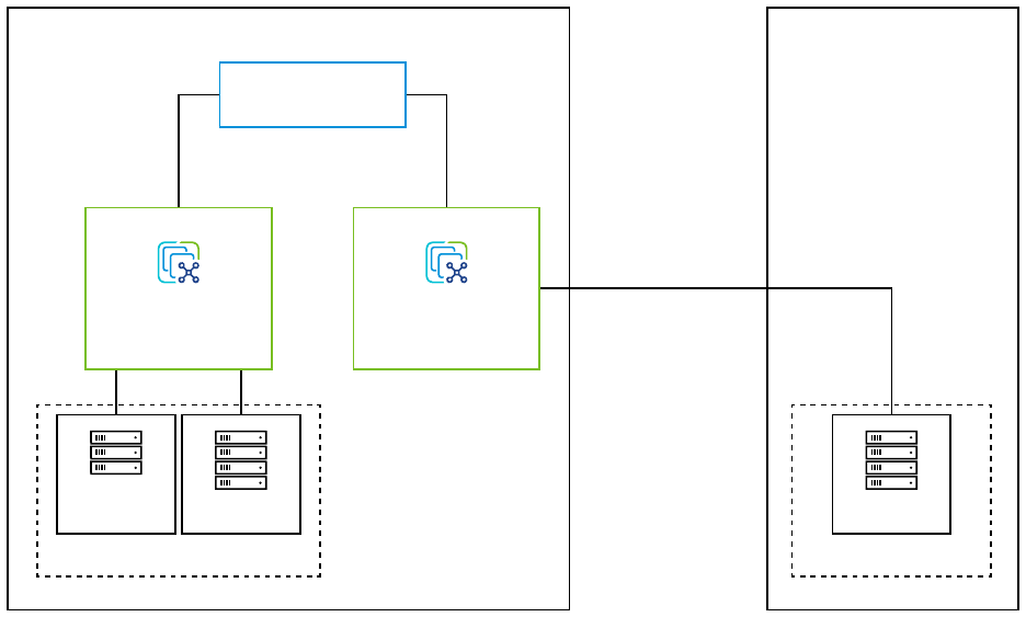
VMware Cloud Foundation Remote Clusters have the following limitations:
n VMware Cloud Foundation supports a single remote cluster per VMware Cloud Foundation
instance.
n A VI workload domain can include local clusters or a remote cluster, but not both.
vCenter Server
SDDC Manager
Site A (local)
Cluster
Cluster
Workload Domain 1
vCenter Server
Site B (remote)
10 Mbs bandwith
50 ms latency
Cluster
Workload Domain 2
The prerequisites for deploying a VI workload domain with a remote cluster are:
n Ensure that you meet the general prerequisites for deploying a VI workload domain. See
Prerequisites for a Workload Domain.
n VMware Cloud Foundation Remote Clusters supports a minimum of 3 and maximum of 4
hosts.
n Dedicated WAN connectivity is required between central site and VMware Cloud Foundation
Remote Clusters site.
n Primary and secondary active WAN links are recommended for connectivity from the central
site to the VMware Cloud Foundation Remote Clusters site. The absence of WAN links can
lead to two-failure states, WAN link failure, or NSX Edge node failure, which can result in
unrecoverable VMs and application failure at the VMware Cloud Foundation Remote Clusters
site.
n Minimum bandwidth of 10 Mbps and latency of 50 Ms is required between the central
VMware Cloud Foundation instance and VMware Cloud Foundation Remote Clusters site.
n The network at the VMware Cloud Foundation Remote Clusters site must be able to reach the
management network at the central site.
VMware Cloud Foundation on Dell EMC VxRail Guide
VMware, Inc. 76

n DNS and NTP server must be available locally at or reachable from the VMware Cloud
Foundation Remote Clusters site
For information on enabling Workload Management (vSphere with Tanzu) on a cluster deployed
at a remote site, see Chapter 14 Workload Management .
Delete a VI Workload Domain
You can delete a VI workload domain from SDDC Manager UI.
Deleting a VI workload domain also removes the components associated with the VI workload
domain from the management domain. This includes the vCenter Server instance and the NSX
Manager cluster instances.
Note If the NSX Manager cluster is shared with any other VI workload domains, it will not be
deleted.
Caution Deleting a workload domain is an irreversible operation. All clusters and virtual
machines within the VI workload domain are deleted and the underlying datastores are
destroyed.
It can take up to 20 minutes for a VI workload domain to be deleted. During this process, you
cannot perform any operations on workload domains.
Prerequisites
n If remote vSAN datastores are mounted on a cluster in the VI workload domain, then the
VI workload domain cannot be deleted. To delete such VI workload domains, you must first
migrate any virtual machines from the remote datastore to the local datastore and then
unmount the remote vSAN datastores from vCenter Server.
n If you require access after deleting a VI workload domain, back up the data. The datastores
on the VI workload domain are destroyed when it is deleted.
n Migrate the virtual machines that you want to keep to another workload domain using cross
vCenter vMotion.
n Delete any workload virtual machines created outside VMware Cloud Foundation before
deleting the VI workload domain.
n Delete any NSX Edge clusters hosted on the VI workload domain. See KB 78635.
Procedure
1 In the navigation pane, click Inventory > Workload Domains.
2 Click the vertical ellipsis (three dots) next to the VI workload domain you want to delete and
click Delete Domain.
VMware Cloud Foundation on Dell EMC VxRail Guide
VMware, Inc. 77

3 On the Delete Workload Domain dialog box, click Delete Workload Domain.
A message indicating that the VI workload domain is being deleted appears. When the
removal process is complete, the VI workload domain is removed from the domains table.
View Workload Domain Details
The Workload Domains page displays high level information about the workload domains in a
VMware Cloud Foundation instance. CPU, memory, and storage utilized by the workload domain
is also displayed here.
Procedure
1 In the navigation pane, click Inventory > Workload Domains.
2 In the workload domains table, click the name of the workload domain.
The workload domain details page displays CPU, memory, and storage allocated to the
workload domain. The tabs on the page display additional information as described in the
table below.
Tab Information Displayed
Summary Summary details for:
n Nsx-T Data Center components.
n Storage types by cluster.
n Application Virtual Network configuration (if deployed).
Services SDDC software stack components deployed for the workload domain's virtual environment
and their IP addresses. Click a component name to navigate to that aspect of the virtual
environment. For example, click vCenter Server to reach the vSphere Client for that workload
domain.
All the capabilities of a VMware SDDC are available to you in the VI workload domain's
environment, such as creating, provisioning, and deploying virtual machines, configuring the
software-defined networking features, and so on.
Updates/Patches Available updates for the workload domain.
Update History Updates applied to this workload domain.
Hosts Names, IP addresses, status, associated clusters, and capacity utilization of the hosts in the
workload domain and the network pool they are associated with.
Clusters Names of the clusters, number of hosts in the clusters, and their capacity utilization.
Edge Clusters Names of the NSX Edge clusters, NSX Edge nodes, and their status.
Security Default certificates for the VMware Cloud Foundation components. For more information, see
Chapter 9 Certificate Management.
VMware Cloud Foundation on Dell EMC VxRail Guide
VMware, Inc. 78
Expand a Workload Domain
You can expand a workload domain by adding VxRail clusters using the SDDC Manager and
VxRail Manager UIs, or using the Workflow Optimization script.
When you use the product UIs, you complete some of the steps in the SDDC Manager UI and
some of the steps in the VxRail Manager UI:
n After imaging the workload domain nodes, perform the VxRail first run (VxRail Manager UI)
n Add the VxRail cluster to the workload domain (SDDC Manager UI)
The following documentation describes the process of expanding a workload domain using the
product UIs.
Alternatively, you can use the Workflow Optimzation script to perform all of the steps to expand
a workload domain in one place. See Add a VxRail Cluster Using the Workflow Optimization
Script.
Adding a VxRail Cluster to a Workload Domain
You can add a VxRail cluster to a workload domain to expand the workload domain.
There are two ways to add a new VxRail cluster to a workload domain, depending on your use
case.
Use Case
Method
You have a single system vSphere Distributed Switch (vDS)
used for both system and overlay traffic.
SDDC Manager UI
You have two system vSphere Distributed Switches. One is
used for system traffic and one is used for overlay traffic.
MultiDvsAutomator script
You have one or two system vSphere Distributed switches
for system traffic and a separate vDS for overlay traffic.
MultiDvsAutomator script
Add a VxRail Cluster to a Workload Domain Using the SDDC Manager UI
You can expand an existing workload domain by adding a VxRail cluster using the SDDC
Manager UI.
Use the SDDC Manager UI to add a VxRail cluster if you have a single system vSphere Distributed
Switch (vDS) used for both system and overlay traffic.
Prerequisites
n Create a local user in vCenter Server as this is an external server deployed by VMware Cloud
Foundation. This is required for the VxRail first run.
n Image the workload domain nodes. For information on imaging the nodes, refer to Dell EMC
VxRail documentation.
VMware Cloud Foundation on Dell EMC VxRail Guide
VMware, Inc. 79

n Perform a VxRail first run of the workload domain nodes using the vCenter Server for
that workload domain. For information on VxRail first run, refer to the Dell EMC VxRail
documentation.
Procedure
1 In the navigation pane, click Inventory > Workload Domains. The Workload Domains page
displays information for all workload domains.
2 In the workload domains table, hover your mouse in the VxRail workload domain row.
A set of three dots appears on the left of the workload domain name.
3 Click these three dots. Click Add VxRail Cluster.
4 On the Discovered Clusters page, the VxRail cluster in the vCenter is discovered. Click Next.
5 On the Discovered Hosts page, enter the SSH password for the discovered hosts and click
Next.
6 On the VxRail Manager page, enter the Admin and Root user names and passwords.
7
On the Thumbprint Verification page, click to confirm the SSH thumbprints for VxRail
Manager and the ESXi hosts.
8 On the Networking page, enter the NSX-T host overlay (Host TEP) VLAN of the management
domain
VMware Cloud Foundation on Dell EMC VxRail Guide
VMware, Inc. 80
9 Select the IP allocation method, provide the required information, and click Next.
Note You can only use a static IP pool for the management domain and VI workload
domains with uniform L2 clusters. For L3 aware or stretch clusters, DHCP is required for Host
Overlay Network TEP IP assignment.
Option Description
DHCP With this option VMware Cloud Foundation uses DHCP for the Host Overlay
Network TEPs.
Static IP Pool With this option VMware Cloud Foundation uses a static IP pool for the Host
Overlay Network TEPs. You can re-use an existing IP pool or create a new
one.
To create a new static IP Pool provide the following information:
n Pool Name
n Description
n CIDR
n IP Range.
n Gateway IP
Make sure the IP range includes enough IP addresses for the number of
hosts that will use the static IP Pool. The number of IP addresses required
depends on the number of pNICs on the ESXi hosts that are used for
the vSphere Distributed Switch that handles host overlay networking. For
example, a host with four pNICs that uses two pNICs for host overlay traffic
requires two IP addresses in the static IP pool.
Note You cannot stretch a cluster that uses static IP addresses for the
NSX-T Host Overlay Network.
10 Enter the license keys for NSX-T Data Center and VMware vSAN. Click Next.
11 Review the details and click Next.
12 On the Validation page, wait until all of the inputs have been successfully validated.
If validation is unsuccessful, you cannot proceed. Use the Back button to modify your
settings and try again.
13 Click Finish.
The add VxRail cluster task is triggered.
Add a VxRail Cluster to a Workload Domain Using the MultiDvsAutomator Script
You can expand an existing workload domain by adding a VxRail cluster using the
MultiDvsAutomator Script.
Use the MultiDvsAutomator script to add a VxRail cluster if:
n You have two system vSphere Distributed Switches. One is used for system traffic and one is
used for overlay traffic.
VMware Cloud Foundation on Dell EMC VxRail Guide
VMware, Inc. 81
n Or, you have one or two system vSphere Distributed switches for system traffic and a
separate vDS for overlay traffic.
Prerequisites
n Create a local user in vCenter Server as this is an external server deployed by VMware Cloud
Foundation. This is required for the VxRail first run.
n Image the workload domain nodes. For information on imaging the nodes, refer to Dell EMC
VxRail documentation.
n Perform a VxRail first run of the workload domain nodes using the vCenter Server for
that workload domain. For information on VxRail first run, refer to the Dell EMC VxRail
documentation.
n Download the Multi-Dvs-Automator-VCF-4.3.0-master.zip file from https://
code.vmware.com/samples?id=7663. Copy the Multi-Dvs-Automator-VCF-4.3.0-
master.zip file to the /home/vcf directory on the SDDC Manager VM and unzip it.
Procedure
1 Using SSH, log in to the SDDC Manager VM with the user name vcf and the password you
specified in the deployment parameter sheet.
2 Enter su to switch to the root account.
3 In the /home/vcf/Multi-Dvs-Automator-VCF-4.3.0-master directory, run python
vxrailworkloadautomator.py.
4 Enter the SSO user name and password.
5 When prompted, select a workload domain to which you want to import the cluster.
6 Select a cluster from the list of clusters that are ready to be imported.
7 Enter passwords for the discovered hosts.
n Enter a single password for all the discovered hosts.
n Enter passwords individually for each discovered host.
8 Choose the vSphere Distributed Switch (vDS) to use for overlay traffic.
n Create new DVS
1 Enter a name for the new vSphere Distributed Switch.
2 Enter a comma-separated list of the vmnics to use.
n Use existing DVS
1 Select an existing vSphere Distributed Switch.
2 Select a portgroup on the vDS. The vmnics mapped to the selected port group are
used to configure overlay traffic.
9 Enter the Geneve VLAN ID.
VMware Cloud Foundation on Dell EMC VxRail Guide
VMware, Inc. 82

10 Select the IP allocation method for the Host Overlay Network TEPs.
Option Description
DHCP With this option VMware Cloud Foundation uses DHCP for the Host Overlay
Network TEPs.
A DHCP server must be configured on the NSX-T host overlay (Host TEP)
VLAN. When NSX creates TEPs for the VI workload domain, they are
assigned IP addresses from the DHCP server.
Static IP Pool With this option VMware Cloud Foundation uses a static IP pool for the Host
Overlay Network TEPs. You can re-use an existing IP pool or create a new
one.
To create a new static IP Pool provide the following information:
n Pool Name
n Description
n CIDR
n IP Range.
n Gateway IP
Make sure the IP range includes enough IP addresses for the number of
hosts that will use the static IP Pool. The number of IP addresses required
depends on the number of pNICs on the ESXi hosts that are used for
the vSphere Distributed Switch that handles host overlay networking. For
example, a host with four pNICs that uses two pNICs for host overlay traffic
requires two IP addresses in the static IP pool.
Note You cannot stretch a cluster that uses static IP addresses for the
NSX-T Host Overlay Network TEPs.
11 Enter and confirm the VxRail Manager root and admin passwords.
12 Confirm the SSH thumbprints for VxRail Manager and the ESXi hosts.
13 Select the license keys for VMware vSAN and NSX-T Data Center.
14 Press Enter to begin the validation process.
15 When validation succeeds, press Enter to import the cluster.
Expand the VxRail Cluster
Once a cluster has been added to a workload domain, you can expand it further by adding hosts.
The process of expanding the VxRail cluster for a workload domain involves three steps:
1 Image the new node.
2 Discover and add new node to the cluster using the VxRail Manager plugin for vCenter
Server. See the Dell EMC documentation.
3 Add the host to the VMware Cloud Foundation domain cluster. The next section provides
more details about this task.
VMware Cloud Foundation on Dell EMC VxRail Guide
VMware, Inc. 83
Add the VxRail Hosts to the Cluster in VMware Cloud Foundation
Once the hosts have been added to the VxRail cluster, you can add them to the cluster in
VMware Cloud Foundation.
If the vSphere cluster hosts an NSX-T Edge cluster, you can only add new hosts with the same
management, uplink, host TEP, and Edge TEP networks (L2 uniform) as the existing hosts.
If the cluster to which you are adding hosts uses a static IP pool for the Host Overlay Network
TEPs, that pool must include enough IP addresses for the hosts you are adding. The number of
IP addresses required depends on the number of pNICs on the ESXi hosts that are used for the
vSphere Distributed Switch that handles host overlay networking. For example, a host with four
pNICs that uses two pNICs for host overlay traffic requires two IP addresses in the static IP pool.
Procedure
1 In the navigation pane, click Inventory > Workload Domains.
2 In the workload domains table, click the name of the workload domain that you want to
expand.
3 Click the Clusters tab.
4 Click the name of the cluster where you want to add a host.
5 Click Actions > Add VxRail Hosts.
6 Select the cluster expansion type.
This option only appears if the vSphere cluster hosts an NSX-T Edge cluster.
Option
Description
L2 Uniform Select if all hosts you are adding to the vSphere cluster have the same
management, uplink, host TEP, and Edge TEP networks as the existing hosts
in the vSphere cluster.
L2 non-uniform and L3 You cannot proceed if you any of the hosts you are adding to the vSphere
cluster have different networks than the existing hosts in the vSphere
cluster. VMware Cloud Foundation does not support adding hosts to L2
non-uniform and L3 vSphere clusters that host an NSX-T Edge cluster.
7 On the Discovered Hosts page, enter the SSH password for the host and click Add.
8
On the Thumbprint Verification page, click to confirm the SSH thumbprints for the ESXi
hosts.
9 On the Validation page, wait until all of the inputs have been successfully validated.
If validation is unsuccessful, you cannot proceed. Use the Back button to modify your
settings and try again.
10 Click Finish.
VMware Cloud Foundation on Dell EMC VxRail Guide
VMware, Inc. 84
Reduce a Workload Domain
You can reduce a workload domain by removing a host from a cluster in the workload domain or
by deleting a cluster.
Remove a Host from a Cluster in a Workload Domain
You can remove a host from a cluster in a workload domain through the Workload Domains
page in SDDC Manager UI.
When a host is removed, the vSAN members are reduced. Ensure that you have enough hosts
remaining to facilitate the configured vSAN availability. Failure to do so might result in the
datastore being marked as read-only or in data loss.
Prerequisites
Use the vSphere Client to make sure that there are no critical alarms on the cluster from which
you want to remove the host.
Procedure
1 In the navigation pane, click Inventory > Workload Domains.
2 In the workload domains table, click the name of the workload domain that you want to
modify.
3 Click the Clusters tab.
4 Click the name of the cluster from which you want to remove a host.
5 Click the Hosts tab.
6 Select the host(s) to remove and click Remove Selected Hosts.
7 Click Remove to confirm the action.
The details page for the cluster appears with a message indicating that the host is being
removed. When the removal process is complete, the host is removed from the hosts table
and deleted from vCenter Server.
Delete a VxRail Cluster
You can delete a VxRail cluster from the management domain or from a VI workload domain.
Datastores on the ESXi hosts in the deleted cluster are destroyed.
You cannot delete the last cluster in a workload domain. Instead, delete the workload domain.
Prerequisites
n If vSAN remote datastores are mounted on the cluster, the cluster cannot be deleted. To
delete such clusters, you must first migrate any VMs from the remote datastore to the local
datastore and then unmount the vSAN remote datastores from vCenter Server.
VMware Cloud Foundation on Dell EMC VxRail Guide
VMware, Inc. 85
n Delete any workload VMs created outside of VMware Cloud Foundation before deleting the
cluster.
n Migrate or backup the VMs and data on the datastore associated with the cluster to another
location.
n Delete the NSX Edge clusters hosted on the VxRail cluster or shrink the NSX Edge cluster
by deleting Edge nodes hosted on the VxRail cluster. You cannot delete Edge nodes if doing
so would result in an Edge cluster with fewer than two Edge nodes. For information about
deleting an NSX Edge cluster, see KB 78635.
Procedure
1 In the navigation pane, click Inventory > Workload Domains.
The Workload Domains page displays information for all workload domains.
2 Click the name of the workload domain that contains the cluster you want to delete.
3 Click the Clusters tab to view the clusters in the workload domain.
4 Hover your mouse in the cluster row you want to delete.
5 Click the three dots next to the cluster name and click Delete VxRail Cluster.
6 Click Delete Cluster to confirm that you want to delete the cluster.
The details page for the workload domain appears with a message indicating that the cluster
is being deleted. When the removal process is complete, the cluster is removed from the
clusters table.
Using the Workflow Optimization Script to Create a VxRail
VI Workload Domain or Add a VxRail Cluster
The Workflow Optimization script takes advantage of new APIs that allow VMware Cloud
Foundation to work with VxRail Manager to create a VI workload domain or add a VxRail cluster
to a VI workload domain.
Use the script to avoid jumping back and forth between the SDDC Manager UI and the VxRail
Manager UI to complete these tasks.
Create a VxRail VI Workload Domain Using the Workflow
Optimization Script
You can create a VxRail VI workload domain using the Workflow Optimization script, in order
to avoid having to complete some tasks in the VxRail Manager UI and other tasks in the SDDC
Manager UI.
The Workflow Optimzation script uses the VMware Cloud Foundation on Dell EMC VxRail
API to perform all of the steps to create a VI workload domain in one place. See https://
developer.vmware.com/apis/vcf-for-vxrail/4.3.1/clusters/ for more information about the API.
VMware Cloud Foundation on Dell EMC VxRail Guide
VMware, Inc. 86
Prerequisites
In addition to the standard Prerequisites for a Workload Domain, using the Workflow
Optimization script requires the following:
n Change the VxRail Manager IP Address
n Update the VxRail Manager Certificate
Procedure
1 Download the .zip file from https://code.vmware.com/samples?id=7647.
2 Unzip the file and copy the WorkflowOptimization directory to the /home/vcf directory on
the SDDC Manager VM.
3 Using SSH, log in to the SDDC Manager VM with the user name vcf and the password you
specified in the deployment parameter sheet.
4 In the /home/vcf/WorkflowOptimization directory, run python
vxrail_workflow_optimization_automator.py.
5 Follow the prompts to create a VI workload domain.
The README.md file in the WorkflowOptimization directory provides detailed instructions
on how to use the script.
Add a VxRail Cluster Using the Workflow Optimization Script
You can add a VxRail cluster using the Workflow Optimization script, in order to avoid having to
complete some tasks in the VxRail Manager UI and other tasks in the SDDC Manager UI.
The Workflow Optimzation script uses the VMware Cloud Foundation on Dell EMC VxRail API to
perform all of the steps to add a VxRail cluster in one place. See https://developer.vmware.com/
apis/vcf-for-vxrail/4.3.1/clusters/ for more information about the API.
Prerequisites
n Image the workload domain nodes. For information on imaging the nodes, refer to Dell EMC
VxRail documentation.
n The IP addresses and Fully Qualified Domain Names (FQDNs) for the ESXi hosts, VxRail
Manager, and NSX Manager instances must be resolvable by DNS.
n If you are using DHCP for the NSX Host Overlay Network, a DHCP server must be configured
on the NSX Host Overlay VLAN of the management domain. When NSX-T Data Center
creates TEPs for the VI workload domain, they are assigned IP addresses from the DHCP
server.
n Change the VxRail Manager IP Address
n Update the VxRail Manager Certificate
VMware Cloud Foundation on Dell EMC VxRail Guide
VMware, Inc. 87
Procedure
1 Download the .zip file from https://code.vmware.com/samples?id=7647.
2 Unzip the file and copy the WorkflowOptimization directory to the /home/vcf directory on
the SDDC Manager VM.
3
Using SSH, log in to the SDDC Manager VM with the user name vcf and the password you
specified in the deployment parameter sheet.
4 In the /home/vcf/WorkflowOptimization directory, run python
vxrail_workflow_optimization_automator.py.
5 Follow the prompts to add a cluster.
The README.md file in the WorkflowOptimization directory provides detailed instructions
on how to use the script.
Change the VxRail Manager IP Address
In order to use the Workflow Optimzation script to trigger VxRail APIs from the SDDC Manager
VM, you must change the static IP address of the VxRail Manager to an IP address that is in the
management network subnet.
Prerequisites
n Ensure that a free IP address is available in the management network subnet
n Configure forward and reverse DNS settings for VxRail Manager
n The VxRail Manager static IP, 192.168.10.200, must be reachable and the UI available
Procedure
1 Enter the following address in a web browser on your host https://192.168.10.200/
rest/vxm/api-doc.html.
2 Select Network.
3 From the Servers drop-down menu, select /rest/vxm - VxRail Manager Server.
4 Click Network > POST /v1/network/vxrail-manager.
5 Click Try it out.
6 Update the sample request body.
Option
Description
ip Enter the new IP address for the VXRail Manager.
gateway Enter the network gateway address for VxRail Manager.
netmask Enter the subnet mask for VxRail Manager.
vlan_id Enter the management network VLAN ID
VMware Cloud Foundation on Dell EMC VxRail Guide
VMware, Inc. 88

7 Click Execute.
8 Verify that the new IP address is reachable.
What to do next
Update the VxRail Manager certificate. See Update the VxRail Manager Certificate.
Update the VxRail Manager Certificate
After you change the VxRail Manager IP address to support using the Workflow Optimization
script, you must update the VxRail Manager certificate.
Prerequisites
Change the VxRail Manager IP Address
Procedure
1 Download generate_ssl.sh from https://code.vmware.com/samples?id=7656.
2 Copy the file to the /home/mystic directory on the VxRail Manager VM.
3 Using SSH, log in to VxRail Manager VM using the management IP address, with the user
name mystic and default mystic password.
4 Type su to switch to the root account and enter the default root password.
5 Navigate to the /home/mystic and set 777 permissions on generate_ssl.sh.
6 Run the script:
./generate_ssl.sh VxRail-Manager-FQDN
Replace
VxRail-Manager-FQDN
with the VxRail Manager hostname.
Rename a Workload Domain
You can rename any workload domain from within the SDDC Manager UI.
Procedure
1 In the navigation pane, click Inventory > Workload Domains.
2 Click the vertical ellipsis (three dots) in the Domain row for the workload domain you want to
rename and click Rename Domain.
3 Enter a new name for the workload domain and click Rename.
vSphere Cluster Management
You can view vSphere cluster details from the SDDC Manager UI and rename the vSphere Cluster
using the vSphere Client if required.
VMware Cloud Foundation on Dell EMC VxRail Guide
VMware, Inc. 89
View vSphere Cluster Details
The cluster summary page displays high level information about the vSphere cluster as well as
the hosts that form that cluster. CPU, memory, and storage utilization are also displayed.
Procedure
1 In the navigation pane, click Inventory > Workload Domain.
2 In the workload domains table, click the name of a workload domain.
3 Click the Clusters tab.
4 In the clusters table, click the name of a vSphere cluster.
The cluster detail page appears. The tabs on the page display additional information as
described in the table below.
Tab Information Displayed
Summary Organization, vSAN storage parameters, and overlay networking VLAN ID.
Hosts Summary details about each host in the vSphere cluster. You can click a name in the FQDN
column to access the host summary page.
What to do next
You can add or remove a host, or access the vSphere Client from this page.
Rename a Cluster
You can use the vSphere Client to rename a cluster managed by SDDC Manager. The SDDC
Manager UIis updated with the new name.
Prerequisites
Ensure that you do not rename a cluster in the following conditions:
n When the cluster belongs to a workflow that is in progress.
n When the cluster belongs to a failed VI workload domain workflow, cluster workflow or host
workflow. If you try to rename a cluster that belongs to a failed workflow, restart of the failed
workflow will not be supported.
Procedure
1 In the navigation pane, click Inventory > Workload Domains.
2 Click a workload domain.
3 Click the Clusters tab.
4 Click the name of the cluster that you want to rename.
5 Click Actions > Open in vSphere Client.
VMware Cloud Foundation on Dell EMC VxRail Guide
VMware, Inc. 90

6 In the vSphere Client, right-click the cluster and then click Rename.
7 Enter a new name for the cluster and click OK.
Note It takes up to two minutes for the new name to appear on the SDDC Manager UI.
NSX Edge Cluster Management
You can deploy NSX Edge clusters with 2-tier routing to provide north-south routing and network
services in the management domain and VI workload domains.
An NSX Edge cluster is a logical grouping of NSX Edge nodes run on a vSphere cluster. NSX-T
Data Center supports a 2-tier routing model.
Component Connectivity Description
Tier-0 logical router Northbound The tier-0 logical router connects to
one or more physical routers or layer
3 switches and serves as a gateway
to the physical infrastructure.
Southbound The tier-0 logical router connects to
one or more tier-1 logical routers
or directly to one or more logical
switches.
Tier-1 logical router Northbound The tier-1 logical router connects to a
tier-0 logical router.
Southbound The tier-1 logical router connects to
one or more logical switches.
By default, workload domains do not include any NSX Edge clusters and workloads are isolated,
unless VLAN-backed networks are configured in vCenter Server. Add one or more NSX Edge
clusters to a workload domain to provide software-defined routing and network services.
Note You must create an NSX Edge cluster on the default management vSphere cluster in order
to deploy vRealize Suite products.
You can add multiple NSX Edge clusters to the management or VI workload domains for
scalability and resiliency. VMware Cloud Foundation supports creating a maximum of 32 Edge
clusters per NSX Manager cluster and 16 Edge clusters per vSphere cluster for Edge clusters
deployed through SDDC Manager or the VMware Cloud Foundation API. For scaling beyond
these limits, you can deploy additional NSX Edge clusters through NSX Manager and scale up-to
the NSX-T Data Center supported maximums limits. For VMware Cloud Foundation configuration
maximums refer to the VMware Configuration Maximums website.
Note Unless explicitly stated in this matrix, VMware Cloud Foundation supports the
configuration maximums of the underlying products. Refer to the individual product configuration
maximums as appropriate.
VMware Cloud Foundation on Dell EMC VxRail Guide
VMware, Inc. 91
The north-south routing and network services provided by an NSX Edge cluster created for a
workload domain are shared with all other workload domains that use the same NSX Manager
cluster.
Prerequisites for an NSX Edge Cluster
Before you deploy an NSX Edge cluster you should review the prerequisites.
n Verify that separate VLANs and subnets are available for the NSX host overlay VLAN and
NSX Edge overlay VLAN. You cannot use DHCP for the NSX Edge overlay VLAN.
n Verify that the NSX host overlay VLAN and NSX Edge overlay VLAN are routed to each
other.
n For dynamic routing, set up two Border Gateway Protocol (BGP) peers on Top of Rack (ToR)
switches with an interface IP, BGP autonomous system number (ASN), and BGP password.
n Reserve a BGP ASN to use for the NSX Edge cluster’s Tier-0 gateway.
n Verify that DNS entries for the NSX Edge nodes are populated in the customer-managed
DNS server.
n The vSphere cluster hosting an NSX Edge cluster must include hosts with identical
management, uplink, NSX Edge overlay TEP, and NSX Edge overlay TEP networks (L2
uniform).
n You cannot deploy an NSX Edge cluster on a vSphere cluster that is stretched. You can
stretch an L2 uniform vSphere cluster that hosts an NSX Edge cluster.
n The management network and management network gateway for the NSX Edge nodes must
be reachable from the NSX host overlay and NSX Edge overlay VLANs.
Deploy an NSX Edge Cluster
Deploy an NSX Edge cluster to provide north-south routing and network services to a workload
domain.
SDDC Manager does not enforce rack failure resiliency for NSX Edge clusters. Make sure that the
number of NSX Edge nodes that you add to an NSX Edge cluster, and the vSphere clusters to
which you deploy the NSX Edge nodes, are sufficient to provide NSX Edge routing services in
case of rack failure.
After you create an NSX Edge cluster, you can use SDDC Manager to expand or shrink it by
adding or deleting NSX Edge nodes.
This procedure describes how to use SDDC Manager to create an NSX Edge cluster with NSX
Edge node virtual appliances. If you have latency intensive applications in your environment, you
can deploy NSX Edge nodes on bare-metal servers. See Deployment of VMware NSX-T Edge
Nodes on Bare-Metal Hardware for VMware Cloud Foundation 4.0.x.
Prerequisites
See Prerequisites for an NSX Edge Cluster.
VMware Cloud Foundation on Dell EMC VxRail Guide
VMware, Inc. 92

Procedure
1 In the navigation pane, click Inventory > Workload Domains.
2 In the Workload Domains page, click a domain name in the Domain column.
3 Select Actions > Add Edge Cluster.
4 Verify the prerequisites, select Select All, and click Begin.
5 Enter the configuration settings for the NSX Edge cluster and click Next.
Setting Description
Edge Cluster Name Enter a name for the NSX Edge cluster.
MTU Enter the MTU for the NSX Edge cluster. The MTU can be 1600-9000.
ASN Enter an autonomous system number (ASN) for the NSX Edge cluster.
Tier-0 Router Name Enter a name for the tier-0 gateway.
Tier-1 Router Name Enter a name for the tier-1 gateway.
Edge Cluster Profile Type Select Default or, if your environment requires specific Bidirectional
Forwarding Detection (BFD) configuration, select Custom.
Edge Cluster Profile Name Enter an NSX Edge cluster profile name. (Custom Edge cluster profile only)
BFD Allowed Hop Enter the number of multi-hop Bidirectional Forwarding Detection (BFD)
sessions allowed for the profile. (Custom Edge cluster profile only)
BFD Declare Dead Multiple Enter the number of number of times the BFD packet is not received before
the session is flagged as down. (Custom Edge cluster profile only)
BFD Probe Interval (milliseconds) BFD is detection protocol used to identify the forwarding path failures. Enter
a number to set the interval timing for BFD to detect a forwarding path
failure. (Custom Edge cluster profile only)
Standby Relocation Threshold
(minutes)
Enter a standby relocation threshold in minutes. (Custom Edge cluster profile
only)
Edge Root Password Enter and confirm the password to be assigned to the root account of the
NSX Edge appliance.
Edge Admin Password Enter and confirm the password to be assigned to the admin account of the
NSX Edge appliance.
Edge Audit Password Enter and confirm the password to be assigned to the audit account of the
NSX Edge appliance.
NSX Edge cluster passwords must meet the following requirements:
n At least 12 characters
n At least one lower-case letter
n At least one upper-case letter
n At least one digit
n At least one special character (!, @, ^, =, *, +)
n At least five different characters
VMware Cloud Foundation on Dell EMC VxRail Guide
VMware, Inc. 93

n No dictionary words
n No palindromes
n More than four monotonic character sequence is not allowed
6 Specify the use case details and click Next.
Setting Description
Use Case n Select Kubernetes - Workload Management to create an NSX Edge
cluster that complies with the requirements for deploying vSphere with
Tanzu. See Chapter 14 Workload Management . If you select this option,
you cannot modify the NSX Edge form factor or Tier-0 service high
availability settings.
n Select Application Virtual Networks to create an NSX Edge cluster that
complies with the requirements deploying vRealize Suite components.
See Deploy Application Virtual Networks for vRealize Suite Components.
Note Management domain only.
n Select Custom if you want an NSX Edge cluster with a specific form
factor or Tier-0 service high availability setting.
Edge Form Factor n Small: 4 GB memory, 2 vCPU, 200 GB disk space. The NSX Edge Small
VM appliance size is suitable for lab and proof-of-concept deployments.
n Medium: 8 GB memory, 4 vCPU, 200 GB disk space. The NSX Edge
Medium appliance size is suitable for production environments with load
balancing.
n Large: 32 GB memory, 8 vCPU, 200 GB disk space. The NSX Edge
Large appliance size is suitable for production environments with load
balancing.
n XLarge: 64 GB memory, 16 vCPU, 200 GB disk space. The NSX Edge
Extra Large appliance size is suitable for production environments with
load balancing.
Tier-0 Service High Availability In the active-active mode, traffic is load balanced across all members. In
active-standby mode, all traffic is processed by an elected active member. If
the active member fails, another member is elected to be active.
Workload Management requires Active-Active.
Some services are only supported in Active-Standby: NAT, load balancing,
stateful firewall, and VPN. If you select Active-Standby, use exactly two NSX
Edge nodes in the NSX Edge cluster.
Tier-0 Routing Type Select Static or EBGP to determine the route distribution mechanism for
the tier-0 gateway. If you select Static, you must manually configure the
required static routes in NSX Manager. If you select EBGP, VMware Cloud
Foundation configures eBGP settings to allow dynamic route distribution.
7 Enter the configuration settings for the first NSX Edge node and click Add Edge Node.
Setting
Description
Edge Node Name (FQDN) Enter the FQDN for the NSX Edge node. Each node must have a unique
FQDN.
Management IP (CIDR) Enter the management IP for the NSX Edge node in CIDR format. Each node
must have a unique management IP.
VMware Cloud Foundation on Dell EMC VxRail Guide
VMware, Inc. 94

Setting Description
Management Gateway Enter the IP address for the management network gateway.
Edge TEP 1 IP (CIDR) Enter the CIDR for the first NSX Edge TEP. Each node must have a unique
Edge TEP 1 IP.
Edge TEP 2 IP (CIDR) Enter the CIDR for the second NSX Edge TEP. Each node must have a
unique Edge TEP 2 IP. The Edge TEP 2 IP must be different than the Edge
TEP 1 IP.
Edge TEP Gateway Enter the IP address for the NSX Edge TEP gateway.
Edge TEP VLAN Enter the NSX Edge TEP VLAN ID.
Cluster Select a vSphere cluster to host the NSX Edge node.
Cluster Type Select L2 Uniform if all hosts in the vSphere cluster have identical
management, uplink, host TEP, and Edge TEP networks.
Select L2 non-uniform and L3 if any of the hosts in the vSphere cluster have
different networks.
Important VMware Cloud Foundation does not support Edge cluster
creation onL2 non-uniform and L3 vSphere clusters.
First NSX VDS Uplink Click Advanced Cluster Settings to map the first NSX Edge node uplink
network interface to a physical NIC on the host, by specifying the ESXi
uplink. The default is uplink1.
When you create an NSX Edge cluster, SDDC Manager creates two trunked
VLAN port groups. The information you enter here determines the active
uplink on the first VLAN port group. If you enter uplink3, then uplink3 is the
active uplink and the uplink you specify for the second NSX VDS uplink is
the standby uplink.
The uplink must be prepared for overlay use.
Second NSX VDS Uplink Click Advanced Cluster Settings to map the second NSX Edge node uplink
network interface to a physical NIC on the host, by specifying the ESXi
uplink. The default is uplink2.
When you create an NSX Edge cluster, SDDC Manager creates two trunked
VLAN port groups. The information you enter here determines the active
uplink on the second VLAN port group. If you enter uplink4, then uplink4
is the active uplink and the uplink you specify for the first NSX VDS uplink is
the standby uplink.
The uplink must be prepared for overlay use.
First Tier-0 Uplink VLAN Enter the VLAN ID for the first uplink.
This is a link from the NSX Edge node to the first uplink network.
First Tier-0 Uplink Interface IP
(CIDR)
Enter the CIDR for the first uplink. Each node must have unique uplink
interface IPs.
Peer IP (CIDR) Enter the CIDR for the first uplink peer. (EBGP only)
Peer ASN Enter the ASN for the first uplink peer. (EBGP only)
BGP Peer Password Enter and confirm the BGP password. (EBGP only).
Second Tier-0 Uplink VLAN Enter the VLAN ID for the second uplink.
This is a link from the NSX Edge node to the second uplink network.
VMware Cloud Foundation on Dell EMC VxRail Guide
VMware, Inc. 95
Setting Description
Second Tier-0 Uplink Interface IP
(CIDR)
Enter the CIDR for the second uplink. Each node must have unique uplink
interface IPs. The second uplink interface IP must be different than the first
uplink interface IP.
Peer IP (CIDR) Enter the CIDR for the second uplink peer. (EBGP only)
ASN Peer Enter the ASN for the second uplink peer. (EBGP only)
BGP Peer Password Enter and confirm the BGP password. (EBGP only).
8 Click Add More Edge Nodes to enter configuration settings for additional NSX Edge nodes.
A minimum of two NSX Edge nodes is required. NSX Edge cluster creation allows up to 8 NSX
Edge nodes if the Tier-0 Service High Availability is Active-Active and two NSX Edge nodes
per NSX Edge cluster if the Tier-0 Service High Availability is Active-Standby.
9 When you are done adding NSX Edge nodes, click Next.
10 Review the summary and click Next.
SDDC Manager validates the NSX Edge node configuration details.
11 If validation fails, use the Back button to edit your settings and try again.
To edit or delete any of the NSX Edge nodes, click the three vertical dots next to an NSX
Edge node in the table and select an option from the menu.
12 If validation succeeds, click Finish to create the NSX Edge cluster.
You can monitor progress in the Tasks panel.
Example
The following example shows a scenario with sample data. You can use the example to guide
you in creating NSX Edge clusters in your environment.
VMware Cloud Foundation on Dell EMC VxRail Guide
VMware, Inc. 96
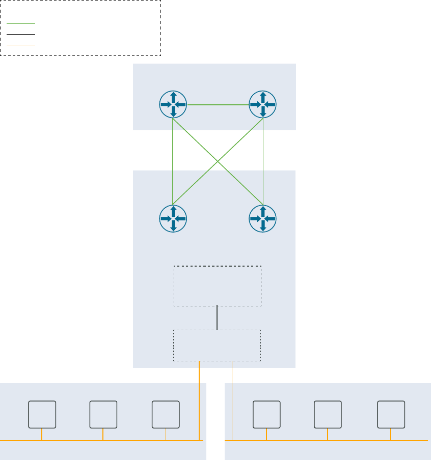
Figure 13-1. Two-node NSX Edge cluster in a single rack
ASN 65001
Physical Layer 3 Devices
NSX-T
Edge Cluster
Edge VM 1
Edge VM 2
Tier-0
Gateway
Active/ Active
ECMP
Tier-1
Gateway
ASN 65005
Segment 1 - 192.168.11.0/24
Segment 2 - 192.168.31.0/24
Legend:
VLANs
Tier-1 to Tier-0 Connection
Segment
VMVMVMVMVMVM
What to do next
In NSX Manager, you can create segments connected to the NSX Edge cluster's tier-1 gateway.
You can connect workload virtual machines to these segments to provide north-south and east-
west connectivity.
Add Edge Nodes to an NSX Edge Cluster
You can add NSX Edge nodes to an NSX Edge Cluster that you created with SDDC Manager.
You might want to add NSX Edge nodes to an NSX Edge cluster, for:
n Rack failure resiliency
VMware Cloud Foundation on Dell EMC VxRail Guide
VMware, Inc. 97

n When the Tier-0 Service High Availability is Active-Standby and you require more than two
NSX Edge nodes for services.
n When the Tier-0 Service High Availability is Active-Active and you require more than 8 NSX
Edge nodes for services.
n When you add Supervisor Clusters to a Workload Management workload domain and need
to support additional tier-1 gateways and services.
The available configuration settings for a new NSX Edge node vary based on:
n The Tier-0 Service High Availability setting (Active-Active or Active-Standby) of the NSX
Edge cluster.
n The Tier-0 Routing Type setting (static or EBGP) of the NSX Edge cluster.
n Whether the new NSX Edge node is going to be hosted on the same vSphere cluster as the
existing NSX Edge nodes (in-cluster) or on a different vSphere cluster (cross-cluster).
Note Stretched clusters only support in-cluster expansion.
Prerequisites
n Verify that separate VLANs and subnets are available for the NSX host overlay VLAN and
NSX Edge overlay VLAN. You cannot use DHCP for the NSX Edge overlay VLAN.
n Verify that the NSX host overlay VLAN and NSX Edge overlay VLAN are routed to each
other.
n For dynamic routing, set up two Border Gateway Protocol (BGP) peers on Top of Rack (ToR)
switches with an interface IP, BGP autonomous system number (ASN), and BGP password.
n Reserve a BGP ASN to use for the NSX Edge cluster’s Tier-0 gateway.
n Verify that DNS entries for the NSX Edge nodes are populated in the customer-managed
DNS server.
n The vSphere cluster hosting the NSX Edge nodes must include hosts with identical
management, uplink, NSX Edge overlay TEP, and NSX Edge overlay TEP networks (L2
uniform).
n The vSphere cluster hosting the NSX Edge nodes must have the same pNIC speed for NSX-
enabled VDS uplinks chosen for Edge overlay.
n All NSX Edge nodes in an NSX Edge cluster must use the same set of NSX-enabled VDS
uplinks. These uplinks must be prepared for overlay use.
n The NSX Edge cluster must be Active.
n The NSX Edge cluster must be hosted on one or more vSphere clusters from the same
workload domain.
Procedure
1 In the navigation pane, click Inventory > Workload Domains.
VMware Cloud Foundation on Dell EMC VxRail Guide
VMware, Inc. 98

2 In the Workload Domains page, click a domain name in the Domain column.
3 Click the Edge Clusters tab.
4 Click the vertical ellipsis menu for the Edge Cluster you want to expand and select Expand
Edge Cluster.
5 Verify the prerequisites, select Select All, and click Begin.
6 Enter and confirm the passwords for the NSX Edge cluster.
7 (Optional) Enter a name to create a new tier-1 gateway.
8 Enter the configuration settings for the new NSX Edge node and click Add Edge Node.
Setting Description
Edge Node Name (FQDN) Enter the FQDN for the NSX Edge node. Each node must have a unique
FQDN.
Management IP (CIDR) Enter the management IP for the NSX Edge node in CIDR format. Each node
must have a unique management IP.
Management Gateway Enter the IP address for the management network gateway.
Edge TEP 1 IP (CIDR) Enter the CIDR for the first NSX Edge TEP. Each node must have a unique
Edge TEP 1 IP.
Edge TEP 2 IP (CIDR) Enter the CIDR for the second NSX Edge TEP. Each node must have a
unique Edge TEP 2 IP. The Edge TEP 2 IP must be different than the Edge
TEP 1 IP.
Edge TEP Gateway Enter the IP address for the NSX Edge TEP gateway.
Edge TEP VLAN Enter the NSX Edge TEP VLAN ID.
Cluster Select a vSphere cluster to host the NSX Edge node.
If the workload domain has multiple vSphere clusters, you can select the
vSphere cluster hosting the existing NSX Edge nodes (in-cluster expansion)
or select a different vSphere cluster to host the new NSX Edge nodes
(cross-cluster expansion).
Cluster Type Select L2 Uniform if all hosts in the vSphere cluster have identical
management, uplink, host TEP, and Edge TEP networks.
Select L2 non-uniform and L3 if any of the hosts in the vSphere cluster have
different networks.
Important VMware Cloud Foundation does not support Edge cluster
creation onL2 non-uniform and L3 vSphere clusters.
VMware Cloud Foundation on Dell EMC VxRail Guide
VMware, Inc. 99

Setting Description
First NSX VDS Uplink Specify an ESXi uplink to map the first NSX Edge node uplink network
interface to a physical NIC on the host. The default is uplink1.
The information you enter here determines the active uplink on the first
VLAN port group used by the NSX Edge node. If you enter uplink3, then
uplink3 is the active uplink and the uplink you specify for the second NSX
VDS uplink is the standby uplink.
(cross-cluster only)
Note For in-cluster NSX Edge cluster expansion, new NSX Edge nodes use
the same NSX VDS uplinks as the other Edge nodes hosted on the vSphere
cluster.
Second NSX VDS Uplink Specify an ESXi uplink to map the second NSX Edge node uplink network
interface to a physical NIC on the host. The default is uplink2.
The information you enter here determines the active uplink on the second
VLAN port group used by the NSX Edge node. If you enter uplink4, then
uplink4 is the active uplink and the uplink you specify for the first NSX VDS
uplink is the standby uplink.
(cross-cluster only)
Note For in-cluster NSX Edge cluster expansion, new NSX Edge nodes use
the same NSX VDS uplinks as the other Edge nodes hosted on the vSphere
cluster.
Add Tier-0 Uplinks Optional. Click Add Tier-0 Uplinks to add tier-0 uplinks.
(Active-Active only)
First Tier-0 Uplink VLAN Enter the VLAN ID for the first uplink.
This is a link from the NSX Edge node to the first uplink network.
(Active-Active only)
First Tier-0 Uplink Interface IP
(CIDR)
Enter the CIDR for the first uplink. Each node must have unique uplink
interface IPs.
(Active-Active only)
Peer IP (CIDR) Enter the CIDR for the first uplink peer.
(EBGP only)
Peer ASN Enter the ASN for the first uplink peer.
(EBGP only)
BGP Peer Password Enter and confirm the BGP password.
(EBGP only)
Second Tier-0 Uplink VLAN Enter the VLAN ID for the second uplink.
This is a link from the NSX Edge node to the second uplink network.
(Active-Active only)
Second Tier-0 Uplink Interface
IP(CIDR)
Enter the CIDR for the second uplink. Each node must have unique uplink
interface IPs. The second uplink interface IP must be different than the first
uplink interface IP.
(Active-Active only)
Peer IP (CIDR) Enter the CIDR for the second uplink peer.
(EBGP only)
VMware Cloud Foundation on Dell EMC VxRail Guide
VMware, Inc. 100
Setting Description
ASN Peer Enter the ASN for the second uplink peer.
(EBGP only)
BGP Peer Password Enter and confirm the BGP password.
(EBGP only)
9 Click Add More Edge Nodes to enter configuration settings for additional NSX Edge nodes.
An NSX Edge cluster can contain a maximum of 10 NSX Edge nodes.
n For an NSX Edge cluster with a Tier-0 Service High Availability setting of Active-Active,
up to 8 of the NSX Edge nodes can have uplink interfaces.
n For an NSX Edge cluster with a Tier-0 Service High Availability setting of Active-Standby,
up to 2 of the NSX Edge nodes can have uplink interfaces.
10 When you are done adding NSX Edge nodes, click Next.
11 Review the summary and click Next.
SDDC Manager validates the NSX Edge node configuration details.
12 If validation fails, use the Back button to edit your settings and try again.
To edit or delete any of the NSX Edge nodes, click the three vertical dots next to an NSX
Edge node in the table and select an option from the menu.
13 If validation succeeds, click Finish to add the NSX Edge node(s) to the NSX Edge cluster.
You can monitor progress in the Tasks panel.
Remove Edge Nodes from an NSX Edge Cluster
You can remove NSX Edge nodes from an NSX Edge Cluster that you created with SDDC
Manager if you need to scale down to meet business needs.
Prerequisites
n The NSX Edge cluster must be available in the SDDC Manager inventory and must be Active.
n The NSX Edge node must be available in the SDDC Manager inventory.
n The NSX Edge cluster must be hosted on one or more vSphere clusters from the same
workload domain.
n The NSX Edge cluster must contain more than two NSX Edge nodes.
n The NSX Edge cluster must not be federated or stretched.
n If the NSX Edge cluster was deployed with a Tier-0 Service High Availability of Active-Active,
the NSX Edge cluster must contain two or more NSX Edge nodes with two or more Tier-0
routers (SR component) after the NSX Edge nodes are removed.
VMware Cloud Foundation on Dell EMC VxRail Guide
VMware, Inc. 101

n If selected edge cluster was deployed with a Tier-0 Service High Availability of Active-
Standby, you cannot remove NSX Edge nodes that are the active or standby node for the
Tier-0 router.
Procedure
1 In the navigation pane, click Inventory > Workload Domains.
2 In the Workload Domains page, click a domain name in the Domain column.
3 Click the Edge Clusters tab.
4 Click the vertical ellipsis menu for the Edge Cluster you want to expand and select Shrink
Edge Cluster.
5 Select the Edge node(s) to remove and click Next.
6 Review the summary and click Next.
SDDC Manager validates the request.
7 If validation fails, use the Back button to edit your settings and try again.
Note You cannot remove the active and standby Edge nodes of a Tier-1 router at the same
time. You can remove one and then remove the other after the first operation is complete.
8 If validation succeeds, click Finish to remove the NSX Edge node(s) from the NSX Edge
cluster.
You can monitor progress in the Tasks panel.
VMware Cloud Foundation on Dell EMC VxRail Guide
VMware, Inc. 102
Workload Management
14
VMware Cloud Foundation™ with VMware Tanzu™ enables you to deploy and operate the
compute, networking, and storage infrastructure for vSphere with Tanzu workloads. vSphere
with Tanzu transforms vSphere to a platform for running Kubernetes workloads natively on the
hypervisor layer.
When enabled on a vSphere cluster, vSphere with Tanzu provides the capability to run
Kubernetes workloads directly on ESXi hosts and to create upstream Kubernetes clusters within
dedicated resource pools. vSphere with Tanzu can also be enabled on the management domain
default cluster.
You validate the underlying infrastructure for vSphere with Tanzu from the SDDC Manager UI and
then complete the deployment in the vSphere Client. The SDDC Manager UI refers to the vSphere
with Tanzu functionality as Kubernetes - Workload Management.
For more information on vSphere with Tanzu, see What Is vSphere with Tanzu?.
Read the following topics next:
n Sizing Compute and Storage Resources for Workload Management
n Create a Subscribed Content Library
n Enable Workload Management
n View Workload Management Cluster Details
n Update Workload Management License
Sizing Compute and Storage Resources for Workload
Management
Compute and storage requirements for each component are key considerations when you size
the solution.
VMware, Inc.
103
Virtual Machine Nodes Total vCPUs Total Memory Total Storage
Supervisor Cluster control
plane
(small nodes - up to
2000 pods per Supervisor
cluster)
3 12 48 GB 200 GB
Registry Service N/A 7 7 GB 200 GB
Tanzu Kubernetes Cluster
control plane (small nodes)
3 (per cluster) 6 12 GB 48 GB
Tanzu Kubernetes Cluster
worker nodes (small nodes)
3 (per cluster) 6 12 GB 48 GB
NSX Edge node 2 16 64 GB 400 GB
Create a Subscribed Content Library
Before you can deploy a Tanzu Kubernetes cluster, create a Subscribed Content Library to store
virtual machine images that the VMware Tanzu™ Kubernetes Grid™ Service uses to create Tanzu
Kubernetes Cluster nodes.
You can create a Subscribed Content Library using the vSphere Client or using PowerShell.
Procedure
1 To create a Subscribed Content Library using the vSphere Client:
a In a web browser, log in to the workload domain vCenter Server by using the vSphere
Client (https://<vcenter_server_fqdn>/ui).
b Select Menu > Content Libraries.
c In the Content Libraries inventory, click +Create.
d On the Name and location page, configure the settings and click Next.
Setting
Value
Name Kubernetes
vCenter Server Select the workload domain vCenter Server.
e On the Configure content library page, select Subscribed content library, configure the
settings and click Next.
Setting
Value
Subscription URL https://wp-content.vmware.com/v2/latest/lib.json
Enable Authentication Deselected
Download Content Immediately
VMware Cloud Foundation on Dell EMC VxRail Guide
VMware, Inc. 104

f In the Kubernetes - Unable to verify authenticity dialog box, click Yes to accept the SSL
certificate thumbprint.
g On the Add Storage page, select your vSAN datastore, click Next.
h On the Ready to Complete page, review the settings and click Finish.
2 To create a Subscribed Content Library using PowerShell:
a Open a PowerShell Console, define variables for the inputs by entering the following
commands:
$sddcManagerFqdn = "sfo-vcf01.sfo.rainpole.io"
$sddcManagerUsername = "[email protected]"
$sddcManagerPassword = "VMw@re1!"
$wldName = "sfo-w01"
$contentLibraryUrl = "https://wp-content.vmware.com/v2/latest/lib.json"
$contentLibraryName = "Kubernetes"
$wldDatastoreName = "sfo-w01-cl01-ds-vsan01"
b Perform the configuration by entering the following commands:
Add-ContentLibrary -Server $sddcManagerFqdn -User $sddcManagerUsername -Pass
$sddcManagerPassword -Domain $wldName -ContentLibraryName $contentLibraryName
-Datastore $wldDatastoreName -SubscriptionUrl $contentLibraryUrl
Enable Workload Management
With Workload Management, you validate the underlying infrastructure for vSphere with Tanzu.
You then complete the deployment using the vSphere Client.
Prerequisites
n A VI workload domain must be deployed.
n An Workload Management ready NSX Edge cluster must be deployed on the workload
domain.
You must select Workload Management on the Use Case page of the Add Edge Cluster
wizard. See step 6 in Deploy an NSX Edge Cluster.
n All hosts in the vSphere cluster for which you enable Workload Management must have a
vSphere with Tanzu license.
n The following IP address subnets must be defined:
n A non-routable subnet for pod networking, minimum of a /22 subnet.
n A non-routable subnet for Service IP addresses, minimum of a /24 subnet
n A routable subnet for ingress, minimum of a /27 subnet
n A routable subnet for egress, minimum of a /27 subnet
VMware Cloud Foundation on Dell EMC VxRail Guide
VMware, Inc. 105
Procedure
1 In the navigation pane, click Solutions.
2 In the Kubernetes - Workload Management section, click Deploy.
3 Review the Workload Management prerequisites, click Select All, and click Begin.
4 Select the workload domain associated with the vSphere cluster where you want to enable
Workload Management.
The Workload Domain drop-down menu displays all Workload Management ready workload
domains, including the management domain.
vSphere clusters in the selected workload domain that are compatible with Workload
Management are displayed in the Compatible section. Incompatible clusters are displayed in
the Incompatible section, along with the reason for the incompatibility. If you want to get an
incompatible cluster to a usable state, you can exit the Workload Management deployment
wizard while you resolve the issue.
5 From the list of compatible clusters on the workload domain, select the cluster where you
want to enable
Workload Management and click Next.
6 On the Validation page, wait for validation to complete successfully and click Next.
The following validations are performed.
n vCenter Server validation (vCenter Server credentials, vSphere cluster object, and
version)
n Network validation (NSX Manager credentials and version)
n Compatibility validation (vSphere cluster and content library)
7 On the Review page, review your selections and click Complete in vSphere.
You are automatically redirected to the vSphere Client.
What to do next
Follow the deployment wizard within the vSphere Client to complete the Workload Management
deployment and configuration steps.
View Workload Management Cluster Details
The Workload Management page displays clusters with Workload Management. The status of
each cluster, number of hosts in the cluster, and associated workload domain is also displayed.
Procedure
1 In the navigation pane, click Solutions.
2 In the Kubernetes - Workload Management section, click View Details.
3 Click vSphere Workload Management Clusters to see cluster details in vSphere.
VMware Cloud Foundation on Dell EMC VxRail Guide
VMware, Inc. 106
Update Workload Management License
Once you enable Workload Management on a cluster, you must assign a Tanzu edition license to
the cluster before the evaluation license expires.
Prerequisites
You must have added the vSphere with Tanzu license key to the Cloud Foundation license
inventory. See Add a License Key.
Procedure
1 In the navigation pane, click Solutions.
2 Click the dots to the left of the cluster for which you want to update the license and click
Update Workload Management license.
3 Select the appropriate license and click Apply.
After the license update processing is completed, the Workload Management page is
displayed. The task panel displays the licensing task and its status.
VMware Cloud Foundation on Dell EMC VxRail Guide
VMware, Inc. 107
Working with vRealize Suite
Lifecycle Manager
15
When VMware Cloud Foundation mode is enabled in vRealize Suite Lifecycle Manager, the
behavior of vRealize Suite Lifecycle Manager is aligned with the VMware Cloud Foundation
architecture.
vRealize Suite Lifecycle Manager in VMware Cloud Foundation mode introduces the following
features:
n Binary mapping optimization. When vRealize Suite Lifecycle Manager runs in VMware Cloud
Foundation mode, it can poll and use the vRealize Suite product binaries directly from SDDC
Manager’s downloaded bundles.
n Automatic load balancer configuration. Load balancer preparation and configuration are no
longer a prerequisite when you use vRealize Suite Lifecycle Manager to deploy or perform a
cluster expansion on Workspace ONE Access, vRealize Operations, or vRealize Automation.
Load balancer preparation and configuration take place as part of the deploy or expand
operation.
n Automatic infrastructure selection in vRealize Suite Lifecycle Manager’s deployment wizards.
When you deploy a vRealize Suite product through vRealize Suite Lifecycle Manager,
infrastructure objects such as clusters and networks are pre-populated. They are fixed and
cannot be changed to ensure alignment with the VMware Cloud Foundation architecture.
n Cluster deployment for a new environment. You can deploy vRealize Log Insight, vRealize
Operations, or vRealize Automation in clusters. You can deploy Workspace ONE Access
either as a cluster or a single node. If you deploy Workspace ONE Access as a single node,
you can expand it to a cluster later.
n Consistent Bill Of Materials (BOM). vRealize Suite Lifecycle Manager in VMware Cloud
Foundation mode only displays product versions that are compatible with VMware Cloud
Foundation to ensure product interoperability.
n Inventory synchronization between vRealize Suite Lifecycle Manager and SDDC Manager.
vRealize Suite Lifecycle Manager can detect changes made to vRealize Suite products and
update its inventory through inventory synchronization. When VMware Cloud Foundation
mode is enabled in vRealize Suite Lifecycle Manager, inventory synchronization in vRealize
Suite Lifecycle Manager also updates SDDC Manager’s inventory to get in sync with the
current state of the system.
VMware, Inc.
108
n Product versions. You can only access the versions for the selected vRealize products that
are specifically supported by VMware Cloud Foundation itself.
n Resource pool and advanced properties. The resources in the Resource Pools under the
Infrastructure Details are blocked by the vRealize Suite Lifecycle Manager UI, so that the
VMware Cloud Foundation topology does not change. Similarly, the Advanced Properties
are also blocked for all products except for Remote Collectors. vRealize Suite Lifecycle
Manager also auto-populates infrastructure and network properties by calling VMware Cloud
Foundation deployment API.
n Federal Information Processing Standard (FIPS) compliance.
n Watermark.
Read the following topics next:
n vRealize Suite Lifecycle Manager Implementation
n Clustered Workspace ONE Access Implementation
vRealize Suite Lifecycle Manager Implementation
You deploy vRealize Suite Lifecycle Manager in VMware Cloud Foundation mode by using SDDC
Manager. After that, you perform the necessary post-deployment configurations.
By default, VMware Cloud Foundation uses NSX-T Data Center to create NSX segments
and deploys vRealize Suite Lifecycle Manager and the vRealize Suite products to these NSX
segments. Starting with VMware Cloud Foundation 4.3, NSX segments are no longer configured
during the management domain bring-up process, but instead are configured using the SDDC
Manager UI. The new process offers the choice of using either overlay-backed or VLAN-backed
segments. See Deploy Application Virtual Networks for vRealize Suite Components.
vRealize Suite Lifecycle Manager runs in VMware Cloud Foundation mode, the integration
ensures awareness between the two components. You launch the deployment of vRealize Suite
products from the SDDC Manager UI and are redirected to the vRealize Suite Lifecycle Manager
UI where you complete the deployment process.
Prerequisites
n Download the VMware Software Install Bundle for vRealize Suite Lifecycle Manager from the
VMware Depot to the local bundle repository. See Download VMware Cloud Foundation on
Dell EMC VxRail Bundles.
n Allocate an IP address for the vRealize Suite Lifecycle Manager virtual appliance on the
cross-instance NSX segment and prepare both forward (A) and reverse (PTR) DNS records.
n Allocate an IP address for the NSX-T Data Center standalone Tier-1 Gateway on the cross-
instance NSX segment. This address is used for the service interface of the standalone NSX-T
Data Center Tier 1 Gateway created during the deployment. The Tier 1 Gateway is used for
load-balancing of specific vRealize Suite products and Workspace ONE Access.
VMware Cloud Foundation on Dell EMC VxRail Guide
VMware, Inc. 109
n Ensure you have enough storage capacity:
n Required storage: 178 GB
n Virtual disk provisioning: Thin
n Verify that the management domain vCenter Server is operational.
n Verify that the cross-instance NSX segment is available.
n Verify that NSX Manager is operational.
n Verify the Prerequisite Checklist sheet in the
Planning and Preparation Workbook
.
Deploy Application Virtual Networks for vRealize Suite Components
Before you can deploy vRealize Suite components, you must deploy Application Virtual
Networks in the management domain.
An Application Virtual Network (AVN) is a software-defined networking concept based on NSX-T
Data Center that allows the hosting of management applications on NSX segments. In NSX-T
Data Center, segments are virtual layer-2 domains.
You can create overlay-backed NSX segments or VLAN-backed NSX segments. Both options
create two NSX segments (Region-A and X-Region) on the NSX Edge cluster deployed in the
default management vSphere cluster. Those NSX segments are used when you deploy the
vRealize Suite products. Region-A segments are local instance NSX segments and X-Region
segments are cross-instance NSX segments.
Overlay-Backed NSX Segments
Overlay-backed segments provide flexibility for workload placement by removing the
dependence on traditional data center networks. Using overlay-backed segments improves the
security and mobility of management applications and reduces the integration effort with existing
networks. Overlay-backed segments are created in an overlay transport zone.
In an overlay-backed segment, traffic between two VMs on different hosts but attached to
the same overlay segment have their layer-2 traffic carried by a tunnel between the hosts.
NSX-T Data Center instantiates and maintains this IP tunnel without the need for any segment-
specific configuration in the physical infrastructure. As a result, the virtual network infrastructure
is decoupled from the physical network infrastructure. That is, you can create segments
dynamically without any configuration of the physical network infrastructure.
VLAN-Backed NSX Segments
VLAN-backed segments leverage the physical data center networks to isolate management
applications, while still taking advantage of NSX-T Data Center to manage these networks.
VLAN-backed network segments ensure the security of management applications without
requiring support for overlay networking. VLAN-backed segments are created in a VLAN
transport zone.
VMware Cloud Foundation on Dell EMC VxRail Guide
VMware, Inc. 110

A VLAN-backed segment is a layer-2 broadcast domain that is implemented as a traditional
VLAN in the physical infrastructure. This means that traffic between two VMs on two different
hosts but attached to the same VLAN-backed segment is carried over a VLAN between the two
hosts. The resulting constraint is that you must provision an appropriate VLAN in the physical
infrastructure for those two VMs to communicate at layer-2 over a VLAN-backed segment.
vRealize Suite Components and NSX Segments
When you deploy the vRealize Suite components, they use the NSX segments that you created.
vRealize Suite Component NSX Segment
vRealize Log Insight Region-A
vRealize Operations Manager X-Region
Workspace ONE Access X-Region
vRealize Automation X-Region
vRealize Suite Lifecycle Manager X-Region
Deploy Overlay-Backed NSX Segments
Create overlay-backed NSX segments, also known as Application Virtual Networks (AVNs), for
use with vRealize Suite components.
This procedure describes creating overlay-backed NSX segments. If you want to create VLAN-
backed NSX segments instead, see Deploy VLAN-Backed NSX Segments.
Prerequisites
Create an NSX Edge cluster for Application Virtual Networks, using the recommended settings, in
the default management vSphere cluster. See Deploy an NSX Edge Cluster.
Procedure
1 In the navigation page, click Inventory > Workload Domains.
2 Click on the management domain.
3 Select Actions > Add AVNs.
4 Select Overlay-backed network segment and click Next.
5 Select an NSX Edge cluster and a Tier-1 gateway.
6 Enter information for each of the NSX segments (Region-A and X-Region):
Option
Description
Name Enter a name for the NSX segment. For example, Mgmt-RegionA01.
Subnet Enter a subnet for the NSX segment.
Subnet mask Enter a subnet mask for the NSX segment.
VMware Cloud Foundation on Dell EMC VxRail Guide
VMware, Inc. 111
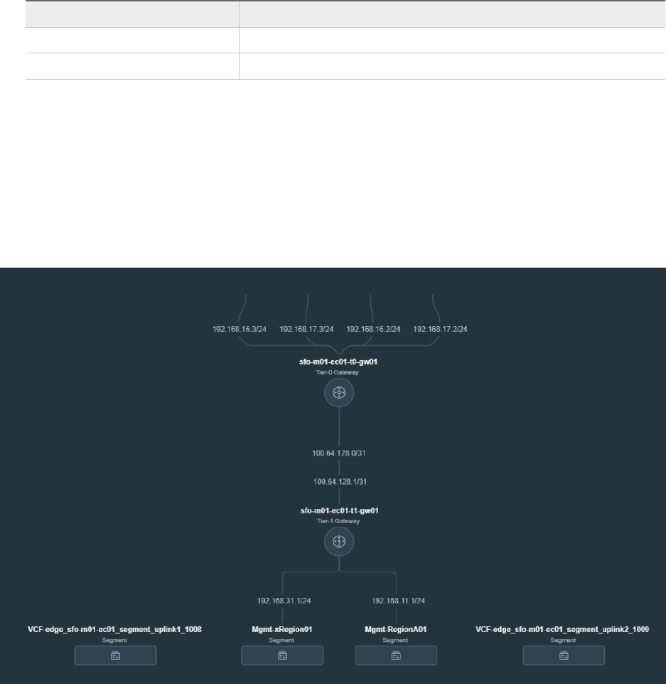
Option Description
Gateway Enter a gateway for the NSX segment.
MTU Enter an MTU for the NSX segment.
7 Click Validate Settings and then click Next.
If validation does not succeed, verify and update the information you entered for the NSX
segments and click Validate Settings again.
8 Review the settings and click Finish.
Example
Example Network Topology for Overlay-Backed NSX Segments
Deploy VLAN-Backed NSX Segments
Create VLAN-backed NSX segments, also known as Application Virtual Networks (AVNs), for use
with vRealize Suite components.
This procedure describes creating VLAN-backed NSX segments. If you want to create overlay-
backed NSX segments instead, see Deploy Overlay-Backed NSX Segments.
Prerequisites
Create an NSX Edge cluster for Application Virtual Networks, using the recommended settings, in
the default management vSphere cluster. See Deploy an NSX Edge Cluster.
You must have an available VLAN ID for each NSX segment.
VMware Cloud Foundation on Dell EMC VxRail Guide
VMware, Inc. 112
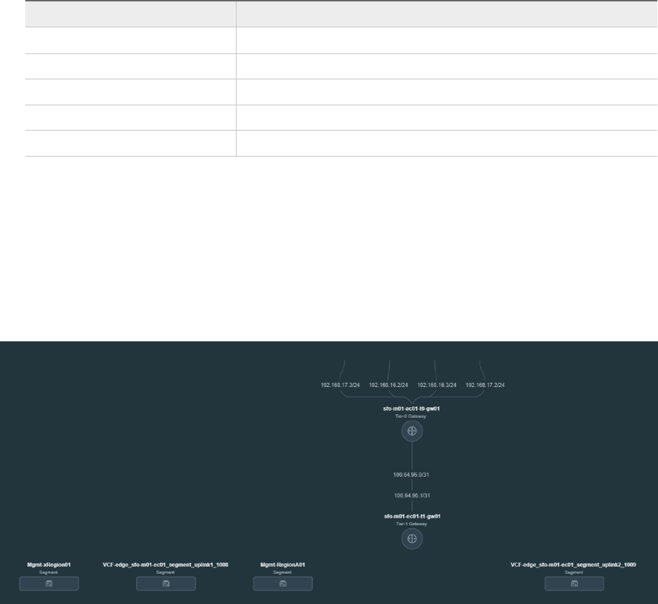
Procedure
1 In the navigation page, click Inventory > Workload Domains.
2 Click on the management domain.
3 Select Actions > Add AVNs.
4 Select VLAN-backed network segment and click Next.
5 Select an NSX Edge cluster.
6 Enter information for each of the NSX segments (Region-A and X-Region):
Option Description
Name Enter a name for the NSX segment. For example, Mgmt-RegionA01.
Subnet Enter a subnet for the NSX segment.
Gateway Enter a gateway for the NSX segment.
MTU Enter an MTU for the NSX segment.
VLAN ID Enter the VLAN ID for the NSX segment.
7 Click Validate Settings and then click Next.
If validation does not succeed, verify and update the information you entered for the NSX
segments and click Validate Settings again.
8 Review the settings and click Finish.
Example
Example Network Topology for VLAN-Backed NSX Segments
Deploy vRealize Suite Lifecycle Manager
You deploy the vRealize Suite Lifecycle Manager in VMware Cloud Foundation mode by using the
SDDC Manager UI.
VMware Cloud Foundation on Dell EMC VxRail Guide
VMware, Inc. 113

Procedure
1 In the navigation pane, click Administration > vRealize Suite.
2 Click Deploy.
3 Review and verify the prerequisites.
Click each prerequisite check box and then click Begin.
4 On the Network Settings page, review the settings and click Next.
5 On the Virtual Appliance Settings page, enter the settings and click Next.
Setting Description
Virtual Appliance: FQDN The FQDN for the vRealize Suite Lifecycle Manager
virtual appliance.
Note The reverse (PTR) DNS record of this fully
qualified domain name is used as the IP address for the
virtual appliance.
NSX-T Tier 1 Gateway: IP Address A free IP Address within the cross-instance virtual
network segment.
Note Used to create a service interface on the NSX-
T Data Center Tier 1 Gateway, where VMware Cloud
Foundation automatically configures the load-balancer
for the vRealize Suite.
System Administrator Create and confirm the password for the vRealize
Suite Lifecycle Manager administrator account,
vcfadmin@local. The password created is the
credential that allows SDDC Manager to connect to
vRealize Suite Lifecycle Manager.
Note When vRealize Suite Lifecycle Manager is
deployed by SDDC Manager it is enabled for VMware
Cloud Foundation mode. As a result, the administrator
account for is vcfadmin@local instead of admin@local.
SSH Root Account Create and confirm a password for the vRealize Suite
Lifecycle Manager virtual appliance root account.
6 On the Review Summary page, review the installation configuration settings and click Finish.
SDDC Manager validates the values and starts the deployment.
The vRealize Suite page displays the following message: Deployment in progress.
If the deployment fails, this page displays a deployment status of Deployment failed. In
this case, you can click Restart Task or Rollback.
7 (Optional) To view details about the individual deployment tasks, in the Tasks panel at the
bottom, click each task.
VMware Cloud Foundation on Dell EMC VxRail Guide
VMware, Inc. 114

Replace the Certificate of the vRealize Suite Lifecycle Manager
Instance
To establish a trusted connection to vRealize Suite Lifecycle Manager, you replace the SSL
certificate on the appliance by using the SDDC Manager UI.
Procedure
1 In the navigation pane, click Inventory > Workload Domains.
2 On the Workload Domain page, from the table, in the domain column click the management
domain.
3 On the domain summary page, click the Security tab.
4 From the table, select the check box for the vrslcm resource type, and click Generate CSRs.
5 On the Details page, enter the following settings and click Next.
Settings Description
Algorithm Select the key algorithm for the certificate.
Key Size Select the key size (2048 bit, 3072 bit, or 4096 bit)
from the drop-down menu.
Email Optionally, enter a contact email address.
Organizational Unit Use this field to differentiate between divisions
within your organization with which this certificate is
associated.
Organization Name Type the name under which your company is known.
The listed organization must be the legal registrant of
the domain name in the certificate request.
Locality Type the city or locality where your company is legally
registered.
State Type the full name (do not abbreviate) of the state,
province, region, or territory where your company is
legally registered.
Country Type the country name where your company is legally
registered. This value must use the ISO 3166 country
code.
6 On the Subject Alternative Name page, leave the default SAN and click Next.
7 On the Summary page, click Generate CSRs.
8 After the successful return of the operation, click Generate signed certificates.
9 In the Generate Certificates dialog box, from the Select Certificate Authority drop-down
menu, select Microsoft.
10 Click Generate certificates.
VMware Cloud Foundation on Dell EMC VxRail Guide
VMware, Inc. 115
11 After the successful return of the operation, click Install certificates.
Wait for the successful return of the operation.
Update vRealize Suite Lifecycle Manager to vSphere Integration
You create a new user in vCenter Single Sign-On and update the vRealize Suite Lifecycle
Manager to vSphere integration.
Create a vCenter Single Sign-On User
Before you can update the vRealize Suite Lifecycle Manager data center to use a new account,
you must first create the account in vCenter Single Sign-On.
Procedure
1 Log in to the management domain vCenter Server at https://
<management_vcenter_server_fqdn>/ui as a user with Administrator role.
2 Navigate to Administration, under Single Sign On, select Users and Groups.
3 In the Users and Groups pane, under Users, select vsphere.local from the Domain drop
down, and click Add.
4 On the Add User page enter the following and click Add.
Setting
Value
Username svc-vrslcm-vsphere-<management_vcenter_name>
Password Enter a password
Confirm Password Re-enter the password
Configure Service Account Permissions in vSphere for Integration with vRealize
Suite Lifecycle Manager
To allow deploying and managing SDDC components on the Management domain vCenter
Server inventory, you assign account permissions to the service account for communication from
vRealize Suite Lifecycle Manager to vSphere.
Procedure
1 Log in to the management domain vCenter Server at https://
<management_vcenter_server_fqdn>/ui as a user with Administrator role.
VMware Cloud Foundation on Dell EMC VxRail Guide
VMware, Inc. 116

2 Assign global permissions to the service account.
a Select Menu > Administration.
b Under Access control, click Global permissions.
c Click the Add permission icon, enter these values, and click OK.
Setting Value
Domain vsphere.local
User/Group svc-vrslcm-vsphere-<management_vcenter_name>
Role vRealize Suite Lifecycle Manager to vSphere
Integration
Propagate to children Selected
Create New Password Alias in the vRealize Suite Lifecycle Manager Locker
You create a new password alias in vRealize Suite Lifecycle Manager that maps to the user
created in vCenter Single-Sign On.
Procedure
1 In a web browser, log in to vRealize Suite Lifecycle Manager with the vcfadmin@local user by
using the user interface (https://<vrslcm_fqdn>).
2 On the My services page, click Locker.
3 In the navigation pane, click Passwords.
4 Add a new password alias
a On the Passwords page, click Add.
b Enter the following and click Add
Setting
Value
Password Alias svc-vrslcm-vsphere_<management_vcenter_name>
Password Enter a password
Confirm Password Re-enter the password
Password Description Optionally, enter a description
User name svc-vrslcm-
vsphere_<management_vcenter_name>@vsphere.lo
cal
VMware Cloud Foundation on Dell EMC VxRail Guide
VMware, Inc. 117
Reconfigure Data Centers and vCenter Server in vRealize Suite Lifecycle
Manager
Before you can create a local environment for product deployments, you must update the
credentials for the management domain vCenter Server that is associated with the region-
specific data center in vRealize Suite Lifecycle Manager.
Prerequisites
During the vRealize Suite Lifecycle Manager deployment, SDDC Manager adds the instance-
specific management data center to vRealize Suite Lifecycle Manager. SDDC Manager
associates the instance-specific data center with the management domain vCenter Server by
using the [email protected] account. You reconfigure the integration to the
management domain vCenter Server in the instance-specific data center to use the svc-vrslcm-
vsphere_<management_vcenter_name> account for the deployment of the instance-specific
components, such as vRealize Log Insight. This ensures a unique account is used per vCenter
Server and enables scale out to additional VMware Cloud Foundation instances.
Procedure
1 In a Web browser, log in to vRealize Suite Lifecycle Manager by using the administration
interface.
2 On the My services page, click Lifecycle operations.
3 In the navigation pane, click Datacenters.
4 Reconfigure integration to the management domain vCenter Server in the region-specific
data center to use the svc-vrslcm-vsphere_<management_vcenter_name> account.
a On the Datacenters page, expand the managment data center.
b In the row for the management vCenter, click Edit vCenter.
c Update these values and click Validate.
Setting
Value
vCenter credentials svc-vrslcm-
vsphere_<management_vcenter_name>
d After the successful vCenter Server validation, click Save.
Configure Data Center and vCenter Server in vRealize Suite Lifecycle
Manager
Before you can create a global environment for product deployments, you must add a cross-
instance data center and the associated management domain vCenter Server to vRealize Suite
Lifecycle Manager.
You add the cross-instance data center, and the associated management domain vCenter Server
for the deployment of the global components, such as the clustered Workspace ONE Access.
VMware Cloud Foundation on Dell EMC VxRail Guide
VMware, Inc. 118
Procedure
1 In a web browser, log in to vRealize Suite Lifecycle Manager with the vcfadmin@local user by
using the user interface (https://<vrslcm_fqdn>).
2 On the My Services page, click Lifecycle Operations.
3 In the navigation pane, click Datacenters.
4 Click Add datacenter, enter the values for the global data center, and click Save.
Setting Value
Datacenter name Name for cross-instance datacenter
Use custom location Disabled
Location Location of datacenter
5 Add the management domain vCenter Server to the global data center.
a On the Datacenters page, expand the global data center and click Add vCenter.
b Enter the management domain vCenter Server information and click Validate.
Setting
Value
vCenter name Enter a name for the vCenter Server
vCenter FQDN Enter the FQDN of the vCenter Server
vCenter credentials Select the svc-vrslcm-vsphere-
<management_vcenter_name> credential.
vCenter type Management
6 After the successful vCenter Server validation, click Save.
7 In the navigation pane, click Requests and verify that the state of the vCenter data collection
request is Completed.
Clustered Workspace ONE Access Implementation
Identity and access management services for the vRealize Suite of products is provided
by Workspace ONE Access. You use vRealize Suite Lifecycle Manager to deploy a 3-node
clustered Workspace ONE Access instance. You then perform the necessary post-deployment
configurations and customization.
Prerequisites
n Downloaded the VMware Software Install Bundle for Workspace ONE Access from the
VMware Depot to the local bundle repository. See Download VMware Cloud Foundation on
Dell EMC VxRail Bundles.
VMware Cloud Foundation on Dell EMC VxRail Guide
VMware, Inc. 119
n Allocate 5 IP addresses from the cross-instance NSX segment and prepare both forward (A)
and reverse (PTR) DNS records.
n 3 IP addresses for the clustered Workspace ONE Access
n An IP address for embedded Postgres database for Workspace ONE Access instance
n An IP address for the NSX-T Data Center external load balancer virtual server for
clustered Workspace ONE Access instance.
n Ensure you have enough storage capacity:
n Required storage per node: 100 GB
n Virtual disk provisioning: Thin
n Verify that the management domain vCenter Server is operational.
n Verify that the cross-instance NSX segment is available
n Verify that the NSX Manager is operational.
n Verify the Prerequisite Checklist sheet in the
Planning and Preparation Workbook
.
n Verify that required Active Directory bind service account is created.
Verify that required Active Directory security groups are created.
n Download the CertGenVVS tool and generate the signed certificate for the clustered
Workspace ONE Access instance. See KB 85527.
Import the Clustered Workspace ONE Access Certificate to vRealize
Suite Lifecycle Manager
In vRealize Suite Lifecycle Manager, import the clustered Workspace ONE Access certificate that
you generated with the CertGenVVS utility.
For details on using the CertGenVVS utility, see https://kb.vmware.com/s/article/85527.
Procedure
1 In a web browser, log in to vRealize Suite Lifecycle Manager with the vcfadmin@local user by
using the user interface (https://<vrslcm_fqdn>).
2 On the My Services page, click Locker.
3 In the navigation pane, click Certificates.
4 On the Certificates page, click Import.
VMware Cloud Foundation on Dell EMC VxRail Guide
VMware, Inc. 120
5 On the Import certificate page, configure the settings and click Import.
Setting Value
Name
Clustered Workspace One Access
Select Certificate file Click Browse file, navigate to the clustered Workspace
ONE Access certificate PEM file, and click Open.
Add Clustered Workspace ONE Access Passwords to vRealize Suite
Lifecycle Manager
To enable life cycle management and configuration management, you set the passwords for the
vRealize Suite Lifecycle Manager cross-instance environment administrator account and for the
Workspace ONE Access administrator and configuration administrator accounts.
You add the following passwords for the corresponding local administrative accounts.
Setting
Value for Global
Environment Administrator
Value for Local
Administrator
Value for
Local Configuration
Administrator
Password alias global-env-admin xint-wsa-admin xint-wsa-configadmin
Password
global_env_admin_passwo
rd
xreg_wsa_admin_passwor
d
xreg_wsa_configadmin_pa
ssword
Confirm password
global_env_admin_passwo
rd
xreg-wsa_admin_password xreg_wsa_configadmin_pa
ssword
Password description vRealize Suite Lifecycle
Manager global
environment administrator
password
Clustered Workspace ONE
Access administrator
Clustered Workspace
ONE Access configuration
administrator
User name admin admin configadmin
Procedure
1 In a web browser, log in to vRealize Suite Lifecycle Manager with the vcfadmin@local user by
using the user interface (https://<vrslcm_fqdn>).
2 On the My Services page, click Locker.
3 In the navigation pane, click Passwords.
4 On the Passwords page, click Add.
5 On the Add password page, configure the settings and click Add.
6 Repeat this procedure for all the remaining credentials.
VMware Cloud Foundation on Dell EMC VxRail Guide
VMware, Inc. 121

Deploy Clustered Workspace ONE Access Instance Using vRealize
Suite Lifecycle Manager
To provide identity and access management services to the cross-instance SDDC components,
you create a global environment in vRealize Suite Lifecycle Manager in which you deploy a
3-node clustered Workspace ONE Access instance.
Procedure
1 In a web browser, log in to vRealize Suite Lifecycle Manager with the vcfadmin@local user by
using the user interface (https://<vrslcm_fqdn>).
2 On the My Services page, click Lifecycle Operations.
3 On the Dashboard page, click Create environment.
4 On the Create environment page, configure the settings and click Next.
Setting Value
Install Identity Manager Selected
Default password global-env-admin
Datacenter Select the cross-instance datacenter.
JSON configuration Disabled
Join the VMware customer experience improvement
program
Selected
5 On the Select product page, select the check box for VMware Identity Manager, configure
these values, and click Next.
Setting
Value
Installation type New install
Version 3.3.5
Deployment type Cluster
6 On the Accept license agreements page, scroll to the bottom and accept the license
agreement, and then click Next.
7 On the Certificate page, from the Select certificate drop-down menu, select the
Clustered
Workspace One Certificate
, and click Next.
8 On the Infrastructure page, verify and accept the default settings, and click Next.
9 On the Network page, verify and accept the default settings, and click Next.
VMware Cloud Foundation on Dell EMC VxRail Guide
VMware, Inc. 122
10 On the Products page, configure the deployment properties of clustered Workspace ONE
Access and click Next.
a In the Product properties section, configure the settings.
Setting Value
Certificate
Clustered Workspace One Certificate
Node size Medium (vRealize Automation recommended size)
Admin password Select the
xint-wsa-admin
Default configuration admin email Enter a default email.
Default configuration admin user name configadmin
Default configuration admin password Select the
xint-wsa-configadmin
Sync group members Selected
b In the Cluster VIP FQDN section, configure the settings.
Setting Value
FQDN Enter the FQDN of the NSX-T Data Center load
balancer virtual server for clustered Workspace ONE
Access instance.
Locker certificate Clustered Workspace ONE Access Certificate
Database IP address Enter the IP address for the embedded Postgres
database.
Note The IP address must be a valid IP address for
the cross-instance NSX segment.
c
In the Components section, configure the three cluster node.
Setting
Value for vidm-primary
Value for vidm-
secondary-1
Value for vidm-
secondary-2
VM Name Enter a VM Name for
vidm-primary.
Enter a VM Name for
vidm-secondary-1.
Enter a VM Name for
vidm-secondary-2.
FQDN Enter the FQDN for
vidm-primary
Enter the FQDN for
vidm-secondary-1.
Enter the FQDN for
vidm-secondary-2.
IP address Enter the IP Address for
vidm-primary.
Enter the IP Address for
vidm-secondary-1.
Enter the IP Address for
vidm-secondary-2.
11 On the Precheck page, click Run precheck.
12 On the Manual validations page, select the I took care of the manual steps above and am
ready to proceed check box and click Run precheck.
13 Review the validation report, remediate any errors, and click Re-run precheck.
VMware Cloud Foundation on Dell EMC VxRail Guide
VMware, Inc. 123

14 Wait for all prechecks to complete with Passed messages and click Next.
15 On the Summary page, review the configuration details. To back up the deployment
configuration, click Export configuration.
16 To start the deployment, click Submit.
The Request details page displays the progress of deployment.
17 Monitor the steps of the deployment graph until all stages become Completed.
Configure an Anti-Affinity Rule and a Virtual Machine Group for the
Clustered Workspace ONE Access Instance
To protect the clustered Workspace ONE Access nodes from a host-level failure, configure an
anti-affinity rule to run the virtual machines on different hosts in the default management vSphere
cluster. You then configure a VM group to define the startup order to ensure that vSphere High
Availability powers on the clustered Workspace ONE Access nodes in the correct order.
Procedure
1 In a web browser, log in to the management domain vCenter Server by using the vSphere
Client (https://<vcenter_server_fqdn>/ui).
2 Select Menu > Hosts and Clusters.
3 In the inventory expand <vCenter Server> Datacenter.
4 Select the cluster and click the Configure tab.
5 Create the anti-affinity rule for the clustered Workspace ONE Access virtual machines.
a Navigate to Configuration > VM/Host rules and click Add.
b Configure the settings and click OK.
Setting
Value
Name <management-domain-name>-anti-affinity-rule-wsa
Enable rule Selected
Type Separate Virtual Machines
Members Click Add, select the clustered Workspace ONE
Access nodes, and click OK.
n vidm-primary_VM
n
vidm-secondary-1_VM
n vidm-secondary-2_VM
VMware Cloud Foundation on Dell EMC VxRail Guide
VMware, Inc. 124
6 Create a virtual machine group for the clustered Workspace ONE Access nodes.
a Navigate to Configuration > VM/Host groups and click Add.
b Configure the settings and click OK.
Setting Value
Name Clustered Workspace ONE Access Appliances
Type VM Group
Members Click Add, select the clustered Workspace ONE
Access nodes, and click OK.
n vidm-primary_VM
n
vidm-secondary-1_VM
n vidm-secondary-2_VM
Configure NTP on the Clustered Workspace ONE Access Instance
To keep NTP synchronized with the other SDDC components, configure NTP on each Workspace
ONE Access node.
You configure the time synchronization for all nodes in the clustered Workspace ONE Access
instance.
Table 15-1. Global Workspace ONE Access Instance Nodes
Role FQDN
Node 1 vidm-primary_VM
Node 2 vidm-secondary-1_VM
Node 3 vidm-secondary-2_VM
Procedure
1 In a web browser, log in to the Workspace ONE Access instance with the admin user by
using the appliance configuration interface (https://<wsa_node_fqdn>:8443/cfg/login).
2 In the navigator pane, click Time synchronization.
3 Configure the settings and click Save.
Setting
Description
Time sync NTP selected
NTP Server Enter the FQDN of the NTP server.
4 Repeat this procedure for the remaining clustered Workspace ONE Access nodes.
VMware Cloud Foundation on Dell EMC VxRail Guide
VMware, Inc. 125

Configure Identity Source for the Clustered Workspace ONE Access
Instance
To enable identity and access management in the SDDC, you integrate your Active Directory
with the clustered Workspace ONE Access instance and configure attributes to synchronize
users and groups.
Procedure
1 In a web browser, log in to the clustered Workspace ONE Access instance by using
the administration interface to the System Domain with configadmin user (https://
<wsa_cluster_fqdn>/admin).
2 On the main navigation bar, click Identity and access management.
3 Click the Directories tab, and from the Add directory drop-down menu, select Add Active
Directory over LDAP/IWA.
4 On the Add directory page, configure the following settings, click Test connection and click
Save and next.
Setting Value
Directory name Enter a name for directory.
For example, sfo.rainpole.io.
Active Directory over LDAP Selected
Sync connector Select the FQDN of vidm-primary
Do you want this connector to also perform
authentication?
Yes
Directory search attribute SAMAccountName
This Directory requires all connections to use
STARTTLS (Optional)
If you want to secure communication between
Workspace ONE Access and Active Directory select
this option and paste the Root CA certificate in the SSL
Certificate box.
Base DN Enter the Base Distinguished Name from which to start
user searches.
For example, cn=Users,dc=sfo,dc=rainpole,dc=io.
Bind DN Enter the DN for the user to connect to Active
Directory.
For example, cn=svc-wsa-ad,ou=Service
Accounts,dc=sfo,dc=rainpole,dc=io.
Bind user password Enter the password for the Bind user.
For example:
svc-wsa-ad_password
.
5 On the Select the domains page, review the domain name and click Next.
6 On the Map user attributes page, review the attribute mappings and click Next.
VMware Cloud Foundation on Dell EMC VxRail Guide
VMware, Inc. 126

7 On the Select the groups (users) you want to sync page, enter the
distinguished name for the folder containing your groups (For example OU=Security
Groups,DC=sfo,DC=rainpole,DC=io) and click Select.
8 For each Group DN you want to include, select the group to use by the clustered Workspace
ONE Access instance for each of the roles, and click Save then Next.
Product Role Assigned via Group
Workspace ONE Access Super Admin
Directory Admin
ReadOnly Admin
vRealize Suite Lifecycle Manager VCF Role
Content Admin
Content Developers
9 On the Select the Users you would like to sync page, enter the distinguished name for the
folder containing your users (e.g. OU=Users,DC=sfo,DC=rainpole,DC=io) and click Next.
10 On the Review page, click Edit, from the Sync frequency drop-down menu, select Every 15
minutes, and click Save.
11 To initialize the directory import, click Sync directory.
Add the Clustered Workspace ONE Access Cluster Nodes as Identity
Provider Connectors
To provide high availability for the identity and access management services of the clustered
Workspace ONE Access instance, you add the cluster nodes as directory connectors.
Procedure
1 In a web browser, log in to the clustered Workspace ONE Access instance by using
the administration interface to the System Domain with configadmin user (https://
<wsa_cluster_fqdn>/admin).
2 On the main navigation bar, click Identity and access management.
3 Click the Identity Providers tab.
4 Click the WorkspaceIDP__1 identity provider.
VMware Cloud Foundation on Dell EMC VxRail Guide
VMware, Inc. 127

5 On the WorkspaceIDP__1 details page, under Connector(s) from the Add a connector drop-
down menu, select vidm-secondary-1_VM, configure the settings, and click Add connector.
Setting Value
Connector vidm-secondary-1_VM
Bind to AD Checked
Bind user password
svc-wsa-ad_password
6 Repeat this step for the vidm-secondary-2_VM connector.
7 In the IdP Hostname text box, enter the FQDN of the NSX-T Data Center load balancer virtual
server for Workspace ONE Access cluster.
8 Click Save.
Assign Roles to Active Directory Groups for the Clustered Workspace
ONE Access Instance
Workspace ONE Access uses role-based access control to manage delegation of roles. You
assign the Super Admin, Directory Admin and ReadOnly roles to Active Directory groups to
manage access to the clustered Workspace ONE Access instance.
You assign the following administrator roles to the corresponding user groups.
Workspace ONE Access Role
Example Active Directory Group Name
Super Admin wsa-admins
Directory Admin wsa-directory-admin
ReadOnly Admin wsa-read-only
Procedure
1 In a web browser, log in to the clustered Workspace ONE Access instance by
using the administration interface to the System Domain with configadmin user (https://
<wsa_cluster_fqdn>/admin).
2 On the main navigation bar, click Roles.
3 Assign Workspace ONE Access roles to Active Directory groups.
a Select the Super Admin role and click Assign.
b In the Users / User Groups search box, enter the name of the Active Directory group you
want to assign the role to, select the group, and click Save.
c Repeat this step to configure the Directory Admin and the ReadOnly Admin roles.
VMware Cloud Foundation on Dell EMC VxRail Guide
VMware, Inc. 128

Assign Roles to Active Directory Groups for vRealize Suite Lifecycle
Manager
To enable identity and access management for vRealize Suite Lifecycle Manager, you integrate
the component with the clustered Workspace ONE Access instance.
You assign the following administrative roles to corresponding Active Directory groups.
vRealize Suite Lifecycle Manager Role Example Active Directory Group Name
VCF Role vrslcm-admins
Content Release Manager vrslcm-release-manager
Content Developer vrlscm-content-developer
Procedure
1 In a web browser, log in to vRealize Suite Lifecycle Manager with the vcfadmin@local user by
using the user interface (https://<vrslcm_fqdn>).
2 On the My Services page, click Identity and Tenant Management.
3 In the navigation pane, click User management and click Add user / group.
4 On the Select users / groups page, in the search box, enter the name of the group you want
to assign the role too, select the Active Directory group, and click Next.
5 On the Select roles page, select the VCF Role role, and click Next.
6 On the Summary page, click Submit.
7 Repeat this procedure to assign roles to the Content Release Manager and Content
Developer user groups.
VMware Cloud Foundation on Dell EMC VxRail Guide
VMware, Inc. 129
Multi-Instance Management
16
With the Multi-Instance Management feature, you can monitor multiple SDDC Manager instances
from a single console.
Multiple SDDC Manager instances can be monitored together by grouping them into a federation,
such that each member can view information about the entire federation and the individual
instances within it. Federation members can view inventory across the SDDC Manager instances
in the federation as well as the available and used capacity (CPU, memory, and storage). This
allows you to maintain control over the different sites and ensure that they are operating with the
right degree of freedom and meeting compliance regulations for your industry. It also simplifies
patch management by showing the number of patches available across sites in the global view.
Federation members communicate with each other via a message bus. Each participant publishes
their local data to the message bus and the remaining participants can read this data for global
visibility across the federation.
VMware, Inc.
130
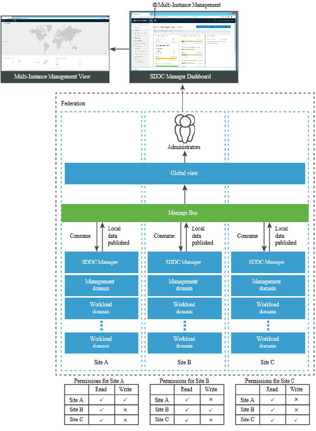
An SDDC Manager instance can see details about the federation only if it is a member of the
federation, and can belong only to a single federation at a time. It is possible to create multiple
federations within an organization; however, there is no global visibility between federations. For
example, it might be desirable to have a dev-test federation and a production federation. In such
an example, members of dev-test can see other dev-test members but they are not able to see
production members.
Federation members can either be controllers or regular members. A controller member has
capabilities of a regular member and runs some additional message bus components to allow
multi-instance management to work.
A controller member can invite other instances to become members as controller or regular
members. The controller role can be granted to a maximum of three instances within a
federation. High availability of multi-instance management functionality is only possible when
there are exactly three controllers in the federation. Though the controller members can be
VMware Cloud Foundation on Dell EMC VxRail Guide
VMware, Inc. 131
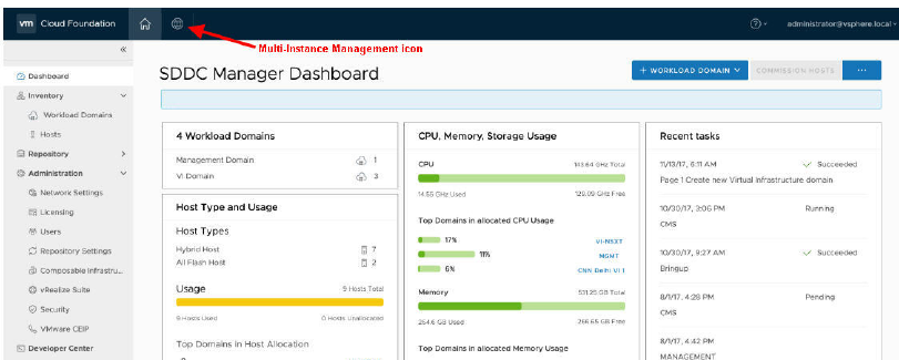
at any three sites in the federation, it is recommended that each controller is in a different
availability zone. The SDDC Manager instance that created the federation is automatically
granted the controller role. If you only have two instances in the federation, there is no need to
create both as controllers. Multi-Instance management works with two VMware Cloud Foundation
sites; however, if one fails then the multi-instance capability is not available on the other site.
Read the following topics next:
n About the Multi-Instance Management Dashboard
n Create a Federation
n Invite an SDDC Manager Instance to Join a Federation
n Join a Federation
n Leave a Federation
n Dismantle a Federation
About the Multi-Instance Management Dashboard
The Multi-Instance Management Dashboard displays the inventory and capacity across the
federation.
You access the Multi-Instance Management Dashboard by clicking the Multi-Instance View icon in
the top left corner of the SDDC Manager UI.
Before a federation is created, the dashboard displays the create and join options.
VMware Cloud Foundation on Dell EMC VxRail Guide
VMware, Inc. 132
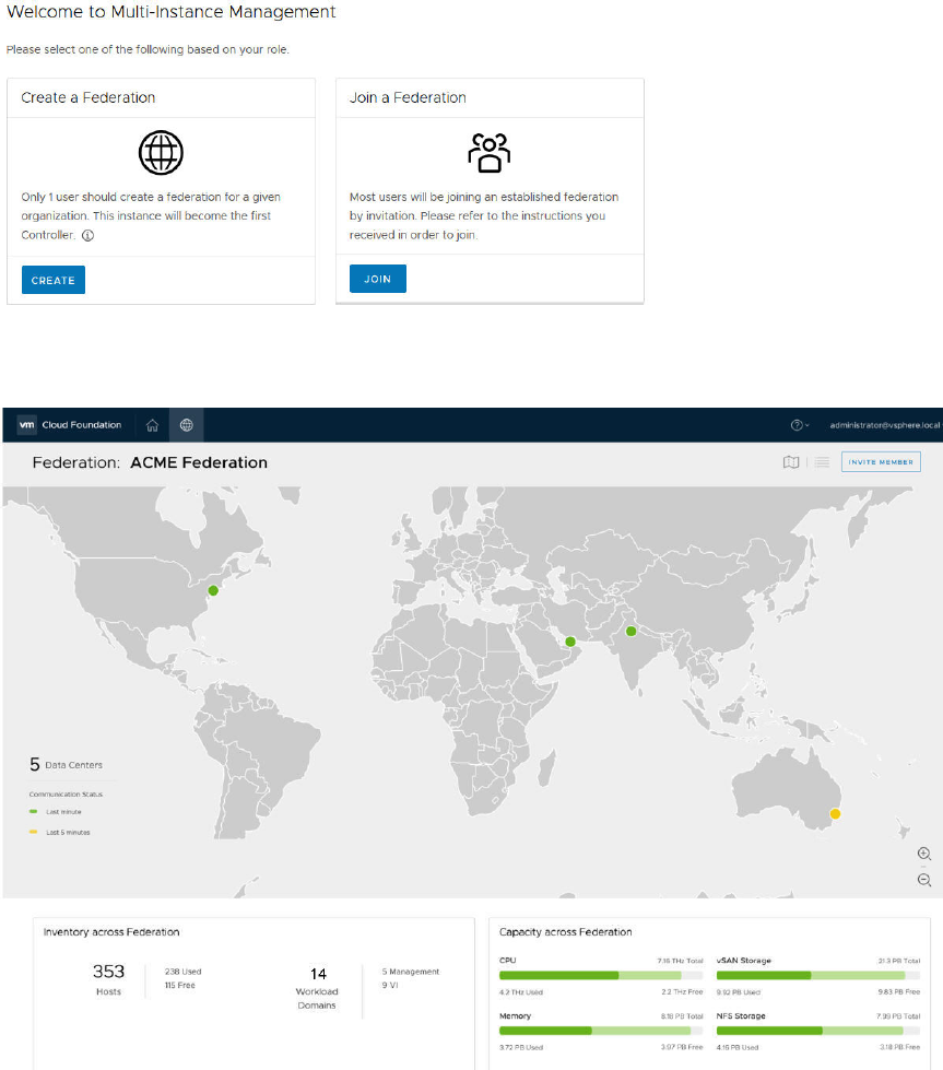
After a federation is created, the Multi-Instance Management Dashboard displays a world map
showing the federation members as dots on the map.
The dot color depends on the communication status between the federation members - green if
they communicated within the last two minutes, yellow if they communicated within the previous
five minutes, and red if they have not communicated for more than ten minutes. You can see the
following information here:
n Hover over a dot to see the member name and location.
VMware Cloud Foundation on Dell EMC VxRail Guide
VMware, Inc. 133
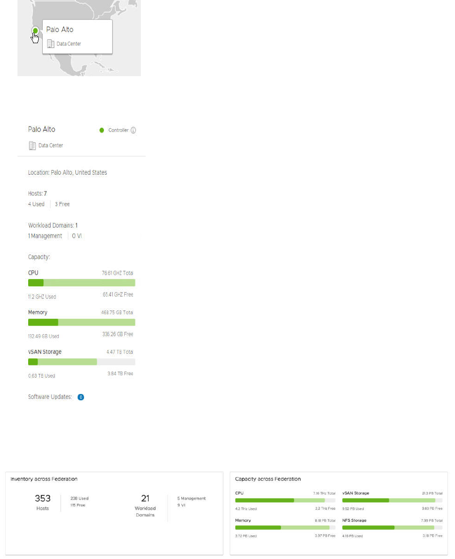
n Click the member location dot to open a panel on the right side with detailed information
about the SDDC Manager instance. The panel also displays available software updates.
The Inventory section in the bottom half of the dashboard displays the number of hosts and
workload domains along with a breakdown of the workload domain type. The capacity section
displays the used and available CPU, memory, and storage across the federation.
Click the Table icon at the top right of the dashboard to display member information in a grid
format. Information for all federation members is displayed in a tabular format.
VMware Cloud Foundation on Dell EMC VxRail Guide
VMware, Inc. 134
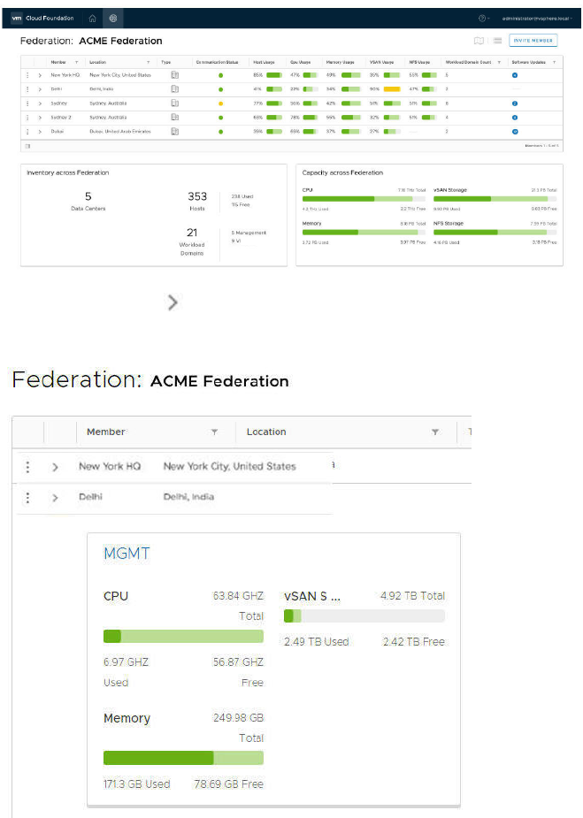
Clicking the arrow ( ) next to the member name displays the CPU, memory, and storage usage
for that member.
Clicking MGMT takes you to the management domain of that member.
Create a Federation
A federation is a group of SDDC Manager instances, such that each member can view
information about the other SDDC Manager instances in the group. The federation creator is
granted the controller role by default.
You can create multiple federations within your organization, but global visibility is available only
within a federation. Members can belong to only a single federation at a time.
See VMware Configuration Maximums for information about the maximum number of SDDC
Manager instances that can be managed using Multi-Instance Management
VMware Cloud Foundation on Dell EMC VxRail Guide
VMware, Inc. 135
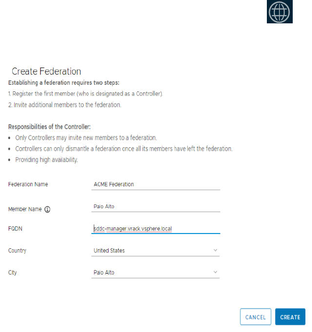
Prerequisites
n The SDDC Manager certificate requires TLS Web server authentication and TLS Web client
authentication extended key usage (EKU). If you are using Microsoft CA or a third-party CA,
you must ensure that the Certificate Authority template is configured with both these EKUs.
n Retrieve the FQDN of your SDDC Manager.
Procedure
1 In the SDDC Manager UI, click the Multi-Instance View ( ) icon at the top of the window.
2 Click Create.
3 Enter a name for the federation.
4 Enter a display name for the member. You may want to base this on the location of this SDDC
Manager instance.
5 Type the FQDN of the SDDC Manager.
6 Select the city and country of this SDDC Manager instance and click Create.
Results
It can take a few minutes for the federation to be created. After the federation is created, the
Multi-Instance Management Dashboard is displayed. The federation location is marked with a
green dot on the world map. You can zoom in or out of the map.
VMware Cloud Foundation on Dell EMC VxRail Guide
VMware, Inc. 136
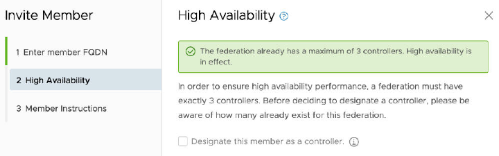
The dashboard also displays the inventory (hosts and workload domains) and capacity (CPU,
memory, and storage) across the federation. These details are updated when additional
members join the federation.
What to do next
Invite an SDDC Manager instance to join the federation.
Invite an SDDC Manager Instance to Join a Federation
You can invite SDDC Manager instances to join a federation. They can be invited as a controller
or a regular member. High availability of multi-instance management functionality is only possible
when there are exactly three controllers in the federation. Though the controller members can
be at any three sites in the federation, it is recommended that each controller is in a different
availability zone.
Prerequisites
You must be a controller in the federation and have the FQDN of the member you are inviting.
Procedure
1 On the top right corner of the Multi-Instance Management dashboard, click Invite Member.
2 Enter the SDDC Manager FQDN of the member you are inviting and click Check Certificate.
The invited member's certificate thumbprint is displayed.
3 Validate the thumbprint and click Confirm fingerprint.
4 Click Next.
5 Select the check box on the High Availability page if you want to designate the controller role
to the member.
6 Click Next.
The Instructions page displays the URL that the invited member needs to access.
7 Click Copy Info to copy the information displayed on this page or copy the URL manually and
send it to the member through an offline method.
VMware Cloud Foundation on Dell EMC VxRail Guide
VMware, Inc. 137
What to do next
The invitation and joining process is a coordinated effort between the invitee controller and
joining member. An additional dot on your Multi-Instance Management Dashboard indicates that
the member you invited is joining the federation. When a controller joins a federation, it can take
a few minutes for the federation to stabilize.
Join a Federation
You can join a federation as a controller or member depending on the assigned role in the
invitation. An invitation is valid for ten days. You must request a new invitation after this period. If
a new invitation is generated for the same site, only the latest invite is valid.
Prerequisites
n Verify that the federation is healthy - there should be no red dots on the world map of the
Multi-Instance Management Dashboard. A red dot indicates that SDDC Manager is unable to
communicate with that member.
n The SDDC Manager certificate requires TLS Web server authentication and TLS Web client
authentication extended key usage (EKU). If you are using Microsoft CA or a third-party CA,
you must ensure that the Certificate Authority template is configured with both these EKUs.
n Retrieve the FQDN of your SDDC Manager.
Join a Federation by Clicking an Invitation
If you join a federation by clicking the invitation you received, federation details are pre-
populated in the SDDC Manager UI.
Prerequisites
Retrieve the invitation you received.
Procedure
1 Click the URL in the invitation you received.
The Join Federation window displays the role assigned in the invitation, the FQDN of the
invited member, token, and the FQDN of the controller member who invited you to join the
federation.
VMware Cloud Foundation on Dell EMC VxRail Guide
VMware, Inc. 138
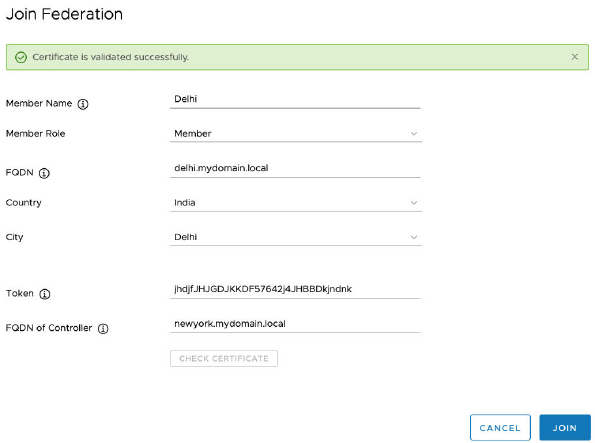
2 Click Join.
Results
The join process is initiated. If you see an error, resolve the issue and then request a new
invitation and follow the steps described above. After the join process is successful, your SDDC
Manager instance becomes a member of the federation.
After a controller joins or leaves a federation, Kafka is restarted on all controllers in the
federation. It can take several minutes for the federation to stabilize even after the dashboard is
refreshed. If an operation performed on the dashboard during this time fails, re-try the operation.
Join a Federation through the Multi-Instance Management
Dashboard
You can join a federation through the Multi-Instance Management Dashboard.
Procedure
1 Click Join Federation on the Multi-Instance Management Dashboard.
2 Type a display name for the site to be added.
3 Select the member role as indicated in the invitation you received.
4 Type the FQDN of your SDDC Manager.
5 Select the country and city for your site.
6 Type the token as indicated in the invitation you received.
7 Type the FQDN of the controller who invited you.
8 Click Join.
VMware Cloud Foundation on Dell EMC VxRail Guide
VMware, Inc. 139
Results
The join process is initiated. If you see an error, resolve the issue and then request a new
invitation and follow the steps described above. After the join process is successful, your SDDC
Manager instance becomes a member of the federation.
After a controller joins or leaves a federation, Kafka is restarted on all controllers in the
federation. It can take several minutes for the federation to stabilize even after the dashboard is
refreshed. If an operation performed on the dashboard during this time fails, re-try the operation.
Leave a Federation
Leaving a federation removes the Multi-Instance Management view from the SDDC Manager UI.
If you are a controller, you can leave a federation only if there is at least one more controller
in the federation. If you are the only controller member in a federation, you must dismantle a
federation instead of leaving it.
Prerequisites
Verify that the federation is healthy - there should be no red dots on the world map of the
Multi-Instance Management Dashboard. A red dot indicates that SDDC Manager is unable to
communicate with that member. A controller must remove the member using the leave API. See
the
VMware Cloud Foundation API Reference Guide
.
Procedure
1 Click the Grid icon at the top right of the Multi-Instance Management Dashboard.
2 In the member table, click the dot icon next to your member name and click Leave
Federation.
3 Type the federation name and click Leave.
What to do next
Do not perform any operation for a few minutes after leaving a federation.
Dismantle a Federation
You can dismantle a federation if you are the last controller member in the federation. Only
members with the controller role can dismantle a federation.
Procedure
1 Click the Grid icon at the top right of the Multi-Instance Management Dashboard.
2 In the member table, click the dot icon next to your member name and click Dismantle
Federation.
3 Type the federation name and click Dismantle.
VMware Cloud Foundation on Dell EMC VxRail Guide
VMware, Inc. 140
What to do next
After the federation is dismantled, the Create Federation screen is displayed instead of the
Multi-Instance Management Dashboard.
VMware Cloud Foundation on Dell EMC VxRail Guide
VMware, Inc. 141

Stretching Clusters
17
You can stretch an NSX-T cluster in the management domain or in a VI workload domain across
two availability zones within a region. Both availability zones must contain an equal number of
hosts to ensure failover in case any of the availability zones goes down.
The default management cluster must be stretched before a workload domain cluster can be
stretched. This ensures that the NSX control plane and management VMs (vCenter, NSX, SDDC
Manager) remain accessible if the stretched cluster in the second availability zone goes down.
Note You cannot stretch a cluster in the following conditions:
n If a cluster uses static IP addresses for the NSX-T Host Overlay Network TEPs.
n If remote vSAN datastores are mounted on any cluster.
You may want to stretch a cluster for the following reasons.
n Planned maintenance
You can perform a planned maintenance on an availability zone without any downtime and
then migrate the applications after the maintenance is completed.
n Automated recovery
Stretching a cluster automatically initiates VM restart and recovery, and has a low recovery
time for the majority of unplanned failures.
n Disaster avoidance
With a stretched cluster, you can prevent service outages before an impending disaster.
This release of Cloud Foundation does not support unstretching a cluster.
About Availability Zones and Regions
This section describes availability zones and regions as used for stretch clusters.
Availability Zones
An availability zone is a collection of infrastructure components. Each availability zone runs on its
own physically distinct, independent infrastructure, and is engineered to be highly reliable. Each
zone should have independent power, cooling, network, and security.
VMware, Inc.
142

Additionally, these zones should be physically separate so that disasters affect only one zone.
The physical distance between availability zones is short enough to offer low, single-digit latency
(less than 5 ms) and large bandwidth (10 Gbps) between the zones.
Availability zones can either be two distinct data centers in a metro distance, or two safety or fire
sectors (data halls) in the same large-scale data center.
Regions
Regions are in two distinct locations - for example, region A can be in San Francisco and region
B in Los Angeles (LAX). The distance between regions can be rather large. The latency between
regions must be less than 150 ms.
VxRail Stretched Cluster Requirements
In an environment with multiple availability zones, Layer 2 networks must be stretched between
the availability zones by the physical infrastructure. You also must provide a Layer 3 gateway
that is highly available between availability zones. The method for stretching these Layer 2
networks and providing a highly available Layer 3 gateway is vendor-specific.
VLANs and Subnets for Multiple Available Zones
This section displays a sample configuration for an environment with multiple availability zones.
The management, Uplink 01, Uplink 02, and Edge Overlay networks in each availability zone
must be stretched to facilitate failover of the NSX-T Edge appliances between availability zones.
The Layer 3 gateway for the management and Edge Overlay networks must be highly available
across the availability zones.
Note The management network VLAN can be the same for the management domain and VI
workload domains, although the table below shows an example where these VLANs are different
(1611 vs 1631).
Table 17-1. Management Domain VLAN and IP Subnet Requirements
Function
Availability
Zone 1
Availability
Zone 2 VLAN ID IP Range
HA Layer 3
Gateway
Recommend
ed MTU
Management
(AZ1 and AZ2)
✓ ✓ 1611
(Stretched)
172.16.11.0/24 ✓ 1500
vSphere
vMotion
✓ X 1612 172.16.12.0/24 ✓ 9000
vSAN ✓ X 1613 172.16.13.0/24 ✓ 9000
NSX-T Host
Overlay
✓ X 1614 172.16.14.0/24 ✓ 9000
NSX-T Edge
Uplink01
✓ ✓ 2711
(Stretched)
172.27.11.0/24 X 9000
NSX-T Edge
Uplink02
✓ ✓ 2712
(Stretched)
172.27.12.0/24 X 9000
VMware Cloud Foundation on Dell EMC VxRail Guide
VMware, Inc. 143
Table 17-1. Management Domain VLAN and IP Subnet Requirements (continued)
Function
Availability
Zone 1
Availability
Zone 2 VLAN ID IP Range
HA Layer 3
Gateway
Recommend
ed MTU
NSX-T Edge
Overlay
✓ ✓ 2713
(Stretched)
172.27.13.0/24 ✓ 9000
vSphere
vMotion
X ✓ 1622 172.16.22.0/24 ✓ 9000
vSAN X ✓ 1623 172.16.23.0/24 ✓ 9000
Host Overlay X ✓ 1624 172.16.24.0/24 ✓ 9000
Note If a VLAN is stretched between AZ1 and AZ2, then the data center needs to provide
appropriate routing and failover of the gateway for that network.
Table 17-2. Workload Domain VLAN and IP Subnet Requirements
Function
Availability
Zone 1
Availability
Zone 2 VLAN ID IP Range
HA Layer 3
Gateway
Management
(AZ1 and AZ2)
✓ ✓ 1631 172.16.31.0/24 ✓
vSphere
vMotion
✓ X 1632 172.16.32.0/24 ✓
vSAN ✓ X 1633 172.16.33.0/24 ✓
Host Overlay ✓ X 1634 172.16.34.0/24 ✓
vSphere
vMotion
X ✓ 2732 172.27.32.0/24 ✓
vSAN X ✓ 2733 172.16.33.0/24 ✓
Host Overlay X ✓ 1621 172.16.21.0/24 ✓
Networking for Multiple Availability Zones
There are specific physical data center network requirements for a topology with multiple
availability zones.
VMware Cloud Foundation on Dell EMC VxRail Guide
VMware, Inc. 144
Table 17-3. Physical Network Requirements for Multiple Availability Zone
Component Requirement
MTU n VLANs which are stretched between availability zones
must meet the same requirements as the VLANs for
intra-zone connection including MTU.
n MTU value must be consistent end-to-end including
components on the inter zone networking path.
n Set MTU for all VLANs and SVIs (management,
vMotion, Geneve, and Storage) to jumbo frames for
consistency purposes. Geneve overlay requires an
MTU of 1600 or greater.
Layer 3 gateway availability For VLANs that are stretched between available zones,
configure data center provided method, for example,
VRRP or HSRP, to failover the Layer 3 gateway between
availability zones.
DHCP availability For VLANs that are stretched between availability zones,
provide high availability for the DHCP server so that a
failover operation of a single availability zone will not
impact DHCP availability.
Note You cannot stretch a cluster that uses static IP
addresses for the NSX-T Host Overlay Network TEPs.
BGP routing Each availability zone data center must have its own
Autonomous System Number (ASN).
Ingress and egress traffic n For VLANs that are stretched between availability
zones, traffic flows in and out of a single zone. Local
egress is not supported.
n For VLANs that are not stretched between availability
zones, traffic flows in and out of the zone where the
VLAN is located.
n For NSX-T virtual network segments that are
stretched between regions, traffic flows in and out
of a single availability zone. Local egress is not
supported.
Latency n Maximum network latency between NSX-T Managers
is 10 ms.
n Maximum network latency between the NSX-T
Manager cluster and transport nodes is 150 ms.
Deploy and Configure vSAN Witness Host
Each vSAN stretched cluster requires a witness host deployed in a vSAN witness zone, which
must be different from the location of both availability zones.
You deploy the vSAN witness host using an appliance instead of using a dedicated physical ESXi
host as a witness host. The witness host does not run virtual machines and must run the same
version of ESXi as the ESXi hosts in the stretched cluster. It must also meet latency and Round
Trip Time (RRT) requirements.
VMware Cloud Foundation on Dell EMC VxRail Guide
VMware, Inc. 145
See the Physical Network Requirements for Multiple Availability Zone table within VxRail
Stretched Cluster Requirements.
Deploy vSAN Witness Host
You deploy the vSAN witness host for a stretched cluster at a site away from the existing
availability zones to prevent propagation of outage in the data center.
Prerequisites
Download the vSAN witness host virtual appliance .ova file.
Procedure
1 In a web browser, log in to vCenter Server at https://
vcenter_server_fqdn
/ui.
2 Select Menu > Hosts and Clusters.
3 In the inventory panel, expand vCenter Server > Datacenter.
4 Right-click the cluster and select Deploy OVF template.
5 On the Select an OVF template page, select Local file, click Upload files, browse to the
location of the vSAN witness host OVA file, and click Next.
6 On the Select a name and folder page, enter a name for the virtual machine and click Next.
7 On the Select a compute resource page, click Next.
8 On the Review details page, review the settings and click Next.
9 On the License agreements page, accept the license agreement and click Next.
10 On the Configuration page, select Medium and click Next.
11 On the Select storage page, select a datastore and click Next.
12 On the Select networks page, select a portgroup for the wintess and management network,
and click Next.
13 On the Customize template page, enter the root password for the witness and click Next.
14 On the Ready to complete page, click Finish and wait for the process to complete.
15 Power on the vSAN witness host.
a In the inventory panel, navigate to vCenter Server > Datacenter > Cluster.
b Right-click the vSAN witness host and from the Actions menu, select Power > Power on.
Configure the Management Network on the vSAN Witness Host
Configure the management network for the vSAN witness host in the ESXi Direct Console User
Interface (DCUI).
VMware Cloud Foundation on Dell EMC VxRail Guide
VMware, Inc. 146
Procedure
1 In the inventory panel of the vCenter Server Client, select vCenter Server > Datacenter.
2 Open the DCUI of the ESXi host.
a Right-click the vSAN witness host and click Open remote console.
b Press F2 to enter the DCUI.
c Log in with the vsan_witness_root_password.
3 Configure the network.
a Select Configure Management Network and press Enter.
b Select IPv4 Configuration and press Enter.
c Select Set static IPv4 address and network configuration and press the Space bar.
d Enter IPv4 Address, Subnet Mask and Default Gateway and press Enter.
e Select DNS Configuration and press Enter.
f Select Use the following DNS Server address and hostname and press the Space bar.
g Enter Primary DNS Server, Alternate DNS Server and Hostname and press Enter.
h Select Custom DNS Suffixes and press Enter.
i Ensure that there are no suffixes listed and press Enter.
4 Press Escape to exit and press Y to confirm the changes.
Configure NTP and SSH on the Witness Host
To prevent time synchronization issues, configure the NTP service and enable SSH on the vSAN
witness host to add static routes for access to availability zone 1 and availability zone 2 networks.
Procedure
1 In the inventory panel of the vCenter Server Client, select vCenter Server > Datacenter.
2 Select the vSAN witness host and click the Configure tab.
VMware Cloud Foundation on Dell EMC VxRail Guide
VMware, Inc. 147

3 Configure the NTP client on the vSAN witness host.
a In the System section, click Time configuration and click the Edit button.
b Select Use Network Time Protocol (enable NTP client).
c Configure the following settings and click OK.
Setting Value
NTP Servers NTP server address
Start NTP Service Selected
NTP Service Startup Policy Start and stop with host
4 Enable the SSH service on the vSAN witness host.
a In the System section, click Services and select SSH.
b Click the Edit startup policy button.
c On the Edit startup policy page, select Start and stop with host and click OK.
Configure the VMkernel Adapters on the vSAN Witness Host
To enable vSAN data network communication between the availability zones, configure the
witness network on the vSAN witness host.
Procedure
1 In the inventory panel of the vCenter Server Client, select vCenter Server > Datacenter.
2 Select the vSAN witness host and click the Configure tab.
3 Remove the dedicated witness traffic VMkernel adapter on the vSAN Witness host.
a In the Networking section, click VMkernel adapters.
b Select the kernel adapter vmk1 with secondaryPg as Network label and click Remove.
c On the Remove VMkernel adapter dialog box, click Remove
4 Remove the virtual machine network port group on the vSAN witness host.
a In the left pane, select Networking > Virtual switches.
b Expand the Standard switch: secondary switch section.
c Click the vertical ellipsis and from the drop-down menu, select Remove.
d On the Remove standard switch dialog box, click Yes.
e Expand the Standard switch: vSwitch0 section.
f In the VM Network pane, click the vertical ellipsis and from the drop-down menu, select
Remove.
g On the Remove port group dialog box, click Yes.
VMware Cloud Foundation on Dell EMC VxRail Guide
VMware, Inc. 148

5 Enable witness traffic on the VMkernel adapter for the management network of the vSAN
witness host.
a On the VMkernel adapters page, select the vmk0 adapter and click Edit.
b In the vmk0 - edit settings dialog box, click Port properties, select the vSAN check box,
and click OK.
Stretch a VxRail Cluster
This procedure describes how to stretch a VxRail cluster across two availability zones.
This example use case has two availability zones in two buildings in an office campus - AZ1 and
AZ2. Each availability zone has its own power supply and network. The management domain is
on AZ1 and contains the default cluster, SDDC-Cluster1. This cluster contains four ESXi hosts.
vSAN network VLAN ID=1623
MTU=9000
Network=172.16.234.0
netmask 255.255.255.0
gateway 172.16.23.253
IP range=172.16.23.11 - 172.16.234.59
vMotion network VLAN ID=1622
MTU=9000
Network=172.16.22.0
netmask 255.255.255.0
gateway 172.16.22.253
IP range=172.16.22.11 - 172.16.22.59
There are four ESXi hosts in AZ2 that are not in the VMware Cloud Foundation inventory yet.
We will stretch the default cluster SDDC-Cluster1 in the management domain from AZ1 to AZ2.
VMware Cloud Foundation on Dell EMC VxRail Guide
VMware, Inc. 149
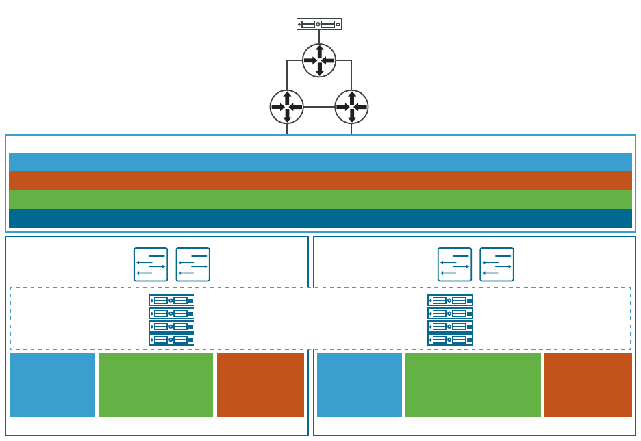
Figure 17-1. Stretch Cluster Example
ToR
Switch
ToR
Switch
Host 1
ToR
Switch
vSAN witness
appliance in
offisite location
Management host name: sfo-m01-cl01-vsw01
Management IP address (vmk0): 172.17.11.201/24
Gateway: 172.17.11.253
vSAN
L3 routing between AZ1 & AZ2 Hosts
L3 routing between AZ1/AZ2 hosts & witness
VMotion
L3 routing between AZ1 & AZ2 hosts
ToR
Switch
AZ1 AZ2
Host 2
Host 3
Host 4
vMotion:
VLAN 1612
172.16.12.0/24
GW 172.16.12.253
NSX-T Host Overlay:
VLAN 1614
172.16.14.0/24
GW 172.16.14.253
Stretched Networks
vSAN:
VLAN 1613
172.16.13.0/24
GW 172.16.13.253
Host 5
Host 6
Host 7
Host 8
vMotion:
VLAN 1622
172.16.22.0/24
GW 172.16.22.253
NSX-T Host Overlay:
VLAN 1624
172.16.24.0/24
GW 172.16.24.253
vSAN:
VLAN 1623
172.16.23.0/24
GW 172.16.23.253
Management cluster stretched
across AZ1 and AZ2
Management (VLAN:1611) 172.16.11.0/24
Edge Uplink 1 (VLAN: 2711) 172.27.11.0/24
Edge Uplink 2 (VLAN: 2712) 172.27.12.0/24
Edge Overlay (VLAN: 2713) 172.27.13.0/24
VMware Cloud Foundation on Dell EMC VxRail Guide
VMware, Inc. 150
To stretch a cluster for VMware Cloud Foundation on Dell EMC VxRail, perform the following
steps:
Prerequisites
n Verify that vCenter Server is operational.
n Verify that you have completed the Planning and Preparation Workbook with the
management domain or VI workload domain deployment option included.
n Verify that your environment meets the requirements listed in the Prerequisite Checklist sheet
in the Planning and Preparation Workbook.
n Ensure that you have enough hosts such that there is an equal number of hosts on each
availability zone. This is to ensure that there are sufficient resources in case an availability
zone goes down completely.
n Deploy and configure a vSAN witness host. See Deploy and Configure vSAN Witness Host.
n If you are stretching a cluster in a VI workload domain, the default management vSphere
cluster must have been stretched.
n Download initiate_stretch_cluster_vxpail.py.
Important You cannot deploy an NSX Edge cluster on a vSphere cluster that is stretched. If
you plan to deploy an NSX Edge cluster, you must do so before you execute the stretch cluster
workflow.
Note You cannot stretch a cluster in the following conditions:
n If a cluster uses static IP addresses for the NSX-T Host Overlay Network TEPs
n If remote vSAN datastores are mounted on any cluster
n If it is enabled for Workload Management
Procedure
1 Using an SSH File Transfer tool, copy initiate_stretch_cluster_vxrail.py to the /
home/vcf/ directory on the SDDC Manager appliance.
2 Using SSH, log in to the SDDC Manager appliance with the user name vcf and the password
you specified in the deployment parameter workbook.
3 Run the script with -h option for details about the script options.
python initiate_stretch_cluster_vxrail.py -h
4 Run the following command to prepare the cluster to be stretched. The command creates
affinity rules for the VMs to run on the preferred site:
python initiate_stretch_cluster_vxrail.py --workflow prepare-stretch --sc-domain <SDDC-
valid-domain-name> --sc-cluster <valid-cluster-name>
VMware Cloud Foundation on Dell EMC VxRail Guide
VMware, Inc. 151

Replace
<SDDC-valid-domain-name>
and
<valid-cluster-name>
with the correct values for
your environment. For example:
python initiate_stretch_cluster_vxrail.py --workflow prepare-stretch --sc-domain
wdc1-workflowspec-vxrail --sc-cluster VxRail-Virtual-SAN-Cluster-8d2c9f37-e230-4238-ab35-
cafd5033a59e
Enter the SSO user name and password when prompted to do so.
Once the workflow is triggered, track the task status in the SDDC Manager UI. If the task fails,
debug and fix the issue and retry the task from the SDDC Manager UI. Do not run the script
again.
5 Use the VxRail vCenter plug-in to add the additional hosts in Availability Zone 2 to the cluster
by performing the VxRail Manager cluster expansion work flow.
6 Run the following command to stretch the cluster:
python initiate_stretch_cluster_vxrail.py --workflow stretch-vsan --sc-domain <SDDC-valid-
domain-name> --sc-cluster <valid cluster name which is a part of the domain to be
stretched> --sc-hosts <valid host names> --witness-host-fqdn <witness host/appliance IP
or fqdn> --witness-vsan-ip <witness vsan IP address> --witness-vsan-cidr <witness-vsan-
network-IP-address-with-mask>
Replace
<SDDC-valid-domain-name>
,
<valid cluster name which is a part of the domain to
be stretched>
,
<valid host names>
,
<witness vsan IP address>
,
<witness host/appliance IP
or fqdn>
,
<witness vsan IP address>
, and
<witness-vsan-network-IP-address-with-mask>
with
the correct values for your environment. For example:
python initiate_stretch_cluster_vxrail.py --workflow stretch-vsan --sc-domain
wdc1-workflowspec-vxrail --sc-cluster VxRail-Virtual-SAN-Cluster-8d2c9f37-e230-4238-ab35-
cafd5033a59e --sc-hosts wdc3-005-proxy.vxrail.local --witness-host-fqdn 172.16.10.235 --
witness-vsan-ip 172.16.20.235 --witness-vsan-cidr 172.16.20.0/24
7 When prompted, enter the following information:
n SSO user name and password
n Root user password for ESXi hosts
n vSAN gateway IP for the preferred (primary) and non-preferred (secondary) site
n vSAN CIDR for the preferred (primary) and non-preferred (secondary) site
n VLAN ID for the non-preferred site overlay VLAN
n Confirm the SSH thumbprints for the hosts
Once the workflow is triggered, the task is tracked in the SDDC Manager UI. If the task fails,
debug and fix the issue and retry from SDDC Manager UI. Do not run the script again.
8 Monitor the progress of the AZ2 hosts being added to the cluster.
a In the SDDC Manager UI, click View All Tasks.
b Refresh the window to monitor the status.
VMware Cloud Foundation on Dell EMC VxRail Guide
VMware, Inc. 152
9 Validate that stretched cluster operations are working correctly by logging in to the vSphere
Web Client.
a Verify vSAN Health.
1 On the home page, click Host and Clusters and then select the stretched cluster.
2 Click Monitor > vSAN > Skyline Health.
3 Click Retest.
4 Fix errors, if any.
b Verify the vSAN Storage Policy.
1 On the home page, click Policies and Profiles > VM Storage Policies > vSAN Default
Storage Policies.
2 Select the policy associated with the vCenter Server for the stretched cluster and click
Check Compliance.
3 Click VM Compliance and check the Compliance Status column for each VM.
4 Fix errors, if any.
NSX-T Data Center Configuration for Availability Zone 2
To provide the necessary networking services for fail-over of SDDC components from availability
zone 1 to availability zone 2 in the management domain, you configure NSX-T Data Center for
availability zone 2.
Configure IP Prefixes in the Tier-0 Gateway for Availability Zone 2
You configure default and any IP prefixes on the tier-0 gateway to permit access to route
advertisement by any network and by the 0.0.0.0/0 network. These IP prefixes are used in
route maps to prepend a path to one or more autonomous systems (AS-path prepend) for BGP
neighbors and to configure local-reference on the learned default-route for BGP neighbors in
availability zone 2.
Procedure
1 In a web browser, log in to NSX Manager for the management or workload domain to be
stretched at https://
nsx_manager_fqdn
/login.jsp?local=true.
2 On the main navigation bar, click Networking.
3 In the navigation pane, click Tier-0 gateways.
4 Select the gateway and from the ellipsis menu, click Edit.
5 Create the Any IP prefix list.
a Expand the Routing section and in the IP prefix list section, click Set.
b In the Set IP prefix list dialog box, click Add IP prefix list.
VMware Cloud Foundation on Dell EMC VxRail Guide
VMware, Inc. 153
c Enter Any as the prefix name and under Prefixes, click Set.
d In the Set prefixes dialog box, click Add Prefix and configure the following settings.
Setting Value
Network any
Action Permit
e Click Add and then click Apply.
6 Repeat step 5 to create the default route IP prefix set with the following configuration.
Setting Value
Name Default Route
Network 0.0.0.0/0
Action Permit
7 On the Set IP prefix list dialog box, click Close.
Configure Route Maps in the Tier-0 Gateway for Availability Zone 2
To define which routes are redistributed in the domain, you configure route maps in the tier-0
gateway.
Procedure
1 On the NSX Manager main navigation bar, click Networking.
2 In the navigation pane, click Tier-0 gateways.
3 Select the gateway, and from the ellipsis menu, click Edit.
4 Create a route map for traffic incoming to availability zone 2.
a Expand the Routing section and in the Route maps section, click Set.
b In the Set route maps dialog box, click Add route map.
c Enter a name for the route map.
d In the Match criteria column, click Set.
VMware Cloud Foundation on Dell EMC VxRail Guide
VMware, Inc. 154
e On the Set match criteria dialog box, click Add match criteria and configure the following
settings.
Setting Value for Default Route Value for Any
Type IP Prefix IP Prefix
Members Default Route Any
Local Preference 80 90
Action Permit Permit
f Click Add and then click Apply.
g In the Set route maps dialog box, click Save.
5 Repeat step 4 to create a route map for outgoing traffic from availability zone 2 with the
following configuration.
Setting Value
Route map name rm-out-az2
Type IP Prefix
Members Any
As Path Prepend
bgp_asn
Local Preference 100
Action Permit
6 In the Set route maps dialog box, click Close.
Configure BGP in the Tier-0 Gateway for Availability Zone 2
To enable fail-over from availability zone 1 to availability zone 2, you configure BGP neighbors on
the tier-0 gateway in the management or workload domain to be stretched. You add route filters
to configure localpref on incoming traffic and prepend of AS on outgoing traffic.
You configure two BGP neighbors with route filters for the uplink interfaces in availability zone 2.
Table 17-4. BGP Neighbors for Availability Zone 2
Setting BGP Neighbor 1 BGP Neighbor 2
IP address
ip_bgp_neighbor1 ip_bgp_neighbor2
BFD Disabled Disabled
Remote AS
asn_bgp_neighbor1 asn_bgp_neighbor2
Hold downtime 12 12
VMware Cloud Foundation on Dell EMC VxRail Guide
VMware, Inc. 155
Table 17-4. BGP Neighbors for Availability Zone 2 (continued)
Setting BGP Neighbor 1 BGP Neighbor 2
Keep alive time 4 4
Password
bgp_password bgp_password
Table 17-5. Route Filters for BGP Neighbors for Availability Zone 2
Setting BGP Neighbor 1 BGP Neighbor 2
IP Address Family IPV4 IPV4
Enabled Enabled Enabled
Out Filter rm-out-az2 rm-out-az2
In Filter rm-in-az2 rm-in-az2
Maximum Routes - -
Procedure
1 On the NSX Manager main navigation bar, click Networking.
2 In the navigation pane, click Tier-0 gateways.
3 Select the gateway and from the ellipsis menu, click Edit.
4 Add the uplink interfaces to the NSX Edge nodes.
a Expand BGP and in the BGP neighbors section, click 2.
b In the Set BGP neighbors dialog box, click Add BGP neighbor and configure the following
settings.
Setting
Value
IP address
ip_bgp_neighbor1
BFD Disabled
Note Enable BFD only if the network supports and is
configured for BFD.
Remote AS
asn_bgp_neighbor1
Hold downtime 12
Keep alive time 4
Password
bgp_password
c In the Route filter section, click Set.
VMware Cloud Foundation on Dell EMC VxRail Guide
VMware, Inc. 156

d In the Set route filter dialog box, click Add route filter and configure the following
settings.
Setting Value
IP Address Family IPV4
Enabled Enabled
Out Filter rm-out-az2
In Filter rm-in-az2
Maximum Routes -
e Click Add and then click Apply.
5 Repeat step 4 to configure BGP neighbor
ip_bgp_neighbor2
and the corresponding route
filter.
6 On the Tier-0 gateway page, click Close editing.
Configure Witness Traffic Separation for VMware Cloud
Foundation on Dell EMC VxRail
Witness traffic separation allows you to use a VMkernel adapter for vSAN witness traffic that is
different from the adapter for vSAN data traffic.
By default, when you stretch a cluster, the vSAN-tagged VMkernel adapter is used to carry traffic
destined for the vSAN witness host. With witness traffic separation, you can use a separately
tagged VMkernel adapter instead of extending the vSAN data network to the witness host. This
feature allows for a more flexible network configuration by allowing for separate networks for
node-to-node and node-to-witness communication.
Prerequisites
You must have a stretched cluster before you can configure it for witness traffic separation.
Procedure
1 Create Distributed Port Groups for Witness Traffic
Create a distributed port group for each availability zone on the vSphere Distributed Switch.
2 Delete Routes to the Witness Host
When you stretch a cluster, a route to the witness host is added to each ESXi host in the
stretched cluster. You must delete these routes to use witness traffic separation.
3 Add VMkernel Adapters for Witness Traffic
Add VMkernel adapters for witness traffic to each availability zone's distributed port group.
VMware Cloud Foundation on Dell EMC VxRail Guide
VMware, Inc. 157
4 Configure the VMkernel Adapters for Witness Traffic
Enable witness traffic for the witness traffic VMkernel adapter on each ESXi host
Create Distributed Port Groups for Witness Traffic
Create a distributed port group for each availability zone on the vSphere Distributed Switch.
Procedure
1 Log in to the vSphere Client.
2 Click Menu > Networking.
3 Right-click the vSphere distributed switch for the cluster and select Distributed Port Group >
New Distributed Port Group.
4 Enter a name for the port group for the first availability zone and click Next.
For example, AZ1_WTS_PG.
5 Change the VLAN type to VLAN and enter a VLAN ID.
6 Select Customize default policies and click Next.
7 On the Security page, click Next.
8 On the Traffic shaping page, click Next.
9 On the Teaming and failover page, modify the failover order of the uplinks to match the
existing failover order of the management traffic and click Next.
10 On the Monitoring page, click Next.
11 On the Miscellaneous page, click Next.
12 On the Ready to Complete page, review your selections and click Finish.
13 Repeat these steps for the second availability zone.
Delete Routes to the Witness Host
When you stretch a cluster, a route to the witness host is added to each ESXi host in the
stretched cluster. You must delete these routes to use witness traffic separation.
Procedure
1 Open an SSH connection to the first ESXi host in the stretched cluster.
2 Log in as root.
3 Run the following command:
esxcli network ip route ipv4 list
VMware Cloud Foundation on Dell EMC VxRail Guide
VMware, Inc. 158

The output returns something like:
Network Netmask Gateway Interface Source
----------- ------------- ------------ --------- ------
default 0.0.0.0 172.18.15.1 vmk2 MANUAL
169.254.0.0 255.255.255.0 0.0.0.0 vmk1 MANUAL
172.18.7.0 255.255.255.0 0.0.0.0 vmk3 MANUAL
172.18.13.0 255.255.255.0 0.0.0.0 vmk5 MANUAL
172.18.14.0 255.255.255.0 172.18.7.253 vmk3 MANUAL
172.18.15.0 255.255.255.0 0.0.0.0 vmk2 MANUAL
172.18.21.0 255.255.255.0 172.18.7.253 vmk3 MANUAL
4 Delete the route to the witness host. For example:
esxcfg-route -d 172.18.14.0/24 172.18.7.253
5 Repeat these steps for each ESXi host in the stretched cluster.
Add VMkernel Adapters for Witness Traffic
Add VMkernel adapters for witness traffic to each availability zone's distributed port group.
Procedure
1 Log in to the vSphere Client.
2 Click Menu > Networking.
3 Right-click the witness distributed port group for the first availability zone, for example,
AZ1_WTS_PG, and select Add VMkernel Adapters.
4 Click + Attached Hosts, select the availability zone 1 hosts from the list, and click OK.
5 Click Next.
6 Accept the default VMkernel port settings and click Next.
Note Do not select any services.
7 Select Use static IPv4 settings and enter the IP addresses and the subnet mask to use for the
witness traffic separation network.
8 Click Next.
9 Review your selections and click Finish.
10 Repeat these steps for the witness distributed port group for the second availability zone.
Configure the VMkernel Adapters for Witness Traffic
Enable witness traffic for the witness traffic VMkernel adapter on each ESXi host
Procedure
1 Log in to the vSphere Client.
VMware Cloud Foundation on Dell EMC VxRail Guide
VMware, Inc. 159

2 Click Menu > Hosts and Clusters.
3 For each host in the stretched cluster, click Configure > Networking > VMkernel adapters to
determine which VMkernel adapter to use for witness traffic. For example, vmk5.
4 SSH to the first ESXi host in the stretched cluster.
5 Log in as root and run the following command:
esxcli vsan network ip add -i <vmkernel_adapter> -T=witness
For example:
esxcli vsan network ip add -i vmk5 -T=witness
6 Verify that the VMkernel adapter is configured for witness traffic:
esxcli vsan network list
7 Verify that the ESXi host can access the witness host:
vmkping -I <vmkernel_adapter> <witness_host_ip_address>
Replace
<vmkernel_adapter>
with the VMkernel adapter configured for witness traffic, for
example vmk5. Replace
<witness_host_ip_address>
with the witness host IP address.
8 Repeat for each ESXi host in the stretched cluster.
Expand a Stretched VxRail Cluster
You can expand a stretched cluster by adding more VxRail nodes to the preferred and non-
preferred sites.
Prerequisites
You must have a stretched cluster.
Procedure
1 Use the VxRail vCenter plug-in to add the additional hosts in availability zone 1 or availability
zone 2 to the cluster by performing the VxRail Manager cluster expansion work flow.
Refer to the Dell EMC VxRail documentation for more details.
2 Log in to SDDC Manager and run the script to trigger the workflow to import the newly
added hosts in the SDDC Manager inventory.
In the script, provide the root credentials for each host and specify which fault domain the
host should be added to.
3 Using SSH, log in to the SDDC Manager VM with the username vcf and the password you
specified in the deployment parameter workbook.
VMware Cloud Foundation on Dell EMC VxRail Guide
VMware, Inc. 160

4 Run the following command to expand the stretched cluster:
python initiate_stretch_cluster_vxrail.py --workflow expand-stretch-cluster --sc-domain
<SDDC-valid-domain-name> --sc-cluster <valid cluster name which is a part of the domain
to be stretched> --sc-hosts <valid host names> --witness-host-fqdn <witness host/appliance
IP or fqdn> --witness-vsan-ip <witness vsan IP address> --witness-vsan-cidr <witness-vsan-
network-IP-address-with-mask>
Replace
<SDDC-valid-domain-name>
,
<valid cluster name which is a part of the domain to
be stretched>
,
<valid host names>
,
<witness vsan IP address>
,
<witness host/appliance IP
or fqdn>
,
<witness vsan IP address>
, and
<witness-vsan-network-IP-address-with-mask>
with
the correct values for your environment.
5 When prompted, enter the following information:
n SSO user name and password
n Root user password for ESXi hosts
n Fault domain for ESXi hosts
n vSAN gateway IP for the preferred (primary) and non-preferred (secondary) site
n vSAN CIDR for the preferred (primary) and non-preferred (secondary) site
n Confirm the SSH thumbprints for the hosts
6 Once the workflow is triggered, track the task status in the SDDC Manager UI.
If the task fails, debug and fix the issue and retry from SDDC Manager UI. Do not run the
script again.
What to do next
If you add hosts to a stretched cluster configured for witness traffic separation, perform the
following tasks for the added hosts:
n Add VMkernel Adapters for Witness Traffic
n Delete Routes to the Witness Host
n Configure the VMkernel Adapters for Witness Traffic
Replace a Failed Host in a Stretched VxRail Cluster
If a host or host component in a stretched cluster fails, it is recommended that you replace the
host with a new host.
Prerequisites
n Check the health of the cluster.
See "Check vSAN Health" in
Administering VMware vSAN
.
VMware Cloud Foundation on Dell EMC VxRail Guide
VMware, Inc. 161
Procedure
1 Remove the failed host from the cluster.
See Remove a Host from a Cluster in a Workload Domain.
2 Expand the cluster to add the new host to the cluster.
See Expand a Stretched VxRail Cluster .
Results
vSAN automatically rebuilds the stretch cluster.
VMware Cloud Foundation on Dell EMC VxRail Guide
VMware, Inc. 162

Monitoring Capabilities in the
VMware Cloud Foundation
System
18
The VMware Cloud Foundation system provides built-in capabilities to help you perform effective
operations monitoring, troubleshooting, performance management, infrastructure capacity
planning, and compliance monitoring and auditing.
You use the built-in monitoring capabilities for these typical scenarios.
Scenario Examples
Are the systems online? A host or other component shows a failed or unhealthy status.
Why did a storage drive fail? Hardware-centric views spanning inventory, configuration, usage, and event
history to provide for diagnosis and resolution.
Is the infrastructure meeting
tenant service level agreements
(SLAs)?
Analysis of system and device-level metrics to identify causes and resolutions.
At what future time will the
systems get overloaded?
Trend analysis of detailed system and device-level metrics, with summarized
periodic reporting.
What person performed which
action and when?
History of secured user actions, with periodic reporting.
Workflow task history of actions performed in the system.
The monitoring capabilities involve these features:
Read the following topics next:
n Viewing Tasks and Task Details
Viewing Tasks and Task Details
From SDDC Manager UI, you can access all tasks. By default, the Dashboard displays the Recent
Tasks widget, providing general information at a glance about the most recent tasks. A task is
a unit of work or a series of subtasks that perform an overall goal, such as creating a workload
domain.
In addition to the most recent tasks, you can view and search for all tasks by clicking View All
Tasks at the bottom of the Recent Tasks widget. This opens the Tasks panel.
Note For more information about controlling the widgets that appear on the Dashboard page of
SDDC Manager UI, see Tour of the SDDC Manager User Interface.
VMware, Inc.
163

Viewing and Filtering Task Details
The Tasks panel provides a high level view all tasks, displaying the descriptive task name, task
status (for example, running, succeeded, or failed), and the timestamp for the last change in task
status. You can also filter and search the task information as follows:
n Search tasks by clicking the filter icon in the Task column header and entering a search string.
n Filter tasks by status by clicking the filter icon in Status column. Select by category All,
Failed, Successful, Running, or Pending.
Note Each category also displays the number of tasks with that status.
n Clear all filters by clicking Reset Filter at the top of the Tasks panel.
n Click Refresh to refresh the task list.
Note You can also sort the table by the contents of the Status and Last Occurrence columns.
Managing Tasks and Subtask Details
Expand a task to view details including the subtasks that comprise the task and their individual
statuses.
n If a task is in a Failed state, you can also attempt to restart it by clicking Restart Task.
Note Not all tasks are restartable.
n If a task is in a Failed state, click on the icon next to the Failed status to view a detailed report
on the cause.
n To view subtasks and their details, click View Subtasks.
Note You can filter subtasks in the same way you filter tasks.
Note You can also sort the table by the contents of the Status and Last Occurrence columns.
Resizing the Task Panel
Use the icons on the task panel to increase or decrease the panel size, or to close or reopen it.
VMware Cloud Foundation on Dell EMC VxRail Guide
VMware, Inc. 164

Updating VMware Cloud
Foundation DNS and NTP Servers
19
If you need to update the DNS or NTP servers that VMware Cloud Foundation uses, you can
update the servers with the VMware Cloud Foundation API.
When you initially deploy VMware Cloud Foundation, you complete the deployment parameter
workbook to provide the system with the information required for bring-up. This includes up to
two DNS servers and up to two NTP servers. You can reconfigure these settings at a later date,
using the VMware Cloud Foundation API.
Read the following topics next:
n Update DNS Server Configuration
n Update NTP Server Configuration
Update DNS Server Configuration
Use this procedure to update the DNS server configuration across VMware Cloud Foundation
components.
SDDC Manager uses DNS servers to provide name resolution for the components in the system.
When you update the DNS server configuration, SDDC Manager performs DNS configuration
updates for the following components:
n SDDC Manager
n vCenter Servers
n ESXi hosts
n NSX Managers
n NSX Edge nodes
n vRealize Suite Lifecycle Manager
n vRealize Log Insight
n vRealize Operations
n vRealize Automation
Note To update the DNS settings for VxRail Manager, see the Dell EMC documentation.
VMware, Inc.
165

If the update fails, SDDC Manager rolls back the DNS settings for the failed component. Fix the
underlying issue and retry the update starting with the failed component.
Note There is no rollback for vRealize Suite Lifecycle Manager. Check the logs, resolve any
issues, and retry the update.
Updating the DNS server configuration can take some time to complete, depending on the size
of your environment. Schedule DNS updates at a time that minimizes the impact to the system
users.
This procedure uses the VMware Cloud Foundation API using the Developer Center from within
the SDDC Manager UI.
Prerequisites
n Verify that both forward and reverse DNS resolution is functional for each VMware Cloud
Foundation component using the updated DNS server information.
n Verify that the new DNS server is reachable from each of the VMware Cloud Foundation
components.
n Verify all VMware Cloud Foundation components are reachable from SDDC Manager.
n Verify that all VMware Cloud Foundation components are in an Active state.
Procedure
1 In a text editor, create a JSON specification with the following content:
{
"dnsServers": [
{ "ipAddress": " IP of Primary DNS Server ", "isPrimary": true },
{ "ipAddress": " IP of Secondary DNS Server ", "isPrimary": false }
]
}
2 In the SDDC Manager UI, click Developer Center > API Explorer.
3 Validate the DNS configuration JSON specification and ensure the system is healthy.
a Expand the APIs for managing DNS & NTP configuration section, and click POST /v1/
system/dns-configuration/validations.
b In the dnsConfiguration text box, paste the contents of the JSON specification, and click
Execute.
c In the Response section, click Validation to expand the task and copy the id.
d Expand the APIs for managing DNS & NTP configuration section, and click GET /v1/
system/dns-configuration/validations.
VMware Cloud Foundation on Dell EMC VxRail Guide
VMware, Inc. 166

e In the executeStatus text box, paste the validation id and click Execute.
f In the Response section, click Validation and verify that resultStatus states SUCCEEDED.
If the resultStatus indicates that validation failed, expand validationChecks and review
which component failed.
4 Perform the DNS configuration using the validated JSON specification.
a Expand the APIs for managing DNS & NTP configuration section and click PUT /v1/
system/dns-configuration.
b In the dnsConfiguration text box, paste the contents of the JSON specification and click
Execute.
c On the Are you sure dialog, click Continue.
Update NTP Server Configuration
Use this procedure to update the NTP server configuration across VMware Cloud Foundation
components.
SDDC Manager uses NTP servers to synchronize time between the components in the system.
You must have at least one NTP server. When you update the NTP server configuration, SDDC
Manager performs NTP configuration updates for the following components:
n SDDC Manager
n vCenter Servers
n ESXi hosts
n NSX Managers
n NSX Edge nodes
n vRealize Suite Lifecycle Manager
n vRealize Log Insight
n vRealize Operations
n vRealize Automation
Note To update the NTP settings for VxRail Manager, see the Dell EMC documentation.
If the update fails, SDDC Manager rolls back the NTP settings for the failed component. Fix the
underlying issue and retry the update starting with the failed component.
Note There is no rollback for the vRealize Suite Lifecycle Manager. Check the logs, resolve any
issues, and retry the update.
Updating the NTP server configuration can take some time to complete, depending on the size
of your environment. Schedule NTP updates at a time that minimizes the impact to the system
users.
VMware Cloud Foundation on Dell EMC VxRail Guide
VMware, Inc. 167

This procedure uses the VMware Cloud Foundation API using the Developer Center from within
the SDDC Manager UI.
Prerequisites
n Verify the new NTP server is reachable from the VMware Cloud Foundation components.
n Verify the time skew between the new NTP servers and the VMware Cloud Foundation
components is less than 5 minutes.
n Verify all VMware Cloud Foundation components are reachable from SDDC Manager.
n Verify all VMware Cloud Foundation components are in an Active state.
Procedure
1 In a text editor, create a JSON specification with the following content:
{
"ntpServers": [
{ "ipAddress": " IP/FQDN of First NTP Server " },
{ "ipAddress": " IP/FQDN of Second NTP Server " }
]
}
2 In the SDDC Manager UI, click Developer Center > API Explorer.
3 Validate the NTP configuration JSON specification and ensure the system is healthy.
a Expand the APIs for managing DNS & NTP configuration section, and expand POST /v1/
system/ntp-configuration/validations.
b In the ntpConfiguration text box, paste the contents of the JSON specification and click
Execute.
c In the Response section, click Validation to expand the task and copy the id.
d Expand the APIs for managing DNS & NTP configuration section, and click GET /v1/
system/ntp-configuration/validations.
e In the executeStatus text box, paste the validation id and click Execute.
f In the Response section, click Validation and verify that resultStatus states SUCCEEDED.
If the resultStatus indicates that validation failed, expand validationChecks and review
which component failed.
4 Perform the NTP configuration using the validated JSON specification.
a Expand the APIs for managing DNS & NTP configuration section and click PUT /v1/
system/ntp-configuration.
b In the ntpConfiguration text box, paste the contents of the JSON specification and click
Execute.
c On the Are you sure dialog, click Continue.
VMware Cloud Foundation on Dell EMC VxRail Guide
VMware, Inc. 168

Supportability and Serviceability
(SoS) Utility
20
The SoS utility is a command-line tool that you can use to run health checks, collect logs for
VMware Cloud Foundation components, and so on.
To run the SoS utility, SSH in to the SDDC Manager appliance using the vcf user account. For
basic operations, enter the following command:
sudo /opt/vmware/sddc-support/sos --option-1 --option-2 --option-3 ... --option-n
To list the available command options, use the --help long option or the -h short option.
sudo /opt/vmware/sddc-support/sos --help
sudo /opt/vmware/sddc-support/sos -h
Note You can specify options in the conventional GNU/POSIX syntax, using -- for the long
option and - for the short option.
For privileged operations, enter su to switch to the root user, and navigate to the /opt/vmware/
sddc-support directory and type ./sos followed by the options required for your desired
operation.
Read the following topics next:
n SoS Utility Options
n Collect Logs for Your VMware Cloud Foundation System
SoS Utility Options
This section lists the specific options you can use with the SoS utility.
For information about collecting log files using the SoS utility, see Collect Logs for Your VMware
Cloud Foundation System.
SoS Utility Help Options
Use these options to see information about the SoS utility itself. For these options, SSH in to the
SDDC Manager VM using the vcf user account and enter the following command:
sudo /opt/vmware/sddc-support/sos --option-name
VMware, Inc.
169
Enter the vcf password when prompted.
Option Description
--help
-h
Provides a summary of the available SoS utility options
--version
-v
Provides the SoS utility's version number.
SoS Utility Generic Options
These are generic options for the SoS utility. For these options, SSH in to the SDDC Manager VM
using the vcf user account and enter the following command:
sudo /opt/vmware/sddc-support/sos --option-name
Enter the vcf password when prompted.
Option Description
--history Displays the last 20 SoS operations performed.
--force Allows SoS operations to be performed while workflows are running.
Note It is recommended that you do not use this option.
--configure-sftp Configures SFTP for logs.
--setup-json SETUPJSON Custom setup-json file for log collection.
SoS prepares the inventory automatically based on the environment where it is
running. If you want to collect logs for a pre-defined set of components, you can create
a setup.json file and pass the file as input to SoS. A sample JSON file is available on
the
SDDC Manager appliance at /opt/vmware/sddc-support/setup.sample.json.
--log-folder LOGFOLDER Specifies the name of the log directory.
--log-dir LOGDIR Specifies the directory to store the logs.
--enable-stats Enable SoS execution stats collection.
--debug-mode Runs the SoS utility in debug mode.
--zip Creates a zipped TAR file for the output.
--domain-name DOMAINNAME Specify the name of the workload domain name on which to perform the SoS
operation.
To run the operation on all workload domains, specify --domain-name ALL.
Note If you omit the
--domain-name
flag and workload domain name, the SoS
operation is performed only on the management domain.
VMware Cloud Foundation on Dell EMC VxRail Guide
VMware, Inc. 170
Option Description
--clusternames
CLUSTERNAMES
Specify the vSphere cluster names associated with a workload domain for which you
want to collect ESXi and Workload Management (WCP) logs.
Enter a comma-separated list of vSphere clusters. For example, --clusternames
cluster1, cluster2
.
Note If you specify
--domain-name ALL
then the --clusternames option is ignored.
--skip-known-host-check Skips the specified check for SSL thumbprint for host in the known host.
--include-free-hosts Collect logs for free ESXi hosts, in addition to in-use ESXi hosts.
SoS Utility VMware Cloud Foundation Summary Options
These options provide summary details of the SDDC Manager instance, including components,
services, and tasks.. For these options, SSH in to the SDDC Manager VM using the vcf user
account and enter the following command:
sudo /opt/vmware/sddc-support/sos --option-name
Enter the vcf password when prompted.
Option
Description
--get-vcf-summary Returns information about your VMware Cloud Foundation system, including
CEIP,workload domains, vSphere clusters, ESXi hosts, licensing, network pools, SDDC
Manager, and VCF services.
--get-vcf-tasks-summary Returns information about VMware Cloud Foundation tasks, including the time the task
was created and the status of the task.
--get-vcf-services-
summary
Returns information about SDDC Manager uptime and when VMware Cloud Foundation
services (for example, LCM) started and stopped.
SoS Utility Fix-It-Up Options
Use these options to manage ESXi hosts and vCenter Servers, including enabling SSH and locking
down hosts. For these options, SSH in to the SDDC Manager VM using the vcf administrative
user account, enter su to switch to the root user, navigate to the /opt/vmware/sddc-support
directory, and type the following command:
./sos --option-name
Note For Fix-It-Up options, if you do not specify a workload domain, the command affects only
the management domain.
VMware Cloud Foundation on Dell EMC VxRail Guide
VMware, Inc. 171

Option Description
--enable-ssh-esxi Enables SSH on ESXi nodes in the specified workload domains.
n To enable SSH on ESXi nodes in a specific workload domain, include the flag
--domain-name DOMAINNAME.
n To enable SSH on ESXi nodes in all workload domains, include the flag
--domain-
name ALL.
--disable-ssh-esxi Disables SSH on ESXi nodes in the specified workload domains.
n To disable SSH on ESXi nodes in a specific workload domain, include the flag
--domain-name DOMAINNAME.
n To disable SSH on ESXi nodes in all workload domains, include the flag
--domain-
name ALL.
--enable-ssh-vc Enables SSH on vCenter Server in the specified workload domains.
n To enable SSH on vCenter in a specific workload domain, include the flag --
domain-name DOMAINNAME
.
n To enable SSH on vCenter Servers in all workload domains, include the flag --
domain-name ALL.
--disable-ssh-vc Disables SSH on vCenter Servers in the specified workload domains.
n To disable SSH on vCenter Server in a specific workload domain, include the flag
--domain-name DOMAINNAME.
n To disable SSH on vCenter Servers in all workload domains, include the flag
--domain-name ALL
.
--enable-lockdown-esxi Enables lockdown mode on ESXi nodes in the specified workload domains.
n To enable lockdown on ESXi nodes in a specific workload domain, include the flag
--domain-name DOMAINNAME.
n To enable lockdown on ESXi nodes in all workload domains, include the flag
--domain-name ALL
.
--disable-lockdown-esxi Disables lockdown mode on ESXi nodes in the specified workload domains.
n To disable lockdown on ESXi nodes in a specific workload domain, include the
flag --domain-name DOMAINNAME.
n To disable lockdown on ESXi nodes in all workload domains, include the flag
--domain-name ALL
.
--ondemand-service Include this flag to execute commands on all ESXi hosts in a workload domain.
Warning Contact VMware support before using this option.
--ondemand-service JSON
file path
Include this flag to execute commands in the JSON format on all ESXi hosts in a
workload domain. For example, /opt/vmware/sddc-support/<JSON file name>
--refresh-ssh-keys Refreshes the SSH keys.
VMware Cloud Foundation on Dell EMC VxRail Guide
VMware, Inc. 172

SoS Utility Health Check Options
These SoS commands are used for checking the health status of various components or services,
including connectivity, compute, storage, database, workload domains, and networks. For these
options, SSH in to the SDDC Manager VM using the vcf user account and enter the following
command:
sudo /opt/vmware/sddc-support/sos --option-name
Enter the vcf password when prompted.
A green status indicates that the health is normal, yellow provides a warning that attention might
be required, and red (critical) indicates that the component needs immediate attention.
Option Description
--health-check Performs all available health checks.
--connectivity-health Performs a connectivity health check to inspect whether the different components
of the system such as the ESXi hosts, vCenter Servers, NSX Managers, and SDDC
Manager can be pinged.
--services-health Performs a services health check to confirm whether services within the SDDC
Manager (like Lifecycle Management Server) and vCenter Server are running.
--compute-health Performs a compute health check, including ESXi host licenses, disk storage, disk
partitions, and health status.
--storage-health Performs a check on the vSAN disk health of the ESXi hosts and vSphere clusters.
Also runs proactive vSAN tests to verify the ability to create VMs within the vSAN
disks.
--run-vsan-checks Runs proactive vSAN tests to verify the ability to create VMs within the vSAN disks.
--ntp-health Verifies whether the time on the components is synchronized with the NTP server in
the SDDC Manager appliance. It also ensures that the hardware and software time
stamp of ESXi hosts are within 5 minutes of the SDDC Manager appliance.
--dns-health Performs a forward and reverse DNS health check.
--general-health Checks ESXi for error dumps and gets NSX Manager and cluster status.
--certificate-health Verifies that the component certificates are valid (within the expiry date).
--composability-infra-
health
Performs an API connectivity health check of the composable infrastructure. If no
composable infrastructure exists, this flag is ignored. If found, the utility checks
connectivity status through the composable infrastructure API, such as Redfish.
--get-host-ips Returns host names and IP addresses of ESXi hosts.
--get-inventory-info Returns inventory details for the VMware Cloud Foundation components, such as
vCenter Server NSX-T Data Center, SDDC Manager, and ESXi hosts. Optionally, add
the flag --domain-name ALL to return details for all workload domains.
--password-health Returns the status of all current passwords, such as Last Changed Date, Expiry Date,
and so on.
VMware Cloud Foundation on Dell EMC VxRail Guide
VMware, Inc. 173
Option Description
--hardware-compatibility-
report
Validates ESXi hosts and vSAN devices and exports the compatibility report.
--json-output-dir JSONDIR Outputs the results of any health check as a JSON file to the specified directory,
JSONDIR.
Example Health Check Commands:
n Check the password health on the management domain only:
./sos --password-health
n Check the connectivity health for all workload domains:
./sos --connectivity-health --domain-name ALL
n Check the DNS health for the workload domain named sfo-w01:
./sos --dns-health --domain-name sfo-w01
Collect Logs for Your VMware Cloud Foundation System
Use the SoS utility to collect the logs for various software components in the system.
Use these options when retrieving support logs from your environment's various components.
n If you run the SoS utility from SDDC Manager without specifying any component-specific
options, the SoS tool collects SDDC Manager, API, and VMware Cloud Foundation summary
logs. To collect all logs, use the --collect-all-logs options.
n If you run the SoS utility from Cloud Builder without specifying any component-specific
options, the SoS tool collects SDDC Manager, API, and Cloud Builder logs.
n To collect logs for a specific component, run the utility with the appropriate options.
For example, the
--domain-name
option is important. If omitted, the SoS operation is
performed only on the management domain. See SoS Utility Options.
After running the SoS utility, you can examine the resulting logs to troubleshoot issues, or
provide to VMware Technical Support if requested. VMware Technical Support might request
these logs to help resolve technical issues when you have submitted a support request. The
diagnostic information collected using the SoS utility includes logs for the various VMware
software components and software products deployed in your VMware Cloud Foundation
environment.
VMware Cloud Foundation on Dell EMC VxRail Guide
VMware, Inc. 174

Table 20-1. SoS Utility Log File Options
Option Description
--esx-logs Collects logs from the ESXi hosts only.
Logs are collected from each ESXi host available in the deployment.
--vc-logs Collects logs from the vCenter Server instances only.
Logs are collected from each vCenter server available in the deployment.
--sddc-manager-logs Collects logs from the SDDC Manager only. sddc
<timestamp>
.tgz contains logs from the
SDDC Manager file system's etc, tmp, usr, and var partitions.
--vxrail-manager-logs Collects logs from VxRail Manager instances only.
--psc-logs Collects logs from the Platform Services Controller instances only.
--nsx-logs Collects logs from the NSX Manager and NSX Edge instances only.
--wcp-logs Collects logs from Workload Management clusters only.
--vrealize-logs Collects logs from vRealize Suite Lifecycle Manager.
--no-clean-old-logs Use this option to prevent the utility from removing any output from a previous collection
run. By default, the SoS utility.
By default, before writing the output to the directory, the utility deletes the prior run's
output files that might be present. If you want to retain the older output files, specify this
option.
--test Collects test logs by verifying the files.
--no-health-check Skips the health check executed as part of log collection.
--api-logs Collects output from REST endpoints for SDDC Manager inventory and LCM.
--rvc-logs Collects logs from the Ruby vSphere Console (RVC) only. RVC is an interface for ESXi and
vCenter.
Note If the Bash shell is not enabled in vCenter Server, RVC log collection will be skipped .
Note RVC logs are not collected by default with ./sos log collection. You must enable RVC
to collect RVC logs.
--vm-screenshots Collects all VM screenshots.
--system-debug-logs Collects system logs to help with debugging uncommon issues.
--collect-all-logs Collects logs for all components, except Workload Management and system debug logs. By
default, logs are collected for the management domain components.
To collect logs for all workload domain, specify --domain-name ALL.
To collect logs for a specific workload domain, specify
--domain-name domain_name
.
--log-dir LOGDIR Specifies the directory to store the logs.
VMware Cloud Foundation on Dell EMC VxRail Guide
VMware, Inc. 175
Table 20-1. SoS Utility Log File Options (continued)
Option Description
--log-folder
LOGFOLDER
Specifies the name of the log directory.
--domain-name
DOMAINNAME
Specify the name of the workload domain name on which the SoS operation is to be
performed.
To run the operation on all domains, specify --domain-name ALL.
Note If you omit the
--domain-name
flag and domain name, the SoS operation is
performed only on the management domain.
Procedure
1 Using SSH, log in to the SDDC Manager appliance as the vcf user.
2 To collect the logs, run the SoS utility without specifying any component-specific options.
sudo /opt/vmware/sddc-support/sos
Enter the vcf password when prompted.
To collect logs for a specific component, run the utility with the appropriate options.
sudo /opt/vmware/sddc-support/sos --option-name
Note By default, before writing the output to the directory, the utility deletes the prior run's
output files that might be present. If you want to retain the older output files, specify the
--no-clean-old-logs option.
If you do not specify the --log-dir option, the utility writes the output to the /var/log/
vmware/vcf/sddc-support directory in the SDDC Manager appliance
Results
The utility collects the log files from the various software components in all of the racks and
writes the output to the directory named in the --log-dir option. Inside that directory, the utility
generates output in a specific directory structure.
Example
vcf@sddc-manager [ ~ ]$ sudo /opt/vmware/sddc-support/sos --domain-name MGMT --skip-known-
host-check --log-dir /tmp/new
[sudo] password for vcf
Welcome to Supportability and Serviceability(SoS) utility!
Performing SoS operation for MGMT domain components
Logs : /tmp/new/sos-2019-09-03-21-04-40-11793
Log file : /tmp/new/sos-2019-09-03-21-04-40-11793/sos.log
Log Collection completed successfully for : [HEALTH-CHECK, SDDC-MANAGER, NSX_MANAGER, API-
LOGS, ESX, VMS_SCREENSHOT, VCENTER-SERVER, VCF-SUMMARY]
VMware Cloud Foundation on Dell EMC VxRail Guide
VMware, Inc. 176

What to do next
Change to the output directory to examine the collected log files.
Component Log Files Collected by the SoS Utility
The SoS utility writes the component log files into an output directory structure within the file
system of the SDDC Manager instance in which the command is initiated, for example:
vcf@sddc-manager [ ~ ]$ sudo /opt/vmware/sddc-support/sos
[sudo] password for vcf
Welcome to Supportability and Serviceability(SoS) utility!
Performing SoS operation for MGMT domain components
Logs : /var/log/vmware/vcf/sddc-support/sos-2019-09-03-20-55-41-10053
Log file : /var/log/vmware/vcf/sddc-support/sos-2019-09-03-20-55-41-10053/sos.log
NOTE : The Health check operation was invoked without --skip-known-host-check, and so will skip
Connectivity Health, Password Health and Certificate Health Checks because of security reasons.
Log Collection completed successfully for : [HEALTH-CHECK, SDDC-MANAGER, NSX_MANAGER, API-LOGS, ESX,
VMS_SCREENSHOT, VCENTER-SERVER, VCF-SUMMARY]
esx Directory Contents
In each rack-specific directory, the esx directory contains the following diagnostic files collected
for each ESXi host in the rack:
File
Description
esx-
FQDN
.tgz Diagnostic information from running the vm-support command on the ESXi host.
An example file is esx-esxi-1.vrack.vsphere.local.tgz.
SmartInfo-
FQDN
.txt
S.M.A.R.T. status of the ESXi host's hard drive (Self-Monitoring, Analysis, and Reporting
Technology).
An example file is SmartInfo-esxi-1.vrack.vsphere.local.txt.
vsan-health-
FQDN
.txt
vSAN cluster health information from running the standard command python /usr/lib/vmware/
vsan/bin/vsan-health-status.pyc on the ESXi host.
An example file is vsan-health-esxi-1.vrack.vsphere.local.txt.
nsx Directory Contents
In each rack-specific directory, the nsx directory contains the diagnostic information files
collected for the NSX Managers and NSX Edge instances deployed in that rack.
The number of files in this directory depends on the number of NSX Manager and NSX Edge
instances that are deployed in the rack. In a given rack, each management domain has a cluster
of three NSX Managers. The first VI workload domain has an additional cluster of three NSX
Managers. Subsequent VI workload domains can deploy their own NSX Manager cluster, or use
the same cluster as an existing VI workload domain. NSX Edge instances are optional.
VMware Cloud Foundation on Dell EMC VxRail Guide
VMware, Inc. 177
File Description
VMware-NSX-Manager-tech-support-
nsxmanagerIPaddr
.tar.gz
Standard NSX Manager compressed support bundle, generated using the
NSX API POST https://nsxmanagerIPaddr/api/1.0/appliance-management/
techsupportlogs/NSX, where
nsxmanagerIPaddr
is the IP address of the NSX
Manager instance.
An example is VMware-NSX-Manager-tech-support-10.0.0.8.tar.gz.
VMware-NSX-Edge-tech-support-
nsxmanagerIPaddr
-
edgeId
.tgz
Note This information is only collected
if NSX Edges are deployed.
Standard NSX Edge support bundle, generated using the NSX API to query
the NSX Edge support logs: GET https://nsxmanagerIPaddr/api/4.0/edges/
edgeId/techsupportlogs, where
nsxmanagerIPaddr
is the IP address of the
NSX Manager instance and
edgeID
identifies the NSX Edge instance.
An example is VMware-NSX-Edge-tech-support-10.0.0.7-edge-1.log.gz.
vc Directory Contents
In each rack-specific directory, the vc directory contains the diagnostic information files collected
for the
vCenter Server instances deployed in that rack.
The number of files in this directory depends on the number of vCenter Server instances that are
deployed in the rack. In a given rack, each management domain has one vCenter Server instance,
and any VI workload domains in the rack each have one
vCenter Server instance.
File Description
vc-
vcsaFQDN
-vm-
support.tgz
Standard vCenter Server support bundle downloaded from the vCenter Server Appliance
instance having a fully qualified domain name
vcsaFQDN
. The support bundle is obtained from
the instance using the standard vc-support.sh command.
VMware Cloud Foundation on Dell EMC VxRail Guide
VMware, Inc. 178
User and Group Management
21
You can allow the users and groups in your Microsoft Active Directory (AD) domain to use their
credentials to log in to the SDDC Manager UI as well as the vCenter Server instances that are
deployed in your VMware Cloud Foundation system.
You provided a password for the superuser account (user name vcf) in the deployment
parameter workbook before bring-up. After VMware Cloud Foundation is deployed, you can log
in with the superuser credentials and then add vCenter Server or AD users or groups to VMware
Cloud Foundation. Authentication to the SDDC Manager UI uses the VMware vCenter
®
Single
Sign-On authentication service that is installed during the bring-up process for your VMware
Cloud Foundation system.
Users and groups can be assigned roles to determine what tasks they can perform from the UI
and API.
In addition to user accounts, VMware Cloud Foundation includes the following accounts:
n Automation accounts for accessing VMware Cloud Foundation APIs. You can use these
accounts in automation scripts.
n Local account for accessing VMware Cloud Foundation APIs when vCenter Server is down.
For a VMware Cloud Foundation 4.1 deployment, you can specify the local account password
in the deployment parameter workbook. If you upgraded to VMware Cloud Foundation 4.1,
you configure the local account through VMware Cloud Foundation API.
n Service accounts are automatically created by VMware Cloud Foundation for inter-product
interaction. These are for system use only.
Read the following topics next:
n Add a User or Group to VMware Cloud Foundation
n Remove a User or Group
n Create a Local Account
n Create an Automation Account
VMware, Inc.
179
Add a User or Group to VMware Cloud Foundation
You can add users or groups so that they can log in to the SDDC Manager UI with their AD
credentials.
Prerequisites
Only a user with the ADMIN role can perform this task.
Procedure
1 In the navigation pane, click Administration > Users.
2 Click + User or Group.
3 Select one or more users or group by clicking the check box next to the user or group.
You can either search for a user or group by name, or filter by user type or domain.
4 Select a Role for each user and group.
Role Description
ADMIN This role has access to all the functionality of the UI and API.
OPERATOR This role cannot access user management, password management, or
backup configuration settings.
VIEWER This role can only view the SDDC Manager. User management and password
management are hidden from this role.
5 Scroll down to the bottom of the page and click Add.
Remove a User or Group
You can remove a user or group, for example when an employee leaves the company. The
removed user or group will not be able to log in to the SDDC Manager UI.
Prerequisites
Only a user with the ADMIN role can perform this task.
Procedure
1 In the navigation pane, click Administration > Users.
2 Click the vertical ellipsis (three dots) next to a user or group name and click Remove.
3 Click Delete.
VMware Cloud Foundation on Dell EMC VxRail Guide
VMware, Inc. 180
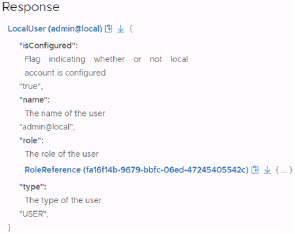
Create a Local Account
A local account is used to access VMware Cloud Foundation APIs when the management vCenter
Server is down. If you upgraded from a previous release or didn't configure the account when
deploying using the API, you can set a password using VMware Cloud Foundation APIs.
Procedure
1 Log in to the SDDC Manager UI as a user with the ADMIN role.
For more information about roles, see Chapter 21 User and Group Management.
2 In the navigation pane, click Developer Center > API Explorer.
3 To verify if the local account is configured, perform the following tasks:
a Expand APIs for managing Users.
b Expand GET /v1/users/local/admin and click EXECUTE.
c In the Response, click LocalUser (admin@local).
You can also download the response by clicking the download icon to the right of
LocalUser (admin@local).
VMware Cloud Foundation on Dell EMC VxRail Guide
VMware, Inc. 181
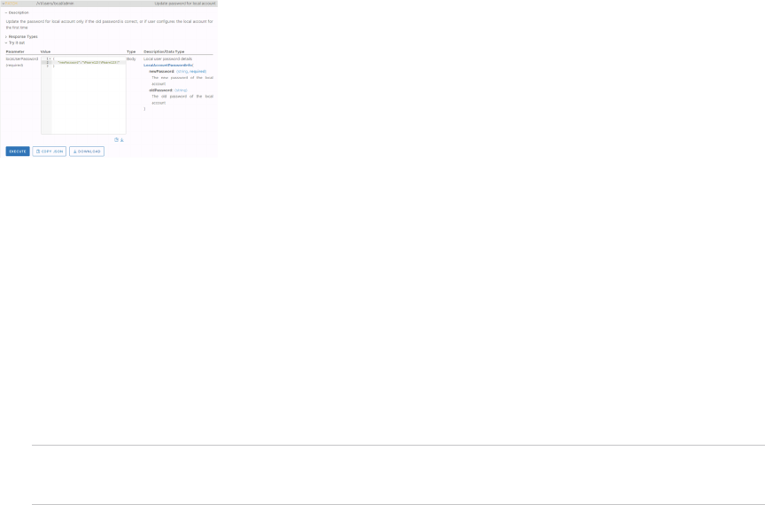
4 If the local account is not configured, perform the following tasks to configure the local
account:
a Expand PATCH /v1/users/local/admin.
b Enter a password for the local account and click EXECUTE.
Password requirements are described below:
n Minimum length: 12
n Maximum length: 127
n At least one lowercase letter, one uppercase letter, a number, and one of the
following special characters ! % @ $ ^ # ? *
n A character cannot be repeated more than three times consecutively
n Must not include three of the same consecutive characters
Note You must remember the password that you created because it cannot be
retrieved. Local account passwords are used in password rotation.
Create an Automation Account
Automation accounts are used to access VMware Cloud Foundation APIs in automation scripts.
Procedure
1 Log in to the SDDC Manager UI as a user with the ADMIN role.
For more about roles, see Chapter 21 User and Group Management.
2 In the navigation pane, click Developer Center > API Explorer.
3 Get the ID for the ADMIN role.
a Expand APIs for managing Users.
b Expand GET /v1/roles and click Execute.
VMware Cloud Foundation on Dell EMC VxRail Guide
VMware, Inc. 182
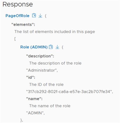
c In the Response, click PageOfRole and Role (ADMIN).
d Copy the ID for the ADMIN role.
VMware Cloud Foundation on Dell EMC VxRail Guide
VMware, Inc. 183
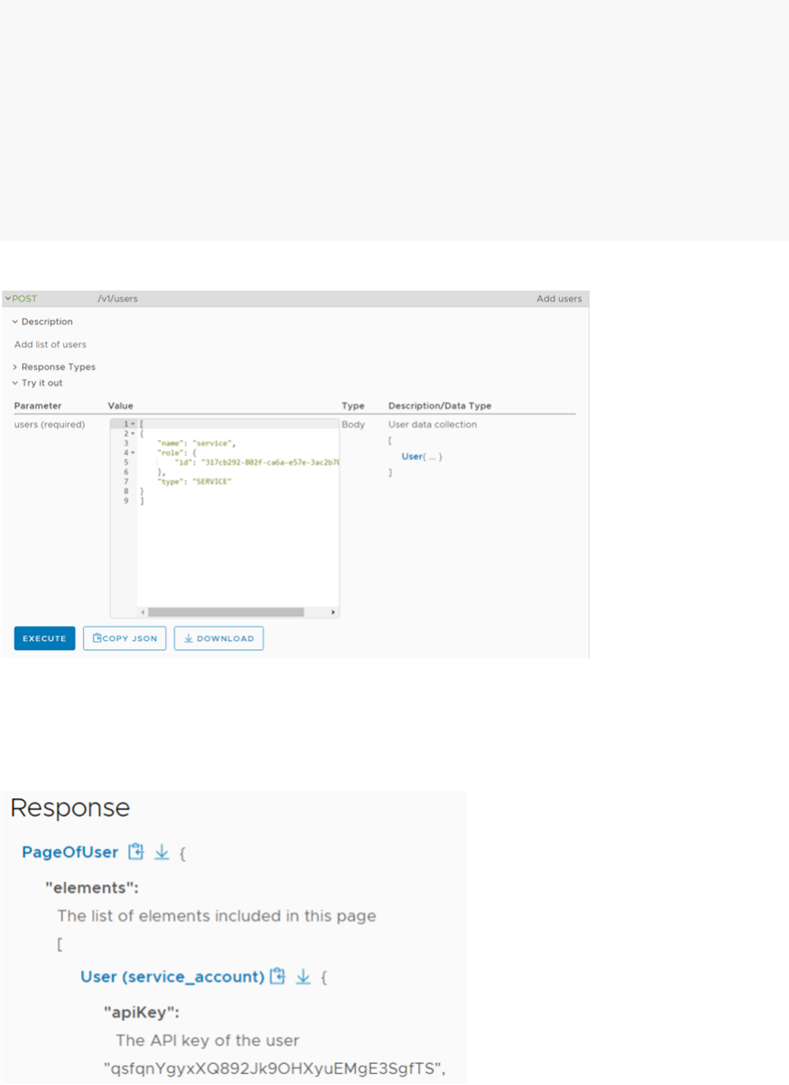
4 Create a service account with the ADMIN role and get the service account's API key.
a Expand POST /v1/users and click User.
b Replace the Value with:
[
{
"name": "service_account",
"type": "SERVICE",
"role":
{
"id": "317cb292-802f-ca6a-e57e-3ac2b707fe34"
}
}
]
Paste the ADMIN role ID from step 3.
c Click Execute.
d In the Response, click PageOfUser and User (service_account).
e Copy the API key for the service account.
VMware Cloud Foundation on Dell EMC VxRail Guide
VMware, Inc. 184
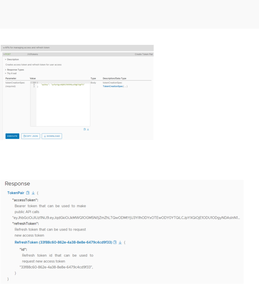
5 Use the service account's API key to generate an access token.
a Expand APIs for managing access and refresh tokens.
b Expand POST /v1/tokens.
c Click TokenCreationSpec.
d Replace Value with:
{
"apiKey": "qsfqnYgyxXQ892Jk90HXyuEMgE3SgfTS"
}
Paste the service account's API key from step 4.
e Click Execute.
f In the Response, click TokenPair and RefreshToken and save the access and refresh
tokens.
VMware Cloud Foundation on Dell EMC VxRail Guide
VMware, Inc. 185

Manage Passwords
22
You specify the passwords for your VMware Cloud Foundation system's internal accounts as part
of the bring-up procedure. You can also modify the passwords for these accounts using RESTful
API calls.
You can update or rotate the password for the root and mystic users of the VxRail Manager and
the root user of ESXi hosts using the SDDC Manager UI. To update or rotate the passwords for
other users refer to the Dell EMC VxRail documentation.
To provide the optimal security and proactively prevent any passwords from expiring, you
should rotate passwords every 80 days.
Read the following topics next:
n Rotate Passwords
n Manually Update Passwords
n Remediate Passwords
n Look Up Account Credentials
n Updating SDDC Manager Passwords
Rotate Passwords
As a security measure, you can rotate passwords for the logical and physical accounts on all
racks in your system. The process of password rotation generates randomized passwords for
the selected accounts. You can rotate passwords manually or set up auto-rotation for accounts
managed by SDDC Manager. By default, auto-rotation is enabled for vCenter Server.
You can rotate passwords for the following accounts.
n VxRail Manager
n ESXi
Note Auto-rotate is not suported for ESXi.
n vCenter Server
By default, the vCenter Server root password expires after 90 days.
VMware, Inc.
186
n vSphere Single-Sign On (PSC)
n NSX Edge nodes
n NSX Manager
n vRealize Suite Lifecycle Manager
n vRealize Log Insight
n vRealize Operations
n vRealize Automation
n Workspace ONE Access
n SDDC Manager backup user
The default password policy for rotated passwords are:
n 20 characters in length
n At least one uppercase letter, a number, and one of the following special characters: ! @ # $
^ *
n No more than two of the same characters consecutively
If you changed the vCenter Server password length using the vSphere Client or the ESXi
password length using the VMware Host Client, rotating the password for those components
from SDDC Manager generates a password that complies with the password length that you
specified.
To update the SDDC Manager root, super user, and API passwords, see Updating SDDC Manager
Passwords.
Prerequisites
n Verify that there are no currently failed workflows in SDDC Manager. To check for failed
workflows, click Dashboard in the navigation pane and expand the Tasks pane at the bottom
of the page.
n Verify that no active workflows are running or are scheduled to run during the brief time
period that the password rotation process is running. It is recommended that you schedule
password rotation for a time when you expect to have no running workflows.
n Only a user with the ADMIN role can perform this task.
Procedure
1 In the navigation pane, click Administration > Security > Password Management.
The Password Management page displays a table of the credentials that SDDC Manager
is able to manage. For each account it lists username, FQDN of the component it belongs
to, workload domain, last modified date, and rotation schedule and next rotation date if
applicable.
VMware Cloud Foundation on Dell EMC VxRail Guide
VMware, Inc. 187

You can click the filter icon next to the table header and filter the results by a string value. For
example, click the icon next to User Name and enter admin to display only domains with that
user name value.
2 Select the account for which you want to rotate passwords from the Component drop-down
menu. For example, ESXI.
3 Select one or more accounts and click one of the following operation.
n Rotate Now
n Schedule Rotation
You can set the password rotation interval (30 days, 60 days, or 90 days). You can also
disable the schdeule.
Note Auto-rotate schedule is configured to run at midnight on the scheduled date. If
auto-rotate could not start due to any technical issue, there is a provision to auto-retry
every hour till start of the next day. In case schedule rotation is missed due to technical
issues the UI displays a global notification with failed task status. The status of the
schedule rotation can also be checked on the Tasks panel.
A message appears at the top of the page showing the progress of the operation. The Tasks
panel also shows detailed status for the password rotation operation. To view sub-tasks, click
the task name. As each of these tasks is run, the status is updated. If the task fails, you can
click Retry.
Results
Password rotation is complete when all sub-tasks are completed successfully.
Manually Update Passwords
You can manually change the password for a selected account. Unlike password rotation, which
generates a randomized password, you provide the new password.
Note You can update passwords for USER and SYSTEM account types.
You can update only one password at a time.
Although individual VMware Cloud Foundation accounts support different password
requirements, it is recommended that you set passwords following a common set of
requirements across all accounts:
n Minimum length: 12
n Maximum length: 20
n At least one lowercase letter, one uppercase letter, a number, and one of the following
special characters: ! @ # $ ^ *
VMware Cloud Foundation on Dell EMC VxRail Guide
VMware, Inc. 188

n Must NOT include:
n A dictionary word
n A palindrome
n More than four monotonic character sequences
n Three of the same consecutive characters
Prerequisites
n Verify that there are no currently failed workflows in your VMware Cloud Foundation system.
To check for failed workflows, click Dashboard in the navigation pane and expand the Tasks
pane at the bottom of the page.
n Verify that no active workflows are running or are scheduled to run during the manual
password update.
n Only a user with the ADMIN role can perform this task. For more information about roles, see
Chapter 21 User and Group Management.
Procedure
1 From the navigation pane, select Administration > Security > Password Management.
The Password Management page displays a table with detailed information about all
domains, including their account, credential type, FQDN, IP address, and user name. This
table is dynamic. Each column can be sorted.
You can click the filter icon next to the table header and filter the results by a string value. For
example, click this icon next to User Name and enter admin to display only domains with that
user name value.
2 Select the account whose password you want to update and click Update at the top of the
page.
Note If you select more than one account, the Update button will be disabled.
The Update Password dialog box appears. This dialog box also displays the account name,
account type, credential type, and user name, in case you must confirm you have selected
the correct account.
3 Enter and confirm the new password.
If the passwords do not match, the dialog box displays a red alert.
4 Click Update.
A message appears at the top of the page showing the progress of the operation. The Tasks
panel also shows detailed status of the password update operation. To view sub-tasks, click
the task name.
If the Tasks panel shows the task as having failed, click Retry.
VMware Cloud Foundation on Dell EMC VxRail Guide
VMware, Inc. 189

Results
Password updation is complete when all sub-tasks are completed successfully.
Remediate Passwords
When an error occurs, for example after a password expires, you must reset the password in
the component. After you reset the password, you must remediate the password. Password
remediation updates the new password in the SDDC Manager database and the dependent
Cloud Foundation workflows.
To resolve any errors that might have occurred during password rotation or updation, you
must use password remediation. Password remediation manually syncs the password of the
component account stored in the SDDC Manager with the updated password in the component.
For USER and SYSTEM account types, you must manually enter the password set in the
component. The SDDC Manager updates the stored password with the new password.
For the SERVICE account type, you must manually enter the password set in the component. The
SDDC Manager updates the service account password with the new password. After password
remediation, the password is rotated to a new password.
Note You can remediate password for only one account at a time.
Although the individual VMware Cloud Foundation components support different password
requirements, you must set passwords following a common set of requirements across all
components. For information on updating passwords manually, see Manually Update Passwords.
Prerequisites
n Verify that there are no currently failed workflows in your VMware Cloud Foundation system.
To check for failed workflows, click Dashboard in the navigation pane and expand the Tasks
pane at the bottom of the page.
n Verify that no active workflows are running or are scheduled to run during the manual
password remediate.
n Only a user with the ADMIN role can perform this task. For more information about roles, see
Chapter 21 User and Group Management.
Procedure
1 From the navigation pane, select Administration > Security > Password Management.
The Password Management page displays a table with detailed information about all
domains, including their component, credential type, FQDN, IP address, and user name. This
table is dynamic. Each column can be sorted.
You can click the filter icon next to the table header and filter the results by a string value. For
example, click this icon next to User Name and enter admin to display only domains with that
user name value.
VMware Cloud Foundation on Dell EMC VxRail Guide
VMware, Inc. 190

2 Select the domain entity whose password you want to remediate, and click Remediate at the
top of the page.
Note If you select more than one account, the Remediate button is disabled.
The Remediate Password dialog box appears. This dialog box also displays the entity name,
account type, credential type, and user name, in case you must confirm you have selected
the correct account.
3 Enter and confirm the new password set at the component.
If the passwords do not match, the dialog box displays a red alert.
4 Click Remediate.
A message appears at the top of the page showing the progress of the operation. The Task
panel also shows detailed status of the password remediation operation. To view subtasks,
you can click the task name.
If the Task panel shows the task as having failed, click Retry.
Results
Password remediation is complete when all sub-tasks are completed successfully.
Look Up Account Credentials
To look up the account credentials for the built-in accounts that are managed and rotated
by SDDC Manager, you can log in to the SDDC Manager appliance using any SDDC Manager
account credentials.
Prerequisites
Only a user with the ADMIN role can perform this task.
Procedure
1 SSH in to the SDDC Manager appliance using the vcf user account.
2 (Optional) Change to the /usr/bin directory.
Note Although the password management CLI commands are located in /usr/bin, you can
run them from any directory.
3 Obtain the account credentials list by typing the command:
lookup_passwords
You must enter the user name and password for a user with the ADMIN role.
Note Accounts with type USER and SYSTEM will be displayed.
VMware Cloud Foundation on Dell EMC VxRail Guide
VMware, Inc. 191
4 (Optional) Save the command output to a secure location with encryption so that you can
access it later and use it to log in to the accounts as needed.
Updating SDDC Manager Passwords
The process for updating SDDC Manager passwords varies, depending on which account you are
updating.
n Update SDDC Manager Root and Super User Passwords
For security reasons, you can change passwords for the SDDC Manager root (root) and
super user (vcf) accounts. Changing these passwords periodically or when certain events
occur, such as an administrator leaving your organization, reduces the likelihood of security
vulnerabilities.
n Update SDDC Manager Local Account Password
The SDDC Manager local account is used to access VMware Cloud Foundation APIs when
the management vCenter Server is down. For security reasons, you should periodically
update the password for this account.
n Update Expired SDDC Manager Root Password
This section describes the procedure for updating an expired password for the SDDC
Manager root (root) user.
Update SDDC Manager Root and Super User Passwords
For security reasons, you can change passwords for the SDDC Manager root (root) and super
user (vcf) accounts. Changing these passwords periodically or when certain events occur, such
as an administrator leaving your organization, reduces the likelihood of security vulnerabilities.
The SDDC Manager root password expires after 365 days.
Procedure
1 SSH in to the SDDC Manager VM using the vcf user account.
2 Enter su to switch to the root user.
3 Enter one of the following commands:
Option
Description
passwd vcf To change the super user password.
passwd root To change the root password.
VMware Cloud Foundation on Dell EMC VxRail Guide
VMware, Inc. 192

4 Enter and retype the new password. For example:
root@sddc-manager [ /home/vcf ]# passwd vcf
New password:
Retype new password:
passwd: password updated successfully
Results
The password is updated.
Update SDDC Manager Local Account Password
The SDDC Manager local account is used to access VMware Cloud Foundation APIs when the
management vCenter Server is down. For security reasons, you should periodically update the
password for this account.
Password requirements for the SDDC Manager local account:
n At least 12 characters
n No more than 127 characters
n At least one lowercase letter
n At least one uppercase letter
n At least one digit
n At least one special character, such as @ ! # $ % ^ or ?
n A character cannot be repeated more than 3 times consecutively
Procedure
1 Log in to the SDDC Manager UI as a user with the ADMIN role.
For more information about roles, see Chapter 21 User and Group Management.
2 Click Developer Center > API Explorer.
3 Expand APIs for managing Users.
4 Expand PATCH /v1/users/local/admin.
5 In the Description/Data Type column, click LocalAccountPasswordInfo{...}.
6 In the Value box, type the new and old passwords and click Execute.
7 Click Continue to confirm.
A response of Status: 204, No Content indicates that the password was successfully
updated.
VMware Cloud Foundation on Dell EMC VxRail Guide
VMware, Inc. 193
Update Expired SDDC Manager Root Password
This section describes the procedure for updating an expired password for the SDDC Manager
root (root) user.
The password must meet the following requirements:
n Length 8-20 characters
n Must include:
n mix of uppercase and lowercase letters
n a number
n a special character, such as @ ! # $ % ^ or ?
n Must not include:
n * { } [ ] ( ) / \ ' " ` ~ , ; : . < >
n A dictionary word (for example, VMware1!)
Procedure
1 In a web browser, log in to the management domain vCenter Server using the vSphere Client
(https://<vcenter_server_fqdn>/ui).
2 In the VMs and Templates inventory, expand the management domain vCenter Server and
the management virtual machines folder.
3 Right-click the SDDC Manager virtual machine, and select Open Remote Console.
4 Click within the console window and press Enter on the Login menu item.
5 Type root as the user name and enter the current password for the root user.
6 Type passwd root.
7 When prompted for a new password, enter a different password than the previous one and
click Enter.
VMware Cloud Foundation on Dell EMC VxRail Guide
VMware, Inc. 194
Backing Up and Restoring SDDC
Manager and NSX Manager
23
Regular backups of the management VMs are important to avoid downtime and data loss in case
of a system failure. If a VM does fail, you can restore it to the last backup.
You can backup and restore SDDC Manager with an image-based or a file-based solution. File-
based backup is recommended for customers who are comfortable with configuring backups
using APIs, and are not using composable servers.
For a file-based backup of SDDC Manager VM, the state of the VM is exported to a file that
is stored in a domain different than the one where the product is running. You can configure
a backup schedule for the SDDC Manager VM and enable task-based (state-change driven)
backups. When task-based backups are enabled, a backup is triggered after each SDDC Manager
task (such as workload domain and host operations or password rotation).
You can also define a backup retention policy to comply with your company's retention policy.
For more information, see the
VMware Cloud Foundation on Dell EMC VxRail API Reference
Guide
.
By default, NSX Manager file-based backups are taken on the SFTP server that is built into SDDC
Manager. It is recommended that you configure an external SFTP server as a backup location for
the following reasons:
n An external SFTP server is a prerequisite for restoring SDDC Manager file-based backups.
n Using an external SFTP server provides better protection against failures because it
decouples NSX backups from SDDC Manager backups.
This section of the documentation provides instructions on backing up and restoring SDDC
Manager, and on configuring the built-in automation of NSX backups. For information on backing
up and restoring a full-stack SDDC, see
VMware Validated Design Backup and Restore
.
Read the following topics next:
n Reconfigure SFTP Backups for SDDC Manager and NSX-T Data Center
n File-Based Backups for SDDC Manager and vCenter Server
n File-Based Restore for SDDC Manager, vCenter Server, and NSX-T Data Center
n Image-Based Backup and Restore of VMware Cloud Foundation
VMware, Inc.
195

Reconfigure SFTP Backups for SDDC Manager and NSX-T
Data Center
By default, backups of SDDC Manager and NSX-T Data Center are stored in the SDDC Manager
appliance. Change the destination of the backups to an external SFTP server.
Procedure
1 In the navigation pane, click Administration > Backup.
2 On the Backup page, click the Site Settings tab and then click Register External.
3 On the Backup page, enter the settings and click Save.
To obtain the SSH Fingerprint of the target system to verify, connect to the SDDC Manager
Appliance over ssh and run the following command:
ssh-keygen -lf <(ssh-keyscan -p 22 -t rsa sftp_server_fqdn 2> /dev/null) |
cut -d' ' -f2
Setting Value
Host FQDN or IP The FQDN or IP Address of the SFTP server.
Port 22
Transfer Protocol SFTP
Username A service account with privileges to the SFTP server.
For example: svc-vcf-bck.
Password The password for the username provided.
Backup Directory The directory on the SFTP server where backups are
saved.
For example: /backups/.
SSH Fingerprint The SSH Fingerprint is automatically retreived from the
SFTP server, verify the SSH Fingerprint.
Confirm Fingerprint Selected
Encryption Passphrase The encryption passphrase used to encrypt the backup
data.
Note The encryption passphrase should be stored
safely as it is required during the restore process.
4 In the Confirm your changes to backup settings dialog box, click Confirm.
File-Based Backups for SDDC Manager and vCenter Server
You use the native file-based backup capabilities of SDDC Manager, vCenter Server, and NSX-T
Data Center. The NSX-T Data Center backup is configured by SDDC Manager during the bring-up
process. You configure the file-based backup jobs for SDDC Manager and vCenter Server.
VMware Cloud Foundation on Dell EMC VxRail Guide
VMware, Inc. 196
To ensure that all management components are backed up correctly, you must create a series
of backup jobs that capture the state of a set of related components at a common point in
time. With some components, simultaneous backups of the component nodes ensure that you
can restore the component a state where the nodes are logically consistent with each other and
eliminate the necessity for further logical integrity remediation of the component.
Table 23-1. File-Based Backup Jobs
Component Recommended Frequency Recommended Retention Notes
SDDC Manager Daily 7 days You must configure the
backup jobs for the SDDC
Manager instance and all
vCenter Server instances in
the vCenter Single Sign-On
domain to start within the
same 5-minute window.
vCenter Server Daily 7 days
vSphere Distributed Switch On-demand Retain last 3 configurations. -
NSX-T Data Center Hourly 7 days Configured by SDDC
Manager during the bring-
up process.
Note
n You must monitor the space utilization on the SFTP server to ensure that you have sufficient
storage space to accommodate all backups taken within the retention period.
n Do not make any changes to the /opt/vmware/vcf directory on the SDDC Manager VM. If
this directory contains any large files, backups may fail.
Prerequisites
Verify that you have an SFTP server on the network to serve as a target of the file-based
backups.
Back Up SDDC Manager
You configure file-based daily backups of the SDDC Manager instances using the SDDC Manager
administration interface.
Only a user with the Admin role can perform this task.
Procedure
1 In the navigation pane, click Administration > Backup.
2 On the Backup page, click the SDDC Manager Configurations tab.
3 Under Backup Schedule, click Edit.
VMware Cloud Foundation on Dell EMC VxRail Guide
VMware, Inc. 197

4 On the Backup Schedule page, enter the settings and click Save.
Setting Value
Automatic Backup Enabled
Backup Frequency Weekly
Days of the Week All selected
Schedule Time 04:02 AM
Take Backup on State Change Enabled
Retain Last Backups 7
Retain Hourly Backups for Days 1
Retain Daily Backups for Days 7
5 To verify the backup, click Backup Now.
Results
The status and the start time of the backup is displayed on the UI. You have set the SDDC
Manager backup schedule to run daily at 04:02 AM and after each change of state.
Configure a Backup Schedule for vCenter Server
You configure file-based daily backups of the vCenter Server instances by using the vCenter
Server Management Interface of each vCenter Server instance.
Procedure
1 In a web browser, log in to the vCenter Server Management Interface (https://appliance-
IP-address-or-FQDN:5480).
2 In the left navigation pane, click Backup.
3 In the Backup schedule pane, click Configure.
4 In the Create backup schedule dialog box, enter these values and click Create.
Setting
Value
Backup location Enter the backup location from
SFTP server.
For example: sftp://
172.16.11.60/backups/
Backup server credentials User name A service account with privileges to
the SFTP server.
For example: svc-vcf-bck.
Password Enter the password for the
username provided.
VMware Cloud Foundation on Dell EMC VxRail Guide
VMware, Inc. 198
Setting Value
Schedule Daily 11:00 PM
Encrypt backup Encryption password
encryption_password
Confirm password
encryption_password
DB health check Selected
Number of backups to retain Retain last 7 backups
Data Stats, events, and tasks Selected
Inventory and configuration Selected
The backup schedule information appears in the Backup schedule pane.
5 Repeat the procedure for the other vCenter Server instances.
Results
Any complete and in-progress backup appears in the Activity pane.
Manually Back Up vCenter Server
Before you upgrade a vCenter Server instance, you should use the vCenter Server Management
Interface to manually back it up.
Prerequisites
n In the vSphere Client, for each vSphere cluster that is managed by the vCenter Server, note
the current vSphere DRS Automation Level setting and then change the setting to Manual.
After the vCenter Server upgrade is complete, you can change the vSphere DRS Automation
Level setting back to its original value. See KB 87631 for information about using VMware
PowerCLI to change the vSphere DRS Automation Level.
n Ensure that there are not any active vMotion tasks.
Procedure
1 In a web browser, log in to the vCenter Server Management Interface (https://appliance-
IP-address-or-FQDN:5480).
2 In the left navigation pane, click Backup.
3 Click Backup Now.
4 If you already have a backup schedule set up, select Use backup location and user name
from backup schedule and click Start.
VMware Cloud Foundation on Dell EMC VxRail Guide
VMware, Inc. 199
5 If you do not already have a backup schedule, enter the following information and click Start.
Setting Value
Backup location Enter the backup location from
SFTP server.
For example: sftp://
172.16.11.60/backups/
Backup server credentials User name A service account with privileges to
the SFTP server.
For example: svc-vcf-bck.
Password Enter the password for the
username provided.
Encrypt backup Encryption password
encryption_password
Confirm password
encryption_password
DB health check Selected
Data Stats, events, and tasks Selected
Inventory and configuration Selected
What to do next
In order to restore vCenter Server, you will need the VMware vCenter Server Appliance ISO file
that matches the version you backed up.
n Identify the required vCenter Server version. In the vCenter Server Management Interface,
click Summary in the left navigation pane to see the vCenter Server version and build
number.
n Download the VMware vCenter Server Appliance ISO file for that version from VMware
Customer Connect.
Export the Configuration of the vSphere Distributed Switches
The vCenter Server backup includes the configuration of the entire vCenter Server instance. To
have a backup only of the vSphere Distributed Switch and distributed port group configurations,
you export a configuration file that includes the validated network configurations. If you want to
recover only the vSphere Distributed Switch, you can import this configuration file to the vCenter
Server instance.
You can use the exported file to create multiple copies of the vSphere Distributed Switch
configuration on an existing deployment, or overwrite the settings of existing vSphere
Distributed Switch instances and port groups.
You must backup the configuration of a vSphere Distributed Switch immediately after each
change in configuration of that switch.
VMware Cloud Foundation on Dell EMC VxRail Guide
VMware, Inc. 200
Procedure
1 In a web browser, log in to vCenter Server by using the vSphere Client.
2 Select Menu > Networking.
3 In the inventory expand vCenter Server > Datacenter.
4 Expand the Management Networks folder, right-click the distributed switch, and select
Settings > Export configuration.
5 In the Export configuration dialog box, select Distributed switch and all port groups.
6 In the Description text box enter the date and time of export, and click OK.
7 Copy the backup zip file to a secure location from where you can retrieve the file and use it if
a failure of the appliance occurs.
8 Repeat the procedure for the other vSphere Distributed Switches.
File-Based Restore for SDDC Manager, vCenter Server, and
NSX-T Data Center
When SDDC Manager, vCenter Server, or NSX Manager in the SDDC fails, you can restore the
component to a fully operational state by using its file-based backup. When an NSX Edge node
fails, you redeploy the node from the NSX Manager instance.
Use this guidance as appropriate based on the exact nature of the failure encountered within
your environment. Sometimes, you can recover localized logical failures by restoring individual
components. In more severe cases, such as a complete and irretrievable hardware failure,
to restore the operational status of your SDDC, you must perform a complex set of manual
deployments and restore sequences. In failure scenarios where there is a risk of data loss, there
has already been data loss or where it involves a catastrophic failure, contact VMware Support to
review your recovery plan before taking any steps to remediate the situation.
Restore SDDC Manager
If SDDC Manager fails, you can restore it from its file-based backup.
Prerequisites
n Power off and rename the failed SDDC Manager instance.
n Verify that you have a valid file-based backup of the failed SDDC Manager instance.
To be valid, the backup must be of the same version as the version of the SDDC Manager
appliance on which you plan to restore the instance.
n Verify that you have the SFTP server details:
n SFTP Server IP
n SFTP Server Username
VMware Cloud Foundation on Dell EMC VxRail Guide
VMware, Inc. 201
n SFTP Server Password
n Encryption Password
Procedure
1 Prepare for Restoring SDDC Manager
Before restoring SDDC Manager, you must download and decrypt the encrypted backup file
from the SFTP server.
2 Restore SDDC Manager from a File-Based Backup
First, you deploy a new SDDC Manager appliance by using the OVA file that you
downloaded during the preparation for the restore. After that, you restore the file-based
backup on the newly deployed SDDC Manager appliance.
3 Validate the Status of SDDC Manager
After a successful restore of SDDC Manager, you must validate its status. You run the health
checks by using the sos tool.
What to do next
After a successful recovery, securely delete the decrypted backup files.
Prepare for Restoring SDDC Manager
Before restoring SDDC Manager, you must download and decrypt the encrypted backup file
from the SFTP server.
The backup file contains sensitive data about your VMware Cloud Foundation instance, including
passwords in plain text. As a best practice, you must control access to the decrypted files and
securely delete them after you complete the restore operation.
Prerequisites
Verify that your host machine with access to the SDDC has OpenSSL installed.
Note The procedures have been written based on the host machine being a Linux-based
operating system.
Procedure
1 Identify the backup file for the restore and download it from the SFTP server to your host
machine.
2 On your host machine, open a terminal and run the following command to extract the content
of the backup file.
OPENSSL_FIPS=1 openssl enc -d -aes-256-cbc -md sha256 -in filename-of-restore-file | tar
-xz
3 When prompted, enter the
encryption_password
.
VMware Cloud Foundation on Dell EMC VxRail Guide
VMware, Inc. 202
4 In the extracted folder, locate and open the metadata.json file in a text editor.
5 Locate the sddc_manager_ova_location value and copy the URL.
6 In a web browser, paste the URL and download the OVA file.
7 In the extracted folder, locate and view the contents of the
security_password_vault.json file.
8 Locate the entityType BACKUP value and record the backup password.
Restore SDDC Manager from a File-Based Backup
First, you deploy a new SDDC Manager appliance by using the OVA file that you downloaded
during the preparation for the restore. After that, you restore the file-based backup on the newly
deployed SDDC Manager appliance.
Procedure
1 In a web browser, log in to management domain vCenter Server by using the vSphere Client
(https://<vcenter_server_fqdn>/ui).
2 Select Menu > VMs and templates.
3 In the inventory expand vCenter Server > Datacenter.
4 Right-click the management folder and select Deploy OVF template.
5 On the Select an OVF template page, select Local file, click Upload files, browse to the
location of the SDDC Manager OVA file, click Open, and click Next.
6 On the Select a name and folder page, in the Virtual machine name text box, enter a virtual
machine name, and click Next.
7 On the Select a compute resource page, click Next.
8 On the Review details page, review the settings and click Next.
9 On the License agreements page, accept the license agreement and click Next.
10 On the Select storage page, select the vSAN datastore and click Next.
The datastore must match the vsan_datastore value in the metadata.json file that you
downloaded during the preparation for the restore.
11 On the Select networks page, from the Destination network drop-down menu, select the
management network distributed port group and click Next.
The distributed port group must match the port_group value in the metadata.json file that
you downloaded during the preparation for the restore.
VMware Cloud Foundation on Dell EMC VxRail Guide
VMware, Inc. 203

12 On the Customize template page, enter the following values and click Next.
Setting Description
Enter root user password You can use the original root user password or a new
password.
Enter login (vcf) user password You can use the original vcf user password or a new
password.
Enter basic auth user password You can use the original admin user password or a new
password.
Enter backup (backup) user password The backup password that you saved during the
preparation for the restore. This password can be
changed later if desired.
Enter Local user password You can use the original Local user password or a new
password.
Hostname The FQDN must match the hostname value in the
metadata.json file that you downloaded during the
preparation for the restore.
NTP sources The NTP server details for the appliance.
Enable FIPs Selected
Default gateway The default gateway for the appliance.
Domain name The domain name for the appliance.
Domain search path The domain search path(s) for the appliance.
Domain name servers The DNS servers for the appliance.
Network 1 IP address The IP address for the appliance.
Network 1 netmask The subnet mask for the appliance.
13 On the Ready to complete page, click Finish and wait for the process to complete.
14 When the SDDC Manager appliance deployment completes, expand the management folder.
15 Right-click the SDDC Manager appliance and select Snapshots > Take Snapshot.
16 Right-click the SDDC Manager appliance, select Power > Power On.
17 On the host machine, copy the encrypted backup file to the /tmp folder on the newly
deployed SDDC Manager appliance by running the following command. When prompted,
enter the
vcf_user_password
.
scp filename-of-restore-file vcf@sddc_manager_fqdn:/tmp/
VMware Cloud Foundation on Dell EMC VxRail Guide
VMware, Inc. 204

18 On the host machine, obtain the authentication token from the SDDC Manager appliance in
order to be able to execute the restore process by running the following command:
TOKEN=`curl https://<sddc_manager_fqdn>/v1/tokens -k -X POST -H "Content-Type: application/
json" -d '{"username": "admin@local","password": "<admin@local_password>"}' | awk -F "\""
'{ print $4}'`
19 On the host machine with access to the SDDC Manager, open a terminal and run the
command to start the restore process.
curl https://<sddc_manager_fqdn>/v1/restores/tasks -k -X POST -H "Content-Type:
application/json" -H "Authorization: Bearer $TOKEN" \
-d '{
"elements" : [ {
"resourceType" : "SDDC_MANAGER"
} ],
"backupFile" : "<backup_file>",
"encryption" : {
"passphrase" : "<encryption_password>"
}
}'
The command output contains the ID of the restore task.
20 Record the ID of the restore task.
21 Monitor the restore task by using the following command until the status becomes
Successful.
curl https://<sddc_manager_fqdn>/v1/restores/tasks/<restore_task_id> -k -X GET -H "Content-
Type: application/json" -H "Authorization: Bearer $TOKEN"
What to do next
Refresh the SSH keys that are stored in the SDDC Manager inventory. See VMware Cloud
Foundation SDDC Manager Recovery Scripts (79004).
Validate the Status of SDDC Manager
After a successful restore of SDDC Manager, you must validate its status. You run the health
checks by using the sos tool.
Procedure
1 Log in to SDDC Manager by using a Secure Shell (SSH) client.
2 Run the health checks by using the SoS tool.
sudo /opt/vmware/sddc-support/sos --health-check
3 When prompted, enter the
vcf_password
.
All tests show green when SDDC Manager is in healthy state.
VMware Cloud Foundation on Dell EMC VxRail Guide
VMware, Inc. 205
Restore vCenter Server
If a vCenter Server instance fails, you can restore it from its file-based backup.
Prerequisites
n Power off the failed vCenter Server instance.
n Verify that you have a valid file-based backup of the failed vCenter Server instance.
To be valid, the backup must be of the version of the vCenter Server Appliance on which you
plan to restore the instance.
n Verify that you have the SFTP server details:
n SFTP Server IP
n SFTP Server Username
n SFTP Server Password
n Encryption Password
Procedure
1 Prepare for Restoring vCenter Server
Before restoring a vCenter Server instance, you must retrieve the vCenter Server build
number and deployment details, as well as vCenter Server and ESXi credentials from the
SDDC Manager inventory.
2 Restore a vCenter Server Instance from a File-Based Backup
If a vCenter Server instance fails, you can restore it from its file-based backup. If the
management domain vCenter Server and the VI workload domain vCenter Server are both
in a failed state, you must restore the management domain vCenter Server before restoring
the VI workload domain vCenter Server.
3 Move the Restored vCenter Server Appliance to the Correct Folder
After deploying and restoring a vCenter Server instance, you must move the new appliance
to the correct folder.
4 Validate the vCenter Server State
After restoring a vCenter Server instance, you must validate the state of the vCenter Server
and vCenter Single Sign-On.
5 Validate the SDDC Manager State After a vCenter Server Restore
After a successful vCenter Server restore, verify that the SDDC Manager inventory is
consistent with the recovered VMs and that the vCenter Server instances are healthy. You
use the Supportability and Serviceability tool (SoS) and the SDDC Manager patch/upgrade
precheck function.
VMware Cloud Foundation on Dell EMC VxRail Guide
VMware, Inc. 206

Prepare for Restoring vCenter Server
Before restoring a vCenter Server instance, you must retrieve the vCenter Server build number
and deployment details, as well as vCenter Server and ESXi credentials from the SDDC Manager
inventory.
Prerequisites
SDDC Manager must be available.
Retrieve the vCenter Server Deployment Details
Before restoring a vCenter Server instance, you must retrieve the vCenter Server build number
and deployment details from the SDDC Manager inventory. The vCenter Server instances in your
system might be running different build numbers if the backups are taken during an upgrade
process. You must restore each vCenter Server instance to its correct version.
Because the Management domain vCenter Server might be unavailable to authenticate the login,
you use the SDDC Manager API via the shell to retrieve this information.
Procedure
1 Log in to SDDC Manager by using a Secure Shell (SSH) client.
2 Run the command to get the list of vCenter Server instances.
curl http://localhost/inventory/vcenters -k | json_pp
3 For each vCenter Server instance, record the values of these settings.
Setting
Value
domainType Name of the domain
vmName VM name of the vCenter Server
managementIpAddress IP address of the vCenter Server
datastoreForVmDeploymentName Datastore name
hostName FQDN of the vCenter Server
version
version_number
-
build_number
Size Size of the deployment
4 Verify that the vCenter Server version retrieved from SDDC Manager is the same as the
version associated with the backup file that you plan to restore.
Retrieve the Credentials for Restoring vCenter Server
Before restoring a vCenter Server instance, you must retrieve the vCenter Server root and
vCenter Single Sign-On administrator credentials from the SDDC Manager inventory. Before
VMware Cloud Foundation on Dell EMC VxRail Guide
VMware, Inc. 207
restoring the Management domain vCenter Server, you must also retrieve the credentials of a
healthy Management domain ESXi host.
Before you can query the SDDC Manager API, you must obtain an API access token by using
admin@local account.
Prerequisites
Note If SDDC Manager is not operational, you can retrieve the required vCenter Server root,
vCenter Single Sign-On administrator, and ESXi root credentials from the file-based backup of
SDDC Manager. See Prepare for Restoring SDDC Manager.
Procedure
1 Log in to your host machine with access to the SDDC and open a terminal.
2 Obtain the API access token.
a Run the command to obtain an access token by using the admin@local credentials.
TOKEN=`curl https://<sddc_manager_fqdn>/v1/tokens -k -X POST -H "Content-Type:
application/json" -d '{"username": "admin@local","password": "admin@local_password"}'
| awk -F "\"" '{print $4}'`
The command returns an access token and a refresh token.
b Record the access token.
3 Retrieve the vCenter Server root credentials.
a Run the following command to retrieve the vCenter Server root credentials.
curl https://<sddc_manager_fqdn>/v1/credentials?resourceType=VCENTER -k -X GET \-H
"Accept: application/json" -H "Authorization: Bearer $TOKEN" | json_pp
The command returns the vCenter Server root credentials.
Setting
Value
domainName Name of the domain
resourceName FQDN of the vCenter Server
username root
password
vcenter_server_root_password
b Record the vCenter Server root credentials.
VMware Cloud Foundation on Dell EMC VxRail Guide
VMware, Inc. 208

4 Retrieve the vCenter Single Sign-On administrator credentials.
a Run the following command to retrieve the vCenter Single Sign-On administrator
credentials.
curl https://<sddc_manager_fqdn>/v1/credentials?resourceType=PSC -k -X GET \-H
"Accept: application/json" -H "Authorization: Bearer $TOKEN" | json_pp
The command returns the [email protected] credentials.
Setting Value
domainName Name of hte domain
resourceName FQDN of the vCenter Server
username [email protected]
password
vsphere_admin_password
b Record the [email protected] credentials.
5 If you plan to restore the management domain vCenter Server, retrieve the credentials for a
healthy management domain ESXi host.
a Run the following command to retrieve the credentials for a management domain ESXi
host.
curl https://<sddc_manager_fqdn>/v1/credentials?resourceType=ESXI -k -X GET \-H
"Accept: application/json" -H "Authorization: Bearer $TOKEN" | json_pp
The command returns the ESXi root credentials.
Setting
Value for first ESXi host
domainName management domain name
resourceName FQDN of the first ESXi host
username root
password
esxi_root_password
b Record the ESXi root credentials.
Restore a vCenter Server Instance from a File-Based Backup
If a vCenter Server instance fails, you can restore it from its file-based backup. If the management
domain vCenter Server and the VI workload domain vCenter Server are both in a failed state, you
VMware Cloud Foundation on Dell EMC VxRail Guide
VMware, Inc. 209

must restore the management domain vCenter Server before restoring the VI workload domain
vCenter Server.
You deploy a new vCenter Server appliance and perform a file-based restore. If you are restoring
the management domain vCenter Server, you deploy the new appliance on a healthy ESXi host
in the management domain vSAN cluster. If you are restoring the VI workload domain vCenter
Server, you deploy the new appliance on the management domain vCenter Server.
Prerequisites
n Download the vCenter Server ISO file for the version of the failed instance. See Retrieve the
vCenter Server Deployment Details.
n If you are recovering the VI workload domain vCenter Server, verify that the management
vCenter Server is available.
Procedure
1 Mount the vCenter Server ISO image to your host machine with access to the SDDC and run
the UI installer for your operating system.
For example, for a Windows host machine, open the dvd-drive:\vcsa-ui-
installer\win32\installer application file.
2 Click Restore.
3 Complete the Restore - Stage 1: Deploy vCenter Server wizard.
a On the Introduction page, click Next.
b On the End user license agreement page, select the I accept the terms of the license
agreement check box and click Next.
c On the Enter backup details page, enter these values and click Next.
Setting
Value for vCenter Server
Location or IP/hostname sftp://sftp_server_ip/backups/vCenter/
sn_
vc_fqdn/
backup_folder
/
User name vSphere service account user
Password
vsphere-service-account-password
d On the Review backup information page, review the backup details, record the vCenter
Server configuration information, and click Next.
You use the vCenter Server configuration information at a later step to determine the
deployment size for the new vCenter Server appliance.
VMware Cloud Foundation on Dell EMC VxRail Guide
VMware, Inc. 210

e On the vCenter Server deployment target page, enter the values by using the
information that you retrieved during the preparation for the restore, and click Next.
Setting
Value for Management Domain
vCenter Server
Value for VI Workload Domain
vCenter Server
ESXi host or vCenter Server name FQDN of the first ESXi host FQDN of the management vCenter
Server
HTTPS port 443 443
Password
esxi_root_password vsphere_admin_password
f In the Certificate warning dialog box, click Yes to accept the host certificate.
g On the Set up a target vCenter Server VM page, enter the values by using the
information that you retrieved during the preparation for the restore, and click Next.
Setting Value
VM name vCenter Server VM name
Set root password
vcenter_server_root_password
Confirm root password
vcenter_server_root_password
h On the Select deployment size page, select the deployment size that corresponds with
the vCenter Server configuration information from Step 3.d and click Next.
Refer to vSphere documentation to map CPU count recorded from Step 3.d to a vSphere
Server configuration size.
i On the Select datastore page, select these values, and click Next.
Setting
Value
Datastore Datastore name
Enable thin disk mode Selected
VMware Cloud Foundation on Dell EMC VxRail Guide
VMware, Inc. 211

j On the Configure network settings page, enter the values by using the information that
you retrieved during the preparation for the restore, and click Next.
Setting Value
Network Name of the vSphere distributed switch
IP version IPV4
IP assignment static
FQDN FQDN of the vCenter Server
IP address IP address of the vCenter Server
Subnet mask or prefix length 24
Default gateway Default gateway IP address
DNS servers DNS server IP addresses with comma separated
k On the Ready to complete stage 1 page, review the restore settings and click Finish.
l When stage 1 of the restore process completes, click Continue.
4 Complete the Restore - Stage 2: vCenter Server wizard.
a On the Introduction page, click Next.
b On the Backup details page, in the Encryption password text box, enter the encryption
password of the SFTP server and click Next.
c On the Single Sign-On configuration page, enter these values and click Next.
Setting
Value
Single Sign-On user name [email protected]
Single Sign-On password
vsphere_admin_password
d On the Ready to complete page, review the restore details and click Finish.
e In the Warning dialog box, click OK to confirm the restore.
f When stage 2 of the restore process completes, click Close.
What to do next
Refresh the SSH keys that are stored in the SDDC Manager inventory. See VMware Cloud
Foundation SDDC Manager Recovery Scripts (79004).
Move the Restored vCenter Server Appliance to the Correct Folder
After deploying and restoring a vCenter Server instance, you must move the new appliance to
the correct folder.
VMware Cloud Foundation on Dell EMC VxRail Guide
VMware, Inc. 212
Procedure
1 In a web browser, log in to the management domain vCenter Server by using the vSphere
Client (https://<vcenter_server_fqdn>/ui).
2 Select Menu > VMs and Templates.
3 In the inventory expand vCenter Server > Datacenter.
4 Right-click the appliance of the restored vCenter Server instance and select Move to folder.
5 Select the management folder and click OK.
Validate the vCenter Server State
After restoring a vCenter Server instance, you must validate the state of the vCenter Server and
vCenter Single Sign-On.
Procedure
1 In a web browser, log in to the management domain vCenter Server by using the vSphere
Client (https://<vcenter_server_fqdn>/ui).
2 In the inventory, click the management domain vCenter Server inventory, click the Summary
tab, and verify that there are no unexpected vCenter Server alerts.
3 Click the Linked vCenter Server systems tab and verify that the list contains all other vCenter
Server instances in the vCenter Single Sign-On domain.
4 Log in to the recovered vCenter Server instance by using a Secure Shell (SSH) client.
5 Run the command to navigate to the bin directory.
cd /usr/lib/vmware-vmdir/bin
6 Validate the current replication status.
a Run the command to list the current replication partners of the vCenter Server instance
with the current replication status between the nodes.
vdcrepadmin -f showpartnerstatus -h localhost -u administrator -w
vsphere_admin_password
b Verify that for each partner, the vdcrepadmin command output contains Host
available: Yes, Status available: Yes, and Partner is 0 changes behind.
c If you observe significant differences, because the resyncing might take some time, wait
five minutes and repeat this step.
7 Repeat the procedure for the other vCenter Server instance.
Validate the SDDC Manager State After a vCenter Server Restore
After a successful vCenter Server restore, verify that the SDDC Manager inventory is consistent
with the recovered VMs and that the vCenter Server instances are healthy. You use the
VMware Cloud Foundation on Dell EMC VxRail Guide
VMware, Inc. 213

Supportability and Serviceability tool (SoS) and the SDDC Manager patch/upgrade precheck
function.
Procedure
1 Log in to SDDC Manager by using a Secure Shell (SSH) client.
2 Run the SoS health check and verify the output.
sudo /opt/vmware/sddc-support/sos --get-health-check
All tests show green when SDDC Manager is in a healthy state.
3 In a Web browser, log in to SDDC Manager using the user interface.
4 In the navigation pane, click Inventory > Workload Domains.
5 For each workload domain, validate the vCenter Server status.
a Click the workload domain name and click the Updates/Patches tab.
b Click Precheck.
c Click View status to review the precheck result for the vCenter Server instance and verify
that the status is Succeeded.
Restore the Configuration of a vSphere Distributed Switch
To recover the configuration of a vSphere Distributed Switch, you can restore its settings from
the configuration file that you previously exported.
This procedure restores only the vSphere Distributed Switch configuration of a vCenter Server
instance.
The restore operation changes the settings on the vSphere Distributed Switch back to the
settings saved in the configuration file. The operation overwrites the current settings of the
vSphere Distributed Switch and its port groups. The operation does not delete existing port
groups that are not a part of the configuration file.
The vSphere Distributed Switch configuration is part of the vCenter Server backup. If you want to
restore the entire vCenter Server instance, see Restore vCenter Server.
Procedure
1 In a web browser, log in to the vCenter Server by using the vSphere Client (https://
<vcenter_server_fqdn>/ui).
2 Select Menu > Networking.
3 In the inventory expand vCenter Server > Datacenter.
4 Expand the Management networks folder, right-click the distributed switch and select
Settings > Restore configuration.
VMware Cloud Foundation on Dell EMC VxRail Guide
VMware, Inc. 214
5 On the Restore switch configuration page, click Browse, navigate to the location of the
configuration file for the distributed switch, and click Open.
6 Select the Restore distributed switch and all port groups radio-button and click Next.
7 On the Ready to complete page, review the changes and click Finish.
8 Repeat these steps for the other vSphere Distributed Switch.
9 Review the switch configuration to verify that it is as you expect after the restore.
Restore an NSX Manager Cluster Node
If an NSX Manager instance fails, you can restore it from its file-based backup.
Prerequisites
n Verify that you have a valid file-based backup of the failed NSX Manager instance.
n Verify that you have the SFTP server details:
n SFTP Server IP
n SFTP Server Username
n SFTP Server Password
n Encryption Password
Procedure
1 Prepare for Restoring an NSX Manager Cluster Node
Before restoring an NSX Manager node, you must retrieve the NSX Manager build number
and deployment details, as well as the credentials from the SDDC Manager inventory.
2 Restore the First Node of a Failed NSX Manager Cluster
If all three NSX Manager nodes in an NSX Manager cluster are in a failed state, you begin the
restore process by restoring the first cluster node.
3 Deactivate the NSX Manager Cluster
If two of the three NSX Manager cluster nodes are in a failed state or if you restored the first
node of a failed NSX Manager cluster, you must deactivate the cluster.
4 Restore an NSX Manager Node to an Existing NSX Manager Cluster
If only one of the three NSX Manager cluster nodes is in a failed state, you restore the failed
node to the existing cluster. If two of the three NSX Manager cluster nodes are in a failed
state, you repeat this process for each of the failed nodes.
5 Update or Recreate the VM Anti-Affinity Rule for the NSX Manager Cluster Nodes
During the NSX Manager bring-up process, SDDC Manager creates a VM anti-affinity rule to
prevent the VMs of the NSX Manager cluster from running on the same ESXi host. If you
redeployed all NSX Manager cluster nodes, you must recreate this rule. If you redeployed
one or two nodes of the cluster, you must add the new VMs to the existing rule.
VMware Cloud Foundation on Dell EMC VxRail Guide
VMware, Inc. 215
6 Validate the SDDC Manager Inventory State
After a successful restore of an NSX Manager cluster, you must verify that the SDDC
Manager inventory is consistent with the recovered virtual machines. You run this verification
by using the sos tool.
Prepare for Restoring an NSX Manager Cluster Node
Before restoring an NSX Manager node, you must retrieve the NSX Manager build number and
deployment details, as well as the credentials from the SDDC Manager inventory.
Procedure
1 Retrieve the NSX Manager Version from SDDC Manager
Before restoring a failed NSX Manager instance, you must retrieve its version from the SDDC
Manager inventory.
2 Retrieve the Credentials for Restoring NSX Manager from SDDC Manager
Before restoring a failed NSX Manager instance, you must retrieve the NSX Manager root
and admin credentials from the SDDC Manager inventory.
Retrieve the NSX Manager Version from SDDC Manager
Before restoring a failed NSX Manager instance, you must retrieve its version from the SDDC
Manager inventory.
Procedure
1 In the navigation pane, click Inventory > Workload Domains.
2 Click the domain name of the failed NSX Manager instance.
3 Click the Update/Patches tab.
4 Under Current versions, in the NSX panel, locate and record the NSX upgrade coordinator
value.
5 Verify that the NSX-T Data Center version retrieved from SDDC Manager is the same as the
version associated with the backup file that you plan to restore.
Retrieve the Credentials for Restoring NSX Manager from SDDC Manager
Before restoring a failed NSX Manager instance, you must retrieve the NSX Manager root and
admin credentials from the SDDC Manager inventory.
Before you can query the SDDC Manager API, you must obtain an API access token by using an
API service account.
Procedure
1 Log in to your host machine with access to the SDDC and open a terminal.
VMware Cloud Foundation on Dell EMC VxRail Guide
VMware, Inc. 216

2 Obtain the API access token.
a Run the command to obtain an access token by using the admin@local account
credentials.
curl 'https://<sddc_manager_fqdn>/v1/tokens' -k -X POST -H 'Content-Type: application/
json' -H 'Accept: application/json' -d '{"username" : "service_user","password" :
"service_user_password"}'
curl https://<sddc_manager_fqdn>/v1/credentials?resourceType=VCENTER -k -X GET \-H
"Accept: application/json" -H "Authorization: Bearer $TOKEN" | json_pp
The command returns an access token and a refresh token.
b Record the access token.
3 Retrieve the NSX Manager root and admin credentials.
a Run the command to retrieve the NSX Manager root and admin credentials.
curl '<sddc_manager_fqdn>/v1/credentials?resourceType=NSXT_MANAGER' -i -X GET \-H
'Accept: application/json' \ -H 'Authorization: Bearer access_token'
curl https://<sddc_manager_fqdn>/v1/credentials?resourceType=NSXT_MANAGER -k -X GET \-
H "Accept: application/json" -H "Authorization: Bearer $TOKEN" | json_pp
The command returns the NSX Manager root and admin credentials.
b Record the NSX Manager root and admin credentials for the instance you are restoring.
VMware Cloud Foundation on Dell EMC VxRail Guide
VMware, Inc. 217

Restore the First Node of a Failed NSX Manager Cluster
If all three NSX Manager nodes in an NSX Manager cluster are in a failed state, you begin the
restore process by restoring the first cluster node.
Important This procedure is not applicable in use cases when there are operational NSX
Manager cluster nodes.
n If two of the three NSX Manager nodes in the NSX Manager cluster are in a failed state,
you begin the restore process by deactivating the cluster. See Deactivate the NSX Manager
Cluster.
n If only one of the three NSX Manager nodes in the NSX Manager cluster is in a failed state,
you directly restore the failed node to the cluster. See Restore an NSX Manager Node to an
Existing NSX Manager Cluster.
What to read next
Procedure
1 Redeploy the First Node of a Failed NSX Manager Cluster
You deploy a new NSX Manager instance by using the configuration of the first NSX
Manager cluster node.
2 Restore the First Node in a Failed NSX Manager Cluster from a File-Based Backup
You restore the file-based backup of the first NSX Manager cluster node to the newly
deployed NSX Manager instance.
3 Validate the Status of the First NSX Manager Cluster Node
After you restored the first NSX Manager cluster node, you validate the services state from
the VM Web console of the restored node.
Redeploy the First Node of a Failed NSX Manager Cluster
You deploy a new NSX Manager instance by using the configuration of the first NSX Manager
cluster node.
Prerequisites
n Download the NSX Manager OVA file for the version of the failed NSX Manager cluster. See
Retrieve the NSX Manager Version from SDDC Manager.
n Verify that the backup file that you plan to restore is associated with the version of the failed
NSX Manager cluster.
Procedure
1 In a web browser, log in to the management domain vCenter Server by using the vSphere
Client (https://<vcenter_server_fqdn>/ui).
2 Select Menu > VMs and Templates.
VMware Cloud Foundation on Dell EMC VxRail Guide
VMware, Inc. 218

3 In the inventory, expand vCenter Server > Datacenter.
4 Right-click the NSX folder and select Deploy OVF Template.
5 On the Select an OVF template page, select Local file, click Upload files, navigate to the
location of the NSX Manager OVA file, click Open, and click Next.
6 On the Select a name and folder page, enter the VM name and click Next.
7 On the Select a compute resource page, click Next.
8 On the Review details page, click Next.
9 On the Configuration page, select the appropriate size and click Next.
For the management domain, select Medium and for workload domains, select Large unless
you changed these defaults during deployment.
10 On the Select storage page, select the vSAN datastore, and click Next.
11 On the Select networks page, from the Destination network drop-down menu, select the
management network distributed port group, and click Next.
12 On the Customize template page, enter these values and click Next.
Setting Value for first NSX Manager cluster node
System root user password
nsx-t_root_password
CLI admin user password
nsx-t_admin_password
CLI audit user password
nsx-t_audit_password
Hostname Enter hostname for the appliance using FQDN format.
Default IPv4 gateway Enter the default gateway for the appliance.
Management network IPv4 address Enter the IP Address for the appliance.
Management network netmask Enter the subnet mask for the appliance.
DNS server list Enter the DNS servers for the appliance.
NTP server list Enter the NTP server for the appliance.
Enable SSH Selected
Allow root SSH logins Deselected
13 On the Ready to complete page, review the deployment details and click Finish.
Restore the First Node in a Failed NSX Manager Cluster from a File-Based Backup
You restore the file-based backup of the first NSX Manager cluster node to the newly deployed
NSX Manager instance.
VMware Cloud Foundation on Dell EMC VxRail Guide
VMware, Inc. 219

Procedure
1 In a web browser, log in to the NSX Manager node for the domain by using the user interface
(https://<nsx_manager_node_fqdn>/login.jsp?local=true)
2 On the main navigation bar, click System.
3 In the left navigation pane, under Lifecycle management, click Backup and restore.
4 In the NSX configuration pane, under SFTP server, click Edit.
5 In the Backup configuration dialog box, enter these values, and click Save.
Setting Value
FQDN or IP address IP address of SFTP server
Protocol SFTP
Port 22
Directory path /backups
Username Service account user name
For example, [email protected]
Password
service_account_password
SSH fingerprint
SFTP_ssh_fingerprint
6 Under Backup history, select the target backup, and click Restore.
7 During the restore, when prompted, reject adding NSX Manager nodes by clicking I
understand and Resume.
Results
A progress bar displays the status of the restore operation with the current step of the process.
Validate the Status of the First NSX Manager Cluster Node
After you restored the first NSX Manager cluster node, you validate the services state from the
VM Web console of the restored node.
Procedure
1 In a web browser, log in to the management domain vCenter Server by using the vSphere
Client (https://<vcenter_server_fqdn>/ui).
2 Select Menu > VMs and Templates.
3 In the inventory expand vCenter Server > Datacenter > NSX Folder.
VMware Cloud Foundation on Dell EMC VxRail Guide
VMware, Inc. 220
4 Click the VM name of the newly deployed first NSX Manager cluster node, click Launch Web
Console, and log in by using administrator credentials.
Setting Value
User name admin
Password
nsx-t_admin_password
5 Run the command to view the cluster status.
get cluster status
The services on the single-node NSX Manager cluster appear as UP.
Deactivate the NSX Manager Cluster
If two of the three NSX Manager cluster nodes are in a failed state or if you restored the first
node of a failed NSX Manager cluster, you must deactivate the cluster.
Important This procedure is not applicable in use cases when there are two operational NSX
Manager cluster nodes.
If only one of the three NSX Manager nodes in the NSX Manager cluster is in a failed state, after
you prepared for the restore, you directly restore the failed node to the cluster. See Restore an
NSX Manager Node to an Existing NSX Manager Cluster.
Procedure
1 In a web browser, log in to the management domain vCenter Server by using the vSphere
Client (https://<vcenter_server_fqdn>/ui).
2 Select Menu > VMs and Templates.
3 In the inventory expand vCenter Server > Datacenter > NSX Folder.
4 Click the VM of the operational NSX Manager node in the cluster, click Launch Web Console,
and log in by using administrator credentials.
Setting
Value
User name admin
Password
nsx-t_admin_password
5 Run the command to deactivate the cluster
deactivate cluster
VMware Cloud Foundation on Dell EMC VxRail Guide
VMware, Inc. 221
6 On the Are you sure you want to remove all other nodes from this cluster? (yes/no)prompt,
enter yes.
You deactivated the cluster.
What to do next
Power off and delete the two failed NSX Manager nodes from inventory.
Restore an NSX Manager Node to an Existing NSX Manager Cluster
If only one of the three NSX Manager cluster nodes is in a failed state, you restore the failed node
to the existing cluster. If two of the three NSX Manager cluster nodes are in a failed state, you
repeat this process for each of the failed nodes.
Procedure
1 Detach the Failed NSX Manager Node from the NSX Manager Cluster
Before you recover a failed NSX Manager node, you must detach the failed node from the
NSX Manager cluster.
2 Redeploy the Failed NSX Manager Node
You deploy a new NSX Manager instance by using the configuration of the failed node.
3 Join the New NSX Manager Node to the NSX Manager Cluster
You join the newly deployed NSX Manager node to the cluster by using the virtual machine
web console from the vSphere Client.
4 Validate the Status of the NSX Manager Cluster
After you added the new NSX Manager node to the cluster, you must validate the
operational state of the NSX Manager cluster.
5 Add an SSL Certificate to the NSX Manager Node
After you added the new NSX Manager node to the cluster and validated the cluster status,
you must add an SSL certificate to the new node.
6 Restart the NSX Manager Node
After assigning the certificate, you must restart the new NSX Manager node.
7 Validate the Status of the NSX Manager Cluster
After restoring an NSX Manager node, you must validate the system status of the NSX
Manager cluster.
Detach the Failed NSX Manager Node from the NSX Manager Cluster
Before you recover a failed NSX Manager node, you must detach the failed node from the NSX
Manager cluster.
VMware Cloud Foundation on Dell EMC VxRail Guide
VMware, Inc. 222
Procedure
1 In a web browser, log in to the management domain vCenter Server by using the vSphere
Client (https://<vcenter_server_fqdn>/ui).
2 Select Menu > VMs and Templates.
3 In the inventory expand vCenter Server > Datacenter > NSX Folder.
4 Click the VM of an operational NSX Manager node in the cluster, click Launch Web Console,
and log in by using administrator credentials.
Setting Value
User name admin
Password
nsx-t_admin_password
5 Retrieve the UUID of the failed NSX Manager node.
a Run the command to view the details of the cluster members.
get cluster status
The status of the failed node is Down.
b Record the UUID of the failed NSX Manager node.
6 Run the command to detach the failed node from the cluster
detach node faild_node_uuid
The detach process might take some time.
7 When the detaching process finishes, run the command to view the cluster status.
get cluster status
The status of all cluster nodes is Up.
Redeploy the Failed NSX Manager Node
You deploy a new NSX Manager instance by using the configuration of the failed node.
Prerequisites
Download the NSX Manager OVA file for the version of the failed NSX Manager instance. See
Retrieve the NSX Manager Version from SDDC Manager.
Procedure
1 In a web browser, log in to the management domain vCenter Server by using the vSphere
Client (https://<vcenter_server_fqdn>/ui).
2 Select Menu > VMs and Templates.
VMware Cloud Foundation on Dell EMC VxRail Guide
VMware, Inc. 223

3 In the inventory expand vCenter Server > Datacenter.
4 Right-click the NSX folder and select Deploy OVF Template.
5 On the Select an OVF template page, select Local file, click Upload files, navigate to the
location of the NSX Manager OVA file, click Open, and click Next.
6 On the Select a name and folder page, in the Virtual machine name text box, enter VM name
of the failed node, and click Next.
7 On the Select a compute resource page, click Next.
8 On the Review details page, click Next.
9 On the Configuration page, select Medium, and click Next.
10 On the Select storage page, select the vSAN datastore, and click Next.
11 On the Select networks page, from the Destination network drop-down menu, select the
management network distributed port group, and click Next.
12 On the Customize template page, enter these values and click Next.
Setting Value
System root user password
nsx-t_root_password
CLI admin user password
nsx-t_admin_password
CLI audit password
nsx-t_audit_password
Hostname
failed_node_FQDN
Default IPv4 gateway Enter the default gateway for the appliance.
Management network IPv4 address
failed_node_IP_address
Management network netmask Enter the subnet mask for the appliance.
DNS server list Enter the DNS servers for the appliance.
NTP servers list Enter the NTP services for the appliance.
Enable SSH Selected
Allow root SSH logins Deselected
13 On the Ready to complete page, review the deployment details and click Finish.
The NSX Manager virtual machine begins to deploy.
Join the New NSX Manager Node to the NSX Manager Cluster
You join the newly deployed NSX Manager node to the cluster by using the virtual machine web
console from the vSphere Client.
VMware Cloud Foundation on Dell EMC VxRail Guide
VMware, Inc. 224
Procedure
1 In a web browser, log in to the management domain vCenter Server by using the vSphere
Client (https://<vcenter_server_fqdn>/ui).
2 Select Menu > VMs and Templates.
3 In the inventory expand vCenter Server > Datacenter > NSX Folder.
4 Click the VM of an operational NSX Manager node in the cluster, click Launch web console,
and log in by using administrator credentials.
Setting Value
User name admin
Password
nsx-t_admin_password
5 Retrieve the ID of the NSX Manager cluster.
a Run the command to view the cluster ID.
get cluster config | find Id:
b Record the cluster ID.
6 Retrieve the API thumbprint of the NSX Manager API certificate.
a Run the command to view the certificate API thumbprint.
get certificate api thumbprint
b Record the certificate API thumbprint.
7 Exit the VM Web console.
8 In the vSphere Client, click the VM of the newly deployed NSX Manager node, click Launch
Web console, and log in by using administrator credentials.
Setting
Value
User name admin
Password
nsx-t_admin_password
9 Run the command to join the new NSX Manager node to the cluster.
join new_node_ip cluster-id cluster_id thumbprint api_thumbprint username admin
The new NSX Manager node joins the cluster.
Validate the Status of the NSX Manager Cluster
After you added the new NSX Manager node to the cluster, you must validate the operational
state of the NSX Manager cluster.
VMware Cloud Foundation on Dell EMC VxRail Guide
VMware, Inc. 225

To view the state of the NSX Manager cluster, you log in to the NSX Manager for the particular
domain.
Procedure
1 In a web browser, log in to the NSX Manager cluster for the domain by using the user
interface (https://<nsx_manager_cluster_fqdn>/login.jsp?local=true)
2 On the main navigation bar, click System.
3 In the left pane, under Configuration, click Appliances.
4 Verify that the Cluster status is green and Stable and that each cluster node is Available.
Add an SSL Certificate to the NSX Manager Node
After you added the new NSX Manager node to the cluster and validated the cluster status, you
must add an SSL certificate to the new node.
In the following steps, replace
<node_FQDN>
with the FQDN of the new NSX Manager node.
Procedure
1 In a web browser, log in to the new NSX Manager node.
https://<node_FQDN>/login.jsp?local=true
VMware Cloud Foundation on Dell EMC VxRail Guide
VMware, Inc. 226

2 Generate a certificate signing request (CSR) for the new NSX Manager node.
a Click System > Certificates > CSRs > Generate CSR and select Generate CSR.
b Enter the CSR information and click Save.
Option Description
Common Name Enter the fully qualified domain name (FQDN) of the
node.
For example, nsx-wld-3.vrack.vsphere.local.
Name Assign a name for the certificate.
For example, nsx-wld-3.vrack.vsphere.local.
Organization Unit Enter the department in your organization that is
handling this certificate.
For example, VMware Engineering.
Organization Name Enter your organization name with applicable suffixes.
For example, VMware.
Locality Add the city in which your organization is located.
For example, Palo Alto.
State Add the state in which your organization is located.
For example, California.
Country Add your organization location.
For example, United States (US).
Message Algorithm Set the encryption algorithm for your certificate.
For example, RSA.
Key Size Set the key bits size of the encryption algorithm.
For example, 2048.
Description Enter specific details to help you identify this
certificate at a later date.
c Click Save.
3 Select the CSR then click Actions and select Download CSR PEM.
4 Rename the downloaded file to <node_FQDN>.csr and upload it to the root directory on the
management domain vCenter Server.
5 SSH to the management domain vCenter Server as the root user and run the following
command:.
bash shell
6 Run the following command:
openssl x509 -req -extfile <(printf "subjectKeyIdentifier = hash
nauthorityKeyIdentifier=keyid,issuer
nkeyUsage = nonRepudiation, digitalSignature, keyEncipherment
nextendedKeyUsage=serverAuth,clientAuth
VMware Cloud Foundation on Dell EMC VxRail Guide
VMware, Inc. 227
nbasicConstraints = CA:false
nsubjectAltName = DNS:<node_FQDN>" )
-days 365 -in <node_FQDN>.csr -CA /var/lib/vmware/vmca/root.cer -CAkey /var/lib/vmware/
vmca/privatekey.pem
-CAcreateserial -out <node_FQDN>.crt -sha256
The expected output should look like the following example:
Signature ok
subject=/L=PA/ST=CA/C=US/OU=VMware Engineering/O=VMware/CN=nsx-wld-3.vrack.vsphere.local
Getting CA Private Key
7 Add the vCenter Server CA root key to the certificate.
cat /var/lib/vmware/vmca/root.cer >> <node_FQDN>.crt
8 Download the <node_FQDN>.crt file from the vCenter Server root directory.
9 Import <node_FQDN>.crt to the NSX Manager node.
a In a web browser, log in to the new NSX Manager node.
https://<node_FQDN>/login.jsp?local=true
b Click System > Certificates > CSRs.
c Select the CSR for the new node, click Actions, and select Import Certificate for CSR.
d Browse to and select the <node_FQDN>.crt file you downloaded in step 8.
10 Apply the certificate to the NSX Manager node.
a Click System > Certificates > Certificates.
b Locate and copy the ID of the certificate for the new node.
c From a system that has the curl command and has access to the NSX Manager nodes (for
example, vCenter Server or SDDC Manager) and run the following command to install the
CA-signed certificate on the new NSX Manager node.
curl -H 'Accept: application/json' -H 'Content-Type: application/json' --insecure
-u 'admin:<nsx_admin_password>' -X POST 'https://<node_FQDN>/api/v1/node/services/http?
action=apply_certificate&certificate_id=<certificate_id>'
Replace
<nsx_admin_password>
with the admin password for the NSX Manager node.
Replace
<certificate_id>
with the certificate ID from step 10b.
11 In the SDDC Manager UI, replace the NSX Manager certificates with trusted CA-signed
certificates from a Certificate Authority (CA). See Chapter 9 Certificate Management.
VMware Cloud Foundation on Dell EMC VxRail Guide
VMware, Inc. 228

What to do next
Important If assigning the certificate fails because the certificate revocation list (CRL) verification
fails, see https://kb.vmware.com/kb/78794. If you deactivate the CRL checking to assign the
certificate, after assigning the certificate, you must re-enable the CRL checking.
Restart the NSX Manager Node
After assigning the certificate, you must restart the new NSX Manager node.
Procedure
1 In a web browser, log in to the management domain vCenter Server by using the vSphere
Client (https://<vcenter_server_fqdn>/ui).
2 Select Menu > VMs and Templates.
3 In the inventory expand vCenter Server > Datacenter > NSX Folder.
4 Right click the new NSX Manager VM and select Guest OS > Restart.
Validate the Status of the NSX Manager Cluster
After restoring an NSX Manager node, you must validate the system status of the NSX Manager
cluster.
To view the system status of the NSX Manager cluster, you log in to the NSX Manager for the
particular domain.
Procedure
1 In a web browser, log in to the NSX Manager cluster for the domain by using the user
interface (https://<nsx_manager_cluster_fqdn>/login.jsp?local=true)
2 On the Home page, click Monitoring Dashboards > System.
3 Verify that all components are healthy.
4 If the host transport nodes are in a Pending state, run Configure NSX on these nodes to
refresh the UI.
What to do next
Refresh the SSH keys that are stored in the SDDC Manager inventory. See VMware Cloud
Foundation SDDC Manager Recovery Scripts (79004).
Update or Recreate the VM Anti-Affinity Rule for the NSX Manager Cluster
Nodes
During the NSX Manager bring-up process, SDDC Manager creates a VM anti-affinity rule to
prevent the VMs of the NSX Manager cluster from running on the same ESXi host. If you
redeployed all NSX Manager cluster nodes, you must recreate this rule. If you redeployed one or
two nodes of the cluster, you must add the new VMs to the existing rule.
VMware Cloud Foundation on Dell EMC VxRail Guide
VMware, Inc. 229

Procedure
1 In a web browser, log in to the management domain vCenter Server by using the vSphere
Client (https://<vcenter_server_fqdn>/ui).
2 Select Menu > Hosts and Clusters.
3 In the inventory expand vCenter Server > Datacenter.
4 Click the cluster object.
5 Click the Configure tab and click VM/Host Rules.
6 Update or recreate the VM anti-affinity rule.
n If you redeployed one or two nodes of the cluster, add the new VMs to the existing rule.
a Click the VM anti-affinity rule name and click Edit.
b Click Add VM/Host rule member, select the new NSX Manager cluster nodes, and
click Add.
n If you redeployed all NSX Manager cluster nodes, click Add VM/Host rule, enter these
values to create the rule, and click OK.
Setting Value
Name Enter the name of the anti-affinity rule
Type Separate virtual machines
Members Click Add VM/Host rule member, select the NSX
Manager cluster nodes, and click Add.
Validate the SDDC Manager Inventory State
After a successful restore of an NSX Manager cluster, you must verify that the SDDC Manager
inventory is consistent with the recovered virtual machines. You run this verification by using the
sos tool.
Procedure
1 Log in to SDDC Manager by using a Secure Shell (SSH).
2 Verify the SDDC Manager health.
a Run the command to view the details about the VMware Cloud Foundation system.
sudo /opt/vmware/sddc-support/sos --get-vcf-summary
b When prompted, enter the
vcf_password
.
All tests show green state.
VMware Cloud Foundation on Dell EMC VxRail Guide
VMware, Inc. 230

3 Run the command to collect the log files from the restore of the NSX Manager cluster.
sudo /opt/vmware/sddc-support/sos. --domain-name domain_name --nsx-logs
What to do next
Refresh the SSH keys that are stored in the SDDC Manager inventory. See VMware Cloud
Foundation SDDC Manager Recovery Scripts (79004).
Restoring NSX Edge Cluster Nodes
If one or both NSX Edge cluster nodes fail due to a hardware or software issue, you must
redeploy the failed NSX Edge instances. You do not restore the NSX Edge nodes from a backup.
Procedure
1 Prepare for Restoring NSX Edge Cluster Nodes
Before restoring an NSX Edge node, you must retrieve its deployment details from the
NSX Manager cluster and retrieve the credentials of the failed NSX Edge node from SDDC
Manager.
2 Replace the Failed NSX Edge Node with a Temporary NSX Edge Node
You deploy a temporary NSX Edge node in the domain, add it to the NSX Edge cluster, and
then delete the failed NSX Edge node.
3 Replace the Temporary NSX Edge Node with the Redeployed NSX Edge Node
After you replaced and deleted the failed NSX Edge node, to return the NSX Edge cluster
to its original state, you redeploy the failed node, add it to the NSX Edge cluster, and delete
then temporary NSX Edge node.
Prepare for Restoring NSX Edge Cluster Nodes
Before restoring an NSX Edge node, you must retrieve its deployment details from the NSX
Manager cluster and retrieve the credentials of the failed NSX Edge node from SDDC Manager.
Procedure
1 Retrieve the NSX Edge Node Deployment Details from NSX Manager Cluster
Before restoring a failed NSX Edge node, you must retrieve its deployment details from the
NSX Manager cluster.
2 Retrieve the NSX Edge Node Credentials from SDDC Manager
Before restoring the failed NSX Edge node that is deployed by SDDC Manager, you must
retrieve its credentials from the SDDC Manager inventory.
3 Retrieve the Workload Domain vSphere Cluster ID from SDDC Manager
If you are restoring a failed workload domain NSX Edge node, you must retrieve the ID
of the vSphere cluster for the workload domain. During the restore process, you use this
vSphere cluster ID to recreate the vSphere DRS rule name with its original name.
VMware Cloud Foundation on Dell EMC VxRail Guide
VMware, Inc. 231
Retrieve the NSX Edge Node Deployment Details from NSX Manager Cluster
Before restoring a failed NSX Edge node, you must retrieve its deployment details from the NSX
Manager cluster.
Procedure
1 In a web browser, log in to the NSX Manager cluster for the domain by using the user
interface (https://<nsx_manager_cluster_fqdn>/login.jsp?local=true)
2 On the main navigation bar, click System.
3 In the left pane, under Configuration, click Fabric > Nodes.
4 Click the Edge Transport Nodes tab.
5 Select the check-box for the failed NSX Edge node.
6 Click Actions and select Change node settings.
7 Record the Host name/FQDN value and click Cancel.
8 Click Actions and select Change Edge VM Resource Reservations.
9 Record the Existing form factor value and click Cancel.
10 Click the name of the NSX Edge node that you plan to replace and record the following
values.
n Name
n Management IP
n Transport Zones
n Edge Cluster
11 Click Edit, record the following values, and click Cancel.
n Edge Switch Name
n Uplink Profile
n IP Assignment
n Teaming Policy Uplink Mapping
Retrieve the NSX Edge Node Credentials from SDDC Manager
Before restoring the failed NSX Edge node that is deployed by SDDC Manager, you must retrieve
its credentials from the SDDC Manager inventory.
Procedure
1 In the SDDC Manager user interface, from the navigation pane click Developer center.
2 Click the API explorer tab.
3 Expand APIs for managing credentials and click GET /v1/credentials.
VMware Cloud Foundation on Dell EMC VxRail Guide
VMware, Inc. 232

4 In the resourceName text box, enter the FQDN of the failed NSX Edge node, and click
Execute.
5 Under Response, click PageOfCredential and click each credential ID.
6 Record the user names and passwords for these credentials.
Credential Type Username Password
SSH root
edge_root_password
API admin
edge_admin_password
AUDIT audit
edge_audit_password
Retrieve the Workload Domain vSphere Cluster ID from SDDC Manager
If you are restoring a failed workload domain NSX Edge node, you must retrieve the ID of the
vSphere cluster for the workload domain. During the restore process, you use this vSphere
cluster ID to recreate the vSphere DRS rule name with its original name.
You use the SDDC Manager user interface to retrieve the ID of the vSphere cluster for the
workload domain.
Procedure
1 In the SDDC Manager user interface, from the navigation pane click Developer center.
2 Click the API explorer tab.
3 Expand APIs for managing clusters, click GET /v1/clusters, and click Execute.
4 Under Response, click PageOfClusters and click Cluster.
5 Record the ID of the cluster for the workload domain cluster ID.
Replace the Failed NSX Edge Node with a Temporary NSX Edge Node
You deploy a temporary NSX Edge node in the domain, add it to the NSX Edge cluster, and then
delete the failed NSX Edge node.
Procedure
1 Deploy a Temporary NSX Edge Node
To avoid conflicts with the failed NSX Edge node, you deploy a temporary NSX Edge node
with a new FQDN and IP address.
2 Replace the Failed NSX Edge Node with the Temporary NSX Edge Node
You add the temporary NSX Edge node to the NSX Edge cluster by replacing the failed NSX
Edge node.
3 Delete the Failed NSX Edge Node from the NSX Manager Cluster
After replacing the failed NSX Edge node with the temporary NSX Edge node in the NSX
Edge cluster, you delete the failed node.
VMware Cloud Foundation on Dell EMC VxRail Guide
VMware, Inc. 233

4 Validate the Temporary State of the NSX Edge Cluster Nodes
After replacing the failed NSX Edge node with a temporary NSX Edge node, you must verify
the state of the NSX Edge cluster nodes.
Deploy a Temporary NSX Edge Node
To avoid conflicts with the failed NSX Edge node, you deploy a temporary NSX Edge node with a
new FQDN and IP address.
Prerequisites
Allocate the FQDN and IP address for the temporary NSX Edge node for the domain of the failed
node.
Procedure
1 In a web browser, log in to the NSX Manager cluster for the domain by using the user
interface (https://<nsx_manager_cluster_fqdn>/login.jsp?local=true)
2 On the main navigation bar, click System.
3 In the left pane, under Configuration, click Fabric > Nodes.
4 Click the Edge transport nodes tab.
5 Click Add edge VM.
6 On the Name and description page, enter these values and click Next.
Setting
Value
Name Enter the VM name
Host name/FQDN Enter the FQDN
Form factor Medium
7 On the Credentials page, enter these values and the passwords recorded in the earlier steps
and then click Next.
Setting
Value
CLI user name admin
CLI password
edge_admin_password
CLI confirm password
edge_admin_password
Allow SSH login Yes
System root password
edge_root_password
System root password confirm
edge_root_password
Allow root SSH login No
VMware Cloud Foundation on Dell EMC VxRail Guide
VMware, Inc. 234

Setting Value
Audit user name audit
Audit password
edge_audit_password
Audit confirm password
edge_audit_password
8 On the Configure deployment page, select the following and click Next.
Setting Value
Compute manager Enter the vCenter Server FQDN
Cluster Select the cluster
Datastore Select the vSAN datastore
9 On the Configure node settings page, enter these values and click Next.
Setting Value
IP Assignment Static
Management IP Enter the management IP address.
Default Gateway Enter the default gateway
Management interface Select the management network distributed port group
Search domain names Enter the search domain
DNS servers Enter the DNS servers
NTP Servers Enter the NTP servers
10 On the Configure NSX page, enter these values which are already recorded and click Finish.
Setting
Value
Edge switch name Enter the edge switch name.
Transport zone Enter the transport zone names.
Uplink profile Enter the uplink profile name.
IP assignment Use static IP list
Static IP list Enter the static IP list.
Gateway Enter the gateway IP
Subnet mask Enter the subnet mask
Teaming policy switch mapping Enter the values for Uplink1 and Uplink2.
VMware Cloud Foundation on Dell EMC VxRail Guide
VMware, Inc. 235
Replace the Failed NSX Edge Node with the Temporary NSX Edge Node
You add the temporary NSX Edge node to the NSX Edge cluster by replacing the failed NSX
Edge node.
Procedure
1 In a web browser, log in to the NSX Manager cluster for the domain by using the user
interface (https://<nsx_manager_cluster_fqdn>/login.jsp?local=true)
2 On the main navigation bar, click System.
3 In the left pane, under Configuration, click Fabric > Nodes.
4 Click the Edge clusters tab.
5 Select the check-box for the NSX Edge cluster.
6 Click Action and select Replace edge cluster member.
7 From the Replace drop down menu, select the Failed edge node and from the with drop
down menu, select the Temporary edge node and then click Save.
Delete the Failed NSX Edge Node from the NSX Manager Cluster
After replacing the failed NSX Edge node with the temporary NSX Edge node in the NSX Edge
cluster, you delete the failed node.
Procedure
1 In a web browser, log in to the NSX Manager cluster for the domain by using the user
interface (https://<nsx_manager_cluster_fqdn>/login.jsp?local=true)
2 On the main navigation bar, click System.
3 In the left pane, under Configuration, click Fabric > Nodes.
4 Click the Edge transport nodes tab.
5 Select the check-box for the failed NSX Edge node and click Delete.
6 In the confirmation dialog box, click Delete.
Validate the Temporary State of the NSX Edge Cluster Nodes
After replacing the failed NSX Edge node with a temporary NSX Edge node, you must verify the
state of the NSX Edge cluster nodes.
You validate the state of the temporary NSX Edge node and the second NSX Edge node in the
cluster.
Procedure
1 In a web browser, log in to the NSX Manager cluster for the domain by using the user
interface (https://<nsx_manager_cluster_fqdn>/login.jsp?local=true)
2 On the main navigation bar, click System.
VMware Cloud Foundation on Dell EMC VxRail Guide
VMware, Inc. 236

3 In the left pane, under Configuration, click Fabric > Nodes.
4 Click the Edge transport nodes tab.
5 Verify all edge transport nodes show these values.
Setting Value
Configuration state Success
Node status Up
Tunnels Upward arrow mark with number of tunnels
Replace the Temporary NSX Edge Node with the Redeployed NSX Edge Node
After you replaced and deleted the failed NSX Edge node, to return the NSX Edge cluster to
its original state, you redeploy the failed node, add it to the NSX Edge cluster, and delete then
temporary NSX Edge node.
Procedure
1 Redeploy the Failed NSX Edge Node
You deploy a new NSX Edge node by using the configurations of the failed NSX Edge node
that you retrieved during the preparation for the restore.
2 Replace the Temporary NSX Edge Node with the Redeployed NSX Edge Node
After deploying the new NSX Edge node with the same configuration as the failed NSX Edge
node, you replace the temporary NSX Edge node with the redeployed failed node in the
NSX- Edge cluster.
3 Delete the Temporary NSX Edge Node
After replacing the temporary NSX Edge node with the new NSX Edge node in the NSX
Edge cluster, you delete the temporary node.
4 Update or Recreate the VM Anti-Affinity Rule for the NSX Edge Cluster Nodes
During the NSX Edge deployment process, SDDC Manager creates a VM anti-affinity rule
to prevent the nodes of the NSX Edge cluster from running on the same ESXi host. If you
redeployed the two NSX Edge cluster nodes, you must recreate this rule. If you redeployed
one node of the cluster, you must add the new VM to the existing rule.
5 Validate the State of the NSX Edge Cluster Nodes
After replacing the temporary NSX Edge node with the redeployed failed NSX Edge node,
you must verify the state of the NSX Edge cluster nodes.
Redeploy the Failed NSX Edge Node
You deploy a new NSX Edge node by using the configurations of the failed NSX Edge node that
you retrieved during the preparation for the restore.
VMware Cloud Foundation on Dell EMC VxRail Guide
VMware, Inc. 237
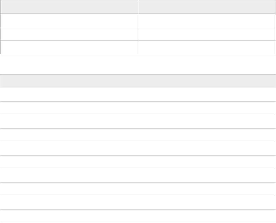
To return the NSX Edge cluster to the original state, you must use the FQDN and IP address of
the failed NSX Edge node that you deleted. This procedure ensures that the inventory in SDDC
Manager is accurate.
Procedure
1 In a web browser, log in to the NSX Manager cluster for the domain by using the user
interface (https://<nsx_manager_cluster_fqdn>/login.jsp?local=true)
2 On the main navigation bar, click System.
3 In the left pane, under Configuration, click Fabric > Nodes.
4 Click the Edge transport nodes tab.
5 Click Add edge VM.
6 On the Name and description page, enter these values and click Next.
Setting Value
Name Enter the VM name
Host name/FQDN Enter the FQDN
Form factor Medium
7 On the Credentials page, enter these values which are recorded earlier and click Next.
Setting
Value
CLI user name admin
CLI password
edge_admin_password
CLI confirm password
edge_admin_password
Allow SSH login Yes
System root password
edge_root_password
System root password confirm
edge_root_password
Allow root SSH login No
Audit user name audit
Audit password
edge_audit_password
Audit confirm password
edge_audit_password
VMware Cloud Foundation on Dell EMC VxRail Guide
VMware, Inc. 238

8 On the Configure deployment page, select these values and click Next.
Setting Value
Compute manager Enter the vCenter Server FQDN
Cluster Enter the cluster name
Resource pool Enter the resource pool
Datastore Enter the datastore
9 On the Configure Node Settings page, enter these values and click Next.
Setting Value
IP assignment Static
Management IP Enter the management IP address.
Default gateway Enter the default gateway
Management interface Select the management network distributed port group
Search domain names Enter the search domain
DNS servers Enter the DNS servers
NTP servers Enter the NTP servers
10 On the Configure NSX page, enter these values which are recorded earlier and click Finish.
Setting
Value
Edge switch name Enter the edge switch name.
Transport zone Enter the transport zone names.
Uplink profile Enter the uplink profile name.
IP assignment Use static IP list
Static IP list Enter the static IP list.
Gateway Enter the gateway IP
Subnet mask Enter the subnet mask
Teaming policy switch mapping Enter the values for Uplink1 and Uplink2.
Replace the Temporary NSX Edge Node with the Redeployed NSX Edge Node
After deploying the new NSX Edge node with the same configuration as the failed NSX Edge
node, you replace the temporary NSX Edge node with the redeployed failed node in the NSX-
Edge cluster.
VMware Cloud Foundation on Dell EMC VxRail Guide
VMware, Inc. 239
Procedure
1 In a web browser, log in to the NSX Manager cluster for the domain by using the user
interface (https://<nsx_manager_cluster_fqdn>/login.jsp?local=true)
2 On the main navigation bar, click System.
3 In the left pane, under Configuration, click Fabric > Nodes.
4 Click the Edge clusters tab.
5 Select the check-box for the NSX Edge cluster.
6 Click Action and select Replace edge cluster member.
7 From the Replace drop down menu, select the temporary node and from the with drop down
menu, select the new node and then click Save.
Delete the Temporary NSX Edge Node
After replacing the temporary NSX Edge node with the new NSX Edge node in the NSX Edge
cluster, you delete the temporary node.
Procedure
1 In a web browser, log in to the NSX Manager cluster for the domain by using the user
interface (https://<nsx_manager_cluster_fqdn>/login.jsp?local=true)
2 On the main navigation bar, click System.
3 In the left pane, under Configuration, click Fabric > Nodes > .
4 Click the Edge transport nodes tab.
5 Select the check-box for the temporary NSX Edge node and click Delete.
6 In the confirmation dialog box, click Delete.
Update or Recreate the VM Anti-Affinity Rule for the NSX Edge Cluster Nodes
During the NSX Edge deployment process, SDDC Manager creates a VM anti-affinity rule to
prevent the nodes of the NSX Edge cluster from running on the same ESXi host. If you
redeployed the two NSX Edge cluster nodes, you must recreate this rule. If you redeployed
one node of the cluster, you must add the new VM to the existing rule.
Procedure
1 In a web browser, log in to the domain vCenter Server by using the vSphere Client (https://
<vcenter_server_fqdn>/ui).
2 Select Menu > Hosts and Clusters.
3 In the inventory expand vCenter Server > Datacenter.
4 Click the cluster object.
5 Click the Configure tab and click VM/Host Rules.
VMware Cloud Foundation on Dell EMC VxRail Guide
VMware, Inc. 240
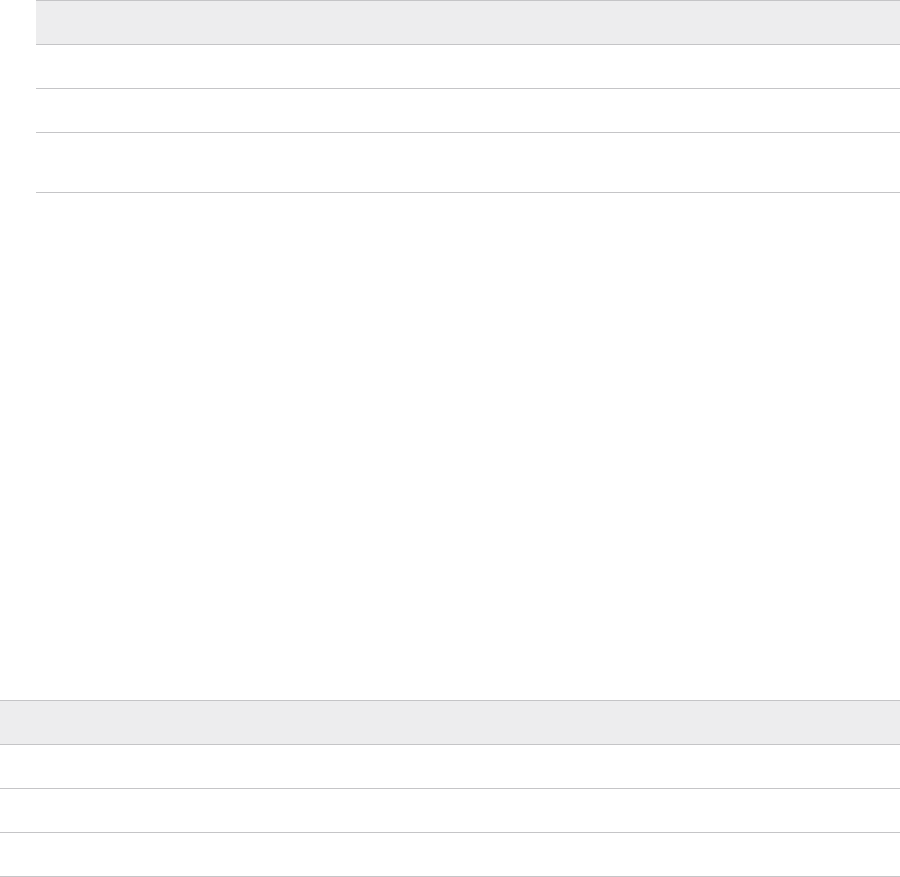
6 Update or recreate the VM anti-affinity rule.
n If you redeployed one of the nodes in the NSX Edge cluster, add the new VM to the
existing rule.
a Click the VM anti-affinity rule name and click Edit.
b Click Add VM/Host rule member, select the new NSX Edge cluster node, and click
Add.
n If you redeployed the two nodes in the NSX Edge cluster, click Add VM/Host rule, enter
these values to create the rule, and click OK.
Setting Value
Name Enter the name of the anti-affinity rule
Type Separate virtual machines
Members Click Add VM/Host rule member, select the NSX
Edge cluster nodes, and click Add.
Validate the State of the NSX Edge Cluster Nodes
After replacing the temporary NSX Edge node with the redeployed failed NSX Edge node, you
must verify the state of the NSX Edge cluster nodes.
You validate the state of the redeployed NSX Edge node and the second NSX Edge node in the
cluster.
Procedure
1 In a web browser, log in to the NSX Manager cluster for the domain by using the user
interface (https://<nsx_manager_cluster_fqdn>/login.jsp?local=true)
2 On the main navigation bar, click System.
3 In the left pane, under Configuration, click Fabric > Nodes.
4 Click the Edge transport nodes tab.
5 Verify all edge transport nodes show these values.
Setting
Value
Configuration state Success
Node status Up
Tunnels Upward arrow mark with number of tunnels
VMware Cloud Foundation on Dell EMC VxRail Guide
VMware, Inc. 241
Image-Based Backup and Restore of VMware Cloud
Foundation
For an image-based backup of the VMware Cloud Foundation, use a solution compatible with the
VMware vSphere Storage APIs - Data Protection (formerly known as VMware vStorage APIs for
Data Protection or VADP).
vSphere Storage APIs - Data Protection compatible backup software connects to the vCenter
servers in the management domain to perform backups. In the event of failure, the backup
software connects to the vCenter servers in the management domain to restore the VMs. If the
management domain is lost, the vCenter servers are no longer available and must be restored
first. Choosing a backup software that supports Direct Restore to an ESXi host allows restoring
the vCenter Servers.
Connect your backup solution with the management domain vCenter Server and configure it. To
reduce the backup time and storage cost, use incremental backups in addition to the full ones.
Quiesced backups are enabled for vRealize Suite Lifecycle Manager and Workspace ONE Access.
VMware Cloud Foundation on Dell EMC VxRail Guide
VMware, Inc. 242
Lifecycle Management
24
Lifecycle Management (LCM) enables you to perform automated updates on VMware Cloud
Foundation services (SDDC Manager and internal services), VMware software (NSX-T Data
Center, vCenter Server, ESXi, and vRealize Suite Lifecycle manager), and Dell EMC VxRail in your
environment. You can download the update bundles and apply them manually or schedule them
within your maintenance window allowing for flexibility in your application.
The LCM bundles that are available are:
n VxRail Partner Bundle: You can download the Dell EMC VxRail partner bundle to update the
VxRail appliance.
n Patch Update Bundle: A patch update bundle contains bits to update the appropriate Cloud
Foundation software components in your management domain or VI workload domain. In
most cases, a patch update bundle must be applied to the management domain before it can
be applied to VI workload domains.
n Cumulative Update Bundle: With a cumulative update bundle, you can directly update the
appropriate software in your workload domain to the version contained in the cumulative
bundle rather than applying sequential updates to reach the target version.
n Install Bundle: If you have updated the management domain in your environment, you can
download an install bundle with updated software bits for VI workload domains and vRealize
Suite Lifecycle Manager.
Read the following topics next:
n Download VMware Cloud Foundation on Dell EMC VxRail Bundles
n Upgrade to VMware Cloud Foundation 4.3 on Dell EMC VxRail
Download VMware Cloud Foundation on Dell EMC VxRail
Bundles
If SDDC Manager is configured to work with your VMware Customer Connect and Dell EMC
accounts, LCM automatically polls the depots to access install and upgrade bundles. You receive
a notification when a bundle is available and can then download the bundle.
VMware, Inc.
243

If SDDC Manager does not have direct internet connectivity, you can either use a proxy server to
access the depot, or download install and upgrade bundles manually using the Bundle Transfer
Utility.
To download an async patch bundle, you must use the Async Patch Tool. For more information,
see the Async Patch Tool documentation.
Download VMware Cloud Foundation on Dell EMC VxRail Bundles
from SDDC Manager
If SDDC Manager has an internet connection, you can download bundles directly from SDDC
Manager UI.
When upgrade bundles are available for your environment, a message is displayed in the SDDC
Manager UI. Available install bundles are displayed on the Bundle Management page and on the
Updates/Patches tab for each workload domain.
Prerequisites
In order to download bundles from the SDDC Manager UI, you must be connected to the My
VMware and Dell EMC repositories.
1 In the navigation pane, click Administration > Repository Settings.
2 Click Authenticate.
3 Enter your user names and passwords and click Authorize.
Automatic polling of the manifest for bundles by SDDC Manager is enabled by default. If you
have previously edited the application-prod.properties file on the SDDC Manager appliance
to download upgrade bundles in an offline mode, you must edit it again before downloading
bundles from SDDC Manager. Follow the steps below:
1 Using SSH, log in to the SDDC Manager appliance as the vcf user.
2 Enter su to switch to the root user.
3 Open the /opt/vmware/vcf/lcm/lcm-app/conf/application-prod.properties file.
4 Set lcm.core.enableManifestPolling=true.
5 Restart the LCM service:
systemctl restart lcm
Procedure
1 In the navigation pane, click Lifecycle Management > Bundle Management.
The Bundles page displays the bundles available for download. The Bundle Details section
displays the bundle version and release date.
VMware Cloud Foundation on Dell EMC VxRail Guide
VMware, Inc. 244

If the bundle can be applied right away, the Bundle Details column displays the workload
domains to which the bundle needs to be applied and the Availability column displays
Available. If another bundle needs to be applied before a particular bundle, the Availability
column displays Future.
2 To view more information about the bundle, click View Details.
The Bundle Details section displays the bundle version, release date, and additional details
about the bundle.
3 Click Exit Details.
4 Specify when to download the bundle.
n Click Download Now to start the download immediately.
n Click Schedule Download to set the date and time for the bundle download.
Results
The Download Status section displays the date and time at which the bundle download has been
scheduled. When the download begins, the status bar displays the download progress.
Download VMware Cloud Foundation on Dell EMC VxRail Bundles
with a Proxy Server
If you do not have internet access, you can use a proxy server to download the LCM bundles.
LCM only supports proxy servers that do not require authentication.
Procedure
1 Using SSH, log in to the SDDC Manager appliance with the user name vcf and password you
specified in the deployment parameter sheet.
2 Type su to switch to the root account.
3 Open the /opt/vmware/vcf/lcm/lcm-app/conf/application-prod.properties file.
4 Add the following lines to the end of the file:
lcm.depot.adapter.proxyEnabled=true
lcm.depot.adapter.proxyHost=proxy IP address
lcm.depot.adapter.proxyPort=proxy port
5 Save and close the file.
6 Restart the LCM server by typing the following command in the console window:
systemctl restart lcm
7 Wait for 5 minutes and then download the bundles.
VMware Cloud Foundation on Dell EMC VxRail Guide
VMware, Inc. 245

Download Bundles for VMware Cloud Foundation on Dell EMC
VxRail with the Bundle Transfer Utility
Lifecycle Management polls the VMware depot to access install and update bundles. If you do
not have internet connectivity in your VMware Cloud Foundation system, you can use the Bundle
Transfer Utility to manually download the bundles from the depot on your local computer and
then upload them to the SDDC Manager appliance.
When you download bundles, the Bundle Transfer Utility verifies that the file size and checksum
of the downloaded bundles match the expected values.
Prerequisites
n A Windows or Linux computer with internet connectivity for downloading the bundles.
n The computer must have Java 8 or later.
n A Windows or Linux computer with access to the SDDC Manager appliance for uploading the
bundles.
n To upload the manifest file from a Windows computer, you must have OpenSSL installed and
configured.
n Configure TCP keepalive in your SSH client to prevent socket connection timeouts when
using the Bundle Transfer Utility for long-running operations.
Note The Bundle Transfer Utility is the only supported method for downloading bundles. Do not
use third-party tools or other methods to download bundles.
Procedure
1 Download the Bundle Transfer Utility on a computer with internet access.
a Log in to VMware Customer Connect and browse to the Download VMware Cloud
Foundation page.
b In the Select Version field, select the version to which you are upgrading.
c Click Drivers & Tools.
d Expand VMware Cloud Foundation Supplemental Tools.
e Click Download Now for the Bundle Transfer Utility.
2 Extract lcm-tools-prod.tar.gz.
3 Navigate to lcm-tools-prod/bin/ and confirm that you have execute permission on all
folders.
4 Copy the Bundle Transfer Utility to a computer with access to the SDDC Manager appliance
and then copy the Bundle Transfer Utility to the SDDC Manager appliance.
a SSH in to the SDDC Manager appliance using the vcf user account.
b Enter su to switch to the root user.
VMware Cloud Foundation on Dell EMC VxRail Guide
VMware, Inc. 246
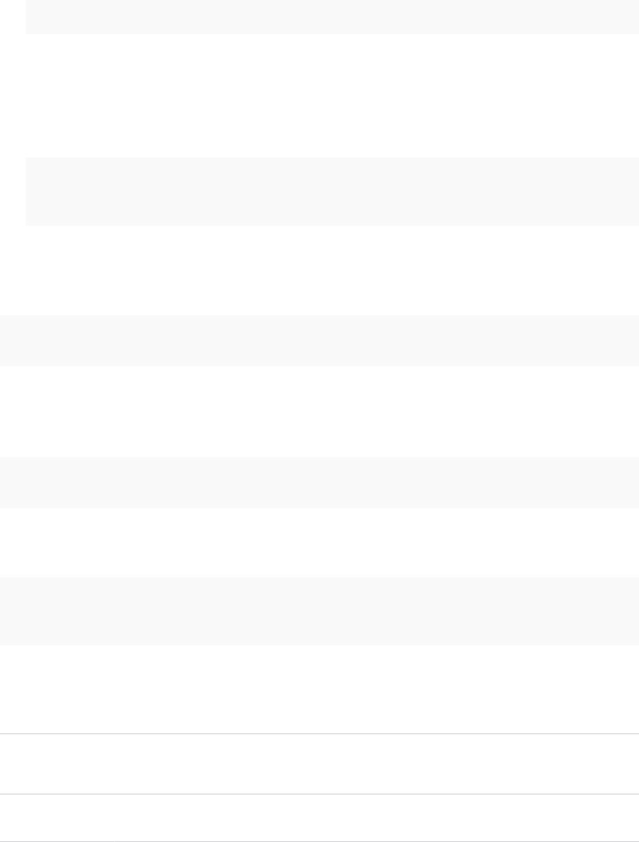
c Create the lcm-tools directory.
mkdir /opt/vmware/vcf/lcm/lcm-tools
d Copy the bundle transfer utility file (lcm-tools-prod.tar.gz) that you downloaded in
step 1 to the /opt/vmware/vcf/lcm/lcm-tools directory.
e Extract the contents of lcm-tools-prod.tar.gz.
f Set the permissions for the lcm-tools directory.
cd /opt/vmware/vcf/lcm/
chown vcf_lcm:vcf -R lcm-tools
chmod 750 -R lcm-tools
5 On the computer with internet access, download the manifest file.
This is a structured metadata file that contains information about the VMware Cloud
Foundation product versions included in the release Bill of Materials.
./lcm-bundle-transfer-util --download --manifestDownload --depotUser Username --
depotUserPassword Password
6 Copy the manifest file and lcm-tools-prod directory to a computer with access to the
SDDC Manager appliance.
7 Upload the manifest file to the SDDC Manager appliance.
./lcm-bundle-transfer-util --update --sourceManifestDirectory downloaded-manifest-
directory --sddcMgrFqdn FQDN --sddcMgrUser Username
Use your vSphere SSO credentials for the --sddcMgrUser credentials in the command.
8 On the computer with internet access, run the following command:
./lcm-bundle-transfer-util --download "downloadPartnerBundle" --outputDirectory absolute-
path-output-dir --depotUser customer_connect_email --sv current-vcf-version --p target-vcf-
version --pdu dell_emc_depot_email
absolute-path-
output-dir
Path to the directory where the bundle files should be downloaded. This directory folder
must have 777 permissions.
If you do not specify the download directory, bundles are downloaded to the default
directory with 777 permissions.
depotUser
VMware Customer Connect email address. You will be prompted to enter the depot user
password. If there are any special characters in the password, specify the password within
single quotes.
current-vcf-
version
Current version of VMware Cloud Foundation. For example, 4.3.1.1.
If you do not specify a current version, the utility uses 4.1.0.0.
VMware Cloud Foundation on Dell EMC VxRail Guide
VMware, Inc. 247

target-vcf-version
Current version of VMware Cloud Foundation. For example, 4.4.0.0.
dell_emc_depot_
email
Dell EMC depot email address.
After you enter you VMware Customer connect and Dell EMC Depot passwords, the utility
asks Do you want to download vRealize bundles?. Enter Y or N.
The utility displays a list of the available bundles based on the current and target versions of
VMware Cloud Foundation.
9 Specify the bundles to download.
Enter one of the following options:
n all
n install
n patch
You can also enter a comma-separated list of bundle names to download specific bundles.
For example:
bundle-38371, bundle-38378.
Download progress for each bundle is displayed. Wait until all bundles are downloaded.
10 If you downloaded VxRail bundles:
a Copy the partner bundle to the /nfs/vmware/vcf/nfs-mount/bundle/depot/local/
bundles directory on the SDDC Manager appliance.
b Copy partnerBundleMetadata.json to the /nfs/vmware/vcf/nfs-mount/bundle/
depot/local directory on the SDDC Manager appliance.
c Copy softwareCompatibilitySets.json to the /nfs/vmware/vcf/nfs-mount/
bundle/depot/local directory on the SDDC Manager appliance.
d Run following commands on the SDDC Manager appliance:
chown -R vcf_lcm:vcf /nfs/vmware/vcf/nfs-mount/bundle/depot/local
chmod -R 755 /nfs/vmware/vcf/nfs-mount/bundle/depot/local
11 If you downloaded bundles for VMware Cloud Foundation and its components, copy the
entire output directory to a computer with access to the SDDC Manager appliance, and then
copy it to the SDDC Manager appliance.
For example:
scp -pr /root/upgrade-bundles vcf@SDDC_MANAGER_IP:/nfs/vmware/vcf/nfs-mount/
The scp command in the example above copies the output directory (upgrade-bundles) to
the /nfs/vmware/vcf/nfs-mount/ directory on the SDDC Manager appliance.
VMware Cloud Foundation on Dell EMC VxRail Guide
VMware, Inc. 248

12 In the SDDC Manager appliance, upload the bundle directory to the internal LCM repository.
./lcm-bundle-transfer-util --upload "uploadPartnerBundle" --bundleDirectory
absolute-path-bundle-dir
where
absolute-path-bundle-dir
is the directory where the bundle files have been be
uploaded, or /nfs/vmware/vcf/nfs-mount/upgrade-bundles as shown in the previous
step.
The utility uploads the bundles and displays upload status for each bundle. Wait for all
bundles to be uploaded before proceeding with an upgrade.
View VMware Cloud Foundation on Dell EMC VxRail Bundle
Download History
The Download History page displays all bundles that have been downloaded.
Procedure
u In the navigation pane, click Repository > Bundle Management > Download History.
All downloaded bundles are displayed. Click View Details to see bundle metadata details.
Upgrade to VMware Cloud Foundation 4.3 on Dell EMC
VxRail
The following procedures provide information about upgrading to VMware Cloud Foundation 4.3
on Dell EMC VxRail.
You can perform a sequential or skip-level upgrade toVMware Cloud Foundation 4.3 from
VMware Cloud Foundation 4.2.1, 4.2, 4.1.0.1, or 4.1. If your environment is at a version earlier
than 4.1, you must upgrade the management domain and all VI workload domains to VMware
Cloud Foundation 4.1 and then upgrade to VMware Cloud Foundation 4.3.
Your environment may contain workload domains at different VMware Cloud Foundation
releases. After upgrading to VMware Cloud Foundation 4.3, you can view the versions in your
environment and the associated component versions in that release by navigating to Lifecycle
Management > Release Versions. Note that the management domain and VI workload domains
must be upgraded to the same release version. For example, suppose your environment is
at VMware Cloud Foundation 4.2. If you are upgrading to VMware Cloud Foundation 4.3, the
management domain and VI workload domains must be upgraded to this release.
Upgrades are applied on a workload domain basis. The management domain contains the core
infrastructure, so you must upgrade the management domain before upgrading the other VI
workload domains. You must upgrade all required components to keep your system in an
optimum state.
n Upgrade Prerequisites for VMware Cloud Foundation on Dell EMC VxRail
Ensure that the following prerequisites are met before starting an upgrade.
VMware Cloud Foundation on Dell EMC VxRail Guide
VMware, Inc. 249
n Upgrade the Management Domain for VMware Cloud Foundation on Dell EMC on VxRail
You must upgrade the management domain before upgrading VI workload domains in
your environment. In order to upgrade to VMware Cloud Foundation 4.3, the management
domain must be at VMware Cloud Foundation 4.2.1, 4.2, 4.1.0.1, or 4.1.
n Upgrade a VI Workload Domain for VMware Cloud Foundation on Dell EMC on VxRail
The management domain in your environment must be upgraded before you upgrade VI
workload domains.
n Upgrade vSAN Witness Host for VMware Cloud Foundation
If your VMware Cloud Foundation environment contains stretched clusters, update and
remediate the vSAN witness host.
Upgrade Prerequisites for VMware Cloud Foundation on Dell EMC
VxRail
Ensure that the following prerequisites are met before starting an upgrade.
n Take a backup of the SDDC Manager appliance. This is required since the SDDC Manager
appliance will be rebooted during the update.
n Take a snapshot of relevant VMs in your management domain.
n Do not run any domain operations while an update is in progress. Domain operations are
creating a new VI domain, adding hosts to a cluster or adding a cluster to a workload domain,
and removing clusters or hosts from a workload domain.
n Download the relevant bundles. See Download VMware Cloud Foundation on Dell EMC VxRail
Bundles.
n If you applied an async patch to your current VMware Cloud Foundation instance you must
use the Async Patch Tool to upgrade to a later version of VMware Cloud Foundation. For
example, if you applied an async vCenter Server patch to a VMware Cloud Foundation 4.3.1
instance, you must use the Async Patch Tool to upgrade to VMware Cloud Foundation 4.4.
See the Async Patch Tool documentation.
n Ensure that there are no failed workflows in your system and none of the VMware Cloud
Foundation resources are in activating or error state. If any of these conditions are true,
contact VMware Support before starting the upgrade.
n Confirm that the passwords for all VMware Cloud Foundation components are valid. An
expired password can cause an upgrade to fail.
n Review the
VMware Cloud Foundation on Dell EMC Release Notes
for known issues related to
upgrades.
VMware Cloud Foundation on Dell EMC VxRail Guide
VMware, Inc. 250

Upgrade the Management Domain for VMware Cloud Foundation on
Dell EMC on VxRail
You must upgrade the management domain before upgrading VI workload domains in your
environment. In order to upgrade to VMware Cloud Foundation 4.3, the management domain
must be at VMware Cloud Foundation 4.2.1, 4.2, 4.1.0.1, or 4.1.
The components in the management domain must be upgraded in the following order:
Components in the management domain must be upgraded in the following order:
1 SDDC Manager and VMware Cloud Foundation services.
2 vRealize Suite Lifecycle Manager, vRealize Suite products, and Workspace ONE Access (if
applicable).
a vRealize Suite Lifecycle Manager
b vRealize Log Insight
c vRealize Operations
d vRealize Automation
e Workspace ONE Access
Note Note: All vRealize Suite upgrades are sequential. You may have to download and apply
multiple bundles, depending on the current product versions in your environment.
3 NSX-T Data Center.
4 vCenter Server.
5 vSAN witness host (If you have stretched clusters in your environment).
6 VxRail Manager and ESXi.
The upgrade process is similar for all components. Information that is unique to a component is
described in the following table.
VMware Cloud Foundation on Dell EMC VxRail Guide
VMware, Inc. 251

Component Additional Information
SDDC Manager and VMware Cloud Foundation services The VMware Cloud Foundation software bundle to
be applied depends on the current version of your
environment.
If you upgrading from VMware Cloud Foundation 4.2.1, 4.2,
or 4.1.0.1, you must apply the following bundles to the
management domain:
n The VMware Cloud Foundation bundle upgrades SDDC
Manager, LCM, and VMware Cloud Foundation services.
n The Configuration Drift bundle applies configuration
drift on software components.
If you upgrading from VMware Cloud Foundation 4.1,
you apply the VMware Cloud Foundation Update bundle,
which upgrades SDDC Manager, LCM, and VMware Cloud
Foundation services, and also applies the configuration
drift.
vRealize Log Insight After upgrading vRealize Log Insight, upgrade the vRealize
Log Insight content packs. Content packs are plugins to
vRealize Log Insight that provide pre-defined knowledge
about specific types of events such as log messages. You
must upgrade to the latest content packs for use with
vRealize Log Insight.
1 Log in to the vRealize Log Insight user interface as the
admin user.
2 Click the configuration drop-down menu icon and
select Content Pack.
3 In the Content Pack pane, under Content Pack Market
Place, click Updates.
4 In the Log Insight Content Pack Marketplace pane,
click Update All to upgrade all content packs to the
latest version.
After you upgrade the content packs, click each of the
items under Installed Content Packs and verify that the
version number of each content pack is the same as or
newer than the version listed in the Release Notes for your
version of VMware Cloud Foundation.
Workspace ONE Access If you had Workspace ONE Access in your pre-upgrade
environment, you must upgrade it using vRealize Suite
Lifecycle Manager.
1 On vRealize Suite Lifecycle Manager UI navigate to
the Lifecycle Operations tab. Click Settings > Binary
Mapping.
2 Select Sync Binaries to discover the upgrade image for
Workspace ONE Access in SDDC Manager.
3 Click Environments > Global Environment. The global
environment contains the Workspace ONE Access
product. To upgrade the Workspace ONE Access
product, see "Upgrade VMware Identity Manager" in
vRealize Suite Lifecycle Manager Installation, Upgrade,
and Management
.
VMware Cloud Foundation on Dell EMC VxRail Guide
VMware, Inc. 252

Component Additional Information
NSX-T Data Center Upgrading NSX-T Data Center involves the following
components:
n Upgrade Coordinator
n NSX Edge clusters (if deployed)
n Host clusters
n NSX Manager cluster
The upgrade wizard provides some flexibility when
upgrading NSX-T Data Center for workload domains. By
default, the process upgrades all NSX Edge clusters in
parallel, and then all host clusters in parallel. Parallel
upgrades reduce the overall time required to upgrade your
environment. You can also choose to upgrade NSX Edge
clusters and host clusters sequentially. The ability to select
clusters allows for multiple upgrade windows and does not
require all clusters to be available at a given time.
The NSX Manager cluster is upgraded only if the Upgrade
all host clusters setting is enabled on the NSX-T Host
Clusters tab. New features introduced in the upgrade
are not configurable until the NSX Manager cluster is
upgraded.
n If you have a single cluster in your environment, enable
the Upgrade all host clusters setting.
n If you have multiple host clusters and choose to
upgrade only some of them, you must go through the
NSX-T upgrade wizard again until all host clusters have
been upgraded. When selecting the final set of clusters
to be upgraded, you must enable the Upgrade all host
clusters setting so that NSX Manager is upgraded.
n If you upgraded all host clusters without enabling the
Upgrade all host clusters setting, run through the NSX-
T upgrade wizard again to upgrade NSX Manager.
vCenter Server
Take a file-based backup of the vCenter Server appliance
before starting the upgrade. See Manually Back Up vCenter
Server.
Note After taking a backup, do not make any changes to
the vCenter Server inventory or settings until the upgrade
completes successfully.
If the upgrade fails, resolve the issue and retry the failed
task. If you cannot resolve the issue, restore vCenter
Server using the file-based backup. See Restore vCenter
Server.
Once the upgrade successfully completes, use the vSphere
Client to change the vSphere DRS Automation Level setting
back to the original value for each vSphere cluster that
is managed by the vCenter Server. See KB 87631 for
information about using VMware PowerCLI to change the
vSphere DRS Automation Level.
VMware Cloud Foundation on Dell EMC VxRail Guide
VMware, Inc. 253
Component Additional Information
vSAN witness host See Upgrade vSAN Witness Host for VMware Cloud
Foundation.
ESXi By default, the upgrade process upgrades the ESXi hosts
in all clusters in a domain in parallel. If you have multiple
clusters in the management domain or in a VI workload
domain, you can select which clusters to upgrade. You
can also choose to upgrade the clusters in parallel or
sequentially.
If you are using external (non-vSAN) storage, updating
and patching is a manual task and falls outside of SDDC
Manager lifecycle management. To ensure supportability
after an ESXi upgrade, consult the vSphere HCL and your
storage vendor.
Procedure
1 Navigate to the Updates/Patches tab of the management domain.
2 Click Precheck to validate that the component is ready to be updated.
Click View Status to see the update status for each component and the tests performed.
Expand a test by clicking the arrow next to it to see further details.
If any of the tests fail, fix the issue and click Retry Precheck.
The precheck results are displayed below the Precheck button. Ensure that the precheck
results are green before proceeding. A failed precheck may cause the update to fail.
3 Click Update Now or Schedule Update next to the relevant bundle.
If you selected Schedule Update, select the date and time for the bundle to be applied.
4 The Update Status window displays the components that will be upgraded and the upgrade
status. Click View Update Activity to view the detailed tasks.
After the upgrade is completed, a green bar with a check mark is displayed.
Upgrade a VI Workload Domain for VMware Cloud Foundation on
Dell EMC on VxRail
The management domain in your environment must be upgraded before you upgrade VI
workload domains.
To upgrade to VMware Cloud Foundation 4.3, the components in a VI workload domain must be
upgraded in the following order:
1 NSX-T Data Center.
2 vCenter Server.
3 vSAN witness host (If you have stretched clusters in your environment).
4 VxRail Manager and ESXi.
VMware Cloud Foundation on Dell EMC VxRail Guide
VMware, Inc. 254
5 Workload Management on clusters that have vSphere with Tanzu. Workload Management
can be upgraded through vCenter Server. See Working with vSphere Lifecycle Manager.
The upgrade process is similar for all components. Information that is unique to a component is
described in the following table.
VMware Cloud Foundation on Dell EMC VxRail Guide
VMware, Inc. 255

Component Additional Information
NSX-T Data Center Upgrading NSX-T Data Center involves the following
components:
n Upgrade Coordinator
n NSX Edge clusters (if deployed)
n Host clusters
n NSX Manager cluster
VI workload domains can share the same NSX Manager
cluster and NSX Edge clusters. When you upgrade
these components for one VI workload domain, they are
upgraded for all VI workload domains that share the same
NSX Manager or NSX Edge cluster. You cannot perform
any operations on the VI workload domains while NSX-T
Data Center is being upgraded.
The upgrade wizard provides some flexibility when
upgrading NSX-T Data Center for workload domains. By
default, the process upgrades all NSX Edge clusters in
parallel, and then all host clusters in parallel. Parallel
upgrades reduce the overall time required to upgrade your
environment. You can also choose to upgrade NSX Edge
clusters and host clusters sequentially. The ability to select
clusters allows for multiple upgrade windows and does not
require all clusters to be available at a given time.
The NSX Manager cluster is upgraded only if the Upgrade
all host clusters setting is enabled on the NSX-T Host
Clusters tab. New features introduced in the upgrade
are not configurable until the NSX Manager cluster is
upgraded.
n If you have a single cluster in your environment, enable
the Upgrade all host clusters setting.
n If you have multiple host clusters and choose to
upgrade only some of them, you must go through the
NSX-T upgrade wizard again until all host clusters have
been upgraded. When selecting the final set of clusters
to be upgraded, you must enable the Upgrade all host
clusters setting so that NSX Manager is upgraded.
n If you upgraded all host clusters without enabling the
Upgrade all host clusters setting, run through the NSX-
T upgrade wizard again to upgrade NSX Manager.
vCenter Server
If your VI workload domain contains Workload
Management enabled clusters, ensure that Workload
Management is at version 1.18 or higher. If
Workload Management is at a lower version, upgrade
Workload Management to at least version 1.18 before
upgradingvCenter Server.
VMware Cloud Foundation on Dell EMC VxRail Guide
VMware, Inc. 256

Component Additional Information
Take a file-based backup of the vCenter Server appliance
before starting the upgrade. See Manually Back Up vCenter
Server.
Note After taking a backup, do not make any changes to
the vCenter Server inventory or settings until the upgrade
completes successfully.
If the upgrade fails, resolve the issue and retry the failed
task. If you cannot resolve the issue, restore vCenter
Server using the file-based backup. See Restore vCenter
Server.
Once the upgrade successfully completes, use the vSphere
Client to change the vSphere DRS Automation Level setting
back to the original value for each vSphere cluster that
is managed by the vCenter Server. See KB 87631 for
information about using VMware PowerCLI to change the
vSphere DRS Automation Level.
vSAN witness host See Upgrade vSAN Witness Host for VMware Cloud
Foundation.
ESXi By default, the upgrade process upgrades the ESXi hosts
in all clusters in a domain in parallel. If you have multiple
clusters in the management domain or in a VI workload
domain, you can select which clusters to upgrade. You
can also choose to upgrade the clusters in parallel or
sequentially.
If you are using external (non-vSAN) storage, updating
and patching is a manual task and falls outside of SDDC
Manager lifecycle management. To ensure supportability
after an ESXi upgrade, consult the vSphere HCL and your
storage vendor.
Procedure
1 Navigate to the Updates/Patches tab of the VI workload domain.
2 Click Precheck to validate that the component is ready to be updated.
Click View Status to see the update status for each component and the tests performed.
Expand a test by clicking the arrow next to it to see further details.
If any of the tests fail, fix the issue and click Retry Precheck.
The precheck results are displayed below the Precheck button. Ensure that the precheck
results are green before proceeding. A failed precheck may cause the update to fail.
3 Click Update Now or Schedule Update next to the relevant bundle.
If you selected Schedule Update, select the date and time for the bundle to be applied.
4 The Update Status window displays the components that will be upgraded and the upgrade
status. Click View Update Activity to view the detailed tasks.
After the upgrade is completed, a green bar with a check mark is displayed.
VMware Cloud Foundation on Dell EMC VxRail Guide
VMware, Inc. 257
Upgrade vSAN Witness Host for VMware Cloud Foundation
If your VMware Cloud Foundation environment contains stretched clusters, update and
remediate the vSAN witness host.
Prerequisites
Download the ESXi ISO that matches the version listed in the the Bill of Materials (BOM) section
of the
VMware Cloud Foundation Release Notes
.
Procedure
1 In a web browser, log in to vCenter Server at https://
vcenter_server_fqdn
/ui.
2 Upload the ESXi ISO image file to vSphere Lifecycle Manager.
a Click Menu > Lifecycle Manager.
b Click the Imported ISOs tab.
c Click Import ISO and then click Browse.
d Navigate to the ESXi ISO file you downloaded and click Open.
e After the file is imported, click Close.
3 Create a baseline for the ESXi image.
a On the Imported ISOs tab, select the ISO file that you imported, and click New baseline.
b Enter a name for the baseline and specify the Content Type as Upgrade.
c Click Next.
d Select the ISO file you had imported and click Next.
e Review the details and click Finish.
4 Attach the baseline to the vSAN witness host.
a Click Menu > Hosts and Clusters.
b In the Inventory panel, click vCenter > Datacenter.
c Select the vSAN witness host and click the Updates tab.
d Under Attached Baselines, click Attach > Attach Baseline or Baseline Group.
e Select the baseline that you had created in step 3 and click Attach.
f Click Check Compliance.
After the compliance check is completed, the Status column for the baseline is displayed
as Non-Compliant.
5 Remediate the vSAN witness host and update the ESXi hosts that it contains.
a Right-click the vSAN witness and click Maintenance Mode > Enter Maintenance Mode.
b Click OK.
VMware Cloud Foundation on Dell EMC VxRail Guide
VMware, Inc. 258
c Click the Updates tab.
d Select the baseline that you had created in step 3 and click Remediate.
e In the End user license agreement dialog box, select the check box and click OK.
f In the Remediate dialog box, select the vSAN witness host, and click Remediate.
The remediation process might take several minutes. After the remediation is completed,
the Status column for the baseline is displayed as Compliant.
g Right-click the vSAN witness host and click Maintenance Mode > Exit Maintenance Mode.
h Click OK.
VMware Cloud Foundation on Dell EMC VxRail Guide
VMware, Inc. 259
