Models
ETF2300PF10
ETF2300PF12
OWNER’S MANUAL
How to install, operate and maintain your
EcoWater Systems
Multi-purpose Filter
7355260 (Rev. B 7/3/17)
EcoWater Systems LLC
P.O. Box 64420, St. Paul, MN 55164-0420
www.ecowater.com
Designed, Engineered &
Assembled in the U.S.A.
Systems tested and certified without media
by the Water Quality Association against
CSA B483.1, NSF/ANSI Standard 61, and
NSF/ANSI Standard 372 for low lead content.

2
ECOWATER
S Y S T E M S
Table of Contents & Safety Guides
that is in a dry location only, grounded and properly
protected by an overcurrent device such as circuit
breaker or fuse.
This system is not intended to be used for treating water
that is microbiologically unsafe or of unknown quality
without adequate disinfection before or after the system.
FCC NOTICE
NOTE: This equipment has been tested and found to
comply with the limits for a Class B digital device, pur-
suant to Part 15 of the FCC Rules. These limits are
designed to provide reasonable protection against
harmful interference in a residential installation. This
equipment generates, uses, and can radiate radio fre-
quency energy and, if not installed and used in accor-
dance with the instructions may cause harmful interfer-
ence to radio communications. However, there is no
guarantee that interference will not occur in a particular
installation. If this equipment does cause harmful inter-
ference to radio or television reception, which can be
determined by turning the equipment off and on, the
user is encouraged to try to correct the interference by
one or more of the following measures:
= Reorient or relocate the receiving antenna.
= Increase the separation between the equipment and
receiver.
= Connect the equipment into an outlet on a circuit dif-
ferent from that to which the receiver is connected.
= Consult the dealer or an experienced radio/TV tech-
nician for help.
Changes or modifications not expressly approved by
EcoWater Systems could void the user’s authority to
operate the equipment.
This device complies with Industry Canada Standard
RSS-210. Operation is subject to the following two con-
ditions: (1) this device may not cause interference, and
(2) this device must accept any interference, including
interference that may cause undesired operation of the
device.
Ce dispositif est conforme avec la norme CNR-210
d’Industrie Canada. Le fonctionnement du dispositif
est sujet aux deux conditions suivantes: (1) le dispositif
ne doit pas causer de brouillage, et (2) le dispositif doit
accepter tous brouillages, incluant tous brouillages qui
peut nuire au bon fonctionnement du dispositif.
European Directive 2002/96/EC requires all
electrical and electronic equipment to be dis-
posed of according to Waste Electrical and
Electronic Equipment (WEEE) requirements.
This directive or similar laws are in place
nationally and can vary from region to region.
Please refer to your state and local laws for
proper disposal of the equipment.
SAFETY GUIDES
Follow the installation instructions carefully. Failure to
install the water filtration system properly voids the
warranty.
Before you begin installation, read this entire manual.
Then, obtain all the materials and tools you will need to
make the installation.
Check local plumbing and electrical codes. The
installation must conform to them.
Use only lead-free solder and flux for all sweat-solder
connections, as required by state and federal codes.
Use care when handling the water filtration system. Do
not turn upside down, drop, or set on sharp protrusions.
Do not locate the water filtration system where freezing
temperatures occur. Do not attempt to treat water over
120°F. Freezing, or hot water damage voids the
warranty.
Avoid installing in direct sunlight. Excessive sun heat
may cause distortion or other damage to non-metallic
parts.
The water filtration system requires a minimum water
pressure of 30 psi at the inlet. Maximum allowable
inlet water pressure is 125 psi. If daytime pressure is
over 80 psi, nighttime pressure may exceed the maxi-
mum. Use a pressure reducing valve if necessary
(Adding a pressure reducing valve may reduce the flow).
The water filtration system works on 24V DC electrical
power, supplied by a direct plug-in power supply
(included). Be sure to use the included power supply,
and plug it into a nominal 120V, 60 Hz household outlet
TABLE OF CONTENTS Page
Specifications & Dimensions . . . . . . . . . . . . . . . . . . . 3
Before Starting Installation . . . . . . . . . . . . . . . . . . . . 4
Media Loading . . . . . . . . . . . . . . . . . . . . . . . . . . . . . . 5
Typical Installation Illustrations . . . . . . . . . . . . . . . . . 6
Installation . . . . . . . . . . . . . . . . . . . . . . . . . . . . . . . 7-8
General Information . . . . . . . . . . . . . . . . . . . . . . . . . 9
Sanitizing Procedure . . . . . . . . . . . . . . . . . . . . . . . . . 9
Setup Procedure . . . . . . . . . . . . . . . . . . . . . . . . 10-13
Filter Operation . . . . . . . . . . . . . . . . . . . . . . . . . . 14-25
Service Information . . . . . . . . . . . . . . . . . . . . . . 26-31
Troubleshooting Guide . . . . . . . . . . . . . . . . . . . . . . 28
Wiring Schematic . . . . . . . . . . . . . . . . . . . . . . . . . . . 28
Repair Parts . . . . . . . . . . . . . . . . . . . . . . . . . . . . 33-35
Warranty . . . . . . . . . . . . . . . . . . . . . . . . . . . . . . . . . 36
3
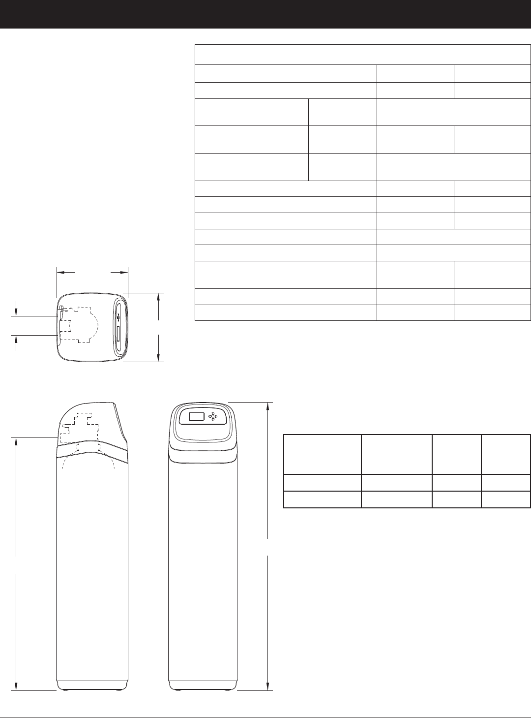
A
FRONT VIEW
SIDE VIEW
TOP VIEW
14-1/4"
13-5/8"
IN
3-3/4"
OUT
IN - OUT
B
ECOWATER
S Y S T E M S
Specifications & Dimensions
Model
Nominal
Mineral Tank
Size
Dimension
A
Dimension
B
ETF2300PF10 10” Dia. x 47” 57” 50”
ETF2300PF12 12” Dia. x 54” 62-1/4” 55-1/4”
14-1/4”
FIG. 1
SIDE VIEW FRONT VIEW
TOP VIEW
13-5/8”
3-3/4”
IN
OUT
IN - OUT
A
B
Ù Not included with the filter.
DIMENSIONS
SPECIFICATIONS
Model ETF2300PF10 ETF2300PF12
Model Code HPF10 HPF12
Sediment Removal
(Filter Aggregate)
limits:
factory recommendation
based on water analysis
Acid Neutralizer
(Neutralite)
water supply
limits:
pH 6.0 - 6.8 pH 6.0 - 6.8
Taste & Odor Removal
(Activated Carbon)
limits:
factory recommendation
based on water analysis
Recommended Amount of MineralÙ
1 to 1-1/4 cu. ft. 2 cu. ft.
Recommended Amount of Filter SandÙ
10 lb. 14 - 15 lb.
Amount of Gravel 17 lb. 29 lb.
Min. - Max. Water Supply Pressure 20 - 125 psi
Min. - Max. Water Supply Temperature 40 - 120 °F (4 - 49 °C)
Minimum Inlet Water Flow,
Backwash & Fast Rinse Flow to Drain
5 gal./min. 7 gal./min.
Default Backwash Time 25 minutes 25 minutes
Default Fast Rinse Time 5 minutes 5 minutes

4
ECOWATER
S Y S T E M S
Before Starting Installation
PLAN HOW YOU WILL INSTALL THE FILTER
You must first decide how to run in and out pipes to
the filter. Look at the house main water pipe at the
point where you will connect the filter. Is the pipe sol-
dered copper, glued plastic, or threaded brass/galva-
nized? What is the pipe size?
Now look at the typical installation illustration on page
6. Use it as a guide when planning your particular
installation. Be sure to direct incoming, unfiltered
water to the filter valve inlet fitting. The valve ports
are marked IN and OUT.
UNPACKING
EcoWater Systems Multi-purpose Filters are shipped
from the factory in one master carton. The carton
also includes a bag of small parts needed to assem-
ble and install the unit, plus this manual.
NOTE: Filtering mineral is not included. See Page
33 for ordering information.
Thoroughly check the filter for possible shipping dam-
age and parts loss. Also inspect and note any dam-
age to the shipping carton. Notify the transportation
company if damage is present. EcoWater Systems is
not responsible for in-transit damages.
Remove and discard (RECYCLE) all packing materi-
als. We suggest you keep the small parts in the
bag(s) until you are ready to use them.
WHERE TO INSTALL THE FILTER
= Place the filter as close as possible to the pressure
tank (well system) or water meter (city water).
= Place the filter as close as possible to a floor
drain, or other acceptable drain point (laundry tub,
sump, standpipe, etc.). CAUTION: Drain water
exits the hose at a fast flow rate, and at water sys-
tem pressure. Be sure the hose is fastened in
some manner to prevent ”whipping” and splashing
to prevent water damage to surrounding area.
= Connect the filter to the main water supply pipe
UPSTREAM OF the water heater. DO NOT RUN
HOT WATER THROUGH THE FILTER. The tem-
perature of water passing through the filter must
be less than 120°F.
= Keep outside faucets on unfiltered water to con-
serve filtering capacity.
= Do not install the filter in a place where it could
freeze. Damage caused by freezing is not cov-
ered by the warranty.
= Put the filter in a place water damage is least likely
to occur if a leak develops. The manufacturer will
not repair or pay for water damage.
= A 120V, 60 Hz electrical outlet, to plug the included
power supply into, is needed near the filter. Be
sure the electrical outlet and power supply are in an
inside location, to protect from wet weather.
= If installing in an outside location, you must take the
steps necessary to assure the filter, installation
plumbing, wiring, etc., are as well protected from the
elements, contamination, vandalism, etc., as when
installed indoors.
= Keep the filter out of direct sunlight. The sun's heat
may soften and distort plastic parts.
TOOLS, PIPE & FITTINGS,
OTHER MATERIALS YOU WILL NEED
= Plastic inlet and outlet fittings included with the filter
allow water flow equivalent to 1 inch nominal pipe.
To maintain full valve flow, 1” pipes to and from the
filter fittings are recommended. Do not reduce the
pipes to less than 3/4” size.
= Use copper, brass or PEX plastic pipe and fittings.
= ALWAYS install the included bypass valve, or 3 shut-
off valves. Bypass valves let you turn off water to
the filter for repairs if needed, but still have water
available to the house pipes.
= Drain hose 5/8” inside diameter minimum, with a
garden hose connection on one end, is needed for
the valve drain. See step 5 on page 8.
= If a rigid valve drain is needed, to comply with plumb-
ing codes, you can buy the parts needed (see page
6) to connect a 5/8” minimum copper tubing drain.
OR
City Water Supply
Well Water Supply
Well
Pump
Pressure
Tank
Untreated Water to
Outside Faucets
Water
Heater
Water
Softener
Taste
& Odor
Filter
Iron
Filter
Sediment
Filter
Neutral -
izer
Filter
Cold Water
to House
Hot Water
to House
FIG. 2
NOTE: Not all devices shown would be needed on a typical water supply.
Illustration shows proper relative sequence for installation.
5
ECOWATER
S Y S T E M S
Media Loading
MEDIA LOADING
Models ETF2300PF10 & ETF2300PF12, as manufac-
tured, have no media other than quartz gravel at the
bottom of the tank. Before plumbing the unit, load fil-
ter sand and mineral (See table on Page 3 for
amounts):
1. Move the filter into installation location and set it on
a flat, level surface.
2. Take off the unit’s top cover and unplug the wiring
connections between the valve and the control
board (PWA).
3. Remove retainer clips and clamp sections from the
tank neck and carefully lift the valve off the tank.
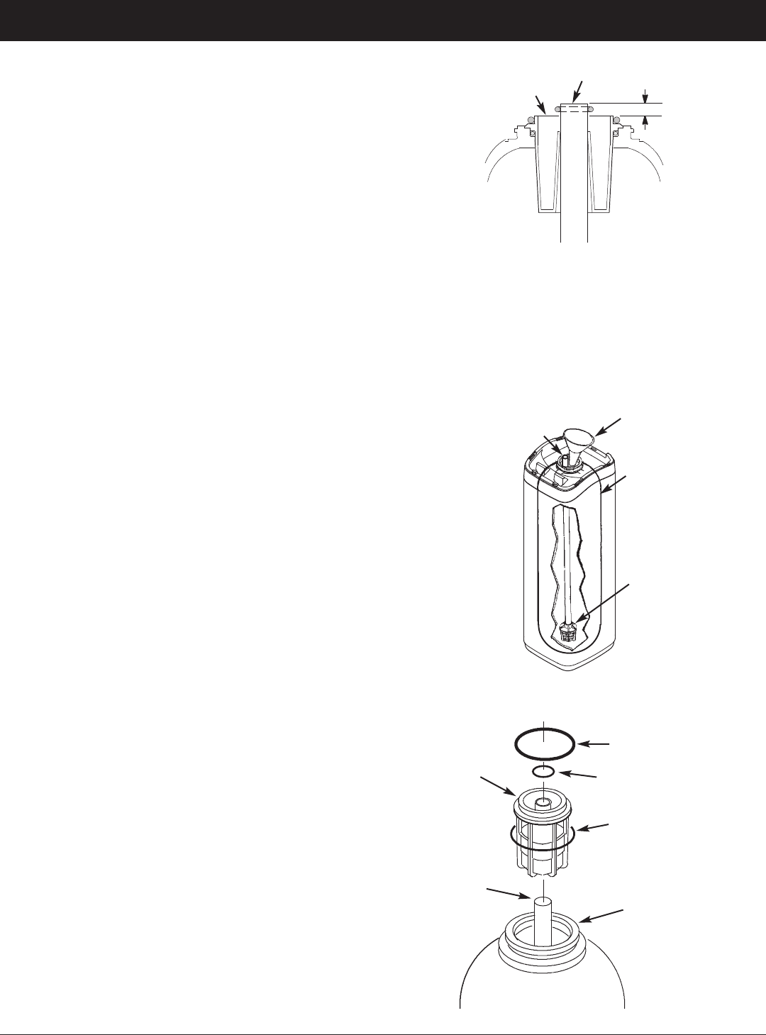
4. Check the height of the riser pipe as shown in
Figure 3. If riser pipe is more than 1/2” above the
top distributor, make sure that bottom distributor is
below gravel at the bottom of the tank. It may be
necessary to lay the filter on its side to move gravel
to one side, hold the bottom distributor at the bot-
tom center of the tank and stand the unit back up.
Level gravel after checking.
5. After confirming the riser pipe height, remove the
top distributor from the tank neck, leaving the bot-
tom distributor (including riser pipe) in place, cen-
tered in the tank.
6. Cover the top end of the riser pipe with a clean
rag, to keep media out (See Fig. 4).
7. Using a larger neck funnel, add the recommended
amounts of filter sand and mineral in that order
(See Page 3). Use water sparingly to speed flow
through the funnel (It may become necessary to
siphon water from the bottom of distributor if tank
becomes full of water).
8. Flush the tank opening with water to clean media
particles from the top of the tank. Uncover the bot-
tom distributor stand tube.
9. Finish filling the tank with water, up to the top of
the tank.
IMPORTANT: Be sure to fill with water. This will elim-
inate air space, wet the media and pre-
vent excessive air-head pressure when
filter is pressurized.
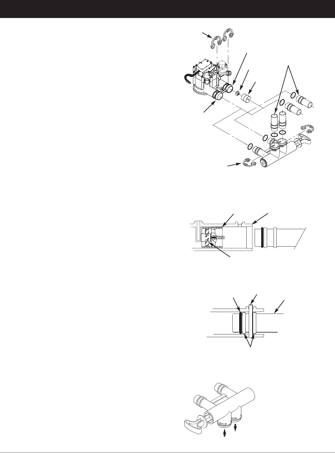
10. Install the o-ring seals and top distributor exactly
as shown in Figure 5. Place the small o-ring at
the top of the riser pipe, where shown in Figure 3.
If the o-rings need lubrication, use a high quality
silicone grease.
11. Lower the valve assembly onto the tank, centering
over the riser tube. Push downward, against the
o-ring, and install the clamp sections, securing
with the retainer clips.
12. Reconnect the wiring between the valve and the
control board (PWA).
13. Verify that the drain flow plug (See Key No. 59 on
Page 35) is appropriately sized for the media
used. If necessary, install a different flow plug.
Note: Resin tank height can vary somewhat within manu-
facturing tolerance. So that the bottom distributor riser pipe
has proper clearance with inside valve porting, check for
the correct length, as shown above. Cut the riser pipe if
needed to adjust the length. Be sure to remove burrs and
sharp edges.
Top Edge of
Top Distributor
Riser Pipe
0” to 1/2”
FIG. 3
FIG. 5
Top
Distributor
Bottom
Distributor
Riser Pipe
O-Ring, 2-7/8” x 3-1/4”
Make sure o-ring
sealing surfaces
are clean
O-Ring, 13/16” x 1-1/16”
O-Ring, 2-3/4” x 3”
FIG. 4
Funnel
Plug or cover top of
riser pipe
Tank
Make sure
bottom distributor
is centered
6
ECOWATER
S Y S T E M S
Typical Installation Illustrations
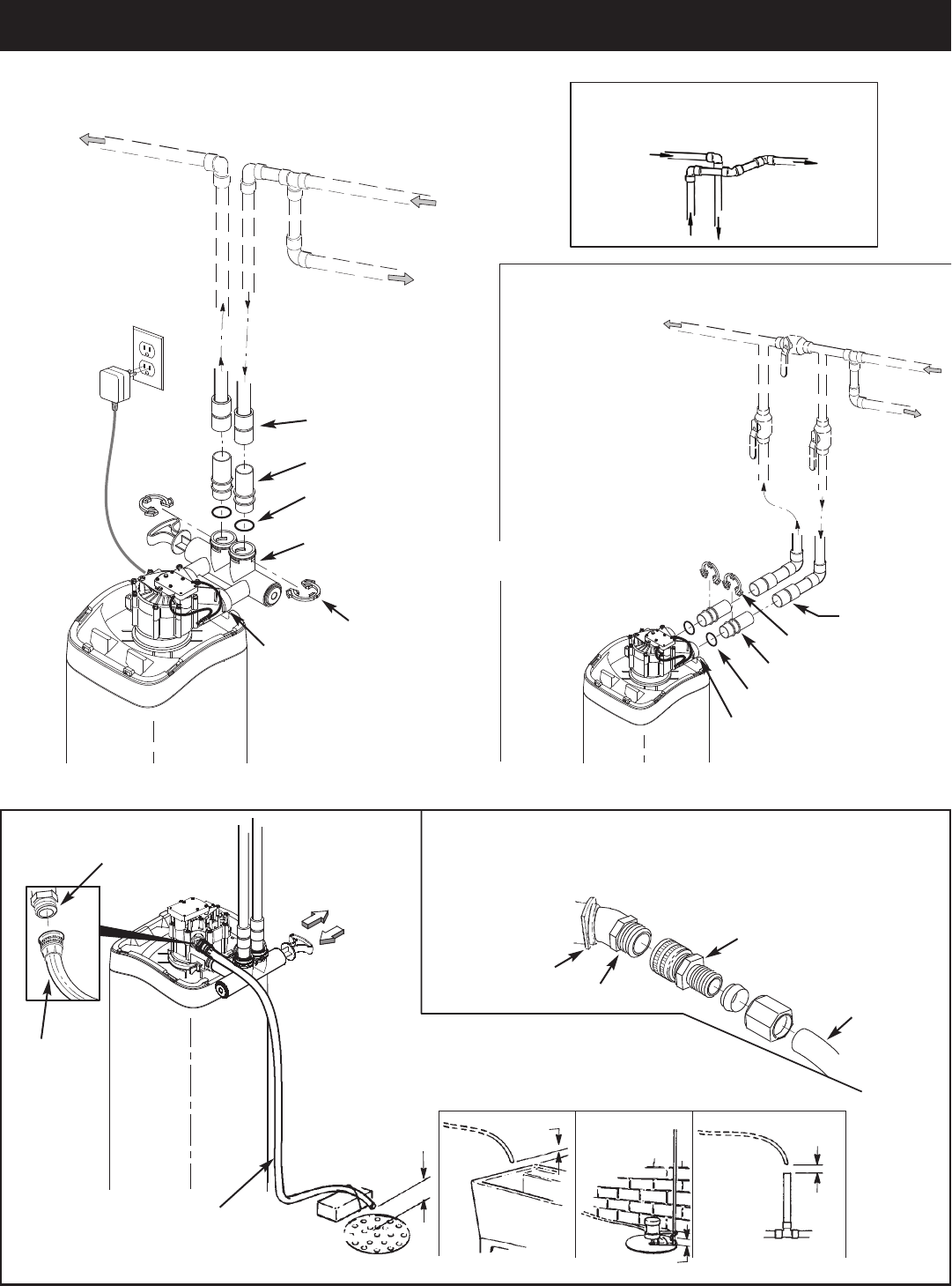
FIG. 8
Drain
Fitting
Valve
Drain
Hose
Valve
Drain
Hose
1-1/2”
Air Gap
1-1/2”
Air Gap
1-1/2””
Air Gap
1-1/2” Air Gap
LAUNDRY
TUB
SUMP
STAND
PIPE
FLOOR
DRAIN
To standpipe, sump, laundry
tub or other suitable drain.
5/8” I.D.
(minimum)
copper tube
Push in for
Bypass
Clip
Drain Fitting
CONNECTING A RIGID VALVE DRAIN TUBE
To adapt a copper tube to the filter, buy a compression fitting (garden hose thread to
5/8” I.D. minimum tube and necessary tubing from your local hardware store.
Adaptor, garden hose
thread to compression
Pull out for
filtered water
“Service”
FIG. 7FIG. 6
INSTALLATION USING 3-VALVE BYPASS
MAIN WATER PIPE
MAIN WATER PIPE
INSTALLATION USING ECOWATER BYPASS VALVE
CROSS-OVER
Use if water supply flows from the left.
Include single or 3-valve bypass.
Filtered
Water OUT
Unfiltered
Water IN
FILTERED
WATER
TO FILTER
INLET
UNFILTERED
WATER
FROM FILTER
OUTLET
BYPASS
Valve
OUTLET
Valve
INLET
Valve
O-Ring Seal (2)*
Valve
INLET
For filtered water SERVICE:
-Open the inlet and outlet
valves
For unfiltered BYPASS:
-Close the inlet and outlet
valves
-Open the bypass valve
Unfiltered Water
to Outside Faucets
* Included with filter - Pipe and
fittings supplied by installer.
1” Copper Tube (2)*
#7214383
Bypass
Valve
Clip (2)*
O-Ring Seal (2)*
1” Sweat Adaptor (2)
not included
Valve
INLET
1” Sweat
Adaptor (2)
not included
1” Copper Tube (2)*
120V,
60 Hz
Outlet
Clip (2)*
Tie or
wire
tubing
in place
7
ECOWATER
S Y S T E M S
Installation
Turbine
Support
Valve
Outlet
FIG. 10
FIG. 11
O-ring
Clip
Cross section of
valve inlet or outlet
Bypass valve,
copper tube or
plastic adaptor
Snap clips into place between
larger diameter rings
FIG. 12
Turn the bypass
valve downward if
connecting to floor
level plumbing
INLET
OUTLET
FIG. 9
INLET
OUTLET
Clip (2)
Bypass Valve
Clip (2)
Turbine
1” Copper Tube
(install in filter valve
or bypass valve)
Turbine
Support
1. TURN OFF WATER SUPPLY
a. Close the main water supply valve near the well
pump or water meter.
b. Shut off the electric or fuel supply to the water
heater.
c. Open high and low faucets to drain all water from
the house pipes.
2. INSTALL BYPASS VALVE AND/OR
PLASTIC ADAPTOR / COPPER TUBE:
a. If installing a single bypass valve, push the bypass
valve, with lubricated o-ring seals in place, into the
valve inlet and outlet ports (See Figures 6 & 9).
- OR -
b. If installing a 3-valve bypass system, slide plastic
installation adaptor and copper tube, with lubricat-
ed o-ring seals in place, into the valve inlet and
outlet ports, respectively (See Figures 7 & 9).
c. Make sure that the turbine and support are in place
in the valve outlet, as shown in Figure 10.
d. Snap the two large plastic clips in place on the inlet
and outlet ports, from the top, down (See Figure
11). Be sure they snap into place. Pull on the
bypass valve, copper tube or plastic adaptor, to
make sure they are held securely in place.
3. COMPLETE PLUMBING TO AND FROM
THE FILTER
Using the “Typical Installation Illustrations” on page 6
as a guide, observe all of the following cautions while
you connect inlet and outlet plumbing:
= Be sure incoming, unfiltered water is directed to
the valve INLET port.
= Be sure to install bypass valve(s).
= If making a soldered copper installation, do all
sweat soldering before connecting pipes to the fil-
ter fittings. Torch heat will damage plastic parts.
= Use pipe joint compound on all external pipe
threads.
= When turning threaded pipe fittings onto plastic fit-
tings, use care not to cross-thread.
= Support inlet and outlet plumbing in some manner
(use pipe hangers) to keep the weight off of the
valve fittings.

8
ECOWATER
S Y S T E M S
Installation
a. Fully open two filtered water faucets, one cold and
one hot, nearby the filter.
b. Place bypass valve(s) into “bypass” position. On a
single valve, slide the stem inward to BYPASS
(See Fig. 8 on page 6). On a 3 valve system,
close the inlet and outlet valves, and open the
bypass valve (See Fig. 7 on page 6).
c. Fully open the house main water pipe shutoff valve.
Observe a steady flow from both opened faucets.
d. Close both faucets.
e. Check your plumbing work for leaks and, if any are
found, fix right away. Be sure to observe previous
caution notes.
f. Turn on the gas or electric supply to the water
heater. Light the pilot, if applicable.
7. CONNECT TO ELECTRICAL POWER:
The filter controller works on 24V DC electrical power.
The included power supply converts 120V AC house-
hold power to 24V DC. Plug the power supply into a
120V, 60 Hz electrical outlet. Be sure the outlet is
always “live” so it can not be switched off by mistake.
8. PROGRAM THE CONTROLLER
See pages 10-12 for instructions to program the elec-
tronic controller.
9. START UP PROCEDURE
a. Confirm that the filter’s main valve is in the “service”
position (“S” on the cam).
b. Place bypass valve(s) into “service”, EXACTLY as
follows:
= Single Bypass Valve: SLOWLY, pull the valve
stem outward to ”service” position, pausing sev-
eral times to allow the filter to pressurize slowly.
= 3 Valve Bypass: Fully close the bypass valve
and open the outlet valve. SLOWLY, open the
inlet valve, pausing several times to allow the
filter to pressurize slowly.
c. Check all connections for leaks.
d. Start a recharge: From the rolling status screens,
press the SELECT (¡) button to display the Main
menu. Make sure Recharge is highlighted, then
press SELECT (¡). Press DOWN (6) to scroll to
Recharge now, then press SELECT (¡) twice.
You should hear the valve motor run as the filter
begins recharging. Verify that the valve advances
to “backwash” (BW) position.
e. Allow the unit to complete the backwash and fast
rinse cycles (takes about 30 minutes). When the
recharge ends, the filter valve automatically returns
to “service”. Start up is complete.
4. COLD WATER PIPE GROUNDING
The house cold water pipe (metal only) is often used
as a ground for the house electrical system. The 3-
valve bypass type of installation, shown in Figure 7,
will maintain ground continuity. If you use the plastic
bypass, continuity is broken. To restore the ground,
do either step 4a or 4b following.
a. Use the EcoWater ground clamp kit (not included)
to make a jumper across the inlet and outlet pipes
(See Figure 13).
b. Install a #4 copper wire across the removed sec-
tion of main water pipe, securely clamping at both
ends – parts not included.
5. INSTALL VALVE DRAIN HOSE
a. Take a length of 5/8” inside diameter garden hose
and attach to the valve drain fitting (See Figure 8
on page 6).
b. Locate the other end of the hose at a suitable drain
point (floor drain, sump, laundry tub, etc.). Check
and comply with local codes. Refer to Figure 8 on
page 6 if codes require a rigid pipe drain run.
IMPORTANT: Use high quality, thick wall hose that
will not easily kink or collapse. The fil-
ter will not backwash properly if water
cannot exit this hose during recharges.
c. Tie or wire the hose in place at the drain point.
Water pressure will cause it to whip during the
backwash portion of the recharge cycle. Also pro-
vide an air gap of at least 1-1/2” between the end
of the hose and the drain point. An air gap pre-
vents possible siphoning of sewer water, into the
filter, if the sewer should back up.
d. If raising the drain hose overhead is required to get
to the drain point, do not raise higher than 8 feet
above the floor. Elevating the hose may cause a
back pressure that could reduce backwash flow
and proper mineral bed cleaning.
6. FLUSH PIPES AND TEST FOR LEAKS
CAUTION: To avoid water or air pressure damage to
filter inner parts, be sure to do the follow-
ing steps exactly as listed:
FIG. 13
Ground
Clamp
Inlet / Outlet
Pipes

SEDIMENT FILTERS
A sediment filter removes, sand, clay, silt, or fine
organic matter from water. You can see sediment in
water by holding a sample, in a clear glass, up to a
light. The particles are either suspended or settled to
the bottom of the glass.
“Filter Aggregate” mineral mechanically filters the sed-
iment particles as water passes through the bed.
This mineral lasts indefinitely when properly main-
tained.
ACID NEUTRALIZERS
Acidic water (6.0 to 6.8 pH) is corrected with an acid
neutralizer filter. Acidic water, although sometimes
clear in appearance, shortens the life of iron pipe, and
corrodes copper or brass pipe and fittings. It causes
green or blue stains on plumbing fixtures and may
etch porcelain enamel over a period of time.
Acidic water, as it passes through the filter’s
Neutralite mineral bed, dissolves some of the mineral.
This raises the pH above 6.8, to neutralize the acid.
Because the mineral does dissolve, the filter eventu-
ally needs refilling. The time between refills varies
with the degree of acidity and how much water is
used. The average life of the bed is about one year.
TASTE & ODOR FILTERS
A taste and odor filter removes most tastes, odors
and certain organic colors from water. Bad tastes
and odors are due to a variety of causes (chlorine,
petroleum, tannins, etc.). The activated carbon min-
eral of a taste and odor filter has a high capacity for
absorbing these im-purities.
The activated carbon bed usually lasts for about one
year. However, high amounts of tastes and odors
and/or excessive water usage may shorten this time.
Activated carbon is nonregenerative and needs
replacing when exhausted.
9
ECOWATER
S Y S T E M S
General Information
Care is taken at the factory to keep your water filter
clean and sanitary. Materials used to make the filter
will not infect or contaminate your water supply, and
will not cause bacteria to form or grow. However,
during shipping, storage, installing and operating,
bacteria could get into the filter or media. For this
reason, sanitizing as follows is suggested* when
installing.
Pour about 1 oz. (for ETF2300PF10), or 2 oz. (for
ETF2300PF12), of the following disinfectant into the
filter:
1. Calcium hypochlorite, available in granular or tablet
form, under trade names such as Perchloron or
HTH.
2. Common 5.25% household bleach, such as Clorox.
NOTE: ACTIVATED CARBON FILTERS - Activated
carbon will absorb the sanitizing agent,
expending some capacity.
Start a recharge: From the rolling status screens,
press the SELECT (¡) button to display the Main
menu. Make sure Recharge is highlighted, then
press SELECT (¡). Press DOWN (6) to scroll to
Recharge now, then press SELECT (¡) twice. You
should hear the valve motor run as the filter begins
recharging. This recharge flushes “fines” from the
new mineral. The sanitizing bleach and any air
remaining in the unit are purged to the drain.
The filter returns to service in about 30 minutes. After
the recharge has completed, fully open a cold water
faucet downstream from the filter and allow 50 gal-
lons of water to pass through the filter. This should
take 20 minutes. Close the faucet. Sanitizing
process is complete.
*NOTE: Sanitizing is recommended by the Water Quality
Association for disinfecting. On some water sup-
plies, they suggest periodic sanitizing.
ECOWATER
S Y S T E M S
Sanitizing Procedure
10
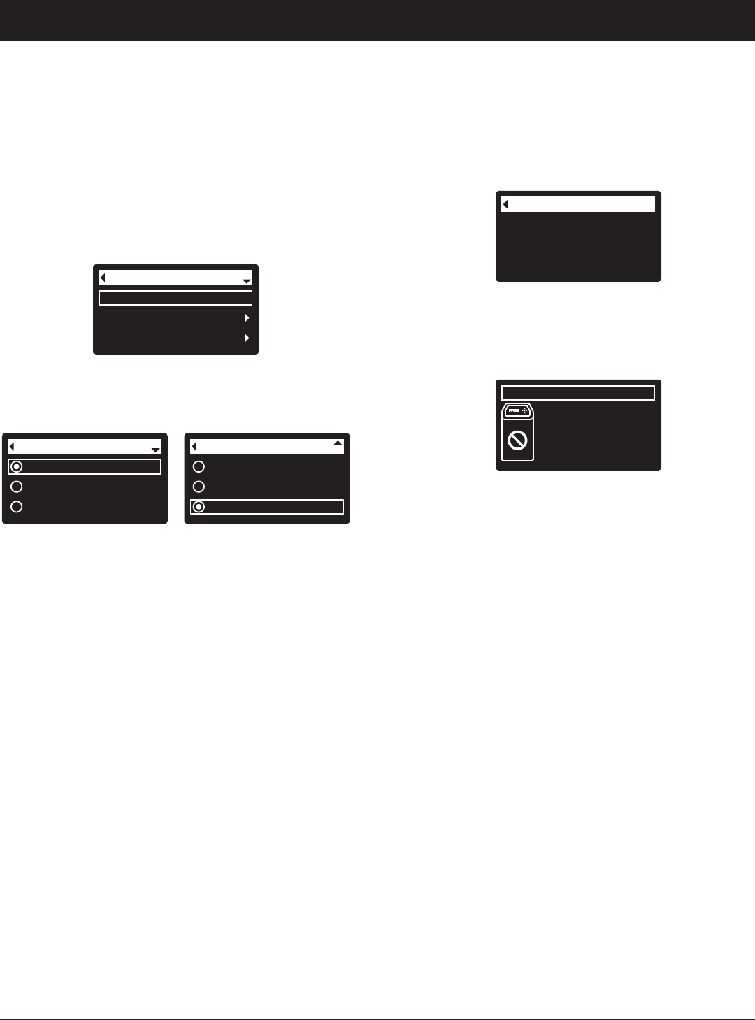
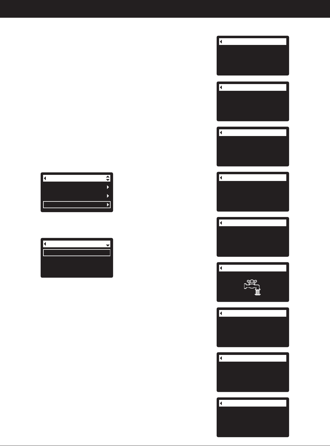
SETUP PROCEDURE
When the EcoWater Systems filter is plugged in for the
first time, a beep sounds and the display briefly shows
a logo, followed by model information. Next, a series of
“wizard” screens prompts you to enter basic operating
information:
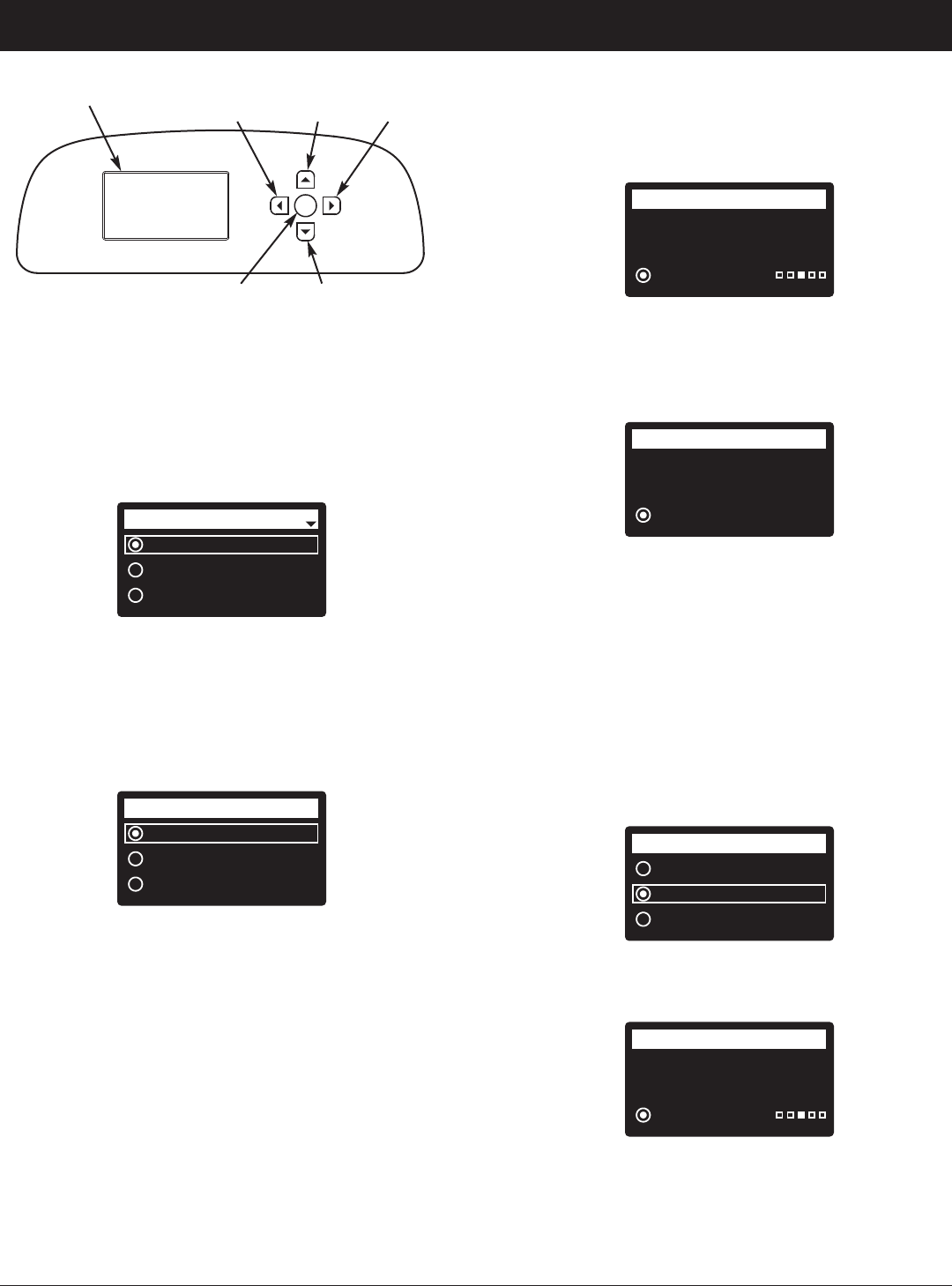
FIG. 15
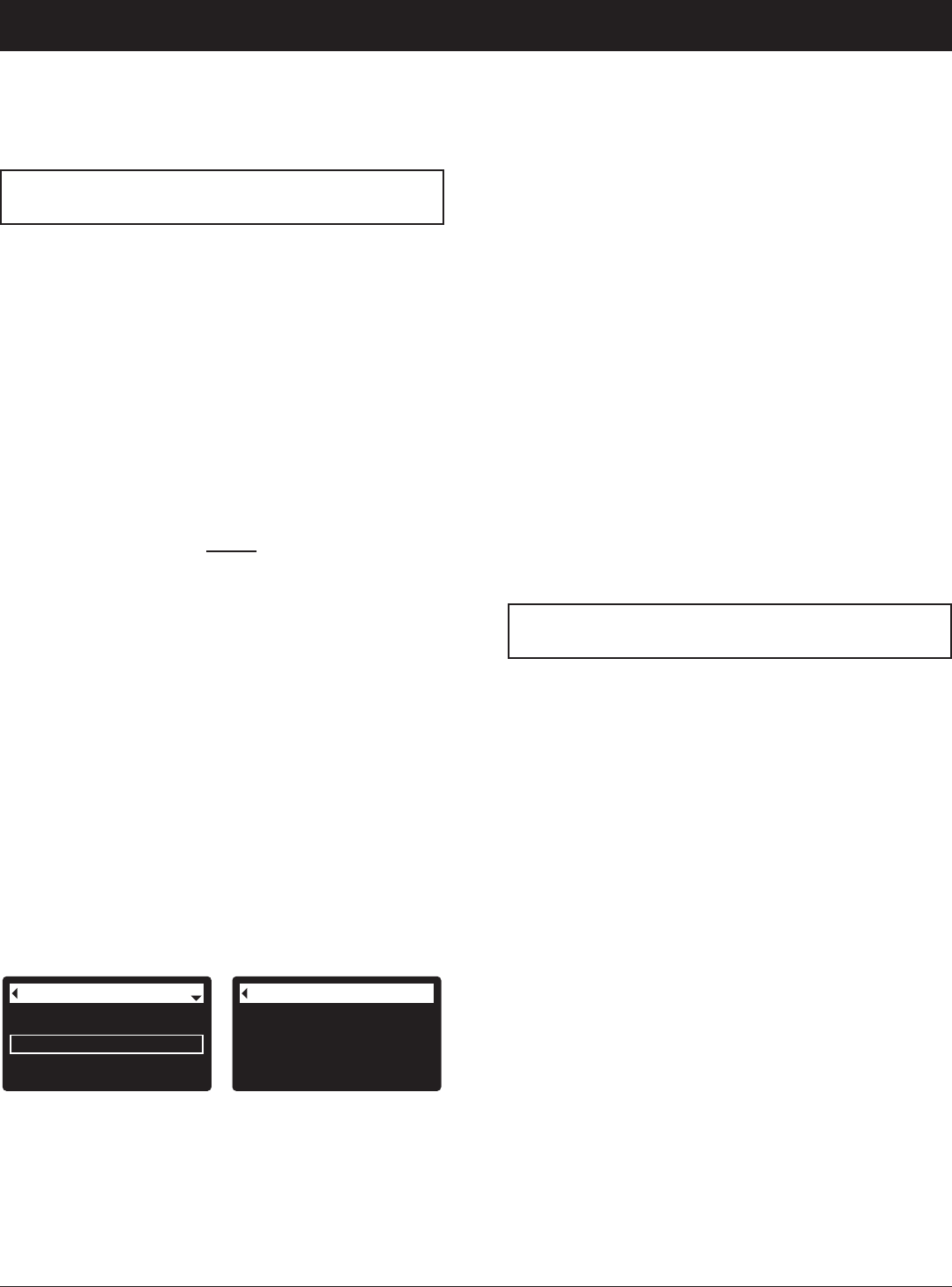
1. LANGUAGE If the desired language already has a
dot next to it (See Figure 15), go to Step 2.
Otherwise, press the filter’s DOWN (6) or UP (5)
buttons to scroll to the desired language, then press
the SELECT (¡) button to choose it.
2. Press the SELECT (¡) button to advance to the next
“wizard” screen.
Pushbutton (WPS)
Browser
Skip
Wireless setup
FIG. 16
NOTE: Wireless Setup can also be done after the rest
of the Setup Procedure (Steps 16-28) has been
completed. From the Main menu, go down to
the Advanced settings menu and select
Wireless setup.
3. WIRELESS SETUP Choose how you will connect
the filter to your home’s wireless network:
Browser: You can connect using the browser on your
laptop, tablet or phone. Skip to Step 7.
OR
Pushbutton: If your wireless router has a WPS (Wi-
Fi Protected Setup) or Push to Con -
nect button, you can use this method to
connect. Proceed to Step 4.
English
Español
Français
Language
ECOWATER
S Y S T E M S
Setup Procedure
Push wireless router
button
Wireless setup
Cancel
FIG. 17
Connected!
Key:
abc123
Wireless setup
Continue
FIG. 18
Pushbutton (WPS) Option
4. Use the SELECT (¡) button to choose Pushbutton
(WPS). The filter display will change to show “Push
wireless router button”.
5. Press the WPS or Push to Connect button on your
router and wait for a minute or two to see if the dis-
play changes again to “Connected” and gives you a
key code. If not, you may need to cancel and use
the browser option.
6. Once the key code is displayed, write it down. It will
be used when you register your system on the Eco -
Water web site. Proceed to Step 16 on the next page.
NOTE: If the “Connected” message shows “
------
”
(dashes) instead of a key code, it may be that
your router is not connected to the internet.
Verify that the router’s internet connection works
with your laptop or other device.
Browser Option
7. Press the filter’s DOWN (6) button to scroll to
Browser.
8. Press the SELECT (¡) button twice. The filter dis-
play will change to show “See connection instruc-
tions”.
Pushbutton (WPS)
Browser
Skip
Wireless setup
FIG. 19
See connection
instructions
Wireless setup
Cancel
FIG. 20
continued on the next page
FIG. 14
Display
LEFT
Button
RIGHT
Button
UP
Button
DOWN
Button
SELECT
Button
11
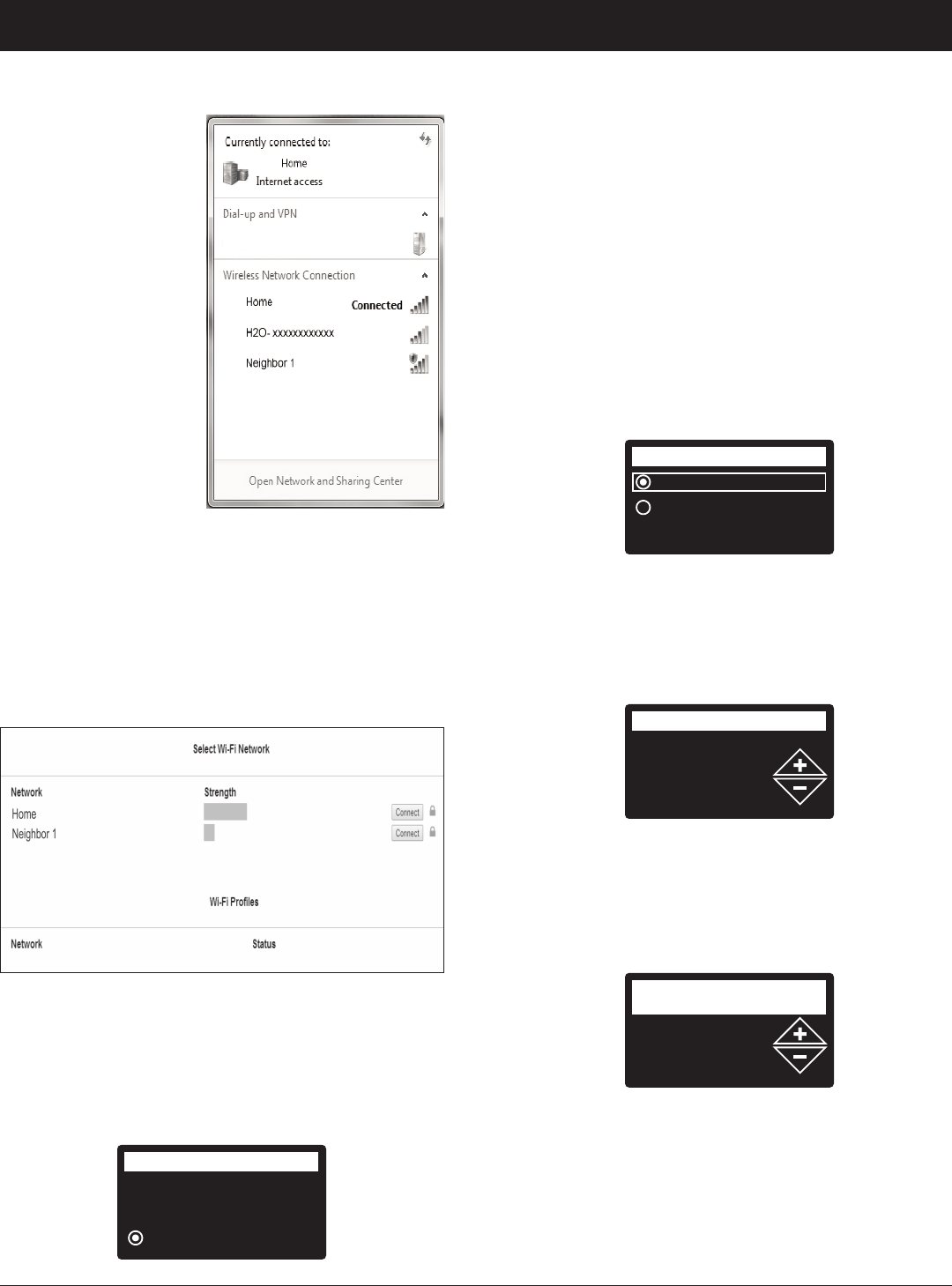
9. On your laptop,
tablet or phone,
activate the view of
wireless networks
in range. For
example, on a lap-
top, look for and
click on the wire-
less icon along the
lower right edge of
the screen. On a
phone, you should
go into “Settings”
and look for “Wi-Fi”.
10. You should see a
network named
“H2O-” followed by
12 characters.
Select this network
to connect your
device with it.
11. Once your device indicates that it is connected to
the H2O network, go to your internet browser
(Chrome, Firefox, Internet Explorer, etc.) and type in
this URL:
192.168.0.1
then click Go or press Enter.
FIG. 21
FIG. 22
12. After a screen like the one shown above appears,
select your in-home wireless network and enter the
correct password.
13. The filter display should change to “Connected” and
give you a key code.
ECOWATER
S Y S T E M S
Setup Procedure
Connected!
Key:
abc123
Wireless setup
Continue
FIG. 23
14. Once the key code is displayed (it may take a few
seconds) , write it down. It will be used when you
register your system on the EcoWater web site.
NOTE: If the “Connected” message shows “
------
”
(dashes) instead of a key code, it may be that
your router is not connected to the internet.
Verify that the router’s internet connection works
with your laptop or other device.
15. On your laptop, tablet or phone, go back to the view
of networks in range, and make sure that your
device is connected back to your local network.
Finish Setting up the Filter
16. Once you have connected the Wi-Fi system and
written down your key code, press the SELECT (¡)
button to advance to the next “wizard” screen.
continued from the previous page
English
Metric
System units
FIG. 24
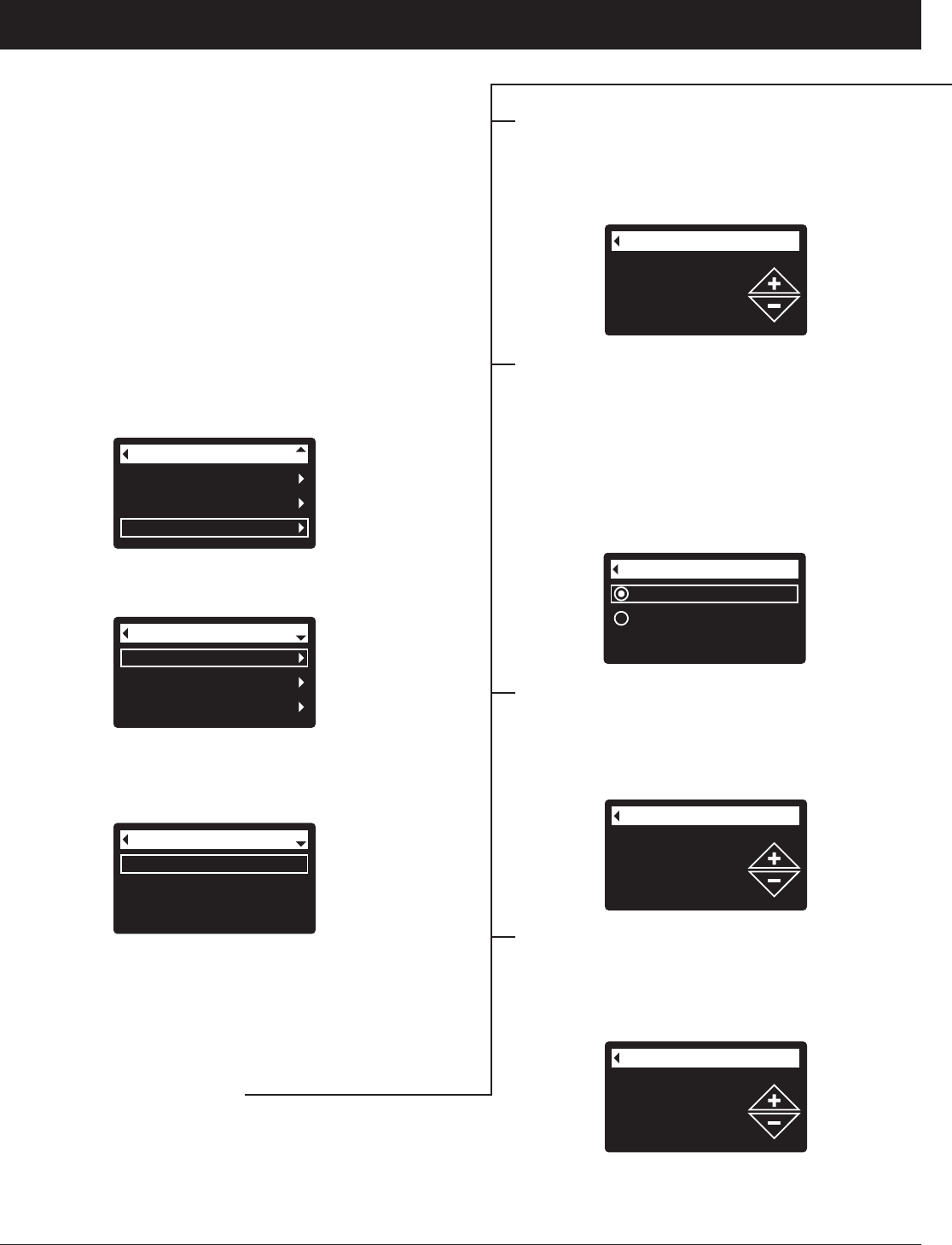
17. SYSTEM UNITS If the desired system already has
a dot next to it (See Figure 24), go to Step 18.
Otherwise, press the DOWN (6) or UP (5) buttons
to scroll to the desired system, then press the
SELECT(¡) button to choose it.
18. Press the SELECT (¡) button.
12:34 PM
Current time
FIG. 25
19. CURRENT TIME Press the DOWN (6) or UP (5)
buttons to set the current time (See Figure 25). Hold
the button down to rapidly advance. Be sure that AM
or PM is correct. If the system units were set to met-
ric in Step 17, the clock will be in 24-hour format.
20. Press the SELECT (¡) button.
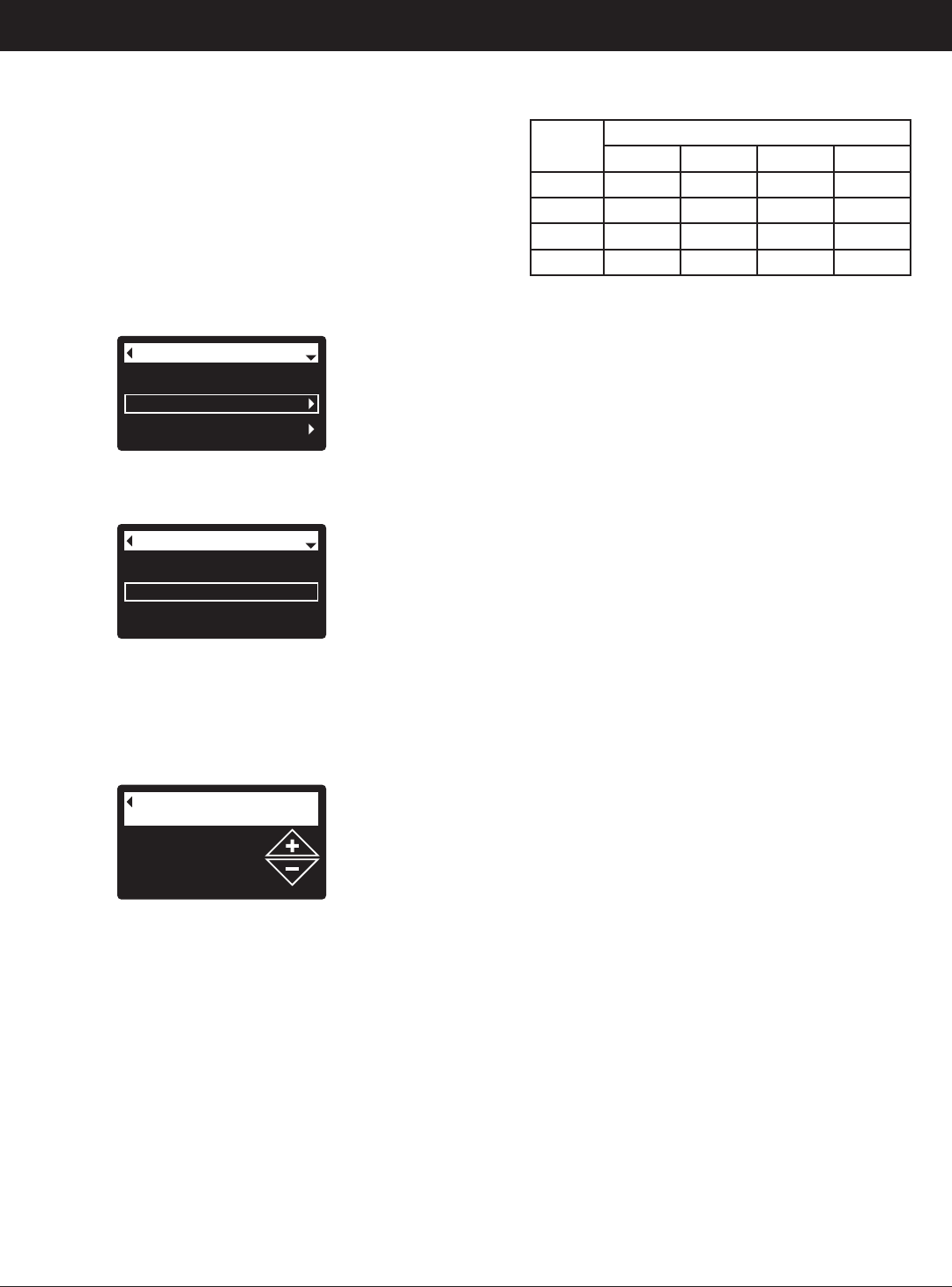
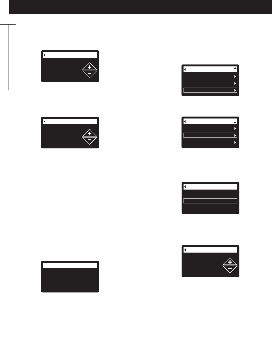
21. MAX. DAYS BETWEEN RECHARGES Press the
UP (5) or DOWN (6) buttons to set the number of
days between automatic recharges (See Figure 26)
The feature can be set from 1 to 99 days.
continued on the next page
3 days
Max. days between
recharges
FIG. 26
12
Wireless information
DSN: AC000W000009876
Key:
abc123
FIG. 28
Model information
Wireless information
Daily avg. water used
System information
ECOWATER
S Y S T E M S
Setup Procedure
NOTE: You can look up the current key code on your
filter’s controller. From the Main menu, go
down to the System information menu and
select Wireless information.
28. After you’ve entered the key code in the Add
System screen, click the “Connect” button to
advance to the Customer Information screen.
29. Fill in the customer information (address, e-mail,
etc.). When entering a password, either have the
customer enter their own, or enter one for them and
give it to them. If you intend to share the system,
sharing needs to be done from the customer’s
account (See “How to Share a System” on the fol-
lowing page). When finished filling in the customer
information screen, click the “Save and Continue”
button.
NOTE: When filling in address information, be sure to
select the country before attempting to select a
state or province.
30. Fill in the System Settings screen and click the
“Save Settings” button.
31. Fill in the Dealer Communication Preferences
screen and click the “Save and Continue” button.
32. The message “Customer System Setup Complete”
should appear, along with the customer’s account
screen. At this point you can make changes or add
another system for this customer. When everything
is correct, return to the dealer Home page by click-
ing the “Home” tab along the top of the page.
33. On the dealer Home page, the new system you set
up should appear on the systems list.
NOTE: On the dealer Home page, the number of
shared systems is displayed below the bar
along the top of the screen. You can display
only shared systems by clicking “shared with
you”, and display all systems again by clicking
the “Home” tab. See the following page for
instructions on how to share a system.
NOTE: A dealer registering filters must log in as a
dealer, not as a customer.
25. In your internet browser, type in this URL:
http://wifi.ecowater.com
26. If you are a dealer, and have an account, log in to
your account and go to the next step. If you are a
customer, go to Page 13 for instructions to create
an account and register.
27. After you’ve logged in to your dealer account, click
“Add New Customer System” and then enter the
key code that you wrote down earlier. If you wait
too long between writing down the key code and
registering (an hour or less), the code may change.
This is a security feature. Look up the new key
code, as described in the following note.
Run system
Redo setup
Setup complete!
FIG. 27
23. If, at this point, you want to go back and make
changes, press the DOWN (6) button to scroll to
Redo setup, then press the SELECT (¡) button
twice to repeat the “wizard” screens.
24. If no changes are desired, make sure Run system
has a dot next to it (See Figure 27) and press the
SELECT (¡) button. The unit begins normal opera-
tion, described on Page 14.
HOW TO REGISTER A SYSTEM ON THE
ECO WATER WEB SITE AS A DEALER
continued from the previous page
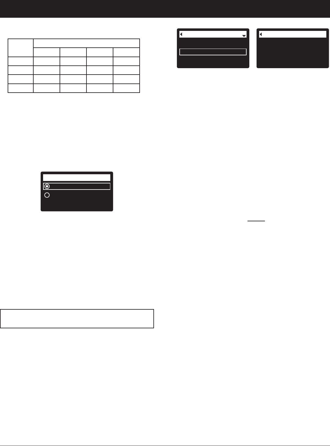
No. of
People
Iron (parts per million)
1 - 2 3 - 4 5 - 7 8 - 20
1 - 2 4 days 3 days 2 days 1 day
3 4 days 3 days 1 day 1 day
4 - 5 3 days 2 days 1 day 1 day
6 - 7 2 days 1 day 1 day 1 day
Use the table above to determine the number of days
between recharges, based on the number of people
in the household and the iron ppm (parts per million)
in the water supply.
NOTE: If the water supply has high turbidity (sand, silt,
sediments, etc.) set to recharge more often than
the table shows.
22. Press the SELECT (¡) button. The screen will
show “Setup complete!” (See Figure 27).
13
ECOWATER
S Y S T E M S
Setup Procedure
HOW TO CREATE AN ACCOUNT AND REG-
ISTER YOUR SYSTEM ON THE ECO WATER
WEB SITE AS A CUSTOMER
NOTE: A dealer registering filters must log in as a
dealer, not as a customer.
1. In your internet browser, type in this URL:
http://wifi.ecowater.com
2. If you are a new customer, click on “Create Account”
to advance to the Create Your Account screen.
3. Fill in the account information (e-mail, password, lan-
guage, etc.). Agree to the Terms of Use, and then
click the “Create Account” button to advance to the
Customer Information screen.
4. Fill in the customer information (name, address, etc.).
When finished filling in the customer information
screen, click the “Save and Continue” button.
NOTE: When filling in address information, be sure to
select the country before
attempting to select a
state or province.
5. Follow the instructions on the Verify e-mail screen.
You will shortly receive an e-mail confirming that you
have created your account. Open this e-mail and
click on the link it contains. Your browser will be
directed to a Verification Complete screen.
6. Now that you have created your account, you may
log in. In the verification screen, click the “logging in”
link (or go to http://wifi.ecowater.com).
7. Log in with the e-mail and password that you entered
when creating your account.
8. After you’ve created and logged in to your account,
the Add System screen will appear. Enter the key
code that you wrote down earlier. If you wait too
long between writing down the key code and register-
ing (an hour or less), the code may change. This is
a security feature. Look up the new key code, as
described in the following note.
Wireless information
DSN: AC000W000009876
Key:
abc123
FIG. 29
Model information
Wireless information
Daily avg. water used
System information
9. After you’ve entered the key code in the Add System
screen, click the “Connect” button to advance to the
System Settings screen.
10. Fill in the System Settings screen and click the
“Save Settings” button.
11. Fill in the Communication Preferences screen and
click the “Save and Continue” button.
12. The screen should change to show the Home page
for your system, including the filter “dashboard”.
Click the “Log Out” tab when you are done.
VISITING YOUR CUSTOMER ACCOUNT
Any time after your customer account has been created
and system registered, you can visit your account to
see your filter “dashboard”, change settings, etc. Direct
your browser to http://wifi.ecowater.com and log in
using the e-mail and password that were specified
when setting up the account.
HOW TO SHARE A SYSTEM BETWEEN A
DEALER AND CUSTOMER
NOTE: You can look up the current key code on your
filter’s controller. From the Main menu, go
down to the System information menu and
select Wireless information.
Systems can be “shared” between a dealer and cus-
tomer. If a system is shared, the dealer has full access
to the displays and settings for that system on the
EcoWater Wi-Fi web site. If a system is not shared, the
dealer only has access to the “Dealer Communication
Preferences” screen for that system.
Once a customer account has been created by a deal-
er, a customer can grant a dealer access to their sys-
tem. Access can only be granted to the dealer who
sold that system.
With permission, a dealer (but only the one who sold
the system) could also grant it for the customer. To do
so, a dealer must log in as a customer rather than as a
dealer, using the customer’s e-mail and password
(which were entered when the customer account was
created).
1. Go to http://wifi.ecowater.com and log in (cus-
tomer’s e-mail and password, not dealer’s).
2. Click on the “Support” tab along the top of the cus-
tomer Home page.
3. On the Support screen, click the “Grant Access” but-
ton. It should change to read “Revoke Access”.
4. The system is now shared. Click the “Log Out” tab
when you are done.
NOTE: A system can only be shared from a cus-
tomer’s account, not a dealer’s.
14
NORMAL OPERATION
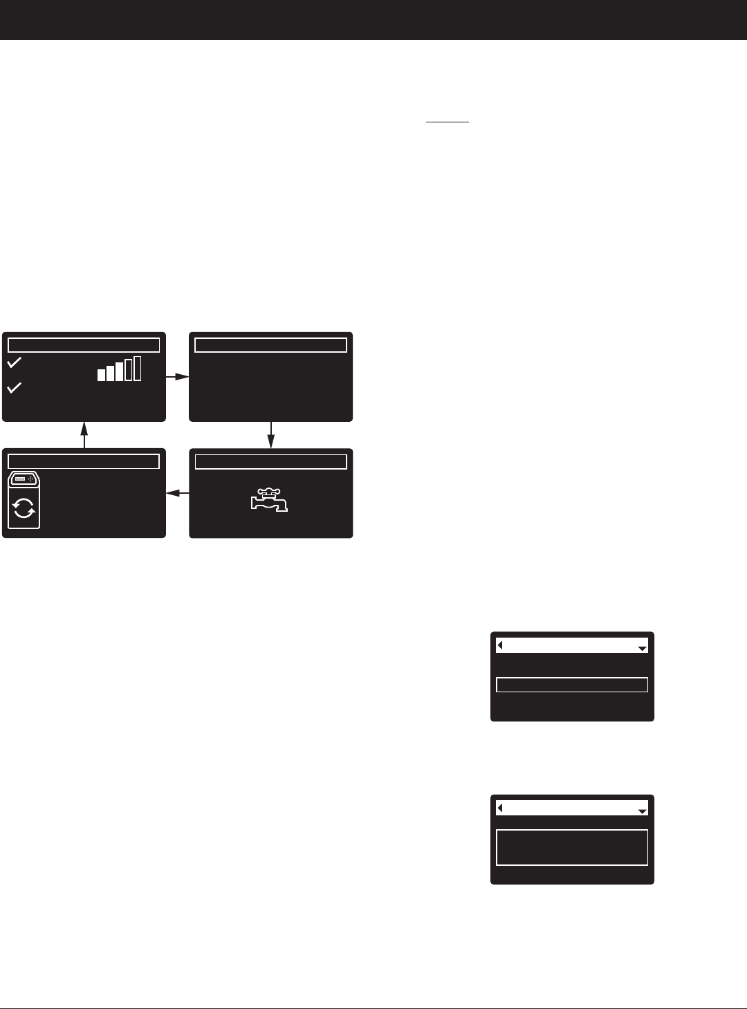
FILTER STATUS SCREENS
During normal operation, the EcoWater Systems filter’s
display shows up to four status screens. Page 19
explains how individual screens can be turned on or off.
Each is shown for six seconds, in a rolling sequence
(See Figure 30).
On the “Wireless status” screen, the check marks indi-
cate the following:
P WiFi - The filter is connected to a Wi-Fi router.
P Internet - The filter is connected to a Wi-Fi router
which is connected to the internet.
FIG. 30
0.0 GPM
Water flow
2:34 PM
Water use (gallons)
2:34 PM
Recharge status
2:34 PM
Set for automatic
recharge
Today: 121
Daily average: 175
Wireless status
2:34 PM
WiFi
Internet
-50 dBm
ECOWATER
S Y S T E M S
Filter Operation
Current time
Max. days between rech...
Recharge time
Basic settings
FIG. 31
Current time
Recharge time
Basic settings
Max. days between
recharges
FIG. 32
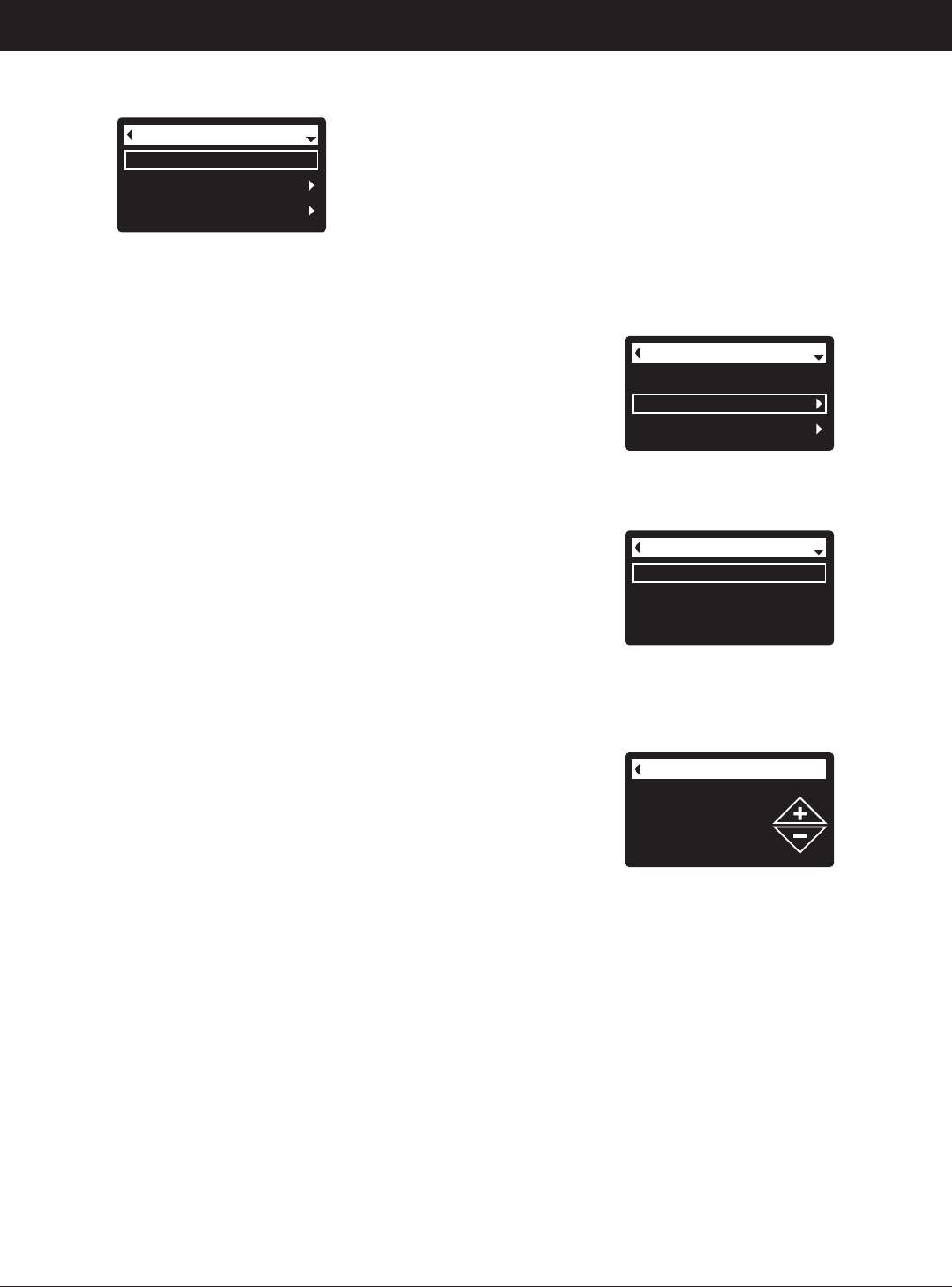
One second after being highlighted, the viewing box
expands (See Figure 32) to show the entire message.
After three seconds the view resets (Figure 31).
The filter status screens described in the previous sec-
tion will not
be displayed in a rolling sequence when
one of the following items is displayed:
=Recharge status (Displayed during recharges,
showing valve position and time remaining)
=Recharge status: Off - no automatic recharges
instead of rolling screens indicates that automatic
recharges have been turned off (See Page 17).
=Current time setting screen instead of status
screens indicates time has been lost, perhaps after
a long power loss. Set the time (See next page).
=Service reminder (See Page 23)
=Error detected (Contact your dealer for service)
FLASHING DISPLAY
The filter’s display will flash on and off when one or
more of the following conditions occurs:
=Time needs to be set (Time has been lost)
=Service is overdue (Service reminder)
=Error condition
The flashing will stop after any key is pressed.
However, it will start again at Midnight if the underlying
condition (e.g. time not set) has not been addressed.
LONG DISPLAY SCREEN MESSAGES
Most messages in the filter’s display screens are short
enough to be shown as a single line. Longer messages
will be truncated (See Figure 31 for an example) until
you highlight them.
OTHER MESSAGES, ALERTS & REMINDERS
Pressing the filter’s RIGHT (4) button manually
advances to the next screen in the sequence. Pressing
the LEFT (3) button manually returns to the previous
status screen. If no buttons are pressed for 30 sec-
onds, the automatic rolling sequence resumes.
If Recharge off has been selected, as described on
page 17, the rolling sequence will stop at the “Recharge
status” screen.
15
Recharge
Basic settings
User preferences
Main menu
FIG. 33
MAIN MENU
ECOWATER
S Y S T E M S
Filter Operation
SETTING THE CURRENT TIME
When the filter’s electronic control is first powered up, a
“wizard” screen prompts you to set the current time
(See Pages 10-12). To change the time at a later date,
such as after a long power loss:
1. From any of the rolling status screens, press the
SELECT (¡) button to display the Main menu.
2. Press the DOWN (6) button to scroll through the
menu options until Basic settings is highlighted
(See Figure 34).
3. Press the SELECT (¡) button to display the Basic
settings menu (See Figure 35).
Recharge
Basic settings
User preferences
Main menu
FIG. 34
Current time
Max. days between rech...
Recharge time
Basic settings
FIG. 35
4. Make sure Current time is highlighted.
5. Press the SELECT (¡) button to display the Current
time screen (See Figure 36).
6. Press the UP (5) or DOWN (6) buttons to change
the time. Hold the button down to rapidly advance.
Be sure that AM or PM is correct (unless filter is set
for a 24-hour clock).
7. Press the SELECT (¡) button. The display will go
back to the Basic settings menu (Figure 35).
8. Press the LEFT (3) button twice to return to the
rolling status screens.
NOTE: On Wi-Fi connected systems, the current time
will be updated and maintained automatically
via Wi-Fi.
Current time
12:34 PM
FIG. 36
During normal operation (status screens rolling), press
the filter’s SELECT (¡) button to display the Main menu
(See Figure 33). This menu and its subsidiary screens
are used to control these operations:
=Recharge (See Page 17)
=Basic settings
=Current time (See next column)
=Max. days between recharges (See Page 18)
=Recharge time (See Page 19)
=Rolling screens (See Page 19)
=User preferences
=Language (See Page 20)
=Time format (See Page 20)
=Volume units (See Page 20)
=System information
=Model information (See Page 21)
=Wireless information (See Page 21)
=Daily avg. water used (See Page 21)
=Water used today (See Page 21)
=Total water used (See Page 21)
=Current water flow (See Page 21)
=Days powered up (See Page 21)
=Last recharge (See Page 21)
=Total recharges (See Page 21)
=Advanced settings
=Cycle times
=Fill time (See Page 23)
=Draw time (See Page 23)
=Backwash time (See Page 22)
=Second backwash (On/Off) (See Page 22)
=Second backwash time (See Page 22)
=Fast rinse time (See Page 22)
=Special features
=Auxiliary control (See Page 24)
=Chemical feed volume** (See Page 24)
=Chemical feed timer** (See Page 24)
=Service reminder (See Page 23)
=Troubleshooting
=Diagnostics (See Page 25)
=Setup changes (See Page 25)
=Wireless setup (See Pages 10-13)
**Only displayed if Auxiliary control is set to Chemical
feed.
16
Another indicator that the lockout feature is on is the
Model Information screen. This screen appears on
power-up, and can also be displayed from the System
Information menu (See Page 21). If the lockout feature
is on, there will be a non-flashing padlock icon in the
upper right corner (See Figure 41).
FIG. 41
FIG. 40
Model information
Model: HPF10
Version: T2.0
3 days
Max. days between
recharges
To turn off the lockout feature:
1-7. Go to the Setup changes screen (Figure 38) by
following Steps 1-7 at left.
8. Press the RIGHT (4) button. The flashing padlock
icon will disappear, as shown in Figure 37.
9. Press the SELECT (¡) button.
10. Press the LEFT (3) button three times to return to
the rolling status screens.
FIG. 38
FIG. 39
3 days
Max. days between
recharges
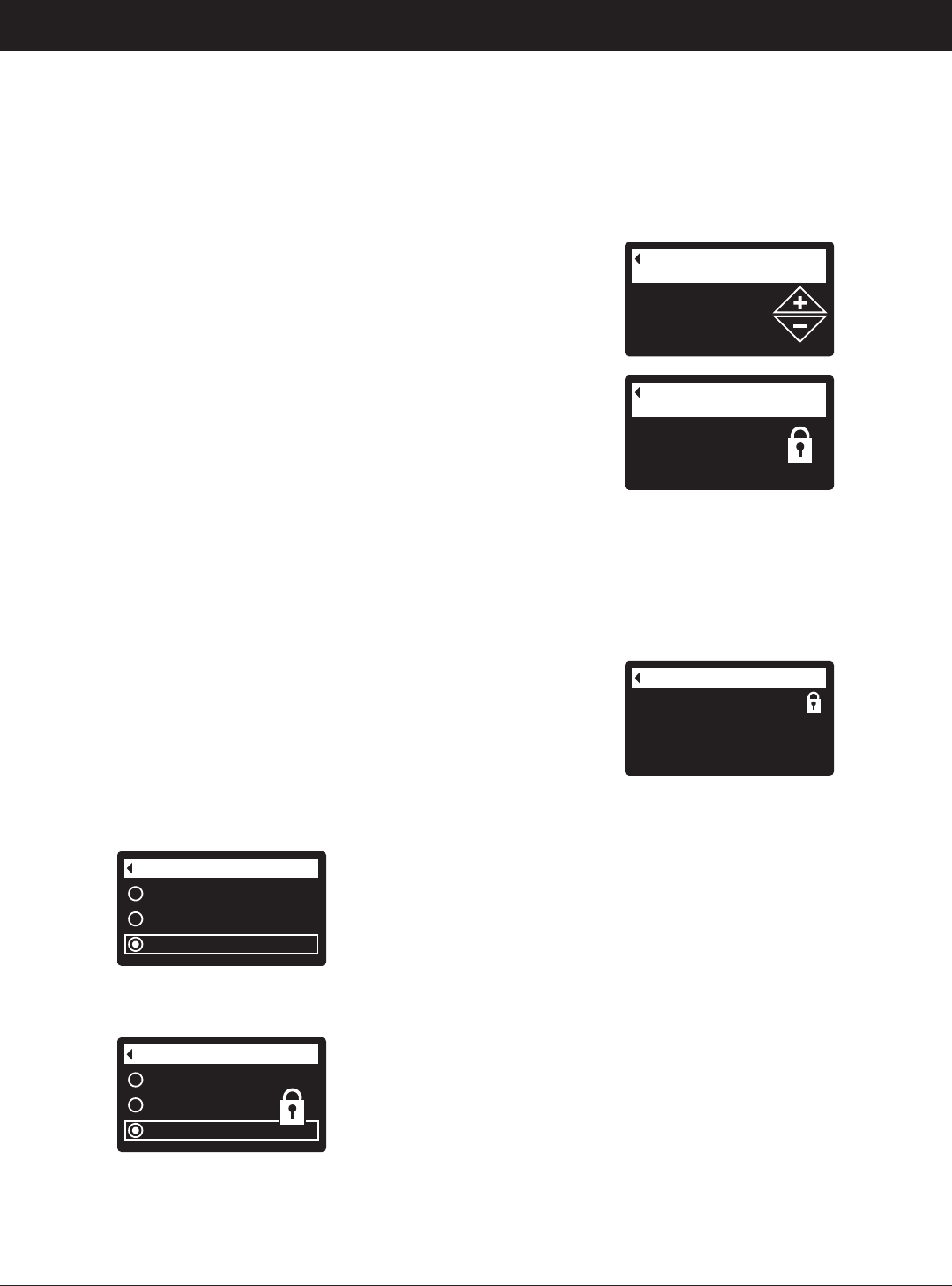
When the lockout feature is on, the flashing padlock
icon will appear in any screen that would normally be
used to change a parameter in the list to the left. For
example, the Max. days between recharges screen
will look like Figure 40, instead of Figure 39.
Redo setup
Restore defaults
Cancel
Setup changes
FIG. 37
Redo setup
Restore defaults
Cancel
Setup changes
8. Press the RIGHT (4) button. A flashing padlock icon
will appear, as shown in Figure 38.
9. Press the SELECT (¡) button.
10. Press the LEFT (3) button three times to return to
the rolling status screens.
ECOWATER
S Y S T E M S
Filter Operation
LOCKOUT FEATURE
A “lockout” feature is available to prevent user modifica-
tion of parameters that affect filter performance. The
unit is shipped from the factory with the lockout feature
off. After programming is complete, the lockout feature
can be turned on to prevent changes to the following:
=Max days between recharges
=Fill time
=Draw time
=Backwash time
=Second backwash (On/Off)
=Second backwash time
=Fast rinse time
=Auxiliary control
=Chemical feed volume
=Chemical feed timer
=Service reminder
=Setup changes
To turn on the lockout feature:
1. From any of the rolling status screens, press the
SELECT (¡) button to display the Main menu.
2. Press the DOWN (6) button to scroll through the
menu options until Advanced settings is highlighted.
3. Press the SELECT (¡) button to display the
Advanced settings menu.
4. Press the DOWN (6) button to scroll through the
menu options until Troubleshooting is highlighted.
5. Press the SELECT (¡) button to display the
Troubleshooting menu.
6. Press the DOWN (6) button to scroll through the
menu options until Setup changes is highlighted.
7. Press the SELECT (¡) button to display the Setup
changes menu (See Figure 37).
5. Press the SELECT (¡) button. If Recharge now is
selected, the display immediately goes to the
Recharge status screen (See Figure 44). If Auto -
matic, Schedule, or Recharge off are selected, the
display goes back to the Main menu (Figure 42).
17
ECOWATER
S Y S T E M S
Filter Operation
2. Make sure Recharge is highlighted (See Figure 42).
3. Press the SELECT (¡) button to display the
Recharge menu (See Figure 43).
Recharge
Basic settings
User preferences
Main menu
FIG. 42
Recharge status
Time left: 1:58
Cycle: Backwash
(Right key press advances
cycle)
FIG. 44
6. Press the LEFT (3) button (twice from the Recharge
status screen) to return to the rolling status screens.
If Recharge off was selected, the normal sequence
of rolling screens will stop at the screen shown in
Figure 45.
RECHARGING THE FILTER
This feature may be used to assure an adequate supply
of conditioned water at times of unusually high water
use. For example, if you have guests you could
deplete conditioned water capacity before the next
automatic recharge. Initiating a manual recharge will
restore 100% conditioned water capacity after com-
plete.
1. From any of the rolling status screens, press the
SELECT (¡) button to display the Main menu.
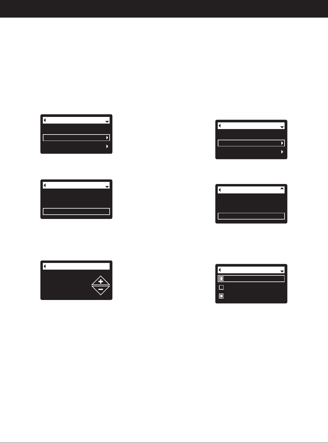
4. If the desired option already has a dot next to it (See
Figure 43), go to Step 5. Otherwise, press the
DOWN (6) or UP (5) buttons to scroll to the desired
option, then press SELECT (¡) to choose it.
=Automatic cancels a manually scheduled recharge
(if it has not already begun) and lets the electronic
control determine when to recharge next.
=Recharge now begins a recharge immediately
after the SELECT (¡) button is pushed again in Step
5.
=Schedule sets a recharge to begin at the preset
recharge time (set according to the instructions on
Page 19).
=Recharge off puts the system into a “vacation
mode” where there will be no automatic recharges.
This can be used during any long absence when you
do not want the system using water. The recharge
status screen will display “No automatic recharges”.
When you return, be sure to cancel Recharge off by
setting recharge to Automatic or Schedule.
Initiating Recharge now does not cancel Recharge
off.
Recharge now
Schedule
Recharge off
Recharge
FIG. 43
Automatic
Recharge now
Schedule
Recharge
Recharge status
2:34 PM
Off - no automatic
recharges
FIG. 45
18
Use the table above to determine the number of days
between recharges, based on the number of people
in the household and the iron ppm (parts per million)
in the water supply.
NOTE: If the water supply has high turbidity (sand, silt,
sediments, etc.) set to recharge more often than
the table shows.
7. Press the SELECT (¡) button. The display will go
back to the Basic settings menu (Figure 47).
8. Press the LEFT (3) button twice to return to the
rolling status screens
ECOWATER
S Y S T E M S
Filter Operation
FIG. 48
3 days
Max. days between
recharges
Current time
Max. days between rech...
Recharge time
Basic settings
FIG. 47
3. Press the SELECT (¡) button to display the Basic
settings menu (See Figure 47).
4. Press the DOWN (6) button to scroll through the
menu options until Max. days between rech... is
highlighted.
5. Press the SELECT (¡) button to display the Max.
days between recharges screen (See Figure 48).
6. Press the UP (5) or DOWN (6) buttons to change
the number of days between automatic recharges.
The feature can be set from 1 to 99 days.
When the filter’s electronic control is first powered up, a
“wizard” screen prompts you to set the number of days
between automatic recharges (See Pages 10-12). To
change it:
1. From any of the rolling status screens, press the
SELECT (¡) button to display the Main menu.
2. Press the DOWN (6) button to scroll through the
menu options until Basic settings is highlighted
(See Figure 46).
Recharge
Basic settings
User preferences
Main menu
FIG. 46
No. of
People
Iron (parts per million)
1 - 2 3 - 4 5 - 7 8 - 20
1 - 2 4 days 3 days 2 days 1 day
3 4 days 3 days 1 day 1 day
4 - 5 3 days 2 days 1 day 1 day
6 - 7 2 days 1 day 1 day 1 day
SETTING MAXIMUM DAYS BETWEEN RECHARGES
19
ECOWATER
S Y S T E M S
Filter Operation
MODIFYING ROLLING SCREENS
During normal filter operation, up to four status screens
are shown in sequence (See “Filter Status Screens” on
Page 14). When the filter’s electronic control is first
powered up, the default is to show all four. You can
turn on/off individual screens*:
1. From any of the rolling status screens, press the
SELECT (¡) button to display the Main menu.
2. Press the DOWN (6) button to scroll through the
menu options until Basic settings is highlighted
(See Figure 52).
3. Press the SELECT (¡) button to display the Basic
settings menu (See Figure 53).
Recharge
Basic settings
User preferences
Main menu
FIG. 52
Max. days between rech...
Recharge time
Rolling screens
Basic settings
FIG. 53
4. Press the DOWN (6) button to scroll through the
menu options until Rolling screens is highlighted.
5. Press the SELECT (¡) button to display the Rolling
screens menu (See Figure 54).
Water use
Flow rate
Recharge status
Rolling screens
FIG. 54
6. Press the DOWN (6) or UP (5) buttons to scroll
through the list. Items with a black square next to
them will be displayed during normal operation.
7. To un-select a screen, make sure its name is high-
lighted in a box. Then press the SELECT (¡) button.
The black square will disappear. Pressing SELECT
(¡) again makes the black square reappear and re-
selects the highlighted item. At least one screen
must be selected/highlighted.
8. When selections are complete, exit this menu by
pressing the LEFT (3) button. The display will go
back to the Basic settings menu (Figure 53).
9. Press the LEFT (3) button twice to return to the
rolling status screens.
*This does not include service reminders, errors, alerts or
Recharge status screens.
SETTING RECHARGE TIME
When the filter’s electronic control is first powered up,
the default time for starting an automatic recharge is
12:00 a.m. This is a good time in most households
because water is not being used. To change this time:
1. From any of the rolling status screens, press the
SELECT (¡) button to display the Main menu.
2. Press the DOWN (6) button to scroll through the
menu options until Basic settings is highlighted
(See Figure 49).
Current time
Max. days between rech...
Recharge time
Basic settings
FIG. 50
3. Press the SELECT (¡) button to display the Basic
settings menu (See Figure 50).
Recharge time
12:00 AM
FIG. 51
Recharge
Basic settings
User preferences
Main menu
FIG. 49
4. Press the DOWN (6) button to scroll through the
menu options until Recharge time is highlighted.
5. Press the SELECT (¡) button to display the
Recharge time screen (See Figure 51).
6. Press the UP (5) or DOWN (6) buttons to change
the recharge time in 1 hour increments. Hold the
button down to rapidly advance. Be sure that AM or
PM is correct (unless filter is set for a 24-hour clock).
7. Press the SELECT (¡) button. The display will go
back to the Basic settings menu (Figure 50).
8. Press the LEFT (3) button twice to return to the
rolling status screens.
20
SETTING TIME FORMAT
Use this feature to select a 12-hour (AM/PM) or 24-hour
clock.
1. From any of the rolling status screens, press the
SELECT (¡) button to display the Main menu.
2. Press the DOWN (6) button to scroll through the
menu options until User preferences is highlighted.
3. Press the SELECT (¡) button to display the User
preferences menu.
4. Press the DOWN (6) button to scroll through the
menu options until Time format is highlighted.
5. Press the SELECT (¡) button to display the Time
format menu (See Figure 58).
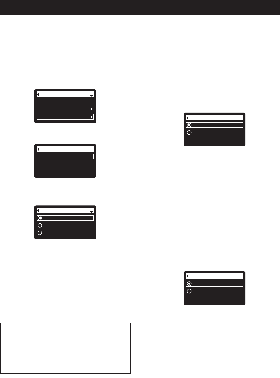
12-hour AM/PM
24-hour
Time format
FIG. 58
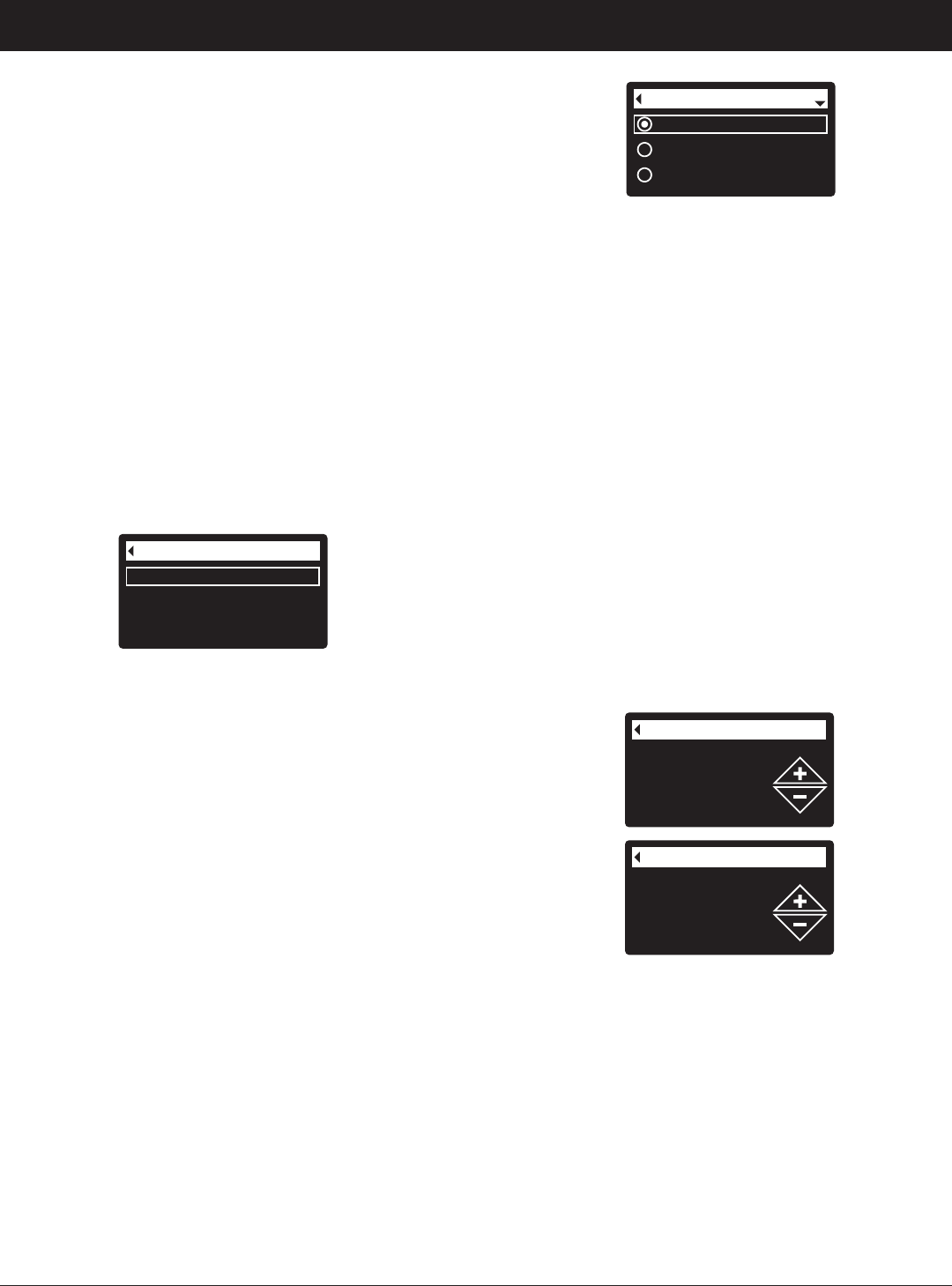
6. If the desired time format already has a dot next to it
(See Figure 58), go to Step 7. Otherwise, press the
DOWN (6) or UP (5) buttons to scroll to the other
time format, then press SELECT (¡) to choose it.
7. Press the SELECT (¡) button. The display will go
back to the User preferences menu.
8. Press the LEFT (3) button twice to return to the
rolling status screens.
SETTING VOLUME UNITS
Use this feature to select gallons or liters as volume
units.
1-3. Go to the User preferences menu by following
Steps 1-3 in “Setting Time Format” above.
4. Press the DOWN (6) button to scroll through the
menu options until Volume units is highlighted.
5. Press the SELECT (¡) button to display the Volume
units menu (See Figure 59).
gallons
liters
Volume units
FIG. 59
6. If the desired volume unit already has a dot next to it
(See Figure 59), go to Step 7. Otherwise, press the
DOWN (6) or UP (5) buttons to scroll to the other
volume unit, then press SELECT (¡) to choose it.
7. Press the SELECT (¡) button. The display will go
back to the User preferences menu.
8. Press the LEFT (3) button twice to return to the
rolling status screens.
ECOWATER
S Y S T E M S
Filter Operation
SETTING THE LANGUAGE
When the filter’s electronic control is first powered up, a
“wizard” screen prompts you to set the language (See
Pages 10-12). To change the language:
1. From any of the rolling status screens, press the
SELECT (¡) button to display the Main menu.
2. Press the DOWN (6) button to scroll through the
menu options until User preferences is highlighted
(See Figure 55).
4. Make sure Language is highlighted.
5. Press the SELECT (¡) button to display the
Language menu (See Figure 57).
Recharge
Basic settings
User preferences
Main menu
FIG. 55
Language
Time format
Volume units
User preferences
FIG. 56
3. Press the SELECT (¡) button to display the User
preferences menu (See Figure 56).
English
Español
Français
Language
FIG. 57
6. If the desired language already has a dot next to it
(See Figure 57), go to Step 7. Otherwise, press the
DOWN (6) or UP (5) buttons to scroll to the desired
language, then press SELECT (¡) to choose it. The
choices are: English, Spanish, French, Italian,
German, Dutch, Polish, Russian, Hungarian, Turkish,
Lithuanian, Greek, Romanian, Czech, Slovak,
Bulgarian, Serbian or Croatian.
7. Press the SELECT (¡) button. The display will go
back to the User preferences menu (Figure 56).
8. Press the LEFT (3) button twice to return to the
rolling status screens.
TO SET THE FILTER TO ENGLISH IF
ANOTHER LANGUAGE IS DISPLAYED:
From the rolling status screens, press SELECT (¡).
Press DOWN (6) three times, then press SELECT
(¡) twice. Press UP (5) to scroll to English at the
top of the list, then press SELECT (¡) twice. Press
LEFT (3) twice to exit all menus.
21
ECOWATER
S Y S T E M S
Filter Operation
SYSTEM INFORMATION
Use these features to look up the following information about the filter
and its operations:
=Model information (model number and software version)
=Wireless information
=Daily average water used
=Water used today
=Total water used (explained in Step 6, below)
=Current water flow
=Days powered up
=Last recharge
=Total recharges
To display one of these screens:
1. From any of the rolling status screens, press the SELECT (¡) button
to display the Main menu.
2. Press the DOWN (6) button to scroll through the menu options until
System information is highlighted (See Figure 60).
Basic settings
User preferences
System information
Main menu
FIG. 60
Model information
Wireless information
Daily avg. water used
System information
FIG. 61
3. Press the SELECT (¡) button to display the System information
menu (See Figure 61).
4. Press the DOWN (6) button to scroll through the menu options until
the desired option is highlighted (See list at the top of this column).
5. Press the SELECT (¡) button to display the desired information
screen (See Figures 62-70).
6. The Total water used screen (See Figure 66) shows the volume of
water used since it was last reset (it works like the trip odometer in a
car). To reset the value to 0, press the RIGHT (4) button while this
screen is displayed.
7. When finished viewing an information screen, press the SELECT (¡)
button. The display will go back to the System information menu
(Figure 61). It will also exit automatically if no buttons are pressed
for four minutes.
8. Press the LEFT (3) button twice to return to the rolling status screens.
Wireless information
DSN: AC000W000009876
Key:
abc123
FIG. 63
Daily avg. water used
175 gallons
FIG. 64
Water used today
121 gallons
FIG. 65
Total water used
86 gallons
(Right key press resets)
FIG. 66
Current water flow
2.0 GPM
FIG. 67
Days powered up
12 days
FIG. 68
Last recharge
2 days ago
FIG. 69
Total recharges
5
FIG. 70
Model information
Model: HPF10
Version: T2.0
FIG. 62
22
CYCLE TIMES
Use these features to change the following filter opera-
tions:
=Fill time (described on the next page)
=Draw time (described on the next page)
=Backwash time
=Second backwash (On/Off)
=Second backwash time
=Fast rinse time
To display these screens:
1. From any of the rolling status screens, press the
SELECT (¡) button to display the Main menu.
2. Press the DOWN (6) button to scroll through the
menu options until Advanced settings is highlighted
(See Figure 71).
Fill time
Draw time
Backwash time
Cycle times
FIG. 73
6. Press the DOWN (6) button to scroll through the
menu options until the desired option is highlighted
(See list at the top of this column).
7. Press the SELECT (¡) button to display the desired
cycle time screen (See Figures 74-79).
8. See the next two columns for specific instructions
on each cycle time screen.
9. Press the SELECT (¡) button. The display will go
back to the Cycle times menu (Figure 73).
10. Press the LEFT (3) button three times to return to
the rolling status screens.
Cycle times
Special features
Troubleshooting
Advanced settings
FIG. 72
4. Make sure Cycle times is highlighted.
5. Press the SELECT (¡) button to display the Cycle
times menu (See Figure 73).
User preferences
System information
Advanced settings
Main menu
FIG. 71
3. Press the SELECT (¡) button to display the
Advanced settings menu (See Figure 72).
2nd backwash time
0 minutes
FIG. 76
8e. Second backwash time: Press the UP (5) or
DOWN (6) buttons to change the second back-
wash time. Hold the button down to rapidly
advance. The time can be set from 0 to 15
minutes (See Figure 76).
Fast rinse time
5 minutes
FIG. 77
8f. Fast rinse time: Press the UP (5) or DOWN
(6) buttons to change the fast rinse time. Hold
the button down to rapidly advance. The fast
rinse time can be set from 1 to 99 minutes* (See
Figure 77).
ECOWATER
S Y S T E M S
Filter Operation
*Reducing the backwash and fast rinse times below a fil-
ter model’s default settings is not recommended.
Backwash time
25 minutes
FIG. 74
8c. Backwash time: Press the UP (5) or DOWN
(6) buttons to change the backwash time.
Hold the button down to rapidly advance. The
backwash time can be set from 1 to 99 min-
utes* (See Figure 74).
Off
On
2nd backwash (On/Off)
FIG. 75
8d. Second backwash (On/Off): If the desired
option already has a dot next to it (See Figure
75), go to Step 9. Otherwise, press the DOWN
(6) or UP (5) buttons to scroll to the other
option, then press SELECT (¡) to choose it.
Setting this feature On adds a second back-
wash and rinse at the beginning of the recharge
cycle. Default is Off. Set this feature On if your
water supply contains a lot of sediment or iron.
23
Fill time
0 minutes
0 seconds
FIG. 78
8a. Fill time: Press the UP (5) or DOWN (6) but-
tons to change the fill time. Hold the button
down to rapidly advance. The fill time can be
set from 0:00 to 99:59 minutes (See Figure 78).
Draw time
0 minutes
FIG. 79
8b. Draw time: Press the UP (5) or DOWN (6)
buttons to change the draw time. Hold the but-
ton down to rapidly advance. The draw time
can be set from 0 to 255 minutes (See Figure
79).
ECOWATER
S Y S T E M S
Filter Operation
SPECIAL FEATURES
Use these features to change the following operations:
=Auxiliary control (described on Page 24)
=Chemical feed volume** (described on Page 24)
=Chemical feed timer** (described on Page 24)
=Service reminder (described below)
SERVICE REMINDER (set / reset)
Use this feature to program the number of months (up
to 24) before a “Service overdue” message will appear
instead of the rolling status screens (See Figure 80).
Cycle times
Special features
Troubleshooting
Advanced settings
FIG. 82
4. Press the DOWN (6) button to scroll through the
menu options until Special features is highlighted.
5. Press the SELECT (¡) button to display the Special
features menu (See Figure 83).
User preferences
System information
Advanced settings
Main menu
FIG. 81
3. Press the SELECT (¡) button to display the
Advanced settings menu (See Figure 82).
Auxiliary control
Service reminder
Special features
FIG. 83
Service reminder
12 months
0 days
FIG. 84
8. Press the UP (5) or DOWN (6) buttons to set the
number of months until the service reminder
appears. Repeatedly pressing the DOWN (6) but-
ton until the display reads “Off” turns this feature off
and zeros the number of months and days.
9. Press the SELECT (¡) button. The display will go
back to the Special features menu (Figure 83).
10. Press the LEFT (3) button three times to return to
the rolling status screens.
6. Press the DOWN (6) button to scroll through the
menu options until Service reminder is highlighted.
7. Press the SELECT (¡) button to display the Service
reminder screen (See Figure 84).
This will be a reminder to call your dealer for service.
Once programmed, this feature displays the number of
months and days left until the service reminder.
Once the “Service overdue” message has appeared,
dealers performing service clear it by setting the num-
Service reminder
Service overdue
FIG. 80
**Only displayed if Auxiliary control is set to Chemical feed.
ber of months until the next service reminder. Set or
reset the service reminder as follows:
1. From any of the rolling status screens, press the
SELECT (¡) button to display the Main menu.
2. Press the DOWN (6) button to scroll through the
menu options until Advanced settings is highlighted.
24
ECOWATER
S Y S T E M S
Filter Operation
Chemical feed volume
1 gallons
FIG. 87
Chemical feed timer
0.1 seconds
FIG. 88
Auxiliary control
Service reminder
Special features
FIG. 85
AUXILIARY CONTROL
The electronic control has an auxiliary output which can
control external devices in a water treatment system.
The signal is 24V DC, current draw 500 mA maximum.
The Auxiliary Output terminals are located on the elec-
tronic control board (See Schematic on Page 28).
For more details on the use of auxiliary controlled
equipment in water treatment systems, consult the
EcoWater Systems “Problem Water Guide.”
To select an auxiliary control mode:
1. From any of the rolling status screens, press the
SELECT (¡) button to display the Main menu.
2. Press the DOWN (6) button to scroll through the
menu options until Advanced settings is highlighted.
3. Press the SELECT (¡) button to display the
Advanced settings menu.
4. Press the DOWN (6) button to scroll through the
menu options until Special features is highlighted.
5. Press the SELECT (¡) button to display the Special
features menu (See Figure 85).
6. Make sure Auxiliary control is highlighted.
7. Press the SELECT (¡) button to display the Auxiliary
control menu (See Figure 86).
8. If the desired option already has a black dot next to it
(See Figure 86), go to Step 9. Otherwise, press the
DOWN (6) or UP (5) buttons to scroll to the desired
option, then press SELECT (¡) to choose it.
=Off is the default. The 24V DC output is always off.
=On: The 24V DC output is always on.
=Chlorine can be used to drive a chlorine generator,
which produces chlorine, as water passes through
it, to sanitize the media during recharges.
=Bypass: Turns 24V DC on during the entire regen-
eration cycle (when the filter’s valve is in bypass
and unfiltered is going to the house).
=Chemical feed:* Can be used to run a chemical
feed pump. If chosen, the chemical feed volume
and timer must be set, as detailed at right.
=Water use*: Turns 24V DC on when the filter’s tur-
bine indicates water flow. Could drive an air pump
for iron or sulfur oxidation.
=Fast Rinse: Turns 24V DC on during the fast rinse
portion of the regeneration cycle.
9. Press the SELECT (¡) button. The display will go
back to the Special features menu (Figure 85).
10. Press the LEFT (3) button three times to return to
the rolling status screens.
Off
On
Chlorine
Auxiliary control
FIG. 86
CHEMICAL FEED*
If the auxiliary control mode has been set to Chemical
feed, as described in the previous section, two addition-
al lines (Chemical feed volume and Chemical feed
timer) will appear on the Special features menu.
To set these values:
1. From any of the rolling status screens, press the
SELECT (¡) button to display the Main menu.
2. Press the DOWN (6) button to scroll through the
menu options until Advanced settings is highlighted.
3. Press the SELECT (¡) button to display the
Advanced settings menu.
4. Press the DOWN (6) button to scroll through the
menu options until Special features is highlighted.
5. Press the SELECT (¡) button to display the Special
features menu (See Figure 85).
6. Press the DOWN (6) button to scroll through the
menu options until Chemical feed volume or
Chemical feed timer is highlighted.
7. Press the SELECT (¡) button to display the
Chemical feed volume or Chemical feed timer menu
(See Figures 87 & 88).
8. Press the UP (5) or DOWN (6) buttons to change
the value. Hold the button down to rapidly advance.
=Chemical feed volume is the amount of water
which will pass through the filter between each acti-
vation of the chemical feed equipment.
=Chemical feed timer is how long the output to the
chemical feed equipment is energized each time it
is activated.
9. Press the SELECT (¡) button. The display will go
back to the Special features menu (Figure 85).
10. Press the LEFT (3) button three times to return to
the rolling status screens.
*A turbine and turbine cable must be added to the system if auxiliary control options “Chemical feed” or “Water use” are to be used.
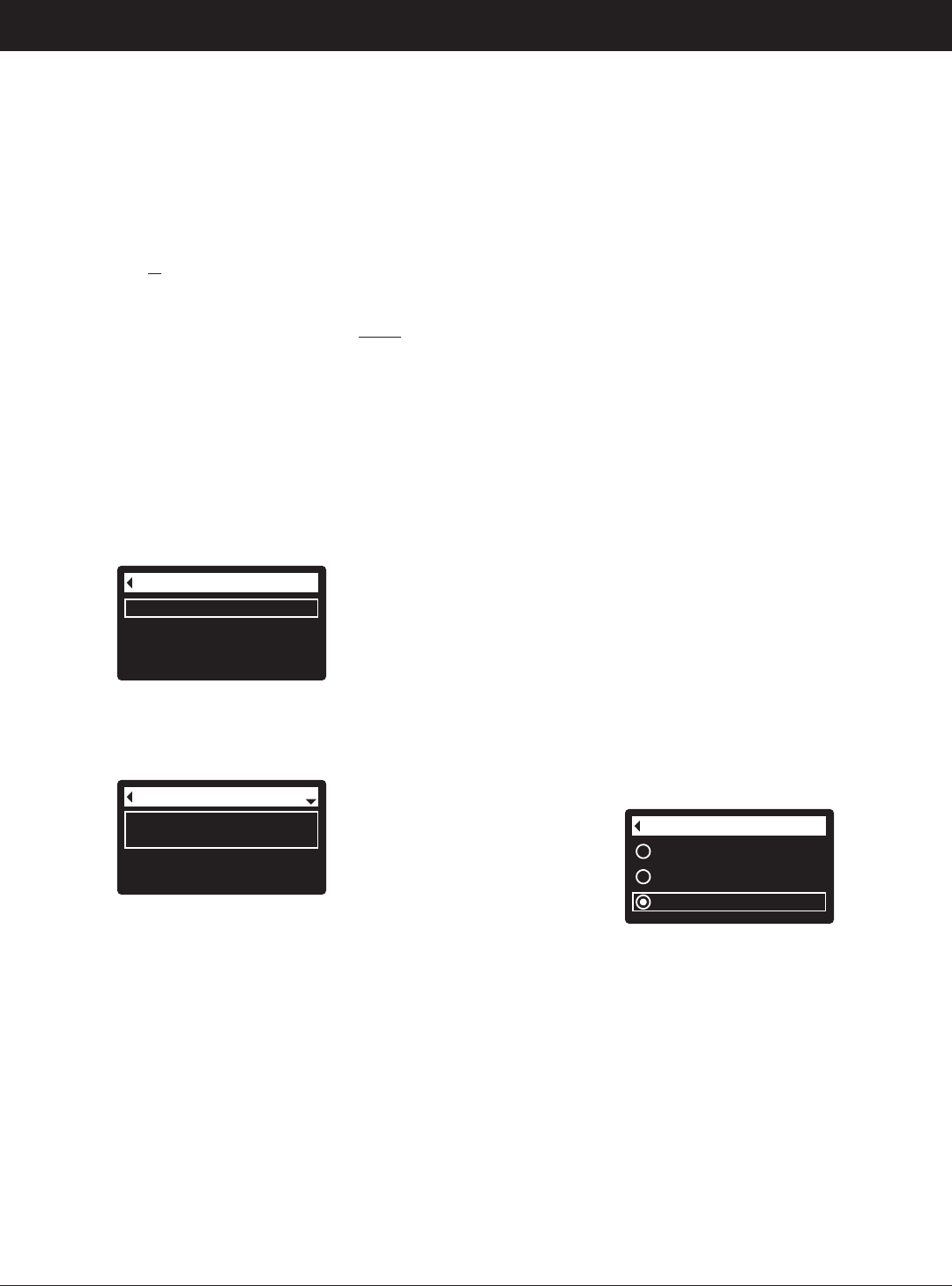
25
DIAGNOSTICS
This feature allows a service technician to check the
operating state of individual components in the filter
(e.g. valve position) to troubleshoot problems. If an
error code is displayed in place of the rolling status
screens, call your dealer for service.
To view the Diagnostics screen:
1. If an error code is
displayed, skip Steps 2-7 and go
directly to Step 8.
2. To display the Diagnostics screen from any of the
rolling status screens (when an error code is not dis-
played), press the SELECT (¡) button to display the
Main menu.
3. Press the DOWN (6) button to scroll through the
menu options until Advanced settings is highlighted.
4. Press the SELECT (¡) button to display the
Advanced settings menu.
5. Press the DOWN (6) button to scroll through the
menu options until Troubleshooting is highlighted.
6. Press the SELECT (¡) button to display the
Troubleshooting menu (See Figure 89).
SETUP CHANGES
This feature allows a service technician to repeat the
setup procedure (See Pages 10-12) or restore the fil-
ter’s default operating values.
1. From any of the rolling status screens, press the
SELECT (¡) button to display the Main menu.
2. Press the DOWN (6) button to scroll through the
menu options until Advanced settings is highlighted.
3. Press the SELECT (¡) button to display the
Advanced settings menu.
4. Press the DOWN (6) button to scroll through the
menu options until Troubleshooting is highlighted.
5. Press the SELECT (¡) button to display the
Troubleshooting menu (See Figure 89).
6. Press the DOWN (6) button to scroll through the
menu options until Setup changes is highlighted.
7. Press the SELECT (¡) button to display the Setup
changes menu (See Figure 91).
Diagnostics
Setup changes
Troubleshooting
FIG. 89
7. Make sure Diagnostics is highlighted.
8. Press the SELECT (¡) button to display the
Diagnostics screen (See Figure 90).
Diagnostics
Time:
3:45 PM
Position time:
0:00
FIG. 90
9. Press the DOWN (6) or UP (5) buttons to scroll
through the list. The following items are displayed:
=Time (current)
=Position time (counts down the time remaining in
the current valve position)
=Current position (of the valve: service, fill, brine,
backwash, fast rinse or moving)
=Requested position (of the valve)
=Motor state (on or off)
=Valve position switch (open or closed)
=Turbine count (if changing, indicates water flow).
=Tank light switch (open or closed)
=RF module (detected or not)
=Error code (call for service if a number is dis-
played)
continued
10. When finished viewing the Diagnostics screen,
press the SELECT (¡) button. The display will go
back to the Troubleshooting menu.
11. Press the LEFT (3) button three times to return to
the rolling status screens (or error code screen if an
error condition exists).
Redo setup
Restore defaults
Cancel
Setup changes
FIG. 91
8. If the desired option already has a dot next to it (See
Figure 91), go to Step 9. Otherwise, press the
DOWN (6) or UP (5) buttons to scroll to the desired
option, then press SELECT (¡) to choose it.
=Redo setup allows you to select a different model
code (intended to be used for upgrades or retrofits
of existing filters). Model codes are listed on Page
3.
=Restore defaults will reset all customizable settings
to their default values and take you through the
“wizard” screen setup procedure (See Pages 10-12).
=Cancel will return to the Troubleshooting menu
(Figure 89).
9. Press the SELECT (¡) button.
ECOWATER
S Y S T E M S
Filter Operation
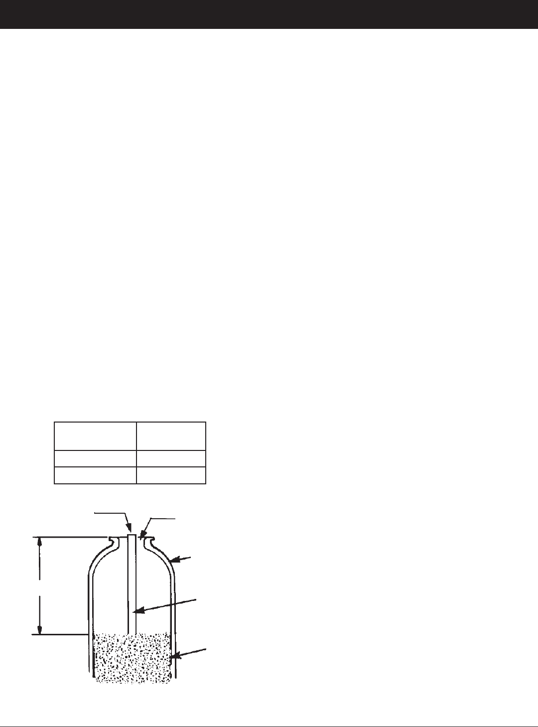
26
ECOWATER
S Y S T E M S
Service Information
NEUTRALIZING FILTER - CHECKING THE
MINERAL LEVEL IN THE TANK
As explained on Page 9, the mineral dissolves in the
water to neutralize the acid. How fast it dissolves
depends on how much water your household uses
and the pH of the water.
Every few months you should measure the mineral
bed level in the tank. Always add new mineral before
the tank is empty. To measure, do the following:
1. Referring to Page 17, initiate a “Recharge Now”.
2. When water starts to run from the drain hose, put
the plumbing bypass valve(s) into bypass position
(See Figures 7 & 8 on page 6), TO DEPRESSUR-
IZE THE FILTER.
3. Unplug the power supply at the wall outlet.
4. Remove the controller cover.
5. Disconnect the bypass valve or copper tubes from
the inlet and outlet (See Page 7).
6. Remove retainer clips and clamp sections from the
tank neck and carefully lift the valve off the tank.
7. Remove the top distributor and four o-ring seals
(See Page 5).
8. Use a yard stick or steel tape measure to find the
distance down to the top of the mineral bed (See
Figure 92). If it is lower than the suggested free-
board, shown in the table below, add more neu-
tralite material.
9. When adding more mineral, use a funnel to add.
10. Flush all mineral from the tank top opening. Then
replace the distributor and four o-ring seals (See
Figure 5 on Page 5).
11. Do the following steps to return the filter to service:
=Steps 10 and 11 on Page 5
=Step 2 on Page 7
=Step 5 on Page 8, if hose was disconnected
=Steps 6, 7 and 9 on Page 8
NOTE: After electrical power is applied, if the
time display is flashing, reset the clock
(See Page 17).
=Initiate a “Recharge Now” (See Page 17).
TASTE & ODOR FILTER - REPLACING
THE ACTIVATED CARBON MINERAL BED
When the filter no longer removes tastes and/or odors
from the water (See Page 9), the activated carbon
bed must be replaced. To replace the bed:
1. Do Steps 1 through 7, at left.
2. Carefully lay the filter tank over. Pull the standpipe
and bottom distributor from the mineral bed.
3. Dump the contents of the tank into a suitable con-
tainer.
4. Stand the tank upright and put the bottom distribu-
tor and standpipe back in place.
5. Add the recommended amounts of gravel, filter
sand, and activated carbon mineral. See
“Specifications” on Page 3.
6. Do Steps 10 & 11, above.
Model
Suggested
Freeboard
ETF2300PF10 15”
ETF2300PF12 16”
FIG. 92
FREEBOARD
Add
Mineral
Mineral
Bed
Mineral
Tank
Bottom
Distributor
Riser
Plug When
Adding Mineral
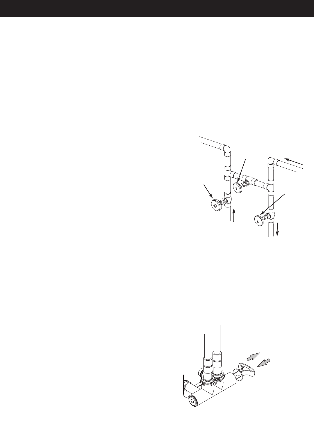
27
ECOWATER
S Y S T E M S
Service Information
RELIEVING WATER PRESSURE WITH THE
BYPASS VALVE(S)
CAUTION: Always relieve water pressure in the
EcoWater Systems filter, as described below, before
removing parts from the valve or media tank.
DE-PRESSURIZE
1. Put bypass valve(s) into Bypass position.
2. Place filter valve in Fill position by performing Steps
1 & 5 of Manual Advance Recharge procedure on
Page 30.
PRESSURIZE
1. Put bypass valve(s) into Service position.
2. Return filter valve to Service position by performing
Steps 6-11 of Manual Advance Recharge procedure
on Page 30.
ALTERNATE METHODS:
3-VALVE BYPASS (See Figure 93)
DE-PRESSURIZE
1. Close the INLET valve.
2. Open HOT and COLD conditioned water house
faucets.
3. Close the OUTLET valve and open the BYPASS
valve.
4. Close all house faucets.
PRESSURIZE
1. Open HOT and COLD house faucets.
2. Close the BYPASS valve and open the OUTLET
valve.
3. Slowly, open the INLET valve.
4. Close all house faucets.
ECOWATER SYSTEMS BYPASS VALVE
(See Figure 94)
DE-PRESSURIZE
1. Close the house main water supply valve.
2. Open HOT and COLD conditioned water house
faucets.
3. Push the bypass valve handle to Bypass position.
4. Optional: For unfiltered water bypass to house
faucets, reopen the main water supply valve.
PRESSURIZE
1. Open main water supply valve if it is closed.
2. Open HOT and COLD house faucets.
3. Pull the bypass valve handle to Service position.
4. Close all house faucets.
FIG. 94
FIG. 93
BYPASS
VALVE
EcoWater Systems Bypass Valve
3-Valve Bypass
To
Filter
From
Filter
Water Flow
OUTLET
VALVE
INLET
VALVE
For Service
Close Bypass Valve.
Open Inlet & Outlet
Valves.
For Bypass
Open Bypass Valve.
Close Inlet & Outlet
Valves.
Pull out for Service
(Filtered water)
Push in for
Bypass
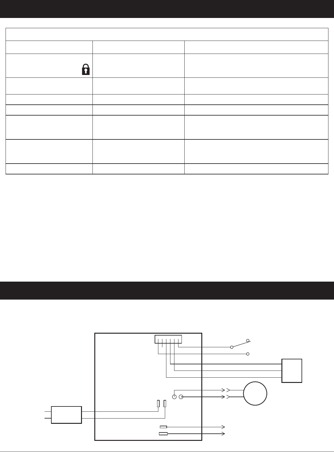
28
ECOWATER
S Y S T E M S
Service Information
TROUBLESHOOTING GUIDE
PROBLEM CAUSE CORRECTION
Cannot set some filter
parameters and display
shows a padlock icon:
Lockout feature is on. Turn off lockout feature (See Page 16).
Status screen shows
“No automatic recharges”
Recharge is set to “Off”
(vacation mode).
If you want automatic recharges, set recharge to
either “Schedule” or “Automatic” (See Page 17).
Air in house lines Riser tube o-ring. Reseat or replace riser o-ring.
Water to drain Defective rotor disc and seals. Replace rotor disc and seals.
Motor stalled or clicking Motor malfunction or internal
valve fault causing high torque
on motor.
Contact your dealer for service.
Error code E1, E3 or E4
displayed.
Fault in wiring harness, con-
nections to position switch,
switch, valve or motor.
Contact your dealer for service.
Error code E5 displayed. Electronic control malfunction. Contact your dealer for service.
TROUBLESHOOTING - INITIAL CHECKS
Always make these initial checks first:
1. Is display blank? Check power source.
2. Is Error code displayed? If so, go to “Automatic
Electronic Diagnostics” on the next page.
3. Is correct time displayed? If not, recharges occur
at the wrong time. Set current time (See Page 15.)
4. Are plumbing bypass valve(s) in service position
(See Figures 93 & 94 on Page 27)?
5. Are inlet and outlet pipes connected to the
EcoWater filter inlet and outlet respectively?
6. Is valve drain hose free of kinks and sharp bends,
and not elevated over 8 feet above the floor.
If no problem is found after making the initial checks,
proceed to “Troubleshooting - Manual Diagnostics”
and “Manual Advance Recharge Check” on the next
two pages.
WIRING SCHEMATIC
1
Orange
Green
Red
Black
Control Board on Back of Faceplate
Valve
Motor
Position
Switch
NO
C
Power
Supply
120V AC
60 Hz
24V DC
Power In
Auxiliary
Output
24V DC
ECOWATER
S Y S T E M S
Schematic
FIG. 95
White
Red
Black
Turbine
Sensor
GND
+5
OUT
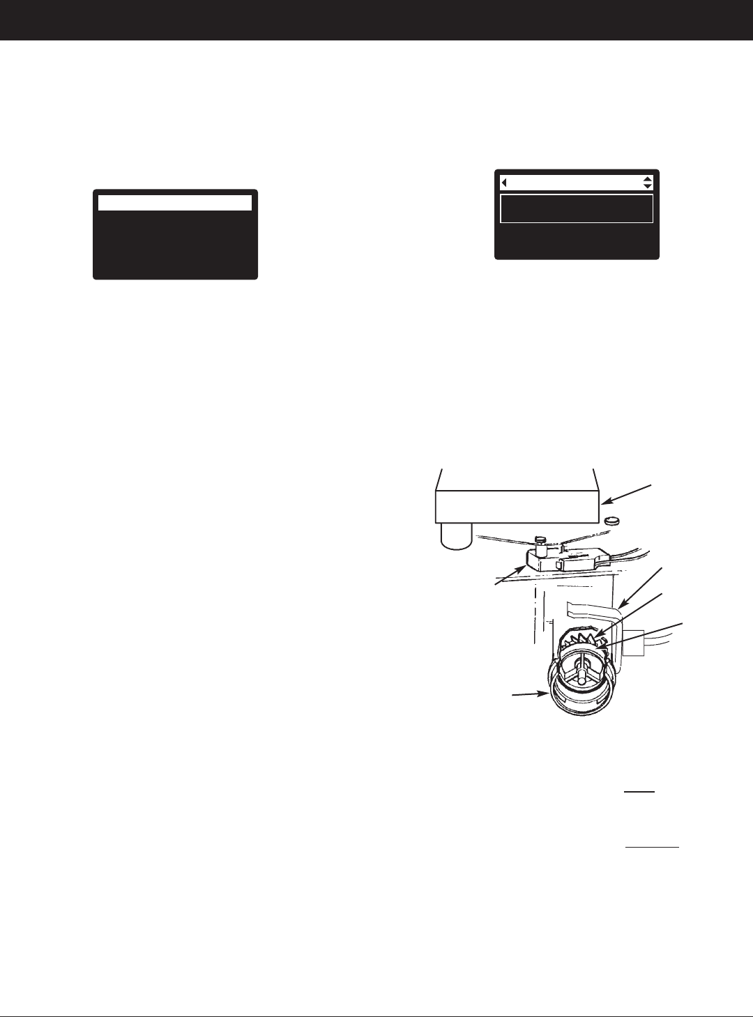
29
ECOWATER
S Y S T E M S
Service Information
AUTOMATIC ELECTRONIC DIAGNOSTICS
This filter has a self-diagnostic function for the electrical
system (except for input power and/or water meter).
The controller monitors electronic components and cir-
cuits for correct operation. If a malfunction occurs, an
Error code is displayed (See Figure 96).
Error detected
Error code: 1
FIG. 96
The troubleshooting chart on the previous page shows
the error codes that could appear, and the possible mal-
functions for these codes.
When an error code appears in the display, pressing
SELECT (¡) will display the Diagnostics screen (See
Page 25), so a service technician can further isolate the
problem.
REMOVING ERROR CODE
1. Unplug power supply from electrical outlet.
2. Correct problem.
3. Plug power supply back in.
4. Wait for 8 minutes while controller operates valve
through an entire cycle. The error code will return if
the problem was not corrected.
TROUBLESHOOTING -
MANUAL DIAGNOSTICS
1. Display the Diagnostics screen, following the proce-
dure on Page 25.
2. Press the DOWN (6) or UP (5) buttons to scroll
through the list. The following items are displayed:
=Time (current)
=Position time (counts down the time remaining in
the current valve position)
=Current position (of the valve: service, fill, brine,
backwash, fast rinse or moving) See “Manual
Advance Recharge Check” on the next page for
position verification.
=Requested position (of the valve)
=Motor state (on or off)
=Valve position switch (open or closed)
=Turbine count (if changing, indicates water flow).
=Tank light switch (open or closed)
=RF module (detected or not)
=Error code
Diagnostics
Turbine count:
0
Tank light switch:
Open
FIG. 97
3. A steady display of “0” (zero) indicates no water flow
through the meter (i.e. no conditioned water being
used).
4. Open a nearby conditioned water faucet.
5. The number in the display should count upward from
0 and reset at 140 for each gallon of flow.
6. If the display reading does not change with the
faucet open, pull the wire harness from the valve out-
let port (See Figure 98).
FIG. 98
7. Pass a small magnet back and forth in front of the
sensor.
8a. If the displayed Turbine Count does
count upward
with each pass of the magnet, disconnect the outlet
plumbing and check the turbine for binding.
8b. If the displayed Turbine Count does not count
upward with each pass of the magnet, the sensor is
probably faulty.
CHECKING THE TURBINE
1. Display the Diagnostics screen, following the proce-
dure on Page 25.
2. Press the DOWN (6) button to scroll through the list
until Turbine Count is displayed (See Figure 97).
Position
Switch
Valve
Outlet
Motor
Sensor
Housing
Turbine
Turbine
Support
& Shaft
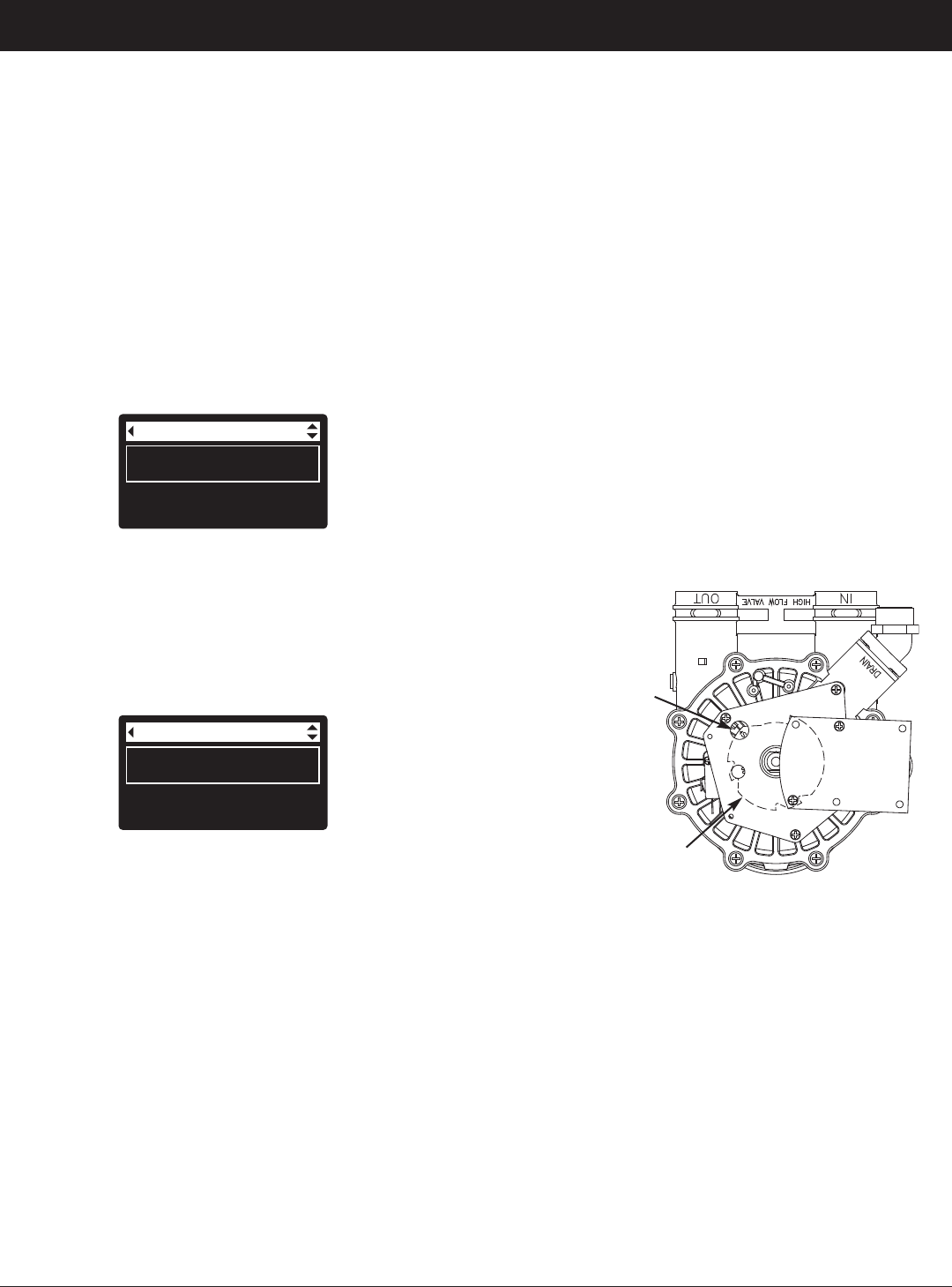
30
TROUBLESHOOTING -
MANUAL ADVANCE RECHARGE CHECK
Use the following procedures to advance the filter
through the recharge cycles to check operation. Always
make the Initial Checks (See Page 28) and the Manual
Diagnostics (See Page 29) first.
Remove the top cover by unlocking the tabs and lifting,
to observe cam and switch operation during valve rota-
tion (See Figure 101).
1. Display the Diagnostics screen, following the proce-
dure on Page 27.
2. Press the DOWN (6) button to scroll through the list
until Valve position switch is displayed (See Figure
99).
Diagnostics
Current position:
Service
Requested position:
Service
FIG. 100
5. With the Diagnostics screen displayed, press the
RIGHT (4) button once to advance the valve from
Service to the next position.
6. Default fill time is zero, so the valve will not remain at
the fill position unless fill time has been otherwise
set. If stopped at Fill, press the RIGHT (4) button
again to advance to the next position.
7. Default draw time is zero, so the valve will not remain
at the brine position unless draw time has been oth-
erwise set. If stopped at Brine*, press the RIGHT
(4) button again to advance to the next position.
8. Verify that the valve position indicator on the motor
cam agrees with the position displayed on the screen
9. Once in Backwash, look for a fast flow of water from
the drain hose. If flow is slow, check for a plugged
top distributor, backwash flow plug or drain hose
*
If the 2nd Backwash option is set (See Page 22), the valve
will enter backwash and fast rinse before brine.
Diagnostics
Valve position switch:
Closed
Turbine count:
0
FIG. 99
3. Verify that when the switch plunger is down (into one
of the detents on the valve motor cam), this screen
reads Open. When the valve cam is rotating (for
example, after Step 5, below) , the switch plunger will
be up and this screen should read Closed.
4. Press the UP (5) button to scroll through the list until
Current position is displayed (See Figure 100).
ECOWATER
S Y S T E M S
Service Information
10. With the Diagnostics screen displayed, once
again press the RIGHT (4) button to advance the
valve to Fast Rinse. Again, look for a drain flow
rate about the same as backwash.
11. With the Diagnostics screen displayed, once
again press the RIGHT (4) button to return the
valve to the Service position.
IMPORTANT: Always return the valve to the Service
position before exiting this procedure.
OTHER SERVICE
Unfiltered Water Bypass (Unfiltered water “bleeds”
into filtered water supply):
1. Faulty inlet disc, seal or wave washer (See Pages
34 and 35).
2. Missing or faulty o-ring(s) at valve connection to
riser pipe.
Water Leaks from Drain Hose during service:
1. Faulty rotor disc, seal or wave washer.
2. Faulty o-ring on inlet disc shaft.
FIG. 101
Position markers
(valve in service)
CAM
MOTOR
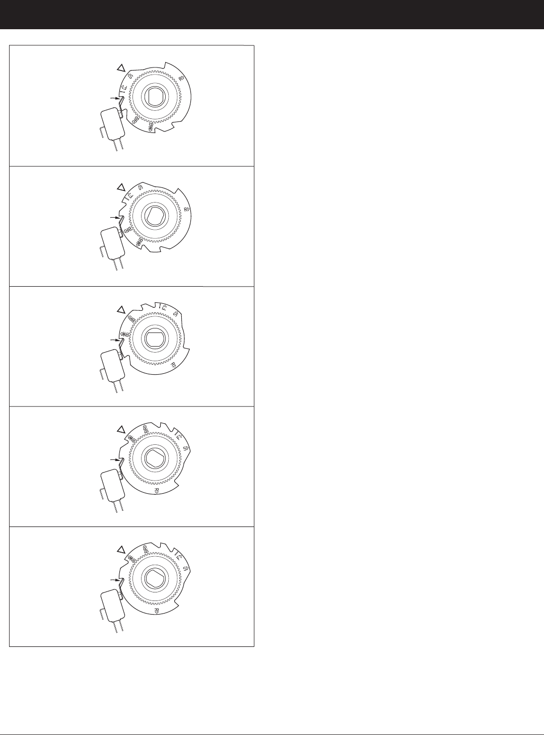
31
ECOWATER
S Y S T E M S
Service Information
Valve Cam
FIG. 102
Position Switch
S
SERVICE
Valve Cam
FIG. 103
BR
FILL
F
BRINE DRAW
Position Switch
Valve Cam
FIG. 104
Position Switch
Valve Cam
FIG. 105
BW
BACKWASH
FAST RINSE
Position Switch
Valve Cam
FIG. 106
Position Switch
R

32
ECOWATER
S Y S T E M S
Notes
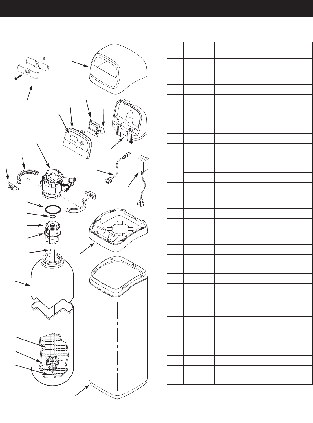
33
FILTER PARTS LISTFILTER EXPLODED VIEW
To order parts, call your local EcoWater dealer or go to
www.ecowater.com to locate a dealer in your area.
ECOWATER
S Y S T E M S
Repair Parts
Key
No.
Part No. Description
1 7353365 Top Cover
–
7357864
Repl. Faceplate Assembly
(includes Key Nos. 2-4)
2
á
Faceplate
3
á
Keypad/Decal
4
á
Electronic Controller (PWA)
5 7341520 Repl. Wi-Fi Board
6 7353381 Support, Faceplate
7 7259927 Wire Harness, Position Switch
8 7351054 Power Supply, 24V DC
9 7353357 Rim
10
7353234 Shroud, ETF2300PF10
7353242 Shroud, ETF2300PF12
–
7331177
Tank Neck Clamp Kit
(includes 2 ea. of Key Nos. 11 & 12)
11
á
Clamp Section (2 req.)
12
á
Retainer, Clamp (2 req.)
–
7112963
Distributor O-Ring Kit
(includes Key Nos. 13-15)
13
á
O-Ring, 2-7/8” x 3-1/4”
14
á
O-Ring, 13/16” x 1-1/16”
15
á
O-Ring, 2-3/4” x 3”
16 7088855 Top Distributor
17 7105047 Repl. Bottom Distributor
18
7092202
Repl. Mineral Tank, 10” x 47”,
ETF2300PF10
7113074
Repl. Mineral Tank, 12” x 54”
ETF2300PF12
19
0505647
Filter Aggregate, 1 cu. ft. Ù
3423699
Neutralite, 1/2 cu. ft. Ù
3424509
Activated Carbon, 1 cu. ft. Ù
7175149
Activated Carbon, 50 lbs. Ù
20 0501783
Filter Sand, 10 lbs. Ù
21 7124415 Gravel, 17 lbs.
22 7248706
Ground Clamp Kit Ù
12
11
13
14
16
15
17
18
9
6
19
10
8
7
1
5
2
22
Valve Assembly
See Pages 34 & 35
for parts
21
20
4
3
Ù Not included with the filter.
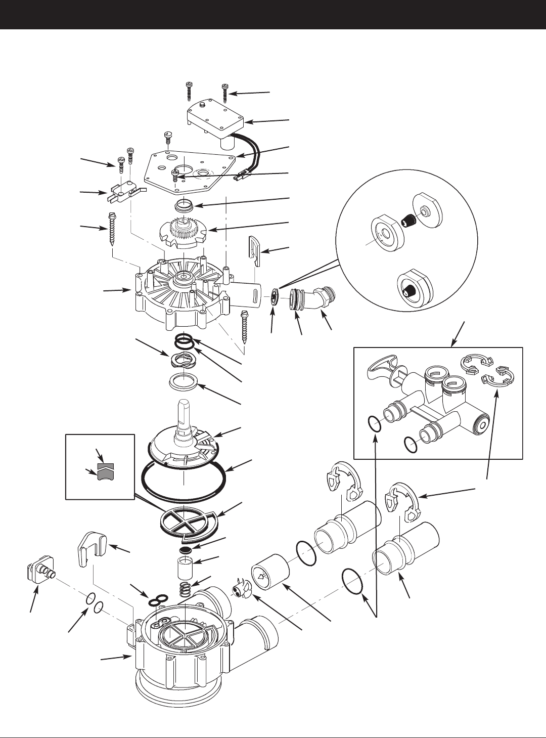
34
ECOWATER
S Y S T E M S
Repair Parts
VALVE EXPLODED VIEW
50
51
52
53
54
55
56
57
58
59
60
61
66
67
79
62
63
64
68
69
65
78
70
71
72
75
76
77
80
81
82
83
134
73
wear strip
seal
cross-section
view
flow plug
assembly
assembled
view
74
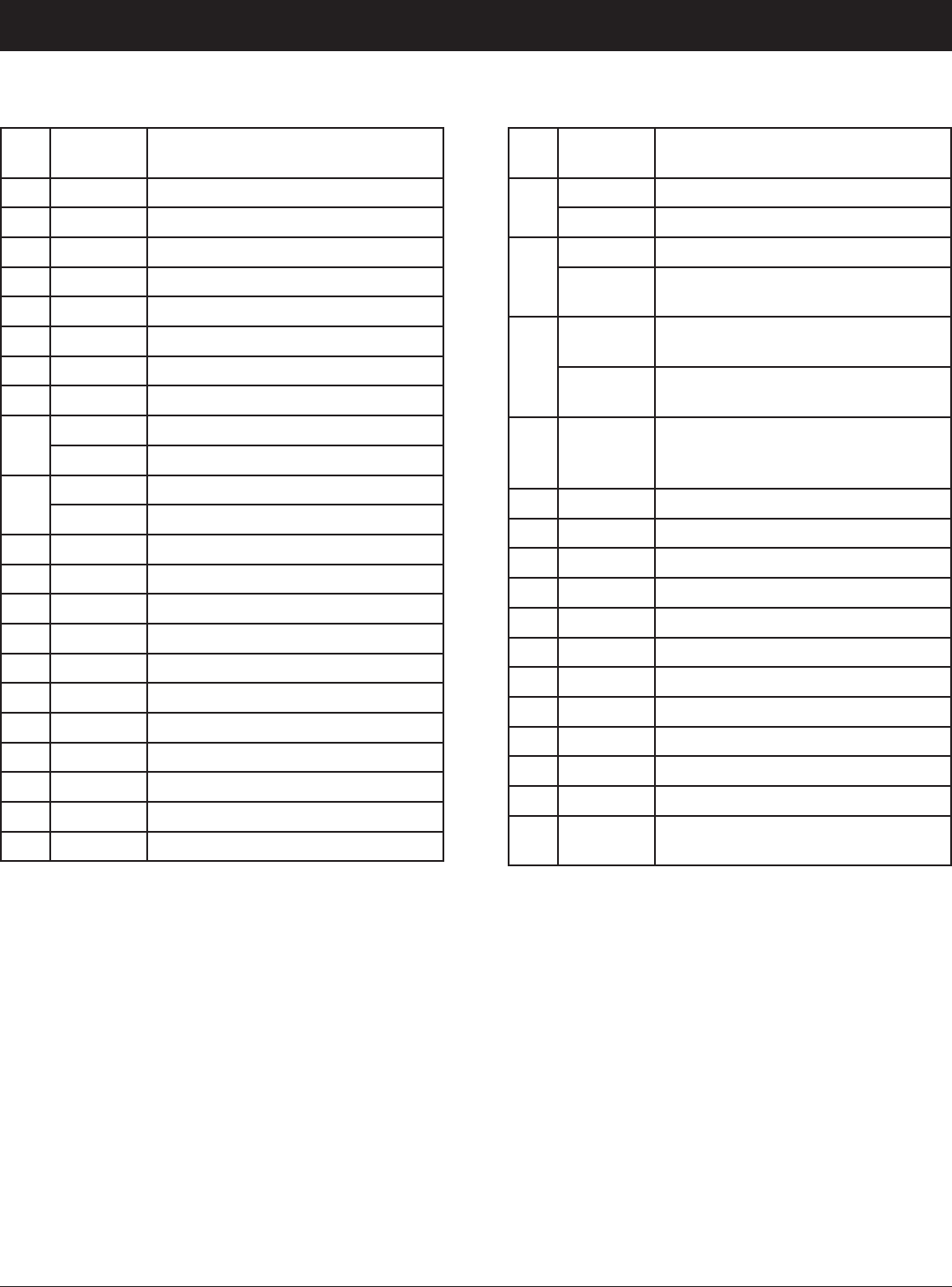
35
ECOWATER
S Y S T E M S
Repair Parts
VALVE PARTS LIST
Key
No.
Part No. Description
50 7224087 Screw, #8-32 x 1” (2 req.)
51 7286039 Motor (incl. 2 ea. of Key No. 50)
52 7231393 Motor Plate
53 0900857 Screw, #6-20 x 3/8” (3 req.)
54 7171250 Bearing
55 7283489 Cam & Gear
56 7169180 Clip, Drain
57 7172793 Drain Hose Adaptor
58
7170288 O-Ring, 15/16” x 1-3/16”, single
7336402 O-Ring, 15/16” x 1-3/16”, pack of 20
59
7178189 Flow Plug, 5 gpm, ETF2300PF10
7178202 Flow Plug, 7 gpm, ETF2300PF12
– 7185487 Seal Kit (includes Key Nos. 60-65)
60
á
O-Ring, 5/8” x 13/16”
61
á
O-Ring, 1-1/8” x 1-1/2”
62
á
O-Ring, 4-1/2” x 4-7/8”
63
á
Rotor Seal
64
á
Seal
65
á
Seal, Nozzle & Venturi
66 7174313 Bearing, Wave Washer
67 7185500 Rotor & Disc
68 7171187 Plug, Drain Seal
69 7129889 Spring
Key
No.
Part No. Description
70
7089306 Clip, 1”, single (2 req.)
7336428 Clip, 1”, pack of 20
71
7077642 Copper Tube, 1”, single (2 req.)
7344138
Copper Tube, 1”, pack of 10
(includes 10 ea. of Key No. 72)
72
7311127
O-Ring, 1-1/16” x 1-5/16”,
single (2 req.)
7336410
O-Ring, 1-1/16” x 1-5/16”,
pack of 20
– 7331703
Turbine & Support Assembly,
including 2 O-Rings (See Key No.
72) & 1 ea. of Key Nos. 73 & 74
73
á
Turbine Support & Shaft
74
á
Turbine
75 7171145 Valve Body
76 7270319 O-Ring, 1/4” x 3/8” (2 req.)
77 7100940 Plug
78 7081201 Retainer
79 7175199 Wave Washer
80 7171161 Valve Cover
81 7172997 Screw, #10 x 2-5/8” (8 req.)
82 7305150 Switch
83 7140738 Screw, #4-24 x 3/4” (2 req.)
84 7214383
Bypass Valve, 1” Ù (includes 2 ea.
of Key Nos. 70 & 72)
Ù Not included with the filter.
To order parts, call your local EcoWater dealer or go to
www.ecowater.com to locate a dealer in your area.

36
ECOWATER
S Y S T E M S
Warranty
LIMITED WARRANTY
EcoWater Systems LLC Advantage Warranty
Series ETF2300PF Water System
Congratulations! You have just purchased the highest quality water conditioning product on the market.
To whom is this warranty extended?
EcoWater Systems LLC warrants its products to the original owner and guarantees that the products will be free from defects
in materials and workmanship from the original date of installation.
How does my warranty work?
If, during the respective warranty period, a part proves, after inspection by EcoWater, to be defective, EcoWater will, at its
sole option repair or replace that part at no charge, other than normal shipping, installation or service charges.
What is covered by the warranty?
EcoWater Systems LLC guarantees that,
for the LIFETIME of the original owner, the MINERAL TANK will not rust, corrode, leak, burst, or in any other manner fail to
perform its proper functions, and that,
for a period of SEVEN (7) YEARS after installation, the ELECTRONIC FACEPLATE will be free of defects in materials and
workmanship and will perform its normal functions, and that,
for a period of FIVE (5) YEARS after installation, the VALVE BODY will be free of defects in materials and workmanship and
will perform its proper function, and that,
for a period of ONE (1) YEAR after installation, ALL OTHER PARTS will be free of defects in materials and workmanship and
will perform their normal functions.
How do I obtain warranty service?
Should you need service, your local, independent EcoWater Dealer is only a phone call away.
PHONE:____________________________________________________________
To obtain warranty service, notice must be given, within thirty (30) days of the discovery of the defect, to your local EcoWater
Systems dealer.
If I need a part replaced after the factory warranty expires, is the replacement part warranted?
Yes, EcoWater Systems LLC warrants FACTORY REPAIRS as well as all REPLACEMENT PARTS for a period of 90 DAYS.
This warranty does not include normal shipping, installation or service charges.
Are any additional warranties available?
We are pleased to say, YES! EcoWater Systems LLC sells an EXTENDED, PARTS ONLY WARRANTY for the ELECTRON-
ICS portion of your product. This warranty is called the “Perfect 10” and extends the warranty on the electronic FACEPLATE,
WIRING HARNESS, DRIVE MOTOR, POWER SUPPLY, POWER CORD, SENSOR HOUSING, and MICRO SWITCHES to a
total of TEN (10) YEARS from the date of original installation. Your local dealer will provide details regarding this warranty or
will refer you to the factory for additional information. Should your local dealer not offer this warranty, you may contact the
factory for additional information.* This guarantee may be subject to normal shipping and installation or service charges.
General Provisions
The above warranties are effective provided the water filter is operated at water pressures not exceeding 125 psi, and at
water temperatures not exceeding 120°F; provided further that the water filter is not subject to abuse, misuse, alteration, neg-
lect, freezing, accident or negligence; and provided further that the water filter is not damaged as the result of any unusual
force of nature such as, but not limited to, flood, hurricane, tornado or earthquake. EcoWater Systems LLC is excused if fail-
ure to perform its warranty obligations is the result of strikes, government regulation, materials shortages, or other circum-
stances beyond its control.
*THERE ARE NO WARRANTIES ON THE WATER FILTER BEYOND THOSE SPECIFICALLY DESCRIBED ABOVE. ALL IMPLIED WAR-
RANTIES, INCLUDING ANY IMPLIED WARRANTY OF MERCHANTABILITY OR OF FITNESS FOR A PARTICULAR PURPOSE, ARE DIS-
CLAIMED TO THE EXTENT THEY MIGHT EXTEND BEYOND THE ABOVE PERIODS. THE SOLE OBLIGATION OF ECOWATER SYS-
TEMS LLC UNDER THESE WARRANTIES IS TO REPLACE OR REPAIR THE COMPONENT OR PART WHICH PROVES TO BE DEFEC-
TIVE WITHIN THE SPECIFIED TIME PERIOD, AND ECOWATER IS NOT LIABLE FOR CONSEQUENTIAL OR INCIDENTAL DAMAGES.
NO ECOWATER DEALER, AGENT, REPRESENTATIVE, OR OTHER PERSON IS AUTHORIZED TO EXTEND OR EXPAND THE WAR-
RANTIES EXPRESSLY DESCRIBED ABOVE.
Some states do not allow limitations on how long an implied warranty lasts or exclusions or limitations of incidental or conse-
quential damage, so the limitations and exclusions in this warranty may not apply to you. This warranty gives you specific legal
rights, and you may have other rights which vary from state to state. This warranty applies to consumer-owned installations only.
