
Installation Instructions
Original Instructions
ArmorBlock I/O 8 Channel IO-Link Master Module
Catalog Number 1732E-8IOLM12R
Summary of Changes
This publication contains the following new or updated information. This list includes substantive updates only and is not intended to reflect all changes. Translated
versions are not always available for each revision.
Topic Page
Summary of Changes 1
Additional Resources 3
About the Module 3
Install the Module 5
Mount the Module 5
Connect the I/O, Network, and Auxiliary Cables to the Module 7
Configure the Module 8
Interpret LED Indicators 9
Specifications 10
Topic Page
Corrected module dimensions 6
Updated cordset catalog reference 8

2 Rockwell Automation Publication 1732E-IN001B-EN-E - July 2020
ArmorBlock I/O 8 Channel IO-Link Master Module Installation Instructions
ATTENTION: Read this document and the documents listed in the Additional Resources section about installation, configuration and operation of this equipment before you install, configure, operate or
maintain this product. Users are required to familiarize themselves with installation and wiring instructions in addition to requirements of all applicable codes, laws, and standards.
Activities including installation, adjustments, putting into service, use, assembly, disassembly, and maintenance are required to be carried out by suitably trained personnel in accordance with applicable
code of practice. If this equipment is used in a manner not specified by the manufacturer, the protection provided by the equipment may be impaired.
岤䠑㖈㸝鄳ծꂁ縨ծ乼⡲ㄤ絶䫡劥❡ㅷ霼ꢓ靀劥俒咓⟄⿺ Ⱖ➭餴彂 鿈ⴔⴀ涸剣Ⱒ霃㢊㸝鄳ծꂁ縨ㄤ乼⡲涸湱䎾俒咓կꤑ✫䨾剣鷓欽錞薴ծ岁䖒ㄤ叻ⲥ涸
湱Ⱒ銳宠⛓㢪欽䨪鵮䗳곢擿䜪㸝鄳ㄤ䱹絁霹僈կ
㸝鄳ծ靈侮ծ䫏鵘ծ⢪欽ծ絆鄳ծ䬒⽸ㄤ絶䫡瘝ぐ고乼⡲䗳곢歋絑鵂鷓䔲雲絅涸⚁⚌➃プ䭽撑鷓欽涸乼⡲錞薴㹊倶կ
㥵卓劢䭽撑ⵖ鸣㉁䭷㹁涸倰䒭⢪欽霪霃㢊ⴭ〳腊⠔䰀㹲霃㢊䲿⣘涸⥂䫡կ
ATENCIÓN: Antes de instalar, configurar, poner en funcionamiento o realizar el mantenimiento de este producto, lea este documento y los documentos listados en la sección Recursos adicionales acerca
de la instalación, configuración y operación de este equipo. Los usuarios deben familiarizarse con las instrucciones de instalación y cableado y con los requisitos de todos los códigos, leyes y estándares
vigentes.
El personal debidamente capacitado debe realizar las actividades relacionadas a la instalación, ajustes, puesta en servicio, uso, ensamblaje, desensamblaje y mantenimiento de conformidad con el
código de práctica aplicable. Si este equipo se usa de una manera no especificada por el fabricante, la protección provista por el equipo puede resultar afectada.
ATENÇÃO: Leia este e os demais documentos sobre instalação, configuração e operação do equipamento que estão na seção Recursos adicionais antes de instalar, configurar, operar ou manter este
produto. Os usuários devem se familiarizar com as instruções de instalação e fiação além das especificações para todos os códigos, leis e normas aplicáveis.
É necessário que as atividades, incluindo instalação, ajustes, colocação em serviço, utilização, montagem, desmontagem e manutenção sejam realizadas por pessoal qualificado e especializado, de
acordo com o código de prática aplicável.
Caso este equipamento seja utilizado de maneira não estabelecida pelo fabricante, a proteção fornecida pelo equipamento pode ficar prejudicada.
ВНИМАНИЕ: Перед тем как устанавливать, настраивать, эксплуатировать или обслуживать данное оборудование, прочитайте этот документ и документы,
перечисленные в разделе «Дополнительные ресурсы». В этих документах изложены сведения об установке, настройке и эксплуатации данного оборудования.
Пользователи обязаны ознакомиться с инструкциями по установке и прокладке соединений, а также с требованиями всех применимых норм, законов и
стандартов.
Все действия, включая установку, наладку, ввод в эксплуатацию, использование, сборку, разборку и техническое обслуживание, должны выполняться
обученным персоналом в соответствии с применимыми нормами и правилами.
Если оборудование используется не предусмотренным производителем образом, защита оборудования может быть нарушена.
:
ACHTUNG: Lesen Sie dieses Dokument und die im Abschnitt „Weitere Informationen“aufgeführten Dokumente, die Informationen zu Installation, Konfiguration und Bedienung dieses Produkts enthalten,
bevor Sie dieses Produkt installieren, konfigurieren, bedienen oder warten. Anwender müssen sich neben den Bestimmungen aller anwendbaren Vorschriften, Gesetze und Normen zusätzlich mit den
Installations- und Verdrahtungsanweisungen vertraut machen.
Arbeiten im Rahmen der Installation, Anpassung, Inbetriebnahme, Verwendung, Montage, Demontage oder Instandhaltung dürfen nur durch ausreichend geschulte Mitarbeiter und in Übereinstimmung mit
den anwendbaren Ausführungsvorschriften vorgenommen werden.
Wenn das Gerät in einer Weise verwendet wird, die vom Hersteller nicht vorgesehen ist, kann die Schutzfunktion beeinträchtigt sein.
ATTENTION : Lisez ce document et les documents listés dans la section Ressources complémentaires relatifs à l’installation, la configuration et le fonctionnement de cet équipement avant d’installer,
configurer, utiliser ou entretenir ce produit. Les utilisateurs doivent se familiariser avec les instructions d’installation et de câblage en plus des exigences relatives aux codes, lois et normes en vigueur.
Les activités relatives à l’installation, le réglage, la mise en service, l’utilisation, l’assemblage, le démontage et l’entretien doivent être réalisées par des personnes formées selon le code de pratique en
vigueur.
Si cet équipement est utilisé d’une façon qui n’a pas été définie par le fabricant, la protection fournie par l’équipement peut être compromise.
: , , , . ,
.
, , , , , , .
.
ATTENZIONE Prima di installare, configurare ed utilizzare il prodotto, o effettuare interventi di manutenzione su di esso, leggere il presente documento ed i documenti elencati nella sezione “Altre
risorse”, riguardanti l’installazione, la configurazione ed il funzionamento dell’apparecchiatura. Gli utenti devono leggere e comprendere le istruzioni di installazione e cablaggio, oltre ai requisiti previsti
dalle leggi, codici e standard applicabili.
Le attività come installazione, regolazioni, utilizzo, assemblaggio, disassemblaggio e manutenzione devono essere svolte da personale adeguatamente addestrato, nel rispetto delle procedure previste.
Qualora l’apparecchio venga utilizzato con modalità diverse da quanto previsto dal produttore, la sua funzione di protezione potrebbe venire compromessa.
DİKKAT: Bu ürünün kurulumu, yapılandırılması, işletilmesi veya bakımı öncesinde bu dokümanı ve bu ekipmanın kurulumu, yapılandırılması ve işletimi ile ilgili İlave Kaynaklar bölümünde yer listelenmiş
dokümanları okuyun. Kullanıcılar yürürlükteki tüm yönetmelikler, yasalar ve standartların gereksinimlerine ek olarak kurulum ve kablolama talimatlarını da öğrenmek zorundadır.
Kurulum, ayarlama, hizmete alma, kullanma, parçaları birleştirme, parçaları sökme ve bakım gibi aktiviteler sadece uygun eğitimleri almış kişiler tarafından yürürlükteki uygulama yönetmeliklerine uygun
şekilde yapılabilir.
Bu ekipman üretici tarafından belirlenmiş amacın dışında kullanılırsa, ekipman tarafından sağlanan koruma bozulabilir.
岤䠑✲갪㖈㸝酤ծ鏤㹁ծ乼⡲䧴笞隋劥欴ㅷ锝⯓ꠖ隡姼俒⟝⟄⿺倴 չⰦ➭顺彂պ畎眎⚥剣ꡠ㸝酤ծ鏤㹁莄乼⡲姼鏤⪓涸俒⟝կ⢪欽罏䗳갭擿䜪㸝酤ㄤꂁ箁䭷
爙⚛痗ざ䨾剣岁鋊ծ岁䖒ㄤ垥彋銳宠կ
⺫䭍㸝酤ծ锄侮ծ❜➰⢪欽ծ⢪欽ծ穉酤ծ䬒⽸ㄤ笞隋瘝⹛⡲鿪䗳갭❜歋䊺竤麔黟殹鎯箻涸➃㆞鹍遤⟄痗ざ黟欽涸㻜⡲岁鋊կ
㥵卓㼞鏤⪓欽倴ꬋ醢鸣㉁䭷㹁涸欽鸀儗〳腊剚鸣䧭鏤⪓䨾䲿⣘涸⥂隋⸆腊「䴦կ
POZOR: Než začnete instalovat, konfigurovat či provozovat tento výrobek nebo provádět jeho údržbu, přečtěte si tento dokument a dokumenty uvedené v části Dodatečné zdroje ohledně instalace,
konfigurace a provozu tohoto zařízení. Uživatelé se musejí vedle požadavků všech relevantních vyhlášek, zákonů a norem nutně seznámit také s pokyny pro instalaci a elektrické zapojení.
Činnosti zahrnující instalaci, nastavení, uvedení do provozu, užívání, montáž, demontáž a údržbu musí vykonávat vhodně proškolený personál v souladu s příslušnými prováděcími předpisy.
Pokud se toto zařízení používá způsobem neodpovídajícím specifikaci výrobce, může být narušena ochrana, kterou toto zařízení poskytuje.
UWAGA: Przed instalacją, konfiguracją, użytkowaniem lub konserwacją tego produktu należy przeczytać niniejszy dokument oraz wszystkie dokumenty wymienione w sekcji Dodatkowe źródła
omawiające instalację, konfigurację i procedury użytkowania tego urządzenia. Użytkownicy mają obowiązek zapoznać się z instrukcjami dotyczącymi instalacji oraz oprzewodowania, jak również z
obowiązującymi kodeksami, prawem i normami.
Działania obejmujące instalację, regulację, przekazanie do użytkowania, użytkowanie, montaż, demontaż oraz konserwację muszą być wykonywane przez odpowiednio przeszkolony personel zgodnie z
obowiązującym kodeksem postępowania.
Jeśli urządzenie jest użytkowane w sposób inny niż określony przez producenta, zabezpieczenie zapewniane przez urządzenie może zostać ograniczone.
OBS! Läs detta dokument samt dokumentet, som står listat i avsnittet Övriga resurser, om installation, konfigurering och drift av denna utrustning innan du installerar, konfigurerar eller börjar använda
eller utföra underhållsarbete på produkten. Användare måste bekanta sig med instruktioner för installation och kabeldragning, förutom krav enligt gällande koder, lagar och standarder.
Åtgärder som installation, justering, service, användning, montering, demontering och underhållsarbete måste utföras av personal med lämplig utbildning enligt lämpligt bruk.
Om denna utrustning används på ett sätt som inte anges av tillverkaren kan det hända att utrustningens skyddsanordningar försätts ur funktion.
LET OP: Lees dit document en de documenten die genoemd worden in de paragraaf Aanvullende informatie over de installatie, configuratie en bediening van deze apparatuur voordat u dit product
installeert, configureert, bediend of onderhoudt. Gebruikers moeten zich vertrouwd maken met de installatie en de bedradingsinstructies, naast de vereisten van alle toepasselijke regels, wetten en
normen.
Activiteiten zoals het installeren, afstellen, in gebruik stellen, gebruiken, monteren, demonteren en het uitvoeren van onderhoud mogen uitsluitend worden uitgevoerd door hiervoor opgeleid personeel en
in overeenstemming met de geldende praktijkregels.
Indien de apparatuur wordt gebruikt op een wijze die niet is gespecificeerd door de fabrikant, dan bestaat het gevaar dat de beveiliging van de apparatuur niet goed werkt.
Rockwell Automation Publication 1732E-IN001B-EN-E - July 2020 3
ArmorBlock I/O 8 Channel IO-Link Master Module Installation Instructions
Additional Resources
If you would like a manual, you can:
• download a free electronic version from the Internet: rok.auto/literature
• purchase a printed manual by contacting your local Allen-Bradley distributor or Rockwell Automation representative
About the Module
The 1732E ArmorBlock® EtherNet/IP™ provides eight channels that can be individually configured as IO-Link master or as a standard digital I/O module. The IO-Link channel
master module can be configured to fit any IO-Link and/or discrete application.
In IO-Link mode, the module supports eight channels for IO-Link master communication with IO-Link compatible devices. In standard digital I/O mode, the module supports
eight channels of digital input or output. Standard digital input channels support IEC61131-2 type 1 input. Channels can also be disabled if not in use.
You must use this module with RSLogix 5000® or Studio 5000 Logix Designer® application, version 20 or later. Use this diagram to identify the external features of the
module.
Environment and Enclosure
ATTENTION: This equipment is intended for use in overvoltage Category II applications (as defined in IEC 60664-1), at altitudes up to 2000 m (6562 ft)
without derating.
This equipment is considered Group 1, Class A industrial equipment according to IEC/CISPR 11. Without appropriate precautions, there may be
difficulties with electromagnetic compatibility in residential and other environments due to conducted and radiated disturbances.
This equipment is supplied as enclosed equipment. It should not require additional system enclosure when used in locations consistent with the
equipment Enclosure Type Ratings. Subsequent sections of this publication may contain more information regarding specific enclosure type ratings,
beyond what this product provides, that are required to comply with certain product safety certifications.
In addition to this publication, see:
• Industrial Automation Wiring and Grounding Guidelines, Rockwell Automation publication 1770-4.1
, for additional install requirements.
• NEMA Standard 250 and IEC 60529, as applicable, for explanations of the degrees of protection provided by different types of enclosure.
Preventing Electrostatic Discharge
ATTENTION: This equipment is sensitive to electrostatic discharge, which can cause internal damage and affect normal operation. Follow these
guidelines when you handle this equipment:
• Touch a grounded object to discharge potential static.
• Wear an approved grounding wriststrap.
• Do not touch connectors or pins on component boards.
• Do not touch circuit components inside the equipment.
• Use a static-safe workstation, if available.
• Store the equipment in appropriate static-safe packaging when not in use.
ATTENTION: To comply with UL restrictions, this equipment and all connected I/O must be powered from a source compliant with the following:
Safety Extra Low Voltage (SELV)
ATTENTION: To comply with CE Low Voltage Directive (LVD), this equipment and all connected I/O must be powered from a source compliant with the
following: Safety Extra Low Voltage (SELV)
Resource Description
ArmorBlock IO-Link Master Module Wiring Diagrams 1732E-WD008
Pinout guide wiring diagram for the ArmorBlock IO-Link Master module.
ArmorBlock 8 Channel IO-Link Master Module User Manual 1732E-
UM007
A detailed description of module functionality, configuration, installation procedure and
information on how to use the 1732E ArmorBlock EtherNet/IP.
Industrial Automation Wiring and Grounding Guidelines, publication
1770-4.1.
More information on proper wiring and grounding techniques.
4 Rockwell Automation Publication 1732E-IN001B-EN-E - July 2020
ArmorBlock I/O 8 Channel IO-Link Master Module Installation Instructions
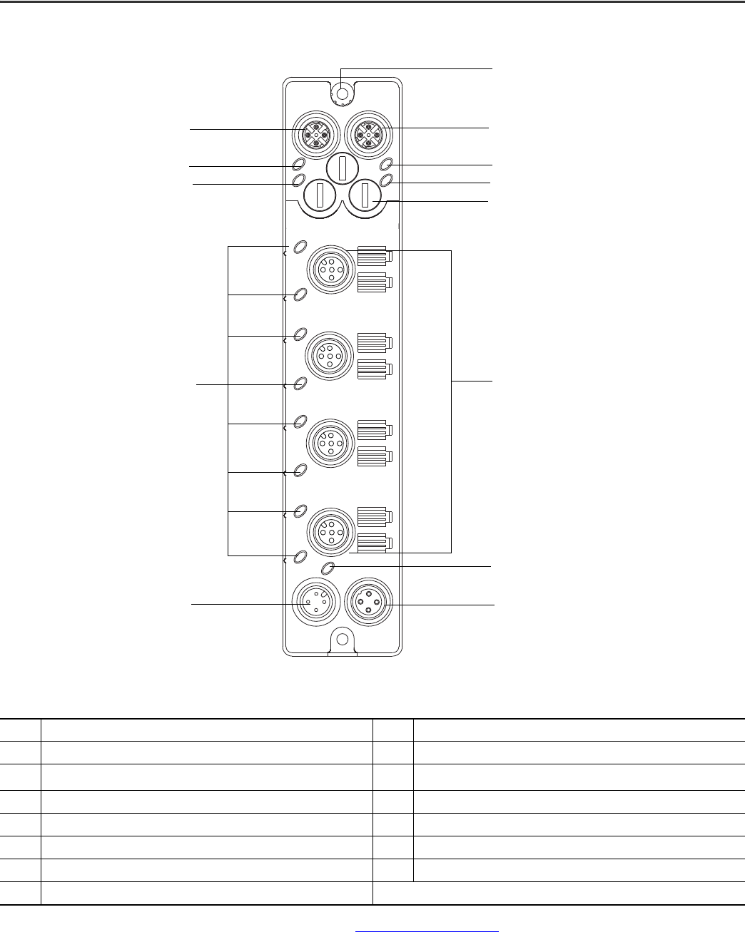
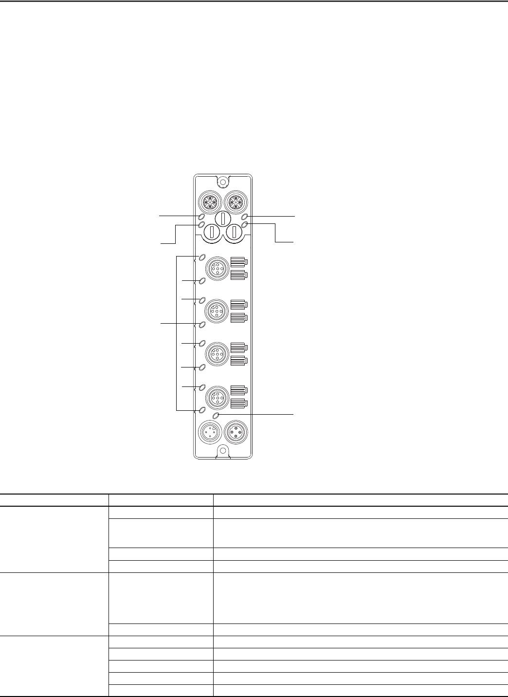
Module Identification
Description Description
1 EtherNet/IP D-code M12 connector 8 Auxiliary power indicator
2
Function earth
(1)
(1) Functional Earth grounds the I/O block’s EtherNet/IP communication circuitry, which is designed to mitigate the effect of noise on the network. The device requires a solid earth ground
connection, either through a metal screw to a grounded metal panel or through a wire. See
EtherNet/IP Connector on page 7 for connections.
9Micro-style power out
3 EtherNet/IP D-code M12 connector 10 Micro-style power in
4 Link 2 status indicator 11 Channel I/O or digital I/O status indicators
5 Network status indicator 12 Module status indicator
6 Node address switches 13 Link 1 status indicator
7 Micro-style I/O connectors
7
9
1
4
5
3
6
13
12
10
11
2
8
Rockwell Automation Publication 1732E-IN001B-EN-E - July 2020 5
ArmorBlock I/O 8 Channel IO-Link Master Module Installation Instructions
Install the Module
To install the module:
• Set the network address.
• Mount the module.
• Connect the I/O, Network, and Auxiliary cables to the module.
Set the Network Address
The I/O block ships with the rotary switches set to 999 and DHCP enabled.
To change the network address, you can do one of the following:
• adjust the switch on the front of the module.
• use a Dynamic Host Configuration Protocol (DHCP) server, such as Rockwell Automation BootP/DHCP.
• retrieve the IP address from nonvolatile memory.
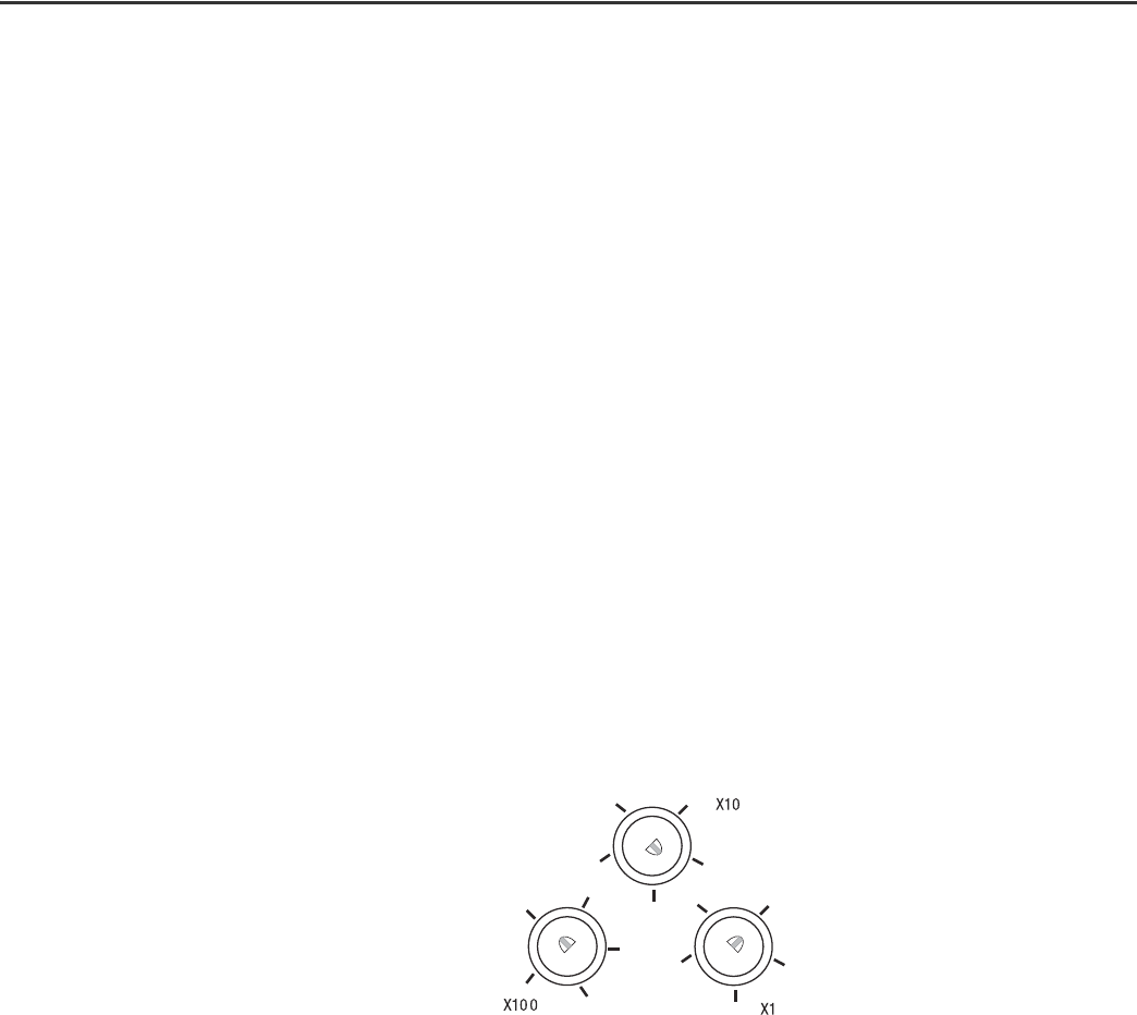
The I/O block reads the switches first to determine if the switches are set to a valid number. To set the network address:
1. Remove power.
2. Remove the switch dust caps.
3. Rotate the three (3) switches on the front of the module using a small blade screwdriver.
4. Line up the small notch on the switch with the number setting you wish to use.
Valid settings range from 001…254.
5. Replace switch dust caps. Make sure not to over tighten.
6. Reapply power.
Set Network Address
When the switches are set to a valid number, the I/O block’s IP address is 192.168.1.xxx (where xxx represents the number set on the switches). The I/O block’s subnet mask
is 255.255.255.0 and the gateway address is set to 0.0.0.0. When the I/O block uses the network address set on the switches, the I/O block does not have a host name
assigned to it or use any Domain Name Server.
If the switches are set to an invalid number (for example, 000 or a value greater than 254 excluding 888), the I/O block checks to see if DHCP is enabled. If DHCP is enabled,
the I/O block asks for an address from a DHCP server. The DHCP server also assigns other Transport Control Protocol (TCP) parameters.
If DHCP is not enabled, the I/O block uses the IP address (along with other TCP configurable parameters) stored in nonvolatile memory.
Mount the Module
Two sets of mounting holes are used to mount the module directly to a panel or machine. Mounting holes accommodate #8 (M4) pan head screws. The torque specification
is 0.68 N•m (6 lb•in.).
0
2
4
6
8
0
2
4
6
8
0
2
4
6
8
Example shows default
node address set at 163.
Note: You need to remove the
protective switch dust caps before you
can adjust the address settings.
6 Rockwell Automation Publication 1732E-IN001B-EN-E - July 2020
ArmorBlock I/O 8 Channel IO-Link Master Module Installation Instructions
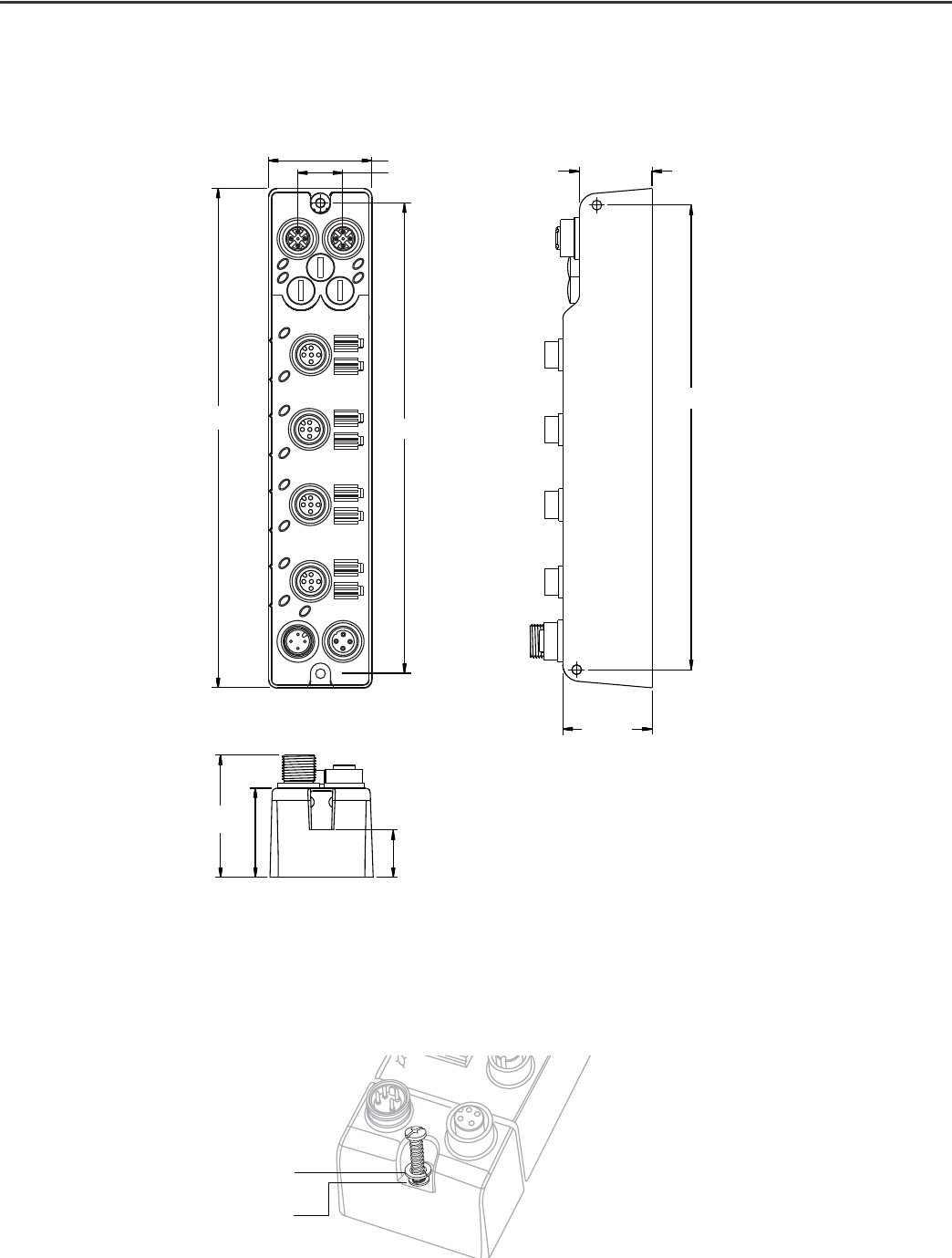
Product Dimensions
See the mounting dimensions illustration to help you mount the module.
Module Dimensions
Mount the Module in High Vibration Areas
If you mount the module in an area that is subject to shock or vibration, we recommend you use a flat and a lock washer to mount the module. Mount the flat and the lock
washer as shown in the mounting illustration. Torque the mounting screws to 0.68 N•m (6 lb•in.).
High Vibration Area Mounting
25.6
(1.01)
166.5 (6.56)
32 (1.26)
Side Mounting
32 (1.26 )
43.3 (1.70)
Front Mounting
18 (0.71)
37 (1.46)
16.2 (0.64)
168.6 (6.63)
179 (7.05)
Measurements are in millimeters (inches)
Lock washer
Flat washer
Rockwell Automation Publication 1732E-IN001B-EN-E - July 2020 7
ArmorBlock I/O 8 Channel IO-Link Master Module Installation Instructions
Connect the I/O, Network, and Auxiliary Cables to the Module
The 1732E-8IOLM12R ArmorBlock EtherNet/IP module has a 5-pin micro-style I/O connectors. We provide caps to cover the unused connectors on your module. Connect the
quick-disconnect cord sets you selected for your module to the appropriate ports.
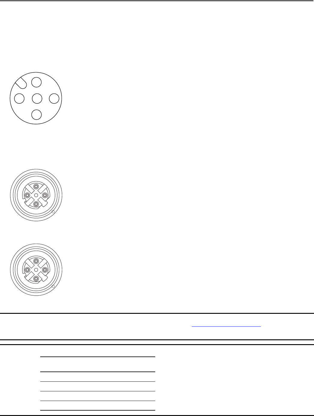
I/O Connectors
Micro-style 5-pin I/O Female Connector
EtherNet/IP Connector
D-Code Micro Network Female Connector
IMPORTANT
Use the 1585D–M4DC–H: Polyamide small body unshielded mating connectors for the D-Code M12 female network connector.
Note that the distance between the center of each Ethernet connector is 16.2 mm (refer to
Module Dimensions on page 6). Rockwell Automation
recommends the use of suitable cable based on this measurement. Some of the recommended cables are 1585D-M4TBJM-x and 1585D-M4TBDM-x
for daisy chains.
IMPORTANT
Use two twisted-pair CAT5E UTP or STP cables
3
4
1
2
5
(View into connector)
Pin 1 Sensor source voltage
Pin 2 IO-Link, Input/output B
Pin 3 Return
Pin 4 IO-Link, Input/output A
Pin 5 PE
(View into connector 1)
Pin 1 M12_Tx+
Pin 2 M12_Rx+
Pin 3 M12_Tx-
Pin 4 M12_Rx-
Pin 5 Connector shell shield GND
4
2
31
5
4
2
31
5
(View into connector 2)
Pin 1 M12_Rx+
Pin 2 M12_Tx+
Pin 3 M12_Rx-
Pin 4 M12_Tx-
Pin 5 Connector shell shield GND
D-Code
M12 Pin
Wire Color Signal
8-way Modular
RJ45 Pin
1 White-orange TX+ 1
2 White-green RX+ 3
3OrangeTX-2
4 Green RX- 6

8 Rockwell Automation Publication 1732E-IN001B-EN-E - July 2020
ArmorBlock I/O 8 Channel IO-Link Master Module Installation Instructions
Configure the Module
See the illustration for configuration operations.
Configure Operations
See Essential Components Selection Guide, publication EC-CA100
, for Rockwell Automation cable and cord set offerings or use the configuration tools available at
rok.auto/systemtools.
Auxiliary Power Connectors
Attach the micro-style 4-pin connector to the micro-style 4-pin receptacle as shown below.
Auxiliary Power Micro-style 4-Pin Receptacles
The power required by the module is based on a 4-pin micro-style connector system. The module receives its required power through the male connector on the left. A
female connector on the right is also provided so that power can be daisy chained from module to module.
IMPORTANT
The maximum current that any pin on the power connectors can carry is 4 A.
EtherNet/IP D-code
M12 connector
EtherNet/IP D-code
M12 connector
Network address
switches
Power connector
Power connector
M12 style
I/O connectors
1
4
3
2
Male Input Female Output
(View into receptacle)
Pin 1 Auxiliary power+
Pin 2 Module/sensor power+
Pin 3 Module/sensor power-
Pin 4 Auxiliary power-
3
4
1
2
Rockwell Automation Publication 1732E-IN001B-EN-E - July 2020 9
ArmorBlock I/O 8 Channel IO-Link Master Module Installation Instructions
The module requires two 24V DC (nominal) supplies. These supplies are called the Module Power and the Auxiliary Power. The module power powers the microprocessor and
Ethernet portions of the module. The Auxiliary Power provides power for the Digital Outputs, the Digital Inputs, and the Sensor Voltage.
Internally, the Module Power and Auxiliary Power are isolated from each other.
Interpret LED Indicators
This module has the following indicators:
• Module, Network, and Link status indicators for EtherNet/IP
• Power status indicator
• Individual channel status indicators for inputs and outputs
Status Indicators
Indicator Status for Module
Indicator Status Description
Module status
Off No power applied to the device.
Flashing green
The device has not been configured.
If Master Sync Enable bit is set, and the device is not synchronized to a PTP master, the device is
not configured.
Green Device operating normally.
Red Unrecoverable fault – may require device replacement.
Module status
Flashing red
One or more recoverable minor faults detected. Possible minor faults indicated are:
• The device is performing a firmware flash update.
• The IO-Link stack is faulted.
• IP address switches do not match configuration in use
• The device has completed a reset to factory default request due to the switches being set to 888 at power-
up, and a power cycle is required.
Flashing red/green The module is performing POST (power on self test), which completes within 30 s.
Network status
Off The device is not initialized or the module does not have an IP address.
Flashing green The device has an IP address, but no connections are established.
Green The device is online, has an IP address, and at least one connection is established.
Flashing red One or more connections have timed out.
Red The module has detected that its IP address is already in use.
Link 2 status indicator
Network status indicator
Module status indicator
I/O status indicators
Auxiliary Power status indicator
Link 1 status indicator

10 Rockwell Automation Publication 1732E-IN001B-EN-E - July 2020
ArmorBlock I/O 8 Channel IO-Link Master Module Installation Instructions
Specifications
Link status
Off No link established.
Green Link established on indicated port at 100 Mbps.
Flashing green Link activity present on indicated port at 100 Mbps.
Yellow Link established on indicated port at 10 Mbps.
Flashing yellow Link activity present on indicated port at 10 Mbps.
Auxiliary power status
Off No power to device or input not valid.
Green Power applied to device.
Channel LED Indicator Status for Module
Indicator Status Mode Description
Channel LED status
Off Both Output/input is in off state, is in IO-Link mode but is not energized.
Yellow Standard I/O Output/input is in on state.
Flashing green IO-Link Port startup or IO-Link device not found.
Green IO-Link IO-Link enabled.
Flashing red IO-Link IO-Link device connected to channel does not match configured electronic key.
Red Both Output is shorted or overcurrent condition exists.
IMPORTANT
The Module Status LED indicator will flash red and green for a maximum 30 s while the module completes its POST (power on self test).
General Specifications
Attribute Value
Number of inputs/outputs 8 Type 1 defined, sinking
Communication rate, Ethernet
10/100 Mbps, Full or half-duplex
100 meter per segment
Communication rate, IO-Link 4.8 kB; 38.4 kB; 230.4 kB
Voltage, power max 28.8V DC
Voltage, power min 20V DC
Current, Module Power, max per module 100 mA @ 24V DC
Current, Auxiliary Power, module only (no Digital Output loads, no Sensor
Voltage Loads, and no power daisy-chain loads)
30 mA @ 24V DC
Current, Auxiliary Power, max per module (module plus Digital Output
Loads, plus Sensor Voltage Loads, plus power daisy-chain loads)
4 A
Isolation voltage
50V (continuous), Basic Insulation Type, outputs and output power to Network. 50V Basic Insulation Type between
the field network connections. 50V Basic Insulation Type between module power and output power.
No isolation between individual I/Os or between I/Os and output power. No isolation between both network
channels at the CPU/DLR power side.
Status indicators
Module status – red/green
Network status – red/green
Link status – green/yellow
Power status – green
I/O LED – yellow/red
IO-Link LED – green/red
Dimensions, approx, HxWxD 179 x 37 x 27 mm (7.05 x 1.46 x 1.06 in.)
Pilot Duty Rating DC-14
Weight approx 0.34 kg (0.75 lb)
Wiring category
(1)
(1) Use this Conductor Category information for planning conductor routing. See publication 1770-4.1, Industrial Automation Wiring and Grounding Guidelines.
1 – on signal ports
1 – on power ports
1 – on communication ports
Enclosure type rating Meets IP65/66/67/69K
Indicator Status for Module
Indicator Status Description

Rockwell Automation Publication 1732E-IN001B-EN-E - July 2020 11
ArmorBlock I/O 8 Channel IO-Link Master Module Installation Instructions
1732E ArmorBlock EtherNet/IP – Standard Digital Input
Attribute Value
On-state voltage min 15V DC
On-state current min 2.0 mA
Off-state voltage max 5V DC
Off-state current max 1.5 mA
Input delay time Software configurable
Sensor Source Voltage (SSV) voltage min 1V
Sensor Source Voltage (SSV) available current, per channel max 500 mA
Sensor Source Voltage (SSV) available current, per connector max 1 A
Short circuit detection Per I/O connector (two shared channels per I/O connector)
1732E ArmorBlock EtherNet/IP – Standard Digital Output
Attribute Value
On-state voltage min 15V DC
On-state voltage max 28.8V DC
On-state voltage nom 24V DC
On-state current, per output max 250 mA
On-state current, total for all channels combined max 2 A (250 mA X 8 outputs)
Off-state current leakage, per output max 500 <Symbols>m<Symbols>A
Surge current, per output max 0.3 A for 10 ms, repeatable every 3 seconds.
Short circuit detection Per channel
Environmental Specifications
Attribute Value
Temperature, operating
IEC 60068-2-1 (Test Ad, Operating Cold),
IEC 60068-2-2 (Test Bd, Operating Dry Heat),
IEC 60068-2-14 (Test Nb, Operating Thermal Shock):
-20…+60 °C (-4…+140 °F)
Temperature, ambient rating (UL) 60 °C (140 °F)
Temperature, nonoperating
IEC 60068-2-1 (Test Ab, Unpackaged Nonoperating Cold),
IEC 60068-2-2 (Test Bb, Unpackaged Nonoperating Dry Heat),
IEC 60068-2-14 (Test Na, Unpackaged Nonoperating Thermal Shock):
-40…+85 °C (-40…+185 °F)
Relative humidity
IEC 60068-2-30 (Test Db, Unpackaged Damp Heat):
5…95% noncondensing
Vibration
IEC 60068-2-6 (Test Fc, Operating):
5 g @ 10…500 Hz
Shock, operating
IEC 60068-2-27 (Test Ea, Unpackaged Shock):
30 g
Shock, nonoperating
IEC 60068-2-27 (Test Ea, Unpackaged Shock):
50 g
Emissions
CISPR 11 (IEC 61000-6-4):
Class A
ESD immunity
IEC 61000-4-2:
6 kV contact discharges
8 kV air discharges
Radiated RF immunity
IEC 61000-4-3:
10V/m with 1 kHz sine-wave 80% AM from 80...1000 MHz
10V/m with 1 kHz sine-wave 80% AM from 1000...2000 MHz
10V/m with 200 Hz SQ-wave 100% Pulse modulated at 50% duty cycle @ 900 MHz Pulse
10V/m with 200 Hz 50% Pulse 100% AM @ 1890 MHz Pulse
10V/m with 1 kHz sine-wave 80% AM from 2000…2700 MHz

12 Rockwell Automation Publication 1732E-IN001B-EN-E - July 2020
ArmorBlock I/O 8 Channel IO-Link Master Module Installation Instructions
EFT/B immunity
IEC 61000-4-4:
±3 kV at 5 kHz on power ports
±3 kV at 5 kHz on signal ports
Surge transient immunity
IEC 61000-4-5:
±1 kV line-line(DM) and ±2 kV line-earth(CM) on power ports
±1 kV line-earth(CM) on signal ports
±2 kV line-earth(CM) on communication ports
Conducted RF immunity
IEC 61000-4-6:
10V rms with 1 kHz sine-wave 80% AM from 150 kHz…80 MHz
Certifications
Certification (when product is marked)
(1)
Value
c-UR-us UL Recognized Component, certified for US and Canada. See UL File E322657.
CE
EMC Directive 2014/30/EU Directive, compliant with:
EN 61326-1; Meas./Control/Lab., Industrial Requirements
EN 61000-6-2; Industrial Immunity
EN 61000-6-4; Industrial Emissions
EN 61131-2; Programmable Controllers (Clause 8, Zone A & B)
RCM
Australian Radiocommunications Act, compliant with:
AS/NZS CISPR11; Industrial Emissions.
KC
Korean Registration of Broadcasting and Communications Equipment, compliant with:
Article 58-2 of Radio Waves Act, Clause 3
EtherNet/IP ODVA conformance tested to EtherNet/IP specifications.
(1) See the Product Certification link at rok.auto/certifications
for Declaration of Conformity, Certificates, and other certification details.
Environmental Specifications
Attribute Value
Publication 1732E-IN001B-EN-E - July 2020 | Supersedes Publication 1732E-IN001A-EN-E-July 2016
Copyright © 2020 Rockwell Automation, Inc. All rights reserved.
Rockwell Otomasyon Ticaret A.Ş. Kar Plaza İş Merkezi E Blok Kat:6 34752 İçerenköy, İstanbul, Tel: +90 (216) 5698400 EEE Yönetmeliğine Uygundur
Allen-Bradley, ArmorBlock, expanding human possibility, FactoryTalk, RSLogix 5000, Rockwell Automation, Studio 5000 Logix Designer, and TechConnect
are trademarks of Rockwell Automation, Inc.
EtherNet/IP is a trademark of ODVA, Inc.
Trademarks not belonging to Rockwell Automation are property of their respective companies.
Your comments help us serve your documentation needs better. If you have any suggestions on how to improve our content, complete the form at rok.auto/docfeedback.
For technical support, visit
rok.auto/support.
Waste Electrical and Electronic Equipment (WEEE)
Rockwell Automation maintains current product environmental compliance information on its website at rok.auto/pec.
At the end of life, this equipment should be collected separately from any unsorted municipal waste.
Rockwell Automation Support
Use these resources to access support information.
Documentation Feedback
Your comments help us serve your documentation needs better. If you have any suggestions on how to improve our content, complete the form at rok.auto/docfeedback.
Technical Support Center Find help with how-to videos, FAQs, chat, user forums, and product notification updates. rok.auto/support
Knowledgebase Access Knowledgebase articles. rok.auto/knowledgebase
Local Technical Support Phone Numbers Locate the telephone number for your country. rok.auto/phonesupport
Literature Library Find installation instructions, manuals, brochures, and technical data publications. rok.auto/literature
Product Compatibility and Download Center
(PCDC)
Download firmware, associated files (such as AOP, EDS, and DTM), and access product
release notes.
rok.auto/pcdc
