T&B
®
Cord &
Cable Fittings
In this section...
T&B
®
Cord & Cable Fittings
STAR TECK
®
Teck Cable Fittings ................................. E-122–E-130
Spin-On
®
Series Fittings and Accessories ...................E-131–E-132
Metallic Liquidtight Cord and Cable Connectors ..........E-133–E-142
Non-Metallic Liquidtight Cord Connectors ...................E-143–E-146
Service Entrance Cable Fittings ................................... E-147–E-151
MC and AC Cable Fittings ............................................E-152–E-158
Tray Cable Fittings ................................................................. E-159
Non-Metallic Sheathed Cable Fittings..........................E-160–E-164
www.tnb.com
United States
Tel: 901.252.8000
800.816.7809
Fax: 901.252.1354
Technical Services
Tel: 888.862.3289
E-122
STAR TECK
®
Teck Cable Fittings
Conduit & Fittings — T&B
®
Cord & Cable Fittings
STAR TECK
®
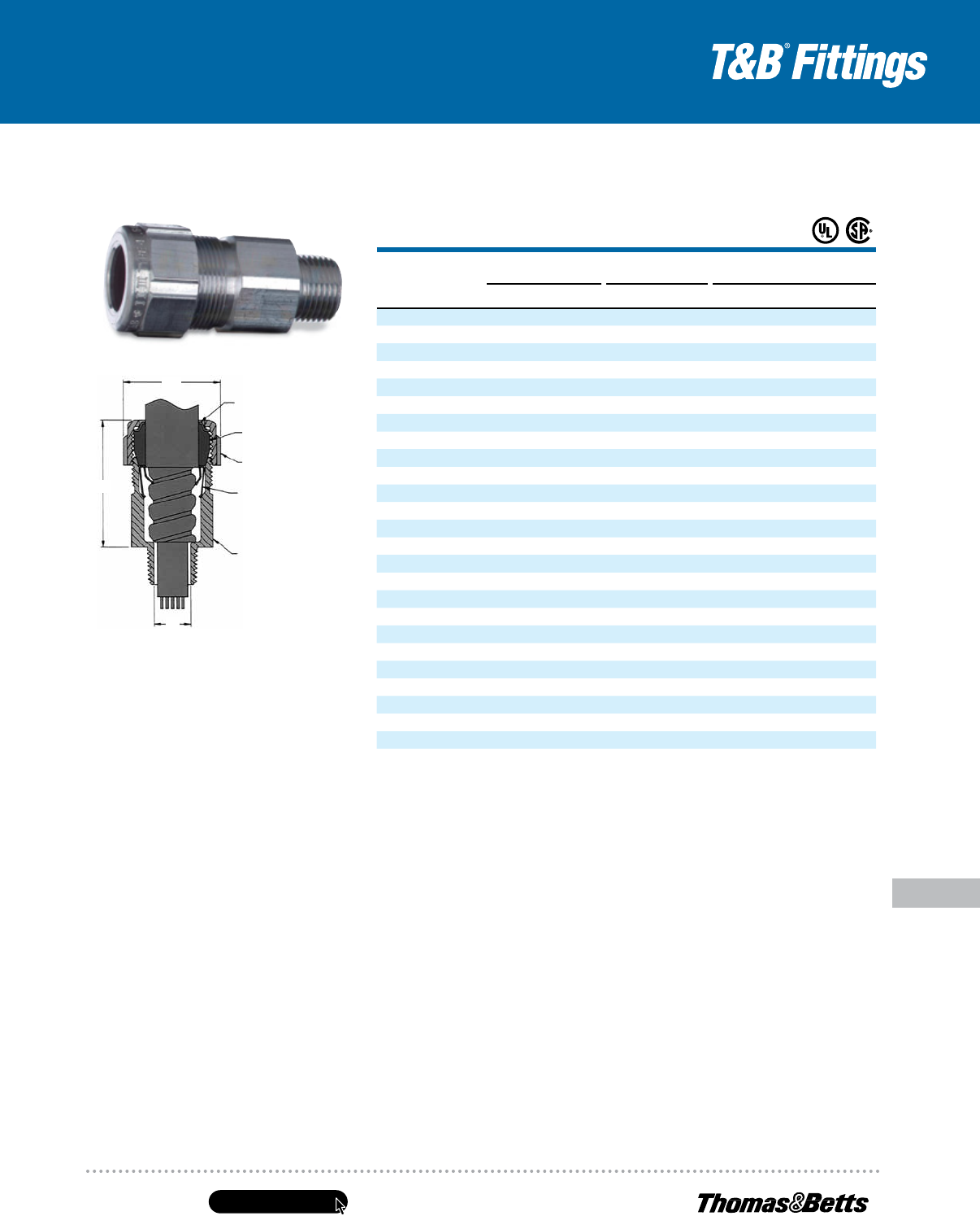
STE/STEX Series Cable Fittings
The STAR TECK
®
STE cable fitting series is designed for optimum integrity in ordinary applications.
TheSTEX series is specially designed for classified hazardous areas. Both are designed to stand
up tothe harshest and most corrosive environment.
Application
• Provides means for passing jacketed
metal clad cables through a bulkhead
or enclosure in industrial and
hazardous areas. (These fittings are
suitable for hazardous areas when
used with T&B sealing compound)
• Forms a mechanical grip and water-
and/or oil-resistant termination
• Provides grounding continuity
ofcable armor
Features
• Powergrip grounding ring
• Removable armor-stop for greater
cable ranges
• Built-in sealing device
• Elastomeric collar ring/ bushing
for greater cable ranges
• Built-in jacket stripping gauge
ongland nut
• Gland nut can be tightened
with hammer and screwdriver
Range
• STAR TECK EXTREME
®
fittings are
designed to accommodate a broad
range of cables. Each hub range
overlaps the adjacent hub range,
thereby minimizing the possibility
ofmismatched cables and fittings
inthe field. They are available in
hub sizes from
1
⁄2" to 4" and will
handle outer jacket diameters
form .525" to 4.340"
Materials
Aluminum is standard material
Add suffix “S” for steel with zincplating
Add suffix “PVC” for corrosion-resistant PVC
coating
Add suffix “SS” for
stainless steel material
Cable Type
JMC, MC-HL, Teck
Environment Classification
STE* Series
–Ordinary Location
–Class I, Division 2
†
–NEMA 4, 4X (stainless steel), 6P
–STE050 – STE200
NEMA 6P
–STE250 – 400
NEMA 4
–STE050 – 400
NEMA 4X (stainless steel)
STEX** Series
–Class I, Division 1, Groups A, B, C, D
–Class II, Division 1, Groups E, F, G
–Class III
–NEMA 4, 4X (stainless steel), 6P
UL Listed for Direct Burial when
made from stainless steel material
Suitable for use in wet locations and concrete
tight (steel) applications per UL 514B
UL File No. E82038/E38947
CSA File No. LR638/LR23086
* These fittings are suitable for Class I hazardous locations
when used in combination with a certified Class I
hazardous location sealing fitting.
** Meets NEC
®
Class I Division 2/Zone 2 and Class II
Division 2/Zone 22 requirements when installed as per
Articles 501.10/505.15 and 502.10/506.15
*** May be used in hazardous areas with approved MC‑HL
orTeck cable (or equal) when installed in accordance
withNEC
®
/CEC requirements.
Not applicable to all STEX series.
NEC and National Electrical Code are registered trademarks
of the National Fire Protection Association, Inc.
Greater Cable
Range + Fewer
PartNumbers =
Less Inventory!
Greater Cable
Range + Fewer
PartNumbers =
Less Inventory!
United States
Tel: 901.252.8000
800.816.7809
Fax: 901.252.1354
Technical Services
Tel: 888.862.3289
www.tnb.com
E-123
Conduit & Fittings — T&B
®
Cord & Cable Fittings
STAR TECK
®
Teck Cable Fittings
STAR TECK EXTREME
®
Jacketed Metal-Clad Cable Fittings
CAT.
NO.
HUB
SIZE
NPT
STRIP
LENGTH
(IN.)
GLAND
TORQUE
(IN.-LB.)
DIMENSIONS (IN.)
SEALING COMPOUND
REQUIRED
CABLE RANGE
OVER JACKET (IN.)
CABLE RANGE
OVER ARMOR (IN.)
A1: THROAT
DIA. MIN.
W/END STOP
A2: THROAT
DIA. MIN.
WO/END STOP
B
OVERALL
C
MAX.
O.D.
SC65
PUTTY (G)
SC4-KIT
LIQUID (CC)MIN. MAX. MIN. MAX.
Ordinary Locations
ST050-462#
1
⁄2 1
1
⁄4 300 .525 .650 .415 .570 N/A* .395 2.020 1.224 — —
STE050DATA**#
1
⁄2
7
⁄8 300 .592 .693 .502 .603 .375 .515 2.100 1.360 — —
STE050*
1
⁄2 1
1
⁄4 300 .600 .985 .520 .895 .505 .612 2.650 1.630 — —
STE075*
3
⁄4 1
1
⁄4 600 .860 1.205 .780 1.125 .655 .816 2.900 2.080 — —
STE100* 1 1
1
⁄4 700 .950 1.375 .870 1.295 .785 1.044 3.020 2.300 — —
STE125* 1
1
⁄4 1
1
⁄4 1,000 1.150 1.625 .990 1.465 .970 1.250 4.010 2.820 — —
STE150* 1
1
⁄2 1
3
⁄4 1,200 1.440 1.965 1.280 1.805 1.260 1.562 4.290 3.250 — —
STE200* 2 1
3
⁄4 1,600 1.825 2.375 1.665 2.215 1.645 1.995 4.120 3.600 — —
STE250 2
1
⁄2 2
1
⁄2 1,600 2.265 2.840 2.105 2.680 2.075 2.424 5.320 4.750 — —
STE300 3 2
1
⁄2 1,600 2.670 3.270 2.545 3.145 2.531 2.890 5.400 5.400 — —
STE350 3
1
⁄2 2
1
⁄2 1,600 3.220 3.870 3.090 3.640 3.065 3.460 5.360 5.900 — —
STE400 4 2
1
⁄2 1,600 3.665 4.340 3.550 4.225 3.525 3.941 5.415 6.400 — —
Hazardous Locations
STX050-462*
1
⁄2 1
1
⁄4 300 .525 .650 .415 .570 N/A* .395 2.500 1.630 7 4
STX050-464*
1
⁄2 1
1
⁄4 300 .600 .760 .490 .680 N/A* .485 2.530 1.630 7 4
STEX075*
3
⁄4 1
1
⁄4 600 .600 .985 .520 .895 .504 .678 3.400 1.820 14 7
STEX100* 1 1
1
⁄4 700 .860 1.205 .780 1.125 .650 .833 3.580 2.300 30 16
STEX125* 1
1
⁄4 1
1
⁄4 1,000 .950 1.375 .870 1.295 .834 1.065 3.920 2.510 45 22
STEX150* 1
1
⁄2 1
3
⁄4 1,200 1.150 1.625 .990 1.465 .958 1.273 5.020 3.260 80 43
STEX200* 2
1
3
⁄4 1,600 1.440 1.965 1.280 1.805 1.250 1.560 5.120 3.620 125 66
STEX250 2
1
⁄2 2
1
⁄2 1,600 1.825 2.375 1.665 2.215 1.640 1.995 5.170 4.580 341 164
STEX300 3 2
1
⁄2 1,600 2.265 2.840 2.105 2.680 2.075 2.461 6.610 5.100 497 239
STEX350 3
1
⁄2 2
1
⁄2 1,600 2.670 3.270 2.545 3.145 2.531 2.864 7.380 5.790 965 464
STEX400 4 2
1
⁄2 1,600 3.220 3.870 3.090 3.640 3.055 3.461 7.650 6.190 1323 636
STX400-484# 4 — 1,600 3.810 4.030 3.680 3.870 — — — — 1645 791
STX400-485# 4 — 1,600 3.965 4.185 3.835 4.025 — — — — 1645 791
STE Series Ordinary
STEX Series Hazardous Locations
DESIRED MATERIAL SUFFIX EXAMPLE
Aluminum fitting with grounding lock nut GRL STE-050GRL
Steel with zinc plate S STE-050S
Stainless steel SS STX050-462SS
Aluminum with PVC coating PVC STE-050PVC
Steel with PVC coating S-PVC STE-050S-PVC
* These products are UL Listed Watertight NEMA Type 6P
** UL tested for data cables
# Does not have a removable armor stop.
To specify other material, add the appropriate suffix to the catalog number.
Sealing Compounds — Used for Hazardous Locations
CAT. NO.
DESCRIPTION VOLUME
SC65 Putty-Type Sealing Compound 60 grams
SC4-KIT Liquid-Type Sealing Compound for Use in High Wire Density Applications
(five or more wires)
2.8 fl. oz. (66 cc)
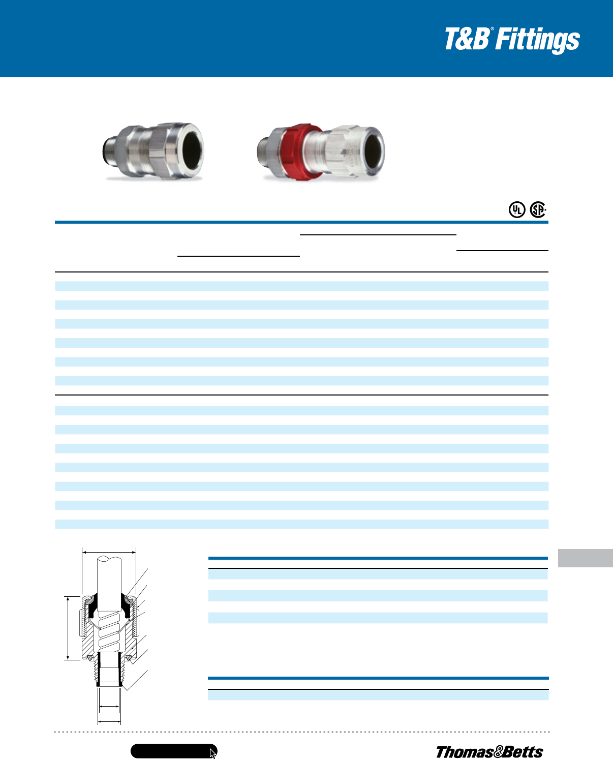
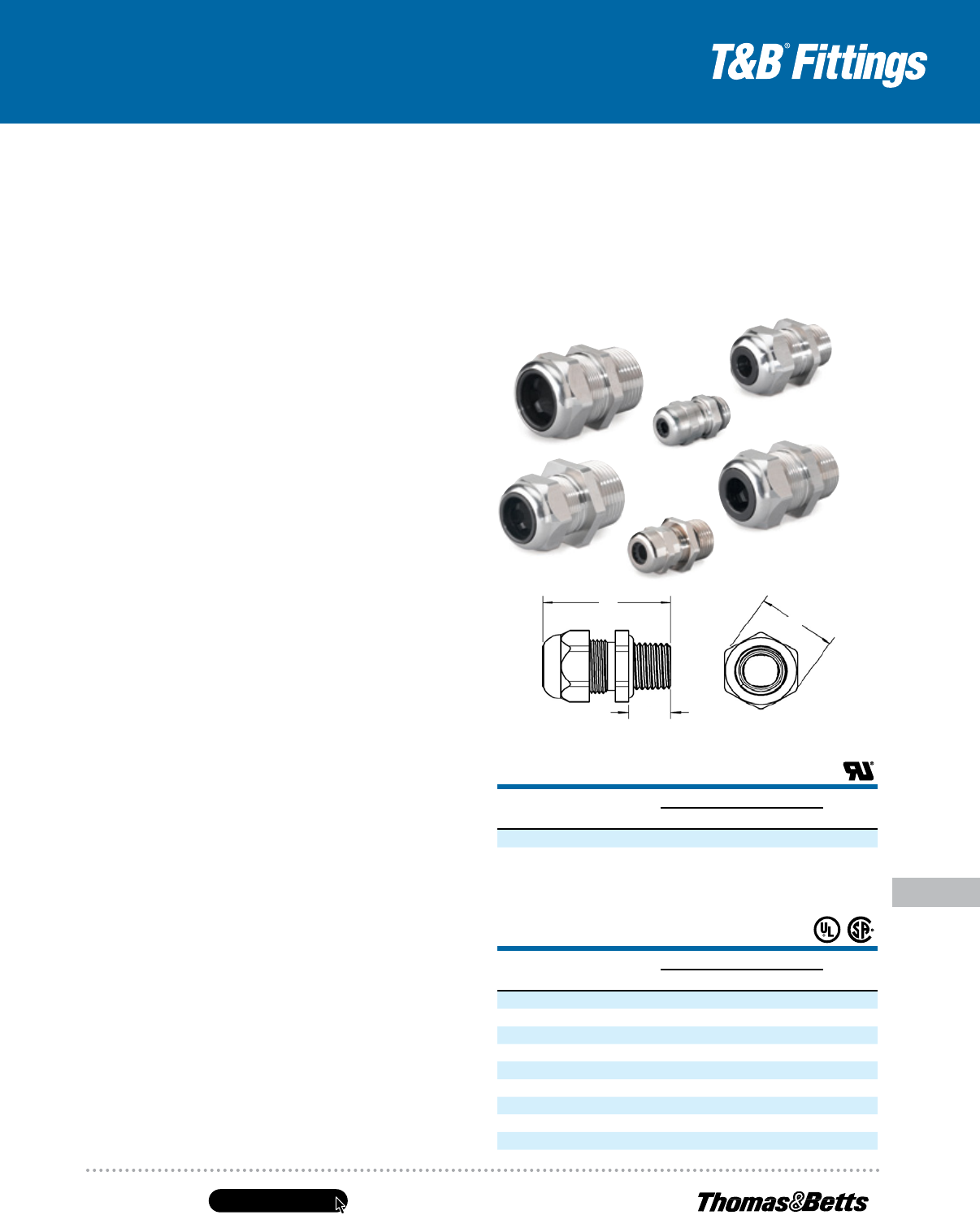
Bushing
(elastomeric)
Grounding Ring
(stainless steel or bronze
with nickel plate)
Gland Nut
(aluminum)
Body
(aluminum)
Sealing Ring
(elastomeric)
Removable Armor-
Stop (nylon
1
⁄2"–1")
(aluminum 1
1
⁄4"–4")
A2
A1
B
C
Collar Ring
(elastomeric)
www.tnb.com
United States
Tel: 901.252.8000
800.816.7809
Fax: 901.252.1354
Technical Services
Tel: 888.862.3289
E-124
STAR TECK
®
Teck Cable Fittings
Conduit & Fittings — T&B
®
Cord & Cable Fittings
STAR TECK
®
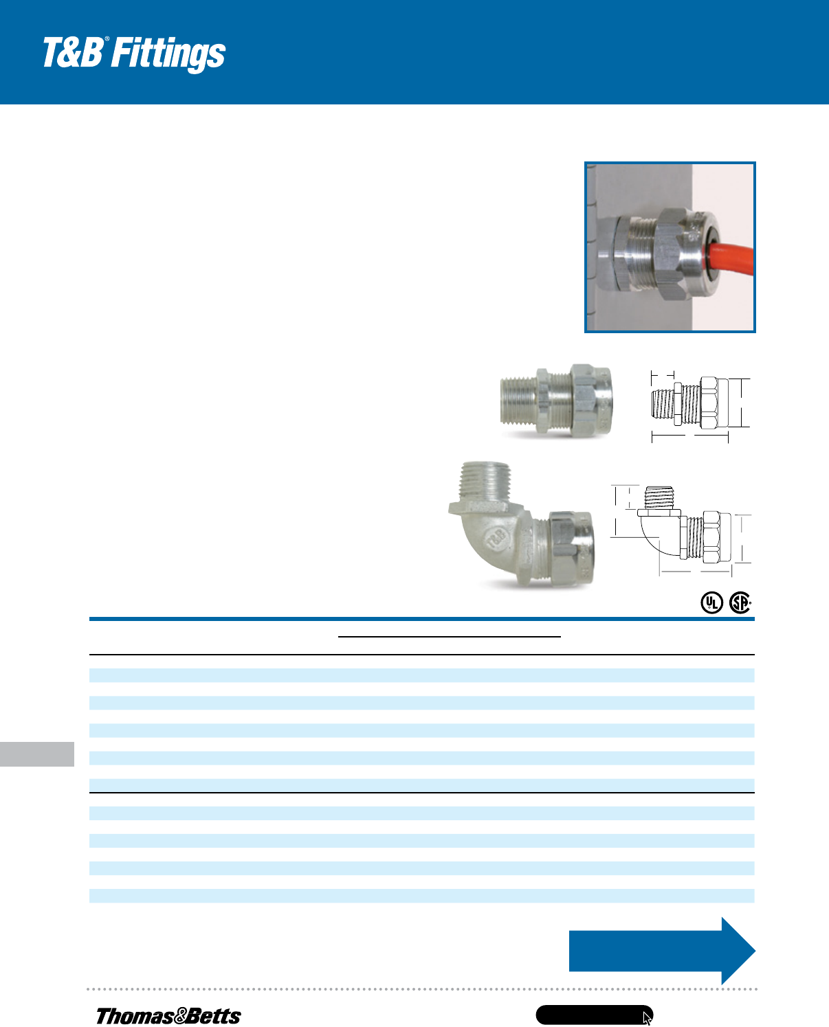
Jacketed Metal-Clad Cable Fittings
Application
• Provide means for passing armored,
metal-clad, jacketed cables through
a bulkhead or enclosure in hazardous
areas (these fittings are suitable for
hazardous areas when used with T&B
sealing compound)
• Form a mechanical grip and water-
and/or oil-resistant termination
• Provide grounding continuity
ofcablearmor
Cable Type
• JMC, MC-HL, Teck
Features
Easy Installation
• Exclusive power-grip. Provides a grip
that’s high up on the cable — not
on the first convolution — sostrip
length and cutting of cableare not
as critical
Dependable Service
• Stainless steel retaining ring.
Withstands corrosive environments.
Non-magnetic
Dependable Grounding
• Power-Grip grounding ring is non-
magnetic stainless steel. Provides
360° long-term dependable
grounding. It makes immediate
contact with the cable
Watertight
• Tapered bushing. Cone shaped
toprovide a secure, tight fit while
eliminating cupping or water in
vertical installations
Easy to Install in Tight Spaces
• Low-profile gland nut fits tight
spaces. Has grooves for screwdriver
installation, and flats for a wrench.
Durable and reusable with funnel
entry for easy cable insertion
Materials
Aluminum is standard material
Add suffix “S” for steel
with zinc plating
Add suffix “PVC” for corrosion- resistant
PVC coating
Add suffix “SS” for stainless steel Grade 316
material (
1
⁄2"–2" sizes)
Environment Classification
Meets NEC
®
Class I Division 2/Zone 2
and Class II Division 2/Zone 22 requirements
when installed as per Articles 501.10/505.15
and 502.10/506.15
NEMA4
Suitable for use in wet locations andconcrete
tight (steel) applications per UL 514B
UL File No. E82038/E38947
CSA File No. LR638/LR23086
Range
Available in hub sizes from
1
⁄2" to 4",
and will handle outerjacket diameters
from .525"to4.340"
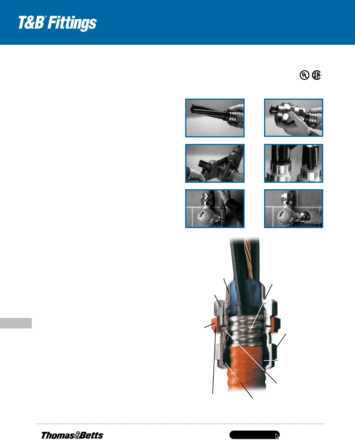
1. Prepare cable
3. Tighten gland nut2. Insert cable
Watertight
Tapered bushing.
Cone shaped
to provide a
secure, tight fit
while eliminating
cupping or
water in vertical
installations.
Easy Installation.
Exclusive power-
grip. Provides a
grip that’s high
up on the cable
— not on the first
convolution —
sostrip length and
cutting of cable
are not critical.
Dependable
Service.
Stainless steel
retaining ring.
Withstands
corrosive
environments.
Non-magnetic.
Dependable
Grounding.
Power-Grip
grounding ring
isnon-magnetic
stainless steel.
Provides 360°
long-term
dependable
grounding.
Itmakes
immediate
contactwith
thecable.
Easy to Install
in tight spaces.
Low-profile gland
nut fits tight spaces.
Has grooves
for screwdriver
installation
and flats for a
wrench. Durable
and reusable
with funnel entry
foreasy cable
insertion.
Installing the STAR TECK
®
Fitting
Overlapping range of sizes. STAR TECK
®
jacketed metal-clad cable fittings are designed to accommodate a broad
range of cables, thereby minimizing the possibility of mismatched cables and fittings in the field.
United States
Tel: 901.252.8000
800.816.7809
Fax: 901.252.1354
Technical Services
Tel: 888.862.3289
www.tnb.com
E-125
Conduit & Fittings — T&B
®
Cord & Cable Fittings
STAR TECK
®
Teck Cable Fittings
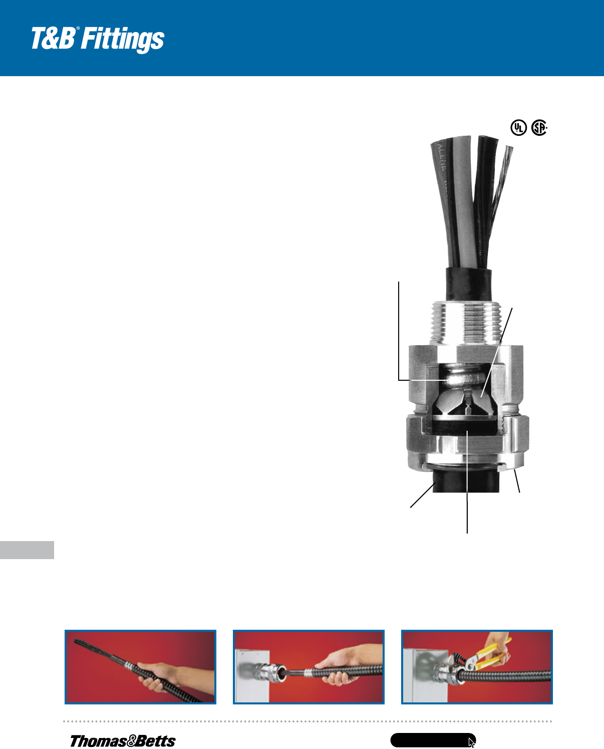
Retaining ring
(stainless steel)
Bushing (neoprene)
Gland nut (aluminum)
Grounding ring
(stainless steel)
Body (aluminum)
• Overlapping sizes minimize
possibility of mismatched
cables and fittings in the field
• Available in hub sizes from
1
⁄2" to 4",
handling outer jacket diameters from
.525" to 4.34"
• Suitable for hazardous locations
(Class 1 Div. 2; Class II Div. 2;
Class III)
• Where explosion-proof or
dust-proof boxes are required
by code, use STAR TECK XP
®
fittings (STX050-462 Series)
B
C
A
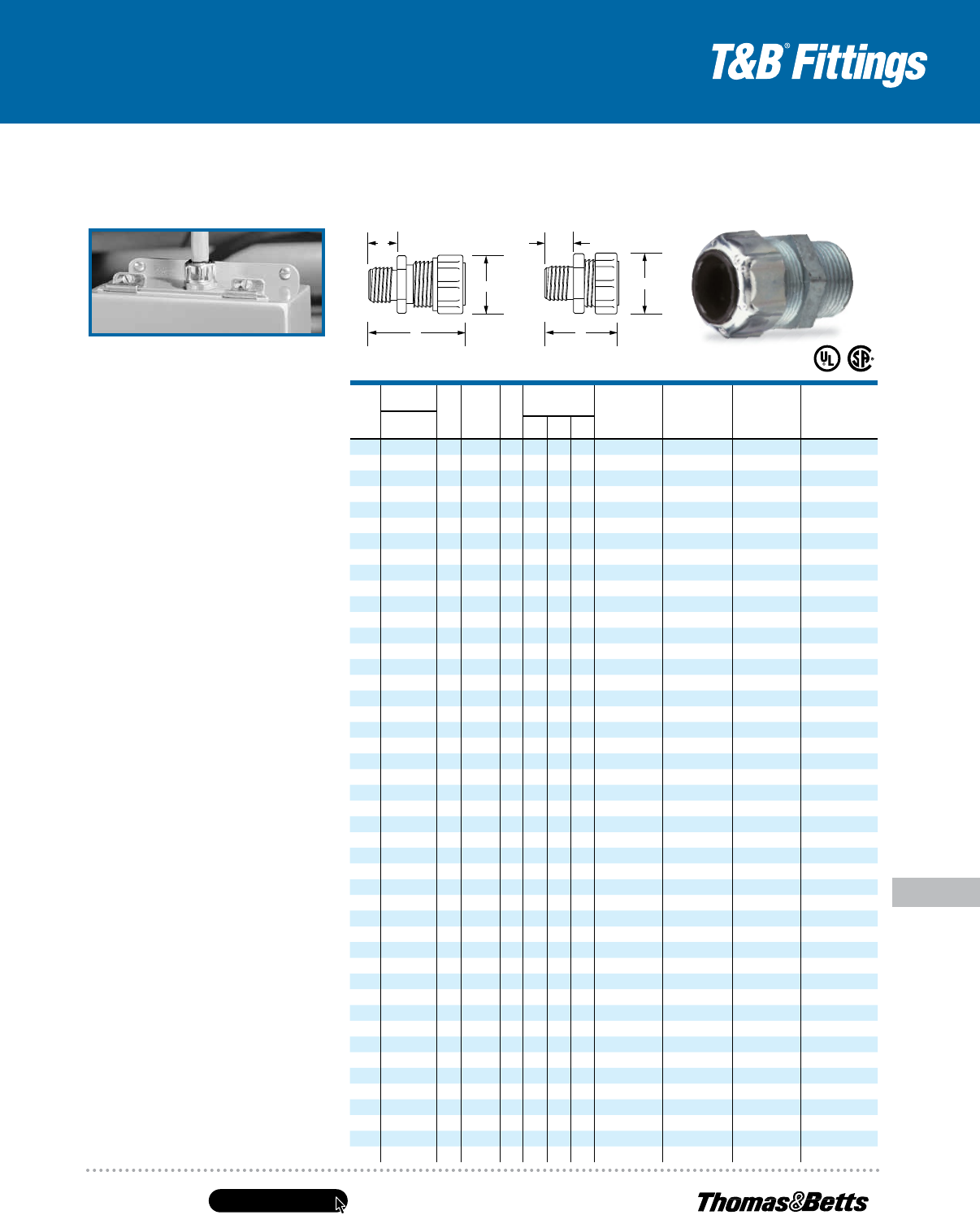
STAR TECK
®
Jacketed Metal-Clad Cable Fittings for Ordinary Locations
CAT.
NO.
HUB
SIZE
NPT
CABLE RANGE OVER
JACKET (IN.)
CABLE RANGE OVER
ARMOR (IN.) DIMENSIONS (IN.)
MIN. MAX. MIN. MAX. A B* C
ST050-462
1
⁄2 .525 .650 .415 .570 .395 2.020 1.224
ST050-464
1
⁄2 .600 .760 .490 .680 .485 2.020 1.363
ST050-465
1
⁄2 .725 .885 .615 .805 .612 2.133 1.633
ST050-466
1
⁄2 .825 .985 .715 .905 .612 2.133 1.633
ST075-467
3
⁄4 .880 1.065 .770 .985 .819 2.450 2.080
ST075-468
3
⁄4 1.025 1.205 .915 1.125 .819 2.450 2.080
ST100-469 1 1.187 1.375 1.077 1.295 1.039 2.601 2.230
ST125-470 1
1
⁄4 1.357 1.625 1.240 1.545 1.182 3.282 2.824
ST125-550 1
1
⁄4 1.500 1.625 1.390 1.545 1.370 3.282 2.824
ST125-471 1
1
⁄4 1.600 1.875 1.490 1.795 1.370 3.282 2.824
ST150-472 1
1
⁄2 1.700 1.965 1.590 1.885 1.557 3.620 3.260
ST150-473 1
1
⁄2 1.900 2.187 1.790 2.107 1.600 3.620 3.260
ST200-551 2 1.900 2.187 1.790 2.107 1.715 3.640 3.620
ST200-474 2 2.100 2.375 1.990 2.280 1.995 3.640 3.620
ST200-475 2 2.300 2.565 2.190 2.485 2.057 3.640 4.020
ST200-476 2 2.500 2.750 2.390 2.656 2.057 3.640 4.020
ST250-477 2
1
⁄2 2.380 2.640 2.240 2.560 2.230 4.700 4.750
ST250-478 2
1
⁄2 2.580 2.840 2.440 2.750 2.430 4.700 4.750
ST300-479 3 2.790 3.060 2.640 2.970 2.630 4.700 5.050
ST300-480 3 3.000 3.270 2.870 3.190 2.860 4.790 5.480
ST300-481 3 3.210 3.480 3.042 3.390 3.032 4.790 5.480
ST350-482 3
1
⁄2 3.420 3.690 3.270 3.590 3.260 4.790 5.980
ST350-483 3
1
⁄2 3.610 3.870 3.440 3.770 3.430 4.790 5.980
ST400-484 4 3.810 4.030 3.600 3.930 3.590 4.840 6.435
ST400-485 4 3.965 4.185 3.755 4.065 3.745 4.840 6.435
ST400-486 4 4.120 4.340 3.910 4.220 3.900 4.840 6.435
* Approximate dimension before installation.
Suggested specifications for metal-clad cable fitting.
1. All metal-clad cable fittings for jacketed interlocked armor cable or continuous corrugated cable shall be
approved by a nationally recognized testing laboratory, inspection agency or product evaluation organization.
2. Where corrugated-jacketed metal-clad cable exposed to intermittent or continuous moisture is terminated
into a threaded opening, the fitting shall be watertight type furnished with:
a. An elastomeric beveled bushing.
b. A funnel entry, splined gland nut.
c. A non-magnetic stainless steel grounding device with dual grounding action.
d. A taper threaded hub.
e. A hexagonal body and gland nut as manufactured by Thomas & Betts (aluminum series ST050-464).
3. Where cable is terminated into a threadless opening, a suitable moisture-resistant elastomeric gasket as manufactured
byThomas & Betts, series 5262, shall be provided between the outside of enclosure and fitting shoulder.
4. With single-conductor cable and/or in corrosive environments, aluminum fittings such as Thomas & Betts series
ST050-464 shall be installed.
Class I Div 2; Class II Div. 2; Class III. Where explosion-proof or dust-ignition-proof boxes are required by Teck, fitting must
beused in conjunction with an approved sealing fitting.
www.tnb.com
United States
Tel: 901.252.8000
800.816.7809
Fax: 901.252.1354
Technical Services
Tel: 888.862.3289
E-126
STAR TECK
®
Teck Cable Fittings
Conduit & Fittings — T&B
®
Cord & Cable Fittings
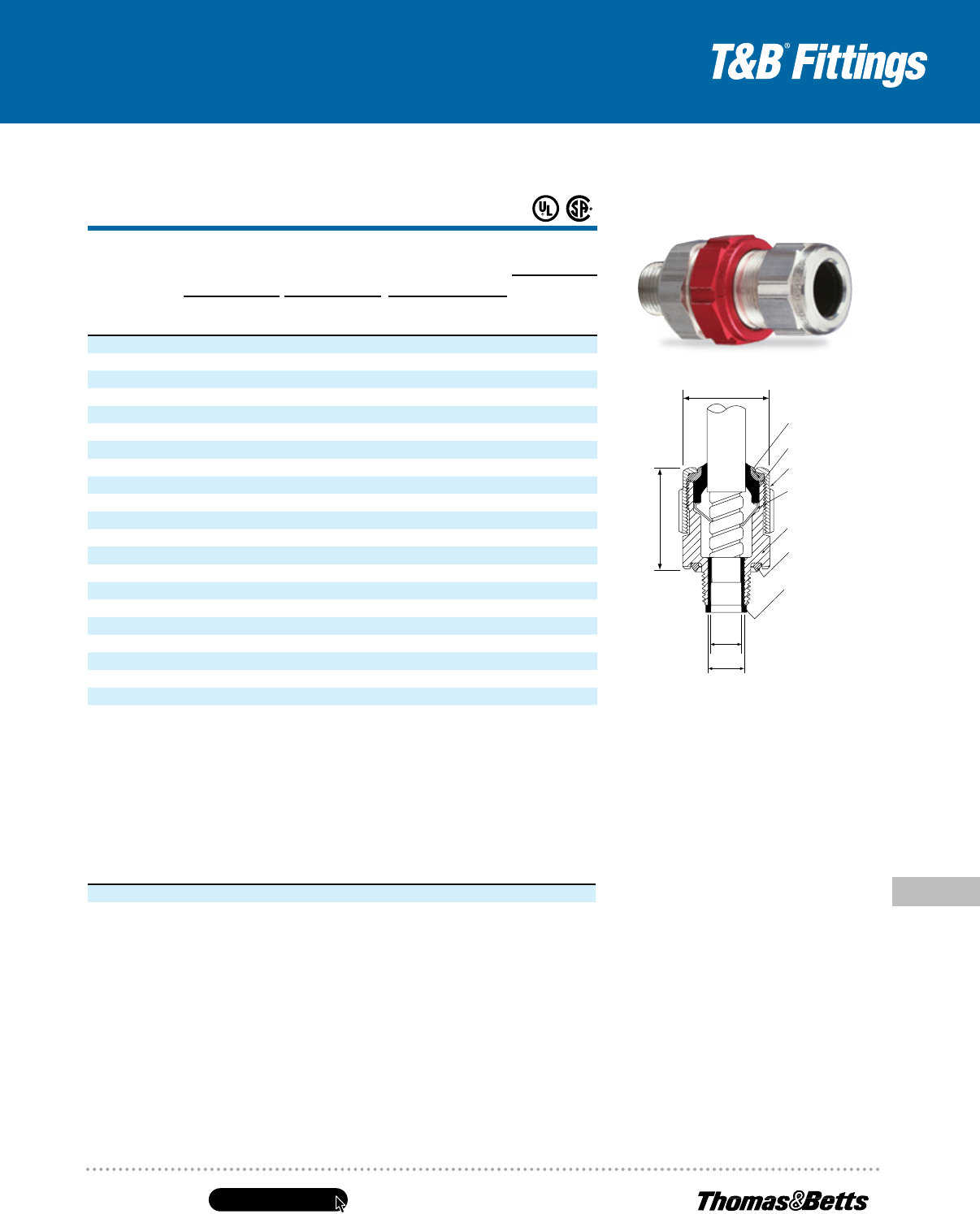
STAR TECK XP
®
Jacketed Metal-Clad Cable
Fittings for Hazardous Locations
Easy installation saves time, money!
Application
• Provide means for passing armored, metal clad, jacketed
cables through a bulkhead or enclosure in hazardous areas
(these fittings are suitable for hazardous areas when used
with T&B sealing compound)
• Form a mechanical grip and water- and/or oil-
resistant termination
• Provide grounding continuity of cable armor
Cable Type
• JMC, MC-HL, Teck
Features
• Sealing chamber is easier to fill, requires less sealing
compound — saves time, material. Flame path is optimally
designed to enable easy insertion into hub. Quick-turn lock
• Internal splines
• Union features twist-on action; red color for high visibility
• Exclusive Power Grip. Provides grip that’s high up on
cable armor non-magnetic stainless steel Power Grip
grounding ring
• Low-profile gland nut
Materials
Aluminum is standard material
Add suffix “S” for steel with zinc plating
Add suffix “PVC” for corrosion-resistant PVC coating
Add suffix “SS” for stainless steel material
Environment Classification
Suitable for hazardous locations. Class I Div. 2; Class II Div. 2; Class III.
Where explosion-proof or dust-proof fittings are required by code, use
STAR TECK XP
®
fittings (STX Series)
NEMA4, 4X (stainless steel)
Suitable for use in wet locations andconcrete-tight (steel) applications
per UL 514B
UL File No. E82038/E38947
CSA File No. LR23086
Range
Available in hub sizes from
1
⁄2" to 4", and will handle outerjacket diameters
from .525" to 4.185"
1. Prepare cable
3. Tighten gland nut
4. Pot cable (using liquid or putty)
5. Install hub on enclosure
6. Insert cable and tighten red union
2. Install Star Teck XP
®
on cable
Sealing chamber is easier
tofill, requires less sealing
compound — saves time,
material. Flame path is
optimally designed to enable
easy insertion into hub.
Quick‑turn lock secures
assembly during installation.
Hub has hexagonal shape
for dependable tool grip.
Internal splines
enable installer
totighten gland
nut either on or
offenclosure.
Union features twist‑on action for
easy connection and disconnection;
red color ensures high visibility,
easyrecognition. Union also serves
asa “puller” during disassembly.
Stainless steel retaining
ring. Withstands corrosive
environments. Non‑magnetic.
Low‑profile gland nut
fitstightest spaces.
Hasgrooves for hammer/
screwdriver installation
and flats forwrench‑
gripping. Durable and
reusable withfunnel entry
for easycable insertion.
Exclusive Power Grip. Provides
grip that’s high up on cable armor
— noton first convolution — so
precise cable preparation is not
critical. Non‑magnetic stainless
steel PowerGrip grounding ring
ensures 360° long‑term dependable
grounding. Itprovides phenomenal
tensile pullout resistance.
Tapered bushing. Cone‑
shaped to provide secure,
tight fit while eliminating
cupping of water in vertical
installations.
Copper‑free construction.
All‑aluminum body and gland
nut resist corrosion, oxidation.
United States
Tel: 901.252.8000
800.816.7809
Fax: 901.252.1354
Technical Services
Tel: 888.862.3289
www.tnb.com
E-127
Conduit & Fittings — T&B
®
Cord & Cable Fittings
STAR TECK
®
Teck Cable Fittings
UL Connectors When Used with Putty-Type
Listed or Liquid-Type Compound for:
1
⁄2" thru 3" Class I Div. 1 Groups A, B,
C, D
Class II Div. 2 Groups F, G
Class III
Enclosure Type 4
Connectors When Used with Putty-Type
or Liquid-Type Compound for:
3
1
⁄2" & 4" Class I Div. 1 Groups B, C, D
Class II Div. 2 Groups F, G
Class III Enclosure Type 4
CSA Certified for:
Class I Division Groups A, B,
1 and 2 C, D
Class II Division Groups E,
1 and 2 F, G
Class III, SL (Integral Seal)
Enclosure Type 4
Sealing Compounds
CAT. NO.
DESCRIPTION VOLUME
SC65 Putty-Type Sealing Compound 60 grams
SC4-KIT Liquid-Type Sealing Compound for use in high wire density
applications (5 or more wires)
2.8 fl. oz. (66 cc)
STAR TECK XP
®
Jacketed Metal-Clad Cable Fittings for Hazardous Locations
CAT. NO.
HUB
SIZE
NPT
CABLE
RANGE OVER
JACKET (IN.)
CABLE
RANGE OVER
ARMOR (IN.)
SEALING
COMPOUND
REQUIRED
DIMENSIONS (IN.)
SC65**
PUTTY
(G)
SC4-
KIT**
LIQUID
(CC)MIN. MAX. MIN. MAX.
A
MIN. B* C
STX075-465
3
⁄4 .725 .885 .615 .805 .612 2.62 1.82 14 7
STX075-466
3
⁄4 .825 .985 .715 .905 .720 2.62 1.82 14 7
STX100-467 1 .880 1.065 .770 .985 .755 2.83 2.30 30 16
STX100-468 1 1.025 1.205 .915 1.125 .900 2.83 2.30 30 16
STX125-469 1
1
⁄4 1.187 1.375 1.077 1.295 1.062 3.05 2.51 45 22
STX150-470 1
1
⁄2 1.357 1.625 1.240 1.545 1.182 3.76 3.26 80 43
STX150-550 1
1
⁄2 1.500 1.625 1.390 1.545 1.370 3.76 3.26 80 43
STX150-471 1
1
⁄2 1.600 1.875 1.490 1.795 1.470 3.76 3.26 80 43
STX200-472 2 1.700 1.965 1.590 1.885 1.557 4.05 3.62 125 66
STX200-473 2 1.900 2.187 1.790 2.107 1.757 4.05 3.62 125 66
STX200-474 2 2.100 2.375 1.990 2.280 1.995 4.15 4.02 150 80
STX250-475 2
1
⁄2 2.300 2.565 2.200 2.485 2.185 4.31 4.58 341 164
STX250-476 2
1
⁄2 2.500 2.750 2.380 2.656 2.365 4.31 4.58 341 164
STX300-478 3 2.580 2.840 2.477 2.750 2.460 5.64 5.10 497 239
STX300-479 3 2.790 3.060 2.677 2.970 2.660 5.80 5.33 609 293
STX350-480 3
1
⁄2 3.000 3.270 2.880 3.190 2.864 6.32 5.79 965 464
STX350-481 3
1
⁄2 3.210 3.480 3.080 3.390 3.062 6.32 5.79 965 464
STX400-482 4 3.420 3.690 3.307 3.590 3.290 6.63 6.19 1323 636
STX400-483 4 3.610 3.870 3.477 3.770 3.460 6.63 6.19 1323 636
STX400-484 4 3.810 4.030 3.650 3.930 3.630 7.09 6.90 1645 791
STX400-485 4 3.965 4.185 3.794 4.065 3.775 7.09 6.90 1645 791
* Approximate dimension before installation.
** One unit of SC65 putty type sealing compound contains 60 g. One unit of SC4-Kit liquid type sealing compound
contains 66 cc and includes a dispensing syringe and fiber damming material.
CAUTION: STAR TECK XP
®
fittings must be installed with Thomas & Betts catalog numbers
SC4-KIT or SC65 sealing compound (purchase separately). See installing instructions.
Note: Stainless Steel (SS suffix) STX and STEX fittings have a NEMA 4X rating.
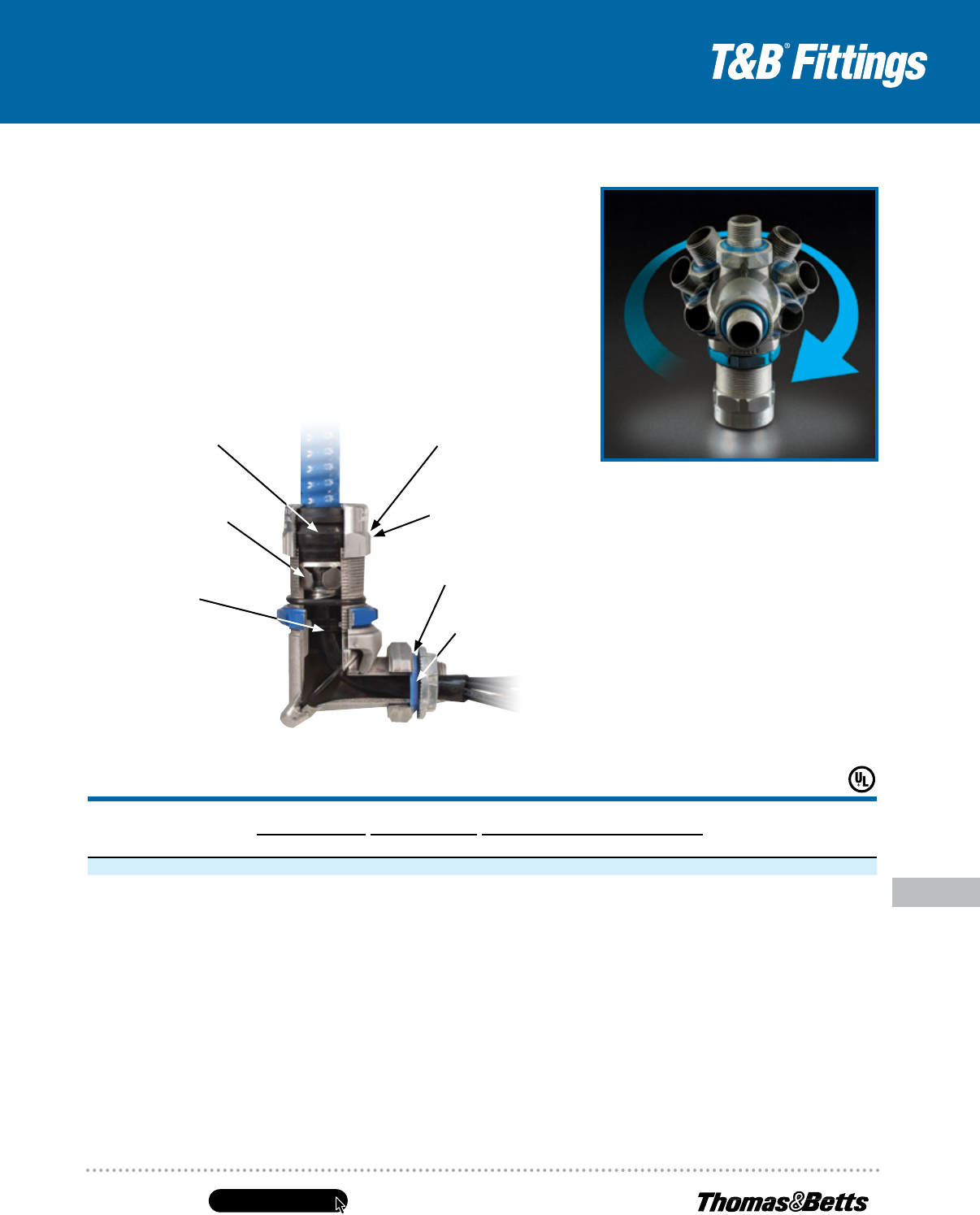
Collar Ring
(elastomeric)
C
B
A1
A2
Bushing
(elastomeric)
Sealing Ring
(elastomeric)
Gland Nut
(aluminum)
Body
(aluminum)
Grounding Ring
(stainless steel
or bronze with
nickel plate)
Removable
Armor‑Stop
(nylon
1
⁄2"–1")
(aluminum 1
1
⁄4"–4")
www.tnb.com
United States
Tel: 901.252.8000
800.816.7809
Fax: 901.252.1354
Technical Services
Tel: 888.862.3289
E-128
STAR TECK
®
Teck Cable Fittings
Conduit & Fittings — T&B
®
Cord & Cable Fittings
Greater range, fewer part numbers,
less inventory. A fitting combination!
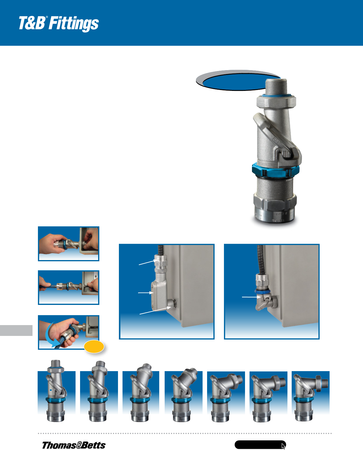
STAR TECK EXTREME
®
DIRECTOR
™
Jacketed Metal-Clad and Teck Cable
Termination Fittings
Terminating jacketed metal-clad and teck cable can be a time-consuming process, especially
when angle adjustments are required. Current termination methods such as 90° elbows and LB
conduit bodies take up a lot of space and lack flexibility.
To address these issues, Thomas & Betts introduces the electrical industry’s first truly adjustable
series of range-taking fittings, the STAR TECK EXTREME
®
DIRECTOR
™
.
STAR TECK EXTREME
®
DIRECTOR
™
Cable Fittings are designed for optimum integrity in ordinary
applications. They accept a range of jacketed metal-clad and teck cable diameters.
Featuring an exclusive swash-plate design, the STAR TECK EXTREME
®
DIRECTOR
™
Cable Fittings
adjust from 90° to 180°. A full circular bore makes cable insertion trouble free. Alignment guides
serve as handy reference points for aligning installed fittings at the same angle.
What’s more, STAR TECK EXTREME
®
DIRECTOR
™
fittings require no disassembly prior to installation
and can also be easily disconnected.
Turn blue compression nut one-half turn to loosen and rotate hub. Tighten blue compression nut to hold hub in place at desired angle.
Install
Insert
Rotate
DONE
Save Time and Money!
Conventional Method
Nipple
Conduit
Body
Ordinary
Location
Fitting
Multiple components are less flexible and require
added space.
Time-Saving Method
STAR TECK
EXTREME
®
DIRECTOR
™
Fitting
One component that can be used at any angle adds flexibility
and requires less space.
NEW!
NEW!
United States
Tel: 901.252.8000
800.816.7809
Fax: 901.252.1354
Technical Services
Tel: 888.862.3289
www.tnb.com
E-129
Conduit & Fittings — T&B
®
Cord & Cable Fittings
STAR TECK
®
Teck Cable Fittings
Built-in sealing gasket
provides a 360° seal even
when enclosure surface is
rough or uneven.
The fitting’s body and gland nut
have been constructed completely
of non-corrosive aluminum.
* Locknut not included
Elastomeric collar ring
and cone-shaped bushing
provide a liquidtight seal
and insulation grip.
Removable armor-stop makes
the fitting range taking.
Stainless steel “Power Grip”
grounding ring — ensures
360° long-term, dependable
grounding.
Gland nut serves as cable
stripping gauge. Just strip the
outer jacket to the length of the
fitting gland.
Low-profile gland nut fits in
tight spaces. Has grooves for
screwdriver installation and flats
for a wrench.
Teeth on the fitting’s
perimeter provide superior
electrical bonding.
STAR TECK EXTREME
®
DIRECTOR
™
Jacketed Metal-Clad and Teck Cable
Termination Fittings (continued)
Inside STAR TECK EXTREME
®
DIRECTOR
™
Cable Fittings
90° to 180° Rotation
STAR TECK EXTREME
®
DIRECTOR
™
Cable Fittings
CAT. NO.
HUB SIZE
(NPT)
GLAND
TORQUE
(LB.-IN.)
RANGE OVER JACKET
(IN.)
RANGE OVER ARMOR
(IN.) THROAT DIA. MIN. (IN.)
OVERALL LENGTH (IN.)MIN. MAX. MIN. MAX. WITH ARMOR STOP WITHOUT ARMOR STOP
STED050
1
⁄2 450 .600 .885 .520 .795 .505 .617 5.375
STED075
3
⁄4 600 .860 1.205 .780 1.125 .645 .819 5.875
Environment Classification
Meets NEC
®
Class I Division 2/Zone 2 and Class II
Division 2/Zone 22 requirements when installed
as per Articles 501.10/505.15 and 502.10/506.15
NEMA Type 4
UL File No. E38947
NEC and National Electrical Code are registered trademarks
of the National Fire Protection Association, Inc.
www.tnb.com
United States
Tel: 901.252.8000
800.816.7809
Fax: 901.252.1354
Technical Services
Tel: 888.862.3289
E-130
Conduit & Fittings — T&B
®
Cord & Cable Fittings
STAR TECK
®
Teck Cable Fittings
Jacketed Metal-Clad Cable and Teck Cable
Metal-Clad Cable (Type MC) Ref. NEC
®
Article 330
“Metal-Clad Cable Type MC is a factory assembly of one or more conductors,
each individually insulated and enclosed in a metallic sheath of interlocking
tape, or a smooth or corrugated tube.”
Metal-Clad Cable Type MC is rated for use up to 5,000 volts. The
National Electrical Code permits use of metallic sheath as an equipment
grounding conductor.
Metal-Clad Cables are available with a variety of phase conductor insulations
such as crosslinked polyethylene and silicone rubber ethylene propylene,
depending on rated temperature of conductors and working potential. Metallic
sheath can be of galvanized steel, aluminum, copper or bronze. Aspecial outer
covering such as PVC or Neoprene over metallic sheath isusually provided for
environmental protection.
Metal-clad cable is not permitted in locations where it could be subject
tophysical damage. Metal-clad cable can be used exposed, concealed, in
cable tray, in any approved raceway and with minor exceptions in hazardous
locations. Type MC cable can also be used for services, feeders, branch
circuits, power, lighting, control and signal circuits.
Use of metal-clad cable is permitted in wet locations, or where exposed to
destructive corrosive conditions or can be directly buried in earth, concrete
or exposed to cinder fills, strong chlorides, caustic alkalis, vapors, chlorine
orhydrochloric acids provided the construction of cable, the conductors within
the metallic sheath, the metallic sheath and protective cover over metallic
sheath comply with requirements enumerated in Sec. 330.10 of theNational
Electrical Code.
Bend radius restrictions are dependent on the size of the cable and the
typeof sheath, i.e., smooth, interlocked armor, corrugated sheath or shielded
conductors and varies from seven times to 15 times cable external diameter.
NEC Article 330 requires that approved fittings be used for termination.
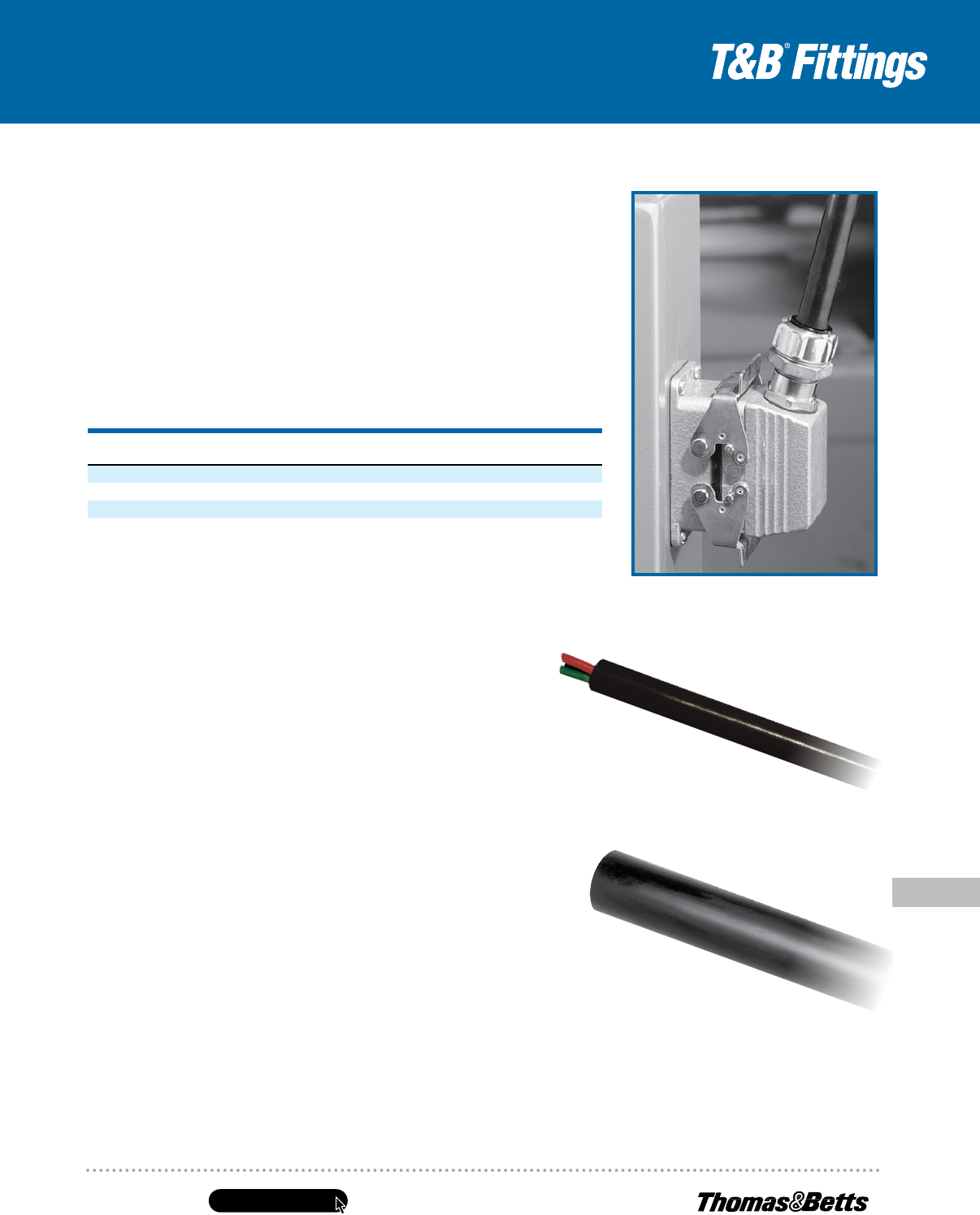
Where single-conductor cables carrying alternating current enter a ferrous
metal box or enclosure, procedures described in NEC Section 300.20 must
be followed to reduce effects of heating due to induced currents. These
procedures include recommended arrangements of conductors, cutting of
slots in metal between individual conductor holes, passing of conductors
through insulating walls, or use of non-magnetic aluminum sheathed cable
and aluminum terminating fittings.
Portions of this section reprinted by permission from NFPA 70, National
Electrical Code
®
, National Fire Protection Association, Boston, MA.
Please refer to the following for further details and complete information:
1. NEC Article 330…Metal Clad Cable (Type MC)
2. UL 4, ANSI C33.9…Safety Standards for Type MC Metal Clad Cable
3. UL 514B, Safety Standards for Outlet Boxes & Fittings
4. A-A50552…Federal Specification. Fittings for Cable, Power Electrical
&Conduit Metal, Flexible
5. NEMA FM-1…Standards Publication. Fittings and Supports for Conduit and
Cable Assemblies
Teck Cables
Teck cable derived its name from one of its first users, the Teck-Hughes
GoldMines in Kirkland Lake, Ontario. Teck 90 is CSA Type designation.
Tradedesignation of this cable is Armored Cable.
Teck cables up to 5,000-volt working potential are manufactured in
accordance with CSA Standard C22.2 No. 131 and are provided with a
bare ground conductor and an optional outer jacket. Depending on phase
conductor insulation, the cables are designated as Teck 90 (X-LINK) when
insulation is cross-linked polyethylene and Teck 90 (EP) when insulation is
ethylene propylene. Both cables are rated for 90° C service (dry location)
and 75° C (wet locations). When Teck cable is suitable for installation down
to -40° F, the cables are marked Teck 90 (X-LINK) minus 40 or Teck 90 (EP)
minus 40.
Over 5,000 volts working potential Teck cables are manufactured in
accordance with IPCEA standards and are certified by CSA. Cables are
provided with or without ground wire as required.
Teck cables with outer jacket may be used for exposed or concealed wiring
in wet or dry locations, indoors/outdoors and in corrosive environments. Teck
cables are suitable for use in ventilated, non-ventilated and ladder-type cable
troughs, in ventilated flexible cable ways in both dry and wet locations. Teck
cable with outer jacket is suitable for direct earth burial and for Class II Division
2, Class III Division 1 & 2 hazardous locations per Canadian Electric Code.
Some of the features of Teck cable are its flexibility and ease of installation.
Absence of dead air space within cable increases heat transfer and minimizes
condensation. Overall protective covering provides good environmental
protection.
Bend radii for permanent training during installation usually varies between
seventimes to 12 times the cable diameter depending on cable construction
andmanufacturer’s recommendations. Larger radii bends are required for
other conditions.
Section 12-3028 of the Canadian Electric Code requires that the terminating
fittings used must provide adequate strain relief to terminal connections
andensure electrical continuity without injury to non-metallic sheath. Continuity
ismandatory whether or not the armor is used as a grounding conductor.
Except for dry locations free from corrosive atmosphere, the non-metallic
jacket is not permitted to be stripped back to a point where armor is exposed
after installation.
Where single conductor cables carrying 200 amps or more enter metal
boxes through separate openings, certain precautions are required to prevent
overheating of the metal by induction. Use of non-ferrous or non-metallic box
connectors, locknuts and bushings and installation of non-magnetic panel
inserts is suggested in the code.
Please refer to the following for further details and complete information:
1. CEC Section 12…Wiring Methods
CEC Section 4…Conductors
2. CSA C22.2 No. 131 & 131S
(Supplement #1)…Safety Standard for Type Teck Cable
3. CSA C22.2 No. 18…Safety Standards for Outlet Boxes, Conduit Boxes
and Fittings
4. UL File E82038 — Volume 1, Section 3, Page 1, Revision 1/31/2007
Note: The materials herein, whether relating to the National Electrical Code, the Underwriters Laboratories, Inc. listing, to industry practice or otherwise are not intended to provide
all relevant information required for use and installation of our products. Refer to applicable codes, instructions and industry specifications prior to installation or use.
United States
Tel: 901.252.8000
800.816.7809
Fax: 901.252.1354
Technical Services
Tel: 888.862.3289
www.tnb.com
E-131
Conduit & Fittings — T&B
®
Cord & Cable Fittings
Spin-On
®
Series Fittings and Accessories
CAT. NO.
HUB
SIZE
NPT
CABLE RANGE
OVER ARMOR
(IN.)
DIMENSIONS (IN.) OPTIONAL
CORROSION
RESISTANT BOOT
CAT. NO.
A DIA. B
2-050-008
1
⁄2 .380–.435 1
1
⁄4 1
7
⁄8 NB050
2-050-010
1
⁄2 .436–.500 1
1
⁄4 1
7
⁄8 NB050
2-050-020
1
⁄2 .501–.580 1
1
⁄4 1
7
⁄8 NB050
2-050-030
1
⁄2 .581–.650 1
1
⁄4 1
7
⁄8 NB050
2-075-040
3
⁄4 .651–.730 1
5
⁄8 2
1
⁄8 NB075
2-075-050
3
⁄4 .731–.820 1
5
⁄8 2
1
⁄8 NB075
2-075-060
3
⁄4 .821–.880 1
5
⁄8 2
1
⁄8 NB075
2-100-070 1 .881–0.960 2 2
1
⁄8 NB100
2-100-080 1 .961–1.030 2 2
1
⁄8 NB100
2-100-090 1 1.031–1.100 2 2
1
⁄8 NB100
2-100-100 1 1.101–1.180 2 2
1
⁄8 NB100
2-125-110 1
1
⁄4 1.181–1.240 2
1
⁄4 2
1
⁄2 NB125
2-125-120 1
1
⁄4 1.241–1.310 2
1
⁄4 2
1
⁄2 NB125
2-125-130 1
1
⁄4 1.311–1.390 2
1
⁄4 2
1
⁄2 NB125
2-150-140 1
1
⁄2 1.391–1.480 2
5
⁄8 2
5
⁄8 NB150
2-150-150 1
1
⁄2 1.481–1.570 2
5
⁄8 2
5
⁄8 NB150
2-150-160 1
1
⁄2 1.571–1.660 2
5
⁄8 2
5
⁄8 NB150
2-200-170 2 1.661–1.750 3 2
7
⁄8 NB200
2-200-180 2 1.751–1.840 3 2
7
⁄8 NB200
2-200-190 2 1.841–1.930 3 2
7
⁄8 NB200
2-200-200 2 1.931–2.030 3 2
7
⁄8 NB200
2-250-210 2
1
⁄2 2.031–2.150 3
7
⁄8 3
3
⁄8 NB250
2-250-220 2
1
⁄2 2.151–2.270 3
7
⁄8 3
3
⁄8 NB250
2-250-230 2
1
⁄2 2.271–2.390 3
7
⁄8 3
3
⁄8 NB250
2-250-240 2
1
⁄2 2.391–2.510 3
7
⁄8 3
3
⁄8 NB250
2-300-250 3 2.511–2.640 4
1
⁄2 3
3
⁄8 NB300
2-300-260 3 2.641–2.770 4
1
⁄2 3
3
⁄8 NB300
2-300-270 3 2.771–2.900 4
1
⁄2 3
3
⁄8 NB300
2-300-280 3 2.901–3.040 4
1
⁄2 3
3
⁄8 NB300
2-350-300 3
1
⁄2 3.171–3.310 5 3
7
⁄8 NB350
2-350-310 3
1
⁄2 3.311–3.450 5 3
7
⁄8 NB350
2-350-320 3
1
⁄2 3.451–3.590 5 3
7
⁄8 NB350
2-400-330 4 3.591–3.730 5
3
⁄8 3
7
⁄8 NB400
2-400-340 4 3.731–3.870 5
3
⁄8 3
7
⁄8 NB400
UL File No. E38947
CSA File No. LR 2884
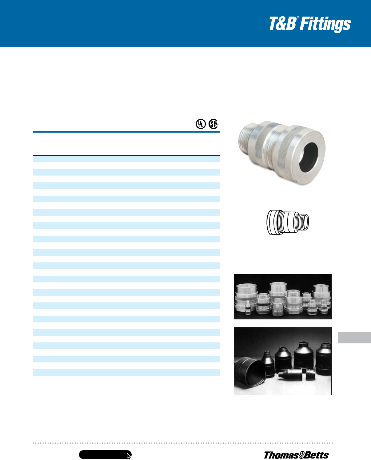
In corrosive environments, the T&B neoprene boot provides
maximum corrosion protection to the connector. Simply
match the connector hub size to the boot hub size to select
the proper boot (NB Series).
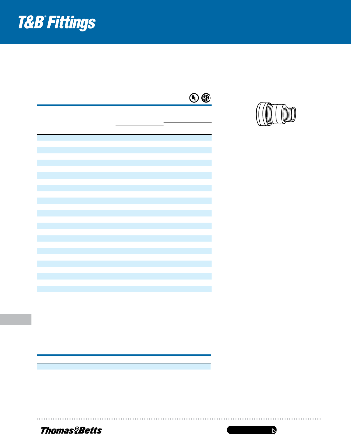
Connector
Aluminum
Spin-On
®
Series II Connectors
and Accessories
www.tnb.com
United States
Tel: 901.252.8000
800.816.7809
Fax: 901.252.1354
Technical Services
Tel: 888.862.3289
E-132
Spin-On
®
Series Fittings and Accessories
Conduit & Fittings — T&B
®
Cord & Cable Fittings
Spin-On
®
X Connectors
forHazardousLocations
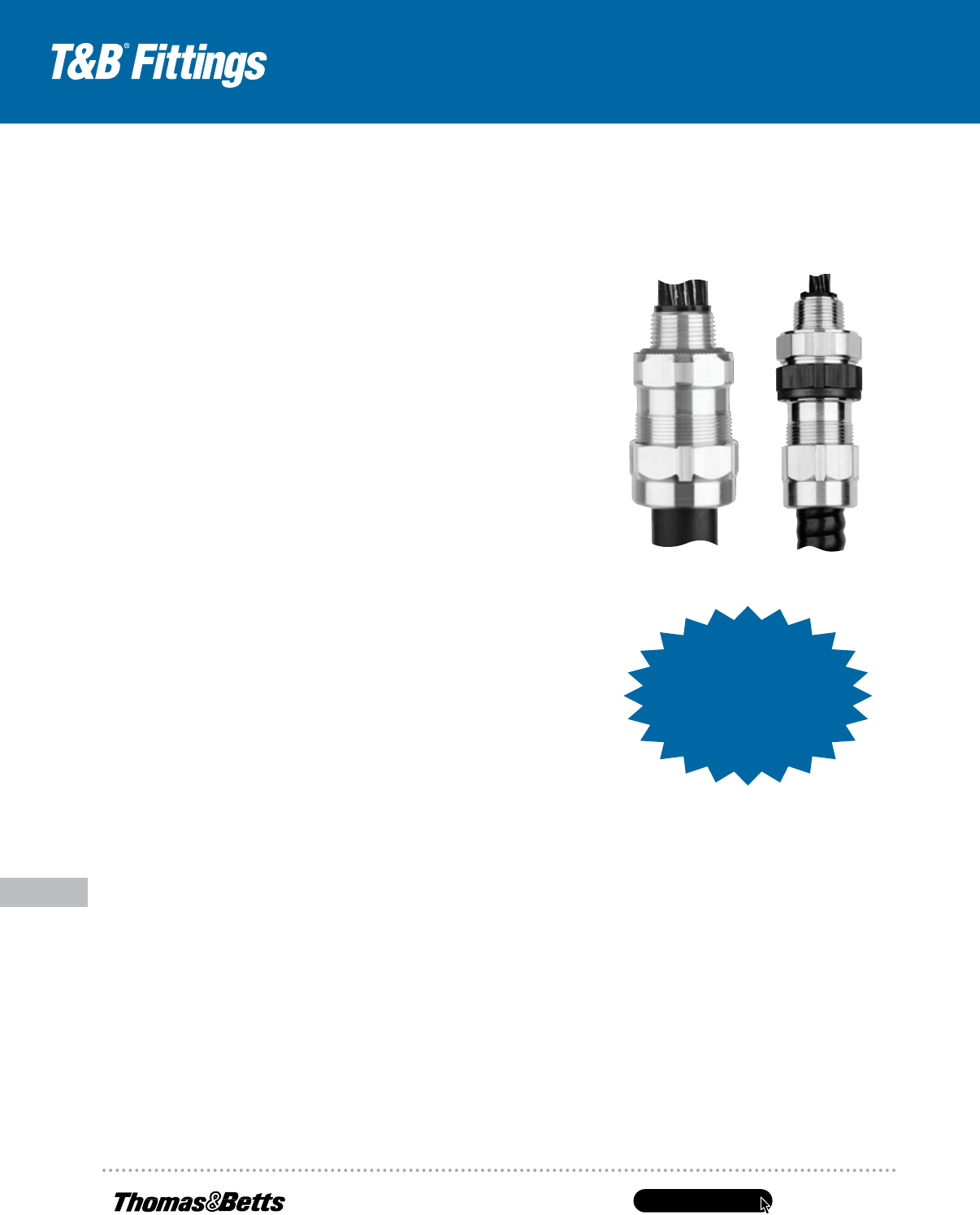
• Each SPIN-ON
®
X catalog number is a
complete compound-filled connector kit
• 3-piece construction — gland/body/insert
with O-ring
• Red anodized gland identifies hazardous
location fitting
• Compact size — overall length is
2
⁄3 less
than conventional fitting
• Installation time is 50% less than
conventional
• Full tapered hub threads for gas-tight
thread engagement
• Machined aluminum construction
for corrosion resistance
• Sealing compound (sold separately)
premixed forconsistency — no jobsite
variations
• Neoprene boots available for additional
corrosion protection
• For control cable applications, order liquid
compound separately
Install a complete gas-blocked connector in a hazardous location!
Suffix Cat. No. with S for steel, B for brass.
SPIN-ON
®
X is UL Listed for: Class I, Div. 2, Groups A, B, C, & D in
3
⁄4
", 1", 1
1
⁄4
", 1
1
⁄2
", 2", 2
1
⁄2
" Hubsizes. Class I, Div.
2, Groups C & D in 3", 3
1
⁄2
", and 4" Hub sizes. The entire line is UL listed forClass II, Div. 2, Groups F & G and Class
III. CSA certified through 4" Hub size for Class I, Groups A, B, C, D; Class II, Groups E, F, G; and Class III.
UL File No. E82038
CSA File No. LR23086
CAT. NO.
DESCRIPTION VOLUME
SC65 Putty-Type Sealing Compound 60 grams
SC4-KIT Liquid-Type Sealing Compound for use in high wire density
applications (5 or more wires)
2.8 fl. oz. (66 cc)
CAT. NO.
HUB SIZE
NPT
CABLE RANGE
OVER ARMOR
(IN.)
DIMENSIONS (IN.)
SEALING
COMPOUND
REQUIRED
SC65**
PUTTY (G)
SC4-KIT**
LIQUID (CC)A DIA. B
4-075-008
3
⁄4 .380–.435 1
5
⁄8 2
1
⁄8 25 12
4-075-010
3
⁄4 .436–.500 1
5
⁄8 2
1
⁄8 25 12
4-075-020
3
⁄4 .501–.580 1
5
⁄8 2
1
⁄8 25 12
4-075-030
3
⁄4 .581–.650 1
5
⁄8 2
1
⁄8 25 12
4-075-040
3
⁄4 .651–.730 1
5
⁄8 2
1
⁄8 25 12
4-100-050 1 .731–820 2 2
1
⁄8 55 30
4-100-060 1 .821–880 2 2
1
⁄8 55 30
4-100-070 1 .881–960 2 2
1
⁄8 55 30
4-100-080 1 .916–1.030 2 2
1
⁄8 55 30
4-125-090 1
1
⁄4 1.031–1.100 2
1
⁄4 2
1
⁄2 70 40
4-125-100 1
1
⁄4 1.101–1.880 2
1
⁄4 2
1
⁄2 70 40
4-125-110 1
1
⁄4 1.181–1.240 2
1
⁄4 2
1
⁄2 70 40
4-125-120 1
1
⁄4 1.241–1.310 2
1
⁄4 2
1
⁄2 70 40
4-150-130 1
1
⁄2 1.311–1.390 2
5
⁄8 2
5
⁄8 80 45
4-150-140 1
1
⁄2 1.181–1.240 2
5
⁄8 2
5
⁄8 80 45
4-150-150 1
1
⁄2 1.241–1.310 2
5
⁄8 2
5
⁄8 80 45
4-200-160 2 1.571–1.660 3 2
7
⁄8 95 55
4-200-170 2 1.661–1.750 3 2
7
⁄8 95 55
4-200-180 2 1.751–1.840 3 2
7
⁄8 95 55
4-200-190 2 1.841–1.930 3 2
7
⁄8 95 55
4-250-200 2
1
⁄2 1.931–2.030 3
7
⁄8 3
3
⁄8 200 120
4-250-220 2
1
⁄2 2.151–2.270 3
7
⁄8 3
3
⁄8 200 120
4-300-240 3 2.391–2.510 4
1
⁄2 3
3
⁄8 275 165
4-300-260 3 2.641–2.770 4
1
⁄2 3
3
⁄8 275 165
4-300-270 3 2.771–2.900 4
1
⁄2 3
3
⁄8 275 165
4-400-350 4 3.871–4.010 5
3
⁄8 3
7
⁄8 500 300
Spin-On
®
X Connectors for Hazardous Locations
Sealing Compounds
United States
Tel: 901.252.8000
800.816.7809
Fax: 901.252.1354
Technical Services
Tel: 888.862.3289
www.tnb.com
E-133
Conduit & Fittings — T&B
®
Cord & Cable Fittings
Metallic Liquidtight Cord and Cable Connectors
Whatever the application. Whatever the size.
Thomas & Betts is your connection to tough,
versatile cord and cable fittings.
Thomas & Betts offers a complete line of rugged, reliable cord and cable fittings. All fittings are
produced to the highest standards, combining innovative design and precision manufacturing
methods to provide the products you need for your specific applications. Combining proven
performance, installation advantages and availability of ranges, T&B is also your connection
to lower installed costs forthe life of your cord and cable requirements.
Use this guide to help you specify the fitting you need for your cord and cable requirements.
Considerations for Selection
• Selection of the proper device or fitting involves consideration of the type of cable
to be installed and the environment that will surround the cable installation.
• A proper matching of the cable and its fitting is necessary to prevent physical
damage to the cable when installed.
• NEMA Applications: Fittings used in a trade size knockout requiring
a NEMA 3R, 4, 6 or 13 listing require a 5262 Series sealing ring.
Cord and Cable Descriptions
Type SJ, tradename is Junior Hard Service Cord. The outer covering is Thermoset and it is
a pendant or portable cord used in damp locations for hard usage.
Type SJO, tradename is Junior Hard Service Cord. The outer covering is oil-resistant Thermoset.
Type SJT, tradename is Junior Hard Service Cord. The outer covering is Thermoplastic.
Type SJTO, tradename is Junior Hard Service Cord. The outer covering is oil-resistant Thermoplastic.
Type SO, tradename is Hard Service Cord. The outer covering is oil-resistant Thermoset
and it is a pendant or portable cord used in damp locations for extra-hard usage.
Suggested Specifications for Flexible Cord and Cable Fittings
• Flexible cord or cable and associated
fittings shall be suitable for conditions
of use and location and approved for the
purpose by anationally recognized testing
laboratory, inspection agency or product
evaluation organization
• Flexible cord or cable shall be so connected
to the device or fitting that tension will not
be transmitted to joints or terminal screws.
Sufficient slack shall be provided to avoid
sharp flexing and straining. Cord or cable
shall be installed in such a manner that
liquid will tend to run off the surface instead
of draining towards the fitting
• Where flexible cord or cable exposed to
intermittent or constant moisture and
subjected to mechanical strain is terminated
into a threaded or threadless opening,
terminating fittings shall be of watertight
strain relief type such as Thomas & Betts
series 2920, 2920AL, 2920NM, 2520, 2631
or 2672. Fittings shall be equipped with
abeveled moisture-resistant/oil-resistant
synthetic rubber bushing
• Where space is limited inside the
enclosure,a female hub type fitting such
asThomas & Betts series 2631 shall be
furnished. A captivated resilient sealing
O-Ring shall be included to positively
protect against damage from overtorquing
Cord and Cable Requirements
CORD AND CABLE TYPE T&B FITTING
S, SO, SV, ST, STD, SJ, Ranger
®
2920NM# Series, 2920# Series
SJO, SJT, SJTO, SVO Liquidtight Strain Relief 2500# Series
S, SO, SV, ST, STD, SJ, SJO, SJT, SJTO, SVO Wire Mesh Grips WMG-PC Series for Portable Cord
www.tnb.com
United States
Tel: 901.252.8000
800.816.7809
Fax: 901.252.1354
Technical Services
Tel: 888.862.3289
E-134
Metallic Liquidtight Cord and Cable Connectors
Conduit & Fittings — T&B
®
Cord & Cable Fittings
2920 Ranger
®
Series
2920AL Ranger
®
Series
Ranger
®
Series of Liquidtight Flexible Cord and Cable Connectors
Standard Material
Gland, Body .......... Steel/Malleable Iron/Zinc
Die Cast
Retaining Ring .....................Thermoplastic/
Stainless Steel
Bushing ...................................... Neoprene
O-Ring ...........................................Buna N
Standard Finish
Electro Zinc Plated & Chromate Coated
Range
2520 Series, straight .......... 0.125" outside
diameter to 3.200"
outside diameter Cord or Cable
2200 Series, 45° ................ 0.125" outside
diameter to 1.485"
outside diameter Cord or Cable
2267 Series, 90° ................ 0.125" outside
diameter to 1.875"
outside diameter Cord or Cable
2900 and 4900 Ranger
®
Series ......0.250"
cable range
Cord/Cable Type .................. S, SO, SV, ST,
STO, SJ, SJO, SJT, SJTO, SVO & SVT
Listings/Compliances
UL File No. E-13938
CSA LR-589, LR-4484
UL 514
CSA. 22.2 No. 18
ANSI C33.84, NFPA 70-1978 (ANSI)
2516 Series
2920SST Ranger
®
Series
Application
• A liquidtight connector to connect flexible cord
or cable toan enclosure and provide adequate strain relief
Features
• Liquidtight connection with enclosure is ensured by:
(A) Taper threaded hub on 2520 series for female
hub application
(B) Using sealing ring series 5262 with 2520 series
forknockout application
(C) Captivated sealing O-Ring on 2631 series
(D) Neoprene bushing makes liquidtight installation;
applies pressure against cable the full length
of bushing
(E) Thermoplastic or stainless steel retaining ring
(1) Will not abrade cord/cable jacket
(2) Reduces installing torque effort
• UL Listed liquidtight, strain relief and as an outlet bushing;
CSA certified watertight
CAT. NO
SIZE MIN. MAX.
SVO, SV, SVT SJ, SJO, SJT, SJTO S, SO, ST, STO
#18 #18 #16 #14 #18 #16 #14 #12 #10 #8 #6
2 Conductor
2920
1
⁄2" .125 .375 X X X X
2921
1
⁄2" .310 .560 X X X X X
2922
1
⁄2" .500 .750 X X X X X X
2930
3
⁄4" .125 .375 X X X X
2931
3
⁄4" .310 .560 X X X X X
2932
3
⁄4" .500 .750 X X X X X X
2940 1" .310 .560 X X X X X
2941 1" .500 .750 X X X X X X
2942 1" .700 .950 X X X
3 Conductor
2920
1
⁄2" .125 .375 X X X
2921
1
⁄2" .310 .560 X X X X X
2922
1
⁄2" .500 .750 X X X
2930
3
⁄4" .125 .375 X X X
2931
3
⁄4" .310 .560 X X X X X
2932
3
⁄4" .500 .750 X X X
2940 1" .310 .560 X X X X
2941 1" .500 .750 X X X X
2942 1" .700 .950 X X
4 Conductor
2920
1
⁄2" .125 .375 X
2921
1
⁄2" .310 .560 X X X X X
2922
1
⁄2" .500 .750 X X
2930
3
⁄4" .125 .375 X
2931
3
⁄4" .310 .560 X X X X X
2932
3
⁄4" .500 .750 X X
2940 1" .310 .560 X X X X X
2941 1" .500 .750 X X
2942 1" .700 .950 X X
United States
Tel: 901.252.8000
800.816.7809
Fax: 901.252.1354
Technical Services
Tel: 888.862.3289
www.tnb.com
E-135
Conduit & Fittings — T&B
®
Cord & Cable Fittings
Metallic Liquidtight Cord and Cable Connectors
The Ranger
®
Series of Steel Liquidtight Cord Connectors
Application
• Provide means for
passing a cord cable
into an enclosure,
through a bulkhead
or into a rigid conduit
• Form a mechanical
grip and water- and/or
oil-resistant seal for cord
• Form a non-slip connection
or termination for
flexible cord
Cord & Cable Type
• S, SO, SV, ST, STD, SJ,
SJO, SJT, SJTO, SVD
Features
• Extended range with
superior strain relief
• Reduced overall size,
fits into tighter spaces
• Gland nut designed
to restrict cable bending
Materials
Body: Steel — 2920 series,
Malleable Iron — 4920
& 4960 series
Gland Nut, Grip: Steel — all series
Bushing: Rubber
Environment Classification
• Ordinary locations
• Wet or dry locations
• Fittings used in a trade size
knockout requiring a NEMA
3R, 4, 6 or 13 listing require
a 5262 Series sealing ring
Range
Cord Range: .125" to .950"
Hub Size Range:
1
⁄2" to 1"
The Ranger
®
Series Steel Liquidtight Connector takes twice the cable range of most ordinary strain-relief connectors.
T&B’s Ranger Connectors enable you to reduce your inventory and save time with one connector that can do the work of two.
A
C
B
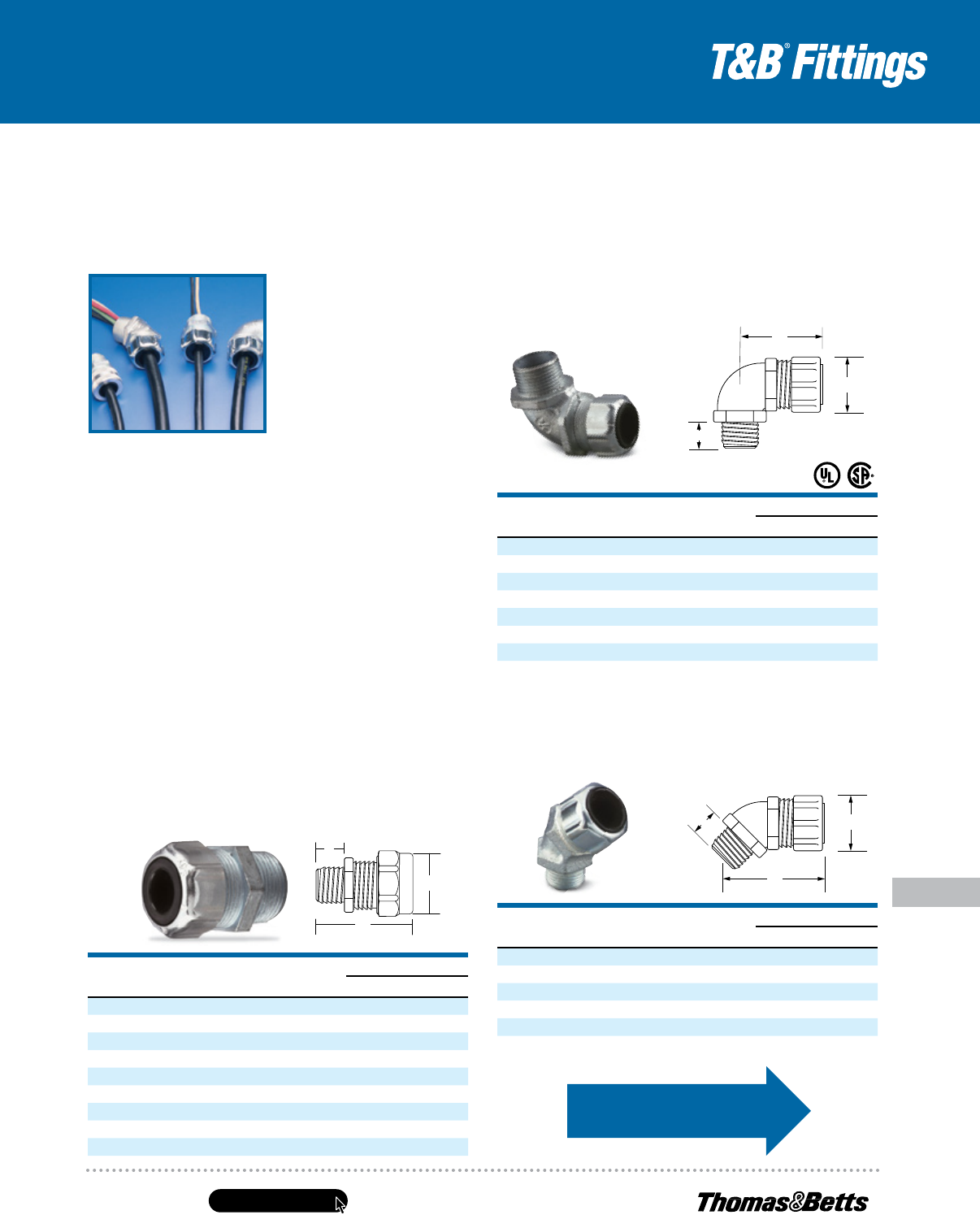
Steel Liquidtight Strain Relief Connectors —
Straight
CAT. NO.
HUB
SIZE
THROAT
DIA. CORD RANGE
DIMENSIONS (IN.)
A B C
2920
1
⁄2"
47
⁄64" .125–.375 1
1
⁄8 1
3
⁄4
5
⁄8
2921
1
⁄2"
47
⁄64" .310–.560 1
1
⁄8 1
3
⁄4
5
⁄8
2922
1
⁄2"
47
⁄64" .500–.750 1
3
⁄8 1
3
⁄4
5
⁄8
2930
3
⁄4"
13
⁄16" .125–.375 1
3
⁄8 1
25
⁄32
5
⁄8
2931
3
⁄4"
13
⁄16" .310–.560 1
3
⁄8 1
25
⁄32
5
⁄8
2932
3
⁄4"
13
⁄16" .500–.750 1
3
⁄8 1
25
⁄32
5
⁄8
2940 1"
11
⁄16" .310–.560 1
3
⁄8 1
3
⁄4
3
⁄4
2941 1"
11
⁄16" .500–.750 1
3
⁄8 1
3
⁄4
3
⁄4
2942 1"
31
⁄32" .700–.950 1
5
⁄8 1
7
⁄8
31
⁄32
C
B
A
Steel Liquidtight Strain Relief Connectors —
90° Angle
CAT. NO.
HUB
SIZE
THROAT
DIA. CORD RANGE
DIMENSIONS (IN.)
A B C
4960
1
⁄2"
19
⁄32 .125–.375 1
1
⁄8 1
3
⁄4
5
⁄8
4961
1
⁄2"
19
⁄32 .310–.560 1
1
⁄8 1
3
⁄4
5
⁄8
4962
1
⁄2"
19
⁄32 .500–.750 1
3
⁄8 1
23
⁄64
5
⁄8
4970
3
⁄4"
25
⁄32 .125–.375 1
3
⁄8 1
25
⁄32
11
⁄16
4971
3
⁄4"
25
⁄32 .310–.560 1
3
⁄8 1
25
⁄32
11
⁄16
4972
3
⁄4"
25
⁄32 .500–.750 1
3
⁄8 1
25
⁄32
11
⁄16
4980 1" 1 .310–.560 1
3
⁄8 2
1
⁄32
13
⁄16
All items shown on this page are suitable for use in hazardous locations where general-
purpose equipment is specifically permitted by the NEC
®
. NEC 501-4(b).
UL File No. E-13938 CSA File No. 52391
C
A
B
Steel Liquidtight Strain Relief Connectors —
45° Angle
For wire mesh grips, refer
to page E-142.
CAT. NO.
HUB
SIZE
THROAT
DIA. CORD RANGE
DIMENSIONS (IN.)
A B C
4920
1
⁄2"
37
⁄64 .125–.375 1
1
⁄8 1
5
⁄16
47
⁄64
4921
1
⁄2"
37
⁄64 .310–.560 1
1
⁄8 1
5
⁄16
47
⁄64
4922
1
⁄2"
37
⁄64 .500–.750 1
3
⁄8 1
7
⁄16
47
⁄64
4930
3
⁄4"
25
⁄32 .125–.375 1
3
⁄8 1
7
⁄16
5
⁄8
4931
3
⁄4"
25
⁄32 .310–.560 1
3
⁄8 1
7
⁄16
5
⁄8
4932
3
⁄4"
25
⁄32 .500–.750 1
3
⁄8 1
7
⁄16
5
⁄8
B
A
C
B
A
C
B
A
C
www.tnb.com
United States
Tel: 901.252.8000
800.816.7809
Fax: 901.252.1354
Technical Services
Tel: 888.862.3289
E-136
Conduit & Fittings — T&B
®
Cord & Cable Fittings
Metallic Liquidtight Cord and Cable Connectors
The Ranger
®
Series of Non-Metallic Liquidtight Cord Connectors
Application
• Provide means for passing a cord
into an enclosure or through a
bulkhead or into a rigid conduit
• Form a mechanical grip and water-
and/or oil-resistant seal for cord
• Form a nonslip connection or
termination for flexible cord,
cable (armored or unarmored)
Cord & Cable Type
• S, SO, SV, ST, STD, SJ, SJO,
SJT, SJTO, SVD
Features
• Extended range with
superior strain relief
• Reduced overall size, fits
into tighter spaces
• Gland nut designed to restrict
cable bending
Materials
Weather-stabilized nylon, temperature rated
-34° C to 105° C
Bushing: Rubber
Environment Classification
Ordinary locations
Wet or dry locations
Fittings used in a trade size knockout requiring
a NEMA 3R, 4, 6 or 13 listing require a 5262
Series sealing ring
Range
Cord Range: Straight — .125" to .950"
90° — .125" to .750"
Hub Size Range: Straight —
1
⁄2" to 1"
90° —
1
⁄2" to
3
⁄4"
Listings/Compliances
UL Type 6 and 4X
The Ranger
®
Series Non-Metallic Liquidtight Cord
Connector takes twice the cable range of most
ordinary strain-relief connectors. T&B’s Ranger
Connectors enable you to reduce your inventory
and save time with one connector that can do
the work of two. The sturdy nylon material adds
corrosion resistance to your installation.
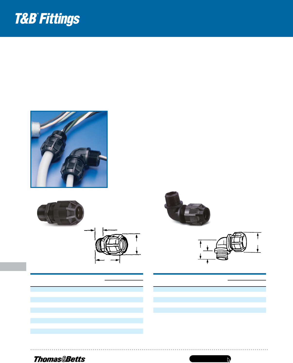
Non-Metallic Liquidtight Strain Relief Connector — Straight
CAT. NO.
TRADE OR
HUB SIZE
THROAT
DIA.
CORD
RANGE
DIMENSIONS (IN.)
A B C
2920NM
1
⁄2" .55 .125–.375 1
7
⁄32 2
1
⁄8
5
⁄8
2921NM
1
⁄2" .55 .310–.560 1
7
⁄32 2
1
⁄8
5
⁄8
2922NM
1
⁄2" .55 .500–.750 1
13
⁄32 2
5
⁄32
5
⁄8
2930NM
3
⁄4" .79 .125–.375 1
13
⁄32 2
3
⁄16
5
⁄8
2931NM
3
⁄4" .79 .310–.560 1
13
⁄32 2
3
⁄16
5
⁄8
2932NM
3
⁄4" .79 .500–.750 1
13
⁄32 2
3
⁄16
5
⁄8
2940NM 1" .98 .310–.560 1
13
⁄32 2
11
⁄32
25
⁄32
2941NM 1" .98 .500–.750 1
13
⁄32 2
11
⁄32
25
⁄32
2942NM 1" .98 .700–.950 1
43
⁄64 2
3
⁄8
25
⁄32
Non-Metallic Liquidtight Strain Relief Connector — 90° Elbow
CAT. NO.
TRADE OR
HUB SIZE
THROAT
DIA.
CORD
RANGE
DIMENSIONS (IN.)
A B C
4960NM
1
⁄2" .55 .125–.375 1
7
⁄32 1
1
⁄4
5
⁄8
4961NM
1
⁄2" .55 .310–.560 1
7
⁄32 1
1
⁄4
5
⁄8
4970NM
3
⁄4" .79 .125–.375 1
13
⁄32 1
3
⁄8
5
⁄8
4971NM
3
⁄4" .79 .310–.560 1
13
⁄32 1
3
⁄8
5
⁄8
4972NM
3
⁄4" .79 .500–.750 1
13
⁄32 1
3
⁄8
5
⁄8
UL File No. E 13938
CSA File No. 52391
Meets Coast Guard CG293
C
C
B
B
A
A
United States
Tel: 901.252.8000
800.816.7809
Fax: 901.252.1354
Technical Services
Tel: 888.862.3289
www.tnb.com
E-137
Conduit & Fittings — T&B
®
Cord & Cable Fittings
Metallic Liquidtight Cord and Cable Connectors
Type 304 stainless construction for your harshest environments!
The Ranger
®
Series of Stainless Steel Liquidtight Cord Connectors
Until now, there’s been no ideal solution for liquidtight connections
of portable cord to a box or enclosure in corrosive environments. Steel
connectors rust, and non-metallic connectors can’t withstand high
temperatures or ultraviolet exposure.
In response to customer demand, Thomas & Betts has developed the
latest addition to its high-performance line of Ranger
®
Cord Connectors.
Made of Type 304 stainless steel, Ranger
®
Stainless Steel Liquidtight
Cord Connectors stand up to highly corrosive environments — such as
washdown areas in food and beverage or pharmaceutical processing —
as well as high temperatures and UV exposure.
Application
• Provide means for passing a cord cable into an enclosure,
through a bulkhead or into a rigid conduit
• Form a mechanical grip and water- and/or oil-resistant seal
for cord
• Form a non-slip connection or termination for flexible cord
Cord & Cable Type
• SJ, SJE, SJEO, SJEOO, SJO, SJOW, SJOO, SJOOW, SJT,
SJTW, SJTO, SJTOW, SJTOO, SJTOOW, SO, SOW, SOO,
SOOW, SV, ST, STD, SVD
Features
• Extended range with superior strain relief
• Reduced overall size, fits into tighter spaces
• Gland nut designed to restrict cable bending
Materials
Body, Gland Nut, Grip ............................................ Type 304 stainless steel
Bushing ...................................................................... Thermoplastic rubber
Grip Ring ........................................................................................... Nylon
O-Ring (supplied) ............................................................................ Buna N
Environment Classification
Ordinary locations (wet or dry)
Temperature Rating ...............................-20° C to 105° C (-4° F to 221° F)
Range
Cord Range ......................................................................... .125" to .950"
Hub Size Range ............................................................................
1
⁄2" to 1"
Listings/Compliances
1
⁄4" and
3
⁄8" Sizes ................................................................. UL Recognized
1
⁄2" through 1" Sizes ..............................UL Listed and CSA Certified for use
with portable cord; UL514B liquidtight
cord connectors; UL Type 6 and 4X
A
B
C
Stainless Steel Liquidtight Strain-Relief
Cord Connectors —
1
⁄
2
"–1" Hub Sizes
CAT. NO.
HUB
SIZE (IN.)
CORD DIA.
RANGE (IN.)
DIMENSIONS (IN.)
STD. PKG.
QTY.A B C
2920SST
1
⁄2 .125–.375 1.935 .610 1.125 25
2921SST
1
⁄2 .310–.560 1.935 .610 1.125 25
2922SST
1
⁄2 .500–.750 2.003 .610 1.125 25
2930SST
3
⁄4 .125–.375 2.063 .630 1.125 10
2931SST
3
⁄4 .310–.560 2.063 .630 1.125 10
2932SST
3
⁄4 .500–.750 2.063 .630 1.125 10
2940SST 1 .310–.560 2.178 .785 1.500 10
2941SST 1 .500–.750 2.218 .785 1.500 10
2942SST 1 .700–.950 2.218 .785 1.500 10
Stainless Steel Cable Glands —
1
⁄
4
"–
3
⁄
8
" Hub Sizes
CAT. NO.
HUB
SIZE (IN.)
CORD DIA.
RANGE (IN.)
DIMENSIONS (IN.)
STD. PKG.
QTY.A B C
2918SST
1
⁄4 .118–.256 1.000 .250 .625 25
2919SST
3
⁄8 .157–.315 1.313 .438 .750 25
www.tnb.com
United States
Tel: 901.252.8000
800.816.7809
Fax: 901.252.1354
Technical Services
Tel: 888.862.3289
E-138
Metallic Liquidtight Cord and Cable Connectors
Conduit & Fittings — T&B
®
Cord & Cable Fittings
A
C
B
D
A
C
B
Application
• A liquidtight connector to connect
flexible cord to an enclosure and
provide adequate strain relief
• Form a mechanical grip and water
and liquidtight seal
• Form a non-slip connection
or termination for flexible cord
Cord & Cable Type
• SJ, SJE, SJEW, SJEO, SJEOO,
SJEOOW, SJO, SJOW, SJOO, SJOOW,
SJT, SJTW, SJTO, SJTOW, SJTOO,
SJTOOW, SO, SOW, SOO, SOOW, SV,
ST, STD, SVD
Features
• Available in straight or 90° designs
• Designed to accept a wide range of
cables, offering nine fittings that cover
cord ranges from .125" through .950"
• Slotted design gland nut to
accommodate securing in tight spaces
• Installer can simply use screwdriver
to get into the hard-to-reach area
and secure the gland nut
• Marked with cable ranges and conduit
hub sizes
Material
Body ................Copper-Free Aluminum
Gland Nut, Grip ................. Copper-Free
Aluminum — All Series
Bushing .............. Thermoplastic Rubber
Grip Ring .................................... Nylon
Environment Classification
Ordinary locations
Wet or dry locations
Temperature Range: -20° C
to 105° C (-4° F to 221° F)
Range
Cord Range: .125" to .950"
Hub Size Range:
1
⁄2" to 1"
The Ranger
®
Series of Aluminum
Liquidtight Cord Connectors
Aluminum Liquidtight Strain-Relief Connectors
CAT. NO.
HUB
SIZE
CORD
RANGE (IN.)
DIMENSIONS (IN.)
STD. PKG.
QTY.
WT. PER
100A B C D
Straight
2920AL
1
⁄2" .125–.375 1
1
⁄8 1
3
⁄4
5
⁄8 — 25 8.50
2921AL
1
⁄2" .310–.560 1
1
⁄8 1
3
⁄4
5
⁄8 — 25 8.05
2922AL
1
⁄2" .500–.750 1
5
⁄16 1
3
⁄4
5
⁄8 — 25 9.95
2930AL
3
⁄4" .125–.375 1
5
⁄16 1
25
⁄32
3
⁄8 — 10 12.30
2931AL
3
⁄4" .310–.560 1
5
⁄16 1
25
⁄32
3
⁄4 — 10 11.90
2932AL
3
⁄4" .500–.750 1
5
⁄16 1
25
⁄32
3
⁄4 — 10 11.50
2940AL 1" .310–.560 1
5
⁄16 1
3
⁄4 1
1
⁄16 — 10 18.00
2941AL 1" .500–.750 1
5
⁄16 1
3
⁄4 1
1
⁄16 — 10 16.00
2942AL 1" .700–.950 1
9
⁄16 1
7
⁄8 3
1
⁄32 — 10 16.70
90° Elbow
4960AL
1
⁄2" .125–.375 1
1
⁄8 1
3
⁄4
5
⁄8 1
5
⁄16 50 23.60
4961AL
1
⁄2" .360–.560 1
1
⁄8 1
3
⁄4
5
⁄8 1
5
⁄16 50 11.60
4970AL
3
⁄4" .125–.375
15
⁄16 1
25
⁄32
11
⁄16 1
15
⁄32 50 17.2
4971AL
3
⁄4" .310–.560
15
⁄16 1
25
⁄32
11
⁄16 1
15
⁄32 50 30.00
4972AL
3
⁄4" .500–.750
15
⁄16 1
25
⁄32
11
⁄16 1
15
⁄32 50 33.09
4980AL 1" .310–.560
15
⁄16 2
1
⁄32
13
⁄16 1
3
⁄4 25 21.50
4981AL 1" .500–.750
15
⁄16 2
1
⁄32
13
⁄16 1
3
⁄4 25 22.36
4982AL 1" .700–.950
15
⁄16 2
11
⁄16
13
⁄16 2 25 18.20
* It may be necessary to remove sufficient outer covering of cable to permit conductors to pass through connector body.
All items shown on this page are suitable for use in hazardous locations where general-purpose equipment is specifically
permitted by the NEC
®
. NEC 501-4(b).
UL File No. E-13938 CSA File No. 52391
For wire mesh grips, refer
to page E-142.
C
A
B
C
D
A
B
United States
Tel: 901.252.8000
800.816.7809
Fax: 901.252.1354
Technical Services
Tel: 888.862.3289
www.tnb.com
E-139
Conduit & Fittings — T&B
®
Cord & Cable Fittings
Metallic Liquidtight Cord and Cable Connectors
T&B
®
Liquidtight Strain-Relief Cord Connectors
CAT.
NO.
CABLE SIZE
(IN)
HUB
SIZE
THROAT
DIA.
(MIN.) FIG.
DIMENSIONS
(IN.
BUSHING
PART
NO.
GLAND-NUT
MODEL
NO.
RETAINER
MODEL
NO.
BODY
MODEL
NO.
RANGE
MIN.–MAX. A B C
2516
†
.060–.125
1
⁄4"
23
⁄64" 2
33
⁄64
17
⁄16
15
⁄32 035-73377-5 035-73377-3 035-73377-9 035-73377-1
2517
†
.120–.250
1
⁄4"
23
⁄64" 2
13
⁄64
17
⁄16
15
⁄32 035-73377-6 035-73377-3 035-73377-9 035-73377-1
2518
†
.060–.150
3
⁄8"
29
⁄64" 2
31
⁄32 1
1
⁄2
15
⁄32 035-73377-7 035-73377-4 035-73377-9 035-73377-2
2519
†
.150–.300
3
⁄8"
29
⁄64" 2
31
⁄32 1
1
⁄2
15
⁄32 035-73377-8 035-73377-4 035-73377-9 035-73377-2
2520 .125–.250
1
⁄2"
9
⁄16" 1 1
21
⁄32
5
⁄8 053-71411-1 053-71411-37 035-72735-1 053-71411-43
2521 .250–.375
1
⁄2"
9
⁄16" 1 1
1
⁄8 1
21
⁄32
5
⁄8 053-71411-2 053-71411-37 035-72735-1 053-71411-43
2522 .375–.500
1
⁄2"
9
⁄16" 1 1
1
⁄8 1
21
⁄32
5
⁄8 053-71411-3 053-71411-37 035-72735-2 053-71411-43
2523 .450–.560
1
⁄2"
9
⁄16" 1 1
1
⁄8 1
21
⁄32
5
⁄8 053-71411-4 053-71411-37 035-72735-2 053-71411-43
2524* .500–.625
1
⁄2"
5
⁄8" 1 1
3
⁄8 1
3
⁄4
5
⁄8 053-71411-59 053-71411-38 035-72735-3 033-72259-21
2525* .625–.750
1
⁄2"
5
⁄8" 1 1
3
⁄8 1
3
⁄4
5
⁄8 053-71411-60 053-71411-38 035-72735-3 033-72259-21
2530 .125–.250
3
⁄4"
13
⁄16" 1 1
3
⁄8 1
3
⁄4
9
⁄16 033-72259-1 053-71411-38 035-72735-4 053-71411-44
2531 .250–.375
3
⁄4"
13
⁄16" 1 1
3
⁄8 1
3
⁄4
9
⁄16 053-71411-5 053-71411-38 035-72735-4 053-71411-44
2532 .375–.500
3
⁄4"
13
⁄16" 1 1
3
⁄8 1
3
⁄4
9
⁄16 053-71411-58 053-71411-38 035-72735-4 053-71411-44
2534 .500–.625
3
⁄4"
13
⁄16" 1 1
3
⁄8 1
3
⁄4
9
⁄16 053-71411-59 053-71411-38 035-72735-3 053-71411-44
2535 .625–.750
3
⁄4"
13
⁄16" 1 1
3
⁄8 1
3
⁄4
9
⁄16 053-71411-60 053-71411-38 035-72735-3 053-71411-44
2536* .750–.880
3
⁄4"
3
⁄4" 1 1
3
⁄8 1
15
⁄16
5
⁄8 053-71411-61 053-71411-39 035-72735-5 033-72259-22
2541 .250–.375 1"
49
⁄64" 1 1
11
⁄16 1
23
⁄32
9
⁄16 053-71411-5 053-71411-38 035-72735-4 053-71411-45
2542 .375–.500 1"
49
⁄64" 1 1
11
⁄16 1
23
⁄32
9
⁄16 053-71411-58 053-71411-38 035-72735-4 053-71411-45
2544 .500–.625 1"
49
⁄64" 1 1
11
⁄16 1
23
⁄32
9
⁄16 053-71411-59 053-71411-38 035-72735-3 053-71411-45
2545 .625–.750 1"
49
⁄64" 1 1
11
⁄16 1
23
⁄32
25
⁄32 053-71411-60 053-71411-38 035-72735-3 053-71411-45
2546 .750–.880 1"
63
⁄64" 1 1
11
⁄16 1
7
⁄8
9
⁄16 053-71411-61 053-71411-39 035-72735-5 053-71411-46
2547 .875–.985 1"
63
⁄64" 1 1
11
⁄16 1
7
⁄8
9
⁄16 053-71411-62 053-71411-39 035-72735-5 053-71411-46
2548* .880–1.065 1"
29
⁄32" 1 2
1
⁄16 2
3
⁄8
25
⁄32 053-71411-63 053-71411-40 035-72735-6 033-72259-23
2549* 1.065–1.205 1"
29
⁄32" 1 2
1
⁄16 2
3
⁄8
25
⁄32 053-71411-64 053-71411-40 035-72735-6 033-72259-23
2558 .880–1.065 1
1
⁄4" 1
17
⁄64" 1 2
1
⁄8 2
5
⁄32
5
⁄8 053-71411-63 053-71411-40 035-72735-6 053-71411-47
2559 1.065–1.205 1
1
⁄4" 1
17
⁄64" 1 2
1
⁄16 2
5
⁄32
5
⁄8 053-71411-64 053-71411-40 035-72735-6 053-71411-47
2556* 1.187–1.375 1
1
⁄4" 1
1
⁄4" 1 2
5
⁄16 2
1
⁄2
13
⁄16 053-71411-18 053-71411-41 035-72735-7 033-72259-24
2557* 1.375–1.485 1
1
⁄4" 1
1
⁄4" 1 2
5
⁄16 2
1
⁄2
13
⁄16 033-72259-2 053-71411-41 035-72735-7 033-72259-24
2562 .812–1.000 1
1
⁄2"
17
⁄16" 1 2
5
⁄16 2
1
⁄2
13
⁄16 033-72259-3 053-71411-41 035-72735-7 053-71411-48
2563 1.000–1.187 1
1
⁄2" 1
7
⁄16" 1 2
5
⁄16 2
17
⁄16
11
⁄16 053-71411-17 053-71411-41 035-72735-7 053-71411-48
2564 1.187–1.375 1
1
⁄2" 1
7
⁄16" 1 2
1
⁄4 2
17
⁄16
11
⁄16 053-71411-18 053-71411-41 035-72735-7 053-71411-48
2565* 1.375–1.625 1
1
⁄2" 1
29
⁄64" 1 2
3
⁄4 2
5
⁄8
13
⁄16 053-71411-65 053-71411-42 035-72735-8 033-72259-25
2573 1.125–1.375 2" 1
7
⁄8" 1 2
3
⁄4 2
5
⁄8
13
⁄16 053-71411-66 053-71411-42 035-72735-8 053-71411-49
2574 1.375–1.625 2" 1
7
⁄8" 1 2
3
⁄4 2
5
⁄8
13
⁄16 053-71411-65 053-71411-42 035-72735-8 053-71411-49
2575 1.625–1.875 2" 1
7
⁄8" 1 2
3
⁄4 3
1
⁄2
13
⁄16 053-71411-67 053-71411-42 035-72735-8 053-71411-49
2576* 1.750–1.965 2" 1
29
⁄32" 1 3
7
⁄32 3
1
⁄2
13
⁄16 033-72259-5 033-72259-17 035-72735-9 033-72259-26
2577* 1.937–2.187 2" 1
29
⁄32" 1 3
7
⁄32 3
1
⁄2
13
⁄16 033-72259-6 033-72259-17 035-72735-9 033-72259-26
2584 1.750–1.965 2
1
⁄2" 2" 1 3
7
⁄32 3
3
⁄4 1
1
⁄32 033-72259-5 033-72259-17 035-72259-14 033-72259-27
2585 1.937–2.187 2
1
⁄2" 2" 1 3
7
⁄32 3
3
⁄4 1
1
⁄32 033-72259-6 033-72259-18 033-72259-14 033-72259-27
2586* 2.156–2.360 2
1
⁄2" 2
5
⁄32" 1 3
15
⁄16 4
1
⁄4 1
1
⁄32 033-72259-7 033-72259-19 033-72259-15 033-72259-28
2587* 2.350–2.565 2
1
⁄2" 2
5
⁄32" 1 3
15
⁄16 4
1
⁄4 1
1
⁄32 033-72259-8 033-72259-19 033-72259-15 033-72259-28
2592 2.156–2.360 3" 2
13
⁄32" 1 3
15
⁄16 4
1
⁄4 1
1
⁄32 033-72259-7 033-72259-19 033-72259-15 033-72259-29
2593 2.350–2.565 3" 2
13
⁄32" 1 3
15
⁄16 4
1
⁄4 1
1
⁄32 033-72259-8 033-72259-19 033-72259-15 033-72259-29
2594 2.535–2.750 3" 2
13
⁄32" 1 3
15
⁄16 41/4 1
1
⁄32 033-72259-9 033-72259-19 033-72259-15 033-72259-29
2595* 2.735–2.985 3" 2
13
⁄16" 1 4
11
⁄16 4
13
⁄16 1
1
⁄8 033-72259-10 033-72259-20 033-72259-16 033-72259-30
2596* 2.970–3.220 3" 2
13
⁄16" 1 4
11
⁄16 4
13
⁄16 1
1
⁄8 033-72259-11 033-72259-20 033-72259-16 033-72259-30
The T&B Steel Liquidtight Strain Relief Cord
Connector is suited for most general control
and power cable applications. This series
features sturdy neoprene bushings and
tapered hub threads.
Application
• Provide means for passing a cord cable
(armored or unarmored) into an enclosure,
through a bulkhead or into a rigid conduit
• Form a mechanical grip and water- and/or
oil-resistant seal for cord and unarmored
or jacketed armored round cables
• Form a non-slip connection or termination for
flexible cord, cable (armored or unarmored)
• Provide grounding continuity of cable armor
Cord & Cable Type
• S, SO, SV, ST, STD, SJ, SJO, SJT, SJTO, SVD
Features
• Extended range with superior strain relief
• Reduced overall size, fits into tighter spaces
• Gland nut designed to restrict cable bending
Materials
Body ............................Cat. Nos. 2516–2519 — Steel
Cat. Nos. 2520–2596 — Malleable Iron or Die-Cast
Zinc
2200 Series — Malleable Iron
Gland .....................................................................Steel
Bushing ......................................................... Neoprene
Environment Classification
Ordinary locations
Wet or dry locations
Fittings used in a trade size knockout requiring a
NEMA 3R, 4, 6 or 13 listing require a 5262 Series
sealing ring
UL Listed as liquidtight strain relief and outlet bushing.
CSA certified watertight.
UL File No. E 13938
CSA File No. 589 & 4484
†
UL not applicable.
* Remove sufficient outer covering of cable to permit
conductors to pass through connector body.
Complies with JIC standards.
Temperature rating 105° C.
Suitable for hazardous locations use where general-purpose
equipment is specifically permitted per NEC
®
Section 501-4(b).
C
B
A
Fig. 1
C
B
A
Fig. 2
C
A
B
C
A
B
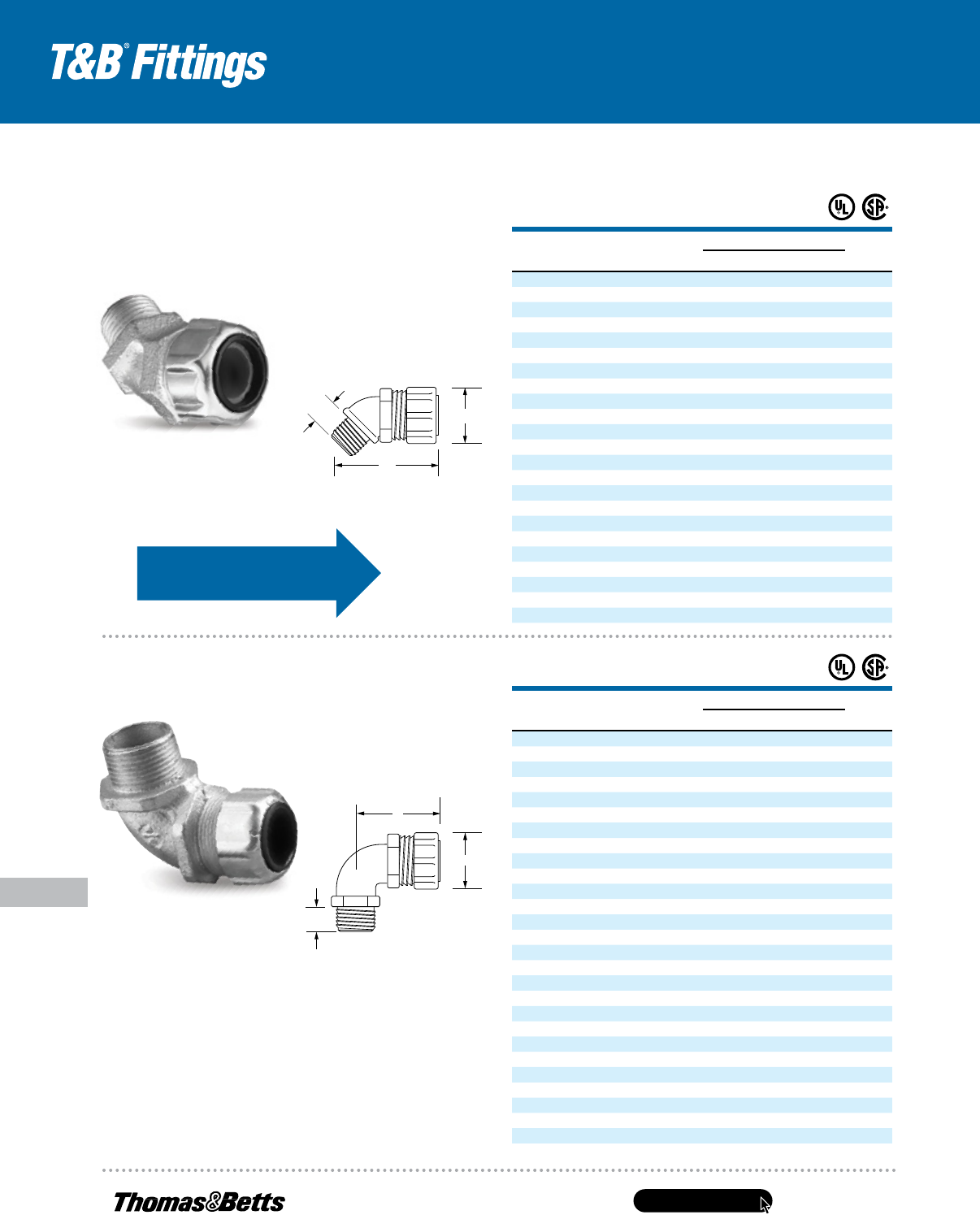
www.tnb.com
United States
Tel: 901.252.8000
800.816.7809
Fax: 901.252.1354
Technical Services
Tel: 888.862.3289
E-140
Metallic Liquidtight Cord and Cable Connectors
Conduit & Fittings — T&B
®
Cord & Cable Fittings
C
A
B
For wire mesh grips, refer
to page E–142.
UL Listed as liquidtight strain relief and outlet bushing.
CSA certified watertight.
UL File No. E 13938
CSA File No. 589 & 4484
†
UL not applicable.
* Remove sufficient outer covering of cable to permit
conductors to pass through connector body.
Complies with JIC standards.
Temperature rating 105° C.
Suitable for hazardous locations use where general–purpose
equipment is specifically permitted per NEC
®
.
CAT. NO.
CABLE–SIZE
MIN.–MAX. (IN.) HUB SIZE
DIMENSIONS (IN.)
THROAT
DIA.A B C
2200 .125–.250
1
⁄2" 1
1
⁄8 1
9
⁄32
9
⁄16
37
⁄64
2201 .250–.375
1
⁄2" 1
1
⁄8 1
9
⁄32
9
⁄16
37
⁄64
2202 .375–.500
1
⁄2" 1
1
⁄8 1
9
⁄32
9
⁄16
37
⁄64
2203 .450–.560
1
⁄2" 1
1
⁄8 1
9
⁄32
9
⁄16
37
⁄64
2204* .500–.625
1
⁄2" 1
3
⁄8 1
13
⁄32
9
⁄16
37
⁄64
2205* .625–.750
1
⁄2" 1
3
⁄8 1
13
⁄32
9
⁄16
37
⁄64
2206 .125–.250
3
⁄4" 1
3
⁄8 1
13
⁄32
5
⁄8
25
⁄32
2207 .250–.375
3
⁄4" 1
3
⁄8 1
13
⁄32
5
⁄8
25
⁄32
2208 .375–.500
3
⁄4" 1
3
⁄8 1
13
⁄32
5
⁄8
25
⁄32
2209 .500–.625
3
⁄4" 1
3
⁄8 1
13
⁄32
5
⁄8
25
⁄32
2210 .625–.750
3
⁄4" 1
3
⁄8 1
13
⁄32
5
⁄8
25
⁄32
2211* .750–.880
3
⁄4" 11
1
⁄16 1
1
⁄2 1
1
⁄2
3
⁄4
2213 .375–.500 1" 1
3
⁄8 1
1
⁄2
25
⁄32
15
⁄16
2214 .500–.625 1" 1
3
⁄8 1
1
⁄2
25
⁄32
15
⁄16
2215 .625–.750 1" 1
3
⁄8 1
1
⁄2
25
⁄32
15
⁄16
2216 .750–.875 1" 11
1
⁄16 1
15
⁄32
25
⁄32
15
⁄16
2217* .875–.985 1" 11
1
⁄16 1
15
⁄32
25
⁄32
15
⁄16
2218* .880–1.065 1" 2
1
⁄16 1
31
⁄32
25
⁄32
15
⁄16
2219* 1.065–1.205 1" 2
1
⁄16 1
31
⁄32
25
⁄32
15
⁄16
2220* .880–1.065 1
1
⁄4" 2
1
⁄16 1
29
⁄32 1
3
⁄16
15
⁄16
2221* 1.065–1.205 1
1
⁄4" 2
1
⁄16 1
29
⁄32 1
3
⁄16
15
⁄16
2222* 1.187–1.375 1
1
⁄4" 2
1
⁄16 2
1
⁄4 1
3
⁄16 1
21
⁄64
2223* 1.375–1.485 1
1
⁄4" 2
1
⁄16 2
1
⁄4 1
3
⁄16 1
21
⁄64
CAT. NO.
CABLE–SIZE
MIN.–MAX. (IN.) HUB SIZE
DIMENSIONS (IN.)
THROAT
DIA.A B C
2268 .250–.375
1
⁄2" 1
1
⁄8 1
23
⁄32
5
⁄8
19
⁄32
2269 .375–.500
1
⁄2" 1
1
⁄8 1
23
⁄32
5
⁄8
19
⁄32
2270 .450–.560
1
⁄2" 1
1
⁄8 1
23
⁄32
5
⁄8
19
⁄32
2250* .500–.625
1
⁄2" 1
3
⁄8 1
11
⁄16
9
⁄16
39
⁄64
2251* .625–.750
1
⁄2" 1
3
⁄8 1
11
⁄16
9
⁄16
39
⁄64
2252 .125–.250
3
⁄4" 1
3
⁄8 1
3
⁄4
1
⁄2
25
⁄32
2271 .250–.375
3
⁄4" 1
3
⁄8 1
5
⁄8
1
⁄2
25
⁄32
2272 .375–.500
3
⁄4" 1
3
⁄8 1
5
⁄8
1
⁄2
25
⁄32
2273 .500–.625
3
⁄4" 1
3
⁄8 1
5
⁄8
1
⁄2
25
⁄32
2274* .620–.750
3
⁄4" 1
3
⁄8 1
5
⁄8
1
⁄2
25
⁄32
2253* .750–.880
3
⁄4" 1
11
⁄16 1
31
⁄32
9
⁄16
25
⁄32
2254 .375–.500 1" 1
3
⁄8 2
25
⁄32 1
2255 .500–.625 1" 1
3
⁄8 2
25
⁄32 1
2256* .625–.750 1" 1
3
⁄8 2
25
⁄32 1
2275 .750–.875 1" 1
11
⁄16 2
5
⁄8 1
2276 .875–.985 1" 1
11
⁄16 2
5
⁄8 1
2257* .880–1.065 1" 2
1
⁄16 2
21
⁄32
25
⁄32 1
5
⁄16
2258* 1.065–1.205 1" 2
1
⁄16 2
21
⁄32
25
⁄32 1
5
⁄16
2277 .880–1.065 1
1
⁄4" 2
1
⁄16 2
7
⁄8
11
⁄16 1
5
⁄16
2278 1.065–1.205 1
1
⁄4" 2
1
⁄16 2
7
⁄8
11
⁄16 1
5
⁄16
2279* 1.187–1.375 1
1
⁄4" 2
5
⁄16 2
13
⁄16
13
⁄16 1
11
⁄32
2280* 1.375–1.485 1
1
⁄4" 2
5
⁄16 2
13
⁄16
13
⁄16 1
11
⁄32
2281 .812–1.000 1
1
⁄2" 2
5
⁄16 2
7
⁄8
13
⁄16 1
15
⁄32
2282 1.000–1.187 1
1
⁄2" 2
5
⁄16 2
7
⁄8
13
⁄16 1
15
⁄32
2283* 1.187–1.375 1
1
⁄2" 2
5
⁄16 2
7
⁄8
13
⁄16 1
15
⁄32
2284 1.125–1.375 2" 2
25
⁄32 3
1
⁄4
27
⁄32 1
31
⁄32
2285 1.375–1.625 2" 2
25
⁄32 3
1
⁄4
27
⁄32 1
31
⁄32
2286 1.625–1.875 2" 2
25
⁄32 3
1
⁄4
27
⁄32 1
31
⁄32
Liquidtight Strain-Relief
Connectors — 90°
Liquidtight Strain-Relief
Connectors — 45°
C
A
B
B
A
C
C
A
B
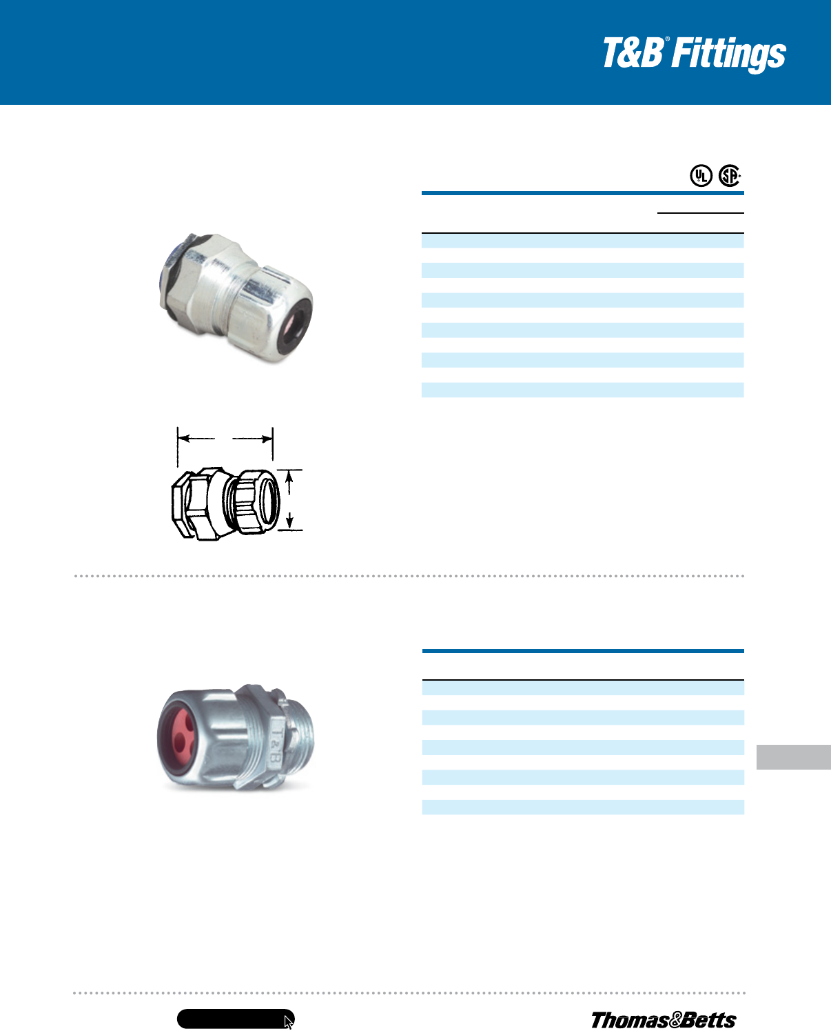
United States
Tel: 901.252.8000
800.816.7809
Fax: 901.252.1354
Technical Services
Tel: 888.862.3289
www.tnb.com
E-141
Conduit & Fittings — T&B
®
Cord & Cable Fittings
Metallic Liquidtight Cord and Cable Connectors
CAT. NO.
HUB
SIZE (IN.)
DIA.
NO.
CORD.
DIA. (IN.)
2520–2
1
⁄2" 2 .220
2530–2
3
⁄4" 2 .220
2531–2
3
⁄4" 2 .260
2531–3
3
⁄4" 3 .260
2541–2 1" 2 .300
2542–2 1" 2 .375
2540–3 1" 3 .225
2541–3 1" 3 .300
2540–4 1" 4 .220
2555–2 1
1
⁄4" 2 .500
Note: Range of cord dia. ±.010.
In many applications, you have only room for one fitting but you need to run two cables
(for example, proximity switches). Now you can provide strain relief and liquidtight protection
with T&B’s new multi–hole liquidtight strain relief connectors. With the ever–increasing
number of signal cables, now you have a solution to the problem of how to strain relieve
multiple cables in one fitting.
Multi-Hole Flexible Cord
and Cable Connectors
CAT. NO.
CABLE SIZE
RANGE SIZE
(IN.)
THROAT
DIA. CORD RANGE
DIMENSIONS (IN.)
A B
2631 .125–.250
1
⁄2"
9
⁄16" 1
1
⁄16 1
5
⁄8
2632 .250–.375
1
⁄2"
9
⁄16" 1
1
⁄16 1
5
⁄8
2633 .375–.500
1
⁄2"
9
⁄16" 1
1
⁄16 1
5
⁄8
2634 .450–.560
1
⁄2"
9
⁄16" 1
1
⁄16 1
5
⁄8
2637 .125–.250
3
⁄4"
25
⁄32" 1
5
⁄16 1
3
⁄4
2638 .250–.375
3
⁄4"
25
⁄32" 1
5
⁄16 1
3
⁄4
2639 .375–.500
3
⁄4"
25
⁄32" 1
5
⁄16 1
3
⁄4
2640 .500–.625
3
⁄4"
25
⁄32" 1
5
⁄16 1
3
⁄4
2641 .625–.750
3
⁄4"
25
⁄32" 1
5
⁄16 1
3
⁄4
2646 .500–.625 1" 1" 1
5
⁄8 1
13
⁄16
2647 .625–.750 1" 1" 1
5
⁄8 1
13
⁄16
2648 .750–.880 1" 1" 1
5
⁄8 1
13
⁄16
Suitable for hazardous locations use in Class I, Div. 2; Class II, Div. 1 and 2;
Class III, Div. 1 and 2, where general–purpose equipment is specifically permitted
per NEC
®
Section 500–2(a).
Complete with O–Ring seal and nylon insulated throat and neoprene bushing.
UL Listed as liquidtight strain relief and outlet bushing.
CSA certified watertight.
Temperature Rating: 105° C UL File No. E 13938
CSA File No. 589. CHASE
®
Liquidtight Cord Connectors are ideal
for installation where space is limited inside the enclosure.
CHASE
®
Liquidtight Cord Connectors
A
B
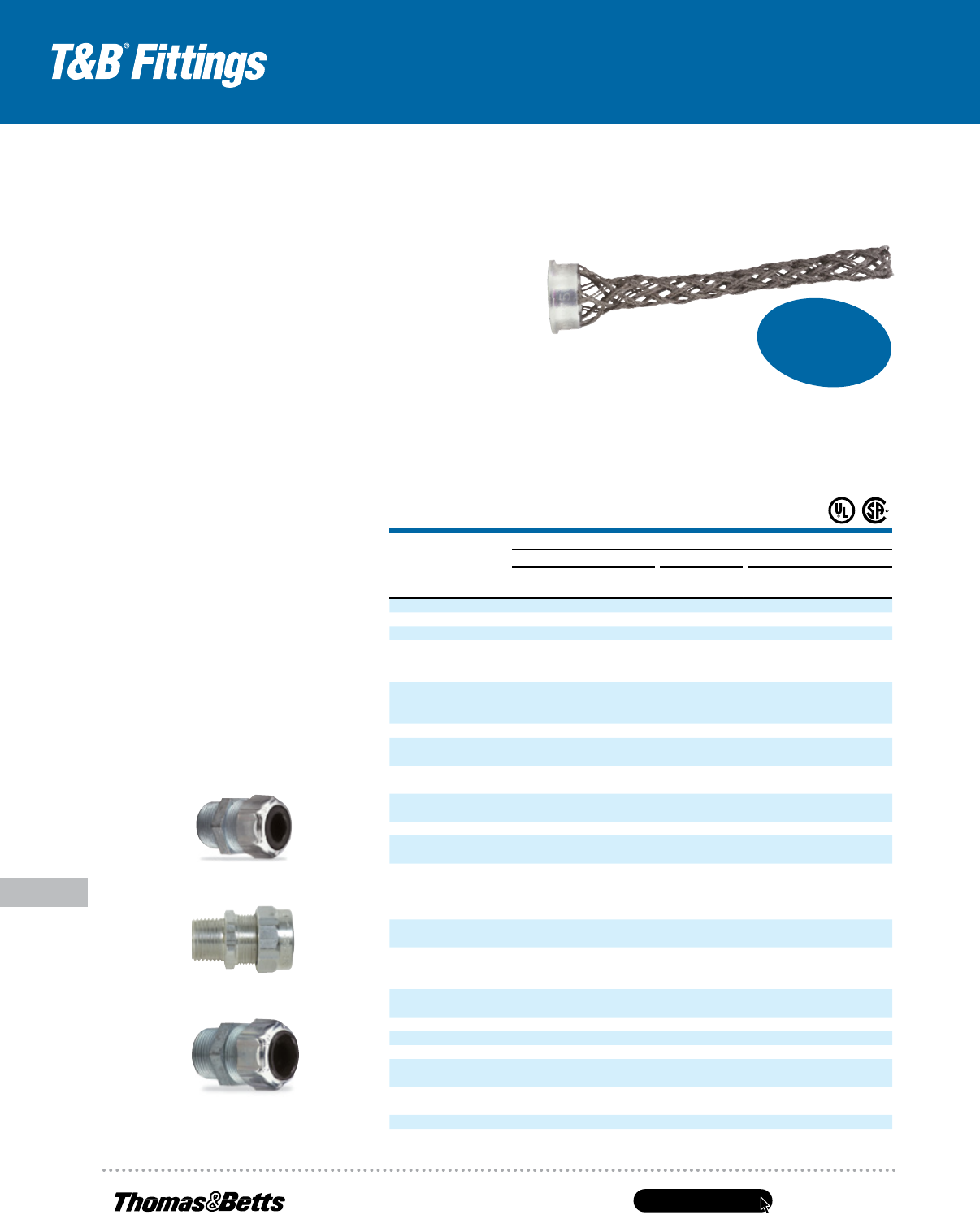
www.tnb.com
United States
Tel: 901.252.8000
800.816.7809
Fax: 901.252.1354
Technical Services
Tel: 888.862.3289
E-142
Metallic Liquidtight Cord and Cable Connectors
Conduit & Fittings — T&B
®
Cord & Cable Fittings
T&B Wire Mesh grips are ordered separately and fit with your existing inventory of Ranger
®
connectors and liquidtight strain-relief connectors. There’s no need to duplicate inventory.
The T&B WMG-PC Series Wire Mesh Grips for Portable Cord
Application
• Provides high gripping strength for adequate cable support
and strain relief without damage to the cable sheath
• Compression of a tapered neoprene bushing ensures
the watertight integrity of the fittings
• To meet National Electrical Code (NEC
®
) requirements for electrical
installations in hazardous atmospheres, a sealing fitting may be
required in conjunction with the cable and cord fitting
Cord & Cable Type
• S, SO, SV, ST, STD, SJ, SJO, SJT, SJTO, SVD
Features
• Prevents severe cord bends and pullouts
• Used in aluminum and/or steel fittings
Materials
Wiremesh made of stainless steel.
Retaining rings made of aluminum
Environment Classification
Ordinary locations
Range
.187 – 3.220
2920 Series
2920AL Series
2516 Series
How to select proper wiremesh grip:
1. Determine O.D. of portable cord, e.g., .200
2. Determine size of knockout or threaded hub,
e.g.
1
⁄2"
3. Select Cat. No. of strain relief connector,
e.g., 2520, 2920AL.
4. Match up O.D. with grip range and strain relief
to determine Cat. No. of Wiremesh Grip
(e.g., .200 + 2520 = WMP-PC1)
CAT. NO.
GRIP
RANGE
STRAIN-RELIEF CONNECTOR
STRAIGHT 45° 90°
RANGER
®
STEEL
RANGER
®
ALUMINUM
T&B
STEEL
RANGER
®
STEEL
T&B
STEEL
RANGER
®
STEEL
RANGER
®
ALUMINUM
T&B
STEEL
WMG-PC1 .187–.250 2920 2920AL 2520 4920 2200 4960 4960AL 2267
WMG-PC2 .250–.375 2920 2920AL 2521 4920 2201 4960 4960AL 2268
WMG-PC3 .375–.500 2921 2921AL 2522 4921 2202 4961 4961AL 2269
2922 2922AL 2524 4922 2204 4962 4962AL 2250
WMG-PC4 .500–.625 2932 2932AL 2534 4932 2209 4972 4972AL 2273
2941 2941AL 2544 4941 2214 4981 4981AL 2255
2922 2922AL 2525 4922 2205 4962 4962AL 2251
WMG-PC5 .625–.750 2932 2932AL 2535 4932 2210 4972 4972AL 2274
2941 2941AL 2545 4941 2215 4981 4981AL 2256
WMG-PC6 .187–.250 2930 2930AL 2530 4930 2206 4970 4970AL 2252
WMG-PC7 .250–.375 2930 2930AL 2531 4930 2207 4970 4970AL 2271
— — 2541 — — — — —
WMG-PC8 .375–.500 2931 2931AL 2532 4931 2208 4961 4961AL 2272
2940 2940AL 2542 4940 2213 4980 4980AL 2254
WMG-PC9 .750–.875 — — 2536 — 2211 — — 2253
2942 2942AL 2546 4942 2216 4982 4982AL 2275
WMG-PC10 .875–1.000 — — 2547 — 2217 — — 2276
WMG-PC11 .875–1.000 — — 2548 — 2218 — — 2257
— — 2558 — 2220 — — 2277
— — 2548 — 2218 — — 2257
WMG-PC12 1.000–1.125 — — 2558 — 2220 — — 2277
— — 2549 — 2219 — — 2258
— — 2559 — 2221 — — 2278
WMG-PC13 1.125–1.250 — — 2549 — — 2258 2258 2219
— — 2559 — 2221 — — 2278
— — 2556 — — 2279 2279 2222
WMG-PC14 1.125–1.250 — — 2563 — — — — 2282
— — 2564 — — — — 2283
WMG-PC15 1.250–1.375 — — — — 2222 — — 2256
— — 2564 — — — — 2283
WMG-PC16* 1.375–1.500 — — 2557 — 2223 — — 2280
WMG-PC17* 1.125–1.250 — — 2573 — — — — 2284
WMG-PC18* 1.250–1.375 — — 2573 — — — — 2284
WMG-PC19* 1.375–1.500 — — 2565 — — — — 2285
— — 2574 — — — — —
WMG-PC20* 1.500–1.625 — — 2565 — — — — 2285
— — 2574 — — — — —
WMG-PC21* 1.625–1.750 — — 2575 — — — — 2286
WMG-PC22* 1.750–1.875 — — 2575 — — — — 2286
* Replacement Gland Nut supplied with these catalog numbers only.
Now
Includes
Ranger
®
Series
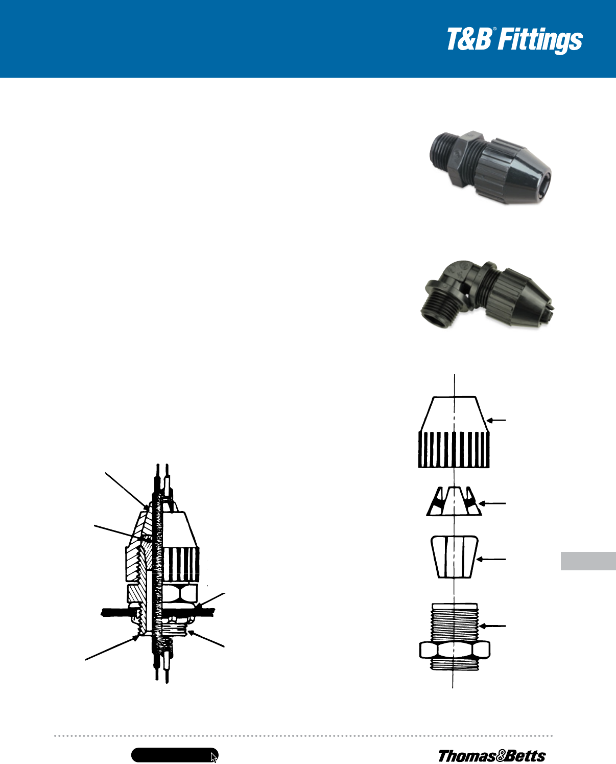
United States
Tel: 901.252.8000
800.816.7809
Fax: 901.252.1354
Technical Services
Tel: 888.862.3289
www.tnb.com
E-143
Conduit & Fittings — T&B
®
Cord & Cable Fittings
Non-Metallic Liquidtight Cord Connectors
Materials
Wiremesh made of stainless steel.
Retaining rings made of aluminum
Environment Classification
Ordinary locations
Range
.187 – 3.220
Note:
Series 5262
Sealing Gasket
(Not provided
with connector)
(C)
(B)
(D)
(A)
Typical Installation
Non-Metallic Liquidtight Flexible Cord
Connectors — Black Beauty
®
Series
Application
• A liquidtight connector to connect flexible
cord to a box or enclosure and provide
adequate strain relief
Features
• Taper Thread hub seals in female
hub (A)
• Neoprene bushing provides liquidtight
installation (B)
• Hand tightens — no tools needed
for assembly
• Segmented chuck provides high
mechanical pullout performance —
will not cut or damage cord jacket (C)
• Corrosion- and weather-resistant plastic is
excellent for outdoor/indoor use
• Plastic parts improve dielectric strength
and provide insulated throat (D)
• Wide range — reduces inventories
Standard Material
Body, Gland & Segmented Chuck .................... Weather-
stabilized thermoplastic rated for -34° C
(-29° F) to 105° C (221° F) application
Bushing ..........................................................Neoprene
Standard Finish
All parts as molded
Range
.250 Outside Diameter to 1.020 Outside Diameter .......Type S,
SO, SV, ST, STO, SJ, SJO, SJT, SJTO, SVTO, SVO, SVT
Flexible Cords & Cables
Listings/Compliances
UL (UL File No. E-23018)
CSA LR-2884, LR-4484
UL 514B
CSA C22.2 No. 18
NFPA 70
Federal Standard H-28 (Threads)
2672 Series
Gland
2672 Series
Segmented
Chuck
Bushing
Body
2682 Series
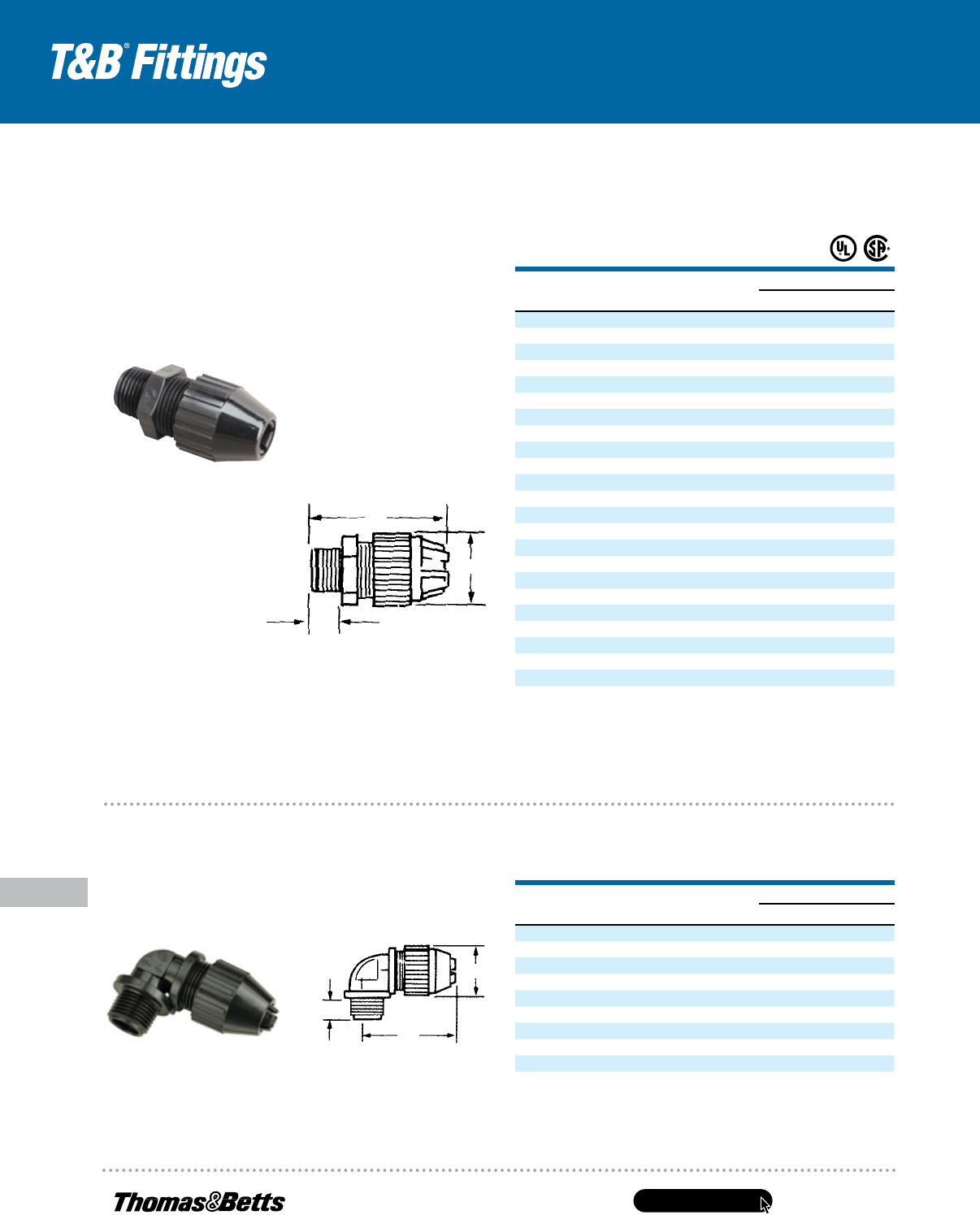
www.tnb.com
United States
Tel: 901.252.8000
800.816.7809
Fax: 901.252.1354
Technical Services
Tel: 888.862.3289
E-144
Non-Metallic Liquidtight Cord Connectors
Conduit & Fittings — T&B
®
Cord & Cable Fittings
• UL 94-V2 flammability rated
• Temperature rating: -34° C to +105° C
• Meets Coast Guard CG293
Rugged, weather-stabilized
nylon construction!
Black Beauty
®
Non-Metallic Liquidtight
Strain-Relief Connector — Straight
Cat.
No.
tradE or
Hub SizE
tHroat
dia. (iN.) Cord raNgE (iN.)
dimENSioNS (iN.)
a b C
2671
3
⁄8" .33 .125–.275 2.0 .90 .46
2690
1
⁄2" .33 .125–.275 2.3 .90 .60
2672
1
⁄2" .55 .250–.400 2.6 1.27 .60
2673*
1
⁄2" .55 .400–.560 2.6 1.27 .60
2691*
1
⁄2" .54 .560–.690 3.0 1.57 .60
2692*
1
⁄2" .54 .660–.780 3.0 1.57 .60
2693
3
⁄4" .55 .250–.400 2.7 1.27 .62
2694*
3
⁄4" .55 .400–.560 2.7 1.27 .62
2674
3
⁄4" .79 .560–.690 3.0 1.57 .62
2675
3
⁄4" .79 .660–.780 3.0 1.57 .62
2696*
3
⁄4" .76 .770–.895 3.2 1.89 .62
2676 1" .98 .660–.780 3.3 1.89 .77
2677 1" .98 .770–.895 3.3 1.89 .77
2678* 1" .98 .870–1.020 3.3 1.89 .77
2699 1" .98 .890–1.090 4.2 2.58 .77
2702 1
1
⁄4" 1.25 .890–1.090 4.2 2.58 .80
2703 1
1
⁄4" 1.25 1.080–1.280 4.0 2.58 .80
2704 1
1
⁄4" 1.25 1.270–1.470 4.0 2.58 .80
2705-tb 1
1
⁄2" 1.47 .890–1.150 4.2 2.95 .82
2706 1
1
⁄2" 1.47 1.140–1.400 4.3 2.95 .82
2707 1
1
⁄2" 1.47 1.390–1.650 4.3 2.95 .82
2708 2" 1.89 1.190–1.530 5.1 3.50 .84
2709 2" 1.89 1.520–1.860 4.9 3.50 .84
2710* 2" 1.89 1.850–2.190 4.9 3.50 .84
*Remove sufficient outer covering of
cable to permit conductors to pass
thru connector body.
All items shown on this page are suitable for use in
hazardous location where general-purpose equipment
is specifically permitted by the NEC
®
. Class I, Div. 2.
Class II, Div. 1 & 2.
Class III, Div. 1 & 2.
UL File No. E 13938
CSA File No. 52391
• Weather-stabilized nylon construction
• UL 94-V2 flammability rated
• Temperature rating: -34° C to +105° C
• Meets Coast Guard CG293
90° angle with a standard-size body!
Black Beauty
®
Non-Metallic Liquidtight
Strain-Relief Connector — 90° Elbow
Cat.
No.
tradE or
Hub SizE
tHroat
dia. (iN.) Cord raNgE (iN.)
dimENSioNS (iN.)
a b C
2680
3
⁄8" .33 .125–.275
29
⁄32 1
3
⁄4 .460
2681
1
⁄2" .55 .250–.400 — — —
2682*
1
⁄2" .55 .400–.560 — — —
2683
3
⁄4" .78 .560–.690 — — —
2684
3
⁄4" .78 .660–.780 — — —
2688 1" .98 .560–.690 1
27
⁄32 3
1
⁄4 .770
2685 1" .98 .660–.780 1
27
⁄32 3
1
⁄4 .770
2686 1" .98 .770–.895 1
27
⁄32 3
3
⁄16 .770
2687* 1" .98 .870–1.020 1
27
⁄32 3 .770
*Remove sufficient outer covering of
cable to permit conductors to pass
thru connector body. 90° angle,
standard size body.
All items shown on this page are suitable for use
in hazardous locations where general-purpose
equipment is specifically permitted by the NEC. Class
I, Div. 2. Class II,
Div. 1 & 2. Class III, Div. 1 & 2.
UL File No. E 13938
CSA File No. 52391
A
B
C
A
B
C
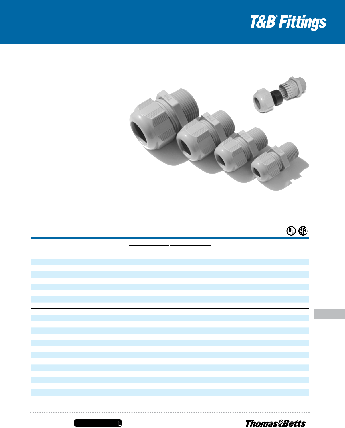
United States
Tel: 901.252.8000
800.816.7809
Fax: 901.252.1354
Technical Services
Tel: 888.862.3289
www.tnb.com
E-145
Conduit & Fittings — T&B
®
Cord & Cable Fittings
Non-Metallic Liquidtight Cord Connectors
Low-profile cable gland perfect for tight spots.
T&B Nylon Cable Glands have a sturdy cable sealing
mechanism that results in superior strain relief.
The compact size ensures quick and easy installation
in cramped spaces. The non-metallic construction
provides excellent corrosion, chemical and impact
resistance. The glands have long threads and
locknuts are available.
• Halogen free
• Flame-retardant UL94V-0
• Rated IP68 5 BAR, suitable for NEMA 4 enclosures
• UL
®
Listed*, CSA Certified for certain ranges of cable
• Working temperatures: -30° C (-22° F) to 80° C (176° F)
Continuous, +150° C (276° F) Intermittent
• Meets VDE ratings
* Material not UV resistant. Sturdy Nylon 6 for strong, lightweight construction. Gray color shown; also available in black.
Non-Metallic Cable Glands
Cat. No.
FittiNgS
tradE
SizE Color
Cord raNgE lENgtH oF tHrEad
uSE t&b
loCkNut Cat. No.
uNit
Pkg.
Std.
Pkg.iN. mm iN. mm
NPT Threads
CC-NPt38-b
3
⁄8" Black .197–.394 5–10mm .590 15mm — 50 250
CC-NPt38-g
3
⁄8" Gray .197–.394 5–10mm .590 15mm — 50 250
CC-NPt12-b
1
⁄2" Black .394–.551 10–14mm .590 15mm LN501 50 250
CC-NPt12-g
1
⁄2" Gray .394–.551 10–14mm .590 15mm LN501 50 250
CC-NPt34-b
3
⁄4" Black .512–.709 13–18mm .590 15mm LN502 25 100
CC-NPt34-g
3
⁄4" Gray .512–.709 13–18mm .590 15mm LN502 25 100
CC-NPt1-b 1" Black .709–.984 18–25mm .709 18mm LN503 20 100
CC-NPt1-g 1" Gray .709–.984 18–25mm .709 18mm LN503 20 100
ISO/Metric Threads
CC-iSo16-g 16" Gray .197–.394 5–10mm .394 10mm LN-ISO16-G 50 200
CC-iSo20-g 20" Gray .236–.473 6–12mm .590 15mm LN-ISO20-G 50 200
CC-iSo25-g 25" Gray .512–.709 13–18mm .590 15mm LN-ISO25-G 25 100
CC-iSo32-g 32" Gray .709–.984 16–25mm .590 15mm LN-ISO32-G 20 100
CC-iSo40-g 40" Gray .748–1.10 22–32mm .709 18mm LN-ISO40-G 15 75
PG Threads
CC-Pg7-g 7" Gray .118–.256 3–6.5mm .315 8mm LN-PG7-G 50 200
CC-Pg9-g 9" Gray .157–.315 4–8mm .315 8mm LN-PG9-G 50 200
CC-Pg11-g 11" Gray .197–.394 5–10mm .315 8mm LN-PG11-G 25 100
CC-Pg135-g 13
1
⁄2" Gray .236–.473 6–12mm .354 9mm LN-PG135-G 25 100
CC-Pg16-g 16" Gray .394–.551 10–14mm .394 10mm LN-PG16-G 25 100
CC-Pg21-g 21" Gray .512–.709 13–18mm .433 11mm LN-PG21-G 10 50
CC-Pg29-g 29" Gray .709–.984 18–25mm .433 11mm LN-PG29-G 10 50
CC-Pg36-g 36" Gray .867–1.26 22–32mm .512 13mm LN-PG36-G 10 50
Listed under UL file E13938, control #137B. NPT and PG threaded Cable Glands are UL Listed; ISO/Metric Threaded Cable Glands are not UL Listed.
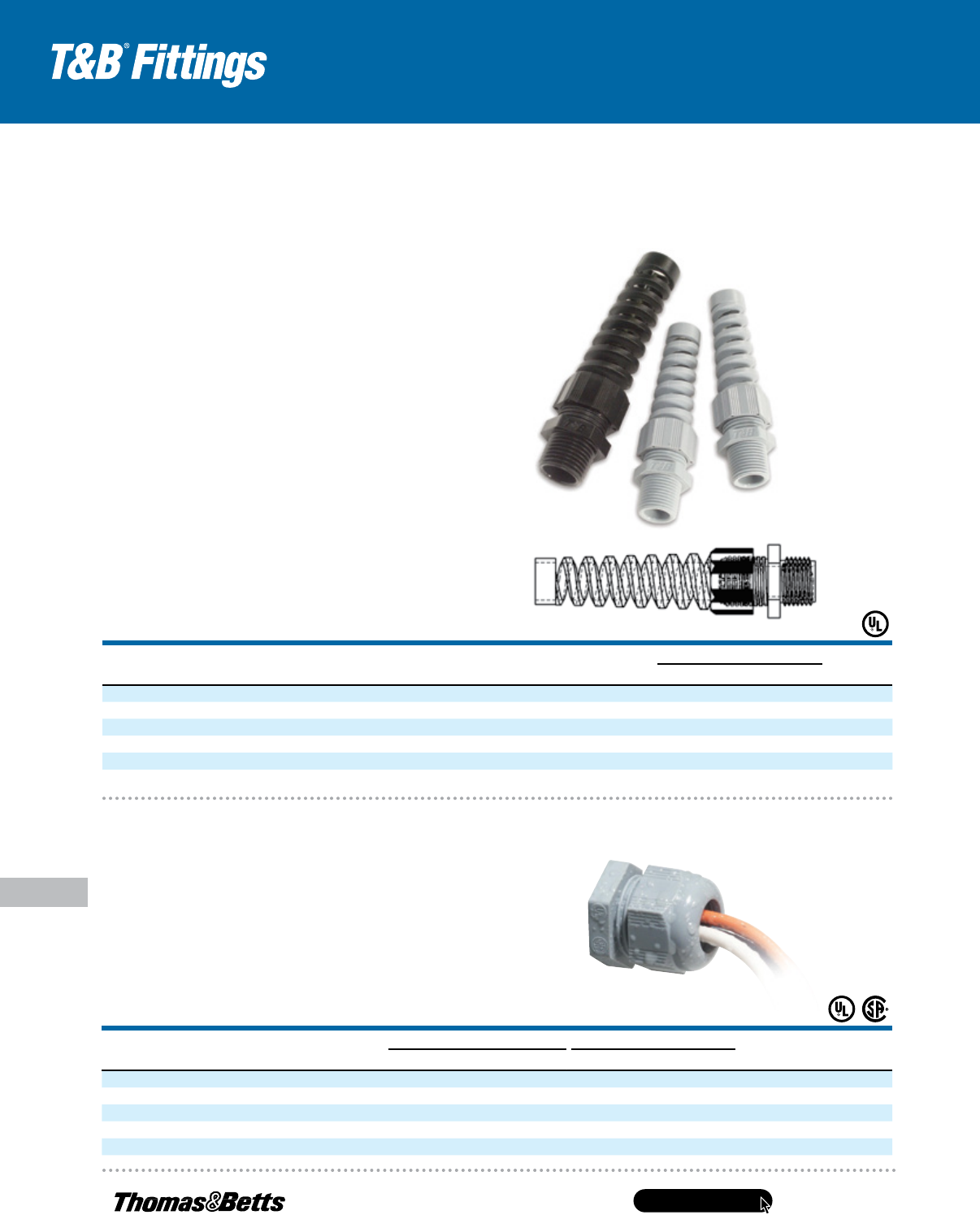
www.tnb.com
United States
Tel: 901.252.8000
800.816.7809
Fax: 901.252.1354
Technical Services
Tel: 888.862.3289
E-146
Conduit & Fittings — T&B
®
Cord & Cable Fittings
Non-Metallic Liquidtight Cord Connectors
Thomas & Betts is pleased to announce the new non-metallic spiral cable/cord
connector. T&B spiral cable/cord connectors are ideal in environments where
maximum protection is needed against conductor fatigue caused by flexing cables.
Non-Metallic Cable/Cord Fitting with Integral Strain-Relief
• Strain-relief is integral to the fitting, saving time and
costs of additional parts for cable/cord installations
• UL Listed
• Rated IP68, suitable for NEMA 4 enclosures
• Meets VDE ratings for European applications
CAT. NO.
TRADE
SIZE
MIN. CABLE
RANGE
MAX. CABLE
RANGE
USE T&B
LOCKNUT CAT. NO. COLOR
DIMENSIONS (IN.)
STD. PKG.
QTY.A B
SP-NPT38-G
3
⁄8" .197 .394 — Gray .866 .590 25
SP-NPT38-B
3
⁄8" .197 .394 — Black .866 .590 25
SP-NPT12-G
1
⁄2" .394 .551 LN501 Gray 1.062 .590 25
SP-NPT12-B
1
⁄2" .394 .551 LN501 Black 1.062 .590 25
SP-NPT34-G
3
⁄4" .512 .709 LN502 Gray 1.299 .590 25
SP-NPT34-B
3
⁄4" .512 .709 LN502 Black 1.299 .590 25
]
A
]
B
Multi-Hole Cord Grip Connectors
• Ideal in limited-space environments where multiple cables
run into an enclosure
• Small cables such as instrumentation wires, proximity device
wiring and signal cables can run safely into the enclosure
• Rated IP68, suitable for NEMA 4 enclosures
• Easy to assemble, provide good strain relief, offer a wide
clamping range and are simple to use
Space and labor-saving cord fittings for panels.
CAT. NO.
TRADE
SIZE
NUMBER OF
OPENINGS
CABLE RANGE BODY LENGTH
LENGTH
OF THREAD
STD. PKG.
QTY.MINIMUM MAXIMUM MINIMUM MAXIMUM
CC-NPT12-G2
1
⁄2" 2 .190" .250" 1.051" 1.291" .590" 50
CC-NPT12-G3
1
⁄2" 3 .190" .250" 1.051" 1.291" .590" 50
CC-NPT34-G2
3
⁄4" 2 .230" .290" 1.283" 1.492" .590" 25
CC-NPT34-G3
3
⁄4" 3 .230" .290" 1.283" 1.492" .590" 25
CC-NPT34-G4
3
⁄4" 4 .230" .290" 1.283" 1.492" .590" 25
A
B
Materials .................................................................. Polyamide 6 (Body, Cap),
Neoprene (Sealing Ring)
Colors Available ........................................................ Black, Gray
Protection Class ........................................................ IP68, 5 Bar
Temperature Range .................................................. -30° C to 80° C permanent
(-22° F to 176° F)
Operating Temperature ............................................. Up to +150° C (+276° F)
continuous
Please contact your Thomas & Betts sales representative regarding our custom
grommet offering.
.................................... Specifications ...................................
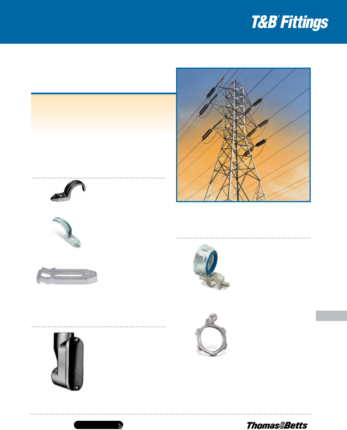
United States
Tel: 901.252.8000
800.816.7809
Fax: 901.252.1354
Technical Services
Tel: 888.862.3289
www.tnb.com
E-147
Conduit & Fittings — T&B
®
Cord & Cable Fittings
Service Entrance Cable Fittings
All service fittings shall be approved for the purpose by a nationally
recognized testing laboratory, inspection agency or product
evaluation organization.
Where service raceway consists of a rigid metal conduit, intermediate
metal conduit, electrical metallic tubing or where service entrance
cable is used as service conductors, a suitable raintight service head
conforming to Federal Standard W-C-586 shall be provided.
Suggested Specifications
for Service Entrance Fittings
Grounding & Bonding
Series 3870
Bonding & Grounding Bushing — Insulated
Series 106
Bonding Locknut
For grounding and bonding of
service raceway, end of raceway
or the terminating fitting shall be
equipped with bonding locknuts
and insulated metallic grounding
and bonding bushing as required.
Bonding locknuts shall be of
hardened steel or malleable iron
construction, electro zinc plated,
and provided with hardened
bonding screws as manufactured
by Thomas & Betts, series 106
bonding locknuts.
Insulated metallic grounding
and bonding bushing shall be of
malleable iron/steel construction,
electro zinc plated and assembled
with an insulator listed or certified
for 150° C/302° F service as
manufactured by Thomas & Betts,
series 3870.
Threaded Rigid Metal
Series 1490
Entrance ELL
Where threaded rigid metal service
raceway enters the building, the
raceway shall be equipped with
a cast malleable iron/copper-free
aluminum entrance ell with a burr-
free end stop and taper tapped
holes as manufactured by Thomas
& Betts, series 1490.
Fastening
Series 4175
Pipe Strap (EMT)
Series 1275/1275AL
Pipe Strap (Rigid Metal Conduit & IMC)
Series 1350/1350AL
Pipe Spacer
(Rigid Metal Conduit IMC & EMT)
Service raceway shall be securely
fastened in place to the supporting
surface at intervals as specified
by the Code using suitable straps
and spacers; straps and spacers
shall be of malleable iron or steel
construction, hot dipped galvanized
or electro zinc plated conforming
to Canadian Standards Association
Standard C22.2 No. 18 and as
manufactured by Thomas & Betts:
series 1275 or 4175 straps and
series 1350 spacers; aluminum
straps or spacers such as series
1275AL and series 1350AL may
be substituted when installed in
environmental conditions that are
more than normally corrosive.
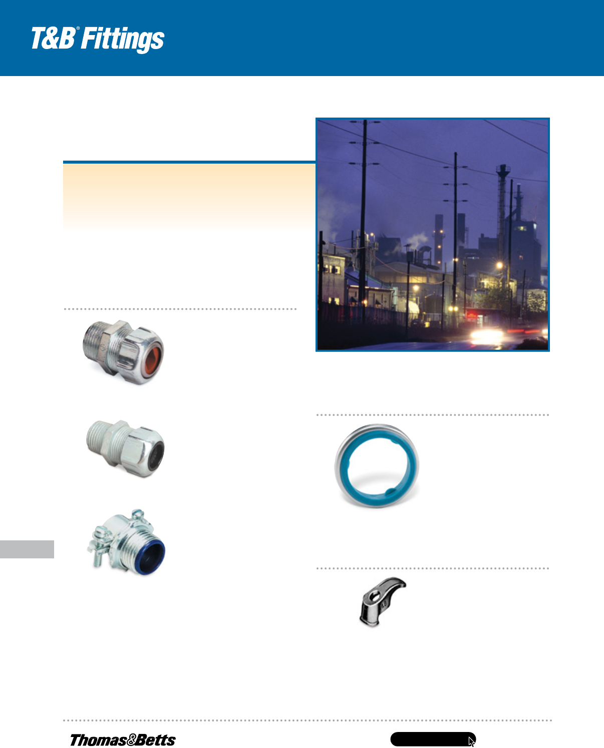
www.tnb.com
United States
Tel: 901.252.8000
800.816.7809
Fax: 901.252.1354
Technical Services
Tel: 888.862.3289
E-148
Conduit & Fittings — T&B
®
Cord & Cable Fittings
Service Entrance Cable Fittings
Where service entrance cable is used as overhead service
conductors and code requires use of a service head, entrance caps
shall be installed; caps shall be cast metal type of suitable ferrous or
non-ferrous metal equipped with thermoset insulators and proper
knockout openings; caps when installed with proper drip loop must
ensure raintight conditions.
At the point where the service cable enters the building, a suitable
sill plate shall be provided; sill/wall plate shall be sealed to ensure
raintight conditions.
Suggested Specifications for
Service Entrance Fittings (continued)
Terminating Fittings
Series 3302M
Two-Screw Connector (Insulated)
Series 2116
Underground Feeder Cable Connector
Series 2111
Service Entrance Cable Connector
Terminating fittings for service
entrance cable (Type SE or
USE) or underground feeder and
branch — circuit cable (Type UF)
in locations where exposed to
intermittent or constant moisture
or in dry locations and subjected
to mechanical strain shall be of
watertight strain-relief type as
manufactured by Thomas & Betts,
series 2111 or 2116; fittings
shall be constructed of ferrous or
non-ferrous metal and equipped
with taper threaded hub, beveled
moisture-resistant/oil-resistant
synthetic rubber bushing.
In dry locations, nylon-insulated
two-screw type fittings of malleable
iron/steel construction electro zinc
plated inside outside, including
threads such as series 3302M
manufactured by Thomas & Betts
may be substituted.
Gaskets
Supports
Series 1341
Cable Strap
Series 5262
Sealing Gasket
Service entrance cable shall be
adequately supported at intervals
enumerated in code using cable
straps conforming to requirements
of Canadian Standards Association
Standard CSA 22.2 No. 18; cable
straps shall be of malleable iron/
steel construction, hot-dipped
galvanized or electro zinc plated as
manufactured by Thomas & Betts,
series 1341.
Where service entrance cable
is terminated into a threadless
opening using hub-type fittings,
a gasket shall be provided between
the outside of box or enclosure
and fitting shoulder; gasket shall be
of moisture-resistant/oil-resistant
synthetic rubber type adequately
protected by and permanently
retained to a metallic retainer as
manufactured by Thomas & Betts,
series 5262.
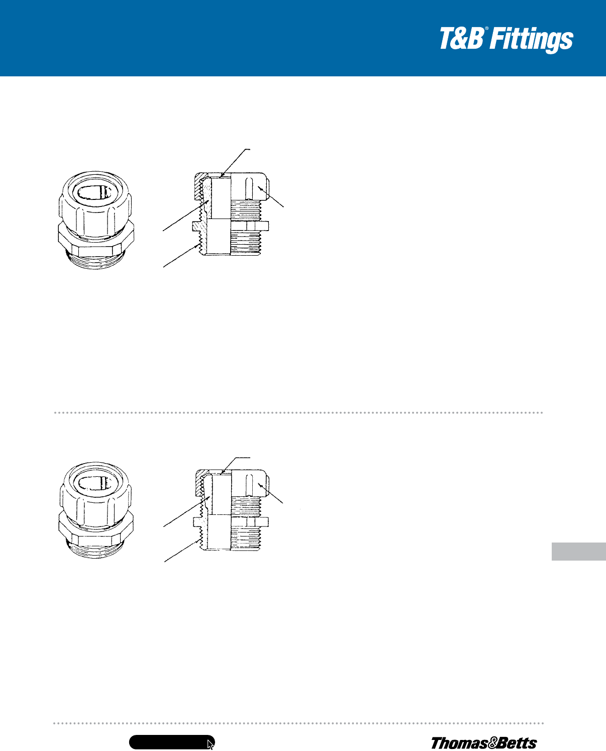
United States
Tel: 901.252.8000
800.816.7809
Fax: 901.252.1354
Technical Services
Tel: 888.862.3289
www.tnb.com
E-149
Conduit & Fittings — T&B
®
Cord & Cable Fittings
Service Entrance Cable Fittings
C
A
B
D
2111 Series
Application
• To connect service entrance cables to a meter box
or an enclosure
Standard Material/Finish
Body .........................................................................Zinc Die Cast/As Cast
Gland ......................................Steel/Electro Zinc Plated & Chromate Coated
Retaining Ring .....................................................Stainless Steel/Passivated
Bushing ...................................................................... Neoprene/As Molded
Range
Oval (Flat) Cable Size ...................................260 x .500 thru 1.062 x 1.765
Type USE Cable Size ........................... (3) #12 thru (3) 4/0 AWG Conductors
Hub Size ...............................................
1
⁄2" thru 2" NPT (taper pipe threads)
Features
• Neoprene bushing, resists oil and water; grips cable the
full length of the bushing, providing adequate strain relief
without damaging outer jacket (A)
• Taper threaded body (B)
• Stainless steel retaining ring protects cable jacket
against abrasion; reduces installing torque effort (C)
• Rugged ribbed steel gland construction (D)
• Suitable for Type SE & USE Service Entrance Cable
Listings/Compliances
UL (UL File No. E15170)
CSA (LR589, LR4484)
UL514, NEMA FB1, Federal Standard
H-28 (Threads), NFPA70
Service Entrance Cable Connector
(Type SE/Type Use)
Application
• To connect underground feeder cables
to a box or an enclosure
Standard Material/Finish
Body .........................................................................Zinc Die Cast/As Cast
Gland ......................................Steel/Electro Zinc Plated & Chromate Coated
Retaining Ring .....................................................Stainless Steel/Passivated
Bushing ...................................................................... Neoprene/As Molded
Range
Oval (Flat) Cable Size .......................................235 x .500 thru .260 x .740
Hub Size ............................................
1
⁄2" thru 1" NPT (tapered pipe threads)
Features
• Neoprene bushing resists oil and water; grips cable the
full length of the bushing providing adequate strain relief
without damaging outer jacket (A)
• Taper threaded body (B)
• Stainless steel retaining ring protects cable jacket
against abrasion; reduces installing torque effort (C)
• Rugged ribbed steel gland construction (D)
Listings/Compliances
UL
CSA (LR2884)
UL514B, NEMA FB1, Federal Standard
H-28 (Threads), NFPA70
C
A
B
D
2116 Series
Underground Feeder Cable Connectors
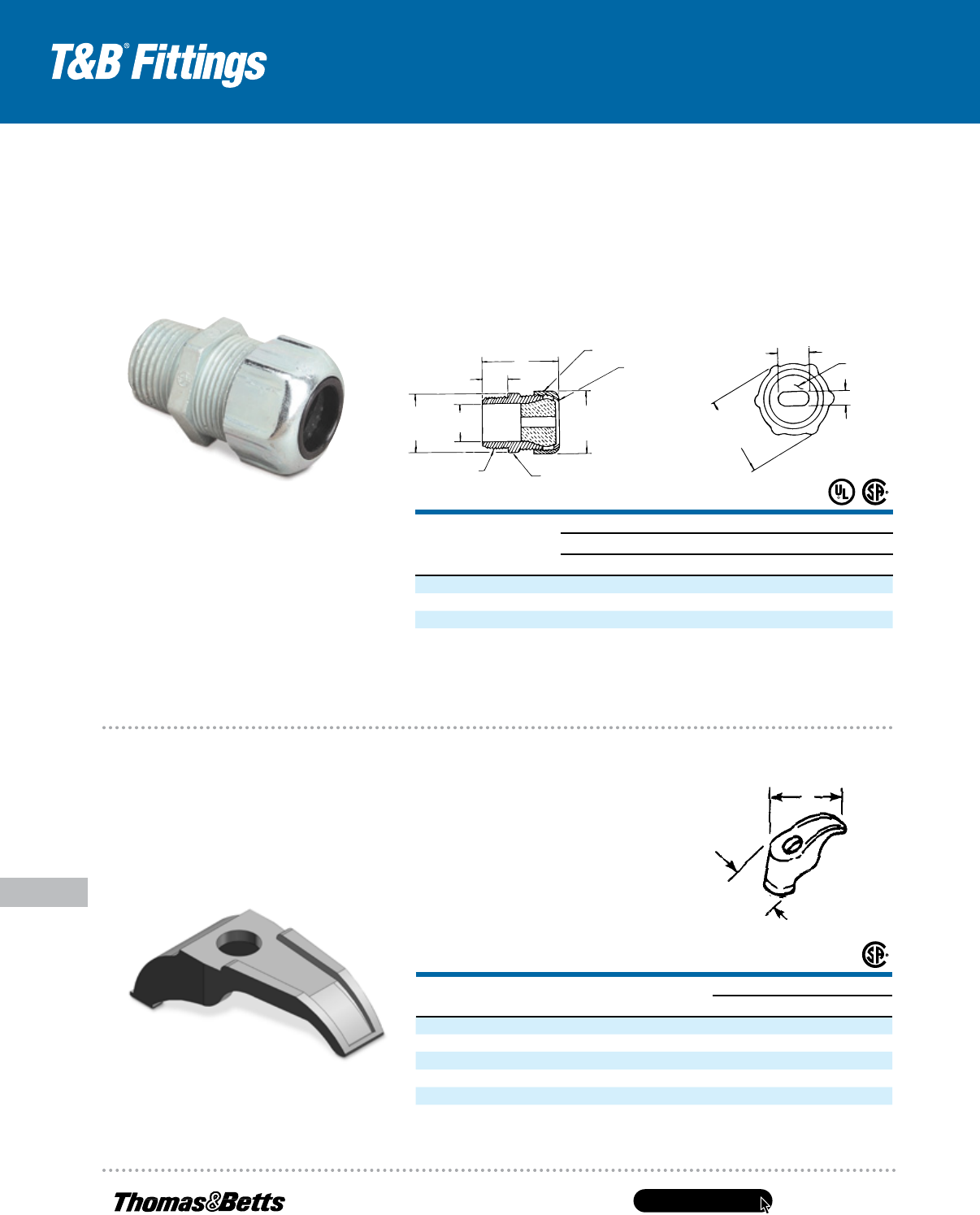
www.tnb.com
United States
Tel: 901.252.8000
800.816.7809
Fax: 901.252.1354
Technical Services
Tel: 888.862.3289
E-150
Conduit & Fittings — T&B
®
Cord & Cable Fittings
Service Entrance Cable Fittings
Oil- and water-resistant neoprene bushing specially
designed for sealing around underground feeder cable!
Underground Liquidtight Feeder-Cable Fittings
• Stainless steel retaining ring provides
bearing surface for glandnut and
eliminates cable twist
• Ribbed glandnut tightens easily with
wrench to form high-strength connection
Cat.
No.
Hub
SizE
CablE
opENiNg
DimENSioNS (iN.)
a b C D E F g H
miN. max. miN. max.
2116-tb*
1
⁄2" .235 x .500 1
11
⁄16
5
⁄8 1 .060 .235 .350 .500
9
⁄16 1
1
⁄8 1
1
⁄8
2237
3
⁄4" .230 x .430 1
9
⁄16
9
⁄16 1
7
⁄32 .080 .230 .320 .430
13
⁄16 1
3
⁄8 1
3
⁄8
2238
3
⁄4" .235 x .465 1
9
⁄16
9
⁄16 1
7
⁄32 .050 .235 .340 .465
13
⁄16 1
3
⁄8 1
3
⁄8
2239
3
⁄4" .240 x .685 1
9
⁄16
9
⁄16 1
7
⁄32 .060 .240 .500 .685
13
⁄16 1
3
⁄8 1
3
⁄8
* Not CSA Certified
UL File No. E-23017
CSA File No. 2884
Cat.
No.
WirE SizE
DimENSioNS (iN.)
a b
1341-tb 2-#10
5
⁄8 1
1
⁄8
1344 3-#6 or 3-#8
5
⁄8 1
15
⁄16
1345* 3-#4 or 3-#2
13
⁄16 1
59
⁄64
1346 3-1/0
3
⁄4 2
7
⁄16
1347 3-4/0
3
⁄4 2
25
⁄32
* Steel, hot-dipped galvanized.
UL not applicable
CSA Certified
• Hole for
1
⁄4" screw
• Hot-dipped galvanized
malleable iron construction
Rocking action of foot allows each strap
to accept a wide range of wire sizes!
Cable Straps
Gland Nut Steel
(Zinc Plated)
A
B
B
A
E
D
F
I.D.
H
Max. Body
Corners
Tapered
Pipe Thread
C
Across
Flats
“G”
Max. Gland
Corners
Body Die
Cast Zinc
(Zinc Plated)
Retainer
Stainless Steel
Neoprene
Bushing
* (Cat. No.
2116 may be
non-metallic)
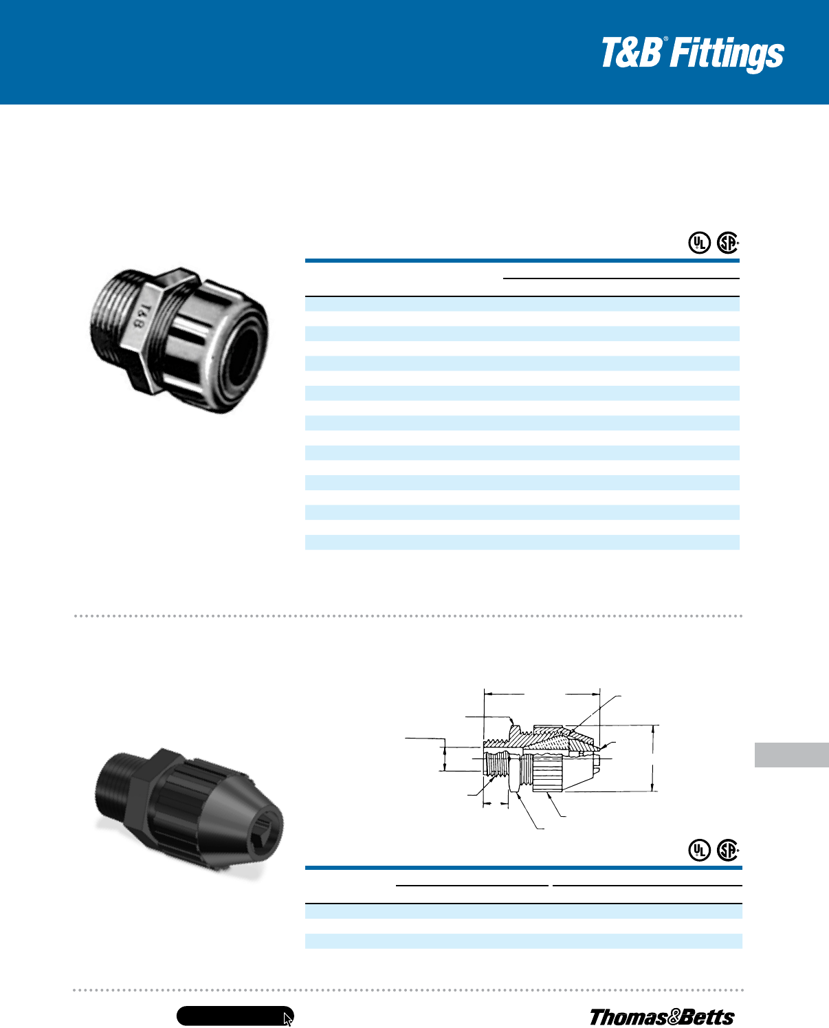
United States
Tel: 901.252.8000
800.816.7809
Fax: 901.252.1354
Technical Services
Tel: 888.862.3289
www.tnb.com
E-151
Conduit & Fittings — T&B
®
Cord & Cable Fittings
Service Entrance Cable Fittings
Cat.
No.
Hub
SizE
oval CablE raNgE
max. miN.
2111
1
⁄2" .420 x .560 .380 x .520
2232
3
⁄4" .385 x .600 .260 x .500
2233
3
⁄4" .500 x .750 .375 x .625
2234
3
⁄4" .555 x .800 .490 x .675
2432 1" .385 x .600 .260 x .500
2433 1" .500 x .750 .375 x .625
2434 1" .555 x .800 .430 x .675
2438 1" .565 x .855 .440 x .730
2439 1" .635 x .975 .510 x .850
2442 1
1
⁄4" .635 x .975 .510 x .850
2443 1
1
⁄4" .640 x 1.050 .490 x .900
2446 1
1
⁄4" .750 x 1.150 .565 x .965
2454 1
1
⁄2" .840 x 1.275 .655 x 1.090
2447 1
1
⁄2" .880 x 1.425 .695 x 1.240
2448 2" .968 x 1.500 .790 x 1.390
2449 2" 1.062 x 1.765 .850 x 1.550
2450 2" 1.820 x 1.190 1.700 x 1.050
UL File No. E-15170
CSA File No. 589
Note: These may be obsoleted and replaced.
Two-taper design — one slow and one fast — enables
connectors to accept varied cable sizes for maximum take-up!
Watertight Connectors for Oval Cable
• Tapered neoprene bushings resist
oil, sunlight and water
• Hex gland and body take same
wrench opening
• Stainless-steel slip ring prevents
cable from twisting as gland ring
is tightened
• Threads on body tapered for
water-sealing
Cat.
No.
Hub
SizE
uF CablE raNgE a b C
max. miN. max. ±.060 ±.060
2827
1
⁄2" .550 x .280 .400 x .190 2.60 1.270 .600
2828
3
⁄4" .675 x .280 .525 x .190 3.00 1.570 .620
2829
3
⁄4" .775 x .280 .625 x .190 3.00 1.570 .620
UL File No. 15170
CSA File No. 589
• Tapered threaded hub
• Liquidtight and dust tight
• Corrosion- and weather-resistant
nylon construction for both outdoor
and indoor applications
Hand tightens — no tools required!
Nylon UF-Cable Fittings
for Corrosive Environments
B
C
Chuck
A (Max.)
Hex Flat
Body
Gland
Throat
Size
Hub N.P.T. THD.
Neoprene
Bushing Seal
www.tnb.com
United States
Tel: 901.252.8000
800.816.7809
Fax: 901.252.1354
Technical Services
Tel: 888.862.3289
E-152
Conduit & Fittings — T&B
®
Cord & Cable Fittings
MC and AC Cable Fittings
Note: The materials herein, whether relating to the National Electrical Code, the Underwriters Laboratories, Inc. listing, to industry practice or otherwise,
are not intended to provide all relevant information required for use and installation of our products. Refer to applicable codes, instructions and
industry specifications prior to installation or use.
Metal-Clad Cable, Armored Cable and Flexible Metal Conduit
Armored Cable (Type AC) —
Ref. NEC
®
Article 320
National Electrical Code
®
defines type AC
armored cable as, “A fabricated assembly
of insulated conductors in a flexible
metallic enclosure.”
ACT Indicates an armored cable
employing conductors having
thermoplastic (Type T) insulation.
AC Indicates an armored cable
employing conductors having
rubber insulation of code grade.
ACH Indicates an armored cable
employing conductors having
rubber insulation of the heat-
resistant (75° C) grade.
ACHH Indicates an armored cable
employing conductors having
rubber insulation of the heat-
resistant (90° C) grade.
ACU Indicates an armored cable
employing conductors having
rubber insulation of latex grade.
“L” Used as a suffix, it indicates that
a lead covering has been applied
over the conductor assembly.
All armored cables may employ copper or
aluminum or copperclad aluminum conductors
with the following sizes and are rated for
600 volts or less:
No. 14 AWG to No. 1 AWG Copper
No. 12 AWG to No. 1 AWG Aluminum
or Copperclad Aluminum
Type AC cables except ACL carry an internal
bonding strip of copper or aluminum in intimate
contact with the armor for its entire length.
Armored cable can be used for both exposed
or concealed locations. With lead-covered
conductors (Type ACL), the cable can be
embedded in masonry or concrete and can be
used in damp locations or where exposed to oil.
Armored cable is not permitted in locations
where it will be subjected to physical damage
or corrosive fumes. Armored cable cannot be
used for direct burial in earth.
With minor exceptions, armored cable is
also not permitted to be used in hoists or
elevators, storage battery rooms, any hazardous
locations, in commercial garages and in theaters
or similar locations.
Codes require that cable shall be supported
with straps or staples without damaging
conductors and also limit the minimum bend
radius to five times the diameter of type AC
cable. Certain precautions are prescribed in code
where cable is installed through joist rafters or
similar wood members.
According to NEC 320 where armored cable
is terminated, a fitting is required to protect
conductors from abrasion. In addition, a
bushing is required between the conductors
and armor. Design of fitting has to be such that
the insulating bushing is visible for inspection.
Bushing is not required with lead-covered
cables when properly installed.
Portions of this section reprinted by permission
from NFPA 70–2005, National Electrical Code
®
,
Copyright © 2004, National Fire Protection
Association, Boston, MA.
Please refer to the following for further
details and complete information:
1. NEC Article 320…Armored Cable
(Type AC Cable)
2. UL 4, ANSI C33.9…Safety Standards
for Armored Cable
3. UL 514B, Safety Standards for Outlet
Boxes and Fittings
4. A-A-50552…Federal Specification.
Fittings for Cable, Power, Electrical
and Conduit, Metal, Flexible
5. NEMA FB-1…Standards Publication.
Fittings & Supports for Conduit and
Cable Assemblies
6. CEC Section 12-700…Wiring Methods
(Armored Cable)
7. CSA C22.2 No. 51…Safety Standards
for Armored Cables
8. CSA C22.2 No. 18…Safety Standards for
Outlet Boxes, Conduit Boxes and Fittings
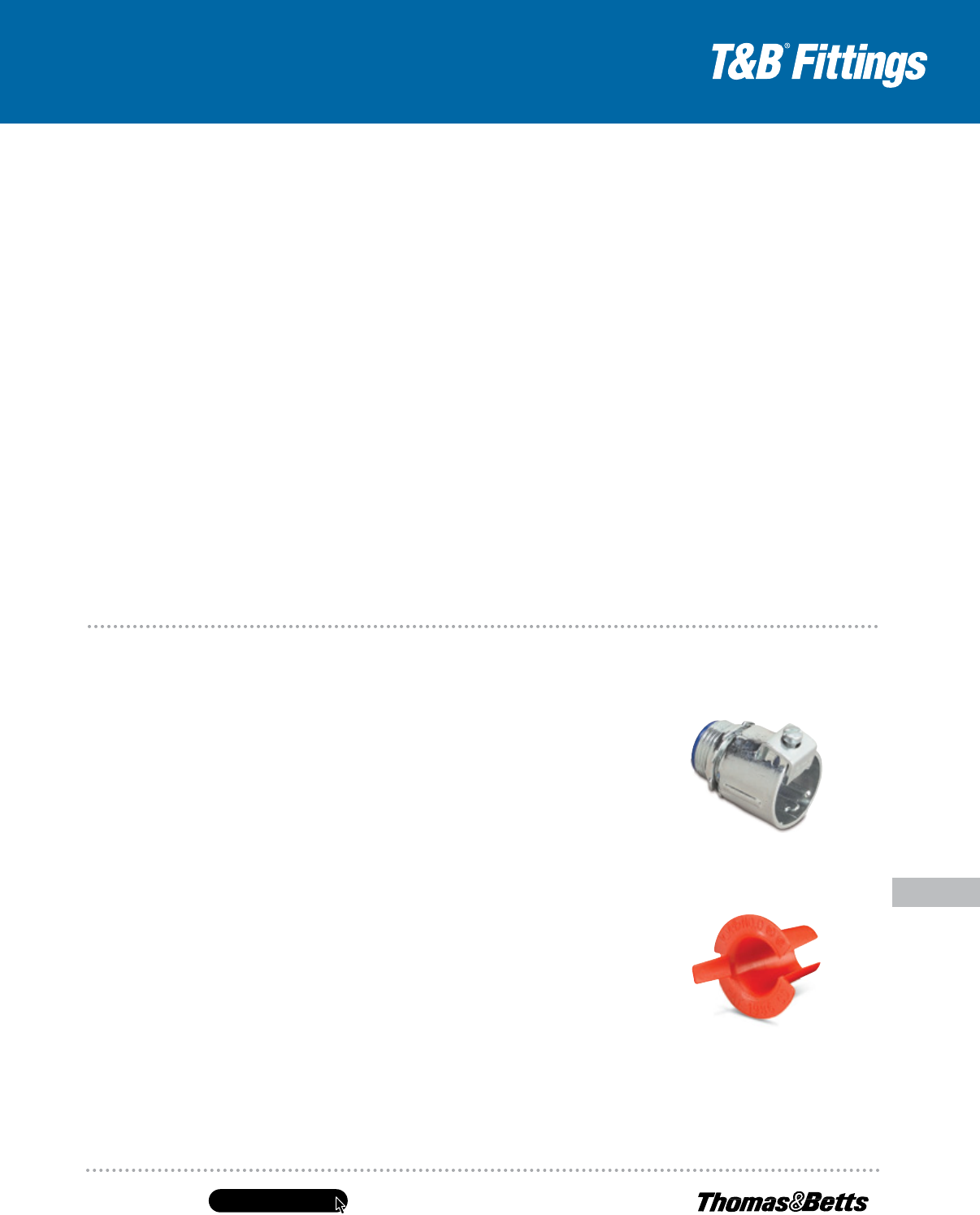
United States
Tel: 901.252.8000
800.816.7809
Fax: 901.252.1354
Technical Services
Tel: 888.862.3289
www.tnb.com
E-153
Conduit & Fittings — T&B
®
Cord & Cable Fittings
MC and AC Cable Fittings
Series 3110
Armored Cable Connector
& Flexible Metal Conduit
Series 390
Anti-Short Bushing
Suggested Specifications for Armored Cable
and Flexible Metal Conduit Fittings
• Armored cable (metal-clad cable type
AC) and flexible metal conduit shall
conform to provisions of following
applicable standards:
Armored Cable…UL 4/ANSI C33.9/
CSA 22.2 No. 51
Flexible Metal Conduit…UL 1/ANSI
C33.92/WW-C-566/CSA 22.2 No. 56
Type of cable used and conductors
within flexible metal conduit shall
besuitable for conditions of use
andlocation.
• Where approved armored cable or
flexible metal conduit is used as an
equipment grounding conductor,
terminating fitting used shall be of
the grounding type as manufactured
by Thomas & Betts, series 3110
• Where armored cable or flexible
metal conduit terminates into a
threadless or threaded opening, it
shall be assembled with approved
fittings; fittings shall be of malleable
iron/steel construction, electro zinc
plated inside/outside, equipped with
nylon insulated throat and shall be of
angled saddle type as manufactured
by Thomas & Betts, series 3110.
Direct-bearing screw type fittings
shall not be used
• Suitable bushing as manufactured
byThomas & Betts, series 422
or 390, shall be provided between
the conductors and armor
Flexible Metal Conduit — Ref. NEC
®
Article 348
Flexible metal conduit can be used for exposed
or concealed work in dry locations. It can be
used for wet locations provided conductors
within are lead covered or other approved type.
Flexible metal conduit cannot be used
underground or embedded in poured concrete
or aggregate. With rubber covered conductors,
the conduit cannot be exposed to oil, gasoline
or other materials having a deteriorating effect
on rubber.
With minor exceptions use of flexible metal
conduit is not permitted in hoists, in storage
battery rooms and in any hazardous locations.
Use of flexible metal conduit is restricted to
systems under 600 volts.
According to NEC
®
Article 348, flexible metal
conduit no longer than six feet and containing
circuit conductors protected by overcurrent
device rated for 20 amps or less is suitable
as a grounding means provided, it is terminated
in fittings approved for the purpose.
Flexible metal conduit longer than six feet
is permitted to be used as a grounding means
provided the conduit and the fitting are approved
for the purpose. To date, there is no flexible
metal conduit approved for the purpose by
the Underwriters Laboratories.
In Class I & II, Division 2 hazardous areas, the
conduit itself cannot be used as the grounding
means. A bonding jumper must be installed in
accordance with NEC Section 250.102. Flexible
metal conduit is available with steel or aluminum
armor in trade size
5
⁄16" to 4". With few exceptions
where
5
⁄16" and
3
⁄8" trade sizes are used, Code
prohibits use of conduit less than “d” trade size.
Bends in concealed work are restricted to 360
degrees total. No angle connectors are permitted
in concealed raceway installations.
Portions of this section reprinted by permission
from NFPA 70, National Electrical Code
®
,
Copyright © 2010, National Fire Protection
Association, Boston, MA.
NEC and National Electrical Code are registered trademarks
of the National Fire Protection Association, Inc.
Please refer to the following for further details
and complete information:
1. NEC Article 348…Flexible Metal Conduit
2. UL 1, ANSI C33.92…Safety Standards
for Flexible Metal Conduit
3. UL 514B, Safety Standards for Outlet
Boxes and Fittings
4. A-A-50552…Federal Specification. Fittings
for Cable, Power, Electrical and Conduit,
Metal Flexible
5. WW-C-566…Federal Specification.
Conduit, Metal, Flexible
6. NEMA FB1…Standards Publication.
Fittings and Supports for Conduit
and Cable Assemblies
7. CEC 12-1100…Wiring Method (Rigid
& Flexible Conduit)
8. CSA C22.2 No. 56…Safety Standards for
Flexible Metallic Conduit and Liquidtight
Flexible Metal Conduit
9. CSA C22.2 No. 18…Safety Standards for
Outlet Boxes, Conduit Boxes and Fittings
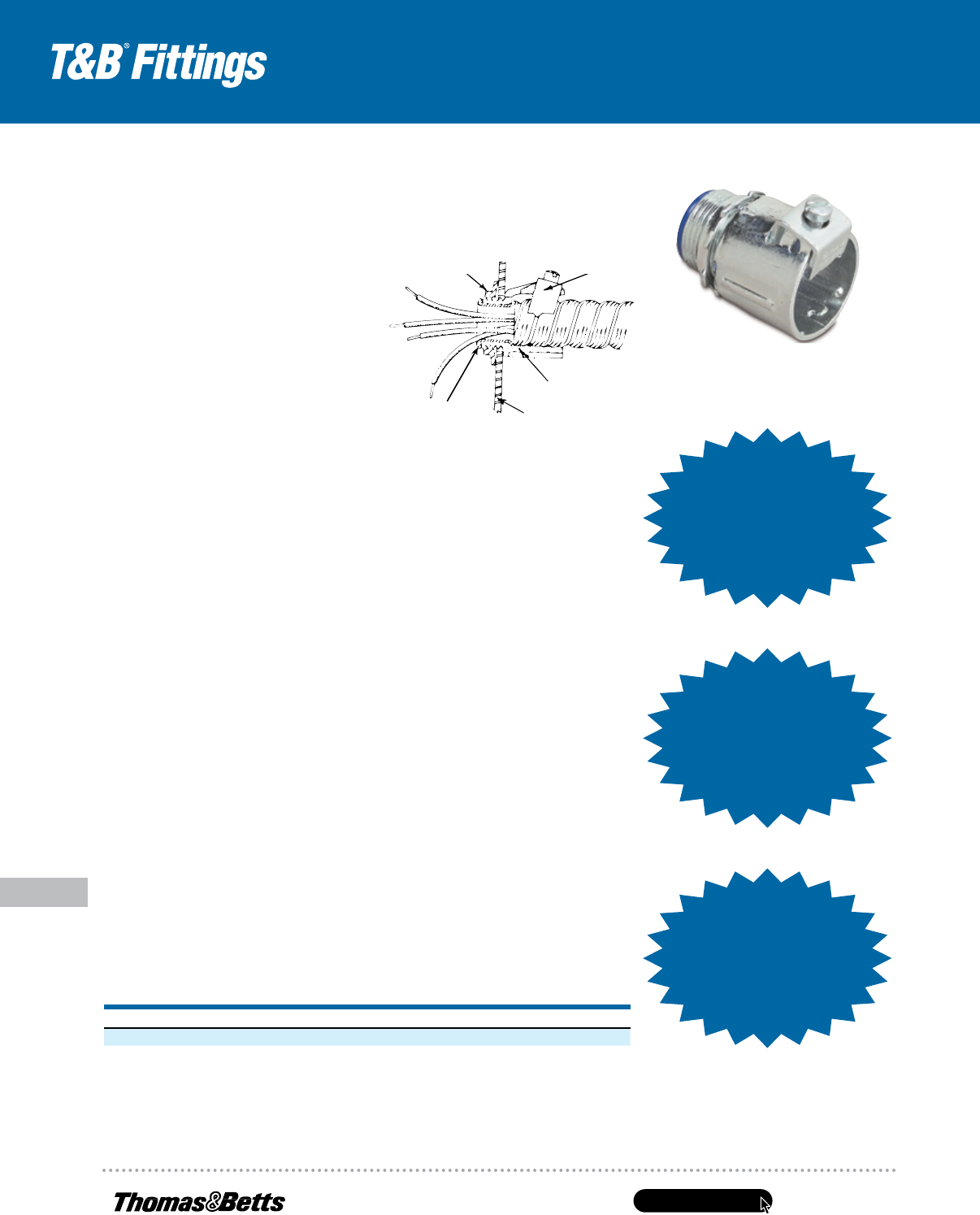
www.tnb.com
United States
Tel: 901.252.8000
800.816.7809
Fax: 901.252.1354
Technical Services
Tel: 888.862.3289
E-154
MC and AC Cable Fittings
Conduit & Fittings — T&B
®
Cord & Cable Fittings
TITE-BITE
®
Connectors
3110 Series
Application
• To connect and effectively bond metal-
clad cables, armored cable or flexible
metal conduit to a box or an enclosure
Features
• Provided with an angled saddle
designed to:
• Insulated throat protects conductors
during and after installation and reduces
wire pull effort
• Heat-curled insulator in throat:
• Locknuts designed to provide effective
bond between connector and box or
enclosure, will not vibrate loose
• Designed with fewer installing
screws — reduces installation time
and labor cost
• Armor stop with viewing window
• Rugged all-steel or malleable
iron construction
• Suitable as a grounding means per
NEC
®
Article 348 for flexible metal
conduit, NEC
®
Article 320 for armored
cable and NEC
®
Article 330 for metal-
clad cable
• Suitable for hazardous location use
per Class 1 Division 2 NEC 501.10 (b)(2)
RANGE HUB SIZE CONDUIT SIZE CABLE OPENING
3110 Series Straight Connectors
1
⁄2" to 4" NPS
3
⁄8" to 4" .470" to 4.560"
3130 Series 90° Connectors
1
⁄2" to 4" NPS
3
⁄8" to 4" .470" to 4.560"
(All hubs provided with straight pipe threads NPS)
Locknut Saddle
Body
Box or Enclosure Wall
Insulated Throat
Super-Fast
Installation!
Super-Fast
Installation!
Up to 2X faster
than standard
connectors!
Very High
Cable Pull-Out
Resistance!
Very High
Cable Pull-Out
Resistance!
Now UL Listed
forNew Interlocked
Armor Ground Type
Metal Clad Cable
(MCI-A)!
Now UL Listed
forNew Interlocked
Armor Ground Type
Metal Clad Cable
(MCI-A)!
Standard Material/Finish
Body ...............Steel or Malleable Iron/
Electro Zinc Plated &
Chromate Coated
Saddle. . . . . . . . . . . . . Steel/Electro Zinc Plated
& Chromate Coated
Screws...........Steel/Electro Zinc Plated &
Chromate Coated
Insulator...........Thermoplastic/As Molded
Listings/Compliances
UL 514B
CSA C22.2 No. 18
NEMA FB1
UL (UL File No. 23018)
CSA (LR-2884, LR-4484)
Typical Installation
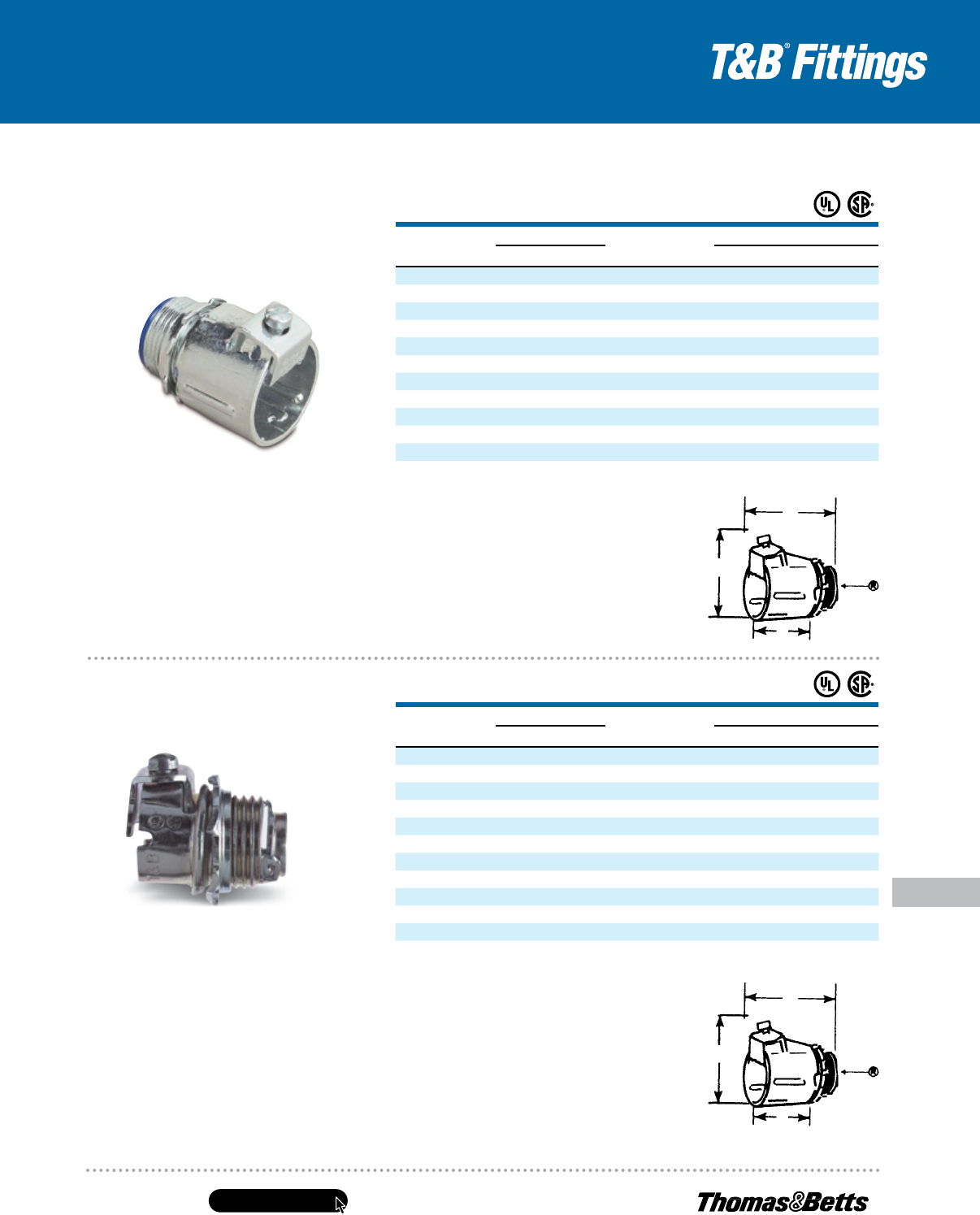
United States
Tel: 901.252.8000
800.816.7809
Fax: 901.252.1354
Technical Services
Tel: 888.862.3289
www.tnb.com
E-155
Conduit & Fittings — T&B
®
Cord & Cable Fittings
MC and AC Cable Fittings
• Super-fast installation and extreme pull-
out resistance due to angled saddle design
• Steel or malleable iron construction
• Tough, insulated lining and Tite-Bite
®
design make these connectors a “must”
when conductors are subject to vibration
or strain
• Look for the unique T&B blue color
to ensure the highest quality fitting
• Easy to install with double-grip saddle
•
3
⁄8" and
1
⁄2" sizes made of formed
steel, which produces uniform high
quality and a smooth throat to protect
conductor insulation
•
3
⁄4" and larger size are malleable iron
CAT. NO.
CABLE OPENING (IN.)
TRADE
SIZE
K.O.
SIZE
DIMENSIONS (IN.)
MAX. MIN. A
†
B C
300-TB**• .660 .470
3
⁄8"
1
⁄2" 1
1
⁄4" 1
5
⁄16
7
⁄16
301-TB*• .781 .460
3
⁄8"
1
⁄2" 1
1
⁄16 1
3
⁄8
7
⁄8
302-TB#• .920 .670
1
⁄2"
1
⁄2" 1
5
⁄8 1
11
⁄16 1
7
⁄64
304# 1.093 .906
3
⁄4"
3
⁄4" 1
7
⁄8 1
11
⁄16 1
7
⁄32
306# 1.468 1.250 1" 1" 2
1
⁄16 1
3
⁄4 1
3
⁄4
308*** 1.750 1.562 1
1
⁄4" 1
1
⁄4" 2
5
⁄16 2
1
⁄32 1
1
⁄4
310*** 2.031 1.812 1
1
⁄2" 1
1
⁄2" 2
5
⁄8 2
9
⁄16 1
3
⁄4
312*** 2.500 2.312 2" 2" 3
1
⁄8 2
13
⁄16 1
13
⁄16
314*** 3.062 2.812 2
1
⁄2" 2
1
⁄2" 3
1
⁄2 3
1
⁄8 2
1
⁄4
316*** 3.562 3.312 3" 3" 4
1
⁄16 3
3
⁄16 2
1
⁄4
318***
††
4.060 3.620 3
1
⁄2" 3
1
⁄2" — — —
320***
††
4.560 4.120 4" 4" — — —
CAT. NO.
CABLE OPENING (IN.)
TRADE
SIZE
K.O.
SIZE
DIMENSIONS (IN.)
MAX. MIN. A
†
B C
2492*•# .500 .370
3
⁄8"
1
⁄2" 1
3
⁄16 1
3
⁄8
7
⁄16
3110-TB**• .660 .470
3
⁄8"
1
⁄2" 1
1
⁄4 1
1
⁄8
7
⁄8
3112#° .920 .670
1
⁄2"
1
⁄2" 1
1
⁄4 1
1
⁄8
7
⁄8
3115# 1.125 .906
3
⁄4"
3
⁄4" 1
25
⁄32 1
3
⁄4 1
7
⁄32
3117# 1.468 1.250 1" 1" 2
3
⁄8 1
3
⁄4 1
1
⁄8
3118*** 1.750 1.562 1
1
⁄4" 1
1
⁄4" 2
3
⁄4 2 1
1
⁄4
3119*** 2.031 1.812 1
1
⁄2" 1
1
⁄2" 3
1
⁄8 2
5
⁄8 1
3
⁄4
3120*** 2.500 2.312 2" 2" 3
3
⁄4 2
3
⁄4 1
13
⁄16
3121*** 3.062 2.812 2
1
⁄2" 2
1
⁄2" 4
3
⁄8 3
1
⁄4 2
1
⁄4
3122*** 3.562 3.312 3" 3" 5 3
1
⁄4 2
1
⁄4
3123***
††
4.060 3.620 3
1
⁄2" 3
1
⁄2" — — —
3124***
††
4.560 4.120 4" 4" — — —
TITE-BITE
®
Connectors —
Nylon Insulated
Easy to install!
TITE-BITE
®
Connectors
B
A
C
B
A
C
Material: Steel thru
1
⁄2" trade size.
UL File No. E 23018
CSA File No. 2884
#UL Listed for Metal Clad Cable (MCI).
•UL Listed for new Interlocked Armor Ground Type Metal Clad Cable (MCI-A).
*Not UL Listed.
**UL Listed for Armored Cable and Metal Clad Cable.
***UL Listed for Flexible Metal Conduit only.
†
Approximate dimension with screw at minimum height.
††
CSA not applicable.
Material: Steel thru
3
⁄4" trade size.
UL File No. E 23018
CSA File No. 2884
#UL Listed for Metal Clad Cable (MCI).
•UL Listed for new Interlocked Armor Ground Type Metal Clad Cable (MCI-A).
*Good for aluminum-sheathed cable.
**UL Listed for Armored Cable and Metal Clad Cable.
***UL Listed for Flexible Metal Conduit only.
†
Approximate dimension with screw at minimum height.
††
CSA not applicable.
Designed to resist vibration and strain!
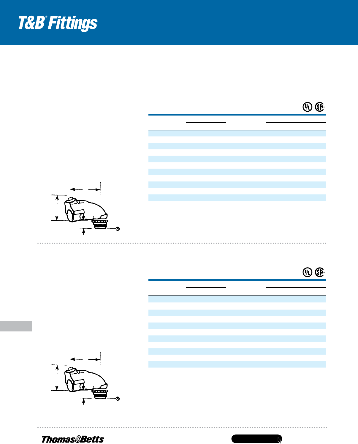
www.tnb.com
United States
Tel: 901.252.8000
800.816.7809
Fax: 901.252.1354
Technical Services
Tel: 888.862.3289
E-156
MC and AC Cable Fittings
Conduit & Fittings — T&B
®
Cord & Cable Fittings
• Steel or malleable iron construction
• Offers all of the advantages of the
straight connector with only one screw
to tighten, except in the larger sizes,
which have two
• Peep hole on top provides for
easy inspection of ABC bushing
• Narrow design makes it easy to
install connectors in adjacent knockouts
• Throat is long enough to install
in cast housing knockouts
•
3
⁄8" and
1
⁄2" sizes of steel construction
•
3
⁄4" and larger sizes made
of malleable iron
UL File No. E 23018
CSA File No. 2884
#UL Listed for Metal Clad Cable (MCI).
•ULListedfornewInterlockedArmorGroundTypeMetal
Clad Cable (MCI-A).
***ULListedforflexiblemetalconduitonly.
†
Approximatedimensionwithscrewatminimumheight.
††
CSAnotapplicable.
The easiest and best connector to install when making
sharp bends at the enclosure or equipment!
TITE-BITE
®
Connectors — 90° Angle Nylon Insulated
UL File No. E 23018
CSA File No. 2884
#UL Listed for Metal Clad Cable (MCI).
•ULListedfornewInterlockedArmorGroundTypeMetal
Clad Cable (MCI-A).
***ULListedforflexiblemetalconduitonly.
†
Approximatedimensionwithscrewatminimumheight.
††
CSAnotapplicable.
Angle clip provides secure mechanical grip
that tightens under tension or vibration!
TITE-BITE
®
Connectors —
90° Angle
B
A
C
B
A
C
Cat. No.
CablE opENiNg (iN.)
tradE
SizE
K.o.
SizE
dimENSioNS (iN.)
max. miN. a
†
b C
321#• .660 .470
3
⁄8"
1
⁄2" 1
11
⁄32 1
1
⁄2
3
⁄8
323#• .920 .670
1
⁄2"
1
⁄2" 1
7
⁄8 2
3
⁄8
17
⁄32
325# 1.093 .906
1
⁄2"
3
⁄4" 2
1
⁄8 2
1
⁄8
1
⁄2
326-tb# 1.468 1.250 1" 1" 2
21
⁄32 2
1
⁄8 1
327-tb*** 1.750 1.562 1
1
⁄4" 1
1
⁄4" 3
1
⁄8 3
5
⁄8 —
328*** 2.031 1.812 1
1
⁄2" 1
1
⁄2" 4
1
⁄8 4
1
⁄8 —
329*** 2.500 2.312 2" 2" 4
3
⁄8 4
31
⁄32 —
330-tb*** 3.062 2.812 2
1
⁄2" 2
1
⁄2" 6
1
⁄2 6 —
331*** 3.562 3.312 3" 3" 5
25
⁄32 7 —
332
††
4.060 3.620 3
1
⁄2" 3
1
⁄2" — — —
333
††
4.560 4.120 4" 4" — — —
3144-tb***
††
4.560 4.120 4" 4" — — —
Cat. No.
CablE opENiNg (iN.)
tradE
SizE
K.o.
SizE
dimENSioNS (iN.)
max. miN. a
†
b C
3130-TB#• .660 .470
3
⁄8"
1
⁄2" 1
11
⁄32 1
19
⁄32
15
⁄16
3132#• .920 .670
1
⁄2"
1
⁄2" 1
7
⁄8 2
5
⁄16
15
⁄16
3135# 1.093 .906
3
⁄4"
3
⁄4" 2
1
⁄8 2
1
⁄8
9
⁄16
3137# 1.468 1.250 1" 1" 2
21
⁄32 2
1
⁄8
1
⁄2
3138*** 1.750 1.562 1
1
⁄4" 1
1
⁄4" 3
5
⁄16 3
9
⁄32
9
⁄16
3139*** 2.031 1.812 1
1
⁄2" 1
1
⁄2" 4 4
1
⁄8
11
⁄16
3140*** 2.500 2.312 2" 2" 4
15
⁄16 5
1
⁄16
11
⁄16
3141*** 3.062 2.812 2
1
⁄2" 2
1
⁄2" 6
9
⁄32 6
3
⁄4
3142*** 3.562 3.312 3" 3" 7
11
⁄32 7
1
⁄16
3
⁄4
3143***
††
4.060 3.620 3
1
⁄2" 3
1
⁄2" — — —
3144-tb***
††
4.560 4.120 4" 4" — — —
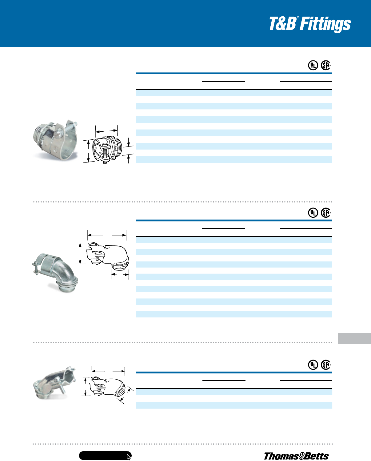
United States
Tel: 901.252.8000
800.816.7809
Fax: 901.252.1354
Technical Services
Tel: 888.862.3289
www.tnb.com
E-157
Conduit & Fittings — T&B
®
Cord & Cable Fittings
MC and AC Cable Fittings
Only two screws to tighten!
Squeeze Connectors —
90° Angle
• Cap lifts off simply by loosening screws partway
•
3
⁄8" and
1
⁄2" sizes made of steel
•
3
⁄4" and larger sizes made of malleable iron
• Add “I” suffix for insulated throat
**ULListedforarmoredcableonly.
***ULListedforflexiblemetalconduitonly.
†
Approximatedimensionwithscrewatminimumheight.
††
cULusCertified
UL File No. E23018
CSA File No. 2884
Fast and easy installation — simply loosen screws partway to lift off cap!
Squeeze Connectors — 45° Angle
A
B
C
A
B
C
A
B
C
• Malleable iron or steel construction
• Catalog Nos. 252, 253-TB, 254-TB
and 255 are steel
• Add “I” suffix for insulated throat
Fits every size of armored
cable, metal-clad cable and
flexible metal conduit!
Squeeze Connectors —
Straight
Cat. No.
iNS.
Cat. No.
CablE opENiNg (iN.)
tradE
SizE
K.o.
SizE
dimENSioNS (iN.)
max. miN. a
†
b C
252*** — .531 .437
5
⁄16"
3
⁄8"
13
⁄16
25
⁄32
11
⁄32
253-tb**
††
253-i-tb**
††
.585 .455
3
⁄8"
1
⁄2"
31
⁄32 1
13
⁄64
5
⁄8
254-tb 254-i-tb .938 .812
1
⁄2"
1
⁄2" 1
7
⁄32 1
3
⁄8
13
⁄32
255 255-i 1.094 .938
3
⁄4"
3
⁄4" 1
1
⁄4 1
17
⁄32
7
⁄16
256 256-i 1.375 1.250 1" 1" 1
19
⁄32 1
5
⁄8
1
⁄2
257*** 257-i*** 1.656 1.500 1
1
⁄4" 1
1
⁄4" 1
7
⁄8 1
23
⁄32
17
⁄32
258*** 258-i*** 1.875 1.688 1
1
⁄2" 1
1
⁄2" 2
1
⁄4 1
7
⁄16
9
⁄16
259*** 259-i*** 2.500 2.313 2" 2" 2
31
⁄32 2
5
⁄8
11
⁄16
249*** 249-i*** 3.062 2.812 2
1
⁄2" 2
1
⁄2" 3
5
⁄16 2
11
⁄16
3
⁄4
277*** 277-i*** 3.563 3.312 3" 3" 3
13
⁄16 2
7
⁄8
3
⁄4
278-tb***
††
278-i-tb***
††
4.370 3.200 3
1
⁄2" 3
1
⁄2" 6
5
⁄8 5
1
⁄4 1
5
⁄16
281-tb***
††
281-i-tb***
††
4.600 3.500 4" 4" 7
1
⁄4 5
3
⁄4 1
5
⁄8
Cat. No.
iNS.
Cat. No.
CablE opENiNg (iN.)
tradE
SizE
K.o.
SizE
dimENSioNS (iN.)
max. miN. a
†
b C
266-tb 266-i-tb .656 .406
3
⁄8"
1
⁄2" 1
1
⁄2 1
13
⁄32 1
7
⁄16
272** 272-i** .812 .688
3
⁄8"
1
⁄2" 1
9
⁄16 1
7
⁄8 —
268-tb 268-i-tb .937 .813
1
⁄2"
1
⁄2" 1
11
⁄16 1
13
⁄16 1
7
⁄8
279 279-i 1.000 .875
3
⁄4"
3
⁄4" 1
13
⁄16 2
1
⁄16 1
13
⁄16
270 270-i 1.125 1.000
3
⁄4"
3
⁄4" 1
7
⁄8 1
3
⁄4 1
13
⁄16
273-tb 273-i-tb 1.406 1.187 1" 1" 2
3
⁄8 2
7
⁄32 2
7
⁄16
274*** 274-i*** 1.656 1.375 1
1
⁄4" 1
1
⁄4" 3 3 3
275*** 275-i*** 1.875 1.625 1
1
⁄2" 1
1
⁄2" 3
3
⁄8 3
5
⁄16 4
276*** 276-i*** 2.500 2.125 2" 2" 4
1
⁄2 3
13
⁄16 4
7
⁄8
282-tb***
††
282-i-tb***
††
3.100 2.520 2
1
⁄2" 2
1
⁄2" 4
5
⁄16 5
17
⁄16 7
9
⁄16
283-tb***
††
283-i-tb***
††
3.640 3.100 3" 3" 5
1
⁄16 6
9
⁄16 8
15
⁄16
284-tb***
††
284-i-tb***
††
4.220 3.700 3
1
⁄2" 3
1
⁄2" 6
13
⁄16 8
5
⁄16 11
1
⁄4
285-tb***
††
285-i-tb***
††
4.600 4.100 4" 4" 7
1
⁄4 8
7
⁄8 12
3
⁄8
**ULListedforarmoredcableonly.Fittingmaterialsteel.
***ULListedforflexiblemetalconduitonly.
†
Approximatedimensionwithscrewatminimumheight.
††
cULusCertified
.485"–.660"cableopeningrangefor253-I-TB.
UL File No. E 23018
CSA File No. 2884
Cat. No.
iNS.
Cat. No.
CablE opENiNg (iN.)
tradE
SizE
K.o.
SizE
dimENSioNS (iN.)
max. miN. a
†
b C
265 265-i .656 .406
3
⁄8"
1
⁄2" 1
17
⁄32
15
⁄32 1
1
⁄8
267 267-i .937 .813
1
⁄2"
1
⁄2" 1
23
⁄32
1
⁄2 1
1
⁄4
269 269-i 1.125 1.000
3
⁄4"
3
⁄4" 2
17
⁄32 1
9
⁄16
UL File No. E-23018
CSA File No. 2884
ULListedforarmoredcableandflexiblemetalconduit.
†
Approximatedimensionwithscrewatminimumheight.
•
3
⁄8" and
1
⁄2" sizes made of steel
•
3
⁄4" size made of malleable iron
• Add “I” suffix for insulated throat
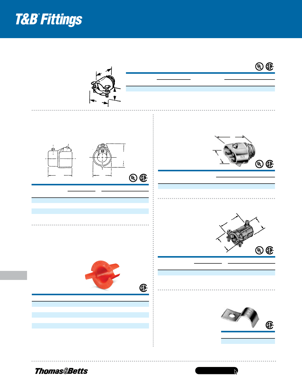
www.tnb.com
United States
Tel: 901.252.8000
800.816.7809
Fax: 901.252.1354
Technical Services
Tel: 888.862.3289
E-158
MC and AC Cable Fittings
Conduit & Fittings — T&B
®
Cord & Cable Fittings
A
B
C
A
B
A
B
C
CAT. NO.
K.O. SIZE
DIMENSIONS (IN.)
A B
291-TB
1
⁄2" 1
13
⁄32" 1
11
⁄16"
UL File No. E 1383 CSA File No. 2884
A
B
C
(MAX)
Armor-gripping saddle stays open by itself when cable is being inserted!
Two-Screw Connectors
• Formed steel body
• Carefully round bushing
For flexible metal conduit and armored cable.
Duplex Clamp Connector
• Malleable iron
construction
CAT. NO.
SIZE DIMENSIONS (IN.)
FLEX TO EMT A B C
503TB
1
⁄2" –
1
⁄2" 1
21
⁄32 1
3
⁄16 1
7
⁄8
504
3
⁄4" –
3
⁄4" 1
25
⁄32 1
7
⁄16 2
1
⁄8
505-TB 1" – 1" 2
1
⁄32 2
1
⁄16 2
5
⁄8
CSA File No. 8994 UL File No. E-23018
CAT. NO.
SIZE DIMENSIONS (IN.)
FLEX TO EMT A B C
449-TB
3
⁄8" –
1
⁄2" 1
21
⁄32 1
11
⁄32
15
⁄16
Cable opening: max. .656, min. .250. UL File No. E-23018
CSA File No. 2884
TITE-BITE
®
design holds flexible metal
cable firmly in place with a single screw!
Adapter — EMT to Flex
One-piece fitting couples
3
⁄8" flexible metal
conduit to
1
⁄2" EMT!
Combination Coupling
Smooth plastic bushing protects
conductor insulation from roughedges of
armored cable andflexible metal conduit!
Anti-Short Bushing
CAT. NO.
SIZE (AWG)
390 #14-2, #14-3, #12-2
391 #14-4, #12-3, #6-1, and #4-1
392 #12-4, #10-2, #10-3 and #2-1
393 #10-4, #8-2, #8-3, and #1-1
394 #8-4, #6-2, #6-3, #4-2, #4-3, and #6-4
Colorized.
Temperature Rating: 240° F.
CSA File No. 589
UL not applicable.
Fast and easy installation!
Strap
CAT. NO.
SIZE
65-TB
3
⁄8" Flex
• Elongated bolt hole makes
alignment easy, even when
holes in mounting surface
are off center
• Snap-on design holds strap
in place
CAT. NO.
CABLE OPENING (IN.)
TRADE
SIZE
K.O.
SIZE
DIMENSIONS (IN.)
MAX. MIN. A
†
B C
3301-TB** .656 .250
3
⁄8"
1
⁄2"
31
⁄32 1
5
⁄16 1
1
⁄16
3312-TB .937 .500
1
⁄2"
1
⁄2" 1
3
⁄32 1
5
⁄8 1
3
⁄8
** UL Listed for armored cable only. UL File No. E 1383 CSA File No. 2884
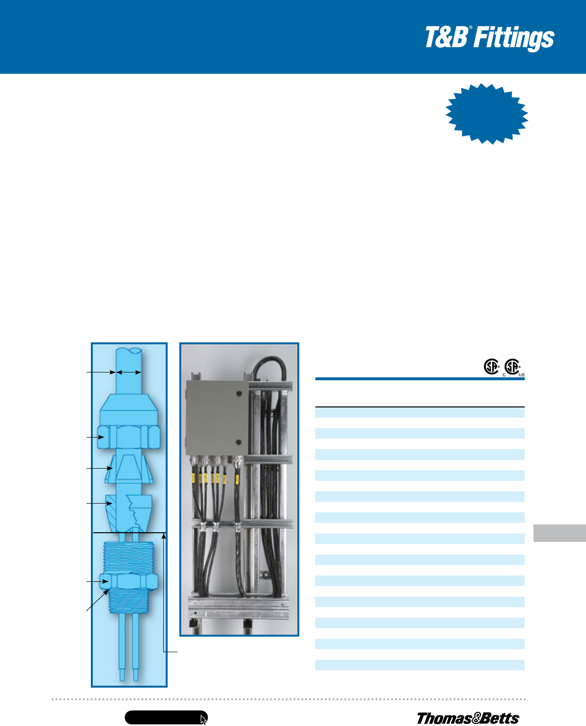
United States
Tel: 901.252.8000
800.816.7809
Fax: 901.252.1354
Technical Services
Tel: 888.862.3289
www.tnb.com
E-159
Conduit & Fittings — T&B
®
Cord & Cable Fittings
Tray Cable Fittings
CAT. NO.
HUB SIZE
NPT
THROAT
DIA.
(IN.)
MIN.
CABLE
DIA. (IN.)
MAX.
OPENING
(IN.)
STD. PKG.
QTY.
TCF050-27AL
1
⁄2 .330 .150 .270 25
TCF050-40AL
1
⁄2 .540 .250 .400 25
TCF050-54AL
1
⁄2 .540 .400 .540 25
TCF050-67AL
1
⁄2 .540 .540 .670 10
TCF050-78AL
1
⁄2 .540 .660 .780 10
TCF075-40AL
3
⁄4 .540 .250 .400 15
TCF075-54AL
3
⁄4 .540 .400 .540 15
TCF075-67AL
3
⁄4 .780 .540 .670 10
TCF075-78AL
3
⁄4 .780 .660 .780 10
TCF075-88AL
3
⁄4 .765 .770 .880 10
TCF100-78AL 1 .980 .660 .780 10
TCF100-88AL 1 .980 .770 .880 10
TCF100-100AL 1 .980 .870 1.000 10
TCF125-109AL 1
1
⁄4 1.255 .800 1.090 4
TCF125-128AL 1
1
⁄4 1.255 1.080 1.280 4
TCF125-147AL 1
1
⁄4 1.255 1.270 1.470 4
TCF150-115AL 1
1
⁄2 1.470 .890 1.150 2
TCF150-140AL 1
1
⁄2 1.470 1.140 1.400 2
TCF150-165AL 1
1
⁄2 1.470 1.390 1.650 2
TCF200-153AL 2 1.896 1.190 1.530 2
TCF200-186AL 2 1.896 1.520 1.860 2
TCF200-219AL 2 1.896 1.850 2.190 2
TCF250-252AL 2
1
⁄2 2.466 2.120 2.520 —
TCF300-278AL 3 2.780 2.380 2.780 —
TCF300-304AL 3 3.037 2.640 3.040 —
TCF300-330AL 3 3.068 2.900 3.300 —
For stainless steel (316), replace AL with SS6 (up to 1" only)
Introducing the Silver Grip
®
Tray Cord Fitting — the safe, yet cost-efficient
choice for increased safety when terminating portable cord and tray cable in
hazardous locations. Designed for use in Class I, Gas and Vapor environments,
the Silver Grip
®
Tray Cord Fitting provides efficient strain relief for cables
entering enclosures and raceways, and for cords used on portable equipment.
• Now available in stainless steel in hub sizes from
1
⁄2" to 1"
• Corrosion-resistant, non-magnetic aluminum construction
• Tapered neoprene bushing and O-ring seal out moisture
and dirt ingress
• Chuck grip provides high mechanical pull-out performance.
Exceeds applicable requirements
• Hand-tightens — no tools required
*When cord will not fit through body, strip
cord jacket and trim fillers if required. Insert
cable, ensuring the outer jacket reaches the
end of the bushing as shown. Tighten gland
nut onto body.
Maximum
Opening
Gland
Nut
Chuck
Grip
Bushing
Body
O-Ring
Increase safety for hazardous locations.
Silver Grip
®
TCF
®
Series —
Tray Cord Fitting
Applications
Tray Cable: Complies with IEC requirements for Class I, Zone 2
locations when used with enclosures containing no arcing or sparking
devices. For enclosures with arcing or sparking devices, TCF
®
fittings
must be used in combination with a certified Class I hazardous
location sealing fitting.
Portable Cord: Complies with IEC requirements for Class I, Zone 1
locations when used with enclosures containing no arcing or sparking
devices. For enclosures with arcing or sparking devices, TCF
®
fittings
must be used in combination with a certified Class I hazardous
location sealing fitting.
Note: Tray cable is not suitable for use in Zone 1 locations. Portable cord can be
used in Zone 1 applications only when installed on portable equipment.
• CSA File Number LR4484
• Class 4418-03 Fittings for Hazardous Locations
• Class 4418-03 Fittings for Hazardous Locations —
Certified to U.S. Standards
• Class I, Zone 1, AEx e ll
Now Available
in Stainless
up to 1"
Now Available
in Stainless
up to 1"
www.tnb.com
United States
Tel: 901.252.8000
800.816.7809
Fax: 901.252.1354
Technical Services
Tel: 888.862.3289
E-160
Conduit & Fittings — T&B
®
Cord & Cable Fittings
Non-Metallic Sheathed Cable Fittings
Note:
The materials herein, whether relating to the National Electrical Code
®
, the Underwriters Laboratories, Inc. listing, to industry practice or otherwise,
are not intended to provide all relevant information required for use and installation of our products. Refer to applicable codes, instructions and
industry specifications prior to installation or use.
Non-Metallic Sheathed Cable
Ref. NEC
®
Article 334
Code defines non-metallic sheathed cable as, “A factory assembly of two
or more insulated conductors having an outer sheath of moisture resistant,
flame retardant, non-metallic material.”
Non-metallic sheathed cable is constructed of insulated conductors (#14 to
#2 AWG Copper or #12 to #2 AWG Aluminum or Copperclad Aluminum),
and an outer non-metallic sheath classified as Type NM or Type NMC.
Non-metallic sheathed cable is provided with or without a bare or insulated
equipment grounding conductor. Non-metallic sheathed cable is rated
for 60° C service with voltage limitation of 600 volts.
Type NM — has flame-retardant moisture resistant sheath.
Type NMC — has flame-retardant, moisture-resistant, fungus-resistant
and corrosion-resistant sheath.
Non-metallic sheathed cable is permitted by code to be used exposed
or concealed in one, two or multifamily dwellings or other structures
not exceeding three floors. Use of Type NM cable is restricted to dry
locations whereas Type NMC can be used in dry, moist, damp or
corrosive environments.
Non-metallic sheathed cable (both Type NM & NMC) is not permitted
to be used as a service conductor, in commercial garages, in hoists
or cannot be embedded in cement, concrete or aggregate. With minor
exceptions, use of non-metallic sheathed cable is also prohibited in
theaters or any hazardous locations.
NEC
®
Section 334.30 requires that cable be secured in place by suitable
means so as not to injure the cable. Adequate protection for cable is
also required when run is exposed, through joists or rafters, through
floors, in unfinished basements and accessible attics.
Cable bends are limited to a minimum of five times the diameter
of the cable.
NEC
®
300.4(B) requires that cable be protected from physical damage
when it passes through factory or field punched, cut or drilled holes in metal
members. A bushing or grommet firmly secured in place is recommended.
Portions of this section reprinted by permission from NFPA 70-2011,
National Electrical Code
®
.
Copyright © 2010, National Fire Protection Association, Boston, MA.
Please refer to the following for further details
and complete information:
1. NEC
®
Article 334…Non-Metallic Sheathed Cable (Type NM & NMC)
2. NEC
®
Article 300…Wiring Methods
3. UL 719, ANSI C33.56…Safety Standards for Non-Metallic
Sheathed Cable
4. UL 514B, Safety Standards for Outlet Boxes and Fittings
5. NEMA FB-1…Standards Publication. Fittings and Supports
for Conduit and Cable Assemblies
6. CEC Section 12-600…Wiring Methods (Non-Metallic Sheathed Cable)
7. CSA C22.2 No. 48…Safety Standards for Non-Metallic
Sheathed Cable
8. CSA C22.2 No. 18…Safety Standards for Outlet Boxes,
Conduit Boxes and Fittings
NEC and National Electrical Code are registered trademarks of the National Fire
Protection Association, Inc.
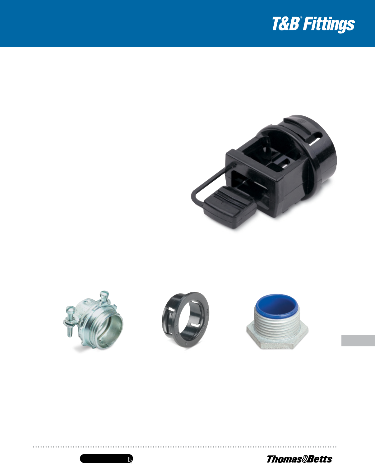
United States
Tel: 901.252.8000
800.816.7809
Fax: 901.252.1354
Technical Services
Tel: 888.862.3289
www.tnb.com
E-161
Conduit & Fittings — T&B
®
Cord & Cable Fittings
Non-Metallic Sheathed Cable Fittings
Series 3302M
Non-Metallic Sheathed Cable and
Flexible Cord Connectors (Steel)
Series 1942
Insulated Nipples
Suggested Specifications for Non-Metallic
Sheathed Cable Fittings
• Where non-metallic sheathed cable or flexible cord
terminates into a threaded or threadless opening,
terminating fittings used shall be approved for the
purpose by nationally recognized laboratory, inspection
agency or product evaluation organization.
• Terminating fittings shall be of malleable iron, steel or
thermoplastic construction designed to provide adequate
strain relief and positively prevent damage to jacket
or conductor insulation such as series 3300 or 3302M
manufactured by Thomas & Betts.
• Ferrous metal fittings shall be electro zinc plated inside/
outside including threads and bushed with a nylon
insulated throat.
• Thermoplastic material used for connector construction
shall be of high impact strength suitable for 105° C/
221° F service with a UL flammability rating of 94V-1.
• Where non-metallic sheathed cable passes through either
factory or field punched, cut or drilled holes in metallic
members, the cable shall be protected by thermoplastic
bushing such as series 3210 manufactured by Thomas &
Betts. Bushing shall be firmly secured in opening. Nylon
bushed metallic fittings such as Thomas & Betts series
1942 may be substituted as required.
Series 3300
Non-Metallic Sheathed
Cable and Flexible Cord
Connectors (All Plastic)
Series 3210
Knockout Bushings
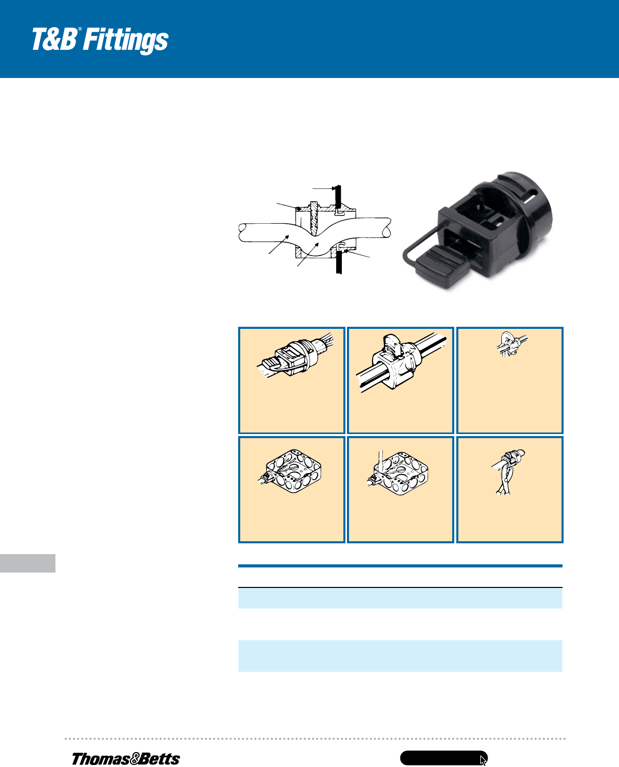
www.tnb.com
United States
Tel: 901.252.8000
800.816.7809
Fax: 901.252.1354
Technical Services
Tel: 888.862.3289
E-162
Conduit & Fittings — T&B
®
Cord & Cable Fittings
Non-Metallic Sheathed Cable Fittings
6. To remove from cable,
cut connector as shown.
Non-Metallic Sheathed Cable and
Flexible Cord Connectors (All Plastic)
Application
• To connect non-metallic sheathed
cable and flexible cord to a box or
an enclosure
Features
• Design provides strain relief by partially
deflecting cable (A); therefore:
(1) Connector will not damage
outer covering or jacket of cable,
or conductor insulation; designed
to give safe trouble free installation
(2) Holding power and cable strain
relief are not affected by surface
finish of outer covering or cable
jacket
(3) Connector provides superior holding
power far in excess of listing agency
requirements
• Snap-in one-piece design;
accommodates variation in knockout
dimensions, saves installation time (B).
• All high-impact thermoplastic
construction provides:
(1) Insulated throat; conductors are
protected from abrasion
(2) Improved dielectric strength, and
eliminates potential shorts
(3) Corrosion resistance
• Wide range — reduces inventories
• Connector may be pre-installed in box
K.O. or on cable
Typical Installation
1. Remove sheath from end of
cable (4" or more as required).
Insert cable through connector
as shown (Cable under button).
4. Snap connector into knockout
box. If desired, this step can
be done prior to Step 1.
5. To remove from knockout box,
depress ears.
2. Insert button into cavity.
3. With grooved pliers or parallel
jaw type pliers (commercially
available), squeeze button into
cord orwires as far into connector
bodyas possible.
Note: It may be necessary to
re-adjust pliers to ensure button
is properly installed.
Box or
Enclosure Wall
(C)
Cable or Cord
(A)
(B)
3300 Series
Range
CAT. NO.
CABLE/KNOCKOUT
SIZE
CORD
RANGE
3300
1
⁄2" #10-2, #12-2 & #14-2 Type NM Cable;
.125" to .300" outside diameter cord
3201 & 3350
1
⁄2" #10-3, #12-3, #14-3, #10-2, #12-2, #14-2 Type NM Cable;
also multiple (2) #12-2 and #14-2 Type NM Cable;
.300" to .600" outside diameter cord
3202
3
⁄4" #8-3 and #6-3 type NM cables;
also Multiple (2) #14-3 and #10-2 Type NM Cable;
.500" to .850" outside diameter cord
Standard Material
All high-impact polycarbonate — UL Class
94V-1 suitable for 105° C application
Standard Finish
As molded (Black)
Listings/Compliances
UL (UL File No: E-23017)
CSA (Cat. #3201, 3350) for factory installation
(LR-589, LR-2884)
UL 514B
CSA C22.2 #18 (Where applicable)
ANSI C33.84, NFPA 70
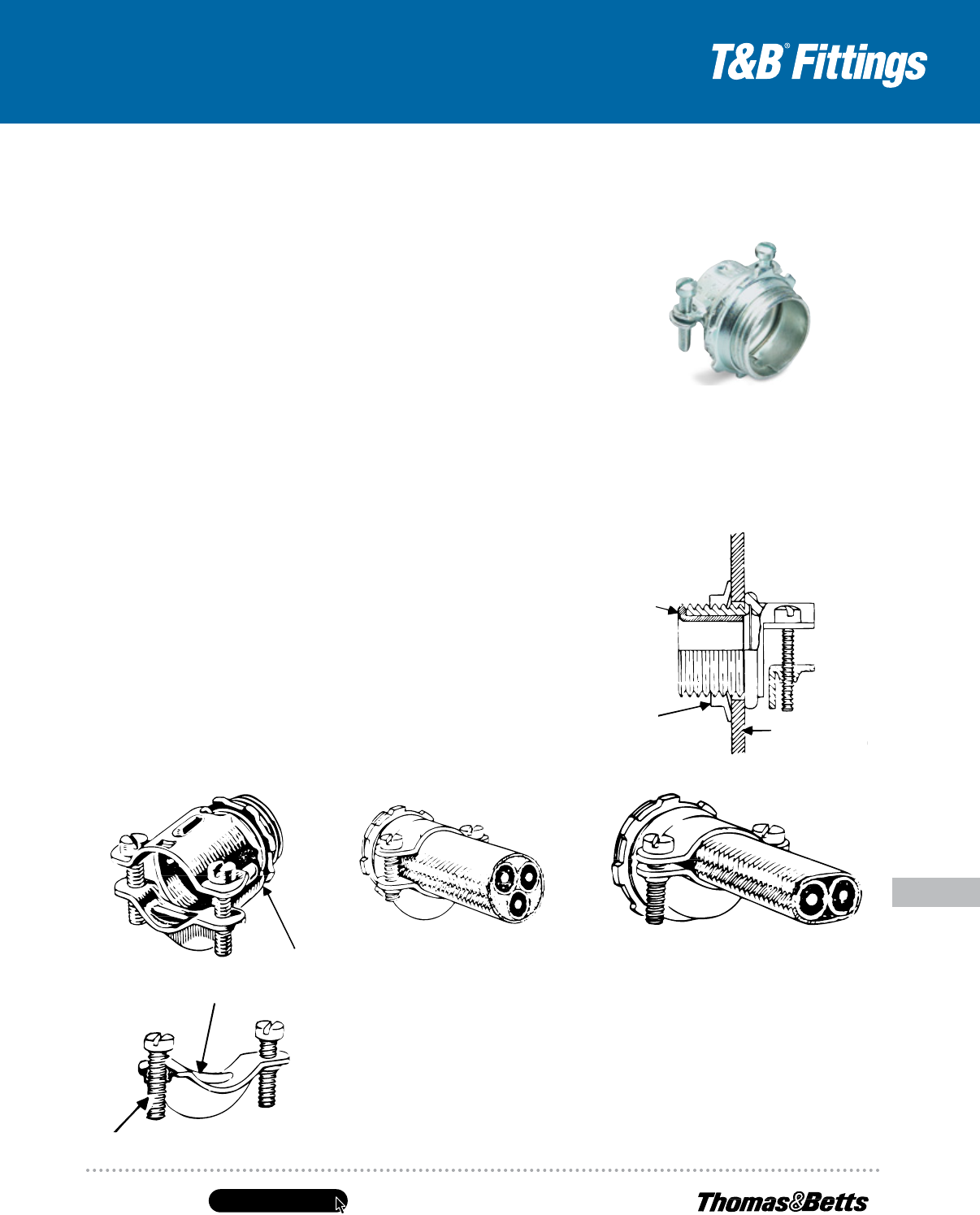
United States
Tel: 901.252.8000
800.816.7809
Fax: 901.252.1354
Technical Services
Tel: 888.862.3289
www.tnb.com
E-163
Conduit & Fittings — T&B
®
Cord & Cable Fittings
Non-Metallic Sheathed Cable Fittings
Application
• To connect non-metallic sheathed
cable and flexible cord to a box
or an enclosure
Features
• Rugged all-steel/malleable iron
construction (A)
• Rounded cable clamp grip provides
superior mechanical holding power
without damaging conductor
insulation or outer jacket (B)
• Clamp designed to cover
body opening for a neat and
safe installation
• Screws thread into clamp and not
body; screw heads are snug with
body and ends of screws do not
project beyond the body (C)
• Insulator firmly secured in place
protects conductors and reduces
wire pulling effort; protects threads
from damaging during handling (D)
• Locknut designed to secure
connector to a box or enclosure;
will not vibrate loose
Standard Material
Body ...........
1
⁄2" thru 1" Steel; 1
1
⁄4" thru
2" Malleable Iron
Clamp .........
1
⁄2" thru 1
1
⁄4" Steel; 1
1
⁄4" thru
2" Malleable Iron
Locknut .......................All Steel
Insulator...................Thermoplastic
Standard Finish
All steel and malleable iron parts —
Electro Zinc Plated & Chromate Coated
Range
Hub Size.................
1
⁄2" thru 2" Hubs
Provided with Straight Pipe Threads (NPS.)
Cable ..........(2) #14 thru (4) #4 Type NM
Cable Outside Diameter ......250" to 1.150"
Listings/Compliances
UL (UL File No: E-23017)
CSA (LR-589, LR-2884)
UL 514B
CSA C22.2 No. 18
NFPA 70
NEMA FB1
Federal Standard H-28 (Threads)
3302M Series
Non-Metallic Sheathed Cable Connector
Typical Installation
(D)
(A)
Non-Metallic Sheathed Cable and
Flexible Cord Connectors (Steel)
Non-Metallic Sheathed Cable and
Flexible Cord Connectors (Steel)
(B)
(C)
Box or
Enclosure Wall
Locknut
Typical Installation (Flexible Cord)
Typical Installation (NM-Sheathed Cable)
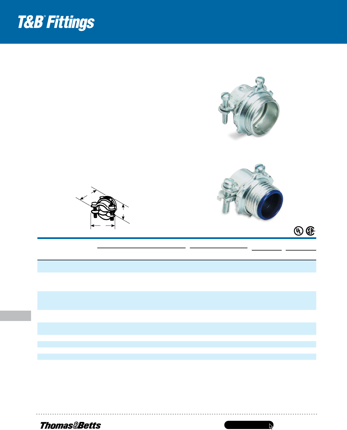
www.tnb.com
United States
Tel: 901.252.8000
800.816.7809
Fax: 901.252.1354
Technical Services
Tel: 888.862.3289
E-164
Conduit & Fittings — T&B
®
Cord & Cable Fittings
Non-Metallic Sheathed Cable Fittings
Steel or malleable iron
Two-Screw Connectors
Rounded cable grip and smooth bushing protect the cable sheath and wire
insulation. Because saddle is threaded, screws do not travel or extend beyond
the connector body as it is clamped to the cable. An extra lip on the saddle
closes the unused part of the connector opening.
• Threaded saddle means screws don’t travel or extend
beyond connector body as it’s clamped to cable
• Extra lip on saddle closes unused part of connector opening
• Steel or malleable iron construction
• Look for the unique T&B blue color ensuring the highest
quality fitting
NoN-INsulatEd
Cat. No.
INsulatEd
Cat. No.
K.o.
sIzE
ul lIstEd & Csa CErtIfIEd ul lIstEd & Csa CErtIfIEd
IN.
INsulatEd CablE
opENINg (IN.)
sINglE
NM & NMC CablE
paIrs of
NM & NMC CablE
sErvICE
ENtraNCE CablEs a b C Max. MIN.
3302-tb* 3302M-tb
1
⁄2" (2) #14, (2) #12, (2) #10, (2) #14, (2) #12 (2) #12 thru (2) #4, (3) #12, (3) #10 1 1
13
⁄32 1 .590 .250
(3) #14, (3) #12, (3) #10
3303-tb 3303M
3
⁄4" (2) #8, (2) #6, (3) #8, (2) #12, (2) #10, (2) #8 thru (2) 1/0, (3) #8, (3) #6, 1
1
⁄4 1
5
⁄8 1
1
⁄8 .750 .530
(3) #6, (3) #4 (2) #8, (3) #14 (2) #6 + #8 GND,
(2) #1, (2) 1/0, (3) #6 thru (3) #2
3304 3304M 1" (3) #8, (3) #6, (3) #4 (2) #8, (3) #10 (2) #4 + #6 GND, (2) #3 + #5 1
1
⁄2 1
7
⁄8 1
1
⁄4 .990 .690
GND, (2) #2 + #4 GND
(3) #2 thru (3) 2/0, (2) #1 + #3 GND
3305 3305M 1
1
⁄4" — (2) #8, (2) #6, (2) #4, (3) #8 (2) 1/0 + #2 GND, 1
29
⁄32 2
1
⁄4 1
1
⁄4 1.320 .850
(2) 2/0 + #1 GND
3306 3306M 1
1
⁄2" (3) #4, (3) #6 — (3) 3/0, (3) 4/0, (2) 3/0 + 1/0 2
3
⁄16 2
5
⁄8 1
9
⁄16 1.530 .930
GND, (2) 4/0 + 2/0 GND
3307 3307M 2" Max. 1.98", Min. 1.15" Max. 1.98", Min. 1.15" — 2
3
⁄4 3
1
⁄4 1
7
⁄8 — —
3308
†
— 2
1
⁄2" Max. 2.38", Min. 1.5" Max. 2.38", Min. 1.5" — 3
1
⁄4 3
15
⁄16 2
3
⁄16 — —
3309
†
— 3" Max. 2.88", Min. 1.75" Max. 2.88", Min. 1.75" — 3
13
⁄16 4
9
⁄16 2
9
⁄16 1.980 1.150
3310
†
— 3
1
⁄2" Max. 3.38", Min. 2.25" Max. 3.38", Min. 2.25" — 4
7
⁄16 5
1
⁄4 2
27
⁄32 — —
3311
†
— 4" Max. 3.88", Min. 2.5" Max. 3.88", Min. 2.5" — 4
7
⁄8 5
15
⁄16 3
3
⁄32 — —
*UL Listed for use with rubber and thermoplastic flexible cords (both single and multiple cords and two oval cables).
UL Listed for multiple cords and cables.
CSA File No. 2884
UL File No. E-23013 –
1
⁄2" – 1
1
⁄2"; U.L. File No. E-15170 – 2"
†
Not UL Listed or CSA certified.
B
A
C
