OPERATIONS MANUAL
ba76201e09 12/2022
Alyza IQ PO4
1- AND 2-CHANNEL MEASURING SYSTEMS FOR ONLINE DETERMINATION
OF ORTHO-PHOSPHATE IN AQUEOUS SAMPLES

Alyza IQ PO4
2
ba76201e09 12/2022
Contact YSI
1725 Brannum Lane
Yellow Springs, OH 45387 USA
Tel: +1 937-767-7241
800-765-4974
Email: [email protected]
Internet: www.ysi.com
Copyright © 2022 Xylem Inc.
For the most recent version of the manual, please visit
www.ysi.com
.

Alyza IQ PO4 Contents
3
ba76201e09 12/2022
Contents
1 Overview . . . . . . . . . . . . . . . . . . . . . . . . . . . . . . . . . . . . . .7
1.1 How to use this component operating manual . . . . . . . . . . . . . . 7
1.2 Metrological basics PO4-P, PO4 . . . . . . . . . . . . . . . . . . . . . . . . . . 8
1.3 Product description . . . . . . . . . . . . . . . . . . . . . . . . . . . . . . . . . . . . 8
1.3.1 Overview . . . . . . . . . . . . . . . . . . . . . . . . . . . . . . . . . . . . . . . . 8
1.3.2 Measuring unit . . . . . . . . . . . . . . . . . . . . . . . . . . . . . . . . . . . 14
1.3.3 ChemBags . . . . . . . . . . . . . . . . . . . . . . . . . . . . . . . . . . . . . . 15
1.3.4 Status LEDs . . . . . . . . . . . . . . . . . . . . . . . . . . . . . . . . . . . . . 16
1.3.5 Instrument variants . . . . . . . . . . . . . . . . . . . . . . . . . . . . . . . 17
1.3.6 Sample filtration . . . . . . . . . . . . . . . . . . . . . . . . . . . . . . . . . . 19
1.4 Name plates . . . . . . . . . . . . . . . . . . . . . . . . . . . . . . . . . . . . . . . . . . 20
2 Safety instructions . . . . . . . . . . . . . . . . . . . . . . . . . . . .22
2.1 Safety information . . . . . . . . . . . . . . . . . . . . . . . . . . . . . . . . . . . . 22
2.1.1 Safety information in the operating manual . . . . . . . . . . . . . 22
2.1.2 Safety signs on the product . . . . . . . . . . . . . . . . . . . . . . . . . 22
2.1.3 Further documents providing safety information . . . . . . . . . 22
2.2 Safe operation . . . . . . . . . . . . . . . . . . . . . . . . . . . . . . . . . . . . . . . . 23
2.2.1 Authorized use . . . . . . . . . . . . . . . . . . . . . . . . . . . . . . . . . . . 23
2.2.2 Requirements for safe operation . . . . . . . . . . . . . . . . . . . . . 23
2.2.3 Unauthorized use . . . . . . . . . . . . . . . . . . . . . . . . . . . . . . . . . 23
2.3 User qualification . . . . . . . . . . . . . . . . . . . . . . . . . . . . . . . . . . . . . 23
2.4 Personal protective equipment (PPE) . . . . . . . . . . . . . . . . . . . . . 24
3 Commissioning . . . . . . . . . . . . . . . . . . . . . . . . . . . . . . .25
3.1 IQ SENSORNET system requirements . . . . . . . . . . . . . . . . . . . . . . 25
3.2 Scope of delivery . . . . . . . . . . . . . . . . . . . . . . . . . . . . . . . . . . . . . 25
3.2.1 Scope of delivery of the Alyza IQ . . . . . . . . . . . . . . . . . . . . . 25
3.2.2 Accessories required in addition . . . . . . . . . . . . . . . . . . . . . 26
3.3 Basic principles of installation . . . . . . . . . . . . . . . . . . . . . . . . . . 27
3.3.1 Requirements of the measurement location . . . . . . . . . . . . 27
3.3.2 Safety requirements of the electrical installation . . . . . . . . . 27
3.3.3 General installation instructions . . . . . . . . . . . . . . . . . . . . . . 28
3.3.4 Installing the housing . . . . . . . . . . . . . . . . . . . . . . . . . . . . . . 30
3.3.5 Installation on the SM stand mount . . . . . . . . . . . . . . . . . . . 30
3.3.6 Installation on a rail . . . . . . . . . . . . . . . . . . . . . . . . . . . . . . . 35

Contents IQ SENSORNET Alyza IQ
4
ba76201e09 12/2022
3.3.7 Installation on a wall . . . . . . . . . . . . . . . . . . . . . . . . . . . . . . . 40
3.3.8 Removing the transport protection of the measuring unit . . . 42
3.3.9 Connecting the cables to the control unit ACM . . . . . . . . . . 43
3.3.10 Mounting the cover plate for the control unit ACM . . . . . . . . 44
3.3.11 Installing the bug screen and condensate drain adapter . . . 45
3.3.12 Mounting the terminal holder (TM) . . . . . . . . . . . . . . . . . . . . 47
3.3.13 Connecting the power cable and heat tracing lines . . . . . . . 50
3.3.14 Mounting the collection funnel . . . . . . . . . . . . . . . . . . . . . . . 59
3.3.15 Mounting the WF Set (collection funnel for sample overflow) 62
3.3.16 Installing the FM/PC filter module and M 1.5 basin holder for
filtration . . . . . . . . . . . . . . . . . . . . . . . . . . . . . . . . . . . 64
3.3.17 Connecting the tubes and liquid lines . . . . . . . . . . . . . . . . . . 66
3.3.18 Setting up a connection with the IQ S
ENSORNET system . . . 69
3.3.19 Taking the filtration pumps into operation . . . . . . . . . . . . . . 70
3.4 Initial commissioning . . . . . . . . . . . . . . . . . . . . . . . . . . . . . . . . . . 72
3.4.1 Checklist for commissioning . . . . . . . . . . . . . . . . . . . . . . . . . 72
3.4.2 Stick the label (national language)
onto the locking device of the MultiPort valve . . . . . . . . . . . 73
3.4.3 Carrying out the install wizard . . . . . . . . . . . . . . . . . . . . . . . 74
3.4.4 Preparing the Alyza IQ for measuring . . . . . . . . . . . . . . . . . 76
4 Measurement / Operation . . . . . . . . . . . . . . . . . . . . . . .78
4.1 General operating principles . . . . . . . . . . . . . . . . . . . . . . . . . . . . 78
4.2 Measurement operation . . . . . . . . . . . . . . . . . . . . . . . . . . . . . . . . 79
4.2.1 Determination of measured values . . . . . . . . . . . . . . . . . . . . 79
4.2.2 Starting the measuring operation . . . . . . . . . . . . . . . . . . . . . 79
4.2.3 Measuring . . . . . . . . . . . . . . . . . . . . . . . . . . . . . . . . . . . . . . . 79
4.3 Settings for the Alyza IQ . . . . . . . . . . . . . . . . . . . . . . . . . . . . . . . . 80
4.3.1 IQ S
ENSORNET Settings of sensors and diff. sensors . . . . . . 80
4.3.2 Priority . . . . . . . . . . . . . . . . . . . . . . . . . . . . . . . . . . . . . . . . . 84
4.3.3 Damping . . . . . . . . . . . . . . . . . . . . . . . . . . . . . . . . . . . . . . . . 84
4.4 Calibration . . . . . . . . . . . . . . . . . . . . . . . . . . . . . . . . . . . . . . . . . . . 85
4.4.1 Overview . . . . . . . . . . . . . . . . . . . . . . . . . . . . . . . . . . . . . . . 85
4.4.2 Calibration . . . . . . . . . . . . . . . . . . . . . . . . . . . . . . . . . . . . . . 86
4.4.3 Calibration history . . . . . . . . . . . . . . . . . . . . . . . . . . . . . . . . . 89
4.4.4 Reactivating the last valid calibration . . . . . . . . . . . . . . . . . . 89
4.5 Information on the Alyza IQ . . . . . . . . . . . . . . . . . . . . . . . . . . . . . 90
4.5.1 Information on the current operating condition
(Tab Status) . . . . . . . . . . . . . . . . . . . . . . . . . . . . . . . . . . . . . 90
4.5.2 Information on the expected lifetimes of replacement parts
(tab Remaining) . . . . . . . . . . . . . . . . . . . . . . . . . . . . . . . . . . 91
4.5.3 Information on maintenance activities and calibration
procedures (tab History) . . . . . . . . . . . . . . . . . . . . . . . . . . . . 93
4.5.4 More information on the Alyza IQ (tab Info) . . . . . . . . . . . . . 96
4.6 Transferring information to a USB memory device via the

IQ SENSORNET Alyza IQ Contents
5
ba76201e09 12/2022
Alyza IQ . . . . . . . . . . . . . . . . . . . . . . . . . . . . . . . . . . . . . . . . . . . 96
4.6.1 Transferring to a USB memory device a selection of important
operating data . . . . . . . . . . . . . . . . . . . . . . . . . . . . . . . . . . . 97
4.6.2 Transferring detailed operating data to a USB memory device
for evaluation by the service department . . . . . . . . . . . . . . . 97
4.7 Software update for the Alyza IQ . . . . . . . . . . . . . . . . . . . . . . . . . 98
5 Maintenance and cleaning . . . . . . . . . . . . . . . . . . . . .101
5.1 Hazard warnings . . . . . . . . . . . . . . . . . . . . . . . . . . . . . . . . . . . . . 101
5.2 Opening the locking device of the MultiPort valve
("Before opening: Drain the system") . . . . . . . . . . . . . . . . . . . . 102
5.3 Replacement parts, accessories . . . . . . . . . . . . . . . . . . . . . . . . 106
5.4 Overview of the maintenance and cleaning activities . . . . . . . 108
5.5 Installing / exchanging the ChemBags, MPV, tubes . . . . . . . . 111
5.5.1 Start the maintenance routine of the Alyza IQ . . . . . . . . . . 112
5.5.2 Prepare the maintenance activities . . . . . . . . . . . . . . . . . . 113
5.5.3 Open the measuring unit . . . . . . . . . . . . . . . . . . . . . . . . . . 113
5.5.4 Installing the MultiPort valve (MPV) and tubes . . . . . . . . . 115
5.5.5 Remove the ChemBags for maintenance activities . . . . . . 118
5.5.6 Check the collection tray under the ChemBags for
liquids . . . . . . . . . . . . . . . . . . . . . . . . . . . . . . . . . 119
5.5.7 Installing the ChemBags . . . . . . . . . . . . . . . . . . . . . . . . . . 121
5.5.8 Terminating the maintenance routine . . . . . . . . . . . . . . . . 124
5.6 Cleaning the sample filtration and sample feed . . . . . . . . . . . 124
5.6.1 Mechanical cleaning of the filter plate . . . . . . . . . . . . . . . . 125
5.6.2 Chemical cleaning of the filter plate . . . . . . . . . . . . . . . . . . 126
5.6.3 Storing a used and cleaned filter plate . . . . . . . . . . . . . . . 128
5.6.4 Replacing the filter plate of the sample filtration . . . . . . . . 128
5.6.5 Cleaning the sample feed, overflow vessel and outlet . . . . 129
5.7 Maintenance activities at the housing . . . . . . . . . . . . . . . . . . . 135
5.7.1 Cleaning the housing of the Alyza IQ . . . . . . . . . . . . . . . . 135
5.7.2 Changing the filter mats . . . . . . . . . . . . . . . . . . . . . . . . . . . 136
5.7.3 Checking the temperature control . . . . . . . . . . . . . . . . . . . 137
5.8 Maintenance activities at the power supply box . . . . . . . . . . . 139
5.9 Emptying the system manually . . . . . . . . . . . . . . . . . . . . . . . . . 144
5.10 SystemCheck . . . . . . . . . . . . . . . . . . . . . . . . . . . . . . . . . . . . . . . 147
6 Maintenance and cleaning (complex activities) . . . .149
6.1 Decommissioning . . . . . . . . . . . . . . . . . . . . . . . . . . . . . . . . . . . . 149
6.1.1 Preparing the decommissioning . . . . . . . . . . . . . . . . . . . . 149
6.1.2 Decommissioning the measuring unit . . . . . . . . . . . . . . . . 151
6.1.3 Decommissioning for transport or storage . . . . . . . . . . . . . 154

Contents IQ SENSORNET Alyza IQ
6
ba76201e09 12/2022
6.2 Complex maintenance- and cleaning activities in the measuring
unit . . . . . . . . . . . . . . . . . . . . . . . . . . . . . . . . . . . . . . . . . . . . . . 154
6.2.1 Dismounting the measuring unit . . . . . . . . . . . . . . . . . . . . . 155
6.2.2 Carrying out complex maintenance activities . . . . . . . . . . . 156
6.2.3 Check the waste collector for coating . . . . . . . . . . . . . . . . . 156
6.2.4 Installing the measuring unit . . . . . . . . . . . . . . . . . . . . . . . . 159
6.3 Transport, storage . . . . . . . . . . . . . . . . . . . . . . . . . . . . . . . . . . . . 159
6.3.1 General notes . . . . . . . . . . . . . . . . . . . . . . . . . . . . . . . . . . . 159
6.3.2 Preparing the Alyza IQ for transport or storage . . . . . . . . . 160
6.4 Recommissioning the Alyza IQ . . . . . . . . . . . . . . . . . . . . . . . . . 162
7 What to do if ... . . . . . . . . . . . . . . . . . . . . . . . . . . . . . . .163
8 Technical data . . . . . . . . . . . . . . . . . . . . . . . . . . . . . . .170
8.1 Measuring characteristics PO4-P, PO4 . . . . . . . . . . . . . . . . . . . 170
8.2 Application conditions . . . . . . . . . . . . . . . . . . . . . . . . . . . . . . . . 171
8.3 General data . . . . . . . . . . . . . . . . . . . . . . . . . . . . . . . . . . . . . . . . . 172
8.4 Electrical data . . . . . . . . . . . . . . . . . . . . . . . . . . . . . . . . . . . . . . . 175
8.5 Consumption data . . . . . . . . . . . . . . . . . . . . . . . . . . . . . . . . . . . . 176
9 Lists . . . . . . . . . . . . . . . . . . . . . . . . . . . . . . . . . . . . . . .177
9.1 Explanation of the messages . . . . . . . . . . . . . . . . . . . . . . . . . . . 177
9.1.1 Error messages . . . . . . . . . . . . . . . . . . . . . . . . . . . . . . . . . 177
9.1.2 Informative messages . . . . . . . . . . . . . . . . . . . . . . . . . . . . 181
9.2 Status info . . . . . . . . . . . . . . . . . . . . . . . . . . . . . . . . . . . . . . . . . . 185
10 Disposal . . . . . . . . . . . . . . . . . . . . . . . . . . . . . . . . . . . .186
11 Appendix . . . . . . . . . . . . . . . . . . . . . . . . . . . . . . . . . . .187
11.1 Glossary . . . . . . . . . . . . . . . . . . . . . . . . . . . . . . . . . . . . . . . . . . . . 187
12 Contact Information . . . . . . . . . . . . . . . . . . . . . . . . . .189
12.1 Ordering & Technical Support . . . . . . . . . . . . . . . . . . . . . . . . . . 189
12.2 Service Information . . . . . . . . . . . . . . . . . . . . . . . . . . . . . . . . . . . 189
Alyza IQ PO4 Overview
7
ba76201e09 12/2022
1Overview
1.1 How to use this component operating manual
Structure of the
IQ S
ENSORNET
operating manual
The IQ S
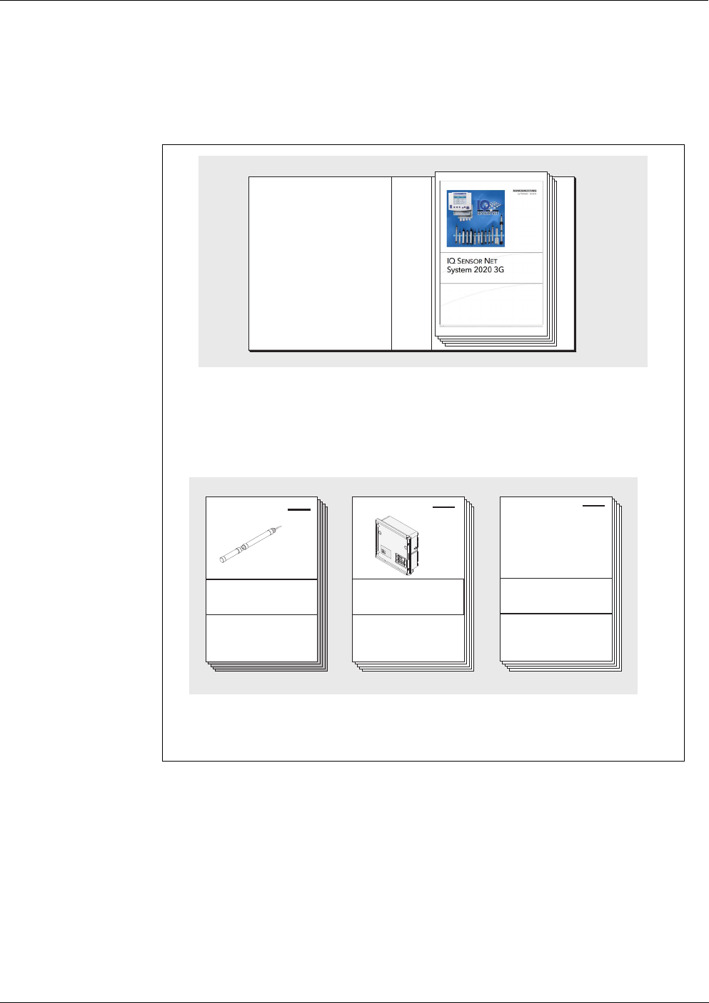
ENSORNET operating manual has a modular structure like the
IQ S
ENSORNET system itself. It consists of a system operating manual and the
operating manuals of all the components used.
Please file this component operating manual into the ring binder of the system
operating manual.
IQ S
ENSORNET System operating manual (ring binder)
+
Operating manuals for components and
options (e.g. field bus)
figure 1-1 Structure of the IQ SENSORNET operating manual
...
Power
!
O
K

Overview Alyza IQ PO4
8
ba76201e09 12/2022
1.2 Metrological basics PO4-P, PO4
Phosphate The salts of the phosphoric acid are called phosphates. In the case of simple
phosphoric acid (orthophosphoric acid, H
3
PO
4
), this is orthophosphate (anion
PO
4
3-
).
Measuring method The Alyza IQ PO4 analyzer measures the concentration of orthophosphate in
an aqueous solution with the aid of the vanadate molybdate method (yellow
method).
The reagent contains an aqueous solution of ammonium monovanadate NH
4-
VO
3
and ammonium heptamolybdate (NH
4
)
6
Mo
7
O
24
with an addition of sulfuric
acid H
2
SO
4
. In an acidic environment, the chemical reaction takes place accord-
ing to the following molecular formula:
PO
4
3-
+ 2 VO
3
-
+ 10 MoO
4
2-
+ 20 H
+
→ [PV
2
Mo
10
O
40
]
5-
+ 10 H
2
O
The originally pale yellow reagent will turn a deep yellow. The change of absor-
bance is photometrically measured at a wavelength of 400 nm. From this, the
concentration of orthophosphate is calculated.
Citation forms Phosphate concentration is quoted in milligrams per liter (mg/l). This value can
either refer to all orthophosphate ions or to the phosphorus atom included in
them. The values can be converted as follows:
1 mg/l P = 3.066 mg/l PO4
1 mg/l PO4 = 0.3261 mg/l P
Concentration values referring to the phosphorus atom are indicated by the ad-
dition PO4-P (citation form).
1.3 Product description
1.3.1 Overview
Application Analyzers of the Alyza IQ series are designed for online measurements in aque-
ous samples.
Measurement takes place photometrically, at adjustable intervals, including au-
tomatic sampling (sample filtration and sample feed).
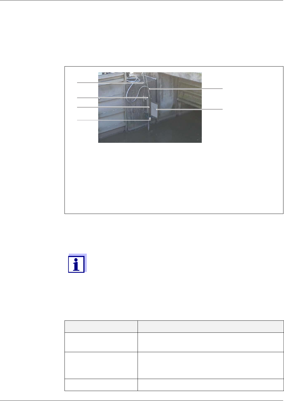
Measuring system Analyzers of the Alyza IQ series are operated as "sensors" in the
Variant Measurement
Alyza IQ PO4 Orthophosphate measurements
e.g.
Measurements for regulation of precipitant dosing in
waste water treatment plants
Measurements in the final effluents of waste water
treatment plants
Measurements for water body and river monitoring

Alyza IQ PO4 Overview
9
ba76201e09 12/2022
IQ SENSORNET.
The following components are required for operation of the AlyzaIQ:
Component /
function
Explanation
Sensor The Alyza IQ analyzer is an IQ S
ENSORNET sensor
with special functions.
Controller,
terminal
connection module
For controlling, and to display the measured val-
ues, the Alyza IQ requires a functioning
IQ S
ENSORNET system.
Examples of simple IQ S
ENSORNET systems (min-
imum configuration):
IQ S
ENSORNET system (2 components):
– 1 terminal/controller (e.g.MIQ/TC 2020 3G)
for operation and display of measured val-
ues
– 1 module (e.g. MIQ/JB)
to establish the connection between the ter-
minal/controller and sensor
IQ S
ENSORNET system (1 component):
– DIQ/S 28X
Mounting The Alyza IQ must be safely mounted for opera-
tion. The following mounting variants are avail-
able:
Wall mounting assembly (WM)
Railing support mounting (RM)
Mounting stand (SM)
Sample filtration,
sampling
Sample feed Alyza IQ variant with filtration pumps (1 or 2) to
feed the sample to the Alyza IQ
or
The sample is externally taken and made available
inside the Alyza IQ.
Sample filtration Filtration module (FM/PC) with frame and filter
plate
Lines for the trans-
port of liquids, with
heat tracing
Lines with heat tracing for
1 x or 2 x intake line (SH - ...),
1 x return line (RH - ...) and, if necessary,
1 x return line (RH - ...)
for the separate disposal
of chemical waste from the measuring unit
Overview Alyza IQ PO4
10
ba76201e09 12/2022
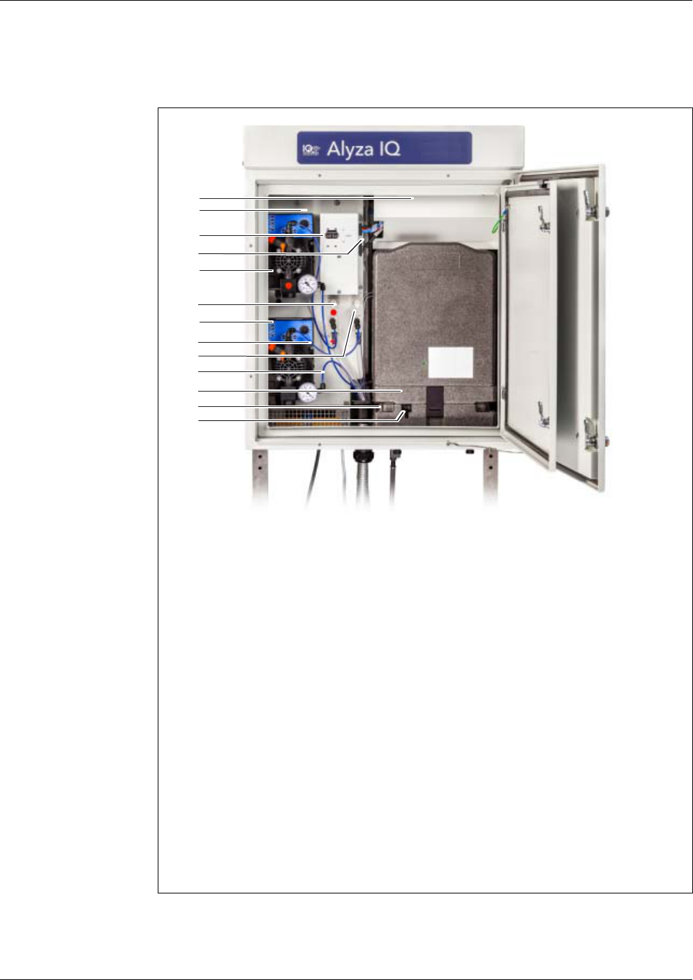
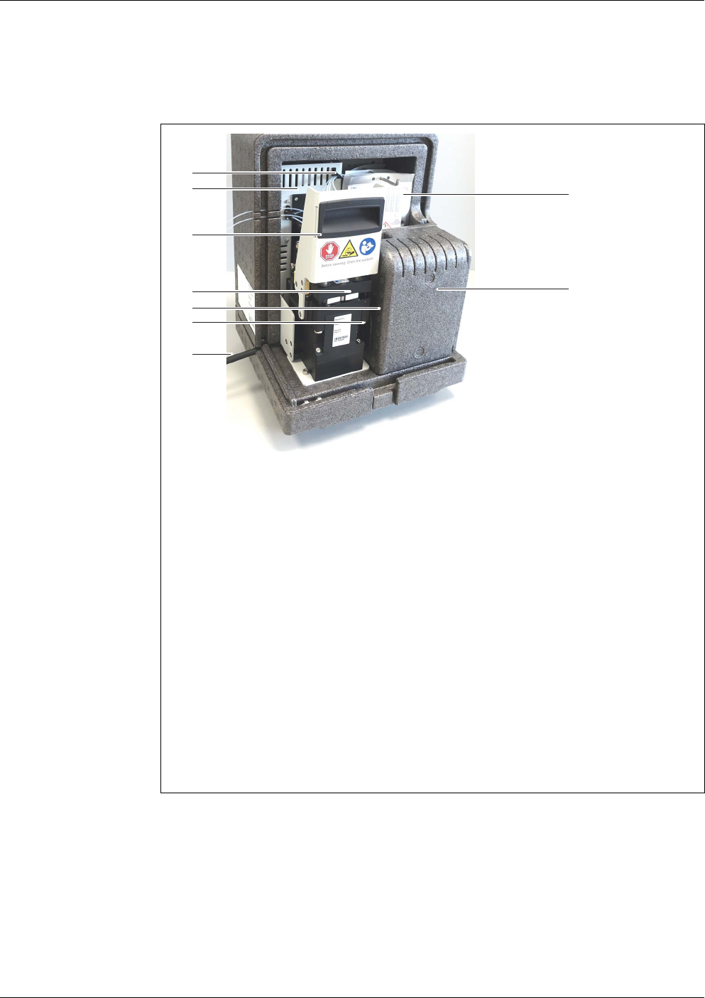
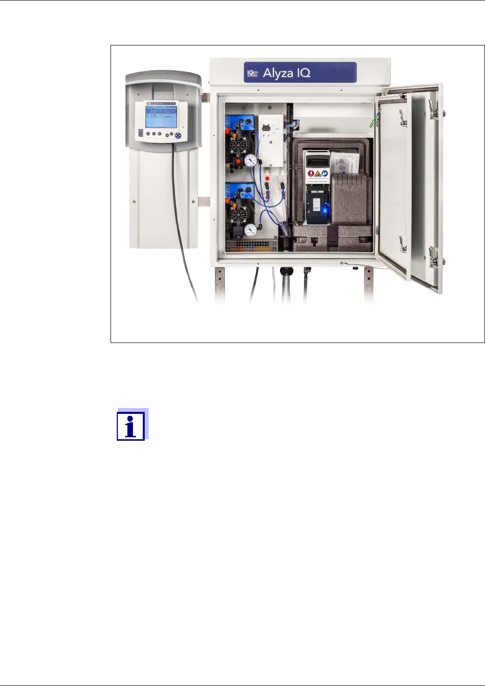
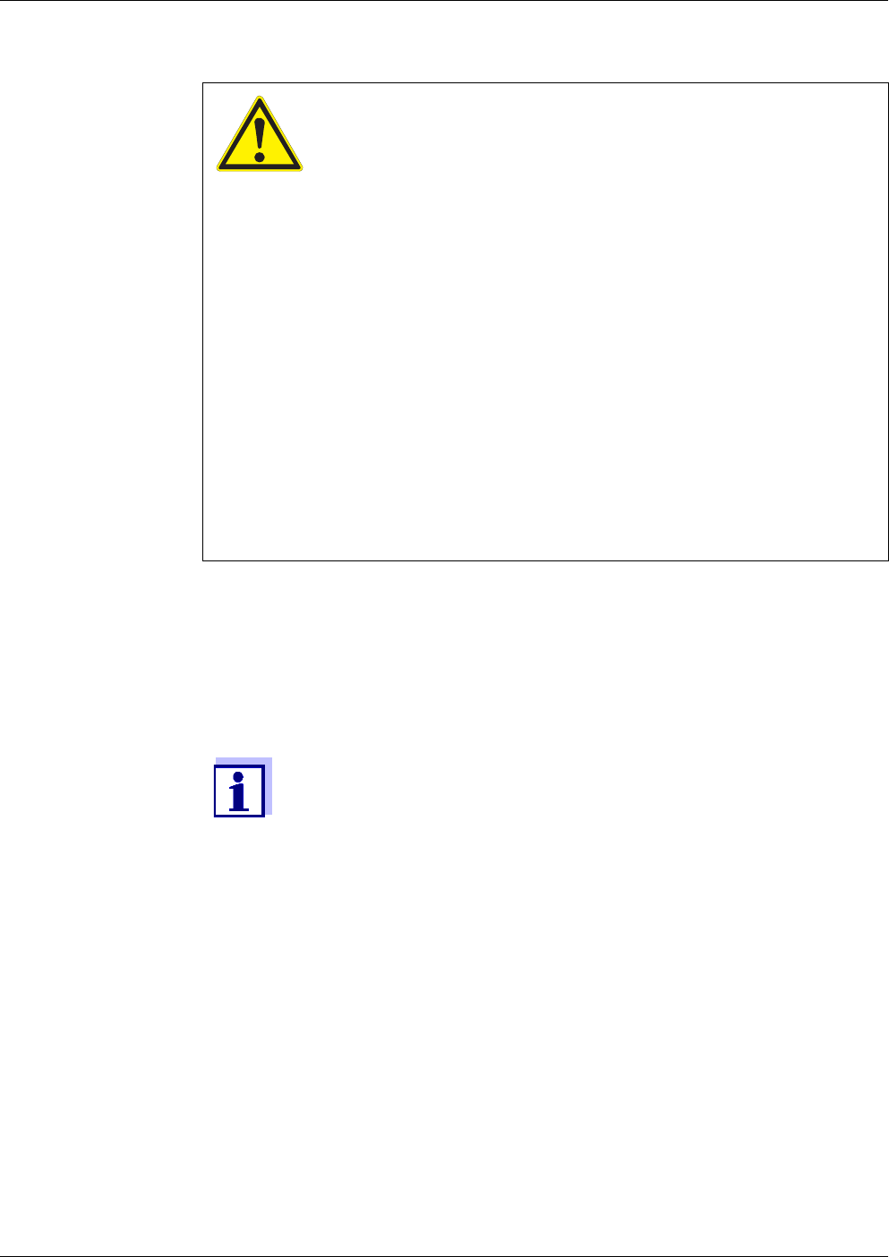
Instrument design fig. 1-2, 10 shows the main components of the Alyza IQ.
figure 1-2 Main components of the Alyza IQ (example: variant with 2 filtration pumps)
1 Cover for the control unit ACM
2 Mounting plate
3 Switch for internal 24 VDC supply
4 Power supply box, behind the mounting plate (120 V / 240 V AC)
5 Channel 2: Filtration pump (installed or free)
6 Channel 2: Overflow vessel 2 (installed or free)
7 Channel 1: Filtration pump (installed or free)
8 Channel 1: Sample feed tube, blue (to the overflow vessel)
9 Channel 1: Overflow vessel (installed or free)
10 Channel 1: Intake line, blue
11 Measuring unit
12 Cooling unit
13 Special tool for mounting the tubes
– at the receptacle for the MultiPort valve
– at the overflow vessels
2
3
5
6
11
13
4
7
8
1
12
9
10

Alyza IQ PO4 Overview
11
ba76201e09 12/2022
The measuring unit ready for operation (11) includes the following components
– Front cover with light duct for the status LED of the measuring unit
– Control unit (ACS)
– Locking device of the MultiPort valve (MPV)
– MultiPort valve (MPV)
– Photometer unit
– Chemicals (ChemBags)
Temperature
control
For correct measurements, the operating temperature of the AlyzaIQ is con-
trolled inside the housing in the following areas.
Thus the Alyza IQ with the door closed is suitable for all-season operation in the
open. The temperature control is automatically active when the Alyza IQ is con-
nected to the power supply and the switch at the switch box is in the ON position.
Range Temperature control
Housing inside frost free
Measuring unit 20 °C (68 °F)
Photometer unit 45 °C (113 °F)
Where there is a chance of frost, the intake lines and return lines
must be provided with heat tracing in order to maintain the sample
feed.
Overview Alyza IQ PO4
12
ba76201e09 12/2022
Power supply and
communication
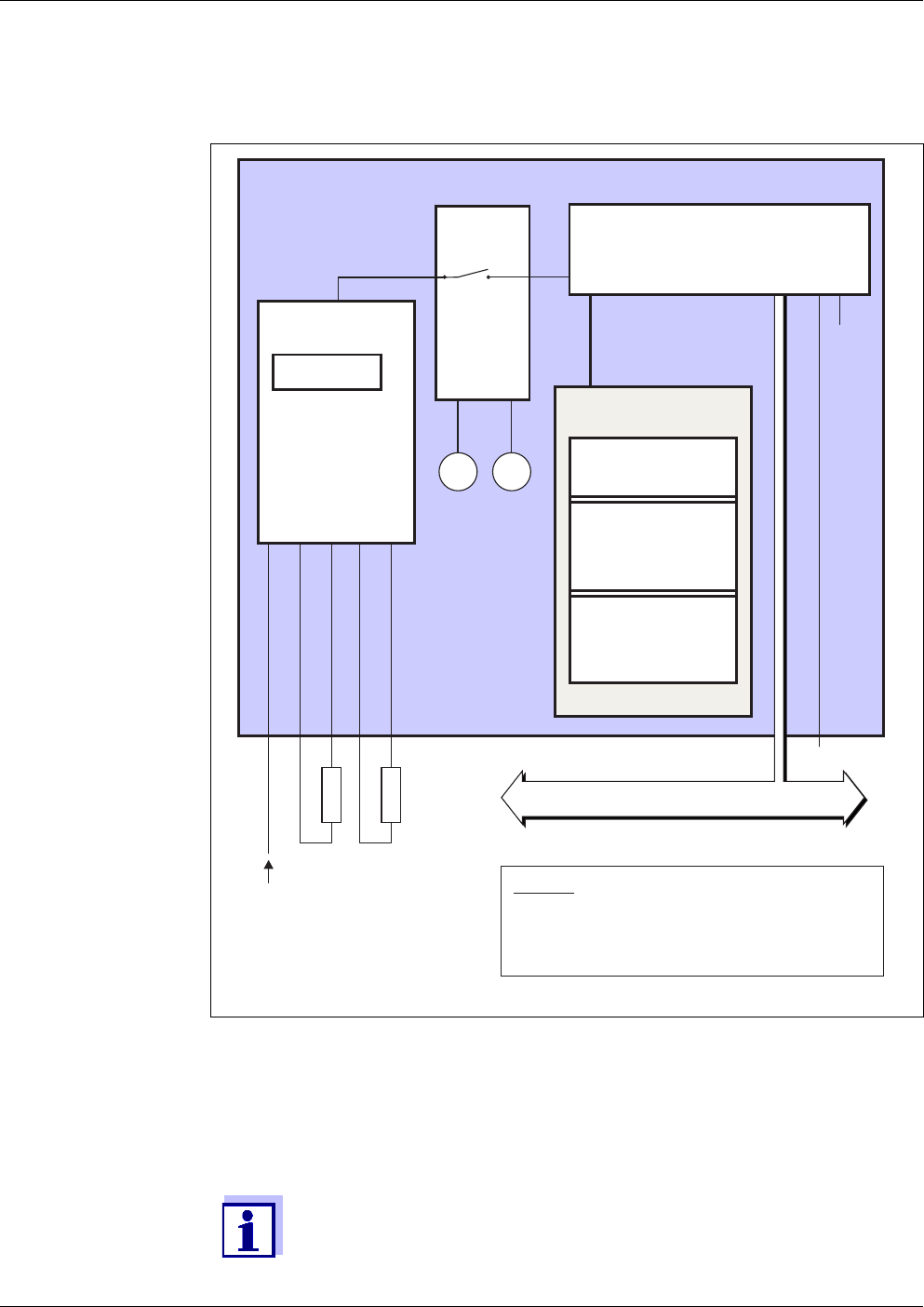
fig. 1-3, 12 shows the power supply and communication interfaces of the
Alyza IQ.
Operation The Alyza IQ is connected to the IQ S
ENSORNET via the IQ SENSORNET cable
(SNCIQ) connected to the control unit ACM and conducted to the outside.
The Alyza IQ is operated with a terminal on the IQ S
ENSORNET.
If maintenance activities are being carried out on the open Alyza IQ, a terminal
for operation must be installed or docked in the vicinity of the Alyza IQ.
figure 1-3 Block diagram Alyza IQ
Alyza IQ
Photometer unit
(Options)
H1
Line voltage
input
P
p1
H4
IQ Sensor Net (data + power)
e.g. SN 18110005
Control unit ACM
IQ Sensor Net interface
e.g. SN 18110258
Legend:
P , P Filtration pumps
p1 P2
H1 ... H4 Heat tracing
(feed lines, return lines)
Control unit ACS
24 V DC
Drive unit
MultiPort valve
USB
...
e.g. SN 18110005
Ethernet
Measuring unit
Daten+Energie
P
p2
Switch box
On/Off
Power supply box
Overload protection
Line power filter
Power supply
Outputs
Information on IQ SENSORNET terminals is given in the relevant
IQ S
ENSORNET system operating manual.
Alyza IQ PO4 Overview
13
ba76201e09 12/2022
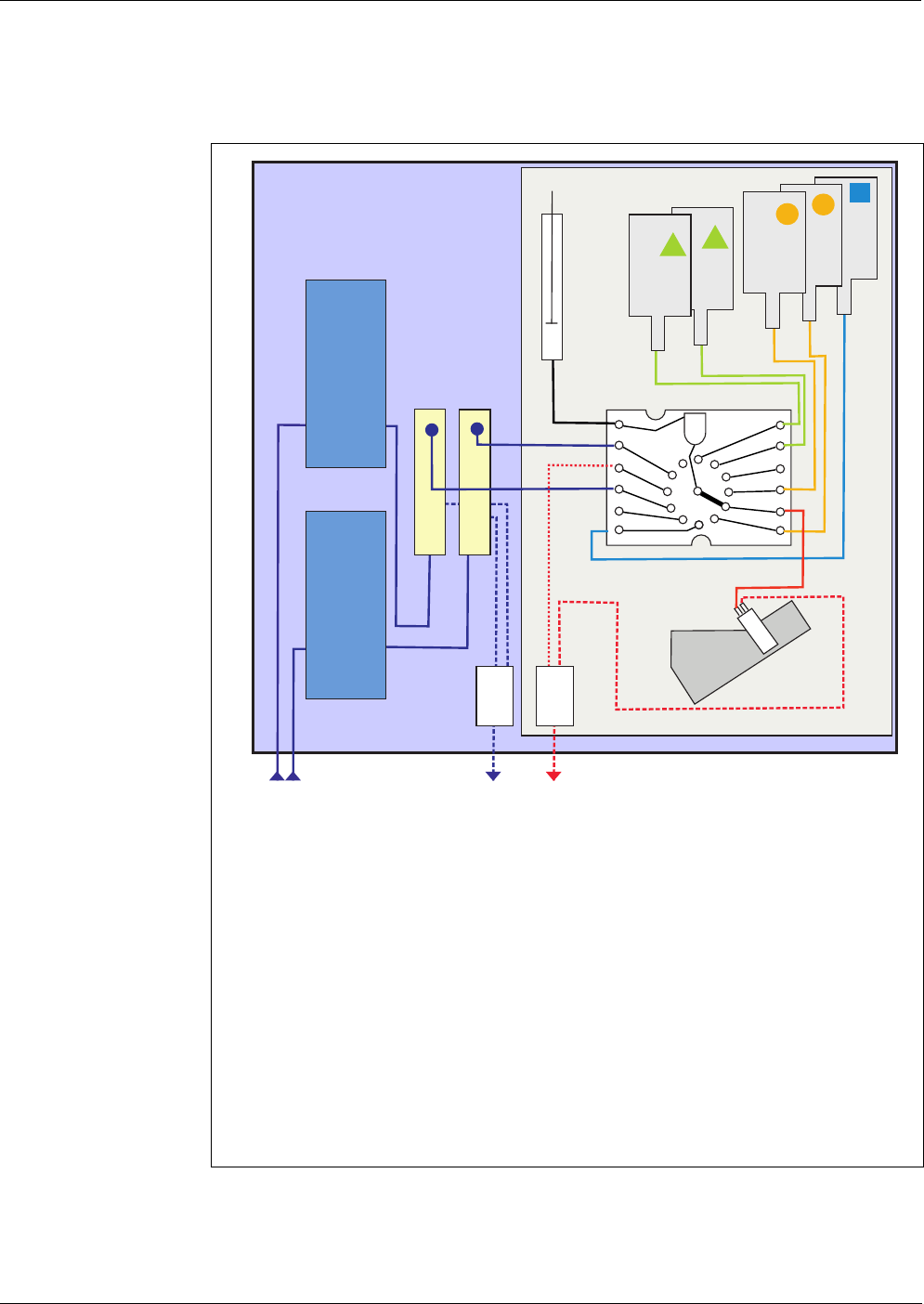
Liquid circle fig. 1-4, 13 shows the liquid circle of the Alyza IQ.
figure 1-4 Liquid circle
1 Intake lines for channel 1 (1a) and 2 (1b)
2 Filtration pumps for channel 1 (2a) and 2 (2b)
3 Overflow vessels for channel 1 (3a) and 2 (3b)
4 Collection funnel for the sample overflow from the overflow vessels
5 Return line for the sample overflow from the overflow vessels
6 Syringe pump
7 ChemBags (reagents, standards, cleaning solution)
8 MultiPort valve
9 Photometer
10 Collection funnel for the waste from the measuring unit
11 Return line for the waste from the measuring unit
2a
2b
3a
3b
6
8
9
10
1b 1a
11
5
4
Alyza IQ
7
C-
S-
S-
R-...B
R-...A
Overview Alyza IQ PO4
14
ba76201e09 12/2022
1.3.2 Measuring unit
fig. 1-5, 14 shows the open measuring unit (without front cover).
How it functions The measuring unit is controlled and supplied with DC voltage by the control unit
ACM. Communication with the IQ S
ENSORNET takes place via the
IQ S
ENSORNET cable, as with all other sensors.
In the overflow vessel, sample that is fresh, filtrated, and nearly free of air bub-
bles is quasi continuously provided for the measurements. The filtration unit
(FM/PC - available as an accessory) in conjunction with the filtration pump (in-
strument variant) provides an optimally prepared sample.
A syringe pump in the measuring unit makes all the liquids move (sample, re-
agents, standard solutions, cleaning solutions).
figure 1-5 Open measuring unit (without front cover)
1 Tube fastening
2 Control unit ACS
3 Locking device of the MultiPort valve (MPV)
4 Receptacle for the MultiPort Valve (MPV) with tubes
5 Contact that detects whether the measuring unit is closed with the
front cover.
(If there is the risk of condensation of air humidity in an open
measuring unit, a warning is triggered.)
6 Status LED of the measuring unit
(The status of the status LED is visible through a light duct at the
outside of the front cover.)
7 Waste tube of the measuring unit
8 ChemBags, suspended from a supporting rod
9 Photometer unit
2
3
4
8
9
5
6
1
7
Alyza IQ PO4 Overview
15
ba76201e09 12/2022
The MultiPort Valve (4) runs each of the moving liquids to the place where they
are required. The dosing of the reagents to the sample takes place in the mixing
chamber in the MultiPort valve.
The sample mixed with reagents is then moved to the cell in the photometer unit
(9) to be measured.
fig. 1-5, 14 shows the open photometer unit (without front cover).
The photometer unit has an LED as the light source and a photo diode as the
detector. After the measurement, the liquid is removed from the photometer unit
through the waste tube (4).
1.3.3 ChemBags
The Alyza IQ has an extra counter for each liquid container. The counter counts
the consumption of the following procedures as soon as the function is started:
Measuring
Calibration
Cleaning
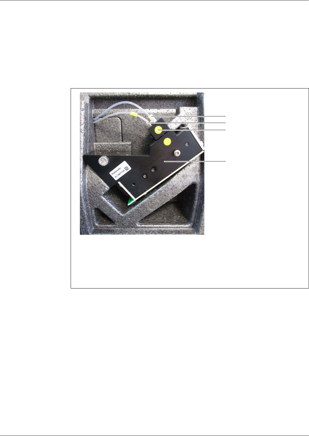
figure 1-6 Photometer unit (without front cover)
1 Photometer
2 Cell holder with connectors for tubes
3 Photometer feed tube (MPV mixing chamber - cell)
4 Photometer drain tube (cell - waste tube)
1
3
4
2
Overview Alyza IQ PO4
16
ba76201e09 12/2022
Other procedures that consume liquids are not counted (e.g. Fill the system).
If the remaining time of a ChemBag is less than 30 days, a log book message is
automatically generated.
Special bags (ChemBags) are used as liquid containers in the Alyza IQ. To
guarantee the shelf life of the liquids (reagents, standard solutions, cleaning
solutions) the ChemBags are coated with aluminium and encase the chemicals
airtight.
The ChemBags are suspended from a supporting rod with the valves pointing
downward.
Installing (even for the first time) and replacing the ChemBags are maintenance
activities, carried out at and documented menu-guided by the Alyza IQ.
Replace the ChemBags before the liquids are used up.
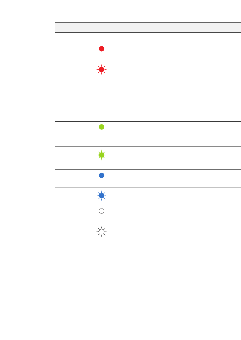
1.3.4 Status LEDs
The status LEDs indicate the statuses of the components:
Status-LED at the
filtration pump
The current counter reading for the ChemBags can be viewed in the
Alyza menu (tab Remaining).
In the overview, the remaining time is displayed in days (Days).
You can display more details for each ChemBag with <OK>.
Attention: The remaining times are only correct if the date of expiry
was correctly entered.
Keep the original caps of the ChemBags. They can be screwed on
for disposal.
LED Meaning
Off No power supply
Green The filtration pump is ready to operate and waiting for the next
action.
Red The filtration pump is making a pump movement.
Alyza IQ PO4 Overview
17
ba76201e09 12/2022
Status LED at the
front cover of the
measuring unit
1.3.5 Instrument variants
The Alyza IQ analyzer is available in different versions. The variant is given in
the type designation on the name plate.
LED Meaning
Off No power supply
Red Error
The Alyza IQ is stopped, details see log book
Red, flashes
quickly
(in addition,
a beep is to
be heard)
Close the front cover of the measuring unit immedi-
ately.
Risk of damage due to the formation of condensa-
tion water on electronic components within the mea-
suring unit.
If the measuring unit is opened for longer than 3
minutes, the Alyza IQ is automatically stopped to
avoid damage due to condensation.
Green The measuring unit is in one of the following states:
– Ready for operation, waiting for the next action
– Getting ready for operation (booting up)
Green,
flashes
slowly
The measuring unit carries out an action e.g.
Measuring, calibrating, cleaning
Blue The Alyza IQ was stopped manually (by the user).
The measuring unit is not (yet) ready to be opened.
Blue, flash-
ing
The control unit ACS starts.
White The Alyza IQ was stopped manually (by the user).
The measuring unit is ready to be opened.
White, flash-
ing
The Alyza IQ was stopped manually (by the user).
The locking device of the MultiPort valve is ready to
be opened.
Overview Alyza IQ PO4
18
ba76201e09 12/2022
Structure of the
name plate
Type designation
(details)
figure 1-7 Structure of the type designation
1 X: Measurement procedure
2
Y: Measuring range
3
Z: Number of channels
Alyza IQ PO4-XYZ
Identifier Val-
ues
Variant
X
(Variant:
measuring pro-
cedure)
1 Photometric measurement (yellow method)
Y
(Variant:
measuring
range)
1 Measuring range for low concentrations
2 Measuring range for higher concentrations
Z
(Variant
sample chan-
nels)
Sample channels (number)
(Z = 0, 1, 2, depending on the variant of the
Alyza IQ)
Each sample channel enables to provide
sample from one source.
For each sample channel, extra components
are required (e.g. filtration pump, overflow
vessel).
The number of sample channels can be
adapted.
0 The test sample has to be provided for the
measurement by external sampling.
Please heed the requirements of the sample.
1 The test sample is automatically fed from a
source and provided for the measurement.
2 The test sample is automatically fed from two
sources and provided for the measurement.
3 115 Input voltage 115 V AC
It is possible to retrofit a variant to a different variant (identifier Y, Z)
by installing or dismantling components (contact the service depart-
ment).
Alyza IQ PO4 Overview
19
ba76201e09 12/2022
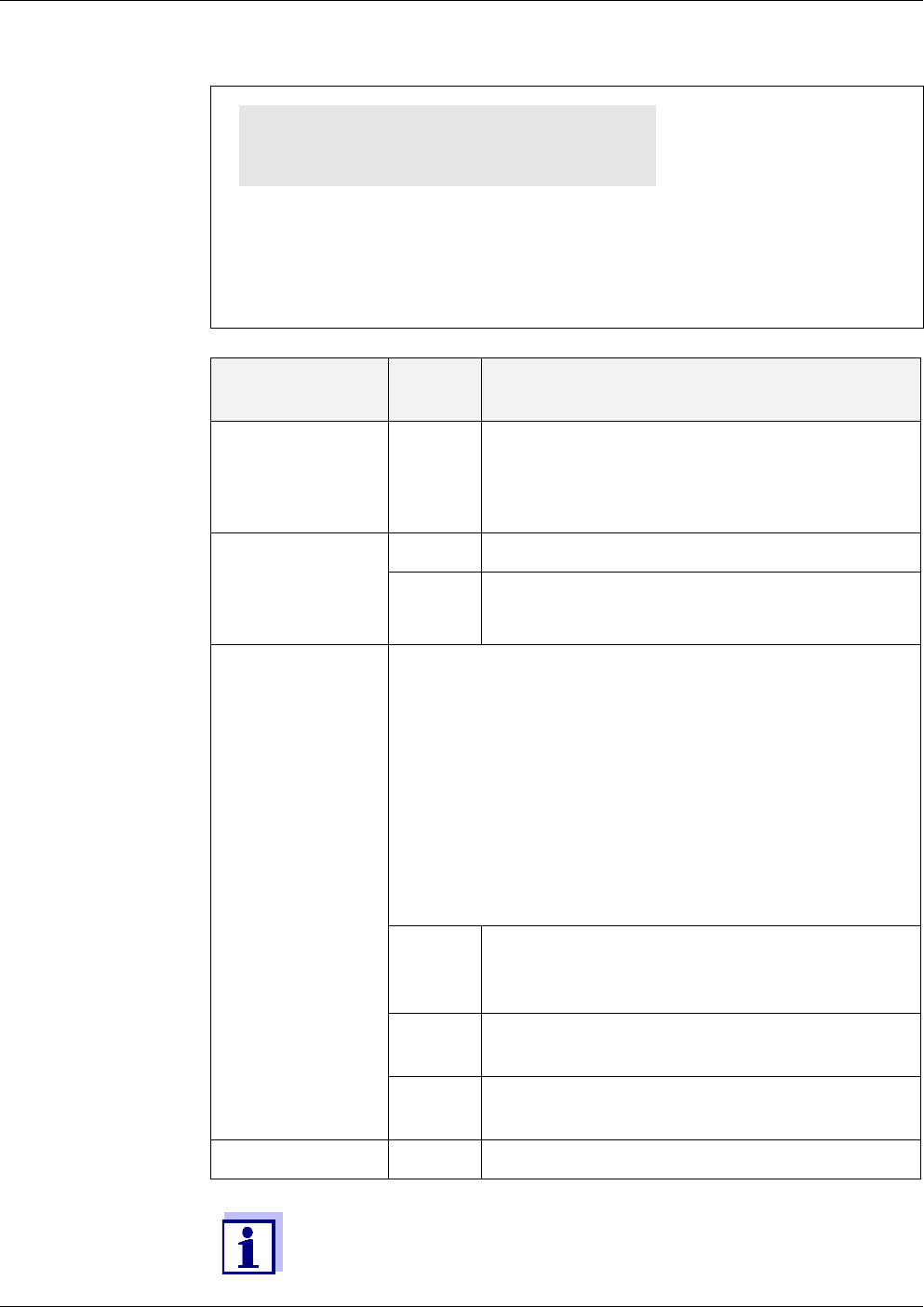
Filtration pumps
(instrument vari-
ants:
1 channel or
2 channels)
The filtration pump is optimally adjusted to the sample filtration available as an
accessory.
fig. 1-8, 19 shows a filtration pump in the Alyza IQ.
The filtration pump quasi continuously draws sample through the intake line (5)
and pumps it into the overflow vessel (3) through the sample feed tube (2). The
flow rate can be set with the control knob on the control panel (1). On the intake
side, a manometer (6) is installed for low pressure measurement.
To provide sample liquid with the required quality, it is necessary to use a suit-
able sample filtration (available as an accessory).
1.3.6 Sample filtration
To separate the particles in the sample, the preassembled filter module FM/PC
is available as an accessory. It is connected to the Alyza IQ via an intake line.
The filtration pump in the Alyza IQ draws in the filtered sample.
The preassembled filter module (FM/PC) consists of a separable PVC frame
(FM Case/PC) and a filter plate (Filter/PC). With the aid of the M 1.5 basin at-
tachment for filtration, the FM filter module FM/PC can be immersed in the mea-
suring medium and can be adjusted in height. To clean the filter plate, the filter
figure 1-8 Filtration pump channel 1
1 Filtration pump (control panel with rotary knob)
2 Sample feed tube (to the overflow vessel)
3 Overflow vessel
4 Sample overflow tube (sample overflow from the overflow vessel)
5 Intake line
6 Manometer (filtration pump)
The sample filtration must prepare the sample so that the sample
quality meets the requirements of the measuring unit (see
section 8.2 Application conditions, 171).
1
2
4
5
6
3
Overview Alyza IQ PO4
20
ba76201e09 12/2022
unit can be pulled out along a guide rail with a chain.
The intake line is in a robust sleeve tube. Intake lines are available in different
lengths and with auxiliary heating to protect against frost (depending on the line
voltage).
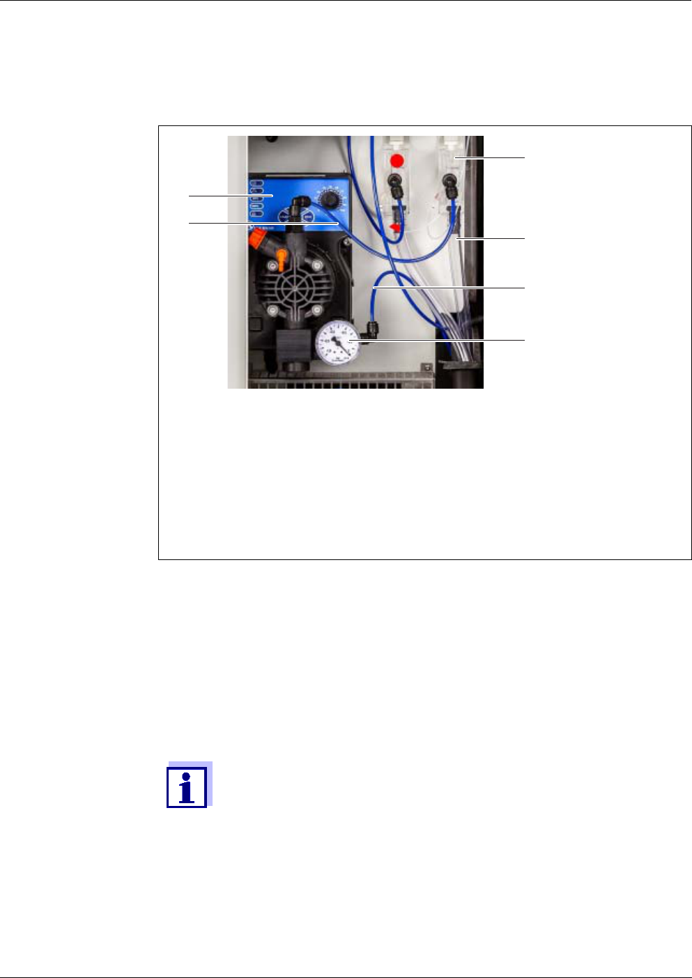
fig. 1-9, 20 shows an application example in a sedimentation tank.
The return lines transport the liquids collected in the collection funnel (sample
from the overflow vessels and the liquid chemical waste from the measuring
unit) out of the housing. Return lines with heat tracing are available for frost pro-
tection.
1.4 Name plates
The following components have name plates:
figure 1-9 Sample filtration device (installed)
1 Chain (scope of delivery: Basin holder for filtration M 1.5)
2 Guide rail (scope of delivery: Attachment for filtration M 1.5)
3 Height adjustable slide (scope of delivery: Suction line)
4 Intake line (scope of delivery: Suction line)
5 Sleeve tube (scope of delivery: Suction line)
6 Filter module (FM Case/PC) with filter plate (Filter/PC)
Order information on accessory items:
see section 5.3 Replacement parts, accessories, 106
Component Place of the name plate
Alyza IQ basic instru-
ment
center, on the left-hand inside housing wall
Measuring unit outside, on the left rear side of the measuring unit
and
on the front of the MPV drive unit
Photometer at the photometer
2
1
3
6
5
4

Alyza IQ PO4 Overview
21
ba76201e09 12/2022
MultiPort valve (MPV) on the side of the MPV
Mounting plate on the right-hand side of the switch box
Sleeve tubes of the
intake lines and return
lines
at the end of the line (toward the Alyza IQ )
Keep the series numbers on the name plates ready for any service
requests.
The serial numbers of the following components can also be queried
via the Alyza menu, tab Info:
Ser. no. MIQ/Alyza (housing/ACM)
Ser. no. Alyza IQ (measuring unit/ACS)
Ser. no. of photometer
Ser. no. MultiPort Valve (MPV)
Component Place of the name plate
Safety instructions Alyza IQ PO4
22
ba76201e09 12/2022
2 Safety instructions
2.1 Safety information
2.1.1 Safety information in the operating manual
This operating manual provides important information on the safe operation of
the product. Read this operating manual thoroughly and make yourself familiar
with the product before putting it into operation or working with it. The operating
manual must be kept in the vicinity of the product so you can always find the in-
formation you need.
Important safety instructions are highlighted in this operating manual. They are
indicated by the warning symbol (triangle) in the left column. The signal word
(e.g. "CAUTION") indicates the level of danger:
NOTE
indicates a situation where goods might be damaged if the actions mentioned
are not taken.
2.1.2 Safety signs on the product
Note all labels, information signs and safety symbols on the product. A warning
symbol (triangle) without text refers to safety information in this operating man-
ual.
2.1.3 Further documents providing safety information
The following documents provide additional information, which you should
observe for your safety when working with the measuring system:
Operating manuals of other components of the IQ S
ENSORNET system
(power packs, controller, accessories)
Labels on the chemical containers (ChemBags)
Safety datasheets of calibration and maintenance equipment (e.g. cleaning
solutions). Safety datasheets provide security relevant information on haz-
ardous materials and mixtures. Carefully read the safety datasheets and fol-
low all instructions. We recommend that you store all datasheets in one
folder.
WARNING
indicates a possibly dangerous situation that can lead to
serious (irreversible) injury or death if the safety instruc-
tion is not followed.
CAUTION
indicates a possibly dangerous situation that can lead to
slight (reversible) injury if the safety instruction is not fol-
lowed.

Alyza IQ PO4 Safety instructions
23
ba76201e09 12/2022
2.2 Safe operation
2.2.1 Authorized use
The authorized use of the Alyza IQ is its use as a sensor in the IQ S
ENSORNET.
Only the operation and running of the Alyza IQ according to the instructions and
technical specifications given in this operating manual is authorized (see
chapter 8 Technical data, 170). Any other use is considered unauthorized.
With unauthorized use, the protection type supported by the instrument can be
adversely affected.
2.2.2 Requirements for safe operation
Note the following points for safe operation:
The product may only be operated according to the authorized use specified
above.
The product may only be operated under the environmental conditions men-
tioned in this operating manual.
The product may only be supplied with power by the energy sources men-
tioned in this operating manual.
The product may only be opened if this is explicitly described in this operating
manual (example: connecting electrical lines to the terminal strip).
2.2.3 Unauthorized use
The product must not be put into operation if:
it is visibly damaged (e.g. after being transported)
it was stored under adverse conditions for a lengthy period of time (storing
conditions, see chapter 8 Technical data, 170).
2.3 User qualification
Target group The IQ SENSORNET system was developed for online analysis. Some mainte-
nance activities, such as exchanging the ChemBags or tubes, require the safe
handling of chemicals. Thus, we assume that the maintenance personnel is fa-
miliar with the necessary precautions to take when dealing with chemicals as a
result of their professional training and experience.
Special user
qualifications
The following installation activities may only be performed by a qualified electri-
cian:
Connecting power cables to the line power supply and the line power box.
Connecting the heat tracing lines to the connectors of the line power box
Safety instructions Alyza IQ PO4
24
ba76201e09 12/2022
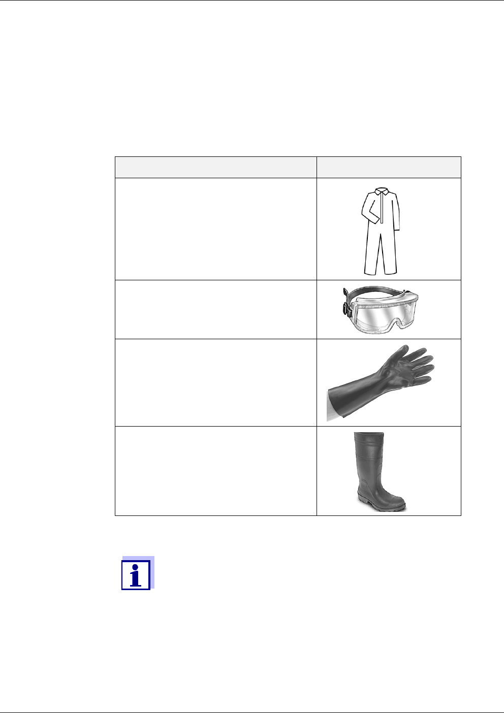
2.4 Personal protective equipment (PPE)
The PPE includes clothing and other equipment that is used to protect you
against risks at your place of work. You must always wear your PPE while doing
dangerous jobs to avoid injuries or damage to your health.
The following table shows the PPE that is required while dealing with dangerous
chemicals such as when exchanging the ChemBags. More detailed information
is given on the labels of the ChemBags and in the relevant safety data sheets.
figure 2-1 Personal protective equipment
Personal protective equipment Typical examples
Protective clothing with long sleeves
Protective goggles
Chemical resistant gloves
Safety shoes
It is the duty of the operator to provide all users with the required
PPE. The PPE must fulfill the national standards and laws.

Alyza IQ PO4 Commissioning
25
ba76201e09 12/2022
3 Commissioning
3.1 IQ SENSORNET system requirements
Software versions
of the controller
and terminal
components
The operation of the Alyza IQ requires the following software versions in the
IQ S
ENSORNET:
3.2 Scope of delivery
3.2.1 Scope of delivery of the Alyza IQ
The following parts are included in the scope of delivery of the Alyza IQ:
Housing (Alyza IQ PO4-XYZ) with
– mounted and wired installations
– mounted power cable (approx. 2 m)
– mounted IQ S
ENSORNET cable (approx. 2 m)
Key for outer housing door
Switch cabinet key for interior door
Cover plate for the control unit ACM
Bug screen (mounting set)
Collection funnel (mounting set)
MultiPort valve (MPV)
Labels in the national language (for the locking device of the MultiPort valve)
2 single tubes
– Tube to connect the ChemBag for standard 2 to the MPV:
It needs to be installed if the function 2-point calibration is selected.
– Tube to connect the ChemBag for reagent B to the MPV:
It needs to be installed if the function Backgr. corr.(opt) is selected.
Operating manual
Check whether the scope of delivery is complete before starting the installation.
MIQ/MC2 Version 3.79 or higher
MIQ/TC 2020 XT Version 3.79 or higher
MIQ/MC3 Version 3.79 or higher
MIQ/TC 2020 3G Version 3.79 or higher
DIQ/S 28X Version 3.79 or higher

Commissioning Alyza IQ PO4
26
ba76201e09 12/2022
3.2.2 Accessories required in addition
Depending on the application, the following additional accessories are required
or recommended for operation. We explicitly recommend that you use original
accessories:
Mounting
accessories
The mounting accessories are used to securely install the instrument at the
mounting location.
The following variants are available:
Rail mount RM
Wall mount WM
Stand mount SM
Mount for a
terminal
Mount TM for fastening and operation of an MIQ module, e.g. MIQ/JB and
terminal/controller MIQ/TC 2020 3G or DIQ/S 28X
ChemBags Depending on the type, variant and configuration of your Alyza IQ, you need one
or several ChemBags for each of the following options:
Reagent solution (R-...) suitable for measured parameter and measuring
range
Standard solution (S-...) suitable for the measured parameter, measuring
range, and calibration procedure
Reagent solution (C-...) suitable for measured parameter and measuring
range
MultiPort valve MultiPort valve (MPV)
Sample
preparation
(filtration)
Filter module FM/PC
(frame FM Case/PC incl. preassembled filter plate Filter/PC)
Basin holder for filtration M 1.5 for frame FM Case/PC, also available with
extension M-EXT 1.5
Sample inlet,
sample drain
Intake line SH ... (different lengths up to 20 m, with and without heat tracing
[240 VAC or 120 VAC])
Return line RH ... (different lengths up to 20 m, with and without heat tracing
[240 VAC or 120 VAC])
The sample filtration must prepare the sample so that the sample
quality meets the requirements of the measuring unit (see
section 8.2 Application conditions, 171).
Order information referring to accessories is given in section 5.3 Re-
placement parts, accessories, 106.

Alyza IQ PO4 Commissioning
27
ba76201e09 12/2022
3.3 Basic principles of installation
3.3.1 Requirements of the measurement location
The measurement location must meet the environmental conditions specified in
section 8.3 General data, 172.
Controlled
ambient
conditions
Work on the open instrument (e.g. during mounting, installation, maintenance)
may only be carried out under controlled environmental conditions:
If the Alyza IQ is already in operation, the temperature of the measuring unit
must be adapted to the ambient temperature prior to opening the measuring
unit. The temperature adaptation is done with the function Prepare to open mea-
suring unit. As soon as the measuring unit is ready to be opened, this is dis-
played in the Status tab. The status LED of the measuring unit lights up white.
NOTE
The interior of the measuring unit is temperature-controlled to 20 °C (68 °F).
With ambient temperatures over 25 °C (77 °F) and high air humidity, conden-
sation water may develop on the cool surfaces and cause damage when the
measuring unit is opened.
To avoid damage of the measuring unit due to the formation of condensation
water, always wait for the temperature adjustment (function Prepare to open
measuring unit) to be completed before opening the measuring unit.
3.3.2 Safety requirements of the electrical installation
The safety of the system into which the instrument is integrated is the responsi-
bility of the builder of the system.
Electrical equipment (e.g. motors, contactors, cables, lines, relays, switches, in-
struments) must meet the following requirements:
Compliance with national regulations (e.g. NEC, VDE and IEC)
Suitability for the electrical conditions at the place of installation
– Maximum operational voltage
– Maximum operational current
Suitability for the ambient conditions at the place of installation
– Temperature resistance (minimum and maximum temperature)
– Stability against UV light in the case of outdoor usage
– Protection against water and dust (Nema or IP type of protection).
Suitable fuse protection of the electrical circuit
Temperature range + 5 ... + 40 °C (+ 41 ... +104 °F)
Relative air humidity ≤ 80 %

Commissioning Alyza IQ PO4
28
ba76201e09 12/2022
– Overcurrent protection devices
(according to the technical data of the instrument input or output)
– Overvoltage class II surge limiters
Suitable disconnecting device (e.g. switch or circuit breaker) for the line
power supply of permanently mounted equipment with separate line power
connection,
– labeled as disconnecting device for this instrument
– compliant with the following regulations
- IEC 60947-1
- IEC 60947-3
– in the vicinity of the instrument (recommendation)
Fault current protection switch (ground fault circuit interrupter)
especially with operation of heat tracings
Flame resistant (cable and lines),
compliant with the following regulations
– UL 2556 VW-1 (for USA, Canada)
– IEC 60332-1-2 (outside of USA, Canada)
3.3.3 General installation instructions
Pay attention to the following points during installation:
The measuring device is shipped in protective transport packaging.
We recommend: Keep the packaging material.
The original packaging protects the measuring device from transport damage
Due to its weight, the Alyza IQ always has to be carried by two people (hous-
ing door upward, both people grasping the housing at the upper C rail and at
the housing bottom on the side of the door).
Wear safety shoes for transport, installation and mounting work (see
section 2.4 Personal protective equipment (PPE), 24).
Installation in the open should be done while the weather is frost-free
(environmental conditions, see section 3.3.1 Requirements of the measure-
ment location, 27).
Details on the conditions at the installation site:
See chapter 8 Technical data, 170.
This section describes the installation of the Alyza IQ with various,
especially designed accessories. We assume that the operator uses
these accessories. In this section, the individual scopes of delivery
are not distinguished so the comprehensibility of the operating man-
ual is not affected.

Alyza IQ PO4 Commissioning
29
ba76201e09 12/2022
Mount the Alyza IQ in a straight position (check, for example, with a water
level) to ensure that the liquids can drain off optimally.
Mount the Alyza IQ so that the space under the housing bottom is always free
for ventilation of the housing.
Mount the Alyza IQ at a suitable height so that the liquids in the return lines
(into the basin) can freely drain off at a steady slope.
The Alyza IQ may only be fastened on a wall or fixture with the aid of the two
C-rails (housing upright).
For mounting work, only use the mounting accessories included in the scope
of delivery (screws, washers, springs, nuts). This ensures the safe fastening
at the mounting location.
Main steps Installation of the Alyza IQ includes the following main steps:
1 Installing the housing (see section 3.3.4 Installing the housing, 30).
2 Removing the transport protection of the measuring unit (see
section 3.3.8 Removing the transport protection of the measuring unit,
42).
3 Connecting the cables to the control unit ACM (see section 3.3.9 Con-
necting the cables to the control unit ACM, 43).
4 Mounting the cover plate for the control unit ACM (see section 3.3.10
Mounting the cover plate for the control unit ACM, 44).
5 Installing the bug screen and condensate drain adapter (see
section 3.3.11 Installing the bug screen and condensate drain adapter,
45).
6 With the relevant accessories:
Mounting the terminal holder (TM) (see section 3.3.12 Mounting the ter-
minal holder (TM), 47).
7 Mounting the collection funnel (see section 3.3.14 Mounting the collec-
tion funnel, 59).
8 With the relevant accessories:
Installing the FM/PC filter module and M 1.5 basin holder for filtration
(see section 3.3.16 Installing the FM/PC filter module and M 1.5 basin
holder for filtration, 64).
9 With the relevant accessories:
Connecting the power cable and heat tracing lines (see section 3.3.13
Connecting the power cable and heat tracing lines, 50).
10 Setting up a connection with the IQ S
ENSORNET system (see
section 3.3.18 Setting up a connection with the IQ S
ENSORNET system,
69).
11 Installing / exchanging the ChemBags, MPV, tubes (see section 5.5
Installing / exchanging the ChemBags, MPV, tubes, 111).
Commissioning Alyza IQ PO4
30
ba76201e09 12/2022
3.3.4 Installing the housing
The housing of the Alyza IQ can be installed in the following ways:
On the SM stand mount (see section 3.3.5 Installation on the SM stand
mount, 30).
On a rail (see section 3.3.6 Installation on a rail, 35).
On a wall (see section 3.3.7 Installation on a wall, 40).
3.3.5 Installation on the SM stand mount
Proceed as follows to install the housing on the stand mount:
Assembling the
stand mount
In the housing there is a foam insert serving as a transport protec-
tion. Remove the foam insert once the installation of the housing
has been completed.
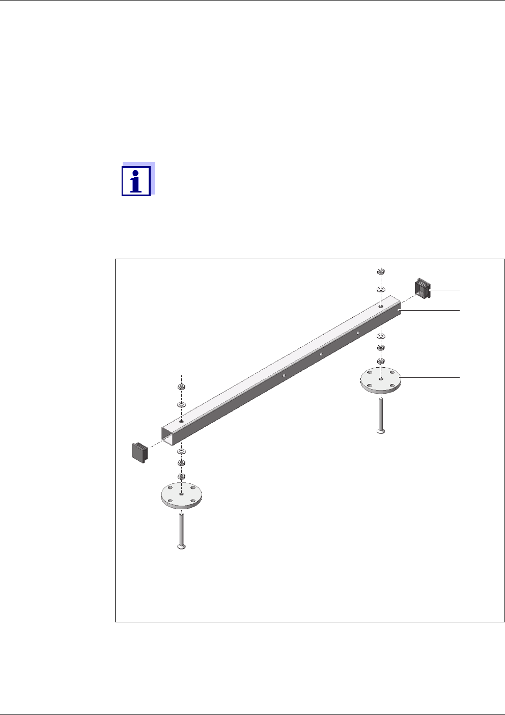
figure 3-1 Mounting the ground pipes
1 Protective plug
2 Square ground pipe
3 Stand foot
1 Press the plastic protective plugs (1) into both ends of the square
ground pipes (2).
1
2
(2 x)
3
Alyza IQ PO4 Commissioning
31
ba76201e09 12/2022
2 Mount the four height adjustable stand feet (3) on the square ground
pipes (2) using the enclosed M10 hexagon countersunk head screws.
Make sure to use the correct number of plain washers and nuts in the
correct order according to fig. 3-1, 30.
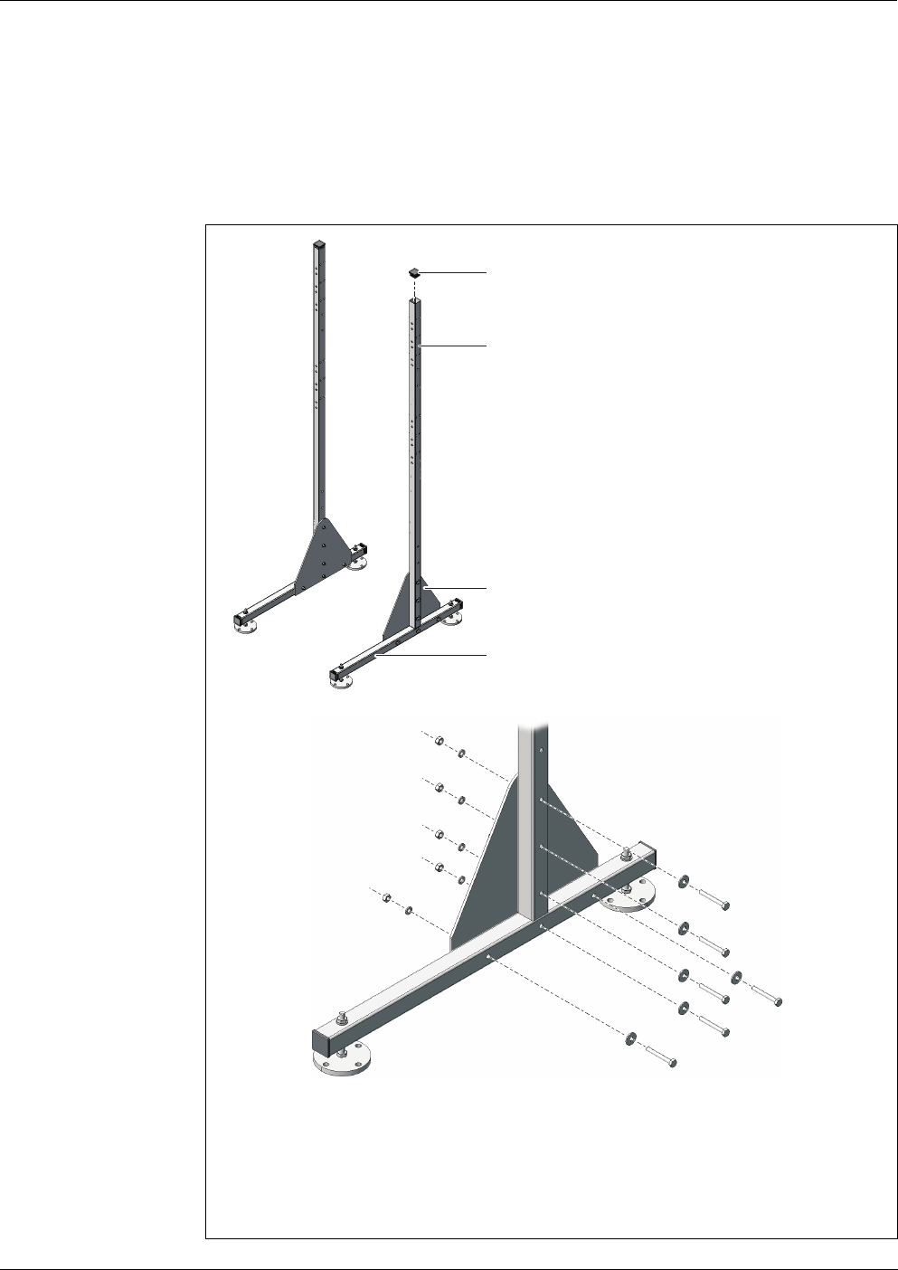
figure 3-2 Connecting the supporting pipes with the ground pipes
1 Protective plug
2 Square ground pipe
3 Square supporting pipe
4 Stabilizing sheet
1
3
4
2
Commissioning Alyza IQ PO4
32
ba76201e09 12/2022
3 Press the plastic protective plugs (1) into the upper ends of both square
supporting pipes (3).
4 Using the triangular stabilizing sheets (4), connect both square support-
ing pipes (3) with the preassembled ground pipes (2). For each side, use
six hexagon head screws with large plain washers, spring washers and
locknuts as shown in fig. 3-2, 31. Make sure the two sides mirror each
other after being mounted.
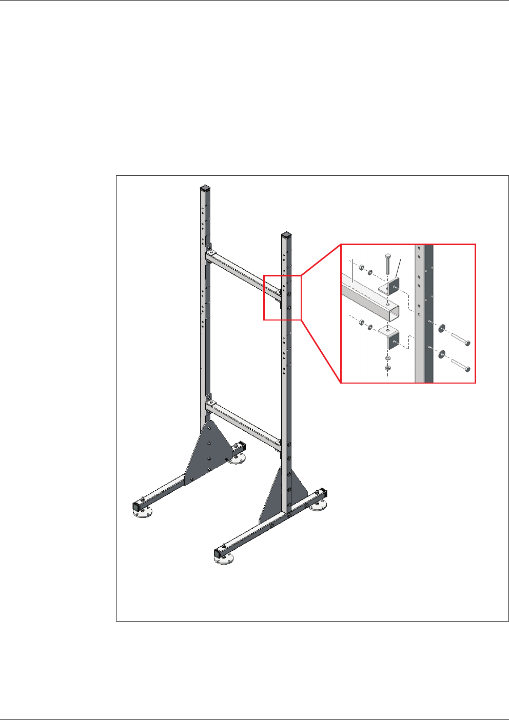
figure 3-3 Connecting the supporting pipes with the cross pipes
1 Square cross pipe
2 Angle bracket
5 Connect both supporting pipes with each other using the two square
cross pipes (1). For each joint, use two angle brackets (2), three hexa-
gon head screws, two large plain washers, three spring washers and
three locknuts.
12
Alyza IQ PO4 Commissioning
33
ba76201e09 12/2022
Positioning the
stand mount
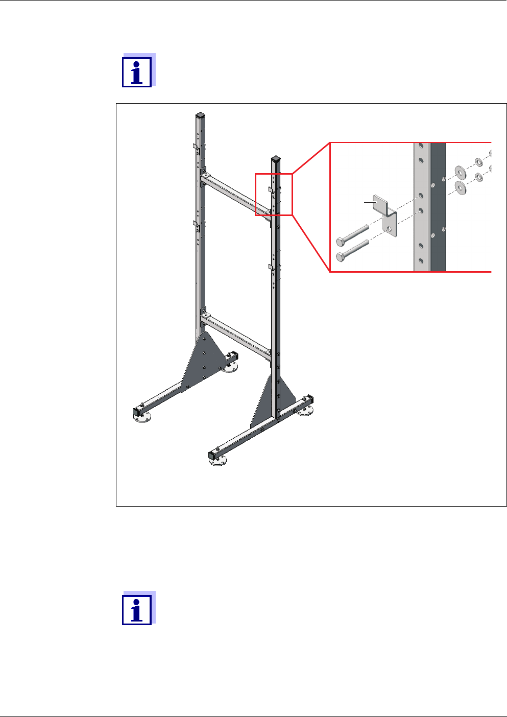
Make sure that both triangular stabilizing sheets (5) are on the in-
side.
figure 3-4 Mounting the retaining hooks
1 Retaining hook
6 Mount the four retaining hooks (1) on the supporting pipes. For each
hook, use two hexagon head screws, large plain washers, spring wash-
ers and locknuts.
On each side there are three pairs of holes for the upper and lower
retaining hooks. Thus the Alyza IQ can be mounted optimally at
working level. Use the same relative positions for each of the upper
and lower hooks.
1
7 Place the stand mount at the intended operating location.
Commissioning Alyza IQ PO4
34
ba76201e09 12/2022
NOTE
Always screw the four stand feet to the ground. If the instrument is mounted in
the open, please make sure that the installation withstands even severe storm.
Mounting the
housing
8 Adjust the four vertically adjustable stand feet in such a way that the
mounting stand is in a straight position (check, for example, with a water
level) to ensure that the liquids can drain off optimally.
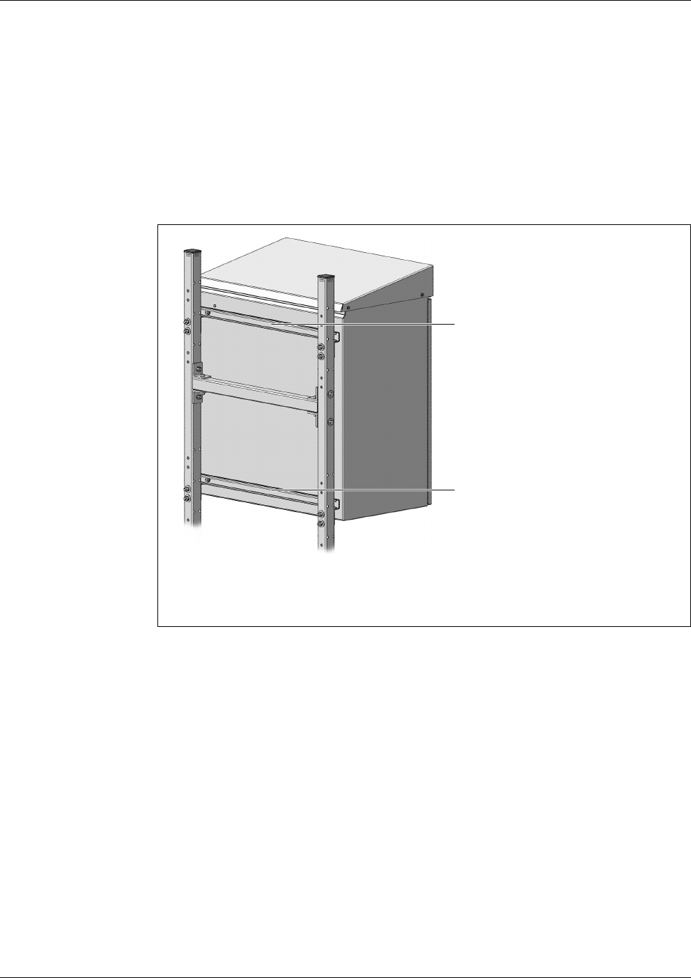
figure 3-5 Mounting the housing
1 Upper C-rail
2 Lower C-rail
9 Mount the housing by hooking the C-rails (1 and 2) fixed on its rear side
into the four retaining hooks of the stand mount.
2
1
Alyza IQ PO4 Commissioning
35
ba76201e09 12/2022
3.3.6 Installation on a rail
For installation on a rail, the RM rail mount bracket is required.
NOTE
Make sure that the rail is sufficiently stable. If the instrument is mounted in the
open, please make sure that the installation withstands even severe storm.
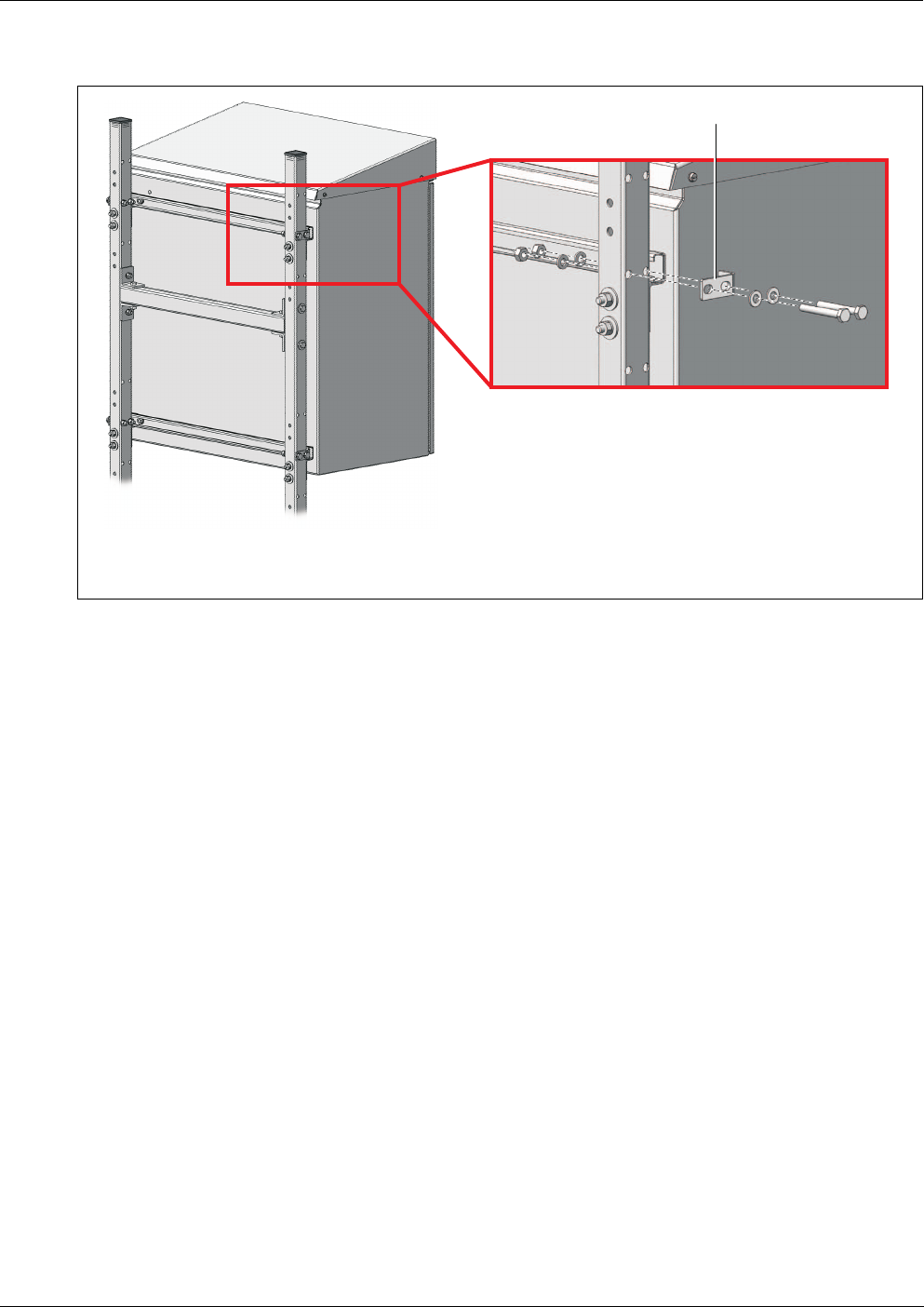
figure 3-6 Fixing the housing
1Angle bracket
1
10 Fix the housing on both sides with four brackets (1) so it cannot shift
sideways. For each bracket, use two hexagon head screws, small plain
washers, spring washers and locknuts.
Commissioning Alyza IQ PO4
36
ba76201e09 12/2022
Assembling the
bracket
Proceed as follows to install the housing on the rail:
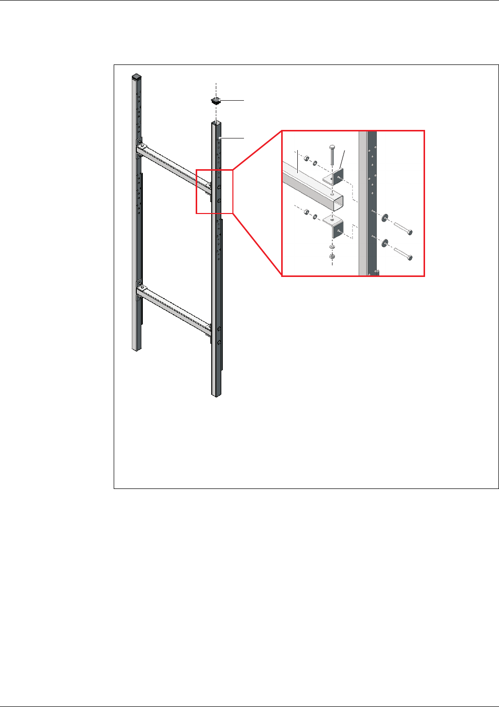
figure 3-7 Connecting the supporting pipes with the cross pipes
1 Protective plug
2 Square supporting pipe
3 Square cross pipe
4 Angle bracket
1 Press the plastic protective plugs (1) into the upper ends of both square
supporting pipes (2).
2 Connect both supporting pipes with each other using the two square
cross pipes (3). For each joint, use two angle brackets (4), three short
hexagon head screws, two large plain washers, three spring washers
and three locknuts as shown in fig. 3-7, 36.
34
1
2
Alyza IQ PO4 Commissioning
37
ba76201e09 12/2022
Fixing the rail
mount bracket
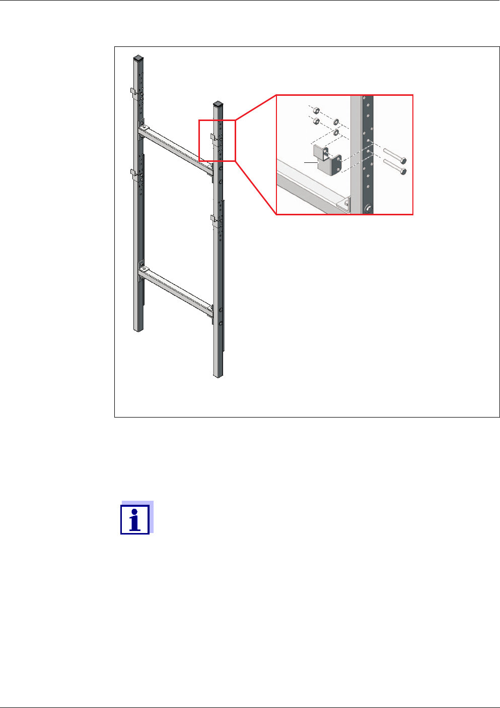
figure 3-8 Mounting the retaining hooks
1 Retaining hook
3 Mount the four retaining hooks (1) on the supporting pipes. For each
hook, use two short hexagon head screws, spring washers and lock-
nuts.
There are three pairs of holes each for the upper and lower retaining
hooks. Thus the Alyza IQ can be mounted optimally at working lev-
el. Use the same relative positions for each of the upper and lower
hooks.
1
4 Place the rail mount bracket in front of the rail in the required position.
Commissioning Alyza IQ PO4
38
ba76201e09 12/2022
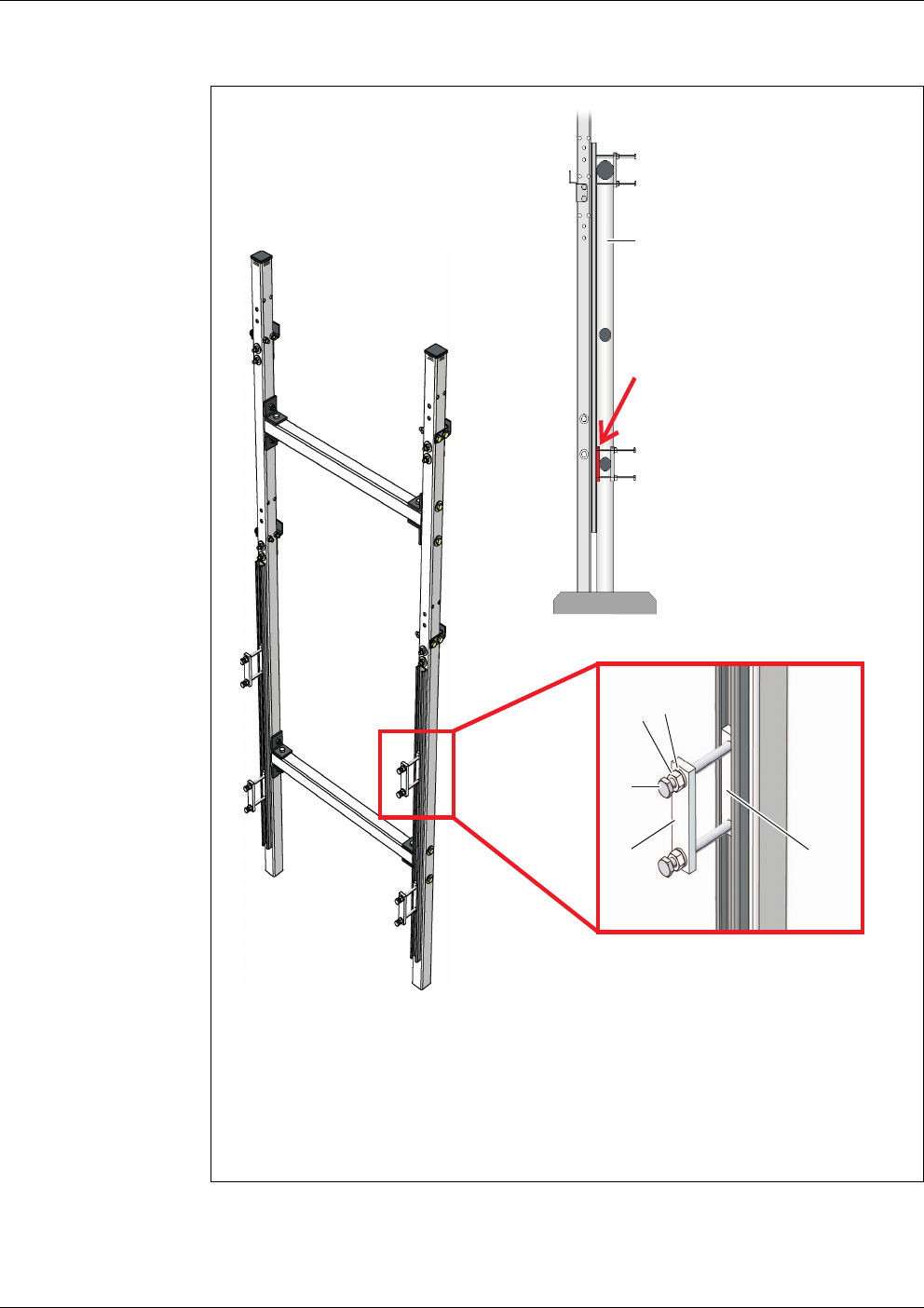
figure 3-9 Mounting the rail mount bracket on the rail
1 Groove bar
2 Clamping strip
3 Long hexagon head screw
4Nut
5 Spring washer
5
1
3
2
4
If necessary, insert fur-
ther clamping strips and
washers
Bracket up-
right!
Rail

Alyza IQ PO4 Commissioning
39
ba76201e09 12/2022
Mounting the
housing
5 Attach the rail mount bracket to two suitable horizontal rail pipes with the
aid of the four clamping devices. Each clamping device consists of a
groove bar (1), a terminal strip (2), two long hexagon head screws (3),
two nuts (4) and two spring washers (5). Adjust the clamping devices to
the rail pipes. To compensate for any possible differences of the upper
and lower rail pipe diameters, 2 further terminal strips and 8 washers
(thickness 2 mm) are provided with the construction set. If necessary,
insert these items between the rail and supporting pipes as shown in
fig. 3-9, 38 so that the rail mount bracket is in a vertical position. Note
that both supporting pipes must stand on the ground!
The weight of the Alyza IQ is supported by the rail mount bracket
standing on the ground. The rail prevents the Alyza IQ from falling
over.
figure 3-10 Mounting the housing
1 Upper C-rail
2 Lower C-rail
6 Mount the housing by hooking the C-rails (1 and 2) fixed on its rear side
into the retaining hooks of the rail mount bracket.
7 Make sure that the housing is suspended in a straight position (check,
for example, with a water level) to ensure that the liquids can drain off
optimally in the Alyza IQ.
2
1
Commissioning Alyza IQ PO4
40
ba76201e09 12/2022
3.3.7 Installation on a wall
With the C-rails on its rear side, the Alyza IQ is hooked into the retaining hooks
of the WM wall mounting set.
NOTE
Make sure that the wall is strong enough for the weight of the Alyza IQ and that
the mounting material (screws, plugs, etc.) is suitable for the wall type. If neces-
sary, use other screws and plugs than the ones provided.
Proceed as follows to install the housing on a wall:
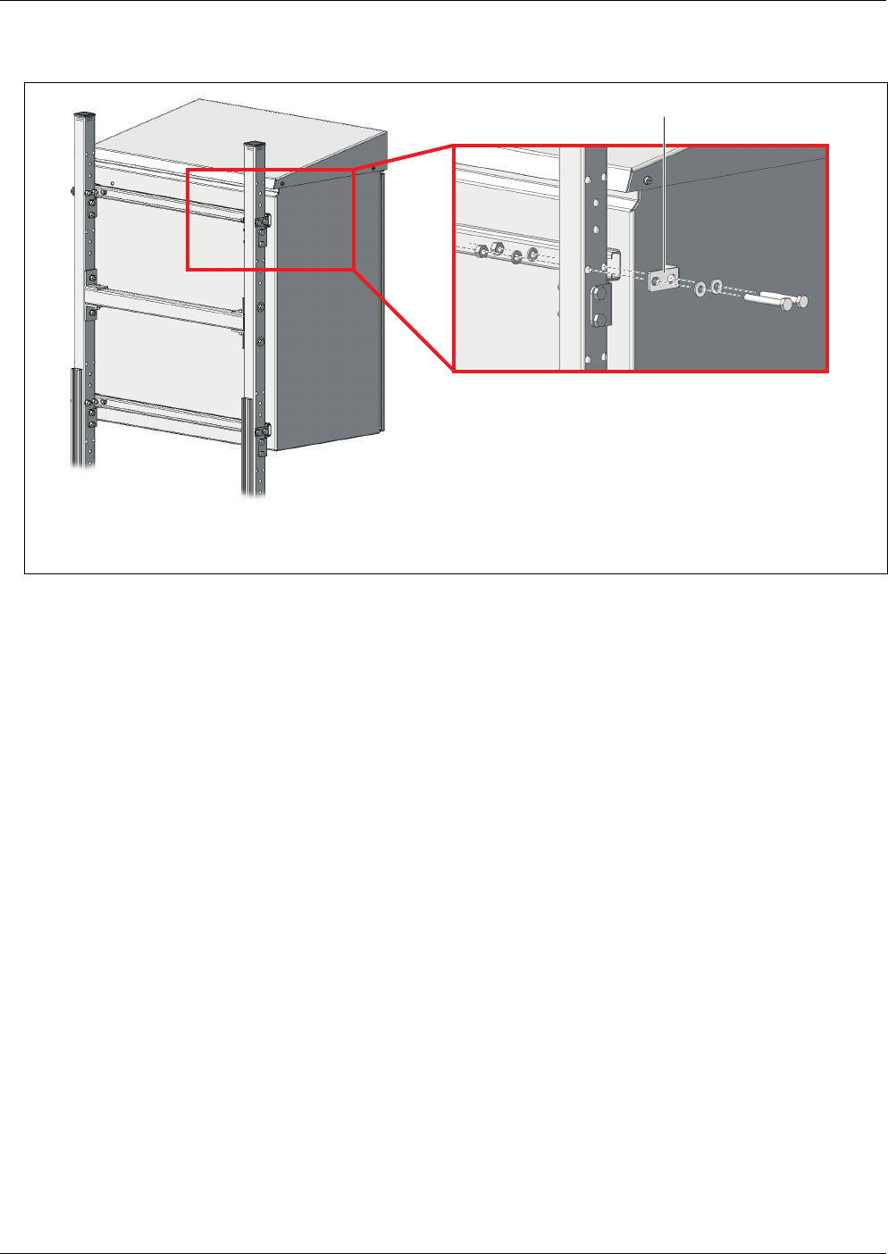
figure 3-11 Fixing the housing (on the right: Detailed view)
1 Angle bracket
1
8 Fix the housing on both sides with four brackets (1) so it cannot shift
sideways. For each bracket, use two short hexagon head screws, small
plain washers, spring washers and locknuts.
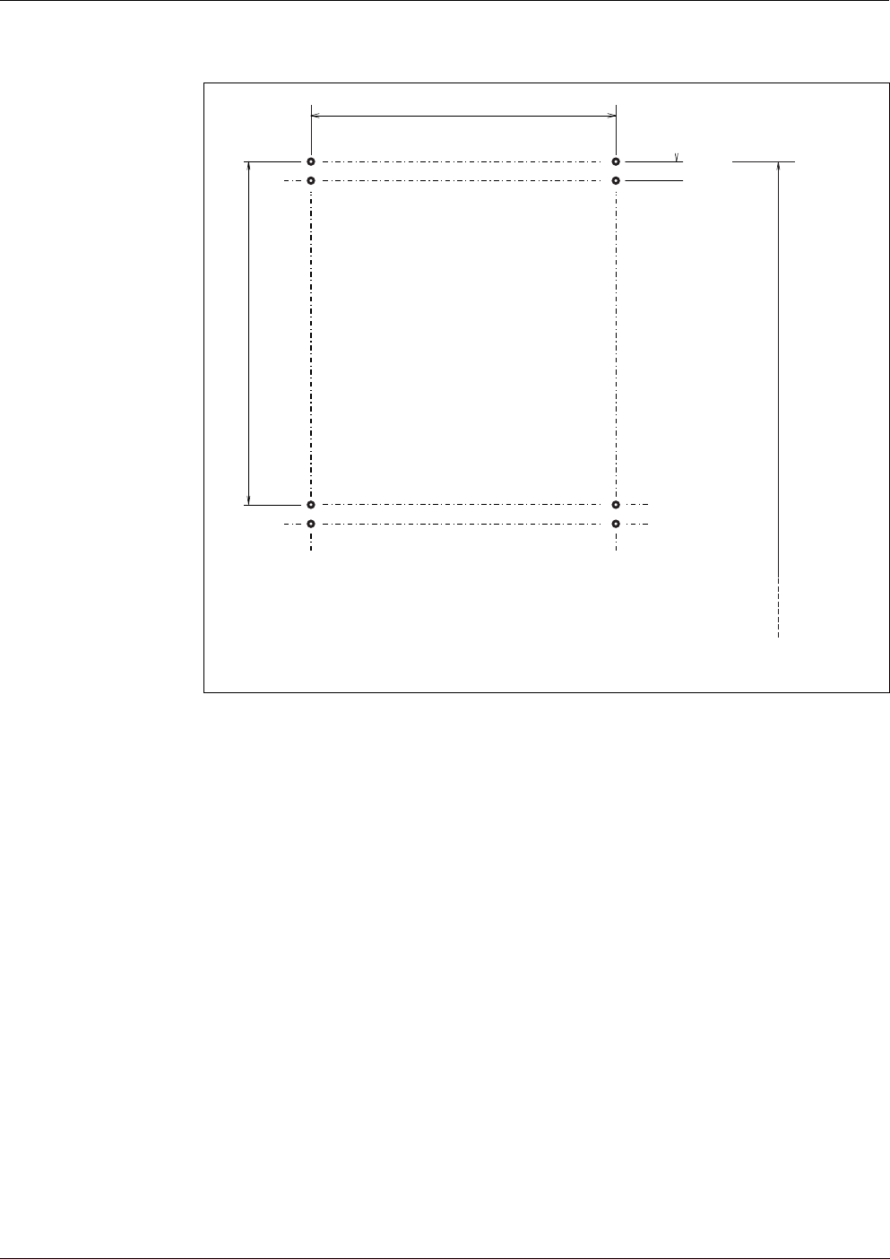
1 Drill eight holes as shown in the following figure:
Alyza IQ PO4 Commissioning
41
ba76201e09 12/2022
NOTE
To prevent the instrument from shifting laterally, the fixing screws of the C-rails
have to be outside the retaining hooks on both sides (see fig. 3-13,
42.)
figure 3-12 Drilling dimensions for mounting the WM wall mounting assembly
2 Screw tight the four retaining hooks of the wall mounting set.
3 Mount the housing by hooking the C-rails fixed on its rear side into the
four retaining hooks.
4 Make sure that the housing is suspended in a straight position (check,
for example, with a water level) to ensure that the liquids can drain off
optimally in the Alyza IQ.
540
408
30
Recommended height above the ground approx. 165 m
Commissioning Alyza IQ PO4
42
ba76201e09 12/2022
3.3.8 Removing the transport protection of the measuring unit
The transport protection in the housing of the Alyza IQ fixes the measuring unit
in its position with the aid of 3 spacers made of foam.
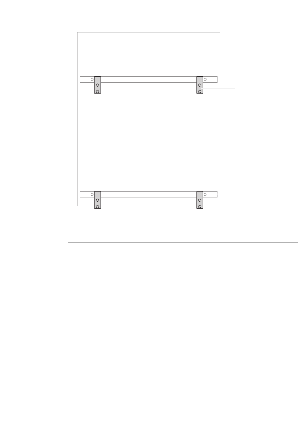
figure 3-13 Housing of the Alyza IQ in the WM wall mounting assembly
1 Retaining hook
2 Fixing screws of the C-rail
1 Open the outer housing door far enough so the arrestable brake-stay
catches.
2 Open the inner housing door far enough so that it touches the outer
door. Tilt the angular sheet (at the inside of the outer door) over the
upper edge of the inside door.
3 foam transport protectors are in the area between the control unit (1)
and the measuring unit (5).
2
1

Alyza IQ PO4 Commissioning
43
ba76201e09 12/2022
3.3.9 Connecting the cables to the control unit ACM
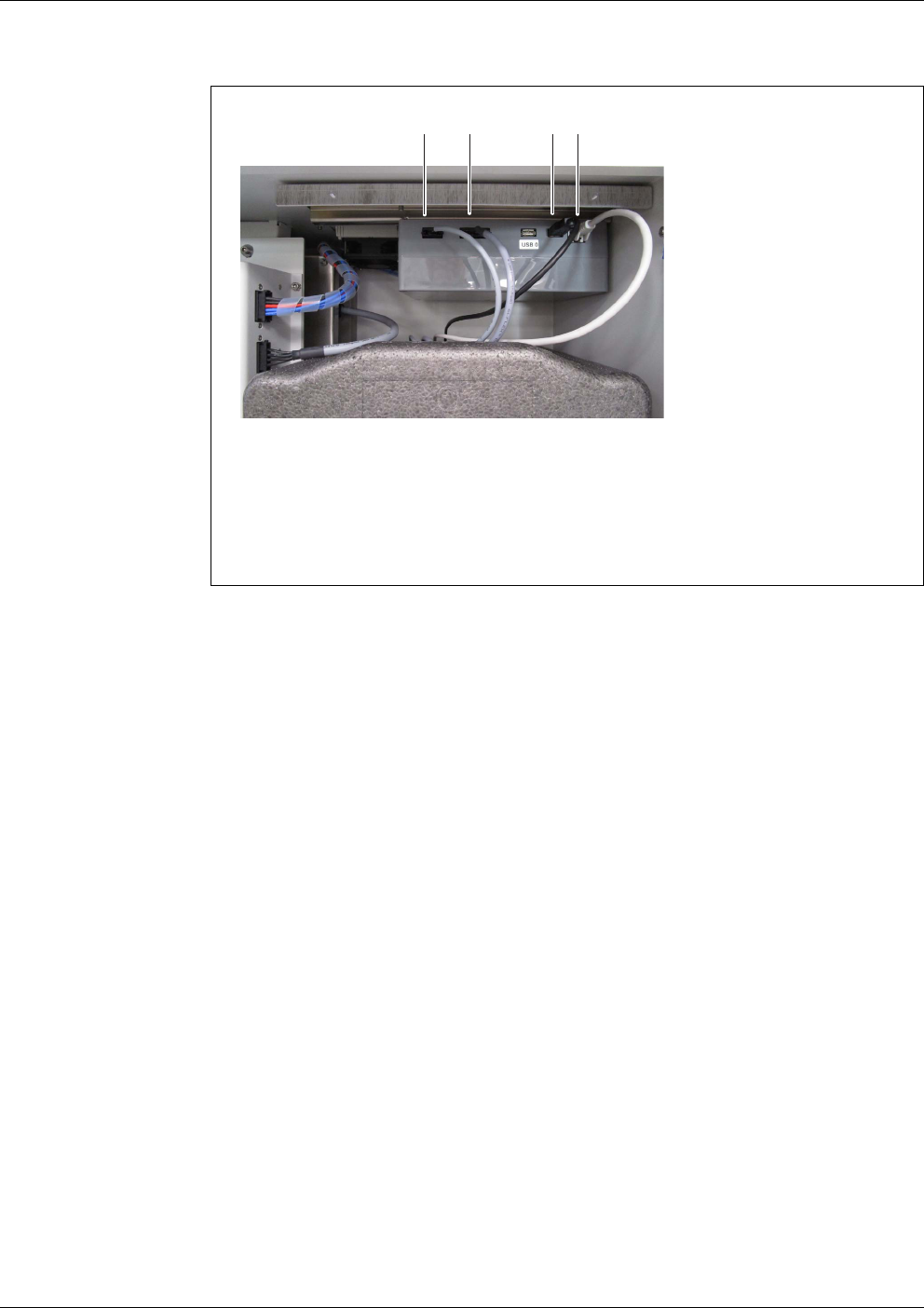
figure 3-14 Transportation safety devices
1 Control unit with connectors
2 Transport protector 1 in the front
3 Transport protector 2 in the front
4 Transport protector 3 in the background
5 Measuring unit
3 Pull the two transport protectors (2, 3) out to the front.
4 Carefully move the transport protector (4) of the measuring unit (5)
upward and then pull it out to the front.
The third transport protector is behind the transport protectors already
removed.
5 Keep all transport protectors.
6 To transport the instrument, always us the transport protectors.
1 Remove the transport protection of the measuring unit (see
section 3.3.8 Removing the transport protection of the measuring unit,
42).
4 cable ends to be connected to the control unit are on the measuring
unit.
2 Connect the 4 cables to the sockets of the control unit ACM.
Connect the USB cable to the unlabeled USB connector (the connector
labeled "USB0" remains free).
All other plugs will only fit into one socket in the correct direction.
3
4
5
2
1
Commissioning Alyza IQ PO4
44
ba76201e09 12/2022
3.3.10 Mounting the cover plate for the control unit ACM
The cover plate for the control unit ACM covers the control unit ACM and the ca-
bles connected to it.
figure 3-15 Cable of the control unit ACM
1 3-pole connection (mains)
2 4-pole connection (data)
3 USB connection
4 RJ45 connection
1 Remove the transport protection of the measuring unit (see
section 3.3.8 Removing the transport protection of the measuring unit,
42).
4 cable ends are on the measuring unit.
2 Connect the 4 cables lying on the measuring unit to the control unit (see
section 3.3.9 Connecting the cables to the control unit ACM, 43).
3 Unscrew the 2 knurled-head screws from the top hat rail on the housing
top,
4 Screw the cover plate to the top hat rail with the 2 knurled-head screws.
3
4
2
1
Alyza IQ PO4 Commissioning
45
ba76201e09 12/2022
3.3.11 Installing the bug screen and condensate drain adapter
Bug screen The bug screen protects the interior of the Alyza IQ against insects coming in
through the air intake opening in the bottom of the housing.
Condensate drain When the Alyza IQ is operated with local temperatures from approx. 25 °C (77
°F) and high moisture, water may condensate within the cooling unit.
The condensate drain adapter runs the condensate that has formed to the out-
side.
Parts of the condensate collect at the housing bottom and at the cooling unit.
This condensation water formed during operation does not adversely affect the
operation of the Alyza IQ.
The condensate drain tube of the Alyza IQ is in the recess of the condensate
drain adapter. Any condensate forming will first fill the recess in the adapter be-
fore overflowing. When enough condensate is present, it closes the condensate
drain tube so that no air humidity can penetrate the housing.
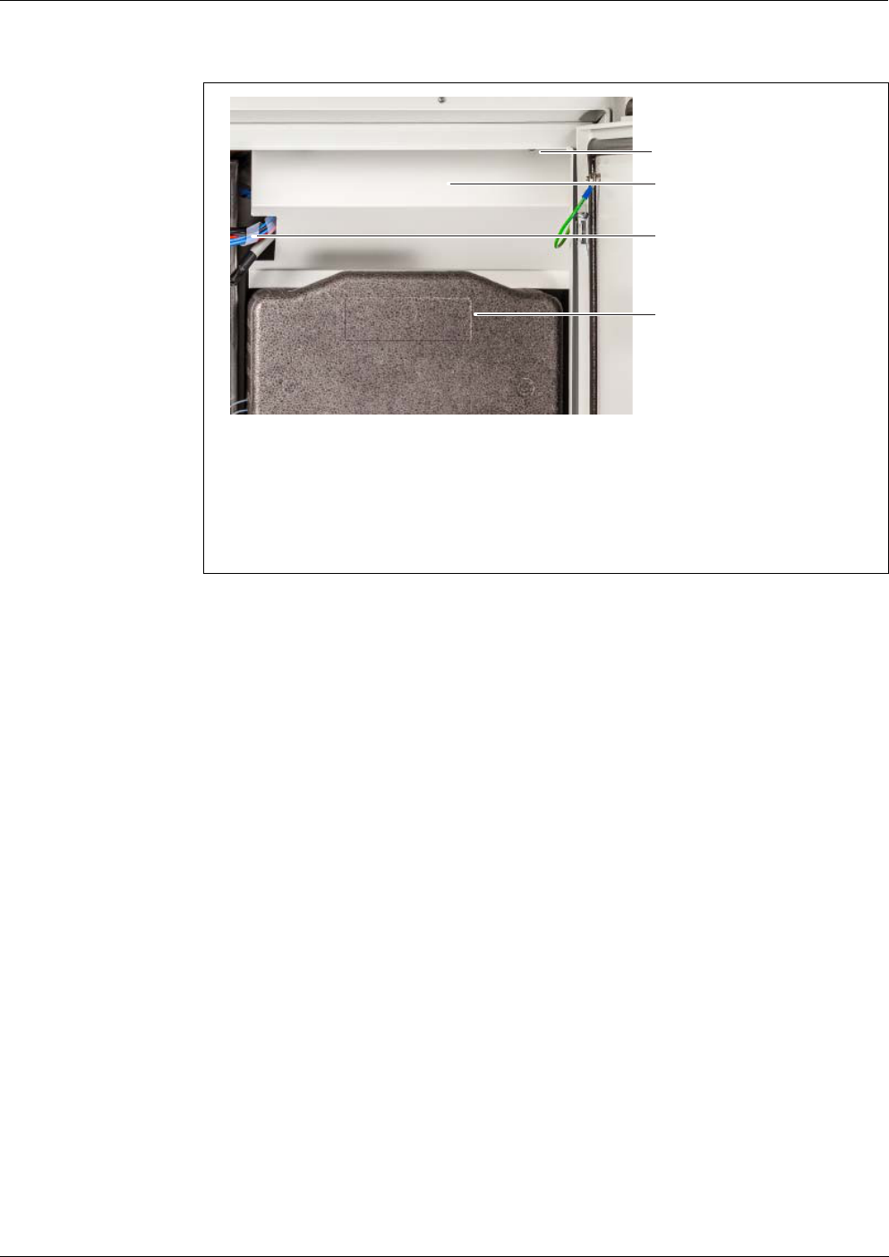
figure 3-16 Cover plate for the control unit ACM
1 Knurled-head screws to mount the cover plate
2 Cover plate for the control unit ACM
3 Cables for power supply
4 Measuring unit
1
3
4
2
Commissioning Alyza IQ PO4
46
ba76201e09 12/2022
Installation
figure 3-17 Mounting the bug screen and condensate drain adapter
1 Condensate drain tube (black) at the housing bottom
2 Bug screen
3 Frame with seal
4 Condensate drain adapter with 2 screws
5 Condensate drain tube (transparent)
6 4 knurled-head screws
1
2
3
4
5
6
1 Screw the condensate drain adapter (4) with 2 screws to the frame (3)
so that the tube nozzle of the adapter is on the outside of the frame.
2 Plug the transparent condensate drain tube (5) onto the tube nozzle of
the condensate drain adapter (4) as far as it will go.
3 Insert the bug screen (2) in the frame so that it is kept in position by the
seal of the frame (3).
4 Position the frame (3) with the bug screen (2) and the mounted conden-
sate drain adapter (4) at the underside of the housing. When doing so,
the black condensate drain tube (1) at the underside of the housing
should exactly fit into the recess of the condensate drain adapter (4).
5 Screw the frame (4) to the housing bottom using the 4 knurled-head
screws.

Alyza IQ PO4 Commissioning
47
ba76201e09 12/2022
3.3.12 Mounting the terminal holder (TM)
Operating the Alyza IQ, especially while maintenance activities are being exe-
cuted at the open measuring unit, requires a terminal mounted in the vicinity
(e.g. MIQ/TC 2020 3G or DIQ/S 28X). The terminal should be mounted at the
left-hand side of the Alyza IQ
so that the terminal is always visible while mainte-
nance activities are being executed at the open measuring unit.
The accessory Terminal holder (TM) enables to install a terminal, irrespective of
the mounting of the Alyza IQ (mounting stand SM, rail mounting accessory RM,
wall mounting accessory WM), in the vicinity of the Alyza IQ.
figure 3-18 Mounted bug screen and condensate drain adapter
1Frame
2 Bug screen
3 Condensate drain adapter
4 One of the 4 knurled-head screws
1
2
3
4
Commissioning Alyza IQ PO4
48
ba76201e09 12/2022
Preparing the
mounting stand or
rail mounting
accessory for the
terminal holder
The terminal holder is installed at the left-hand side of the Alyza IQ. Thus the ter-
minal is always visible, even with maintenance activities being executed at the
open housing of the Alyza IQ.
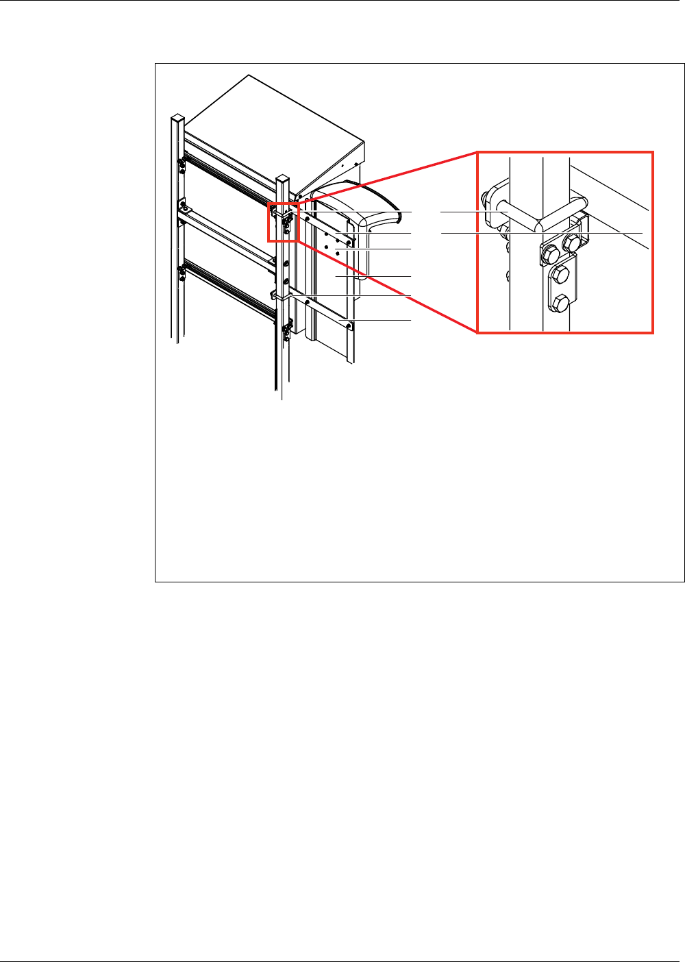
figure 3-19 Installed terminal holder TM (view of the rear side)
Example: Installation on an SM stand mount
1 Upper bracket
2 Upper angle bracket
3 Bore holes for the canopy
4 Mounting sheet
5 Lower bracket
6 Lower angle bracket
1
2
4
5
6
3
1 Position the mounting stand with the Alyza IQ mounted. The rear of the
mounting stand has to be freely accessible.
2 Insert the long side of an angle bracket (2) between the housing and
mounting stand, above the upper C-rail and past the mounting stand
until the short side of the angle bracket touches the mounting stand.
Keep the angle bracket in this position.
3 Position a bracket (1) on the mounting stand and insert the ends of the
bracket in the bore holes of the angle bracket.
Fix the angle bracket (2) to the bracket loosely with 2 nuts.
4 Insert the long side of the second angle bracket (6) between the housing
and mounting stand, under the lower C-rail and past the mounting stand
until the short side of the angle bracket touches the mounting stand.
Keep the angle bracket in this position.

Alyza IQ PO4 Commissioning
49
ba76201e09 12/2022
Installation on a
mounting stand or
rail mounting
accessory
Installation on a
wall
Installing the
canopy and
terminal
5 Position the second bracket (5) on the mounting stand and insert the
ends of the bracket in the bore holes of the angle bracket.
Fix the angle bracket (6) to the bracket loosely with 2 nuts.
1 Screw the mounting sheet (4) to both brackets (2, 6) with 4 hexagon
socket screws and nuts.
2 On the rear side of the mounting sheet (4), plug four screws into the drill-
ings (3) far enough so that they can be seen on the other side.
3 Hold the mounting sheet (4) in the desired height and tighten the 4 nuts
at the brackets (1, 3) until the terminal holder is safely mounted.
1 On the rear side of the mounting sheet (4), plug four screws into the drill-
ings (3) far enough so that they can be seen on the other side.
2 Screw the mounting sheet (4) to the wall.
1 Tighten the 4 screws to fix the canopy to the mounting sheet (4).
At the bottom of the mounting sheet, keep some space free for the
cabling of the power supply.
2 Mount an IQ module (e.g. MIQ/JB, DIQ/S 28X, ...) to the canopy (see
IQ S
ENSORNET system operating manual).
3 Dock a terminal onto the MIQ/JB as necessary.
4 Connect the IQ S
ENSORNET cable of the Alyza IQ to the IQ module (see
IQ S
ENSORNET system operating manual).
5 If necessary, connect the IQ module with a second IQ S
ENSORNET
cable to integrate the Alyza IQ into an existing IQ S
ENSORNET (see
IQ S
ENSORNET system operating manual).
Commissioning Alyza IQ PO4
50
ba76201e09 12/2022
3.3.13 Connecting the power cable and heat tracing lines
The intake lines and return lines are inserted into the housing through dust-proof
lead-in ducts. The cable glands with seals are at the bottom of the housing.
figure 3-20 Mounted terminal holder TM with canopy, MIQ/JB and MIQ/TC 2020 3G
For all work done with the housing open:
If the Alyza IQ was already in operation:
Before opening the measuring unit, start the maintenance routine
at the terminal.
Note the environmental conditions (see section 3.3.1 Require-
ments of the measurement location, 27).
Open the outer housing door far enough so the arrestable brake-
stay (on the lower right side of the housing) catches.
Open the inner housing door far enough so that it touches the
outer door. Tilt the angular sheet (at the inside of the outer door)
over the upper edge of the inside door.
Alyza IQ PO4 Commissioning
51
ba76201e09 12/2022
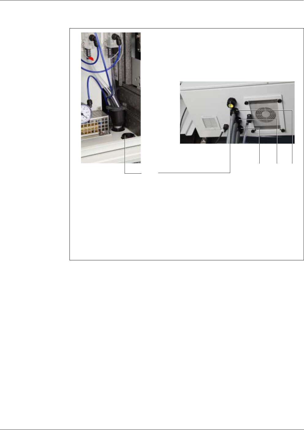
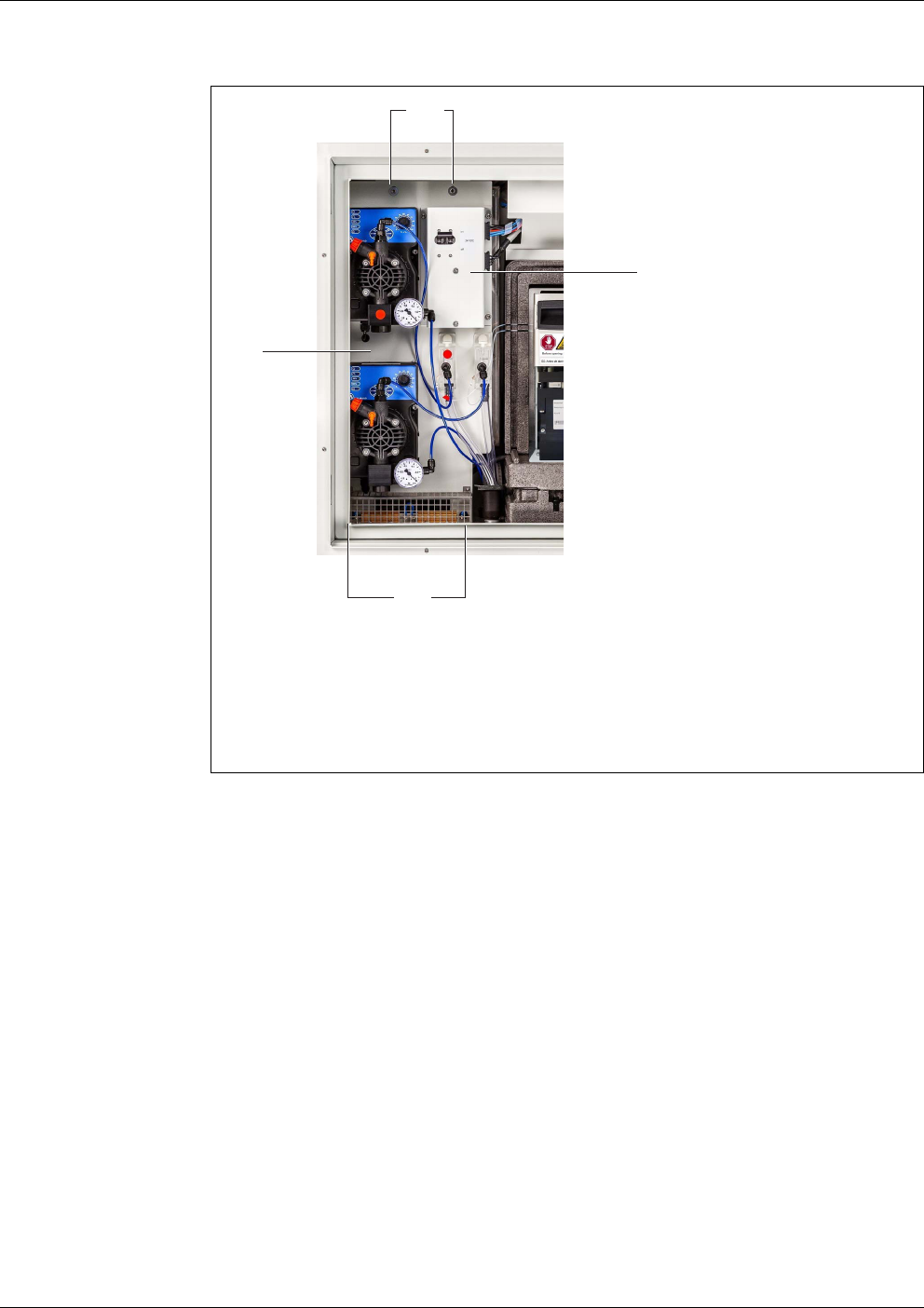
figure 3-21 Cable glands for intake lines and return lines
(view from inside and from below)
1 Cable gland (front) for return line 2 (in the example, sealed with
yellow plug)
2 Cable gland (2nd from the front) for return line 1
(in the example: waste from the measuring unit and sample overflow
from the overflow vessels)
3 Cable gland (3rd from the front) for intake line 1 (channel 1)
4 Cable gland (rear) for intake line 2 (channel 2)
4
1
2
3
Commissioning Alyza IQ PO4
52
ba76201e09 12/2022
Opening the power
box
(to connect the
heat tracing)
In the delivery condition, the power cable (2 m length) is connected to the termi-
nals in the power supply box of the Alyza IQ and is run outside through the hous-
ing bottom of the Alyza IQ.
The power cable is delivered without plug. It is designed to be directly connected
to the power supply. Note the safety requirements (see section 3.3.2 Safety re-
quirements of the electrical installation, 27).
If a heat tracing is connected, a fault current protection switch (ground fault cir-
cuit interrupter) and a fuse must be installed additionally.
To connect to the power supply box a heat tracing or power cable, the mounting
plate has to be removed.
WARNING
If the power supply is connected incorrectly, there may be
danger to life from electric shock.
Pay attention to the following points during installation:
The power supply box may only be connected to the
power supply by a qualified electrician.
The power supply box may only be connected to the
power supply when it is not carrying any voltage.
The power supply must fulfill the specifications given
on the nameplate and in chapter 8 Technical data,
170.
The power supply of the heat tracing must fulfill the
specifications given on the heat tracing (240 VAC or 120
VAC).
To operate a heat tracing line, a fault current protection
switch (ground fault circuit interrupter) has to be in-
stalled.
The power cable must meet the requirements according
to the technical data (see section 8.4, 175).
If necessary, you can install a longer power cable in the power sup-
ply box (see section 3.3.13 Connecting the power cable and heat
tracing lines, 50). When doing so, note the requirements of the
power cable (see section 8.4 Electrical data, 175).
Install an additional external power interrupter to be able to switch
the power supply box potential free from outside.
1 Open the outer housing door far enough so the arrestable brake-stay
(on the lower right side of the housing) catches.
2 Open the inner housing door far enough so that it touches the outer
door. Tilt the angular sheet (at the inside of the outer door) over the
upper edge of the inside door.

Alyza IQ PO4 Commissioning
53
ba76201e09 12/2022
Switching off the
power supply
Removing the
mounting plate
3 Switch off all filtration pumps (STOP).
4 Switch off the 24 V power supply.
5 Switch the power line potential free.
6 Unscrew the 2 fixing screws of the cover (on the top right side in the
housing) and remove the cover of the ACM.
If the filtration pumps have already been in operation, sample liquid
may escape when the tubes and liquid lines are unscrewed. Provide
a collecting container in such a case.
7 Remove the cable connections and the connections of the tubes and liq-
uid lines from the mounting plate:
Unplug the 2 cables from the switch box.
Unscrew the sample tubes from the overflow vessels.
Unplug the blue intake lines of the filtration units.
Pull the sample overflow tubes out of the collection funnel.
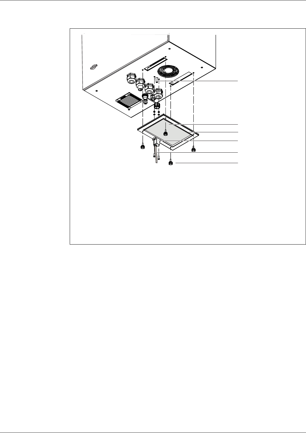
8 Remove the mounting plate:
Unscrew the 2 fixing nuts (3) at the bottom of the mounting plate.
Unscrew the 2 fixing screws (2) at the upper edge of the mounting
plate.
Secure the mounting plate against falling out.
Commissioning Alyza IQ PO4
54
ba76201e09 12/2022
Opening the power
box
figure 3-22 Mounting plate
1 Mounting plate
2 Fixing screw at the upper edge
3 Fixing nuts at the lower edge
4 Switch box with 24 VDC switch
9 Remove the mounting plate:
Lift the mounting plate upward over the threaded pins.
Tilt the upper edge of the mounting plate somewhat backwards and
remove the mounting plate from the housing downwards.
Place the mounting plate with the rear side down on a protected sur-
face (e.g. with cardboard).
2
1
4
3
10 Unscrew all nuts with safety disks (10 pieces) from the power supply
box and remove the lid of the power supply box.

Alyza IQ PO4 Commissioning
55
ba76201e09 12/2022
figure 3-23 Connections of the power supply box
1 Power supply module
2 Ventilator
3 Power supply filter
4 Connecting terminals for the heat tracing lines
4 - 7: yellow/green (protective earth conductor)
8 - 11: gray
12 - 15: blue
5 Power supply of the heat tracing lines
6 Overvoltage protection
7 Power line
8 Cable gland for heat tracing of intake line (channel 2)
9 Cable gland for heat tracing of intake line (channel 1)
10 Cable gland for heat tracing of return line 2 (sample return)
11 Cable gland for heat tracing of return line 1 (chemicals return)
11 Unscrew the nuts of the cable glands for the cables of the heat tracing
at the underside of the power supply box.
2
1
5
7
6
4
3
8 9
10
11

Commissioning Alyza IQ PO4
56
ba76201e09 12/2022
Connecting the
intake lines and
return lines
12 On the underside of the power supply box, remove the protective plugs
from those cable glands you need to connect the cables.
Unused cable glands have to be closed with the supplied black plugs.
13 Only for variants with 2 sample channels:
Run the intake line for channel 2 through the big rear cable gland (from
the rear housing panel) at the housing bottom.
– The sleeve tube should protrude into the interior approx. 1 cm to pro-
tect the intake line from being damaged (see figure 3-25).
– Fix the sleeve tube with the cable gland.
14 Run the intake line for channel 1 through the second big cable gland
(from the rear housing panel) at the housing bottom.
– The sleeve tube should protrude into the interior approx. 1 cm to pro-
tect the intake line from being damaged (see figure 3-25).
– Fix the sleeve tube with the cable gland.
15 Run the return line for waste from the measuring unit through the next
big cable gland at the housing bottom.
– The sleeve tube should end flush with the tube inside the housing so
that a collection funnel can be installed.
– Fix the sleeve tube with the cable gland.
The liquid in the return line must be able to flow freely (steady
slope). Do not immerse the end of the return line in water.
16 To guide the sample return into the basin and dispose of the chemicals
waste separately:
Install the collection funnel (WF Set) (see section 3.3.15 Mounting the
WF Set (collection funnel for sample overflow), 62).
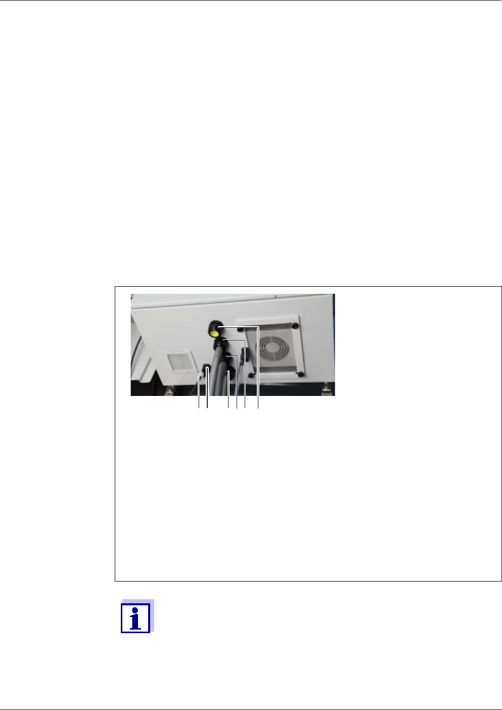
Alyza IQ PO4 Commissioning
57
ba76201e09 12/2022
Connecting the
cable with the
power supply box
NOTE
No other consumers, with the exception of those described in this operating
manual, may be connected to the power supply box.
Line branches in the supply lines are not permitted.
17 To guide the sample return into the basin and dispose of the chemicals
waste separately:
Run the return line for sample through the front big cable gland at the
housing bottom.
– The sleeve tube should end flush with the tube inside the housing so
that a collection funnel can be installed.
– Fix the sleeve tube with the cable gland.
– Position a suitable collecting container for the chemical waste under
the Alyza IQ and secure it.
Empty the collecting container regularly.
– Put the return line for the chemical waste into the collecting container
and secure it.
– The chemical waste in the return line must be able to flow freely
(steady slope). The end of the return line must not be immersed in
water or the liquid chemicals collected.
figure 3-24 Connections at the housing bottom (from below)
Example: 2 sample channels, 1 drain
1IQSENSORNET cable
2 Power line
3 Variants with 2 sample channels:
Gland for sleeve tube of intake line (channel 2)
4 Gland for sleeve tube of intake line (channel 1)
5 Gland for sleeve tube of return line 1
6 Gland for sleeve tube of return line 2
(in the example it is unused and sealed with a yellow protective plug)
Unused cable glands of the basic instrument have to be closed with
the yellow protective plugs supplied.
1
3
6
2
54

Commissioning Alyza IQ PO4
58
ba76201e09 12/2022
Closing the power
supply box
18 Slide the nut of the cable gland (of the power supply box) over the cable
of the heat tracing.
19 First run the wire with the greatest diameter (protective earth conductor,
yellow/green) through the sealing of the cable gland.
20 Then run the two thinner wires (black) of the heat tracing through the
sealing of the cable gland.
21 Push the entire cable with the cable sheath through the sealing until the
cable is visible in the power supply box.
22 Insert the cables of the heat tracing lines for the intake lines and return
lines through the cable glands on the underside.
23 Seal unused cable glands with the black plugs supplied.
Thus the power supply box is closed and protected against dust and
moisture.
24 Screw tight the nut of the cable gland (with a torque of 7.5 Nm).
25 Insert all heat tracing cables into the power supply box.
26 Insert the heat tracing wires into the respective terminals so that each
terminal catches.
Green/yellow cable: any green/yellow terminal
1st black cable: any blue terminal
2nd black cable: any gray terminal
The heating bands of the heat tracing must start within the housing
of the Alyza IQ to keep the lines frost free. At the outlet of the return
line, the heat tracing must protrude 20 to 50 mm from the sleeve
tube. If necessary, shift the heat tracing in the sleeve tube accord-
ingly.
27 If necessary, replace the power cable with another power cable (e.g. a
longer one).
28 Check whether all connections are made correctly.
29 Screw tight the nut of the cable gland of the power cable (with a torque
of 2.5 Nm).
Make sure that no cable touches the power supply filter.
30 Remount the lid of the power supply box and screw tight all nuts with
safety disks as far as they will go (0.4 Nm).

Alyza IQ PO4 Commissioning
59
ba76201e09 12/2022
Reinserting the
mounting plate
3.3.14 Mounting the collection funnel
The liquid waste from the measuring unit and sample overflow from the overflow
vessels have to be transported out of the housing of the Alyza IQ.
The collection funnel collects the liquids from up to 3 sources (waste tube from
the measuring unit, sample overflow tube from overflow vessel 1 and sample
overflow tube from overflow vessel 2 ) and transports them out of the housing
via a common return line.
To keep moisture and damp air from penetrating the housing of the Alyza IQ, the
collection funnel is closed with a rubber cover. Unused openings of the rubber
cover are closed with plugs.
The collection funnel is installed in the housing of the Alyza IQ at the
second cable gland from the front.
31 Insert the mounting plate:
Plug the mounting plate on the threaded pins inside the housing.
Tighten the 2 fixing screws (2) at the upper edge of the mounting
plate.
Tighten the 2 fixing nuts (3) at the bottom of the mounting plate.
32 Re-establish the cable connections and the connection of the tubes and
liquid lines.
Connect the 2 cables to the switch box.
Mount the collection funnel:
– the collection funnel for the chemical waste and, if necessary,
– the second collection funnel for the sample overflow from the
overflow vessels.
Plug the intake lines onto the connectors of the filtration pumps.
Screw the sample tubes to the connectors of the overflow vessels.
Re-insert the sample overflow tubes into the collection funnel for the
sample overflow or into the joint collection funnel for chemical waste
and sample overflow.
Connect the liquid lines (see section 3.3.17 Connecting the tubes
and liquid lines, 66).
Insert the sample return tubes of the overflow vessels in the collec-
tion funnels:
33 Reinsert the cover and fix it with the 2 fixing nuts.

Commissioning Alyza IQ PO4
60
ba76201e09 12/2022
Scope of delivery
of the collection
funnel of the
Alyza IQ
Collection funnel
Rubber cover for collection funnel
3 plugs for the openings of the rubber cover
2 sample overflow tubes (from the overflow vessel to the collection funnel)
Cable ties to fasten the collection funnel to the fixing bracket.
Preparatory
activities
When operating heat tracing lines for the return lines:
Install the heat tracing first (see chapter section 3.3.13 Connecting the power
cable and heat tracing lines, 50).
It is possible to dispose of the sample overflow and chemical waste
from the measuring unit separately by using a second collection fun-
nel (accessory WF Set). The second collection funnel is installed at
the front cable gland. There the sample return is transported out of
the housing separately (see section 3.3.15 Mounting the WF Set
(collection funnel for sample overflow), 62).
Install the collection funnel together with the heat tracing lines. If the
mounting plate is removed, there is more room to install the collec-
tion funnel.

Alyza IQ PO4 Commissioning
61
ba76201e09 12/2022
Mounting
figure 3-25 Collection funnel for the common discharging of all liquids
(lateral view)
1 Heating line of the heat tracing
(attached to the fixing bracket with a cable tie)
2 Waste tube of the measuring unit
3 Sample overflow tube from the overflow vessel
4 Rubber cover of the collection funnel
(close any unused openings with plugs)
5 Cable ties
6 Fixing angle bracket
7 Collection funnel
8 Cable gland (2nd from the front)
9 Cable gland (in the front)
1 Insert the return line into the housing from the outside through the cable
gland (8). Inside, the end of the waste tube should be flush with the
cable gland (8).
Details on how to install the return lines and heat tracing lines:
see section 3.3.13 Connecting the power cable and heat tracing lines,
50
2 Fix the heat tracing (1) of the return line to the fixing angle bracket
behind the cable gland with the cable tie (scope of delivery: collection
funnel).
3 Insert the collection funnel (7) in the opening of the cable gland (8) in
the housing:
the beveled side of the collection funnel (7) points to the heat tracing
(1)
the drain of the collection funnel flows into the return line
4 Press the collection funnel down till it sits tight.
1
3
2
4
5
6
9
8
7

Commissioning Alyza IQ PO4
62
ba76201e09 12/2022
NOTE
Make sure that the liquids in the collection funnel can drain off freely. A blocked
collection funnel can cause the liquids to overflow into the housing of the
Alyza IQ . Liquids can cause damage to the housing and electrical components.
If the liquids are disposed of via a second collection funnel available as an ac-
cessory (WF Set) (see section 3.3.15 Mounting the WF Set (collection funnel for
sample overflow), 62).
3.3.15 Mounting the WF Set (collection funnel for sample overflow)
To transport from the housing the liquid chemical waste from the measuring unit
separately from the sample overflow, install a second collection funnel (acces-
sory, WF Set). Via the second collection funnel, only the sample overflow from
the overflow vessels is transported out of the housing.
To collect and dispose separately of the chemical waste from the measuring
unit, a suitable (chemical resistant, winterproof) collecting container is required
additionally.
Scope of delivery
of the WF Set
Collection funnel
Rubber cover for collection funnel
3 plugs for the 3 openings of the rubber cover
Sample overflow tube, transparent
Fixing angle bracket for the heating line at the foremost cable gland with
cheese-head screws (M3x8)
Cable ties to fasten the collection funnel to the fixing bracket
Mounting
5 Pull the rubber cover (4) of the collection funnel over the edges of the
collection funnel.
The opening of the collection funnel has to be closed tightly.
6 Put the waste tube (2) of the measuring unit into the collection funnel
through the small opening of the rubber cover (4).
The liquid in the waste tube must be able to flow freely (steady slope,
no kinking, no damage).
7 If all liquids are disposed of through a common return line:
Put the sample overflow tubes (3) of the overflow vessels into the col-
lection funnel through the big openings of the rubber cover (4).
8 Close any unused openings of the rubber cover (4) with the plugs pro-
vided so that the housing interior is protected against humidity.
1 Fix the fixing angle bracket at the front cable gland.

Alyza IQ PO4 Commissioning
63
ba76201e09 12/2022
NOTE
Make sure that the liquids in the collection funnel can drain off freely. A blocked
collection funnel can cause the liquids to overflow into the housing of the
Alyza IQ . Liquids can cause damage to the housing and electrical components.
2 Insert the sleeve tube of the return line for the sample overflow into the
housing from the outside through the cable gland (9). Inside, the end of
the return tube should be flush with the cable gland (9).
Details on the how to install the sleeve tubes and heat tracing lines:
see section 3.3.13 Connecting the power cable and heat tracing lines,
50
3 Insert the collection funnel (7) in the opening of the cable gland (9) in
the housing:
the beveled side of the collection funnel (7) points to the heat tracing
(1)
the drain of the collection funnel flows into the return line for the sam-
ple return.
4 Pull off the short sample overflow tubes from the overflow vessels.
5 Cut off pieces of the transparent sample overflow tube included in the
scope of delivery long enough that the new sample overflow tubes go
from the overflow vessels to the foremost collection funnel.
6 Plug the fitted sample overflow tubes to the overflow vessels.
7 Pull the rubber cover (4) of the collection funnel over the edges of the
collection funnel.
The opening of the collection funnel should be closed tightly.
8 Put the sample overflow tubes of the overflow vessels into the collection
funnel through the big openings of the rubber cover.
9 Close any unused openings of the rubber cover with the plugs provided
so that the housing is protected from humidity.
Commissioning Alyza IQ PO4
64
ba76201e09 12/2022
3.3.16 Installing the FM/PC filter module and M 1.5 basin holder for filtra-
tion
Installation
instructions
Heed the following notes when installing the filter module:
Mount the filter module so that the plate is in a position vertical to the flow
direction.
figure 3-26 Collection funnel for the separate discharge of all liquids
1 Heating line of the heat tracing
(attached to the fixing bracket with a cable tie)
2 Waste tube of the measuring unit
3 Sample overflow tube from the overflow vessel
4 Plug for the rubber cover
5 Rubber cover of the collection funnel
(seal unused openings of the rubber cover with plugs)
6 Cable gland (2nd from the front) with collection funnel for chemical
waste
7 Fixing angle bracket
8 Collection funnel
9 Cable gland (front) with collection funnel for sample overflow
10 Position a suitable collecting container (chemical resistant, winterproof)
under the Alyza IQ to collect the chemical waste from the measuring
unit.
11 Fasten the collecting container.
12 Insert the return line of the cable gland (6) into the collecting container.
13 Fasten the return line.
14 Empty the collecting container regularly.
1
2
9
3
5
7
8
6
4
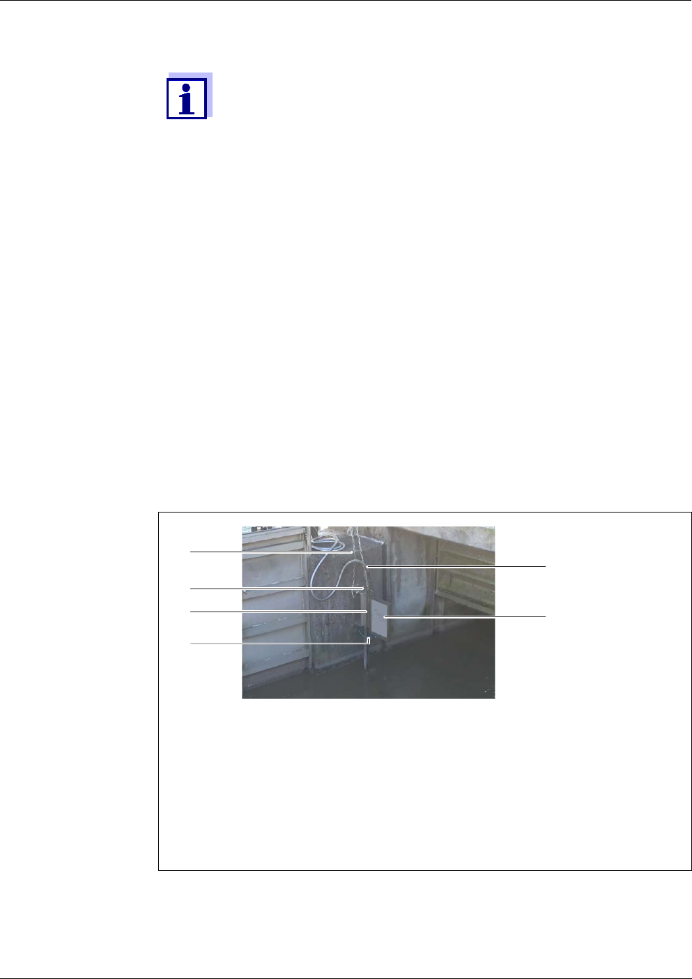
Alyza IQ PO4 Commissioning
65
ba76201e09 12/2022
The filter module (FM/PC) and the slide must be completely submersed
(max. 40 cm).
Take changing water levels into account when mounting the filter membrane
module.
The lower edge of the filter module must be mounted with at least 10 cm dis-
tance to the bottom.
NOTE
Dirt particles and contamination in the sample tube can block the valves of the
measuring unit.
During the cleaning activities, make sure that no dirt particles get into the open
tube ends or the connector of the filter module.
Protect the open tubes and connectors during the cleaning activities, e.g. with
blind plugs.
Installation
In special cases (e.g. in a channel) it is better to mount the FM/PC
filter module in a horizontal position in the flow direction.
An adapter for horizontal mounting is available as an accessory.
1 Mount the rail of the basin holder for filtration in the basin.
If necessary, extend the rail with the M-EXT 1.5 extension accessory.
figure 3-27 Sample filtration device (installed)
1 Chain (scope of delivery: basin holder for filtration M 1.5)
2 Guide rail (scope of delivery: basin holder for filtration M 1.5)
3 Height adjustable slide (scope of delivery: Suction line)
4 Intake line (scope of delivery: Suction line)
5 Sleeve tube (scope of delivery: Suction line)
6 Filter module (FM/PC) with filter plate (Filter/PC)
2 Mount the filter module on the slide of the basin holder for filtration.
3 Connect the intake line to the filter module.
2
1
3
6
5
4

Commissioning Alyza IQ PO4
66
ba76201e09 12/2022
3.3.17 Connecting the tubes and liquid lines
After connecting the intake lines to the housing, connect the following tubes and
liquid lines:
the blue intake lines to the filtration pumps
the sample feed tubes of the pumps to the overflow vessels
the transparent sample overflow tubes of the overflow vessels to the collec-
tion funnel for the sample overflow
the transparent sample tubes of the measuring unit to the overflow vessels
the black waste tube of the measuring unit to the collection funnel for chem-
ical waste or to the collection funnel for the sample overflow.
fig. 3-28, 67 shows the housing with the completely connected lines including
the accessories and all options:
4 Insert the slide of the filter module in the rail and lower it into the basin
with the aid of the chain. Fix the end of the chain outside the basin.
5 Run the intake line to the Alyza IQ. Fix the sleeve tube with cable ties
at some suitable places as necessary. How to connect the intake line to
the Alyza IQ, (see section 3.3.17 Connecting the tubes and liquid lines,
66).
For all work done with the housing open:
If the Alyza IQ was already in operation:
Before opening the doors, start the maintenance routine at the
terminal.
Note the environmental conditions (see fig. 3.3.1, 27).
Open the outer housing door far enough so the arrestable brake-
stay catches.
Open the inner housing door far enough so that it touches the
outer door. Tilt the angular sheet (at the inside of the outer door)
over the upper edge of the inside door.
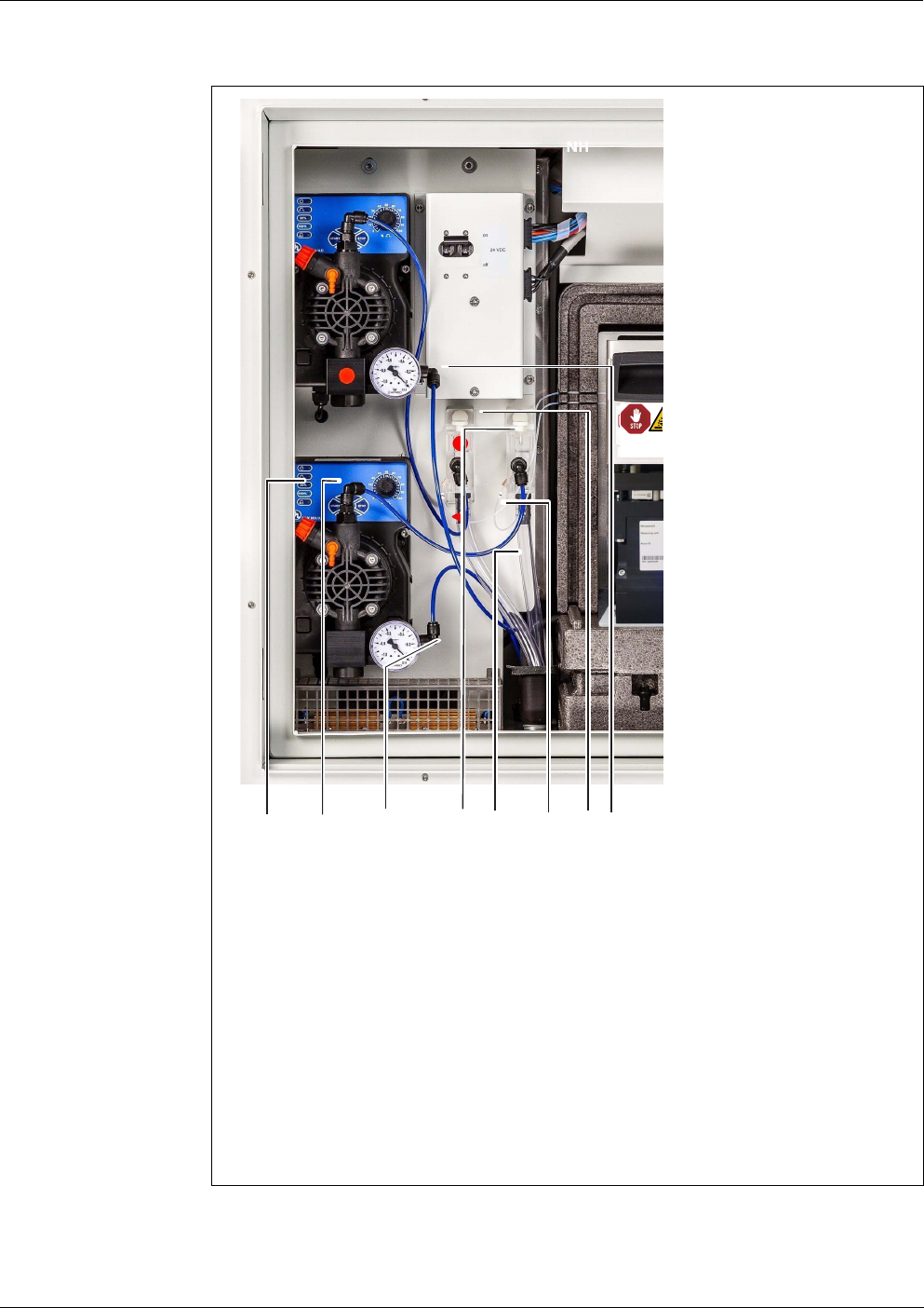
Alyza IQ PO4 Commissioning
67
ba76201e09 12/2022
Proceed as follows to connect each line:
figure 3-28 Completely connected lines
1 Channel 1: Filtration pump
2 Channel 1: Sample feed tube (filtration pump - overflow vessel)
3 Channel 1: Intake line
4 Channel 1: Overflow vessel
5 Channel 1: Sample overflow tube (overflow vessel - collection funnel)
6 Channel 1: Sample tube (overflow vessel - measuring unit)
7 Channel 2: Overflow vessel
8 Channel 2: Intake line
All parts for channel 1 described here also exist for channel 2 (red
labeling)
1 Connect the intake line 1 to the filtration pump 1.
2
3
5
6
1
4
78
Before opening:
ES: Antes de abrir:
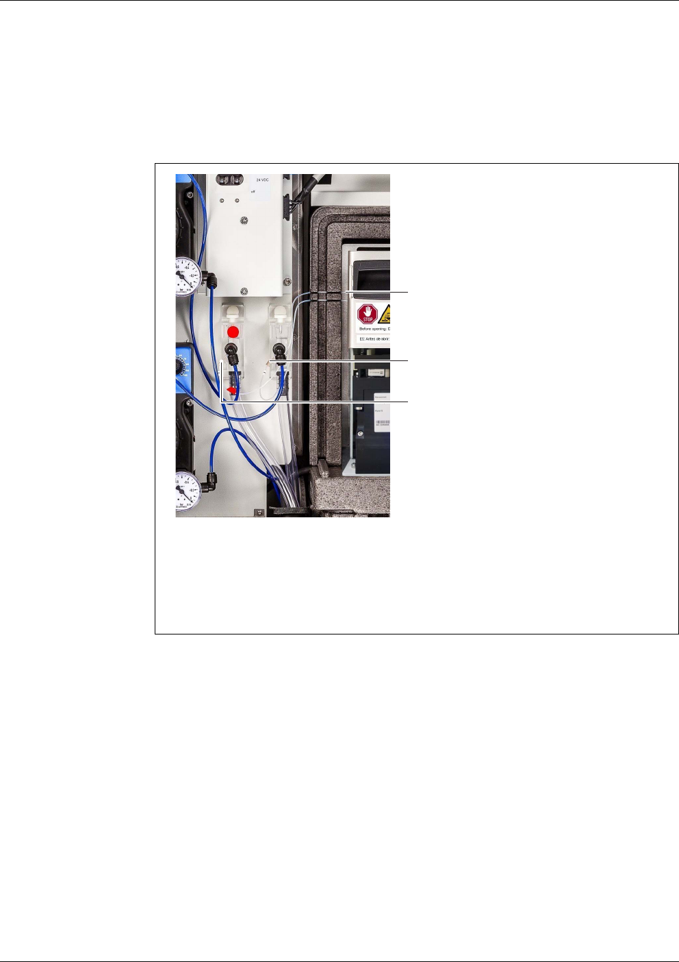
Commissioning Alyza IQ PO4
68
ba76201e09 12/2022
2 Connect the intake line 2 to the filtration pump 2.
3 Connect the sample tubes to the overflow vessels.
The sample tube (channel 2) for overflow vessel 2 has a red labeling.
figure 3-29 Opening for the sample tubes
1 Grooves for the sample tubes through the insulation of the measuring
unit
2 Connection of sample tube 1 (channel 1) to overflow vessel 1
3 Connection of sample tube 2 (channel 2) to overflow vessel 2
4 Carefully press the sample tubes into the grooves (1) left of the measur-
ing unit so that the sample tubes are not bent even when the front cover
is closed.
5 Install the collection funnel for the chemical waste.
6 If necessary, install the collection funnel for the sample overflow.
7 Insert the waste tube of the measuring unit into the collection funnel for
the chemical waste of the measuring unit.
The liquid in the waste tube must be able to flow freely (steady slope,
no kinking, no damage).
1
3
2

Alyza IQ PO4 Commissioning
69
ba76201e09 12/2022
3.3.18 Setting up a connection with the IQ SENSORNET system
In the delivery condition the IQ S
ENSORNET cable (2 m long) is connected to the
ACM control unit of the Alyza IQ and is run to the outside through the bottom
plate.
Connect the IQ S
ENSORNET cable of the Alyza IQ to an IQ SENSORNET module
mounted in the vicinity.
If the Alyza IQ is operated in an IQ S
ENSORNET configured minimally, we recom-
mend that you set the terminator switch in the MIQ module (e.g. MIQ/JB) to ON
(see IQ S
ENSORNET system operating manual).
Example of a simple IQ S
ENSORNET system:
1 TerminalController ( e.g. MIQ/TC 2020 3G),
1 MIQ module (e.g. MIQ/JB),
1 sensor (e.g. Alyza IQ)
8 Insert the sample overflow tubes from the overflow vessels into the col-
lection funnel for the sample overflow.
Collection funnel at the foremost cable gland:
(with separate disposal of the chemical waste from the measuring
unit)
or
Collection funnel at the second cable gland:
(with joint disposal of the chemical waste from the measuring unit
and of the sample overflow into the container)
The liquids in the return lines have to be able to drain off freely
(steady slope). Do not immerse the end of the line in water.
9 Check whether the pre-installed sample feed tubes are correctly con-
nected to the filtration pumps and overflow vessels
For detailed information on how to connect the IQ S
ENSORNET cable
to an IQ S
ENSORNET module mounted in the vicinity please refer to
the IQ S
ENSORNET system operating manual, paragraph "Distribut-
ed mounting“.
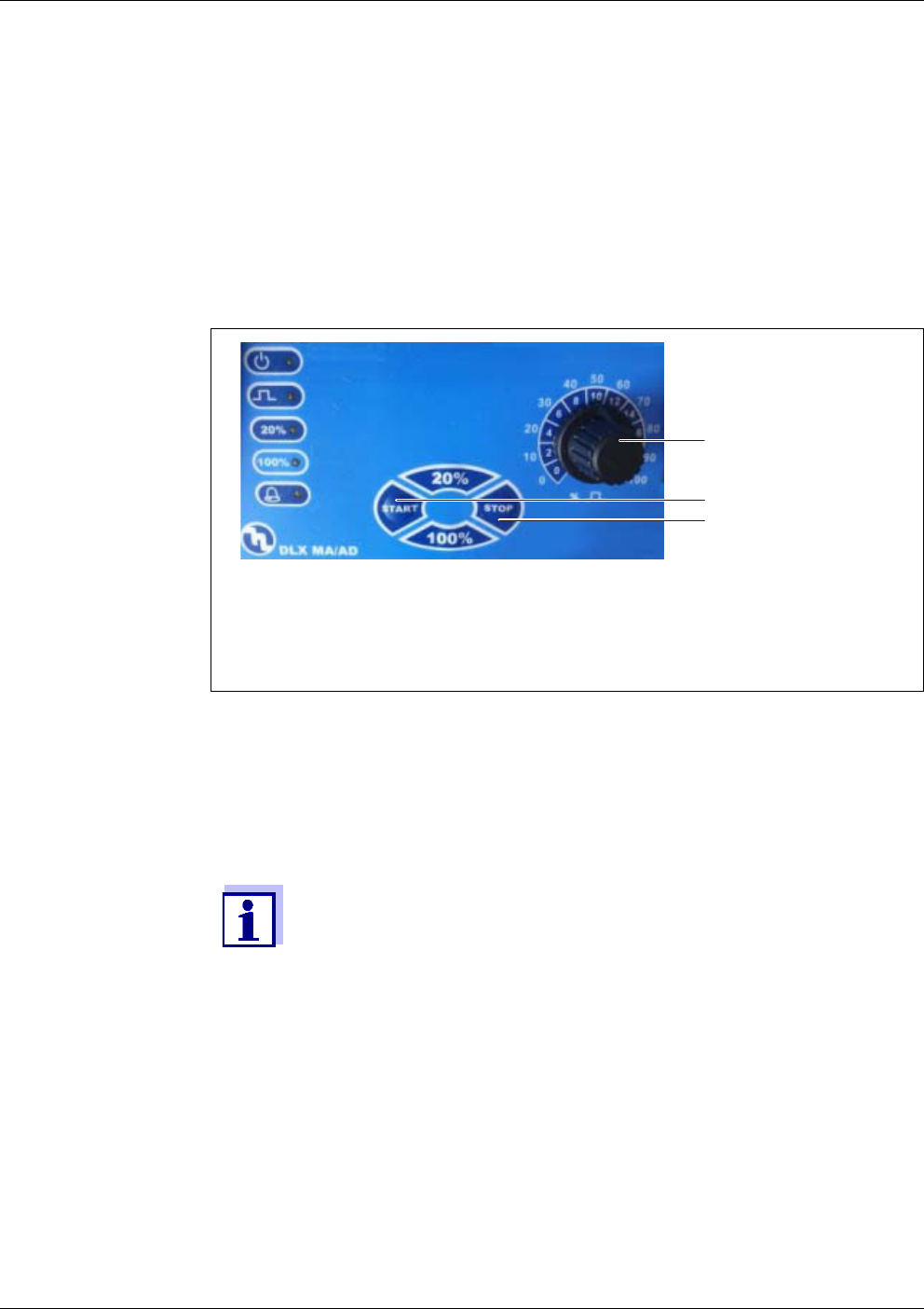
Commissioning Alyza IQ PO4
70
ba76201e09 12/2022
3.3.19 Taking the filtration pumps into operation
1 Make sure that all lines (intake lines, return lines) and tubes (sample
feed tube, sample overflow tube, sample tube, waste tube) in the
Alyza IQ are connected correctly.
2 Set the 24 VDC switch on the mounting plate to ON (I pressed upward).
3 Use the rotary knob to set the pump capacity to 80 ... 100 %.
figure 3-30 Filtration pump
1 Pump capacity in %
2 Start key
3 Stop key
4 Switch on the filtration pump with the Start key.
5 Wait until sample liquid runs from the overflow vessel into the sample
overflow tube. Depending on the length of the intake line, this may take
some minutes.
If no sample runs into the overflow vessel, proceed in one of the fol-
lowing ways.
1
2
3
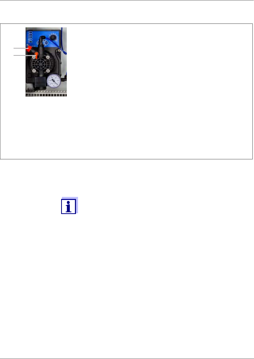
Alyza IQ PO4 Commissioning
71
ba76201e09 12/2022
figure 3-31 Filtration pump
1 Vent valve
2 Vent connection
Open and then close again the ventilation valve (1).
Fill the intake line with water manually:
– Switch off the filtration pump.
– Pull the intake line off the filtration pump.
– Fill the intake line with water (e.g. using a wash bottle).
– Connect the intake line to the pump again and secure it.
– Switch the filtration pump on again.
Increase the suction power manually:
– At the vent connection (2), connect a syringe with a tube:
– Open the vent valve (1).
– Create an additional negative pressure with the syringe.
– Close the vent valve (1).
– Repeat the procedure until sample runs into the overflow vessel.
– Remove the tube and syringe from the vent connection (2).
1
2
6 As soon as a sufficient amount of sample is flowing, reduce the pump
capacity as far as possible (to approx. 2 - 10 %) with the rotary knob.
Adjust the pump capacity so that the sample overflow can drain off
through the sample overflow tube into the collection funnel for the
sample overflow.
No sample may come into the housing through the vent valve (1).
7 Alyza IQ variant with 2 sample channels:
Take the second filtration pump into operation.
8 Let the sample feed run continuously, until the sample flow is stable and
no more air is in the lines.
9 Close the doors of the housing.
10 If necessary, put the IQ S
ENSORNET system into operation (see the rel-
evant IQ S
ENSORNET system operating manual).

Commissioning Alyza IQ PO4
72
ba76201e09 12/2022
3.4 Initial commissioning
For initial commissioning, proceed as follows:
3.4.1 Checklist for commissioning
With the aid of the following questions, check whether the Alyza IQ is ready to
start operating:
Is the housing of the Alyza IQ installed safely
(see section 3.3.4 Installing the housing, 30) ?
Are all lines (intake lines, return lines) and tubes for inlet and outlet of the
sample installed section 3.3.17 Connecting the tubes and liquid lines, 66) ?
Are the heat tracing lines installed to protect the intake and return lines
against frost (see section 3.3.13 Connecting the power cable and heat trac-
ing lines, 50) ?
Is the Alyza IQ safely connected to the power supply?
Is there an external power disconnector?
Are the filtration pumps ready for operation and is the pump capacity adjusted
(see section 3.3.19 Taking the filtration pumps into operation, 70) ?
For all work done with the housing open:
If the Alyza IQ was already in operation:
Before opening the measuring unit, start the maintenance routine
at the terminal.
Note the environmental conditions (see fig. 3.3.1, 27).
Open the outer housing door far enough so the arrestable brake-
stay catches.
Open the inner housing door far enough so that it touches the
outer door. Tilt the angular sheet (at the inside of the outer door)
over the upper edge of the inside door.
1 Check all connections and tubes connecting the Alyza IQ with the out-
side world (see section 3.4.1 Checklist for commissioning, 72)
2 Install the replacement parts required in the Alyza IQ with the aid of the
install wizard (section 3.4.3 Carrying out the install wizard, 74).
3 Complete the initial commissioning at the terminal of the IQ S
ENSORNET
(see section 3.4.4 Preparing the Alyza IQ for measuring, 76)
4 In an IQ S
ENSORNET system without automatic air pressure compensa-
tion:
Set the local altitude at the IQ S
ENSORNET in the menu <S> / Settings /
System settings / Location altitude/Air pressure (see IQ S
ENSORNET
system operating manual).
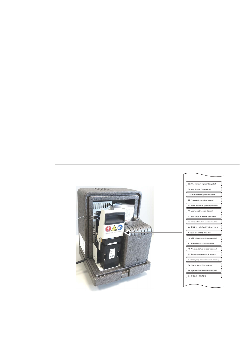
Alyza IQ PO4 Commissioning
73
ba76201e09 12/2022
Is sample present in the overflow vessels?
Does the sample in the overflow vessels meet the quality requirements (see
section 8.2 Application conditions, 171)?
Is the Alyza IQ connected to the IQ S
ENSORNET
(MIQ/JB + Terminal/Controller, is the Alyza IQ displayed as a sensor on the
IQ S
ENSORNET terminal,
see section 3.3.18 Setting up a connection with the IQ S
ENSORNET system,
69) ?
Was the correct altitude or correct air pressure entered in the IQ S
ENSORNET
system
(menu <S> / Settings / System settings / Location altitude/Air pressure, see
IQ S
ENSORNET system operating manual) ?
If a collecting container for separate disposal of the chemical waste is
installed:
Are the collecting container and return line fastened?
Is regular emptying secured?
3.4.2 Stick the label (national language)
onto the locking device of the MultiPort valve
figure 3-32 Stick the label (national language) onto the locking device of the MultiPort
valve
ES: Antes de abrir: vaciar el sistema!
¡
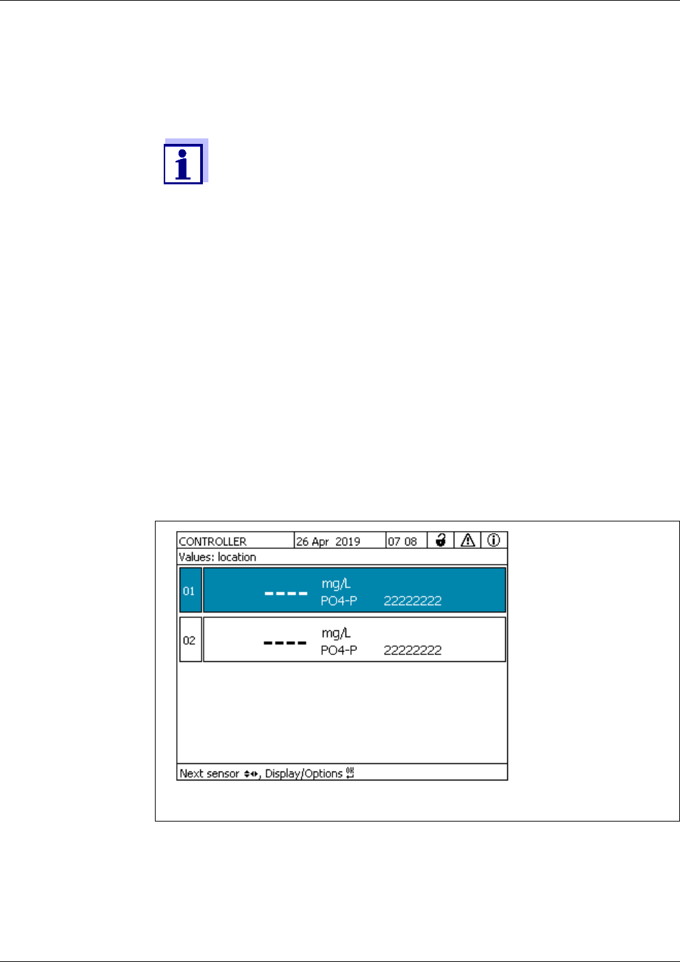
Commissioning Alyza IQ PO4
74
ba76201e09 12/2022
3.4.3 Carrying out the install wizard
When all requirements for the commissioning are met, start the install wizard to
install the replacement parts required.
As soon as the controller of the IQ S
ENSORNET identifies the Alyza IQ, the chan-
nels of the Alyza IQ are displayed in the measured value display of the
IQ S
ENSORNET.
Before the first measurement, bars are displayed.
For the commissioning you have to know how to:
Open the measuring unit,
Install the MultiPort valve (MPV),
Install the ChemBag,
Install the tube at the MultiPort valve (MPV)
(if the functions Backgr. corr.(opt) or 2-point calibration are con-
figured)
Close the measuring unit.
Details on the individual steps are given in the present operating
manual of your Alyza IQ. When the Alyza menu is opened, the install
wizard starts automatically until a first valid configuration of the
Alyza IQ is available.
The install wizard does no longer automatically start once the parts
required have been installed.
figure 3-33 Measured value display of the Alyza IQ (example: 2-channel instrument)
1 Highlight the measured value display of the Alyza IQ.
2 Open the Alyza menu with <C>.
On initial commissioning, the install wizard of the Alyza IQ opens auto-
matically.
Alyza IQ PO4 Commissioning
75
ba76201e09 12/2022
3 Put on your personal protective equipment (PPE) and chemical resis-
tant gloves (see section 2.4 Personal protective equipment (PPE),
24).
WARNING
Dangerous chemicals.
Improper use of chemicals can cause damage to your
health.
Heed the following rules:
Read the labels of the ChemBags and follow the safety
instructions
Wear protective equipment (lab coat, protective gog-
gles, chemical resistant protective gloves, safety
shoes)
4 Open the outer housing door far enough so the arrestable brake-stay
(on the lower right side of the housing) catches.
5 Open the inner housing door far enough so that it touches the outer
door. Tilt the angular sheet (at the inside of the outer door) over the
upper edge of the inside door.
6 Remove the front cover of the measuring unit.
Using one hand, grip the handle at the upper edge of the front cover
of the measuring unit.
Pull the front cover of the measuring unit somewhat to the front
against the resistance.
Carefully take the front cover out to the front and put it in a clean
place.
7 Start the install wizard.
8 Follow the instructions of the install wizard.
Step 1:
Configure all settings requiring the installation of replacement parts
(ChemBags, tubes). From them, the install wizard makes a list of the
replacement parts required.
Step 2:
Install the replacement parts required (MultiPort valve, tube, Chem-
Bags).
Details on installing the replacement parts (see section 5.5 Installing
/ exchanging the ChemBags, MPV, tubes, 111).
For each of the functions 2-point calibration and background correc-
tion (optimized), an extra tube has to be installed.
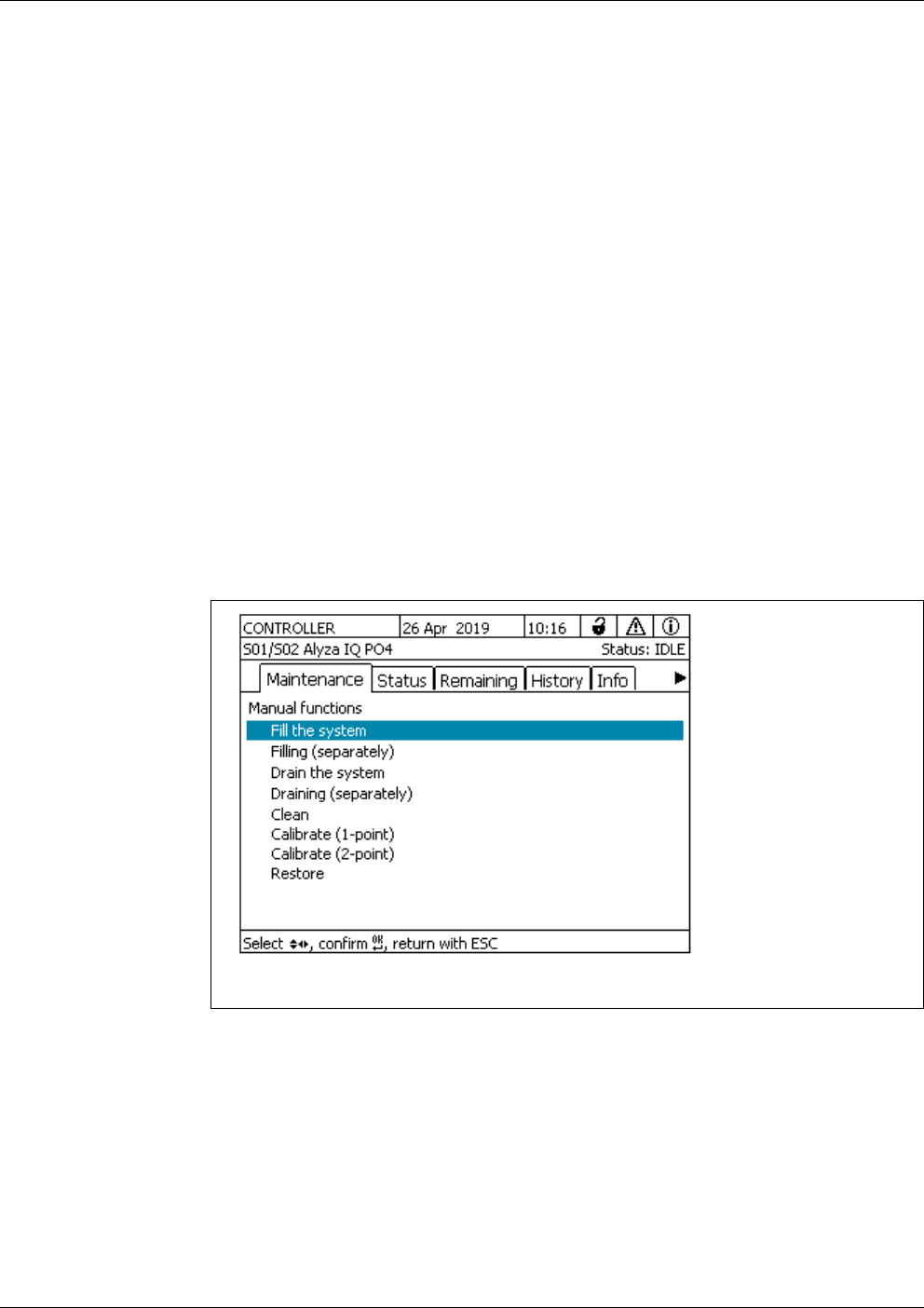
Commissioning Alyza IQ PO4
76
ba76201e09 12/2022
3.4.4 Preparing the Alyza IQ for measuring
After completing the install wizard, carry out some further steps at the terminal
of the IQ S
ENSORNET.
9 Re-insert the front cover of the measuring unit.
10 Close the housing of the Alyza IQ.
11 Prepare the Alyza IQ for measuring (see section 3.4.4 Preparing the
Alyza IQ for measuring, 76)
1 Open the Alyza menu / tab Maintenance / Manual maintenance.
2 Carry out the function Prepare measuring
(Alyza menu / tab Maintenance / Manual maintenance / Prepare mea-
suring).
3 Switch to the menu Maintenance / Manual maintenance.
figure 3-34 Tab Maintenance / Manual maintenance
4 Carry out the function Fill the system.
(Alyza menu / tab Maintenance / Manual maintenance / Fill the system)
The tubes and MultiPort valve (MPV) are filled.
When the function has been successfully completed, the message Fill-
ing successfully completed. is displayed.
5 Quit the menu Manual maintenance with <ESC>.

Alyza IQ PO4 Commissioning
77
ba76201e09 12/2022
figure 3-35 Tab Maintenance
6 Carry out the function START Alyza IQ.
Measurement is started and the measured value is displayed in the
measured value display after approx. 5 ... 7 minutes.
Wait for the temperature adjustment to be completed.
7 If necessary, switch off the maintenance condition.
(Alyza menu, tab Maintenance / Switch on/off the maintenance condi-
tion).
8 Check the settings for measurements (see section 4.3.1 IQ S
ENSORNET
Settings of sensors and diff. sensors, 80)
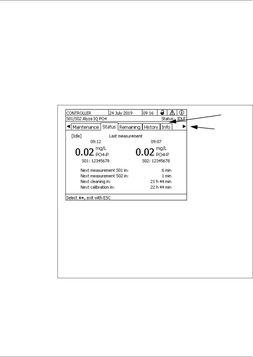
Measurement / Operation Alyza IQ PO4
78
ba76201e09 12/2022
4 Measurement / Operation
4.1 General operating principles
Contrary to the general operating principles of the IQ SENSORNET, the Alyza IQ
is operated via a separate menu (Alyza menu) at the IQ S
ENSORNET terminal.
Opening the Alyza
menu
In the Alyza menu,
you have access to information on the current operating condition
(tabs Status, Remaining, History, Info)
you can start the calibrating and service functions (tab Maintenance), e.g.:
– stop or start the Alyza IQ
– Activate or terminate the maintenance condition
– Start calibration
– Start the service functions
1 In the measured value display, use < > to select the Alyza IQ.
2 Using the <C> key, switch to the Alyza menu.
The Alyza menu opens with the tab Status. The tab Status provides
information on the current operating status of the Alyza IQ.
figure 4-1 Alyza menu tab Status
1 Tabs form the first menu level in the Alyza menu
– To switch between the tabs, use the arrow keys < >< >. Informa-
tion, submenus and functions of the selected tabs are displayed.
– To switch between the displayed information, submenus and func-
tions within a tab, use the arrow keys < >< >. Open the sub-
menus with <OK>.
2 Arrows on the side of the screen
More tabs can be accessed with the arrow keys < >< >. With the
arrow keys < >< > you can access further information within a tab.
1
2
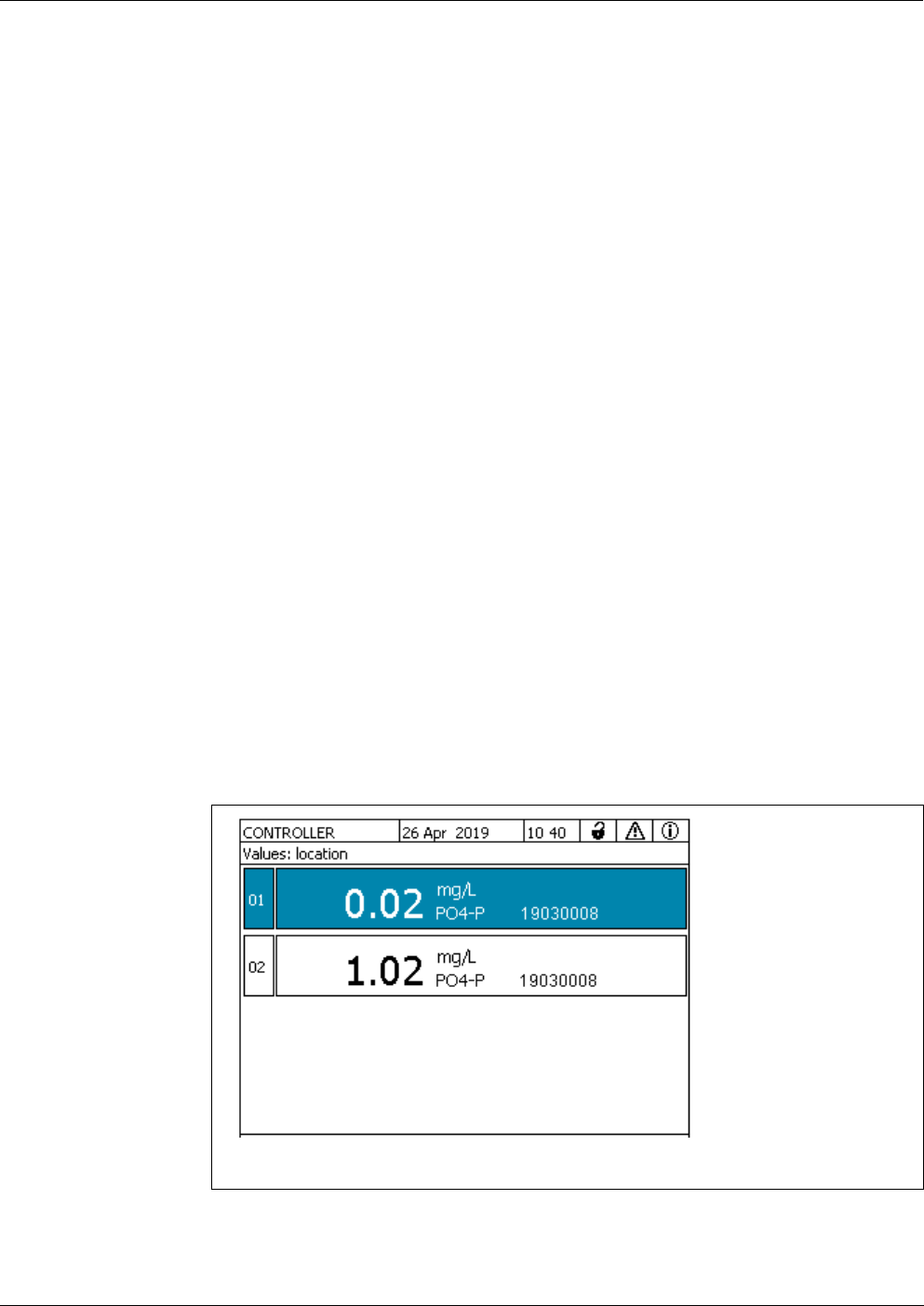
Alyza IQ PO4 Measurement / Operation
79
ba76201e09 12/2022
4.2 Measurement operation
4.2.1 Determination of measured values
The Alyza IQ determines the measured values with a chemical analyzing proce-
dure. The measured values are determined at intervals specified in the settings
(see section 4.3 Settings for the Alyza IQ, 80).
If the intervals overlap with the specified start times and intervals of other func-
tions (Autom.cleaning or Autom.calibration), the functions are carried out ac-
cording to their priority (see section 4.3.2 Priority, 84).
4.2.2 Starting the measuring operation
The Alyza IQ starts measuring only when the START Alyza IQ function is start-
ed.
When the Alyza IQ is started (function START Alyza IQ), it checks automatically
whether the requirements for measurement are met, e.g.:
Plausible pressure and volume conditions in the tubes
Temperature control of the various areas of the Alyza IQ
The regulating of the temperature may take up to 30 minutes.
More details: See section 3.4.4 Preparing the Alyza IQ for measuring, 76.
4.2.3 Measuring
The measured values are displayed in the measured value display on the termi-
nal.
The current Alyza IQ measured values are also displayed in the Alyza menu, tab
Status. More detailed information on the current status is available here, (e.g.
next measurement, next cleaning, next calibration).
figure 4-2 Measured value display of the Alyza IQ
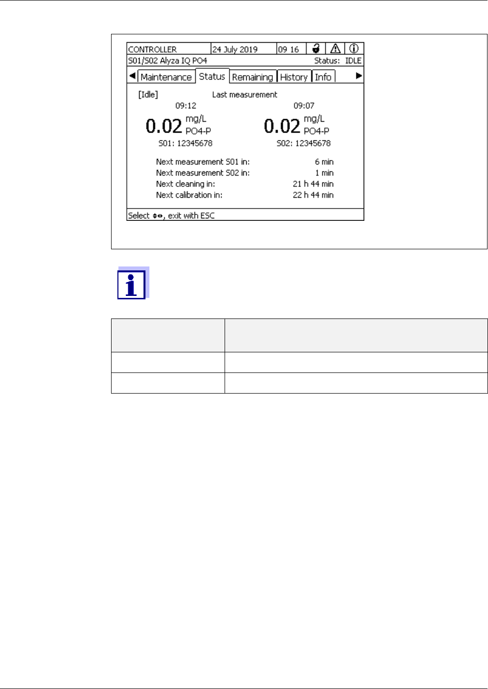
Measurement / Operation Alyza IQ PO4
80
ba76201e09 12/2022
4.3 Settings for the Alyza IQ
For the Alyza IQ, the settings are done like that for the other IQ SENSORNET sen-
sors in the menu Settings of sensors and diff. sensors (IQ S
ENSORNET mea-
sured value display / <S> / Settings of sensors and diff. sensors).
Start the measuring operation so the measured values of the Alyza IQ can be
displayed (see section 4.2.2 Starting the measuring operation, 79).
4.3.1 IQ S
ENSORNET Settings of sensors and diff. sensors
figure 4-3 Alyza menu tab Status
During an automatic cleaning or calibrating procedure, the display
shows CLEAN or CAL instead of a measured value. Linked outputs
are frozen.
Measured value
display
Function
CLEAN Autom.cleaning is being carried out.
CAL Autom.calibration is being carried out.
1Use the <M> key to switch to the measured value display as necessary.
2Using <S>, switch from the measured value display to the main menu
of the sensor settings.
3 Then navigate to the menu Settings of sensors and diff. sensors.
The exact procedure is given in the IQ S
ENSORNET system operating
manual.

Alyza IQ PO4 Measurement / Operation
81
ba76201e09 12/2022
Setting table Setting menus with the possible values to be set. Default values are marked in
bold.
4 Adjust the setting values as necessary.
Setting menu (PO4) Possible values Description
Measuring mode
PO4-P
PO4
The measured parameter is displayed
in the selected citation form.
Measuring range
With the setting
Measuring mode: PO4-P,
MR1
0.02 .. 15.00 mg/L
0.02 .. 15.00 ppm
Depending on the setting of the Mea-
suring mode, different measured vari-
ables can be selected within the low
(MR1) or high (MR2) measuring range.
The configuration (ACM and ACS) and
the installed parts (cell, ChemBags)
determine whether measurements in
the low (MR1) or high (MR2) measuring
range are possible.
With the setting
Measuring mode: PO4-P,
MR2
0.2 .. 50.0 mg/L
0.2 .. 50.0 ppm
With the setting
Measuring mode PO4, MR1:
0.06 .. 46.00 mg/L
0.06 .. 46.00 ppm
With the setting
Measuring mode PO4, MR2:
0.6 .. 153.0 mg/L
0.6 .. 153.0 ppm
Offset correction
With the setting
Measuring mode PO4-P
and
Measuring range
0.02 .. 15.00 mg/L, MR1
- 0.50…
0.00…+ 0.50
mg/L
For other measuring modes and mea-
suring ranges, the value ranges are
adjusted.
With the setting
Measuring mode PO4-P
and
Measuring range
0.2 .. 50.0 mg/L, MR2
- 5…
0…+ 5 mg/L

Measurement / Operation Alyza IQ PO4
82
ba76201e09 12/2022
Setting menu (general set-
tings)
Possible values Description
Meas. interval 5*,
10, 15, 20, 30, 45,
60 min
2, 4, 6, 8, 12 h
Measuring interval
* only for the low measuring range (MR1)
Damping
Off
Signal smoothing
median filter
Methods for filtering the signals
A signal filter in the sensor reduces the
limits of variation of the measured value.
For details, see section 4.3.3
With the setting
Signal smoothing:
The signal filter is essentially character-
ized by the response time t90.
Response time of the signal filter (in sec-
onds).
This is the time after which 90 % of a sig-
nal change is displayed.
Response time t90
100, 200, 300, 400 s
With the setting
median filter
The instrument displays the median of the
last 3 measurements as the measurement
value.
Autom.cleaning On
Off
Switches the automatic cleaning function
on or off
Interval 6, 12,
24, 48, 96 Interval in h
Ref.time hours 0…
7…23 Defines the start time from which the auto-
matic cleaning procedures will take place
at the set interval
(default setting: 7:00 o'clock)
PLEASE NOTE:
Recommended start time for
Autom.cleaning: approx. 1 - 2 hours
before Autom.calibration.
Ref.time minutes
0…59
Conditioning
count of steps
On
1 ...10
Adjustable number of rinses subsequent
to cleaning.
Off
Autom.calibration On
Off
Switches the automatic calibration func-
tion on or off

Alyza IQ PO4 Measurement / Operation
83
ba76201e09 12/2022
Procedure 1 Point
2 Point
Number of calibration points for automatic
calibration.
With the measured values deviating more
and more from the nominal value of the
calibration standard of the 1-point calibra-
tion, the measured values become more
inaccurate. If the measuring accuracy is
not sufficient with 1-point calibration (no
determination of the slope), activate 2-
point calibration.
PLEASE NOTE:
For 1-point calibration the ChemBag at
the connector S1 is always used.
For 2-point calibration, an extra tube
and an extra ChemBag have to be
installed (see section 5 Maintenance
and cleaning, 101).
Interval 6, 12,
24, 48, 96 Interval in h
Ref.time hours 0…
8…23 Defines the start time from which the auto-
matic calibration procedures will take
place at the set interval
(default setting: 8:00 o'clock)
PLEASE NOTE:
Recommended start time for
Autom.cleaning: approx. 1 - 2 hours
before Autom.calibration.
Ref.time minutes
0…59
Backgr. corr.(opt) On
Off
Especially with low concentrations, the
standard background correction does not
sufficiently compensate for some interfer-
ences (e.g. due to colorations, humins). In
this case, activate the optimized back-
ground correction.
PLEASE NOTE:
For the optimized background correction,
an extra tube and an extra ChemBag have
to be installed (see section 5 Maintenance
and cleaning, 101).
Autost.after PwrOff On
Off
Activate or switch off the automatic start of
the Alyza IQ after a power failure
Setting menu (general set-
tings)
Possible values Description
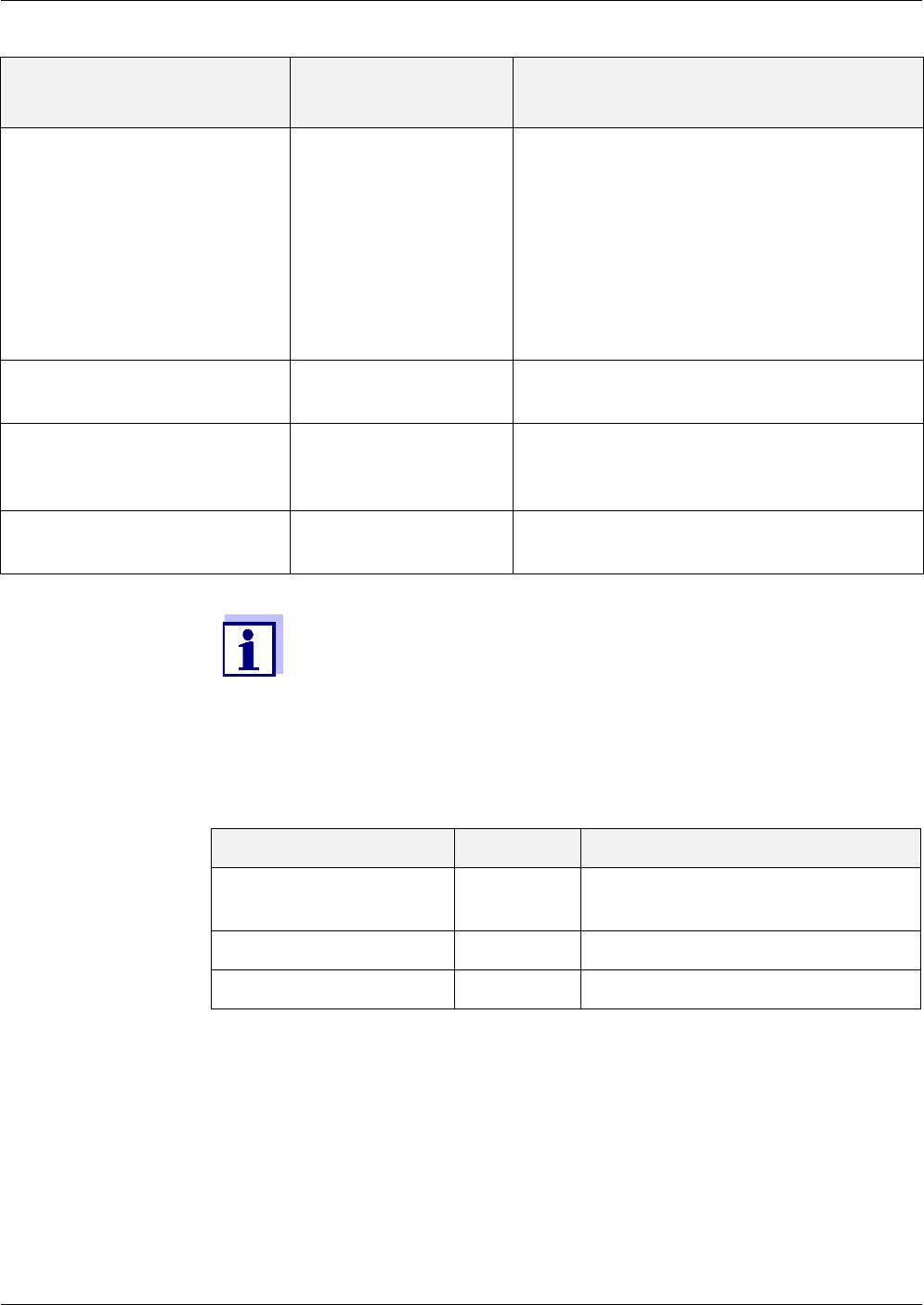
Measurement / Operation Alyza IQ PO4
84
ba76201e09 12/2022
4.3.2 Priority
4.3.3 Damping
The Alyza IQ determines the measured values not continuously but at defined
intervals.
Two consecutive measured values can be quite different due to various rea-
sons. Possible reasons are
actual concentration changes in the sample
influence on the measured value determination not based on the sample.
Sample channel 1
2
1+2
Setting of the sample channel from which
the sample should be measured.
PLEASE NOTE:
If channel 2 or 1+2 is selected, channel 2
has to be installed (overflow vessel and fil-
tration pump).
If sample only from one channel should be
measured, the sample from channel 1 is
measured.
Temperature mode °C
°F
Temperature values are displayed in the
selected unit
Save and quit The Alyza IQ stores all changed settings
and the display switches to the next higher
level.
Quit The display switches to the next higher
level without storing the new settings.
Setting menu (general set-
tings)
Possible values Description
The Autom.cleaning, Autom.calibration and Meas. interval settings
may result in the overlapping of the carrying out of different func-
tions.
In this case, the functions are carried out according to priority.
Function Priority Duration (min)
Autom.cleaning 1 6 (1-channel variant)
12 (2-channel variant)
Autom.calibration 26
Measuring 3 5

Alyza IQ PO4 Measurement / Operation
85
ba76201e09 12/2022
With the Damping you can specify how the Alyza IQ displays and transmits the
measured values.
Damping Off
The measured value is displayed immediately and unchanged.
Signal smoothing The last measured value is displayed with a delay.
Every 20 seconds the Signal smoothing function creates a display value in the
range between the last and the current measured value. This display value grad-
ually approximates the actual measured value during the time specified
( Response time t90).
The Response time t90 is the time after which 90 % of a signal change is dis-
played.
Median filter
The last determined measured value is only displayed if it meets the criteria for
the median.
The median filter function selects the medium value of the last 3 measured
values as the displayed value. The extreme values (upper and lower extreme
value) are discarded.
4.4 Calibration
4.4.1 Overview
Why calibrate? During operation, individual components of the Alyza IQ can age or become
dirty with time and thus change their characteristics, e.g.:
Flow through cell
LED of the photometer
Photo diodes
Color reagent
Regular automatic or manual calibration procedures help you to recognize any
changes of the measuring characteristics of the Alyza IQ.
1-point calibration The offset of the characteristic curve is adjusted with a regular 1-point calibra-
tion.
2-point calibration The slope and offset of the characteristic curve are adjusted with a 2-point cali-
bration.
For 2-channel instruments, the damping can be set separately for
each of the two channels.
The median filter only becomes active when three directly succeed-
ing measured values are present.
Example:
Measuring interval 10 min: The median filter is active after 30 min.

Measurement / Operation Alyza IQ PO4
86
ba76201e09 12/2022
When to calibrate? Calibrate at regular intervals.
Automatic
calibration
Any calibration can be carried out fully automatically at regular intervals.
Manual calibration An additional, manual calibration can be started in the Alyza menu (tab Mainte-
nance / Manual maintenance) at any time (see section 4.4.2 Calibration, 86).
Calibration record /
calibration history
The result of a calibration is stored in the calibration history (see Alyza menu /
tab History / Calibration history).
Maintenance
condition
To carry out a calibration procedure (automatically or manually), the mainte-
nance condition is always automatically activated for the Alyza IQ in the
IQ S
ENSORNET system. All linked outputs remain in their current status.
After an automatic calibration has been finished, the maintenance condition is
switched off automatically.
After a manual calibration has been finished, the maintenance condition has to
be switched off manually.
More detailed information on the maintenance condition is given in the
IQ S
ENSORNET system operating manual.
4.4.2 Calibration
Automatic
calibration
Automatic calibration is carried out in the measuring operation at regular inter-
vals.
The setting of the calibration interval and calibration time is done in the menu
Settings of sensors and difference sensors (see section 4.3 Settings for the
Alyza IQ, 80).
Manual calibration The manual calibration procedure can be started manually at any time if neces-
sary. The calibration procedure is started, and the setting of the standard used
is made, in the Alyza menu.
Proceed as follows to start a calibration procedure manually:
Stopping running
operation
You can also switch off the maintenance condition in the Alyza
menu, tab Maintenance.
Prior to every automatic calibration, the SystemCheck function is
carried out. The SystemCheck function automatically and regularly
checks whether the Alyza IQ is operable (for details, see section
5.10).
1 In the measured value display, use < > to select the Alyza IQ.
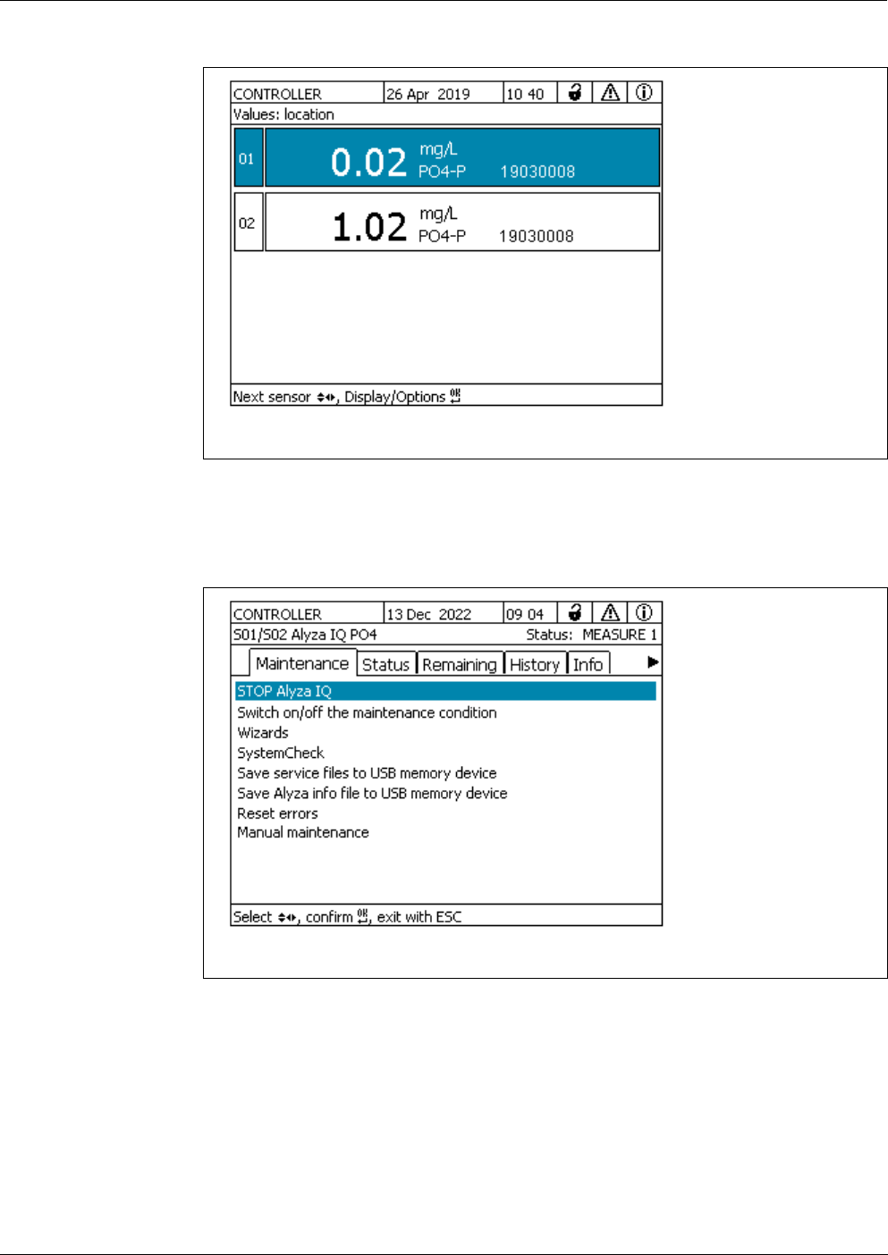
Alyza IQ PO4 Measurement / Operation
87
ba76201e09 12/2022
figure 4-4 Measured value display of the Alyza IQ
2Using <C>, open the Alyza menu for the Alyza IQ.
3Using < >, switch to the Maintenance tab.
figure 4-5 Tab Maintenance
4 Carry out the STOP Alyza IQ function to stop the running operation.
5 Confirm the function to stop the running operation.
The maintenance condition is automatically activated in the
IQ S
ENSORNET for the Alyza IQ.
6 Open the menu item Manual maintenance.

Measurement / Operation Alyza IQ PO4
88
ba76201e09 12/2022
Carry out
calibration
Possible
calibration results
The calibration data are evaluated by the system. A calibration procedure can
have the following results:
Restarting the
measuring
operation
7 Carry out the function / Calibrate (1-point) or Calibrate (2-point).
For 1-point calibration the ChemBag at the connector S1 is always
used.
The calibration procedure runs automatically. The calibration result is
displayed after the calibration standards have been measured.
You have the following possibilities if the calibration failed:
Repeat the calibration procedure
(make sure that the correct calibration standard is connected and
selected for calibration).
Use the last valid calibration
(see section 4.4.4 Reactivating the last valid calibration, 89 )
Use the factory calibration
(see section 4.4.4 Reactivating the last valid calibration, 89)
Display after cali-
brating
Meaning/actions
Measured value Successful calibration
"----" Calibration unsuccessful (see log book).
The Alyza IQ is blocked for measurement.
Carry out maintenance activities immediately
(see sensor operating manual).
View the calibration history in the Alyza menu.
Check the calibration conditions and calibration
standard.
8 Carry out the START Alyza IQ function.
Measurement is started and the measured value is displayed in the
measured value display after approx. 5 ... 7 minutes.
9 Carry out the Switch off the maintenance condition function.
The maintenance condition is terminated in the IQ S
ENSORNET for the
Alyza IQ.
10 In the Alyza menu, use < > to switch to the Status tab.
The measured value display appears. While no valid measured value is
available, the display shows bars «- - - -».

Alyza IQ PO4 Measurement / Operation
89
ba76201e09 12/2022
4.4.3 Calibration history
The calibration history of the Alyza IQ is available in the Alyza menu (tab History
/ Calibration history).
Example and explanation of a calibration history (see section 4.5.3 Information
on maintenance activities and calibration procedures (tab History), 93)
4.4.4 Reactivating the last valid calibration
Manual calibration
unsuccessful
If a manual calibration procedure is unsuccessful, the measuring operation can
only be resumed once a valid calibration was carried out or reactivated.
Thus you can immediately continue to measure if a calibration failed or you sus-
pect that the calibration conditions were not optimally met.
Automatic
calibration
unsuccessful
If an automatic calibration is unsuccessful, the last valid calibration is automati-
cally reactivated. If three calibration procedures in succession are unsuccessful,
the measuring operation can only be resumed once a valid calibration was car-
ried out or manually reactivated.
Reactivating old calibration data is a temporary measure. Take into
consideration that the sensor may provide wrong measured values.
Ensure the correct functioning of the Alyza IQ by checking and/or
recalibrating.
1 In the measured value display, use < > to select the Alyza IQ.
2 Using the <C> key, switch to the Alyza menu.
3Using < >, switch to the Maintenance tab.
4 Carry out the STOP Alyza IQ function to stop the running operation.
5 Confirm the function to stop the running operation.
The maintenance condition is automatically activated in the
IQ S
ENSORNET for the Alyza IQ.
6 Carry out the START Alyza IQ function.
A menu pops up with the following options:
Repeat calibration
Use factory calibration
Use last valid calibration
Show calibration details
7Select Use last valid calibration or Use factory calibration.
8 Switch off the maintenance condition.
The measured value is displayed after approx. 5 ... 7 minutes in the
measured value display.

Measurement / Operation Alyza IQ PO4
90
ba76201e09 12/2022
4.5 Information on the Alyza IQ
In the Alyza menu, there is comprehensive information available on the current
status of the Alyza IQ:
Current operating condition (measuring, calibration, etc.)
Schedule for the next interval-controlled actions, e.g. measuring, calibrating,
cleaning (tab Status)
Schedule for the exchange of ChemBags (tab Remaining)
Schedule for the execution of maintenance activities, e.g. replacement parts
(tab History / Installed replacement parts)
Documentation of the maintenance activities carried out (tab History / Main-
tenance history)
Documentation of the calibration procedures (Tab History / Calibration his-
tory)
More information on the Alyza IQ (tab Info)
– Current measured values of sensors (e.g. temperature, etc.)
– Current statuses (e.g. heating, ventilator, cooling, etc.)
– Software versions of individual components of the Alyza IQ
– Serial numbers of individual assembly groups
4.5.1 Information on the current operating condition
(Tab Status)
During measuring operation, the information on the current operation condition
1 In the measured value display, use < > to select the Alyza IQ.
2 Using the <C> key, switch to the Alyza menu.
3Using < >< >, open one of the tabs with information on the Alyza IQ:
Status (see section 4.5.1 Information on the current operating condi-
tion (Tab Status), 90)
Remaining (see section 4.5.2 Information on the expected lifetimes
of replacement parts (tab Remaining), 91)
History (see section 4.5.3 Information on maintenance activities and
calibration procedures (tab History), 93)
Info (see section 4.5.4 More information on the Alyza IQ (tab Info),
96)
You can also additionally transfer to a USB memory device the in-
formation displayed via the Alyza IQ (see section 4.6 Transferring
information to a USB memory device via the Alyza IQ,
96).
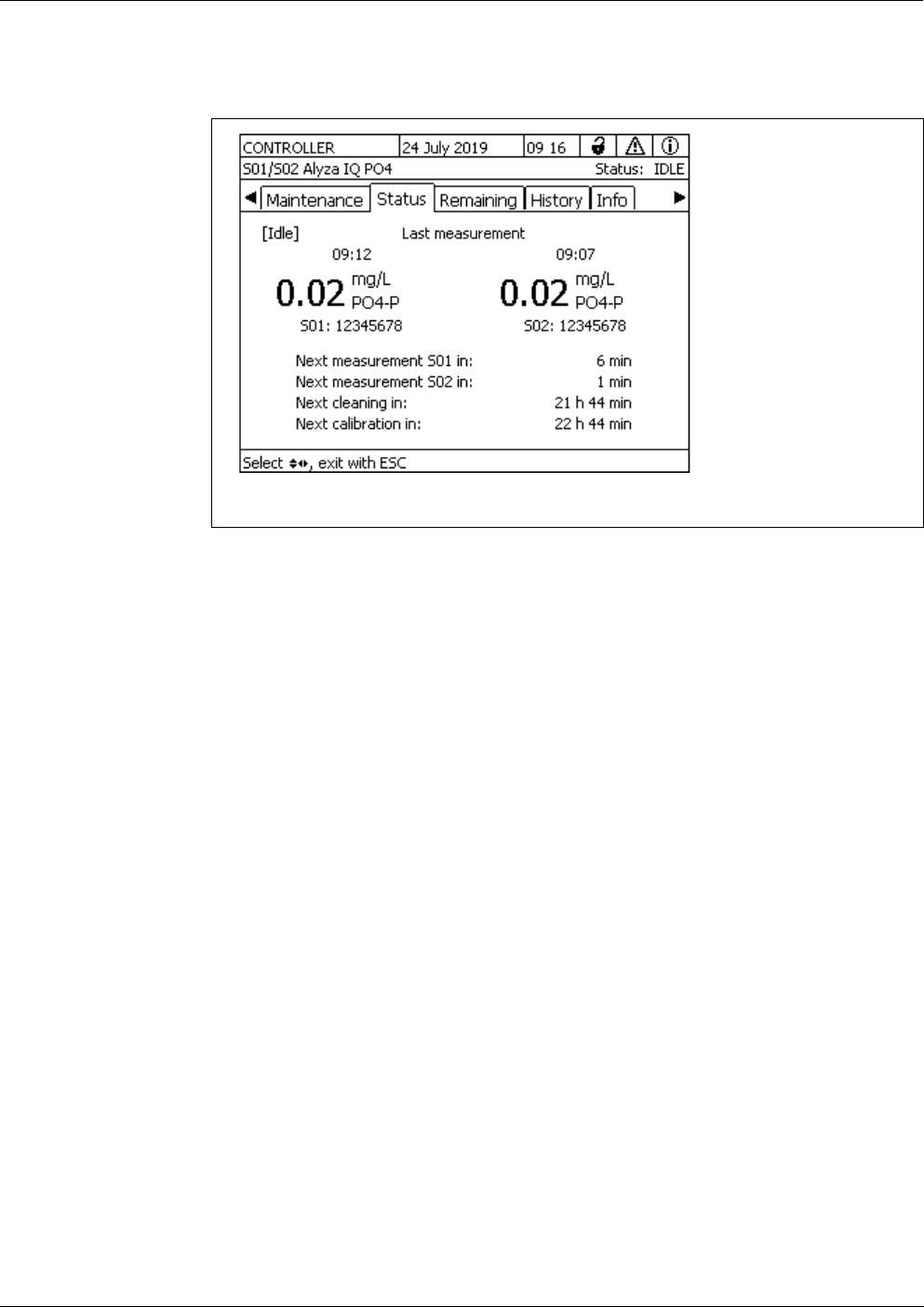
Alyza IQ PO4 Measurement / Operation
91
ba76201e09 12/2022
comprises the current measured values and also the schedule for the next inter-
val-controlled actions, e.g. measuring, calibrating or cleaning.
In the Status tab, the following information on the current operating condition is
available:
Current operating condition (e.g. measuring, calibration, etc.)
Measured value of the last measurement with date and time
Schedule for the next interval-controlled action, e.g. measuring, calibrating
and cleaning
4.5.2 Information on the expected lifetimes of replacement parts
(tab Remaining)
The Remaining tab provides a quick overview of the maintenance activities due.
This information facilitates the planning and co-ordination of the maintenance
activities for the most important replacement parts (chemicals and MultiPort
valve) of the Alyza IQ.
figure 4-6 Operating condition (tab Status, example 2-channel variant)
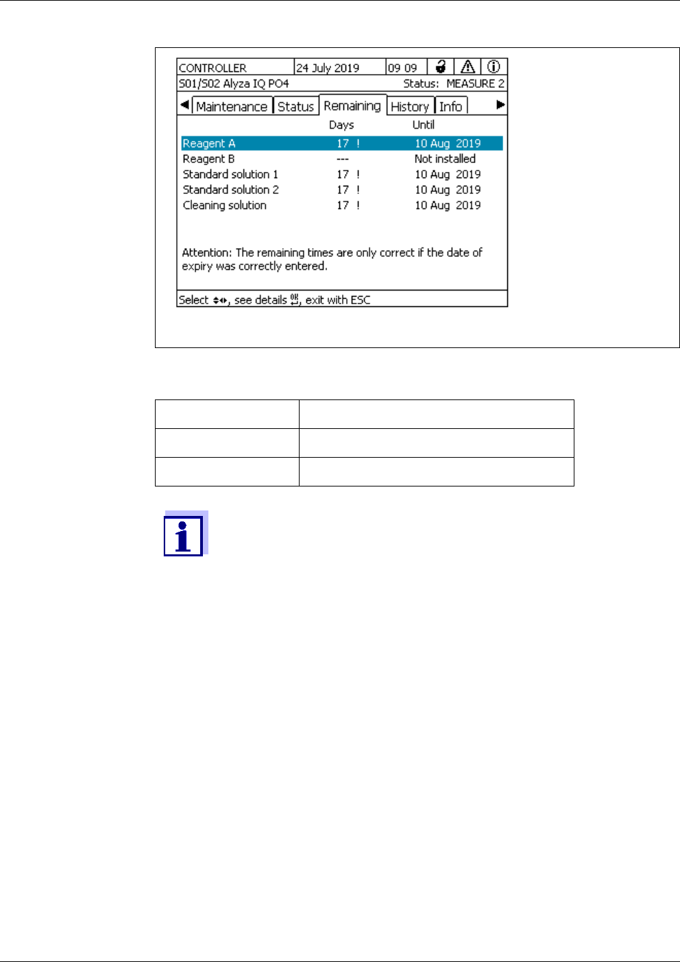
Measurement / Operation Alyza IQ PO4
92
ba76201e09 12/2022
The estimated times remaining until the next exchange are shown in days in the
overview. If the times remaining are short, this is also indicated in the display.
figure 4-7 Overview Remaining (tab Remaining)
Remaining time Signal
< 30 d ! (next to remaining time)
< 10 d ! (flashes next to remaining time)
The remaining times can only be stated correctly if
The exchange is done via the maintenance menu
full ChemBags or new replacement parts are installed
the expiry date printed on the ChemBag is correctly entered
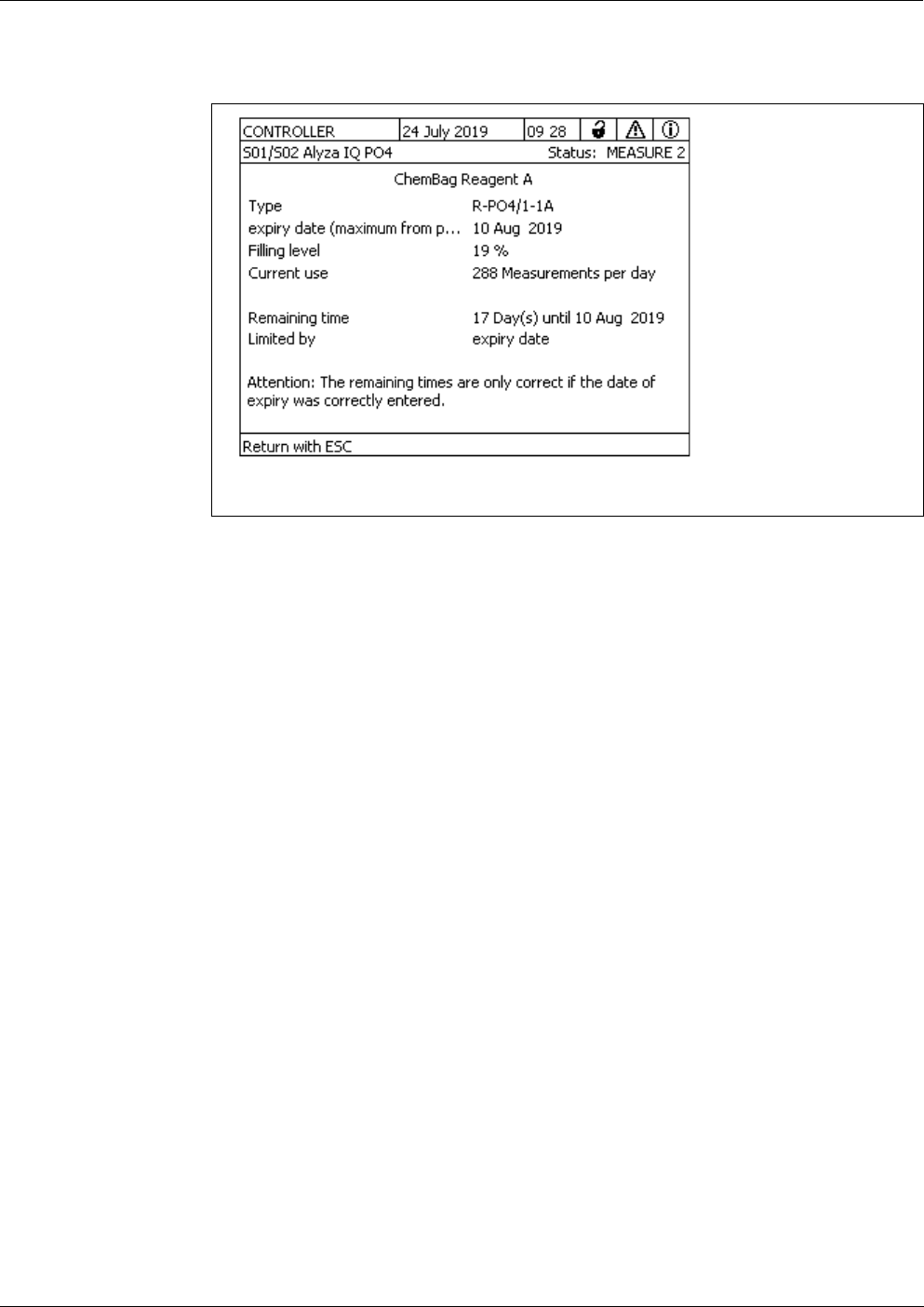
Alyza IQ PO4 Measurement / Operation
93
ba76201e09 12/2022
More details on the lifetime of a replacement part can be opened with <OK> .
4.5.3 Information on maintenance activities and calibration procedures
(tab History)
The Alyza IQ histories provide an overview of the replacement parts installed,
the maintenance activities carried out, and the calibration procedures per-
formed.
Installed replacement parts
(list of the replacement parts installed with installation date and the expiry
date entered)
Calibration history
(list of the last calibration procedures with the relevant calibration data)
Cycle history (Service info)
(chronological list of performed partial steps on the MPV with evaluation)
SystemCheck history (Service info)
(chronological list of performed System Checks with evaluation)
figure 4-8 Information on Remaining, detailed view (Tab Remaining)
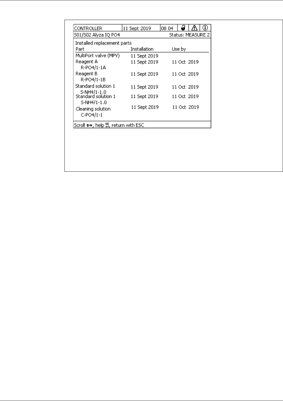
Measurement / Operation Alyza IQ PO4
94
ba76201e09 12/2022
Installed
replacement parts
figure 4-9 Installed replacement parts (tab History / Installed replacement parts)
The list Installed replacement parts shows a list of all components that
have to be replaced regularly, i.e.when the use-by period has expired.
The installation date and expiry date of a component are recorded when
the component is installed. These data are documented.
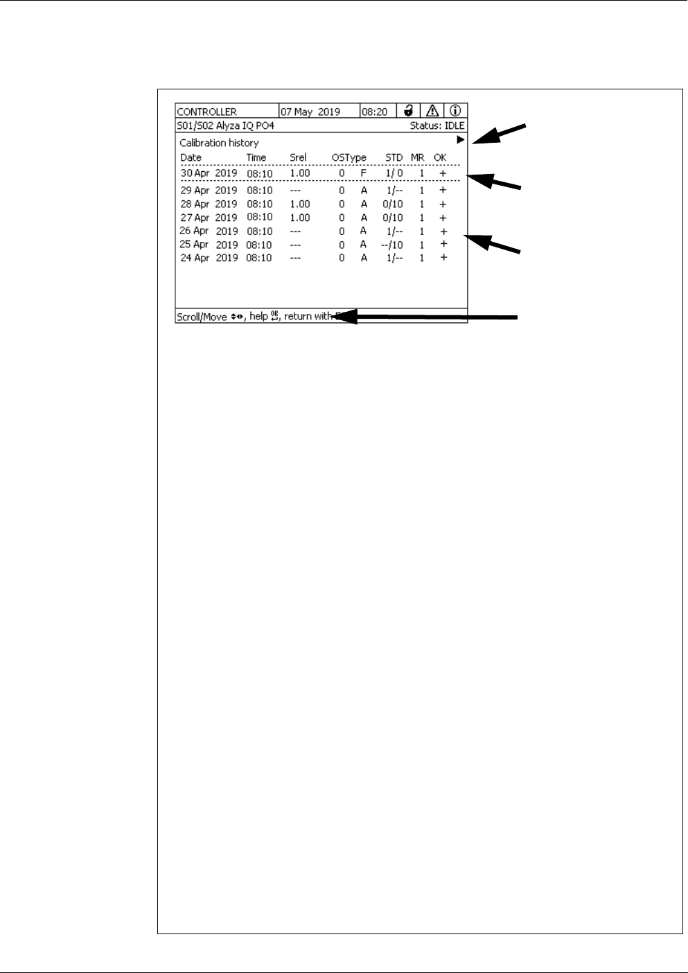
Alyza IQ PO4 Measurement / Operation
95
ba76201e09 12/2022
Calibration history The Calibration history list shows the last calibration results (see section 4.4.3
Calibration history, 89).
figure 4-10 Calibration history Alyza IQ
The calibration history provides the following information:
Date and time of the calibration
Srel (relative slope, is determined with 2-point-calibration)
Value without asterisk (*):
the slope was determined (2-point calibration)
* value with asterisk (*) :
the slope was not determined (1-point calibration);
the last active slope was taken over unchanged
OS (offset, is determined with 1- and 2-point calibration)
Type
M: Manual calibration
A: Automatic calibration
F: Factory setting
STD (concentration in mg/l of the calibration standards used)
MR (measuring range 1 [low] or 2 [high])
OK (evaluation of the calibration result):
+ successful calibration.
The new calibration data are taken over for measurement.
- calibration unsuccessful. Sensor blocked for measurement.
? : The last valid calibration or
factory setting was taken over
Abs. (absorbance standard 1 / standard 2), display with < >
To display more
information, use
< >< >
Current
calibration data
Chronological list of
the last calibration
procedures
To display explana-
tions and additional
information, use
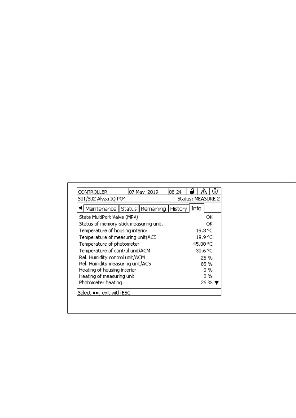
Measurement / Operation Alyza IQ PO4
96
ba76201e09 12/2022
Cycle history (Ser-
vice info)
In the list Cycle history (Service info), partial steps (cycles) are recorded during
the operation of the Alyza IQ. The details of the cycles are used by the service
department to diagnose the causes of errors.
SystemCheck
history (Service
info)
In the list SystemCheck history (Service info), all System Checks that were car-
ried out automatically or manually are recorded. The details of the components
checked are used by the service department to diagnose the causes of errors.
4.5.4 More information on the Alyza IQ (tab Info)
In the Info tab there is more information on the Alyza IQ, which may be helpful
in the case of errors or implausible measured values. The following information
is displayed:
Temperature control (temperature, functioning of the ventilators, heating
units, cooling unit)
Software statuses (control units ACM, ACS, etc.)
Serial numbers of individual components
4.6 Transferring information to a USB memory device via the
Alyza IQ
You can save the measurement data of the Alyza IQ via the USB interface of
your IQ S
ENSORNET controller as usual (see system operating manual).
Moreover, other operating data can also be transferred to a USB memory device
via the Alyza IQ:
A selection of important operating data
(see section 4.6.1 Transferring to a USB memory device a selection of
important operating data, 97)
figure 4-11 Info (tab Info)

Alyza IQ PO4 Measurement / Operation
97
ba76201e09 12/2022
Detailed operating data for evaluation by the service department
(see section 4.6.2 Transferring detailed operating data to a USB memory
device for evaluation by the service department, 97)
4.6.1 Transferring to a USB memory device a selection of important oper-
ating data
These operating data provide an overview of important settings and data for the
functioning of your Alyza IQ.
Measurement settings
Calibration settings
Calibration data of the last calibration
Lifetimes of the replacement parts (MPV, ChemBags)
4.6.2 Transferring detailed operating data to a USB memory device for
evaluation by the service department
The service department can make use of the detailed operating data to analyze
and eliminate errors.
1 Plug a USB memory device to the USB interface of your IQ S
ENSORNET
controller (e.g. Terminal/Controller 2020 3G).
2 At the terminal, open the tab Maintenance in the Alyza menu.
3 Select the function, Save Alyza info file to USB memory device.
Follow the instructions on the display.
4 Remove the USB memory device from the USB interface of your
IQ S
ENSORNET controller.
5 Connect the USB memory device to the USB interface of a PC and dis-
play the file system of the USB memory device.
On the USB memory device there is the folder "AlyzaInfoData" with the
info data of the Alyza IQ.
Each time the data are output, a new file with the creation date and cre-
ation time in the file name is saved to the folder.
The assignment of the data to an Alyza IQ is secured via the series
number of the Alyza IQ in the file name.
1 Unscrew the 2 fixing screws of the cover lid of the control unit ACM and
remove the cover lid of the ACM.
2 If a USB plug is connected to the USB interface next to the "USB0" inter-
face:
Remove this USB plug.

Measurement / Operation Alyza IQ PO4
98
ba76201e09 12/2022
4.7 Software update for the Alyza IQ
With a Software-Update you can alway update your Alyza IQ to the latest status
of the instrument software.
For the update packet with the current instrument software for the Alyza IQ as
well as a comprehensive manual on how to carry out the update, go to
www.YSI.com.
The Alyza IQ is an IQ S
ENSORNET component with separate USB interface.
3 Plug a USB memory device to the USB interface "USB0".
4 At the terminal, open the tab Maintenance in the Alyza menu.
5 Select the function, Save service files to USB memory device.
Follow the instructions on the display.
6 Remove the USB memory device from the interface "USB0".
7 If necessary, re-insert the previously removed USB plug into the unla-
beled USB interface.
8 Reinsert the cover and fix it with the 2 fixing screws.
9 Connect the USB memory device to the USB interface of a PC and dis-
play the file system of the USB memory device.
On the USB memory device there is the folder "LogData" with the oper-
ating data of the Alyza IQ.
The folder includes several files with the operating data of the Alyza IQ.
The assignment of the data to an Alyza IQ is secured via the series
number of the Alyza IQ in the file name.
10 If requested, send some individual files or the entire folder "LogData" to
the service department.
The Software-Update for the Alyza IQ
is included in the update
packet for the IQ S
ENSORNET.
The software versions of all components can be viewed in the dialog
box List of all components (see IQ S
ENSORNET system operating
manual).
1 Download the software update IQ S
ENSORNET "Update Pack (L1)" and
store the directories to a USB memory device.

Alyza IQ PO4 Measurement / Operation
99
ba76201e09 12/2022
NOTE
An interruption of the power supply during the update process can damage your
Alyza IQ.
After starting the update process, do not interrupt or cancel the data transmis-
sion. Do not interrupt the supply voltage during the update process!
The update takes up to 10 minutes.
2 Unscrew the 2 fixing screws of the cover lid of the control unit ACM and
remove the cover lid of the ACM.
3 Plug the USB memory device with the software update IQ S
ENSORNET
"Update Pack (L1)" to the USB interface "USB0".
4 On the terminal, switch to the measured value display of the
IQ S
ENSORNET.
5 In the service menu, start the software update (component with USB
interface).
A Software-Update does not change any measurement settings,
measurement data or calibration data.

Measurement / Operation Alyza IQ PO4
100
ba76201e09 12/2022
A sequence of beeps indicates the status of the software update.
The sequence of beeps is repeated until the status is finished automatically or
manually:
Sequence of beeps Explanation STATUS / Next step
UPDATE ACTIVE
1 short beep (0.2 secs.)
1 long pause (2.8 secs.)
Software update acti-
vated.
Wait for the software update to be com-
pleted, e.g.
– 3 short beeps: SUCCESSFUL
– 3 long beeps: ERROR
Wait for the software update to be contin-
ued or canceled.
If there is a longer pause (> approx.
3min)
with the display switched off:
– Switch off the Alyza IQ
– Wait for 10 seconds
– Switch on the Alyza IQ
1 very long pause
during the active update
(approx. 1 min),
the display is switched off.
The ACM is restarted
during a software
update.
UPDATE SUCCESSFUL
3 short beeps (0.2 s)
2 short pauses (0.2 s)
1 long pause (2 s)
Software updated car-
ried out
Remove the USB memory device.
The Alyza IQ automatically restarts.
ERROR
3 long beeps (1 s)
2 long pauses (1 s)
1 long pause (10 s)
Software update not
successful
Remove the USB memory device.
The Alyza IQ starts with the old software.
Check the data on the USB memory
device and, if necessary, copy them
once again.
Repeat the software update
2 long beeps (1 s)
1 long pause (1 s)
1 long pause (12 s)
Software update not
complete.
3 s
...
...
3 s
15 s
...
15 s
...

Alyza IQ PO4 Maintenance and cleaning
101
ba76201e09 12/2022
5 Maintenance and cleaning
5.1 Hazard warnings
Read the chapter 2 Safety instructions, 22 before doing any maintenance
work. This is important for your personal safety.
NOTE
The interior of the measuring unit is temperature-controlled to 20 °C (68 °F).
With ambient temperatures over 25 °C (77 °F) and high air humidity, conden-
sation water may develop on the cool surfaces and cause damage when the
measuring unit is opened.
To avoid damage of the measuring unit due to the formation of condensation
water, always wait for the temperature adjustment (function "Prepare to open
measuring unit") to be completed before opening the measuring unit.
Hazards due to
chemicals
During the regular operation of the Alyza IQ, small quantities of (hazardous)
chemicals are used because of the measuring method.
The remains of the chemicals are transported out of the Alyza IQ via the drain
tubes:
Return tube (outlet to the sedimentation tank)
Waste tube (outlet into a collecting container for separate disposal)
For a safe routine operation, the required chemicals are stored in closed, leak-
proof ChemBags.
Contact with hazardous chemicals is possible especially in the following situa-
tions:
Contact with waste solutions after measurement
Contact with open tubes that still contain small amounts of chemicals (e.g.
during installation or maintenance work).
Contact with damaged, leaking ChemBags (e.g. during installation or main-
tenance work).
Contact with liquids in the collection tray under the ChemBags (e.g. during
installation or maintenance work).
Risks when
handling the
ChemBags
WARNING
Dangerous chemicals.
Improper use of chemicals can cause damage to your
health.
Heed the following rules:
Read the labels of the ChemBags and follow the safety
instructions
Wear protective equipment (lab coat, protective gog-
gles, chemical resistant protective gloves, safety
shoes)

Maintenance and cleaning Alyza IQ PO4
102
ba76201e09 12/2022
Notes on safely
handling the
ChemBags
If a ChemBag was damaged in the transport packaging, e.g. visibly leaked
liquid, do not use this ChemBag in the Alyza IQ.
Make sure you don't damage the ChemBags when unpacking them from the
transport packaging.
Do not use any sharp object when dealing with (or unpacking) the Chem-
Bags.
If possible, handle the ChemBags gripping only the cap in order not to kink
the ChemBags.
For work done with the locking device of the MultiPort valve open:
Prior to working with the locking device open make sure that the connected
ChemBags are safely suspended from the supporting rod, and that they are
not pressed or moved while the locking device is open.
Working with the ChemBags:
Prior to working with any connected ChemBags make sure that the MultiPort
valve is inserted and the locking device of the MultiPort valve is closed.
5.2 Opening the locking device of the MultiPort valve
("Before opening: Drain the system")
The MultiPort Valve is the core element for the distribution and dosing of the liq-
uids in the measuring unit. The MultiPort valve is connected to the liquids by ex-
actly positioning the MultiPort valve and pressing it to the seals. The pressing of
the MultiPort valve to the seals is done by closing the locking device. Only then
is the system sealed at the contact points of the liquids.
Alyza IQ PO4 Maintenance and cleaning
103
ba76201e09 12/2022
How to prepare the maintenance of the measuring unit is described in detail with
the maintenance of the measuring unit (see section 5.5 Installing / exchanging
the ChemBags, MPV, tubes, 111).
Emptying the
system via the
Alyza menu
With an Alyza IQ ready for operation, empty the system via the Alyza menu.
WARNING
Dangerous chemicals.
Do not open the locking device of the MultiPort valve if the
maintenance activities at the measuring unit have not been
completed. Leaking chemicals can cause health problems
and damage the measuring unit.
Heed the following rules:
Carry out the Prepare to open measuring unit function.
Carry out the "Drain the system / All" function.
Guide all tubes of the ChemBags over the tube fasten-
ers above the locking device.
Fix the tubes in the tube fasteners.
Make sure that the connected ChemBags are safely sus-
pended from the supporting rod, and that they are not
pressed or moved while the locking device is open.
Make sure that the sample tubes (from the overflow ves-
sel to the measuring unit) are fixed in the recesses at the
left-hand side of the measuring unit.
Follow the safety instructions.
Wear protective equipment (lab coat, protective gog-
gles, chemical resistant protective gloves, safety
shoes)
Prior to opening the locking device always check whether the mea-
suring unit was prepared for the opening and whether the system
was emptied (e.g. tab Status in the Alyza menu).
1 Open the Maintenance / Manual maintenance menu in the Alyza menu.
2 Select the function, Prepare to open measuring unit.
Follow the instructions on the display.
The procedure starts the temperature adjustment of the measuring unit.
3 Drain all tubes (Maintenance / Manual maintenance / Drain the system
/ All).
If emptying via the Alyza menu is not possible, carry out the manual
emptying (section 5.9 Emptying the system manually, 144).

Maintenance and cleaning Alyza IQ PO4
104
ba76201e09 12/2022
Opening the
locking device
4 Put on your personal protective equipment (PPE) and chemical resis-
tant gloves (see section 2.4 Personal protective equipment (PPE),
24).
5 Remove the front cover of the measuring unit.
The measuring unit is ready to be opened when the LED of the measur-
ing unit lights up white.
6 Using one hand, grip the handle at the upper edge of the front cover of
the measuring unit.
7 Pull the front cover of the measuring unit somewhat to the front against
the resistance.
8 Carefully take the front cover out to the front.
Put the front cover down in a clean place.
9 Make sure that the connected ChemBags are safely suspended from
the supporting rod.
10 Guide all tubes of the ChemBags over the tube fasteners above the
locking device and fix the tubes in tube fasteners.
figure 5-1 Tubes in the tube fasteners
11 Make sure that the connected ChemBags are safely suspended from
the supporting rod, and that they are not pressed or moved while the
locking device is open.
12 Make sure that the sample tubes (from the overflow vessel to the mea-
suring unit) are fixed in the recesses at the left-hand side of the measur-
ing unit.
13 Keep absorbent and lint free paper at hand so you can immediately
absorb any small chemicals remains.
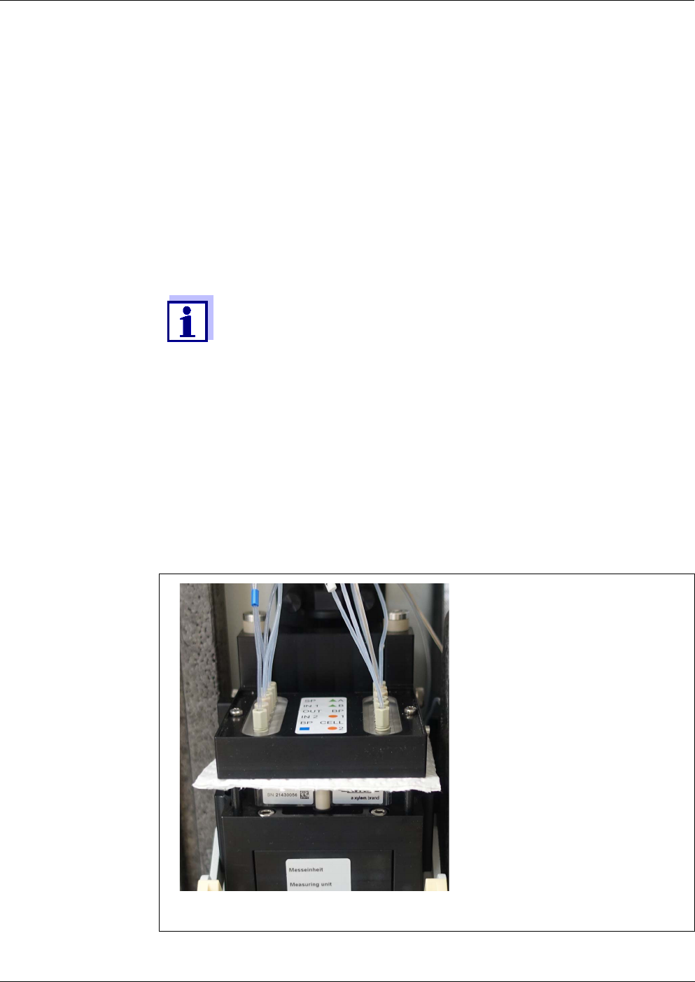
Alyza IQ PO4 Maintenance and cleaning
105
ba76201e09 12/2022
14 Prepare the locking device of the MultiPort valve (MPV) to be opened
(Maintenance / Manual maintenance / Prepare to open the locking
device of the MPV).
15 Confirm that the requirements for the opening are met.
When the locking device is ready to be opened, the status LED flashes
white. (You can open the locking device of the MultiPort valve without
warning sounds.)
16 When the status LED flashes white:
Open the locking device of the MultiPort valve (MPV)
Beeps and a red flashing status LED signal that not all require-
ments for a safe opening of the locking device were met.
When the locking device is open, there is the risk of leaking chem-
icals.
17 Immediately place the absorbent, lint free paper onto the MultiPort
valve.
18 Gently fold down the fluidic interface above the MultiPort valve by hand
so that it contacts the paper, and liquid remains are absorbed.
The locking device is now safely opened.
19 Make sure that the seals of the fluidic interface remain within the inter-
face.
figure 5-2 Removing the liquids remains with absorbent, lint free paper

Maintenance and cleaning Alyza IQ PO4
106
ba76201e09 12/2022
5.3 Replacement parts, accessories
Only use original replacement parts and accessories.
ChemBags are available as sets optimally combined for your application.
The combination as sets takes into account the following factors for your appli-
cation:
Measured parameter
Measuring range
Quantity of liquid
Stability
By using the sets you avoid any unsuitable combinations of ChemBags.
ChemBags are also obtainable individually.
ChemBags
NOTE
To avoid damage to the measuring unit caused by leaking chemicals,
make sure that the following requirements are met while you are work-
ing with the locking device open:
The connected ChemBags are safely suspended from the supporting
rod.
The ChemBags are not pressed or moved.
The tubes of the ChemBags are fastened in the tube fastening above
the locking device.
The sample tubes (from the overflow vessel to the measuring unit)
are fixed in the recesses at the left-hand side of the measuring unit.
20 Carry out any maintenance activities now as necessary.
Type Replacement parts
(ChemBag sets)
Order
number
R-PO4/1-1A Reagent for measuring range 1
(MR1, low MR)
827520
R-PO4/1-1B Reagent for measuring range 1
(MR1, low MR)
827521
R-PO4/1-2A Reagent for measuring range 2
(MR2, high MR)
827522
R-PO4/1-2B Reagent for measuring range 2
(MR2, high MR)
827523
Alyza IQ PO4 Maintenance and cleaning
107
ba76201e09 12/2022
Further
replacement parts
S-PO4/1-0.0 Calibration standard 0.0 for mea-
suring range 1 (MR1, low MR)
827526
S-PO4/1-1.0 Calibration standard 1.0 for mea-
suring range 1 (MR1, low MR)
827527
S-PO4/1-10.0 Calibration standard 10.0 for mea-
suring range 1 (MR1, low MR) or
measuring range 2 (MR2, high
MR)
827528
S-PO4/1-40.0 Calibration standard 100.0 for
measuring range 2 (MR2, low MR)
827529
C-PO4/1-1 Cleaning solution 827533
R-Set PO4/1-1 Set of reagents for measuring
range 1 (MR1, low MR)
827550
R-Set PO4/1-2 Set of reagents for measuring
range 2 (MR2, high MR)
827551
SC-Set PO4/1-1_0/1 Set of calibration standards and
cleaning solution for measuring
range 1 (MR1, low MR)
827555
SC-Set PO4/1-1_0/10 Set of calibration standards and
cleaning solution for measuring
range 1 (MR1, low MR)
827556
SC-Set PO4/1-2_10/40 Set of calibration standards and
cleaning solution for measuring
range 2 (MR2, high MR)
827557
Individual ChemBags:
Available on the Internet at www.YSI.com.
Type Replacement parts
(ChemBag sets)
Order
number
Type Replacement parts Order
number
MPV-1 MultiPort valve 827000Y
Syringe Pump Set Syringe body with holder 827170Y
Further replacement parts and accessories:
Available on the Internet at www.YSI.com.

Maintenance and cleaning Alyza IQ PO4
108
ba76201e09 12/2022
Accessories
(optional)
The base solutions for chemical cleaning of the filter membrane can be pur-
chased in household or specialist shops, e.g. household hygienic cleaners
based on sodium hypochlorite.
For chemical cleaning, see section 5.6.2 Chemical cleaning of the filter plate,
126.
NOTE
Detergents containing tensides can cause damage.
Therefore, do not use any detergents containing tensides.
5.4 Overview of the maintenance and cleaning activities
Maintenance activities have to be done at regular intervals on the Alyza IQ.
The following maintenance activities can be performed by the operator.
Type Accessories Order
number
WF Set Mounting set for a collection funnel 827187Y
TM Mounting set for the terminal
holder
822000Y
CheckValve Check valve
(for the sample feed tube)
827186Y

Alyza IQ PO4 Maintenance and cleaning
109
ba76201e09 12/2022
Regular
maintenance
activities
Regular maintenance Interval
Measuring unit
(simple mainte-
nance activities
on site)
Installing/replacing the
MultiPort valve (MPV)
Approx. 12 months
with a measuring interval of 10
min.
Depending on the frequency of
the measuring, cleaning or cal-
ibrating procedures, the main-
tenance intervals will be
shorter or longer (see section
5.5, 111)
Installing / replacing
the ChemBags
Approx. 3 - 6 months (MR1),
approx. 1.5 - 3 months (MR2),
depending on the frequency of
the measuring, cleaning and
calibration routines (see sec-
tion 5.5, 111)
Check the collection
tray under the Chem-
Bags for dryness
When replacing ChemBags or
MPV (see section 5.5, 111,
and section 5.5.6, 119)
For logbook messages on
MPV leak tightness
Installing/replacing the
tubes on the MultiPort
valve (MPV)
12 - 24 months
(see section 5.5, 111)
Measuring unit
(complex main-
tenance activi-
ties in the labora-
tory, after remov-
ing the measur-
ing unit)
Installing / replacing
the syringe body
Approx. 2 years
(see mounting instructions of
the syringe body)
Installing / replacing
the tubes of the pho-
tometer unit )
As necessary
(see mounting instructions of
the tubes of the photometer
unit)
Waste collector and
waste tube of the mea-
suring unit
6 months
(see section 6.2.3, 156)
Sample inlet,
outlet
Clean the overflow
vessel and intake line
As necessary
(see section 5.6.5, 129)
Sample overflow tube As necessary
Collection funnel 2 ... 4 months
depending on the application
Return line

Maintenance and cleaning Alyza IQ PO4
110
ba76201e09 12/2022
Maintenance
activities at the
power supply box
Maintenance activities at the power supply box are only required for work at the
heat tracing or power cable (see section 5.8 Maintenance activities at the power
supply box, 139).
Sample filtration Sample filtration:
Cleaning the filter
plate (Filter/PC)
1 ... 4 months
depending on the application.
If cleaning does not help
(see section 5.6.4, 128)
Housing Cleaning the filter
mats at the housing
Depending on contamination
(see section 5.7.2, 136)
Cleaning the housing As required
(see section 5.7.1, 135)
Bug screen As necessary
Regular maintenance Interval
Alyza IQ PO4 Maintenance and cleaning
111
ba76201e09 12/2022
5.5 Installing / exchanging the ChemBags, MPV, tubes
The routine maintenance activities at the measuring unit are included in one pro-
cedure (MPV, tubes, ChemBags).
Maintenance
preparation
Proceed as follows to carry out maintenance activities of the liquid circle of the
Alyza IQ:
WARNING
Dangerous chemicals.
Improper use of chemicals can cause damage to your
health.
Heed the following rules:
Read the labels of the ChemBags and follow the safety
instructions
Wear protective equipment (protective goggles, chemi-
cal resistant gloves)
For all activities at the open measuring unit:
Note the environmental conditions (see fig. 3.3.1, 27).
With low ambient temperatures, make sure that the liquids do not
freeze while the maintenance activities are carried out. Leave the
housing open for as short a time as possible.
Open the outer housing door far enough so the arrestable brake-
stay catches.
Open the inner housing door far enough so that it touches the
outer door. Tilt the angular sheet (at the inside of the outer door)
over the upper edge of the inside door.
During the initial commissioning, the install wizard guides you
through the maintenance preparation.
Continue with section 5.5.4 Installing the MultiPort valve (MPV) and
tubes , 115.
1 Start the maintenance routine of the Alyza IQ (see section 5.5.1, 112)
2 Prepare the maintenance activities (see section 5.5.2, 113)
3 Open the measuring unit (see section 5.5.3, 113)
4 Check the collection tray under the ChemBags for liquids (see section
5.5.6, 119)
5 If required:
Installing the MultiPort valve (MPV) and tubes (see section 5.5.4,
115)
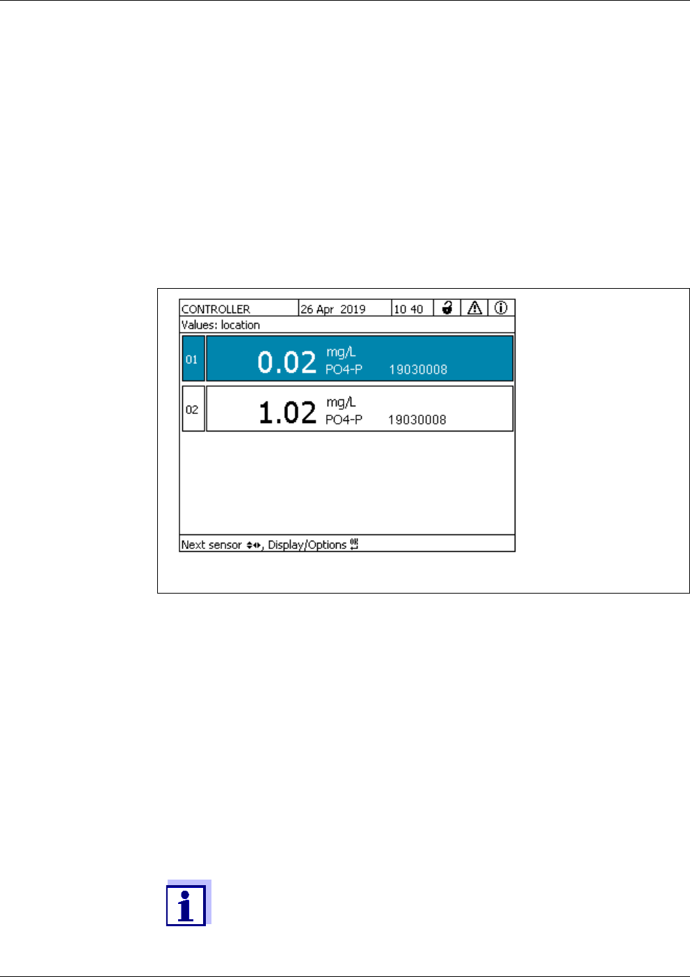
Maintenance and cleaning Alyza IQ PO4
112
ba76201e09 12/2022
5.5.1 Start the maintenance routine of the Alyza IQ
6 If required:
Installing the ChemBags (see section 5.5.7, 121)
7 Terminating the maintenance routine (see section 5.5.8, 124)
1 In the measured value display, use < >< > to select the Alyza IQ.
figure 5-3 Measured value display of the Alyza IQ
2 Using the <C> key, switch to the Alyza menu.
3Using < >, switch to the Maintenance tab.
4 Open the Wizards menu.
5 Carry out the Replace MPV/ChemBag, change configuration function.
The menu Edit list of replacement parts is open.
6 Select the maintenance parts intended for maintenance and continue
the wizard.
7 Wait until the maintenance wizards allows the opening of the Alyza IQ.
The list of replacement parts does not include exchanging the tubes.
Alyza IQ PO4 Maintenance and cleaning
113
ba76201e09 12/2022
5.5.2 Prepare the maintenance activities
5.5.3 Open the measuring unit
WARNING
Dangerous chemicals.
Improper use of chemicals can cause damage to your
health.
Heed the following rules:
Read the labels of the ChemBags and follow the safety
instructions
Wear protective equipment (protective goggles, chemi-
cal resistant gloves)
For all activities at the open measuring unit:
Note the environmental conditions (see fig. 3.3.1, 27).
With low ambient temperatures, make sure that the liquids do not
freeze while the maintenance activities are carried out. Leave the
housing open for as short a time as possible.
Open the outer housing door far enough so the arrestable brake-
stay catches.
Open the inner housing door far enough so that it touches the
outer door. Tilt the angular sheet (at the inside of the outer door)
over the upper edge of the inside door.
1 Put on your personal protective equipment (PPE) and chemical resis-
tant gloves (see section 2.4 Personal protective equipment (PPE),
24).
The list of replacement parts does not include exchanging the tubes.
1 Start the maintenance routine of the Alyza IQ (see section 5.5.1, 112)
2 Prepare the maintenance activities (see section 5.5.2, 113)
3 Open the Alyza IQ.
4 Remove the front cover of the measuring unit.
The measuring unit is ready to be opened when the LED of the measur-
ing unit lights up white.
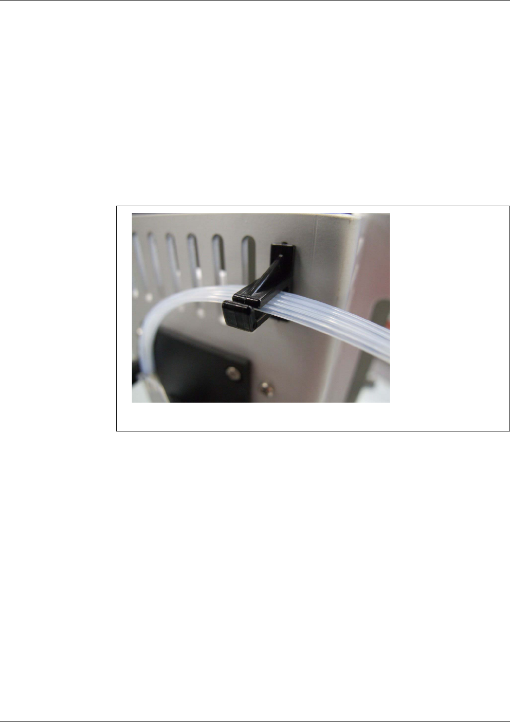
Maintenance and cleaning Alyza IQ PO4
114
ba76201e09 12/2022
5 Using one hand, grip the handle at the upper edge of the front cover of
the measuring unit.
6 Pull the front cover of the measuring unit somewhat to the front against
the resistance.
7 Carefully take the front cover out to the front.
Put the front cover down in a clean place.
8 Guide all tubes of the ChemBags over the tube fasteners above the
locking device and fix the tubes in tube fasteners.
figure 5-4 Tubes in the tube fasteners
9 Carry out the maintenance activities in the measuring unit.
or
Complete the maintenance routine (see section 5.5.8, 124).
Alyza IQ PO4 Maintenance and cleaning
115
ba76201e09 12/2022
5.5.4 Installing the MultiPort valve (MPV) and tubes
WARNING
Dangerous chemicals.
Do not open the locking device of the MultiPort valve if the
maintenance activities at the measuring unit have not been
completed. Leaking chemicals can cause health problems
and damage the measuring unit.
Heed the following rules:
Carry out the Prepare to open measuring unit function.
Carry out the "Drain the system / All" function.
Guide all tubes of the ChemBags over the tube fasten-
ers above the locking device.
Fix the tubes in the tube fasteners.
Make sure that the connected ChemBags are safely sus-
pended from the supporting rod, and that they are not
pressed or moved while the locking device is open.
Make sure that the sample tubes (from the overflow ves-
sel to the measuring unit) are fixed in the recesses at the
left-hand side of the measuring unit.
Follow the safety instructions.
Wear protective equipment (lab coat, protective gog-
gles, chemical resistant protective gloves, safety
shoes)
Prior to opening the locking device always check whether the mea-
suring unit was prepared for the opening and whether the system
was emptied (e.g. tab Status in the Alyza menu).
1 Start the maintenance routine of the Alyza IQ (see section 5.5.1, 112)
2 Prepare the maintenance activities (see section 5.5.2, 113)
3 Open the measuring unit (see section 5.5.3, 113)
4 Make sure that the connected ChemBags are safely suspended from
the supporting rod, and that they are not pressed or moved while the
locking device is open.
5 Make sure that the sample tubes (from the overflow vessel to the mea-
suring unit) are fixed in the recesses at the left-hand side of the measur-
ing unit.
6 Keep absorbent and lint free paper at hand so you can immediately
absorb any small chemicals remains.
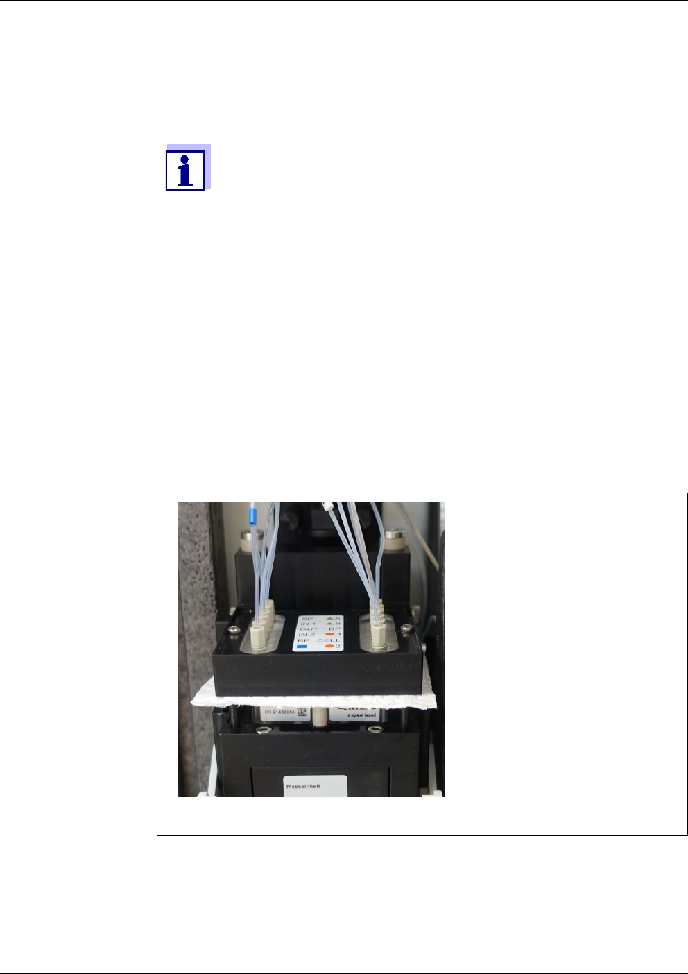
Maintenance and cleaning Alyza IQ PO4
116
ba76201e09 12/2022
7 When the status LED flashes white:
Open the locking device of the MultiPort valve (MPV)
Beeps and a red flashing status LED signal that not all require-
ments for a safe opening of the locking device were met.
When the locking device is open, there is the risk of leaking chem-
icals.
8 Check the MPV for moisture residue.
In case of larger amounts of moisture:
Check whether there is liquid in the collection tray (see section 5.5.6,
119)
Check the info and error messages in the logbook.
9 Check that all seals are present on the underside of the fluidic interface.
10 Place the absorbent, lint free paper onto the MultiPort valve.
11 Gently fold down the fluidic interface above the MultiPort valve by hand
so that it contacts the paper, and liquid remains are absorbed.
The locking device is now safely opened.
figure 5-5 Removing the liquids remains with absorbent, lint free paper

Alyza IQ PO4 Maintenance and cleaning
117
ba76201e09 12/2022
NOTE
To avoid damage to the measuring unit caused by leaking chemicals,
make sure that the following requirements are met while you are work-
ing with the locking device open:
The connected ChemBags are safely suspended from the supporting
rod.
The ChemBags are not pressed or moved.
The tubes of the ChemBags are fastened in the tube fastening above
the locking device.
The sample tubes (from the overflow vessel to the measuring unit)
are fixed in the recesses at the left-hand side of the measuring unit.
12 For initial installation of a tube at the MultiPort valve
(e.g. installing the tubes for standard 2 or reagent B):
Remove the blind plugs for the additionally required tube connectors
from the pressure plate of the MultiPort valve.
13 For initial installation of a MultiPort valve:
If necessary, remove from the fluidic interface of the MultiPort valve the
blind plugs required for the tube connectors of the MultiPort valve.
To do so, use the special tool in the base of the measuring unit.
14 When replacing individual tubes on the MultiPort valve:
Unscrew any old tubes from the fluidic interface of the MultiPort valve.
To do so, use the special tool in the base of the measuring unit.
15 When exchanging the MultiPort valve (MPV):
Remove the MultiPort valve.
The tubes of the MultiPort valve can be exchanged individually or as
a set:
In the delivery condition, the tube set is already mounted.
16 Only when exchanging the MultiPort valve (MPV):
Insert the new MultiPort valve (MPV).
17 Connect the tubes to the fluidic interface of the MultiPort valve.
NOTE
Damaged tubes may leak.
Folded or knotted tubes hamper the transport of the liquids.
The tubes must not be damaged, folded or knotted.
The tube to the photometer (glass capillary) is easily damaged and can
break when bended.

Maintenance and cleaning Alyza IQ PO4
118
ba76201e09 12/2022
5.5.5 Remove the ChemBags for maintenance activities
Color coding Connection of
Green (reagent) MPV - ChemBag R
Orange (calibration stan-
dard)
MPV - ChemBag S
Blue (cleaning solution) MPV - ChemBag C
18 Screw the new tubes onto the fluidic interface of the MultiPort valve.
Use the special tool for this.
19 If not yet done:
Remove the absorbent paper from the MultiPort valve (MPV).
20 Close the locking device of the MultiPort valve (MPV)
21 Carry out further maintenance activities in the measuring unit.
or
Complete the maintenance routine (see section 5.5.8, 124).
1 Start the maintenance routine of the Alyza IQ (see section 5.5.1,
112).
2 Prepare the maintenance activities (see section 5.5.2, 113).
3 Open the measuring unit (see section 5.5.3, 113).
NOTE
To avoid damage to the measuring unit caused by leaking chemicals,
make sure that the following requirements are met while you are work-
ing with the ChemBags:
The MultiPort valve is inserted.
The locking device of the MultiPort valve is closed.
4 Remove the empty ChemBags from the supporting rod one by one.
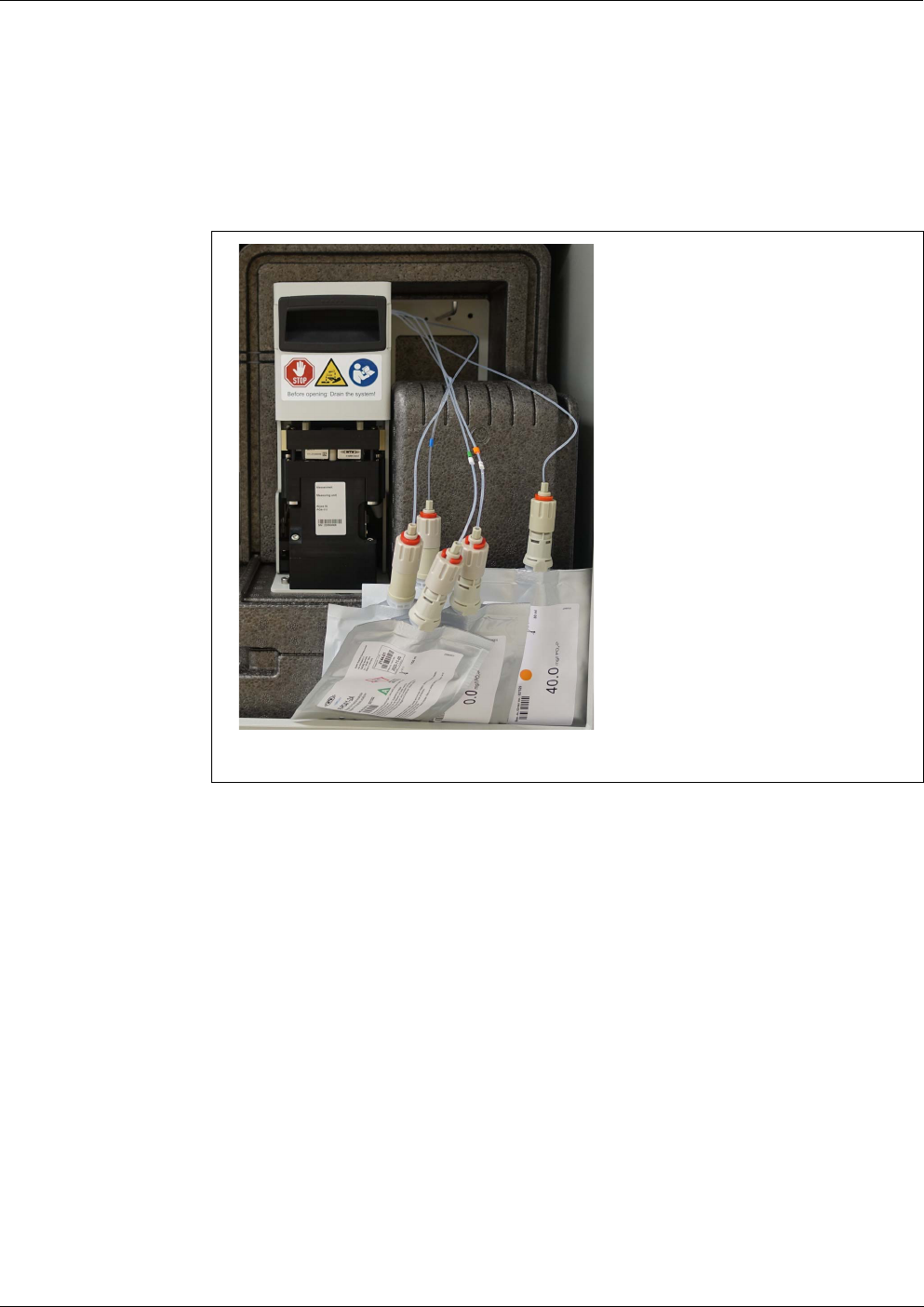
Alyza IQ PO4 Maintenance and cleaning
119
ba76201e09 12/2022
5.5.6 Check the collection tray under the ChemBags for liquids
5 Turn the ChemBags so that the valve points upward.
Suspend the tubes of the empty ChemBags from the tube grooves at
the photometer unit so that the ChemBags are suspended downwards
from the tubes.
figure 5-6 ChemBags removed to be exchanged
6 Check the collection tray under the ChemBags for moisture (see section
5.5.6, 119).
1 Start the maintenance routine of the Alyza IQ (see section 5.5.1,
112).
2 Prepare the maintenance activities (see section 5.5.2, 113).
3 Open the measuring unit (see section 5.5.3, 113).
4 Remove the ChemBags for maintenance activities (see section 5.5.5,
118)
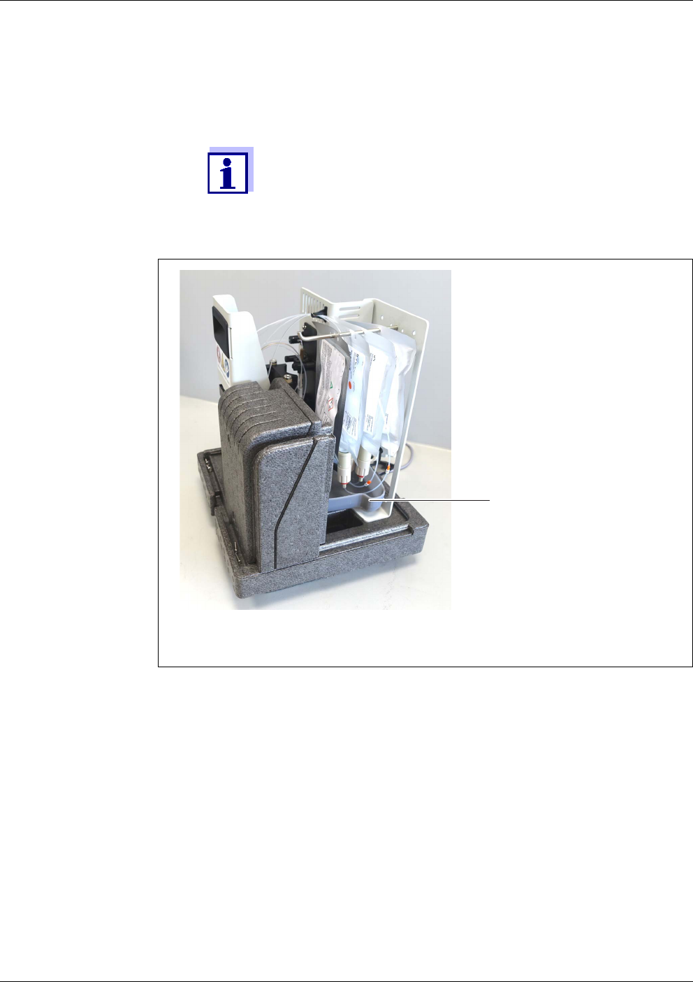
Maintenance and cleaning Alyza IQ PO4
120
ba76201e09 12/2022
5 Check the collection tray under the ChemBags for liquids.
When the measuring unit is installed, the collection tray under
the ChemBags cannot be seen.
Indications of liquid in the collection tray can be detected, for
example, with the camera of a smartphone.
figure 5-7 Position of the collection tray in the measuring unit (under the ChemBags)
1 Collection tray
1

Alyza IQ PO4 Maintenance and cleaning
121
ba76201e09 12/2022
5.5.7 Installing the ChemBags
NOTE
To avoid damage to the measuring unit caused by leaking chemicals, make sure
that the following requirements are met while you are working with the Chem-
Bags:
The MultiPort valve is inserted.
The locking device of the MultiPort valve is closed.
6 If there is liquid in the collection tray:
Check the ChemBags for moisture and damage.
Check the drain tube from the MPV to the collection tray for moisture.
Dry the collection tray
– For larger quantities of liquid:
Draw up liquid e.g. with a syringe and dispose of it.
– With little moisture:
Absorb the moisture with an absorbent cloth and dispose of it.
In case of leaking or defective maintenance parts:
– Schedule the replacement of leaking parts via the maintenance
routine in the Alyza menu.
– Schedule the replacement of the leaking ChemBag via the main-
tenance routine in the Alyza menu (see section 5.5.7, 121)
– Check the MPV for moisture (see section 5.5.4, 115)
– Check the log book messages.
7 Carry out further maintenance activities in the measuring unit.
or
Complete the maintenance routine (see section 5.5.8, 124).
1 Start the maintenance routine of the Alyza IQ (see section 5.5.1,
112).
2 Prepare the maintenance activities (see section 5.5.2, 113).
3 Open the measuring unit (see section 5.5.3, 113).
4 Remove the ChemBags for maintenance activities (see section 5.5.5,
118).
5 Check the collection tray under the ChemBags for liquids (see section
5.5.6, 119).
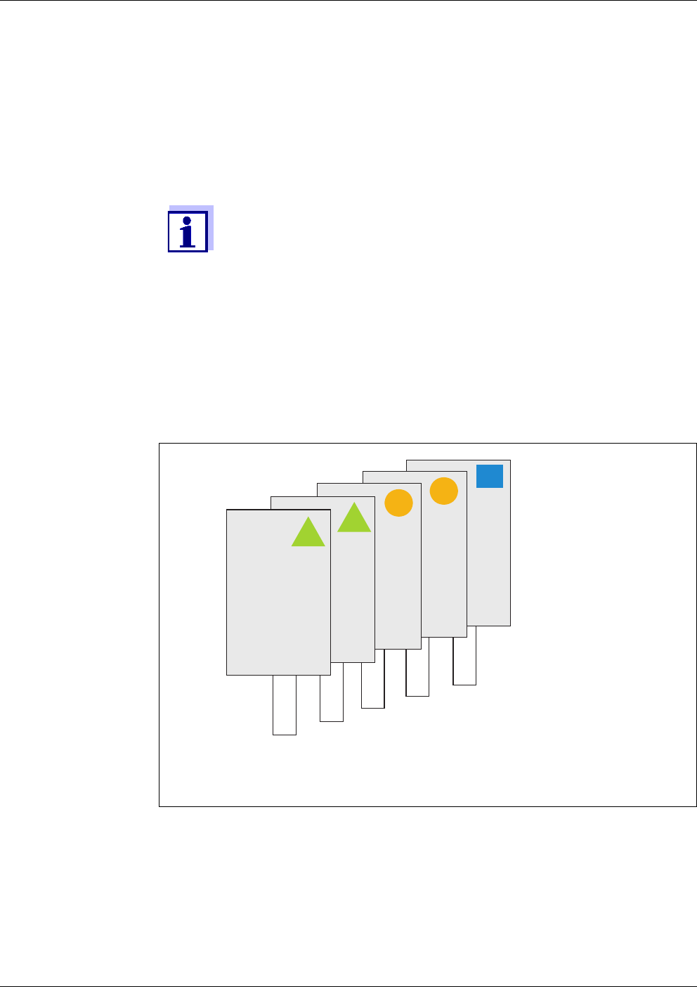
Maintenance and cleaning Alyza IQ PO4
122
ba76201e09 12/2022
NOTE
Damaged ChemBags may leak.
To avoid damage, the ChemBags must not be folded near the connector.
6 Unscrew the coupling of the tube from the ChemBag connector.
7 Unscrew the protection cap of the ChemBag to be connected. The
ChemBag connector points upward.
8 Screw the protective cap onto the connector of the empty ChemBag.
The ChemBags with the longest lifetime do not have to be ex-
changed often. Suspend them first from the supporting rod and slide
them to the rear.
Cleaning solution (C-...),
most often has the longest lifetime
Standard 2 (S-...x)
Standard 1 (S-...y)
Reagent B (R-...B) (for optimized background correction, Backgr.
corr.(opt))
Reagent A (R-...A)
figure 5-8 Recommended order of the ChemBags on the supporting rod
9 Screw the coupling of the tube tightly onto the connector of the new
ChemBag.
Make sure that the codings of the ChemBag and tube agree (symbol,
color, number).
C-...
S-...-x
S-...-y
R-...B
R-...A
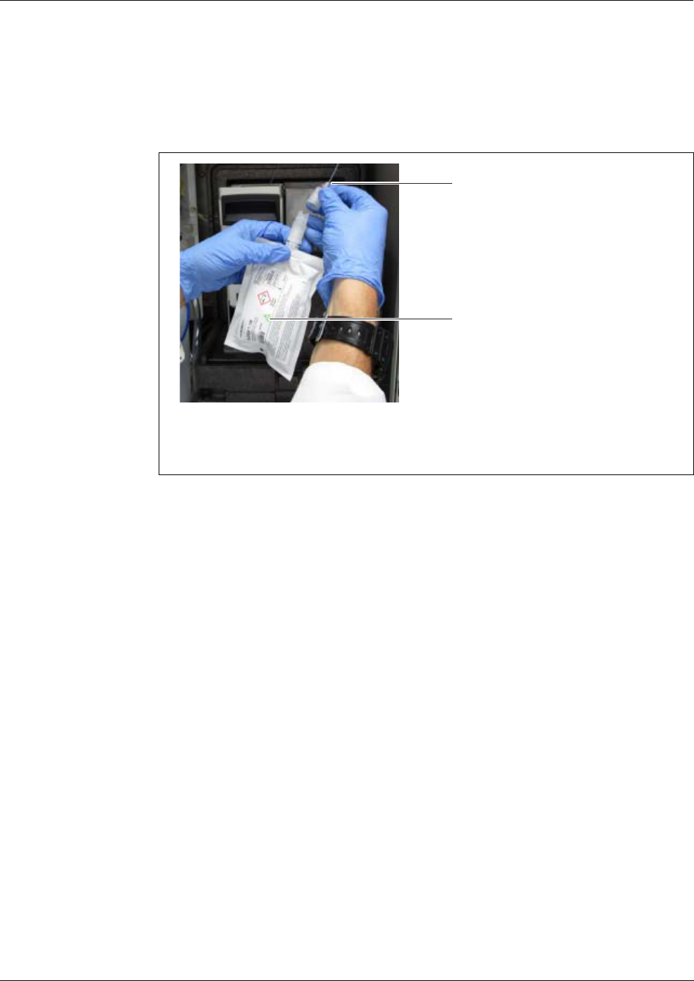
Alyza IQ PO4 Maintenance and cleaning
123
ba76201e09 12/2022
Hold the ChemBags by the connector, with the connector facing upwards .
To suspend the ChemBags from the supporting rod:
Carefully turn the ChemBags upside down, without folding the ChemBags or
tubes.
figure 5-9 Connecting the ChemBag
1 Color coding of the tube
2 Color coding of the ChemBag
10 Carefully turn the ChemBag upside down.
The connector points downward.
11 If necessary, slightly knock on the connector of the ChemBag to remove
any small bubbles from the connector.
12 Suspend the ChemBag from the supporting rod.
13 Connect all selected ChemBags
– 1 cleaning solution (blue)
– 1 - 2 standard solutions (orange)
– 1-point calibration: Standard solution to connector S1
– 2-point calibration:
low standard solution to connector S1,
higher standard solution to connector S2
– 1 - 2 reagent solutions (green)
14 For each ChemBag, enter the expiry date and, if necessary, the filling
level (for used ChemBags) on the display.
15 Guide all tubes of the ChemBags over the tube fasteners above the
locking device and fix the tubes in the tube fasteners.
1
2

Maintenance and cleaning Alyza IQ PO4
124
ba76201e09 12/2022
5.5.8 Terminating the maintenance routine
5.6 Cleaning the sample filtration and sample feed
The Alyza IQ has an extra counter for each ChemBag (see
section 1.3.3 ChemBags, 15).
When delivered, the counters are set to 100 %.
16 Carry out further maintenance activities in the measuring unit.
or
Complete the maintenance routine (see section 5.5.8, 124).
1 After maintenance activities at the measuring unit:
Hang the ChemBags back onto the supporting rod (see section
5.5.7, 121).
Close the front cover of the measuring unit and the doors of the
Alyza IQ.
2 Follow the maintenance wizard.
Carry out the OK + START + Switch off maintenance condition function.
Wait until the maintenance wizard has finished.
Measurement is restarted and the measured value is displayed in the
measured value display after approx. 5 ... 7 minutes.
3 After installing ChemBags with reagents:
Calibrate the measuring system
(Alyza menu / tab Maintenance / Manual maintenance / Calibrate (2-
point))
Carry out the START Alyza IQ function. Measurement is started and
the measured value is displayed in the measured value display after
approx. 5 ... 7 minutes.
Carry out the Switch off the maintenance condition function.
Cleaning of the filter module, see the following documents:
Mounting instructions for the filter module (FM/PC)
Alyza IQ - short instructions for cleaning the filter membrane
module (included in the scope of delivery of the Alyza IQ )

Alyza IQ PO4 Maintenance and cleaning
125
ba76201e09 12/2022
5.6.1 Mechanical cleaning of the filter plate
The time when to clean the filter plate can be determined empirically based on
the negative pressure display on the filtration pump.
A pulsing negative pressure manometer suggests a normal operating condi-
tion of the filtration unit.
With a delivery height of approx. 2 m and a new filter plate, the negative pres-
sure is approx. -0.3 bar.
Every meter of delivery height increases the negative pressure by approx. -
0.1 bar.
If the negative pressure increases by a further -0.3 ... -0.4 bar with time, the
filter plate is covered with solid matter from the sample and has to be cleaned.
If, after the mechanical cleaning, there is still negative pressure, a chemical
cleaning is required, or the intake line may be blocked.
NOTE
Dirt particles and contamination in the sample line can block the valves of the
measuring unit.
During the cleaning activities, make sure that no dirt particles get into the open
tube ends or the connector of the filter module.
Protect the open tubes and connectors during the cleaning activities, e.g. with
blind plugs.
Maintenance
interval
2 to 4 months, depending on the application
Preparations
NOTE
The filter plate is easily damaged. Never touch the filter plate with sharp-edged
objects or place any objects on it.
Pressure on the filter plate may only be applied from the outside. No counter-
1 Stop the Alyza IQ with the function, STOP Alyza IQ.
The maintenance condition is automatically activated in the
IQ S
ENSORNET for the Alyza IQ.
2 Switch off the filtration pump with the Stop key.
3 Pull the filtration unit out of the basin or channel.
The filter module does not have to be separated from the guide slide.
Do not unplug the sample line.
Do not dismount the filter plate from the frame.
4 Rinse off of the filtration unit any gross contamination with low water
pressure (e.g. with a watering can or wash bottle).
5 Then carefully remove the coating from the filter plate using a soft spe-
cial brush. Normally the brownish coating can well be seen coming off
while the lighter surface of the filter plate is appearing.

Maintenance and cleaning Alyza IQ PO4
126
ba76201e09 12/2022
pressure may build up through the intake line.
Do not press the special brush onto the surface of the filter plate too firmly and
do not change the moving direction of the brush (do not scrub!).
Restarting the
measuring
operation
5.6.2 Chemical cleaning of the filter plate
Chemical cleaning is recommended if mechanical cleaning no longer achieves
any significant improvement, i.e. the negative pressure on the manometer no
longer decreases significantly after mechanical cleaning.
In this case, the filter plate is blocked. The blockage is mostly organic and can
only be removed by chemical cleaning.
The chemical cleaning is carried out with the aid of a suitable container (Filter-
CL) for the cleaning bath. The amount of cleaning solution required depends on
the shape and size of the cleaning container.
Cleaning solution In most cases, organic blockages can easily be removed with an aqueous sodi-
um hypochlorite solution (chlorine bleaching agent, NaClO, 1 % active chlorine).
In some cases, NaOH 4 % (sodium hydroxide) has proven effective.
In case of calcification, diluted acetic acid (max. 10 % acetic acid) or diluted citric
acid (max. 10 % citric acid) is recommended.
NOTE
High temperatures damage the material of the filter. Use acidic cleaning
solutions only in the temperature range 5°C...35°C.
Preparing the
cleaning solution
The cleaning solution can be made from different detergent concentrates by di-
luting with water. A selection of possible detergent concentrates is given in the
section 5.3 Replacement parts, accessories, 106.
Prepare the cleaning solution according to the following table. It can be mixed in
If the contamination cannot be removed with the mechanical clean-
ing, carry out the chemical cleaning (see section 5.6.2 Chemical
cleaning of the filter plate, 126).
6 After cleaning, check both sides of the filter plate for damage.
7 Thoroughly clean the special brush under running water, dry it and store
in a dust free place till the next use.
8 Remount and secure the cleaned filter module on the slide.
9 Submerse the filtration unit in the basin or channel.
10 Switch on the filtration pump with the Start key.
11 Restart the Alyza IQ and switch off the maintenance condition at the
IQ S
ENSORNET.
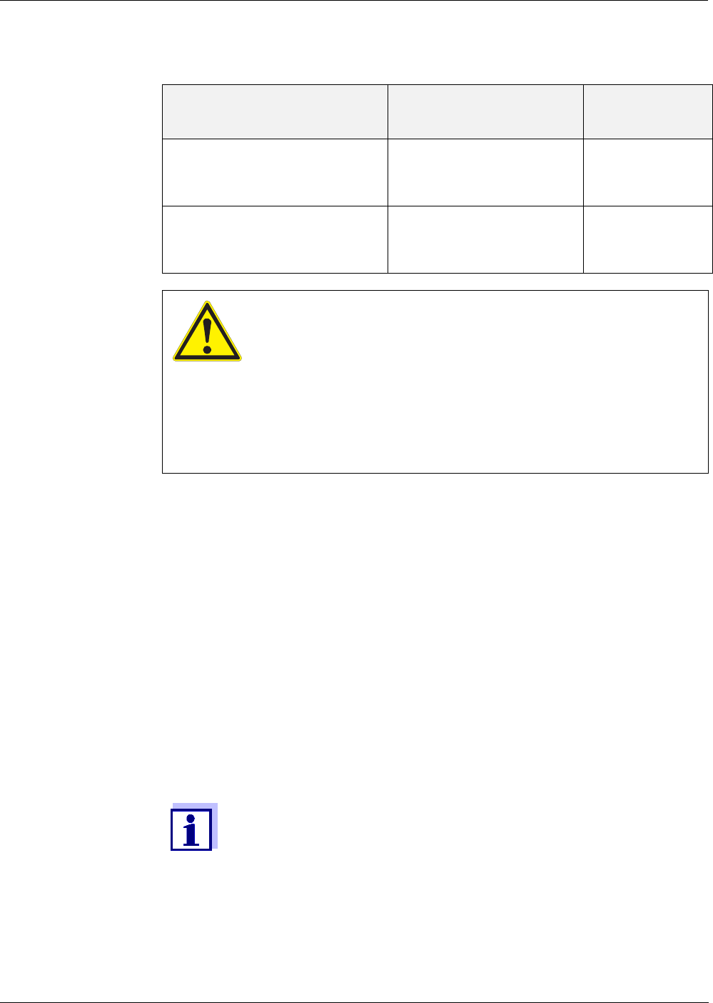
Alyza IQ PO4 Maintenance and cleaning
127
ba76201e09 12/2022
the cleaning container.
Pre-cleaning
Base solution
Preparation instruc-
tions
Yield
Household hygienic cleaner
based on sodium hypochlorite
Add so much water to
1.5 l hygienic cleaner
that the volume is 6 l
6 l
Techn. sodium hypochlorite
solution (13 % active chlorine)
Add so much water to
300 ml solution that the
volume is 5 l
5 l
WARNING
Dangerous chemicals.
Improper use of chemicals can cause damage to your
health.
Heed the following rules:
Read the labels of the ChemBags and follow the safety
instructions
Wear protective equipment (lab coat, protective gog-
gles, chemical resistant protective gloves)
1 Prior to each chemical cleaning, pre-clean the membrane with the spe-
cial brush and rinse it with water (see section 5.6.1 Mechanical cleaning
of the filter plate, 125).
2 Dismount the filter unit from the slide.
3 Dismount the intake line from the filter unit.
4 Protect the filter plate against any contamination coming in (e.g. by clos-
ing the connection adapter for the intake line).
5 Dismount the filter plate (see section 5.6.4 Replacing the filter plate of
the sample filtration, 128).
6 Close the connector of the filter unit and the open intake line with blind
plugs to that no contamination can get into the filter.
The chemical cleaning of the filter plate may take some time.
Use a replacement filter module (FM/PC) during the cleaning pro-
cess to keep the downtime of the Alyza IQ as short as possible.

Maintenance and cleaning Alyza IQ PO4
128
ba76201e09 12/2022
Chemical cleaning
Restarting
operation
5.6.3 Storing a used and cleaned filter plate
Proceed as follows to store the filter plate:
5.6.4 Replacing the filter plate of the sample filtration
NOTE
The filter plate is easily damaged. Never touch the filter plate with sharp-edged
objects or place any objects on it.
7 Completely submerse the filter module with the installed filter plate in
the cleaning container filled with the cleaning solution.
Start with a reaction time of 30 minutes.
Watch the cleaning success and extend the reaction time as neces-
sary.
8 After the chemical cleaning, rinse the filter module with clean water.
Even a filter plate that is supposedly irreversibly blocked may be re-
stored by leaving it in the cleaning solution for a longer period of time
and then rinsing it several times.
9 After cleaning, check both sides of the filter plate for damage.
10 Remount the filter plate (see section 5.6.4 Replacing the filter plate of
the sample filtration, 128).
or
Store the cleaned filter plate (see section 5.6.3 Storing a used and
cleaned filter plate, 128).
1 Clean the filter plate mechanically.
2 Clean the filter plate chemically.
3 Rinse the filter plate under flowing tap water.
4 To protect it against drying out, store the filter plate in the Filter-CL
cleaning container or in a sealed plastic bag.
Prior to each use, soak the filter plate in tap water.
If the filter plate has dried out, soak it in tap water for several hours.

Alyza IQ PO4 Maintenance and cleaning
129
ba76201e09 12/2022
Maintenance
interval
As necessary, if cleaning does not help.
Proceed as follows to exchange the filter plate:
Dismounting the
filter plate
Remounting the
filter plate
Restarting the
measuring
operation
5.6.5 Cleaning the sample feed, overflow vessel and outlet
The intake line takes the sample liquid from the filter module to the filtration
1 Stop the Alyza IQ with the function, STOP Alyza IQ.
The maintenance condition is automatically activated in the
IQ S
ENSORNET for the Alyza IQ.
2 Switch off the filtration pump with the Stop key.
3 Pull the filtration unit out of the basin or channel.
Do not separate the filter module from the guide slide.
Do not dismount the filter plate from the frame.
4 Clean the filtration unit.
5 Dismount the filter module from the guide slide.
6 Unscrew the V4A countersunk screws of the frame (12 hexagon sock-
ets).
7 Remove the used filter plate.
8 Clean the frame.
Cleaning of the filter plate, see
section 5.6.1 Mechanical cleaning of the filter plate, 125
section 5.6.2 Chemical cleaning of the filter plate, 126
9 Insert a new filter plate in the lower frame part.
10 Place the upper frame part onto the lower frame part with the built-in fil-
ter plate.
11 Insert the V4A countersunk screws and tighten them by hand.
The fixing ring and lower part of the housing must be pressed together
and flush (without gap).
12 Remount and secure the cleaned filter module on the slide.
13 Submerse the filtration unit in the basin or channel.
14 Switch on the filtration pump with the Start key.
15 Restart the Alyza IQ and switch off the maintenance condition at the
IQ S
ENSORNET.
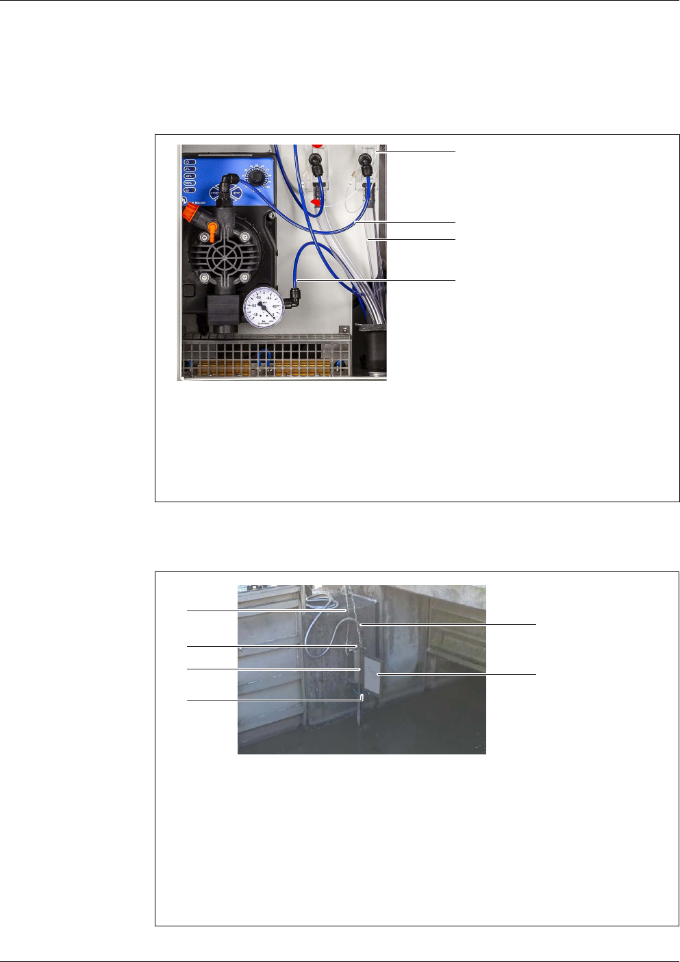
Maintenance and cleaning Alyza IQ PO4
130
ba76201e09 12/2022
pump. The sample feed tube goes from the filtration pump to the overflow ves-
sel. From time to time it can be required to clean the intake line, sample feed
tube and overflow vessel.
fig. 5-10, 130 shows the intake line (blue, ID 2mm; OD 4 mm) in the Alyza IQ.
fig. 5-11, 130 shows the intake line on a mounted filter module in a sedimen-
tation tank.
figure 5-10 Filtration pump with intake line and tubes
1 Overflow vessel
2 Sample feed tube
3 Sample overflow tube
4 Intake line
figure 5-11 Sample filtration device (installed)
1 Chain (scope of delivery: basin holder for filtration M 1.5)
2 Guide rail (scope of delivery: basin holder for filtration M 1.5)
3 Height adjustable slide (scope of delivery: Suction line)
4 Intake line (scope of delivery: Suction line)
5 Sleeve tube (scope of delivery: Suction line)
6 Filter module (FM/PC) with filter plate (Filter/PC)
4
3
1
2
2
1
3
6
5
4
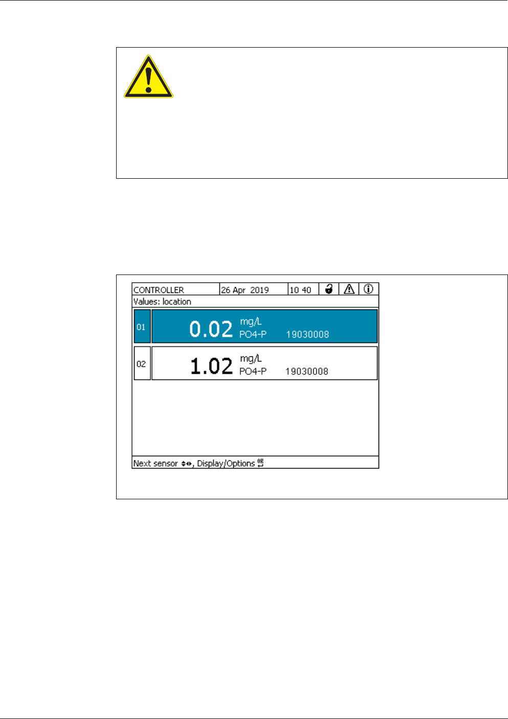
Alyza IQ PO4 Maintenance and cleaning
131
ba76201e09 12/2022
Maintenance
interval
As required.
Proceed as follows to clean the intake line:
Starting the
maintenance
routine of the
Alyza IQ
WARNING
Dangerous chemicals.
Improper use of chemicals can cause damage to your
health.
Heed the following rules:
Read the labels of the ChemBags and follow the safety
instructions
Wear protective equipment (lab coat, protective gog-
gles, chemical resistant protective gloves)
1 In the measured value display, use < >< > to select the Alyza IQ.
figure 5-12 Measured value display of the Alyza IQ
2 Using the <C> key, switch to the Alyza menu.
3Using < >, switch to the Maintenance tab.
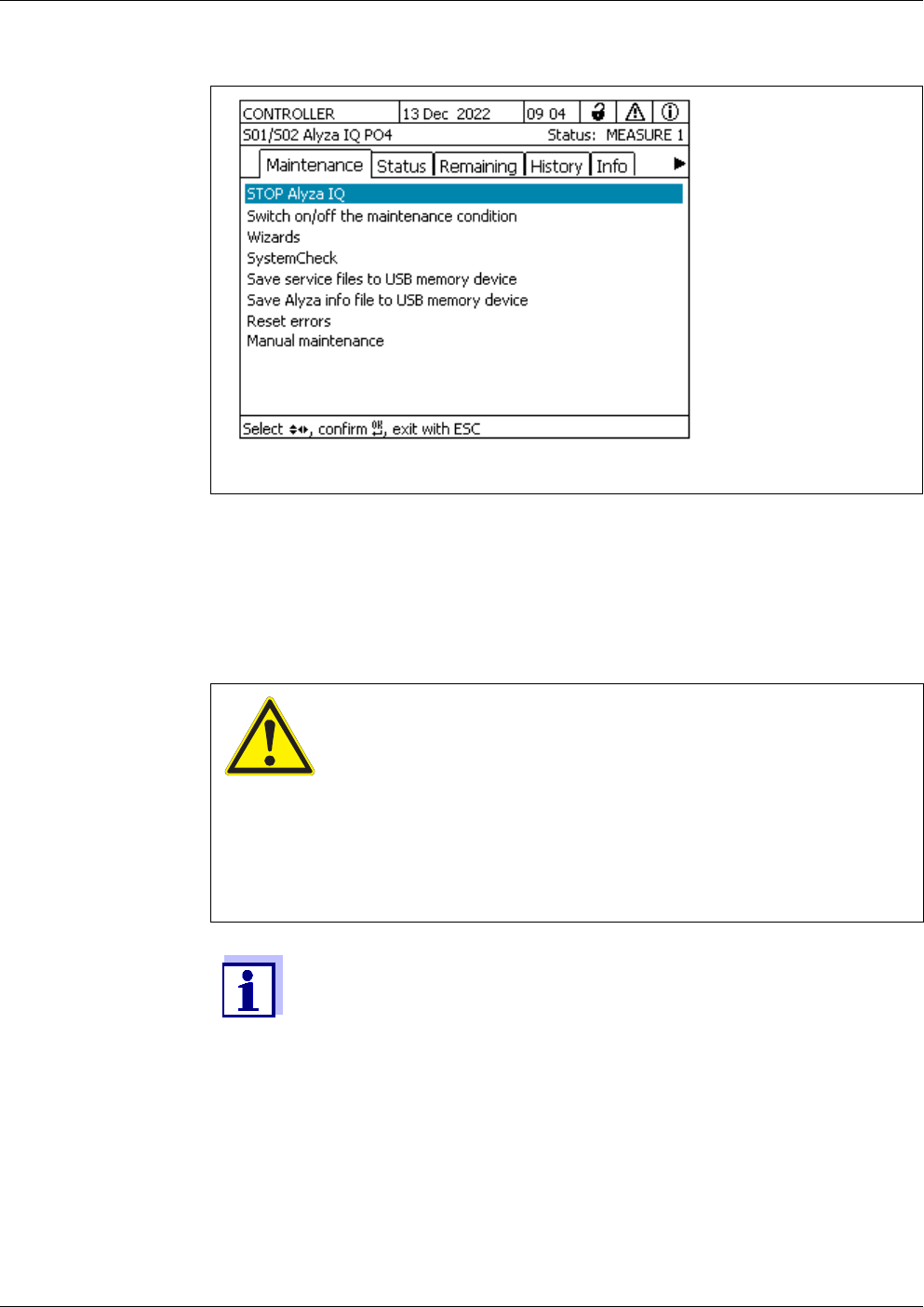
Maintenance and cleaning Alyza IQ PO4
132
ba76201e09 12/2022
Carrying out
maintenance
activities
figure 5-13 Tab Maintenance
4 Carry out the STOP Alyza IQ function to stop the running operation.
5 Confirm the function to stop the running operation.
The maintenance condition is automatically activated in the
IQ S
ENSORNET for the Alyza IQ.
WARNING
Dangerous chemicals.
Improper use of chemicals can cause damage to your
health.
Heed the following rules:
Read the labels of the ChemBags and follow the safety
instructions
Wear protective equipment (protective goggles, chemi-
cal resistant gloves)
For all activities at the open measuring unit:
Note the environmental conditions (see fig. 3.3.1, 27).
With low ambient temperatures, make sure that the liquids do not
freeze while the maintenance activities are carried out. Leave the
housing open for as short a time as possible.
Open the outer housing door far enough so the arrestable brake-
stay catches.
Open the inner housing door far enough so that it touches the
outer door. Tilt the angular sheet (at the inside of the outer door)
over the upper edge of the inside door.

Alyza IQ PO4 Maintenance and cleaning
133
ba76201e09 12/2022
Preparations
Cleaning
NOTE
Detergents containing alcohol will damage the overflow vessel.
NOTE
Acids as cleaning agents damage individual components of the sample feed and
sample inlet (Requirements of the test sample (by the filtration system) see sec-
tion 8.2).
6 Put on your personal protective equipment (PPE) and chemical resis-
tant gloves (see section 2.4 Personal protective equipment (PPE),
24).
7 Switch off the filtration pump with the Stop key.
8 Keep ready a container to collect the contents of the overflow vessel.
9 Empty the sample tube (Alyza menu / tab Maintenance / Manual main-
tenance / Drain the system / Sample xxx)
10 Unscrew the sample tube from the overflow vessel.
11 Open the quick coupling of the sample feed tube on the overflow vessel
and let the contents of the overflow vessel drain into the container.
12 Remove the overflow vessel from the Alyza IQ.
13 Open the lid of the overflow vessel.
14 Clean the overflow vessel and lid with a brush, water, descaler or deter-
gent.
Subsequently, thoroughly rinse the overflow vessel with water to
remove any detergent residues.
15 If necessary: exchange or clean the filter plate (see section 5.6.1
Mechanical cleaning of the filter plate, 125).
16 Provide a container of cleaning solution for the intake line and sample
feed tube.
Recommended minimum amount of cleaning fluid:
Length of intake line Minimum quantity of cleaning solution
5 m ≥ 30 ml
10 m ≥ 50 ml
20 m ≥ 100 ml
Maintenance and cleaning Alyza IQ PO4
134
ba76201e09 12/2022
17 Disconnect the intake line from the filter module and put it in a container
with cleaning solution (recommendation: see section 5.3 Replacement
parts, accessories, 106).
18 Insert the end of the sample feed tube into a bottle (≥ 0.5 l) or another
suitable container.
19 Secure the bottle and sample feed tube.
WARNING
Dangerous chemicals.
Wear protective equipment (lab coat, protective goggles,
chemical resistant protective gloves)
Risk of splashing!
During operation, the filtration pump can develop consid-
erable pressure. Therefore, absolutely heed the following
instructions:
Fix the sample intake tube so that the pressure surges
of the filtration pump will not make it come out of the
bottle.
Cover the bottle so that no cleaning solution can splash
out due to the pressure surges.
Bring the bottle into a stable position and fix it if neces-
sary.
If necessary, test the arrangement with tap water first.
20 Switch on the filtration pump with the Start key.
Cleaning solution is drawn in through the intake line until it flows into the
bottle at the open line end. Leave the filtration pump switched on until
the minimum quantity (see 133) has been drawn in from the container
with cleaning solution.
If necessary, increase the percent setting for the pump performance at
the filtration pump.
21 Switch off the filtration pump with the Stop key; allow the cleaning solu-
tion to take effect (altogether approx. 10 min). During this time, occa-
sionally start/stop the filtration pump so the cleaning solution in the
intake line is moved towards the bottle.
22 When doing so, check the filling level of the bottle to keep the solution
from overflowing. If necessary, empty the bottle (dispose of the cleaning
solution properly).
23 Switch off the filtration pump with the Stop key.
24 Reconnect the intake line to the filter module and reinstall the filter mod-
ule in the sample.

Alyza IQ PO4 Maintenance and cleaning
135
ba76201e09 12/2022
NOTE
Make sure that the liquids in the collection funnels can drain off freely. A blocked
collection funnel can cause the liquids to overflow into the housing of the
Alyza IQ . Liquids can cause damage to the housing and electrical components.
Restarting the
measuring
operation
5.7 Maintenance activities at the housing
5.7.1 Cleaning the housing of the Alyza IQ
Outside Clean the outside of the housing with a brush, water, and dish-washing solution.
Inside Clean the inside with a moist (not dripping) cloth, water, and dish-washing solu-
tion.
25 Switch on the filtration pump with the Start key and let it pump for some
time (at least 5 - 10 min, depending on the length of the intake line) with
approx. 60% capacity to completely remove all the cleaning solution
from the filter plate and intake line. This can normally be recognized by
the clear sample liquid that comes out of the line. If necessary, set the
percent setting for the pump capacity to the previous value.
26 Switch off the filtration pump with the Stop key.
27 Reinstall the overflow vessel in the Alyza IQ.
28 If necessary: Clean the collection funnel for the sample return and the
return line with a brush and water.
29 Mount the sample overflow tube to the collection funnel for the sample
overflow.
30 Screw the sample feed tube to the overflow vessel.
31 Re-connect the sample tube to the overflow vessel.
32 Remove the container that held the cleaning solution. Dispose of the
remainders of the cleaning liquid properly.
33 Switch on the filtration pump with the Start key.
34 Leave the filtration pump to work for some time to completely remove
the detergents.
35 Fill the sample tube (Maintenance / Manual maintenance / Fill the sys-
tem / Sample xxx)
36 Restart the Alyza IQ and switch off the maintenance condition at the
IQ S
ENSORNET.
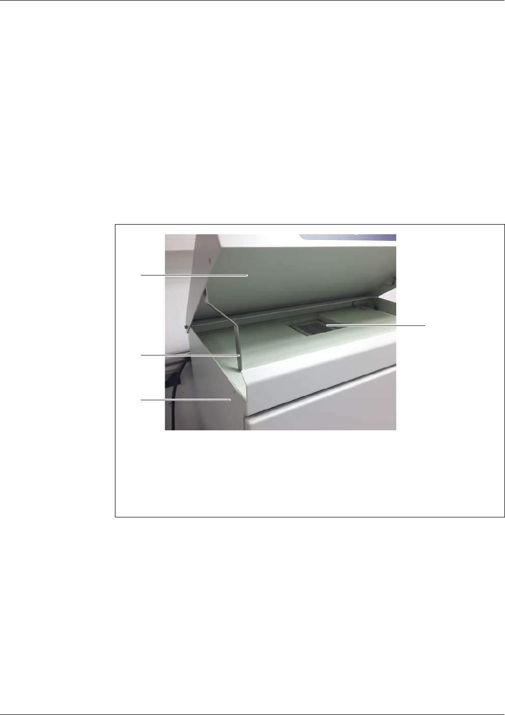
Maintenance and cleaning Alyza IQ PO4
136
ba76201e09 12/2022
5.7.2 Changing the filter mats
The filter mats are in front of the ventilation grids (under the housing lid and on
the underside of the housing).
The ventilators are behind the ventilation grids. The filter mats can thus be ex-
changed riskless even during operation.
Maintenance
interval
Depending on contamination
Upper filter mat
1 Remove both front screws on the housing lid.
2 Open the housing lid upward and fix it with the bearer (see fig. 5-14,
136).
figure 5-14 Opening the housing lid
1 Housing lid
2 Bearer
3 Boring for the fixing screw
4 Filter mat holder
3 Open the upper filter mat holder with the aid of a screwdriver by levering
it off and exchange the upper filter mat (see fig. 5-15, 137).
1
2
3
4
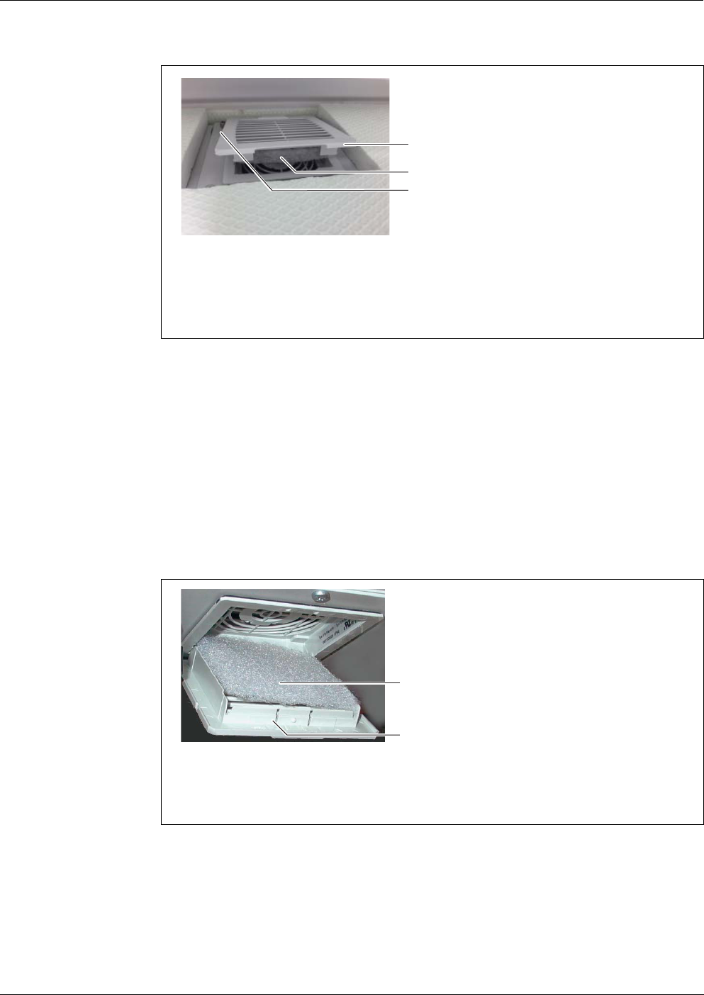
Alyza IQ PO4 Maintenance and cleaning
137
ba76201e09 12/2022
Lower filter mat
5.7.3 Checking the temperature control
For correct measured values, it is required to control the temperature of some
figure 5-15 Exchanging the upper filter mat
1 Upper filter mat holder
2 Upper filter mat
3 Opening for screwdriver
4 Press the upper filter mat holder shut again.
5 Fold the bearer and close the housing lid.
6 Screw the housing lid tight with the two screws.
3
1
2
7 Position yourself under the Alyza IQ housing.
8 Open the lower filter mat holder and exchange the filter mat as done
with the upper filter mat holder.
figure 5-16 Exchanging the lower filter mat
1 Lower filter mat
2 Lower filter mat holder
9 Close the lower filter mat holder again.
1
2

Maintenance and cleaning Alyza IQ PO4
138
ba76201e09 12/2022
areas of the Alyza IQ.
The temperature control is automatically and regularly checked by the function
SystemCheck (see section 5.10). You can start the SystemCheck function also
manually (Alyza menu, tab Maintenance / SystemCheck).
The Alyza IQ has 3 areas that are temperature-controlled differently:
Heating units, a ventilator and a cooling unit are used to control the temperature
of the areas.
The correct temperature control is continuously and automatically monitored for
each area in the Alyza IQ.
If an area of the Alyza IQ is not within the specified range, a message appears
in the log book. If the deviation from the specified range is great, the Alyza IQ is
automatically stopped. The error is documented by an error message in the log
book.
You can check very easily and at any time the current status of the temperature
control in the Alyza menu / tab Info. All temperatures (temperature inside the
housing, temperature within the measuring unit) and the operating condition of
the ventilators, heating and cooling unit are documented.
Range Temperature control
Housing inside +5 ... +40 °C (+41 ... +104 °F)
Measuring unit 20 °C (68 °F)
Photometer unit 45 °C (113 °F)
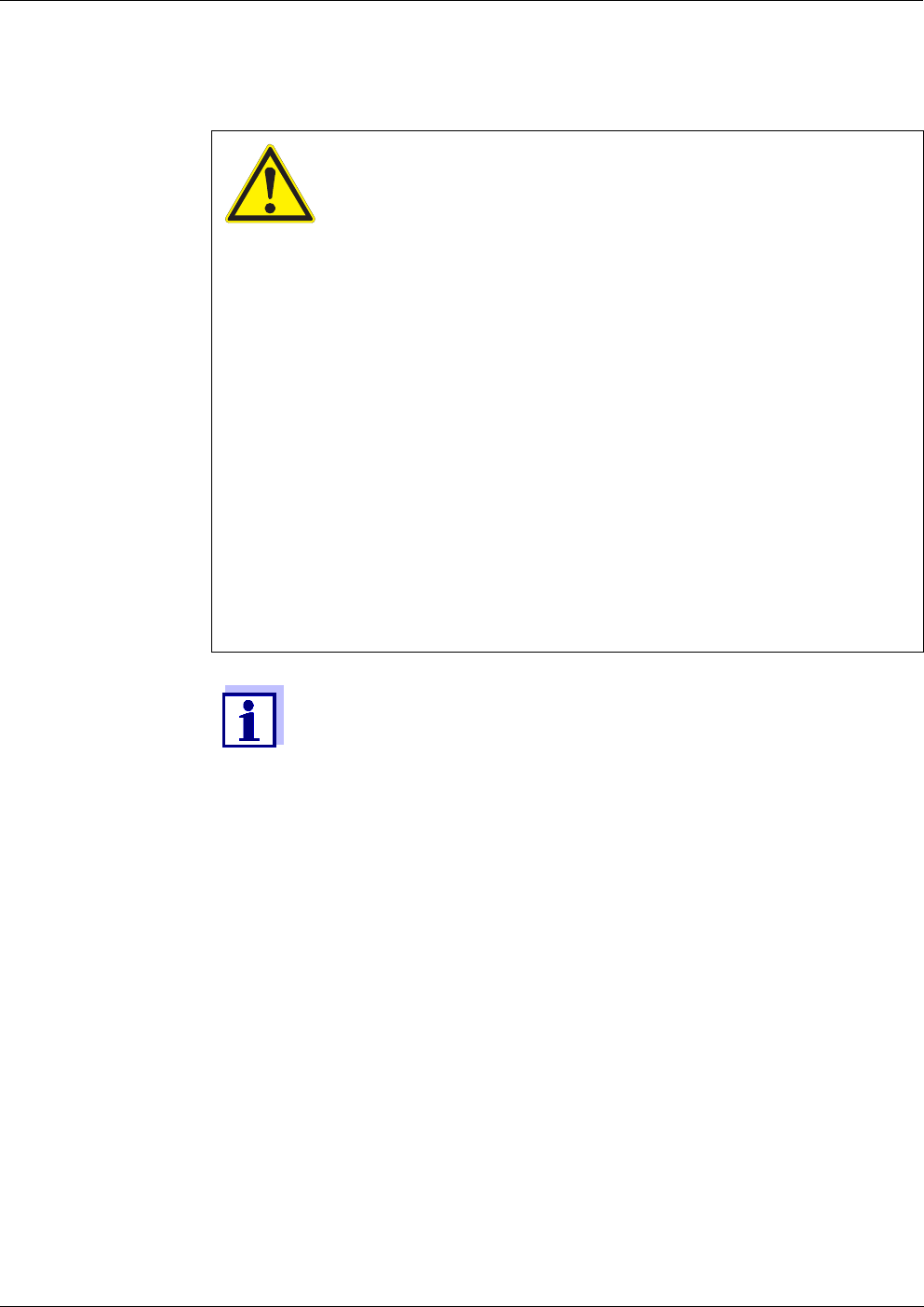
Alyza IQ PO4 Maintenance and cleaning
139
ba76201e09 12/2022
5.8 Maintenance activities at the power supply box
Switching off the
power supply
WARNING
If the power supply is connected incorrectly, there may be
danger to life from electric shock.
Pay attention to the following points during installation:
The power supply box may only be connected to the
power supply by a qualified electrician.
The power supply box may only be connected to the
power supply when it is not carrying any voltage.
The power supply must fulfill the specifications given
on the nameplate and in chapter 8 Technical data,
170.
The power supply of the heat tracing must fulfill the
specifications given on the heat tracing (240 VAC or 120
VAC).
To operate a heat tracing line, a fault current protection
switch (ground fault circuit interrupter) has to be in-
stalled.
The power cable must meet the requirements according
to the technical data (see section 8.4 Electrical data,
175).
For all work done with the housing open:
If the Alyza IQ was already in operation:
Before opening the doors, start the maintenance routine at the
terminal.
Note the environmental conditions (see section 3.3.1 Require-
ments of the measurement location, 27).
Open the outer housing door far enough so the arrestable brake-
stay (on the lower right side of the housing) catches.
Open the inner housing door far enough so that it touches the
outer door. Tilt the angular sheet (at the inside of the outer door)
over the upper edge of the inside door.
1 Open the outer housing door far enough so the arrestable brake-stay
(on the lower right side of the housing) catches.
2 Open the inner housing door far enough so that it touches the outer
door. Tilt the angular sheet (at the inside of the outer door) over the
upper edge of the inside door.
3 Switch off all filtration pumps (STOP).
4 Switch off the 24 V power supply.

Maintenance and cleaning Alyza IQ PO4
140
ba76201e09 12/2022
Removing the
mounting plate
5 Switch the power line potential free.
6 Unscrew the 2 fixing screws of the cover (on the top right side in the
housing) and remove the cover of the ACM.
If the filtration pumps have already been in operation, sample liquid
may escape when the tubes are unscrewed. Provide a collecting
container in such a case.
7 Remove the cable connections and the connections of the tubes and liq-
uid lines from the mounting plate:
Unplug the 2 cables from the switch box.
Unscrew the sample tubes from the overflow vessels.
Unplug the blue intake lines of the filtration unit.
8 Remove the mounting plate:
Unscrew the 2 fixing nuts (3) at the bottom of the mounting plate.
Unscrew the 2 fixing screws (2) at the upper edge of the mounting
plate.
Secure the mounting plate against falling out.
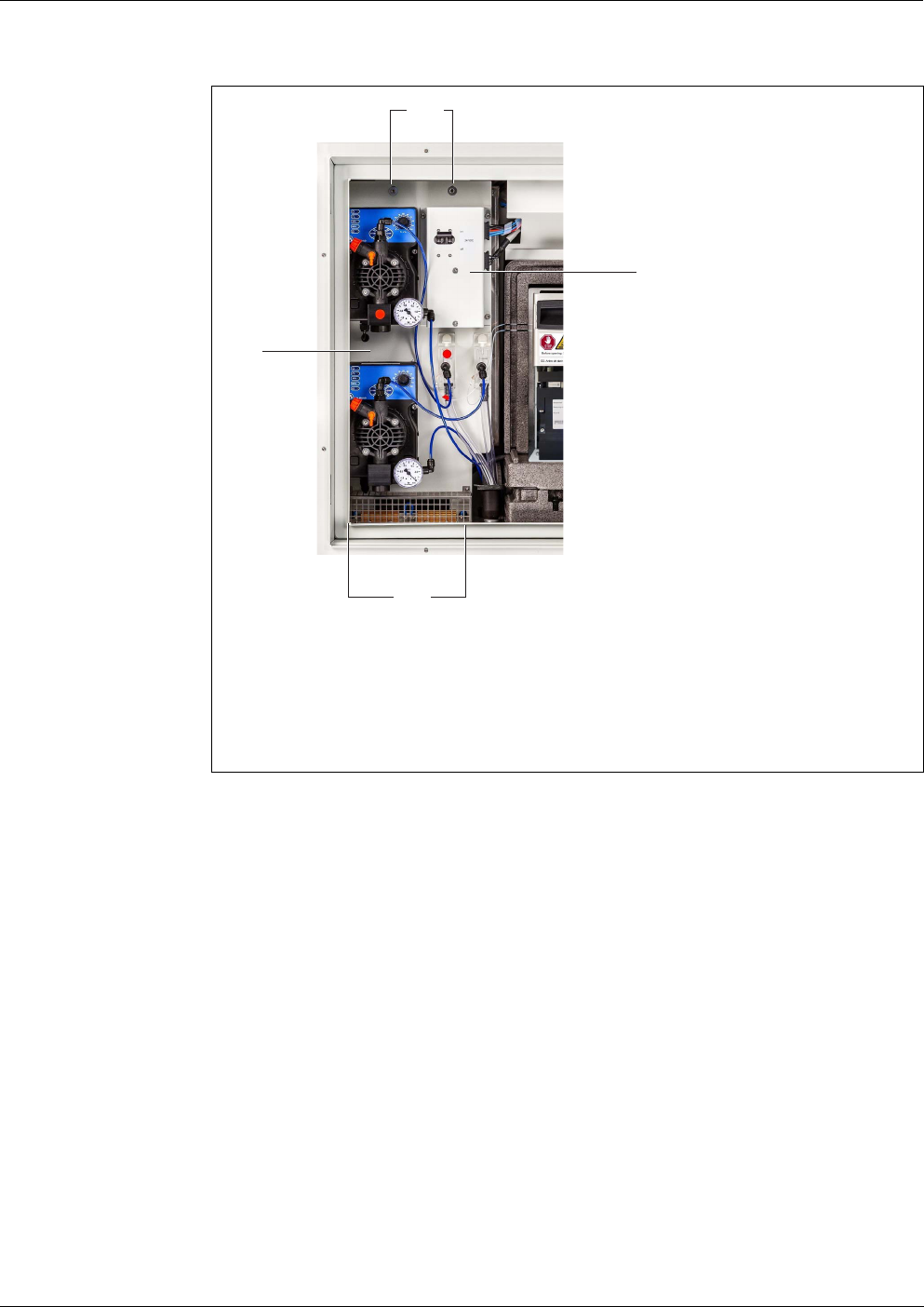
Alyza IQ PO4 Maintenance and cleaning
141
ba76201e09 12/2022
Opening the power
box
figure 5-17 Mounting plate
1 Mounting plate
2 Fixing screw at the upper edge
3 Fixing nuts at the lower edge
4 Switch box with 24 VDC switch
9 Remove the mounting plate:
Lift the mounting plate upward over the threaded pins.
Tilt the upper edge of the mounting plate somewhat backwards and
remove the mounting plate from the housing downwards.
Place the mounting plate with the rear side down on a protected sur-
face (e.g. with cardboard).
2
1
4
3
10 Unscrew all nuts with safety disks (10 pieces) from the power supply
box and remove the lid of the power supply box.
Maintenance and cleaning Alyza IQ PO4
142
ba76201e09 12/2022
figure 5-18 Connections of the power supply box
1 Power supply module
2 Ventilator
3 Power supply filter
4 Connecting terminals for the heat tracing lines
4 - 7: yellow/green (protective earth conductor)
8 - 11: gray
12 - 15: blue
5 Power supply of the heat tracing lines
6 Overvoltage protection
7 Power line
8 Cable gland for heat tracing of intake line (channel 1)
9 Cable gland for heat tracing of intake line (channel 2)
10 Cable gland for heat tracing of return line 1
11 Cable gland for heat tracing of return line 2
11 Carry out the maintenance activities at the power supply box.
2
1
5
7
6
4
3
8 9
10
11

Alyza IQ PO4 Maintenance and cleaning
143
ba76201e09 12/2022
Closing the power
supply box
Reinserting the
mounting plate
Restoring the
power supply
Details on connecting the heat tracing and power cable:
See section 3.3.13 Connecting the power cable and heat tracing
lines, 50.
12 Check whether all connections are made correctly.
13 Tighten the cable glands on the power supply box with a torque of 2.5
Nm.
The cable glands protect the power supply box from dust and moisture.
Make sure that no cable touches the power supply filter.
14 Remount the lid of the power supply box and screw tight all nuts with
safety disks as far as they will go (0.4 Nm).
The power supply box is closed and protected against dust and mois-
ture.
15 Insert the mounting plate:
Plug the mounting plate on the threaded pins inside the housing.
Tighten the 2 fixing screws (2) at the upper edge of the mounting
plate.
Tighten the 2 fixing nuts (3) at the bottom of the mounting plate.
16 Re-establish the cable connections and the connection of the tubes and
liquid lines.
Plug the sample feed tubes onto the connectors of the filtration
pumps.
Screw the sample tubes to the connectors of the overflow vessels.
Re-insert the sample return tubes into the collection funnel for the
sample return.
Re-connect the 2 cables to the switch box.
17 Reinsert the cover and fix it with the 2 fixing screws.
18 Switch on the mains power supply.
19 Switch on the 24 V power supply.
20 Switch on all filtration pumps (START).
Maintenance and cleaning Alyza IQ PO4
144
ba76201e09 12/2022
Restarting the
measuring
operation
5.9 Emptying the system manually
NOTE
With manual emptying, there is the risk of material damage due to spilled chem-
icals.
Do not empty manually if it is possible to empty the system via the Alyza menu
(see section 5.2 Opening the locking device of the MultiPort valve ("Before
opening: Drain the system"),
102).
Emptying the
system manually
21 Complete the maintenance routine (see section 5.5.8, 124).
For all activities at the open measuring unit:
Note the environmental conditions (see fig. 3.3.1, 27).
With low ambient temperatures, make sure that the liquids do not
freeze while the maintenance activities are carried out. Leave the
housing open for as short a time as possible.
Open the outer housing door far enough so the arrestable brake-
stay catches.
Open the inner housing door far enough so that it touches the
outer door. Tilt the angular sheet (at the inside of the outer door)
over the upper edge of the inside door.
WARNING
Dangerous chemicals.
Improper use of chemicals can cause damage to your
health.
Heed the following rules:
Read the labels of the ChemBags and follow the safety
instructions
Wear protective equipment (protective goggles, chemi-
cal resistant gloves)
1 Open the outer housing door far enough so the arrestable brake-stay
(on the lower right side of the housing) catches.
2 Open the inner housing door far enough so that it touches the outer
door. Tilt the angular sheet (at the inside of the outer door) over the
upper edge of the inside door.
3 Put on your personal protective equipment (PPE) and chemical resis-
tant gloves (see section 2.4 Personal protective equipment (PPE),
24).

Alyza IQ PO4 Maintenance and cleaning
145
ba76201e09 12/2022
NOTE
Damaged ChemBags may leak.
To avoid damage, the ChemBags must not be folded near the connector.
Hold the ChemBags at the connector, with the liquid downward.
To suspend the ChemBags from the supporting rod:
Carefully turn the ChemBags upside down, without folding the ChemBags or
tubes.
4 Remove the front cover of the measuring unit.
5 Using one hand, grip the handle at the upper edge of the front cover of
the measuring unit.
6 Pull the front cover of the measuring unit somewhat to the front against
the resistance.
7 Carefully take the front cover out to the front.
Put the front cover down in a clean place.
8 Guide all tubes of the ChemBags over the tube fasteners above the
locking device and fix the tubes in tube fasteners.
9 Remove all ChemBags from the supporting rod one after the other and
turn the ChemBags so the valves point upward.
Suspend the tubes of the empty ChemBags from the tube grooves at
the photometer unit so that the ChemBags are suspended downwards
from the tubes.
Place the ChemBags down with the connectors pointing upward.
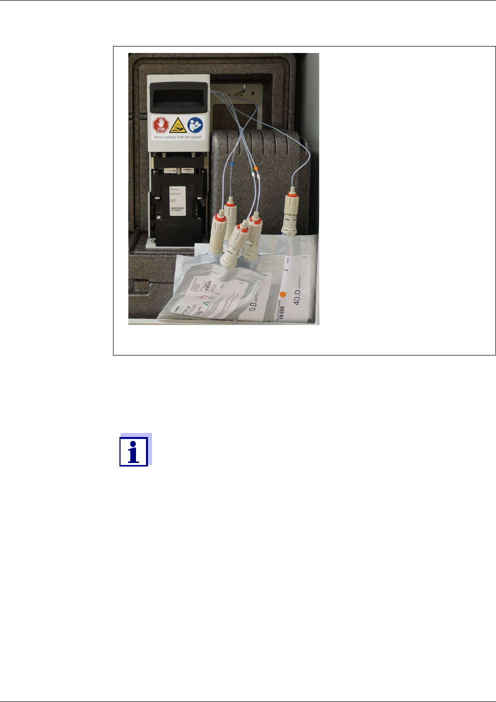
Maintenance and cleaning Alyza IQ PO4
146
ba76201e09 12/2022
figure 5-19 ChemBags removed from the supporting rod
10 Switch off all filtration pumps (STOP).
11 Switch off the 24 V power supply at the switch box.
If the filtration pumps have already been in operation, sample liquid
may escape when the tubes and liquid lines are unscrewed. Provide
a collecting container in such a case.
12 Unscrew the sample tubes from the overflow vessels.
13 Protect the sample tubes against loss of liquids and against the pene-
tration of dust and dirt (e.g. with rubber plugs or absorbent paper).
14 Keep some absorbent paper ready to absorb small quantities of leaked
liquids at the MultiPort valve.
15 Open the locking device of the MultiPort valve.
When the locking device is open, there is the risk of leaking chemicals.
16 Immediately place the absorbent paper onto the MultiPort valve.
17 Wait until the liquids have run back into the ChemBags.
18 Close the locking device of the MultiPort valve to absorb leaked liquids
with the absorbent paper.
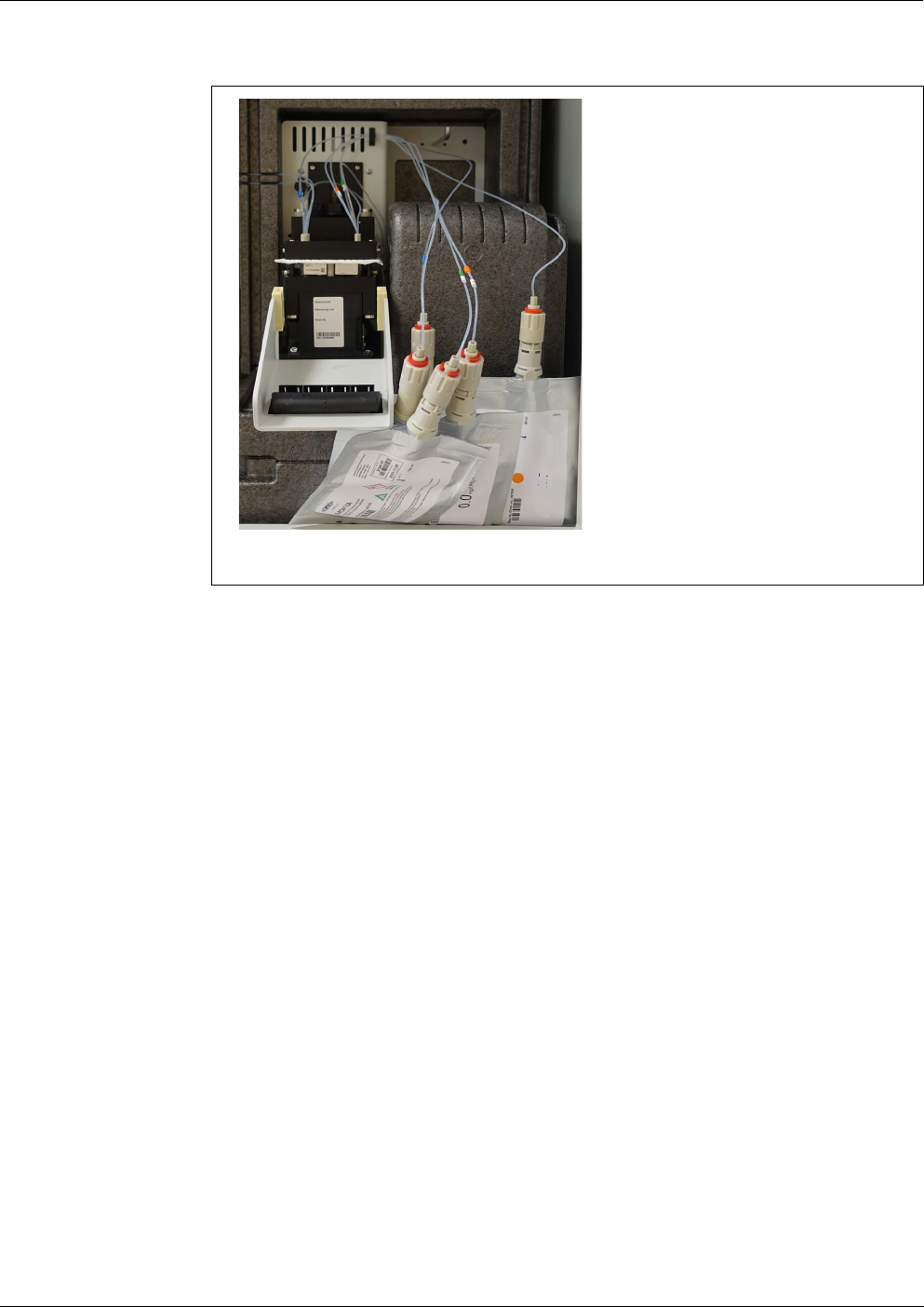
Alyza IQ PO4 Maintenance and cleaning
147
ba76201e09 12/2022
5.10 SystemCheck
The SystemCheck function automatically checks whether the Alyza IQ is oper-
able. It also brings the MultiPort Valve (MPV) into a defined basic state.
The SystemCheck function is carried out regularly prior to every automatic cali-
bration. You can start the SystemCheck function also manually (Alyza menu, tab
Maintenance / SystemCheck).
If a component approaches a critical state, information messages with preven-
figure 5-20 Absorbent paper in the receptacle of the MultiPort valve
19 Open the locking device of the MultiPort valve.
20 Remove the absorbent paper.
21 Remove any remains of chemicals immediately.
22 Unscrew the tube couplings from the ChemBag connectors.
23 Close the ChemBag connectors with the yellow protection caps.
24 Store the ChemBags and secure them against being damaged.
25 Now carry out further actions, e.g.
Cleaning
Troubleshooting
Exchanging components
(see section 5.5 Installing / exchanging the ChemBags, MPV, tubes,
111)
Transport, storage
(see section 6.3 Transport, storage, 159)
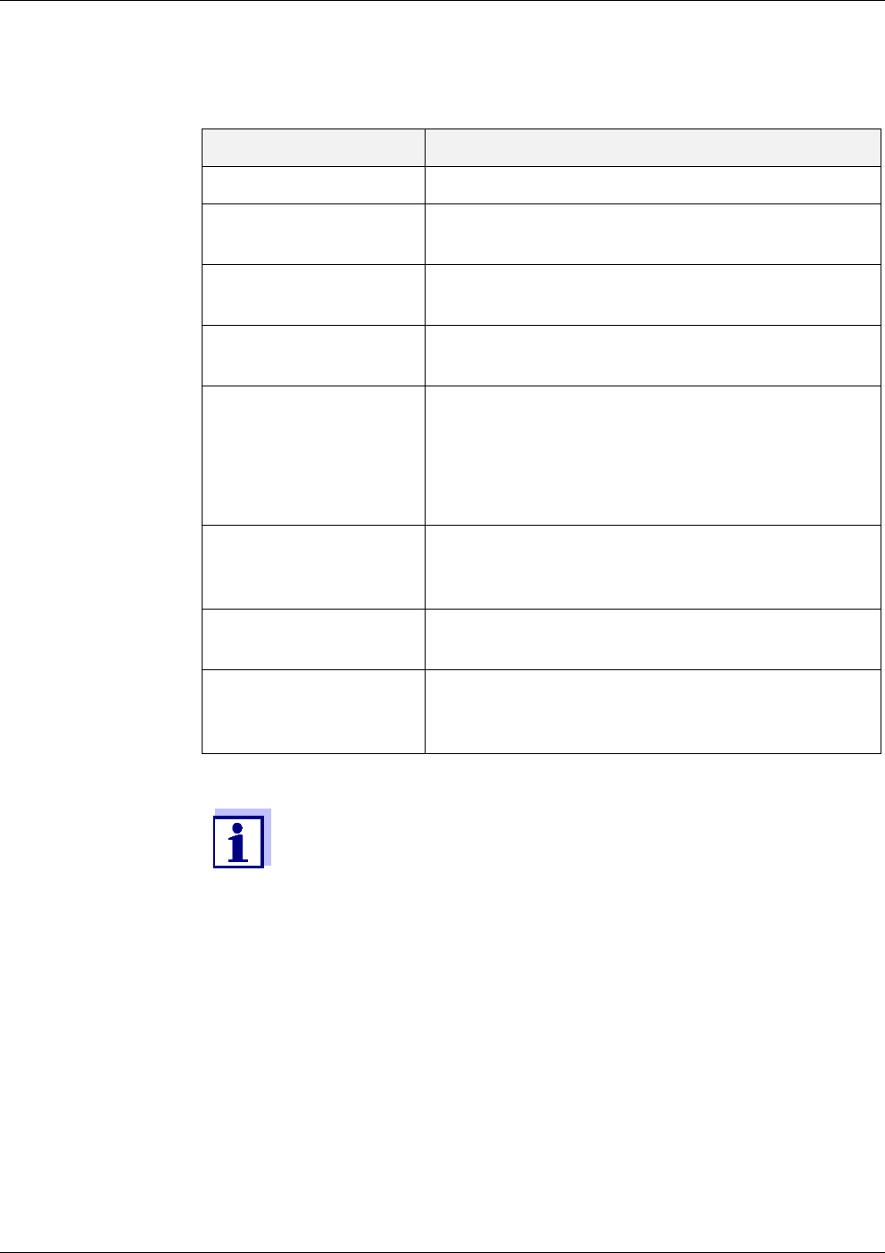
Maintenance and cleaning Alyza IQ PO4
148
ba76201e09 12/2022
tive maintenance instructions are issued.
Component Explanation
Photometer LED Function check of the LED of the photometer
MPV detected Checking whether the serial number of the
MultiPort valve (MPV) can be read.
MPV initialized Aligning the MultiPort valve (MPV) to a defined
basic position
Syringe pump SP1 Checking whether the syringe pump can cre-
ate the required pressure
Valve V2 Checking whether a pressure applied to the
valve is maintained (tightness of the valve)
Checking whether the applied pressure
decreases when the valve is open (permeabil-
ity of the valve).
Pressure sensor PS1 Checking whether the pressure sensor (at
atmospheric pressure) delivers a value in the
valid range
MPV tightness Checking whether the MultiPort Valve (MPV)
can maintain the applied pressure
Air condition Testing whether all elements for air-condition-
ing (heating elements, cooling elements, fans)
are working
If an error occurs during the check of a component, the System-
Check function is canceled and an error message is created.
No following checks will be performed.
Eliminate the error and then start the SystemCheck function manu-
ally to check the success of the maintenance (Alyza menu, tab Main-
tenance / SystemCheck).

Alyza IQ PO4 Maintenance and cleaning (complex activities)
149
ba76201e09 12/2022
6 Maintenance and cleaning (complex activi-
ties)
Decommission the Alyza IQ prior to carrying out one of the following activities:
Dismounting the measuring unit
(e.g. for complex maintenance activities in the measuring unit)
Transporting the Alyza IQ
Read the chapter 2 Safety instructions, 22 before doing any maintenance
work. This is important for your personal safety.
NOTE
The interior of the measuring unit is temperature-controlled to 20 °C (68 °F).
With ambient temperatures over 25 °C (77 °F) and high air humidity, condensa-
tion water may develop on the cool surfaces and cause damage when the mea-
suring unit is opened.
To avoid damage to the measuring unit due to the formation of condensation
water, always wait for the temperature adjustment (function Prepare to open
measuring unit) to be completed before opening the measuring unit.
6.1 Decommissioning
6.1.1 Preparing the decommissioning
Starting the
maintenance
routine of the
Alyza IQ
For all activities at the open measuring unit:
Note the environmental conditions (see section 3.3.1 Require-
ments of the measurement location, 27).
With low ambient temperatures, make sure that the liquids do not
freeze while the maintenance activities are carried out. Leave the
housing open for as short a time as possible.
Open the outer housing door far enough so the arrestable brake-
stay catches.
Open the inner housing door far enough so that it touches the
outer door. Tilt the angular sheet (at the inside of the outer door)
over the upper edge of the inside door.
1 In the measured value display, use < >< > to select the Alyza IQ.
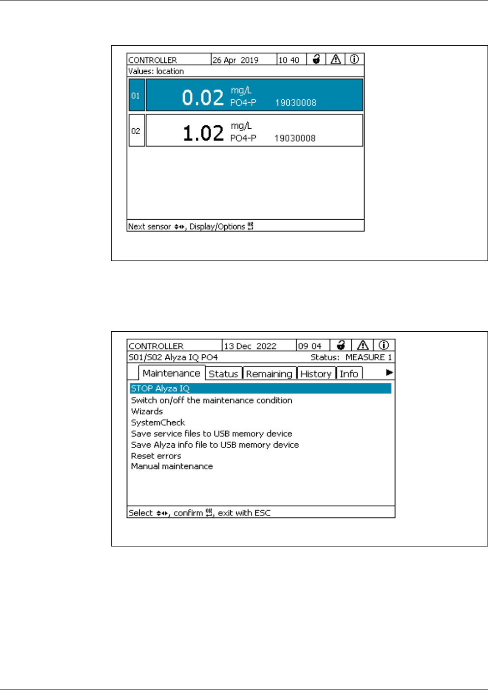
Maintenance and cleaning (complex activities) Alyza IQ PO4
150
ba76201e09 12/2022
figure 6-1 Measured value display of the Alyza IQ (example Alyza IQ PO4)
2 Using the <C> key, switch to the Alyza menu.
3Using < >, switch to the Maintenance tab.
figure 6-2 Tab Maintenance (example Alyza IQ PO4)
4 Carry out the STOP Alyza IQ function to stop the running operation.
5 Confirm the function to stop the running operation.
The maintenance condition is automatically activated in the
IQ S
ENSORNET for the Alyza IQ.

Alyza IQ PO4 Maintenance and cleaning (complex activities)
151
ba76201e09 12/2022
6.1.2 Decommissioning the measuring unit
1 Open the Manual maintenance menu.
2 Select the function, Prepare to open measuring unit.
Follow the instructions on the display.
The procedure starts the temperature adjustment of the measuring unit.
3 Drain the tubes (Maintenance /Manual maintenance / Drain the system
All).
Follow the instructions on the display until the emptying is complete.
4 Open the outer housing door far enough so the arrestable brake-stay
(on the lower right side of the housing) catches.
5 Open the inner housing door far enough so that it touches the outer
door. Tilt the angular sheet (at the inside of the outer door) over the
upper edge of the inside door.
The measuring unit is ready to be opened when the status LED of the
measuring unit lights up white.
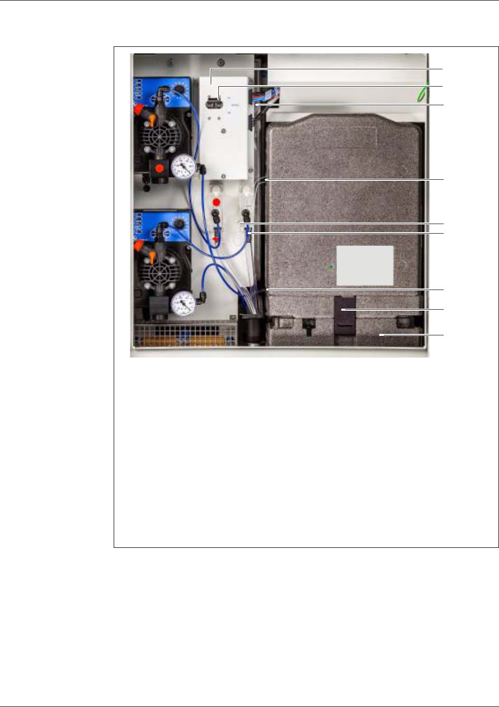
Maintenance and cleaning (complex activities) Alyza IQ PO4
152
ba76201e09 12/2022
figure 6-3 Alyza IQ, housing open, variant with 2 channels
1 Switch box
2 24V switch (at the switch box)
3 2 plugs at the switch box
4 Sample tubes (2 channels)
5 Connection sample tube to overflow vessel 1
6 Connection sample feed tube to overflow vessel 1
(quick fastener)
7 Waste tube of the measuring unit
8 Fixation of the measuring unit to the cooling unit
9 Cooling unit
6 Switch off all filtration pumps (STOP).
7 Switch off the 24 V power supply at the switch box.
1
3
2
4
5
6
7
8
9
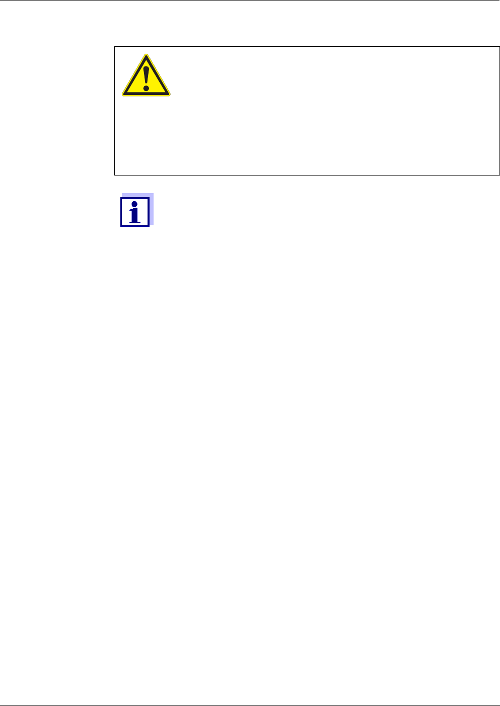
Alyza IQ PO4 Maintenance and cleaning (complex activities)
153
ba76201e09 12/2022
WARNING
Dangerous chemicals.
Improper use of chemicals can cause damage to your
health.
Heed the following rules:
Read the labels of the ChemBags and follow the safety
instructions
Wear protective equipment (protective goggles, chemi-
cal resistant gloves)
If the filtration pumps have already been in operation, sample liquid
may escape when the tubes and liquid lines are unscrewed. Provide
a collecting container in such a case.
8 Put on your personal protective equipment (PPE) and chemical resis-
tant gloves (see section 2.4 Personal protective equipment (PPE),
24).
9 Provide a collection container for the contents of the overflow vessel
below the connection for the sample tube.
10 Unscrew the sample tube from the overflow vessel.
To do so, use the special tool in the base of the measuring unit.
The liquid exits the overflow vessel from the connection of the sample
tube to the overflow vessel.
11 Drain the contents of the overflow vessel into the collection container
provided. A rest of sample (approx. 3 ml) remains in the overflow vessel.
12 For Alyza IQ variants with 2 channels:
Repeat steps 9 - 11 for the second overflow vessel.
13 Pull the waste tube of the measuring unit out of the collection funnel.
14 Secure the waste tube against leakage of liquids (e.g. with rubber stop-
per or absorbent paper).
15 Now carry out the intended maintenance activities, such as:
Dismount the measuring unit and carry out maintenance activities
(see section 6.2 Complex maintenance- and cleaning activities in the
measuring unit, 154)
or
Prepare the Alyza IQ for storage or transport (see section
6.3.2 P
REPARING THE ALYZA IQ FOR TRANSPORT OR STORAGE).

Maintenance and cleaning (complex activities) Alyza IQ PO4
154
ba76201e09 12/2022
6.1.3 Decommissioning for transport or storage
6.2 Complex maintenance- and cleaning activities in the measur-
ing unit
For complex maintenance activities or cleaning activities in the measuring unit
we recommend that you dismount the measuring unit and transport it to a clean
laboratory environment.
When the measuring unit is dismounted, its parts are more easily accessible and
the environmental conditions (temperature, cleanliness) are more suitable for
complex maintenance activities or cleaning activities to be carried out.
1 Decommission the measuring unit (see section 6.1.2 D
ECOMMISSIONING
THE MEASURING UNIT).
2 Open the quick coupling of the sample feed tube at the overflow vessel.
3 Remove the remaining sample (approx. 3 ml) from the overflow vessel:
Open the lid of the overflow vessel.
Remove any remaining sample from the overflow vessel (e.g. using
a plastic pipette).
Close the overflow vessel with the lid.
4 Empty the sample feed tube:
Pull the filter module (FM/PC) out of the basin.
Remove the intake line from the filter module (FM/PC)
(see operating manual of the filter module (FM/PC)).
Protect the open connection and the open intake line against ingress
of dirt.
Put the sample feed tube into the collecting container and secure it.
Switch on the filtration pump. Operate the filtration pump until the liq-
uid residues are displaced from the sample feed tube.
Switch off the filtration pump (STOP).
Protect the filter module against drying out (see operating manual for
the filter module FM/PC).
5 Then re-connect the sample feed tube to the overflow vessel.
6 For Alyza IQ variants with 2 channels:
Repeat steps 2 - 5 for the second overflow vessel.
7 Transport or store the Alyza IQ
(see section 6.3 Transport, storage, 159).
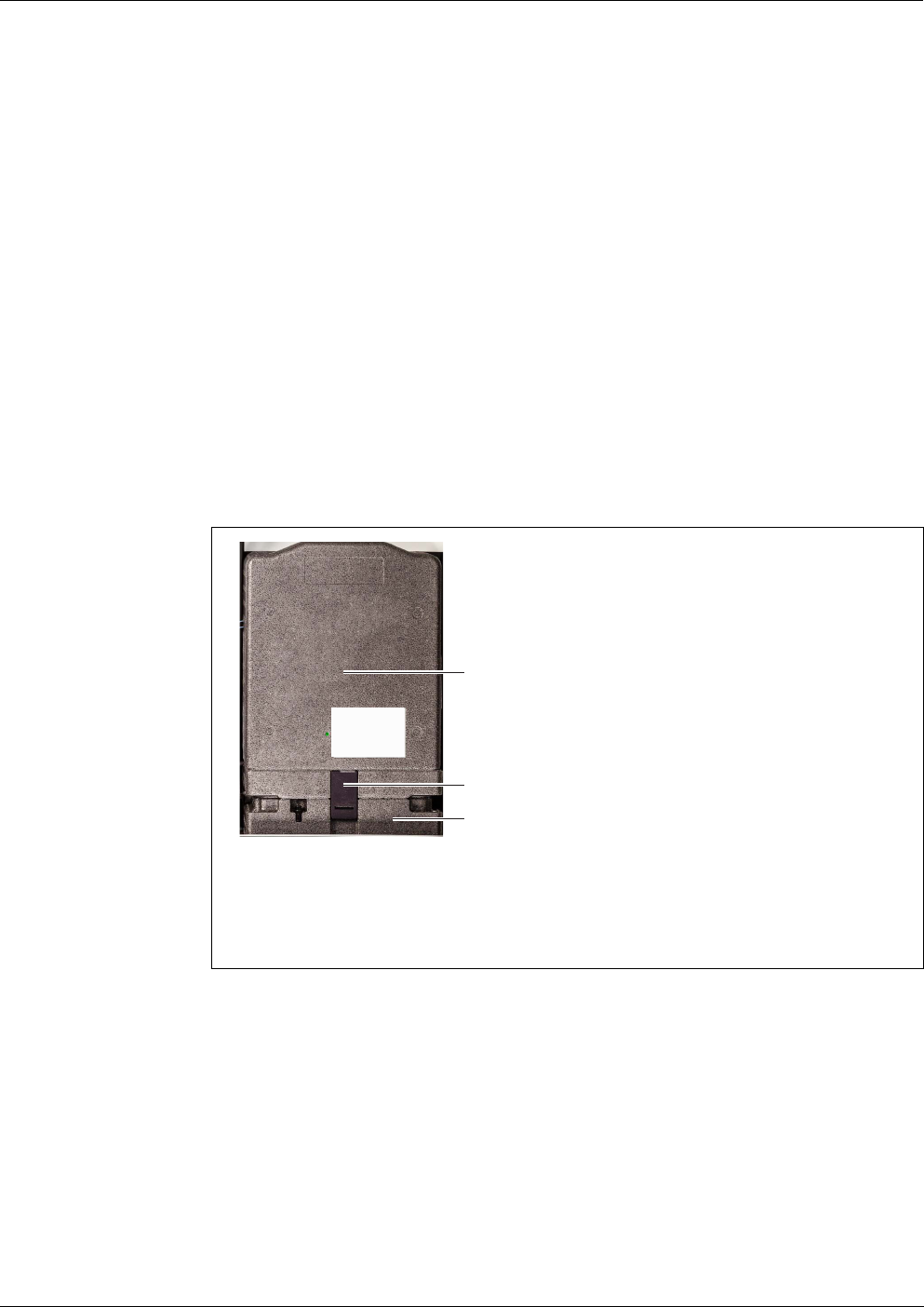
Alyza IQ PO4 Maintenance and cleaning (complex activities)
155
ba76201e09 12/2022
6.2.1 Dismounting the measuring unit
1 Decommission the measuring unit of the Alyza IQ (see section 6.1
Decommissioning, 149).
2 Secure the waste tube against leakage of liquids (e.g. with a rubber
stopper or absorbent paper).
3 Check the collection tray for moisture.
In case of larger amounts of moisture:
Dry the collection tray before removing it (see section 5.5.6 Check the
collection tray under the ChemBags for liquids, 119).
4 Unscrew the 2 fixing screws of the cover lid of the control unit ACM and
remove the cover lid of the ACM.
5 Unplug the 4 cables of the measuring unit from the control unit ACM and
let them hang to the front over the measuring unit.
figure 6-4 Fixing the measuring unit
1 Front cover of the measuring unit
2 Fixation of the measuring unit to the cooling unit
3 Cooling unit
6 Using one hand, grip the handle at the upper edge of the front cover (1)
of the measuring unit.
7 Pull the front cover of the measuring unit somewhat to the front against
the resistance.
8 Carefully take the front cover out to the front.
Put the front cover down in a clean place.
9 Check whether there is liquid in the collection tray under the ChemBags
(see section 5.5.6 Check the collection tray under the ChemBags for liq-
uids, 119).
2
1
3

Maintenance and cleaning (complex activities) Alyza IQ PO4
156
ba76201e09 12/2022
6.2.2 Carrying out complex maintenance activities
Carry out the maintenance- or cleaning activities at the dismounted measuring
unit, such as:
Check the waste collector for coating and clean it (see section 6.2.3 Check
the waste collector for coating, 156)
Details on further complex maintenance activities are given in the relevant doc-
umentation of the spare parts, e.g.:
Syringe body
Tubes of the photometer unit
6.2.3 Check the waste collector for coating
NOTE
A deposit in the waste collector (e.g. lime deposit) can obstruct the drainage of
the liquids and cause damage due to overflowing liquids .
NOTE
Damaged tubes may leak.
Folded or knotted tubes hamper the transport of the liquids. The tubes must not
be damaged, folded or knotted.
10 Pull the fixation (2) of the measuring unit to the cooling unit out from
below.
11 Take the measuring unit up off the cooling unit and tilt it backwards.
Then remove the measuring unit from the housing of the Alyza IQ, to the
front.
12 Put the measuring unit down in a flat and clean place.
13 Protect the cables, tubes, and measuring unit against loss of liquids and
against the penetration of dust and dirt (e.g. with rubber plugs or absor-
bent paper).
14 Remove the cables hanging to the front of the measuring unit from the
grooves at the back cover and lay them down.
15 Carry out the maintenance activities in the measuring unit.
1 Dismounting the measuring unit (see section 6.2.1, 155)
2 Remove the ChemBags from the supporting rod (see section 5.5.5,
118).
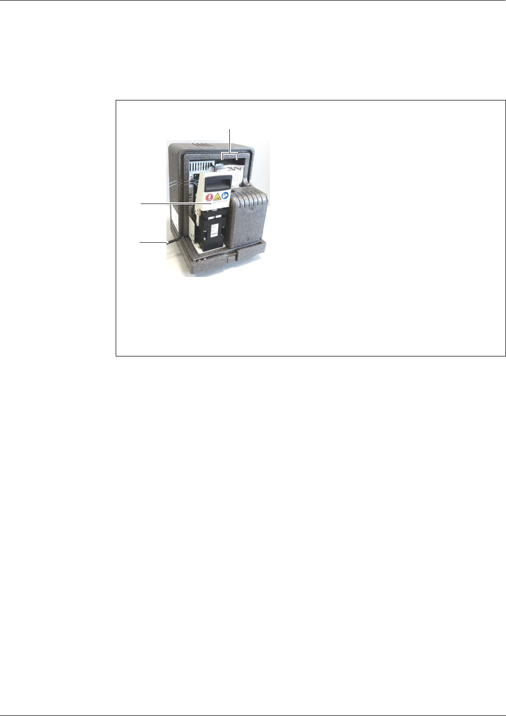
Alyza IQ PO4 Maintenance and cleaning (complex activities)
157
ba76201e09 12/2022
3 Behind the ChemBags, unscrew the 2 screws for the rear cover of the
measuring unit.
figure 6-5 Measuring unit, dismantled and open
1 Two screws to fasten the rear cover
2 Locking device of the MultiPort valve (MPV)
3 Waste tube
4 Tilt the rear cover of the measuring unit away to the rear.
1
3
2
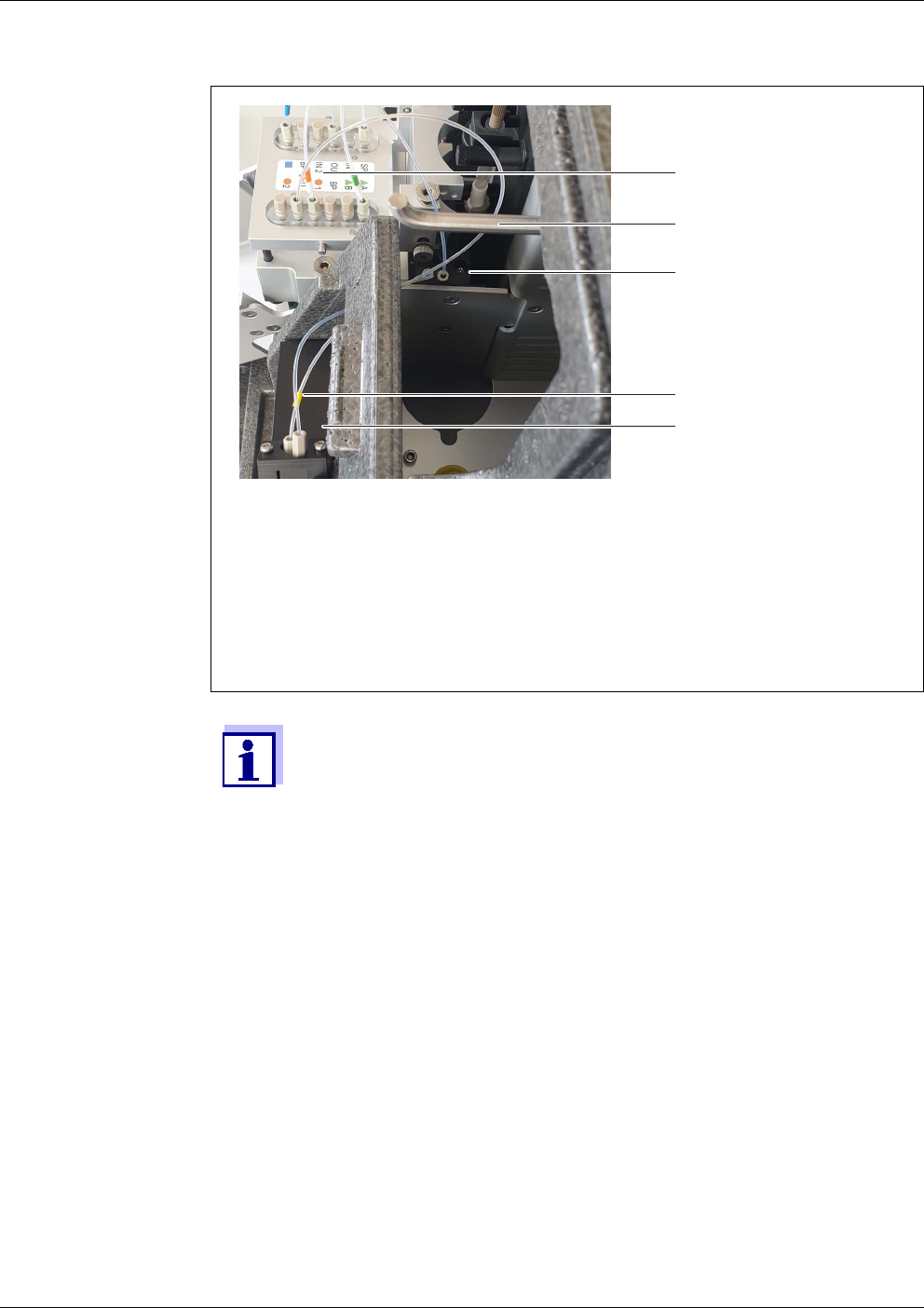
Maintenance and cleaning (complex activities) Alyza IQ PO4
158
ba76201e09 12/2022
figure 6-6 Lid of the waste collector with screw
1 Photometer
2 Photometer feed tube (yellow marking)
3 Lid of the waste collector with screw and 2 tubes
4 Empty supporting rod for ChemBags
5 MultiPort valve
The photometer feed tube (2) of the Alyza IQ PO4 is a sensitive
glass capillary. During the following steps, take care not to bend the
photometer feed tube (a sensitive glass capillary in the case of Alyza
IQ PO4) too much and thus damage it.
5 Loosen the screw on the lid (3) of the waste collector.
6 Pull the lid (3) of the waste collector with the two hoses upwards until
the bottom of the opened waste collector is visible.
7 Place the lid (with the two tubes plugged in) back onto the open waste
collector. The recess with the screw points to the rear.
8 Reinsert the rear cover of the measuring unit.
9 Reattach the rear cover with the 2 screws.
10 Hang the ChemBags back onto the supporting rod (see section 5.5.7,
121).
11 Remount the measuring unit (see section 6.2.4, 159).
5
3
1
4
2

Alyza IQ PO4 Maintenance and cleaning (complex activities)
159
ba76201e09 12/2022
6.2.4 Installing the measuring unit
6.3 Transport, storage
6.3.1 General notes
Please observe the allowed environmental conditions for transport and storage
of the Alyza IQ (see section 8.3 General data, 172).
Please not that no liquids or ChemBags may be in the Alyza IQ for storage and
transport.
NOTE
Inappropriate transport and inappropriate storage of the Alyza IQ (especially of
the measuring unit) can cause damage due to spilled liquids.
Safe transport and safe storage are only possible if the Alyza IQ is free from liq-
uids (tubes, photometer unit, overflow vessels empty; ChemBags removed).
1 Position the rear cover of the measuring unit at the measuring unit. Fix
it to the measuring unit by tightening the 2 screws.
2 Close the measuring unit with the front cover.
3 Press the cables of the measuring units into the grooves of the back
cover from the rear and let the plugs hang to the front.
4 Position the closed measuring unit on the cooling unit inside the housing
of the Alyza IQ.
5 Tilt the measuring unit slightly backwards and press it onto the cooling
unit.
The measuring unit must be tightly connected to the cooling unit so that
no moisture can penetrate.
6 Mount the measuring unit to the cooling unit (with the fixation of the
measuring unit).
7 Re-insert the waste tube into the collection funnel.
The liquid in the waste tube must be able to flow freely (steady slope,
no kinking, no damage).
8 Screw the sample tubes of the measuring units to the overflow vessels.
The sample tube for overflow vessel 2 is labeled red.
9 Re-plug the 4 data cables of the measuring unit to the ACM.
10 Re-plug the 2 power supply cables to the switch box.
11 Reinsert the cover in front of the ACM and fix it with the 2 screws.
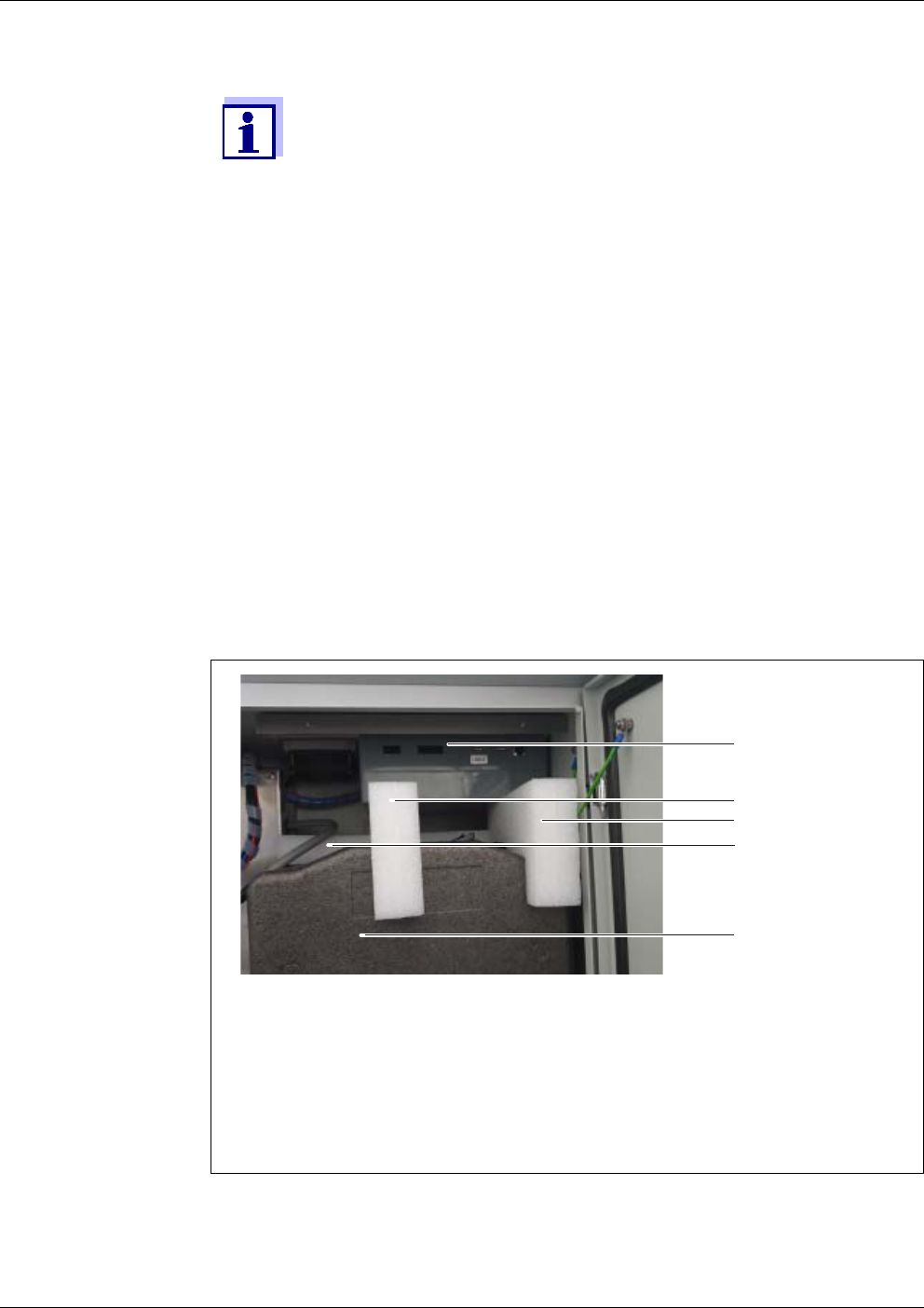
Maintenance and cleaning (complex activities) Alyza IQ PO4
160
ba76201e09 12/2022
6.3.2 Preparing the Alyza IQ for transport or storage
Preparing the
measuring unit for
transport or
storage
Preparing the
basic instrument
for transport or
storage
Even minor damage to tubes or ChemBags due to mechanical
stress (e.g. pressure, shock etc.) or thermal impact (e.g. frozen liq-
uids) can cause consequential damage due to spilled liquids.
1 Decommission the Alyza IQ (see section 6.1 Decommissioning, 149)
2 Open the front cover of the measuring unit.
3 Remove all ChemBags from the supporting rod.
4 Remove the cover of the control unit ACM.
5 Unplug the 4 cables from the control unit ACM.
6 Close the measuring unit.
7 Fix the measuring unit in its position inside the housing of the Alyza IQ
with the 3 original transportation safety devices.
figure 6-7 Transportation safety devices
1 Control unit with connectors
2 Transport protector 1 in the front
3 Transport protector 2 in the front
4 Transport protector 3 in the background
5 Measuring unit
3
4
5
2
1
8 Switch the power line potential free.

Alyza IQ PO4 Maintenance and cleaning (complex activities)
161
ba76201e09 12/2022
9 Remove the mounting plate (section 3.3.13 CONNECTING THE POWER
CABLE AND HEAT TRACING LINES).
WARNING
When the power supply box is open, there is a danger to
life from electric shock. Observe the following points:
The power supply box may only be opened when it is
de-energized.
The power supply box may only be opened by a quali-
fied electrician.
10 Open the power supply box (see section 3.3.13 C
ONNECTING THE
POWER CABLE AND HEAT TRACING LINES).
11 Disconnect the cables of the heat tracings.
12 Disassemble the liquid lines (with heat tracings):
1 or 2 intake lines (with heat tracings)
1 or 2 return lines (with heat tracings)
13 Close the power supply box (see section 3.3.13 C
ONNECTING THE
POWER CABLE AND HEAT TRACING LINES).
14 Reinstall the mounting plate (see section 3.3.13 C
ONNECTING THE
POWER CABLE AND HEAT TRACING LINES)
15 Close the openings at the bottom of the housing again with the cable
glands.
16 Close the doors of the Alyza IQ and secure the doors against inadver-
tent opening.
17 Disconnect the power line from the separator.
18 Disconnect the IQ S
ENSORNET cable of the Alyza IQ from the
IQ S
ENSORNET module.
19 With the terminal holder installed:
Disconnect all IQ S
ENSORNET cables from the IQ SENSORNET mod-
ule.
Remove the terminal holder (TM).
20 Secure the housing of the Alyza IQ against being damaged (e.g. by
shock, overturning, falling, sliding, etc.).
21 Check the condition of the Alyza IQ with the checklist for transport and
storage.

Maintenance and cleaning (complex activities) Alyza IQ PO4
162
ba76201e09 12/2022
Preparing the
ChemBags for
transport or
storage
Checklist
storage and
transport
6.4 Recommissioning the Alyza IQ
22 For transport, pack the ChemBags leakproof and protected against any
mechanical stress (e.g. shock, folding) and thermal impact (e.g. tem-
peratures too high or too low).
Is the Alyza IQ prepared for transport or storage (see section 6.1
Decommissioning, 149)?
Is the system empty (tubes, MultiPort valve, photometer unit) ?
Are the overflow vessels empty?
Were the ChemBags removed from the supporting rod?
Is the measuring unit fixed inside the housing with the 3 original
transportation safety devices?
Are the housing doors closed and secured against inadvertent open-
ing?
Is the housing secured against shock, falling, overturning and slid-
ing?
23 Transport or store the Alyza IQ.
24 Always transport or store the ChemBags separately from the measuring
unit or housing of the Alyza IQ.
On recommissioning, the data of the last used components (measur-
ing unit, ChemBags) are automatically used again.
Installing any components with the Install wizard is only required if
other components should be installed.
1 For recommissioning, proceed in the same way as for the initial com-
missioning (see section 3 Commissioning, 25).

Alyza IQ PO4 What to do if ...
163
ba76201e09 12/2022
7 What to do if ...
Display “----”
Information on the cause of the indication is in the log book and in
the Alyza menu / tab Status.
Cause Remedy
No (valid) measured value
available
Start measurement and wait for the mea-
surement to be finished (5 ... 7 min)
Three erroneous automatic
calibrations in succession
Check the calibration standards
(e.g. expiry date)
Check the connection of the calibration
standards
(for 1-point calibration the ChemBag at
connector 'S1' is always used.)
Refill the tubes for the ChemBags with
standard solutions
Alyza menu / tab Maintenance / Manual
maintenance/Fill the system
Carry out a cleaning cycle
Alyza menu / tab Maintenance / Manual
maintenance/Clean
Exchange calibration standards
Contact the service department
Status ERROR
The Alyza IQ is stopped
General proceeding
View the details of the error
e.g. in the Alyza menu / tab Status (dis-
play details with <OK>)
or
View the log book message
Reset the error:
(Alyza menu, tab Maintenance / Manual
maintenance / Reset errors)
Remedy the error
START Alyza IQ
If the Status ERROR is still there:
Contact the service department

What to do if ... Alyza IQ PO4
164
ba76201e09 12/2022
Status ERROR
The liquids from one or sev-
eral ChemBags are not trans-
ported to the MultiPort valve
View the log book message
Check the filling level of the ChemBags
Check the connection of the tubes
Empty and refill the tube
Alyza menu / tab Maintenance / Manual
maintenance / Drain the system and Fill
the system
Status ERROR
Sample intake does not work
Check the filtration pump
Check and, if necessary, clean the filter
plate
Switch on the filtration pump
Clean the overflow vessel and intake
line
Status ERROR
The temperature in the mea-
suring unit or photometer unit
Alyza IQ is outside the allowed
range
(e.g. due to the air circulation
in the Alyza IQ being
impeded)
Measuring (automatically or manually) is
only possible if the operating temperature
in both the measuring unit and photometer
unit is in the allowed range.
Check for contamination and, if neces-
sary, exchange the filter mats at the
housing (see section 5.7.2, 136)
Check for contamination and, if neces-
sary, clean the bug screen
Check for contamination and, if neces-
sary, clean the condensate drain
adapter
Cause Remedy

Alyza IQ PO4 What to do if ...
165
ba76201e09 12/2022
Display of OFL
Status ERROR
Danger of condensation water
forming in the measuring unit
View the details of the error
e.g. in the Alyza menu / tab Status (dis-
play details with <OK>)
or
View the log book message
Start the dehumidifying program for the
measuring unit
Alyza menu/ tab Maintenance / Manual
maintenance /Dry the measuring unit
START Alyza IQ
Power failure In the Alyza menu (tab Maintenance),
start the Alyza IQ.
If necessary, activate the function "Auto-
matic start after power failure“
Unknown See log book or Alyza menu / tab Status
(display details with <OK>)
Cause Remedy
Cause Remedy
Measuring range exceeded Select different measuring range
Calibration error Check the calibration standards
(e.g. expiry date)
Check the connection of the calibra-
tion standards
(for 1-point calibration the ChemBag
at connector S1 is always used.)
Refill the tubes for the ChemBags with
standard solutions
Alyza menu / tab Maintenance / Man-
ual maintenance / Fill the system
Carry out a cleaning cycle
Alyza menu / tab Maintenance / Man-
ual maintenance / Clean
Exchange calibration standards
Contact the service department
Measuring cell of the photometer
unit dirty
Clean
Alyza menu / tab Maintenance / Man-
ual maintenance / Clean)
Contact the service department

What to do if ... Alyza IQ PO4
166
ba76201e09 12/2022
Display of ERROR
Implausible
measured values
Cause Remedy
Alyza IQ is not properly con-
nected
Check the assignment of the terminal
connections
Communication between
Alyza IQ and IQ S
ENSORNET is
interrupted
Check the cable and connections
The electrical power supply of
the Alyza IQ is interrupted
Check the power supply
Check the maximum load
Cause Remedy
Erroneous measurement Wait for another measurement
Calibration error Repeat calibration
Check the calibration standards
Check the connection of the calibra-
tion standards
(for 1-point calibration the ChemBag
at connector S1 is always used.)
Refill the tubes for the ChemBags
with standard solutions
Alyza menu / tab Maintenance / Man-
ual maintenance / Fill the system
Exchange calibration standards
Increase the time between cleaning
and calibration.
Measured values always too
high after cleaning
Activate the function Conditioning
(menu Settings of sensors and diff. sen-
sors / Autom.cleaning).
After cleaning, a rinse is carried out for
each of the set number of steps and then
a rinse with the sample and the added
reagent.

Alyza IQ PO4 What to do if ...
167
ba76201e09 12/2022
Measuring mode
cannot be set
Measuring cell of the photometer
unit dirty
Carry out a cleaning cycle
Alyza menu / tab Maintenance / Man-
ual maintenance / Clean
Contact the service department
Interferences
e.g. in sample matrix
Activate the function Backgr.
corr.(opt).
PLEASE NOTE:
For the optimized background correc-
tion, an extra tube and an extra
ChemBag have to be installed (see
section 5 Maintenance and cleaning,
101).
Select suitable measuring location
Photometer unit draws in air (e.g.
air bubbles in the sample tube)
Reduce the pump capacity of the fil-
tration pump (set to approx. 2 - 5 %).
Check the screw couplings of the
tubes for tightness.
Cause Remedy
Cause Remedy
Alyza IQ is not stopped Stop the Alyza IQ

What to do if ... Alyza IQ PO4
168
ba76201e09 12/2022
Red signal LED at
the measuring unit
The system cannot
be emptied via the
Alyza menu
Storing the
detailed operating
data of the
Alyza IQ
Cause Remedy
LED lights up red.
Error causing the STOP of the
Alyza IQ
Check and, if necessary, eliminate the
error message in the log book
LED flashes red
A beep is to be heard.
The front cover of the measuring unit
is open. There is risk of damage due
to the formation of condensation water
within the measuring unit. Close the
measuring unit immediately. After
being open for 3 minutes, the measur-
ing unit is automatically separated
from the power supply to avoid dam-
age due to a short-circuit on the PCB.
To open the measuring unit for main-
tenance activities without any risk:
– Before, start the function Prepare
to open measuring unit.
– Wait until the opening of he mea-
suring unit is released
The locking device of the MultiPort
valve is open. There is a risk of dam-
age due to leaking chemicals (see
section 5.2, 102).
Cause Remedy
Defective component, e.g.:
– Syringe pump
– MultiPort valve (MPV)
–ACM
–ACS
– Power supply module
– ...
Empty the system manually (see
section 5.9 Emptying the system man-
ually, 144).
Then exchange the defective compo-
nent.
Contact the service department
Cause Remedy
e.g. request by service depart-
ment
Transmit the detailed operating data of
your Alyza IQ to a USB memory device
(see section 4.6.2, 97).

Alyza IQ PO4 What to do if ...
169
ba76201e09 12/2022
Collection tray
under the
ChemBags is
moist
Cause Remedy
ChemBag is leaking
MPV is leaking
Empty the tray and dry it (e.g. with a
paper towel)
Caution, chemicals
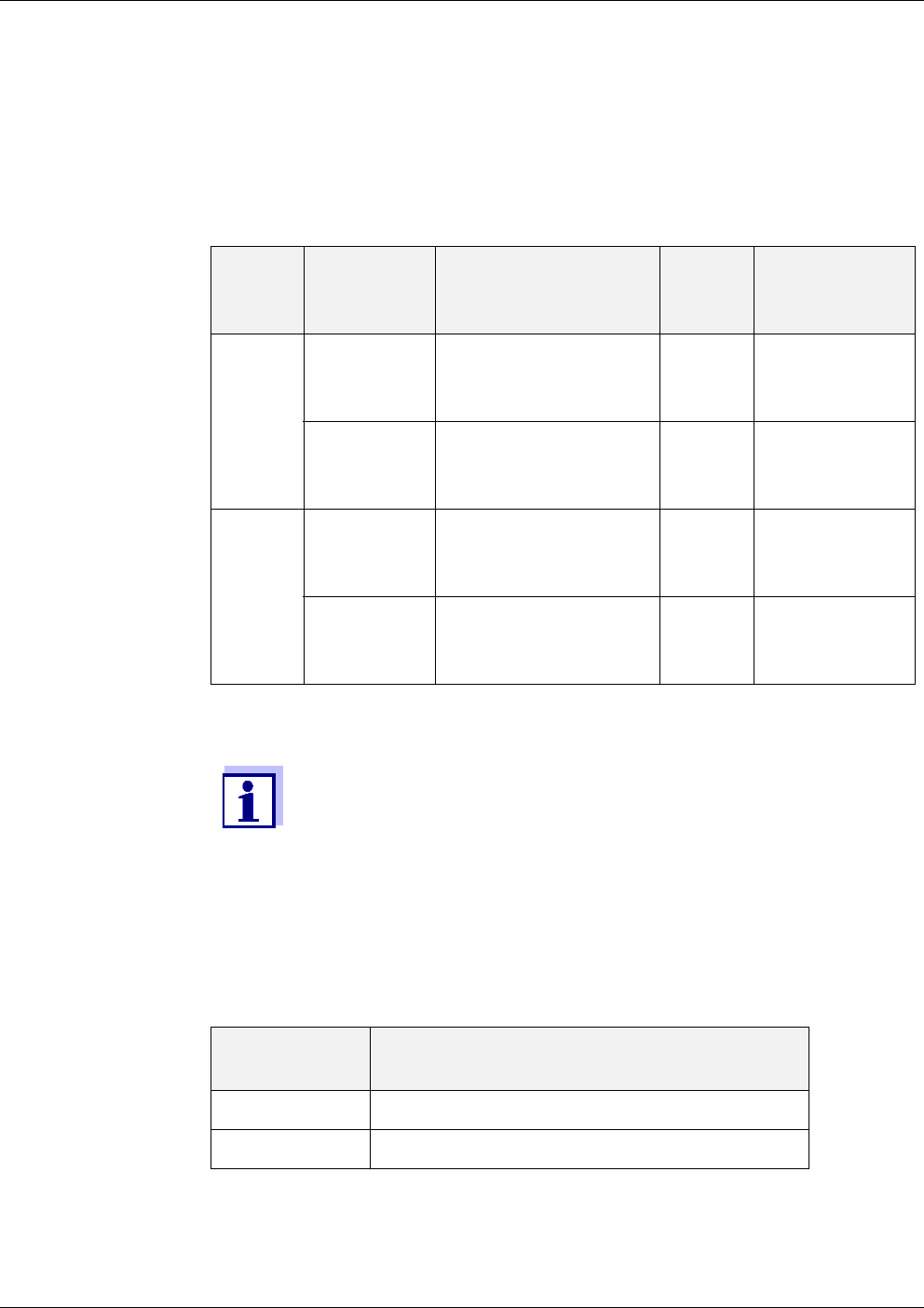
Technical data Alyza IQ PO4
170
ba76201e09 12/2022
8 Technical data
8.1 Measuring characteristics PO4-P, PO4
Measuring method Vanadate molybdate method (yellow method) in combination with an LED pho-
tometer
Measuring ranges
and resolution
All specifications concerning the measuring accuracy refer to the use of suitable
standard solutions.
Response time t90 < 5min
Process variation
coefficient
< ±2%
Detection limit
Mea-
suring
range
Measuring
mode (cita-
tion form)
Measuring ranges Reso-
lution
Accuracy
1 PO4-P 0.02 ... 15.00 mg/L
0.02 ... 15.00 ppm
0.6 ... 480.0 umol/L
0.01
0.01
0.1
±2 % , ±0.02
±2 % , ±0.02
±2 % , ±0.6
PO4 0.06 ... 46.00 mg/L
0.06 ... 46.00 ppm
0.6 ... 480.0 umol/L
0.01
0.01
0.1
±2 % , ±0.06
±2 % , ±0.06
±2 % , ±0.6
2 PO4-P 0.2 ... 50.0 mg/L
0.2 ... 50.0 ppm
6 ... 1600 umol/L
0.05
0.05
1
±2 % , ±0.2
±2 % , ±0.2
±2 % , ±6
PO4 0.6 ... 153.0 mg/L
0.6 ... 153.0 ppm
6 ... 1600 umol/L
0.05
0.05
1
±2 % , ±0.6
±2 % , ±0.6
±2 % , ±6
The display ranges are extended to 0.00 each at the lower measur-
ing range limits.
Measuring
range
Detection limit
1 ≤ 0.02 mg/L PO4-P
2 ≤ 0.05 mg/L PO4-P
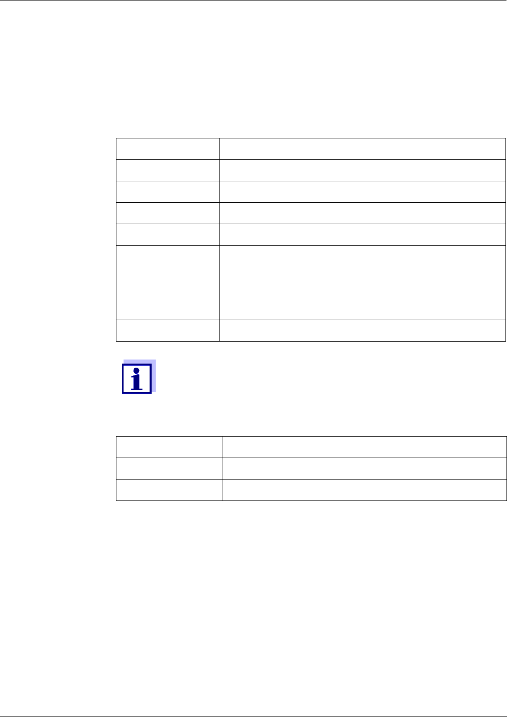
Alyza IQ PO4 Technical data
171
ba76201e09 12/2022
8.2 Application conditions
Suitability and
areas of
application
The Alyza IQ analyzer is designed for online measurements of the orthophos-
phate concentration (PO4) in aqueous samples (e.g. in the effluents of waste
water treatment plants), and to control and regulate the elimination of phospho-
rus in waste water treatment plants.
Requirements of
the measuring
medium (by the
measuring unit)
The FM/PC can be used if the test sample meets the following requirements.
Requirements of
the test sample
(by the filtration
system)
Temperature +4 … +45 °C (+39 … +113°F)
pH value 5…9
Solids contents 0 (max. particle size: 0.45 µm)
Bacteria 0 (as far as possible, free from bacteria)
Air bubbles 0 (as far as possible, free from air bubbles)
Required flow rate Volume surge of the sample in the overflow vessel: < 1
ml/surge or,
with quasi continuous supply:
Volume flow of the sample in the overflow vessel:
1 ... 25 ml/min
Hardness Total hardness < 3.5 mmol/l (20 °dH)
The requirements of the test sample are met by using the FM/PC fil-
ter module available as an accessory.
Temperature +4 … +45 °C (+39 … +113°F)
pH value 5…9
Solids contents < 6 g/l
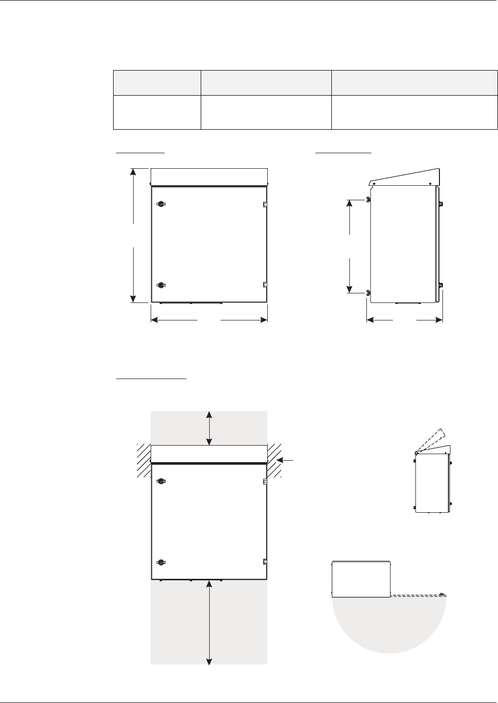
Technical data Alyza IQ PO4
172
ba76201e09 12/2022
8.3 General data
Dimensions and
weight
figure 8-1 Dimension drawing of Alyza IQ housing (dimensions in mm)
Component Height x width x depth Weight (without chemicals)
Housing with
components
825 x 675 x 445 mm up to approx. 50 kg
(depending on equipment)
675 445
775
approx. 500
540
approx. 200
Space to open the lid
Lid
Access to lid screws
from both sides
Opening angle
180 °
Front view:
Required space
Lateral view:
Space for
- connections
- ventilation
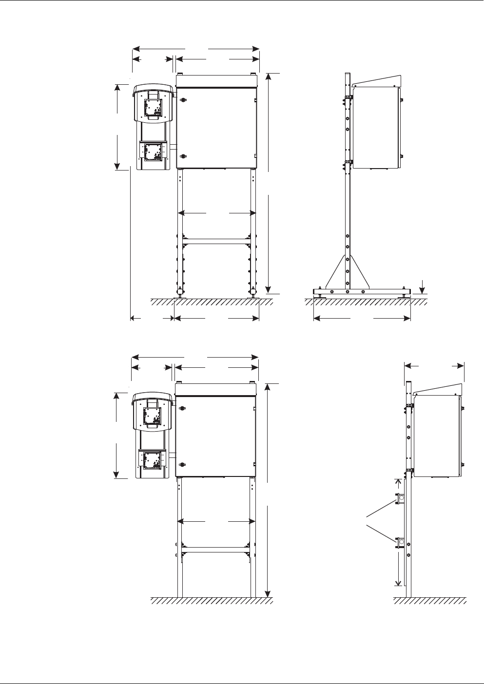
Alyza IQ PO4 Technical data
173
ba76201e09 12/2022
figure 8-2 Dimension drawing of Alyza IQ, installation on a mounting stand (dimensions in mm)
figure 8-3 Dimension drawing of Alyza IQ, rail mounting (dimensions in mm)
Connection
technique
Connection to the IQ SENSORNET with the IQ SENSORNET cable
~ 20-50
710 810
1850
332
721
657
650
344
1050
~ 500
721
657
650
344
1050
1850
Height is variable
Rail pipe diameter
max. 50 mm

Technical data Alyza IQ PO4
174
ba76201e09 12/2022
Ambient
conditions
Components
Temperature range
Mounting/installation/
maintenance
+ 5 ... + 40 °C (+ 41 ... +104 °F)
Operation - 20 … + 40 °C ( - 4 … + 104 °F)
Storage - 20 …+ 50 °C (- 4 … + 122 °F)
(in completely empty condition)
Relative air humidity Max. 95 % (noncondensing)
Mounting/installation/
maintenance
≤ 80 %
Yearly average ≤ 90 %
Dew formation Possible
Environment non-corrosive, non-saline.
Operation in a moist, saline atmosphere (e.g.
near the sea) can lead to corrosion of metallic
components.
Measuring location Indoors and outdoors
Site altitude Max. 4000 m above sea level
Level of contamination 2
Chloride concentration < 500 mg/l (no sea water)
Housing Sunlight (UV) resistant
Material: powder-coated aluminium
Mounting plate: PVC
Housing of the measuring
unit
EPP foam
Cable glands at the base
plate
M40 x 1.5 (black, large):
Clamping range 19 - 28 mm
M20 x 1.5 (black, small):
Clamping range 6.5 - 12 mm
Overflow vessel Material: PMMA
Required sample quantity:
1... 25 ml/min
For correct measurements, enough sample
must always be available in the overflow ves-
sel.
Temperature control Heating, cooling, ventilation

Alyza IQ PO4 Technical data
175
ba76201e09 12/2022
Accessories
Meter safety
Test certificates CE, cETLus
8.4 Electrical data
Light source for photome-
ter
LED, 400 nm (violet)
MultiPort valve (MPV) Material: PMMA, fluoroplastic, aluminum
Mounting stand, wall
mount and rail mount
Rails: Stainless steel V2A,
Screws etc.: stainless steel V2A, V4A
Filtration unit Membrane surface of the filter plate: 1300 cm
2
Cut-off limit: < 0.45 µm
Max. operating temperature: 45 °C (113 °F)
Max. suction height: 5 m
pH value: 2…11.5
Housing: PVC
Sleeve tube: PVC-reinforced PCV tube, trans-
parent, 24 x 3 mm
Intake line: PE 4 x 1 mm
Line length (intake line, return line): Max. 20 m
Applicable norms EN 61010-1
UL 61010-1
CAN/CSA C22.2#61010-1
Electromagnetic compati-
bility
EN 61326-1, EN 61326-2-3,
FCC 47 CFR Part 15
Type of protection (hous-
ing)
IP 54 (EN 60529)
Type of protection
(internal power supply box)
IP 67 (EN 60529)
Protective class I
Overvoltage category II
Input voltage 120 V / AC ±10% / 60 Hz
Fuse protection of the
building
16 A with ground fault circuit interrupter
Line power connection 3-pin, N/L /PE
Line cross-section of line
power connection
Europe: 1.5 ... 4.0 mm
2
USA: AWG 14 ... 12

Technical data Alyza IQ PO4
176
ba76201e09 12/2022
8.5 Consumption data
The consumption of chemicals depends on the specified intervals and on the se-
lected measuring range.
Typical
consumption
values
Cable (requirements) Europe: IEC 60332-1-2
USA, Canada: UL 2556 VW-1
Details:
Temperature resistant
in the range -20 °C…+80 °C
(-68 °C…+176 °F),
Weather-resistant (year-round)
Watertight (cable sheath)
Copper wire
Power consumption
Alyza IQ
300 - 1600 W
(depending on the length of the heat tracing)
Basic consumption 300 W
Heat tracing, intake line
return line
16 W/m
(max. 80 m heat tracing allowed)
IQ S
ENSORNET cable
(SNCIQ, SNCIQ/UG,
SACIQ)
Insulation ≥ 500 V
Temperature resistant
in the range -20 °C…+80 °C
(-68 °C…+176 °F),
Weather-resistant (year-round)
Watertight (cable sheath)
Power delivery to the
IQ S
ENSORNET
max. 10 W
Solution Sufficient for
Reagent solution
R-PO4/1-1A/B (MR1)
R-PO4/1-2A/B (MR2)
Examples:
– 3 months (measuring interval 5 min-
utes)
(only MR1)
– 6 months (measuring interval 10 min-
utes)
Cleaning solution
C-PO4/1-1
6 months (daily cleaning)
Standard solution
S-PO4/1-0.0/-1.1/-1.10/-40
6 months (daily calibration)
Alyza IQ PO4 Lists
177
ba76201e09 12/2022
9Lists
9.1 Explanation of the messages
This chapter contains a list of all message codes and the related message texts
that can occur in the log book of the IQ S
ENSORNET system for the Alyza IQ an-
alyzer.
The last three digits of the message code form the component code. It identifies
the component (active component) that caused the message:
Some error messages contain an internal error code, starting with "#".
9.1.1 Error messages
Information on the contents and structure of the log book and the
structure of the message code is given in the L
OG BOOK chapter of
the IQ S
ENSORNET system operating manual.
Module code Component
3D1 Alyza IQ PO4, channel 1
3D2 Alyza IQ PO4, channel 2
552 MIQ/Alyza (adapter ADA)
Message code Message text
EA1552 Meas. range exceeded or undercut
* Check process
* Select other meas. range
EA2552 Sensor temperature too high!
* Check process and application
EA3552 Sensor temperature too low!
* Check process and application
EAM552 Meas. range exceeded or undercut
* Check process
EC1552 Calibration error: Calibration standard could not be determined or is
not suitable for current measurement range. Alyza IQ is stopped.
* Check the current measurement range
* Check the calibration standard used

Lists Alyza IQ PO4
178
ba76201e09 12/2022
EI1552 Operational voltage too low
* Check installation and cable lengths, Follow installation instruc-
tions
* Power supply module(s) overloaded, add power supply module(s)
* Check terminal and module connections
* Defective components, replace components
EI2552 Operational voltage too low, no operation possible
* Check installation and cable lengths, Follow installation instruc-
tions
* Power supply module(s) overloaded, add power supply module(s)
* Check terminal and module connections
* Defective components,
replace components
EI3552 Operational voltage too low
* Check installation and cable lengths, Follow installation instruc-
tions
* Power supply module overloaded
* Check terminal and module connections
* Defective component, replace components
EI4552 Operational voltage too low, no operation possible
* Check installation and cable lengths, Follow installation instruc-
tions
* Power supply module overloaded
* Check terminal and module connections
* Defective component,
replace components
EI5552 The measuring unit is not compatible!
* Contact service
EIA552 Communication fault between MIQ/Alyza and ACM
* Check cable connections
* Check the power supply of the Alyza IQ
* Contact service
ES1552 Component hardware defective
* Contact service
ES2552 Component hardware defective xxx
* Contact service
ES3552 Danger of condensation water forming in the measuring unit. The
measuring unit is switched off.
* Dry the measuring unit
Message code Message text

Alyza IQ PO4 Lists
179
ba76201e09 12/2022
ES4552 'Ready to measure could not be established after 1 hour. Alyza IQ
was stopped.
* Check climate control
* Check/close doors, front cover of measuring unit.
* Check IQ logbook and info window
ES5552 Communication failure with ACS
* Check ACS connection
ES6552 Pressure on port xxx too high.
* Check the liquid circle for erros and replace maintenance parts if
necessary.
ES7552 Dosing of xxx failed several times
* Make sure that tubes, ChemBags and couplings are free from air
bubbles.
ES8552 Error initializing MPV and syringe pump.
* Drain the system manually (see operating manual)
* Replace the MPV
* Contact service
ES9552 The locking device of the MPV is open. The Alyza IQ was stopped.
* Close the locking device of the MPV
ESA552 Error of photometer LED: The Alyza IQ was stopped.
* Contact service
ESB552 Error MPV: No MPV detected. The Alyza IQ was stopped.
* Install the MPV correctly (see operating manual)
* Contact service
ESC552 Error syringe pump: The Alyza IQ was stopped.
* Contact service
ESD552 Pressure xxx too high. The Alyza IQ was stopped.
* Contact service
ESE552 Error of valve V2: The Alyza IQ was stopped.
* Contact service
ESF552 Error pressure sensor PS1: Pressure sensor PS1 defective. The
Alyza IQ was stopped.
* Contact service
ESG552 Error MPV tightness: The Alyza IQ was stopped.
* Drain the system manually (see operating manual)
* Replace the MPV immediately via Alyza menu
ESH552 Error MPV tightness: The Alyza IQ was stopped.
* Drain the system via Alyza menu
* Replace the MPV immediately via Alyza menu
Message code Message text

Lists Alyza IQ PO4
180
ba76201e09 12/2022
ESI552 Fehler MPV Dichtigkeit: Der Alyza IQ wurde gestoppt.
* Replace the MPV immediately via Alyza menu
ESJ552 ACS board cross changed!
* Contact service
ESK552 New ACS board, missing backup!
* Contact service
ESL552 ACS software too old, no restore to ACS board!
* Update software
ESM552 ACS backup error xxx
ESO552 Power output into IQ SensorNet too high
* Check installation and length, see installation instruction
* Power supply overloaded, add power supply
* Check clamping and modul connections
* Replace defective devices
ESP552 Error drive blockade MPV: The Alyza IQ was stopped. Syringe
pump locked.
* Drain the system manually (see operating manual)
* Contact service
ESQ552 Dosing of xxx failed several times. sample is missing.
* Check sample flow
ESR552 Error MPV-positioning: The Alyza IQ was stopped.
* Contact service
ESS552 'Climate control not fully functional!
* Indoor temperature sensor defective
* The Alyza IQ was stopped
* Attention: Emergency operation due to danger of frost!
* Contact service
EST552 'Climate control not fully functional!
* Temperature sensor of the measuring unit defective
* The Alyza IQ was stopped
* Contact service
ESU552 'Climate control not fully functional!
* Temperature sensor of the ACM control unit defective
* Caution: Danger of condensation when opening the measuring
unit!
* Contact service
ESV552 Heating photometer defective!
* Contact service
Message code Message text

Alyza IQ PO4 Lists
181
ba76201e09 12/2022
9.1.2 Informative messages
ESW552 Filling error: xxx
ESX552 Error MPV blocking: Alyza IQ was stopped. System was drained.
* Check MPV and piping to syringe pump
* Contact service
ESY552 Error MPV blocking: Alyza IQ was stopped.
* Drain the system manually (see operating manual)
* Check MPV and piping to syringe pump
* Contact service
Message code Message text
Message code Message text
IA1552 Please check the remaining times of the ChemBags.
IA2552 Permissible internal temperature of the basic unit has been under-
shot! Acute danger of frost!
* Observe permissible outside temperature for operation
* Keep doors closed
* Check heater basic unit for blocking
* In case of defect: Contact Service
IA3552 Permissible internal temperature of basic unit has been exceeded!
* Keep doors closed
* Check fan grille for blockage
* Observe permissible outside temperature for operation
* In case of defect: Contact Service
IC2552 Sensor still successfully calibrated,
Calibration in limit range
* Service sensor as soon as possible
(see operating manual)
* View calibration history
* Check calibration conditions and calibration standard
IC7552 Calibration error: Calibration standard could not be determined or is
not suitable for current measurement range.
Calibration is rejected. Measurement will be continued with active
valid calibration!
* Check the current measurement range
* Check the calibration standard used

Lists Alyza IQ PO4
182
ba76201e09 12/2022
IC8552 Calibration error: dosing or pressure error xxx.
Calibration is rejected. Measurement will be continued with active
valid calibration!
* Make sure that tubes, ChemBags and couplings are free from air
bubbles.
* Check the liquid circle for errors and replace maintenance parts if
necessary.
* Clean the liquid circle
IC9552 Cleaning error: dosing or pressure error xxx.
* Make sure that tubes, ChemBags and couplings are free from air
bubbles.
* Check the liquid circle for erros and replace maintenance parts if
necessary.
* Clean the liquid circle
II1552 Language not available,
Default language German
* Contact service
IS1552 The front cover of the measuring unit.is open. Danger of condensa-
tion water.
* Close the front cover of the measuring unit immediately
IS3552 MPV has been changed!
IS4552 Warning MPV tightness. MPV replacement recommended.
IS5552 ACS backup created!
IS6552 ACS backup restored!
IS7552 Missing USB flash drive or Alyza control file!
* Contact service
IS8552 Cell exchanged!
IS9552 Vtot determined!
ISA552 VPark determined!
ISB552 Alyza IQ has been reconfigured!
ISC552 Temperature control not working properly!
* Current interruption housing fan
* Contact service
ISD552 Temperature control not working properly!
* Housing fan
* Contact service
Message code Message text

Alyza IQ PO4 Lists
183
ba76201e09 12/2022
ISE552 Temperature control not working properly!
* Caution: frost danger if ambient temperature falls below 0°C
* Power interruption of housing heating
* Contact service
ISF552 Temperature control not working properly!
* Heating of the basic instrument
* Caution: frost danger if ambient temperature falls below 0°C
* Contact service
ISG552 Temperature control not working properly!
* Power interruption at the peltier element of cooling unit
* Contact service
ISH552 Temperature control not working properly!
* Peltier element of cooling unit
* Contact service
ISI552 Temperature control not working properly!
* Power interruption of outside fan peltier element
* Peltier element turned off
* Contact service
ISJ552 Temperature control not working properly!
* Outside fan peltier element
* Contact service
ISK552 Temperature control not working properly!
* Current interruption inside fan peltier element
* Peltier element turned off
* Contact service
ISL552 Temperature control not working properly!
* Inside fan peltier element
* Contact service
ISM552 Temperature control not working properly!
* Current interruption heating measure unit
* Contact service
ISN552 Temperature control not working properly!
* Heating of measuring
* Contact service
ISO552 Internal voltage implausible
* Contact service
ISP552 'Climate control not fully functional!
* Humidity measurement of the ACM control unit defective.
* Measurement is not affected.
* Attention: Opening the measuring unit can take decidedly longer.
* Contact service
Message code Message text

Lists Alyza IQ PO4
184
ba76201e09 12/2022
ISQ552 Temperature control not working properly!
* Housing fan turned off
* Contact service
ISR552 Temperature control not working properly!
* Heating of the basic instrument turned off
* Caution: frost danger if ambient temperature falls below 0°C
* Contact service
ISS552 -
IST552 Temperature control not working properly!
* Peltier element of cooling unit turned off
* Contact service
ISU552 Temperature control not working properly!
* Outside fan and peltier element turned off
* Contact service
ISV552 Temperature control not working properly!
* Inside fan and peltier element turned off
* Contact service
ISW552 Temperature control not working properly!
* Heating of measuring unit turned off
* Contact service
Message code Message text
Alyza IQ PO4 Lists
185
ba76201e09 12/2022
9.2 Status info
The status info is a coded piece of information on the current status of a sensor.
Each sensor sends this status info to the controller. The status info of sensors
consists of 32 bits, each of which can have the value 0 or 1.
Status info,
general structure
The bits 0 - 15 are reserved for general information.
The bits 16 - 21 are reserved for internal service information.
You obtain the status info:
• via a manual query in the menu Settings/Service/List of all components (see
IQ S
ENSORNET system operating manual)
• by an automated query
• from a superordinate process control (e. g. when connected to the Pro-
fibus)
• from the IQ Data Server (see IQ S
ENSORNET Software Pack operating
manual)
The evaluation of the status info, e.g. in the case of an automated query, has to
be made individually for each bit.
Status info
Alyza IQ
01234567 89101112131415
1 0 0 0 0 0 0 0 0 0 0 0 0 0 0 0 (general)
0 0 0 0 0 0 0 0 0 0 0 0 0 0 0 0 (internal)
16 17 18 19 20 21 22 23 24 25 26 27 28 29 30 31
Status bit Explanation
Bit 0 Component hardware defective
Bit 1 ERROR
The Alyza IQ is stopped
Bit 2 Please check the remaining times of the ChemBags.
Bit 3 -
Bit 4 - 31 -
Disposal Alyza IQ PO4
186
ba76201e09 12/2022
10 Disposal
Handle and dispose of all waste in compliance with local laws and regulations.
EU only: Correct disposal of this product — WEEE Directive on waste
electrical and electronic equipment
This marking on the product, accessories or literature indicates that the
product should not be disposed of with other waste at the end of its working
life.
To prevent possible harm to the environment or human health from uncon-
trolled waste disposal, please separate these items from other types of
waste and recycle them responsibly to promote the sustainable reuse of
material resources.
Waste from electrical and electronic equipment can be returned to the pro-
ducer or distributor.
EU only: Correct disposal of batteries in this product
This marking on the battery, manual or packaging indicates that the batter-
ies in this product should not be disposed of with other waste at the end of
its working life. Where marked, the chemical symbols Hg, Cd or Pb indicate
that the battery contains mercury, cadmium or lead above the reference lev-
els in Directive 2006/66/EC. If batteries are not properly disposed of, these
substances can cause harm to human health or the environment.
To protect natural resources and to promote material re-use, please sepa-
rate batteries from other types of waste and recycle them through your local,
free battery return system.

Alyza IQ PO4 Appendix
187
ba76201e09 12/2022
11 Appendix
11.1 Glossary
Absorbance Logarithmic measure for the absorption of the sample; negative
decadic logarithm of the transmission.
Adjusting To manipulate a measuring system so that the relevant value (e. g. the
displayed value) differs as little as possible from the correct value or a
value that is regarded as correct, or that the difference remains within
the tolerance.
Blank value The blank value is the measured value of a measuring system if the
measured parameter has the value zero or is nonexistent. The blank
value has to be determined and subtracted from the measured values
of the actual samples.
Calibration Comparing the value from a measuring system (e. g. the displayed val-
ue) to the correct value or a value that is regarded as correct. Often,
this expression is also used when the measuring system is adjusted at
the same time. See «Adjusting».
Citation forms Different display formats that can be derived from each other of the
measured value for a concentration. The method for determining phos-
phate provides, for example, a measured value for phosphorous P.
This measured value can also be quoted in other citation forms such as
PO4, PO4-P or P2O5.
Concentration Mass or amount of a dissolved substance per volume, e. g. in g/L or
mol/L.
Deionized water Water that was freed of minerals with the aid of an ion exchanger. De-
ionized water may still contain uncharged contamination such as or-
ganic compounds. It is also called DI water.
Firmware The software permanently assigned to an instrument.
Ground fault circuit
interrupter
Earth leakage circuit breaker. An electrical assembly group that switch-
es off a circuit as soon as the strength of current in the phases does not
exactly agree with the strength of current in the neutral conductor. The
current difference can be caused by a grounded person inadvertently
touching a live part of the circuit.
LED Light emitting diode
Measured parameter The measured parameter is the physical dimension determined by
measuring, e. g. pH, conductivity or D.O. concentration.
Measured value The special value to be determined of a measured parameter. It is giv-
en as a combination of the numerical value and unit (e. g. 3 m; 0.5 s;
5.2 A; 373.15 K).

Appendix Alyza IQ PO4
188
ba76201e09 12/2022
Measuring system A measuring system comprises all the devices used for measuring, e.
g. meter and sensor. In addition, there is the cable and possibly an am-
plifier, terminal box and armature.
MSDS Safety datasheets (Material Safety Data Sheets). Usually, the chemi-
cals manufacturers provide safety datasheet with the chemicals deliv-
ered. The safety datasheets provide security relevant information on
the substances delivered. MSDS can also be found on the Internet.
Operator Legal designation for the owner of the system. The operator is respon-
sible for the installed system, especially for the safety and training of
the staff.
pH value A measure of the acidic or basic effect of an aqueous solution. It corre-
sponds to the negative decadic logarithm of the molal hydrogen ions
activity divided by the unit of the molality. The practical pH value is the
value of a pH measurement.
PPE Personal protective equipment. The PPE includes clothing and other
equipment that is used to protect you against risks at your place of
work. You must always wear your PPE while doing dangerous jobs to
avoid injuries or damage to your health. Typical examples are gloves,
protective goggles, face protection shield, breathing protection, ear
protection, safety helmet, safety shoes, fall protection. The PPE must
fulfill the national standards and laws.
Reset Restoring the original condition of all settings of a measuring system.
Resistance Short name for the electrolytic resistivity. It corresponds to the recipro-
cal value of the electrical conductivity.
Resolution Smallest difference between two measured values that can be dis-
played by a meter.
Slope The slope of a linear calibration function.
Standard solution A solution whose measured value is known per definition. It is used to
calibrate a measuring system.
Test sample Designation of the test sample ready to be measured. Normally, a test
sample is made by processing the original sample. The test sample
and original sample are identical if the test sample was not processed.
Transmission The part of the light that goes through the sample.

Alyza IQ Contact Information
189
ba76201e09 12/2022
12 Contact Information
12.1 Ordering & Technical Support
When placing an order please have the following information available:
12.2 Service Information
YSI has authorized service centers throughout the United States and
Internationally. For the nearest service center information, please visit
www.ysi.com
and click ‘Support’ or contact YSI Technical Support
directly at 800-897-4151.
When returning a product for service, include the Product Return form
with cleaning certification. The form must be completely filled out for an
YSI Service Center to accept the instrument for service. The Product
Return form may be downloaded at www.ysi.com
and clicking on the
‘Support‘ tab.
Telephone
: (800) 897-4151
(937) 767-7241
Monday through Friday, 8:00 AM to 5:00 PM ET
Fax
: (937) 767-1058
Email
Mail: YSI Incorporated
1725 Brannum Lane
Yellow Springs, OH 45387
USA
Internet
: www.ysi.com
- YSI account number (if available)
- Model number or brief description
- Quantity
- Name and Phone Number
- Billing and shipping address
- Purchase Order or Credit Card

Contact Information Alyza IQ
190
ba76201e09 12/2022

1) The tissue in plants that brings water upward from the roots;
2) a leading global water technology company.
We're 12,500 people unified in a common purpose: creating innovative solutions
to meet our world's water needs. Developing new technologies that will improve
the way water is used, conserved, and re-used in the future is central to our work.
We move, treat, analyze, and return water to the environment, and we help people
use water efficiently, in their homes, buildings, factories and farms. In more than
150 countries, we have strong, long-standing relationships with customers who
know us for our powerful combination of leading product brands and applications
expertise, backed by a legacy of innovation.
For more information on how Xylem can help you, go to www.xyleminc.com
Xylem |' m|zīlə
YSI
1725 Brannum Lane
Yellow Springs, OH 45387
Tel: +1 937-767-7241; 800-765-4974
Fax: +1 937-767-1058
Email: [email protected]
Web: www.ysi.com
©Xylem Inc
