Delrin
acetal resin
®
Start
with
DuPont
Design Guide—Module III
Table of Contents
Chapter 1
General Information . . . . . . . . . . . . . . . . . . . . . . . . . . . . . . . . . . 1
Description . . . . . . . . . . . . . . . . . . . . . . . . . . . . . . . . . . . . . . . . 2
Applications . . . . . . . . . . . . . . . . . . . . . . . . . . . . . . . . . . . . . . . 2
Properties and Characteristics . . . . . . . . . . . . . . . . . . . . . . . . 2
Processing . . . . . . . . . . . . . . . . . . . . . . . . . . . . . . . . . . . . . . . . 2
Compositions . . . . . . . . . . . . . . . . . . . . . . . . . . . . . . . . . . . . . . 3
Proven Performance in Actual Use . . . . . . . . . . . . . . . . . . . . 3
Product Form and Packaging . . . . . . . . . . . . . . . . . . . . . . . . . 3
Typical Properties of Delrin Acetal Resins . . . . . . . . . . . . . . 6
Introduction to ISO . . . . . . . . . . . . . . . . . . . . . . . . . . . . . . . . 12
ISO Test Procedures for Plastics . . . . . . . . . . . . . . . . . . . . . 12
Chapter 2
Mechanical Properties . . . . . . . . . . . . . . . . . . . . . . . . . . . . . . . 18
Stress Strain Curves . . . . . . . . . . . . . . . . . . . . . . . . . . . . . . . 19
Tensile Stress Strain . . . . . . . . . . . . . . . . . . . . . . . . . . . . . . . 19
Tensile Strength . . . . . . . . . . . . . . . . . . . . . . . . . . . . . . . . . . 19
Yield Strength . . . . . . . . . . . . . . . . . . . . . . . . . . . . . . . . . . . . 19
Compression versus Tension . . . . . . . . . . . . . . . . . . . . . . . . 19
Shear Strength . . . . . . . . . . . . . . . . . . . . . . . . . . . . . . . . . . . 19
Poissons’ Ratio . . . . . . . . . . . . . . . . . . . . . . . . . . . . . . . . . . . 19
Stiffness . . . . . . . . . . . . . . . . . . . . . . . . . . . . . . . . . . . . . . . . . 21
Creep and Relaxation . . . . . . . . . . . . . . . . . . . . . . . . . . . . . . 21
Thermal Aging . . . . . . . . . . . . . . . . . . . . . . . . . . . . . . . . . . . . 25
Fatigue Resistance . . . . . . . . . . . . . . . . . . . . . . . . . . . . . . . . 26
Impact Resistance . . . . . . . . . . . . . . . . . . . . . . . . . . . . . . . . . 27
Tensile Impact . . . . . . . . . . . . . . . . . . . . . . . . . . . . . . . . . . . . 27
Izod Impact . . . . . . . . . . . . . . . . . . . . . . . . . . . . . . . . . . . . . . . 27
Very Sharp Notch . . . . . . . . . . . . . . . . . . . . . . . . . . . . . . . . . 28
Repeated Impact . . . . . . . . . . . . . . . . . . . . . . . . . . . . . . . . . . 29
Chapter 3
Thermal Properties . . . . . . . . . . . . . . . . . . . . . . . . . . . . . . . . . . 30
Thermal Characteristics . . . . . . . . . . . . . . . . . . . . . . . . . . . . 31
Thermal Expansion . . . . . . . . . . . . . . . . . . . . . . . . . . . . . . . . 31
Heat Deflection . . . . . . . . . . . . . . . . . . . . . . . . . . . . . . . . . . . 31
Specific Heat . . . . . . . . . . . . . . . . . . . . . . . . . . . . . . . . . . . . . 31
Thermal Conductivity . . . . . . . . . . . . . . . . . . . . . . . . . . . . . . 31
Melting Point . . . . . . . . . . . . . . . . . . . . . . . . . . . . . . . . . . . . . 31
Chapter 4
Electrical Properties and Flammability . . . . . . . . . . . . . . . . . 32
Electrical Characteristics . . . . . . . . . . . . . . . . . . . . . . . . . . . . 33
Dielectric Strength . . . . . . . . . . . . . . . . . . . . . . . . . . . . . . . . . 33
Dielectric Constant . . . . . . . . . . . . . . . . . . . . . . . . . . . . . . . . 33
(continued)
Table of Contents
(continued)
Chapter 4
(continued)
Dissipation Factor . . . . . . . . . . . . . . . . . . . . . . . . . . . . . . . . . 33
Volume Resistivity . . . . . . . . . . . . . . . . . . . . . . . . . . . . . . . . . 33
Ignition Temperatures . . . . . . . . . . . . . . . . . . . . . . . . . . . . . 33
Flammability . . . . . . . . . . . . . . . . . . . . . . . . . . . . . . . . . . . . . 33
Combustibility . . . . . . . . . . . . . . . . . . . . . . . . . . . . . . . . . . . . 33
Arc Resistance . . . . . . . . . . . . . . . . . . . . . . . . . . . . . . . . . . . . 33
Chapter 5
Abrasion and Wear . . . . . . . . . . . . . . . . . . . . . . . . . . . . . . . . . . 36
Hardness . . . . . . . . . . . . . . . . . . . . . . . . . . . . . . . . . . . . . . . . 37
Abrasion Resistance . . . . . . . . . . . . . . . . . . . . . . . . . . . . . . . 37
Frictional Properties . . . . . . . . . . . . . . . . . . . . . . . . . . . . . . . 37
Chapter 6
Environmental Effects . . . . . . . . . . . . . . . . . . . . . . . . . . . . . . . 39
Weathering . . . . . . . . . . . . . . . . . . . . . . . . . . . . . . . . . . . . . . 40
Chemical Resistance . . . . . . . . . . . . . . . . . . . . . . . . . . . . . . 40
Effect of Specific Chemicals . . . . . . . . . . . . . . . . . . . . . . . . . 40
Test Data—Unstressed . . . . . . . . . . . . . . . . . . . . . . . . . . . . . 41
Test Data—Stressed . . . . . . . . . . . . . . . . . . . . . . . . . . . . . . . 41
Stain Resistance . . . . . . . . . . . . . . . . . . . . . . . . . . . . . . . . . . 41
Permeability . . . . . . . . . . . . . . . . . . . . . . . . . . . . . . . . . . . . . . 45
Exposure to Space and Radiation . . . . . . . . . . . . . . . . . . . . 45
Dimensional Considerations for Molded Parts . . . . . . . . . 47
Moisture Effects . . . . . . . . . . . . . . . . . . . . . . . . . . . . . . . . . . . 47
Post-Molding Shrinkage . . . . . . . . . . . . . . . . . . . . . . . . . . . . 47
Annealing . . . . . . . . . . . . . . . . . . . . . . . . . . . . . . . . . . . . . . . . 47
Tolerance . . . . . . . . . . . . . . . . . . . . . . . . . . . . . . . . . . . . . . . . 49
Miscellaneous . . . . . . . . . . . . . . . . . . . . . . . . . . . . . . . . . . . . 49
Chapter 7
Agency Approval . . . . . . . . . . . . . . . . . . . . . . . . . . . . . . . . . . . 51
UL Recognition . . . . . . . . . . . . . . . . . . . . . . . . . . . . . . . . . . . 52
Regulatory Agencies—Specifications . . . . . . . . . . . . . . . . . 52
Chapter 8
Applications . . . . . . . . . . . . . . . . . . . . . . . . . . . . . . . . . . . . . . . 53
Painting . . . . . . . . . . . . . . . . . . . . . . . . . . . . . . . . . . . . . . . . . 54
Dyeing . . . . . . . . . . . . . . . . . . . . . . . . . . . . . . . . . . . . . . . . . . 54
Chrome Plating . . . . . . . . . . . . . . . . . . . . . . . . . . . . . . . . . . . 54
Hot Stamping . . . . . . . . . . . . . . . . . . . . . . . . . . . . . . . . . . . . . 55
Silk Screening . . . . . . . . . . . . . . . . . . . . . . . . . . . . . . . . . . . . 56
Direct Printing . . . . . . . . . . . . . . . . . . . . . . . . . . . . . . . . . . . . 56
Wipe-in Paints . . . . . . . . . . . . . . . . . . . . . . . . . . . . . . . . . . . . 56
Adhesive Joining . . . . . . . . . . . . . . . . . . . . . . . . . . . . . . . . . . 57
Index . . . . . . . . . . . . . . . . . . . . . . . . . . . . . . . . . . . . . . . . . . . . . 59

1
Chapter 1
General Information
Contents
Description
Applications
Properties and Characteristics
Processing
Compositions
Proven Performance in Actual Use
Product Form and Packaging
Typical Properties of Delrin Acetal Resins
Introduction to ISO
ISO Test Procedures for Plastics

2
Description
Delrin, the world’s first acetal resin, is a highly
versatile engineering plastic with metal-like proper-
ties. It offers an excellent balance of desirable
properties that bridge the gap between metals and
ordinary plastics. Since its introduction in 1960,
it has been widely used around the world in many
applications, such as in the automotive, appliance,
construction, hardware, electronic, and consumer
goods industries. Delrin has gained widespread
recognition for its reliability and performance in
thousands of engineering components.
Delrin is the DuPont registered trademark for its
acetal resins. Delrin acetal resin is a crystalline
plastic made by the polymerization of formaldehyde.
Applications
Chemical
• Garden chemical sprayers
• Carburetor venturi
• Pumps and beverage valves
• Farm machinery
• Household water softeners
• Soap dispensers
• Paint mixing paddles, canisters
• Scrubbing discs on power rug cleaners
• Irrigation sprinkler components
Mechanical
• Wear surfaces: many types of bushings,
bearings, cams
• Gears: spur, cluster, helical, bevel, worm
• Conveyors: flat top conveyor chain, wear strips,
conveyor links
• Pump impellers: submersible, gear, centrifugal,
proportioning, reinforced diaphragms, jet well
• Fan and blower blades
• Handles and knobs: automotive window and
marine hardware, auto brake release handles,
knife handles, movie and slide projector knobs
• Springs: tape embossers, cameras, print wheels,
staple removers, drip emitters, tubing clamps
• Fasteners: buckles, zippers, latches
Electrical
• Automotive switches and connectors
• Coil forms
• Telephone terminal strips
• Relay components
• Electrical switch components, buttons, and knobs
• Audio and videotape cartridge platforms and
wear parts
• Electromechanical counter frames
Environmental Conditions
• Hot air: heater blowers, clothes dryers, auto-
motive light sockets, 35 mm slide projector parts
• Water: shower heads, faucet aerators, lawn
sprinklers, hose couplings, water meter
components, garden hose nozzles, toilet flush
valves, and faucet valve cartridges
• Salt water: marine fittings, fishing reels
• Fuels: gas caps, fuel senders/modules, filters
Properties and Characteristics
The chemical composition and highly crystalline
structure of Delrin acetal homopolymers offer a
unique combination of physical properties not
available with metals or most other plastics. The
outstanding characteristics of Delrin resins include:
• High tensile strength, impact resistance, and
stiffness
• Outstanding fatigue endurance
• Excellent resistance to moisture, gasoline,
solvents, and many other neutral chemicals
• Excellent dimensional stability
• Good electrical insulating characteristics
• Good resilience and resistance to creep
• Natural lubricity
• Wide end-use temperature range
The main property limitations are repeated use in
steam or hot water, and exposure to strong acids
or bases outside the pH range of 4–9.
All grades of Delrin are classed as horizontal
burning by Underwriters Laboratories (UL 94).
Mold shrinkage data may be found in the DuPont
Delrin Acetal Resin Molding Guide.
Processing
The most commonly used method for processing
Delrin is injection molding. Extrusion, stamping,
and machining are also used. Parts or stock shapes
can be machined or stamped.
In 1992, DuPont Engineering Polymers introduced
Delrin P performance acetal resin. This new Delrin
resin offers the molder community a revolutionary
new stabilizer technology that allows for wider
processing windows even in the most demand-
ing situations. The excellent thermal stability
of Delrin P resin allows for low mold and screw
deposit, outstanding regrind stability, and minimal
mold corrosion. Delrin P gives a molder an acetal
resin that is easily processed, in addition to having
the ultimate mechanical performance that is associ-
ated with a homopolymer.
General Information

3
Compositions
Standard Delrin and Delrin P are available in
several basic melt flow rates, i.e., Delrin 100, 500,
900, and 1700 grades. These differ primarily in
melt viscosity, with 100 being the most viscous
and 1700 the most fluid. Delrin products are also
available as specialty grades with additives that
allow for enhanced UV stability, faster cycling,
lower friction and wear, and toughness. A complete
listing of standard Delrin and Delrin specialty
products can be found in Table 1.
Proven Performance in Actual Use
Standard Delrin and Delrin P have similar
properties and may be interchangeable in most
applications. Both of these products are available
in a wide variety of colors.
It should be noted that the elongation and impact
values shown in this brochure have been increased
for Delrin 100 and 500 to reflect actual properties
demonstrated over several years. Delrin acetal homo-
polymer has performed successfully in thousands
of commercial applications since its introduction
in 1960 and Delrin performance acetal resin now
responds to the need for an easy-to-process, low
odor resin. Delrin and Delrin P resins share out-
standing physical and mechanical properties. These
properties are shown in Table 2 and Table 3.
The suitability of a material for a given application
depends not on a single property but on a combi-
nation of properties. While the data shown here
are useful for comparing and selecting materials,
experienced designers and end users should make
a final choice after part performance has been
demonstrated by their end-use testing. For more
detailed design information and data, consult your
DuPont representative.
Product Form and Packaging
Delrin acetal resin is supplied as spherical pellets
approximately 2.5 mm (0.1 in) in diameter or
cylindrical pellets, 3 mm (0.125 in) in diameter
by 2.3 mm (0.09 in) in length. They are packaged
in 1,000 kg (2,200 lb) net weight bulk corrugated
boxes and 25 kg (55.1 lb) moisture protected, tear
resistant polyethylene bags.
Table 1
Compositions of Delrin Acetal Resins
Standard Delrin Resin Products
Process Product
Melt Flow Rates Processing Method Characteristics Characteristics Applications
Extruded, Injection
Molded
Maximum toughness
without modification.
General mechanical
parts—gears, fast-
eners, cams. Mill
shapes for produc-
tion machining.
Extruded, Injection
Molded
Good balance of
properties.
Multicavity molds
and thin sections
that are difficult
to fill.
Similar to Delrin
500 with slightly
lower tensile
elongation and
impact resistance.
Injection Molded
Parts with complex
shapes, thin walls,
long flow paths or
multicavity tools.
Injection Molded
Balance of properties
lower than general
purpose Delrin.
Highly stressed
parts; mill shapes,
sheet, rod tubing.
High viscosity resin
used in easy-to-fill
molds. Surface
lubricated. Delrin
100P has superior
processing char-
acteristics.
General purpose,
surface lubricated
resin. Delrin 500P has
superior processing
characteristics.
Low viscosity, high
flow, surface lubri-
cated resin. Delrin
900P has superior
processing char-
acteristics.
Ultra-low viscosity
suitable for special
purpose molding.
Delrin 1700P has
superior processing
characteristics.
(continued)
1700, 1700P
900,
a,b
900P
500,
a,b
500P
100,
a,b
100P

4
Table 1
(continued)
Compositions of Delrin Acetal Resins
(continued)
Specialty Delrin Resin Products
High toughness with
weatherability.
Highly stressed
parts for outdoor
use.
Bearings, bushings,
cams, and other
anti-friction devices
where extra tough-
ness is needed.
Process Product
Grade Processing Method Characteristics Characteristics Applications
General purpose,
chemically lubri-
cated resin.
(continued)
100AF
a
107
150SA
a,b
150E
b
100ST
500AF
a
500CL
a
500T
507
Injection Molded
Injection Molded
Extruded, Injection
Molded
Extruded, Injection
Molded
Extruded, Injection
Molded
Extruded
Extruded
Extruded, Injection
Molded
Extruded, Injection
Molded
High viscosity resin
used in easy-to-fill
molds. Teflon
PTFE
fibers added to resin.
Maximum unmodi-
fied toughness;
extremely low
friction and wear.
High viscosity resin
used in easy-to-fill
molds with UV
stabilizer.
Highly stressed
sheet, rod, and
tubing.
Exclusively stock
shapes that are
greater than
0.25 in thick.
Maximum tough-
ness in an extrusion
resin without
modification.
Toughness with
reduced center-line
porosity.
High viscosity
resin with low die
deposit.
High viscosity
resin with low die
deposit.
Highly stressed
parts where out-
standing toughness
is essential.
Bearings, bushings,
cams, and other
antifriction uses.
Balanced properties
with extremely low
friction and wear.
Super tough acetal.High viscosity resin
used in easy-to-fill
molds. Surface
lubricated.
General purpose,
surface lubricated
resin with 20%
Teflon PTFE fibers
added to resins.
Low friction and
wear against metal.
Highest PV limit of all
Delrin acetal resins.
Mechanical parts
requiring improved
wear resistance.
General mechani-
cal parts where
improved tough-
ness is needed.
Toughness similar
to Delrin 100, low
wear slightly reduced
stiffness and strength
properties.
General purpose,
surface lubricated
resin.
General purpose
outdoor applica-
tions.
Balanced properties
resistant to UV light.
General purpose,
surface lubricated
resin with UV
stabilizer.

5
Table 1
(continued)
Compositions of Delrin Acetal Resins
(continued)
Specialty Delrin Resin Products
(continued)
Process Product
Grade Processing Method Characteristics Characteristics Applications
a
Many grades of Delrin meet NSF potable water contact requirements for Standard 14 and Standard 61. Contact DuPont
for a current NSF official listing.
b
May comply with FDA regulations for use as an article or components of articles intended for food-contact use on a
repeated basis. Contact DuPont for current FDA status.
500TL
b
550SA
b
577
570
Injection Molded
Injection Molded
Extruded
Injection Molded General purpose,
surface lubricated
resin with 1.5%
Teflon micropowder.
General purpose,
extrusion resin with
additive system that
allows fast cycling
without voids or
warpage.
General purpose,
surface lubricated UV
stabilizer 20% glass-
filled resin.
General purpose,
surface lubricated
20% glass-filled resin.
Very high stiffness,
low warpage,
low creep for
superior perfor-
mance at elevated
temperatures.
Very high stiffness,
low warpage, low
creep for superior
performance at
elevated temper-
atures with UV
stabilizer.
Excellent balanced
properties in resin
producing uniform
rod stock.
Balanced properties
suitable for high
speed, low friction
applications.
Low coefficient of
friction applications
such as conveyor
chain.
Stock shapes for
machining parts
including rod, sheet,
and tube.
General mechanical
parts where stiffness
and weatherability
are required.
General mechani-
cal parts where
improved stiffness
is needed.

6
Table 2. Typical Properties of Delrin Acetal Resins
Toughness Stiffness and Creep
Mechanical
c
All of the values reported in this table are based on ASTM methods.
ISO methods may produce different test results due to differences
in test specimen dimensions and/or test procedures.
d
100ST and 500T tensile and elongation values are determined at a
strain rate of 5.0 cm/min (2.0 in/min). Values for other compositions
were determined at 0.5 cm/min (0.2 in/min).
a
Values listed are only to be used on a comparative basis between
melt flow rates. Colorants, additives, and stabilizers used in, or
added to, different grades of Delrin may alter some or all of these
properties. Contact DuPont for specific data sheets.
b
Colorants, additives, and stabilizers used in, or added to, different
grades of Delrin may alter some or all of these properties. Contact
DuPont for specific data sheets.
Strength
Standard Delrin Products
b
Melt Flow Rates
a
Method
c
Property
a
ASTM ISO Unit 100 500 900 1700
Tensile Elongation at Break
5.1 mm/min (0.2 in/min) D638 R527 %
–55°C (–68°F) 38 15 10 —
23°C (73°F) 75 40 25 17
70°C (158°F) 230 220 180 —
100°C (212°F) >250 >250 >250 >250
121°C (250°F) >250 >250 >250 >250
Tensile Strength, 5.1 mm/min (0.2 in/min) D638 R527 MPa (kpsi)
–55°C (–68°F) 101 (14.7) 101 (14.7) 101 (14.7) 88 (12.7)
23°C (73°F) 69 (10.0) 69 (10.0) 69 (10.0) 68 (9.9)
70°C (158°F) 48 (6.9) 48 (6.9) 48 (6.9) 40 (3.9)
100°C (212°F) 36 (5.2) 36 (5.2) 36 (5.2) 27 (3.9)
121°C (250°F) 26 (3.8) 26 (3.8) 26 (3.8) 21 (3.1)
Shear Strength D732 — MPa (kpsi)
23°C (73°F) 66 (9.5) 66 (9.5) 66 (9.5) 58 (8.5)
Flexural Yield Strength D790 178 MPa (kpsi)
1.3 mm/min (0.05 in/min)
23°C (73°F) 99 (14.3) 97 (14.1) 97 (14.0) —
Poisson Ratio — — — 0.35 0.35 0.35 0.35
Tensile Modulus, 5.1 mm/min (0.2 in/min) D638 R527 MPa (kpsi)
23°C (73°F) 2800 (400) 3100 (450) 3100 (450) 3100 (450)
Flexural Modulus, 1.3 mm/min (0.05 in/min) D790 178 MPa (kpsi)
–55°C (–68°F) 3650 (530) 3900 (570) 4130 (600) 4500 (660)
23°C (73°F) 2900 (420) 2950 (430) 2960 (460) 3000 (440)
70°C (158°F) 1550 (225) 1600 (230) 1650 (240) 1400 (200)
100°C (212°F) 900 (130) 900 (135) 950 (140) 900 (130)
121°C (250°F) 600 (90) 600 (90) 600 (90) 700 (95)
Compressive Stress, 1.3 mm/min (0.05 in/min) D695 604 MPa (kpsi)
23°C (73°F) at 1% Def. 36 (5.2) 36 (5.2) 34 (5.0) 22 (3.2)
23°C (73°F) at 10% Def. 124 (18.0) 124 (18.0) 121 (17.6) 106 (15.3)
Deformation under Load D621 — %
13.8 MPa at 50°C (2,000 psi at 122°F) 0.5 0.5 0.5 0.9
Flexural Fatigue Endurance Limit D671 — MPa (kpsi)
50% RH, 23°C (73°F), 10
6
Cycles 32 (4.7) 31 (4.5) 32 (4.6) —
Tensile Impact D1822 8256
Strength Long Long kJ/m
2
(ft⋅lb/in
2
)
23°C (73°F) 358 (170) 210 (100) 147 (70) 213 (101)
Izod Impact (Notched) D256 R180 J/m
(ft⋅lb/in)
–40°C (–40°F) 96 (1.8) 64 (1.2) 53 (1.0) 53 (1.0)
23°C (73°F) 123 (2.3) 80 (1.5) 70 (1.3) 58 (1.1)
Izod Impact (Unnotched) D256 R180 J/m
(ft⋅lb/in)
23°C (73°F) (no break) (no break) 854 (16) 1060 (20)

7
(continued)
Specialty Delrin Products
b
Low Friction—Low Wear
Weatherable
High and High Chemically Delrin with Teflon PTFE Impact
Extrusion Resins Weatherable Stiffness Stiffness Lubricated Fibers and Filler Modified
150SA,
150E 550SA 107 507 570 577 500CL 100AF 500AF 500TL 100ST 500T
38 15 38 15 3 3 13 15 10 9 — —
75 40 75 40 12 12 40 22 15 13 >200
d
60
d
230 220 230 220 50 50 190 50 40 110 >250
d
>250
d
>250 >250 >250 >250 >250 >250 >250 >250 160 >250 >250
d
>250
d
>250 >250 >250 >250 >250 >250 >250 >250 190 >250 >250
d
>250
d
101 (14.7) 101 (14.7) 101 (14.7) 101 (14.7) 88 (12.7) 88 (12.7) 96 (13.9) 75 (10.9) 74 (10.7) 101 (14.7) 65 (14.5)
d
100 (14.5)
d
69 (10.0) 69 (10.0) 69 (10.0) 69 (10.0) 59 (8.5) 59 (8.5) 66 (9.5) 52 (7.6) 48 (6.9) 69 (10.0) 45 (6.5)
d
58 (8.4)
d
48 (6.9) 48 (6.9) 48 (6.9) 48 (6.9) 40 (5.8) 40 (5.8) 46 (6.6) 37 (5.3) 32 (4.7) 46 (6.6) 32 (4.7)
d
43 (6.2)
d
36 (5.2) 36 (5.2) 36 (5.2) 36 (5.2) 28 (4.1) 28 (4.1) 30 (4.3) 28 (4.0) 23 (3.4) 36 (5.2) 23 (3.4)
d
34 (5.0)
d
26 (3.8) 26 (3.8) 26 (3.8) 26 (3.8) 21 (3.0) 21 (3.0) 23 (3.3) 21 (3.1) 19 (2.8) 26 (3.8) 18
(>2.6)
d
24 (>3.5)
d
66 (9.5) 66 (9.5) 66 (9.5) 66 (9.5) 66 (9.5) 66 (9.5) 66 (9.5) 55 (8.0) 55 (8.0) 66 (9.5) 34 (5.0) 44 (6.4)
99 (14.3) 97 (14.1) 99 (14.3) 97 (14.1) 74 (10.7) 74 (10.7) 90 (13.0) 72 (10.5) 71 (10.3) 96 (13.9) 40 (5.8) 69 (10.0)
0.35 0.35 0.35 0.35 0.35 0.35 0.35 0.35 0.35 0.35 0.35 0.35
2800 (400) 3100 (450) 2800 (400) 3100 (450) 6200 (900) 6200 (900) 3100 (450) 2900 (420) 2900 (420) 3100 (450) 1300 (190) 2400 (350)
3650 (530) 3900 (570) 3650 (530) 3900 (570) 6400 (930) 6400 (930) 3800 (550) 3600 (520) 3700 (540) — 3250 (470) 3650 (530)
2900 (420) 2950 (430) 2900 (420) 2950 (430) 5000 (730) 5000 (730) 2750 (400) 2350 (340) 2400 (350) 3000 (430) 1250 (180) 2400 (350)
1550 (225) 1600 (230) 1550 (225) 1600 (230) 3800 (550) 3800 (550) 1500 (220) 1300 (190) 1400 (200) 1600 (230) 700 (100) 1250 (180)
900 (130) 900 (135) 900 (130) 900 (135) 2050 (360) 2050 (360) 900 (130) 750 (110) 800 (120) 1000 (150) 350 (50) 700 (100)
600 (90) 600 (90) 600 (90) 600 (90) 1850 (270) 1850 (270) 550 (80) 550 (80) 600 (85) 650 (95) 200 (33) 400 (60)
36 (5.2) 36 (5.2) 36 (5.2) 36 (5.2) 36 (5.2) 36 (5.2) 31 (4.5) 31 (4.5) 31 (4.5) 36 (5.2) 8 (1.2) 16 (2.3)
124 (18.0) 124 (18.0) 124 (18.0) 124 (18.0) 124 (18.0) 124 (18.0) 107 (15.5) 90 (13.0) 90 (13.0) 124 (18.0) 52 (7.6) 81 (11.8)
0.5 0.5 0.5 0.5 0.4 0.4 0.7 0.6 0.6 0.5 3.0 0.9
32 (4.7) 31 (4.5) 32 (4.7) 31 (4.5) 31 (4.5) 31 (4.5) 28 (4.0) 25 (3.6) 24 (3.5) — 16 (2.3) 25 (3.6)
358 (170) 210 (100) 358 (170) 210 (100) 69 (33) 69 (33) 210 (100) 105 (50) 67 (32) 210 (100) 1580 (750) 800 (380)
96 (1.8) 64 (1.2) 96 (1.8) 64 (1.2) 27 (0.5) 27 (0.5) 64 (1.2) 53 (1.0) 32.0 (0.6) 43 (0.8) 250 (4.7) 106 (2.0)
123 (2.3) 80 (1.5) 123 (2.3) 80 (1.5) 43 (0.8) 43 (0.8) 75 (1.4) 64 (1.2) 37 (0.7) 52 (1.0) 908 (17) 135 (2.5)
(no break) (no break) (no break) (no break) — — 2520 (47) — 450 (8.0) 740 (14) (no break) (no break)

8
Table 2. Typical Properties of Delrin Acetal Resins
(continued)
Miscellaneous
Thermal
Electrical
Standard Delrin Products
b
Melt Flow Rates
a
Method
c
Property
a
ASTM ISO Unit 100 500 900 1700
Heat Deflection Temperature
d
D648 75 °C (°F)
1.8 MPa (264 psi) 125 (257) 129 (264) 130 (266) 123 (253)
0.5 MPa (66 psi) 169 (336) 168 (334) 167 (333) 171 (340)
Melting Point D2117 3146 °C (°F)
(Crystalline) 175 (347) 175 (347) 175 (347) 175 (347)
Coefficient of Linear Thermal Expansion
D696 — 10
-5
m/m⋅°C
–40 to 29°C (–40 to 85°F) (10
-5
in/in⋅°F) 10.4 (5.8) 10.4 (5.8) 10.4 (5.8) —
29 to 60°C (85 to 140°F) 12.2 (6.8) 12.2 (6.8) 12.2 (6.8) —
60 to 104°C (140 to 220°F) 13.7 (7.6) 13.7 (7.6) 13.7 (7.6) —
104 to 149°C (220 to 300°F) 14.9 (8.3) 14.9 (8.3) 14.9 (8.3) —
Thermal Conductivity W/m⋅K 0.4 (2.6) 0.4 (2.6) 0.4 (2.6) 0.33 (2.3)
(Btu
⋅
in/hr
⋅
ft
2
⋅
°F)
Volume Resistivity D257 IEC 93 ohm-cm
at 2% water, 23°C (73°F) 10
15
10
15
10
15
10
14
Dielectric Constant D150 IEC 250
50% RH, 23°C (73°F), 10
6
Hz — 3.7 3.7 3.7 4.7
Dissipation Factor D150 IEC 250
50% RH, 23°C (73°F), 10
6
Hz — 0.005 0.005 0.005 0.011
Dielectric Strength
Short Time, 2.3 mm (90 mil) D149 IEC 243 MV/m (V/mil) 19.7 (500) 19.7 (500) 19.7 (500) 16.0 (405)
Arc Resistance D495 — sec 220 220 220 120
Flame extinguishes when no no no no
arcing stops, 3.1 mm (120 mil) tracking tracking tracking tracking
Water Absorption, 23°C (73°F) D570 62 %
24 hr Immersion 0.25 0.25 0.25 —
Equilibrium, 50% RH 0.22 0.22 0.22 —
Equilibrium, Immersion 0.90 0.90 0.90 —
Rockwell Hardness D785 2039 — M94, R120 M94, R120 M94, R120 M91, R122
Combustibility
e
UL94 — — 94HB 94HB 94HB 94HB
Coefficient of Friction D3702 — —
(no lubricant)
f
Static — 0.20 0.20 0.20 —
Dynamic — 0.35 0.35 0.35 —
Specific Gravity
g
D792 R1183 — 1.42 1.42 1.42 1.41
Melt Flow Rate
h
D1238 1133 g/10 min 1.0 6.0 11.0 16.0
Chemical Resistance
i
All resins have outstanding resistance to neutral chemicals including
a wide variety of solvents.
a
Values listed are only to be used on a comparative basis between
melt flow rates. Colorants, additives, and stabilizers used in, or
added to, different grades of Delrin may alter some or all of these
properties. Contact DuPont for specific data sheets.
b
Colorants, additives, and stabilizers used in, or added to, different
grades of Delrin, may alter some or all of these properties. Contact
DuPont for specific data sheets.
c
All of the values reported in this table are based on ASTM methods.
ISO methods may produce different test results due to differences in
test specimen dimensions and/or test procedures.
d
Heat deflection data from oil annealed samples.
e
The UL 94 test is a laboratory test and does not relate to actual fire hazard.

9
f
Thrust washer test results depend upon pressure and velocity.
The test conditions for Delrin were 50 mm/sec (10 ft/min) and
2 MPa (300 psi) rubbing against AISI carbon steel, Rc 20 finished
to 16 µm (AA) using a Faville-LeValley rotating disk tester.
g
Specific gravity values are maximum values; the range for
commercial parts molded from unfilled resin is 1.40 to 1.42.
h
Test conditions: 1.05 kg (2.31 lb) at 190°C (374°F).
i
Delrin acetal resins have excellent resistance to a wide variety
of solvents, esters, oils, greases, gasoline, and other petroleum
hydrocarbons. They resist weak acids and bases, but are not
recommended for uses outside of pH range of 4–9. Furthermore,
other components in water may react with acids and bases and
affect the resistance characteristics.
Specialty Delrin Products
b
Low Friction—Low Wear
Weatherable
High and High Chemically Delrin with Teflon PTFE Impact
Extrusion Resins Weatherable Stiffness Stiffness Lubricated Fibers and Filler Modified
150SA,
150E 550SA 107 507 570 577 500CL 100AF 500AF 500TL 100ST 500T
125 (257) 129 (264) 125 (257) 129 (264) 158 (316) 158 (316) 125 (257) 118 (244) 118 (244) 136 (277) 64 (148) 85 (185)
169 (336) 168 (334) 169 (336) 168 (334) 174 (345) 174 (345) 165 (329) 168 (334) 168 (334) 172 (342) 145 (293) 169 (336)
175 (347) 175 (347) 175 (347) 175 (347) 175 (347) 175 (347) 175 (347) 175 (347) 175 (347) — 175 (347) 175 (347)
10.4 (5.8) 10.4 (5.8) 10.4 (5.8) 10.4 (5.8) 3.6 (2.0) 3.6 (2.0) 10.4 (5.8) 10.4 (5.8) 10.4 (5.8) — (5.0) 12.2 (6.8) 11.0 (6.1)
12.2 (6.8) 12.2 (6.8) 12.2 (6.8) 12.2 (6.8) 8.1 (4.5) 8.1 (4.5) 12.2 (6.8) 12.2 (6.8) 12.2 (6.8) — (5.5) 12.6 (7.0) 12.2 (6.8)
13.7 (7.6) 13.7 (7.6) 13.7 (7.6) 13.7 (7.6) — — — — — — (7.4) 12.8 (7.1) 13.3 (7.4)
14.9 (8.3) 14.9 (8.3) 14.9 (8.3) 14.9 (8.3) — — — — — — (11.8) 14.0 (7.8) 15.3 (8.5)
0.4 (2.6) 0.4 (2.6) 0.4 (2.6) 0.4 (2.6) — — — — — 0.31 (2.2) — —
10
15
10
15
10
15
10
15
10
14
10
14
10
15
10
16
10
16
10
15
10
14
10
15
3.7 3.7 3.7 3.7 3.9 3.9 3.5 3.1 3.1 3.32 4.1 3.6
0.005 0.005 0.005 0.005 0.005 0.005 0.006 0.009 0.009 0.004 0.007 —
19.3 (490) 19.3 (490) 15.8 (400) 15.8 (400) 15.8 (400)
19.7 (500) 19.7 (500) 19.7 (500) 19.7 (500) 3.2 mm 3.2 mm 3.2 mm 3.2 mm 3.2 mm 15.2 (450) 18.9 (480) 15.8 (400)
(125 mil) (125 mil) (125 mil) (125 mil) (125 mil)
220 220 220 220 168 168 183 183 183 — 120 120
no no no no no no no no no no no no
tracking tracking tracking tracking tracking tracking tracking tracking tracking tracking tracking tracking
0.25 0.25 0.25 0.25 0.25 0.25 0.27 0.20 0.20 0.19 0.44 0.30
0.22 0.22 0.22 0.22 0.22 0.22 0.24 0.18 0.18 0.11 0.35 0.27
0.90 0.90 0.90 0.90 1.00 1.00 1.00 0.72 0.72 0.86 0.85 0.75
M94, R120 M94, R120 M94, R120 M94, R120 M90, R118 M90, R118 M90, R120 M78, R118 M78, R118 M93, R123 M58, R105 M79, R117
94HB 94HB 94HB 94HB — — 94HB 94HB 94HB 94HB 94HB 94HB
0.20 0.20 0.20 0.20 — — 0.10 0.08 0.08 0.13 — —
0.35 0.35 0.35 0.35 0.35 0.35 0.20 0.14 0.14 0.13 0.14 0.17
1.42 1.42 1.42 1.42 1.56 1.56 1.42 1.54 1.54 1.42 1.34 1.39
1.0 6.0 1.0 6.0 6.0 6.0 6.0 0.5 2.0 6.0 1.0 6.0

10
Stiffness and Creep
Strength
Thermal
Toughness
Table 3
Typical Properties of Delrin P Performance Acetal Resin
Method
b
Property
a
ASTM ISO Unit 100P 500P 900P 1700P
Tensile Stress at Yield
c
D638 R527 MPa (kpsi)
–40°C (–40°F) 93 (13.5) 86 (12.4) 97 (14.0) 88 (12.8)
23°C (73°F) 70 (10.1) 68 (9.9) 67 (9.7) 72 (10.0)
100°C (212°F) 26 (3.8) 28 (4.0) 30 (4.2) 28 (4.1)
Elongation at Yield
c
D638 R527 %
–40°C (–40°F) 21 13 9 8
23°C (73°F) 23 15 11 8
100°C (212°F) 10 9 9 8
Tensile Strength
c
D638 R527 MPa (kpsi)
–40°C (–40°F) 95 (13.7) 86 (12.5) 97 (14.1) 90 (12.9)
23°C (73°F) 68 (9.8) 68 (9.8) 69 (10.0) 70 (10.2)
100°C (212°F) 31 (4.5) 31 (4.5) 31 (4.5) 31 (4.5)
Elongation at Break
c
D638 R527 %
–40°C (–40°F) 40 20 12 10
23°C (73°F) 70 35 20 10
100°C (212°F) >250 >250 >250 >150
Shear Strength D732 — MPa (kpsi)
23°C (73°F) 62 (9.0) 62 (9.0) 66 (9.5) 67 (9.7)
Flexural Yield Strength, 1.3 mm/min D790 178 MPa (kpsi)
(0.05 in/min)
23°C (73°F) 94 (13.6) 99 (14.3) 105 (15.2) 110 (16.0)
Tensile Modulus
c
D638 R527 MPa (kpsi)
–40°C (–40°F) 3310 (480) 3450 (500) 3930 (570) 3620 (520)
23°C (73°F) 2900 (420) 3250 (470) 3480 (500) 3470 (500)
100°C (212°F) 760 (110) 700 (100) 930 (140) 930 (140)
Flexural Modulus, 1.3 mm/min
(0.05 in/min) D790 178 MPa (kpsi)
–40°C (–40°F) 3310 (480) 3930 (570) 4000 (580) 4140 (600)
23°C (73°F) 2900 (420) 3100 (450) 3240 (470) 3380 (490)
100°C (212°F) 760 (110) 830 (120) 830 (120) 970 (140)
Compressive Strength, 13 mm/min D695 604 MPa (kpsi)
(0.5 in/min)
(23°C [73°F] at 10% Def.) 105 (15.2) 112 (16.3) 108 (15.7) 119 (17.3)
Deformation Under Load D621 — %
2000 psi at 50°C (122°F) 0.7 0.7 0.7 0.9
Izod Impact Strength (Notched) D256 R180 J/m (ft·lb/in)
23°C (73°F) 107 (2.0) 75 (1.4) 69 (1.3) 59 (1.1)
Heat Deflection Temperature
d
D648 75 °C (°F)
1.8 MPa (264 psi) 123 (253) 124 (255) 127 (260) 125 (258)
0.5 MPa (66 psi) 167 (333) 168 (335) 165 (330) 162 (324)
Melting Point (Crystalline) D2117 3146 °C (°F) 177 (350) 177 (350) 177 (350) 177 (350)
Coefficient of Linear Thermal Exp. D696 — 10
–5
m/m·°C
–40 to 29°C (–40 to 85°F) (10
–5
in/in·°F) 10.4 (5.8) 10.4 (5.8) 10.4 (5.8) 10.4 (5.8)
29 to 60°C (85 to 140°F) 12.2 (6.8) 12.2 (6.8) 12.2 (6.8) 12.2 (6.8)
60 to 104°C (140 to 220°F) 13.7 (7.6) 13.7 (7.6) 13.7 (7.6) 13.7 (7.6)
104 to 149°C (220 to 300°F) 14.9 (8.3) 14.9 (8.3) 14.9 (8.3) 14.9 (8.3)
Thermal Conductivity — — W/m·K
(Btu·in/hr·ft
2
·°F)
0.33 (2.3) 0.33 (2.3) 0.33 (2.3) 0.33 (2.3)
(continued)

11
Electrical
Miscellaneous
Table 3
Typical Properties of Delrin P Performance Acetal Resin
(continued)
Method
b
Property
a
ASTM ISO Unit 100P 500P 900P 1700P
Volume Resistivity D257 IEC 93 ohm-cm
at 2% water, 23°C (73°F) 10
14
10
14
10
14
10
14
Surface Resistivity D257 IEC 93 ohms 10
14
10
14
10
14
10
14
Dielectric Constant D150 IEC 250 —
50% RH, 23°C (73°F), 10
6
Hz 3.4 3.3 3.3 3.3
Dissipation Factor D150 IEC 250 —
50% RH, 23°C (73°F), 10
6
Hz 0.005 0.005 0.005 0.005
Dielectric Strength D149 IEC 243 MV/m (V/mil) 16.6 (420) 17 (430) 17 (430) 17 (430)
Short Time (90 mil)
Water Absorption, 23°C (73°F) D570 62 %
24 hr Immersion 0.40 0.40 0.40 0.40
Equilibrium, 50% RH 0.27 0.27 0.27 0.27
Equilibrium, Immersion 1.5 1.5 1.5 1.5
Rockwell Hardness, R D785 2039 — 120 120 120 120
Combustibility
e
UL94 — — 94HB 94HB 94HB 94HB
Coefficient of Friction
e
D3702 — —
(no lubricant)
Dynamic 0.30 0.30 0.30 0.30
Specific Gravity D792 R1183 — 1.42 1.42 1.42 1.42
Melt Flow Rate
f
D1238 1133 g/10 min 1.0 6.0 11.0 16.0
Chemical Resistance
g
All resins have outstanding resistance to neutral chemicals including a wide variety
of solvents.
a
Colorants or additives of any kind may alter some or all of these properties. The data listed here fall within the normal range of product
properties, but they should not be used to establish specification limits nor be used alone as the basis of design.
b
All of the values reported in this table are based on ASTM methods. ISO methods may produce different test results due to differences in
test specimen dimensions and/or test procedures.
c
5 mm/min (0.2 in/min)
d
Annealed test specimens.
e
The UL 94 test is a laboratory test and does not relate to actual fire hazard.
f
Test conditions: 1.05 kg (2.31 lb) at 190°C (374°F).
g
`
Delrin acetal resins have excellent resistance to a wide variety of solvents, esters, oils, greases, gasoline, and other petroleum hydrocarbons.
They resist weak acids and bases, but are not recommended for uses outside of pH range 4 to 9. Furthermore, other components in water
may react with acids and bases and affect the resistance characteristics.
12
Introduction to ISO
The use of ISO testing procedures for plastics is
increasing in the United States and throughout
much of the world.
ISO, the Geneva-based International Organization
for Standardization, was founded in 1947. It is a
worldwide federation of national standards organi-
zations from 100 countries. ISO promotes standard-
ization to facilitate the international exchange of
goods and services and develop cooperation in
economic, intellectual, scientific, and technical
activities. ISO encompasses standardization in
all fields except electrical and electronics, which
are the responsibility of the International Electro-
technical Commission (IEC). ISO and IEC proce-
dures have almost totally replaced the various
national standards for plastics in Europe.
This brochure briefly describes ISO test procedures
for plastics. Tables 4 and 5 summarize ISO and
ASTM properties for selected Delrin acetal resins.
DuPont Engineering Polymers is expanding the use
of ISO testing procedures. In 1994, for example,
DuPont Engineering Polymers began to distribute
ISO physical property data for its US products
through the CAMPUS (Note 1) electronic database.
ISO Test Procedures for Plastics
ISO 10350:1993 recommends a particular set of
polymer properties and test procedures as a gener-
ally acceptable way to characterize and describe a
plastic. Use of ISO 10350 is growing. Therefore,
the organization of this brochure will follow that
of ISO 10350. Each property recommended in ISO
10350 has a property number and in most cases a
recommended ISO or IEC test procedure. Table 4
lists those property and procedure numbers.
Tables 4 and 5 contain some properties (e.g.,
notched Izod impact strength, flammability by
UL94) that are not included in ISO 10350. They
appear in Tables 4 and 5 to promote understanding
of “unfamiliar” ISO procedures or to replace certain
ISO procedures (only flammability testing).
Rheological Properties
ISO 10350 categorizes melt flow and shrinkage as
rheological properties. The melt mass-flow test
(ISO 1133:1991) is similar to ASTM D1238, but
procedures and weights may differ. ISO results may
be reported in terms of melt volume-flow. Melt
mass-flow and melt volume-flow are useful for
materials such as Delrin acetal resins.
Currently, there is no approved ISO procedure for
determining the shrinkage of thermoplastics. ISO
shrinkage results listed in Table 4 were obtained
for injection-molded plaques with dimensions
127 × 127 × 2 mm.
Mechanical Properties
ISO 527-1:1993 and ISO 527-2:1993 define
procedures for determining tensile properties. The
preferred specimen is an end-gated bar with a cross
section in the test area of 4 × 10 mm. The tensile
modulus is determined at a test speed of 1 mm/min.
The resin properties or the ISO material specifica-
tion determines the testing speed for other tensile
properties. If a material has either a strain (elonga-
tion) at yield or a strain at break of more than 10%,
then the testing speed is 50 mm/min. If a material
breaks without yielding and has a strain at break of
less than 10%, the testing speed is 5 mm/min. Thus,
the ISO tensile test speed for Delrin is 50 mm/min.
ISO 527:1993 defines a new property: nominal
strain at break. Strains above the yield point are
designated as “nominal strains” and are calculated
based on grip separation instead of extensometer
or other measurements of the actual change in test
specimen gauge length. A “nominal strain” value
based on grip separation will be smaller than the
corresponding value calculated from the change in
gauge length. Accurate ISO values for nominal
strain or strain at break for Delrin are not available
at this time. Table 4 includes a reference to the
more familiar and traditional “strain at break value”
obtained according to the older ISO tensile test
procedure (ISO 527:1966).
The testing speed in the ASTM tensile test D638
is determined by the time to complete the test or
by the relevant material standard. Historically,
ASTM tensile tests for Delrin and other acetals
were conducted at 5 mm/min (0.2 in/min) in
conformance with the ASTM acetal specification.
The ASTM tensile properties for Delrin shown in
Table 5 were run at 5 mm/min.
The ISO test for flexural modulus and flexural
strength is similar to the ASTM procedure. How-
ever, there is growing preference in ISO and within
the design community to report tensile modulus
rather than flexural modulus. For example, the
CAMPUS database of ISO physical properties
lists tensile modulus but omits flexural modulus.
13
The ISO Charpy impact strength test was recently
revised (ISO 179:1993). In the new procedure, the
hammer strikes the 4-mm edge of the specimen
(4 × 10 mm cross section). The specimen is not
clamped in either the ISO or the ASTM Charpy
test. The hammer strikes the edge opposite the
notched edge in both the ISO and ASTM notched
Charpy tests.
Charpy impact is more frequently reported than
Izod impact in Europe. For example, the CAMPUS
electronic database of ISO properties reports
Charpy impact strength results but omits Izod im-
pact strength results. Table 5 includes ISO Izod
and ISO Charpy values as well as ASTM Izod
results to promote understanding of these proce-
dures.
The ISO tensile impact test employs a specimen
with an original cross section of 4 × 10 mm that is
notched on both 4-mm edges. Table 5 includes ISO
tensile impact results only for materials that do not
break in the ISO notched Charpy test. ISO 10350
and the CAMPUS database both prescribe that
pattern for testing.
Thermal Properties
ISO 3146:1985 reports the melting temperature
measured by DSC (differential scanning calori-
metric) procedures.
In the new ISO procedure for temperature of de-
flection under load (ISO 75-1, -2:1993), the load
can be applied to either the 10-mm side or the
4-mm edge of the standard specimen (4 × 10 mm
cross section). In the ASTM procedure (D648) the
load is applied to the thin edge of the specimen
(typically 3 × 13 mm cross section; thicknesses
up to 13 mm are permitted).
The coefficient of linear thermal expansion was
determined by thermomechanical analysis (TMA).
There is no ISO TMA procedure. Table 5 reports
results for the temperature interval 23° to 55°C as
specified by ISO 10350.
Table 5 reports results from the widely accepted
UL 94 flammability tests rather than results for ISO
1210. (CAMPUS also includes UL 94 test results.)
Electrical Properties
The IEC and ASTM testing procedures are similar.
Table 5 includes IEC results for dielectric strength
only if measured on specimens 1 mm thick.
Other Properties
ISO and ASTM procedures for water absorption
are similar.
ISO 10350 recommends the testing and reporting
of density rather than specific gravity. Table 5
includes values for both properties.
Notes for Text and Tables
1. CAMPUS is a registered trademark of CWFG,
Frankfurt am Main, Germany. The acronym
stands for “Computer Aided Material
Preselection by Uniform Standards.”
2. Delrin is the registered trademark for acetal
resins from DuPont.
3. Melt mass-flow rate tests for Delrin acetal
resins by ASTM D1238 employed a 1.05-kg
weight and 190°C.
4. Melt volume-flow rate tests for Delrin acetal
resins by ISO 1133 employed a 2.16-kg weight
and 190°C.
5. Shrinkage was determined on injection molded
plaques with dimensions 127 × 127 × 2 mm.
6. Shrinkage was determined on injection-molded
specimens with 3.2 mm (0.125-in) thickness.
7. ASTM tensile tests were at 5 mm/min.
8. ISO tensile tests were at 50 mm/min.
9. The ASTM test (D648) for deflection tempera-
ture under load employed annealed specimens.
10. The ASTM tensile impact test (D1822)
employed long specimens.

14
Table 4
ISO and ASTM Test Methods
Property
Number SI Units SI Units U.S. Units
in ISO ISO ASTM for for for
10350:1993 Property Standard Standard ISO Test ASTM Test ASTM Test
1. Rheological properties
1.1 Melt mass-flow rate 1133:1991 D 1238 g/10 min g/10 min g/10 min
1.2 Melt volume-flow rate 1133:1991 — cm
3
/10 min — —
1.3 Shrinkage, flow direction — — % % %
1.3 Shrinkage, transverse — — % % %
2. Mechanical properties
2.1 Tensile modulus 527-1 & -2:1993 D 638 MPa MPa psi
2.2 Yield stress 527-1 & -2:1993 D 638 MPa MPa psi
2.3 Yield strain 527-1 & -2:1993 D 638 % % %
2.4 Nominal strain at break 527-1 & -2:1993 — % — —
— Elongation at break 527:1966 D 638 % % %
2.5 Stress at 50% strain 527-1 & -2:1993 — MPa — —
2.6 Stress at break 527-1 & -2:1993 D 638 MPa MPa psi
2.7 Strain at break 527-1 & -2:1993 D 638 % % %
2.10 Flexural modulus 178:1993 D 790 MPa MPa psi
2.11 Flexural strength 178:1993 D 790 MPa MPa psi
2.12 Charpy impact strength at –30°C 179:1993 — kJ/m
2
——
2.12 Charpy impact strength at 23°C 179:1993 — kJ/m
2
——
2.13 Charpy notched impact strength at –30°C 179:1993 — kJ/m
2
——
2.13 Charpy notched impact strength at 23°C 179:1993 — kJ/m
2
——
2.14 Tensile impact 8256:1990 D 1822 kJ/m
2
kJ/m
2
ft⋅lb/in
2
— Izod impact strength at –30°C 180:1993 D 4812 kJ/m
2
J/m ft⋅lb/in
— Izod impact strength at 23°C 180:1993 D 4812 kJ/m
2
J/m ft⋅lb/in
— Izod notched impact strength at –30°C 180:1993 D 256 kJ/m
2
J/m ft⋅lb/in
— Izod notched impact strength at 23°C 180:1993 D 256 kJ/m
2
J/m ft⋅lb/in
3. Thermal properties
3.1 Melting temperature 3146:1985 D 3418 C C F
3.3 Temp. of deflection at 1.8 MPa 75-1 & -2:1993 D 648 C C F
3.4 Temp. of deflection at 0.45 MPa 75-1 & -2:1993 D 648 C C F
3.7 Vicat softening temperature 306:1987 D 1525,rt.B C C F
3.8 COLTE, flow direction, 23–55°C TMA E 228 or 831 E-4 1/K 1/C 1/F
3.9 COLTE, transverse dir, 23–55°C TMA E 228 or 831 E-4 1/K 1/C 1/F
— Flammability at 1.6 mm (UL 94) (UL 94) class (as HB, V-2, V-1, V-0)
— Thickness (UL 94) (UL 94) mm mm in
— Flammability at thickness (UL 94) (UL 94) class class class
— Thickness (UL 94) (UL 94) mm mm in
— Flammability—5V (UL 94) (UL 94) class class class
— Thickness (UL 94) (UL 94) mm mm in
3.16 Limiting oxygen index 4589:1984 D 2863 % % %
(continued)

15
Table 4
ISO and ASTM Test Methods
(continued)
Property
Number SI Units SI Units U.S. Units
in ISO ISO ASTM for for for
10350:1993 Property Standard Standard ISO Test ASTM Test ASTM Test
4. Electrical properties
4.1 Relative permittivity, 100 Hz IEC 250 D 150
4.2 Relative permittivity, 1 MHz IEC 250 D 150
4.3 Dissipation factor, 100 Hz IEC 250 D 150 E-4
4.4 Dissipation factor, 1 MHz IEC 250 D 150 E-4
4.5 Volume resistivity IEC 93 D 257 ohm cm ohm cm ohm cm
4.6 Surface resistivity IEC 93 D 257 ohm ohm ohm
4.7 Electric strength IEC 243-1 D 149 kV/mm kV/mm V/mil
4.9 Comparative tracking index IEC 112 —
5. Other properties
5.1 Water absorption—24 hr immersion/23°C 62:1980 D 570 % % %
5.2 Water absorption—saturation at 23°C 62:1980 D 570 % % %
5.3 Water absorption—at 23°C/50% RH 62:1980 — % % %
5.4 Density 1183:1987 D 792 g/cm
3
g/cm
3
lb/ft
3
— Specific gravity 1183:1987 D 792

16
ISO ASTM ISO ASTM Delrin 100 NC010 Delrin 100P NC010 Delrin 500 NC010
ISO ASTM ISO ASTM ISO ASTM
Procedure Procedure Units Units Value Value Value Value Value Value
Property SI SI U.S. SI SI U.S. SI SI U.S. SI SI U.S.
Rheological Properties
Melt mass-flow rate 1133 D 1238 (3) g/10 min g/10 min g/10 min — 1 1 — 1 1 — 6 6
Melt volume-flow rate 1133 (4) — cm
3
/10 min — — 1.8 — — 1.8 — — 12 — —
Shrinkage, flow direction (5) (6) % % % 2.4 2.3 2.3 2.2 2.3 2.3 2.1 2.0 2.0
Shrinkage, transverse (5) — % % % 2.3 — — 2.2 — — 2.1 — —
Mechanical Properties
Tensile modulus 527-1 & -2 D 638 MPa MPa psi 3110 2800 400,000 2830 2900 420,000 3160 3100 450,000
Yield stress 527-1 & -2 (8) D 638 (7) MPa MPa psi 73 69 10,000 71 70 10,100 71 69 10,000
Yield strain 527-1 & -2 (8) D 638 (7) % % % 31 — — 28 23 23 15 — —
Nominal strain at break 527-1 & -2 (8) — % — — — — — — — — — — —
Elong. at break (old 527) D 638 (7) % % % — 75 75 — 70 70 — 40 40
Flexural modulus 178 D 790 MPa MPa psi 2750 2900 420,000 2710 2900 420,000 2960 2950 430,000
Flexural strength 178 D 790 MPa MPa psi — 99 14,300 — 94 13,600 — 97 14,100
Unnotched Charpy at –30°C 179 — kJ/m
2
— — 390 — — 390 — — 260 — —
Unnotched Charpy at 23°C 179 — kJ/m
2
— — NB — — NB — — 300 — —
Notched Charpy at –30°C 179 — kJ/m
2
— — 11 — — 14 — — 6 — —
Notched Charpy at 23°C 179 — kJ/m
2
— — 14 — — 16 — — 6 — —
Tensile impact 8256 D 1822 (10) kJ/m
2
kJ/m
2
ft⋅lb/in
2
— 358 170 — — — — 210 100
Unnotched Izod at –30°C 180 D 4812 kJ/m
2
J/m ft⋅lb/in NB — — NB — — 200 — —
Unnotched Izod at 23°C 180 D 4812 kJ/m
2
J/m ft⋅lb/in NB NB NB NB — — 220 NB NB
Notched Izod at –30°C 180 D 256 kJ/m
2
J/m ft⋅lb/in 11 — — 12 — — 7 — —
Notched Izod at 23°C 180 D 256 kJ/m
2
J/m ft⋅lb/in 11 123 2.3 15 107 2 7 80 1.5
Thermal Properties
Melting temperature 3146 D 3418 °C °C °F 178 175 347 178 177 350 178 175 347
Temp. of deflect. at 1.8 MPa 75-1 & -2 D 648 (9) °C °C °F 97 125 257 93 123 253 98 129 264
Temp. of deflect. at 0.45 MPa 75-1 & -2 D 648 (9) °C °C °F 165 169 336 165 167 333 163 168 334
CLTE, flow
direction, 23–55°C TMA E228 or 831 E-4/K E-5/C E-5/F 0.85 12.2 6.8 0.89 12.2 5.8 0.82 12.2 6.8
–40 to 23°C TMA E228 or 831 E-4/K E-5/C E-5/F 0.78 10.4 5.8 0.79 10.4 6.8 0.73 10.4 5.8
55 to 160°C TMA E228 or 831 E-4/K E-5/C E-5/F 1.2 14.9 8.3 1.26 14.9 8.3 1.3 14.9 8.3
CLTE, transverse
direction, 23–55°C TMA E228 or 831 E-4/K E-5/C E-5/F 0.95 — — 0.96 — — 0.82 — —
–40 to 23°C TMA E228 or 831 E-4/K E-5/C E-5/F 0.83 — — 0.84 — — 0.75 — —
55 to 160°C TMA E228 or 831 E-4/K E-5/C E-5/F 1.5 — — 1.6 — — 1.5 — —
Flammability—1.6 mm (UL 94) (UL 94) HB HB HB HB HB HB HB HB HB
Actual thickness (UL 94) (UL 94) mm mm in 1.47 1.47 0.058 1.5 1.5 0.059 1.47 1.47 0.058
Flammability at min. thickness (UL 94) (UL 94) HB HB HB HB HB HB HB HB HB
Actual thickness (UL 94) (UL 94) mm mm in 0.8 0.8 0.032 0.75 0.75 0.03 0.8 0.8 0.032
Limiting oxygen index 4589 D 2863 % % % 21.8 — — 21 — — 21.6 — —
Electrical Properties
Relative permittivity, 100 Hz IEC 250 D 150 — — — — — — 3.5 — —
Relative permittivity, 1 MHz IEC 250 D 150 — 3.7 3.7 — 3.4 3.4 3.4 3.7 3.7
Dissipation factor, 100 Hz IEC 250 D 150 E-4 — — — — — — 10 — —
Dissipation factor, 1 MHz IEC 250 D 150 E-4 — 0.005 0.005 — 0.005 0.005 60 0.005 0.005
Volume resistivity IEC 93 D 257 ohm cm ohm cm ohm cm — 1E+15 1E+15 — 1E+14 1E+14 6E+15 1E+15 1E+15
Surface resistivity IEC 93 D 257 ohm ohm ohm — — — — — — 2E+16 — —
Electric strength IEC 243-1 D 149 kV/mm kV/mm V/mil — 19.7 500 — 16.6 420 — 19.7 500
Thickness D 149 mm mm in — 2.3 0.09 — 2.3 0.09 — 2.3 0.09
Comparative tracking index IEC 112 — — — — — — — — — — 600 — —
Other Properties
H
2
O abs—24 hr immers/23°C 62 D 570 % % % 0.3 0.25 0.25 0.43 0.4 0.4 0.31 0.25 0.25
H
2
O abs—saturation/23°C 62 D 570 % % % — 0 .9 0.9 1.3 1.5 1.5 0.9 0.9 0.9
H
2
O abs—23°C/50% RH 62 % % % — 0.22 0.22 — 0.27 0.27 0.14 0.22 0.22
Density 1183 — g/cm
3
1.42 — — 1.42 — — 1.42 — —
Specific gravity — D 792 — 1.42 1.42 — 1.42 1.42 — 1.42 1.42
Table 5
ISO and ASTM Properties for
Delrin Acetal Resin

17
Delrin 500P NC010 Delrin 900 NC010 Delrin 900P NC010 Delrin 1700P NC010
ISO ASTM ISO ASTM ISO ASTM ISO ASTM
Value Value Value Value Value Value Value Value
SI SI U.S. SI SI U.S. SI SI U.S. SI SI U.S.
— 6 6 — 11 11 — 11 11 — 16 16
13 — — 21 — — 21 — — 31 — —
1.8 2.0 2.0 1.9 2.0 2.0 2.1 2.0 2.0 1.8 — —
2 — — 2 — — 2.2 — — 1.9 — —
3040 3250 470,000 3310 3100 450,000 3290 3480 500,000 3270 3470 500,000
71 68 9900 72 69 10,000 72 67 9700 73 72 10,000
16 15 15 12 — — 11 11 11 8 8 8
— — — ——— ——— — — —
— 35 35 — 25 25 — 20 20 — 10 10
2870 3100 450,000 3030 2960 460,000 2970 3240 470,000 3300 3380 490,000
— 99 14,300 — 97 14,000 — 105 15,200 — 110 16,000
280 — — 190 — — 190 — — 100 — —
310 — — 190 — — 180 — — 90 — —
6——6——6——4——
6——6——6——4——
— ———147 ——————
270 — — 170 — — 160 — — 70 — —
240 — — 140 854 16 170 — — 80 — —
7——6 6——6——
8 75 1.4 6 70 1.3 6 69 1.3 5 59 1.1
178 177 350 178 175 347 178 177 350 178 177 350
93 124 255 102 130 266 97 127 260 103 125 258
162 168 335 165 167 333 165 165 330 166 162 324
0.91 12.2 5.8 0.83 12.2 6.8 0.89 12.2 6.8 0.81 12.2 6.8
0.79 10.4 6.8 0.73 10.4 5.8 0.79 10.4 5.8 0.7 10.4 5.8
1.4 14.9 8.3 1.4 14.9 8.3 1.3 14.9 8.3 1.5 14.9 8.3
0.93 — — 0.84 — — 0.92 — — 0.81 — —
0.8 — — 0.74 — — 0.78 — — 0.71 — —
1.6 — — 1.5 — — 1.5 — — 1.58 — —
HB HB HB HB HB HB HB HB HB HB HB HB
1.5 1.5 0.059 1.47 1.47 0.058 1.5 1.5 0.059 1.5 1.5 0.059
HB HB HB HB HB HB HB HB HB HB HB HB
0.75 0.75 0.03 0.8 0.8 0.032 0.75 0.75 0.03 0.75 0.75 0.03
21.2 — — 21.1 — — 21 — — — — —
3.6 — — 3.4 — — 3.5 — — 3.4 — —
3.5 3.3 3.3 3.3 3.7 3.7 3.5 3.3 3.3 3.3 3.3 3.3
30 — — 30 — — 20 — — 30 — —
60 0.005 0.005 70 0.005 0.005 60 0.005 0.005 60 0.005 0.005
3E+14 1E+14 1E+14 2E+15 1E+15 1E+15 1E+15 1E+14 1E+14 2E+15 1E+14 1E+14
4E+14 — — 6E+15 — — 3E+14 — — 1E+15 — —
— 17 430 33.1 19.7 500 — 17 430 38 17 430
— 2.3 0.09 1.1 2.3 0.09 — 2.3 0.09 1.1 2.3 0.09
600 — — 600 — — 600 — — 600 — —
0.41 0.4 0.4 0.29 0.25 0.25 0.36 0.4 0.4 0.3 0.4 0.4
1.4 1.5 1.5 0.9 0.9 0.9 1.4 1.5 1.5 1.5 1.5 1.5
0.2 0.27 0.27 0.14 0.22 0.22 0.2 0.27 0.27 — 0.27 0.27
1.42 — — 1.42 — — 1.42 — — 1.43 — —
— 1.42 1.42 — 1.42 1.42 — 1.42 1.42 — 1.42 1.42

18
Chapter 2
Mechanical Properties
Contents
Stress Strain Curves
Tensile Stress Strain
Tensile Strength
Yield Strength
Compression versus Tension
Shear Strength
Poissons’ Ratio
Stiffness
Creep and Relaxation
Thermal Aging
Fatigue Resistance
Impact Resistance
Tensile Impact
Izod Impact
19
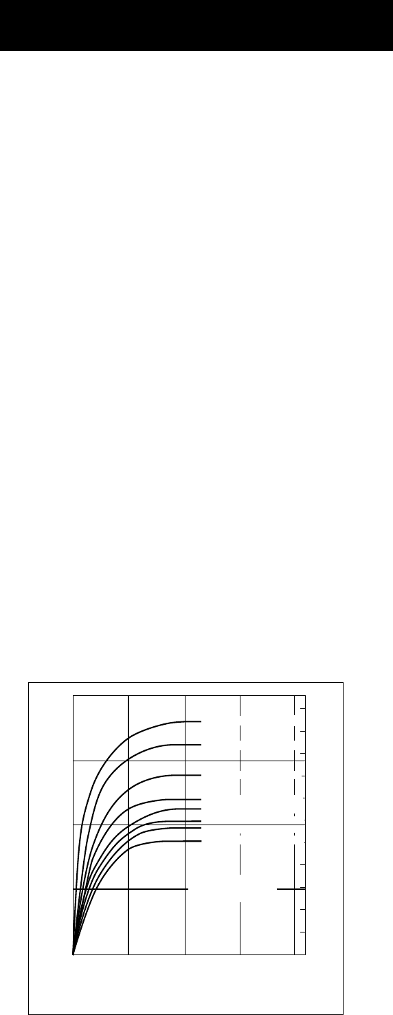
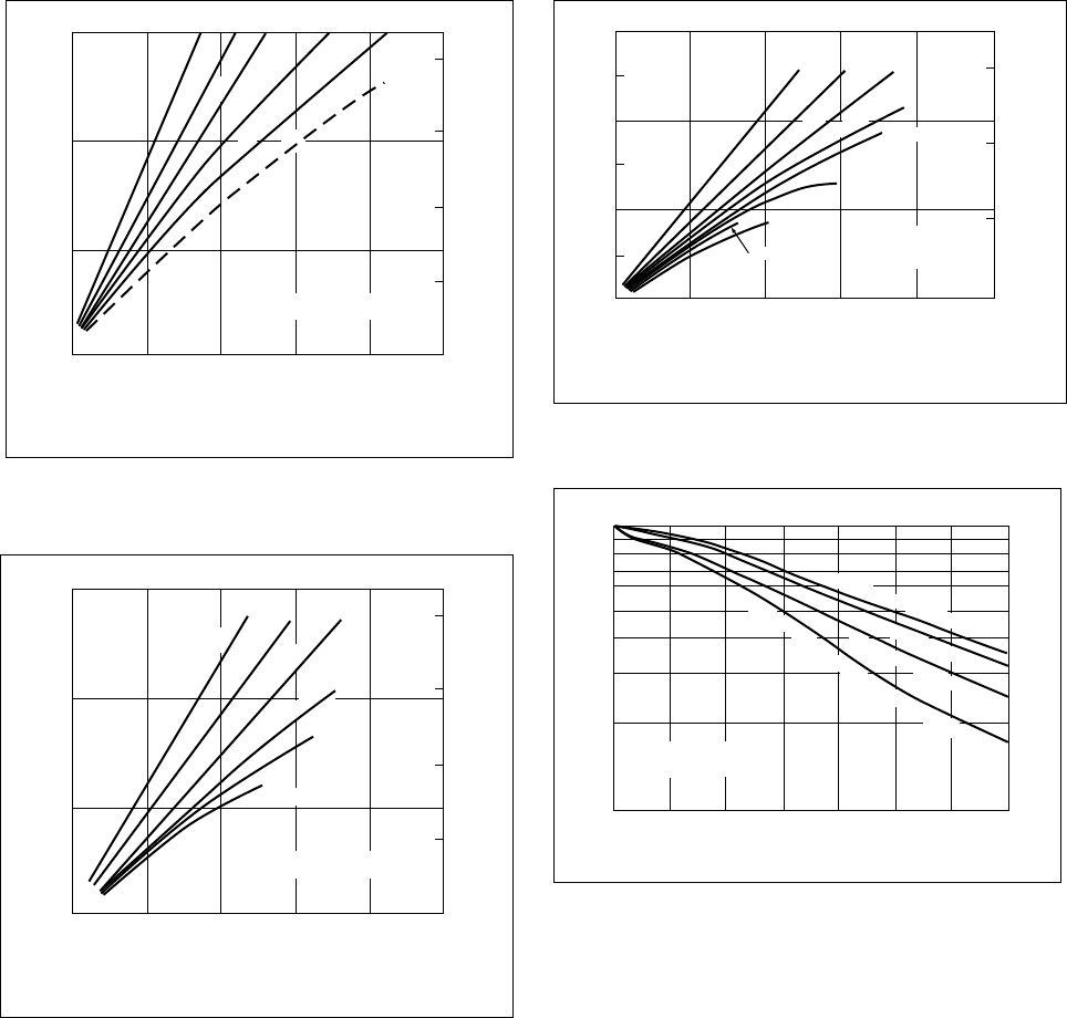
Stress Strain Curves
Stress strain curves show the effects of resin
composition, draw rate, and environmental factors
such as temperature and humidity on the resin’s
tensile properties.
Tensile Stress Strain
See Figures 1–3 for Delrin acetal resin stress strain
data. Within this range of temperature and strain rate,
temperature has the greater effect on the tensile
properties of Delrin acetal resin. The effect of strain
rate becomes more pronounced at high temperatures.
Tensile Strength
The tensile strength values are obtained from stress
strain curves by noting the maximum stress on the
curve. The maximum tensile values are given in
Table 2 and can be used in rating the relative resin
strengths.
Figure 4 gives Delrin acetal resin tensile strength
data.
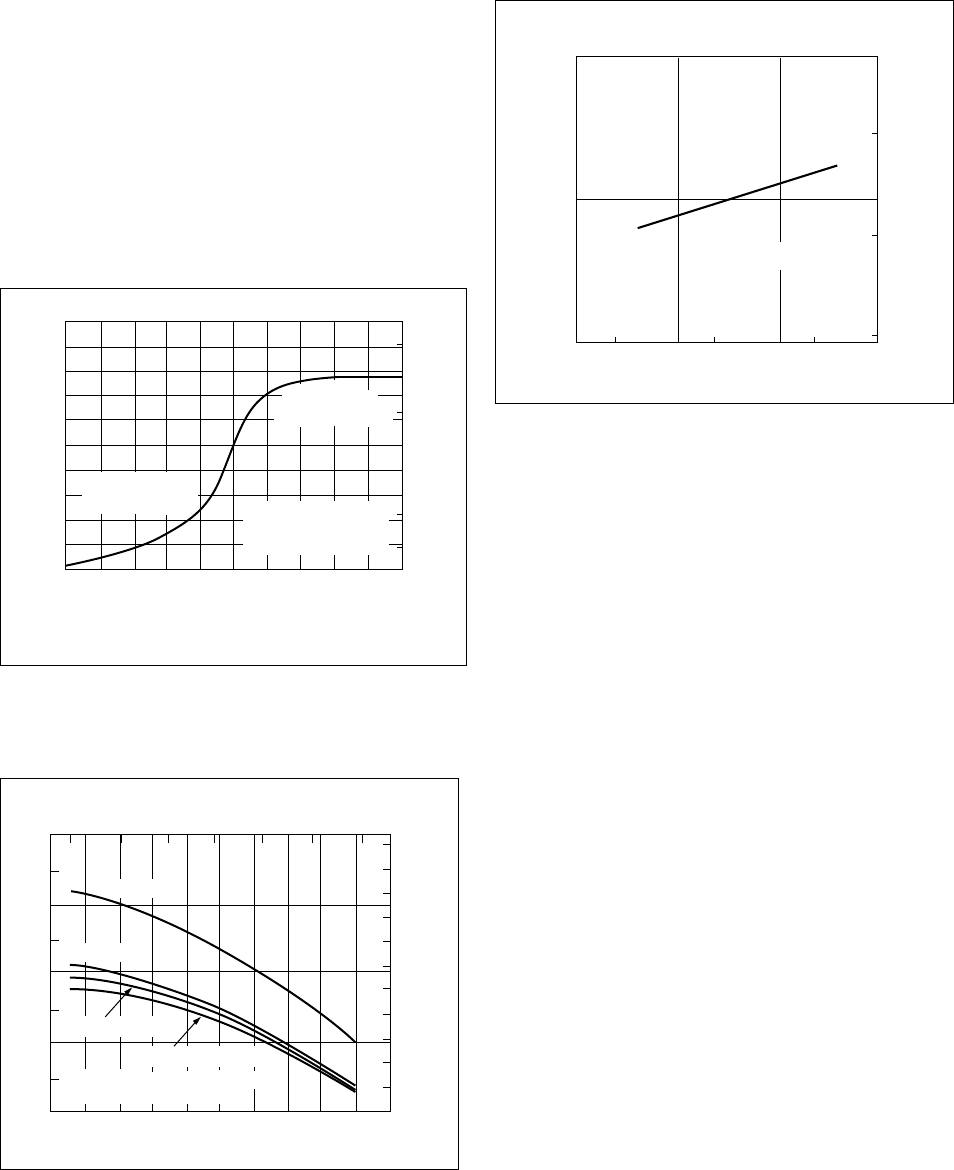
Yield Strength
The yield strength, also taken from the stress strain
curve, is the point at which the material continues
to elongate (strain) with no increase in stress. The
yield strength normally has a lower value than
the tensile strength. When fracture occurs before
yielding, the maximum stress value is recorded as
tensile strength, and there is no yield value.
In the design of plastic parts, yield strength is the
most common reference, as it is uncommon for a
part to be stressed beyond the yield point. Unless
one is designing gaskets and washers, which are
often stressed beyond the yield point, it is good
practice to design within the proportional limit,
which is substantially below the yield point.
Selection of proper design stress is covered in
the Design Principles Module.
Tensile yield strength data for some Delrin acetal
resins is shown in Figure 5. For data on resins not
shown, consult your DuPont representative.
Compression versus Tension
In some design work it is important to know the
stress strain relationship in compression as well as
tension. At high stress levels, the strain in com-
pression is less than in tension. For all practical
purposes, however, the tensile and compressive
stress strain curves are identical at normal working
stress levels, and the compressive modulus is equal
to the tensile modulus.
Figure 6 is a stress strain curve for Delrin acetal
resin in both compression and tension. The test
was carried out at 23°C (73°F) and at 5.1 mm/min
(0.2 in/min) and 1.3 mm/min (0.05 in/min) in
tension and compression, respectively. The curve
indicates that compressive strength is greater than
tensile strength.
Shear Strength
Shear stress is the resistance measured in psi or
MPa of two planes moving relative to one another
in the direction of load. Shear strength is the stress
level at which fracture occurs.
Refer to Table 2 for specific shear strength values
for Delrin acetal resin.
Poissons’ Ratio
Poissons’ Ratio measures the relative ability of a
material to deform at right angles to applied stress.
It permits the mathematical determination of a
material’s physical characteristics and values in a
direction perpendicular to the direction of loading.
Poissons’ Ratio is defined as the ratio of the
transverse strain to the longitudinal strain of a
material. For plastics, the ratio is affected by time,
temperature, stress, sample size, etc.
Poissons’ Ratio for Delrin 500 at 23°C (73°F) is
0.35. The value is not expected to change signifi-
cantly for other Delrin acetal resins.
Figure 1. Stress Strain Curves for Delrin Acetal
Resins at Various Temperatures and Rates
of Loading (ASTM D638)
0510
Strain, %
Note: Elongation at break not shown.
Delrin 100, 500,
500CL, 900
Stress, MPa
Stress, 10
3
psi
15 20
0
20
40
60
80
2
4
6
8
10
23°C (73°F), 5.1 mm/min (0.2 in/min)
66°C (150°F), 51 mm/min (2.0 in/min)
66°C (150°F), 5.1 mm/min (0.2 in/min)
85°C (185°F), 51 mm/min (2.0 in/min)
100°C (212°F), 51 mm/min (2.0 in/min)
85°C (185°F), 5.1 mm/min (0.2 in/min)
100°C (212°F), 5.1 mm/min (0.2 in/min)
23°C (73°F), 51 mm/min (2.0 in/min)
Mechanical Properties

20
Figure 2. Stress versus Strain for Delrin—Crosshead
Speed of 5.1 mm/min (0.2 in/min)
1
Strain, %
Stress, MPa
0
0
10
20
30
40
50
60
2
23°C (73°F)
66°C (150°F)
85°C (185°F)
100°C (212°F)
3
1
2
3
4
5
6
7
8
Stress, 10
3
psi
Delrin 100, 500,
500CL, 900
Figure 3. Stress versus Strain for Delrin—Crosshead
Speed of 51 mm/min (2.0 in/min)
1
Strain, %
Stress, MPa
0
0
10
20
30
40
50
60
2
23°C (73°F)
66°C (150°F)
85°C (185°F)
100°C (212°F)
3
1
2
3
4
5
6
7
8
Stress, 10
3
psi
Delrin 100, 500,
500CL, 900
Figure 4. Tensile Strength—Crosshead Speed
5.1 mm/min (0.2 in/min)
Temperature, °C
23–55
14
28
42
56
70
84
98
101
70 100122
–50 0 50
Temperature, °F
–100 150100 200 250
16
14
12
10
8
6
Tensile Strength, 10
3
psi
Tensile Strength, MPa
4
2
Delrin 100, 500,
500CL, 900
Delrin 570
Delrin 100 AF
Delrin 500 AF
Figure 5. Tensile Yield Strength of Delrin versus
Temperature—Crosshead Speed of
5.1 mm/min (0.2 in/min)
20 40 60 80 100 1200–20–40–60
0
10
20
30
40
50
60
70
80
90
100
110
–50 0 50
Temperature, °F
Temperature, °C
100 150 200
14
12
10
8
6
4
2
Tensile Yield Strength, 10
3
psi
Tensile Yield Strength, MPa
Delrin 100, 500,
500CL, 900
Delrin
570
Delrin 100 AF, 500 AF
21
Stiffness
Flexural modulus is a measure of the stiffness of a
plastic. It is expressed as the ratio of stress to strain
before permanent or severe deformation occurs.
Although the elastic modulus can be determined in
tension and compression, it is commonly shown in
flexure because of the greater likelihood of bending
stress in use.
The effect of temperature and rate of loading on
Delrin acetal resin is shown in Figures 7 and 8.
Figure 6. Stress Strain Curves for Delrin in Tension
and Compression 23°C (73°F)
–20246810
–15
–10
–5
0
5
10
15
–4–6–8–10
–125
–100
–75
–50
–25
0
25
50
75
100
125
Strain, %
Note: Elongation at break not shown.
Stress, MPa
Stress, 10
3
psi
Compression
crosshead speed
1.3 mm/min (0.05 in/min)
Tension
crosshead speed
5.1 mm/min (0.2 in/min)
Delrin 100, 500,
500CL, 900
Figure 7. Flexural Modulus of Delrin versus
Temperature at Crosshead Speed of
0.13 cm/min (0.05 in/min)
100
200
400
600
800
1000
250200150100500–50
8
6
4
2
0
–60 –40 –20 0 20 40
Temperature, °C
Temperature, °F
Flexural Modulus, 10
3
MPa
Flexural Modulus, 10
3
psi
60 80 100 120
Delrin 570
Delrin 900
Delrin 500
Delrin 100, 100AF, 500AF
Note: Moisture can change stiffness
±5% from 0% RH to 100% RH
Figure 8. Flexural Modulus of Delrin at 23°C (73°F)
versus Crosshead Speed
0.5 5.1 51
300
400
500
10.01.00.10.01
400
300
200
Crosshead Speed, mm/min
Crosshead Speed, in/min
Flexural Modulus, 10
3
MPa
Flexural Modulus, 10
3
psi
Delrin 100, 500, 900
For design purposes, assume that the effect of
chemical substances on the flexural modulus of
Delrin acetal resin is proportional to the effect on
the tensile modulus of Delrin acetal resin as shown
in Section 8—Chemical Resistance.
The fact that flexural modulus values are lower
than tensile and compressive modulus values can
be explained, in part, by noting that the fiber strain
rate in the flexural modulus test is a small fraction
(
1
/
20
) of the tensile test machine crosshead speed,
whereas in the tensile and compression tests the
fiber strain rate is equal to the crosshead speed.
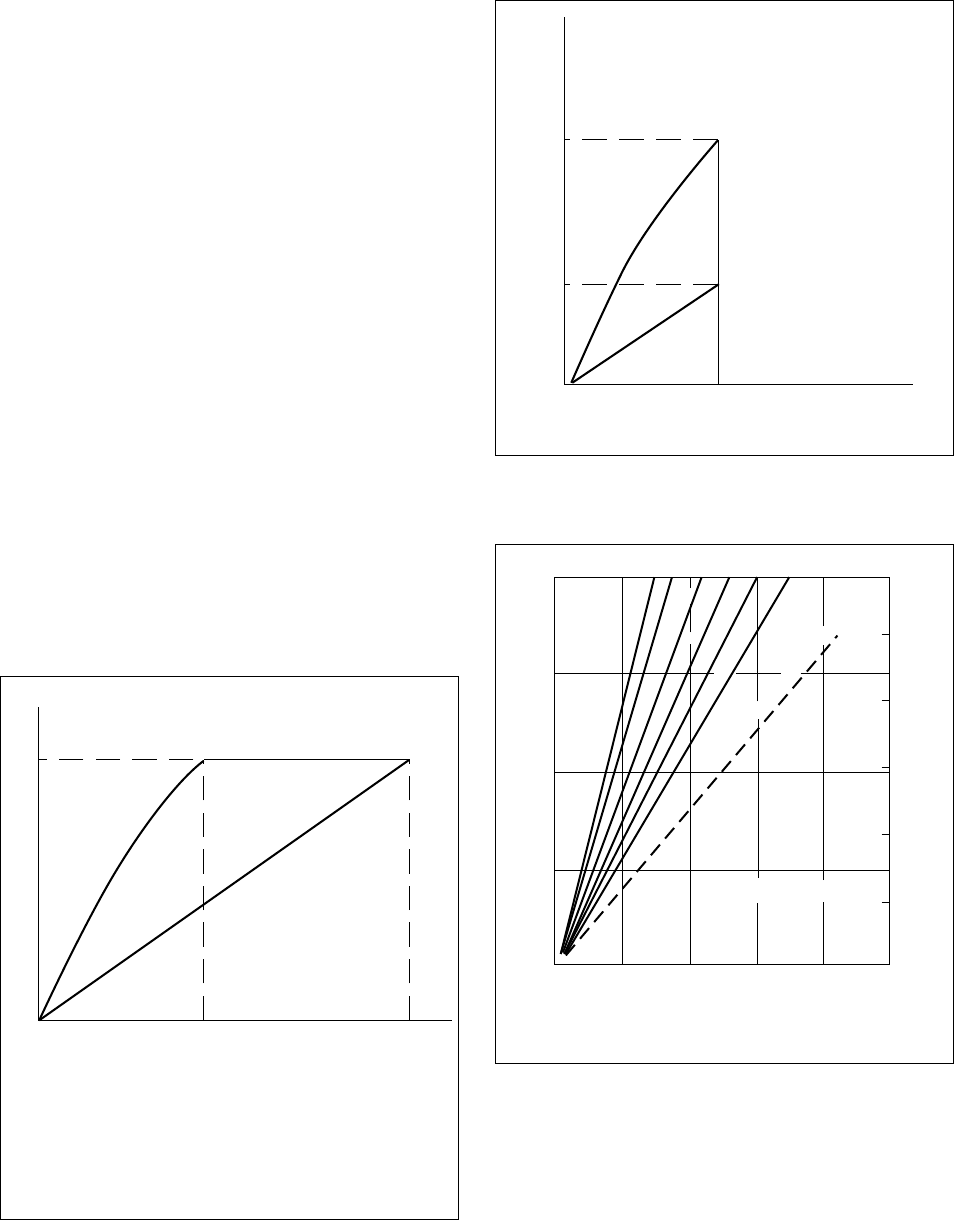
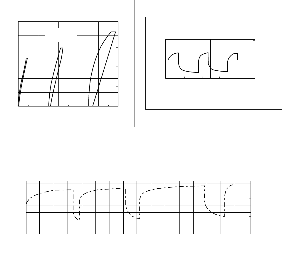
Creep and Relaxation
Creep
When stressed within the proportional limit, a
plastic material shows an initial strain proportional
to the modulus of elasticity, followed by a slow but
steady increase in strain with time. This phenom-
enon is called creep. Creep is the combination of
plastic flow and elastic deformation expressed as
the sum of the initial strain plus the incremental
strain that occurs with time at constant stress.
Creep rates will vary with composition, ambient
temperature, stress level, and moisture content.
Consequently, designs must incorporate the esti-
mated creep behavior of a particular resin under
the load and environmental conditions expected.
22
Relaxation
Stress relaxation is defined as the decrease over a
given time period of the stress required to maintain
constant strain over the same period of time. Like
creep, it can occur in tension, compression, flexure,
or shear.
Figures 9 and 10 show the effect of creep and
stress relaxation plotted on stress strain diagrams,
and is the method commonly used for calculating
creep and relaxation modulus, sometimes referred
to as “apparent modulus.”
• Creep in Air
The results of experiments in flexural creep at
various air temperatures and stress levels have
been plotted in Figures 11–14. Data from these
figures may be used to predict creep in Delrin
acetal resin parts in tensile, compressive, or
flexural loadings. This prediction is made by
substitution of the stress-temperature-time
dependent (creep) modulus in the appropriate
engineering formulae.
• Stress Relaxation
Figure 15 shows the tensile relaxation prop-
erties of Delrin acetal resin at various stress
levels.
Figure 9. Creep
S
0
e
0
e
0
e
T
S
0
e
T
Stress (S), MPa (psi)
Strain (e), mm/mm (in/in)
Creep between time T and T
0
= e
T
– e
0
mm/mm (in/in). The creep modulus* E
T
Pa
(psi) for design in creep applications at
stress S
0
and time T is the slope of the
secant from the origin to the point (S
0
e
T
)
Pa (psi).
Figure 10. Relaxation
S
0
e
0
S
0
e
0
S
T
e
0
S
T
Stress (S), MPa (psi)
Strain (e), mm/mm (in/in)
Relaxation between time T and T
0
= S
0
–S
T
Pa (psi). The relaxation modulus* E
T
Pa(psi)
for design in relaxation applications (e.g.,
press fits) at time T is the slope of the
secant from the origin to the point (S
T
e
0
).
Figure 11. Long-Term Behavior of Delrin Under
Load at 23°C (73°F) Air
0
0
5
10
15
20
0.5 1.0 1.5 2.0 2.5
0.5
1.0
1.5
2.0
2.5
3.0
Total Strain, % at Indicated Stress and Time
mm/mm or in/in × 100
Stress Level, 10
3
psi
Stress Level, MPa
Delrin 100, 500, 900
1 hr
10 hr
100 hr
1,000 hr
5,000 hr
10,000 hr
100,000 hr Projected
23
Figure 12. Long-Term Behavior of Delrin Under
Load at 45°C (115°F), Air
0
0
5
10
15
0.5 1.0 1.5 2.0 2.5
0.5
1.0
1.5
2.0
Total Strain, % at Indicated Stress and Time
mm/mm or in/in × 100
Stress Level, 10
3
psi
Stress Level, MPa
Delrin 100, 500, 900
1 hr
10 hr
100 hr
1,000 hr
10,000 hr
50,000 hr Projected
Figure 13. Long-Term Behavior of Delrin Under
Load at 85°C (185°F), Air
0
0
5
10
15
0.5 1.0 1.5 2.0 2.5
0.5
1.0
1.5
2.0
Total Strain, % at Indicated Stress and Time
mm/mm or in/in × 100
Stress Level, 10
3
psi
Stress Level, MPa
Delrin 100, 500, 900
1 hr
10 hr
100 hr
1,000 hr
10,000 hr
5,000 hr
Figure 14. Long-Term Behavior of Delrin Under
Load at 100°C (212°F), Air
0
0
2
4
6
8
10
12
0.5 1.0 1.5 2.0 2.5
0.5
1.0
1.5
Total Strain, % at Indicated Stress and Time
mm/mm or in/in
×
100
Stress Level, 10
3
psi
Stress Level, MPa
Delrin 100,
500, 900
1 hr
10 hr
100 hr
500 hr
5,000 hr
1,000 hr
2,000 hr
3,000 hr
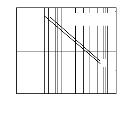
Figure 15. Tensile Stress Relaxation of Delrin Under
Constant Strain at 23°C (73°F)
0.01
10
20
40
60
80
100
0.1 1 10
Time, hr
Initial Stress, %
100 1,000 10,000 100,000
Delrin 100, 500,
500CL, 900
1
2
.
5
%
(
Y
i
e
l
d
P
o
i
n
t
S
t
r
a
i
n
)
,
6
9
M
P
a
(
1
0
,
0
0
0
p
s
i
)
5%, 66 MPa (9,500 psi)
0.9%, 34 MPa (5,000 psi)
Strain 0.3%, 17 MPa (2,500 psi)
Notes on Figures 11–15:
• For greatest accuracy, prototypes of production
parts should be fabricated by the same methods
and under the same conditions as parts intended
for production.
• Parts designed by use of the appropriate creep
or relaxation moduli and engineering formulae
will be over-designed below the chosen time “T”
and under-designed beyond time “T” in terms of
their creep or relaxation behavior. However, their
response to rapidly applied and removed loads will
not be affected greatly, provided “stress-time”
limits at the temperature are not exceeded.
• At any time “T,” the creep or relaxation modulus
(E
r
) for a given temperature is almost proportional
to the applied stress.
• The rate of creep and relaxation increases with
increasing level of stress.
• Extrapolations of data in Figures 11–15 to higher
stresses and temperature or longer times than
shown should not be made unless parts so de-
signed can be verified by vigorous testing.
24
Figure 16. Recovery of Delrin from Dynamic Loading
012012
Strain, %
Five Cycle Hysteresis Loops at 23°C (73°F),
loading rate 5.1 mm/min (0.2 in/min)
012
2
0
10
20
30
40
50
4
Tensile Stress, MPa
Tensile Stress, 10
3
psi
6
8
3
Delrin 100,
500, 900
Figure 18. Recovery of Delrin from Cyclic Long-Term
Loading at 23°C (73°F) in Air at 14 MPa
(2,000 psi) (Higher Ratio of Time Allowed
for Recovery to Time Under Load)
Delrin 100, 500, 900
0 40 80 120 160 200
0
2
Deflection, mm at end of
95
×
12.5
×
12.5 mm cantilever
Deflection, in at end of
3.75
×
1/2
×
1/8 in cantilever
4
6
Time, hr
0.10
0.20
0.30
Figure 17. Recovery of Delrin from Cyclic Long-Term Loading at 23°C (73°F) in Air at 14 MPa (2000 psi) (Short
Ratio of Time Allowed for Recovery to Time Under Load)
Delrin 100, 500, 900
0
0
2
Deflection, mm at end of
95 × 12.5 × 12.5 mm cantilever
Deflection, in at end of
3.75 × 1/2 × 1/8 in cantilever
4
6
50 100 150 200 250 300 350 400
Time, hr
450 500 550 600 650 700 750 800
0.10
0.20
0.30
25
• Recovery from Dynamic Loading
Few plastic materials exhibit good recovery
characteristics when subjected to repeated
loading at relatively high stress levels.
– Short-Term Dynamic Loading
Figure 16 shows stress strain curves for Delrin
acetal resin stressed and relaxed five times at
three successively higher stress levels. At a
stress level of 35 MPa (5,000 psi), well above
normal working stress levels, recovery is
complete. Even at very high stress levels,
hysteresis is surprisingly low.
– Long-Term Dynamic Loading
Figures 17 and 18 typify the behavior of
Delrin acetal resin under cyclic loading at
23°C (73°F). Recovery depends on the
duration of the applied load and on the time
allowed for recovery. When the load is re-
moved, there is an immediate recovery of
about 40%, followed by a time-dependent
recovery.
In general, the amount of recovery after static
loads are removed will depend on the:
• Duration of the loads
• Level of stress under load
• Temperature
• Time allowed for recovery
• Nature of the environment
Thermal Aging
This section describes the behavior of Delrin acetal
resin under conditions of no load, in the presence
of both air and water over a temperature range.
Unstressed in Air
Test bars molded in Delrin 500 NC010 more than
20 years ago were stored in the absence of light
at room temperature. The bars retained their
elongation, tensile strength, original luster, impact
strength, and molecular weight.
At elevated storage temperatures the unstressed
bars retained at least 78% of their original tensile
strength as shown in Figure 19.
Delrin 100 has 10 to 20% better retention of
properties at higher temperatures than Delrin
500 or 900.
Figure 19. Long-Term Unstressed Exposure in Air
0.2 0.5 1
Exposure Time, yr for which tensile strength
in excess of 55 MPa (8,000 psi) is retained
Air Temperature, °C
Air Temperature, °F
2510
100
150
500
900
200
250
Data for exposure of
injection molded bars
under no external stress
0.1
25
50
75
100
125
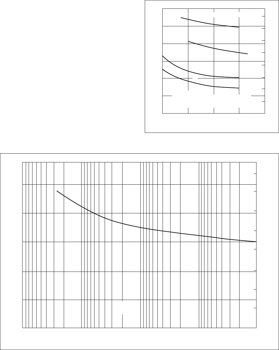
26
Fatigue Resistance
Materials subjected to cyclic stresses sometimes
fail at stress levels below their yield strength. This
condition is fatigue failure, and the cyclic loading
in tension and compression combined is the most
severe situation.
Delrin acetal resins have extremely high resistance
to fatigue failure from –40 to 82°C (–40 to 180°F).
Furthermore, their resistance to fatigue is affected
little by water, solvents, neutral oils, and greases.
Fatigue resistance data (in air) for injection molded
samples of Delrin acetal resin are shown in Figures
20 and 21.
For highest fatigue endurance select Delrin 100.
For example, in gear tests, Delrin 100 exhibits
approximately 40% higher fatigue endurance than
Delrin 500.
Figure 20. Fatigue Resistance of Delrin 500 at
1800 cpm versus Temperature (Air)
10
3
0
10
1
0
2
3
4
5
6
7
23°C (73°F)
1800 Cycles per Minute
1
2
3
4
1. Tensile stress only
2. Completely reversed tensile and compressive stress
3. Completely reversed tensile and compressive stress
4. Completely reversed tensile and compressive stress
23°C (73°F)
66°C (150°F)
100°C (212°F)
8
20
30
40
50
60
10
4
10
5
Cycles to Failure
10
6
10
7
Stress, 10
3
psi
Stress, MPa
Figure 21. Flexural Fatigue of Delrin (ASTM D671)
8
7
6
5
4
3
2
1
10
7
10
6
10
5
10
4
10
3
0
10
20
30
Stress, MPa
Stress, 10
3
psi (ASTM D671)
40
50
Delrin 100,
500, 900
Cycles to Failure
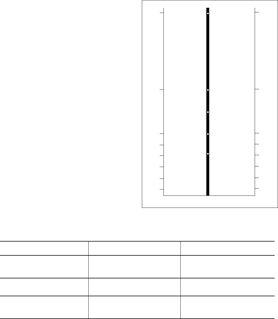
27
Table 6
Impact Strength in Very Thin Sections—93°C (200°F) Mold
Part Thickness 0.8 mm or less 1.6 mm or more
Resin 500 100 500 100
Elongation, % 25 10 30 75
Tensile Impact, kJ/m
2
210 170 210 360
Tensile Strength, MPa 69 76 69 69
Part Thickness
1
/
32
in or less
1
/
16
in or more
Resin 500 100 500 100
Elongation, % 25 10 30 75
Tensile Impact, ft⋅lb/in
2
100 80 100 170
Tensile Strength, psi 10,000 11,000 10,000 10,000
Impact Resistance
Impact resistance is the ability to withstand a
sudden blow rather than a slowly applied load.
Toughness is a general term indicating ability
to withstand high stress applied in various ways
including impact, without failure. No single test
has been devised that can evaluate toughness under
the many conditions in which plastic parts are used.
Tests have been developed to show impact resis-
tance to single blows, repeated blows, and notched
specimens. These data are useful in predicting
performance in service involving impact.
Tensile Impact
Tensile impact strength is the energy per unit of
cross-sectional area required to break a specimen
in tension. The load is applied rapidly, as in the
Izod Test, and uses the same equipment. Figure 22
shows data obtained for various Delrin acetal resins
subjected to Tensile Impact (ASTM D1822—Long).
In this test, Delrin 100 exhibits the greatest impact
resistance of the unmodified acetals.
Thin Sections
Table 6 describes tensile impact strength for Delrin
acetal resins in very thin sections using a 93°C
(200°F) mold. Delrin 100 has outstanding impact
resistance when the part is
1
/
16
in thick or greater. Its
high viscosity, however, limits its filling in very
thin molds.
Izod Impact
Figure 23 shows the results of Izod Impact (ASTM
D256) tests on various Delrin acetal resins. The test
uses a notch in the specimen to simulate a stress
concentration, and measures the energy per unit
length of notch to break the specimen with a fast
moving weight.
When notched and unnotched values are compared,
the test gives a measure of notch sensitivity. See
Table 7. It is important that sharp corners and
stress raisers be eliminated in parts of Delrin acetal
resin, as with most other materials of construction.
When a notch effect cannot be avoided, Delrin 100
ST is the resin of choice.
Figure 22. Resin Guide—Tensile Impact—Long Bar
350
200
Tensile Impact, kJ/m
2
Tensile Impact, ft⋅lb/in
2
100
80
60
40
20
0
0
23°C (73°F)
10
20
30
Delrin 500AF
Delrin 500
Delrin 500CL
Delrin 900
Delrin 100AF
Delrin 570
Delrin 100
40
50
100
170
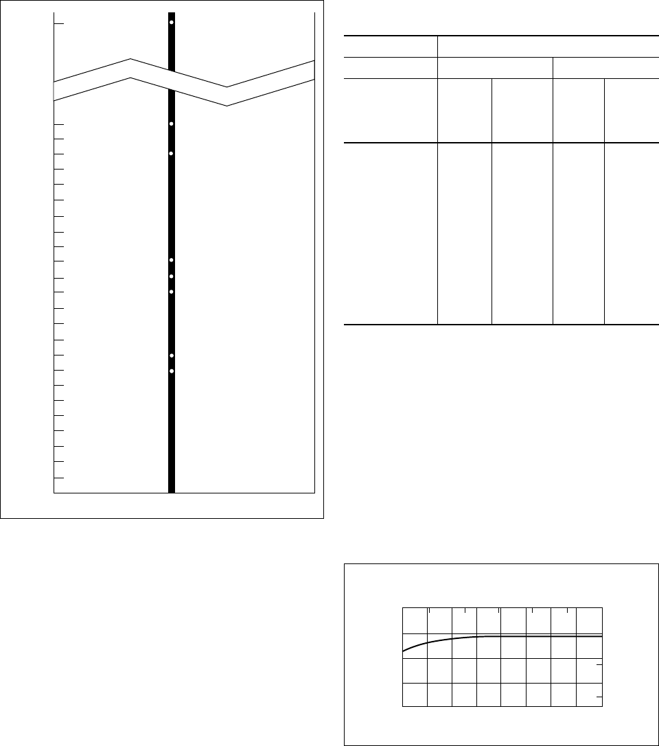
28
Table 7
Impact Strength, ASTM D256,
SI Units (English Units)
Temperature
23°C (73°F) –40°C (–40°F)
Notched Unnotched Notched Unnotched
Izod Izod Izod Izod
Composition* J/m J/m J/m J/m
(ft⋅lb/in) (ft⋅lb/in) (ft⋅lb/in) (ft⋅lb/in)
Delrin 100 123 >5300 96 —
(2.3) (>100) (1.8) (—)
(no break)
Delrin 500 80 1280 64 —
(1.5) (24) (1.2) (—)
Delrin 900 70 850 53 —
(1.3) (16) (1.0) (—)
Delrin 500T 135 no break 106 —
(2.5) (2.0) (—)
Delrin 100ST 910 no break 250 —
(17.0) (4.7) (—)
*NC010
Even without impact, the bar can be easily broken
by hand at the sharp notch, whereas it cannot be
broken even when severely bent at the round notch.
Thus, the avoidance of the notch effect is not only
important to parts subject to impact, it is important
to any part subject to stress. See the Design Mod-
ule, “Fillets and Radii” for more information on
stress concentration factors.
Figure 24. Effect of Temperature on Notched Izod
Impact Resistance of Delrin 500
Temperature, °C
Izod Impact Strength, J/m
Izod Impact Strength, ft⋅lb/in
Temperature, °F
10 50
020
20
40
60
80
100
40 60 80 100 120
0.5
1.0
1.5
–20–40
100 150 200
Figure 23. Resin Guide—Izod Impact—Notched Bar
Izod Impact
0
0.1
0.2
0.3
0.4
0.5
0.6
0.7
0.8
0.9
1.0
1.1
1.2
1.3
1.4
1.5
1.6
1.7
1.8
1.9
2.0
2.1
2.2
2.3
23°C (73°F)
Delrin 100
Delrin 500T
Delrin 500
Delrin 900
Delrin 100AF
Delrin 570
Delrin 500AF
Delrin 100ST
17.0
Figures 24 and 25 show that the Izod impact
strength of Delrin 500 changes only slightly over
the temperature range from –45 to 122°C (–50 to
250°F) and over the entire humidity range at room
temperature. This is another unique characteristic of
Delrin acetal resin, as most plastics have substan-
tially reduced impact strength at low temperatures.
Very Sharp Notch
In order to examine the effect of notch radii sub-
stantially smaller than the 0.010 in radius specified
for the Izod Impact test, special bars were molded,
as shown in Figure 26, having a very sharp notch
with a radius of 0.0005 in and a round notch cut
to the same depth. Thus, the very sharp notch has
a radius 20 times sharper than the standard Izod.
The bar was impacted in the same manner as in the
standard Izod test, being struck at the end nearest
the notch.
The data shows the tremendous effect sharp corners
can have on the strength of a part and makes it even
more clear why most failures are caused by the
notch effect.
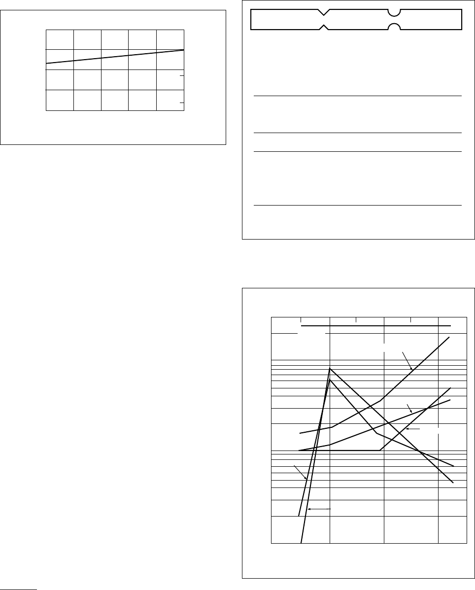
29
Figure 25. Effect of Moisture on Notched Izod Impact
Resistance of Delrin 500 at 23°C (73°F)
Relative Humidity, %
Izod Impact Strength, J/m
Izod Impact Strength, ft⋅lb/in
020
20
40
60
80
100
40 60 80 100
0.5
1.0
1.5
Note the Izod impact strength of Delrin 100ST
remains very high, even with this very sharp notch,
dropping from 17 ft⋅lb/in obtained in the standard
notched Izod test to 10.9. In a similar experiment
with a 2 mil radius notch Delrin 100ST exhibited
no reduction in notched Izod impact strength.
Repeated Impact*
Repeated Impact indicates the ability of a material
to stand up to vigorous handling in an application
and shows how resistance varies with the loading
rate.
The Repeated Impact test consists of a series of
impact loads at an energy lower than required for
fracture. The number of blows to cause failure is a
measure of repeated impact resistance and becomes
especially important to the appliance and automo-
tive industries. Some plastics with a high initial
impact strength fail rapidly when subjected to
repeated impacts at much lower energy levels.
The Repeated Impact test uses the same equipment
and procedure as the Tensile Impact Test, except
the energy is controlled at 60% of the tensile im-
pact strength of the material being tested.
The data in Figure 27 shows that Delrin 500 has
good resistance to repeated impacts over the rates
tested. As the loading rate increases, so does the
capability of Delrin 500 to withstand shock without
rupture. Data comparison of Delrin acetal resin,
other plastics, and die-cast metals shows Delrin
acetal resin to be exceptionally resistant to repeated
impact loads. Delrin 100ST, 100, and 500T pro-
vide even greater impact performance.
* Ref.: Modern Plastics, May 1964, Repeated Impact Tests—J. R.
Heater and E. M. Lacey. Delrin acetal resin tested at 60% breaking
load on cylindrical test specimen (ASTM D256).
Figure 26. Impact on Molded Notches (Non-ASTM)
Figure 27. Resistance of Various Materials to
Repeated Tensile Impacts versus Rate
of Loading*
Velocity of Pendulum, in/sec
Velocity of Pendulum, m/sec
Number of Impacts to Failure
5020
1
0.5 1.0 1.5 2.0
20
30
40
60
80
100
200
10
8
6
4
3
2
30 40 60
Delrin 500 NC010
Die cast aluminum
Die cast zinc
Polycarbonate
ABS
Nylon 66
70 80 90
For this non-ASTM two side notched test specimen
indicated, round notches give 8 to 15 times more
impact strength than sharp notches molded into
the same depth:
Effect of Notch Type on Impact Strength
Ratio,
Round/
Round Notch Sharp Notch* Sharp
Composition J/m ft⋅lb/in J/m ft⋅lb/in
Delrin 100 NC010 667 12.5 43 0.81 15.4/1
Delrin 500 NC010 315 5.9 38 0.71 8.3/1
Delrin 900 NC010 256 4.8 27 0.50 9.6/1
Delrin 100ST No Break 583 10.9 —
*Notch radius 0.0005 in versus Standard Izod Impact
Radius of 0.010 in.

30
Chapter 3
Thermal Properties
Contents
Thermal Characteristics
Thermal Expansion
Heat Deflection
Specific Heat
Thermal Conductivity
Melting Point
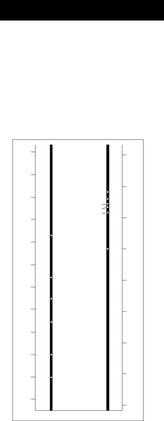
31
Thermal Characteristics
This section will provide information on the
thermal characteristics of Delrin acetal resin,
supplementing previous information on the effect
of temperature on physical properties. Information
such as coefficient of linear thermal expansion,
heat deflection temperature, specific heat, thermal
conductivity, and melting point are often useful to
the designer.
Thermal Expansion
Thermal expansion is an important design consider-
ation when the end-use temperature will vary sig-
nificantly, and especially when metal and plastic
parts are used in the same assembly. Coefficient
of linear thermal expansion for most Delrin acetal
resins ranges from (10.4 to 13.5) × 10
–5
m/m/°C
([5.8 to 7.5] × 10
–5
in/in/°F) over a temperature
range of –40 to 94°C (–40 to 200°F). Delrin 570,
containing glass fibers, is substantially lower.
Actual data on each resin in temperature increments
can be found in Table 2.
Heat Deflection
The deflection temperature is the temperature at
which a test bar in flexure will deflect 0.25 mm
(0.01 in) when heated under stress as described in
ASTM D648. This test is widely used in specifi-
cations, however, it should not be used to judge
maximum use temperature or for design purposes.
Refer to Strength, Stiffness, Creep, and Aging data.
Figure 28 shows the Heat Deflection Values for
Delrin acetal resin compositions at stresses of
1.8 MPa and 0.5 MPa (264 psi and 66 psi). The
values given are for annealed test specimens.
Specific Heat
The specific heat is the ratio of the amount of heat
required to warm 1 g of substance through 1°C to
the amount of heat similarly required for water.
Specific heat is dimensionless. Many laboratories
are using the Differential Scanning Calorimeter for
this measurement.
The specific heat has been determined for some
Delrin acetal resins as an average over a range from
–18 to 100°C (0 to 212°F). The value is constant
at 0.35.
Thermal Conductivity
Thermal conductivity is a measure of the rate of
heat transfer through a material. Delrin acetal resin
compositions range from 0.30 to 0.37 W/m⋅k (2.1
to 2.6 Btu⋅in/hr⋅ft
2
⋅°F). When compared to metals,
plastics are good insulators and poor conductors
of heat. This can be a secondary advantage in
designing with plastics in applications where the
retention of heat or the damping of rapid temp-
erature changes can be advantageous.
Melting Point
Melting point data for Delrin acetal resins is given
in Table 2. This information can be useful in
applications where very short time peak tempera-
tures can be encountered, such as paint bake ovens.
Figure 28.
Resin Guide—Heat Deflection Temperature
210
200
190
180
170
160
150
140
130
120
110
100
Heat Deflection Temperature, °C
Heat Deflection Temperature, °F
175
225
200
250
275
300
325
350
375
264 psi 66 psi
Delrin 100ST
Delrin 500CL
Delrin 100, 107, 150SA
Delrin 100AF, 500AF
Delrin 500T
Delrin 570
Delrin 570
Delrin 100ST
Delrin 500T
Delrin 500CL
Delrin 100AF, 500AF
Delrin 100, 107,
150SA, 500, 900
}
Thermal Properties

32
Chapter 4
Electrical Properties
and Flammability
Contents
Electrical Characteristics
Dielectric Strength
Dielectric Constant
Dissipation Factor
Volume Resistivity
Ignition Temperatures
Flammability
Combustibility
Arc Resistance

33
Electrical Characteristics
Delrin acetal resins have characteristics that make
them attractive for electrical applications.
• Moisture has minimal effect on electrical properties.
• Sparks or continuous arcs seldom alter the
insulating properties of natural color resins
because they do not carbon track. Carbon-filled
resins such as Delrin 507 BK601 may carbon
track due to the carbon fillers.
• The resins have high self-ignition temperature,
376°C (707°F), and are classified as slow burning.
The following data are for Delrin 100, 500, and 900
NC010. Electrical data for other Delrin acetal resins
can be found in Table 2.
Dielectric Strength (ASTM D149)
In testing dielectric strength, a molded test sample
is placed between energized electrodes and re-
sistance to the passage of an electric current is
measured. Voltage may be increased gradually or
in steps, or test sample may be subjected to high
voltage for an extended period. By definition, the
dielectric strength of a material (expressed in V/
mil) is the voltage measure immediately before a
circuit path is initiated through the test sample. It is
an absolute value and varies with section thickness.
Figures 29 and 30 show dielectric strength versus
thickness for two Delrin acetal resins.
Dielectric Constant (ASTM D150)
To assign a dielectric constant value to a material,
the dielectric strength of a given material at a speci-
fied thickness and applied voltage is compared with
that of free air at the same thickness (gap between
energized electrodes) and applied voltage. By assign-
ing the value of “1” to free air, a plastic found to
have four times that value would have a dielectric
constant of “4.”
Values for dielectric strength and dielectric con-
stant may change with variations in frequency of
the applied voltage.
Figures 31, 32, and 33 describe dielectric constant
data for various resins under different conditions.
Dissipation Factor (ASTM D150)
The dissipation factor is the amount of electrical
energy absorbed by an insulating material and dis-
sipated as heat. It is expressed as a percentage of
energy lost (dissipated) divided by energy applied.
Figures 34, 35, and 36 show dissipation factor data
for Delrin acetal resins under various conditions.
Volume Resistivity (ASTM D257)
Volume resistivity is the direct current resistance
between two opposite faces of a 1 cm cube. It
is expressed as ohm-cm. Materials with volume
resistivities above 10
8
ohm-cm are considered
insulators, while those with values of 10
3
to 10
8
ohm-cm are partial conductors.
Tests were conducted at 500 V DC, 1 min electrifi-
cation at 23°C (73°F). The results show:
Bone dry 1 × 10
16
ohm-cm
50% RH 1 × 10
15
ohm-cm
Polymer with 0.99% moisture 1 × 10
14
ohm-cm
(i.e., equilibrium in water)
Delrin 100, 500, 900 NC010
I
gnition Temperatures (ASTM D1929)
Flash ignition temperature is the lowest temperature
at which the material supplies enough vapor to be
ignited by an external flame.
For Delrin 100, 500, and 900 NC010:
• Flash Ignition 323°C (613°F)
• Self-Ignition 376°C (707°F)
Flammability (ASTM D635)
Delrin 100, 500, and 900 NC010 burn slowly at
the rate of 27.9 mm/min (1.1 in/min) for a 31.8
× 12.7 mm (1.25 in × 0.500 in) specimen when
ignited by a flame.
Combustibility (UL 94)
The combustibility classification of Delrin acetal
res-ins under UL Standard 94 is HB for all compo-
sitions.
Arc Resistance (ASTM D495)
Specimen, Thickness, Time (To Develop Hole),
mil mm sec
10 0.254 125
20 0.508 140
30 0.763 190
Neither carbonizing nor tracking occurred in the
above test for Delrin 100, 500, or 900 NC010.
Electrical Properties and Flammability
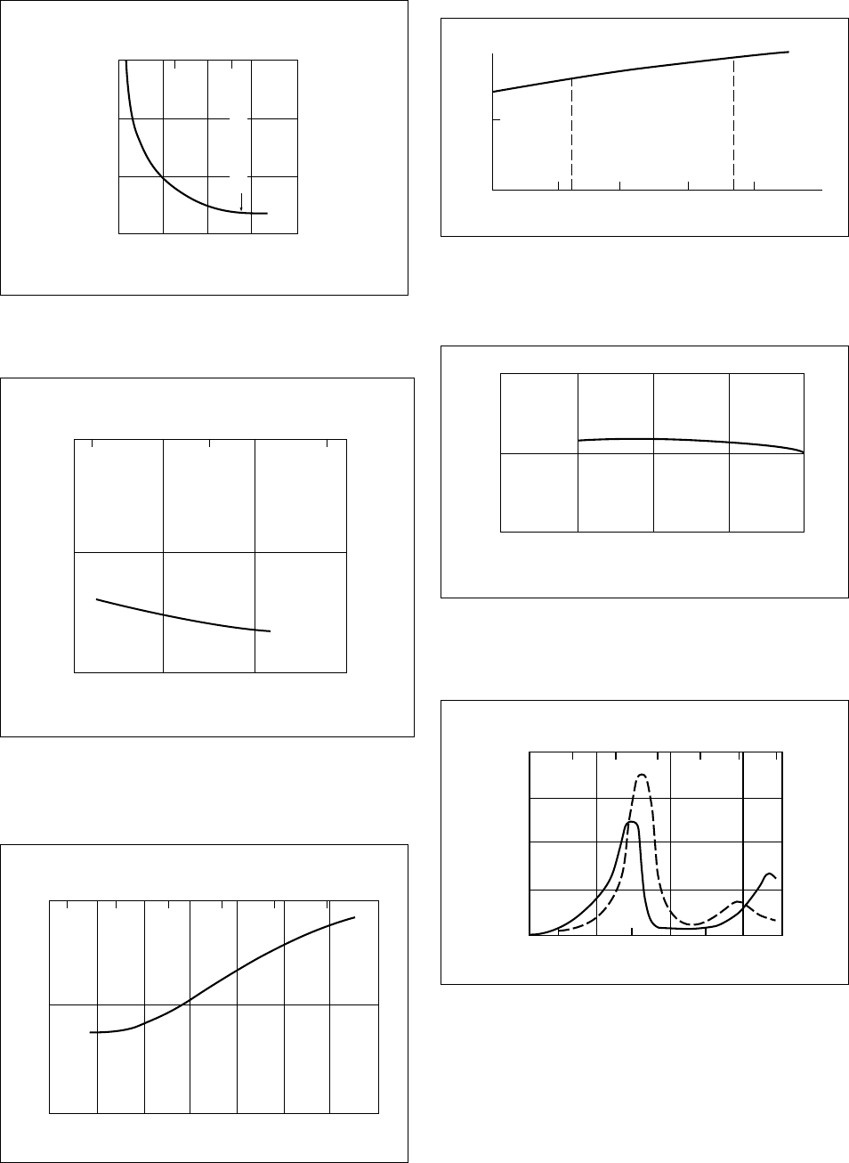
34
Figure 29. Dielectric Strength (ASTM D149)
Delrin 500 NC010 23°C (73°F)
Thickness, mil
50
0
40,000
80,000
120,000
1234
100 150
3,000
2,000
1,000
1 min Value Also
Thickness, mm
V/mm
V/mil
Figure 30. Dielectric Strength (ASTM D149) and
Delrin 507 BK601 at 23°C (73°F)
Thickness, mil
50 100 150
1.0
40,000
80,000
2.0 3.0 4.0
2,000
1,000
Thickness, mm
V/mm
V/mil
0
Figure 31. Dielectric Constant (ASTM D150) versus
Temperature for Delrin 100, 500, 900
NC010 at 50% RH and 10
3
–10
6
Hz
–300 –200 –100 0 100 200 300
4.0
3.0
2.0
–150 –100 –50 0 50 100 150
Temperature, °C
Temperature, °F
Dielectric Constant
Figure 32. Dielectric Constant (ASTM D150) versus
Moisture Content for Delrin 500
NC010 23°C (73°F), 10
3
–10
6
Hz
4.0
3.0
2.0
0 0.2 0.4
50% RH 100% RH
Moisture Content, %
0.6 0.8 1.0
Dielectric Constant
Figure 33. Dielectric Constant (ASTM D150) versus
F
requency for Delrin 507 BK601 at 50% RH
or After Immersion in Water at 23°C (73°F)
4
3
5
10
3
10
4
10
5
10
6
Frequency, cPs
Dielectric Constant
Figure 34. Dissipation Factor (ASTM D150), Delrin
500 NC010 versus Temperature at 10
3
and
10
5
Hz
0.02
0.01
0
0.03
0.04
–185
–300 –200 –100 0 100 200 300
–100 0 100 150
10
3
Hz
10
5
Hz
Temperature, °C
Temperature, °F
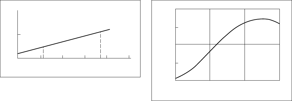
35
Figure 35. Dissipation Factor (ASTM D150) versus
Moisture Content, Delrin 500 NC010 at
23°C (73°F)
0.01
0
0.2 0.4
50% RH
100% RH
Moisture Content, %
0.6 0.8 1.0
Dissipation Factor
Figure 36. Dissipation Factor (ASTM D150) versus
Frequency fo
r Delrin 507 BK601 at 50% RH
or After Immersion in Water at 23°C (73°F)
0.009
0.008
0.007
0.006
0.005
10
3
10
4
10
5
10
6
Frequency, cPs
Dissipation Factor

36
Chapter 5
Abrasion and Wear
Contents
Hardness
Abrasion Resistance
Frictional Properties

37
Hardness
Hardness of Delrin acetal resin is usually reported
in terms of Rockwell Hardness (ASTM D785),
which measures surface penetration with a steel ball
under specified loading conditions. The Rockwell
hardness scales that indicate indenter diameter and
load are the M and R scale.
For the different grades of Delrin acetal resins,
there are only slight variations in Rockwell hard-
ness values (see Table 2).
Delrin acetal resin is unusually hard for a material
with such good toughness. This combination has
been a distinct advantage in many applications.
The high hardness enhances friction and wear char-
acteristics against a wide variety of mating materials,
improves damage resistance and speeds up ejection
from the mold, as well as being the key characteristic
in applications such as printer wheels, etc.
Abrasion Resistance
Delrin acetal resin has good abrasion resistance.
Two tests were used to compare the properties of
Delrin acetal resin with Zytel
®
101 nylon resin and
other materials. Zytel nylon resins are well-known
for their outstanding abrasion resistance. Although
not comparable to nylon, Delrin acetal resins are
superior to most other engineering plastics. The
results are shown in Table 8.
Table 8
Comparative Weight Loss of Various
Materials in Abrasion Tests
Taber Test Ball Mill Test
Zytel 101 Nylon Resin 1 1
Delrin 500 NC010 2–5 4–6
Polystyrene (several types) 9–26 15–20
ABS 9 10–20
Cellulose Acetate 9–10 —
Cellulose Acetate Butyrate 9–15 10–20
Methyl Methacrylate 2–5 10–20
Polyvinylidene Chloride 9–12 —
Melamine Formaldehyde —*
15–20
(molded)
Phenol Formaldehyde 4–12 —
(molded)
Hard rubber — 10
Die Cast Aluminum — 11
Mild Steel — 15–20
Leather 22 —
* Indicates not tested.
Each number represents the weight loss factor in the same time
period based on the weight loss of Zytel 101 nylon resin as unity.
Taber abrasion tests were made with CS-17 wheel and a 1,000 g
load. The plastic test pieces were conditioned at 23°C (73°F) and
50% RH.
Ball mill abrasion tests were made by rolling 50.8 mm × 12.7 mm ×
3.2 mm (2 in ×
1
/
2
in ×
1
/
8
in) bars in a 12.7 mm (5 in) Abbe ball mill
with 25 “Borundum” balls and 500 mL water. In various instances,
molded objects were substituted for test bars, the “Borundum” balls
were replaced by steel balls and the water was omitted without
Frictional Properties
Delrin acetal resins have excellent frictional and
wear characteristics and can be used in applications
where lubricants are not permitted or desirable.
Continuous or initial lubrication of the surface ex-
tends the application range for Delrin acetal resin.
The coefficient of friction depends upon many
variables, including:
• Equipment
• Temperature
• Clearance
• Material
• Mating surface finish
• Pressure
• Velocity
Table 9 gives the Thrust Washer test results to
determine coefficient of friction and shows a
comparison of various grades of Delrin acetal resin
against steel at specific conditions. In addition,
Table 9 shows that Delrin acetal resin offers low
stick slip design possibilities, as the static coeffi-
cient of friction is lower than the dynamic. See
Table 2 for the complete resin listing.
Resins filled with low friction materials may be
preferable for specific applications where a low
coefficient of friction is essential. One example is
highly loaded bearings with short service life,
running for very short time periods.
Delrin AF, filled with Teflon fibers, has the lowest
coefficient of friction of all grades of Delrin.
Table 9
Coefficient of Friction*
Static Dynamic
Delrin on Steel
Delrin 100, 500, 900 0.20 0.35
Delrin 500CL 0.10 0.20
Delrin AF 0.08 0.14
Delrin on Delrin
Delrin 500/Delrin 500 0.30 0.40
Delrin on Zytel
Delrin 500/Zytel 101 0.10 0.20
*Thrust Washer test, nonlubricated, 23°C (73°F); P, 2.1 MPa
(300 psi); V, 3 m/min (10 ft/min).
Wear
The influence of mating surface on wear rate
between Delrin acetal resin and various materials is
shown in Figure 37. A dramatic reduction in wear
can be seen as material hardness increases among
curves 1, 2, and 3. The most dramatic differences
can be seen in curve 4, where Delrin acetal resin is
matched with Zytel 101 nylon resin.
Abrasion and Wear
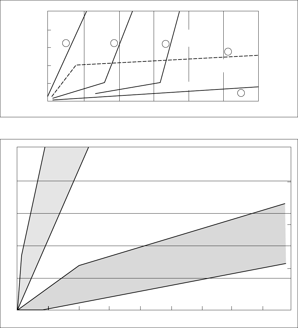
38
Figure 37. Wear of Delrin 500, 500T, 100ST Against Various Materials*
3
21
5
4
Time of Test
Wear
Delrin
Mild
Steel
Delrin
Hard
Steel
Delrin
Tungsten
Carbide
Delrin Hard Steel
with Slots
Delrin–Zytel 101
Figure 38. Wear of Delrin 500 Against Mild Steel*
Time of Test
Wear
Delrin
500
Delrin
500CL
*Thrust Washer Test; Nonlubricated; P, 0.04 MPa (5.7 psi); V, 0.95 m/sec (190 ft/min)
The wear performances of Delrin 500 and 500CL
are illustrated in Figure 38 against mild steel.
Comparable data have also been obtained to show
the suitability of Delrin acetal resin with aluminum
and brass. Most other engineering resins do not
perform well running against soft metals due to the
tendency to pick up metal particles in the plastic
surface. Because Delrin acetal resin is harder, this
tendency is reduced.
The actual wear performance of specific resins will
vary depending upon load, speed, mating surface,
lubrication, and clearance.
Delrin 500CL offers wear performance that is
superior to all filled resins, even to those having
a lower coefficient of friction. It is especially
preferred when running against soft steel and
nonferrous metals.

39
Chapter 6
Environmental Effects
Contents
Weathering
Chemical Resistance
Effect of Specific Chemicals
Test Data—Unstressed
Test Data—Stressed
Stain Resistance
Permeability
Exposure to Space and Radiation
Dimensional Considerations for Molded Parts
Moisture Effects
Post-Molding Shrinkage
Annealing
Tolerance
Miscellaneous

40
Weathering
Over time, exposure to ultraviolet light adversely
affects the tensile strength of plastics. Weather-
resistant compositions of Delrin acetal resin have
been developed to withstand such exposure.
For outdoor applications involving either inter-
mittent exposure or a service life of 1 to 2 years,
colors of Delrin acetal resin are generally suitable
based on property retention. For increased resis-
tance to surface dulling and chalking and better
tensile property retention, specially formulated
colors containing a UV stabilizer provide signifi-
cantly better performance. However, even with
UV-stabilized color compositions, surface dulling
and chalking begin in about 6 to 8 months of ex-
posure in Florida. The chalk may be removed by
hand polishing in the early stages of development.
If removal is delayed, the chalk layer hardens with
time and becomes more difficult to remove.
For applications that require outdoor exposure
to direct sunlight and much more than 2 years of
useful life, the carbon black-filled UV-resistant
resin should be used.
Delrin 507 BK601 compositions have shown
excellent retention of strength properties after
20 years of outdoor exposure in Arizona, Florida,
and Michigan. Over this period, essentially no loss
of tensile strength occurred, but elongation was
reduced to about 40% of the initial test value, with
the greatest change in elongation occurring during
the first 6 months of exposure. These performance
data are shown in Table 10.
Chemical Resistance
One of the outstanding properties of Delrin acetal
resin is excellent resistance to a variety of organic
compounds. The resins have good load-carrying
ability in many neutral organic and inorganic
materials, even at elevated temperatures. Delrin
acetal resin exhibits good dimensional stability
and superior chemical resistance to the following:
• Alcohols
• Aldehydes
• Esters
• Ethers
• Hydrocarbons (gasolines, lubricants, hydraulic
fluids)
• Agricultural chemicals
• Many weak acids and weak bases
• Water
The load-carrying ability of Delrin acetal resin, or
any plastic material, will depend on the following
factors:
• Nature and concentration of the chemical
• Temperature
• Stress level
• Time of chemical exposure at the given stress
level
In addition, the change can be either reversible
(absorption) or irreversible (chemical attack or
mechanical failure).
Effect of Specific Chemicals
Unstressed specimens of Delrin acetal resin were
exposed to a variety of chemicals for periods up
to one year and temperatures up to 93°C (199°F).
Solvents
Delrin acetal resin is exceptionally resistant to
solvents, retaining over 90% of its tensile stress
after exposure to almost all solvents.
Lubricants and Hydraulic Fluids
Delrin acetal resin generally has good resistance
to base oils. The presence of chemical additives
in some oils may have a marked effect on perfor-
mance, particularly at temperatures above 66°C
(150°F).
Gasolines
Tensile strength of Delrin acetal resin is essentially
unaffected by exposure to gasolines. Stiffness can
be reduced a moderate amount, depending upon the
concentration of aromatic hydrocarbons in the fuel.
This slight plasticizing effect is completely recover-
able if exposure is terminated and the hydrocarbons
allowed to evaporate.
Agricultural Chemicals
Delrin acetal resin has excellent resistance to agri-
cultural chemicals such as commercial types of
weed killers, insecticides, fungicides, and fertilizers.
Acids, Bases, and Oxidizing Agents
Delrin acetal resin has good resistance to many
weak acids and weak bases. It is not suitable for
service in strong acids, strong bases, or oxidizing
agents. Thus, they are not recommended for uses
outside of pH range 4–9. Furthermore, other
components in water may react with acids and
bases and affect the resistance characteristics.
Environmental Effects

41
Zinc Chloride and Chlorine
Delrin acetal resin is not recommended for use in
zinc chloride solutions or environments that may
generate zinc chloride. Zinc chloride acts to depoly-
merize (corrode) Delrin acetal resin. The extent of
attack will depend on stress, temperature, concen-
tration, and time of exposure. This should not be
construed to imply that Delrin acetal resin cannot
be used in contact with zinc or zinc-plated metals.
Delrin acetal resin has been used successfully in
many such applications since its commercialization
in 1960. However, where continuous exposure to
salt water and contact with zinc-plated steel is
encountered, extensive testing is recommended.
Sacrificial corrosion can produce zinc ions. These,
together with the chlorine ions present in the salt
water, can produce an effect similar to, but slower
than, that produced by zinc chloride. Delrin acetal
resin is not affected by exposure to salt water alone.
Delrin acetal resin is attacked by chlorine at con-
centrations of 3 to 5 ppm and higher. It is not
recommended for long-term, continuous expo-
sure at these concentrations.
Test Data—Unstressed
Injection molded bars, 127 mm long × 3.2 mm
thick × 12.7 mm wide (5 in ×
1
/
8
in ×
1
/
2
in) were
immersed in the test chemical under no load and
maintained at constant temperature. After exposure
the bars were examined for evidence of chemical
attack and measured to determine change in length,
weight, tensile strength, and tensile modulus.
The complete results are shown in Table 11.
Test Data—Stressed
No stress cracking resulted when injection molded
bars of Delrin acetal resin 5.08 cm × 1.27 cm ×
0.32 cm (2 in ×
1
/
2
in ×
1
/
8
in) of Delrin 500 were
held in a U shape by steel clamps and submerged
in the following reagents at room temperature for
one week:
• Carbon tetrachloride
• Toluene
• Acetone
• Ethyl acetate
• 5% acetic acid
• 37% formaldehyde
• Motor oil
• Used crankcase oil
• 10% sodium chloride
• 25% “Igepal”
• Buffer pH 4
• Buffer pH 10
• Brake fluid
Stain Resistance
At room temperature Delrin acetal resin has excel-
lent resistance to staining by a wide variety of
common and usually troublesome substances
including:
• Tea
• Catsup
• Vinegar
• Vegetable dyes
• Oleomargarine
• Lemon juice
• Lipstick
• Industrial oils
• Greases
• Typewriter ribbon inks
At higher temperatures, some of these substances
may cause slight discoloration.
Table 10
Weatherability of Delrin 507 BK601
Arizona Michigan
Tensile Strength Tensile Strength
Exposure Time, yr MPa psi Elongation, % MPa psi Elongation, %
0 70.3 10,200 20 70.3 10,200 20
1 71.0 10,300 12 70.3 10,200 7
2 71.7 10,400 11 70.3 10,200 13
3 71.0 10,300 9 70.3 10,200 12
4 73.1 10,600 11 72.4 10,500 14
10 69.6 10,100 10 69.6 10,100 10
20 70.2 10,185 8 64.4 9,339 11
Samples: ASTM Tensile Specimens, 216 mm × 13 mm × 3 mm (8
1
/
2
in ×
1
/
2
in ×
1
/
8
in)

42
Table 11
Chemical Resistance Data for Delrin
Test Conditions Test Results, % Change
Conc., Duration, Temperature Tensile Tensile
Material % Days °C °F Modulus Strength Length Weight
Section A: Chemical Compounds
Acetic Acid 5 365 23 73 –12 0 0.2 0.8
20 90 60 140 U U U U
80 90 60 140 U U U U
Acetone 100 365 23 73 –32 –5 0.9 4.9
100 365 50 122 –40 –7 1.1 2.6
100 10 60 140 — –5.9 — 3.3
Adipic Acid 5 365 23 73 — 5 — –0.1
Aluminum Sulfate 5 365 23 73 — 1 — –0.2
Ammonium Chloride 10 275 60 140 –16 2 0.1 3
5 365 23 73 — 2 — –0.1
Ammonium Hydroxide 10 90 23 73 U U U U
Ammonium Orthophosphate 5 365 23 73 — 2 — 0.1
Ammonium Thioglycolate (pH 9.4) 8 4 23 73 — — — 0
(Component of Hair Waving Solution)
Aniline 100 275 60 140 –67 –12 0.3 8.3
Benzene 100 275 60 140 –49 –11 2.2 4
Butylaldehyde 100 275 60 140 –49 –12 1.8 3.0
Butylamine 100 90 60 140 U U U U
Butyl Carbitol 100 28 54 130 — 0 — —
Calcium Chloride 5 365 23 73 — 0 — –0.2
Calcium Hydroxide 10 275 60 140 –6 1 0.4 0.7
Carbon Tetrachloride 100 365 23 73 –14 –3 0.3 1.3
100 365 50 122 –44 –7 –0.3 5.7
Castor Oil 100 365 23 73 — 0 — –0.1
Cellosolve 5 365 23 73 — 0 0.1 0
Cellosolve Acetate 5 365 23 73 — –2 0.3 0.5
Copper Chloride 5 365 23 73 — 0 — –0.1
Dioxane 100 275 60 140 –59 –13 2.7 6
Dimethyl Formamide 100 275 60 140 –7.3 0.6 0 –0.2
Ethanol 100 365 23 73 –33 –5 0.8 2.2
100 365 50 122 –32 –5 1.0 1.9
100 10 60 140 — –7 — 2.1
Ethyl Acetate 100 365 23 73 –40 –7 1.4 2.7
100 365 50 122 –42 –7 1.1 2.9
Ethylene Chloride 100 365 23 73 — –2 0.8 2.0
Ferric Chloride 5 365 23 73 — –4 — –0.9
Ferrous Chloride 5 270 23 73 — 0 — –0.1
Formic Acid 100 90 60 140 U U U U
Hexane 100 275 60 140 –9 –4 0.6 0.7
Hydrochloric Acid 10 90 23 73 U U U U
Hydrogen Peroxide 90 7 66 150 U U U U
90 28 29 85 U U U U
50 365 23 73 — –2 — –0.1
Isoamyl Alcohol 100 275 60 140 –32 –4 1.2 2
Kerosene 100 275 60 140 –4 0 0.1 0
Lithium Chloride 43 275 60 140 –2 2 0.3 –2.6
Methanol 100 275 60 140 –41 –10 1.4 –2.3
Methyl Ethyl Ketone 100 7 54 130 — –11.5 — —
Methyl Salicylate 100 365 23 73 — –2 1.3 2.6
Methyl Chloride 100 365 23 73 — 0 — 0.9
Nicotine Sulfate 5 365 23 73 — 0 — –0.1
Nitric Acid 10 275 24 75 U U U U
Perchloroethylene 100 275 60 140 –43 –7 1.6 5.6
Phenol 100 90 60 140 U U U U
Phosphoric Acid 10 90 60 140 U U U U
80 90 60 140 U U U U
Key: U—Unsatisfactory
(continued)

43
Table 11
Chemical Resistance Data for Delrin
(continued)
Test Conditions Test Results, % Change
Conc., Duration, Temperature Tensile Tensile
Material % Days °C °F Modulus Strength Length Weight
Section A: Chemical Compounds
Potassium Permanganate 10 275 60 140 –14 0 0.3 –7
Pyridine 100 275 60 140 –57 –9 2.7 6
Sodium Bisulfate 5 365 23 73 — –1 — –0.3
Sodium Bisulfite 5 14 23 73 U U U U
Sodium Bromate 14 4 23 73 — — — –1.3
Sodium Bromide 5 365 23 73 — 0 — –0.1
Sodium Chlorate 5 365 23 73 — 2 — –0.1
Sodium Chloride 10 365 70 158 –5 –15 0 –0.6
Sodium Hydroxide 10 365 23 73 U U U U
Sodium Hypochlorite 5 30 23 73 U U U U
(Commercial Bleach)
Sodium Sulfide 5 365 23 73 — –1 — –0.3
Sodium Sulfite 5 365 23 73 — 0 — –0.2
Sodium Thiosulfate 26 275 60 140 –31 –18 0.3 –3
Stannous Chloride 5 270 23 73 U U U U
Sulfuric Acid 1 316 35 95 U U U U
30 182 23 73 U U U U
Tartaric Acid 5 365 23 73 — –1 — –0.2
Tetrahydrofuran 100 17 23 73 — — 0.4 —
100 3 66 150 — — — 0.2
Toluene 100 365 23 73 –45 –7 1.2 2.6
100 365 50 122 –42 –7 1.2 2.8
100 10 60 140 — –7 — 2.8
Triethylamine 100 275 60 140 –41 –19 0 –4.3
Urea 5 365 23 73 — 0 — –0.1
Section B: Commercial Products
(
Many of these materials are blends. Changes in the nature of
concentration of components of the blends could change the effect of Delrin)
Agricultural Chemicals
Weed Killers
2,4-D dimethylamine salt of (saturated) 365 23 73 –5 –4 — —
2,4 dichlorophenoxyacetic Acid 100% 273 23 73 — — 0.28 0.85
2,4,5-T trimethylamine salt of 25% by 365 23 73 –45 –10 — —
2,4,5 trichlorophenoxyacetic weight of 273 23 73 — — 2.6 8.2
Acid-pH = 11.3 solution
Insecticides
Malathion-organic phosphorus 6 tsp/qt of 365 23 73 –17 –3 — —
50% solution 273 23 73 — — 0.55 1.3
Dieldrin-aromatic (saturated) 365 23 73 –9 0 — —
terpene 100% 273 23 73 — — 0.47 1.0
DDT 2 tsp/qt 365 23 73 –9 1 — —
273 23 73 — — 0.4 1.0
Lead Arsenate 1 tsp/qt 365 23 73 –3 1 — —
273 23 73 — — 0.31 0.85
Fungicides
Manzate
manganese 3 g/qt 365 23 73 –5 2 — —
ethylenebis-dithiocarbamate 273 23 73 — — 0.32 0.91
Captan 5 g/qt 365 23 73 –5 1 — —
273 23 73 — — 0.28 0.85
Fertilizers
N, P, K Type (pH = 6.7) 3.6, 5.4, 5.4 273 23 73 — — — 0.61
Key: U—Unsatisfactory
(continued)

44
Table 11
Chemical Resistance Data for Delrin
(continued)
Test Conditions Test Results, % Change
Conc., Duration, Temperature Tensile Tensile
Material % Days °C °F Modulus Strength Length Weight
Section B: Commercial Products
Fertilizers
(continued)
N, P, K Type (pH = 5.3) 3.4, 7.3, 5.1 273 23 73 — — — 0.67
N, O, K Type (pH = 10.2) 3.8, 0, 5.6 273 23 73 — — — 0.76
N, O, O Type-Ammonium Nitrate21.6, 0, 0 273 23 73 — — — 0.35
N, O, O Type-Urea 21.3, 0, 0 273 23 73 — — — 0.74
Brake Fluids
Delco Super 9 100 310 70 158 — –6 0.6 1.6
Delco Super 11 H.D. 100 427 66 150 — — 0.35 0.7
Lockheed 21 100 310 70 158 — –23 0.3 0.9
Cleaners, Detergents, and
Household Agents
“Ajax” 2 and “Bucket of Power” * 365 23 73 — –1 — –0.1
Alkylaryl Sulfonate-Quaker 50 5 70 158 — — 0.3 –0.2
“Dianol” #11 50 3 93 200 U U U U
“Calgon Rinse Aid” 50 5 70 158 — — 0.3 0.9
(pH 4.4 general purpose) 50 5 93 200 — — 0.3 0.9
“Calgolac” * 365 23 73 — 0 — –0.2
“Cold Water All” ** 365 23 73 — 0 — –0.1
“Defend” * 365 23 73 — –1 — –0.1
Duponol
ME-Sodium Lauryl Sulfate 100 275 60 140 –18 1 0.4 0.8
25 5 70 158 — — 0.3 0.5
25 5 93 200 — — 0.2 0.8
“El Rinse Dry” 50 5 70 158 — — 0.3 0.7
(pH 5.0 general purpose) 50 5 93 200 — — 0.3 0.8
Hair Waving & Neutralizing Solutions — 4 23 73 — — — 0.4
“Igepal” 50 365 23 73 –2 2 0.1 –0.2
50 180 70 158 U U U U
“Lestoil” * 365 23 73 — –3 — –0.2
“Lysol” * 365 23 73 — 1 0.4 0.1
“Mr. Clean” * 365 23 73 — –2 — —
“Poreen” 25 5 70 158 — — 0.4 0.7
(pH 4.2 general purpose) 25 5 93 200 — — 0.2 –1.2
“Oakite” 33 5 70 158 — — 0.2 0.4
(Trisodium Phosphate) 33 5 93 200 — — 0.1 0.1
“Tide” * 365 23 73 — 0 — –0.1
“Triton” X-100 100 275 60 140 –13 0 0.5 0.3
Gasolines
Iso-Octane 100 820 23 73 0 –3 0.1 0.2
Exxon Regular 100 820 23 73 –12 –4 0.2 0.7
Sunoco 100 820 23 73 –16 –6 0.3 0.8
Exxon High-Test 100 820 23 73 –17 –7 0.4 0.9
Exxon Golden 100 820 23 73 –18 –6 0.5 1.2
Amoco 100 820 23 73 –20 –9 0.5 1.3
Texaco 100 820 23 73 –17 –7 0.7 1.6
Gulf Crest 100 820 23 73 –31 –6 0.6 1.6
Lubricants
C890-T (Sun Oil Co.)-Chassis Lubricant 100 550 23 73 — — — 0
100 240 93 200 — 0 — –0.3
“Nujol” 100 365 23 73 10 1 –0.1 0.3
100 365 70 158 13 2 –0.4 –0.5
Oil-Exxon “Uniflo” 10W30 100 365 70 158 2 3 –0.3 –0.2
Key: U—Unsatisfactory *
1
/
4
cup/gallon **2 cups/gallon
45
Permeability
Delrin acetal resin has good impermeability to
many substances including aliphatic, aromatic,
and halogenated hydrocarbons, alcohol, and esters.
However, its permeability to some small polar
molecules such as water, methyl alcohol, and
acetone is relatively high. Permeability characteris-
tics and strength properties of Delrin acetal resin
make it suitable material for containers, particularly
of the aerosol type. Permeability factors for a
number of compounds are listed in Table 12.
Exposure to Space and Radiation
Space is an exceedingly hostile environment, not
only for human beings, but also for most plastic
materials. In the space environment, materials are
subjected to the effects of vacuum, temperature,
particulate radiation (e.g., ions, protons, electrons),
and electromagnetic radiation (e.g., ultraviolet light,
x rays, gamma rays).
Delrin acetal resin will be stable in the vacuum of
space under the same time-temperature conditions
it can withstand in air (see pg. 26). Exposure
to vacuum alone would cause no loss of the engi-
neering properties of Delrin. The principal result
would be slight outgassing of small amounts of
moisture and free formaldehyde. In a vacuum, as
in air, prolonged exposure to elevated temperatures
would result in the liberation of increasing amounts
of formaldehyde due to thermal degradation of
the polymer.
Particulate radiation, such as the protons and
electrons of the Van Allen radiation belts, is
damaging to acetal resins and will cause loss
of engineering properties. For example, Delrin
acetal resin should not be used in a radiation en-
vironment where the total electron dose is likely
to exceed 1 Mrad. When irradiated with 2 meV
electrons, a 1 Mrad dose causes only slight dis-
coloration while 2.3 Mrad, however, causes con-
siderable embrittlement. At 0.6 Mrad, however,
Delrin acetal resin is still mechanically sound
except for a moderate decrease in impact strength.
The result of exposing Delrin to 2 meV electrons
is given in Table 13.
The regions of the electromagnetic spectrum that
are most damaging to acetal resins are UV light
and gamma rays. In space, the deleterious effects
of UV light are of prime consideration. This is due
to the absence of the protective air atmosphere that
normally filters out much of the sun’s UV energy.
Therefore, the amount of UV light in space may
be 10 to 100 times as intense as on the ground.
Gamma radiation in space is of a lower order of
intensity than that emitted by nuclear reactors.
The effect of gamma rays on Delrin is essentially
the same as that observed with high energy elec-
trons. Exposure to gamma radiation of a ground
test reactor caused rapid decrease in tensile
strength with increasing dose. The Shore D hard-
ness decreased exponentially with absorbed dose.
The predominant mode of degradation resulting
from excessive gamma ray dosage appears to be
depolymerization.
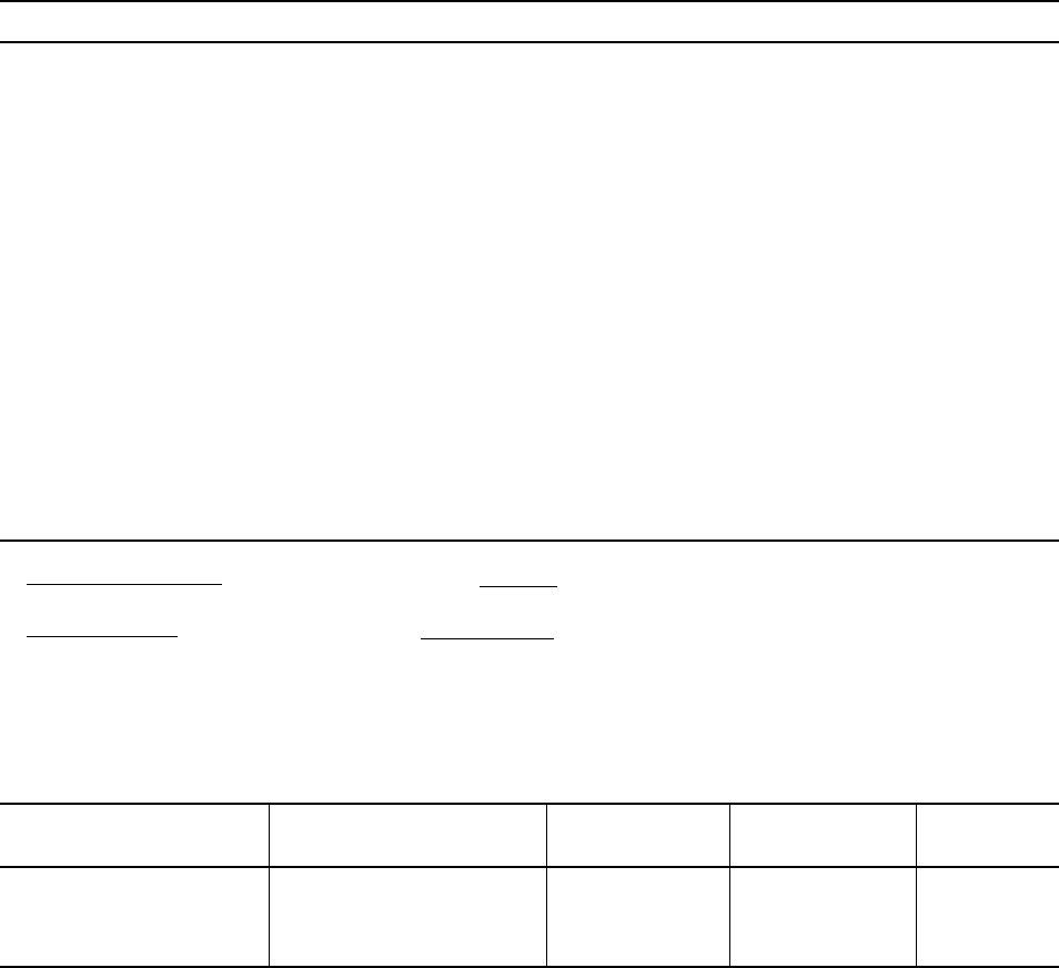
46
Table 12
Permeability Factors*
23°C (73°F), 50% RH 38°C (100°F)
Cologne formulations 0.6 4.5
Ethyl alcohol/water (90%/10% by wt.) 0.25 —
Ethyl alcohol/water (70%/30% by wt.) 1.5 7.8
Freon
12/11 propellant (30/70) 0.2 0.54
Freon 12/114 propellant (20/80) 0.2 0.42
Gasoline 0.1 —
Hair spray formulations 0.8 6.0
Methylsalicylate 0.3 —
Nitrogen at 620 kPa (90 psi) 0.05 —
Oils (motor, mineral, vegetable) 0 0
Perchloroethylene 0.2 —
Shampoo formulations 2.4 8.5
Tar and road-oil remover 0.03 0.19
Trichloroethylene 25 56
Toluene 0.6 —
Carbon dioxide 37–50** —
Oxygen 12–17** —
* ; multiply by 0.394 to convert to
** ; multiply by 3.89 to convert to
Table 13
Exposure of Delrin to 2 meV Electrons
Dose, Tensile Strength Elongation, Izod Impact, Strength,
Mrad MPa psi % J/m ft⋅lb/in
0 69 10,000 15 75 1.4
0.6 67 9,680 11.5 53 1.0
2.3 43 6,200 0.9 11 0.2
g × mil wall thickness
100 in
2
of wall area × 24 hr
cc × mil
100 in
2
× 24 hr × atm
mL × mm
m
2
× 24 hr × MPa
g × mm
m
2
× 24 hr
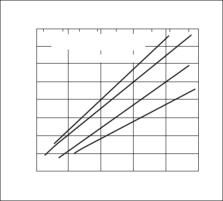
47
Dimensional Considerations for
Molded Parts
Dimensional stability of a plastic part is an impor-
tant design consideration, especially where close
tolerances are required. Aside from highly rein-
forced compounds, thermoplastic materials are not
as dimensionally stable as metals. Yet the bulk
of engineering plastic applications have stemmed
from the replacement of metals. Understanding the
factors that cause changes in dimensions of plastic
parts, and properly allowing for these effects in the
design and specifications controlling the part, is
the key to successful use of plastic materials in
engineering applications.
Delrin acetal resins have been used successfully
since 1960 in a multitude of close tolerance parts,
such as gears, bearings, cams and the like, operat-
ing in a variety of industries and environments.
Delrin acetal resin has good dimensional stability
over a wide range of temperatures and in environ-
ments containing moisture, lubricants, solvents,
and many chemicals.
The following data show the dimensional change
of Delrin acetal resin due to moisture, temperature,
and post-molding shrinkage.
Moisture Effects
Delrin acetal resin absorbs a small amount of water,
creating minor changes in the dimensions of molded
parts. Figure 39 shows how changes in moisture
content at various temperatures will affect Delrin
100, 500, and 900. The rate at which water will be
absorbed by Delrin 100, 500, and 900 at various
conditions is shown in Figure 40.
Post-Molding Shrinkage
The rheological characteristics of Delrin acetal
resins are tightly controlled during the manufactur-
ing process. Thus, parts molded of Delrin acetal
resin will exhibit highly consistent as-molded
dimensions.
As with any thermoplastic material, post-molding
shrinkage will occur due to the relief of internal
stresses. Of interest is not only the amount, but also
the rate of post-molding shrinkage or stress relief.
Rate of shrinkage is time/temperature dependent
and is greatly accelerated as the temperature of the
part is raised. The amount of shrinkage is depen-
dent primarily on molding conditions and wall
thickness.
Figure 39. Dimensional Changes of Delrin with
Variations of Temperature and Moisture
Content
160120
Environmental Temperature, °F
Environmental Temperature, °C
Increase in Length, %
80
Delrin 100, 500, 900
Specimen Thickness 3 mm (1/8 in)
Immersion in Water
100% RH
50% RH
0% RH
40
0 20 40 60 80 100
1.4
1.2
1.0
0.8
0.6
0.4
0.2
0
–0.2
200
Figure 41 shows typical post-molding shrinkage
of Delrin acetal resins after exposure for 1,000 hr
(after molding) at various temperatures. The data
for moldings of three different thicknesses are
plotted on separate graphs. Each graph presents
a family of curves for several mold temperatures.
Years of experience with many applications have
shown that parts of Delrin acetal resin molded in
a hot mold (93°C [200°F]) will exhibit negligible
post-molding shrinkage in most applications.
Annealing
Although most applications do not require anneal-
ing, in applications where tolerances are extremely
critical, annealing has been successfully used. It is
also used for checking machined parts for dimen-
sional stability. Annealing is the process of raising
part temperature prior to use high enough so that
most of the internal stresses will be relieved in a
short time—usually less than one hour. Annealing
can also be useful in the prototype stage to examine
the tendency of a part to warp so that design changes,
if necessary, can be made to eliminate or minimize
the warpage. Common methods of annealing are
as follows:
• Air Annealing
In an air circulating oven, the parts are heated
to 160 ± 3°C (320 ± 5°F) for 30 min plus 5 min/
1 mm (0.04 in) of wall thickness. It is important
that parts be uniformly heated and the oven cap-
able of controlling the circulating air temperature
to ±3°C (±5°F).
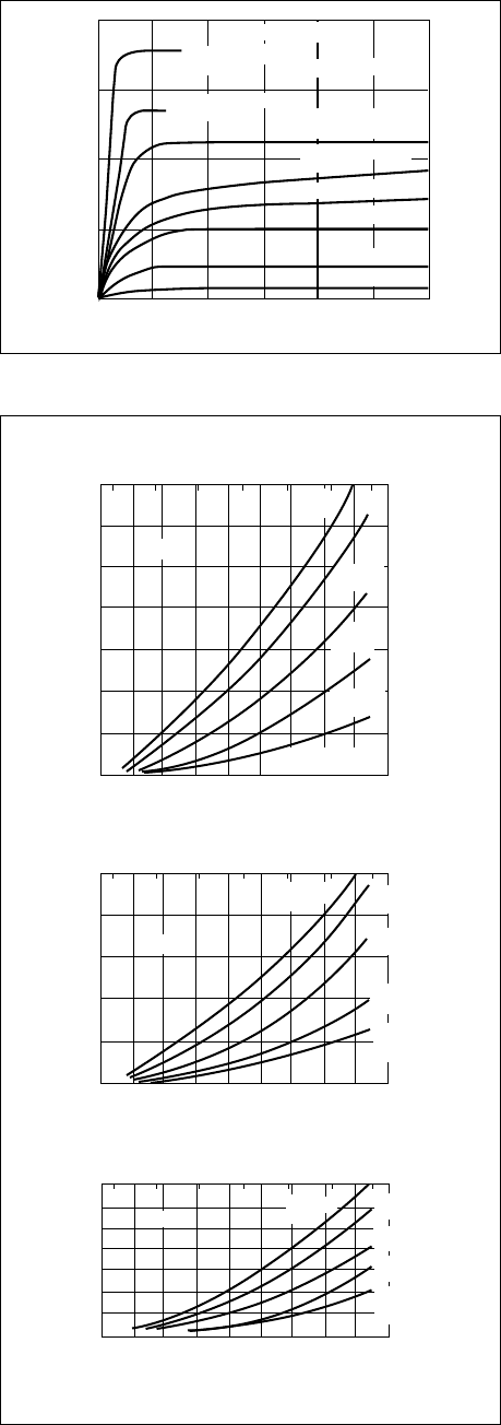
48
Figure 40. Rate of Water Absorption of Delrin at
Various Conditions
0102030
Time, Days
Water Absorption, %
40 50 60
0
0.5
1.0
1.5
2.0
Thickness = 3 mm (1/8 in)
Delrin 100, 500, 900
Immersion in Water
100°C (212°F)
Immersion in Water
79°C (175°F)
Immersion in Water
60°C (140°F)
100% RH, 25°C (77°F)
83% RH, 25°C (77°F)
50% RH, 25°C (77°F)
12% RH, 25°C (77°F)
Immersion in Water
25°C (77°F)
Figure 41. Post-Molding Shrinkage in Air
75
1.8
1.2
1.0
0.8
0.6
0.4
0.2
0
20 30 40 50 60
Exposure Temperature, °C
Post-Molding Shrinkage, %
Exposure Temperature, °F
Thickness—0.8 mm (1/32 in)
70 80 90 100
Delrin 500
Delrin 500
Delrin 500
38°C Mold
(100°F)
66°C Mold
(150°F)
66°C Mold
(150°F)
93°C Mold
(200°F)
121°C Mold
(250°F)
Annealed
All mold
temperatures
66°C Mold
(150°F)
38°C Mold
(100°F)
93°C Mold
(200°F)
121°C Mold
(250°F)
Annealed
All mold
temperatures
38°C Mold
(100°F)
93°C Mold
(200°F)
121°C Mold
(250°F)
Annealed
All mold temperatures
110
100 125 150 175 200 225
75
1.0
0.8
0.6
0.4
0.2
0
20 30 40 50 60
Exposure Temperature, °C
Post-Molding Shrinkage, %
Exposure Temperature, °F
Thickness—1.6 mm (1/16 in)
70 80 90 100 110
100 125 150 175 200 225
75
0.7
0.6
0.5
0.4
0.3
0.2
0.1
0
20 30 40 50 60
Exposure Temperature, °C
Exposure Time = 1,000 hr
Post-Molding Shrinkage, %
Exposure Temperature, °F
Thickness—3.2 mm (1/8 in)
70 80 90 100 110
100 125 150 175 200 225
• Oil Annealing
Parts annealed in a recommended oil* circulat-
ing bath at 160 ± 3°C (320 ± 5°F) will require
15–20 min to come up to temperature plus
5 min/1 mm (0.04 in) of wall thickness. Again,
uniform heating is important, and the parts should
be restrained from contact with each other or the
walls of the bath.
As parts are flexible at elevated temperatures, they
should be handled carefully to prevent deforming
and allowed to cool slowly in an undisturbed
manner. Stacking or piling should be delayed
until parts are cool to the touch.
• Partial Annealing
Partial annealing is sometimes adequate instead
of full annealing described above. Partial anneal-
ing is accomplished by raising the temperature
of the part 28°C (50°F) above the maximum-use
temperature for a period of 1 hr.
When testing a part for a one-time short-term
exposure to high temperature, such as paint bake
oven, neither full annealing nor partial annealing
may be appropriate. In such a case, testing with
the part in the installed condition at the actual
temperature and for the actual time is much more
meaningful. Testing at a higher temperature or
for a longer period of time could throw out a
perfectly good application.
*Recommended Oil Suppliers:
U.S.A.
“Primol” 355 – Exxon
“Chevron White Oil
No. 15” – Standard Oil Co. of California Western
Operation, Inc.
“Nujol” – Plough, Inc.
Europe
“Primol” 292 and
“Majoline” 238 CRA– Exxon
“Ondina” 33 – Shell
49
Tolerance
Tolerance is the amount of variation that can be
permitted in the dimensions of a plastic component
while still enabling the component to function.
Tolerance is affected by a wide variety of factors
including resin composition, mold dimensions and
condition, molding techniques, and others.
The degree of tolerance depends on the application
and can be divided into two general categories:
commercial and fine. Commercial tolerances are
those obtained under average production condi-
tions. Fine tolerances require special attention
to mold design and construction and processing
conditions and Q/C procedures.
Parts made of Delrin acetal resins may be manu-
factured to close tolerances. See the tolerance
standards shown in Figure 42.
Miscellaneous
Autoclave Sterilization
Delrin acetal resin survived 100 15-min cycles of
121°C (250°F) in an autoclave. However, addi-
tional cycles could result in surface chalking and
hydrolysis.
Sanitization
Several methods are available. Consult your
DuPont representative.
Underground Applications
Samples of Delrin buried underground for a long
period of time in Landenberg, PA, showed no signs
of deterioration of physical properties from fungi,
bacteria, or insects. Tests were conducted to estab-
lish whether termites would attack Delrin. In these
tests, wooden strips were placed between each
piece of Delrin to serve as bait and indicators of
the presence of termites. After firming the soil,
the area was contaminated with debarked logs
containing termites. The samples were examined
at the end of 3
1
/
2
yr, at which time the pine wood
pieces were heavily infested with termites and
had been decayed by fungi. Delrin had not been
attacked.
Bacteria and Fungi
In many applications, the materials of construction
used must not support growth of bacteria and fungi
and in addition, should be easy to clean. Where
these requirements are demanded, Delrin acetal
resin is comparable to other materials of construc-
tion currently employed.
In 1958, basic tests of bacteria and fungus resis-
tance of Delrin acetal resin were conducted by
the United States Testing Company, Inc. In their
evaluation, tests were made to determine:
• Mildew resistance properties
• Bacterial resistance properties
• If absorption or adsorption of nutrient from
pasteurized milk, which could lead to an increase
in bacterial population following standard wash-
ing and disinfecting procedures of the food
industries, would occur.
The U.S. Testing Company concluded the rate
of bacterial growth in food in contact with Delrin
acetal resin is comparable to other materials in
the rate of bacterial growth in foods and causes no
significant decrease or increase in bacterial popu-
lation. In this respect it is similar to stainless steel
or rubber.
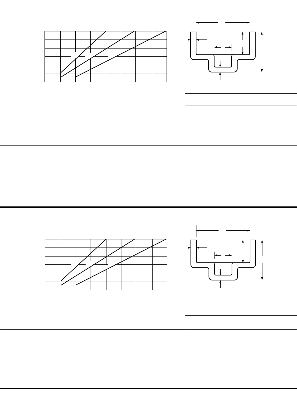
50
External Single Cavity, D = 0 to 1
Height Multiple Cavity, D = 0 to 1
D D greater than 1, add per inch
Side Wall For C = 0 to 1
Thickness C greater than 1, add per inch
F
for F = 0 to 0.25
Bottom Wall E = 0 to 0.1
Thickness E = 0.1 to 0.2
E E = 0.2 to 0.3
Tolerance ± (Dimensions in inches)
Fine Standard Coarse
0.002 0.004 0.006
0.003 0.005 0.007
0.002 0.003 0.004
0.002 0.003 0.004
0.001 0.002 0.003
0.002 0.004 0.006
0.004 0.005 0.007
0.006 0.007 0.008
External Single Cavity, D = 0 to 25
Height Multiple Cavity, D = 0 to 25
D D greater than 25, add per mm
Side Wall For C = 0 to 25
Thickness C greater than 25, add per mm
F
for F = 0 to 6
Bottom Wall E = 0 to 2.5
Thickness E = 2.5 to 5.0
E E = 5.0 to 7.5
Tolerance ± (Dimensions in mm)
Fine Standard Coarse
0.05 0.1 0.15
0.08 0.13 0.18
0.002 0.003 0.004
0.05 0.08 0.1
0.001 0.002 0.003
0.05 0.1 0.15
0.1 0.13 0.18
0.15 0.18 0.2
English Units
Metric Units
Figure 42. Molding Tolerances for Parts of Delrin
A
Part Dimensions
Fine
Standard
Coarse
Suggested Tolerances
(Dimensions in mm)
B
F
E
D
C
0.200.05
Tolerance ±
For dimensions over 150 mm, add (±)
0.001 (fine), 0.002 (standard), or 0.003 (coarse)
mm per added mm
Internal
Dimensions
A, B, or C
25
50
75
100
125
150
0.10 0.15 0.25 0.30 0.35 0.40
A
Part Dimensions
Fine
Standard
Coarse
Suggested Tolerances
(Dimensions in inches)
B
F
E
D
C
0.0080.002
Tolerance ±
For dimensions over 6 in, add (±) 0.001 (fine),
0.002 (standard), or 0.003 (coarse) in per
added inch
Internal
Dimensions
A, B, or C
1
2
3
4
5
6
0.004 0.006 0.010 0.012 0.014 0.016

51
Chapter 7
Agency Approval
Contents
UL Recognition
Regulatory Agencies—Specifications

52
UL Recognition
Underwriters Laboratories, Inc. is an indepen-
dent, nonprofit testing laboratory whose primary
function is fire safety evaluation of equipment
and products. Many states and local governments
require UL certification before items such as elec-
trical appliances may be sold or installed within
their jurisdiction.
Recognition of plastic resins is based on perfor-
mance indexes derived from testing unaged molded
samples for such characteristics as flammability,
hot wire ignition, dielectric strength, heat deflec-
tion, dimensional stability, tensile strength, and
impact strength. UL also provides temperature
indexes based on long-term testing of electrical
and mechanical properties at temperatures above
50°C (122°F).
UL rating cards provide UL ratings for Delrin
acetal resins based on properties most commonly
used by designers in selecting material for electrical
applications. UL updates rating cards on a regular
basis. Contact your local DuPont sales office for
current information.
Regulatory Agencies—
Specifications
Before a material can be used in certain applica-
tions, it must be approved by or meet the require-
ments of various government and private agencies.
The list of resins qualified in this respect changes
frequently. DuPont will provide the current status
of specific regulations with respect to Delrin acetal
resins on request.
Agency Approval

53
Chapter 8
Applications
Contents
Painting
Dyeing
Chrome Plating
Hot Stamping
Silk Screening
Direct Printing
Wipe-in Paints
Adhesive Joining

54
Painting
Painting articles made of Delrin acetal resin may be
desirable for any of the reasons mentioned in Table
14. High paint adhesive is possible on “flame-
treated” surfaces of Delrin acetal resin with the
following types of paint:
• Nitrocellulose lacquer
• Acrylic lacquer
• Alkyd enamel
• Polyurethane/enamel
• Epoxy enamel
• Phenolic enamel
Commercial formulations of these paints, com-
pounded either for interior or exterior use, may
be used provided they are compatible with Delrin
acetal resin.
Delrin acetal resin has good structural properties for
short-term exposure up to 172°C (292°F), its heat
distortion temperature under 0.5 MPa (66 psi) load.
Thus, painted articles of Delrin acetal resin can be
baked to harden the paint at temperatures normally
employed for painted metallic components. Tem-
peratures as high as 157°C (315°F) are used for
typical automotive grade paints.
Dyeing
Surfaces of Delrin acetal resin can be dyed by
either the “Water Solvent Method” or the “Organic
Solvent Method.” Part geometry must be taken into
account when dyeing Delrin acetal resin because
part thickness influences the rate at which staining
occurs. Thin sections stain more rapidly than thick.
Consequently, variations in section thickness will
determine the immersion time required for color
uniformity and tone. Light uniform tones may be
difficult to achieve.
Commercial household dyes such as “Tintex”
1
and “Rit”
2
have also been used successfully to dye
parts of Delrin acetal resin for color coding. Bath
temperatures of 85–90°C (185–195°F) should be
employed with “Tintex” and “Rit” to obtain ad-
equate dye penetration and good color.
Chrome Plating
Delrin acetal resin has been plated in the laboratory
by a solution-type process to produce high quality,
cost competitive articles of excellent appearance
and durability for inside and outside weather
exposure. All steps in the plating process except
the etch steps are compatible with standard ABS
plating processes. Chrome-plated articles of Delrin
acetal resin pass the automotive thermal cycle tests
requiring repeated cycle exposure to heat (85°C
[185°F]) and cold (–18°C [–20°F]), without blister-
ing of the plating.
Chrome-plated components of Delrin acetal resin
have surfaces of the characteristic brilliance and
hardness of plated metals. Furthermore, chrome
plating can double the stiffness and add 33°C
(60°F) to the 1.8 MPa (264 psi) heat distortion
temperature.
Applications for chrome-plated Delrin acetal resin
will include mechanical plumbing components,
auto door handles,
3
and a variety of hardware parts.
These generally require the combination of metallic
appearance and mechanical properties such
as rigidity, strength, resistance to fatigue, and
repeated impact.
Suppliers of Plating Chemicals
for Delrin Acetal Resin
• MacDermid, Inc.
50 Brookside Road
Waterbury, CT 06870
1
Reg. Tm. of Tintex Corp. Div. of Revlon, Inc.
2
Reg. Tm. of Corn Products Co.
3
Standard interior automotive plating is 0.013 cm (0.005 in) copper,
0.005 cm (0.002 in) nickel, and 0.005 cm (0.002 in) chrome on each
side of the article.
Applications

55
Table 14
Techniques Used for Decorating Articles of Delrin Acetal Resin
Technique Reason for Use Remarks
Cube-blending of natural and • Aesthetic • Good economics
colored resins followed by molding • Color coding • Freedom from color chipping
on a screw injection machine • Close color rematch difficult
Dry-blend natural resins • Aesthetic • Good economics
with pigments • Color coding • Freedom from color chipping
• Close color rematch difficult
Use standard or • Aesthetic • Good economics
custom colors • Color coding • Freedom from color chipping
• Color rematch assured
Painting of molded parts. • To match appearance of adjacent • The component must be
Natural colors used for parts of painted metal treated with a primer before
cost reasons • To obtain finish of quality and painting.
tone only possible by painting
• To improve “weatherability”
Dyeing • Color coding • Good economics
• Uniform light colors may
be unattainable.
• Coloring on surface only
Chrome plating • Aesthetic • A special process is
• To improve flame resistance recommended.
• To impart electrical con-
ductivity to part surfaces
• To increase rigidity
Hot stamping (roll leaf) • Lettering, numerals and emblems
Silk screening • General decoration
Direct printing • Lettering, numerals
Wipe-in paints • Lettering, numerals
Experience with Delrin acetal resin has demon-
strated that satisfactory markings will be obtained
by use of die temperatures in the neighborhood of
190°C (375°F) but temperatures as high as 315°C
(600°F) may be necessary for some tapes and for
wide lettering. Because Delrin acetal resin has a
sharp melting point of 175°C (297°F), contact or
“dwell” periods must be short to avoid excessive
indentation or melting of the substrate. Dwell times
from 0.2 to 2.0 sec may be used according to the
die temperature and contact pressure. Pressures in
the range of 0.29–0.55 MPa (50–80 psi) seem to be
satisfactory for Delrin acetal resin. Preheating the
parts to 105°C (220°F) and hot stamping, while the
part is still hot, can improve adhesion.
The manufacturers listed in Table 15 have tapes
and machines for hot stamping, which have shown
by experience to be suitable for Delrin acetal resin.
Hot Stamping (roll leaf)
The hot-stamping method of printing has been
successfully used for a number of commercial
applications of Delrin acetal resin. Commercial
parts include objects requiring stamping on curved
as well as flat surfaces. Good appearance and
adhesion have been achieved in diverse styles of
lettering, employing script, thin, and bold-faced
type. The durability of markings under service
conditions was demonstrated in one case by expo-
sure in an automatic dishwasher for over one year.
There was no loss of adhesion or gross detraction
from appearance.
No one set of operating conditions can be pre-
scribed for hot stamping. Die temperature, pressure,
and dwell time must be worked out for each
particular design. The optimum combination of
these variables will depend on the tape characteris-
tics (release temperature, for example), width of
typeface, variations in the size of lettering desired,
and the geometry of the part.

56
Table 15
Suppliers of Marking Equipment for the
Roll-Leaf Hot-Stamp Printing (Partial List)
Foil Type
U.S.A.
The Acromark Co. Series P
52 Locust Ave.
Berkeley Heights, NJ 07922
Kingsley Plastic Marking Machines Series K-30
850 Cahnenga Blvd. Series K-290
Hollywood, CA 90038
Howmet Corp.
475 Steamboat Road
Greenwich, CT 06830
Contact local DuPont office for suppliers of hot-stamping
tapes.
Silk Screening
Silk screening on surfaces of Delrin acetal resin
produces a print of high quality.
Silk screening inks are available from Markem
Machine Co., Keene, NH.
A European supplier of water-resistant inks is
listed in Table 16.
The ink can be applied with conventional screen-
ing equipment, and must be hardened after print-
ing by baking for 15–30 min at 105–120°C
(220–250°F) in air. Because of the high tempera-
tures required for hardening, the annealing effects
of baking on part dimensions must be considered
when close part tolerances are essential.
The “Markem 90 S” machine has been used satis-
factorily for work on Delrin acetal resin. Maximum
production rates range from 1200 printings/hr for
flat objects to 2400 printings/hr for cylindrical articles.
Direct Printing
In this process, a rubber stamp picks up ink from
a reservoir and transfers it directly to the article.
The piece is then baked at 120°C (250°F) for
30 min. The printing inks manufactured and sold
in a wide range of colors under the code 8850/1 by
the Markem Machine Co., Keene, NH, have been
used successfully.
The above process gives good adhesion of the ink
film to surfaces of Delrin acetal resin. The film
resists fingernail scratching and lifting by cello-
phane adhesive tape and will not break away from
the surface on impact with a sharp object. Also, it
resists water soaking at room temperature for 24 hr
or boiling for 3 hr.
The film is not smeared by hexane or toluene but
is attacked by ketones and alcohols.
Wipe-in Paints
The use of wipe-in paints or inks is a practical
means of marking that has been utilized in several
commercial applications of Delrin acetal resin.
Wipe-in paints are convenient to apply for molded
embossed lettering. After being wiped in, the ink
is dry to the touch immediately but has to be cured
in an oven for 1 hr at 100°C (212°F) to ensure
good adhesion.
Suppliers of wipe-in paints are:
Ernst Diegel K. G.
632 Alsfeld/Germany
Table 16
European Manufacturer of
Water and Water/Solvent-Resistant Silk Screen Inks
Water-Resistant Silk Screen Inks
Time in Oven
(for 3 mm part Temperature
Company Type Color thickness) in Oven Remarks
Ernst Diegel K. G. Thermofixierfarben Red No. 20787 5–10 min 160°C After cooling,
Lackfabrik Black No. 29743 (320°F) rinse off
632 Alsfeld (Hessen) excess ink
Germany with water
only.
Thinner: Druckmittel
No. 19587
Cleaner: Tap water
57
Adhesive Joining
The adhesive joining of Delrin acetal resin is gen-
erally limited to prototype models with low shear
forces. This is because the shear strength achieved
with most adhesives is only 2 to 10% of the avail-
able shear strength of Delrin acetal resin. The best
adhesion requires a special roughening step such as
sanding with 280 grit emery cloth.
A number of adhesives have been evaluated for
bonding surfaces treated with sanded surfaces of
Delrin acetal resin to other materials. See Table 17
for adhesives, suppliers, procedures, and bond
strengths.

58
Table 17
Performance of Adhesives with Delrin (U.S. Suppliers)
Shear Strength, psi
a
Delrin Delrin
to Delrin to Steel
Color of Room
Adhesive Base Adhesive Sanded Sanded Temperature Oven, °F
Chemlock 220
b
Rubber Black 1 hr at 250
Phenoweld 7
c
Phenolic Red 100 250 24 hr or 1 hr at 200
Narmco 3135A
d
Modified Yellow 150 300
3135B Epoxy 24 to 48 hr 50 min at 200
Resiweld 7004
e
Epoxy Yellow 150 200 8 hr or 30 min at 150
Cycleweld C-14
f
Epoxy Straw 1 hr at 180
Yellow
a
To convert psi to MPa, multiply by 6.895 × 10
–3
b
Hughson Chemicals, Lord Corp., 200 W. Grandview Blvd., Erie, PA 16512
c
Hardman, Inc., 600 Cortland Street, Belleville, NJ 07109
d
Crest Products Corp., 2000 S. Susan Street, Santa Ana, CA 92704
e
H. B. Fuller Co., 2400 Kasota Ave., St. Paul, MN 55108
f
Fiber-Resin Corp., 27877 Grosbeck Hwy., Roseville, MI 48066

59
A
Abrasion Resistance 37
Adhesives, Use of 57
Annealing 47, 48
Apparent Modulus 21
Applications 2, 3–5
Arc Resistance 8, 9, 33
Arc Tracking 33
B
Bacterial Effects 49
Brake Fluid Resistance 41, 44
C
CAMPUS 12
Carbonizing 29
Chalking 42
Chemical Resistance 8, 11, 40
Chemical Substances,
Effects of 40
Chemically Lubricated Grades 4, 7, 9
Chlorine, Effects of 41
Chrome Plating 54, 55
Combustibility 8, 9, 11, 33
Compositions 3–5
Compression Strength 10
Compression Stress 6, 7
Compression versus Tension 19
Creep, Causes of 21
Creep, Flexural 21, 22
Creep, General 21, 22
Creep, Modulus 22
Cyclic Failure 25
Cyclic Loading 23, 25
D
Decorating 48–50
Deflection Temperature 10
Deformation, Under Compression
(See Poissons’ Ratio)
Design Stress 17
Dielectric Constant 8, 9, 11, 33
Dielectric Strength 8, 9, 11, 33
Dimensional Considerations 47
Direct Current (DC) Resistance 33
Dissipation Factor 8, 9, 11, 33
Dyeing 54, 55
Dynamic Loading 25
E
Electrical Properties 8, 9, 11, 13, 32
F
Failure, Cycles to 25
Fatigue Resistance 6, 7, 26
Flammability 14, 33
Flexural Fatigue 26
Flexural Modulus 6, 7, 10, 16
Flexural Yield Strength 6, 7, 10
Friction, Coefficient of 8, 9
Frictional Properties 37, 38
Fungi, Effects of 49
G
Gasoline Resistance 40
Glass Filled 5
Grades
High Productivity 4, 5
Improved Extrusion 4, 5
Improved Stiffness 4, 5
Low Friction 4, 5
Low Wear 4, 5
H
Hardness 40
Hardness, Rockwell 8, 9, 11
Heat Resistance 24
Hot Mold Shrinkage 38
Hot Stamping (roll leaf) 55, 56
Hot Water Exposure 24
Humidity, Effect of 27, 28
Hydraulic Fluid Resistance 44
Hydrocarbon Resistance 44
Hysteresis Curves 23
I
Ignition Temperatures 33
Impact Resistance 27–29
Impact Strength 27, 28
Impact, Notched, Unnotched 6, 7
Insects, Effects of 46
Internal Stresses 38, 39
ISO Data 12–17
Izod Impact 6, 7, 27
Izod Impact, Notched 6, 7, 28
L
Load Bearing Capability 21, 22, 33
Long-Term Loading 22–24
Lubricant Resistance 40
Lubricated Delrin 3–5, 7, 9
Index
60
M
Mating Surfaces 57
Melting Point 8–10, 14, 16, 31
Moisture, Effects on Dimensions 47
Molded Notches 29
N
Notches, Effect of 27, 28
O
Overstressed Designs 22
P
Painting 54
Permeability 45, 46
Physical Data 6–11, 40–47
Poissons’ Ratio 6, 7, 19
Post-Molding Shrinkage 47
Printing 50
Processing Characteristics 3–5
Processing Methods 3–5
Product Characteristics 3–5
Property
Guide 6–9, 16, 17
Summary 10, 11
Property Retention 24
Proportional Limit 17
R
Rate of Absorption 39
Recovery of Delrin 23, 24
Relaxation, Stress 22
Repeated Impact 29
Comparison 29
Repeated Loading 23, 24
S
Sanitizing 49
Shear Strength 6, 7, 10, 19
Silk Screening 55, 56
Solvent Resistance 40
Specific Gravity 8, 9, 16
Specific Heat 32
Sterilization, Autoclave 46
Stiffness and Creep 6, 7, 10, 21
Strength 6, 7
Strength Curves 19–24
Stress Relaxation 21, 22
Stress Strain Curves 19–21
Stress, Concentration Factor 27
T
Temperature, Effects of 17, 18, 22, 25, 27
Tensile
Elongation 6, 7, 10
Stress Strain 19
Strength 6, 7, 19, 20
Tensile Impact Comparison 6, 7, 16
Resistance 10, 11
Thermal Aging 25
Thermal Conductivity 8–10, 31
Thermal Expansion 8–10, 31
Thermal Properties 13, 30
Tolerance 49
U
UL Ratings 52
UV Exposure 45
UV Resistant Grades 4, 5
V
Volume Resistivity 8, 9, 33
W
Water, Absorption 8, 9, 11, 48
Wear Resistance 37, 38
Weathering 40
Wipe-in Paints 55, 56
Y
Yield Strength 6, 7
Z
Zinc Chloride, Effects of 41

61
NOTES

DuPont Engineering Polymers
For more information
on Engineering Polymers:
For Automotive Inquiries:
Start
with
DuPont
(302) 999-4592
(800) 533-1313
WEST
DuPont Engineering Poly-
mers
18500 Von Karman Avenue
Suite 750, P.O. Box 19732
Irvine, CA 92715
(714) 263-6233
U.S.A.
EAST
DuPont Engineering Poly-
mers
1007 Market Street
Suite D-12064
Wilmington, DE 19898
(302) 773-0640
MIDWEST
DuPont Engineering Poly-
mers
100 Corporate North
Suite 200
Bannockburn, IL 60015
(708) 831-6420
Canada
DuPont Canada, Inc.
DuPont Engineering Poly-
mers
P.O. Box 2200
Streetsville, Mississauga
Ontario, Canada L5M 2H3
(905) 821-5953
DuPont Engineering Polymers
Automotive Products
950 Stephenson Highway
Troy, MI 48007-7013
(313) 583-8000
Europe
DuPont de Nemours Int’l S.A.
2, chemin du Pavillon
P.O. Box 50
CH-1218 Le Grand-Saconnex
Geneva, Switzerland
Telephone: ##41 22 7175111
Telefax: ##41 22 7175200
The data listed here fall within the normal range of properties but they should not be used to establish specification limits nor used alone as the
basis of design. The DuPont Company assumes no obligations or liability for any advice furnished or for any results obtained with respect to this
information. All such advice is given and accepted at the buyer’s risk. The disclosure of information herein is not a license to operate under, or
a recommendation to infringe, any patent of DuPont or others. DuPont warrants that the use or sale of any material which is described herein and
is offered for sale by DuPont does not infringe any patent covering the material itself, but does not warrant against infringement by reason of the
use thereof in combination with other materials or in the operation of any process.
CAUTION: Do not use in medical applications involving permanent implantation in the human body. For other medical applications, see “DuPont
Medical Caution Statement,” H-50102.
Asia Pacific
DuPont Asia Pacific Ltd.
P.O. Box TST 98851
Tsim Sha Tsui
Kowloon, Hong Kong
852-3-734-5345
Latin America
DuPont S.A. de C.V.
Homero 206
Col. Chapultepec Morales
11570 Mexico D.F.
(011 525) 250-8000
Japan
DuPont Kabushiki Kaisha
Arco Tower
8-1, Shimomeguro 1-chome
Meguro-ku, Tokyo 153
Japan
(011) 81-3-5434-6100
230323C Printed in U.S.A.
[Replaces: E-62619-1]
Reorder No.: H-57472 (95.1)
