
All possible contingencies which may arise during installation, operation or maintenance, and all details and vari-
ations of this equipment do not purport to be covered by this instructions. If further informaitonis desired by pur-
chaser regarding this particular installation, operation or maintenance of this equipment, the local ABB Inc.
representative should be contacted.
Instruction LeafletInstruction Leaflet
ABB
CONTENTS
This instruction leaflet applies to the following
types of relays:
• Type CR Voltage Polarized Phase Relay
• Type CRC Current Polarized Ground Relay
• Type CRP Voltage Polarized Ground Relay
• Type CRD Dual Polarized Ground Relay
CAUTION
!
Before putting relays into service, remove all
blocking which may have been inserted for the
purpose of securing the parts during shipment,
make sure that all moving parts operate freely,
inspect the contacts to see that they are clean
and close properly, and operate the relay to
check the settings and electrical connections.
1.0 APPLICATION
These time delayed directional overcurrent relays are
used to detect phase or ground faults in a particular
direction on a power system and to initiate isolation of
these faults. Each is torque-controlled by a built-in
high speed directional unit.
The CR is a phase relay with a directional unit polar-
ized by phase to phase voltage while the CRC, CRP
and CRD are ground relays. The CRC directional unit
is zero-sequence-current polarized, the CRP is
zero-sequence-voltage polarized and the CRD con-
tains two directional units, one zero-sequence-cur-
rent polarized and another zero-sequence-voltage
polarized.
The choice of the CRC or CRP is dependent on the
reliability of the zero-sequence polarizing current or
voltage for all ground faults with all power system vari-
ations. Where neither alone is generally reliable for all
ground faults, but one or the other is always present
for ground faults, the dual polarized CRD is used.
2.0 CONSTRUCTION AND OPERATION
The various types of relays as outlined in the contents
consists of a directional unit or units, an overcurrent
unit, an indicating contactor switch unit, and an indi-
cating instantaneous trip unit when required. The type
CRP and type CRD relays also utilize an internal
phase shifting mechanism. The principal component
parts of the relay and their location are shown in Fig-
ures 1 and 2, page 9; Figures 3 and 4, page 10.
2.1 Overcurrent Unit (CO)
The overcurrent unit operates on the induction princi-
ple. A main tapped coil located on the center leg of an
“E” type laminated structure produces a flux which di-
vides and returns through the outer legs. A shading
coil causes the flux through the left leg to lag the main
pole flux. The out-of-phase fluxes thus produced in
the air gap causes a contact closing torque.
Effective: June 1998
Supersedes I.L. 41-131P, dated August 1986
( | ) Denotes change since previous issue
41-131Q
Types CR, CRC, CRP and CRD
Directional Overcurrent Relays

41-131Q
2
Directional Overcurrent Relays
Types CR, CRC, CRP & CRD
2.2 Indicating Contactor Switch Unit (ICS)
The indicating contactor switch is a small dc operated
clapper type device. A magnetic armature, to which
leaf-spring mounted contacts are attached, is attract-
ed to the magnetic core upon energization of the
switch. When the switch closes, the moving contacts
bridge two stationary contacts, completing the trip cir-
cuit. Also during this operation two fingers on the ar-
mature deflect a spring located on the front of the
switch, which allows the operation indicator target to
drop. The target is reset from the outside of the case
by a push rod located at the bottom of the cover.
The front spring, in addition to holding the target, pro-
vides restraint for the armature and thus controls the
pickup value of the switch.
2.3 Indicating Instantaneous Trip Unit (IIT)
The instantaneous trip unit is a small ac operated
clapper type device. A magnetic armature, to which
leaf-spring mounted contacts are attached, is attract-
ed to the magnetic core upon energization of the
switch. When the switch closes, the moving contacts
bridge two stationary contacts completing the trip cir-
cuit. Also during the operation two fingers on the ar-
mature deflect a spring located on the front of the
switch which allows the operation indicator target to
drop. The target is reset from the outside of the case
by a push rod located at the bottom of the cover.
A core screw accessible from the top of the switch
provides the adjustable pickup range.
2.4 Directional Unit (D)
The directional unit is a product induction cylinder
type unit operating on the interaction between the po-
larizing circuit flux and the operating circuit flux.
Mechanically, the directional unit is composed of four
basic components: a die-cast aluminum frame, an
electromagnet, a moving element assembly, and a
molded bridge.
The frame serves as the mounting structure for the
magnetic core. The magnetic core which houses the
lower pin bearing is secured to the frame by a locking
nut. The bearing can be replaced, if necessary, with-
out having to remove the magnetic core from the
frame.
The electromagnet has two series-connected polariz-
ing coils mounted diametrically opposite one another;
two series-connected operating coils mounted dia-
metrically opposite one another; two magnetic adjust-
ing plugs; upper and lower adjusting plug clips, and
two locating pins. The locating pins are used to accu-
rately position the lower pin bearing, which is mount-
ed on the frame, with respect to the upper pin bearing,
which is threaded into the bridge. The electromagnet
is secured to the frame by four mounting screws.
The moving element assembly consists of a spiral
spring, contact carrying member, and an aluminum
cylinder assembled to a molded hub which holds the
shaft. The shaft has removable top and bottom jewel
bearings. The shaft rides between the bottom pin
bearing and the upper pin bearing with the cylinder ro-
tating in an air gap formed by the electromagnet and
the magnetic core. The stops for the moving element
contact arm are an integral part of the bridge.
The bridge is secured to the electromagnet and frame
by two mounting screws. In addition to holding the up-
per pin bearing, the bridge is used for mounting the
adjustable stationary contact housing. The stationary
contact housing is held in position by a spring type
clamp. The spring adjuster is located on the under-
side of the bridge and is attached to the moving arm
by a spiral spring. The spring adjuster is also held in
place by a spring type clamp.
With the contacts closed, the electrical connection is
made through the stationary contact housing clamp,
to the moving contact, through the spiral spring out to
the spring adjuster clamp.
The contacts of the directional unit are connected in
series with the shading coil of the overcurrent unit.
This arrangement prevents the relay from operating
for faults in the non-tripping direction.
3.0 CHARACTERISTICS
The time characteristics of the directional overcurrent
relays are designated by specific numbers as indicat-
ed in Table 1, page 3 (e.g. CR-8).

41-131Q
3
Directional Overcurrent Relays
Types CR, CRC, CRP & CRD
The relays are generally available in the following
overcurrent unit current ranges:
These relays may have either single or double circuit
closing contacts for tripping either one or two circuit
breakers.
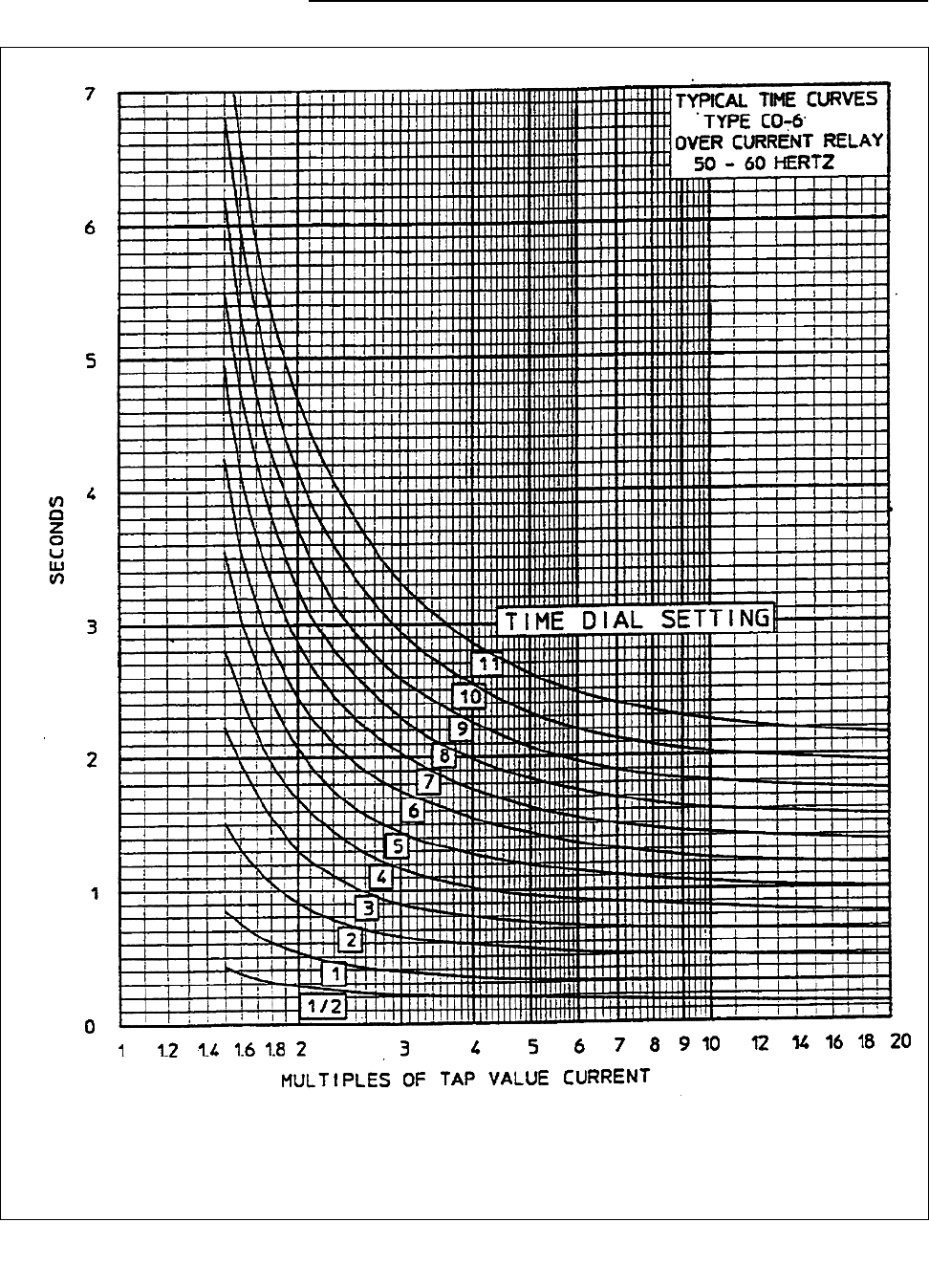
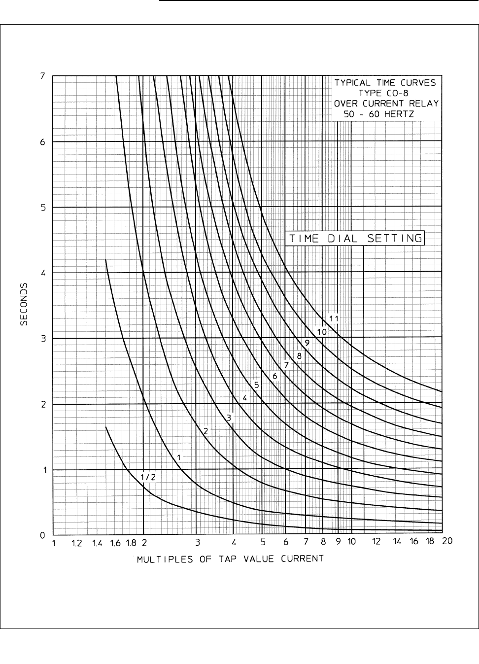
The time vs. current characteristics are shown in Fig-
ures 17 to 23 (starting on page 23). These character-
istics give the contact closing time for the various time
dial settings when the indicated multiples of tap value
current are applied to the relay.
3.1 Trip Circuit
The main contacts will safely close 30 amperes at 250
volts dc and the seal-in contacts of the indicating con-
tactor switch will safely carry this current long enough
to trip a circuit breaker.
The indicating instantaneous trip contacts will safely
close 30 amperes at 250 volts dc, and will carry this
current long enough to trip a breaker.
The indicating contactor switch has two taps that pro-
vide a pickup setting of 0.2 or 2 amperes. To change
taps requires connecting of lead located in front of the
tap block to the desired setting by means of a screw
connection.
3.2 Trip Circuit Constants
Indicating Contactor Switch
0.2 amp tap. . . . . . . . 6.5 ohms dc resistance
2.0 amp tap. . . . . . . . 0.15 ohms dc resistance
3.3 Type CR Relay
This voltage polarized type relay is intended for phase
fault protection and the directional unit has its maxi-
mum torque when the current leads the voltage by ap-
proximately 30°. The directional unit minimum pickup
is 1 volt and 4 amperes at its maximum torque angle
for the 4 and 12 ampere range relays and 1 volt and 2
amperes for the 2 to 6 ampere and 0.5 to 2.5 ampere
range relays.
The directional unit should be connected using the
current in one phase wire and the potential across the
other two phase wires. This connection is commonly
referred to as the 90
°
connection. When utilizing the
90
°
connection the maximum torque of the relay oc-
curs when the fault current lags its 100% P.F. position
by approximately 60
°
. (See Figure 13, page 21.)
3.4 Type CRC Relay
The current polarized type relay is intended for
ground fault protection and operates on residual cur-
rent. (See Figure 15, page 22.) The type CRC relay
has its maximum torque when the operating current
leads the polarizing current by approximately 40
°
. The
directional unit minimum pickup is 0.5 ampere in each
winding in phase for the 0.5 to 2.5 ampere and the 2
to 6 ampere range relays.
3.5 Type CRP Relay
The voltage polarized relay is intended for ground
fault protection and has its maximum torque when the
current lags the voltage by approximately 60
°
. The
shifting of the maximum torque angle has been ac-
complished by the use of an internally mounted phase
shifter as illustrated in Figure 7 (page 17).
The type CRP relay operates on residual voltage and
residual current. (See Figure 14, page 21).
The directional unit minimum pickup is 1 volt and 2
amperes at its maximum torque angle for the 0.5 to
2.5 ampere and the 2 to 6 ampere range relays.
TABLE 1:
Time Characteristics Designation
Short Time 2
Long Time 5
Definite Time 6
Moderately Inverse Time 7
Inverse Time 8
Very Inverse Time 9
Extremely Inverse Time 11
Range Taps
0.5 - 2.5 0.5 0.6 0.8 1.0 1.5 2.0 2.5
2 - 6 2 2.5 3 3.5 4 5 6
4 - 12 456781012

41-131Q
4
Directional Overcurrent Relays
Types CR, CRC, CRP & CRD
3.6 Type CRD Relay
The dual polarized type relay is intended for ground
fault protection. The relay can be polarized from a po-
tential source, from a local ground source, or from
both simultaneously.
The type CRD relay utilizes the directional unit of the
CRC relay in conjunction with the directional unit and
phase shifting mechanism of the type CRP relay. The
directional contacts are connected in parallel to
torque-control a common overcurrent unit. See Figure
8 (page 17).
The current-polarized directional unit of the type CRD
relay operates on residual currents while the potential
polarized directional unit of the type CRD relay oper-
ates on residual voltage and residual current. See
Figure 16 (page 22).
For the 0.5 to 2.5 ampere and the 2 to 6 ampere range
relays, the minimum pickup of the current polarized
unit is 0.5 ampere in each winding in-phase and the
minimum pickup for the voltage polarized unit is 1 volt
and 2 amperes with the current lagging voltage by
60
°
.
4.0 SETTINGS
4.1 Overcurrent Unit (CO)
The overcurrent unit settings can be defined either by
tap settings and time dial position or by tap setting
and a specific time of operation at some current
multiple of the tap setting (e.g. 4 tap setting, 2 time
dial position or 4 tap setting, 0.6 times tap value cur-
rent).
To provide selective circuit breaker operation, a mini-
mum coordinating time of 0.3 seconds plus breaker
time is recommended between the relay being set
and the relays with which coordination is to be affect-
ed.
The connector screw on the terminal plate above the
time dial makes connection to various turns on the op-
erating coil. By placing the screw in the various termi-
nal plate holes, the relay will respond to multiples of
tap value currents in accordance with the various typ-
ical time-current curves.
CAUTION
!
Since the tap block screws carry operating
current, be sure that the screws are turned
tight.
In order to avoid opening current transformer
circuits when changing taps under load, start
with RED handles FIRST and open all
switchblades. Chassis operating shorting
switches on the case will short the secondary
of the current transformer. Taps may then be
changed with the relay either inside or out-
side the case. Then reclose all switchblades
making sure the RED handles are closed
LAST.
4.2 Instantaneous Reclosing
The factory adjustment of the CO unit contacts pro-
vides a contact follow. Where circuit breaker reclosing
will be initiated immediately after a trip by the CO con-
tact, the time of the opening of the contacts should be
a minimum. This condition is obtained by loosening
the stationary contact mounting screw, removing the
contact plate and then replacing the plate with the
bent end resting against the contact spring.
For double trip relays, the upper stationary contact is
adjusted such that the contact spring rests solidly
against the back stop. The lower stationary contact is
then adjusted such that both stationary contacts
make contact simultaneously with their respective
moving contact.
4.3 Indicating Contactor Switch (ICS)
The only setting required on the ICS unit is the selec-
tion of the 0.2 or 2.0 ampere tap setting. This selec-
tion is made by connecting the lead located in front of
the tap block to the desired setting by means of the
connecting screw.
4.4 Indicating Instantaneous Trip (IIT)
The core screw must be adjusted to the value of
pickup desired.
The nameplate data will furnish the actual current
range that may be obtained from IIT unit.

41-131Q
5
Directional Overcurrent Relays
Types CR, CRC, CRP & CRD
4.5 Directional Unit (D)
No setting is required.
5.0 INSTALLATION
The relays should be mounted on switchboard panels
or their equivalent in a location free from dirt, mois-
ture, excessive vibration and heat. Mount the relay
vertically by means of the two mounting studs for the
type FT projection case or by means of the four
mounting holes on the flange for the semi-flush type
FT case. Either of the studs or the mounting screws
may be utilized for grounding the relay. The electrical
connections may be made directly to the terminals by
means of screws for steel panel mounting or to termi-
nal studs furnished with the relay for thick panel
mounting. The terminal studs may be easily removed
or inserted by locking two nuts on the studs and then
turning the proper nut with a wrench.
The external ac connections of the directional over-
current relays are shown in Figures 13 to 16 (starting
on page 21).
6.0 ADJUSTMENTS
The proper adjustments to insure correct operation of
this relay have been made at the factory. Upon receipt
of the relay, no customer adjustments, other than
those covered under “SETTINGS” (page 4), should
be required.
For relays which include an indicating instantaneous
trip unit (IIT), the junction of the induction and indicat-
ing instantaneous trip coils is brought out to switch
jaw #3. With this arrangement the overcurrent units
can be tested separately.
The following acceptance check is recommended to
insure that the relay is in proper working order:
6.1 Acceptance Check
6.1.1 Overcurrent Unit (CO)
The directional unit contacts must be in the closed po-
sition when checking the operation of the overcurrent
unit.
6.1.2 Contact
a) By turning the time dial, move the moving contacts
until they deflect the stationary contact to a position
where the stationary contact is resting against its
backstop. The index mark located on the move-
ment frame should coincide with the “0” mark on
the time dial. For double trip relays, the follow on
the stationary contacts should be approximately
1/64”.
b) For relays identified with a “T”, located at lower left
of stationary contact block, the index mark on the
movement frame will coincide with the “0” mark on
the time dial when the stationary contact has
moved through approximately one-half of its nor-
mal deflection. Therefore, with the stationary
contact resting against the backstop, the index
mark is offset to the right of the “0” mark by
approximately .020". The placement of the various
time dial positions in line with the index mark will
give operating times shown on the respective
time-current curves. For double trip relays, the fol-
low on the stationary contacts should be
approximately 1/32”.
6.1.3 Minimum Trip Current
Set the time dial to position 6. Alternately apply tap
value current plus 3% and tap value current minus
3%. The moving contact should leave the backstop at
tap value current plus 3% and should return to the
backstop at tap value current minus 3%.
6.1.4 Time Curve
Table 2 (page 11) shows the time curve calibration
points for the various types of relays. With the time
dial set to the indicated position, apply the currents
specified by Table 2 (e.g. for the CR-8, 2 and 20 times
tap value current) and measure the operating time of
the relay. The operating times should equal those of
Table 2 plus or minus 5 percent.
For type CR-11 relay only, the 1.30 times tap value
operating time from the number 6 time dial position is
54.9 ±5% seconds. It is important that the 1.30 times
tap value current be maintained accurately. The main-
taining of this current accurately is necessary be-
cause of the steepness of the slope of the time-cur-
rent characteristics (Figure 23, page 29). A 1%
variation in the 1.30 times tap value current (including
measuring instrument deviation) will change the nom-
inal operating time by approximately 4%.

41-131Q
6
Directional Overcurrent Relays
Types CR, CRC, CRP & CRD
6.2 Indicating Contactor Switch (ICS)
Close the main relay contacts and pass sufficient dc
current through the trip circuit to close the contacts of
the ICS. This value of current should not be greater
than the particular ICS tap setting being used. The in-
dicator target should drop freely.
The contact follow should be approximately 1/64” to
3/64”. The bridging moving contacts should touch
both stationary contacts simultaneously.
6.3 Indicating Instantaneous Trip Unit (IIT)
The core screw must be adjusted to the value of
pickup current desired.
The nameplate data will furnish the actual current
range that may be obtained from the IIT unit.
6.4 Directional Unit (D)
6.4.1 Contact Gap
The gap between the stationary contact and moving
contact with the relay in a de-energized position
should be approximate ly.020".
6.4.2 Sensitivity
The respective directional units should trip with value
of energization and phase angle relationships as indi-
cated in Table 3 (page 11).
6.4.3 Spurious Torque Adjustments
There should be no spurious closing torques when
the operating circuits are energized, per Table 4
(page 12), with the polarizing circuits short-circuited
for the voltage polarized units and open-circuited for
the current polarized units.
7.0 ROUTINE MAINTENANCE
All relays should be inspected and checked periodi-
cally to assure proper operation. Generally a visual in-
spection should call attention to any noticeable
changes. A minimum suggested check on the relay
system is to close the contacts manually to assure
that the breaker trips and the target drops. Then re-
lease the contacts and observe that the reset is
smooth and positive.
If an additional time check is desired, pass secondary
current through the relay and check the time of oper-
ation. It is preferable to make this at several times
pickup current at an expected operating point for the
particular application. For the .5 to 2.5 ampere rating
CO-5 and CO-6 induction unit use the alternative test
circuit in Figure 24 (page 30) as these relays are af-
fected by a distorted wave form. With this connection
the 25/5 ampere current transformers should be
worked well below the knee of the saturation (i.e., use
10L50 or better).
All contacts should be periodically cleaned. A contact
burnisher, Style number 182A836H01, is recom-
mended for this purpose. The use of abrasive material
for cleaning contacts is not recommended, because
of the danger of embedding small particles in the face
of the soft silver and thus impairing the contact.
8.0 CALIBRATION
Use the following procedure for calibrating the relay if
the relay has been taken apart for repairs or adjust-
ments have been disturbed. This procedure should
not be used unless it is apparent that the relay is not
in proper working order. (See “ACCEPTANCE
CHECK”, page 5).
8.1 Overcurrent Unit (CO)
8.1.1 Contact
a) By turning the time dial, move the moving contacts
until they deflect the stationary contact to a position
where the stationary contact is resting against its
backstop. The index mark located on the move-
ment frame should coincide with the “0” mark on
the time dial. For double trip relays, the follow on
the stationary contacts should be approximately
1/64”.
b) For relays identified with a “T”, located at lower left
of stationary contact block, the index mark on the
movement frame will coincide with the “0” mark on
the time dial when the stationary contact has
moved through approximately one-half of its nor-
mal deflection. Therefore, with the stationary
contact resting against the backstop, the index
mark is offset to the right of the “0” mark by
approximately .020". The placement of the various
time dial positions in line with the index mark will
give operating times as shown on the respective

41-131Q
7
Directional Overcurrent Relays
Types CR, CRC, CRP & CRD
time-current curves. For double trip relays, the fol-
low on the stationary contacts should be
approximately 1/32”.
8.2 Minimum Trip Current
The adjustment of the spring tension in setting the
minimum trip current value of the relay is most conve-
niently made with the damping magnet removed.
With the time dial set on “0”, wind up the spiral spring
by means of the spring adjuster until approximately
6-3/4 convolutions show.
Set the relay on the minimum tap setting, the time dial
to position 6.
Adjust the control spring tension so that the moving
contact will leave the backstop at tap value current
plus 1.0% and will return to the backstop at tap value
current minus 1.0%.
8.3 Time Curve Calibration
Install the permanent magnet. Apply the indicated
current (per Table 2, page 11) for the permanent mag-
net adjustment (e.g. CR-8, 2 times tap value) and
measure the operating time. Adjust the permanent
magnet keeper until the operating time corresponds
to the value of Table 2.
For type CR-11 relay only, the 1.30 times tap value
operating time from the number 6 time dial position is
54.9 ±5% seconds. It is important that the 1.30 times
tap value current be maintained accurately. The main-
taining of this current accurately is necessary be-
cause of the steepness of the slope of the time-cur-
rent characteristic (Figure 23, page 29). A 1%
variation in the 1.30 times tap value current (including
measuring instrument deviation) will change the nom-
inal operating time by approximately 4%. If the oper-
ating time at 1.3 times tap value is not within these
limits, a minor adjustment of the control spring will
give the correct operating time without any undue ef-
fect on the minimum pickup of the relay. This check is
to be made after the 2 times tap value adjustment has
been completed.
Apply the indicated current per Table 2 of the electro-
magnet plug adjustment (e.g. CR-8, 20 times tap val-
ue) and measure the operating time. Adjust the prop-
er plug until the operating time corresponds to the
value in Table 2. (Withdrawing the left-hand plug,
front view, increases the operating time and withdraw-
ing the right hand plug, front view, decreases the
time.) In adjusting the plugs, one plug should be
screwed in completely and the other plug run in or out
until the proper operating time has been obtained.
Recheck the permanent magnet adjustment. If the
operating time for this calibration point has changed,
readjust the permanent magnet and then recheck the
electromagnet plug adjustment.
8.4 Indicating Contactor Switch Unit (ICS)
Close the main relay contacts and pass sufficient dc
current through the trip circuit to close the contacts of
the ICS. This value of current should not be greater
than the particular ICS tap setting being used. The in-
dicator target should drop freely.
8.5 Indicating Instantaneous Trip Unit (IIT)
The core screw which is adjustable from the top of the
trip unit determines the pickup value. The trip unit has
a normal ratio of adjustment of 1 to 4 and an accuracy
within the limits of 10%.
The making of the contacts and target indication
should occur at approximately the same instant. Posi-
tion the stationary contact for a minimum of 1/32”
wipe. The bridging moving contact should touch both
stationary contacts simultaneously.
Apply sufficient current to operate the IIT. The indica-
tor target should drop freely.
8.6 Directional Unit (D)
a. The upper pin bearing should be screwed down
until there is approximately .025" clearance be-
tween it and the top of shaft bearing. The upper pin
bearing should then be securely locked in position
with the lock nut. The lower bearing position is
fixed and cannot be adjusted.
b. The contact gap adjustment for the directional unit
is made as follows:
With the moving contact in the normally-opened
position, i.e. against the right stop on bridge, screw
in the stationary contact until both contacts just
close as indicated by a neon lamp in the contact
circuit. Then, screw the stationary contact away
from the moving contact 3/4 of a turn. The clamp
holding the stationary contact housing need not be
loosened for the adjustment since the clamp utiliz-

41-131Q
8
Directional Overcurrent Relays
Types CR, CRC, CRP & CRD
es a spring-type action in holding the stationary
contact in position.
The set screw in the stationary contacts has been
factory adjusted for optimum follow and this adjust-
ment should not be disturbed.
The moving contact assembly has been factory
adjusted for low contact bounce performance and
should not be disturbed.
c. The sensitivity adjustment is made by varying the
tension of the spiral spring attached to the moving
element assembly. The spring is adjusted by plac-
ing a screwdriver or similar tool into one of the
notches located on the periphery of the spring ad-
juster and rotating it. The spring adjuster is located
on the underside of the bridge and is held in place
by a spring-type clamp that does not have to be
loosened prior to making the necessary adjust-
ments.
The spring is to be adjusted such that the contacts
will close as indicated by a neon lamp in the con-
tact circuit when energized with the required
current and voltage as shown in Table 3 on page
11. This table indicates that the spring can be ad-
justed when the phase angle relationship between
the operating circuit and the polarizing circuit is at
the maximum torque angle or when the circuit rela-
tionship has the operating and polarizing circuits in
phase. It is recommended that a single phase
(in-phase relationship) setup be used as a matter
of ease and convenience.
4. The magnetic plugs are used to reverse any un-
wanted spurious torques that may be present
when the relay is energized on current alone.
The reversing of the spurious torques is accom-
plished by using the adjusting plugs in the following
manner:
a) Voltage circuit terminals on the voltage polar-
ized relays (CR, CRP and CRD voltage
polarized unit) are short-circuited.
b) The polarizing circuit of the current polarized
relays (CRC and CRD current polarized unit)
are open-circuited.
Upon completion of either “a” or “b” apply currents
from 5 to 40 amps or 5 to 80 amps.
Note: High current to be applied only momentarily.
Plug adjustment is then made per Table 4 (see page
12) such that the spurious torques are reversed. The
plugs are held in position by upper and lower plug
clips. These clips need not be disturbed in any man-
ner when making the necessary adjustment.
The magnetic plug adjustment may be utilized to pos-
itively close the contacts on current alone. This may
be desired on some installations in order to insure
that the relay will always trip the breaker on zero
potential.
9.0 RENEWAL PARTS
Repair work can be done most satisfactorily at the
factory. However, interchangeable parts can be fur-
nished to customers who are equipped for doing
repair work. When ordering parts, always give the
complete nameplate data.

41-131Q
9
Directional Overcurrent Relays
Types CR, CRC, CRP & CRD
Figure 1: Type CR Relay Without Case
#1 – Directional Unit (D)
#2 – Overcurrent Unit (CO)
#3 – Indicating Contactor Switch (ICS)
#4– Indicating Instantaneous Trip Unit IIIT)
Figure 2: Directional Unit
#1 – Stationary Contact #2 – Stationary Contact Pressure
Spring
#3 – Magnetic Adjusting Plugs #4 – Upper Bearing Screw
#5 – Moving Element Assembly #6 – Spring Adjuster Clamp
#7 – Current Bias Vane
Photo
Photo
#1
#2
#3
#4
#2
#1
#3
#4
#5
#6
#7

41-131Q
10
Directional Overcurrent Relays
Types CR, CRC, CRP & CRD
Figure 3: Time Overcurrent Unit (Front View)
1-Tap Block 2-Time Dial 3-Control Spring Assembly
4-Disc 5-Stationary Contact Assembly 6-Magnetic Plugs
7-Permanent Magnet.
Figure 4: Indicating Instantaneous Trip Unit (IIT)
Photo
Photo
#1
#2
#3
#4
#5
#6
#7

41-131Q
11
Directional Overcurrent Relays
Types CR, CRC, CRP & CRD
TABLE 2:
TIME CURVE CALIBRATION DATA - 50 AND 60 HERTZ FOR OVERCURRENT UNIT
PERMANENT
MAGNET ADJUSTMENT
ELECTROMAGNET
PLUG ADJUSTMENT
RELAY
TYPE
TIME
DIAL
POSITION
CURRENT
(MULTIPLES OF
TAP VA LUE)
OPERATING
TIME
(SECONDS)
CURRENT
(MULTIPLES OF
TAP VALUE)
OPERATING
TIME
(SECONDS)
2
5
6
7
8
9
11
6
6
6
6
6
6
6
3
2
2
2
2
2
2
0.57
37.80
2.46
4.27
13.35
8.87
11.27
20
10
20
20
20
20
20
0.22
14.30
1.19
1.11
1.11
0.65
0.24
*
* For 50 Herz CO-11, the “20 times multiple” Time Limits are 0.24 sec. +20% -5%.
TABLE 3:
DIRECTIONAL UNIT SENSITIVITY
RELAY TYPE
SETTING RANGE
OF TIME -
OVERCURRENT
UNIT
Values for Min. Pick-Up
*
* The energization quantities are input quantities at the relay terminals.
Volts
†
† For relays rated 240 volts, apply 2 volts.
Amperes Phase Angle Relationship
CR
0.5 - 2.5
2 - 6
12.0
I Leading V by 30°
‡
‡ Maximum torque angle.
1 2.3 I in-phase with V
4 - 12
14.0
I Leading V by 30°
‡
1 4.6 I in-phase with V
CRP
0.5 - 2.5
2 - 6
12.0
I lagging V by 60°
‡
1 4.0 I in-phase with V
4 - 12
14.0
I Leading V by 60°
‡
1 4.6 I in-phase with V
CRC
0.5-2.5
2-6
0.5 I in-phase
CRD (Voltage Unit)
05-2.5
2-6
1
2.0
I Lagging V by 60°
‡
4.0 I in-phase with V
4-12 1
4.0
I Lagging V by 60°
‡
8.0 I in-phase with V
CRD (Current Unit)
0.5-2.5
2-6
0.5 in-phase

41-131Q
12
Directional Overcurrent Relays
Types CR, CRC, CRP & CRD
TABLE 4:
DIRECTIONAL UNIT CALIBRATION
SETTING
RANGE OF
TIME–
OVERCURRENT
UNIT
CURRENT
AMPERES
CONDITION FOR BOTH PLUGS “IN” ADJUSTMENT
0.5 - 2.5 Amps
2 - 6 Amps
5 to 40
Spurious Torque in contact closing
direction (left front view)
Right (front-view) plug screwed out
until spurious torque is reversed.
4 - 12 Amps 5 to 80
0.5 - 2.5 Amps
2 - 6 Amps
5 to 40 Spurious Torque in contact opening
direction (right front view, contacts
remain open)
Left (front view) plug screwed out until
Spurious Torque is in contact closing
direction. Then the plug is screwed in
until spurious Torque is reversed.
4 - 12 Amps 5 to 80
DIRECTIONAL UNIT POLARIZING CIRCUIT BURDEN
Relay
Type Rating
Volt
Amperes
*
* Voltages taken with high impedance type voltmeter - Burden of Voltage polarized units taken at 120 volts - Bur-
den of current polarized units taken at 5 amperes.
Power
Factor
Angle
†
† Degrees current leads or lags voltage at 120 volts on voltage polarized units and 5 amperes on current polar-
ized units.
CR
132
‡
Volts
‡ Continuous rating.
11.5 58° Lag
CRC
230
**
Amperes
** One second rating.
1.45 8° Lag
CRP
208
††
Volts
†† 30 second rating.
11.2 28° Lead
CRD
Current Unit
230 ** Amperes 1.45 8° Lag
CRD
Voltage Unit
208
††
Volts
11.2 28° Lead
DIRECTIONAL UNIT OPERATING CIRCUIT BURDEN
Relay
Type
Range
(Amperes)
Continuous
Rating
(Amperes)
One Second
Rating
*
(Amperes)
* Thermal capacities for short times other than one second may be calculated on the basis of time being inversely propor-
tional to the square of the current.
Power
Factor
Angle
†
†
Degrees current lags voltage at tap value current
.
VOLT AMPERES
‡
‡ Voltages taken with high impedance type voltmeter.
At
Minimum
Tap Value
Current
3 Times
Minimum
Tap Value
Current
At 10 Times
Minimum
Tap Value
Current
At 20 Times
Minimum
Tap Value
Current
CR
2-6 10 230 34.5 0.44 4.08 48.0 182.0
4-12 12 280 25.0 0.53 5.0 59.2 236.0
CRC
0.5-2.5 - 230 44.0 0.033 0.30 3.3 14.2
2-6 - 230 42.5 0.58 5.28 58.0 240.0
CRP
0.5-2.5 10 230 34.5 0.03 0.23 2.8 11.5
2-6 10 230 34.5 0.44 4.08 48.0 182.0
CRD
0.5-2.5 10 230 45.0 0.07 0.59 6.6 26.0
2-6 10 230 45.0 1.04 9.9 106.0 420.0

41-131Q
13
Directional Overcurrent Relays
Types CR, CRC, CRP & CRD
ENERGY REQUIREMENTS
OVERCURRENT UNITS = CR-2, CRC-2, CRP-2 CRD-2
AMPERE
RANGE TAP
CONTINUOUS
RATING
(AMPERES)
ONE SECOND
RATING
*
(AMPERES)
* Thermal capacities for short times other than one second may be calculated on the basis of time being inversely proportional
to the square of the current.
POWER
FACTOR
ANGLE
†
† Degrees current lags voltage at tap value current.
VOLT AMPERES
‡
‡ Voltages taken with high impedance type voltmeter.
AT
TAP VALUE
CURRENT
AT 3 TIMES
TAP VALUE
CURRENT
AT 10 TIMES
TAP VALUE
CURRENT
AT 20 TIMES
TAP VALUE
CURRENT
0.5/2.5
0.5 .91 28 58 4.8 39.6 256 790
0.6 0.96 28 57 4.9 39.8 270 851
0.8 1.18 28 53 5.0 42.7 308 1024
1.0 1.37 28 50 5.3 45.4 348 1220
1.5 1.95 28 40 6.2 54.4 435 1740
2.0 2.24 28 36 7.2 65.4 580 2280
2.5 2.50 28 29 7.9 73.6 700 2850
2/6
2.0 3.1 110 59 5.04 38.7 262 800
2.5 4.0 110 55 5.13 39.8 280 920
3.0 4.4 110 51 5.37 42.8 312 1008
3.5 4.8 110 47 5.53 44.0 329 1120
4.0 5.2 110 45 5.72 46.0 360 1216
5.0 5.6 110 41 5.90 50.3 420 1500
6.0 6.0 110 37 6.54 54.9 474 1800
4/12
4.0 7.3 230 65 4.92 39.1 268 848
5.0 8.0 230 50 5.20 42.0 305 1020
6.0 8.8 230 47 5.34 44.1 330 1128
7.0 9.6 230 46 5.53 45.8 364 1260
8.0 10.4 230 43 5.86 49.9 400 1408
10.0 11.2 230 37 6.60 55.5 470 1720
12.0 12.0 230 34 7.00 62.3 528 2064

41-131Q
14
Directional Overcurrent Relays
Types CR, CRC, CRP & CRD
ENERGY REQUIREMENTS
OVERCURRENT UNITS = CR-5, CRC-5, CRP-5, CRD-5, CR-6, CRC-6, CRP-6, CRD-6
OVERCURRENT UNITS = CR-7, CRC-7, CRP-7, CRD-7
VOLT AMPERES
‡
AMPERE
RANGE TAP
CONTINUOUS
RATING
AMPERES
ONE SECOND
RATING *
AMPERES
POWER
FACTOR
ANGLE
†
AT
TAP VALUE
CURRENT
AT 3 TIMES
TAP VALUE
CURRENT
AT 10 TIMES
TAP VALUE
CURRENT
AT 20 TIMES
TAP VALUE
CURRENT
0.5/2.5
0.5 2.7 88 69 3.92 20.6 103 270
0.6 3.1 88 68 3.96 20.7 106 288
0.8 3.7 88 67 3.96 21 114 325
1.0 4.1 88 66 4.07 21.4 122 360
1.5 5.7 88 62 4.19 23.2 147 462
2.0 6.8 88 60 4.30 24.9 168 548
2.5 7.7 88 58 4.37 26.2 180 630
2/6
2 8 230 67 3.88 21 110 308
2.5 8.8 230 66 3.90 21.6 118 342
3 9.7 230 64 3.93 22.1 126 381
3.5 10.4 230 63 4.09 23.1 136 417
4 11.2 230 62 4.12 23.5 144 448
5 12.5 230 59 4.20 24.8 162 540
6 13.7 230 57 4.38 26.5 183 624
4/12
4 16 460 65 4.00 22.4 126 376
5 18.8 460 63 4.15 23.7 143 450
6 19.3 460 61 4.32 25.3 162 531
7 20.8 460 59 4.35 26.4 183 611
8 22.5 460 56 4.40 27.8 204 699
10 25 460 53 4.60 30.1 247 880
12 28 460 47 4.92 35.6 288 1056
AMPERE
RANGE TAP
CONTINUOUS
RATING
AMPERES
ONE SECOND
RATING
*
AMPERES
* Thermal capacities for short times other than one second may be calculated on the basis of time being inversely proportional to the square of
the current.
POWER
FACTOR
ANGLE
†
† Degrees current lags voltage at tap value current.
VOLT AMPERES
‡
‡ Voltages taken with high impedance type voltmeter.
AT
TAP VALUE
CURRENT
AT 3 TIMES
TAP VALUE
CURRENT
AT 10 TIMES
TAP VALUE
CURRENT
AT 20 TIMES
TAP VALUE
CURRENT
0.5/2.5
0.5 2.7 88 68 3.88 20.7 103 278
0.6 3.1 88 67 3.93 20.9 107 288
0.8 3.7 88 66 3.93 21.1 114 320
1.0 4.1 88 64 4.00 21.6 122 356
1.5 5.7 88 61 4.08 22.9 148 459
2.0 6.8 88 58 4.24 24.8 174 552
2.5 7.7 88 56 4.38 25.9 185 640
2/6
2 8 230 66 4.06 21.3 111 306
2.5 8.8 230 63 4.07 21.8 120 342
3 9.7 230 63 4.14 22.5 129 366
3.5 10.4 230 62 4.34 23.4 141 413
4 11.2 230 61 4.34 23.8 149 448
5 12.5 230 59 4.40 25.2 163 530
6 13.7 230 58 4.62 27 183 624
4/12
4 16 460 64 4.24 22.8 129 392
5 18.8 460 61 4.30 24.2 149 460
6 19.3 460 60 4.62 25.9 168 540
7 20.8 460 58 4.69 27.3 187 626
8 22.5 460 55 4.80 29.8 211 688
10 25 460 51 5.20 33 260 860
12 28 460 46 5.40 37.5 308 1032

41-131Q
15
Directional Overcurrent Relays
Types CR, CRC, CRP & CRD
ENERGY REQUIREMENTS
OVERCURRENT UNITS = CR-8, CRC-8, CRP-8, CRD-8 and CR-9, CRC-9 CRP-9 CRD-9
OVERCURRENT UNITS = CR-11, CRC-11, CRP-11 CRD-11
AMPERE
RANGE TAP
CONTINUOUS
RATING
AMPERES
ONE SECOND
RATING
*
AMPERES
POWER
FACTOR
ANGLE
†
VOLT AMPERES
††
AT
TAP VALUE
CURRENT
AT 3 TIMES
TAP VALUE
CURRENT
AT 10 TIMES
TAP VALUE
CURRENT
AT 20 TIMES
TAP VALUE
CURRENT
0.5/2.5
0.5 2.7 88 72 2.38 21 132 350
0.6 3.1 88 71 2.38 21 134 365
0.8 3.7 88 69 2.40 21.1 142 400
1.0 4.1 88 67 2.42 21.2 150 440
1.5 5.7 88 62 2.51 22 170 530
2.0 6.8 88 57 2.65 23.5 200 675
2.5 7.7 88 53 2.74 24.8 228 800
2/6
2 8 230 70 2.38 21 136 360
2.5 8.8 230 66 2.40 21.1 142 395
3 9.7 230 64 2.42 21.5 149 430
3.5 10.4 230 62 2.48 22 157 470
4 11.2 230 60 2.53 22.7 164 500
5 12.5 230 58 2.64 24 180 580
6 13.7 230 56 2.75 25.2 198 660
4/12
4 16 460 68 2.38 21.3 146 420
5 18.8 460 63 2.46 21.8 158 480
6 19.3 460 60 2.54 22.6 172 550
7 20.8 460 57 2.62 23.6 190 620
8 22.5 460 54 2.73 24.8 207 700
10 25 460 48 3.00 27.8 248 850
12 28 460 45 3.46 31.4 292 1020
AMPERE
RANGE TAP
CONTINUOUS
RATING
AMPERES
ONE SECOND
RATING
*
AMPERES
* Thermal capacities for short times other than one second may be calculated on the basis of time being inversely proportional to the square of
the current.
POWER
FACTOR
ANGLE
†
† Degrees current lags voltage at tap value current.
VOLT AMPERES
‡
‡ Voltages taken with high impedance type voltmeter.
AT
TAP VALUE
CURRENT
AT 3 TIMES
TAP VALUE
CURRENT
AT 10 TIMES
TAP VALUE
CURRENT
AT 20 TIMES
TAP VALUE
CURRENT
0.5/2.5
0.5 1.7 56 36 0.72 6.54 71.8 250
0.6 1.9 56 34 0.75 6.80 75.0 267
0.8 2.2 56 30 0.81 7.46 84.0 298
1.0 2.5 56 27 1.89 8.30 93.1 330
1.5 3.0 56 22 1.13 10.04 115.5 411
2.0 3.5 56 17 1.30 11.95 136.3 502
2.5 3.8 56 16 1.48 13.95 160.0 610
2/6
3.0 7.0 230 32 0.73 6.30 74.0 264
2.5 7.8 230 30 0.78 7.00 78.5 285
2.0 8.3 230 27 0.83 7.74 84.0 309
3.5 9.0 230 24 0.88 8.20 89.0 340
4.0 10.0 230 23 0.96 9.12 102.0 372
5.0 11.0 230 20 1.07 9.80 109.0 430
6.0 12.0 230 20 1.23 11.34 129.0 504
4/12
4.0 14 460 29 0.79 7.08 78.4 296
5.0 16 460 25 0.89 8.00 90.0 340
6.0 17 460 22 1.02 9.18 101.4 378
7.0 18 460 20 1.10 10.00 110.0 454
8.0 20 460 18 1.23 11.1 124.8 480
10.0 22 460 17 1.32 14.9 131.6 600
12.0 26 460 16 1.8 16.3 180.0 720

41-131Q
16
Directional Overcurrent Relays
Types CR, CRC, CRP & CRD
Figure 5: Internal Schematic of double-trip, directional overcurrent relay
type CR in type FT-21 Case. For the single-trip relay the circuits
associated with terminal 2 are omitted, 57D4549
Figure 6: Internal Schematic of double-trip, directional overcurrent relay
type CRC in type FT-21 Case. For the single -rip relay the circuits
associated with terminal 2 are omitted, 57D4539
Sub 2
57D4547
Sub 3
57D4543
RED HANDLE
TEST SWITCH
CURRENT TEST JACK
CHASSIS OPERATED
SHORTING SWITCH
TERMINAL
INDICATING
CONTACTOR SWITCH
DIRECTIONAL UNIT
INDUCTION UNIT
INTRNAL SCHEMATIC
INDICATING
CONTACTOR SWITCH
DIRECTIONAL UNIT
INDUCTION UNIT
RED HANDLE
TEST SWITCH
CURRENT TEST JACK
CHASSIS OPERATED
SHORTING SWITCH
TERMINAL
WITH RELATIVE INSTANTANEOUS
POLARITY AS SHOWN THE
DIRECTIONAL UNIT CONTACTS CLOSE
WITH RELATIVE INSTANTANEOUS
POLARITY AS SHOWN THE
DIRECTIONAL UNIT CONTACTS CLOSE
INTRNAL SCHEMATIC

41-131Q
17
Directional Overcurrent Relays
Types CR, CRC, CRP & CRD
Figure 7: Internal Schematic of double-trip, directional overcurrent relay
type CRP in type FT-21 Case. For the single-trip relay the circuits
associated with terminal 2 are omitted, 57D4545
Figure 8: Internal Schematic of double-trip, directional overcurrent relay
type CRD in type FT-21 Case. For the single-trip relay the
circuits associated with terminal 2 are omitted, 57D4561
Sub 2
57D4541
Sub 3
57D4559
INDUCTION UNIT
RED HANDLE
TEST SWITCH
CURRENT TEST JACK
CHASSIS OPERATED
SHORTING SWITCH
TERMINAL
DIRECTIONAL
UNIT
INDICATING
CONTACTOR
SWITCH
CHASSIS OPERATED
SHORTING SWITCH
RED HANDLE
TEST SWITCH
CURRNT TEST JACK
TERMINAL
UPPER DIRECTIONAL
UNIT
LOWER DIRECTIONAL
UNIT
INDUCTION UNIT
INDICATING
CONTACTOR SWITCH
WITH RELATIVE
INSTANTANEOUS
POLARITY AS SHOWN
THE DIRECTINAL UNIT
CONTACTS CLOSE

41-131Q
18
Directional Overcurrent Relays
Types CR, CRC, CRP & CRD
Figure 9A: Internal schematic of single-trip, directional control relay type CR
with indicating instantaneous trip unit, and ICS unit having two
independent contacts, in type FT-21 case
Figure 9B: Internal schematic of single-trip directional control relay type CR
with indicating instantaneous trip unit, in Type FT-21 case
Sub 1
9657A31
Sub 6
57D4520

41-131Q
19
Directional Overcurrent Relays
Types CR, CRC, CRP & CRD
Figure 10A: Internal schematic of single-trip directional control relay type CR
with indicating instantaneous trip unit and ac shunt trip, in type
FT-21 case
Sub 5
57D4540
Figure 10B: Internal Schematic of single-trip directional control relay type CRC
with Indicating Instantaneous Trip Unit, in type FT21 case
Sub 2
3507A69

41-131Q
20
Directional Overcurrent Relays
Types CR, CRC, CRP & CRD
Figure 11: Internal schematic of single-trip directional control relay type CRP
with indicating instantaneous trip unit, in type FT-21 case
Figure 12: Internal schematic of single-trip directional control relay type CRD
with indicating instantaneous trip unit, in type FT-31 case
*Sub 6
57D4546
Sub 5
57D4560

41-131Q
21
Directional Overcurrent Relays
Types CR, CRC, CRP & CRD
Sub 2
182A793
Figure 13: External schematic of the type CR relay for phase fault protection Figure 14: External schematic of the type CRP relay for ground fault
protection
* Sub 3
182A792

41-131Q
22
Directional Overcurrent Relays
Types CR, CRC, CRP & CRD
Figure 15: External schematic of the type CRC relay for ground fault
protection
Sub 3
182A790
Figure 16: External schematic of the type CRD relay for ground fault
protection
Sub 5
182A791

41-131Q
23
Directional Overcurrent Relays
Types CR, CRC, CRP & CRD
Figure 17: Typical time curves for relays with CO-2 units
Sub 1
Curve 619584

41-131Q
24
Directional Overcurrent Relays
Types CR, CRC, CRP & CRD
Figure 18: Typical time curves for relays with CO-5 units
Sub 2
Curve 418245
41-131Q
25
Directional Overcurrent Relays
Types CR, CRC, CRP & CRD
Figure 19: Typical time curves for relays with CO-6 units
Sub 3
Curve 418246

41-131Q
26
Directional Overcurrent Relays
Types CR, CRC, CRP & CRD
Figure 20: Typical time curves for relays with CO-7 units
Sub 3
Curve 418247
41-131Q
27
Directional Overcurrent Relays
Types CR, CRC, CRP & CRD
Figure 21: Typical time curves for relays with CO-8 units
Sub 3
Curve 418248

41-131Q
28
Directional Overcurrent Relays
Types CR, CRC, CRP & CRD
Figure 22: Typical time curves for relays with CO-9 units
Sub 2
Curve 418249

41-131Q
29
Directional Overcurrent Relays
Types CR, CRC, CRP & CRD
Figure 23: Typical time curves for relays with CO-11 units
Sub 2
Curve 288B655

41-131Q
30
Directional Overcurrent Relays
Types CR, CRC, CRP & CRD
Figure 24: Diagram of test connections of the overcurrent units
Sub 2
182A873
41-131Q
31
Directional Overcurrent Relays
Types CR, CRC, CRP & CRD
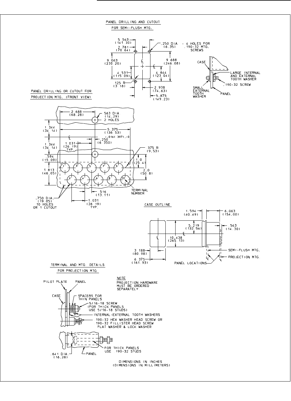
Figure 25: Outline and drilling plan for the type CR, CRC and CRP relays in the type FT-21 case
* Denotes Change Since Previous Issue
* Sub 17
57D7901

