Page 1 of 2
DRT2000 & DRC2000 SERIES
P/N 900004-06, REV. B, 01/2017
Fireplace Dimensions
DIRECT-VENT FIREPLACES
NOTE: DIAGRAMS & ILLUSTRATIONS ARE NOT TO SCALE.
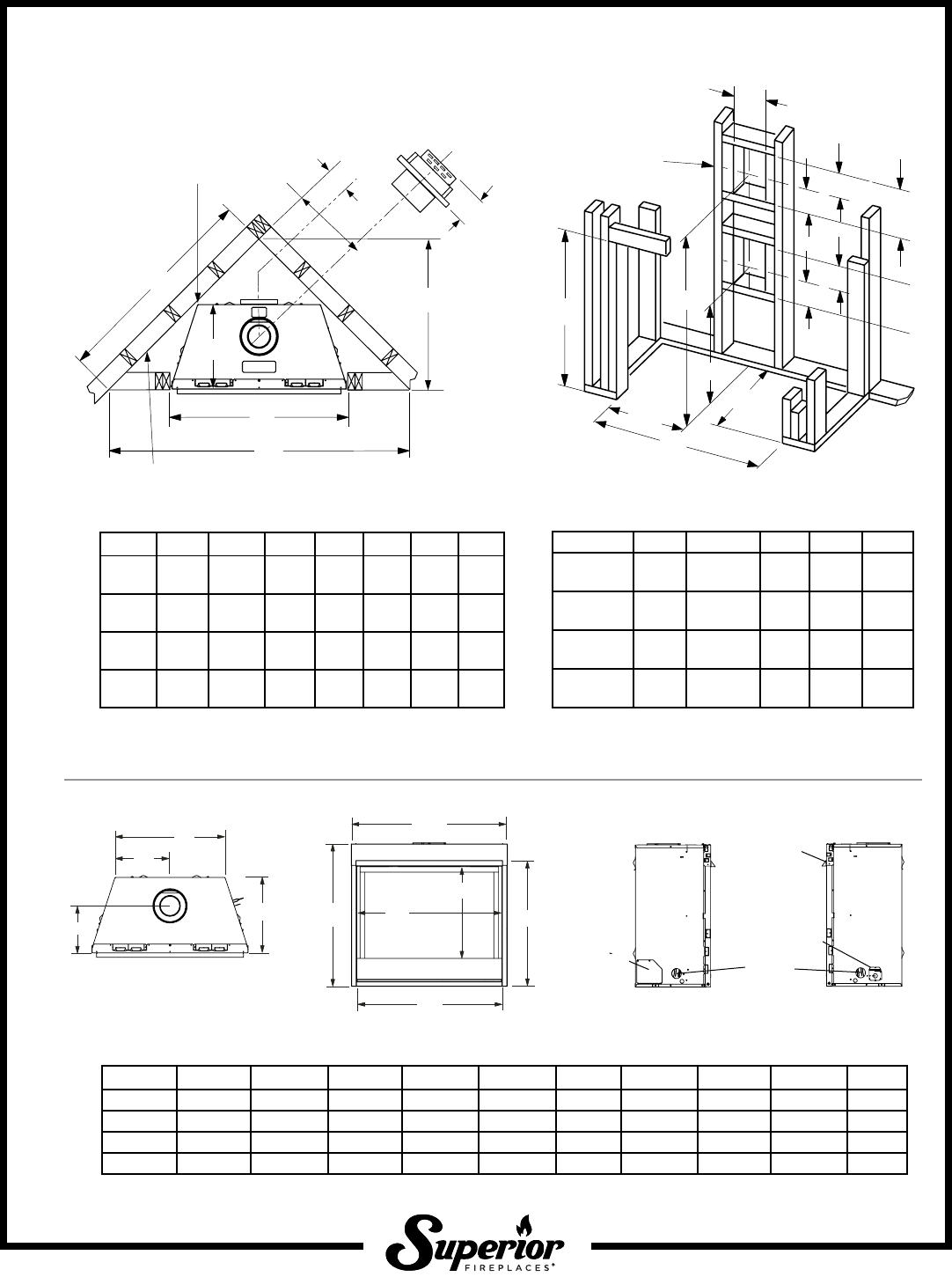
Framing Dimensions
Vent Framing—Top Vent
with One 90° Elbow
NOTE: Dimension “D” is the
required framing depth when the
finish material (drywall) thickness
is 1/2” (13mm).
Inches (millimeters)
Framing construction
to be 2 x 4, or larger.
B
C
D
A
1/2 A
5-1/8
(130)
7 (178)
12-1/8
(308)
10-1/2
(267)
E
C = Minimum height of top vent installations
E = Minimum height of rear vent installations
*Minimum opening size; additional 1/8” per side is recommended.
NOTE: Framing specifications do NOT apply for flexible venting. When using
flexible venting, refer to the kit requirements for framing specifications.
Model A * B C D E
33 Models
33-3/4
(857)
34-1/4
(870)
36-7/8
(930)
14-1/2
(368)
19-5/8
(499)
35 Models
35-3/8
(899)
36-1/4
(921)
38-3/4
(984)
18
(447)
23-3/8
(594)
40 Models
40-3/8
(1026)
41-1/4
1048)
43-3/4
(1111)
18
(447)
28-1/4
(717)
45 Models
45-3/8
(1153)
41-1/4
(1048)
43-3/4
(1111)
18
(447)
28-1/4
(717)
NOTE: When finishing the area around the hood, 5/8” clearance above hood is required for hood installation.
Back wall of chase/enclosure (including finishing materials)
B
A
C
D
E
F
G
7
(178)
Model A B C D E F G
33 Models
33-3/4
(857)
51-1/4
(1302)
36-1/4
(921)
25-5/8
(651)
12-1/8
(308)
5-1/2
(140)
14-1/2
(368)
35 Models
35-3/8
(899)
59-1/2
(1511)
42-1/8
(1070)
30-1/4
(768)
14-1/4
(362)
6-5/8
(168)
18
(457)
40 Models
40-3/8
(126)
63-7/8
(1622)
45-3/8
(1153)
33-1/4
(845)
15-7/8
(403)
8-1/2
(216)
18
(457)
45 Models
45-3/8
(1153)
70-3/8
(1788)
49-3/4
(1264)
35-1/4
(895)
17-1/2
(445)
10-1/4
(260)
18
(457)
Top View Front View
Left Side View Right Side View
E
F
G
H
J
K
L
M
Blower access
panel
Hood
Junction
box access
Gas line
access
N
O
Model E F G H (door) J K L M N O
33” Models 30-1/8 (765) 26-1/4 (667) 18-3/8 (467) 30-1/2 (775) 33-5/8 (854) 21-7/8 (556) 11 (279) 31 (787) 8-1/2 (216) 14 (356)
35” Models 32-1/8 (816) 28-3/4 (730) 22-1/4 (565) 32-3/8 (822) 35-1/4 (895) 25 (635) 12-1/2 (317) 32-7/8 (835) 10-1/8 (257) 17 (432)
40” Models 37-1/8 (943) 33-1/4 (845) 27-1/4 (692) 37-3/8 (949) 40-1/4 (1022) 30 (762) 15 (381) 37-7/8 (962) 10-1/8 (257) 17 (432)
45” Models 37-1/8 (943) 33-1/4 (875) 27-1/4 (692) 42-3/8 (1076) 45-1/4 (1149) 35 (889) 17-1/2 (445) 42-7/8 (1089) 10-1/8 (257) 17 (432)
Inches (millimeters)
Printed in U.S.A. © 2014 Innovative Hearth Products
P/N 900004-06 REV. B 01/2017
Page 2 of 2
Specifications and clearances are subject to change without notice. Refer to
Installation and Operation Manual before installation of these appliances for
updated dimensions and instructions.
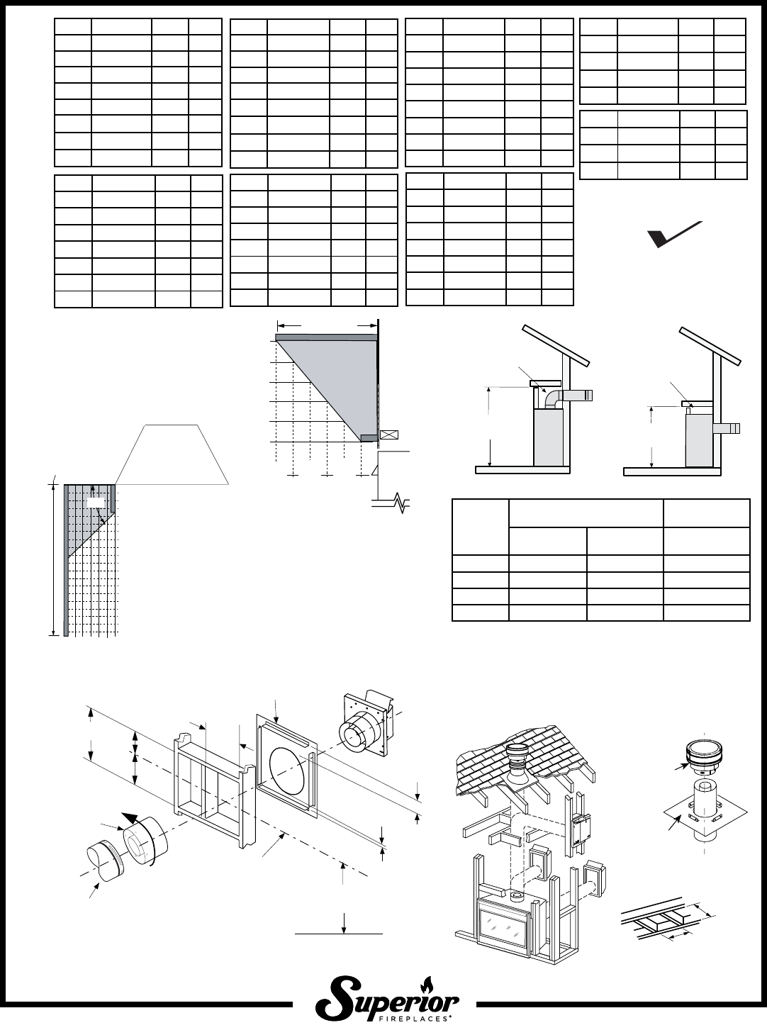
Venting Clearances
Shelf Height
Product Information
Listing
DRT2000 & DRC2000 SERIES
NOTE: DIAGRAMS & ILLUSTRATIONS ARE NOT TO SCALE.
Listed by PFS Corporation to - ANSI Z21.88 (in
Canada, CSA-2.33), and CAN/CGA-2.17-M91 in both
USA and Canada, as a vented gas fireplace heater.
PFS
®
USC
Report No. F13-094
Cat. No. Model Weight Cu. Ft.
F1438 DRT2040TMN 128 lb. 13.7
F1439 DRT2040TMP 128 lb. 13.7
F1440 DRT2040TEN 128 lb. 13.7
F1729 DRT2040TEP 128 lb. 13.7
F1444 DRT2040RMN 128 lb. 13.7
F1445 DRT2040RMP 128 lb. 13.7
F1446 DRT2040REN 128 lb. 13.7
F1731 DRT2040REP 128 lb. 13.7
Cat. No. Model Weight Cu. Ft.
F1450 DRT2045DMN 120 lb. 15.4
F1451 DRT2045DMP 120 lb. 15.4
F1452 DRT2045DEN 120 lb. 15.4
F1733 DRT2045DEP 120 lb. 15.4
F1411 DRC2033TMN 96 lb. 11.0
F1412 DRC2033TMP 96 lb. 11.0
F1413 DRC2033TEN 96 lb. 11.0
F1720 DRC2033TEP 96 lb. 11.0
F1417 DRC2033RMN 96 lb. 11.0
F1418 DRC2033RMP 96 lb. 11.0
F1419 DRC2033REN 96 lb. 11.0
F1722 DRC2033REP 96 lb. 11.0
F1447 DRC2045DMN
128 lb. 16.5
F1448 DRC2045DMP
128 lb. 16.5
F1449 DRC2045DEN
128 lb. 16.5
F1732 DRC2045DEP
128 lb. 16.5
F1435 DRC2040TMN 121 lb. 12.7
F1436 DRC2040TMP 121 lb. 12.7
F1437 DRC2040TEN 121 lb. 12.7
F1728 DRC2040TEP 121 lb. 12.7
F1441 DRC2040RMN 121 lb. 12.7
F1442 DRC2040RMP 121 lb. 12.7
F1443 DRC2040REN 121 lb. 12.7
F1730 DRC2040REP 121 lb. 12.7
F1423 DRC2035TMN
99 lb. 10.4
F1424 DRC2035TMP
99 lb. 10.4
F1425 DRC2035TEN
99 lb. 10.4
F1724 DRC2035TEP
99 lb. 10.4
F1429 DRC2035RMN
99 lb. 10.4
F1430 DRC2035RMP
99 lb. 10.4
F1431 DRC2035REN
99 lb. 10.4
F1726 DRC2035REP
99 lb. 10.4
* Includes 3” clearance to combustibles (required above vent components)
**
In alternative, Rear Vent applications, Top Vent will be sealed as detailed in the Installa-
tion and Operation manual.
Shelf Above Fireplace With Rear Venting
Shelf Above Fireplace With Top Venting
Shelf Height
(see table)
Shelf Height
(see table)
Do not insulate the
space between the
appliance and the
area above it.
Do not insulate the
space between the
appliance and the
area above it.
* Ceiling Firestop/
Spacer (SV4.5VF)
Vertical Ter-
mination Cap
SV4.5CGV-1
(rated for high
winds and
freezing condi-
tions)
Roof Framing
Min. 10-1/2"
(267 mm)
Min. 10-1/2"
(267 mm)
Vertical TerminationTypical Installations
Cat. No. Model Weight Cu. Ft.
F1414 DRT2033TMN 88 lb. 11.0
F1415 DRT2033TMP 88 lb. 11.0
F1416 DRT2033TEN 88 lb. 11.0
F1721 DRT2033TEP 88 lb. 11.0
F1420 DRT2033RMN 88 lb. 11.0
F1421 DRT2033RMP 88 lb. 11.0
F1422 DRT2033REN 88 lb. 11.0
F1723 DRT2033REP 88 lb. 11.0
Cat. No. Model Weight Cu. Ft.
F1426 DRT2035TMN 102 lb. 10.4
F1427 DRT2035TMP 102 lb. 10.4
F1428 DRT2035TEN 102 lb. 10.4
F1725 DRT2035TEP 102 lb. 10.4
F1432 DRT2035RMN 102 lb. 10.4
F1433 DRT2035RMP 102 lb. 10.4
F1434 DRT2035REN 102 lb. 10.4
F1727 DRT2035REP 102 lb. 10.4
Model
Top Vent with one 90° Elbow
Alternative Rear
Vent applications
Secure Vent
®
Secure Flex
®
(flex elbow)
Secure Vent
®
33” Models 44” (1118 mm)* 46” (1168 mm)* 34” (864 mm)**
35” Models 47” (1194 mm)* 49” (1245 mm)* 36-1/4” (921 mm)**
40” Models 52” (1321 mm)* 54” (1372 mm)* 40-1/2” (1029 mm)**
45” Models 50” (1270 mm)* 52” (1321 mm)* 45-1/2” (1169 mm)**
12
(305)
10
(254)
8
(203)
6
(152)
4
(102)
2
(51)
in. (mm)
8 (203)
10 (254)
12 (305)
14 (356)
16 (406)
18 (457)
Hood
Fireplace
Mantel depth
3-1/2”
(89 mm)
6”
(152 mm)
Top View of
Fireplace
45
o
Combustible
mantel legs may
project beyond either side
of the fireplace opening
as long as they are kept
within the shaded area
illustrated here.
Combustible Materials
Allowed In Shaded Area
“Safe Zone”
Combustible Walls
shown in dark gray
At 6” minimu
m
side wall clearance,
a combustible wall
can project to an
y
length
.
Uses 4.5” / 7.5” Secure Vent
®
Rigid and
Secure Flex
®
Direct-Vent Components
Horizontal Termination
*Recommended IHP termination kits: F1797, H1968, and 94L10.
**With termination kit only, 6” to 9-1/4”
*
**
T
ermination
10-1/2”
(267mm)
7”
(178)
5-1/8”
(130 mm)
12-1/8”
(308 mm)
Note: Centerline of Vent Piping is
NOT the Same as the Centerline of
the Framed Opening.
6 to 48” Vent Section,
Telescopic vent section,
Elbow or Appliance Collar
Min. Distance to Base
of Appliance.
Base of Appliance
3”
(77 mm)
1”
(26 mm)
Adaptor
SV4.5RCH
To help minimize water
infiltration it is recommended that
the Firestop/Spacer (SV4.5HF)
be installed on the exterior
side of the wall.
See Page 1
