
ETSI TR 143 903 V8.3.0 (2009-02)
Technical Report
Digital cellular telecommunications system (Phase 2+);
A-
interface over IP study (AINTIP)
(3GPP TR 43.903 version 8.3.0 Release 8)
GLOBAL SYSTEM FOR
MOBILE COMMUNICATIONS
R

ETSI
ETSI TR 143 903 V8.3.0 (2009
-
02)
1
3GPP TR 43.903 version 8.3.0 Release 8
Reference
DTR/TSGG-0043903v830
Keywords
GSM
ETSI
650 Route des Lucioles
F-06921 Sophia Antipolis Cedex - FRANCE
Tel.: +33 4 92 94 42 00 Fax: +33 4 93 65 47 16
Siret N° 348 623 562 00017 - NAF 742 C
Association à but non lucratif enregistrée à la
Sous-Préfecture de Grasse (06) N° 7803/88
Important notice
Individual copies of the present document can be downloaded from:
http://www.etsi.org
The present document may be made available in more than one electronic version or in print. In any case of existing or
perceived difference in contents between such versions, the reference version is the Portable Document Format (PDF).
In case of dispute, the reference shall be the printing on ETSI printers of the PDF version kept on a specific network drive
within ETSI Secretariat.
Users of the present document should be aware that the document may be subject to revision or change of status.
Information on the current status of this and other ETSI documents is available at
http://portal.etsi.org/tb/status/status.asp
If you find errors in the present document, please send your comment to one of the following services:
http://portal.etsi.org/chaircor/ETSI_support.asp
Copyright Notification
No part may be reproduced except as authorized by written permission.
The copyright and the foregoing restriction extend to reproduction in all media.
© European Telecommunications Standards Institute 2009.
All rights reserved.
DECT
TM
, PLUGTESTS
TM
, UMTS
TM
, TIPHON
TM
, the TIPHON logo and the ETSI logo are Trade Marks of ETSI registered
for the benefit of its Members.
3GPP
TM
is a Trade Mark of ETSI registered for the benefit of its Members and of the 3GPP Organizational Partners.
LTE™ is a Trade Mark of ETSI currently being registered
for the benefit of its Members and of the 3GPP Organizational Partners.
GSM® and the GSM logo are Trade Marks registered and owned by the GSM Association.

ETSI
ETSI TR 1
43 903 V8.3.0 (2009
-
02)
2
3GPP TR 43.903 version 8.3.0 Release 8
Intellectual Property Rights
IPRs essential or potentially essential to the present document may have been declared to ETSI. The information
pertaining to these essential IPRs, if any, is publicly available for ETSI members and non-members, and can be found
in ETSI SR 000 314: "Intellectual Property Rights (IPRs); Essential, or potentially Essential, IPRs notified to ETSI in
respect of ETSI standards", which is available from the ETSI Secretariat. Latest updates are available on the ETSI Web
server (http://webapp.etsi.org/IPR/home.asp
).
Pursuant to the ETSI IPR Policy, no investigation, including IPR searches, has been carried out by ETSI. No guarantee
can be given as to the existence of other IPRs not referenced in ETSI SR 000 314 (or the updates on the ETSI Web
server) which are, or may be, or may become, essential to the present document.
Foreword
This Technical Report (TR) has been produced by ETSI 3rd Generation Partnership Project (3GPP).
The present document may refer to technical specifications or reports using their 3GPP identities, UMTS identities or
GSM identities. These should be interpreted as being references to the corresponding ETSI deliverables.
The cross reference between GSM, UMTS, 3GPP and ETSI identities can be found under
http://webapp.etsi.org/key/queryform.asp
.

ETSI
ETSI TR 143 903 V8.3.0 (2009
-
02)
3
3GPP TR 43.903 version 8.3.0 Release 8
Contents
Intellectual Property Rights................................................................................................................................2
Foreword.............................................................................................................................................................2
Foreword.............................................................................................................................................................5
Introduction ........................................................................................................................................................5
1 Scope........................................................................................................................................................6
2 References................................................................................................................................................6
3 Definitions, symbols and abbreviations..............................................................................................................7
3.1 Definitions..........................................................................................................................................................7
3.2 Symbols..............................................................................................................................................................8
3.3 Abbreviations .....................................................................................................................................................9
4 Requirements............................................................................................................................................9
5 Overview................................................................................................................................................10
5.1 Background ......................................................................................................................................................10
5.2 Architecture......................................................................................................................................................11
5.2.1 Legacy Architecture....................................................................................................................................11
5.2.2 PCM encoded speech (G.711) over IP........................................................................................................12
5.2.3 Compressed speech over IP........................................................................................................................13
5.2.4 Example Deployment Scenarios.................................................................................................................15
5.3 Functional Impacts ...........................................................................................................................................19
5.3.1 G.711 and compressed speech over IP........................................................................................................19
5.3.2 Support for Data and Fax Services .............................................................................................................20
5.3.3 Functional Impacts for Migration...............................................................................................................20
6 Study Results, User Plane ......................................................................................................................20
6.1 User Plane Principles........................................................................................................................................20
6.1.1 Transport network User Plane for A over IP ..............................................................................................20
6.1.1.1 PCM coded speech (G.711) over IP......................................................................................................20
6.1.1.2 Compressed speech and data/fax over IP..............................................................................................21
6.1.2 Transport network Control Plane for A over IP..........................................................................................21
6.1.3 Potential impact on the Nb and Nc interfaces.............................................................................................21
6.2 Payload Formats...............................................................................................................................................21
6.2.1 Existing TRAU Frames for Speech ............................................................................................................21
6.2.2 RTP profiles for speech ..............................................................................................................................25
6.2.2.1 RTP profiles for G.711 encoded speech on the A over IP interface......................................................25
6.2.2.2 RTP profiles for compressed speech on the A over IP..........................................................................25
6.2.2.3 RTP profiles for compressed speech on Nb interface ...........................................................................26
6.2.3 RTP profiles for data and fax calls .............................................................................................................26
6.2.3.1 RTP profiles for data and fax calls with rate adaptation in BSS ...........................................................26
6.2.3.2 RTP profiles for data and fax calls with rate adaptation in CN.............................................................26
6.3 Transport Layer................................................................................................................................................27
6.3.1 Link Layer and Physical Layer...................................................................................................................27
6.3.2 UDP and IP.................................................................................................................................................27
6.3.3 RTP.............................................................................................................................................................27
6.3.4 RTCP ..........................................................................................................................................................27
6.3.5 IP Multiplexing...........................................................................................................................................27
6.4 Handover Procedure (User Plane)....................................................................................................................28
6.4.1 Alternative 1 ...............................................................................................................................................28
6.4.1.1 General Handover Procedure ................................................................................................................28
6.4.1.2 Intra-BSC Handover to a compatible target cell ...................................................................................28
6.4.1.3 Intra-BSC Handover to an incompatible target cell ..............................................................................28
6.4.1.4 Inter-BSC Handover..............................................................................................................................28
6.4.2 Alternative 2 ...............................................................................................................................................28
6.5 Time Alignment ...............................................................................................................................................28
ETSI
ETSI TR 143 903 V8.3.0 (2009
-
02)
4
3GPP TR 43.903 version 8.3.0 Release 8
6.5.1 Introduction.................................................................................................................................................28
6.5.2 Time Alignment principles .........................................................................................................................29
6.5.3 Time Alignment performances evaluation..................................................................................................30
6.5.4 Proposed implementation ...........................................................................................................................31
6.5.5 Summary.....................................................................................................................................................32
7 Study Results, Control Plane..................................................................................................................33
7.1 Control Plane Principles...................................................................................................................................33
7.1.1 Exchange of Transport Layer Information.................................................................................................33
7.1.2 Need for a Call Identifier for IP-based calls ...............................................................................................34
7.1.3 Exchange of Codec Information.................................................................................................................35
7.1.3.1 Exchange of Codec Information at Call Establishment ..............................................................................35
7.1.3.2 Exchange of Codec Information at Handover.......................................................................................37
7.1.4 Location of Transcoder Resource in BSS or CN ........................................................................................38
7.1.5 Exchange of RTP Parameters .....................................................................................................................38
7.2 Signalling Messages.........................................................................................................................................40
7.2.1 BSSMAP ....................................................................................................................................................40
7.2.1.1 Assignment Request..............................................................................................................................40
7.2.1.2 Assignment Complete...........................................................................................................................40
7.2.1.3 Handover Required ...............................................................................................................................41
7.2.1.4 Handover Request.................................................................................................................................42
7.2.1.5 Handover Request Acknowledge..........................................................................................................43
7.2.1.6 Handover Performed.............................................................................................................................43
7.2.1.7 Complete Layer 3 Information..............................................................................................................44
7.2.1.8 BSC-SCL and MSC-PCL......................................................................................................................44
7.2.1.9 Speech Codec (Chosen) ........................................................................................................................45
7.2.1.10 Speech Codec (Used)............................................................................................................................45
7.2.1.11 Circuit Switched Data Codec (CSD Dummy Codec)............................................................................45
7.2.2 DTAP..........................................................................................................................................................46
7.2.3 VGCS/VBS Protocol ..................................................................................................................................46
7.2.4 H.248 Protocol............................................................................................................................................46
7.3 Procedures........................................................................................................................................................46
7.3.1 Codec Negotiation at Call Setup.................................................................................................................46
7.3.2 Codec Negotiation at Handover..................................................................................................................48
7.3.2.1 Intra-BSC Handover to a Compatible Target Cell................................................................................49
7.3.2.2 Intra-BSC Handover to an Incompatible Target Cell............................................................................49
7.3.2.3 Inter-BSC Handover..............................................................................................................................52
7.3.3 Codec Re-Negotiation after Inter-BSC Handover ......................................................................................54
7.4 Impacts on the A Interface Control Plane ........................................................................................................56
7.4.1 New Information Element: BSC-SCL ........................................................................................................56
7.4.2 New Information Element: MSC-PCL .......................................................................................................58
7.4.3 New Information Element: Speech Codec (Chosen) ..................................................................................59
7.4.4 New Information Element: Speech Codec (Used)......................................................................................59
8 Informative: Network Design Issues......................................................................................................60
8.1 Solution 1 .........................................................................................................................................................60
8.2 Solution 2 .........................................................................................................................................................60
9 Expected impacts to existing specifications...........................................................................................60
10 Summary and Conclusion ......................................................................................................................60
Annex A (informative): Change history...............................................................................................62
History..............................................................................................................................................................63

ETSI
ETSI TR 143 903 V8.3.0 (2009
-
02)
5
3GPP TR 43.903 version 8.3.0 Release 8
Foreword
This Technical Report has been produced by the 3
rd
Generation Partnership Project (3GPP).
The contents of the present document are subject to continuing work within the TSG and may change following formal
TSG approval. Should the TSG modify the contents of the present document, it will be re-released by the TSG with an
identifying change of release date and an increase in version number as follows:
Version x.y.z
where:
x the first digit:
1 presented to TSG for information;
2 presented to TSG for approval;
3 or greater indicates TSG approved document under change control.
y the second digit is incremented for all changes of substance, i.e. technical enhancements, corrections,
updates, etc.
z the third digit is incremented when editorial only changes have been incorporated in the document.
Introduction
The present document captures the results of the feasibility study for introducing support for A-interface over IP.

ETSI
ETSI TR 143 903 V8.3.0 (2009
-
02)
6
3GPP TR 43.903 version 8.3.0 Release 8
1 Scope
The present document contains the result from the study of introduction of support for A-interface over IP. High level
areas that are studied are e.g. potential placement of transcoders in the core network, effective bandwidth utilisation at
the A-interface, impact on call related messages, payload formats.
The following items shall be covered in the study:
In the target solution it is wanted to transfer compressed speech as far as possible end-to-end to achieve
efficient transport and speech quality. The possibility to free GERAN from handling all kind of transcoders
shall be studied, and the architecture might place Codecs in the core network.
Impacts/changes on current A-interface procedures resulting from placing transcoders in the core network as
well as in the BSS shall be studied, e.g. impacts on the assignment and handover procedures.
In addition to allow compressed speech over the A-interface the study shall provide further solution for
effective bandwidth utilisation at the A interface, which means it shall describe multiplexing of RTP flows and
how this will be negotiated between the BSS and CN nodes.
The study shall describe a solution for "true end-to-end Codec negotiation", which considers on a call basis the
preference/situation of the radio network.
It shall be studied how call related messages have to be adapted, e.g. transfer of Codec related information,
identification of calls/sessions.
The study shall describe the wanted payload formats and other relevant user plane parameters like
packetization time etc.
2 References
The following documents contain provisions which, through reference in this text, constitute provisions of the present
document.
• References are either specific (identified by date of publication, edition number, version number, etc.) or
non-specific.
• For a specific reference, subsequent revisions do not apply.
• For a non-specific reference, the latest version applies. In the case of a reference to a 3GPP document (including
a GSM document), a non-specific reference implicitly refers to the latest version of that document in the same
Release as the present document.
[1] 3GPP TR 21.905: "Vocabulary for 3GPP Specifications".
[2] 3GPP TS 23.205: "Bearer-independent circuit-switched core network".
[3] 3GPP TS 25.415: "UTRAN Iu Interface User Plane Protocols".
[4] 3GPP TS 48.006: "Signaling Transport Mechanism Specification for the Base Station System -
Mobile-services Switching Centre (BSS - MSC) Interface".
[5] 3GPP TS 23.002: "Network architecture (Release 8)".
[6] 3GPP TS 48.008: "Mobile Switching Centre - Base Station System (MSC-BSS) interface
Layer 3 specification".
[7] 3GPP TS 48.060: "In-band control for remote transcoders and rate adaptors for
full rate traffic channels".
[8] 3GPP TS 48.061: "In-band control for remote transcoders and rate adaptors for
half rate traffic channels".
[9] 3GPP TS 26.103: "Speech Codec list for GSM and UMTS".
ETSI
ETSI TR 143 903 V8.3.0 (2009
-
02)
7
3GPP TR 43.903 version 8.3.0 Relea
se 8
[10] 3GPP TS 29.802: "(G)MSC-S - (G)MSC-S Nc Interface based on the SIP-I protocol".
[11] 3GPP TS 23.153: "Out of band transcoder control; Stage 2".
[12] 3GPP TS 23.231: "SIP-I based circuit-switched core network; Stage 2".
[13] 3GPP TS 29.414: "Core network Nb data transport and transport signalling".
[14] 3GPP TS 25.415: "UTRAN Iu interface user plane protocols".
[15] 3GPP TS 29.415: "Core Network Nb Interface User Plane Protocols".
[16] 3GPP TS 28.062: "Inband Tandem Free Operation (TFO) of speech codecs; Service description;
Stage 3".
[17] 3GPP TS 26.093: "Mandatory speech codec speech processing functions Adaptive Multi-Rate
(AMR) speech codec; Source controlled rate operation".
[18] IETF RFC 4040: "RTP Payload Format for a 64 kbit/s Transparent Call".
[19] IETF RFC 3551: "RTP Profile for Audio and Video Conferences with Minimal Control".
[20] IETF RFC 768: "User Datagram Protocol".
[21] IETF RFC 791: "Internet Protocol".
[22] IETF RFC 792: "Internet Control Message Protocol".
[23] IETF RFC 2460: "Internet Protocol, Version 6 (IPv6) Specification".
[24] IETF RFC 4443: "Internet Control Message Protocol (ICMPv6) for the Internet Protocol Version 6
(IPv6) Specification".
[25] IETF RFC 4867: "RTP Payload Format and File Storage Format for the Adaptive Multi-Rate
(AMR) and Adaptive Multi-Rate Wideband (AMR-WB) Audio Codecs".
3 Definitions, symbols and abbreviations
3.1 Definitions
For the purposes of the present document, the terms and definitions given in TR 21.905 [1] and the following apply. A
term defined in the present document takes precedence over the definition of the same term, if any, in TR 21.905 [1].
example: text used to clarify abstract rules by applying them literally.
For the sake of easy explanation the following short terms are defined:
Legacy MSC Server:
The Legacy MSC server does not support AoIP.
Legacy MGW:
The Legacy MGW does not support AoIP.
Legacy BSS:
The Legacy BSS does not support AoIP.
New MSC Server:
The New MSC Server supports only the AoIP-interface.
Legacy BSSes are not supported by a New MSC Server.
Upgraded MSC Server:
The Upgraded MSC Server supports both, the TDM A-interface and the IP A-interface. Both kinds of interfaces could
work simultaneously for different BSSs. It is claimed by some companies (e.g. Ericsson) that it is necessary to support
AoTDM and AoIP also for the same, Upgraded BSS.
Also legacy BSS, i.e. without any change, is supported by an Upgraded MSC Server.
ETSI
ETSI TR 143 903 V8.3.0 (2009
-
02)
8
3GPP TR 43.903 version 8.3.0 Release 8
New MGW:
The New MGW supports all UMTS and GSM Codecs as specified in 3GPP TS 26.103 [18] and has only an IP interface
towards the BSS. The New MGW does not support AoTDM, not TFO and not PCMoIP.
Upgraded MGW:
The Upgraded MGW supports most or all UMTS and GSM Codecs as specified in 3GPP TS 26.103 [9] and has an IP
interface towards the BSS. The Upgraded MGW supports both, AoIP and AoTDM. It supports PCMoIP and optionally
TFO on any PCM link.
New Core Network:
A New Core Network has only New MSC Servers and New MGWs.
Upgraded Core Network:
A Core Network, where at least one MSC-Server or one MGW is upgraded to handle AoIP, while AoTDM, TFO or
PCMoIP may be handled by some MSC-Servers or MGWs still.
Transcoder-less BSS:
A Transcoder-less BSS supports only AoIP, not AoTDM any longer. There is no way to use transcoders in a
Transcoder-less BSS. It is not compatible to legacy core networks.
Upgraded BSS:
An Upgraded BSS starts from AoTDM with transcoders in BSS and ends potentially in AoIP without any transcoders in
BSS and without AoTDM, i.e. as "Transcoder-less BSS". But several intermediate deployment scenarios are allowed
for a safe and flexible migration. In order to be able to interwork with any kind of core network it seems obvious that
AoTDM and AoIP will be needed in parallel for some time in most BSS vendors development strategies.
The Upgraded BSS has the option to report its capability to the CN.
For the purposes of the present document, the following concepts apply:
Codec Type Any of the existing GSM Codec Types, like
GSM_FR, GSM_HR, GSM_EFR, FR_AMR, HR_AMR,
FR_AMR-WB, see 26.103.
Codec Configuration mainly used in context of AMR and AMR-WB to specify the mode set to
be used during the call, e.g.
NB-Set1 = {(12.2) – 7.4 – 5.9 – 4.75}
WB-Set0 = {12.65 – 8.85 – 6.60}
Compatible Codec Configurations Codec Configurations that do not require transcoding, although the Codec
Types and Configurations may be different, e.g. FR_AMR(set 1) to
HR_AMR (set 1), i.e. .
FR_AMR {12.2 – 7.4 – 5.9 – 4.75} to
HR_AMR { 7.4 - 5.9 - 4.75}
Interface Type The A-Interface will exist in various types, e.g. as
AoTDM or AoIP (target)
3.2 Symbols
None.

ETSI
ETSI TR 143 903 V8.3.0 (2009
-
02)
9
3GPP T
R 43.903 version 8.3.0 Release 8
3.3 Abbreviations
For the purposes of the present document, the abbreviations given in TR 21.905 [1] and the following apply. An
abbreviation defined in the present document takes precedence over the definition of the same abbreviation, if any, in
TR 21.905 [1].
AoIP A over IP
AoTDM A over TDM
CIC Call Identifier Code or Circuit Identifier Code
GCP Gateway Control Protocol (H.248)
MS-SCL Mobile Station – Supported Codec List
PCL (MSC-) Preferred Codec List
SCL Supported Codec List (in OoBTC)
SCVL Speech Coder Version List
4 Requirements
1) The transport protocol for the BSC-MGW interface (user-plane) shall be IP based.
2) There shall be no impact on legacy and all GERAN MS/UE.
3) Legacy BSCs with TDM interface shall be supported.
4) TrFO shall be supported.
5) Any proposed solution shall not preclude the use of any existing speech Codec (this includes GSM EFR, GSM
FR, GSM HR, AMR-WB, AMR-FR and AMR-HR) supported by GERAN in Rel-8.
6) It shall be possible to re/use 2G/3G MGW/MSC hardware.
7) All teleservices, bearer services, VGCS and supplementary services defined for GSM shall be supported on the
BSC-MGW interface.
8) There shall be no impact on the GERAN radio interface (Um interface).
9) There shall be no impact on the BTS hardware and software. An exception could be in the case of TC is
removed from the BSC (FFS), then there may be impact to the BTS software.
10) A-flex shall be supported.
11) TFO shall not be mandated. An exception is for the case of the TC remains in the BSC (FFS).
12) Multiplexing of user-plane data shall be possible.
13) GSM/AMR Codec adaptation shall be possible, e.g. due to overloading of the BSC or radio conditions. The
GSM/AMR Codec adaptation delay shall be in the same order as in the current A-interface solution.
14) End-to-end speech delay shall not be increased. Congestion in the IP transport may introduce additional delay;
however the end-to-end delay shall not exceed the ITU recommendation [G.114].
15) It shall be possible to secure the BSC-MGW interface (see item e) below).
16) It shall be possible to automatically configure IP addresses and transport layer ports (e.g. RTCP, UDP port
numbers). Whether manual configuration is possible is FFS.
17) Speech interruption times during handovers shall be in the same order as in the current TDM implementations.
18) The interaction of dynamic AMR Codec change and TrFO shall not degrade the overall quality of the speech
in the case of MS to MS calls.
19) BTS synchronization requirements as stated in 45.010 clause 5 shall be fulfilled. The means to achieve this are
implementation specific.

ETSI
ETSI TR 143 903 V8.3.0 (2009
-
02)
10
3GPP TR 43.903 version 8.3.0 Release 8
For further investigation in feasibility study:
a) The location of the TC (in BSC and/or MGW).
b) Bandwidth efficiency improvements through use of compressed Codec (GSM EFR, GSM FR, GSM HR,
AMR-WB, AMR-FR and AMR-HR) on the BSC-MGW interface.
c) Smooth migration from the legacy A-interface to the new BSC-MGW IP-based interface.
d) The manual configuration of IP addresses and any transport layer ports, e.g. RTCP or UDP port numbers.
e) Since IP transport is vulnerable to unauthorised intrusions, security aspects shall be investigated.
f) Whether to align the support of IPv4 or IPv6 for the U-plane according to the C-plane.
g) Support for GAN.
5 Overview
5.1 Background
BSS (Base Station System) over IP is a technique trend in wireless network evolution, which can construct high
bandwidth, high efficiency and low cost basic networks. BSS over IP involves Gb interface and A interface over IP. For
Gb interface over IP, it has been standardised in 3GPP Release 4. For A interface over IP, control plane signalling over
IP (SIGTRAN) has been introduced in 3GPP Release 7 while certain features (e.g. MSC in Pool and Layered
Architecture) require an intermediate signalling network for best performance.
During the specification drafting of A interface control plane signalling over IP in 3GPP Release 7, some operators
expressed the concern that in order to take full advantage of IP based technologies the protocols of A interface user
plane should be adapted for IP based transport.
The IP based transport protocols provide a low cost intermediate network which is very attractive to the operators
because CAPEX and OPEX can be significantly reduced.
A interface over IP can also simplify the implementation of MSCs in a pool. Furthermore, UTRAN network and more
advanced RAN can use a common IP backhaul with GERAN.
In mobile networks many domains and interfaces within and between those domains have already been adapted to IP
technology or are on the way to introduce IP as an alternative to ATM and TDM based technologies. For example the
BICN (Bearer Independent Core Network [2]) has introduced IP in the CS domain and there is support of IP at the Iu
interface towards the 3G radio network [3]. While IP based A-interface signaling is introduced in 3GPP release 7 [4],
the user plane of the A-interface is still solely based on TDM transmission technology.
ETSI
ETSI TR
143 903 V8.3.0 (2009
-
02)
11
3GPP TR 43.903 version 8.3.0 Release 8
IP based
BSS
IP based
CS Domain
A interface user data
over 64 kbps circuits
A interface signalling
over M3UA/SCTP/IP
Figure 5.1.1: Today only the TDM based user plane prevents operators
from achieving an ALL-IP implementation in the GSM radio and core networks
One of the main advantages of having IP based A-interface for the user plane is a much more flexible network design
between the BSS and the CS core.
Furthermore IP hardware in the nodes and IP site and backbone infrastructure can be shared by the A-interface control
plane and the user plane. A separation of the signaling network from the user plane can be achieved by using
technologies like VLAN tagging, virtual routing etc. This will allow the operator to abolish TDM hardware and TDM
infrastructure and by that reduce OPEX and CAPEX.
Further on in most of the current networks, both BSS and CN have transcoding functionality, i.e. Transcoder in BSS
and Media Gateway (MGW) in CN. Some core networks have been upgraded to convey compressed speech over IP
transport. In this case, removing TC from BSS and transfer compressed speech over A interface will reduce cost of
transcoder device, reduce cost of transport resource and improve voice quality by implementing TrFO.
5.2 Architecture
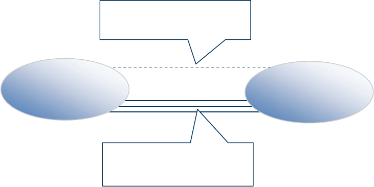
5.2.1 Legacy Architecture
The current A-interface has signaling over IP defined (SIGTRAN) in addition to the original signaling using TDM
signaling transport. But, as stated before, for the user plane only TDM transmission is defined, with transcoding always
located inside the BSS. The only Codec defined for this TDM A-Interface is PCM (G.711). In addition TFO may exist,
which tunnels compressed speech through this PCM link between TRAU and MGW.
ETSI
ETSI TR 143 903 V8.3.0 (2009
-
02)
12
3GPP TR 43.903 version 8.3.0 Release 8
MSC-S
MGW
BS S
A (IP or
TDM)
Mc/IP
MSC-S
MGW
Mc/IP
Nb
Nc
A/TDM
A/TDM
= Signalling
= User plane
A (IP or
TDM)
TRAU
BS S
TRAU
= Transcoder
Note: the TRAU boxes include the transcoders, located somewhere in BSS.
Figure 5.2.1.1: Current legacy architecture
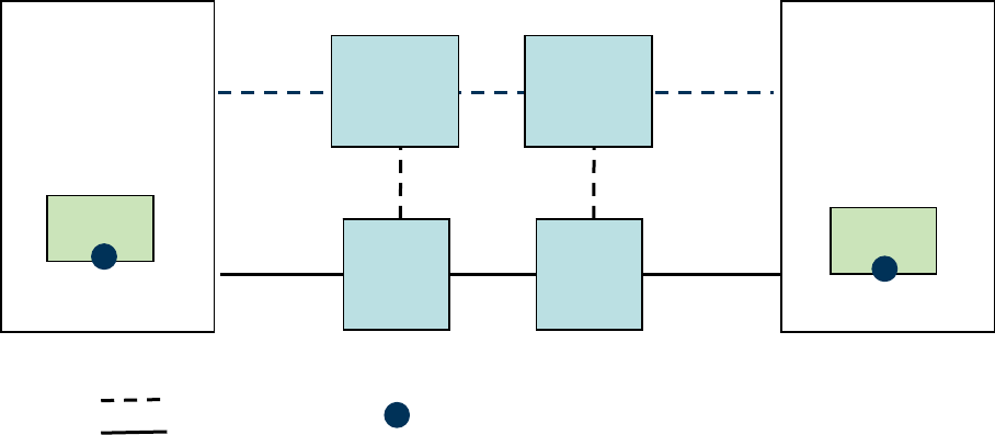
5.2.2 PCM encoded speech (G.711) over IP
A first improvement, which is seen as an "interim" solution, can be introduced with no changes on the functional
division between Base Station System (BSS) and CS Core Network, as specified in TS 48.002 [5]. Specifically the
transcoding is left within the BSS. This approach focuses on migrating the existing A interface to IP; the network
architecture is not really impacted. It will specify how to carry 64 kbps A-interface channels between the BSC and the
MGW over an underlying IP based transport protocol; for both voice services as well as for data and fax services.
The Codec defined for the A-Interface is still PCM, again TFO is an option.
ETSI
ETSI TR 143 903 V8.3.0 (2009
-
02)
13
3GPP TR 43.903 version 8.3.0 Release 8
MS C-S
MGW
BSS
A/ IP
Mc / I P
MS C-S
MGW
Mc / I P
Nb
Nc
A/ IP
A/IP
A/ IP
TRAU
BSS
TRAU
64 kbps payload
IP based
protocol
stack
64 kbps payload
IP based
protocol
stack
= Transcoder
= Signalling
= User plane
Figure 5.2.2.1: Architecture for the G.711 over IP "interim solution"
In this case the recommended network architecture is that Media Gateways (MGWs) are co-located at the same site
where the transcoders are. This is always desirable, but the high transport volume makes it quite important. To achieve
better bandwidth efficiency at the A interface IP-multiplexing techniques shall become an option. The packetization
time may be either 5 ms or 20 ms (FFS).
The main advantage of this approach relates to the fact that IP solves problems related to the inflexible physical
connectivity of TDM. The solution introduces the freedom to place a BSC/TRAU somewhere in an IP network. To
scale the capacity of the A interface becomes much easier because another MGW can be added without considering
adding TDM connectivity to local BSC/TRAUs. And obviously the deployment of A-flex will be much easier, because
the BSC/TRAUs have to be "connected" with all MGWs belonging to the MSC in Pool. And, as already said above, IP
hardware in the nodes and IP site and backbone infrastructure can be shared by the A-interface control plane and user
plane.
In this approach, these advantages can be achieved by using the existing transcoder pools within BSS, without requiring
any new transcoder resources in MGW. This may be of especial importance for legacy Codecs, like GSM_FR and
GSM_HR, where no future growth is expected, but which will disappear over time.
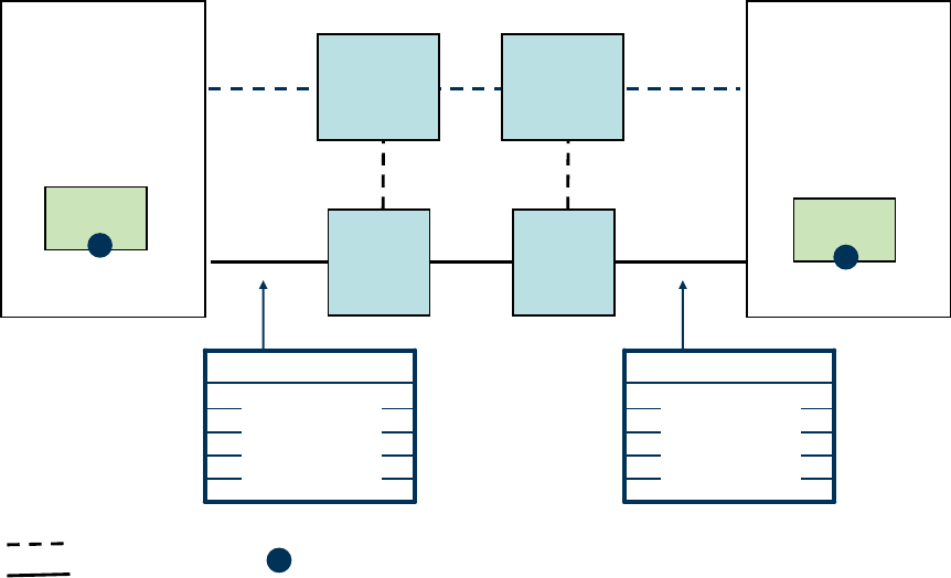
5.2.3 Compressed speech over IP
The target solution aims at carrying compressed speech in an efficient way across the A interface over the RTP/UDP/IP
protocol stack. In contrast to TFO in this case the compressed speech is formatted directly and there is no PCM stream
in parallel, and this allows to support TrFO.
This solution implies a deviation from the current BSS architecture, where today PCM is used on the A interface and
transcoders are functionally integrated into the BSS.
In fact, compressed speech on the A interface can rely on transcoder resources in the Core Network and allow removal
of transcoder resources from the BSS, thus impacting the functional division between the BSS and the CN. Besides
improving the end-to-end speech quality, reducing the overall speech path delay and reducing the bit rate on the A
interface, this approach would also reduce the overall need for transcoder resources in BSS and Core Network and
could be considered as the target deployment scenario. But it will require additional transcoder resources
(e.g. more DSP-power for transcoding in all Mobile-to-PSTN calls) within the Core Network and possibly new
transcoder types (e.g. GSM_HR) within the Core Network.
For the following discussion it is exactly define what the term "transcoder" means. So far it was in GERAN used for the
transcoding between the 3GPP-Codec used on the radio interface and the G.711 Codec used on the A-Interface. The
ETSI
ETSI TR 143 903 V8.3.0 (2009
-
02)
14
3GPP TR 43.903 version 8.3.0 Release 8
installed transcoder base is exactly performing this kind of transcoding and G.711 is an "integral part" of the transcoder
pools.
In contrast to that the transcoding between two different 3GPP-Codecs, e.g. between GSM_HR and GSM_EFR should
be termed "transcoder-pair", with implicitly knowing that this transcoding is done in several steps, e.g. 1) from
GSM_HR to lin.PCM then 2) from lin.PCM to G.711 then 3) from G.711 to lin.PCM and finally 4) from lin.PCM to
GSM_EFR. (lin.PCM stands for 8kHz sampled speech with 16 bit per sample). Using the installed transcoder base
involves in fact three (3!) Codecs and only the "middle one", i.e. G.711, could potentially be left out – with quite some
consequences in TRAU-Pool organization and interfaces. Any other "direct" transcoding between two different 3GPP
Codecs is currently NOT allowed by 3GPP Standards, because it would violate the mandatory bit exactness. If any such
direct transcoding should be considered, then 3GPP-SA4 shall be consulted for evaluation and potential standardisation.
Any "proprietary" shortcut is currently not allowed, since it could lead into unpredictable speech quality problems.
Consequently in the following the terms "transcoder" and "transcoder-pair" are use, where appropriate.
MSC-S
MGW
BS S
A/IP
Mc/IP
MSC-S
MGW
Mc/ IP
Nb
Nc
A/IP A/IP
A/IP
e.g. AMR coded
IP based
protocol
stack
e.g. AMR coded
IP based
protocol
stack
BS S
= Transcoder or Transcoder-pair, typically not used in MS-to MS calls
= Signalling
= User plane
Figure 5.2.3.1: Architecture for Compressed speech over IP, with transcoder-less BSS
This approach yields to align the BSS network architecture with the 3G CS core network architecture. This will allow
concentrating development and deployment of transcoders within the core network. They will become part of the media
gateway (MGW) and will be controlled by the MSC servers.
When deploying a transcoder-less BSS together with a new Core Network, the transcoders (if a transcoder or
transcoder-pair is needed at all for this call) are allocated in the MGW. The transcoder resource can be shared by several
BSSs. A transcoder-less BSS can not be connected to a legacy Core Network. An upgraded BSS therefore has
transcoders and supports AoIP.
The Codec to be used on the radio interface and the A interface is negotiated between BSC and MSC with the goal to
allow TrFO operation. In the successful case no transcoder resources are needed, neither in the BSS nor in the CN.
Please note: BSC and MSC can not negotiate two different Codecs for the radio and the A interface, except when PCM
is used on the A interface.
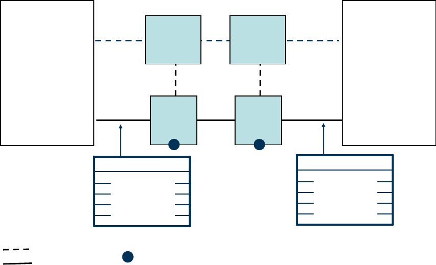
As an (other) implementation option, that aims at exploiting the huge amount of transcoding resources installed in
today's GSM networks, Transcoder-pairs in the BSS could be used to cover the scenarios where TrFO is not possible or
not desirable, e.g. if both radio legs must use different Codecs and transcoding between the different Codecs used on
both ends of the call is necessary.
ETSI
ETSI TR 143 903 V8.3.0 (2009
-
02)
15
3GPP TR 43.903 version 8.3.0 Release 8
The typical approach in 3G networks is, however, to insert a transcoder or a transcoder-pair in the MGW to cover the
scenarios where TrFO is not possible/desirable. In this way the MSC-Servers have full control over the end-to-end
transcoder combination and therefore full control over the achieved speech quality.
An important case for a transcoder-pair could be when Codec adaptation is required on one radio leg during a call (e.g.
switch to GSM_HR on the radio in overload condition or intra-BSS handover to an incompatible cell), and an end-to-
end Codec re-negotiation to maintain TrFO operation is not desirable due to high signalling load. In this specific case
the Codec adaptation can be "performed locally" within the BSS by inserting the pair of transcoders there (or remove it
again at the following handover). This BSS-internal Codec change would be communicated to the rest of the network
by means of the 'handover performed' message, containing the information of the Codec used on the radio interface. But
the need to maintain transcoder resources in the BSS - to be used when TrFO operation is not possible/desirable –
would not allow exploiting a 3G-like architecture.
NOTE: In this case, if a 'handover performed' message contains a different Codec than the one used on the A-
interface, the MSC would have to assume that a transcoder-pair has been introduced by the BSS (this
needs to be discussed further).
Since the rest of the network will be informed that the BSS inserted a transcoder-pair, situations where the voice quality
can be unpredictably decreased, could be prevented. For instance, in case both radio legs perform such a Codec
adaptation (e.g. both from FR_AMR to GSM_HR), MSC-Servers would be informed and, instead of maintaining the
situation where transcoding is performed from GSM_HR to G.711 to FR_AMR(set 12.2) to G.711 and to GSM_HR,
they could trigger a Codec re-negotiation in the core network to achieve a much better call quality by using GSM_HR
end-to-end in such high-overload situations. Optimal would be to use FR_AMR (set 1) and HR_AMR (set 1), because
these allow always end-to-end transcoding free operation.
This implementation option (transcoder-pair in BSS) shall not imply any changes to the control plane and user plane
signalling of the future standard for AoIP.
MSC-S
MGW
BS S
A/IP
Mc/IP
MSC-S
MGW
Mc/ IP
Nb
Nc
A/IP A/IP
A/IP
e.g. AMR coded
IP based
protocol
stack
e.g. AMR coded
IP based
protocol
stack
BS S
= Transcoder-pair
= Signalling
= User plane
TRAU TRAU
GSM_ HR / FR_AMR
FR_AMR / GSM_ HR
Figure 5.2.3.2: Architecture for the Compressed speech over IP solution, with transcoders in the BSS
5.2.4 Example Deployment Scenarios
There is an enormous amount of transcoder resources installed in today's GSM radio networks. Therefore the "final
solution" in the standard shall be flexible and allow the use of transcoders placed in the BSS or removed from the BSS

ETSI
ETSI TR 143 903 V8.3.0 (2009
-
02)
16
3GPP TR 43.903 version
8.3.0 Release 8
and located, when needed, in the CS Core Network. In addition, e.g. for the purpose of migrating the A interface from a
TDM to an IP interface, both TDM and IP based A interface should be supported concurrently, at least for the migration
phase.
NOTE: TFO is not mandated. As long as transcoders are kept in the BSS and G.711 is used on A (either in
AoTDM or AoIP), it is an option for the operator to utilize TFO. It is not foreseen that TFO will have
impacts on the AoIP work item.
The table below shows example deployment scenarios that shall be evaluated
for potential support by the signalling in
the standard. It is not required that an operator has to go through different deployment scenarios. In contrast the
intention is that the standard shall not hinder an operator from implementing his specific deployment strategy for AoIP.
Table.5.2.4-1: Example Deployment Scenarios for various BSS and CN versions
Example
Deployment
Scenarios
TC location AoTDM AoIP BSS Version Core
Network
Version
Legacy
=
Deployment 1
In the BSS,
for all Codec
Types
Yes,
only G.711
No legacy legacy
Deployment 2
In the BSS,
for all Codec
Types
possible,
only G.711
Yes,
only G.711
Upgraded Upgraded
Deployment 3a Selectable, e.g.
per Codec Type
Yes,
only G.711
Yes,
G.711 and
3GPP Codecs
Upgraded Upgraded
Deployment 3b Selectable, e.g.
per Codec Type
Yes,
only G.711
Yes,
only 3GPP
Codecs
Upgraded Upgraded
Deployment 4
In the CN,
for all Codec
Types
No Yes,
only 3GPP
Codecs
Transcoder-less New
In these example deployment scenarios it is assumed that first the MSC-Server software is upgraded in one step to an
upgraded MSC Server. This will then support all listed deployment scenarios (and maybe more), from legacy scenario
(Deployment 1) to "Transcoder-less BSS" scenario (Deployment 4), based on O&M parameter setting in BSS and MSC
and maybe on sophisticated load sharing algorithms, not detailed here. In case of optimal signalling support on
BSSMAP the BSS parameters need not to be administered in the MSC a second time, which would always be error
prone.
If the MGW is also upgraded to the optimal, final deployment, i.e. including all necessary hardware and firmware for
AoIP and all transcoder capabilities, then only the BSS-O&M-parameters define the upgrading steps.
For legacy deployment, it is necessary to allow an incremental migration of all transcoder resources to the MGW.
Therefore MGW capability must be administered in the MSC by O&M (unless also MGW capability signalling is
introduced).
The Technical Specification of AoIP shall define means to allow the coexistence of TDM and IP between the Core
Network and the same BSS.
In the following the example deployment scenarios are described in more details and with some block diagrams to
illustrate the most important aspects.
ETSI
ETSI TR 143 903 V8.3.0 (2009
-
02)
17
3GPP TR 43.903 version 8.3.0 Release 8
Please note that the "transcoder resource" shall be considered for each individual Codec Type separately. It is possible
that some Codec Types are supported in BSS, while others are already moved completely out of BSS.
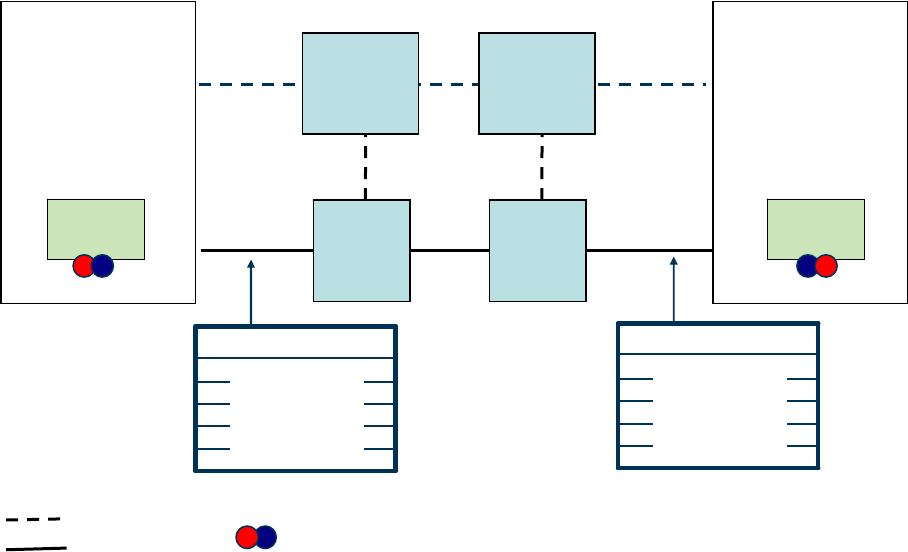
Deployment Scenario 1 (legacy): Only AoTDM with G.711 coded speech is used on the A interface. TFO is an option,
on a Codec-by-Codec base. TFO/TrFO Interworking exists in the core network and OoBTC is quite efficient to manage
in many cases transcoding free operation in MS-to-MS calls. In the example below (see figure.5.2.4.1) only AMR is
used in OoBTC, because this is also an UTRAN Codec. Of course also EFR could be used in OoBTC in other
examples.
Instead of OoBTC the CN may, however, still use ISUP, then Codec Negotiation is not possible and PCM is used on
Nb. In nearby future also SIP-I will be standardized for the Core Network Nc interface and then compressed speech is
possible on Nb in RTP framing.
In Deployment Scenario 1 the MSC has only a vague knowledge on BSS Codec capabilities by static O&M. The MSC
has no temporary and locally accurate information on BSS capabilities for a specific call. This limits the capability of
the core network to negotiate a common Codec end-to-end. The BSS in turn has also only static O&M knowledge on
the AMR Configurations used in CN. TFO between BSS and CN is not guaranteed.
MS BTS
BTS
MS
TRAU
TC - Pools
BSC
MSC
MGW
TC - Pools
MGW
TC - Pools
MSC
BSC
TRAU
TC -Pools
FR
HR
EFR
FR
HR
EFR
FR
HR
EFR
AMR
PCM
AMR
PCM
AMR
FR
HR
EFR
AMR
FR
HR
EFR
AMR
FR
EFR
AMR
OoBTC
AoTDM
PCM
NboIP
AoTDM
PCM
AMR Configuration by O&M
AMR Configuration by O&M
Codec List (supported by BSC) by static O&M
Figure.5.2.4.1: Deployment Scenario 1 for legacy BSS
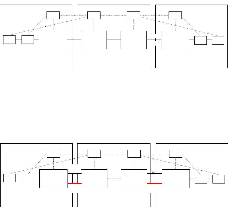
Deployment Scenario 2: IP transport is introduced, transcoders stay all in the BSS, and G.711 is the only allowed
Codec on the A-Interface. A TDM-to-IP converter in BSS is needed for interfacing. The upgraded BSS works on
AoTDM and AoIP concurrently (see left BSS in figure below).
MS BTS
BTS
MS
TRAU
TC-Pools
BSC
MSC
MGW
TC - Pools
MGW
TC - Pools
MSC
BSC
T
RA
U
TC-Pools
FR
HR
EFR
FR
HR
EFR
FR
HR
EFR
AMR
PCM
AMR
PCM
AMR
FR
HR
EFR
AMR
FR
HR
EFR
AMR
FR
EFR
AMR
OoBTC
TrFO
AoTDM
PCM
N
bo
IP
AoIP
PCM
AoIP
PCM
TDM
IP
TDM
IP
Figure.5.2.4.2: Deployment Scenario 2 for an upgraded BSS and CN
Signalling between BSC and MSC should be introduced to decide on a call-by-call basis and Codec-by-Codec basis,
which Interface Type to use. It should be noted that parallel support for both types of interface in the BSS should not be
mandated, but supported by the standard, since an operator should have the freedom to transmit voice traffic on either
link to ensure there is no traffic lost during the transition. The parallel support of AoTDM and AoIP allows also a
smooth extension of transport capacity by keeping the existing TDM links, while investing extensions only in IP links.
During the BSS upgrading phase the MSC Server could know the available Interface Types by MSC-O&M
configuration per BSS. There is thus no absolute need to introduce Interface Type capability related signalling on
ETSI
ETSI TR 143 903 V8.3.0 (
2009
-
02)
18
3GPP TR 43.903 version 8.3.0 Release 8
BSSMAP. But this MSC-O&M could be quite cumbersome and especially annoying, since it is maybe only necessary
for a short time, until the next migration step. It would also be inflexible and would not allow a dynamic resource
sharing. Attention should also be given to A-Flex scenarios (MSC in Pool), where a change in a BSS would affect all
connected MSCs immediately. It seems questionable if a simultaneous update of MSC can be handled by separate
O&M.
It is therefore proposed (by Ericsson) to define Interface Type capability signalling to avoid cumbersome and error
prone O&M in BSS and MSC during the migration phase and to allow a flexible load sharing. When introducing this
signalling extension then it is not a big step to provide it on a per Codec basis.
In an other example IP transport is introduced, transcoders stay all in the BSS, G.711 is the only allowed Codec on the
A-Interface. AoTDM is shut down at the same time (see right BSS in figure above), there is no fallback to AoTDM, the
upgraded BSS works on AoIP solely. This is a direct migration from AoTDM to AoIP in one step without link by link
transition from the legacy BSC.
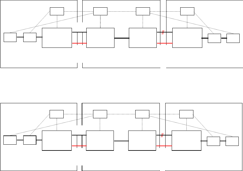
Deployment Scenarios 3a/3b: AoTDM is still allowed, AoIP is used in addition, and the decision is done call-by-call.
Transcoder resources stay in the BSS on a per-Codec-base; compressed speech on the A interface is possible for Codecs
both supported and not supported by transcoders in BSS, in case the MGW has sufficient capability.
The difference between scenarios 3a and 3b is as follows: while scenario 3a allows the use of G.711 for AoIP (and thus
allows a faster migration from TDM to IP), scenario 3b allows the use of G.711 only for AoTDM, which allows a
smoother migration from TDM to IP and prevents from managing 3 configurations in parallel.
MS BTS
BTS
MS
TRAU
TC-Pools
BSC
MSC
MGW
TC - Pools
MGW
TC - Pools
MSC
BSC
T
RA
U
TC-Pools
FR
HR
EFR
FR
HR
EFR
FR
HR
EFR
AMR
PCM
EFR
AMR
PCM
HR
EFR
AMR
FR
HR
EFR
AMR
FR
HR
EFR
AMR
FR
EFR
AMR
OoBTC
TrFO
AoTDM
PCM
N
bo
IP
AoIP
AoIP
TDM
IP
TDM
IP
PCM
EFR
AMR
PCM
HR
EFR
AMR
Figure.5.2.4.3a: Deployment Scenario 3a for an Upgraded BSS
MS BTS
BTS
MS
TRAU
TC-Pools
BSC
MSC
MGW
TC - Pools
MGW
TC - Pools
MSC
BSC
TRAU
TC-
P
oo
ls
FR
HR
EFR
FR
HR
EFR
FR
HR
EFR
AMR
PCM
EFR
AMR
PCM
HR
EFR
AMR
FR
HR
EFR
AMR
FR
HR
EFR
AMR
FR
EFR
AMR
OoBTC
TrFO
AoTDM
PCM
N
bo
IP
AoIP
AoIP
TDM
IP
TDM
IP
EFR
AMR
HR
EFR
AMR
Figure.5.2.4.3b: Deployment Scenario 3b for an Upgraded BSS
Transcoders in the BSS may be used to still support the G.711 Codec on the A interface, e.g. in case of a local MS-to-
PSTN call.
As an implementation option transcoder-pairs in BSS could also be used to support transcoding between the Codec used
on the radio interface and the Codec used on the A over IP interface. This could happen after BSS-internal handover.
It should be possible for a specific Codec Type, e.g. EFR, to use the existing EFR-TRAU pool in the BSS, while
extending EFR-transcoder capability only in the MGW. On a call-by-call basis BSC and MSC would negotiate where to
locate the EFR-transcoding function. One strategy could be to first fill the EFR-TRAU pool in the BSS and only when
this is fully deployed locate the EFR-transcoding
ETSI
ETSI TR 143 903 V8.3.0 (2009
-
02)
19
3GPP TR 43.903 version 8.3.0 Release 8
function for the next call within the MGW. The BSC would then for this next call indicate that EFR is supported only
with compressed on AoIP
Deployment scenarios 3a/3b are the most demanding scenarios in terms of necessary signalling between BSC and MSC
server.
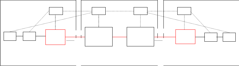
Deployment Scenario 4: Transcoders are completely removed from the BSS. IP transmission and compressed speech
on A interface are mandatory. The Core Network does not support AoTDM any longer. This is a proposed target
deployment scenario for a Transcoder-lessBSS. Transcoder resources only exist in the MGW; IP transmission and
compressed speech is used over the A interface.
BSC
MSC
MSC
BSC
FR
HR
E
F
R
FR
HR
EFR
AMR
AMR-WB
PCM
FR
HR
EFR
FR
EFR
AMR
AMR-WB
SIP-I
TrFO
RTP
AoIP
PCM
FR
HR
EFR
AMR
AMR-WB
AoIP
AMR
AMR-WB
PCM
FR
HR
EFR
AMR
AMR-WB
PCM
FR
HR
EFR
AMR
AMR-WB
FR
HR
EFR
AMR
AMR-WB
MS BTS
BSC
User Plane
MGW
TC - Pools
MGW
TC - Pools
BTS
MS
BSC
User Plane
Figure.5.2.4.4: Deployment Scenario 4 for a New BSS
It is BSS-internal implementation strategy, whether to use existing BTSes with TDM interfaces and convert to IP in a
new functional device (e.g. TDM-IP Converter), or to integrate the IP interface directly into the New BTS. The TDM-IP
Converter could also take care of BSS-internal handovers with unmodified Codec Type, or a separate Handover-
Handler could do that.
Introducing such a Transcoder-less BSS could be the simplest and most efficient way for deployment of AoIP by two
upgrading steps:
Step 1: Upgrade MSC Server and MGW to an Upgraded MSC Server and Upgraded MGW.
Step 2: Commission and deployment of Transcoder-less BSS.
This migration strategy may, however, require more interim Transcoder resources in the Core Network.
After all BSS are upgraded to Transcoder-less BSS the final step could be to remove all AoTDM support from the Core
Network, i.e. migrate all MSC Servers and MGWs to "New" ones.
5.3 Functional Impacts
This TR investigates the functional impact and required specification work for the support of an A interface over IP.
5.3.1 G.711 and compressed speech over IP
"A interface over IP" requires to setup IP connections for each call. That means IP terminations have to be seized on
both sides of the A interface. The related IP end point address information of the transport connection between MGW
and BSS must be exchanged. This will impact the assignment and handover procedures of the BSSMAP protocol [6]
and the GCP.
The payload formats need to be defined. It is proposed to adopt RTP/UDP/IP as the user plane protocol stack.
An option is to use for PCM speech (i.e. G.711 A/u-law Codec) the RTP profile according to RFC 3551 [19].
Furthermore for G.711 20 ms or 5 ms packetization time may be used. The increase in speech path delay, when using
20ms packetization time, is acceptable.
The RTP payload format for compressed speech shall be based on existing RFC profiles, or, if needed RFCs may be
created (e.g. for GSM_HR).

ETSI
ETSI TR 143 903 V8.3.0 (2009
-
02)
20
3GPP TR 43.903 version 8.3.0 Release 8
It is proposed to specify RTP bearers multiplexing and RTP header compression as a means to achieve better bandwidth
efficiency. 3GPP has already specified for BICC-based circuit switched core networks (CNCS) an RTP bearers
multiplexing and RTP header compression scheme for Nb and similar work is ongoing for SIP-I based CSCNs; the
possibility to reuse these solutions shall be studied.
Solutions based on tunneling E1 or other TDM channels over IP would remove one main advantage of IP transport,
which is the ability to dynamically set up connections between the BSS and any MGW. Therefore it is proposed to
exclude those from the study.
When compressed speech is used on the A interface over IP, then it is easier to achieve "true end-to-end Codec
negotiation". The existing Codec Negotiation within the Core Network as specified in OoBTC (see TS 23.153) and the
future Codec Negotiation in SIP-I (see TR 29.802) will benefit from better knowledge about the BSS resource situation.
This will improve the speech quality further. "True end-to-end" Codec negotiation impacts the BSC, because it should
provide the CS core network with its Codec capability. A Codec negotiation procedure between BSS and CN is
required, having impacts on the assignment procedure.
Having no transcoders in the BSS any more requires adaptations of the handover procedures. When the handover
requires a change of the Codec, then existing mechanisms should be reused that involves the MSC Server. Intra BSC
handover that do not require a change of the Codec should be handled without MSC impacts.
5.3.2 Support for Data and Fax Services
Regarding to the target deployment scenario where Transcoders are removed from the BSS, a simple and economic
migration procedure should be investigated.
AoIP must support data and fax calls. There are 2 approaches further discussed in chapter 6.2 of this TR. The first one
leaves rate adaptation functionality in BSS and transfers 64 kbps over the A-interface using clearchannel according to
RFC 4040 [18] as RTP profile. The second one moves rate adaptation functionality to the core network and needs new
RTP profiles for the A-Interface for lower bit rate.
5.3.3 Functional Impacts for Migration
To support smooth migration it should be possible to support transcoders placed in the BSS as well as in the MGWs
simultaneously, see deployment scenario 1. Therefore on a call basis BSSMAP signaling is needed to decide whether
compressed or PCM (G7.11) coded speech shall be used on the A interface. The BSC is impacted because even though
it still controls the radio Codec finally selected on the radio bearer it does not anymore control the transcoder equipment
for calls where the transcoder is removed from.
6 Study Results, User Plane
6.1 User Plane Principles
6.1.1 Transport network User Plane for A over IP
6.1.1.1 PCM coded speech (G.711) over IP
The following figure shows the proposed protocol stack for the A interface transport over RTP/UDP/IP.
G.711
RTP
UDP
IP
ETSI
ETSI TR 143 903 V8.3.0 (2009
-
02)
21
3GPP TR 43.903 version 8.3.0 Release 8
Link layer
Physical layer
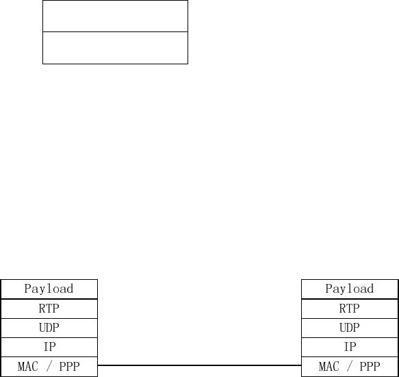
6.1.1.2 Compressed speech and data/fax over IP
Payloads of both speech and CS data/fax are encapsulated into RTP packet, and are carried on the UDP/IP protocol. The
specific carrying way at physical layer and corresponding link layer of IP protocol are not limited. If Ethernet is
adopted, link layer will be MAC protocol, while if POS or IPoE1 is adopted for carrying, link layer will be PPP
protocol.
The user plane of the A interface is shown in figure 6.1.1.2.1.
BSC MGW
Figure 6.1.1.2.1: User Plane: AoIP protocol stack
6.1.2 Transport network Control Plane for A over IP
It is proposed that the exchange of IP address and other transport related information (see chapters 7.1 and 7.2) between
the core network and BSS takes place transparently via GCP and BSSAP.
6.1.3 Potential impact on the Nb and Nc interfaces
The transport of G.711-coded or 3GPP-compressed speech across the A-interface over IP has not necessarily any
impact on the Nb or Nc interfaces.
However, if end-to-end transcoding free operation is desired for all defined 3GPP Codec Types, then the Nb interface
needs to transmit also GSM_FR- and GSM_HR-coded speech. These two "legacy" Codec Types are currently not
allowed for the Nb interface, because no Nb framing is defined for these. All other 3GPP Codec Types are already
supported in the standards for Nb and Nc.
Nb framing may need to be specified for GSM_FR and GSM_HR for the case that OoBTC/BICC is used on Nc. For the
case that SIP-I is used on Nc only the RTP Profile for GSM_HR needs to be defined. This could be based on
RFC 3551 [19].
For the Codec Negotiation on the Nc interface these two Codec Types have already a code point associated, see
TS 26.103. Since no Nb framing exists they can not be used on Nc so far.
6.2 Payload Formats
6.2.1 Existing TRAU Frames for Speech
This chapter discussed all control bits of the existing TRAU Frames to identify, which are potentially needed in a future
AoIP framing (i.e. RTP). The discussion is performed for the example AMR, but the result of the discussion can be
applied to other speech Codec Types.
The conclusion first: the defined RTP profiles are sufficient for all GSM Codecs except for GSM_HR for which a new
RTP profile needs to be defined.

ETSI
ETSI TR 143 903 V8.3.0 (2009
-
02)
22
3GPP TR 43.903 version 8.3.0 Release 8
The detailed discussion follows below.
The existing TRAU frame layout for the FR_AMR identifies 25 "C"ontrol bits for AMR [3]. Only these need discussion
for AMR over AoIP. The synchronisation bits and the The "T" bits at the end are not relevant for AoIP. The "D"ata bits
are contained in the RTP payload format for AMR.
Table 6.2.1.1-1: TRAU frame layout for the AMR_FR frame [7].
Bit number
Octet no. 1 2 3 4 5 6 7 8
0
0 0 0 0 0 0 0 0
1
0 0 0 0 0 0 0 0
2
1 C1 C2 C3 C4 C5 C6 C7
3
C8 C9 C10 C11 C12 C13 C14 C15
4
1 C16 C17 C18 C19 C20 C21 C22
5
C23 C24 C25 D1 D2 D3 D4 D5
6
1 D6 D7 D8 D9 D10 D11 D12
7
D13 D14 D15 D16 D17 D18 D19 D20
8
1 D21 D22 D23 D24 D25 D26 D27
9
D28 D29 D30 D31 D32 D33 D34 D35
10
1 D36 D37 D38 D39 D40 D41 D42
11
D43 D44 D45 D46 D47 D48 D49 D50
12
1 D52 D52 D53 D54 D55 D56 D57
13
D58 D59 D60 D61 D62 D63 D64 D65
14
1 D66 D67 D68 D69 D70 D71 D72
15
D73 D74 D75 D76 D77 D78 D79 D80
16
1 D81 D82 D83 D84 D85 D86 D87
17
D88 D89 D90 D91 D92 D93 D94 D95
18
1 D96 D97 D98 D99 D100 D101 D102
19
D103 D104 D105 D106 D107 D108 D109 D110
20
1 D111 D112 D113 D114 D115 D116 D117
21
D118 D119 D120 D121 D122 D123 D124 D125
22
1 D126 D127 D128 D129 D130 D131 D132
23
D133 D134 D135 D136 D137 D138 D139 D140
24
1 D141 D142 D143 D144 D145 D146 D147
25
D148 D149 D150 D151 D152 D153 D154 D155
26
1 D156 D157 D158 D159 D160 D161 D162
27
D163 D164 D165 D166 D167 D168 D169 D170
28
1 D171 D172 D173 D174 D175 D176 D177
29
D178 D179 D180 D181 D182 D183 D184 D185
30
1 D186 D187 D188 D189 D190 D191 D192
31
D193 D194 D195 D196 D197 D198 D199 D200
32
1 D201 D202 D203 D204 D205 D206 D207
33
D208 D209 D210 D211 D212 D213 D214 D215
34
1 D216 D217 D218 D219 D220 D221 D222
35
D223 D224 D225 D226 D227 D228 D229 D230
36
1 D231 D232 D233 D234 D235 D236 D237
37
D238 D239 D240 D241 D242 D243 D244 D245
38
1 D246 D247 D248 D249 D250 D251 D252
39
D253 D254 D255 D256 T1 T2 T3 T4
The TRAU Frames for other Codec Types are similar or simpler than for FR_AMR and thus it is sufficient to analyse
the FR_AMR case.
Detailed discussion on the control bits using description from [7] is provided below.
All comments are edited in italic.
Detailed Description:
Frame Type:
The coding of the Frame_Type (also called "Codec_Type") for AMR is identical in uplink and downlink.
C1...C5:
0.0.1.1.0: Adaptive Multi-Rate Codec.
ETSI
ETSI TR 143 903 V8.3.0 (2009
-
02)
23
3GPP TR 43.903 version 8.3.0 Release 8
Discussion: The Codec Type is included in the RTP Header.
Time Alignment Field:
The Time Alignment Field (Bits C6...C11) is used to carry either the Time Alignment Command (TAC), the Phase
Alignment Control (PAC) or the TFO and Handover Information. The Time Alignment Command is coded as for the
Full Rate and Enhanced Full Rate (clause 5.5.1.1.1).
Time Alignment Command (TAC):
In the uplink direction (BTS to TRAU) the TAC indicates the required timing adjustment for the downlink TRAU
frame to be made by the TRAU in 250/500μs steps.
C6...C11:
0.0.0.0.0.0 No change in frame timing
0.0.0.0.0.1 Delay frame 1 x 500μs (send four additional T-Bit-pairs after the end of the TRAU Frame)
0.0.0.0.1.0 Delay frame 2 x 500μs (send eight additional T-Bit-pairs after the end of the TRAU Frame)
…
1.0.0.1.1.1 Delay frame 39 x 500μs (send 156 additional T-Bit-pairs after the end of the TRAU Frame)
(1.0.1.0.0.0 to 1.1.0.1.1.1: 16 code-points, unused, reserved)
Discussion: support of Time Alignment for A over IP is FFS.
If Time Alignment is not supported then the corresponding control bits would not be needed. Otherwise, possible
solutions are investigated in sub-clause 6.5.
(1.1.1.0.0.0 to 1.1.1.0.1.1: 4 code-points, reserved for TFO)
(1.1.1.1.0.0 reserved for TFO)
Discussion: TFO is not used for all calls where the AMR transcoder is not in the BSS, but in the MGW. So these bits
are irrelevant for AoIP with compressed AMR speech on AoIP.
(1.1.1.1.0.1 reserved for AMR CMI/CMR Phase Alignment Command (PAC), no change in frame timing)
Discussion: The RTP Profile transports both, the CMI and the CMR in parallel. No change in CMI/CMR phase is
necessary. So this code point is not necessary in AoIP.
1.1.1.1.1.0 Delay frame by 250μs (send two additional T-Bit-pairs after the end of the TRAU Frame)
1.1.1.1.1.1 Advance frame by 250μs (do not send the two T-Bit-pairs at the end of the TRAU Frame).
Discussion: See above comments on Time Alignment.
Phase Alignment Command (PAC) (useful when TFO is not supported or disabled):
The Phase Alignment Command (PAC) can be used by the BTS to command the TRAU to change (invert) the phase of
CMI/CMR, respectively RIF, in downlink TRAU frames, see clause 6.6.1.2.1.
C6...C11:
1.1.1.1.0.1 AMR CMI/CMR Phase Alignment Command (PAC), no change in frame timing.
In No_Speech frames the Phase Alignment Command may optionally be transmitted by one additional bit (PAB, see
subclause 5.5.1.2.2) that allows a direct time and phase alignment in one step.
Discussion: no Phase Adjustment is needed any longer.
This may as a consequence result in up to 20ms more delay in DL for local MS-to-PSTN calls and for all long distance
calls where the (local) MGW must transcode.
TFO Information (defined when TFO is supported, see 3GPP TS 28.062 [16]):
C6...C11
1.1.1.0.0.0
1.1.1.0.0.1
1.1.1.0.1.0
1.1.1.0.1.1
ETSI
ETSI TR 143 903 V8.3.0 (2009
-
02)
24
3GPP TR 43.903 version 8.3.0 Release 8
1.1.1.1.0.0
These five codes are reserved for Tandem Free Operation (see 3GPP TS 28.062 [16]). They result in no change in frame
timing. If the BTS does not support TFO or TFO is disabled these codes shall not be used in uplink and shall be ignored
in downlink. The procedure to exchange this information between BTS and TRAU is described in
3GPP TS 28.062 [16].
Discussion: Not needed on AoIP.
Request or Indication Flag (RIF):
This flag indicates the phase of the Codec_Mode_Indication (RIF == 0) respectively the Codec_Mode_Request (RIF ==
1). It has the same meaning in uplink and in downlink. Typically this flag toggles every frame. Exceptions may occur at
handover and CMI/CMR phase alignment, see clause 6.6.1.2.1.
Discussion: The RTP Profile carries both, CMI and CMR in parallel. So the RIF is not needed in AoIP.
Uplink Frame Error (UFE):
In downlink the UFE indicates that the most recently received uplink TRAU frame had detectable errors. In uplink this
bit shall be set to "1".
UFE == 0: "Uplink Frame received with Errors";
UFE == 1: "Uplink Frame received without Errors".
Note: the UFE is not related to the frame classification (Rx_Type) as computed by the BTS radio receiver. It is related
to inconsistencies in the TRAU frame synchronization, control bits or CRCs within the TRAU frame.
Discussion: This is a question of link supervision. It is assumed that new methods will be introduced.
Config_Prot
This field is reserved for the Configuration Protocol in case of Tandem Free Operation (see 3GPP TS 28.062 [16]). If
the BTS does not support TFO or TFO is disabled, then this field shall be set to "0.0.0".
Message_No
This field is reserved for the Configuration Protocol in case of Tandem Free Operation (see 3GPP TS 28.062 [16]). If
the BTS does not support TFO or TFO is disabled, then this field shall be set to "0.0".
In AoIP TFO is not used
Discussion: TFO is not used for calls where the transcoder is not longer in BSCs, but in MGW. So these bits are
irrelevant for AoIP.
DTX in downlink requested (DTXd)
See clause 6.6.2.2.
Discussion: The decision whether or not to use DTX shall be moved from the BSC to the MSC.
In end-to-end transcoding free operation this decision is anyway on the distant side and it is therefore mandatory for
the BSS to support DTX in downlink always. So this bit is not needed in AoIP.
TFO Enabled (TFOE)
This bit enables or disables Tandem Free Operation in the TRAU. If the BTS does not support TFO or TFO is disabled,
then this bit shall be set to "0". Coding:
TFOE == 0: TFO Disabled;
TFOE == 1: TFO Enabled.
Discussion: Not needed in AoIP.
Frame_Classification:
This field classifies the contents of the TRAU frame as seen by the radio receiver, see 3GPP TS 26.093 [17]:
C21...C22:
1 1 "Speech_Good" the frame can be decoded without restriction
1 0 "Speech_Degraded" the frame might contain undetected errors
0 1 "Speech_Bad" the frame contains errors that can not be corrected
0 0 "No_Speech" the frame is not a speech frame, see below.
ETSI
ETSI TR 143 903 V8.3.0 (2009
-
02)
25
3GPP T
R 43.903 version 8.3.0 Release 8
In the uplink direction the Frame_Classification is also called "Rx_Type" and is always set by the BTS.
In the downlink direction the Frame_Classification is also called "Tx_Type".
If Tandem Free Operation is not ongoing, then the codes "Speech_Degraded", and "Speech_Bad" shall not be used in
the downlink direction. If Tandem Free Operation is ongoing, then all codes may be used in the downlink direction. For
the handling within the downlink BTS, see 3GPP TS 28.062 [16]).
Discussion: The RTP Profile for AMR contains this frame classification (to some extend).
Codec_Mode_Indication / Codec_Mode_Request:
This 3-bit field has three different meanings, depending on the Frame_Classification field and the
Request_or_Indication_Flag (RIF):
If Frame_Classification is different than "0.0" then this field contains
either the Codec_Mode_Indication (CMI), if RIF equals 0;
or the Codec_Mode_Request (CMR), if RIF equals 1.
If Frame_Classification is equal to "0.0", i.e. when a No_Speech frame is transmitted, then this field shall be set to
"0.0.0". CMI and CMR are then simultaneously transmitted in the Data Bits.
The coding is identical in uplink and downlink.
C23 . C24. C25:
0 0 0 Codec_Mode 4,75 kBit/s
0 0 1 Codec_Mode 5,15 kBit/s
0 1 0 Codec_Mode 5,90 kBit/s
0 1 1 Codec_Mode 6,70 kBit/s
1 0 0 Codec_Mode 7,40 kBit/s
1 0 1 Codec_Mode 7,95 kBit/s
1 1 0 Codec_Mode 10,2 kBit/s
1 1 1 Codec_Mode 12,2 kBit/s
The CMI indicates the Codec_Mode to be used for decoding the associated speech parameters in the same and the next
frame. The CMR indicates the highest allowed Codec_Mode to be used for encoding in the opposite direction.
Discussion: The RTP Profile contains CMI and CMR in parallel.
6.2.2 RTP profiles for speech
6.2.2.1 RTP profiles for G.711 encoded speech on the A over IP interface
Whenever PCM (G.711) encoded speech is used on the A interface, with or without embedded TFO frames (TFO is
optional), it is proposed to use RFC 3551 [19]. However, RFC 3551 [19] does not consider the embedded TFO frames.
It must therefore be ensured by other means that possibly inserted in-path equipment is TFO compatible in case TFO is
used.
Working Assumption:
For the case of PCM-encoded speech on AoIP 20 ms framing is used.
6.2.2.2 RTP profiles for compressed speech on the A over IP
The Codec Types that are currently used in GSM and the available RTP profiles are listed below:
GSM_FR: RFC 3551 for GSM_FR
GSM_HR: No RTP profile exists.
A new profile needs to be specified in case GSM_HR is to be supported at the A-interface.
GSM_EFR: RFC 3551 for EFR
AMR: RFC 4867 [25] for AMR. It covers both FR_AMR and HR_AMR.
AMR-WB: RFC 4867 [25] for AMR-WB. It covers FR_AMR-WB.
Working Assumption:
For the case of compressed speech on AoIP 20 ms framing is used.

ETSI
ETSI TR 143 903 V8.3.0 (2009
-
02)
26
3GPP TR 43.903 version 8.3.0 Release 8
6.2.2.3 RTP profiles for compressed speech on Nb interface
While different approaches are applied to single-rate GSM Codec and multi-rate GSM Codec at Nb interface. UP
transparent mode is applied for single-rate GSM Codec, and UP Support mode is applied for multi-rate GSM Codec as
it is today.
6.2.3 RTP profiles for data and fax calls
6.2.3.1 RTP profiles for data and fax calls with rate adaptation in BSS
In this Alternative 1 the legacy architecture split between the GSM Radio Access Network and the Core Network for
data and fax calls is kept
. In uplink direction the BTS extracts the payload of the CS data or fax service from the radio
interface and rate-adapts it to 16 kbps via four V.110 frames with 72 bits each and sends this in TRAU frames (or E-
TRAU frames) in uplink every 20ms. Between 300 bps and 14.4 kbps net bit rate of data may be contained in this
uplink stream on one 16kbps Abis/Ater link.
The TRAU (or an equivalent function) in BSS extracts the data from these TRAU frames and rate-adapts them to
64 kbps.
In case of High Speech Circuit Switched Data
(HSCSD) up to four of these channels are multiplexed within the BSS
into one 64kbps stream. Up to 4*14.4kbps = 57.6kbps net bit rate of data may be contained in this uplink stream on one
A-Interface.
The transmission on the A-interface over IP uses a 64 kbps channel carried over IP. The RTP profile defined in
RFC 4040 is used for this purpose. This RFC has been created for the purpose of transparently transporting a 64 kbps
channel over IP. The data rate on the A-Interface is comparably high and constant.
The default Packetization Time is 20ms. If 1+1 redundancy is applied, then the delay is increased by 20ms, if this
redundancy is exploited at receiver side.
The service is processed comparably at reverse direction from IWF to MGW to BSS to BTS and to the downlink radio
interface.
Working Assumption: This Alternative 1 is the default, mandatory
Alternative for all BSS and Core Networks for
AoIP, mainly for backward compatibility and ease of migration. The packetization time for this alternative 1 is fixed to
20ms. It will not be negotiated.
6.2.3.2 RTP profiles for data and fax calls with rate adaptation in CN
In this Alternative 2 the legacy architecture split between the GSM Radio Access Network and the Core Network for
data and fax calls is modified
. In uplink direction the BTS extracts the payload of the CS data or fax service from the
radio interface and rate-adapts it to 16 kbps via four V.110 frames with 72 bits each and sends this in TRAU frames (E-
TRAU frames) in uplink every 20ms. Between 300 bps and 14.4 kbps net bit rate of data may be contained in this
uplink stream on one 16kbps Abis/Ater link. Maybe we need to consider also 8 kbps and 64 kbps here?
So far this is as in Alternative 1.
Some new function in the BSS extracts the data from these TRAU frames and directly encapsulates four V.110 frames
of 72 bits, as carried in one TRAU frame of 16kbps sub-multiplexing (see 3GPP TS 48.060), into one RTP packet and
sends it to the MGW.
The default Packetization Time is 20ms. If 1+1 redundancy is applied, then the delay is increased by 20ms, if this
redundancy is exploited at receiver side.
A new RTP Profile needs to be defined. The average bandwidth on the A-Interface is about 4 times smaller than in
Alternative 1 and also constant.
Between 300 bps and 14.4 kbps net bit rate of data may be contained in this uplink stream on one A-Interface RTP
stream.

ETSI
ETSI TR
143 903 V8.3.0 (2009
-
02)
27
3GPP TR 43.903 version 8.3.0 Release 8
The case of High Speech Circuit Switched Data (HSCSD), especially the question, where the combining is performed,
is FFS.
The MGW performs Rate Adaptation to 64kbps (new functionality) and delivers the resulting frames to the
Interworking Function (IWF) for processing as today. In an alternative (new) implementation (e.g. if MGW and IWF
are integrated) the IWF gets the RTP packages with V.110 frames directly.
The service is processed comparably at reverse direction from IWF to MGW to BSS to BTS and to the downlink radio
interface.
Working Assumption: This Alternative 2 will not be included in the Stage 3 Technical Specifications.
6.3 Transport Layer
6.3.1 Link Layer and Physical Layer
Neither link layer nor physical layer need to be standardized.
6.3.2 UDP and IP
IPv.4 (RFC 791 [21] and RFC 792 [22]) is proposed to be mandatory.
IPv.6 (RFC 2460 [23] and RFC 4443 [24]) is proposed to be optional.
In this way, lack of IPv.6 support will not delay the introduction of AoIP.
UDP is specified in RFC 768 [20].
Each user plane connection is identified by an IP address and an UDP port number in the MGW and another IP address
and UDP port number in BSS. These addresses are exchanged via GCP and BSSAP prior to user plane establishment.
The port numbers that are exchanged are the port numbers associated with the RTP data stream. These port numbers are
even. Corresponding odd port numbers are used for the associated RTCP protocol.
RTP/UDP/IP packets multiplexing mechanism already defined for Nb interface in 3GPP TS, 29.414 may be re-used on
AoIP.
6.3.3 RTP
See above.
6.3.4 RTCP
RTCP is a control protocol included in the RTP specification. The multiplexing mechanism mentioned in chapter 5.3.5
makes use of RTCP messages to control multiplexing.
Other usage of RTCP is ffs.
6.3.5 IP Multiplexing
In order to increase bandwidth utilization on the A-interface, multiplexing several RTP/UDP/IP packets together into
larger but fewer IP packets should be specified as optional functionality. It is proposed to re-use the mechanisms
already defined for the Nb interface in 3GPP TS 29.414. These mechanisms require the usage of RTCP for negotiation
of multiplexing between the nodes.
ETSI
ETSI TR 143 903 V8.3.0 (2009
-
02)
28
3GPP TR 43.903 version 8.3.0 Release 8
6.4 Handover Procedure (User Plane)
6.4.1 Alternative 1
6.4.1.1 General Handover Procedure
For all solutions allowing compressed speech over the A interface the assignment procedure at Call Setup, including the
enhanced Codec negotiation (as described in chapter 6.2), strives at best possible Codec setup to best speech quality
end-to-end. In the ideal case in a future architecture with AoIP there is no transcoder in the BSS and also the MGW uses
transcoders only, if the call terminates in the PSTN or the Codec negotiation did not succeed in end-to-end transcoding
free operation.
Following the call setup there may be several reasons for BSS to change cell and/or Codec Type and/or Codec
Configuration. Also the Interface Type (AoIP or AoTDM) may change. These changes may have influence on the User
Plane.
6.4.1.2 Intra-BSC Handover to a compatible target cell
It is assumed that the IP-address-plus-UDP-port does not change at Intra-BSC Handover with compatible Codec Type,
Codec Configuration and unmodified Interface Type (BSS-internal implementation). The MGW sees only some
irregularities in the uplink RTP stream.
6.4.1.3 Intra-BSC Handover to an incompatible target cell
At Intra-BSC handover and Intra-cell handover, if the BSC cannot or do not want to keep the Codec Type or Codec
Configuration compatible, or if there is need to change the Interface Type (AoIP to AoTDM or vice versa), then the
MGW shall add a new termination towards the target cell and handle the handover like in Inter-BSC handover, see
below. As an exception, if the BSS supports transcoding between the Codec used in the source cell and the one used in
the target cell, it can still handle the handover like in the "Intra-BSC Handover to a compatible target cell" scenario
described above.
6.4.1.4 Inter-BSC Handover
At Inter-BSC handover the MGW will see for a transient time two terminations towards the radio interface, one to the
old, serving BSC and one to the new, target BSC. The Codec Types, Codec Configuration and Interface Types may be
compatible or different on both MGW terminations. It is up to the MGW to insert necessary transcoding equipment and
to perform proper handover handling. Details do not need to be standardized.
6.4.2 Alternative 2
In case of A over IP when compressed speech is transported over A-interface, if handover occurs and voice Codec in
the Um interface has changed, the MGW needs to change its Codec Type accordingly. It can be achieved by BSS
sending a Channel Modify Prepare message to MSC server (below shown as alternative 1 in subclause 7.4.2.1).
Another alternative (below shown as alternative 2 in subclause 7.4.2.2) solution can be user plane inband adaptation.
6.5 Time Alignment
6.5.1 Introduction
One of the features to improve end to end speech delay in GSM and UMTS is the Time Alignment feature. Time
Alignment provides a mechanism for aligning the phase of the release of packets by the Media Gateway to the phase at
which the BSS or the RNC transmits packets downstream to a given mobile station. In doing so, queuing delay and
buffer memory resources in the BSS / RNC are reduced and downlink delay can be decreased by up to 20 ms.
The support of the Time Alignment feature for A over IP solutions as well is evaluated in the present section in the
scope of the "A interface over IP" Study Item aiming at ensuring that the "End-to-end speech delay shall not be
increased" (requirement 14 in section 4 of the present document).
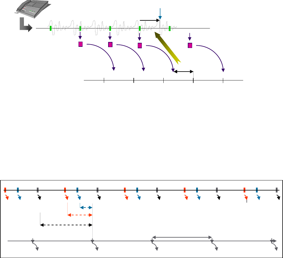
ETSI
ETSI TR 143 903 V8.3.0 (2009
-
02)
29
3GPP TR 43.903 version 8.3.0 Release 8
6.5.2 Time Alignment principles
In this sub-clause the Time Alignment (also referred further to as "TA") feature is described as it works for the UTRAN
Iu interface [14]. For GSM the same function is used but is internal to the BSS where the transcoder is located (see sub-
clause 6.2.1). If the transcoder is moved to the Core Network as being allowed for "A interface over IP" solutions, TA
information would need to be exchanged between the BSS and the CN.
For UTRAN the Time Alignment function is intended to align the phase of the MGW to that of the RNC to minimize
RNC queuing delay and memory resource utilization. The MGW combines speech samples into 20 ms frames and
compresses them by the AMR encoder. Compressed speech packets are sent to the RNC, which will in turn send them
downstream according to a fixed phase. Because MGW and RNC are not synchronized, RNC has to queue compressed
packets until the proper transmit time. Added queuing time/delay due to the phase mismatch can range from 0 up to 20
ms. The RNC measures the queuing delay and sends a TA request to the MGW for a phase adjustment based on the
measured queuing delay. The MGW adjusts the framing boundary to match the requested phase (see figure 6.5.2.1).
D
MGW TRAU
RNC
D
X
Figure 6.5.2.1 MGW phase matching
In figure 6.5.2.2 below, a, b and c represent different phases of arrival of packets (e.g. pertaining to different voice
channels) from the MGW to the RNC. The values da, db, and dc, represent the queuing delay due to arrival of the
phases a, b and c, respectively, as measured between the time of arrival of packet to the RNC and the time of
transmission from RNC. In the example below the phase of b is better than a, and a is better than c (due to lower delay).
The purpose of TA for the RNC is to request the appropriate phase shift (based on measured queuing delay) from the
MGW, in order to minimize the RNC queuing delay. TA also reduces the amount of time that RNC buffer resources are
allocated to a given channel. Since the transmission period is 20 ms, the alignment of arrival phase to transmission
phase can reduce the RNC queuing delay by up to 20 ms.
a
b
c
d
b
d
a
d
c
20 ms
RNC Arrival timeline
Transmit timeline
Figure 6.5.2.2 RNC Time Alignment
It should also be noted that in case of G.711 usage on A interface (voice transcoders in the BSS), Time Alignment
feature could avoid considering the 5 ms packetization and the drawbacks of the resulting overhead (four times the
20 ms packetization overhead due to multiple packet headers).
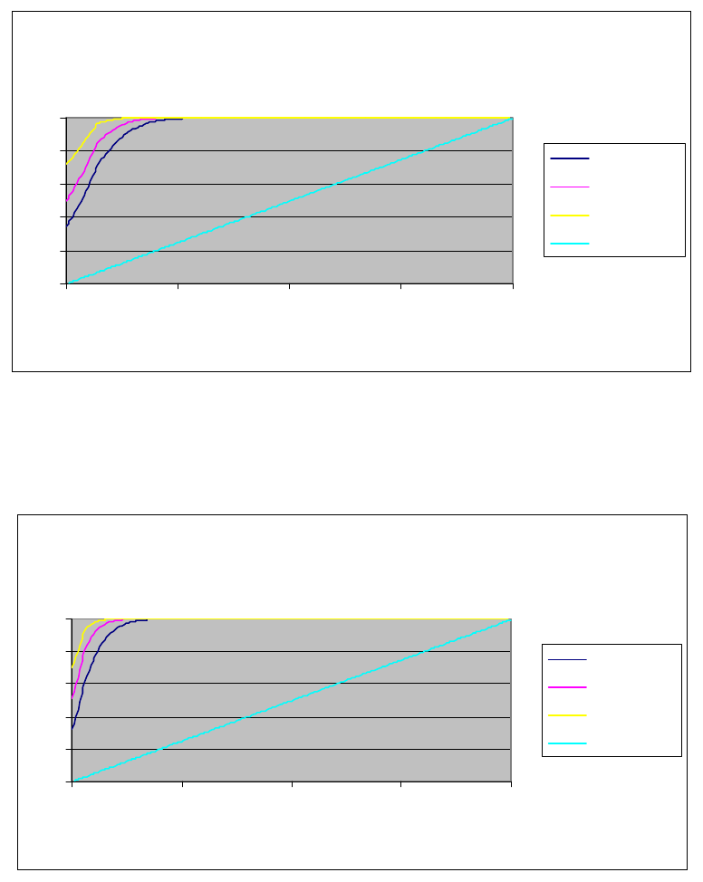
ETSI
ETSI TR 143 903 V8.3.0 (2009
-
02)
30
3GPP TR 43.903 version 8.3.0 Release 8
6.5.3 Time Alignment performances evaluation
The ability of Time Alignment to satisfy the optimal phase requested by the BSC (RNC) depends on the number of
channels processed on the same CPU, as well as the processor load; this is due to the fact that independent channels
processed on the same Media Gateway (MGW) CPU may have overlapping phase requirements. As such, the overlap of
optimal phase among channels sharing the same CPU will act to diminish TA effectiveness. A lower loading factor will
reduce the overlap, thereby increasing TA effectiveness. Also, a higher CPU channel capacity is likely to improve TA
effectiveness in a statistical sense, since a larger number of channels should allow for a better statistical spread of
optimal phases.
Given the considerations above, a set of results have been produced for different CPU capacities, and for different
loading factors in each case. More specifically, figures 6.5.3.1, 6.5.3.2 and 6.5.3.3 provide the cumulative delay
distribution for CPU channel capacities of 10, 20 and 40, respectively, representing different DSP device generations,
each at loading factors of 50%, 75% and 100%. For reference, in each case the cumulative delay distribution when TA
is not supported is also provided.
Cumulative delay distribution
(10 channels/processor)
0
0.2
0.4
0.6
0.8
1
0 50 100 150 200
x 0.1 ms
100 % load
75 % load
50 % load
No TA
Figure 6.5.3.1: Cumulative delay distribution for a CPU capacity of 10 channels
Cumulative delay distribution
(20 channels/processor)
0
0.2
0.4
0.6
0.8
1
0 50 100 150 200
x 0.1 ms
100 % load
75 % load
50 % load
No TA
Figure 6.5.3.2: Cumulative delay distribution for a CPU capacity of 20 channels
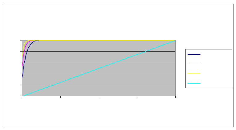
ETSI
ETSI TR 143 903 V8.3.0 (2009
-
02)
31
3GPP TR 43.903 version 8.3.0 Release 8
Cumulative delay distribution
(40 channels/processor)
0
0.2
0.4
0.6
0.8
1
0 50 100 150 200
x 0.1 ms
100 % load
75 % load
50 % load
No TA
Figure 6.5.3.3: Cumulative delay distribution for a CPU capacity of 40 channels
A number of observations are made with respect to figure 6.5.3.2, which can be taken to be representative of
contemporary CPU capacity:
- With TA, a CPU running at full load can eliminate queuing delay for over 30% of the calls. By contrast, without
TA the 30%-channel count with lowest queuing delays will still experience delays of up to about 7 ms.
- The percentage of calls experiencing no queuing delay with TA increases with reduced load, such that at 50%
load about 70% of calls will experience no queuing delay. Without TA, the 70%-channel count with lowest
queuing delays will have queuing delays up to about 14 ms.
- With TA, over 99% of the calls will experience queuing delay of less than 3 ms at full load. This delay figure is
reduced with reduced CPU load; at 50% load, over 99% of calls will have queuing delay of less than 2 ms.
Without TA, regardless off the CPU load, only 15% of calls will have queuing delay of 3 ms or less, and only
10% of calls will have queuing delay of 2 ms or less; all other calls will experience queuing delays of up to 20
ms.
Figure 6.5.3.3 shows that all of the performance figures cited above will further improve as more modern DSP devices
provide increased CPU capacity.
6.5.4 Proposed implementation
The following considerations should be kept in mind for deciding on a given implementation path:
- The feature should be optional in order to not constraint product implementation / usage in networks for which
the feature is not felt needed.
- The standardization effort should be kept as a minimum in order to avoid delaying the completion of the A over
IP work.
A possible implementation could be based on a simplified version of the UP (User Plane) protocol currently specified
for the Iu and Nb interfaces (see [14], [15]). This solution implements a request PDU, an acknowledgement PDU and a
timer providing the necessary means to support the TA feature (see figure 6.5.4.1).
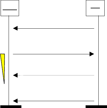
ETSI
ETSI TR 143 903 V8.3.0 (2009
-
02)
32
3GPP TR 43.903 version
8.3.0 Release 8
CN
BSS
TIME ALIGNMENT
ACK
User data with bad timing
User data with adjusted timing
Figure 6.5.4.1: Successful Time Alignment procedure
Should the receiving MGW be in "TrFO mode", it shall relay the TIME ALIGNMENT PDU transparently from the A
interface over IP protocol to Nb. Should the receiving MGW be transcoding to G.711, it may process the request or
respond with a negative acknowledgement indicating it either doesn't support the procedure or it is not prepared to
process the request at this time. Should the BSS receive a negative acknowledgement, it should wait some time before
trying again.
The UP protocol on the A interface is based on RTP/UDP/IP transport and uses an established RTP session for
transferring frames between the two RTP endpoints at both ends of the A interface User Plane access points. A single
PDU will be transported as RTP payload. Different PDU Types would allow differentiating between user data transport
(e.g. PDU Type 1 in [14]) and Time Alignment control (e.g. PDU Type 14 in [14]).
Other features that are part of Iu / Nb UP protocols and are not required for A over IP would not be ported to the A over
IP UP protocol. The support of the "transparent" mode of the UP protocol can be considered to avoid the transmission
of the UP header whenever the TA is not implemented / used.
This approach would:
- Avoid the need to update the various RFCs for different Codecs and narrow down the standardization work to
3GPP to prevent extra standardization delays.
- Limit the standardization effort as the UP protocol specification is already existing for Iu and Nb, and the UP
protocol for A over IP would consist in a be subset of the existing UP functions.
- Maintain design coherence between Iu, Nb and A over IP interfaces.
- Basically allows TA for being optional.
6.5.5 Summary
Time Alignment provides an enhancement of the end-to-end delay for A over IP. It would therefore provide additional
flexibility for the design and management of the delay budget in reducing the downlink delay by up to 20 ms for Land-
to-Mobile calls (see sub-clause 6.5.3).
Time Alignment is available for GSM solutions with the transcoders in the BSS (see [7] and [8]) and for UMTS on the
Iu and Nb interfaces (see [14] and [15], respectively). For GSM solutions with the transcoders in the Core Network,
porting the TA design elements into the definition of the new A over IP interface would avoid restricting the usage of
Time Alignment to established architectures only and would maintain the consistency of 3GPP-based networks
regarding the support of this feature.
A solution based on a simplified version of the UP protocol currently specified for the Iu and Nb interfaces would
stringently limit the required standardization effort to removing the features that are not required for A over IP.
Preserving the optional nature of TA support for A over IP solutions as provisioned by the original standard is felt
essential for enabling vendors and operators to take advantage of the feature, should they choose to do so, while not
enforcing extra implementation efforts wherever they are not felt needed.

ETSI
ETSI TR 143 903 V8.3.0 (2009
-
02)
33
3GPP TR 43.903 version 8.3.0 Release 8
However, no consensus to support TA for A over IP was expressed during the discussion.
The current working assumption is that a mechanism to provide Time Alignment is out of scope of a possible
Work Item introducing A-interface over IP.
7 Study Results, Control Plane
7.1 Control Plane Principles
Introducing IP as Transport Layer for the User Plane on the A-interface necessitates accommodations of the BSSMAP
and GCP signalling. The following items are identified and discussed in the following sub-sections:
1. Exchange of Transport Layer Information,
i.e. exchange of IP-Address plus UDP-Port-Number between BSS and MGW
2. Need for a Call Identifier for IP-based calls
3. Exchange of Codec Information,
i.e. BSS Capability and MSC Preference
4. Location of Transcoder Resources in BSS or CN
5. Exchange of RTP Parameters.
7.1.1 Exchange of Transport Layer Information
It is proposed that the A-interface User Plane connection between Core Network and BSS is dynamically established for
every call. Transport Layer information has to be exchanged between the MGW and the MSC-Server (hereafter "MSC")
via H.248 protocol and between the MSC and the BSS via BSSMAP.The following information is identified as
mandatory transport layer information:
- IP-Address
- UDP-Port-Number
The conceptual view of the exchange procedure between MGW and MSC and between MSC and BSC is shown in
figure 7.1.1.1.
BSC
MGW
MSC
H
.
248
BSSMAP
H
.
248
procedures
:
Reserve RTP Connection Point
/
Configure RTP Resources
Assignment Request
/
Assignment Complete
:
Exchange of transport layer information
A interface
user plane
Figure 7.1.1.1: Conceptual exchange of Transport Layer Information
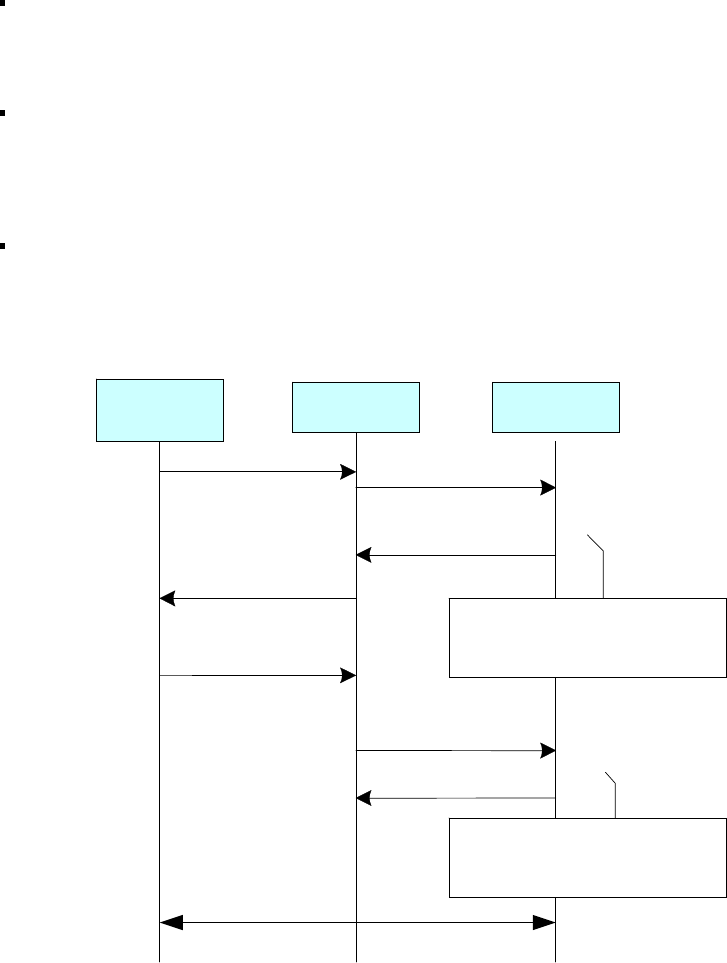
ETSI
ETSI TR 143 903 V8.3.0 (
2009
-
02)
34
3GPP TR 43.903 version 8.3.0 Release 8
After the MSC has received the Complete Layer 3 message and decided to use/offer AoIP for the call the following
signalling sequence is proposed:
The MSC sends an ADD.REQuest to the MGW to request the MGW to reserve the local IP Address and
UDP Port. The MGW reserves the A interface IP termination and indicates the local IP address and UDP
port number to the MSC in ADD.RESpond. That is done by using the existing H.248 procedure 'Reserve
RTP Connection Point'.
The MSC forwards the MGW IP address and UDP port information in the new AoIP Container to the BSS
using an enhanced BSSMAP Assignment Request message. The BSS performs channel assignment. As
part of the assignment procedure the Transport Layer information of the local connection end point inside
BSS is put into another AoIP Container, which is sent back to the MSC within the BSSMAP Assignment
Complete message.
The MSC passes the received BSS IP address and UDP port to the MGW by using the existing procedure
'Configure RTP Resources'.
Figure 7.1.1.2 shows a possible signalling sequence to exchange Transport Layer information between MGW and BSS.
Complete Layer
3
BSS
Add
.
Req
Add
.
Reply
(
T
$,
Reference point
:
A
(
oIP
)
,
local IP address
=
?,
port
=
?
)
MSC
MGW
(
T
1
,
IP address
,
port
)
Assignment Request
(
AoIP Container IE
{
MGW local IP
address and UDP port information
}
)
Assignment Comp
lete
(
AoIP Container IE
{
BSS local IP
address and UDP port information }
)
Mod
.Req
Mod
.Reply
(
T
1
,
remote IP address
,
port
)
(
T
1
)
H
.
248
Procedure
Reserve RTP Connection Point
+
Change RTP Through
-
connection
H
.
248
Procedure
Configure RTP Resources
+
Change RTP Through
-
connection
User plane is available for traffic
Figure 7.1.1.2: Exchange of Transport Layer Information via a new AoIP-Container
It is for further study whether to use an AoIP-Container or to use individual IEs for IP-Address and UDP-Port-Number.
The current working assumption is to use an AoIP-Container in BSSMAP.
7.1.2 Need for a Call Identifier for IP-based calls
In the legacy architecture, either the MSC or the BSC seizes a CIC (Circuit Identity Code). If the MSC seizes the CIC, it
sends it to the BSS at BSSMAP Assignment Request. The CIC identifies a physical connection to be used in the
transport layer. This identifier is also used as Call Identifier Code.
For the new AoIP standard there is need for a similar Call Identifier Code (named it here "Call Identifier"), by which an
IP-based call in MSC and BSC could be identified uniquely. This Call Identifier would be helpful in case the SCCP

ETSI
ETSI TR 143 903 V8.3.0 (2009
-
02)
35
3GPP TR 43.903 version 8.3.0 Release 8
connection between BSC and MSC gets lost and one side has to tell the other, by means of the RESET RESOURCE
message, which call has to be released. The Call Identifier would be especially helpful in A-flex (MSC in Pool), where
in an error case a list of calls may need to be cleared. The Call Identifier could be an IP-Version-independent (e.g. 32-
bit) number, or it could be the pair of (IP-address+UDP-port)s. The latter is -IP-Version-dependent and much longer.
Another way of clearing calls could be to rely on User Plane RTCP signalling. However, this would modify the current
behaviour based on explicit BSSMAP signalling.
The current working assumption is to use BSSMAP signalling (RESET RESOURCE and RESET RESOURCE
ACKNOWLEDGE) to release hanging IP-based calls. The Call Identifier is an IP-Version-independent 32-bit
number, defined on a per MSC basis. The Call Identifier is not used for TDM-based calls.
7.1.3 Exchange of Codec Information
G.711 is used as Codec Type on the A-interface User Plane, when TDM is used as bearer. Replacing the transport with
IP suggests a change of the Codec, because G.711 is not the most efficient Codec over IP. The 3GPP Codec Type that is
used on the air interface could be reused on the A-interface User Plane, when IP is used as bearer, without any loss in
quality. This is needed at least when TrFO operation is required. This also supports the option of moving transcoder
resources from BSS to the Core Network.
7.1.3.1 Exchange of Codec Information at Call Establishment
The codec information has to be exchanged between MGW and MSC via H.248 protocol and between MSC and the
user plane peer node in BSS via BSSMAP.
When the MSC reserves the (IP) termination in the MGW for the AoIP connection endpoint, the MSC provides also
Codec information to the MGW. It is proposed to reuse the mechanism applied for the termination reservation on Mb
and Nb (SIP-I) (i.e. Reserve RTP Connection Point procedure).
The Codec information is provided in H.248 interface as defined in 3GPP TS 29.332 and 3GPP TS 29.232. The Codec
Information passed to the MGW in termination reservation phase reflects the 'MSC-Preferred Codec Type and
Configuration', which has been determined by MSC after performing the codec negotiation with the remote side MSC.
After MSC has reserved the (IP) termination, it constructs the MSC Preferred Codec List (MSC-PCL) and initiates the
codec negotiation towards BSS. The MSC sends the Codec information (i.e. MSC-PCL) towards the BSS within the
BSSMAP Assignment Request message. The MSC-PCL contains the MSC Preferred Codec Type, but also other,
alternative Codec Types. The current Information Element defined for AoTDM should be replaced, because in addition
to the Codec Type also Codec Configuration information should be sent in case of AMR and AMR-WB Codec Types.
Therefore a new Information Element (called "MSC-PCL", MSC preferred Codec List IE) is defined for transporting
this Codec information to the BSS. The MSC-PCL is a prioritized list of all Codecs offered to BSS for channel
assignment. The MSC-Preferred Codec Type is the first one in the MSC-PCL. It matches the Selected Codec (SC)
within the Core Network in the best possible way. This MSC-PCL replaces the existing information (permitted speech
version identifier, also called Speech Coder Version List, SCVL) coded within Channel Type IE octets 5, 5a, 5b and
afterwards.
In addition the new MSC-PCL contains also information on transcoder resource location and interface type.
The BSS has in principle the freedom to select any Codec Type from the received MSC-PCL. The BSS is not mandated
to select the MSC-Preferred Codec Type, but it should do so whenever possible. BSS internal algorithms may result in
rare cases in the selection of another Codec Type from the MSC-PCL. Therefore the BSS provides information about
the finally chosen Codec ("Speech Version (chosen)") within the BSSMAP Assignment Complete message. If the
chosen Codec is different to the MSC-Preferred Codec Type, already selected within the MGW, then the MSC has to
MODify the MGW termination with the new Codec information.
NOTE 1: Also the information element 'Speech Version (chosen)' should be enhanced to include the chosen Codec
Configuration for AMR and AMR-WB Codec Types. It is proposed to introduce a new Information
Element "Speech Codec (chosen)" for that purpose.
In order to reduce the number of case, when the BSS has to select a Codec Type different from the Codec Type
prioritized by the MSC, the BSS informs the MSC for each call about the availability of resources to support different
3GPP Codec Types. This information has to be provided before
the MSC starts the end-to-end Codec Negotiation.
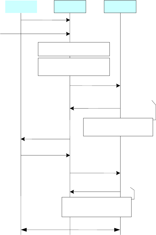
ETSI
ETSI TR 143 903 V8.3.0 (2009
-
02)
36
3GPP TR 43.903 version 8.3.0 Release 8
One proposal is to use a "per call" approach by introducing a new Information Element "BSC-SCL" (BSC Supported
Codec List), which the BSC appends the BSC-SCL to the BSSMAP Complete Layer 3 Information message. If MSC
detects that this new BSC-SCL is related to a speech call, then it uses this information for end-to-end Codec negotiation
and for Codec pre-selection for the RAN interface. In case MSC receives the information for any other transaction (for
example MSC receives BSC-SCL for a data call), it is proposed to store this BSC-SCL in case a subsequent speech call
is triggered afterwards, where the stored BSC-SCL can be used for this speech call's Codec negotiation.
Complete Layer
3
Add
.Req
Add
.Reply
(
T
$,
Reference point
:
A
(
oIP
)
,
IP address
=
?,
port
=
?,
pCodec
*
,
RTP PT
)
MSC
MGW
(
T
1
,
IP address
,
port
)
Assignment Request
(
AoIP Container IE
,
MSS
-
PCL IE
)
Assignment Complete
(
AoIP Container IE
,
Speech Codec
(
chosen
)
IE
)
Mod
.Req
Mod
.
Reply
(
T1)
H
.
248
Procedure
Reserve RTP Connection Point
+
Change RTP Through
-
connection
H
.
248
Procedure
Configure RTP Resources
+
Change RTP Through
-
connection
User plane is available for traffic
BSC
-
SCL
Complete L
ayer
3
DTAP
,
SETUP
(
MS
-
SCL
)
MSS determines the “MSS
Preferred Codec Type
and Configuration”
.
BSC
(
T
1
,
remote IP address
,
port
,
(
codec
**
,
RTP PT
)
MSS performs the
(
OoBTC
)
codec
negotiation with
terminating side
.
* pCodec = MSC Preferred Codec type
** Codec = Speech Codec (chosen), indicated to MGW if the chosen Codec is different to the MSC-Preferred Codec
Type.
Figure 7.1.3.1.1: Exchange of Codec Information 'per call'
Another proposal is to provide BSC-SCL information for the whole BSS area (all Codec Types in all cells) in one or
more messages in a periodical or on-demand manner. In these messages the BSS could report all its Codec capabilities
or only the Codec capabilities it wants to dynamically communicate to the MSC. It would be up to BSS implementation
and operators' deployment strategy (by O&M setting) to decide which of the actual Codec capabilities should be
reported. The MSC would have to store the whole list of BSC-SCLs until a new update is available. The BSC-SCL
information could be sent by reusing and slightly expanding the existing two BSSAP messages RESOURCE
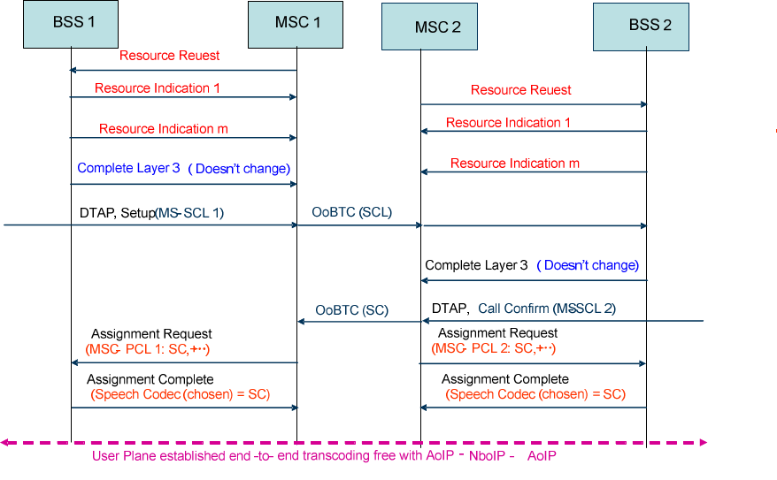
ETSI
ETSI TR 143 903 V8.3.0 (2009
-
02)
37
3GPP TR 43.903 version 8.3.0 Release 8
REQUEST/RESOURCE INDICATION pair (see TS 48.008) on a cell basis. The overall architecture and signalling are
shown in figure 7.1.3.1.1.
…
…
Figure 7.1.3.1.2: BSC-SCL information exchange "per whole BSS"
NOTE 2: If there is concern that the stored BSC-SCL can be outdated for a subsequent speech call, an optional 'pull
BSC-SCL' procedure can be implemented to fetch the up to date Codec capabilities of the BSC whenever
needed.
EXAMPLE: The BSS decided to prohibit the usage of full rate channels due to high load in the served cell. In
that case the BSS indicates within the BSC-SCL to MSC that only half rate Codec Types are
allowed.
The current working assumption is to transmit the BSC-SCL per call.
NOTE 3: The default Codec Type GSM-FR shall never be excluded by the BSS in the BSC-SCL, but it will be
used only in very rare cases, e.g. when the MS does not support any other Codec Type.
7.1.3.2 Exchange of Codec Information at Handover
In the (traffic channel) handover procedure the BSSMAP Complete Layer 3 message is not always exchanged. The
MSC does therefore not always receive the Codec resource information (BSC-SCL) of the new, target BSS before it
requests channel assignment in the BSSMAP Handover Request.
In these cases the MSC has to guess what the target BSS supports. It can be shown, that this is not a serious drawback.
The best an MSC can do - in every handover situation - is to offer a Codec Type that is compatible to the already fixed
SC in the Core Network as Preferred BSS Codec Type. If this Codec is accepted by the target BSC, then the optimal
Codec combination is reached for this handover case. If this Codec is not accepted by the target BSC, then there are
good reasons and the early knowledge of the BSC-SCL could not change these.
The MSC does in general also not know, which Interface Types (AoIP and/or AoTDM) the target BSS supports for this
handover event. Consider that an Interface Type may not be provided at all, or it could be temporarily unavailable, e.g.
due to overload or failure. Therefore both Interface Types may be offered in the MSC-PCL. Alternatively the MSC
could use a 'pull BSC-SCL' procedure to get the most updated target BSC-SCL to construct the MSC-PCL for the
BSSMAP Handover Request message. This is, however, slower and needs more signalling on the A-Interface and has
no obvious strong advantage.
The current working assumption is that it shall be possible for the CN to offer both, AoIP and AoTDM, Interface
Types in parallel, if the MSC has no other information to decide the Interface Type. But offering two

ETSI
ETSI TR 143 903 V8.3.0 (2009
-
02)
38
3GPP TR 43.903 version 8.3.0 Release 8
termination types will not be mandatory. In this case, if the interface type chosen by the MSC cannot be
supported – for that call - by the target BSS, a new reject cause (e.g. "interface not available") shall be used, so
that the CN can issue a new request using the other interface type.
The new, target BSC may provide its BSC-SCL in the BSSMAP Handover Request Acknowledge message or in the
BSSMAP Handover Failure message. The MSC may use this information for the potential, optional subsequent Codec
Re-Negotiation procedures within the Core Network or to initiate a new channel assignment request in case the first
channel assignment request failed (rare case).
7.1.4 Location of Transcoder Resource in BSS or CN
The proposed new Information Elements (BSC-SCL and MSC-PCL) provide flexible means to negotiate and select the
location of the transcoder resource, if needed, either within the BSS or within the Core Network. By flexible setting
different bits within the BSC-SCL, the BSC can indicate to the MSC for each Codec Type, whether the BSS has the
transcoder resource or not. The MSC can indicate by setting the corresponding bits within the MSC-PCL, whether it
requests the BSS to support the transcoding to PCM or whether the BSS shall not perform transcoding.
In this way the existing transcoder resources of a legacy BSS can be efficiently reused after the upgrade to AoIP.
Existing transcoder pools within the BSS for a specific Codec Type can be expanded within the MGW for growing
traffic demands.
7.1.5 Exchange of RTP Parameters
The IETF-standardized RTP Profiles for 3GPP Codecs offer quite some flexibility.
Examples are: Payload Type, Redundancy, Packetization Time, etc.
These RTP Parameters must be either pre-defined per 3GPP- standardization (simplest, but least flexible solution) or the
exchange of these RTP Parameters must be defined.
The current working assumptions are:
pre-defined fixed RTP Payload Type per Codec shall be used,
pre-defined fixed RTP parameters per Codec shall be used:
no redundancy shall be used, one RTP packet shall include only one speech or SID frame
it shall be possible to use Redundancy for CS data services.
Some CSD services, especially fax, are sensitive to data loss. For those CSD services without re-transmisson scheme in
the application layer (e.g. fax), the loss of data blocks will cause distortion in the transmitted data or maybe even the
failure of the service. Although IP is an effective transportation bearer, it does have some inherent flaws and packet loss
is one of them. When transport link quality is not so stable (e.g. ADSL, microwave relay, etc.) or when there is
congestion, the loss of packets is almost unavoidable. Because data redundancy will reduce the data loss rate caused by
packet lost, it will improve the successful rate of CSD services for AoIP.
For data redundancy, several successive data blocks are packed into one RTP packet, just as shown in Fig.1 and Fig.2.
The number of successive data blocks in an RTP packet is defined as Redundancy Level. Redundancy Level 1 denotes
the transmission without redundancy. The redundancy level is 2 in Fig.1, where altogether 5 (n) data blocks are
transferred in 6 (n+1) RTP packets with a substantially increased payload size (n*2+2). The redundancy level is 3 in
Fig.2, where altogether 4 (m) data blocks are transferred in six RTP packets (m+2) and substantially increased payload
size (m*3+2).
For redundancy level 1, if one RTP packet is lost, one data block is lost, too. The delay is at its minimum. For
redundancy level 2, if one RTP packet is lost, no data block will be lost. The delay at receiver side is increased by the
need to wait for one more RTP packet. For redundancy level 3, if two successive RTP packets are lost, no data blocks
will be lost. The delay at receiver side is increased by the need to wait for two more RTP packets.
The format of the payload in the RTP packet that contains redundant data blocks could use the format defined in
RFC2198. In order to protect the head data block and tail data block, dummy data blocks are inserted. The inserted
dummy data blocks eliminate the extra delay at sender side otherwise caused by data redundancy. The idle frame could
be used as dummy data block. The dummy data blocks do not eliminate the delay at receiver side, if the receiver decides
to deploy the redundancy. Redundancy increases the bandwidth demand substantially and the number of RTP packets
and the transmission delay noticeably. A change of the redundancy level during a call causes a jump of the delay in the
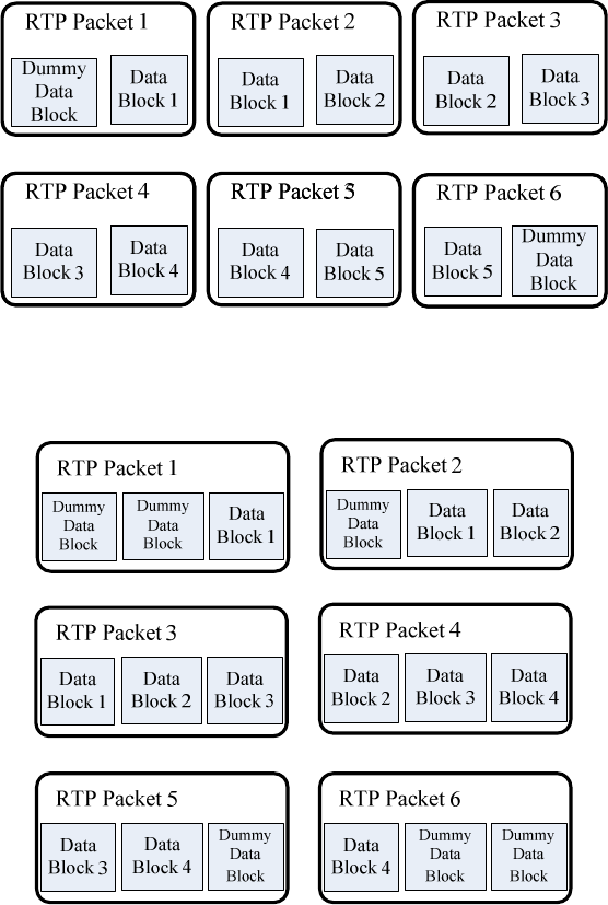
ETSI
ETSI TR 143 903 V8.3.0 (2009
-
02)
39
3GPP TR 43.903 version 8.3.0 Release 8
data path and therefore (most likely) a loss or distortion of data. Redundancy and the change of the redundancy level
shall therefore be use with care – if at all.
Redundancy is always used symmetrically, i.e. the same redundancy level is used in both directions across the A-
Interface.
Fig.1 Redundant Packet with redundancy level = 2
Fig.2 Redundant Packet with redundancy level = 3
In general, the redundancy level of the RTP packet transferred on the A-interface should be negotiable at Assignment
Request and/or Handover Request. It should be finally determined by the BSS according to the wire (IP) link quality
and the bandwidth resource. For bad IP link quality, where the disturbance is fairly high, the redundancy level should be
a little higher; while for lack of bandwidth resource, the redundancy level could be adjusted to a lower value to reduce
the bandwidth cost.

ETSI
ETSI TR 143 903 V8.3.0 (2009
-
02)
40
3GPP TR 43.903 version 8.3.0 Release 8
7.2 Signalling Messages
In this section some examples are provided showing how the relevant signalling messages and Information Elements
could look like.
7.2.1 BSSMAP
7.2.1.1 Assignment Request
INFORMATION ELEMENT REFERENCE / Description DIRECTION TYPE LEN
Message Type 48.008 Section 3.2.2.1 MSC-BSS M 1
Channel Type 48.008 Section 3.2.2.11 MSC-BSS M 5-10
Layer 3 Header Information 48.008 Section 3.2.2.9 MSC-BSS O (note 3) 4
Priority 48.008 Section 3.2.2.18 MSC-BSS O 3
Circuit Identity Code 48.008 Section 3.2.2.2 MSC-BSS O (note 1) 3
Downlink DTX Flag 48.008 Section 3.2.2.26 MSC-BSS O (note 2) 2
Interference Band To Be
Used
48.008 Section 3.2.2.21 MSC-BSS O 2
Classmark Information 2 48.008 Section 3.2.2.19 MSC-BSS O (note 4) 4-5
Group Call Reference 48.008 Section 3.2.2.55 MSC-BSS O (note 5) 7
Talker Flag 48.008 Section 3.2.2.54 MSC-BSS O (note 6) 1
Configuration Evolution
Indication
48.008 Section 3.2.2.57 MSC-BSS O (note 7) 2
LSA Access Control
Suppression
48.008 Section 3.2.2.61 MSC-BSS O (note 8) 2
Service Handover 48.008 Section 3.2.2.75 MSC-BSS O (note 9) 3
Encryption Information 48.008 Section 3.2.2.10 MSC-BSS O (note 10) 3-n
Talker Priority 48.008 Section 3.2.2.89 MSC-BSS O (note 11) 2
AoIP Container (MGW) The container information is
exchanged between MSC and BSS.
MSC-BSS C
MSC Preferred Codec List
(MSC-PCL)
List of Codec Types,
eligible at channel assignment,
ordered by MSC preference
MSC-BSS C
Call Identifier Defined on a per MSC basis and only
used for IP-based calls
MSC-BSS C
7.2.1.2 Assignment Complete
INFORMATION ELEMENT REFERENCE / Description DIRECTION TYPE LEN
Message Type 48.008 Section 3.2.2.1 BSS-MSC M 1
RR Cause 48.008 Section 3.2.2.22 BSS-MSC O 2
Circuit Identity Code 48.008 Section 3.2.2.2 BSS-MSC O (note 4) 3
Cell Identifier 48.008 Section 3.2.2.17 BSS-MSC O (note 1) 3-10
Chosen Channel 48.008 Section 3.2.2.33 BSS-MSC O (note 3) 2
Chosen Encryption Algorithm 48.008 Section 3.2.2.44 BSS-MSC O (note 5) 2
Circuit Pool 48.008 Section 3.2.2.45 BSS-MSC O (note 2) 2
Speech Version (Chosen) 48.008 Section 3.2.2.51 BSS-MSC O (note 6) 2
LSA Identifier 48.008 Section 3.2.2.15 BSS-MSC O (note 7) 5
Talker Priority 48.008 Section 3.2.2.89 BSS-MSC O (note 8) 2
AoIP Container (BSS) The information is exchanged
between MSC and BSS.
BSS-MSC C x
Speech Codec (chosen) Enhanced "Speech Version
(chosen)", including information on:
- Configuration (AMR/AMR-WB);
- Transcoder resource location;
- Interface Type.
BSS-MSC C x

ETSI
ETSI TR 143 903 V8.3.0 (2009
-
02)
41
3GPP T
R 43.903 version 8.3.0 Release 8
7.2.1.3 Handover Required
INFORMATION ELEMENT REFERENCE/ Description DIRECTION TYPE LEN
Message Type 48.008 Section 3.2.2.1 BSS-MSC M 1
Cause 48.008 Section 3.2.2.5 BSS-MSC M 3-4
Response Request 48.008 Section 3.2.2.28 BSS-MSC O (note 8) 1
Cell Identifier List
(Preferred)
48.008 Section 3.2.2.27 BSS-MSC M (note 4) 2n+3
to
7n+3
Circuit Pool List 48.008 Section 3.2.2.46 BSS-MSC O (note 1) V
Current Channel Type 1 48.008 Section 3.2.2.49 BSS-MSC O (note 2) 2
Speech Version (Used)
48.008 Section 3.2.2.51 BSS-MSC O (note 3) 2
Queueing Indicator 48.008 Section 3.2.2.50 BSS-MSC O 2
Old BSS to New BSS
Information
48.008 Section 3.2.2.58 BSS-MSC O 2-n
Source RNC to target RNC
transparent information
(UMTS)
48.008 Section 3.2.2.76 BSS-MSC O (note 5) 3-m
Source RNC to target RNC
transparent information
(cdma2000)
48.008 Section 3.2.2.77 BSS-MSC O (note 6) n-m
GERAN Classmark 48.008 Section 3.2.2.78 BSS-MSC O (note 7) V
Talker Priority 48.008 Section 3.2.2.89 BSS-MSC O (note 9) 2
BSC Supported Codec List
(BSC-SCL)
List of Codec Types, Codec
Configurations, Transcoder Resource
Locations and Interface Types
supported by the BSS
in this very moment
BSS-MSC O
Speech Codec (Used) Enhanced "Speech Version (used)",
including information on:
- Configuration (AMR/AMR-WB);
- Transcoder resource location;
- Interface Type.
BSS-MSC C x

ETSI
ETSI TR 143 903 V8.3.0 (2009
-
02)
42
3GPP TR 43.903 version 8.3.0 Release 8
7.2.1.4 Handover Request
INFORMATION ELEMENT REFERENCE / Description DIRECTION TYPE LEN
Message Type 48.008 Section 3.2.2.1 MSC-BSS M 1
Channel Type 48.008 Section 3.2.2.11 MSC-BSS M 5-10
Encryption Information 48.008 Section 3.2.2.10 MSC-BSS M (note 1) 3-n
Classmark Information 1
or
Classmark Information 2
48.008 Section 3.2.2.30 48.008
Section 3.2.2.19
MSC-BSS
MSC-BSS
M#
M (note 6)
2
4-5
Cell Identifier (Serving) 48.008 Section 3.2.2.17 MSC-BSS M (note 20) 5-10
Priority 48.008 Section 3.2.2.18 MSC-BSS O 3
Circuit Identity Code 48.008 Section 3.2.2.2 MSC-BSS O (note 7) 3
Downlink DTX Flag 48.008 Section 3.2.2.26 MSC-BSS O (note 3) 2
Cell Identifier (Target) 48.008 Section 3.2.2.17 MSC-BSS M (note 17) 3-10
Interference Band To Be
Used
48.008 Section 3.2.2.21 MSC-BSS O 2
Cause 48.008 Section 3.2.2.5 MSC-BSS O (note 9) 3-4
Classmark Information 3 48.008 Section 3.2.2.20 MSC-BSS O (note 4) 3-14
Current Channel type 1 48.008 Section 3.2.2.49 MSC-BSS O (note 8) 2
Speech Version (Used) 48.008 Section 3.2.2.51 MSC-BSS O (note 10) 2
Group Call Reference 48.008 Section 3.2.2.55 MSC-BSS O (note 5) 7
Talker Flag 48.008 Section 3.2.2.54 MSC-BSS O (note 11) 1
Configuration Evolution
Indication
48.008 Section 3.2.2.57 MSC-BSS O (note 12) 2
Chosen Encryption Algorithm
(Serving)
48.008 Section 3.2.2.44 MSC-BSS O (note 2) 2
Old BSS to New BSS
Information
48.008 Section 3.2.2.58 MSC-BSS O (note 13) 2-n
LSA Information 48.008 Section 3.2.2.23 MSC-BSS O (note 14) 3+4n
LSA Access Control
Suppression
48.008 Section 3.2.2.61 MSC-BSS O (note 15) 2
Service Handover 48.008 Section 3.2.2.75 MSC-BSS O (note 21) 3
IMSI 48.008 Section 3.2.2.6 MSC-BSC O (note 16) 3-10
Source RNC to target RNC
transparent information
(UMTS)
48.008 Section 3.2.2.76 MSC-BSS O (note 18) n-m
Source RNC to target RNC
transparent information
(cdma2000)
48.008 Section 3.2.2.77 MSC-BSS O (note 19) n-m
SNA Access Information 48.008 Section 3.2.2.82 MSC-BSC O (note 22) 2+n
Talker Priority 48.008 Section 3.2.2.89 MSC-BSC O (note 23) 2
AoIP Container (MGW) The container information is
exchanged between MSC and BSS.
MSC-BSS C
MSC Preferred Codec List
(MSC-PCL)
List of Codec Types, Codec
Configurations, Transcoder Resource
Locations and Interface Types
supported by the CN
in this very moment for channel
assignment, ordered by MSC
preference.
MSC-BSS C
Call Identifier Defined on a per MSC basis and only
used for IP-based calls
MSC-BSS C

ETSI
ETSI TR
143 903 V8.3.0 (2009
-
02)
43
3GPP TR 43.903 version 8.3.0 Release 8
7.2.1.5 Handover Request Acknowledge
INFORMATION ELEMENT REFERENCE / Description DIRECTION TYPE LEN
Message Type 48.008 Section 3.2.2.1 BSS-MSC M 1
Layer 3 Information 48.008 Section 3.2.2.24 BSS-MSC M (note 1) 11-n
Chosen Channel 48.008 Section 3.2.2.33 BSS-MSC O (note 4) 2
Chosen Encryption Algorithm 48.008 Section 3.2.2.44 BSS-MSC O (note 5) 2
Circuit Pool 48.008 Section 3.2.2.45 BSS-MSC O (note 2) 2
Speech Version (Chosen) 48.008 Section 3.2.2.51 BSS-MSC O (note 6) 2
Circuit Identity Code 48.008 Section 3.2.2.2 BSS-MSC O (note 3) 3
LSA Identifier 48.008 Section 3.2.2.15 BSS-MSC O (note 7) 5
New BSS to Old BSS
Information
48.008 Section 3.2.2.80 BSS-MSC O (note 8) 2-n
Inter-System Information 48.008 Section 3.2.2.81 BSS-MSC O (note 9) 2-n
Talker Priority 48.008 Section 3.2.2.89 BSS-MSC O (note 10) 2
AoIP Container (BSS) The container information is exchanged
between MSC and BSS.
BSS-MSC C
BSC Supported Codec List
(BSC-SCL)
List of Codec Types, Codec
Configurations, Transcoder Resource
Locations and Interface Types supported
by the BSS in this very moment
BSS-MSC O
Speech Codec (Chosen) Enhanced "Speech Version (used)",
including information on:
- Configuration (AMR/AMR-WB);
- Transcoder resource location;
- Interface Type.
BSS-MSC C
7.2.1.6 Handover Performed
INFORMATION ELEMENT REFERENCE DIRECTION TYPE LEN
Message Type 48.008 Section 3.2.2.1 BSS-MSC M 1
Cause 48.008 Section 3.2.2.5 BSS-MSC M 3-4
Cell Identifier 48.008 Section 3.2.2.17 BSS-MSC M (note 5) 3-10
Chosen Channel 48.008 Section 3.2.2.33 BSS-MSC O (note 1) 2
Chosen Encryption Algorithm 48.008 Section 3.2.2.44 BSS-MSC O (note 2) 2
Speech Version (Chosen) 48.008 Section 3.2.2.51 BSS-MSC O (note 3) 2
LSA Identifier 48.008 Section 3.2.2.15 BSS-MSC O (note 4) 5
Talker Priority 48.008 Section 3.2.2.89 BSS-MSC O (note 6) 2
BSC Supported Codec List
(BSC-SCL)
List of Codec Types, Codec
Configurations, Transcoder Resource
Locations and Interface Types supported
by the BSS in this very moment
BSS-MSC O
Speech Codec (Chosen) Enhanced "Speech Version (Chosen)",
including information on:
- Configuration (AMR/AMR-WB);
- Transcoder resource location;
- Interface Type.
BSS-MSC C x

ETSI
ETSI TR 143 903 V8.3.0 (2009
-
02)
44
3GPP TR 43.903 version 8.3.0 Release 8
7.2.1.7 Complete Layer 3 Information
INFORMATION ELEMENT REFERENCE DIRECTION TYPE LEN
Message Type 48.008 Section 3.2.2.1 BSS-MSC M 1
Cell Identifier 48.008 Section 3.2.2.17 BSS-MSC M 3-10
Layer 3 Information 48.008 Section 3.2.2.24 BSS-MSC M 3-n
Chosen Channel 48.008 Section 3.2.2.33 BSS-MSC O (note 1) 2
LSA Identifier List 48.008 Section 3.2.2.16 BSS-MSC O (note 2) 3+3n
PADU 48.008 Section 3.2.2.68 BSS-MSC O (note 3) 3-n
BSC Supported Codec List
(BSC-SCL)
List of Codec Types, Codec
Configurations, Transcoder Resource
Locations and Interface Types
supported by the BSS in this very
moment
BSS-MSC O
7.2.1.8 BSC-SCL and MSC-PCL
# Comments Coding
mandatory
or optional
1 IE-Identifier "BSC-SCL" or "MSC-SCL" mandatory
2 Length "Length of IE after length byte" = 11 mandatory
3 1. Codec Full IP TFO PCMoIP
PCMoTDM
"FR" =0000 mandatory
in BSC-
SCL
4 2. Codec Full IP TFO PCMoIP
PCMoTDM
"HR" =0001 optional
5 3. Codec Full IP TFO PCMoIP
PCMoTDM
"EFR" =0010 optional
6 4. Codec Full IP TFO PCMoIP
PCMoTDM
"FR_AMR" =0011 optional
7 Configuration set7 set6 set5 set4 set3 set2 set1 set0 conditional
8 Configuration set15 set14 set13 set12 set11 set10 set9 set8 conditional
9 5. Codec Full IP TFO PCMoIP
PCMoTDM
"HR_AMR" =0100 optional
10 Configuration set7 set6 set5 set4 set3 set2 set1 set0 conditional
11 Configuration set15 set14 set13 set12 set11 set10 set9 set8 conditional
12 6. Codec Full IP TFO PCMoIP
PCMoTDM
"FR_AMR-WB" =1001 optional
13 Configuration - - set5 set4 set3 set2 set1 set0 conditional
NOTE 1: The coding of Codec Types (FR, HR, …) is according to TS 26.103 [9] and TS 28.062 [16].
NOTE 2: The coding of AMR Configurations with set 0 to set 15 is used in TS 28.062 [16] (TFO).
Alternatively the AMR Configurations could be coded according to TS 26.103[9]:
1 Codec Full IP TFO
PCMoIP
PCMoTDM
"FR_AMR" mandatory
2 ACS 12.2 10.2
7.95 7.4 6.7 5.9 5.15 4.75 conditional
3 SCS 12.2 10.2
7.95 7.4 6.7 5.9 5.15 4.75 conditional
4 OM, MACS - - - - OM MACS

ETSI
ETSI TR 143 903 V8.3.0 (2009
-
02)
45
3GPP TR 43.903 version 8.3.0 Release 8
Each AMR Mode could be included or excluded by marking the corresponding bit. In this representation "set 1" would
be:
1 Codec Full IP TFO
PCMoIP
PCMoTDM
"FR_AMR" mandatory
2 ACS 1 0 0 1 0 1 0 1 conditional
3 SCS 1 0 0 1 0 1 0 1 conditional
4 OM, MACS - - - - 0 4
A mapping between both representations is possible. This alternative coding is used in OoBTC on Nc. It needs more
octets per AMR Codec. It allows more flexibility, but has the substantial drawback of higher risk of end-to-end
incompatibility, higher implementation and verification effort.
It is current working assumption to use set 0 to set 15 on AoIP.
7.2.1.9 Speech Codec (Chosen)
# Comments Coding
mandatory
or optional
1 IE-Identifier " Speech Codec (chosen)" mandatory
2 Length "Length of IE after length byte" = 1, 2, 3 mandatory
3 Codec Full IP TFO
PCMoIP
PCMoTDM
"Codec Chosen" mandatory
(4) Configuration Set set set set set set set set conditional
(5) Configuration Set set set set set set set set conditional
NOTE: The coding of "Codec Chosen" is according to TS 26.103 [9], i.e. the same as in e.g. BSC-SCL.
7.2.1.10 Speech Codec (Used)
# Comments Coding
mandatory
or optional
1 IE-Identifier " Speech Codec (Used)" mandatory
2 Length "Length of IE after length byte" = 1, 2, 3 mandatory
3 Codec Full IP TFO
PCMoIP
PCMoTDM
"Codec Used" mandatory
(4) Configuration Set set set set set set set set conditional
(5) Configuration Set set set set set set set set conditional
NOTE: The coding of "Codec Used" is according to TS 26.103 [9], i.e. the same as in e.g. BSC-SCL.
7.2.1.11 Circuit Switched Data Codec (CSD Dummy Codec)
In order to support a flexible migration from fax and data via 64k TDM lines to fax and date via IP, considering the
redundancy for better packet loss resilience, it is proposed to define a 'CSD Dummy Codec' for the BSC-SCL, the
MSC-PCL, the 'Speech Codec (used)' and 'Speech Codec (chosen)' and the 'Speech Codec (MSC Chosen)'. This CSD
Dummy Codec is handled formally like any other (Speech) Codec in the call setup and handover negotiations.
The direct code-space for Speech Codecs has only 15 entries. But this CSD Dummy Codec is not a Speech Codec and is
used comparably rare and so a somewhat less efficient coding is allowed. It is therefore proposed that the coding for the
Dummy Codec is using an 'extension' mechanism (similar to TS 28.062): the Code-Point '0xF' indicates that in fact the
next octet in the IE contains the real 8-bit Code-Point for the Codec. The code-point for this Fax and Data 'CSD
Dummy Codec' should be 'registered' in TS 26.103. There are already two other Dummy Codecs defined for Multi-

ETSI
ETSI TR 143 903 V8.3.0 (2009
-
02)
46
3GPP TR 43.903 version 8.3.0 Release 8
Media Applications. They have Code-Values 0xFF and 0xFE, so the proposed value 0xFD for Circuit Switched Data
Codec is the next choice, counting downwards.
As discussed in chapter 6 it is necessary to differentiate two A-Interface Types for Fax and Data calls (the alternative 2,
i.e. 16kbps, is not included in the working assumptions):
- 64k over legacy TDM lines
- 64k over IP using RFC 4040.
Two bits are reserved to flag these A-Interface Types.
As discussed in chapter 6, redundancy should be an option. The redundancy field contains two flags (R2, R3) indicating
the support of the Redundancy Level 2 (optional) and 3 (optional), while support of Redundancy Level 1 is mandatory..
The redundancy levels are not depending on each other, it is for example allowed to support redundancy level 1 and 3
without supporting redundancy level 2.
# Comments Coding
mandatory
or optional
1 IE-
Identifier
Speech Codec mandatory
2 Length "Length of IE after length byte" mandatory
3 Codec spare
64koIP
64koTDM spare
"Codec Extension" = 0xF
mandatory
4 Codec
'Extended Codec Type(CS Data)' = 0xFD
mandatory
5 Redundancy
level
R2 R3 spare (6 bits) mandatory
Note 1: In BSC-SCL and MSC-PCL more than one of these A-Interface Types and redundancy options may be flagged
to allow an open negotiation and to restrict the negotiation as far as necessary. But in 'Speech Codec (Used)', 'Speech
Codec (Chosen)' and 'Speech Codec (MSC Chosen)'exactly one A-Interface Type and one redundancy option shall be
specified. Redundancy Level 1 is specified by flagging neither R2 nor R3.
Note 2: the existing 'Channel Type' IE contains all the other parameters for fax and data calls. This Channel Type IE
and the CSD Dummy Codec shall contain consistent data.
Note 3: Redundancy Level is – of course – not defined for the legacy A-Interface (64koTDM).
7.2.2 DTAP
Modifications of DTAP are not allowed to maintain compatibility with existing mobiles.
7.2.3 VGCS/VBS Protocol
VGCS/VBS messages are to be investigated if the BSC Codec List has to be added.
7.2.4 H.248 Protocol
Void.
7.3 Procedures
7.3.1 Codec Negotiation at Call Setup
An optimal end-to-end Codec Negotiation shall be performed for each individual call to achieve best quality of service,
considering the Codec capabilities of the MS, the BSS as well as the CN and the distant end.
Figure 7.3.1.1a shows an example MS-to-MS call, with end-to-end Codec negotiation at call setup.
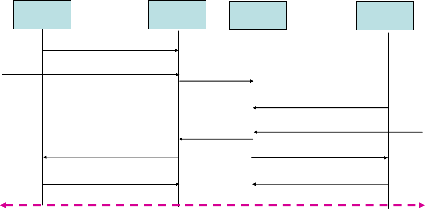
ETSI
ETSI TR 143 903 V8.3.0 (2009
-
02)
47
3GPP TR 43.903 version 8.3.0 Release 8
BSC1 sends to MSC1 its actual "BSC Supported Codec List" (BSC-SCL1) in the first Complete Layer 3 Message that
encapsulates the DTAP CM SERVICE REQUEST message from MS1. BSC1 shall predict to its best possible
knowledge at this point in time for this specific call, which Codec Types, Configurations and Interface Types could be
used in this specific cell area. BSC1 shall not include Codec Types in this BSC-SCL1 that are currently not available.
The Codec capabilities of MS1 (MS-SCL1) are received in MSC1 in DTAP SETUP, which includes also other call set
up details. Upon receiving SETUP, MSC1 shall construct the SCL taking into consideration MS-SCL1, BSC-SCL1 as
well as MGW1 capabilities. MSC1 then initiates Codec negotiation through OoBTC (or SIP-I) towards the terminating
side, including the SCL.
MSC 1 BSC 1
Assignment Request
(MSC
-
PCL 1:
pRanC1, +…)
Assignment Complete
(Speech Codec
(chosen) = cRanC1)
Complete Layer 3
(BSC
-
SCL 1)
MSC 2
BSC 2
OoBTC
(SCL)
Complete Layer 3
(BSC
-
SCL 2)
OoBTC (SC)
Assignment Request
(MSC
-
PCL 2:
pRanC2, +…)
Assignment Complete
(Speech Codec
(chosen) = cRanC2)
User Plane established end
-
to
-
end transcoding free with AoIP
-
NboIP
-
AoIP
DTAP, Setup (MS
-
SCL 1)
Figure 7.3.1.1a: Example, end-to-end Codec negotiation at call setup, MS-to-MS call
If cRanC1 == SC == cRanC2 then the call is end-to-end transcoding free
Upon receiving the terminating call attempt, MSC2 initiates paging of the terminating subscriber. BSC2 sends to MSC2
its actual "BSC Supported Codec List" (BSC-SCL2) in the first Complete Layer 3 Message that encapsulates PAGING
RESPONSE message from MS2.
MS2 sends its Codec capabilities to MSC2 in the DTAP CALL CONFIRMED message. Upon receiving CALL
CONFIRMED, MSC2 selects a pair of Codecs to be used for the call, one for the Core Network (called "SC") and one
for the terminating RAN (called "pRanC2", Preferred RAN Codec). For that selection MSC2 takes into consideration
MS-SCL2, BSC-SCL2, MGW2 capabilities as well as the SCL received from MSC1. In the optimal case SC and
pRanC2 are identical or at least compatible. MSC2 considers also possible Interface Types and Transcoder Resource
Locations. Of course also the Codec Configurations are pre-decided by MSC2.
MSC2 then sends the SC back to MSC1.
MSC1 selects now the Preferred RAN Codec for the originating side (pRanC1), taking the SC, the MS-SCL1, BSC-
SCL1 and MGW1 capabilities into account. In the optimal case SC and pRanC1 are identical or at least compatible.
MSC1 considers also possible Interface Types and Transcoder Resource Locations. Of course also the Codec
Configurations are pre-decided by MSC1.
MSC1 and MSC2 start now in parallel to construct their offers to BSC1, respectively BSC2.
The MSC-PCL1 contains pRanC1 as first, most preferred Codec Type for the originating side.
The MSC-PCL2 contains pRanC2 as first, most preferred Codec Type for the terminating side.
MSC1/MSC2 sends MSC-PCL1/MSC-PCL2 to BSC1/BSC2 in Assignment Request. BSC1/BSC2 will most likely
choose finally the Preferred RAN Codecs for the respective radio interface.
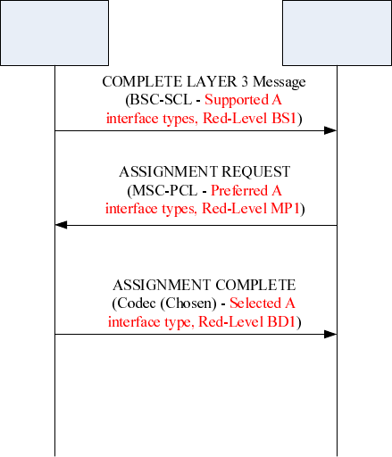
ETSI
ETSI TR 143 903 V8.3.0 (2009
-
02)
48
3GPP TR 43.903 version
8.3.0 Release 8
When the Codec Type is negotiated on the A interface, also the Codec Configuration, the location of the Transcoder
resource and the Interface Type are negotiated and decided. This secures the flexible configuration and deployment of
A over IP according to different network situations.
NOTE: TFO in the BSC-SCL and MSC-PCL is optional, but not mandated to be configured or used.
For data and fax call, codec negotiation should also been carried out to select the proper CSD Dummy Codec. The
purpose of CSD codec negotiation is to determine the A-interface type and the redundancy level. Figure 7.3.1.1b shows
an example with CSD Codec Negotiation for the A-interface transport link at call setup. There are two differences
between CSD Codec Negotiation and normal Speech Codec Negotiation:
1. Because the circuit-switch data link for the A-interface will always be terminated in the MGW, CSD Codec
Negotiation is not an end-to-end procedure. The negotiation will be carried out by the two involved MSC-BSS pairs
separately, each as shown in Figure 7.3.1.1b.
2. Redundancy level Negotiation will only happen for the A-Interface transport link and will not affect the air interface.
BSS1 MSC1
Figure 7.3.1.1b: Example redundancy level negotiation at call setup for a data/fax call
BSC1 sends MSC1 its actual "BSC Supported Codec List" (BSC-SCL1) in the first Complete Layer 3 Message. In
BSC-SCL1, BSC1 uses the CSD Dummy Codec to indicate its capability of supported A-interface type(s) and the
supported redundancy levels (RED-Levels BS1 = RED1-RED2-RED3 of BSS1).
After receiving BSC-SCL1, MSC1 shall tell BSC1 its preferred/supported A-interface type(s) by considering the link
resource of MGW1 and the capability of BSC1 comprehensively. Besides that, MSC1 shall also tell BSC1 its
preferred/supported redundancy levels (RED-Levels MP1) by considering the link resource of MGW1 and the
capability of BSC1 (RED-Levels BS1). The preference of MSC1 is indicated by the CSD Dummy Codec(s) included in
MSC-PCL.
MSC1 sends MSC-PCL to BSC1 in the Assignment Request message. BSC1 will make the final decision of which A-
interface will be used and which redundancy level will be used (RED-Level BD1). Only redundancy levels that are
supported by both entities (BSS and MSC) may be used. BSC1 tells MSC1 its final decision by the Speech Codec
(Chosen) included in the ASSIGNMENT COMPLETE message. MSC1 informs MGW1 accordingly.
7.3.2 Codec Negotiation at Handover
The assignment procedure at Call Setup, including the enhanced Codec negotiation, aims for best possible Codec setup
for best speech quality end-to-end, with the minimal number of transcoding stages in the path and the minimal transport
bandwidth. Aiming for improving the successful rate of CSD services, the CSD Codec negotiation is performed in
assignment procedure at data/fax Call setup.
ETSI
ETSI TR 143 903 V8.3.0 (2009
-
02)
49
3GPP TR 43.903 version 8.3.0 Release 8
Following the assignment at Call Setup there may be several reasons for the BSS to change the cell and/or the Codec
Type and/or the Codec Configuration and/or the Interface Type. The BSC shall always try to keep the Codec Type and
Codec Configuration compatible as well as keep the same Interface Type to create least impact on Core Network and
distant termination. Sometimes this is, however, not possible.
For data/fax calls handover might cause the change of the redundancy level used in A-interface and/or the type of A-
interface. When the redundancy level and/or the type of A-interface has to be changed, a new CSD Codec shall be
negotiated between BSS and MSC.
The following subchapters discuss different handover cases.
7.3.2.1 Intra-BSC Handover to a Compatible Target Cell
For an intra-cell or intra-BSC handover to the same Interface Type and a compatible Codec Type and Codec
Configuration, the BSS handles the handover internally. One important Intra-Cell handover case is the cell repacking
for higher radio efficiency under high load conditions. The handover from FR_AMR to HR_AMR is such an example.
For data/fax call in AoIP, a compatible target cell means that the CSD Codec will not be changed after handover, i.e.,
neither the type of A interface nor the redundancy level should be changed after Handover.
The MSC is merely informed about the handover by the Handover Performed message. A new BSC-SCL, containing
the up-to-date Codec capability of the BSC may be included in the Handover Performed message. The MSC may use
this in future e.g. at Codec re-negotiation towards the remote end.
For data/fax call in AoIP, the Handover Performed message may contain a new BSC-SCL which include a new CSD
Codec of the target BSS after handover. The MSC may use this for future CSD Codec negotiation.
7.3.2.2 Intra-BSC Handover to an Incompatible Target Cell
At intra-cell and intra-BSC handover, if the BSC has to change to an incompatible Codec Type or incompatible Codec
Configuration, or if there is a need to change the Interface Type, the BSC shall inform the MSC.
For data/fax call in AoIP, an incompatible target cell means that the A interface type and/or redundancy level should be
changed after handover.
One important Intra-Cell handover case is the cell repacking for higher radio efficiency under high load conditions. The
handover from GSM_EFR to GSM_HR is such an example. Important may be that this cell-repacking affects only some
of the calls in this cell, not all. The BSC-SCL is therefore often only relevant for the specific call, not for the whole cell.
One possible strategy is – for example – to handover only calls with good to best radio conditions from GSM_EFR to
GSM_HR, while keeping calls with low radio conditions in GSM_EFR. Also starting new calls may preferably be done
in GSM_EFR, until the radio condition is known and a subsequent repacking to GSM_HR is possible. In this way the
overall speech quality is optimized on cost of more frequent handovers. This Intra-BSC handover is therefore important
and should be performed with minimal impact and delay.
In general, the Intra-Cell handover will not affect the CSD Codec used for the ongoing data/fax call because neither the
type of A interface nor the transport link for Abis and A interface will be affected by Intra-Cell handover.
One possibility is to initiate a procedure similar to Inter-BSC handover, i.e. Handover Required is send to the MSC,
optionally including a new, up-to-date BSC-SCL. This Handover Required may also include the new AoIP Container
for the new radio channel termination. The MSC may handle this Intra-BSC handover like an Inter-BSC handover, see
below. The advantage of this possibility is that existing messages and procedures can be reused, although new IEs have
to be added. It needs further study how to handle the potentially newly created SCCP connection between the MSC and
the same BSC.
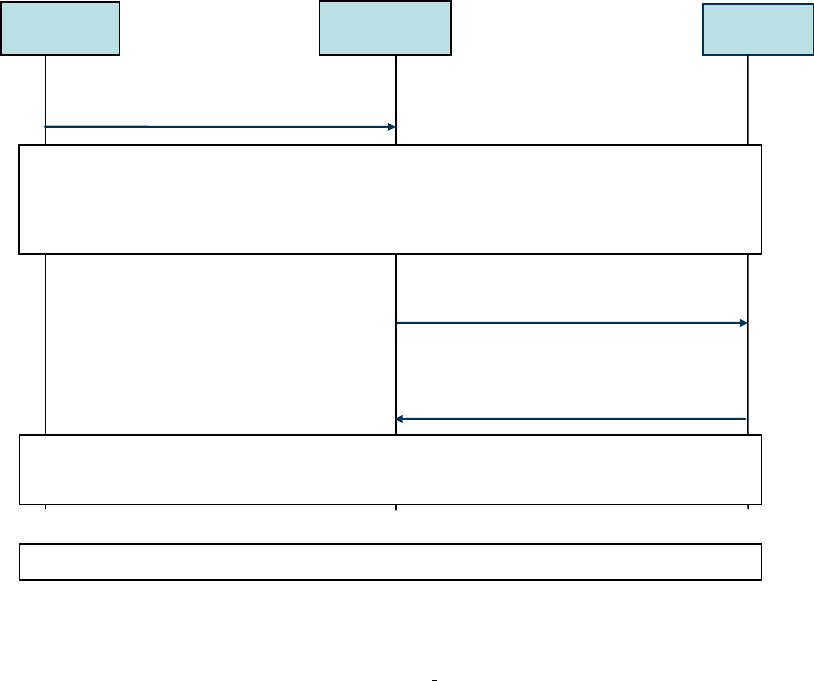
ETSI
ETSI TR 143 903 V8.3.0 (
2009
-
02)
50
3GPP TR 43.903 version 8.3.0 Release 8
MSC
BSS 1
Handover Request
(MSC-PCL: pRanC2,+…), AoIP Container, …
Handover
Request
Acknow ledge
(Speech Codec (chosen) = cRanC2,
BSC-SCL 1*)
Handover Required
(Speech Codec (used) = RanC1, BSC-SCL1;
AoIP
-
Co n ta in e r
)
BSS 1
MSC
knows
:
Selected Codec = SC, BSC
-
SCL1
,
MS
-
SCL1, Interface Type 1.
Only a Codec compatible to SC allows transcoding free operation.
So MSC prioritizes a SC-compatible Codec and an Interface Type as before, and sends this
MSC-PCL together with the AoIP Container of the new MGW-termination tow ards BSS 1.
If no compatible Codec exists, then the MGW must insert a transcoder-pair.
Typically cRanC2 == pRanC2.
The case that BSC1 selects another Codec than pRanC2 is very unlikely, but possible.
In that rare case the MSC has to MODify the MGW termination.
Note: The Handover is not completely shown here.
Figure 7.3.2.2.1: Intra-BSC Handover to a non-compatible Codec
A second possibility is to define a simplified 3-ways-signalling
MSC-controlled handover procedure, relying on the
observation that the source and the target BSS would be the same in this scenario so that two messages used in the
normal inter-BSC Handover procedure (namely the "Handover Request" and "Handover Request Acknowledge"
messages) would not be needed.
A 3-ways-signalling procedure could be defined where the first message could be a "Channel Modify Required" or a
"Internal Handover Required" message containing at least:
- A target cell. This shall be a cell controlled by the same BSS
- The up-to-date Codec capabilities in the target cell, i.e. the BSC-SCL
- The new AoIP container with the new IP/UDP termination at the BSS for the new radio channel termination.
When receiving the "Channel Modify Required"/"Internal Handover Required" message from the BSS, the MSC
would select its most preferred Codec Type (pRanC) taking into account the BSC-SCL. The pRanC and the new
IP/UDP termination at the BSS would be communicated to the MGW in order to add another termination towards the
BSS. The MGW would then acknowledge the Add request by sending back to the MSC the new IP/UDP termination at
the MGW.
Similarly, for data/fax call, when receiving the "Channel Modify Required"/"Internal Handover Required" message
from the BSS, the MSC would select its most preferred interface type and redundancy level (RED-Level MP) by taking
into account the BSC-SCL and the currently transport link resource of MGW.
At this point in time the MSC could reuse existing messages on the A interface to trigger the handover execution phase.
In particular, to trigger the handover, the "Handover Command" message would be sent to the BSS, including the MSC-
PCL (with pRanC as the first choice) and the new MGW IP/UDP termination. A legacy handover procedure would be
performed on the radio interface and then the BSS would finally confirm the handover/Codec change to the MSC with
the "Handover Complete" message. See figure 7.3.2.2.2. For data/fax call, the Codec(chosen) in 'Handover Complete'
message will indicate the interface type and redundancy level chosen by BSS. In general, the whole procedure
illustrated in fig 7.3.2.2.2 is also applied to data/fax call.
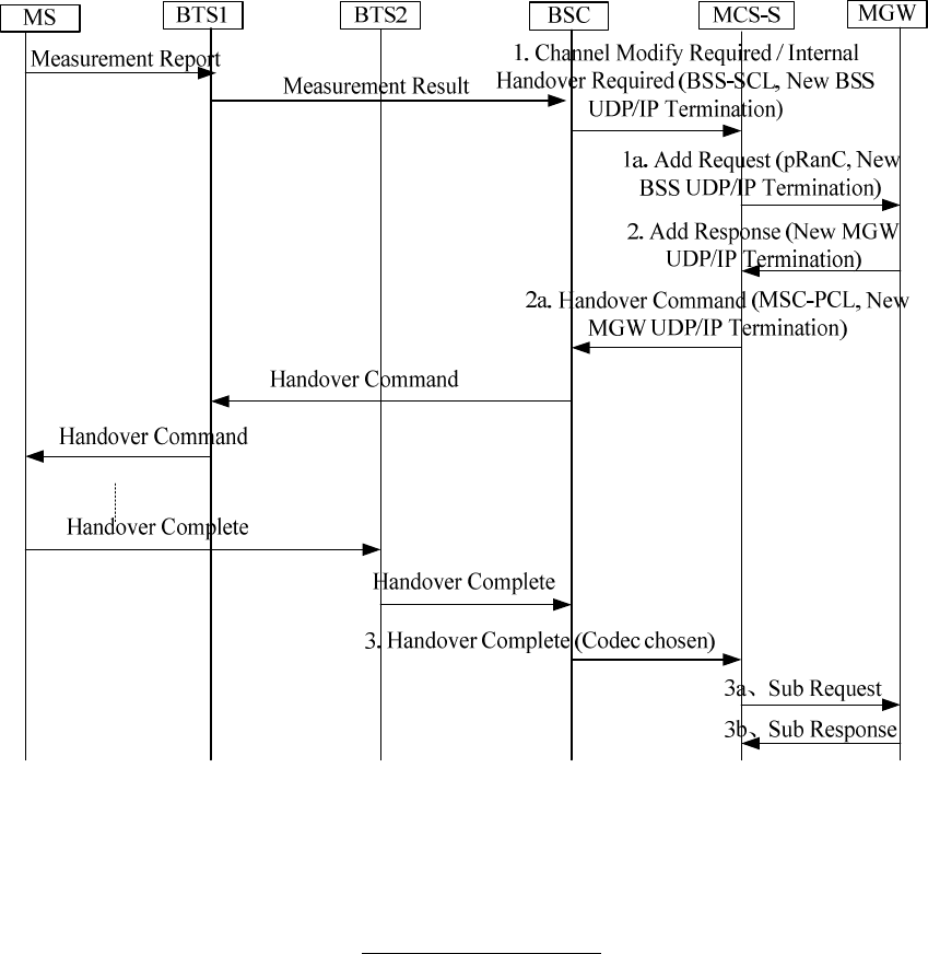
ETSI
ETSI TR 143 903 V8.3.0 (2009
-
02)
51
3GPP TR 43.903 version 8.3.0 Release 8
Figure 7.3.2.2.2: Simplified procedure for intra-BSS Handover to an incompatible Codec
(Codec change triggered by the BSS)
A variant of this procedure is also possible. For instance:
- Instead of containing the BSC-SCL, the "Channel Modify Required"
/"Internal Handover Required" could
directly contain the chosen Codec, i.e. the BSS could finally decide the Codec-type.
- Instead of reusing the legacy Handover Command/Handover Complete handover execution procedure, a new
message could be defined to trigger the intra-BSS handover and the Handover Performed message could be used
to inform the CN of the handover completion (in this case the Handover Performed message would be used by
the MSC-S as a trigger to remove the old MGW UDP/IP termination).
The advantages of a 3-ways-signalling MSC-controlled procedure would be a faster handover handling.
The disadvantage could be higher implementation and verification effort.
The decision should be based on statistics from existing networks. If this kind of Intra-BSC handover is expected to
happen often, then the procedure should be optimized. Otherwise the existing procedure should be sufficient.
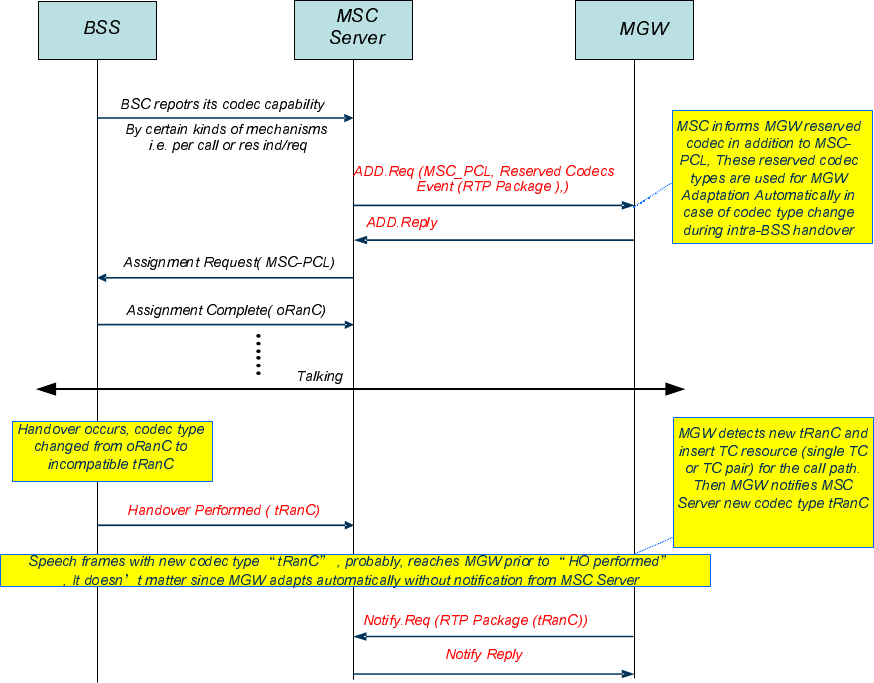
ETSI
ETSI TR 143 903 V8.3.0 (2009
-
02)
52
3GPP TR 43.903 version 8.3.0 Release 8
A third possibility is to rely on User Plane procedures, whereby the MSC allows multiple Codecs to be used in the
MGW and whereby the BSS performs a normal intra-BSS handover, finally sending the "Handover Performed"
message to the MSC, and the new target radio leg starts sending UL data to the MGW (from a different, new BSS
UDP/IP termination) encoded according the new Codec Type. The MGW would have to detect the Codec change and,
before receiving any Control Plane message, add automatically a new termination to the Context, if necessary with
transcoder resources, and start sending DL data to the new BSS UDP/IP termination encoded according the new Codec
Type. In uplink a smart handover combining could take place and finally the MGW would send a Notify Request to
inform the MSC. See figure 7.3.2.2.3.
Figure 7.3.2.2.3: User Plane procedure for intra-BSS Handover to an incompatible Codec
(Codec change triggered by the BSS)
The suggested User Plane procedure seems attractive, but needs further study and coordination with other
groups (e.g. CT4).
The current working assumption is to introduce a simplified 3-ways-signalling MSC-controlled handover
procedure.
7.3.2.3 Inter-BSC Handover
Inter-BSC handovers can not be handled BSC-internally and the MSC and MGW need to be involved, regardless
whether or not the Codec Type, Codec Configuration, A-Interface Type, redundancy level (for data/fax call) or
Transcoder Resource location has to be changed.
The source BSC sends Handover Required to the MSC.
As described above this Handover Required may optionally contain a new BSC-SCL and a new AoIP Container for the
Intra-BSC handover case. For the 'real' Inter-BSC handover case the source BSC is taken out of the call path and thus
it's BSC-SCL is useless.
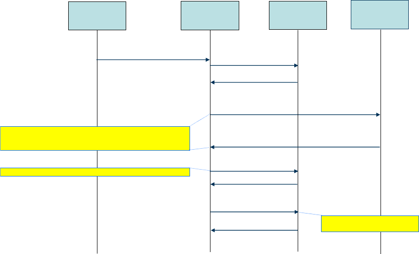
ETSI
ETSI TR 143 903 V8.3.0 (2009
-
02)
53
3GPP TR 43.903 version 8.3.0 Release 8
The reason to include a new BSC-SCL (for Intra-BSC handover case) is to have the latest BSC capability
communicated to the MSC. The MSC could then decide whether or not this new BSC-SCL is to be used e.g. in deciding
the Codec Type and Codec Configuration and Interface Type for the target cell for Intra-BSC handover to an
incompatible target cell. The MSC may also use this new BSC-SCL after handover for Codec Re-Negotiation towards
the remote end.
For a real Inter-BSC handover, MSC does in general not know the target BSC's capability. In that case the MSC may
construct the MSC-PCL taking into consideration the currently Selected Codec (Type and Configuration) on the Nb
interface. The first Codec in the MSC-PCL shall be compatible to the SC. The other Codecs in the MSC-PCL are
determined by the known MS-SCL and the MGW capabilities.
For data/fax call, the CSD Codecs in MSC-PCL indicates the A interface types preferred by MSC and the types will be
ordered according to the preference of MSC. CSD Codec in MSC-PCL also indicates the MSC preferred redundancy
level, which could be determined by the current transport link resource of MGW and the redundancy level used by the
old BSS.
In general the MSC does also not know the supported Interface Types of the target BSS. Therefore the MSC may offer
all Interface Types in the MSC-PCL, which is send in the Handover Request Message. This Handover Request Message
contains also the AoIP Container, if AoIP is offered.
The target BSC selects finally the Codec Type, Codec Configuration, A-Interface Type, redundancy level (for data/fax
call) and Transcoder Resource Location out of the MSC-PCL. The target BSC reports this back to the MSC in Speech
Codec (chosen), included in Handover Request Acknowledge. This Handover Request Acknowledge contains also the
AoIP Container, if AoIP is chosen and the new, up-to-date BSC-SCL*.
The MSC updates the MGW accordingly. If more than one Interface Type was seized in the MGW, then the not used
one has to be SUBtracted from the MGW context.
If, for whatever reasons, the MSC knows the capabilities of the target BSC, partly or fully, then the MSC may pre-
decide the Interface Type and offer only one Interface Type in MSC-PCL. In that case the update of the MGW is
sometimes not necessary (except the MODification of the connection address). See figure 7.3.2.3-1 below.
MSC 1
BSS 1
Handover Required
(Speech Codec (used) = RanC)
BSS 1*
MGW 1
ADD.Req (TDM + IP, pRanC)
ADD.Reply (TDM + IP)
Handover Request
(MSC-PCL 1: pRanC, +…; TDM+IP terminations)
Handover Acknowledge
(Speech Codec (chosen) = RanC*: AoITDM, BSC-SCL 1*)
MOD.Req (TDM, RanC*)
MOD.Reply ()
SUB.Req (IP)
SUB.Reply ()
BSS 1* got a fully flexible offer in MSC-PCL 1 for AoTDM + AoIP).
BSS 1* selected RanC* and AoTDM and reports this back.
BSS 1* also provides its TDM termination data.
MSC 1 MODifies the MGW-TDM-Termination accordingly
MSC 1 releases
the not needed IP termination
Figure 7.3.2.3.1: Real Inter-BSC Handover, example of TDM as selected Interface Type

ETSI
ETSI TR 143 903 V8.3.0 (2009
-
02)
54
3GPP TR 43.903 version 8.3.0 Release 8
7.3.3 Codec Re-Negotiation after Inter-BSC Handover
After the handover is completed and the BSC-SCL of the now serving BSC and the Speech Codec (chosen) is known to
the MSC, the MSC may (optional) evaluate, based on the SC and the Available Codec List received earlier from the
distant call leg, whether or not Mid-Call Codec Re-Negotiation may result in a better overall end-to-end Codec
selection. For data/fax call, MSC may also initiate the procedures to adjust the currently used A-interface type.
Different from Speech Codec Re-Negotiation, the CSD Codec re-negotiation procedure in data/fax call is not an end-to-
end one. It only happens between a MSC and its connected BSS.
One important scenario for such a potential Codec Re-Negotiation is the upgrade from narrowband (NB) speech
telephony to wideband (WB) speech telephony, when the old BSC was not able to support AMR-WB, but the new BSC
is capable to offer AMR-WB speech.
Although Codec Re-Negotiations are currently possible within the Core Network, there is currently no defined
procedure to trigger a Codec change from the Core Network to the BSS.
One possibility for the Core Network to trigger a Codec Type change (e.g. to re-establish TrFO) could be to trigger a
new assignment procedure on the same SCCP connection. This approach would reuse existing messages, but there
could be a few drawbacks as well:
A new Assignment message would replace the UDP/IP termination at the BSS (and at the MGW), but it would
be preferable to have the 2 terminations (old and new) in place during the Codec change, like in the handover
case
The Core Network would not be aware of the current BSS capabilities when initiating the new Assignment
procedure.
In fact, the main issue is to provide a mechanism whereby the BSS informs the Core Network about the Codec Types it
can support for the ongoing call, before the Core Network triggers a Codec change. Although the BSS communicates its
Codec capabilities at call setup, this is a dynamic information related to a specific time instant in a specific cell so that
this might change in time, e.g. due to overload conditions. Therefore a mechanism is needed to update this information
for an ongoing call.
One possibility would be to rely on the simplified MSC-controlled handover procedure defined in section 7.3.2.2, in this
case initiated by a preliminary signalling message sent by the MSC to the BSS to trigger a feedback from the BSS about
its current Codec capabilities regarding a specific ongoing call.
This message could be named "Channel Modify Enquiry" or "Internal Handover Enquiry", and it would be different
from a legacy "Handover Request" sent to the target BSS during the preparation phase of an inter-BSS handover: its
goal is to get back the updated BSS Codec capabilities to handle a specific call and no specific target cell is indicated in
the message (the primary goal is to change the Codec, not necessarily the cell, and typically an intra-cell handover
would be finally triggered in this case). On the other hand a MSC-PCL (MSC-Preferred Codec List) could be included
in the "Internal Handover Enquiry" message to inform the BSS about the MSC Codec preferences. If the goal is to re-
establish TrFO, the MSC-PCL in this case should reflect the remote end indicated Codec. The BSS might use this
information to decide a possible target cell that meets such requirements.
The BSS response to the "Channel Modify Enquiry"/"Internal Handover Enquiry" message would be the "Channel
Modify Required"/"Internal Handover Required" message described in the section 7.3.2.2. The target cell indicated in
the message could be the same cell where the call is currently ongoing; alternatively this could also be a cell where the
BSS could better satisfy the MSC Codec preferences expressed in the MSC-PCL contained in the "Internal Handover
Enquiry" message. The current BSC-SCL and the new UDP/IP BSS termination for the new radio channel termination
would also be added.
As described in section 7.3.2.2, when receiving the "Channel Modify Required"/"Internal Handover Required"
message from the BSS, the MSC would select its most preferred Codec Type (pRanC) taking into account the BSC-
SCL. If the goal of the Codec change is to re-establish TrFO, and the BSS could not meet the request in the MSC-PCL
contained in the "Internal Handover Enquiry" message (i.e. if the BSC-SCL in the "Internal Handover Required"
message does not contain the MSC-PCL), then the MSC could also decide it's not beneficial to finally trigger a Codec
change and could avoid sending the Handover Command at all (of course this means that TrFO would not be re-
established at the end). In data/fax call, if MSC preferred CSD Codec is the same to the BSS selected CSD Codec, MSC
could send the Handover Command to change the interface type used by BSS. Otherwise, MSC should avoid sending
out the Handover Command message.
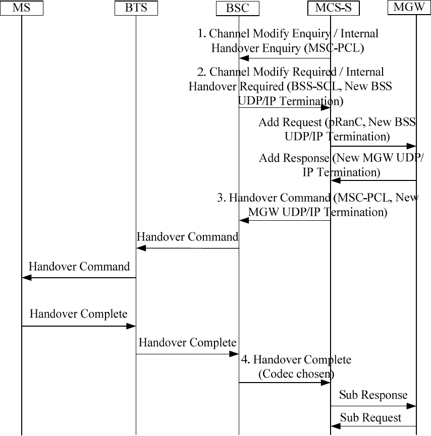
ETSI
ETSI TR 143 903 V8.3.0 (2009
-
02)
55
3GPP TR 43.903 version 8.3.0 Release 8
NOTE: One possible way for the MSC to detect whether the BSS is actually waiting for the Handover Command
is to add a flag in the "Internal Handover Required" message to clarify whether this message is:
- sent by the BSS in response to an "Internal Handover Enquiry" -> the BSS doesn't have a real need to
perform the intra-BSS HO -> no problem if Handover Command is not received;
- sent by the BSS because of a real need to perform the intra-BSS HO (e.g. to an incompatible Codec
Type) -> Handover Command is finally expected.
If the MSC decides to continue with the handover, the message exchange with the MGW and the signaling procedure
on the A interface for the handover execution phase would be the same as described in section 7.3.2.2 The overall
procedure is described in figure 7.3.3.1.
Figure 7.3.3.1: Codec change triggered by the Core Network
NOTE: A potential, optional Codec Re-Negotiation may lead to a change of all Codecs in the speech path, also
the one just selected by the BSC during handover. This will result in a short interruption of the speech path
and it costs not negligible signalling load.
Codec Re-Negotiation is therefore considered as optional.
The definition of the triggers to initiate a Codec Re-Negotiation is not in the scope of a possible Work Item on "AoIP".

ETSI
ETSI TR 143 903 V8.3.0 (2009
-
02)
56
3GPP TR 43.903 version 8.3.0 Release 8
7.4 Impacts on the A Interface Control Plane
In this section some examples are provided showing how the relevant Information Elements could look like.
7.4.1 New Information Element: BSC-SCL
As described above a new Information Element (BSC-SCL) is defined to transfer the BSC capabilities from the BSC to
the MSC in the Complete L3 message at call setup. This BSC-SCL is constructed as shown above and reprinted here for
ease of reading:
# Comments Coding mandatory
or optional
1 IE-Identifier "BSC-SCL" mandatory
2 Length "Length of IE after length byte" = 11 mandatory
3 1. Codec Full IP TFO
PCMoIP
PCMoTDM
"FR" =0000 mandatory
4 2. Codec Full IP TFO
PCMoIP
PCMoTDM
"HR" =0001 optional
5 3. Codec Full IP TFO
PCMoIP
PCMoTDM
"EFR" =0010 optional
6 4. Codec Full IP TFO
PCMoIP
PCMoTDM
"FR_AMR" =0011 optional
7 Configuration set7 set6
set5 set4 set3 set2 set1 set0 conditional
8 Configuration set15 set1
4
set13 set12 set11 set10 set9 set8 conditional
9 5. Codec Full IP TFO
PCMoIP
PCMoTDM
"HR_AMR" =0100 optional
10 Configuration set7 set6
set5 set4 set3 set2 set1 set0 conditional
11 Configuration set15 set1
4
set13 set12 set11 set10 set9 set8 conditional
12 6. Codec Full IP TFO
PCMoIP
PCMoTDM
"FR_AMR-WB" =1001 optional
13 Configuration - - set5 set4 set3 set2 set1 set0 conditional
The table shows a maximum-length example of a BSC-SCL. In a specific call case the sequence of Codecs and the
number of Codecs may vary. It is allowed to flag more than one Interface Type for a given Codec Type. In case of
AMR and AMR-WB it is also allowed to flag more than one Configuration (set).
The BSC-SCL is not ordered according to any preference. It must at least contain the GSM_FR Codec Type with at
least one Interface Type.
The BSC informs the MSC by BSC-SCL, which Codec Types, Codec Configurations, Interface Types and Transcoder
Resource Locations it supports in this very moment for this very call.
For each Codec Type, there are four bits to indicate the Transcoder Resource location, the Interface Type and the
optional support of TFO. These four bits are:
Full IP
'1' means: AoIP with compressed speech via RTP/UDP/IP is supported for this Codec Type.
No Transcoder resource is necessary in BSS.
If Full IP is selected, then the Codec Type on the radio interface
is identical to the Codec Type on the A-interface
'0' means: compressed speech via RTP/UDP/IP is not supported for this Codec Type.

ETSI
ETSI TR 143 903 V8.3.0 (2009
-
02)
57
3GPP T
R 43.903 version 8.3.0 Release 8
TFO
'1' means: TFO supported for this Codec Type
'0' means: TFO is not supported for this Codec Type
TFO is only applicable, if at the same time the Interface Types PCMoIP and/or PCMoTDM
are set to '1', too.
PCMoIP
'1' means: A Transcoder Resource for this (radio) Codec Type may be located in BSS.
PCM may be transmitted over the A interface with PCM/RTP/UDP/IP.
If this Interface Type is selected, then the Codec Type on the radio interface is different to the
Codec Type on the A-Interface (PCM).
If TFO is supported then the parameters of the radio Codec may be tunnelled through the
PCM link on the A interface.
'0' means: PCM over A interface with IP as transport is not supported for this Codec Type
PCMoTDM
'1' means: A Transcoder Resource for this (radio) Codec Type may be located in BSS.
PCM may be transmitted over A interface with TDM.
If this Interface Type is selected, then the Codec Type on the radio interface is different to the
Codec Type on the A-Interface (PCM).
If TFO is supported, then the parameters of the radio Codec may be tunnelled through the
PCM link on the A interface.
'0' means: PCM over A interface with TDM as transport is not supported for this Codec Type.
NOTE: Full IP, PCMoIP and PCMoTDM can be simultaneously supported in the same BSC.
EXAMPLE 1: For the target Deployment Scenario, with only compressed speech over AoIP, the coding of these
four bits for all supported Codec Types would be:
Full IP TFO PCMoIP
PCMoTDM
1 0 0 0
EXAMPLES 2 TO 5: For deployment scenarios, where the transcoders may reside either inside the BSS or in the
Core Network and where the Codec Type may be supported for either TDM or IP or both, the
coding of these four bits in the BSC-SCL can for example be one of the following configurations:
Full IP TFO PCMoIP
PCMoTDM
0 1 1 1
1 0 0 1
1 1 1 0
1 1 1 1
The coding of BSC-SCL gives the flexibility to allow different location of Transcoder resources for different Codec
Types, i.e. for one Codec Type the Transcoder may be located in the BSS and for another Codec Type the Transcoder
can be located in core network (or is not needed at all). It is even possible to allocate for the same Codec Type for one
call the Transcoder within the BSS and for another call within the CN.

ETSI
ETSI TR 143 903 V8.3.0 (2009
-
02)
58
3GPP TR 43.903 version 8.3.0 Release 8
7.4.2 New Information Element: MSC-PCL
A new Information Element "MSC-PCL" is defined to transfer the MSC preferred Codec List from the MSC to the BSC
at call setup and in handover cases. This MSC-PCL is constructed as shown above and reprinted here for ease of
reading in the order of decreasing speech quality:
# Comments Coding mandatory
or optional
1 IE-Identifier "MSC-PCL" mandatory
2 Length "Length of IE after length byte" = 11 mandatory
3 Codec Full IP TFO
PCMoIP
PCMoTDM
"FR_AMR-WB" =1001 optional
4 Configuration - - set5 set4 set3 set2 set1 set0 conditional
5 Codec Full IP TFO
PCMoIP
PCMoTDM
"FR_AMR" =0011 optional
6 Configuration set7 set6
set5 set4 set3 set2 set1 set0 conditional
7 Configuration set15 set1
4
set13 set12 set11 set10 set9 set8 conditional
8 Codec Full IP TFO
PCMoIP
PCMoTDM
"EFR" =0010 optional
9 Codec Full IP TFO
PCMoIP
PCMoTDM
"HR_AMR" =0100 optional
10 Configuration set7 set6
set5 set4 set3 set2 set1 set0 conditional
11 Configuration set15 set1
4
set13 set12 set11 set10 set9 set8 conditional
12 Codec Full IP TFO
PCMoIP
PCMoTDM
"FR" = 0000 optional
13 Codec Full IP TFO
PCMoIP
PCMoTDM
"HR" = 0001 optional
The table shows a maximum-length example of an MSC-PCL. In a specific call case the sequence of Codecs and the
number of Codecs may vary. It is allowed to flag more than one Interface Type for a given Codec Type. In case of
AMR and AMR-WB it is also allowed to flag more than one Configuration (set).
The MSC-PCL is ordered according to the MSC preference with the highest priority Codec being put at the top of the
list. The MSC expects the BSC to choose the preferred Codec Type. It must at least contain one Codec Type with at
least one Interface Type. The MSC informs the BSC by MSC-PCL, which Codec Types, Codec Configurations,
Interface Types and Transcoder Resource Locations it supports in this very moment for this very call.
For each Codec Type, there are four bits to indicate the Transcoder Resource location, the Interface Type and the
optional support of TFO. These four bits are:
Full IP
'1' means: AoIP with compressed speech via RTP/UDP/IP is supported for this Codec Type.
No Transcoder resource is necessary in BSS.
If Full IP is selected, then the Codec Type on the radio interface
is identical to the Codec Type on the A-interface
'0' means: compressed speech via RTP/UDP/IP is not supported for this Codec Type.
TFO
'1' means: TFO supported for this Codec Type
'0' means: TFO is not supported for this Codec Type
TFO is only applicable, if at the same time the Interface Types PCMoIP and/or PCMoTDM
are set to '1', too.

ETSI
ETSI TR
143 903 V8.3.0 (2009
-
02)
59
3GPP TR 43.903 version 8.3.0 Release 8
PCMoIP
'1' means: A Transcoder Resource for this (radio) Codec Type may be located in BSS.
PCM may be transmitted over the A interface with PCM/RTP/UDP/IP.
If this Interface Type is selected, then the Codec Type on the radio interface is different to the
Codec Type on the A-Interface (PCM).
If TFO is supported, then the parameters of the radio Codec may be tunnelled through the
PCM link on the A interface.
'0' means: PCM over A interface with IP as transport is not supported for this Codec Type
PCMoTDM
'1' means: A Transcoder Resource for this (radio) Codec Type may be located in BSS.
PCM may be transmitted over A interface with TDM.
If this Interface Type is selected, then the Codec Type on the radio interface is different to the
Codec Type on the A-Interface (PCM).
If TFO is supported, then the parameters of the radio Codec may be tunnelled through the
PCM link on the A interface.
'0' means: PCM over A interface with TDM as transport is not supported for this Codec Type.
Full IP, PCMoIP and PCMoTDM can be simultaneously supported in the same MSC/MGW.
If more than one Interface Type is flagged in the MSC-PCL, then the priority order is per definition:
Full IP > PCMoIP+TFO > PCM oTDM+TFO > PCMoIP > PCMoTDM.
7.4.3 New Information Element: Speech Codec (Chosen)
The existing Information Element "Speech Version (Chosen)" is not sufficient for AoIP, because neither Codec
Configuration nor Interface Type nor Transcoder Location can be specified. It is therefore proposed to introduce a new
Information Element "Speech Codec (chosen)".
# Comments Coding
mandatory
or optional
1 IE-Identifier " Speech Codec (chosen)" mandatory
2 Length "Length of IE after length byte" = 1, 2, 3 mandatory
3 Codec Full IP TFO
PCMoIP
PCMoTDM
"Codec Chosen" mandatory
(4) Configuration set set set set set set set set conditional
(5) Configuration set set set set set set set set conditional
Speech Codec (Chosen) shall contain exactly one Codec Type with one Codec Configuration (conditional) with one
Interface Type and the exact Transcoder Location.
7.4.4 New Information Element: Speech Codec (Used)
The existing Information Element "Speech Version (Used)" is not sufficient for AoIP, because neither Codec
Configuration nor Interface Type nor Transcoder Location can be specified. It is therefore proposed to introduce a new
Information Element "Speech Codec (Used)".

ETSI
ETSI TR 143 903 V8.3.0 (2009
-
02)
60
3GPP TR 43.903 version 8.3.0 Release 8
# Comments Coding
mandatory
or optional
1 IE-Identifier " Speech Codec (Used)" mandatory
2 Length "Length of IE after length byte" = 1, 2, 3 mandatory
3 Codec Full IP TFO
PCMoIP
PCMoTDM
"Codec Chosen" mandatory
(4) Configuration set set set set set set set set conditional
(5) Configuration set set set set set set set set conditional
Speech Codec (Used) shall contain exactly one Codec Type with one Codec Configuration (conditional) with one
Interface Type and the exact Transcoder Location.
NOTE: It is for further study if and where and when Speech Codec (Used) is necessary for AoIP.
Current Working Assumption is that Speech Codec (Used) is necessary, e.g. for Inter-MSC Handover.
8 Informative: Network Design Issues
8.1 Solution 1
Void.
8.2 Solution 2
Void.
9 Expected impacts to existing specifications
Void.
10 Summary and Conclusion
This Technical Report shows the feasibility for introducing the User Plane transport over IP for the A-interface (BSS –
MGW interface) into 3GPP specifications.
In particular it's possible to define a solution that, at the same time:
will benefit from the flexibility of the IP transport on the A-interface,
will improve bandwidth efficiency through the use of 3GPP Codecs on the A-interface,
will allow to reuse installed Transcoder equipment,
will allow to remove Transcoders from the BSS,
will enable TRanscoder Free Operation (TrFO) in the BSS,
will maximize the likelihood for end-to-end TRanscoding Free Operation and therefore improve the service
quality compared to existing TDM-based BSS.
A detailed analysis has been performed for all requirements, except:

ETSI
ETSI TR 143 903 V8.3.0 (2009
-
02)
61
3GPP TR 43.903 version 8.3.0 Release 8
7) All teleservices, bearer services, VGCS and supplementary services defined for GSM shall be supported on
the BSC-MGW interface
Comment: Not studied in full detail, but no issues are expected.
13) GSM/AMR Codec adaptation shall be possible, e.g. due to overloading of the BSC or radio conditions.
The GSM/AMR Codec adaptation delay shall be in the same order as in the current A-interface solution.
Comment: This requirement could be understood as "Codec Type" adaptation or as "AMR Codec Mode"
adaptation. AMR Codec Mode adaptation is addressed under Requirement 18, see below. Codec Type
adaptation has been studied in chapter 7. Several feasible solutions have been identified.
14) End-to-end speech delay shall not be increased. Congestion in the IP transport may introduce additional
delay; however the end-to-end delay shall not exceed the ITU recommendation [G.114]
Comment: Not studied in the present TR. This will be investigated further. It is, however, expected that the
selected solution complies with this requirement.
15) It shall be possible to secure the BSC-MGW interface (see item e) below.
Comment: Not studied in full detail, but the same method as for SIGTRAN should be applicable.
Speech interruption times during handovers shall be in the same order as in the current TDM implementations
Comment: Not studied in the present TR. This will be investigated further. It is, however, expected that the
selected solution complies with this requirement.
The interaction of dynamic AMR Codec change and TrFO shall not degrade the overall quality of the speech
in the case of MS to MS calls.
Comment: Not studied in full detail. No issues are expected because AMR Codec Mode adaptation for MS-to-
MS calls in transcoding free operation is already specified in TS 45.009.
From the items under "further investigation" two items have not been addressed in detail:
e) Since IP transport is vulnerable to unauthorised intrusions, security aspects shall be investigated
Comment: Not studied in full detail, but the same method as for SIGTRAN should be applicable, see
requirement 15.
Support for GAN
Comment: Not studied in detail, no issues expected.
The investigated solution allows a smooth migration from the legacy, TDM-based A-interface to the new, IP-based A-
interface.
Working Assumptions were formulated to guide the specification phase.
The investigated solution assumes support on the MSC-MGW- (Mc) and the MGW-MGW- (Nb) interfaces and
therefore cooperation with CT and SA groups is required.
A new Work Item for the specification work shall be defined to progress and finalize the work within REL-8.

ETSI
ETSI TR 143 903 V8.3.0 (2009
-
02)
62
3GPP TR 43.903 version 8.3.0 Release 8
Annex A (informative):
Change history
Change history
Date TSG # TSG Doc. CR Rev
Subject/Comment Old New
02-2008 37 GP-080414
Presented to TSG GERAN#37 for approval 8.0.0
05-2008 38 GP-080897
0001
3 Chapter 6 Discussion on data and fax calls 8.0.0 8.1.0
05-2008 38 GP-080951
0002
2 Corrections to MSC-S – MGW signalling 8.0.0 8.1.0
08-2008 39 GP-081372
0003
Working Assumption for CSD Services in AoIP 8.1.0 8.2.0
08-2008 39 GP-081401
0004
1 Applying Data Redundancy for CSD Services in AoIP 8.1.0 8.2.0
08-2008 39 GP-081407
0005
1 Working Assumption on PCM Packetization time 8.1.0 8.2.0
11-2008 40 GP-081528
0006
Corrections on CS Data and Fax Coding 8.2.0 8.3.0
11-2008 40 GP-081866
0007
AINTIP – Call Identifier 8.2.0 8.3.0

ETSI
ETSI TR 143 903 V8.3.0 (2009
-
02)
63
3GPP TR 43.903 version 8.3.0 Release 8
History
Document history
V8.3.0 February 2009 Publication
