
Software Design Document
for a specific implementation of ‘BCI2000’
Gerwin Schalk
Thilo Hinterberger
Dennis J. McFarland
J¨urgen Mellinger
New York State Department of Health
Wadsworth Center
Laboratory of Nervous Systems Disorders
Eberhard–Karls–Universit¨at T¨ubingen
Medizinische Fakult¨at
Institut f¨ur Medizinische Psychologie
Sponsors
Jonathan R. Wolpaw and Niels Birbaumer
Albany, NY
February 2000–July 2004
Contents
1 Introduction 1
1.1 Purpose . . . . . . . . . . . . . . . . . . . . . . . . . . . . . . . . . . 1
1.2 Scope . . . . . . . . . . . . . . . . . . . . . . . . . . . . . . . . . . . 1
1.3 Intended Audience . . . . . . . . . . . . . . . . . . . . . . . . . . . . 2
1.4 List of System Components . . . . . . . . . . . . . . . . . . . . . . . 2
1.5 References . . . . . . . . . . . . . . . . . . . . . . . . . . . . . . . . . 2
1.6 Content Summary . . . . . . . . . . . . . . . . . . . . . . . . . . . . 2
2 System Overview 3
3 Design Considerations 4
3.1 Assumptions and Dependencies . . . . . . . . . . . . . . . . . . . . . 4
3.1.1 Processing performance, definition of real time . . . . . . . . . 4
3.1.2 Operating systems . . . . . . . . . . . . . . . . . . . . . . . . 6
3.1.3 End-user characteristics . . . . . . . . . . . . . . . . . . . . . 7
3.1.4 Possible and/or probable changes in functionality . . . . . . . 7
3.2 General Constraints . . . . . . . . . . . . . . . . . . . . . . . . . . . . 7
3.3 Goals and Guidelines . . . . . . . . . . . . . . . . . . . . . . . . . . . 7
3.3.1 Module Indepe ndence . . . . . . . . . . . . . . . . . . . . . . . 7
3.4 Development Methods . . . . . . . . . . . . . . . . . . . . . . . . . . 7
4 Architectural Strategies 8
5 System Architecture 9
6 Detailed System Design 10
6.1 Operator . . . . . . . . . . . . . . . . . . . . . . . . . . . . . . . . . . 10
6.2 Core Modules . . . . . . . . . . . . . . . . . . . . . . . . . . . . . . . 10
6.2.1 Module Initialization . . . . . . . . . . . . . . . . . . . . . . . 10
6.2.2 System Termination . . . . . . . . . . . . . . . . . . . . . . . 10
6.3 EEG Data Acquisition . . . . . . . . . . . . . . . . . . . . . . . . . . 11
6.4 Signal Processing . . . . . . . . . . . . . . . . . . . . . . . . . . . . . 12
i
CONTENTS ii
6.4.1 Overview . . . . . . . . . . . . . . . . . . . . . . . . . . . . . 12
6.4.2 Goals . . . . . . . . . . . . . . . . . . . . . . . . . . . . . . . . 12
6.4.3 Assumptions and Dependencies . . . . . . . . . . . . . . . . . 13
6.5 User Application . . . . . . . . . . . . . . . . . . . . . . . . . . . . . 13
6.6 Understanding and Writing BCI2000 Code . . . . . . . . . . . . . . . 13
6.6.1 Reporting errors and warnings . . . . . . . . . . . . . . . . . . 13
6.6.2 Your code’s Environment . . . . . . . . . . . . . . . . . . . . 14
6.6.3 Signals and Signal Properties . . . . . . . . . . . . . . . . . . 16
6.6.4 The GenericFilter class . . . . . . . . . . . . . . . . . . . . 16
6.6.5 The filter chain . . . . . . . . . . . . . . . . . . . . . . . . . . 19
6.6.6 Presenting data to the operator user . . . . . . . . . . . . . . 20
6.6.7 Tutorial: Implementing Your Own Data Acquisition . . . . . . 20
6.6.8 Tutorial: Implementing Your Own Signal Processing Filter . . 23
6.7 Entity–Relationship Model for Shared Classes . . . . . . . . . . . . . 31
7 Available Filters and their Parameters 33
7.1 EEG Source . . . . . . . . . . . . . . . . . . . . . . . . . . . . . . . . 33
7.2 Signal Processing . . . . . . . . . . . . . . . . . . . . . . . . . . . . . 33
7.2.1 Calibration . . . . . . . . . . . . . . . . . . . . . . . . . . . . 33
7.2.2 Spatial Filter . . . . . . . . . . . . . . . . . . . . . . . . . . . 34
7.2.3 Temporal Filter Using an AR Model . . . . . . . . . . . . . . 34
7.2.4 Classifier / Translation Algorithm . . . . . . . . . . . . . . . . 36
7.2.5 Normalizer . . . . . . . . . . . . . . . . . . . . . . . . . . . . . 36
7.2.6 Slow-Wave-Feedback . . . . . . . . . . . . . . . . . . . . . . . 37
7.3 Application . . . . . . . . . . . . . . . . . . . . . . . . . . . . . . . . 40
7.3.1 Right Justified Boxes Task . . . . . . . . . . . . . . . . . . . . 40
8 Glossary 42
A List of Requested States 43
B List of Requested Parameters 44
C List of Source IDs 45
D Error and Status Messages 46
Chapter 1
Introduction
1.1 Purpose
All pres ently available augmentative communication systems depend in some mea-
sure on voluntary muscle control. Thus, they are useless to those who are totally
paralyzed and to some others with severe motor dis abilities. EEG–based commu-
nication, because it does not depend on voluntary muscle control, could provide
a valuable new communication and control option for these individuals. Over the
past decade, a number of laboratories have begun developing EEG–based Brain
Computer Interfaces (i.e., BCIs) as a new augmentative technology for people with
motor disabilities.
The BCI2000 standard (as described in the BCI2000 Project Outline) has been
designed in a coop eration between the Laboratory of Nervous Systems Disorders at
the Wadsworth Center in the New York State Department of Health and the Institut
f¨ur Medizinische Psychologie at the Medizinische Fakult¨at at the Eberhard–Karls–
Universit¨at in T¨ubingen/Germany, in an effort to create a well documented and
open system that is open for extensions; this document describes one particular
implementation of this standard.
Not only does this document describe the software already in place, it is also
intended to enforce compatibility of future modifications or add–ons.
1.2 Scope
This document is intended to give a detailed technical description of the BCI2000
software project. It does not, however, explain the BCI 2000 standard itself, or the
rationale behind the implementation or standard.
1

CHAPTER 1. INTRODUCTION 2
1.3 Intended Audience
The intended audience for this document are engineers or researchers, who want
to modify and/or extend the existing reference implementation. As described soft-
ware is implemented using Borland’s C++ Builder, the reader should have some
knowledge of the C/C++ programming language.
1.4 List of System Components
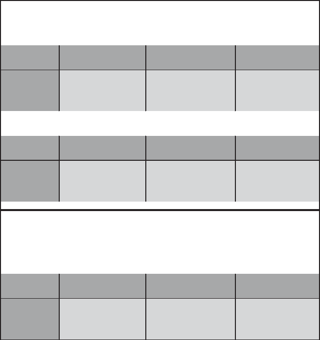
The software package consists of four Win32 executables:
Module Name Filename Current Version
Operator Operat.exe V1.31
EEG source e.g., DT2000.exe V0.30
Signal Processing e.g., ARSignalProcessing.exe V0.30
Application e.g., RJB.exe V0.30
Table 1.1: The four executables
For modules other than the operator module, executable file names vary, reflect-
ing specializations of the generic modules.
1.5 References
The BCI2000 project homepage contains all relevant documentation, source code,
and additional analysis tools:
http://www.bciresearch.org/BCI2000/bci2000.html
1.6 Content Summary
This document presents an overview of the system, the design considerations leading
to the system architecture, describes the system architecture itself, and finally details
the system design.
Chapter 2
System Overview
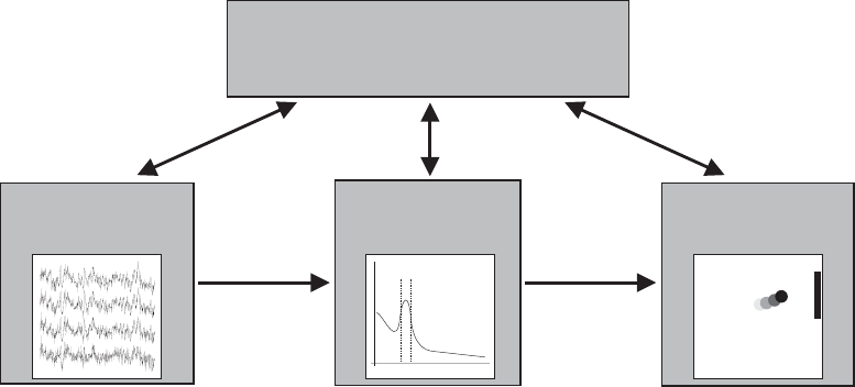
While BCIs can differ widely in the nature of the physiological components they
use, in the signal processing they perform, in the feedback they provide, or in the
underlying training and operation paradigm, they all need the same four elements:
EEG data collection, signal processing, an output device and manual or automatic
parameterization and configuration. Therefore, it seems to be a natural choice to
partition the system into four modules with respective functionality. Figure 5.1
illustrates a high–level overview of this partitioning scheme.
It is conceivable that for certain BCIs, the chosen decomposition might be
overkill, or even unfavorable, but still it se emed to be the most appropriate for
a variety of systems.
3
Chapter 3
Design Considerations
3.1 Assumptions and Dependencies
3.1.1 Processing performance, definition of real time
This section is concerned with perfomance related issues, and the assumptions and
dependencies that exist in the present system.
Processing performance
The existing system involves many components of a PC architecture:
• The microprocessor
• The graphic subsystem
• The I/O subsystem – hard drive storage
• The I/O subsystem – networking
The configuration of the system will determine the actual load on these compo-
nents and therefore the software might run on low–end machines, or it might require
more advanced hardware.
If processor speed becomes an issue, adding subsystems with bus–mastered hard-
ware and dedicated processors (SCSI–controllers, good 100MBit networking cards),
might be a more favorable (and cheaper) solution than using a faster processor.
Feasibility study
We evaluated the system behavior and processor load caused by the ’administra-
tive’ duties of the system, i.e., the communication between modules, under different
scenarios (e.g., whether the modules reside on one or on seperate machines). In this
4
CHAPTER 3. DESIGN CONSIDERATIONS 5
study, all core modules not only transmitted all generated channels to the next core
module (which is more than what the system would transmit in a real–world config-
uration), but also sent all channels as visualization data to the operator. However,
neither was any data further processed in any module, nor was it visualized at the
operator.
The results in Figure 3.1 clearly show that this inter–module communication only
has a small impact on processor load, and that this impact is relatively independent
on system configuration.
Machine:
Pentium III 450Mhz, 384Mb RAM, NT4.0
Data creation: 10/sec
TransmitCh 16
SampleBlockSize 16
100% uniform CPU load 100% uniform CPU load
CPU not busy 1 task 100% 2 tasks 100%
timer interval roundtrip timer interval roundtrip timer interval roundtrip
mean 100.14 7.09 100.14 6.15 100.21 5.53
std dev 0.39 2.32 7.35 5.02 25.19 4.74
min 97.00 2.00 77.00 2.00 9 2
max 103.00 11.00 123.00 77.00 209 79
CPU load: 1% N/A N/A N/A N/A
Data creation: 10/sec
TransmitCh 64
SampleBlockSize 16
100% uniform CPU load 100% uniform CPU load
CPU not busy 1 task 100% 2 tasks 100%
timer interval roundtrip timer interval roundtrip timer interval roundtrip
mean 100.19 4.09 100.14 3.75 100.18 3.67
std dev 3.07 3.61 7.89 3.91 27.60 0.63
min 96.00 2.00 78.00 2.00 10 3
max 311.00 47.00 122.00 84.00 200 22
CPU load: 1% N/A N/A
Machine:
Core Modules: Pentium III 450Mhz, NT 4.0
3COM Etherlink (PCI), 10/100MBit
Operator: Pentium III 550Mhz, Win 2000 SMC EtherEZ (ISA), 10MBit
Data creation: 10/sec in this case, there were 61440+ bytes transferred over the network/sec
TransmitCh 64 (64 channels from each core module * 2 bytes * 16 samples * 10/sec)
SampleBlockSize 16 network traffic + networking card performance is becoming important
100% uniform CPU load 100% uniform CPU load
CPU not busy 1 task 100% 2 tasks 100%
timer interval roundtrip timer interval roundtrip timer interval roundtrip
mean 100.24 3.09
std dev 5.13 1.70
min 96.00 2.00
max 354.00 36.00
CPU load: <10% for both
Figure 3.1: Overview over the results of the feasibility study
Definition of real time
In the most general terms, real time means a reaction of a system to an event in an
appropriate time period. However, the exact nature of this ’appropriate time period’
depends on the application; for instance, the constraint could be maximal response
time, or average response time, or a system could only be called a real–time system,
CHAPTER 3. DESIGN CONSIDERATIONS 6
if it responds in no more than x ms in y percent of the time. In a virtual surgery
environment, for example, one unexp e cted delay per year of 20ms could be fatal.
In a Brain Computer Interface environment, the system usually has to
1. keep up with processing the EEG components over long time periods
2. on average provide feedback in a timely manner (e.g., less than 100ms)
Being able to keeping up with processing directly is a function of the system’s
overall performance. System response time is related to system performance, but
also influenced by the operating system (i.e., OS) – simply because the communica-
tion involves the OS. As the feasibility study (figure 3.1) shows, system latency in
absence of signal processing or graphical feedback is very low (i.e., a few ms). This
latency marks the minimal latency the system will be able to achieve.
Most OSs on the market are not real time operating systems, that is, they
don’t guarantee a deterministic system response time. This includes the Microsoft
Windows family of op erating systems (except, Windows CE, under certain circum-
stances). This means that it is impossible to (at the application level) write code
that operates under this definition. Time stamping data collection and feedback,
and storing these in fields with the data recorded, can b e used to accommodate
for differences in latency. In addition, for a BCI, it is appropriate to say that it
is sufficient, if it provides feedback on average (e.g., 99.9 percent of the time) in a
timely manner.
3.1.2 Operating systems
The system is programmed using Borland’s C++ Builder application development
environment. The target platform of this environment is Win32 code for Intel CPUs.
Therefore, the possible operating systems are Windows 95/98, Windows NT4.0, or
Windows 2000/XP.
This system contains four processes with up to two threads each. Windows NT
and its successors have built-in advanced priority based scheduling algorithms that
are far superior than the simple context–switching based concepts in Windows 95 or
98. While neither the BCI2000 Project Outline nor this document excludes the use
of any of these operating systems, it seems that described real time requirements
can be met more easily under Windows NT and its successors.
CHAPTER 3. DESIGN CONSIDERATIONS 7
3.1.3 End-user characteristics
3.1.4 Possible and/or probable changes in functionality
3.2 General Constraints
3.3 Goals and Guidelines
3.3.1 Module Independence
One of the goals of the system design is to generate modules that are as independent
of each other as possible. The BCI2000 Project Outline defines the communication
protocols between the modules, but not the content of the transmitted EEG signals,
control signals, or the state vector. Ideally, all modules are totally independent of
each other. Even in a real–world situation, both the Data Acquisition and Operator
modules can be independent of all other modules. However, signal processing might
often depend on the feedback provided.
In any case, the goal should be to minimize this interdepence. For example,
different physiological phenomena (e.g., slow cortical potentials or the µ–rhythm)
might result in control signals with different distribution characteristics. As we pass
a derived control signal from Signal Processing to the Application, we could e ither
do post–processing, e.g., normalizing the signal and making it zero mean, in either
the Signal Processing or Application module. Following the aforementioned idea,
it seems favorable to do these manipulations in the signal processing module. In
this case, the application does not need to account for different signal processing
techniques.
3.4 Development Methods
Chapter 4
Architectural Strategies
8
Chapter 5
System Architecture
Operator
signal
processing
application
control signal
EEG signal
EEG source
EEG storage
Figure 5.1: High–level overview of modules in BCI2000
This partitioning scheme and the used communication protocols are described
in detail in the BCI2000 Project Outline.
9
Chapter 6
Detailed System De sign
6.1 Operator
6.2 Core Modules
6.2.1 Module Initialization
The initialization of each core module follows the procedure that is described in
detail in chapter System Initialization in the BCI2000 Project Outline:
Each module publishes its requests for parameters and states to the Operator
module, which configures those and sends them back. After Data Acquisition re-
ceived all parameters and states, it tries to connect to Signal Processing and – upon
successful connection – sends a positive status message to the Operator. In the
same way, Signal Processing connects to the Application and the Application mod-
ule connects to the Data Acquisition module. After the Operator received status
messages from all three core modules, the system is fully initialized and is triggered
to start, as soon as the Operator sends the state Running with a value of 1 to the
Data Acquisition.
6.2.2 System Termination
To each of the three core modules, the operator module indicates system termination
by closing the connection to that module.
When a core module loses connection to the two other core modules it is con-
nected to, it will send an error message to the operator, and then quit. The operator
module, in turn, will close the connections to the remaining core mo dules.
10
CHAPTER 6. DETAILED SYSTEM DESIGN 11
6.3 EEG Data Acquisition
The EEG Data Acquisition (or Source) module’s role is to wait f or data blocks
coming in from the A/D hardware, and to send these blocks of data on to Signal
Processing, thus acting as the on-line system’s “metronome” synchronized to the
A/D hardware clock. At the same time, it receives state vector information from
the Application module, and saves this state vector information to a file in BCI2000
.dat format, together with the raw digitized data.
During normal operation (Running is 1), the EEG source module runs in a data
acquisition loop that basically reads
1: While Running
2: Save state vector to file
3: Wait for A/D data
4: Send A/D data to Signal Processing
5: Wait for state vector from Application
6: Save A/D data to file
Note that statement 3 as well as statement 5 are blocking operations, i.e. the
module w ill wait for A/D data as well as for the state vector data coming in from
the Application module.
This mode of operation requires a sufficiently fast system to work properly. For
our purposes, a “fast” system is a system where
• synchronous I/O operations (2, 4, 5, and 6) require an execution time that is
small compared to the duration of a data block (as given by the sampling rate
and the sample block size), and
• the time required by the Signal Processing and Application modules for process-
ing the data sent out in statement 4 is small compared to the duration of a
data block.
In an on-line system, the time between sampling of a data block, and display of
the resulting feedback information to the subject, is critical. Given a “sufficiently
fast” system as defined above, only statement 4 will enter into this critical time
path, while the time spent on execution of the remaining statements will reduce the
waiting interval occurring in statement 3.
CHAPTER 6. DETAILED SYSTEM DESIGN 12
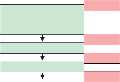
6.4 Signal Processing
6.4.1 Overview
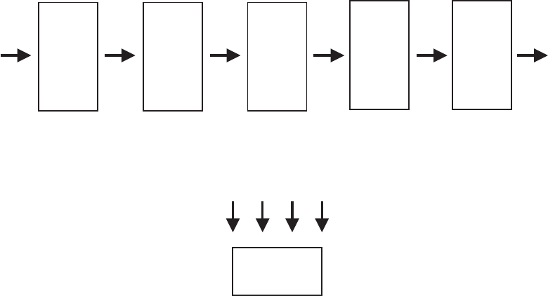
Signal Processing acts like a black box to the rest of the system – it receives EEG
signals from the Data Acquisition and sends control signals on to the Application.
Figure 6.1 illustrates the data flow in this implementation. As layed out in Figure
6.1, there are basically 5 main filters (Calibration, Spatial Filter, Temporal Filter,
Classifier, and Normalizer) and 6 different signals (A (EEG signal), B, C, D, E, F
(control signal)). The dimensionality of each of thes e signals is described in their
respective filter description.
calibrated
EEG
signal
spatially
filtered
signal
temporally
filtered
signal
control
signal
Spatial
Filtering
Temporal
Filtering
Classifier
BC
D
E
Statistics
Cali-
rationb
EEG
signal
from Data
Acquisition
Signals, Filters
Norma-
izerl
normalized
control signal
to go to
Application
FA
Figure 6.1: Data flow in the signal processing module
6.4.2 Goals
As described in chapter 3.3, one of the goals for this system is for each module to
be as independent of the others as possible, e.g., Signal Processing should not have
to take the type of data collection hardware into account. For the same reason,
Application should (ideally) not have to know about the used signal processing
method. While in real-world s ituations this will not be possible, control signals
shall be normalized to the value range of s hort integers (-32767 to +32767), shall
be zero mean (to the extent that this is possible), and each value shall be equally
CHAPTER 6. DETAILED SYSTEM DESIGN 13
accessible by the user’s EEG. In this fashion, the interdependence between Signal
Processing and Application can be minimized.
6.4.3 Assumptions and Dependencies
Signal Processing can contain instances of multiple filter classes. These filter classes
cannot assume any specific values for SampleB lockSize, SamplingRate, or Trans-
mitCh. They have to be able to adapt their functionality according to thes e three
parameters – they might not only be used in scenarios with varying parameters,
but also they might have to work together with other filters. Therefore, hard coded
assumptions about thes e three parameters have to be avoided.
6.5 User Application
As described in chapter 3.3.1, one major goal for system design is the independence
between modules. In most BCI systems, however, some parts of the signal processing
applied (i.e., the device-dependent part of signal processing) depend on the feedback
to the user – a feature provided by the user application.
This inter-dependence between signal processing and the user application poses
severe problems to the system design, because it is not possible to completely en-
capsulate each module and separate it from others.
In order to minimize inter-dependence, duties should be performed by the module
that is conceptually defining it, e.g., task paradigm and timing are conceptually parts
of a task and should therefore be handled by the user application module.
Section 7.3.1 describes a particular implementation of a user task – a simple
cursor task – that complies with this motivation.
6.6 Understanding and Writing BCI2000 Code
This s ection provides background information which you need in order to under-
stand, modify, or create code that depends on the specific B CI2000 framework pre-
sented in this document. You should read it before writing your own BCI2000
module, or modifying an existing one as pres ented in the examples of sections 6.6.7
and 6.6.8 below.
6.6.1 Reporting errors and warnings
There are two output channels available to any code inside a BCI2000 module. Tech-
nically, these channels are global objects derived from the STL’s std::ostream class.
As such, they work much like the global std::cout and std::cerr output streams
CHAPTER 6. DETAILED SYSTEM DESIGN 14
available inside a C++ command line program, except that their output will be sent
to the operator module’s log window rather than a terminal window. The names
of these output streams are bciout and bcierr, declared in shared/UBCIError.h,
and while writing output to bciout has no side effects, writing to bcierr has side
effects that depend on the system’s phase of operation: In preflight phase, the side
effect will be a preflight failure, and the system will refuse to be started unless recon-
figured with correct parameters; otherwise, the side effect will be system termination
after error display.
For the Preflight function, there is also a macro PreflightCondition available
that is intended to make checking for conditions more convenient:
PreflightCondition( Parameter( "MyFirstParam" ) >= 3 );
will result in a message
"A necessary condition is violated: Parameter( "MyFirstParam" ) >= 3"
in the operator window if MyFirstParam’s value is below 3.
Finally, in case of a non-recoverable error, you may also throw an exception
of type const char* in order to report an error in the operator window, and to
terminate the BCI2000 system after the error has been displayed:
throw __FUNC__ ": Disk space is exhausted";
A more detailed discussion of these error reporting facilities, and the overall error
handling concept in this BCI2000 implementation is available at Documentation/
errorhandling.
6.6.2 Your code’s Environment
In each BCI2000 module, there exist system wide parameters and states as described
in the project outline document. In this implementation, access to parameters and
states is mediated through a class Environment. This class provides functions for
convenient access to parameters and states, and transparently handles a number
of error conditions that might occur. The services provided by the Environment
class interface are available to all classes that inherit from it. For GenericFilter
descendants, this is automatically the case; for other classes, you need to explicitly
state the inheritance as in
#include "UEnvironment.h"
...
MyClass : private Environment
{
...
};
From any code inside MyClass, you may then read or set parameter and state
values simply by writing
CHAPTER 6. DETAILED SYSTEM DESIGN 15
int numberOfItems = Parameter( "NumberOfItems" );
float matrixValue = Parameter( "MatrixParam", index1, index2 );
short feedbackState = State( "Feedback" );
State( "Feedback" ) = 0;
If you try accessing a parameter or state that does not exist, an appropriate
error message will be sent to bcierr, so you don’t need to handle this type of error
explicitly.
For a greater independence between modules, it is sometimes desirable to read
a parameter or state if it exists, and use a default value otherwise. You achieve this
behavior by writing
int numberOfItems = OptionalParameter( defaultValue, "NumberOfItems" );
short itiState = OptionalState( 0, "IntertrialInterval" );
Note: Due to some non-standard conventions in Borland’s VCL library, you can-
not create a VCL class such as a TForm descendant that also inherits from Environment
– the compiler will report an error if you try. As a work-around, you might declare
an Environment subclass inside your VCL TForm child declaration, and create a
single instance mEnv of this subclass as a member of your class, using it to access
the Environment functions as in
MyForm : public TForm
{
...
private:
class MyFormEnvironment : private Environment
{
public:
MyFormEnvironment( MyForm& parent );
void Preflight() const;
void Initialize();
} mEnv;
};
...
MyForm::MyFormEnvironment( MyForm& parent )
: mParent( parent )
{
BEGIN_PARAMETER_DEFINITIONS
"UsrTask int MyParam= 1 1 0 5 // my parameter",
END_PARAMETER_DEFINITIONS
}
...
CHAPTER 6. DETAILED SYSTEM DESIGN 16
void
MyForm::Initialize()
{
mEnv.Initialize();
}
void
MyForm::MyFormEnvironment::Initialize()
{
mParent.mMyParam = Parameter( "MyParam" );
}
This should work in situations where your code’s class model is centered around
VCL form classes. When writing new code, you might consider basing your class
model on functionality, and use VCL forms merely for input and output – instan-
tiating populating, and deleting them as you need them, such that the BCI2000
Environment interfacing is done from your own classes, independently of the VCL’s
special needs.
For a detailed description of the Environment facilities, see the Environment
section of the BCI2000 error handling document.
6.6.3 Signals and Signal Properties
Many classes in both Data Acquisition and Signal Processing work on signals. The
GenericSignal class contains floating point data organized as a matrix of channels
and “elements” (a generalized notion of samples – e.g., spectrally analyzed data
might contain the spectrum of each channel as a list of “elements”).
Sometimes, the number of channels, elements, and the number of bytes required
for storing values, are referred to as “Signal Properties”. T here is a separate class,
SignalProperties, for expressing those values, and determining whether a given
signal “fits” into another one, i.e. whether the values contained in one signal may
be copied into another signal without loss of information. GenericSignal inherits
from SignalProperties.
6.6.4 The GenericFilter class
GenericFilter is a base class that provides a programming interface for all user
code inside the core modules of this BCI2000 implementation. Programming your
own data acquisition module, your own filter inside Signal Processing, or your own
application, all implies deriving your own class from GenericFilter.
GenericFilter’s member functions represent the various initialization and process-
ing events that occur during system startup and operation (cf. the System Initializa-

CHAPTER 6. DETAILED SYSTEM DESIGN 17
tion chapter in the BCI2000 project outline). Your own filter code must implement
its own versions of some of these member functions:
• The Constructor, besides its general purpose of initializing member data, de-
clares the parameters and states your filter wants to introduce into the system
(the BEGIN ... and END ... macros handle the actual function calls):
MyFilter::MyFilter()
: mMyParam( 1 ),
mMyOtherParam( 0.1 ),
mCount( 0 )
{
BEGIN_PARAMETER_DEFINITIONS
"MySection int MyParam= 1 "
"0 0 3 // This is range-checked between 0 and 3",
"MySection float MyOtherParam= 0.1 "
"0 0 0 // This is not automatically range-checked",
END_PARAMETER_DEFINITIONS
BEGIN_STATE_DEFINITIONS
"MyState 1 0 0 0",
END_STATE_DEFINITIONS
}
• The Preflight function checks whether the preconditions for success ful opera-
tion are met. This function is called whenever parameter values are re- applied,
i.e. whenever the user presses “Set Config”, “Start”, or “Resume” in the op-
erator window. If Preflight does not report an error via bcierr, this is
considered a promise that Initialize and Process will work properly with
the current parameters.
The first argument to Preflight will inform you about what kind of input
signal your filter is going to receive, and your filter is expected to report the
properties of its output signal via the second parameter:
void
MyFilter::Preflight( const SignalProperties& inputProperties,
SignalProperties& outputProperties ) const
{
PreflightCondition( Parameter( "MyOtherParam" ) > 0.0 );
PreflightCondition( inputProperties.Channels() > 0 );
PreflightCondition( inputProperties.MaxElements( 0 ) > 0 );
outputProperties = inputProperties;
}
Note that the const keyword following the function argument list forbids to
alter any data member of your filter object. This avoids diffusion of initializa-
tion code from Initialize into Preflight. If you have your own sub-objects
CHAPTER 6. DETAILED SYSTEM DESIGN 18
instantiated and maintained by your filter, you should provide them with their
own Preflight() const member functions, and call these from your filter’s
Preflight.
• Initialize is called after a successful Preflight. Thus, it may safely omit
all checks related to parameter consistency. In Initialize, your filter’s data
members are set to the values implied by the user’s choices, or to the initial
values required for the filter’s operation:
void
MyFilter::Initialize()
{
mMyParam = Parameter( "MyParam" );
mMyOtherParam = Parameter( "MyOtherParam" );
mCount = 0;
}
• The Process function is called once for each blo ck of EEG data. It receives
an input in its first argument, and sets the output signal to values resulting
from the filter operation. In the current BCI2000 implementation, there is a
single chain of filters; one filter’s output signal is the next filter’s input. A
filter which does not perform any modification to the signal (e.g., a statistics
filter) needs to copy its input signal into the output signal, as in the example:
void
MyFilter::Process( const GenericSignal* inputSignal,
GenericSignal* outputSignal )
{
if( ( *inputSignal )( 0, 0 ) > mMyOtherParam )
++mCount;
*outputSignal = *inputSignal;
}
The Process function should not acquire or release resources (opening/closing
files, allocating memory, etc). Natural places for such operations are the
Initialize, StartRun, and StopRun member functions.
Other member functions are optional; you may decide whether you override their
default implementation with your own version, depending on what your filter needs
to do:
• StartRun is called when the system enters the running state. As opposed to
Initialize – which is the place for tasks that need to be performed on each
parameter change –, StartRun is provided for tasks that need to be performed

CHAPTER 6. DETAILED SYSTEM DESIGN 19
each time the user clicks “Run” or “Resume” in the operator window. As a
canonical example, the DataIOFilter opens a new .dat file from its StartRun
member function.
By default, StartRun calls Initialize to make sure that intermittent para-
meter changes are applied. If you provide your own StartRun function, you
will probably want to call Initialize from there as well.
• StopRun is called each time the system leaves the running state, entering the
suspended state. Typically, this happens whenever the user clicks “Suspend”
in the operator window. The DataIOFilter provides an example for its usage:
This filter closes the current .dat file from its StopRun member function.
StopRun is also the only function from which a filter may change a parameter
value. Any parameter changes inside StopRun will propagate to the other
modules without any explicit request from your side.
• Resting is called instead of Process while the system is in suspended state.
• The Halt function is called before any re-configuration of the system takes
place. If your filter initiates asynchronous operations such as playing a sound
file, acquiring EEG data, or executing threads, its Halt member function
should terminate all such operations immediately. Failure to do so might
result in a non-responding module, or in other errors difficult to track down.
For descendants of GenericADC, implementing the Halt function is mandatory.
• Your filter’s Destructor should free all resources acquired in the Constructor
or in Initialize. In many cases, freeing of resources will be done automat-
ically if you use direct members instead of pointers, removing the need of a
destructor.
However, if your filter has a non-empty Halt function, it needs a destructor
that calls Halt:
1
MyFilter::~MyFilter()
{
Halt();
}
6.6.5 The filter chain
As noted in the discussion of the GenericFilter::Process function, all GenericFil-
ter descendants inside a BCI2000 module form a single chain of filters. Each filter’s
1
This can not be done from the base class destructor b ec ause overridden virtual functions cannot
be called from base class constructors or destructors.
CHAPTER 6. DETAILED SYSTEM DESIGN 20
output forms the input of the subsequent filter. Creating instances of all filter classes
inside a module, and building the filter chain, is handled by the framework. How-
ever, it needs a hint to determine the sequence in which filters are to be arranged.
In general, this hint consists of a single statement placed inside your filter’s .cpp file:
RegisterFilter( MyFilter, 2.C );
The first argument to this statement is your filter’s class name; the second argument
is a string value (given without quotes) that determines the relative position of your
filter in the filter chain. This is done applying the simple rule that the filter positions
in the chain match the alphanumeric sorting order of the filters’ associated position
strings. This scheme allows you to place an additional filter between existing ones
without changing the position strings of the existing filters.
In principle, this allows to add filters to a module’s filter chain without modifi-
cation to existing source code, simply by adding a .cpp file with a RegisterFilter
statement to the project.
However for Signal Processing modules, it appears more desirable to have an
explicit representation of the entire filter chain centralized in one file. So there is,
for each individual Signal Processing module, one file UFilterHandling.cpp that
defines the filter chain as a sequence of Filter statements (see Section 6.6.8 for an
example).
6.6.6 Presenting data to the operator user
Your filter may have information that it wants to present to the user – e.g., the EEG
signal might appear graphically in a window, or an application task log should be
presented. Packaging this information into core messages, and sending these to the
operator module, is handled by the GenericVisualization class.
Typically, to visualize data this way, you will add a data member of type
GenericVisualization to your filter class – see Section 6.6.8 for an example.
6.6.7 Tutorial: Implementing Your Own Data Acquisition
Data acquisition modules are factored into code required for any hardware, and code
required to access a specific hardware. What you need to do is provide a function
that waits for and reads A/D data (line 3 in the EEG source pseudo code of section
6.3), together with some helper functions that perform initialization and cleanup
tasks. Together these functions form a class derived from GenericADC.
In this tutorial, we consider this scenario: Your Tachyon Corporation A/D card
comes with a C-style software interface declared in a header file "TachyonLib.h"
that consists of three functions
CHAPTER 6. DETAILED SYSTEM DESIGN 21
#define TACHYON_NO_ERROR 0
int TachyonStart( int inSamplingRate, int inNumberOfChannels );
int TachyonStop( void );
int TachyonWaitForData( short** outBuffer, int inCount );
From the library help file, you learn that TachyonStart configures the card and
starts acquisition to some internal buffer; that TachyonStop stops acquisition to
the buffer, and that TachyonWaitForData will block execution until the specified
amount of data has been acquired, and that it will return a pointer to a buffer
containing the data in its first argument. Each of the functions will return zero if
everything went well, and some error value otherwise.
Luckily (and somewhat unrealistic), Tachyon Corporation gives you just what
you need for a BCI2000 source module, so implementing the ADC class is quite
straightforward. In your class’ header file, "TachyonADC.h", you write
#ifndef TachyonAdcH
#define TachyonAdcH
#include "GenericADC.h"
class TachyonADC : public GenericADC
{
public:
TachyonAdc();
~TachyonAdc();
void Preflight( const SignalProperties&, SignalProperties& ) const;
void Initialize();
void Process( const GenericSignal*, GenericSignal* );
void Halt();
private:
int mSoftwareCh,
mSampleBlockSize,
mSamplingRate;
};
#endif // TachyonAdcH
In the .cpp file, you will need some #includes, and a filter registration:
#include "TachyonADC.h"
#include "Tachyon/TachyonLib.h"
#include "UBCIError.h"
using namespace std;
RegisterFilter( TachyonADC, 1 );
CHAPTER 6. DETAILED SYSTEM DESIGN 22
From the constructor, you request parameters and states that your ADC needs;
from the destructor, you call Halt to make sure that your board stops acquiring
data whenever your class instance gets destructed:
TachyonADC::TachyonADC()
: mSoftwareCh( 0 ),
mSampleBlockSize( 0 ),
mSamplingRate( 0 )
{
BEGIN_PARAMETER_DEFINITIONS
"Source int SoftwareCh= 64 64 1 128 "
"// this is the number of digitized channels",
"Source int SampleBlockSize= 16 5 1 128 "
"// this is the number of samples transmitted at a time",
"Source int SamplingRate= 128 128 1 4000 "
"// this is the sample rate",
END_PARAMETER_DEFINITIONS
}
TachyonADC::~TachyonADC()
{
Halt();
}
Your Preflight function will check whether the board works with the parame-
ters requested, and communicate the dimensions of its output signal:
void TachyonADC::Preflight( const SignalProperties&,
SignalProperties& outputProperties ) const
{
if( TachyonStart( Parameter( "SamplingRate" ), Parameter( "SoftwareCh" ) )
!= TACHYON_NO_ERROR )
bcierr << "SamplingRate and/or SoftwareCh parameters are not compatible"
<< " with the A/D card"
<< endl;
TachyonStop();
outputProperties = SignalProperties( Parameter( "SoftwareCh" ),
Parameter( "SampleBlockSize" ), 2 );
}
For the Initialize function, you know that it will only be called if Preflight
did not report any errors. So everything will work fine with the parameters, and
you may skip any checks, writing
void TachyonADC::Initialize()
{
mSoftwareCh = Parameter( "SoftwareCh" );
mSampleBlockSize = Parameter( "SampleBlockSize" );
CHAPTER 6. DETAILED SYSTEM DESIGN 23
mSamplingRate = Parameter( "SamplingRate" );
TachyonStart( mSamplingRate, mSoftwareCh );
}
Your Halt function should stop all asynchronous activity that your ADC code
initiates:
void TachyonADC::Halt()
{
TachyonStop();
}
And now, finally, the actual meat of your class – note that the function may not
return unless the output signal is filled with data, so it is crucial that TachyonWaitForData
is a blocking function. (If your card does not provide such a function, and you need
to poll for data, don’t forget to call Sleep( 0 ) inside your polling loop to avoid
hogging the CPU.)
void TachyonADC::Process( const GenericSignal*, GenericSignal* outputSignal )
{
int valuesToRead = mSampleBlockSize * mSoftwareCh;
short* buffer;
if( TachyonWaitForData( &buffer, valuesToRead ) == TACHYON_NO_ERROR )
for( int channel = 0; channel < mSoftwareCh; ++channel )
for( int sample = 0; sample < mSampleBlockSize; ++sample )
( *outputSignal )( channel, sample ) = buffer[ i ];
else
bcierr << "Error reading data" << endl;
}
You are done! Use your TachyonADC.cpp to replace the GenericADC descendant
in an existing source module, add the TachyonADC.lib shipped with your card to
the project, compile, link, and find the bugs...
6.6.8 Tutorial: Implementing Your Own Signal Processing
Filter
This tutorial shows you how to derive a new filter class from GenericFilter, how
to check preconditions, initialize your filter, and process data. It will also show you
how to visualize a filter’s output signal, presenting it to the operator user.
A simple low pass filter
We want to implement a low pass filter with a time constant T (given in units of a
sample’s duration), a sequence S
in,t
as input and a sequence S
out,t
as output (where

CHAPTER 6. DETAILED SYSTEM DESIGN 24
t is an sample index proportional to time), and obeying
S
out,0
=
1
T
S
in,0
S
out,t
= e
−1/T
S
out,t−1
+
1
T
S
in,t
(6.1)
The filter skeleton
The resulting filter class is to be called LPFilter. We create two new files , LPFilter.h,
and LPFilter.cpp, and put a minimal filter declaration into LPFilter.h:
#ifndef LPFilterH
#define LPFilterH
#include "GenericFilter.h"
class LPFilter : public GenericFilter
{
public:
LPFilter();
~LPFilter();
void Preflight( const SignalProperties&, SignalProperties& ) const;
void Initialize();
void Process( const GenericSignal*, GenericSignal* );
};
#endif // LPFilterH
Into LPFilter.cpp we put the lines
#include "PCHIncludes.h" // Make the compiler’s Pre-Compiled Headers feature happy
#pragma hdrstop
#include "LPFilter.h"
#include "MeasurementUnits.h"
#include "UBCIError.h"
#include <vector>
#include <cmath>
using namespace std;
The Process function
For implementing a filter, a good strategy is to begin with the Process function, and
consider the remaining class member functions mere helpers, mainly determined by
the code of Process. So we convert (6.1) into the Process code, introducing mem-
ber variables ad hoc, ignoring possible error conditions, and postponing efficiency
considerations:
CHAPTER 6. DETAILED SYSTEM DESIGN 25
void LPFilter::Process( const GenericSignal* input, GenericSignal* output )
{
// This will initialize additional elements with 0,
// implementing the first line of the filter prescription:
mPreviousOutput.resize( input->Channels(), 0 );
// This implements the second line for all channels:
for( size_t channel = 0; channel < input->Channels(); ++channel )
{
for( size_t sample = 0; sample < input->MaxElements( channel ); ++sample )
{
mPreviousOutput[ channel ] *= mDecayFactor;
mPreviousOutput[ channel ] += ( *input )( channel, sample ) / mTimeConstant;
( *output )( channel, sample ) = mPreviousOutput[ channel ];
}
}
}
The Initialize member function
As you will notice when comparing Process to equation (6.1), we introduced mem-
ber variables representing these sub-expressions:
mPreviousOutput[ ] = S
out,t−1
mDecayFactor = e
−1/T
mTimeConstant = T
We introduce these members into the class declaration, adding the following lines
after the Process declaration:
private:
float mTimeConstant,
mDecayFactor;
std::vector<float> mPreviousOutput;
The next step is to initialize these member variables, introducing filter parame-
ters as needed. This is done in the Initialize member function – we write it down
without considering possible error conditions:
void LPFilter::Initialize()
{
mTimeConstant = Parameter( "LPTimeConstant" );
mDecayFactor = ::exp( -1.0 / mTimeConstant );
mPreviousOutput.clear();
}
Now this version is quite uncomfortable for a user going to configure our filter
– the time constant is given in units of the sample duration, resulting in a need
to re-configure each time the sampling rate is changed. Wouldn’t it be a nice idea
to let the user choose whether to give the time constant in seconds or in sample
CHAPTER 6. DETAILED SYSTEM DESIGN 26
blocks? To achieve this, there is a utility class MeasurementUnits that has a member
ReadAsTime(), returning values in units of sample blocks which is the natural time
unit in a BCI2000 system. Writing a number followed by an “s” will allow the user
to specify a time value in seconds; writing an naked number will be interpreted as
sample blocks. Thus, our user friendly version of Initialize reads
void LPFilter::Initialize()
{
// Get the time constant in units of sample block durations:
mTimeConstant = MeasurementUnits::ReadAsTime( Parameter( "LPTimeConstant" ) );
// Convert it into units of sample durations:
mTimeConstant *= Parameter( "SampleBlockSize" );
mDecayFactor = ::exp( -1.0 / mTimeConstant );
mPreviousOutput.clear();
}
The Preflight function
Up to now, we didn’t consider any error conditions that might occur during execution
of our filter code. Scanning through the Process and Initialize code, we identify
a number of implicit assumptions:
1. The time constant is not zero – otherwise, a division by zero will occur.
2. The time constant is not negative – otherwise, the output signal is no longer
guaranteed to be finite, and a numeric overflow may occur.
3. Input and output signal pointers are assumed to point to valid locations in
memory.
4. The output s ignal is assumed to hold at least as much data as the input signal
contains.
The first two assumptions may be violated if a user enters an illegal value into
the LPTimeConstant parameter; we need to make sure that an error is reported, and
no code is executed that depends on these two assumptions. The third assumption
will hold if the framework code does what it is supposed to do, so we don’t need to
check for it. For the last assumption, we request an appropriate output signal from
the Preflight function. Thus, the Preflight code reads
void LPFilter::Preflight( const SignalProperties& inputProperties,
SignalProperties& outputProperties ) const
{
float LPTimeConstant = MeasurementUnits::ReadAsTime(
Parameter( "LPTimeConstant" ) );
CHAPTER 6. DETAILED SYSTEM DESIGN 27
LPTimeConstant *= Parameter( "SampleBlockSize" );
// The PreflightCondition macro will automatically generate an error
// message if its argument evaluates to false.
// However, we need to make sure that its argument is user-readable
// -- this is why we chose a variable name that matches the parameter
// name.
PreflightCondition( LPTimeConstant > 0 );
// Alternatively, we might write:
if( LPTimeConstant <= 0 )
bcierr << "The LPTimeConstant parameter must be greater 0" << endl;
// Request output signal properties:
outputProperties = inputProperties;
}
Constructor and destructor
Because we don’t explicitly acquire resources, nor perform asynchronous operations,
there is nothing to be done inside the LPFilter destructor. Our constructor will
contain initializers for the members we declared, and a BCI2000 parameter definition
for LPTimeConstant:
LPFilter::LPFilter()
: mTimeConstant( 0 ),
mDecayFactor( 0 ),
mPreviousOutput( 0 )
{
BEGIN_PARAMETER_DEFINITIONS
"Filtering float LPTimeConstant= 16s"
" 16s 0 0 // time constant for the low pass filter in blocks or seconds",
END_PARAMETER_DEFINITIONS
}
LPFilter::~LPFilter()
{
}
Filter instantiation
To have our filter instantiated in a signal processing module, we add a line containing
a Filter statement to the module’s UFilterHandling.cpp. This statement expects
a string parameter which is used to determine the filter’s position in the filter chain.
If we want to use the filter in the AR Signal Processing module, and place it after
the SpatialFilter, we add
#include "LPFilter.h"
...
Filter( LPFilter, 2.B1 );
CHAPTER 6. DETAILED SYSTEM DESIGN 28
to the file SignalProcessing/AR/UFilterHandling.cpp.
Now, if we compile and link the AR Signal Processing module, we get an “un-
resolved external” linker error that reminds us to add our LPFilter.cpp to that
module’s project.
Visualizing filter output
We would like to present the LPFilter’s output signal in an operator window. To
accomplish this, we add a member of type GenericVisualization to our filter class,
adding
#include "GenericVisualization.h"
...
class LPFilter : public GenericFilter
{
...
private:
...
GenericVisualization mSignalVis;
};
...
GenericVisualization’s constructor takes a one-byte visualization ID as a pa-
rameter; we need to get a unique ID in order to get our data routed to the correct
operator window. This can be done by adding an entry LowPass at the end of the
SOURCEID enumeration in the file shared/defines.h.
Then, in our .cpp file, we add
#include "defines.h"
and change the LPFilter constructor to read
LPFilter::LPFilter()
: mTimeConstant( 0 ),
mDecayFactor( 0 ),
mPreviousOutput( 0 ),
mSignalVis( SOURCEID::LowPass )
{
BEGIN_PARAMETER_DEFINITIONS
"Filtering float LPTimeConstant= 16s"
" 16s 0 0 // time constant for the low pass filter in blocks or seconds",
"Visualize int VisualizeLowPass= 1"
" 1 0 1 // visualize low pass output signal (0=no, 1=yes)",
"Visualize int LPVisMin= -100 0 0 0 "
"// low pass visualization min value",
"Visualize int LPVisMax= 100 0 0 0 "
"// low pass visualization max value",
END_PARAMETER_DEFINITIONS
}
CHAPTER 6. DETAILED SYSTEM DESIGN 29
where LPVisMin and LPVisMax parameters determine the default scaling of the
displayed signal; these parameters may even be reverted, resulting in an inversion of
the displayed signal, so there is no need to check these parameters from Preflight.
In Initialize, we add
mSignalVis.Send( CFGID::WINDOWTITLE, "Low Pass" );
mSignalVis.Send( CFGID::graphType, CFGID::polyline );
mSignalVis.Send( CFGID::MINVALUE, ( const char* )Parameter( "LPVisMin" );
mSignalVis.Send( CFGID::MAXVALUE, ( const char* )Parameter( "LPVisMax" );
Finally, to update the display in regular intervals, we add the following at the
end of Process:
if( Parameter( "VisualizeLowPass" ) == 1 )
mSignalVis.Send( outputSignal );
We might also send data to the already existing task log memo window, adding
another member
GenericVisualization mTakLogVis;
initializing it with
LPFilter::LPFilter()
: ...
mTaskLogVis( SOURCEID::TASKLOG )
{
...
}
and, from inside Process, writing some text to it as in
if( ( *output )( 0, 0 ) > 10 )
{
ostringstream oss;
oss << "LPFilter: (0,0) entry of output exceeds 10 and is "
<< ( *output )( 0, 0 );
mTaskLogVis.Send( oss.str() );
}
Multiple filter instances
When instantiating a filter more than once, one needs to maintain multiple “in-
stances” of the filter’s parameters as well. In the following example, we will number
filter instances from 1 to N , and append instance numbers to parameter names
in order to obtain a separate copy of the parameters for each instance. To keep

CHAPTER 6. DETAILED SYSTEM DESIGN 30
things simple, we use the initial version of LPFilter – without visualization – in
the example.
To obtain 1-based instance numbers for the instances of LPFilter, we introduce
a static class member that acts as an instance counter – static data members of a
class exist once per class, so we will increment the counter in the constructor, and
decrement it in the destructor, to obtain a number that will always represent the
current number of class instances.
Practically, this implies
• adding the lines
std::string mParamName_LPTimeConstant;
static int sNumInstances;
to the end of the private section of the class declaration;
• adding the definition and initialization
int LPFilter::sNumInstances = 0;
to LPFilter.cpp;
• adding an initializer for mParamName LPTimeConstant to the constructor, ap-
pending the instance number to it, and replacing all occurrences of the para-
meter name with mParamName LPTimeConstant:
LPFilter::LPFilter()
: ...
mParamName_LPTimeConstant( "LPTimeConstant" )
{
ostringstream oss;
oss << ++sNumInstances;
mParamName_LPTimeConstant += oss.str();
// Instead of using the BEGIN_... and END_... macros, we need
// to construct our parameter by hand:
string paramLine = "Filtering float ";
paramLine += mParamName_LPTimeConstant
+ "= 16s 16s 0 0 // time constant for the low pass filter"
+ " in blocks or seconds";
( *Parameters )[ mParamName_LPTimeConstant ] = PARAM( paramLine.c_str() );
}

CHAPTER 6. DETAILED SYSTEM DESIGN 31
• changing the destructor to read
LPFilter::~LPFilter()
{
--sNumInstances;
}
• replacing the literal occurrences of "LPTimeConstant" in the Preflight, Initialize,
and Process functions with mParamName LPTimeConstant.
Now, when adding multiple Filter statements to UFilterHandling.cpp, as in
Filter( CalibrationFilter, 2.A );
Filter( LPFilter, 2.A1 ); // this instance owns LPTimeConstant1
Filter( SpatialFilter, 2.B );
Filter( LPFilter, 2.B1 ); // this instance owns LPTimeConstant2
Filter( ARTemporalFilter, 2.C );
Filter( ClassFilter, 2.D );
Filter( StatFilter, 2.E1 );
Filter( NormalFilter, 2.E2 );
each instance of LPFilter has its own parameter LPTimeConstant1, LPTimeConstant2,
and so on, and the numbers are in the order in which the instances appear in the
filter chain.
6.7 Entity–Relationship Model for Shared Classes
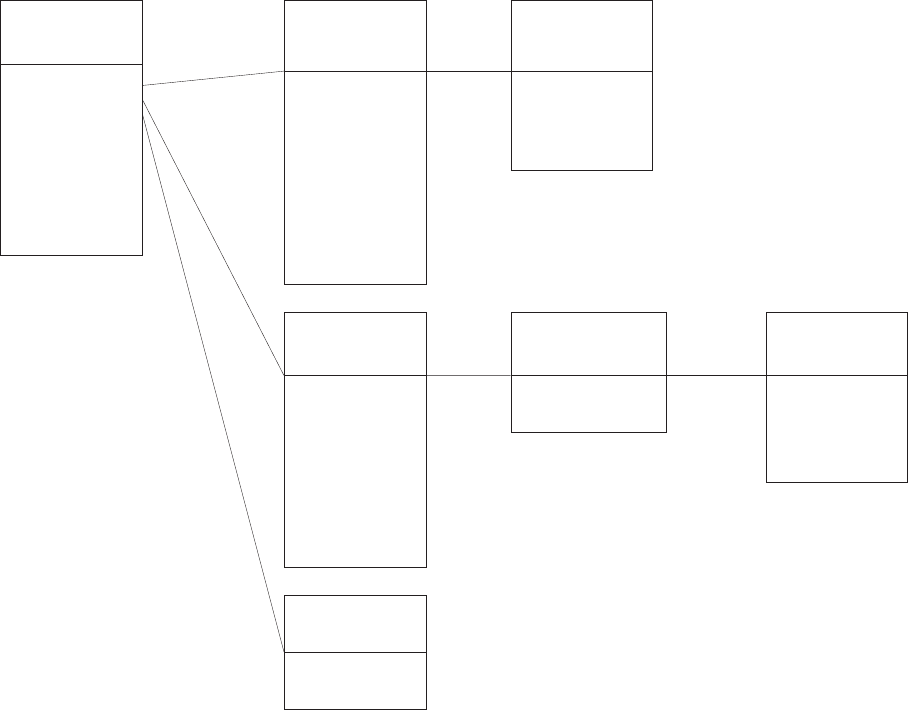
CHAPTER 6. DETAILED SYSTEM DESIGN 32
PARAM
STATE
STATUS
ParseMessage()
SetDescriptor()
SetSuppDescriptor()
GetDescriptor()
SetLength ()
GetLength()
ReceiveCoreMessage()
SendCoreMessage()
COREMESSAGE
SetSection()
SetType()
SetName()
GetSection()
GetType()
GetName()
GetParamLine()
GetListPtr()
SetListPtr()
GetValue()
ParseParameter()
ConstructParameterLine
valid
PARAM
ParseStatus()
GetStatus()
GetCode()
STATUS
GetName()
GetLength()
GetValue()
GetByteLocation()
GetBitLocation()
SetByteLocation()
SetBitLocation()
ConstructStateLine ()
GetStateLine()
ParseState()
valid
STATE
GetStatePtr
AddS tate2List
GetListCount
STATELIST
Initialize_StateVector()
GetS ta te Value()
SetStateValue()
GetStateVe ctorLength ()
GetStateVectorPtr()
STATEVECTOR
AddParameter2List()
Add()
GetListCoun t()
GetParamPtr()
PARAMLIST
x 1
x 1
Figure 6.2: Class model for all shared classes
Chapter 7
Available Filters and their
Parameters
7.1 EEG Source
7.2 Signal Processing
7.2.1 Calibration
The calibration filter (class CalibrationFilter ) calibrates the incoming EEG signal.
It performs a linear scaling, such that each channel is expressed in µV and has a
mean of zero (i.e., newvalue = (ADvalue − SourceChOffset ) ∗ SourceChGain).
The calibration filter acts only on the subset of channels defined by TransmitCh
and TransmitChList; regardless of this, the SourceChOffset and SourceChGain pa-
rameters refer to the full set of software channels as stored in the data file, in the
order in which they are digitized.
Requested Parameters
Section Parameter Data Type
Source SourceChOffset floatlist
Source SourceChGain floatlist
Source AlignChannels int
Table 7.1: Parameters requested by the class CalibrationFilter
SourceChOffset specifies a list of offsets in AD units – one value for each channel.
SourceChGain specifies a list of gains as used in described formula – one value for
each channel.
33

CHAPTER 7. AVAILABLE FILTERS AND THEIR PARAMETERS 34
AlignChannels specifies whether samples should be aligned in time – most data
acquisition boards multiplex one A/D converter and thus samples for SoftwareCh
channels are linearly distributed in time over
1000
SamplingRate
milliseconds (0=no align-
ment, 1=perform alignment).
Input/Output
The input to an instance of this filter class is GenericIntSignal A (dimensions Trans-
mitCh channels by SampleBlockSize elements). Its output is Signal B with the same
dimensions.
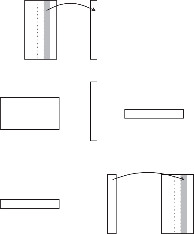
7.2.2 Spatial Filter
The spatial filter class SpatialFilter performs for each sample vector (TransmitCh
values – one for each channel) an operation as shown in Figure 7.1.
Requested Parameters
Section Parameter Data Type
Filtering SpatialFilterKernel matrix
Table 7.2: Parameters requested by the class SpatialFilter
The dimensions of SpatialFilterKernel are m’ by TransmitCh.
Input/Output
The input to an instance of this filter class is Signal B (dimensions TransmitCh
channels by SampleBlockSize elements). Its output is Signal C with the following
dimensions: m’ channels and SampleBlockSize elements.
7.2.3 Temporal Filter Using an AR Model
Each instance of the temp oral filter class ARFilter requests the following parameters:
Requested Parameters
Section Parameter Data Type
Filtering TempFiltCfg matrix
Table 7.3: Parameters requested by the class ARFilter
CHAPTER 7. AVAILABLE FILTERS AND THEIR PARAMETERS 35
Filter Kernel
Matrix
x
channel in Signal C
D
A
T
A
=
m’ x TransmitCh TransmitCh x 1 1 x m’
D
A
T
A
TransmitCh SampleBlockSizex
Signal
B
TransmitCh x 1
The spatial filter performs
the matrix operation for
each sample in Signal B.
channel in Signal C
1xm’
transpose
m’ x1
m’ SampleBlockSizex
Signal
C
Figure 7.1: Matrix operation on the input signal
TempFiltCfg is a matrix of dimensionality m’ x (max nr. of columns). It serves
to configure the nature of temporal filtering.
Input/Output
The input to an instance of this filter class is Signal C (dimensions number of
spatially filtered channels by SampleBlockSize elements). Its output is Signal D
with the following dimensions: m’ x n’.

CHAPTER 7. AVAILABLE FILTERS AND THEIR PARAMETERS 36
7.2.4 Classifier / Translation Algorithm
An instance of ClassifierFilter transforms pre–processed signal components into sig-
nals that can – after normalization – be used for device control.
Requested Parameters
Section Parameter Data Type
Filtering MUD matrix
Filtering MLR matrix
Table 7.4: Parameters requested by the class ClassifierFilter
MUD and MLR are matrices of the same dimensionality as Signal D (m’ x n’).
The two scalars in the resulting control signal (Signal E) – one for up/down and one
for left/right movement – each are linear combinations of Signal D and their respec-
tive weight matrix (MUD or MLR) as follows: updown =
P
i<m
0
,j<n
0
i=0,j=0
MUD
ij
∗ SignalD
ij
Input/Output
The input to this filter class is Signal D with the following dimensions: m’ x n’. The
output is Signal E with NumControlSignals channels and 1 element per channel.
7.2.5 Normalizer
An instance of NormalizeFilter makes each scalar in the vector of control signals
(Signal E) zero mean and thereafter normalizes it to a desired range (not exceeding
-32767 to +32767).
Requested Parameters
Section Parameter Data Type
Filtering Gain floatlist
Filtering Intercept floatlist
Table 7.5: Parameters requested by the class NormalizeFilter
Each of the NumControlSignals scalars in Gain and Intercept are used as follows:
SignalF
i
= Gain
i
∗ (SignalE
i
+ Intercept
i
)
CHAPTER 7. AVAILABLE FILTERS AND THEIR PARAMETERS 37
Input/Output
The input to this filter class is Signal E with the following dimensions: NumCon-
trolSignals channels and 1 element per channel. Its output, Signal F, is of the same
dimensionality.
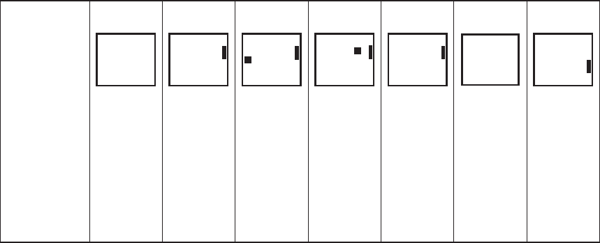
7.2.6 Slow-Wave-Feedback
Author and Introduction
Description of Signal Processing Module for the Slow-Wave-Feedback written by Dr.
Thilo Hinterberger, University of T¨ubingen, Germany.
The calculation of the Slow-Wave feedback signal is subdivided into three mod-
ules: The SW-Filter, which is realized as an efficient boxcar-filter, the SetBaseline
module, which subtracts a defined baseline from the signal and an artifact correction
module, which contains two different artifact correction modes.
SignalB
SignalC
SWFilter
incl.: boxcar filter,
artifact control and
timeconstant correction
SetBaseline
SignalC
SignalC
FBArteCorrection
Figure 7.2: Data flow in the slow wave filter
Temporal SW-Filter
Following states are used: Artifact (bool) is set to 1 when the signal changes exceed
the threshold values defined in ThresholdAmp (see below). BeginOfTrial is checked
to trigger the start of the trial and reset the internal counter.
Requested Parameters
The SW-Filter uses the following parameters:
SWFilter int SWAvgSpan= 0.5 0.5 0 10
// Averaging window in s
SWFilter intlist SWInChList= 3 0 1 2 0 0 63
CHAPTER 7. AVAILABLE FILTERS AND THEIR PARAMETERS 38
// Channel index of input signal (include artifact channel!)
SWFilter intlist SWOutChList= 3 0 1 2 0 0 63
// Channel index of output signal (include artifact channel!)
SWFilter floatlist ThresholdAmp= 3 100 100 400 200 -2000 2000
// Threshold for invalid Trial in uV
SWFilter float Tc= 0 16 0 1024
// Time constant filter settings in s
Visualize int VisualizeSWFiltering= 1 0 0 1
// visualize SW filtered signals (0=no 1=yes)
SWAvgSpan defines the time window of the boxcar-filter. SWInChList defines,
which channels from Signal B are filtered. They are sorted to the channels in Signal
C which are selected in SWOutChList. In the Standard setting, three channels
are filtered. The ThresholdAmp is an artifact control parameter. In between one
trial (from one BeginOfTrial to the next), the amplitude is not allowed to vary
more than the in ThresholdAmp defined size in V. Otherwise the trial should be
neglected and set as invalid in the application module (state Artifact is set to one).
A time constant (Tc) correction function simulates a real DC-behaviour, even if the
amplifier has no DC- option. This can be done by the knowledge of the amplifiers’
time constant, which is set as the parameter Tc. To avoid that the signal will drift
towards very high positive or negative values, the correction signal is set to zero each
time, when BeginOfTrial is one. Tc=0 will switch off the Tc-correction. Note: The
Tc-correction will only work properly, when the A/D-converter and the amplifier
puts out 0 when the input is 0 V and there is no electrode polarization! If you are
not sure, switch off this correction.
Baseline Setting
Following states are used: Baseline (bool) is set to 1 during the baseline perio d
between BaseBegin and BaseEnd. Otherwise it is zero. BeginOfTrial is checked to
trigger the start of the trial and reset the internal counter.
Requested Parameters
The SW-Filter uses the following parameters:
BLFilter float BaseBegin= 0.9 1.9 0 60
// Begin of Baseline in s
BLFilter float BaseEnd= 1.0 2.0 0 60
// End of Baseline in s
BLFilter intlist BaseChList= 3 1 1 1 1 0 1
// 1 to mark that BL is subtracted
CHAPTER 7. AVAILABLE FILTERS AND THEIR PARAMETERS 39
Visualize int VisualizeBaselineFiltering= 1 0 0 1
// visualize baseline filtered signals (0=no 1=yes)
The baseline is set each trial at the time point BaseEnd seconds after BeginOf-
Trial was set to one. The baseline amplitude is the average amplitude in the time
interval between BaseBe gin and BaseEnd. The baseline is subtracted of all channels
marked with 1 in the BaseChList. As default, baseline subtraction is applied on all
three channels.
This version still uses the parameters BIPts and FIPts, which define the duration
of the baseline-interval and the feedback-interval in seconds. These parameters are
used for the buffer, which needs the duration of a trial. They will be no longer used
in the next version.
Artifact Correction
Following s tates are used:
Artifact (bool) is set to 1 only in ArteMode=3 when the feedback signal is set
to zero due to the EOG artifact BeginOfTrial is checked to trigger the start of the
trial and reset the internal counter.
Requested Parameters
The SW-Filter uses the following parameters:
ArteFilter intlist ArteChList= 3 2 2 -1 2 -1 63
// Assignment of artefact channels, -1: no artifact channel
ArteFilter floatlist ArteFactorList= 7 0.15 0.15 0 0 0 0 0 0 -1 1
// Influence of artefact channel on input channel,
-1: no artifact channel
ArteFilter int ArteMode= 0 1 0 3
// Artefact correction mode, 0 off, 1 continuous, 2 conditioned
Visualize int VisualizeFBArteCorFiltering= 1 0 0 1
// visualize FBArte corrected signals (0=no 1=yes)
Artifacts are corrected on all channels which are not marked with -1 in the
ArteChList. For the correction, the channel number at the position of the channel
in the ArteChList is used as artifact channel. For example, the standard setting
corrects the channels 0 and 1 by using channel 2 for the correction. The correction
factor is the factor set in ArteFactorList, 0.15 in the standard setting.
For the ArteMode parameter, the following values are possible:
• ArteMode 0 switches this filter off.
CHAPTER 7. AVAILABLE FILTERS AND THEIR PARAMETERS 40
• ArteMode 1 will subtract the artifact channel multiplied with a constant fac-
tor.
• ArteMode 2 will correct the signal according to Koutchoubey, 1997: If the
artifact signal has the same sign as the control signal, a correction is applied
by subtracting the artifact signal; otherwise, no correction is performed. If the
artifact crosses a threshold value, feedback is suppressed.
• ArteMode 3 is working identically to ArteMode 2 but sets the Artifact state
to 1 when the feedback is set to zero.
7.3 Application
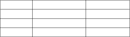
7.3.1 Right Justified Boxes Task
The right justified box task is a cursor task, in which the subject tries to hit one
out of n targets on a screen in trials of equal length. As listed in figure 7.3, the task
requests and controls spec ific states.
Whatever signal processing algorithm is used, it can passively monitor these
states and modify its operation accordingly, e.g., one algorithm might derive its
baseline from the inter-trial interval (i.e., ITI), whereas another might calculate it
differently. In this fashion, signal processing algorithms can be interchanged without
affecting the user application.
State
TargetCode
Baseline
Feedback
IntertrialInterval
ResultCode
0
1
0
1
0
2
0
0
0
0
2
0
1
0
0
2
0
1
0
0
2
0
0
0
1
0
1
0
1
0
3
0
0
0
0
123
4
5
6
7
Figure 7.3: Time Line for Right Justified Box task. The top-most target position cor-
responds to TargetCode=1. TargetCode increases towards the bottom. ResultCode
corresponds to the target actually selected. Thus, if TargetCode equals ResultCode,
the trial was a hit, otherwise a miss.
CHAPTER 7. AVAILABLE FILTERS AND THEIR PARAMETERS 41
Figure 7.3 illustrates the time line for the right justified box task and, for each
time interval, its respective content for each state.
1 is the intertrial interval, were the screen is blank and baseline data can be
collected (optional). In 2 the target is presented, but the cursor is absent (no
feedback). In 3 the cursor is present and it’s vertical movement is controlled by
the user’s EEG. Horizontal cursor movement is under c omputer control and is at a
constant rate. In 4 the cursor approaches the target and in 5 the target has been hit
and trial-outcome feedback is presented. In 6 the screen is blank (intertrial interval
again) and in 7 another target is presented.

Chapter 8
Glossary
Real Time
There are many definitions of the term real time. One example (as presented on
http://www.zdwebopedia.com/TERM/r/real time.html) is:
Occurring immediately. The term is used to describe a number of different com-
puter features. For example, real–time operating systems are systems that respond
to input immediately. They are used for such tasks as navigation, in which the com-
puter must react to a steady flow of new information without interruption. Most
general–purpose operating systems are not real–time because they can take a few
seconds, or even minutes, to react.
Real time can also refer to events simulated by a computer at the same speed
that they would occur in real life. In graphics animation, for example, a real–time
program would display objects moving across the screen at the same speed that they
would actually move.
42

Appendix A
List of Requested States
Project Unit State Description
DTsource DTADC.cpp Running Indicates when system is running
DTsource DTADC.cpp Active What is the difference between running and active?
DTsource DTADC.cpp SourceTime Time when data is acquired
Dtsource DTADC.cpp RunActive What is the difference between this, active and running?
SignalProc Statistics Artifact Identifies artifact in current data
Application Application.cpp StimulusTime Time when stimulus is displayed
Application Application.cpp TargetCode Identifies the active target
Application Application.cpp Baseline Identifies when baseline data is collected
Application Application.cpp Feedback Identifies when feedback is presented to user
Application Application.cpp IntertrialInterval Identifies inactive period between trials
Application Application.cpp Outcome Identifies trial outcome (0= pending, 1= hit, 2=miss)
to be announced
43

Appendix B
List of Requested Par ameters
Project Unit Section Type Parameter Description
Dtsource Storage.cpp Storage string FileName Name of Data File
Dtsource Storage.cpp Storage string SubjectName Name of subject
Dtsource Storage.cpp Storage string* SubjectSession Session Number
Dtsource Storage.cpp Storage string* SubjectRun run number
Dtsource Storage.cpp Storage string StorageTime time of beginning of data
Dtsource dtadc.cpp Source int SoftwareCh number of digitized channels
Dtsource dtadc.cpp Source int TransmitCh number of transmitted channels
Dtsource dtadc.cpp Source int SampleBlockSize number of samples transmitted at a time
Dtsource dtadc.cpp Source int SamplingRate sample rate
Dtsource dtadc.cpp Source string BoardName AD board name from driver
Dtsource dtadc.cpp Storage string FileName Data File Name
SignalProc Calibration Filtering floatlist SourceChOffset offset in A/D units
SignalProc Calibration Filtering floatlist SourceChGain gain for each channel (A/D units to µV)
SignalProc Calibration Filtering int AlignChannels align channels in time (0= no, 1= yes)
SignalProc Calibration Visualization int VisualizeCalibration visualize calibration channels
SignalProc Spatial Filtering int SpatialFilteredChannels Number of spatially filtered channels
SignalProc Spatial Filtering matrix SpatialFilterKernal Spatial Filter Kernal Weights
SignalProc Spatial Visualization int VisualizeSpatialFiltering Visualize Spatial Filtering?
SignalProc Temporal Filtering float StartMem Start of Sp ectrum in Hz
SignalProc Temporal Filtering float StopMem End of Spectrum in Hz
SignalProc Temporal Filtering float deltaMem Resolution (line density) in Hz
SignalProc Temporal Filtering float MemBandWidth Spectral Bandwidth in Hz
SignalProc Temporal Filtering int MemModelOrder AR mo del Order
SignalProc Temporal Filtering int MemDetrend Detrend data? (0=no, 1= mean, 2=linear)
SignalProc Temporal Visualization int VisualizeTemporalFiltering Visualize Temporal Filtering
SignalProc
Classifier Filtering matrix MUD Classifier Up/Down Control Weights
SignalProc Classifier Filtering matrix MLR Classifier Left/Right Control Weights
SignalProc Classifier Filtering int VisualizeClassFiltering Visualize Classifier Filtering (y/n)
to be announced
44

Appendix C
List of Source IDs
Module/Filter Defined As Source ID
EEG Source SOURCEID EEGDISP 53
Calibration Filter SOURCEID CALIBRATION 54
Spatial Filter SOURCEID SPATFILT 55
AR Temporal Filter SOURCEID TEMPORALFILT 56
Classifier SOURCEID CLASSIFIER 57
Normalizer SOURCEID NORMALIZER 58
Statistics Mo dule SOURCEID STATISTICS 59
User Task Log SOURCEID TASKLOG 60
to be announced
45

Appendix D
Error and Status Messages
Co de Text
200 EEGsource module initialized successfully ...
201 SignalProcessing module initialized successfully ...
202 Application module initialized successfully ...
203 EEGsource started ...
204 EEGsource susp ended ...
205 SignalProcessing started ...
206 SignalProcessing suspended ...
207 Application started ...
208 Application suspended ...
300 Parameters are inconsistent ...
301 State vector update timeout !
302 PostSetInterval shorter than time derived by NumERPSamples
303 One of the parameters needed by the task not found
400 Could not initialize socket connection to Signal Processing
401 Could not initialize socket connection to Application
402 Could not initialize socket connection to Source
403 Signal Processing dropped connection unexpectedly
404 Source dropped connection unexpectedly
405 Application dropped connection unexpectedly
406 Could not set SourceTime in the statevector
407 Error creating filters
408 Error initializing filters
409 Error while processing filters
410 Source: could not initialize connections
411 Error in Source: Exception thrown while initializing: !
412 Signal Processing: state vector is not defined !
413 Signal Processing: Exception thrown in Initialize()
414 Application: state vector is not defined !
415 P3 Temporal Filter: Inconsistency or ran out of buffers
416 P3 Speller: Could not open target definition file
417 Number of targets HAS TO BE 2 in Yes/No mo de !!
499 Logic Error (error condition otherwise unhandled)
46
