
Continuous 325 – 1000 VDC
Model: HPP-20KA01KAT B
Version: Rev. S.00
PULSED
DC Power Supply
INDEX
Chapter 1 : Safety and Standard
..............................................
1
1.1 Important Safety Information.........................................................................................................1
1.2 Safety and Warning Symbols........................................................................................................1
1.3 Electromagnetic Compatibility Directives and Standard................................................................2
1.4 Industry Guideline.........................................................................................................................2
Chapter 2 : Introduction
...........................................................
2
2.1 Brief Statement.............................................................................................................................2
2.2 Key Feature...................................................................................................................................2
Chapter 3 : Specication
.........................................................
3
3.1 System Block Diagram ................................................................................................................. 3
3.2 Electrical Specication ................................................................................................................. 4
3.3 Reverse Time as a Function of Voltage Limit.................................................................................5
3.4 Arc Suppression Specication……………………….....................................................................11
3.5 Process and Monitor Functio ..................................................................................................... 12
3.6 Mechanical Specication............................................................................................................ 12
3.7 Environment Specication.......................................................................................................... 14
Chapter 4 : System Protection Mechanism
.............................
15
4.1 Input Breaker...............................................................................................................................15
4.2 Protection by MCU ..................................................................................................................... 15
Chapter 5 : Installation
...........................................................
16
5.2 Cooling Requirements................................................................................................................ 17
5.3 Cabinet Design........................................................................................................................... 17
5.4 Grounding .................................................................................................................................. 13
Chapter 6 : Interface
..............................................................
18
6.1 Front Panel................................................................................................................................. 18
6.2 Rear Panel ................................................................................................................................. 19
6.3 Main Menu Map ......................................................................................................................... 20
6.4 Digital Communication Port (Host) ............................................................................................. 21
6.5 Analog Communication Port (User)............................................................................................ 26
Chapter 7 : Operation
............................................................
28
7.1 Local Operating Steps ............................................................................................................... 28
7.2 D-SUB Operating Steps ............................................................................................................. 29
7.3 RS232 Operating Steps ............................................................................................................. 29
7.4 RS485 Operating Steps ............................................................................................................. 29
Chapter 8 : Maintenance
........................................................
29
Copyright
All rights reserved. The contents either of manual and design of power supply
may not be
reproduced or used in any manner whatsoever without admittance by
Delta Electronics Inc.
Warranty
This product Delta “HPP-20KA01KAT” Model is been warranted against defect in material and
workmanship for a period of “1” year after date of shipment. Delta agrees to repair or replace the fault
unit free-of-charge which fails to perform with specication and under normal use during this period.
This warranty shall not apply to the following items and will be billed of cost:
1 . To exceed the warranty period.
2 . Subject to misuse, negligence, accident or natural disaster.
3 . Used in a hazardous or dangerous manner either alone or in conjunction with other equipment.
4 . Repaired or altered by person who was not authorized by Delta.
5 . Appearance change with environment factor
Delta will be the sole arbiter for those circumstances.
To make a warranty claim please contact Delta at telephone number in the table or support at
delta.com, the fault unit transportation to Delta to be prepaid and responsibility by purchaser, and
Delta will take responsibility for ship it back.
Delta Electronics, Inc.
3 Tungyuan Road, Chungli Industrial Zone
Taoyuan County 32063, Taiwan, ROC
Tel: 886-3-4526107
Fax: 886-3-4331706
Web Site: www.deltaww.com
Chapter 1 : Safety and Standard
1.1 Important Safety Information
To keep your safety from hazardous and fatal circumstance, please read and realize the content
of this manual before installing and operating Delta “HPP-series” power supply.
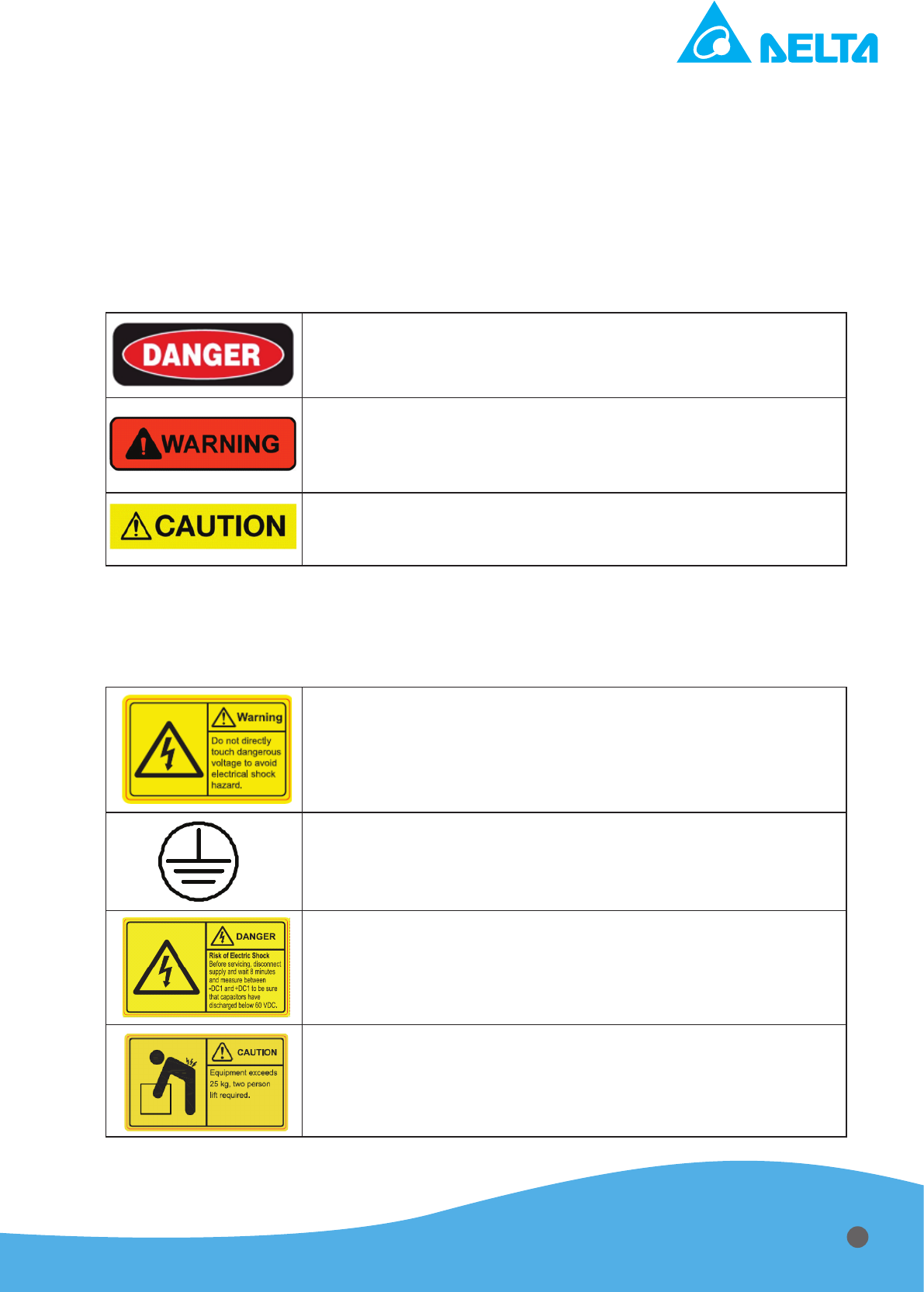
1.2 Safety and Warning Symbols
The following advisory symbols as shown in Table 1.1 will be used in the manual for different level
of warning. The meanings of the advisory symbols are explained below.
Table 1.1 Safety and warning symbols (1)
This danger symbol advises that improper operation will cause
serious personal injury or death.
This warning symbol advises that improper operation will cause
serious personal injury, or catastrophic damage the generator
or any electronic devices connected to the generator, or lose
important data.
This caution symbol advises that improper operation will cause
personal injury, damage the power supply or any electronic
devices connected to the power supply, lose data.
The following advisory symbols as shown in Table 1.2 are used on safety warning labels, and/
or on printed circuit board (only provided with white paint), and/or other part of the generator. The
meanings of these symbols are explained as below.
Table 1.2 Safety and warning symbols (2)
Dangerous voltage symbol indicates the presence of high
voltage. Access the high voltage will cause serious personal
injury or death.
To protect against electrical shock in case of a fault. This symbol
indicates that the terminal must be connected to ground before
operation of equipment.
Residual voltage:
Wait 8 minutes at least for capacitor discharge after power cord is
removed and before servicing
.
Heavy object:
Two persons lifting are recommended to avoid muscle strain or
back injuries.
1
1.3 Electromagnetic Compatibility Directives and Standards
- Disturbance Characteristic: EN55011 - CRSP11 Class A, Group 1 (
>20kVA)
- General Immunity Standard for Industry: EN 61000-6-2
- Safety Requirement: IEC-61010-1 (CE and UL certication)
1.4 Industry Guideline
Guideline for Semiconductor manufacturing equipment: SEMI S2 and F47
Chapter 2 : Introduction
2.1 Brief Statement
Delta “HPP-20KA01KAT” is a high voltage pulsed DC generator that meets the exciting require-
ment in physical vapor deposition technique with a wide range of applications in the semiconductor,
optical and industrial coating, particularly for Reactive Sputtering, like Alumina, Titania and Silica
with high deposition rates.
Asymmetric pulsing output makes the arc happening reduced dramatically. With Delta micro-
sec arc detection, the output will be reversed to positive output to eliminate the arc and reduce arc
energy.
With Delta’s mutual power supply design technology, efciency at rated load is higher than com-
peting products. High efciency, less temperature stress and highly integrated circuit make it more
stable, reliable and longer product lifetime. DSP-based digital control provides user an accurate, re-
peatable and quick pulsed output response. Active front panel, multiple serial and analog interfaces
facilitate user to get an easy and exible control over power supply.
Figure 2.1 Delta “HPP-20KA01KAT” power supply
2.2 Key Feature
•
Advanced SiC mosfets module implement:
→ The highest power level of pulse DC generator.
→ The widest frequency adjustment.
•
Lossless Snubber circuit.
→ Clamp voltage stress of pulse switch.
→ Less oscillation.
•
Ultra low arc energy (< 200uJ/KW)
2
Chapter 3 : Specication
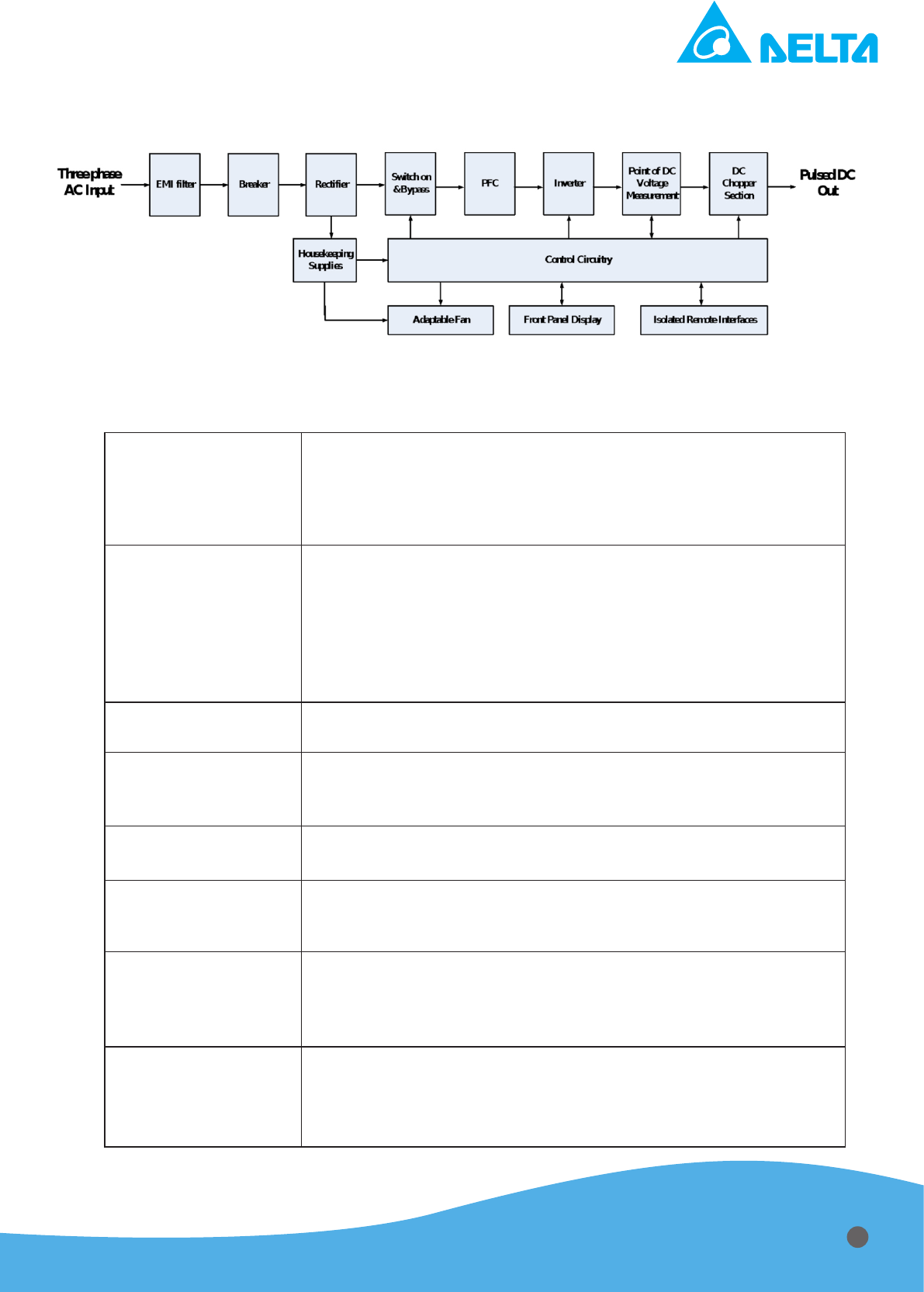
3.1 System Block Diagram
Figure 3.1 System block diagram of Delta “HPP-20KA01KAT”
T
able 3.1 Detail description for block diagram
PFC Sectionn
Three phase mains voltage is applied while breaker is closed.
After EMI lter, soft start mechanism suppresses inrush current to
prevent any damage. A good power factor condition back to the
mains then is modified through PFC section and AC voltage is
rectied to DC bus for DC-DC Section.
Inverter
The converter section converts DC voltage stored in the bulk
capacitors to high-frequency voltage by alternating the current
through switching power components. In the output side, an
isolation transformer steps up the high-frequency voltage from
the converter section and delivers it to a full-wave rectier bridge.
The rectied DC power is then passed through a measurement
section to the output connector.
DC Chopper Section
In the pulse section, a tapped inductor and a controlled switch
are responsible for generating pulse output from straight DC.
Output Measurement
and Feedback
The output measurement section measures current and voltage,
and feedback the voltage and current information to MCU for
voltage, current and power control and related protection.
Housekeeping
supplies
The AUX power provides low voltage source to supply the Vcc of
analog OPA, main controller, MCU, fan and LCD display.
Control Circuitry
The MCU is responsible for controlling the power supply status
and providing status information to the operator through all
interfaces.
Front Panel Display
Control panel shows operating mode, command level, feedback
values, set up Arc processing, process control, interface setup,
communication set and system status during power supply
working.
Remote Control
Interface
The power supply supports three types of interfaces: a User port
(analog), a Host port (RS-232, RS-485) and an active front panel.
All three interfaces communicate operator-supplied inputs to
MCU and provide the operator with status information.
3
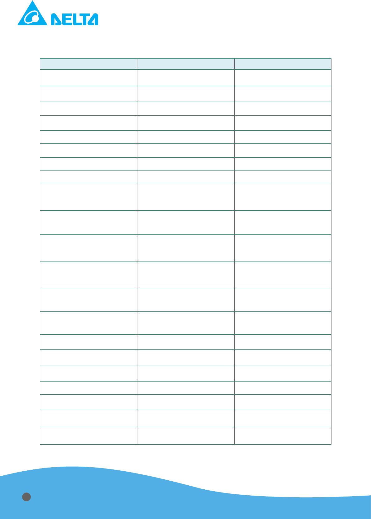
3.2 Electrical Specication
T
able 3.2 Electrical specication
Item Specication Condition
Input Voltage
208V ± 10% (Three Phase). 50 to 60Hz
Input Current (Per Phase)
75 A nominal per phase Rated output power
Maximum Output Power
20kW -
Output Voltage Range
131 to 1000V Measured at the DC output
Output Current Range
5 to 60A
Power Supply Efciency
> 90% Rated output power at DC 1000V
Power Factor
> 0.9 Rated output power
Output Voltage Ripple
< 2% (V ) At DC Mode
Output Voltage Accuracy
1% of command setting or 0.25%
of full scale voltage between
output and command
Within operation range at 25˚C
Output Current Accuracy
1% of command setting or 0.25%
of full scale current between
output and command
Within operation range at 25˚C
D-sub Monitor/Command
(Analog Interface) Accuracy
1% of full scale rating between
output and D-sub
Operation range
Load Regulation
1% of command setting or 0.5% of
full scale voltage between output
and command
10% to 100% Output Power
Ignition Capability
1000Vdc to 1500Vdc
100Vdc increments
Temperature Coefcient
< 50ppm/˚C
20˚C to 40˚C Variation in regulated
output
Operation Mode
CV, CC, and CP Mode -
Operation Temperature
0˚C to 40˚C% -
Arc Energy
< 200uJ per 1kW -
Main Protection
OVP, OCP, OTP, SCP, ARC
Output Frequency
5K~400KHz, 5KHz increments
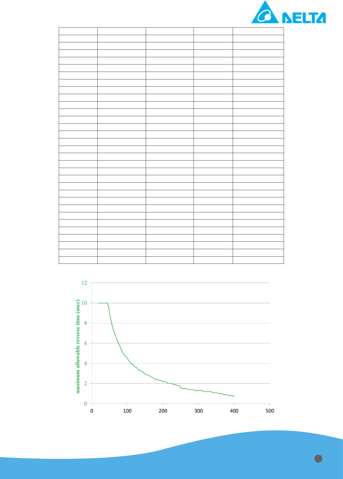
Reverse Time
0.4us to 10us, 0.1us increments
Allowable reverse time is limited
for a given frequency
Reverse Voltage
Approximately 10% of the applied
voltage
AC
RMS
RMS
DC
4

Repeatability
Output power repeatability of the
DC inverter from run to run at a
constant setpoint is 0.1% from
10% to 100% of rated power.
3.3 Reverse Time as a Function of Voltage Limit (V-Limit)
V-Limit(in Volts) Corresponding Reverse Time
0-325 10 μs
330 9.8 μs
335 9.7 μs
340 9.5 μs
345 9.4 μs
350 9.2 μs
355 9.1 μs
360 9 μs
365 8.9 μs
370 8.7 μs
375 8.6 μs
380 8.5 μs
385 8.4 μs
390 8.3 μs
395 8.2 μs
400 8.1 μs
405 8 μs
410 7.9 μs
415 7.8 μs
420 7.7 μs
425 7.6 μs
430 7.5 μs
435 7.4 μs
440 7.3 μs
445 7.3 μs
450 7.2 μs
455 7.1 μs
460 7 μs
465 6.9 μs
470 6.9 μs
475 6.8 μs
480 6.7 μs
485 6.7 μs
490 6.6 μs
495 6.5 μs
500 6.5 μs
505 6.4 μs
510 6.3 μs
515 6.3 μs
520 6.2 μs
525 6.1 μs
530 6.1 μs
535 6 μs
540 6 μs
545 5.9 μs
550 5.9 μs
5
555 5.8 μs
560 5.8 μs
565 5.7 μs
570 5.7 μs
575 5.6 μs
580 5.6 μs
585 5.5 μs
590 5.5 μs
595 5.4 μs
600 5.4 μs
605 5.3 μs
610 5.3 μs
615 5.2 μs
620 5.2 μs
625 5.2 μs
630 5.1 μs
635 5.1 μs
640 5 μs
645 5 μs
650 5 μs
655 4.9 μs
660 4.9 μs
665 4.8 μs
670 4.8 μs
675 4.8 μs
680 4.7 μs
685 4.7 μs
690 4.7 μs
695 4.6 μs
700 4.6 μs
705 4.6 μs
710 4.5 μs
715 4.5 μs
720 4.5 μs
725 4.4 μs
730 4.4 μs
735 4.4 μs
740 4.3 μs
745 4.3 μs
750 4.3 μs
755 4.3 μs
760 4.2 μs
765 4.2 μs
770 4.2 μs
775 4.1 μs
780 4.1 μs
785 4.1 μs
790 4.1 μs
795 4.0 μs
800 4.0 μs
805 4.0 μs
810 4.0 μs
815 3.9 μs
820 3.9 μs
6

825 3.9 μs
830 3.9 μs
835 3.8 μs
840 3.8 μs
845 3.8 μs
850 3.8 μs
855 3.7 μs
860 3.7 μs
865 3.7 μs
870 3.7 μs
875 3.7 μs
880 3.6 μs
885 3.6 μs
890 3.6 μs
895 3.6 μs
900 3.6 μs
905 3.5 μs
910 3.5 μs
915 3.5 μs
920 3.5 μs
925 3.5 μs
930 3.4 μs
935 3.4 μs
940 3.4 μs
945 3.4 μs
950 3.4 μs
955 3.3 μs
960 3.3 μs
965 3.3 μs
970 3.3 μs
975 3.3 μs
980 3.3 μs
985 3.2 μs
990 3.2 μs
995 3.2 μs
1000 3.2 μs
7
Reverse Time Given a Self-Run Frequency
Requested
Frequency
(kHz)
Actual
Frequency
(kHz)
Pulse
Reversal Time
Maximum (μs)
Duty Cycle
(min%)
Reverse/
Period
Duty Cycle
(max%)
Reverse/
Period
5 5 10 0.2 5
10 10 10 0.4 10
15 15.004 10 0.6 15
20 20 10 0.8 20
25 25 10 1 25
30 29.985 10 1.2 30
35 35.026 10 1.4 35
40 40 10 1.6 40
45 45.045 9.9 1.8 44.6
50 50 9 2 45
55 54.945 8.1 2.2 44.5
60 60.06 7.4 2.4 44.4
65 64.935 6.9 2.6 44.8
70 69.93 6.4 2.8 44.8
75 74.906 6 3 44.9
80 80 5.6 3.2 44.8
85 85.106 5.2 3.4 44.3
90 90.09 4.9 3.6 44.1
95 94.787 4.7 3.79 44.5
100 100 4.5 4 45
105 105.263 4.2 4.21 44.2
110 109.89 4 4.4 44
115 114.943 3.9 4.6 44.8
120 119.76 3.7 4.79 44.3
125 125 3.6 5 45
130 129.87 3.4 5.19 44.2
135 135.135 3.3 5.41 44.6
140 139.86 3.2 5.59 44.8
145 144.928 3.1 5.8 44.9
150 150.376 2.9 6.02 43.6
155 155.039 2.9 6.2 45
160 160 2.8 6.4 44.8
165 165.289 2.7 6.61 44.6
170 169.492 2.6 6.78 44.1
175 175.439 2.5 7.02 43.9
180 180.18 2.4 7.21 43.2
185 183.486 2.4 7.41 44
190 190.476 2.3 7.62 43.8
195 194.175 2.3 7.77 44.7
200 200 2.2 8 44
205 204.082 2.2 8.16 44.9
210 210.526 2.1 8.42 44.2
215 215.054 2 8.6 43
220 219.78 2 8.79 44
225 224.719 2 8.99 44.9
230 229.885 1.9 9.2 43.7
235 235.294 1.9 9.41 44.7
240 240.964 1.8 9.64 43.4
8
245 243.902 1.8 9.76 43.9
250 250 1.6 10 40
255 256.41 1.5 10.26 38.5
260 259.74 1.5 10.39 39
265 266.667 1.5 10.67 40
270 270.27 1.4 10.81 37.8
275 273.973 1.4 10.96 38.4
280 281.69 1.4 11.27 39.4
285 285.714 1.4 11.43 40
290 289.855 1.3 11.59 37.7
295 294.118 1.3 11.76 38.2
300 298.507 1.3 11.94 38.8
305 303.03 1.3 12.12 39.4
310 307.692 1.3 12.31 40
315 312.5 1.2 12.5 37.5
320 317.46 1.2 12.7 38.1
325 322.581 1.2 12.9 38.7
330 327.869 1.2 13.11 39.3
335 333.333 1.2 13.33 40
340 338.983 1.1 13.56 37.3
345 344.828 1.1 13.79 37.9
350 350.877 1.1 14.04 38.6
355 355.877 1 14.2 35.5
360 360.878 1 14.4 36
365 365.788 1 14.6 36.5
370 370.787 0.9 14.8 33.3
375 375.877 0.9 15 33.75
380 380.788 0.9 15.2 34.2
385 385.877 0.9 15.4 34.7
390 390.878 0.9 15.6 35.1
395 395.787 0.9 15.8 35.6
400 400.788 0.9 16 36.0
9
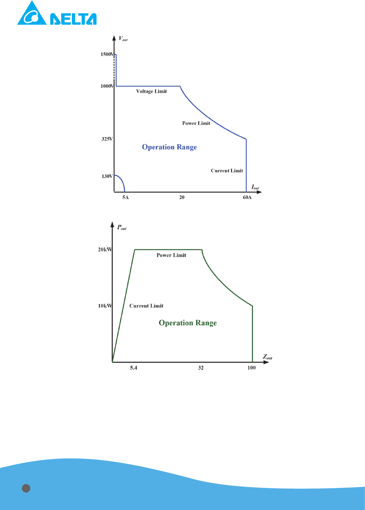
Figure 3.2 Curve of Output V-I Characteristic
Figure 3.3 Curve of Output Impedance Characteristic
For Delta “HPP-20KA01KAT” power supply, the maximum output voltage and current level are
1000 V and 60 A (Measured at the DC output). The output characteristic is as the gures above.
If the operation point is below 325V, the power supply can provide at most 60 A, if the operation is
more than 325V, the maximum output current will decrease to 20 A within the output voltage reach-
ing 1000V.
10
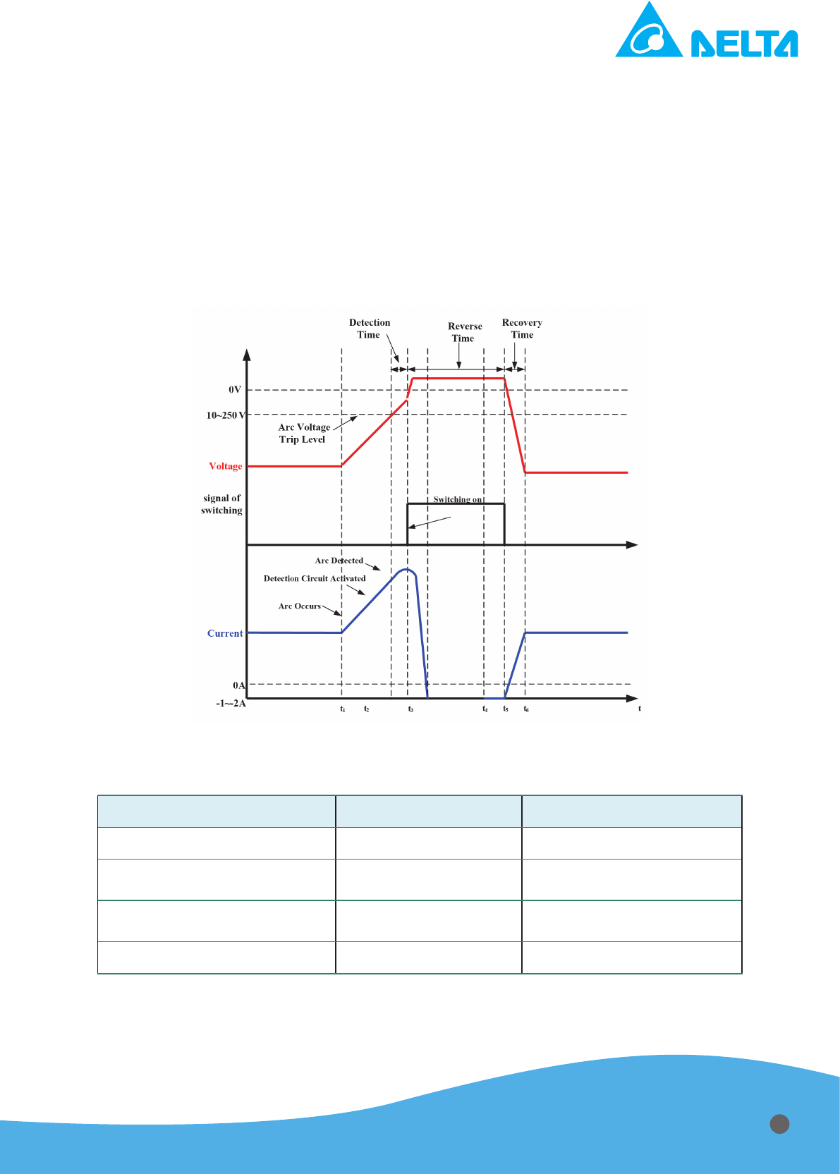
3.4 Arc Suppression Specication
Figure 3.4 shows the waveforms and key parameters under arc condition, and Table 3.3 indi-
cates the arc energy and adjustable parameters for user. As soon as the arc is detected by arc volt-
age detection within 1 microsec, power ON delay after a micro ARC will be approximately 5 micro-
seconds. When the micro ARC is cleared normal pulsing resumes.
Hard Arcs (dened as those micro Arcs which cannot be extinguished with the standard micro
ARC algorithm of a 5 microsecond shutdown) will be detected within low impedance after the initial
micro ARC started. Number of detected arcs is displayed by the front panel display or from commu-
nication interface. If hard arc inside vacuum chamber occur, the hard arc ag will be raised and the
power will shutdown for a predetermined time.
Figure 3.4 Arc suppression mechanisms
T
able 3.3 Arc energy specication and adjustable parameters for user
Item Specication Description
Reverse Time
5µ sec
Voltage Level Recognizing
as Arc
10V to 250V, adjustable 10V step, 100V default
Hard Arc Shutdown time
200us to 10000us
After Low Z output, power
will shutdown
Arc Energy
< 1200uJ per 1kW With System
11
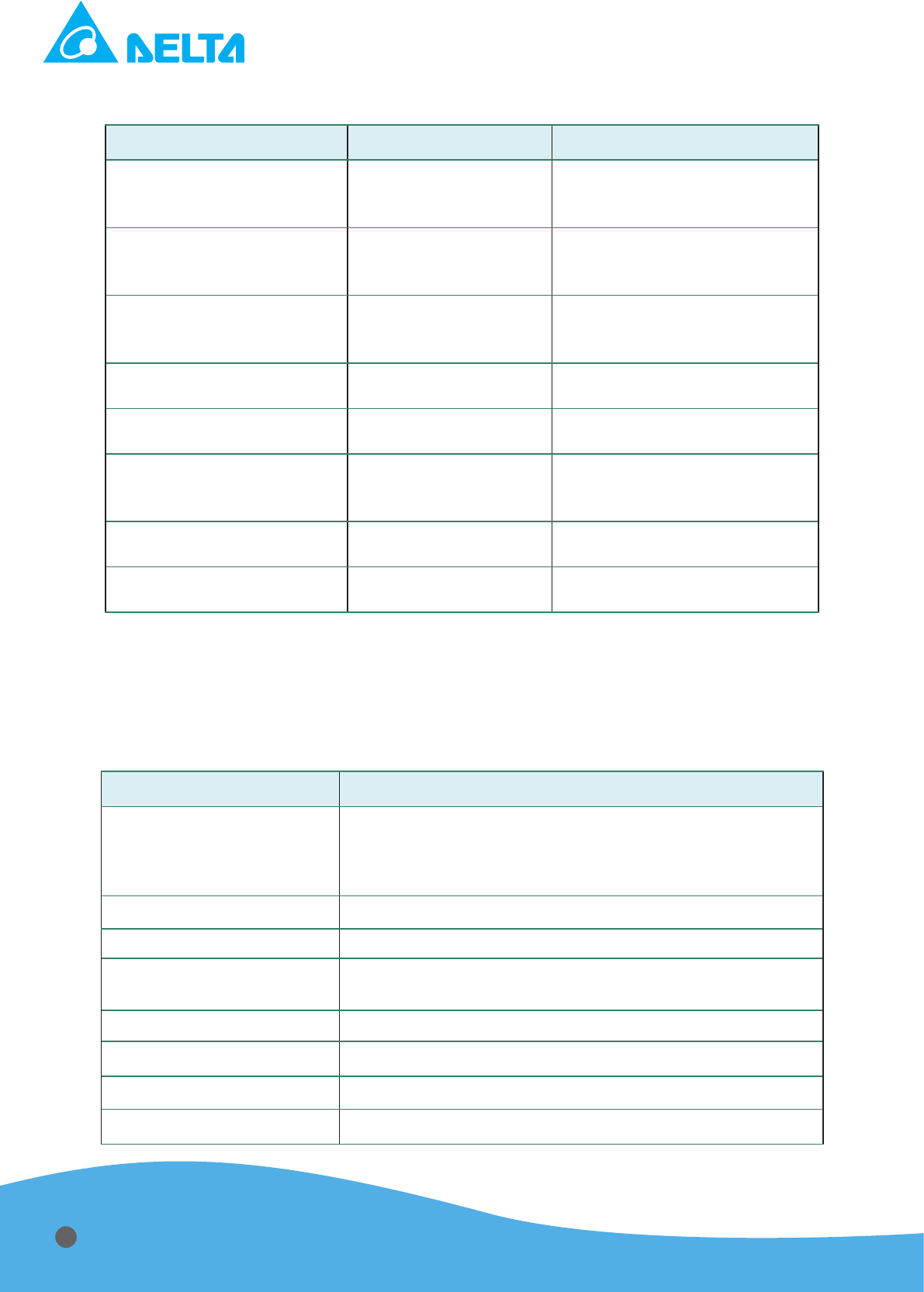
3.5 Process and Monitor Function
T
able 3.4 Adjustable function parameters for User
Item Specication Description
Max. Power
2 to 20kW
Power will be constrained within
the value of setting prior to the
set point of regulation
Max. Current
5 to 60A
Current will be constrained
within the value of setting prior
to the set point of regulation
Max. Voltae
500 to 1000V
Voltage will be constrained
within the value of setting prior
to the set point of regulation
Ignition Mechanism
1000 to 1500V
A voltage up to 1500 V is adjus-
table for igniting the system
Ramp Time
50 to 2000ms
A ramp up to set point is adjus-
table for a soft start mechanism
Set Point
1 to 10s
Monitoring if the output reaches
the setting of regulation within
the setting of period
Energy Mode
1 to 99999 kJ
Monitoring if the output energy
reaches the setting of energy
Target Life Mode
1 to 15000 kWh
Monitoring if the output energy
reaches the setting of kWh
3.6 Mechanical Specication
The outward appearance, cooling specication for minimum CFM Requirement, and I/O ports
of
Delta “HPP-20KA01KAT” sputtering power supply are described as below:
T
able 3.5 Mechanical specication
Item Description
Physical Dimension
482.6 mm (W) x 132.5 mm (H) x 600 mm (L)
19" (W) x 5.2" (H) x 23.6" (L)
(19" 3U)
Weight
45kg
Coolingt
Fan cooling
Noise
Noise generated by this unit under 70 dB (A) at a 1m
distance in 25˚C ambient temperature
AC Input Connector
4 pin terminal block
DC Output Connector
UHF connector,female
User Port
Analog I/O: 15-pin female D-sub
Host Port
Digital I/O: 9-pin female RS232 and RS485 and RJ45
12
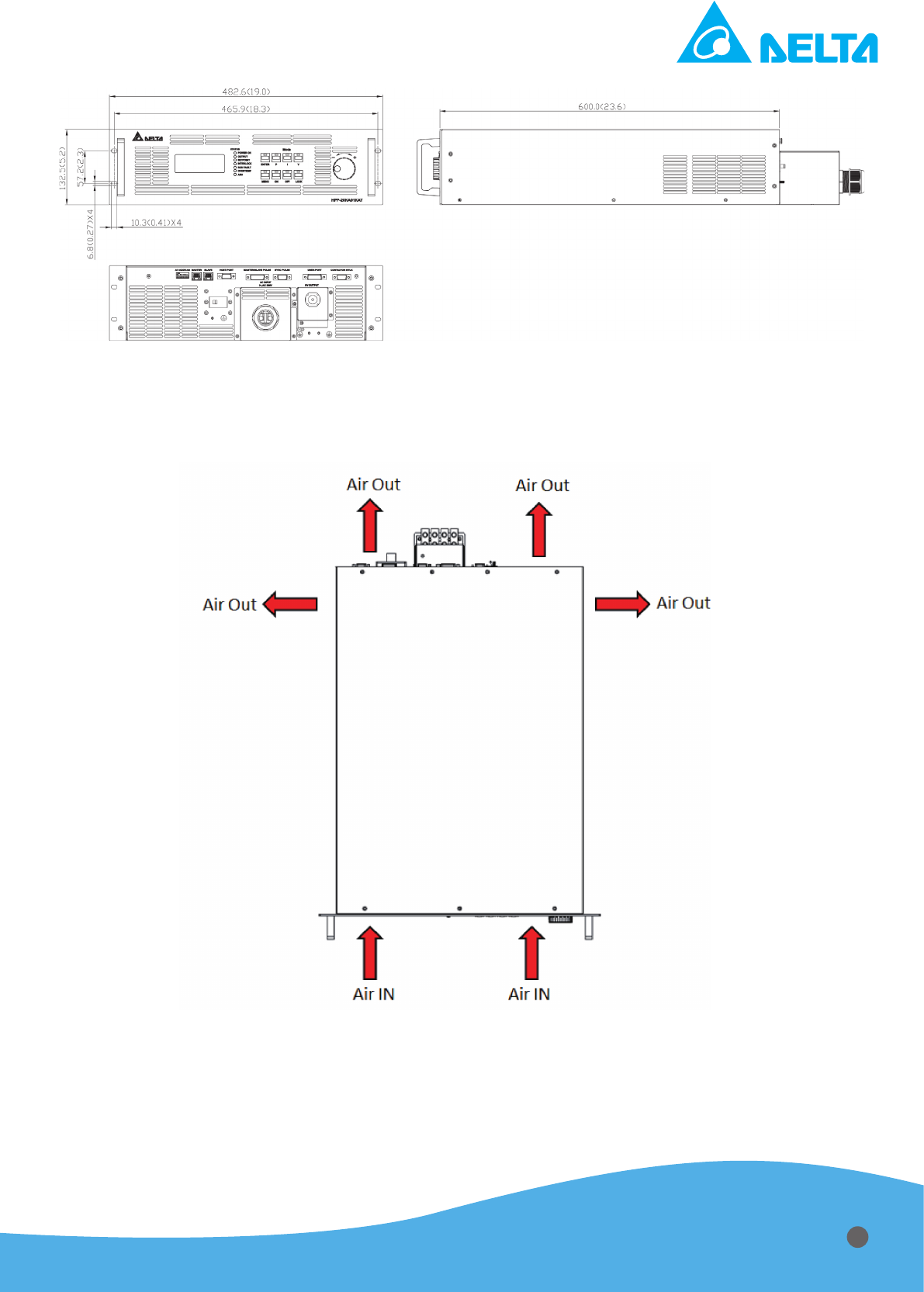
Figure 3.5 Physical dimension of HPP-20KA01KAT sputtering power supply
Air cooling
Figure 3.6 Air ow directions
Delta “HPP-20KA01KAT” sputtering power supply is the forced air cooling type. Please keep
enough space for air ow cooling capability when it is installing to the cabinet. Air inlet on the front
panel and air outlet on the rear panel is shown in gure 3.6. Air outlet of rear panel is responsible
for dissipating the heat from inside of power supply to outside by internal two fans. The temperature
of air inlet should not exceed 40
℃
.
13
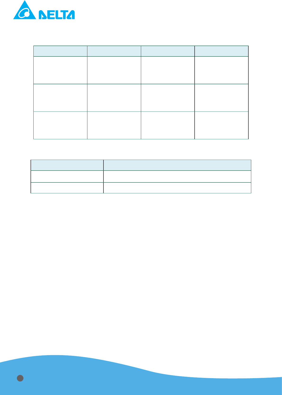
3.7 Environment Specication
T
able 3.6 Climatic specication
Item Temperature Relative Humidity Air Pressure
Operating
0 to 40˚C
(32˚F to 104˚F)
10% to 90% RH
(Non-
condensing)
80 to 106kPa
(approximately
2000m
above sea
level)
Storage
-25 to 55˚C
(-13˚F to 131˚F)
10% to 95% RH
80 to 106kPa
(approximately
2000m
above sea
level)
Transportation
-25 to 40˚C
(-13˚F to 104˚F)
95% RH
(Maximum)
66 to 106kPa
(approximately
2000m
above sea
level)
T
able 3.7 Environment specication
Item Description
Operating
Category II
Pollution Degree
Pollution Degree 2
14
Chapter 4 :System Protection Mechanism
4.1 Input Breaker
The function of this switch is to prevent over current at input side from any malfunction
happen-
ing and simultaneously provide a manual switch for user to turn off the power supply.
4.2 Protection by MCU (A: Auto Recovery, L: Latch)
Table 4.1 Denition and description of MCU protection
Alarm Condition Code Description Mode
HW Fault M1
M1F Hardware error from the left module
A
(3 min latch)
HW Fault M2
M2F Hardware error from the right module
A
(3 min latch)
SW OVP
OV Output over voltage
A
(3 min latch)
SW OCP
OC Output over current
A
(3 min latch)
SW OPP
OP Output over power
A
(3 min latch)
Arc Number Limit
07 Arc number is over setting parameter L
Target Life Monitor
09 Power off while output reaches setting Energy L
Output Interlock
11 Uninstallation of output cover L
Contactor Interlock
12 Uninstallation of contactor pin in D-sub connector L
Communication Loss
15 Error from internal communication L
Fan1 Error
17 Error from the left fan L
Fan2 Error
18 Error from the right fan L
Bus UVP
20 Input voltage is under operation range L
Bus OVP
21 Input voltage is over operation range L
GND Detect
22 Positive output is not connected to system ground L
Set Point Monitor
23
Error while output fails to reach setting parameter
within setting time
L
Energy Mode Monitor
24 Power off while output reaches setting energy L
Warning Condition Code Description Mode
Arc Density Limit
01 Arc Density is over parameters of setting A
Output Limit
limit Output is over setting parameters of setting A
15
Chapter 5 :Installation
Delta “HPP-20KA01KAT” power supply is a high voltage power supply. Please read this manual
carefully and follow the instruction before installation and operation, otherwise an electric shock or
a fatal accident might be caused.
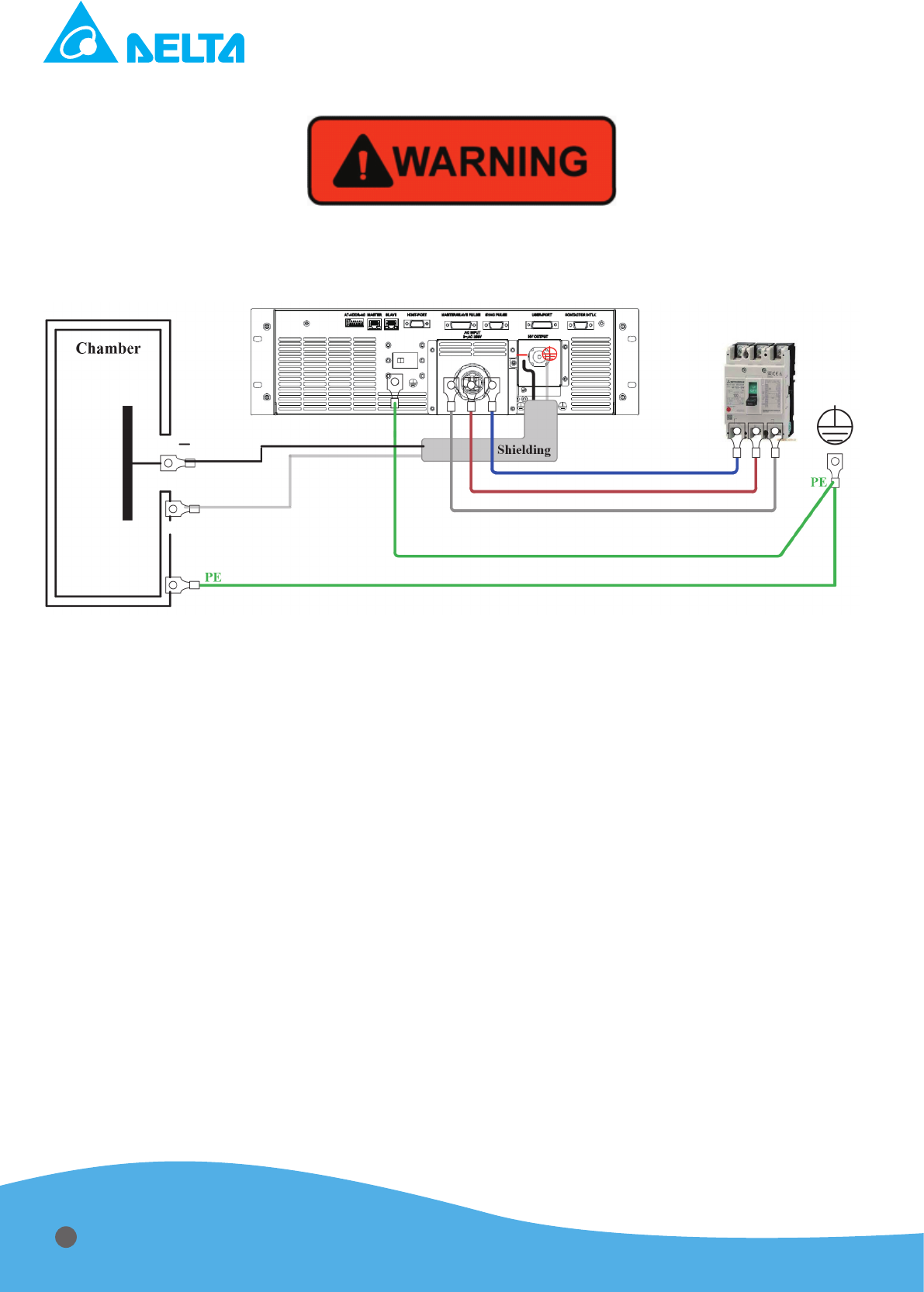
Figure 5.1 Installation diagram
- This power supply could only be placed horizontally and connect the protective grounding to
prevent an electric shock before use.
- Consideration must be taken not to impede the supply or ow of air to the unit.
- Please switch off the power supply before touching the case.
- Before applying power, please verify that the product is set to match with the line voltage.
- The circumstance temperature should be managed under 40˚C
- The installation and operation should be only in pollution degree 2 or better environment. Do
not operate this device in a dusty area or in corrosive gas environment.
- Proper grounding: For safe use, must connect ground cable (Yellow / Green wire) from ground
stud on the power supply rear panel to the pure earth ground. Poor grounding may cause an
electric shock or fatal accident.
- Output connector must be connected with the attached output cable. (3KV/6AWG/200°C, with
shielding). Do not use other output cables.
- Before applying power, please verify that the product is set to match with the line voltage.
When emergency, cut-off the circuit breaker, and then removing mains supply cord.
- Operating personnel must not remove the cover of the instrument. Component replacement
and internal adjustment can be done only by qualied service personnel.
- Remove mains cord and output cable before exterior maintenance and service.
- Use the carrying handle when dismantling it. Avoid drop resulting in hurt.
16
5.1 Cooling Requirements
For the HPP-20KA01KAT B supply to be sufciently cooled, the cabinet must be set up to:.
1. Bring in coolant air of the correct temperature(40 ˚C maximum)
2. Distribute coolant air to the power supplies
3. Prevent air exhausted from the cabinet from circulating back and becoming input air
4. Exhaust the hot air from the cabinet with minimal airow restriction.
5.2 Cabinet Design
The following is a synopsis of the HPP-20KA01KAT A to follow when designing a cabinet con-
taining a stack of HPP-20KA01KAT A power supplies.
Coolant air must be drawn easily into the cabinet; exhaust air must be able to pass unrestricted
out of the cabinet. If some physical constriant restricts the ow of exhaust air out of the cabinet,
we recommend that fans or blowers be mounted so that the hot air is removed from the cabinet as
quickly as possible.
Each HPP-20KA01KAT A power supply dissipates up to 10% of its maximum power at full rated
output. The minimum air flows in cubic feet per minute(CFM) required by individual HPP-20KA-
01KAT A supplies are shown in table 5.1. The static pressure(inches of water) of the empty cabinet
should not exceed 0.1 inches of water at the CFM level obtained by adding together the minimum
CFM values for all the power supplies that will be placed in the cabinet. For example, if three HPP-
20KA01KAT A supplies are mounted in a cabinet, the minimum CFM requirement would be three
times the CFM of cabinet air volume compared to an individual supply.
Approximations of this gure, the total power dissipation, and the temperature difference be-
tween coolant air and exhaust air are shown as an example in table 5.2.
Table 5.1 Minimum CFM requirement for HPP-20KA01KAT unit
Type of PSU CFM Required
20KW 260 CFM (122.7 liters/second)
Table 5.2 Approximate cooling requirements for three units mounted in a cabinet
Type of PSU CFM for 3 Supplies Total Power Dissipation
Dif. In Temp. Between
Coolant & Exhaust Air
20KW x 3
780CFM
(260+260+260=780)
(368.1 liters/ second)
9000W
(3000+3000+3000=9000)
23 ˚C
5.3 Grounding
For your convenience, the rear panel of the HPP-20KA01KAT supply features three equipoten-
tial ground screw: three M4 screw. These are indicated on the rear panel by a ground symbol.See
gure 6.2 for more information.
17

Chapter 6 : Interface
6.1 Front Panel
The functions for several buttons on the front panel are described on Table 6.1
Table 6.1 Function description of front panel
“Enter” Button
1. Press the button to change all of adaptive parameters.
2. Press the button to enter the next layer while in menu screen.
“Menu” Button
1. Press the button to menu screen from home screen.
2. Press the button to return to the previous layer while in menu screen.
“P” Button
Press the button to set the output condition in constant power mode. In constant
power mode user could adjust output power regulation level by “enter button” and
“knob”.
“I” Button
Press the button to set the output condition in constant current mode. In constant
current mode user could adjust output current regulation level by “enter button” and
“knob”.
“V” Button
Press the button to set the output condition in constant voltage mode. In constant
voltage mode user could adjust output voltage regulation level by “enter button” and
“knob”.
“ON” Button
Press the button to turn on the output power. While power on User could adjust
output regulation level by “enter button” and “knob”.
“OFF” Button
Press the button to turn on the output power.
“LOCK” Button
Press the button to lock “Enter”, “Menu”, “P”, “I”, “V”, “ON”, “OFF” button. This
function could prevent any unexpected change from panel while PSU in operation.
Regulation Knob
Rotate the knob to adjust the regulation level.
LCD Display
The display shows command of output regulation level according to control modes of
Power/Current/Voltage. It also indicates feedback values of Power/Current/Voltage
and system status, such as error conditions for all protect signals.
18
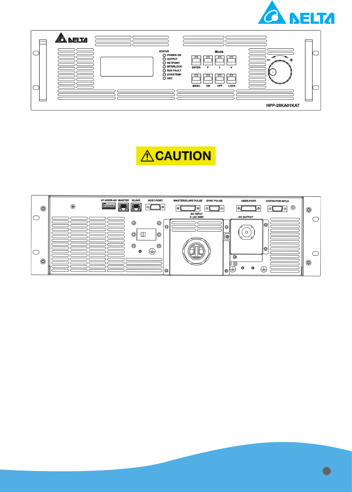
Figure 6.1 Front panel
6.2 Rear Panel
1. GND terminal is for chamber grounding, and earth grounding should be performed for safety.
2. Connect output terminal to target and connect +COM to the grounding of the chamber.
Figure 6.2 Rear panel
19
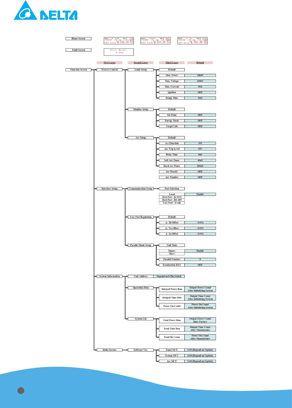
6.3 Main Menu Map
20
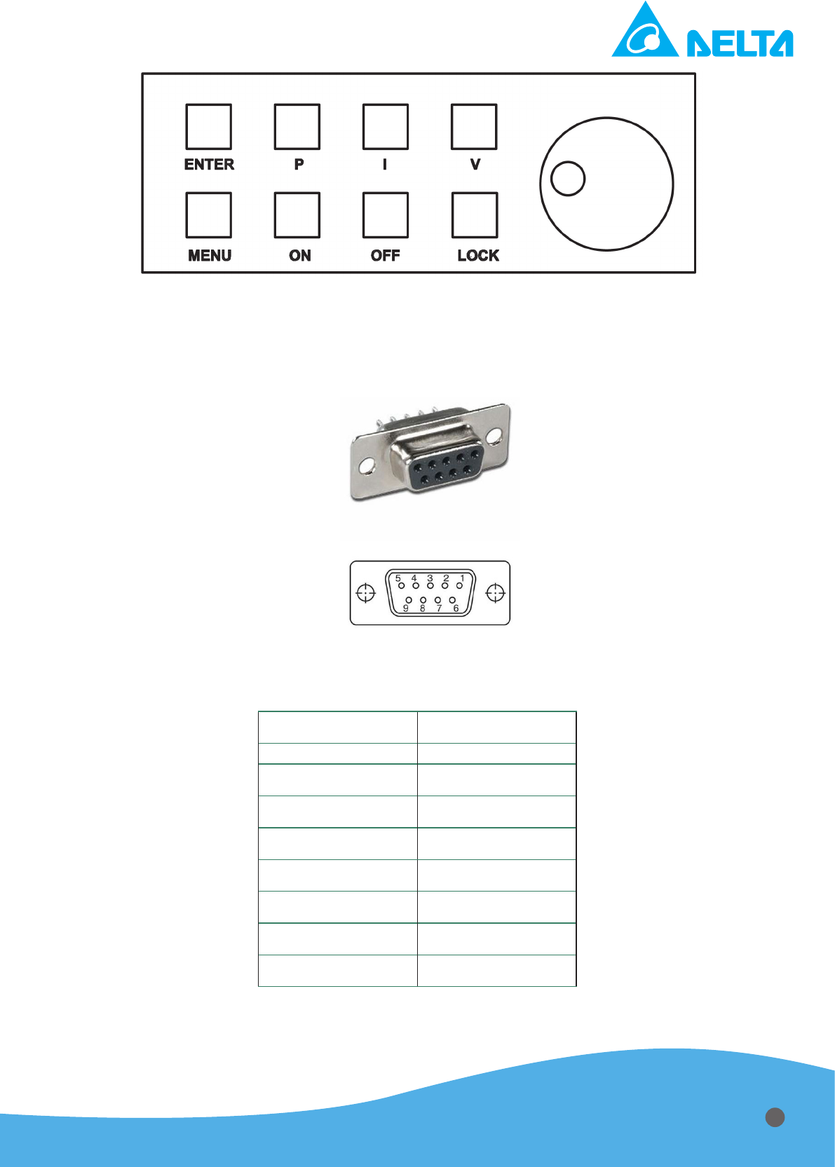
Figure 6.3 Function key
6.4 Digital Communication Port (Host)
The 9-pin female RS232 connector labeled “Host Port” on the rear of the power supply lets user
connect with computer to control the power supply. Denition of RS232 connector is as follows:
Figure 6.4 Host Port: 9-pin female RS232/RS485 connector
Table 6.2 Denition of RS232 RS485 connector
Pin 1
N/A
Pin 2
RS-232(Tx)
Pin 3
RS-232(Rx)
Pin 4
N/A
Pin 5
GND
Pin 6
RS-485 (+)
Pin 7
RS-485 (-)
Pin 8
N/A
Pin 9
N/A
21
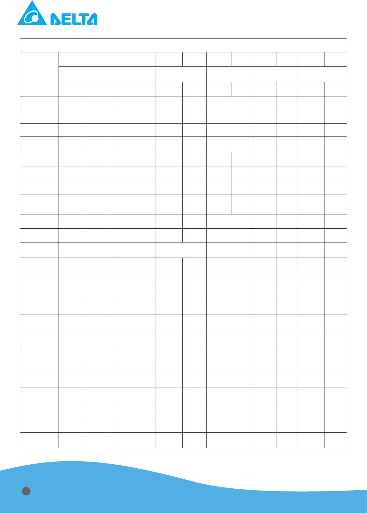
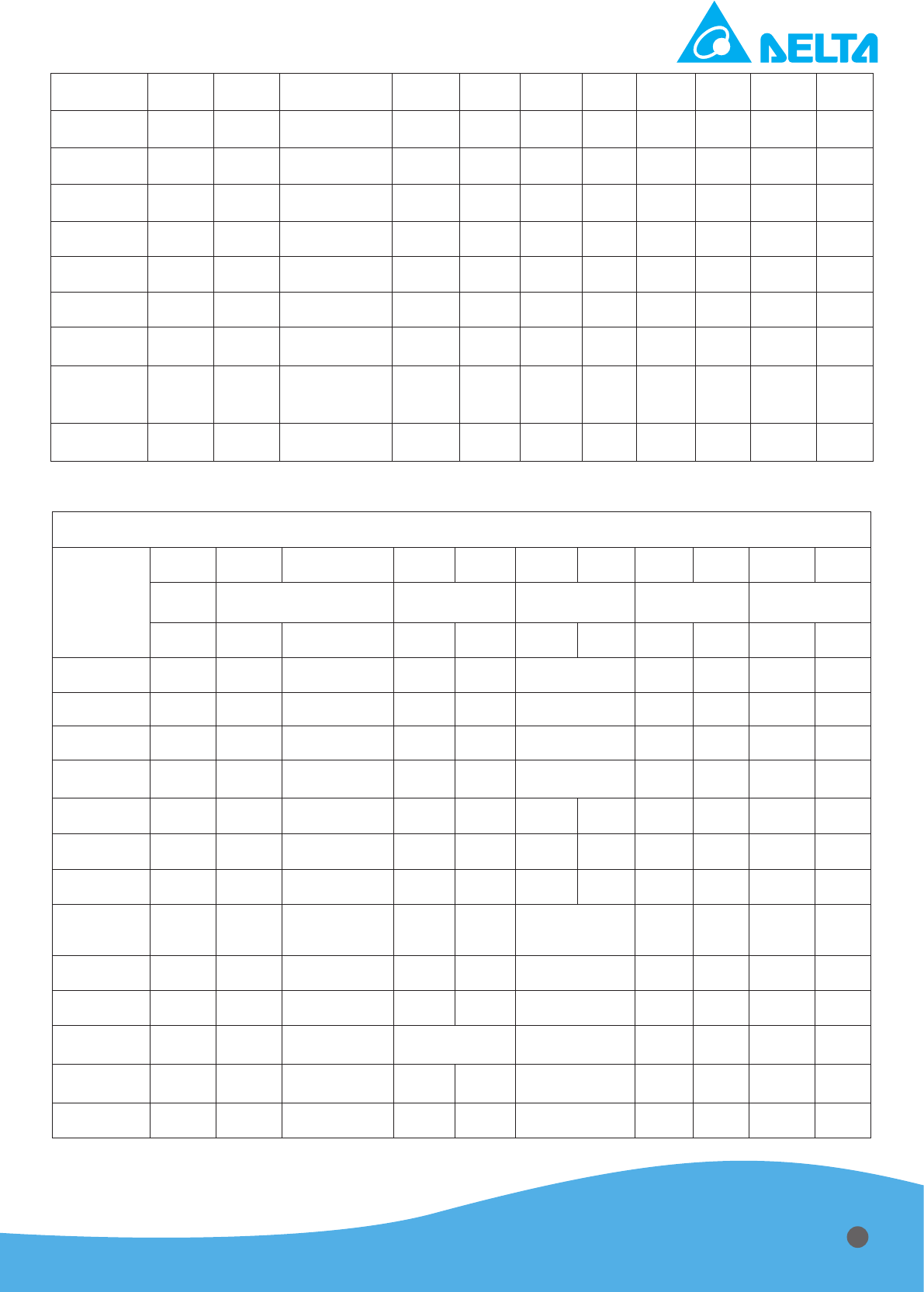
Table 6.3 Protocol of RS232 denition (1)
Remote to PSU
Byte
0 1 2 3 4 5 6 7 8 9 10
IP Command Data1 Data2 Check Sum Termination
Byte H-Byte L-Byte H-Byte L-Byte H-Byte L-Byte 0x00 Byte 0x00 0x0D
CV Mode
IP 0x11 0x00/01/02 0x00 0x00 Value 0x00 Value 0x00 0x0D
CC Mode
IP 0x12 0x00/01/02 0x00 0x00 Value 0x00 Value 0x00 0x0D
CP Mode
IP 0x13 0x00/01/02 0x00 0x00 Value 0x00 Value 0x00 0x0D
Master/
Slave
IP 0x14 0x00/01 0x00 0x00 Value 0x00 Value 0x00 0x0D
A/Ri Offset
IP 0x15 0x00/01 0x00 0x00 00/01 Value 0x00 Value 0x00 0x0D
A/Vo Offse
IP 0x16 0x00/01 0x00 0x00 00/01 Value 0x00 Value 0x00 0x0D
A/Io Offset
IP 0x17 0x00/01 0x00 0x00 00/01 Value 0x00 Value 0x00 0x0D
Terminating
Resistor
IP 0x18 0x00/01 0x00 0x00 IP Value 0x00 Value 0x00 0x0D
Set Point
IP 0x1A 0x00/01/02 0x00 0x00 Value 0x00 Value 0x00 0x0D
Pause Time
IP 0x1B 0x00/01 0x00 0x00 Value 0x00 Value 0x00 0x0D
Energy
Mode
IP 0x1D 0x00/01/02 Value Value 0x00 Value 0x00 0x0D
Arc
Function
IP 0x1E 0x00/01 0x00 0x00 Value 0x00 Value 0x00 0x0D
Max Power
IP 0x22 0x00/01 0x00 0x00 Value 0x00 Value 0x00 0x0D
Max Current
IP 0x23 0x00/01 0x00 0x00 Value 0x00 Value 0x00 0x0D
Max Voltage
IP 0x24 0x00/01 0x00 0x00 Value 0x00 Value 0x00 0x0D
Ramp Time
IP 0x25 0x00/01 0x00 0x00 Value 0x00 Value 0x00 0x0D
Target Life
IP 0x26 0x00/01/02 0x00 0x00 Value 0x00 Value 0x00 0x0D
Pulse Duty
IP 0x29 0x00/01 0x00 0x00 Value 0x00 Value 0x00 0x0D
Pulse kHz
IP 0x2A 0x00/01 0x00 0x00 Value 0x00 Value 0x00 0x0D
VTHRS
IP 0x2B 0x00/01 0x00 0x00 Value 0x00 Value 0x00 0x0D
Arc Voltage
IP 0x30 0x00/01 0x00 0x00 Value 0x00 Value 0x00 0x0D
Limit Arc
Number
IP 0x31 0x00/01/02 0x00 0x00 Value 0x00 Value 0x00 0x0D
Total ARC
Number
IP 0x32 0x00/01/02 0x00 0x00 Value 0x00 Value 0x00 0x0D
Ignition
Data
IP 0x33 0x00/01 0x00 0x00 Value 0x00 Value 0x00 0x0D
22
External On
IP 0x41 0x00/01/02 0x00 0x00 0x00 0x00 0x00 0x00 0x00 0x0D
External Off
IP 0x42 0x00/01/02 0x00 0x00 0x00 0x00 0x00 0x00 0x00 0x0D
Reset
IP 0x45 0x00 0x00 0x00 0x00 0x00 0x00 0x00 0x00 0x0D
Default 1
IP 0x60 0x00 0x00 0x00 0x00 0x00 0x00 0x00 0x00 0x0D
Default 2
IP 0x61 0x00 0x00 0x00 0x00 0x00 0x00 0x00 0x00 0x0D
Default 3
IP 0x62 0x00 0x00 0x00 0x00 0x00 0x00 0x00 0x00 0x0D
Default 4
IP 0x63 0x00 0x00 0x00 0x00 0x00 0x00 0x00 0x00 0x0D
Version
Return
IP 0x70 0x02 0x00 0x00 0x00 0x00 0x00 0x00 0x00 0x0D
Error IP and
Alarm Code
Return
IP 0x71 0x02 0x00 0x00 0x00 0x00 0x00 0x00 0x00 0x0D
PSU State
Return
IP 0x80 0x02 0x00 0x00 0x00 0x00 0x00 0x00 0x00 0x0D
Table 6.4 Protocol of RS232 denition (2)
PSU to Remote
Byte
0 1 2 3 4 5 6 7 8 9 10
IP Command Data1 Data2 Check Sum Termination
Byte H-Byte L-Byte H-Byte L-Byte H-Byte L-Byte 0x00 Byte 0x00 0x0D
CV Mode
IP 0x11 0x0A 0x00 0x00 Value 0x00 Value 0x00 0x0D
CC Mode
IP 0x12 0x0A 0x00 0x00 Value 0x00 Value 0x00 0x0D
CP Mode
IP 0x13 0x0A 0x00 0x00 Value 0x00 Value 0x00 0x0D
Master/
Slave
IP 0x14 0x0A 0x00 0x00 Value 0x00 Value 0x00 0x0D
A/Ri Offset
IP 0x15 0x0A 0x00 0x00 00/01 Value 0x00 Value 0x00 0x0D
A/Vo Offse
IP 0x16 0x0A 0x00 0x00 00/01 Value 0x00 Value 0x00 0x0D
A/Io Offset
IP 0x17 0x0A 0x00 0x00 00/01 Value 0x00 Value 0x00 0x0D
Terminating
Resistor
IP 0x18 0x0A 0x00 0x00 Value 0x00 Value 0x00 0x0D
Set Point
IP 0x1A 0x0A 0x00 0x00 Value 0x00 Value 0x00 0x0D
Pause Time
IP 0x1B 0x0A 0x00 0x00 Value 0x00 Value 0x00 0x0D
Energy
Mode
IP 0x1D 0x0A Value Value 0x00 Value 0x00 0x0D
Arc
Function
IP 0x1E 0x0A 0x00 0x00 Value 0x00 Value 0x00 0x0D
Max Power
IP 0x22 0x0A 0x00 0x00 Value 0x00 Value 0x00 0x0D
23
Max Current
IP 0x23 0x0A 0x00 0x00 Value 0x00 Value 0x00 0x0D
Max Voltage
IP 0x24 0x0A 0x00 0x00 Value 0x00 Value 0x00 0x0D
Ramp Time
IP 0x25 0x0A 0x00 0x00 Value 0x00 Value 0x00 0x0D
Target Life
IP 0x26 0x0A 0x00 0x00 Value 0x00 Value 0x00 0x0D
Pulse Duty
IP 0x29 0x0A 0x00 0x00 Value 0x00 Value 0x00 0x0D
Pulse kHz
IP 0x2A 0x0A 0x00 0x00 Value 0x00 Value 0x00 0x0D
VTHRS
IP 0x2B 0x0A 0x00 0x00 Value 0x00 Value 0x00 0x0D
Arc Voltage
IP 0x30 0x0A 0x00 0x00 Value 0x00 Value 0x00 0x0D
Limit Arc
Number
IP 0x31 0x0A 0x00 0x00 Value 0x00 Value 0x00 0x0D
Total ARC
Number
IP 0x32 0x0A 0x00 0x00 Value 0x00 Value 0x00 0x0D
Ignition
Data
IP 0x33 0x0A 0x00 0x00 Value 0x00 Value 0x00 0x0D
External On
IP 0x41 0x0A 0x00 0x00 0x00 0x00 0x00 0x00 0x00 0x0D
External Off
IP 0x42 0x0A 0x00 0x00 0x00 0x00 0x00 0x00 0x00 0x0D
Reset
IP 0x45 0x0A 0x00 0x00 0x00 0x00 0x00 0x00 0x00 0x0D
Default 1
IP 0x60 0x0A 0x00 0x00 0x00 0x00 0x00 0x00 0x00 0x0D
Default 2
IP 0x61 0x0A 0x00 0x00 0x00 0x00 0x00 0x00 0x00 0x0D
Default 3
IP 0x62 0x0A 0x00 0x00 0x00 0x00 0x00 0x00 0x00 0x0D
Default 4
IP 0x63 0x0A 0x00 0x00 0x00 0x00 0x00 0x00 0x00 0x0D
Version
Return
IP 0x70 0x0A 0x00 0x00 0x00 0x00 0x00 0x00 0x00 0x0D
Error IP and
Alarm Code
Return
IP 0x71 0x0A 0x00 0x00 0x00 0x00 0x00 0x00 0x00 0x0D
Byte 0 1 2 3 4 5 6 7 8 9 10 11
IP 0x90 Status1 Status2 Warning Alarm Voltage(V) Current(.0A) Power(.0Kw)
Byte
12 13 14 15 16 17 18 19 20 21 22 23
User Command Arc Density(/s) Arc Counter 0x00
Check
Sum
0x00 0x0D
Note: Check Sum Value is the summation of “1” signal calculated by byte 0 to 6.
Note: Use 9600bps, 8 data bits, no parity, 1 stop bit (9600 8-N-1)
24
Bit 0 1 2 3 4 5 6 7
Status1
CV Mode CC Mode CP Mode HV ON
Setpoint
MODE
Ignition
MODE
System
Warning
System
Shutdown
Bit 0 1 2 3 4 5 7 7
Status2
System
Ready
OVP OCP OTP OPP Interlock Arc Protect
AC Bus
Protect
Table 6.5 Value denition (Translate decimal to hexadecimal for utilizing)
Command Byte3 Byte4 Byte5 Byte6
CV Mode
0 to 1000 for 0 to 1000V
CC Mode
0 to 600 for 0~60.0A
CP Mode
0 to 200 for 0 to 20.0kW
Master/Slave
Master: 00, Slave: 01
A/Ri Offset
Plus: 00, Minus: 01 0 to 99 for 0 to 9.9%
A/Vo Offset
Plus: 00, Minus: 01 0 to 99 for 0 to 9.9%
A/Io Offset
Plus: 00, Minus: 01 0 to 99 for 0 to 9.9%
Set Point
1 to 10 for 1 to 10s
Hard ARC
Shutdown Time
2 to 100 for 200 to 10000us, Scale: 100us
Pulse frequency
0 to 80 for DC to 400k Scale:5kHz
Pulse reverse time
4 to 100 for 0.4us to 10us Scale:0.1us
Energy Mode
1 to 99999 for 1 to 99999kJ, 0: OFF
Arc Function
OFF: 0, ON: 1
Max Power
20 to 200 for 2 to 20kW
Max Current
50 to 600 for 5 to 60A
Max Voltage
500 to 1000 for 500 to 1000V
Ramp Time
5 to 200 for 50 to 2000ms
Target Life
0 to 1500000 for OFF to 15000.00kWh, 0: OFF
Arc Voltage
25 to 200 for 25 to 200us
Arc Density
0 to 99 for 0 to 99 times/s
Arc Number
0 to 999 for 0 to 999 times
Ignition
10 to 15 for 1000 to 1500V
Note: Please use hexadecimal
25
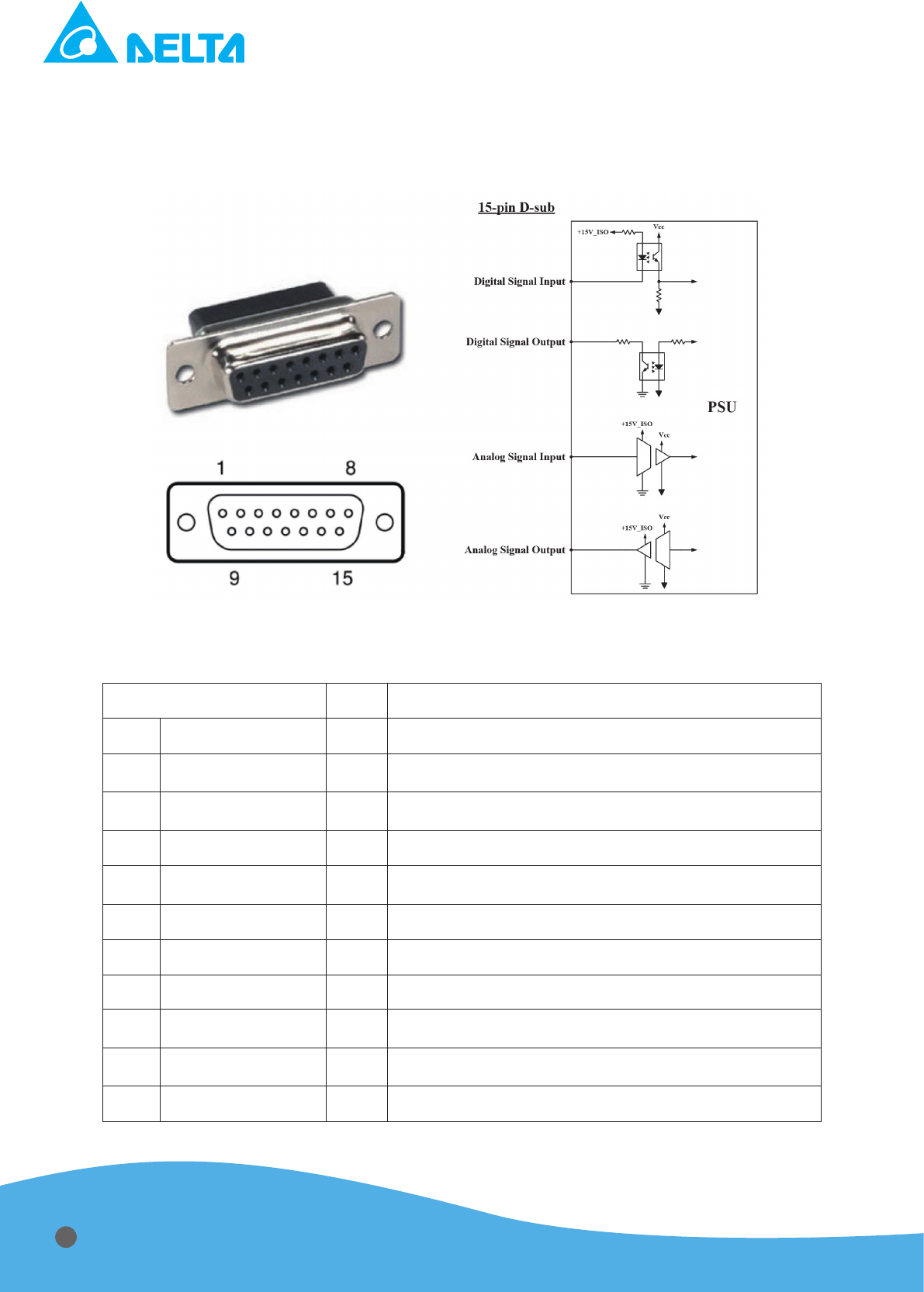
6.5 Analog Communication Port (User)
The 15-pin female subminiature-D connector labeled “User Port” on the rear of the power
supply lets you connect with control box to control the power supply in analog signal. Denition of
15-pin female subminiature-D connector is as follows:
Figure 6.5 Connector of user port, 15pin female subminiature-D
Table 6.6 Denition of subminiature-D connector
Pin Dene I/O Description
1 +24V
I External 24V is connected to the collector of photo coupler
2 VOUT_A
O
Pin 2 shows the reader of output voltage
0 to 10 V for V = 0 to 1000 V
3 POUT_A
O
Pin 3 shows the reader of output Power
0 to 10 V for P = 0 to 20 kW
4 OUTPUT_ENABLE_D
I Turn on the output power by pulling the pin low
5 XPROG_A
I
User could adjust regulation by Pin 5
0 to 10 V for P = 0 to 20 kW
6 COM_A
- The return pin for VOUT_A, POUT_A, XPROG_A
7 PWRON_D
O Pin 7 shows the on/off state of output
8 PWRON COM_D
- The return pin for PWRON_D
9
OUTPUT_ENABLE_
COM_D
- The return pin for OUTPUT_ENABLE_D
10 MOD GREEN
O
Pin 10 is connected to the emitter of photo coupler for MOD
GREEN function
11 INTERLOCK_D
I Pin 11 indicates the disconnection of interlock
26

12 INTLK COM_D
- The return pin for INTERLOCK_D
13 NET GREEN
O
Pin 13 is connected to the emitter of photo coupler for NET
GREEN function
14 MOD AMBER
O
Pin 14 is connected to the emitter of photo coupler for MOD
AMBER function
15 NET AMBER
O
Pin 15 is connected to the emitter of photo coupler for NET
AMBER function
Note 6.5: Precaution for external connection
- Port of digital Signal input
To control the input signal, a switch is utilized between the ports and isolated ground.
Open → Floating
Close → Grounding
- Port of digital Signal output
The internal resistance of the ports is 5.1kohm, and a pull-up power supply V is required
with a 5.1kohm resistor.
Initial → > 0.9*V
Trigger → < 0.5*V + 1V
If V is connected to “+15V_ISO” supplied by pin18 with a 5.1kohm resistor, initial state
would be high than 13.5V and trigger state would be lower than 8.5V.
- Analog signal input port
An isolated amplier is utilized in the ports. The voltage level is 0 to 10V for user to enter the
command and shall not greater than 12V.
- Analog signal output port
An isolated amplier is utilized in the ports. The voltage level is 0 to 10V for users to read out
the output values of voltage, current, and power.
pull-up
pull-up
pull-up
pull-up
27
Chapter 7 :Operation
7.1 Local Operating Steps
Step A
Import AC voltage to input connector on rear panel. The mains voltage level should be 400±
10% V .
Step B
Turn on the breaker to start the power supply. Now, you can see “LCD Display” is working and
shows the default setting of the power supply.
Step C
Choose one operating mode from “P”, “I”, “V” button, and “LCD Display” will show the mode you
selected and change the command unit mode by mode.
Operating mode cannot be changed during power on period. It only can select while power off.
Step D
Rotate the knob to adjust the regulation level. The command (P, I or V) will change by different
mode selection in step B. When in Power mode, the command can be adjusted from 0 to 20 kW;
when in Current mode, command can be adjusted from 0 to 50 A; when in Voltage mode, and com-
mand can be adjusted from 130 to 1000 V
Step E
Press the “On” button to turn on the output power. While power on, user could adjust output
regulation level by “Enter” button and “knob”. “LCD Display” will show the feedback values once the
output is on.
After power on, the electric shock may lead to death or serious injury. Please read this manual
carefully and follow the instruction steps before installation and operation, otherwise an electric
shock or a fatal accident might be caused.
Step F
Press the “Off” button to turn off the output power.
Step G
If the power supply is kept off for a while, please remove AC power cord.
Don’t touch the load before grounding it. And make sure the electricity is fully discharged by meter.
AC
28
7.2 D-SUB Operating Step
Example 1: CP mode 20 kW output
Operating steps:
1. Set the front panel => Interface Setup => Communnication Setup => D-sub.
2. Command Level: Set +10 V input to pin 5 for 20 kW Command.
4. Power On: Connect pin 4 to pin 9.
5. Power Off: Remove pin14 from pin 9.
7.3 RS-232 Operating Steps
1. Set the front panel => Interface Setup => Communnication Setup => RS-232.
2. Follow the protocol dened in chapter 6.4 to operating.
7.4 RS-485 Operating Steps
1. Set the front panel => Interface Setup => Communnication Setup => RS-485.
2. Follow the protocol dened in chapter 6.4 to operating.
Chapter 8 :Maintenance
Alarm Condition Code Description Suggested Action
HW Fault M1
M1F Hardware error from the left module
Take all safety precaution,
and then check if the mains
voltage that is in specication.
Turn on the output power with
a dummy load to ensure if it is
under normal operation.
HW Fault M2
M2F Hardware error from the right module
Take all safety precaution,
and then check if the mains
voltage that is in specication.
Turn on the output power with
a dummy load to ensure if it is
under normal operation.
SW OVP
OV Output over voltage
Take all safety precaution,
and then check if the mains
voltage that is in specication.
Turn on the output power with
a dummy load to ensure if it is
under normal operation.
SW OCP
OC Output over current
Take all safety precaution,
and then check if the mains
voltage that is in specication.
Turn on the output power with
a dummy load to ensure if it is
under normal operation
SW OPP
OP Output over power
Take all safety precaution,
and then check if the mains
voltage that is in specication.
Turn on the output power with
a dummy load to ensure if it is
under normal operation.
Arc Number Limit
07 Arc number is over setting parameter
Press and hold “OFF” button
with 10 second to clear error.
Contactor Interlock
10
Uninstallation of contactor pin in D-sub
connector
Check if contactor pin in D-sub
connector is short.
29
Output Interlock
11 Uninstallation of output cover
Check if output cover is
correctly installed.
Communication Loss
15 Error from internal communication
Check if the bus between
panel and control card is
correctly connected.
Fan1 Error
17 Error from the left fan
Check if the cable between fan
in the left module 1 and control
card is correctly connected.
Fan2 Error
18 Error from the right fan
Check if the cable between
fan in the right module 2
and control card is correctly
connected.
Bus UVP
20 Input voltage is under operation range
Take all safety precaution,
and then check if the mains
voltage that is in specication.
Bus OVP
21 Input voltage is over operation range
Take all safety precaution,
and then check if the mains
voltage that is in specication.
GND Detect
22
Positive output is not connected to
protective earth
Check if the output positive
terminal is short to protective
earth.
Set Point Monitor
23
Error while output fails to reach setting
parameter within setting time
Take all safety precaution, and
then turn on the output power
with a dummy load to ensure if
it is under normal operation.
Energy Mode Monitor
24
Power off while output reaches setting
Energy
Monitor Setting is end. Press
and hold “OFF” button with 10
second to clear error.
Warning Condition Code Description Suggested Action
Arc Density Limit
01 Arc density is over setting parameter N/A
Output Limit
Limit Output is over setting parameters N/A
30