
Chapter 10
Introduction to
Axiomatic Design
Suh, N. P. Axiomatic Design: Advances and Applications. New York:
This presentation draws extensively on materials from [Suh 2001]:
Oxford University Press, 2001. ISBN: 0195134664.
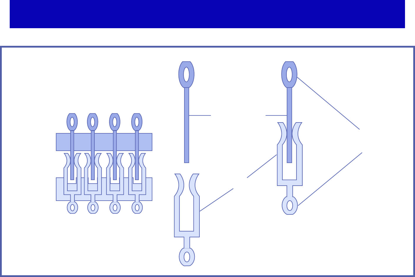
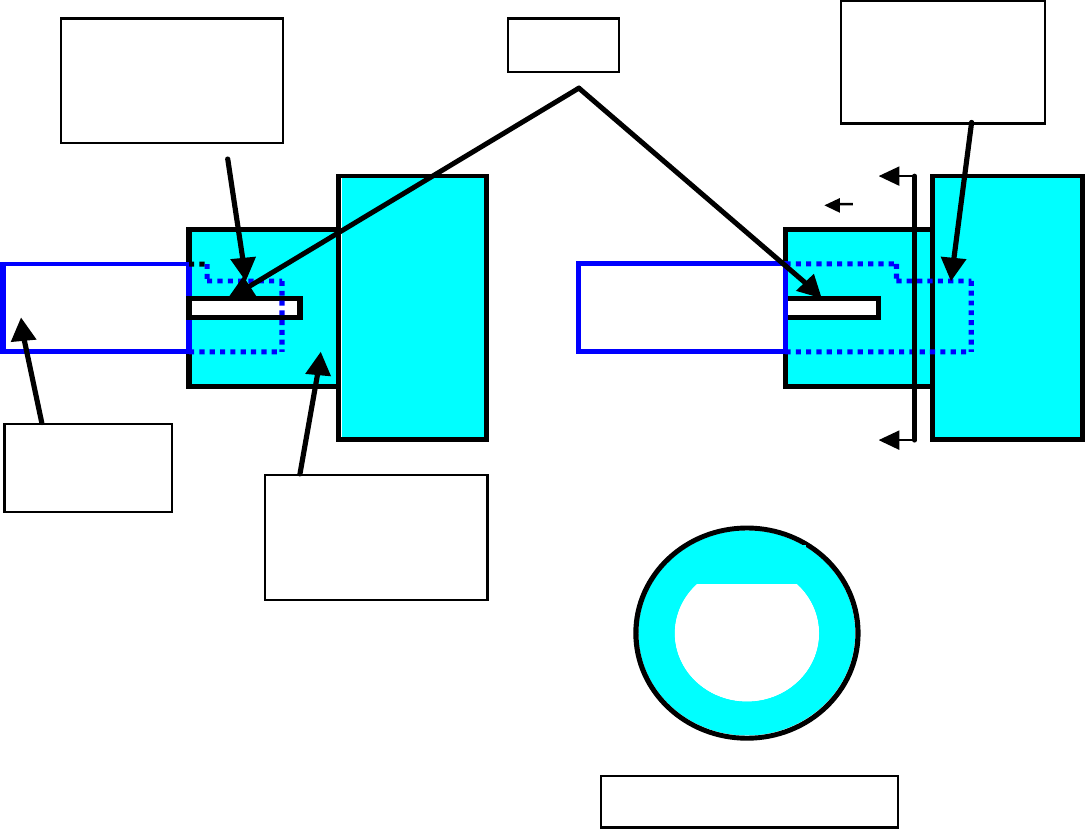
Example: Electrical Connector
Figure by MIT OCW.
Male connector
Female connector
Plastic
overmolding
Plastic
overmolding
Compliant pin
(for permanent connection)
Multiple layers will be stacked together
to obtain an entire connector.
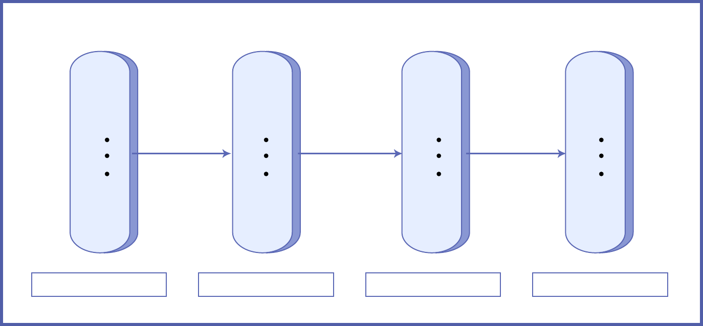
Axiomatic Design Framework
The Concept of Domains
Four Domains of the Design World.
The {x} are characteristic vectors of each domain.
Figure by MIT OCW. After Figure 1.2 in [Suh 2001].
Customer domain Functional domain Physical domain Process domain
Mapping Mapping Mapping
{CAs} {FRs} {DP} {PVs}

Characteristics of the four domains of the design
world
Domains Character
Vectors
Customer Domain
{CAs}
Functional Domain
{FRs}
Physical Domain {DPs} Process Domain {PVs}
Manufacturing Attributes which
consumers desire
Functional
requirements
specified for the
product
Physical variables
which can satisfy the
functional
requirements
Process variables that
can control design
parameters (DP
s
)
Materials Desired performance Required Properties Micro-structure Processes
Software Attributes desired in
the software
Output Spec of
Program codes
Input Variables or
Algorithms Modules
Program codes
Sub-routines machine
codes compilers
modules
Organization Customer satisfaction Functions of the
organization
Programs or Offices
or Activities
People and other
resources that can
support the programs
Systems Attribute desired of
the overall system
Functional
requirements of the
system
Machines or
components,
sub-components
Resources (human,
financial, materials,
etc.)
Business ROI Business goals Business structure Human and financial
resource
Table by MIT OCW. After Table 1.1 in [Suh 2001].

Definitions
�Axiom:
Self-evident truth or fundamental truth for
which there is no counter examples or
exceptions. It cannot be derived from other
laws of nature or principles.
Corollary:
Inference derived from axioms or propositions
that follow from axioms or other propositions
that have been proven
.

Functional Requirement:
Functional requirements (FRs) are a minimum set of
independent requirements that completely
characterizes the functional needs of the product (or
software, organizations, systems, etc.) in the
functional domain. By definition, each FR is
independent of every other FR at the time the FRs are
established.
Constraint:
Constraints (Cs) are bounds on acceptable solutions.
There are two kinds of constraints: input constraints
and system constraints. Input constraints are
imposed as part of the design specifications. System
constraints are constraints imposed by the system in
which the design solution must function.
Definitions - cont’d

Design parameters (DPs) are the key physical
(or other equivalent terms in the case of
software design, etc.) variables in the physical
domain that characterize the design that
satisfies the specified FRs.
Process variable:
Process variables (PVs) are the key variables
(or other equivalent term in the case of
software design, etc.) in the process domain
that characterizes the process that can
generate the specified DPs.
Definitions - cont’d
Design parameter:

The Design Axioms
Maintain the independence of the
functional
requirements (FRs).
Axiom 2: The Information Axiom
Minimize the information content of the
design.
Axiom 1: The Independence Axiom
Example: Beverage Can Design
Consider an aluminum beverage
can that contains carbonated
drinks.
How many functional
requirements must the can
satisfy?
See Example 1.3 in [Suh 2001].
How many physical parts does it
have?
What are the design parameters
(DPs)? How many DPs are there?

Design Matrix
The relationship between {FRs} and {DPs} can be
written as
{FRs}=[A] {DPs}
form as
{dFRs}=[A] {dDPs}
[A] is defined as the Design Matrix given by
elements :
∂FRi/∂DPi
When the above equation is written in a differential
Aij =
Example
For a matrix A:
⎡
A11 A12 A13
⎤
A
[]=
⎢
A21 A22 A23
⎥
⎢
⎣
A31 A32 A33
⎦
⎥
Equation (1.1) may be written as
FR1 = A11 DP1 + A12 DP2 + A13 DP3
FR2 = A21 DP1 + A22 DP2 + A23 DP3 (1.3)
FR3 = A31 DP1 + A32 DP2 + A33 DP3
Uncoupled, Decoupled, and Coupled Design
Uncoupled Design
(1.4)
⎡
A11 0 0
⎤
A
[]=
⎢
0 A22 0
⎥
⎢
⎣
0 0 A33
⎦
⎥
Decoupled Design
⎡
A
11 0 0
⎤
A[]=
⎢
A21 A22 0
⎥
(1.5)
⎢
⎣
A31 A32 A33
⎦
⎥
Coupled Design
All other design matrices

Design of Processes
{DPs}=[B] {PVs}
[B] is the design matrix that defines the
characteristics of the process design and
is similar in form to [A].
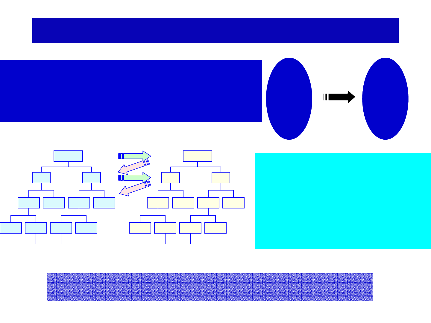
Axiomatic Design Theory
Functional Requirement (FR) –‘What’ we want to achieve
A minimum set of requirements a system must satisfy
Design Parameter (DP) –‘How’ FRs will be achieved
Key physical variables that characterize design solution
Functional
Domain
{FR}
Physical
Domain
{DP}
Mapping
FR1
FR11 FR12
FR111 FR112 FR121 FR122
FR1111 FR1112 FR1211 FR1212
:
DP1
DP11 DP12
DP111 DP112 DP121 DP122
DP1111 DP1112 DP1211 DP1212
:
Decomposition – ‘Zigzagging’
Process of developing detailed
requirements and concepts by moving
between functional and physical
domain
Hierarchical FR-DP structure
Independence Axiom
Maintain the independence of FRs
Information Axiom
Minimize the information content

Design Axioms
⎭
⎬
⎫
⎩
⎨
⎧
⎥
⎦
⎤
⎢
⎣
⎡
=
⎭
⎬
⎫
⎩
⎨
⎧
2
1
2
1
DP
DP
XO
OX
FR
FR
⎭
⎬
⎫
⎩
⎨
⎧
⎥
⎦
⎤
⎢
⎣
⎡
=
⎭
⎬
⎫
⎩
⎨
⎧
2
1
2
1
DP
DP
XX
OX
FR
FR
⎭
⎬
⎫
⎩
⎨
⎧
⎥
⎦
⎤
⎢
⎣
⎡
=
⎭
⎬
⎫
⎩
⎨
⎧
2
1
2
1
DP
DP
XX
XX
FR
FR
Uncoupled Decoupled Coupled
FR
dr
u
p.d.f.
f(FR)
dr
l
System Range,
p.d.f. f(FR)
Design
Range
|sr|
Common
Range, A
C
|dr|
Information content for functional requirement i = - log
2
P
i
Independence Axiom: Maintain the independence of FRs
Information Axiom
: Minimize the information content
FR
DP
FR
DP
FR
DP
FR
DP
FR
DP
FR
DP
FR
DP
FR
DP
FR
DP
FR
DP
FR
DP
FR
DP
FR
DP
FR
DP
FR
DP
FR
DP
FR
DP
FR
DP
FR
DP
FR
DP
FR
DP
FR
DP
FR
DP
FR
DP
FR
DP
FR
DP
FR
DP
FR
DP
FR
DP
FR
DP
FR
DP
FR
DP
FR
DP
FR
DP
FR
DP
FR
DP
FR
DP
FR
DP
FR
DP
FR
DP
FR
DP
FR
DP
FR
DP
FR
DP
FR
DP
FR
DP
FR
DP
FR
DP
FR
DP
FR
DP
FR
DP
FR
DP
FR
DP
FR
DP
FR
DP
FR
DP
FR
DP
FR
DP
FR
DP
FR
DP
FR
DP
FR
DP
FR
DP
FR
DP
FR
DP
FR
DP
FR
DP
FR
DP
FR
DP
FR
DP
FR
DP
FR
DP
FR
DP
FR
DP
FR
DP
FR
DP
FR
DP
FR
DP
FR
DP
FR
DP
FR
DP
FR
DP
FR
DP
FR
DP
FR
DP
FR
DP
FR
DP
FR
DP
FR
DP
FR
DP
FR
DP
FR
DP
FR
DP
FR
DP
FR
DP
FR
DP
FR
DP
FR
DP
FR
DP
FR
DP
FR
DP
FR
DP
FR
DP
FR
DP
FR
DP
FR
DP
FR
DP
FR
DP
FR
DP
FR
DP
FR
DP
FR
DP
FR
DP
FR
DP
FR
DP
FR
DP
FR
DP
FR
DP
FR
DP
FR
DP
FR
DP
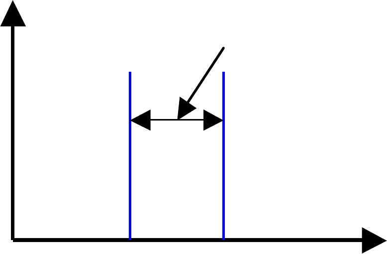
FR must be satisfied within the design
range.
Design
Prob.
Density
range
FR
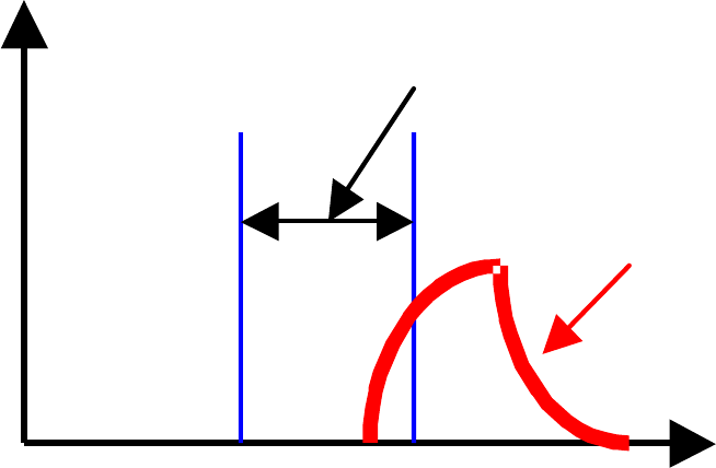
To satisfy the FR, we have to map FRs in the
physical domain and identify DPs.
Design
Prob.
Density
range
System
range
FR
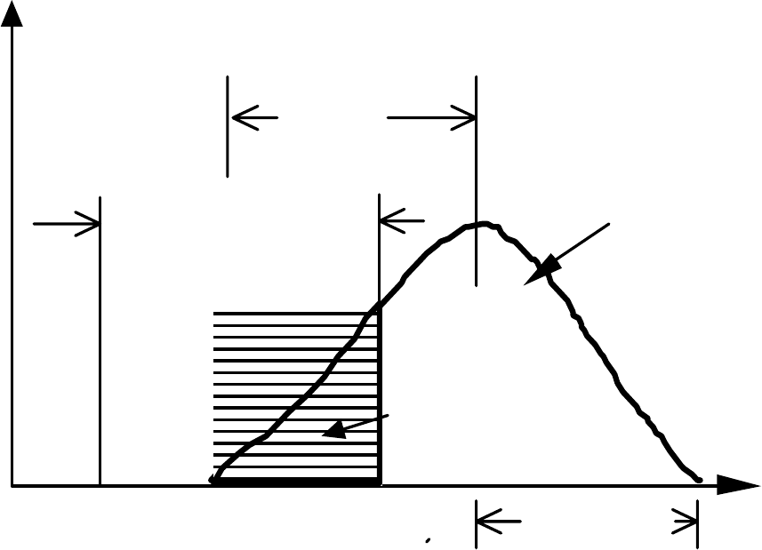
Design Range, System Range, and Common
Range
Probab.
Density
( )
Design Rang e
Syst em
Rang e
Area o f
Common
Rang e Ac
Bia s
Target
Varia tion
FR
from t he
pea k valu e

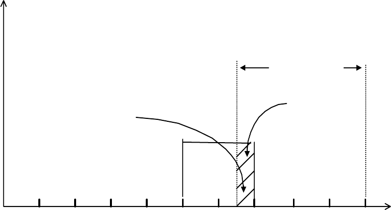
What happens when there are many FRs?
each level of the system hierarchy.
The relationship between the FRs determines how
desired certainty and thus complexity.
Most engineered systems must satisfy many FRs at
difficult it will be to satisfy the FRs within the
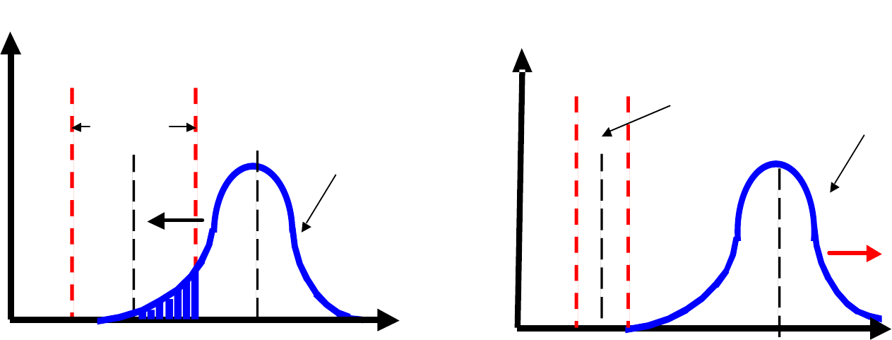
If FRs are not independent from each other,
the following situation may exist.
FR1
Pro b. De n s i ty
De si g n
Ra n g e
Syste m
Ra n g e
Pro b. De n s ity
De si g n
Ra n g e
Syste m
Ra n g e
FR2
Coupling decreases the design range
and thus robustness!!
Uncoupled Decoupled
0
⎤
⎧
DP1
⎫
⎧
FR
1
⎫
⎡
A
11 0 0
⎤
⎧
DP
1
⎫
⎧
FR1
⎫
⎡
A11 0
⎪
⎪
⎥
⎪
⎪
⎪ ⎪
⎢ ⎥
⎪
⎪
⎨
FR
2
⎬
=
⎢
⎢
0
A
22 0
⎥
⎨
DP
2
⎬
⎨
FR2
⎬
=
⎢
A21 A22 0
⎥
⎨
DP2
⎬
⎪
⎩
FR
3
⎪
⎢
⎣
0 0
A
33
⎦
⎥
⎩
DP
3
⎭
⎩
FR3
⎭
⎢
⎣
A31 A32 A33
⎥
⎪
⎪
⎭
⎪
⎪
⎪ ⎪
⎦
⎩
DP3
⎭
∆
F
R1
∆DP1 =
A11
∆FR2
∆DP2 =
A22
∆FR3
∆DP3 =
A
33
33
2321313
3
22
1212
2
11
1
1
A
DPADPAFR
DP
A
DPAFR
DP
A
FR
DP
∆⋅−∆⋅−∆
=∆
∆⋅−∆
=∆
∆
=∆

What is wrong with conventional connectors?
It violates the Independence Axiom, which
states that
“Maintain the independence of Functional
Requirements (FRs)”.
It is a coupled design.

What is the solution?
Tribotek connector: A woven connector
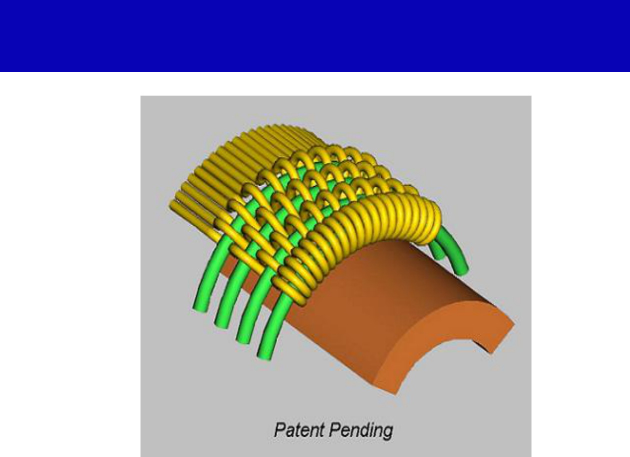
Tribotek Electrical Connectors
(Courtesy of Tribotek, Inc. Used with permission.)

Performance of “Woven” Power Connectors
Power density => 200% of conventional
connectors
Insertion force => less than 5% of
conventional connectors
Electric contact resistance = 5 m ohms
Manufacturing cost
Capital Investment
TMA Projection System
Photos removed for copyright reasons.

What are the FRs of a face seal that must
isolate the lubricated section from the
abrasives of the external environment?
There are many FRs.
They must be defined in a solution neutral
environment.
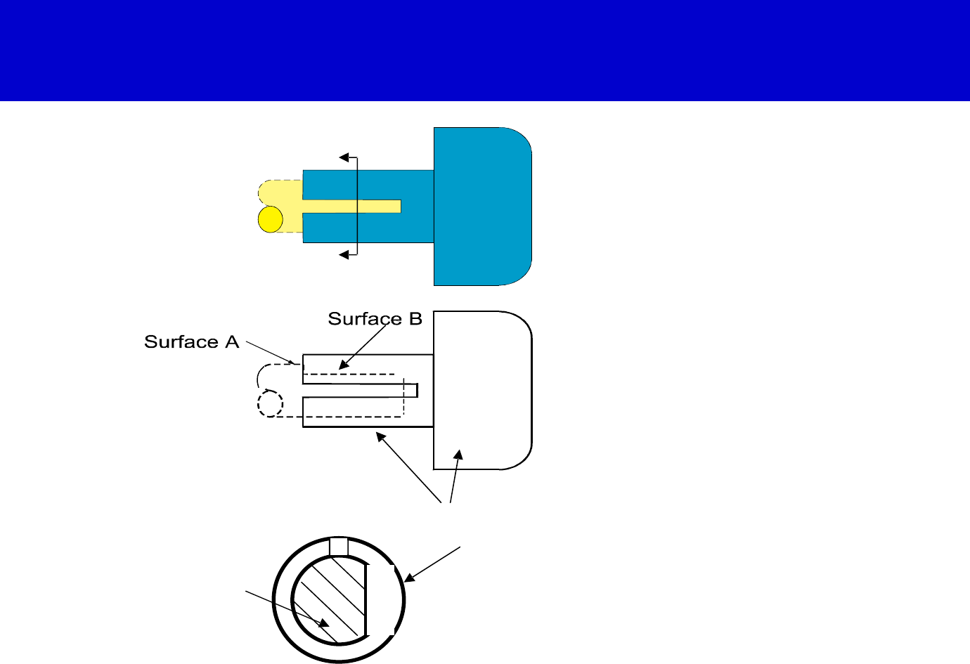
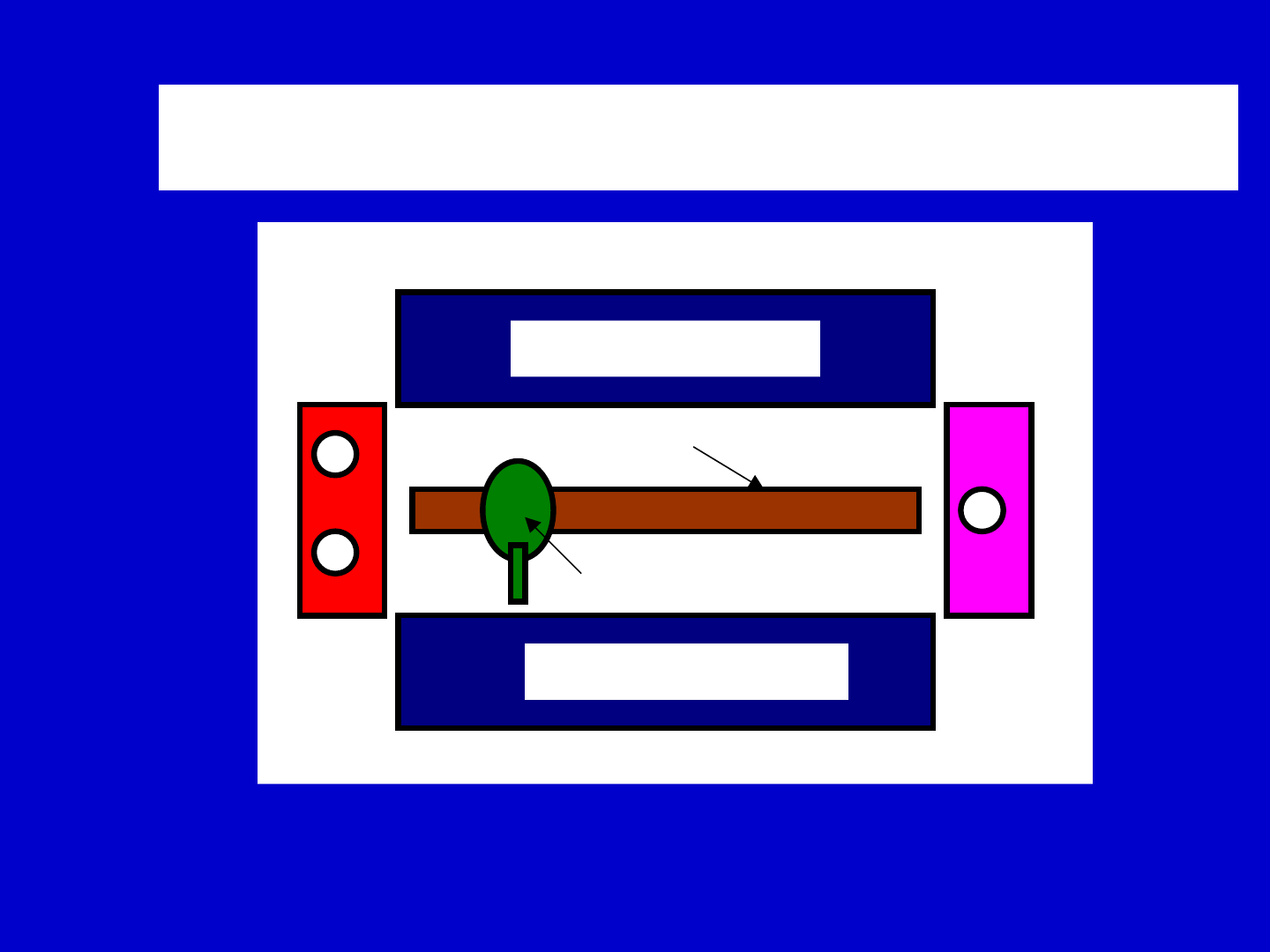
Is this knob a good design or a poor
design?
A
A
Injection
molded knob
Shaft
with flat
milled
surface
Section A-A
A
A
Injecti on
molded k nob
Shaft
with flat
milled
surface
Sect ion A-A
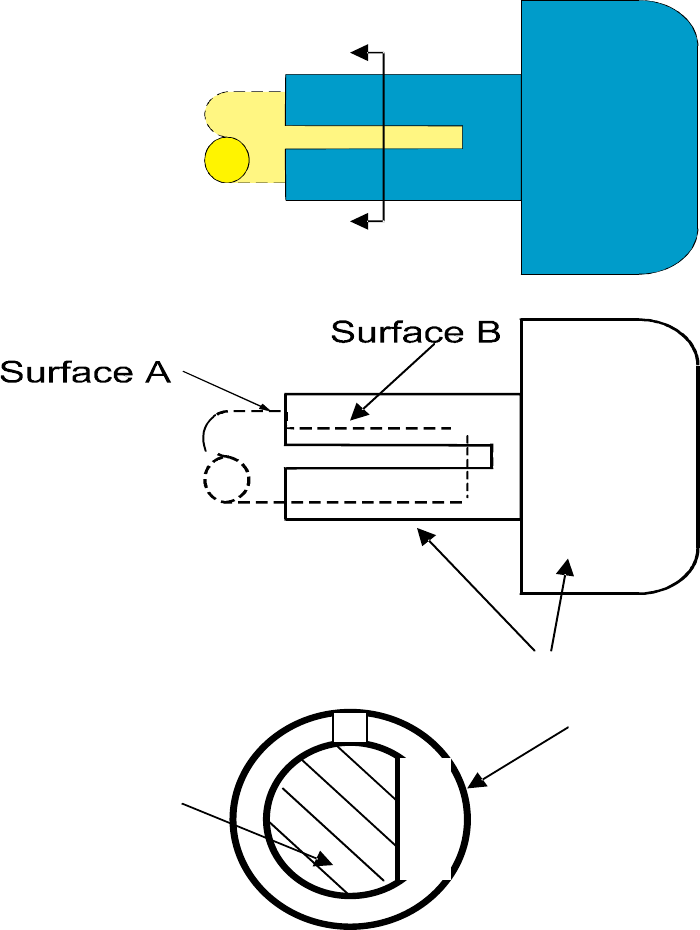
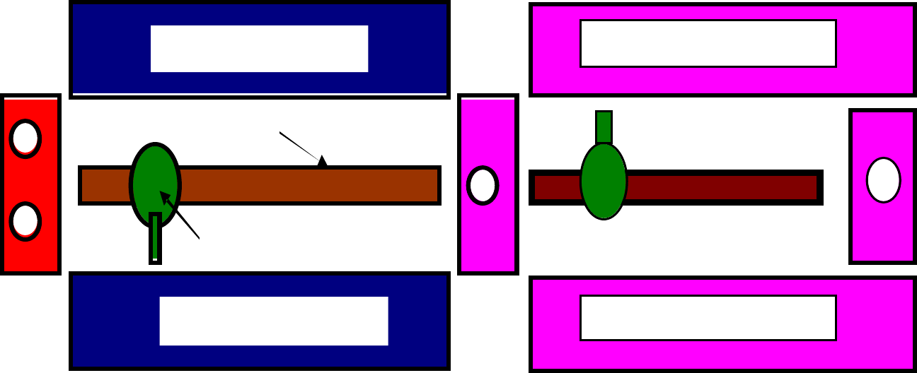
Which is a better design?
j
A
A
(a)
(b)
Me tal
Sh af t
In ec tio n
mold ed
nylo n K n ob
M ill ed Flat
En d o f th e
sh aft
Slot
M ill ed Flat
En d o f th e
sh aft
Se cti on view A A

History
Goal
To establish the science base
for areas such as design and
manufacturing

How do you establish science
base in design?
Axiomatic approach
Algorithmic approach

References
N. P. Suh, Axiomatic Design: Advances
and Applications. New York: Oxford
University Press, 2001
N. P. Suh, The Principles of Design. New
York: Oxford University Press, 1990

Axiomatic Design
Axiomatic Design applies to all
designs:
•Hardware
•Software
•Materials
•Manufacturing
•Organizations

Axiomatic Design
Axiomatic Design helps the
design decision making process.
•Correct decisions
•Shorten lead time
•Improves the quality of products
•Deal with complex systems
•Simplify service and maintenance
•Enhances creativity

Axiomatic Design
•Axioms
•Corollaries
•Theorems
•Applications --
hardware, software,
manufacturing,
materials, etc.
•System design
•Complexity
Introduction
Stack of modules
Stack of modules
Robot
Loading
Station
Unloading
station
Track
Xerography machine design– See Example 9.2 in [Suh 2001].
System integration
Stac k o f modul es
Stack of modules
Robo t
Loading
Station
Trac k
S t a c k o f mo du l e s
S t a c k o f mo du l e s
Mac hi ne A Mac hi ne B
A cluster of two machines that are physically coupled
to manufacture a part.
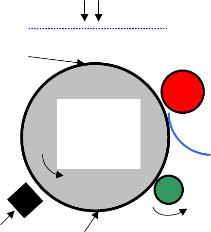
Introduction (cont’d)
Example1 Xerography-based Printing Machine
Light
Original
image
Image is
created here
Paper
Feed Roll
Roll
Selenium
coated Al.
cylinder
Paper
Wiper
Toner
Toner is coated
container
on surfaces of
Selenium with
electric charges
Schematic drawing of the xerography based printing machine.

Who are the Designers?
How do we design? What is design?
Is the mayor of Boston a designer?
Design Process
1. Know their
2. Define the problem they must solve to satisfy the
needs.
3. , which
analysis
5. Check the resulting design solution to see if it meets
the original customer needs.
"customers' needs".
Conceptualize the solution through synthesis
involves the task of satisfying several different
functional requirements using a set of inputs such as
product design parameters within given constraints.
4. Perform to optimize the proposed solution.

Definition of Design
Design is an interplay between
what we want to achieve and
how we want to achieve them.

Definition of Design
to to
"What
we want
achieve"
"How
we want
achieve
them"
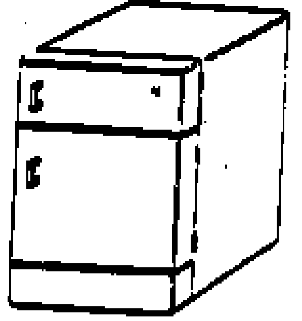
Example: Refrigerator Door Design
Figure ex.1.1.a Vertically hung refrigerator door.

Ultimate Goal of Axiomatic Design
The ultimate goal of Axiomatic Design is to
establish a science base for design and to
improve design activities by providing the
designer with a theoretical foundation based
on logical and rational thought processes and
tools.

Creativity and Axiomatic Design
Axiomatic design enhances creativity
by eliminating bad ideas early and
designers .
thus, helping to channel the effort of

Axioms are truths that cannot be derived but for which
there are no counter-examples or exceptions.
Many fields of science and technology owe their
advances to the development and existence of axioms.
(1) Euclid's geometry
(2) The first and second laws of thermodynamics
are axioms
(3) Newtonian mechanics
Historical Perspective on Axiomatic
Design

Constraints
What are constraints?
Constraints provide the bounds on the
acceptable design solutions and differ from
the FRs in that they do not have to be
independent.
There are two kinds of constraints:
input constraints
system constraints.

Example: Shaping of Hydraulic Tubes
To design a machine and a process that can
achieve the task, the functional requirements
can be formally stated as:
FR1= bend a titanium tube to prescribed
curvatures
FR2= maintain the circular cross-section of
the bent tube

Tube Bending Machine Design (cont’s)
Given that we have two FRs,
how many DPs do we need?

Example: Shaping of Hydraulic Tubes
ω
1
<
ω
2
ω
1
=
ω
2
ω
1
ω
2
ω
1
ω
2
Fixed set of
counter-rotating
grooved rollers
Pivot
axis
Flexible set of
counter-rotating
grooved rollers
for bending
Tube between
the two rollers
See Example 1.6 in [Suh 2001].
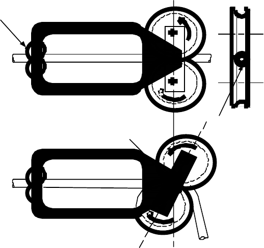
Example: Shaping of Hydraulic Tubes
DP1= Differential rotation of the bending rollers to bend the tube
DP2= The profile of the grooves on the periphery of the bending
rollers
axis
ω
1
<
ω
2
ω
1
=
ω
2
ω
1
ω
2
ω
1
ω
2
Fixed set of
counter-rotating
grooved rollers
Pivot
Flexible set of
counter-rotating
grooved rollers
for bending
Tube between
the two rollers
Tube bending apparatus
Example: Van Seat Assembly
(Adopted from Oh, 1997)
See Example 2.6 in [Suh 2001].
Schematic drawing of a van seat that can be removed
and installed easily using a pin/latch mechanism

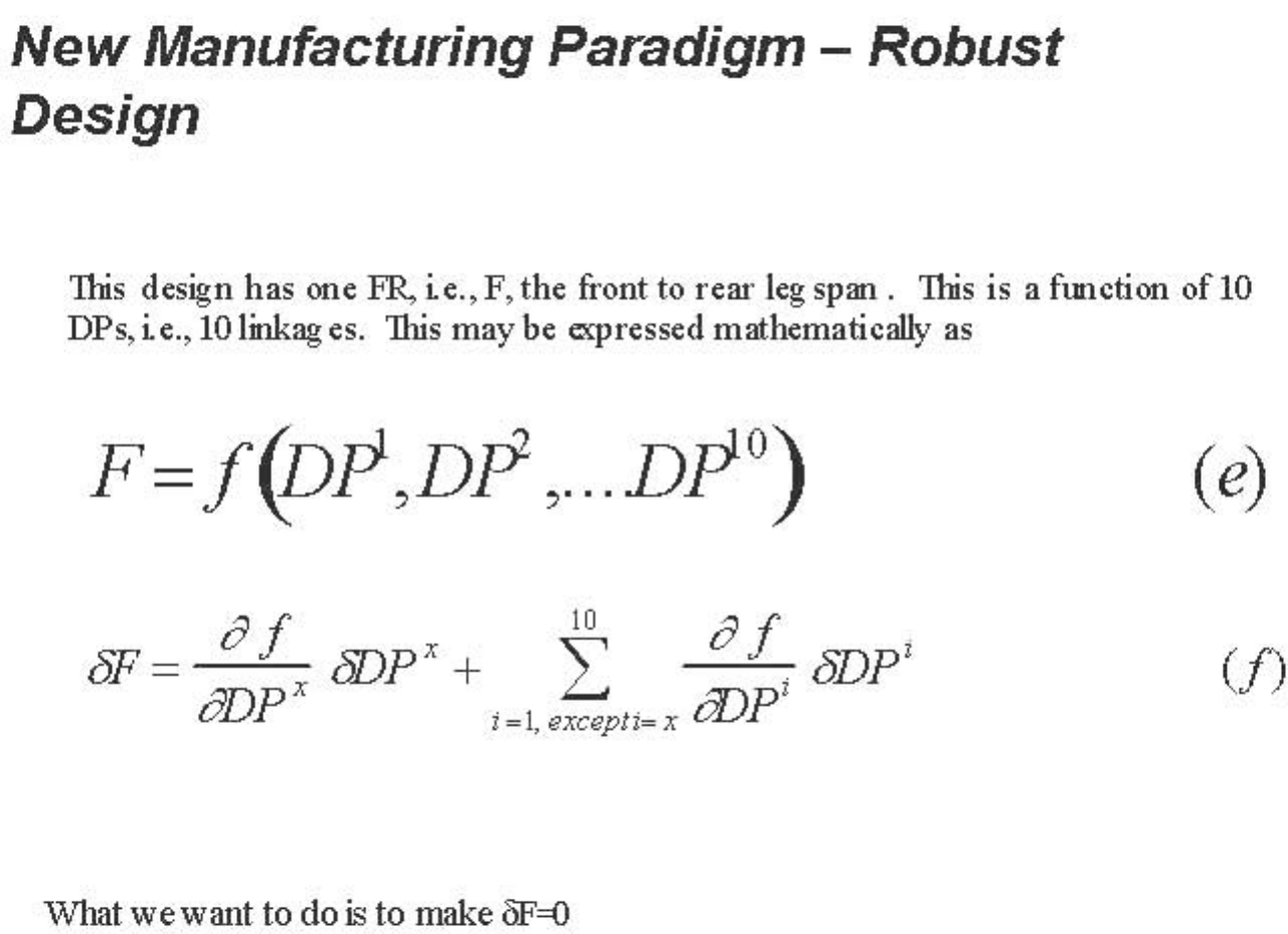
Example: Van Seat Assembly
Solution
The FR of the seat engagement linkage is that the
distance between the front leg and the rear latch
when the seat engages the pins must be equal to
the distance between the pins, which is 340 mm.
The linkages [see Figures E2.6.b and c in Suh
2001] determine the FR = F. The following table
shows the nominal lengths of the linkages.
Example: Van Seat Assembly
Traditional SPC Approach to Reliability and Quality
The traditional way of solving this kind of problem has been to do
the following:
(a) Analyze the linkage to determine the sensitivity of the
error.
Table a Length of linkages and sensitivity analysis
Links Nominal Length (mm) Sensitivity (mm/mm)
L12 370.00 3.29
L14 41.43 3.74
L23 134.00 6.32
L24 334.86 1.48
L27 35.75 6.55
L37 162.00 5.94
L45 51.55 11.72
L46 33.50 10.17
L56 83.00 12.06
L67 334.70 3.71
Decomposition, Zigzagging and Hierarchy
Zigzagging to decompose in the functional and the physical domains and create
the FR- and DP hierarchies
Figure by MIT OCW. After Figure 1.3 in [Suh 2001].
FR
FR1
FR11 FR12
FR121 FR122 FR123
FR1231
Functional Domain Physical Domain
FR1232
FR2
DP
DP1
DP11 DP12
DP121 DP122 DP123
DP1231 DP1232
DP2

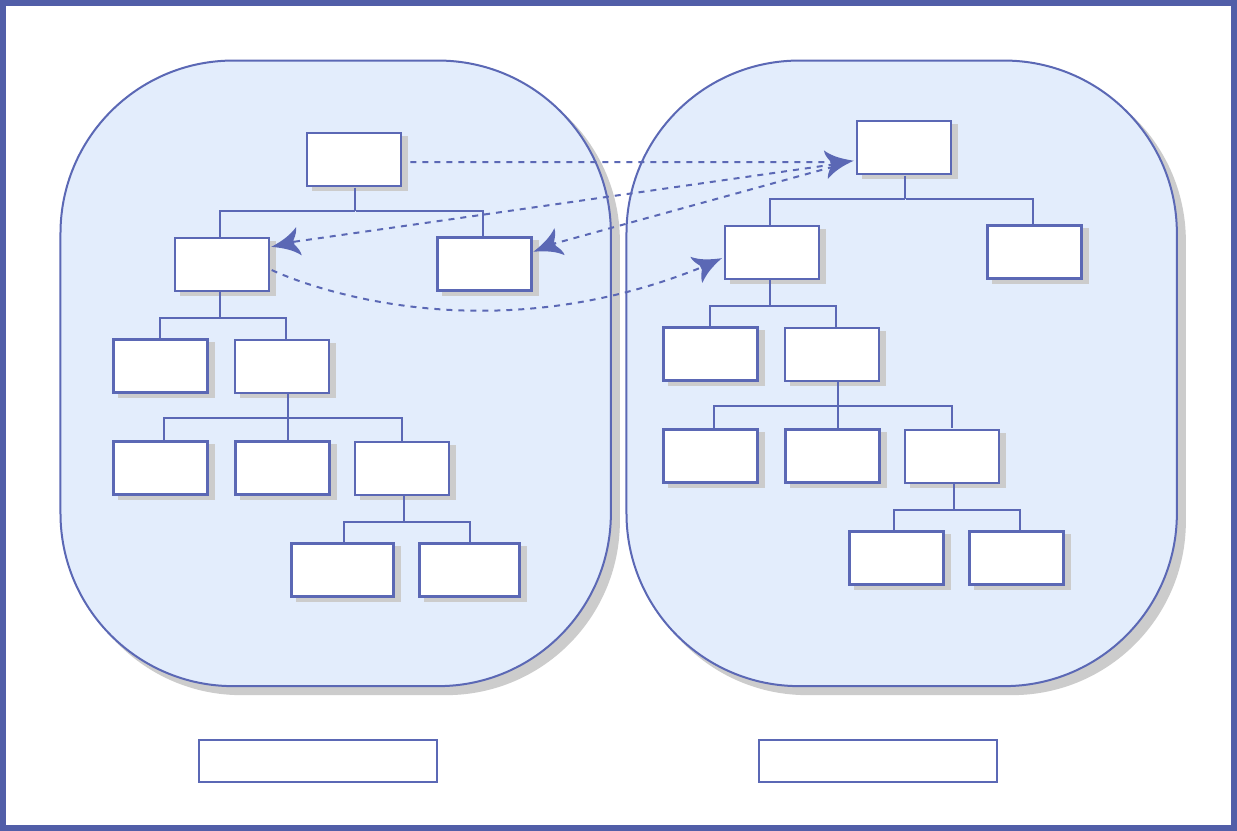
Equivalent Design:
of the highest-level FRs but have different
hierarchical architecture, the designs are
defined to be equivalent designs.
Identical Design:
of FRs and have the identical design
architecture, the designs are defined to be
identical designs.
Identical Design and Equivalent Design
When two different designs satisfy the same set
When two different designs satisfy the same set

FR1 = Freeze food for long-term preservation
FR2 = Maintain food at cold temperature for
short-term preservation
compartments is designed. Two DPs for this
refrigerator may be stated as:
DP1 = The freezer section
DP2 = The chiller (i.e., refrigerator) section.
Example: Refrigerator Design
To satisfy these two FRs, a refrigerator with two

FR1 = Freeze food for long-term preservation
FR2 = Maintain food at cold temperature for short-term
preservation
DP1 = The freezer section
DP2 = The chiller (i.e., refrigerator) section.
Example: Refrigerator Design
FR 1
FR 2
⎧
⎨
⎩
⎫
⎬
⎭
=
X
0
0 X
⎡
⎣
⎢
⎤
⎦
⎥
DP 1
DP 2
⎧
⎨
⎩
⎫
⎬
⎭

Example: Refrigerator Design
Having chosen the DP1, we can now decompose
FR1 as:
FR11 = Control temperature of the freezer
FR12 = Maintain the uniform temperature
throughout the freezer section at the
preset temperature
FR13 = Control humidity of the freezer section to
relative humidity of 50%
section in the range of -18 C +/- 2 C

Example: Refrigerator Design
FR11 =
DP11 = Sensor/compressor system that turn on and
off the compressor when the air temperature is
higher and lower than the set temperature in
the
DP12 = Air circulation system that blows air into the
freezer section and circulate it uniformly
throughout the freezer section at all times
returned air when its dew point is exceeded
Control temperature of the freezer section in the range of -18 C +/- 2 C
FR12 = Maintain the uniform temperature throughout the freezer section at the preset temperature
FR13 = Control humidity of the freezer section to relative humidity of 50%
freezer section, respectively.
DP13 = Condenser that condenses the moisture in the

Example: Refrigerator Design
Similarly, based on the choice of DP2 made, FR2
may be decomposed as:
FR21 = Control the temperature of the
chilled section in the range of 2 to 3 C
Maintain a uniform temperature
C of a preset temperature
FR22 =
throughout the chilled section within 1

Example: Refrigerator Design
and off the compressor when the air
temperature is higher and lower than the
set temperature in the chiller section,
respectively.
DP12 = Air circulation system that blows air into
the freezer section and circulate it
at all times
FR21 = Control the temperature of the chilled section in the range of 2 to 3 C
FR22 = Maintain a uniform temperature throughout the chilled section within 1 C of
a preset temperature
DP11 = Sensor/compressor system that turn on
uniformly throughout the freezer section
Example: Refrigerator Design
Figures removed for copyright reasons.
See Example 1.7 in [Suh 2001].
Example: Refrigerator Design
The design equation may be written as:
⎧
FR12
⎫
⎡
X
OO
⎤
⎧
DP12
⎫
⎪ ⎪ ⎪
⎪
⎨
FR11
⎬
=
⎢
XXO
⎥
⎨
DP11
⎬
⎪ ⎪
⎥
⎪
⎪
⎩
FR13
⎭
⎣
⎢
XOX
⎦
⎩
DP13
⎭
Equation (a) indicates that the design is a decoupled design.
DP22 DP21
FR22 X 0
FR21 X X

Full DM of Uncoupled Refrigerator Design
DP1
DP12 DP11 DP13 DP22 DP21
FR21 X 0 0 0 0
FR1 FR11 X X 0 0 0
X 0 X 0 0
FR2 FR22 0 0 0 X 0
0 0 0 X X
DP2
____________________________________________________
____________________________________________________
FR13
_____________________________________________________
FR21
_____________________________________________

Full DM of Uncoupled Refrigerator Design
DP1
DP12 DP11 DP13 DP22 DP21
FR12 X 0 0 0 0
FR1 FR11 X X 0 0 0
FR13 X 0 X 0 0
FR2 FR22 X 0 0 0 0
0 0 0 X 0/X
DP2
____________________________________________________
____________________________________________________
_____________________________________________________
FR21
_____________________________________________

Analysis
When do we perform analysis
during the design process?
Requirements for Concurrent Engineering
[A ] [B] [C] = [A] {B]
1. Bot h diago nal [\ ] [\ ] [\]
2. D iag x Full [\ ] [X] [X]
3. D iag x tria ng. [\ ] [LT] [LT]
4. Tria. x Triang [LT] [LT] [LT]
5. Tria. x Triang [LT] [U T] [X]
6. Fu ll x Full [X] [X] [X]
Table 1.3 The characteristic of concurrent engineering matrix [C].

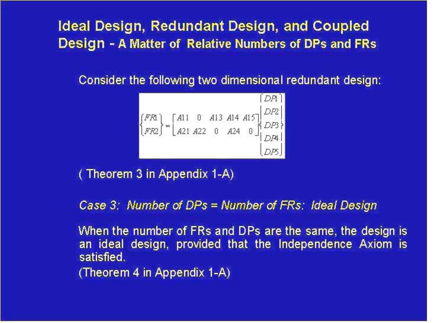
Ideal Design, Redundant Design, and Coupled
Design -
A Matter of Relative Numbers of DPs and FRs
Case 1:
Design
i
number of functional requirements, we always have a
coupled design. This is stated as Theorem 1.
Design
Axiom.
Depending on the relative numbers of DPs and FRs the design
can be classified as coupled, redundant and ideal designs.
Number of DPs < Number of FRs: Coupled
When the number of des gn parameters is less than the
Case 2: Number of DPs > Number of FRs: Redundant
When there are more design parameters than the functional
requirements, the design is called a redundant design. A
redundant design may or may not violate the Independence

The Second Axiom: The Information
Axiom
Axiom 2: The Information Axiom
Minimize the information content.
Information content I is defined in terms of the probability of
satisfying a given FR.
I = log
2
1
P
=−log
2
P
In the general case of n FRs for an uncoupled design, I may be
expressed as
n
∑
log
2
1
P
i
=−
n
∑
I = log
2
P
i
= 1 = 1 i i
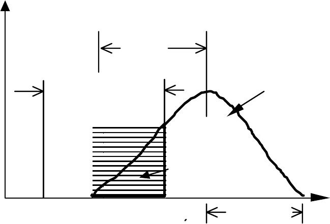
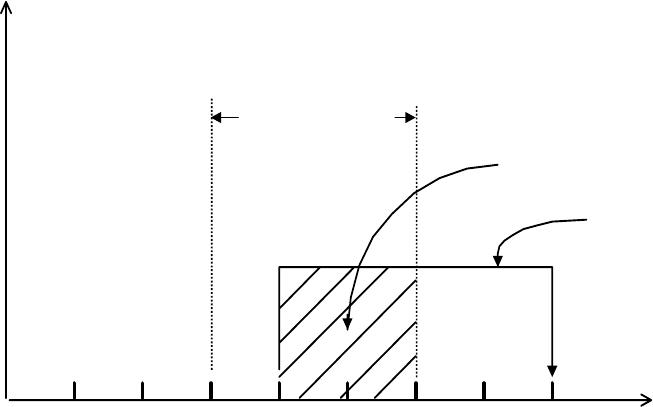
Design Range, System Range, and Common Range
e
Probab.
Den sity
Design Rang
Syst em
Rang e
Ar ea o f
Com m on
Rang e ( Ac)
Bi a s
Tar get
Varia tion
FR
from t he
pe a k valu e
Design Range, System Range, and Common Range in a plot of the
probability density function (pdf) of a functional requirement. The deviation
from the mean is equal to the square root of the variance. The design
range is assumed to have a uniform probability distribution in determining
the common range.

Measure of Information Content in Real Systems
The probability of success can be computed by specifying the Design
Range (dr) for the FR and by determining the System Range (sr) that the
proposed design can provide to satisfy the FR.
A
sr
I = log
2
(1.9)
A
cr
where A
sr
denotes the area under the System Range and A
cr
is the area of
the Common Range.
Furthermore, since A
sr
= 1.0 in most cases (since the total area of the
probability distribution function is equal to the total probability, which is
one) and there are n FRs to satisfy, the information content may be
expressed as
n
I =
∑
log
2
1
(1.10)
i=1
A
cr

FR1 =
to 30 minutes.
colleges.
good over 340 days a year.
less than $650,000.
Example: Buying a House
Commuting time for Prof. Wade must be in the range of 15
FR2 = The quality of the high school must be good, i.e., more than
65 % of the high school graduates must go to reputable
FR3 = The quality of air must be good, i.e., the air quality must be
FR4 = The price of the house must be reasonable, i.e., a four bed
room house with 3,000 square feet of heated space must be
Example: Buying a House
They looked around towns A, B, C and collected the following
data:
Tow n FR1=Comm. FR2=Qualit y FR3=Qualit y FR4=Price [$]
time [min] of school [%] of air [days]
A 20 to40 50 to70 300 to 320 450k to 550k
B 20 to 30 50 to 75 340 to 350 $450k to 650k
C 25 to45 50 to80 350 and up $600k to 800k
Which is the town that meets the requirements of the Wade
family the best? You may assume uniform probability
distributions for all FRs.
Example: Buying a House
Solution
10 20 30 40
Prob.
Dist.
Design Range
Commo
n
Range
System
Range
FR1 = Commuting Time (min).
Probability distribution of commuting time
Example: Buying a House
Prob.
Dist.
Design Range
System Range
Common Range
20 40 60 80
Quality of
Sc
h
oo
l
(%)
Probability distribution of the quality of schools
Example: Buying a House
The information content of Town A is infinite since it cannot satisfy
FR3, i.e., the design range and the system range do not overlap at
all. The information contents of Towns B and C are computed
using Eq. (1.8) as follows:
Town I
1
[bits]
I
2
[bits]
I
3
[bits]
I
4
[bits]
Σ
I
[bits]
A 1.0 2.0 Infi nite 0 Infini te
B 0 1.32 0 0 1.32
C 2.0 1.0 0 2.0 5.0

1.8 Common Mistakes Made by Designers
i. Due to Insufficient Number of DPs
(Theorem 1)
ii. Not Recognizing a Decoupled Design
iii. Having more DPs than the number of FRs
iv. minimizing the
bias and reduction of variance
v. --
Importance of Establishing and Concentrating on FR.
Coupling
Not creating a robust design -- not
information content through elimination of
Concentrating on Symptoms rather than Cause
