
Missouri University of Science and Technology Missouri University of Science and Technology
Scholars' Mine Scholars' Mine
Electrical and Computer Engineering Faculty
Research & Creative Works
Electrical and Computer Engineering
01 May 2019
The Decoupling Methods For Increasing The Isolation Between The Decoupling Methods For Increasing The Isolation Between
Two Antennas Two Antennas
Min Li
Lijun Jiang
Missouri University of Science and Technology
Follow this and additional works at: https://scholarsmine.mst.edu/ele_comeng_facwork
Part of the Electrical and Computer Engineering Commons
Recommended Citation Recommended Citation
M. Li and L. Jiang, "The Decoupling Methods For Increasing The Isolation Between Two Antennas,"
2019
IEEE MTT-S International Wireless Symposium, IWS 2019 - Proceedings
, article no. 8803978, The Institute
of Engineering and Technology, May 2019.
The de<nitive version is available at https://doi.org/10.1109/IEEE-IWS.2019.8803978
This Article - Conference proceedings is brought to you for free and open access by Scholars' Mine. It has been
accepted for inclusion in Electrical and Computer Engineering Faculty Research & Creative Works by an authorized
administrator of Scholars' Mine. This work is protected by U. S. Copyright Law. Unauthorized use including
reproduction for redistribution requires the permission of the copyright holder. For more information, please
contact [email protected].
The Decoupling Methods for Increasing the Isolation
between Two Antennas
Min Li and Lijun Jiang
Department of Electrical and Electronic Engineering, The University of Hong Kong, Hong Kong
Abstract—This paper presented the parasitic structure
decoupling method and other related approaches to increase the
isolation between two closely coupled antennas. The design
parameters of the resultant decoupling structures based on the
proposed methods can be precisely derived instead of fitted to
achieve high antenna isolations. A two-element monopole array is
employed as a benchmark to demonstrate the effectiveness of the
proposed methods. The simulation results show that good
impedance matching and high port isolation could be achieved
simultaneously based on the proposed methods.
Keywords—Isolation, decoupling methods, MIMO antenna,
network parameters, impedance matching
I.
I
NTRODUCTION
For a compact MIMO system, the mutual coupling (MC)
among antennas could degrade the system performance.
Various decoupling techniques (DTs) including the decoupling
network (DN) [1], artificial metamaterial (MM) [2],
neutralization line (NL) [3], defected ground structure (DGS)
[4], parasitic structure (PS) [5], etc., have been developed to
reduce the MC. However, most DNs suffer from narrow
isolation bandwidths. The decoupling designs employing MMs
usually require large antenna separations. Complex
optimization processes were adopted for the NL, DGS and PS
to realize high antenna isolations.
In this paper, we present derivation based methods to increase
the isolation between two antennas. These methods are realized
by adopting different decoupling structures, i.e., the PS, DN, NL
and shorting structure (SS). The design parameters of the
resultant decoupling structure can be directly derived to
achieve high antenna isolations. These decoupling structures
have different formations but similar design procedure:
utilizing the reactive component to manipulate and eliminate
the MC between antennas.
II. M
ETHODOLOGY
In the following discussion, a theoretical network model is
developed first by using the parasitic structure (PS). The high
antenna isolation is achieved by deriving the network
parameters and manipulating its condition for the minimum
coupling. Notably, this network model can also be applied to
the other methods. But certain modifications are required.
A. Isolation Enhancement by the Parasitic Strucure (PS)
The network model of the proposed method for using the
parasitic structure assisted by reactive component is shown in
Fig. 1. To decouple the coupling between Ant 1 and Ant 2, a
parasitic structure (PS) is inserted in between them. Two
additional transmission lines (TLs) with the same characteristic
impedance Z
0
(normally equal to 50 Ω) and the electrical
lengths
θ
1
and
θ
2
are added to the antennas’ feed lines. The PS
is connected with a TL (Z
0
,
θ
3
) and terminated by a reactive
load Z
L1
. Hence, the problem is changed to find appropriate
parameter values of
θ
1
,
θ
2
,
θ
3
and Z
L1
to achieve the high
antenna isolation.
For a two-element antenna system with one PS in the middle,
as shown in Fig. 1, the 3 by 3 matrix [S
t
1
] at the reference plane
t
1
describes the relationship between two antennas and the
effect of the added PS. After adding the additional TLs with the
same characteristic impedances Z
0
and different electrical
lengths
{
}
, [1,3]
i
i
θ
∈∈θ
to their feed lines, a new scattering
matrix [S
t
2
] is obtained at the reference plane t
2
.
The voltage-current relations of the new 3-port network can
be expressed by its impedance matrix [Z
t
2
] as
= ⋅
222
ttt
VZI
(1)
where [Z
t
2
] can be obtained by applying an S-to-Z
transformation to [S
t
2
]. If the PS is terminated by a reactive
component with an impedance Z
L1
, the voltage-current
relationship across this reactive load can be describe by
22
313
tt
L
VZI=− ⋅
. (2)
Substituting (2) into (1) yields a new 2×2 impedance matrix for
the input ports of the two objective antennas only, i.e.,
= ⋅
333
ttt
VZI
(3)
For a perfect isolation, the following decoupling condition shall
be satisfied in (3):
3
21
0
t
Z =
. (4)
Solving (4) yields Z
L1
as
1
(
L
Z
f= θ)
(5)
where
(
f
θ)
is a complex function with the input phase-delay
vector θ=[
θ
1
,
θ
2
,
θ
3
]. For MIMO antennas, higher radiation
efficiency is always preferred. Hence, the Z
L1
must be purely
imaginary to avoid any unwanted ohmic loss, i.e.,
1
Re{ } Re{ ( } 0
L
Ζ f==θ)
. (6)
Hence, the phase-delay vector θ is derived from (6) directly.
Then they are used to compute the purely imaginary Z
L1
using
(5). The reactance Z
L1
can be consequently realized by
appropriate inductor or capacitor.
In addition, implanting the resultant Z
L1
into [Z
t
3
] in (3) yields
the input impedances of both decoupled antennas. They are
used to design the matching circuits with little impact to the
resultant high isolation.
978-1-7281-0716-5/19/$31.00 ©2019 IEEE
Authorized licensed use limited to: Missouri University of Science and Technology. Downloaded on February 23,2024 at 17:31:47 UTC from IEEE Xplore. Restrictions apply.
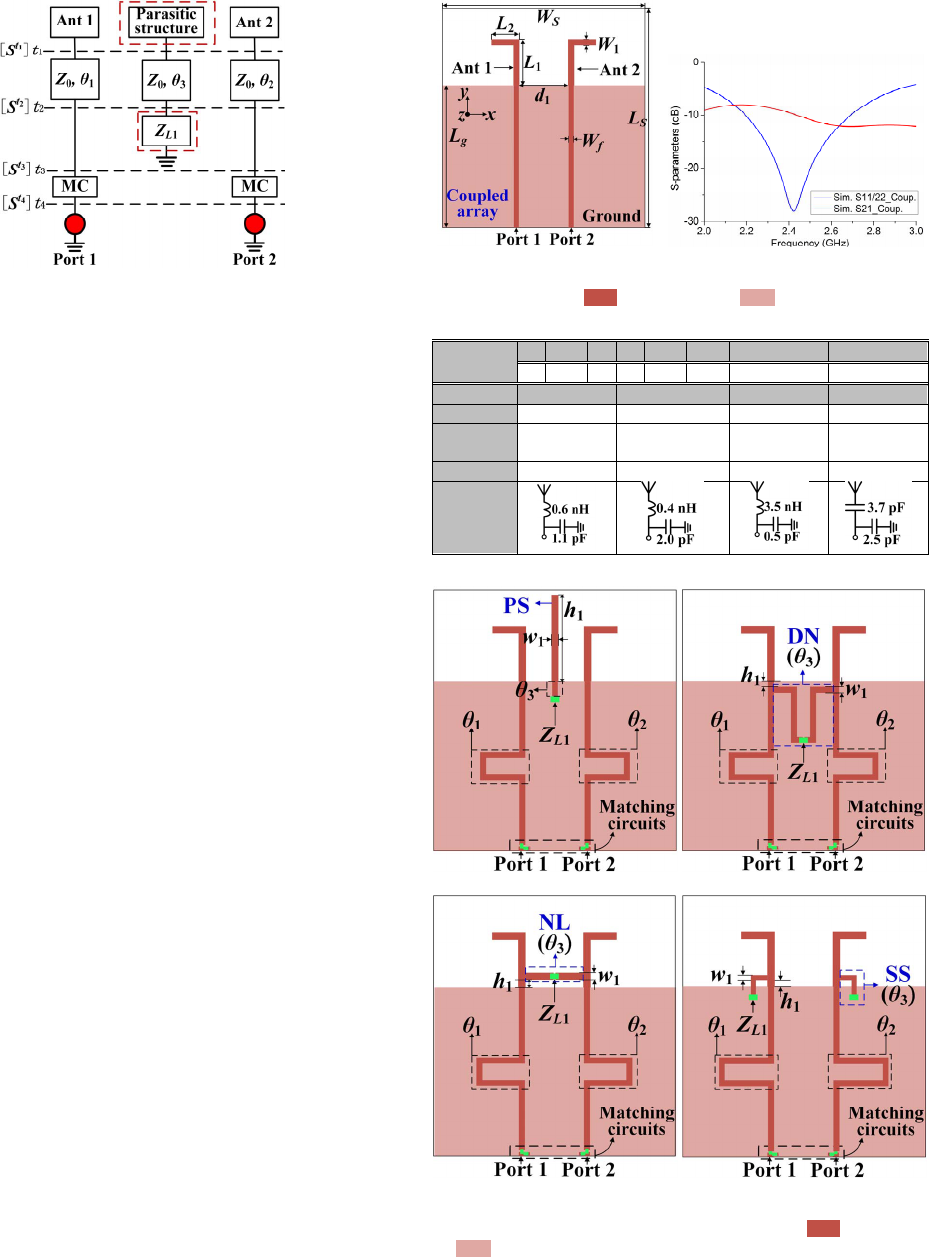
Fig. 1. The proposed method using parasitic structure.
B. Other Decoupling Methods
To decouple Ants 1 and 2, we could connect a decoupling
network (DN) to the antennas’ feed lines, or connect a
neutralization line (NL) to the antenna radiators, or even use
the shorting structure (SS) to connect the radiators to the
ground. For DN and NL, a TL is needed in between two
antennas with a reactive lumped component installed in the
middle of it. The SS could be realized by using a TL with a
reactive component in serial to the ground. Two additional TLs
and matching networks are further added to the antennas. The
lengths of TLs and reactance of the lumped component can be
derived similarly by imposing the isolation condition to the
network analysis.
III.
D
ESIGN
E
XAMPLE
Fig. 2(a) shows a 2.4-GHz array consisting of two symmetric
inverted-L monopole antennas (Ants 1 and 2) with the edge
separation distance d
1
=18 mm=0.22
λ
g
, where
λ
g
is the guided
wavelength at 2.4 GHz. The antennas are fed through two 50-
Ω microstrip lines with the width
W
f
=1.8 mm on a 74 mm
×
80
mm (
L
s
×
W
s
) Rogers substrate, RO 4350. The detailed
dimensions are given in Table I. The simulated S-parameters of
the coupled array are presented in Fig. 2(b). It can be seen that
the antennas have the poor isolation of around 10 dB at the
frequency of 2.4 GHz.
To improve the isolation, the PS decoupling scheme is
presented together with other three methods, as shown in Fig.
3. Based on the methodology proposed in section II, the
required lengths of TLs and reactances of lumped components
are calculated to realize the high antenna isolations. The L-
section matching circuits are adopted at the antenna inputs for
the impedance matching. The derived design parameters are
given in Table I.
Fig. 4 shows the simulated S-parameters of the decoupled
arrays. It can be seen that the decoupled antennas all
demonstrate good matching conditions with S
11
&S
22
<-10 dB at
2.4 GHz. Moreover, by using the proposed methods, the
simulated isolations of the decoupled arrays in cases 1, 2, 3 and
4 are substantially improved to around 35 dB, 28 dB, 32 dB and
29 dB, respectively at 2.4 GHz.
(a) (b)
Fig. 2. (a) The configuration and (b) the simulated S-parameters of the two-
element coupled array. ( metal in front and metal in bottom)
T
ABLE
I P
ARAMETER
V
ALUES
Common
parameters
L
1
L
2
Ls Lg W
1
Wf Ws d
1
17 10.2 80 52 2.2 1.8 74 18
Method #1 Method #2 Method #3 Method #4
h
1
/ w
1
26.5/2.2 1.5/1.8 2.2/2.3 2.0/1.5
θ
1
/
θ
2
/
θ
3
2.23/2.23
/0.38
2.18/2.18
/3.75
2.38/2.38
/1.38
2.68/2.68
/0.77
Z
L
1
-j22.1(3 pF) -j663(0.1 pF) j30.2 (2 nH) -j132(0.5pF)
Matching
circuits
Unit for
θ
1
: rad, and unit for other length variables: mm
(a) (b)
(c) (d)
Fig. 3. (a) Decoupling case using PS. (b) Decoupling case using DN. (c)
Decoupling case using NL. (d) Decoupling case using SS. ( metal in front
and metal in bottom)
Authorized licensed use limited to: Missouri University of Science and Technology. Downloaded on February 23,2024 at 17:31:47 UTC from IEEE Xplore. Restrictions apply.
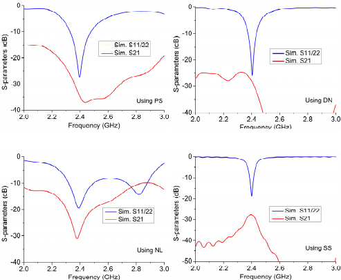
(a) (b)
(c) (d)
Fig. 4. Simulated S-parameters of the decoupled cases shown in Fig. 3: (a)
using PS, (b) using DN, (c) using NL, and (d) using SS.
IV.
C
ONCLUSIONS
This paper presented the parasitic structure decoupling
method and other methods for two closely spaced antennas.
The decoupling design parameters could be rigorously derived.
A two-element monopole array was analyzed and decoupled
for the demonstration purpose. By using the proposed four
methods, the decoupled antennas could have very high port
isolations over 25 dB.
A
CKNOWLEDGEMENT
This work was supported in part by the Research Grants
Council of Hong Kong GRF 17209918, AOARD FA2386-17-
1-0010, NSFC 61271158, and HKU Seed Fund 201711159228.
R
EFERENCES
[1] S. C. Chen, Y. S. Wang and S. J. Chung, "A decoupling technique for
increasing the port isolation between two strongly coupled antennas,"
IEEE Trans. Antennas Propag., vol. 56, no. 12, pp. 3650-3658, Dec.
2008.
[2] H.S. Farahani, M. Veysi, M. Kamyab and A. Tadjalli, “Mutual coupling
reduction in patch antenna arrays using a UC-EBG superstrate,” IEEE
Antennas Wireless Propag. Lett., vol. 9, no. , pp. 57-59, 2010.
[3] Chebihi, C. Luxey, A. Diallo, P. Le Thuc and R. Staraj, "A novel isolation
technique for closely spaced PIFAs for UMTS mobile phones," IEEE
Antennas Wireless Propag. Lett., vol.7, pp. 665-668, 2008.
[4] S. Zhang, S. N. Khan, and S. He, ‘‘Reducing mutual coupling for an
extremely closely-packed tunable dual-element PIFA array through a
resonant slot antenna formed in-between,’’ IEEE Trans. Antennas
Propag., vol. 58, no. 8, pp. 2771---2776, Aug. 2010.
[5] M. Li, B. G. Zhong and S. W. Cheung, "Isolation Enhancement for
MIMO Patch Antennas Using Near-Field Resonators as Coupling-Mode
Transducers," IEEE Trans. Antennas Propag. (Early Access)
Authorized licensed use limited to: Missouri University of Science and Technology. Downloaded on February 23,2024 at 17:31:47 UTC from IEEE Xplore. Restrictions apply.
