
Rockwell Automation Publication 1756-PM020H-EN-P - March 2022
Supersedes Publication 1756-PM020G-EN-P - September 2020
Programming Manual
Original Instructions
Logix 5000 Controllers Data
Access
1756 ControlLogix, 1756 GuardLogix, 1769 CompactLogix,
1769 Compact GuardLogix, 1789 SoftLogix, 5069
CompactLogix, 5069 Compact GuardLogix, Studio 5000
Logix Emulate

Logix 5000 Controllers Data Access
2 Rockwell Automation Publication 1756-PM020H-EN-P - March 2022
Important User Information
Read this document and the documents listed in the additional resources section about installation, configuration, and
operation of this equipment before you install, configure, operate, or maintain this product. Users are required to
familiarize themselves with installation and wiring instructions in addition to requirements of all applicable codes, laws,
and standards.
Activities including installation, adjustments, putting into service, use, assembly, disassembly, and maintenance are
required to be carried out by suitably trained personnel in accordance with applicable code of practice.
If this equipment is used in a manner not specified by the manufacturer, the protection provided by the equipment may
be impaired.
In no event will Rockwell Automation, Inc. be responsible or liable for indirect or consequential damages resulting from
the use or application of this equipment.
The examples and diagrams in this manual are included solely for illustrative purposes. Because of the many variables
and requirements associated with any particular installation, Rockwell Automation, Inc. cannot assume responsibility or
liability for actual use based on the examples and diagrams.
No patent liability is assumed by Rockwell Automation, Inc. with respect to use of information, circuits, equipment, or
software described in this manual.
Reproduction of the contents of this manual, in whole or in part, without written permission of Rockwell Automation, Inc.,
is prohibited.
Throughout this manual, when necessary, we use notes to make you aware of safety considerations.
WARNING:
Identifies information about practices or circumstances that can cause an explosion in a hazardous environment, which may lead to
personal injury or death, property damage, or economic loss.
ATTENTION:
Identifies information about practices or circumstances that can lead to personal injury or death, property damage, or economic loss.
Attentions help you identify a hazard, avoid a hazard, and recognize the consequence.
IMPORTANT
Identifies information that is critical for successful application and understanding of the product.
Labels may also be on or inside the equipment to provide specific precautions.
SHOCK HAZARD:
Labels may be on or inside the equipment, for example, a drive or motor, to alert people that dangerous voltage may be present.
BURN HAZARD: Labels may be on or inside the equipment, for example, a drive or motor, to alert people that surfaces may reach dangerous
temperatures.
ARC FLASH HAZARD:
Labels may be on or inside the equipment, for example, a motor control center, to alert people to potential Arc Flash. Arc Flash will
cause severe injury or death. Wear proper Personal Protective Equipment (PPE). Follow ALL Regulatory requirements for safe work practices and for
Personal Protective Equipment (PPE).
Rockwell Automation
recognizes that some of the terms that are currently used in our industry and in
this publication are not in alignment with the movement toward inclusive language in technology. We
are proactively collaborating with industry peers to find alternatives to such terms and making
changes to our products and content. Please excuse the use of such terms in our content while we
implement these changes.

Rockwell Automation Publication 1756-PM020H-EN-P - March 2022 3
Summary of Changes
This manual includes new and updated information. Use these reference
tables to locate changed information.
Grammatical and editorial style changes are not included in this
summary.
Global changes
This table identifies changes that apply to all information about a subject
in the manual and the reason for the change. For example, the addition of
new supported hardware, a software design change, or additional
reference material would result in changes to all of the topics that deal
with that subject.
Change
Topic
New Studio 5000 Logix Designer branding Studio 5000 Environment on page 9
New or enhanced features
None in this version.

Rockwell Automation Publication 1756-PM020H-EN-P - March 2022 5
Table of Contents
Studio 5000 environment .............................................................. 9
Additional resources ..................................................................... 9
Legal notices ................................................................................. 9
Chapter 1
CIP Services Overview ............................................................... 11
CIP Data Types ...................................................................... 11
Atomic data type sizes ..................................................... 12
Logix 5000 data .................................................................... 12
Tag type service parameter .................................................. 13
Tag type service parameter values used with Logix
controllers ........................................................................ 13
Analysis ................................................................................. 13
Segment Encoding ................................................................ 13
Logical Segments ............................................................ 14
Symbolic Segments ......................................................... 14
CIP Service Request/Response Format ............................... 15
Services Supported by Logix 5000 Controllers ........................... 16
Read Tag Service ................................................................. 17
Example Using Symbolic Segment Addressing ............... 18
Example Using Symbol Instance Addressing .................. 18
Read Tag Service Error Codes ........................................ 19
Read Tag Fragmented Service ............................................. 19
Example Using Symbolic Segment Addressing ............... 19
Example Using Symbol Instance Addressing .................. 21
Read Tag Fragmented Service Error Codes ................... 23
Write Tag Service ................................................................. 23
Example Using Symbolic Segment Addressing ............... 23
Example Using Symbol Instance Addressing .................. 24
Write Tag Service Error Codes ........................................ 24
Write Tag Fragmented Service ............................................. 25
Example Using Symbolic Segment Addressing ............... 25
Example Using Symbol Instance Addressing .................. 27
Write Tag Fragmented Service Error Codes .................... 29
Read Modify Write Tag Service ............................................ 29
Service Request Parameters ........................................... 29
Example ........................................................................... 30
Read Modify Write Tag Service Error Codes ................... 30
Multiple Service Packet Service ...................................... 31
Example ........................................................................... 31
Logix Data Structures ................................................................. 32
Work with Data Structures .................................................... 33
Tag type service parameters for structure ............................. 34
Chapter 2
How tags are organized in the controller ..................................... 35
Symbol object ........................................................................ 36
Template object ..................................................................... 36
Summary of Changes
Preface
CIP services
CIP Services and User-created
Tags

Table of Contents
6 Rockwell Automation Publication 1756-PM020H-EN-P - March 2022
Create and maintain a symbol object list .................................... 37
Step 1: Find user-created controller scope tags in a Logix 5000
controller ..................................................................................... 38
Retrieve all symbol object instances ..................................... 39
Example of retrieving the first group of tags .......................... 39
Analysis ................................................................................. 40
Continue the retrieval process ......................................... 40
Step 2: Isolate user-created tags from system tags/identifying
structured tags ............................................................................ 42
Symbol Type Attribute ........................................................... 42
Eliminate tags by applying rules ...................................... 43
Step 3: Determine the structure makeup for a specific structure 44
Example of reading template attributes ................................. 44
Analysis ................................................................................. 45
Structure data format ....................................................... 46
Contents of the member information ................................ 47
Example of retrieving member information ...................... 47
Example ........................................................................... 47
More about BOOLS in UDTs ........................................... 49
Step 4: Determine the data packing of the members of a structure
when accessed as a whole ......................................................... 49
Example of reading an entire structure ................................. 50
Step 5: Determine when the tags list and structure information
need refreshing .......................................................................... 51
How to detect changes .......................................................... 51
Chapter 3
Atomic Members of Predefined Data Types................................ 55
Example 1 (Symbolic Segment Addressing Method) ............. 55
Example 2 (Symbol Instance Addressing Method) ............... 56
Example 3 (Symbolic Segment Addressing Method) ............ 56
Example 4 (Symbolic Segment Addressing Method) ............ 57
Example 5 (Symbol Instance Addressing Method) ............... 57
Example 6 (Symbolic Segment Addressing Method) ............ 58
Example 7 (Symbolic Segment Addressing Method) ............ 59
Example 8 (Both Addressing Methods) ................................. 59
Example 9 (Both Addressing Methods) ................................. 60
Example 10 (Symbolic Segment Addressing Method) with
BOOLs .................................................................................. 60
Access User-Defined Structures ................................................ 61
Example 1 ............................................................................. 62
Example 2 ............................................................................. 62
Example 3 ............................................................................. 63
Example 4 ............................................................................. 63
Example 5 ............................................................................. 64
Example 6 ............................................................................. 64
Chapter 4
CIP Addressing Examples

Table of Contents
Rockwell Automation Publication 1756-PM020H-EN-P - March 2022 7
Unconnected Messaging (UCMM) through PCCC ...................... 67
Connected Explicit Messages through PCCC ............................. 68
Fragmentation Protocol ............................................................... 70
PCCC Commands ...................................................................... 71
Supported Subset of PCCC Commands .................................... 71
Initial Fields of All PCCC Commands ......................................... 72
PLC-2 Communication Commands ............................................ 72
Unprotected Read (CMD=01, 41; FNC not present) ............. 73
Protected Write (CMD=00, 40; FNC not present) .................. 73
Unprotected Write (CMD=08, 48; FNC not present) ............. 73
Protected Bit Write (CMD=02, 42; FNC not present) ............ 73
Unprotected Bit Write (CMD=05, 45; FNC not present) ........ 74
PLC-5 Communication Commands ............................................ 74
Addressing examples ............................................................ 75
Read Modify Write N (CMD=0F, 4F; FNC=79) ...................... 76
Typed Read (CMD=0F, 4F; FNC=68) ................................... 76
Typed Write (CMD=0F, 4F; FNC=67) ................................... 77
Word Range Read (CMD=0F, 4F; FNC=01) ......................... 77
Word Range Write (CMD=0F, 4F; FNC=00) ......................... 77
Bit Write (CMD=0F, 4F; FNC=02) ......................................... 78
SLC Communication Commands ............................................... 78
SLC Protected Typed Logical Read with 3 Address Fields
(CMD=0F, 4F; FNC=A2) ....................................................... 79
SLC Protected Typed Logical Write with 3 Address
Fields(CMD=0F, 4F, FNC=AA) ............................................. 79
SLC Protected Typed Logical Read with 2 Address Fields
(CMD=0F, 4F; FNC=A1) ....................................................... 80
SLC Protected Typed Logical Write with 2 Address Fields
(CMD=0F, 4F; FNC=A9) ....................................................... 80
CIP Over the Controller Serial
Port
Index

Rockwell Automation Publication 1756-PM020H-EN-P - March 2022 9
Preface
Before using this document:
• Have a thorough understanding of CIP and EtherNet/IP.
• Have purchased a copy of the pertinent volumes of the CIP
Networks Library.
• Be properly licensed through ODVA to use the CIP technology.
For more information on the CIP Networks Library and CIP technologies,
contact ODVA at http://www.odva.org/.
The Studio 5000 Automation Engineering & Design Environment®
combines engineering and design elements into a common environment.
The first element is the Studio 5000 Logix Designer® application. The
Logix Designer application is the rebranding of RSLogix 5000® software
and will continue to be the product to program Logix 5000™ controllers
for discrete, process, batch, motion, safety, and drive-based solutions.
The Studio 5000® environment is the foundation for the future of
Rockwell Automation® engineering design tools and capabilities. The
Studio 5000 environment is the one place for design engineers to
develop all elements of their control system.
These documents contain additional information concerning related
Rockwell Automation products.
Resource Description
Industrial Automation Wiring and Grounding
Guidelines, publication 1770-4.1
Provides general guidelines for installing a Rockwell
Automation industrial system.
Product Certifications webpage, available at
http://ab.rockwellautomation.com
Provides declarations of conformity, certificates, and
other certification details.
View or download publications at
http://www.rockwellautomation.com/literature. To order paper copies of
technical documentation, contact the local Rockwell Automation
distributor or sales representative.
Rockwell Automation publishes legal notices, such as privacy policies,
license agreements, trademark disclosures, and other terms and
Studio 5000 environment
Additional resources
Legal notices

Preface
10 Rockwell Automation Publication 1756-PM020H-EN-P - March 2022
conditions on the Legal Notices page of the Rockwell Automation
website.
End User License Agreement (EULA)
You can view the Rockwell Automation End User License Agreement
(EULA) by opening the license.rtf file located in your product's install
folder on your hard drive.
The default location of this file is:
C:\Program Files (x86)\Common Files\Rockwell\license.rtf.
Open Source Software Licenses
The software included in this product contains copyrighted software that
is licensed under one or more open source licenses.
You can view a full list of all open source software used in this product
and their corresponding licenses by opening the oss_license.txt file
located in your product's OPENSOURCE folder on your hard drive. This
file is divided into these sections:
• Components
Includes the name of the open source component, its version
number, and the type of license.
• Copyright Text
Includes the name of the open source component, its version
number, and the copyright declaration.
• Licenses
Includes the name of the license, the list of open source
components citing the license, and the terms of the license.
The default location of this file is:
C:\Program Files (x86)\Common Files\Rockwell\Help\<product
name>\Release Notes\OPENSOURCE\oss_licenses.txt.
You may obtain Corresponding Source code for open source packages
included in this product from their respective project web site(s).
Alternatively, you may obtain complete Corresponding Source code by
contacting Rockwell Automation via the Contact form on the Rockwell
Automation website:
http://www.rockwellautomation.com/global/about-us/contact/contact.pag
e. Please include "Open Source" as part of the request text.

Rockwell Automation Publication 1756-PM020H-EN-P - March 2022 11
Chapter 1
CIP services
Communicating with Logix 5000 controllers require using CIP explicit
messaging. This chapter describes the subset of the CIP explicit
messaging constructs for understanding the service explanations that
follow.
See also
CIP services overview on page 11
Tag type service parameter on page 13
Analysis on page 13
Segment Encoding on page 13
CIP Service Request/Response Format on page 15
Before using CIP services, review introductory information:
• CIP data types
• Logix 5000 data
• Tag Type Service parameter
• Segment encoding
• CIP Service Request/Response format
Data type information is very important in all aspects of CIP
communication. The type information is used for reading, writing, and, if
necessary, deciphering structures. The Logix 5000 controller supports
these data types.
• Atomic. A bit, byte, 16-bit word, or 32-bit word, each of which
stores a single value. (CIP refers to these as Elementary Data
Types.)
• Structure. A grouping of different data types that functions as a
single unit and serves a specific purpose. Depending on the needs
of the application, create additional structures, which are referred
to as user-defined structures.
• Array. A sequence of elements, each of which is the same data
type.
• Define data in one, two, or three dimensions, as required (one
dimension is the most common).
• Use atomic or structure data types.
Data in the controller is organized as tags. The tags come in two basic
types: atomic and structure. Atomic types can be arrayed or singular, and
are very easy to work with. Structure types provide a great deal of
CIP Services Overview
CIP Data Types

Chapter 1 CIP services
12 Rockwell Automation Publication 1756-PM020H-EN-P - March 2022
flexibility, but are more challenging to access. See the Atomic data type
sizes table for details.
See also
CIP services overview on page 11
Atomic data type sizes on page 12
Logix 5000 data on page 12
Use the atomic data type sizes table for the data type value to use to
store a bit.
To store a Use this data type
Bit BOOL
Bit array
DWORD (32-bit boolean array)
8-bit integer
SINT
16-bit integer
INT
32-bit integer DINT
32-bit float REAL
64-bit integer LINT
The Logix 5000 controller stores data in tags, in contrast to a PLC-5 or
SLC controller, which stores data in data files. Logix 5000 tags have
these properties:
• Name that identifies the data:
• Up to 40 characters in length.
• Scope:
• Controller (global), accessed directly.
• Program (local), which cannot be directly accessed, but can be
copied to a controller scope tag.
• Data type, which defines the organization of the data.
See CIP data types for more information.
In the Logix Designer application, version 21.00.00 and later, and in
RSLogix 5000 software, version 18.00.00 and later, external access to
controller scoped tags is user selectable. If a tag’s External Access
attribute is set to None, then the tag cannot be accessed from outside the
controller.
For more information about external access to controller scoped tags see
the Logix 5000 Controllers I/O and Tag Data Programming Manual,
publication 1756-PM004.
For more information about tags and data types, see the Logix 5000
Controllers Design Considerations Reference Manual, publication
1756-RM094.
Atomic data type sizes
Logix 5000 data

Chapter 1 CIP services
Rockwell Automation Publication 1756-PM020H-EN-P - March 2022 13
See also
CIP data types on page 11
The Read tag, Write Tag, Read Tag Fragmented, Write Tag
Fragmented, and Read-Modify-Write Tag services require a service
parameter that identifies the data type of the tag being referenced. This
tag type parameter is:
• A 16-bit value for atomic tags
• Two 16-bit values for structured tags
The value used for structures is a calculated value. For details, see Tag
type service parameters for structures.
The tag type values used for atomic tags and the resulting data size are
shown in the table shown in Tag type service parameter values used with
Logix controllers.
See also
Tag type service parameters for structures on page 34
Use this table for date types, tag type values, and size of transmitted data
for Logix controllers.
Data Type
Tag Type Value
Size of Transmitted Data
BOOL 0x0nc1
The BOOL value includes an additional
field (n) for specifying the bit position
within the SINT (n = 0-7).
1 byte
SINT 0x00C2 1 byte
INT
0x00C3
2 bytes
DINT
0x00C4
4 bytes
REAL
0x00CA
4 bytes
DWORD
0x00D3
4 bytes
LINT
0x00C5
8 bytes
bytes = Multi-byte data values are transmitted low-byte first
These values are based on the CIP Data Type Reporting Values that are
defined in Volume 1, Appendix C of the CIP Networks Library, but are
extended to 16-bits.
The Request Path in a CIP explicit message contains addressing
information indicating which internal resource in the target node directs
the service. This addressing information is organized by using Logical
Segments, Symbolic Segments, or both.
For more detailed information about segments, see the CIP Networks
Library, Volume 1, Appendix C.
The following is a summary of the Logical Segment types defined by CIP
that are supported by the Logix 5000 controller.
Tag type service parameter
Tag type service parameter
values used with Logix
controllers
Analysis
Segment Encoding
Chapter 1 CIP services
14 Rockwell Automation Publication 1756-PM020H-EN-P - March 2022
See also
CIP services overview on page 11
These tables explain the Logical Segments. Not all segment types
defined by CIP are supported by Logix 5000 controllers.
Segment Type
Value
Byte Order Representation of Element ID Value (low byte first)
0
1
…
n
n+1
8-bit Element ID 0x28 Value N/A N/A N/A N/A
16-bit Element ID
0x29
00
Low
High
N/A
N/A
32-bit Element ID
0x2A
00
Lowest
Low
High
Highest
Segment Type
Value
Byte Order Representation of Class ID Value (low byte first)
0
1
…
n
n+1
8-bit Class ID 0x20 Value N/A N/A N/A N/A
16-bit Class ID 0x21 00 Low High N/A N/A
Segment Type
Value
Byte Order Representation of Instance ID Value (low byte first)
0
1
…
n
n+1
8-bit Instance ID 0x24 Value N/A N/A N/A N/A
16-bit Instance ID
0x25
00
Low
High
N/A
N/A
Segment Type Value Byte Order Representation of Attribute ID Value (low byte first)
0
1
…
n
n+1
8-bit Attribute ID 0x30 Value N/A N/A N/A N/A
16-bit Attribute ID 0x31 00 Low High N/A N/A
See also
CIP services on page 11
Segment Encoding on page 13
CIP defines a way to reference items by their symbolic name. The
segment used is the ANSI Extended Symbol Segment defined in the CIP
Networks Library, Volume 1, Appendix C.
The Read/Write tags services can use these segments in the request
path to indicate which target tag to operate on. When addressing an
arrayed tag, the Logical Segment for Element ID is also used with the
Symbolic Segment.
Segment Type
Value
Byte Order Representation (low byte first)
0
1
…
N
N+1
ANSI Extended
Symbolic
0x91 Length 1st char … Nth Char (1)
Logical Segments
Symbolic Segments
Chapter 1 CIP services
Rockwell Automation Publication 1756-PM020H-EN-P - March 2022 15
See also
Segment Encoding on page 13
All CIP services follow the Message Router Request/Response format
defined in the CIP Networks Library, Volume 1, Chapter 2. For complete
descriptions, see the CIP Networks Library. All requests take this form.
Message Request
Field
Description
Request Service Indicates to the object referenced in the request path to perform a task. The CIP or
the device manufacturer define these tasks. Most of the services covered in this
manual are defined by the Rockwell Automation vendor-specific objects, and are
not found in the CIP Networks Library.
Request Path Size A byte value that indicates the number of 16-bit words in the Request Path.
Request Path A variable sized field that consists of one or more segments. The path references
the item that services operate on in the controller. The path contains Logical or
Symbolic segments or both.
Request Data The service-specific data that is delivered to the object referenced in the Request
Path. This field only appears in the message frame if a service has service-specific
data.
This same form is used for ControlNet and EtherNet/IP communication
CIP-based networks. Requests received through the serial port use
another protocol.
Use the CIP service format for CIP-explicit messages and to deliver
connected or unconnected messages to the controller. The mechanisms
for doing this are CIP-network specific. For example, for EtherNet/IP
access, see the CIP Networks Library, Volume 1 unconnected, Chapter 3
and the EtherNet/IP Adaptation of CIP, Volume 2.
For more information about using the EtherNet/IP network to
communicate with the controller, see
http://www.rockwellautomation.com/rockwellautomation/solutions-servic
es/oem/design-develop-deliver/information-enabled-solutions.page. We
recommend using connected messaging whenever possible. Be aware
that the information presented here does not replace the need to be
properly authorized by ODVA, Inc. to use the Ethernet/IP protocol.
The examples used throughout the manual show only the explicit
message protocol elements and not the network-specific details. The
exception to this is the information in CIP Over the Controller Serial Port,
which shows more details of unconnected versus connected explicit
messages, and of the PCCC and DF1 layers. All responses take the
general form as shown in the table.
Message Response
Field
Description
Reply Service The request service with the MSB set to 1.
00
Reserved.
General Status An 8-bit value indicating success or error status. The CIP Networks Library, Volume
1, Appendix B has a list of the general status codes. The object class specified in the
request path defines any extended status codes for each service defined for that
class.
Extended Status Size An 8-bit value that indicates how many 16-bit values follow in the additional status
field. For status=0 (success) this is 0.
CIP Service
Request/Response Format

Chapter 1 CIP services
16 Rockwell Automation Publication 1756-PM020H-EN-P - March 2022
Message Response
Field
Description
Extended Status The array of 16-bit values that describe the general status code. Only present when
the size field is > 0.
Reply Data The data returned by the service request. This field only appears in the message
frame if a service has service-specific data.
See also
CIP Over the Controller Serial Port on page 67
PCCC Commands on page 71
These sections describe the inherent mode of communication and
addressing of the Logix 5000 controller. The following vendor-specific
services operate on tags in the controller using symbolic addressing:
• Read Tag Service (0x4c)
• Read Tag Fragmented Service (0x52)
• Write Tag Service (0x4d)
• Write Tag Fragmented Service (0x53)
• Read Modify Write Tag Service (0x4e)
The first four services preceding can be used with two addressing
methods:
• Symbolic Segment Addressing
• Symbol Instance Addressing (available in version 21 and later.)
This table describes the addressing methods.
Addressing Method
How it Works
When to Use
Symbolic Segment
•
Uses the name of the tag in an ASCII format using
ANSI Extended Symbolic Segments
• Allows direct access to the tags as displayed in the
Logix Designer application Data Monitor
• The number of characters in the name affects:
• Packet size
• The number of services that can fit in the
Multiple Service Packet service
• The parsing time of the incoming message in
the controller
•
For best performance in applications that access
small to moderate amounts of data.
• For improving performance by organizing the data
into user-defined structures and accessing those
structures.
Symbol Instance • Uses the instance ID of the symbol class for the
tag you want to access.
• The client application that accesses the controller
must
:
• Retrieve the symbol instance information from
the controller to associate the name of the tag
with its instance ID
•
Use the instance ID to access the tag.
For best performance in applications that access a
large number of tags.
Also use the Multiple Service Packet Service (0x0a) to combine multiple
requests in one message frame. This improves performance when
accessing many tags by minimizing the time to transmit and process
multiple packets. The number of requests that are included is limited by
the size of each request. This depends on the content of the request. For
Services Supported by
Logix 5000 Controllers

Chapter 1 CIP services
Rockwell Automation Publication 1756-PM020H-EN-P - March 2022 17
example, the number of characters in the tag names impacts the number
of requests combined by the Multiple Service Packet Service. For further
information, see Multiple Service Packet Service.
These services have more descriptive names than earlier versions of this
publication.
Service
Service name in earlier versions of this manual,
Service name in Logix Designer
Read Tag Service CIP Read Data CIP Data Table Read
Read Tag Fragmented Service Read Data Fragmented Format N/A
Write Tag Service CIP Write Data CIP Data Table Write
Write Tag Fragmented Service
Write Data Fragmented Format
N/A
Multiple Service Packet Service
Multiple Service Packet Service
Multi-Request Service
For further information on services, refer to the services topics in this
chapter.
For examples showing more complex addressing using both types of
addressing, see CIP Addressing Examples.
For further information on the Request Data and Reply Data, refer to the
examples in this chapter.
See also
Multiple Service Packet Service on page 31
CIP Addressing Examples on page 55
Read Tag Service on page 17
Read Tag Fragmented Service on page 19
Write Tag Service on page 23
The Read Tag Service reads the data associated with the tag specified in
the path.
• Any data that fits into the reply packet is returned, even if it does
not all fit.
• If all the data does not fit into the packet, the error 0x06 is returned
along with the data.
• When reading a two or three dimensional array of data, all
dimensions must be specified.
• When reading a BOOL tag, the values returned for 0 and 1 are 0
and 0xFF, respectively.
See also
Services Supported by Logix 5000 Controllers on page 16
Example Using Symbolic Segment Addressing on page 18
Example Using Symbol Instance Addressing on page 18
Read Tag Service

Chapter 1 CIP services
18 Rockwell Automation Publication 1756-PM020H-EN-P - March 2022
Read a single tag named rate using Symbolic Segment Addressing. The
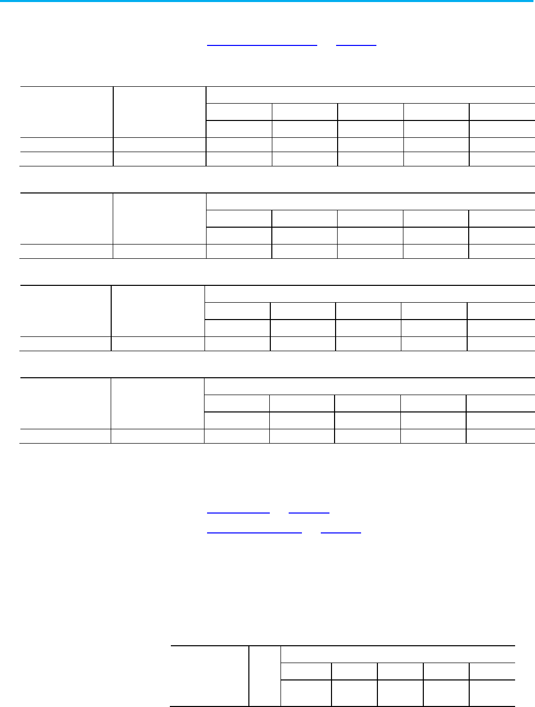
tag has a data type of DINT and a value of 534. The value used for
Instance ID was determined using methods described in CIP Services
and User-created Tags.
1st Message Request Field
Bytes (in hex)
Description - Symbolic Segment Addressing
Request Service 4C Read Tag Service (Request)
Request Path Size
06
Request Path is 6 words (12 bytes) long
Request Path
91 0A 54 6F 74 61 6C 43 6F 75 6E 74
ANSI Ext. Symbolic Segment for
TotalCount
Request Data
01 00
Number of elements to read (1)
1st Message Reply Field
Bytes (in hex)
Description - Symbolic Segment Addressing
Reply Service CC Read Tag Service (Reply)
Reserved 00
General Status
00
Success
Extended Status Size
00
No extended status
Reply Data C4 00 DINT Tag Type Value
16 02 00 00 0000216 = 534 decimal
See also
CIP Services and User-created Tags on page 35
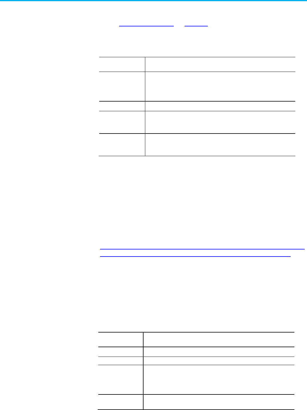
Read a single tag named rate using Symbol Instance Addressing. The
tag has a data type of DINT and a value of 534.
1st Message Request Field
Bytes (in hex)
Description - Symbol Instance Addressing
Request Service 4C Read Tag Service (Request)
Request Path Size
03
Request Path is 3 words (6 bytes) long
Request Path 20 6B
25 00 8F F6
Logical Segment for Symbol Class ID
Logical Segment for Instance ID of the tag
rate
Request Data 01 00 Number of elements to read (1)
1st Message Reply Field
Bytes (in hex)
Description - Symbol Instance Addressing
Reply Service CC Read Tag Service (Reply)
Reserved
00
General Status 00 Success
Extended Status Size
00
No extended status
Reply Data C4 00 DINT Tag Type Value
16 02 00 00 0000216 = 534 decimal
Example Using Symbolic
Segment Addressing
Example Using Symbol
Instance Addressing

Chapter 1 CIP services
Rockwell Automation Publication 1756-PM020H-EN-P - March 2022 19
See also
Read Tag Service on page 17
Services Supported by Logix 5000 Controllers on page 16
Both Symbolic Segment Addressing and Symbol Instance Addressing
may return these errors.
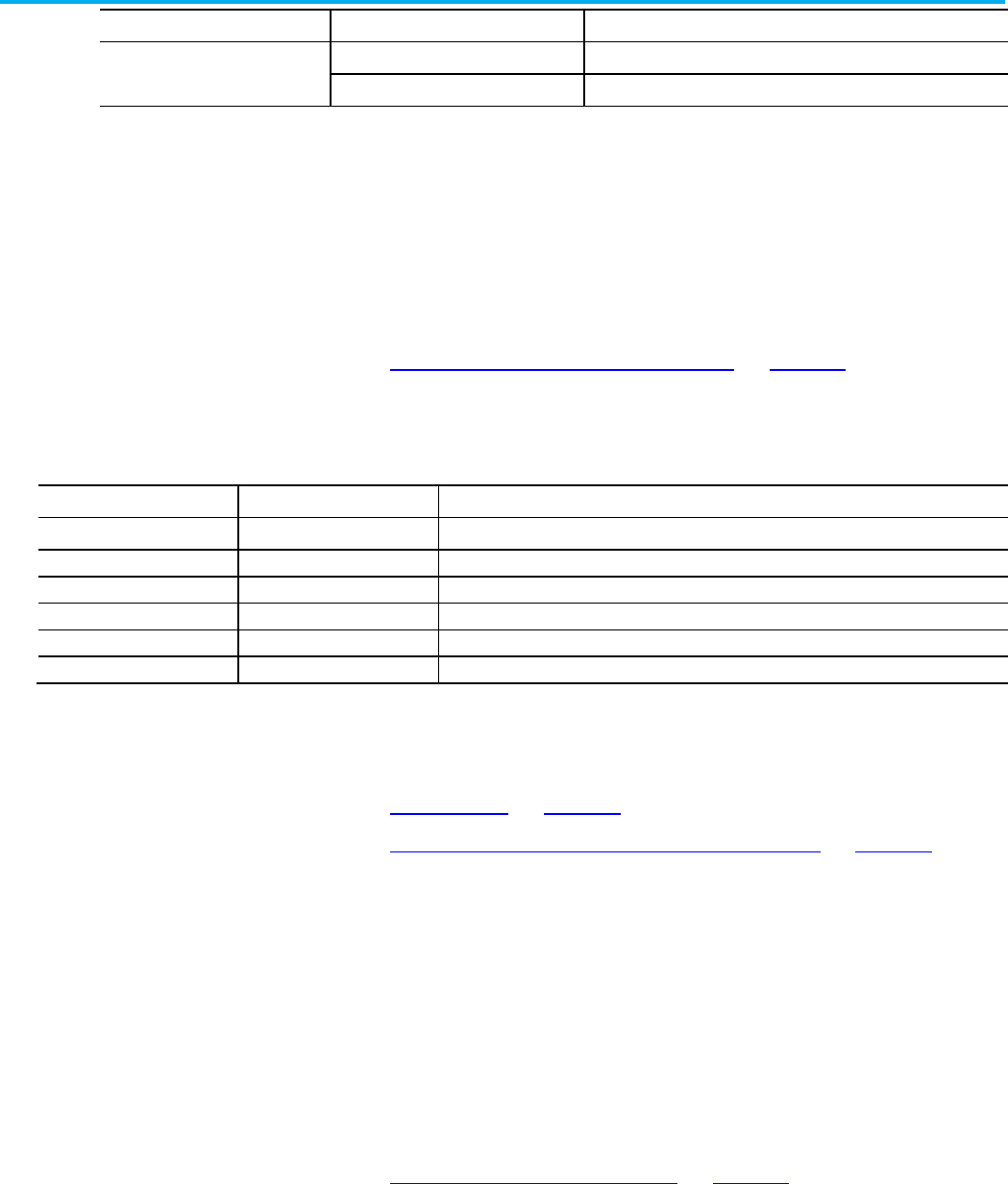
Error Code (Hex)
Extended Error (Hex)
Description of Error
0x04 0x0000 A syntax error was detected decoding the Request Path.
0x05
0x0000
Request Path destination unknown: Probably instance number is not present.
0x06 N/A Insufficient Packet Space: Not enough room in the response buffer for all the data.
0x13
N/A
Insufficient Request Data: Data too short for expected parameters.
0x26 N/A The Request Path Size received was shorter or longer than expected.
0xFF
0x2105
General Error: Access beyond end of the object.
See also
Read Tag Service on page 17
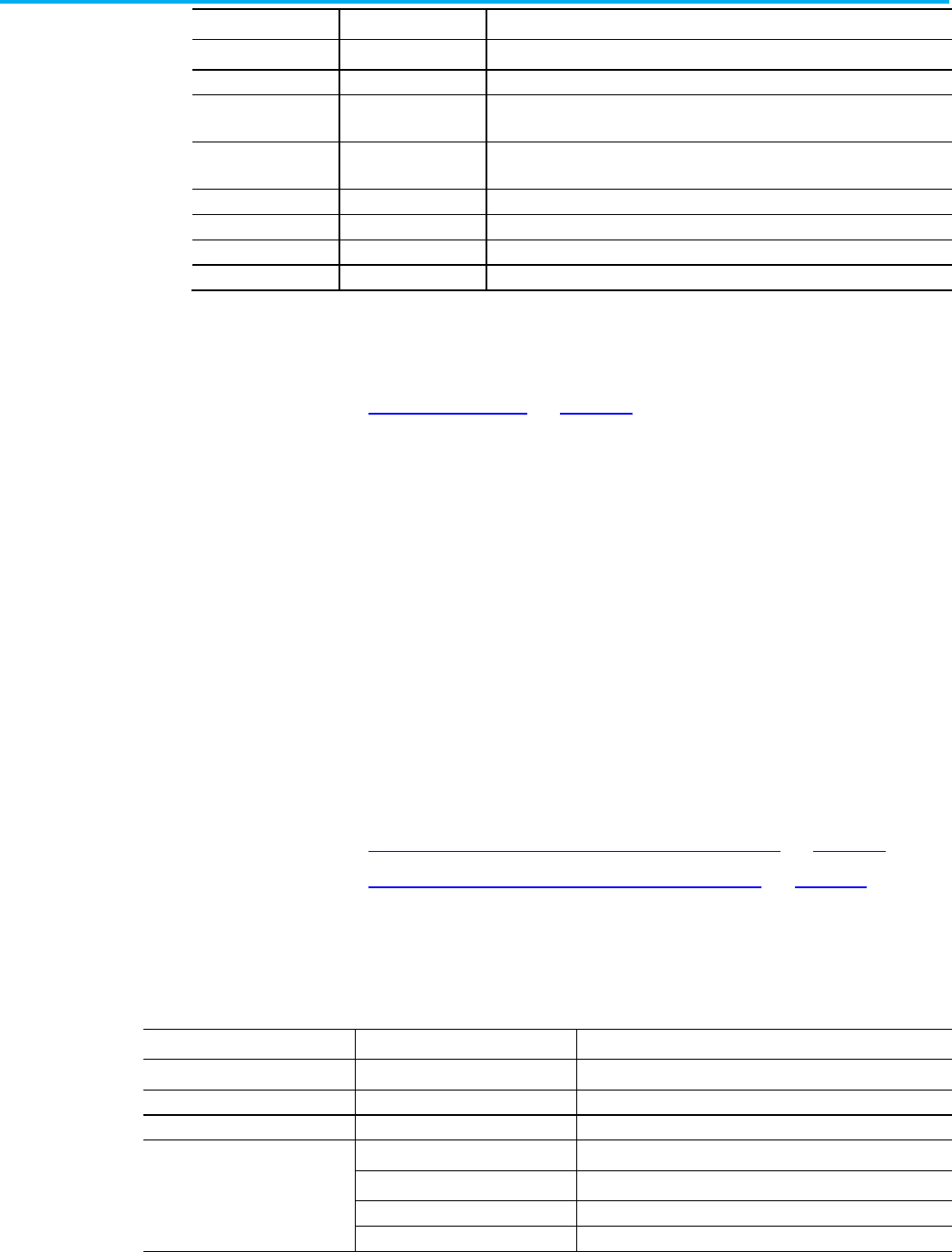
The Read Tag Fragmented Service enables client applications to read a
tag with data that does not fit into a single packet (approximately 500
bytes). The client must issue a series of requests to the controller to
retrieve the data using this service. The client must change the Offset
field value with each request by the number of bytes transferred in the
response to the previous request.
The Byte Offset field is expressed in number of bytes regardless of the
data type being read. In the example following, the data type being read
is SINT, which happens to be a byte. The elements and offset are in the
same units, which is not the case for other data types.
See also
CIP services on page 11
Services Supported by Logix 5000 Controllers on page 16
Reading the tag TotalCount that has 1750 SINTs consists of these four
service requests with service data, as shown in the tables.
1st Message Request Field
Bytes (in hex)
Description - Symbolic Segment Addressing
Request Service 52 Read Tag Fragmented Service (Request)
Request Path Size
06
Request Path is 6 words (12 bytes) long
Request Path
91 0A 54 6F 74 61 6C 43 6F 75 6E 74
ANSI Ext. Symbolic Segment for
TotalCount
Request Data D6 06 Number of elements to read (1750)
00 00 00 00 Start at this byte offset (0) and return as much as will fit
Read Tag Service Error
Codes
Read Tag Fragmented
Service
Example Using Symbolic
Segment Addressing

Chapter 1 CIP services
20 Rockwell Automation Publication 1756-PM020H-EN-P - March 2022
1st Message Reply Field
Bytes (in hex)
Description - Symbolic Segment Addressing
Reply Service D2 Read Tag Fragmented Service (Reply)
Reserved
00
General Status 06 Reply Data Too Large
Extended Status Size 00 No extended status
Reply Data C2 00 SINT Tag Type Value
nn nn nn…nn Data for Elements 0 through 489
2nd Message Request Field Bytes (in hex) Description - Symbolic Segment Addressing
Request Service 52 Read Tag Fragmented Service (Request)
Request Path Size
06
Request Path is 6 words (12 bytes) long
Request Path
91 0A 54 6F 74 61 6C 43 6F 75 6E 74
ANSI Ext. Symbolic Segment for
TotalCount
Request Data D6 06 Number of elements to read (1750)
EA 01 00 00 Start at this byte offset (490) and return as much as will fit
2nd Message Reply Field
Bytes (in hex)
Description - Symbolic Segment Addressing
Reply Service D2 Read Tag Fragmented Service (Reply)
Reserved
00
General Status
06
Reply Data Too Large
Extended Status Size
00
No extended status
Reply Data C2 00 SINT Tag Type Value
nn nn nn…nn Data for Elements 490 through 979
3rd Message Request Field
Bytes (in hex)
Description - Symbolic Segment Addressing
Request Service 52 Read Tag Fragmented Service (Request)
Request Path Size
06
Request Path is 6 words (12 bytes) long
Request Path
91 0A 54 6F 74 61 6C 43 6F 75 6E 74
ANSI Ext. Symbolic Segment for
TotalCount
Request Data D6 06 Number of elements to read (1750)
D4 03 00 00 Start at this offset (980) and return as much as will fit
3rd Message Reply Field
Bytes (in hex)
Description - Symbolic Segment Addressing
Reply Service D2 Read Tag Fragmented Service (Reply)
Reserved
00
General Status
06
Reply Data Too Large
Extended Status Size
00
No extended status
Reply Data C2 00 SINT Tag Type Value
nn nn nn…nn Data for Elements 980 through 1469
4th Message Request Field
Bytes (in hex)
Description - Symbolic Segment Addressing
Request Service 52 Read Tag Fragmented Service (Request)
Request Path Size
06
Request Path is 6 words (12 bytes) long

Chapter 1 CIP services
Rockwell Automation Publication 1756-PM020H-EN-P - March 2022 21
4th Message Request Field
Bytes (in hex)
Description - Symbolic Segment Addressing
Request Path
91 0A 54 6F 74 61 6C 43 6F 75 6E 74
ANSI Ext. Symbolic Segment for
TotalCount
Request Data D6 06 Number of elements to read (1750)
BE 05 00 00 Start at this offset (1470) and return as much as will fit
4th Message Reply Field
Bytes (in hex)
Description - Symbolic Segment Addressing
Reply Service D2 Read Tag Fragmented Service (Reply)
Reserved
00
General Status
00
Success
Extended Status Size
00
No extended status
Reply Data C2 00 SINT Tag Type Value
nn nn nn…nn Data for Elements 1470 through1749
See also
Read Tag Fragmented Service Error Codes on page 23
Reading the tag TotalCount that has 1750 SINTs using Symbol Instance
Addressing would consist of these four service requests with service
data, as shown in the tables. The value used for Instance ID was
determined using methods described in CIP Services and User-created
Tags.
1st Message Request Field
Bytes (in hex)
Description - Symbol Instance Addressing
Request Service 52 Read Tag Fragmented Service (Request)
Request Path Size 03 Request Path is 3 words (6 bytes) long
Request Path 20 6B
25 00 1A E0
Logical Segment for Symbol Class ID
Logical Segment for Instance ID for the tag
TotalCount
Request Data D6 06 Number of elements to read (1750)
Data Offset
00 00 00 00
Start at this element (0) and return as much will fit
1st Message Reply Field
Bytes (in hex)
Description - Symbol Instance Addressing
Reply Service D2 Read Tag Fragmented Service (Reply)
Reserved
00
General Status 06 Reply Data Too Large
Extended Status Size 00 No extended status
Reply Data C2 00 SINT Tag Type Value
nn nn nn…nn Data for Elements 0 thorough 489
2nd Message Request Field
Bytes (in hex)
Description - Symbol Instance Addressing
Request Service 52 Read Tag Fragmented Service (Request)
Request Path Size
03
Request Path is 3 words (6 bytes) long
Request Path 20 6B
25 00 1A E0
Logical Segment for Symbol Class ID
Logical Segment for Instance ID for the tag
TotalCount
)
Example Using Symbol
Instance Addressing

Chapter 1 CIP services
22 Rockwell Automation Publication 1756-PM020H-EN-P - March 2022
2nd Message Request Field
Bytes (in hex)
Description - Symbol Instance Addressing
Request Data D6 06 Number of elements to read (1750)
Data Offset
EA 01 00 00
Start at this element (490) and return as much will fit
2nd Message Reply Field
Bytes (in hex)
Description - Symbol Instance Addressing
Reply Service D2 Read Tag Fragmented Service (Reply)
Reserved 00
General Status
06
Reply Data Too Large
Extended Status Size 00 No extended status
Reply Data C2 00 SINT Tag Type Value
nn nn nn…nn Data for Element 490 through 979
3rd Message Request Field
Bytes (in hex)
Description - Symbol Instance Addressing
Request Service 52 Read Tag Fragmented Service (Request)
Request Path Size 03 Request Path is 3 words (6 bytes) long
Request Path 20 6B
25 00 1A E0
Logical Segment for Symbol Class ID
Logical Segment for Instance ID for the tag
TotalCount
Request Data D6 06 Number of elements to read (1750)
Data Offset
D4 03 00 00
Start at this element (980) and return as much will fit
3rd Message Reply Field
Bytes (in hex)
Description - Symbol Instance Addressing
Reply Service D2 Read Tag Fragmented Service (Reply)
Reserved
00
General Status 06 Reply Data Too Large
Extended Status Size 00 No extended status
Reply Data C2 00 SINT Tag Type Value
nn nn nn…nn Data for Elements 980 through 1469
4th Message Request Field Bytes (in hex) Description - Symbol Instance Addressing
Request Service 52 Read Tag Fragmented Service (Request)
Request Path Size
03
Request Path is 3 words (6 bytes) long
Request Path 20 6B
25 00 1A E0
Logical Segment for Symbol Class ID
Logical Segment for Instance ID for the tag
TotalCount
Request Data
D6 06
Number of elements to read (1750)
Data Offset
BE 05 00 00
Start at this element (1470) and return as much will fit
4th Message Reply Field
Bytes (in hex)
Description - Symbol Instance Addressing
Reply Service D2 Read Tag Fragmented Service (Reply)
Reserved
00
General Status
06
Reply Data Too Large
Extended Status Size
00
No extended status
Chapter 1 CIP services
Rockwell Automation Publication 1756-PM020H-EN-P - March 2022 23
4th Message Reply Field
Bytes (in hex)
Description - Symbol Instance Addressing
Reply Data C2 00 SINT Tag Type Value
nn nn nn…nn Data for Elements 1490 through 1749
Each response, except the last one, shows the General Status of 06,
Reply Data Too Large, to indicate that more data is present than is in this
particular frame. The last response shows the General Status of 0
indicating that the data read did not exceed the message size limit. This
means that the entire sequence of bytes has been read.
See also
CIP Services and User-created Tags on page 35
The Symbolic Segment Addressing and Symbol Instance Addressing
may return these errors.
Error Code (Hex)
Extended Error (Hex)
Description of Error
0x04 0x0000 A syntax error was detected decoding the Request Path.
0x05 0x0000 Request Path destination unknown: probably instance number is not present.
0x06
N/A
Insufficient Packet Space: Not enough room in the response buffer for all the data.
0x13
N/A
Insufficient Request Data: Data too short for expected parameters.
0x26
N/A
The Request Path Size received was shorter or longer than expected.
0xFF
0x2105
General Error: Number of Elements or Byte Offset is beyond the end of the requested tag.
See also
CIP services on page 11
Services Supported by Logix 5000 Controllers on page 16
The Write Tag Service writes the data associated with the tag specified in
the path. The tag type must match for the write to occur. The controller
validates the tag type matches before executing the service.
• When writing a two or three dimensional array of data, all
dimensions must be specified.
• When writing to a BOOL tag, any non-zero value is interpreted as
1.
See also
Write Tag Service Error Codes on page 24
Write the value of 14 to a DINT tag named CartonSize using Symbolic
Segment Addressing.
Read Tag Fragmented
Service Error Codes
Write Tag Service
Example Using Symbolic
Segment Addressing

Chapter 1 CIP services
24 Rockwell Automation Publication 1756-PM020H-EN-P - March 2022
Message Request Field
Bytes (in hex)
Description - Symbolic Segment Addressing
Request Service 4D Write Tag Service (Request)
Request Path Size
06
Request Path is 6 words (12 bytes) long
Request Path 91 0A 43 61 72 74 6F 6E 53 69 7A 65 ANSI Ext. Symbolic Segment for
CartonSize
Request Data C4 00 DINT Tag Type Value
01 00 Number of elements to write (1)
0E 00 00 00
Data 0000000E=14 decimal
Message Reply Field
Bytes (in hex)
Description - Symbolic Segment Addressing
Reply Service
CD
Write Tag Service (Reply)
Reserved
00
General Status
00
Success
Extended Status Size
00
No extended status
See also
Write Tag Service on page 23
Write the value of 14 to a DINT tag named CartonSize using Symbolic
Instance Addressing. The value used for Instance ID was determined
using methods described in CIP Services and User-created Tags.
Message Request Field
Bytes (in hex)
Description - Symbol Instance Addressing
Request Service 4D Write Tag Service (Request)
Request Path Size
03
Request Path is 3 words (6 bytes) long
Request Path 20 6B
25 00 36 71
Logical Segment for Symbol Class ID
Logical Segment for Instance ID for the tag
CartonSize
Request Data C4 00 DINT Tag Type Value
01 00 Number of elements to write (1)
0E 00 00 00
Data 0000000E=14 decimal
Message Reply Field
Bytes (in hex)
Description - Symbol Instance Addressing
Reply Service CD Write Tag Service (Reply)
Reserved
00
General Status
00
Success
Extended Status Size
00
No extended status
See also
CIP Services and User-created Tags on page 35
The Symbolic Segment Addressing and Symbol Instance Addressing
may returns these error codes.
Error Code (Hex)
Extended Error (Hex)
Description of Error
Example Using Symbol
Instance Addressing
Write Tag Service Error
Codes
Chapter 1 CIP services
Rockwell Automation Publication 1756-PM020H-EN-P - March 2022 25
Error Code (Hex)
Extended Error (Hex)
Description of Error
0x04 0x0000 A syntax error was detected decoding the Request Path.
0x05
0x0000
Request Path destination unknown: Probably instance number is not present.
0x10 0x2101 Device state conflict: keyswitch position: The requestor is changing force
information in HARD RUN mode.
0x10 0x2802 Device state conflict: Safety Status: The controller is in a state in which Safety
Memory cannot be modified.
0x13
N/A
Insufficient Request Data: Data too short for expected parameters.
0x26 N/A The Request Path Size received was shorter or longer than expected.
0xFF 0x2105 General Error: Number of Elements extends beyond the end of the requested tag.
0xFF
0x2107
General Error: Tag type used n request does not match the target tag’s data type.
See also
Write Tag Service on page 23
The Write Tag Fragmented Service enables client applications to write to
a tag in the controller whose data will not fit into a single packet
(approximately 500 bytes). The client must issue a series of requests to
the controller to write all data using this service.
The Request Service, Request Path Size, Request Path, and Number of
Elements fields remain the same for each request. The client must
change the byte offset field value with each request by the number of
bytes it transferred in the previous request.
The Byte Offset field is expressed in number of bytes regardless of the
data type being read. In the examples that follow, the data type being
read is SINT, which happens to be a byte. In this case, the elements and
offset are in the same units, which is not the case for other data types.
See also
Example Using Symbolic Segment Addressing on page 25
Example Using Symbol Instance Addressing on page 27
Writing 1750 SINTs to the tag TotalCount using Symbolic Segment
Addressing would consist of the following four service requests with
service data as shown in the tables that follow. The value used for
Instance ID was determined using methods described in CIP Services
and User-created Tags.
1st Message Request Field
Bytes (in hex)
Description - Symbolic Segment Addressing
Request Service 53 Read Tag Fragmented Service (Request)
Request Path Size
06
Request Path is 6 words (12 bytes) long
Request Path
91 0A 54 6F 74 61 6C 43 6F 75 6E 74
ANSI Ext. Symbolic Segment for
TotalCount
Request Data C2 00 SINT Tag Type Value
D6 06 Total number of elements to write (1750)
00 00 00 00
Start at this offset.
nn, nn, …nn
Element Data for Elements 0 through 473
Write Tag Fragmented
Service
Example Using Symbolic
Segment Addressing

Chapter 1 CIP services
26 Rockwell Automation Publication 1756-PM020H-EN-P - March 2022
1st Message Reply Field
Bytes (in hex)
Description - Symbolic Segment Addressing
Reply Service D3 Write Tag Fragmented Service (Reply)
Reserved 00
General Status
00
Success
Extended Status Size
00
No extended status
2nd Message Request Field
Bytes (in hex)
Description - Symbolic Segment Addressing
Request Service 53 Write Tag Fragmented Service (Request)
Request Path Size 06 Request Path is 6 words (12 bytes) long
Request Path 91 0A 54 6F 74 61 6C 43 6F 75 6E 74 ANSI Ext. Symbolic Segment for
TotalCount
Request Data C2 00 SINT Tag Type Value
D6 06 Total number of elements to write (1750)
DA 01 00 00
Start at this offset.
nn, nn, …nn
Element Data for Elements 474 through 947
2nd Message Reply Field
Bytes (in hex)
Description - Symbolic Segment Addressing
Reply Service D3 Write Tag Fragmented Service (Reply)
Reserved 00
General Status
00
Success
Extended Status Size 00 No extended status
3rd Message Request Field
Bytes (in hex)
Description - Symbolic Segment Addressing
Request Service 53 Write Tag Fragmented Service (Request)
Request Path Size
06
Request Path is 6 words (12 bytes) long
Request Path
91 0A 54 6F 74 61 6C 43 6F 75 6E 74
ANSI Ext. Symbolic Segment for
TotalCount
Request Data C2 00 SINT Tag Type Value
D6 06 Total number of elements to write (1750)
B4 03 00 00 Start at this offset
nn, nn, …nn Element Data for Elements 948 through 1421
3rd Message Reply Field
Bytes (in hex)
Description - Symbolic Segment Addressing
Reply Service D3 Write Tag Fragmented Service (Reply)
Reserved
00
General Status
00
Success
Extended Status Size
00
No extended status
4th Message Request Field
Bytes (in hex)
Description - Symbolic Segment Addressing
Request Service 53 Write Tag Fragmented Service (Request)
Request Path Size
06
Request Path is 6 words (12 bytes) long
Request Path 91 0A 54 6F 74 61 6C 43 6F 75 6E 74 ANSI Ext. Symbolic Segment for
TotalCount

Chapter 1 CIP services
Rockwell Automation Publication 1756-PM020H-EN-P - March 2022 27
4th Message Request Field
Bytes (in hex)
Description - Symbolic Segment Addressing
Request Data C2 00 SINT Tag Type Value
D6 06 Total number of elements to write (1750)
8E 05 00 00
Start at this Offset
nn, nn, …nn Element Data for Elements 1422 through 1749
4th Message Reply Field
Bytes (in hex)
Description - Symbolic Segment Addressing
Reply Service
D3
Write Tag Fragmented Service (Reply)
Reserved
00
General Status
00
Success
Extended Status Size
00
No extended status
See also
CIP Services and User-created Tags on page 35
Writing 1750 SINTs to the tag TotalCount using Symbol Instance
Addressing would consist of the following four service requests with
service data as shown in the tables.
1st Message Request Field
Bytes (in hex)
Description - Symbol Instance Addressing
Request Service 53 Write Tag Fragmented Service (Request)
Request Path Size 03 Request Path is 3 words (6 bytes) long
Request Path 20 6B
25 00 1A E0
Logical Segment for Symbol Class ID
Logical Segment for Instance ID for the tag
TotalCount
Request Data C2 00 SINT Tag Type Value
D6 06 Number of elements to write (1750)
00 00 00 00 Start at this Offset
nn,nn,...nn
Element Data for Elements 0 through 473
1st Message Reply Field
Bytes (in hex)
Description - Symbol Instance Addressing
Reply Service
D3
Write Tag Fragmented Service (Reply)
Reserved
00
General Status
00
Success
Extended Status Size
00
No extended status
2nd Message Request Field
Bytes (in hex)
Description - Symbol Instance Addressing
Request Service 53 Write Tag Fragmented Service (Request)
Request Path Size
03
Request Path is 3 words (6 bytes) long
Request Path 20 6B
25 00 1A E0
Logical Segments for Symbol Class ID
Logical Segment for Instance ID for the tag
TotalCount
Request Data C2 00 Tag Data Type
D6 06 Number of elements to write (1750)
EC 01 00 00
Start at this Offser
Example Using Symbol
Instance Addressing

Chapter 1 CIP services
28 Rockwell Automation Publication 1756-PM020H-EN-P - March 2022
2nd Message Request Field
Bytes (in hex)
Description - Symbol Instance Addressing
nn,nn,...nn
Element Data (474 through 947)
2nd Message Reply Field
Bytes (in hex)
Description - Symbol Instance Addressing
Reply Service D3 Write Tag Fragmented Service (Reply)
Reserved
00
General Status
00
Success
Extended Status Size 00 No extended status
3rd Message Request Field
Bytes (in hex)
Description - Symbol Instance Addressing
Request Service 53 Write Tag Fragmented Service (Request)
Request Path Size
03
Request Path is 3 words (6 bytes) long
Request Path 20 6B
25 00 1A E0
Logical Segment for Symbol Class ID
Logical Segment for Instance ID for the tag
TotalCount
Request Data C2 00 Tag Data Type
D6 06 Number of elements to write (1750)
B4 03 00 00 Start at this Offset
nn,nn,...nn Element Data (948 through 1421)
3rd Message Reply Field
Bytes (in hex)
Description - Symbol Instance Addressing
Reply Service D3 Write Tag Fragmented Service (Reply)
Reserved
00
General Status
00
Success
Extended Status Size
00
No extended status
4th Message Request Field
Bytes (in hex)
Description - Symbol Instance Addressing
Request Service 53 Write Tag Fragmented Service (Request)
Request Path Size 03 Request Path is 3 words (6 bytes) long
Request Path 20 6B
25 00 1A E0
Logical Segment for Symbol Class ID
Logical Segment for Instance ID for the tag
TotalCount
Request Data C2 00 Tag Data Type
D6 06 Number of elements to write (1750)
8E 05 00 00
Start at this Offset
nn,nn,...nn
Element Data (1422 through 1749)
4th Message Reply Field
Bytes (in hex)
Description - Symbol Instance Addressing
Reply Service D3 Write Tag Fragmented Service (Reply)
Reserved
00
General Status 00 Success
Extended Status Size 00 No extended status

Chapter 1 CIP services
Rockwell Automation Publication 1756-PM020H-EN-P - March 2022 29
The response to each request shows a General Status value of 00,
Success status indication, to indicate that the write operation was
successful. No other Reply Data is returned for this service.
See also
Write Tag Fragmented Service on page 25
Symbolic Segment Addressing and Symbol Instance Addressing return
these error codes.
Error Code
(Hex)
Extended
Error (Hex)
Description of Error
0x04 0x0000 A syntax error was detected decoding the Request Path.
0x05
0x0000
Request Path destination unknown: instance number is not present.
0x10 0x2101 Device state conflict: keyswitch position: The requestor is changing force information in HARD RUN mode.
0x10 0x2802 Device state conflict: Safety Status: Unable to modify Safety Memory in the current controller state.
0x13
N/A
Insufficient Request Data: Data is too small for expected parameters.
0x26
N/A
The Request Path Size received was shorter or longer than expected.
0xFF 0x2104 General Error: Offset is beyond end of the requested tag.
0xFF 0x2105 General Error: Offset plus Number of Elements extends beyond the end of the requested tag.
0xFF
0x2107
General Error: Data type used in request does not match the data type of the target tag.
See also
Write Tag Fragmented Service on page 25
The Read Modify Write Tag Service modifies Tag data with individual bit
resolution. ControlLogix controllers read the Tag data, applies the logical
or modification masks or both, and writes the data the Tag. Also use the
Read Modify Write Tag Service to modify a single bit in a Tag without
disturbing other data.
See also
PCCC Commands on page 71
These are the Service Request Parameters.
Name
Description of Reply Data
Semantics of Values
Size of masks Size in bytes of modify masks Only 1,2,4,8,12 accepted
OR masks
Array of OR modify masks
1 mask sets bit to 1
AND masks
Array of AND modify masks
0 mask resets bit to 0
The size of masks must be the same or smaller than the size of the data
type being accessed. For complete data integrity, the size of the mask
should match the size of the data type. For example, to avoid the
Write Tag Fragmented
Service Error Codes
Read Modify Write Tag
Service
Service Request
Parameters

Chapter 1 CIP services
30 Rockwell Automation Publication 1756-PM020H-EN-P - March 2022
possibility of a mix of old and new data when modifying dynamic data, the
size of the mask must match the size of the data type.
See also
CIP services on page 11
Read Modify Write Tag Service on page 29
Set bit 2 and reset bit 5 of the DINT named ControlWord.
Message Request Field Bytes (in hex) Description
Request Service 4E Read Modify Write Tag Service (Request)
Request Path Size
07
Request Path is 7 words (14 bytes) long
Request Path 91 0B 43 6F 6E 7H 72 6F 6C 57 6F 72 64 00 ANSI Ext. Symbolic Segment for ControlWord
Request Data 04 00 Size of Masks (shall be 4)
04 00 00 00 Array of OR modify masks
DF FF FF FF Array of AND modify masks
Message Reply Field
Bytes (in hex)
Description
Reply Service CE Read Modify Write Tag Service (Reply)
Reserved 00
General Status
00
Success
Extended Status Size 00 No extended status
See also
Read Modify Write Tag Service on page 29
These are the Read Modify Write Tag Service error codes.
Error Code
(Hex)
Extended Error
(Hex)
Description of Error
0x03
N/A
Bad parameter, size > 12 or size greater than size of element.
0x04
0x0000
A syntax error was detected decoding the Request Path.
0x05
0x0000
Request Path destination unknown: Probably instance number is not present.
0x10 0x2101 Device state conflict: keyswitch position: The requestor is attempting to change force
information in HARD RUN mode.
0x10 0x2802 Device state conflict: Safety Status: The controller is in a state in which Safety Memory
cannot be modified.
0x13 N/A Insufficient Request Data: Data too short for expected parameters.
0x26
N/A
The Request Path Size received was shorter or longer than expected.
See also
Read Modify Write Tag Service on page 29
Example
Read Modify Write Tag
Service Error Codes

Chapter 1 CIP services
Rockwell Automation Publication 1756-PM020H-EN-P - March 2022 31
The Multiple Service Packet Service conducts more than one CIP
request in a single CIP explicit-message frame. Use this service to
optimize CIP reads and writes by grouping service requests together for
faster request processing.
For details on this service, see the CIP Networks Library, Volume 1,
Appendix A.
See also
Read Modify Write Tag Service on page 29
CIP services on page 11
This is an example for Multiple Service Packets.
Message Request Field
Bytes (in hex)
Description
Request Service 0A Multiple Service Packet Service (Request)
Request Path Size
02
Request Path is 2 words (4 bytes) long
Request Path 20 02 24 01 Logical Segment: CLass 0x02, Instance 01 (Message Router)
Request Data 02 00 Number of Services contained in this request
06 00
12 00
Offsets for each Service; from the start of the Request Data
4C
04 91 05 70 61 72 74
73 00
01 00
First Request: Read Tag Service
Tag name:
parts
Read 1 element
4C
07 91 0B 43 6F 6E 74 72 6F 6C
57 6F 72 64 00
01 00
Second Request: Read Tag Service
Tag name:
ControlWord
Read 1 element
The Multiple Service Packet Request Path contains the Message Router
object (Class 2, Instance 1). This is the destination of the Multiple Service
Packet’s Request Path. The Request Data field contains the Number of
Services followed by byte offsets to the start of each service, followed by
each of the CIP requests, each following the standard Message Router
Request format.
Observe this example
Message Reply Field
Bytes (in hex)
Description
Reply Service 8A Multiple Service Packet Service (Reply)
Reserved
00
General Status
00
Success
Extended Status Size
00
No extended status
Reply Data 02 00 Number of Service Replies
06 00
10 00
Offsets for each Service Reply; from the start of the Reply Data
CC 00 00 00
C4 00
2A 00 00 00
Read Tag Service Reply, Status: Success
DINT Tag Type Value
Value: 0x0000002A (42 decimal)
Multiple Service Packet
Service
Example

Chapter 1 CIP services
32 Rockwell Automation Publication 1756-PM020H-EN-P - March 2022
Message Reply Field
Bytes (in hex)
Description
CC 00 00 00
C4 00
DC 01 00 00
Read Tag Service Reply, Status: Success
DINT Tag Type Value
Value: 0x000001DC (476 decimal)
The Multiple Service Packet response follows the same Message Router
Response format as all CIP services; therefore, the General Status, Ext
Status Size fields are in the same CIP Service Request/Response
Format as described in previous examples. The Reply Data field contains
the number of service replies followed by the byte offset to the start of
each reply, followed by each of the CIP responses. Each of the
responses follows the standard Message Router Response format.
See also
Read Modify Write Tag Service on page 29
Multiple Service Packet Service on page 31
A structure is a compound data type that stores a group of possibly
different data types that function as a single unit and serve a specific
purpose. (For example, a combination of values.)
• A structure contains one or more members.
• Each member can be an:
• Atomic data type.
• Another structured data type.
• A single dimension array of an atomic or structure data type.
The controller contains these basic types of structures:
• Module-Defined data types - created by adding modules to the I/O
tree
• Predefined data types - created by default in the controller (for
example, TON, CTU, and Motion)
• Add-On-Defined data types
• User-Defined data types (UDT) - created by the user
Group most structures into arrays or use them in other structures.
For more information on data types and creating structures Logix 5000
Controllers Design Considerations Reference Manual, publication
1756-RM094.
The Predefined, Add-On-Defined, and Module-Defined types, and
Booleans within these structures, are difficult to deal with for various
reasons and are beyond the scope of this publication. For alternatives for
working with Predefined, Add-On-Defined, and Module-Defined types,
and Booleans within these structures see the following topics in this
chapter.
See also
Work with Data Structures on page 33
Logix Data Structures

Chapter 1 CIP services
Rockwell Automation Publication 1756-PM020H-EN-P - March 2022 33
CIP services on page 11
For these guidelines for working with data structures.
• Complete user-defined structure tags, or individual members are
accessed. Access to complete structure Tags requires an
understanding of the organization and alignment of structure
members, which follows rules. The UDT organization are
described in the structure Template in CIP Services and
User-created Tags. Do not access complete UDT tags that contain
nested system structures, such as Module-Defined, Predefined, or
Add-On Defined.
• Predefined, Module-Defined, and Add-On-Defined structure tags
have a more complex set of rules than user-defined data types
(UDT). Do not access complete structure tags of these types, or
complete UDTs with nested tags of these types. Instead, access
atomic members of these tags that are visible in the Logix
Designer application Data Monitor, using one of the methods that
follow.
• Create an alias of the atomic member and access the alias
instead of the structure.
• Create an atomic tag or UDT structure tag with an atomic
member, and then have the user program copy the data to and
from the tag or atomic member. Access the new tag or atomic
member instead.
• In the Logix Designer, version 21 and later, and in RSLogix 5000
software, version 18 and later, external access to controller scope
tags is user-selectable. If an External Access tag attribute is set to
None, the tag cannot be accessed from outside of the controller.
Therefore, structures that contain members whose external
access is set to None cannot be accessed as a whole (that is, by
reading or writing the entire structure). Similarly, structures that
have one or more members whose External Access is set to Read
Only cannot be written to as a whole (that is, by reading or writing
the entire structure), but the members that are not restricted in
access can be accessed by using symbolic segment addressing to
the specific member.
Further information on data access control and the effect it has on
structure access can be found in Logix 5000 Controllers I/O and Tag
Data Programming Manual, publication 1756-PM004.
• To improve tag access performance and to simplify the task of
accessing structured tags through a network, create UDTs for the
data that needs to be accessed through the network with members
of the types listed following only, and access the UDTs as a whole.
• Atomic tags
• Arrays of atomic tags
• Other UDTs of atomic tags
• Arrays of UDTs of atomic tags
See also
CIP Services and User-created Tags on page 35
Work with Data Structures

Chapter 1 CIP services
34 Rockwell Automation Publication 1756-PM020H-EN-P - March 2022
Structures use a Tag Type Service Parameter that is different from the
one used with atomic tags. Like atomic tags, writing to UDT-based tags
as a whole (that is, the whole structure, not just individual members)
requires supplying the proper value for this parameter in the service
request to successfully write to the tag. The value is also returned when
the structure is read.
The Tag Type Service Parameter for structures is a 4-byte sequence.
The first two bytes are the values A0 and 02, followed by the latter two
bytes, which contain a 16-bit calculated field called a Structure Handle.
When transmitted on the wire, it looks like this:
A0 02 Structure Handle Low Byte Structure Handle High Byte
The Structure Handle comes from Template instance attribute 1 of the
template instance associated with the tag. It is a calculated field, but
generally it is not necessary to calculate the value. Reading and
understanding the template information provides all the required
information about the structure makeup to unambiguously access it. With
that understanding, the client application can use the Structure Handle
value read from the template instance attribute 1, rather than calculating
it. For more information about structure templates, see Chapter 2, CIP
services and user-created tags.
When choosing to calculate a Structure Handle, the process used to
calculate this value can be found on this website:
https://www.rockwellautomation.com/resources/downloads/rockwellauto
mation/pdf/sales-partners/technology-licensing/TypeEncode_CIPRW.pd
f
In Logix controllers, arrays report the data type of its members. An array
of an atomic type reports the corresponding 2 byte Tag Type Service
Parameter, while an array of structures reports the corresponding 4 byte
Tag Type Service Parameter.
IMPORTANT
Reading a structure before writing to it is one way to obtain the value for this
parameter, but that does not provide any understanding of the structure makeup,
which is critical information when manipulating structure data. Also, the Structure
Handle value is not unique among structures. Some positional changes of members
within an otherwise identical structure yield the same value.
The correct way to access structures as a whole is to first read their template
information and understand the data packing. This assures that the application knows
what data type is in what position.
When reading the structure to get the Structure Handle value before
writing to it, be aware that the results may be ambiguous. Reserve this
method only in cases where the control system development is complete
and no further data structure changes will be made.
See also
CIP Services and user-created tags on page 35
Tag type service
parameters for structure

Rockwell Automation Publication 1756-PM020H-EN-P - March 2022 35
Chapter 2
CIP Services and User-created Tags
This chapter describes processes that CIP clients use when interacting
with Logix 5000 controller data. The processes are:
• Finding the controller-scope tags that are created in a Logix 5000
controller
• Isolating user created tags from system tags and identify
structured tags
• Locating the structure template for a specific structure
• Determining the structure makeup of a specific structure
• Determining the data packing of the members of a structure when
accessed as a whole and not member by a member.
• Determining when to refresh the list of tags and structure
information
See also
How tags are organized in the controller on page 35
Symbol object on page 36
Template object on page 36
Creating and maintaining a symbol object list on page 37
A client application interacts with the symbol and template objects
associated with tags in Logix 5000 controllers. Through this interaction,
the client application determines:
• What tags are created
• If a tag is structure
• The structure members
• How the data is packed in a message when reading a structure
This diagram shows the two objects in the Logix 5000 controller that are
associated with tags. A client application must use the attributes and
services of these objects to understand the tag data makeup when
reading or writing to tags.
How tags are organized in
the controller

Chapter 2 CIP Services and User-created Tags
36 Rockwell Automation Publication 1756-PM020H-EN-P - March 2022
See also
CIP Services and User-created Tags on page 35
Creating a tag creates an instance of the Symbol class (Class ID 0x6B) in
the controller. The name of the tag is stored in attribute 1 of the instance.
The data type of the tag is stored in attribute 2.
Instances of the Symbol class defines a class-specific service with the
name Get_Instance_Attribute_List. This service helps find an instance of
the class, and enables retrieving the name and type attributes for each
instance of the class.
The member names for structures only exist in the template definition. It
is acceptable for a user-defined data type template definition to contain
members with the same names as other tags in the controller.
See also
CIP Services and User-created Tags on page 35
How tags are organized in the controller on page 35
When creating a user-defined data type, an instance of the Template
object (Class ID 0x6C) is created to hold information about the structure
makeup. This instance of the template object provides information about
the template structure such as:
• Its name.
• The member list.
• The number of members.
• The size of the structure when read or written.
• The Structure Handle.
The Get_Attribute_List service directed to the Template object allows the
client application to retrieve one or more attributes from an instance of
the Template class. Template instance attributes provide information
about the template structure itself so the application can interpret what it
receives when using the Template_Read service.
The Template Read service is used to retrieve the template structure
information that describes the members of the structure, their ordering,
and data types. This information is required when accessing a structured
tag as an entire structure to understand the data packing in the message
frame.
Other structures in the Logix 5000 controller, including Module-Defined,
Add-On-Defined, and Predefined data types, are also described in
instances of the Template object. Use the Logix Designer application to
implement one of the following indirect methods to access individual
member tags.
Access atomic or arrayed atomic members of Module-Defined,
Add-On-Defined, or Predefined structure tags using one of the following
methods:
Symbol object
Template object

Chapter 2 CIP Services and User-created Tags
Rockwell Automation Publication 1756-PM020H-EN-P - March 2022 37
• Create a corresponding atomic tag (or atomic member of a
structured tag) and use ladder logic to periodically copy the atomic
member of the structure to the atomic tag.
• Create an alias tag for the atomic member that needs to be
accessed.
These tags are present in the Symbol object instances and can be
accessed like any other atomic tag.
The previous methods are also used with structured tags of a
user-defined data type that contain a nested Module-Defined,
Add-On-Defined, or Predefined type member.
IMPORTANT
The information described in this manual about accessing and understanding
structures should not be used to access complete Module-Defined structures,
Predefined structures, Add-On-Defined structures, or system tags, whether they are
stand alone, an alias, or nested within another user created tag. Tags of these types
have rules for dealing with host members and mapping of BOOLS, which are beyond the
scope of this document. If such structures are manipulated or accessed, results can be
unpredictable.
The STRING data type is a form of Predefined structure that would
normally be excluded after executing steps that are described later. It is
also acceptable to create user-defined data type string structures,
including Strings of the same format as the standard STRING. This
allows external access to the string and avoids the issues of Predefined
structures.
To access any atomic tag that is visible in the Logix Designer application
Data Monitor, it is also acceptable to manually enter the full symbolic tag
address (NAME in the Data Monitor) in the client software. This includes
atomic members of any structure that are visible in Data Monitor. This
only applies to visible atomic tags and atomic members of structured
tags.
See also
CIP Services and User-created Tags on page 35
How tags are organized in the controller on page 35
Client applications access atomic tags or atomic members of structured
tags by:
• Identifying the name of the tags for accessing
• Learning what tags are present in the controller and enabling
users to select the desired data.
Tip: In certain scenarios, it is not necessary to read all symbol instances or interpret template
information. For example, if the name of the tags are recognized and the Symbolic Segment
Addressing method is used to access only atomic tags or atomic members of structured tags,
it is not necessary to read all symbol instances or interpret the template information.
Client applications identifying the available tags or accessing structures
must identify the required tags for access before manipulating tag data.
This information is used to identify the data type of each tag and enable
the application to interpret the data value associated with the tag.
Create and maintain a
symbol object list

Chapter 2 CIP Services and User-created Tags
38 Rockwell Automation Publication 1756-PM020H-EN-P - March 2022
Update the list of information as required. User program changes
frequently create or delete tags, and add, delete, and modify
user-defined data types.
This procedure:
• Creates and maintain a list of controller-scope symbol objects in
an Logix 5000 controller
• Associates each instance with a template object instance if it is a
structured tag
• Eliminates the symbol instances of data that the client application
does not access or manipulate
To create and maintain a symbol object list:
1. Find all controller-scope tags.
2. Isolate user-created tags from system tags.
3. Determine the makeup of the structures. Structure members are
not separate Symbol instances.
4. Determine the data packing of structure members in a message.
5. Determine when Symbol Instances have changed.
See also
Step 1: Find user-created controller scope tags in a Logix 5000
controller on page 38
Step 2: Isolate user-created tags from system tags/identifying
structured tags on page 42
Step 3: Determine the structure makeup for a specific structure on
page 44
Step 4: Determine the data packing of the members of a structure
on page 49
Step 5: Determine when the tags list and structure information
need refreshing on page 51
This section describes the process used to learn what controller-scoped
tags are located in the Logix 5000 controller by retrieving the Symbol
Name and Symbol Type attributes for each instance of the Symbol
Object.
The Get_Instance_Attribute_List (0x55) service returns instance IDs for
each created instance of the Symbol class, along with a list of the
attribute data associated with the requested attributes.
See also
CIP Services and User-created Tags on page 35
Retrieve all symbol object instances on page 39
Example of retrieving the first group of tags on page 39
Analysis on page 40
Step 1: Find user-created
controller scope tags in a
Logix 5000 controller

Chapter 2 CIP Services and User-created Tags
Rockwell Automation Publication 1756-PM020H-EN-P - March 2022 39
The maximum size of a packet does not return all instances and
attributes in a single request. To retrieve all instances, the client
application must issue a series of requests to the controller and adjust
the starting instance with each request.
This sequence describes how client application retrieves all the
instances:
1. Set initial instance to zero.
2. Send request.
3. When General Status = 06 is returned, there is more data to read.
To determine the last instance sent in the reply, parse the data
received from the Logix 5000 controller to find the last instance ID
returned.
4. Add one to the instance number determined in step 3.
5. Send the request again using the new instance value in the
Request Path.
When General Status = 00 Success, then all the symbol instances that
are created have been returned.
See also
CIP Services and User-created Tags on page 35
Step 1: Finding user-created controller scope tags in a Logix 5000
controller on page 38
The table shows the format of the initial service request, which starts with
Symbol Object, Instance 0. This returns as much of the requested data
as will fit in the reply. Most controller programs require multiple attempts
to get all the tags.
Message Request Field
Bytes (in hex)
Description
Request Service
55
Get_Instance_Attribute_List Service (Request)
Request Path Size
03
Request Path is 3 words (6 bytes) long
Request Path
20 6B 25 00 00 00
Logical Segments: Class 0x6B, Instance 0 (starting instance)
Request Data 02 00 Number of attributes to retrieve
01 00 Attribute 1 – Symbol Name
02 00
Attribute 2 – Symbol Type
Message Reply Field
Bytes (in hex)
Description
Reply Service D5 Get_Instance_Attribute_List Service (Reply))
Reserved
00
General Status
06
Status of 06 means: Too Much Data
Extended Status Size
00
No extended status
Reply Data 12 03 00 00 First 32-bit Instance ID
(The 1st Instance ID after the instance specified in the Request Path)
0D 00
43 69 70 52 65 61 64 44 61 74 61 31
30
16-bit Symbol Name Length
Characters in the symbol name
FF 8F Symbol Type
Retrieve all symbol object
instances
Example of retrieving the
first group of tags

Chapter 2 CIP Services and User-created Tags
40 Rockwell Automation Publication 1756-PM020H-EN-P - March 2022
Message Reply Field
Bytes (in hex)
Description
51 0E 00 00 Second 32-bit Instance ID
06 00
63 6F 75 6E 74 73
16-bit Symbol Name Length
Characters in the symbol name
82 CF Symbol Type
… Next …
34 5D 00 00 Last 32-bit Instance ID in this reply
0A 00
50 61 72 74 73 5F 44 65 73 74
16-bit Symbol Name Length
Characters in the symbol name
C3 00 Symbol Type
See also
CIP Services and User-created Tags on page 35
Step 1: Finding user-created controller scope tags in a Logix 5000
controller on page 38
Observe the analysis:
• The Reply Data includes the Instance ID along with the data
values for attributes 1 and 2.
• The Symbol Name attribute is a variable length structure of type
STRING that consists of a UINT character count followed by the
single octet characters (ASCII encoded) in the name.
• The Symbol Type attribute is a WORD, which is a 16-bit string,
representing the symbol data type that is described in the next
step.
The example previously returned number of instances, starting with
instance 0x0312 and ending with instance 0x5D34. Only instances that
are created are returned. Gaps in the instance numbers will occur.
Any symbol instances that represent tags whose External Access is set
to None are not included in the reply data.
See also
Continue the retrieval process on page 40
In this example, assume that the controller has too many symbols to fit in
one reply. The last instance number shown in the previous example is
0x5D34, and incremented to 0x5D35.
This table shows the request for the next set of instances or attribute
data. The value 0x5D35 is the starting instance ID in the path.
Message Request Field
Bytes
Description
Request Service 55 Get_Instance_Attribute_List Service (Request)
Request Path Size
03
Request Path is 3 words (6 bytes) long
Request Path
20 6B 25 00 35 5D
Logical Segments: Class 0x6B, Instance 0 x5D35(starting instance)
Analysis
Continue the retrieval
process

Chapter 2 CIP Services and User-created Tags
Rockwell Automation Publication 1756-PM020H-EN-P - March 2022 41
Message Request Field
Bytes
Description
Request Data 02 00 Number of attributes to retrieve
01 00 Attribute 1 – Symbol Name
02 00
Attribute 2 – Symbol Type
The Logix 5000 controller retrieves data beginning with instance 0x5D35
and returns all of the data that fits in the message frame. The table lists
examples of subsequent responses.
Message Reply Field
Bytes (in hex)
Description
Reply Service D5 Get_Instance_Attribute_List Service (Reply)
Reserved 00
General Status 06 Status of 06 means: Too Much Data
Extended Status Size
00
No extended status
Reply Data 43 63 00 00 First 32-bit Instance ID
(The 1st Instance ID after the instance specified in the Request Path)
0C 00
43 69 70 52 65 61 64 44 61 74 61 33
16-bit Symbol Name Length
Characters in the symbol name
FF 8F Symbol Type
54 72 00 00
Second 32-bit Instance ID
0F 00
73 61 6D 70 6C 65 54 69 6D 65 5F 44 65 73 74
16-bit Symbol Name Length
Characters in the symbol name
83 8F Symbol Type
… Next …
E8 08 00 00
Last 32-bit Instance ID in this reply
13 00
50 72 65 67 72 61 6D 3A 4D 61 69 6E 50 72 6F 67 72 61
6D
16-bit Symbol Name Length
Characters in the symbol name
68 10
Symbol Type
The retrieval process is repeated until the General Status of 00 is
received from the Logix 5000 controller, indicating the last of the data has
been sent.
When the retrieval process is complete, the client has a list of these
items.
• All the controller scope tags in the controller, including atomics,
structures, arrays, and aliases
• Which instance of the Symbol class is associated with each
controller scope tag
• Information about the data type of each controller scope tag,
including whether it is a structured tag
See also
Analysis on page 40

Chapter 2 CIP Services and User-created Tags
42 Rockwell Automation Publication 1756-PM020H-EN-P - March 2022
Once the application has retrieved the last of the data, the next step is to
remove the system tags, Predefined tags, Add-On-Defined tags, and
Module-Defined tags. This is accomplished by interpreting the Symbol
Type, Symbol Name, and structure Template Name, structure first
Member Name, and the Type of each structure member.
See also
CIP Services and User-created Tags on page 35
Symbol Type Attribute on page 42
Eliminate tags by applying rules on page 43
The Symbol Type value is decoded as follows:
Atomic and structured tags are differentiated by the value of bit 15. Do
not access Symbols where bit 12 =1 is a system tag.
Tag Type
Symbol Type Attribute
Description
Atomic tag Bit 15 = 0, Bit 12 = 0 The value of bits 0-11 of the Symbol Type attribute is
the Tag Type Service Parameter used in the
Read/Write Tag services.
Structured tag Bit 15 = 1, Bit 12 = 0 Bits 0-11 of the SymbolType attribute are the
instance ID of the template object that contains the
structure definition for this tag.
For any tag type, the value of bits 13 and 14 indicates the dimensions of
the tag as shown in this table:
Bit 14
Bit 13
Meaning
0 0 0 dimensions (not an array)
0
1
1 dimension array
1
0
2 dimension array
1
1
3 dimension array
The Template object contains information about structures and many
instances of the object class created to hold structures associated with
data inside the Logix 5000 controller. When creating new user-defined
types creates a new instance of the object class. The instance ID
numbers do not follow any order.
Structured tags are linked to the template object instance through the
Symbol Type attribute. For this reason, it is not necessary to read all the
instances of the Template class. Simply view the Symbol Type attribute.
Step 2: Isolate user-created
tags from system
tags/identifying structured
tags
Symbol Type Attribute

Chapter 2 CIP Services and User-created Tags
Rockwell Automation Publication 1756-PM020H-EN-P - March 2022 43
When Bit 12=0; Bit15=1, then Bits 0-11 represent the instance ID of the
template associated with this tag.
For example, assume a MachineSummary tag exists in the controller the
tag is a structure of type STRUCT_B. The Symbol Type attribute
(attribute 2) for this tag has the value 0x82E9. Bit 15 is set, indicating this
tag is a structured tag and Bit 12 is reset so it is not a reserved tag. The
value of bits 0-11 is 0x2E9 is the instance ID of the Template object
where the structure makeup of the tag is defined and the value is in the
range of values that are accessed.
Use instance ID 0x2E9 in the Step 3 example to retrieve the structure
information for a tag of this type.
After gaining an understanding of interpreting the Symbol Type attribute,
identify tags that are not user-created from those that are user-created.
See also
Step 2: Isolate user-created tags from system tags/identifying
structured tags on page 42
Beginning with the full list of symbol instances, eliminate tags that should
not be accessed or manipulated by applying the following rules.
1. Discard tags that are not in these ranges (eliminates Predefined
and String)
• The Symbol Type, Bit 12=0, Bit 15=0, and Bits 0-11 range from
0x001-0x0FF (atomics)
• The Symbol Type, Bit 12=0, Bit 15=1, and Bits 0-11 range from
0x100-0xEFF (structures, not including Predefined)
2. Discard tags that contain these characters
• The Symbol Name contains leading double underscores (for
example, __ABC) (eliminates some system tags)
• The Symbol Name contains a colon (:) (for example, eliminates
Module-Defined tags)
3. For the structure tags that remain (bit 15=1), access the
Templates and discard tags where the Template Name, or the
name of the first member of the structure, contains leading double
underscores or a colon (:) This eliminates Add-On-Defined tags
and aliases of Module-Defined tags.
For template details, see Step 3: Determining the structure
makeup for a specific structure.
4. Locate any nested member structures within the remaining
structures, by checking the Type of each member. For any nested
structures, repeat the checks earlier for Type in valid range,
Template Name and first Member Name, and discard the total
structure if a check fails. Continue until all nested structures are
checked.
Eliminate tags by applying
rules
Chapter 2 CIP Services and User-created Tags
44 Rockwell Automation Publication 1756-PM020H-EN-P - March 2022
See also
Step 3: Determining the structure makeup for a specific structure
on page 44
Any remaining tag with the Symbol Type Bit 15 = 1 is a structured data
type. The client application must read information from the Template
object Instance ID associated with this tag. This Instance ID is the value
of Symbol Type, Bits 0-11. Four attributes of this instance contain
information about structured data types for a client application that
interacts with a UDT-based tag.
Read these Template Instance attributes, using the instance ID in the
Request Path of the Get_Attribute_List service (0x03) to the Template
class (0x6C).
Attribute
Description/Characteristics
1 • This is the Tag Type Parameter used in Read/Write Tag service
• Structure Handle
• Data Type: UINT
2 • This is the number of structure members
• Template Member Count
• Data Type: UINT
4 • This is the number of 32-bit words
• Template Object Definition Size
•
Data Type: UDINT
5 • This is the number of bytes of the structure data
• Template Structure Size
•
Data Type: UDINT
The table that follows shows how to read the list of attributes for an
instance of the Template Object associated with the STRUCT_B
example.
See also
Example of reading template attributes on page 44
This is an example of reading template attributes.
Message Request Field
Bytes (in hex)
Description
Request Service 03 Get Attributes, List Service (Request)
Request Path Size
03
Request Path is 3 words (6 bytes) long
Request Path
20 6C 25 00 E9 02
Logical Segment Class 0x6C, Instance ID 0x02E9
Request Data
04 00
Attribute Count
Request Data
04 00
05 00
02 00
01 00
Attribute List: Attributes 4, 5, 2 and 1 are requested
Step 3: Determine the
structure makeup for a
specific structure
Example of reading
template attributes

Chapter 2 CIP Services and User-created Tags
Rockwell Automation Publication 1756-PM020H-EN-P - March 2022 45
The response in the table contains a count of the items requested,
followed by a structured response for each item consisting of the attribute
ID (16-bits), status of retrieval (16-bits), and the attribute data (size
varies).
Message Reply Field
Bytes (in hex)
Description
Reply Service 83 Get_Attributes_List Service (Reply)
Reserved 00
General Status
00
Success
Extended Status Size
00
No extended status
Reply Data 04 00 Count of Items returned
04 00
00 00
IE 00 00 00
Attribute 4, Template Object Definition Size
Status: 0000 = success
Size of the template definition structure in 32-bit words
05 00
00 00
20 00 00 00
Attribute 5, Template Structure Size
Status: 0000 = success
Number of bytes transferred on the wire when the structure is read using the Read Tag service
02 00
00 00
04 00
Attribute 2, Member Count
Status: 0000 = success
Number of members defined in the structure
01 00
00 00
CD 9E
Attribute 1, Structure Handle
Status: 0000 = success
Calculated CRC value for members of the structure.
The error codes may be returned by the Get_Attribute_List service to the
Template object.
Error Code (Hex)
Extended Error (Hex)
Description of Error
0x04 0x0000 A syntax error was detected decoding the Request Path.
0x05
0x0000
Request Path destination unknown: probably instance number is not present.
0x06
N/A
Insufficient Packet Space: Not enough room in the response buffer for all the data.
0x0A N/A Attribute list error, generally attribute not supported. The status of the unsupported
attribute is 0x14.
0x1C N/A Attribute List Shortage: The list of attribute numbers was too few for the number of
attributes parameter.
0x26 N/A The Request Path Size received was shorter than expected.
See also
CIP Services and User-created Tags on page 35
Step 3: Determining the structure makeup for a specific structure
on page 44
With the information returned in the previous example, the client
application now has all the information necessary to use the Template
Read service to retrieve the template member information.
• Attribute 4 (Template Object Definitions Size) will be used to
calculate how much data to read when using the Template Read
service (0x4C) to get the template definition structure from the
Template instance. The service data includes the starting byte
offset (initially = 0) and the number of bytes to read.
Analysis
Chapter 2 CIP Services and User-created Tags
46 Rockwell Automation Publication 1756-PM020H-EN-P - March 2022
The number of bytes to read is calculated as:
(Template Object Definition Size * 4) – 23.
Use the entire size calculated here in the request, regardless of
how big it is.
• The service handler in the Logix 5000 controller will only return as
much data as will fit in the message frame, and uses the General
Status = 06 to indicate more to read. The client can adjust the
starting offset (that is, new starting offset = bytes received +1) and
reissue this request, repeating the process until General Status =
0 is returned, indicating that all data has been read. For smaller
structures, these extra steps may not be required, as all the data
will fit in a single reply.
• The structure data returned by the Template Read service has the
format shown in Structure data format.
See also
Structure data format on page 46
The structure data returned by the Template Read service has this
format:
The response to the Template Read service is the Member Information in
Contents of the member information.
See also
Contents of the member information on page 47
Structure data format

Chapter 2 CIP Services and User-created Tags
Rockwell Automation Publication 1756-PM020H-EN-P - March 2022 47
The first 32-bit value contains:
• The lower 16-bits are the INFO value, which is one of these value:
• If the member is an atomic data type, the value is zero.
• If the member is an array data type, the value is the array size
(max 65535).
• If the member is a Boolean data type, the value is the bit
location
(0-31; 0-7 if mapped to a SINT).
• The upper 16-bits represent the data type.
• The second 32-bit value is the offset location of the member in the
UDT structure.
The offset given in the Member n offset value in the Example of retrieving
member information topic is where the member is located in the stream of
bytes returned from reading a tag of this type in the controller.
See also
Analysis on page 13
Example of retrieving member information on page 47
This example uses the Template Read service to retrieve the member
information for an instance of the Template object. This examples
explains how to interpret the member information stored in the template
instance.
The structure that is accessed in this example is a user defined structure
named STRUCT_B that was defined with the following members:
• BOOL named pilot_on
• INT array of 12 elements named hourlyCount
• REAL named rate
A tag of the type STRUCT_B was created and given the name
MachineSummary. This tag name is used in the following example. The
instance ID used in this example was determined by examining the
Symbol Type attribute of the tag MachineSummary, as described in Step
2: Isolating user-created tags from system tags/identifying structured
tags. The Template Read service request and response to that instance
is shown in the following examples.
See also
Step 2: Isolating user-created tags from system tags/identifying
structured tags on page 42
Read the structure information for the MachineSummary tag, which is the
STRUCT_B user-defined type
Message Request Field
Bytes
Description
Request Service 4C Read Template Service (Request)
Request Path Size
03
Request Path is 3 words (6 bytes) long
Contents of the member
information
Example of retrieving
member information
Example

Chapter 2 CIP Services and User-created Tags
48 Rockwell Automation Publication 1756-PM020H-EN-P - March 2022
Message Request Field
Bytes
Description
Request Path
20 6C 25 00 E9 02
Logical Segment: Class 0x6C, Instance 0x02E9
Request Data 00 00 00 00
61 00
Offset to start reading from (should be zero, initially)
The number of bytes to be read.
Message Reply Field
Bytes
Description
Reply Service CC Read Template Service (Reply)
Reserved 00
General Status 00 Success
Extended Status Size 00 No Extended Status
Reply Data
00 00
C2 00
00 00 00 00
Member 1 info, type, offset:
non-array (0000)
SINT (00C2)
Offset (00000000)
00 00
C1 00
00 00 00 00
Member 2 info, type, offset:
bit 0 (0000)
BOOL (00C1)
Offset (00000000) (bit 0 in the previous SINT)
0C 00
C3 20
04 00 00 00
Member 3 info, type, offset:
12 element array (000c)
INT (C3 20)
Offset (00000004)
00 00
CA 00
1C 00 00 00
Member 4 info, type, offset:
non-array (0000)
REAL (00CA)
Offset (0000001C)
53 54 52 55 43 54 5F 42
3B 6E 45 42 45 43 45 41 48 41
00
Template Name (STRUCT_B)
The structure name precedes the 0x3B in the stream of bytes. All remaining
bytes are outside the scope of this document.
5A 5A 5A 5A 5A 5A 5A 5A 5A 5A
53 54 52 55 43 54 5F 42 30 00
Member 1 Name: The Logix Designer application selects the name of the
member for one or more members. The host member for the BOOL (Member 2)
follows.
Member 1 is sent on the wire but is not visible to the user in the Logix
Designer application Data Monitor view. As indicated by the offset value for
Member 3, three bytes of pad are inserted after the SINT for this host member,
for data alignment. When reading or writing the structure, the pad bytes are
sent on the wire.
70 69 6C 6F 74 5F 6F 6E 00 Member 2 Name is the first member of the structure that is visible to the user
in the Logix Designer application Data Monitor view. This is the
pilot_on
member. The Member 2 information from earlier in the packet indicates this is
a BOOL type and the data offset is zero. The client identifies that the BOOL is
part of the Member_1 at the zero data offset, and that this is bit 0 of that
member. The other 7 bits of Member_1 are not used and are not visible.
Member 2 is not sent separately on the wire because it is part of Member_1.
68 6F 75 72 6C 79 43 6F 75 6E
74 00
Member 3 Name: This is the
hourlyCount
member.
It is a DINT data type and is at offset 4.
72 61 74 65 00 Member 4 Name: This is the
rate
member. It is a REAL data type and is at
offset 1C.
The user-defined data type (UDT) Template Name string and structure
member names, stored as null-terminated strings follow the member
information. For a UDT structure, the Template Name string contains the

Chapter 2 CIP Services and User-created Tags
Rockwell Automation Publication 1756-PM020H-EN-P - March 2022 49
Template Name followed by the characters ;n plus additional characters.
This may also apply for some non-UDT structures. For other non-UDT
structures, the semi-colon may be followed by other characters, or just a
NULL instead of the semi-colon and characters. Non-UDT structures are
beyond the scope of this publication and should not be accessed as
whole structures.
In this example, the first and second members have the same offset. This
is typical of how BOOL members are mapped into UDTs. The first
member is the host member for the data described by the second
member. The second member, which is the visible member, is seen in
the Logix Designer application Data Monitor.
See also
Analysis on page 45
This description applies only to UDTs, not Module-Defined,
Add-On-Defined or Predefined structures.
BOOLs in UDTs are typically mapped to a previous SINT (whose name
begins with the prefix ZZZZZZZZZZ) in the structure data stream. This
SINT does not appear in the Logix Designer application Data Monitor
view. With SINT host members, if more than eight contiguous BOOLs are
defined, multiple adjacent SINTs are created to hold them. The bits are
mapped into each SINT beginning with bit 0 thru bit 7 for contiguous
BOOLS. If BOOLS are defined non-contiguously in a UDT, they are
mapped to more than one host member. The Member Offset in the
Template identifies where the host SINT is located and the bit order of the
BOOL in the SINT is determined by the order of the bit in the structure.
The host member is sent on the wire when the tag is accessed, but the
visible BOOL is only present in the structure definition to enumerate the
value and is not part of what is sent on the wire.
Logix BOOL arrays are multiples of BOOL[32] and are implemented as a
DWORD array.
To better understand structure encoding, see the information on
structured definitions in the Logix 5000 Controllers Import/Export Manual,
publication 1756-RM084.
See also
Analysis on page 13
This example illustrates reading a structure to understand how data
transmits. This example also shows the value for the accessed tag.
The MachineSummary structured tag is a STRUCT_B type tag. The
members of the MachineSummary tag have these values:
• pilot_on = 1
• hourlyCount[0] = 0x00
• hourlyCount[1] = 0x01
• hourlyCount[2] = 0x02
More about BOOLS in UDTs
Step 4: Determine the data
packing of the members of
a structure when accessed
as a whole

Chapter 2 CIP Services and User-created Tags
50 Rockwell Automation Publication 1756-PM020H-EN-P - March 2022
• …
• hourlyCount[11] = 0x0b
• rate = 1.0
See also
Example of reading an entire structure on page 50
The following is an example of reading an entire structure.
Message Request Field Bytes Description
Request Service 4C Read Tag Service (Request)
Request Path Size
08
Request Path is 8 words (16 bytes) long
Request Path 91 0E 4D 61 63 68 69 6E
65 53 75 6D 6D 61 72 79
ANSI Ext. Symbol Segment for
Machine Summary
Request Data
01 00
Number of elements to read (1)
The data returned would be packed like this:
Message Reply Field
Bytes
Description
Reply Service CC Read Tag Service (Reply)
Reserved
00
General Status
00
Success
Extended Status Size
00
No Extended Status
Reply Data A0 02 CD 9E =Tag Type Service Parameter (The Structure Handle, Template Instance
Attribute 1. See Step 3.)
01 = host SINT (for BOOLs)
00 = Pad byte
00 = Pad byte
00
= Pad byte
00 00
= hourlyCount[0] (array of INT)
01 00
= hourlyCount[1]
02 00
= hourlyCount[2]
03 00
= hourlyCount[3]
04 00 = hourlyCount[4]
05 00 = hourlyCount[5]
06 00
= hourlyCount[6]
07 00
= hourlyCount[7]
08 00
= hourlyCount[8]
09 00
= hourlyCount[9]
0a 00
= hourlyCount[10]
0b 00
= hourlyCount[11]
00 00 80 3F
= rate (REAL)
Example of reading an
entire structure

Chapter 2 CIP Services and User-created Tags
Rockwell Automation Publication 1756-PM020H-EN-P - March 2022 51
The amount of data returned (0x20 bytes) agrees with the value of
Attribute 5 (Template Structure Size = 0x20 as determined in Step 3)
using the Get_Attributes_List service.
See also
Step 4: Determining the data packing of the members of a
structure when accessed as a whole on page 49
CIP Services and User-created Tags on page 35
The client application should periodically check for changes in the
controller to determine if it must repeat the process outlined in this
chapter. Once controller program development is complete, tags and
UDT definitions generally remain constant; however, it is possible that a
PLC program developer may create or delete tags from time to time, or
change a UDT definition. When that happens, the symbol object instance
associated with a tag may change, the relationship between the template
instance and the symbol instance may change, or the data makeup of a
UDT-based tag can change.
See also
How to detect changes on page 51
Controller object attributes indicate changes made to the controller. A
change in these values indicates changes to symbol instances, template
instances, or both. These are not the only changes indicated by these
attributes, but these provide the most straightforward way to determine
when the client application should refresh the list of created tags, while
keeping the number of false indications to a minimum.
For client applications, use the Get_Attribute_List service to periodically
retrieve attributes 1, 2, 3, 4 and 10 of class 0xAC in the controller. If the
value of these attributes changes between reads, the client application
must refresh the:
• List of symbols
• Association between symbols and templates
• Template information.
To verify these attributes, use the Multi Service Packet Service (0x0a) to
group the Get_Attribute_List service with the Read Tag services. If the
situations occur, discard the Tag Read reply data and refresh the symbol
and template information:
• The values returned for these attributes are different than the last
time they were read.
• The General Status 0x05 (Path Not Known) is returned, which
indicates that a project download is in progress.
IMPORTANT
Do not use the Multi Service Packet service to group the attribute check with
the Tag Write service, as this would allow data to be written before determining
whether the tag information needs to be re-read.
Step 5: Determine when the
tags list and structure
information need refreshing
How to detect changes

Chapter 2 CIP Services and User-created Tags
52 Rockwell Automation Publication 1756-PM020H-EN-P - March 2022
When writing to tags, prepare the tags to be written and then check the
attributes. If no change is indicated and the General Status of the request
is Success, proceed with writing the tag data. If a change is indicated,
refresh the tag and template information as described. The tag write is
followed by the attribute reads to confirm that the tag did not change
before the write. If the attribute check fails, check the tag to confirm it did
not change.
The client application should refresh this information after re-establishing
the CIP network connection with the Logix 5000 controller, or if a General
Status of 0x05 occurs when reading these attributes.
The service request and reply are shown as:
Message Request Field
Bytes (in hex)
Description
Request Service 03 Get_Attribute_List Service (Request)
Request Path Size
03
Request Path is 3 words (6 bytes) long
Request Path
20 AC 25 00 01 00
Logical Segments: Class 0xAC, Instance 0x0001
Request Data
05 00
Number of attribute IDs that follow(5)
01 00
02 00
03 00
04 00
0A 00
Attribute list:
Attribute 1
Attribute 2
Attribute 3
Attribute 4
Attribute 10
Message Reply Field
Bytes (in hex)
Description
Reply Service 83 Get_Attributes_List Service (Reply)
Reserved
00
Reserved
General Status
00
Success
Extended Status Size
00
No extended status
Reply Data
02 00
Number of attribute responses that follow
01 00 Attribute number (attribute 1)
00 00 Success
05 00
Attribute value (INT)
02 00
Attribute number (attribute 2)
00 00
Success
01 00
Attribute value (INT)
03 00
Attribute Number (Attribute 3)
00 00 Success
03 B2 80 C5 Attribute value (DINT)
04 00
Attribute Number (Attribute 4)
00 00
Success
03 B2 80 C5
Attribute value (DINT)
0A 00
Attribute Number (Attribute 10)
00 00
Success
F8 DE 47 B8
Attribute value (DINT)
The CPU Lock feature of Logix 5000 controllers causes this service
request to return a General Status 0x10, Device State Conflict when the
controller is password locked. In this state, controller memory can not be

Chapter 2 CIP Services and User-created Tags
Rockwell Automation Publication 1756-PM020H-EN-P - March 2022 53
altered. Rockwell Automation suggests after receipt of the Device State
Conflict for the first time, the client application should refresh the tag
information one time. The client application should refresh again if the
connection lost. The client application should reconnect after receipt of
General Status 0x05, or a successful response to the service that
indicates the CPU is unlocked.
See also
Step 5: Determining when the tags list and structure information
need refreshing on page 51

Rockwell Automation Publication 1756-PM020H-EN-P - March 2022 55
Chapter 3
CIP Addressing Examples
The examples in this chapter show:
• Request Path strings for various data accesses using native CIP
service requests and addressing.
• Only a portion of a message frame for requests and responses.
• How various references to atomic data types, arrays, and portions
of arrays are constructed.
Visit http://www.rockwellautomation.com/enabled/guides.html to
download:
• The traffic capture files that contain these services.
• The controller project file used as the target in these examples.
See also
Atomic Members of Predefined Data Types on page 55
Accessing User-Defined Structures on page 61
The examples access tags that return atomic data types.
Read a single integer tag named parts. The tag has a data type of INT
and a value of 42.
Message Request Field
Bytes (in hex)
Description - Symbolic Segment Addressing
Request Service 4C Read Tag Service (Request)
Request Path Size 04 Request Path is 4 words (8 bytes) long
Request Path 91 05 70 61 72 74 73 00 ANSI Ext. Symbolic Segment for
parts
Request Data 01 00 Number of elements to read (1)
Message Reply Field
Bytes (in hex)
Description - Symbolic Segment Addressing
Reply Service CC Read Tag Service (Reply)
Reserved
00
General Status
00
Success
Extended Status Size
00
No extended status
Reply Data C3 00 INT Tag Type Value
2A 00 0x002A= 42 decimal
Atomic Members of
Predefined Data Types
Example 1 (Symbolic
Segment Addressing
Method)

Chapter 3 CIP Addressing Examples
56 Rockwell Automation Publication 1756-PM020H-EN-P - March 2022
See also
Atomic Members of Predefined Data Types on page 55
Read a single integer tag named parts.The tag has a data type of INT
and a value of 42.
Message Request Field
Bytes (in hex)
Description - Symbol Instance Addressing
Request Service 4C Read Tag Service (Request)
Request Path Size
03
Request Path is 3 words (6 bytes) long
Request Path 20 6B
25 00 82 25
Logical Segment for Symbol Class ID
Logical Segment for Instance ID for tag
parts
Request Data 01 00 Number of elements to read (1)
Message Reply Field
Bytes (in hex)
Description - Symbol Instance Addressing
Reply Service CC Read Tag Service (Reply)
Reserved
00
General Status
00
Success
Extended Status Size 00 No extended status
Reply Data C3 00 INT Tag Type Value
2A 00 002A = 42 decimal
See also
Atomic Members of Predefined Data Types on page 55
Write the value of 14.5 to the 6th element of an array of REALs named
setpoints(setpoints[5]).
Message Request Field
Bytes (in hex)
Description - Symbolic Segment Addressing
Request Service 4D Write Tag Service (Request)
Request Path Size
07
Request Path is 7 words (14 bytes) long
Request Path 91 09 73 65 74 70 6F 69 6E 74 73 00 28 05 ANSI Ext. Symbolic Segment for
setpoints
and
¼the Member segment for
5
Request Data CA 00 REAL Tag Type Value
01 00 Number of elements to write (1)
00 00 68 41
0x41680000 = 14.5 decimal
Message Reply Field
Bytes (in hex)
Description - Symbolic Segment Addressing
Reply Service CD Write Tag Service (Reply)
Reserved 00
Example 2 (Symbol
Instance Addressing
Method)
Example 3 (Symbolic
Segment Addressing
Method)

Chapter 3 CIP Addressing Examples
Rockwell Automation Publication 1756-PM020H-EN-P - March 2022 57
Message Reply Field
Bytes (in hex)
Description - Symbolic Segment Addressing
General Status
00
Success
Extended Status Size
00
No extended status
See also
Atomic Members of Predefined Data Types on page 55
Read two elements of profile[0,1,257], which is a three dimensional DINT
array The values of the tag are 572 and 50988.
Message Request Field
Bytes (in hex)
Description - Symbolic Segment Addressing
Request Service 4C Read Tag Service (Request)
Request Path Size
09
Request Path is 9 words (18 bytes) long
Request Path 91 07 70 72 6f 66 69 6c 65 00
28 00
28 01
29 00 01 01
ANSI Ext. Symbolic Segment for
profile
Member Segment for 0
Member Segment for 1
Member Segment for 257
Request Data 02 00 Number of elements to read (2)
Message Reply Field
Bytes (in hex)
Description - Symbolic Segment Addressing
Reply Service CC Read Tag Service (Reply)
Reserved
00
General Status
00
Success
Extended Status Size 00 No extended status
Reply Data C4 00 DINT Tag Type Value
F0 02 00 00
2C C7 00 00
0x000002F0 = 752 decimal
0x0000C72C=50988 decimal
See also
Atomic Members of Predefined Data Types on page 55
Read one element of profile[0,1,257] which is a three dimensional array
of DINTs.
Message Request Field
Bytes (in hex)
Description
Request Service 4C Read Tag Service (Request)
Request Path Size 07 Request Path is 7 words (14 bytes) long
Example 4 (Symbolic
Segment Addressing
Method)
Example 5 (Symbol
Instance Addressing
Method)

Chapter 3 CIP Addressing Examples
58 Rockwell Automation Publication 1756-PM020H-EN-P - March 2022
Message Request Field
Bytes (in hex)
Description
Request Path
20 6B
25 00 97 8A
28 00
28 01
29 00 01 01
Logical Segment for Symbol Class ID
Logical Segment for Instance ID for tag
profile
Member Segment for 0
Member Segment for 1
Member Segment of 257
Request Data 01 00 Number of elements to read (1)
Message Reply Field
Bytes (in hex)
Description
Reply Service CC Read Tag Service (Reply)
Reserved
00
General Status
00
Success
Extended Status Size
00
No extended status
Reply Data C4 00 DINT Tag Type Value
F0 02 00 00
0x000002F0 = 752 decimal
See also
Atomic Members of Predefined Data Types on page 55
Read the accumulated value of a timer named dwell3 (dwell3.ACC).
Message Request Field
Bytes (in hex)
Description - Symbolic Segment Addressing
Request Service 4C Read Tag Service (Request)
Request Path Size
07
Request Path is 7 words (14 bytes) long
Request Path 91 06 64 77 65 6C 6C 33
91 03 61 63 63 00
ANSI Ext. Symbolic Segment for
dwell3
ANSI Ext. Symbolic Segment for
ACC
Request Data
01 00
Number of elements to read (1)
Message Reply Field
Bytes (in hex)
Description - Symbolic Segment Addressing
Reply Service CC Read Tag Service (Reply)
Reserved
00
General Status
00
Success
Extended Status Size
00
No extended status
Reply Data C4 00 DINT Tag Type Value
25 02 00 00 0x00000252 = 549 decimal
See also
Atomic Members of Predefined Data Types on page 55
Example 6 (Symbolic
Segment Addressing
Method)
Chapter 3 CIP Addressing Examples
Rockwell Automation Publication 1756-PM020H-EN-P - March 2022 59
Write a preset value of 50 to the .PRE member of the counter ErrorLimit
(ErrorLimit.PRE).
Message Request Field
Bytes (in hex)
Description - Symbolic Segment Addressing
Request Service 4D Read Tag Service (Request)
Request Path Size
09
Request Path is 9 words (18 bytes) long
Request Path 91 0A 45 7272 6F 72 4C 69 60 69 74
91 03 50 52 45 00
ANSI Ext. Symbolic Segment for
ErrorLimit
ANSI Ext. Symbolic Segment for
PRE
Request Data C4 00
01 00
32 00 00 00
DINT Tag Type Value
Number of elements to write (1)
0x00000032 = 50 decimal
Message Reply Field
Bytes (in hex)
Description - Symbolic Segment Addressing
Reply Service CC Read Tag Service (Reply)
Reserved 00
General Status
00
Success
Extended Status Size
00
No extended status
See also
Atomic Members of Predefined Data Types on page 55
Read the tag struct3.today.rate, which is a structure of type STRUCT_C,
using both the Symbol Instance and Symbolic Segment Addressing
methods.
Message Request Field
Bytes (in hex)
Description- Symbol Instance and Symbolic Segment Addressing
Request Service 4C Read Tag Service (Request)
Request Path Size 0A Request Path is 9 words (18 bytes) long
Request Path
20 6B
25 00 D1 18
91 05 74 6F 64 61 79 00
91 04 72 61 74 65
Logical Segment for Symbol Class ID
Logical Segment for Instance ID for tag
struct3
ANSI Ext. Symbolic Segment for member
today
ANSI Ext. Symbolic Segment for member
rate
Request Data 01 00 Number of elements to read (1)
Message Reply Field
Bytes (in hex)
Description - Symbol Instance and Symbolic Segment Addressing
Reply Service CC Read Tag Service (Reply)
Reserved
00
General Status
00
Success
Extended Status Size
00
No extended status
Reply Data CA 00 REAL Tag Type Service Parameter
00 00 80 41 16.0 decimal
Example 7 (Symbolic
Segment Addressing
Method)
Example 8 (Both Addressing
Methods)

Chapter 3 CIP Addressing Examples
60 Rockwell Automation Publication 1756-PM020H-EN-P - March 2022
See also
Atomic Members of Predefined Data Types on page 55
Read the tag my2Dstruct4[1].today.hourlyCount[3] using both Symbolic
Instance and Symbolic Segment Addressing methods.
Message Request Field
Bytes (in hex)
Description - Symbol Instance and Symbolic Segment Addressing
Request Service 4C Read Tag Service (Request)
Request Path Size
16
Request Path is 22 words (44 bytes) long
Request Path 20 6B 25 00
4B 0D
28 00
91 07 6D 79 61 72 72 61 79 00
28 01
91 05 74 6F 64 61 79 00
91 0B 68 6F 75 72 6C 79 43 6F 75 6E 74 00
28 03
Logical Segments for Symbol Class ID and Instance ID for
myDstruct4
Element ID for element 0
ANSI Ext. Symbolic Segment for
myarray
Element ID for element 1
ANSI Ext. Symbolic Segment for
today
ANSI Ext. Symbolic Segment for
hourlyCount
Element ID for element 3
Request Data 01 00 Number of elements to read (1)
Message Reply Field
Bytes (in hex)
Description- Symbol Instance and Symbolic Segment Addressing
Reply Service CC Read Tag Service (Reply)
Reserved 00
General Status
00
Success
Extended Status Size 00 No extended status
Reply Data C3 00 Data Type for INT
D0 5C 0x5CD0 = 23760 decimal
See also
Atomic Members of Predefined Data Types on page 55
Read the value of a BOOL named struct2.pilot_on using Symbolic
Segment Addressing. The value of the BOOL is 1.
The values for BOOL 0 and 1 returned by the controller are 0x00 and
0xFF respectively.
Message Request Field
Bytes (in hex)
Description - Symbolic Segment Addressing
Request Service 4C Read Tag Service (Request)
Request Path Size
0A
Request Path is 10 words (20 bytes) long
Request Path 91 07 73 74 72 75 63 74 32 00
91 08 70 69 6C 6F 74 5F 6F 6E
Symbolic Segment for
struct2
Symbolic Segment for
pilot_on
Example 9 (Both Addressing
Methods)
Example 10 (Symbolic
Segment Addressing
Method) with BOOLs

Chapter 3 CIP Addressing Examples
Rockwell Automation Publication 1756-PM020H-EN-P - March 2022 61
Message Request Field
Bytes (in hex)
Description - Symbolic Segment Addressing
Request Data 01 00 Number of elements to read (1)
Message Reply Field
Bytes (in hex)
Description - Symbolic Segment Addressing
Reply Service CC Read Tag Service (Reply)
Reserved
00
General Status 00 Success
Extended Status Size
00
No extended status
Reply Data C1 00 BOOL Tag Type Value
FF BOOL value for
1
See also
Atomic Members of Predefined Data Types on page 55
This topic shows examples of accessing simple structures to help
illustrate the message formats needed. The examples all use the
Symbolic Segment Addressing method. The four structure examples are
defined and various members of the structures are accessed in the
examples that follow.
Structure Name: STRUCT_A
Structure Name: STRUCT_B
Member Data Type
Member Data Type
limit4 BOOL
pilot_on BOOL
limit7 BOOL
hourlyCount INT [12]
travel DINT
rate REAL
errors SINT
wear REAL
Structure Name: STRUCT_C
Structure Name: STRUCT_D
Member Data Type
Member Data Type
hours_full BOOL
myint INT
today STRUCT_B
myfloat REAL
sampleTime DINT
myarray STRUCT_C[8]
shipped DINT
mypid REAL
For the controller project file and EtherNet/IP traffic capture files
examples shown here, go to
http://www.rockwellautomation.com/enabled/guides.html.
See also
Example 1 on page 62
Example 2 on page 62
Example 3 on page 63
Access User-Defined
Structures

Chapter 3 CIP Addressing Examples
62 Rockwell Automation Publication 1756-PM020H-EN-P - March 2022
Example 4 on page 63
Example 5 on page 64
Read the tag struct1 that is a tag of type STRUCT_A. This reads the
entire structure.
Message Request Field Bytes (in hex) Description -
Symbolic Segment Addressing
Request Service 4C Read Tag Service (Request)
Request Path Size
05
Request Path is 5 words (10 bytes) long
Request Path
91 07 73 74 72 75 63 74 31 00
ANSI Ext. Symbolic Segment for
struct1
Request Data
01 00
Number of elements to read (1)
Message Reply Field
Bytes (in hex)
Description - Symbolic Segment Addressing
Reply Service CC Read Tag Service (Reply)
Reserved 00
General Status
00
Success
Extended Status Size
00
No extended status
Reply Data A0 02 C1 FA Tag Type for STRUCT_A
03 00 00 00
55 00 00 00
77 00 00 00
33 33 2B 41
limit4 and limit7 members (bits 0 and 1 respectively) (BOOL) = 1,
travel member (DINT) = 0x55 (85 decimal),
errors member (SINT) = 0x77 (119 decimal),
wear member (REAL) = 10.7 decimal
See also
Access User-Defined Structures on page 61
Read the tag struct1.wear.
Message Request Field
Bytes (in hex)
Description - Symbolic Segment Addressing
Request Service 4C Read Tag Service (Request)
Request Path Size 08 Request Path is 8 words (16 bytes) long
Request Path 91 07 73 74 72 75 63 74 31 00
91 04 77 65 61 72
ANSI Ext. Symbolic Segment for
struct1
,
ANSI Ext. Symbolic Segment for
wear
Request Data 01 00 Number of elements to read (1)
Message Reply Field Bytes (in hex) Description
Reply Service CC Read Tag Service (Reply)
Reserved
00
General Status
00
Success
Extended Status Size
00
No extended status
Reply Data CA 00 REAL Tag Type Value
33 33 2b 41
0x412B3333=10.7 decimal
Example 1
Example 2

Chapter 3 CIP Addressing Examples
Rockwell Automation Publication 1756-PM020H-EN-P - March 2022 63
See also
Access User-Defined Structures on page 61
Read the tag str1Array[8].travel which is a one dimensional array of
STRUCT_A.
Message Request Field
Bytes (in hex)
Description - Symbolic Segment Addressing
Request Service 4C Read Tag Service (Request)
Request Path Size 0B Request Path is 11 words (22 bytes) long
Request Path 91 09 73 74 72 31 41 72 72 61 79 00
28 08
91 06 74 72 61 76 65 6c
ANSI Ext. Symbolic Segment for
str1Array
,
Member ID for element 8,
ANSI Ext. Symbolic Segment for
travel
Request Data
01 00
Number of elements to read (1)
Message Reply Field Bytes (in hex) Description - Symbolic Segment Addressing
Reply Service CC Read Tag Service (Reply)
Reserved
00
General Status
00
Success
Extended Status Size
00
No extended status
Reply Data C4 00 DINT Tag Type Value
0F 27 00 00 0x0000270F=9999 decimal
See also
Access User-Defined Structures on page 61
Read two elements of the tag struct2.hourlyCount[4], which is a structure
of type STRUCT_B.
Message Request Field
Bytes (in hex)
Description - Symbolic Segment Addressing
Request Service 4C Read Tag Service (Request)
Request Path Size
0D
Request Path is 13 words (26 bytes) long
Request Path 91 07 73 74 72 75 63 74 32 00
91 0B 68 6f 75 72 6c 79 43 6F 75 6E 74 00
28 04
ANSI Ext. Symbolic Segment for
struct2
,
ANSI Ext. Symbolic Segment for
hourlyCount
,
Member Segment for element 4
Request Data 02 00 Number of elements to read (2)
Message Reply Field
Bytes (in hex)
Description - Symbolic Segment Addressing
Reply Service CC Read Tag Service (Reply)
Reserved
00
General Status 00 Success
Extended Status Size 00 No extended status
Reply Data
C3 00
INT Type Value
05 00
06 00
0x0005=5 decimal
0x0006=6 decimal
Example 3
Example 4

Chapter 3 CIP Addressing Examples
64 Rockwell Automation Publication 1756-PM020H-EN-P - March 2022
See also
Access User-Defined Structures on page 61
Read the tag struct3.today.rate, which is a structure of type STRUCT_C.
Message Request Field
Bytes (in hex)
Description - Symbolic Segment Addressing
Request Service 4C Read Tag Service (Request)
Request Path Size
0C
Request Path is 12 words (24 bytes) long
Request Path 91 07 73 74 72 75 63 74 33 00
91 05 74 6F 64 61 79 00
91 04 72 61 74 65
ANSI Ext. Symbolic Segment for
struct3
,
ANSI Ext. Symbolic Segment for
today,
ANSI Ext. Symbolic Segment for
rate
Request Data 01 00 Number of elements to read (1)
Message Reply Field
Bytes (in hex)
Description - Symbolic Segment Addressing
Reply Service CC Read Tag Service (Reply)
Reserved 00
General Status 00 Success
Extended Status Size
00
No extended status
Reply Data CA 00 REAL Tag Type Value
00 00 80 41 0x41800000=16.0 decimal
See also
Access User-Defined Structures on page 61
Read the tag myDstruct4[0].myarray[1].today.hourlyCount[3] in the
controller, which is a one dimensional array of type STRUCT_D.
Message Request Field
Bytes (in hex)
Description - Symbolic Segment Addressing
Request Service 4C Read Tag Service (Request)
Request Path Size 19 Request Path is 25 words (50 bytes) long
Request Path 91 0A 6D 79 44 73 74 72 75 63 74 34
28 00
91 07 6D 79 61 72 72 61 79 00
28 01
91 05 74 6F 64 61 79 00
91 0B 68 6F 75 72 6C 79 43 6F 75 6E 74 00
28 03
ANSI Ext. Symbolic Segment for
myDstruct4
,
Element ID for element 0
ANSI Ext. Symbolic Segment for
myarray
Element ID for element 1
ANSI Ext. Symbolic Segment for
today
ANSI Ext. Symbolic Segment for
hourlyCount
Element ID for element 3
Request Data
01 00
Number of elements to read (1)
Message Reply Field
Bytes (in hex)
Description - Symbolic Segment Addressing
Reply Service CC Read Tag Service (Reply)
Reserved
00
General Status
00
Success
Extended Status Size
00
No extended status
Reply Data C3 00 INT Tag Type Value
D0 5C
0x5CD0=23760 decimal
Example 5
Example 6


Rockwell Automation Publication 1756-PM020H-EN-P - March 2022 67
Chapter 4
CIP Over the Controller Serial Port
The information in this chapter provides guidelines for communicating
with ControlLogix controllers that use CIP over the serial port. For more
information about DFI, see the DF1 Protocol and Command Set
Reference Manual, publication 1770-6.5.16. For more information about
CIP services used with Logix 5000 controllers, see CIP services.
The serial port of the controller supports the DF1 protocol and PCCC
commands. Also deliver CIP messages and CIP services by
encapsulating CIP explicit messages inside of the PCCC commands
0x0A and 0x0B.
PCCC has an inherent format limit of 244 bytes of application data. If an
application sends a message larger than 244 bytes, it returns an error.
The PCCC commands support a PCCC fragmentation protocol to allow
the transmission of larger CIP messages (up to 510 bytes). For more
information, see Fragmentation Protocol.
See also
CIP services on page 11
Unconnected Messaging (UCMM) through PCCC on page 67
Connected Explicit Messages through PCCC on page 68
Fragmentation Protocol on page 70
PCCC Command Code 0B provides CIP unconnected explicit-message
capability over the controller's serial port. Use this for infrequent requests
to the controller (for example, to read or write ControlLogix tags) or to
establish an explicit message connection with the controller. See
Connected Explicit Messages through PCCC for connected
communication.
The content of this PCCC message is a CIP explicit-message service
request or response, such as those described earlier in this manual.
Name
Type
Description of Request Parameter
Semantics of Values
CMD USINT Command = 0x0B
STS USINT Status (0 in request) See the
DF1 Protocol and Command Set
Reference Manual
,
publication 1770-6.5.16
.
TNSW
UINT
Used to match response with request
FNC USINT Fragmentation protocol function See CIP Services on page 11.
Extra USINT Additional information for fragmentation protocol
Request Service
USINT
CIP Service Code
Unconnected Messaging
(UCMM) through PCCC
Chapter 4 CIP Over the Controller Serial Port
68 Rockwell Automation Publication 1756-PM020H-EN-P - March 2022
Name
Type
Description of Request Parameter
Semantics of Values
Request Path Size
USINT
Number of 16-bit words in the Request Path
Request Path
EPATH
Logical or Symbolic Segments, or both
Service Request Data
Service data as defined by the service. Size and type
varies
Similarly, the CIP service response is returned in a PCCC command
reply, as shown in the following table.
Name
Type
Description of Request Parameter
Semantics of Values
CMD USINT Response = 0x0B + 0x40 See the
DF1 Protocol and Command Set
Reference Manual
,
publication 1770-6.5.16
.
STS USINT Status (0 == Success)
TNSW
UINT
Used to match response with request
FNC USINT Fragmentation protocol function See Fragmentation Protocol
Extra USINT Additional information for fragmentation protocol
Reply Service USINT CIP Service Code + 0x80 See CIP Services.
Reserved USINT 00
General Status
USINT
ss
Extended Status Size
USINT
nn
Extended Status
Only present if Size > 0
Service Response Data
Service determines whether present or not, and the size/
data type
See also
Connected Explicit Messages through PCCC on page 68
CIP Services on page 11
Fragmentation Protocol on page 70
PCCC Command Code 0A provides CIP explicit-message connection
behavior. The services are used within these commands. For example,
the only difference between connected explicit messages through PCCC
and an EtherNet/IP explicit message connection is the wrapper that the
CIP service is carried in. EtherNet/IP network uses Ethernet and TCP/IP
technology and this uses DF1 and PCCC.
Tip: Rockwell Automation assumes that you are familiar with CIP and the information related to CIP
that is discussed here. The details of the CIP portions of the frame are not fully described here.
References to where more detailed information can be found are provided later. If you are not
familiar with CIP, a tutorial is available for purchase at
http://www.rockwellautomation.com/enabled/cipetraining.html.
The table shows the fields used and where more information can be
found about specific fields of the command structure.
Name
Type
Description of Request Parameter
Semantics of Values
CMD
USINT
Command = 0x0A
See
the DF1 Protocol and Command Set Reference
Manual, publication 1770-6.5.16.
STS(1) USINT Status (0 in request)
TNSW
UINT
Transaction sequence number
FNC USINT Fragmentation protocol function See
Fragmentation Protocol
Connected Explicit
Messages through PCCC

Chapter 4 CIP Over the Controller Serial Port
Rockwell Automation Publication 1756-PM020H-EN-P - March 2022 69
Name
Type
Description of Request Parameter
Semantics of Values
Extra USINT Additional information for fragmentation protocol
CID(2) UINT Connection ID Determined in the Forward_Open request or reply.
One unique ID for requests and another for replies.
Refer to the CIP Specification.
Trans. Header ** UINT Transport class 3 Sequence Count Increments with each new data request, echoed in
response. Refer to the CIP Specification.
Data - CIP Explicit Message See
CIP services
.
Establish the CIP explicit message connection before using the 0A
command. This is accomplished by sending the 0B command to the
controller with the CIP Forward_Open service request. The successful
Forward_Open response provides the information for the fields shown
later. The Forward_Open service is described in the CIP Specification
and in the CIP tutorial.
The 0A command only supports Transport Class 3 connections to the
Message Router object. No other transport classes are supported. The
contents of the data field are CIP services that follow the CIP Service
Request/Response Format.
Like all CIP connections, an RPI value associated with the connection
establishes the rate at which messages must be sent. If they are not sent
at this rate, timeouts occur. Rest the RPI timer should be reset when a
message is sent. When the timer reaches the RPI value, the re-transmit
the connection to the last sent message and keep the same sequence
count. The target does not reprocess the message after it detects the
same sequence count. The target resends the same response previously
sent. The connection timeout has a short duration, and the recovery time
from a noise or a temporary disconnect also has a short duration. It is
recommended to scale the timeout for noise recovery to 20 seconds and
then set the RPI rate productions to avoid allowing connections to time
out repeatedly.
The PCCC status (STS) in the PCCC response indicates the success or
failure of the PCCC system to deliver the data across the PCCC link. It
does not indicate the success or failure of the CIP service in the reply.
The status for that presents in the CIP service response, within the data
field. See the CIP services for details.
Connections are usually kept open for very long periods of time.
However, it may be necessary for the client to close the connection from
time to time. In that case, the client application must close the connection
using the 0B command with a CIP Forward_Close service request in it. It
is not acceptable to allow connections to timeout naturally and clean
themselves up.
The following is an example of the fields for a CIP explicit message
connection using a Class 3 Transport encapsulated in PCCC sent
unfragmented, using DF1 Full Duplex on RS-232.
Name
Type
Description of Request Parameter
Semantics of Values
DLE USINT ASCII escape character See the DF1 Protocol and Command Set Reference
Manual
,
publication 1770-6.5.16
.
STX USINT Start of message
DST
USINT
Address of destination
Chapter 4 CIP Over the Controller Serial Port
70 Rockwell Automation Publication 1756-PM020H-EN-P - March 2022
Name
Type
Description of Request Parameter
Semantics of Values
SRC
USINT
Address of source
CMD USINT Command = 0Ahex
STS USINT Status (0 in request) See the DF1 Protocol and Command Set Reference
Manual
,
publication 1770-6.5.16
.
TNSW UINT Transaction sequence number
FNC USINT Fragmentation protocol function Fragmentation Protocol
00hex (
Only
function)
Extra USINT Additional information for fragmentation protocol Fragmentation Protocol
00hex (
Only
has no Extra)
CID UINT O-T Connection ID Refer to the CIP Specification
Transport Header UINT Transport class 3 Sequence Count
Request Service USINT CIP Service Code See
CIP Services
.
Request Path Size
USINT
Number of 16-bit words in the Request Path
Request Path EPATH Logical or Symbolic Segments, or both
Service Data
Service data
DLE USINT ASCII escape character See the
DF1 Protocol and Command Set Reference
Manual
,
publication 1770-6.5.16
.
ETX USINT End of message
BCC or CRC USINT or UINT Block Check Character
Cyclic Redundancy Check See the DF1 Protocol and
Command Set Reference
Manual
,
publication
1770-6.5.16
.
See also
Fragmentation Protocol on page 70
CIP Service Request/Response Format on page 15
CIP services on page 11
The fragmentation protocol allows messages up to 510 bytes to be sent
over PCCC/DF1, which has an inherent limit of 240 bytes. It allows each
fragment to be identified as it is transferred, with each fragment being
acknowledged (Ack or Nak) before the next fragment is sent, and
provides the ability for the client device to abort the fragmentation
sequence if necessary. This fragmentation protocol is used only with the
0A and 0B PCCC commands.
For more information on the PCCC fragmentation protocol, go to
http://www.rockwellautomation.com/enabled/guides.html.
See also
CIP Over the Controller Serial Port on page 67
Fragmentation Protocol

Chapter 4 CIP Over the Controller Serial Port
Rockwell Automation Publication 1756-PM020H-EN-P - March 2022 71
PCCC Commands
PCCC commands are carried within DF1 packets to the serial port of the
Logix 5000 controller. This option for accessing data table mappings
inside the Logix 5000 controller is provided for backward compatibility
with legacy controllers that do not understand CIP. CIP is the native
language of a Logix 5000 controller. Other applications that worked with
our legacy controllers over serial port could, with proper mapping of Logix
5000 tags to data tables, be used to access information in the Logix 5000
controller.
IMPORTANT
For details on mapping of tags to PLC/SLC data files or data tables, see the Logix 5000
Controllers Design Considerations Reference Manual, publication 1756-RM094. To avoid
data mismatch, use an array tag of the same data type as the PLC/SLC file.
CIP messaging is the preferred method of interacting with Logix 5000
controllers, but PCCC messaging is serviceable for many applications,
especially where the legacy communications product is not able to be
modified, and where the Logix 5000 customer is willing to do the extra
configuration of data table mappings in the Logix 5000 controller. Remote
applications that depend on serial communication over a modem or serial
radio link can also use this method.
PCCC commands can also arrive at the controller in these ways:
• Through the RS-232 serial port
• Encapsulated inside a ControlNet message
• Encapsulated inside a EtherNet/IP message
This chapter identifies the PCCC commands supported by Logix and the
formatting required. A license from ODVA is not required for you to use
the PCCC commands described in this chapter.
See also
Supported Subset of PCCC Commands on page 71
Logix controllers support these subset of PCCC commands.
• PLC-2 Communication Commands on page 72
• Unprotected Read
• Protected Write
• Unprotected Write
• Protected Bit Write
• Unprotected Bit Write
• PLC-5 Communication Commands on page 74
• Read Modify Write
• Read Modify Write N
• Typed Read
• Typed Write
• Word Range Read
• Word Range Write
• Bit Write
• SLC Communication Commands on page 78
Supported Subset of PCCC
Commands

Chapter 4 CIP Over the Controller Serial Port
72 Rockwell Automation Publication 1756-PM020H-EN-P - March 2022
• SLC Protected Typed Logical Read with 3 Address Fields
• SLC Protected Typed Logical Write with 3 Address Fields
• SLC Protected Typed Logical Read with 2 Address Fields
• SLC Protected Typed Logical Write with 2 Address Fields
See also
PCCC Commands on page 71
This topic describes the initial fields present in all PCCC commands.
These fields are followed by command-specific fields
The name of each command is listed in this format:
Command Name (CMD=xx,yy; FNC=zz), where:
• xx= CMD code in the Request
• yy= CMD code in the Reply
• zz = Function code
All Requests Start with these Fields: [CMD] [STS] [TNS] [FNC]
• [CMD] 1-byte, Request command code
• 0x0F in PLC-5 and SLC commands
• 0x0N in PLC2 commands (N is the hex value for the command)
• [STS] 1-byte, status code, 0x00 in commands
• [TNS] 16-bits, transaction identifier
•
[FNC] 1 byte, function code (not included in some PLC2 commands)
All Replies Start with these Fields: [CMD] [STS] [TNS]+[EXT STS]
• [CMD] 1-byte, Reply command code
• 0x4F in PLC-5 and SLC commands
• 0x4N in PLC2 commands (N is the same hex value in the corresponding Request CMD)
• [STS] 1-byte, status code
• 0x00 (success)
• 0xNN is error code (N is any hex value)
• 0xF0 means fourth field present (EXT STS] See following.
• [TNS] 16-bits, unique transaction identifier
• [EXT STS] 1-byte, extended status error code
• only present if [STS]=0xF0
See also
PCCC Commands on page 71
Use the PLC-2 commands to access one tag in a Logix 5000 controller.
After sending the command, it is acceptable to map the message to an
INT(16 bit integer) tag in the Logix 5000 controller. All the PLC2
commands access the same tag, typically an INT array.
Logix Designer handles protected and unprotected commands the same
way, whether the access for the data is set to Read/Write, Read Only, or
None.
Initial Fields of All PCCC
Commands
PLC-2 Communication
Commands

Chapter 4 CIP Over the Controller Serial Port
Rockwell Automation Publication 1756-PM020H-EN-P - March 2022 73
See also
PCCC Commands on page 71
This command provides the read capability for the PLC-2 commands.
Request Format: [PLC-2 address] [size]
• [PLC-2 address] 2-bytes; byte offset from start of file, on 16-bit boundary, low byte first
• [size] 1-byte; must be an even number of bytes
Reply Format: [data]
[data] is up to 244 bytes
See also
PLC-2 Communication Commands on page 72
This Protected Write command provides a protected write capability for
the PLC-2 commands.
Request Format: [PLC-2 address] [data]
• [PLC-2 address] 2-bytes; byte offset from start of file, on 16-bit boundary, low byte first
• [data]
Reply Format:
no data-only status
See also
PCCC Commands on page 71
PLC-2 Communication Commands on page 72
This command provides a basic write capability for the PLC-2
commands.
Request Format: [PLC-2 address] [data]
• [PLC-2 address] 2-bytes; byte offset from start of file, on 16-bit boundary, low byte first
•
[data]
Reply Format:
no data-only status
See also
PLC-2 Communication Commands on page 72
The Protected Bit Write (CMD=02, 42; FNC not present) command
provides a protected bit write capability for the PLC-2 commands.
For each 3-field set, the command performs this sequence:
1. Copy the specified byte from limited areas of memory
2. Set the bits specified in the [SET mask]
3. Reset the bits specified in the [RESET mask]
Unprotected Read (CMD=01,
41; FNC not present)
Protected Write (CMD=00,
40; FNC not present)
Unprotected Write (CMD=08,
48; FNC not present)
Protected Bit Write
(CMD=02, 42; FNC not
present)

Chapter 4 CIP Over the Controller Serial Port
74 Rockwell Automation Publication 1756-PM020H-EN-P - March 2022
4. Write the byte back.
Request Format: [PLC-2 address][SET mask] [RESET mask] + repeats
(1)
• [PLC-2 address] 2-bytes; byte offset from start of file, on 16-bit boundary, low byte first
• [SET mask] is 1 byte (1=set to 1)
• [RESET mask] is 1 byte (1=reset to 0)
Reply Format:
no data-only status
See also
PCCC Commands on page 71
PLC-2 Communication Commands on page 72
This command provides a bit write capability for the PLC-2 commands.
For each 3-field set, this command performs this sequence:
1. Copy the specified byte from limited areas of memory
2. Set the bits specified in the [SET mask]
3. Reset the bits specified in the [RESET mask]
4. Write the byte back.
Request Format: [PLC-2 address] [SET mask][RESET mask] + repeats(1)
• [PLC-2 address] 2-bytes; byte offset from start of file, on 16-bit boundary, low byte first
• [SET mask] is 1 byte (1=set to 1)
• [RESET mask] is 1 byte (1=reset to 0)
Reply Format:
no data-only status
See also
PLC-2 Communication Commands on page 72
Each PLC-5 command requires a system address in one of these forms:
• Logical binary or logical ASCII, which addresses data by file and
element.
• The first level of the logical binary must be 0. This is required to
access controller-scoped tags.
• The second level is the file number. This is also the level
following the letters in the logical ASCII form.
• The next 1, 2, or 3 levels correspond to the array dimension
indices as follows: data[1][2][3].
• Any subsequent levels of logical address access parts of the
complex types. See CIP data types
IMPORTANT
Logical addressing requires use of data table mapping. Use a Logix array
tag that matches the data type of the PLC5 file. Members of SINT, INT, DINT,
and REAL arrays are contiguous in Logix memory. For more information on
Logical addressing, see the DF1 Protocol and Command Set Manual,
publication 1770-6.5.16.
• Symbolic, which addresses data directly by a tag name.
Unprotected Bit Write
(CMD=05, 45; FNC not
present)
PLC-5 Communication
Commands

Chapter 4 CIP Over the Controller Serial Port
Rockwell Automation Publication 1756-PM020H-EN-P - March 2022 75
• The symbol string starts with a NULL character and ends with a
NULL character.
• In the simplest case, the symbol string consists of just the tag
name.
• To address an array, delimit the array indices with square
brackets.
The examples depict symbolic addresses.
EXAMPLE
Symbolic addresses:
tag_name
tag_name[x]
tag_name[x,y,z]
tag_name[x][y][z]
IMPORTANT
The PLC-5 TYPED READ and TYPED WRITE commands access tags (elements) of
SINT, INT, DINT, or REAL only. The other PLC-5 commands access only INTs, that
is, 16-bit words.
Use the PLC-5 file data type that matches the data type of the Logix tag.
See also
CIP data types on page 11
This table lists the addressing examples for PLC-5 PCCC Messages.
To access
This entry is specified (1)
Single integer tag named
parts
PCCCsymbolic parts
The sixth element of the array of REALs named
setpoints
PCCC Logical ASCII $F8:6
PCCC symbolic setpoints[5]
Single integer [2,5,257] of three dimensional
array named
profile
PCCC Logical ASCII
$N7:2:5:257
PCCC symbolic profile[2,5,257]
Read Modify Write (CMD=0F, 4F; FNC=26)
For each 3-field sequence (address, AND mask, OR mask), this RMW
command performs this procedure.
1. Copy the specified word.
2. Reset the bits specified in the [AND mask].
3. Set the bits specified in the [OR mask].
4. Write the word back.
Request Format: [PLC-5 system address] [AND mask] [OR mask] + repeats(1)
•
[PLC-5 system address] specifies the word to be modified
• [AND mask] 2 bytes (low byte first) specifying which bits in the word to reset (0=reset to 0)
•
[OR mask] 2 bytes (low byte first) specifying which bits in the word to set (1=set to 1)
Reply Format:
no data-only status
Addressing examples
Chapter 4 CIP Over the Controller Serial Port
76 Rockwell Automation Publication 1756-PM020H-EN-P - March 2022
See also
Read Modify Write N (CMD=0F, 4F; FNC=79) on page 76
Typed Read (CMD=0F, 4F; FNC=68) on page 76
Typed Write (CMD=0F, 4F; FNC=67) on page 77
Word Range Read (CMD=0F, 4F; FNC=01) on page 77
Word Range Write (CMD=0F, 4F; FNC=00) on page 77
For each 4-field sequence, this RMW-N command performs this
procedure:
1. Copy the specified word.
2. Reset the bits specified in the [AND mask].
3. Set the bits specified in the [OR mask].
4. Write the word back.
Request Format: [no of sets][PLC-5 system address] [mask length][AND mask][OR mask]
+repeats(1)
• [no of sets] indicates the number of sets of the following four fields.
• [PLC-5 system address] specifies the word to be modified
• [mask length] specifies 2 or 4 byte masks.
For this command, most Logix controllers only support
4-byte mask; use RMW command (FNC=26) for 2-byte mask
• [AND mask] 2 or 4 bytes (low byte first) specifying which bits in the word to reset (0=reset to 0)
• [OR mask] 2 or 4 bytes (low byte first) specifying which bits in the word to set (1= set to 1)
Reply Format: [data]
[data]
• For a successful command ([STS]=0x00), data may be returned, but the Logix data format is not
documented
• For an unsuccessful command ([STS]=0xF0), a byte (error code) occurs; data may be returned, but the
Logix data format is not documented.
See also
PCCC Commands on page 71
PLC-5 Communication Commands on page 74
The typed read command reads a block of data starting at the PLC-5
system address plus the packet offset.
Request Format: [packet offset][total transaction][PLC-5 system address][size]
• [packet offset] 2 bytes, offset in number of elements
• [total transaction] 2 bytes, number of elements in complete transaction
• [PLC-5 system address]
• [size] is 2 bytes; number of elements to return in this reply
Reply Format: [Type/ID][data]
• [Type/ID] 1 byte, (for integers) or 2 bytes (for float) type and size of elements
• SINT, INT, DINT (type: integer; size 1,2,4 bytes) REAL (type: float, size 4 bytes)
• For details about Type/ID encoding, see the
DF1 Protocol and Command Set Reference Manual
,
publication 1770-6.5.16
.
[data]
Read Modify Write N
(CMD=0F, 4F; FNC=79)
Typed Read (CMD=0F, 4F;
FNC=68)
Chapter 4 CIP Over the Controller Serial Port
Rockwell Automation Publication 1756-PM020H-EN-P - March 2022 77
See also
PLC-5 Communication Commands on page 74
The typed write command writes a block of data starting at the PLC-5
system address plus the packet offset.
Request Format: [packet offset] [total transaction][PLC-5 system address] [type/ID] [data]
• [packet offset] 2 bytes, offset in number of elements
• [total transaction] 2 bytes, number of elements in complete transaction
• [PLC-5 system address]
• [type/ID] 1 byte (for integers) or by 2 bytes (for float), type and size of elements.
• SINT, INT, DINT (type: integer; size 1,2,4 bytes) REAL (type: float, size 4 bytes)
• Integer conversion; error if data value too large for target integer type (SINT or INT)
• For details about Type/ID encoding, see the
DF1 Protocol and Command Set Reference Manual
,
publication 1770-6.5.16
.
•
[data]
Reply Format:
no data, only status
See also
PLC-5 Communication Commands on page 74
The word range read command reads a block of words starting at the
PLC-5 system address plus the word offset.
Request Format: [packet offset] [total transaction][PLC-5 system address] [size]
• [packet offset] 2 bytes, offset in number of 16-bit words
• [total transaction] 2 bytes, number of 16-bit words in complete transaction
• [PLC-5 system address]
• [size] is 1 byte, number of bytes and must be even in number
Reply Format: [data]
[data] up to 244 bytes
See also
PLC-5 Communication Commands on page 74
The word range write command writes a block of words starting at the
PLC-5 system address plus the word offset.
Request Format: [packet offset] [total transaction][PLC-5 system address] [data]
• [packet offset] 2 bytes, offset in number of 16-bit words
• [total transaction] 2 bytes, number of 16-bit words in complete transaction
• [PLC-5 system address]
• [data]
Reply Format:
no data; only status
Typed Write (CMD=0F, 4F;
FNC=67)
Word Range Read (CMD=0F,
4F; FNC=01)
Word Range Write (CMD=0F,
4F; FNC=00)

Chapter 4 CIP Over the Controller Serial Port
78 Rockwell Automation Publication 1756-PM020H-EN-P - March 2022
See also
PLC-5 Communication Commands on page 74
The Bit Write (CMD=0F, 4F; FNC=02) command sets and resets bits in a
single word specified by the PLC-5 logical address. It changes a single
word in a command.
For the 3-field sequence, the Bit Write (CMD=0F, 4F; FNC=02)
command:
• Copies the specified word.
• Sets the bits specified in the [SET mask].
• Resets the bits specified in the [RESET mask].
• Writes the word back.
Request Format: [PLC-5 system address][SET mask][RESET mask]
• [PLC-5 system address] specifies the word to be modified.
• [SET mask] is 2 bytes (low byte first) specifying which bits in the word to set (1=set to 1)
•
[RESET mask] is 2 bytes (low byte first) specifying which bits in the word to reset (1=reset to 0)
Reply Format:
no data; only status
See also
PLC-2 Communication Commands on page 72
The SLC commands use strictly a logical form of addressing (for
example, file/element/sub-element). For details about mapping the SLC
files to Logix 5000 tags, see the Logix 5000 Controllers Design
Considerations Reference Manual, publication 1756-RM094.
Logix handles protected and unprotected commands the same way,
whether the access for data is set to Read/Write, Read Only, or None.
IMPORTANT
For the SLC Typed Read and Typed Write commands, map the data files to Logix tags of
types INT, DINT, or REAL only. Use an SLC or MicroLogix file data type that matches the
data type of the Logix tag.
For INT tags, use file type 85hex (Binary) or 89hex (Integer)
For DINT tags, use file type 91hex (Long
- MicroLogix only
)
For REAL tags, use file type 8Ahex (Float)
For more information on SLC file types, see the
DF1 Protocol and Command Set
Reference Manual, publication 1770-6.5.16.
SLC logical addressing has a limited number of logical address levels so
there are some special concerns.
In a
The element number is used as the
One-dimension array Dimension index for addressing (data[elem])
Two-dimensional array Index of the second dimension and the first dimension index is 0
(data[0][elem])
Three-dimensional array Index of the third dimension and the first and second dimension indices
are both 0 (data[0][0][elem])
Bit Write (CMD=0F, 4F;
FNC=02)
SLC Communication
Commands

Chapter 4 CIP Over the Controller Serial Port
Rockwell Automation Publication 1756-PM020H-EN-P - March 2022 79
See also
SLC Protected Typed Logical Read with 3 Address Fields
(CMD=0F, 4F; FNC=A2) on page 79
SLC Protected Typed Logical Write with 3 Address
Fields(CMD=0F, 4F, FNC=AA) on page 79
SLC Protected Typed Logical Read with 2 Address Fields
(CMD=0F, 4F; FNC=A1) on page 80
SLC Protected Typed Logical Write with 2 Address Fields
(CMD=0F, 4F; FNC=A9) on page 80
PCCC Commands on page 71
The service is supported for compatibility with SLC modules. It reads
data from the logical address.
Request Format: [byte size][file number][file type][element number][sub-element number]
• [byte size] 1 byte, number of data bytes to be read
• [file number]1 byte for 0-254; for >=255, 3 bytes, 0xFF followed by 2-byte number, low byte first
• [file type] 1 byte. For file types and codes, see the
DF1 Protocol and Command Set Reference Manual
,
publication 1770-6.5.16
.
Refer to
SLC Communication Command
.
• [element number] 1 byte, 0-254; 3 bytes for >=255, first byte=0xFF then 2-byte number, low byte first
•
[sub-element number] 1 byte, 0-254; 3 bytes for >=255, first byte=0xFF then 2-byte number, low byte first
Reply Format: [data]
[data]
See also
SLC Communication Commands on page 78
PCCC Commands on page 71
This service is supported for compatibility with older modules. It writes to
the logical address.
Request Format: [byte size][file number][file type][element number][sub-element number]
• [byte size] 1 byte, number of data bytes to be written
• [file number]1 byte for 0-254; for >=255, 3 bytes, 0xFF followed by 2-byte number, low byte first
• [file type] 1 byte. For file types and codes, see the
DF1 Protocol and Command Set Reference Manual
,
publication 1770-6.5.16
.
Refer to
SLC Communication Command
.
• [element number] 1 byte, 0-254; 3 bytes for >=255, first byte=0xFF then 2-byte number, low byte first
• [sub-element number] 1 byte, 0-254; 3 bytes for >=255, first byte=0xFF then 2-byte number, low byte first
Reply Format:
no data-only access
See also
SLC Communication Commands on page 78
SLC Protected Typed
Logical Read with 3 Address
Fields (CMD=0F, 4F;
FNC=A2)
SLC Protected Typed
Logical Write with 3
Address Fields(CMD=0F, 4F,
FNC=AA)

Chapter 4 CIP Over the Controller Serial Port
80 Rockwell Automation Publication 1756-PM020H-EN-P - March 2022
PCCC Commands on page 71
This read command provides a simpler version for reading data.
Request Format: [byte size][file number][file type][element number]
• [byte size] 1 byte, number of data bytes to be read
• [file number]1 byte for 0-254; for >=255, 3 bytes, 0xFF followed by 2-byte number, low byte first
• [file type] 1 byte. For file types and codes, see the
DF1 Protocol and Command Set Reference Manual
,
publication 1770-6.5.16
.
Refer to
SLC Communication Command
.
• [element number] 1 byte, 0-254; 3 bytes for >=255, first byte=0xFF then 2-byte number, low byte first
Reply Format: [data]
[data]
See also
SLC Communication Commands on page 78
PCCC Commands on page 71
This write command provides a simpler version for writing data.
Request Format: [byte size][file number][file type][element number]
• [byte size] 1 byte, number of data bytes to be written
• [file number]1 byte for 0-254; for >=255, 3 bytes, 0xFF followed by 2-byte number, low byte first
• [file type] 1 byte. For file types and codes, see the
DF1 Protocol and Command Set Reference Manual
,
publication 1770-6.5.16
.
Refer to
SLC Communication Command
.
• [element number] 1 byte, 0-254; 3 bytes for >=255, first byte=0xFF then 2-byte number, low byte first
•
[data]
Reply Format:
no data-only access
See also
SLC Communication Commands on page 78
PCCC Commands on page 71
SLC Protected Typed
Logical Read with 2 Address
Fields (CMD=0F, 4F; FNC=A1)
SLC Protected Typed
Logical Write with 2
Address Fields (CMD=0F, 4F;
FNC=A9)

Index
Rockwell Automation Publication 1756-PM020H-EN-P - March 2022 81
Index
A
Atomic members 59, 60, 61, 62, 63, 64
C
CIP 13, 17, 39, 59, 69
CIP Addressing Examples 59, 60, 61, 62,
63, 64
CIP, data types 14
D
Data structures, Logix 35
P
PCC Commands 73, 74
PLC-2 Communication Commands 75, 76
PLC-5 Communication Commands 78, 79,
80
R
Read Modify Write Tag Service 32, 33
Read Modify Write Tag Service, error codes
32
Read tag error codes 21
Read Tag Fragmented Service Error Codes
25
Read Tag Fragmented Service, examples
21, 23
Read Tag Service 19, 20
S
Segment encoding 16
Services supported by Logix5000
Controllers 18, 19, 21, 25, 27, 31
SLC Communicatino Commands 81, 82
Structures, user-defined 64, 65, 66, 67
Symbol object list, create 43, 46, 48, 54,
55
Symbol object list, maintain 43, 46, 48,
54, 55
T
Tags 39, 40
U
User-defined structures, access 64, 65,
66, 67
W
Write Tag Fragmented Service Error Codes
31
Write Tag Fragmented Service, examples
27, 29
Write tag service error codes 27
Write Tag Servie, Examples 26

Allen-Bradley, expanding human possibility, Logix, Rockwell Automation, and Rockwell Software are trademarks of Rockwell Automation, Inc.
EtherNet/IP is a trademark of ODVA, Inc.
Trademarks not belonging to Rockwell Automation are property of their respective companies.
Rockwell Otomayson Ticaret A.Ş. Kar Plaza İş Merkezi E Blok Kat:6 34752, İçerenkÖy, İstanbul, Tel: +90 (216) 5698400 EEE YÖnetmeliğine Uygundur
Rockwell Automation Publication 1756-PM020H-EN-P - March 2022
Supersedes Publication 1756-PM020G-EN-P - September 2020 Copyright © 2022 Rockwell Automation Technologies, Inc. All Rights Reserved. Printed in the U.S.A.
Rockwell Automation support
Use these resources to access support information.
Technical Support Center
Find help with how-to videos, FAQs, chat, user forums, and product notification
updates.
rok.auto/support
Knowledgebase
Access Knowledgebase articles.
rok.auto/knowledgebase
Local Technical Support Phone Numbers
Locate the telephone number for your country. rok.auto/phonesupport
Literature Library
Find installation instructions, manuals, brochures, and technical data publications.
rok.auto/literature
Product Compatibility and Download Center
(PCDC)
Get help determining how products interact, check features and capabilities, and
find associated firmware.
rok.auto/pcdc
Documentation feedback
Your comments help us serve your documentation needs better. If you have any suggestions on how to improve our content, complete the form at
rok.auto/docfeedback.
Waste Electrical and Electronic Equipment (WEEE)
At the end of life, this equipment should be collected separately from any unsorted municipal waste.
Rockwell Automation maintains current product environmental information on its website at rok.auto/pec.
