Utility Network Data
Migration: Best
Practices
March 2019

Copyright © 2019 Esri
All rights reserved.
Printed in the United States of America.
The information contained in this document is the exclusive property of Esri. This work is protected under United States copyright law and
other international copyright treaties and conventions. No part of this work may be reproduced or transmitted in any form or by any means,
electronic or mechanical, including photocopying and recording, or by any information storage or retrieval system, except as expressly
permitted in writing by Esri. All requests should be sent to Attention: Contracts and Legal Services Manager, Esri, 380 New York Street,
Redlands, CA 92373-8100 USA.
The information contained in this document is subject to change without notice.
Esri, the Esri globe logo, The Science of Where, ArcGIS, esri.com, and @esri.com are trademarks, service marks, or registered marks of Esri
in the United States, the European Community, or certain other jurisdictions. Other companies and products or services mentioned herein may
be trademarks, service marks, or registered marks of their respective mark owners.
Table of Contents
Executive summary ......................................................................................................... 4
What is the motivation for this migration? ........................................................................ 4
What tools are available for supporting the data migration? ............................................. 5
Workflow overview........................................................................................................... 6
Data modeling ................................................................................................................. 10
Data quality control and remediation ............................................................................... 14
Migration tools ................................................................................................................. 17
Validating the utility network ............................................................................................ 21
Finalizing the migration .................................................................................................... 26
Utility Network Data Migration:
Best Practices
Executive
Summary
ArcGIS Utility Network Management is an ArcGIS Enterprise extension that helps
you model and manage your utility or telecom network in ArcGIS. The extension
provides a framework for utility asset management, as well as tools for network
modeling, editing, and analysis. These capabilities let you deliver a comprehensive
view into the current state of the network. With this level of visibility, you can
better understand your network, make more informed decisions, and deliver
more reliable services to customers. To implement more advanced analytics and
total platform capabilities in a services-based architecture, you will need to
migrate your data to take advantage of the new utility network information
model.
What Is the
motivation
for this
migration?
The objective of this white paper is to provide context for some of the conceptual
elements of the utility network and offer guidelines for implementing a Utility
Network configuration and data workflows. In this document you will better
understand the process to migrate your data to the utility network and challenges
you may encounter. After reading this white paper, you should be able to plan
the various phases of the data migration and have some understanding of what to
expect from each phase.

What tools
are available
for
supporting
the data
migration?
Migrating to the utility network utilizes the following three solution components:
• ArcGIS Data Reviewer extension provides preconfigured batch jobs (.rbj) that
can be used to validate, maintain, and improve the integrity of utility data.
ArcGIS Data Reviewer provides a set of tools to simplify many aspects of
automated and visual data quality control. ArcGIS Data Reviewer provides
over 40 out-of-the-box checks that can be run individually, grouped into batch
jobs, or run as a scheduled service. The batch jobs provided with Data
Reviewer for Utilities Solution are configured to work with the most common
data models.
• The utility network solution deployment configurations include an industry
specific asset package. An Asset Package(AP) is a simple way to share the
schema of a utility network schema as a file geodatabase. The AP contains
schema for common components, subtypes, domains, network rules to define
network behavior, subnetwork definitions and sample data. It can also
contain all the data and configurations for a utility network. The solution
deployments provide step-by-step instructions for creating a utility network
and deploying the network to an ArcGIS Enterprise organization. In addition, it
includes ArcGIS Pro projects for configuring and publishing the utility network
services.
• ArcGIS Data Interoperability extension provides powerful data manipulation
tools to extract, transform, and load data. It is a key tool to migrate existing
data into an asset package that will be loaded to a staged utility network. The
sample utility network migration workspaces (available on GeoNet) are
configurable and can be customized to work with non-standard data models
and various source data. These workspaces are specifically configured to use
the asset package supplied by the utility network solution deployment tools.
The workspace outputs the necessary schema and features to an asset
package for loading into a utility network. The sample migration workspace
also enables the creation of network associations and devices that produce a
fully functioning network output.
In the following sections we will review the workflow leveraging these components
and discuss practical considerations for each.
Workflow
Overview
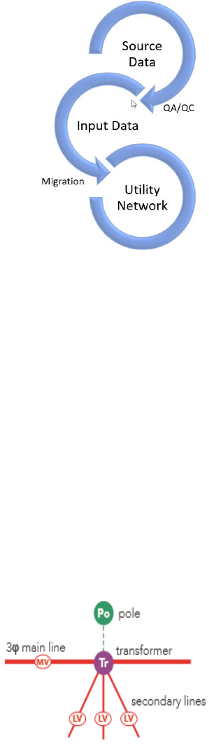
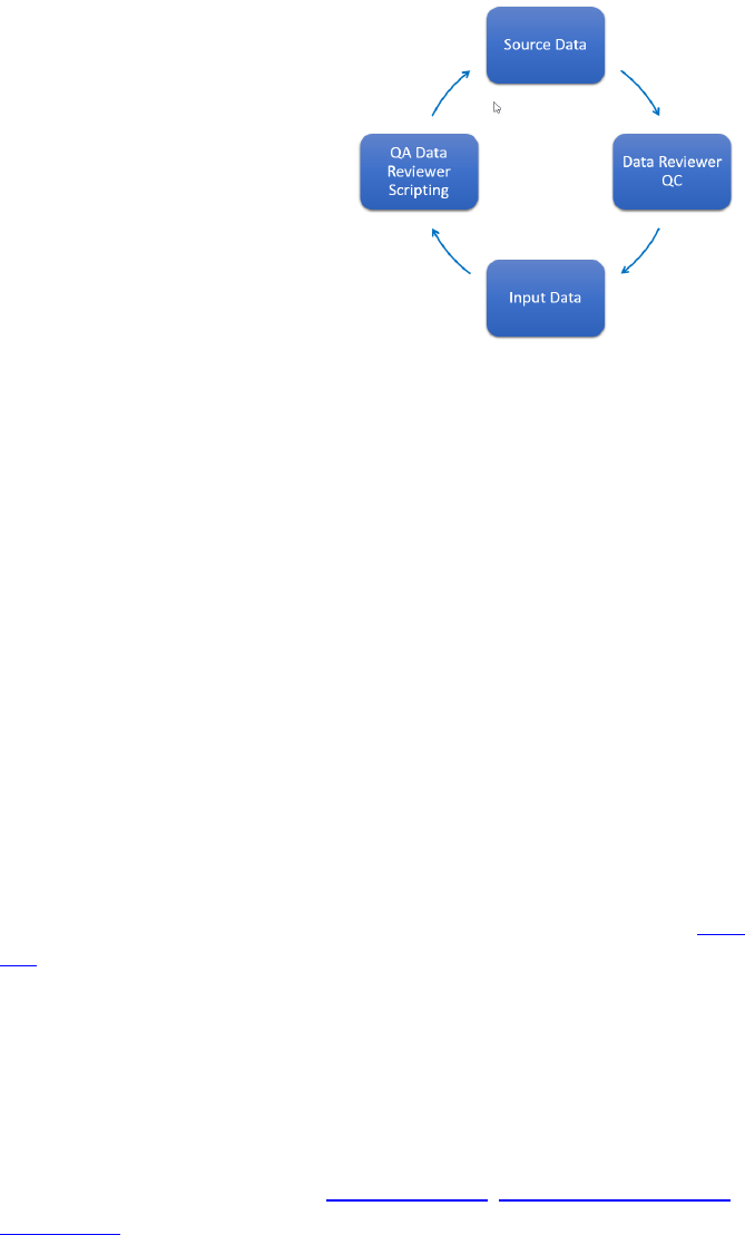
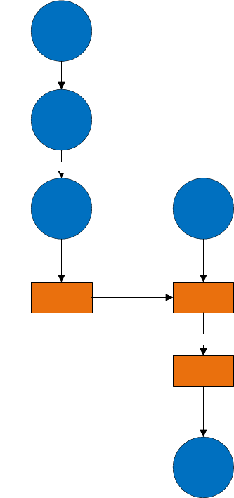
Conceptually, the process for migrating seems linear as
shown in the graphic on the right. Source data is run
through quality control (QC) to validate the data against a
predefined set of rules. Data errors are then pre-
processed through data editing clean-up procedures. The
clean source data is then pushed through a secondary
process to transform the source schema and data into the
target utility network-ready asset package. As you will see,
the actual workflow is a non-linear and iterative
methodology.
The migration workflow you choose depends on your goals
of the target output representation. By understanding
what the target representation of your data will look like, you will better understand
the overall migration process. There are three general data migration
representation patterns in a utility network:
1. Simple—data migrated in its current form from the source data. Using this
approach will not allow you to take full advantage of the capabilities of the
utility network.
2. Basic—modeling and representing the real world to better support analytics
within and outside of GIS. Many external modeling and analysis package
require a more complete representation of the data. Using at least a Basic
pattern promotes an easier exchange of data with these other packages.
3. Advanced—modeling in greater detail than basic to support planning, design,
and advanced analytics within the GIS
To visualize the difference between these
levels of data modeling complexity, the
illustration on the right shows how data
modeled in the geometric network can be
loaded into the utility network data model
using a simple migration. The resulting utility
network would have same number of
features and very similar configuration to
the original. The benefit of this approach is
the relative east of migration and resulting
parity in network functionality.

The same data illustrated above can also
be migrated with a much higher degree of
fidelity as illustrated with the graphic on
the right. The benefit of this configuration
is that individual devices, phases and
voltages are modeled through the
transformer using connectivity
associations and containerization. The
level of data complexity and data
migration effort for this migration is significantly higher than the previous
example.
Due to the distinct differences between the electric data modeling requirements and
configuration compared to both gas and water to support utility network functions,
some recommendations are specific to either electric or non-electric migration
workflows. In these instances, the text will be highlighted as such.
In the next section we will describe the preparation required before starting the data
migration process. There are also several Esri training classes that introduce the
ArcGIS Platform, the migration workbench functionality, Utility network concepts,
and administration. The information provided in these classes is extremely valuable
for informing data model decisions, configuration requirements, and
troubleshooting.
Preparation
To begin the data migration process, there are a few prerequisite items to inventory
and prepare:
• Portal for ArcGIS: This software is required primarily for final steps of
building and deploying the utility network database and publishing the
services to the organization. Install using either Enterprise components or
the ArcGIS Enterprise Builder.
• ArcGIS Pro: ArcGIS Pro is required for executing many of the tools provided for
working with the utility network data migration. The system requirements for
ArcGIS Pro are available here.
• ArcGIS Interoperability extension: This extension is required for running the
data migration workspace. A licensed copy of FME can also be used
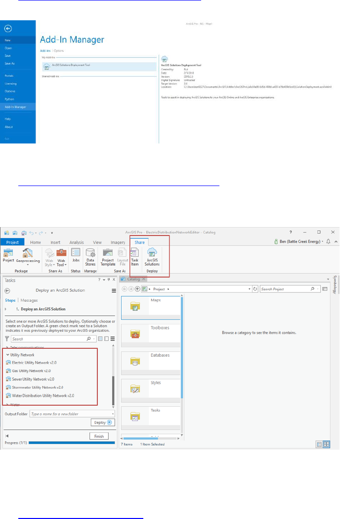
• ArcGIS Solutions Deployment Tool Add-In: Required add-in to ArcGIS Pro that
will be used to deploy the utility network Configuration.
• ArcGIS Solution Utility Network Configuration: The domain specific ArcGIS
Pro project maps and asset package that will be used throughout the process
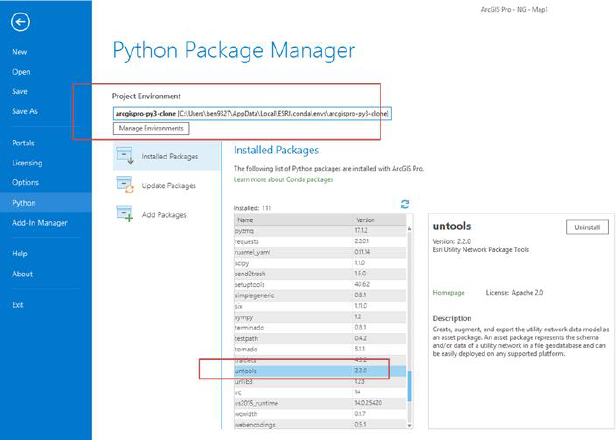
• Pro-Python Environment: Since the deployment requires extending the
Python site package list, a custom cloned environment is needed. Create one
following these instructions.
• Untools site package: Installation of this site package provides additional
tools for the Utility network deployment process including specialized tools
to facilitate working with the asset package and staging a utility network.
Upgrading relationship classes: If existing geodatabase relationships exist and will be
migrated, they must be based on GlobalIDs.
Data
Modeling
Once the prerequisites are in place you will have the latest Utility Network
Configuration asset package. This is the beginning of the data modeling effort that will
define the transformation of the data. This is a common process used whenever data
is migrated between environments.
Schema Mapping
Fundamentally, the existing source data will need to be transformed from its current
state into the target utility network schema (in an asset package format). The specific
purpose of this task is to define the high-level mapping that will define source-to-
target matching of feature classes. Data mapping choices here include the following:
• Which objects belong in the utility network vs. outside of the network. These
could include non-network feature tables, non-network feature classes and
tables.
• Which user defined fields need to be maintained in the target utility network
schema.
• Which existing tables and relationships are deprecated or restructured in the
utility network, such as relationships converted to associations or assemblies.
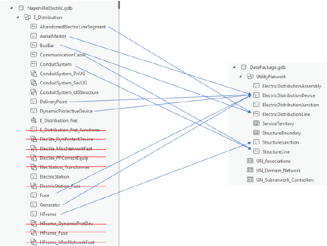
An example of this mapping is shown below from a geometric network to a utility
network:

Note that some data from stand-alone tables and relationships in the geometric
network will be modeled by spatial objects or associations within the network itself.
While their representation may change, the data will be maintained in the utility
network.
Object Mapping
Once the source features are identified and mapped to the target schema, the existing
attribute objects of the features need to be mapped to utility network objects. This
task requires a deeper understanding of the source data and how it will be
represented in the target, because it requires evaluating each feature type and
ensuring it is properly mapped to an existing utility network object. A utility network
object is defined as a unique combination of feature class, asset group, and asset type
fields. Object and field level considerations include the following:
• Feature subtyping for asset groups / asset types
• Field data type transformation
• Domain value transformations
• Related record and look-up table transformation
• Existing triggers
Esri’s data migration workspace templates provide a mapping spreadsheet as a
starting framework, documentation of the process, and a domain-specific workspace
migration template. all of which are included in the download. The ArcGIS Data
Interoperability extension workspace reads the schema mapper spreadsheet, which
parameterizes the data mappings for the data transformer so that data mappings can
be configured in a central location.
• Required attributes are identified in the attribute managers as the
fields being renamed. Focus on mapping all these fields. Once
mapped, you will need to then focus on the values in each field
because selection logic assumes the source data domains and
values. Your choice is to transform the values or modify the
workbench logic in the various test filters and attribute creators.
• Often fields are needed to complete an asset type definition or
attribute mapping is found on a related table. The join field can be
used to get all the attributes in the right place.
Asset Groups and Asset Types in the utility network

To fully appreciate the importance of the object mapping we will take a short sidebar
and discuss Asset Groups and Asset Types (AG/AT) in the utility network. Looking at
the transformer feature class from the geometric network as an example, the
subtypes in the feature class (step transformer, Overhead, underground) become the
Asset Groups, in the utility netowrk. Asset types are then defined based on the
number of phases the transformer supports
Conceptually, all network behaviors are configured at the object level which is defined
as a unique feature class, asset group, and asset type combination (AG/AT). This
means that for every network configuration, all network rules including connectivity,
association, and containment, are defined for each unique AG/AT by name.
• If the AG/AT changes are to a line feature, connectivity settings also apply.
• If the AG/AT is a subnetwork controller, then subnetwork definitions also
need to be updated.
• Any modification to the AG/AT whatsoever requires utility network
configuration changes. Network configurations are stored referencing
the AG/AT descriptions, so changing even the domain description will
require changing all the related utility network configurations. Within
the AP, a rename table propagates AG/AT name changes to network
rules and configurations.
If using the data migration workbench, invalid AG/AT features are routed to the error
GDB. However, all Invalid AG/AT features are flagged automatically by the utility
network validation as well.
Gap Analysis
Part of the data modeling process should yield a gap analysis identifying missing
configurations in the asset package that need to be added to support all of the objects
from the source data. While this is a normal and inevitable part of data migration, the
complexities involved with modifying the target utility network are significant. Any
changes to the asset group or asset types require rule and network configuration
changes as discussed in subsequent sections.
Every effort should be made to map the input data into the target model with the
fewest changes to the target utility network. Avoid where at all possible:
• Changing existing AG or AT domain descriptions
• Adding or removing AG/AT values from the domains
• Changing network attribute domains
Data Quality
Control and
Remediation
Once we understand the requirements
that support the mapping of individual
features into the utility network data
model, we can evaluate the current data
against these requirements to determine
where remediation needs to occur.
Esri developed a preconfigured solution
using ArcGIS Data Reviewer that provides
a starting point for this quality control
step. The solution configuration provides
exhaustive checks on the input data but would have to be configured to include the
specific fields and conditions identified in the data modeling step.
An added benefit of having the data mapping document is that it will narrow down
the fields that are fundamentally necessary for a successful migration. These are the
fields that should be prioritized for cleanup. If a field itself is irrelevant to the
migration, why should we spend time fixing it?
A good place to start the QC program is to focus on the fundamental requirements of
the utility network and apply them to the incoming data. There are a few hard and
fast rules that we can start with:
1. Data should be snapped. If migrating from an existing geometric network this
may not be an issue, but for non-networked data, topological coincidence
should be verified and enforced. Develop a snapping strategy utilizing snap
tool and defining environments with snap rules, ranks, and tolerances to
minimize the potential of introducing overlaps into the data.
2. Line segments cannot self-intersect or have complex geometry. Data
Reviewer does a good job here and is a great way to begin the QC journey.
Every time line segments share a vertex (as opposed to an endpoint); an error
will be generated in the utility network. Lines that are self-overlapping or are
multipart are also not allowed. ArcGIS provides many tools to deal with the
errors in this category, including repair geometry, Multipart To Singlepart,
simplify line, etc.
3. Features of the same geometry cannot intersect. This situation occurs when
points features or lines vertexes share the same x,y,z. With regards to lines,
this situation is specific to line vertexes. Line segments crossing without
sharing a vertex or lines connecting at an endpoint are allowed. Although this
configuration is technically not supported in the geometric network, this error
is extremely common in many of the datasets we have seen. Evaluate at the

Pairwise Overlay Toolset for ways to identify these issues within a single
feature class and across different feature classes. A common example of this
is stacked junctions.
4. All features in the input data must be mapped to a utility network asset
group/asset type. What this means is that the attribute information identified
in the data mapping activity used to translate the feature from the current
object type to the target object type in the utility network needs to be
validated for accuracy and completeness. This will vary by data model, but the
requirements are the same.
5. Unit records are important. Some data models rely on unit tables to store
object information such as individual anodes at a location or individual
capacitor units in a bank. These records will likely be used by the migration
workbench to create actual geographic features and connectivity associations,
so the unit records are relevant and important. Furthermore, a select set of
attributes are mandatory for the migration to be successful and those are the
ones that the QC process should focus on. Not all unit records are relevant,
but you will need to understand the workbench and target data model to
understand which unit record attributes are needed.
6. Junctions at intersections are required. Because the utility network is a rule
driven system, it is necessary to have junction or device features at every
location where two lines features of different types come together.
• Snapping the data is important. For many of the issues to be identified in
the first place, the data must be coincident. Without snapping, many of
the features will not be connected in the utility network OR will not be
flagged as overlapping.
• Because the electric data model relies heavily on assemblies, features
that are currently coincident may be transformed into complex
assemblies in the utility network. While this may seem like it will resolve
overlaps, be aware that the initial location is often used for the creation
of a connection point or line end, thus still causing an error in the output
utility network.
We will revisit other QC tasks as other errors are discovered later in the migration
process, but meanwhile these 6 rules are a solid starting point for the QC phase of the
deployment. Note that the rules above are domain agnostic. They apply universally to
all utility network data structures regardless of specific implementation details.
Domain specific validation will occur later in the process. Validation of domain rules
are best left to the topology engine within the utility network There is little benefit at
this point trying to recreate that validation using either ArcGIS Data Reviewer or
custom scripts.
By evaluating the requirements for the data mapping, you will undoubtedly find
additional QC targets that were not identified initially. Examples of this may be the
rotation angle field, design pressure field, or nominal voltage fields. These are not
critical in mapping the asset group and asset type, but they are identified in the
workbench and are necessary for properly migrating the data.
Configuring the input data into the workbench is the first contextualization of the data
and going through the schema mapping will provide invaluable insight into the fields
needed to successfully migrate the data. These are the fields the QC should focus on.
To get deeper into the data quality we then must get the data into the utility network.
Once in the utility network architecture, the topology engine will QC the data and
generate errors accordingly. These errors will expose additional QC steps that may be
needed before running the full migration.
Migration
Tools
With the schema mapping complete and another round of QC, we are now ready to
run the data migration workbench using the Data Interoperability extension.
The migration workbench is designed with a set of user-defined variables.
These are accessed through the navigation panel and are also prompted for during
execution. These parameters draw together all the sources compiled so far.
Migration Workbench Inputs
The main user-supplied input to the migration workbench is the source data. Either
the full source of the area of interest can be used, but it should already be past the
QC stage previously outlined above. The Schema Mapper downloaded as part of the
data migration solution and edited as part of the data modeling are fundamental for
the successful execution of the migration.
From the solution site you will have the following:
• Migration workbench file
• Schema Mapper
• Assembly XML file (Generally no edits required)
• Domain asset package
Executing the workbench is relatively straightforward, although several iterations are
frequently required to get all the data across. Since this is where the various
configurations are put into practice, expect some errors on the first several iterations
as mistakes in the mapping or configurations are encountered.
The workbench will not only implement the
mappings defined in the schema mapper,
but test any assumptions made against the
input data. You may find input data errors
that will require another QC target in the
source data and additional cleanup.
Using feature caching and feature inspector
functions while troubleshooting will speed
the process significantly. Review both the output asset package as well as the redline
GDB and error excel file until you are satisfied that the migration was successful. In
ArcGIS Pro, visualizing the input data and migrated data in linked views is the ideal

way to spot check the output. For more information on the workbench be sure to
review the training materials from FME.
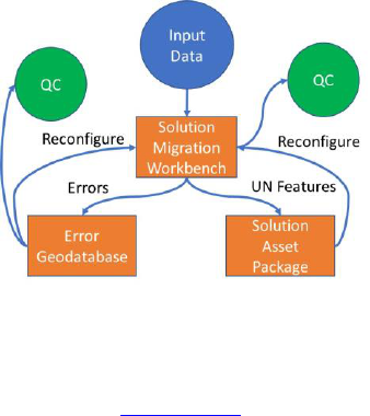
Migration Workbench Outputs
Running the migration workbench generates several outputs. The outputs from the
workbench will be as follows:
1. A copy of the domain asset package with the source data loaded into it.
2. A redline database containing new or assumed features.
3. An error Excel report of specific input feature errors.
Examination of the excel errors report and the redline features is the first
troubleshooting step to ensuring a complete migration. Error features are often
caused by misconfigurations in the workbench or attribute errors where the
workbench logic was unable to determine how to transform the features. Ideally,
they should both have no entries in them.
The asset package containing the successfully migrated data should be evaluated for
any of the previously mentioned rules (overlapping features, invalid geometry, etc.)
in case the migration process inadvertently created errors.
Invalid mapping of an object to an AG/AT is another important check that should get
flagged as an error. A less obvious error is a mis-mapped object assigned an incorrect
yet valid AG/AT. An example of this may be a plastic PE main segment source data
whose material is accidentally transformed to a main segment of iron. The AG/AT
(main/iron) is valid but obviously the mapping is an error.
To evaluate whether the data migrated successfully, check all the following:
• No unexplained errors in the output excel sheet.
• Ensure the redline database features do not need additional post processing.
• Verify that the features in the asset package are going to the expected
feature class, asset group and asset type designations. No unknown asset
groups or types should exist in the output
• Ensure the domain mapping for material, lifecycle status, and other fields are
correct
• Ensure feature associations exist in the C_Associations table
• Ensure subnetwork controllers exist in the C_SubnetworkControllers table
Once these basic checks are completed, we are ready to move to the next phase of
the migration which is to build the utility network from the asset package
With the data successfully migrated to the asset package, a series of Esri-provided
geoprocessing tools completes the migration by transferring the asset package into
an enterprise geodatabase. This is required since a utility network can only be
supported inside a database capable of branch versioning and snapshot isolation. The
following steps are required to create a utility network from an asset package:
1. Create or enable enterprise geodatabase: (Must be at version 10.6 or higher)
2. Create enterprise geodatabase user (The user cannot have database owner
privilege)
3. Stage asset package (select portal user that will own the utility network
service)
4. Apply asset package (load data and calculate statistics)
5. Enable network topology (report errors only)

Validating
the utility
network
Now that we have a utility network and have validated the migrated data (as
described above), we need to evaluate the topology errors in the sample AOI. This
crucial step provides data validation within the context of the network configuration.
Even with the performed QC outlined earlier in the process, we still may be
confronted with thousands of errors that arise from the data once placed within the
context of the utility network data model and under the constraints of the rules
defined in the network configuration. Don’t be disheartened if you have more errors
than you expected. Large numbers of errors can often be alleviated with the
addition of an additional rule or two or a new step in the QA/QC process.
These errors are essentially the final authority on the success of the migration
process. As we review the network topology, we will have to diagnose the cause of
the errors and define a solution to resolve them, which may include:
• Redefining the migration data mapping and re-running the migration
• Create / update network topology rules to adhere to the data at hand
• Manually edit features to resolve the errors
Evaluating Topology
Once the sample data is migrated to the asset package, it is time to apply the asset
package to the staged utility network. This is also the next step in validating the
migrated data and how well it adheres to the network topology rules. The “apply
asset package” geoprocessing tool loads the migrated asset package file geodatabase
into the staged utility network enterprise geodatabase. Once the asset package has
been successfully applied to the staged utility network, you will then proceed to run
the “enable network topology” geoprocessing tool with the “only generate errors”
option.
• Do not version the staged utility network enterprise geodatabase
for topology error validation. This will be done once you are ready
to publish your utility network services.
• It is recommended that you initially limit the errors to 10,000 or
less
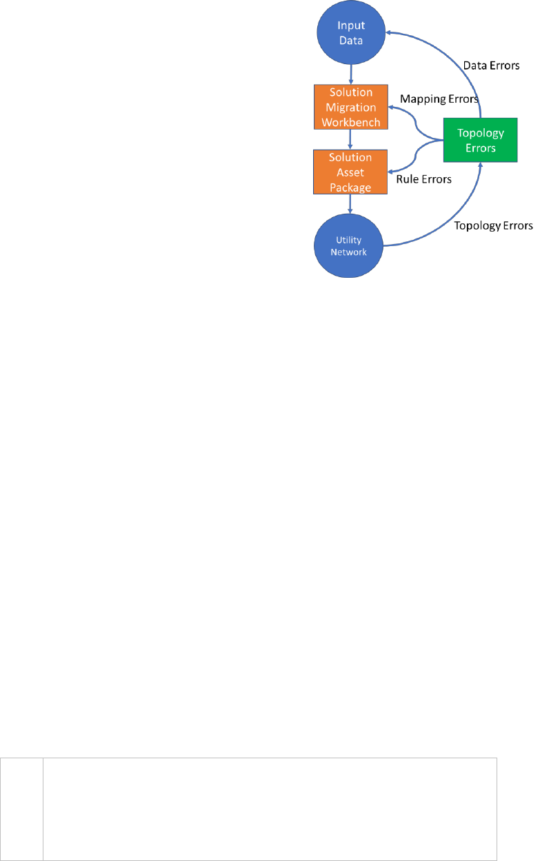
Conceptually, the topology validation provides errors that are fundamentally caused
by two types of issues: Errors caused by data and errors caused by configuration. The
utility network error features contain the error type and description that will help
categorize the error into one of these two categories. Identifying the correct cause of
the error is critical for correctly resolving the issue because the two categories have
different resolution paths. Errors that are fundamentally caused by data are resolved
in the data, while errors that are caused by misconfiguration are resolved through
configuration.
This sounds obvious but understanding this distinction will prevent you from trying to
resolve a data issue through configuration. The errors themselves may or may not
help you determine which root cause is at play, but we can group all error types into
general classes of errors for us to investigate:
• Data Errors: Feature and attribute errors that were missed in the QC process
and are now flagged as errors due to rule violation. These errors include
codes 4,5,6,7,15,19,20,21,22,23
• Mapping Errors: Translation errors from the translation workbench where
input data is miscategorized (possible misconfigurations). These errors
usually show up as codes 2, 3, 8, 9, 10, and 36, which are basically saying that
a network rule is being violated for some reason. The most common reason
is that the object attributes forced them into different AG/AT than what they
were supposed to be, and thus do not have a rule to allow it. Carefully
evaluate the context the error is in and resist the urge to just modify the
rules.
Utility network configuration errors: configurations that are valid in the data that are
flagged as errors due to network rules or definitions. These errors usually show up as
codes 13, 15, 17, 18, 34, and 35. Again, this may come down to attribute mapping.
Another common source for these error types are unique data configurations or
relationships in the input data model and not encoded into the default AP. For these
errors you will likely need to modify the utility network rules.
The error types listed in the error feature
attributes will guide the categorization. A simple
frequency on the description will give you a
quick overview of your errors. Using frequency
analysis or summary statistics, we can get an
estimate of the type of errors in the system.
Errors are referenced by GlobalID back to the
parent feature, so additional joins are needed to
drill down to the offending AG/AT or feature
classes. This may or may not be of interest since
many non-geometry related rule violations are
caused by omissions in the data or rule and not
necessarily by the features themselves
If a feature does not have a valid AG/AT, the network does not know what rules to
apply to it and will violate every possible rule the system tries to validate against it.
Several factors can produce an invalid AG/AT feature as follows:
• Incorrect attributes were used to map the feature from source to target
(attribute manager/schema mapper)
• The correct attributes were used but the values in the attributes were
missing or invalid (dirty data)
• Attributes and values were valid, but the transformation inserted the wrong
value (incorrect transformer or test filter)
As mentioned previously, the total number of errors in the utility network should be
as close to 0 as possible. Besides categorizing and fixing errors, you can analyze the
errors to calculate error rates for the data. If a 10 percent sample AOI resulted in 200
errors, you can expect 2,000 in the final utility network build. Error counts greater
than 10,000 have severe performance and functionality implications.
• For a properly functioning utility network the error count should
be as close to 0 as possible.
• Error counts greater than 10,000 have severe performance and
functionality implications.
We can resolve many of the identified issues with different strategies. Depending on
the most appropriate approach, we have the option of preprocessing the input data,
adding transformers in the migration workbench, or adding rules to allow the
behavior.
Carefully evaluate each error scenario and potential fixes to determine the best way
to resolve them. As mentioned previously, what presents as a missing rule may in
fact be a migration mapping error.
Managing Rules
Ideally, all existing features in the input data can be mapped to existing AG/ATs in the
utility network. These feature types are defined, and their real-world function and
representation should be consistent with the preconfigured rule base. When errors
are identified that are due to missing or incomplete rule definitions, the only way to
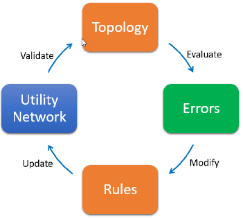
resolve them is by modifying the utility network configurations. When trying to
resolve errors by reconfiguring the utility network, the iterative process for modifying
networks follows these general steps:
1. Validate the network on the AOI with the option to “only generate errors”.
This should complete quickly and display the topology errors.
2. Evaluate the errors to determine a
pattern and cause. Use frequency to
determine if this is a common issue
or just a random data error
3. Create or modify rules to allow the
behavior either using a template
(see below) or adding an individual
rule
4. Update the network with the rule
changes and other necessary
configurations (such as edge
connectivity or tier definitions)
5. Re-validate the topology
In the case where an entire feature AG/AT is missing in the utility network, the
change will require significant modifications to the utility network rules. This task

should not be taken lightly. When adding a new AG/AT, every single connectivity,
containment, and association rule must be defined as well.
Consider the following case: A new type of fiberglass lid for underground enclosures
has been developed and approved for use in the organization. While the utility
network has an asset group called “lid” in the structure junction feature class, the
available asset types are only concrete and metal. Adding a new fiberglass asset type
is required, following these steps:
1. Add the new asset type. Asset types are defined by a domain. Open the
subtypes view of the structure junction feature class and locate the “lid”
subtype (aka asset group). The asset type field will list the domain assigned
to that field for that AG. Open the domains view and edit that domain by
adding a “fiberglass” AT.
2. Now that the domain value is added, rules must be defined. The quickest
way to get this done is to start from a template. If the new asset type is like
an existing feature, it is better to gather the existing rules that define the
network behavior for that feature and use them as a starting point. All rules
can be exported using the GP tool. Once the rules are exported, filter the list
to only show the rules for the template feature.
3. Copy these rules to a new .csv and replace the AT code of the template
feature to the AT code we just created. Edit these rules as needed to define
the desired behavior for your new AT.
4. Append these rules back into the utility network using the GP tool.
The solutions team created a nice GP toolbox that helps with this task. The tool will
read the utility network rules and instead of exporting all the rules as a .csv, it will
create an excel spreadsheet for you to visualize the rules. Moreover, editing the
spreadsheet will allow you to generate the new rules for import into the utility
network. This tool is available on GitHub for download. If severe modifications to the
rule base are needed, this is a much better method for managing the rules.
Finalizing
the
Migration
Once the utility network that is built against the AOI is complete and the topology is
validating with an acceptable level of errors (usually the intrinsic error rate that is
attributed to bad data), the entire data migration process should be re-factored to
run against the whole dataset and build the full utility network. To do this, the
following steps are required.
Re-Factor the migration process:
1. Export the AOI utility network
asset package using the Export
Asset Package tool. This tool will
take all the configuration changes
you made to the utility network
during the topology validation
phase and create a new asset
package based on those changes.
Any rule modifications,
configuration changes, etc. are
exported for use in the next
iteration
2. Modify the data migration
workbench to use the updated
asset package from the previous
step. Also change the input feature
classes to reference the full source
data.
3. Re-run the migration workbench.
Check the log and the error GDB.
You should not have any
unexpected error features. The
same steps used to create the AOI
utility network will be taken again,
this time with the full dataset.
4. Build a new utility network and apply the asset package.
With the data successfully loaded in the utility network, the final phase of the
implementation is to complete the configurations to enable the advanced network
functionality and analysis. To do this, the data must be prepared for publication to
Portal and shared with the end users.
Input Data
(AOI)
Create
Utility Network
(AOI)
Source Data
QC
Custom Asset
Package
Export schema
Solution
Migration
Workbench
Input Data
(Full Dataset)
Template Input
Utility Network
Output
Final Asset
Package
Apply
Enable branch versioning
Branch versioning which was introduced at
10.6 is the mechanism behind long
transactions for services. The utility network
can only be edited through branch
versioned services. To enable branch
versioning, the dataset must have both
editor tracking enabled and GlobalIDs on
each feature class in the dataset.
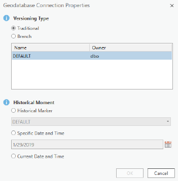
To register the data as branch versioned,
the versioning type in the database
connection file needs to be set to branch
BEFORE the register as versioned command
is executed.
Once registered as branch versioned, the data cannot be edited except through
services
Publish utility network service
Publish the utility network service by adding all the utility network layers and related
tables into an ArcGIS Pro map. To publish the service and enable the utility network
extension on the service remember the following:
• All utility network feature classes must be present in the map.
• All fields in the utility network feature classes should be visible.
• Layers from the utility network feature classes cannot contain any definition
queries.
• All layers in the map must be branch versioned.
Only the Portal user who created the utility network can publish the service. This use
will need to be logged in to Portal to complete the sharing of the service with the
users.
Enable Network Topology
Network topology is enabled using the same tool used previously to generate the
topology errors in the AOI utility network. The difference in this run is that we will
not enable the “only generate errors” option. This will enable the network. The
functions available at this point include the following:
• Intelligent snapping
• Validate network topology
• Network tracing
Execute the tool from ArcGIS Pro either using the service or directly against the
database.
Update Subnetworks
Updating subnetworks can only occur once the network topology is enabled. This
tool can be run immediately after enabling topology. This tool must be run against
the utility network service.
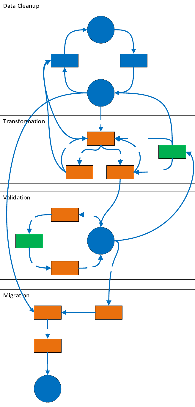
In Conclusion
The utility network data migration is only one aspect of a multi-faceted process of
moving to the utility network. For a successful migration, transforming the data is the
fundamental first step in this process. As you can see from the complete workflow
diagram below, the migration does follow logical process in a non-linear flow. With
proper prior planning and the structured methodology outlined in this white paper,
the migration process is understandable, and the resulting data will provide a solid
foundation for the subsequent phases of the utility network deployment.
Data Reviewer
QC
Input Data
POC / Area of Interest
Topology
Errors
Data Errors
Utility Network
Source Data
QA
Data Reviewer
Scripting
Solution
Migration
Workbench
Solution Asset
Package
Error
Geodatabase
Errors
UN Features
QC
Reconfigure
Reconfigure
Remaining
Topology
Errors
Topology
Validate
Evaluate
Rules
Modify
Update
Configuration
Errors
Solution
Migration
Workbench
Utility Network
Output
Migration Asset
Package
Apply
Custom Asset
Package
Template Input
Reconfigure
Export schema