
4
CONTENTS OF CARTON
42”/46” Double Bagger
Before beginning installation, remove all parts from the carton to make sure
everything is present. Carton contents are listed below and shown in Figure 1. The
hardware pack(s) included in this kit are detailed at the end of this section.
• Boot Assembly - 731-09329A
• Grass Bag Assembly (2) - 664-05104
• Vertical Bagger Support - 683-04519C
• Grass Bag Support - 683-05329A
• End Plugs (4) - 735-0246A (pre-installed)
• Bagger Cover - 631-05474B
• Bagger Vent Wall Assembly - 631-05491B
• Bagger Cover Left Side Wall - 731-12350B
• Hose - 764-05082
• Lower Hose Connection - 731-12353A (pre-installed)
• Hinge Pin - 711-06701
• Adapter Bracket - 789-02518
• Hitch Adapter Bracket - 789-02298
• RZT Bagger Weight - 719-04271A
• Weight Plates (3) - 789-02137
• Weight Hanger Bracket Left - 789-02197
• Weight Hanger Bracket Right - 789-02198
• Hardware Pack - 689-01419
• Anti-marking Adhesive Strips - 777X52246
• Bagger Boot Hardware Pack - 689-00636
50”/54” Double Bagger
Before beginning installation, remove all parts from the carton to make sure
everything is present. Carton contents are listed below and shown in Figure 2. The
hardware pack(s) included in this kit are detailed at the end of this section.
• Boot Assembly - 631-05103
• Grass Bag Assembly (2) - 664-05104
• Vertical Bagger Support - 683-04519C
• Grass Bag Support - 683-05329A
• Chute Adapter - 731-10133
• End Plugs (4) - 735-0246A (pre-installed)
• Bagger Cover - 631-05474B
• Bagger Vent Wall Assembly - 631-05491B
• Bagger Cover Left Side Wall - 731-12350B
• Hose - 764-05135
• Lower Hose Connection - 731-12353A (pre-installed)
• Hinge Pin - 711-06701
• Adapter Bracket - 789-02518
• Hitch Adapter Bracket - 789-02298
• RZT Bagger Weight - 719-04271A
• Weight Plates (3) - 789-02137
• Weight Hanger Bracket Left - 789-02197
• Weight Hanger Bracket Right - 789-02198
• Hardware Pack - 689-01419
• Anti-marking Adhesive Strips - 777X52246
• Bagger Boot Hardware Pack - 689-02199
Figure 1
Figure 2
Thank You
Thank you for purchasing a bagging attachment. It was carefully engineered to provide excellent performance when properly operated and maintained.
Please read this entire manual prior to operating the equipment. It instructs you how to safely and easily set up, operate and maintain your equipment. Please be sure that you, and any other persons who will
operate the machine, carefully follow the recommended safety practices at all times. Failure to do so could result in personal injury or property damage.
All information in this manual is relative to the most recent product information available at the time of printing. Review this manual frequently to familiarize yourself with the equipment, its features and
operation. Please be aware that this Operator’s Manual may cover a range of product specifications for various models. Characteristics and features discussed and/or illustrated in this manual may not be
applicable to all models. We reserve the right to change product specifications, designs and equipment without notice and without incurring obligation.
If you have any problems or questions concerning this equipment, phone your local dealer or contact us directly. We want to ensure your complete satisfaction at all times.
Throughout this manual, all references to right and left side of the machine are observed from the operating position.
5
CONTENTS OF CARTON
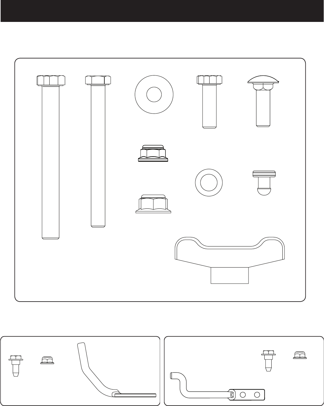
Contents of Hardware Pack
Please check your hardware packs against the illustrations below. The quantities for each item are listed in parenthesis.
Hardware Pack 689-01419
(1)
(2)
(4)
(2)
(2)
(5)
(2)
(2)
(7)
(12)
710-0276
710-0376
710-3056
710-3085
712-04063
712-04065
720-04122
735-05938
736-0117
736-0242
42”/46” Hardware Pack 689-00636
738-1225 712-04064
(1)
747-06043
(2)(2)
50”/54”Hardware Pack 689-02199
(2)
712-04064
738-1225
747-06309
(2)
(1)
6
ASSEMBLY & INSTALLATION
NOTE: References to left, right, front and rear of the tractor are from the operator’s position, unless
otherwise stated.
• Before assembly, place the tractor on a firm, level surface, disengage the
PTO, stop the tractor engine and set the parking brake.
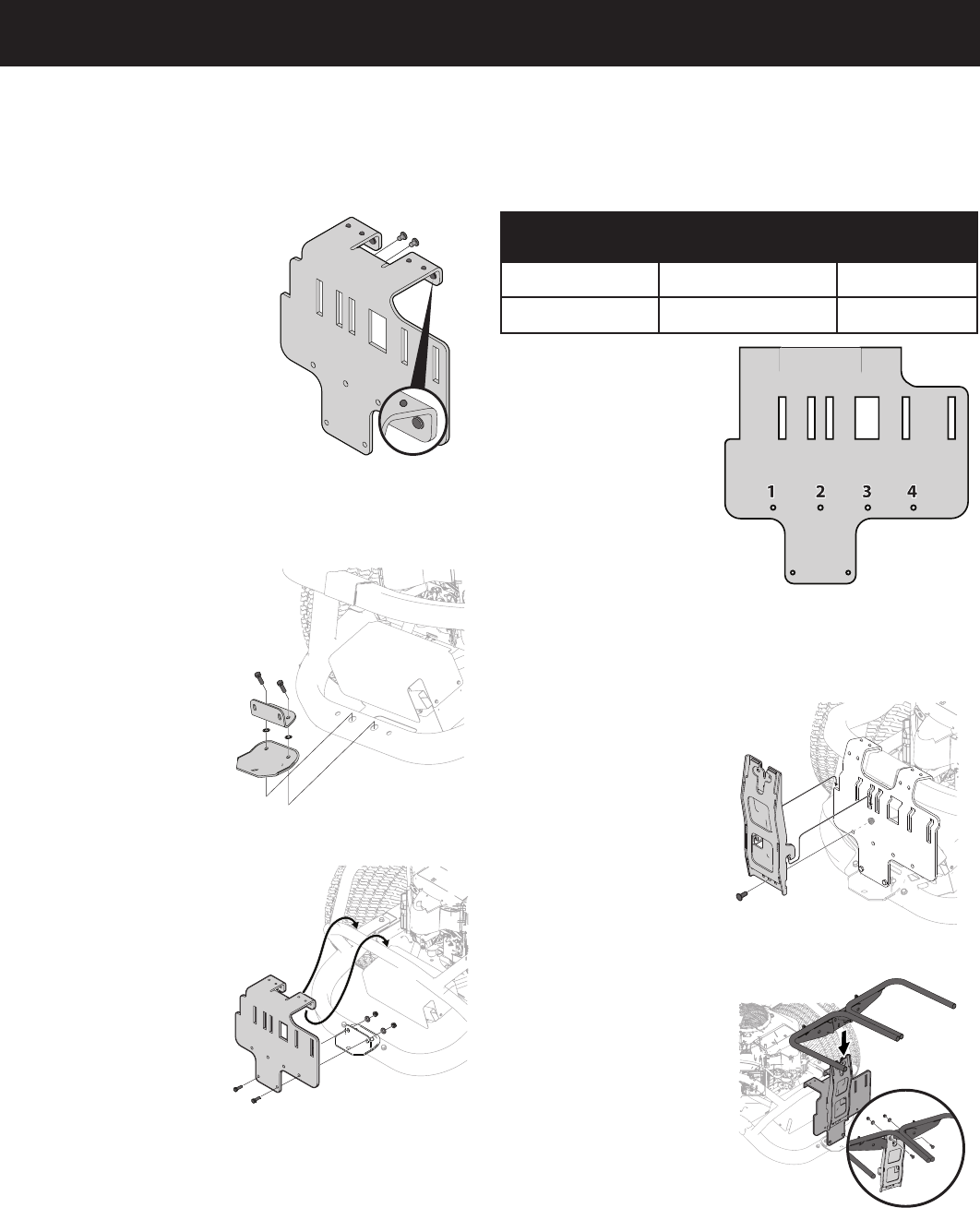
Assemble Mounting Brackets
1. Install 12 rubber pads (735-
05938) into adapter bracket
(789-02518) using the mounting
holes shown in Figure 3.
NOTE: Check the bumper pads after
each season for excessive wear and
replace as necessary.
Install Bracket Assembly
on Tractor
NOTE: When assembling this mounting assembly,
it is best to not fully tighten the bracket at this
time. This will facilitate the mounting process in
later steps, which will then require fully
tightening this mounting assembly.
Install mounting bracket assembly on tractor as follows:
1. Remove hitch bracket.
2. For ZT1 installation only:
Place two flat washers
(736-0117) between
hitch bracket adapter
(789-02298) and the hitch
bracket removed in Step 1.
3. Install bracket assembly to
the tractor’s lower frame
with two capscrews (710-
0376). See Figure 4.
4. Hang adapter bracket
assembly onto upper frame
square tube and connect to
hitch bracket adapter (789-
02298) with two screws
(710-0376), two cup
washers (736-0242) ,and
two flange lock nuts (710-
04063). See Figure 5.
NOTE: Make sure that the adapter
bracket is seated firmly on the
upper tube frame.
5. Tighten all of the hardware
installed at this time.
Install Vertical Support
NOTE: This manual covers various bagger configurations. Please follow the instructions
applicable to your machine.
1. Using Figure 6 and the chart below, locate the correct mounting hole location
on the mounting bracket for your tractor:
Model No. Description Position
19A70054* 42”/46” Double Bagger 4
19A70055* 50”/54” Double Bagger 3
NOTE: Hole position 2 is
currently not used.
2. Install the vertical support
bracket onto the mounting
assembly on the tractor
by hooking it over the
mounting assembly as
shown in Figure 7.
3. Secure the upright
support bracket to the
mounting assembly using
a hex bolt (710-0376)
and flange lock nut (712-
04063) from hardware
pack 689-01419. See
Figure 7.
Install Hanger Assembly
1. Install and secure the
hanger assembly onto the
upright support bracket
using two carriage bolts
(710-0276), two cup
washers (736-0242) and
two flange lock nuts (712-
04063) from hardware
pack 689-01419. See
Figure 8.
NOTE: The carriage bolts (710-0276),
from hardware pack 689-01419, go in the
top hole with the nut facing the engine.
The hex bolt (710-0376), from the same
hardware pack, goes in the bottom hole.
Install Top Bagger
Components
With the mounting brackets
assembled and in place on the
tractor, follow these steps to
assemble the remaining bagger
components.
1. If not already installed
by the factory, snap
the vent cover into the
holes found on the chute
support assembly.
Figure 3
Figure 4
Figure 5
Figure 6
Figure 7
Figure 8

7
ASSEMBLY & INSTALLATION
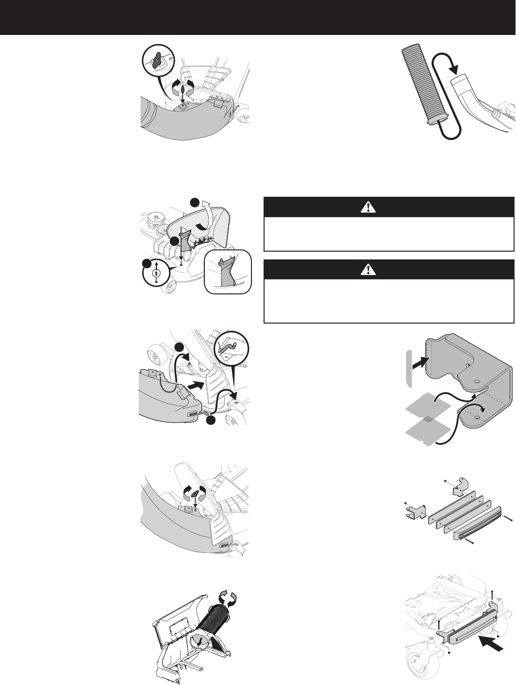
2. Snap the plastic upper chute support in place by first clipping the side
portion onto the bagger support rail (1) as shown in Figure 9.
3. Snap the front side of the chute support to the rail (2) as shown in Figure 9.
4. Snap the top cover support on to the bagger support rail at a slight angle.
Rotate the assembly down and into the chute support assembly, making sure
that the tab (shown in inset of Figure 10) is locked into place.
5. Install the bagger top cover by aligning the tabs of the cover and sliding the
mounting pin into the channel as shown in Figure 11.
6. Open hood by pushing in on the rear side tabs with your hand (1), and lifting
the cover with your other hand in the center rear of the bagger cover (2) as
shown in Figure 12.
7. Install both bag assemblies onto the bag support brackets by inserting the
front edge in first (1), and then setting the back edge down until it fits into the
assembly (2) as shown in Figure 13.
Installing the Boot Rod and Hardware
Model 19A70054*:
1. From the inside of the boot, put
the two hex head screws (738-
1225) through the holes at the
bottom front of the boot. See
Figure 14.
2. Put the mounting rod (747-06043)
in place over the hex head screws.
Make sure the tip of the rod is
facing out from the boot. See
Figure 14.
3. Begin threading the flange lock nuts (712-04064) onto the hex head screws.
See Figure 14.
4. Using a 7/16” wrench or socket on the screw and a 7/16” box wrench on the
lock nuts, tighten down so flange is flush to secure the assembly.
Model 19A70055*:
1. From the inside of the boot,
put the two hex head screws
(738-1225) through the holes at
the bottom front of the boot. See
Figure 15.
2. Put the mounting rod (747-06309)
in place over the hex head screws.
Make sure the tip of the rod is
facing out from the boot. See
Figure 15.
3. Begin threading the flange lock
nuts (712-04064) onto the hex head screws. See Figure 15.
4. Using a 7/16” wrench or socket on
the screw and a 7/16” box wrench
on the lock nuts, tighten down
so flange is flush to secure the
assembly.
Installing the Discharge
Chute - 42/46” Double
Bagger
1. With the tractor’s discharge chute
raised up and held open (1), install
the chute elbow by placing the
chute elbow mounting rod into
the chute mounting tab (2), as
shown in Figure 16.
2. Secure the chute elbow to
the deck using a wing knob
(720-04122) from hardware pack
689-01419. See Figure 17.
NOTE: If present, remove the protective
cap off of the mounting stud on the
mowing deck as shown in the upper inset
of Figure 17.
IMPORTANT: Be certain that the
bottom of the discharge chute is
located inside of the lip of the deck
opening, as shown in Figure 18.
Installing the Discharge
Chute - 50/54” Double
Bagger
When installing the discharge chute,
two different installation instructions
exist. For the 54” Fabricated deck units, the discharge chute elbow mounts directly
onto the cutting deck. For the 50” and 54” stamped decks, an adapter must first be
installed. Be sure to follow the instructions that pertain to the unit you are installing
this bagger on.
54” Fabricated Deck Units:
1. Raise the deck to its highest
position.
2. Raise the chute deflector (1 in
Figure 19) on the deck and hold it
while you position the discharge
chute over the chute opening.
Figure 14
Figure 15
1
2
Figure 16
1
2
Figure 17
Figure 18
1
2
3
Figure 19
Figure 9
Figure 10
Figure 11
Figure 12
Figure 13
8
ASSEMBLY & INSTALLATION
3. Insert the end of the discharge chute
elbow (2) into the hole provided in
the deck wheel mount as shown
in the inset of Figure 19.
4. Pivot the discharge chute
rearward until the hole in the
discharge chute elbow aligns with
the pin on the deck. Move the
discharge elbow down onto that
pin as shown in 3 of Figure 19.
5. Secure the discharge chute elbow
to the cutting deck using a wing
knob (720-04122) included with
the bagger kit. Refer to Figure 20.
On 50” and 54” Stamped Decks:
1. Raise the deck to its highest
position.
2. Remove the deck pin rubber
protective cap (1) in Figure 21.
3. Raise the chute deflector (2 in
Figure 21) on the deck and hold
it while you install the chute
adapter (731-10133) (3) onto the
deck as shown in Figure 21.
4. Insert the end of the discharge
chute elbow (1) into the hole
provided in the deck wheel mount
as shown in the inset of Figure 22.
5. Pivot the discharge chute
rearward until the hole in the
discharge chute elbow aligns
with the pin on the deck adapter.
Move the discharge elbow down
onto that pin as shown in 2 of
Figure 22.
6. Secure the discharge chute elbow
to the cutting deck using a wing
knob (720-04122) included in
hardware pack 689-01419. Refer
to Figure 23.
Installing the Upper Chute
Tube
1. Thread the upper end of the chute
tube securely into the upper chute
support. There are two tabs on
the lower inside part of the upper
chute support to allow for secure
threading. See Figure 24.
NOTE: The chute tube and upper chute
support are left-hand threaded. Thread
counterclockwise until secure.
2. Lift by the handles at the bottom
of the chute tube. Slide the
chute tube over the chute elbow
mounted on the cutting deck, as
shown in Figure 25.
3. Make sure the connection is
secure and there are no gaps
between the chute tube and the
chute elbow.
4. If open, close the grass catcher
cover prior to mowing.
Install The Counter Weight
WARNING
This front-weight kit is required when operating any compatible zero turn
tractor models equipped with a grass collector. Failure to install this kit
may result in serious injury or death.
WARNING
Before beginning installation, place the zero turn tractor on a firm and
level surface, set the parking brake, place the PTO in the disengaged
(OFF) position, stop the motor and remove the ignition key to prevent
unintended starting.
1. Before assembly, peel the
adhesive decals from the sheet
and apply to the inside faces of
the right and left weight hanger
brackets, as shown in Figure 26.
2. Attach the weight and three
weight plates to the weight
hanger brackets with two 3/8” hex
head capscrews (710-3085) and
two nuts (712-04065) as shown in
Figure 27.
3. Visually center the weight bar
assembly on the tractor and using
two 7/16” hex head capscrews
(710-3056) and two nuts (712-
04063) secure the counter weight
assembly to the tractor as shown
in Figure 28.
Figure 20
1
3
2
Figure 21
1
2
Figure 22
Figure 23
Figure 24
Figure 25
Figure 26
Figure 27
Figure 28
