
Operating Instruction OI/FCB300/FCH300-EN Rev. F
CoriolisMaster FCB330, FCB350, FCH330, FCH350
Coriolis Mass Flowmeter
Measurement made easy
2 OI/FCB300/FCH300-EN Rev. F | CoriolisMaster FCB330, FCB350, FCH330, FCH3500
C
oriolisMaster FCB330, FCB350, FCH330, FCH350
Coriolis Mass Flowmeter
Operating Instruction
OI/FCB300/FCH300
-EN
Rev. F
Issue date:
05.2014
Translation of the original instruction
Manufacturer
ABB Automation Products GmbH
Process Automation
Dransfelder Str
. 2
37079 Göttingen
Germany
Tel: +49 551 905
-0
Fax: +49 551 905
-777
Customer service center
Tel
: +49 (0) 180 5 222 580
Fax: +49 (0) 621 381 931
-29031
CoriolisMaster FCB330, FCB350, FCH330, FCH3500 | OI/FCB300/FCH300-EN Rev. F 3
Chan ge from on e to two c olumns
Contents
1 Safety ............................................................................... 6
1.1 General information and notes for the reader ........ 6
1.2 Intended use ........................................................ 6
1.3 Improper use ....................................................... 6
1.4 Target groups and qualifications .......................... 6
1.5 Warranty provisions ............................................. 6
1.6 Plates and symbols .............................................. 7
1.6.1 Safety / warning symbols, note symbols .............. 7
1.6.2 Name plate .......................................................... 7
1.7 Transport safety instructions ................................ 8
1.8 Installation safety instructions ............................... 8
1.9 Safety instructions for electrical installation ........... 8
1.10 Safety instructions for operation ........................... 8
1.11 Technical limit values ........................................... 9
1.12 Permissible media for measurement ..................... 9
1.13 Safety information for inspection and maintenance9
1.14 Returning devices ................................................ 9
1.15 Integrated management system ......................... 10
1.16 Disposal............................................................. 10
1.16.1 Information on WEEE Directive 2002/96/EC (Waste
Electrical and Electronic Equipment) ................... 10
1.16.2 RoHS Directive 2002/95/EC .............................. 10
2 Function and System Design ........................................ 11
2.1 General remarks ................................................ 11
2.2 Measuring principle ............................................ 11
2.3 Device designs .................................................. 12
2.3.1 ATEX, IECEx, NEPSI device overview ................. 14
2.3.2 cFMus device overview ...................................... 15
3 Transport ....................................................................... 16
3.1 Inspection .......................................................... 16
3.2 General remarks ................................................ 16
4 Mounting ....................................................................... 16
4.1 General remarks ................................................ 16
4.2 Flowmeter sensor .............................................. 16
4.3 Transmitter ........................................................ 17
4.3.1 Transmitter in remote mount design (option F1 or
F2) ..................................................................... 17
4.3.2 Transmitter in remote mount design (option R1 or
R2) .................................................................... 17
4.4 Rotating the transmitter and LCD display ........... 18
4.4.1 Transmitter enclosure ........................................ 18
4.4.2 LCD indicators ................................................... 18
4.5 Installation instructions ....................................... 19
4.5.1 Installation requirements/System sizing information
.......................................................................... 19
4.5.2 Inlet sections ...................................................... 19
4.5.3 Model in remote mount design ........................... 19
4.5.4 Pressure loss ..................................................... 19
4.6 Mounting positions ............................................ 19
4.6.1 Vertical installation in riser .................................. 19
4.6.2 Vertical installation in a drop line ......................... 20
4.6.3 Horizontal installation in case of measurement of
liquids ................................................................ 20
4.6.4 Horizontal installation in case of measurement of
gases ................................................................. 20
4.6.5 Difficult installation locations for liquid measurement
.......................................................................... 21
4.6.6 Difficult installation locations and gas metering ... 21
4.6.7 Zero balance ...................................................... 21
4.6.8 Installation dependent on the temperature of the
medium being measured ................................... 22
4.6.9 Installation with option TE1 "extended tower length"
.......................................................................... 22
4.6.10 Notes about EHEDG conformity ......................... 22
5 Electrical connections ................................................... 23
5.1 Information for connecting the power supply ...... 23
5.2 Information for cable installation ......................... 23
5.3 Integral mount design ........................................ 24
5.4 Remote mount design ........................................ 25
5.4.1 Cable specification ............................................. 25
5.4.2 Routing the signal cable ..................................... 25
5.4.3 Connecting the signal cable ............................... 25
5.5 Digital communication ........................................ 26
5.5.1 HART protocol ................................................... 26
5.6 Terminal connection diagrams ........................... 27
5.6.1 Connection of transmitter models to peripherals . 27
5.6.2 Connection examples for the peripherals ............ 28
5.6.3 Connection of transmitter to flowmeter sensor ... 29
5.6.4 Connection of transmitter to flowmeter sensor in
Zone 1 / Div. 1 ................................................... 30
6 Commissioning .............................................................. 31
6.1 Checks prior to commissioning .......................... 31
6.2 Switching on the power supply .......................... 31
6.2.1 Inspection after switching on the power supply .. 31
6.3 Basic Setup ....................................................... 31
6.4 Configuring the pulse output .............................. 32
6.5 Operating protection switch ............................... 32
6.6 Information for safe operation in potentially
explosive atmospheres – ATEX .......................... 33
6.6.1 Inspection .......................................................... 33
6.6.2 Output circuits ................................................... 33
6.6.3 NAMUR contact ................................................. 34
6.6.4 Cable entries ...................................................... 34
6.6.5 Flowmeter sensor insulation ............................... 34
6.6.6 Operation in Zone 2 with protection class "restricted
breathing" (nR) ................................................... 34
6.6.7 Changing the type of protection ......................... 35
4 OI/FCB300/FCH300-EN Rev. F | CoriolisMaster FCB330, FCB350, FCH330, FCH3500
6.7 Information for safe operation in potentially
explosive atmospheres – cFMus ........................ 36
6.7.1 Inspection .......................................................... 36
6.7.2 Cable entries ..................................................... 36
6.7.3 Electrical connection .......................................... 36
6.7.4 Process sealing ................................................. 37
6.7.5 Changing the type of protection ......................... 37
7 Configuration, parameterization ................................... 38
7.1 Operation .......................................................... 38
7.1.1 Menu navigation ................................................ 38
7.2 Menu levels........................................................ 38
7.2.1 Process display ................................................. 39
7.2.2 Switching to the configuration level
(parameterization) .............................................. 39
7.2.3 Selecting and changing parameters ................... 40
7.3 Overview of parameters on the configuration level41
7.4 Parameter descriptions ...................................... 45
7.4.1 Menu: *Prog. level .............................................. 45
7.4.2 Menu: Language ................................................ 45
7.4.3 Menu: Mode of operation ................................... 46
7.4.4 Menu: Concentration ......................................... 47
7.4.5 Menu: Unit ......................................................... 48
7.4.6 Menu: Flowmeter primary .................................. 49
7.4.7 Menu: QmMax ................................................... 49
7.4.8 Menu: Damping ................................................. 49
7.4.9 Menu: Low cutoff setting ................................... 49
7.4.10 Menu: Field optimization .................................... 49
7.4.11 Menu: System Zero adj. ..................................... 50
7.4.12 Menu: Alarm ...................................................... 50
7.4.13 Menu: Display .................................................... 51
7.4.14 Menu: Totalizer .................................................. 52
7.4.15 Menu: Pulse Output ........................................... 53
7.4.16 Menu: Current output 1 ..................................... 54
7.4.17 Menu: Current output 2 ..................................... 55
7.4.18 Menu: Switch contacts ...................................... 56
7.4.19 Menu: Label ....................................................... 56
7.4.20 Menu: Interface .................................................. 56
7.4.21 Menu: Function test ........................................... 57
7.4.22 Menu: Status ..................................................... 59
7.4.23 Menu: Software version ..................................... 59
7.5 DensiMass concentration measurement (FCB350
only) .................................................................. 60
7.5.1 Accuracy of concentration measurement ........... 60
7.5.2 Entering the concentration matrix ....................... 60
7.5.3 Structure of the concentration matrix ................. 61
7.6 Software history ................................................. 62
8 Error messages ............................................................. 62
8.1 General remarks ................................................ 62
8.2 Overview ........................................................... 63
8.3 Error messages ................................................. 64
8.4 Warnings ........................................................... 66
9 Maintenance / Repair .................................................... 67
9.1 General remarks ................................................ 67
9.2 Cleaning ............................................................ 67
9.3 Flowmeter sensor .............................................. 67
9.4 Transmitter ........................................................ 67
9.4.1 Replacement ..................................................... 67
10 Flowmeter sensor specifications .................................. 68
10.1 Designs ............................................................. 68
10.2 Nominal diameter and measuring range ............. 68
10.2.1 Recommended flow range ................................. 68
10.3 Measuring accuracy ........................................... 68
10.3.1 Reference conditions ......................................... 68
10.3.2 Measured error .................................................. 68
10.3.3 Zero stability ...................................................... 69
10.3.4 Effect of the temperature of the medium being
measured .......................................................... 69
10.3.5 Effect of the operating pressure ......................... 69
10.4 Technical data ................................................... 70
10.4.1 Pressure loss ..................................................... 70
10.4.2 Viscosity range................................................... 70
10.4.3 Temperature limits °C (°F) .................................. 70
10.4.4 Process connections ......................................... 70
10.4.5 Pressure rating................................................... 70
10.4.6 Enclosure as protective device (optional) ............ 70
10.4.7 Pressure Equipment Directive ............................ 70
10.4.8 Materials for transmitters .................................... 71
10.4.9 Materials for flowmeter sensors .......................... 71
10.4.10 Material load for process connections ................ 71
10.4.11 Material load curves for flange devices ............... 71
11 Transmitter specifications ............................................ 72
11.1 General remarks ................................................ 72
11.2 Technical data ................................................... 72
11.2.1 Measuring range ................................................ 72
11.2.2 Degree of protection .......................................... 72
11.2.3 Electrical connections ........................................ 72
11.2.4 Power supply ..................................................... 72
11.2.5 Response time ................................................... 72
11.2.6 Ambient temperature ......................................... 72
11.2.7 Housing design .................................................. 72
11.2.8 Forward/reverse flow metering ........................... 72
11.2.9 LCD display ....................................................... 72
11.2.10 Operation........................................................... 73
11.2.11 Data backup ...................................................... 73
11.3 Electrical data .................................................... 73
11.3.1 Current outputs ................................................. 73
11.3.2 Pulse output ...................................................... 74
11.3.3 Digital switching outputs .................................... 74
11.3.4 Digital switching inputs ....................................... 74
12 Ex relevant specifications acc. to ATEX / IECEx / NEPSI
....................................................................................... 75
12.1 Electrical data .................................................... 75
12.1.1 Overview of the different output options ............. 75
12.1.2 Version I: Active / passive current outputs .......... 75
12.1.3 Version II: Passive / passive current outputs ....... 76
12.1.4 Special connection conditions ............................ 76
CoriolisMaster FCB330, FCB350, FCH330, FCH3500 | OI/FCB300/FCH300-EN Rev. F 5
12.2 Flowmeter sensor model FCB3xx / FCH3xx ....... 77
12.2.1 Temperature class ............................................. 77
12.2.2 Hazardous area approval ATEX / IECEx / NEPSI 78
12.3 Transmitter model FCT300 in remote mount design
.......................................................................... 79
12.3.1 Hazardous area approval ATEX / IECEx / NEPSI 79
13 Ex relevant specifications acc. to cFMus .................... 80
13.1 Overview of the different output options ............. 80
13.2 Electrical data for Div. 2 / Zone 2 ....................... 80
13.2.1 Version I: Active / passive current outputs and
Version II: passive / passive current outputs ....... 80
13.3 Electrical data for Div. 1 / Zone 1 ....................... 81
13.3.1 Version I: Active / passive current outputs .......... 81
13.3.2 Version II: Passive / passive current outputs ....... 81
13.3.3 Special connection conditions ............................ 81
13.4 Flowmeter sensor model FCB300 / FCH300 ...... 82
13.4.1 Temperature class ............................................. 82
13.4.2 Hazardous area approval cFMus ........................ 83
13.5 Transmitter model FCT300 in remote mount design
.......................................................................... 85
13.5.1 Hazardous area approval cFMus ........................ 85
14 Appendix ....................................................................... 87
14.1 Approvals and certifications ............................... 87
14.2 Installation diagram 3KXF002126G0009 ............ 92
6 OI/FCB300/FCH300-EN Rev. F | CoriolisMaster FCB330, FCB350, FCH330, FCH3500
1 Safety
1.1 General information and notes for the reader
You must read these instructions carefully prior to installing
and commissioning the device.
These instructions are an important part of the product and
must be kept for future reference.
These instructions are intended as an overview and do not
contain detailed information on all designs for this product or
every possible aspect of installation, operation and
maintenance.
For additional information or if specific problems occur that are
not discussed in these instructions, contact the manufacturer.
The content of these instructions is neither part of any
previous or existing agreement, promise or legal relationship
nor is it intended to change the same.
This product is built based on state-of-the-art technology and
is operationally safe. It has been tested and left the factory in
perfect working order from a safety perspective. The
information in the manual must be observed and followed in
order to maintain this state throughout the period of operation.
Modifications and repairs to the product may only be
performed if expressly permitted by these instructions.
Only by observing all of the safety instructions and all
safety / warning symbols in these instructions can optimum
protection of both personnel and the environment, as well as
safe and fault-free operation of the device, be ensured.
Information and symbols directly on the product must be
observed. They may not be removed and must be fully legible
at all times.
1.2 Intended use
This device is intended for the following uses:
— To convey liquids and gases (including unstable liquids
and gases)
— To meter mass flow directly
— To meter volumetric flow (indirectly via mass flow and
density)
— To measure the density of the liquid or gas
— To measure the temperature of the liquid or gas
Using these products as intended involves observing the
following points:
— Read and follow the instructions in this manual
— Observe the technical ratings (refer to the “Technical limit
values” section)
— Use only approved media for measurement (refer to the
“Permissible media for measurement” section)
1.3 Improper use
The following are considered to be instances of improper use
of the device:
— Operation as a flexible adapter in piping, e.g., to
compensate for pipe offsets, pipe vibrations, pipe
expansions, etc.
— Use as a climbing aid, e.g., for mounting purposes
— Use as a support for external loads, e.g., as a support for
piping, etc.
— Addition of material, e.g., by painting over the name plate
or welding/soldering on parts
— Removal of material, e.g., by spot drilling the housing
1.4 Target groups and qualifications
Installation, commissioning and maintenance of the product
may only be performed by trained specialist personnel who
have been authorized by the plant operator to do so. The
specialist personnel must have read and understood the
manual and comply with its instructions.
The operators must strictly observe the applicable national
regulations with regards to installation, function tests, repairs,
and maintenance of electrical products.
1.5 Warranty provisions
Using the device in a manner that does not fall within the
scope of its intended use, disregarding this manual, using
underqualified personnel, or making unauthorized alterations
releases the manufacturer from liability for any resulting
damage. This renders the manufacturer's warranty null and
void.
CoriolisMaster FCB330, FCB350, FCH330, FCH3500 | OI/FCB300/FCH300-EN Rev. F 7
1.6 Plates and symbols
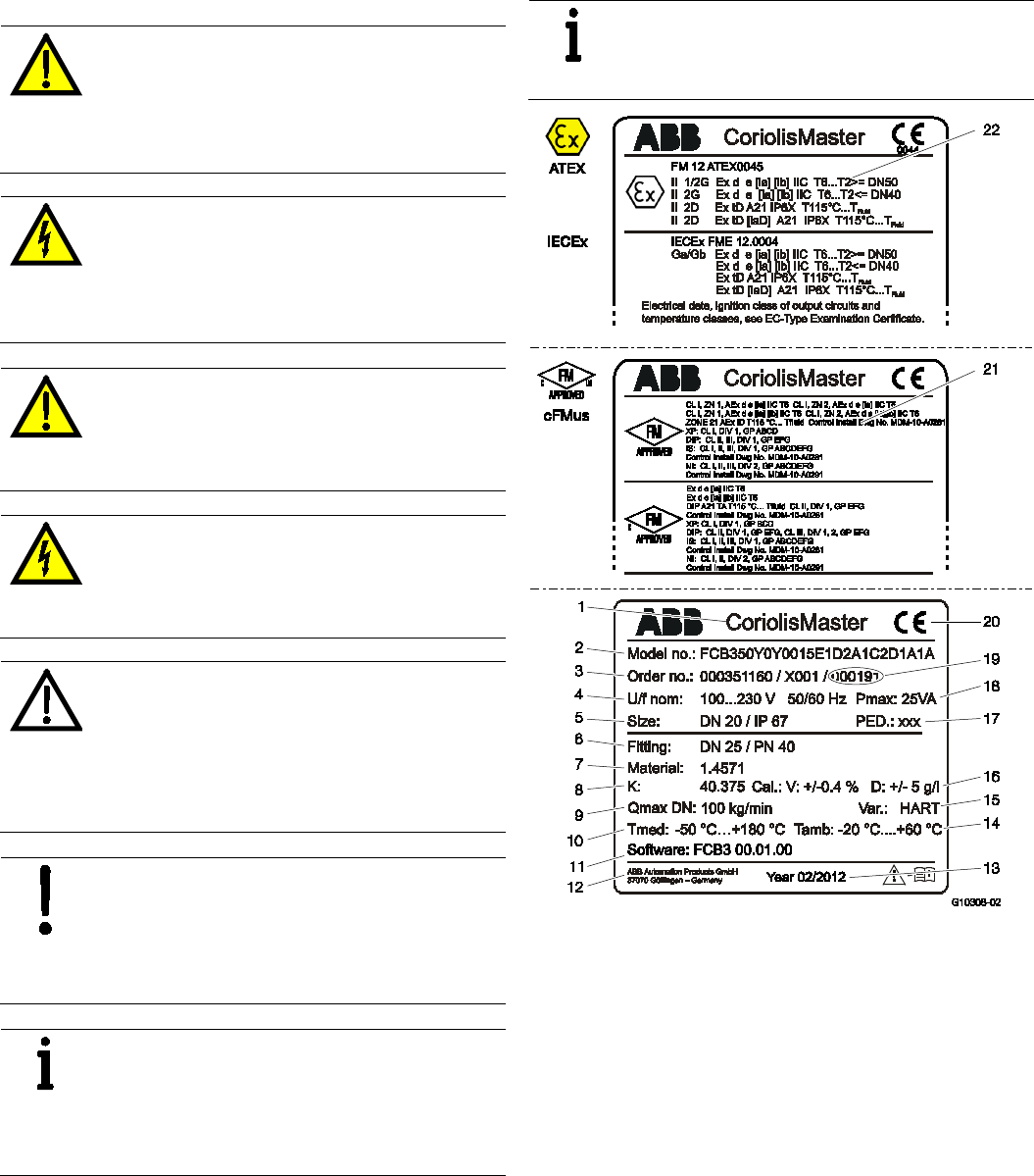
1.6.1 Safety / warning symbols, note symbols
DANGER – Serious damage to health / risk to
life
This symbol in conjunction with the signal word
"DANGER" indicates an imminent danger. Failure
to observe this safety information will result in
death or severe injury.
DANGER – Serious damage to health / risk to
life
This symbol in conjunction with the signal word
"DANGER" indicates an imminent electrical
hazard. Failure to observe this safety information
will result in death or severe injury.
WARNING – Bodily injury
This symbol in conjunction with the signal word
"WARNING" indicates a potentially dangerous
situation. Failure to observe this safety
information may result in death or severe injury.
WARNING – Bodily injury
This symbol in conjunction with the signal word
"WARNING" indicates a potential electrical
hazard. Failure to observe this safety information
may result in death or severe injury.
CAUTION – Minor injuries
This symbol in conjunction with the signal word
"CAUTION" indicates a potentially dangerous
situation. Failure to observe this safety
information may result in minor or moderate
injury. The symbol may also be used for property
damage warnings.
NOTICE – Property damage
This symbol indicates a potentially damaging
situation.
Failure to observe this safety information may
result in damage to or destruction of the product
and / or other system components.
IMPORTANT (NOTE)
This symbol indicates operator tips, particularly
useful information, or important information about
the product or its further uses. The signal word
"IMPORTANT (NOTE)" does not indicate a
dangerous or harmful situation.
1.6.2 Name plate
IMPORTANT (NOTE)
The name plates shown here are only examples.
The name plates attached to the device may be
different to what you see here.
Fig. 1: Flowmeter sensor, integral mount design (example)
1 Full designation | 2 Order code | 3 Order number |
4 Power supply | 5 Nominal diameter / Degree of protection |
6 Process connection / Pressure rating | 7 Meter tube material |
8 Calibration factor | 9 Maximum flow rate |
10 Medium temperature range | 11 Software version |
12 Manufacturer | 13 Year of construction (month / year) |
14 Ambient temperature range | 15 Communication |
16 Calibration accuracy | 17 PED mark |
18 Maximum power consumption | 19 Serial number of sensor |
20 CE mark | 21 Ex approval cFMus | 22 Ex approval ATEX / IECEx

8 OI/FCB300/FCH300-EN Rev. F | CoriolisMaster FCB330, FCB350, FCH330, FCH3500
1.7 Transport safety instructions
Observe the following instructions:
— Do not expose the device to moisture during transport.
Pack the device accordingly.
— Pack the device so that it is protected against vibrations
during transport, e.g., by using air-cushioned packaging.
— Depending on the device, the center of gravity may not be
in the center of the equipment.
1.8 Installation safety instructions
Prior to installation, check the devices for possible damage
that may have occurred as a result of improper transport.
Details of any damage that has occurred in transit must be
recorded on the transport documents. All claims for damages
must be submitted to the shipper without delay and before
installation.
— The flow direction must correspond to the direction
indicated on the meter (if labeled).
— The maximum torque must not be exceeded for all flange
connections.
— The meters must be installed without mechanical tension
(torsion, bending).
— Install flange devices with coplanar counter flanges.
— Equipment must only be installed for the intended
operating conditions and with suitable gaskets.
— Flange bolts and nuts must be secured to provide
protection against pipeline vibrations.
1.9 Safety instructions for electrical installation
The electrical connection may only be established by
authorized specialist personnel and in accordance with the
connection diagrams.
The electrical connection information in the manual must be
observed; otherwise, the type of electrical protection may be
adversely affected.
Ground the measurement system according to requirements.
1.10 Safety instructions for operation
Before switching on the device, make sure that your
installation complies with the environmental conditions listed in
the chapter “Technical Data” or on the data sheet.
If there is a chance that safe operation is no longer possible,
take the device out of operation and secure it against
unintended startup.
During operation with hot media, contact with the surface may
result in burns.
Aggressive media may result in corrosion and abrasion of the
parts that come into contact with the medium. As a result,
pressurized media may escape prematurely.
Wear to the flange gasket or process connection gaskets
(e.g., aseptic threaded pipe connections, Tri-Clamp, etc.) may
enable a pressurized medium to escape.
When using internal flat gaskets, these can become embrittled
through CIP/SIP processes.
WARNING – Risk of poisoning!
Bacteria and chemical substances can
contaminate or pollute pipeline systems and the
materials they are made of.
Observe the following instructions in installations
conforming to EHEDG requirements.
— EHEDG certification requires a self draining installation,
only possible with a vertical installation.
— In order to achieve compliance with EHEDG requirements,
the combination of process connection and gaskets
selected by the operator must consist solely of EHEDG-
compliant parts. Note the information in the latest version
of the following document: EHEDG Position Paper:
"Hygienic process connections to use with hygienic
components and equipment".

CoriolisMaster FCB330, FCB350, FCH330, FCH3500 | OI/FCB300/FCH300-EN Rev. F 9
1.11 Technical limit values
The meter has been designed for use exclusively within the
values stated on the name plate and within the technical limit
values specified on the data sheets.
The following technical limit values must be observed:
— The permissible pressure (PS) and the permissible fluid
temperature (TS) must not exceed the
pressure/temperature ratings (refer to the "Specifications"
section).
— The maximum and minimum operating temperature limits
must not be exceeded or undershot.
— The permissible ambient temperature must not be
exceeded.
— The housing's degree of protection must be observed
during operation.
— The flowmeter sensor must not be operated in the vicinity
of powerful electromagnetic fields, e.g., motors, pumps,
transformers, etc. A minimum spacing of approx. 1 m
(3.28 ft) must be maintained. For installation on steel parts
(e.g., steel brackets), a minimum spacing of 100 mm (4")
must be maintained. (These values have been calculated
on the basis of IEC 801-2 and IEC TC77B.)
1.12 Permissible media for measurement
When using media for measurement, please note:
— Media may only be used if, based on the state of the art or
the operating experience of the user, it can be assured
that chemical and physical properties of the transmitter
wetted parts will not be adversely affected during the
operating period.
— Media containing chloride in particular can cause
corrosion damage to stainless steels which, although not
visible externally, can damage wetted parts beyond repair
and lead to the medium for measurement escaping. It is
the operator's responsibility to check the suitability of
these materials for the application at hand.
— Media with unknown properties or abrasive media may
only be used if the operator can perform regular and
suitable tests to ensure the safe condition of the meter.
— Follow the instructions on the name plate.
1.13 Safety information for inspection and maintenance
WARNING – Electrical dangers!
When the housing is open, EMC protection is
impaired and there is no longer any protection
against accidental contact.
Switch off the power supply before opening the
housing.
Corrective maintenance work may only be performed by
trained personnel.
— Before removing the device, depressurize it and any
adjacent lines or containers.
— Check whether hazardous materials have been used as
materials to be measured before opening the device.
Residual amounts of hazardous material may still be
present in the device and could escape when it is opened.
Within the scope of operator responsibility, check the following
as part of a regular inspection:
— the pressure-carrying walls / lining of the pressure device
— the measurement-related function
— the leak tightness
— the wear (corrosion)
1.14 Returning devices
Use the original packaging or a secure transport container of
an appropriate type if you need to return the device for repair
or recalibration purposes. Fill out the return form (see the
Appendix) and include this with the device.
According to the EU Directive governing hazardous materials,
the owner of hazardous waste is responsible for its disposal or
must observe the following regulations for shipping purposes:
All devices delivered to ABB must be free from any hazardous
materials (acids, alkalis, solvents, etc.).
Please contact Customer Center Service acc. to page 2 for
nearest service location.
10 OI/FCB300/FCH300-EN Rev. F | CoriolisMaster FCB330, FCB350, FCH330, FCH3500
1.15 Integrated management system
ABB Automation Products GmbH operates an integrated
management system, consisting of:
— Quality management system to ISO 9001:2008
— Environmental management system to ISO 14001:2004
— Occupational health and safety management system to
BS OHSAS 18001:2007 and
— Data and information protection management system
Environmental awareness is an important part of our company
policy.
Our products and solutions are intended to have minimum
impact on the environment and on people during
manufacturing, storage, transport, use, and disposal.
This includes the environmentally-friendly use of natural
resources. We conduct an open dialog with the public through
our publications.
1.16 Disposal
This product is manufactured from materials that can be
recycled by specialist recycling companies.
1.16.1 Information on WEEE Directive 2002/96/EC (Waste
Electrical and Electronic Equipment)
This product is not subject to WEEE Directive 2002/96/EC or
relevant national laws (e.g., ElektroG in Germany).
The product must be disposed of at a specialist recycling
facility. Do not use municipal garbage collection points.
According to the WEEE Directive 2002/96/EC, only products
used in private applications may be disposed of at municipal
garbage collection points. Proper disposal prevents negative
effects on people and the environment, and supports the
reuse of valuable raw materials.
If it is not possible to dispose of old equipment properly, ABB
Service can accept and dispose of returns for a fee.
1.16.2 RoHS Directive 2002/95/EC
With the Electrical and Electronic Equipment Act (ElektroG) in
Germany, the European Directives 2002/96/EC (WEEE) and
2002/95/EC (RoHS) are translated into national law. ElektroG
defines the products that are subject to regulated collection
and disposal or reuse in the event of disposal or at the end of
their service life. ElektroG also prohibits the marketing of
electrical and electronic equipment that contains certain
amounts of lead, cadmium, mercury, hexavalent chromium,
polybrominated biphenyls (PBB), and polybrominated diphenyl
ethers (PBDE) (also known as hazardous substances with
restricted uses).
The products provided by ABB Automation Products GmbH
do not fall within the current scope of regulations on
hazardous substances with restricted uses or the directive on
waste electrical and electronic equipment according to
ElektroG. If the necessary components are available on the
market at the right time, in the future these substances will no
longer be used in new product development.
CoriolisMaster FCB330, FCB350, FCH330, FCH3500 | OI/FCB300/FCH300-EN Rev. F 11
2 Function and System Design
2.1 General remarks
The ABB Automation Products Mass Flowmeter operation is
based on the Coriolis principle.
The construction uses the classical parallel meter pipes and is
characterized, in particular, by a space saving and rugged
design, a wide flowmeter size spectrum at an advantageous
price to the customer.
2.2 Measuring principle
When a mass flows through a vibrating pipe, Coriolis forces
are generated which bend and twist the pipe. These very small
pipe deformations are measured by optimally mounted
sensors and electronically evaluated. Because the measured
phase shift of the sensor signals is proportional to the mass
flow rate, the Coriolis Mass Flowmeter measures the mass
flow rate in the flowmeter directly. The metering principle is
independent of the density, temperature, viscosity, pressure
and conductivity of the fluid.
The meter tubes always vibrate at resonance. This resonant
frequency, at the operating conditions, is a function of the
meter tube geometry, the characteristics of the flowmeter
materials and the mass of the fluid in the meter tube, which is
also vibrating. It provides an accurate measure of the density
of the fluid being metered.
An integrated temperature sensor measures the fluid
temperature and is utilized for corrections to temperature-
dependent instrument parameters. Summarizing, it is possible
to simultaneously measure the mass flow rate, fluid density
and temperature with the Coriolis Mass Flowmeter. Other
measurement values can be derived from these values, e.g.
volume flow rate or concentration.
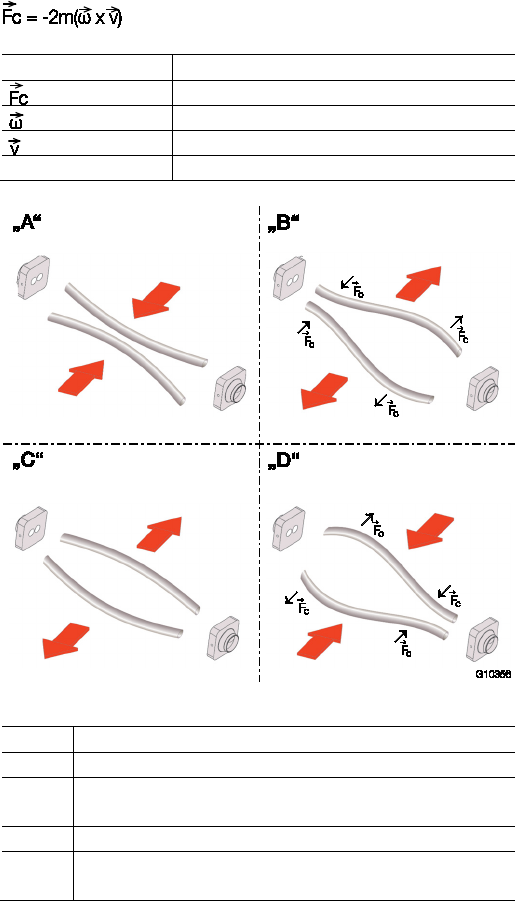
Function for calculating Coriolis force
Element in formula
Description
Coriolis force
Angular velocity
Velocity of the mass
m
Mass
Fig. 2: Simplified representation of Coriolis forces
Fig. 2
Description
"A" Movement of the pipes inward no flow
"B" Direction of the Coriolis force with flow when the tubes are
moving outward
"C" Movement of the pipes outward no flow
"D" Direction of the Coriolis force with flow when the tubes are
moving inward
12 OI/FCB300/FCH300-EN Rev. F | CoriolisMaster FCB330, FCB350, FCH330, FCH3500
Chan ge from tw o to one c olum n
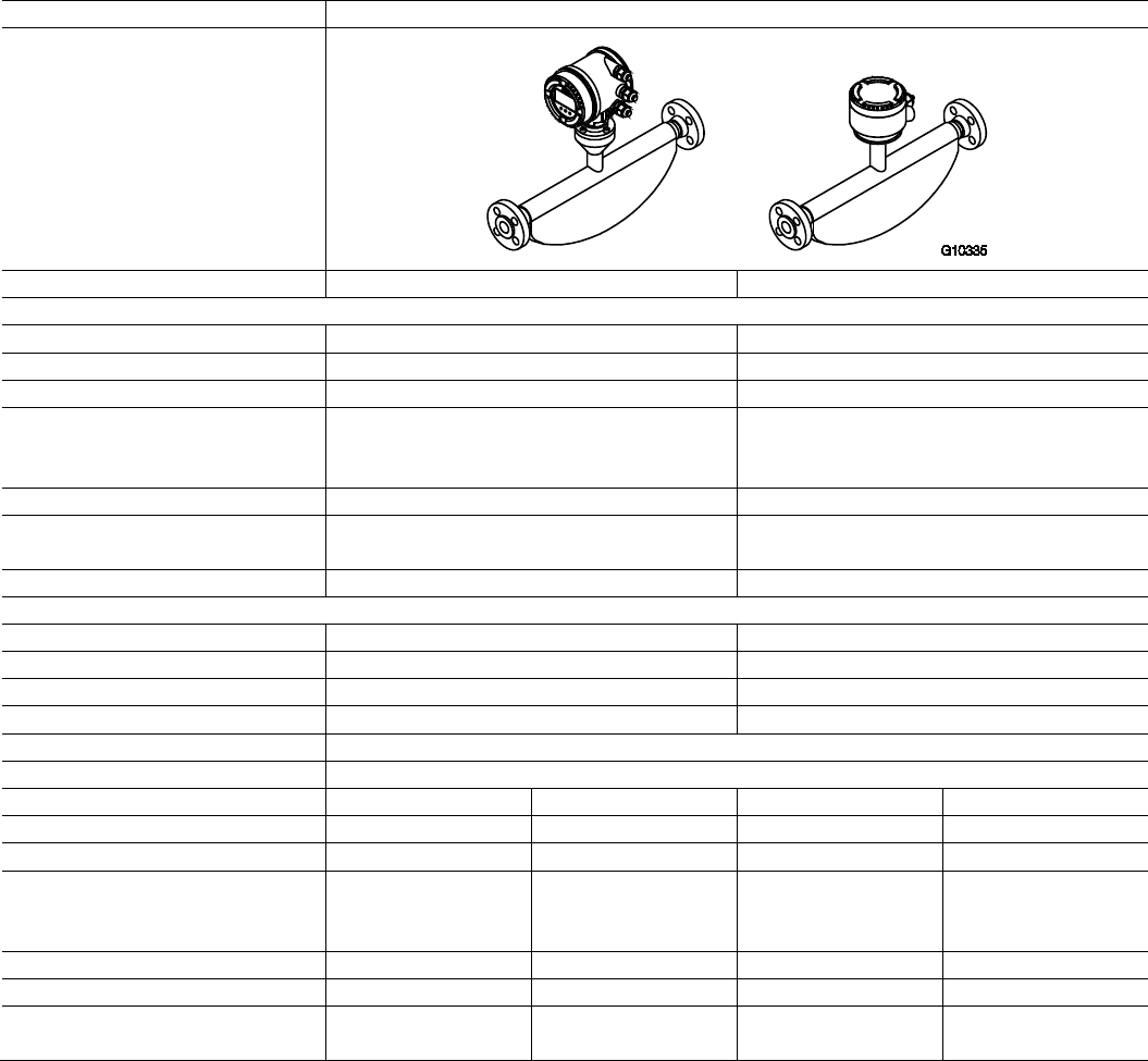
2.3 Device designs
FCB3xx and FCH3xx flowmeter sensor (integral mount design)
Model number
FCB300 for standard applications FCH300 for hygienic applications
Process connections
—
Flange DIN 2501 / EN 1092-1
DN 10 … 200, PN 40 … 100
-
—
Flange ASME B16.5
DN 1/4“ … 8“ PN CL150 … CL600 -
— Threaded pipe connection DIN 11851
DN 10 … 100 (1/4“ … 4“)
DN 25 … 80 (1“ … 3“)
— Tri-Clamp
DIN 32676 (ISO 2852)
BPE Tri-Clamp
DN 10 … 100 (1/4“ … 4“)
DIN 32676 (ISO 2852)
BPE Tri-Clamp
DN 20 … 100 (3/4“ … 4“)
—
Other connections On request On request
Wetted materials Stainless steel
Nickel-Alloy C4 / C22
Stainless steel, polished 1.4404 (AISI 316L) or
1.4435 (AISI 316L)
Degree of protection acc. to EN 60529
IP 65 / 67, NEMA 4X
IP 65 / 67, NEMA 4X
Approvals and certificates
— Explosion protection ATEX / IECEx
Zone 0, 1, 2, 21, 22
Zone 0, 1, 2, 21, 22
—
Explosion protection cFMus Class I Div. 1, Class I Div. 2, Zone 0, 1, 2, 20, 21 Class I Div. 1, Class I Div. 2, Zone 0, 1, 2, 20, 21
—
Explosion protection NEPSI Zone 0, 1, 2, 21, 22 Zone 0, 1, 2, 21, 22
— Hygienic and sterile requirements
-
EHEDG, FDA
—
Other approvals On request
Enclosure
Integral mount design, remote mount design
Measuring accuracy for liquids
FCB330 FCB350 FCH330 FCH350
—
Mass flow
1)
0,4 % and 0,25 % 0,1 % and 0,15 % 0,4 % and 0,25 % 0,1 % and 0,15 %
— Volume flow
1)
0,4 % and 0,25 %
0,15 %
0,4 % and 0,25 %
0,15 %
— Density 0,01 kg/l
— 0,002 kg/l
— 0,001 kg/l (option)
— 0,0005 kg/l
2)
0,01 kg/l
— 0,002 kg/l
— 0,001 kg/l (option)
— 0,0005 kg/l
2)
—
Temperature 1 K 0,5 K 1 K 0,5 K
Measuring accuracy for gases
1)
1 %
0,5 %
1 %
0,5 %
Permissible temperature of the
medium being measured
-50 … 160 °C
(-58 … 320 °F)
-50 … 200 °C
(-58 … 392 °F)
-50 … 160 °C
(-58 … 320 °F)
-50 … 200 °C
(-58 … 392 °F)
1) Stated measuring accuracy in % of rate (% o. r.)
2) Measuring accuracy following on-site calibration under operating conditions
CoriolisMaster FCB330, FCB350, FCH330, FCH3500 | OI/FCB300/FCH300-EN Rev. F 13
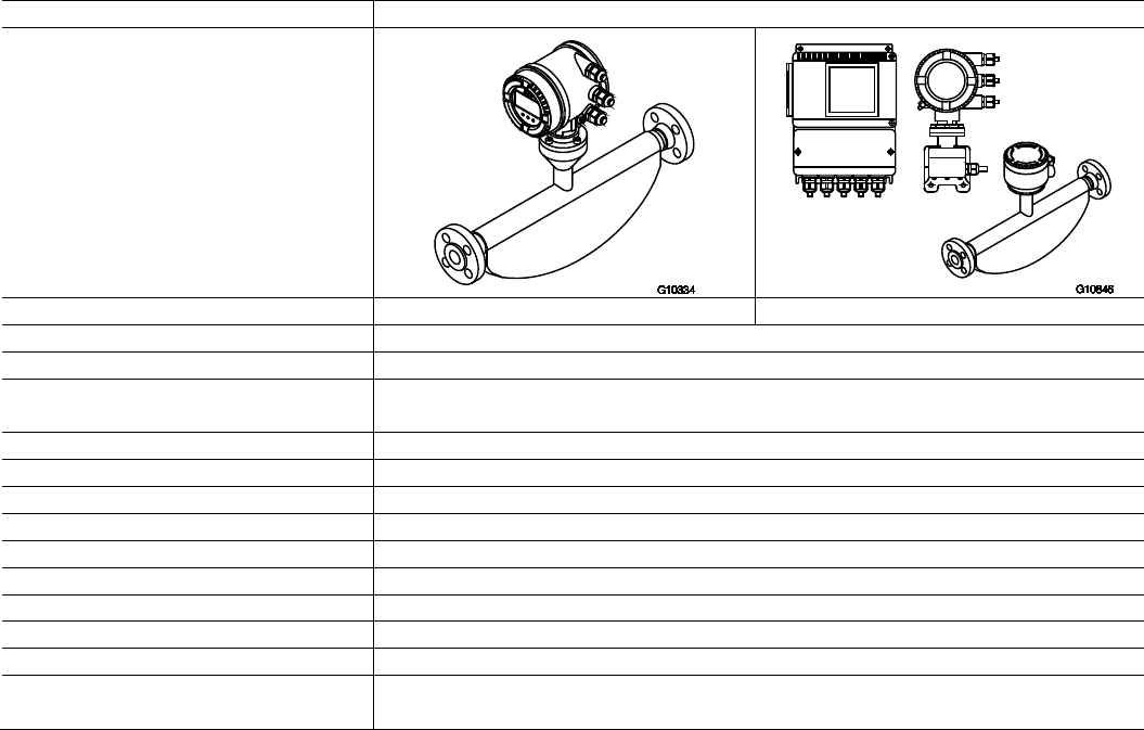
FCTxxx transmitter
Enclosure
Integral mount design
Remote mount design
Cable length
Maximum 10 m (33 ft), remote mount design only
Power supply
100 … 230 V AC, 24 V AC/DC
Current output
Current output 1: 0/4 … 20 mA active or 4 … 20 mA passive
Current output 2: 4 ... 20 mA passive
Pulse output
Active (not Zone 1 / Div. 1) or passive
External output zero return
Yes
External totalizer reset
Yes
Forward / reverse flow metering
Yes
Communication
HART protocol
Empty pipe detection
Yes, based on preconfigured density alarm < 0.5 kg/l
Self-monitoring and diagnostics
Yes
Local display / totalization
Yes
Field optimization for flow and density
Yes
Degree of protection acc. to EN 60529
Integral mount design: IP 65/IP 67, NEMA 4X
Remote mount design: IP 67, NEMA 4X
14 OI/FCB300/FCH300-EN Rev. F | CoriolisMaster FCB330, FCB350, FCH330, FCH3500
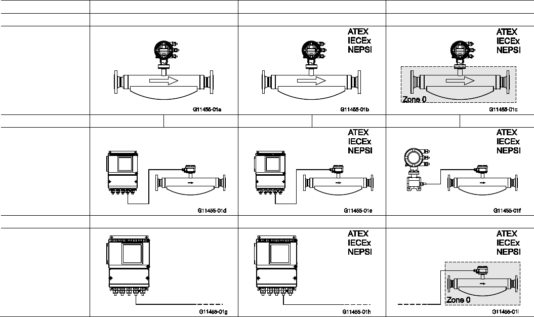
2.3.1 ATEX, IECEx, NEPSI device overview
Standard / No explosion protection
Zone 2, 21, 22
Zone 1, 21 (Zone 0)
Model number
FCx3xx Y0
FCx3xx A2, S2
FCx3xx A1, S1
Integral mount design
— Standard
— Zone 2, 21, 22
— Zone 1, 21
— Zone 0
Model number FCT3xx Y0 FCx3xx Y0 FCT3xx A2 FCT3xx Y0 FCx3xx Y0 FCT3xx A2
Remote mount design
Transmitter and
flowmeter sensor
— Standard
— Zone 2, 21, 22
— Zone 1, 21
— Zone 0
Model number FCT3xx Y0 FCT3xx A2 FCx3xx A1, S1
Remote mount design
Transmitter
— Standard
— Zone 2, 21, 22
Flowmeter sensor
— Zone 1, 21
— Zone 0
IMPORTANT (NOTE)
Detials can be found in chapter „Ex relevant specifications acc. to ATEX / IECEx / NEPSI“ or in the respective certificate.

CoriolisMaster FCB330, FCB350, FCH330, FCH3500 | OI/FCB300/FCH300-EN Rev. F 15
2.3.2 cFMus device overview
Standard / No explosion protection Class I Div. 2 Zone 2, 21 Class I Div. 1 Zone 0, 1, 20 ,21
Model number
FCx3xx Y0
FCx3xx F2
FCx3xx F1
Integral mount design
— Standard
— Class I Div. 2
— Class I Div. 1
— Zone 2, 21
— Zone 1, 21
— Zone 0, 20
Model number
FCT3xx Y0
FCx3xx Y0
FCT3xx F2
FCT3xx Y0
FCx3xx Y0
FCT3xx F2
Remote mount design
Transmitter and
flowmeter sensor
— Standard
— Class I Div. 2
— Class I Div. 1
— Zone 2, 21
— Zone 1, 21
—
Zone 0, 20
Model number FCT3xx Y0 FCT3xx F2 FCx3xx F1
Remote mount design
Transmitter
— Standard
— Class I Div. 2
— Zone 2, 21
Flowmeter sensor
— Class I Div. 1
— Zone 1, 21
— Zone 0, 20
IMPORTANT (NOTE)
Details can be found in chapter „Ex relevant specifications acc. to cFMus“ or in the respective certificate.
16 OI/FCB300/FCH300-EN Rev. F | CoriolisMaster FCB330, FCB350, FCH330, FCH3500
Chan ge from on e to two c olumns
3 Transport
3.1 Inspection
Check the devices immediately after unpacking for possible
damage that may have occurred from improper transport.
Details of any damage that has occurred in transit must be
recorded on the transport documents.
All claims for damages must be submitted to the shipper
without delay and before installation.
3.2 General remarks
Observe the following when transporting the device to the
measurement site:
— The center of gravity is off center.
— Flange devices may not be lifted by the transmitter
housing or terminal box.
Chan ge from tw o to one c olum n
Chan ge from on e to two c olumns
4 Mounting
4.1 General remarks
The following points must be observed during installation:
— The flow direction must correspond to the marking, if
there is one.
— The maximum torque for all flange connections must be
complied with.
— The meters must be installed without mechanical tension
(torsion, bending).
— Install flange and wafer type devices with coplanar counter
flanges and use only appropriate gaskets.
— Use only gaskets made from a compatible material for the
medium and medium temperature or use only gasket
material compatible with hygienic designs.
— Gaskets must not extend into the flow area since possible
turbulence could influence the device accuracy.
— The pipeline may not exert any unallowable forces or
torques on the device.
— Do not remove the plugs in the cable connectors until you
are ready to install the electrical cable.
— Make sure the gaskets for the housing cover are seated
properly. Carefully gasket the cover. Tighten the cover
fittings.
— A separate transmitter must be installed at a largely
vibration-free location.
— Do not expose the transmitter and sensor to direct
sunlight. Provide appropriate sun protection as necessary.
— When installing the transmitter in a control cabinet, make
sure adequate cooling is provided.
4.2 Flowmeter sensor
The device can be installed at any location in a pipeline under
consideration of the installation conditions.
1. Remove protective plates, if present, to the right and left
of the flowmeter sensor.
2. Position the flowmeter sensor coplanar and centered
between the pipes.
3. Install gaskets between the sealing surfaces.
CoriolisMaster FCB330, FCB350, FCH330, FCH3500 | OI/FCB300/FCH300-EN Rev. F 17
Chan ge from tw o to one c olum n
4.3 Transmitter
The installation site for the transmitter must be essentially vibration free, see "Technical data". The specified temperature limits
and the maximum signal cable length between the transmitter and the flowmeter sensor must not be exceeded.
IMPORTANT (NOTE)
When selecting a location for the transmitter, make sure that it will not be exposed to direct sunlight.
If exposure to direct sunlight cannot be avoided, a sun shade should be installed.
The limit values for the ambient temperature must be observed.
Field-mount housing
The housing is designed for protection class IP 65 / 67, NEMA 4X (EN 60529) and must be mounted using 4 screws. For
dimensions, see Fig. 3 and Fig. 4.
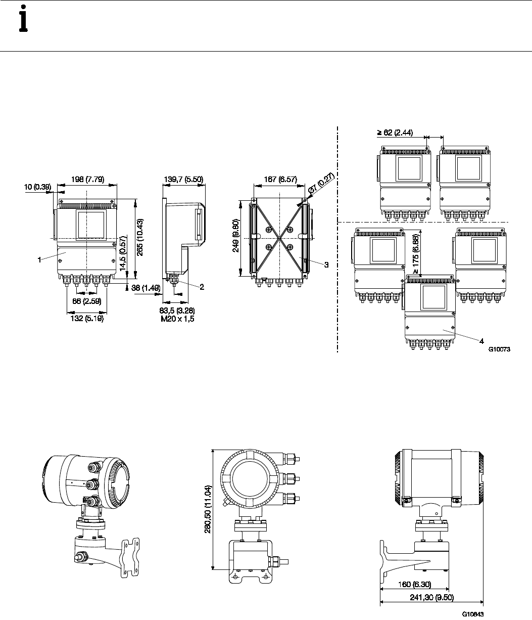
4.3.1 Transmitter in remote mount design (option F1 or F2)
Fig. 3: Dimensions in mm (inch)
1 Field-mount enclosure with window | 2 Cable gland M20 x 1.5 or 1/2” NPT |
3 Installation holes for pipe mounting set, for 2" pipe installation; mounting set available on request (order no. 612B091U07) |
4 IP 67 degree of protection
4.3.2 Transmitter in remote mount design (option R1 or R2)
IP 65 / 67, NEMA 4X
Fig. 4: Dimensions in mm (inch)
Chan ge from on e to two c olumns
18 OI/FCB300/FCH300-EN Rev. F | CoriolisMaster FCB330, FCB350, FCH330, FCH3500
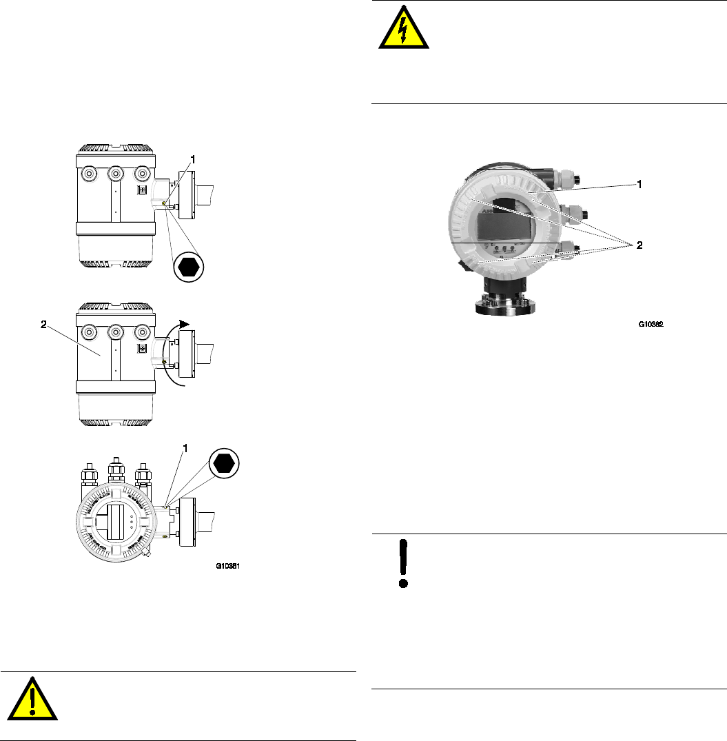
4.4 Rotating the transmitter and LCD display
Depending on the installation position, the integral transmitter
housing or LCD display can be rotated to enable horizontal
readings.
4.4.1 Transmitter enclosure
To rotate the transmitter housing, proceed as described
below. A stop in the transmitter housing will prevent rotation
through more than 330°.
Fig. 5: Rotating the transmitter housing
1 Fixing screw | 2 Transmitter housing
1. Loosen the fixing screws approx. 2 turns.
2. Turn the transmitter housing to the required position.
3. Tighten the fixing screw.
DANGER – Risk of explosion!
Violation of hazardous area protection.
Do not disconnect the transmitter from the
sensor.
4.4.2 LCD indicators
WARNING – Electrical dangers!
When the housing is open, EMC protection is
impaired and there is no longer any protection
against accidental contact.
Switch off the power supply before opening the
housing.
To rotate the LCD Display, proceed as described below.
Fig. 6: Rotating the LCD display
1. Switch off the power supply.
2. Unscrew the housing cover (1).
3. Loosen the four fixing screws (2) on the LCD display. The
LCD display is now hanging from the cable harness that
connects it to the electronic plug-in unit.
4. Screw the LCD display into the required position. Take
care not to damage the cable harness when tightening the
screws.
5. Screw on housing cover (1) again.
NOTICE – Potentially adverse effect on
housing ingress protection
If the gasket (o-ring) is seated incorrectly or
damaged, this may have an adverse effect on the
housing ingress protection.
Before closing the housing cover, check the
gasket (o-ring) for any damage and replace if
necessary. Check that the gasket is properly
seated when closing the housing cover.
CoriolisMaster FCB330, FCB350, FCH330, FCH3500 | OI/FCB300/FCH300-EN Rev. F 19
4.5 Installation instructions
4.5.1 Installation requirements/System sizing information
The CoriolisMaster FCB330, FCB350, FCH330, FCH3500 is
suitable for both indoor and outdoor installations. The
standard device has an IP 67 enclosure. The flowmeter sensor
is bidirectional and can be installed in any mounting position. It
is important to ensure that the meter pipes are always
completely filled with fluid. The material resistance of all
wetted parts must be clarified.
The following points are to be considered during installation:
— The preferred flow direction is indicated by the arrow on
the flowmeter sensor. Flow in this direction will be
indicated as positive (a forward/reverse flow calibration is
available as an option).
— The presence of gas bubbles in the meter tube increases
the likelihood of erroneous measurements, particularly
when measuring density. Therefore, the sensor should not
be installed at the highest point in the system.
Advantageous are installations in low pipeline sections,
e.g., at the bottom of a U-section in the pipeline (invert).
— Make sure that any gases dissolved in the medium do not
outgas and that the meter tubes are always completely
full. To safeguard this, a minimum back pressure of 0.2
bar (2.9 psi) is recommended.
— In case of gas measurements ensure that the gases are
dry and do not contain liquids.
— Make sure that operation below the vapor pressure cannot
occur when a vacuum exists in the meter tube or when
liquids with a low boiling point are being processed.
— Ensure that during operation no Phase transitions take
place in the medium. For gaseous Media any liquid phase
must be avoided, for liquid media, any gas phase must be
avoided.
— Long drop lines downstream of the flowmeter sensor
should be avoided to prevent the meter tube from
draining.
— The devices can be installed directly to or from elbows,
valves or other equipment unless no cavitation is caused.
— This Flowmeter is designed for industrial installations. As
long as electromagnetic fields in the environment of the
meter are according to "best practice" as defined in the
standards covered in our "EC-declaration of conformity",
no additonal efforts have to be taken. If electromagnetic
fields exceed usual levels, sufficient distance is to be kept.
— Check that the flowmeter sensor does not come into
contact with other objects. Do not attach the flowmeter
sensor to the enclosure.
— In principle, no special supports or dampers are required
on the device. In industrial and maritime facilities designed
as "Best Paractice " typical forces are absorbed
sufficiently by the device. This is valid for serial or parallel
installation of Coriolis meters as well, as long as the use
and installation follows the manual.
— To avoid damages to the process connections and pipes
by axial forces, supports are recommended for devices of
higher weights.
4.5.2 Inlet sections
The flowmeter sensor does not require any inlet sections.
Make sure that any valves, gates, sight glasses, etc., in the
vicinity of the flowmeter sensor do not cavitate and are not set
in vibration by the flowmeter sensor.
4.5.3 Model in remote mount design
Make sure that the flowmeter sensor and transmitter are
assigned correctly. Compatible devices have the same end
numbers, e. g., X001 and Y001 or X002 and Y002, on the
name plate.
4.5.4 Pressure loss
Pressure loss is determined by the properties of the medium
and the flow.
Documents to help you to calculate pressure loss can be
downloaded from www.abb.com/flow.
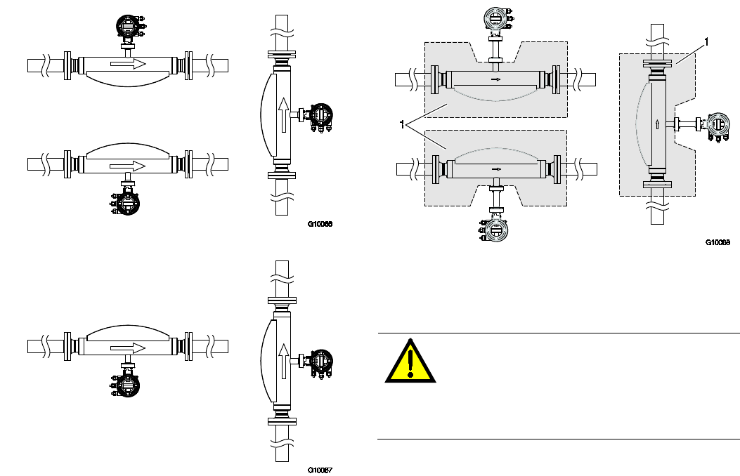
4.6 Mounting positions
The flowmeter operates in any mounting position. The ideal
installation position is vertical with flow from bottom to top.
IMPORTANT (NOTE)
EHEDG certification requires a self draining installation, only
possible with a vertical installation.
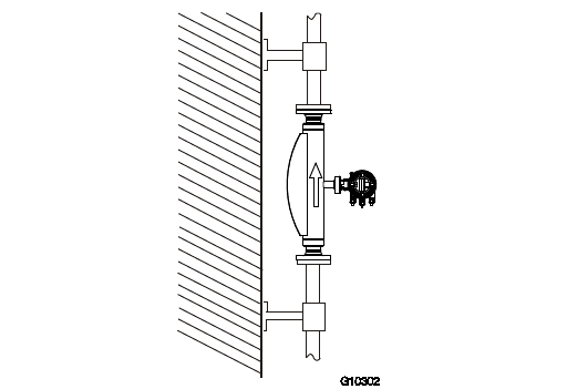
4.6.1 Vertical installation in riser
Fig. 7: Vertical installation, self-draining
20 OI/FCB300/FCH300-EN Rev. F | CoriolisMaster FCB330, FCB350, FCH330, FCH3500
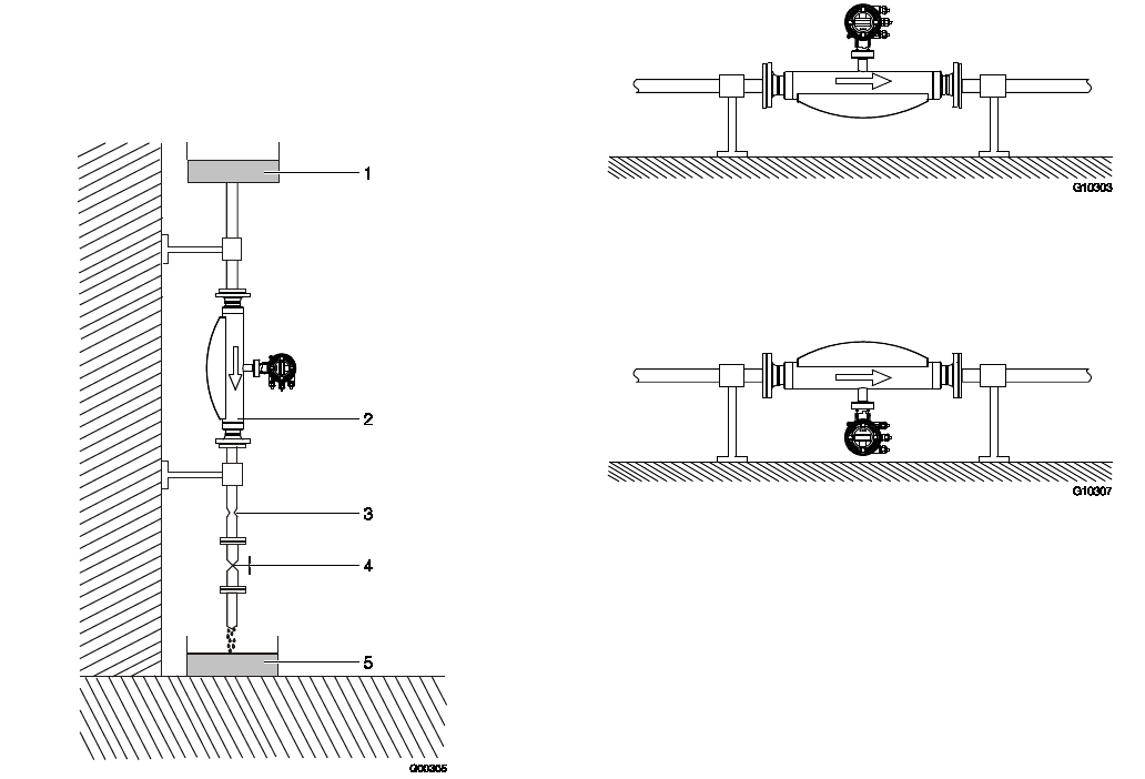
4.6.2 Vertical installation in a drop line
Make sure that the flowmeter sensor is always completely full
while measurements are being taken.
A pipeline reduction or an orifice must also be installed
underneath the flowmeter sensor. The cross-section of the
pipeline reduction or orifice must be smaller than the cross-
section of the pipeline in order to prevent the flowmeter sensor
from running dry while measurements are being taken.
Fig. 8: Vertical installation in a drop line
1 Supply reservoir | 2 Flowmeter sensor |
3
Orifice or pipe constriction | 4 Valve | 5 Product reservoir
4.6.3 Horizontal installation in case of measurement of
liquids
Fig. 9: Horizontal installation (liquids)
4.6.4 Horizontal installation in case of measurement of
gases
Fig. 10: Horizontal installation (gases)
In case of measurement of gases ensure that the transmitter
housing or the terminal box pointing downwards.
CoriolisMaster FCB330, FCB350, FCH330, FCH3500 | OI/FCB300/FCH300-EN Rev. F 21
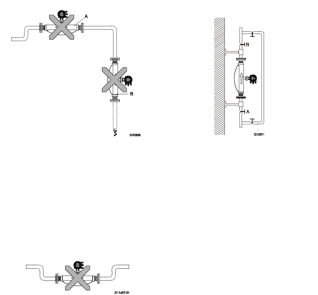
4.6.5 Difficult installation locations for liquid
measurement
The accumulation of air or gas bubbles in the meter tube will
lead to increased inaccuracies.
Avoid the following installation locations in case of liquid
measurement:
Fig. 11: Difficult installation locations
— "A": Installing the flowmeter sensor at the highest point of
a pipeline leads to increased inaccuracies due to the
accumulation of air or gas bubbles in the meter tube.
— "B": Installing the flowmeter sensor in a drop line means
that there is no guarantee that the meter tube will be
completely full while measurements are being taken and
leads to increased inaccuracies.
4.6.6 Difficult installation locations and gas metering
When metering gas, the accumulation of fluid or the formation
of condensate in the meter tube will lead to increased
inaccuracies.
Avoid the following installation locations when metering gas:
Fig. 12: Difficult installation locations
Installing the flowmeter sensor at the lowest point of a pipeline
leads to increased inaccuracies due to the accumulation of
fluid or the formation of condensate in the meter tube.
4.6.7 Zero balance
CoriolisMaster flowmeters do not require in any case a zero
point calibration. Only under these circumstances a calibration
is recommended:
— when measuring below 10% of QmaxDN,
— when very high accuracies are required (0.1% or better),
— the operating conditions (pressure and temperature) differ
widely from the reference conditions.
Fig. 13: Bypass line
Closing valves are to be installed in front (A) and after (B) the
flowmeter.
We recommend installing a bypass line. Installing a bypass line
means that adjustment can take place while the process is
ongoing.
Before adjusting the zero under operating conditions, make
sure that:
— The meter tube is completely full
— There are no gas bubbles or air in the meter tube (in case
of liquid measurements)
— There are no condensates in the meter tube (in case of
gas measurements)
— The pressure and temperature in the meter tube are
appropriate for normal operating conditions
In case of a high zero point (> 0.1%) please check the
installation for best praxis and ensure that there are no gas
contents in a liquid or solids or liquids in gases. Please ensure
that the meter is completely filled.
22 OI/FCB300/FCH300-EN Rev. F | CoriolisMaster FCB330, FCB350, FCH330, FCH3500
4.6.8 Installation dependent on the temperature of the
medium being measured
The mounting position of the sensor is dependent on the
temperature of the medium being measured T
medium
. Be
aware of the following mounting options!
Fig. 14: Installation at T
medium
-50°… 120 °C (-58 … 248 °F)
Fig. 15: Installation at T
medium
-50°… 200 °C (-58 … 392 °F)
4.6.9 Installation with option TE1 "extended tower
length"
IMPORTANT (NOTE)
The sensor must only be insulated in conjunction with the TE1
"Extended tower length" option, as shown in Fig. 16.
Fig. 16: Installation at T
medium
-50°… 200 ℃ (-58 … 392 °F)
1 Insulation
4.6.10 Notes about EHEDG conformity
WARNING – Risk of poisoning!
Bacteria and chemical substances can
contaminate or pollute pipeline systems and the
materials they are made of.
Observe the following instructions in installations
conforming to EHEDG requirements.
— EHEDG certification requires a self draining installation,
only possible with a vertical installation.
— In order to achieve compliance with EHEDG requirements,
the combination of process connection and gaskets
selected by the operator must consist solely of EHEDG-
compliant parts. Note the information in the latest version
of the following document: EHEDG Position Paper:
"Hygienic process connections to use with hygienic
components and equipment".
CoriolisMaster FCB330, FCB350, FCH330, FCH3500 | OI/FCB300/FCH300-EN Rev. F 23
5 Electrical connections
5.1 Information for connecting the power supply
IMPORTANT (NOTE)
— Observe the limit values for the power supply
listed in the "Technical data" section.
— Please remember that there is a voltage drop
associated with long lead lengths and small
lead cross-sections. The voltage at the
terminals of the device may not fall below the
minimum value required.
— Complete the electrical connection according
to the connection diagram.
The line voltage and power consumption are indicated on the
name plate for the transmitter.
A circuit breaker with a maximum rated current of 16 A must
be installed in the supply power line of the transmitter.
The wire cross-sectional area of the supply power cable and
the circuit breaker used must comply with VDE 0100 and must
be dimensioned in accordance with the current consumption
of the flowmeter measuring system. The leads must comply
with IEC 227 and/or IEC 245.
The circuit breaker should be located near the transmitter and
marked as being associated with the device.
The power supply is connected to terminal L (phase), N
(neutral), or 1+, 2-, and PE, as stated on the name plate.
Connect the transmitter and flowmeter sensor to functional
ground.
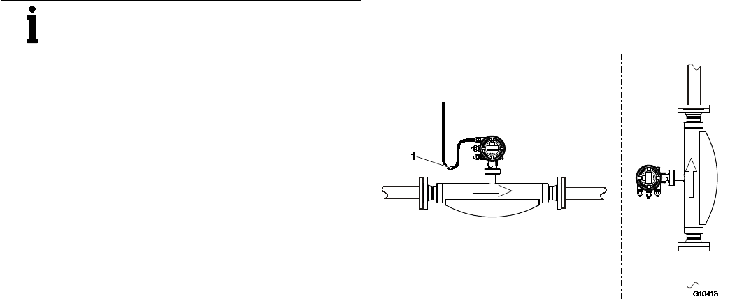
5.2 Information for cable installation
Make provision for a drip loop (water trap) when installing the
connecting cables for the flowmeter sensor.
If you are installing the flowmeter transmitter vertically, point
the cable entry points downwards. (You might need to rotate
the transmitter housing accordingly.)
Fig. 17: Installing the connection cables
1 Drip loop
24 OI/FCB300/FCH300-EN Rev. F | CoriolisMaster FCB330, FCB350, FCH330, FCH3500
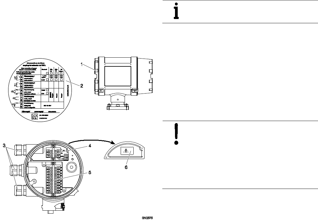
5.3 Integral mount design
On integral mount design devices, the terminals are located
behind the cover on the rear of the transmitter housing.
A schematic electrical connection diagram can be found on
the inside of the cover. The configuration of the device is
marked here.
Fig. 18: Terminals
1 Cover for connection area | 2 Pin assignment |
3 Cable entry points | 4 Terminals for power supply |
5 Terminals for signal inputs and signal outputs | 6 Terminal cover
IMPORTANT (NOTE)
Use suitable wire end sleeves when connecting
the cables.
Connect the device:
1. Unscrew the cover for the connection area.
2. Prepare the cable ends and feed them into the connection
area through the cable entry points.
3. Remove the terminal cover and connect the power supply
cables as shown in the connection diagrams.
4. Replace the terminal cover.
5. Connect the signal input and output cables as shown in
the connection diagrams. Connect the cable shielding (if
used) to the designated grounding clamp.
6. Unscrew the cover for the connection area again.
NOTICE – Potentially adverse effect on
housing ingress protection
If the gasket (o-ring) is seated incorrectly or
damaged, this may have an adverse effect on the
housing ingress protection.
Before closing the housing cover, check the
gasket (o-ring) for any damage and replace if
necessary. Check that the gasket is properly
seated when closing the housing cover.
CoriolisMaster FCB330, FCB350, FCH330, FCH3500 | OI/FCB300/FCH300-EN Rev. F 25
5.4 Remote mount design
With remote mount design devices, the transmitter is installed
separately and connected to the flowmeter sensor via a signal
cable.
5.4.1 Cable specification
Signal cable
Designation LI2YCY PiMF
5 x 2 x 0.5 mm
2
Shield Pair shielding with continuity wire and copper
braided screen
Temperature range
-30 ... 70 °C (-22 ... 158 °F)
Loop resistance maximum 78.4 Ω/km
Inductance
0,4 mH/km approx.
Max. cable length 10 m (33 ft)
5.4.2 Routing the signal cable
Observe the following points when routing cables:
— The signal cable carries a voltage signal of only a few
millivolts and must, therefore, be routed over the shortest
possible distance. The maximum permissible signal cable
length is 10 m (33 ft).
— Avoid routing the cable in the vicinity of electrical
equipment or switching elements that can create stray
fields, switching pulses, and induction. If this is not
possible, route the signal cable inside a metal cable
conduit and connect the cable conduit to operational
ground.
— To shield against magnetic interspersion, the cable
contains outer shielding that is attached to operational
ground.
— Do not run the signal cable over junction boxes or terminal
strips.
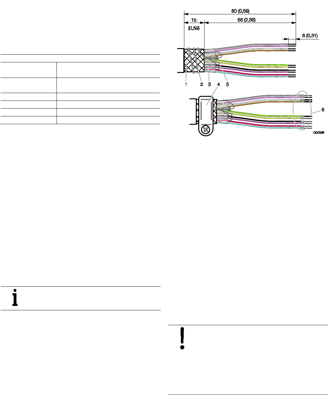
5.4.3 Connecting the signal cable
IMPORTANT (NOTE)
Use suitable wire end sleeves when connecting
the cables.
Fig. 19: Signal cable assembly, dimensions in mm (inch)
1 Wire mesh shield | 2 Foil shield continuity wires (twisted) |
3 Foil shield | 4 Grounding clamp | 5 Continuity wire |
6 Wire end sleeves
1. Strip the signal cable as shown.
2. Cut the wire mesh shield to a length of approx. 15 mm
(0.59 inch).
3. Remove the cable core and foil shield from the wire pairs.
4. Strip the wires and attach wire end sleeves.
5. Twist the foil shield continuity wires and wrap them around
the wire mesh shield. When connecting to the devices,
clamp the wire mesh shield and the twisted continuity
wires underneath the grounding clamp.
6. Connect the signal cables to the transmitter and flowmeter
sensor as shown in the connection diagrams.
7. Connect the signal cables for signal inputs and outputs to
the transmitter as shown in the connection diagrams.
Connect the cable shields to the designated grounding
clamp.
8. Connect the power supply cables to the transmitter as
shown in the connection diagrams.
9. Screw all open covers for the transmitter and flowmeter
sensor connection areas back into place.
NOTICE – Potentially adverse effect on
housing ingress protection
If the gasket (o-ring) is seated incorrectly or
damaged, this may have an adverse effect on the
housing ingress protection.
Before closing the housing cover, check the
gasket (o-ring) for any damage and replace if
necessary. Check that the gasket is properly
seated when closing the housing cover.
26 OI/FCB300/FCH300-EN Rev. F | CoriolisMaster FCB330, FCB350, FCH330, FCH3500
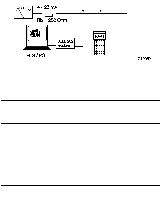
5.5 Digital communication
5.5.1 HART protocol
The device is registered with the HART Communication
Foundation.
Fig. 20: Communication via HART protocol
HART protocol
Configuration — Directly on the device
— Via software DSV401 + HART-DTM
Transmission FSK modulation on voltage output 4 … 20 mA
according to Bell 202 standard
Baud rate 1200 baud
Display Logic 1: 1200 Hz
Logic 0: 2200 Hz
Maximum signal
amplitude
1.2 mAss
Load at current output 250 … 560 Ω
(in hazardous area: maximum 300 Ω)
Cable
Design Two-wire cable AWG 24, twisted
Maximum length
1500 m (4921 ft)
See the interface description for detailed information.
System integration:
Communication (configuration, parameterization) can be
performed with the DTM (Device Type Manager) available for
the device and the corresponding framework applications as
per FDT 0.98 or 1.2 (DSV401 R2).
Other tool/system integrations (e.g., Emerson AMS/Siemens
PCS7) are available on request.
The necessary DTMs can also be downloaded from
www.abb.com/flow.
CoriolisMaster FCB330, FCB350, FCH330, FCH3500 | OI/FCB300/FCH300-EN Rev. F 27
Chan ge from tw o to one c olum n
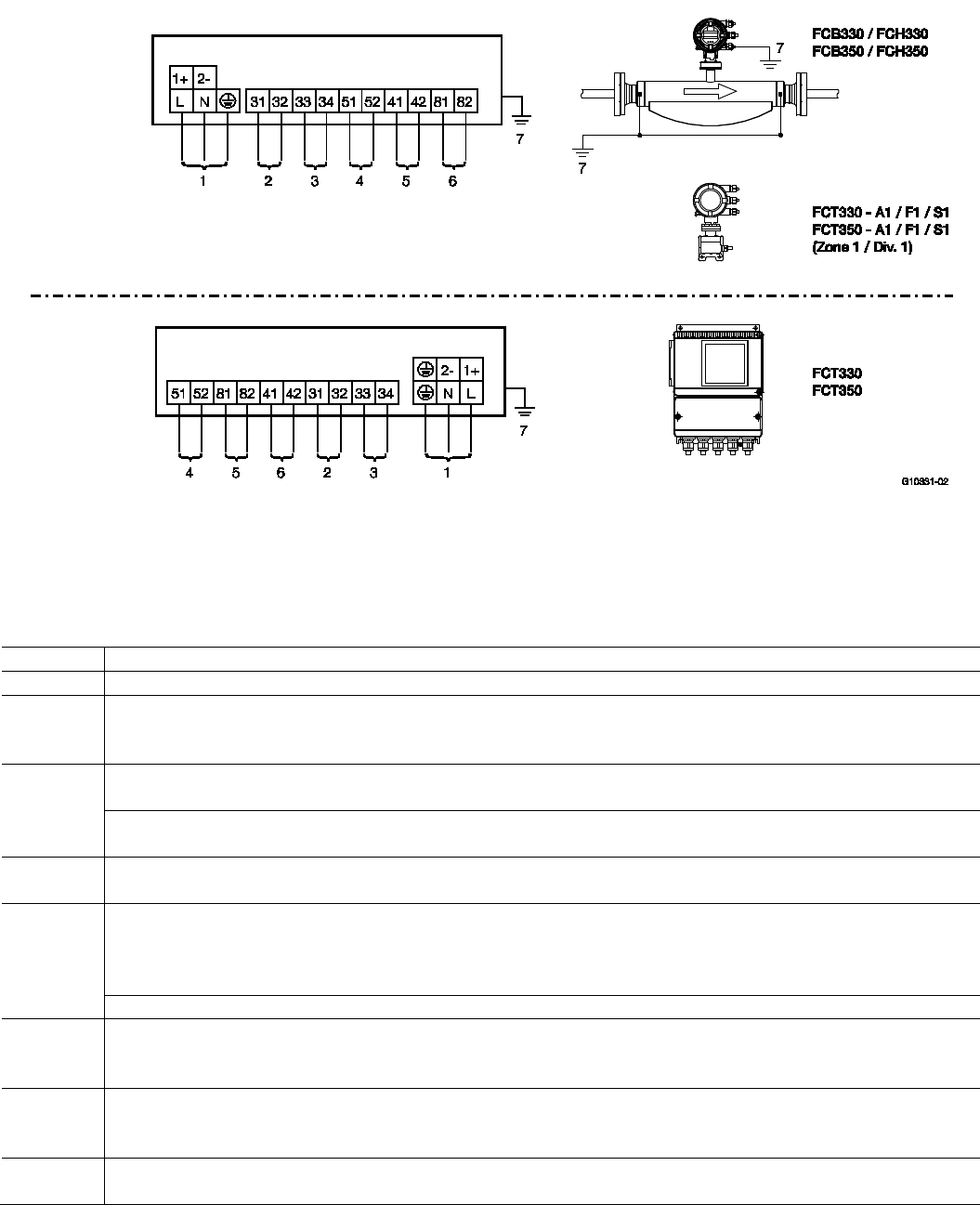
5.6 Terminal connection diagrams
5.6.1 Connection of transmitter models to peripherals
Models FCB330, FCB350, FCH330, FCH350, FCT330, FCT350
Fig. 21
1 Power supply | 2 Current output 1 | 3 Current output 2 | 4 Pulse output | 5 Digital switching output |
6 Digital switching input | 7 Equipotential bonding (PA)
IMPORTANT (NOTE)
When using the device in hazardous areas, note the additional connection data in the chapter titled "Ex relevant specifications"!
Terminal
Function
L / N / PE
Power supply, 100 … 230 V AC, 50/60 Hz
1+ / 2- / PE Power supply
— 24 V AC, 50/60 Hz
— 24 V DC
31 / 32 Current output 1, active
0/4 … 20 mA , (0 Ω ≤R
B
≤560 Ω, FCT300-A1/F1:1 0 Ω ≤R
B
≤300 Ω)
Current output 1, passive
4 … 20 mA (0 Ω ≤R
B
≤600 Ω), source voltage 12 ≤U
q
≤ 30 V
33 / 34 Current output 2, passive
4 … 20 mA (0 Ω ≤R
B
≤600 Ω), source voltage 12 ≤U
q
≤ 30 V
51 / 52 Pulse output, passive
fmax = 5 kHz, pulse width = 0.1 … 2000 ms, 0.001 ... 1000 pulses/unit
— "Closed": 0 V ≤ U
CEL
≤ 2 V, 2 mA ≤ I
CEL
≤ 220 mA
—
"Open": 16 V ≤ U
CEH
≤ 30 V DC, 0 mA ≤ I
CEH
≤ 0.2 mA
Pulse output active, U = 16 … 30 V, load ≥ 150 Ω, fmax = 5 kHz
41 / 42 Digital switching output, passive
— "Closed": 0 V ≤ U
CEL
≤ 2 V, 2 mA ≤ I
CEL
≤ 220 mA
—
"Open": 16 V ≤ U
CEH
≤ 30 V DC, 0 mA ≤ I
CEH
≤ 0.2 mA
81 / 82 Digital switching input, passive
— Input "On": 16 V ≤ UKL ≤ 30 V
— Input "Off": 0 V ≤ UKL ≤ 2 V
- Equipotential bonding "PA"
When the FCT300 transmitter is connected to the FCB3xx / FCH3xx flowmeter sensor, the transmitter must also be connected to "PA".
28 OI/FCB300/FCH300-EN Rev. F | CoriolisMaster FCB330, FCB350, FCH330, FCH3500
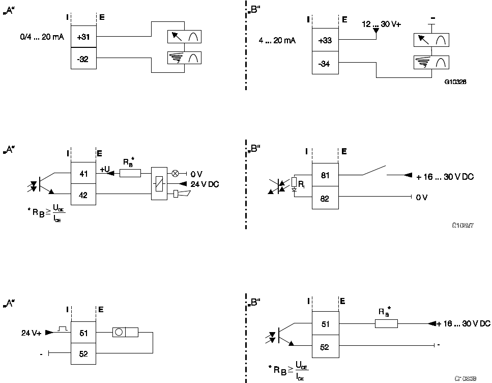
5.6.2 Connection examples for the peripherals
Current outputs (including HART communication)
Fig. 22: Active / passive current outputs
"A" Active | "B" Passive | I Internal | E External
Digital switching output and digital switching input
Fig. 23
"A" Output for system monitoring, min. / max. alarm for empty meter tube or forward / reverse signal |
"B" Input for external totalizer reset or external output zero return | I Internal | E External
Pulse output
Fig. 24: Active / passive pulse output
"A" Active | "B" Passive (optocoupler) | I Internal | E External
CoriolisMaster FCB330, FCB350, FCH330, FCH3500 | OI/FCB300/FCH300-EN Rev. F 29
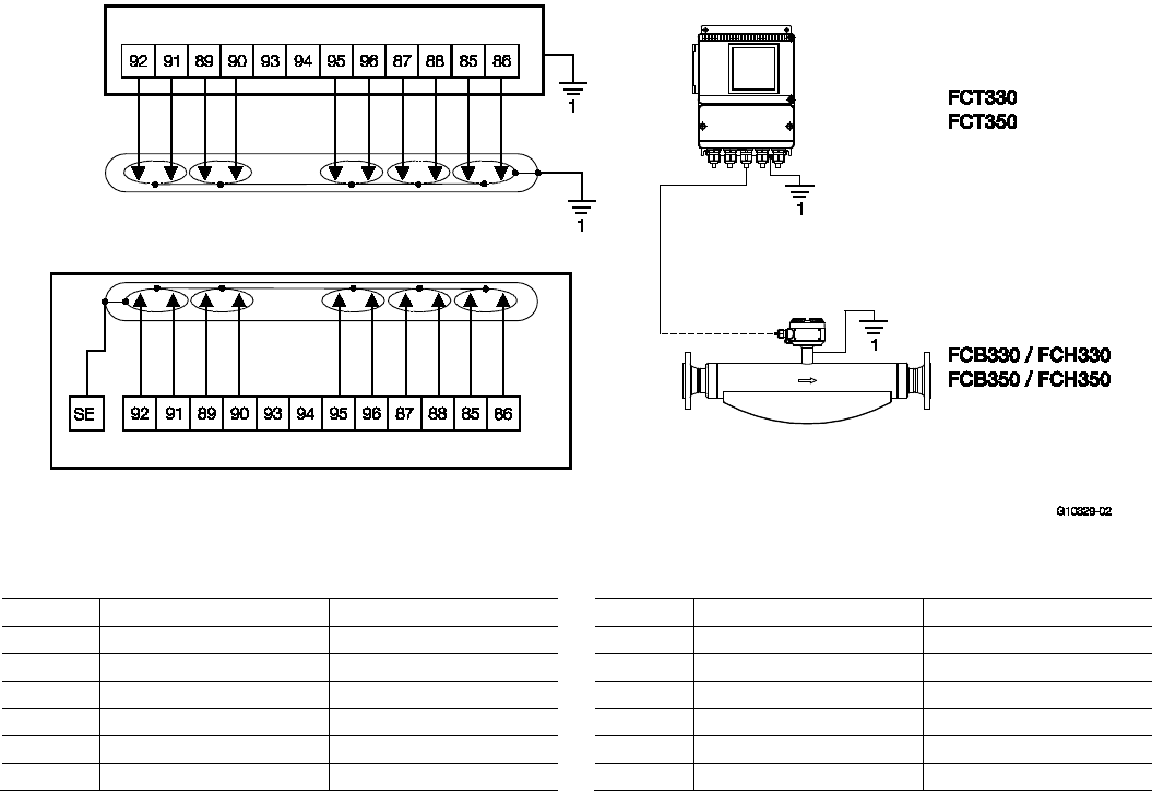
5.6.3 Connection of transmitter to flowmeter sensor
FCT330, FCT350 transmitter to FCB330, FCB350, FCH330, FCH350 flowmeter sensor
Fig. 25
1 Equipotential bonding (PA)
Terminal
Corresponding wire color
Function
Terminal
Corresponding wire color
Function
85 White Sensor 1 91 Gray Driver
86
Brown
Sensor 1
92
Pink
Driver
87 Green Sensor 2 93 - Not used
88
Yellow
Sensor 2
94
-
Not used
89 Black Temperature 95 Blue Temperature
90
Violet
Temperature
96
Red
Temperature
IMPORTANT (NOTE)
The precise position of the PA terminals may vary according to the device type. Each terminal is marked accordingly. When the
FCT330, FCT350 transmitter is connected to the FCB330, FCB350, FCH330, FCH350 flowmeter sensor, the transmitter must
also be connected to "PA".
The following flowmeter sensor / transmitter combinations are permitted:
— FCB330, FCH330 flowmeter sensor with FCT330 transmitter
— FCB350, FCH350 flowmeter sensor with FCT350 transmitter
30 OI/FCB300/FCH300-EN Rev. F | CoriolisMaster FCB330, FCB350, FCH330, FCH3500
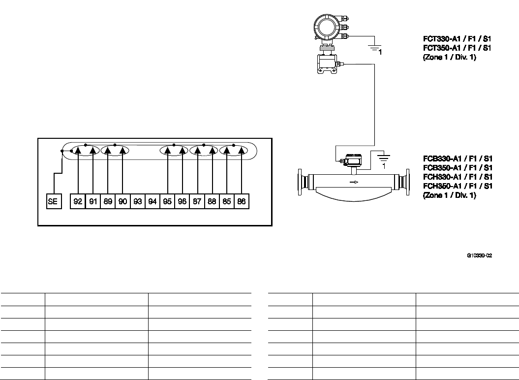
5.6.4 Connection of transmitter to flowmeter sensor in Zone 1 / Div. 1
FCT330, FCT350 transmitter to FCB330, FCB350, FCH330, FCH350 flowmeter sensor
Fig. 26
1 Equipotential bonding (PA)
Terminal
Corresponding wire color
Function
Terminal
Corresponding wire color
Function
85 White Sensor 1 91 Gray Driver
86
Brown
Sensor 1
92
Pink
Driver
87 Green Sensor 2 93 - Not used
88
Yellow
Sensor 2
94
-
Not used
89 Black Temperature 95 Blue Temperature
90
Violet
Temperature
96
Red
Temperature
IMPORTANT (NOTE)
The wires must be connected in pairs in order to ensure EMC protection.
The following flowmeter sensor / transmitter combinations are permitted:
— FCB330, FCH330 flowmeter sensor with FCT330 transmitter
— FCB350, FCH350 flowmeter sensor with FCT350 transmitter
Chan ge from on e to two c olumns

CoriolisMaster FCB330, FCB350, FCH330, FCH3500 | OI/FCB300/FCH300-EN Rev. F 31
6 Commissioning
6.1 Checks prior to commissioning
The following points must be checked before commissioning
the device:
— The assignment of the flowmeter sensor to the transmitter
must be correct
— The wiring must have been completed as described in the
"Electrical connections" section
— The flowmeter sensor must be correctly grounded
— The external data memory module (FRAM) must have the
same serial number as the flowmeter sensor
— The external data memory module (FRAM) must be
inserted in the correct position (see the "Maintenance /
Repairs" section)
— The ambient conditions must meet the requirements set
out in the technical data
— The power supply must meet the requirements set out on
the name plate
6.2 Switching on the power supply
Switch on the power supply.
After switching on the power supply, the flowmeter data in the
external FRAM is compared with the data saved internally.
If the data is not identical, the transmitter data is replaced
automatically. Once completed, the message "Ext. Data
loaded" is displayed. The flowmeter is now ready for
operation.
The LCD display indicates the current flow.
6.2.1 Inspection after switching on the power supply
The following points must be checked after commissioning the
device:
— The parameter configuration must correspond to the
operating conditions.
— The system zero adjustment must have been made.
General information:
— If the flow direction indicated on the display is incorrect, it
could mean that the signal lead connections between the
sensor and the transmitter have been accidentally
reversed
— The position of the fuses and the fuse values are listed in
the spare parts list
6.3 Basic Setup
IMPORTANT (NOTE)
For additional information regarding operation of
the LCD display, refer to the "Configuration,
parameterization / operation" section.
For detailed descriptions of all menus and
parameters, see the "Configuration,
parameterization / parameter description" section.
The device can be factory calibrated to customer
specifications upon request. If no customer information is
available, the device is delivered with factory settings.
On-site configuration requires only a few parameter settings.
The following parameters must be checked and/or set when
commissioning the device:
Flow range end value
("QmMax" parameter and "Unit" submenu)
The device is factory calibrated to the largest flow range end
value, unless customer information to the contrary is available.
Current outputs
("Current output 1" and "Current output 2" submenus)
Select the desired current range (0 … 20 mA or 4 … 20 mA).
Pulse output
("Pulse" parameter and "Unit" submenu)
To set the number of pulses per volume flow unit, a unit for
the totalizer (e.g., kg or t) must first be selected in the "Unit"
submenu. After this, the number of pulses has to be entered in
the "Pulse" parameter.
Pulse width
("Pulse width" parameter)
For external processing of the present counting pulses, the
pulse width can be set to between 0.1 ms and 2,000 ms.
System zero point
("System Zero adj." submenu)
The fluid in the flowmeter sensor must be brought to a
complete standstill. The flowmeter sensor must be full. Select
the "System Zero adj." menu. Next press ENTER. Use the
STEP key to call up "System Zero adj. Function automatic?"
and select ENTER to start the adjustment. You can choose
between slow or fast adjustment. Slow adjustment generally
provides a more accurate zero point.
32 OI/FCB300/FCH300-EN Rev. F | CoriolisMaster FCB330, FCB350, FCH330, FCH3500
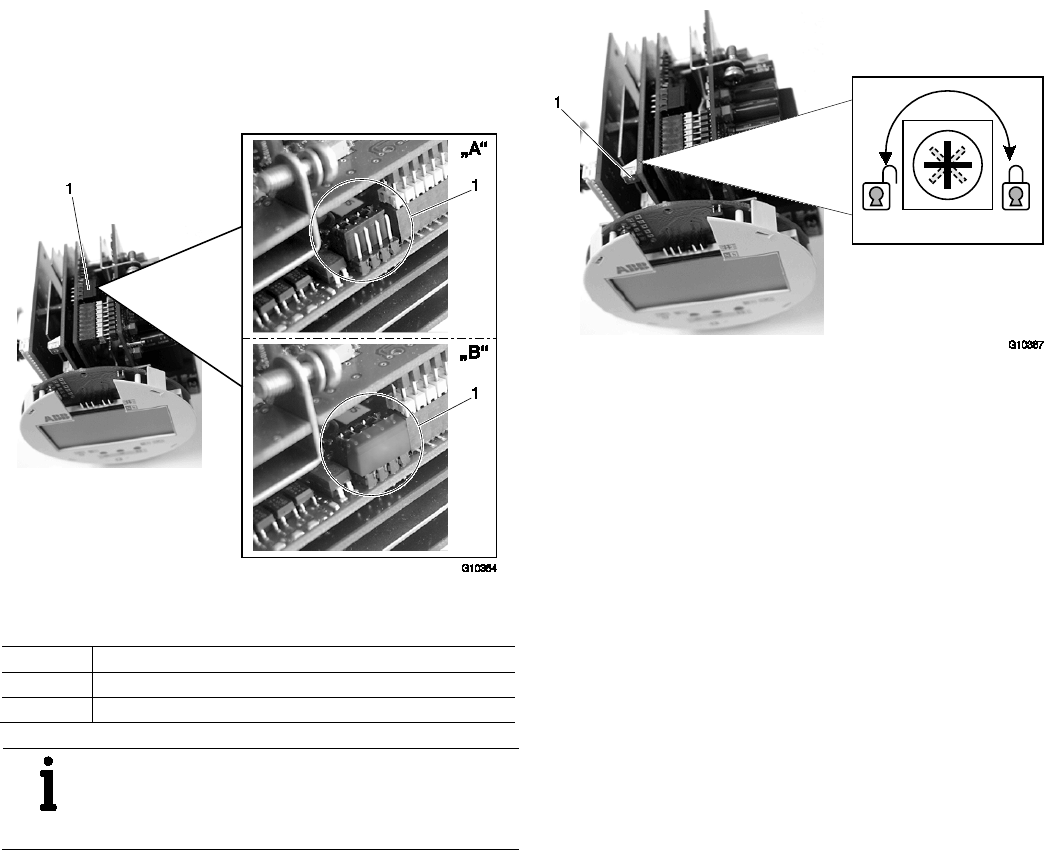
6.4 Configuring the pulse output
The configuration (active, passive) for the pulse output is set in
the transmitter using a jumper.
To change the configuration, you must remove the transmitter
plug-in module from the housing.
Fig. 27: Plug-in Jumper Location
1 Jumper for configuring the pulse output
Number Function
"A" Pulse output 51 / 52 passive
"B" Pulse output 51 / 52 active (not for hazardous area design)
IMPORTANT (NOTE)
Please note that in case of Zone 1 or Div. 1
approved meters, this jumper will be in position
"B" (active) although the pulse output is passive!
6.5 Operating protection switch
Fig. 28: Operating protection switch
In addition to password protection, it is possible to activate
hardware write protection.
Turning the switch (1) clockwise activates the programming
protection while turning the switch anti-clockwise deactivates
it.
If you attempt to change parameters while the protection is
active, the "Operating protection" warning is displayed and the
entry is rejected.
It is also possible to use a cover locking screw with a hole to
seal the compact unit so that changes to calibration-related
parameters cannot remain undetected.

CoriolisMaster FCB330, FCB350, FCH330, FCH3500 | OI/FCB300/FCH300-EN Rev. F 33
6.6 Information for safe operation in potentially explosive
atmospheres – ATEX
6.6.1 Inspection
DANGER – Risk of explosion!
Risk of explosion when opening the housing.
Before opening the housing:
— Check that a valid fire permit is available
— Check that there is no risk of explosion
— Switch off the power supply
CAUTION – Risk of burns!
Risk of burns on the flowmeter sensor posed by
hot media for measurement. The surface
temperature may exceed 70 °C (158 °F),
depending on the temperature of the medium.
Before starting work on the flowmeter sensor,
make sure that the device has cooled sufficiently.
Flowmeter sensors must be commissioned and operated
according to ElexV (German ordinance on electrical
installations in potentially explosive atmospheres), EN 60079-
14 (setting up electrical installations in potentially explosive
atmospheres), and relevant national standards.
In potentially explosive atmospheres, installation,
commissioning, maintenance, and servicing must only be
performed by properly trained personnel.
The commissioning activities described here are performed
after the flowmeter has been installed and the electrical
connection has been made.
The supply power must be switched off.
When operating the flowmeter in areas containing
combustible dusts, comply with EN 61241-0:2006.
Please observe the drawing „3KXF002126G0009“ in the
appendix.
6.6.2 Output circuits
Installation of intrinsically safe "i" or increased safety "e"
The output circuits are designed so that they can be
connected to both intrinsically safe and non-intrinsically safe
circuits.
It is not permitted to combine intrinsically safe and non-
intrinsically safe circuits.
On intrinsically safe circuits, equipotential bonding must be in
place along the entire length of the cable used for the current
outputs.
The rated voltage of the non-intrinsically safe circuits is
Um = 60 V.
IMPORTANT (NOTE)
The cable glands are supplied in black by default.
If the signal outputs are wired to intrinsically safe
circuits, we recommend that you use the light
blue cap supplied, which you will find in the
connection area, for the corresponding cable
entry.
IMPORTANT (NOTE)
The safety specifications for intrinsically safe
circuits can be found on the EC type-examination
certificate.
— Make sure that the cover over the voltage supply
connection is tightly closed. With intrinsically safe output
circuits, the terminal box can be opened.
— It is recommended that you use the cable glands supplied
(not for the -40 °C (-40 °F) version) for the output circuits
as appropriate for the relevant type of protection:
intrinsically safe: blue, non-intrinsically safe: black
— The sensor and the transmitter housing must be
connected via the equipotential bonding. For intrinsically
safe current outputs, equipotential bonding needs to be in
place all the way along the circuits.
— After switching off the power supply, wait t > 2 minutes
before opening the transmitter housing.
— When commissioning the flowmeter, refer to
EN 61241-1:2004 regarding use in areas containing
combustible dust.
— The operator must ensure that, when connecting the
protective conductor (PE), no potential differences exist
between the protective conductor and the equipotential
bonding (PA), even in the event of a fault.
— In case of Dust-Ex application, the maximum surface
temperature is 85 °C (185 °F).
— The process temperature of connected piping can exceed
85 °C (185 °F).
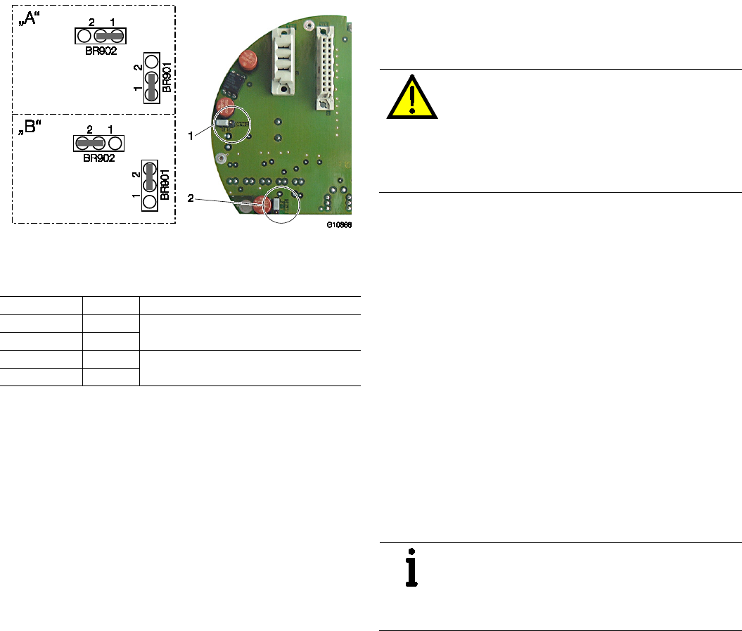
34 OI/FCB300/FCH300-EN Rev. F | CoriolisMaster FCB330, FCB350, FCH330, FCH3500
6.6.3 NAMUR contact
Fig. 29: Positions of jumpers
"A" Standard wiring | "B" NAMUR wiring
1 Jumper BR902 | 2 Jumper BR901
Jumper
Number
Function
BR902 1 Standard configuration, preferred for Ex "e"
(factory default)
BR901 1
BR902 2 NAMUR configuration, preferred for Ex "i"
BR901 2
The switching output and the pulse output (terminals 41 / 42
and 51 / 52) can be wired internally as a NAMUR contact for
the purpose of connecting to a NAMUR amplifier; this is
achieved by setting the jumpers accordingly.
6.6.4 Cable entries
Special instructions for devices with North American
certification
Devices certified in accordance for North America are only
ever supplied with 1/2" NPT threads without glands.
6.6.5 Flowmeter sensor insulation
If the flowmeter is to be insulated, follow the instructions in the
"Mounting / Installation positions / Installation with option TE1
"extended tower length"" section.
6.6.6 Operation in Zone 2 with protection class
"restricted breathing" (nR)
The transmitter housing (rectangular or round, compact or
separate) can be operated in Zone 2 with protection class
"restricted breathing" (nR).
WARNING – Potentially adverse effect on
protection class
The operator must check the device in
accordance with IEC 60079-15 following
installation or maintenance, or each time the
housing has been opened (see chapter
“Important notes to test the device”).
Important notes to test the device
According to IEC 60079-15 chapter 23.2.3.2.1.2 “Equipment
without test port” observe the following points:
— Under constant temperature conditions, the time interval
required for an internal pressure of at least
0.3 kPa (30 mmWS) below atmospheric to change to half
the initial value shall be not less than 180 seconds.
Alternatively following test procedures may be used to shorten
the time needed for the routine tests:
— Under constant temperature conditions, the time interval
required for an internal pressure of 0.3 kPa (30 mmWS)
below atmospheric to change to 0.27 kPa (27 mmWS)
below atmospheric shall be not less than 27 seconds.
— Under constant temperature conditions, the time interval
required for an internal pressure of 3.0 kPa (300 mmWS)
below atmospheric to change to 2.7 kPa (270 mmWS)
below atmospheric shall be not less than 27 seconds.
IMPORTANT (NOTE)
If using the low value of pressure (0.3 kPa
(30 mmWS)) creates difficulties, the alternative
10 times higher figures (3.0 kPa (300 mmWS))
may be used.
CoriolisMaster FCB330, FCB350, FCH330, FCH3500 | OI/FCB300/FCH300-EN Rev. F 35
Carrying out the check
1. Switch off the power supply and wait for at least two
minutes before opening the housing.
2. Remove a cable gland which is not being used. Cable
glands certified to ATEX or IECEx are usually used,
e.g., M20 x 1.5 or 1/2" NPT thread.
3. Connect the device being used to test the pressure in
place of the cable gland you removed. Check that the test
device has been installed and sealed correctly.
4. Carry out the test with the test device (see chapter
“Important notes to test the device”).
5. Remove the test device and put the cable gland back in
place correctly.
Before the power supply is switched on again, the housing,
seals, thread, and cable entries must be subjected to a visual
inspection. There must be no evidence of damage.
IMPORTANT (NOTE)
For sealing original spare parts should be used
only.
Spare parts can be ordered from ABB Service:
Please contact Customer Center Service acc. to
page 2 for nearest service location.
IMPORTANT (NOTE)
When selecting a location for the transmitter,
make sure that it will not be exposed to direct
sunlight.
If exposure to direct sunlight cannot be avoided,
a sun shade should be installed.
The limit values for the ambient temperature must
be observed.
Chan ge from tw o to one c olum n
6.6.7 Changing the type of protection
When installed in DIV 1 / Zone 1 the FCB330/350, FCH330/350 and FCT330/350 models can be operated at Signal Data
INPUT / OUTPUT
with different types of protection:
— Signal Data INPUT / OUTPUT as intrinsically safe ia (ib) / IS or
— Signal Data INPUT / OUTPUT as non-intrinsically safe
Initial installation
Should be installed as
Required step to check
DIV 1 / Zone 1:
Signal Data
INPUT / OUTPUT as non-
intrinsically safe
DIV 1 / Zone 1:
Signal Data
INPUT / OUTPUT as
intrinsically safe ia (ib) / IS
— 500 V AC/1 min or 500 x 1,414 = 710 V DC/1 min
test between terminals 31 / 32, 33 / 34, 41 / 42, 51 / 52, 81 / 82 and / or 97 / 98 and
terminals 31, 32, 33, 34, 41, 42, 51, 52, 81, 82, 97, 98 and the housing.
— Visual inspection, particularly of the electronic circuit boards
—
Visual inspection: No damage or explosion can be detected.
DIV 1 / Zone 1:
Signal Data
INPUT / OUTPUT as
intrinsically safe ia (ib) / IS
DIV 1 / Zone 1:
Signal Data
INPUT / OUTPUT as non-
intrinsically safe
Visual inspection: No damage to the threads (cover, 1/2" NPT cable glands)
Important (NOTE)
For more details on hazardous areas, protection type and instrument Model No see installation
diagram FCB 3KXF002126G0009 (see chapter „Appendix“).
Chan ge from on e to two c olumns
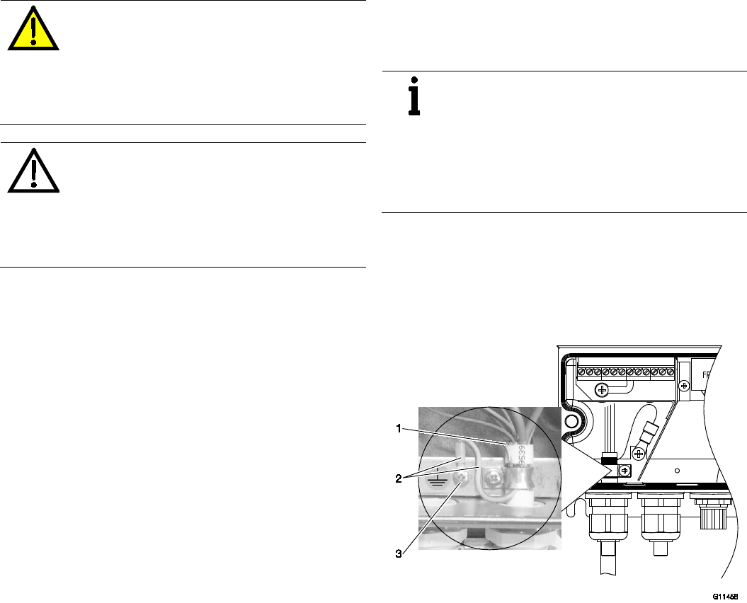
36 OI/FCB300/FCH300-EN Rev. F | CoriolisMaster FCB330, FCB350, FCH330, FCH3500
6.7 Information for safe operation in potentially explosive
atmospheres – cFMus
6.7.1 Inspection
DANGER – Risk of explosion!
Risk of explosion when opening the housing.
Before opening the housing:
— Check that a valid fire permit is available
— Check that there is no risk of explosion
— Switch off the power supply and wait for
t > 2 minutes.
CAUTION – Risk of burns!
Risk of burns on the flowmeter sensor posed by
hot media for measurement. The surface
temperature may exceed 70 °C (158 °F),
depending on the temperature of the medium.
Before starting work on the flowmeter sensor,
make sure that the device has cooled sufficiently.
Additionally observe the following points:
— In potentially explosive atmospheres, installation,
commissioning, maintenance, and servicing must only be
performed by properly trained personnel.
— When the housing is open, there is no longer any EMC
protection or protection against accidental contact.
— The sensor and transmitter must be grounded in
accordance with the applicable international standards.
— The flowmeter sensor must be connected to the
transmitter by means of the signal cable supplied by ABB
Automation Products; no other cable may be used for this
purpose.
— In the case of the remote mount design, the signal cable
between the flowmeter sensor and the transmitter must
measure at least 5 m (16.4 ft) in length.
— It is essential that the temperature classes as per the
approvals contained in the section titled „Ex relevant
specifications acc. to cFMus“ are observed.
— Please observe the drawing “3KXF002126G0009” in the
appendix.
6.7.2 Cable entries
Special instructions for devices with North American
certification
Devices certified in accordance for North America are only
ever supplied with 1/2" NPT threads without glands.
6.7.3 Electrical connection
IMPORTANT (NOTE)
The housing for the transmitter and flowmeter
sensor must be connected to the potential
equalization PA. The operator must ensure that
when connecting the protective conductor (PE)
no potential differences can occur between
protective conductor and potential
equalization (PA).
A temperature of 70 °C (158 °F) at the cable entry is assumed
for the Ex calculations. Therefore, the cables used for the
supply power and the signal inputs and outputs must have a
minimum specification of 70 °C (158 °F).
Grounding
Fig. 30
According to NEC standards, the separate ground connection
between flowmeter sensor and transmitter can be established
as follows:
1. Strip the signal cable on a length of 100 ... 120 mm
(3.94 ... 4,72 inch).
2. Fan out the braided shield (1) that runs through the signal
cable to a length of 10 ... 15 mm (0.39 ... 0.59 inch). Twist
the disentangled wires of the braided shield so that they
form one strand.
3. Slide the green/yellow protective tubing over the strand,
leaving 10 mm (0.39 inch) protruding from the end (if
necessary, shorten the protective tubing).
4. Press on the ring-type terminal (2) supplied.
5. Connect to the grounding connection (3).

CoriolisMaster FCB330, FCB350, FCH330, FCH3500 | OI/FCB300/FCH300-EN Rev. F 37
6.7.4 Process sealing
According to „North American Requirements for Process
Sealing between Electrical Systems and Flammable or
Combustible Process Fluids“
IMPORTANT (NOTE)
Equipment for use in Canada, Class II,
Groups E, F and G shall be limited to a maximum
surface temperature of 165°C (329 °F).
Seal all conduits within 18 inches (457.20 mm).
The flow meters from ABB are designed for the world wide
industrial market and are suitable to measure among others
flammable and combustible process fluids and are installed
within a process pipe.
Among others the instruments are connected to an electrical
system via a conduit system which is able to allow the
migration of process fluids directly into the electrical system.
To avoid the migration of process fluids the instruments has a
process seal which meet the requirements of
ANSI/ISA 12.27.01.
The Coriolis Flowmeters are designed as a “single seal
device”.
In accordance to the requirements of ANSI/ISA 12.27.01 the
existing operating rates of temperature, pressure and liner
types have to reduce to the following limits:
Limits
Flange or tube Material All materials of the existing model
number
Sizes
DN 20 ... 150 (1/2” ... 6”)
Usable Operating Temperature -50 °C ... 200 °C (-58 °F ... 392 °F)
Pressure result
PN100 / Class 600
Chan ge from tw o to one c olum n
6.7.5 Changing the type of protection
The FCB330/350, FCH330/350 and FCT330/350 models can be operated in different types of protection:
— When connected to an intrinsically safe circuit in Div. 1, operated as an intrinsically safe device (IS)
— When connected to a non-intrinsically safe circuit in Div. 1, operated as a device with a explosionproof enclosure (XP)
— When connected to a non-intrinsically safe circuit in Div. 2, operated as a non-incendive device (NI)
If a device which is already installed is required to provide a different type of protection, the following measures must be
implemented/inspections must be performed in accordance with applicable standards.
1. Type of protection 2. Type of protection Required step/check
Housing: XP, U
max
= 60 V
Outputs non IS
Housing: XP
Outputs: IS
— 500 V AC/1 min or 500 x 1,414 = 710 V DC/1 min
test between terminals 31 / 32, 33 / 34, 41 / 42, 51 / 52, 81 / 82 and / or 97 / 98 and
terminals 31, 32, 33, 34, 41, 42, 51, 52, 81, 82, 97, 98 and the housing. When this
test is performed, no voltage flashover is permitted in or on the device.
— Visual inspection, particularly of the electronic circuit boards
—
Visual inspection: No damage or explosion can be detected.
Housings: Div 2
Outputs: NI
— 500 V AC/1 min or 500 x 1,414 = 710 V DC/1 min
test between terminals 31 / 32, 33 / 34, 41 / 42, 51 / 52, 81 / 82 and / or 97 / 98 and
terminals 31, 32, 33, 34, 41, 42, 51, 52, 81, 82, 97, 98 and the housing. When this
test is performed, no voltage flashover is permitted in or on the device.
— Visual inspection, particularly of the electronic circuit boards
—
Visual inspection: No damage or explosion can be detected.
Outputs: IS
Housing: XP
Housing: XP
Outputs: non IS
Visual inspection: No damage to the threads (cover, 1/2" NPT cable glands)
Housing: XP
Outputs: NI
No special measures
Housing: XP, U
max
= 60 V
Outputs: NI
Housing: XP
Outputs: IS
— 500 V AC/1 min or 500 x 1,414 = 710 V DC/1 min
test between terminals 31 / 32, 33 / 34, 41 / 42, 51 / 52, 81 / 82 and / or 97 / 98 and
terminals 31, 32, 33, 34, 41, 42, 51, 52, 81, 82, 97, 98 and the housing.When this test
is performed, no voltage flashover is permitted in or on the device.
— Visual inspection, particularly of the electronic circuit boards
—
Visual inspection: No damage or explosion can be detected.
Housing: XP
Outputs: non IS
Visual inspection: No damage to the threads (cover, 1/2" NPT cable glands)
Chan ge from on e to two c olumns
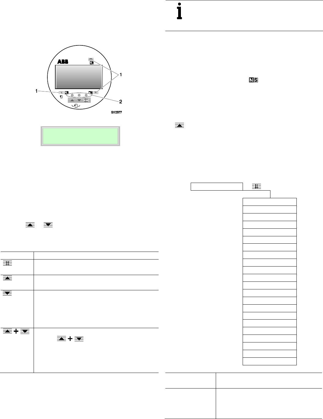
38 OI/FCB300/FCH300-EN Rev. F | CoriolisMaster FCB330, FCB350, FCH330, FCH3500
7 Configuration, parameterization
7.1 Operation
7.1.1 Menu navigation
3 Line 1
4
Line 2
Fig. 31: LCD indicators
1 Points for inserting the magnet stick |
2 Buttons for menu navigation | 3 1st line of the LCD display |
4 2nd line of the LCD display
When setting parameters, the transmitter remains online, i.e.,
current and pulse outputs still show the current operating
mode.
Control button functions
You can browse through the menu or select values from a list
using the or buttons.
Depending on your position in the menu, the buttons may
have other functions.
Symbol Meaning
— Toggle between process display and menu
— Exit submenu
— Scroll forwards through the menu or a parameter list
— For increasing numerical values (increment)
— Scroll backwards through the menu or a parameter
list
— For reducing numerical values (decrement)
— Select the next position for entering numerical and
alphanumeric values
ENTER function
Press the buttons at the same time to
execute the ENTER function.
— Select a parameter to change
— Confirm the entry of a value or parameter
— Call up submenu
IMPORTANT (NOTE)
The values entered are checked for plausibility; if
they are not plausible, a corresponding message
appears on the LCD display.
Magnet stick operation
The magnet stick provides an alternative means of configuring
the device even when the housing cover is closed.
To execute the functions, hold the active side of the magnet
stick against the corresponding areas on the LCD display.
These areas are identified by the symbol.
ENTER function with magnet stick operation
It is not possible to use the magnet stick to press two buttons
at the same time. To execute the ENTER function when using
the magnet stick to operate the device, hold the stick against
the area for more than 3 seconds.
The LCD display flashes to indicate that the ENTER function
has been executed successfully.
7.2 Menu levels
The configuration level is located under the process display.
Process display
Configuration level
Language
Mode of operation
Concentration
Unit
Flowmeter primary
QmMax
Damping
Low cutoff setting
Field optimization
System Zero adj.
Alarm
Display
Totalizer
Pulse Output
Current output 1 / 2
Switch contacts
Label
Interface
Function test
Status
Software version
Process display
The process display shows the current process
values.
Configuration level
The configuration level contains all the
parameters required for device commissioning
and configuration. The device configuration can
be changed on this level.
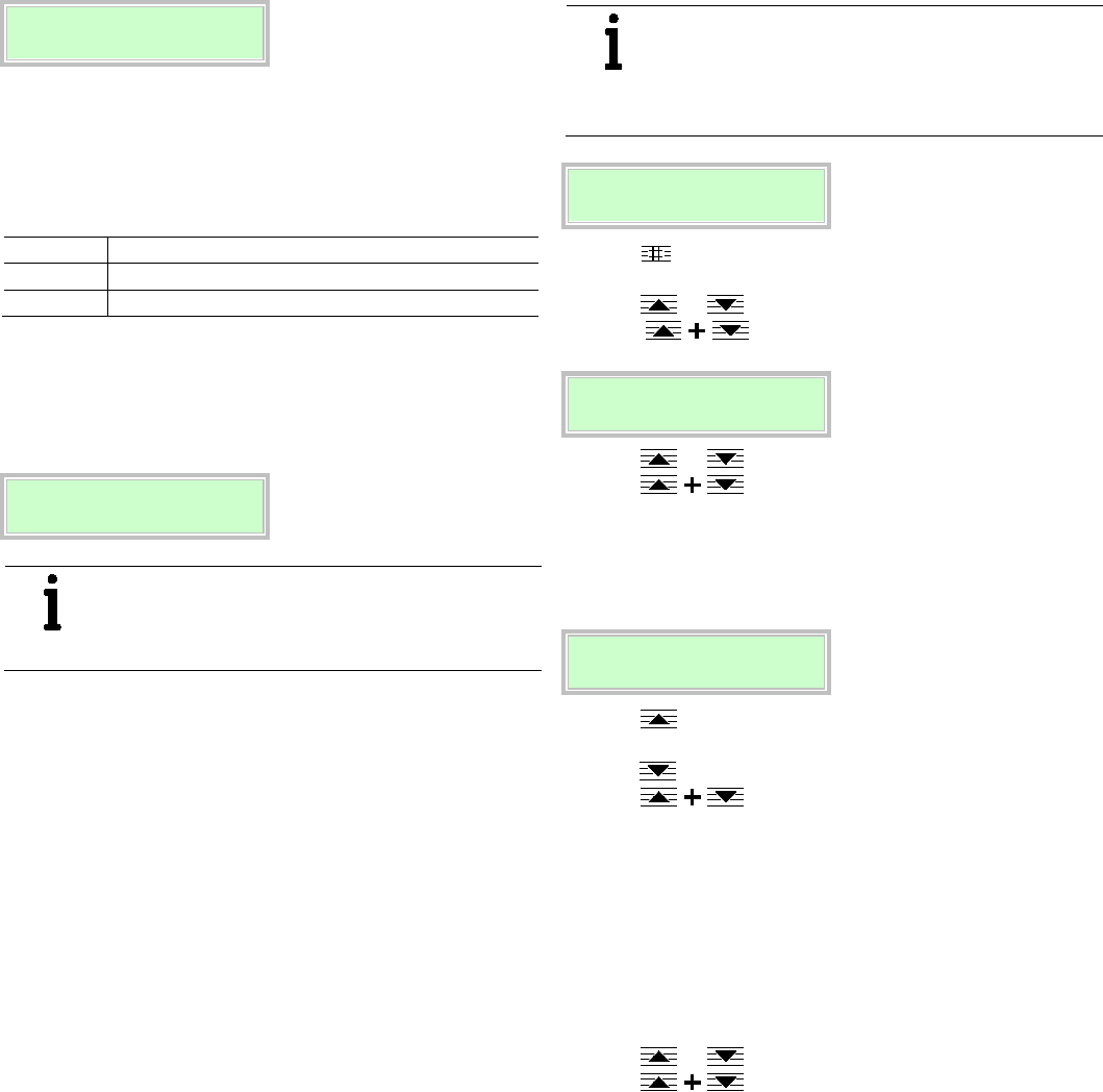
CoriolisMaster FCB330, FCB350, FCH330, FCH3500 | OI/FCB300/FCH300-EN Rev. F 39
7.2.1 Process display
The process display appears on the LCD display when the
device is switched on. It shows information about the device
and current process values.
→ V 98.14 %
1
→ V 12,000 m
3
2
Fig. 32: Process display
1 1st line of the process display |
2 2nd line of the process display
The way in which the current process values are shown in
lines 1 and 2 can be adjusted on the configuration level.
Symbol Description
→ Display in forward direction
←
Display in reverse direction
Error messages on the LCD display
In the event of an error, a message appears on the process
display. The text displayed provides information about the area
in which the error has occurred.
Process display
Error message
IMPORTANT (NOTE)
For a detailed description of the errors and
information on how to remedy them, refer to the 8
"Error messages" section.
7.2.2 Switching to the configuration level
(parameterization)
The device parameters can be displayed and changed on the
configuration level.
IMPORTANT (NOTE)
If the message "Error – operating protection"
appears on the LCD display, hardware write
protection has been activated with the operating
protection switch.
→ V 98.14 %
→ V 12.000 m3
1. Use to switch to the configuration level: A menu
option now appears at random on the LCD display.
2. Use or to select the "Prog. level" submenu
and (ENTER function) to select edit mode.
*Prog. level
Blocked
3. Use or to select the "Specialist" access level.
4. Use (ENTER function) to confirm your
settings.
If a password has been set (Prog. Prot. Code) you must enter
it now.
Prog. Prot. Code
****
5. Use to set the required value (the decimal position is
incremented every time the button is pressed).
6. Use to select the next decimal position.
7. Use (ENTER function) to confirm your
settings.
After the correct password has been entered, the
corresponding access level is opened. If the "Service"
programming level was selected, then the service password
must be entered.
The LCD display now indicates the first menu item on the
configuration level.
8. Use or to select a menu.
9. Use (ENTER function) to confirm your
selection.
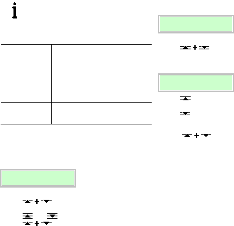
40 OI/FCB300/FCH300-EN Rev. F | CoriolisMaster FCB330, FCB350, FCH330, FCH3500
Access levels
IMPORTANT (NOTE)
There are four access levels: A password can be
specified for the "Standard" and "Specialist"
access levels.
There is no factory default password.
Access levels Description
Blocked On the "Blocked" level all entries are disabled.
Menus / parameters are read only and cannot
be modified.
Standard Display and modify all menus / parameters
required for operating the device.
Specialist Display and modify all menus / parameters that
can be accessed by the customer.
Service The service menu can be displayed by entering
the correct service password (for ABB Service
only).
7.2.3 Selecting and changing parameters
Entry from table
When an entry is made from a table, a value is selected from a
list of parameter values.
Submenu
Unit
1. Select the parameters you want to set in the menu.
2. Use (ENTER function) to call up the
parameter for editing.
3. Use oder to select the required value.
4. Use (ENTER function) to confirm your
selection.
Numerical entry
When a numerical entry is made, a value is set by entering the
individual decimal positions.
QmMax
180.00 kg/h
1. Select the parameters you want to set in the menu.
2. Use (ENTER function) to call up the
parameter for editing. The value set previously is deleted
and a cursor (_) is displayed in the first position.
QmMax
254.50 kg/h
3. Use to set the required value (the decimal place is
incremented every time the button is pressed).
4. Use to select the next decimal position.
5. If necessary, select and set other decimal positions using
the same procedure as described in steps 3 and 4.
6. Use (ENTER function) to confirm your
settings.
This concludes the procedure for changing a parameter value.
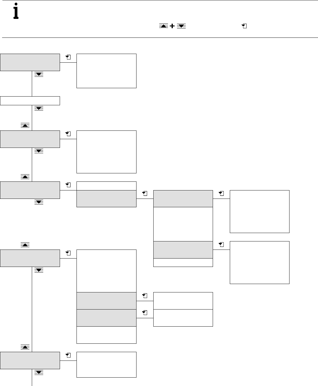
CoriolisMaster FCB330, FCB350, FCH330, FCH3500 | OI/FCB300/FCH300-EN Rev. F 41
Chan ge from tw o to one c olum n
7.3 Overview of parameters on the configuration level
IMPORTANT (NOTE)
This overview of parameters shows all the menus and parameters available on the device. Depending on the
version and configuration of the device, not all of the menus and parameters may be visible on it.
In this overview of parameters, the ENTER function is represented by the symbol for reasons of
space.
*Prog. level Blocked
Standard
Specialist
Service
Language
Mode of operation Flow indication
Directional display
Signal Level
DensiMass Code
DensiMass
Min Density
Concentration Medium
Variable Matrix Configuration Number matrices
Number temp.
Number conc.
Enter conc. in %
Reset matrix
Label
Unit name
Min. concentr.
Max. concentr.
Matrix 1 / 2 Temperature
Concentration in unit
Concentration in percent
Density
Matrix calculation
Unit Unit Qm
Unit Qv
Density unit
Totalizer Unit Volume
Totalizer Unit Mass
Enter matrix finish
Prog. Unit Qm Unit name
Units factor
Prog. Unit Qv Unit name
Units factor
Temp. unit
Unit concentration
Flowmeter primary Meter tube
QmMax meter tube
Order no.
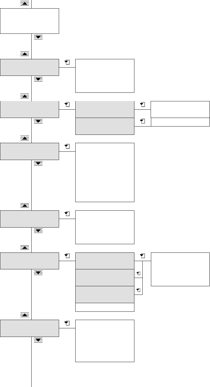
42 OI/FCB300/FCH300-EN Rev. F | CoriolisMaster FCB330, FCB350, FCH330, FCH3500
QmMax
Damping
Low cutoff setting
Field optimization D correction
Qm correction
C correction tab. 1
C correction tab. 2
System Zero adj. System Zero adj.
Function automatic?
System Zero adj. Slow?
System Zero adj. Fast?
System Zero adj.
manual?
System Zero adj.
Alarm Min Alarm Qm
Max Alarm Qm
Min Alarm density
Max Alarm density
Min Alarm Temp.
Max Alarm Temp.
Min Alarm Concentr.
Max Alarm Concentr.
Display 1st Line
2nd Line
1st Line Multiplex
2nd Line Multiplex
Totalizer Totalizer mass Counter > F
Overflow > F
Totalizer < R
Overflow < R
Totalizer volume
Totalizer net. mass
Totalizer Reset
Pulse Output Output of
QvMax pulse
Qm% max pulse
Pulse
Pulse width
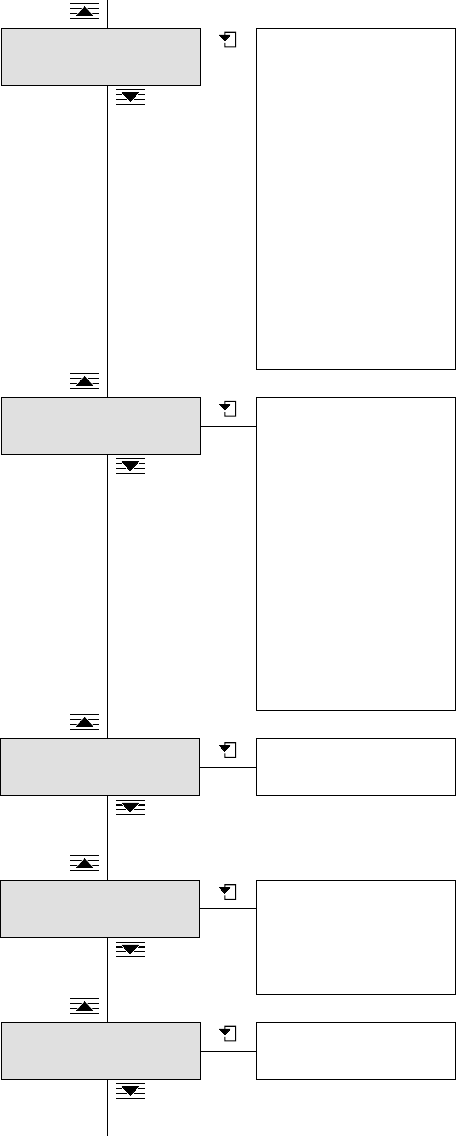
CoriolisMaster FCB330, FCB350, FCH330, FCH3500 | OI/FCB300/FCH300-EN Rev. F 43
Current output 1 Output of
Qv → l = 100 %
Density → l = 0 %
Density → l = 100 %
Temp → l = 0 %
Temp → l = 100 %
Qm% → l = 100 %
Concentr. → l = 0 %
Concentr. → l = 100 %
Current output
Iout for Alarm
Low Alarm
High Alarm
Current output 2 Output of
Qv → l = 100 %
Density → l = 0 %
Density → l = 100 %
Temp → l = 0 %
Temp → l = 100 %
Qm% → l = 100 %
Concentr. → l = 0 %
Concentr. → l = 100 %
Iout for Alarm
Low Alarm
High Alarm
Switch contacts Contact input
Contact output
Label TAG number
Descriptor
Date
Unit number
Interface Communication
Unit address

44 OI/FCB300/FCH300-EN Rev. F | CoriolisMaster FCB330, FCB350, FCH330, FCH3500
Function test Function test pulse
Output
Pulse Output
Function test Iout 1 Iout 1
Function test Iout 2 Iout 2
Function test Contact
input
Contact input
Function test Contact
output
Contact output
Function test HART
Transmitter
Function test HART
Command
Function test Memory
Simulation Simulation
Qm
Density
Temperature
Temp. housing
Status Error log Number: 3
7 (Set) Temp. Measurement
9a (current) Density
Warning Register
Number: 1
Power outage
Status Reset
4 (Set) Ext. Cut-off
CoriolisMaster 03.2012
FCB FW
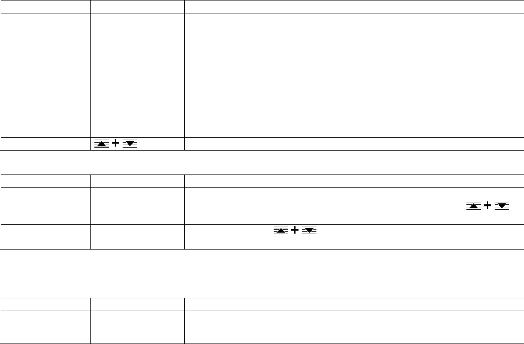
CoriolisMaster FCB330, FCB350, FCH330, FCH3500 | OI/FCB300/FCH300-EN Rev. F 45
7.4 Parameter descriptions
7.4.1 Menu: *Prog. level
…/ *Prog. level
Mask contents
Value range
Description
*Prog. level Blocked
Standard
Specialist
Service
Selection of access level.
If a password has been set (prog. protection code) you must enter it now.
Once the password has been entered, the required access level can be selected. If the password
= 0000 (factory setting), the access level can be selected without entering the password.
— "Blocked": On the "Locked" level all entries are disabled. Menus / parameters are read only
and cannot be modified.
— "Standard": Display and modify all menus / parameters required for operating the device.
— "Specialist":Display and modify all menus / parameters that can be accessed by the customer.
— "Service":The service menu can be displayed by entering the correct service password
(for ABB Service only).
Prog. Prot. Code
Select the "Prog. Prot. Code" submenu.
…/ *Prog. level / Prog. Prot. Code
Mask contents
Value range
Description
Old Prog. Prot. (PS)
code?
0 … 9999 Change the password.
To change the password, you must start by entering the current password. Press to
confirm your entry.
New Prog. Prot. (PS)
code?
0 … 9999
Enter a password. Press to confirm your entry.
7.4.2 Menu: Language
…/ Language
Mask contents
Value range
Description
Language
German
English
Select the menu language.

46 OI/FCB300/FCH300-EN Rev. F | CoriolisMaster FCB330, FCB350, FCH330, FCH3500
7.4.3 Menu: Mode of operation
…/ Mode of operation
Mask contents
Value range
Description
Flow indication
Forward / Return
Forward
Select the flow direction.
— "Forward / Return": Display showing measurement of flow in forward and reverse direction.
— "Forward": Display showing measurement of flow in forward direction only. If the medium is
flowing through the flowmeter sensor in the reverse direction, ← R flashing is displayed on the
LCD display and the flow is indicated as 0 %. The warning "Reverse Q" is also output.
IMPORTANT (NOTE)
In "Forward / Return" operating mode, the pulse output is active for both flow
directions.
Directional display Normal, Reverse Invert the flow direction display. Note that the accuracy of the flow measurement is dependent
upon whether the device has been calibrated in the forward direction only or in the forward and
reverse directions.
— "Normal": Normal display of flow direction.
— "Reverse": Inverted display of flow direction.
Signal Level automatic, High, Low Select the signal level response.
— "automatic": Determined by density.
— "High": Density < 0.4 kg/i -> switch signal level to "High".
—
"Low": Density > 0.5 kg/l/i -> switch signal level to "Low".
IMPORTANT (NOTE)
Signal level "Low" = 0.5 * signal level "High".
DensiMass Code - On devices with the DensiMass option, the device-specific code is displayed here.
To retrofit this option, contact the ABB service team or sales organization.
DensiMass On, Off, Code invalid Status display of the DensiMass function. If "Code invalid" is displayed, an invalid enable code has
been entered.
Min Density 0 … 3,5 kg/l Min Density sets a possible lower alarm limit in case of empty tubes or high gas bubbles content.
As CoriolisMaster is capable of measuring gas as well, the default setting is 0=off.
In case of densities below that limit an error "9b" will occur, and all flow and density measurement
will be stopped. Please see the table in chapter “Error messages / Overview” for detailed output
and totalizer behaviour. This error overrides all possible alarms set in submenu "alarm". The
hysteresis of this error is 0.001kg/l.

CoriolisMaster FCB330, FCB350, FCH330, FCH3500 | OI/FCB300/FCH300-EN Rev. F 47
7.4.4 Menu: Concentration
…/ Concentration
Mask contents
Value range
Description
Medium
Variable Matrix
Sodium hydro
Alcohol in water
Wheat starch
Corn starch
Sugar in H2O (BRIX)
Selection of the matrix for calculating concentration.
For more detailed information, read and follow the instructions in the "DensiMass concentration
measurement" section.
Variable Matrix
Select the "Variable Matrix" submenu.
…/ Concentration / Variable Matrix
Mask contents
Value range
Description
Configuration Select the "Configuration" submenu.
Label
A name for the matrix can be entered here.
Unit name
Alphanumeric, max.
20 characters
Entry indicating the unit name for the variable matrix.
Min. concentr.
0 … 100 %
Entry indicating the minimum permissible concentration for the variable matrix.
Max. concentr.
0 … 100 %
Entry indicating the maximum permissible concentration for the variable matrix.
Matrix 1 / 2 Select the "Matrix 1 / 2" submenu.
Enter matrix finish Completes the entry of the matrices. The values entered are saved or rejected.
…/ Concentration / Variable Matrix / Configuration
Mask contents
Value range
Description
Number matrices
1, 2
Entry indicating the number of matrices. Up to 2 different matrices can be created.
Number temp. 2 … 20 Entry indicating the number of temperature values in a matrix.
Number conc. 2 … 20 Entry indicating the number of concentration values in a matrix.
Enter conc. in % Yes, no Selection of the unit for the concentration.
If the concentration unit is something other than %, % can be selected in addition here.
This is essential when calculating net mass flows.
Reset matrix
Resets the matrix settings to the factory settings.
…/ Concentration / Variable Matrix / Matrix 1 / 2
IMPORTANT (NOTE)
For more detailed information about entering matrices, read and follow the instructions in the "DensiMass
concentration measurement" section.
Mask contents
Value range
Description
Temperature
Entry indicating the temperature values for the selected matrix (1 or 2).
Concentration in unit Entry indicating the concentration values for the selected matrix (1 or 2).
Concentration in
percent
Entry indicating the concentration values in % for the selected matrix (1 or 2).
Density Entry indicating the density values for the selected matrix (1 or 2).
Entered values are identified by "E"; values calculated by means of interpolation or extrapolation
by "B".
Matrix calculation Calculation of the matrix based on previous entries. Missing values are interpolated or
extrapolated.
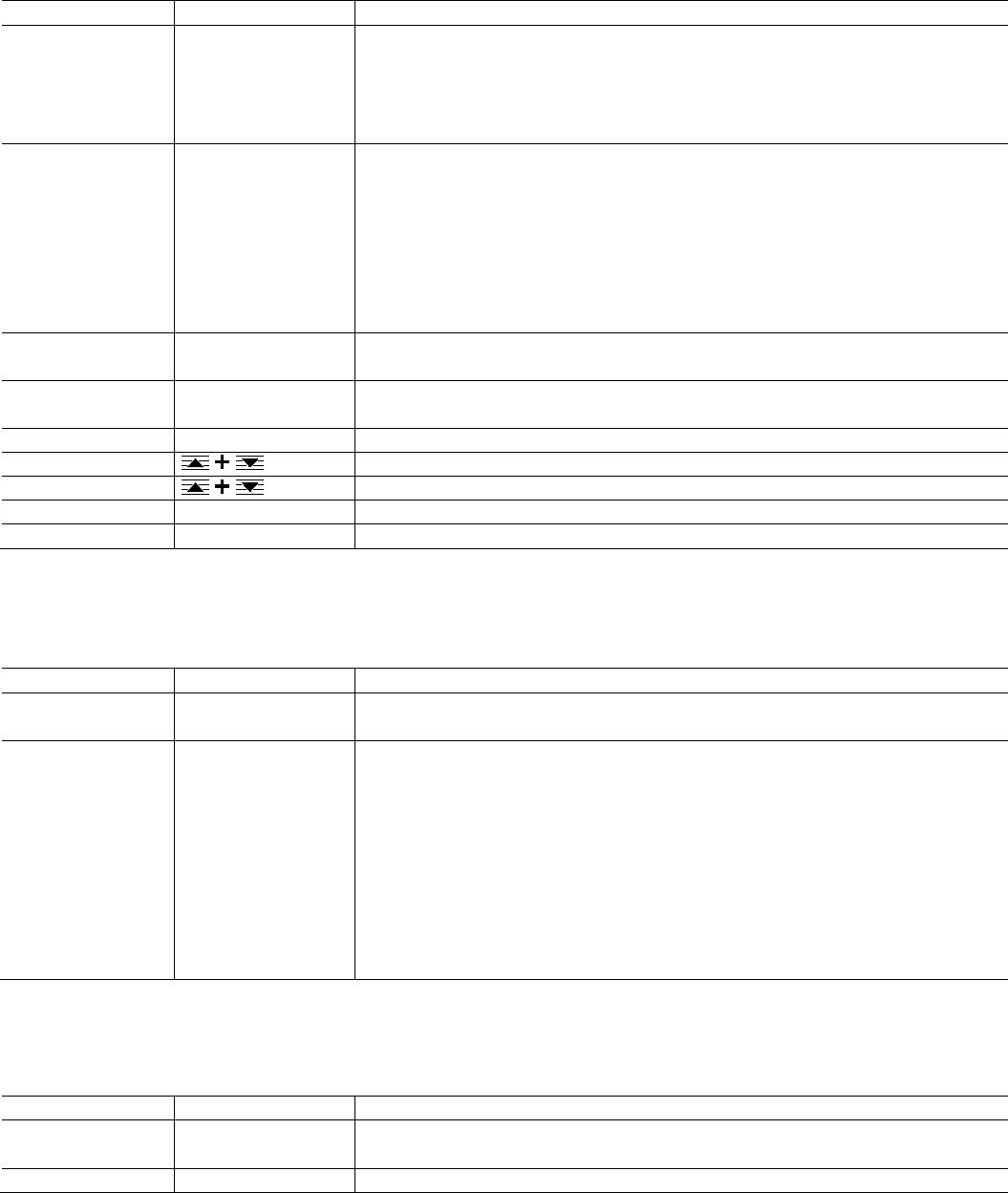
48 OI/FCB300/FCH300-EN Rev. F | CoriolisMaster FCB330, FCB350, FCH330, FCH3500
7.4.5 Menu: Unit
…/ Unit
Mask contents
Value range
Description
Unit Qm g/s, g/min, g/h, kg/s,
kg/min, kg/h, kg/d, t/min,
t/h, t/d, lb/s, lb/min, lb/h,
lb/d, abc/s, abc/min,
abc/h, abc/d
Selection of the unit for the mass flow.
The selection is applied for the "QmMax" and "QmMax Meter Tube" parameters as well as for the
display of the current mass flow.
Unit Qv l/s, l/min, l/h, m3/s,
m3/min, m3/h, m3/d,
ft3/s, ft3/min, ft3/h, ft3/d,
ugl/s, ugl/min, ugl/h,
mgl/d, igps, igpm, igph,
igpd, bbl/s, bbl/min,
bbl/h, bbl/d, abc/s,
abc/min, abc/h, abc/d
Selection of the unit for the volume flow.
The selection is applied, for example, when the volume flow is displayed or the minimum and
maximum limits for the current output are entered, if the volume flow is to be output at the current
output.
Density unit g/ml, g/l, g/cm3, kg/l,
kg/m3, lb/ft3, lb/ugl
Selection of the unit for the density.
Totalizer Unit Volume
abc, l, m3, ft3, ugl, igl,
bbl
Selection of the unit for the volume totalizer.
Totalizer Unit Mass g, kg, t, lb, abc
Selection of the unit for the mass totalizer.
Prog. Unit Qm
Select the "Prog. Unit Qm" submenu (programmed mass unit).
Prog. Unit Qv Select the "Prog. Unit Qv" submenu (programmed volume unit).
Temp. unit °C, K, °F Selection of the unit for the temperature.
Unit concentration %, BRIX, Baumé, etc. Selection of the unit for the concentration. See also the "Concentration" menu.
…/ Unit / Prog. Unit Qm
A user-defined (programmed) mass unit can be defined in this menu. This unit is available for selection in the corresponding
menus and parameters.
Mask contents
Value range
Description
Unit name ASCII, maximum 3
characters
Entry indicating the name of the user-defined mass unit or the unit of the standard volume.
Units factor 0.00001 … 5000000 kg Entry indicating the kg/unit factor of the user-defined mass unit.
Using this factor the Prog. Unit Qm can be used to calculate standard volume as output variable
based on the massflow.
Just enter the reference density value as a factor in this submenu. Please always enter the
reference density using the unit [kg/x] where x is the standard volume unit of your choice..
Example:
Gas with density reference of 1.28kg/m3
Units factor = 1,28; Unit name = Nm3
To be able to output this standard volume, please choose this new customized unit in submenu
"Unit" and choose "Qm" or "mass" in the output of your choice.
…/ Unit / Prog. Unit Qv
A user-defined (programmed) volume unit can be defined in this menu. This unit is available for selection in the corresponding
menus and parameters.
Mask contents
Value range
Description
Unit name ASCII, maximum 3
characters
Entry indicating the name of the user-defined volume unit.
Units factor
0.00001 … 5000000 l
Entry indicating the l/unit factor of the user-defined mass unit.

CoriolisMaster FCB330, FCB350, FCH330, FCH3500 | OI/FCB300/FCH300-EN Rev. F 49
7.4.6 Menu: Flowmeter primary
…/ Flowmeter primary
Mask contents
Value range
Description
Meter tube Read only Displays the device's nominal diameter setting.
QmMax meter tube Read only Displays the QmMax (maximum mass flow) for the corresponding device nominal diameter.
Order no. Read only Display of the order number. The order number displayed matches the information on the name
plate and in the external data memory.
7.4.7 Menu: QmMax
…/ QmMax
Mask contents
Value range
Description
QmMax
0.01 … 1.0 x QmMax
meter tube
Entry indicating the flow range.
The flow range can be set between the limits 0.01 ... 1.0 QmMax Meter Tube and applies to both
flow directions. QmMax is the value used as the basis for the Qm current value, the low flow
cutoff value, and the Qm alarm limits. (QmMax = 20 mA for Qm current output)
IMPORTANT (NOTE)
When a new nominal diameter is entered, the value of the QmMax parameter is
automatically set to 1.0 x QmMax meter tube.
7.4.8 Menu: Damping
…/ Damping
Mask contents
Value range
Description
Damping (5 tau)
1 … 100 s Entry indicating the damping.
The damping represents the time required for the transmitter to reach 99 % of the end value in
one unit step.
7.4.9 Menu: Low cutoff setting
…/ Low cutoff setting
Mask contents
Value range
Description
Low cutoff setting
0 … 10 % Entry indicating the low flow as a % of QmMax.
The maximum low flow cutoff setting is 10 %. The switching hysteresis is 0.1 %. If a value of 0 %
is entered for the low flow cutoff, then the switching hysteresis is also deactivated.
7.4.10 Menu: Field optimization
…/ Field optimization
Mask contents
Value range
Description
D correction -50 … 50 g/l Entry indicating the correction factor for the density.
In order to attain an accuracy in the density measurement which comes close to the
reproducibility of 0.0001 g/ml, this factor can be used to perform an optimization in the field. The
limits of this correction are ±50 g/l (± 0.05 g/ml).
Qm correction -5 … 5 % Entry indicating the correction factor for flow measurement.
In order to attain an accuracy in the flow measurement which comes close to or even exceeds a
reproducibility of at least 0.1 % of the measured value, this factor can be used to undertake an
optimization in the field. This value acts as a correction value for the current mass flow rate. It is
given as a percentage of the current measured value.
The limits of this entry are ±5 % of the measured value.
C correction tab. 1
-1000 … 1000 % Entry indicating the correction factor for concentration measurement.
In order to attain an accuracy in the concentration measurement which comes close to or even
exceeds reproducibility, this factor can be used to undertake an optimization in the field. This
value acts as a correction value for the current concentration measured value.
It is given in the unit that is currently set for concentration. The correction value is based on the
concentration matrix currently selected. In the case of one fixed matrix, only one correction value
is available. If variable matrices are used, 2 values are available.
C correction tab. 2
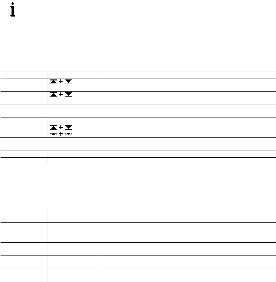
50 OI/FCB300/FCH300-EN Rev. F | CoriolisMaster FCB330, FCB350, FCH330, FCH3500
7.4.11 Menu: System Zero adj.
IMPORTANT (NOTE)
Prior to starting the zero adjustment, make sure that:
— The flowmeter sensor must be filled completely with medium for measurement.
— There is no flow through the flowmeter sensor (close all valves, shut-off devices, etc.)
— No pressure surges in the medium for measurement.
— The flowmeter sensor must be vibration-free.
— There must be no gas bubbles in the medium for measurement.
— Zero point adjustment must be performed under normal operating conditions (operating temperature, operating
pressure, etc.).
…/ System Zero adj.
Mask contents
Value range
Description
System Zero adj.
Function automatic?
Select the "System Zero adj. Function automatic?" submenu.
System Zero adj.
manual?
Select the "System Zero adj. manual?" submenu.
…/ System Zero adj. / System Zero adj. Function automatic?
Mask contents
Value range
Description
System Zero adj. Slow?
Start slow adjustment of the system zero point.
System Zero adj. Fast? Start fast adjustment of the system zero point.
…/ System Zero adj. / System Zero adj. manual?
Mask contents
Value range
Description
System Zero adj. x.xxx % Entry indicating the value for manual zero point adjustment.
7.4.12 Menu: Alarm
Entry of limit values (minimum and maximum) for the mass flow, density, concentration, and temperature variables. The entry of
values above or below the limit values can be signaled with the digital switching output 41 / 41. The settings are configured via
the "… / Switch contacts / Contact output" menu.
…/ Alarm
Mask contents
Value range
Description
Min Alarm Qm 0 … 105 % Entry indicating the lower limit for mass flow. The value must be less than "Max Alarm Qm".
Max Alarm Qm 0 … 105 % Entry indicating the upper limit for mass flow. The value must be greater than "Min Alarm Qm".
Min Alarm density
0.5 … 3.5 kg/l
Entry indicating the lower limit for density. The value must be less than "Max Alarm density".
Max Alarm density 0.5 … 3.5 kg/l Entry indicating the upper limit for density. The value must be greater than "Min Alarm density".
Min Alarm Temp.
-50 … 200 °C
Entry indicating the lower temperature limit. The value must be less than "Max Alarm Temp.".
Max Alarm Temp. -50 … 200 °C Entry indicating the upper temperature limit. The value must be greater than "Min Alarm Temp.".
Min Alarm Concentr. -5 … 105,0 % Entry indicating the lower limit for concentration. The value must be less than "Max Alarm
Concentr.".
Max Alarm Concentr. -5 … 105,0 % Entry indicating the upper limit for concentration. The value must be greater than "Min Alarm
Concentr.".

CoriolisMaster FCB330, FCB350, FCH330, FCH3500 | OI/FCB300/FCH300-EN Rev. F 51
7.4.13 Menu: Display
Configuration of the flowmeter sensor process display. There are two lines for the independent display of two values. Multiplex
mode can also be activated. When multiplex mode is activated, two values which change automatically (every 3 seconds) are
displayed on each line.
…/ Display
Mask contents
Value range
Description
1st Line
See the following table
Selection of the value displayed.
2nd Line
1st Line Multiplex
2nd Line Multiplex
Value
Description
Q [Bargraph] Displays the flow as bars.
Qm
Displays the mass flow in the configured unit.
Qv Displays the volume flow in the configured unit.
Q [%]
Displays the mass flow in percent.
Temperature Displays the medium temperature in the configured unit.
Density
Displays the density in the configured unit.
Concentr. Unit Displays the concentration in the configured unit.
Concentr. Percent
Displays the concentration in percent.
Qm Concentration Displays the net mass flow according to the current concentration.
TAG Nummer Displays the configured TAG number.
Totalizer Mass
Displays the mass forward or reverse flow totalizer dependent on the present flow direction
Totalizer Mass>F Displays the mass forward flow totalizer.
Totalizer Mass<R
Displays the mass reverse flow totalizer.
Totalizer Volumes Displays the volume forward or reverse flow totalizer dependent on the current flow direction.
Totalizer Vol.>V
Displays the volume forward flow totalizer.
Totalizer Vol.<R Displays the volume reverse flow totalizer.
Totalizer Net Mass Displays the net mass totalizer according to the net mass flow.
Total. Net Mass >F Displays the net mass forward flow totalizer.
Total. Net Mass <R Displays the net mass reverse flow totalizer.
Pipe frequency
Frequency of the meter pipe.
Blank -
Off
Multiplex mode deactivate (multiplex mode only).
IMPORTANT (NOTE)
The units of the displayed values correspond to the units configured in the "… / Unit" menu.
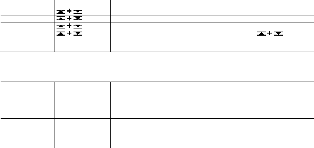
52 OI/FCB300/FCH300-EN Rev. F | CoriolisMaster FCB330, FCB350, FCH330, FCH3500
7.4.14 Menu: Totalizer
All four to six totalizers count up to 10 million (in the selected totalizer unit). After a value of 10 million is reached, the
corresponding overflow counter is incremented by one and the totalizer value reset to zero to continue counting the flow.
In order to indicate in the process display that an overflow has occurred, a warning is displayed. Up to 65,535 overflows can be
registered per totalizer.
A value for each totalizer can be individually set or reset (by entering a zero value) in the appropriate menu. When a totalizer is
set (or reset), the relevant overflow counter automatically resets to zero.
If the "Mode of operation" setting has been selected in the "… / Flow indication / Forward" menu, the "Totalizer" menu will
only contain the parameters for the forward totalizer.
… / Totalizer
Mask contents
Value range
Description
Totalizer mass Select the "Totalizer mass" submenu.
Totalizer volume
Select the "Totalizer volume" submenu.
Totalizer net. mass Select the "Totalizer net. mass" submenu.
Totalizer Reset Resets all totalizers once the security prompt has been confirmed with . All totalizers
are reset at the same time. To clear an individual totalizer, set the corresponding parameters to
zero.
… / Totalizer / Totalizer mass
… / Totalizer / Totalizer volume
… / Totalizer / Totalizer net. mass
Mask contents
Value range
Description
Counter > F
0 … 10.000.000
Entry and display of the totalizer reading in the forward direction for the corresponding totalizer.
Overflow > F Read only Displays the totalizer overflows in the forward direction for the corresponding totalizer. An
overflow is equivalent to a totalizer reading of 10,000,000. A maximum of 65, 636 overflows can
be displayed.
Totalizer < R 0 … 10.000.000 Entry and display of the totalizer reading in the reverse direction for the corresponding totalizer.
Overflow < R Read only Displays the totalizer overflows in the reverse direction for the corresponding totalizer. An overflow
is equivalent to a totalizer reading of 10,000,000. A maximum of 65, 636 overflows can be
displayed.
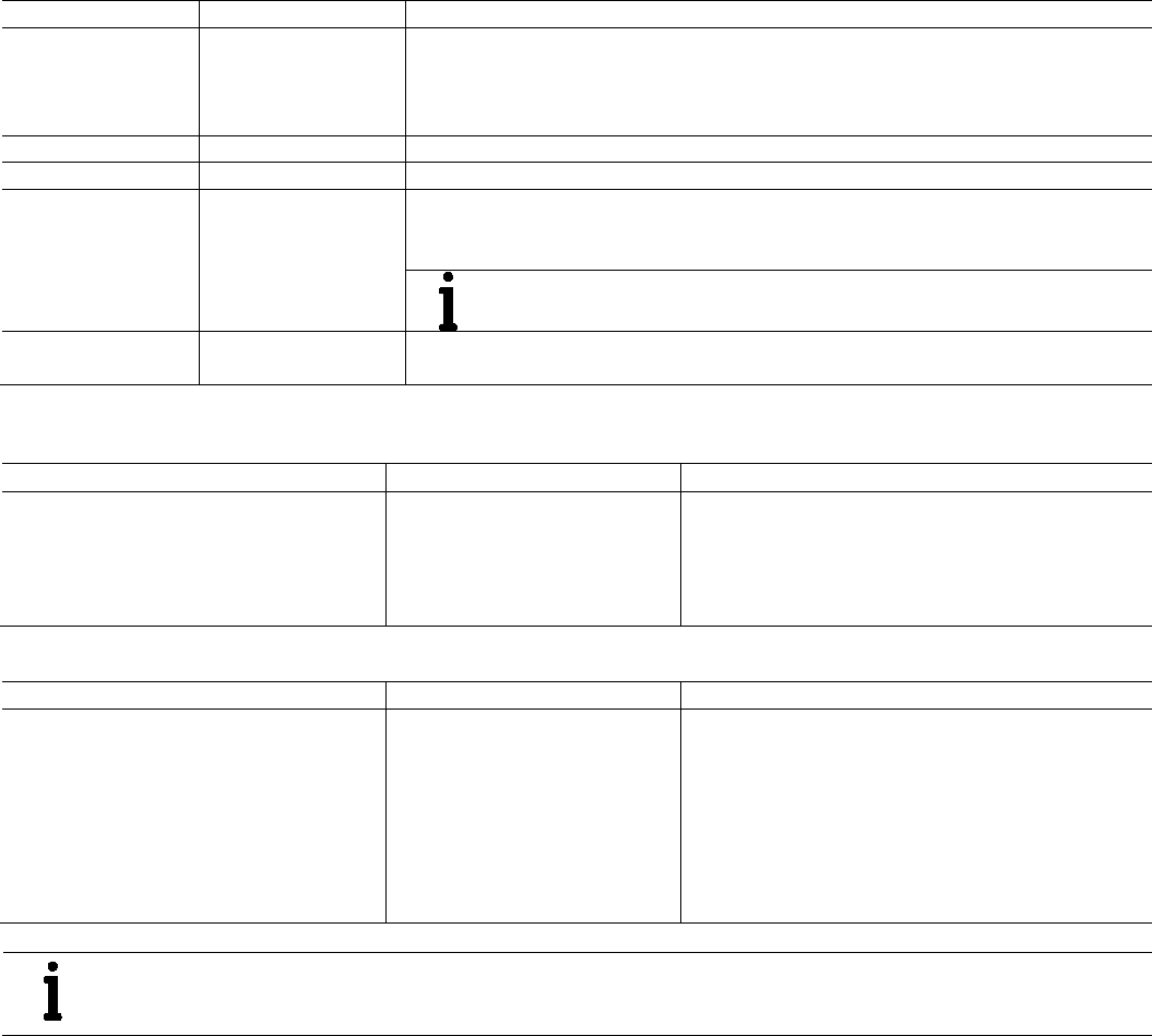
CoriolisMaster FCB330, FCB350, FCH330, FCH3500 | OI/FCB300/FCH300-EN Rev. F 53
7.4.15 Menu: Pulse Output
… / Pulse Output
Mask contents
Value range
Description
Output of Mass
Volume
Qm Concentration
Selection of the measured value output at the pulse output.
— Mass: Output of mass flow
— Volume: Output of volume flow
— Qm Concentration: Output of net mass flow
QvMax pulse
Displays the flow rate per pulse (only with output of volume flow).
Qm% max pulse
Displays the mass per pulse (only with output of mass flow).
Pulse 0.001 … 1000 pulse/unit Entry indicating pulses per unit (pulse factor).
This entry may be corrected by the flowmeter sensor as the limit frequency of the pulse output is
5000 Hz.
IMPORTANT (NOTE)
An increase in the pulse factor can result in a reduction of the pulse width!
Pulse width 0.1 … 2000 ms Entry indicating the pulse width. The pulse factor and pulse width are interdependent and may be
corrected by the flowmeter sensor.
Examples
Example 1
Settings
Entry
Result
QmMax = 24 kg/min = 0.4 kg/s
Totalizer unit kg
Pulse factor: 100 pulses/kg
New pulse width: 10 ms
0.4 kg/s x 100 pulses/kg = 40 pulses/s = 40 Hz
Period = 25 ms
Maximum pulse width = Period/2 = 12.5 ms
Result: The entered pulse width of 10 ms is acceptable.
Example 2
Settings Entry Result
QmMax = 6 kg/min = 0.1 kg/s = 100 g/s
Totalizer unit g
Pulse width: 10 ms
New pulse factor: 60 pulses/g
100g/s x 60 pulses/g = 6000 pulses/s = 6000 Hz
The limit frequency of 5000 Hz has been exceeded. The
flowmeter sensor automatically set the pulse factor to 50
pulses/g and the period to 0.2 ms (5 kHz), which
corresponds to exactly 5000 Hz.
Maximum pulse width = Period /2 = 0.1 ms
Result: The entered pulse factor and also the pulse width
had to be reduced.
IMPORTANT (NOTE)
If you are using a mechanical totalizer, we recommend setting a pulse width of ≥ 30 ms and a maximum frequency
of fmax ≤ 3 kHz.

54 OI/FCB300/FCH300-EN Rev. F | CoriolisMaster FCB330, FCB350, FCH330, FCH3500
7.4.16 Menu: Current output 1
… / Current output 1
Mask contents
Value range
Description
Output of Qm, Qv, Density,
Temperature,
Concentration
Selection of the measured value output at current output 1 (31 / 32).
Qv → l = 100 %
0.1 … 10.000.000 Entry indicating the volume flow at which the current output reaches its maximum value (20 mA)
(only visible if the volume flow is output via the current output).
Density → l = 0 %
0.5 ... 3.5 g/cm
3
Entry indicating the density at which the current output reaches its minimum value (0 mA)
(only visible if the density is output via the current output).
Density → l = 100 %
0.5 ... 3.5 g/cm
3
Entry indicating the density at which the current output reaches its maximum value (20 mA)
(only visible if the density is output via the current output).
Temp → l = 0 %
-50 … 200 °C
Entry indicating the temperature at which the current output reaches its minimum value (0 mA)
(only visible if the temperature is output via the current output).
Temp → l = 100 %
-50 … 200 °C Entry indicating the temperature at which the current output reaches its maximum value (20 mA)
(only visible if the temperature is output via the current output).
Qm% → l = 100 %
- Entry indicating the net mass flow at which the current output reaches its maximum value (20 mA)
(only visible if the net mass flow is output via the current output).
Concentr. → l = 0 %
Entry indicating the concentration at which the current output reaches its minimum value (0 mA)
(only visible if the concentration is output via the current output).
Concentr. → l = 100 %
Entry indicating the concentration at which the current output reaches its maximum value (20 mA)
(only visible if the concentration is output via the current output).
Current output 0 … 20 mA, 4 … 20 mA Select the operating mode for the current output. 4 … 20 mA must be selected for active HART
communication.
IMPORTANT (NOTE)
HART communication takes place via current output 1. If HART communication is to
be used, 4 … 20 mA MUST be selected as the operating mode.
— If HART communication is activated in 0 … 20 mA operating mode, an error
message is displayed and the communication mode does not change.
— If 0 … 20 mA operating mode is activated when HART communication is
activated, an error message is displayed and HART communication is
deactivated.
Iout for Alarm Low, High Select the status of current output 1 in error condition. The output "Low" or "High" current is set
in the subsequent menus.
Low Alarm 2 … 3.6 mA Select the current for Low alarm.
The value is a function of the current output range selected.
For the current output range 0 ... 20 mA, the alarm current is 0 mA.
For the current output range 4 ... 20 mA, the low alarm current can be set between the limits of
2 ... 3.6 mA.
When the current output range is changed, the transmitter automatically adjusts the low alarm
current to the new current output range (current output range 0 ... 20 mA to 0 mA and
4 ... 20 mA to 2 mA).
High Alarm 21 … 26 mA Select the current for High alarm.
The value for the alarm current is independent of the current output range selected, since all
range end values are 20 mA. The high alarm current can be set between the limits of 21 mA and
26 mA.

CoriolisMaster FCB330, FCB350, FCH330, FCH3500 | OI/FCB300/FCH300-EN Rev. F 55
7.4.17 Menu: Current output 2
In contrast to current output 1, current output 2 is not HART-enabled and has a fixed current output range (4 ... 20 mA).
… / Current output 2
Mask contents
Value range
Description
Output of Qm, Qv, Density,
Temperature,
Concentration
Selection of the measured value output at current output 1 (31 / 32).
Qv → l = 100 % 0.1 … 10.000.000 Entry indicating the volume flow at which the current output reaches its maximum value (20 mA).
(only visible if the volume flow is output via the current output).
Density → l = 0 % 0.5 ... 3.5 g/cm
3
Entry indicating the density at which the current output reaches its minimum value (0 mA).
(only visible if the density is output via the current output).
Density → l = 100 % 0.5 ... 3.5 g/cm
3
Entry indicating the density at which the current output reaches its maximum value (20 mA)
(only visible if the density is output via the current output).
Temp → l = 0 % -50 … 200 °C Entry indicating the temperature at which the current output reaches its minimum value (0 mA)
(only visible if the temperature is output via the current output).
Temp → l = 100 % -50 … 200 °C Entry indicating the temperature at which the current output reaches its maximum value (20 mA)
(only visible if the temperature is output via the current output).
Qm% → l = 100 % - Entry indicating the net mass flow at which the current output reaches its maximum value (20 mA)
(only visible if the net mass flow is output via the current output).
Concentr. → l = 0 % Entry indicating the concentration at which the current output reaches its minimum value (0 mA)
(only visible if the concentration is output via the current output).
Concentr. → l = 100 % Entry indicating the concentration at which the current output reaches its maximum value (20 mA)
(only visible if the concentration is output via the current output).
Iout for Alarm Low, High Select the status of current output 1 in error condition. The output "Low" or "High" current is set
in the subsequent menus.
Low Alarm 2 … 3.6 mA Select the current for Low alarm.
High Alarm
21 … 26 mA
Select the current for High alarm.

56 OI/FCB300/FCH300-EN Rev. F | CoriolisMaster FCB330, FCB350, FCH330, FCH3500
7.4.18 Menu: Switch contacts
… / Switch contacts
Mask contents
Value range
Description
Contact input No function,
Totalizer reset. Concentr.
Table, Ext. output Shut-
off, Totalizer reset.
Selection of the function for the digital switching input (81 / 82).
— No function: Switching input without function.
— Totalizer reset. Concentr. Table: Switchover of tables (matrix 1 / 2) for concentration
measurement.
— Ext. output Shut-off: Current and pulse outputs are set to 0, the totalizers are stopped.
— Totalizer reset.: Resets all totalizers to zero.
Contact output See the following table Selection of the function for the digital switching output (41 / 42).
The output can be configured for the selected function as either a normally open contact or a
normally closed contact.
Function Contact output
Description
No function No function, output open.
F/R-Signal _
Output of flow direction, output closed when flow is in reverse direction.
F/R-Signal / Output of flow direction, output open when flow is in reverse direction.
General alarm _
Output closed unless a general alarm is pending. Output opens in the event of a fault.
General alarm / Output open unless a general alarm is pending. Output closes in the event of a fault.
MAX/MIN Alarm _
Output closed unless a min./max. alarm is pending. Output opens in the event of a min./max. alarm.
MAX/MIN Alarm / Output open unless a min./max. alarm is pending. Output closes in the event of a min./max. alarm.
MIN Alarm _ Output closed unless a min. alarm is pending. Output opens in the event of a min. alarm.
MIN Alarm / Output open unless a min. alarm is pending. Output closes in the event of a min. alarm.
MAX Alarm _ Output closed unless a max. alarm is pending. Output opens in the event of a max. alarm.
MAX Alarm /
Output open unless a max. alarm is pending. Output closes in the event of a max. alarm.
7.4.19 Menu: Label
…/ Label
Mask contents
Value range
Description
TAG number ASCII, maximum 8
characters
Entry of a TAG number identifying the measuring point in the HART protocol.
Descriptor ASCII, maximum 16
characters
Entry of a HART descriptor.
Date 1.1.1900 … 31.12.2155 Date of the HART file.
Unit number Read only Display indicating the device number.
7.4.20 Menu: Interface
…/ Interface
Mask contents
Value range
Description
Communication Off, HART Selection of the communication mode for digital communication.
— Off: No digital communication.
— HART: HART communication active via current output 1. The operating mode for current
output 1 must first be set to 4 … 20 mA.
Unit address 0 … 15 Entry indicating the HART address. The HART protocol has provisions for creating a bus with up
to 15 devices (1 ... 15).
IMPORTANT (NOTE)
If an address greater than 0 is set, the device operates in multidrop mode. The
current output is fixed at 4 mA. Apart from that, the current output is only used for
HART communication.
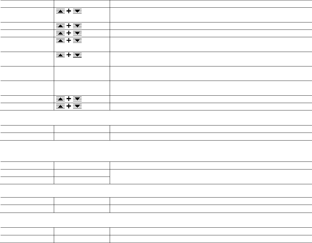
CoriolisMaster FCB330, FCB350, FCH330, FCH3500 | OI/FCB300/FCH300-EN Rev. F 57
7.4.21 Menu: Function test
… / Function test
Mask contents
Value range
Description
Function test pulse
Output
Select the "Function test pulse Output" submenu.
Function test Iout 1
Select the "Function test Iout 1" submenu.
Function test Iout 2
Select the "Function test Iout 2" submenu.
Function test Contact
input
Select the "Function test Contact input" submenu.
Function test Contact
output
Select the "Function test Contact output" submenu.
Function test HART
Transmitter
1200 Hz, 2200 Hz Selection of the HART frequency to be simulated.
Function test HART
Command
Read only Display of the most recently received HART command.
Function test Memory Activation of the memory function test.
Simulation
Select the "Simulation" submenu.
… / Function test / Function test pulse Output
Mask contents
Value range
Description
Pulse Output
0.001 … 5000 Hz Entry indicating the pulse rate for testing the pulse output. Press any button to abort.
… / Function test / Function test Iout 1
… / Function test / Function test Iout 2
Mask contents
Value range
Description
Iout 1 0 … 26 mA Entry indicating the output current for testing current output 1. Press any button to abort.
Iout 2
3.5 … 26 mA
… / Function test / Function test Contact input
Mask contents
Value range
Description
Contact input
On, off Test of the switching input. Press any button to abort.
… / Function test / Function test Contact output
Mask contents
Value range
Description
Contact output
On, off Test of the switching output. Press any button to abort.

58 OI/FCB300/FCH300-EN Rev. F | CoriolisMaster FCB330, FCB350, FCH330, FCH3500
… / Function test / Simulation
The Simulation menu contains a number of options which can be used to set individual or even all measured variables of the
transmitter to programmable values. When simulation is turned on, additional menu items become available in the submenu
Simulation.
They enable you to determine for every variable whether it should be measured or simulated and what value should be assigned
to it. Therefore a selection can be made from the following:
Value
Description
Measure The true measured value of the variable is output.
Enter
The value of the variable is simulated and can be set to a fixed value using the appropriate menu.
Step The variable is simulated and can be increased or decreased in steps using the STEP and DATA keys if the process display is
shown.
Mask contents
Value range
Description
Simulation On, off Activation of the simulation functions.
Qm Measure, enter, step Selection of the simulation function.
Qm
-115 … +115 %
Entry indicating of the mass flow rate to be simulated in %.
Density
Measure, enter, step
Selection of the simulation function.
Density 0.001 g/ml Entry indicating the density to be simulated in g/ml.
Temperature
Measure, enter, step
Selection of the simulation function.
Temp. housing Measure, enter, step Selection of the simulation function.
Temperature -60 … 210 °C Entry indicating the temperature to be simulated in °C.
Temp. housing
-60 … 210 °C
Entry indicating the temperature to be simulated in °C.
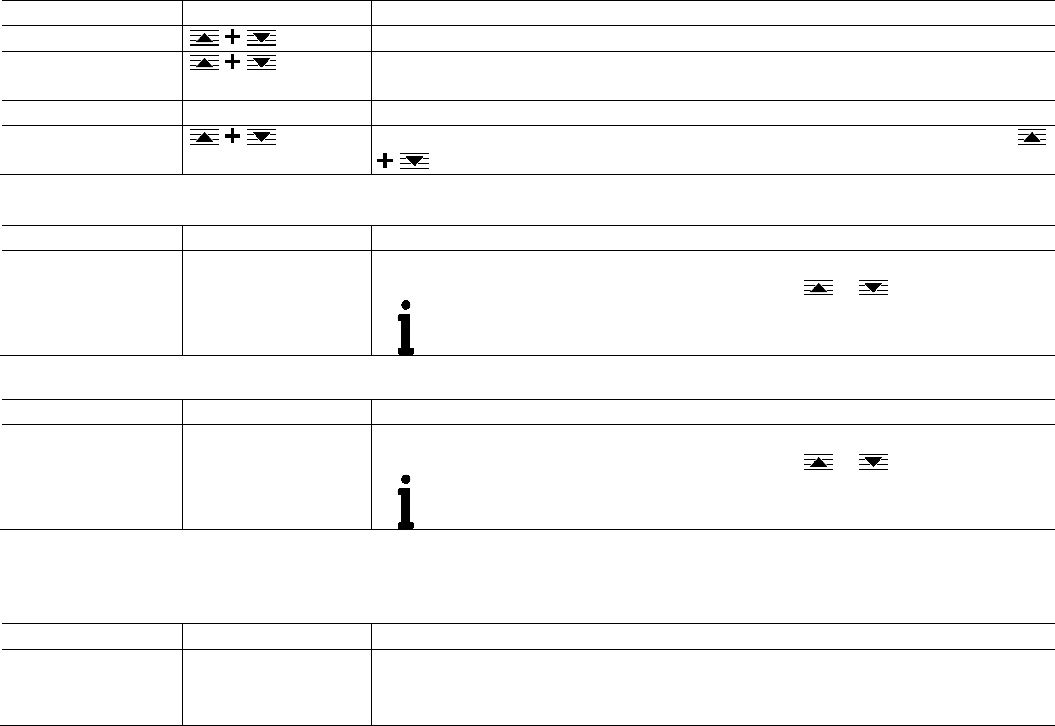
CoriolisMaster FCB330, FCB350, FCH330, FCH3500 | OI/FCB300/FCH300-EN Rev. F 59
7.4.22 Menu: Status
… / Status
Mask contents
Value range
Description
Error log Number: 3
Display indicating the number of error messages saved and selection of the "Error log" submenu.
Warning Register
Number: 1
Display indicating the number of warnings saved and selection of the "Warning register"
submenu.
Power outage
Read only
Display indicating the number of power outages.
Status Reset To reset the error log, warning register, and power outage log, confirm the prompt and press
. All three are reset at the same time.
… / Status / Error log
Mask contents
Value range
Description
7 (Set) Temp.
Measurement
Read only (example) Displays the last error that occurred with error number and status (current or set).
If more errors are pending, you can scroll through the list with or .
9a (current) Density
measurement
IMPORTANT (NOTE)
The errors are not listed in order of priority!
… / Status / Warning register
Mask contents
Value range
Description
4 (Set) Ext. Cut-off Read only (example) Displays the last error that occurred with error number and status (current or set).
If more errors are pending, you can scroll through the list with or .
IMPORTANT (NOTE)
The errors are not listed in order of priority!
7.4.23 Menu: Software version
…/ Software version
Mask contents
Value range
Description
CoriolisMaster 03.2012
FCB FW
Read only (example)
Displays the software version.
The device ID and the software revision date are displayed on the first line.
The software ID and the revision level are displayed on the second line.
In addition to the software identification in the menu, the identification can also be found on the information tag on the
transmitter module.

60 OI/FCB300/FCH300-EN Rev. F | CoriolisMaster FCB330, FCB350, FCH330, FCH3500
Chan ge from on e to two c olumns
7.5 DensiMass concentration measurement
(FCB350 only)
The transmitter can calculate the current concentration from
the measured density and temperature using concentration
matrices.
The following concentration matrices are preconfigured in the
transmitter as standard:
— Concentration of sodium hydroxide in water
— Concentration of alcohol in water
— Concentration of sugar in water
— Concentration of corn starch in water
— Concentration of wheat starch in water
The user can enter two more user-defined matrices containing
up to 100 values.
7.5.1 Accuracy of concentration measurement
The accuracy of the concentration measurement is determined
in the first instance by the quality of the matrix data entered.
However, as the calculation is based on temperature and
density (the input variables), the accuracy of the concentration
measurement is ultimately determined by the measuring
accuracy of temperature and density.
Example:
Density of 0 % alcohol in water at 20 °C (68 °F): 998.23 g/l
Density of 100 % alcohol in water at 20 °C (68 °F): 789.30 g/l
Concentration Density
100 % 208.93 g/l
0.48 % 1 g/l
0.69 % 2 g/l
The accuracy class of the density measurement thus directly
determines the accuracy of the concentration measurement.
7.5.2 Entering the concentration matrix
The concentration matrix is entered via the "... /
Concentration / Variable Matrix" menu. The data for the
matrix must be available as described in the "Structure of the
concentration matrix" section.
Step 1:
Menu "… / Concentration / Variable Matrix".
Enter the unit name for the variable matrix, enter the upper
and lower concentration limits.
Step 2:
Enter the basic settings for the matrix in the
"… / Concentration / Variable Matrix / Configuration"
menu.
The number of matrices (1 or 2), the number of temperature
values, and the number of concentration values are specified
here.
Step 3:
Enter the matrix data in the "… / Concentration / Variable
Matrix / Matrix 1 / 2" menu.
The temperature values, the concentration values (in the
required unit or in %), and the density values are entered here.
Once the data has been entered, select "Matrix calculation"
from the menu to calculate the matrix. Missing values are
interpolated or extrapolated.
Step 4:
Save the matrices by selecting the "Concentration" option
from the "… / Variable Matrix / Enter matrix finish" menu.
This completes the process to enter the matrices.

CoriolisMaster FCB330, FCB350, FCH330, FCH3500 | OI/FCB300/FCH300-EN Rev. F 61
Chan ge from tw o to one c olum n
7.5.3 Structure of the concentration matrix
The software supports two different concentration values:
1. Concentration in unit (e.g., % or °Bé)
The range of values is not restricted, the value can be output at the current output, the value can be selected in the Units
submenu.
2. Concentration in percent (%)
The range of values is restricted to 0 ... 103.125 %. This value is only used for the internal calculation of the net mass flow.
The net mass flow can be output at the current and pulse outputs.
Concentration MIN/MAX limit: -5.0 ... 105.0.
The matrix for calculating the concentration looks like this:
Temperature 1 … Temperature n
Value 1 concentration in %
Value 1 concentration in
unit (e.g., % or°Bé)
Value 1,1 density
… Value n,1 density
….
…
…
…
…
Value m concentration in %
Value m concentration
in unit (e.g., % or°Bé)
Value 1, m density
… Value n,m density
The following rules apply when entering values in the matrix:
— One matrix: 2 ≤ N ≤ 20; 2 ≤ M ≤ 20; N * M ≤ 100
— Two matrices: 2 ≤ N ≤ 20; 2 ≤ M ≤ 20; N * M ≤ 50
The density values in a column must be in ascending order due to the algorithm used in the transmitter software.
Density x,1 < … < Density x,2 <…< Density x,M for 1 ≤ x ≤ M
The temperature values must be in ascending order from left to right due to the algorithm used in the transmitter software.
Temperature 1 <…< Temperature x <…< Temperature N for 1 ≤ x ≤ N
The concentration values must be monotonically nondecreasing or monotonically nonincreasing from top to bottom due to the
algorithm used in the transmitter software.
Concentr. 1 <…< Concentr. x <…< Concentr. N for 1 ≤ x ≤ N
or
Concentr. 1 >…> Concentr. x > … > Concentr. N for 1 ≤ x ≤ N
Example:
10 °C (50 °F)
20 °C (68 °F)
30 °C (86 °F)
0 % 0 °BRIX 0,999 kg/l 0,982 kg/l 0,979 kg/l
10 % 10 °BRIX 1,010 kg/l 0,999 kg/l 0,991 kg/l
40 % 30 °BRIX 1,016 kg/l 1,009 kg/l 0,999 kg/l
80 %
60 °BRIX
1,101 kg/l
1,018 kg/l
1,011 kg/l
Chan ge from on e to two c olumns

62 OI/FCB300/FCH300-EN Rev. F | CoriolisMaster FCB330, FCB350, FCH330, FCH3500
Chan ge from tw o to one c olum n
7.6 Software history
In accordance with NAMUR recommendation NE53, ABB offers a transparent and traceable software history.
Standard and HART version
Software FCB FW
Software version Revision date Type of change Description
00.01.xx 03.2012 New release -
00.02.xx
06.2013
Update
Adding a new functionality: min density limit causing error "9b"
Chan ge from tw o to one c olum n
8 Error messages
8.1 General remarks
The tables on the following pages are an overview of the alarm program and describe the response of the converter when errors
are detected.
Listed are all the possible errors together with a description of their effects on the measurements as well as the status of the
current and alarm outputs.
If the entry in the column is blank there is no effect on the measurement variable or no alarm signal for the particular output. If in
the current output column only Alarm is listed, then an alarm output is transmitted based on the High- or Low-Alarm selections
made in the current output menus.
The sequence of the errors in the tables corresponds to the error priorities.
The first entry has the highest priority and the last the lowest.
If multiple errors are detected simultaneously, the error with the highest priority determines the alarm status of the measurement
variable and the current output. If an error with a higher priority does not affect the measurement variable or the output status,
then the error with the next highest priority determines the status of the measurement variable and the outputs.
Example:
If the error 7a “T Pipe measurement“ is active, the table indicates that this affects the value of the temperature measurement
variable (constant 20 °C [68 °F]).
Since the temperature measurement is absolutely necessary in order to calculate the density and thus also to calculate the Qv
value, the current outputs that are assigned to these parameters will enter the programmed alarm state (high or low alarm).
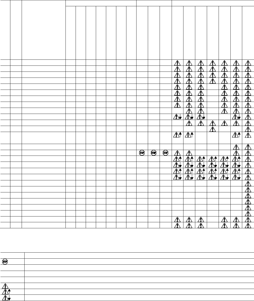
CoriolisMaster FCB330, FCB350, FCH330, FCH3500 | OI/FCB300/FCH300-EN Rev. F 63
8.2 Overview
Measurements
Totalizer
Current output
Priority
Error no.
Error text
Qm [%]
Qv [%]
Density [g/cm
3
]
Temperature [°C]
Concentration [%]
Concentration [unit]
Net mass flow
Mass
Volume
Net mass
Qm
Qv
Density
Temperature
Concentration [unit]
Net mass flow
Alarm output
1
5a
Internal FRAM
0
0
1
20
0
0
0
—
—
—
2
5b
External FRAM
0
0
1
20
0
0
0
—
—
—
3
10
DSP communication
0
0
1
20
0
0
0
—
—
—
4
1
AD Transmitter
0
0
1
20
0
0
0
—
—
—
5
11d
Sensor
0
0
1
—
0
0
0
—
—
—
—
6
0
Sensor amplitude
0
0
1
—
0
0
0
—
—
—
—
7
2a
Driver
0
0
1
—
0
0
0
—
—
—
—
8
2b
Driver current
0
0
1
—
0
0
0
—
—
—
—
9
9a
Density measurement
—
0
4
—
0
0
0
—
—
—
—
—
10
9b
Min Density
0
0
2)
—
2)
2)
0
—
—
—
—
—
11
7a
T Pipe measurement
—
—
—
20
0
0
0
—
—
—
—
12
7b
T Housing measurement
—
—
—
20
—
—
—
—
—
—
—
—
—
—
—
13 3
Flowrate >103.25 %
103
Qm =
103
— — — —
Qm =
103
— — —
— — —
14
12
Concentration (Percent)
—
—
—
—
0
—
0
—
—
—
—
—
—
—
—
15
4
Ext. zero return
—
—
—
—
—
—
—
—
—
—
16
8a
Iout 1 to large
—
—
—
—
—
—
—
—
—
—
17
8b
Iout 1 to small
—
—
—
—
—
—
—
—
—
—
18
8c
Iout 2 to large
—
—
—
—
—
—
—
—
—
—
19 8d
Iout 2 to small
— —
— — — — — — —
—
20
6a
Totalizer Mass -> V
—
—
—
—
—
—
—
1)
—
—
—
—
—
—
—
—
21
6b
Totalizer Mass <- R
—
—
—
—
—
—
—
1)
—
—
—
—
—
—
—
—
22
6c
Totalizer Vol.-> V
—
—
—
—
—
—
—
—
1)
—
—
—
—
—
—
—
23
6d
Totalizer Vol.<- R
—
—
—
—
—
—
—
—
1)
—
—
—
—
—
—
—
24
6e
Totalizer Net Mass -> V
—
—
—
—
—
—
—
—
—
1)
—
—
—
—
—
—
25
6f
Totalizer Net Mass <- R
—
—
—
—
—
—
—
—
—
1)
—
—
—
—
—
—
26
11a
Sensor A
0
0
1
—
0
0
0
—
—
—
—
27
11b
Sensor B
0
0
1
—
0
0
0
—
—
—
—
The totalizer readings and the states of the current outputs and the alarm output are represented by symbols; please see the
table below.
Symbol
Description
Totalizer stop
—
No change
1)
In the event of an error, the corresponding totalizer is reset to 0.
2)
In the event of an error, the corresponding measurement is set to the minimum density value.
Alarm (general)
High Alarm
Low Alarm

64 OI/FCB300/FCH300-EN Rev. F | CoriolisMaster FCB330, FCB350, FCH330, FCH3500
8.3 Error messages
Error message
Priority
Description
Possible causes
Corrective action
Error: 0
Sensor amplitude
6 The nominal-diameter-specific
sensor amplitude is less than 10 mV.
Does the error only occur when the
flowmeter sensor is full?
"Energy absorbent" fluid in meter
(e.g., high gas content, highly
viscous liquids), so that the driver
current is insufficient
Reduce gas content, change fluid
Very strong mechanical or hydraulic
disturbances in the pipeline
Decouple flowmeter sensor from
disturbances
Hazardous area design and remote
mount design:
Electrical resistance for driver cable
is too high
Reduce cable length, lower
resistance by connecting in parallel
or using a lower-resistance cable.
Error: 1
AD Transmitter
4 The AD converter is overloaded and
is not responding.
Sensor voltage is too large Check sensor amplitudes, check if
the setting for the sensor amplitude
is correct
The AD converter is defective Exchange DSP board
Error: 2a
Driver
7 Flowmeter sensor does not vibrate Control circuit is interrupted,
flowmeter sensor is incompatible
with converter
For remote design: Check wiring
between flowmeter sensor and
converter
Error: 2b
Driver current
8 The current limiter in the driver has
responded because the driver
current is insufficient
see error 0 see error 0
Error: 3
Flowrate >103.25 %
13
The value set in QmMax was
exceeded by more that 5%
Flow range setting too small Increase flow range (QmMax)
Flow too large Reduce flow rate
Error: 4
Ext. zero return
14
The flow rate is set to zero; the
totalizers are halted
The external switching input is set to
"High"
Set external switching input to "Low"
Error: 5b
External FRAM
2 Loss of the external database Database is corrupted Turn unit off and on again, call up
functional test for converter
Ext. memory module missing Ext. memory module must be
installed
Ext. memory module is empty Ext. memory module must be loaded
Error: 6a
Totalizer Mass -> V
19 The forward mass totalizer is
damaged beyond repair.
Reprogram the totalizer
Error: 6b
Totalizer Mass <- R
20 The reverse mass totalizer is
damaged beyond repair.
Reprogram the totalizer
Error: 6c
Totalizer Vol.-> V
21 The forward volume totalizer is
damaged beyond repair.
Reprogram the totalizer
Error: 6d
Totalizer Vol.<- R
22 The reverse volume totalizer is
damaged beyond repair.
Reprogram the totalizer
Error: 6e
Totalizer Net Mass ->
V
The net mass totalizer is damaged
beyond repair.
Reprogram the totalizer
Error: 6f
Totalizer Net Mass <-
R
The net mass totalizer is damaged
beyond repair.
Reprogram the totalizer

CoriolisMaster FCB330, FCB350, FCH330, FCH3500 | OI/FCB300/FCH300-EN Rev. F 65
Error message
Priority
Description
Possible Causes
Corrective action
Error: 7a
T Pipe measurement
11 Error during temperature
measurement.
For the temperature compensation of
the measurement variable Qm a
density of 20°C is used, i.e. for a
fluid temperature near 20 °C the
measurements will be correct
Incorrect wiring
(only for remote mount design)
Check wiring between flowmeter
sensor and converter
Pt 100 is defective Check the resistance of PT100 on
the flowmeter sensor
Error: 7b
T Housing
measurement
12 Error during temperature
measurement.
For the temperature compensation of
the measurement variable Qm a
density of 20°C is used, i.e. for a
fluid temperature near 20 °C the
measurements will be correct
Incorrect wiring
(only for remote mount design)
Check wiring between flowmeter
sensor and converter
Pt 100 is defective Check the resistance of PT100 on
the flowmeter sensor
Error: 8a
Iout 1 to large
15 The current value is above the
programmed range for current
output 1.
Range setting is too small Increase range setting
Error: 8b
Iout 1 to small
16 The current value is below the
programmed range for current
output 1
Range setting is too small Increase range setting
Error: 8c
Iout 2 to large
17 The current value is above the
programmed range for current
output 2.
Range setting is too small Increase range setting
Error: 8d
Iout 2 to small
18 The current value is below the
programmed range for current
output 2
Range setting is too small Increase range setting
Error: 9a
Density measurement
9 The measured density of the fluid in
the flowmeter sensor is outside of
the specifications
This error usually occurs together
with errors 1 and 9.
See errors 1 and 9
See errors 1 and 9
Error 9b:
Min Density
10 Refer to page 46, Menu „Mode of
operation / Min Density“.
Customer setting of „Min Density”. Prevent tubes from running empty or
elimitae gas bubbles in liquid.
Or remove the „Min Density“-Limit.
Error: 11a
Sensor A
23 The signal from Sensor A is missing Sensor A is defective, or the
amplitude control circuit is open
Measure resistance of Sensor A
Remote mount design: Check wiring
between flowmeter sensor and
converter
Error: 11b
Sensor B
24 The signal from Sensor B is missing Sensor B is defective, or the
amplitude control circuit is open
Measure resistance of Sensor B.
Remote mount design: Check wiring
between flowmeter sensor and
converter
Error: 11d
Sensor
5 The signal from at least two sensors
is missing
At least two sensors are faulty, or the
amplitude control circuit is open.
Measure resistance of the sensors.
Remote mount design: Check wiring
between flowmeter sensor and
converter
Error: 12
Concentration
(Percent)
Concentration in percent < 0 % or >
103.125 %.
Concentration in percent < 0 % or >
103.125 %.
Adjust the matrix data in the
Concentration submenu
Errors
Operating protection
Parameters cannot be changed The operating protection switch is
active
Deactivate the hardware protection
switch.

66 OI/FCB300/FCH300-EN Rev. F | CoriolisMaster FCB330, FCB350, FCH330, FCH3500
8.4 Warnings
Warning
Priority
Description
Possible Causes
Corrective action
Warning: 1
**Simulation**
16 The Simulation is turned on The Simulation is turned on in the
submenu Self Check
Turn off Simulation
Warning: 2
totalizer reset
1 A totalizer was reset - -
Warning: 5a
Min Alarm Qm
3 The value is below the MIN Alarm
setting for Qm
The value is below the MIN Alarm setting
for Qm
Reduce the MIN Alarm
Warning: 5b
Min Alarm Density
5 The value is below the MIN Alarm
setting for the density
The value is below the MIN Alarm setting
for the density
Reduce the MIN Alarm
Warning: 5c
Min Alarm Temp.
7 The value is below the MIN Alarm
setting for the temperature
The value is below the MIN Alarm setting
for the temperature
Reduce the MIN Alarm
Warning: 5d
Min Alarm Conc.
The value is below the MIN Alarm
setting for the concentration. The
switching hysteresis is ± 0.1 of the
set concentration unit.
The value is below the MIN Alarm setting
for the concentration.
Reduce the MIN Alarm
Warning: 6a
Max Alarm Qm
2 The value is above the MAX Alarm
setting for Qm
The value is above the MAX Alarm
setting for Qm
Increase the MAX Alarm
Warning: 6b
Max Alarm Density
4 The value is above the MAX Alarm
setting for the density
The value is above the MAX Alarm
setting for the density
Increase the MAX Alarm
Warning: 6c
Max Alarm Temp.
6 The value is above the MAX Alarm
setting for the temperature
The value is above the MAX Alarm
setting for the temperature
Increase the MAX Alarm
Warning: 6d
Max Alarm Conc.
The value is above the MAX Alarm
setting for the concentration. The
switching hysteresis is ± 0.1 of the
set concentration unit.
The value is above the MAX Alarm
setting for the concentration.
Increase the MAX Alarm
Warning: 7
Ext. Data loaded
9 Is displayed for 1 minute after the
supply power is turned on
Ext. data memory (FRAM) was replaced -
Warning: 8a
Update int. data
10 Is displayed for 1 minute after the
supply power is turned on
The software was updated
Ext. data memory (FRAM) was replaced
-
Warning: 8b
Update ext. data
11 Is displayed for 1 minute after the
supply power is turned on
The software was updated
Ext. data memory (FRAM) was replaced
-
Warning: 9a
Overflow -> F Mass
12 Totalizer overflow of the mass
forward totalizer
Totalizer overflow of the mass forward
totalizer
Reset totalizer
Note: A larger unit increases the
time until the next overflow.
Warning: 9b
Overflow <- R Mass
13 Totalizer overflow of the mass return
totalizer
Totalizer overflow of the mass return
totalizer
Warning: 9c
Overflow -> F Volume
14 Totalizer overflow of the mass
forward totalizer
Totalizer overflow of the mass forward
totalizer
Warning: 9d
Overflow <- R Volume
14 Totalizer overflow of the volume
return totalizer
Totalizer overflow of the volume return
totalizer
Warning: 9e
Overflow -> F %M
Totalizer overflow of the net mass
forward flow totalizer
Totalizer overflow of the net mass
forward flow totalizer
Warning: 9f
Overflow <- R %M
Totalizer overflow of the net mass
return flow totalizer
Totalizer overflow of the net mass return
flow totalizer
Warning: 10
Reverse Q
17 Flow rate is in the reverse direction The operating mode of the device is set
to forward but the medium is flowing
through the flowmeter sensor in the
reverse direction.
-
Chan ge from on e to two c olumns
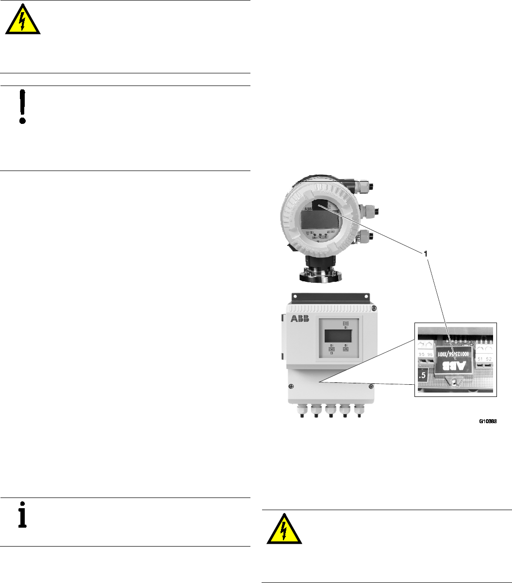
CoriolisMaster FCB330, FCB350, FCH330, FCH3500 | OI/FCB300/FCH300-EN Rev. F 67
9 Maintenance / Repair
9.1 General remarks
WARNING – Electrical dangers!
When the housing is open, EMC protection is
impaired and there is no longer any protection
against accidental contact.
Switch off the power supply before opening the
housing.
NOTICE – Potential damage to parts
The electronic components of the printed circuit
board can be damaged by static electricity
(observe ESD guidelines).
Make sure that the static electricity in your body
is discharged before touching electronic
components.
Repair and maintenance activities may only be performed by
authorized customer service personnel.
When replacing or repairing individual components, use
original spare parts.
9.2 Cleaning
When cleaning the exterior of meters, make sure that the
cleaning agent used does not corrode the housing surface and
the seals.
To avoid static charge, a damp cloth must be used for
cleaning.
9.3 Flowmeter sensor
Essentially no maintenance is required for the flowmeter
sensor.
The following items should be checked annually:
— Ambient conditions (air circulation, humidity),
— Seal integrity of the process connections,
— Cable entry points and cover screws,
— Operational reliability of the power supply feed, the
lightning protection, and the station ground.
Repairs to the flowmeter sensor
Should the flowmeter sensor need to be repaired, follow the
instructions in the "Safety / Sending back devices" section.
IMPORTANT (NOTE)
In case of devices for hazardous areas observe
the respective regulations. Please see chapter 6.6
and 6.7 as well as chapter 12 and 13.
9.4 Transmitter
9.4.1 Replacement
All parameter settings are stored in an external memory
module. If the electronic system is replaced, the external data
memory is changed in order to keep all the setting
parameters.
Data specific for the flowmeter sensor and customer setting
parameters are kept automatically.
When replacing the transmitter, make sure that the serial
number on the external data memory matches the serial
number on the flowmeter sensor.
If you replace the transmitter, please do not hesitate to
contact our service team if you have any queries.
When changing a transmitter to a transmitter with a lower
software level, please always contact our service team.
Position of the external data memory (FRAM)
Fig. 33: Position of the FRAM module
1 FRAM (plug-in)
The location of the transmitter's external data memory (FRAM)
is determined by its design (integral mount or remote mount)
as shown.
WARNING – Electrical dangers!
When the housing is open, EMC protection is
impaired and there is no longer any protection
against accidental contact.
Switch off the power supply before opening the
housing.
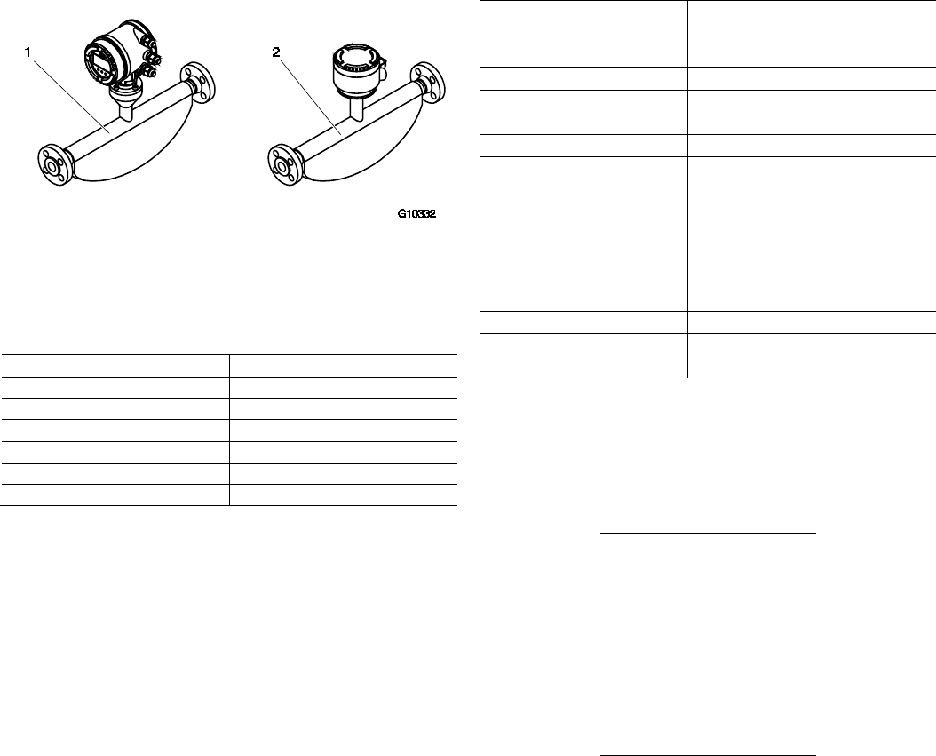
68 OI/FCB300/FCH300-EN Rev. F | CoriolisMaster FCB330, FCB350, FCH330, FCH3500
10 Flowmeter sensor specifications
10.1 Designs
Fig. 34: FCB3xx / FCH3xx flowmeter sensor
1 Integral mount design |
2 Remote mount design (without transmitter)
10.2 Nominal diameter and measuring range
Nominal diameter
Q
max
in kg/h (lb/h)
DN 15 (1/2“)
0 … 8,000 (0 … 17,637)
DN 25 (1“) 0 … 35,000 (0 … 77,162)
DN 50 (2“) 0 … 90,000 (0 … 198,416)
DN 80 (3“) 0 … 250,000 (0 … 551,156)
DN 100 (4“) 0 … 520,000 (0 ... 1,146,404)
DN 150 (6“) 0 … 860,000 (0 … 1,895,975)
10.2.1 Recommended flow range
Fluids:
— The recommended flow range is 5 … 100 % of Q
max
.
— Flows < 1 % of Q
max
should be avoided.
Gases:
— The flow velocity of gases in the meter tube should not
exceed 0.3 Mach (approx. 100 m/s (328 ft/s)).
— Flow velocities above 80m/s may lead to increased
reproducibility values.
— The maximum flow range of gases is determined by the
operating density. Dimensioning guidelines are available at
www.abb.com/flow.
10.3 Measuring accuracy
10.3.1 Reference conditions
Calibration fluid Water
— Temperature: 25 °C (77 °F) ±5 K
—
Pressure: 2 … 4 bar (29 … 58 psi)
Ambient temperature 25 °C (77 °F) +10 K / -5 K
Power supply Line voltage according to name plate
U
N
±1 %
Warm-up phase
30 minutes
Installation — Installation according to chapter
titled “Installation instructions” and
“Mounting positions”
— No visible gas phase
— No external mechanical or
hydraulic disturbances, particularly
cavitation
Output calibration Pulse output
Effect of the analog output on
measuring accuracy
As pulse output ±0.1 % of
measurement
10.3.2 Measured error
The measured error is calculated as follows for the flow:
Scenario 1:
If
Flow ≥
Zero stability
(base accuracy / 100)
Then:
— Maximum measured error:
± base accuracy as % of measured value
— Reproducibility:
± 1/2 x base accuracy as % of measured value
Scenario 2:
If
Flow <
Zero stability
(base accuracy / 100)
Then:
— Maximum measured error:
± (zero stability / measured value) x 100 % of measured
value
— Reproducibility:
± 1/2 x (zero stability / measured value) x 100% of
measured value
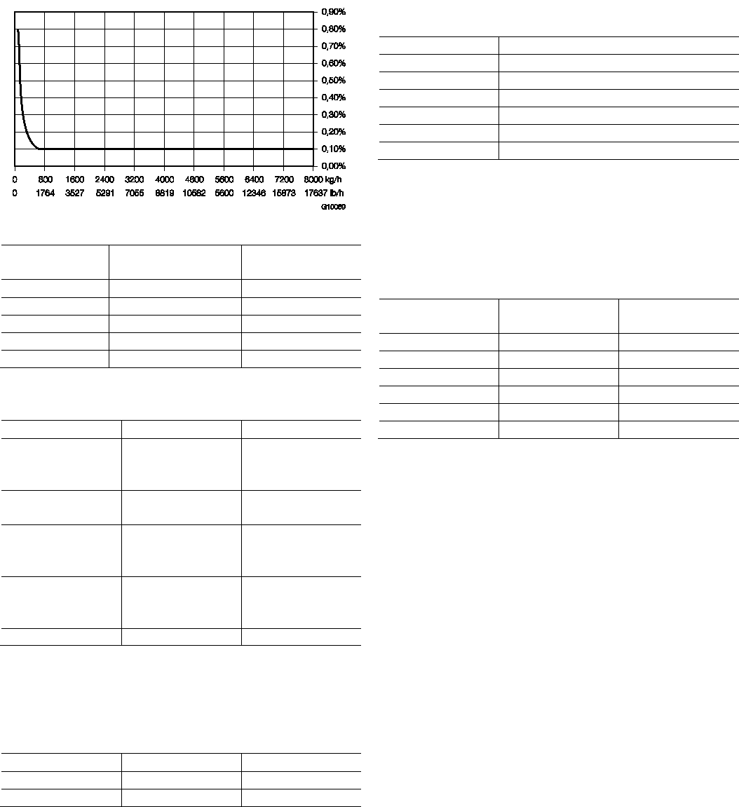
CoriolisMaster FCB330, FCB350, FCH330, FCH3500 | OI/FCB300/FCH300-EN Rev. F 69
Fig. 35: Calculation of measured error FCB350 DN15 (example)
Measurement
dynamic
Flow
Maximum measured
error
100:1
80 kg/h (176.4 lb/h)
0.8 % o.r.
50:1 160 kg/h (352.7 lb/h) 0.4 % o.r.
10:1
800 kg/h (1763.7 lb/h)
0.1 % o.r.
2:1 4000 kg/h (8818.5 lb/h) 0.1 % o.r.
1:1 8000 kg/h (17637 lb/h) 0.1 % o.r.
Measured error and base accuracy for liquids
FCx330 FCx350
Mass flow ± 0.4 % of rate
± 0.25 % of rate
± 0.15 % of rate
± 0.1 % of rate
(option)
Volume flow ± 0.4 % of rate
± 0.25 % of rate
± 0.15 % of rate
Density 0.010 kg/l
1)
0.002 kg/l
1)
0.001 kg/l
2)
0.0005 kg/l (option)
3)
Reproducibility for
density
0.002 kg/l
0.002 kg/l
1)
0.001 kg/l
2)
0.00025 kg/l (option)
3)
Temperature 1 K 0.5 K
1) For the density range from 0.5 … 1.8 kg/dm³
2) As 1 and for the medium temperature range from -10 … 50 °C (14 … 122 °F)
3) As 2 and following field adjustment under operating conditions
Measured error and base accuracy for gases
FCx330
FCx350
Mass flow ± 1 % of rate ± 0.5 % of rate
Temperature
1 K
0.5 K
10.3.3 Zero stability
Nominal diameter kg/h (lb/h)
DN 15 (1/2“) 0.64 (1.41)
DN 25 (1“) 2.16 (4.76)
DN 50 (2“) 7.20 (15.87)
DN 80 (3“) 20 (44)
DN 100 (4“)
41.6 (91.7)
DN 150 (6“) 68.8 (151.68)
10.3.4 Effect of the temperature of the medium being
measured
For the flow, less than ± 0.0015 % of Q
max
/ 1 K.
For the density, less than 0.0001 kg/dm
3
/ 1 K.
10.3.5 Effect of the operating pressure
Nominal diameter Flow [% of
measurement / bar]
Density
[kg/dm
3
/ bar]
DN 15 (1/2“)
-0.002
No effect
DN 25 (1“) -0.013 0.00035
DN 50 (2“)
-0.010
0.00027
DN 80 (3“) -0.006 0.00019
DN 100 (4“)
-0.009
0.00024
DN 150 (6“) -0.035 0.00045
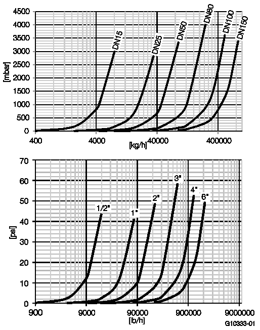
70 OI/FCB300/FCH300-EN Rev. F | CoriolisMaster FCB330, FCB350, FCH330, FCH3500
10.4 Technical data
10.4.1 Pressure loss
Fig. 36: Pressure loss curve (measured with water,
viscosity: 1 mPas)
10.4.2 Viscosity range
If you are working with dynamic viscosities
≥ 1 Pas (1000 mPas = 1000 cP), please contact ABB.
10.4.3 Temperature limits °C (°F)
IMPORTANT (NOTE)
When using the device in hazardous areas, note the additional
temperature data in the chapter titled "Technical data relevant
to hazardous areas"!
Temperature range of the medium being measured
FCx350: -50 … 160 °C (-58 … 320 °F)
FCx350: -50 … 200 °C (-58 … 392 °F)
Ambient temperature range
Standard: -20 … 60 °C (-4 … 140 °F)
Optional: -40 … 60 °C (-40 … 140 °F)
10.4.4 Process connections
— Flange design according to EN / ASME / JIS
— Tri-Clamp according to DIN 32676 (ISO 2852)
— DN 15 … 100 (1/2 … 4“): Series 3
— BPE Tri-Clamp
— DN 15 … 100 (1/2 … 4“)
10.4.5 Pressure rating
PN 16, PN 40, PN 100, PN 160
CL 150, CL 300, CL 600, CL 900, CL 1500
The maximum permissible operating pressure is determined by
the respective process connection, the temperature of the
medium to be measured, the screws, and the gasket material.
10.4.6 Enclosure as protective device (optional)
Standard:
— Maximum burst pressure 60 bar (870 psi)
Optional:
— Higher bursting pressure resistant housings possible up to
100 bar (1450 psi) for meter sizes DN15 .. DN100
(1/2" … 4").
— Higher bursting pressure resistant housings possible up to
150 bar (2175 psi) for meter sizes DN15 ... DN80
(1/2" … 3")
— Purge fittings can be provided on request.
10.4.7 Pressure Equipment Directive
Conformity assessment according to Category III, fluid
group 1, gas
Check the corrosion resistance of the meter tube materials
against the measuring medium.
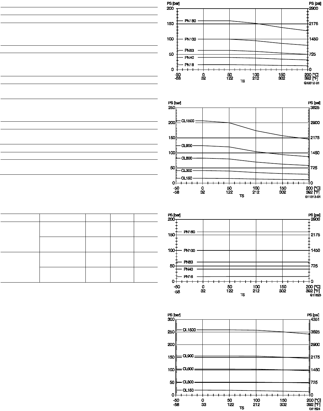
CoriolisMaster FCB330, FCB350, FCH330, FCH3500 | OI/FCB300/FCH300-EN Rev. F 71
10.4.8 Materials for transmitters
Enclosure
Varnished alloy casting
Enclosure color
— Mid-section:
—
Cover:
RAL 7012
RAL 9002
Varnish layer thickness: 80 … 120 µm
10.4.9 Materials for flowmeter sensors
Wetted parts
Stainless steel
—
1.4404 (AISI 316L) or 1.4435 (AISI 316L)
Stainless steel, polished
— 1.4404 (AISI 316L) or 1.4435 (AISI 316L) certified to EHEDG with
flowmeter sensor material (AISI 316L)
—
Nickel-Alloy C4
1)
(2.4610) oder Nickel-Alloy C22
1)
(2.4602)
Optional: Manufacture in accordance with NACE MR0175 and MR0103
(ISO 15156)
Enclosure
Stainless steel 1.4404 (AISI 316L), 1.4301 (AISI 304),
1.4308 (ASTM CF8)
1) Hastelloy C is a registered trademark of Haynes International. Nickel-Alloy C4
and C22 is equal to Hastelloy C4 and Hastelloy C22.
10.4.10 Material load for process connections
Design Nominal diameter PS
max
TS
max
TS
min
Threaded pipe
connection
(DIN 11851)
DN 15 … 40
(1/2 … 1 1/2“)
40 bar
(580 psi)
140 °C
(284 °F)
-40 °C
(-40 °F)
DN 50 … 100
(2 … 4“)
25 bar
(363 psi)
140 °C
(284 °F)
-40 °C
(-40 °F)
Tri-Clamp
(DIN 32676)
DN 15 … 50
(1/2 … 2“)
16 bar
(232 psi)
120 °C
(248 °F)
-40 °C
(-40 °F)
DN 65 … 100
(2 1/2 … 4“)
10 bar
(145 psi)
120 °C
(248 °F)
-40 °C
(-40 °F)
10.4.11 Material load curves for flange devices
Fig. 37: Stainless steel DIN flange 1.4571 / 1.4404 (316Ti / 316L) up
to DN 200 (8“)
Fig. 38: Stainless steel ASME flange 1.4571 / 1.4404 (316Ti / 316L)
up to DN 200 (8“)
Fig. 39: DIN flange Nickel-Alloy C4 (2.4610) or Nickel-Alloy C22 up to
DN 200 (8“)
Fig. 40: ASME flange Nickel-Alloy C4 (2.4610) or Nickel-Alloy C22 up
to DN 200 (8“)
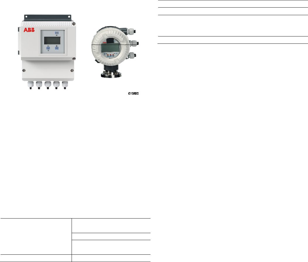
72 OI/FCB300/FCH300-EN Rev. F | CoriolisMaster FCB330, FCB350, FCH330, FCH3500
11 Transmitter specifications
11.1 General remarks
Fig. 41: FCT3xx transmitter in field enclosure
11.2 Technical data
11.2.1 Measuring range
The measuring range can be set at will between 0.01 … 1
Qmax.
11.2.2 Degree of protection
IP 65 / IP 67, NEMA 4X
11.2.3 Electrical connections
Cable gland M20 x 1.5 or 1/2" NPT
The maximum signal cable length for the remote mount design
is 50 m (164 ft) (longer lengths on request).
11.2.4 Power supply
Supply voltage 100 … 230 V AC, 47 … 63 Hz
(tolerance -15 % / +10 %)
20.4 … 26.4 V AC, 47 … 63 Hz
20.4 … 31.2 V DC
(ripple: ≤ 5 %)
Power consumption S ≤ 25 VA
11.2.5 Response time
As step function 0 … 99 % (corr. to 5 τ) ≥ 1 s
11.2.6 Ambient temperature
Standard: -20 … 60 °C (-4 … 140 °F)
Optional: -40 … 60 °C (-40 … 140 °F)
At operation below -20 °C (-4 °F), the LCD can no longer be
read and the electronic unit should be operated with as few
vibrations as possible.
Full functionality is assured at temperatures
above -20 °C (-4 °F).
11.2.7 Housing design
Enclosure
Varnished alloy casting
Enclosure color
— Mid-section:
—
Cover:
RAL 7012
RAL 9002
Varnish layer thickness: 80 … 120 µm
11.2.8 Forward/reverse flow metering
The flow direction is indicated by the arrows on the transmitter
LCD and via the digital switching output (if configured).
11.2.9 LCD display
LCD, 2 lines, backlit
Both lines of the LCD are freely configurable.
The following values can be displayed:
— Mass flow
— Volume flow
— Density or temperature
— Flow count, 7-digit with overflow counter and specification
of physical unit for mass or volume.
On integral mount design devices, the transmitter enclosure
can be rotated through approx. 180° in any direction. The LCD
can be rotated to four positions to ensure optimum readability.
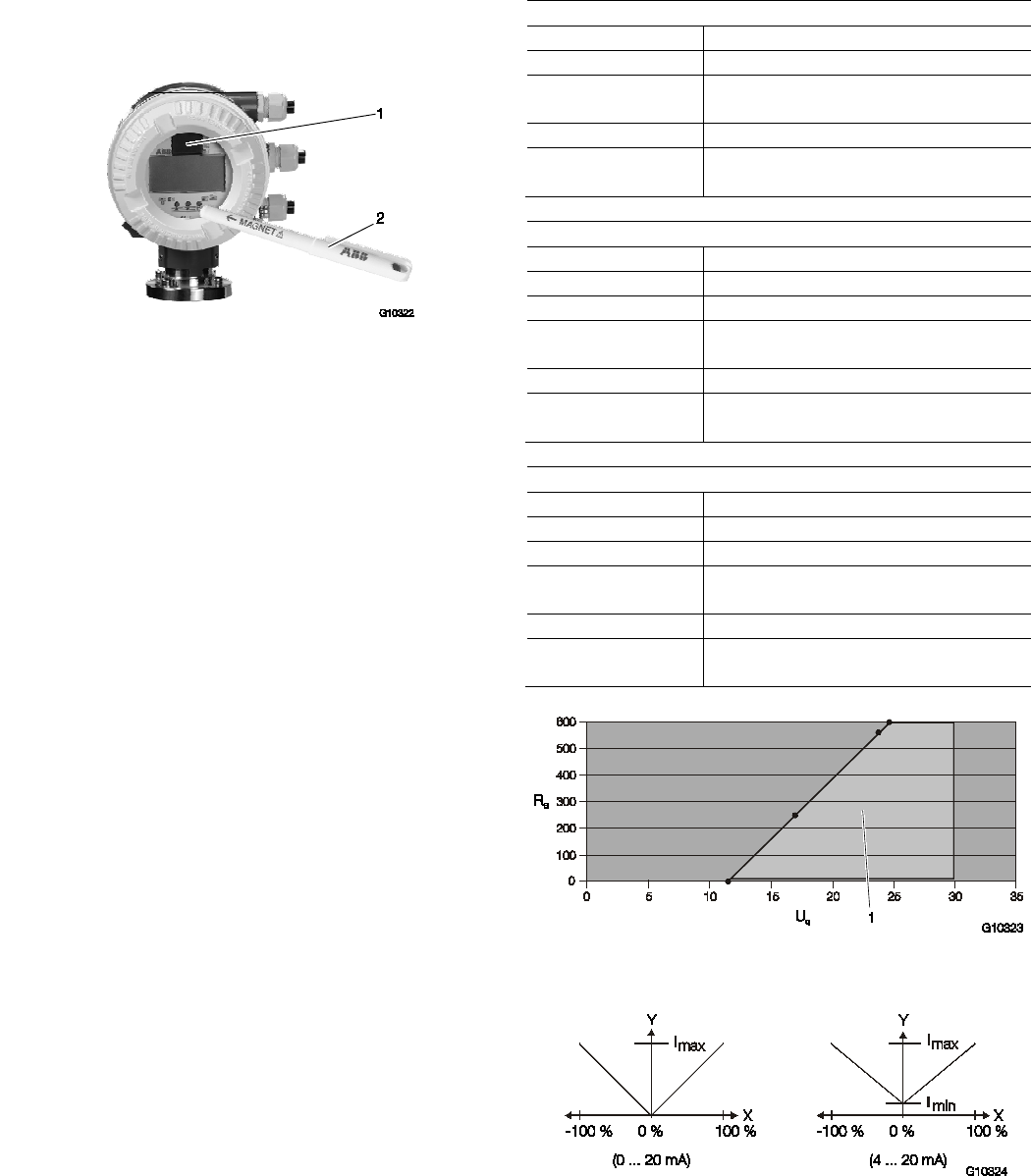
CoriolisMaster FCB330, FCB350, FCH330, FCH3500 | OI/FCB300/FCH300-EN Rev. F 73
11.2.10 Operation
Three buttons on the transmitter are used to operated the
device and enter parameters. Alternatively, if the enclosure
cover on the transmitter is closed, operators can use a
magnetic pen.
Fig. 42: Operation with magnetic pen
1 FRAM (plug-in) | 2 Magnetic pen
11.2.11 Data backup
Data is backed up to an FRAM integrated in the transmitter.
Data is saved for a period of 10 years without power supply.
Hardware and software are identified according to NAMUR
recommendation NE53.
IMPORTANT (NOTE)
The device meets the requirements of the EMC directive
2004/108/EC (EN 61326) and the low-voltage directive
2006/95/EC (EN 61010-1).
11.3 Electrical data
11.3.1 Current outputs
Current output 1, active
Output signal
Active, 0 … 20 mA or 4 … 20 mA switchable
Load 0 Ω ≤ R
B
≤560 Ω
Measurement
uncertainty
< 0.1 % of measured value
Terminals 31 / 32
Measured values Mass flow, volume flow, density, and
temperature (freely configurable via software)
Current output 1, passive
Output signal 4 ... 20 mA passive
Load
0 Ω ≤ R
B
≤600 Ω
Source voltage 12 V ≤ U
q
≤ 30 V
Measurement
uncertainty
< 0.1 % of measured value
Terminals 31 / 32
Measured values Mass flow, volume flow, density, and
temperature (freely configurable via software)
Current output 2, passive
Output signal 4 ... 20 mA passive
Load
0 Ω ≤ R
B
≤600 Ω
Source voltage 12 V ≤ U
q
≤ 30 V
Measurement
uncertainty
< 0.1 % of measured value
Terminals 33 / 34
Measured values Mass flow, volume flow, density, and
temperature (freely configurable via software)
Fig. 43: Permissible source voltage as a function of load resistance,
where I
max
= 22 mA
1 Permissible range
Fig. 44
IMPORTANT (NOTE)
Failure information according to NAMUR recommendation
NE43.

74 OI/FCB300/FCH300-EN Rev. F | CoriolisMaster FCB330, FCB350, FCH330, FCH3500
11.3.2 Pulse output
Scaled pulse output (maximum 5 kHz) with configurable pulse
factor between 0.001 and 1000 pulses per unit. The pulse
width is configurable from 0.1 … 2000 ms. The output is
electrically isolated from the current outputs.
Passive Active
Operating voltage 16 V ≤ U
CEH
≤ 30 V DC
0 V ≤ U
CEL
≤ 2 V
16 V ≤ U ≤ 30 V DC
Load ≥ 150 Ω
Operating current 0 mA ≤ I
CEH
≤ 0.2 mA
2 mA ≤ I
CEL
≤ 220 mA
-
fmax 5 kHz 5 kHz
Pulse width
0.1 … 2000 ms
0.1 … 2000 ms
Terminals 51 / 52 51 / 52
IMPORTANT (NOTE)
If you are using a mechanical totalizer, we recommend setting
a pulse width of ≥ 30 ms and a maximum frequency of
fmax ≤ 3 kHz.
11.3.3 Digital switching outputs
The switching function can be selected via the software.
Switching function — System monitoring (normally closed
contact or normally open contact)
— Forward / reverse (closed for forward)
— Min. /max. alarm (normally closed contact
or normally open contact)
Output "closed" 0 V ≤ U
CEL
≤ 2 V
2 mA ≤ I
CEL
≤ 220 mA
Output "open" 16 V ≤ U
CEH
≤ 30 V DC
0 mA ≤ I
CEH
≤ 0.2 mA
Terminals 41 / 42
11.3.4 Digital switching inputs
The switching function can be selected via the software.
Switching function — External output zero return
— External totalizer reset
Input "On" 16 V ≤ U
KL
≤ 30 V
Input "Off"
0 V ≤ U
KL
≤ 2 V
Internal resistance Ri = 2 kΩ
Terminals
81 / 82
All inputs and outputs are electrically isolated from one other.

CoriolisMaster FCB330, FCB350, FCH330, FCH3500 | OI/FCB300/FCH300-EN Rev. F 75
Chan ge from tw o to one c olum n
12 Ex relevant specifications acc. to ATEX / IECEx / NEPSI
12.1 Electrical data
12.1.1 Overview of the different output options
Versions ATEX, IECEx, NEPSI Zone 2 ATEX, IECEx, NEPSI Zone 1
Version I
Output option A1, A2, H1, H2
in the order number
— Current output 1: Active
— Current output 2: Passive
— Pulse output: Active / passive, switchable
—
Switching input and output: Passive
— Current output 1: Active
— Current output 2: Passive
— Pulse output: Passive
—
Switching input and output: Passive
Version II
Output option A3, H3
in the order number
— Current output 1: Passive
— Current output 2: Passive
— Pulse output: Passive
—
Switching input and output: Passive
12.1.2 Version I: Active / passive current outputs
Model FCx3xx-A1, FCT3xx-A1 or FCx3xx-A2, FCT3xx-A2 or FCx3xx-S2, FCT3xx-S2
Type of protection
"nA" (Zone 2)
General operating
values
Type of protection
"e" (Zone 1)
Type of protection "ib"
(Zone 1)
Current output 1, active
Terminals 31 / 32
Terminal 32 is connected to
"PA"
U
i
(V)
I
i
(mA)
U
b
(V)
I
b
(mA)
U (V)
I (mA)
U
o
(V)
I
o
(mA)
P
o
(mW)
C
o
(nF)
C
o
pa
(nF)
L
o
(mH)
20
100
500
217
0
3.8
30 30 30 30 60 35 U
i
(V)
I
i
(mA)
P
i
(mW)
C
i
(nF)
C
i
pa
(nF)
L
i
(mH)
60 100 500 2.4 2.4 0.17
Current output 2, passive
Terminals 33 / 34
Terminal 34 is connected to
"PA"
30 30 30 30 60 35 30 100 760 2.4 2.4 0.17
Pulse output, passive
Terminals 51 / 52
30 65 30 65 60 35 15 30 115 2.4 2.4 0.17
Switching output, passive
Terminals 41 / 42
30 65 30 65 60 35 15 30 115 2.4 2.4 0.17
Switching input, passive
Terminals 81 / 82
30 10 30 10 60 35 30 60 500 2.4 2.4 0.17
All inputs and outputs are electrically isolated from one other and from the power supply. Only current outputs 1 and 2 in zone 1
design are not electrically isolated from one another.

76 OI/FCB300/FCH300-EN Rev. F | CoriolisMaster FCB330, FCB350, FCH330, FCH3500
12.1.3 Version II: Passive / passive current outputs
Model FCx3xx-A1, FCT3xx-A1 or FCx3xx-A2, FCT3xx-A2 or FCx3xx-S2, FCT3xx-S2
Type of protection
"nA" (Zone 2)
General operating
values
Type of protection
"e" (Zone 1)
Type of protection "ia"
(Zone 1)
U
i
(V)
I
i
(mA)
U
b
(V)
I
b
(mA)
U (V)
I (mA)
U
i
(V)
I
i
(mA)
P
i
(mW)
C
i
(nF)
C
i
pa
(nF)
L
i
(mH)
Current output 1, passive
Terminals 31 / 32
30 30 30 30 60 35 60 300 2000 0.47 0.47 0.17
Current output 2, passive
Terminals 33 / 34
30 30 30 30 60 35 60 300 2000 0.47 0.47 0.17
Pulse output, passive
Terminals 51 / 52
30 65 30 65 60 35 60 300 2000 0.47 0.47 0.17
Switching output, passive
Terminals 41 / 42
30 65 30 65 60 35 60 300 2000 0.47 0.47 0.17
Switching input, passive
Terminals 81 / 82
30 10 30 10 60 35 60 300 2000 0.47 0.47 0.17
All inputs and outputs are electrically isolated from one other and from the auxiliary power.
Chan ge from on e to two c olumns
12.1.4 Special connection conditions
The output circuits are designed so that they can be
connected to both intrinsically-safe and non-intrinsically-safe
circuits.
It is not permitted to combine intrinsically safe and non-
intrinsically safe circuits. In case of a change of type of
protection observe chapter 6.6.7.
On intrinsically-safe circuits, equipotential bonding must be in
place along the entire length of the cable used for the current
outputs.
The rated voltage of the non-intrinsically safe circuits is
U
M
= 60 V.
The switching output and the pulse output (terminals 41 / 42
and 51 / 52) can be wired internally as a NAMUR contact for
the purpose of connecting a NAMUR amplifier.
The cable glands are supplied in black by default. If the signal
outputs are wired to intrinsically-safe circuits, we recommend
that you use the light blue caps supplied for the appropriate
cable entries.
IMPORTANT (NOTE)
If the protective conductor (PE) is connected in the
flowmeter's terminal box, you must ensure that no dangerous
potential difference can arise between the protective
conductor (PE) and the equipotential bonding (PA) in the
hazardous area.
Chan ge from tw o to one c olum n

CoriolisMaster FCB330, FCB350, FCH330, FCH3500 | OI/FCB300/FCH300-EN Rev. F 77
12.2 Flowmeter sensor model FCB3xx / FCH3xx
12.2.1 Temperature class
Model FCx3xx-A1Y… or FCx3xx-S1Y… Zone 1
Ambient temperature ≤40 °C (≤104 °F) ≤50 °C (≤122 °F) ≤60 °C (≤140 °F)
Temperature class
T1 200 °C (392 °F) 200 °C (392 °F) 200 °C (392 °F)
T2 200 °C (392 °F) 200 °C (392 °F) 200 °C (392 °F)
T3
185 °C (365 °F)
180 °C (356 °F)
180 °C (356 °F)
T4 125 °C (257 °F) 120 °C (248 °F) 120 °C (248 °F)
T5 85 °C (185 °F) 85 °C (185 °F) 75 °C (167 °F)
T6 65 °C (149 °F) 65 °C (149 °F) 60 °C (140 °F)
Model FCx3xx-A2Y… or FCx3xx-S2Y… Zone 2
Ambient temperature
≤40 °C (≤104 °F)
≤50 °C (≤122 °F)
≤60 °C (≤140 °F)
Temperature class
T1 200 °C (392 °F) 200 °C (392 °F) 180 °C (356 °F)
T2
200 °C (392 °F)
200 °C (392 °F)
180 °C (356 °F)
T3 180 °C (356 °F) 180 °C (356 °F) 180 °C (356 °F)
T4 115 °C (239 °F) 115 °C (239 °F) 115 °C (239 °F)
T5 80 °C(176 °F) 80 °C(176 °F) 75 °C (167 °F)
T6 60 °C (140 °F) 60 °C (140 °F) 60 °C (140 °F)
Ambient and process conditions:
T
amb
-
20 ...
60 °C (-4 ... 140 °F)
T
amb, optional
-40 ... 60 °C (-40 ... 140 °F) (only for integral mount design devices)
T
medium
-
50 ... 200 °C (-58 ... 392 °F)
Protection class
IP 65, IP 67, and NEMA 4X

78 OI/FCB300/FCH300-EN Rev. F | CoriolisMaster FCB330, FCB350, FCH330, FCH3500
12.2.2 Hazardous area approval ATEX / IECEx / NEPSI
Specific marking according to ATEX, IECEx and NEPSI applies depending on the design of the flowmeter sensor (integral or
remote mount design).
IMPORTANT (NOTE)
ABB reserves the right to make changes to the Ex-marking. The exact marking can be found at the name plate of the meter.
Modell FCx3xx-A2A… or FCx3xx-S2A… (remote mount design in Zone 2)
Approval Marking Comment
ATEX II 3 G Ex nA IIC T6 … T2
II 2 D Ex tD IIIC T85°C .. Tmedium
-
IECEx or NEPSI Ex nA IIC T6 .. T2 Gc
Ex tb IIIC T85°C Tmedium
-
Model FCx3xx-A1A… or FCx3xx-S1A… (remote mount design in Zone 1)
Approval Marking Comment
ATEX II 1 G Ex ia IIC T6 … T2
II 1 D Ex ia IIIC T85°C… Tmedium
-
IECEx or NEPSI
T2 Ga
Ex ia IIIC T85°C .. Tmedium Da
-
Model FCx3xx-A2Y… or FCx3xx-S2Y… (integral mount design in Zone 2)
Approval
Marking
Comment
ATEX II 3 G Ex nA nR IIC T6 … T2
II 2 D Ex tD IIIC T85°C .. Tmedium
-
IECEx or NEPSI Ex nA nR IIC T6 .. T2 Gc
Ex tb IIIC T85°C Tmedium Db
-
Modell FCx3xx-A1Y… or FCx3xx-S1Y… (integral mount design in Zone 1)
Approval
Marking
Comment
ATEX
Version II II 1/2 G Ex d e ia IIC T6 .. T2
II 2 D Ex ia tb IIIC T85°C .. Tmedium
2 passive analog outputs, outputs "ia" / "e",
depending on user wiring.
Version I II 1/2 G Ex d e ia ib IIC T6 .. T2 or II 1/2 G Ex d e ia IIC T6 .. T2
II 2 D Ex ia ia tb IIIC T85°C .. Tmedium or II 2 D Ex ia tb IIIC T85°C ..
Tmedium
Active / passive analog outputs, outputs "ib" / "e",
depending on user wiring.
IECEx or NEPSI
Version II Ex d e ia IIC T6 .. T2 Ga/Gb
Ex ia tb IIIC T85°C .. Tmedium
2 passive analog outputs, outputs "ia" / "e",
depending on user wiring.
Version I Ex d e ia ib IIC T6 .. T2 Ga/Gb or Ex d e ia IIC T6 .. T2 Ga/Gb
Ex ia ib tb IIIC T85°C .. Tmedium or Ex ia tb IIIC T85°C .. Tmedium
Active / passive analog outputs, outputs "ib" / "e",
depending on user wiring.

CoriolisMaster FCB330, FCB350, FCH330, FCH3500 | OI/FCB300/FCH300-EN Rev. F 79
12.3 Transmitter model FCT300 in remote mount design
Ambient and process conditions:
T
amb
-20 ... 60 °C (-4 ... 140 °F)
Protection class
IP 65, IP 67, and NEMA 4X / Type 4X
12.3.1 Hazardous area approval ATEX / IECEx / NEPSI
Specific marking according to ATEX, IECEx and NEPSI applies depending on the design of the flowmeter sensor (integral or
remote mount design).
IMPORTANT (NOTE)
ABB reserves the right to make changes to the Ex-marking. The exact marking can be found at the name plate of the meter.
Model FCT3xx-Y0… (Transmitter outside the hazardous area, Sensor in Zone 0, 1 or 2)
Approval
Marking
Comment
ATEX II (1) G [Ex ia] IIC -
IECEx or NEPSI
[Ex ia Ga] IIC
-
Model FCT3xx-A2… or FCT3xx-S2… (Transmitter in Zone 2, Sensor in Zone 0, 1 or 2)
Approval Marking Comment
ATEX II 3(2) G Ex nA nR [ia] IIC T6
II 2 D Ex tb [ia] IIIC T85°C
-
IECEx or NEPSI Ex nA nR [ia] IIC T6 Gc (Gb)
Ex tb [ia] IIIC T85°C Db
-
Modell FCT3xx-A1… or FCT3xx-S1… (Transmitter in Zone 1, Sensor in Zone 0, 1 or 2)
Approval Marking Comment
ATEX
Version II
II 2 (1) G Ex d e ia IIC T6
II 2 (1) D Ex ia tb IIIC T85°C
2 passive analog outputs, outputs "ia" / "e", depending on
user wiring.
Version I
II 2 (1) G Ex d e ib [ia] IIC T6 or II 2 (1) G Ex d e [ia] IIC T6
II 2 (1) D Ex ib tb [ia] IIIC T85°C or II 2 (1) D Ex tb [ia] IIIC T85°C
Active / passive analog outputs, outputs "ib" / "e",
depending on user wiring.
IECEx or NEPSI
Version II
Ex d e ia IIC T6 Gb (Ga)
Ex ia tb IIIC T85°C Db (Da)
2 passive analog outputs, outputs "ia" / "e", depending on
user wiring.
Version I
Ex d e ib [ia Ga] IIC T6 Gb or Ex d e [ia Ga] IIC T6 Gb
Ex ib tb [ia Da] IIIC T85°C Db or Ex tb [ia Da] IIIC T85°C Db
Active / passive analog outputs, outputs "ib" / "e",
depending on user wiring.

80 OI/FCB300/FCH300-EN Rev. F | CoriolisMaster FCB330, FCB350, FCH330, FCH3500
13 Ex relevant specifications acc. to cFMus
13.1 Overview of the different output options
Versions
Class I Div. 2
Class I Div. 1
Version I
Output option A1, A2, H1, H2
in the order number
— Current output 1: Active
— Current output 2: Passive
— Pulse output: Active / passive, switchable
—
Switching input and output: Passive
— Current output 1: Active
— Current output 2: Passive
— Pulse output: Passive
—
Switching input and output: Passive
Version II
Output option A3, H3
in the order number
— Current output 1: Passive
— Current output 2: Passive
— Pulse output: Passive
—
Switching input and output: Passive
13.2 Electrical data for Div. 2 / Zone 2
13.2.1 Version I: Active / passive current outputs and Version II: passive / passive current outputs
Model FCx3xx-F2, FCT3xx-F2
Type of protection NI
Vmax
o
(V)
Imax
o
(mA)
Current output 1
Terminals 31 / 32
30 30
Current output 2
Terminals 33 / 34
30 30
Pulse output
Terminals 51 / 52
30 65
Switching output
Terminals 41 / 42
30 65
Switching input
Terminals 81 / 82
30 10
All inputs and outputs are electrically isolated from one other and from the power supply.

CoriolisMaster FCB330, FCB350, FCH330, FCH3500 | OI/FCB300/FCH300-EN Rev. F 81
13.3 Electrical data for Div. 1 / Zone 1
13.3.1 Version I: Active / passive current outputs
Model FCx3xx-F1, FCT3xx-F1
Type of protection non IS
Type of protection IS
Vmax
o
(V) Imax
o
(mA) Vmax
o
(V) Imax
o
(mA) P
o
(mW) C
o
(nF) C
o PA
(nF) L
0
(mH)
Current output 1, active
Terminals 31 / 32
30 30 20 100 500 217 0 3.8
VMax (V) I
Max
(mA) P
i
(mW) C
i
(nF) C
i PA
(nF) L
i
(mH)
60 100 500 2.4 2.4 0.17
Current output 2, passive
Terminals 33 / 34
30 30 30 100 760 2.4 2.4 0.17
Pulse output, active or passive
Terminals 51 / 52
30 65 15 30 115 2.4 2.4 0.17
Switching output, passive
Terminals 41 / 42
30 65 15 30 115 2.4 2.4 0.17
Switching input, passive
Terminals 81 / 82
30 10 30 60 500 2.4 2.4 0.17
All inputs and outputs are electrically isolated from one other and from the power supply. Only current outputs 1 and 2 are not
electrically isolated from one another.
13.3.2 Version II: Passive / passive current outputs
Model FCx3xx-F1, FCT3xx-F1
Type of protection non IS
Type of protection IS
Vmax (V)
Imax (mA)
Vmax (V)
Imax (mA)
Pi (mW)
Ci (nF)
C
i PA
(nF)
L
i
(mH)
Current output 1, passive
Terminals 31 / 32
30 30 60 300 2000 0.47 0.47 0.17
Current output 2, passive
Terminals 33 / 34
30 30 60 300 2000 0.47 0.47 0.17
Pulse output, active or passive
Terminals 51 / 52
30 65 60 300 2000 0.47 0.47 0.17
Switching output, passive
Terminals 41 / 42
30 65 60 300 2000 0.47 0.47 0.17
Switching input, passive
Terminals 81 / 82
30 10 60 300 2000 0.47 0.47 0.17
All inputs and outputs are electrically isolated from one other and from the power supply.
Chan ge from on e to two c olumns
13.3.3 Special connection conditions
The output circuits are designed so that they can be
connected to both intrinsically-safe and non-intrinsically-safe
circuits.
It is not permitted to combine intrinsically-safe and non-
intrinsically safe circuits. In case of a change of type of
protection observe chapter 6.7.5.
On intrinsically-safe circuits, equipotential bonding must be in
place along the entire length of the cable used for the current
outputs.
The rated voltage of the non-intrinsically-safe circuits is
U
M
= 60 V.
Provided that rated voltage UM = 60 V is not exceeded if
connections are established to non-intrinsically-safe external
circuits, intrinsic safety is retained.
IMPORTANT (NOTE)
The transmitter and flowmeter sensor enclosures must be
connected to equipotential bonding PA. The operator must
ensure that when connecting the protective conductor PE no
potential differences can occur between the protective
conductor PE and the equipotential bonding PA.
Chan ge from tw o to one c olum n

82 OI/FCB300/FCH300-EN Rev. F | CoriolisMaster FCB330, FCB350, FCH330, FCH3500
13.4 Flowmeter sensor model FCB300 / FCH300
13.4.1 Temperature class
Model FCx3xx-F1…, in Class I Div. 1
Ambient temperature
≤40 °C (≤104 °F)
≤50 °C (≤122 °F)
≤60 °C (≤140 °F)
Temperature class
T1
200 °C (392 °F)
200 °C (392 °F)
200 °C (392 °F)
T2
200 °C (392 °F)
200 °C (392 °F)
200 °C (392 °F)
T3 185 °C (365 °F) 180 °C (356 °F) 180 °C (356 °F)
T4
125 °C (257 °F)
120 °C (248 °F)
120 °C (248 °F)
T5
85 °C (185 °F)
85 °C (185 °F)
75 °C (167 °F)
T6 65 °C (149 °F) 65 °C (149 °F) 60 °C (140 °F)
Model FCx3xx-F2…, in Class I Div. 2
Ambient temperature ≤40 °C (≤104 °F) ≤50 °C (≤122 °F) ≤60 °C (≤140 °F)
Temperature class
T1
200 °C (392 °F)
200 °C (392 °F)
180 °C (356 °F)
T2 200 °C (392 °F) 200 °C (392 °F) 180 °C (356 °F)
T3 180 °C (356 °F) 180 °C (356 °F) 180 °C (356 °F)
T4 115 °C (239 °F) 115 °C (239 °F) 115 °C (239 °F)
T5 80 °C (176 °F) 80 °C (176 °F) 75 °C (167 °F)
T6
60 °C (140 °F)
60 °C (140 °F)
60 °C (140 °F)
Ambient and process conditions:
T
amb
-20 ... 60 °C (-4 ... 140 °F)
T
amb, optional
-40 ... 60 °C (-40 ... 140 °F) (only for integral mount design devices)
T
medium
-50 ... 200 °C (-58 ... 392 °F)
Protection class
IP 65, IP 67, and NEMA 4X / Type 4X
IMPORTANT (NOTE)
In the case of the remote mount design, the signal cable between the flowmeter sensor and the transmitter must measure at
least 5 m (16.4 ft) in length. Install conduit seals within 18” (45 cm).

CoriolisMaster FCB330, FCB350, FCH330, FCH3500 | OI/FCB300/FCH300-EN Rev. F 83
13.4.2 Hazardous area approval cFMus
Specific marking according to FM applies depending on the design of the flowmeter sensor (integral or remote mount design).
IMPORTANT (NOTE)
ABB reserves the right to make changes to the Ex-marking. The exact marking can be found at the name plate of the meter.
Model FCx3xx-F2A… (remote mount design in Zone 2, Div 2)
Approval Marking Comment
FM (marking US) NI: CL I,II,III, DIV 2, GPS ABCDEFG
CL I, ZN2, AEx nA IIC T6 ... T2
ZN 21 AEx tb IIIC T85°C ... T165°C
-
FM (marking Canada) NI: CL I, II, III, Div 2 GPS ABCDEFG
Ex nA IIC T6 … T2
-
Model FCx3xx-F2Y… (integral mount design in Zone 2, Div 2)
Approval Marking Comment
FM (marking US) NI: CL I, II, III, Div 2 GPS ABCDEFG
DIP: CL II Div 1 GPS EFG
DIP : CL III, Div 1,2
CL I, ZN 2, AEx nA nR IIC T6 ... T2
ZN 21 AEx tb IIIC T85°C ... T165°C
-
FM (marking Canada) NI: CL I, II, III, Div 2 GPS ABCDEFG
DIP: CL II Div 1 GPS EFG
DIP : CL III, Div 1,2
Ex nA nR IIC T6 … T2
-
Model FCx3xx-F1A… (remote mount design in Zone 1, Div 1)
Approval Marking Comment
FM (marking US) CL I, II, III, Div 1, GPS ABCDEFG
CL I, ZN0, AEx ia IIC T6 ... T2
ZN 20 AEx ia IIIC T85°C ... T165°C
-
FM (marking Canada) CL I, II, III, Div 1, GPS ABCDEFG
Ex ia IIC T6 … T2
-

84 OI/FCB300/FCH300-EN Rev. F | CoriolisMaster FCB330, FCB350, FCH330, FCH3500
Model FCx3xx-F1Y… (integral mount design in Zone 1, Div 1)
Approval
Marking
Comment
FM (marking US)
Version II IS: CL I, Div 1, GPS ABCD
NI: CL I,II,III, DIV2, GPS ABCDEFG
XP: CL I, Div 1, GPS ABCD
DIP: CL II, Div 1, GPS EFG
DIP: CL III, Div 1, 2
CL I, ZN1, AEx d ia IIC T6
ZN 21 AEx ia tb IIIC T85°C to T165°C
2 passive analog outputs, outputs "ia" / "e", depending on
user wiring.
Version I IS: CL I, Div 1, GPS ABCD
NI: CL I, II, III, DIV2, GPS ABCDEFG
XP: CL I, Div 1, GPS ABCD
DIP: CL II, Div 1, GPS EFG
DIP: CL III, Div 1, 2
CL I, ZN 1, AEx d ia ib IIC T6 or CL I, ZN 1, AEx d ia IIC T6
ZN 21 AEx ib ia tb IIIC T85°C or ZN21 AEx tb ia IIC T6
Active / passive analog outputs, outputs "ib" / "e",
depending on user wiring.
FM (marking Canada)
-
Version II IS: CL I, Div 1, GPS ABCD
NI: CL I,II,III, Div 2, GPS ABCDEFG
XP: CL I, Div 1, GPS BCD
DIP CL II, Div 1, GPS EFG
DIP CL III, Div 1, 2
Ex d ia IIC T6
2 passive analog outputs, outputs "ia" / "e", depending on
user wiring.
Version I IS: CL I, Div 1, GPS ABCD
NI: CL I, II, III, Div 2, GPS ABCDEFG
XP: CL I, Div 1, GPS BCD
DIP: CL II, Div 1, GPS EFG
DIP: CL III, Div 1, 2
Ex d ia ib IIC T6 or Ex d ia IIC T6
Active / passive analog outputs, outputs "ib" / "e",
depending on user wiring.

CoriolisMaster FCB330, FCB350, FCH330, FCH3500 | OI/FCB300/FCH300-EN Rev. F 85
13.5 Transmitter model FCT300 in remote mount design
Ambient and process conditions:
T
amb
-20 ... 60 °C (-4 ... 140 °F)
Protection class
IP 65, IP 67, and NEMA 4X / Type 4X
13.5.1 Hazardous area approval cFMus
Specific coding according to FM applies depending on the design of the flowmeter sensor (integral or remote mount design).
IMPORTANT (NOTE)
ABB reserves the right to make changes to the Ex-marking. The exact marking can be found at the name plate of the meter.
Model FCT3xx-Y0… (Transmitter in General Purpose and Sensor in Zone 2, Div 2 or Zone 0, Div 1)
Approval
Marking
Comment
FM (marking US) NI: CL I, II, III, Div 2 GPS ABCDEFG
DIP: CL II Div 1 GPS EFG
DIP: CL III, Div 1,2
-
FM (marking Canada) NI: CL I, II, III, Div 2 GPS ABCDEFG
DIP: CL II Div 1 GPS EFG
DIP: CL III, Div 1,2
-
Model FCT3xx-F2… (Transmitter and Sensor in Zone 2, Div 2)
Approval Marking Comment
FM (marking US) NI: CL I, II, III, Div 2 GPS ABCDEFG
DIP: CL II Div 1 GPS EFG
DIP: CL III, Div 1,2
CL I, ZN 2, AEx nA nR [ia] IIC T6
ZN 21 AEx tb [ia] IIIC T85°C
-
FM (marking Canada) NI: CL I, II, III, Div 2 GPS ABCDEFG
DIP: CL II Div 1 GPS EFG
DIP: CL III, Div 1,2
Ex nA nR [ia] IIC T6
-

86 OI/FCB300/FCH300-EN Rev. F | CoriolisMaster FCB330, FCB350, FCH330, FCH3500
Model FCT3xx-F1… (Transmitter in Zone 1, Div 1, Sensor in Zone 0, 1 or 2, Div 2 oder Div 1)
Approval Marking Comment
FM (marking US)
Version II IS: CL I, Div 1, GPS ABCD
NI: CL I, II, III, DIV2, GPS ABCDEFG
XP: CL I, Div 1, GPS ABCD
DIP: CL II, Div 1, GPS EFG
DIP: CL III, Div 1, 2
CL I, ZN1, AEx d ia IIC T6
ZN 21 AEx ia tb IIIC T85°C
2 passive analog outputs, outputs "ia" / "e", depending
on user wiring.
Version I IS: CL I, Div 1, GPS ABCD
NI: CL I, II, III, DIV2, GPS ABCDEFG
XP: CL I, Div 1, GPS ABCD
DIP: CL II, Div 1, GPS EFG
DIP: CL III, Div 1, 2
CL I, ZN 1, AEx d ib [ia] IIC T6 or CL I, ZN1, AEx d [ia] IIC T6
ZN21 AEx ib tb [ia] IIIC T85°C or ZN21 AEx tb [ia] IIC T6
Active / passive analog outputs, outputs "ib" / "e",
depending on user wiring.
FM (marking Canada)
Version II IS: CL I, Div 1, GPS ABCD
NI: CL I, II, III, Div 2, GPS ABCDEFG
XP: CL I, Div 1, GPS BCD
DIP: CL II, Div 1, GPS EFG
DIP: CL III, Div 1, 2
Ex d ia IIC T6
2 passive analog outputs, outputs "ia" / "e", depending
on user wiring.
Version I IS: CL I, Div 1, GPS ABCD
NI: CL I, II, III, Div 2, GPS ABCDEFG
XP: CL I, Div 1, GPS BCD
DIP: CL II, Div 1, GPS EFG
DIP CL III, Div 1, 2
Ex d ib [ia] IIC T6 or Ex d [ia] IIC T6
Active / passive analog outputs, outputs "ib" / "e",
depending on user wiring.
Chan ge from on e to two c olumns
Trademarks
® HART is a registered trademark of the HART Communication Foundation
™ Hastelloy C-4 is a Haynes International trademark
™ Hastelloy C-22 is a Haynes International trademark
™ Hastelloy C-276 is a Haynes International trademark
Chan ge from tw o to one c olum n
CoriolisMaster FCB330, FCB350, FCH330, FCH3500 | OI/FCB300/FCH300-EN Rev. F 87
Chan ge from tw o to one c olum n
14 Appendix
14.1 Approvals and certifications
CE mark
The version of the device as provided by us meets the requirements of the following EU directives:
— EMC Directive 2004/108/EC
— Low Voltage Directive 2006/95/EC
— Pressure Equipment Directive (PED) 97/23/EC
— ATEX directive 94/9/EC
E
xplosion protection
Designation relating to intended use in potentially explosive atmospheres in compliance with:
—
ATEX Directive (additional identification with CE mark)
IECEx
—
IEC standards
—
NEPSI (China)
—
cFMus Approvals for Canada and United States
IMPORTANT (NOTE)
All documentation, declarations of conformity, and certificates are available in ABB's download area.
www.abb.com/flow

88 OI/FCB300/FCH300-EN Rev. F | CoriolisMaster FCB330, FCB350, FCH330, FCH3500

CoriolisMaster FCB330, FCB350, FCH330, FCH3500 | OI/FCB300/FCH300-EN Rev. F 89
90 OI/FCB300/FCH300-EN Rev. F | CoriolisMaster FCB330, FCB350, FCH330, FCH3500
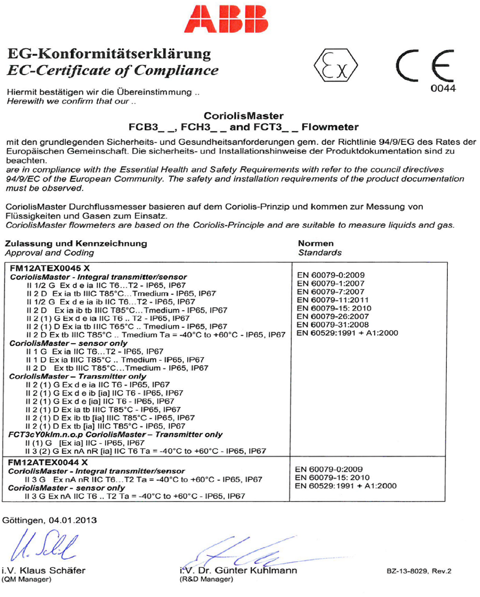
CoriolisMaster FCB330, FCB350, FCH330, FCH3500 | OI/FCB300/FCH300-EN Rev. F 91
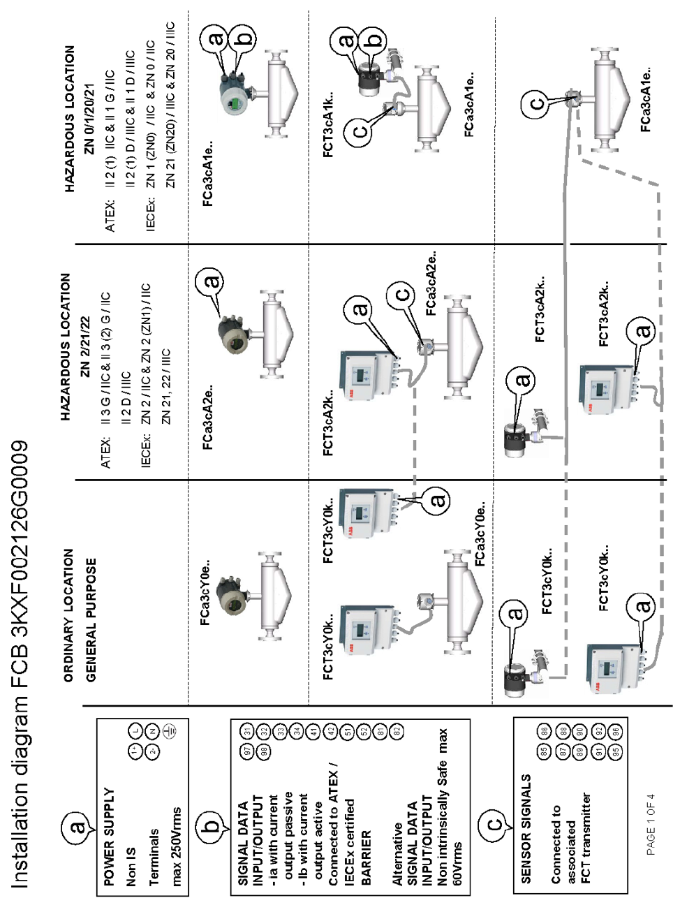
92 OI/FCB300/FCH300-EN Rev. F | CoriolisMaster FCB330, FCB350, FCH330, FCH3500
14.2 Installation diagram 3KXF002126G0009
Page 1 of 4
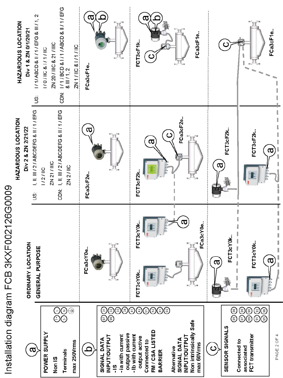
CoriolisMaster FCB330, FCB350, FCH330, FCH3500 | OI/FCB300/FCH300-EN Rev. F 93
Page 2 of 4
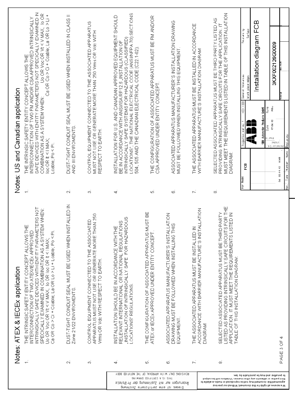
94 OI/FCB300/FCH300-EN Rev. F | CoriolisMaster FCB330, FCB350, FCH330, FCH3500
Page 3 of 4
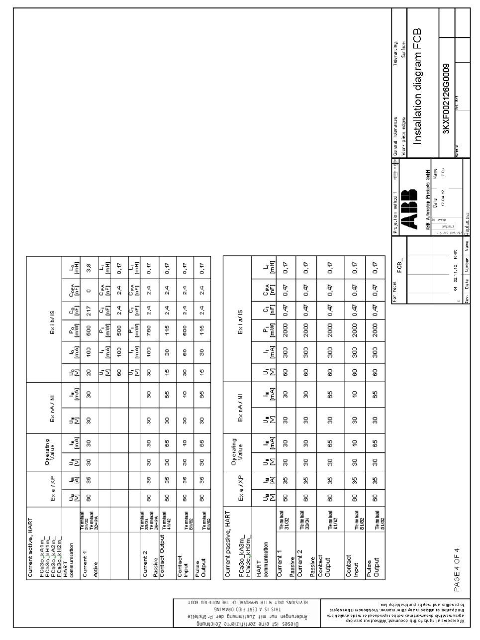
CoriolisMaster FCB330, FCB350, FCH330, FCH3500 | OI/FCB300/FCH300-EN Rev. F 95
Page 4 of 4

96 OI/FCB300/FCH300-EN Rev. F | CoriolisMaster FCB330, FCB350, FCH330, FCH3500
Statement on the contamination of devices and components
Repair and / or maintenance work will only be performed on devices and components if a statement form has been completed
and submitted.
Otherwise, the device / component returned may be rejected. This statement form may only be completed and signed by
authorized specialist personnel employed by the operator.
Customer details:
Company:
Address:
Contact person:
Telephone:
Fax:
E-Mail:
Device details:
Typ:
Serial no.:
Reason for the return/description of the defect:
Was this device used in conjunction with substances which pose a threat or risk to health?
Yes No
If yes, which type of contamination (please place an X next to the applicable items)?
Biological
Corrosive / irritating
Combustible (highly / extremely combustible)
Toxic
Explosiv
Other toxic substances
Radioactive
Which substances have come into contact with the device?
1.
2.
3.
We hereby state that the devices / components shipped have been cleaned and are free from any dangerous or poisonous
substances.
Town/city, date
Signature and company stamp
CoriolisMaster FCB330, FCB350, FCH330, FCH3500 | OI/FCB300/FCH300-EN Rev. F 97
Notes
98 OI/FCB300/FCH300-EN Rev. F | CoriolisMaster FCB330, FCB350, FCH330, FCH3500
Notes
CoriolisMaster FCB330, FCB350, FCH330, FCH3500 | OI/FCB300/FCH300-EN Rev. F 99
Notes

Contact us
OI/FCB300/FCH300-EN Rev. F 05.2014
ABB Ltd.
Process Automation
Oldends Lane, Stonehouse
Gloucestershire, GL10 3TA
UK
Tel:
+44 (0)1453 826661
Fax:
+44 (0)1453 829671
Mail:
ABB
Inc.
Process Automation
125 E. County Line Road
Warminster PA 18974
USA
Tel:
+1 215 674 6000
Fax:
+1 215 674 7183
ABB
Automation Products GmbH
Process Automation
Dransfelder Str. 2
37079 Goettingen
Germany
Tel
: +49 551 905-0
Fax:
+49 551 905-777
ABB E
ngineering (Shanghai) Ltd.
Process Automation
No.5, Lane 369, Chuangye Road,
Shanghai, 201319,
P.R. China
Tel:
+86(0) 21 6105 6666
Fax:
+86(0) 21 6105 6992
Mail:
www.abb.com/
flow
Note
We reserve the right to make technical changes or
modify the contents of this document without prior
notice. With regard to purchase orders, the agreed
particulars shall prevail. ABB does not accept any
responsibility whatsoever for potential errors or
possible lack of information in this document.
We reserve all rights in this document and in the
subject matter and illustrations conta
ined therein.
Any reproduction, disclosure to third parties or
utilization of its contents
- in whole or in parts – is
forbidden without prior written consent of ABB.
Copyright©
2014 ABB
All rights reserved
3KXF411008R4201
Translation of the original instruction
