
CONCRETE TECHNOLOGY
LABORATORY MANUAL
DEPARTMENT OF CIVIL ENGINEERING
JORHAT ENGINEERING COLLEGE
JORHAT, ASSAM-785007

Concrete Technology Laboratory Manual
1 | P a g e
COLLEGE VISION AND MISSION
Vision:
To develop human resources for sustainable industrial and societal growth through excellence in
technical education and research.
Mission:
1. To impart quality technical education at UG, PG and PhD levels through good academic
support facilities.
2. To provide an environment conducive to innovation and creativity, group work and
entrepreneurial leadership.
3. To develop a system for effective interactions among industries, academia, alumni and
other stakeholders.
4. To provide a platform for need-based research with special focus on regional development.
DEPARTMENT VISION AND MISSION
Vision:
The department will be a centre of excellence in creating highly competent civil engineers with
professional ethics, social responsibility and entrepreneurial skills for sustainable development.
Mission:
1. To offer quality technical education in undergraduate, post-graduate and doctoral level that
enables students in honing their professional skills.
2. To provide a congenial, interactive and inspiring environment that enables student to
develop innovative ideas, ethical values and entrepreneurial skills.
3. To promote research initiatives to address regional and global problems.
4. To extend technical expertise to meet industrial and societal need.

Concrete Technology Laboratory Manual
2 | P a g e
PROGRAM OUTCOMES (POs)
Engineering graduates will be able to:
1. Engineering knowledge: Apply the knowledge of mathematics, science, engineering
fundamentals, and an engineering specialization to the solution of complex engineering
problems.
2. Problem analysis: Identify, formulate, review research literature, and analyze complex
engineering problems reaching substantiated conclusions using first principles of
mathematics, natural sciences, and engineering sciences.
3. Design/development of solutions: Design solutions for complex engineering problems
and design system components or processes that meet the specified needs with appropriate
consideration for the public health and safety, and the cultural, societal, and environmental
considerations.
4. Conduct investigations of complex problems: Use research-based knowledge and
research methods including design of experiments, analysis and interpretation of data, and
synthesis of the information to provide valid conclusions.
5. Modern tool usage: Create, select, and apply appropriate techniques, resources, and
modern engineering and IT tools including prediction and modelling to complex
engineering activities with an understanding of the limitations.
6. The engineer and society: Apply reasoning informed by the contextual knowledge to
assess societal, health, safety, legal and cultural issues and the consequent responsibilities
relevant to the professional engineering practice.
7. Environment and sustainability: Understand the impact of the professional engineering
solutions in societal and environmental contexts, and demonstrate the knowledge of, and
need for sustainable development.
8. Ethics: Apply ethical principles and commit to professional ethics and responsibilities and
norms of the engineering practice.
9. Individual and team work: Function effectively as an individual, and as a member or
leader in diverse teams, and in multidisciplinary settings.
10. Communication: Communicate effectively on complex engineering activities with the
engineering community and with society at large, such as, being able to comprehend and
write effective reports and design documentation, make effective presentations, and give
and receive clear instructions.
11. Project management and finance: Demonstrate knowledge and understanding of the
engineering and management principles and apply these to one’s own work, as a member
and leader in a team, to manage projects and in multidisciplinary environments.
12. Life-long learning: Recognize the need for, and have the preparation and ability to engage
in independent and life-long learning in the broadest context of technological change.

Concrete Technology Laboratory Manual
3 | P a g e
PROGRAMME SPECIFIC OUTCOMES (PSOs)
PSO1: Graduates will be able to apply technical skills and modern engineering tools of civil
engineering to meet desired need of project.
PSO2: Graduates will be able to handle the challenges of civil engineering projects that requires
analytical and design skills.

Concrete Technology Laboratory Manual
4 | P a g e
STUDENT PROFILE
NAME :
ROLL NUMBER :
SEMESTER :
YEAR :
PERFORMANCE RECORD
EXP. NO.
TITLE OF EXPERIMENT
REMARKS
1
Determination of specific gravity of cement
2
Determination of standard consistency
3
Determination of the initial setting time
4
Determination of the final setting time
5
To determine the compressive strength of 1:3 cement and
sand mortar cubes after 3 days and 7 days curing
6
Gradation of fine aggregate (fineness modulus)
7
To study the bulking of fine aggregate
8
Gradation of coarse aggregates
9
To determine the slump value of a prepared concrete mix
(Slump test)
10
To determine the compaction factor of concrete mix of
given proportion (Compaction factor test)
OFFICE USE
Checked By :
Overall Marks :
Signature of Teacher :

Concrete Technology Laboratory Manual
5 | P a g e
EXPERIMENT NO - 1
Aim of The Experiment:
Determination of specific gravity of cement (IS 4031 (Part 11) 1988).
Theory:
The specific gravity of cement is the ratio of the weight of a given volume of substance to the
weight of an equal volume of water. It is a number and denotes how many times a substance is
heavy as water. To find the specific gravity of cement, it is required to find the weight of a certain
volume cement and the weight of an equal volume of water. As cement reacts with water its
specific gravity is determined with reference to a non-reactive liquid like kerosene.
Apparatus: Le-Chatelier Flask (Specific gravity bottle), trowel, measuring jar, weighing
balance, plate, rubber glove.
Fig. 1. Le-Chatelier Flask
Procedure:
1. Weight of specific gravity bottle dry, W1
2. Fill the bottle with distilled water and weight it, W2
3. Dry the specific gravity bottle and fill it with kerosene and weight again, W3
4. Pour some of the kerosene out and introduce a weighted quantity of cement into the bottle.
5. Roll the bottle gently in the inclined position until no further air bubble rise to the surface.
6. Fill the bottle to the top with kerosene and weight it, W4.
Precautions:
1. Only kerosene which is free of water is to be used.
2. All air bubbles shall be eliminated in filling the apparatus and inserting the stopper.
3. Weighing is to be done quickly after filling the apparatus and shall be accurate to 0.1 mg.
4. Precautions are to be taken to prevent expansion and overflow of the contents resulting
from the heat of the hand when wiping the surface of the apparatus.

Concrete Technology Laboratory Manual
6 | P a g e
Observation and Result:
Weight of empty dry bottle (W1) = ___________ g
Weight of bottle + water (W2) = ___________ g
Weight of bottle + kerosene (W3) = ___________ g
Weight of bottle + cement + kerosene (W4) = ___________g
Weight of cement (W5) = ___________ g
Specific gravity of kerosene, G =
W5(W3-W1)
(W5+W3-W4)(W2-W1)
=
Conclusion:
Questionnaire:
1. Define specific gravity.
2. Why is kerosene used instead of water in the specific gravity test.
3. What is the use of specific gravity of cement ?
4. Is specific gravity of cement constant ?
5. Name the factors affecting the specific gravity of cement.
Concrete Technology Laboratory Manual
7 | P a g e
EXPERIMENT NO - 2
Aim of The Experiment:
Determination of standard consistency (IS 4031 (Part 4) 1988).
Test Standard Reference:
To determine the standard consistency of cement by classifications based on IS:4031(Part4)-1988
Theory:
The purpose of conducting this test is to find the amount of water to be added to the cement to get
a normal consistency. The result obtained from this test is used to fix the quantity of water to be
mixed in cement before conforming test for tensile strength, sitting time and soundness.
Apparatus:
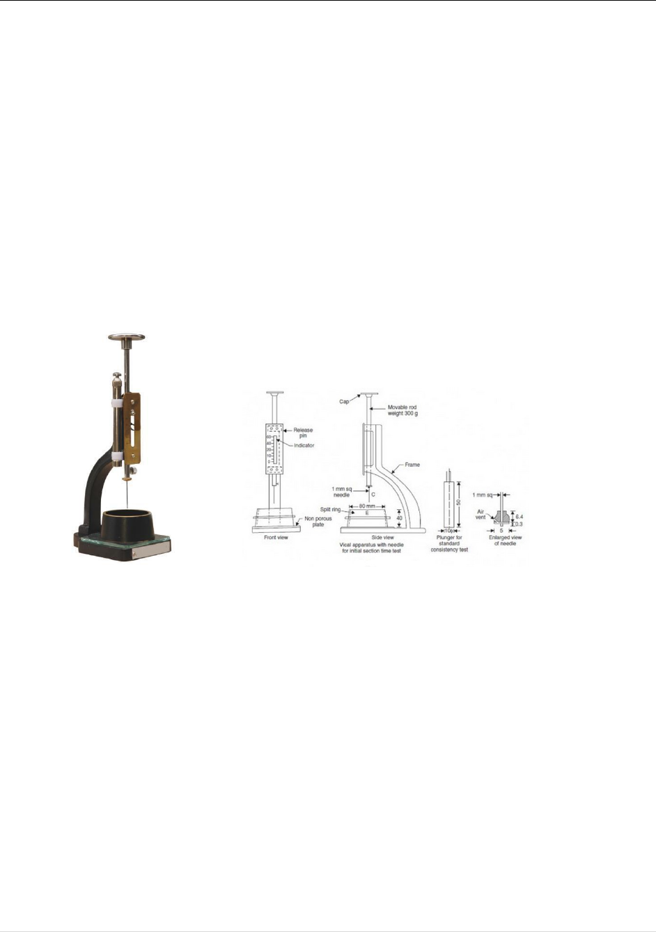
Vicat apparatus with vicat mould, vicat plunger and needles, gauging trowel, measuring jar,
weighing balance, stop watch, rice plate, rubber glove and glass plate.
Fig. 2. Vicat apparatus with vicat mould
Procedure:
1. Taken 400 gm of cement passing 15850 Micron.
2. Prepared paste with varying percentage of water, starting from 25% by weight of cement;
the time of gauging is between 3 to 5 minutes. The gauging time is counted from the time
of adding water to the dry cement.
3. Filled the vicat mould resting upon non-porous plate with this paste after completing filling
the mould, smooth off, surface of the paste by single movement of plan making with level
with the top of the mould, the mould may be slighting shaken to explicit.
4. Placed the mould with the non-porous resting plate under the rod attacked with the plunger,
lowered the plunger gently to touch the surface of the test block and quickly released,
allowing it to sink into the paste.
5. Found the water content at which the plunger penetrates up to 5 mm from the lower side.

Concrete Technology Laboratory Manual
8 | P a g e
Precautions:
1. Clean appliances shall be used for gauging.
2. Release the plunger gently.
3. The temperature of cement, water and that of test room, at the time when the above
operations are being performed, shall be 27 ± 2 ºC.
4. For each repetition of the experiment fresh cement is to be taken.
Observation and Result:
1.
No. of trials
1
2
3
4
5
6
2.
Percentage of
water
3.
Initial
reading(mm)
4.
Final
reading(mm)
5.
Height not
penetrated
Conclusion:
(Note: Initial reading is the indicator reading when the lower end of the plunger touches the
bottom of non-porous surface of mould.)
Questionnaire:
1. Define consistency of cement?
2. Why is the consistency of cement determined?
3. Is it possible to perform the initial and final setting time test of cement without performing
consistency test?
Concrete Technology Laboratory Manual
9 | P a g e
EXPERIMENT NO - 3
Aim of the Experiment:
Determination of the initial setting time (IS 4031 (Part 5) 1988).
Test standard reference:
Determine the initial setting time of cement.
Theory:
Initial setting time is the time when the paste starts losing its plasticity. And setting time is the time
required for stiffening of cement paste to a defined consistency. It is the time taken for the cement
paste or cement concrete to harden sufficiently and attain the shape of the sculpt in which it is cast.
In order that the concrete may be placed conveniently it is necessary that the initial setting time is
not too quick and after is has been laid, hardening should be so that the structure can be made use
of as early as possible. The initial set is a stage in the process of hardening after which any crack
that may reappear will not unite.
Apparatus:
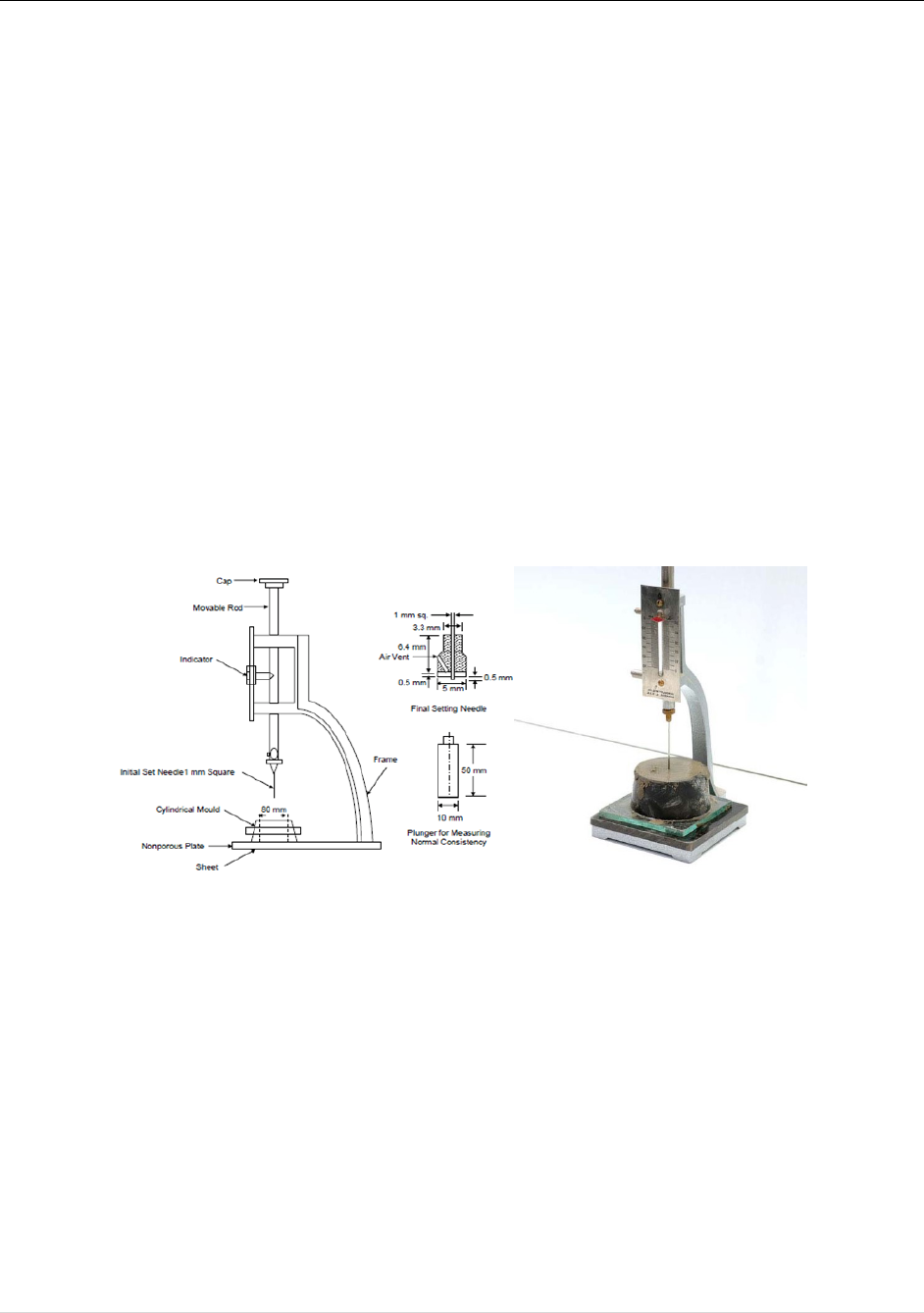
Vicat apparatus, vicat mould, needle, gauging, trowel, measuring jar, weighing balance, stop
watch, rice plate, rubber glove, nonporous glass plate.
Fig. 3. Vicat apparatus with vicat mould
Procedure:
1. Prepared a neat cement paste by mixing with 85 water, P = standard consistency as found
before. The gauging is again kept between 3 to 5 minutes start the stop watch at the instant
when the water is added to cement.
2. Filled the Vicat mould and smoothed the surface of the paste. Making level with the top of
the mould.
3. Placed the test block in the mould resting on non-porous plate under the rod attached with
the needle for initial setting time. Lowered the needle gently in contact with the surface of
the test block. Quickly released allowing it to penetrate into the test block.
4. Repeated the procedure until the needle failed to pierce the block for about 5 mm measured
from bottom of the mould for initial setting time test. The period elapsing between the time

Concrete Technology Laboratory Manual
10 | P a g e
when water is added to the cement and the time at which the needle fails to pierce the test
block about 5 mm is the initial setting time.
Precautions:
1. Clean appliances shall be used for gauging.
2. Release the plunger gently.
3. The temperature of cement, water and that of test room, at the time when the above
operations are being performed, shall be 27 ± 2 ºC.
4. For each repetition of the experiment fresh cement is to be taken.
Observation and Result:
Weight of cement taken = 400 gm
Weight of water taken = 0.85 × water obtained from standard consistency
1. No. of trials
1
2
3
4
5
6
2. Time taken (minutes)
3. Initial reading (mm)
4. Final reading (mm)
5. Height not penetrated (mm)
Conclusion:
Questionnaire:
1. For ordinary Portland cement, what is the minimum setting time as per Indian Standard?
2. Name the factors affecting the initial setting time of cement ?
3. What is the difference between setting and hardening ?Is there any way to lengthen the
duration of setting time of cement ?
Concrete Technology Laboratory Manual
11 | P a g e
EXPERIMENT NO - 4
Aim of the Experiment:
Determination of the final setting time (IS 4031 (Part 5) 1988).
Test standard reference:
Determine the final setting time of cement
Theory:
Final setting time is that time period between the time water is added to cement and the time at
which 1 mm needle makes an impression on the paste in the mould but 5 mm attachment does not
make any impression.
Apparatus:
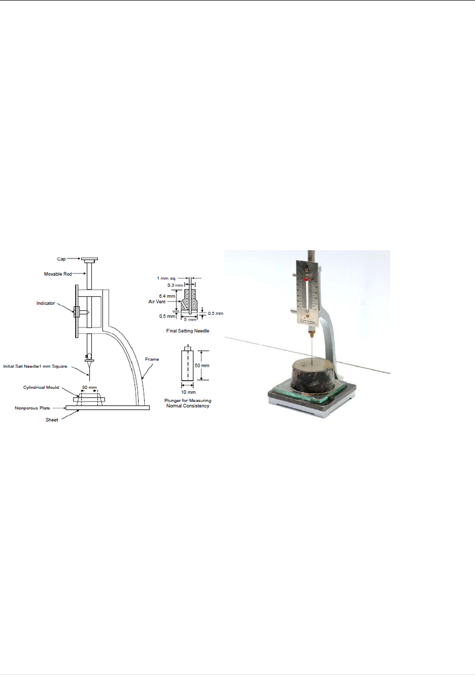
Vicat apparatus, vicat mould, needle, trowel, measuring jar, weighing balance, stop watch, plate,
rubber glove, nonporous glass plate.
Fig. 4. Vicat apparatus with Vicat mould
Procedure:
1. Prepare a neat cement paste by mixing with 85 water, P = standard consistency as found
before. The gauging is kept between 3 to 5 minutes.
2. Start the stop watch at the instant when the water is added to cement.
3. Fill the Vicat mould and smooth the surface of the paste. Make level with the top of the
mould.
4. Place the test block in the mould resting on non-porous plate under the rod attached with
the needle for initial setting time.
5. Lower the needle with an annular attachment to get in contact with the surface of the test
block.
6. The cement is considered finally set when upon applying the final setting needle gently to
the surface of the test block; the needle makes an impression thereon, while the annular
attachment fails to do so. Record this time.

Concrete Technology Laboratory Manual
12 | P a g e
Observation and Result:
Weight of cement taken = 400 gm
Weight of water taken = 0.85 × water obtained from standard consistency
1. No. of trials
1
2
3
4
5
6
2. Final reading time (minutes)
Conclusion:
Questionnaire:
1. For ordinary Portland cement, what is the duration of final setting time ?
2. Name the factors affecting the final setting time of cement ?
3. What is the difference between setting and hardening ?
4. Is there any way to shorten the setting time of cement ?
Concrete Technology Laboratory Manual
13 | P a g e
EXPERIMENT NO - 5
Aim of the experiment:
To determine the compressive strength of 1:3 cement and sand mortar cubes after 3 days and 7
days curing (IS 4031 (Part 6) 1988).
Test Standard Reference:
To determine the compressive strength of 1:3 cement and sand mortar cubes after 3 days and 7
days curing using the classifications based on IS:269-1985
Theory:
The compressive strength of cement is determined in order to verify whether the cement conforms
to the above mentioned I.S code specifications and whether it will be able to develop the required
compressive strength of concrete. According to the IS:269-1985, the ultimate compressive strength
of cubes of cement and sand mortar in 1:3 proportion containing (P/4 + 3.5) % of water should be
as follows:
After 3 days: Not less than 11.5 N/mm
2
After 7 days: Not less than 17.5 N/mm
2
Apparatus:
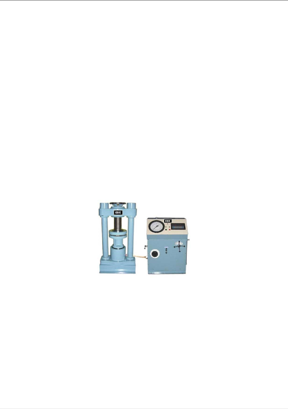
Universal testing machine or compressive testing machine, cube mould (7.16 cm side), vibrating
machine, measuring cylinder trowels, non-porous plate and balance with weight box.
Fig. 5. Compressive Testing Machine
Procedure:
1. Taken the weight of the materials required. The material for each cube shall be mixed
separately and quantities for one single cube are follows:
cement = 185 gm, sand = 555 gm, water = (P/4+3.5) % of weight of cement and sand,
where P is the % of water for standard consistency = 30%
2. Placed on a non-porous plate, the mixture of cement and sand in the proportion 1:3 by
weight and mixed it dry with a trowel for one minute. Then mixed it with water until the
mixture is of uniform color.
3. Placed the assembled mould in the table of vibrating machine and firmly put it in the
position by means of suitable clamp.

Concrete Technology Laboratory Manual
14 | P a g e
4. Immediately after mixing the mortar filled the entire quantity of mortar in the mould and
compacted by vibration.
5. The period of vibrating should be ten minutes in the specific speed of 120 to 140 vibrations
per minutes.
6. Removed the mould from m/c and kept it at a temperature of 27±2
o
C in an atmosphere of
at least 90% relative humidity for 24 hours after completion of vibrating.
7. At the end of that removed the cube from the mould and immediately submerged in clean
and fresh water and kept there until they are tussled.
Precautions:
1. Inside of the cube moulds should be oiled to prevent the mortar from adhering to the sides
of the mould.
2. Test three cubes for compressive strength at the periods mentioned under the relevant
specification.
3. Perform the standard consistency test of cement prior to this experiment.
Observation and Result:
Testing: Tested the cubes at the end of 3 days and 7 days.
3 day strength
7 day strength
Sl. No.
Load (kN)
Strength in
N/mm
2
Load (kN)
Strength in
N/mm
2
Conclusion:
Questionnaire:
1. What is the relation between the strength of cement and concrete?
2. What is the minimum and maximum quantity of cement recommended as per IS 456
2000?
3. What are the various grade of ordinary Portland cement as per Indian Standard?
Concrete Technology Laboratory Manual
15 | P a g e
EXPERIMENT NO - 6
Aim of the Experiment:
Gradation of fine aggregate (fineness modulus) (IS 383 1970).
Test Standard Reference:
To determine the fineness modulus of fine aggregates by classifications based on IS: 383-1970.
Theory:
Fine aggregates in concrete serve the dual purpose of providing dispersed mass of cement paste
much larger in volume to facilitate bonding of coarse aggregates as well as filling the voids
amongst coarse aggregates. Higher percentage of coarse aggregates however means larger total
surface area needing higher amount of cement for bonding. Very fine size particles are not
desirable in high percentage from strength point of view. Therefore, fine aggregates should be
taken in suitable proportion of coarse to medium to fine particle sizes. Sieve analysis is carried out
to ascertain the gradients of particle size distribution.
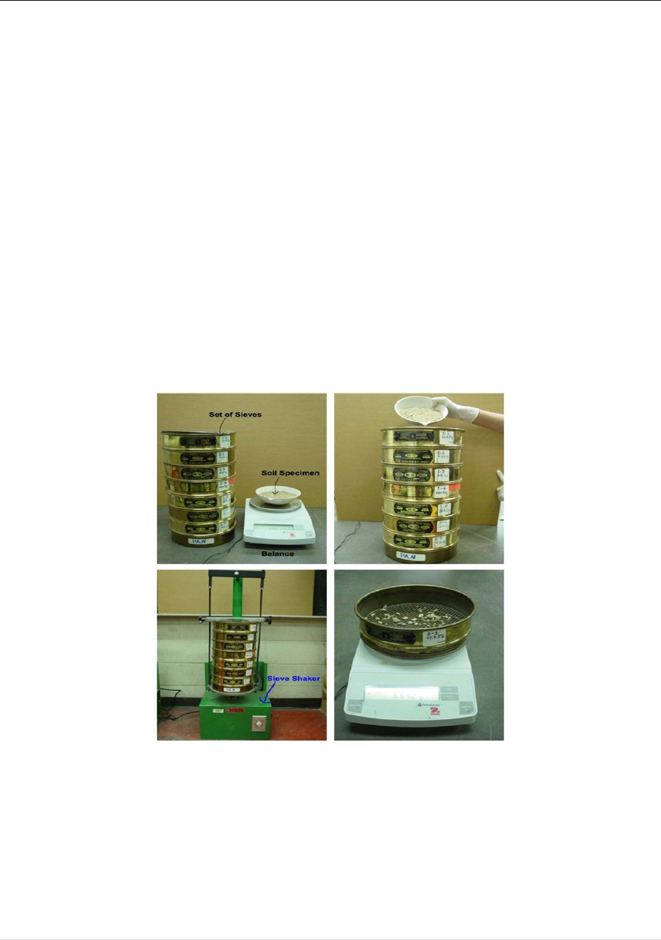
Apparatus:
Set of IS sieve, weighing balance, trays and mechanical sieve-shaker.
Fig. 6. Method of testing
Procedure:
1. Take 500 g of dry fine aggregate for sieve analysis by quartering from the test sample.
2. Place the material in the top of the sieve of largest size.
3. The stack of sieve should be arranged from top to bottom in sizes as shown in the
observation table.
4. Place the stack of sieve in the mechanical shaker and allow sieving for about 10 minutes.

Concrete Technology Laboratory Manual
16 | P a g e
5. Weigh the aggregates retained on each sieve and carry out computations to determine
particle size distribution and fineness modulus.
Precautions:
1. The sample should be taken by quartering.
2. The sieving must be done carefully to prevent the spilling of fine aggregate.
Observation and Result:
Sl. No.
Sieve size
Weight
retained
% Weight
retained
Cumulative %
retained (C)
% Weight passing
(finer)
∑C =
Fineness modulus (excluding C for pan) = ∑C/100
=
Conclusion:
Questionnaire:
1. What is the role of fine aggregate in concrete?
2. How is fine aggregate classified as per Indian Standard (IS 383 1970)?
3. What is the basis of classification of fine aggregate as per Indian Standard (IS 383 1970)?
4. What type of sand (as per Indian Standard IS 383 1970) is found around Jorhat Engineering
5. College?
Concrete Technology Laboratory Manual
17 | P a g e
EXPERIMENT NO - 7
Aim of the Experiment:
To study the bulking of fine aggregate (IS:2386 (Part3) 1963).
Test Standard Reference:
To study the sand grains under varying percentage of moisture content with the help of
classifications based on IS:2386(Part3)-1963
Theory:
When dry comes into contact with moisture, thin film is formed around the particles which
causes them to get apart from each other. This will result in increasing volume of the sand. This
phenomenon is known as bulking of sand. For this reason, if sand is measured by volume,
bulking should be properly accounted.
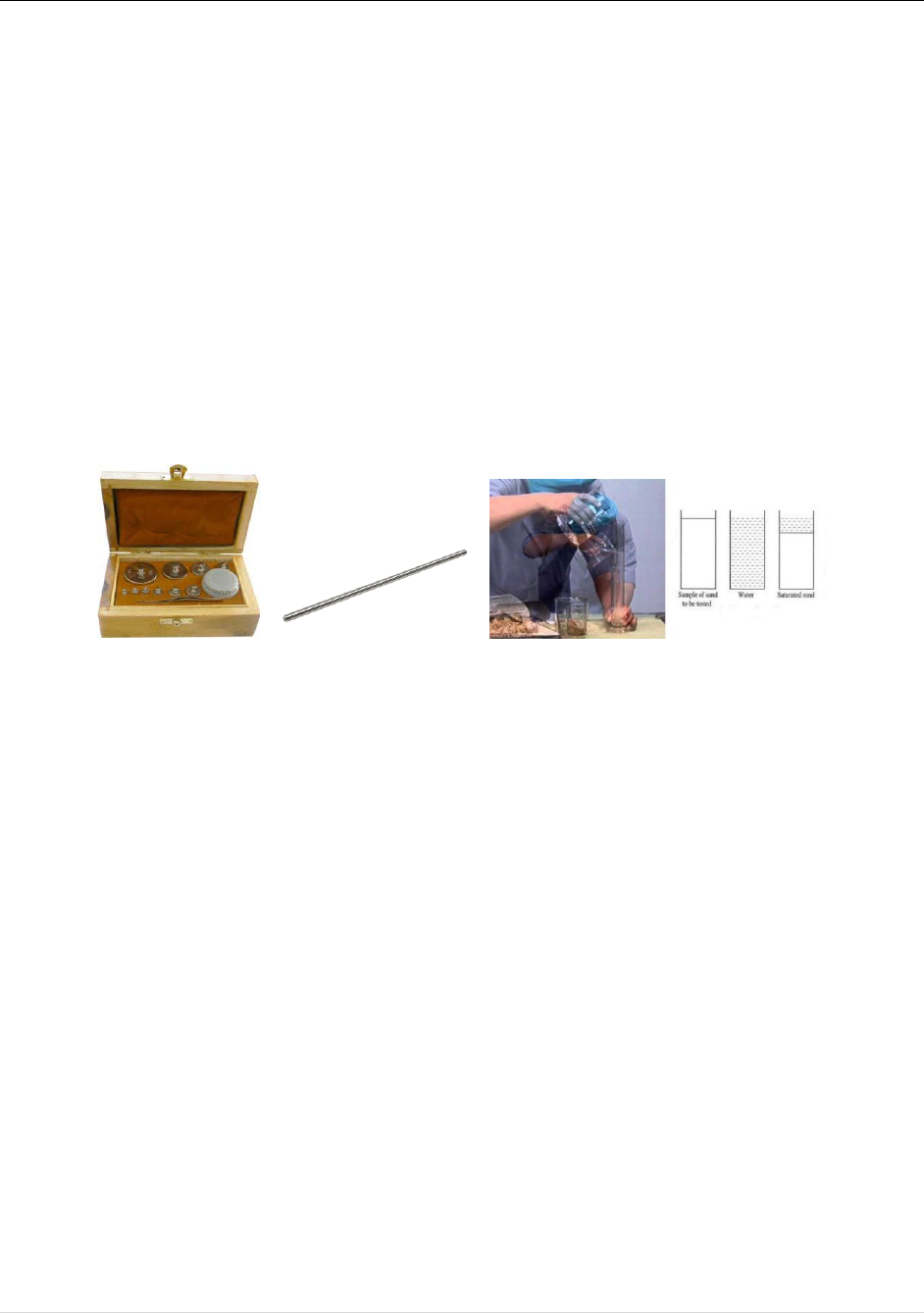
Apparatus:
Weighing balance, weight box, mixing pan, measuring cylinder, rod for compaction.
Fig. 7. Weight box and rod for compaction: Bulking of sand
Procedure:
1. Taken 500 gm(W1) of sand passing through 1.18 mm sieve.
2. Kept the sample in an oven in a tray at a temperature of 100
o
C-110
o
C for 24±0.5 hours.3.
3. Cool the sand in air tight container and weight it(W
2
), water content of the sample is (W
1
-
W
2
) ×100/W
1
.
4. Taken out about 200 gm of sand and poured it into a pan.
5. Added 2% of water (by weight) and mixed well.
6. Poured the sand sample into a measuring cylinder.
7. Leveled the surface and read the volume in ml (h
1
).
8. Poured water into the measuring cylinder and completely inundated the sand and shaken
it.
9. Leveled the surface and noted down the level in ml (h
2
).
10. Taken out the whole quantity of sand and continued the experiment by adding 2% water
more each time and noted down the corresponding volume of sand until the dump sand
volume starts decreasing.
11. Then (h
1
+h
2
) shows the bulking of the sample sand under test. Percentage of bulking = (h
1
-
h
2
/h
2
) ×100 %

Concrete Technology Laboratory Manual
18 | P a g e
Precautions:
1. While mixing water with sand grains, mixing should be thorough and uniform.
2. The sample should not be compressed while being filled in jar.
3. The sample must be slowly and gradually poured into measuring jar from its top.
4. Increase in volume of sand due to bulking should be measured accurately.
Observation and Result:
To draw the graph in between % of moisture added by weight along X-axis and % of increased
volume along Y-axis. From the graph, the maximum % of bulking occurred to be picked, and %
of water content at maximum bulking.
Conclusion:
Questionnaire:
1. What do you mean by bulking of sand?
2. What is the effect of bulking of sand in concrete mix?

Concrete Technology Laboratory Manual
19 | P a g e
EXPERIMENT NO - 8
Aim of the Experiment:
Gradation of coarse aggregates (fineness modulus) (IS 383 1970).
Test Standard Reference:
To determine the fineness modulus of coarse aggregates by classifications based on IS: 383-1970.
Theory:
Fineness modulus of coarse aggregates represents the average size of the particles in the coarse
aggregate by an index number. It is calculated by performing sieve analysis with standard sieves.
Higher the aggregate size higher the Fineness modulus hence fineness modulus of coarse aggregate
is higher than fine aggregate. In general, however, a smaller value indicates a finer aggregate.
Apparatus:
Set of IS sieve, weighing balance, trays and mechanical sieve-shaker.
Procedure:
1. Take 5 kg of coarse aggregate by quartering from the test sample.
2. Arrange the relevant sieves one above the other with the sieve size increasing from the top
and put the pan at the bottom.
3. Put the set of sieves over the sieve shaker and shake 2 to 3 minutes.
4. Weigh the amount of aggregate retained on each sieve.
Precautions:
1. The sample should be taken by quartering.
2. The sieving must be done carefully to prevent the spilling of fine aggregate.

Concrete Technology Laboratory Manual
20 | P a g e
Observation and Result:
Sl. No.
Sieve size
Weight
retained
% Weight
retained
Cumulative %
retained (C)
% Weight passing
(finer)
∑C =
Fineness modulus (excluding C for pan) = ∑C/100
=
Conclusion:
Questionnaire:
1. What is the role of coarse aggregate in concrete?
2. Does the coarse aggregate take part in any chemical reaction in concrete?
3. What is the role of angular coarse aggregate in the workability of concrete?
4. What type of coarse aggregate is found in the river bed of Bhogdoi River near Jorhat
Engineering College?
5. What is the significance of Fineness Modulus ?
6. What do you understand by grading of aggregates ?
7. What is single-sized aggregate and graded aggregate ?
8. Why gradation of aggregate is important for concrete mix design ?

Concrete Technology Laboratory Manual
21 | P a g e
EXPERIMENT NO - 9
Aim of the Experiment:
To determine the slump value of a prepared concrete mix (Slump test) (IS 1199 1959).
Test Standard Reference:
Test for Workability - Slump Test as per IS: 1199 1959, Methods of Sampling and Analysis of
Concrete.
Theory:
Slump valve gives the measure of workability of concrete. In this test fresh concrete is filled into
a mould of specified shape and dimensions, and the settlement or slump is measured when
supporting mould is removed. Slump increases as water-content is increased. For different works
different slump values have been recommended. By this test one can determine the water content
to give specified slump value.
Apparatus:
Slump cone, concrete mixing pan, weighing balance, trays, spatula, trowels, tamping rod and
graduated cylinder.
Procedure:
1. Prepare fresh concrete of desired mix proportion.
2. Thoroughly clean and free the internal surface of the slump cone from superfluous moisture
and any set concrete.
3. Place the slump cone on a smooth, horizontal, rigid and non-absorbent surface.
4. Fill the cone with the fresh in four layers, each approximately one-quarter of the height of
the cone. Each layer shall be tamped with twenty-five strokes of the rounded end of the
tamping rod.
5. The strokes shall be distributed in a uniform manner over the cross-section of the cone.
6. After the top layer has been filled, struck off and level the concrete.
7. The mould shall be removed from the concrete immediately by raising it slowly and
carefully in a vertical direction.
8. Measure the slump by determining the difference between the height of the mould and that
of the highest point of the concrete after subsiding.
Precautions:
1. The strokes are to be uniformly applied through the entire area of the concrete section.
2. The cone should be removed very slowly by lifting it upwards without disturbing the
concrete.
3. During filling, the mould must be firmly pressed against the base.
4. Vibrations from nearly machinery might also increase subsidence; hence test should be
made beyond the range of ground vibrations

Concrete Technology Laboratory Manual
22 | P a g e
Observation and Result:
Slump value = _______ mm
Conclusion:
Questionnaire:
1. Define workability of concrete?
2. What is the role of water/cement ratio in modifying the workability of concrete?
3. Is it possible to increase the workability of concrete by maintaining constant water/cement
ratio, if yes, how can it increased?
4. What is the relation between the water/cement ratio and strength of concrete?
5. What do you mean by dry slump and shear slump?
6. Is this experiment suitable for finding the flow-ability of concrete?
7. What is segregation and bleeding ?
8. What is the significance of flow test ?
9. What are the factors affecting the workability of concrete ?

Concrete Technology Laboratory Manual
23 | P a g e
EXPERIMENT NO – 10
Aim of the Experiment:
To determine the compaction factor of concrete mix of given proportion (Compaction factor test)
(IS 1199 1959).
Test Standard Reference:
Test for Workability – Compacting factor test as per IS: 1199 1959, Methods of Sampling and
Analysis of Concrete.
Theory:
This test is adopted to determine workability of concrete where nominal size of aggregate does not
exceed 40 mm. It is based on the definition, that workability is that property of concrete, which
determines the amount of work required to produce full compaction. The test consists essentially
of applying a standard amount of work to standard quantity of concrete and measuring the resulting
compaction.
The compaction factor is defined as the ratio of the weight of partially compacted concrete to the
weight of fully compacted concrete. It shall be stated to the nearest second decimal place.
Apparatus:
Compaction factor apparatus, concrete mixing pan, weighing balance, trays, spatula, trowels,
tamping rod and graduated cylinder.
Procedure:
1. Thoroughly clean and grease the inner surface of the hoppers and the cylinder.
2. Fasten the hopper doors.
3. Weigh the empty cylinder accurately (W
1
).
4. Fix the cylinder on the base with fly nuts and bolts
5. Prepare fresh concrete of desired mix proportion.
6. Fill the freshly mixed concrete in upper hopper gently with trowel without compacting.
7. Release the trap door of the upper hopper and allow the concrete of fall into the lower
hopper bringing the concrete into standard compaction.
8. Immediately after the concrete comes to rest, open the trap door of the lower hopper and
allow the concrete to fall into the cylinder, bringing the concrete into standard compaction.
9. Remove the excess concrete above the top of the cylinder by a trowel.
10. Weigh the cylinder i.e cylinder filled with partially compacted concrete (W
2
).
11. Refill the cylinder with same sample of concrete in 4 layers, tamping each layer with
tamping for 25 times in order to obtain full compaction of concrete.
12. Level the mix and weigh the cylinder filled with fully compacted concrete (W
3
).
Precautions:
1. The top hopper must be filled gently.
2. The mix should not be pressed or compacted in the hopper.
3. If the concrete in the hopper does not fall through when the trap door is released, it should
be freed by passing a metal rod. A single steady penetration will usually affect release.

Concrete Technology Laboratory Manual
24 | P a g e
Observation and Result:
Weight of cylinder = W
1
kg =
Weight of cylinder with partially compacted concrete = W
2
kg =
Weight of cylinder with fully compacted concrete = W
3
kg =
Compaction factor =
W
2
- W
1
W
3
- W
1
=
Conclusion:
Questionnaire:
1. How is compaction factor related to workability of concrete?
2. What is the role of water/cement ratio in modifying the compaction factor of concrete?
3. How is concrete compacted in-situ to fill the structural members perfectly?
