
MCRMA
18 MERE FARM ROAD
PRENTON
WIRRAL
CHESHIRE
CH43 9TT
TEL: 0151 652 3846
FAX: 0151 653 4080
www.mcrma.co.uk
Composite Slabs and Beams Using Steel Decking: Best Practice for Design and Construction
THE METAL CLADDING & ROOFING MANUFACTURERS ASSOCIATION
in partnership with
THE STEEL CONSTRUCTION INSTITUTE
COMPOSITE SLABS AND BEAMS
USING STEEL DECKING:
BEST PRACTICE FOR DESIGN
AND CONSTRUCTION
MCRMA Technical Paper No. 13
SCI Publication P300
CI/SfB
Nh2(23)
MARCH 2009
THE STEEL CONSTRUCTION INSTITUTE
SILWOOD PARK
ASCOT
BERKSHIRE
SL5 7QN
TEL: 01344 636525
FAX: 01344 636570
www.steel-sci.org
cyan plate magenta plate yellow plate black plate
REVISED EDITION
REVISED EDITION

P:\PUB\PUB800\SIGN_OFF\P300\2nd Edition\P300V02D12.doc
SCI (The Steel Construction Institute) is the leading, independent provider of technical expertise and
disseminator of best practice to the steel construction sector. We work in partnership with clients,
members and industry peers to help build businesses and provide competitive advantage through the
commercial application of our knowledge. We are committed to offering and promoting sustainable and
environmentally responsible solutions.
Our service spans the following five areas:
Membership
Individual and corporate
membership
Technical information
Courses and Education
Publications
Online reference tools
Codes and standards
Construction solutions
Sustainability
Product development
Research
Engineering solutions
Communications technology
Websites
Communities
Design tools
Assessment
SCI assessed
The Steel Construction Institute
Silwood Park, Ascot, Berkshire, SL5 7QN.
Telephone: +44 (0) 1344 636525
Fax: +44 (0) 1344 636570
Email: membership@steel-sci.com
World Wide Web site: http://www.steel-sci.org
The Metal Cladding and Roofing Manufacturers Association represents the major manufacturers in the
metal roofing and cladding industry and seeks to foster and develop a better understanding amongst
specifiers and end users alike of the most effective use of metal building products, components and
systems.
From its inception, MCRMA has been the leading voice for the industry and works closely with a
variety of industry bodies and standards committees to ensure that best practice is followed at all times.
The Association’s campaign for improved technical knowledge of metal building construction within the
industry is borne out by its well established and authoritative series of technical design guides which are
all freely available on the MCRMA web site to ensure the widest dissemination of good practice.
The environmental and sustainable benefits of metal, together with developments in colour and form
have led to a much wider use of metal in construction. MCRMA is committed to remaining at the
forefront of developments in metal building technology to ensure that specifiers have the opportunity to
create imaginative and innovative building designs that offer both cost-effective and sustainable
solutions to benefit future generations.
The Metal Cladding And Roofing Manufacturers Association Limited
18 Mere Farm Road, Prenton, Wirral, Cheshire CH43 9TT
Tel: +44 (0) 151 652 3846
Fax: + 44 (0) 151 653 4080
www.mcrma.co.uk
.
MCRMA Technical Paper No. 13
SCI Publication No. P300
Composite Slabs and Beams using
Steel Decking:
Best Practice for Design and
Construction
(Revised Edition)
J W Rackham BSc (Build Eng), MSc, DIC, PhD, CEng, MICE
G H Couchman MA, PhD, CEng, MICE
S J Hicks
B Eng, PhD (Cantab)
Published by:
The Metal Cladding & Roofing Manufacturers Association
in partnership with
The Steel Construction Institute
P:\PUB\PUB800\SIGN_OFF\P300\2nd Edition\P300V02D12.doc ii Printed 29/04/09
2009 The Steel Construction Institute and The Metal Cladding & Roofing Manufacturers Association
Apart from any fair dealing for the purposes of research or private study or criticism or review, as permitted under the
Copyright Designs and Patents Act, 1988, this publication may not be reproduced, stored or transmitted, in any form or by
any means, without the prior permission in writing of the publishers, or in the case of reprographic reproduction only i
n
accordance with the terms of the licences issued by the UK Copyright Licensing Agency, or in accordance with the terms
of licences issued by the appropriate Reproduction Rights Organisation outside the UK.
Enquiries concerning reproduction outside the terms stated here should be sent to the publishers, The Steel Constructio
n
Institute, at the address given on the inside cover page.
Although care has been taken to ensure, to the best of our knowledge, that all data and information contained herein are
accurate to the extent that they relate to either matters of fact or accepted practice or matters of opinion at the time o
f
publication, The Steel Construction Institute, The Metal Cladding & Roofing Manufacturers Association, the authors and
the reviewers assume no responsibility for any errors in or misinterpretations of such data and/or information or any loss
or damage arising from or related to their use.
Publications supplied to the Members of the Institute at a discount are not for resale by them.
Publication Number: MCRMA Technical Paper No 13; SCI P300 Revised Edition
ISBN 978-1-85942-184-0 .
A catalogue record for this book is available from the British Library.
P:\PUB\PUB800\SIGN_OFF\P300\2nd Edition\P300V02D12.doc iii Printed 29/04/09
FOREWORD
Composite construction has proven popular because it combines structural efficiency with
speed of construction to offer an economic solution for a wide range of building types.
Applications include commercial, industrial and residential buildings.
This guide covers the design and construction of composite slabs and beams, and
addresses the good practice aspects of these activities. It updates the previous
MCRMA/SCI guide, which was published in 2000. The update reflects the latest
guidance for good practice and gives information on design to the Eurocodes, but omits
most of the advice given previously on construction practice for decking, as this is now
covered comprehensively in separate BCSA documents Guide to the installation of deep
decking, Publication No. 44/07, and Code of Practice for metal decking and studwelding,
Publication No. 37/04.
Design and construction guidance related to Slimdek construction is dealt with in a
separate part of the guide because of the significant number of differences from
‘traditional’ composite beam and slab construction.
The principal authors of this publication were Dr J W Rackham, Dr G H Couchman, and
Dr S J Hicks (all from The Steel Construction Institute). They were part of a
collaborative group responsible for the content of the publication, other members of
which were:
Mr A J Shepherd Richard Lees Steel Decking Ltd
Mr J Turner Structural Metal Decks Ltd
Mr A Wallwork Corus Panels and Profiles Ltd
Mr D St Quinton Kingspan Structural Products Ltd
Mr D Mullett Studwelders Ltd
Mr D E Simpson The Concrete Society
Further information was provided by Dr W I Simms and Mr A Way, both from
The Steel Construction Institute.
The preparation of this document was funded and commissioned by the Metal Cladding
and Roofing Manufacturers Association (MCRMA).
P:\PUB\PUB800\SIGN_OFF\P300\2nd Edition\P300V02D12.doc iv Printed 29/04/09
P:\PUB\PUB800\SIGN_OFF\P300\2nd Edition\P300V02D12.doc v Printed 29/04/09
CONTENTS
Page No.
FOREWORD iii
SUMMARY vi
1 INTRODUCTION 1
1.1 Benefits of composite construction 2
1.2 Applications 3
1.3 Scope of this publication 3
2 THE DESIGN AND CONSTRUCTION TEAM 4
2.1 Team members 4
2.2 Roles in design and construction 5
2.3 Design and construction sequences 8
3 INFORMATION TRANSFER 10
3.1 Design stage 10
3.2 Construction stage 11
4 DESIGN OF DECKING AND SLABS 15
4.1 Steel decking 15
4.2 Composite slabs 26
4.3 Acoustic insulation 48
4.4 Health & Safety 51
4.5 Further reading 52
5 DESIGN OF COMPOSITE BEAMS 54
5.1 Construction stage 55
5.2 Composite stage 56
5.3 Shear connection 63
5.4 Further reading 72
6 CONSTRUCTION PRACTICE - CONCRETE 75
6.1 Concrete supply design 75
6.2 Placing concrete 76
6.3 Loads on the slab during and after concreting 81
6.4 Further reading 83
7 SLIM FLOOR CONSTRUCTION 85
7.1 Introduction 85
7.2 Design 88
7.3 Construction practice 100
7.4 Further reading 104
8 REFERENCES 105
P:\PUB\PUB800\SIGN_OFF\P300\2nd Edition\P300V02D12.doc vi Printed 29/04/09
SUMMARY
This guide covers the design and construction of composite floors, paying particular
attention to the good practice aspects. Following a description of the benefits of
composite construction and its common applications, the roles and responsibilities of the
parties involved in the design and construction process are identified. The requirements
for the transfer of information throughout the design and construction process are
described.
The design of composite slabs and beams is discussed in detail in relation to the
Eurocodes and BS 5950. In addition to general ultimate and serviceability limit state
design issues, practical design considerations such as the formation of holes in the slab,
support details, fire protection, and attachments to the slab are discussed. Guidance is
also given on the acoustic performance of typical composite slabs. The obligations of
designers according to the CDM Regulations are identified and discussed.
The practical application of Slimdek construction, which normally utilises deep decking
and special support beams, is also covered. Typical construction details are illustrated,
and guidance is given on the formation of openings in the beams and the slab.
P:\PUB\PUB800\SIGN_OFF\P300\2nd Edition\P300V02D12.doc 1 Printed 29/04/09
1 INTRODUCTION
Composite slabs consist of profiled steel decking with an in-situ reinforced
concrete topping. The decking not only acts as permanent formwork to the
concrete, but also provides sufficient shear bond with the concrete so that, when
the concrete has gained strength, the two materials act together compositely.
Composite beams are normally hot rolled or fabricated steel sections that act
compositely with the slab. The composite interaction is achieved by the
attachment of shear connectors to the top flange of the beam. These connectors
generally take the form of headed studs. It is standard practice in the UK for the
studs to be welded to the beam through the decking (known as ‘thru-deck’
welding) prior to placing the concrete. The shear connectors provide sufficient
longitudinal shear connection between the beam and the concrete so that they act
together structurally.
Composite slabs and beams are commonly used (with steel columns) in the
commercial, industrial, leisure, health and residential building sectors due to the
speed of construction and general structural economy that can be achieved.
Although most commonly used on steel framed buildings, composite slabs may
also be supported off masonry or concrete components.
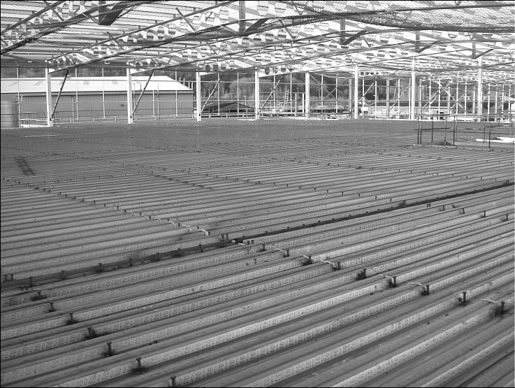
A typical example of the decking layout for a composite floor is shown in
Figure 1.1. The lines of shear connectors indicate the positions of the composite
beams.
Figure 1.1 A typical example of composite floor construction,
showing decking placed on a steel frame
P:\PUB\PUB800\SIGN_OFF\P300\2nd Edition\P300V02D12.doc 2 Printed 29/04/09
1.1 Benefits of composite construction
Composite construction has contributed significantly to the dominance of steel
frames in the commercial building sector in the UK. The main benefits of
composite construction are:
Speed of construction
Bundles of decking can be positioned on the structure by crane and the
individual sheets then installed by hand. Using this process, crane time is
minimal, and in excess of 400 m
2
of decking can be installed by one team in a
day, depending on the shape and size of the building footprint. The use of the
decking as a working platform speeds up the construction process for following
trades. Minimal reinforcement is required, and large areas of floor can be
poured quickly. Floors can be concreted in rapid succession. The use of fibre
reinforced concrete can further reduce the programme, as the reinforcement
installation period is significantly reduced.
Safe method of construction
The decking can provide a safe working platform and act as a safety ‘canopy’ to
protect workers below from falling objects.
Saving in weight
Composite construction is considerably stiffer and stronger than many other
floor systems, so the weight and size of the primary structure can be reduced.
Consequently, foundation sizes can also be reduced.
Saving in transport
Decking is light and is delivered in pre-cut lengths that are tightly packed into
bundles. Typically, one lorry can transport in excess of 1000 m
2
of decking.
Therefore, a smaller number of deliveries are required when compared to other
forms of construction.
Structural stability
The decking can act as an effective lateral restraint for the beams, provided that
the decking fixings have been designed to carry the necessary loads and
specified accordingly. The decking may also be designed to act as a large floor
diaphragm to redistribute wind loads in the construction stage, and the
composite slab can act as a diaphragm in the completed structure. The floor
construction is robust due to the continuity achieved between the decking,
reinforcement, concrete and primary structure.
Shallower construction
The stiffness and bending resistance of composite beams means that shallower
floors can be achieved than in non-composite construction. This may lead to
smaller storey heights, more room to accommodate services in a limited ceiling
to floor zone, or more storeys for the same overall height. This is especially
true for slim floor construction, whereby the beam depth is contained within the
slab depth (see Section 7).
Sustainability
Steel has the ability to be recycled repeatedly without reducing its inherent
properties. This makes steel framed composite construction a sustainable
solution. ‘Sustainability’ is a key factor for clients, and at least 94% of all steel
construction products can be either re-used or recycled upon demolition of a
P:\PUB\PUB800\SIGN_OFF\P300\2nd Edition\P300V02D12.doc 3 Printed 29/04/09
building. Further information on sustainability of composite flooring systems is
given in Composite Flooring Systems: Sustainable construction solutions
[1]
.
Easy installation of services
Cable trays and pipes can be hung from hangers that are attached using special
‘dovetail’ recesses rolled into the decking profile, thereby facilitating the
installation of services such as electricity, telephone and information technology
network cabling. These hangers also allow for convenient installation of false
ceilings and ventilation equipment (see Section 4.2.8).
The above advantages (detailed in more depth in SCI publication Better Value in
Steel: Composite flooring
[2]
) often lead to a saving in cost over other systems.
SCI publication Comparative structure cost of modern commercial buildings
[3]
shows solutions involving composite construction to be more economical than
steel or concrete alternatives for both a conventional four storey office block
and an eight storey prestigious office block with an atrium.
1.2 Applications
Composite slabs have traditionally found their greatest application in steel-
framed office buildings, but they are also appropriate for the following types of
building:
Other commercial buildings
Industrial buildings and warehouses
Leisure buildings
Stadia
Hospitals
Schools
Cinemas
Housing; both individual houses and residential buildings
Refurbishment projects.
1.3 Scope of this publication
This publication gives guidance on the design and construction of composite
slabs and composite beams in order to disseminate all the relevant information
to the wide and varied audience involved in the design and construction chain.
Guidance is given on design and construction responsibilities, and requirements
for the effective communication of information between the different parties are
discussed.
The principal aim of the design guidance given in this publication is to identify
relevant issues. The reader is directed elsewhere, including to British Standards
and Eurocodes, for specific design guidance. Summary boxes are used to
highlight how to achieve economic, buildable structures through good practice
in design.
P:\PUB\PUB800\SIGN_OFF\P300\2nd Edition\P300V02D12.doc 4 Printed 29/04/09
2 THE DESIGN AND CONSTRUCTION
TEAM
The aim of this Section is to identify typical activities and responsibilities for
the team members involved in the design and construction of a building using
composite components. Clearly, the precise delegation of responsibilities will
depend on the details of the contract for a specific project, with which all
parties need to be familiar.
As an overriding principle, the CDM Regulations
[4]
state that ‘Every person on
whom a duty is placed by these Regulations in relation to the design, planning
and preparation of a project shall take account of the general principles of
prevention in the performance of those duties during all stages of the project’.
A similar requirement applies for the responsibilities during construction: ‘Every
person on whom a duty is placed by these Regulations in relation to the
construction phase of the project shall ensure as far as is reasonably practicable
that the general principles of prevention are applied in the carrying out of the
construction work’. Guidance on the specific details of the responsibilities of
each of the relevant parties under the CDM Regulations may be found in
Reference 5.
2.1 Team members
In recognition of the different types of contract that may be employed, the
following generic terminology has been adopted for the key parties involved:
The Client is the person (or organisation) procuring the building from those
who are supplying the components and building it.
The Architect is the person (or practice) with responsibility for the integration
of the overall design of the building, and with a particular responsibility for the
building function and aesthetics.
The Structural Designer is the person (or organisation) who is responsible for
the design of the structural aspects of the permanent works. This role could, for
example, be fulfilled by a Consultant, a ‘Design and Build’ Contractor, or a
Steelwork Sub-contractor. In many cases the Structural Designer will delegate
some of the design responsibility. For example, a Consultant may effectively
delegate some of the design work by using data supplied by a decking
manufacturer. The manufacturer then becomes a Delegated Designer, with
responsibility for certain aspects of the decking and, perhaps, the slab design.
Where applicable, this must be clearly communicated to the manufacturer along
with all relevant design information required early in the project design process.
A Delegated Designer is a person (or organisation) who, because of specialist
knowledge, carries out some of the design work on behalf of the Structural
Designer. This may be achieved by supplying design information such as
load-span tables for composite slabs.
The Main Contractor is the organisation responsible for the building of the
permanent works, and any associated temporary works.
P:\PUB\PUB800\SIGN_OFF\P300\2nd Edition\P300V02D12.doc 5 Printed 29/04/09
The CDM co-ordinator has obligations with regard to the safety aspects of a
project. This is a role defined in the CDM Regulations (see Section 2.2,
Safety).
2.2 Roles in design and construction
Form of floor construction
The choice of floor construction and the general beam and column arrangements
are the responsibility of the Architect and the Structural Designer. The Architect
will be concerned with more general and spatial aspects of the building form,
such as the column locations, the construction depth of the floors, and the soffit
appearance (if it is to be exposed).
The Structural Designer will determine the general loads to be considered in the
design of the structure, based on the type of occupancy for each area specified
by the Architect/Client. Details of any specific loads, for example due to
services, may need to be supplied by others. The Structural Designer will also
undertake scheme designs to identify beam and slab solutions with spanning
capabilities to suit the Architect’s requirements.
Composite beams
The detailed design of the composite beams (Section 5) is the responsibility of
the Structural Designer, who should recognise that there is an interaction
between the beam and slab design, particularly with the decking and transverse
reinforcement. In designing the composite beams, due consideration should be
given to the construction stage load case.
Although it may be necessary to consult the decking manufacturer for practical
advice on shear connector configurations, it is the responsibility of the structural
designer to specify the shear connector type and quantities required.
When considering composite beams, the designer should be aware of practical
considerations such as the access requirements for using stud welding equipment
(see Section 5.3.1) and minimum practical flange widths for sufficient bearing
of the decking (see Section 4.1.4). These requirements may have serious
implications on the economy of the chosen solution.
Composite slab
The design of the composite slab (Section 4) is the responsibility of the
Structural Designer. Particular attention should be paid to areas where there are
special loads, such as vehicle loads and loads from solid partitions and tanks.
Construction stage loads should also be considered, with particular attention to
any concentrated loads from plant or machinery required to carry out the safe
erection of the building and its structure. When designing and detailing any
reinforcement, the Structural Designer should ensure that the specified bars can
be located within the available depth of slab and that the correct reinforcement
covers for the design durability conditions can be achieved. (Recognise any
other space constraints that may exist on site.)
It is recommended that the Structural Designer prepares general arrangement
drawings for the slab (in addition to the steelwork general arrangement
drawings). In particular, these drawings should define the edges and thickness
of the slab, and they should form the basis of the decking layout drawings and
the reinforcement drawings.
P:\PUB\PUB800\SIGN_OFF\P300\2nd Edition\P300V02D12.doc 6 Printed 29/04/09
The Structural Designer should also produce a reinforcement layout drawing for
each bay of each floor. The reinforcement grade, location, lengths, minimum
overlaps and minimum concrete cover should be shown (and appropriate
information about fibres if they are to be used). On site, these drawings will be
used to check that all the reinforcement has been fixed correctly (or fibres
correctly incorporated).
Designing a concrete mix to provide the required structural and durability
performance is normally the responsibility of the Main Contractor.
Choice of Decking
The choice of decking and its general arrangement is the responsibility of the
Structural Designer. The design must consider the fire resistance of the slab
(which may depend on the decking type), the ability of the decking and
composite slab to resist the applied loading, the propping requirements, and the
deflections at both the construction and in-service (composite) stages. As well as
influencing all of these, the choice of decking profile may have implications for
the composite beam design.
Design data provided by a decking manufacturer will normally be used to select
the decking, as its performance is complex and is best determined from tests.
The Structural Designer must be satisfied with the information supplied in this
form by the Delegated Designer (decking supplier/manufacturer), and ensure
that it is not used ‘out of context’. Consultation with the decking
supplier/manufacturer is recommended if there is any doubt. Where decking is
specified for unusual applications, the ‘standard’ design information may not be
directly applicable (see Section 4).
Decking arrangement and details
The decking layout drawings (Section 3.2) are normally prepared by a decking
sub-contractor acting as a Delegated Designer. Details should be checked by the
Structural Designer, who should advise the Delegated Designer of any special
requirements, such as the need for extra fixings when the decking is required to
act as a wind diaphragm, or of any particular requirements concerning the
construction sequence. The Structural Designer should check that the proposed
bearing details and the interfaces with the other elements of construction are
practicable, and that they permit a logical, buildable sequence.
In preparing the decking layout drawings, the decking sub-contractor may find it
beneficial to refine the design. For example, it may be necessary to change
some of the continuous spans to simple spans for practical reasons. This may
have implications on the propping requirements during construction.
The loads that may be applied to the decking in the construction condition, both
as a temporary working platform and as formwork, should be clearly indicated
on the decking layout drawings or general notes. The loads that may be applied
to the composite slab should also be shown on the decking layout drawings, and
on the appropriate concreting drawings (these will be included in the Health and
Safety File for reference throughout the lifetime of the building). It is therefore
essential that all loading assumptions and design criteria are communicated to
the decking sub-contractor.
Temporary works
Propping should be avoided wherever possible, as it reduces the speed of
construction and therefore affects the construction sequence and economy. When
P:\PUB\PUB800\SIGN_OFF\P300\2nd Edition\P300V02D12.doc 7 Printed 29/04/09
propping is unavoidable, it is usually necessary to prop through several floors to
support the prop loads. This can prevent other operations over a large area.
However, when the construction sequence permits, propping does increase the
spanning capability of the decking. Determining the propping requirements is
generally the responsibility of the Structural Designer (normally using
information supplied by a Delegated Designer), although local propping needs
may change when the Delegated Designer details the decking layout. The
decking should be checked by the Structural Designer to ensure that it can
withstand the concentrated loads from the propping arrangement.
The location of lines of props or other temporary supports should be shown on
the decking layout drawings. The design and installation of the propping system
is the responsibility of the Main Contractor, but propping systems should be
braced appropriately. Removal of props should not be carried out before the
concrete has reached its specified strength, or, when specified in the contract,
before the Structural Designer gives explicit approval.
In addition, the Structural Designer should supply the Main Contractor with the
propping loads, and the dead load that has been considered, to help him/her to
draw up the propping scheme. When devising the scheme, consideration must
be given to the fact that floors will need to be designed to carry the
concentrated loads from props (see Section 6 for advice on possible loading).
Further advice on propping is given in Section 4.2.7.
Fire protection
The Architect is normally responsible for determining the fire resistance period
required for the building, and for choosing the type of fire protection. The
Structural Designer, in many cases represented by a Delegated Designer
(specialist sub-contractor), is responsible for the specific details of the fire
protection. The Structural Designer should also make it clear on the drawings
when any voids between the profiled decking and the steel beams have to be
filled (see Section 5.2.3).
Safety
Whilst all parties involved in the design and construction process are required to
consider construction safety, the CDM co-ordinator has some specific
obligations under the CDM Regulations
[4,5]
. [It is to be noted that the post of
Planning Supervisor established under the previous Regulations has been
revoked and replaced by the post of CDM co-ordinator.] These obligations
include the creation of the Health & Safety Plan and the Health & Safety File.
The aim of the first of these documents is to inform others of potential health
and safety issues; the Structural Designer should supply, for example, details of
any risks that may be foreseen during construction for inclusion in this plan.
The Health and Safety File is intended to assist persons undertaking
maintenance work, and will include information such as as-built drawings. The
Structural Designer should inform the contractor of any ‘residual hazards’ (those
that the contractor will manage during the construction) associated with any
unorthodox method of construction, and the provisions made to help the
contractor to manage them. It is the CDM Co-ordinator’s responsibility to
provide advice and assistance, to ensure that designers fulfil their obligations, to
consider health and safety issues, to co-operate with others, and to supply all
appropriate information.
P:\PUB\PUB800\SIGN_OFF\P300\2nd Edition\P300V02D12.doc 8 Printed 29/04/09
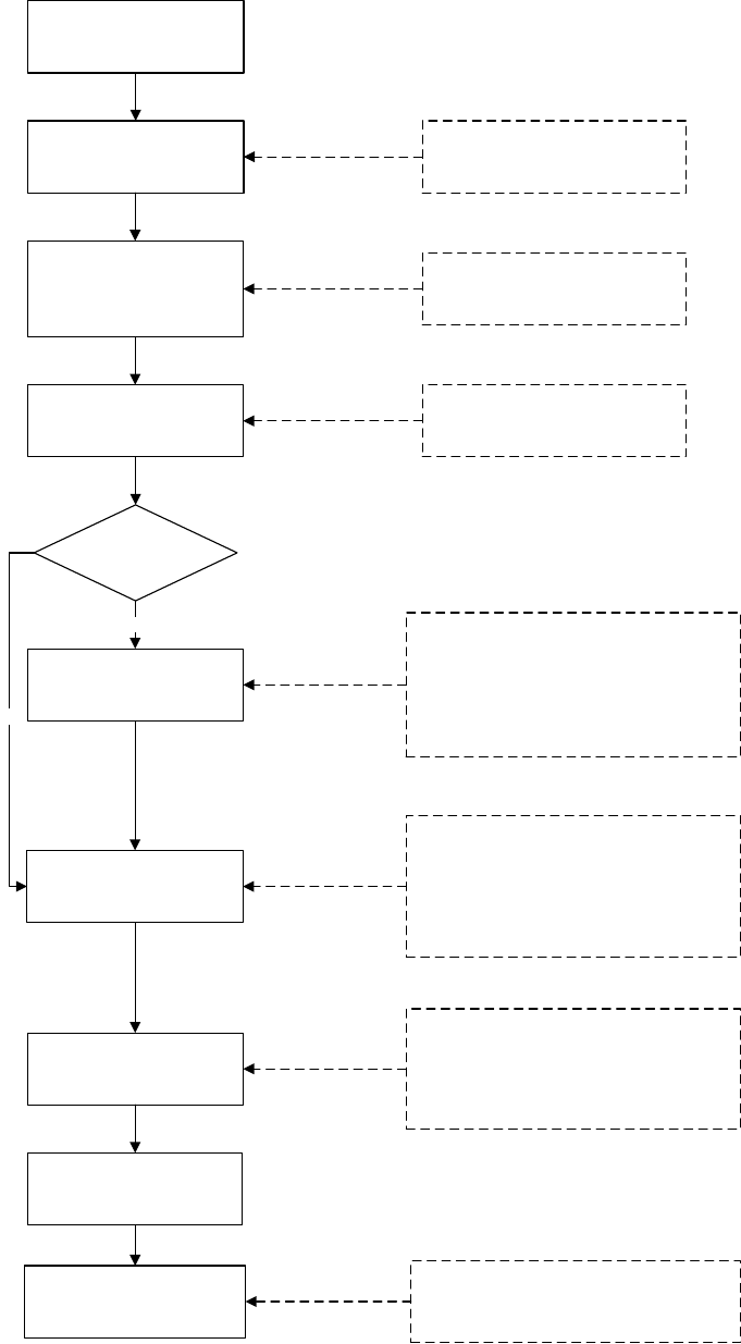
2.3 Design and construction sequences
The following flowcharts describe typical design (Figure 2.1) and construction
(Figure 2.2) sequences for composite floor construction.
Choose type of floor
construction, e.g. slimfloor,
composite beam + slab,
non-composite beam + slab
Choose concrete type and
grade, slab depth
Consider likely decking, slab
and beam span capability
Consider construction depth,
service requirements, need for
an exposed soffit?
Consider fire resistance period,
availability of concrete type
durability
Design as composite
beam?
Choose type of connector
and when to be welded
Building arrangement
chosen by Client/Architect
Choose column grids/beam
arrangement
Design beams
Design reinforcement at
openings in slab
Check composite slab and
design reinforcement
For composite beams:
Determine shear connector layout and
design transverse reinforcement
Consider:
Fire resistance period
In-service loading, e.g. solid partitions,
concentrated loads
Temporary construction loading, e.g. from
MEWPs
Consider:
Construction loading, dead weight
Concrete ponding deflections
Propping, effects of propping on fall arrest
system
Single or continuous spans
Consider:
Access for welding equipment
Electrical earthing
Economic No. of shear connectors
Can top flange of beams be left unpainted?
Alternatives to stud connectors
Site or shop welding
Design floor decking and
check at construction stage
Yes
No
Figure 2.1 Sequence of design activities
P:\PUB\PUB800\SIGN_OFF\P300\2nd Edition\P300V02D12.doc 9 Printed 29/04/09
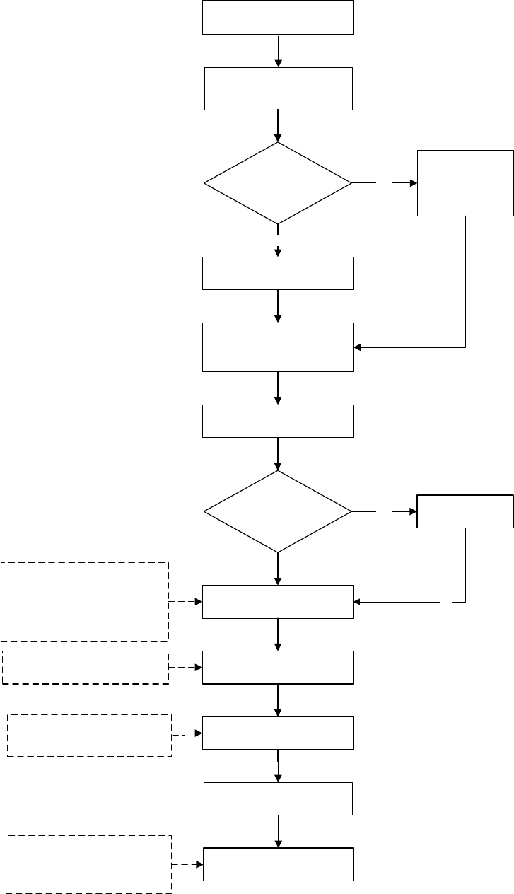
Remove props
Install fall arrest system
Position floor deck edge trims
and end closures and fix to
steelwork
Fix shear connectors, if any
Are props required
prior to casting
slab?
Fix reinforcement
Form slab
construction joints
Place concrete
Prepare slab surface
Install props
Install fall arrest
system (nets not
appropriate)
Install props
Fix:
Reinforcement at slab openings
and cantilevers, transverse
reinforcement, mesh
reinforcement, and ‘fire’
reinforcement, as necessary
Limit potential for grout loss
Consider concrete strength
Carry out additional cube tests?
Consult structural designer?
Are props required
prior to placing
decking?
No
Yes
Yes
Offload and hoist packs into
place
Erect steel frame
No
Including fibre reinforcement,
when specified
Figure 2.2 Sequence of construction activities
P:\PUB\PUB800\SIGN_OFF\P300\2nd Edition\P300V02D12.doc 10 Printed 29/04/09
3 INFORMATION TRANSFER
Clear and timely communication of information is important given that several
parties are involved in the building design process (see Section 2 for
identification of typical responsibilities). There are also obligations placed on
the key parties under the CDM Regulations
[4]
to exchange information during
both design and construction.
3.1 Design stage
The design of composite beams and slabs is clearly influenced by spanning
requirements, and the loads that are to be supported. In addition to grid layouts,
it is therefore important that accurate details of all the loads are established at
an early stage. Unfortunately, some information, such as the loads due to the
services, is often unavailable when needed, and the Structural Designer has to
use conservative values in order to give flexibility when the services are
designed at a later stage.
Knowledge of the position of services is also important, because it enables
account to be taken of any opening requirements in the beam webs and/or slabs.
Openings can have a significant effect on the resistance of a member.
The following list is a guide to the information required to design the composite
slabs and beams:
Column grid and beam general arrangement
Position of slab edges
Static and dynamic imposed loads (to include consideration of any
temporary concentrated loads from plant/machinery that may be required
during construction)
Services and finishes loads
Special loads (e.g. walls, wind diaphragm loads)
Fire resistance period
Decking type (shallow or deep, re-entrant or trapezoidal)
Slab depth limitations
Minimum mass requirements (for acoustic performance)
Location of openings
Requirements for soffit appearance and general exposure
Requirements for service fixings
Requirements for cladding attachments (which may affect the slab edge
detailing)
Construction tolerances
Deflection limits
Propping requirements or restrictions
Any known site restrictions on the use of thru-deck welding.
P:\PUB\PUB800\SIGN_OFF\P300\2nd Edition\P300V02D12.doc 11 Printed 29/04/09
In order to prepare the decking layout drawings, a Delegated Designer will also
need to know the:
Concrete type and grade
Shear connector layout and details
Cladding support method (for edge trim design, etc.)
There are also specific issues of information transfer that arise because the
design of the decking and composite slabs often relies on the use of information
presented in decking manufacturers’ literature. It is important that the tabulated
data and explanatory information is comprehensive. For example, in load-span
tables the following points should be clear:
Are the loads that are given nominal values or design values?
What allowances, if any, have been made for services loads etc.?
What fire performance do the tables relate to?
Do specified reinforcement requirements imply any crack control
capability?
Do the tables imply adequate serviceability behaviour as well as resistance,
and if so what limiting criteria have been assumed?
If the Structural Designer chooses to delegate some of the slab design to the
design service of a decking manufacturer (Delegated Designer), it is essential
that there is clear communication of all relevant design information.
3.2 Construction stage
An absence of essential information transfer between the design and construction
teams can lead to delays or, at worst, incorrect or unsafe construction.
The site personnel should check the information provided and confirm that it is
complete, passing any relevant information to appropriate sub-contractors. Any
variations on site that might affect the design should be referred to the
Structural Designer.
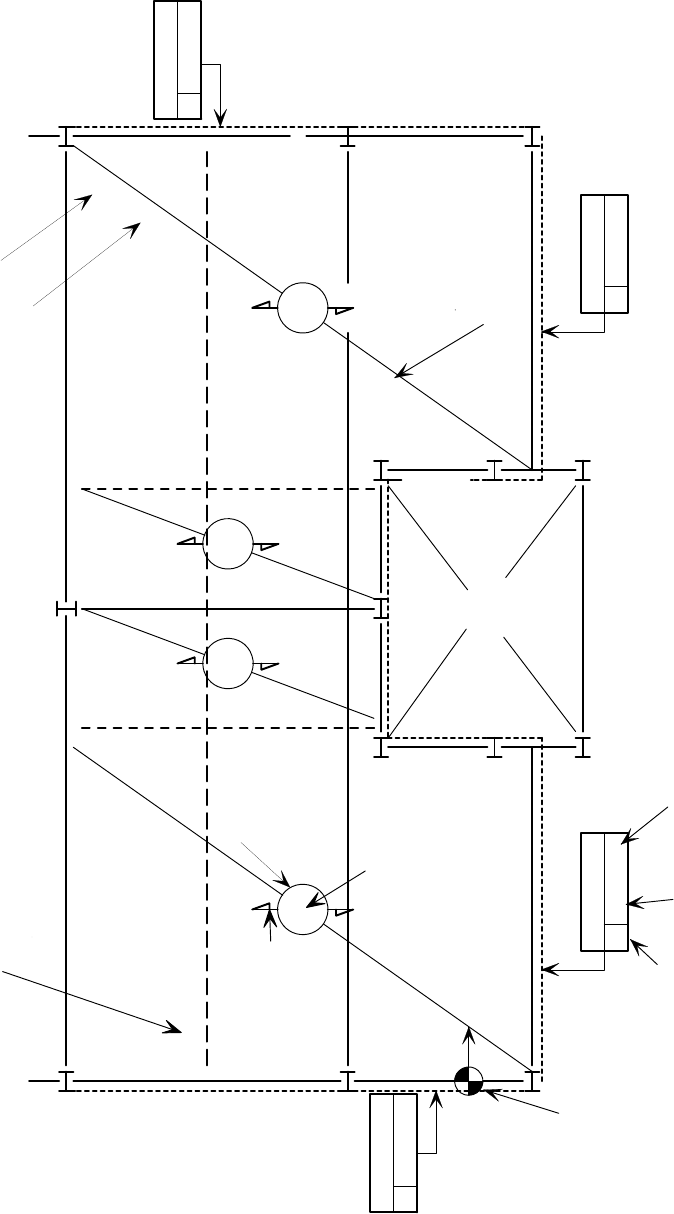
Decking layout drawing
Decking layout drawings should be available for those lifting the decking, so
that the bundles can be positioned correctly around the frame. Clearly, they
should also be available for the deck laying team.
Although different decking contractors’ drawing details may vary slightly, the
drawings should show (in principle) each floor divided into bays, where a bay is
an area that is to be laid from a bundle as one unit. Bays are normally indicated
on the drawing using a diagonal line. The number of sheets and their length
should be written against the diagonal line. The bundle reference may also be
detailed against this diagonal line. Further construction notes for the bay can be
referenced using numbers in circles drawn on the diagonal lines, as shown in
Figure 3.1. This figure shows an example of a decking layout drawing, but with
the shear connectors and fastener information omitted for clarity. Decking
contractors’ literature should be referenced for exact details.
P:\PUB\PUB800\SIGN_OFF\P300\2nd Edition\P300V02D12.doc 12 Printed 29/04/09
A
2
1
-
7
4
6
5
A
2
1
-
7
4
6
5
B
5
-
5
0
4
0
3
N
o
.
B
5
-
5
0
4
0
3
N
o
.
1
2
Stairs by others
Temporary propline
Symbol
defining
one bay
Edge Trim
A 150,50
Edge Trim
A 150,100
Edge Trim
A 150,100
Indicator start
point for
laying of panels
distance of edge
from C of beam
Edge
trim
height
9
N
o
.
Reference
number for
special
comments
Orientation of
decking ribs
Edge Trim
4
3
Reference
for edge trim
TP
TP
Number of
panels
9
N
o
.
TP
B 150,100
Panel lengths
Bundle identification code
L
Figure 3.1 Typical decking layout drawing (shear connector and
fastener information omitted)
P:\PUB\PUB800\SIGN_OFF\P300\2nd Edition\P300V02D12.doc 13 Printed 29/04/09
The approximate starting point for laying the decking should be given on the
drawings, together with the direction in which laying should proceed. All
supports (permanent or temporary) should be identified, and whether they
should be in place prior to laying the decking. The letters TP on the drawings
typically indicate lines of propping. Column positions and their orientation
should also be shown. The decking type, thickness and material strength should
be indicated on the drawing.
The location of all openings trimmed with steelwork, and all slab perimeters,
should be given relative to the permanent supports. This may be in the form of
a reference box titled ‘Edge Trim’, with a reference number (for details shown
elsewhere), the slab depth, and the distance from the edge of the slab to the
centre line of the nearest permanent support, but decking contractors’ literature
should be referred to for the exact drawing details.
The shear connector layout should also be shown on the decking drawings, or
on separate drawings for reasons of clarity. The information should include the
type of shear connector, its length, orientation (if shot-fired) and position
relative to the ribs. The minimum distance between the centre-line of the shear
connector and the edge of the decking should be given. Details of preparation,
fixing and testing of shear connectors should be available on site. For more
information on shear connection, refer to Sections 5.3 and BCSA publication
37/04
[6]
Fastener information should be given on the drawings. The fastener type for
both seams and supports should be given, along with maximum spacings (or
minimum number of fasteners per metre). Where the Structural Designer has
designed the decking to act as an effective lateral restraint to the beams and
additional fasteners to the manufacturer’s normal fixing arrangement are
necessary, this should be clearly indicated on the decking layout drawing and/or
general notes.
The general notes should include the design loads that the decking can support
in the construction condition. Guidance on avoidance of overload prior to
placing the concrete is given in the BCSA publication 37/04
[6]
.
A copy of the decking layout drawings must be given to the Main Contractor so
that checks can be made that the necessary propping is in place. The Main
Contractor will also need to refer to these drawings for details of the maximum
construction loading and any special loading.
Decking bundle identification
An identification tag should be attached to each bundle of decking delivered to
site. The tag will normally contain the following information:
Number of sheets, their lengths and thickness
Total bundle weight
Location of floor to receive bundle
Deck type
Bundle identification.
Product information on the decking should also be available on site, including
the height of the ribs and their spacing, and other technical information.
P:\PUB\PUB800\SIGN_OFF\P300\2nd Edition\P300V02D12.doc 14 Printed 29/04/09
Information required for laying the reinforcement, casting the slab and
its use thereafter
A reinforcement layout drawing should be prepared for each bay of each floor
by the Structural Designer. The location, length, minimum overlap and
minimum concrete cover of all reinforcement should be indicated. The grade of
all reinforcement should also be noted. This grade can be checked against the
identification tag for each reinforcement bundle delivered to site. Appropriate
information about fibres should be given, if they are to be used.
Important reinforcement details (such as at construction joints, support
locations, openings and edges) should be referenced and placed on this drawing.
The floor slab general arrangement drawings (or the Specification) should
include the concrete performance requirements or mix details (including any
details for fibre reinforcement), surface finish requirements, level tolerances and
any restrictions on the location of construction joints. They should also identify
the minimum concrete strength at which temporary supports may be removed,
the minimum concrete strength at which temporary construction loads may be
applied, and, where appropriate, the maximum allowable vehicular axle weight
(for punching shear). Minimum concrete strengths may be given in terms of
days after concreting.
Propping Information
As mentioned in Section 2.2, the Structural Designer should supply the Main
Contractor with the floor dead load value to allow a propping solution to be
developed.
P:\PUB\PUB800\SIGN_OFF\P300\2nd Edition\P300V02D12.doc 15 Printed 29/04/09
4 DESIGN OF DECKING AND SLABS
This Section provides information about design principles and procedures,
codified design rules, and guidance on good practice in design and detailing.
Along with Section 5, it is aimed primarily at the Structural Designer, and any
Delegated Designers. Summary boxes are used to highlight particular issues of
good practice, or areas where particular attention is needed
4.1 Steel decking
The steel decking has two main structural functions:
During concreting, the decking supports the weight of the wet concrete and
reinforcement, together with the temporary loads associated with the
construction process. It is normally intended to be used without temporary
propping.
In service, the decking acts ‘compositely’ with the concrete to support the
loads on the floor. Composite action is obtained by shear bond and
mechanical interlock between the concrete and the decking. This is
achieved by the embossments rolled into the decking – similar to the
deformations formed in rebar used in a reinforced concrete slab - and by
any re-entrant parts in the deck profile (which prevent separation of the
deck and the concrete).
The decking may also be used to stabilise the beams against lateral torsional
buckling during construction, and to stabilise the building as a whole by acting
as a diaphragm to transfer wind loads to the walls and columns (where it is
designed to do so, and in particular where there are adequate fixings
[7]
. The
decking, together with either welded fabric reinforcement placed in the top of
the slab or steel/synthetic fibres throughout the slab (see Section 6.2.1), also
helps to control cracking of the concrete caused by shrinkage effects.
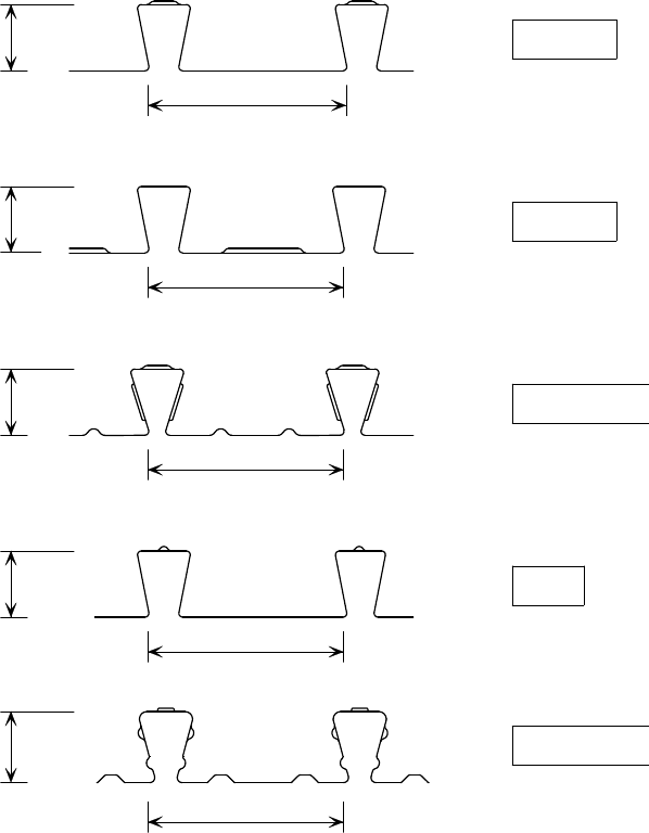
A.1.1 Decking profiles
Decking profiles are produced by a number of manufacturers in the UK.
Although there are similarities between their profiles, the exact shape and
dimensions depend on the particular manufacturer. There are two generic types
of shallow decking; re-entrant (dovetail) profiles and trapezoidal profiles.
Examples of re-entrant profiles are shown in Figure 4.1. Examples of
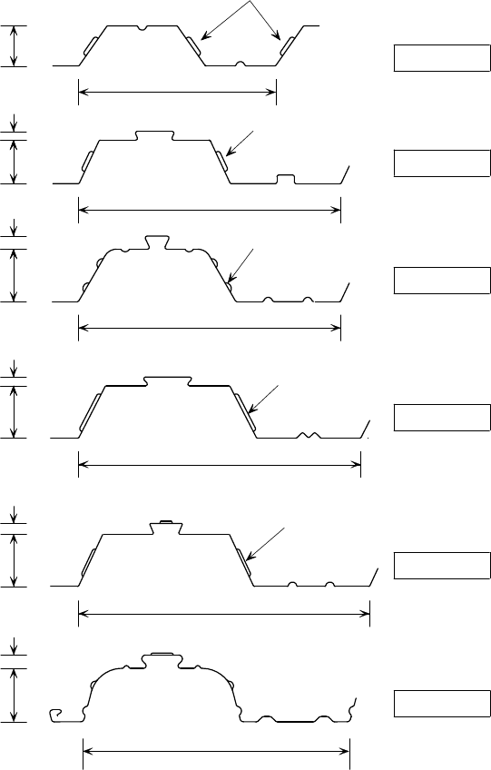
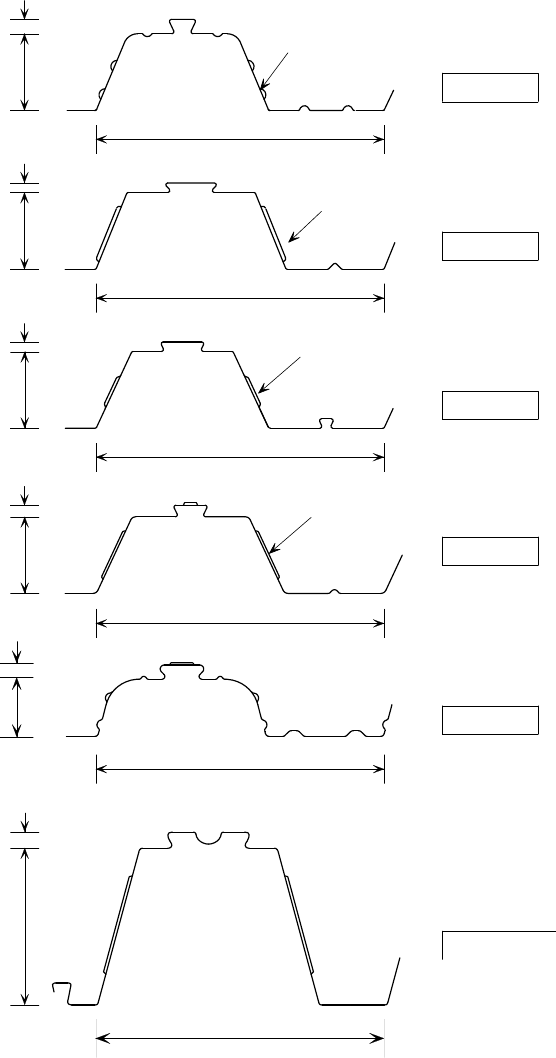
trapezoidal profiles with a shoulder height of up to 60 mm (excluding the crest
stiffener) are shown in Figure 4.2, and similar profiles deeper than this are
shown in Figure 4.3.
The traditional shallow decking profiles are between 45 to 60 mm high, with a
rib spacing usually of 150 to 333 mm. This type of decking typically spans 3 m,
leading to frame grids of 9 m 9 m or similar dimensions, using secondary
beams at 3 m spacing, for which temporary propping is usually not required.
Profiles up to 95 mm high overall have been developed which can achieve over
4.5 m spans without propping. Normally, the decking is laid continuously over
a number of spans, which makes it stronger and stiffer than over a single span.
More recently, a 160 mm (overall) profile has been developed which can span
6 m unpropped as a simply supported member.
P:\PUB\PUB800\SIGN_OFF\P300\2nd Edition\P300V02D12.doc 16 Printed 29/04/09
Deep decking profiles, which are over 200 mm deep, are also available. These
are mainly used in slim floor construction, which is considered separately in
Section 7 of this guide.
51mm
152mm
51mm
51mm
150mm
51mm
150mm
150mm
149 mm
Multideck 50
R51
2
1
3
4
ComFlor
Holorib
MetFloor 55
5
55mm
Figure 4.1 Examples of re-entrant deck profiles used for composite
slabs, supplied by:
1. Richard Lees Steel Decking Ltd.
2. Corus Panels and Profiles
3. Kingspan Structural Products Ltd.
4. Structural Metal Decks Ltd.
5. CMF Ltd.
P:\PUB\PUB800\SIGN_OFF\P300\2nd Edition\P300V02D12.doc 17 Printed 29/04/09
46 mm
10 mm
50 mm
300 mm
225 mm
2
1
4
Ribdeck AL
TR60
333 mm
12 mm
60 mm
Chevron embossments
Vertical embossments
Sloping and
horizontal
embossments
ComFlor 46
15 mm
300 mm
2
3
Multideck 60
Sloping embossments
60 mm
323 mm
9 mm
ComFlor 60
Embossments
60 mm
60 mm
MetFloor 60
5
300 mm
15 mm
Figure 4.2 Examples of trapezoidal deck profiles up to 60 mm deep
(excluding the top stiffener) used for composite slabs,
supplied by:
1. Richard Lees Steel Decking Ltd.
2. Corus Panels and Profiles
3. Kingspan Structural Products Ltd.
4. Structural Metal Decks Ltd.
5. CMF Ltd.
P:\PUB\PUB800\SIGN_OFF\P300\2nd Edition\P300V02D12.doc 18 Printed 29/04/09
300 mm
80 mm
10 mm
1
4
Ribdeck 80
12 mm
K shaped embossments
Sloping and
horizontal
embossments
300 mm
300 mm
TR80
15
mm
300 mm
2
80 mm
3
Sloping embossments
Multideck 80
9 mm
300 mm
ComFlor 80
Embossments
80 mm
5
MultiDeck 146
3
80 mm
15 mm
15 mm
80 mm
145 mm
MetFloor 80
300 mm
Figure 4.3 Examples of trapezoidal deck profiles greater than 60 mm
deep (excluding the top stiffener) used for composite
slabs, supplied by:
1. Richard Lees Steel Decking Ltd.
2. Corus Panels and Profiles
3. Kingspan Structural Products Ltd.
4. Structural Metal Decks Ltd.
5. CMF Ltd.
The grades of steel used for decking are specified in BS EN 10326
[8]
. The
common grade in the UK is S350 (the designation identifies the yield strength of
the steel in N/mm
2
).
P:\PUB\PUB800\SIGN_OFF\P300\2nd Edition\P300V02D12.doc 19 Printed 29/04/09
Decking is generally rolled from 0.9 to 1.2 mm thick strip steel. The spanning
capability of a given decking profile clearly increases as the steel thickness
increases, but not in direct proportion to the strength. The steel is galvanized
before forming, and this is designated in the steel grade by the letters GD,
followed by a number corresponding to the number of grammes of zinc per m
2
.
The normal specification is GD
275, i.e. 275 grammes of zinc per m
2
, which
results in a thickness of approximately 0.02 mm per face (sufficient to achieve
an excellent design life in internal applications with mild exposure conditions).
Thicker galvanized coatings of 350
g/m
2
, and up to 600 g/m
2
, are available for
special applications where improved durability is needed, but specifications
other than 275
g/m
2
will be difficult to obtain and are likely to require a large
minimum order. ‘Thru-deck’ welding may also be affected. For this reason,
polyester paints are sometimes applied over the galvanizing to provide a longer
service life. Advice should be sought from the supplier/manufacturer when
decking is to be used in a moderate or severe environment. Further advice on
the use of composite construction in an aggressive environment is given in
AD 247
[9]
.
Standard thickness galvanizing (275 g/m
2
) will give an excellent design life
in most internal applications. Non-standard thicknesses of galvanizing are
difficult to obtain and should not therefore be considered as a practical way
of increasing durability.
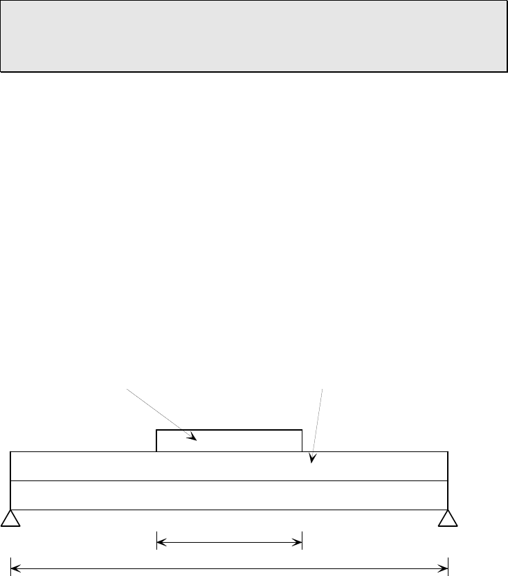
4.1.2 Design for resistance
The temporary construction load usually governs the choice of decking profile.
When designing to Eurocodes, the construction loading that should be
considered in the design of the decking is defined in BS EN 1991-1-6
[10]
and its
National Annex. Unfortunately, the provisions are a little unclear; the following
is understood to be the recommended construction loading, which should be
treated as a variable load:
(i) 0.75 kN/m
2
generally
(ii) 10% slab self weight or 0.75 kN/m
2
, whichever is greater, over a
3 m 3 m ‘working area’. This area should be treated as a moveable patch
load that should be applied to cause maximum effect
This is shown diagrammatically in Figure 4.4.
3m square working area
Clear span + 0.075m
Self weight
Construction load
0.75 kN/m²
Construction load
inside 'working area'
= 10% slab self weight
0.75 kN/m²
Figure 4.4 Loading on decking at the construction stage to
BS EN 1991-1-6
P:\PUB\PUB800\SIGN_OFF\P300\2nd Edition\P300V02D12.doc 20 Printed 29/04/09
When designing to BS 5950-4
[11]
, the construction loading is defined as:
A uniformly distributed load of 1.5 kN/m
2
acting over one span. For spans
less than 3 m, the load should be increased to 4.5/L
p
, where L
p
is the
effective span of the decking.
A reduced load of 0.5 kN/m
2
on adjacent spans.
In both these cases, the construction loads are in addition to the self weight of
the slab (usually 2 to 3 kN/m
2
), which may need to include an allowance for
‘ponding’ of the concrete (see Section 4.1.3). When concrete is poured using
the ‘flood’ technique, care must be taken that the assumptions made in respect
of the concrete thickness are reflected in the calculation of deflections of the
slab and the supporting beams. The above load values allow for construction
operatives, impact, the heaping of concrete during placing, hand tools, and
small items of equipment and materials for immediate use. The loads are not
intended to cover excessive impact or excessive heaping of concrete, pipeline or
pumping loads.
In the Eurocodes, densities of the wet weight of reinforced concrete are given in
BS EN 1991-1-1
[12]
, and the data is classified as ‘informative’. The data is for
heavily reinforced construction associated with conventional reinforced concrete
structures. The UK NA states that those values may be used, but it is
recommended that the density of dry concrete used in composite floor
construction should be 24 kN/m³ for normal weight concrete and 19 kN/m³ for
lightweight concrete, increased to 25 kN/m³ and 20 kN/m³ respectively for wet
concrete. The weight of the reinforcement should be added separately. The self
weight of the wet concrete is treated as a variable load for the construction
condition, but the reinforcement may be considered as a permanent load.
In BS 5950-4, wet densities are given as 2400 kg/m
3
and 1900 kg/m
3
for normal
and lightweight concrete respectively, and similarly 2350 kg/m
3
and 1800 kg/m
3
for dry concrete. The self weight of the wet concrete is treated as a dead load.
The design of shallow decking is covered in BS EN 1991-1-3
[13]
. The moment
resistance of the section is established using an effective width model to take
account of the thin steel elements in compression. Stiffeners (in the form of
folds) are often introduced into the decking profile to increase the effectiveness
of the section. The effective width approach is relatively conservative because
the section behaviour is very complicated owing to local buckling, and so the
section properties can be predicted neither easily nor accurately. The design of
the decking is also covered in BS 5950-4 and BS 5950-6
[11]
, where a similar
approach is given.
As an alternative to analytical procedures, the Standards also allow the use of
testing in order to determine the performance of the decking. Spans 10% to
15% in excess of the limits predicted by simple elastic analysis using effective
section models are possible. For this reason, manufacturers often provide load-
span tables based on tests rather than on an elastic analysis approach.
In addition to tests under simulated uniform loading, further tests are normally
carried out to check the resistance of the decking to localised loading. This
provides information on the resistance to local loading from above as well as on
the maximum allowable prop and support forces.

P:\PUB\PUB800\SIGN_OFF\P300\2nd Edition\P300V02D12.doc 21 Printed 29/04/09
Decking design based on testing is more economical than design based on
analytical models. Manufacturer’s (empirical) information should therefore
be used whenever possible.
Empirical information must not be used for designs outside the scope of the
tests on which it is based. Load-span tables will generally only cover
uniformly distributed loading.
4.1.3 Design for serviceability
It is necessary to limit the deflections at the construction stage to limit the
volume of concrete that is placed on the decking; excess deflections will lead to
‘ponding’ of the concrete, and this will increase the dead loads on the structure.
Deflection limits for the decking are given in BS EN 1994-1-1
[14]
, and in
BS 5950-4. According to BS EN 1994-1-1, if the central deflection of the
sheeting δ is greater than 1/10 of the slab thickness, ponding should be allowed
for. In this situation the nominal thickness of the concrete over the complete
span may be assumed to be increased by 0.7δ.
For the serviceability limit state, the recommended value of the deflection δ
s,max
of steel sheeting under its own weight plus the weight of wet concrete is L/180
in BS EN 1994-1-1 (where L is the effective span between supports). In
BS 5950-4, the limit on the residual deflection of the soffit of the deck (after
concreting) is also given as span/180 (but not more than 20 mm), which may be
increased to span/130 (but not more than 30 mm) if the effects of ‘ponding’ are
included explicitly in the design.
The standard limits may be increased ‘where it can be shown that greater
deflections will not impair the strength and efficiency of the slab’, although this
is rarely applied. As a further check, it is recommended that the increased
weight of concrete due to ponding should be included in the design of the
support structure if the predicted deflection, without including the effect of
ponding, is greater than one tenth of the overall slab depth.
The requirement for verification of the profiled sheeting at SLS in BS EN 1994-
1-1 is expressed simply in terms of deflection under the weight of wet concrete
and there is no requirement to check that such deflection should be elastic.
However, it is recommended that there is also a check to ensure that there is no
premature local buckling of the profile under the weight of wet concrete and the
construction loading, to prevent irreversible deformation. This applies
particularly to the intermediate support regions of continuous spans.
Excess deflections of the decking (and beams) may lead to ‘ponding’ of the
concrete and therefore increased self weight of the slab. The decking and
propping requirements should be chosen to minimise ponding.
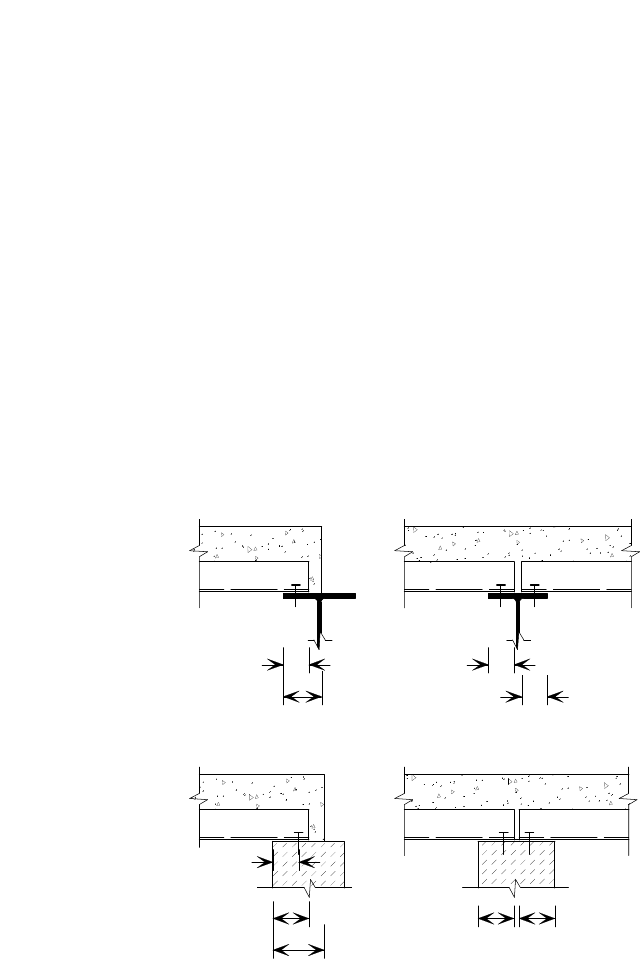
4.1.4 Supports
Minimum bearing length
The bearing length is the longitudinal length of decking or slab in direct contact
with the support. In each case, this length should be sufficient to satisfy the
following relevant criterion. For decking, it should be sufficient to avoid
excessive rib deformations, or web failure, near the supports during
construction. For the slab, it should be sufficient to achieve the required load
carrying capacity of the composite slab in service.
The recommended minimum bearing lengths shown in Figure 4.5 should be
observed. The values given in this figure are based on the requirements of
P:\PUB\PUB800\SIGN_OFF\P300\2nd Edition\P300V02D12.doc 22 Printed 29/04/09
BS EN 1994-1-1, but similar requirements are given in BS 5950-4. These limits
should also be respected for temporary supports. The limits given represent
nominal values that should be considered in the design and detailing, i.e. they
include an allowance for construction deviations leading to slightly reduced
values on site.
The recommended bearing lengths and support details differ depending upon the
support material (steel, concrete, etc.), and they are different for interior and
exterior (end) supports. Typical values and details are given in Figure 4.5 for
the following:
Steel or concrete supports - Composite slabs on steel or concrete supports
should have minimum bearing lengths of 75 mm for the slab, and a
minimum end bearing length of 50 mm for the decking (see Figure 4.5(a)
and Figure 4.5(b)). For continuous decking, the minimum overall bearing
length should be 75 mm.
Masonry and other support types - Composite slabs on supports made of
materials other than steel and concrete should have a minimum bearing
length of 100 mm for the slab and a minimum end bearing length of 70 mm
for the decking (see Figure 4.5(c) and Figure 4.5(d)). For continuous
decking, the minimum overall bearing length should be 100 mm.
The flange width of supporting steel beams should be sized to supply the
minimum bearing, by assuming that erection tolerances sum up unfavourably.
Details of how the decking should be fixed to supports are given in BCSA
Publication No. 37/04
[6]
.
If ‘thru-deck’ welding of the studs is to be used to anchor the decking, so that it
contributes to the transverse shear reinforcement (see Section 5.3.2), the
dimensions specified in Figure 4.5 may need to be increased (see Figure 5.9).
In cases where the slab must transfer the wall loads from one storey to the next
(rather than simply sitting on the top of a wall), the relatively lower volume of
voids in a slab formed using a re-entrant profile means it may be better able to
satisfy the design requirements.
Minimum 50 mm
edge distance for
screwed and
plugged fixings
a) b)
c) d)
Masonr
y
and other materials
Steel or concrete
70
100
70
70
50
75
50
50
Figure 4.5 Minimum bearing lengths for permanent supports
P:\PUB\PUB800\SIGN_OFF\P300\2nd Edition\P300V02D12.doc 23 Printed 29/04/09
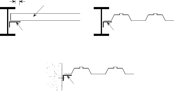
Recommended support details
In addition to the ‘standard’ detail of a slab bearing on a steel beam or wall,
there are a number of other commonly occurring support conditions which need
to be considered at the design stage in order to avoid problems or delays on
site. Some typical details are shown in Figure 4.6.
There are two basic cases at the interface of the decking with beams; where end
support is required (Figure 4.6(a)), and where side support is required
(Figure 4.6(b)). In both cases a steel ‘shelf angle’ is normally detailed as the
decking support, and it is preferable to fix this during fabrication. Angle
flashing is not suitable. To enable fixing of the decking, particularly in the case
of an end support, it is important that the leg of the angle extends at least
50 mm beyond the flange of the beam. The support angles should be continuous
and extend as close as is practical to beam connections, to minimise the
unsupported length of the decking.
Support is also required when the decking interfaces with a concrete wall. This
may be provided by attaching a steel angle, flashing, or timber batten to the
wall, preferably by using cast-in fixings (Figure 4.6(c)). Provision may need to
be made to achieve reinforcement continuity between the wall and slab.
The decking should not cantilever beyond a support more than 600 mm (or ¼
of the span, if less) when spanning perpendicular to it. When the decking is
spanning in a parallel direction, no cantilever is possible without extra support
being provided – although the edge trim may cantilever a short distance (see
Section 4.2.6)
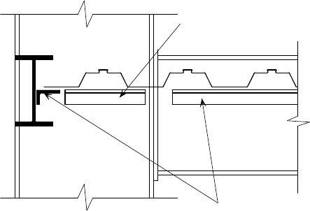
The decking may also need to be supported around penetrations which reduce,
or prevent, the effective bearing. Supports should be provided as part of the
permanent steelwork, for example in the form of cleats or angles. Examples of
when such supports are necessary include when the decking is penetrated by
columns greater than 250 mm wide (without incoming beams on both axes), or
by columns supported off beams. Figure 4.7 shows a recommended detail using
a shelf angle to support the decking around a column.
50 min.
Discrete lengths of shelf
angle to support decking
and to prevent grout loss
a) End support at a beam web
(decking ribs perpendicular to beam)
b) Side support at a beam web
(decking ribs parallel to beam)
c) Side support at a concrete wall
Decking
Discrete lengths of
steel angle or timber batten
fixed to concrete wall
Shelf angle to project 50 mm min.
from toe of flange for
fixing accessibility
Figure 4.6 Decking support details at a beam web and at a concrete
wall
P:\PUB\PUB800\SIGN_OFF\P300\2nd Edition\P300V02D12.doc 24 Printed 29/04/09
A less common detail is one in which the column is supported by a beam, in
which case special detailing may be required to achieve sufficient bearing for
the decking around the perimeter of the column. Where the deck is spanning in
a direction perpendicular to the beam, the minimum bearing of 50 mm required
to support the end of the decking may not be available because of the presence
of the column base plate. Therefore, the beam flange may need to be extended
by welding plates to the sides at the column position, as shown in Figure 4.8(a).
If the column position does not coincide with a butt joint in the decking, the
continuous decking sheet may have to be cut to fit around it. At this position,
the decking should then be treated as if it was simply supported, and props
maybe required locally. A similar situation may arise when flange splice plates
are fixed to the top of the steel section, as shown in Figure 4.8(b).
Supports may also be needed if the decking is to be penetrated by temporary
works structures (depending on the size of the penetration). To avoid problems
in such situations, it is vital that there is good communication between the Main
Contractor, who is responsible for the temporary works, and the Structural
Designer, who should specify the appropriate steelwork.
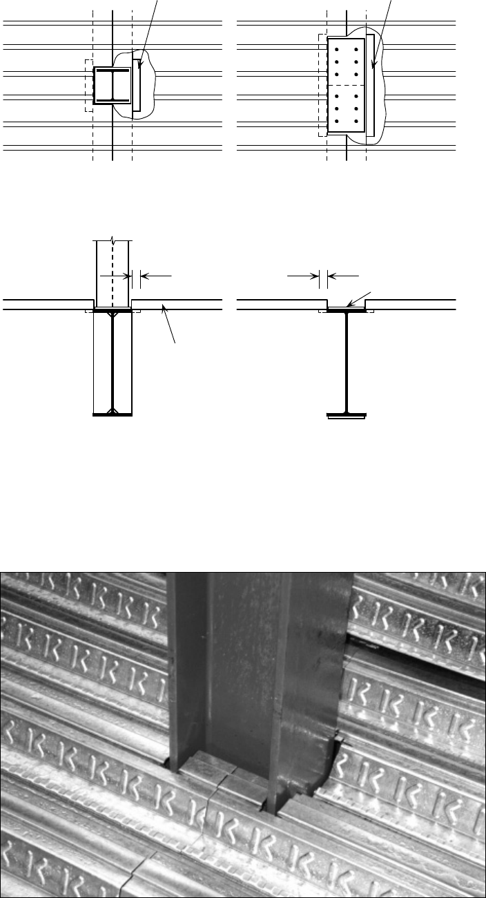
The decking should be cut to fit around any penetration. A typical detail, with a
column, is shown in Figure 4.9.
If temporary propping is proposed as a support around a penetration, this will
clearly only be present during the construction stage, i.e. to support the
decking. The completed slab may then need to include additional reinforcement,
as might be necessary around any untrimmed opening in a reinforced concrete
slab (see Section 4.2.6), in order to support the in-service loads. This
reinforcement should be specified by the Structural Designer.
Sheet lengths
The tolerance in the sheet lengths for shallow decking is normally specified as
+0 mm and –3 mm. A zero positive tolerance is used to avoid accumulations in
length when sheets are butted in a long run. Long sheets could lead to the butt
joint positions becoming increasingly displaced thus giving inadequate bearing
for the sheets near the end of a run. Cutting on site might be needed to
overcome this problem. It is, therefore, easier for the decking to be installed
when sheets are slightly short. A small gap between sheets above the supporting
beams is of no structural significance.
Shelf angle or plate required
Shelf angles
Figure 4.7 Decking support details at a column web
P:\PUB\PUB800\SIGN_OFF\P300\2nd Edition\P300V02D12.doc 25 Printed 29/04/09
Decking cut away
for clarity
Decking cut away
for clarity
PLAN PLAN
Extension to
beam flange
Extension to
beam flange
Decking
a) Column support off beam b) Beam flan
g
e splice plate
Flange splice plate
50 mm min. required
for decking bearing
(extend flange if necessary)
50 mm min. required
for decking bearing
(extend flange if necessary)
Figure 4.8 Decking details where a column is supported off a beam
and where a beam flange plate occurs
Figure 4.9 Typical detail of decking installation around a column
P:\PUB\PUB800\SIGN_OFF\P300\2nd Edition\P300V02D12.doc 26 Printed 29/04/09
4.2 Composite slabs
Composite slabs are normally used to span between 3 m and 4.5 m onto
supporting beams or walls. The ability of the decking to support the
construction loads, without the need for temporary propping, generally dictates
such spans (longer spans are possible when props are used). Slab thicknesses are
normally in the range 100 mm to 250 mm for shallow decking, and in the range
280 mm to 320 mm for deep decking.
When the concrete has gained sufficient strength, it acts in combination with the
tensile strength of the decking to form a ‘composite’ slab. It can be considered
as a reinforced concrete slab, using the decking as external reinforcement.
The load carrying capacity of composite slabs is normally dictated by the shear
bond, enhanced by interlock, between the decking and the concrete, rather than
by yielding of the decking. From tests, it is known that this shear bond
generally breaks down when a ‘slip’ (relative displacement between the decking
and the concrete) of 2 to 3 mm has occurred at the ends of the span. In
practice, this will not occur below ultimate load levels. An initial slip, which is
associated with the breakdown of the chemical bond, may occur at a lower level
of load. The interlock resistance is therefore due to the performance of the
embossments in the deck (which cause the concrete to ‘ride-over’ the decking),
and the presence of re-entrant parts in the deck profile (which prevent the
separation of the deck and the concrete).
Information on improving the bending resistance of composite slabs by
providing additional reinforcement, or end anchorage in the form of shear
connectors, can be found in BS EN 1994-1-1
[14]
and BS 5950-4
[11]
.
If the slab is unpropped during construction, the decking alone resists the self-
weight of the wet concrete and construction loads. Subsequent loads are applied
to the composite section. If the slab is propped, all of the loads have to be
resisted by the composite section. Surprisingly, this can lead to a reduction in
the imposed load that the slab can support, because the applied horizontal shear
at the decking-concrete interface increases. However, for both unpropped and
propped conditions, load resistances well in excess of loading requirements for
most buildings can be achieved.
Composite slabs are usually designed as simply supported members in the
normal condition, with no account taken of the continuity offered by any
reinforcement at the supports. Two methods of design are generally recognised,
both of which use empirically derived information on the ‘shear bond’ resistance
of the slab from uniformly distributed loading arrangements. The more
traditional method, and one which is given in both BS EN 1994-1-1 and
BS 5950-4, is the so-called ‘m and k’ method (see Section 4.2.3). However, this
method has limitations and is not particularly suitable for the analysis of
concentrated line and point load conditions. An alternative method of design is
included in the Eurocode, which is based on the principles of partial shear
connection. This method provides a more logical approach to determine the
slab’s resistance to applied concentrated line or point loadings. It is not
normally necessary for designers to understand the design methodology in
detail, as manufacturers normally present the design data in the form of load-
span tables, but these are only applicable for uniformly loaded conditions.

P:\PUB\PUB800\SIGN_OFF\P300\2nd Edition\P300V02D12.doc 27 Printed 29/04/09
4.2.1 Concrete
Concrete types
Both normal weight concrete and lightweight concrete are used in composite
slabs, but in the Eurocodes these are now referred to as normal concrete and
lightweight aggregate concrete respectively. Normal concrete is made using
dense aggregates from natural sources
[15]
. Lightweight aggregate concrete
contains artificially produced aggregates such as expanded pulverised fuel ash
pellets. The cement and water contents are higher in lightweight concrete
because of the absorption of water by the aggregate. For normal weight
concrete, strength classes C25/30, C28/35 or C32/40 are normally chosen; for
lightweight concrete, strength classes LC25/28, LC28/31 or LC32/35 are
typical.
Lightweight concrete is commonly used because the obvious advantage of
(typically) 25% weight saving can provide economic benefit for the overall
design of the structure and its foundations (see Section 4.1.2 for concrete
densities used for design). Lightweight concrete also has better fire insulating
qualities than normal weight concrete, and so thinner slabs may be possible
when the ‘fire condition’ governs the slab design (see Section 4.2.5).
Unfortunately, lightweight concrete is not always readily obtainable in all areas
of the UK. Also, it may not be appropriate if it is to be used in trafficked areas;
to achieve a good wearing surface, the finishing process must cover the particles
of lightweight coarse aggregate with an adequate, well-trowelled dense surface
mortar layer. It also has poorer sound insulation properties than normal weight
concrete.
Lightweight concrete offers several performance advantages, but it is not
available in all parts of the UK.
Concrete grade
The Structural Designer chooses a concrete specification that is suitable for the
intended application. This specification is normally chosen on the basis of the:
overall structural requirements
flooring finish, if any, to be laid on the slab
exposure conditions.
The concrete strength class designations according to BS EN 206-1
[16]
and
BS 8500
[17]
relate to the characteristic strength (95% probability of being
exceeded) achieved after 28 days, based on cylinder or cube tests. The cylinder
strength is about 80% of the strength of a 150 mm cube. Design standards
provide rules that relate the design strength to the concrete grade.
As a minimum standard, concrete of strength class C25/30 or LC25/28 should
be specified. In the case of concrete used as a wearing surface, the minimum
strength class should be C28/35 (although C32/40 is preferred).
Surface finishes
There are two basic performance conditions; concrete to be used as a wearing
surface, and concrete that is to be covered by raised floors, screeds, carpets,
tiles, sheet vinyl, etc. When the concrete is to be used as a wearing surface, the
concrete is first power floated. The specification should then require the slab to
be allowed to stiffen for a short time prior to power trowelling, which
P:\PUB\PUB800\SIGN_OFF\P300\2nd Edition\P300V02D12.doc 28 Printed 29/04/09
compresses and polishes the surface material, resulting in a harder and more
durable surface. Recommendations for power floating and power trowelling are
given in BS 8204
[18]
and Concrete Society Technical Report No.34
[19]
.
When the concrete is not to be used as the wearing surface, it is recommended
that a wood floated, skip floated or power floated finish is specified.
Drying
Because the concrete is only exposed on one surface of a composite floor, it can
take a longer period than a traditional reinforced concrete slab to dry out. If
moisture sensitive floorings and/or adhesives are to be applied, many months
may be needed before the slab is sufficiently dry to accept them. Measures such
as the specification of special concrete, dewatering or surface vapour-proof
membranes, may need to be considered if inadequate time for drying is allowed
in the contract programme.
If surface vapour-proof membranes are used, moisture will be trapped in the
slab. This trapped moisture will not be detrimental to the concrete or the
decking, as the steel in contact with the concrete is prevented from corrosion by
its high pH. The provision of small holes, perforations, in the decking to aid
drying is ineffective; the area represented by the holes is insufficient to have
any significant effect on drying times.
AD 163
[20]
provides additional guidance on provisions for water vapour release.
Level and flatness
It is recommended that a precisely level and flat concrete floor is not specified
unless it is absolutely necessary, as it is difficult to achieve because the tamping
rails are usually positioned along the support beams, which deflect under the
self weight of the finished floor. To achieve greater accuracy, it is necessary to
estimate the central deflection of the beams and to set the tamping rails along
each beam to allow for this deflection. This can result in errors because, in
practice, the beams may not deflect as much as expected (e.g. because of the
stiffness of the beam-column connections). It is reasonable to set the rails on the
basis that the beams will deflect 30% less than predicted by simple theory.
In propped construction, further deflection occurs on removal of the props.
Subsequent deflections will be greater the earlier the props are removed (due to
the lower stiffness of the ‘immature’ concrete). Therefore, props should not be
removed until the concrete has gained its design strength.
As deviations in level are dependent on the deflection of the composite slab and
the supporting beams, tolerances within which these deviations must lie should
only be specified at points where there is negligible deflection of the supporting
structure, i.e. at columns. The Main Contractor will be able to do little to
correct matters if deviations exceed tolerances specified at other points.
The following tolerances are recommended:
Top surface of concrete, level to datum ± 15 mm
Top surface of supporting steel beams, level to datum ± 10 mm
For the reasons discussed above, a thickness tolerance should only be specified
at the column locations. If it is really necessary to specify absolute levels for the
top surface, the thickness tolerance should be calculated by combining the top

P:\PUB\PUB800\SIGN_OFF\P300\2nd Edition\P300V02D12.doc 29 Printed 29/04/09
and bottom level tolerances using a method given in BS 5606
21
. This results in a
slab thickness tolerance of ± 18 mm. To achieve slightly tighter tolerances on
thickness, the level of the concrete should be specified relative to the level of
the supporting steelwork.
Owing to the accumulative deflections of the deck and beams, it is not practical
to specify tight flatness tolerances on composite slabs. BS 8204
[18]
gives three
tolerances for floor flatness, as shown in Table 4.1. The deviation is determined
by measuring the maximum gap beneath a 3 m straight edge laid on the surface.
For composite slabs, the straight edge must always be positioned parallel to the
supporting beams, i.e. perpendicular to the decking span.
Table 4.1 Surface flatness tolerances
BS 8204
Flatness
Designation
Maximum gap (mm)
below a 2 m
straight edge laid on
the surface
Comments
SR1 3
(1 in 667)
Not achievable on suspended floors of any
construction.
SR2 5
(1 in400)
May be achievable on parts of a composite floor,
but will not be achievable over all of a floor, owing
to deflections. This is a tight flatness tolerance and
high levels of workmanship are required to achieve
SR2 on any type of suspended floor.
SR3 10
(1 in 200)
May be achievable over most of a floor, depending
on the deflections of the supporting beams.
4.2.2 Reinforcement
Bar reinforcement
Types and details
The bar reinforcement in composite slabs usually takes the form of a relatively
light welded fabric, commonly supplemented by some bar reinforcement. The
fabric reinforcement is required to perform a number of functions:
Provide bending resistance at the supports of the slab in the fire condition
(this reinforcement is usually ignored under ‘normal’ load conditions).
Reduce and control cracking at the supports, which occurs because of
flexural tension and differential shrinkage effects.
Distribute the effects of localised point loads and line loads.
Strengthen the edges of openings (see Section 4.2.6).
Act as transverse reinforcement for the composite beams (see
Section 5.3.2).
The most common fabric sizes are A142 and A193 (using designations
according to BS 4483
[22]
), with the numbers indicating the cross-sectional area
(mm
2
) of reinforcing bars per metre width. The fabric is normally manufactured
in ‘sheets’ that are 2.4 m wide and 4.8 m long. ‘A’ type fabric has layers of
bars equally spaced in both directions (known as ‘square’ fabric) and is most
commonly used. It is possible to order special fabric with heavier wires or
closer spacing in one direction, such as ‘B’ or ‘C’ type fabrics. ‘B’ type
‘structural’ fabrics have longitudinal bars at 100 mm centres and transverse bars
at 200 mm centres. These can be used when highly reinforced areas are

P:\PUB\PUB800\SIGN_OFF\P300\2nd Edition\P300V02D12.doc 30 Printed 29/04/09
required for structural or fire resistance purposes. ‘C’ type ‘highway’ fabrics
are intended for highway use and have only very light reinforcement in the
transverse direction. C type fabrics should not be used in composite floors.
Fabric sizes less than A142 are not recommended because of their poor
performance as fire reinforcement and inability to control shrinkage, and are
considered as non-structural.
Bar reinforcement may be used to supplement the fabric:
To achieve longer fire resistance periods.
To reinforce the slab around significant openings.
When additional transverse reinforcement is needed.
To achieve greater crack control.
Reinforcement should comply with BS 4483
[22]
(fabric) or BS 4449
[23]
(bars), and
the detailing of it should be in accordance with BS EN 1992-1-1
[24]
or
BS 8110
[30]
and BS 8666
[25]
. Bar reinforcement is produced in three ductility
grades; A, B or C. In the UK, bar reinforcement of ductility grade B is
normally used, but most fabric is supplied with ductility grade A. The ductility
grade of the reinforcement has no effect on the lap and anchorage lengths. The
bars in fabric supplied to BS 4483 are ribbed, and this will reduce the required
anchorage lengths compared to plain bars. BS EN 1992-1-1 assumes that bars
are ribbed, but BS 8110 allows for the use of ribbed and plain bars.
In shallow composite slabs, the reinforcement should be supported sufficiently
high above the top of the decking to allow concrete placement around the bars.
The required top cover depends on the concrete class and the exposure.
Recommendations are given in Tables NA.2 and NA.3 to BS EN 1992-1-1;
these present the same information as in BS 8500-1
[17]
but in a more compact
form. The Structural Designer should determine the relevant exposure condition
for the top of the floor. The following exposure conditions apply:
For a floor in a dry protected environment, e.g. in enveloped buildings such
as offices, the exposure class for the concrete is XC1.
For an external floor exposed to high levels of humidity, the exposure class
for the concrete would be XC3 or XC4.
For a floor exposed in a marine environment, the exposure class would be
XS1, XS2 or XS3.
For a floor that is exposed to freeze-thaw cycles, the exposure class would
be XS (see BS 8500-1 for recommendations for this class).
Table NA.2 in BS EN 1992-1-1 applies where the intended working life is 50
years and Table NA.3 applies where the intended working life is 100 years (not
normally applicable to buildings).
In car parks, where the slab is exposed to chlorides and freeze/thaw attack, the
exposure class is XD3 or, if the intended design life does not exceed 30 years,
the exposure class is XF3 or XF4, provided that the concrete surface is
protected by an effective, durable and long-lasting waterproof membrane. (Any
membrane should be a waterproof coating that prevents the ingress of water
containing dissolved de-icing salts into the concrete, including at any joints and
cracks in the concrete.)

P:\PUB\PUB800\SIGN_OFF\P300\2nd Edition\P300V02D12.doc 31 Printed 29/04/09
Recommended covers for XC1 and XC3/4 exposure classes are given in
Table 4.2. Refer to BS 8500-1 for covers and concrete specifications for other
exposure classes.
The recommendations for durability in this section only relate to the concrete
and reinforcement. The corrosion protection of the metal decking is covered in
Section A.1.1
Table 4.2 Minimum reinforcement covers for various levels of
exposure
Aggregate Type Normal weight Lightweight
Concrete Strength
Class
C25/30
C28/35
C32/40
C35/45
C40/50
LC25/28
LC28/31
LC32/35
Max Water cement
ratio
0.65 0.60 0.55 0.50 0.45 0.65 0.60 0.55
Min cement
content for 20 mm
aggregate (kg/m
3
)
260 280 300 320 340 260 280 300
Min cement
content for 14 mm
aggregate (kg/m
3
)
280 300 320 340 360 280 300 320
Min cement
content for 10 mm
aggregate (kg/m
3
)
300 320 340 360 360 300 320 360
Nominal cover in mm to reinforcement according to the exposure level:
XC1
25 25 25 25 25 25 25 25
XC3/4
45 40 35 35 30 45 40 35
Notes:
(a) These values are taken from BS 8500-1
[17]
and BS EN 206-1
[16]
(b) The exposure conditions are defined in BS 8500-1. For internal floors in a watertight heated
building, with dry conditions the exposure condition would be XC1. For floors subject to
high humidity or cyclical wet and dry conditions the exposure condition would be XC3/4.
More severe exposure conditions may be applicable in some conditions, e.g. car parks.
(c) Nominal Cover: BS 8500-1 lists minimum covers not nominal covers. The nominal covers
listed in Table 4.2 are the minimum covers given in BS 8500-1 plus a fixing tolerance (Δc)
of 10 mm. The covers listed are for an intended working life of 50 years. For an intended
working life of 100 years no change is required to the XC1 exposure class covers, and 15
mm should be added to the XC3/4 covers.
(d) In practice, nominal covers less than 30 mm with light fabrics are not recommended owing
to practical difficulty in supporting the light fabric in the correct location.
(e) The listed covers are for durability purposes. Greater covers may be needed for fire
resistance considerations.
Recommended tension laps and anchorage lengths for welded fabric and bars for
design to BS 8110 are given in Table 4.3, and for design to BS EN 1992-1-1 in
Table 4.4.

P:\PUB\PUB800\SIGN_OFF\P300\2nd Edition\P300V02D12.doc 32 Printed 29/04/09
Table 4.3 Recommended tension laps and anchorage lengths for
welded fabric and bars to BS 8110
Aggregate Type Normal Lightweight
Strength Class
C25/28 C28/30 C28/31 LC28/35 LC32/35 LC32/40
Reinforcement
Type
Wire/Bar Type
Grade 500 Bar of
diameter d
Deformed Type 2
44d 40d 38d 56d 54d 50d
A142 Fabric
(6 mm wires at
200 centres)
Deformed Type 2
275 250 250 350 325 300
A193 Fabric
(7 mm wires at
200 mm centres)
Deformed Type 2
300 275 275 400 375 350
A252 Fabric
(8 mm wires at
200 mm centres)
Deformed Type 2
350 325 300 450 425 400
A393 Fabric
(10 mm wires at
200 mm centres)
Deformed Type 2
440 400 375 550 550 500
Notes:
(a) Table 4.3 is based on information given in BS 8110-1
[30]
, assuming fully stressed bars/fabric.
It should be noted however that the recommendations determined in accordance with
BS EN 1992-1-1 (as shown in Table 4.4, below) may differ from the above.
(b) Where a lap occurs at the top of a section and the minimum cover is less than twice the size
of the lapped reinforcement, the lap length should be increased by a factor of 1.4.
(c) Deformed Type 2 Bars/Wires: Bars with transverse ribs of substantially uniform spacing,
which protrude beyond the main round part of the bars/wires. There may be longitudinal
ribs. Note: The majority of deformed high yield reinforcement available in the UK is Type 2.
(d) The minimum Lap/Anchorage length for bars and fabric should be 300 mm and 250 mm
respectively.

P:\PUB\PUB800\SIGN_OFF\P300\2nd Edition\P300V02D12.doc 33 Printed 29/04/09
Table 4.4 Recommended tension laps and anchorage lengths for
welded fabric and bars to BS EN 1992-1-1in C25/30
concrete
Reinforcement in tension, bar diameter,
(mm)
Bond
condition
8 10 12 16 20 25 32 40
Good 230 320 410 600 780 1010 1300 1760
Straight bars
only
Poor 330 450 580 850 1120 1450 1850 2510
Good 320 410 490 650 810 1010 1300 1760
Anchorage
length, l
bd
Other bars
Poor 460 580 700 930 1160 1450 1850 2510
Good 320 440 570 830 1090 1420 1810 2460
50% lapped in
one location
(
6 = 1.4)
Poor 460 630 820 1190 1560 2020 2590 3520
Good 340 470 610 890 1170 1520 1940 2640
Lap
length, l
0
100% lapped
in one location
(
6 = 1.5)
Poor 490 680 870 1270 1670 2170 2770 3770
Notes
1 Nominal cover to all sides and distance between bars ≥ 25 mm (i.e.
2 < 1).
2 It is assumed that the coefficients to allow for factors effecting the anchorage (defined in BS EN 1992-1-1, clause
8.4.4.)
1 = 3 = 4 = 5 = 1.0.
3 Design stress has been taken as 435 MPa. Where the design stress in the bar at the position from where the
anchorage is measured,
sd, is less than 435 MPa the figures in this table can be factored by sd/435. The
minimum lap length is given in clause 8.7.3 of BS EN 1992-1-1.
4 The anchorage and lap lengths have been rounded up to the nearest 10 mm.
5 Where 33% of bars are lapped in one location, decrease the lap lengths for ‘50% lapped in one location’ by a
factor of 0.82.
6 The reinforcement ductility class has no effect on lap and anchorage lengths.
7 In slabs up to 250 mm thick all horizontal reinforcement can be considered to have Good Bond conditions.
8 In slabs over 250 mm thick horizontal reinforcement in the bottom 250 mm can be considered to have Good Bond
conditions. Reinforcement in the top zone (above 250 mm from the bottom) can be considered to have Poor Bond
conditions.
9 The information in this table is taken from How to design concrete structures to Eurocode 2
[26]
. This publication
should be consulted for other concrete classes or for further guidance.
Concrete class
C20/25 C28/35 C30/37 C32/40 C35/45 C40/50 C45/55 C50/60
Factor
1.16 0.93 0.89 0.85 0.80 0.73 0.68 0.63
Fibre reinforcement
Fibre reinforcement consists of short fibres made from steel, polypropylene or a
combination of both, which are mixed into the concrete prior to placement.
Under controlled circumstances, fibres may be substituted for some or all of the
fabric reinforcement. Use of fibre reinforcement results in a three dimensional
reinforced concrete composite slab.
The performance of fibre reinforcement is verified empirically, specifically for
fire resistance and for longitudinal shear transfer, using the same testing regimes
that are used to validate the use of traditional reinforcement within steel deck
composite floors.
Considerable benefits can be achieved using fibre reinforcement, including a
reduction in labour costs and a saving on the construction programme. The
requirement for longitudinal shear reinforcement, in the form of bars or fabric,

P:\PUB\PUB800\SIGN_OFF\P300\2nd Edition\P300V02D12.doc 34 Printed 29/04/09
can be dramatically reduced and only a minimal amount of fabric reinforcement
need be purchased, transported and stored. There is less usage of the crane as
there are fewer lifting operations. The installation of the floor is easier and safer
because there is less reinforcement to obstruct the floor working area and to
handle, fix and check, and this can reduce installation times by up to 20%.
Independent testing has shown that fibre reinforcement systems can provide an
equivalent or superior performance to traditional welded wire fabric solutions,
although local reinforcement may be necessary in locations of concentrated
loads. Fibre reinforcement provides resistance to plastic shrinkage, settlement
cracking and toughness, but the performance is related to the specific fibre.
BS EN 14889
[27]
covers the requirements for fibres used as concrete
reinforcement. Part 1 covers steel fibres, and Part 2 polymer fibres. Care
should be taken with the selection of polymer fibres, as only Class 11 (macro)
fibres in accordance with BS EN 14889 are suitable as a replacement for
traditional fabric reinforcement in steel deck composite slabs.
It is very important to note that fibre reinforced composite slabs are not a
generic product. A specific type and dosage of fibres must be used according to
the fibre manufacturer’s specification for the particular deck, and other deck or
fibre types cannot be substituted.
When using a fibre reinforcement solution, it is still general practice to use
U-bars on composite edge beams, bar reinforcement around openings in the
slab, and fabric or bar reinforcement at construction joints, or where the
composite slab cantilevers beyond a support.
More information on fibre reinforcement is given in Section 6.2.1. Further
guidance on the use of steel or macro-synthetic fibre-reinforced concrete can be
found in Concrete Society Technical Reports No. 63
[40]
and 65
[41]
respectively.
Fiber reinforcement is provided within the concrete that is delivered and
ready to pump on site. This can reduce installation times by up to 20%.
4.2.3 Design for resistance
The performance of a composite slab with a particular decking profile can only
be assessed readily by testing. Test procedures are set out in both
BS EN 1994-1-1
[14]
and BS 5950-4
[11]
. The tests must cover the complete range
of the key design parameters (usually slab depth and span). The specimens are
first subject to dynamic load (5,000 load cycles up to 1.5 times the working
load are specified in BS EN 1994-1-1, but 10,000 cycles are required by
BS 5950-4). Following this, a static load is applied and increased until failure
occurs. The objective of the dynamic part of the test is to break any adhesion
bond, so that only the more stable mechanical interlock remains.
The test procedure is such that all loads are applied to the composite section to
simulate a uniformly loaded condition. The test results are then presented in
terms of empirical constants, either (m and k) or Tau (τ), that can be used to
quantify the interaction between the steel and concrete.
As far as slab design is concerned, the Structural Designer will not undertake
tests to determine the m and k or Tau (τ) factors. These constants are used by
the decking manufacturers themselves in order to present designers with a range
of load-span tables for uniformly loaded conditions for their specific products.

P:\PUB\PUB800\SIGN_OFF\P300\2nd Edition\P300V02D12.doc 35 Printed 29/04/09
Specific checks are necessary where there are concentrated line or point loads
whose effect is normally greater than that of a nominal uniformly distributed
blanket load.
The vertical shear resistance of a reinforced composite slab using bar or fabric
is assessed as for a reinforced concrete slab, using guidance given in
BS EN 1992-1-1
[24]
or BS 5950-4. ‘Punching’ shear resistance, against localised
loads, should also be assessed using these Standards. When fibre reinforcement
is used, designers should seek guidance from the manufacturers.
Manufacturers’ load-span tables for slabs are normally based on testing (in
order to minimise conservatism). Designers should take care to ensure that
they do not use this information for situations that are not covered by the
scope of the testing especially if concentrated line or point loads are
applied to the slab.
4.2.4 Design for serviceability
Crack control
There is a risk of cracking in the concrete in all composite slabs due to the
restraint to drying shrinkage provided by the steel decking and primary
steelwork, even though the decking effectively acts as reinforcement and helps
to distribute the shrinkage strains so that large cracks do not form. However,
cracks do not normally pose a durability or serviceability hazard. Only where
the surface of the slab is used as a wearing surface, or where terrazzo or other
‘rigid’ floor coverings are to be used, may specific reinforcement (in addition to
the ‘standard’ fabric) be required in order to control the cracking. When
cracking is an issue, reinforcement percentages in excess of 0.3% will normally
be required in order to limit crack widths to the recommended limit. Fabric,
rather than bars, is generally used to control cracking.
According to BS EN 1994-1-1, when continuous slabs are designed as simply-
supported, the minimum cross-sectional area of the anti-crack reinforcement
within the depth of the concrete cover to the decking should be as follows:
0.2% of the cross-sectional area of the concrete above the ribs for
unpropped construction
0.4% of the cross-sectional area of the concrete above the ribs for propped
construction.
It is possible that larger crack widths will occur over the intermediate supports
with propped construction, because the full self-weight of the slab is applied in
the composite slab on removal of the props, which explains the higher minimum
percentage reinforcement required.
The above amounts do not automatically ensure that the crack widths are less
than the typical value of 0.3 mm given in BS EN 1992-1-1 (and the UK
National Annex to this code) for certain exposure classes. If the exposure class
(or the floor finish) is such that cracking needs to be controlled, the slab should
be designed as continuous, and the crack widths in hogging moment regions
evaluated according to BS EN 1992-1-1.
Experience shows that the greatest risk of cracking is over supporting beams,
owing to the combination of restrained drying shrinkage and flexural action
[28]
.
‘Induced’ joints may be used to reduce the risk of random cracking at these

P:\PUB\PUB800\SIGN_OFF\P300\2nd Edition\P300V02D12.doc 36 Printed 29/04/09
locations. Such joints can be formed by sawing the slab, but clearly, care is
needed to prevent the reinforcement required for fire resistance and longitudinal
shear resistance from being damaged or severed. However, where cracking has
to be controlled, a more reliable measure is to use additional crack control
reinforcement at the support.
When fibre reinforcement is to be used in place of bar/fabric reinforcement the
suppliers of the fibres should be consulted regarding crack control measures.
Deflections
Deflections due to loading applied to the composite member should be
calculated using elastic analysis, neglecting the effects of shrinkage. For an
internal span of a continuous slab, where the shear connection is achieved by
either mechanical or frictional interlock, or end anchorage by through-deck
welded studs, the deflection may be determined using the average value of the
cracked and uncracked second moment of area may be taken. This applies both
for design to the Eurocodes and design to BS 5950, but the modular ratio for
long-term and short-term effects is calculated slightly differently in
BS EN 1994-1-1 and BS 5950-4 (which refers to BS 5950-3).
BS EN 1994-1-1 permits calculations of the deflection of the composite slab to
be omitted if both the following conditions are satisfied for external or simply-
supported spans:
the span/depth ratio of the slab does not exceed certain limits specified in
BS EN 1992-1-1 for lightly stressed concrete (shown here in Table 4.5);
and
the load causing an end slip of 0.5 mm in the (long span) tests on
composite slabs exceeds 1.2 times the design service load.
Table 4.5 General rules for the slab maximum span-to-depth
ratios in accordance with BS EN 1992-1-1
Normal concrete
Lightweight
concrete
Single spans 20 18.8
End spans 26 24.5
Internal spans 30 28.3
For cases where the end slip exceeds 0.5 mm at a load below 1.2 times the
design service load, two options exist for the designer:
(i) end anchors should be provided; or
(ii) deflections should be calculated including the effect of end slip.
Should the behaviour of the shear connection between the sheet and the concrete
not be known from tests on composite slabs with end anchorage,
BS EN 1994-1-1 permits a tied-arch model to be used. Guidance for designers
on this case can be found in the Designer’s guide to BS EN 1994-1-1
[29]
.

P:\PUB\PUB800\SIGN_OFF\P300\2nd Edition\P300V02D12.doc 37 Printed 29/04/09
For design to BS 5950-4, there are also simple design rules to ensure adequate
deflection behaviour of a composite slab. Calculation of deflections is not
necessary when designing to this code if the span-to-depth ratios are not greater
than those given in Table 4.7. Confirming that the slab satisfies these limits will
ensure that excessive deflections are avoided. The effective span of the decking
is defined in BS 5950-4 as the smaller of:
the distance between the centres of the supports, and
the clear span between the supports plus the effective depth of the
composite slab.
The values in Table 4.7 apply to slabs under uniformly distributed loading, with
nominal continuity reinforcement (0.1%) over the intermediate supports, i.e.
they are designed as simply supported. For slabs with full continuity
reinforcement over the supports, reference should be made to BS 8110
[30]
.
Deflections should be calculated explicitly for slabs that fail to satisfy the span-
to-depth ratio or reinforcement limits. BS 5950-4 recommends that the
deflection of the composite slab should not normally exceed the limits in
Table 4.6.
Table 4.6 Recommended limits for the maximum deflection of
composite slabs given in B S5950-4
Criterion Recommended Limit
Deflection due to the imposed load
L
s
/350 or 20 mm, whichever is
the lesser
Deflection due to the total load less the
deflection due to the self-weight of the
slab plus, when props are used, the
deflection due to prop removal
L/250
The stiffness of slabs reinforced with conventional fabric reinforcement can be
determined using ‘normal’ reinforced concrete design rules (assuming fully
effective bond between the decking and the concrete). When fibre reinforced
concrete is used, advice on the slab stiffness should be sought from the
manufacturer.
Table 4.7 General rules for the slab maximum span-to-depth ratios in
accordance with BS 5950-4
Normal
concrete
Lightweight
concrete
Single spans 30 25
End spans 35 30
Internal spans 38 33
Values apply to supported spans
with nominal continuity
reinforcement, subject to
uniformly distributed loading
Dynamic sensitivity
The dynamic sensitivity of composite slabs is not normally critical, because they
are relatively stiff compared with the beams, although the dynamics of the
whole floor should be considered, as explained in Section 5.2.2.
Cracking of internal concrete surfaces will generally not compromise the
structural performance of a building, so for economic design its
consequences may often be ignored.
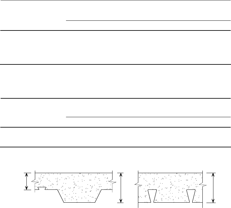
P:\PUB\PUB800\SIGN_OFF\P300\2nd Edition\P300V02D12.doc 38 Printed 29/04/09
4.2.5 Design for fire resistance
The required fire performance of floor slabs is defined by the Approved
Document B to the National Building Regulations. The Approved Document
requires the slab performance to be assessed based on criteria for insulation ‘I’,
integrity ‘E’ and load bearing capacity ‘R’. For design to the Eurocodes,
BS EN1994-1-2
[31]
and the UK National Annex to BS EN1994-1-2
[32]
provide
guidance on how composite slabs may be designed to meet these criteria. For
UK design, guidance is available in BS 5950-8
[11]
.
The insulation criterion is satisfied by providing adequate slab thickness to
ensure that the temperature of the unexposed surface of the slab does not exceed
140
o
C. BS 5950-8 and the UK National Annex to EN1994-1-2 provide a table
of recommended concrete thicknesses to satisfy the insulation criterion for
common periods of fire resistance. The minimum thickness of concrete required
to satisfy the insulation requirements is shown in Table 4.8 for trapezoidal decks
and Table 4.9 for re-entrant decks. Figure 4.10 shows that the insulation depth
depends on the type of profile, and it is the concrete cover to the main crest of
the deck for trapezoidal profiles and the full slab depth for re-entrant profiles.
Table 4.8 Minimum thickness of concrete, measured above the steel
deck, for trapezoidal profiled steel deck exposed to the
standard fire
Minimum thickness of concrete (mm) for a fire
resistance period (mins) of:
Concrete type
30 60 90 120 180 240
Normal concrete
(All cases)
60 70 80 90 115 130
Lightweight concrete
(All cases)
50 60 70 80 100 115
Table 4.9 Minimum thickness of slab for re-entrant profiled steel
sheets exposed to the standard fire
Minimum thickness of concrete (mm) for a fire
resistance period (min) of:
Concrete type
30 60 90 120 180 240
Normal concrete 90 90 110 125 150 170
Lightweight concrete 90 90 105 115 135 150
EN1994-1-2 permits the designer to calculate the bending resistance and
insulation properties assuming that composite slabs fulfil the integrity criterion.
D
s
Insulation
depth
Insulation
depth
Trapezoidal steel deck Re-entrant steel deck
Figure 4.10 Minimum insulation depth measurement
P:\PUB\PUB800\SIGN_OFF\P300\2nd Edition\P300V02D12.doc 39 Printed 29/04/09
Fire tests have been carried out on slabs with conventional fabric reinforcement,
and on fibre reinforced slabs.
The load bearing resistance of the slab at elevated temperatures can be
determined by calculation in accordance with the principles given in EN1994-1-
2. The UK National Annex provides additional guidance on determining design
temperatures for UK decking geometries.
Depending on the span required, an increased size of fabric may need to be
used, or extra bars may need to be placed in the troughs of the deck, to satisfy
the load bearing criteria (R) for the fire condition. In either case, the additional
reinforcement is used to compensate for the loss of strength of the (exposed)
decking at elevated temperatures. Design guidance covering this aspect is
normally given by the decking manufacturers in their design tables. These
design tables are based on the extended application of fire test results and
provide product specific guidance which will result in the most economic
solutions for fire design. The extended applications of the fire test results are
based on a design model for plastic resistance that is in accordance with the
principles of EN1994-1-2 §4.3.1 and the recommendations of the UK National
Annex to EN1994-1-2.
In the UK National Annex, the use of Informative Annex D of EN1994-1-2 is
rejected as many UK decking profiles are outside the limits of the field of
application. It was found that when the methods in Annex D were applied to
these decking geometries, unusable answers were obtained. For projects in other
European countries where the use of Annex D is recommended, it is likely that
the manufacturer’s fire design tables will be the only valid method of design for
UK decking profiles.
Slab designs that comply with the recommendations of EN1994-1-1 for room
temperature design are deemed to have 30 minutes fire resistance, when
assessed under the load bearing criteria ‘R’, but these slabs still need to be
checked for compliance with the insulation criteria.
Further information on the calculation of load bearing resistance of composite
slabs can be obtained from P375
[33]
.
4.2.6 Openings and edges
Openings
Openings can be accommodated readily in composite slabs. Some advice as to
limits on the size of openings, and the provision of any extra reinforcement that
may be required, is normally given in the notes accompanying a decking
manufacturer’s load-span tables. Further advice is given here on issues relating
to design with shallow decking (deep decking is covered in Section 7), and
advice relating to the construction of openings is given in the BCSA Code of
practice for metal decking and stud welding
[6]
.
Openings may be categorised by their size:
Small - openings up to 300 mm square - unlikely to present a problem
structurally and do not normally require additional reinforcement.
Medium - openings between 300 mm and 700 mm square - normally
require additional reinforcement to be placed in the slab. This is also the
case if the openings are placed close together.
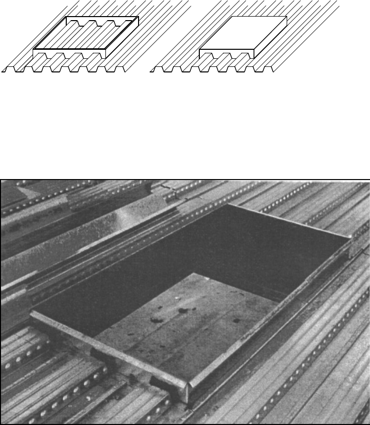
P:\PUB\PUB800\SIGN_OFF\P300\2nd Edition\P300V02D12.doc 40 Printed 29/04/09
Large - openings greater than 700 mm square - should be trimmed with
addition permanent steelwork back to the support beams.
It should be noted that slightly different dimensions from those given above may
be quoted in a manufacturer’s literature for specific profiles, in which case the
manufacturer’s guidance should be followed.
For small and medium size openings, normal practice is for the Main
Contractor to form an opening by ‘boxing-out’ an area of decking using timber
or polystyrene inserts before concreting, as shown in Figure 4.11. The decking
should not be cut until the concrete has gained 75% of its design strength. Then
it may be cut or burnt away to form the opening, and the cut edges bent up or
ground off. If cutting the deck prior to casting is unavoidable, temporary
propping is likely to be required. This may have implications on the slab
design, and the Structural Designer should be consulted.
For large openings, the supporting trimming steel should be in positioned prior
to placing the decking. The opening should then be trimmed prior to casting the
slab, as shown in Figure 4.12.
Timber shutter Dense polystyrene block
Figure 4.11 Typical examples of boxing out openings
Figure 4.12 A typical trimmed opening (immediately after deck laying,
prior to fixing the edge protection and reinforcement
around the opening)
P:\PUB\PUB800\SIGN_OFF\P300\2nd Edition\P300V02D12.doc 41 Printed 29/04/09
Cutting the slab after concreting (post-forming the openings) may cause a loss
of bond between the concrete and the decking, and is not recommended. When
post-forming is unavoidable, non-percussive cutting methods such as diamond
core drills/saws should be adopted, so that the disturbance to the mechanical
interlock between the decking and the concrete is kept to a minimum. The
structural implications of the location and size of the opening need careful
consideration, and should always be referred to the Structural Designer.
The need for extra reinforcement in the slab, or additional trimming steelwork,
depends on the size of the opening. Requirements should be determined by the
Structural Designer, who may be represented by a slab or steelwork specialist.
The Structural Designer will identify reinforcement requirements on the contract
drawings, and should be consulted if there are any doubts about the location of
openings or the amount of reinforcement needed. Any additional reinforcement
that may be required should be designed in accordance with BS EN 1992-1-1
[24]
or BS 8110
[30]
. Site operatives should be made aware that additional
reinforcement is required around medium sized openings. This often takes the
form of bars placed in the troughs of the decking adjacent to the opening, with
additional transverse bars used to ‘smooth out’ the load transfer around the
opening (see Figure 4.14). The distance between an opening and an unsupported
edge should not be less than the greater of either 500 mm and the width of the
opening. If the opening falls within the usual ‘effective breadth’ of concrete
flange of any composite beams (typically span/8 each side of the beam centre
line), the beam resistance should be checked assuming an appropriately reduced
effective breadth of slab.
In the absence of any specific manufacturer’s guidance on the provision of extra
reinforcement, it may be assumed that an effective system of ‘beam strips’ span
the perimeter of the opening, as shown in Figure 4.13. The effective breadth of
the beam strips should be taken as d
o
/2, where d
o
is the width of the opening in
the direction transverse to the decking ribs. Only the concrete above the ribs is
effective. The transverse beam strips are assumed to be simply supported, and
span a distance of 1.5 d
o
. The longitudinal beam strips are designed to resist the
load from the transverse beam strips, in addition to their own proportion of the
loading. Extra reinforcement is provided within the ‘beam strips’ to suit the
applied loading. This reinforcement often takes the form of bars placed in the
troughs of the decking (see Figure 4.14). Additional transverse or diagonal bars
may be used to improve load transfer around the opening. Reinforcement bars
in these beam strips will need to extend at least an anchorage length beyond the
centre line of the supporting beam.
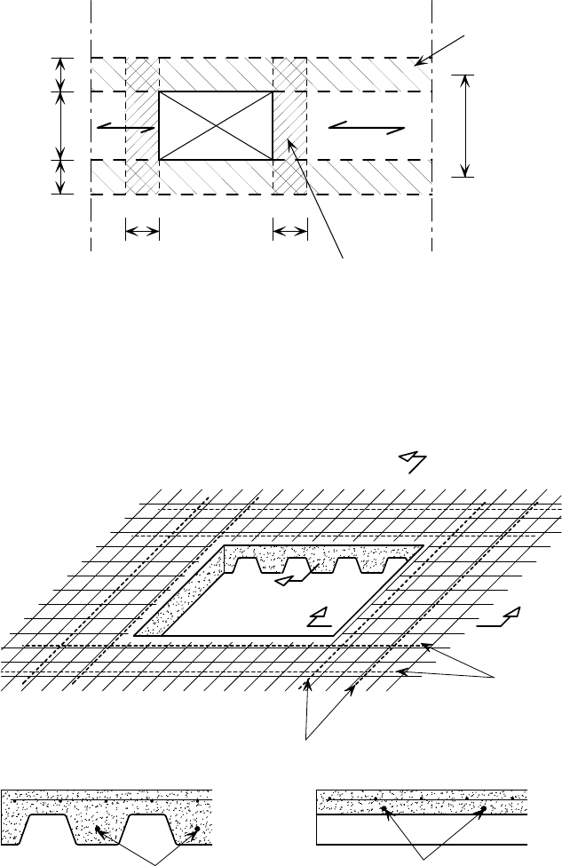
P:\PUB\PUB800\SIGN_OFF\P300\2nd Edition\P300V02D12.doc 42 Printed 29/04/09
Multiple openings in a floor may need to be considered as equivalent to one
large opening, and the reinforcement should be designed accordingly.
Slab edges
The edges of the floor are usually formed using ‘edge trims’ made from pressed
strips of light gauge galvanized steel. Edge trim is delivered to site to the
required depth and normally in standard 3.0 m long strips. The thickness of the
steel used may vary with location, but is normally no more than 2 mm. The
strips are cut to length on site to suit column centres. The trim is usually set out
from the edge beam centre line (rather than the grid lines, which cannot be set
out easily on site), as shown in Figure 4.15. The trim should be fixed in the
same way as the decking. It should not be used as a tamping rail because it may
be damaged.
d /2
o
C Floor beam
L
C Floor beam
L
Deck
span
d /2
o
d /2
d /2
d
o
o
o
Longitudinal reinforce
d
concrete beam strips
Transverse reinforced
concrete beam strip
Effective span
of transverse
beam strips
= 1.5 d
o
Figure 4.13 Load paths and beam strips around medium to large
openings
A
B
Section A - A Section B - B
Opening
B
A
Extra bars in troughs
Extra bars
in slab
(over the deck)
Extra bars in troughs
Extra bars over deck
Fabric
reinforcement
Fabric
reinforcement
Figure 4.14 Typical reinforcement detailing around an opening
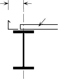
P:\PUB\PUB800\SIGN_OFF\P300\2nd Edition\P300V02D12.doc 43 Printed 29/04/09
Straps are always specified to tie back the upper part of the trim at 0.6 m to
1 m spacing, depending on the slab depth and overhang. Typical details are
given in Figure 4.16, covering two distinct cases. Where the decking (with
transverse ribs) runs over the edge beam and cantilevers out a short distance,
the edge trim can be fastened in the manner suggested in Figure 4.16(a). The
cantilever projection should be no more than 600 mm, depending on the depth
of the slab and deck type used.
The more difficult case is where the decking ribs run parallel to the edge beam,
and the finished slab is required to project a short distance, so making the
longitudinal edge of the sheet unsupported Figure 4.16(b). When the slab
projection is more than approximately 200 mm (depending on the specific
details), the edge trim should span between stub beams attached to the edge
beam, as shown in Figure 4.16(c). These stub beams are usually less than 3 m
apart, and should be designed and specified by the Structural Designer as part
of the steelwork package. If stub beams are not provided in this case, then
additional support to the edge of the decking, such as by propping from the
floor beneath, may be required and this information must be highlighted in the
information passed to the contractor. Non-standard edge trims (for example
those used to support cladding, or those forming a curved edge) will require
more accurate setting out procedures than standard trim.
Trims fixed to a curved edge are normally formed by cutting and bending the
standard lengths to form a continuous faceted ‘curve’ with, typically, 300 mm
straight sides.
Further information on how edge trims should be attached and supported is
given in Reference 6.
Achievable tolerances for the position of the top of standard edge trims relative
to the steelwork (after concreting) are ±10 mm horizontally, and ± 5 mm
vertically (see Figure 4.15). Tighter tolerances than these may need to be
specified for edge trims that incorporate housings for cladding supports. It will
also be necessary to ensure that these trims do not deflect excessively during
concreting. The Structural Designer must specify requirements for any such
‘non-standard’ trims.
L
Decking
C Beam
Edge trim should be set out from
centre line of beam (not grid)
Figure 4.15 Setting out of edge trim
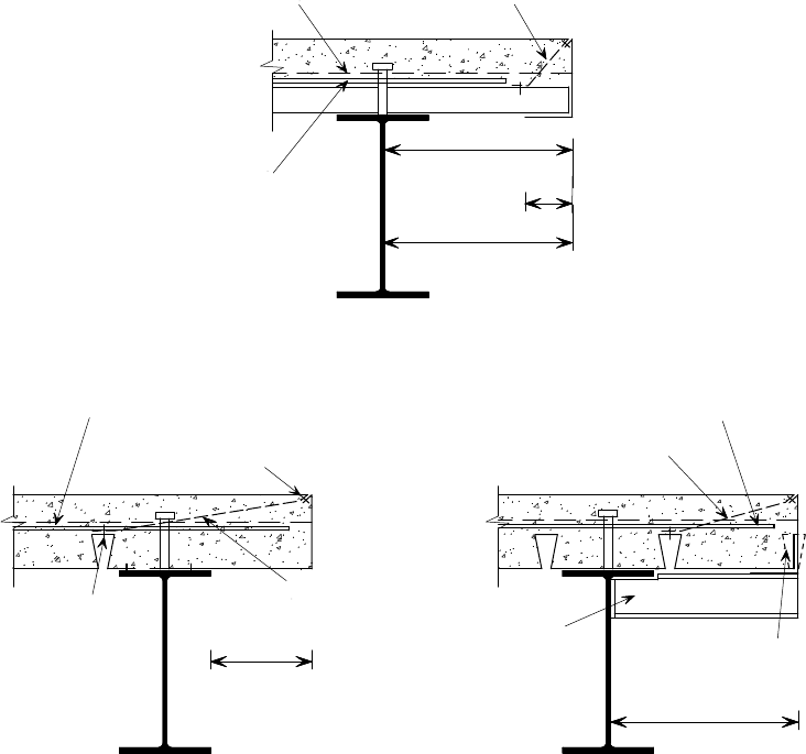
P:\PUB\PUB800\SIGN_OFF\P300\2nd Edition\P300V02D12.doc 44 Printed 29/04/09
4.2.7 Temporary supports
Decking is usually designed to be unpropped for spans up to 3 m for profiles up
to 60 mm deep, and up to 4.5 m for profiles 80 mm deep. For longer spans
temporary propping may be required, but this will depend on the depth of the
concrete, the profile used and whether the decking is multiple or single
spanning. The limitations of a particular decking should be checked with the
manufacturer at an early stage so that any propping requirement can be planned.
The structural designer should check whether beam deflections during
construction and the method of levelling of the slab would lead to significant
additional concrete loads (from concrete ponding) that have not been allowed for
in the design of the structure and decking (see Section 4.1.3). Propping may be
necessary to minimise ponding.
In general, traditional ‘shallow’ decking spanning greater than 4 m will require
the propping system to be in place, braced and levelled, before placing the
decking. SD225 deep decking will generally require such propping for spans
greater than 7.5 m. Propping will reduce the deflections from the self-weight of
the decking, which would otherwise be difficult to remove if props were
installed after laying the decking. It will also minimise the risk of overloading
the decking under loads during construction, e.g. from operatives and storage,
but the implications of using design which requires propping should be
Fixing to top
of edge trim
U-bars required to prevent
longitudinal splitting
Fixing
Restraint straps at
600 mm c/c approx.
Max. 200 mm
Stub cantilever
specified by
structural designer
> 200 mm
Steel deck cut on site
to suit edge detail
Additional U-bars required to
resist longitudinal splitting
Restraint straps at
600 mm c/c approx.
Mesh reinforcement
Restraint strats at
600 mm c/c approx.
Minimum 114 mm
(for 19 mm studs)
Maximum 600 mm
cantilever (or 1/4 of
adjacent span, if less)
Additional U-bars required to
resist longitudinal splitting
a) Typical end cantilever
(decking ribs transverse to beam)
b) Typical edge detail
(decking ribs parallel to beam)
c) Side cantilever with stub bracket
(decking ribs parallel to beam)
75
mm
Figure 4.16 Typical edge details
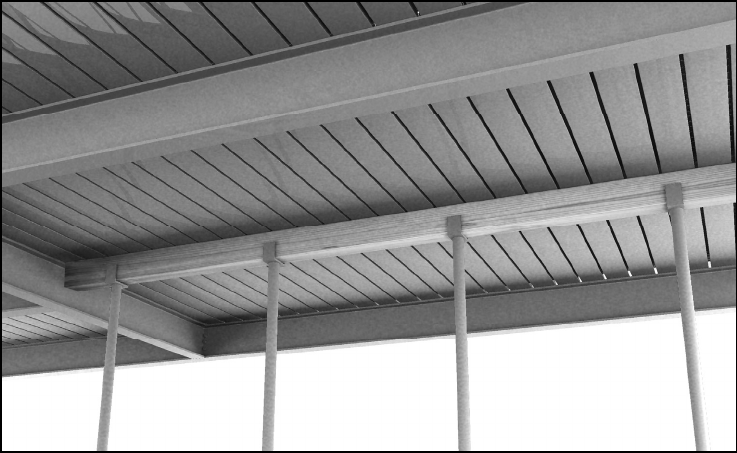
P:\PUB\PUB800\SIGN_OFF\P300\2nd Edition\P300V02D12.doc 45 Printed 29/04/09
considered at an early stage, because it can have sequence and programming
implications, and can preclude the use of safety netting. When temporary
propping is positioned after the decking is placed, it is particularly important to
check that the props are set in accordance with the Structural Designer’s
requirements, and that the increased weight due to concrete ponding is allowed
for in the design of the propping system.
There may be small areas in a building where propping is necessary, even when
the main areas of the floor remain unpropped. These propped areas may include
bays that are in-filled after the removal of climbing cranes, or lift shafts which
have non-standard span lengths. The decking layout drawings should show the
extent and lines of temporary supports.
Normally, props are placed at either mid-span (one line of props) or at third
points (2 lines of props) within a span. Isolated props should not be used, and
all props should be suitably braced (in the direction of the line of the props and
perpendicular to this) to prevent dislodgement during construction operations.
Props normally consist of lengths of timber and/or steel plates supported by
adjustable length steel tubes (‘Acrows’). The minimum bearing length of the
timber and/or plates depends upon the thickness of the slab, the span length and
the decking rib geometry. Bearing lengths are typically in the 75 to 100 mm
range. The timber bearer should be continuous, and should extend the full width
of the bay. The decking sheets should never be interrupted (cut) at the location
of a temporary support, and the decking should not be fastened to the temporary
supports. It is good practice to carry out a final check of the propping system
before pouring the concrete.
A typical temporary support is shown in Figure 4.17. Props of this nature are
normally placed about 1 m apart, according to the Structural Designer’s
requirements.
Props may be supported off the floor directly beneath the floor being concreted,
but the designer should check that the design capacity of the lower floor is not
exceeded (the supporting floor should achieve its design strength before props
Figure 4.17 Temporary support using an ‘Acrow’ props
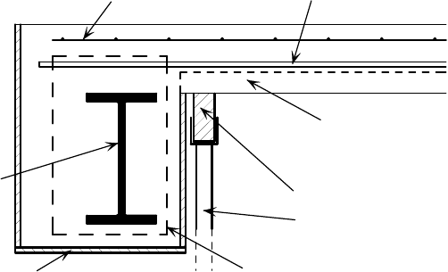
P:\PUB\PUB800\SIGN_OFF\P300\2nd Edition\P300V02D12.doc 46 Printed 29/04/09
are installed). If the lower floor does not have sufficient resistance, further
‘back’ propping will be needed (i.e. using props to support the floor that is
supporting the props). Props should never be placed directly on the decking
alone as this could result in localised buckling of the deck. Further guidance on
back propping can be found in Reference 34.
Props should not be removed until the floor has reached 75% of its design
strength. This is normally achieved in 7 to 8 days, but the Structural Designer
should be consulted specifically before removal, unless general guidance has
already been given. Where crack control is essential, props should not be
removed until the floor has achieved its specified strength.
Other temporary support details may be needed for special situations, such as
end supports in refurbishment projects or where there are concrete encased
beams. Particular care should be taken with non-standard details to ensure that
the sequencing of the construction is practicable. A typical detail for the
temporary support of the decking at an encased beam is shown in Figure 4.18.
In this case, the decking is supported initially off the steel beam, and a
temporary prop is inserted under the decking close to the beam. This must be of
sufficient width to avoid crushing of the decking during concreting (see
Section 4.1.4). The decking is then cut back to allow access for the
reinforcement and the shuttering to be positioned, and the concrete to be
poured. This detail is only suitable for re-entrant decking because the decking
can interlock into the concrete by the ‘dovetails’, without needing support
underneath in the permanent condition. The decking cannot contribute to the
shear resistance of the finished slab. Use of this detail should be confirmed by
the Structural Designer and indicated on the drawings.
4.2.8 Attachments
Hangers
The best way to eliminate the hazardous activity of post-drilling concrete to
attach services is to use hangers, and designers are encouraged to specify them.
Many decking profiles have re-entrant slots into which proprietary wedges can
be inserted to receive threaded rods. The rods serve as hangers to the services,
and they have a safe load-carrying capacity of, typically, 100 kg to 200 kg
each. Some examples of these attachments are shown in Figure 4.19.
Beam
Timber shutter
Re-entrant steel deck
initially supported on
steel beam, then cut back
after prop installed
Temporary prop installed
to support decking
during construction
Supporting timber
Reinforcement
Crack control mesh
Hairpin tie bar/transverse
reinforcement
Figure 4.18 Special temporary support detail for re-entrant decking on
a concrete-encased beam
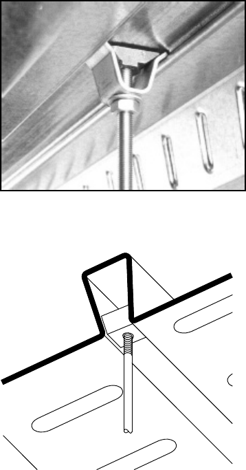
P:\PUB\PUB800\SIGN_OFF\P300\2nd Edition\P300V02D12.doc 47 Printed 29/04/09
Designers or Architects wishing to make use of these attachments should seek
information, including safe load capacities, from the decking supplier. For
services that are too heavy for the capability of the hangers, it may be necessary
to use drilled expanding anchor fixings into the composite slab (taking care to
ensure that the resistance of the fixing is appropriate for this type of use).
For detailed information on the interface between the services and the floor,
refer to Interfaces: Design of Steel framed buildings for service integration
[35]
.
Cladding supports
Brackets cast in to the edge of the slab may be used to support the cladding.
These may form part of a proprietary edge trim. Even though this may need to
be set out more accurately on site than the standard edge trim, the support
system should be co-ordinated early during the design process to allow for
horizontal deviations in the edge of slab position of at least ± 25 mm (more for
high rise buildings). Such an allowance is necessary because not only may the
allowed tolerances for the cladding be considerably more stringent than those
for the frame, but also that the brackets may move during concreting. An
example of a typical stainless steel brickwork support arrangement is shown in
Figure 4.20.
As an alternative to cast-in brackets, drilled fixings may be used to achieve
greater accuracy and require the use of power tools. Drilling for these fixings
may, however, be more time-consuming. For further information on cladding
attachments see Interfaces: Curtain wall connections to steel frames
[36]
.
A wedge attachment
An alternative wedge attachment
Figure 4.19 Examples of fixings for ceilings and services
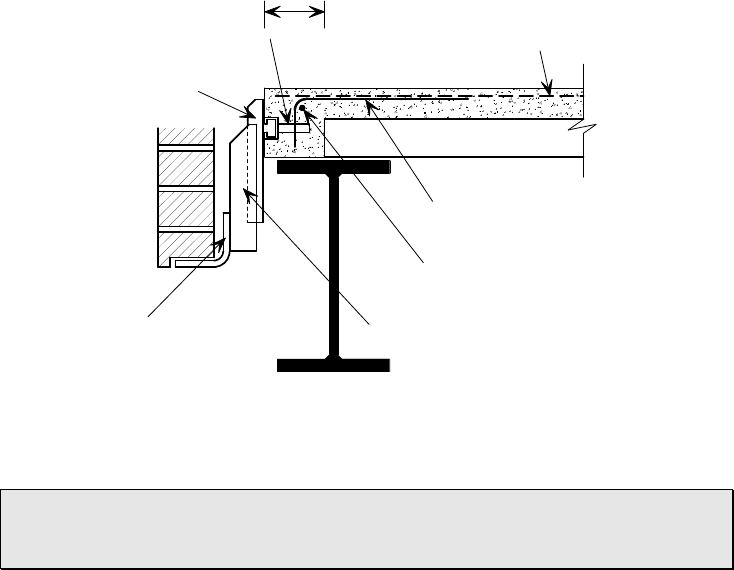
P:\PUB\PUB800\SIGN_OFF\P300\2nd Edition\P300V02D12.doc 48 Printed 29/04/09
Cladding fixing brackets should be provided with provision for adjustment,
in recognition of different tolerance requirements for the slab edge and the
cladding. This may avoid problems and additional cost on site.
4.3 Acoustic insulation
Building designers should consider two basic ‘types’ of sound transmission;
airborne and impact. The acoustic insulation (attenuation) of both types of
sound, and particularly airborne sound, is partly related to the mass (or weight)
of the element through which the sound is passing. It is also affected by the
presence of any ‘soft’ layers, which increase the sound absorption.
High levels of sound insulation are typically required in:
Multi-occupancy residential buildings
Hotels
Schools and other education-related buildings
Hospitals and other health-related buildings.
For composite floors with shallow decking, a bare composite slab will normally
provide about the same degree of acoustic insulation as a reinforced concrete
slab with a thickness equal to the average thickness of the composite slab.
However, the floor should not be considered as an element in isolation because
the acoustic performance of the walls, and the junction details between the walls
and floors, also need consideration. The junctions need to be detailed to
minimise sound which may travel around the floor; known as flanking sound.
Further guidance on this is provided in SCI Publication P372
[37]
. Approved
Document E to The Building Regulations
[38]
requires residential buildings to
undergo pre-completion acoustic testing to demonstrate compliance unless the
walls, floors and their interfaces have been constructed in accordance with
‘Robust Details’
[39]
.
Enhancing the acoustic performance of the floor by adding mass is not very
efficient and is not always practical. This is particularly true for impact sound.
Embedded channel and anchor
(part of proprietry edge trim)
Brickwork
support angle
Serrated U bar bolted
to embedded channel
Fabric reinforcement
Spacer bar
L bar to prevent
pull-out of anchor
Reinforcement bar
parallel to edge trim
110 typ
(depends on trim channel size)
Figure 4.20 Typical steel brickwork support
P:\PUB\PUB800\SIGN_OFF\P300\2nd Edition\P300V02D12.doc 49 Printed 29/04/09
A much more effective means of enhancing sound attenuation is by the use of
layers above and below the floor slab. A ‘resilient layer’ of material applied
above the bare slab and beneath the walking surface is an effective way of
reducing the impact sound transmission through the floor. The walking surface
material, such as a screed or chipboard, forms a ‘floating layer’ above the
resilient layer; the sound energy is absorbed by the resilient layer rather than
being transmitted through the floor. A ceiling layer suspended below the floor
slab will reduce airborne and impact sound transmission. In addition, the impact
sound transmission can be reduced by suspending the ceiling on resilient bars,
which reduces the sound transfer from the slab. A wide range of proprietary
acoustic floor and ceiling systems are available which incorporate these features.
As a guide to the acoustic performance of typical composite floor constructions,
the attenuation that can be expected is given in Table 4.10. All the values given
in the table are for normal weight concrete, which is recommended for
dwellings and buildings where acoustic insulation is important. Lightweight
concrete will generally give slightly less sound insulation than normal weight
concrete.
Details of a shallow deck composite floor and a deep deck composite floor that
both comply with Robust Details are shown in Figure 4.21 and Figure 4.22
respectively.
4.4 Health & Safety
Revised CDM Regulations came into force in 2007 and were published with an
associated Approved Code of Practice (ACoP)
[4]
. The ACoP should be read in
conjunction with the Regulations, as it has special legal status and gives advice
on how to comply with the law. These are the most important new regulations
affecting safety in construction to be published in recent years. Their primary
thrust is to ensure that structures can be constructed, used and demolished
safely. ‘Use’ in this context relates to operations such as maintenance,
redecoration, repair and cleaning.
One of the most significant features of the Regulations is that designers are now
required to concern themselves with construction safety. They must give
adequate regard to ‘foreseeable’ hazards and, by implication, the designer is
expected to have a sound appreciation of the hazards that may be involved in
the project. This does not mean that the designer is expected to take
responsibility for all hazards that will eventually arise on site. A designer cannot
prevent unsafe practices taking place, and the word ‘foreseeable’ acknowledges
that some hazards cannot be anticipated. The Contractor remains responsible for
health and safety on site and this responsibility is not diminished by the
designer’s regard to the foreseeable hazards.
Another area where the designer has significant influence is in the specification
of components, which falls within the definition of design according to the
Regulations. The selection of materials, equipment, etc. must be given equal
attention to that of the construction method itself.

P:\PUB\PUB800\SIGN_OFF\P300\2nd Edition\P300V02D12.doc 50 Printed 29/04/09
Table 4.10 Site test data for composite floors
Sound pressure level (dB)
Form of Floor Construction
Airborne Sound
Attenuation
D
nT,w
+Ctr
(dB)
Impact Sound
Level
L’
nT,w
(dB)
Approved Document E requirement for purpose
built dwellings
[38]
≥ 45 ≤ 62
Shallow Deck Floors
An 18 mm chipboard walking surface over
25 mm of dense mineral wool over a 175 mm
slab on a 60 mm trapezoidal deck. A 12.5 mm
plasterboard ceiling suspended from the slab on
a metal framed grid.
55 43
An 18 mm MDF walking surface over a 10 mm
dense fibre resilient layer over a 200 mm slab on a
re-entrant deck. A 30 mm (2 x 15) plasterboard
ceiling suspended from the slab on a metal
framed grid.
56 34
A 70 mm screed on 5 mm foam resilient layer
over a 150 mm slab on 50 mm re-entrant deck.
A 12.5 mm plasterboard ceiling suspended from
the slab on a metal framed grid with 85 mm of
mineral wool in the ceiling void.
56 40
A 18 mm chipboard walking surface supported
on softwood timber battens on a 25 mm
acoustic quilt over a 150 mm slab on a re-
entrant deck. A 25 mm (2 x 12.5) plasterboard
ceiling suspended from the slab on a metal
framed grid.
60 34
Deep Deck Floors
An 18 mm chipboard walking surface supported
on softwood timber battens with resilient strips
over a 13 mm mineral fibre quilt over a 300 mm
deep slab. A 12.5 mm plasterboard ceiling fixed
to timber battens fixed to the underside of the
slab.
54 48
An 18 mm chipboard walking surface over
30 mm of dense mineral wool over a 300 mm
deep slab. A 12.5 mm plasterboard ceiling
suspended from the slab on a metal framed grid.
54 43
An 18 mm chipboard walking surface supported
on softwood timber battens with resilient strips
over a 300 mm deep slab. A 12.5 mm
plasterboard ceiling suspended from the slab on
a metal framed grid.
55 42
A 55 mm screed over a 5 mm foam resilient
layer over a 300 mm deep slab. A 12.5 mm
plasterboard ceiling suspended from the slab on
a metal framed grid.
57 45
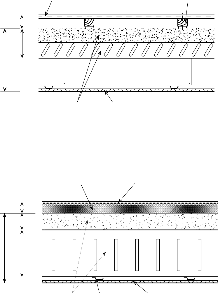
P:\PUB\PUB800\SIGN_OFF\P300\2nd Edition\P300V02D12.doc 51 Printed 29/04/09
approx
Softwood timber battens
with resilient strips.
300
Normal weight concrete slab with
Shallow decking
Single skin 12.5 mm (8 kg/m²) plasterboard
suspended ceiling
130
18 mm thick tongued and grooved
chipboard walking surface
70
Figure 4.21 Typical shallow composite slab with a battened resilient floor
system (classified as a Robust Detail)
Dense mineral wool
( 25 mm)
225
18 mm thick tongued
and grooved chipboard
walking surface
80
48
approx.
300
Resilient
bars
Single skin 12.5 mm (8 kG/m³)
plasterboard suspended ceiling
Normal weight concrete
floor slab with
SD225 deep decking
Figure 4.22 Composite slab with deep decking and a layered resilient floor
system (classified as a Robust Detail)
The designer is obliged to follow the same hierarchy of measures whether
considering the construction process or the specification of components, namely
to avoid hazards, reduce their impact, or protect people from their
consequences. Designers may assume (as indeed the ACoP requires) that
contractors will be competent, i.e. not only capable of providing quality work,
but also experienced in the day-to-day hazards associated with that work. For
example, designers may assume that decking layers are experienced specialists

P:\PUB\PUB800\SIGN_OFF\P300\2nd Edition\P300V02D12.doc 52 Printed 29/04/09
who are aware of the hazards of working at height, and used to managing the
associated risks by adopting best practice in laying techniques.
Nevertheless, designers must consider whether there are any features of the
design itself, or the way in which it would be constructed, which are unusual,
or unduly onerous, for operatives. Features falling into one of these categories
may include the specification of items which are difficult to handle and locate,
such as excessively long and heavy decking sheets. Such features may be
avoided by changing the steelwork layout, propping arrangements, etc. Another
feature falling into this category is the need for propping of the decking during
construction. If, on the basis of information given in a load-span table, the
designer knows that there will be a need to prop the chosen decking in order to
satisfy the load and span requirements, this information must be clearly
communicated to the relevant parties, preferably on the drawings.
A number of ways to reduce ‘general’ risks and afford greater protection to
those working at height during the deck installation are recommended in the
good practice guidance given in Reference 6. They include such measures as
edge protection and the use of fall arrest equipment. A list of common hazards
that are more specific to floor construction using steel decking, and the
measures to control the risks associated with them, are shown in Table 4.11.
Table 4.11 Common hazards associated with floor construction using
metal decking and potential design and site control
measures
Hazard Design/Site Control Measures
Falling through decking -
due to inadequate
resistance of decking
Check the decking for the erection case.
Falling through decking -
due to inadequate
support
Allow for adequate bearing. Minimise the
use of propping. Highlight the need to
ensure the propping arrangement is in
place and of adequate construction.
Supply propping loads
Falling through penetrations in decking
Create openings by ‘boxing out’ and
cutting out later. Minimise penetration
(liaise with services engineer)
Contact with hot particles during stud
welding
Wear appropriate protection when stud
welding, and barrier and/or screen areas
below or in proximity
Collapse of decking from overload during
concreting
Check decking for erection loads given in
BS EN 1991-1-6 or BS 5950-Part 4
Collapse of decking due to overload from
bad storage of materials.
Place stored materials directly over, or
close to, support beams, and distribute
their weight over the decking ribs using
timbers
4.5 Further reading
The references given below mainly relate to slab design. See Section 5.4 for
additional design guidance related more to beams. (For information on authors
and publishers, see Section 8, References.)
P:\PUB\PUB800\SIGN_OFF\P300\2nd Edition\P300V02D12.doc 53 Printed 29/04/09
Concrete Society Technical Report No. 63, 2007 - Guidance for the design of
steel-fibre-reinforced concrete
[40]
.
This publication summarises the range of applications for steel-fibre-reinforced
concrete and includes practical aspects such as production and quality control.
Concrete Society Technical Report No. 65, 2007 - Guidance on the use of
macro-synthetic fibre reinforced concrete
[41]
.
This publication reviews the current range of applications for Macro-synthetic
Fibre Reinforced Concrete and gives guidance on quality control.
Interfaces: Curtain wall systems for steel frames (P101)
[36]
This outlines the main considerations in the design of a curtain wall attachment
system, and reviews some of the systems available for steel framed buildings.
Interfaces: Composite floor systems (P166)
[42]
This book provides information on most aspects relating to the design of
composite floors. It is particularly useful in that it covers both conventional
composite floors with shallow decking and slim floors (with deep decking). A
comprehensive set of worked examples of the design of floor beams is included.
Design of composite slabs and beams with steel decking (P055)
[43]
This provides the theoretical aspects of the design of composite beams with
shallow decking. It includes a comprehensive series of design tables for
common loading and span arrangements, and a worked example.
Acoustic detailing for steel construction (P372)
[37]
This guide explains the principles of acoustics in a very readable way. Sound
insulation values are given for many examples of floor and wall construction,
and typical details are recommended which are compatible with the Robust
Details Handbook
[39]
.
Advisory Desk
The following ‘Advisory Desk’ items, published in New Steel Construction and
available on www.steelbiz.org, provide further information relevant to this
Section:
AD 150, Vol 1, December 1993
[45]
, Composite floors - wheel loads for fork lift
trucks. This note gives a procedure for checking the behaviour of slabs under
heavy point loading.[ Further advice is given in BS EN 1994-1-1, clause 9.4.3.]
AD 163, Vol 2, December 1994
[20]
, Provision for water vapour release in
composite slabs. This note explains the problems sometimes associated with
water vapour release in composite roof slabs. It is suggested that perforated roof
felt may be used, but the use of perforated decking is not recommended.
AD 247, Vol 9, March 2001
[9]
, Use of composite construction in an aggressive
environment. This note gives advice on improving the corrosion resistance of
decking and beams for an aggressive environment. It recommends using coated
steel or additional paint protection for decking, and discusses the advantages and
disadvantages of using shot-fired studs or pre-welded studs for beams.
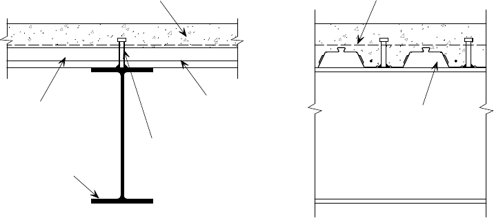
P:\PUB\PUB800\SIGN_OFF\P300\2nd Edition\P300V02D12.doc 54 Printed 29/04/09
5 DESIGN OF COMPOSITE BEAMS
This Section provides information about design principles and procedures,
codified design rules, and guidance on good practice in design and detailing. It
(along with Section 4) is aimed primarily at the Structural Designer, and any
Delegated Designers. Summary boxes are used to highlight particular issues of
good practice, or things that the designer should beware of.
Composite beams typically consist of steel ‘I’ sections acting structurally with a
concrete slab by means of shear connectors attached to the top flange of the
steel section, as shown in Figure 5.1. An effective width of slab is taken as
acting as part of the composite section on either side of the centreline. Fabric
reinforcement is ideally placed below the head of the studs; its main role,
possibly supplemented by individual bars, is to act as transverse reinforcement
in order to transfer the forces between the shear connectors and the slab.
Alternatively, fibre reinforcement may be used to fulfil this role. Fabric or fibre
reinforcement may also serve as a means of controlling crack widths. The
beams are generally designed to be simply supported.
Steel section
Transverse
reinforcement
In-situ concrete
Voids left unfilled
for fire resistance
periods 90 mins
Profiled
steel decking
Shear stud
connector
Mesh
Figure 5.1 Typical cross-section through a composite beam
The composite action developed between the steel beam and concrete slab
significantly increases the load carrying capacity and stiffness of the beam by
factors of up to 2 and 3.5 respectively
[46]
. These benefits can result in significant
savings in steel weight and/or structural floor depth.
It is often found that the size of the steel section is governed by serviceability
considerations because composite beams tend to be used for long span
applications (in excess of 9 m). This makes deflection and dynamic criteria
more likely to be critical. Controlling deflections is particularly important where
brittle ceiling finishes are specified, or for edge beams, where excessive
deflections can damage the cladding.
Designers should note that where edge beams are designed as composite beams,
care is required to ensure that the decking, edge trim, shear connector, slab
edge and reinforcement details are practicable. Edge beams are sometimes
designed non-compositely to avoid transverse reinforcement requirements, which
may result in problems of reinforcement congestion.

P:\PUB\PUB800\SIGN_OFF\P300\2nd Edition\P300V02D12.doc 55 Printed 29/04/09
5.1 Construction stage
The steel sections are normally designed to be unpropped during construction,
and must be sized to support the self-weight of the slab, and other construction
loads, in their non-composite state. Design is generally in accordance with
either BS EN 1993-1-1
[47]
or BS 5950-1.
The weight of extra concrete from ponding of the slab should be allowed for in
the design of the beams when the deflection of the decking under the wet weight
of the concrete exceeds one tenth of the depth of the slab, in accordance with
both BS EN 1994-1-1 and BS 5950-4. Careful consideration should be given to
the correct allowance for the weight of the concrete when ‘mass flood’ levelling
techniques are adopted – see Section 6.2.1. As well as checking the resistance
of the steel beams, this will involve an assessment of their stiffness. Beams that
are not suitably stiff will deflect excessively during concrete placement, and the
extra concrete should be allowed for in the design.
When designing to the Eurocodes, the construction load is defined in
BS EN 1991-1-6 and is taken as the same construction load as for designing the
decking, as described in Section 4.1.2. The self weight of the wet concrete is
treated as a variable load. The construction loading is significantly more
onerous for beams than previous UK practice and, at the time of writing,
consideration is being given to address this.
When designing to BS 5950, the construction load should be taken as an
‘imposed load’ of not less than 0.5 kN/m
2
applied uniformly over the supported
area. The construction loading should be applied in addition to the self weight
of the concrete, reinforcement and decking. This non-composite check may
dictate the final choice of section size if subsequent imposed loads are low.
To use a steel beam economically, the top (compression) flange needs to be
restrained laterally. The restraint provided by the decking to the beams depends
on the decking orientation and the fixings. The restraint provided by decking
spanning in a direction parallel to a beam is normally assumed to be negligible,
but decking spanning perpendicularly to a beam can provide restraint if it is
adequately connected. In this latter case, continuous lateral restraint occurs
when thru-deck welded shear connectors are provided (irrespective of other
fixings), but when there are no shear connectors, restraint is limited by the
resistance of the fixings. This will depend not only on the shear resistance of an
individual fixing (typically, 0.8 kN to 4.0 kN, according to the type of fixing),
but also on their spacing along the beam. The Structural Designer should ensure
that the restraint assumed in the design is provided by the fixing arrangement;
guidance on the force that must be resisted is given in the SCI publication
Lateral stability of steel beams and columns
[48]
and BS EN 1993-1-1 (or
BS 5950-1).
Check that the steel beam size chosen is capable of supporting the wet
weight of the concrete, and other construction loads, in its non-composite
state.
Check that beam deflections during construction will not lead to significant
additional concrete loads (due to ponding) that have not been allowed for in
the design.

P:\PUB\PUB800\SIGN_OFF\P300\2nd Edition\P300V02D12.doc 56 Printed 29/04/09
The decking will only provide lateral restraint to the beams during
construction if the resistance of the fixings is adequate, and where the
decking ribs run perpendicular to the beams.
5.2 Composite stage
5.2.1 Design for resistance
Composite beams are generally designed in accordance with either
BS EN 1994-1-1 or BS 5950-3. In both cases, the bending resistance of the
section is normally evaluated using ‘plastic’ principles (provided the cross
section will not be subject to local buckling). The calculated resistance is then
independent of the order of loading, i.e. whether the beam is propped or
unpropped during construction. The resistance should be adequate for the
maximum total design moment at the ultimate limit state.
The plastic moment resistance is calculated using idealised rectangular stress
blocks, as shown in Figure 5.2. In BS EN 1994-1-1 it is assumed that stresses
of f
yd
and 0.85 f
cd
can be achieved in the steel and concrete respectively, where
f
yd
(=f
y
/
M0
) is the design yield strength of the steel and 0.85f
cd
is the bending
compression resistance of the concrete. It is 0.85 times the design cylinder
strength of the concrete f
cd
, where f
cd
=f
ck
/
c
. Equivalent strengths in BS 5950
are p
y
for the design yield strength of the steel and 0.45 f
cu
for the design
bending compression strength of the concrete (where f
cu
is the cube strength of
the concrete).
The plastic neutral axis may fall within the depth of either the slab or steel
section, depending on the relative areas of these two components.
The area of concrete in compression is limited by its effective breadth. This
breadth varies along the length of a beam, as shown schematically in
Figure 5.3. Its form depends on the type of loading, and the end conditions
(simply supported or continuous). However, a simpler form may be assumed for
design. In BS EN 1994-1-1, the effective breadth is defined as constant for the
middle portion of the span and tapering towards each end, as shown in
Figure 5.3. The distance between centres of pairs of shear connectors, b
0
, is
also included. However, for the serviceability limit state, a constant effective
breadth can be assumed to act over the entire span, based on the mid-span
value. In BS 5950-3, the effective breadth is a constant value for a simply-
supported beam with decking perpendicular to the beam. For both BS 5950-3
Secondary
beam
Shear
connector
Concrete
Decking
Plastic neutral
axis
Idealised stress
distribution
0.85f
cd
yd
f
Figure 5.2 Plastic analysis of composite section (using
BS EN 1994-1-1 notation)
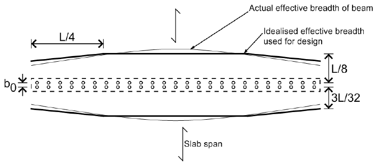
P:\PUB\PUB800\SIGN_OFF\P300\2nd Edition\P300V02D12.doc 57 Printed 29/04/09
and BS EN 1994-1-1 the maximum value of the effective breadth is span/8 on
each side of the centre-line of the beam for both serviceability conditions and
for the ultimate limit state. As well as considering this limit, the width assumed
in design must not exceed the actual slab width available. This is particularly
relevant for edge beams and beams adjacent to openings, where there may be
only a narrow width of slab on one side.
The compressive area of the concrete also depends on the orientation of the
decking. When the decking ribs run perpendicular to the beam, the concrete
contained within the depth of the decking must be neglected (see Figure 5.4(a)).
When the decking ribs run parallel to the beam, the total cross-sectional area of
the concrete may be considered, provided that it lies above the neutral axis of
the composite section (Figure 5.4(b)).
The stress blocks that can be generated in the steel and concrete, and used to
calculate the moment resistance, may be limited by the amount of longitudinal
shear force that can be transferred between the materials at their interface. If
this limit governs, it is called ‘partial interaction’ (see Section 5.3.3).
It is assumed that in both BS EN 1994-1-1 and BS 5950-3 all of the vertical
shear force applied to the beam is resisted by the steel section alone. Design
checks should therefore be in accordance with BS EN 1994-1-1 or BS 5950-3,
which give guidance on the consideration of combined bending and shear. In
addition, the width of the top flange of the steel section must be sufficient to
ensure that the decking does not fail in bearing over the beam.
Figure 5.3 Effective breadth profile of a simply supported beam
according to BS EN 1994-1-1
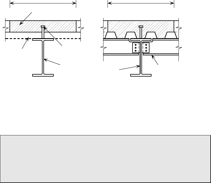
P:\PUB\PUB800\SIGN_OFF\P300\2nd Edition\P300V02D12.doc 58 Printed 29/04/09
The concrete adjacent to the steel beam forms a structural flange, and the
presence of openings in the slab will therefore influence the performance of
the beam.
Avoid placing slab openings next to beams (within the effective flange
width) wherever possible. If such openings cannot be avoided, their effect
must be included in the beam design.
5.2.2 Design for serviceability
Deflections
Composite beams are generally shallower (for any given span and loading) than
non-composite beams, and they are used commonly in long span applications.
Consequently, deflections are often critical. BS EN 1990
[49]
(and BS 5950-1)
recommends that deflections should not affect the appearance, the comfort of
users or the functioning of the structure.
In addition to the ‘traditional’ deflection check under imposed loads, it is also
prudent to check deflections due to the following:
Total (in-service) loads – the combined dead and imposed loads should be
considered to ensure that floor curvatures will not be unacceptable (see
comments below on deflection limits). This is particularly important for
long spans if there is limited depth available in the zone for under-floor
services.
Construction loads – although not a serviceability deflection limit, it is
necessary to check that excessive concrete ponding will not apply
significant extra loading to the structure.
For edge beams supporting cladding, it is important that the deflections are
checked under cladding and imposed floor loads to ensure that the deflection of
the beams does not compromise the performance of the cladding.
‘Uncracked’ elastic section properties should be used to calculate the deflection
of simply supported beams (the total area of concrete within the effective flange
width is considered, even that part which in reality will be cracked in tension).
A transformed section is used; the effective width of the slab is reduced using a
Secondary
beam
Deck
Shear
connector
Effective breadth Effective breadth
Secondary
beam
Primary
beam
Idealised available
compressive area of slab
(
a
)
(
b
)
Figure 5.4 Composite beams incorporating composite slabs. (a) Deck
perpendicular to secondary beam. (b) Deck parallel to
primary beam

P:\PUB\PUB800\SIGN_OFF\P300\2nd Edition\P300V02D12.doc 59 Printed 29/04/09
modular ratio equal to the elastic modulus of the steel divided by that of the
concrete. The effect of creep of the concrete is taken into account by choosing a
modular ratio between one based on short term concrete properties and one
based on long term properties, according to the mix of long and short term
loading.
When designing to BS EN 1994-1-1, the increased flexibility of the composite
beam caused by greater slippage between the concrete slab and the steel section
when using partial shear connection may be ignored if the degree of shear
connection is not below 50%. However, BS 5950-3 requires an additional
deflection to be included using a modification factor.
For the calculation of deflections where props are used, all the loads are applied
to the composite section.
Deflection limits for beams subject to imposed load are recommended in the
National Annex to BS EN 1993-1-1 (or BS 5950-1). As a more comprehensive
guide, the deflection limits given in Table 5.1 may be considered in design.
Table 5.1 Suggested deflection limits for composite beams
Beam Type Load Case Limit
Absolute Limit
(mm)
Imposed load Span/360 To suit finishes
Total load Span/200 To suit finishes
Internal beams
Dead load at construction
stage
–
25
‡
Imposed load Span/500 To suit cladding
Imposed load + cladding
Span/360 To suit finishes
Edge beams
supporting both
floor and cladding
Total load Span/250 To suit cladding
Edge beams
supporting cladding
only
Cladding weight Span/500 To suit cladding
Notes:
‡ Although not a serviceability criterion, this is to limit the additional load due to ponding of the
concrete, consequent on beam deflection.
Where dead load deflections are excessive, pre-cambering may be appropriate
(this is normally only adopted for beams longer than 10 m). However, the
pre-camber required may be difficult to determine accurately; for example, the
stiffening effect of the end connections may be significant, so some pre-camber
may remain after casting, and the depth of the slab may not be as intended at
the critical point of mid-span. Therefore, a general rule of thumb is to design
any pre-cambering to eliminate no more than two thirds of the dead load
deflection. In some situations, large amounts of pre-camber may possibly hinder
the laying of decking.
Further information on methods of calculating deflections are given in Design of
composite slabs and beams with steel decking
[43]
. For the assessment of beam
with web openings, additional guidance may be found in Design of beams with
large web openings for services
[50]
.
The deflection limits used in design should be chosen to suit the building
details.

P:\PUB\PUB800\SIGN_OFF\P300\2nd Edition\P300V02D12.doc 60 Printed 29/04/09
Pre-cambering can be used to limit beam deflections under dead load.
Assessing the amount of pre-camber needed may prove difficult, and
calculations should take into account the likely stiffness of the connections.
Irreversible deformation
In BS EN 1994-1-1 there is no specific requirement to limit stresses at the
serviceability limit state (see clause 7.2.2). In BS 5950-3, the stresses in simply
supported composite beams at the serviceability limit state, calculated using
elastic principles, are limited to p
y
in the bottom fibres of the steel section, and
0.5 f
cu
in the concrete slab. Full shear connection, with negligible slip, may be
assumed when calculating these stresses. Any part of the concrete in tension
should be neglected when calculating stresses (‘cracked’ section properties
should be assumed – unlike the procedure for calculating deflections, when
uncracked properties may be assumed). A similar limitation could be applied
when designing to BS EN 1994-1-1, whereby the steel stress would be limited
to f
y
and the concrete stress
to 0.63 f
ck
.
In unpropped construction, the stresses should be calculated first for the
non-composite section subjected to the loading at the construction stage, and
then those for the composite section should be added. In propped construction,
the stresses due to the construction loading are often ignored.
Dynamic sensitivity
Traditionally, the parameter used to assess the dynamic sensitivity of a floor is
its natural frequency. This allows a simple assessment of what is, in reality,
very complex behaviour. A frequency of 4 Hz is a commonly accepted lower
limit for the natural frequency of an individual composite floor beam, as this
will generally mean that the frequency of the entire floor system is greater than
3 Hz, and therefore ensure that excitation activities do not occur at a frequency
that coincides with that of the floor. A higher frequency limit may be
appropriate for applications such as dance floors and gymnasia.
The natural frequency of a floor beam may be determined from the approximate
formula f = 18/√, where
is the static deflection (in millimetres) resulting
from the application of the self-weight of the floor, plus that of the ceiling and
finishes, plus 10% of the imposed loading applied to the composite beam.
Partitions tend to increase the damping and stiffness of the structure, and are not
included in the loading.
Floors are likely to be more ‘lively’ in situations where there is a grid of
primary beams and secondary beams. In these cases, the cumulative deflection
of the slab, secondary beams and primary beams (i.e. the total deflection in the
middle of the slab) should be assessed, and a combined floor frequency
calculated. A method for determining the combined frequency is set out in
Design of floors for vibration: A new approach
[51]
. This publication also includes
methods for determining the likely accelerations of a floor when subjected to
vibration, in terms of Response Factors, and it is recommended that this more
detailed analysis is used to assess the dynamic sensitivity of a floor.
Long span applications, for which composite beams are often used on account
of their excellent resistance and stiffness characteristics, often have a relatively
low natural frequency. However, they also tend to have a high effective mass.
The consequence of this is that the inertia of the floor relative to the impacting
dynamic loads is large, so that floor accelerations (which are what dictate

P:\PUB\PUB800\SIGN_OFF\P300\2nd Edition\P300V02D12.doc 61 Printed 29/04/09
occupant comfort) remain acceptably low. This means that even if the natural
frequency limit is not satisfied, a full calculation of the floor response may show
it to be satisfactory. Further information may be found in Reference 51.
5.2.3 Design for fire resistance
Typically, composite beams are design to achieve the required fire resistance by
applying fire protection materials. Three methods of protection are commonly
used; boards, sprays and intumescent coatings. Fire protection adds to the cost
of the structural frame and has implications on the construction programme, as
another trade has to be accommodated in the construction programme. There are
alternative methods of design available which limit the extent of fire protection
required on composite floor plates, as described in SCI publication, P288
[52]
.
It is also possible to take the fire protection operations for beams off-site.
Off-site intumescent coatings are becoming increasingly popular because, unlike
traditional forms of protection (which are applied on site), the operation is not
on the critical path and is not affected by the weather. Although better handling
and storage of the sections is required with offsite coatings, any slight damage
can be touched up easily. Through-deck stud welding on site will have an affect
on the intumescent coating, but does not prohibit the use of off-site protection of
composite beams. Further information is available in Structural fire design:
Offsite applied thin film intumescent coatings
[53]
.
For composite beams that are to be fire protected, a ‘critical temperature’ needs
to be established in order to enable the required thickness of fire protection to
be determined. Methods of determining the failure temperatures are provided in
BS EN 1994-1-2
[28]
and BS 5950-8
[11]
. The terminology used to describe these
methods is different in each Standard but they both provide a calculation model
for determining the relationship between beam failure temperature and the load
applied in fire conditions. The thermal properties of proprietary fire protection
systems are not readily available in the public domain. However, Table 5.2
provides an initial estimate for the critical temperature for composite beams
subject to bending. More comprehensive information is given in the NA to
BS EN 1994-1-2 and in BS 5950-8. The load level at the fire limit state η
fi
should be calculated as follows:
d
td,fi,
fi
R
E
where
E
fi,d,t
is the design value of the effects of actions at the fire limit state and
R
d
is the design resistance at normal temperature.
For beams designed to the Eurocodes, it is recommend that the resistance of the
composite beam is verified by calculation of the moment resistance
M
fi,Rd
using
the procedure given in BS EN1994-1-2 §4.3.4.2, which is described in more
detail in P375
[30]
. The temperature of the steel for this calculation should be
based on the value of critical temperature obtained from Table 5.2. Table 5.2
has been calculated on the basis of a uniform temperature for the steel section.
There is no limitation on the depth of the section that may be designed using the
temperatures from Table 5.2, and the temperatures are appropriate for all values
of shear connection. For beams designed to BS 5950-8, the use of the limiting
temperature method is recommended.
Beams with web openings present a particular problem as far as the
specification of fire protection is concerned, as the critical mode of failure may

P:\PUB\PUB800\SIGN_OFF\P300\2nd Edition\P300V02D12.doc 62 Printed 29/04/09
be related to buckling of the web posts between the openings rather than global
bending at the point of maximum applied moment. The performance of the fire
protection material has also been found to influence the critical temperature.
The critical temperatures given in Table 5.2 should not be applied to beams
with web openings. Further guidance on fire protection of cellular beams is
given in RT1187
[54]
.
Table 5.2 Critical temperatures for composite downstand beams
Critical Temperature (ºC) for a load level η
fi
of:
Description of member
0.7 0.6 0.5 0.4 0.3 0.2 0.1
Unprotected or protected
composite members in
bending supporting concrete
slabs or composite slabs
535 567 600 641 680 738 838
When the ribs of the profiled steel decking run across the steel beams, voids are
created between the decking and the top flange of the steel (see Figure 5.4).
Although additional heat enters into the steel beam via these voids,
BS EN1994-1-2 recommends that the voids are ignored if at least 85% of the
surface of the top flange is in contact with the slab. This means that for re-
entrant decks the voids do not need to be filled. However, for trapezoidal decks
the voids must be filled - or the effect of the voids on the beam temperature
must be considered when determining the critical temperature of the section.
This is beyond the scope of the simple thermal model given in BS EN1994-1-2.
Therefore, if the voids are to be unfilled, the temperature of the beam must be
determined from tests or advanced analysis.
Fire tests in accordance with BS 476
[55]
have shown the effects of unfilled voids
on structural performance
[56]
. As UK Building Regulations still recognise the
BS 476 test methods, this guidance may still be used in the UK - although this
situation may change in the future. Guidance in accordance with P109
[56]
is
given in Table 5.3 to identify when special measures must be taken because of
these voids, and what they should be. In some cases it may be necessary to
increase the thickness of fire protection to compensate for the adverse effect of
the voids, or they may be filled.
It should nevertheless be remembered that, for all beams forming part of a fire
compartment, the voids should always be filled to avoid affecting the integrity
of the compartment wall.
Where the voids have to be filled, it is not necessary to use the same material as
that used to protect the beam; any non-combustible material will suffice.
For beams with decking orientated parallel to them, the edges of the top flange
must be protected; when board protection is used, the boards should be taken
past the edge of the flange to abut the underside of the decking.
It is not always necessary to fire protect the voids between the steel flange
and decking. Specifying such protection unnecessarily will lead to increased
costs.

P:\PUB\PUB800\SIGN_OFF\P300\2nd Edition\P300V02D12.doc 63 Printed 29/04/09
Table 5.3 Recommendations for fire protection of voids between
profiled steel decking and steel beams in composite floor
construction
Trapezoidal deck
Fire Resistance (minutes)
Beam Type
Fire Protection
on Beam
Up to 60 90 Over 90
Composite
Insulating
sprays and
boards
(assessed at
550̊ C)
No increase in
thickness
Increase
thickness by
10 % or assess
thickness using
A/V increased
by 15%*
Fill voids
Intumescent
coatings
(assessed at
620̊ C)
Increase thickness
by 20% or assess
thickness using
A/V increased by
30%*
Increase thickness
by 30% or assess
thickness using
A/V increased by
50%
Fill voids
Non-composite All types Fill voids
Dovetail deck
Fire Resistance (minutes)
Beam Type
Fire Protection
on Beam
Up to 60 90 Over 90
Any All types
Voids may be left unfilled for all periods of fire
resistance
* The least onerous option may be used (A/V=heated surface area per unit volume of the steel
section)
5.3 Shear connection
The longitudinal shear connection between the steel section and the concrete is
provided by shear connectors, which normally take the form of studs welded to
the top of the steel section. All connectors should be capable of resisting uplift
forces caused by the tendency for the slab to separate from the beam as it
bends. In the case of shear studs this is achieved by the head of the stud.
Although shear connectors ensure adequate fixing of the decking to the beam,
they are not needed simply to achieve this. They should only be used when it is
desired to achieve composite action between the slab and the steel beam, or to
tie the slab at edge beams when the floor acts as a diaphragm.
5.3.1 Connectors
The most common type of shear connector used in composite beams for
buildings is a 19 mm diameter by either 100 mm or 125 mm long welded stud.
For thru-deck welding (see below), this is the only stud diameter that can be
used practically, because it is the only one for which suitable ferules are
available. Although other heights are available, they are not so easy to obtain.
There are a number of other forms of shear connector available, such as angles
welded to the top flange. However, most lack a practical application in
composite beams, with the exception of shot-fired connectors. These should be
considered for smaller projects, those where beams need to be galvanized or top

P:\PUB\PUB800\SIGN_OFF\P300\2nd Edition\P300V02D12.doc 64 Printed 29/04/09
flanges painted for reasons of durability, or indeed any project where the
provision of power for stud welding is a problem. They may be particularly
appropriate for refurbishment projects, where there is either limited access or no
earthing facility. The most common shot-fired shear connector is that produced
by Hilti, which is available in heights of 95 mm to 140 mm. It should be noted
that a shot-fired connector has less resistance than a welded stud. Design
guidance and design values of the shear resistance should be obtained from the
supplier.
It should be noted that a shot-fired connector has less resistance than a
welded stud. Design guidance should be obtained from the supplier.
Resistance
Design resistances of shear studs are given in BS EN 1994-1-1 and BS 5950-3,
based on standard push-out tests on samples with ‘standard’ fabric
reinforcement. However, tests have also been carried out on specimens with
fibre reinforcement, and these results show they perform at least as well as
those with fabric reinforcement. The design resistance is a function of the:
shape of the decking profile
size, strength and number of connectors per decking trough
concrete properties
the sheet thickness (according to BS EN 1994-1-1)
In BS EN 1994-1-1, the resistance of a stud in a solid slab is calculated directly
from formulae which include terms for the concrete strength and modulus. The
concrete modulus can be found in BS EN 1992-1-1
[24]
, where the value for
normal concrete (
E
cm
) is given in Table 3.1, and the value for lightweight
aggregate concrete (
E
lcm
) is given in Table 11.3.1. The presence of shallow
cracking above a beam does not necessitate a reduction in the design resistance
of the shear connectors, because of the presence of the transverse reinforcement
or steel fabric reinforcement.
In BS 5950-3, the design resistance of a stud in a solid slab in normal weight
concrete is given in Table 5, according to concrete strength and stud
dimensions. These values are reduced by 10% when lightweight concrete is
used.
The reason why the efficiency of the shear connectors is reduced when the
decking is orientated with the ribs transverse to the beam is because the force
transferred through the shear connector into the slab relies on a small localised
area of concrete immediately in front of the stud. For this orientation of the
decking, this area of concrete is limited in size by the presence of the profile, as
shown in Figure 5.5. Reduction formulae are given in BS EN 1994-1-1 and
BS 5950-3 to allow for this by considering the relative geometry of the stud and
the decking rib.
As well as the shape and thickness of the decking, the position of the stud in the
trough is important; tests have shown that the integrity of this local area of
concrete can break down if the stud is positioned close to the decking. The
formulae given in BS EN 1994-1-1 and BS 5950-3 assume that studs are located
centrally in the troughs, or are alternated between the ‘favourable’ and
‘unfavourable’ side of the trough. Recommended practice is to place the studs in
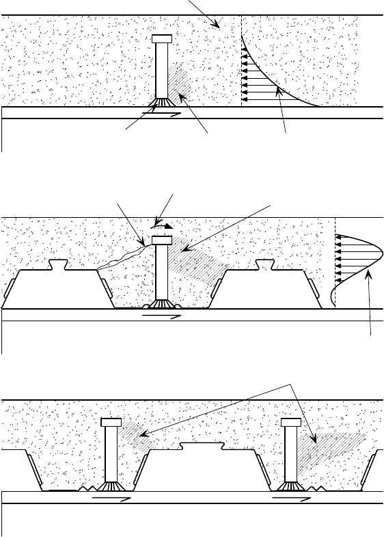
P:\PUB\PUB800\SIGN_OFF\P300\2nd Edition\P300V02D12.doc 65 Printed 29/04/09
the ‘favourable’ side (see Figure 5.5). This means that, for single studs on
simply supported beams with symmetric loading, the position of the stud in a
trough with a central stiffener must change at mid-span.
The number of studs placed transversely (across the width of the beam) in each
trough also affects their resistance. A reduction factor should be applied to the
design resistance when two studs are present. Note that the design resistances
given in BS EN 1994-1-1 explicitly do not cover more than two studs per
trough. For further information, reference should be made to the Designer’s
guide to BS EN 1994-1-1
[26]
and the Commentary on BS 5950: Part 3:
Section 3.1 Composite beams
[46]
.
Attachment of studs
‘Thru-deck’ welding is generally used, particularly in the UK, to attach the
shear studs to the steel beams. This process welds the stud, decking and steel
section effectively together in a single operation. A typical run of thru-deck
welded shear studs is shown in Figure 5.7. The Structural Designer should
recognise the following practical limitations before specifying thru-deck
welding:
Cracking
Crushing
Crushing
Concrete
Moment
on head
Force distribution
in concrete
Force distribution
in concrete
Crushing
Weld
Force
Force
Force Force applied
to slab
c) Off-centre welding of shear connector
a) Shear connector in plain slab
b) Shear connector fixed through profiled sheeting
End of
beam
End of
beam
End of
beam
Unfavourable side Favourable side
Figure 5.5 Shear connector forces in composite slabs
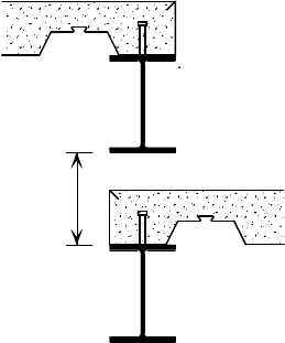
P:\PUB\PUB800\SIGN_OFF\P300\2nd Edition\P300V02D12.doc 66 Printed 29/04/09
The galvanized steel decking should not exceed 1.25 mm thick, and the
total galvanizing thickness should not exceed 0.04 mm.
The thickness of the top flange of the steel section must not be less than 0.4
times the stud diameter (i.e. 7.6 mm for a 19 mm stud) to prevent localised
bending of the flange at ultimate loading.
Small numbers of studs are uneconomic because of the amount and expense
of the equipment needed.
A clear height above a beam of at least 450 mm is necessary to carry out
the process of stud welding, i.e. to give room for the operative and
equipment. (A typical example of where a problem can occur is when there
is a change in the floor level, as shown in Figure 5.6.) In these situations
it may also prove difficult to fix the slab edge trim.
The need to keep the top of the beam flange free of paint is generally not a
problem (in an internal environment having an exposed, unprotected top of
flange in the ‘voids’ is acceptable). Thru-deck welding may however blister
any paint applied, and required, on the underside of the flange. Remedial
measures may be required for aesthetic, if not corrosion protection,
reasons. An intumescent coating on the underside of the flange might also
be damaged, but would not normally need remedial work other than for
aesthetic reasons.
A minimum flange width is needed to provide sufficient bearing for the
decking on both sides, end distance from the stud to the sheet when
anchorage from the stud is required (for decking design and to enable the
decking to be included as transverse reinforcement and shear reinforcement),
and transverse distance between studs. Consequently, when the decking is
perpendicular to the beam, flange widths less than 125 mm are not
recommended (see below for advice when pre-welded studs are used).
Further limitations, related to site practice, are discussed in Section 6.5.
450 mm min.
required for
stud fixing
Figure 5.6 Minimum height clearance for stud welding
Thru-deck welding is significantly more economical than the alternative of pre-
welding the studs to the steel beams in the factory, although it is not possible
when the beam has to be galvanized. Problems associated with using pre-welded
studs include:
Erection becomes more hazardous and therefore slower.
Decking has to be laid in single spans between the lines of studs, which
requires beams with a sufficient flange width (≥133 mm) to provide the
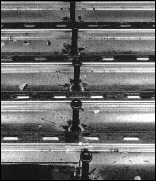
P:\PUB\PUB800\SIGN_OFF\P300\2nd Edition\P300V02D12.doc 67 Printed 29/04/09
minimum safe bearing for the decking on each side of the beam, and the
decking is less efficient as a single-spanning member.
Alignment of the troughs in decking perpendicular to the beam with
pre-welded studs can be difficult. The flange width should be specified so
that, should they not align, at least 50 mm concrete encasement is provided
beyond the transverse spacing of the studs to the edges of the decking. The
stud resistance may be reduced when studs do not align with the troughs,
and it should be calculated using the reduction factor for ribs parallel to the
beam using the width of encasement provided, rather than the reduction
factor for ribs perpendicular to beam.
Holes may be cut in the decking to avoid these problems, but this leads to other
complications trying to align the studs and holes. Decking placement will
become more hazardous because of the need to slot the studs through the holes,
and so this method is not recommended.
Detailing rules
The following detailing rules apply to the positioning of stud shear connectors,
and are illustrated in see Figure 5.9:
BS EN 1994-1-1 requires that nominal height (before welding) of the shear
studs should be at least 2
d (where d is the stud diameter) above the top of
the decking. The corresponding requirement in BS 5950-3 is 35 mm. (Note
that the ‘top of the decking’ refers to the height of the shoulder, i.e.
excluding any small stiffening ribs in the crest of the decking.) Studs that
are longer than is necessary to meet these requirements will not have a
greater resistance.
To avoid damaging the decking, the studs should be located along pre-
determined lines marked on it.
Figure 5.7 A typical run of stud shear connectors
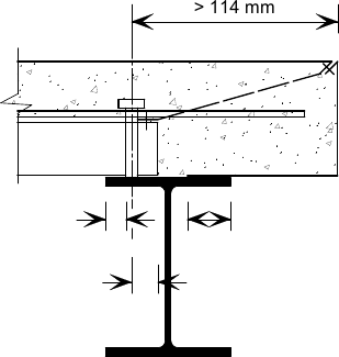
P:\PUB\PUB800\SIGN_OFF\P300\2nd Edition\P300V02D12.doc 68 Printed 29/04/09
The distance between the edge of the shear connector and the edge of the
steel flange should not be less than 20 mm.
The minimum longitudinal spacing of the studs should be 5d.
BS EN 1994-1-1 states that the maximum spacing should not exceed the
lesser of 800 mm and six times the slab depth. The limit given in
BS 5950-3 is 450 mm, and this latter value is recommended in the light of
recent test evidence
[57]
. It should be noted that studs are often required at
larger spacings than these on non-composite beams for other purposes, such
as restraint of the beam.
The transverse stud spacing should not be less than 2.5d in sold slabs and
4
d in other cases.
Studs should normally be placed uniformly along the length of the beam;
one (or a pair) in every trough of the decking, or one in alternate troughs.
Any additional studs noted on the drawing that cannot be placed in equal
numbers in all the troughs should be positioned symmetrically about the
mid-span of the beam, working from the supports inward (assuming
uniformly distributed loading).
When the decking has a central stiffener in the trough (which makes it
impossible to attach the stud centrally), the studs should be attached on the
favourable side of the trough. For symmetrically loaded beams, this will
involve a changeover of position of the stud at mid-span.
At discontinuities in the decking, the studs should anchor both sheets. The
minimum distance from the centre of the stud to the edge of each sheet
should be 30 mm. Because of this, beams with flange widths less than
125 mm are not recommended – see notes on attachment of studs, above.
[Note that studs should never be welded through two layers of decking. At
joints, it is recommended the decking should be butted, and when studs are
in single lines they should be welded alternately on one sheet then the
other, and when in pairs they can be welded one on each.]
Studs attached to edge beams should be placed no closer than 6d (from the
stud centre-line) to the slab edge, as shown inFigure 5.8. Where the slab
edge is less than 300 mm from the line of the studs, ‘U’ bars should be
specified around the studs in accordance with BS EN 1994-1-1 (or
BS 5950-3) to prevent bursting of the concrete near the slab edge.
edge distance
(flange)
20 mm
edge distance
(decking)
30 mm
50 mm
edge trim
bearing
Figure 5.8 Shear connector detailing at an edge (for 19 mm diameter
studs)
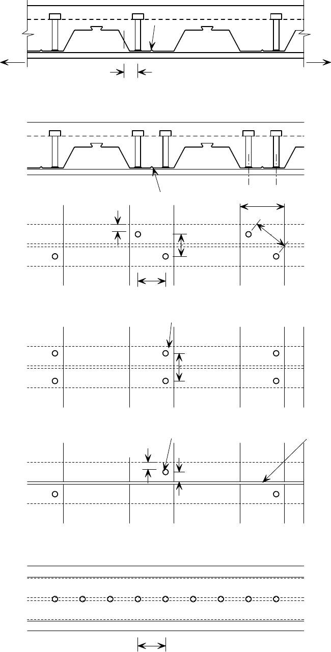
P:\PUB\PUB800\SIGN_OFF\P300\2nd Edition\P300V02D12.doc 69 Printed 29/04/09
a) Single shear connector per trough in staggered pattern
Stiffener
ELEVATION
Mesh
b) Pairs of shear connectors per trough in staggered pattern
Decking trough
Beam
Beam
Beam
Shear connector
to stud centreline
20 mm
to edge of stud
e) Shear connectors on decking laid parallel to beam
Beam
c) Correct positioning of pairs of studs not in a staggered pattern
Shear connector
End of
span
End of
span
d) Butt joint in decking (correct positioning of single stud per trough)
Stiffener
To end
of span
Beam
To mid-span
Non-beneficial side Beneficial side
25 mm
Butt joint
in decking
20 mm
95 mm
76 mm
76 mm
57 mm
30 mm
95 mm
Figure 5.9 Detailing of shear connectors (19 mm diameter) welded
through decking
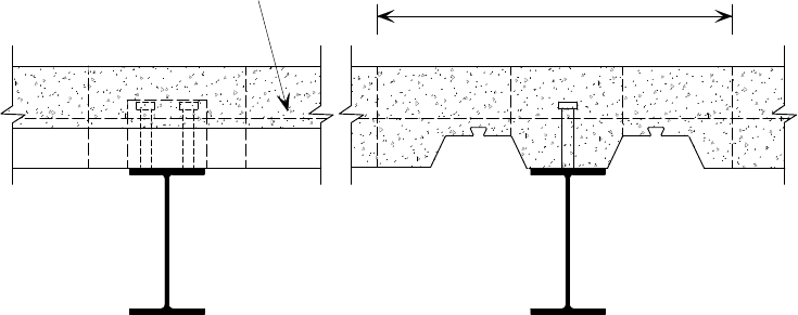
P:\PUB\PUB800\SIGN_OFF\P300\2nd Edition\P300V02D12.doc 70 Printed 29/04/09
5.3.2 Longitudinal shear
Composite beams may be designed plastically if the shear connectors are
sufficiently ductile. This enables a plastic shear connection resistance to be
assumed, whereby the maximum resistance in each connector is assumed to
occur simultaneously down the length of the beam. BS EN 1994-1-1 states that
19 mm diameter studs with a ‘length as welded’ greater than 76 mm may be
assumed to satisfy this requirement. The total longitudinal shear force that can
be transferred across the steel-concrete interface is the sum of the resistances of
the shear connectors positioned within the length between a support and the
point of zero bending moment. Where the loading is asymmetric, the lesser of
the resistances totalled either side of the point of zero bending should be used.
Transverse reinforcement
The longitudinal shear resistance of the concrete slab must be checked to ensure
that the force from the shear connectors can be transferred into the slab without
splitting the concrete. This requires the provision of transverse reinforcement
(perpendicular to the beam centre-line). It is usually found that fabric or fibre
reinforcement is sufficient for the design of secondary beams, where the
decking ribs run perpendicular to the beam (as shown in Figure 5.10(a)). For
beams where the ribs run parallel to the beam (Figure 5.10(b)) additional bar
reinforcement is likely to be required. Potential shear planes through the slab lie
on either side of the shear connectors (Figure 5.10). However, plane b-b need
not be checked for composite slabs with decking because characteristic stud
resistances are determined from tests which allow for this type of failure. The
shear resistance per unit length of shear plane along the beam is a function of
the concrete strength and the amount of reinforcement provided.
For edge beams, ‘U’ bars should be positioned as low as possible but with
sufficient bottom cover for the aggregate to flow (BS 5950-3 states that the bars
should be placed at least 15 mm below the head of the stud, although there is no
such requirement in BS EN 1994-1-1).
The decking may also act as part of the transverse reinforcement to contribute
to the longitudinal shear resistance. The full resistance of the decking can be
used when it is placed transverse to the beams and is continuous. In situations
where the decking is discontinuous, the anchorage force that can be developed
by the shear connectors limits this action, but the decking contribution may be
Cover width of decking
Mesh reinforcement
ccd
d
c
c
d
d
ab
ab
a
a
a
)
b
)
Figure 5.10 Potential failure planes through the slab in longitudinal
shear (a) Decking perpendicular to beam
(b) Decking parallel to beam

P:\PUB\PUB800\SIGN_OFF\P300\2nd Edition\P300V02D12.doc 71 Printed 29/04/09
included, provided that there is sufficient end distance of the decking beyond the
centre line of the studs. Guidance on the anchorage resistance is given in
BS EN 1994-1-1 (clause 9.7.4(3)) and in BS 5950-4 (clause 6.4.3), but
minimum values are quoted as 1.65 times stud diameter in the former and 1.7
times stud diameter in the latter.
The contribution of the decking should always be neglected where it is not
properly anchored at discontinuities, or where the decking ribs run parallel to
the beam. In theory, when the decking is parallel to the beam and properly
anchored, some contribution to the longitudinal shear resistance could be
included. However, including this contribution is not recommended because the
decking resistance is affected by the (unpredictable) presence of laps on site;
this approach is consistent with BS EN 1994-1-1. Studs fixed in a single line at
a butt joint in the decking do not provide sufficient anchorage for the decking to
contribute to the transverse reinforcement. Further guidance on transverse
reinforcement can be found in AD 192
[58]
and AD 266
[59]
.
Transverse reinforcement is always needed to ensure adequate
performance of the shear connection. Fabric may be sufficient, but a check
is always necessary, particularly for primary beams. Fabric is preferred
because it minimises the need for steel fixers to work in a bent position.
The contribution of the decking to the transverse reinforcement can only be
included if it is properly anchored, and this depends on a number of factors
- continuity of the decking, decking rib orientation, and laps in the decking.
The contribution of the decking should always be neglected where the ribs
run parallel to the beam.
Bending resistance envelope
The bending resistance of a composite beam depends on the shear transfer
between the beam and the slab. Consequently, the resistance increases away
from the supports; the resistance at a given point is a function of the resistance
moment of the bare steel beam and the number of connectors between that point
and the nearest support.
For a beam subject to uniformly distributed load, the maximum design moment
is at mid span. It is only necessary for the Structural Designer to check the
moment resistance at this point, and determine the total number of connectors
needed to transfer the load into the slab (see Section 5.2.1 and Figure 5.3);
these connectors may be evenly distributed between the support and mid-span.
For beams subject to point loads, it is necessary to check the resistance moment
at intermediate points, not just the point of maximum design moment. For
example, Figure 5.11 shows a beam with four point loads, the applied bending
moment diagram, and a resistance moment that is just sufficient at each of the
four load positions. To achieve the required resistance at the intermediate point
‘A’, the number of connectors between that point and the nearest support must
enable sufficient force to be transferred to the slab to achieve the required
resistance
M
A
. With a heavy point load close to the support, it may not be
possible to accommodate the required number of studs over that short length.
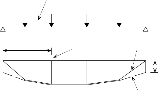
P:\PUB\PUB800\SIGN_OFF\P300\2nd Edition\P300V02D12.doc 72 Printed 29/04/09
5.3.3 Degree of shear connection
The maximum longitudinal shear force that is required to be transferred from
the steel to the concrete is the lesser of the compressive force to cause concrete
crushing, and the force that would cause yielding of the steel section in tension.
If sufficient shear connectors can be provided to transfer this force, the full
plastic resistance moment of the composite section can be achieved. This is
known as providing ‘full shear connection’ (sometimes referred to as full
interaction).
‘Partial shear connection’ refers to situation in which fewer shear connectors are
provided. In this case, the stress block method used for calculating the
resistance moment (see Section 5.2.1) must be modified to take into account the
reduced longitudinal force that can be transferred. The use of partial interaction
often results in improved economy, especially where the number of shear
connectors is limited by the spacing of the ribs in the decking.
Deformation of the shear connectors allows slip between the concrete and the
steel section. This slip is zero at the point of maximum bending moment (often
at mid-span) and increases towards the supports; the longer the beam span, the
greater the slip at the supports. For partial shear connection, because there are
fewer shear connectors, there will be more slip for a given load than with full
shear connection. To avoid any adverse effects arising from excessive slip, a
minimum limit to the degree of shear connection is specified in BS EN 1994-1-1
and BS 5950-3, although the rules differ between them slightly.
Further guidance on the degree of shear connection can be found in AD 266
[59]
.
5.4 Further reading
The references given below relate particularly to beam design - see Section 4.5
for additional design guidance related more to slabs. (For information on
authors and publishers, see Section 8, References.)
Interfaces: Design of steel framed buildings for service integration (P166)
[35]
This design guide outlines the various services that have to be integrated into
the floor zone of a building and illustrates how this may be achieved with
several different structural steel floor framing systems, many of which
incorporate composite floors.
N = (N +N )
Resistance moment
envelope (M )
Total No. of connectors
Intermediate
load point
Applied load (M)
Number of connectors between load points
s
i
1
2
A
PP P P
N
1
NN
23
A
M( M )
R
R
Steel section
resistance
moment
(M )
Figure 5.11 Shear connector distribution for beams subject to point
loading
P:\PUB\PUB800\SIGN_OFF\P300\2nd Edition\P300V02D12.doc 73 Printed 29/04/09
Designer’s guide to BS EN 1994-1-1
[29]
This guide provides the detailed background to the clauses to Eurocode 4. It
includes many worked examples that show the application of the individual
clauses. It is a standard reference for designers of composite beams to EC4.
Commentary on BS 5950: Part 3: Section 3.1 Composite beams (P078)
[46]
This is a comprehensive guide that provides the background to the clauses in the
BS 5950-3. It discusses the relevant research, and includes a worked example of
the design of a composite beam. It is an essential reference for designers of
composite beams in the UK.
Design of beams with large web openings for services (P355)
[50]
This guide provides a design method for both composite and non-composite
beams with web openings. A model for the complex force distribution around
an opening is explained, from which a simplified method for stiffened and
un-stiffened openings is derived. Guidance on the positioning and size of
openings is included.
P354: Design of floors for vibration: A new approach (P354)
[51]
This guide examines the theoretical aspects of vibrations in buildings caused by
people walking. It shows how floors may be analysed for their dynamic
sensitivity, and suggests acceptance criteria for the floor response.
Fire protection for structural steel in buildings (4th Edition)
[60]
This publication explains the basic aspects of fire protection and fire protection
appraisal procedures. It gives application details for most of the products
available, and protection thickness required for different beam and column
exposure conditions. This is the standard design reference for fire protection of
structural steel.
Structural fire design: Off-site applied thin film intumescent coatings (2
nd
edition)
(P160)
[53]
This publication describes the design and specification issues relating to off-site
applied thin film intumescent coatings. An example of a calculation for the
determination of the coating thickness for a steel member is presented. A
‘model’ Specification is also included.
Managing construction for health and safety - Construction (Design and
Management) Regulations, 2007. Approved Code of Practice L144 (ACoP)
[4]
This document contains the Regulations themselves, together with an
explanatory commentary for each requirement. It is an essential source
document.
P178: Design for construction (P178)
[61]
This guide highlights the effects of basic design decisions on the overall
buildability and cost of a building. It is aimed at engineers primarily, but has a
relevance to all those having a design input. It includes a section on the 1994
CDM Regulations.
Advisory Desk
The following ‘Advisory Desk’ items, published by the SCI in New Steel
Construction and on the SCI Steelbiz web site www.steelbiz.org, provide
further information relevant to this Section:
AD 174,
Shear connection along composite edge beams
[62]
. This note outlines a
method for checking the bending resistance of composite edge beams in existing
P:\PUB\PUB800\SIGN_OFF\P300\2nd Edition\P300V02D12.doc 74 Printed 29/04/09
buildings where the shear connectors have not been properly fixed, or the
transverse reinforcement has been omitted.
AD 175,
Diaphragm action of steel decking during construction
[7]
. A method is
given in this note for checking the adequacy of the decking to stabilise the
structure by providing diaphragm action. Fixing requirements are given.
AD 192,
Transverse reinforcement in composite T-beams
[58]
. A detailed
description of the principles of longitudinal shear, and the role of transverse
reinforcement, is given in this note. The background to the relevant clauses in
BS 5950-3 is explained.
AD 266,
Shear connection in composite beams
[59]
. This note discusses the basis
for effective breadth rules, the minimum degree of shear connection rules and
transverse reinforcement calculations.

P:\PUB\PUB800\SIGN_OFF\P300\2nd Edition\P300V02D12.doc 75 Printed 29/04/09
6 CONSTRUCTION PRACTICE -
CONCRETE
This Section provides information concerning good practice in relation to the
site activities associated with the procurement, placement and finishing of in-
situ concrete. It is aimed at all personnel involved in the site activities.
Guidance on concrete mix design is included, but guidance is not given on
access requirements for concrete mixers, checking of concrete delivery notes
etc. These issues are considered to be general site practice, and not appropriate
for inclusion in a guide on composite construction.
6.1 Concrete supply
Concrete supply is normally the responsibility of the Main Contractor, who
should make sure that it is specified, supplied and assessed in accordance with
BS 8500-1
[17]
to meet the strength grade specified by the Structural Designer.
Basic details for some typical concrete mixes are given in Table 6.1.
Table 6.1 Concrete specifications (extracted from BS 8500)
Aggregate Type Normal weight Lightweight
Strength class
C25/30
C28/35
C32/40
C35/45
C40/50
LC25/28 LC28/31 LC32/35
Maximum water
cement ratio
0.65 0.60 0.55 0.50 0.45 0.65 0.60 0.55
Minimum cement
content (kg/m
3
)
260 280 300 320 340 260 280 300
Notes:
1. BS 8500-1 does not give universal relationships between strength class and water cement
ratio and minimum cement content. The relationships depends upon the exposure class and
cement types used. The relationships shown in table 6.1 are those given in BS 8500-1 for XC
exposure conditions. Other strength class/water cement ratio/cement content relationships are
listed in BS 8500-1 for other exposure conditions.
2. The minimum cement contents listed are for 20 mm aggregate. Generally minimum cement
contents would need to be increased by 20 kg/m3 for 14 mm aggregate and 40 kg/m3 for
10 mm aggregate
To ensure the quality control of the concrete mix, it should be obtained from a
plant providing concrete in accordance with an approved quality assurance
scheme.
Aggregate types and size
Most composite slabs are constructed with a normal aggregate, but lightweight
aggregate is available.
When normal concrete is specified, the maximum size of the aggregate needs to
be limited to ensure that the concrete may be placed easily into the decking ribs
and between the reinforcing bars.
The nominal dimension of the largest aggregate, which has an angular nature,
should not exceed the smallest of the following limits (see Figure 6.1).
40% of the concrete cover above the ribs.
The average width of the decking ribs (trapezoidal decking).
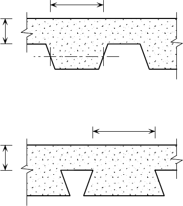
P:\PUB\PUB800\SIGN_OFF\P300\2nd Edition\P300V02D12.doc 76 Printed 29/04/09
One third of the minimum rib width (dovetail decking).
It is recommended that 20 mm aggregate is used whenever possible. When
smaller aggregates are used, the required cement content will increase, and the
shrinkage performance of the concrete will be adversely affected.
With lightweight concrete, aggregate size is not a problem because of the small
rounded nature of the pellets.
Consistence
To ensure that the concrete is sufficiently workable to allow it to be pumped
with the correct flow, and to achieve adequate compaction around the
reinforcement, in the troughs of the decking and around the steel beams in slim
floors, a minimum consistence class of S3 should be specified in line with
BS 8500-1.
Concrete mixes with low consistence should not be used as this can lead more
readily to heaping of the concrete and overloading of the steel deck.
6.2 Placing concrete
6.2.1 Preparation
Prior to beginning work on the decking, guard rails should be in position at all
perimeters, internal edges and voids. The positions of any props (and back
props) should be checked against the details shown on the decking layout
drawings to ensure that the required support has been provided.
Cleaning the decking
The surface of the decking should be reasonably free of dirt, oil, etc. prior to
concreting. The slight surface grease that is present on the decking when it is
delivered to site does not affect the interaction between the concrete and steel,
Height of
concrete
above ribs
Height of
concrete
above ribs
a) Open profile
b) Dovetail (re-entrant)
p
rofile
Average
trough width
Minimum
trough width
Figure 6.1 Nominal cross-sectional dimensions used to determine
maximum concrete aggregate size
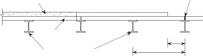
P:\PUB\PUB800\SIGN_OFF\P300\2nd Edition\P300V02D12.doc 77 Printed 29/04/09
and therefore need not be removed. Though recommended, it is not essential to
clean out all the broken ceramic ferrules from stud welding.
Construction joints
Typical pour sizes are up to 1000 m
2
/day, although there is no technical
limitation to the area that may be concreted. Where the limits of the pour do not
coincide with permanent slab edges, construction joints (day joints) are used to
define the extent of the pour.
Where possible, the construction joints should be located close to butt joints in
the decking. For conventional composite beams, it is preferable to create the
joint to one side of the line of the shear connectors, to ensure sound concrete
around the studs. This does not affect the resistance of the shear connectors. If
the construction joint cannot be made near a butt joint, it is suggested that no
more than one-third of the decking span from a butt joint should be left
unpoured, as shown in Figure 6.2. Concreting should not be stopped within a
sheet length with more than this left unpoured because excessive deflections
might occur when the loads on a continuous decking sheet are not balanced
either side of the intermediate support beam.
Stop ends, usually in the form of timber or plastic inserts, are used to create the
construction joints. As with all the joints and ends of the decking, they should
be checked for potential grout loss.
A construction joint will form a discontinuity in the slab, so it is important that
continuity reinforcement is provided across the joint. When fibre reinforcement
is used, continuity reinforcement in the form of conventional reinforcing bars or
a strip of steel fabric will be required at construction joints. The decking
supplier should be consulted regarding the continuity reinforcement required in
fibre reinforced slabs. The occurrence of cracking in the concrete adjacent to
day joints is normal, and does not affect the structural performance. If the size
of the crack at the construction joint is important, e.g. when brittle finishes are
being used, the reinforcement should be sized to control the crack width by the
structural designer. Alternatively, there are commercial systems for decoupling
brittle finishes from the underlying composite concrete slab, and guidance on
their use should be sought from the supplier.
Bar and fabric (mesh) reinforcement
All bar/fabric reinforcement should be properly supported so that it does not
become displaced during concreting. Plastic stools, loops or preformed fabric
may be used as ‘chairs’, but not plastic channels, which can induce cracking.
Chairs should be robust, because operatives will need to use the floor as a
working platform for themselves and their equipment. In particular, the handling
1/3 max
Span
Deck
Intermediate decking
su
pp
orts
Concrete
Dec
k
butt
joint
Construction joint
preferred position
Construction joint
alternative position
Figure 6.2 Recommended positions for construction joints in the
concrete slab
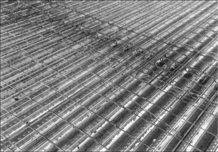
P:\PUB\PUB800\SIGN_OFF\P300\2nd Edition\P300V02D12.doc 78 Printed 29/04/09
and movement of concrete-filled pipes during pumping can cause significant
local impacts on the fabric reinforcement. Although a slight depression (up to
15 mm) of the fabric may occur during concreting, the performance of the slab
is not affected significantly by this. An example of a floor with the
reinforcement in place and ready for casting is shown in Figure 6.3.
The reinforcement that has been fixed should be checked against the slab
reinforcement drawing. Particular attention should be given to checking any
additional bar reinforcement, such as may be needed around openings, across
composite beams and U-bars for composite edge beams.
Fibre reinforcement
When steel or polymer fibres are used, they are added to the concrete mix at the
batching plant, or directly in to the mixer on site. Fibre reinforced concrete can
be pumped to elevated floors, as shown in Figure 6.4. When using a fibre
reinforcement solution, it is still general practice to use U-bars on composite
edge beams, bar reinforcement around openings in the slab, and fabric or bar
reinforcement at construction joints, or where the composite slab cantilevers
beyond a support. When preparing for concreting, the site team should ensure
that any such bars/fabric are present.
Grout loss
The decking joints should be closely butted and exposed ends should be
‘stopped’ with proprietary filler pieces to avoid grout loss. Gaps greater than
5 mm should be sealed, but gaps smaller than this do not need any special
provision normally. Small gaps may be spray-filled with expanding polyurethane
foam.
Figure 6.3 Decking and fabric reinforcement – ready for casting the
concrete
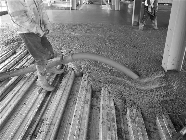
P:\PUB\PUB800\SIGN_OFF\P300\2nd Edition\P300V02D12.doc 79 Printed 29/04/09
Tamping rails
Tamping rails should be placed close to the beam centre-lines, to avoid
excessive deflection during concreting. The level of the concrete top surface will
then tend to reflect the deflected shape of the beams.
Mass flood technique
Where a ‘mass flood’ technique of casting (whereby the concrete is poured and
the whole floor levelled to a fixed datum) is used, considerably more concrete
will be needed and thicker slabs will result from deflections of the steelwork
and decking. Levelling to a fixed datum should not be adopted without first
confirming with the Structural Designer that the extra weight of concrete
‘ponding’ has been allowed for in the design.
6.2.2 Placement
The concrete should be well compacted, particularly near and around any shear
connectors. This can be done using a vibrating beam, which will require
adequate supports at both ends, or by an immersion poker vibrator. Hand
tamping is not recommended as a way of compacting the concrete.
Concrete can be placed when the air temperature is 5°C or above. In cold
weather, it may be necessary to make provision to maintain this temperature
during at least part of the curing period (see below).
Concrete pumping
Pumping has become the normal way of placing concrete, and can be adopted
for both normal and lightweight aggregate mixes. Flow rates in the order of 0.5
to 1 m
3
of concrete per minute can be achieved, although, clearly, the longer
the pump lines and the higher the concrete is to be pumped, the slower the
operation. A pump can normally ‘lift’ the concrete up to 30 m. Secondary
pumps, placed at intermediate levels, may be necessary for higher lifts.
Figure 6.4 Pumping of fibre-reinforced concrete
P:\PUB\PUB800\SIGN_OFF\P300\2nd Edition\P300V02D12.doc 80 Printed 29/04/09
Pump lines are normally 150 mm in diameter and are assembled in segments.
Because the force exerted at bends can be significant, straight line pumping is
preferred. The lines should be supported on timber blocks at intervals of 2 to
3 m. Resetting of pump lines is required at frequent intervals as the pour
progresses. This means that the outlet pipe should be moved frequently and
carefully so that concrete heaping is minimised. A minimum of two operatives
are necessary for this operation, one to hold and manoeuvre the outlet pipe, the
other to shovel away excess concrete. No more than 4 workmen should be
present around the pipe outlet during pumping, because of the potential for
overloading the decking. The concrete should not be dropped from the outlet
pipe onto the decking from a height of more than about 1 m.
Any low quality concrete (the first part of each lorry load, or after flushing out
pipeline blockages) should be discarded.
Skip and barrow
Ideally, concrete should always be placed by pump, but there will be occasions
when small areas need to be concreted where placing by pump is not practical.
Considerable care is needed if a skip and barrows are to be used, to ensure the
decking is not overloaded. It would be preferable to discharge concrete into
barrows on previously constructed areas, to avoid concrete being discharged
directly from a skip onto decking. Placing concrete from a skip hung from a
crane may be difficult because of obstructions from beams and decking at higher
floor levels. However, despite being time consuming (progress rates rarely
exceed 5 m
3
per hour), it is sometimes efficient to use the skip and barrow
technique for small infill bays.
Skips should have a means of controlling the rate of discharge, and should not
be discharged from more than 0.5 metres above the decking or barrow. When
discharging into a barrow, the barrow should be supported by thick (30 mm)
boards covering a 2 m by 2 m area, or by a finished part of the slab. Either
provision limits impact loads. Barrows should be run over thick boards placed
on the fabric reinforcement, which should be supported locally.
Testing
The concrete should normally be tested in accordance with the requirements of
BS EN 12350
[63]
. At least two cubes will need to be taken from every 20 m
3
delivered and batched, or two cubes per day if the quantity used that day is less
than 20 m
3
. The cubes are crushed at 28 days, and the average of the two cubes
strengths becomes the individual 28 day result for the batch sampled. Additional
cubes may be taken for testing at 7 days, or other ages, for the determination of
early strengths.
6.2.3 Finishing, curing and drying
The concrete surface finish is normally specified by the Structural Designer
(Section 4.2.1). If power-floating is to be carried out, this should be done
within 2-3 hours of casting. This allows time for the concrete to sufficiently
harden.
Experience shows that there is a high risk that well trowelled surfaces will
exhibit crazing
[64]
. Crazing is the term used to describe an irregular polygonal
pattern of fine interconnected cracks which often occur on power trowelled
concrete surfaces. Crazing should not be considered a defect and it generally
has no adverse effect on the performance of the floor surface.
P:\PUB\PUB800\SIGN_OFF\P300\2nd Edition\P300V02D12.doc 81 Printed 29/04/09
Although concrete normally gains strength relatively quickly, it is necessary to
keep temperatures above 5°C for at least 3 days after pouring. When concreting
during the winter months, loss of heat, such as by radiation from the lower
surface of the decking at night, can be significant. It may then be necessary to
use space-heaters to maintain the temperature. Some heat is generated during
setting, or ‘hydration’, of the concrete (this raises the temperature by 3 to 5°C,
typically).
The moisture in the concrete should not be allowed to evaporate too early,
otherwise the surface may lose its integrity, forming dust and possibly cracking,
and it will not have a good abrasion resistance. The slab therefore needs to be
‘cured’ by covering the surface with polythene sheeting for 3 to 7 days,
depending on the weather (this is particularly important in warm or windy
weather). Alternatively, the concrete may be sprayed with a proprietary curing
compound.
Because the concrete is only exposed on one surface of a composite floor, it can
take longer than a traditional reinforced concrete slab to dry out. The preferred
method of checking the moisture content of the slab is the insulated hygrometer
method given in BS 8203
[65]
.
6.3 Loads on the slab during and after concreting
6.3.1 Loads during concreting
Loads during concreting arise mainly from the weight of the operatives,
concrete, pump-lines and impact forces. Loads to be taken into account for
design during concreting are specified in BS EN 1991-1-6 and in BS 5950-3,
and are outlined in Section 4.1.2. The self weight of the finished slab (typically
2 to 3 kN/m
2
) and local loading (caused by normal localised heaping of the
concrete) are included. This is usually not critical because adjacent areas of
decking are unloaded, or only partially loaded.
The following list describes the loads that usually arise during concreting, and
that will normally have been allowed for by the Structural Designer:
A concrete gang consisting of 5 or 6 men (only 4 of whom are within 2 m
of the pump outlet).
Concrete that is poured from no higher than knee level above the decking
(to avoid excessive impact loading).
A 150 mm diameter pipeline full of concrete. [The weight of the line
should be adequately spread across the decking by using suitable timbers to
avoid local damage to the deck.]
A cone of heaped concrete of approximately 0.2 m height and 1 m base. It
will have been assumed that the pump line outlet will be moved frequently
to avoid excessive heaping (or, if a skip is used, the discharge will be
carefully controlled).
Additional concrete may be placed because of deflections of both the decking
and the steel frame, particularly if the slab is finished to ‘absolute’ (datum)
levels. The Structural Designer must be consulted to confirm whether the
resultant increased loads have been allowed for in the design. Levelling the top
of slab to achieve a uniform thickness, rather than a ‘level’ top surface is
recommended and will avoid this problem.
P:\PUB\PUB800\SIGN_OFF\P300\2nd Edition\P300V02D12.doc 82 Printed 29/04/09
6.3.2 Construction loads after concreting
Construction loads are often applied to the slab soon after concreting. Examples
of commonly occurring loads are bags of fire protection, skips of debris, pallets
of blocks and other equipment. If these loads are no more than 1.5 kN/m
2
(over
a 3 m by 3 m area), the construction load used in the design of the decking,
then the slab is clearly not overloaded (provided there is no additional,
unforeseen load due to ‘ponding’). For loads above this, the concrete strength
will need to be relied upon. Props should not be removed, nor additional loads
applied, until the concrete has reached 75% of its design strength, as indicated
by ‘control’ concrete compression tests. If the slab is to be loaded before 28
days after concreting, its strength at the time of loading needs to be established
(possibly by testing cubes or cylinders early), and an effective ‘design strength’
agreed with the Structural Designer.
The following list gives examples of typical construction loads. Items are
assumed to be placed on pallets, which should always be positioned directly
over the support beams:
Concrete blocks: a 1 m high pallet of blocks applies a load up to 10 kN/m
2
.
Bricks: a 1 m high pallet of bricks can exert a load of over 15 kN/m
2
.
Bags of fire protection: a bag of fire protection material normally weighs
25 kg. A 1 m high pallet of bags can be equivalent to a load of 2.5 kN/m
2
.
Bags of cement: bags of cement weigh 25 kg each. A standard pallet of
these weighs 1,400 kg (12 kN/m
2
).
The application of very heavy construction loads should always be referred to
the Structural Designer. When considering the location of such loads, it is best
to position them over the beams wherever possible. Examples of such loads are:
Generators: welding generators can apply a load of 50 kN.
Fork lift trucks: fork lift trucks can exert a load up to 100 kN, not
including their live load. In general, vehicles with axle weights above
3 tonnes should be used only if the slab has been designed/checked
specifically for that purpose.
Crane counter weights: each counter weight is marked clearly with the
value of its weight.
Mobile access platforms: The potential loading imposed by any mobile
access platforms used to install services, finishes, etc should be checked.
A procedure for checking the adequacy of the slab to support heavy point loads,
such as the wheel loads from forklift trucks, is given in AD 150
[44]
.
Care is needed if a composite floor is to be used in situations where there could
be frequent vehicle movements. Designing such floors just for uniformly
distributed loads may not be satisfactory. The fatigue effects of the repeated
dynamic loading from vehicles on the slab and supporting beams must be
considered by the Structural Designer. The suitability of the floor design (beams
and slab) for dynamic loading from vehicles should be checked.
Where the concrete is to be used as a wearing surface, or where bonded finishes
are specified, the concrete surface should be protected from oil spillage and
damage from moving plant.
P:\PUB\PUB800\SIGN_OFF\P300\2nd Edition\P300V02D12.doc 83 Printed 29/04/09
6.4 Further reading
The references given below relate particularly to this Section. (For information
on authors and publishers, see Section 8, References.)
ACIFC and Concrete Society Good Concrete Guide No. 5 – Composite concrete
slabs on steel decking – Guidance on construction and associated design
considerations
[66]
This Guide is intended to provide an overview of the factors which should be
considered in the design of composite slabs with steel decking.
Concrete Society Technical Report No.34, 1994 - Concrete industrial ground
floors
[19]
.
This document provides comprehensive guidance on the design, specification,
construction and finishing of industrial concrete ground floors. The guidance on
concrete quality requirements for durability, and on finishing procedures, is also
relevant to suspended composite slabs.
Concrete Advisory Service Data Sheets
These are produced and published by The Concrete Advisory Service, a
subsidiary of the Concrete Society. They provide theoretical and practical advice
on matters pertaining to concrete. The sheets referred to in this Section are:
No.8, 1997 Crazing: power trowelled concrete floor slabs
[64]
No.14, 1997 Cracking in composite concrete/corrugated metal decking floor
slabs
[28]
The manual and advisory safety code of practice for concrete pumping
[67]
This a specialist guide for concrete pumping contractors which covers in detail
both the theoretical and practical sides of pumping concrete.
Guide to steel erection in windy conditions
[68]
This guide provides advice to designers concerning the effect of wind on
steelwork during erection. It also explains the role of management and
supervision in controlling work as wind freshens, as well as giving comparative
information concerning weather forecasts that might be used to plan steel
erection.
Guide to the erection of multi-storey buildings
[69]
This document is a code of practice for Steelwork Contractors erecting multi-
storey steel-framed buildings. The principles included also apply to high-rise
structures generally. The code also provides guidance to Clients, CDM
co-ordinators, Principal Contractors and Designers. It describes the management
procedures and methods to be adopted when drafting site- and project-specific
Erection Method Statements. The document contains advice on the safety
aspects of site management; site preparation; delivery, stacking and storage of
materials; structural stability; holding down and locating arrangements for
columns; lifting and handling; and interconnection of components.
Good construction practice for composite slabs
[70]
This document covers much of the information included in the current guide,
but has a bias towards the European market.
National structural steelwork specification for building construction
[71]
This is the industry ‘standard’ for the quality of workmanship associated with
the fabrication and erection of steel framed buildings and will often form one of
P:\PUB\PUB800\SIGN_OFF\P300\2nd Edition\P300V02D12.doc 84 Printed 29/04/09
the contract documents. It includes procedures for shear stud welding and
testing.
Health and Safety Executive Guidance Note GS28: Safe erection of structures
[72]
This publication relates to the 1994 CDM Regulations and is currently
withdrawn, but an update is awaited. It is expected to provide essential
information on safety from the initial planning stage through to site management
and procedures, and will help users interpret the Regulations more readily.
Health and Safety in Construction HS(G)150
[73]
This is a comprehensive guide giving practical advice for achieving healthy and
safe construction sites. It helps to identify many common hazards and explains
control measures. It also deals with planning and management issues, including
risk assessment and the Method Statement. It is an essential reference.
P:\PUB\PUB800\SIGN_OFF\P300\2nd Edition\P300V02D12.doc 85 Printed 29/04/09
7 SLIM FLOOR CONSTRUCTION
This Section describes slim floor construction and outlines its benefits. Aspects
of design that differ from those of ‘traditional’ composite slabs and beams
(described in Sections 4and 5) are highlighted. The construction process is
described, as are typical construction details. The guidance is aimed at both
design and construction personnel.
Boxes are used to highlight issues of good practice in design, or things that the
designer should be aware of. They are also used to highlight issues of safety
during construction.
7.1 Introduction
Slim floor is a generic term used to describe a form of construction where the
supporting beams are contained within the depth of the concrete slab. This is
achieved by supporting the slab off the bottom flanges of the beams. Although
this concept is not new, it has been significantly refined in recent years, with
considerable development work undertaken in the UK by Corus (formerly,
British Steel). This work led to
Slimdek construction, a form of slim floor
construction using hot rolled beams together with composite slabs using deep
decking. Older forms of slim floor construction, using precast concrete planks
to form the slab, are less effective in a number of ways (such as ease of service
integration), and are not considered in this document.
Slim floor construction using deep decking is suitable for building layouts
requiring the decking, and subsequently the slab, to span up to 9 m. For typical
applications, spans vary between 5.5 m and 6.5 m, and the decking does not
need propping during construction. This spanning capability means that
secondary beams are not normally needed.
The role and structural behaviour of deep decking are similar to those of
shallow decking (Section 4), except that the composite resistance of the slab
needs to be enhanced by reinforcing bars located in the decking troughs.
A range of beam sections is available (Section 7.1.2). Some of these sections
can achieve composite interaction with the slab as a result of the shear bond at
the interface between the steel and concrete components, with no need for
additional shear connectors.
7.1.1 Benefits
The benefits of composite construction listed in Section 1.1 all apply to slim
floor construction using steel decking. It is particularly beneficial in providing
the following:
Shallow floor depth. This may lead to savings in cladding cost, or help to
meet overall building height restrictions.
Ease of service integration. There is a potential to accommodate the
services within the slab depth (between the ribs of the decking).
Inherent fire resistance. A fire resistance of 60 minutes can be achieved
without fire protection.
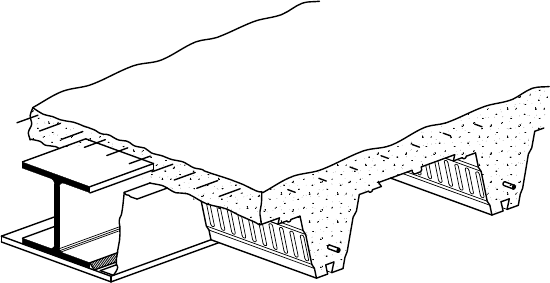
P:\PUB\PUB800\SIGN_OFF\P300\2nd Edition\P300V02D12.doc 86 Printed 29/04/09
7.1.2 Slim floor components and systems
The most recent slim floor development produced by Corus is the Slimdek
system. This system comprises
Slimflor beams and ComFlor 225 deep decking.
Three different types of
Slimflor beam are produced: Slimflor Fabricated Beams
(SFB), Asymmetric
Slimflor Beams (ASB), and Rectangular Hollow Slimflor
Beams (RHSFB).
Slimflor Beams
A
Slimflor Fabricated Beam consists of a Universal Column section with a wide
flange plate welded to its underside. This plate supports the slab. Sections
ranging from 152 mm to 356 mm nominal depth may be used. Shear connectors
can be fixed to the top flange of the beam to achieve composite interaction with
the slab. Thin gauge closure pieces, known as ‘end diaphragms’, are fixed to
the flange plate to stiffen the ends of the decking (particularly during
concreting), and to form the concrete around the SFB. This type of construction
is shown in Figure 7.1.
An Asymmetric
Slimflor Beam is a hot rolled section with a narrower top flange
than bottom flange. The slab is supported off the upper surface of the bottom
flange. Composite interaction can be, and usually is, achieved by partial
encasement of the section (see Section 7.2.2). Two types of ASB are produced
by Corus, one of which has a thicker web. The thicker web type, known as
ASB(FE), can be used without fire protection for up to 60 minutes fire
resistance. In total, ten different ASB sections are produced by Corus
[74]
,
ranging from a 280 ASB 74 (272 mm deep, 74 kg/m) to a 300 ASB (FE) 249
(340 mm deep, 249 kg/m)). Construction using an ASB is shown in Figure 7.2.
A Rectangular Hollow
Slimflor Beam is fabricated from a rectangular hollow
section with a flange plate welded to its lower face. These beams are more
efficient than either SFBs or ASBs in resisting unbalanced loading, and so are
ideal for use at the edges of a building. Composite interaction can be achieved
by welding studs to the upper flange of the hollow section. Hollow sections up
to 500 mm deep may be used, with typical sizes ranging from 200 mm to
300 mm depth. Construction using a RHSFB is shown in Figure 7.3.
Figure 7.1 SFB with deep decking (non-composite beam)
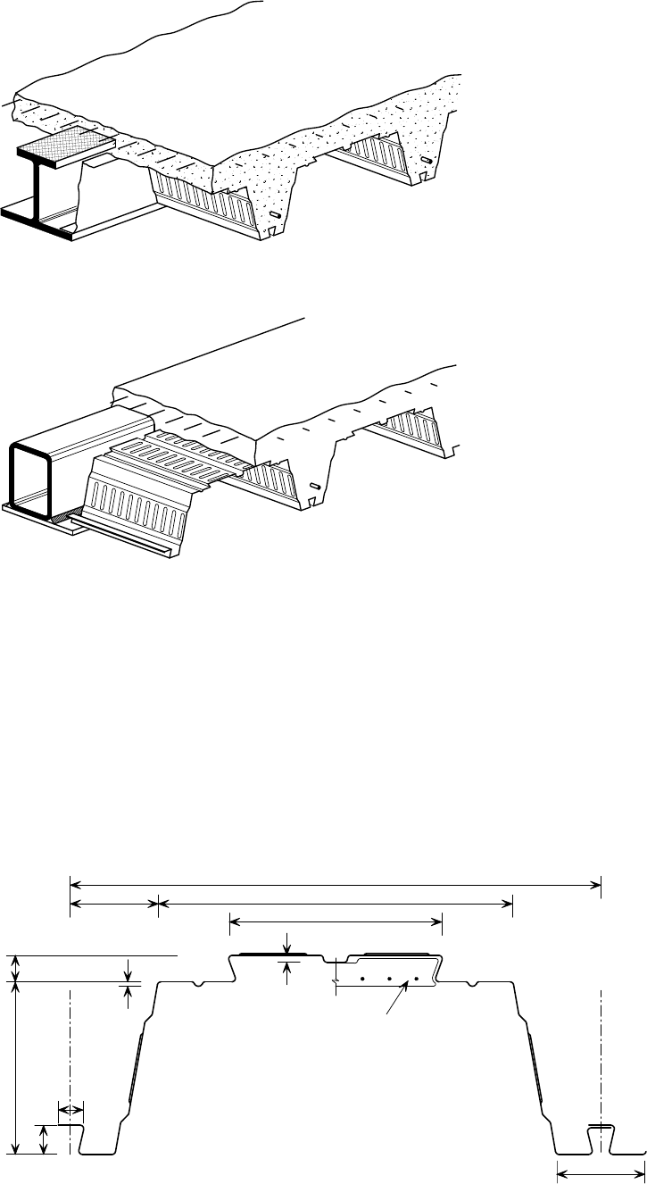
P:\PUB\PUB800\SIGN_OFF\P300\2nd Edition\P300V02D12.doc 87 Printed 29/04/09
ComFlor 225 deep decking
The
ComFlor 225 profile is the most recent form of deep decking, and it may
be used with any of the beam types described above. Its cross-section is
illustrated in Figure 7.4; the profile includes provision for special attachment
points for services and/or a suspended ceiling. A cut-out is included at the top
of each rib to ease concrete placement around the beams. The decking is
produced in 600 mm wide units, normally from 1.25 mm thick grade S350
galvanized steel. Typical floor construction using
ComFlor 225 decking is
shown in Figure 7.5.
Figure 7.2 ASB with deep decking (composite beam)
Figure 7.3 RHSFB with deep decking (non-composite beam)
600
400100
27
33
238
100
5
Attachment hanger
(typical detail)
8
30
195
Figure 7.4 Cross-section of ComFlor 225 deep decking profile,
showing a typical service attachment detail.
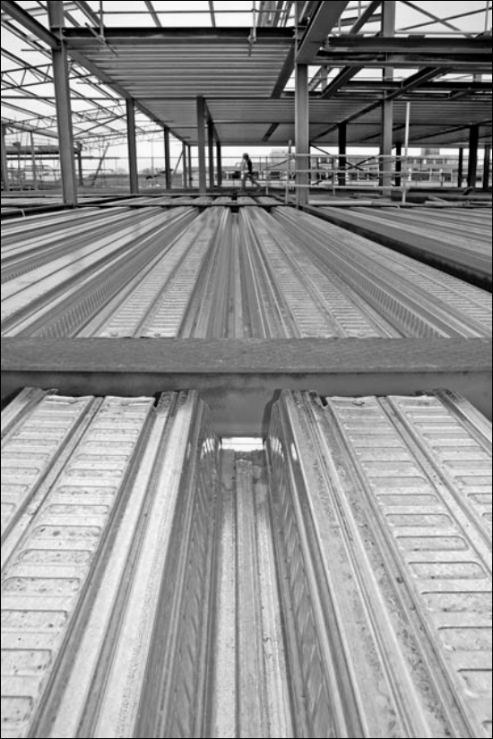
P:\PUB\PUB800\SIGN_OFF\P300\2nd Edition\P300V02D12.doc 88 Printed 29/04/09
7.2 Design
Detailed methods for the design of all the components in the Slimdek system are
presented in References 75, 76 and 77, as well as being summarised in the
Corus Slimdek Manual
[74]
. Design software for the beams and decking, Slim
Floor Integrated Design Software
– SIDS®
[78]
, is available from Corus at
www.corusconstruction.com. The software designs and analyses flooring
solutions utilizing both
Slimflor® Fabricated Beams (SFB) and Asymmetric
Slimflor Beams (ASB).
There are two distinct stages for which the elements of the
Slimdek system must
be designed. The first is the construction stage, during which the beams and
decking support the loads as non-composite sections. The second is the final
stage, during which the decking and concrete act together compositely, as do
(generally) the ASBs and slab. SFBs and RHSFBs will act compositely if shear
studs have been provided. A summary of the key design considerations for both
of these stages is given below.
Figure 7.5 View of Slimflor construction using ComFlor 225 decking.

P:\PUB\PUB800\SIGN_OFF\P300\2nd Edition\P300V02D12.doc 89 Printed 29/04/09
The sequence of design activities generally follows that given in Figure 2.1. The
following two points should be noted:
Consideration of the required spans will allow the depth of the beams to be
estimated.
Consideration of the required fire resistance will allow the depth of slab to
be estimated, as a function of the cover required for the beams and the
decking.
Having established these scheme design parameters, detailed design of the
beams and slab can be undertaken. The following slab depths should be
considered as typical:
280 ASB sections ~ 290-320 mm deep slab
300 ASB sections ~ 315-340 mm deep slab.
These depths will enable adequate cover to the ASB for it to act compositely
with the slab. For SFBs a greater range of slab depths may be considered for a
given depth of beam; the slab depth requirement will depend on whether shear
studs must be accommodated to make the SFB act compositely.
7.2.1 Construction stage
Beam design
Design of the beams at the construction stage is essentially the same as for
conventional steel beams. It may control the size of the beam when the
in-service imposed loads are small. The one significant difference arises from
the fact that in
Slimdek construction the bottom flange (or flange plate) is loaded
by the weight of the wet concrete and construction loads. The flange (or plate)
must be designed to carry this loading in ‘transverse’ bending, at the same time
as acting in tension as part of the beam section.
Out-of-balance loading from one side during construction results in torsion
being applied to the beam. This is resisted by the beam and its end connections.
Two load conditions should be considered:
uniformly distributed load on one side of the beam, causing maximum
torsion in the beam
uniformly distributed load over the entire supported area, causing maximum
bending moment in the beam.
Check that the steel beam size chosen is capable of supporting the wet
weight of the concrete, and other construction loads, in its non-composite
state.
Check for the worst case combination of ‘transverse’ and ‘longitudinal’
bending. Loading on one side of the beam only will often dictate the
required section size.
Decking design
In addition to considering the self weight of the slab, the design of the deep
decking should take into account temporary construction loads. It is
recommended that the construction loads specified in the Eurocodes are used for
the design of deep decking, and not those specified in BS 5950-4, which are
considered unduly onerous for long span decking. The specified loads are the

P:\PUB\PUB800\SIGN_OFF\P300\2nd Edition\P300V02D12.doc 90 Printed 29/04/09
same as for shallow decking, and are explained in detail in Section 4.1.2. They
include a 3 m length construction load of 1.5 kN/m
2
, which may be placed
anywhere for the most onerous effect, and adjacent loads of 0.75 kN/m
2
.
The effect of concrete ponding should be taken into account (by increasing the
self weight of the slab) if the deflection under self weight alone exceeds the
lesser of span/180 or 20 mm.
If temporary props are used to support the decking during construction, the 3 m
length construction load of 1.5 kN/m
2
should be applied in the most onerous
positions for the prop and the decking design, although, for design simplicity, a
constant load could be considered across the span for these ‘propped’ design
conditions.
It is likely that deep decking will require propping during construction if it is
required to span more than about 6.5 m. The precise limit depends on whether
lightweight or normal weight concrete is used. The spacing of the props is
governed by the ability of the decking to resist combined bending and shear in
the hogging (negative) moment regions over the lines of props. It is
recommended that the spacing between the props should be relatively close, so
that local loads do not cause damage to the decking (2.5 m to 3.5 m spacing
depending on the slab weight
[79]
). A 100 mm wide by at least 40 mm thick
timber bearer should be used to distribute the load at these points.
The nominal end bearing of the sheets should be specified as 50 mm. The
flange widths are such that this bearing can be achieved, whilst still allowing the
sheets to be dropped vertically into position (i.e. without having to ‘thread’
them between the top and bottom flanges). It should be noted that a nominal
bearing length of 50 mm has been justified
[74]
by recent testing (earlier
publications suggested that 75 mm was necessary).
It is not necessary for the deep decking to be designed to support
1.5 kN/m
2
over its entire span. Half this value may be considered outside
the ‘middle 3 m’, although when the slab is propped it may be prudent to
design for a constant 1.5 kN/m
2
.
Allow for increased self weight due to concrete ponding when deflections
are substantial.
Specify an end bearing length of 50 mm. Any less would be insufficient to
achieve the necessary resistance to local loading, any more would make
the decking sheets more difficult to drop into position.
7.2.2 Final stage
Beam design
ASBs will in most cases be designed to act compositely in the final stage.
Composite action is developed by the shear bond between the steel and concrete
around the beam, and this is enhanced by the raised pattern rolled into the top
surface of the beam. The bond is sufficient to satisfy the minimum degree of
shear connection required by BS 5950-3. Only in unusual cases, for example
when there is less than 30 mm concrete cover over the top flange, will a
non-composite design be necessary. This will mean that section sizes may have
to be increased for given span and loading requirements.
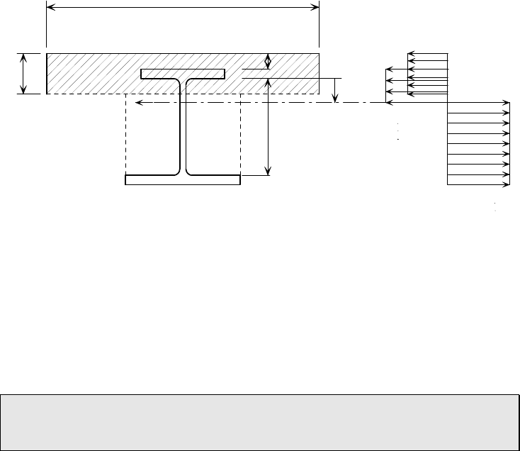
P:\PUB\PUB800\SIGN_OFF\P300\2nd Edition\P300V02D12.doc 91 Printed 29/04/09
SFBs may be designed either non-compositely or compositely. Composite action
can be achieved by the use of shear studs welded to the top flange. These studs
are usually 19 mm diameter and 70 mm as-welded height.
RHSFB edge beams may be designed either non-compositely or compositely. As
for SFBs, composite action can be achieved by the use of ‘short’ shear studs
welded to the top flange. Sufficient transverse reinforcement looped around the
shear connectors is required in order to transfer the shear force into the slab
[75]
.
For ASBs, SFBs and RHSFBs, the minimum concrete cover required for the
beams depends on the beam size, exposure conditions, the concrete specification
and composite interaction is required.
The plastic stress blocks assumed when calculating the moment resistance of a
composite ASB section are shown in Figure 7.6. The resistance model for a
composite SFB or RHSFB is basically the same as that for a ‘traditional’
composite beam (Section 5.2.1), with a requirement to consider the ability of
the shear studs to transfer the envisaged longitudinal force.
For edge beams, or beams adjacent to openings in the slab, out-of-balance
loading occurs during both the construction and final stages. This may be taken
into account by a rigorous analysis combining the longitudinal bending effects
with the torsional effects. A method is presented in Reference 79.
If possible, sufficient concrete cover should be provided to allow composite
interaction between the beams and slab. This will generally allow the beam
sizes to be reduced.
Slab design
The design of composite slabs using deep decking differs from that for shallow
decking (Section 4.2) in the following ways:
The ultimate load resistance of the slab is increased by placing bar
reinforcement in the troughs of the decking. The benefit of these bars is
considered in both the ‘normal’ and fire conditions.
The slab depth may need to be chosen not only to satisfy the structural,
durability and fire resistance requirements of the slab itself (see
Compression in concrete
Plastic
neutral
axis
s
Cross sectional stresses
in com
p
osite section
c
e
Plastic neutral axis
in web below slab
Effective breadth of slab B
D
d
D
0.85f /
f /
ya a
f /
ya a
y
s
ck u
M
y
Figure 7.6 Assumed stress blocks for ASB design (using
BS EN 1994-1-1 notation)
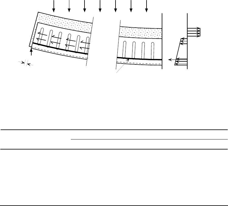
P:\PUB\PUB800\SIGN_OFF\P300\2nd Edition\P300V02D12.doc 92 Printed 29/04/09
Sections 4.2.3, 4.2.4 and 4.2.5), but also to provide appropriate cover over
composite beam sections (Section 7.2.2).
The reinforcing bars in the troughs of the decking provide additional tensile area
to that provided by the decking, and thus enhance the bending resistance of the
composite slab (Figure 7.7). Diameters range from 16 mm to 32 mm,
depending on the span and fire resistance requirements.
Straight bars may be used to achieve 60 minutes fire resistance (provided that
shear stresses are low
[74]
. In other cases, L bars (see Figure 7.8) should be used
to provide sufficient end anchorage in fire conditions. Detailing rules are
summarised in Table 7.1 and Figure 7.8.
Table 7.1 Detailing requirements for deep composite slabs
Fire Resistance (min)
Detailing Requirement
≤60 90 120
Minimum bar dia (mm)
- unpropped 16 20 25
- propped 20 25 32
Cover to bar (mm) 70 90 120
Bar type Straight L-bar L-bar
Min fabric in topping A142 A193 A252
The minimum anchorage details depend on the level of applied shear and the diameter of the main
reinforcing bars in the rib, which in turn depends on the fire resistance period and whether or not
the slab is propped. For 60 minutes fire resistance, when the level of applied shear is less than
0.5 times the available shear resistance, straight bars may be used without extra anchorage bars -
in accordance with BS 8110-1:2005
[30]
, clause 3.12.9.4. However, anchorage bars are
recommended even for low values of applied shear at 90 and 120 minutes fire resistance periods.
For more details see Reference 74.
Slip between
deck and concrete
Support
Longitudinal
shear bond
Concrete in
compression
Tension in
decking and
bar reinforcement
Stress
distribution
Vertical
reaction
Mid-span
Bar reinforcement
Figure 7.7 Action of composite slab with reinforcement in ribs
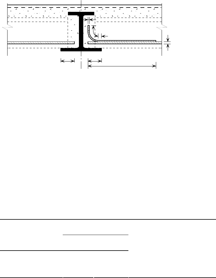
P:\PUB\PUB800\SIGN_OFF\P300\2nd Edition\P300V02D12.doc 93 Printed 29/04/09
Additional reinforcement may be required to fulfil the following roles:
Transverse reinforcement adjacent to shear connectors.
U-bars at composite edge beams.
Additional crack control reinforcement (see below).
Strengthening around openings.
Strengthening at positions of concentrated loads.
One of the principal considerations governing the choice of slab depth is the
required fire resistance period. Minimum depths are given in Table 7.2
[74]
as a
function of the concrete type and fire resistance required.
Table 7.2 Minimum concrete depth above decking for adequate fire
insulation
Concrete Depth Above
Decking (mm)
Fire Resistance (mins)
Normal
concrete
Lightweight
concrete
60 70 60
90 80 70
120 90 80
Note: Depths given are the
minimum for fire insulation
purposes. Greater thicknesses
may be required for spanning
capability, or to achieve
adequate beam cover.
The slab depth may also be governed by structural resistance requirements.
However, as for shallow decking (Section 4.2.3), the performance of a
composite slab using deep decking can only be accurately determined by testing.
Detailed design procedures have been developed based on appropriate tests
[74]
,
and should be used to determine the depth of slab needed to satisfy structural
requirements.
It is normal for some cracking to occur in the slab over the beams. These
cracks run parallel with the beams and are not detrimental to the structural
behaviour of the slab. They may be controlled by fabric reinforcement provided
across the tops of the beams. Guidance on the detailing of reinforcement to
control cracking may be found in the Corus
Slimdek manual
[74]
.
12
L
25
50
L
100 mm100 mm
L
Figure 7.8 Detailing of bar reinforcement in slabs (need for L bars
depends on level of shear stress)
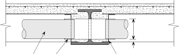
P:\PUB\PUB800\SIGN_OFF\P300\2nd Edition\P300V02D12.doc 94 Printed 29/04/09
7.2.3 Service integration
There are three opportunities for service integration in the Slimdek system:
Partial integration: Major services pass below the slab and beams and the
space between the ribs is used for small pipes and fitments, such as lighting
units. This allows for cross-overs of ducts or pipes. The absence of
downstands provides for greater flexibility of service distribution and
reduces the depth of the structure-services zone.
Full integration: Circular or elongated openings formed in the webs of the
beams for ducts and pipes located between and within the depth of the ribs
to pass through the beams. (Alternatively, the space between the ribs can
act as a duct in itself, which again continues through the openings in the
beams.)
Slab penetrations: Services can pass vertically through openings (up to
400 mm wide by 1 m long) in the concrete topping between the ribs.
Larger openings can be formed, but require more detailed design.
In certain areas where spans are relatively short (< 3.5 m), shallower floors
may be created locally, using a composite slab of 120 to 150 mm depth
comprising more traditional decking of 50 to 60 mm depth. This is particularly
useful in, or adjacent to, core areas where duct cross-overs and horizontal bends
are required without deepening the ceiling-floor zone excessively.
Web openings
Full integration of services can be achieved by providing openings through the
beam web midway between the ribs of the deep decking. During fabrication, an
opening (usually circular or oval) is cut in the web. The same sized openings
are also cut in the diaphragms that fit between the ribs and a ‘sleeve’ is placed
through the beam and diaphragms before the concrete is placed. The elements
that form the opening are shown in Figure 7.9. Flat, oval or circular ducts may
be placed inside the sleeve and sealed externally.
End diaphragm
Sleeve
20 minimum
160 maximum
Duct
Figure 7.9 Forming openings through ASB
Maximum acceptable sizes, and positions, for openings in the webs of ASBs
have been established by full-scale tests:
ASB sections:
Provide elongated openings up to 160 mm deep by 320 mm long centrally
between the ribs over the middle half of the beam span, but not within
1500 mm from the supports.
Alternatively, provide circular openings up to 160 mm diameter, but not
within 1000 mm from the supports.

P:\PUB\PUB800\SIGN_OFF\P300\2nd Edition\P300V02D12.doc 95 Printed 29/04/09
Ensure that the base of all openings is 20 mm above the bottom flange,
independent of their depth. This avoids the root radius of the section and
fits the openings within the decking shape.
ASB (FE) sections:
Provide elongated openings up to 160 mm deep by 320 mm long centrally
between the ribs, but not within 450 mm from the supports.
Alternatively, provide circular openings up to 160 mm diameter.
Ensure that the base of all openings is 20 mm above the bottom flange,
independent of their depth. This avoids the root radius of the section and
fits the openings within the decking shape.
Detailing rules for web openings are summarised in Figure 7.10.
320 65
600
400
160
20
80
ComFlor 225
decking
320 x 160 max.
dimensions
of opening
15
75 typ.
30
195
a) Maximum size of opening
Support
Support
Thick web ASB
Thin web ASB
450
1000
Span/4 1500
b) Location of openings
Figure 7.10 Detailing rules for web openings in ASB a) maximum size
of openings b) location of openings
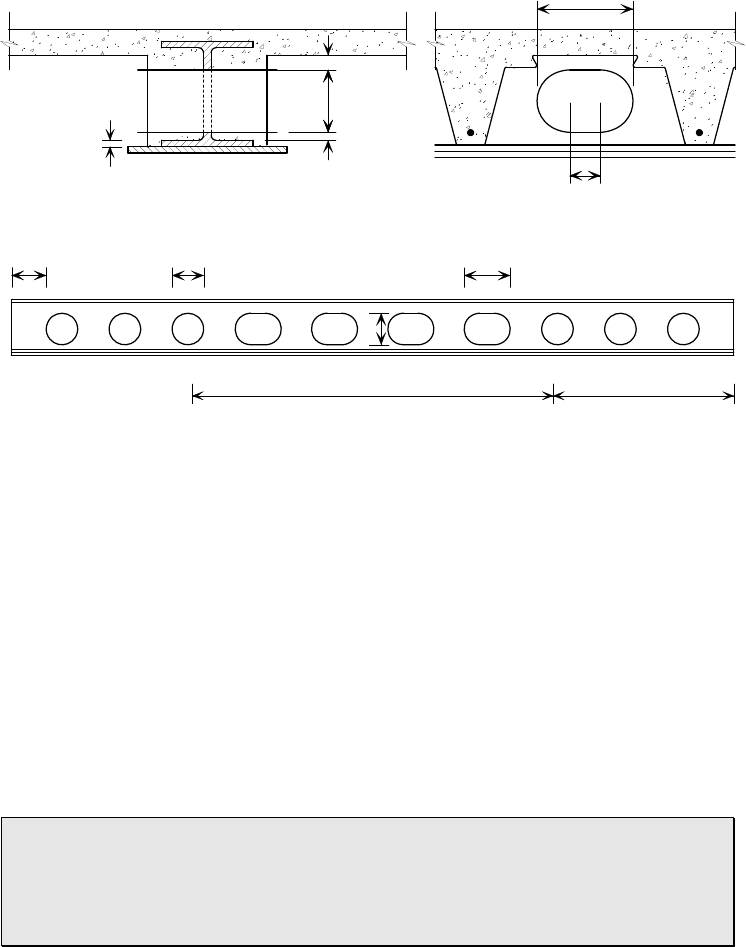
P:\PUB\PUB800\SIGN_OFF\P300\2nd Edition\P300V02D12.doc 96 Printed 29/04/09
Maximum acceptable sizes, and positions, for openings in the webs of SFBs
have also been established by testing. The base of all openings should be
detailed approximately 20 mm above the top of the bottom flange of the UC.
Combinations of elongated openings up to160 mm deep by 240 mm long, and
circular openings up to 160 mm in diameter, may be accommodated in different
parts of a span. Full details of maximum sizes and allowable positions are given
in Figure 7.11.
Web openings affect the shear resistance, the bending resistance, and the second
moment of area of a beam. Empirical formulae for predicting revised properties
for ASB and SFB sections, as a function of the opening geometry, may be
found in Reference 74. Design allowing for openings is also included in design
software available from Corus.
Openings may also affect the fire resistance of a section. ASB sections with
openings invariably require fire protection to the bottom flange for 60 minutes
fire resistance (and above) for economic design. However, for 30 minutes fire
resistance, ASB sections with openings do not require fire protection.
One of the major benefits of the Slimdek system is its ability to
accommodate services. Substantial web openings may be formed in the
beams, but the designer must adhere to strict empirical rules concerning
the position and size of the openings, and their influence on beam
behaviour.
Openings in the slab
Provision for vertical service openings within the floor slab will necessitate
careful design and planning. The following list summarises the options that are
available to the designer (see Figure 7.12):
Openings up to 300 mm 300 mm can be accommodated anywhere in the
slab over a crest section of the deck, normally without needing additional
reinforcement.
o
o
o
o
Side view
End view
55 - t
f
f
f
D 160mm
in rest of span
a) Detailing of openings in sections
b) Maximum size of openings in Slimflor sections
20
160 for
t 20
D
Circular openings permittedOval openings permitted in middle half of beam span
t
240
80
D
D 1.5D
Figure 7.11 Detailing rules for web openings in SFB a) maximum size of
openings b) location of openings

P:\PUB\PUB800\SIGN_OFF\P300\2nd Edition\P300V02D12.doc 97 Printed 29/04/09
Openings up to 400 mm wide 1000 mm long may be taken through the
crest of the
ComFlor 225 decking. Additional reinforcement, which should
be designed in accordance with BS EN 1992-1-1
[24]
(or BS 8110
[30]
), may be
required around the opening.
Openings up to 1000 mm wide 2000 mm long may be accommodated by
removing one rib (maximum) of the decking, fixing suitable edge trims and
providing additional reinforcement to transfer forces from the discontinuous
rib. The slab should be designed as a ribbed slab in accordance with
BS EN 1992-1-1 (or BS 8110), with the decking being used as permanent
formwork. Guidance may be found in the Corus
Slimdek Manual
[74]
.
Larger openings will generally require trimming by secondary beams.
Openings required in the slab should be made using shuttering or void-
formers, and the decking cut after curing – unless properly supported
during construction or permanently trimmed.
If an opening greater than 300 mm
300 mm lies within the effective width of
slab adjacent to a beam (L/8), the beam should be designed as non-composite.
A close grouping of penetrations transverse to the span direction of the decking
should be treated as a single large opening.
ASB beam
ASB beam
Minimum A142 mesh
throughout
400
Opening
B
B
AA
beam span/16*500
1000
beam span/16*
beam span/16*
* for composite beam design
Edge trim
fixed as 'box'
Curtailed bar
Transverse
bar
Edge trim
fixed as 'box'
End diaphragm Transverse bar
Temporary prop Temporary prop
Temporary prop Temporary prop
Section A - A
Section B - B
T12 bar x 1500 long
Centre-line
of ribs
Additional bottom
reinforcement to
adjacent ribs
(by engineer)
Opening
1000
300
2000
Additional top
reinforcement
Figure 7.12 Details of small and medium size openings in the slab.
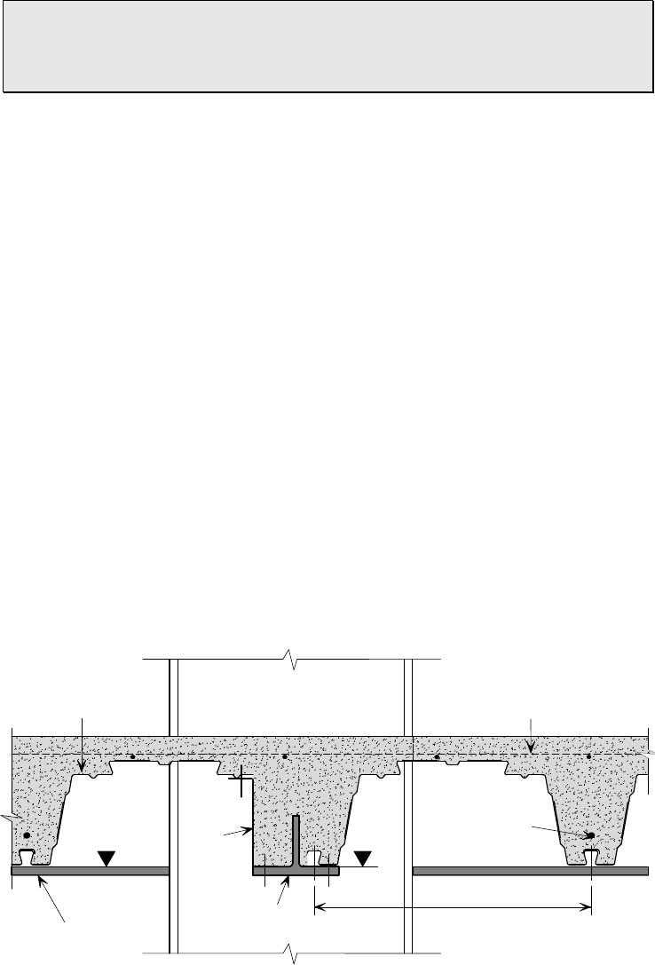
P:\PUB\PUB800\SIGN_OFF\P300\2nd Edition\P300V02D12.doc 98 Printed 29/04/09
A range of possibilities exist for passing services vertically through the
slab. The designer should recognise that some of these have implications
for the permanent works design, e.g. the need to specify additional
reinforcement and/or trimming steel.
Service attachments
The
ComFlor 225 decking facilitates the fixing of services and suspended
ceilings. Hangers can be used to support services running either parallel or
perpendicular to the decking span.
The new adjustable Lindapter
Slimdek 2 fixing clip
[80]
can achieve a safe
working load of 1.0 kN per fixing. These allow service pipes to be suspended
directly from the decking between the ribs. Alternatively, self-drilling self-
tapping screws may be used to attach hangers to the decking after the concrete
has been placed but care is required when attaching fixings to ensure that the
bond between the decking and concrete is not impaired.
Service integration is covered in detail in
Service integration in the Slimdek
system
[35]
.
7.2.4 Construction details
Ends of decking
Often, it is necessary to use part width sheets of decking, particularly at tie
beams or at slab edges. When a part width is specified, a Z section is needed to
provide local support to the decking, as shown in Figure 7.13. This should be
identified on the decking layout drawing (Section 3.2).
Slab edges
There are various alternatives for edge beams in
Slimdek construction. These
are:
Conventional downstand beams
Rectangular Hollow Section Slimflor Beams
Asymmetric Slimflor Beams.
Tee section
cut from UC
Z
section
ASB bottom
flange
Decking cut to
suit setting-out
requirement
Mesh reinforcement
Reinforcement
bar
600
Figure 7.13 Z section to support edge of decking at a tie beam
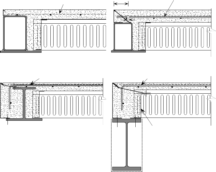
P:\PUB\PUB800\SIGN_OFF\P300\2nd Edition\P300V02D12.doc 99 Printed 29/04/09
Typical details for edge beams are shown in Figure 7.14. There are some
critical dimensions that should be noted:
In detail (a) the concrete cover to the RHSFB should either be zero or
greater than or equal to 40 mm
In detail (b) the concrete cover to the composite RHSFB should be at least
15 mm greater than the as-welded height of the studs (85 mm for 70 mm
long studs)
In detail (c) the minimum distance from the edge trim to the top flange of
the beam should be 125 mm (to allow access for a fixing tool) and
maximum overhang of the trim from the bottom flange should be 150 mm.
Column ties
Tie members are required between columns, perpendicular to the main beams,
in order to provide:
Stability during construction.
Robustness and stability of the completed construction.
Transfer of forces (e.g. due to wind action).
The tie members may be of various forms, as illustrated in Figure 7.15, the
most common being:
T sections in which the flange of the T provides support to the decking.
RHS sections with a bottom plate to support the decking.
Mesh
6
U bar
10 mm dia. (min)
a) Non composite RHSFB b) Composite RHSFB
L bar
End diaphragm
L bar
c) Composite ASB d) Downstand beam
Figure 7.14 Typical edge beams.
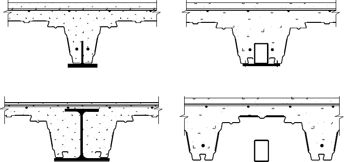
P:\PUB\PUB800\SIGN_OFF\P300\2nd Edition\P300V02D12.doc 100 Printed 29/04/09
Lighter ASB sections, especially adjacent to openings.
Fire protected RHS sections not encased in the slab.
Advice on tying requirements for robustness may be found in Reference 81.
Connecting decking to the bottom flange of I beams often presents practical
difficulties on site because the fixing tool cannot be fitted in the space between
the web of the decking and the beam flange. Therefore, the use of an ASB
beam or a RHS with welded bottom plate is preferred. Where the T or RHS
members are encased in the slab, a shelf plate should be welded to the column
web to provide local support to the decking.
7.3 Construction practice
Good practice for receiving, storing, and placing bundles of deep decking on the
steel frame is essentially the same as for shallow decking. However, because of
the use of end diaphragms, there is a significant difference in the procedure
adopted for placing and fixing the decking.
Slimdek designers and installers
should refer to the
BCSA Guide to the installation of deep decking
[82]
. This
publication carries detailed description of safe installation procedures.
Planning
Deep decking is similar to shallow decking in that good planning on the part of
the designers is essential for the success of the project. In particular, with deep
decking it is quite common for designers to show details that are impossible to
install; these of course should be avoided and the Corus standard details
(available for download from the Corus website) always used. Some typical
details to avoid are shown in Figure 7.16. In the figure, details (a) and (b) are
possible with an appropriate steel angle or timber support (see Figure 4.6).
Detail (c) is not possible when the clearance between the top flange of the ASB
and the edge trim is less than 110 mm because of inadequate access to fix the
trim on the bottom flange. This can be remedied by detailing the trim and slab
to cantilever slightly. Welding a flange plate to the section on which to support
the decking is one option to avoid the problems caused by detail (d). Detail (g)
is not possible because of inadequate access to fix the trim on the section bottom
flange. A solution is to extend the flange plate (by at least 110 mm) to enable
a) Tee section b) Encased RHS with shelf plate
c) ASB d) Exposed RHS
Figure 7.15 Alternative forms of tie members
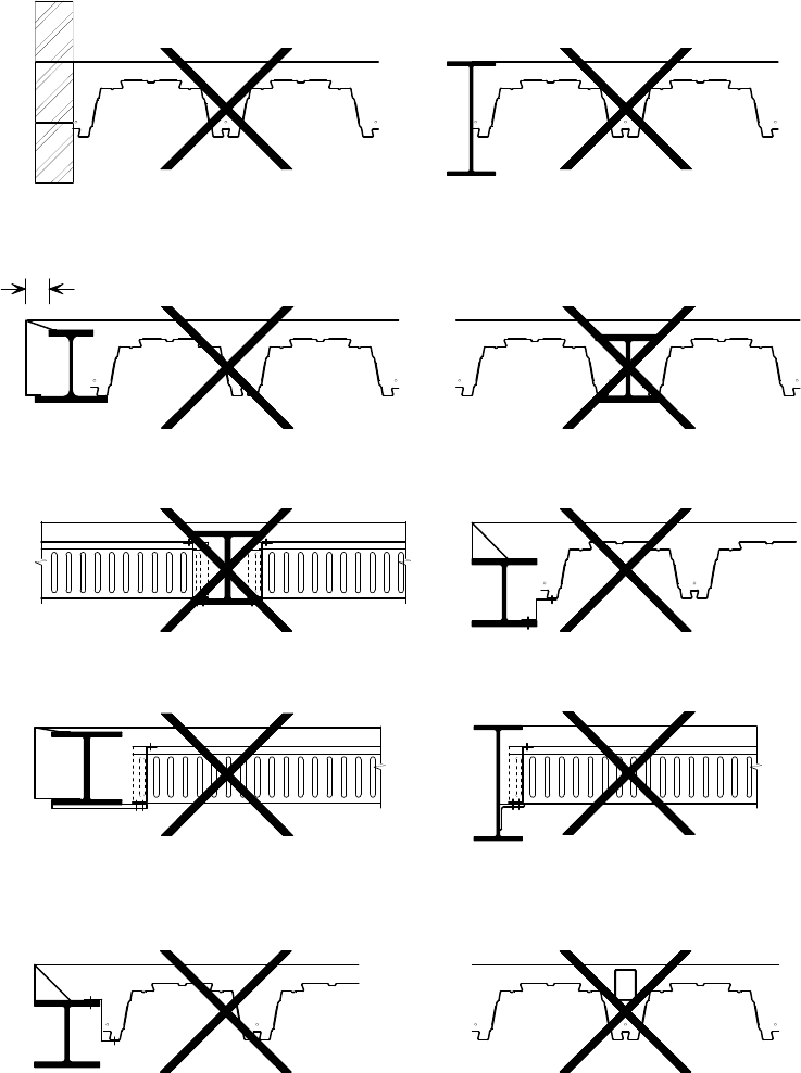
P:\PUB\PUB800\SIGN_OFF\P300\2nd Edition\P300V02D12.doc 101 Printed 29/04/09
the edge trim to be fixed directly to it. The table of the angle in detail (h) needs
to be extended to provide the access needed (see Figure 4.6). The problems
associated with detail (j) can be overcome by adding a flange plate to the RHS
member and setting it at a level where the decking can be supported either side
of it on the flange plate.
Other important planning points include:
Ground conditions - it is even more important for deep decking than for
shallow decking that there is a hard, flat, well-compacted surface for the
decking installer to work from within the building footprint. This is because
a) Abutting masonry wall without
support
b) Abutting beam flange without
support
<125 mm
c) Inadequate access to fix edge trim
to beam flange
d) Inadequate access to fix decking to
beam flange
e) Inadequate access to fix diaphragms
and decking to beam flange
f) Inadequate access to fix zed trim to
beam flange
g) Inadequate access to fix lower
flange of edge trim to beam flange
and insufficient access for concrete
h) Inadequate access to fix diaphragms
and decking to shelf angle
i) Decking not laterally restrained
(from spreading at edge)
j
) Decking cannot be stitched on
longitudinal seam because of
presence of tie
Figure 7.16 Unsuitable decking details
P:\PUB\PUB800\SIGN_OFF\P300\2nd Edition\P300V02D12.doc 102 Printed 29/04/09
deep decking uses diaphragms that are generally fitted from a work
platform or MEWP (see below).
The location of the perimeter edge protection needs to be considered at an
early stage, and should be fitted at an offset from the perimeter beams
because the deckers need to work from these to lay the decking sheets.
Decking bundles must be correctly positioned as indicated on the Decking
Contractor’s drawings, to minimise unnecessary manual handling and the
need for operatives to traverse open steelwork.
Placement and fixing of decking
Following erection of the permanent steelwork, the following procedure should
be adopted for installing and fixing a panel of deep decking on
Slimflor beams.
The end diaphragms are fixed first, as shown in Figure 7.17. These are supplied
in lengths of 1800 mm, which equates to three sections of
ComFlor 225
decking. They are fixed to the edges of the lower flanges of the beams on both
sides (except for edge beams), using at least two shot-fired pins for each length.
The diaphragms should be installed from a work platform wherever reasonably
practicable. Access systems such as MEWPs or Mobile Scaffold Work
Platforms can be used if the ground conditions are adequately levelled and
compacted, including the areas around the column bases.
Decking installation should only commence once the end diaphragms and safety
net (or alternative) fall arrest system are in place. The decking sheets are then
manually lowered individually onto the beams. The nominal end bearing of the
sheets should be 50 mm; the flange widths are such that this can be achieved,
whilst still being able to drop the sheets vertically into position (i.e. without
having to ‘thread’ them between the top and bottom flanges). The bearing length
should never be less than 40 mm. As it is often not possible to straddle the
steelwork once the end diaphragms are in place, decking operatives will usually
stand on the top flange of the beam at either end of the first bundle of decking
to cut open the steel banding and lift the first decking sheet out onto the
steelwork and over the pre-fitted diaphragms. Decking sheets should always be
positioned by a minimum of two operatives. Where sheets are longer than 6 m,
decking should be positioned preferably by two operatives at each end of the
sheet using an extended handlebar lifting device, unless mechanical lifting
systems are available.
Once the sheets for the whole bay are in place, they are secured to the beam
lower flanges using heavy duty shot-fired fixings, and to the top of the
diaphragms using self drilling self tapping screws.
Light steel edge trim is used to form the edges of the slab and to infill where
the 600 mm profile of the decking does not align with the parallel supports.
These sections are custom manufactured for each project, and will be detailed
on the decking layout drawing (Section 3.2).
The decking forms a part of the slab reinforcement, with the remainder being
supplied by a bar in each trough of the decking and a fabric placed near to the
top of the slab. Reinforcement should be fixed in accordance with the
requirements of the Structural Designer (or Delegated Designer). Normally,
spacers are used to position the bars 70 mm from the base of the trough. This
distance will increase to 90 or 120 mm (respectively) when 90 or 120 minutes
fire resistance are required. There may be additional fabric or bar reinforcement
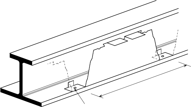
P:\PUB\PUB800\SIGN_OFF\P300\2nd Edition\P300V02D12.doc 103 Printed 29/04/09
to fix adjacent to supports or edge beams, or above beams for crack control
purposes.
Having fixed the reinforcement, the Main Contractor completes the floor slab
by providing any necessary temporary propping and finally concreting the slab.
It is important to ensure that the concrete is properly compacted, and a poker is
needed to ensure proper concrete flow around the beams, beyond the ends of
the decking.
Any shear studs that are required (to make SFBs or RHSFBs composite) may
be welded to these sections during fabrication, because they do not interfere
with the decking. If they are to be welded on site, the precautions and
procedures outlined in Section 6.5 should be considered.
Propping
For long spans the decking should be propped; requirements will have been
identified by the Structural Designer and indicated on the decking layout
drawings. Props should be in place prior to placing the decking, for spans of
7.5 m or more; the props will provide an additional support point for the sheets
when they are being lowered into position on the beam flanges. In all cases
props should be stable without relying on friction with the decking for lateral
stability. The end props in a row should be self supporting and braced to the
internal props.
If it is necessary to prop the beams, the supports should be much more robust
than those used to support decking. Generally, a ‘Tri-shore’ or braced propping
system will be required. These props should be placed at a minimum of 3 m
spacing along the beams. It will often be necessary to prop to two levels below
the supported beam to avoid creep-induced deflections of the supporting beam.
Very short lengths of decking
Where the beam spacing demands a length of decking of 1 m or less, especially
where the beams are not parallel, it is far more efficient to use a shallow
composite floor deck. This eliminates the need for close spaced diaphragms and
complicated cutting of very short pieces of
ComFlor 225.
6
0
0
Shot fired fixing
Figure 7.17 Fixing of end diaphragms at ASB
P:\PUB\PUB800\SIGN_OFF\P300\2nd Edition\P300V02D12.doc 104 Printed 29/04/09
7.4 Further reading
The references given below relate particularly to this Section. (For information
on authors and publishers, see Section 8, References.)
Corus Slimdek Manual
[74]
This is an essential reference as it covers all aspects relating to the design and
construction of the
Slimdek system.
BCSA Guide to the installation of deep decking
[82]
This publication carries a detailed description of safe installation procedures for
deep decking.
P:\PUB\PUB800\SIGN_OFF\P300\2nd Edition\P300V02D12.doc 105 Printed 29/04/09
8 REFERENCES
1 Composite Flooring Systems: Sustainable construction solutions
MCRMA, 2003
2 Better value in steel - Composite flooring - floors using steel decking
(P285)
The Steel Construction Institute, 2001
3 HICKS, S.J, LAWSON, R.M, RACKHAM, J.W, and FORDHAM, P.
Comparative structure cost of modern commercial buildings - Second
Edition (P137)
The Steel Construction Institute, 2003
4 Managing health and safety in construction
Construction (Design and Management) Regulations 2007. (CDM)
Approved Code of Practice (Series code L144).
HSE Books, 2007
5 BROWN, D.G.
The Construction (Design and Management) Regulations 1994:
Advice for designers in steel (P162)
The Steel Construction Institute, 1997
6 Code of Practice for metal decking and stud welding (Ref 37/04).
BCSA, 2004
7 AD 175: Diaphragm action of steel decking during construction
Advisory Desk, in New Steel Construction, Vol 3 (4), Aug 1995
8 BS EN 10326: 2004 Continuously hot-dip coated strip and sheet of
structural steels. Technical delivery conditions
BSI
9 AD 247: Use of composite construction in an aggressive environment.
Advisory Desk, in New Steel Construction, Vol 9(2), March 2001
10 BS EN 1991-1-6:2005 Eurocode 1. Actions on structures. General
actions. Actions during execution
BSI
11 BS 5950: Structural use of Steelwork in Building:
BS 5950-1:2000 Structural use of steelwork in building. Code of
practice for design. Rolled and welded sections
BS 5950-3.1:1990 Design in composite construction. Code of practice
for design of simple and continuous composite beams
BS 5950-4:1994 Structural use of steelwork in building. Code of
practice for design of composite slabs with profiled steel sheeting
BS 5950-6:1995 Structural use of steelwork in building. Code of
practice for design of light gauge profiled steel sheeting
BS 5950-8: 2003 Code of practice for fire resistant design
BSI
P:\PUB\PUB800\SIGN_OFF\P300\2nd Edition\P300V02D12.doc 106 Printed 29/04/09
12 BS EN 1991-1-1:2002 Eurocode 1. Actions on structures. General
actions. Densities, self-weight, imposed loads for buildings
BSI
13 BS EN 1993-1-3:2006 Eurocode 3. Design of steel structures. General
rules. Supplementary rules for cold-formed members and sheeting
BSI
14 BS EN 1994-1-1:2004 Eurocode 4. Design of composite steel and
concrete structures. General rules and rules for buildings
BSI
15 BS 882:1992 Specification for aggregates from natural sources for
concrete
BSI
16 BS EN 206-1:2000 Concrete. Specification, performance, production and
conformity
BSI
17 BS 8500-1:2006 Concrete. Complementary British Standard to BS EN
206-1. Method of specifying and guidance for the specifier
BSI.
18 BS 8204-2:2003 Screeds, bases and in situ floorings. Concrete wearing
surfaces. Code of practice
BSI
19 Concrete industrial ground floors - A guide to their design and
construction. Third Edition (TR34)
The Concrete Society, 2003
20 AD 163: Provision for water vapour release in composite slabs
Advisory Desk, in New Steel Construction, Vol 2 (6), December 1994
21 BS 5606: 1990 Guide to accuracy in building
BSI
22 BS 4483:2005 Steel fabric for the reinforcement of concrete.
Specification.
BSI
23 BS 4449:2005 Steel for the reinforcement of concrete. Weldable
reinforcing steel. Bar, coil and decoiled product. Specification.
BSI
24 BS EN 1992-1-1:2004 Eurocode 2: Design of concrete structures.
General rules and rules for buildings
BSI
25 BS 8666:2005 Scheduling, dimensioning, bending and cutting of steel
reinforcement for concrete. Specification.
BSI
26 BOND, A.J., HARRISON T., BROOKER O., MOSS R.,
NARAYANAN, R. and WEBSTER, R.
How to design concrete structures using Eurocode 2 (CCIP-006)
The Concrete Centre, 2007
P:\PUB\PUB800\SIGN_OFF\P300\2nd Edition\P300V02D12.doc 107 Printed 29/04/09
27 BS EN 14889 Fibres for concrete:.
BS EN 14889-1:2006 Steel fibres. Definitions, specifications and
conformity.
BS EN 14889-2:2006 Polymer fibres. Definitions, specifications and
conformity
BSI
28 Cracking in composite/corrugated metal decking floor slabs (CAS13)
The Concrete Society, 2003
29 JOHNSON, R.P. and ANDERSON, D.
Designer’s Guide to BS EN 1994-1-1
Eurocode 4: Design of composite steel and concrete structures
Part 1.1 General rules an rules for buildings
Thomas Telford, 2004
30 BS 8110-1:1997 Structural use of concrete. Code of practice for design
and construction
BSI
31 BS EN 1994-1-2:2005 Eurocode 4. Design of composite steel and
concrete structures. General rules. Structural fire design
BSI
32 NA to BS EN 1994-1-2:2005 UK National Annex to Eurocode 4. Design
of composite steel and concrete structures. General rules. Structural fire.
design
BSI
33 SIMMS, W.I., KIRBY, B.R., BAILEY, C.G. and BURGESS, I.W.
Steel building design: Fire resistance design (P375)
The Steel Construction Institute, 2008.
34 Backpropping Flat Slabs by Eur Ing Pallett Bsc Eng FICE FCS –
PFP/136 (23/08/04): Pallett Temporary
Works Ltd
35 McKENNA, P.D. and LAWSON, R.M.
Interfaces: Design of steel framed buildings for service integration (P166)
The Steel Construction Institute, 1997
36 OGDEN, R.G.
Interfaces: Curtain wall connections to steel frames (P101)
The Steel Construction Institute, 1992
37 WAY, A.G. and COUCHMAN, G.H.
Acoustic Detailing for Steel Construction (P372)
The Steel Construction Institute, 2008
38 DEPARTMENT OF LOCAL GOVERNMENT AND COMMUNITIES
The Building Regulations 2000
Approved Document E: Resistance to the passage of sound
The Stationery Office, 2003
39 Part E Robust Details Handbook 3
nd
edition
Robust Details Ltd, 2007
40 Guidance for the design of steel-fibre-reinforced concrete (TR63)
The Concrete Society, 2007
41 Guidance on the use of macro-synthetic fibre reinforced concrete (TR65)
The Concrete Society, 2007
P:\PUB\PUB800\SIGN_OFF\P300\2nd Edition\P300V02D12.doc 108 Printed 29/04/09
42 MULLETT, D.L.
Composite floor systems
Blackwell Science and The Steel Construction Institute, 1998
43 LAWSON, R.M.
Design of composite slabs and beams with steel decking (P055)
The Steel Construction Institute, 1989
45 AD 150, Composite floors - wheel loads from forklift trucks
Advisory Desk, in New Steel Construction, Vol 1(7), Dec 1993
46 LAWSON, R.M.
Commentary on BS 5950: Part 3: Section 3.1 ‘Composite Beams’ (P078)
The Steel Construction Institute, 1990
47 BS EN 1993-1-1:2005 Eurocode 3. Design of steel structures. General
rules and rules for buildings
BSI
48 NETHERCOT, D.A. and LAWSON, R.M.
Lateral stability of steel beams and columns (P093)
The Steel Construction Institute, 1992
49 BS EN 1990:2002 Eurocode. Basis of structural design
BSI
50 LAWSON, R.M. and HICKS, S.J.
Design of beams with large web openings for services (P355)
The Steel Construction Institute, to be published 2009
51 SMITH, A.L., HICKS, S.J. and DEVINE, P.J.
Design of floors for vibration: A new approach (P354)
The Steel Construction Institute, 2007
52 NEWMAN, G.M., ROBINSON, J.T. and BAILEY, C.G.
A new approach to multi-storey steel-framed buildings.Second Edition
(P288)
The Steel Construction Institute, 2006.
53 NEWMAN L C, DOWLING, J.J. and SIMMS, W I.
Structural fire design: Offsite applied thin film intumescent
coatings.Second Edition (P160)
The Steel Construction Institute, 2005.
54 RT1187: Guidance on the fire protection of beams with web openings The
Steel Construction Institute, 2005.
55 BS 476-21:1987 Fire tests on building materials and structures. Methods
for determination of the fire resistance of loadbearing elements of
construction
BSI
56 NEWMAN, G.M. and LAWSON, R.M.
Fire resistance of composite beams (P109)
The Steel Construction Institute, 1991
57 HICKS, S.J.
Strength and ductility of headed stud connectors welded in modern
profiled steel sheeting,
The Structural Engineer, Vol. 85(10), May 2007, pp 32-38
P:\PUB\PUB800\SIGN_OFF\P300\2nd Edition\P300V02D12.doc 109 Printed 29/04/09
58 AD 192, Transverse reinforcement in composite T-beams
Advisory Desk, in New Steel Construction, Vol 5 (1), Feb/Mar 1997
59 AD 266, Shear connection in composite beams
Advisory Desk, in New Steel Construction, Vol 11 (4), July 2003
60 Fire protection for structural steel in buildings (4th edition)
ASFP/ FTSG/ SCI, 2007.
61 CIMSTEEL
Design for Construction
The Steel Construction Institute, 1997
62 AD 174, Shear connection along composite edge beams
Advisory Desk, in New Steel Construction, Vol 3 (3), June 1995
63 BS EN 12350-1:2000 Testing fresh concrete. Sampling
BSI
64 Crazing: power trowelled concrete for floor slabs (CAS8)
The Concrete Society, 2003
65 BS 8203: 1996 Code of Practice for installation of resilient floor
coverings.
66 Composite concrete slabs on steel decking - GCG5 (CS161)
The concrete Society, 2008
67 The Manual and Advisory Safety Code of Practice for concrete pumping
BCPA, 1990
68 Guide to steel erection in windy conditions (ref 39/05)
BCSA, 2004
69 Guide to the erection of multi-storey buildings (ref 42/06)
BCSA, 2006
70 Good construction practice for composite slabs
Publication No. 73, European Convention for Constructional Steelwork
Technical Committee 7 - Working Group 7.6
ECCS, 1993
71 National Structural Steelwork Specification for Building Construction (5
th
edition)
BCSA and SCI, 2007
72 Guidance Note GS28: Safe Erection of Structures
HMSO, 1984 (currently withdrawn, awaiting update)
73 Health and safety in construction (3
rd
Edition))
HSG 150, HSE Books, 2006
74 CORUS
Slimdek Manual (http://www.corusconstruction.com)
75 MULLETT, D.L.
Design of RHS
Slimflor® edge beams (P169)
The Steel Construction Institute, 1997
76 LAWSON, R.M., MULLETT, D.L., and RACKHAM, J.W.
Design of Asymmetric
Slimflor® Beams using deep composite decking
(P175)
The Steel Construction Institute, 1997
P:\PUB\PUB800\SIGN_OFF\P300\2nd Edition\P300V02D12.doc 110 Printed 29/04/09
77 MULLETT, D.L., and LAWSON, R.M.
Design of
Slimflor® fabricated beams using deep composite decking
(P248)
The Steel Construction Institute, 1999
78 Slim Floor Integrated Design Software (SIDS)
Corus (http://www.corusconstruction.com)
79 NETHERCOT, D. A., SALTER, P. R. and MALIK, A. S.
Design of members subject to combined bending and torsion (P057)
The Steel Construction Institute, 1989
80 Lindaptor International, Brackenbeck Road, Bradford, West Yorkshire
BDN 2NF
81 WAY, A.J.
Guidance on meeting the robustness requirements in Approved Document
A (P341)
The Steel Construction Institute, 2005
82 BCSA Guide to the Installation of Deep Decking
Publication number 44/07
BCSA, 2007

MCRMA
18 MERE FARM ROAD
PRENTON
WIRRAL
CHESHIRE
CH43 9TT
TEL: 0151 652 3846
FAX: 0151 653 4080
www.mcrma.co.uk
Composite Slabs and Beams Using Steel Decking: Best Practice for Design and Construction
THE METAL CLADDING & ROOFING MANUFACTURERS ASSOCIATION
in partnership with
THE STEEL CONSTRUCTION INSTITUTE
COMPOSITE SLABS AND BEAMS
USING STEEL DECKING:
BEST PRACTICE FOR DESIGN
AND CONSTRUCTION
MCRMA Technical Paper No. 13
SCI Publication P300
CI/SfB
Nh2(23)
MARCH 2009
THE STEEL CONSTRUCTION INSTITUTE
SILWOOD PARK
ASCOT
BERKSHIRE
SL5 7QN
TEL: 01344 636525
FAX: 01344 636570
www.steel-sci.org
cyan plate magenta plate yellow plate black plate
REVISED EDITION
REVISED EDITION
