
Z4 PRODUCT
CATALOG
08-01-17

b
1.
At MiTek
®
, we believe that better processes can empower your business; and we’ve learned
three important things over the years:
• We’ve learned that when people collaborate well, great things can happen – that‘s
about both strong collaboration within your teams, and also strong collaboration
between you and your customers.
• We’ve learned that when we build a relationship focused on growing your ability to
achieve a Higher Standard of performance and success year over year, that relationship
will stand the test of time. We've also learned that when we help you deliver those kinds of
relevant results and value to your customers year over year, you will build a relationship that
will also stand the test of time.
• We’ve learned that our customers are the heroes of our story, and that when we
continually get that right, all our efforts will yield the best results for our relationships.
And that is The New Standard that we are talking about from MiTek
®
these days. It’s a new
standard for what you can expect in optimizing your business performance, and a new standard
for what you can expect from a strong, committed relationship that works well, day after day and
stands the test of time.

1
Index
Product Prole .............................................................................................................................................. 2
Design, Technical, and Customer Support ....................................................................................................... 2
General Notes ............................................................................................................................................... 3
Z4 Tie-Down System Components
Cinch Nut (CNX) ............................................................................................................................................ 4
Bearing Plate Washer (BPW) .......................................................................................................................... 5
Rods (Z-Rod/ATR) ......................................................................................................................................... 6
Coupler (CPL)... ............................................................................................................................................. 7
Anchor Tie (AT) ............................................................................................................................................. 8
Installation Instructions .................................................................................................................................. 9
Z4 Tie-Down System Design Examples
Introduction ................................................................................................................................................ 10
Quick Reference .................................................................................................................................... 11-12
Component Capacities ................................................................................................................................ 13
Wood Compression Post Capacities
Douglas Fir-Larch ....................................................................................................................................... 15
Hem-Fir......... ............................................................................................................................................. 15
Spruce-Pine-Fir .......................................................................................................................................... 16
Southern Pine ............................................................................................................................................. 16
Z4 Tie-Down System Typical Details
Tie-Down System ................................................................................................................................... 17-20
Z4 Concentric Ties
CT & T2 ................................................................................................................................................... 21
Dimensions and Fasteners ........................................................................................................................... 22
Allowable Loads .......................................................................................................................................... 23
Rod Capacities ........................................................................................................................................... 24
Photos ................................................................................................................................................... 25
Hardy Frame
®
Shear Walls ....................................................................................................................... 26
Hardy Frame
®
Special Moment Frame ....................................................................................................... 27
USP
®
Structural Connectors ....................................................................................................................... 28

2
Our mission is to provide the building industry with a simple, efcient,
quality tie-down system with unparalleled customer service.
The MiTek Z4 Tie-Down System is used in multi-story buildings to transfer
overturning and uplift tension forces that result from seismic and wind
loading, to the foundation. The CNX Cinch Nut allows for easy, fast, and
dependable one-step installation. Mitek Z4 Tie-Down Runs are engineered
for maximum material and labor efciency to provide the most economical
system in the industry.
The CNX Cinch Nut is a shrinkage take-up device that is evaluated under
the IBC and the City of Los Angeles building codes and is accepted by
building departments nation-wide. The CNX ability to perpetually “travel”
down the length of the threaded rod allows it to compensate for natural
shrinkage and settlement which occurs in wood buildings, therefore
keeping connections of Tie-Down Runs tight to the oor framing members
for the life of the building.
The MiTek Z4 Tie-Down System with the CNX Cinch Nut is designed to
limit story drifts of multi-story buildings and eliminate additional structural
damage caused by loose connections in the oor framing. The system was
designed following the Northridge Earthquake when the effects of wood shrinkage, building settlement, and other building deformation were shown to
be factors contributing to structural damage.
This design was the rst in the industry to provide a continuous load path for uplift that perpetually adjusts its connections to the oor system as the
building deforms. The MiTek Z4 Tie-Down System is engineered, tested, and code evaluated to perform. It continues to be an innovative leader in the
multi-story building industry.
Design, Technical, and Customer Support
We offer comprehensive technical support, design of tie-down systems to meet engineered loads, and deliver products packaged and
labeled for easy identication in the eld.
1. For the Design Professional, we provide pre-engineered standard runs as well as individual component capacities to design custom runs. We also
offer turn-key, sealed designs when engineered loads are provided to us.
2. Building Ofcials condently approve our systems because they assemble with code evaluated components that have an ESR listing.
3. For the installer, our products arrive on time and are packaged systematically for easy identication of parts and sequence of assembly. We offer
typical installation details, immediate telephone support and personal training is available from a sales or customer service representative.
Product Profile

3
General Notes
1. MiTek reserves the right to modify Z4 Tie-Down System specications and designs without notication or liability for such changes.
2. All materials used in the design of MiTek Z4 Tie-Down Systems are based on the specications provided in this catalog. Contact MiTek Z4
Technical Support for related information.
3. Project specications including load demand, rod elongation limits and oor level deection limits are required prior to design of MiTek Z4
Tie-Down System.
4. Values for the products of MiTek Z4 Tie-Down System are provided in Allowable Stress Design (ASD). For LRFD design values, consult with
MiTek Z4 Technical Support.
5. The MiTek Z4 Tie-Down System is designed to provide the overturning or uplift load capacity that meets the project demand. It is the
responsibility of the EOR or qualied building designer to integrate the Tie-Down system designs into the structural system.
6. For wind load uplift Tie-Down systems, please refer to ICC-ES AC391 for recommended project design requirements and specications.
7. For seismic and wind shear wall Tie-Down Systems, please refer to ICC-ES AC316 for recommended project design requirements and
specications.
8. Per Section 2304.3.3, 2015 IBC for wood walls and bearing partitions supporting more than two oors and a roof, the shrinkage effect of
wood framing shall be analyzed as not to have any adverse effects on the building performance. MiTek Z4 shrinkage take-up devices (CNXs)
are designed exclusively to compensate for potential effects of building settlements and deformations on the Tie-Down System.
9. The design of concrete anchorage for MiTek Z4 Tie-Down Systems and all foundation designs are the responsibility of the EOR or qualied
building designer.
10. The integration of the MiTek Z4 Tie-Down System into the building structural system shall be the responsibility of the EOR or qualied building
designer. Consult with MiTek Z4 Technical Support for any assistance when needed.
11. Compression members and multi-ply compression member connections within the shear wall Tie-Down System shall be specied by the EOR
or qualied building designer. Consult with MiTek Z4 Technical Support for any assistance when needed.
12. All nal MiTek Z4 Tie-Down System design structural documents shall be reviewed and approved by the EOR or qualied building designer.
13. Deviation from the MiTek Z4 Tie-Down System construction documents is not permitted. Any eld alterations in installation requires consultation
with MiTek Technical Service and EOR for review and approval.
14. The MiTek Z4 Tie-Down System does not require special inspection unless it is required by the local building jurisdiction.
15. Proper corrosion protection for all delivered Z4 products at the project job site shall be provided by others.
4
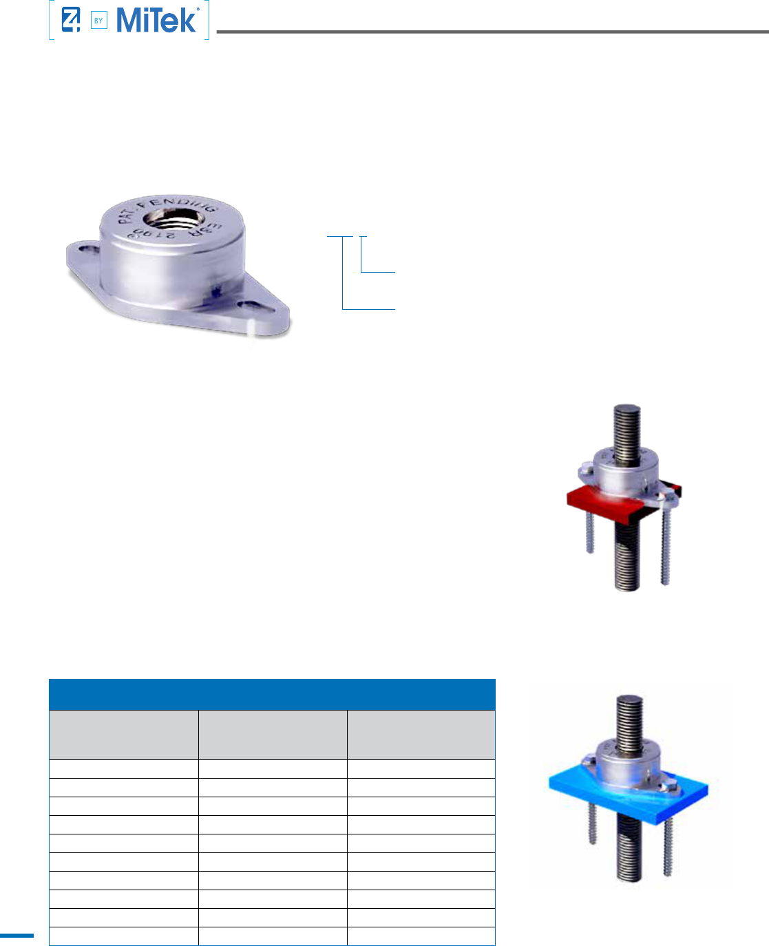
The MiTek Z4 CNX-Series Cinch Nut is a shrinkage compensating take-up device that keeps connections of Tie-Down runs tight to the oor framing
members when shrinkage and compression of wood bers occur. The Cinch Nut uses an internal self-ratcheting action that permits movement, or
“travel” perpetually in one direction along the length of a threaded rod. When connected to the oor framing, the Cinch Nut travels down the Z-Rod
with the building as it shrinks and compresses. The CNX Series Cinch Nut is available in 1/8 inch increments for installation with threaded rods that
are 3/8 inch through 1-1/2 inch diameter.
CNX-5
Connecting Rod Diameter
(1/8" Increments)
CNX-Series Cinch Nut
Cinch Nut (CNX)
CINCH NUT (CNX)
Model Number
1
Connecting
Rod Diameter (in.)
Allowable
Load Capacity (lbs.)
2
CNX-3 3/8 5,175
CNX-4 1/2 9,205
CNX-5 5/8 14,065
CNX-6 3/4 16,940
CNX-7 7/8 28,185
CNX-8 1 29,285
CNX-9 1 1/8 42,335
CNX-10 1 1/4 54,190
CNX-11 1 3/8 51,095
CNX-12 1 1/2 82,835
Code Reports
1. ESR-2190
2. LA City RR 25623
3. Florida Building Code - FL 17546
1. All CNX models t within a nominal 4” wall depth.
2. Cinch Nut allowable loads have been evaluated and approved in ICC-ES ESR-2190.
BPW-5, BPW-6
Installation
BPW-7 and Larger
Installation
1. Features perpetual ratcheting along the length of a threaded rod that is not limited like
the energy stored in a spring loaded device.
2. Simple, one-time installation that does not require pin or screw activation after the
building is loaded.
3. CNX models are matched to the rod diameter specied for optimal tolerances.
CNX-Series Advantages

5
MiTek Z4 Bearing Plate Washers (BPW) are the interface between the Tie-Down System and the level of the building being anchored to the
foundation. As the oor system is pulled upward by shear wall overturning forces, pressure is applied to the BPW/CNX assembly and transferred
into the Z-Rod or all thread rod (ATR). The required bearing area is based on the design uplift to minimize crushing of the wood and the BPW
thickness must be sufcient such that BPW exural yielding does not limit the capacity of the system. The wood species is also a factor when
sizing. The pounds per square inch (psi) of compression cannot exceed the allowable compression perpendicular to the grain of the wood species it
is bearing on.
Materials
ASTM A36
Finish
Powder coated nish in
various colors for
easy identication
Bearing Plate Washer (BPW)
BEARING PLATE WASHER (BPW)
1
Model
Number
Dimensions (in.)
Min. Nominal
Wall
Thickness
(in.)
Color
Allowable Bearing Capacity (lbs.)
3, 4
Width & Length
(in.)
Thickness
2
(in.)
Hole Dia.
(in.)
DF-L (625 psi.) SP (565 psi.) HF (405 psi.) SPF (425psi.)
BPW-5 3 x 3 1/4 1 5/16˝
4˝
Brown 4,780
5,6
4,320
5
3,100 3,250
BPW-6 3 1/4 x 3 3/8 3/8
1 9/16˝
Red 5,660 5,110 3,670 3,850
BPW-7 3 1/4 x 4 3/8 1/2 Yellow 7,690 6,950 4,980 5,230
BPW-9 3 1/4 x 5 5/8 Green 8,960 8,100 5,800 6,090
BPW-11 3 1/4 x 5 7/8 3/4 Blue 10,740 9,700 6,960 7,300
BPW-15 3 1/4 x 7 7/8 7/8 Black 14,800 13,380 9,590 10,060
BPW-20 3 1/4 x 10 1/4 1 1/4 White 19,620 17,740 12,710 13,340
BPW-25 3 1/2 x 11 3/4 1 1/2 Orange 24,500 22,150 15,880 16,660
BPW-30 3 1/2 x 14 1 3/4 Lt. Gray 29,430 26,600 19,070 20,010
BPW-17-6 5 x 5 7/8 5/8
1 9/16˝ 6˝
Lt. Blue 17,160 15,510 11,120 11,670
BPW-27-6 5 x 9 1 Tan 26,930 24,340 17,450 18,310
BPW-36-6 5 x 12 1 1/2 Gray 36,300 32,820 23,520 24,690
BPW-43-6 5 x 14 1 3/4 Purple 42,550 38,470 27,570 28,940
BPW-46-6 5 x 15 1 7/8 Pink 45,680 41,290 29,600 31,060
1.Bearing Plate Washers are fabricated from ASTM A36 steel
2.Thicknesses are such that allowable bearing capacity is not limited by plate bending.
3.Bearing Plate Washer capacities are governed by compression of wood with no limitation to plate bending.
4.Allowable Bearing Capacity = (A
plate
– A
hole
)x (f’
c⊥
of Wood Species); where f’
c⊥
= allowable compression perpendicular to grain
5. Allowable Bearing Capacity = 4,160 lbs. when used with CNX-3
6. Allowable Bearing Capacity = 4,445 lbs. when used with CNX-4
BPW-17-6
6" Nominal Wall Thickness
Bearing Capacity based on DF-L
Bearing Plate Washer (BPW)
6
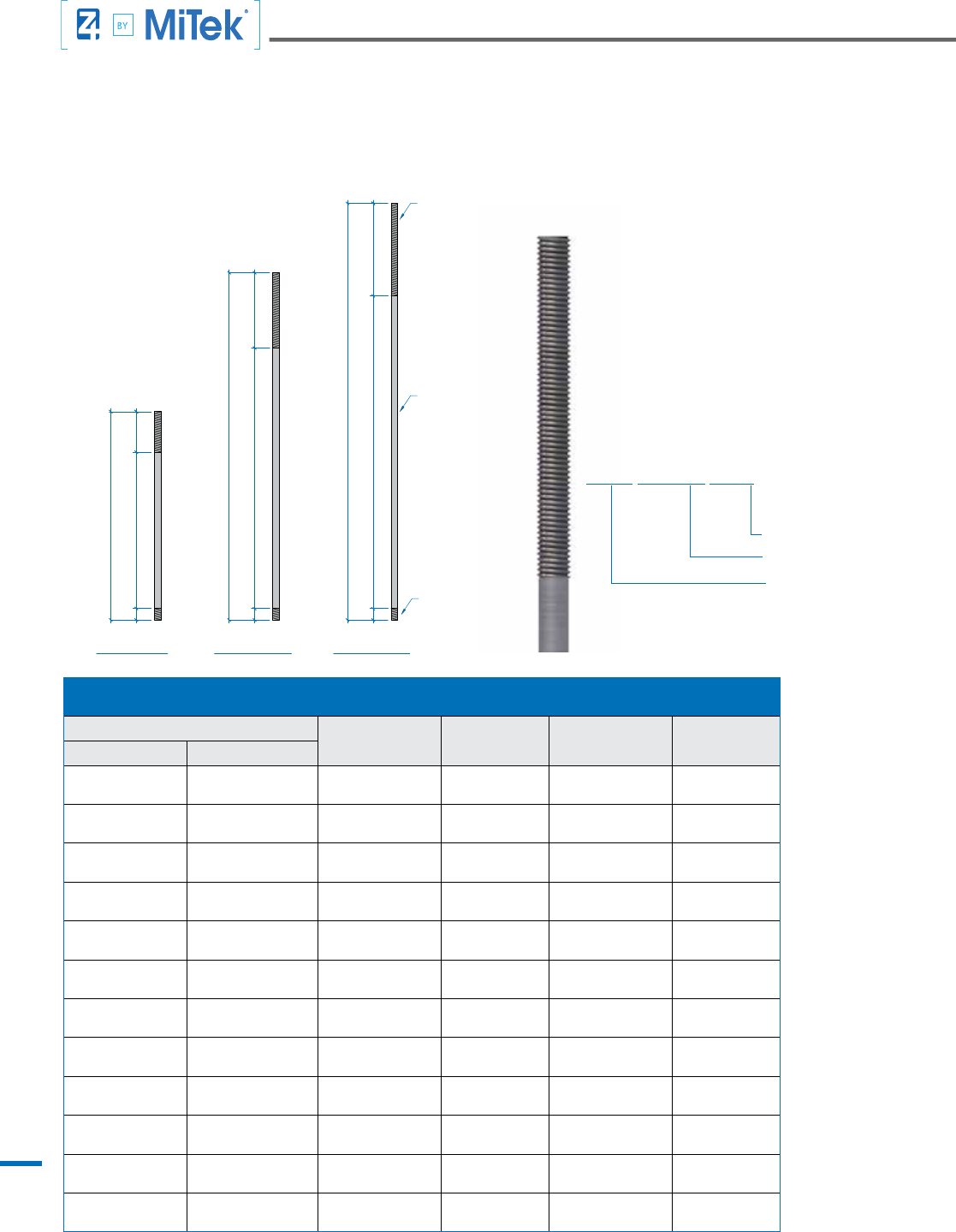
MiTek Z4 Rod transfers load from Cinch Nuts (CNX) or standard hex nuts to the terminating structure (foundation, concrete slab, steel beam, wood
beam). Rod may either be standard all threaded rod (ATR) or Z-Rod. Z-Rod are economical alternatives to ATR with the difference that the Z-Rod
remains unthreaded except at its ends for connection assmebly. In terms of engineering strength and rod elongation, Z-Rod and ATR of similar
nominal diameter and material grade behave identically. Z-Rod lengths are currently available in 6, 10, and 12 feet segments. Both ATR and Z-Rod
are available in either ASTM A36 or ASTM A193-B7 steel grades.
1 1/4" A193-B7 Z-Rod
Z-Rod
ASTM Material Grade
Nominal Diameter (inches)
Rods (Z-Rod / ATR)
6' Z-ROD
14"
54"
4"
4"
4"
90" 26"
32"108"
144"
120"
72"
10' Z-ROD 12' Z-ROD
UNTHREADED
LENGTH (TYPICAL)
THREADED FOR
COUPLER
CONNECTION TO
ROD BELOW
THREADED FOR
CINCH NUT (CNX)
AND COUPLER
CONNECTIONS
1. Effective area, AE is
determined directly by
manufacture's item
specication report and are
not derived from nominal
diameters.
2. Z-Rod are currently not
provided in 3/8" and 1/2"
nominal diameters.
3. For rod elongation
calculations, AE is used
for ATR and both threaded
and unthreaded sections of
Z-Rod.
4. For strength calculations,
0.75AN is used for ATR
and both threaded and
unthreaded sections of
Z-Rod.
5. Ultimate stresses, Fu for
ASTM A36 and ASTM
A193-B7 rod material
are 60 ksi and 125 ksi
respectively.
6. Calculation of rod tensile
capacities (ASD) adheres
to AISC 360-10, Sect: J3.6
Tensile and Shear Strength
of Bolts and Threaded Parts.
Z-Rod (Z-Rod/ATR)
Model Number
Nominal
Diameter,
φ
N
(in.)
Nominal Area,
A
N
(in.)
Effective Area, A
E
(sq. in.)
Tensile
Capacity (lbs)
ATR Z-ROD
3/8" A36 ATR
3/8" A193-B7 ATR
3/8" A36 Z-ROD
3/8" A193-B7 Z-ROD
3/8 0.1104 0.0913
2,485
5,175
1/2" A36 ATR
1/2" A193-B7 ATR
1/2" A36 Z-ROD
1/2" A193-B7 Z-ROD
1/2 0.1963 0.1651
4,420
9,205
5/8" A36 ATR
5/8" A193-B7 ATR
5/8" A36 Z-ROD
5/8" A193-B7 Z-ROD
5/8 0.3068 0.2493
6,905
14,380
3/4" A36 ATR
3/4" A193-B7 ATR
3/4" A36 Z-ROD
3/4" A193-B7 Z-ROD
3/4 0.4418 0.3652
9,940
20,710
7/8" A36 ATR
7/8" A193-B7 ATR
7/8" A36 Z-ROD
7/8" A193-B7 Z-ROD
7/8 0.6013 0.5011
13,530
28,185
1" A36 ATR
1" A193-B7 ATR
1" A36 Z-ROD
1" A193-B7 Z-ROD
1 0.7854 0.6570
17,670
36,815
1 1/8" A36 ATR
1 1/8" A193-B7 ATR
1 1/8" A36 Z-ROD
1 1/8" A193-B7 Z-ROD
1 1/8 0.9940 0.8294
22,365
46,595
1 1/4" A36 ATR
1 1/4" A193-B7 ATR
1 1/4" A36 Z-ROD
1 1/4" A193-B7 Z-ROD
1 1/4 1.2272 1.0423
27,610
57,525
1 3/8" A36 ATR
1 3/8" A193-B7 ATR
1 3/8" A36 Z-ROD
1 3/8" A193-B7 Z-ROD
1 3/8 1.4849 1.2528
33,410
69,605
1 1/2" A36 ATR
1 1/2" A193-B7 ATR
1 1/2" A36 Z-ROD
1 1/2" A193-B7 Z-ROD
1 1/2 1.7671 1.5162
39,760
82,835
1 3/4" A36 ATR
1 3/4" A193-B7 ATR
1 3/4" A36 Z-ROD
1 3/4" A193-B7 Z-ROD
1 3/4 2.4053 2.0523
54,120
112,750
2" A36 ATR
2" A193-B7 ATR
2" A36 Z-ROD
2" A193-B7 Z-ROD
2 3.1416 2.6880
70,685
147,260
7
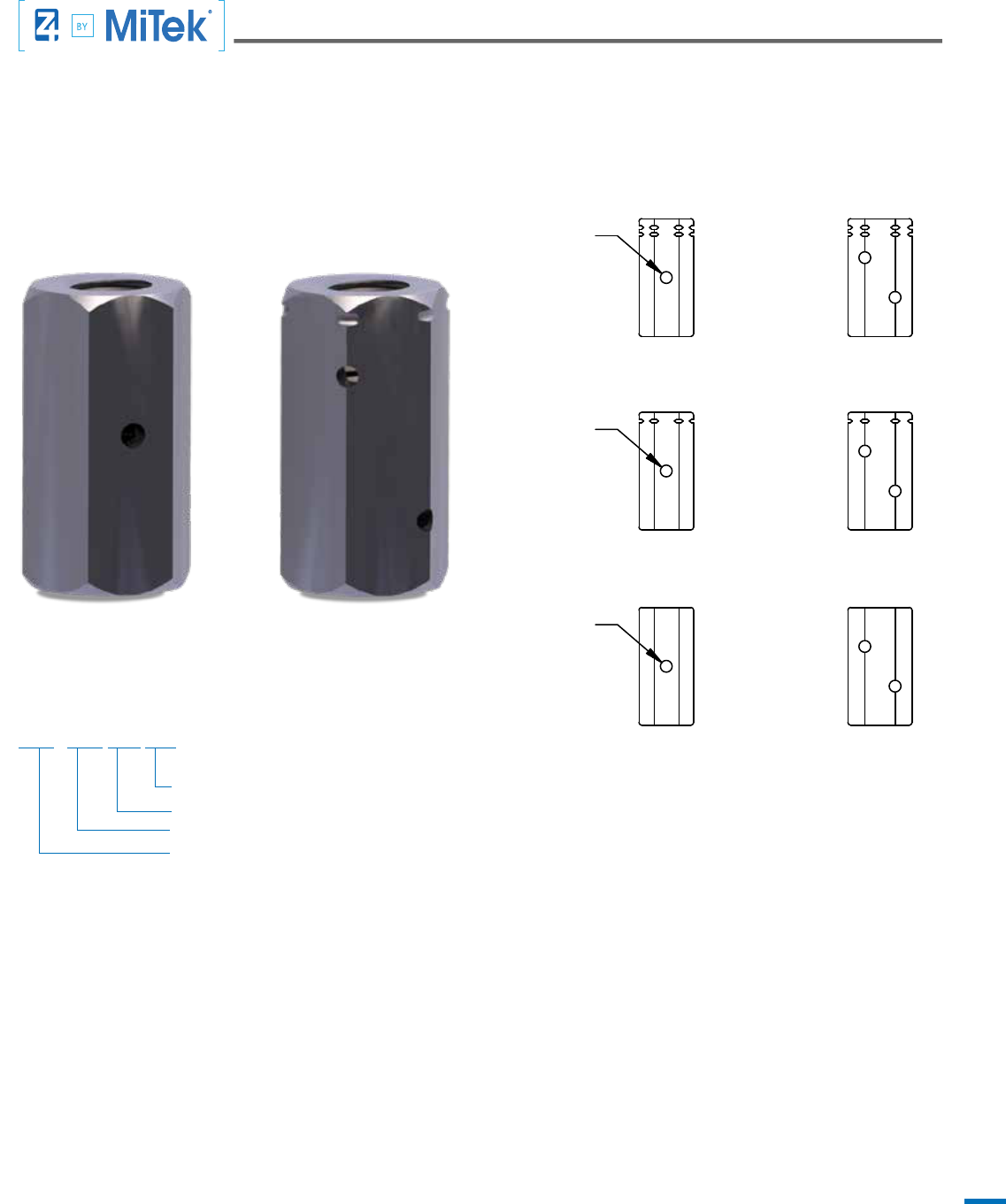
The MiTek Z4 Tie-Down System begins by connecting the rst level Z-Rod to the hold down anchor in the foundation with a Coupler. At upper
levels, Couplers are used to connect Z-Rods or ATRs end to end to create a continuous load path. Transition Couplers connect two Rods that are
different diameters.
Advantages
1. All Couplers have a higher capacity than those of the adjoining rods. When joining rods with different tensile strengths, the Couplers capacity is
higher than the rod with the smaller strength.
2. Reducers are Couplers used to connect rods of with different diameters to combine the most effective and most economical rod
needed at each level.
3. Witness holes are provided to assure easy inspection and inspection.
Finish
Plain Finish
Installation
Thread Coupler onto the two Z-Rods ends
5/8"- 3/4" STD CPL
Coupler Nut with Witness Hole (CPL)
Rod Grade
Larger Connecting Rod Diameter (1/8” increments)
Smaller Connecting Rod Diameter (1/8” increments)
Coupler (CPL)
Coupler Reducer
HS COUPLER
NUT REDUCER
MS COUPLER
NUT REDUCER
STD COUPLER
NUT REDUCER
MS COUPLER NUT
HS COUPLER NUT
STD COUPLER NUT
SIGHT HOLE
SIGHT HOLE
SIGHT HOLE
8
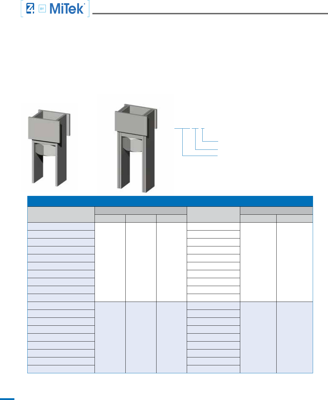
The Anchor Tie is a structural component designed for connecting Z4 Tie-Down-Runs to steel members. Anchor Ties are fabricated from ASTM
Grade A36 steel plates and include a pre-welded nut, making the Tie-Down connection quick and easy. AT devices are available in 9 and 12 inch
heights. Other heights available upon request. The 9 inch version with 1/4 inch plate steel legs is available for connecting 5/8” through 1-1/2”
diameter threaded rod and the 12 inch version with twice the steel thickness at the legs is used for connecting up to 2” diameter rod.
Common applications include connecting to steel plates at concrete decks and steel beams where Tie-Down runs terminate. When installing at
concrete decks, steel plates are designed by the Engineer of Record to resist the uplift loads. After concrete is poured, the AT is welded to the plate
and a threaded rod is connected to the Anchor Tie's pre-welded nut enabling the Tie-Down Run from above to attach. Steel beam installations
are designed by the EOR. The Anchor Tie is welded to the beam prior to oor framing then attachment of the threaded rod and Tie-Down Run
completes the installation.
Anchor Tie (AT)
ANCHOR TIE (AT)
1, 2, 3
Model Number
Dimensions (in.)
Connecting Rod
Diameter (in.)
Allowable Uplift (lbs.)
4
Height Width Depth ASD LRFD
Z4-AT32-3
9 3 1/2 3
3/8
32,400 48,600
Z4-AT32-4 1/2
Z4-AT32-5 5/8
Z4-AT32-6 3/4
Z4-AT32-7 7/8
Z4-AT32-8 1
Z4-AT32-9 1 1/8
Z4-AT32-10 1 1/4
Z4-AT32-11 1 3/8
Z4-AT32-12 1 1/2
Z4-AT65-5
11 3/4 4 1/4 3 1/2
5/8
64,800 97,200
Z4-AT65-6 3/4
Z4-AT65-7 7/8
Z4-AT65-8 1
Z4-AT65-9 1 1/8
Z4-AT65-10 1 1/4
Z4-AT65-11 1 3/8
Z4-AT65-12 1 1/2
Z4-AT65-16 2
1. Weld size to steel member below is 1/4” for AT32 and 5/16” for AT65. Weld length is 3 inches for each leg, one side for AT32 and two
sides for AT65.
2. Design of the steel member below the Anchor Tie is the responsibility of the EOR.
3. All plate material is ASTM A36.
4. Allowable uplift loads are per AISC no increase permitted.
5. 16" height available.
Z4-AT32 Z4-AT65
Z4-AT 32-3
Rod Diameter (1/8" increments)
Allowable ASD Uplift
Anchor Tie
9
Z4-AT 32-3
Rod Diameter (1/8" increments)
Allowable ASD Uplift
Anchor Tie
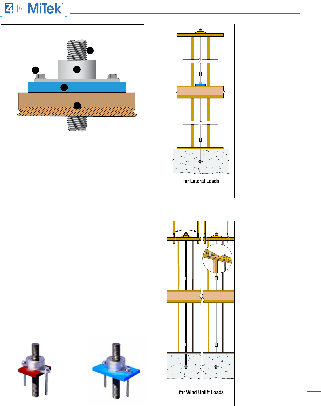
1. Z-ROD
2. CINCH NUT
3. USP WS-SCREWS
4. BEARING PLATE WASHER
5. WOOD FRAMING
1
4
3
5
2
MiTek
®
Z4 Tie-Down Systems utilize CNX-Series Cinch Nuts to compensate
for wood shrinkage and building settlement that cause connections to
loosen over time. The Cinch Nut uses a self-ratcheting action that permits
the cinch nut to move (the rod doesn’t move) or “travel” perpetually in one
direction only down the rod. Available for installation with threaded rods
that are 3/8 inch through 1 1/2 inch diameter in 1/8 inch increments, the
CNX Cinch Nut has been code evaluated and published in ESR-2190.
ROOF RAFTERS
ROOF RAFTERS
MiTek
®
Z4 Tie-Down
System for Lateral
Loads
To resist tension loads due
to overturning moments in
multi-story buildings the
CNX Cinch Nut is installed
over a Bearing Plate
Washer at each level in a
fast and easy application.
At the upper-most level a
Cinch Nut is installed over
a Bearing Plate Washer
above the top plates. At
walls below that bear on
wood oor systems, the
Cinch Nut and Bearing Plate
Washer are installed over
the bottom plate. Tension
loads are gathered at each
level and transferred into
the foundation through a
continuous system of Cinch
Nuts, Bearing Plate Washers,
Z-Rods/ATRs and Couplers
all available from MiTek
®
.
MiTek
®
Z4 Tie-Down
System for Wind
Uplift
For resisting roof uplift loads
resulting from wind the Z4
Cinch Nut is installed over
a Bearing Plate Washer
above the top plates with
roof framing above to create
a tie-down system. Uplift
forces are transferred into
a continuous system of
Z-Rods / ATRs and Couplers
that form a load path to the
foundation.
• Place the specied Bearing Plate Washer onto the bottom plate of a
wood framed wall.
• With the “wings” oriented downward, place Cinch Nut over the Z-Rod
extending from below and push down until it seats rmly on the Bearing
Plate Washer.
• Install 1/4 inch diameter USP WS-Series screws through the wings,
penetrating 1 1/2 inches (minimum) into the wood bottom plate.
• Model numbers BPW5 and BPW6 t in-between the screws fastening
the wings.
• Model numbers BPW7 (3 1/4 x 4 3/8) and larger are provided with two
screw holes. Align the wing and the Bearing Plate Washer screw holes
to allow installation of 1/4 inch diameter WS-Series screws.
Installation
BPW5, BPW6
Installation
BPW7 and larger
Installation

10
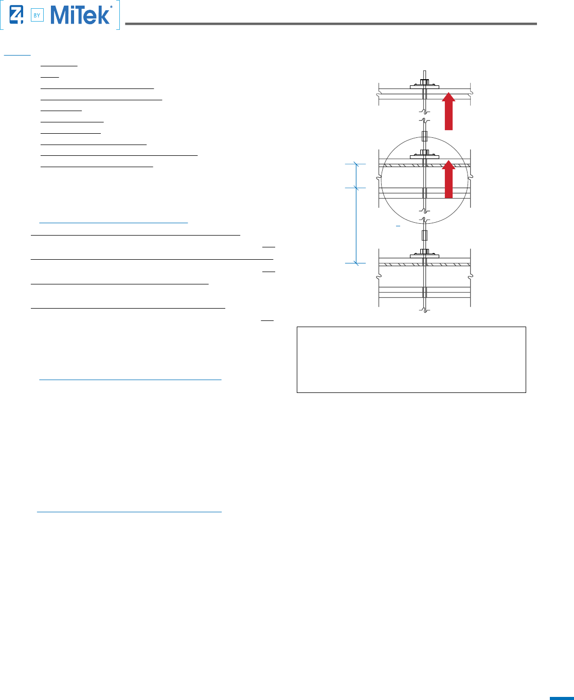
GIVEN
Wood Type: Douglas Fir-Larch
Code: 2012 IBC
Maximum Rod Elongation Per Floor = 0.200"
Maximum Total Deformation Per Floor = 0.200"
Story Height: 9' 0"
Floor System Depth = 1' 0"
Use: Z-Rod Length = 2nd Floor Story Height + Floor System Depth = 10' Z-Rod
Top Floor ASD Design Uplift Load = 6.0 Kips
ASD Design Uplift Load of oor being considered = 9.0 Kips
Cumulative ASD Design Uplift Load = 6.0 Kips + 9.0 Kips = 15.0 Kips
LOOKUP BY ALLOWABLE LOADS
A. Refer to Quick Reference Table 10.2:
Z-Rod Length = 10’ OK!
Maximum Total Deformation Per Floor = 0.200” OK!
B. Refer to Cumulative Load column:
Find value > Cumulative ASD Design Uplift Load
Select 16,050 lbs. > 15,000 lbs. OK!
C. Refer to the Individual Floor Load – DF-L column:
Find value > ASD Design Uplift Load
Select 10,750 lbs. > 9,000 lbs. OK!
D. Follow Row Across to Determine Components:
• ZR-8 STD
• CNX-8
• BPW11 (3-1/4 x 5-7/8)
1' 0" 9,000 lbs.
6,000 lbs.
9' 0"
Introduction
Note:
This example uses 0.200” deection limit and a
10 ft. rod length. Design criteria may vary by building
jurisdiction and job specic requirements.
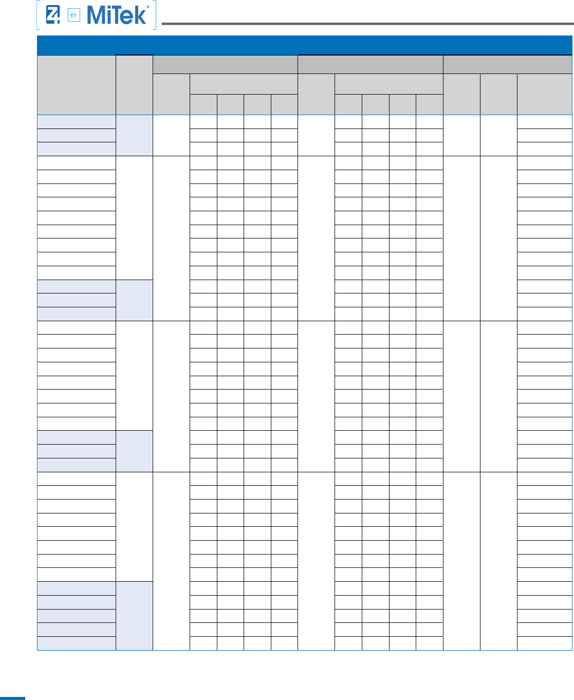
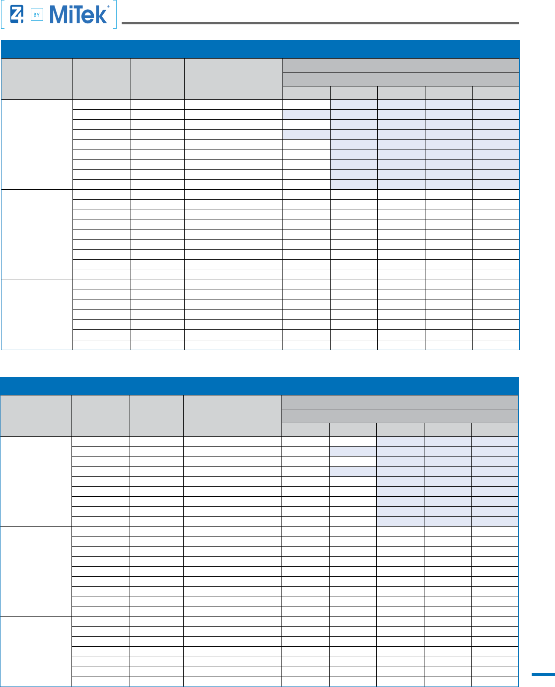
QUICK REFERENCE TABLE 10.2: FOR 10-FT Z-ROD, TOTAL LEVEL DISPLACEMENT ≤ 0.200”
1
Model Number
Minimum
Wall
Framing
Nominal
Depth
Allowable Uplift (lbs.) Vertical Displacement (in.) Components
Cumulative
Load (lbs)
2
Individual Floor Load (lbs)
3
Elongation
of Z-Rod
(in)
4
Total Level Displacement (in)
5
Cinch Nut
(CNX)
6
Z-Rod
(ZR)
Bearing Plate
Washer (BPW)
Dimensions
DF-L HF SPF SP DF-L HF SPF SP
Z-3STD-3 x 3 4” 2,400 2,400 2,400 2,400 2,400 0.099 0.157 0.161 0.159 0.157 CNX-3 ZR-3 STD 3 x 3
Z-4STD-3 x 3
4” 4,270
4,270 3,100 3,250 4,270
0.099
0.190 0.194 0.194 0.196
CNX-4 ZR-4 STD
3 x 3
Z-4STD-3-1/4 x 3-3/8 - 3,670 3,850 - - 0.195 0.196 - 3-1/4 x 3-3/8
Z-8STD-3-1/4 x 4-3/8
4
" 16,050
7,690 4,980 5,230 6,950
0.091
0.192 0.190 0.190 0.191
CNX-8 ZR-8 STD
3-1/4 x 4-3/8
Z-8STD-3-1/4 x 5 8,960 5,800 6,090 8,100 0.193 0.191 0.191 0.192 3-1/4 x 5
Z-8STD-3-1/4 x 5-7/8 10,750 6,960 7,300 9,700 0.195 0.191 0.192 0.194 3-1/4 x 5-7/8
Z-8STD-3-1/4 x 7-7/8 14,800 9,590 10,050 13,400 0.198 0.194 0.194 0.197 3-1/4 x 7-7/8
A D
The MiTek Z4 Tie-Down System is comprised of multiple threaded rods joined with coupling nuts to create a continuous, multi-story Tie-Down Run
that is connected to the structure at each oor with a Z4-CNX Cinch Nut installed over a Z4-Bearing Plate Washer.
Overturning of the building shear walls create an uplift force on the oor below that is resisted by the MiTek Z4 Tie–Down System. In multi-story
structures the uplift tension forces are transferred into the rods at each oor and/or roof level and are cumulative from the top to the bottom of
the Run.
In this catalog we provide three Design Examples that utilize MiTek Z4 components to resist tension loads.
1. Design by referencing the Quick Reference Table (Assumes 10 foot rod lengths and 0.0200 inch deection limit)
2. Design by using the catalog tables for each individual component including the CNX, BPW, Z-R and CNW
3. Design by using USP Specier Design Software.
B C
Design Example By Quick Reference Table

11
Design Example Quick Reference Table
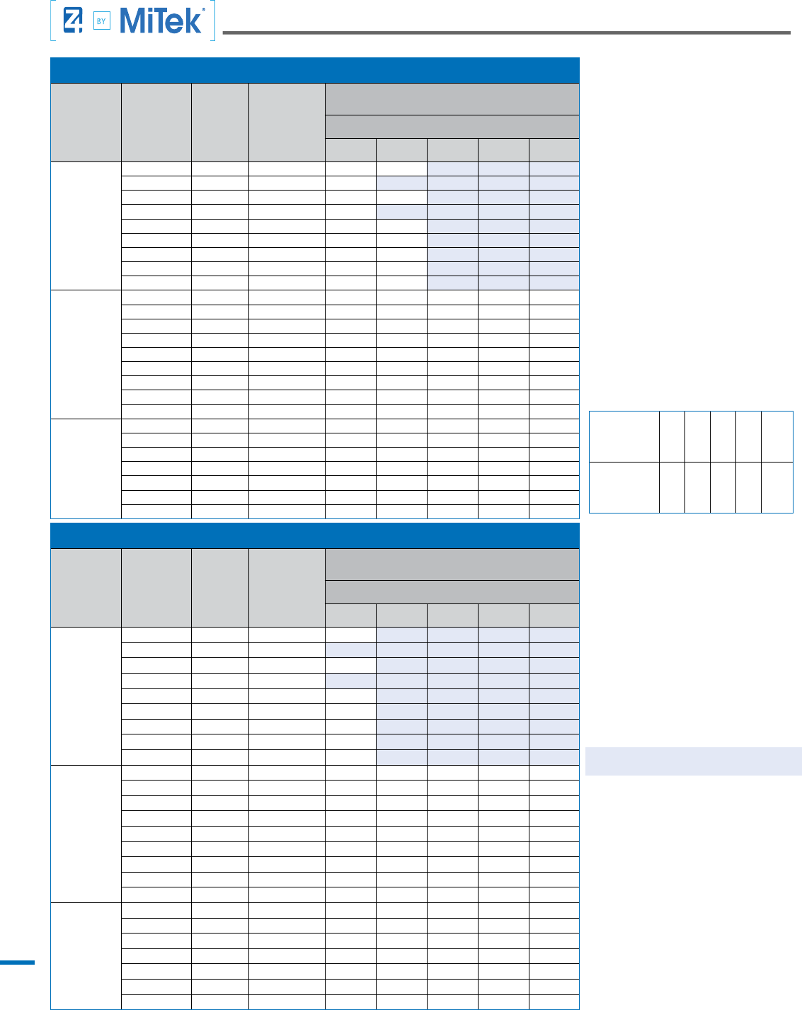
QUICK REFERENCE TABLE 10.2: FOR 10-FT Z-ROD, TOTAL LEVEL DISPLACEMENT ≤ 0.200”
1
Model Number
Minimum
Wall
Framing
Nominal
Depth
Allowable Uplift (lbs.)
Vertical Displacement (in.) Components
Cumula-
tive Load
(lbs)
2
Individual Floor Load (lbs)
3
Elongation
of Z-Rod
(in)
4
Total Level Displacement (in)
5
Cinch Nut
(CNX)
6
Z-Rod
(ZR)
Bearing Plate
Washer (BPW)
Dimensions
DF-L HF SPF SP DF-L HF SPF SP
Z-3STD-3 x 3 4” 2,400 2,400 2,400 2,400 2,400 0.099 0.157 0.161 0.159 0.157 CNX-3 ZR-3 STD 3 x 3
Z-4STD-3 x 3
4” 4,270
4,270 3,100 3,250 4,270
0.099
0.190 0.194 0.194 0.196
CNX-4 ZR-4 STD
3 x 3
Z-4STD-3-1/4 x 3-3/8 - 3,670 3,850 - - 0.195 0.196 - 3-1/4 x 3-3/8
Z-4STD-3-1/4 x 4-3/8 - 4,270 4,270 - - 0.188 0.185 - 3-1/4 x 4-3/8
Z-5STD-3 x 3
4” 6,680
4,780 3,100 3,250 4,320
0.098
0.196 0.194 0.194 0.195
CNX-5 ZR-5 STD
3 x 3
Z-5STD-3-1/4 x 3-3/8 5,660 3,670 3,850 5,110 0.197 0.194 0.195 0.196 3-1/4 x 3-3/8
Z-5STD-3-1/4 x 4-3/8 6,680 4,980 5,230 6,680 0.190 0.196 0.196 0.196 3-1/4 x 4-3/8
Z-5STD-3-1/4 x 5 - 5,800 6,090 - - 0.197 0.198 - 3-1/4 x 5
Z-5STD-3-1/4 x 5-7/8 - 6,680 6,680 - - 0.196 0.193 - 3-1/4 x 5-7/8
Z-6STD-3 x 3
4”
8,840
4,780 3,100 3,250 4,320
0.089
0.194 0.191 0.192 0.193
CNX-6 ZR-6 STD
3 x 3
Z-6STD-3-1/4 x 3-3/8 5,660 3,670 3,850 5,110 0.195 0.192 0.192 0.194 3-1/4 x 3-3/8
Z-6STD-3-1/4 x 4-3/8 7,690 4,980 5,230 6,950 0.197 0.194 0.194 0.196 3-1/4 x 4-3/8
Z-6STD-3-1/4 x 5 8,840 5,800 6,090 8,100 0.198 0.195 0.195 0.198 3-1/4 x 5
Z-6STD-3-1/4 x 5-7/8 - 6,960 7,300 8,840 - 0.196 0.197 0.194 3-1/4 x 5-7/8
Z-6STD-3-1/4 x 7-7/8 - 8,840 8,840 - - 0.194 0.192 - 3-1/4 x 7-7/8
Z-6STD-5 x 5-7/8 6” - 8,840 8,840 - - 0.187 0.185 - 5 x 5-7/8
Z-7STD-3 x 3
4”
13,100
4,780 3,100 3,250 4,320
0.097
0.191 0.190 0.190 0.191
CNX-7 ZR-7 STD
3 x 3
Z-7STD-3-1/4 x 3-3/8 5,660 3,670 3,850 5,110 0.192 0.190 0.191 0.192 3-1/4 x 3-3/8
Z-7STD-3-1/4 x 4-3/8 7,690 4,980 5,230 6,950 0.194 0.192 0.192 0.193 3-1/4 x 4-3/8
Z-7STD-3-1/4 x 5 8,960 5,800 6,090 8,100 0.195 0.192 0.192 0.194 3-1/4 x 5
Z-7STD-3-1/4 x 5-7/8 10,750 6,960 7,300 9,700 0.196 0.193 0.193 0.195 3-1/4 x 5-7/8
Z-7STD-3-1/4 x 7-7/8 13,100 9,590 10,050 13,100 0.191 0.195 0.196 0.197 3-1/4 x 7-7/8
Z-7STD-3-1/4 x 10-1/4 - 12,700 13,100 - - 0.198 0.197 - 3-1/4 x 10-1/4
Z-7STD-3-1/2 x 11-3/4 - 13,100 - - - 0.188 - - 3-1/2 x 11-3/4
Z-7STD-5 x 5-7/8
6”
- 11,100 11,650 13,100 - 0.197 0.197 0.189 5 x 5-7/8
Z-7STD-5 x 9 - 13,100 13,100 - - 0.183 0.182 - 5 x 9
Z-8STD-3 x 3
4”
16,050
4,780 3,100 3,250 4,320
0.091
0.190 0.188 0.188 0.189
CNX-8 ZR-8 STD
3 x 3
Z-8STD-3-1/4 x 3-3/8 5,660 3,670 3,850 5,110 0.190 0.189 0.189 0.190 3-1/4 x 3-3/8
Z-8STD-3-1/4 x 4-3/8 7,690 4,980 5,230 6,950 0.192 0.190 0.190 0.191 3-1/4 x 4-3/8
Z-8STD-3-1/4 x 5 8,960 5,800 6,090 8,100 0.193 0.191 0.191 0.192 3-1/4 x 5
Z-8STD-3-1/4 x 5-7/8 10,750 6,960 7,300 9,700 0.195 0.191 0.192 0.194 3-1/4 x 5-7/8
Z-8STD-3-1/4 x 7-7/8 14,800 9,590 10,050 13,400 0.198 0.194 0.194 0.197 3-1/4 x 7-7/8
Z-8STD-3-1/4 x 10-1/4 16,050 12,700 13,350 16,050 0.188 0.196
0.197 0.193 3-1/4 x 10-1/4
Z-8STD-3-1/2 x 11-3/4 - 15,900 16,050 - - 0.199 0.197 - 3-1/2 x 11-3/4
Z-8STD-3-1/2 x 14 - 16,050 - - - 0.190 - - 3-1/2 x 14
Z-8STD-5 x 5-7/8
6”
16,050 11,100 11,650 15,500 0.195 0.195 0.195 0.199 5 x 5-7/8
Z-8STD-5 x 9 - 16,050 16,050 16,050 - 0.194 0.192 0.184 5 x 9
Z-10STD-3 x 3
4” 20,300
4,780 3,100 3,250 4,320
0.073
0.191 0.190 0.190 0.191
CNX-10 ZR-10 STD
3 x 3
Z-10STD-3-1/4 x 3-3/8 5,660 3,670 3,850 5,110 0.191 0.190 0.190 0.191 3-1/4 x 3-3/8
Z-10STD-3-1/4 x 4-3/8 7,690 4,980 5,230 6,950 0.192 0.191 0.191 0.192 3-1/4 x 4-3/8
Z-10STD-3-1/4 x 5 8,960 5,800 6,090 8,100 0.193 0.191 0.192 0.193 3-1/4 x 5
Z-10STD-3-1/4 x 5-7/8 10,750 6,960 7,300 9,700 0.194 0.192 0.192 0.193 3-1/4 x 5-7/8
Z-10STD-3-1/4 x 7-7/8 14,800 9,590 10,050 13,400 0.196 0.193 0.194 0.195 3-1/4 x 7-7/8
Z-10STD-3-1/4 x 10-1/4 19,600 12,700 13,350 17,750 0.199 0.195 0.195 0.198 3-1/4 x 10-1/4
Z-10STD-3-1/2 x 11-3/4 20,300 15,900 16,650 20,300 0.189 0.197 0.197 0.194 3-1/2 x 11-3/4
Z-10STD-3-1/2 x 14 - 19,050 20,000 - - 0.198 0.199 - 3-1/2 x 14
12
Design Example Quick Reference Table
Notes:
1. The values in this table are Allowable Stress Design (ASD) excluding a 1.33 stress increase and pertain to a maximum 0.20 in. total vertical displacement per oor. Values shown pertain to a 10-foot
Z-Rod length (L) and wood design values in accordance with 2012 NDS per species shown.
2. The allowable cumulative load is the Z-Rod (ZR) capacity to resist tension forces equal to the sum of individual oor loads from each level above the Cinch Nut (CNX) connection being considered.
3. The allowable individual oor load is the Cinch Nut (CNX) and Bearing Plate Washer (BPW) capacity to transfer uplift forces from the single level being considered into the Z-Rod (ZR).
4. Elongation of the Z-Rod is determined by calculating (PL
T
/A
T
E) + (PL
U
/A
U
E) ; where P = cumulative tension force, L
T
= length of rod with threads (.25L), L
U
= length of rod without threads (.75L), A
T
=
effective cross sectional area of rod length with threads, A
U
= net cross sectional area of rod length without threads, and E = Modulus of Elasticity (29x10
6
) .
5. Total vertical displacement is the sum of wood deformation due to compression of the Bearing Plate Washer (BPW), total movement of the Cinch Nut (CNX), and total Z-Rod (ZR) elongation per oor.
6. Cinch Nut model numbers CNX-5 through CNX-12 are evaluated and approved per ICC-ES (ESR-2190); CNX-3 & CNX-4 are ESR pending.
QUICK REFERENCE TABLE 10.2: FOR 10-FT Z-ROD, TOTAL LEVEL DISPLACEMENT ≤ 0.200”
1
Model Number
Minimum
Wall
Framing
Nominal
Depth
Allowable Uplift (lbs.)
Vertical Displacement (in.) Components
Cumula-
tive Load
(lbs)
2
Individual Floor Load (lbs)
3
Elongation
of Z-Rod
(in)
4
Total Level Displacement (in)
5
Cinch Nut
(CNX)
6
Z-Rod
(ZR)
Bearing Plate
Washer (BPW)
Dimensions
DF-L HF SPF SP DF-L HF SPF SP
Z-10STD-5 x 5-7/8
6” 21,300
17,150 11,100 11,650 15,500
0.073
0.197 0.194 0.195 0.197
CNX-10 ZR-10 STD
5 x 5-7/8
Z-10STD-5 x 9 20,300 17,450 18,300 20,300 0.184 0.198 0.198 0.189 5 x 9
Z-12STD-5 x 12 - 20,300 20,300 - - 0.191 0.188 - 5 x 12
Z-9STD-3 x 3
4”
21,400
4,780 3,100 3,250 4,320
0.096
0.191 0.190 0.190 0.191
CNX-9 ZR-9 STD
3 x 3
Z-9STD-3-1/4 x 3-3/8 5,660 3,670 3,850 5,110 0.191 0.190 0.190 0.191 3-1/4 x 3-3/8
Z-9STD-3-1/4 x 4-3/8 7,690 4,980 5,230 6,950 0.192 0.191 0.191 0.192 3-1/4 x 4-3/8
Z-9STD-3-1/4 x 5 8,960 5,800 6,090 8,100 0.193 0.191 0.192 0.193 3-1/4 x 5
Z-9STD-3-1/4 x 5-7/8 10,750 6,960 7,300 9,700 0.194 0.192 0.192 0.194 3-1/4 x 5-7/8
Z-9STD-3-1/4 x 7-7/8 14,800 9,590 10,050 13,400 0.196 0.194 0.194 0.196 3-1/4 x 7-7/8
Z-9STD-3-1/4 x 10-1/4 19,600 12,700 13,350 17,750 0.199 0.195 0.196 0.198 3-1/4 x 10-1/4
Z-9STD-3-1/2 x 11-3/4 21,400 15,900 16,650 21,400 0.192 0.197 0.197 0.198 3-1/2 x 11-3/4
Z-9STD-3-1/2 x 14 - 19,050 20,000 - - 0.199 0.199 - 3-1/2 x 14
Z-9STD-5 x 5-7/8
6”
17,150 11,100 11,650 15,500 0.198 0.194 0.195 0.197 5 x 5-7/8
Z-9STD-5 x 9 21,400 17,450 18,300 21,400 0.188 0.198 0.198 0.193 5 x 9
Z-12STD-5 x 12 - 21,400 21,400 - - 0.195 0.192 - 5 x 12
Z-11STD-3-1/4 x 3-3/8
4”
22,300
5,660 3,670 3,850 5,110
0.067
0.190 0.189 0.189 0.190
CNX-11 ZR-11 STD
3-1/4 x 3-3/8
Z-11STD-3-1/4 x 4-3/8 7,690 4,980 5,230 6,950 0.191 0.190 0.190 0.191 3-1/4 x 4-3/8
Z-11STD-3-1/4 x 5 8,960 5,800 6,090 8,100 0.192 0.190 0.190 0.191 3-1/4 x 5
Z-11STD-3-1/4 x 5-7/8 10,750 6,960 7,300 9,700 0.193 0.191 0.191 0.192 3-1/4 x 5-7/8
Z-11STD-3-1/4 x 7-7/8 14,800 9,590 10,050 13,400 0.195 0.192 0.192 0.194 3-1/4 x 7-7/8
Z-11STD-3-1/4 x 10-1/4 19,600 12,700 13,350 17,750 0.197 0.194 0.194 0.196 3-1/4 x 10-1/4
Z-11STD-3-1/2 x 11-3/4 22,300 15,900 16,650 22,150 0.193 0.195 0.196 0.199 3-1/2 x 11-3/4
Z-11STD-3-1/2 x 14 - 19,050 20,000 22,300 - 0.197 0.197 0.189 3-1/2 x 14
Z-11STD-5 x 5-7/8
6”
17,150 11,100 11,650 15,500 0.196 0.193 0.193 0.195 5 x 5-7/8
Z-11STD-5 x 9 22,300 17,450 18,300 22,300 0.188 0.196 0.197 0.193 5 x 9
Z-12STD-5 x 12 - 22,300 22,300 - - 0.195 0.193 - 5 x 12
Z-12STD-3-1/4 x 3-3/8
4”
30,000
5,660 3,670 3,850 5,110
0.075
0.189 0.188 0.188 0.189
CNX-12 ZR-12 STD
3-1/4 x 3-3/8
Z-12STD-3-1/4 x 4-3/8 7,690 4,980 5,230 6,950 0.190 0.189 0.189 0.189 3-1/4 x 4-3/8
Z-12STD-3-1/4 x 5 8,960 5,800 6,090 8,100 0.190 0.189 0.189 0.190 3-1/4 x 5
Z-12STD-3-1/4 x 5-7/8 10,750 6,960 7,300 9,700 0.191 0.189 0.190 0.191 3-1/4 x 5-7/8
Z-12STD-3-1/4 x 7-7/8 14,800 9,590 10,050 13,400 0.193 0.191 0.191 0.192 3-1/4 x 7-7/8
Z-12STD-3-1/4 x 10-1/4 19,600 12,700 13,350 17,750 0.195 0.192 0.192 0.194 3-1/4 x 10-1/4
Z-12STD-3-1/2 x 11-3/4 24,500 15,900 16,650 22,150 0.197 0.193 0.194 0.196 3-1/2 x 11-3/4
Z-12STD-3-1/2 x 14 29,450 19,050 20,000 26,600 0.199
0.195 0.195 0.198 3-1/2 x 14
Z-12STD-5 x 5-7/8
6”
17,150 11,100 11,650 15,500 0.194 0.191 0.192 0.193 5 x 5-7/8
Z-12STD-5 x 9 26,950 17,450 18,300 24,350 0.198 0.194 0.194 0.197 5 x 9
Z-12STD-5 x 12 30,000 23,500 24,700 30,000 0.189 0.197 0.197 0.194 5 x 12
Z-12STD-5 x 14 - 27,550 28,950 - - 0.198 0.199 - 5 x 14
Z-12STD-5 x 15 - 29,600 30,000 - - 0.199 0.197 - 5 x 15
13
1' 0" 9,000 lbs.
6,000 lbs.
9' 0"
Design Example By Component Capacities
GIVEN
Wood Type: Douglas Fir-Larch
Code: 2012 IBC
Maximum Rod Elongation Per Floor = 0.200"
Maximum Total Deformation Per Floor = 0.200"
Story Height: 9' 0"
Floor System Depth = 1' 0"
Use: Z-Rod Length = 2nd Floor Story Height + Floor System Depth = 10' Z-Rod
Top Floor ASD Design Uplift Load = 6.0 Kips
ASD Design Uplift Load of oor being considered = 9.0 Kips
Cumulative ASD Design Uplift Load = 6.0 Kips + 9.0 Kips = 15.0 Kips
STEP 1. LOOKUP COMPONENT CAPACITIES
A. Bearing Plate Washer (BPW) Capacity > ASD Design Uplift Load:
BPW 11 (3-1/4 x 5-7/8) Capacity = 10,750 lbs. > 9,000 lbs OK!
B. Standard-Grade Z-Rod (ZR) Capacity > Cumulative ASD Design Uplift Load:
ZR-8 STD Capacity = 17,080 lbs. > 15,000 lbs. OK!
C. Cinch Nut (CNX) Hole Diameter = Z-Rod (ZR) Diameter:
CNX-8 (1" hole diameter) = ZR-8 STD (1" diameter)
D. Check: Cinch Nut (CNX) Capacity > ASD Design Uplift Load:
CNX-8 capacity = 29,285 lbs. > 9,000 lbs. OK!
STEP 2. CALCULATE TOTAL FLOOR DEFORMATION
∆
T
= ∑(∆
L
+ ∆
M
+ ∆
W
)
∆
L
= Z-Rod Elongation
∆
M
= Cinch Nut Movement
∆
W
= Bearing Plate Washer Deformation into Wood
STEP 3 Check total oor deformation ≤ code limit
The ICC-Evaluation Service Acceptance Criteria for Shrinkage Compensating Devices (AC316) requires the
Building Design Professional to consider a 0.20-inch (5 mm) vertical displacement limit for shear wall drift limit calculations.
The 0.20-inch vertical displacement limit can be exceeded when:
• All sources of vertical displacement are considered
• The shear wall story drift limit is not exceeded
• The deformation compatibility requirements of IBC Section 1604.4 are being met.
Note:
This example uses 0.200” deection limit and a 10 ft. rod
length. Design criteria may vary by building jurisdiction and
job specic requirements.
14
7/8" - 1" MS CPL
CNX-8 & BPW-5
CNX-7 & BPW-5
FLOOR FRAMING BY OTHERS
FLOOR FRAMING BY OTHERS
FLOOR FRAMING BY OTHERS
(BROWN)
CNX-5 & BPW-5
6" MIN
1" A36 Z-ROD
1" STD CPL
120"
120"
5/8" A36 ATR
5/8" STD CPL
FLOOR FRAMING BY OTHERS
7/8" A36 Z-ROD
3/4" A36 Z-ROD
3/4" - 7/8" MS CPL
5/8" A36 Z-ROD
5/8" - 3/4" MS CPL
120"
FOUNDATION ANCHOR
BY OTHERS
133"
(BROWN)
120"
(BROWN)
CNX-6 & BPW-5
(BROWN)
(BROWN)
CNX-5 & BPW-5
(3) 2x4
(3) 2x4
(5) 2x4
(2) 2x4
(2) 2x4
(2) 2x4
(2) 2x4
(2) 2x4
(1) 2x4
(1) 2x4
15
TABLE 2.1- DF: COMPRESSION CAPACITIES FOR DOUGLAS FIR-LARCH
1, 2
Nominal Wall
Depth, b
3
(in)
Nominal Lumber
Dimensions
Lumber Grade
P
c⊥
Maximum
Compression Capacity
Perpendicular to Grain (lbs.)
4, 5
P
c
- Maximum Design Compression Capacity Parallel to Grain (lbs.)
6, 7, 8, 9
Nominal Wall Height (ft.)
10
8 9 10 11 12
4"
2x4 No. 2 3,280 3,370 2,680 2,180 1,805 1,520
2x4 Stud 3,280 2,825 2,280 1,870 1,555 1,315
3x4 No. 2 5,470 5,615 4,470 3,635 3,010 2,530
3x4 Stud 5,470 4,710 3,800 3,120 2,595 2,190
4x4 No. 1 7,655 8,425 6,705 5,450 4,510 3,790
4x6 No. 1 12,030 13,195 10,510 8,545 7,080 5,950
4x8 No. 1 15,860 17,325 13,815 11,245 9,315 7,835
4x10 No. 1 20,235 22,010 17,570 14,310 11,860 9,980
4x12 No. 1 24,610 26,770 21,370 17,405 14,425 12,140
6"
2x6 No. 2 5,155 11,090 9,280 7,780 6,570 5,600
2x6 Stud 5,155 8,095 7,135 6,205 5,375 4,660
3x6 No. 2 8,595 18,485 15,465 12,965 10,950 9,335
3x6 Stud 8,595 13,495 11,890 10,345 8,955 7,765
6x4 No. 1 12,030 27,595 23,105 19,380 16,375 13,960
6x6 No. 1 18,905 34,385 30,165 26,140 22,575 19,535
6x8 No. 1 25,780 46,890 41,130 35,650 30,785 26,640
6x10 No. 1 32,655 59,395 52,100 45,155 38,995 33,740
6x12 No. 1 39,530 71,900 63,070 54,660 47,205 40,845
8"
2x8 No. 2 7,030 20,810 18,815 16,730 14,730 12,920
3x8 No. 2 11,720 34,685 31,360 27,880 24,545 21,535
4x8 No. 1 16,405 51,645 46,735 41,595 36,645 32,165
6x8 No. 1 25,780 57,070 53,880 50,145 46,030 41,800
8x8 No. 1 35,155 77,820 73,475 68,380 62,770 57,000
8x10 No. 1 44,530 98,570 93,065 86,610 79,510 72,200
8x12 No. 1 53,905 119,325 112,660 104,845 96,250 87,400
TABLE 2.1- HF: COMPRESSION CAPACITIES FOR HEM-FIR
1, 2
Nominal Wall
Depth, b
3
(in)
Nominal Lumber
Dimensions
Lumber Grade
P
c⊥
Maximum
Compression Capacity
Perpendicular to Grain (lbs.)
4, 5
P
c
- Maximum Design Compression Capacity Parallel to Grain (lbs.)
6, 7, 8, 9
Nominal Wall Height (ft.)
10
8 9 10 11 12
4"
2x4 No. 2 2,125 2,745 2,180 1,770 1,465 1,230
2x4 Stud 2,125 2,450 1,970 1,615 1,345 1,135
3x4 No. 2 3,545 4,570 3,630 2,950 2,440 2,050
3x4 Stud 3,545 4,085 3,285 2,690 2,240 1,890
4x4 No. 1 4,960 7,430 5,915 4,810 3,980 3,350
4x6 No. 1 7,795 11,635 9,270 7,540 6,245 5,255
4x8 No. 1 10,275 15,275 12,185 9,920 8,220 6,915
4x10 No. 1 13,110 19,410 15,495 12,625 10,470 8,815
4x12 No. 1 15,945 23,605 18,850 15,355 12,730 10,720
6"
2x6 No. 2 3,340 9,385 7,735 6,425 5,395 4,580
2x6 Stud 3,340 7,285 6,340 5,465 4,700 4,060
3x6 No. 2 5,570 15,640 12,890 10,710 8,995 7,635
3x6 Stud 5,570 12,140 10,565 9,105 7,835 6,765
6x4 No. 1 7,795 24,455 20,450 17,140 14,475 12,340
6x6 No. 1 12,250 28,450 24,785 21,370 18,395 15,880
6x8 No. 1 16,705 38,795 33,795 29,145 25,080 21,655
6x10 No. 1 21,160 49,140 42,810 36,915 31,770 27,430
6x12 No. 1 25,615 59,485 51,820 44,685 38,460 33,205
8"
2x8 No. 2 4,555 18,660 16,475 14,355 12,445 10,800
3x8 No. 2 7,595 31,100 27,460 23,925 20,745 18,000
4x8 No. 1 10,630 46,115 41,630 36,970 32,520 28,515
6x8 No. 1 16,705 47,960 45,070 41,715 38,085 34,410
8x8 No. 1 22,780 65,400 61,455 56,885 51,930 46,925
8x10 No. 1 28,855 82,840 77,845 72,050 65,780 59,440
8x12 No. 1 34,930 100,280 94,235 87,220 79,630 71,950
Wood Compression Post Capacities
16
Notes
1. Wood compression members are not a Z4
product and are not provided with Z4 Tie-Down
Systems.
2. All values assume single species installation.
The Engineer of Record is responsible for designs
with more than one species or for heights not listed
in these tables.
3. Wall depth (b) = 3.5 inches for nominal 4-inch,
5.5 inches for nominal 6-inch, and 7.25 inches for
nominal 8-inch wall depths
4. Maximum design compression capacities
perpendicular to grain, Pc are based on wood
compressive strengths equal to 625 psi for DF-L,
405 psi for HF, 425 psi for SPF, and 565 psi for SP.
5. The Bearing Area factor, C
b
, is not included
in table values. For bearing areas located 3” or
more from the end of the horizontal member,
perpendicular to grain capacities, P
c⊥
, may be
multiplied by the following factor:
6. Maximum design compression capacities
parallel to grain, P
c
are based on the tabulated
wood species, effective length, cross-sectional
area, and grade in compliance with the 2015
National Design Specication (NDS).
7. Loads shown are for axial compression of
individual single member capacities. Individual
capacities may be combined when multiple
members are installed, stitch nailing not
required.
8. Parallel to grain capacities P
c
include a load
duration factor, C
D
. Increase equal to 1.60.
9. Shaded cells represent capacities governed by
compression parallel to grain.
10. The lumber effective length (le) for an 8-ft
nominal wall height is equal to 92-1/4" for DF-L
and 92-5/8" for HF, SPF, and SP. l
e
/ b ≤ 50.
TABLE 2.1- SP: COMPRESSION CAPACITIES FOR SOUTHERN PINE
1, 2
Nominal Wall
Depth, b
3
(in)
Nominal
Lumber
Dimensions
Lumber
Grade
P
c⊥
Maximum
Compression
Capacity
Perpendicular to
Grain (lbs.)
4, 5
P
c
- Maximum Design Compression Capacity Parallel to
Grain (lbs.)
6, 7, 8, 9
Nominal Wall Height (ft.)
10
8 9 10 11 12
4"
2x4 No. 2 2,965 2,980 2,365 1,920 1,590 1,335
2x4 Stud 2,965 2,615 2,105 1,725 1,435 1,210
3x4 No. 2 4,945 4,970 3,945 3,200 2,650 2,225
3x4 Stud 4,945 4,360 3,510 2,875 2,390 2,015
4x4 No. 1 6,920 7,910 6,280 5,100 4,215 3,545
4x6 No. 1 10,875 12,345 9,820 7,980 6,605 5,555
4x8 No. 1 14,335 16,180 12,890 10,485 8,685 7,305
4x10 No. 1 18,290 20,500 16,360 13,325 11,050 9,300
4x12 No. 1 22,245 24,855 19,855 16,180 13,420 11,295
6"
2x6 No. 2 4,660 10,165 8,380 6,965 5,850 4,970
2x6 Stud 4,660 7,520 6,605 5,730 4,955 4,290
3x6 No. 2 7,770 16,940 13,970 11,610 9,750 8,280
3x6 Stud 7,770 12,530 11,005 9,550 8,255 7,150
6x4 No. 1 10,875 26,450 21,945 18,305 15,410 13,110
6x6 No. 1 17,090 30,025 26,820 23,595 20,610 17,975
6x8 No. 1 23,305 40,940 36,575 32,180 28,105 24,515
6x10 No. 1 29,520 51,860 46,325 40,760 35,595 31,050
6x12 No. 1 35,735 62,775 56,080 49,340 43,090 37,585
8"
2x8 No. 2 6,355 19,750 17,540 15,355 13,365 11,625
3x8 No. 2 10,595 32,915 29,235 25,595 22,270 19,375
4x8 No. 1 14,830 50,260 45,060 39,770 34,815 30,420
6x8 No. 1 23,305 48,185 45,970 43,335 40,340 37,130
8x8 No. 1 31,780 65,705 62,690 59,095 55,010 50,630
8x10 No. 1 40,255 83,225 79,405 74,850 69,680 64,130
8x12 No. 1 48,730 100,745 96,125 90,610 84,345 77,635
TABLE 2.1- SPF: COMPRESSION CAPACITIES FOR SPRUCE-PINE-FIR
1, 2
Nominal Wall
Depth, b
3
(in)
Nominal
Lumber
Dimensions
Lumber
Grade
P
c⊥
Maximum
Compression
Capacity
Perpendicular to
Grain (lbs.)
4, 5
P
c
- Maximum Design Compression Capacity Parallel to
Grain (lbs.)
6, 7, 8, 9
Nominal Wall Height (ft.)
10
8 9 10 11 12
4"
2x4 No. 2 2,230 2,930 2,340 1,905 1,575 1,325
2x4 Stud 2,230 2,415 1,955 1,605 1,335 1,130
3x4 No. 2 3,720 4,885 3,895 3,175 2,630 2,210
3x4 Stud 3,720 4,030 3,255 2,670 2,225 1,880
4x4 No. 1 5,205 6,840 5,455 4,440 3,680 3,095
4x6 No. 1 8,180 10,710 8,550 6,965 5,775 4,860
4x8 No. 1 10,785 14,060 11,235 9,160 7,600 6,400
4x10 No. 1 13,760 17,850 14,285 11,655 9,675 8,150
4x12 No. 1 16,735 21,710 17,375 14,175 11,765 9,910
6"
2x6 No. 2 3,505 9,600 8,055 6,770 5,725 4,885
2x6 Stud 3,505 6,915 6,100 5,310 4,605 3,995
3x6 No. 2 5,845 16,000 13,425 11,280 9,545 8,145
3x6 Stud 5,845 11,525 10,165 8,850 7,670 6,655
6x4 No. 1 8,180 22,040 18,585 15,665 13,280 11,350
6x6 No. 1 12,855 25,545 22,840 20,115 17,580 15,340
6x8 No. 1 17,530 34,835 31,150 27,430 23,970 20,915
6x10 No. 1 22,205 44,125 39,455 34,740 30,360 26,495
6x12 No. 1 26,880 53,415 47,760 42,055 36,755 32,075
8"
2x8 No. 2 4,780 17,875 16,215 14,465 12,770 11,230
3x8 No. 2 7,970 29,790 27,025 24,110 21,285 18,715
4x8 No. 1 11,155 40,420 36,880 33,090 29,350 25,895
6x8 No. 1 17,530 40,930 39,070 36,850 34,330 31,620
8x8 No. 1 23,905 55,810 53,280 50,255 46,810 43,115
8x10 No. 1 30,280 70,695 67,485 63,655 59,295 54,615
8x12 No. 1 36,655 85,580 81,695 77,055 71,780 66,110
Thickness
of Horizontal
Member (in)
1.5 2.5 3.5 5.5 ≥ 6.0
C
b
Factor 1.25 1.15 1.11 1.07 1.00
Wood Compression Post Capacities

17
0
SCOPE OF WORK, SYSTEM DESCRIPTION, GENERAL
NOTES, DISCLAIMER & ABBREVIATIONS
1.
CINCH NUT (CNX) - SEE DETAIL 1
A.
THE Z4 CINCH NUT IS A SHRINKAGE COMPENSATION DEVICE THAT CONNECTS THE WOOD FRAMING TO THE Z4 ROD TIE-DOWN
SYSTEM. WHEN THE WOOD FRAMING SHRINKS OR SETTLES, THE CINCH NUT RATCHETS DOWN THE THREADS OF THE Z4 ROD SYSTEM
TO PROVIDE PERPETUAL SHRINKAGE COMPENSATION.
B.
CINCH NUT IS IN COMPLIANCE WITH IBC 2009, 2012, CBC 2010, 2013, 2016, LABC 2011, 2014, 2017. TESTING OF THE CNX IS IN
ACCORDANCE WITH ICC-ES AC316. RESEARCH REPORT: COLA RR 25623, ICC-ES REPORT ESR-2190.
C. CINCH NUTS USED IN THE CONTINUOUS TIE DOWN SYSTEM ATTACH TO THE WOOD WITH (2) ¼" LAG SCREWS WITH MINIMUM WOOD
PENETRATION OF 1".
2.
BEARING PLATE WASHER (BPW) - SEE DETAIL 2
A.
Z4 BEARING PLATE WASHERS MAY BE PAINTED DIFFERENT COLORS TO VISUALLY DIFFERENTIATE LOAD CAPACITIES AND IMPROVE
INSTALLATION ACCURACY.
B.
Z4 BEARING PLATE WASHERS ARE MANUFACTURED WITH ASTM A36 STEEL AND ARE REQUIRED TO BE INSTALLED TIGHT AGAINST THE
WOOD TOP PLATE MEMBER.
3.
COUPLING NUT - SEE DETAIL 3
A.
SIGHT HOLES ARE INCLUDED WITH ALL Z4 COUPLER NUTS.
B.
COUPLER REDUCING NUTS MAY BE REQUIRED AT FOUNDATION OR FLOOR TO FLOOR CONNECTIONS.
C. REDUCING COUPLERS SHOULD HAVE THE LARGER DIAMETER ROD FULLY SEATED FIRST, BEFORE TIGHTENING THE SMALLER ROD.
D.
STANDARD (STD) COUPLERS CONFORM TO ASTM A-563 GRADE A, SAE GRADE 2.
E.
MID STRENGTH (MS) COUPLERS CONFORM TO ASTM A-563 GRADE B OR SAE GRADE 5 AND ARE DIFFERENTIATED WITH A SINGLE "SAW
CUT" MARKING AS INDICATED IN DETAIL 3.
F.
HIGH STRENGTH (HS) COUPLERS CONFORM TO ASTM A-563 GRADE DH, ASTM A194-2H, OR SAE GRADE 8 AND ARE DIFFERENTIATED
WITH A DOUBLE "SAW CUT" MARKING AS INDICATED IN DETAIL 3.
G. CONTRACTOR TO VERIFY COUPLERS ARE THREADED HALF WAY INTO COUPLER FROM EACH SIDE.
H.
SIGHT HOLES ARE PROVIDED TO ENSURE PROPER INSTALLATION DURING INSPECTION.
4.
THREADED ROD - SEE DETAIL 4 & 6
A.
Z4 USES STANDARD GRADE AND HIGH STRENGTH Z-ROD AND/OR ALL THREAD ROD (ATR). STANDARD GRADE ROD CONFORMS WITH
ASTM A36. HIGH STRENGTH ROD CONFORMS WITH ASTM A193-B7 AND IS IDENTIFIED BY RED PAINT ON THE ENDS AND CENTER WITH A
STAMP LOCATED EITHER AT THE ENDS OR THE CENTER OF THE ROD.
B.
Z4 USES UNIFORM NATIONAL COURSE (UNC) THREADS FOR THE ROD.
C.
THREADED ROD INSTALLATION AT BOTTOM PLATE AND FLOOR FRAMING SHOULD USE OVERSIZE HOLES PER DETAIL 4 & 9. HOLES IN
THE FLOOR FRAMING THAT ARE NOT OVERSIZED CAN BIND AND BOW THE ROD AS THE BUILDING SETTLES.
D.
MAXIMUM OUT OF PLUMB FOR ROD IS 2" FOR EVERY 100" OF FLOOR HEIGHT. (SEE DETAIL 4)
E.
1ST FLOOR ROD CAN BE A LARGER DIAMETER THAN THE FOUNDATION ANCHOR AS THE DESIGN MAY BE CONTROLLED BY
ELONGATION UNDER TENSION WHILE THE FOUNDATION ANCHOR MAY BE DESIGNED FOR TENSION ONLY.
5.
COMPRESSION POSTS - SEE DETAIL 5
A.
ENGINEER OF RECORD (EOR) SHALL CHECK COMPRESSION POST DESIGN CAPACITY FOR CONDITIONS SUBJECT TO ADDITIONAL
LOADS SUCH AS BEAM OR HEADER REACTIONS.
B.
WHERE QUANTITY OF COMPRESSION POSTS ARE GREATER THAN THE SPACE BETWEEN ROD OR BEARING PLATE WASHER AND THE
END OF THE SHEAR WALL, THE ADDITIONAL POSTS REQUIRED WILL BE ADDED TO THE OPPOSITE SIDE OF THE ROD.
C. COMPRESSION POST SHALL BE OF SIZE, GRADE & SPECIES SPECIFIED. POSTS NOT SPECIFIED HEREIN SHALL BE THE RESPONSIBILITY
OF THE EOR.
AB
ANCHOR BOLT
ATR
ALL THREAD ROD
BPW
BEARING LATE WASHER
CL CENTERLINE
CNX CINCH NUT
CONST CONSTRUCTION
CP COMPRESSION POST(S)
CPL COUPLER
DF
DOUGLAS-FIR LARCH
DIA DIAMETER
EA
EACH
EN
EDGE NAILING
EOR ENGINEER OF RECORD
F.F.
FINISHED FLOOR
HF HEM-FIR
ABBREVIATIONS
HS HIGH STRENGTH
HT.
HEIGHT
MS MID STRENGTH
MIN MINIMUM
PL PLATE
SP SOUTHERN YELLOW PINE
SPF SPRUCE-PINE-FIRE
STD STANDARD
TYP
TYPICAL
OC ON CENTER
U.N.O. UNLESS NOTED OTHERWISE
UNC UNIFORM NATIONAL COURSE
USP
UNITED STEEL PRODUCTS (COMPANY BY MITEK)
WS WOOD SCREW
Z4
ZONE FOUR
GENERAL NOTES
SYSTEM DESCRIPTION
MITEK ZONE FOUR (Z4) IS A CONTINUOUS ROD TIE-DOWN SYSTEM USED IN WOOD FRAMED SHEAR WALLS CONSISTING OF
CINCH NUT (CNX) DEVICES, Z4 STEEL ROD (ATR AND/OR Z-ROD), AND STEEL BEARING PLATES. THE SYSTEM WILL RESIST
SHEAR WALL UPLIFT WHILE COMPENSATING FOR SETTLEMENT, SHRINKAGE, AND COMPRESSION LOADING BY THE
CONTINUAL DOWNWARD ACTUATION OF THE CNX DEVICES AS RECOGNIZED IN LA CITY RR 25623 AND ICC (ESR 2190)
REPORTS.
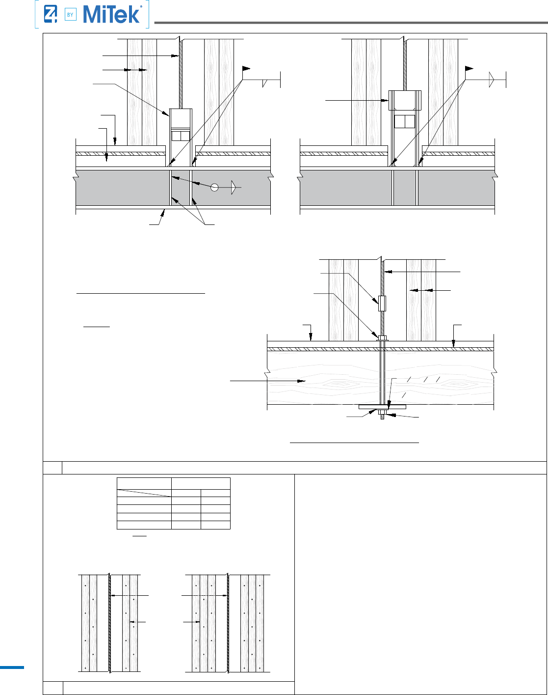
Typical Details Tie-Down System
18
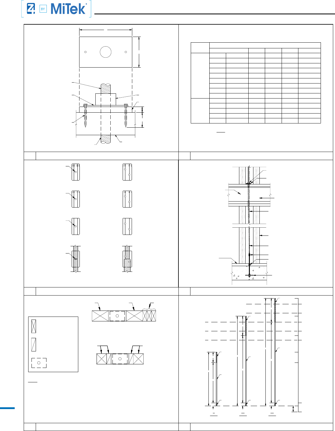
Typical Details Tie-Down System
1 CINCH NUT (CNX) INSTALLATION
2 BEARING PLATE WASHER (BPW) DIMENSIONS
COUPLING NUT & DESCRIPTIONS 4 ALLOWABLE ROD OFFSET3
EXAMPLE FULL HEIGHT
COMPRESSION POST LAYOUT
EXAMPLE BRIDGE COMPRESSION
POST LAYOUT WITH BRIDGE
NOTES:
1. EXAMPLES SHOWN FOR 4" WALL FRAMING. 6" WALL FRAMING AND LARGER IS SIMILAR.
2. COMPRESSION POSTS SHOWN ARE THE MINIMAL REQUIREMENT TO EQUAL THE UPLIFT TENSION FORCES
CALLED OUT BY THE STRUCTURAL DRAWINGS. ADDITIONAL COMPRESSION STUDS OR POSTS MAY BE REQUIRED
BY STRUCTURAL ENGINEER OF RECORD. APPLIES TO ALL HOLDOWN RUNS.
3. COMPRESSION POSTS MUST BE LOCATED WITH THE BEARING ZONE AS SHOWN IN DETAILS 9 & 12.
4. ADJACENT FULL HEIGHT SHEARWALL FRAMING CAN BE USED AS COMPRESSION POSTS PROVIDED THEY ARE
LOCATED WITHIN THE BEARING ZONE AS SHOWN IN DETAILS 9 & 12.
BRIDGE
= COMPRESSION
POST
(1) 4x4
(1) 2x4
(3) 2x4
(1) 6x4 (1) 6x4
FULL HT.
= COMPRESSION
POST
= BPW
(1) 2x4
(1) 4x4
THREADED
TRIMMABLE
END
THREADED
TRIMMABLE
END
THREADED
TRIMMABLE
END
152"
144"
132"
120"
108"
96"
12"
0"
128"
102"
80"
66"
8"
32"
108"
4"
90"
120"
144"
26"
54"
72"
14"
4"4"
UNTHREADED
UNTHREADED
UNTHREADED
THREADED
COUPLER END
THREADED
COUPLER END
THREADED
COUPLER END
ASSUMED 8" STUB
OUT ABOVE F.F.
FLOOR
HEIGHT
6'
Z-ROD
10'
Z-ROD
12'
Z-ROD
EXAMPLE ASSUMING 8" STUB OUT ABOVE FINISHED FLOOR
CNX BOTTOM
ROD PER Z4 ELEVATION
1" MIN
CNX BODY
MIN WALL
THICKNESS
BEARING PLATE WASHER (BPW) DIMENSIONS [IN]
DESIGNATION W L T HOLE DIA
4"
BPW-5
(BROWN)
3 3 1/4 1 5/16
BPW-6
(RED)
3 1/4 3 3/8 3/8
1 9/16
BPW-7
(YELLOW)
3 1/4 4 3/8 1/2 1 9/16
BPW-9
(GREEN)
3 1/4
5
5/8
1 9/16
BPW-11
(BLUE)
3 1/4 5 7/8 3/4 1 9/16
BPW-15
(BLACK)
3 1/4
7 7/8
7/8
1 9/16
BPW-20
(WHITE)
3 1/4
10 1/4
1 1/4
1 9/16
BPW-25
(ORANGE)
3 1/4 11 3/4 1 1/2 1 9/16
BPW-30
(LIGHT GRAY)
3 1/4 14 1 3/4
1 9/16
6"
BPW17-6
(LIGHT BLUE)
5 5 7/8 5/8 1 9/16
BPW27-6
(TAN)
5 9
1
1 9/16
BPW36-6
(GRAY)
5 12 1 1/2 1 9/16
BPW43-6
(PURPLE)
5
14 1 3/4
1 9/16
BPW46-6
(PINK)
5
15 1 7/8
1 9/16
BPW PER PLAN
WOOD PLATE PER PLAN
ROD PER Z4 ELEVATIONS
1/4" LAG SCREW, TYP
T
W
L
NOTE:
1. SEE DETAIL 1 FOR BPW DIMENSION DEFINITIONS.
STD COUPLER NUT
REDUCER
THREAD ROD IN
HALF WAY FROM
EACH SIDE, VISIBLE
THROUGH SITE HOLE
STD COUPLER NUT
MS COUPLER NUT
FULLY SEAT LARGE DIA. ROD FIRST, FULLY
SEAT SMALL DIA ROD SECOND, SO
COUPLER CANNOT TURN
MS COUPLER
NUT REDUCER
HS COUPLER
NUT REDUCER
SIGHT HOLE
HS COUPLER NUT
SIGHT HOLE
SIGHT HOLE
SIGHT HOLE
NOTES:
5 Z-ROD DIMENSIONSCOMPRESSION POST LAYOUT 6
OVERSIZE ROD HOLE: ROD DIA. +
1/2" MAX.
CL
POSTS PER ELEVATIONS
ATR
CNX PER PLAN
NOTE:
BLOCKING PER DETAIL 9
BPW PER PLAN
CL AT PLUMB OF ANCHOR BELOW
AB PER PLAN
CPL
FLOOR FRAMING BY OTHERS
SILL PLATE
19
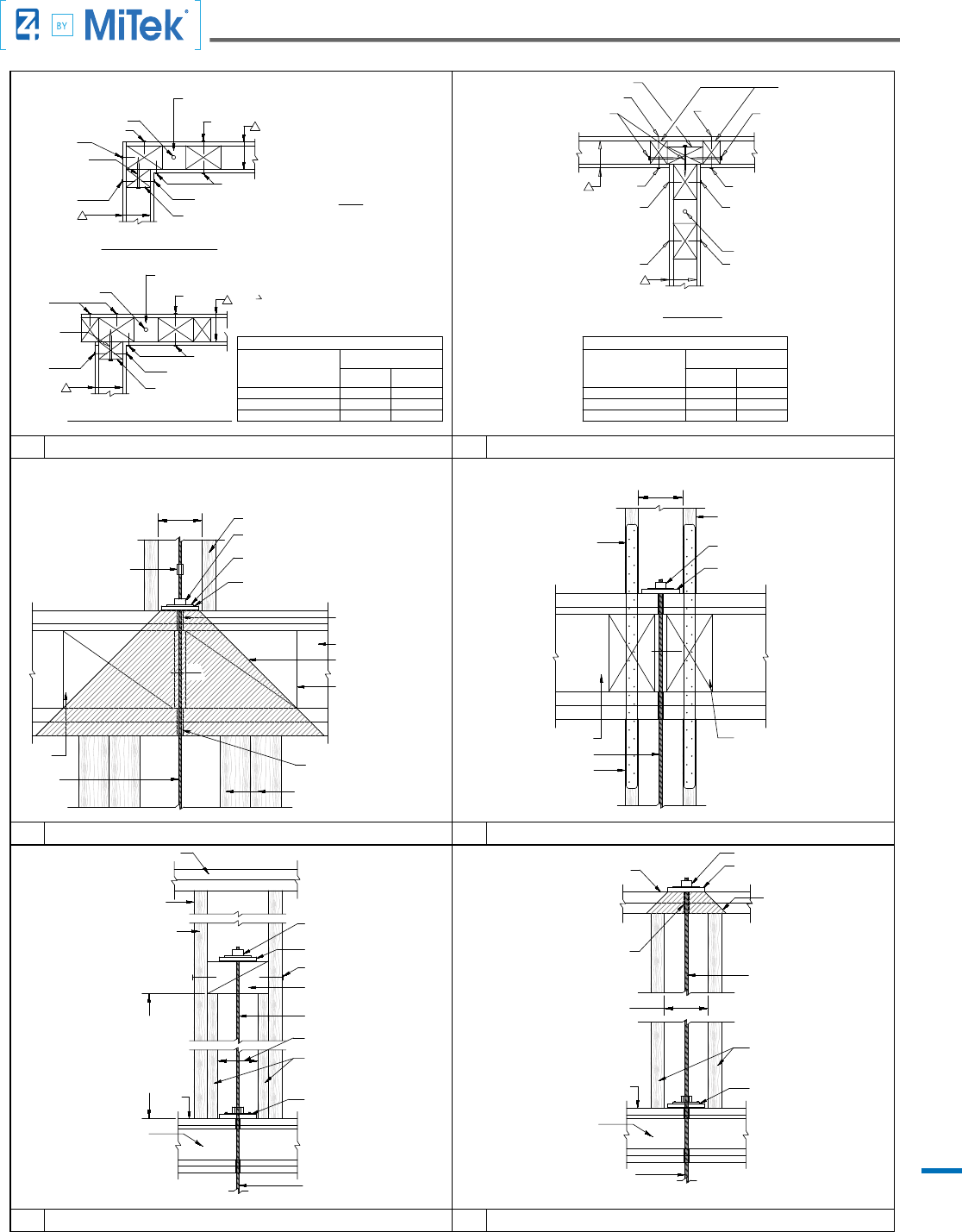
Typical Details Tie-Down System
7 Z4 TIE-DOWN SYSTEM AT COMMON CORNER 8 Z4 TIE-DOWN SYSTEM AT INTERSECTION
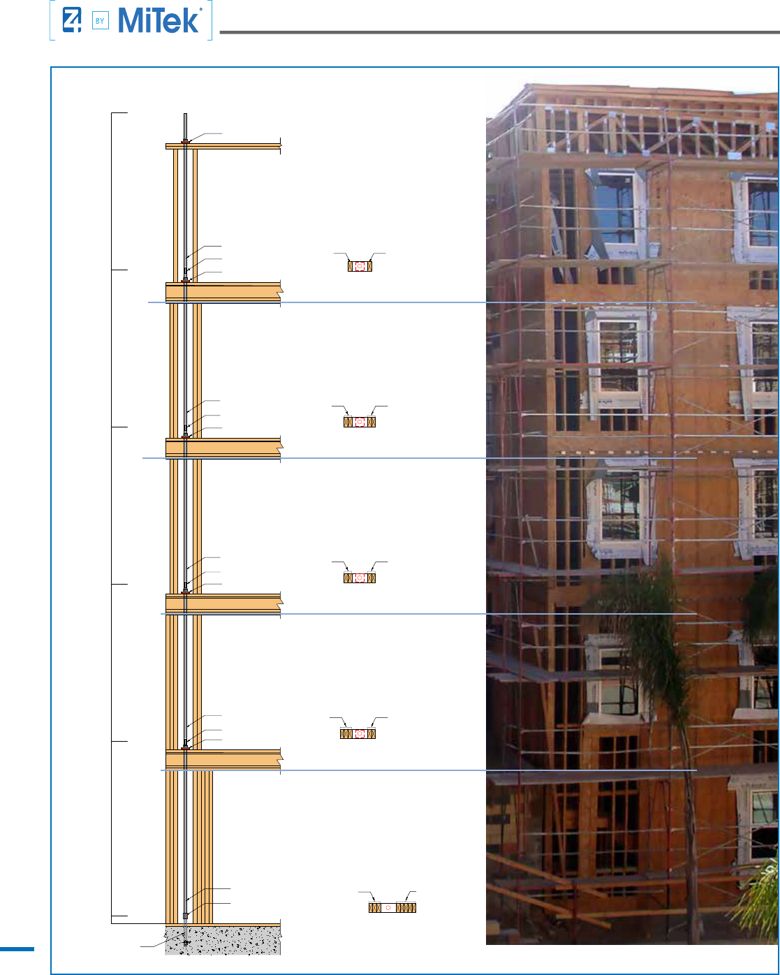
9 10
TYPICAL Z4 TIE-DOWN SYSTEM INSTALLATION DETAIL
STRAP TERMINATION OPTION
PER DETAIL 16, INSERT STITCH
NAILING WHERE REQUIRED
Z4 ELEVATIONS WITH EDGE NAILING
BRIDGE COMPRESSION POSTS PER
TOP PLATES
ROD CONTINUES TO FLOOR
TO BRIDGE BLOCK
BELOW PER Z4 ELEVATION
BPW & CNX AT SILL AS REQUIRED
PER Z4 ELEVATION
16d EA. SIDE, STUD
STRAPS FROM FLOOR ABOVE
PER PLAN, AS REQUIRED
BPW LENGTH (AT SILL) OR 6" MIN.
ROD PER Z4 ELEVATIONS
BPW PER Z4 ELEVATIONS
CNX PER Z4 ELEVATIONS
ROD DIA. + 1/2" MAX.
TOP PLATES - DO NOT
PER Z4 ELEVATIONS
SPLICE WITHIN 8" OF ROD
OVERSIZED ROD HOLE:
BPW AT SILL OR 6" MIN
ROD CONTINUES TO FLOOR
BELOW PER Z4 ELEVATION
BPW & CNX AT SILL AS REQUIRED
BEARING ZONE 45°
PER Z4 ELEVATIONS
THRU FRAMING
ROD PER Z4 ELEVATIONS
BPW PER Z4 ELEVATIONS
CNX PER Z4 ELEVATIONS
COMPRESSION POSTS PER Z4
ELEVATION WITH EDGE NAILING
PER DETAIL 15, INSERT STITCH
NAILING WHERE REQUIRED
FULL HT. COMPRESSION POSTS EACH SIDE
WITH EDGE NAILING PER PROJECT PLAN.
STITCH NAIL FULL HT. COMPRESSION POSTS
TO BRIDGE COMPRESSION POST ON EACH
SIDE, 16d AT 6" O.C. WHEN STRAPS OCCUR
FROM FLOOR ABOVE STITCH NAIL FULL HT.
STUD TO COMPRESSION POSTS, 2 ROWS 16d
AT 6" O.C. STAGGERED.
SILL PL
6x4 (4" WALL) OR
6x6 (6" WALL), MIN.
SILL PL
FLOOR FRAMING
FLOOR FRAMING
EN (A)
EN (B)
EN 2
ROD PER Z4 ELEVATIONS
*
*
EXTERIOR COMMON CORNER
EN (B)
EN (B)
INTERSECTION
3x STUDS
*
ROD PER Z4 ELEVATIONS
3x FLAT
IF PLYWOOD THIS
EN 2
EN 2
*
USP WS WOOD SCREW
1ST & 2ND LEVELS SHOWN
(SEE SEE Z4 ELEVATIONS FOR
COMPRESSION POSTS)
*
USP WS WOOD SCREW
3x
PER EOR'S
PLAN AND
SCHEDULE
SIDE OF WALL
EN (B)
EN (B)
EN 1
EN 1
*
EN 1
*
EN (A)
*
ATR
*
HEAVIEST LOADED HOLD-DOWN RUN (SEE Z4
ELEVATIONS FOR COMPRESSION POSTS)
3x
IF PLYWOOD THIS
HEAVIEST LOADED TIE-DOWN RUN (SEE Z4
ELEVATION FOR COMPRESSION POSTS)
SIDE OF WALL
EN 2
NOTE:
INTERIOR COMMON CORNER AT OPENING
SCREW
WOOD
WOOD
USP WS
USP WS
SCREW
PER EOR'S
PLAN AND
SCHEDULE
PER EOR'S
PLAN AND
SCHEDULE
PER EOR'S
PLAN AND
SCHEDULE
PER EOR'S
PLAN AND
SCHEDULE
PER EOR'S
PLAN AND
SCHEDULE
8d OR 10d @ 4" O.C.
8d OR 10d @ 3" O.C.
5" O.C.8d OR 10d @ 2" O.C.
UPS WS SCREW CONNECTION TABLE
2 1/2" O.C.
10" O.C.
7" O.C.
5" O.C.
3 1/2" O.C.
PLYWOOD EN2 NAILING
(PER EOR'S SCHEDULE)
USP WS
1/4" X 4 1/2" OR EQUAL
PLYWOOD
1 SIDE
PLYWOOD
2 SIDES
8d OR 10d @ 4" O.C.
8d OR 10d @ 3" O.C.
5" O.C.8d OR 10d @ 2" O.C.
UPS WS SCREW CONNECTION TABLE
2 1/2" O.C.
10" O.C.
7" O.C.
5" O.C.
3 1/2" O.C.
PLYWOOD EN2 NAILING
(PER EOR'S SCHEDULE)
USP WS
1/4" X 4 1/2" OR EQUAL
PLYWOOD
1 SIDE
PLYWOOD
2 SIDES
EN (B)
EN (A)
EN (A)
EN (B)
EN (A)
*
ATR DIA. PLUS 1/2", TYP.
CPL AND ROD
OVERSIZED ROD HOLE:
FRAMING
DEPTH OF FLOOR FRAMING
THRU FRAMING
AS REQUIRED
2"
Z4 ELEVATIONS
BPW LENGTH OR 6" MIN. ABOVE
& BELOW FLOOR FRAMING
ROD PER
FLOOR
COMPRESSION POSTS PER PLAN
OVERSIZED ROD HOLE:
ROD DIA. PLUS 1/2", TYP.
SNUG CNX TO BPW AND BPW TO TOP PLATE
MAX.
ELEVATIONS
COMPRESSION POSTS PER PLAN
BEARING ZONE 45°
CNX PER ZONE FOUR
SOLID BLOCKING FOR FULL
EACH SIDE OF ROD. LENGTH
TIGHTEN 1/4" LAG SCREW TO
TO MATCH POSTS BELOW.
BPW PER PLAN
FOR SPECIFIC BLOCKING
REQUIREMENTS
REFER TO EOR DOCUMENTS
WIDTH OF WALL AND FULL
FLOOR FRAMING
STRAPS PER PLAN
(BY OTHERS)
USE Z4 SPECIFIED POSTS
OR STRAP FRAMING PER Z4
ELEVATIONS, WHICHEVER
IS LARGER
STRAP FRAMING
POSTS PER PLAN
2"
MAX.
OR 8" MAX
LENGTHBPW
ROD PER Z4 ELEVATIONS
BPW PER Z4 ELEVATIONS
CNX PER Z4 ELEVATIONS
SOLID BLOCKING FOR FULL
WIDTH OF WALL AND FULL
DEPTH OF FLOOR FRAMING
EACH SIDE OF ROD. LENGTH TO
MATCH POSTS BELOW. REFER
TO EOR DOCUMENTS FOR
SPECIFIC BLOCKING
REQUIREMENTS
JOIST SPACE
12
BRIDGE TERMINATION OPTION AT TOP LEVEL
TOP PLATE TERMINATION OPTION11
20
Typical Details Tie-Down System
OPTIONAL ANCHOR AT BEAM13
6 O.C.
8" O.C.
12" O.C.
COMPRESSION
POSTS PER Z4
ELEVATIONS
ON EITHER SIDE OF ROD
FOR SINGLE POST EACH SIDE OF ROD,
3 OR MORE POSTS
NAIL PER SHEARWALL SCHEDULE.
ROD PER Z4
ELEVATIONS
2 POSTS
4" O.C.
6" O.C.
3+ POSTS
2 O.C.
3 O.C.
4 O.C.
6" O.C.
9" O.C.
12" O.C.
12" O.C.
EN PER EOR'S
PLAN AND SCHEDULE
2 POSTS
ON EITHER SIDE OF ROD
NOTE:
EDGE NAIL SPACING TO
EACH POST EACH SIDE
INTENTIONALLY
LEFT
BLANK
3
1
2
x 3
1
2
x
3
8
TRANSITION
WASHER w/ HOLE DIAMETER
1
16
"GREATER THAN ROD
TERMINATION AT STEEL BEAM
5/16"
TERMINATION AT WOOD BEAM
3"1/4" 3"
NOTE:
FABRICATOR FOR SHOP WELDING. FOR
BPW & NUT PER
Z4 RUN ELEVATIONS
NOT SHOWN
SPECIAL INSPECTION OR APPROVED
INFORMATION
SEE DETAIL
*
REQUIRED. WELD SHALL MEET AWS D1.8
FIELD WELDING SPECIAL INSPECTION
ON LEFT FOR
*
AT-65
ANCHOR TIE
NAILER
*
ANCHOR TIE
AT-32
ROD
SILL PL EA. SIDE. MINIMUM U.N.O. BY ENGINEER
MIN. "t" = 1/4" MIN. IN ALL CASES,
STEEL BEAM &
NAILER PER PLAN
BEARING PLATE TO MEET OR EXCEED
"CUMULATIVE LOAD DEMAND" NOTED
ON Z4 ELEVATIONS.
BEAM SUPPORTING
DISCONTINUOUS TIE-DOWN
SHALL BE DESIGNED BY
THE EOR
SHEATHING
NUT &
WASHER
ROD
COUPLER
NUT & WASHER TO MATCH
ROD DIAMETER & GRADE
COMPRESSION
POSTS
COMPRESSION
POSTS
SILL PL
SILL PL
STEEL BEAM
3/16"
STEEL BEAM
14 COMPRESSION POST EDGE NAILING
21
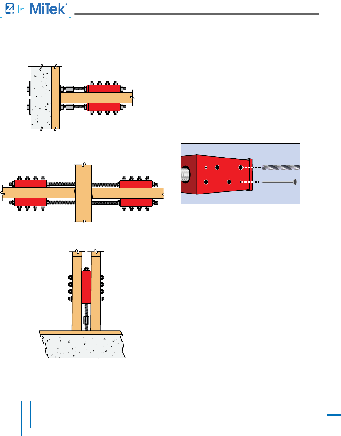
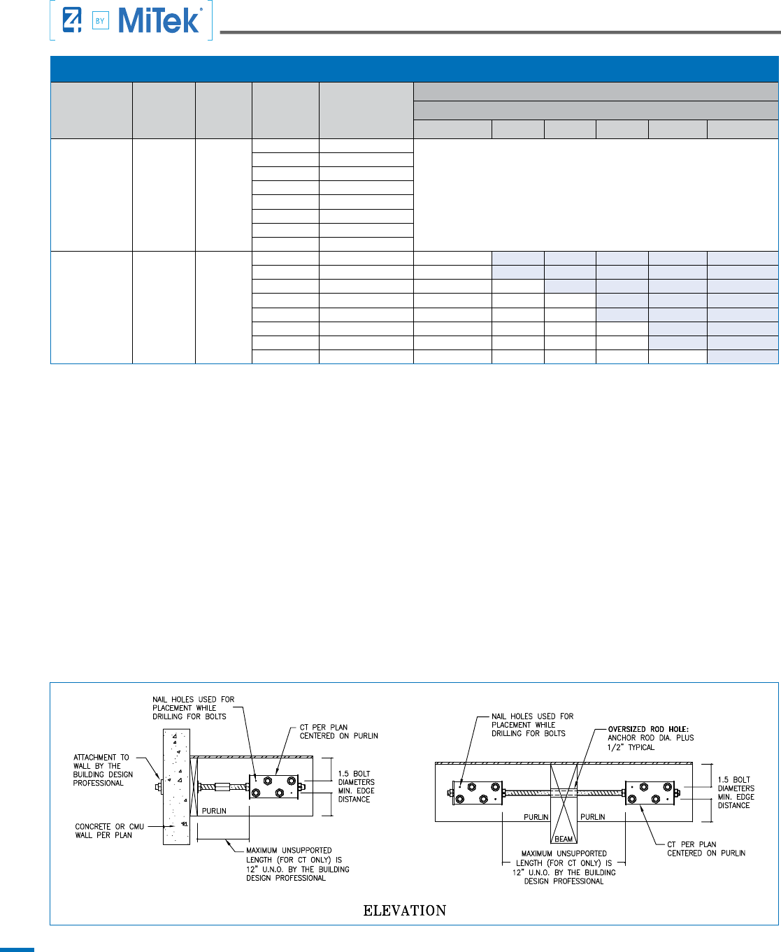
MiTek Z4 Continuity Tie
The MiTek Z4 “CT” is a steel tube with steel end plates
welded to both ends designed to transfer tension and
compression forces from one beam to another (Purlin
Splice application) or from a beam to a perpendicular
wall (Wall Tie application). Connections are made by
bolting the tube to a wood member and attaching to a
threaded rod for transferring forces.
Accurate Placement and
Installation
Step 1: Use the two 3/16” holes provided to nail CT or
T2 at desired location on wood member
Step 2: Use the CT or T2 as a template to accurately
drill holes for bolting
Step 3: Make bolted connection to the wood member
per plans and specications
Step 4: Make threaded rod connection per plans and
specications.
MiTek Z4 Tension Tie
The MiTek Z4 “T2” is a steel tube with a steel end plate
welded to one end designed to transfer tension forces
with a single concentric hold-down device. Sandwiched
Installations are made by through bolting two wood
members with a T2 between. The tube is then attached
to a threaded rod to transfer the tension loads.
Sandwiched T2
As Concentric Hold-Down
Paired CT Wall Tie
Paired CT Purlin Tie
Concentric Ties CT & T2
Z4-CT 2 4 - 4
Anchor Rod. Dia. (1/8" Increments)
Fastening Bolt Dia. (1/8" Increments)
Fastening Bolt Quantity
Continuity Tie
Z4-T2 - 4 8 - 9
Anchor Rod. Dia. (1/8" Increments)
Fastening Bolt Dia. (1/8" Increments)
Fastening Bolt Quantity
Tension Tie
Code Reports
• ESR-3105
• LA City RR 25334
22
TABLE 3.0- DIMENSIONS AND FASTENERS FOR THE CT & T2
Description Model Number
Fastening Bolts
1, 2
Anchor Rod Diameter Tube Dimensions (in.)
Qty & Size
Single Assembly
(1 HS Rod)
3
Paired Assembly
(2 STD Rods)
4, 5
Thickness Width Depth Length
“T2” Tension Tie
Z4-T2-24-4 (2) 1/2” 1/2”
n/a
1/8” 3” 3” 2-7/8”
Z4-T2-43-4 (4) 3/8” 1/2” 1/8” 2-1/2” 2-1/2” 4-7/8”
Z4-T2-44-5 (4) 1/2” 5/8” 1/8” 3” 3” 5”
Z4-T2-46-8 (4) 3/4” 1” 3/16” 4” 3” 7-1/4”
Z4-T2-48-9S (4) 1” 1-1/8” 3/16” 5” 3” 10-3/8”
Z4-T2-64-6 (6) 1/2” 3/4” 1/8” 3” 3” 7-1/8”
Z4-T2-68-11S (6) 1” 1-3/8” 3/16” 5” 3” 14-3/4”
Z4-T2-84-7 (8) 1/2” 7/8” 1/8” 3” 3” 9-1/4”
“CT” Continuity Tie
Z4-CT-24-4 (2) 1/2”
n/a
1/2” 1/8” 3” 3” 3-1/4”
Z4-CT-43-4 (4) 3/8” 1/2” 1/8” 2-1/2” 2-1/2” 5-1/4”
Z4-CT-44-5 (4) 1/2” 5/8” 1/8” 3” 3” 5-1/2”
Z4-CT-46-8 (4) 3/4” 1” 3/16” 4” 3” 7-3/4”
Z4-CT-48-9 (4) 1” 1-1/8” 3/16” 5” 3” 10-1/4”
Z4-CT-64-6 (6) 1/2” 3/4” 1/8” 3” 3” 7-3/4”
Z4-CT-68-11 (6) 1” 1-3/8” 3/16” 5” 3” 15”
Z4-CT-84-7 (8) 1/2” 7/8” 1/8” 3” 3” 10”
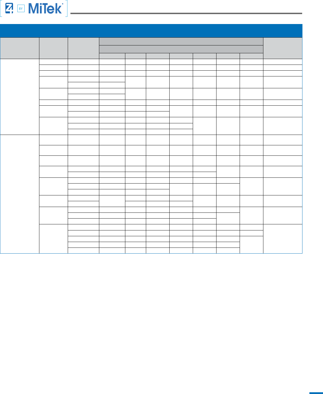
Notes:
1. Fastening Bolts must comply with ASTM A307. Standard round washers and hex nuts, for tightening the CT or T2 to adjacent wood member(s),
must comply with F844 and A563A respectively.
2. The minimum required distance from the end of the wood member to the centerline of the rst bolt is seven bolt diameters. Increasing the end
distance has no effect on the allowable tension load.
3. Single (Sandwiched) Assemblies are applicable to Tension Ties (T2) when one Tie is sandwiched between and through-bolted to two wood
members. One Tie and one HS rod required.
4. For Paired Assemblies, threaded rods must comply with ASTM F1554 Grade 36 (minimum) connecting the CT with one standard (F844) round
washer and one A563A hex nut. For Single (Sandwiched) Assemblies, threaded rod must comply with ASTM A311 Grade 1045 (minimum).
5. Paired Assemblies of Continuity Ties (CT) require two Ties bolted together with a single wood member between. Two Ties and two STD rods
required (one per Tie).
Concentric Ties CT & T2 Dimensions and Fasteners
23
TABLE 3.1-DF-L: CT & T2 ALLOWABLE LOADS WHEN CONNECTED TO DOUGLAS FIR-LARCH
1
Installation
2, 3, 4
Model Number
Width of
Attached Wood
Member (in.)
Allowable Tension Load (lbs.)
5, 6,
Displacement @
Allowable Tension
Load (in.)
7
Thickness of Attached Wood Member (in.)
1.5 2.5 3 3.5 5.125 5.5 7.25 / 7.5
Sandwiched T2
Concentric
Hold Down
Z4-T2-24-4 3.5 4,984 6,235 6,235 6,235 6,235 6,235 6,235 0.085
Z4-T2-43-4 3.5 6,457 7,001 7,001 7,005 7,007 7,009 7,009 0.102
Z4-T2-44-5 3.5 9,904 12,422 12,432 12,436 12,445 12,449 12,449 0.108
Z4-T2-64-6
3.5 14,276
18,465 18,499 18,533 18,573 18,597 18,597 0.128
5.5 14,637
Z4-T2-84-7
3.5 14,276
23,417 23,794 23,417 23,417 23,417 23,417 0.129
5.5 19,077
Z4-T2-46-8 5.5 19,385 19,385 19,385 19,385 19,385 19,385 19,385 0.114
Z4-T2-48-9S
5.5 18,691 31,151 37,382
42,141 42,867 42,867 42,867 0.122
7.25 / 7.5 24,057 36,671 39,152
Z4-T2-68-11S
5.5 18,691 31,151 37,382 43,612
64,036 64,036 64,036 0.2107.25 / 7.5 24,057 40,095 48,114 56,133
9.25 / 9.5 31,833 52,474 56,276 61,061
Paired CT
Wall & Purlin Ties
Z4-CT-24-4 3.5 3,360 5,600 6,235 6,235 6,235 6,235 6,235 0.160
Z4-CT-43-4 3.5 5,010 6,989 6,993 6,997 7,004 7,004 7,007 0.132
Z4-CT-44-5 3.5 6,637 11,118 12,395 12,405 12,420 12,430 12,457 0.146
Z4-CT-64-6
3.5 7,138 11,897 14,276 16,656 18,442
18,504 18,592 0.145
5.5 9,679 16,395 18,330 18,383 18,442
Z4-CT-84-7
3.5 7,138 11,897 14,276 16,656 21,137 22,683
24,590 0.1525.5 10,662 17,769 21,323
24,057 24,241 24,381
7.25 / 7.5 12,377 21,300 23,892
Z4-CT-46-8
5.5
9,749
16,453 19,744 23,034
27,776 27,804 28,028 0.155
7.25 / 7.5 16,464 19,817 23,184
Z4-CT-48-9
5.5 9,345 15,576 18,691 21,806 30,020 32,216
43,240 0.1627.25 / 7.5 12,029 20,048 24,057 28,067 41,858
43,240
9.25 / 9.5 12,591 21,513 25,939 30,460 43,240
Z4-CT-68-11
5.5 9,345 15,576 18,691 21,806 30,020 32,216 43,931
0.148
7.25 / 7.5 12,029 20,048 24,057 28,067 41,858 46,736 63,731
9.25 / 9.5 14,590 24,317 29,180 34,044 49,850 50,119
64,593
11.25 / 11.5 16,504 27,506 33,008 38,509 56,388 61,999
13.25 / 13.5 16,622 29,652 36,167 42,901 64,541 64,593
Notes:
1. Values in this table are Allowable Stress Design (ASD) for No. 1 grade Douglas Fir-Larch and include a 1.60 stress increase factor, C
D
, for short-
term load duration as permitted by the National Design Specication (NDS 2012).
2. Paired Assemblies of Continuity Ties (CT) require two ties to be connected to a standard grade anchor rod and the ties bolted together with a
single wood member between.
3. Single (Sandwiched) Assemblies are applicable when one Tension Tie (T2) is sandwiched between and through-bolted to two wood members.
One Tie and one HS rod and bolts required.
4. For compression loading the minimum required distance from the end of the wood member to the centerline of the rst bolt is seven bolt
diameters. allowable tension load.
5. The capacity of the anchor rod must be equal to or greater than the allowable tension load of the Tie being attached. See table 3.2 for anchor rod
capacities.
6. Allowable tension loads consider
• Tested CT or T2 capacity divided by 2.5
• Maximum anchor rod capacity
• Cross sectional area of the attached wood member where it is drilled for the bolted connection
7. Displacement at tension loads less than the respective allowable load are determined by proportioning the design load to the allowable load.
Shrinkage of supporting wood members and anchor rod elongation are the responsibility of the Building Design Professional. Tabulated
displacement values consists of:
a) Vertical displacement of the CT or T2 Tie due to rotation.
b) Fastener slip where the CT or T2 Tie connects to the wood member.
Concentric Ties CT & T2 Allowable Loads
24
TABLE 3.2- ROD DESIGN TENSION AND COMPRESSION CAPACITIES FOR THE CT & T2
1
Installation
Anchor Rod
Grade
2
Quantity Diameter (in.)
Allowable Tension
Capacity (lbs.)
Allowable Compression Capacity (lbs.)
3, 4, 5
Maximum Unsupported Length, L (in.)
6
12 18 24 30 36 42
Single
(Sandwiched)
Assembly
(1 Tie)
HS 1
1/2” 8,468
n/a in Compression
5/8” 13,231
3/4” 19,052
7/8” 25,932
1” 33,870
1-1/8” 42,867
1-1/4” 52,922
1-3/8” 64,036
Paired Assembly
(2 Ties)
STD 2
1/2” 8,541 3,200 1,478 830 532 370 272
5/8” 13,346 6,448 3,746 2,108 1,348 936 688
3/4” 19,218 10,741 7,778 4,616 2,954 2,052 1,508
7/8” 26,157 15,863 12,684 8,795 5,630 3,910 2,872
1” 34,165 21,724 18,333 14,252 9,690 6,728 4,944
1-1/8” 43,240 28,188 24,596 20,313 15,317 10,684 7,850
1-1/4” 53,383 36,689 32,868 28,347 23,134 17,224 12,654
1-3/8” 64,593 44,400 40,397 35,681 30,279 24,162 17,970
Notes:
1. The values in this table are Allowable Stress Design (ASD), excluding a 1.33 duration of load stress increase factor, C
D
.
2. STD indicates rods complying with ASTM F1554 Grade 36. HS indicates rods complying with ASTM A311 Grade 1045.
3. When using Continuity Ties (CT) to transfer compression loads, the Building Design Professional is responsible for checking the wood member(s)
design capacity for the most critical load combination (i.e. bending about one or both principal axes and axial compression).
4. Compression capacities shown in blue apply to KL / r > C
C
, where: r = (D
R
- .9743 / n) / 4, where n = threads per inch,
C
c
= (2π
2
E / F
y
)
1/2
, E = Modulus of Elasticity of rod, (29 x 10
6
) and Fy = yield strength of rod steel (36 ksi).
5. Compression capacities assume a slenderness factor, K, of 1.00 or for installations with both ends of the rod pinned. When both ends of the rod
are approximately xed, K = 0.65.
6. Compression capacities are for Continuity Ties (CT) spaced no greater than the specied maximum unsupported length.
Concentric Ties CT & T2 Rod Capacities
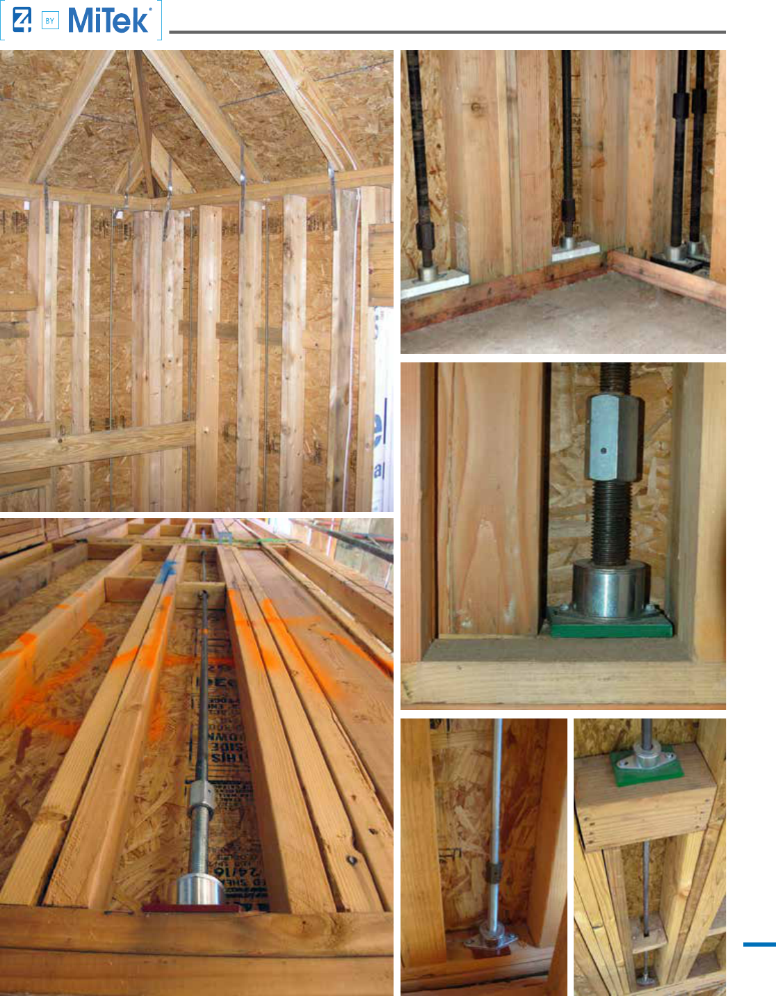
25
Tie-Down System Installation Photos
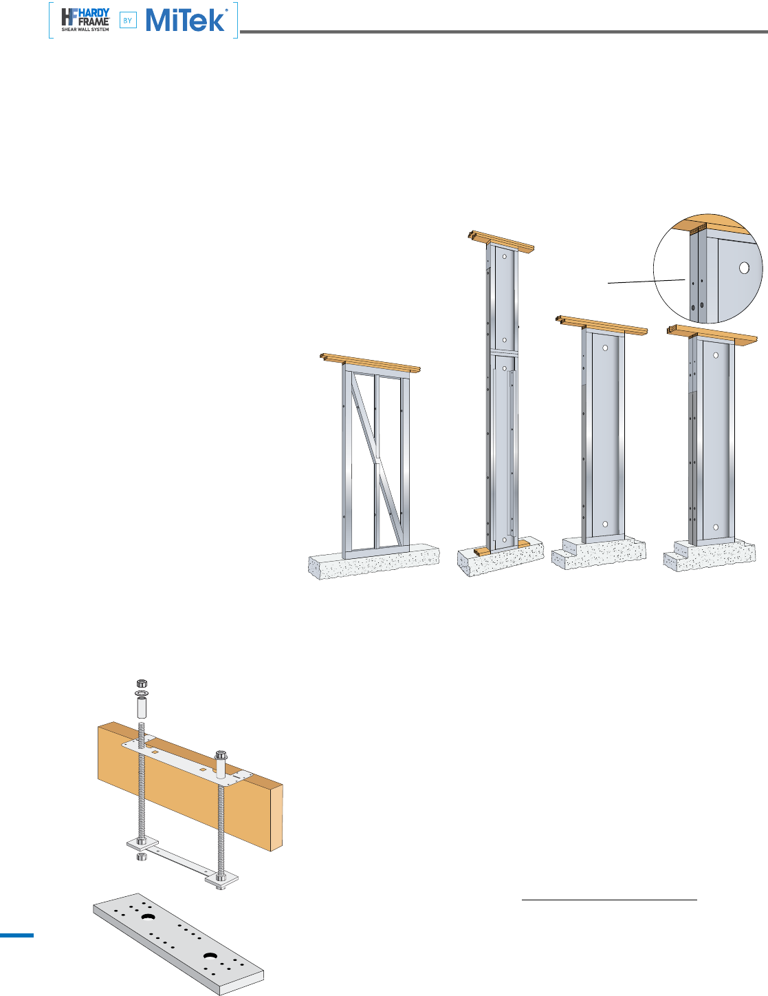
26
Hardy Frames has been leading the pre-manufactured shear wall industry from its beginning. Hardy Frames were the rst to be recognized by
ICBO-ES and LA City, rst to gain approval for multi-story applications, rst Balloon Wall application and rst to be recognized to comply with the
2003 and 2006 IBC and IRC Building Codes. Today we are the rst, and only, to offer a 9 inch Panel width and a Balloon Wall application that is
fully assembled in the manufacturing plant and ships as a one piece unit.
All Hardy Frame
®
Panels and Brace Frames are code listed and include installations on concrete, raised oor and upper oor systems.
Template Kit (HFXTK)
Includes:
1. One Template (HFXT) for accurate anchor spacing and alignment
2. One Bolt Brace (HFXBB) for installation at embed end of anchors to prevent independent
sway while pouring concrete
3. Two 1-1/8 inch diameter hold down anchors
4. Six Grade 8 hex nuts
5. Two hardened round washers
6. Two 1/2 x 3 x 3 plate washers (HFPW) are included when high strength (HS) anchors are
specied
Hardy Frame
®
Bearing Plate (HFXBP)
7. 3/4” thick x 3 1/2” wide ASTM A36 steel
8. Length extends 3” beyond Panel edges. Check for outside corner conditions!
9. Reduces wood deformation from overturning forces
10. Reduces effects of shrinkage by eliminating bottom plate
Note: The allowable values in raised oor and upper oor tables assume installation of HFXBP.
Installation without a HFXBP may result in a reduction of allowable loads.
Hardy Frame
®
HFX-Series Panels
1. Panels are available in 9, 12, 15, 18, 21 and 24 inch widths
2. Standard Heights range from 78 inches for portal applications to 20 feet
for Balloon Walls
3. Custom heights are manufactured routinely
4. R Value for design = 6.5, Cd = 4.0
5. With proper detailing and anchorage “Back to Back”
installations provide two times the allowable shear
value without increasing the wall width
Hardy Frame
®
Brace Frame
Hardy Frame
®
Panel
Hardy Frame
®
Balloon Wall
Hardy Frame
®
Panel
Back to Back
“Back to Back”
installations provide
two times the allowable
shear value
Hardy Frame
®
Shear Walls
www.hardyframe.com • 1-800-754-3030
Hardy Frame
®
Code Evaluations
ICC-Evaluation Service ESR-2089
LA City Research Report RR-25759
Hardy Frame
®
HFX-Series Brace Frames
1. Brace Frames are available in 32 and 44 inch
widths
2. Standard Heights range from nominal 8 to 13 feet
3. Custom heights are manufactured routinely
4. R Value for design = 6.5, Cd = 4.0
5. For a given shear load, installing a wider shear
wall results in reduced overturning
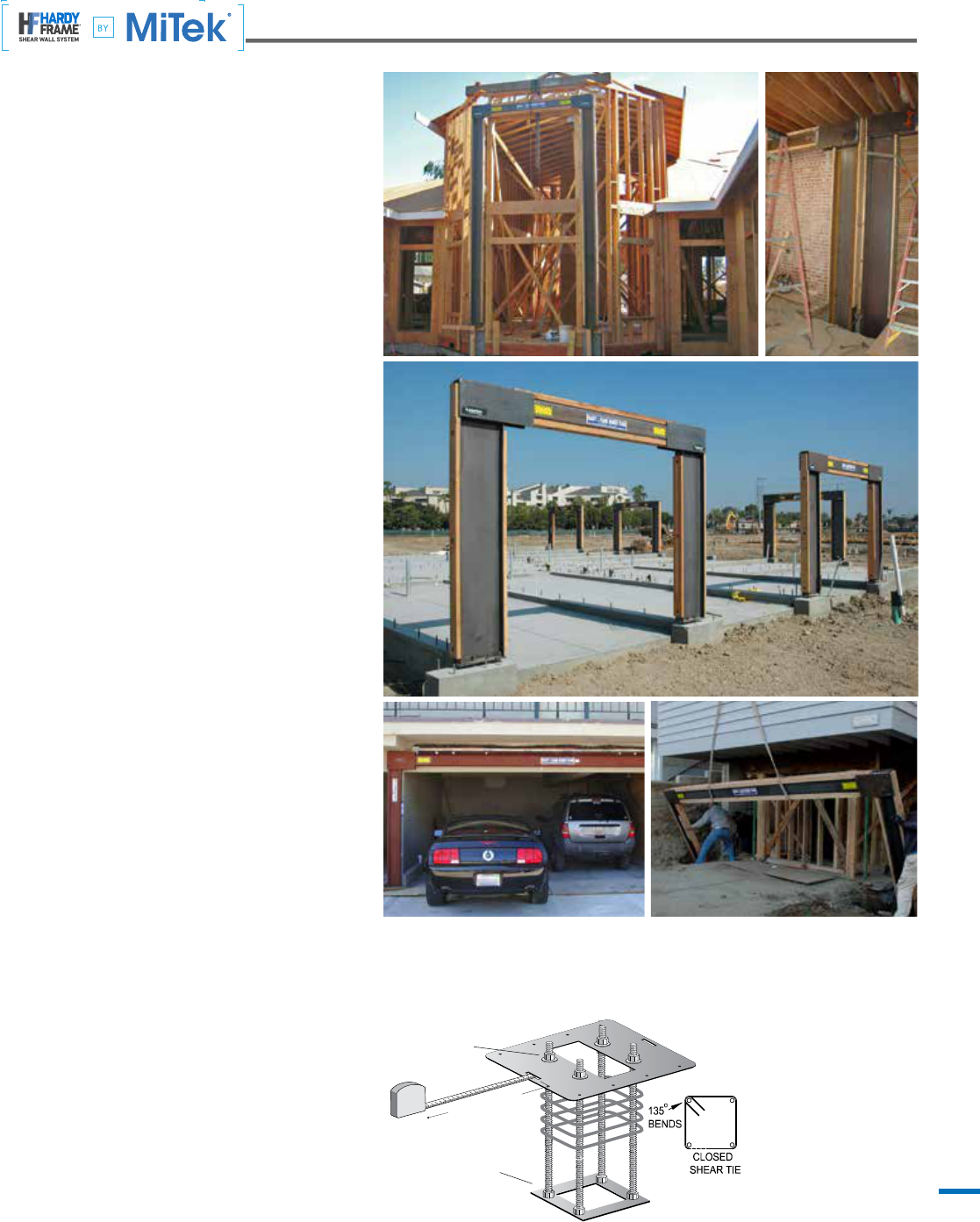
27
Hardy Frame
®
Special Moment Frame
Hardy Frames introduced the rst standardized,
prefabricated Special Moment Frame in 2006. Since then
we have delivered thousands of Special Moment Frames
that have been successfully installed. Our Special Special
Moment Frames provide maximum structural capacities
and enable large openings in architectural design.
Hardy Frame
®
Special Moment Frames utilize the
SidePlate moment connection which has now been
approved by the Connection Prequalication Review Panel
(CPRP) for inclusion in the AISC 358 Prequalied Moment
Connection Standard. Typically, Hardy Frame
®
Special
Moment Frames are delivered to the jobsite in one-piece,
completely prefabricated with wood nailers attached, and
ready to be installed with no assembly. No eld welding
and or special inspection is required.
On production framing jobs the Hardy Frame
®
Special
Moment Frame installation is fast and framer friendly.
We have delivered truckload quantities of up to 30
Special Moment Frames that were installed in a single
day. That is an accomplishment that cannot be matched
by conventional or assembly-required Special Moment
Frames.
Custom Sizes and Custom Calculations
We offer over 300 standard dimension Special Moment
Frames, but we don’t stop there. We also offer calculations
and solutions for sizes beyond our standard listing. We
commonly provide solutions for two-story and multi-story
frames as well as for xed base connections.
At Hardy Frames we understand that Special Moment
Frames require job-specic considerations. We work
with contractors to meet their needs without treating
adjustments as a custom order.
Special Moment Frame Template Kits
Template Kits are included with the purchase of the Hardy
Frame
®
Special Moment Frame and are a stock item that
can be shipped within one business day. The Kit includes
all embed anchors, nuts, washers and Templates so the
concrete pour can proceed prior to the Special Moment
Frame delivery. Correctly locating the anchors is easy
with a slot provided in the Template to measure the “W
in
”,
(inside steel-to-steel) dimension.
Measured Distance
from notch to notch is
Moment Frame
W
IN
dimension
Double nut
at HFT
Double nut at bolt brace
SidePlate Code Evaluations
Included in the Standard AISC 358
www.hardyframe.com • 1-800-754-3030
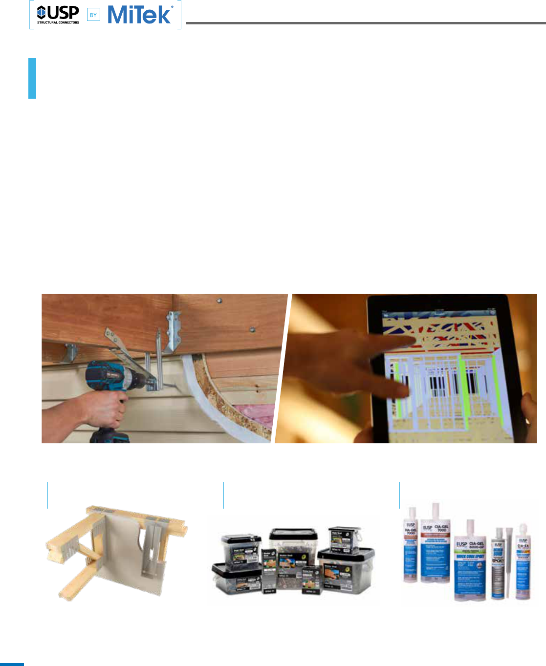
28
USP
®
Structural Connectors
USP Customer Service 1-800-328-5934 • uspconnectors.com
AT MITEK WE BELIEVE THAT BETTER
PROCESSES CAN EMPOWER YOUR BUSINESS.
And we’ve learned three important things over the years:
→ We’ve learned that when people collaborate well, great things can happen – that‘s about both strong collaboration
within your teams, and also strong collaboration between you and your customers.
→ We’ve learned that when we build a relationship focused on growing your ability to achieve a Higher Standard
of performance and success year over year, that relationship will stand the test of time. We’ve also learned that
when we help you deliver those kinds of relevant results and value to your customers year over year, you will
build a relationship that will also stand the test of time.
→ We’ve also learned that our customers are the heroes of our story, and that when we continually get that right,
all our efforts will yield the best results for our relationships.
And that is THE NEW STANDARD that we are talking about from MiTek these days. It’s a new standard for what you
can expect in optimizing your business performance, and a new standard for what you can expect from a strong,
committed relationship that works well, day after day and stands the test of time.
| FWH FIRE WALL HANGER | PRO SERIES WOOD SCREWS
| ANCHORING SOLUTIONS
| ADTTTZ ADJUSTABLE DECK TENSION TIE | MITEK
®
SAPPHIRE
™
SUPPLY SOFTWARE

250 Klug Circle, Corona, California 92880 951 245-9525
HardyFrame.com
©2017 MiTek All Rights Reserved
Hardy Frame
®
Product Catalog
The Hardy Frame
®
Product Catalog provides complete information for Engineers, Architects and Designers
to specify our shear wall system. There is a complete listing of all Panels, Brace Frames and Accessories,
allowable shear loads, corresponding uplift and drift, pre-engineered anchorage information, specication
tips, photos and Typical Installation Details.The Installation Details in the Product Catalog conveniently
match our ACad version that can be included as supplemental sheets to plan submittals.
Product catalog
Better Technology. Better Building.
1-16
USP Structural Connectors Product Catalog
The 2015-2016 USP Catalog is a comprehensive 236 page guide to the United States product line.
It features all new product and application illustrations, detailed installation instructions, fastening
schedules and load ratings. EWP and Plated Truss connectors are included.
Hardy Frame
®
Installation Guide
The Hardy Frame
®
Installation Guide was written specically for Suppliers and Installers. This publication
provides all HFX model numbers, dimensions, bolt and screw patterns, connectors, installation illustrations,
attachments with self-tapping screws and information regarding Template Kit (HFXTK) and Floor to Floor
Connector Kit (HFTC) components.
ADDITIONAL PUBLICATIONS FROM MiTek, USA
Hardy Frames is a wholly owned subsidiary of MiTek, USA. Along with USP Structural Connectors and the Z4 Tie-Down System
our combined team serves the construction industry with a full range of structural and design solutions.
USP Structural Connectors Anchoring Solutions Guide
Detailed descriptions and specications for the complete line of epoxy products; CIA-GEL 7000-C for
Cracked Concrete, CIA GEL 7000 Masonry epoxy, CIA GEL 6000-GP General Purpose & Department of
Transportation (DOT) epoxy, CIA-EA Un-cracked Concrete epoxy and Acrylate, Incredi-Bond
®
multi-purpose epoxy. 16 pages. #2278 April 2017
