INDUSTRY STANDARD ON
v1.0
INDUSTRY STANDARD ON IN-WATER CLEANING WITH CAPTURE v1.0 1
Industry standard on in-water cleaning with capture
Version 1.0
Terms of use
Industry standard for in-water cleaning with capture (Industry standard)
Industry standardIndustry standard
Industry standard
Industry standard

INDUSTRY STANDARD ON IN-WATER CLEANING WITH CAPTURE v1.0 2
The Industry standard is one of two separate documents that outline performance-based
requirements for in-water cleaning of a ship’s hull, propeller and niche areas with the capture of the
materials that are removed during the process:
Approval procedure for in-water cleaning companies
Industry standard on in-water cleaning with capture.
In the documents, the stakeholders are ships, cleaning companies, independent approval bodies, an-
fouling system (AFS) manufacturers, ports and other local authories. The set- up is as follows:
1. The cleaning system and working procedures are tested and approved by an independent
approval body in accordance with the Approval procedure for in-water cleaning companies.
2. Aer approval, the quality systems of the cleaning company will be subject to periodic internal
audits and external audits carried out by the approval body.
3. Ships, AFS manufacturers and cleaning companies will use the requirements outlined in the
Industry standard on in-water cleaning for planning, conducng and reporng on the cleaning
process.
4. For an approved cleaning company to operate in any given locaon, a local permit
1
must be
issued by the port and other relevant authories.
The Industry standard helps to ensure that the in-water cleaning of a ship’s hull, and niche areas
including the propeller, can be carried out safely, eciently and in an environmentally sustainable
way.
The Industry standard has been wrien by an industry working group consisng of AFS
manufacturers, in-water cleaners, shipowners, ports, internaonal organisaons and authories.
The following were represented in the work: Akzo Nobel, BIMCO, C-Leanship, CMA Ships, DG Diving
Group, Dutch Ministry of Infrastructure and Water Management, Fleet Cleaner, Hapag-Lloyd, Hempel,
HullWiper, Internaonal Associaon of Classicaon Sociees, Internaonal Chamber of Shipping,
Minerva Shipping, Portland Port (UK), Port of Roerdam and PPG Coangs.
A reference group was asked twice to comment on the Industry standard and several parts of the
standard have been updated by correspondence. Members of the reference group represented
the following AFS manufacturers, authories, cleaning companies, internaonal organisaons
represenng shipowners, laboratories, research instutes, and shipowners:
Bernhard Schulte Shipmanagement, Chevron Shipping CO – Houston, ECOsubsea AS, Internaonal
Associaon of Independent Tanker Owners (INTERTANKO), Krisan Gerhard Jebsen Skipsrederi AS,
Laboratory for Aquac Research and Comparave Pathology, NACE Internaonal, SeaTec, SRN Group,
TecHullClean Pte. Ltd.
1 Note: local permits may require addional requirements to the ones in the Industry Standard on in-water cleaning with capture and the Approval
procedure for in-water cleaning companies.
Introduction

INDUSTRY STANDARD ON IN-WATER CLEANING WITH CAPTURE v1.0 3
Contents
Introducon ................................................... ......................................................................................................... 2
Foreword ................................................................................................................................................................ 4
1 Bibliography .................................................................................................................................................. 5
2 Scope ............................................................................................................................................................ 6
3 .................................................................................................................................... 7
4 .................................................................................................................................. 10
4.1 Biofouling management plan and record book .................................................................................................... 10
4.2 Reference areas .................................................................................................................................................... 10
4.3 Photos and videos ................................................................................................................................................ 11
5 ....................................................................................................................... 12
5.1 Assessment of biofouling growth ......................................................................................................................... 12
5.2 Assessment of the propulsion power and fuel consumpon ............................................................................... 13
6 .................................................................................................................................................. 14
6.1 Biofouling types .................................................................................................................................................... 14
6.2 Biofouling coverage .............................................................................................................................................. 15
6.3 AFS’ condion ................................................... .................................................................................................... 16
6.4 Service report aer inspecon ............................................................................................................................. 17
6.5 Inspecon report .................................................................................................................................................. 17
7 ..................................................................................................................................... 18
8 ............................................................................................................................ 20
8.1 Safety and environmental requirements for the cleaning company .................................................................... 20
8.2 Pre-assessment of the cleaning area ...................................................................................................... .............. 21
9 ...................................................................... 22
9.1 Operang requirements of niche area cleaning ................................................................................................... 23
9.2 Propeller cleaning ................................................................................................................................................. 23
9.3 Post-cleaning inspecon ...................................................................................................... ................................. 23
9.4 Post cleaning safety and environmental requirements ........................................................................................ 24
9.5 Service report aer cleaning ................................................................................................................................ 24
9.6 Cleaning report ..................................................................................................................................................... 24
10 ................................................................................................. 25
10.1 Coang system .................................................................................................................................................... 25
10.2 Marine growth prevenon systems (MGPS) ........................................................................................................ 26
10.3 Communicaon between shipowner and AFS manufacturer aer cleaning ........................................................ 26
11 ......................................................................................... 28
11.1 Procedures to manage materials and seawater euent ..................................................................................... 28
11.2 Material handling ................................................................................................................................................. 28
11.3 Auding of the cleaning system ........................................................................................................................... 29
11.4 Documentaon requirements .............................................................................................................................. 29
11.5 Underperforming systems .................................................................................................................................... 29
...................................................................... 30
........................................................................................................................................... 32
.......................................................................................................... 35
......................................................................................................................................... 37
Service report .............................................................................................................................................. 40
............................................................................................................................................ 41
Industry standard on in-water cleaning with capture ............................................ 44
Ship’s documentaon ........................................................................................................................................... 45
In-water inspecon planning ...................................................................................................... .......................... 46
Inspecons ........................................................................................................................................................... 48
Pre-communicaon ............................................................................................................................................. 50
Pre-cleaning preparaons .................................................................................................................................... 52
Operang requirements of the cleaning system with capture ............................................................................. 53
Systems used to prevent biofouling growth ......................................................................................................... 57
Management of the handling of materials and seawater euent ....................................................................... 60
Communicaon ow chart ................................................................................................................................... 62

INDUSTRY STANDARD ON IN-WATER CLEANING WITH CAPTURE v1.0 4
Foreword
The work started three years ago because more and more ports were prohibing in-water cleaning
acvies in their areas. Further, there was a genuine desire among stakeholders to improve pracces
by establishing a minimum standard for the cleaning and capture of biofouling.
BIMCO would like to thank all members of the working group for their valuable me and construcve
contribuons. The reference group is also thanked for their comments and proposals to the text.
BIMCO, January 2021

INDUSTRY STANDARD ON IN-WATER CLEANING WITH CAPTURE v1.0 5
Bibliography
Alliance for Coastal Technologies Marime Environmental Resource Center [ACT/MERC], Evaluaon of
Subsea Global Soluons in-Water Cleaning and Capture Technology for Ships (2019). ACT/MERC IWCC
Evaluaon Report ER01-19.
Burkard T. Watermann, Propeller Polishing Condion and Denions. LimnoMar (2019).
Clare Grandison, Richard Piola and Lyn Fletcher, A Review of Marine Growth Protecon System
(MGPS) Opons for the Royal Australian Navy (2011). DSTO-TR-2631.
Department of the Environment (DOE) and New Zealand Ministry for Primary Industries [MPI],
Anfouling and in-Water Cleaning Guidelines (2015). ISBN 978-1-76003-009-4 (online).
Eugene Georgiades, Abraham Growco & Daniel Kluza, Biosecurity, Technical Guidance on Biofouling
Management for Vessels Arriving to New Zealand (2018). Technical Paper No: 2018/07.
European Chemicals Agency, Guidance on the Biocidal Products Regulaon Volume II Ecacy –
Assessment and Evaluaon (Parts B+C) (2018). ISBN 978-92-9020-502-9.
Growco, A., Kluza, D., and E. Georgiades, Technical Advice: Evaluaon of in-Water Systems to
Reacvely Treat or Remove Biofouling within Vessel Internal Niche Areas (2019). Wellington: Ministry
for Primary Industries. ISBN No 978-1-98-859419-4 (online).
Growco, A., Kluza, D. & E. Georgiades, In-water systems to remove or treat biofouling in vessel sea
chests and internal pipework – Literature review (2016). ISBN No: 978-1-77665-210-5 (online).
Growco, A., Kluza, D. & E. Georgiades, Technical advice: Evaluaon of in-water systems to remove or
treat biofouling in vessel internal seawater systems (2019). ISBN No: 978-1-98-859419-4 (online).
IMO resoluon MEPC.207(62), The Guidelines for the control and management of ships’ biofouling to
minimize the transfer of invasive aquac species, Version 3.0 (2018).
Kirk-Othmer, Encyclopaedia of Chemical Technology, Volume 7 (2004).
Malcolm J. Brandt, Don D. Ratnayaka, Morrisey, D., and Woods, C., In-Water Cleaning Technologies:
Review of Informaon (2015). ISBN 978-1-77665-128-3 (online).
Morrisey, D., and Woods, C., In-Water Cleaning Technologies: Review of Informaon (2015). MPI ISBN
No: 978-1-77665-128-3 (online).
Morrisey, D., Inglis, G., Tait, L., Woods, C., Lewis, J., and Georgiades, E., Procedures for Evaluang in-
Water Systems to Remove or Treat Vessel Biofouling (2015). ISBN 978-1-77665-129-0 (online).
Ports of Ghent and Antwerp, Procedure hull cleaning (2020).
Scianni, C., and Georgiades, E., Vessel in-water cleaning or treatment: Idencaon of environmental
risks and science needs for evidence-based decision making (2019). Froners in Marine Science, 6,
467.
Tiensor, D., Mora, C., Jetz, W. et al., Global paerns and predictors of marine biodiversity across taxa
(2010). Nature 466, Doi 10.1038/nature09329.
1

INDUSTRY STANDARD ON IN-WATER CLEANING WITH CAPTURE v1.0 6
This Industry standard outlines the requirements for planning and carrying out in-water cleaning
while the ship is alongside or at anchorage. It addresses a planned approach by all stakeholders
connected to in-water cleaning: the shipowner, cleaning company, AFS manufacturer, the port and
other relevant authories.
This Industry standard applies to in-water cleaning methods with capture capabilies only and does
not apply to cleaning systems that cannot capture material during cleaning.
The hull, propeller and niche areas of the ship can be cleaned either in-water or in dry dock. Since the
scope of this standard is limited to in-water cleaning, the discussion about out of water cleaning is
excluded.
The Industry standard addresses the in-water cleaning of ships carried out by cleaning companies
that are approved in accordance with the Approval procedure for in-water cleaning companies. Aer
the cleaning capability of the cleaning company has been tested, the approval cercate states the
types of biofouling, the height of hard calcareous biofouling and the coverage that the system can
clean and capture. Some niche areas located on the at surfaces of the ship’s hull (for example dock
support strips) are more suscepble to biofouling than the rest of the hull. If such niche areas contain
so and hard macro biofouling beyond the tested capability of the approved cleaning system, the
standard allows the cleaning of the idened niche areas to proceed providing the total area of the
fouled niche areas and hull does not cover more than 5% of the submerged area of the hull. If this
limit is exceeded, the cleaning shall be undertaken by a more capable cleaning company, out of water
or aer obtaining special permission from the authories. The Industry standard does not specify
a detailed descripon of the methods and/or techniques required for carrying out the cleaning.
However, the AFS manufacturer is encouraged to provide detailed informaon on recommended
cleaning methods including brush type and water pressure to the shipowner and the cleaning
company.
The primary users of this Industry standard are shipowners, who are responsible for managing
biofouling on the ship’s hull, propeller and niche areas, and approved cleaning companies (ie
in accordance with the standard’s requirements for approval of in-water cleaning companies).
The Industry standard can also be used by ports and other authories for making decisions
regarding permits etc. Finally, the Industry standard provides a possibility to improve the level of
communicaon between shipowners and AFS manufacturers.
In this Industry standard, the management of biofouling is based on using responsive cleaning as part
of a ship’s normal maintenance system. Connual monitoring of changes in hull performance and
biofouling condion will enable the shipowner to iniate in-water cleaning with due diligence before
the biofouling growth becomes severe.
This Industry standard does not cover cleaning systems that do not capture materials during cleaning
(grooming), although systems with capture capability used in a proacve way are covered by this
standard.
Commercial aspects covered by a contract between the shipowner, AFS manufacturer and/or the
cleaning company and others are outside the scope of this Industry standard.
2 Scope

INDUSTRY STANDARD ON IN-WATER CLEANING WITH CAPTURE v1.0 7
3 Terms and definitions
Accredited laboratory A laboratory veried to an appropriate level of experse, and whose
quality management system can perform specic test methods
accredited to internaonally accepted standards or recognized by the
government where the laboratory is located.
The combinaon of all component coangs, surface treatments
(including primer, sealer, an-corrosive and an-fouling coangs)
or other surface treatments used on a ship to control or prevent
aachment of unwanted aquac organisms.
A coang, paint, surface treatment, surface, or device that is used on a
ship to control or prevent aachment of unwanted organisms.
Approval body An organizaon, which audits the cleaning company (including its
subsidiaries and sub-contractors) in accordance with the requirements
of the Industry standard on in-water cleaning with capture and the
Approval procedure for in-water cleaning companies and issues a
cercate of approval.
Biocide A chemical substance incorporated into an-fouling coangs to prevent
selement or survival of aquac organisms.
The accumulaon of aquac organisms such as micro-organisms, algae,
and animals on surfaces and structures immersed in or exposed to the
aquac environment. Biofouling types can include so biofouling (slime
and so macrofouling), and hard calcareous biofouling (see below).
plan
A ship-specic document(s), that includes details of the ship and
the biofouling management procedures consistent with the IMO's
Biofouling guidelines to minimize the transfer of invasive aquac
species.
A record book that captures all the acvies in relaon to the
biofouling of the ship as menoned in the IMO's Biofouling Guidelines
to minimize the transfer of invasive aquac species.
These connect the cleaning unit to the unit ashore or on a barge. The
hoses may carry water to transport the captured material from the
cleaning unit to the separaon and/or treatment unit. Cables are used
to power the various units in the system.
Refers to an inspecon of the area to be cleaned prior to conducng
the actual cleaning acvity or of the area that has just been cleaned.
The cleaning device interacts with the ship’s hull and other areas to
remove and capture the material aached to the surface. This unit may
be operated by a diver or by a remotely operated vehicle (ROV) pilot.
This unit houses the controls such as the remote control of ROVs,
communicaon devices with divers, camera monitors etc.

INDUSTRY STANDARD ON IN-WATER CLEANING WITH CAPTURE v1.0 8
Diver A person, who is qualied to dive underwater safely using self-
contained breathing apparatus or other similar systems. He/she
is trained in one of the diving standards recognized by relevant
authories and has working knowledge on the use of tools normally
used in in-water cleaning/ visual inspecon as well as emergency
escape training.
Oen referred to as hard calcareous biofouling, which consists of
organisms visible to the human eye. It can include barnacles, mussels
tube worms and bryozoans etc.
A species which may pose threats to human, animal and plant life,
economic and cultural acvies and the aquac environment.
In-water cleaning The physical removal of biofouling from a ship in water.
Marine growth
An AFS used for the prevenon of biofouling accumulaon in internal
seawater cooling systems and sea chests and can include the use of
anodes, injecon systems, electrolysis, ultrasound or other methods.
Materials The solid substances captured during the cleaning of a ship. This may
include biofouling (macro and micro) growth, paint akes and the
maers contained within the AFC such as biocides, heavy metals,
silicon substances etc.
Niche areas Areas on a ship that may be more suscepble to biofouling due to
dierent hydrodynamic forces, coang system wear or damage, or
being inadequately painted, eg, sea chests, bow thrusters, propellers
and propeller shas, rope guards, inlet grangs, dry-dock support
strips, rudder pintle areas etc.
Refers to the cleaning of the hull areas when the ship is out of water,
for example, in a dry-dock.
A square or rectangle on the hull with an area of approximately 1
square metre, or a niche area that serves as a datum for inspecons
and/or cleanings.
Remotely operated
A vehicle that may be used as part of a cleaning unit, which is navigated
remotely from the surface to inspect and/or clean submerged hull and
niche areas.
Responsive cleaning Cleaning iniated by a marked reducon in the ship's performance or
when an inspecon shows that cleaning is necessary.
Refers to the water that has been ltered, and/or treated to
specicaons menoned in this industry standard and is ready to be
discharged back into the environment.
Refers to the water that is captured into the cleaning system during the
cleaning process. This water may sll contain biofouling, paint akes
and other associated solids.
Refers to the eecveness of separang solid materials from water
during in water cleaning. The separaon unit used in connecon with
in-water cleaning shall be able to remove parcles of solid materials
that are larger than a dened limit.

INDUSTRY STANDARD ON IN-WATER CLEANING WITH CAPTURE v1.0 9
Consists of the equipment that uses physical processes to remove solid
material (macrofouling, coang chips, etc) from the collected water,
including but not limited to seling tanks, ltraon, and centrifugaon.
Separaon and treatment stages may be combined into one unit.
Ship A watercra of any type whatsoever operang in the aquac
environment including hydrofoil boats, air-cushion vehicles,
submersibles, oang cra, xed or oang plaorms (excluding
licensed aquaculture assets), oang storage units (FSUs) and oang
producon storage and o-loading units (FPSOs).
Consists of organisms without calcareous shells or tubes, that develops
and overgrows the microfouling slime. It consists of large, disnct
mulcellular organisms visible to the human eye such as so corals,
sponges, hydroids, anemones, algae and tunicates.
Storage unit Captured material is pumped directly into tanks, a barge, etc. The
collected material and seawater in a storage unit can either be
appropriately disposed of or subsequently processed through a
separaon and/or treatment units.
Treatment unit Treatment consists of a physical, chemical or biological addion(s)
to alter or remove solid and/or dissolved material(s). The range of
treatments can include but are not limited to occulaon, metals
sorbent media, UV (ultraviolet) light and biocides. Treatment and
separaon stages may be combined into one unit.

INDUSTRY STANDARD ON IN-WATER CLEANING WITH CAPTURE v1.0 10
4 Ship’s documentation
Biofouling management measures shall be outlined in the ship’s biofouling management plan, and
records of biofouling management pracces including all inspecon and cleaning reports shall be
documented in a biofouling record book.
For detailed informaon on what to put in the biofouling management plan and the biofouling record
book, please refer to the IMO’s Guidelines for the control and management of ships’ biofouling to
minimize the transfer of invasive aquac species (IMO Biofouling Guidelines).
In-water cleaning is a tool to be considered as part of eecve biofouling management and any
acons and events, such as in-water inspecons, cleaning operaons, maintenance and incidents
related to it should be reected in the biofouling management plan and record book.
In addion to the IMO Biofouling Guidelines, the following informaon should be reected in the
biofouling management plan:
reference areas to be used for inspecons and reporng
informaon on the chemicals, such as chlorine or sodium hypochlorite, used in MGPS, including
the recommended amount of chemicals that should be used
conngency planning for managing biofouling when the ship is inacve for an extended period.
conngency planning for incidents such as grounding, contact with a tug etc that may cause
damage to the AFS.
In conjuncon with the biofouling management plan, the ship shall maintain a biofouling record book
that itemises all inspecons and biofouling management acons undertaken. The record book should
include documentaon or references to documentaon about acons undertaken in connecon with
biofouling management such as service reports, incidents, video/photo recordings of inspecon/
cleaning etc.
The biofouling management plan and record book may be stand-alone documents, or integrated in
part, or fully, into exisng operaonal and procedural manuals and/or planned maintenance system
(PMS).
Readers should refer to the IMO Biofouling Guidelines for a more detailed descripon on the content
of the biofouling record book.
Annex 1 shows a sample of a biofouling record book referring to in-water cleaning acons.
The biofouling record book must be retained on the ship for the life of the ship.
Reference areas should be used for monitoring biofouling and controlling the ecacy of the cleaning
2
.
2 If the biofouling management plan does not include reference areas, alternave methods to inspect can be used to ensure that the enre
underwater area will be inspected.

INDUSTRY STANDARD ON IN-WATER CLEANING WITH CAPTURE v1.0 11
A minimum of ten reference areas, represenng the enre underwater area forward to a including
vercal sides, at boom and niche areas, shall be determined and included in the biofouling
management plan. The number of reference areas should increase in proporon to the size of the
ship size to ensure an adequate representaon of the fouling on the ships’ hull and niche areas.
The number of reference areas shall ensure that inspecons can be carried out in accordance with
chapter 6.
More informaon about determining the reference areas can be found in Annex 2. Examples of
documenng management acons in the biofouling record book using reference areas are shown in
Annex 1.
Photos and videos of reference areas and other relevant areas shall document inspecons and the
results of in-water cleaning.
Photographs and videos shall have a scale that uses the metric system, so the size of the pictured area
and the size of the biofouling can be esmated. The scale may be added electronically.
The following requirements should be fullled when the underwater visibility is minimum 0.5 metres:
a. Photographs and videos should clearly depict the condion of the AFS and biofouling growth
b. Photographs and videos should have an electronic stamp with the following details:
• the number of the reference area or the locaon of the area on the ship by using for example
distance from deck line or boom, frame number or any other relevant descripon, to depict
where the picture has been taken, and date and me
c. Name of the ship or other unique idener, if possible.
The me stamp can also include:
depth
locaon (port)
details about the cleaning itself such as water pressure or speed of brush rotaon.
If the visibility is less than 0.5 metres, inspecons or cleanings should not be carried out unless there
is a special reason for doing so, and the system is able to navigate safely under such condions.
More informaon about photographs and/or videos can be found in Annex 3.

INDUSTRY STANDARD ON IN-WATER CLEANING WITH CAPTURE v1.0 12
5 In-water inspection planning
This chapter describes methods that can be used to determine when to perform an in-water
inspecon to iniate in-water cleaning before the biofouling growth and coverage become severe.
The biofouling management plan should specify under which condions in-water inspecons may be
conducted. Some inspecons are prescheduled in accordance with the ship’s planned maintenance
system (PMS) while others are planned in accordance with the operaonal prole of the ship. The
decision to conduct an in-water inspecon should be based on, but not limited to the following:
1. risk assessment of biofouling growth
2. assessment of the propulsion power and fuel consumpon over a specied period (hull
performance monitoring)
3. statutory and class IWS (in-water survey) between dry docks
4. availability of services provided by divers eg regular propeller polishing or cleaning or underwater
repair
5. idle periods or specic lay ups for example as spulated in a charter party or in a contract with
the AFS manufacturer
6. mandatory inspecon requirements according to relevant regulatory regimes before proceeding
to an arrival port or waters of a coastal state
7. requested by the charterer eg due to failure of the AFS
8. inspecons carried out at planned intervals in accordance with the PMS
9. inspecons requested by the AFS manufacturer.
Biofouling growth is dependent on the operaonal prole of the ship and the biofouling management
pracces applied. A risk assessment is a useful tool to help determine how oen in-water inspecons
will be necessary.
The following factors should be considered when determining the risk of biofouling growth and the
need to carry out an in-water inspecon:
Water salinity Biofouling growth increases with salinity up to 25-36 PSU (Praccal Salinity Unit), aer which it
levels o. This is due to an increase in species’ richness.
Water temperature It is generally understood that the world’s oceans are divided into three main water
temperature areas: Tropical, temperate and polar. The risk of accumulang biofouling will vary
in each of these areas as a result of the variaon in sea water temperature.
For example in tropical waters, where the temperature of the water is >25°C, there may be
an increase in biofouling growth as the seling-competent larvae is dispersed in the water
throughout the year whereas, colder waters <15°C tend to have a seasonal risk of biofouling
growth.
Depth of water and
distance from shore
An increase in depth of water decreases the risk of biofouling owing to the increase in distance
to adult biofouling organisms, which reduces the likelihood of organisms seling on the ship.

INDUSTRY STANDARD ON IN-WATER CLEANING WITH CAPTURE v1.0 13
Hull roughness High roughness provides an ideal selement surface for biofouling organisms.
Age of an-fouling
coang
The eecveness of an AFS may decrease with age if for example the acve substance has
diminished.
Ulizaon rate and idle
me
Depending on local environmental condions and type of AFS used, extended idle periods may
allow an increase in biofouling. For example, calcareous organisms establish on a ship within
5-8 days. Some species may signicantly aect the AFS capabilies.
Speed Biofouling growth may increase when the ship operates at a lower speed than that which is
recommended for the specied AFS.
Damage to the an-
fouling coang
A ship which frequently visits ports will tend to damage the an-fouling coang due to fricon
with fenders etc.
Ports or anchorages, where high dal variaons result in the ship standing on the seabed
during low des, may damage the boom paint.
The areas that are more prone to coang damage are tug-points, fender points, anchor chain
abrasion, areas that are le dry during ballast voyages etc.
The above is a non-exhausve list.
Table 1: Factors aecng biofouling growth and specic associated risk.
Biofouling on the hull will result in an increase in a ship’s propulsion power demand and subsequently
fuel consumpon. A hull performance monitoring system can be used to assess the changes in the
propulsion power and fuel consumpon of the ship, and the changes may indicate a degradaon of
hull or propeller condion.
The following is a non-exhausve list of methods available:
1. online hull performance monitoring systems using sensors and collecng high frequency data
2. semi-automac or manual calculaons using data collected from ship’s sta (eg noon reports)
3. conducng speed trials and comparing the performance data with previous speed trial reports.

INDUSTRY STANDARD ON IN-WATER CLEANING WITH CAPTURE v1.0 14
6 Inspections
As menoned in chapter 5, in-water inspecons should be carried out to determine if a cleaning is
necessary. The reason for iniang the inspecon shall be included in the biofouling record book.
The inspecon should give an overview of the condion of the hull and niche areas and be used to
determine the most appropriate method of in-water cleaning based on the level of fouling.
During the inspecon of the underwater area (hull and niche areas) of the ship, the following shall be
ascertained:
1. types of biofouling
2. percentage of biofouling coverage
3. height of hard calcareous biofouling
4. condion of the AFS on the hull and reference areas.
The photos and videos from the underwater inspecon should be retained in the biofouling record
book and used to compare the result of the cleaning acvity.
The inspecon shall be carried out aer having taken into consideraon the in-water condions
such as dal ow, sea state and visibility etc and shall ensure that the result provides a realisc
representaon of the overall condion of the submerged area of the hull to the shipowner, AFS
manufacturer, port, local authority etc.
Inspecons and cleaning acvies may be carried out by either the same company or dierent
companies providing each company has the necessary approval. When doing so, all safety concerns
must be taken into consideraon.
For the purpose of in-water cleaning, communicaon with AFS manufacturers, authories etc the
following details about dierent biofouling types shall as a minimum be reported for each reference
area or other inspected niche areas:
1. percentage of biofouling cover for each reference area as well as biofouling cover of the total
underwater area
2. for so biofouling
a. slime
b. so macrofouling
3. for hard calcareous biofouling, the height of the organisms.
The below table gives examples of the biofouling types menoned above:
Micro Macro Macro
Slime So corals Barnacles
Sponges Mussels
Hydroids Tube worms
Anemones Bryozoa
Algae Oysters
Tunicates
Table 2: Examples of biofouling types.

INDUSTRY STANDARD ON IN-WATER CLEANING WITH CAPTURE v1.0 15
During inspecons as well as before and aer the cleaning, the biofouling coverage scale as depicted
below should be used to dene the extent of biofouling on the hull and niche areas.
An esmaon shall be recorded of the total biofouling coverage and total hard calcareous biofouling
coverage of the hull. The extent of biofouling observed during the inspecon shall also be given for
each reference area.
10%5%2% 20% 30% 40%
50% 60% 70% 80% 90% 100%
Figure 1: Coverage of biofouling in reference areas.
10%5%2% 20% 30% 40%
50% 60% 70% 80% 90% 100%
INDUSTRY STANDARD ON IN-WATER CLEANING WITH CAPTURE v1.0 16
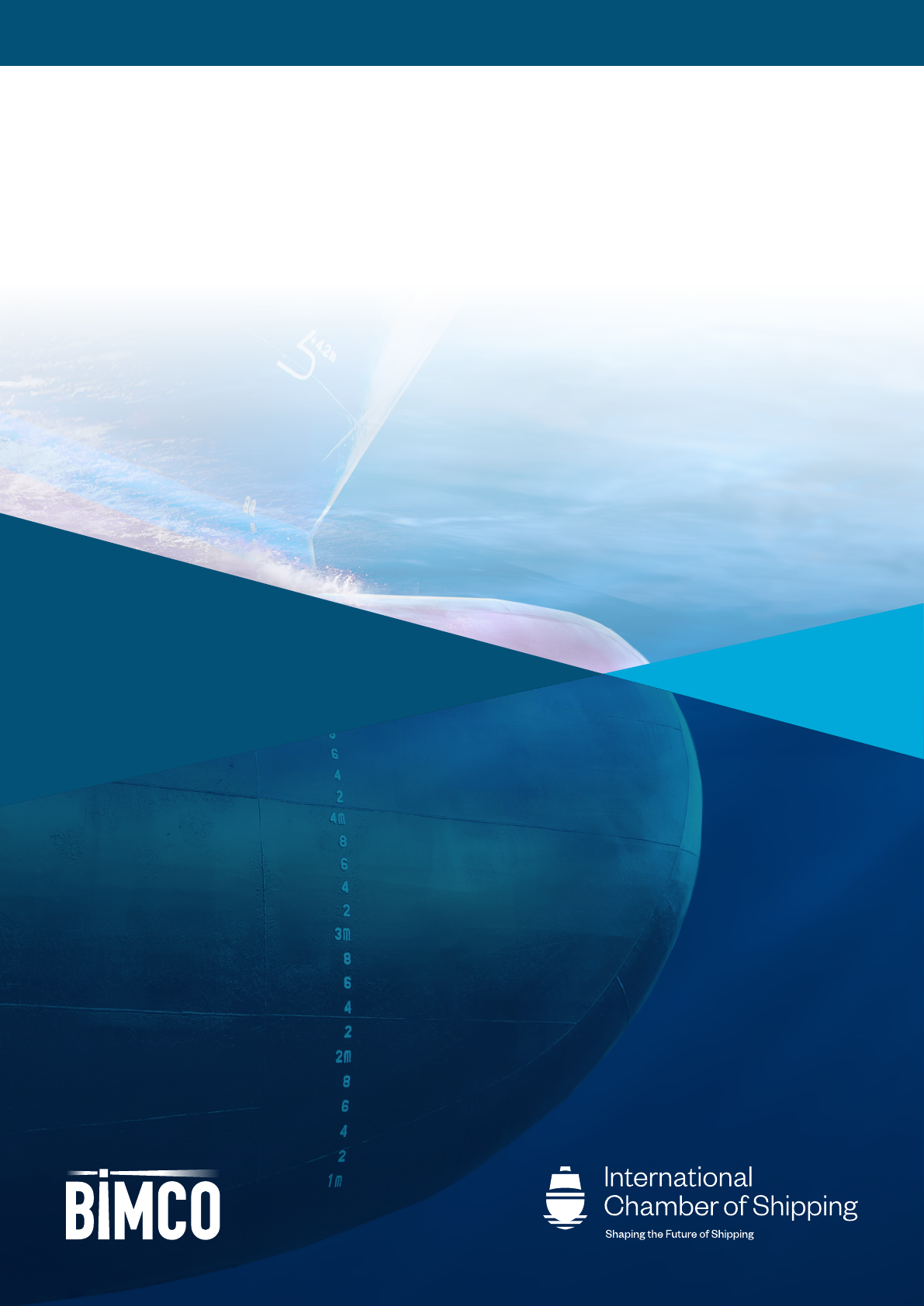
Any damage to the condion of the AFS, which is observed during an inspecon or cleaning, shall be
reported. The following descripons as visualised in the table below should be used for reporng:
Type
Adhesion The failure of adhesion between a
coang and a metallic surface that
is directly aributable to cathodic
protecon condions. It is oen
iniated by a defect in the coang
system, such as accidental damage,
imperfect applicaon or excessive
permeability.
Blistering Dome shaped projecons or
blisters in dry paint lm.
Paint coangs with visible cracks
which may penetrate down to the
substrate.
Viscous ow of solid at ordinary
temperatures. The distoron of
solid coang under sustained
pressure during curing.
/peeling/
detachment
Defects associated with
detachment of coang.
The connuous release of the
outermost binder material into
the seawater during the ship’s
operaon.
general
damage
The eect on the anfouling
coang system caused by contact
with the seabed or bank.
Figure 2: Examples of coang damage.

INDUSTRY STANDARD ON IN-WATER CLEANING WITH CAPTURE v1.0 17
The service report contains basic informaon about the inspecon that was carried out. This service
report shall be completed by the inspecon company and be handed over to the masteror another
representave of the ship. A format of the service report can be found in Annex 5.
The inspecon report is the nal report of the inspecon. It shall be completed by the cleaning
company and contain the following: The ship’s details and dra at the me of survey; names of
stakeholders in aendance, an-fouling system type and date applied. It shall include details of the
inspecon and any observaons including detailed informaon about the biofouling types, condion
of the AFS and biofouling coverage on the underwater area of the ship as well as the reference areas.
Photos and/or videos shall form part of the documentaon.
A copy of the inspecon report should be retained by the ship and kept with the biofouling record
book.
An example of the minimum content for an inspecon report is provided in the Annex 4 to this
Industry standard.

INDUSTRY STANDARD ON IN-WATER CLEANING WITH CAPTURE v1.0 18
7 Pre-communication
When the decision to clean the ship’s hull and/or niche areas has been taken, the shipowner should
request a list of approved cleaning companies from the port.
The shipowner shall send the following informaon to the appointed cleaning company:
1. age of AFS and its expected service life mespan
2. previous damage to the AFS if any
3. type of an-fouling coang and the coang manufacturer’s advice on cleaning
4. list or drawing arrangement of reference areas
5. the area(s) of the ship to be cleaned. For example, does the ship need a full cleaning or has a
paral cleaning been done previously by another company?
6. niche areas needing to be cleaned and divided into the following categories:
a. niche areas present on the vercal side or the boom of the ship that can be readily cleaned
b. propellers
c. niche areas that need special cleaning equipment and procedures
7. previous inspecon/cleaning reports since the AFS was applied
8. place where the cleaning is to be carried out (berth/anchorage)
9. available amount of me for cleaning
10. other operaons planned by the ship such as repairs, bunkering, storing, etc
11. transfer of the ship within port area, alongside and at anchorage, if relevant
12. any other relevant informaon, such as idle periods.
The cleaning company shall inform the shipowner about the regulatory requirements and standards
applicable for cleaning in the specied port and if the cleaning company can provide the required
service.
The appointed cleaning company shall inform the shipowner about the following:
1. categories that the company has been approved to operate in accordance with the Industry
standard for in-water cleaning with capture:
a. hull, and niche areas present on the vercal side or the boom of the ship that can be readily
cleaned
b. propellers
c. niche areas or hull areas that due to bends, turns etc need special cleaning equipment and
procedures
2. local cleaning permit (issued by the port and/or other relevant authority) and evidence of
approval (cercate issued by an approval body in accordance with the Approval procedure of
cleaning companies)
3. environmental condions, in which the cleaning company is permied to operate, including sea
state, weather condions, visibility, etc
4. the equipment that will be used for cleaning the ship’s hull and/or niche areas such as cleaning
units, umbilical, control unit, separaon and treatment unit including use of acve substances, if
any
INDUSTRY STANDARD ON IN-WATER CLEANING WITH CAPTURE v1.0 19
5. cleaning procedure, type of AFC or MGPS that the company has been approved to clean eg by a
manufacturer etc
6. place of cleaning either alongside and/or anchorage area
7. the required length of me to conduct the cleaning
8. limitaons associated with performing the cleaning
9. capture, separaon, treatment and waste disposal processes
10. local port requirements
11. any other relevant informaon.
The cleaning company shall supply the informaon, which is required by the local regulaons, to the
port/relevant authories in order to be allowed to proceed with the cleaning.
If niche areas on the vercal sides or the boom of the ship contain so and hard macro biofouling
beyond the tested capability of the approved cleaning system, the standard allows the cleaning of the
idened niche areas to proceed providing the total area of the fouled hull and niche areas does not
cover more than 5% of the submerged area of the hull. If this limit is exceeded, the cleaning shall be
undertaken either out of water or aer obtaining special permission from the relevant authories. If
such permission is granted, then the cleaning system shall sll adhere to the requirements detailed
within this Industry standard to manage the risk to the port environment.
There are no exempons for the approved special cleaning equipment that handle other niche areas,
as the cleaning system must be able to capture the so and hard macro biofouling in accordance with
this Industry standard.
The cleaning company shall maintain communicaon with the ship, port and other relevant
authories throughout the cleaning operaon and comply with any instrucons in accordance with
operaonal protocols specic to the ship and the port.

INDUSTRY STANDARD ON IN-WATER CLEANING WITH CAPTURE v1.0 20
8 Pre-cleaning preparations
A meeng shall be held between the ship and the cleaning company’s representave to determine
appropriate safety parameters and relevant informaon on how to access niche areas.
The cleaning company shall plan the cleaning meculously to ensure that the process is undertaken
eciently, safely and in an environmentally sound manner. The cleaning company should submit an
outline of the operaon plan to the ship and the port.
The cleaning company shall plan its resources to avoid/minimise breakdowns/interrupons.
Communicaon between the ship and in-water cleaner shall be planned and tested.
Before the planned operaon, funconal checks, pre-dive checks of the cleaning and capture system
plus the associated ancillary equipment shall be conducted.
An approved pre-dive checklist for guidance shall be used and cross checked with the record of any
possible defects and recent repairs
3
.
The ship shall follow established procedures to ensure that equipment such as thrusters, propellers
etc are locked or tagged out in order to ensure they cannot be used while the diver and/or ROV are in
the water. The divers, if any, must witness the locking and tagging of equipment prior to entering the
water.
Before the commencement of the cleaning acvity, the cleaning company shall conduct an inspecon
of the area to be cleaned and a safety check of equipment etc, as per the list below:
1. The cleaning acvity shall be planned to ensure the safety of the personnel, equipment and ship
during the enre operaon. The underwater cleaning route should be well planned to avoid
losing orientaon underwater. As a minimum, the planning should take into consideraon water
visibility, current, dal variaons, weather condions, simultaneous operaons such as bunkering,
ballasng/de-ballasng, movement of cranes, obstrucons at the quay such as fenders, mooring
dolphins, other ships in the area, pinch points and locaon of surface support (for diver’s
emergency evacuaon).
2. Establish safety procedures should the movements of other ships aect the cleaning operaon.
3. Agree on a meline regarding the securing of key systems and equipment. For example, the
propeller shall not be able to move during the cleaning process and the cathodic hull protecon
system should be powered o whilst the hull is being cleaned.
4. Procedures shall be in place to ensure that all systems and equipment, including personal
protecon equipment (PPE) are funconal and sll within their operaonal life.
5. Establish how to minimise the risk of loss of material when planning the cleaning in complex
areas eg in the vicinity of bends, turns etc.
6. Conngency plans and procedures shall be in place to prevent and migate the exceedance of any
safety and/or environmental parameters and ensure that the cleaning operaons are suspended
and remain suspended unl such parameters are safely restored.
3 Such checklists are dependent on local regulaons and diving equipment and are thus outside the scope of this Industry standard.

INDUSTRY STANDARD ON IN-WATER CLEANING WITH CAPTURE v1.0 21
7. Outline emergency shut down procedures designed to prevent the spill of biofouling euent back
into port waters.
Based on a previous inspecon report and/ or a pre-inspecon of the submerged area of the ship, a
pre-assessment of the cleaning areas shall be carried out by the cleaning company in accordance with
the following:
1. To conrm that the observed biofouling lies within the cleaning systems capabilies.
2. The cleaning company should, if applicable, inform or seek approval of the port authority to
commence operaons.
3. A check of the operaonal area should be conducted to take note of the following:
a. if there is enough clearance to clean the side of the ship. For example, quay side clearance,
fender obstrucons etc
b. clearance under the ship throughout the operaon, taking into consideraon the expected rise
and fall of de and change in the dra of the ship
c. any potenal movements of ships which could aect the cleaning operaon.
4. Any areas of concern as a result of the inspecon, shall be discussed with the ship and/or port or
other authories before proceeding with the cleaning acvity.
5. AFS damage shall be discussed with the ship to establish if the cleaning should proceed.
6. Any discrepancies between the records on the ship and the actual condion of underwater hull
or niche areas of the ship, shall be discussed with the ship before proceeding with the cleaning
acvity.
7. The cleaning company must outline the sequence of cleaning with the ship to ensure best results
in terms of safety, quality and protecon of the environment.
The cleaning company shall inform the port/relevant authories if it suspects that the type or
coverage of biofouling on the ship is outside the capability of their system.
INDUSTRY STANDARD ON IN-WATER CLEANING WITH CAPTURE v1.0 22
9
Operating requirements of the cleaning system with capture
An in-water cleaning system may consist of the units that are shown in gure 3.
A control unit houses the controls such as remote control of ROVs, communicaon devices with
divers, camera monitors etc.
The cleaning unit is used to clean the hull, propeller and/or niche areas. It can be operated by a diver
using a cleaning technology or by a ROV. The cleaning unit removes and captures materials and is
aached to the separaon and treatment or storage unit by hoses.
The hoses provide means of transporng the captured material and seawater from the cleaning unit
to the separaon and treatment unit or a storage unit. Cables are used for communicaon purposes
and to power the ROV or other cleaning technology.
Some cleaning systems pump the captured material and seawater into a storage unit eg a barge
or mono-hull tanker. The captured material and seawater in the storage unit will subsequently be
pumped to the separaon and treatment unit(s).
The separaon unit houses the equipment that removes the captured material and the seawater
inuent.
The treatment unit can be used as an integrated part of the separaon unit or as an addional unit to
treat the inuent water further aer the separaon unit. Treatment may include use of heat, biocides,
or ultra-violet light.
CONTROL
UNIT
STORAGE
UNIT
CLEANING UNIT
ROV
REMOTELY
OPERATED
VEHICLE
CABLES & HOSES
DIVER
TREATMENT
UNIT
SEPARATION
UNIT
Figure 3: Schemac diagram of a cleaning system.

INDUSTRY STANDARD ON IN-WATER CLEANING WITH CAPTURE v1.0 23
The cleaning must be conducted using approved systems and procedures as outlined in the Approval
procedure for in-water cleaning companies.
1. When choosing the cleaning equipment, careful consideraon should be given to the informaon
received from the AFS manufacturers and/or ship to ensure the performance of the AFS is not
impaired.
2. The cleaning unit must be able to safely reach the secon of underwater area that has to be
cleaned and be able to remove visible biofouling
4
.
3. Procedures must be in place to avoid accidental releases into the water and the cleaning system
shall capture the dislodged material. If a cleaning unit accidentally releases material into the
sea, it shall be assessed to nd the root cause. In case of consecuve malfuncons or when a
malfuncon results in the release of captured materials to the marine environment, the cleaning
equipment shall be taken out of service and tested. Any accidental release should be recorded in
the cleaning acvity log with the conngency measures taken and the relevant authories should
be alerted of the incident.
4. Pictures and/or videos shall be used to document the eecveness of the cleaning. The
photographs and videos should conform to the specicaons menoned in the Annex 3 of this
Industry standard.
The cleaning company shall maintain a log of all cleaning acvies. It should include the name and
IMO number of the ship, the AFS, type of cleaning, amount of material captured, records (or copies
of records) of the disposal of all such material and sea water euent, plus records of accidental
discharges, if any. The log shall be available on request by the port and other relevant authories and
retained for 3 years or longer if so required by a port or other relevant authority. A representave
video or photos of the enre cleaning for each ship shall be kept for a minimum period of 1 year.
In-water niche area cleaning shall be carried out using systems and procedures that are approved in
accordance with the Approval procedure for in-water cleaning companies.
Cleaning of niche areas shall be done by removal and capture of all material.
When cleaning a propeller, which has biofouling growth, this Industry standard fully applies.
The Industry standard does not cover polishing a hard and tenacious layer of calcareous chalk without
capture.
1. A post-cleaning inspecon shall be carried out upon compleon of the operaon.
2. The post cleaning inspecon can be done during the cleaning process by using cameras installed
on the ROV unit. It is important that the photos and videos are able to clearly depict the exact
condion of the hull, and AFS plus any biofouling. If this cannot be achieved, then the cleaning
company shall conduct a post-cleaning inspecon aer the cleaning acvity is completed.
4 Some types of biofouling will adhere to the surface and will leave residual biofouling, oen non-viable, skeletal remnants, even aer cleaning, which
cannot be removed without damaging the AFS. Examples include the baseplates of barnacles and bases of worm tubes.

INDUSTRY STANDARD ON IN-WATER CLEANING WITH CAPTURE v1.0 24
3. This inspecon shall cover the enre area that was cleaned with special aenon to the reference
areas.
4. Photographs and/or videos should be used to collect and retain evidence of the cleaning acvity
and demonstrate eecve removal and capture of biofouling have taken place. Photos and/
or videos of at least all the reference areas within the cleaned area shall be documented and
retained as evidence.
5. A service report should be completed by the cleaning company in the format menoned in
Annex 5 of the Industry standard.
6. If the cleaning acvity did not cover the enre planned area or areas, documentaon shall be
made to show where the cleaning started and where it stopped. The documentaon shall be
suciently detailed to enable another in-water cleaning company to connue the cleaning at the
next available opportunity. This documentaon should be recorded in the cleaning report and in
the biofouling record book.
A post cleaning meeng must be held to terminate the permit and to conrm that ship’s equipment
and machinery can be reinstated to the normal operaonal status.
Aer the following procedures have been completed, a post cleaning meeng must be held:
1. Aer compleng all in-water cleaning acvies, the equipment should be removed from the
water and brought back to their original posions.
2. All underwater grangs shall be safely restored to their original state.
3. All remaining material in the in-water cleaning system including the hoses, separaon and
treatment units shall be contained and disposed of in a safe manner. The cleaning company shall
ensure the material does not nd its way into the local marine environment.
4. When conrmaon has been received that all cleaning equipment and personnel have been
removed from the water, the ship can be made operaonal by releasing locked out or tagged out
systems.
This service report contains basic informaon about the cleaning that was carried out. The cleaning
company shall hand over the service report to the master or another representave of the ship at the
post cleaning meeng and before the ship’s departure. A format of the service report can be found in
Annex 5.
The results of the cleaning operaon shall be accurately documented in the cleaning report as
described in Annex 6, and shall be retained on board the ship, along with the biofouling record book.
The cleaning report shall contain informaon based on documentaon from reference areas or other
areas if available about the biofouling observed prior to cleaning, details of the cleaning performed
plus the state of the AFC before and aer cleaning.
Further, it shall provide detailed informaon about the locaon of the cleaned areas to enable
another in-water cleaning company to connue the cleaning if necessary.
Cleaning reports shall be retained for a period of two years on board the ship and thereaer with the
shipping company unl at least ve years have elapsed since the date of the cleaning.

INDUSTRY STANDARD ON IN-WATER CLEANING WITH CAPTURE v1.0 25
10 Systems used to prevent biofouling growth
According to the IMO Biofouling Guidelines, the ship’s biofouling management plan should include
details of the AFS, and operaonal pracces used.
There are ways to reduce the likelihood of biofouling on the underwater hull and niche areas such as:
1. An-fouling coang system (AFC)
2. Marine growth prevenon system (MGPS)
To ensure the use of appropriate methods and equipment, the cleaning company should prior to
commencing the work gather informaon such as:
1. type/specicaon of the cleaning equipment to be used
2. manufacturer’s recommendaons for in-water cleaning based on the coang properes
3. details of the areas, to which each specic treatment/cleaning is to be applied
4. any other details relevant to the processes (eg chemicals required for treatment, any discharge
standards).
The IMO Biofouling Guidelines include a number of issues that needs to be communicated between
the AFS supplier and the ship. The following informaon provided by the AFC supplier must be
included in the biofouling management plan and record book:
1. type of AFC
a. manufacturer, product names and the locaon on the ship where the AFS has been applied
b. in case dierent coang types have been used for the hull and the niche areas, this should be
specied
2. AFC specicaons
a. dry lm thickness of coangs
b. the expected service lifeme of the an-fouling coang
c. operang condions required for coangs to be eecve
d. any other specicaons relevant to the AFS performance
e. any addional products/chemicals used in conjuncon with the AFS (either to increase
durability or prepare the surfaces)
f. aachments in form of the material safety data sheet and technical data sheet.
This is a combinaon of all component coangs and/or surface treatments (such as primer, sealer,
an-corrosive e-coat, and an-fouling coangs etc) used on a ship to control or prevent the
aachment of unwanted aquac organisms.
The lifeme of an AFS depends on several factors such as thickness of the paint, operang parameters
of the ship, cleaning frequency etc.
AFS manufacturers should supply informaon about the expected lifeme of the AFS applied on the
ship, along with the condions that need to be fullled in order to ensure the an-fouling coang’s
durability.

INDUSTRY STANDARD ON IN-WATER CLEANING WITH CAPTURE v1.0 26
If available, the following specic informaon used to determine the appropriate AFS and relevant
scheme for the ship shall be recorded in the biofouling management plan and record book, in
addion to the informaon already required in the biofouling management plan:
assumed typical operang speed of the ship (knots)
assumed acvity period (%)
maximum acceptable idle period (where relevant)
assumed areas of operaon
other relevant informaon pertaining to ensuring AFS performance.
The above is the minimum informaon required but more may be needed depending on the specic
coang system. It is crical that these assumpons are periodically reviewed during the ship’s
operaons to idenfy periods that the AFS will or may not perform according to the manufacturer’s
technical specicaons. Deviaons from these parameters should be discussed with the coang
manufacturer to determine the impact on the ecacy of the specied coang scheme.
MGPS systems use several technologies to reduce the likelihood of biofouling growth in niche areas.
Some of these are not technically robust and providing an overview of all available methods is beyond
the scope of this document.
The MGPS manufacturer should provide instrucons on the cleaning and protecon of the MGPS
during cleaning.
The following informaon provided by the MGPS supplier must be included in the biofouling
management plan and record book as appropriate:
a. type of MGPS
b. date of applicaon and performance period/lifeme
c. locaon(s) where MGPS was/were installed
d. the expected eecve lifeme of consumable elements of the MGPS
e. operang condions required for MGPS to be eecve
f. dosing and applicaon frequency of MGPS (as applicable)
g. any other specicaons relevant to the MGPS’ performance.
When using a system that injects chemicals such as chlorine or sodium hypochlorite, the
manufacturer should provide informaon about the recommended amount of chemical that should
be used and include chemical safety as well as emergency and neutralizaon protocols.
cleaning
When the cleaning acvity has been completed and the cleaning report has been received, the
shipowner should provide the following cleaning informaon to the AFS manufacturer:
details from the cleaning report including any reported damage to the AFS, excluding
commercially sensive informaon
date of cleaning
INDUSTRY STANDARD ON IN-WATER CLEANING WITH CAPTURE v1.0 27
number of previous cleans since the applicaon or installaon
cleaning company
method used during cleaning (diver, ROV)
nechanism of clean (brush, waterjet, cavitaon etc).
The AFS manufacturer should compare the available data of their product with the informaon
received from the shipowner in order to be able to give an esmaon of the remaining lifeme of the
AFS. This assessment including any recommendaons that need to be met for the remaining lifeme
of the AFS should be communicated to the shipowner.

INDUSTRY STANDARD ON IN-WATER CLEANING WITH CAPTURE v1.0 28
11
Management of materials and seawater effluent
This chapter sets the standards for the capture and handling of removed materials in connecon with
in-water cleaning. The handling of seawater euent prior to its release back into the sea are also
included in this chapter.
This chapter is not intended to replace requirements of local port state control and other
relevant authories. The cleaning company should seek advice regarding the required tesng and
environmental sampling regimes for each individual port, where the cleaning will take place. Local
requirements concerning eg disposal of material captured during a cleaning operaon must be met.
This chapter also outlines the standards according to which approved cleaning companies shall carry
out internal auding of their systems to ensure the required level of ecacy.
The cleaning company shall have procedures in place to avoid release of materials throughout the
enre cleaning operaon, including when mobilising and demobilising the equipment. Use of non-
return valves should be described, if available.
11.2 Material handling
The cleaning company shall have procedures in place that describe the handling of material as well as
the capture, separaon and/or treatment of seawater.
The approval cercate of the cleaning company shows that the following criteria have been tested
and fullled:
1. The in-water cleaning process removes at least 90% of macrofouling (ie individuals or colonies
visible to the human eye).
2. The separaon and/or treatment of captured materials during in-water cleaning both: (1)
removes at least 90% (by mass) of material from seawater inuent and (2) at least 95% of
parculate material in euent water is 10 µm in equivalent spherical diameter (ESD);
3. Local water quality parameters of Total Suspended Solids (TSS) are not elevated above ambient
levels during the same me period.
The approval cercate of the cleaning company may also show that the following criteria have been
tested and fullled:
4. Local water quality parameters of dissolved and parculate biocides found in AFC are not
elevated signicantly above ambient levels during the same me period.
The tesng of the system has been described in detail in the Approval procedure for in-water cleaning
companies.
In addion, the separated material shall be disposed of in accordance with local regulaons and sea
water euent shall conform with the specicaons of the port.

INDUSTRY STANDARD ON IN-WATER CLEANING WITH CAPTURE v1.0 29
The cleaning company shall carry out internal audits to check the cleaning system’s safety
requirements and ability to capture material during operaon at least once every 12 months unless
higher frequency is required by relevant authories.
Prior reports in connecon with internal auding of cleaning systems shall be given to the approval
body before the below menoned audits are iniated. If required, internal audit reports should also
be sent to the port and/or local authories.
An annual vericaon audit is an external audit that involves vericaon of documents and a visual
inspecon of the cleaning system and its units.
Aer any major substanal technical change that has a direct impact on the operaonal manual and
necessitates training of personnel, a renewal or re-endorsement of the cercate shall be carried out.
Every ve years, the approval must be renewed though tesng and external auding. If required,
outcomes of external audits should be submied to the port and/or local authories.
More details on approval, cercaon and quality insurance can be found in the Approval procedure
for in-water cleaning companies. If required, outcomes of external audits should be submied to the
port and/or local authories.
Date of audits must be entered into the cleaning company’s log of cleaning acvies and refer to
audit reports and test results.
The cleaning company shall maintain a log of all cleaning acvies. This should include the number
of cleaning operaons carried out, the name and IMO number of the ship, the AFS, type of cleaning,
amount of material captured, records (or copies of records) of disposal of such material and sea
water euent, records of accidental discharges if any (including records of having reported this to the
relevant authories) and all relevant laboratory results to conrm the ecacy of the system.
Commercially sensive informaon shall not be stored by the cleaning companies, unless authorised
by the respecve owners of such informaon. Should there be a need for any further informaon
later, the same shall be sourced from the righul owner of such informaon.
Underperformance of cleaning systems must be immediately reported to the port, the approval body
and relevant authories.
Any underperforming cleaning system shall be repaired or replaced to the sasfacon of the approval
body issuing the cercate and local authories issuing the permit.

INDUSTRY STANDARD ON IN-WATER CLEANING WITH CAPTURE v1.0 30
Sample in-water cleaning actions in a biofouling record book
Details of all inspecons and biofouling management measures undertaken on the ship shall be
entered into the biofouling record book. The following shows a number of examples that have been
entered into dierent biofouling record books.
The tables should be read in conjuncon with Appendix 2 of the IMO Biofouling Guidelines. The item
numbers in the table refer to this appendix.
Date
15-Jan-2018 2.2 a 05 Jan 2018, Dubai anchorage, assessment indicates biofouling growth on hull.
Reference areas 1.1, 1.2, 2.1, 2.2,3 .1,3.2, 4.1, 4.2, 5.1, 6.1, 6.2 found to be
covered with so biofouling.
2.2 b Enre underwater hull including reference areas and 8 niche areas inspected.
2.2 c 10% biofouling growth observed on the hull and niche areas. Hard calcareous
biofouling covering between 2-5% of the enre underwater hull areas observed.
Height of hard calcareous ranges between 5 to 15 mm.
2.2 d Refer to hull inspecon report no: XXXX, dated: XXXX, for more informaon.
2.2 e Name of oce in charge:
Posion:
Signature:
Date
15-Jan-2018 2.3 a 05 Jan 2018, Dubai anchorage
2.3 b A half of hull including reference areas 1.1, 1.2, 2.1, 2.2, 3.1, 3.2, 4.1, 4.2, 5.1,
6.1, 6.2 cleaned. Following niche areas cleaned – propeller, rudder, sea chest, a
echo sounder probe.
2.3 c High pressure water jets and vacuum sucon used.
2.3 d 10% Biofouling growth observed on the hull and niche areas.
Hard calcareous biofouling covering less than 5% of the enre underwater hull
areas observed.
A half of hull, including reference areas 1.1, 1.2, 2.1, 2.2, 3.1,
3.2, 4.1, 4.2, 5.1, 6.1, 6.2 cleaned, and documentaon shows no biofouling in
these areas.
2.3 e See cleaning report no: XXXX, dated: XXXX
And associated photographs and videos.
2.3 f Ship permit to work No: XXXX, dated: XXXX Port permit to work No: XXXX, dated:
XXXX
2.3 g Name of oce in charge:
Posion:
Signature:

INDUSTRY STANDARD ON IN-WATER CLEANING WITH CAPTURE v1.0 31
Date
15-Jan-2018 2.3 a 05 Jan 2018, Dubai anchorage
2.3 b A half of hull including reference areas 1.1, 1.2, 2.1, 2.2, 3.1, 3.2, 4.1, 4.2, 5.1,
6.1, 6.2 cleaned. Following niche areas cleaned – propeller, rudder, sea chest, a
echo sounder probe.
2.3 c High pressure water jets and vacuum sucon used.
2.3 d 10% Biofouling growth observed on the hull and niche areas.
Hard calcareous biofouling covering less than 5% of the enre underwater hull
areas observed.
A half of hull, including reference areas 1.1, 1.2, 2.1, 2.2, 3.1,
3.2, 4.1, 4.2, 5.1, 6.1, 6.2 cleaned, and documentaon shows no biofouling in
these areas.
2.3 e See cleaning report no: XXXX, dated: XXXX
And associated photographs and videos.
2.3 f Ship permit to work No: XXXX, dated: XXXX Port permit to work No: XXXX, dated:
XXXX
2.3 g Name of oce in charge:
Posion:
Signature:
Date
15-Jan-2018 2.4 a 05 Jan 2018, Dubai anchorage
2.4 b Signicant growth of biofouling was observed in the seawater cooling pipes.
Predominant type of biofouling was goose neck barnacles.
2.4 c Cleaned to the extent possible
2.4 d Vacuum sucon, manual tools
2.4 e See cleaning report no: XXXX, dated: XXXX
2.4 f Name of oce in charge:
Posion:
Signature:
Date
01-Mar-2020 2.6 a Ship anchored at Fujairah anchorage.
01-Apr-2020 2.6 b Anchor aweigh and ship resumed voyage to Ruwais.
02-Apr-2020 2.6 c Ship headed for an underwater hull inspecon.
02-Apr-2020 2.6 d Sea chest blanked o / Echo Sounder probe raised etc.
Date
15-Feb-2019 2.9 a During port entry, tug made metal to metal contact with ship’s hull. AFS damage
may have occurred. Hull to be inspected during ship’s port stay.
INDUSTRY STANDARD ON IN-WATER CLEANING WITH CAPTURE v1.0 32
Reference areas
A set of reference areas should be determined for use of inspecon and to gauge the ecacy of the
cleaning.
Reference areas located on the hull should be prepared as early as possible in the life of the ship,
and preferably as soon as the hull has been coated or re-coated with a new AFS. The outline of the
reference areas could be done using contrasng colours.
Reference areas shall give a general representaon of the submerged areas of the enre ship’s hull
and niche areas. When selecng the areas, it should be considered that dierent areas of the hull are
aected by biofouling to varying degrees.
Already exisng idencaon marks, such as dra marks, tank/hold marks, load line marks and
other easily idenable locaons, sea chests, discharges, transducers, boom plugs on the ship’s hull
should be used whenever possible. Ships, that are assigned in-water cleaning class notaons, have
addional hull markings that can be used.
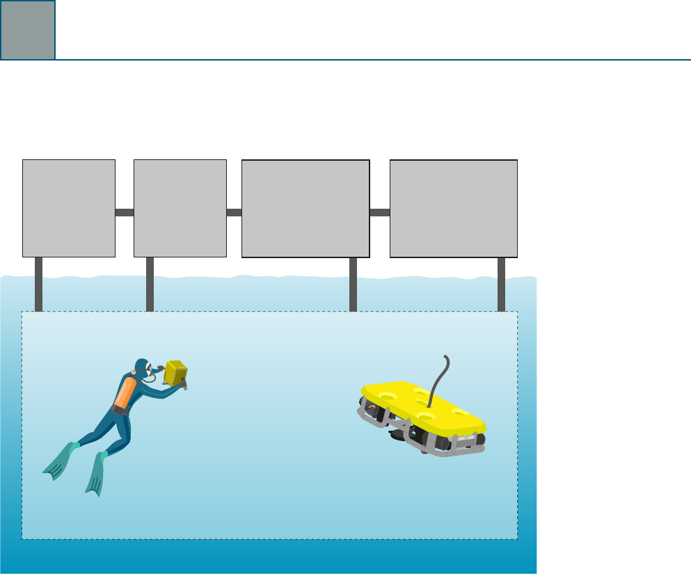
When determining the reference areas, the underwater hull of the ship should be divided into
vercally separated areas and each assigned a reference locaon.
The underwater hull area of the ship should be divided into enough longitudinally (fore and a
direcon) separated secons. See gure 4.
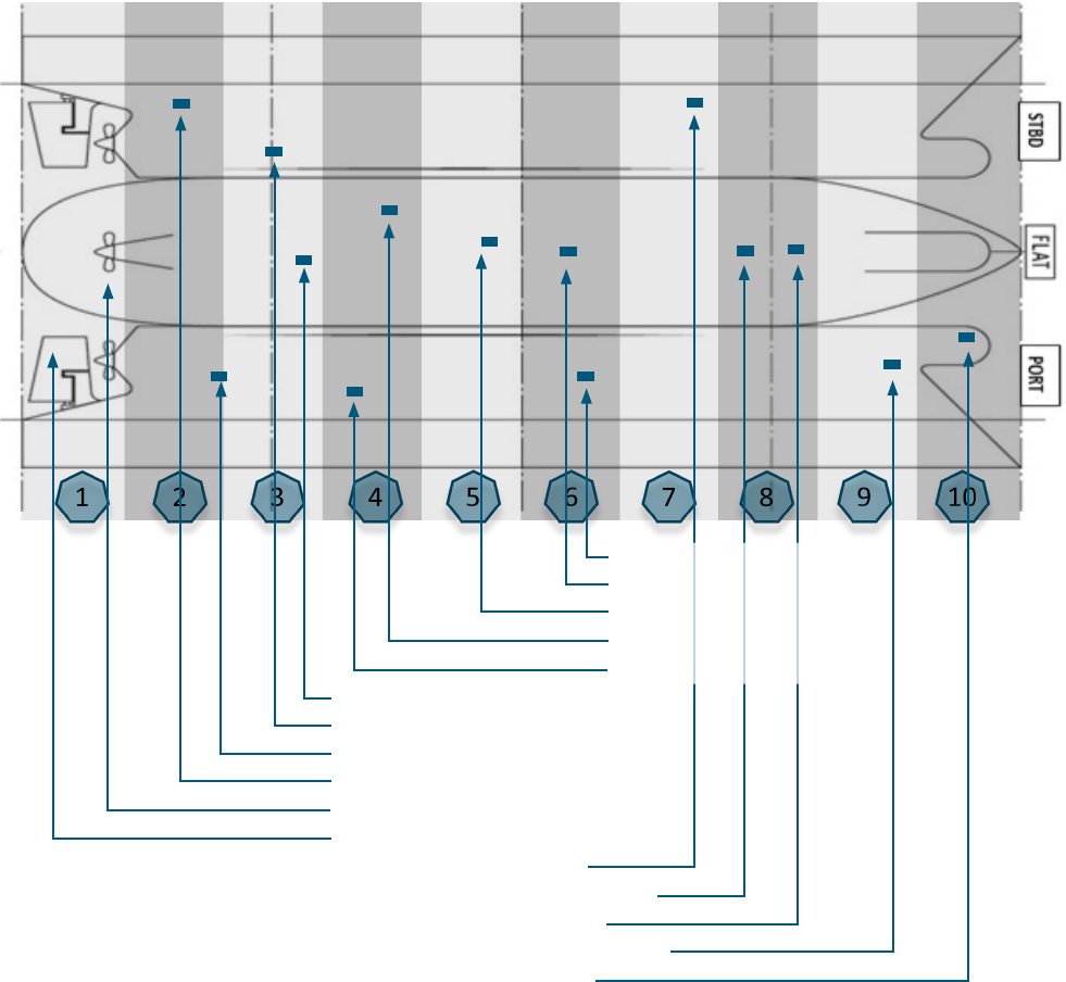
Figure 4: Ship divided into longitudinally separated vercal secons.
INDUSTRY STANDARD ON IN-WATER CLEANING WITH CAPTURE v1.0 33
In each of these secons, one or more reference areas should be selected. Studying the following
plans and reports may help in this process:
1. general arrangement plan
2. plans showing exisng hull markings
3. boom plug plan
4. shell expansion plan
5. previous in-water inspecon reports that help to indicate which areas divers found easy to reach
or idenfy, as there will be repeated menon of the same areas in mulple reports
6. dry-dock reports.
The result of a selecon of reference areas can be seen on gure 5.
Figure 5: Example of reference areas and their numbering.
INDUSTRY STANDARD ON IN-WATER CLEANING WITH CAPTURE v1.0 34
1. The number and locaon of the selected areas should represent the enre underwater hull and
niche areas of the ship. This means choosing reference areas at various depths of the vercal hull
as well as the boom of the ship.
2. Reference areas should be named/numbered for easy idencaon. Numbering should be such
that, it is easily idenable, and easy to be sequenally inspected by a diver or camera/ROV.
3. The reference areas shall be inserted in the biofouling management plan and a similar entry shall
be made in a separate secon in the biofouling record book.
Alternave method in case the reference areas are not marked by contrasng colours etc:
1. The underwater hull area of the ship should be divided longitudinally into (fore and a direcon)
separate secons that represent the whole underwater area.
2. In each of these zones, reference areas should be selected at preassigned dras of the ship. For
example, at the depth 6 meter, 4 meter, 2 meter and 0 meter (boom) on each side of the hull.
3. For each of these areas, an exisng hull marking above the water line such as dra mark, load line
mark, cargo hold number, cargo tank number, pilot boarding area marking, tug marks should be
chosen as pre-reference mark.
4. If there are not enough exisng markings or disnguishing hull structures, the shipowner
may choose to mark addional marking on the vercal surface above the water line for easy
idencaon.
Figure 5 illustrates the choice of reference areas.
INDUSTRY STANDARD ON IN-WATER CLEANING WITH CAPTURE v1.0 35
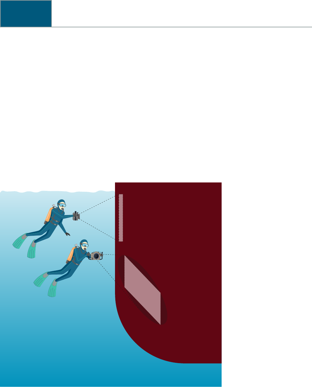
Standards of photographs and videos
Photographs and/or videos taken by a diver or ROV should follow certain specicaons to conform
with this standard. The purpose of the photographs/videos is to support the diver/ROV inspecon
and to document the biofouling and AFS condion.
Photograph of reference areas:
1. The photograph should depict the general condion of the area and should, if visibility permits,
cover the enre reference area. In the event of restricted visibility, the reference area can be
photographed using a mosaic of photographs.
2. The diver/camera operator should carefully choose the camera sengs to ensure proper lighng,
exposure, focus, colour, tone etc for capturing an accurate image.
3. The angle of the picture should be chosen carefully to ensure a true reecon of the marine
growth and/or damages to AFS system, if any. The correct angle, without use of IT programs to
compensate, is perpendicular to the surface.
Figure 6: Camera angle and locaon.
The reference area number should be idenable on the photograph. This may be done either during
lming or later during the eding process.
NACE Internaonal has published a standard, SP21421 – 2017, for underwater evaluaon of
biofouling degree on ships hulls, which is designed to facilitate descripons of degree of biofouling.
This standard uses pictures with examples of high quality and gives standards for scale etc.
INDUSTRY STANDARD ON IN-WATER CLEANING WITH CAPTURE v1.0 36
1. Speed: The diver or the cleaning supervisor should determine the speed keeping the following
factors in mind:
a. size of the eld-of-view in video
b. sunlight and associated glare
c. area of the ship being videoed
d. video equipment’s capability.
2. In any case, the swimming speed over the hull should not exceed 30 cm/s (0.6 knots) to prevent
blurring of the image in individual frames.
3. The reference areas should be captured within the video. If the video camera is unable to cover
an enre reference area in one run, a system should be in place to enable sampling of recordings
to show the enre reference area.

INDUSTRY STANDARD ON IN-WATER CLEANING WITH CAPTURE v1.0 37
Inspection report
Inspecon reports should as a minimum include the following:
Date of report:
Name of the ship
IMO number
Name of the company performing the service
Evidence of cleaning company authorizaon This is evidence that the company is authorised to conduct operaons as per this
Industry standard. Could be authorizaon number or copy of the approval cercate.
Document ID / job number
Posion of the ship / geographical locaon
of ship
Type, age, and size of the ship
Date of inspecon
Arrival dra (forward, midships, a) F: M: A:
Current (knots) XX knots
Visibility of water XX metres
Sea state Calm, fair, rough etc
Weather Sunny, cloudy, rainy etc
Type and age of an-fouling system(s) Self-polishing paint (SPC), foul release coang (FRC), hard paint, others
Date of applicaon or number of years/months since applicaon
Ship’s specic details Number of propellers –
Number of rudders –
Bow, stern, azimuth thrusters –
Time – contractor alongside
Time – start operaons
Time – completed operaons
Delays, if any with reasons
Descripon of inspecon carried out Number of divers, ROVs and recorded metables
Damage and/or special events, if any
Biofouling coverage observed (% of hull) and
type observed
The percentage should state the coverage of biofouling of areas inspected. For
example, if only the a half of the ship was inspected and 5% cover was seen in this
area, then the report should state – “5% biofouling coverage seen from midships
to a end of the ship”. Care should be taken to not menon this as 2.5% of the
enre underwater surface or 5% of the enre underwater surface as this may dier
signicantly.
Area Number XX
Each area that is inspected should be described below
Name of the an-fouling system
Type of an-fouling or MGPS
Condion of the an-fouling system
Type of paint defects observed and extent
(% of area)
Intact / detached / cracked / blistered / cold ow / orange peel / sagging (tears) /
polished o / damage due to external contact (tug, fenders, grounding)
Is biofouling observed?
Type of biofouling observed and extent
(% of area or dimensions in length and
breadth)

INDUSTRY STANDARD ON IN-WATER CLEANING WITH CAPTURE v1.0 38
So biofouling, select applicable Coverage (%)
Micro Slime
Macro So corals
Sponges
Hydroids
Anemones
Algae
Tunicates
Hard calcareous biofouling, select applicable Coverage (%)
Macro Barnacles
Mussels
Tube worms
Bryozoan
Oysters
Other (specify)
Predominant type of biofouling observed, if
any. Please ck.
Slime So corals
Sponges
Hydroids
Anemones
Algae
Tunicates
Barnacles
Mussels
Tube worms
Bryozoan
Oysters
Other (specify)
Method used for the inspecon (divers, ROV)
Photos and/or videos of the area
Any other comments
Area number XX
Each area that is inspected should be described below
To repeat the items as menoned above.
The report should contain separate details of
all inspected areas.
An entry should be made separately for every area inspected and details menoned
above to be included.
Each area that is inspected should be described below
To repeat the items as menoned above.
The report should contain separate details of
all inspected areas.
An entry should be made separately for every area inspected and details menoned
above to be included.
Number of propellers
Number of blades on the propellers
Pods Yes / No
Blade type Fixed pitch / Controllable pitch
Boss cap ns Yes / No
Propeller diameter XX mm
AFS coang if any
AFS condion Intact / detached / cracked / blistered / cold ow / orange peel / sagging(tears) /
polished o / damage due to external contact (grounding)

INDUSTRY STANDARD ON IN-WATER CLEANING WITH CAPTURE v1.0 39
Biofouling
Slime So corals
Sponges
Hydroids
Anemones
Algae
Tunicates
Barnacles
Mussels
Tube worms
Bryozoan
Oysters
Other (specify)
Other sediments Coverage of calcium
Boss cap N/A / secure / keepers intact / bolted cover secure / covered
Boss anode % depleted
Blade fastenings N/A / secure /keepers intact / covered / not visible
Visible damage Cavitaon / ping – details – depth of damage in mm
Any other ndings
Name and posion of the person in charge
of the service acvity / cleaning company
representave including signature and date:
Name and posion of the person in charge of
the ship/shipowner representave including
signature and date:

INDUSTRY STANDARD ON IN-WATER CLEANING WITH CAPTURE v1.0 40
Service report
The service report should at least include the following:
Date of report:
Name of the ship
IMO number
Name of the company performing the service
Evidence of cleaning company authorizaon This is evidence that the company is authorised to conduct operaons as per this
Industry standard. Could be authorizaon number or copy of the approval cercate.
Document ID / job number
Posion of the ship / geographical locaon of
cleaning
Last inspecon/cleaning Date, locaon, (company)
Date(s) of inspecon/cleaning
Arrival dra (forward, midships, a) F: M: A:
Current XX knots
Visibility of water XX metres
Sea state Calm, fair, rough etc
Weather Sunny, cloudy, rainy etc
Time – contractor alongside
Time – start operaons
Time – complete operaons
Delays, if any with reasons
Descripon of service acvity carried out Should include a descripon of all the services carried out on the ship. This may
include type of inspecon, or type of cleaning etc. In case a cleaning was only partly
nished the descripon should include enough informaon of the start and stop of
the acvity to enable another cleaner to connue the cleaning.
Descripon of the materials captured and
handling
A short descripon of what was captured and how it was handled should be included.
General descripon of evidence collected
and evidence of cleaning that will accompany
the cleaning report
A short descripon of what will be included in the nal report should be included
here.
AFS damage and/or special occurrences if
any
Name and posion of the person in charge
of the service acvity / cleaning company
representave including signature and date:
Name and posion of the person in charge of
the ship/shipowner representave including
signature and date:

INDUSTRY STANDARD ON IN-WATER CLEANING WITH CAPTURE v1.0 41
Cleaning report
The cleaning report should as a minimum include:
Date of report:
Name of the ship
IMO number
Principal dimensions
(length * breadth * depth)
Name of the company performing the service
Document idencaon / job number
Posion of the ship / geographical locaon of
ship
Last cleaning Date, locaon, (company)
Date(s) of cleaning (present cleaning)
Arrival dra (forward, midships, a) F: M: A:
Exact posion of cleaning Cleaning locaon ie berth number, terminal, mooring buoys, mooring dolphins,
anchorage (name of anchorage) etc
Descripon of posion Availability of space for cleaning between ship and quay, presence of other ships
such as bunker barges, lowest under keel clearance during the enre stay of the ship,
blocking parts of the hull (eg fender area) etc
Current XX knots
Visibility of water XX metres
Sea state Calm, fair, rough etc
Weather Sunny, cloudy, rainy etc
Type and age of an-fouling system(s)
Last cleaning details (if available) Date, locaon, (company)
Vessel specic details Number of propellers, rudders, bow thruster, stern thruster, azimuth thrusters etc
Time – contractor alongside
Time – start operaons
Time – complete operaons
Delays, if any with reasons
Descripon of cleaning acvity carried out Should include a descripon of all the services carried out on the ship. This may
include type of inspecon, or type of cleaning etc. In case a cleaning was only partly
nished the descripon should include enough informaon of the start and stop of
the acvity to enable another cleaner to connue the cleaning.
Descripon of the materials captured and
handling
A short descripon of what was captured and how it was handled should be
included.
Damage and or special occurrences if any A short descripon of what will be included in the nal report should be included
here.

INDUSTRY STANDARD ON IN-WATER CLEANING WITH CAPTURE v1.0 42
Area number XX
Each area that is cleaned should be described below
Hull cleaning: Starng point, area cleaned and end point. A sketch eg on the general
arrangement may be used.
Detailed descripon of the niche areas in queson
Condion of the an-fouling system before
cleaning.
Type of biofouling observed and extent
(% of area or dimensions in length and
breadth)
Select applicable
Coverage before (%) Coverage aer (%)
Micro Slime
Macro So corals
Sponges
Hydroids
Anemones
Algae
Tunicates
Macro Barnacles
Mussels
Tube worms
Bryozoan
Oysters
Other (specify)
Condion of the an-fouling system aer
cleaning?
Pictures of the area before cleaning
Pictures of the area aer cleaning
Area number XX
Each area that is cleaned should be described below
To repeat the items as menoned above.
The report should contain separate details of
all cleaned areas.
An entry should be made separately for every area cleaned and details menoned
above to be included.
Number of propellers
Number of blades on the propellers
Pods Yes / No
Blade type Fixed pitch / Controllable pitch
Boss cap ns Yes / No
Propeller diameter XX mm
AFS coang if any
AFS condion Intact / detached / cracked / blistered/ cold ow/ orange peel / sagging(tears) /
polished o / damage due to external contact (grounding)
Biofouling
Slime So corals
Sponges
Hydroids
Anemones
Algae
Tunicates
Barnacles
Mussels
Tube worms
Bryozoan
Oysters
Other (specify)

INDUSTRY STANDARD ON IN-WATER CLEANING WITH CAPTURE v1.0 43
Other sediments Coverage of calcium
Boss cap N/A / secure / keepers intact / bolted cover secure / covered
Boss anode % depleted
Blade fastenings N/A/ secure / keepers intact / covered / not visible
Visible damage Cavitaon / ping – details – depth of damage in mm
Condion of the an-fouling system aer
cleaning?
Pictures of the area before cleaning
Pictures of the area aer cleaning
Any other ndings
Treatment details
What is the esmated amount of materials
captured?
By weight
What treatment of seawater was done? eg technology used to separate and treat
Name and posion of the person in charge
of the service acvity / cleaning company
representave including signature and date:
Name and posion of the person in charge of
the ship/shipowner representave including
signature and date:

INDUSTRY STANDARD ON IN-WATER CLEANING WITH CAPTURE v1.0 44
EXPLANATORY NOTES TO THE INDUSTRY STANDARD...
Explanatory notes to the Industry standard on
in-water cleaning with capture
It has been necessary to divide niche areas into dierent categories because the same piece of
equipment cannot be used to clean all of them:
a. The hull itself and niche areas present on the vercal side or the boom of the ship that can be
readily cleaned without using special equipment. On such areas, the equipment used is designed
to clean large at areas fast, which includes remotely operated vehicles (ROV’s) and divers.
b. Propellers. The Industry standard addresses cleaning of the propeller with capture.
c. Niche areas that for example are built into the hull and/or have bends or corners have to be
cleaned with special equipment and therefore are non-comparable to (a) and (b).
A cleaning company can be approved for one or more of the categories. The approval process involves
a test of the equipment and the cercate will specify which category or categories the cleaning
company is approved to perform.
Biofouling will build-up faster in areas, where it has not been possible to apply an AFS, for example
dock block areas, which can be categorized as a niche area in the above-menoned category (a).
On average dry-dock support strips situated on the boom of the ship (also referred to as block
marks) are dened as niche areas and can be calculated to cover between 0.6% and 1.5% of the
submerged hull area dependant on the kind and size of the ship. The Industry standard, therefore,
presumes that the above-menoned category (a) niche areas may be equal to 5% of the submerged
hull area and an ROV or a diver can use normal equipment to clean them.
Dock block areas may be more fouled than the surrounding coated areas, some of which may be
hard calcareous biofouling with a height that lies beyond that for which the cleaning unit has been
approved.
The references areas are used to esmate the total percentage coverage by taking the average
coverage of all the reference areas as well as other observed areas.
The following is a non-exhausve list of niche areas:
1. sea chests
2. thrusters (bow, stern, azimuth etc)
3. tunnels associated with these thrusters
4. propeller shas
5. grangs (all grangs underwater)
6. access hatches and covers
7. rudder, rudder stock, hinge/pintle area
8. stern tube seal, rope guard external/internal
9. propeller and boss cap
10. bilge keels
11. cathodic protecon anodes
12. stabilizers and associated ns, spoilers
13. inlet/outlet pipes (all pipes underwater)

INDUSTRY STANDARD ON IN-WATER CLEANING WITH CAPTURE v1.0 45
EXPLANATORY NOTES TO THE INDUSTRY STANDARD...
14. transducers (echo sounder, speed log)
15. pitot tubes
16. bulbous bow
17. tug push points
18. areas of the hull that have been in contact with fenders
19. areas of the hull that have been in contact with anchor chains
20. waterline (boot top area)
21. anchor chains and chain lockers
22. edges and weld joints
23. any free ood spaces that may be immersed either wholly or partly when the ship is aoat.
There are a variety of methods available for cleaning the hull and niche areas. Some companies
use ROVs and others use divers. Further, some cleaners use brushes, whilst others use water jets
and other types of equipment. The Industry standard does not delve into the details of any specic
cleaning methods and techniques nor does it provide any form of rang. Instead, the Industry
standard concentrates on the processes for relevant stakeholders that will ensure a safe, ecient and
environmentally sound in-water cleaning process.
In 2011, IMO adopted the guidelines recommending the use of a biofouling management plan and
biofouling record book (Resoluon MEPC.207(62), 2011 Guidelines for the Control and management
of Ships’ Biofouling to Minimize the Transfer of Invasive Aquac Species (IMO Biofouling Guidelines).
The informaon in the IMO Biofouling Guidelines has formed the basis of the Industry standard.
In this chapter, the requirements for the recordings that should be made by the ship in addion to
the IMO Biofouling Guidelines are listed. Further, some coastal states and port states may require
addional documentaon.
The ship specic informaon that should be included in the biofouling management plan can be
found from the inial ship specicaon documents and docking survey les. Other sources of this
informaon are the shipyard or AFS manufacturer.
From a praccal point of view, it may be benecial to incorporate biofouling management in the PMS
of the ship and/or the ship’s SMS.
The biofouling record book should assist the shipowner and operator to evaluate the ecacy of the
specic AFS, the operaonal pracces on the ship and the biofouling management plan in general.
The biofouling record book should be completed, so that relevant authories can assess the potenal
biofouling risk of the ship quickly and eciently, thus minimising potenal delays to the ship’s
operaons.
The Instute of Marine Engineering, Science and Technology (IMarEST) and Internaonal Paint and
Print Ink Council (IPPIC) have provided a template for the biofouling management plan, which is
recognised by some coastal state authories for invasive species prevenon. It can be downloaded
from the internet
5
.
5

INDUSTRY STANDARD ON IN-WATER CLEANING WITH CAPTURE v1.0 46
EXPLANATORY NOTES TO THE INDUSTRY STANDARD...
The Industry standard introduces reference areas, which will serve as areas that are used to measure
the ecacy of the cleaning. By denion, a niche area is a reference area.
During every inspecon, aenon should be paid to the reference areas and ensure informaon is
being recorded correctly. The condion of reference areas will help give an indicaon of biofouling
growth, therefore, accurate inspecon and recording of details will be of upmost importance. It may
not be possible to inspect all reference areas during one inspecon, so every new inspecon should
select dierent reference areas in order to represent the enre underwater area. A full inspecon
should cover the enre ship and in addion inspect other relevant locaons between areas that are
not designated as reference areas.
The minimum number of reference areas menoned in the Industry standard is ten, but on a large
ship and taking the number of niche areas into account, more areas will be needed. On at surfaces,
reference areas should be carefully chosen to ensure that they are sucient in number and spread
out in such a way that as a whole, they are representave of the enre underwater area of the ship.
The total number of reference areas should be manageable, and the maximum number of reference
areas should be chosen to ensure that the inspecon will be praccal.
Today, most reference areas on the hull are unmarked. When repainng the hull or when building a
new ship, the marking of these areas should be considered.
If the quality is good, a photo says more than a thousand words. The Industry standard sets minimum
requirements for sll photos and videos used for documentaon both before and aer cleaning.
In general, biofouling management should be based on an assessment of the ship’s condion in
combinaon with visual in-water inspecons. The assessment may include an on-line monitoring
system collecng data from sensors, analysis of manually collected data such as from noon reports,
dedicated speed trials, employment of diving contractors to conduct inspecons, use of ROVs, or crew
inspecons using underwater cameras and drones.
At mes, local regulaons demand that a ship arrives aer it has carried out an in-water inspecon
and, if necessary, a cleaning of the hull and niche areas. Also, certain commercial agreements as
specied in the contract between the shipowner and the charterer or the AFS manufacturer can
necessitate an inspecon.
Whenever a propeller cleaning operaon takes place, it is recommended that the scope includes a
hull and niche areas inspecon to determine the level of biofouling, condion of the AFC (existence
of blisters, peeling o or any other sign of deterioraon) and hull damage. Propulsion improvement
devices, scrubber outlets and transducers may also be inspected to establish if cleaning is required.
A risk assessment can vary in sophiscaon depending on whether it is based on eet stascs or on
the actual trade of the ship. It should be noted that some coastal states perform a risk assessment
on a ship, prior to arrival at port to determine if access may be granted or if an inspecon of the
biofouling is required.
Based on the predominant trading areas and operaonal prole of the ship, the risk of biofouling
growth can be described by using the following risk groups, nong that acve biofouling management

INDUSTRY STANDARD ON IN-WATER CLEANING WITH CAPTURE v1.0 47
EXPLANATORY NOTES TO THE INDUSTRY STANDARD...
can be used to improve a ship’s risk group:
The ship trades and operates in a way that the risk of biofouling can be
considered as low.
Medium
The risk of biofouling growth is present due to the trade and operaon paern
of the ship
The ship’s trade and operaon paern results in a high risk of biofouling growth.
The extent to which the operaonal prole of the ship is in the “high risk” or “medium risk”
categories triggers shorter periods between in-water inspecons.
The following explains the factors in more detail:
Water salinity – Scienc evidence suggests that the number of living organisms increase in
water, which has a higher level of salt and minerals.
Water temperature – I0t has been shown that global marine biodiversity is correlated with water
temperature. The western Pacic Ocean and broad equatorial regions of the oceans in general
host the greatest diversity
6
. Locally, coastal regions and areas with higher water temperatures
will host a greater diversity as a result of more favourable nutrients, sunlight and other factors
associated with species’ abundance. So, there is an increased chance of biofouling accumulaon
on the surface of the ships operang in these warmer areas compared with cooler water bodies.
Depth of water and distance to shore – As the depth of water increases, the abundance of
biofouling species typically decreases as a result of changing environmental condions. As such,
ships operang in trans-connental routes as opposed to coastal ones typically experience a
lower biofouling challenge.
Hull roughness – A rough hull provides an ideal substrate for biofouling organisms. With today’s
technology it is not possible to reliably measure the hull’s roughness underwater on a commercial
scale. This may change as technology evolves.
Age of an-fouling coang – By design, self-polishing or ablave AFS erodes over me, but the
predictable characterisc of the product helps ensure proper ecacy. The impact of potenal
cleaning should be taken into consideraon during the paint specicaon process. Unplanned
cleaning may accelerate coang loss, thus making it dicult to reliably measure the remaining
lifeme span of the AFS when the ship is in the water or to ancipate coang depleon. Dierent
coloured layers of coang can give a visible indicaon of polishing/erosion speed. This will not be
the case with non-polishing coangs, such as epoxy or silicone-based systems.
Surface treatment – The extent of surface treatment done at last drydocking has an impact on
the potenal biofouling growth on a hull. Full blast means that there is a low risk, while spot blast
(especially if consecuve spot blasts have been conducted on previous drydocking) constute a
signicant risk.
Ulisaon rate and idle me – This has a very direct and large impact on aachment of biofouling
organisms onto a ship’s hull. The risk of biofouling for a ship increases with idle me and/or low
ulisaon rates. This is especially the case with coangs that are dependent on polishing or water
fricon to facilitate biofouling control, ie waterow over the hull surface is necessary to maintain
the coang’s surface condion. The AFS manufacturer’s recommendaons regarding idle periods
and speed proles for the ship provided should be adhered to. Failure to do so increases the
risk that accumulated biofouling may not detach even if the ship meets recommended cruising
speeds. In such cases, cleaning may be required to correct the coang’s surface condion.
6 Tiensor, D., Mora, C., Jetz, W. et al. Global paerns and predictors of marine biodiversity across taxa. Nature 466, 1098–1101 (2010) doi:10.1038/
nature09329.

INDUSTRY STANDARD ON IN-WATER CLEANING WITH CAPTURE v1.0 48
EXPLANATORY NOTES TO THE INDUSTRY STANDARD...
Speed – Coangs should be chosen to match the operang prole and speed of the ship. In cases,
where ships operate below the recommended speed, biofouling can accumulate, especially if
this connues for extended periods. Only when a ship travels at speeds specied by the AFS
manufacturer, will biofouling aachment be prevented. It should be noted that some niche
areas will be exposed to dierent water ows when the speed changes and this may reduce the
biofouling accumulaon.
Damage to the AFC – The AFC can get damaged by physical contact with hard and heavy objects
such as fenders, tugs, anchor chain, sing on seabed during low des etc. Areas with damaged or
missing AFC may no longer be protected against biofouling growth.
The hull and propeller performance monitoring are carried out by analysing the data collected from
the ship either manually for example by noon reports or automacally through high frequency data
collecon tools.
A standardized method to measure the performance of a ship’s hull through the water can be found
in the internaonal standard ISO 19030, which outlines general principles on how to measure changes
in hull and propeller performance, and denes the four performance indicators for hull and propeller
maintenance as well as repair and retrot acvies. The standard outlines a series that consist of
three separate parts:
Part 1: General principles – Ships and marine technology – Measurement of changes in hull and
propeller performance
Part 2: Default method – Ships and marine technology – Measurement of changes in hull and
propeller performance
Part 3: Ships and marine technology – Measurement of changes in hull and propeller
performance – alternave methods.
It should be noted that a high frequency data collecon system gives a beer esmaon of the level
of biofouling, the condion of the AFS on the hull and the state of the propeller. This informaon can
help determine when a hull inspecon may be needed, the outcome of which may lead to hull and/or
propeller cleaning.
In the absence of an online data collecon system, dedicated ship trials can also help determine the
hull eciency in terms of power and fuel consumpon variaons at certain loading condions.
Ship trials require planning to minimise the disrupon to the ship’s schedule and crew’s roune.
Also, commercial commitments need to be taken into consideraon in order to plan the possibility of
performing return runs.
Besides the use of an eecve hull and propeller performance monitoring system to ascertain if
expected performance targets are met, an operator should also set up a documented drydocking
procedure with quaned quality control metrics. Drydocking strategy comprises of the selecon
of the appropriate an-fouling suitable for the type of ship, its expected trade prole, coang
applicaon and surface preparaon (extent and quality).
Hull inspecons are carried out for various reasons and may be a part of the ship’s operaon cycle.
Documentaon of an inspecon is crucial to biofouling management. Missing or inaccurate
documents can lead to delays, and/or extra costs. It is, therefore, important to ensure the inspecon

INDUSTRY STANDARD ON IN-WATER CLEANING WITH CAPTURE v1.0 49
EXPLANATORY NOTES TO THE INDUSTRY STANDARD...
is suciently documented to full the following purposes:
be a decision tool for the shipowner as to when to iniate a cleaning
funcon as documentaon for authories
provide enough informaon for the cleaning company to visualise and plan the cleaning regarding
cleaning method, equipment and procedures.
This documentaon may also be required when dealing with the commercial aspects such as
assigning responsibility or nancial burdens.
In this context, details should be provided about biofouling types, coverage, height or length, and the
condion of the AFS.
The Industry standard is based on an esmaon of the biofouling coverage of the reference areas
as well as an esmaon of the total coverage. There are other standards that are based on the
biofouling coverage. The table below is a comparison between dierent popular standards:
Industry standard ASTM
Slime
FR 0, FR 10, FR 20 Code L, Code M, Code H
Algae
FR 20 Code H
So corals, sponges, hydroids,
anemones, tunicates
FR 30 Under revision
So corals, sponges, hydroids,
anemones, tunicates
FR 40 (tubeworms), FR 50 (barnacles),
FR 60 (tubeworms and barnacles) (less
than 6.4 mm in height)
FR 70 (tubeworms and barnacles),
FR 80, Fr 90, (more than 6.4 mm in
height) and Fr 100
Under revision
Table 1: Comparison between biofouling categorisaons.
ASTM refers to: Naval Ships’ Technical Manual, chapter 081, Waterborne Underwater Hull Cleaning of
Navy Ships, 2006.
NACE refers to: SP21421 “Pictorial Standard for Underwater Evaluaon of Fouling Degree on Ship
Hulls”, 2020.
Further NACE TG 581, “Standard Pracce Inspecng and Reporng Biofouling and Anfouling Systems
Condion during an In-water survey”, 2020 provides an Appendix with indicave comparison of
common biofouling rangs and scales used by the industry.
The dierent types and scales of biofouling listed in the Industry standard can be used as praccal
tools for planning and carrying out in-water cleaning.
Dierent types of biofouling will result from dierent hydrodynamic drag. This increase in drag can
be up to 40%
7
. The impact depends on type, distribuon and growth, which are rarely homogenous,
thereby adding to the complexity of the problem.
7 See for example: Schultz, M. P., Bendick, J. A., Holm, E. R. and Hertel, W. M. (2011) Economic impact of biofouling on a naval surface ship, Biofouling,
27: 1, 87 – 98.

INDUSTRY STANDARD ON IN-WATER CLEANING WITH CAPTURE v1.0 50
EXPLANATORY NOTES TO THE INDUSTRY STANDARD...
In order to make the Industry standard praccal, it has been decided to use visual assessment tools
and pictorial reporng. The reporng should describe the size, coverage and overall type of biofouling
rather than delve into the detail of the dierent types of biofouling.
A ship’s AFS may have a set of terms and condions that ensure a specic performance level.
The method, by which this is determined, will vary depending on the company and product. For
example, performance can be measured according to the extent of biofouling observed on the
ship during the lifeme or based on fuel consumpon rates or other associated parameters such
as power consumpon of the ship. It is typical to set a threshold, which is dened as the “failure
point”. It is important to note that the failure point agreed upon with the manufacturer may not
always correspond to regulatory requirements for hull cleanliness. Data sharing requirements may
be required dependant on the basis of the agreement regarding performance measurement and the
provision of the data used to conrm any failure.
It is important for the shipowner, cleaner and AFS manufacturer to have knowledge of the AFS
condion. The use of a pictorial guidance has been chosen to ensure the Industry standard is easy to
use. Some types of damage and the extent of the damage may prevent cleaning from being iniated.
This will have to be decided on a case by case basis aer contacng the AFS manufacturer.
There are standards, which can also be used to assess the condion of the AFC. Examples can be
found in the following standards ASTM D610, Standard Pracce for Evaluang Degree of Rusng
on Painted Steel Surfaces, and SSPC-VIS2-68T, Standard Method of Evaluang Degree of Rusng on
Painted Steel Surfaces.
The full details of the inspecon and/or cleaning are contained in the inspecon/ cleaning reports.
However, since the level of detail is high and me consuming, the report may not be ready at the
same me as the work is completed. In these situaons, a service report containing minimum
details of the work will be submied by the company to the master of the ship as a preliminary
documentaon.
The inspecon report spulated in the Industry standard is aimed at the inspecon of biofouling
and should not be confused with the in-water inspecons carried out as part of class or statutory
inspecons.
It is important that the inspecon describes the biofouling growth in the various reference areas, the
condion of AFS and that the conclusion esmates the total percentage growth of biofouling on the
hull.
Apart from appending the report itself to the biofouling record book, the ship should add all the
relevant informaon from the inspecon report into the biofouling record book.
The cleaning should be seen as a part of the whole biofouling management process. Annex 1 provides
an overview of the communicaon ow between the various pares using the Industry standard
when conducng hull inspecon and/or in-water cleaning.
Only approved cleaning companies should be used for cleaning acvies. The shipowner should ask
to see proof of approval and the cleaning company shall provide informaon about the permits and
approval cercates in its possession.
INDUSTRY STANDARD ON IN-WATER CLEANING WITH CAPTURE v1.0 51
EXPLANATORY NOTES TO THE INDUSTRY STANDARD...
The shipowner should provide enough informaon to enable the cleaning company to plan the
praccal cleaning. This informaon can be found in the ship’s biofouling management plan as well as
in previous in-water inspecon and cleaning reports.
There is a reducon in the performance of some types of AFS during the second half of their lifespan.
Sharing the age of AFS and its expected lifespan will give an indicaon of the growth of biofouling that
can be expected on the hull and/or niche areas.
Details of other planned acvies such as bunkering operaons, storing operaons etc should be
shared with the cleaning company. This informaon is parcularly relevant for the cleaning company’s
risk assessment if the inspecon and/or cleaning operaon is going to be conducted.
The cleaning company should be informed if the ship has had any prolonged idle periods or if any
other risk of biofouling can be expected in accordance with the ship’s operaonal prole.
Informaon about the type of equipment used for cleaning the ship’s hull and niche areas is crucial
and must be provided by the cleaning company. The ship should then check if the proposed method is
in accordance with the AFS applied.
The informaon provided by the cleaning company will enable the ship to plan internal procedures to
accommodate the in-water cleaning and any measures to be applied during the process.
If the AFS has exceeded its operaonal life, the cleaning company should refuse to conduct the
cleaning operaon. However, the master of the ship and cleaning company, can reach a special
agreement with the local authories to conduct the cleaning. It should be noted that during the
cleaning of a ship coated with an expired AFS, the coang may have a higher risk of being damaged
and present an increased risk of chemical contaminaon to the environment. Generally, in-water
cleaning of coangs that have exceeded their operaonal life is not recommended.
The most noceable dierence between operang alongside or at anchorage is the ability of the ROV
or diver to safely access all immersed areas of the ship to carry out a full inspecon or cleaning.
When aending a ship alongside, due consideraon should be given to the ship’s berthing
arrangement. The ship should be moored alongside in such a way that allows safe access to the in-
board side of the ship.
In some countries, the authories, who are responsible for issuing permits, will be located in the port
whilst others are a central authority of a country or a region. In some instances, local regulaons
may call for a permit for each cleaning operaon. A cleaning permit may include requirements for a
communicaon plan outlining the emergency stops necessary to avoid damage to safety, health and
the environment.
Permit condions are likely to be country and port specic. The permit is issued according to the local
health, safety, biosecurity and environmental regulaons. Many of these permits only allow cleaning
of ships once all the safety parameters are adhered to. Should any of the condions change the
cleaning may have to be suspended unl such parameters are restored.
This refers to pre-operaon checks, which the cleaning company should perform
using ROV or divers to assess the level and coverage of biofouling and AFS condion, and to ensure
that the cleaning technology is suitable.
This refers to a safety system, where key systems and equipment of the ship are
isolated from operaon in order to ensure the safety of the cleaning operaon. For example, when
cleaning is being carried out the propeller should be turned o and secured. The cathodic hull

INDUSTRY STANDARD ON IN-WATER CLEANING WITH CAPTURE v1.0 52
EXPLANATORY NOTES TO THE INDUSTRY STANDARD...
protecon system should also be powered o during the cleaning.
The cleaning procedure should not be conducted in a manner that impairs the
current and future performance of the an-fouling system. Certain cleaning procedures may damage
the AFS without being immediately visible but may later accelerate biofouling growth. Rough edges
on the wheels of the unit or other parts of the equipment that touches the ship’s AFS during cleaning
may cause slight damage to the AFS.
Any exisng damage to the AFS should be carefully documented by the cleaning company and
brought to the aenon of the master. It should be noted that the performance of an impaired AFS
should not be expected to be the same aer the compleon of the cleaning operaon.
There may be instances when the cleaning of the enre hull and niche areas are not
possible. There could be several reasons for this, such as size of the ship, duraon in port/anchorage,
operaonal dicules that led to the suspension of a cleaning acvity midway etc.
In these circumstances, the ship should connue its cleaning acvity at the next available opportunity.
To achieve this, the cleaning report should include specic details such as the reference areas to
give an overview as to which areas were cleaned. This will enable other pares, including the next
cleaning company, to connue cleaning from where it was le o.
The process necessary before the cleaning commences is described in this part of the Industry
standard.
The ship and the cleaning company representaves should meet before the start of the cleaning
operaon. This meeng should address any last-minute changes of the planned operaon and focus
on safety during the cleaning process.
The risk assessment should take into consideraon any applicable rise and fall of de and/or change
in dra of ship during loading and unloading/cargo operaons. Changes to these may aect the
operang clearance between the ship and seabed. A careful assessment of these condions should
be made prior inspecon and/or cleaning acvies. The clearance between the ship and quay side
should also be carefully considered as part of the risk assessment.
Safety and environmental requirements for the cleaning company
The safety and environment elements of the Industry standard are based on the general approval of
the in-water cleaner’s equipment and procedures by an approval body and the permit given by local
authories that allows the cleaner to operate at certain locaons. In some cases, to issue the permit,
local authories will also have to approve the equipment and procedures.
The cleaning permit is issued according to the local health, safety, biosecurity and environmental
regulaons and the cleaning of the ship is dependent on adherence to all the safety parameters
and to adherence with the set environmental parameters. Should any of the condions change or
environmental limits be exceeded, the cleaning shall be suspended unl such parameters can be
restored.
A pre-cleaning assessment can help safeguard the interests of both the ship and cleaning company.
For example, when the actual biofouling observed on the hull is more than what is ancipated
by the ship or when previous cleaning acvies has resulted in damage, the cleaning company is

INDUSTRY STANDARD ON IN-WATER CLEANING WITH CAPTURE v1.0 53
EXPLANATORY NOTES TO THE INDUSTRY STANDARD...
safeguarded by documentaon from a pre-cleaning assessment. On the other hand, if the pre-
inspecon report is clean and damage is caused to the AFS by the cleaning company, the shipowner’s
interests are safeguarded.
A pre-assessment can be carried out by a suitably trained diver or by use of an ROV. This should
include an inspecon of the enre area that is planned to be cleaned in that session.
The inspecon should also be used to assess any damage to AFS, any unexpected growth of
biofouling.
If this assessment reveals things such as hard calcareous biofouling growth above the capability of the
cleaning system and covering more than 5% of the enre underwater area of the ship, the condion
is outside the scope of the Industry standard. However, the cleaning may be conducted subject to
special permission from the port or other authories and a special agreement between ship and
cleaning company.
Mutual planning between the cleaning company and the ship is key to a safe and ecient cleaning
operaon that protects the marine environment.
A system used for cleaning the ship’s hull and niche areas may contain several parts. Depending on
the technology used, the system may consist of a cleaning unit, cables, hoses, control unit, ltraon
unit, storage unit and a separaon and/or treatment unit. Some of these may be combined into one
unit.
The choice of cleaning system depends on many factors, such as:
1. Ship’s condion – dra and trim. Since most cleaning systems can only clean below the
waterline, it is ideal to clean the ship at its deepest dra ie fully loaded condion. However, this
is not praccal for all ship types. Commercial agreements for tankers and bulkers may restrict
them from carrying out hull cleaning, when in fully loaded condion. Therefore, the ship should
endeavour to be in the best possible dra/trim condion that is praccal for its type and trading
paern when carrying out cleaning acvies.
2. Water visibility – This is an important criterion for obtaining proper records in form of
photographs and videos during inspecons and cleaning. Generally, it is beer to conduct the
in-water inspecons in clear water, but this is not always possible.
3. Availability of a cleaning company – Even if planned well in advance, the availability of an
approved cleaning company may be a problem somemes due to changes in other ships’
schedules etc.
4. Other operaons – At mes, bunkering, ballasng or other maintenance operaons may pose a
hindrance to conducng in-water operaons.
5. Port and terminal requirements – Some authories may allow in-water cleaning only in a
designated berth and/or anchorage while others may restrict cleaning to anchorages outside the
port’s limits. The risks are dierent when conducng a cleaning operaon at berth compared to
an anchorage. In the port, frequent movement of ships in close vicinity should be considered.
At the anchorage, movement of other ships, swinging of one’s own ship around the anchor
cable, increased current and dal ows etc should be considered. The ship should observe any
operaonal procedures in the port that will make it necessary to suspend the cleaning acvies
for example if the permissible weather condions are exceeded.
6. Weather, sea state, currents – It is more dicult to conduct in-water cleaning in rough weather
and high waves. This factor is amplied when conducng the inspecon and cleaning at
anchorages in open water. The manoeuvrability of barges, carrying the cleaning equipment
INDUSTRY STANDARD ON IN-WATER CLEANING WITH CAPTURE v1.0 54
EXPLANATORY NOTES TO THE INDUSTRY STANDARD...
and treatment units, will also be aected by rough weather condions. The risk assessment
should carefully capture all these points. If the cleaning operaon is performed at anchorage,
the anchor watch should observe wind, current, and waves to ascertain if and when it might be
necessary to suspend the cleaning operaons.
7. Cleaning area – Physical restricons at berth such as fenders, oil protecon booms etc may
cause a hindrance to the cleaning acvity. Water depth in some ports may not allow a diver or
an ROV to move easily and safely under the ship.
8. While it is recommended to clean at the most convenient locaon, it is not always feasible. For
example, regulaons may require a ship to be cleaned prior to heading into the territorial sea
of certain coastal states. Under such circumstances, the ship may be restricted in the choice of
cleaning companies and locaons.
9. The amount of me available compared to the me required to clean the designated area
should be carefully checked. This check should ensure that quality is not compromised by trying
to cover too big an area in too short a period of me.
10. The sequence of cleaning should be carefully planned and discussed with the master of the
ship. For example: If the boom area needs to be cleaned, then the vercal sides, which will
come into contact with the cable, should be cleaned rst. If the boom areas are cleaned rst,
the cable may come into contact with the vercal sides, which could result in biofouling growth
detaching and being released into the water.
11. Accidental dislodgement or release of biofouling may take place even if all countermeasures
have been taken by the cleaners. The cause for any accident should always be examined and all
incidents shall be recorded in the cleaning log and reported.
12. Cameras may be incorporated in the cleaning unit itself to capture the required pictures and/or
videos while conducng the cleaning.
The risks involved in accidental release are related to both safety and environment. An accidental
release may be caused by one or more of the following:
1. damage to cables between the cleaning and surface units
2. operang equipment in exceedance of operaonal limits (level of biofouling, weather condions,
current, etc)
3. damage to cleaning machines
4. inclement weather – posing a challenge for the cleaning machine to maintain the required sucon
and adhesion eect on the surface being cleaned
5. damage to the holding tank on the surface
6. failure to separate material or other associated components in the treatment unit of the system.
The result of accidental release could be one or more of the following, the list of which is non-
exhausve:
1. injury to personnel involved
2. release of invasive aquac species that may result in damage to the marine environment
3. release of AFS materials, which may include biocides, heavy metal compounds into the local
waters, aecng the marine environment
4. disrupon of the service being carried out
5. possible clean-up operaons as required by local authories
6. possible delay to the ship operaons.
Therefore, it is important to have a procedure in place to migate the risk to both safety and
environment in case of an accidental release of material. This is akin to a spill response procedure.
This procedure may include:

INDUSTRY STANDARD ON IN-WATER CLEANING WITH CAPTURE v1.0 55
EXPLANATORY NOTES TO THE INDUSTRY STANDARD...
1. informing all relevant port and local authories for example environmental protecon agencies
2. engaging in spill containment operaon and monitoring aer the event
3. engaging in clean-up operaons
4. assisng eected pares as appropriate.
In the event of a black out or total loss of power, care should be taken to recover the diver and the
cleaning unit to the surface without releasing any biofouling into the water column.
In the event of a leakage of biofouling or other material into the water, operaons should be stopped
immediately. Every eort should be made to stop the leakage and minimise the spread in the water
whilst safely recovering the hull cleaning unit.
Quancaon of the captured material gives an indicaon of the amount of biofouling present on
the ship. Quancaon may also give an indicaon of any leakage of biofouling into the water at any
other stage of capture such as the hose. For example, if the ship was found to be fouled uniformly
over the enre surface of the hull but during the separaon and quancaon process, less biofouling
was captured by the system than expected, then there is a strong likelihood that the system is not
funconing correctly.
It is hard to separate all water or moisture from the solid materials immediately. As biofouling is
a living organism with moisture, it will connue to lose moisture as it dries once removed from
the water. Therefore, if the biofouling is allowed to dry, there will a signicant change in the
measurements of weight or volume, every me a new reading is taken. In order to maintain a
balance and some standardisaon in the quancaon process, the Industry standard requires that
quancaon is done within one hour of the compleon of the cleaning acvity. This will also ensure
that there is no undue delay to the ship/port operaons and disposal of the material.
Some niche areas will form structures inside the plang of the hull, and this will make cleaning of
niche areas more dicult compared to hull cleaning and cleaning companies will have to be approved
and tested accordingly. Niche area cleaning may be undertaken by divers using special equipment
or by ROVs that can clean niche areas. Technology is evolving and in me beer equipment may be
available.
Due to dierent water ow paerns in niche areas compared to the hull, the growth of biofouling in
niche areas is generally higher and more dicult to remove and capture.
Aside from biofouling, propellers also develop a tenacious, hard, rough layer of calcareous chalk,
produced as a by-product to the cathodic protecon system. Ships usually have zinc or anodes that
generate a ow of electrons to areas of AFC damage on the hull and propeller to prevent corrosion.
This causes the areas of bare metal to become cathodic, which reduces oxygen and water to hydroxyl
ions that react with calcium, magnesium and carbon dioxide to form calcium and magnesium
carbonates (chalk). The chalk deposits add protecon to the surface but also cause signicant
roughening. The amount, rate and type of deposit is dependent on cathodic current density and
ambient seawater condions. Chalk generally forms faster in tropical waters
8
.
Cleaning of propellers is conducted by specialized cleaning companies approved in accordance with
the Approval procedure for in-water cleaning companies. The Industry standard does not deal with
such propeller polishing but rather in-water cleaning and capture of biofouling on the propeller that
may be coated.
8 Propeller Polishing Condion and Denions, compiled by Burkard T. Watermann, LimnoMar.
INDUSTRY STANDARD ON IN-WATER CLEANING WITH CAPTURE v1.0 56
EXPLANATORY NOTES TO THE INDUSTRY STANDARD...
One of the most important inputs to the cleaning report should come from the post cleaning
inspecon. The post cleaning inspecon helps in checking two important things:
1. The area cleaned is free of visible biofouling.
2. The AFS has not been damaged during the cleaning process.
This can help pares safeguard their own interests in the event of a future claim. When proper care is
taken while cleaning the ship, it is in the interests of the cleaning company to ensure that this is well
documented.
Systems, which use ROVs as cleaning equipment, may not have to conduct a separate post cleaning
inspecon but instead use strategically mounted cameras on the ROV that photograph the cleaned
hull. Thus, the inspecon is completed at the same me as the cleaning. However, it is essenal that
the photos and videos can clearly depict the exact condion of the hull: existence of any biofouling
if there is any and the condion of the an-fouling coang. Images must live up to the specicaons
required by the Industry standard for in-water cleaning with capture. If the ROV’s photographs are
not to specicaon, a diver or other equipment will have to be employed for the task.
The cleaning report and post cleaning inspecon report may be combined into one report, providing
all the necessary details have been suciently captured. This report will provide the ship with proof
of compliance with various local regulaons.
Once the cleaning operaon is completed, all systems on the ship that were locked or tagged out
from operaon should be brought back into their normal operaonal state.
This cannot be done unl the cleaning company representave has conrmed to the master that the
divers and all the equipment have been taken out of the water to a safe area and that the cleaning
and/or inspecon operaon has been completed.
The cleaning report contains detailed informaon, which means that it is not available immediately
aer the cleaning operaon. However, to provide the master of the ship with proof that the acvity
has been carried out in accordance with the requirements of various pares, the cleaning company
shall issue a service report that contains the basic informaon on the job performed. This serves
as preliminary documentaon of the cleaning process. The service report contains less informaon
than the cleaning report but can be used by the master to inform involved pares, such as port,
commercial enes, regulatory bodies etc.
The detailed cleaning report will be created and forwarded at a later date by the cleaning company to
either the ship’s master or the shipowner depending on the agreement.
This report contains all the informaon about the cleaning operaon. The cleaning company should
ll in all the details required.
The cleaning report should be suciently detailed to ensure the shipowner has all the necessary
informaon on the cleaning operaon. It is acceptable if due to various reasons, a full cleaning of
the ship cannot be completed in one aempt. The cleaning report template is made in such a way to
enable the next cleaning company to connue the process aer the previous cleaning operaon.
Apart from appending the report itself to the biofouling record book, relevant informaon should be
also entered in the biofouling record book by the ship.

INDUSTRY STANDARD ON IN-WATER CLEANING WITH CAPTURE v1.0 57
EXPLANATORY NOTES TO THE INDUSTRY STANDARD...
There are many dierent systems used to prevent biofouling growth and the Industry standard has
been limited to the most popular or promising systems that are currently on the market. This list is
likely to change in accordance with technological developments and innovaon.
An AFC is a paint coang system using biofouling resistant materials, which is applied on the
immersed part of the ship’s hull. It can be used for piping and other unpainted components of the
underwater hull. Marine growth prevenon systems (MGPSs) using ultrasound, cathodes, anodes and
the process of electrolysis are used to control biofouling in niche areas such as sea chests and internal
seawater cooling systems. Other innovave procedures are also available to control biofouling
however, their use is not yet established in commercial shipping.
The biofouling management plan should also include a descripon of the submerged areas, where
there is no AFS.
The shipowner shall enter the informaon provided by the AFS manufacturer into the biofouling
management plan. This informaon will become the core reference document for all future in-water
inspecons and cleaning. It is important to obtain all relevant details of the AFS and in parcular any
recommendaons on cleaning. The quality of a future in-water cleaning depends on the robustness of
this informaon and therefore, it is essenal to have all the details accurately recorded and retained
onboard the ship.
The AFS manufacturer should supply any informaon that may be required in order to properly
plan and conduct an in-water cleaning operaon. The IMO Biofouling Guidelines species the
minimum level of informaon that should be supplied. Such informaon is necessary to ensure a
sound foundaon, on which the in-water cleaning can be carried out in accordance with the Industry
standard.
Several dierent an-fouling coangs are used on ship surfaces depending on the operang prole,
therefore, using the right cleaning equipment and method is extremely important. The incorrect use
of equipment and/or methods for cleaning may impair the performance, damage the surface or even
remove the coang.
Any in-water cleaning damage to the AFC can have a signicant impact on the performance of a
ship oen resulng in loss of me and increased costs. As such the primary aim of the AFS selecon
process, which is based on seng targets for the ship’s performance between drydocking periods,
should be to minimize the number of in-water cleanings.
Coangs systems can broadly be categorised into the following ve groups:
In coangs of this type, the acve substance(s) has (have) been physically
mixed (“freely associated”) into a resin matrix. Upon exposure to seawater,
the slightly acidic matrix slowly dissolves releasing the acve substance(s) into
the water. Seawater is slightly alkaline (pH 8) and the acidic matrix dissolves.
Connuous dissoluon of the coang surface will occur resulng in fresh acve
substance(s) being released unl eventually the lm is depleted. Soluble matrix
an-fouling products typically show a biocide release rate curve, which decays
exponenally. The soluble matrix coangs have reduced mechanical properes
that limit their lm thickness.
The paint lm’s thickness of these coangs depletes over me in an imprecise
manner and the lm does not show smoothing characteriscs on ships in
service. Such coangs are normally specied for a lifeme of typically 12-36
months on a commercial ship.

INDUSTRY STANDARD ON IN-WATER CLEANING WITH CAPTURE v1.0 58
EXPLANATORY NOTES TO THE INDUSTRY STANDARD...
This type of coang contains a mixture of resins that together form an
insoluble binder phase. One or more acve substances are physically mixed
into this matrix. As seawater enters the paint lm, the biocides are released
by dissoluon and diusion from within the insoluble matrix. Aer the acve
substance has been released from the lm, the binder remains intact and
an empty “honeycomb” structure (the leached layer) remains at the paint
surface. This type of coang has a high inial release rate, which decreases
exponenally with me as the acve substance(s) has (have) to travel further
through the paint lm. The rate of diusion of biocide from within the lm
then becomes a liming factor in maintaining an eecve biocide release rate,
thereby prevenng biofouling. Insoluble matrix an-fouling coangs do not
show lm-depleon or polishing as the resin is insoluble. The biocide release
process connues unl the coang is depleted.
The higher mechanical strength obtained with these coangs allows for
applicaons of thicker systems and coang lifemes of typically 12- 36 months
are aainable for commercial ships, although some products (predominantly in
the pleasure cra sector) can have lifemes in excess of 5 years.
This group is currently the most common and covers a range of dierent
technologies that deliver the acve substance through a gradual depleon/
ablaon of the paint lm throughout the lifeme of the coang. These
coangs use binder systems, which control polishing behaviour by dierent
mechanisms. A broad range of binder technologies are found in this group
that has replaced tributyln (TBT) copolymer-based paints, which have been
withdrawn from use. Binder systems range from those based on the dissoluon
of metal carboxylates and polymers relying on ion-exchange, to polymers
relying on hydrolysis to control the rate of polishing.
Modicaon of the binder systems and pigment phases of products within
this group can be used to tailor them to dierent end users. The protecon
requirements of a fast moving and very acve ship can be very dierent from
that of a slow moving, less acve one. Such modicaons can also be used
to tailor performance to accommodate the potenal intensity of biofouling.
The dierent binder technologies can be used alone or in combinaon, which
results in products with varying levels of an-fouling protecon. Other binder
components may also be added in order to modify the overall properes of the
paint lm.
Typical dry-docking intervals for ships coated with self-polishing an-fouling
paints range from 24 to 60 months. However, these systems may also be
specied for lifemes beyond this period.
Fouling release These coangs prevent biofouling growth by reducing the adhesion strength
of the biofouling on the coang, thereby allowing the coang to “release” the
biofouling once the ship has passed a certain speed through the water. This
is achieved by using resin systems that provide a smooth, low surface energy,
which reduces the tenacity of the biofouling organisms’ “glue”. Biocides may
also be used in these systems to provide a “hybrid” coang that has both
biocidal and biofouling release properes.
These coangs are used in a wider range of applicaons within both pleasure
cra and commercial sectors. Typical dry-docking intervals for ships coated
with biofouling release coangs range from 12 to 60 months, unless specied
for a lifeme beyond this period.
This type of coang contains a mixture of resins that together form an
insoluble binder phase, which are very hard, mechanically robust coangs.
Biocide free insoluble matrix an-fouling coangs do not show lm-depleon
or polishing as the resin is insoluble. Biofouling prevenon is achieved by
creang a smooth surface and regular hull cleaning. The process of cleaning
achieves two things, biofouling removal and polishing of the coang surface to
maintain the smooth surface. Such coangs require regular cleaning to ensure
eecve biofouling control.
Table 2: Dierent paint categories and their lifemes (source: European Chemicals Agency, 2018).
INDUSTRY STANDARD ON IN-WATER CLEANING WITH CAPTURE v1.0 59
EXPLANATORY NOTES TO THE INDUSTRY STANDARD...
Determining the remaining lifeme of an AFC is heavily dependent on the type of technology that is
used in the coang system. The resins used and the fundamental properes of each resin will have
a direct eect on the way that biofouling is controlled and on the maximum lifeme, during which
acceptable biofouling control can be maintained.
The following methods can be used to esmate the remaining lifeme of an an-fouling system:
dry lm thickness (DFT) measurements
the layers in the an-fouling system.
However, with the technology that is available today, these methods are not reliable, especially when
measured under water. Future technology may evolve to ensure a higher degree of accuracy. Unl
such me, the Industry standard highlights the importance of communicaon with AFS manufacturers
to obtain the best esmate of the remaining lifeme of the coang.
The following paragraphs give a more detailed descripon of these methods:
DFT measurements can be ascertained by using DFT gauges, varying in size from hand-held portables
to rugged shore-power-supplied units. The variaon in magnec force between a metal surface and
self-contained permanent magnets is measured. Instruments are available for use in drydock as well
as underwater.
When the probe of the gauge is placed perpendicular to the surface of the ship, the gauge returns a
measurement that represents the distance from the probe to the metal surface beneath.
This method is not free from errors. Most of the me, there is a layer of biofouling on the hull and the
thickness measurement gauge returns a reading that includes this biofouling layer. Also, it does not
consider the uneven wear and tear as a result of a ship’s operaonal cycle.
Some of the AFS have several layers of paint in dierent colours. As a layer leaches out, a new layer is
visible. This use of dierent colours helps to esmate the remaining lifeme of the coang. However,
it is oen dicult to clearly dene between the layers due to the under-water visibility. When there
is uneven leaching, due to dierent water ows over various areas, there is a risk, the esmaon will
somemes be incorrect.
The AFS manufacturer will inform the shipowner about which methods should be used for cleaning
each coang and this should be recorded in the biofouling management plan. Abrasive brushes are
generally not recommended for the cleaning of AFC unless the fouling is parcularly severe. Brush
type should match the type of coang to be cleaned, so that biofouling can be eecvely removed
whilst minimising damage to the underlying an-fouling coang.
A MGPS uses dierent methods to protect niche areas. The most common systems used are:
1. chemical dosing system
2. ultrasonic system
3. electrolyc system.
To ensure connual and eecve operaon, the manufacturer’s maintenance roune should be
carried out. This may include replacing the anodes at specied intervals.
A MGPS releases a small amount of chemical into the water of the niche area such as sea chests.
While some systems require chemicals to be manually added, others produce chemicals by breaking
down the water molecules of seawater. The presence of chemicals inhibits the selement of marine
growth to those parts of the ship.

INDUSTRY STANDARD ON IN-WATER CLEANING WITH CAPTURE v1.0 60
EXPLANATORY NOTES TO THE INDUSTRY STANDARD...
Ultrasonic systems use pulsed acousc energy (generated by electrical discharge causing an
electrohydraulic shock) in pipes to prevent any selement of biofouling in seawater systems used on
board.
Electrolycal systems use copper, aluminium and ferrous anodes and sends metal ions through the
water to form a thin lm over pipelines, coolers, heat exchangers etc that come in contact with
sea water. This layer of metal ions inhibits the marine organisms from aaching themselves to the
surface.
The communicaon between shipowner and AFS manufacturer is very important especially when
esmang the remaining lifeme of the coang system or MGPS.
AFS manufacturers may also comment on the method of cleaning used and if it had anything to do
with the performance of the coang or MGPS.
The Industry standard concentrates on cleaning systems used to remove and capture the biofouling
from the ship’s hull or niche areas.
The material captured from the ship contains a mixture of biofouling, paint akes and associated
metals and compounds, which are hard to separate from each other.
Once the material is removed from the ship and captured, it should be separated from the water that
may be treated further and discharged back into the sea, subject to approval from local authories.
The captured biofouling material should be quaned. Quancaon can be done either by weight
or volume or a combinaon of both. Quancaon can be done either before or aer the separaon
process. It is recommended to separate as much solid material from the water, as reasonably
praccable, before undertaking the quancaon process.
The cleaning company has to have been approved before it is allowed to operate. During the approval
process, an approval body will closely scrunise the sea water euent and capture specicaons. The
samples will be measured by an independent laboratory. This is described in detail in the Approval
procedure for in-water cleaning companies.
Cleaning companies shall pay close aenon to the sea water euent specicaon and have
procedures in place that include self-monitoring and the periodic maintenance of automac euent
monitoring devices, separaon equipment changes and back ush acvies etc so as to avoid
exceeding the sea water euent parameters. The self-audit in this chapter is part of the intermediate
control of the cleaning system.
In case the diver company is unable to provide a separaon system, captured material can be
collected in storage units and treated by mobile separaon units.
Furthermore, the port or local authories issue a permit that allows the cleaning company to operate
under certain requirements.
Material handling
The aim of the Industry standard is to minimize biofouling or any other parculate materials entering
the marine environment.
INDUSTRY STANDARD ON IN-WATER CLEANING WITH CAPTURE v1.0 61
EXPLANATORY NOTES TO THE INDUSTRY STANDARD...
The standard also aims at avoiding aecng the environment negavely by addressing means to
capture dissolved components such as copper or zinc that is linked to the AFS. As the requirements
of various coastal states vary a lot with regards to dissolved components, a requirement of capture
of dissolved components has been made oponal. Some cleaning companies may be approved for
this but if that is not the case it is recommended that that a risk-based approach is used to establish
the potenal impact on water quality in consultaon with the local authories in order to obtain a
permit.
The selecon of 10 micron as a measure allows a single analycal method to be used to measure both
the parculate associated with the AFS and the biological components.
The selecon of 10 microns is seen to be possible in accordance with today’s technology. Filtraon
down to smaller sizes reecng the risk of releasing spores or propagules around the 2 µm size
category raises dicules for cleaning companies in terms of best available technology to achieve
this. Also, too strict a limit could hold back cleaning to the detriment of marine biosecurity.
The recommendaons in the standard do not and are not intended to replace the requirements
of local authories meaning that any system approved according to this standard will also need to
comply with local specicaons prior to operaon.
The rate at which biocide is released from AFC is complex as it depends on several factors. Such
factors include coang type, coang age, water quality parameters (notably temperature, pH and
salinity), the local hydrodynamic regime and history of the coang. In connecon with cleaning, some
AFS may leach more just aer a cleaning operaon because the layer is more exposed to the water.
Due to the variety of cleaning systems and various methods available to clean a ship, the best way to
test their performance is to check the results of the cleaning.
Therefore, the performance of cleaning systems is evaluated by collecng samples and tesng them
in accredited laboratories. The results of such tests should conform to the specicaons menoned in
the Approval procedure for in-water cleaning companies.
The cleaning company shall have a procedure to ensure that cleanings are carried out in accordance
with the Industry standard. This shall be demonstrated by an internal audit mechanism not exceeding
12 months.
A good quality assurance system helps in ensuring that samples are collected in a responsible way,
can be properly idened, safely transported, tested in an accredited laboratory etc. The results shall
be properly documented and shared with relevant, authorised pares.
The approval body and/or port and relevant local authories may be part of the process in various
ways, for example, some may only need to see the results while others may want to witness the
sampling and/or analysis processes. All this should be considered and accommodated to ensure that
the robustness of the Industry standard is maintained.
This secon describes the conngency measures that will have to be performed in case the cleaning
system fails.
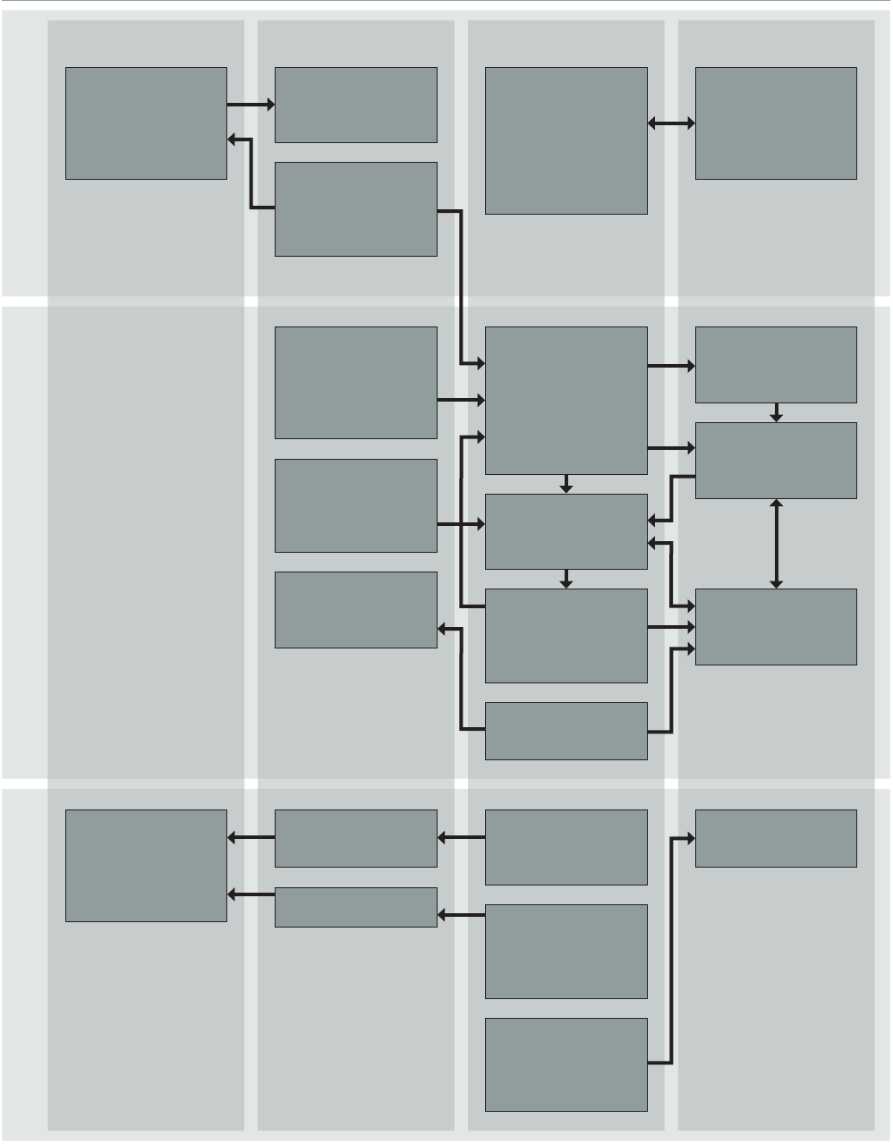
INDUSTRY STANDARD ON IN-WATER CLEANING WITH CAPTURE v1.0 62
EXPLANATORY NOTES TO THE INDUSTRY STANDARD...
AFS specicaons,
cleaning guidelines/
recommendaons
and opmal
operaonal prole
Based on the
cleaning report,
esmates the AFS’
remaining lifeme
and performance
Biofouling
management plan
and record book
Prepares its
operaons to
conform to this
standard and
obtains approval
cercate from
approval body
Issue(s) a local
cleaning permit
(aer detailing local
requirements) to
cleaning company
Conducts a risk
assessment and
ensures that
correct method
and equipment of
inspecon/cleaning
is used
Receive(s)
applicaon for
inspecon/cleaning
Issue(s) approval
to commence
operaons
Monitor(s)
compliance with
local regulaons
Inspecon/cleaning
carried out as per
standard
Proof of inspecon/
cleaning (service
report)
Environmental
records
Informaon
on collecon,
treatment and
disposal
Full report of
inspecon/cleaning
(commercially
condenal)
Operaon
suspended if
risk parameters
exceeded
Operaon stopped/
completed
Shipowner hires
cleaning company
in accordance with
AFS manufacturer’s
recommendaons
Risk assessment and
safety procedure
on board during
cleaning operaon
Ship returns to
normal operaonal
state
Biofouling record
book
Shipowner’s les
Ship’s operaonal
prole and previous
inspecon/cleaning
reports
