
Cisco 1100 Terminal Gateway Software Configuration Guide, Cisco IOS
XE 17
First Published: 2020-03-20
Last Modified: 2020-05-21
Americas Headquarters
Cisco Systems, Inc.
170 West Tasman Drive
San Jose, CA 95134-1706
USA
http://www.cisco.com
Tel: 408 526-4000
800 553-NETS (6387)
Fax: 408 527-0883
©
2020–2024 Cisco Systems, Inc. All rights reserved.

CONTENTS
Preface xi
PREFACE
Objectives xi
Important Information on Features and Commands xi
Related Documentation xi
Document Conventions xii
Obtaining Documentation and Submitting a Service Request xiii
Introduction 1
CHAPTER 1
Sections in this Document 2
Processes 2
Configure Initial Router Settings on Cisco 1100 Terminal Gateway 5
CHAPTER 2
Perform Initial Configuration on Cisco 1100 Terminal Gateway 5
Use Cisco Setup Command Facility 5
Complete the Configuration 9
Use Cisco IOS XE CLI—Manual Configuration 10
Configure Cisco 1100 Terminal Gateway Hostname 11
Configure the Enable and Enable Secret Passwords 12
Configure the Console Idle Privileged EXEC Timeout 13
Gigabit Ethernet Management Interface Overview 15
Default Gigabit Ethernet Configuration 15
Gigabit Ethernet Port Numbering 15
Configure Gigabit Ethernet Interfaces 15
Configuration Examples 17
Specify a Default Route or Gateway of Last Resort 17
Configure IP Routing and IP Protocols 17
Cisco 1100 Terminal Gateway Software Configuration Guide, Cisco IOS XE 17
iii

Default Routes 18
Default Network 18
Gateway of Last Resort 18
Configuration Examples 20
Configure Virtual Terminal Lines for Remote Console Access 20
Configuration Examples 22
Configure the Auxiliary Line 22
Verify Network Connectivity 23
Examples 24
Save Your Device Configuration 24
Save Backup Copies of Configuration and System Image 25
Configuration Examples 26
Verify Initial Configuration on Cisco 1100 Terminal Server Gateway 27
Basic Router Configuration 29
CHAPTER 3
Default Configuration 29
Configuring Global Parameters 31
Configuring Gigabit Ethernet Interfaces 31
Configuring a Loopback Interface 32
Configuring Module Interfaces 34
Enabling Cisco Discovery Protocol 34
Configuring Command-Line Access 34
Configuring Static Routes 36
Configuring Dynamic Routes 38
Configuring Routing Information Protocol 38
Configuring Enhanced Interior Gateway Routing Protocol 41
Accessing the CLI Using a Router Console 43
CHAPTER 4
Accessing the CLI Using a Directly-Connected Console 43
Connecting to the Console Port 44
Using the Console Interface 44
Using SSH to Access Console 44
Accessing the CLI from a Remote Console Using Telnet 45
Preparing to Connect to the Router Console Using Telnet 45
Cisco 1100 Terminal Gateway Software Configuration Guide, Cisco IOS XE 17
iv
Contents

Using Telnet to Access a Console Interface 46
Using Keyboard Shortcuts 47
Using the History Buffer to Recall Commands 47
Understanding Command Modes 48
Understanding Diagnostic Mode 49
Getting Help 50
Finding Command Options: Example 51
Using the no and default Forms of Commands 54
Saving Configuration Changes 54
Managing Configuration Files 55
Filtering Output from the show and more Commands 55
Powering Off a Router 56
Finding Support Information for Platforms and Cisco Software Images 56
Using Cisco Feature Navigator 56
Using Software Advisor 56
Using Software Release Notes 56
CLI Session Management 57
Information About CLI Session Management 57
Changing the CLI Session Timeout 57
Locking a CLI Session 57
Licenses and Licensing Models 59
CHAPTER 5
Available Licenses 59
How to Configure Available Licenses 59
Configuring a Boot Level License 59
Enabling the Booster Performance License 62
Supported Licensing Models 65
Smart Licensing Using Policy 65
Smart Licensing 65
Prerequisites for Smart Licensing 66
Transitioning from CSL to Smart Licensing 66
Cisco ONE Suites 66
Troubleshooting for Cisco Smart Licensing Client 66
Example: Displays summary information about all licenses 67
Cisco 1100 Terminal Gateway Software Configuration Guide, Cisco IOS XE 17
v
Contents

Managing the Device Using Web User Interface 69
CHAPTER 6
Setting Up Factory Default Device Using Web UI 69
Using Basic or Advanced Mode Setup Wizard 70
Configure LAN Settings 70
Configure Primary WAN Settings 71
Configure Secondary WAN Settings 72
Configure Security Settings 72
Using Web User Interface for Day One Setup 73
Console Port, Telnet, and SSH Handling 75
CHAPTER 7
Notes and Restrictions for Console Port, Telnet, and SSH 75
Console Port Overview 75
Console Port Handling Overview 76
Telnet and SSH Overview 76
Persistent Telnet and Persistent SSH Overview 76
Configuring a Console Port Transport Map 77
Configuring Persistent Telnet 79
Configuring Persistent SSH 81
Viewing Console Port, SSH, and Telnet Handling Configurations 84
Configuring Auxiliary Port for Modem Connection 89
Installing the Software 91
CHAPTER 8
Overview 91
ROMMON Images 92
Provisioning Files 92
File Systems 92
Autogenerated File Directories and Files 93
Flash Storage 94
Configuring the Configuration Register for Autoboot 94
How to Install and Upgrade the Software 95
Managing and Configuring a Router to Run Using a Consolidated Package 95
Managing and Configuring a Consolidated Package Using copy and boot Commands 95
Cisco 1100 Terminal Gateway Software Configuration Guide, Cisco IOS XE 17
vi
Contents

Configuring a Router to Boot the Consolidated Package via TFTP Using the boot Command:
Example 96
Managing and Configuring a Router to Run Using Individual Packages 100
Installing Subpackages from a Consolidated Package 100
Installing Subpackages from a Consolidated Package on a Flash Drive 105
Installing a Firmware Subpackage 105
Configuring No Service Password-Recovery 111
How to Enable No Service Password-Recovery 111
Slot and Subslot Configuration 117
CHAPTER 9
Configuring the Interfaces 117
Configuring Gigabit Ethernet Interfaces 117
Configuring the Interfaces: Example 119
Viewing a List of All Interfaces: Example 119
Viewing Information About an Interface: Example 119
Support for Security-Enhanced Linux 121
CHAPTER 10
Overview 121
Prerequisites for SELinux 121
Restrictions for SELinux 121
Information About SELinux 121
Supported Platforms 122
Configuring SELinux 122
Configuring SELinux (EXEC Mode) 123
Configuring SELinux (CONFIG Mode) 123
Examples for SELinux 123
SysLog Message Reference 124
Verifying SELinux Enablement 124
Troubleshooting SELinux 125
System Messages 127
CHAPTER 11
Information About Process Management 127
How to Find Error Message Details 127
Cisco 1100 Terminal Gateway Software Configuration Guide, Cisco IOS XE 17
vii
Contents

Trace Management 133
CHAPTER 12
Tracing Overview 133
How Tracing Works 133
Tracing Levels 134
Viewing a Tracing Level 135
Setting a Tracing Level 137
Viewing the Content of the Trace Buffer 137
Environmental Monitoring and PoE Management 139
CHAPTER 13
Environmental Monitoring 139
Environmental Monitoring and Reporting Functions 139
Environmental Monitoring Functions 140
Environmental Reporting Functions 142
Factory Reset 153
CHAPTER 14
Feature Information for Factory Reset 153
Information About Factory Reset 153
Prerequisites for Performing Factory Reset 154
Restrictions for Performing a Factory Reset 154
When to Perform Factory Reset 155
How to Perform a Factory Reset 155
What Happens after a Factory Reset 156
Configuring Cisco C1100TG-A-48 or C1100TG-A-32 Serial Port Module on Cisco 1100 Terminal
Gateway 157
CHAPTER 15
Configuring Cisco C1100TG-A-48 or C1100TG-A-32 as a Terminal Server 157
Prerequisites for Configuring Cisco C1100TG-A-48 or C1100TG-A-32 as a Terminal Server 157
How to Configure Cisco C1100TG-A-48 or C1100TG-A-32 as a Terminal Server 157
Optional Parameters 158
Verification and Troubleshooting 158
Command Summary 159
show line 160
show interface 162
Cisco 1100 Terminal Gateway Software Configuration Guide, Cisco IOS XE 17
viii
Contents

show tcp 162
Configuring Cisco C1100TG-ES-24 EtherSwitch Network Interface Module 165
CHAPTER 16
Overview 165
Software Features 165
Assigning IP Addresses to Switch Virtual Interfaces 165
IEEE 802.1x Protocol 166
IGMP Snooping for IPv4 166
MAC Table Manipulation 167
Spanning Tree Protocol 170
Configuring the Switched Port Analyzer 170
Configuring Layer 2 Quality of Service 171
VLANs 173
Configuring LAN Ports for Layer 2 Switching 173
Layer 2 LAN Port Modes 174
Default Layer 2 LAN Interface Configuration 174
Configuring LAN Interfaces for Layer 2 Switching 175
STP Overview 179
Default STP Configuration 179
Enabling STP 180
Configuring Optional STP Features 182
Enabling PortFast 182
Enabling PortFast 183
Configuring PortFast BPDU Filtering 184
Enabling PortFast BPDU Filtering 185
Enabling BPDU Guard 186
Enabling UplinkFast 187
Enabling BackboneFast 188
Support for Security-Enhanced Linux 191
CHAPTER 17
Overview 191
Prerequisites for SELinux 191
Restrictions for SELinux 191
Information About SELinux 191
Cisco 1100 Terminal Gateway Software Configuration Guide, Cisco IOS XE 17
ix
Contents

Supported Platforms 192
Configuring SELinux 192
Configuring SELinux (EXEC Mode) 193
Configuring SELinux (CONFIG Mode) 193
Examples for SELinux 193
SysLog Message Reference 194
Verifying SELinux Enablement 194
Troubleshooting SELinux 195
Cisco 1100 Terminal Gateway Software Configuration Guide, Cisco IOS XE 17
x
Contents

Preface
This section briefly describes the objectives of this document and provides links to additional information on
related products and services:
• Objectives, on page xi
• Important Information on Features and Commands, on page xi
• Related Documentation, on page xi
• Document Conventions, on page xii
• Obtaining Documentation and Submitting a Service Request, on page xiii
Objectives
This guide provides an overview of the Cisco 1100 Terminal Gateway and explains how to configure the
various features on these routers.
The structure of this document is explained in the Overview section.
Important Information on Features and Commands
For more information about Cisco IOS XE software, including features available on the router (described in
configuration guides), see the Cisco IOS XE 17 Software Documentation set.
To verify support for specific features, use Cisco Feature Navigator. For more information about this, see the
Using Cisco Feature Navigator section.
To find reference information for a specific Cisco IOS XE command, see the Cisco IOS Master Command
List, All Releases.
Related Documentation
• Hardware Installation Guide for the Cisco Terminal Gateway
• Release Notes for the Cisco Terminal Gateway
Cisco 1100 Terminal Gateway Software Configuration Guide, Cisco IOS XE 17
xi

Commands
Cisco IOS XE commands are identical in look, feel, and usage to Cisco IOS commands on most platforms.
To find reference information for a specific Cisco IOS XE command, see the Cisco IOS Master Command
List, All Releases document.
Features
The router runs Cisco IOS XE software which is used on multiple platforms. For more information on the
available software features, see the configuration guides on the Cisco IOS XE 17 page.
To verify support for specific features, use the Cisco Feature Navigator tool. For more information, see Using
Cisco Feature Navigator, on page 56.
Document Conventions
This documentation uses the following conventions:
DescriptionConvention
The ^ and Ctrl symbols represent the Control key.
For example, the key combination ^D or Ctrl-D
means hold down the Control key while you press
the D key. Keys are indicated in capital letters but are
not case sensitive.
^ or Ctrl
A string is a nonquoted set of characters shown in
italics. For example, when setting an SNMP
community string to public, do not use quotation
marks around the string or the string will include the
quotation marks.
string
Command syntax descriptions use the following conventions:
DescriptionConvention
Bold text indicates commands and keywords that you
enter exactly as shown.
bold
Italic text indicates arguments for which you supply
values.
italics
Square brackets enclose an optional element (keyword
or argument).
[x]
A vertical line indicates a choice within an optional
or required set of keywords or arguments.
|
Square brackets enclosing keywords or arguments
separated by a vertical line indicate an optional choice.
[x | y]
Braces enclosing keywords or arguments separated
by a vertical line indicate a required choice.
{x | y}
Cisco 1100 Terminal Gateway Software Configuration Guide, Cisco IOS XE 17
xii
Preface
Document Conventions

Nested sets of square brackets or braces indicate optional or required choices within optional or required
elements. For example:
DescriptionConvention
Braces and a vertical line within square brackets
indicate a required choice within an optional element.
[x {y | z}]
Examples use the following conventions:
DescriptionConvention
Examples of information displayed on the screen are
set in Courier font.
screen
Examples of text that you must enter are set in Courier
bold font.
bold screen
Angle brackets enclose text that is not printed to the
screen, such as passwords.
< >
An exclamation point at the beginning of a line
indicates a comment line. (Exclamation points are
also displayed by the Cisco IOS XE software for
certain processes.)
!
Square brackets enclose default responses to system
prompts.
[ ]
Means reader be careful. In this situation, you might do something that could result in equipment damage or
loss of data.
Caution
Means reader take note. Notes contain helpful suggestions or references to materials that may not be contained
in this manual.
Note
Obtaining Documentation and Submitting a Service Request
• To receive timely, relevant information from Cisco, sign up at Cisco Profile Manager.
• To get the business impact you’re looking for with the technologies that matter, visit Cisco Services.
• To submit a service request, visit Cisco Support.
• To discover and browse secure, validated enterprise-class apps, products, solutions and services, visit
Cisco Marketplace.
• To obtain general networking, training, and certification titles, visit Cisco Press.
Cisco 1100 Terminal Gateway Software Configuration Guide, Cisco IOS XE 17
xiii
Preface
Obtaining Documentation and Submitting a Service Request


CHAPTER 1
Introduction
The Cisco 1100 Terminal Services Gateway is a modular terminal gateway that provides asynchronous
connections to the console ports for different kinds of network devices such as Cisco third-party network
devices, and servers. The Cisco 1100 Terminal Services Gateway offers integrated asynchronous ports, optional
switching, and simplified Ethernet. It also supports secure tunnels, such as IPSec, generic routing encapsulation
(GRE), and Cisco Dynamic Multipoint VPN, all at scale.
The Cisco 1100 Services Terminal Gateway with the LAN and WAN connections can be configured by means
of interface modules and Network Interface Modules (NIMs).
The following features are provided for enterprise and service provider applications:
• Enterprise Applications
• High-end branch gateway
• Centralized Management
• Zero Touch Provisioning
• Mulit Tenant
• Role based access to server and session
• Regional site aggregation
• Key server or PfR master controller
• Device consolidation or "Rack in a Box"
• Service Provider Applications
• High-end managed services in Customer-Premises Equipment (CPE)
• Services consolidation platform
• Flexible customer edge terminal gateway
The Cisco 1100 Terminal Services Gateway runs Cisco IOS XE software, and uses software components in
many separate processes. This modular architecture increases network resiliency, compared to standard Cisco
IOS software.
• Sections in this Document, on page 2
• Processes, on page 2
Cisco 1100 Terminal Gateway Software Configuration Guide, Cisco IOS XE 17
1

Sections in this Document
Table 1: Sections in this Document
DescriptionSection
Provides a high-level description of the router and
describes the main internal processes of the router.
Overview
Describes the basics of using Cisco IOS XE software
with the router.
Using Cisco IOS XE Software
Describes the uses of a Gigabit Ethernet management
interface and a web user interface.
Managing the Device Using Web User Interface, on
page 69
Describes software features that are common across
Cisco IOS XE platforms.
Console Port, Telnet, and SSH Handling, on page 75
Contains important information about filesystems,
packages, licensing, and installing software.
Installing the Software, on page 91
Describes the basic tasks required to configure a
router.
Basic Router Configuration, on page 29
Provides information about the chassis slot numbers
and subslots where the service modules are installed.
Slot and Subslot Configuration, on page 117
Provides information about syslog messages.System Messages, on page 127
Describes the tracing function where logs of internal
events on a router are recorded.
Trace Management, on page 133
Describes the environmental monitoring features on
a router.
Environmental Monitoring and PoE Management, on
page 139
Describes how it can be used to protect or restore a
router to an earlier, fully functional state.
Information About Factory Reset
Processes
The list of background processes in the following table may be useful for checking router state and
troubleshooting. However, you do not need to understand these processes to understand most router operations.
Cisco 1100 Terminal Gateway Software Configuration Guide, Cisco IOS XE 17
2
Introduction
Sections in this Document

Table 2: Individual Processes
Sub Package MappingAffected FRUsPurposeProcess
RPControl
SIPBase
ESPBase
RP
SIP
ESP
Controls chassis
management functions,
including management of
the High Availability
(HA) state, environmental
monitoring, and FRU state
control.
Chassis Manager
RPControl
SIPBase
ESPBase
RP
SIP
ESP
Provides an interface
between the IOS process
and many of the
information gathering
functions of the
underlying platform
kernel and operating
system.
Host Manager
RPControl
SIPBase
ESPBase
RP
SIP
ESP
Provides IOS logging
services to processes
running on each FRU.
Logger
RPIOSRPImplements all forwarding
and routing features for
the router.
IOS
RPControl
ESPBase
RP
ESP
Manages downloading of
configuration details to
the ESP and the
communication of
forwarding plane
information, such as
statistics, to the IOS
process.
Forwarding Manager
RPControlRPProvide integration
between platform policy
applications, such as
authentication and the IOS
process.
Pluggable Services
RPControlRPProvides user interface
(UI) features relating to
non-IOS components of
the consolidated package.
These features are also
available for use in
diagnostic mode when the
IOS process fails.
Shell Manager
Cisco 1100 Terminal Gateway Software Configuration Guide, Cisco IOS XE 17
3
Introduction
Processes

Sub Package MappingAffected FRUsPurposeProcess
SIPSPAIO ModuleExchanges configuration
and other control
messages with a NIM.
IO Module process
ESPBaseESPManages CPP hardware
forwarding engine on the
ESP.
CPP driver process
ESPBaseESPManages HA state for the
CPP hardware forwarding
engine.
CPP HA process
ESPBaseESPPerforms high-latency
tasks for the CPP-facing
functionality in the ESP
instance of the
Forwarding Manager
process.
CPP SP process
For further details of router capabilities and models, see the Hardware Installation Guide for Cisco 1100
Terminal Gateway.
Cisco 1100 Terminal Gateway Software Configuration Guide, Cisco IOS XE 17
4
Introduction
Processes

CHAPTER 2
Configure Initial Router Settings on Cisco 1100
Terminal Gateway
This chapter describes how to perform the initial configuration on Cisco 1100 Terminal Gateway. It contains
the following sections:
• Perform Initial Configuration on Cisco 1100 Terminal Gateway, on page 5
• Verify Network Connectivity, on page 23
• Verify Initial Configuration on Cisco 1100 Terminal Server Gateway, on page 27
Perform Initial Configuration on Cisco 1100 Terminal Gateway
You can perform initial configuration on Cisco 1100 Terminal Gateway by using either the setup command
facility or the Cisco IOS command-line interface (CLI):
Use Cisco Setup Command Facility
The setup command facility prompts you to enter the information about your router and network. The facility
steps guides you through the initial configuration, which includes LAN and WAN interfaces. For more general
information about the setup command facility, see the following document:
Cisco IOS Configuration Fundamentals Configuration Guide , Release 12.4, Part 2: Cisco IOS User Interfaces:
Using AutoInstall and Setup:
http://www.cisco.com/c/en/us/support/ios-nx-os-software/ios-xe-3s/products-installation-and-configuration-guides-list.html.
This section explains how to configure a hostname for the router, set passwords, and configure an interface
to communicate with the management network.
The messages that are displayed will vary based on your router model, the installed interface modules, and
the software image. The following example and the user entries (in bold) are shown only as examples.
Note
If you make a mistake while using the setup command facility, you can exit and run the setup command
facility again. Press Ctrl-C, and enter the setup command in privileged EXEC mode (Router#)
Note
Cisco 1100 Terminal Gateway Software Configuration Guide, Cisco IOS XE 17
5

To configure the initial router settings by using the setup command facility, follow these steps:
SUMMARY STEPS
1. From the Cisco IOS-XE CLI, enter the setup command in privileged EXEC mode:
2. To proceed using the setup command facility, enter yes.
3. To enter the basic management setup, enter yes.
4. Enter a hostname for the router (this example uses ‘myrouter’):
5. Enter an enable secret password. This password is encrypted (for more security) and cannot be seen
when viewing the configuration.
6. Enter an enable password that is different from the enable secret password. This password is not encrypted
(and is less secure) and can be seen when viewing the configuration.
7. Enter the virtual terminal password, which prevents unauthenticated access to the router through ports
other than the console port:
8. Respond to the following prompts as appropriate for your network:
9. Respond to the following prompts as appropriate for your network:
10. Respond to the following prompts. Select [2] to save the initial configuration:
DETAILED STEPS
Step 1 From the Cisco IOS-XE CLI, enter the setup command in privileged EXEC mode:
Example:
Router> enable
Password: <password>
Router# setup
--- System Configuration Dialog ---
Continue with configuration dialog? [yes/no]:
You are now in the Setup Configuration Utility.
Depending on your router model, the installed interface modules, and the software image, the prompts in the setup
command facility vary. The following steps and the user entries (in bold) are shown only as examples.
This setup command facility is also entered automatically if there is no configuration on the router when
it is booted into Cisco IOS-XE.
Note
If you make a mistake while using the setup command facility, you can exit and run the setup command
facility again. Press Ctrl-C, and enter the setup command at the privileged EXEC mode prompt (Router#).
For more information on using the setup command facility, see The Setup Command chapter in Cisco IOS
Configuration Fundamentals Command Reference , Release 12.2T, at the following URL:
http://www.cisco.com/en/US/docs/ios/12_2t/fun/command/reference/122tfr.html
Note
Step 2 To proceed using the setup command facility, enter yes.
Example:
Continue with configuration dialog? [yes/no]:
At any point you may enter a question mark '?' for help.
Cisco 1100 Terminal Gateway Software Configuration Guide, Cisco IOS XE 17
6
Configure Initial Router Settings on Cisco 1100 Terminal Gateway
Use Cisco Setup Command Facility

Use ctrl-c to abort configuration dialog at any prompt.
Default settings are in square brackets '[]'.
Step 3 To enter the basic management setup, enter yes.
Example:
Would you like to enter basic management setup? [yes/no]: yes
Step 4 Enter a hostname for the router (this example uses ‘myrouter’):
Example:
Configuring global parameters:
Enter host name [Router]: myrouter
Step 5 Enter an enable secret password. This password is encrypted (for more security) and cannot be seen when viewing the
configuration.
Example:
The enable secret is a password used to protect access to
privileged EXEC and configuration modes. This password, after
entered, becomes encrypted in the configuration.
Enter enable secret: cisco
Step 6 Enter an enable password that is different from the enable secret password. This password is not encrypted (and is less
secure) and can be seen when viewing the configuration.
Example:
The enable password is used when you do not specify an
enable secret password, with some older software versions, and
some boot images.
Enter enable password: cisco123
Step 7 Enter the virtual terminal password, which prevents unauthenticated access to the router through ports other than the
console port:
Example:
The virtual terminal password is used to protect
access to the router over a network interface.
Enter virtual terminal password: cisco
Step 8 Respond to the following prompts as appropriate for your network:
Example:
Configure SNMP Network Management? [no]: yes
Community string [public]:
A summary of the available interfaces is displayed.
The interface summary includes interface numbering, which is dependent on the router model and the
installed modules and interface cards.
Note
Example:
Current interface summary
Cisco 1100 Terminal Gateway Software Configuration Guide, Cisco IOS XE 17
7
Configure Initial Router Settings on Cisco 1100 Terminal Gateway
Use Cisco Setup Command Facility

Interface IP-Address OK? Method Status Protocol
GigabitEthernet0/0/0 unassigned YES NVRAM administratively down down
GigabitEthernet0/1/0 10.10.10.12 YES DHCP up up
GigabitEthernet0/2/0 unassigned YES NVRAM administratively down down
SSLVPN-VIF0 unassigned NO unset up
Any interface listed with OK? value "NO" does not have a valid configuration
Step 9 Respond to the following prompts as appropriate for your network:
Example:
Configuring interface GigabitEthernet0/1/0
:
Configure IP on this interface? [yes]: yes
IP address for this interface [10.10.10.12
]:
Subnet mask for this interface [255.0.0.0] : 255.255.255.0
Class A network is 10.0.0.0, 24 subnet bits; mask is /24
The following configuration command script was created:
Example:
hostname myrouter
enable secret 5 $1$t/Dj$yAeGKviLLZNOBX0b9eifO0 enable password cisco123 line vty 0 4 password cisco
snmp-server community public !
no ip routing
!
interface GigabitEthernet0/0/0
shutdown
no ip address
!
interface GigabitEthernet0/1/0
no shutdown
ip address 10.10.10.12 255.255.255.0
!
interface GigabitEthernet0/2/0
shutdown
no ip address
!
end
Step 10 Respond to the following prompts. Select [2] to save the initial configuration:
Example:
[0] Go to the IOS command prompt without saving this config.
[1] Return back to the setup without saving this config.
[2] Save this configuration to nvram and exit.
Enter your selection [2]: 2
Building configuration...
Use the enabled mode 'configure' command to modify this configuration.
Press RETURN to get started! RETURN
The user prompt is displayed:
Example:
myrouter>
Cisco 1100 Terminal Gateway Software Configuration Guide, Cisco IOS XE 17
8
Configure Initial Router Settings on Cisco 1100 Terminal Gateway
Use Cisco Setup Command Facility

Complete the Configuration
When using the Cisco Setup, and after you have provided all the information requested by the facility, the
final configuration appears. To complete your router configuration, follow these steps:
SUMMARY STEPS
1. Choose to save the configuration when the facility prompts you to save the configuration.
2. When the messages stop appearing on your screen, press Return to get the Router> prompt.
3. Choose to modify the existing configuration or create another configuration. The Router> prompt indicates
that you are now at the command-line interface (CLI) and you have just completed a initial router
configuration. Nevertheless, this is not a complete configuration. At this point, you have two choices:
DETAILED STEPS
Step 1 Choose to save the configuration when the facility prompts you to save the configuration.
• If you answer ‘no’, the configuration information you entered is not saved, and you return to the router enable prompt
(Router#). Enter setup to return to the System Configuration Dialog.
• If you answer ‘yes’, the configuration is saved, and you are returned to the user EXEC prompt (Router>).
Example:
Use this configuration? {yes/no} : yes
Building configuration...
Use the enabled mode 'configure' command to modify this configuration.
Press RETURN to get started!
%LINK-3-UPDOWN: Interface Ethernet0/0, changed state to up
%LINK-3-UPDOWN: Interface Ethernet0/1, changed state to up
%LINK-3-UPDOWN: Interface Serial0/0/0, changed state to up
%LINK-3-UPDOWN: Interface Serial0/0/1, changed state to down
%LINK-3-UPDOWN: Interface Serial0/2, changed state to down
%LINK-3-UPDOWN: Interface Serial1/0, changed state to up
%LINK-3-UPDOWN: Interface Serial1/1, changed state to down
%LINK-3-UPDOWN: Interface Serial1/2, changed state to down
<Additional messages omitted.>
Step 2 When the messages stop appearing on your screen, press Return to get the Router> prompt.
Step 3 Choose to modify the existing configuration or create another configuration. The Router> prompt indicates that you are
now at the command-line interface (CLI) and you have just completed a initial router configuration. Nevertheless, this
is not a complete configuration. At this point, you have two choices:
• Run the setup command facility again, and create another configuration.
Example:
Router> enable
Password: password
Router# setup
• Modify the existing configuration or configure additional features by using the CLI:
Example:
Router> enable
Password: password
Cisco 1100 Terminal Gateway Software Configuration Guide, Cisco IOS XE 17
9
Configure Initial Router Settings on Cisco 1100 Terminal Gateway
Complete the Configuration

Router# configure terminal
Router(config)#
Use Cisco IOS XE CLI—Manual Configuration
This section describes you how to access the command-line interface (CLI) to perform the initial configuration
on the router.
To configure the initial router settings by using the Cisco IOS CLI, you must set up a console connection.
Note
If the default configuration file is installed on the router prior to shipping, the system configuration dialog
message does not appear, To configure the device, follow these steps:
SUMMARY STEPS
1. Enter the appropriate answer when the following system message appears on the router.
2. Press Return to terminate autoinstall and continue with manual configuration:
3. Press Return to bring up the Router> prompt.
4. Type enable to enter privileged EXEC mode:
DETAILED STEPS
Step 1 Enter the appropriate answer when the following system message appears on the router.
Example:
--- System Configuration Dialog ---
At any point you may enter a question mark '?' for help.
Use ctrl-c to abort configuration dialog at any prompt.
Default settings are in square brackets '[]'.
Would you like to enter the initial configuration dialog? [yes/no]: no
Step 2 Press Return to terminate autoinstall and continue with manual configuration:
Example:
Would you like to terminate autoinstall? [yes]
Return
Several messages are displayed, ending with a line similar to the following:
Example:
...
Copyright (c) 1986-2012 by cisco Systems, Inc.
Compiled <date
> <time
> by <person
>
Cisco 1100 Terminal Gateway Software Configuration Guide, Cisco IOS XE 17
10
Configure Initial Router Settings on Cisco 1100 Terminal Gateway
Use Cisco IOS XE CLI—Manual Configuration

Step 3 Press Return to bring up the Router> prompt.
Example:
...
flashfs[4]: Initialization complete.
Router>
Step 4 Type enable to enter privileged EXEC mode:
Example:
Router> enable
Router#
Configure Cisco 1100 Terminal Gateway Hostname
The hostname is used in CLI prompts and default configuration filenames. If you do not configure the router
hostname, the router uses the factory-assigned default hostname “Router.”
SUMMARY STEPS
1. enable
2. configure terminal
3. hostname name
4. Verify that the router prompt displays your new hostname.
5. end
DETAILED STEPS
PurposeCommand or Action
Enables privileged EXEC mode.enable
Step 1
Example:
• Enter your password if prompted.
Router> enable
Enters global configuration mode.configure terminal
Example:
Step 2
Router# configure terminal
Specifies or modifies the hostname for the network server.hostname name
Example:
Step 3
Router(config)# hostname myrouter
—Verify that the router prompt displays your new hostname.
Example:
Step 4
Cisco 1100 Terminal Gateway Software Configuration Guide, Cisco IOS XE 17
11
Configure Initial Router Settings on Cisco 1100 Terminal Gateway
Configure Cisco 1100 Terminal Gateway Hostname

PurposeCommand or Action
myrouter(config)#
(Optional) Returns to privileged EXEC mode.end
Example:
Step 5
myrouter# end
Configure the Enable and Enable Secret Passwords
To provide an additional layer of security, particularly for passwords that cross the network or are stored on
a TFTP server, you can use either the enable password command or enable secret command. Both commands
accomplish the same thing—they allow you to establish an encrypted password that users must enter to access
privileged EXEC (enable) mode.
We recommend that you use the enable secret command because it uses an improved encryption algorithm.
Use the enable password command only if you boot an older image of the Cisco IOS XE software.
For more information, see the “Configuring Passwords and Privileges” chapter in the Cisco IOS Security
Configuration Guide . Also see the Cisco IOS Password Encryption Facts tech note and the Improving Security
on Cisco Routers tech note.
If you configure the enable secret command, it takes precedence over the enable password command; the
two commands cannot be in effect simultaneously.
Note
SUMMARY STEPS
1. enable
2. configure terminal
3. enable password password
4. enable secret password
5. end
6. enable
7. end
DETAILED STEPS
PurposeCommand or Action
Enables privileged EXEC mode.enable
Step 1
Example:
• Enter your password if prompted.
Router> enable
Enters global configuration mode.configure terminal
Example:
Step 2
Cisco 1100 Terminal Gateway Software Configuration Guide, Cisco IOS XE 17
12
Configure Initial Router Settings on Cisco 1100 Terminal Gateway
Configure the Enable and Enable Secret Passwords

PurposeCommand or Action
Router# configure terminal
(Optional) Sets a local password to control access to various
privilege levels.
enable password password
Example:
Step 3
• We recommend that you perform this step only if you
boot an older image of the Cisco IOS-XE software or
Router(config)# enable password pswd2
if you boot older boot ROMs that do not recognize the
enable secret command.
Specifies an additional layer of security over the enable
password command.
enable secret password
Example:
Step 4
• Do not use the same password that you entered in Step
3 .
Router(config)# enable secret greentree
Returns to privileged EXEC mode.end
Example:
Step 5
Router(config)# end
Enables privileged EXEC mode.enable
Step 6
Example:
• Verify that your new enable or enable secret password
works.
Router> enable
(Optional) Returns to privileged EXEC mode.end
Example:
Step 7
Router(config)# end
Configure the Console Idle Privileged EXEC Timeout
This section describes how to configure the console line’s idle privileged EXEC timeout. By default, the
privileged EXEC command interpreter waits 10 minutes to detect user input before timing out.
When you configure the console line, you can also set communication parameters, specify autobaud connections,
and configure terminal operating parameters for the terminal that you are using. For more information on
configuring the console line, see the Cisco IOS Configuration Fundamentals and Network Management
Configuration Guide . In particular, see the “Configuring Operating Characteristics for Terminals” and
“Troubleshooting and Fault Management” chapters.
SUMMARY STEPS
1. enable
2. configure terminal
3. line console 0
4. exec-timeout minutes [seconds]
5. end
Cisco 1100 Terminal Gateway Software Configuration Guide, Cisco IOS XE 17
13
Configure Initial Router Settings on Cisco 1100 Terminal Gateway
Configure the Console Idle Privileged EXEC Timeout

6. show running-config
DETAILED STEPS
PurposeCommand or Action
Enables privileged EXEC mode.enable
Step 1
Example:
• Enter your password if prompted.
Router> enable
Enters global configuration mode.configure terminal
Example:
Step 2
Router# configure terminal
Configures the console line and starts the line configuration
command collection mode.
line console 0
Example:
Step 3
Router(config)# line console 0
Sets the idle privileged EXEC timeout, which is the interval
that the privileged EXEC command interpreter waits until
user input is detected.
exec-timeout minutes [seconds]
Example:
Router(config-line)# exec-timeout 0 0
Step 4
• The example shows how to specify no timeout. Setting
the exec-timeout value to 0 will cause the router to
never log out after it is logged in. This could have
security implications if you leave the console without
manually logging out using the disable command.
Returns to privileged EXEC mode.end
Example:
Step 5
Router(config)# end
Displays the running configuration file.show running-config
Step 6
Example:
• Verify that you properly configured the idle privileged
EXEC timeout.
Router(config)# show running-config
Examples
The following example shows how to set the console idle privileged EXEC timeout to 2 minutes 30 seconds:
line console
exec-timeout 2 30
The following example shows how to set the console idle privileged EXEC timeout to 30 seconds:
line console
exec-timeout 0 30
Cisco 1100 Terminal Gateway Software Configuration Guide, Cisco IOS XE 17
14
Configure Initial Router Settings on Cisco 1100 Terminal Gateway
Examples

Gigabit Ethernet Management Interface Overview
The router uses gi0/0/0 or gi0/0/1 as management port.
The purpose of this interface is to allow users to perform management tasks on the router. It is an interface
that should not and often cannot forward network traffic. It ca, however, be used to access the router through
Telnet and SSH to perform management tasks on the router. The interface is most useful before a router begins
routing, or in troubleshooting scenarios when other forwarding interfaces are inactive.
Note he following aspects of the management ethernet interface:
• The router has one management ethernet interface named GigabitEthernet0.
• IPv4, IPv6, and ARP are the only routed protocols supported for the interface.
• The interface provides a way to access to the router even if forwarding interfaces are not functional, or
the IOS process is down.
Default Gigabit Ethernet Configuration
By default, a forwarding VRF is configured for the interface with a special group named “Mgmt-intf.” This
cannot be changed. This isolates the traffic on the management interface away from the forwarding plane.
The basic configuration is like other interfaces; however, there are many forwarding features that are not
supported on these interfaces. No forwarding features can be configured on the GigabitEthernet0 interface as
it is only used for management.
For example, the default configuration is as follows:
interface GigabitEthernet0
vrf forwarding Mgmt-intf
ip address 172.18.77.212 255.255.255.240
negotiation auto
Gigabit Ethernet Port Numbering
The Gigabit Ethernet Management port is always GigabitEthernet0.
The port can be accessed in configuration mode.
Router# config t
Enter configuration commands, one per line. End with CNTL/Z.
Router(config)#interface gigabitethernet0
Router(config-if)#
Configure Gigabit Ethernet Interfaces
This sections shows how to assign an IP address and interface description to an Ethernet interface on your
router.
For comprehensive configuration information on Gigabit Ethernet interfaces, see the “Configuring LAN
Interfaces” chapter of Cisco IOS Interface and Hardware Component Configuration Guide ,
http://www.cisco.com/en/US/docs/ios/12_2/interface/configuration/guide/icflanin.html
For information on interface numbering, see the software configuration guide for your router.
SUMMARY STEPS
1. enable
2. show ip interface brief
Cisco 1100 Terminal Gateway Software Configuration Guide, Cisco IOS XE 17
15
Configure Initial Router Settings on Cisco 1100 Terminal Gateway
Gigabit Ethernet Management Interface Overview

3. configure terminal
4. interface {fastethernet | gigabitethernet} 0/port
5. description string
6. ip address ip-address mask
7. no shutdown
8. end
9. show ip interface brief
DETAILED STEPS
PurposeCommand or Action
Enables privileged EXEC mode.enable
Step 1
Example:
• Enter your password if prompted.
Router> enable
Displays a brief status of the interfaces that are configured
for IP.
show ip interface brief
Example:
Step 2
• Learn which type of Ethernet interface is on your
router.
Router# show ip interface brief
Enters global configuration mode.configure terminal
Example:
Step 3
Router# configure terminal
Specifies the Ethernet interface and enters interface
configuration mode.
interface {fastethernet | gigabitethernet} 0/port
Example:
Step 4
For information on interface numbering, see
Slots, Subslots (Bay), Ports, and Interfaces in
section page 1-38 .
Note
Router(config)# interface gigabitethernet 0/0/0
(Optional) Adds a description to an interface configuration.
The description helps you remember what is attached to
description string
Example:
Step 5
this interface. The description can be useful for
troubleshooting.
Router(config-if)# description GE int to 2nd floor
south wing
Sets a primary IP address for an interface.ip address ip-address mask
Example:
Step 6
Router(config-if)# ip address 172.16.74.3
255.255.255.0
Enables an interface.no shutdown
Example:
Step 7
Router(config-if)# no shutdown
Cisco 1100 Terminal Gateway Software Configuration Guide, Cisco IOS XE 17
16
Configure Initial Router Settings on Cisco 1100 Terminal Gateway
Configure Gigabit Ethernet Interfaces

PurposeCommand or Action
Returns to privileged EXEC mode.end
Example:
Step 8
Router(config)# end
Displays a brief status of the interfaces that are configured
for IP. Verify that the Ethernet interfaces are up and
configured correctly.
show ip interface brief
Example:
Router# show ip interface brief
Step 9
Configuration Examples
Configuring the GigabitEthernet Interface: Example
!
interface GigabitEthernet0/0/0
description GE int to HR group
ip address 172.16.3.3 255.255.255.0
duplex negotiation auto
speed negotiation auto
no shutdown
!
Sample Output for the show ip interface brief Command
Router#show ip interface brief
Interface IP-Address OK? Method Status Protocol
GigabitEthernet0/0/0 unassigned YES NVRAM administratively down down
GigabitEthernet0/0/1 unassigned YES NVRAM administratively down down
GigabitEthernet0/0/2 unassigned YES NVRAM administratively down down
GigabitEthernet0/0/3 unassigned YES NVRAM administratively down down
GigabitEthernet0 10.0.0.1 YES manual up up
Specify a Default Route or Gateway of Last Resort
This section describes how to specify a default route with IP routing enabled. For alternative methods of
specifying a default route, see the Configuring a Gateway of Last Resort Using IP Commands Technical
Specifications Note.
The Cisco IOS-XE software uses the gateway (router) as a last resort if it does not have a better route for a
packet and if the destination is not a connected network. This section describes how to select a network as a
default route (a candidate route for computing the gateway of last resort). The way in which routing protocols
propagate the default route information varies for each protocol.
Configure IP Routing and IP Protocols
For comprehensive configuration information about IP routing and IP routing protocols, see the Configuring
IP Routing Protocol-Independent Feature at cisco.com.
Cisco 1100 Terminal Gateway Software Configuration Guide, Cisco IOS XE 17
17
Configure Initial Router Settings on Cisco 1100 Terminal Gateway
Configuration Examples

IP Routing
IP routing is automatically enabled in the Cisco ISO- XE software. When IP routing is configured, the system
will use a configured or learned route to forward packets, including a configured default route.
This task section does not apply when IP routing is disabled. To specify a default route when IP routing is
disabled, refer to the Configuring a Gateway of Last Resort Using IP Commands Technical Specifications
Note at cisco.com.
Note
Default Routes
A router might not be able to determine the routes to all other networks. To provide complete routing capability,
the common practice is to use some routers as smart routers and give the remaining routers default routes to
the smart router. (Smart routers have routing table information for the entire internetwork.) These default
routes can be passed along dynamically, or can be configured into the individual routers.
Most dynamic interior routing protocols include a mechanism for causing a smart router to generate dynamic
default information that is then passed along to other routers.
Default Network
If a router has an interface that is directly connected to the specified default network, the dynamic routing
protocols running on the router generates or sources a default route. In the case of RIP, the router will advertise
the pseudonetwork 0.0.0.0. In the case of IGRP, the network itself is advertised and flagged as an exterior
route.
A router that is generating the default for a network may also need a default of its own. One way a router can
generate its own default is to specify a static route to the network 0.0.0.0 through the appropriate device.
Gateway of Last Resort
When default information is being passed along through a dynamic routing protocol, no further configuration
is required. The system periodically scans its routing table to choose the optimal default network as its default
route. In the case of RIP, there is only one choice, network 0.0.0.0. In the case of IGRP, there might be several
networks that can be candidates for the system default. The Cisco IOS-XE software uses both administrative
distance and metric information to determine the default route (gateway of last resort). The selected default
route appears in the gateway of last resort display of the show ip route EXEC command.
If dynamic default information is not being passed to the software, candidates for the default route are specified
with the ip default-network global configuration command. In this usage, the ip default-network command
takes an unconnected network as an argument. If this network appears in the routing table from any source
(dynamic or static), it is flagged as a candidate default route and is a possible choice for the default route.
If the router has no interface on the default network, but does have a route to it, it considers this network as
a candidate default path. The route candidates are examined and based on administrative distance and metric,
the best one is chosen. The gateway to the best default path becomes the gateway of last resort.
SUMMARY STEPS
1. enable
2. configure terminal
3. ip routing
Cisco 1100 Terminal Gateway Software Configuration Guide, Cisco IOS XE 17
18
Configure Initial Router Settings on Cisco 1100 Terminal Gateway
IP Routing

4. ip route dest-prefix mask next-hop-ip-address [admin-distance] [permanent]
5. Do one of the following:
• ip default-network network-number
•
• ip route dest-prefix mask next-hop-ip-address
6. end
7. show ip route
DETAILED STEPS
PurposeCommand or Action
Enables privileged EXEC mode. Enter your password if
prompted.
enable
Example:
Step 1
Router> enable
Enters global configuration mode.configure terminal
Example:
Step 2
Router# configure terminal
Enables IP routing.ip routing
Example:
Step 3
Router(config)# ip routing
Establishes a static route.ip route dest-prefix mask next-hop-ip-address
[admin-distance] [permanent]
Step 4
Example:
Router(config)# ip route 192.168.24.0 255.255.255.0
172.28.99.2
Selects a network as a candidate route for computing the
gateway of last resort.
Do one of the following:
Step 5
• ip default-network network-number
Creates a static route to network 0.0.0.0 0.0.0.0 for
computing the gateway of last resort.
•
• ip route dest-prefix mask next-hop-ip-address
Example:
Router(config)# ip default-network 192.168.24.0
Example:
Router(config)# ip route 0.0.0.0 0.0.0.0
172.28.99.1
Returns to privileged EXEC mode.end
Example:
Step 6
Cisco 1100 Terminal Gateway Software Configuration Guide, Cisco IOS XE 17
19
Configure Initial Router Settings on Cisco 1100 Terminal Gateway
Gateway of Last Resort

PurposeCommand or Action
Router(config)# end
Displays the current routing table information. Verify that
the gateway of last resort is set.
show ip route
Example:
Step 7
Router# show ip route
Configuration Examples
Specifying a Default Route: Example
!
ip route 192.168.24.0 255.255.255.0 172.28.99.2
!
ip default-network 192.168.24.0
!
Sample Output for the show ip route Command
Router# show ip route
Codes: L - local, C - connected, S - static, R - RIP, M - mobile, B - BGP
D - EIGRP, EX - EIGRP external, O - OSPF, IA - OSPF inter area
N1 - OSPF NSSA external type 1, N2 - OSPF NSSA external type 2
E1 - OSPF external type 1, E2 - OSPF external type 2 i - IS-IS, su - IS-IS summary, L1 -
IS-IS level-1, L2 - IS-IS level-2 ia - IS-IS inter area, * - candidate default,
U - per-user static route o - ODR, P - periodic downloaded static route, H - NHRP,
l - LISP a - application route + - replicated route, % - next hop override
Gateway of last resort is not set 40.0.0.0/8 is variably subnetted, 2 subnets, 2 masks C
40.0.0.0/24 is directly connected, Loopback1 L 40.0.0.1/32 is directly connected, Loopback1
Router#
Configure Virtual Terminal Lines for Remote Console Access
Virtual terminal (vty) lines are used to allow remote access to the router. This section shows you how to
configure the virtual terminal lines with a password, so that only authorized users can remotely access the
router.
By default, the router has five virtual terminal lines. However, you can create additional virtual terminal lines.
See the Cisco IOS XE Dial Technologies Configuration Guide at
http://www.cisco.com/en/US/docs/ios/dial/configuration/guide/2_xe/dia_2_xe_book.html .
Line passwords and password encryption is described in the C isco IOS XE Security Configuration Guide:
Secure Connectivity document available at the following URL:
http://www.cisco.com/en/US/docs/ios/ios_xe/sec_secure_connectivity/configuration/guide/2_xe/sec_secure_connectivity_xe_book.html
. See the Security with Passwords, Privilege Levels, and Login Usernames for CLI Sessions on Networking
Devices section. If you want to secure the virtual terminal lines (vty) with an access list, see the Access Control
Lists: Overview and Guidelines.
SUMMARY STEPS
1. enable
Cisco 1100 Terminal Gateway Software Configuration Guide, Cisco IOS XE 17
20
Configure Initial Router Settings on Cisco 1100 Terminal Gateway
Configuration Examples

2. configure terminal
3. line vty line-number [ending-line-number]
4. password password
5. login
6. end
7. show running-config
8. From another network device, attempt to open a Telnet session to the router.
DETAILED STEPS
PurposeCommand or Action
Enables privileged EXEC mode. Enter your password if
prompted.
enable
Example:
Step 1
Router> enable
Enters global configuration mode.configure terminal
Example:
Step 2
Router# configure terminal
Starts the line configuration command collection mode for
the virtual terminal lines (vty) for remote console access.
line vty line-number [ending-line-number]
Example:
Step 3
• Make sure that you configure all vty lines on your
router.
Router(config)# line vty 0 4
To verify the number of vty lines on your
router, use the line vty ? command.
Note
Specifies a password on a line.password password
Example:
Step 4
Router(config-line)# password guessagain
Enables password checking at login.login
Example:
Step 5
Router(config-line)# login
Returns to privileged EXEC mode.end
Example:
Step 6
Router(config-line)# end
Displays the running configuration file. Verify that you
bave properly configured the virtual terminal lines for
remote access.
show running-config
Example:
Router# show running-config
Step 7
Cisco 1100 Terminal Gateway Software Configuration Guide, Cisco IOS XE 17
21
Configure Initial Router Settings on Cisco 1100 Terminal Gateway
Configure Virtual Terminal Lines for Remote Console Access

PurposeCommand or Action
Verifies that you can remotely access the router and that
the virtual terminal line password is correctly configured.
From another network device, attempt to open a Telnet
session to the router.
Example:
Step 8
Router# 172.16.74.3
Example:
Password:
Configuration Examples
The following example shows how to configure virtual terminal lines with a password:
!
line vty 0 4
password guessagain
login
!
What to Do Next
After you configure the vty lines, follow these steps:
• (Optional) To encrypt the virtual terminal line password, see the “Configuring Passwords and Privileges”
chapter in the Cisco IOS Security Configuration Guide . Also see the Cisco IOS Password Encryption
Facts tech note.
• (Optional) To secure the VTY lines with an access list, see the “Part 3: Traffic Filtering and Firewalls”
in the Cisco IOS Security Configuration Guide .
Configure the Auxiliary Line
This section describes how to enter line configuration mode for the auxiliary line. How you configure the
auxiliary line depends on your particular implementation of the auxiliary (AUX) port. See the following
documents for information on configuring the auxiliary line:
• Configuring a Modem on the AUX Port for EXEC Dialin Connectivity , Technical Specifications Note
http://www.cisco.com/en/US/tech/tk801/tk36/technologies_tech_note09186a0080094bbc.shtml
• Configuring Dialout Using a Modem on the AUX Port , sample configuration
http://www.cisco.com/en/US/tech/tk801/tk36/technologies_configuration_example09186a0080094579.shtml
• Configuring AUX-to-AUX Port Async Backup with Dialer Watch , sample configuration
http://www.cisco.com/en/US/tech/tk801/tk36/technologies_configuration_example09186a0080093d2b.shtml
• Modem-Router Connection Guide , Technical Specifications Note
http://www.cisco.com/en/US/tech/tk801/tk36/technologies_tech_note09186a008009428b.shtml
SUMMARY STEPS
1. enable
2. configure terminal
3. line aux 0
Cisco 1100 Terminal Gateway Software Configuration Guide, Cisco IOS XE 17
22
Configure Initial Router Settings on Cisco 1100 Terminal Gateway
Configuration Examples

4. See the Technical Specifications Note and sample configurations to configure the line for your particular
implementation of the AUX port.
DETAILED STEPS
PurposeCommand or Action
Enables privileged EXEC mode.enable
Step 1
Example:
• Enter your password if prompted.
Router> enable
Enters global configuration mode.configure terminal
Example:
Step 2
Router# configure terminal
Starts the line configuration command collection mode for
the auxiliary line.
line aux 0
Example:
Step 3
Router(config)# line aux 0
—See the Technical Specifications Note and sample
configurations to configure the line for your particular
implementation of the AUX port.
Step 4
Verify Network Connectivity
This section describes how to verify network connectivity for your router.
Before you begin
• All configuration tasks describe in this chapter must be completed.
• The router must be connected to a properly configured network host.
SUMMARY STEPS
1. enable
2. ping [ip-address | hostname]
3. telnet {ip-address | hostname}
DETAILED STEPS
PurposeCommand or Action
Enables privileged EXEC mode. Enter your password if
prompted.
enable
Example:
Step 1
Router> enable
Cisco 1100 Terminal Gateway Software Configuration Guide, Cisco IOS XE 17
23
Configure Initial Router Settings on Cisco 1100 Terminal Gateway
Verify Network Connectivity

PurposeCommand or Action
Diagnoses initial network connectivity. To verify
connectivity, ping the next hop router or connected host for
each configured interface to.
ping [ip-address | hostname]
Example:
Router# ping 172.16.74.5
Step 2
Logs in to a host that supports Telnet. If you want to test
the vty line password, perform this step from a different
network device, and use your router’s IP address.
telnet {ip-address | hostname}
Example:
Router# telnet 10.20.30.40
Step 3
Examples
The following display shows sample output for the ping command when you ping the IP address 192.168.7.27:
Router# ping
Protocol [ip]:
Target IP address: 192.168.7.27
Repeat count [5]:
Datagram size [100]:
Timeout in seconds [2]:
Extended commands [n]:
Sweep range of sizes [n]:
Type escape sequence to abort.
Sending 5, 100-byte ICMP Echos to 192.168.7.27, timeout is 2 seconds:
!!!!!
Success rate is 100 percent, round-trip min/avg/max = 1/2/4 ms
The following display shows sample output for the ping command when you ping the IP hostname donald:
Router# ping donald
Type escape sequence to abort.
Sending 5, 100-byte ICMP Echos to 192.168.7.27, timeout is 2 seconds:
!!!!!
Success rate is 100 percent, round-trip min/avg/max = 1/3/4 ms
Save Your Device Configuration
This section describes how to avoid losing your configuration at the next system reload or power cycle by
saving the running configuration to the startup configuration in NVRAM. The NVRAM provides 256KB of
storage on the router.
SUMMARY STEPS
1. enable
2. copy running-config startup-config
Cisco 1100 Terminal Gateway Software Configuration Guide, Cisco IOS XE 17
24
Configure Initial Router Settings on Cisco 1100 Terminal Gateway
Examples

DETAILED STEPS
PurposeCommand or Action
Enables privileged EXEC mode. Enter your password if
prompted.
enable
Example:
Step 1
Router> enable
Saves the running configuration to the startup configuration.copy running-config startup-config
Example:
Step 2
Router# copy running-config startup-config
Save Backup Copies of Configuration and System Image
To aid file recovery and minimize downtime in case of file corruption, we recommend that you save backup
copies of the startup configuration file and the Cisco IOS-XE software system image file on a server.
SUMMARY STEPS
1. enable
2. copy nvram:startup-config {ftp: | rcp: | tftp:}
3. show {bootflash0|bootflash1}:
4. copy {bootflash0|bootflash1}: {ftp: | rcp: | tftp:}
DETAILED STEPS
PurposeCommand or Action
Enables privileged EXEC mode. Enter your password if
prompted.
enable
Example:
Step 1
Router> enable
Copies the startup configuration file to a server. The
configuration file copy can serve as a backup copy.Enter
the destination URL when prompted.
copy nvram:startup-config {ftp: | rcp: | tftp:}
Example:
Router# copy nvram:startup-config ftp:
Step 2
Displays the layout and contents of a flash memory file
system. Learn the name of the system image file.
show {bootflash0|bootflash1}:
Example:
Step 3
Router# show {bootflash0|bootflash1}:
Copies a file from flash memory to a server.copy {bootflash0|bootflash1}: {ftp: | rcp: | tftp:}
Step 4
Example:
• Copy the system image file to a server to serve as a
backup copy.
Router# copy {bootflash0|bootflash1}: ftp:
Cisco 1100 Terminal Gateway Software Configuration Guide, Cisco IOS XE 17
25
Configure Initial Router Settings on Cisco 1100 Terminal Gateway
Save Backup Copies of Configuration and System Image

PurposeCommand or Action
• Enter the filename and destination URL when
prompted.
Configuration Examples
Copying the Startup Configuration to a TFTP Server: Example
The following example shows the startup configuration being copied to a TFTP server:
Router# copy nvram:startup-config tftp:
Remote host[]? 172.16.101.101
Name of configuration file to write [rtr2-confg]? <cr>
Write file rtr2-confg on host 172.16.101.101?[confirm] <cr>
![OK]
Copying from Flash Memory to a TFTP Server: Example
The following example shows the use of the show {flash0|flash1}: command in privileged EXEC to learn
the name of the system image file and the use of the copy {flash0|flash1}: tftp: privileged EXEC command
to copy the system image to a TFTP server. The router uses the default username and password.
Router#Directory of bootflash:
11 drwx 16384 Jun 12 2012 17:31:45 +00:00 lost+found 64897 drwx 634880 Sep 6 2012 14:33:26
+00:00 core 340705 drwx 4096 Oct 11 2012 19:28:27 +00:00 .prst_sync 81121 drwx 4096 Jun
12 2012 17:32:39 +00:00 .rollback_timer 12 -rw- 0 Jun 12 2012 17:32:50 +00:00 tracelogs.336
713857 drwx 1347584 Oct 11 2012 20:24:26 +00:00 tracelogs 162241 drwx 4096 Jun 12 2012
17:32:51 +00:00 .installer 48673 drwx 4096 Jul 2 2012 17:14:51 +00:00 vman_fdb 13 -rw-
420654048 Aug 28 2012 15:01:31 +00:00
crankshaft-universalk9.BLD_MCP_DEV_LATEST_20120826_083012.SSA.bin 14 -rw- 727035 Aug 29
2012 21:03:25 +00:00 uut2_2000_ikev1.cfg 15 -rw- 420944032 Aug 29 2012 19:40:28 +00:00
crankshaft-universalk9.BLD_MCP_DEV_LATEST_20120829_033026.SSA.bin 16 -rw- 1528 Aug 30 2012
14:24:38 +00:00 base.cfg 17 -rw- 360900 Aug 31 2012 19:10:02 +00:00 uut2_1000_ikev1.cfg
18 -rw- 421304160 Aug 31 2012 16:34:19 +00:00
crankshaft-universalk9.BLD_MCP_DEV_LATEST_20120821_193221.SSA.bin 19 -rw- 421072064 Aug 31
2012 18:31:57 +00:00 crankshaft-universalk9.BLD_MCP_DEV_LATEST_20120830_110615.SSA.bin 20
-rw- 453652 Sep 1 2012 01:48:15 +00:00 uut2_1000_ikev1_v2.cfg 21 -rw- 16452768 Sep 11 2012
20:36:20 +00:00 upgrade_stage_1_of_1.bin.2012-09-05-Delta 22 -rw- 417375456 Sep 12 2012
20:28:23 +00:00 crankshaft-universalk9.2012-09-12_00.45_cveerapa.SSA.bin 23 -rw- 360879 Oct
8 2012 19:43:36 +00:00 old-config.conf 24 -rw- 390804800 Oct 11 2012 15:34:08 +00:00
_1010t.bin 7451738112 bytes total (4525948928 bytes free)
Router#show bootflash: -#- --length-- ---------date/time--------- path 1 4096 Oct 11 2012
20:22:19 +00:00 /bootflash/ 2 16384 Jun 12 2012 17:31:45 +00:00 /bootflash/lost+found 3
634880 Sep 06 2012 14:33:26 +00:00 /bootflash/core 4 1028176 Sep 06 2012 14:31:17 +00:00
/bootflash/core/UUT2_RP_0_iomd_17360.core.gz 5 1023738 Sep 06 2012 14:31:24 +00:00
/bootflash/core/UUT2_RP_0_iomd_23385.core.gz 6 1023942 Sep 06 2012 14:31:30 +00:00
/bootflash/core/UUT2_RP_0_iomd_24973.core.gz 7 1023757 Sep 06 2012 14:31:37 +00:00
/bootflash/core/UUT2_RP_0_iomd_26241.core.gz 8 1023726 Sep 06 2012 14:31:43 +00:00
/bootflash/core/UUT2_RP_0_iomd_27507.core.gz 9 1023979 Sep 06 2012 14:31:50 +00:00
/bootflash/core/UUT2_RP_0_iomd_28774.core.gz 10 1023680 Sep 06 2012 14:31:56 +00:00
/bootflash/core/UUT2_RP_0_iomd_30045.core.gz 11 1023950 Sep 06 2012 14:32:02 +00:00
/bootflash/core/UUT2_RP_0_iomd_31332.core.gz 12 1023722 Sep 06 2012 14:32:09 +00:00
/bootflash/core/UUT2_RP_0_iomd_5528.core.gz 13 1023852 Sep 06 2012 14:32:15 +00:00
/bootflash/core/UUT2_RP_0_iomd_7950.core.gz 14 1023916 Sep 06 2012 14:32:22 +00:00
Cisco 1100 Terminal Gateway Software Configuration Guide, Cisco IOS XE 17
26
Configure Initial Router Settings on Cisco 1100 Terminal Gateway
Configuration Examples

/bootflash/core/UUT2_RP_0_iomd_9217.core.gz 15 1023875 Sep 06 2012 14:32:28 +00:00
/bootflash/core/UUT2_RP_0_iomd_10484.core.gz 16 1023907 Sep 06 2012 14:32:35 +00:00
/bootflash/core/UUT2_RP_0_iomd_11766.core.gz 17 1023707 Sep 06 2012 14:32:41 +00:00
/bootflash/core/UUT2_RP_0_iomd_13052.core.gz 18 1023963 Sep 06 2012 14:32:48 +00:00
/bootflash/core/UUT2_RP_0_iomd_14351.core.gz 19 1023915 Sep 06 2012 14:32:54 +00:00
/bootflash/core/UUT2_RP_0_iomd_15644.core.gz 20 1023866 Sep 06 2012 14:33:00 +00:00
/bootflash/core/UUT2_RP_0_iomd_17171.core.gz 21 1023518 Sep 06 2012 14:33:07 +00:00
/bootflash/core/UUT2_RP_0_iomd_18454.core.gz 22 1023938 Sep 06 2012 14:33:13 +00:00
/bootflash/core/UUT2_RP_0_iomd_19741.core.gz 23 1024017 Sep 06 2012 14:33:20 +00:00
/bootflash/core/UUT2_RP_0_iomd_21039.core.gz 24 1023701 Sep 06 2012 14:33:26 +00:00
/bootflash/core/UUT2_RP_0_iomd_22323.core.gz 25 4096 Oct 11 2012 19:28:27 +00:00
/bootflash/.prst_sync 26 4096 Jun 12 2012 17:32:39 +00:00 /bootflash/.rollback_timer 27 0
Jun 12 2012 17:32:50 +00:00 /bootflash/tracelogs.336 28 1347584 Oct 11 2012 20:24:26 +00:00
/bootflash/tracelogs 29 392 Oct 11 2012 20:22:19 +00:00
/bootflash/tracelogs/inst_cleanup_R0-0.log.gz 30 308 Oct 11 2012 18:39:43 +00:00
/bootflash/tracelogs/inst_cleanup_R0-0.log.0000.20121011183943.gz 31 308 Oct 11 2012 18:49:44
+00:00 /bootflash/tracelogs/inst_cleanup_R0-0.log.0000.20121011184944.gz 32 42853 Oct 04
2012 07:35:39 +00:00 /bootflash/tracelogs/hman_R0-0.log.0498.20121004073539.gz 33 307 Oct
11 2012 18:59:45 +00:00 /bootflash/tracelogs/inst_cleanup_R0-0.log.0000.20121011185945.gz
34 308 Oct 11 2012 19:19:47 +00:00
/bootflash/tracelogs/inst_cleanup_R0-0.log.0000.20121011191947.gz 35 307 Oct 11 2012 19:37:14
+00:00 /bootflash/tracelogs/inst_cleanup_R0-0.log.0000.20121011193714.gz 36 308 Oct 11
2012 19:47:15 +00:00 /bootflash/tracelogs/inst_cleanup_R0-0.log.0000.20121011194715.gz 37
308 Oct 11 2012 19:57:16 +00:00
/bootflash/tracelogs/inst_cleanup_R0-0.log.0000.20121011195716.gz 38 308 Oct 11 2012 20:07:17
+00:00 /bootflash/tracelogs/inst_cleanup_R0-0.log.0000.20121011200717.gz 39 307 Oct 11
2012 20:12:18 +00:00 /bootflash/tracelogs/inst_cleanup_R0-0.log.0000.20121011201218.gz 40
306 Oct 11 2012 20:17:18 +00:00
/bootflash/tracelogs/inst_cleanup_R0-0.log.0000.20121011201718.gz 41 44220 Oct 10 2012
11:47:42 +00:00 /bootflash/tracelogs/hman_R0-0.log.32016.20121010114742.gz 42 64241 Oct 09
2012 20:47:59 +00:00 /bootflash/tracelogs/fman-fp_F0-0.log.12268.20121009204757.gz 43 177
Oct 11 2012 19:27:03 +00:00 /bootflash/tracelogs/inst_compmatrix_R0-0.log.gz 44 307 Oct
11 2012 18:24:41 +00:00 /bootflash/tracelogs/inst_cleanup_R0-0.log.0000.20121011182441.gz
45 309 Oct 11 2012 18:29:42 +00:00
/bootflash/tracelogs/inst_cleanup_R0-0.log.0000.20121011182942.gz 46 43748 Oct 06 2012
13:49:19 +00:00 /bootflash/tracelogs/hman_R0-0.log.0498.20121006134919.gz 47 309 Oct 11
2012 18:44:43 +00:00 /bootflash/tracelogs/inst_cleanup_R0-0.log.0000.20121011184443.gz 48
309 Oct 11 2012 19:04:46 +00:00
/bootflash/tracelogs/inst_cleanup_R0-0.log.0000.20121011190446.gz 49 2729 Oct 09 2012
21:21:49 +00:00 /bootflash/tracelogs/IOSRP_R0-0.log.20011.20121009212149 50 116 Oct 08 2012
21:06:44 +00:00 /bootflash/tracelogs/binos_log_R0-0.log.20013.20121008210644
To avoid losing work you have completed, be sure to save your configuration occasionally as you proceed.
Use the copy running-config startup-config command to save the configuration to NVRAM.
Note
Verify Initial Configuration on Cisco 1100 Terminal Server
Gateway
Enter the following commands at Cisco IOS-XE to verify the initial configuration on the router:
• show version—Displays the system hardware version; the installed software version; the names and
sources of configuration files; the boot images; and the amount of installed DRAM, NVRAM, and flash
memory.
• show diag—Lists and displays diagnostic information about the installed controllers, interface processors,
and port adapters.
Cisco 1100 Terminal Gateway Software Configuration Guide, Cisco IOS XE 17
27
Configure Initial Router Settings on Cisco 1100 Terminal Gateway
Verify Initial Configuration on Cisco 1100 Terminal Server Gateway

• show interfaces— Shows interfaces are operating correctly and that the interfaces and line protocol are
in the correct state; either up or down.
• show ip interface brief— Displays a summary status of the interfaces configured for IP protocol.
• show configuration— Verifies that you have configured the correct hostname and password.
• show platform— Displays the software/rommon version, and so on.
When you have completed and verified the initial configuration, specific features and functions are ready to
be configured.
Cisco 1100 Terminal Gateway Software Configuration Guide, Cisco IOS XE 17
28
Configure Initial Router Settings on Cisco 1100 Terminal Gateway
Verify Initial Configuration on Cisco 1100 Terminal Server Gateway

CHAPTER 3
Basic Router Configuration
This section includes information about some basic terminal server gateway configuration, and contains the
following sections:
• Default Configuration, on page 29
• Configuring Global Parameters, on page 31
• Configuring Gigabit Ethernet Interfaces, on page 31
• Configuring a Loopback Interface, on page 32
• Configuring Module Interfaces, on page 34
• Enabling Cisco Discovery Protocol, on page 34
• Configuring Command-Line Access, on page 34
• Configuring Static Routes, on page 36
• Configuring Dynamic Routes, on page 38
Default Configuration
When you boot up the router, the router looks for a default file name-the PID of the router. For example, the
Cisco 1100 Terminal Server Gateway look for a file named c1100.cfg. The device looks for this file before
finding the standard files-router-confg or the ciscortr.cfg.
The device looks for the c1100.cfg file in the bootflash. If the file is not found in the bootflash, the router then
looks for the standard files-router-confg and ciscortr.cfg. If none of the files are found, the router then checks
for any inserted USB that may have stored these files in the same particular order.
If there is a configuration file with the PID as its name in an inserted USB, but one of the standard files are
in bootflash, the system finds the standard file for use.
Note
Use the show running-config command to view the initial configuration, as shown in the following example:
Router# show running-config
Building configuration... Current configuration : 977 bytes !
version 15.3
service timestamps debug datetime msec
service timestamps log datetime msec
no platform punt-keepalive disable-kernel-core
!
page21image1612800
hostname Router
Cisco 1100 Terminal Gateway Software Configuration Guide, Cisco IOS XE 17
29

!
boot-start-marker
boot-end-marker
!
!
vrf definition Mgmt-intf
!
address-family ipv4
exit-address-family
!
address-family ipv6
exit-address-family
!
!
no aaa new-model
!
ipv6 multicast rpf use-bgp
!
!
multilink bundle-name authenticated
!
!
redundancy
mode none
!
interface GigabitEthernet0/0/0
no ip address
negotiation auto
!
interface GigabitEthernet0/0/1
no ip address
negotiation auto
!
interface GigabitEthernet0/0/2
no ip address
negotiation auto
!
interface GigabitEthernet0/0/3
no ip address
negotiation auto
!
interface GigabitEthernet0/0/4
no ip address
negotiation auto
interface GigabitEthernet0/0/5
no ip address
negotiation auto
!
ip forward-protocol nd
!
no ip http server
no ip http secure-server
!
!
control-plane
!
!
line con 0
stopbits 1
line vty 0 4
login
Cisco 1100 Terminal Gateway Software Configuration Guide, Cisco IOS XE 17
30
Basic Router Configuration
Default Configuration

end
Configuring Global Parameters
To configure the global parameters for your router, follow these steps.
SUMMARY STEPS
1. configure terminal
2. hostname name
3. enable secret password
4. no ip domain-lookup
DETAILED STEPS
PurposeCommand or Action
Enters global configuration mode when using the console
port.
configure terminal
Example:
Step 1
Use the following to connect to the router with a remote
terminal:
Router> enable
Router# configure terminal
Router(config)#
telnet router-name or address
Login: login-id
Password: *********
Router> enable
Specifies the name for the router.hostname name
Example:
Step 2
Router(config)# hostname Router
Specifies an encrypted password to prevent unauthorized
access to the router.
enable secret password
Example:
Step 3
Router(config)# enable secret cr1ny5ho
Disables the router from translating unfamiliar words (typos)
into IP addresses.
no ip domain-lookup
Example:
Step 4
For complete information on global parameter commands,
see the Cisco IOS Release Configuration Guide
documentation set.
Router(config)# no ip domain-lookup
Configuring Gigabit Ethernet Interfaces
To manually define onboard Gigabit Ethernet interfaces, follow these steps, beginning from global configuration
mode.
Cisco 1100 Terminal Gateway Software Configuration Guide, Cisco IOS XE 17
31
Basic Router Configuration
Configuring Global Parameters

SUMMARY STEPS
1. interface gigabitethernet slot/bay/port
2. ip address ip-address mask
3. ipv6 address ipv6-address/prefix
4. no shutdown
5. exit
DETAILED STEPS
PurposeCommand or Action
Enters the configuration mode for a Gigabit Ethernet
interface on the router.
interface gigabitethernet slot/bay/port
Example:
Step 1
Router(config)# interface gigabitethernet 0/0/1
Sets the IP address and subnet mask for the specified
Gigabit Ethernet interface. Use this Step if you are
configuring an IPv4 address.
ip address ip-address mask
Example:
Router(config-if)# ip address 192.168.12.2
255.255.255.0
Step 2
Sets the IPv6 address and prefix for the specified Gigabit
Ethernet interface. Use this step instead of Step 2, if you
are configuring an IPv6 address.
ipv6 address ipv6-address/prefix
Example:
Router(config-if)# ipv6 address
2001.db8::ffff:1/128
Step 3
Enables the Gigabit Ethernet interface and changes its state
from administratively down to administratively up.
no shutdown
Example:
Step 4
Router(config-if)# no shutdown
Exits configuration mode for the Gigabit Ethernet interface
and returns to privileged EXEC mode.
exit
Example:
Step 5
Router(config-if)# exit
Configuring a Loopback Interface
Before you begin
The loopback interface acts as a placeholder for the static IP address and provides default routing information.
To configure a loopback interface, follow these steps.
Cisco 1100 Terminal Gateway Software Configuration Guide, Cisco IOS XE 17
32
Basic Router Configuration
Configuring a Loopback Interface

SUMMARY STEPS
1. interface type number
2. (Option 1) ip address ip-address mask
3. (Option 2) ipv6 address ipv6-address/prefix
4. exit
DETAILED STEPS
PurposeCommand or Action
Enters configuration mode on the loopback interface.interface type number
Example:
Step 1
Router(config)# interface Loopback 0
Sets the IP address and subnet mask on the loopback
interface. (If you are configuring an IPv6 address, use the
(Option 1) ip address ip-address mask
Example:
Step 2
ipv6 address ipv6-address/prefix command described
below.
Router(config-if)# ip address 10.108.1.1
255.255.255.0
Sets the IPv6 address and prefix on the loopback interface.(Option 2) ipv6 address ipv6-address/prefix
Example:
Step 3
Router(config-if)# 2001:db8::ffff:1/128
Exits configuration mode for the loopback interface and
returns to global configuration mode.
exit
Example:
Step 4
Router(config-if)# exit
Example
Verifying Loopback Interface Configuration
The loopback interface in this sample configuration is used to support Network Address Translation
(NAT) on the virtual-template interface. This configuration example shows the loopback interface
configured on the Gigabit Ethernet interface with an IP address of 192.0.2.0/24, which acts as a static
IP address. The loopback interface points back to virtual-template1, which has a negotiated IP address.
!
interface loopback 0
ip address 192.0.2.0 255.255.255.0 (static IP address)
ip nat outside
!
interface Virtual-Template1
ip unnumbered loopback0
no ip directed-broadcast
ip nat outside
Cisco 1100 Terminal Gateway Software Configuration Guide, Cisco IOS XE 17
33
Basic Router Configuration
Configuring a Loopback Interface

Enter the show interface loopback command. You should see an output similar to the following
example:
Router# show interface loopback 0
Loopback0 is up, line protocol is up
Hardware is Loopback
Internet address is 200.200.100.1/24
MTU 1514 bytes, BW 8000000 Kbit, DLY 5000 usec,
reliability 255/255, txload 1/255, rxload 1/255
Encapsulation LOOPBACK, loopback not set
Last input never, output never, output hang never
Last clearing of "show interface" counters never
Queueing strategy: fifo
Output queue 0/0, 0 drops; input queue 0/75, 0 drops
5 minute input rate 0 bits/sec, 0 packets/sec
5 minute output rate 0 bits/sec, 0 packets/sec
0 packets input, 0 bytes, 0 no buffer
Received 0 broadcasts, 0 runts, 0 giants, 0 throttles
0 input errors, 0 CRC, 0 frame, 0 overrun, 0 ignored, 0 abort
0 packets output, 0 bytes, 0 underruns
0 output errors, 0 collisions, 0 interface resets
0 output buffer failures, 0 output buffers swapped out
Alternatively, use the ping command to verify the loopback interface, as shown in the following
example:
Router# ping 192.0.2.0
Type escape sequence to abort.
Sending 5, 100-byte ICMP Echos to 192.0.2.0, timeout is 2 seconds:
!!!!!
Success rate is 100 percent (5/5), round-trip min/avg/max = 1/2/4 ms
Configuring Module Interfaces
For detailed information about configuring service modules, see "Service Modules" in the "Service Module
Management" section of the Cisco Service Module Configuration Guide.
Enabling Cisco Discovery Protocol
Cisco Discovery Protocol (CDP) is enabled by default on the router.
For more information on using CDP, see Cisco Discovery Protocol Configuration Guide.
Configuring Command-Line Access
To configure parameters to control access to the router, follow these steps.
SUMMARY STEPS
1. line [| console | tty | vty] line-number
2. password password
Cisco 1100 Terminal Gateway Software Configuration Guide, Cisco IOS XE 17
34
Basic Router Configuration
Configuring Module Interfaces

3. login
4. exec-timeout minutes [seconds]
5. exit
6. line [| console | tty | vty] line-number
7. password password
8. login
9. end
DETAILED STEPS
PurposeCommand or Action
Enters line configuration mode, and specifies the type of
line.
line [| console | tty | vty] line-number
Example:
Step 1
The example provided here specifies a console terminal for
access.
Router(config)# line console 0
Specifies a unique password for the console terminal line.password password
Example:
Step 2
Router(config-line)# password 5dr4Hepw3
Enables password checking at terminal session login.login
Example:
Step 3
Router(config-line)# login
Sets the interval during which the EXEC command
interpreter waits until user input is detected. The default is
10 minutes. Optionally, adds seconds to the interval value.
exec-timeout minutes [seconds]
Example:
Router(config-line)# exec-timeout 5 30
Router(config-line)#
Step 4
The example provided here shows a timeout of 5 minutes
and 30 seconds. Entering a timeout of 0 0 specifies never
to time out.
Exits line configuration mode to re-enter global
configuration mode.
exit
Example:
Step 5
Router(config-line)# exit
Specifies a virtual terminal for remote console access.line [| console | tty | vty] line-number
Example:
Step 6
Router(config)# line vty 0 4
Router(config-line)#
Specifies a unique password for the virtual terminal line.password password
Example:
Step 7
Router(config-line)# password aldf2ad1
Cisco 1100 Terminal Gateway Software Configuration Guide, Cisco IOS XE 17
35
Basic Router Configuration
Configuring Command-Line Access

PurposeCommand or Action
Enables password checking at the virtual terminal session
login.
login
Example:
Step 8
Router(config-line)# login
Exits line configuration mode, and returns to privileged
EXEC mode.
end
Example:
Step 9
Router(config-line)# end
Example
The following configuration shows the command-line access commands.
You do not have to input the commands marked default. These commands appear automatically in
the configuration file that is generated when you use the show running-config command.
!
line console 0
exec-timeout 10 0
password 4youreyesonly
login
transport input none (default)
stopbits 1 (default)
line vty 0 4
password secret
login
!
Configuring Static Routes
Static routes provide fixed routing paths through the network. They are manually configured on the router. If
the network topology changes, the static route must be updated with a new route. Static routes are private
routes unless they are redistributed by a routing protocol.
To configure static routes, follow these steps.
SUMMARY STEPS
1. (Option 1) ip route prefix mask {ip-address | interface-type interface-number [ip-address]}
2. (Option 2) ipv6 route prefix/mask {ipv6-address | interface-type interface-number [ipv6-address]}
3. end
Cisco 1100 Terminal Gateway Software Configuration Guide, Cisco IOS XE 17
36
Basic Router Configuration
Configuring Static Routes

DETAILED STEPS
PurposeCommand or Action
Specifies a static route for the IP packets. (If you are
configuring an IPv6 address, use the ipv6 route command
described below.)
(Option 1) ip route prefix mask {ip-address |
interface-type interface-number [ip-address]}
Example:
Step 1
Router(config)# ip route 192.168.1.0 255.255.0.0
10.10.10.2
Specifies a static route for the IP packets.(Option 2) ipv6 route prefix/mask {ipv6-address |
interface-type interface-number [ipv6-address]}
Step 2
Example:
Router(config)# ipv6 route 2001:db8:2::/64
Exits global configuration mode and enters privileged EXEC
mode.
end
Example:
Step 3
Router(config)# end
Verifying Configuration
In the following configuration example, the static route sends out all IP packets with a destination
IP address of 192.168.1.0 and a subnet mask of 255.255.255.0 on the Gigabit Ethernet interface to
another device with an IP address of 10.10.10.2. Specifically, the packets are sent to the configured
PVC.
You do not have to enter the command marked default. This command appears automatically in the
configuration file generated when you use the running-config command.
!
ip classless (default)
ip route 192.168.1.0 255.255.255.0
To verify that you have configured static routing correctly, enter the show ip route command (or
show ipv6 route command) and look for static routes marked with the letter S.
When you use an IPv4 address, you should see verification output similar to the following:
Router# show ip route
Codes: C - connected, S - static, R - RIP, M - mobile, B - BGP
D - EIGRP, EX - EIGRP external, O - OSPF, IA - OSPF inter area
N1 - OSPF NSSA external type 1, N2 - OSPF NSSA external type 2
E1 - OSPF external type 1, E2 - OSPF external type 2
i - IS-IS, su - IS-IS summary, L1 - IS-IS level-1, L2 - IS-IS level-2
ia - IS-IS inter area, * - candidate default, U - per-user static route
o - ODR, P - periodic downloaded static route
Gateway of last resort is not set
10.0.0.0/24 is subnetted, 1 subnets
C 10.108.1.0 is directly connected, Loopback0
S* 0.0.0.0/0 is directly connected, FastEthernet0
Cisco 1100 Terminal Gateway Software Configuration Guide, Cisco IOS XE 17
37
Basic Router Configuration
Configuring Static Routes

When you use an IPv6 address, you should see verification output similar to the following:
Router# show ipv6 route
IPv6 Routing Table - default - 5 entries
Codes: C - Connected, L - Local, S - Static, U - Per-user Static route
B - BGP, R - RIP, H - NHRP, I1 - ISIS L1
I2 - ISIS L2, IA - ISIS interarea, IS - ISIS summary, D - EIGRP
EX - EIGRP external, ND - ND Default, NDp - ND Prefix, DCE -
Destination
NDr - Redirect, O - OSPF Intra, OI - OSPF Inter, OE1 - OSPF ext 1
OE2 - OSPF ext 2, ON1 - OSPF NSSA ext 1, ON2 - OSPF NSSA ext 2
ls - LISP site, ld - LISP dyn-EID, a - Application
C 2001:DB8:3::/64 [0/0]
via GigabitEthernet0/0/2, directly connected
S 2001:DB8:2::/64 [1/0]
via 2001:DB8:3::1
Configuring Dynamic Routes
In dynamic routing, the network protocol adjusts the path automatically, based on network traffic or topology.
Changes in dynamic routes are shared with other routers in the network.
A router can use IP routing protocols, such as Routing Information Protocol (RIP) or Enhanced Interior
Gateway Routing Protocol (EIGRP), to learn about routes dynamically.
• Configuring Routing Information Protocol, on page 38
• Configuring Enhanced Interior Gateway Routing Protocol, on page 41
Configuring Routing Information Protocol
To configure the RIP on a router, follow these steps.
SUMMARY STEPS
1. router rip
2. version {1 | 2}
3. network ip-address
4. no auto-summary
5. end
DETAILED STEPS
PurposeCommand or Action
Enters router configuration mode, and enables RIP on the
router.
router rip
Example:
Step 1
Router(config)# router rip
Cisco 1100 Terminal Gateway Software Configuration Guide, Cisco IOS XE 17
38
Basic Router Configuration
Configuring Dynamic Routes

PurposeCommand or Action
Specifies use of RIP version 1 or 2.version {1 | 2}
Example:
Step 2
Router(config-router)# version 2
Specifies a list of networks on which RIP is to be applied,
using the address of the network of each directly connected
network.
network ip-address
Example:
Router(config-router)# network 192.168.1.1
Router(config-router)# network 10.10.7.1
Step 3
Disables automatic summarization of subnet routes into
network-level routes. This allows subprefix routing
information to pass across classful network boundaries.
no auto-summary
Example:
Router(config-router)# no auto-summary
Step 4
Exits router configuration mode, and enters privileged
EXEC mode.
end
Example:
Step 5
Router(config-router)# end
Example
Verifying Configuration
The following configuration example shows RIP Version 2 enabled in IP networks 10.0.0.0 and
192.168.1.0. To see this configuration, use the show running-config command from privileged
EXEC mode.
!
Router# show running-config
Building configuration... Current configuration : 977 bytes !
version 15.3
service timestamps debug datetime msec
service timestamps log datetime msec
no platform punt-keepalive disable-kernel-core
!
page21image1612800
hostname Router
!
boot-start-marker
boot-end-marker
!
!
vrf definition Mgmt-intf
!
address-family ipv4
exit-address-family
!
address-family ipv6
exit-address-family
!
Cisco 1100 Terminal Gateway Software Configuration Guide, Cisco IOS XE 17
39
Basic Router Configuration
Configuring Routing Information Protocol

!
no aaa new-model
!
ipv6 multicast rpf use-bgp
!
!
multilink bundle-name authenticated
!
!
redundancy
mode none
!
interface GigabitEthernet0/0/0
no ip address
negotiation auto
!
interface GigabitEthernet0/0/1
no ip address
negotiation auto
!
interface GigabitEthernet0/0/2
no ip address
negotiation auto
!
interface GigabitEthernet0/0/3
no ip address
negotiation auto
!
interface GigabitEthernet0/0/4
no ip address
negotiation auto
interface GigabitEthernet0/0/5
no ip address
negotiation auto
!
ip forward-protocol nd
!
no ip http server
no ip http secure-server
!
!
control-plane
!
!
line con 0
stopbits 1
line vty 0 4
login
end
To verify that you have configured RIP correctly, enter the show ip route command and look for
RIP routes marked with the letter R. You should see an output similar to the one shown in the
following example:
Router# show ip route
Codes: C - connected, S - static, R - RIP, M - mobile, B - BGP
D - EIGRP, EX - EIGRP external, O - OSPF, IA - OSPF inter area
N1 - OSPF NSSA external type 1, N2 - OSPF NSSA external type 2
E1 - OSPF external type 1, E2 - OSPF external type 2
i - IS-IS, su - IS-IS summary, L1 - IS-IS level-1, L2 - IS-IS level-2
ia - IS-IS inter area, * - candidate default, U - per-user static route
Cisco 1100 Terminal Gateway Software Configuration Guide, Cisco IOS XE 17
40
Basic Router Configuration
Configuring Routing Information Protocol

o - ODR, P - periodic downloaded static route
Gateway of last resort is not set
10.0.0.0/24 is subnetted, 1 subnets
C 10.108.1.0 is directly connected, Loopback0
R 3.0.0.0/8 [120/1] via 2.2.2.1, 00:00:02, Ethernet0/0/0
Configuring Enhanced Interior Gateway Routing Protocol
To configure Enhanced Interior Gateway Routing Protocol (EIGRP), follow these steps.
SUMMARY STEPS
1. router eigrp as-number
2. network ip-address
3. end
DETAILED STEPS
PurposeCommand or Action
Enters router configuration mode, and enables EIGRP on
the router. The autonomous-system number identifies the
router eigrp as-number
Example:
Step 1
route to other EIGRP routers and is used to tag the EIGRP
information.
Router(config)# router eigrp 109
Specifies a list of networks on which EIGRP is to be
applied, using the IP address of the network of directly
connected networks.
network ip-address
Example:
Router(config)# network 192.168.1.0
Router(config)# network 10.10.12.115
Step 2
Exits router configuration mode, and enters privileged
EXEC mode.
end
Example:
Step 3
Router(config-router)# end
Example
Verifying the Configuration
The following configuration example shows the EIGRP routing protocol enabled in IP networks
192.168.1.0 and 10.10.12.115. The EIGRP autonomous system number is 109. To see this
configuration, use the show running-config command.
Router# show running-config
.
.
.
!
Cisco 1100 Terminal Gateway Software Configuration Guide, Cisco IOS XE 17
41
Basic Router Configuration
Configuring Enhanced Interior Gateway Routing Protocol

router eigrp 109
network 192.168.1.0
network 10.10.12.115
!
.
.
.
To verify that you have configured IP EIGRP correctly, enter the show ip route command, and look
for EIGRP routes marked by the letter D. You should see verification output similar to the following:
Router# show ip route
Codes: C - connected, S - static, R - RIP, M - mobile, B - BGP
D - EIGRP, EX - EIGRP external, O - OSPF, IA - OSPF inter area
N1 - OSPF NSSA external type 1, N2 - OSPF NSSA external type 2
E1 - OSPF external type 1, E2 - OSPF external type 2
i - IS-IS, su - IS-IS summary, L1 - IS-IS level-1, L2 - IS-IS level-2
ia - IS-IS inter area, * - candidate default, U - per-user static route
o - ODR, P - periodic downloaded static route
Gateway of last resort is not set
10.0.0.0/24 is subnetted, 1 subnets
C 10.108.1.0 is directly connected, Loopback0
D 3.0.0.0/8 [90/409600] via 2.2.2.1, 00:00:02, Ethernet0/0
Cisco 1100 Terminal Gateway Software Configuration Guide, Cisco IOS XE 17
42
Basic Router Configuration
Configuring Enhanced Interior Gateway Routing Protocol

CHAPTER 4
Accessing the CLI Using a Router Console
Before you begin
Use the console (CON) port to access the command-line interface (CLI) directly or when using Telnet.
The following sections describe the main methods of accessing the router:
• Accessing the CLI Using a Directly-Connected Console, on page 43
• Using SSH to Access Console, on page 44
• Accessing the CLI from a Remote Console Using Telnet, on page 45
• Accessing the CLI Using a Directly-Connected Console, on page 43
• Using SSH to Access Console, on page 44
• Accessing the CLI from a Remote Console Using Telnet, on page 45
• Using Keyboard Shortcuts, on page 47
• Using the History Buffer to Recall Commands, on page 47
• Using the no and default Forms of Commands, on page 54
• Saving Configuration Changes, on page 54
• Managing Configuration Files, on page 55
• Filtering Output from the show and more Commands, on page 55
• Powering Off a Router, on page 56
• Finding Support Information for Platforms and Cisco Software Images, on page 56
• CLI Session Management, on page 57
Accessing the CLI Using a Directly-Connected Console
The CON port is an EIA/TIA-232 asynchronous, serial connection with no-flow control and an RJ-45 connector.
The CON port is located on the front panel of the chassis.
The following sections describe the procedure to access the control interface:
• Connecting to the Console Port, on page 44
• Using the Console Interface, on page 44
Cisco 1100 Terminal Gateway Software Configuration Guide, Cisco IOS XE 17
43

Connecting to the Console Port
Step 1 Configure your terminal emulation software with the following settings:
• 9600 bits per second (bps)
• 8 data bits
• No parity
• No flow control
Step 2 Connect to the CON port using the RJ-45-to-RJ-45 cable and the RJ-45-to-DB-25 DTE adapter or the RJ-45-to-DB-9
DTE adapter (labeled Terminal).
Using the Console Interface
Step 1 Enter the following command:
Router> enable
Step 2 (Go to Step 3 if the enable password has not been configured.) At the password prompt, enter your system password:
Password: enablepass
When your password is accepted, the privileged EXEC mode prompt is displayed.
Router#
You now have access to the CLI in privileged EXEC mode and you can enter the necessary commands to complete your
desired tasks.
Step 3 If you enter the setup command, see “Using Cisco Setup Command Facility” in the “Initial Configuration” section of
the Hardware Installation Guide for the Cisco 1100 Terminal Gateway.
Step 4 To exit the console session, enter the quit command:
Router# quit
Using SSH to Access Console
Secure Shell (SSH) is a protocol which provides a secure remote access connection to network devices. To
enable SSH support on the device:
Step 1 Configure the hostname:
Router#configure terminal
Enter configuration commands, one per line. End with CNTL/Z.
Router(config)#hostname xxx_lab
Cisco 1100 Terminal Gateway Software Configuration Guide, Cisco IOS XE 17
44
Accessing the CLI Using a Router Console
Connecting to the Console Port

Here, host name is the router hostname or IP address.
Step 2 Configure the DNS domain of the router:
xxx_lab(config)# xxx.cisco.com
Step 3 Generate an SSH key to be used with SSH:
xxx_lab(config)# crypto key generate rsa
The name for the keys will be: xxx_lab.xxx.cisco.com Choose the size of the key modulus in the range
of 360 to 4096 for your General Purpose Keys. Choosing a key modulus greater than 512 may take a few
minutes.
How many bits in the modulus [512]: 1024 % Generating 1024 bit RSA keys, keys will be non-exportable...
[OK] (elapsed time was 0 seconds)
xxx_lab(config)#
Step 4 By default, the vtys? transport is Telnet. In this case, Telnet is disabled and only SSH is supported:
xxx_lab(config)#line vty 0 4
xxx_lab(config-line)#transport input SSH
Step 5 Create a username for SSH authentication and enable login authentication:
xxx_lab(config)# username jsmith privilege 15 secret 0 p@ss3456
xxx_lab(config)#line vty 0 4
xxx_lab(config-line)# login local
Step 6 Verify remote connection to the device using SSH.
Accessing the CLI from a Remote Console Using Telnet
The following topics describe the procedure to access the CLI from a remote console using Telnet:
• Preparing to Connect to the Router Console Using Telnet, on page 45
• Using Telnet to Access a Console Interface, on page 46
Preparing to Connect to the Router Console Using Telnet
To access the router remotely using Telnet from a TCP/IP network, configure the router to support virtual
terminal lines using the line vty global configuration command. Configure the virtual terminal lines to require
users to log in and specify a password.
See the Cisco IOS Terminal Services Command Reference document for more information about the line vty
global configuration command.
To prevent disabling login on a line, specify a password with the password command when you configure
the login command.
If you are using authentication, authorization, and accounting (AAA), configure the login authentication
command. To prevent disabling login on a line for AAA authentication when you configure a list with the
login authentication command, you must also configure that list using the aaa authentication login global
configuration command.
Cisco 1100 Terminal Gateway Software Configuration Guide, Cisco IOS XE 17
45
Accessing the CLI Using a Router Console
Accessing the CLI from a Remote Console Using Telnet

For more information about AAA services, see the Cisco IOS XE Security Configuration Guide: Secure
Connectivity and the Cisco IOS Security Command Reference documents. For more information about the
login line-configuration command, see the Cisco IOS Terminal Services Command Reference document.
In addition, before you make a Telnet connection to the router, you must have a valid hostname for the router
or have an IP address configured on the router. For more information about the requirements for connecting
to the router using Telnet, information about customizing your Telnet services, and using Telnet key sequences,
see the Cisco IOS Configuration Fundamentals Configuration Guide.
Using Telnet to Access a Console Interface
Step 1 From your terminal or PC, enter one of the following commands:
• connect host [port] [keyword]
• telnet host [port] [keyword]
Here, host is the router hostname or IP address, port is a decimal port number (23 is the default), and keyword is a
supported keyword. For more information about these commands, see the Cisco IOS Terminal Services Command
Reference document.
If you are using an access server, specify a valid port number, such as telnet 172.20.52.40 2004, in addition
to the hostname or IP address.
Note
The following example shows how to use the telnet command to connect to a router named router:
unix_host% telnet router
Trying 172.20.52.40...
Connected to 172.20.52.40.
Escape character is '^]'.
unix_host% connect
Step 2 Enter your login password:
User Access Verification
Password: mypassword
If no password has been configured, press Return.
Note
Step 3 From user EXEC mode, enter the enable command:
Router> enable
Step 4 At the password prompt, enter your system password:
Password: enablepass
Step 5 When the enable password is accepted, the privileged EXEC mode prompt is displayed:
Router#
Step 6 You now have access to the CLI in privileged EXEC mode and you can enter the necessary commands to complete your
desired tasks.
Step 7 To exit the Telnet session, use the exit or logout command.
Router# logout
Cisco 1100 Terminal Gateway Software Configuration Guide, Cisco IOS XE 17
46
Accessing the CLI Using a Router Console
Using Telnet to Access a Console Interface

Using Keyboard Shortcuts
Commands are not case sensitive. You can abbreviate commands and parameters if the abbreviations contain
enough letters to be different from any other currently available commands or parameters.
The following table lists the keyboard shortcuts for entering and editing commands.
Table 3: Keyboard Shortcuts
PurposeKey Name
Move the cursor back one character.Ctrl-B or the Left Arrow key
1
Move the cursor forward one character.Ctrl-F or the Right Arrow key
1
Move the cursor to the beginning of the command
line.
Ctrl-A
Move the cursor to the end of the command line.Ctrl-E
Move the cursor back one word.Esc B
Move the cursor forward one word.Esc F
Using the History Buffer to Recall Commands
The history buffer stores the last 20 commands you entered. History substitution allows you to access these
commands without retyping them, by using special abbreviated commands.
The following table lists the history substitution commands.
Table 4: History Substitution Commands
PurposeCommand
Recalls commands in the history buffer, beginning
with the most recent command. Repeat the key
sequence to recall successively older commands.
Ctrl-P or the Up Arrow key
1
Returns to more recent commands in the history buffer
after recalling commands with Ctrl-P or the Up
Arrow key.
Ctrl-N or the Down Arrow key
1
While in EXEC mode, lists the last few commands
you entered.
Router# show history
1
The arrow keys function only on ANSI-compatible terminals such as VT100s.
Cisco 1100 Terminal Gateway Software Configuration Guide, Cisco IOS XE 17
47
Accessing the CLI Using a Router Console
Using Keyboard Shortcuts

Understanding Command Modes
The command modes available in Cisco IOS XE are the same as those available in traditional Cisco IOS. Use
the CLI to access Cisco IOS XE software. Because the CLI is divided into many different modes, the commands
available to you at any given time depend on the mode that you are currently in. Entering a question mark (?)
at the CLI prompt allows you to obtain a list of commands available for each command mode.
When you log in to the CLI, you are in user EXEC mode. User EXEC mode contains only a limited subset
of commands. To have access to all commands, you must enter privileged EXEC mode, normally by using a
password. From privileged EXEC mode, you can issue any EXEC command—user or privileged mode—or
you can enter global configuration mode. Most EXEC commands are one-time commands. For example, sho w
commands show important status information, and clear commands clear counters or interfaces. The EXEC
commands are not saved when the software reboots.
Configuration modes allow you to make changes to the running configuration. If you later save the running
configuration to the startup configuration, these changed commands are stored when the software is rebooted.
To enter specific configuration modes, you must start at global configuration mode. From global configuration
mode, you can enter interface configuration mode and a variety of other modes, such as protocol-specific
modes.
ROM monitor mode is a separate mode used when the Cisco IOS XE software cannot load properly. If a valid
software image is not found when the software boots or if the configuration file is corrupted at startup, the
software might enter ROM monitor mode.
The following table describes how to access and exit various common command modes of the Cisco IOS XE
software. It also shows examples of the prompts displayed for each mode.
Table 5: Accessing and Exiting Command Modes
Exit MethodPromptAccess MethodCommand Mode
Use the logoutcommand.Router>Log in.User EXEC
To return to user EXEC
mode, use the disable
command.
Router#From user EXEC mode,
use the enable command.
Privileged EXEC
To return to privileged
EXEC mode from global
configuration mode, use
the exit or end command.
Router(config)#From privileged EXEC
mode, use the configure
terminal command.
Global configuration
To return to global
configuration mode, use
the exit command.
To return to privileged
EXEC mode, use the end
command.
Router(config-if)#From global configuration
mode, specify an interface
using an interface
command.
Interface configuration
Cisco 1100 Terminal Gateway Software Configuration Guide, Cisco IOS XE 17
48
Accessing the CLI Using a Router Console
Understanding Command Modes

Exit MethodPromptAccess MethodCommand Mode
If failure of the Cisco IOS
process is the reason for
entering diagnostic mode,
the Cisco IOS problem
must be resolved and the
router rebooted to get out
of diagnostic mode.
If the router is in
diagnostic mode because
of a transport-map
configuration, access the
router through another
port or by using a method
that is configured to
connect to the Cisco IOS
CLI.
Router(diag)#The router boots up or
accesses diagnostic mode
in the following scenarios:
• In some cases,
diagnostic mode will
be reached when the
Cisco IOS process or
processes fail. In
most scenarios,
however, the router
will reload.
• A user-configured
access policy is
configured using the
transport-map
command that directs
a user into diagnostic
mode.
• A break signal
(Ctrl-C,
Ctrl-Shift-6, or the
send break
command) is entered
and the router is
configured to go to
diagnostic mode
when the break
signal is received.
Diagnostic
To exit ROM monitor
mode, manually boot a
valid image or perform a
reset with autoboot set so
that a valid image is
loaded.
rommon#>From privileged EXEC
mode, use the reload
EXEC command. Press
the Break key during the
first 60 seconds while the
system is booting.
ROM monitor
Understanding Diagnostic Mode
The router boots up or accesses diagnostic mode in the following scenarios:
• The IOS process or processes fail, in some scenarios. In other scenarios, the system resets when the IOS
process or processes fail.
• A user-configured access policy was configured using the transport-map command that directs the user
into the diagnostic mode.
Cisco 1100 Terminal Gateway Software Configuration Guide, Cisco IOS XE 17
49
Accessing the CLI Using a Router Console
Understanding Diagnostic Mode

• A send break signal (Ctrl-C or Ctrl-Shift-6) was entered while accessing the router, and the router was
configured to enter diagnostic mode when a break signal was sent.
In the diagnostic mode, a subset of the commands that are available in user EXEC mode are made available
to the users. Among other things, these commands can be used to:
• Inspect various states on the router, including the IOS state.
• Replace or roll back the configuration.
• Provide methods of restarting the IOS or other processes.
• Reboot hardware, such as the entire router, a module, or possibly other hardware components.
• Transfer files into or off of the router using remote access methods such as FTP, TFTP, and SCP.
The diagnostic mode provides a more comprehensive user interface for troubleshooting than previous routers,
which relied on limited access methods during failures, such as ROMMON, to diagnose and troubleshoot
Cisco IOS problems. The diagnostic mode commands can work when the Cisco IOS process is not working
properly. These commands are also available in privileged EXEC mode on the router when the router is
working normally.
Getting Help
Entering a question mark (?) at the CLI prompt displays a list of commands available for each command
mode. You can also get a list of keywords and arguments associated with any command by using the
context-sensitive help feature.
To get help that is specific to a command mode, a command, a keyword, or an argument, use one of the
following commands.
PurposeCommand
Provides a brief description of the help system in any
command mode.
help
Provides a list of commands that begin with a
particular character string.
There is no space between the command
and the question mark.
Note
abbreviated-command-entry?
Completes a partial command name.abbreviated-command-entry<Tab>
Lists all the commands that are available for a
particular command mode.
?
Lists the keywords or arguments that you must enter
next on the command line.
There is a space between the command
and the question mark.
Note
command ?
Cisco 1100 Terminal Gateway Software Configuration Guide, Cisco IOS XE 17
50
Accessing the CLI Using a Router Console
Getting Help

Finding Command Options: Example
This section provides information about how to display the syntax for a command. The syntax can consist of
optional or required keywords and arguments. To display keywords and arguments for a command, enter a
question mark (?) at the configuration prompt or after entering a part of a command followed by a space. The
Cisco IOS XE software displays a list and brief descriptions of the available keywords and arguments. For
example, if you are in global configuration mode and want to see all the keywords and arguments for the arap
command, you should type arap ?.
The <cr> symbol in command help output stands for carriage return. On older keyboards, the carriage return
key is the Return key. On most modern keyboards, the carriage return key is the Enter key. The <cr> symbol
at the end of command help output indicates that you have the option to press Enter to complete the command
and that the arguments and keywords in the list preceding the <cr> symbol are optional. The <cr> symbol by
itself indicates that no more arguments or keywords are available, and that you must press Enter to complete
the command.
The following table shows examples of using the question mark (?) to assist you in entering commands.
Table 6: Finding Command Options
CommentCommand
Enter the enable command and password to access
privileged EXEC commands. You are in privileged
EXEC mode when the prompt changes to a “ # ”
from the “ > ”, for example, Router> to Router#
Router> enable
Password: <password>
Router#
Enter the configure terminal privileged EXEC
command to enter global configuration mode. You
are in global configuration mode when the prompt
changes to Router (config)#
Router# configure terminal
Enter configuration commands, one per line. End
with CNTL/Z.
Router(config)#
Enter interface configuration mode by specifying
the interface that you want to configure, using the
interface GigabitEthernet global configuration
command.
Enter ? to display what you must enter next on the
command line.
When the <cr> symbol is displayed, you can press
Enter to complete the command.
You are in interface configuration mode when the
prompt changes to Router(config-if)#
Router(config)# interface GigabitEthernet ?
<0-0> GigabitEthernet interface number
<0-2> GigabitEthernet interface number
Router(config)# interface GigabitEthernet 1/?
<0-4> Port Adapter number
Router (config)# interface GigabitEthernet 1/3/?
<0-15> GigabitEthernet interface number
Router (config)# interface GigabitEthernet
1/3/8?
. <0-3>
Router (config)# interface GigabitEthernet
1/3/8.0
Router(config-if)#
Cisco 1100 Terminal Gateway Software Configuration Guide, Cisco IOS XE 17
51
Accessing the CLI Using a Router Console
Finding Command Options: Example

CommentCommand
Enter ? to display a list of all the interface
configuration commands available for the interface.
This example shows only some of the available
interface configuration commands.
Router(config-if)# ?
Interface configuration commands:
.
.
.
ip Interface Internet
Protocol
config commands
keepalive Enable keepalive
lan-name LAN Name command
llc2 LLC2 Interface Subcommands
load-interval Specify interval for load
calculation
for an interface
locaddr-priority Assign a priority group
logging Configure logging for
interface
loopback Configure internal
loopback on an
interface
mac-address Manually set interface
MAC address
mls mls router sub/interface
commands
mpoa MPOA interface
configuration commands
mtu Set the interface
Maximum Transmission Unit
(MTU)
netbios Use a defined NETBIOS
access list
or enable
name-caching
no Negate a command or set
its defaults
nrzi-encoding Enable use of NRZI
encoding
ntp Configure NTP
.
.
.
Router(config-if)#
Cisco 1100 Terminal Gateway Software Configuration Guide, Cisco IOS XE 17
52
Accessing the CLI Using a Router Console
Finding Command Options: Example

CommentCommand
Enter the command that you want to configure for
the interface. This example uses the ip command.
Enter ? to display what you must enter next on the
command line. This example shows only some of
the available interface IP configuration commands.
Router(config-if)# ip ?
Interface IP configuration subcommands:
access-group Specify access control
for packets
accounting Enable IP accounting on
this interface
address Set the IP address of an
interface
authentication authentication subcommands
bandwidth-percent Set EIGRP bandwidth limit
broadcast-address Set the broadcast address
of an interface
cgmp Enable/disable CGMP
directed-broadcast Enable forwarding of
directed broadcasts
dvmrp DVMRP interface commands
hello-interval Configures IP-EIGRP hello
interval
helper-address Specify a destination
address for UDP broadcasts
hold-time Configures IP-EIGRP hold
time
.
.
.
Router(config-if)# ip
Enter the command that you want to configure for
the interface. This example uses the ip address
command.
Enter ? to display what you must enter next on the
command line. In this example, you must enter an
IP address or the negotiated keyword.
A carriage return (<cr>) is not displayed. Therefore,
you must enter additional keywords or arguments
to complete the command.
Router(config-if)# ip address ?
A.B.C.D IP address
negotiated IP Address negotiated over
PPP
Router(config-if)# ip address
Enter the keyword or argument that you want to
use. This example uses the 172.16.0.1 IP address.
Enter ? to display what you must enter next on the
command line. In this example, you must enter an
IP subnet mask.
<cr> is not displayed. Therefore, you must enter
additional keywords or arguments to complete the
command.
Router(config-if)# ip address 172.16.0.1 ?
A.B.C.D IP subnet mask
Router(config-if)# ip address 172.16.0.1
Cisco 1100 Terminal Gateway Software Configuration Guide, Cisco IOS XE 17
53
Accessing the CLI Using a Router Console
Finding Command Options: Example

CommentCommand
Enter the IP subnet mask. This example uses the
255.255.255.0 IP subnet mask.
Enter ? to display what you must enter next on the
command line. In this example, you can enter the
secondary keyword, or you can press Enter.
<cr> is displayed. Press Enter to complete the
command, or enter another keyword.
Router(config-if)# ip address 172.16.0.1
255.255.255.0 ?
secondary Make this IP address a
secondary address
<cr>
Router(config-if)# ip address 172.16.0.1
255.255.255.0
Press Enter to complete the command.
Router(config-if)# ip address 172.16.0.1
255.255.255.0
Router(config-if)#
Using the no and default Forms of Commands
Almost every configuration command has a no form. In general, use the no form to disable a function. Use
the command without the no keyword to re-enable a disabled function or to enable a function that is disabled
by default. For example, IP routing is enabled by default. To disable IP routing, use the no ip routing command;
to re-enable IP routing, use the ip routing command. The Cisco IOS software command reference publications
provide the complete syntax for the configuration commands and describe what the no form of a command
does.
Many CLI commands also have a default form. By issuing the <command> default command-name, you
can configure the command to its default setting. The Cisco IOS software command reference publications
describe the function from a default form of the command when the default form performs a different function
than the plain and no forms of the command. To see what default commands are available on your system,
enter default ? in the appropriate command mode.
Saving Configuration Changes
Use the copy running-config startup-config command to save your configuration changes to the startup
configuration so that the changes will not be lost if the software reloads or a power outage occurs. For example:
Router# copy running-config startup-config
Building configuration...
It may take a few minutes to save the configuration. After the configuration has been saved, the following
output is displayed:
[OK]
Router#
This task saves the configuration to the NVRAM.
Cisco 1100 Terminal Gateway Software Configuration Guide, Cisco IOS XE 17
54
Accessing the CLI Using a Router Console
Using the no and default Forms of Commands

Managing Configuration Files
The startup configuration file is stored in the nvram: file system and the running configuration files are stored
in the system: file system. This configuration file storage setup is also used on several other Cisco router
platforms.
As a matter of routine maintenance on any Cisco router, users should back up the startup configuration file
by copying the startup configuration file from NVRAM to one of the router’s other file systems and,
additionally, to a network server. Backing up the startup configuration file provides an easy method of
recovering the startup configuration file if the startup configuration file in NVRAM becomes unusable for
any reason.
The copy command can be used to back up startup configuration files.
Examples of backing up the startup configuration file in NVRAM are shown in the Backing Up Cofiguration
Files section.
For more detailed information on managing configuration files, see the “Managing Configuration Files”
section in the Cisco IOS XE Configuration Fundamentals Configuration Guide.
Filtering Output from the show and more Commands
You can search and filter the output of show and more commands. This functionality is useful if you need to
sort through large amounts of output or if you want to exclude output that you need not see.
To use this functionality, enter a show or more command followed by the “pipe” character ( | ); one of the
keywords begin, include, or exclude; and a regular expression on which you want to search or filter (the
expression is case sensitive):
show command | {append | begin | exclude | include | redir ect | section | tee} regular-expression
The output matches certain lines of information in the configuration file.
Example
In this example, a modifier of the show interface command (include protocol) is used to provide only the
output lines in which the expression protocol is displayed:
Router# show interface | include protocol
GigabitEthernet0/0/0 is administratively down, line protocol is down
0 unknown protocol drops
GigabitEthernet0/0/1 is administratively down, line protocol is down
0 unknown protocol drops
GigabitEthernet0/0/2 is administratively down, line protocol is down
0 unknown protocol drops
GigabitEthernet0/0/3 is administratively down, line protocol is down
0 unknown protocol drops
GigabitEthernet0 is up, line protocol is up
0 unknown protocol drops
Loopback0 is up, line protocol is up
0 unknown protocol drops
Cisco 1100 Terminal Gateway Software Configuration Guide, Cisco IOS XE 17
55
Accessing the CLI Using a Router Console
Managing Configuration Files

Powering Off a Router
The router can be safely turned off at any time by moving the router’s power supply switch to the Off position.
However, any changes to the running config since the last WRITE of the config to the NVRAM is lost.
Ensure that any configuration needed after startup is saved before powering off the router. The copy
running-config startup-config command saves the configuration in NVRAM and after the router is powered
up, the router initializes with the saved configuration.
Finding Support Information for Platforms and Cisco Software
Images
The Cisco IOS XE software is packaged in feature sets consisting of software images that support specific
platforms. The group of feature sets that are available for a specific platform depends on which Cisco software
images are included in a release. To identify the set of software images available in a specific release or to
find out if a feature is available in a given Cisco IOS XE software image, you can use Cisco Feature Navigator
or see the Release Notes for Cisco IOS XE.
Using Cisco Feature Navigator
Use Cisco Feature Navigator to find information about platform support and software image support. Cisco
Feature Navigator is a tool that enables you to determine which Cisco IOS XE software images support a
specific software release, feature set, or platform. To use the navigator tool, an account on Cisco.com is not
required.
Using Software Advisor
Cisco maintains the Software Advisor tool. See Tools and Resources. Use the Software Advisor tool to see
if a feature is supported in a Cisco IOS XE release, to locate the software document for that feature, or to
check the minimum software requirements of Cisco IOS XE software with the hardware installed on your
router. You must be a registered user on Cisco.com to access this tool.
Using Software Release Notes
See the Release Notes document for Cisco Terminal Gateway for information about the following:
• Memory recommendations
• Open and resolved severity 1 and 2 caveats
Release notes are intended to be release-specific for the most current release, and the information provided
in these documents may not be cumulative in providing information about features that first appeared in
previous releases. For cumulative feature information, refer to the Cisco Feature Navigator at:
http://www.cisco.com/go/cfn/.
Cisco 1100 Terminal Gateway Software Configuration Guide, Cisco IOS XE 17
56
Accessing the CLI Using a Router Console
Powering Off a Router

CLI Session Management
An inactivity timeout is configurable and can be enforced. Session locking provides protection from two users
overwriting changes that the other has made. To prevent an internal process from using all the available
capacity, some spare capacity is reserved for CLI session access. For example, this allows a user to remotely
access a router.
• Changing the CLI Session Timeout, on page 57
• Locking a CLI Session, on page 57
Information About CLI Session Management
An inactivity timeout is configurable and can be enforced. Session locking provides protection from two users
overwriting changes that each other has made. To prevent an internal process from using all the available
capacity, some spare capacity is reserved for CLI session access. For example, this allows a user to remotely
access the router.
Changing the CLI Session Timeout
Step 1 configure terminal
Enters global configuration mode
Step 2 line console 0
Step 3 session-timeout minutes
The value of minutes sets the amount of time that the CLI waits before timing out. Setting the CLI session timeout
increases the security of a CLI session. Specify a value of 0 for minutes to disable session timeout.
Step 4 show line console 0
Verifies the value to which the session timeout has been set, which is shown as the value for " Idle Session ".
Locking a CLI Session
Before you begin
To configure a temporary password on a CLI session, use the lock command in EXEC mode. Before you can
use the lock command, you need to configure the line using the lockable command. In this example the line
is configured as lockable, and then the lock command is used and a temporary password is assigned.
Step 1 Router# configure terminal
Enters global configuration mode.
Step 2 Enter the line upon which you want to be able to use the lock command.
Cisco 1100 Terminal Gateway Software Configuration Guide, Cisco IOS XE 17
57
Accessing the CLI Using a Router Console
CLI Session Management

Router(config)# line console 0
Step 3 Router(config)# lockable
Enables the line to be locked.
Step 4 Router(config)# exit
Step 5 Router# lock
The system prompts you for a password, which you must enter twice.
Password: <password>
Again: <password>
Locked
Cisco 1100 Terminal Gateway Software Configuration Guide, Cisco IOS XE 17
58
Accessing the CLI Using a Router Console
Locking a CLI Session

CHAPTER 5
Licenses and Licensing Models
This chapter provides information about the licenses that are available on Cisco 1100 Terminal Services
Gateway and outlines the licensing models available on the platform.
For an overview on Cisco Licensing, go to https://cisco.com/go/licensingguide.
• Available Licenses, on page 59
• How to Configure Available Licenses, on page 59
• Supported Licensing Models, on page 65
Available Licenses
Cisco 1100 Terminal Server Gateway platforms support the following licenses:
• Appx (appxk9)
• Security (securityk9)
• IP Base (ipbasek9)
This license is enabled by default.
• Booster Performance (booster_performance)
This license is available from Cisco IOS XE Cupertino 17.8.1a only. You must enable it for unthrottled
throughput of unencrypted traffic. By default (If the Booster Performance license is not enabled),
unencrypted traffic is throttled at 500 Mbps.
How to Configure Available Licenses
Configuring a Boot Level License
This task shows you how to enable a boot level license. The available boot level licenses include: Appx and
Security licenses.
Device reload is required before the configured changes are effective.
Cisco 1100 Terminal Gateway Software Configuration Guide, Cisco IOS XE 17
59

Before you begin
You can use this task to configure a boot level license in the Smart Licensing (Cisco IOS XE Amsterdam
17.2.x, Cisco IOS XE Amsterdam 17.3.x) and the Smart Licensing Using Policy environment (Cisco IOS XE
Bengaluru 17.4.1 and later).
If the software version running on the device is one that supports Smart Licensing, you must register the device
as per: Cisco Smart Licensing Guide for Cisco Enterprise Routing Platforms.
If the software version running on the device is one that supports Smart Licensing Using Policy, you can
purchase and use the licenses you want and complete reporting (if applicable) at a later date, as per Smart
Licensing Using Policy for Cisco Enterprise Routing Platforms.
Note
Step 1 show version
Example:
Device# show version
<output truncated>
Technology Package License Information:
-----------------------------------------------------------------
Technology Technology-package Technology-package
Current Type Next reboot
------------------------------------------------------------------
appxk9 None Smart License None
securityk9 None Smart License None
ipbase ipbasek9 Smart License ipbasek9
The current throughput level is unthrottled
<output truncated>
Displays the currently configured boot level license. In the accompanying example, a boot level license is not configured
yet.
Step 2 configure terminal
Example:
Device# configure terminal
Enters global configuration mode.
Step 3 license boot level { appxk9 | securityk9 }
Example:
Device(config)# license boot level ?
appxk9 Appx License Level
securityk9 Security License Level
Device(config)# license boot level securityk9
Configures a boot level license.
Step 4 exit
Cisco 1100 Terminal Gateway Software Configuration Guide, Cisco IOS XE 17
60
Licenses and Licensing Models
Configuring a Boot Level License

Example:
Device(config)# exit
Exits global configuration mode and returns to privileged EXEC mode.
Step 5 copy running-config startup-config
Example:
Device# copy running-config startup-config
Destination filename [startup-config]?
Building configuration...
[OK]
<output truncated>
Saves your entries in the configuration file.
Step 6 reload
Example:
Device# reload
Proceed with reload? [confirm]
<output truncated>
Reloads the device. License levels configured in Step 2 are effective and displayed only after this reload.
Step 7 show version
Example:
Device# show version
<output truncated>
Technology Package License Information:
-----------------------------------------------------------------
Technology Technology-package Technology-package
Current Type Next reboot
------------------------------------------------------------------
appxk9 None Smart License None
securityk9 securityk9 Smart License securityk9
ipbase ipbasek9 Smart License ipbasek9
The current throughput level is unthrottled
<output truncated>
Reloads the device. License levels configured in Step 3 are effective and displayed only after this reload.
Step 8 Complete license usage reporting - if required.
This step is applicable only if the software version running on the device is Cisco IOS XE Bengaluru 17.4.1
and later.
Note
After you configure a license level, you may have to send a RUM report (Resource Utilization Measurement Report) to
CSSM to report license usage information. To know if reporting is required, you can wait for a system message or refer
to the policy using show commands.
• The system message, which indicates that reporting is required: %SMART_LIC-6-REPORTING_REQUIRED: A Usage
report acknowledgement will be required in [dec] days.
[dec] is the amount of time (in days) left to meet reporting requirements.
Cisco 1100 Terminal Gateway Software Configuration Guide, Cisco IOS XE 17
61
Licenses and Licensing Models
Configuring a Boot Level License

• If using show commands, refer to the output of the show license status privileged EXEC command and check the
Next ACK deadline field. This means a RUM report must be sent and the acknolwedgement (ACK) from CSSM
must be installed by this date.
How you send the RUM report, depends on the topology you have implemented in the Smart Licensing Using Policy
environment. For more information, see How to Configure Smart Licensing Using Policy: Workflows by Topology
Enabling the Booster Performance License
This task shows you how enable the Booster Performance license. This license enables unthrottled throughput
for unencrypted traffic. Without it, unencrypted traffic is restricted to 500 Mbps.
Enabling this license does not change the cryptographic throughput level. Cryptographic throughput is restricted
to 100 Mbps on Cisco 1100 Terminal Services Gateway platforms.
Note
Before you begin
The Booster Performance license is available on all Cisco 1100 Terminal Services Gateway platforms from
Cisco IOS XE Cupertino 17.8.1a. Ensure that the software version running on the device is a supported version.
Step 1 show platform hardware throughput level
Displays the currently configured throughput level.
In the accompanying example, the throughput level is currently 500 Mbps.
Example:
Device# show platform hardware throughput level
The current throughput level is 500000 kb/s
Step 2 configure terminal
Enters the global configuration mode.
Example:
Device# configure terminal
Enter configuration commands, one per line. End with CNTL/Z.
Step 3 platform hardware throughput level boost
Enables unthrottled throughput for unencrypted traffic.
Example:
Device(config)# platform hardware throughput level boost
% The config will take effect on next reboot
Step 4 end
Exits the global configuration mode and returns to the privileged EXEC mode.
Example:
Cisco 1100 Terminal Gateway Software Configuration Guide, Cisco IOS XE 17
62
Licenses and Licensing Models
Enabling the Booster Performance License

Device# end
Step 5 copy running-config startup-config
Saves changes in the configuration file.
Example:
Device# copy running-config startup-config
Building configuration...
[OK]
Step 6 reload
Reloads the device.
Example:
Device# reload
Proceed with reload? [confirm]
Mar 17 17:04:01.704: %PMAN-5-EXITACTION: R0/0: pvp: Process manager is exiting: process exit with
reload chassis code
Initializing Hardware …
<output truncated>
Step 7 show platform hardware throughput level
Displays currently configured throughput level.
Example:
Device# show platform hardware throughput level
The current throughput level is unthrottled
Step 8 show license summary
Displays a summary of the licenses being used. In the accompanying example, the Booster Performance license is displayed
as IN USE.
Example:
Device# show license summary
Account Information:
Smart Account: Eg-SA As of Feb 26 20:57:30 2022 CST
Virtual Account: Eg-VA
License Usage:
License Entitlement Tag Count Status
-----------------------------------------------------------------------------
booster_performance (ISR_1100TG_BOOST) 1 IN USE
securityk9 (SL_1100TG_SEC_K9) 1 IN USE
Step 9 show license status
Displays currently configured transport settings, applicable policy information, and reporting requirements.
After you configure a license level, you may have to send a RUM report (Resource Utilization Measurement Report) to
CSSM to report license usage information. To know if reporting is required, you can wait for a system message or refer
to the policy using show commands.
• The system message, which indicates that reporting is required: %SMART_LIC-6-REPORTING_REQUIRED: A
Usage report acknowledgement will be required in [dec] days. [dec] is the amount of time (in days) left to meet
reporting requirements.
Cisco 1100 Terminal Gateway Software Configuration Guide, Cisco IOS XE 17
63
Licenses and Licensing Models
Enabling the Booster Performance License

• If using show commands, refer to the output of the show license status privileged EXEC command and check the
Next ACK deadline field. This means a RUM report must be sent and the acknolwedgement (ACK) from CSSM
must be installed by this date.
How you send the RUM report, depends on the topology you have implemented in the Smart Licensing Using Policy
environment. For more information, see How to Configure Smart Licensing Using Policy: Workflows by Topology
In the accompanying example, the device is connected directly to CSSM and is using Smart transport for communication
with CSSM. The device is configured to send a Resource Utilization Measurement report (RUM report) every 30 days.
It will automatically send the next RUM report on Mar 17 17:07:41 2022 CST.
Example:
Device# show license status
<output truncated>
Transport:
Type: Smart
URL: https://smartreceiver.cisco.com/licservice/license
Proxy:
Not Configured
VRF:
Not Configured
Policy:
Policy in use: Installed On Jan 27 18:47:22 2021 CST
Policy name: SLE Policy
Reporting ACK required: yes (Customer Policy)
Unenforced/Non-Export Perpetual Attributes:
First report requirement (days): 30 (Customer Policy)
Reporting frequency (days): 60 (Customer Policy)
Report on change (days): 60 (Customer Policy)
Unenforced/Non-Export Subscription Attributes:
First report requirement (days): 120 (Customer Policy)
Reporting frequency (days): 150 (Customer Policy)
Report on change (days): 120 (Customer Policy)
Enforced (Perpetual/Subscription) License Attributes:
First report requirement (days): 30 (Customer Policy)
Reporting frequency (days): 90 (Customer Policy)
Report on change (days): 60 (Customer Policy)
Export (Perpetual/Subscription) License Attributes:
First report requirement (days): 30 (Customer Policy)
Reporting frequency (days): 30 (Customer Policy)
Report on change (days): 30 (Customer Policy)
Miscellaneous:
Custom Id: <empty>
Usage Reporting:
Last ACK received: Feb 26 21:25:57 2022 CST
Next ACK deadline: Apr 27 21:25:57 2022 CST
Reporting push interval: 30 days
Next ACK push check: Feb 26 21:05:37 2022 CST
Next report push: Mar 17 17:07:41 2022 CST
Last report push: Feb 26 20:55:56 2022 CST
Last report file write: <none>
Trust Code Installed: Nov 10 16:35:47 2021 CST
Cisco 1100 Terminal Gateway Software Configuration Guide, Cisco IOS XE 17
64
Licenses and Licensing Models
Enabling the Booster Performance License

Supported Licensing Models
The licensing model defines how you account for or report the licenses that you use, to Cisco. The licensing
model supported on Cisco 1100 Terminal Services Gateway platforms depends on the Cisco IOS XE software
version running on the device.
• Cisco IOS XE Amsterdam 17.2.x to 17.3.x supports Smart Licensing.
• Cisco IOS XE Bengaluru 17.4.1 and later supports Smart Licensing Using Policy.
Refer to the corresponding section for more information about the licensing model.
Smart Licensing Using Policy
Smart Licensing Using Policy is an enhanced version of Smart Licensing.
With this licensing model, you purchase the licenses you want to use, configure them on the device, and then
report license usage – as required. You do not have to complete any licensing-specific operations, such as
registering or generating keys before you start using the software and the licenses that are tied to it - unless
you are using export-controlled and enforced licenses.
Multiple options are available for license usage reporting. You can use the Cisco Smart Licensing Utility
(CSLU), report usage information directly to CSSM, use a Controller (like Cisco DNA Center or Cisco
vManage), deploy Smart Software Manager On-Prem (SSM On-Prem) to administer products and licenses
on your premises. A provision for offline reporting for air-gapped networks, where you download usage
information and upload to CSSM, is also available.
You can also migrate from an existing licensing model, to Smart Licensing Using Policy. To migrate, you
must upgrade the software version (image) on the product instance to a supported version.
For more information, see Smart Licensing Using Policy for Cisco Enterprise Routing Platforms.
Smart Licensing
Cisco Smart Licensing is a flexible licensing model that provides you with an easier, faster, and more consistent
way to purchase and manage software across the Cisco portfolio and across your organization. And it’s secure
– you control what users can access. With Smart Licensing, you get:
• Easy Activation: Smart Licensing establishes a pool of software licenses that can be used across the
entire organization—no more PAKs (Product Activation Keys).
• Unified Management: My Cisco Entitlements (MCE) provides a complete view into all of your Cisco
products and services in an easy-to-use portal, so you always know what you have and what you are
using.
• License Flexibility: Your software is not node-locked to your hardware, so you can easily use and transfer
licenses as needed.
To use Smart Licensing, you must first set up a Smart Account on Cisco Software Central
(http://software.cisco.com/).
For a more detailed overview on Cisco Licensing, go to https://cisco.com/go/licensingguide.
Cisco 1100 Terminal Gateway Software Configuration Guide, Cisco IOS XE 17
65
Licenses and Licensing Models
Supported Licensing Models

For Smart Licensing configuration information for access and edge routers, see the https://www.cisco.com/
c/en/us/td/docs/ios-xml/ios/smart-licensing/qsg/b_Smart_Licensing_QuickStart/b_Smart_Licensing_QuickStart_
chapter_01.html.
• Smart Licensing feature provides users an experience of a single, standardized licensing solution for all
Cisco products. Adding support for CiscoONE suites in the Cisco IOS Software License (CISL) and
Smart Licensing mode, including the Foundation Suite and Active Directory Users and Computers
(ADUC) Suite.
• Smart Licensing provides the ability to switch between traditional licensing (CSL) and Smart Licensing
mode.
• Smart Licensing supports four software universal images NPE, NO-LI, NPE-NO-LI, and Non-NPE
images.
Prerequisites for Smart Licensing
• Ensure that the software version running on the device is one that supports Smart Licensing. Smart
Licensing is supported from Cisco IOS XE Amsterdam 17.2.x to 17.3.x.
• Ensure that Call Home is enabled before using Smart Licensing.
The Smart Call Home Transport Gateway helps to complete product registration and authorization based
on the desired performance and technology levels of Cisco products. To know more about Call Home,
refer to Call Home .
Transitioning from CSL to Smart Licensing
In the Smart Licensing Model, customers can activate licensed objects without the use of a special software
key or upgrade license file. Customers simply activate the new functionality using the appropriate product
commands and configurations and the functionality is activated. A software reboot may or may not be required
depending on the product capabilities and requirements.
Similarly, downgrading or removing an advanced feature, performance, or functionality would require removal
of the configuration or command.
After either of the above actions has been taken, the change in license state is noted by the Smart Software
Manager upon next synchronization and an appropriate action is taken.
Cisco ONE Suites
Cisco ONE Suites is a new way for customers to purchase infrastructure software. Cisco ONE offers a
simplified purchasing model, centered on common customer scenarios in the data center, wide area network,
and local access networks.
Smart Licensing supports Smart License Cisco ONE suite level licenses and image licenses, such as ipbase,
Advanced IP Services (AIS), Advanced Enterprise Services (AES) and feature license and throughput
performance, crypto throughput and port licensing on ASR 1000 Aggregation Series Routers.
To know more about Cisco One Suites, please refer to Cisco ONE Suites.
Troubleshooting for Cisco Smart Licensing Client
You can troubleshoot Smart Licensing enabling issues using the following commands on the device:
• show version
Cisco 1100 Terminal Gateway Software Configuration Guide, Cisco IOS XE 17
66
Licenses and Licensing Models
Prerequisites for Smart Licensing

• show running-config
• show license summary
• show license all
• show license tech support
• debug smart_lic error
• debug smart_lic trace
Example: Displays summary information about all licenses
The following example shows how to use the show license all command to display summary
information about all licenses.
Device#show license all
Smart Licensing Status
======================
Smart Licensing is ENABLED
Registration:
Status: REGISTERED
Smart Account: BU Production Test
Virtual Account: ISR4K
Export-Controlled Functionality: Allowed
Initial Registration: SUCCEEDED on Sep 04 15:40:03 2015 PDT
Last Renewal Attempt: None
Next Renewal Attempt: Mar 02 15:40:02 2016 PDT
Registration Expires: Sep 03 15:34:53 2016 PDT
License Authorization:
Status: AUTHORIZED on Sep 04 15:40:09 2015 PDT
Last Communication Attempt: SUCCEEDED on Sep 04 15:40:09 2015 PDT
Next Communication Attempt: Oct 04 15:40:08 2015 PDT
Communication Deadline: Dec 03 15:35:01 2015 PDT
License Usage
==============
ISR_4400_FoundationSuite (ISR_4400_FoundationSuite):
Description: Cisco ONE Foundation Perpetual License ISR 4400
Count: 1
Version: 1.0
Status: AUTHORIZED
ISR_4400_AdvancedUCSuite (ISR_4400_AdvancedUCSuite):
Description: Cisco ONE Advanced UC Perpetual License ISR 4400
Count: 1
Version: 1.0
Status: AUTHORIZED
ISR_4451_2G_Performance (ISR_4451_2G_Performance):
Description: Performance on Demand License for 4450 Series
Count: 1
Version: 1.0
Status: AUTHORIZED
Product Information
===================
Cisco 1100 Terminal Gateway Software Configuration Guide, Cisco IOS XE 17
67
Licenses and Licensing Models
Example: Displays summary information about all licenses

UDI: PID:ISR4451-X/K9,SN:FOC17042FJ9
Agent Version
=============
Smart Agent for Licensing: 1.4.0_rel/16
Component Versions: SA:(1_4_rel)1.0.15, SI:(dev22)1.2.6, CH:(dev5)1.0.32, PK:(dev18)1.0.17
Device#
Cisco 1100 Terminal Gateway Software Configuration Guide, Cisco IOS XE 17
68
Licenses and Licensing Models
Example: Displays summary information about all licenses

CHAPTER 6
Managing the Device Using Web User Interface
The Web User Interface (Web UI) is an embedded GUI-based device-management tool that provides the
ability to provision the device, to simplify device deployment and manageability, and to enhance the user
experience. It comes with the default image, so there is no need to enable anything or install any license on
the device. You can use WebUI to build configurations, and to monitor and troubleshoot the device without
having CLI expertise. This chapter includes the these sections:
• Setting Up Factory Default Device Using Web UI , on page 69
• Using Web User Interface for Day One Setup, on page 73
Setting Up Factory Default Device Using Web UI
Quick Setup Wizard allows you perform the basic router configuration. To configure the router:
Before you access the Web UI, you need to have the basic configuration on the device.
Note
Step 1 Connect the RJ-45 end of a serial cable to the RJ-45 console port on the router.
Step 2 After the device initial configuration wizard appears, enter No to get into the device prompt when the following system
message appears on the router.
Would you like to enter the initial configuration dialog? [yes/no]: no
Step 3 From the configuration mode, enter the following configuration parameters.
!
ip dhcp pool WEBUIPool
network 192.168.1.0 255.255.255.0
default-router 192.168.1.1
username admin privilege 15 password 0 default
!
interface gig 0/0/1
ip address 192.168.1.1 255.255.255.0
!
Step 4 Connect the PC to the router using an Ethernet cable to the gig 0/0/1 interface.
Step 5 Set up your PC as a DHCP client to obtain the IP address of the router automatically.
Cisco 1100 Terminal Gateway Software Configuration Guide, Cisco IOS XE 17
69
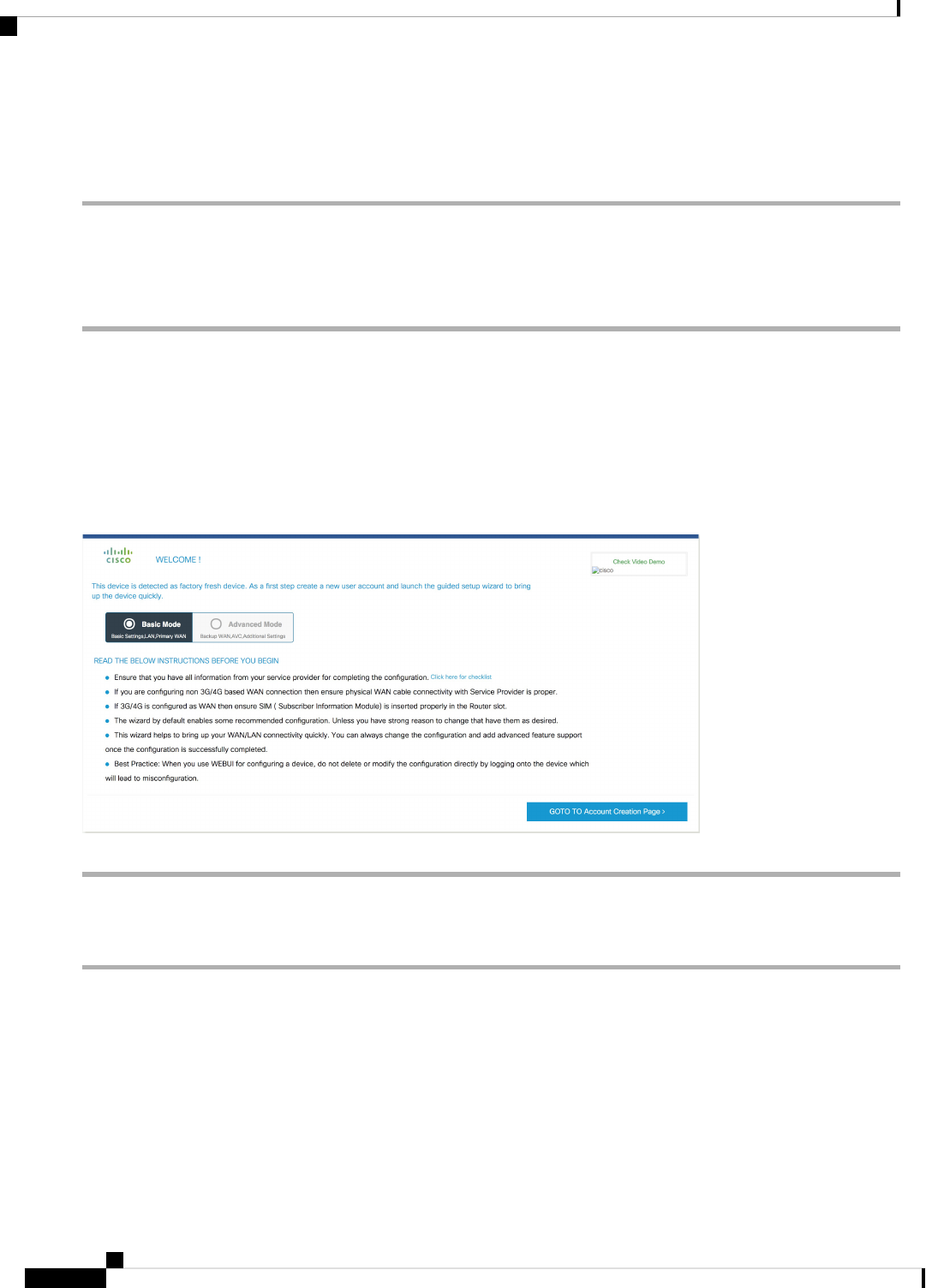
Step 6 Launch the browser and enter the device IP address in your browser’s address line. For a secure connection, type
https://192.168.1.1/#/dayZeroRouting. For a less secure connection, enter http://192.168.1.1/#/dayZeroRouting.
Step 7 Enter the default username (admin) and the password as default.
Using Basic or Advanced Mode Setup Wizard
To configure the router using the basic or advanced mode setup:
Step 1 Choose the Basic Mode or Advanced Mode and click Go To Account Creation Page.
Step 2 Enter the username and password. Reenter the password to confirm.
Step 3 Click Create and Launch Wizard.
Step 4 Enter the device name and domain name.
Step 5 Select the appropriate time zone from the Time Zone drop-down list.
Step 6 Select the appropriate date and time mode from the Date and Time drop-down list.
Step 7 Click LAN Settings.
Configure LAN Settings
Step 1 Choose the Web DHCP Pool/DHCP Pool name or the Create and Associate Access VLAN option.
a) If you choose the Web DHCP Pool, specify the following:
Pool Name—Enter the DHCP Pool Name.
Network—Enter network address and the subnet mask.
b) If you choose the Create and Associate Access VLAN option, specify the following:
Access VLAN—Enter the Access VLAN identification number. The range is from 1 to 4094.
Network—Enter the IP address of the VLAN.
Cisco 1100 Terminal Gateway Software Configuration Guide, Cisco IOS XE 17
70
Managing the Device Using Web User Interface
Using Basic or Advanced Mode Setup Wizard
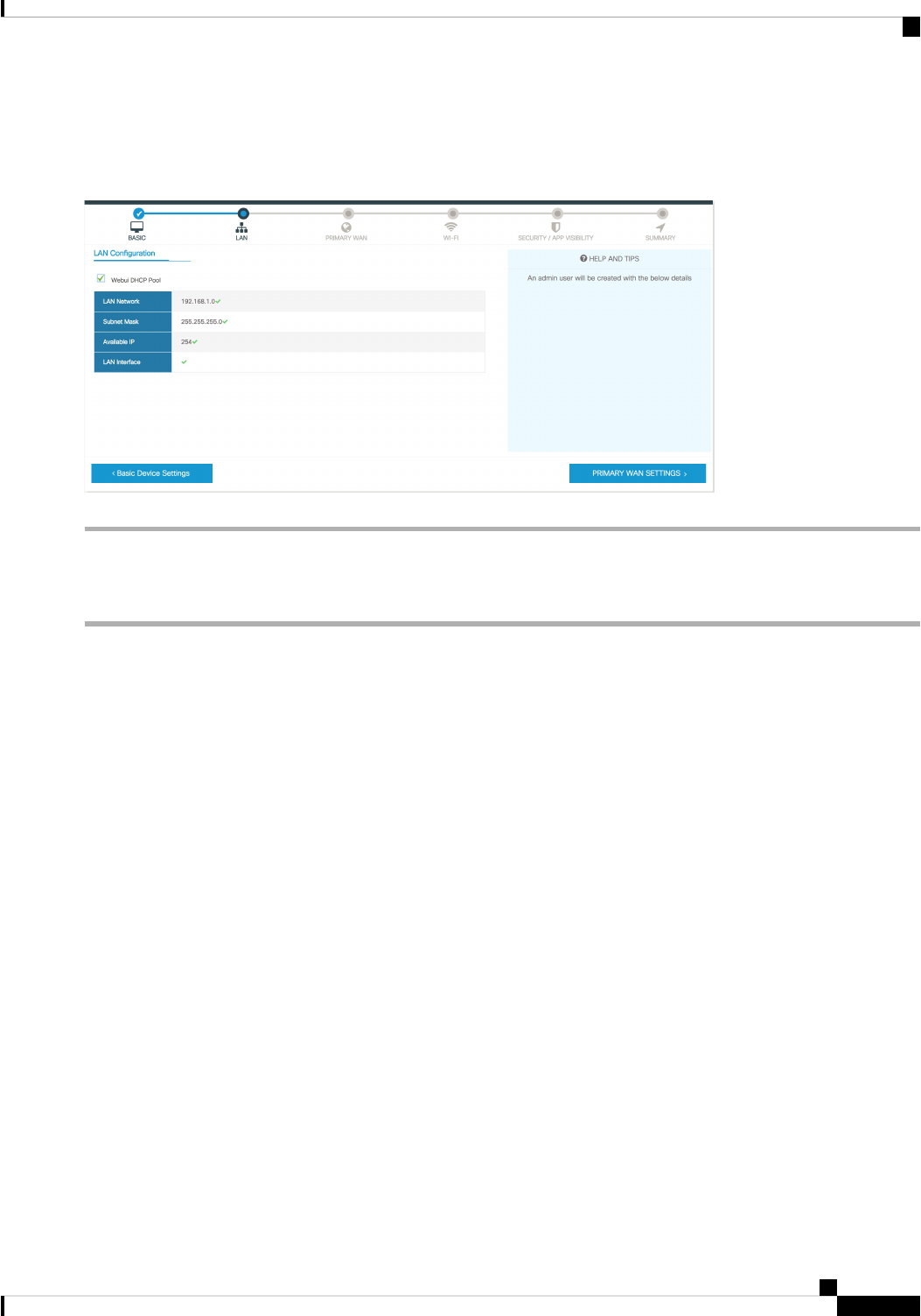
Management Interfaces—Select the interface and move to the selected list box using the right and left arrows. You
can also double click or drag and drop to move the interface to the selected list box.
Step 2 Click Primary WAN Settings.
Configure Primary WAN Settings
Step 1 Select the primary WAN type. You con configure Serial, 3G/4G, Ethernet, or Broadband (xDSL) as primary WAN
depending on the WAN types supported by the router.
Step 2 Select the interface from the drop-down list.
Step 3 Check the GetDNS Server info directly from ISP check box to get the DNS server information directly from the service
provider. You can also manually enter the Primary DNS and Secondary DNS.
Step 4 Check the Get IP automatically fromISP check box to get the IP address information directly from the service provider.
You can also manually enter the IP address and subnet mask.
Step 5 Check the Enable NAT check box to enable NAT. It is recommended to enable NAT.
Step 6 Check the Enable PPPOE check box to enable PPPoE. If you have enabled PPPoE, select the required authentication
mode. The options are: PAP and CHAP.
Step 7 Enter the user name and password provided by the service provider.
Step 8 Click Security / APP Visibility WAN Settings.
Cisco 1100 Terminal Gateway Software Configuration Guide, Cisco IOS XE 17
71
Managing the Device Using Web User Interface
Configure Primary WAN Settings

Configure Secondary WAN Settings
For advanced configuration, you should configure the secondary WAN connection.
Step 1 Select the secondary WAN type. You con configure Serial, 3G/4G, Ethernet, or Broadband (xDSL) as a secondary WAN
depending on the WAN types supported by the router.
Step 2 Select the interface from the drop-down list.
Step 3 Check the GetDNS Server info directly from ISP check box to get the DNS server information directly from the service
provider. You can also manually enter the Primary DNS and Secondary DNS.
Step 4 Check the Get IP automatically fromISP check box to get the IP address information directly from the service provider.
You can also manually enter the IP address and subnet mask.
Step 5 Check the Enable NAT check box to enable NAT. It is recommended to enable NAT.
Step 6 Check the Enable PPPOE check box to enable PPPoE. If you have enabled PPPoE, select the required authentication
mode. The options are PAP and CHAP .
Step 7 Enter the user name and password provided by the service provider.
Step 8 Click Security / APP Visibility WAN Settings.
Configure Security Settings
Step 1 Check the Enable Cisco Recommended Security Settings check box to ensure that all passwords are not shown in plain
text. The passwords are encrypted.
Step 2 Click Day 0 Config Summary.
Step 3 To preview the configuration, click CLI Preview to preview the configuration.
Step 4 Click Finish to complete the Day Zero setup.
Cisco 1100 Terminal Gateway Software Configuration Guide, Cisco IOS XE 17
72
Managing the Device Using Web User Interface
Configure Secondary WAN Settings
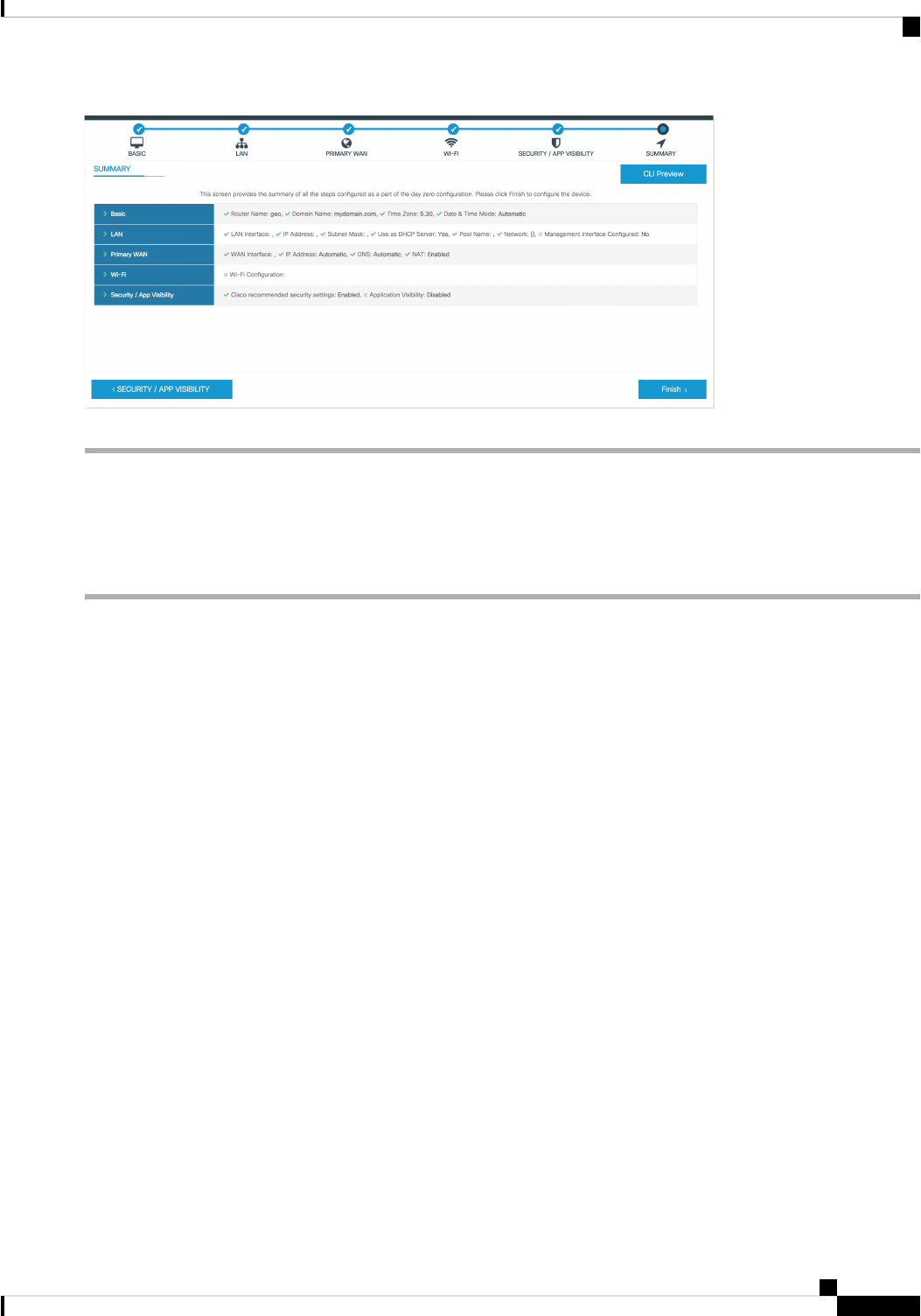
Using Web User Interface for Day One Setup
To configure the Web user interface:
Step 1 Configure the HTTP server. By default, the HTTP server configuration should be present on the device. Ensure the
configuration by checking if the ip http server and ip http secure-server commands are present in the running
configuration.
Device #configure terminal
Device (config)#ip http server
Device (config)#ip http secure-server
Step 2 Set up the authentication options to log into Web UI. You can use one of these methods to authenticate:
a) You can authenicate using local database. To use a local database for Web UI authentication, ensure to have the ip
http authentication local command in the running configuration. This command is preconfigured on the device. If
the command is not present, configure the device as shown in this example:
Device #configure terminal
Device (config)#ip http authentication local
You need a user with privilege 15 to access the configuration screens on Web UI. If the privilege is less
than 15, you can access only the Dashboard and Monitoring screens on Web UI.
Note
To create a user account, use the username <username> privilege <privilege> password 0 <passwordtext>
Device #configure terminal
Device (config)# username <username> privilege <privilege> password 0 <passwordtext>
b) Authenticate using AAA options. To use AAA authentication for Web UI, ensure to configure ‘ip http authentication
aaa’ on the device. Also, ensure that the required AAA server configuration is present on the device.
Device #configure terminal
Device (config)#ip http authentication local
Cisco 1100 Terminal Gateway Software Configuration Guide, Cisco IOS XE 17
73
Managing the Device Using Web User Interface
Using Web User Interface for Day One Setup

Step 3 Launch the browser. In the address bar, type the IP address of the device. For a secure connection, type https://ip-address.
Step 4 Enter the default username (cisco) and password provided with the device
Step 5 Click Log In.
Cisco 1100 Terminal Gateway Software Configuration Guide, Cisco IOS XE 17
74
Managing the Device Using Web User Interface
Using Web User Interface for Day One Setup

CHAPTER 7
Console Port, Telnet, and SSH Handling
This chapter includes the following sections:
• Notes and Restrictions for Console Port, Telnet, and SSH, on page 75
• Console Port Overview, on page 75
• Console Port Handling Overview, on page 76
• Telnet and SSH Overview, on page 76
• Persistent Telnet and Persistent SSH Overview, on page 76
• Configuring a Console Port Transport Map, on page 77
• Configuring Persistent Telnet, on page 79
• Configuring Persistent SSH, on page 81
• Viewing Console Port, SSH, and Telnet Handling Configurations, on page 84
• Configuring Auxiliary Port for Modem Connection , on page 89
Notes and Restrictions for Console Port, Telnet, and SSH
• Telnet and Secure Shell (SSH) settings configured in the transport map override any other Telnet or SSH
settings when the transport map is applied to the Ethernet management interface.
• Only local usernames and passwords can be used to authenticate users entering a Ethernet management
interface. AAA authentication is not available for users accessing the router through a Ethernet
management interface using persistent Telnet or persistent SSH.
• Applying a transport map to a Ethernet management interface with active Telnet or SSH sessions can
disconnect the active sessions. Removing a transport map from an interface, however, does not disconnect
any active Telnet or SSH session.
• Configuring the diagnostic and wait banners is optional, but recommended. The banners are especially
useful as indicators to users about the status of their Telnet or SSH attempts.
Console Port Overview
The console port on the router is an EIA/TIA-232 asynchronous, serial connection with no flow control and
an RJ-45 connector. The console port is used to access the router and is located on the front panel of the Route
Processor.
Cisco 1100 Terminal Gateway Software Configuration Guide, Cisco IOS XE 17
75

For information on accessing the router using the console port, see the Using Cisco IOS XE Software section.
Console Port Handling Overview
If you are using the console port to access the router, you are automatically directed to the Cisco IOS
command-line interface (CLI).
If you are trying to access the router through the console port and send a break signal (by entering Ctrl-C or
Ctrl-Shift-6, or by entering the send break command at the Telnet prompt) before connecting to the CLI,
you are directed to a diagnostic mode if the non-RPIOS subpackages are accessible. These settings can be
changed by configuring a transport map for the console port and applying that transport map to the console
interface.
Telnet and SSH Overview
Telnet and SSH on the router can be configured and handled like Telnet and SSH on other Cisco platforms.
For information on traditional Telnet, see the line command in the Cisco IOS Terminal Services Command
Reference, Release 12.2 document. For more information on AAA authentiction methods, see the line command
in the Authentication Commands chapter.
For information on configuring traditional SSH, see the “Configuring Secure Shell” chapter in the Cisco IOS
Terminal Services Command Reference, Release 12.2 document.
On the router, persistent Telnet and persistent SSH allow network administrators to more clearly define the
treatment of incoming traffic when users access the router through the management ethernet port using Telnet
or SSH. Notably, persistent Telnet and persistent SSH provide more robust network access by allowing the
router to be configured to be accessible through the Ethernet management port using Telnet or SSH even
when the Cisco IOS process has failed.
Persistent Telnet and Persistent SSH Overview
In traditional Cisco routers, accessing the router using Telnet or SSH is not possible if the Cisco IOS software
fails. When Cisco IOS fails on a traditional Cisco router, the only method of accessing the router is through
the console port. Similarly, if all the active Cisco IOS processes have failed on a router that is not using
persistent Telnet or persistent SSH, the only method of accessing the router is through the console port.
However, with persistent Telnet and persistent SSH, you can configure a transport map that defines the
treatment of incoming Telnet or SSH traffic on the Ethernet management interface. Among the many
configuration options, a transport map can be configured to direct all traffic to the Cisco IOS CLI, diagnostic
mode, or to wait for a Cisco IOS VTY line to become available and then direct users to diagnostic mode when
a user sends a break signal while waiting for the IOS VTY line to become available. If a user uses Telnet or
SSH to access diagnostic mode, that Telnet or SSH connection will be usable even in scenarios when no Cisco
IOS process is active. Therefore, persistent Telnet and persistent SSH introduce the ability to access the router
via diagnostic mode when the Cisco IOS process is not active. For information on diagnostic mode, see Using
Cisco IOS XE Software. For information on the options that are can be configured using persistent Telnet or
persistent SSH transport maps, see Configuring Persistent Telnet, on page 79 and Configuring Persistent
SSH, on page 81.
Cisco 1100 Terminal Gateway Software Configuration Guide, Cisco IOS XE 17
76
Console Port, Telnet, and SSH Handling
Console Port Handling Overview

Configuring a Console Port Transport Map
This task describes how to configure a transport map for a console port interface on the router.
SUMMARY STEPS
1. enable
2. configure terminal
3. transport-map type console transport-map-name
4. connection wait [allow [interruptible] | none [disconnect]]
5. (Optional) banner [diagnostic | wait] banner-message
6. exit
7. transport type console console-line-number input transport-map-name
DETAILED STEPS
PurposeCommand or Action
Enables privileged EXEC mode.enable
Step 1
Example:
Enter your password if prompted.
Router> enable
Enters global configuration mode.configure terminal
Example:
Step 2
Router# configure terminal
Creates and names a transport map for handling console
connections, and enters transport map configuration mode.
transport-map type console transport-map-name
Example:
Step 3
Router(config)# transport-map type console
consolehandler
Specifies how a console connection will be handled using
this transport map.
connection wait [allow [interruptible] | none
[disconnect]]
Step 4
Example:
• allow interruptible—The console connection waits
for a Cisco IOS VTY line to become available, and
Router(config-tmap)# connection wait none
also allows users to enter diagnostic mode by
interrupting a console connection that is waiting for a
Cisco IOS VTY line to become available. This is the
default setting.
Users can interrupt a waiting connection
by entering Ctrl-C or Ctrl-Shift-6.
Note
• none—The console connection immediately enters
diagnostic mode.
Cisco 1100 Terminal Gateway Software Configuration Guide, Cisco IOS XE 17
77
Console Port, Telnet, and SSH Handling
Configuring a Console Port Transport Map

PurposeCommand or Action
(Optional) Creates a banner message that will be seen by
users entering diagnostic mode or waiting for the Cisco IOS
(Optional) banner [diagnostic | wait] banner -messa g e
Example:
Step 5
VTY line because of the console transport map
configuration.
Router(config-tmap)# banner diagnostic X
Enter TEXT message. End with the character 'X'.
• diagnostic—Creates a banner message seen by users
directed to diagnostic mode because of the console
transport map configuration.
--Welcome to Diagnostic Mode--
X
Router(config-tmap)#
Users can interrupt a waiting connection
by entering Ctrl-C or Ctrl-Shift-6.
Note
• wait—Creates a banner message seen by users waiting
for Cisco IOS VTY to become available.
• banner-message—Banner message, which begins and
ends with the same delimiting character.
Exits transport map configuration mode to re-enter global
configuration mode.
exit
Example:
Step 6
Router(config-tmap)# exit
Applies the settings defined in the transport map to the
console interface.
transport type console console-line-number input
transport-map-name
Step 7
Example:
The transport-map-name for this command must match the
transport-map-name defined in the transport-map type
console command.
Router(config)# transport type console 0 input
consolehandler
Examples
The following example shows how to create a transport map to set console port access policies and
attach to console port 0:
Router(config)# transport-map type console consolehandler
Router(config-tmap)# connection wait allow interruptible
Router(config-tmap)# banner diagnostic X
Enter TEXT message. End with the character 'X'.
--Welcome to diagnostic mode--
X
Router(config-tmap)# banner wait X
Enter TEXT message. End with the character 'X'.
Waiting for IOS vty line
X
Router(config-tmap)# exit
Router(config)# transport type console 0 input consolehandler
Cisco 1100 Terminal Gateway Software Configuration Guide, Cisco IOS XE 17
78
Console Port, Telnet, and SSH Handling
Configuring a Console Port Transport Map

Configuring Persistent Telnet
For a persistent Telnet connection to access an Cisco IOS vty line on the router, local login authentication
must be configured for the vty line (the login command in line configuration mode). If local login authentication
is not configured, users will not be able to access Cisco IOS using a Telnet connection into the management
Ethernet interface with an applied transport map. Diagnostic mode will still be accessible in this scenario.
SUMMARY STEPS
1. enable
2. configure terminal
3. transport-map type persistent telnet transport-map-name
4. connection wait [allow [interruptible] | none [disconnect]]
5. (Optional) banner [diagnostic | wait] banner-message
6. transport interface
7. exit
8. transport type persistent telnetinput transport-map-name
DETAILED STEPS
PurposeCommand or Action
Enables privileged EXEC mode.enable
Step 1
Example:
• Enter your password if prompted.
Router> enable
Enters global configuration mode.configure terminal
Example:
Step 2
Router# configure terminal
Creates and names a transport map for handling persistent
Telnet connections, and enters transport map configuration
mode.
transport-map type persistent telnet
transport-map-name
Example:
Step 3
Router(config)# transport-map type persistent
telnet telnethandler
Specifies how a persistent Telnet connection will be handled
using this transport map:
connection wait [allow [interruptible] | none
[disconnect]]
Step 4
Example:
• allow—The Telnet connection waits for a Cisco IOS
vty line to become available, and exits the router if
interrupted.
Router(config-tmap)# connection wait none
• allow interruptible—The Telnet connection waits for
the Cisco IOS vty line to become available, and also
allows user to enter diagnostic mode by interrupting
Cisco 1100 Terminal Gateway Software Configuration Guide, Cisco IOS XE 17
79
Console Port, Telnet, and SSH Handling
Configuring Persistent Telnet

PurposeCommand or Action
a Telnet connection waiting for the Cisco IOS vty line
to become available. This is the default setting.
Users can interrupt a waiting connection
by entering Ctrl-C or Ctrl-Shift-6.
Note
• none—The Telnet connection immediately enters
diagnostic mode.
• none disconnect—The Telnet connection does not
wait for the Cisco IOS vty line and does not enter
diagnostic mode, so all Telnet connections are rejected
if no vty line is immediately available in the Cisco IOS
software.
(Optional) Creates a banner message that will be seen by
users entering diagnostic mode or waiting for the Cisco IOS
vty line because of the persistent Telnet configuration.
(Optional) banner [diagnostic | wait] banner -messa g e
Example:
Router(config-tmap)# banner diagnostic X
Step 5
• diagnostic—Creates a banner message seen by users
directed into diagnostic mode because of the persistent
Telnet configuration.
Enter TEXT message. End with the character 'X'.
--Welcome to Diagnostic Mode--
X
Router(config-tmap)#
Users can interrupt a waiting connection
by entering Ctrl-C or Ctrl-Shift-6.
Note
• wait—Creates a banner message seen by users waiting
for the vty line to become available.
• banner-message—The banner message, which begins
and ends with the same delimiting character.
Applies the transport map settings to the management
Ethernet interface (interface gigabitethernet 0).
transport interface
Example:
Step 6
Persistent Telnet can be applied only to the management
Ethernet interface on the router. This step must be taken
Router(config-tmap)# transport interface
gigabitethernet 0
before applying the transport map to the management
Ethernet interface.
Exits transport map configuration mode to re-enter global
configuration mode.
exit
Example:
Step 7
Router(config-tmap)# exit
Applies the settings defined in the transport map to the
management Ethernet interface.
transport type persistent telnetinput
transport-map-name
Step 8
Example:
The transport-map-name for this command must match the
transport-map-name defined in the transport-map type
persistent telnet command.
Router(config)# transport type persistent telnet
input telnethandler
Cisco 1100 Terminal Gateway Software Configuration Guide, Cisco IOS XE 17
80
Console Port, Telnet, and SSH Handling
Configuring Persistent Telnet

Examples
In the following example, a transport map that will make all Telnet connections wait for a Cisco IOS
XE vty line to become available before connecting to the router, while also allowing the user to
interrupt the process and enter diagnostic mode, is configured and applied to the management Ethernet
interface (interface gigabitethernet 0).
A diagnostic and a wait banner are also configured.
The transport map is then applied to the interface when the transport type persistent telnet input
command is entered to enable persistent Telnet.
Router(config)# transport-map type persistent telnet telnethandler
Router(config-tmap)# connection wait allow interruptible
Router(config-tmap)# banner diagnostic X
Enter TEXT message. End with the character 'X'.
--Welcome to diagnostic mode--
X
Router(config-tmap)# banner wait X
Enter TEXT message. End with the character 'X'.
Waiting for IOS IOS Process--
X
Router(config-tmap)# transport interface gigabitethernet 0
Router(config-tmap)# exit
Router(config)# transport type persistent telnet input telnethandler
Configuring Persistent SSH
This task describes how to configure persistent SSH on the router.
SUMMARY STEPS
1. enable
2. configure terminal
3. transport-map type persistent ssh transport-map-name
4. connection wait [allow [interruptible] | none [disconnect]]
5. rsa keypair-name rsa-keypair-name
6. (Optional) authentication-retries number-of-retries
7. (Optional) banner [diagnostic | wait] banner-message
8. (Optional) time-out timeout-interval
9. transport interface gigabitethernet 0
10. exit
11. transport type persistent ssh input transport-map-name
DETAILED STEPS
PurposeCommand or Action
Enables privileged EXEC mode.enable
Step 1
Example:
Enter your password if prompted.
Cisco 1100 Terminal Gateway Software Configuration Guide, Cisco IOS XE 17
81
Console Port, Telnet, and SSH Handling
Configuring Persistent SSH

PurposeCommand or Action
Router> enable
Enters global configuration mode.configure terminal
Example:
Step 2
Router# configure terminal
Creates and names a transport map for handling persistent
SSH connections, and enters transport map configuration
mode.
transport-map type persistent ssh
transport-map-name
Example:
Step 3
Router(config)# transport-map type persistent
telnet telnethandler
Specifies how a persistent SSH connection will be handled
using this transport map:
connection wait [allow [interruptible] | none
[disconnect]]
Step 4
Example:
• allow—The SSH connection waits for a Cisco IOS
VTY line to become available, and exits the router if
interrupted.
Router(config-tmap)# connection wait interruptible
• allow interruptible—The SSH connection waits for
the VTY line to become available, and also allows a
user to enter diagnostic mode by interrupting an SSH
connection waiting for the VTY line to become
available. This is the default setting.
Users can interrupt a waiting connection
by entering Ctrl-C or Ctrl-Shift-6.
Note
• none—The SSH connection immediately enters
diagnostic mode.
• none disconnect—The SSH connection does not wait
for the VTY line and does not enter diagnostic mode.
Therefore, all SSH connections are rejected if no VTY
line is immediately available.
Names the RSA keypair to be used for persistent SSH
connections.
rsa keypair-name rsa-keypair-name
Example:
Step 5
For persistent SSH connections, the RSA keypair name
must be defined using this command in transport map
Router(config)# rsa keypair-name sshkeys
configuration mode. The RSA keypair definitions defined
elsewhere on the router, such as through the use of the ip
ssh rsa keypair-namecommand, do not apply to persistent
SSH connections.
No rsa-keypair-name is defined by default.
Cisco 1100 Terminal Gateway Software Configuration Guide, Cisco IOS XE 17
82
Console Port, Telnet, and SSH Handling
Configuring Persistent SSH

PurposeCommand or Action
(Optional) Specifies the number of authentication retries
before dropping the connection.
(Optional) authentication-retries number-of-retries
Example:
Step 6
The default number-of-retries is 3.
Router(config-tmap)# authentication-retries 4
(Optional) Creates a banner message that will be seen by
users entering diagnostic mode or waiting for the VTY
line because of the persistent SSH configuration.
(Optional) banner [diagnostic | wait]
banner-message
Example:
Step 7
• diagnostic—Creates a banner message seen by users
directed to diagnostic mode because of the persistent
SSH configuration.
Router(config-tmap)# banner diagnostic X
Enter TEXT message. End with the character 'X'.
--Welcome to Diagnostic Mode--
X
Router(config-tmap)#
• wait—Creates a banner message seen by users
waiting for the VTY line to become available.
• banner-message—The banner message, which begins
and ends with the same delimiting character.
(Optional) Specifies the SSH time-out interval, in seconds.(Optional) time-out timeout-interval
Step 8
Example:
The default timeout-interval is 120 seconds.
Router(config-tmap)# time-out 30
Applies the transport map settings to the Ethernet
management interface (interface gigabitethernet 0).
transport interface gigabitethernet 0
Example:
Step 9
Persistent SSH can be applied only to the Ethernet
management interface on the router.
Router(config-tmap)# transport interface
gigabitethernet 0
Exits transport map configuration mode to re-enter global
configuration mode.
exit
Example:
Step 10
Router(config-tmap)# exit
Applies the settings defined in the transport map to the
Ethernet management interface.
transport type persistent ssh input
transport-map-name
Step 11
Example:
The transport-map-name for this command must match
the transport-map-name defined in the transport-map
type persistent ssh command.
Router(config)# transport type persistent ssh
input sshhandler
Examples
The following example shows a transport map that will make all SSH connections wait for the VTY
line to become active before connecting to the router being configured and applied to the Ethernet
management interface (interface gigabitethernet 0). The RSA keypair is named sshkeys.
This example only uses the commands required to configure persistent SSH.
Cisco 1100 Terminal Gateway Software Configuration Guide, Cisco IOS XE 17
83
Console Port, Telnet, and SSH Handling
Configuring Persistent SSH

Router(config)# transport-map type persistent ssh sshhandler
Router(config-tmap)# connection wait allow
Router(config-tmap)# rsa keypair-name sshkeys
Router(config-tmap)# transport interface gigabitethernet 0
Enter TEXT message. End with the character 'X'.
--Welcome to diagnostic mode--
X
Router(config-tmap)# banner wait X
Enter TEXT message. End with the character 'X'.
--Waiting for IOS IOS Process--
X
Router(config-tmap)# transport interface gigabitethernet 0
Router(config-tmap)# exit
Router(config)# transport type persistent telnet input telnethandler
In the following example, a transport map is configured and will apply the following settings to users
attempting to access the Ethernet management port via SSH:
• SSH users will wait for the VTY line to become active, but will enter diagnostic mode if the
attempt to access the Cisco IOS software through the VTY line is interrupted.
• The RSA keypair name is sshkeys.
• The connection allows one authentication retry.
• The banner --Welcome to Diagnostic Mode-- will appear if diagnostic mode is entered as
a result of SSH handling through this transport map.
• The banner --Waiting for vty line-- will appear if the connection is waiting for the VTY
line to become active.
• The transport map is then applied to the interface when the transport type persistent ssh input
command is entered to enable persistent SSH:
Router(config)# transport-map type persistent ssh sshhandler
Router(config-tmap)# connection wait allow interruptible
Router(config-tmap)# rsa keypair-name sshkeys
Router(config-tmap)# authentication-retries 1
Router(config-tmap)# banner diagnostic X
Enter TEXT message. End with the character 'X'.
--Welcome to diagnostic mode--
X
Router(config-tmap)# banner wait X
Enter TEXT message. End with the character 'X'.
--Waiting for vty line--
X
Router(config-tmap)# time-out 30
Router(config-tmap)# transport interface gigabitethernet 0
Router(config-tmap)# exit
Router(config)# transport type persistent ssh input sshhandler
Viewing Console Port, SSH, and Telnet Handling Configurations
Use the following commands to view console port, SSH, and Telnet handling configurations:
• show transport-map
• show platform software configuration access policy
Cisco 1100 Terminal Gateway Software Configuration Guide, Cisco IOS XE 17
84
Console Port, Telnet, and SSH Handling
Viewing Console Port, SSH, and Telnet Handling Configurations

Use the show transport-map command to view transport map configurations.
show transport-map [all | name transport-map-name | type [console | persistent [ssh | telnet]]]
This command can be used either in user EXEC mode or privileged EXEC mode.
Example
The following example shows transport maps that are configured on the router: a console port
(consolehandler), persistent SSH (sshhandler), and persistent Telnet transport (telnethandler):
Router# show transport-map all
Transport Map:
Name: consolehandler
Type: Console Transport
Connection:
Wait option: Wait Allow Interruptable
Wait banner:
Waiting for the IOS CLI
bshell banner:
Welcome to Diagnostic Mode
Transport Map:
Name: sshhandler
Type: Persistent SSH Transport
Interface:
GigabitEthernet0
Connection:
Wait option: Wait Allow Interruptable
Wait banner:
Waiting for IOS prompt
Bshell banner:
Welcome to Diagnostic Mode
SSH:
Timeout: 120
Authentication retries: 5
RSA keypair: sshkeys
Transport Map:
Name: telnethandler
Type: Persistent Telnet Transport
Interface:
GigabitEthernet0
Connection:
Wait option: Wait Allow Interruptable
Wait banner:
Waiting for IOS process
Bshell banner:
Cisco 1100 Terminal Gateway Software Configuration Guide, Cisco IOS XE 17
85
Console Port, Telnet, and SSH Handling
Viewing Console Port, SSH, and Telnet Handling Configurations

Welcome to Diagnostic Mode
Transport Map:
Name: telnethandling1
Type: Persistent Telnet Transport
Connection:
Wait option: Wait Allow
Router# show transport-map type console
Transport Map:
Name: consolehandler
Type: Console Transport
Connection:
Wait option: Wait Allow Interruptable
Wait banner:
Waiting for the IOS CLI
Bshell banner:
Welcome to Diagnostic Mode
Router# show transport-map type persistent ssh
Transport Map:
Name: sshhandler
Type: Persistent SSH Transport
Interface:
GigabitEthernet0
Connection:
Wait option: Wait Allow Interruptable
Wait banner:
Waiting for IOS prompt
Bshell banner:
Welcome to Diagnostic Mode
SSH:
Timeout: 120
Authentication retries: 5
RSA keypair: sshkeys
Router# show transport-map type persistent telnet
Transport Map:
Name: telnethandler
Type: Persistent Telnet Transport
Interface:
GigabitEthernet0
Connection:
Wait option: Wait Allow Interruptable
Wait banner:
Waiting for IOS process
Cisco 1100 Terminal Gateway Software Configuration Guide, Cisco IOS XE 17
86
Console Port, Telnet, and SSH Handling
Viewing Console Port, SSH, and Telnet Handling Configurations

Bshell banner:
Welcome to Diagnostic Mode
Transport Map:
Name: telnethandling1
Type: Persistent Telnet Transport
Connection:
Wait option: Wait Allow
Router# show transport-map name telnethandler
Transport Map:
Name: telnethandler
Type: Persistent Telnet Transport
Interface:
GigabitEthernet0
Connection:
Wait option: Wait Allow Interruptable
Wait banner:
Waiting for IOS process
Bshell banner:
Welcome to Diagnostic Mode
Router# show transport-map name consolehandler
Transport Map:
Name: consolehandler
Type: Console Transport
Connection:
Wait option: Wait Allow Interruptable
Wait banner:
Waiting for the IOS CLI
Bshell banner:
Welcome to Diagnostic Mode
Router# show transport-map name sshhandler
Transport Map:
Name: sshhandler
Type: Persistent SSH Transport
Interface:
GigabitEthernet0
Connection:
Wait option: Wait Allow Interruptable
Wait banner:
Waiting for IOS prompt
Bshell banner:
Cisco 1100 Terminal Gateway Software Configuration Guide, Cisco IOS XE 17
87
Console Port, Telnet, and SSH Handling
Viewing Console Port, SSH, and Telnet Handling Configurations

Welcome to Diagnostic Mode
SSH:
Timeout: 120
Authentication retries: 5
RSA keypair: sshkeys
Router#
Use the show platform software configuration access policy command to view the current configurations
for handling the incoming console port, SSH, and Telnet connections. The output of this command provides
the current wait policy for each type of connection (Telnet, SSH, and console), as well as information on the
currently configured banners.
Unlike the show transport-map command, the show platform software configuration access policy
command is available in diagnostic mode so that it can be entered in scenarios where you need transport map
configuration information, but cannot access the Cisco IOS CLI.
Example
Router# show platform software configuration access policy
The current access-policies
Method : telnet
Rule : wait
Shell banner:
Wait banner :
Method : ssh
Rule : wait
Shell banner:
Wait banner :
Method : console
Rule : wait with interrupt
Shell banner:
Wait banner :
Example
The following example shows the show platform software configuration access policy command
being issued both before and after a new transport map for SSH are configured. During the
configuration, the connection policy and banners are set for a persistent SSH transport map, and the
transport map for SSH is enabled.
Router# show platform software configuration access policy
The current access-policies
Method : telnet
Rule : wait with interrupt
Shell banner:
Welcome to Diagnostic Mode
Wait banner :
Waiting for IOS Process
Cisco 1100 Terminal Gateway Software Configuration Guide, Cisco IOS XE 17
88
Console Port, Telnet, and SSH Handling
Viewing Console Port, SSH, and Telnet Handling Configurations

Method : ssh
Rule : wait
Shell banner:
Wait banner :
Method : console
Rule : wait with interrupt
Shell banner:
Wait banner :
Router# configure terminal
Enter configuration commands, one per line. End with CNTL/Z.
Router(config)# transport-map type persistent ssh sshhandler
Router(config-tmap)# connection wait allow interruptible
Router(config-tmap)# banner diagnostic X
Enter TEXT message. End with the character 'X'.
Welcome to Diag Mode
X
Router(config-tmap)# banner wait X
Enter TEXT message. End with the character 'X'.
Waiting for IOS
X
Router(config-tmap)# rsa keypair-name sshkeys
Router(config-tmap)# transport interface gigabitethernet 0
Router(config-tmap)# exit
Router(config)# transport type persistent ssh input sshhandler
Router(config)# exit
Router# show platform software configuration access policy
The current access-policies
Method : telnet
Rule : wait with interrupt
Shell banner:
Welcome to Diagnostic Mode
Wait banner :
Waiting for IOS process
Method : ssh
Rule : wait with interrupt
Shell banner:
Welcome to Diag Mode
Wait banner :
Waiting for IOS
Method : console
Rule : wait with interrupt
Shell banner:
Wait banner :
Configuring Auxiliary Port for Modem Connection
Cisco 1100 Terminal Server Gateway supports connecting a modem to the router auxiliary port for EXEC
dial in connectivity. When a modem is connected to the auxiliary port, a remote user can dial in to the router
and configure it. To configure a modem on the auxiliary port, perform these steps:
Cisco 1100 Terminal Gateway Software Configuration Guide, Cisco IOS XE 17
89
Console Port, Telnet, and SSH Handling
Configuring Auxiliary Port for Modem Connection

Step 1 Connect the RJ-45 end of the adapter cable to the black AUX port on the router.
Step 2 Use the show line command to determine the async interface of the AUX port:
Router# show line
Tty Typ Tx/Rx A Modem Roty AccO AccI Uses Noise Overruns Int
* 0 CTY - - - - - 0 0 0/0 -
1 AUX 9600/9600 - - - - - 0 0 0/0 -
2 VTY - - - - - 0 0 0/0 -
3 VTY - - - - - 0 0 0/0 -
4 VTY - - - - - 0 0 0/0 -
5 VTY - - - - - 0 0 0/0 -
6 VTY - - - - - 0 0 0/0 -
Step 3 Use the following commands to configure the router AUX line::
Router(config)# line 1
Router(config-line)#modem inOut
Router(config-line)#modem autoconfigure type usr_sportster
Router(config-line)#speed 115200 [Speed to be set according to the modem manual]
Router(config-line)#stopbits 1 [Stopbits to be set according to the modem manual]
Router(config-line)#transport input all
Router(config-line)#flowcontrol hardware [flowcontrol to be set according to the modem manual]
Router(config-line)#password cisco
Router(config-line)#login
Router(config-line)#end
Router(config)#enable password lab
Step 4 Use the reverse telnet method on the modem to verify the modem connectivity and configuration string:
Router(config)#int loopback 0
Router(config-if)#ip add 1.1.1.1 255.255.255.0
Router(config-if)#end
Router#telnet 1.1.1.1 2001
Trying 1.1.1.1, 2001 ... Open
User Access Verification
Password: <enter the password given under line configuration>
at <<<=== Modem command
OK <<<=== This OK indicates that the modem is connected successully to the AUX port.
Step 5 Use an analog phone to verify that the phone line is active and functions properly. Then, connect the analog phone line
to the modem.
Step 6 Initialize an EXEC modem call to the router from another device (PC) to test the modem connection.
Step 7 When the connection is established, the dial in client is prompted for a password. Enter the correct password.
Note: This password should match the one that is configured on the auxiliary port line.
Cisco 1100 Terminal Gateway Software Configuration Guide, Cisco IOS XE 17
90
Console Port, Telnet, and SSH Handling
Configuring Auxiliary Port for Modem Connection

CHAPTER 8
Installing the Software
This chapter includes the following sections:
• Overview, on page 91
• ROMMON Images, on page 92
• Provisioning Files, on page 92
• File Systems, on page 92
• Autogenerated File Directories and Files, on page 93
• Flash Storage, on page 94
• Configuring the Configuration Register for Autoboot, on page 94
• How to Install and Upgrade the Software, on page 95
• Managing and Configuring a Router to Run Using Individual Packages, on page 100
• Installing a Firmware Subpackage, on page 105
• Configuring No Service Password-Recovery, on page 111
Overview
Installing software on the router involves installing a consolidated package (bootable image). This consists
of a bundle of subpackages (modular software units), with each subpackage controlling a different set of
functions.
These are the two main methods to install the software:
• Managing and Configuring a Router to Run Using a Consolidated Package, on page 95—This method
allows for individual upgrade of subpackages and generally has reduced boot times compared to the
method below. Use this method if you want to individually upgrade a module's software.
• Managing and Configuring a Router to Run Using Individual Packages, on page 100—This a simple
method that is similar to a typical Cisco router image installation and management that is supported
across Cisco routers.
It is better to upgrade software in a planned period of maintenance when an interruption in service is acceptable.
The router needs to be rebooted for a software upgrade to take effect.
Cisco 1100 Terminal Gateway Software Configuration Guide, Cisco IOS XE 17
91

ROMMON Images
A ROMMON image is a software package used by ROM Monitor (ROMMON) software on a router. The
software package is separate from the consolidated package normally used to boot the router.
An independent ROMMON image (software package) may occasionally be released and the router can be
upgraded with the new ROMMON software.
A new version of the ROMMON image is not necessarily released at the same time as a consolidated package
for a router.
Note
Provisioning Files
This section provides background information about the files and processes used in Managing and Configuring
a Router to Run Using Individual Packages, on page 100.
The consolidated package on a router consists of a collection of subpackages and a provisioning file titled
packages.conf. To run the software, the usual method used is to boot the consolidated package, which is
copied into memory, expanded, mounted, and run within memory. The provisioning file's name can be renamed
but subpackage file's names cannot be renamed. The provisioning file and subpackage files must be kept in
the same directory. The provisioning file does not work properly if any individual subpackage file is contained
within a different directory.
An exception to this is that if a new or upgraded module firmware package is subsequently installed, it need
not be in the same directory as the provisioning file.
Note
Configuring a router to boot, using the provisioning file packages.conf, is beneficial because no changes have
to be made to the boot statement after the Cisco IOS XE software is upgraded.
File Systems
The following table provides a list of file systems that can be seen on the Cisco Terminal Gateway.
Table 7: Router File Systems
DescriptionFile System
Boot flash memory file system.bootflash:
Alias to the boot flash memory file system above.flash:
Cisco 1100 Terminal Gateway Software Configuration Guide, Cisco IOS XE 17
92
Installing the Software
ROMMON Images

DescriptionFile System
Hard disk file system (if NIM-SSD, NIM-HDD, or internal M.2 flash device is present
in the router).
The internal M.2 flash device is supported only on Cisco 1100 Terminal
Server Gateway.
Note
harddisk:
Cisco Networking Services file directory.cns:
Router NVRAM. You can copy the startup configuration to NVRAM or from
NVRAM.
nvram:
File system for Onboard Failure Logging (OBFL) files.obfl:
System memory file system, which includes the running configuration.system:
Archive file system.tar:
Temporary system files file system.tmpsys:
The Universal Serial Bus (USB) flash drive file systems.
The USB flash drive file system is visible only if a USB drive is installed
in usb0: or usb1: ports.
Note
usb0: USB 3.0 Type-
A
usb1: USB 3.0
Type-B
Use the ? help option, or use the copy command in command reference guides, if you find a file system that
is not listed in the table above.
Autogenerated File Directories and Files
This section discusses the autogenerated files and directories that can be created, and how the files in these
directories can be managed.
Table 8: Autogenerated Files
DescriptionFile or Directory
Crashinfo files may appear in the bootflash: file system.
These files provide descriptive information of a crash and may be useful for
tuning or troubleshooting purposes. However, the files are not part of router
operations, and can be erased without impacting the functioning of the router.
crashinfo files
The storage area for .core files.
If this directory is erased, it will automatically regenerate itself at bootup.
The .core files in this directory can be erased without impacting any router
functionality, but the directory itself should not be erased.
core directory
This directory is created on bootup if a system check is performed. Its
appearance is completely normal and does not indicate any issues with the
router.
lost+found directory
Cisco 1100 Terminal Gateway Software Configuration Guide, Cisco IOS XE 17
93
Installing the Software
Autogenerated File Directories and Files

DescriptionFile or Directory
The storage area for trace files.
Trace files are useful for troubleshooting. If the Cisco IOS process fails, for
instance, users or troubleshooting personnel can access trace files using
diagnostic mode to gather information related to the Cisco IOS failure.
Trace files, however, are not a part of router operations, and can be erased
without impacting the router's performance.
tracelogs directory
Important Notes About Autogenerated Directories
Important information about autogenerated directories include:
• Autogenerated files on the bootflash: directory should not be deleted, renamed, moved, or altered in any
way unless directed by Cisco customer support.
Altering autogenerating files on the bootflash: may have unpredictable
consequences for system performance.
Note
• Crashinfo, core, and trace files can be deleted.
Flash Storage
Subpackages are installed to local media storage, such as flash. For flash storage, use the dir bootflash:
command to list the file names.
Flash storage is required for successful operation of a router.
Note
Configuring the Configuration Register for Autoboot
The configuration register can be used to change router behavior. This includes controlling how the router
boots. Set the configuration register to 0x0 to boot into ROM, by using one of the following commands:
• In Cisco IOS configuration mode, use the config-reg 0x0 command.
• From the ROMMON prompt, use the confreg 0x0 command.
For more information about the configuration register, see Use of the Configuration Register on All Cisco
Routers.
Setting the configuration register to 0x2102 will set the router to autoboot the Cisco IOS XE software.
Note
Cisco 1100 Terminal Gateway Software Configuration Guide, Cisco IOS XE 17
94
Installing the Software
Flash Storage

The console baud rate is set to 9600 after changing the confreg to 0x2102 or 0x0. If you cannot establish a
console session after setting confreg, or garbage output appears, change the setting on your terminal emulation
software to 9600.
Note
How to Install and Upgrade the Software
To install or upgrade the software, use one of the following methods to use the software from a consolidated
package or an individual package. Also see the overview section.
• Managing and Configuring a Router to Run Using a Consolidated Package, on page 95
• Managing and Configuring a Router to Run Using Individual Packages, on page 100
Managing and Configuring a Router to Run Using a Consolidated Package
Do not use these procedures if you also need to install any optional subpackages or plan to upgrade individual
subpackages. See Managing and Configuring a Router to Run Using Individual Packages, on page 100.
Note
• Managing and Configuring a Consolidated Package Using copy and boot Commands, on page 95
• Configuring a Router to Boot the Consolidated Package via TFTP Using the boot Command: Example,
on page 96
Managing and Configuring a Consolidated Package Using copy and boot Commands
To upgrade a consolidated package, copy the consolidated package to the bootflash: directory on the router
using the copy command. After making this copy of the consolidated package, configure the router to boot
using the consolidated package file.
The following example shows the consolidated package file being copied to the bootflash: file system via
TFTP. The config register is then set to boot using boot system commands, and the boot system commands
instruct the router to boot using the consolidated package stored in the bootflash: file system. The new
configuration is then saved using the copy running-config startup-config command, and the system is then
reloaded to complete the process.
Router# dir bootflash:
Directory of bootflash:/
11 drwx 16384 Dec 4 2007 04:32:46 -08:00 lost+found
86401 drwx 4096 Dec 4 2007 06:06:24 -08:00 .ssh
14401 drwx 4096 Dec 4 2007 06:06:36 -08:00 .rollback_timer
28801 drwx 4096 Mar 18 2008 17:31:17 -07:00 .prst_sync
43201 drwx 4096 Dec 4 2007 04:34:45 -08:00 .installer
928862208 bytes total (712273920 bytes free)
Router# copy tftp: bootflash:
Address or name of remote host []? 172.17.16.81
Source filename []? /auto/tftp-users/user/isr4400-universalk9.03.10.00.S.153-3.S-ext.SPA.bin
Cisco 1100 Terminal Gateway Software Configuration Guide, Cisco IOS XE 17
95
Installing the Software
How to Install and Upgrade the Software

Destination filename [isr4400-universalk9.03.10.00.S.153-3.S-ext.SPA.bin]?
Accessing
tftp://172.17.16.81//auto/tftp-users/user/isr4400-universalk9.03.10.00.S.153-3.S-ext.SPA.bin
...
Loading /auto/tftp-users/user/isr4400-universalk9.03.10.00.S.153-3.S-ext.SPA.bin from
172.17.16.81 (via GigabitEthernet0):
!!!!!!!!!!!!!!!!!!!!!!!!!!!!!!!!!!!!!!!!!!!!!!!!!!!!!!!!!!!!!!!!!!!!!!!!!!!!!!!!!!!!!!!!!!
!!!!!!!!!!!!!!!!!!!!!!!!!!!!!!!!!!!!!!!!!!!!!!!!!!!!!!!!!!!!!!!!!!!!!!!!!!!!!!!!!!!!!!!!!!
!!!!!!!!!!!!!!!!!!!!!!!!!!!!!!!!!!!!!!!!!!!!!!!!!!!!!!!!!!!!!!!!!!!!!!!!!!!!!!!!!!!!!!!!!!
!!!!!!!
[OK - 208904396 bytes]
208904396 bytes copied in 330.453 secs (632176 bytes/sec)
Router# dir bootflash:
Directory of bootflash:/
11 drwx 16384 Dec 4 2007 04:32:46 -08:00 lost+found
86401 drwx 4096 Dec 4 2007 06:06:24 -08:00 .ssh
14401 drwx 4096 Dec 4 2007 06:06:36 -08:00 .rollback_timer
28801 drwx 4096 Mar 18 2008 17:31:17 -07:00 .prst_sync
43201 drwx 4096 Dec 4 2007 04:34:45 -08:00 .installer
12 -rw- 208904396 May 28 2008 16:17:34 -07:00
isr4400-universalk9.03.10.00.S.153-3.S-ext.SPA.bin
928862208 bytes total (503156736 bytes free)
Router# configure terminal
Enter configuration commands, one per line. End with CNTL/Z.
Router(config)# boot system flash bootflash:isr4400-universalk9.03.10.00.S.153-3.S-ext.SPA.bin
Router(config)# config-reg 0x2102
Router(config)# exit
Router# show run | include boot
boot-start-marker
boot system flash bootflash:isr4400-universalk9.03.10.00.S.153-3.S-ext.SPA.bin
boot-end-marker
Router# copy run start
Destination filename [startup-config]?
Building configuration...
[OK]
Router# reload
Configuring a Router to Boot the Consolidated Package via TFTP Using the
boot Command: Example
Router# configure terminal
Enter configuration commands, one per line. End with CNTL/Z.
Router(config)#boot system tftp://10.74.48.3/c1100tg-universalk9.17.02.01r.SPA.bin
Router(config)#config-register 0x2102
Router(config)#exit
Router#show run | include boot
boot-start-marker
boot system bootflash:c1100tg-universalk9.BLD_POLARIS_DEV_LATEST_20200506_055739.SSA.bin
boot system tftp://10.74.48.3/c1100tg-universalk9.17.02.01r.SPA.bin
boot-end-marker
diagnostic bootup level minimal
Router# copy running-config startup-config
Destination filename [startup-config]?
Building configuration...
[OK]
Router# reload
Proceed with reload? [confirm]
May 15 17:42:54.445 R0/0: %PMAN-5-EXITACTION: Process manager is exiting: process exit with
Cisco 1100 Terminal Gateway Software Configuration Guide, Cisco IOS XE 17
96
Installing the Software
Configuring a Router to Boot the Consolidated Package via TFTP Using the boot Command: Example

reload chassis code
Initializing Hardware ...
ECC Support : NO
Checking for PCIe device presence...done
System integrity status: 0x610
Rom image verified correctly
System BootStrap, Version 17.2.1, 1913f73a, Tue 11/26/2019
Copyright (c) 1994-2019 by cisco Systems, Inc.
Current image running: Boot ROM1
Last reset cause: LocalSoft
C1100TG-1N24P32A platform with 4194304 Kbytes of main memory
........
IP_ADDRESS: 10.75.163.169
IP_SUBNET_MASK: 255.255.255.0
DEFAULT_GATEWAY: 10.75.163.1
TFTP_SERVER: 10.74.48.3
TFTP_FILE: c1100tg-universalk9.17.02.01r.SPA.bin
TFTP_MACADDR: 00:A0:C9:00:00:00
ETHER_PORT: 0
Validating dev_mode signature
dev_mode validation succeeded for token 00A0C9000000 (0)
DevMode is enabled
Package header rev 3 structure detected
IsoSize = 543461376
Calculating SHA-1 hash...Validate package: SHA-1 hash:
calculated 9FA1303E:AA3924C8:DE4A7528:F89D6172:D7BD4201
expected 9FA1303E:AA3924C8:DE4A7528:F89D6172:D7BD4201
RSA Signed RELEASE Image Signature Verification Successful.
Image validated
.
Restricted Rights Legend
Use, duplication, or disclosure by the Government is
subject to restrictions as set forth in subparagraph
(c) of the Commercial Computer Software - Restricted
Rights clause at FAR sec. 52.227-19 and subparagraph
(c) (1) (ii) of the Rights in Technical Data and Computer
Software clause at DFARS sec. 252.227-7013.
Cisco Systems, Inc.
170 West Tasman Drive
San Jose, California 95134-1706
Cisco IOS Software [Amsterdam], ISR Software (X86_64_LINUX_IOSD-UNIVERSALK9-M), Version
17.2.1r, RELEASE SOFTWARE (fc2)
Technical Support: http://www.cisco.com/techsupport
Copyright (c) 1986-2020 by Cisco Systems, Inc.
Cisco 1100 Terminal Gateway Software Configuration Guide, Cisco IOS XE 17
97
Installing the Software
Configuring a Router to Boot the Consolidated Package via TFTP Using the boot Command: Example

Compiled Thu 09-Apr-20 23:27 by mcpre
This software version supports only Smart Licensing as the software licensing mechanism.
PLEASE READ THE FOLLOWING TERMS CAREFULLY. INSTALLING THE LICENSE OR
LICENSE KEY PROVIDED FOR ANY CISCO SOFTWARE PRODUCT, PRODUCT FEATURE,
AND/OR SUBSEQUENTLY PROVIDED SOFTWARE FEATURES (COLLECTIVELY, THE
"SOFTWARE"), AND/OR USING SUCH SOFTWARE CONSTITUTES YOUR FULL
ACCEPTANCE OF THE FOLLOWING TERMS. YOU MUST NOT PROCEED FURTHER IF YOU
ARE NOT WILLING TO BE BOUND BY ALL THE TERMS SET FORTH HEREIN.
Your use of the Software is subject to the Cisco End User License Agreement
(EULA) and any relevant supplemental terms (SEULA) found at
http://www.cisco.com/c/en/us/about/legal/cloud-and-software/software-terms.html.
You hereby acknowledge and agree that certain Software and/or features are
licensed for a particular term, that the license to such Software and/or
features is valid only for the applicable term and that such Software and/or
features may be shut down or otherwise terminated by Cisco after expiration
of the applicable license term (e.g., 90-day trial period). Cisco reserves
the right to terminate any such Software feature electronically or by any
other means available. While Cisco may provide alerts, it is your sole
responsibility to monitor your usage of any such term Software feature to
ensure that your systems and networks are prepared for a shutdown of the
Software feature.
All TCP AO KDF Tests Pass
cisco C1100TG-1N24P32A (1RU) processor with 1392289K/6147K bytes of memory.
Processor board ID PSZ23461E0E
Router operating mode: Autonomous
1 Virtual Ethernet interface
26 Gigabit Ethernet interfaces
64 terminal lines
8192K bytes of non-volatile configuration memory.
4194304K bytes of physical memory.
6565887K bytes of flash memory at bootflash:.
no device-tracking logging theft
^
% Invalid input detected at '^' marker.
Press RETURN to get started!
Router>
Router>
Router>enable
Router# show version
Cisco IOS XE Software, Version 17.02.01r
Cisco IOS Software [Amsterdam], ISR Software (X86_64_LINUX_IOSD-UNIVERSALK9-M), Version
17.2.1r, RELEASE SOFTWARE (fc2)
Technical Support: http://www.cisco.com/techsupport
Copyright (c) 1986-2020 by Cisco Systems, Inc.
Compiled Thu 09-Apr-20 23:27 by mcpre
Cisco IOS-XE software, Copyright (c) 2005-2020 by cisco Systems, Inc.
All rights reserved. Certain components of Cisco IOS-XE software are
Cisco 1100 Terminal Gateway Software Configuration Guide, Cisco IOS XE 17
98
Installing the Software
Configuring a Router to Boot the Consolidated Package via TFTP Using the boot Command: Example

licensed under the GNU General Public License ("GPL") Version 2.0. The
software code licensed under GPL Version 2.0 is free software that comes
with ABSOLUTELY NO WARRANTY. You can redistribute and/or modify such
GPL code under the terms of GPL Version 2.0. For more details, see the
documentation or "License Notice" file accompanying the IOS-XE software,
or the applicable URL provided on the flyer accompanying the IOS-XE
software.
ROM: IOS-XE ROMMON
RSBL uptime is 5 minutes
Uptime for this control processor is 7 minutes
System returned to ROM by Reload Command
System image file is "tftp://10.74.48.3/c1100tg-universalk9.17.02.01r.SPA.bin"
Last reload reason: Reload Command
This product contains cryptographic features and is subject to United
States and local country laws governing import, export, transfer and
use. Delivery of Cisco cryptographic products does not imply
third-party authority to import, export, distribute or use encryption.
Importers, exporters, distributors and users are responsible for
compliance with U.S. and local country laws. By using this product you
agree to comply with applicable laws and regulations. If you are unable
to comply with U.S. and local laws, return this product immediately.
A summary of U.S. laws governing Cisco cryptographic products may be found at:
http://www.cisco.com/wwl/export/crypto/tool/stqrg.html
If you require further assistance please contact us by sending email to
Suite License Information for Module:'esg'
--------------------------------------------------------------------------------
Suite Suite Current Type Suite Next reboot
--------------------------------------------------------------------------------
Technology Package License Information:
-----------------------------------------------------------------
Technology Technology-package Technology-package
Current Type Next reboot
------------------------------------------------------------------
appxk9 None Smart License None
securityk9 None Smart License None
ipbase ipbasek9 Smart License ipbasek9
The current throughput level is 500000 kbps
Smart Licensing Status: UNREGISTERED/No Licenses in Use
cisco C1100TG-1N24P32A (1RU) processor with 1392289K/6147K bytes of memory.
Processor board ID PSZ23461E0E
Router operating mode: Autonomous
1 Virtual Ethernet interface
26 Gigabit Ethernet interfaces
64 terminal lines
8192K bytes of non-volatile configuration memory.
Cisco 1100 Terminal Gateway Software Configuration Guide, Cisco IOS XE 17
99
Installing the Software
Configuring a Router to Boot the Consolidated Package via TFTP Using the boot Command: Example

4194304K bytes of physical memory.
6565887K bytes of flash memory at bootflash:.
Configuration register is 0x2102
Managing and Configuring a Router to Run Using Individual
Packages
To choose between running individual packages or a consolidated package, see Overview section.
The following topics are included in this section:
• Installing a Firmware Subpackage, on page 105
• Installing Subpackages from a Consolidated Package on a Flash Drive, on page 105
Installing Subpackages from a Consolidated Package
Perform the following procedure to obtain the consolidated package from a TFTP server.
Another variation of this procedure obtains the consolidated package from a USB flash drive. This is described
in Installing Subpackages from a Consolidated Package on a Flash Drive.
Before you begin
Copy the consolidated package to the TFTP server.
SUMMARY STEPS
1. show version
2. dir bootflash:
3. show platform
4. mkdir bootflash: URL-to-directory-name
5. request platform software package expand file URL-to-consolidated-package to
URL-to-directory-name
6. reload
7. boot URL-to-directory-name/packages.conf
8. show version installed
DETAILED STEPS
PurposeCommand or Action
Shows the version of software running on the router. This
can later be compared with the version of software to be
installed.
show version
Example:
Router# show version
Cisco IOS XE Software, Version 17.02.01r
Step 1
Cisco IOS Software [Amsterdam], ISR Software
(X86_64_LINUX_IOSD-UNIVERSALK9-M), Version 17.2.1r,
Cisco 1100 Terminal Gateway Software Configuration Guide, Cisco IOS XE 17
100
Installing the Software
Managing and Configuring a Router to Run Using Individual Packages

PurposeCommand or Action
RELEASE SOFTWARE (fc2)
Technical Support: http://www.cisco.com/techsupport
Copyright (c) 1986-2020 by Cisco Systems, Inc.
Compiled Thu 09-Apr-20 23:27 by mcpre
.
.
.
Displays the previous version of software and that a package
is present.
dir bootflash:
Example:
Step 2
Router# dir bootflash:
Displays the inventory.show platform
Example:
Step 3
Router# show platform
Chassis type: C1100TG-1N24P32A
Creates a directory to save the expanded software image.mkdir bootflash: URL-to-directory-name
Step 4
Example:
You can use the same name as the image to name the
directory.
Router# mkdir bootflash:mydir
Expands the software image from the TFTP server
(URL-to-consolidated-package) into the directory used to
request platform software package expand file
URL-to-consolidated-package to URL-to-directory-name
Step 5
save the image (URL-to-directory-name), which was created
in Step 4.
Example:
Router# request platform software package expand
file
bootflash:c1100tg-universalk9.17.02.01r.SPA.bin to
bootflash:mydir
Enables ROMMON mode, which allows the software in
the consolidated file to be activated.
reload
Example:
Step 6
Router# reload
rommon >
Boots the consolidated package, by specifying the path and
name of the provisioning file: packages.conf.
boot URL-to-directory-name/packages.conf
Example:
Step 7
rommon 1 > boot bootflash:mydir/packages.conf
Displays the version of the newly installed software.show version installed
Example:
Step 8
Router# show version installed
Package: Provisioning File, version: n/a, status:
active
Cisco 1100 Terminal Gateway Software Configuration Guide, Cisco IOS XE 17
101
Installing the Software
Installing Subpackages from a Consolidated Package

Examples
The initial part of the example shows the consolidated package,
c1100tg-universalk9.17.02.01r.SPA.bin, being copied to the TFTP server. This is a prerequisite step.
The remaining part of the example shows the consolidated file, packages.conf, being booted.
Router# copy tftp:c1100tg-universalk9.17.02.01r.SPA.bin bootflash:
Address or name of remote host []? 1.1.1.1
Destination filename [c1100tg-universalk9.17.02.01r.SPA.bin]?
Accessing tftp://1.1.1.1/c1100tg-universalk9.17.02.01r.SPA.bin...
Loading /c1100tg-universalk9.17.02.01r.SPA.bin from 1.1.1.1 (via GigabitEthernet0): !!!!!!!!
[OK - 410506248 bytes]
410506248 bytes copied in 338.556 secs (1212521 bytes/sec)
Router# show version
Cisco IOS XE Software, Version 17.02.01r
Cisco IOS Software [Amsterdam], ISR Software (X86_64_LINUX_IOSD-UNIVERSALK9-M), Version
17.2.1r, RELEASE SOFTWARE (fc2)
Technical Support: http://www.cisco.com/techsupport
Copyright (c) 1986-2020 by Cisco Systems, Inc.
Compiled Thu 09-Apr-20 23:27 by mcpre
Cisco IOS-XE software, Copyright (c) 2005-2020 by cisco Systems, Inc.
All rights reserved. Certain components of Cisco IOS-XE software are
licensed under the GNU General Public License ("GPL") Version 2.0. The
software code licensed under GPL Version 2.0 is free software that comes
with ABSOLUTELY NO WARRANTY. You can redistribute and/or modify such
GPL code under the terms of GPL Version 2.0. For more details, see the
documentation or "License Notice" file accompanying the IOS-XE software,
or the applicable URL provided on the flyer accompanying the IOS-XE
software.
ROM: IOS-XE ROMMON
RSBL uptime is 5 minutes
Uptime for this control processor is 7 minutes
System returned to ROM by Reload Command
System image file is "tftp://10.74.48.3/c1100tg-universalk9.17.02.01r.SPA.bin"
Last reload reason: Reload Command
This product contains cryptographic features and is subject to United
States and local country laws governing import, export, transfer and
use. Delivery of Cisco cryptographic products does not imply
third-party authority to import, export, distribute or use encryption.
Importers, exporters, distributors and users are responsible for
compliance with U.S. and local country laws. By using this product you
agree to comply with applicable laws and regulations. If you are unable
to comply with U.S. and local laws, return this product immediately.
A summary of U.S. laws governing Cisco cryptographic products may be found at:
http://www.cisco.com/wwl/export/crypto/tool/stqrg.html
If you require further assistance please contact us by sending email to
Cisco 1100 Terminal Gateway Software Configuration Guide, Cisco IOS XE 17
102
Installing the Software
Installing Subpackages from a Consolidated Package

Suite License Information for Module:'esg'
--------------------------------------------------------------------------------
Suite Suite Current Type Suite Next reboot
--------------------------------------------------------------------------------
Technology Package License Information:
-----------------------------------------------------------------
Technology Technology-package Technology-package
Current Type Next reboot
------------------------------------------------------------------
appxk9 None Smart License None
securityk9 None Smart License None
ipbase ipbasek9 Smart License ipbasek9
The current throughput level is 500000 kbps
Smart Licensing Status: UNREGISTERED/No Licenses in Use
cisco C1100TG-1N24P32A (1RU) processor with 1392289K/6147K bytes of memory.
Processor board ID PSZ23461E0E
Router operating mode: Autonomous
1 Virtual Ethernet interface
26 Gigabit Ethernet interfaces
64 terminal lines
8192K bytes of non-volatile configuration memory.
4194304K bytes of physical memory.
6565887K bytes of flash memory at bootflash:.
Configuration register is 0x2102
Router# dir bootflash:
Directory of bootflash:/
11 drwx 16384 May 3 2012 19:58:37 +00:00 lost+found
178465 drwx 4096 Jun 6 2012 15:20:20 +00:00 core
584065 drwx 4096 Jul 13 2012 19:19:00 +00:00 .prst_sync
405601 drwx 4096 May 3 2012 19:59:30 +00:00 .rollback_timer
113569 drwx 40960 Jul 13 2012 19:19:32 +00:00 tracelogs
64897 drwx 4096 May 3 2012 19:59:42 +00:00 .installer
13 -rw- 1305 May 7 2012 17:43:42 +00:00 startup-config
14 -rw- 1305 May 7 2012 17:43:55 +00:00 running-config
15 -r-- 1541 Jun 4 2012 18:32:41 +00:00 debug.conf
16 -rw- 1252 May 22 2012 19:58:39 +00:00 running-config-20120522
519169 drwx 4096 Jun 4 2012 15:29:01 +00:00 vman_fdb
7451738112 bytes total (7067635712 bytes free)
Router# show platform
Chassis type: C1100TG-1N24P32A
Slot Type State Insert time (ago)
--------- ------------------- --------------------- -----------------
0 C1100TG-1N24P32A ok 00:13:53
0/0 C1100TG-2x1GE ok 00:12:31
0/1 C1100TG-A-48 ok 00:12:31
0/2 C1100TG-ES-24 ok 00:12:31
0/3 NIM-16A ok 00:12:31
R0 C1100TG-1N24P32A ok, active 00:13:53
Cisco 1100 Terminal Gateway Software Configuration Guide, Cisco IOS XE 17
103
Installing the Software
Installing Subpackages from a Consolidated Package

F0 C1100TG-1N24P32A ok, active 00:13:53
P0 PWR-12V empty never
P2 C1100TG-FANASSY ok 00:13:23
Slot CPLD Version Firmware Version
--------- ------------------- ---------------------------------------
0 2004172A 17.2.1, 1913f73a
R0 2004172A 17.2.1, 1913f73a
F0 2004172A 17.2.1, 1913f73a
Router# mkdir bootflash:c1100tg-universalk9.17.02.01r.dir1
Create directory filename [c1100tg-universalk9.17.02.01r.dir1]?
Created dir bootflash:/c1100tg-universalk9.17.02.01r.dir1
Router# request platform software package expand file bootflash:c1100tg-universalk9.NIM.bin
to bootflash:c1100tg-universalk9.17.02.01r.dir1
Verifying parameters
Validating package type
Copying package files
SUCCESS: Finished expanding all-in-one software package.
Router# reload
Proceed with reload? [confirm]
*May 15 19:39:06.354: %SYS-5-RELOAD: Reload requested by console.Reload Reason: Reload
Command.
rommon 1 > boot bootflash:c1100tg-universalk9.17.02.01r.dir1/packages.conf
File size is 0x00002836
Located c1100tg-universalk9.17.02.01r.dir1/packages.conf
Image size 10294 inode num 324484, bks cnt 3 blk size 8*512
#
File is comprised of 1 fragments (33%)
is_valid_sha1hash: SHA-1 hash:
calculated 62f6235a:fc98eb3a:85ce183e:834f1cb3:8a1f71d1
expected 62f6235a:fc98eb3a:85ce183e:834f1cb3:8a1f71d1
File size is 0x04b3dc00
Located c1100tg-universalk9.17.02.01r.dir1/c1100tg-mono-universalk9-build_164422SSA.pkg
Image size 78896128 inode num 324491, bks cnt 19262 blk size 8*512
##############################################################################################
File is comprised of 21 fragments (0%)
.....
Router# show version installed
Package: Provisioning File, version: n/a, status: active
File: bootflash:ic1100tg-universalk9.17.02.01r9.dir1/packages.conf, on: RP0
Built: n/a, by: n/a
File SHA1 checksum: ad09affd3f8820f4844f27acc1add502e0b8f459
Cisco IOS XE Software, Version 17.02.01r
Cisco IOS Software [Amsterdam], ISR Software (X86_64_LINUX_IOSD-UNIVERSALK9-M), Version
17.2.1r, RELEASE SOFTWARE (fc2)
Technical Support: http://www.cisco.com/techsupport
Copyright (c) 1986-2020 by Cisco Systems, Inc.
Compiled Thu 09-Apr-20 23:27 by mcpre
File SHA1 checksum: 5e95c9cbc4eaf5a4a5a1ac846ee2d0f41d1a026b
Cisco 1100 Terminal Gateway Software Configuration Guide, Cisco IOS XE 17
104
Installing the Software
Installing Subpackages from a Consolidated Package

Installing Subpackages from a Consolidated Package on a Flash Drive
The steps for installing subpackages from a consolidated package on a USB flash drive are similar to those
described in Installing Subpackages from a Consolidated Pacakage section .
Step 1 show version
Step 2 dir usbn:
Step 3 show platform
Step 4 mkdir bootflash:URL-to-directory-name
Step 5 request platform software package expand fileusbn: package-name to URL-to-directory-name
Step 6 reload
Step 7 boot URL-to-directory-name/packages.conf
Step 8 show version installed
Installing a Firmware Subpackage
Before you begin
Obtain a consolidated package that contains your required firmware package and expand the package. (See
Managing and Configuring a Router to Run Using Individual Packages, on page 100.) Make a note of the
location and name of the firmware package and use this information in the steps below for
URL-to-package-name.
You can install a firmware subpackage if the router has been configured using, for example, Managing and
Configuring a Router to Run Using Individual Packages, on page 100.
Firmware subpackages are not released individually. You can select a firmware package from within a
consolidated package after expanding the consolidated package. The firmware package can then be installed
as shown in the procedure below.
Read the Release Notes document pertaining to the consolidated package to verify that the firmware within
the consolidated package is compatible with the version of Cisco IOS XE software that is currently installed
on a router.
Note
SUMMARY STEPS
1. show version
2. dir bootflash:
3. show platform
4. mkdir bootflash: URL-to-directory-name
5. request platform software package expand file URL-to-consolidated-package to
URL-to-directory-name
6. reload
Cisco 1100 Terminal Gateway Software Configuration Guide, Cisco IOS XE 17
105
Installing the Software
Installing Subpackages from a Consolidated Package on a Flash Drive

7. boot URL-to-directory-name /packages.conf
8. show version installed
DETAILED STEPS
PurposeCommand or Action
Shows the version of software running on the router. This
can later be compared with the version of software to be
installed.
show version
Example:
Router# show version
Cisco IOS Software, IOS-XE Software
Step 1
(X86_64_LINUX_IOSD-UNIVERSALK9-M), Experimental
Version 15.3(20120627:221639) [build_151722 111]
Copyright (c) 1986-2012 by Cisco Systems, Inc.
Compiled Thu 28-Jun-12 15:17 by mcpre
.
.
.
Displays the previous version of software and that a package
is present.
dir bootflash:
Example:
Step 2
Router# dir bootflash:
Checks the inventory.show platform
Step 3
Example:
Also see the example in Installing Subpackages from a
Consolidated Package section.
Router# show platform
Chassis type: ISR4451/K9
Creates a directory to save the expanded software image.mkdir bootflash: URL-to-directory-name
Step 4
Example:
You can use the same name as the image to name the
directory.
Router# mkdir bootflash:mydir
Expands the software image from the TFTP server
(URL-to-consolidated-package) into the directory used to
request platform software package expand file
URL-to-consolidated-package to URL-to-directory-name
Step 5
save the image (URL-to-directory-name), which was created
in the Step 4.
Example:
Router# request platform software package expand
file
bootflash:c1100tg-universalk9-NIM.bin to
bootflash:mydir
Enables ROMMON mode, which allows the software in
the consolidated file to be activated.
reload
Example:
Step 6
Router# reload
rommon >
Boots the consolidated package by specifying the path and
name of the provisioning file: packages.conf.
boot URL-to-directory-name /packages.conf
Example:
Step 7
rommon 1 > boot bootflash:mydir/packages.conf
Cisco 1100 Terminal Gateway Software Configuration Guide, Cisco IOS XE 17
106
Installing the Software
Installing a Firmware Subpackage

PurposeCommand or Action
Displays the version of the newly installed software.show version installed
Example:
Step 8
Router# show version installed
Package: Provisioning File, version: n/a, status:
active
Examples
The initial part of the following example shows the consolidated package,
isr4400-universalk9.164422SSA.bin, being copied to the TFTP server. This is a prerequisite step.
The remaining part of the example shows the consolidated file, packages.conf, being booted.
Router# tftp:isr4400/isr4400-universalk9.164422SSA.bin bootflash:
Address or name of remote host []? 1.1.1.1
Destination filename [isr4400-universalk9.164422SSA.bin]?
Accessing tftp://1.1.1.1/isr4400/isr4400-universalk9.164422SSA.bin...
Loading isr4400/isr4400-universalk9.164422SSA.bin from 1.1.1.1 (via GigabitEthernet0):
!!!!!!!!
[OK - 410506248 bytes]
410506248 bytes copied in 338.556 secs (1212521 bytes/sec)
Router# show version
Cisco IOS Software, IOS-XE Software (X86_64_LINUX_IOSD-UNIVERSALK9-M), Experimental Version
15.3(20120627:221639) [build_151722 111]
Copyright (c) 1986-2012 by Cisco Systems, Inc.
Compiled Thu 28-Jun-12 15:17 by mcpre
IOS XE Version: 2012-06-28_15.31_mcpre
Cisco IOS-XE software, Copyright (c) 2005-2012 by cisco Systems, Inc.
All rights reserved. Certain components of Cisco IOS-XE software are
licensed under the GNU General Public License ("GPL") Version 2.0. The
software code licensed under GPL Version 2.0 is free software that comes
with ABSOLUTELY NO WARRANTY. You can redistribute and/or modify such
GPL code under the terms of GPL Version 2.0. For more details, see the
documentation or "License Notice" file accompanying the IOS-XE software,
or the applicable URL provided on the flyer accompanying the IOS-XE
software.
ROM: IOS-XE ROMMON
Router uptime is 0 minutes
Uptime for this control processor is 3 minutes
System returned to ROM by reload
System image file is "tftp:isr4400/isr4400.bin"
Last reload reason: Reload Command
This product contains cryptographic features and is subject to United
States and local country laws governing import, export, transfer and
use. Delivery of Cisco cryptographic products does not imply
third-party authority to import, export, distribute or use encryption.
Importers, exporters, distributors and users are responsible for
compliance with U.S. and local country laws. By using this product you
agree to comply with applicable laws and regulations. If you are unable
Cisco 1100 Terminal Gateway Software Configuration Guide, Cisco IOS XE 17
107
Installing the Software
Installing a Firmware Subpackage

to comply with U.S. and local laws, return this product immediately.
A summary of U.S. laws governing Cisco cryptographic products may be found at:
http://www.cisco.com/wwl/export/crypto/tool/stqrg.html
If you require further assistance please contact us by sending email to
License Level: adventerprise
License Type: EvalRightToUse
Next reload license Level: adventerprise
cisco ISR4451/K9 (2RU) processor with 1136676K/6147K bytes of memory.
Processor board ID FGL161611AB
4 Gigabit Ethernet interfaces
32768K bytes of non-volatile configuration memory.
4194304K bytes of physical memory.
7393215K bytes of Compact flash at bootflash:.
Configuration register is 0x8000
Router# dir bootflash:
Directory of bootflash:/
11 drwx 16384 May 3 2012 19:58:37 +00:00 lost+found
178465 drwx 4096 Jun 6 2012 15:20:20 +00:00 core
584065 drwx 4096 Jul 13 2012 19:19:00 +00:00 .prst_sync
405601 drwx 4096 May 3 2012 19:59:30 +00:00 .rollback_timer
113569 drwx 40960 Jul 13 2012 19:19:32 +00:00 tracelogs
64897 drwx 4096 May 3 2012 19:59:42 +00:00 .installer
13 -rw- 1305 May 7 2012 17:43:42 +00:00 startup-config
14 -rw- 1305 May 7 2012 17:43:55 +00:00 running-config
15 -r-- 1541 Jun 4 2012 18:32:41 +00:00 debug.conf
16 -rw- 1252 May 22 2012 19:58:39 +00:00 running-config-20120522
519169 drwx 4096 Jun 4 2012 15:29:01 +00:00 vman_fdb
7451738112 bytes total (7067635712 bytes free)
Router# show platform
Chassis type: ISR4451/K9
Slot Type State Insert time (ago)
--------- ------------------- --------------------- -----------------
0 ISR4451/K9 ok 15:57:33
0/0 ISR4451-6X1GE ok 15:55:24
1 ISR4451/K9 ok 15:57:33
1/0 SM-1T3/E3 ok 15:55:24
2 ISR4451/K9 ok 15:57:33
2/0 SM-1T3/E3 ok 15:55:24
R0 ISR4451/K9 ok, active 15:57:33
F0 ISR4451-FP ok, active 15:57:33
P0 Unknown ps, fail never
P1 XXX-XXXX-XX ok 15:56:58
P2 ACS-4450-FANASSY ok 15:56:58
Slot CPLD Version Firmware Version
--------- ------------------- ---------------------------------------
0 12090323 15.3(01r)S [ciscouser-ISRRO...
1 12090323 15.3(01r)S [ciscouser-ISRRO...
2 12090323 15.3(01r)S [ciscouser-ISRRO...
R0 12090323 15.3(01r)S [ciscouser-ISRRO...
F0 12090323 15.3(01r)S [ciscouser-ISRRO...
Cisco 1100 Terminal Gateway Software Configuration Guide, Cisco IOS XE 17
108
Installing the Software
Installing a Firmware Subpackage

Router# mkdir bootflash:isr4400-universalk9.dir1
Create directory filename [isr4400-universalk9.dir1]?
Created dir bootflash:/isr4400-universalk9.dir1
Router# request platform software package expand file bootflash:isr4400-universalk9.NIM.bin
to
bootflash:isr4400-universalk9.dir1
Verifying parameters
Validating package type
Copying package files
SUCCESS: Finished expanding all-in-one software package.
Router# reload
Proceed with reload? [confirm]
*Jul 13 19:39:06.354: %SYS-5-RELOAD: Reload requested by console. Reload Reason: Reload
Command.
rommon 1 > boot bootflash:isr4400-universalk9.dir1/packages.conf
File size is 0x00002836
Located isr4400-universalk9.dir1/packages.conf
Image size 10294 inode num 324484, bks cnt 3 blk size 8*512
#
File is comprised of 1 fragments (33%)
is_valid_sha1hash: SHA-1 hash:
calculated 62f6235a:fc98eb3a:85ce183e:834f1cb3:8a1f71d1
expected 62f6235a:fc98eb3a:85ce183e:834f1cb3:8a1f71d1
File size is 0x04b3dc00
Located isr4400-universalk9.dir1/isr4400-mono-universalk9-build_164422SSA.pkg
Image size 78896128 inode num 324491, bks cnt 19262 blk size 8*512
##############################################################################################
File is comprised of 21 fragments (0%)
.....
Router# show version installed
Package: Provisioning File, version: n/a, status: active
File: bootflash:isr4400-universalk9.dir1/packages.conf, on: RP0
Built: n/a, by: n/a
File SHA1 checksum: ad09affd3f8820f4844f27acc1add502e0b8f459
Package: rpbase, version: 2012-07-10_16.22_mcpre, status: active
File: bootflash:isr4400-universalk9.dir1/isr4400-mono-universalk9-build_164422SSA.pkg, on:
RP0
Built: 2012-07-10_16.22, by: mcpre
File SHA1 checksum: 5e95c9cbc4eaf5a4a5a1ac846ee2d0f41d1a026b
Package: firmware_attributes, version: 2012-07-10_16.22_mcpre, status: active
File: bootflash:isr4400-universalk9.dir1/isr4400-firmware_attributes_164422SSA.pkg, on:
RP0/0
Built: 2012-07-10_16.22, by: mcpre
File SHA1 checksum: 71614f2d9cbe7f96d3c6e99b67d514bd108c6c99
Package: firmware_dsp_sp2700, version: 2012-07-10_16.22_mcpre, status: active
File: bootflash:isr4400-universalk9.dir1/isr4400-firmware_dsp_164422SSA.pkg, on: RP0/0
Built: 2012-07-10_16.22, by: mcpre
File SHA1 checksum: 8334565edf7843fe246783b1d5c6ed933d96d79e
Package: firmware_fpge, version: 2012-07-10_16.22_mcpre, status: active
File: bootflash:isr4400-universalk9.dir1/isr4400-firmware_fpge_164422SSA.pkg, on: RP0/0
Built: 2012-07-10_16.22, by: mcpre
File SHA1 checksum: eb72900ab32c1c50652888ff486cf370ac901dd7
Cisco 1100 Terminal Gateway Software Configuration Guide, Cisco IOS XE 17
109
Installing the Software
Installing a Firmware Subpackage

Package: firmware_sm_1t3e3, version: 2012-07-10_16.22_mcpre, status: active
File: bootflash:isr4400-universalk9.dir1/isr4400-firmware_sm_1t3e3_164422SSA.pkg, on: RP0/0
Built: 2012-07-10_16.22, by: mcpre
File SHA1 checksum: 803005f15d8ea71ab088647e2766727ac2269871
Package: rpcontrol, version: 2012-07-10_16.22_mcpre, status: active
File: bootflash:isr4400-universalk9.dir1/isr4400-mono-universalk9_164422SSA.pkg, on: RP0/0
Built: 2012-07-10_16.22, by: mcpre
File SHA1 checksum: 980fd58fe581e9346c44417b451d1c09ebb640c2
Package: rpios-universalk9, version: dir1, status: active
File: bootflash:isr4400-universalk9.dir1/isr4400-mono-universalk9_164422SSA.pkg, on: RP0/0
Built: 2012-07-10_16.23, by: mcpre
File SHA1 checksum: 27084f7e30a1d69d45a33e05d1b00345040799fb
Package: rpaccess, version: 2012-07-10_16.22_mcpre, status: active
File: bootflash:isr4400-universalk9.dir1/isr4400-mono-universalk9_164422SSA.pkg, on: RP0/0
Built: 2012-07-10_16.22, by: mcpre
File SHA1 checksum: 0119802deda2da91c38473c47a998fb3ed423448
Package: firmware_attributes, version: 2012-07-10_16.22_mcpre, status: n/a
File: bootflash:isr4400-universalk9.dir1/isr4400-firmware_attributes_164422SSA.pkg, on:
RP0/1
Built: 2012-07-10_16.22, by: mcpre
File SHA1 checksum: 71614f2d9cbe7f96d3c6e99b67d514bd108c6c99
Package: firmware_dsp_sp2700, version: 2012-07-10_16.22_mcpre, status: n/a
File: bootflash:isr4400-universalk9.dir1/isr4400-firmware_dsp_164422SSA.pkg, on: RP0/1
Built: 2012-07-10_16.22, by: mcpre
File SHA1 checksum: 8334565edf7843fe246783b1d5c6ed933d96d79e
Package: firmware_fpge, version: 2012-07-10_16.22_mcpre, status: n/a
File: bootflash:isr4400-universalk9.dir1/isr4400-firmware_fpge-BLD-BLD_MCP_DEV_LATEST_
20120710_164422SSA.pkg, on: RP0/1
Built: 2012-07-10_16.22, by: mcpre
File SHA1 checksum: eb72900ab32c1c50652888ff486cf370ac901dd7
Package: firmware_sm_1t3e3, version: 2012-07-10_16.22_mcpre, status: n/a
File: bootflash:isr4400-universalk9.dir1/isr4400-firmware_sm_1t3e3-BLD-BLD_MCP_DEV_LATEST_
20120710_164422SSA.pkg, on: RP0/1
Built: 2012-07-10_16.22, by: mcpre
File SHA1 checksum: 803005f15d8ea71ab088647e2766727ac2269871
Package: rpcontrol, version: 2012-07-10_16.22_mcpre, status: n/a
File: bootflash:isr4400-universalk9.dir1/isr4400-rpcontrol-BLD-BLD_MCP_DEV_LATEST_20120710_
164422SSA.pkg, on: RP0/1
Built: 2012-07-10_16.22, by: mcpre
File SHA1 checksum: 980fd58fe581e9346c44417b451d1c09ebb640c2
Package: rpios-universalk9, version: 2012-07-10_16.23_mcpre, status: n/a
File: bootflash:isr4400-universalk9.dir1/isr4400-rpios-universalk9-BLD-BLD_MCP_DEV_LATEST_
20120710_164422SSA.pkg, on: RP0/1
Built: 2012-07-10_16.23, by: mcpre
File SHA1 checksum: 27084f7e30a1d69d45a33e05d1b00345040799fb
Package: rpaccess, version: 2012-07-10_16.22_mcpre, status: n/a
File: bootflash:isr4400-universalk9.dir1/isr4400-rpaccess-BLD-BLD_MCP_DEV_LATEST_20120710_
164422SSA.pkg, on: RP0/1
Built: 2012-07-10_16.22, by: mcpre
File SHA1 checksum: 0119802deda2da91c38473c47a998fb3ed423448
Package: rpbase, version: 2012-07-10_16.22_mcpre, status: n/a
File: bootflash:isr4400-universalk9.dir1/isr4400-rpbase-BLD-BLD_MCP_DEV_LATEST_20120710_
164422SSA.pkg, on: RP1
Built: 2012-07-10_16.22, by: mcpre
Cisco 1100 Terminal Gateway Software Configuration Guide, Cisco IOS XE 17
110
Installing the Software
Installing a Firmware Subpackage

File SHA1 checksum: 5e95c9cbc4eaf5a4a5a1ac846ee2d0f41d1a026b
Package: firmware_attributes, version: 2012-07-10_16.22_mcpre, status: n/a
File: bootflash:isr4400-universalk9.dir1/isr4400-firmware_attributes-BLD-BLD_MCP_DEV_LATEST_
20120710_164422SSA.pkg, on: RP1/0
Built: 2012-07-10_16.22, by: mcpre
File SHA1 checksum: 71614f2d9cbe7f96d3c6e99b67d514bd108c6c99
Package: firmware_dsp_sp2700, version: 2012-07-10_16.22_mcpre, status: n/a
File: bootflash:isr4400-universalk9.dir1/isr4400-firmware_dsp_sp2700-BLD-BLD_MCP_DEV_LATEST_
20120710_164422SSA.pkg, on: RP1/0
Built: 2012-07-10_16.22, by: mcpre
File SHA1 checksum: 8334565edf7843fe246783b1d5c6ed933d96d79e
Package: firmware_fpge, version: 2012-07-10_16.22_mcpre, status: n/a
Configuring No Service Password-Recovery
The Cisco IOS password recovery procedure allows you to to gain access, using the console, to the ROMMON
mode by using the Break key during system startup and reload. When the router software is loaded from
ROMMON mode, the configuration is updated with the new password. The password recovery procedure
makes anyone with console access have the ability to access the router and its network.
The No Service Password-Recovery feature is designed to prevent the service password-recovery procedure
from being used to gain access to the router and network.
Configuration Registers and System Boot Configuration
The lowest four bits of the configuration register (bits 3, 2, 1, and 0) form the boot field. The boot field
determines if the router boots manually from ROM or automatically from flash or the network. For example,
when the configuration register boot field value is set to any value from 0x2 to 0xF, the router uses the register
boot field value to form a default boot filename for autobooting from a network server.
Bit 8, when set to 1, ignores the startup configuration. Bit 6, when set to 1, enables break key detection. You
must set the configuration register to autoboot to enable this feature. Any other configuration register setting
will prevent the feature from being enabled.
By default, the no confirm prompt and messages are not displayed after reloads.
Note
How to Enable No Service Password-Recovery
You can enable the No Service Password-Recovery in the following two ways:
• Using the no service password-recovery command. This option allows password recovery once it is
enabled.
• Using the no service passw ord-recovery strict command. This option does not allow for device recovery
once it is enabled.
Cisco 1100 Terminal Gateway Software Configuration Guide, Cisco IOS XE 17
111
Installing the Software
Configuring No Service Password-Recovery

As a precaution, a valid Cisco IOS image should reside in the bootflash: before this feature is enabled.
Note
If you plan to enter the no service password-recovery command, Cisco recommends that you save a copy of
the system configuration file in a location away from the router.
Befor you beging, ensure that this feature is disabled before making any change to the router regardless of
the significance of the change—such as a configuration, module, software version, or ROMMON version
change.
The configuration register boot bit must be enabled to load the startup configuration by setting bit-8 to 0, to
ignore the break key in Cisco IOS XE by setting bit-6 to 0, and to auto boot a Cisco IOS XE image by setting
the lowest four bits 3-0, to any value from 0x2 to 0xF. Changes to the configuration register are not saved
after the No Service Password-Recovery feature is enabled.
If Bit-8 is set to 1, the startup configuration is ignored. If Bit-6 is set to 1, break key detection is enabled in
Cisco IOS XE. If both Bit-6 and Bit-8 are set to 0, the No Service Password-Recovery feature is enabled.
Note
This example shows how to enable the No Service Password-Recovery feature:
Router> enable
Router# show version
Router# configure terminal
Router(config)# config-register 0x2012
Router(config)# no service password-recovery
Router(config)# exit
Recovering a Device with the No Service Password-Recovery Feature Enabled
To recover a device after the no service password-recovery feature is enabled using the no service
password-r ecovery command, look out for the following message that appears during the boot: “PASSWORD
RECOVERY FUNCTIONALITY IS DISABLED.” As soon as “.. ” appears, press the Break key. You are
then prompted to confirm the Break key action:
• If you confirm the action, the startup configuration is erased and the router boots with the factory default
configuration with the No Service Password-Recovery enabled.
• If you do not confirm the Break key action, the router boots normally with the No Service
Password-Recovery feature enabled.
You cannot recover a device if the No Service Password-Recovery feature was enabled using the no service
password-recovery strict command.
Note
This example shows a Break key action being entered during boot up, followed by confirmation of the break
key action. The startup configuration is erased and the device then boots with the factory default configuration
with the No Service Password-Recovery feature enabled.
Initializing Hardware...
System integrity status: 00000610
Cisco 1100 Terminal Gateway Software Configuration Guide, Cisco IOS XE 17
112
Installing the Software
How to Enable No Service Password-Recovery

Rom image verified correctly
System Bootstrap, Version 15.3(3r)S, RELEASE SOFTWARE
Copyright (c) 1994-2013 by cisco Systems, Inc.
Current image running: Boot ROM1
Last reset cause: LocalSoft
Cisco ASR 1000 platform with 4194304 Kbytes of main memory
PASSWORD RECOVERY FUNCTIONALITY IS DISABLED
..
telnet> send brk
..
PASSWORD RECOVERY IS DISABLED.
Do you want to reset the router to the factory default
configuration and proceed [y/n] ? y
Router clearing configuration. Please wait for ROMMON prompt...
File size is 0x17938a80
Located isr4400-universalk9.BLD_V153_3_S_XE310_THROTTLE_LATEST_20130623_234109.SSA.bin
Image size 395545216 inode num 26, bks cnt 96569 blk size 8*512
This example shows a Break key action being entered during boot up, followed by the non-confirmation of
the break key action. The device then boots normally with the No Service Password-Recovery feature enabled.
Initializing Hardware...
System integrity status: 00000610
Rom image verified correctly
System Bootstrap, Version 15.3(3r)S, RELEASE SOFTWARE
Copyright (c) 1994-2013 by cisco Systems, Inc.
Current image running: Boot ROM1
Last reset cause: LocalSoft
Cisco ASR 1000 platform with 4194304 Kbytes of main memory
PASSWORD RECOVERY FUNCTIONALITY IS DISABLED
..
telnet> send brk
...
PASSWORD RECOVERY IS DISABLED.
Do you want to reset the router to the factory default
configuration and proceed [y/n] ? n
Cisco 1100 Terminal Gateway Software Configuration Guide, Cisco IOS XE 17
113
Installing the Software
How to Enable No Service Password-Recovery

Router continuing with existing configuration...
File size is 0x17938a80
Located isr4400-universalk9.BLD_V153_3_S_XE310_THROTTLE_LATEST_20130623_234109.SSA.bin
Image size 395545216 inode num 26, bks cnt 96569 blk size 8*512
######################################################################## …
Configuration Examples for No Service Password-Recovery
The following example shows how to obtain the configuration register setting (which is set to autoboot),
disable password recovery capability, and then verify that the configuration persists through a system reload:
Router# show version
Cisco Internetwork Operating System Software
IOS (tm) 5300 Software (C7200-P-M), Version 12.3(8)YA, RELEASE SOFTWARE (fc1)
TAC Support: http://www.cisco.com/tac
Copyright (c) 1986-2004 by Cisco Systems, Inc.
Compiled Wed 05-Mar-04 10:16 by xxx
Image text-base: 0x60008954, data-base: 0x61964000
ROM: System Bootstrap, Version 12.3(8)YA, RELEASE SOFTWARE (fc1)
...
125440K bytes of ATA PCMCIA card at slot 0 (Sector size 512 bytes).
8192K bytes of Flash internal SIMM (Sector size 256K).
Configuration register is 0x2102
Router# configure terminal
Router(config)# no service password-recovery
WARNING:
Executing this command will disable the password recovery mechanism.
Do not execute this command without another plan for password recovery.
Are you sure you want to continue? [yes]: yes
...
Router(config)# exit
Router#
Router# reload
Proceed with reload? [confirm] yes
00:01:54: %SYS-5-RELOAD: Reload requested
Cisco 1100 Terminal Gateway Software Configuration Guide, Cisco IOS XE 17
114
Installing the Software
How to Enable No Service Password-Recovery

System Bootstrap, Version 12.3...
Copyright (c) 1994-2004 by cisco Systems, Inc.
C7400 platform with 262144 Kbytes of main memory
PASSWORD RECOVERY FUNCTIONALITY IS DISABLED
...
The following example shows how to disable password recovery capability using the no service
password-recovery strict command:
Router# configure terminal
Router(config)# no service password-recovery strict
WARNING:
Do not execute this command without another plan for password recovery.
Are you sure you want to continue? [yes]: yes
..
Cisco 1100 Terminal Gateway Software Configuration Guide, Cisco IOS XE 17
115
Installing the Software
How to Enable No Service Password-Recovery

Cisco 1100 Terminal Gateway Software Configuration Guide, Cisco IOS XE 17
116
Installing the Software
How to Enable No Service Password-Recovery

CHAPTER 9
Slot and Subslot Configuration
This chapter contains information on slots and subslots. Slots specify the chassis slot number in your router
and subslots specify the slot where the service modules are installed.
For further information on the slots and subslots, see the “About Slots and Interfaces” section in the Cisco
1100 Terminal Server Gateway .
The following section is included in this chapter:
• Configuring the Interfaces, on page 117
Configuring the Interfaces
The following sections describe how to configure Gigabit interfaces and also provide examples of configuring
the router interfaces:
• Configuring Gigabit Ethernet Interfaces, on page 117
• Configuring the Interfaces: Example, on page 119
• Viewing a List of All Interfaces: Example, on page 119
• Viewing Information About an Interface: Example, on page 119
Configuring Gigabit Ethernet Interfaces
SUMMARY STEPS
1. enable
2. configure terminal
3. interface GigabitEthernet slot/subslot/port
4. ip address ip-address mask [secondary] dhcp pool
5. negotiation auto
6. end
Cisco 1100 Terminal Gateway Software Configuration Guide, Cisco IOS XE 17
117

DETAILED STEPS
PurposeCommand or Action
Enables privileged EXEC mode.enable
Step 1
Example:
Enter your password if prompted.
Router> enable
Enters global configuration mode.configure terminal
Example:
Step 2
Router# configure terminal
Configures a GigabitEthernet interface.interface GigabitEthernet slot/subslot/port
Step 3
Example:
• GigabitEthernet—Type of interface.
Router(config)# interface GigabitEthernet 0/0/1
• slot—Chassis slot number.
• /subslot—Secondary slot number. The slash (/) is
required.
• /port—Port or interface number. The slash (/) is
required.
Assigns an IP address to the GigabitEthernetip address ip-address mask [secondary] dhcp pool
Step 4
Example:
• ip address ip-address—IP address for the interface.
Router(config-if)# ip address 10.0.0.1
255.255.255.0 dhcp pool
• mask—Mask for the associated IP subnet.
• secondary (optional)—Specifies that the configured
address is a secondary IP address. If this keyword is
omitted, the configured address is the primary IP
address.
• dhcp—IP address negotiated via DHCP.
• pool—IP address autoconfigured from a local DHCP
pool.
Selects the negotiation mode.negotiation auto
Step 5
Example:
• auto—Performs link autonegotiation.
Router(config-if)# negotiation auto
Ends the current configuration session and returns to
privileged EXEC mode.
end
Example:
Step 6
Router(config-if)# end
Cisco 1100 Terminal Gateway Software Configuration Guide, Cisco IOS XE 17
118
Slot and Subslot Configuration
Configuring Gigabit Ethernet Interfaces

Configuring the Interfaces: Example
The following example shows the interface gigabitEthernet command being used to add the interface and
set the IP address. 0/0/0 is the slot/subslot/port. The ports are numbered 0 to 3.
Router# show running-config interface gigabitEthernet 0/0/0
Building configuration...
Current configuration : 71 bytes
!
interface gigabitEthernet0/0/0
no ip address
negotiation auto
end
Router# configure terminal
Enter configuration commands, one per line. End with CNTL/Z.
Router(config)# interface gigabitEthernet 0/0/0
Viewing a List of All Interfaces: Example
In this example, the show platform software interface summary and show interfaces summary commands
are used to display all the interfaces:
Router# show platform software interface summary
Interface IHQ IQD OHQ OQD RXBS RXPS TXBS TXPS TRTL
-----------------------------------------------------------------------------
* GigabitEthernet0/0/0 0 0 0 0 0 0 0 0 0
* GigabitEthernet0/0/1 0 0 0 0 0 0 0 0 0
* GigabitEthernet0/0/2 0 0 0 0 0 0 0 0 0
* GigabitEthernet0/0/3 0 0 0 0 0 0 0 0 0
* GigabitEthernet0 0 0 0 0 0 0 0 0 0
Router# show interfaces summary
*: interface is up
IHQ: pkts in input hold queue IQD: pkts dropped from input queue
OHQ: pkts in output hold queue OQD: pkts dropped from output queue
RXBS: rx rate (bits/sec) RXPS: rx rate (pkts/sec)
TXBS: tx rate (bits/sec) TXPS: tx rate (pkts/sec)
TRTL: throttle count
Interface IHQ IQD OHQ OQD RXBS RXPS TXBS TXPS TRTL
------------------------------------------------------------------------------------------
* GigabitEthernet0/0/0 0 0 0 0 0 0 0 0 0
* GigabitEthernet0/0/1 0 0 0 0 0 0 0 0 0
* GigabitEthernet0/0/2 0 0 0 0 0 0 0 0 0
* GigabitEthernet0/0/3 0 0 0 0 0 0 0 0 0
* GigabitEthernet 0 0 0 0 0 0 0 0 0
Viewing Information About an Interface: Example
The following example shows how to display a brief summary of an interface's IP information and status,
including the virtual interface bundle information, by using the show ip interface brief command:
Router# show ip interface brief
Interface IP-Address OK? Method Status Protocol
GigabitEthernet0/0/0 10.0.0.1 YES manual down down
GigabitEthernet0/0/1 unassigned YES NVRAM administratively down down
Cisco 1100 Terminal Gateway Software Configuration Guide, Cisco IOS XE 17
119
Slot and Subslot Configuration
Configuring the Interfaces: Example

GigabitEthernet0/0/2 10.10.10.1 YES NVRAM up up
GigabitEthernet0/0/3 8.8.8.1 YES NVRAM up up
GigabitEthernet0 172.18.42.33 YES NVRAM up up
Cisco 1100 Terminal Gateway Software Configuration Guide, Cisco IOS XE 17
120
Slot and Subslot Configuration
Viewing Information About an Interface: Example

CHAPTER 10
Support for Security-Enhanced Linux
This chapter describes the SELinux feature, and includes the following sections:
• Overview, on page 121
• Prerequisites for SELinux, on page 121
• Restrictions for SELinux, on page 121
• Information About SELinux, on page 121
• Configuring SELinux, on page 122
• Verifying SELinux Enablement, on page 124
• Troubleshooting SELinux, on page 125
Overview
Security-Enhanced Linux (SELinux) is a solution composed of Linux kernel security module and system
utilities to incorporate a strong, flexible Mandatory Access Control (MAC) architecture into Cisco IOS-XE
platforms.
SELinux provides an enhanced mechanism to enforce the separation of information, based on confidentiality
and integrity requirements, which addresses threats of tampering and bypassing of application security
mechanisms and enables the confinement of damage that malicious or flawed applications can cause.
Prerequisites for SELinux
There are no specific prerequisites for this feature.
Restrictions for SELinux
There are no specific restrictions for this feature.
Information About SELinux
SELinux enforces mandatory access control policies that confine user programs and system services to the
minimum privilege required to perform their assigned functionality. This reduces or eliminates the ability of
Cisco 1100 Terminal Gateway Software Configuration Guide, Cisco IOS XE 17
121

these programs and daemons to cause harm when compromised (for example, through buffer overflows or
misconfigurations). This is a practical implementation of principle of least privilege by enforcing MAC on
Cisco IOS-XE platforms. This confinement mechanism works independently of the traditional Linux access
control mechanisms. SELinux provides the capability to define policies to control the access from an application
process to any resource object, thereby allowing for the clear definition and confinement of process behavior.
SELinux can operate either in Permissive mode or Enforcing mode when enabled on a system.
• In Permissive mode, SELinux does not enforce the policy, and only generates system logs for any denials
caused by violation of the resource access policy. The operation is not denied, but only logged for resource
access policy violation.
• In Enforcing mode, the SELinux policy is enabled and enforced. It denies resource access based on the
access policy rules, and generates system logs.
From Cisco IOS XE 17.13.1a, SELinux is enabled in Enforcing mode by default on supported Cisco IOS XE
platforms. In the Enforcing mode, any system resource access that does not have the necessary allow policy
is treated as a violation, and the operation is denied. The violating operation fails when a denial occurs, and
system logs are generated. In Enforcing mode, the solution works in access-violation prevention mode.
Supported Platforms
From Cisco IOS XE 17.13.1a, SELinux is enabled on the following platforms:
• Cisco 1000 Series Aggregation Services Routers
• Cisco 1000 Series Integrated Services Routers
• Cisco 4000 Series Integrated Services Routers
• Cisco Catalyst 8000v Edge Software
• Cisco Catalyst 8200 Series Edge Platforms
• Cisco Catalyst 8300 Series Edge Platforms
• Cisco Catalyst 8500 and 8500L Series Edge Platforms
• Cisco VG Series Gateways: VG400, VG410, VG420, and VG450
• Cisco 1100 Terminal Services Gateway
Configuring SELinux
The are no additional requirements or configuration steps needed to enable or use the SELinux feature in
Enforcing mode.
The following commands are introduced as part of the SELinux feature:
set platform software selinux {default | enforcing | permissive}
platform security selinux {enforcing | permissive}
show platform software selinux
Cisco 1100 Terminal Gateway Software Configuration Guide, Cisco IOS XE 17
122
Support for Security-Enhanced Linux
Supported Platforms

These new commands are implemented as service internal commands.
Note
Configuring SELinux (EXEC Mode)
Use the set platform software selinux command to configure SELinux in EXEC mode.
The following example shows SELinux configuration in EXEC mode:
Device# set platform software selinux ?
default Set SELinux mode to default
enforcing Set SELinux mode to enforcing
permissive Set SELinux mode to permissive
Configuring SELinux (CONFIG Mode)
Use the platform security selinux command to configure SELinux in configuration mode.
The following example shows SELinux configuration in CONFIG mode:
Device(config)# platform security selinux
enforcing Set SELinux policy to Enforcing mode
permissive Set SELinux policy to Permissive mode
Device(config)# platform security selinux permissive
Device(config)#
*Oct 20 21:52:45.155: %IOSXE-1-PLATFORM: R0/0:
SELINUX_MODE_PROG: Platform Selinux confinement mode downgraded to permissive!
Device(config)#
Examples for SELinux
The following example shows the output for changing the mode from Enforcing to Permissive:
“*Oct 20 21:44:03.609: %IOSXE-1-PLATFORM: R0/0:
SELINUX_MODE_PROG: Platform Selinux confinement mode downgraded to permissive!”
The following example shows the output for changing the mode from Permissive to Enforcing:
“*Oct 20 21:44:34.160: %IOSXE-1-PLATFORM: R0/0:
SELINUX_MODE_PROG: Platform Selinux confinement mode upgraded to enforcing!”
If the SELinux mode is changed, this change is considered a system security event, and a system log message
is generated.
Note
Cisco 1100 Terminal Gateway Software Configuration Guide, Cisco IOS XE 17
123
Support for Security-Enhanced Linux
Configuring SELinux (EXEC Mode)

SysLog Message Reference
%SELINUX-1-VIOLATIONFacility-Severity-Mnemonic
Alert Level LogSeverity-Meaning
N/AMessage
Resource access was made by the process for which
a resource access policy does not exist. The operation
was flagged, and resource access was denied. A
system log was generated with information that
process resource access has been denied.
Message Explanation
SELINUXComponent
Contact Cisco TAC with the following relevant
information as attachments:
• The exact message as it appears on the console
or in the system
• Output of the show tech-support command
(text file)
• Archive of Btrace files from the box using the
following command:
requestplatf ormsoftwaretrace archiv etarget
<URL>
• Output of the show platform software selinux
command
Recommended Action
The following examples demonstrate sample syslog messages:
Example 1:
*Nov 14 00:09:04.943: %SELINUX-1-VIOLATION: R0/0: audispd: type=AVC
msg=audit(1699927057.934:129): avc: denied { getattr } for pid=5899 comm="ls"
path="/root/test" dev="rootfs" ino=25839
scontext=system_u:system_r:polaris_iosd_t:s0
tcontext=system_u:object_r:admin_home_t:s0 tclass=file permissive=0
Example 2:
*Nov 14 00:09:04.947: %SELINUX-1-VIOLATION: R0/0: audispd: t type=AVC
msg=audit(1699927198.486:130): avc: denied { write } for pid=6012 comm="echo"
path="/root/test" dev="rootfs" ino=25839
scontext=system_u:system_r:polaris_iosd_t:s0
tcontext=system_u:object_r:admin_home_t:s0 tclass=file permissive= 0
Verifying SELinux Enablement
Use the show platform software selinux command to view the SELinux configuration mode:
Cisco 1100 Terminal Gateway Software Configuration Guide, Cisco IOS XE 17
124
Support for Security-Enhanced Linux
SysLog Message Reference

Device# show platform software selinux
=========================================
IOS-XE SELINUX STATUS
=========================================
SElinux Status : Enabled
Current Mode : Enforcing
Config file Mode : Enforcing
Troubleshooting SELinux
If there is an instance of an SELinux violation on your device or network, please reach out to Cisco TAC with
the following details:
• The message exactly as it appears on the console or in the system log. For example:
device#request platform software trace archive target
flash:selinux_btrace_logs
• Output of the show tech-support command (text file)
• Archive of Btrace files from the box using the following command:
request platform software trace archive target <URL>
• Output of the show platform software selinux command
Cisco 1100 Terminal Gateway Software Configuration Guide, Cisco IOS XE 17
125
Support for Security-Enhanced Linux
Troubleshooting SELinux

Cisco 1100 Terminal Gateway Software Configuration Guide, Cisco IOS XE 17
126
Support for Security-Enhanced Linux
Troubleshooting SELinux

CHAPTER 11
System Messages
System messages are saved in a log file or directed to other devices from the software running on a router.
These messages are also known as syslog messages. System messages provide you with logging information
for monitoring and troubleshooting purposes.
The following sections are included in this chapter:
• Information About Process Management, on page 127
• How to Find Error Message Details, on page 127
Information About Process Management
You can access system messages by logging in to the console through Telnet protocol and monitoring your
system components remotely from any workstation that supports the Telnet protocol.
Starting and monitoring software is referred to as process management. The process management infrastructure
for a router is platform independent, and error messages are consistent across platforms running on Cisco IOS
XE. You do not have to be directly involved in process management, but we recommend that you read the
system messages that refer to process failures and other issues.
How to Find Error Message Details
To see further details about a process management or a syslog error message, see the System Error Messages
Guide For Access and Edge Routers Guide.
The following are examples of the description and the recommended action displayed by the error messages.
Error Message: %PMAN-0-PROCESS_NOTIFICATION : The process lifecycle notification component
failed because [chars]
Recommended ActionExplanation
Cisco 1100 Terminal Gateway Software Configuration Guide, Cisco IOS XE 17
127

Note the time of the message and investigate the
kernel error message logs to learn more about the
problem and see if it is correctable. If the problem
cannot be corrected or the logs are not helpful, copy
the error message exactly as it appears on the console
along with the output of the show tech-support
command and provide the gathered information to a
Cisco technical support representative.
The process lifecycle notification component failed,
preventing proper detection of a process start and stop.
This problem is likely the result of a software defect
in the software subpackage.
Error Message: %PMAN-0-PROCFAILCRIT A critical process [chars] has failed (rc [dec])
Recommended ActionExplanation
Note the time of the message and investigate the error
message logs to learn more about the problem. If the
problem persists, copy the message exactly as it
appears on the console or in the system log. Research
and attempt to resolve the issue using the tools and
utilities provided at: http://www.cisco.com/tac. With
some messages, these tools and utilities will supply
clarifying information. Search for resolved software
issues using the Bug Search Tool at:
http://www.cisco.com/cisco/psn/bssprt/bss. If you still
require assistance, open a case with the Technical
Assistance Center at:
http://tools.cisco.com/ServiceRequestTool/create/, or
contact your Cisco technical support representative
and provide the representative with the information
you have gathered. Attach the following information
to your case in nonzipped, plain-text (.txt) format: the
output of the show logging and show tech-support
commands and your pertinent troubleshooting logs.
A process important to the functioning of the router
has failed.
Error Message: %PMAN-3-PROCFAILOPT An optional process [chars] has failed (rc [dec])
Recommended ActionExplanation
Cisco 1100 Terminal Gateway Software Configuration Guide, Cisco IOS XE 17
128
System Messages
How to Find Error Message Details

Note the time of the message and investigate the
kernel error message logs to learn more about the
problem. Although traffic will still be forwarded after
receiving this message, certain functions on the router
may be disabled because of this message and the error
should be investigated. If the logs are not helpful or
indicate a problem you cannot correct, copy the
message exactly as it appears on the console or in the
system log. Research and attempt to resolve the issue
using the tools and utilities provided at
http://www.cisco.com/tac. With some messages, these
tools and utilities will supply clarifying information.
Search for resolved software issues using the Bug
Search Tool at:
http://www.cisco.com/cisco/psn/bssprt/bss. If you still
require assistance, open a case with the Technical
Assistance Center at:
http://tools.cisco.com/ServiceRequestTool/create/, or
contact your Cisco technical support representative
and provide the representative with the information
you have gathered. Attach the following information
to your case in nonzipped, plain-text (.txt) format: the
output of the show logging and show tech-support
commands and your pertinent troubleshooting logs.
A process that does not affect the forwarding of traffic
has failed.
Error Message: %PMAN-3-PROCFAIL The process [chars] has failed (rc [dec])
Recommended ActionExplanation
This message will appear with other messages related
to the process. Check the other messages to determine
the reason for the failures and see if corrective action
can be taken. If the problem persists, copy the message
exactly as it appears on the console or in the system
log. Research and attempt to resolve the issue using
the tools and utilities provided at:
http://www.cisco.com/tac. With some messages, these
tools and utilities will supply clarifying information.
Search for resolved software issues using the Bug
Search Tool at:
http://www.cisco.com/cisco/psn/bssprt/bss. If you still
require assistance, open a case with the Technical
Assistance Center at:
http://tools.cisco.com/ServiceRequestTool/create/, or
contact your Cisco technical support representative
and provide the representative with the information
you have gathered. Attach the following information
to your case in nonzipped, plain-text (.txt) format: the
output of the show logging and show tech-support
commands and your pertinent troubleshooting logs.
The process has failed as the result of an error.
Cisco 1100 Terminal Gateway Software Configuration Guide, Cisco IOS XE 17
129
System Messages
How to Find Error Message Details

ErrorMessage: %PMAN-3-PROCFAIL_IGNORE [chars] process exits and failures are being ignored
due to debug settings. Normal router functionality will be affected. Critical router
functions like RP switchover, router reload, FRU resets, etc. may not function properly.
Recommended ActionExplanation
If this behavior is desired and the debug settings are
set according to a user's preference, no action is
needed. If the appearance of this message is viewed
as a problem, change the debug settings. The router
is not expected to behave normally with this debug
setting. Functionalities such as SSO switchover, router
reloads, FRU resets, and so on will be affected. This
setting should only be used in a debug scenario. It is
not normal to run the router with this setting.
A process failure is being ignored due to the
user-configured debug settings.
Error Message: %PMAN-3-PROCHOLDDOWN The process [chars] has been helddown (rc [dec])
Recommended ActionExplanation
This message will appear with other messages related
to the process. Check the other messages to determine
the reason for the failures and see if corrective action
can be taken. If the problem persists, copy the message
exactly as it appears on the console or in the system
log. Research and attempt to resolve the issue using
the tools and utilities provided at:
http://www.cisco.com/tac. With some messages, these
tools and utilities will supply clarifying information.
Search for resolved software issues using the Bug
Search Tool at:
http://www.cisco.com/cisco/psn/bssprt/bss. If you still
require assistance, open a case with the Technical
Assistance Center at:
http://tools.cisco.com/ServiceRequestTool/create/, or
contact your Cisco technical support representative
and provide the representative with the information
you have gathered. Attach the following information
to your case in nonzipped, plain-text (.txt) format: the
output of the show logging and show tech-support
commands and your pertinent troubleshooting logs.
The process was restarted too many times with
repeated failures and has been placed in the hold-down
state.
Error Message: %PMAN-3-RELOAD_RP_SB_NOT_READY : Reloading: [chars]
Recommended ActionExplanation
Ensure that the reload is not due to an error condition.The route processor is being reloaded because there
is no ready standby instance.
Error Message: %PMAN-3-RELOAD_RP : Reloading: [chars]
Recommended ActionExplanation
Cisco 1100 Terminal Gateway Software Configuration Guide, Cisco IOS XE 17
130
System Messages
How to Find Error Message Details

Ensure that the reload is not due to an error condition.
If it is due to an error condition, collect information
requested by the other log messages.
The RP is being reloaded.
Error Message: %PMAN-3-RELOAD_SYSTEM : Reloading: [chars]
Recommended ActionExplanation
Ensure that the reload is not due to an error condition.
If it is due to an error condition, collect information
requested by the other log messages.
The system is being reloaded.
Error Message: %PMAN-3-PROC_BAD_EXECUTABLE : Bad executable or permission problem with
process [chars]
Recommended ActionExplanation
Ensure that the named executable is replaced with the
correct executable.
The executable file used for the process is bad or has
permission problem.
Error Message: %PMAN-3-PROC_BAD_COMMAND:Non-existent executable or bad library used for
process <process name>
Recommended ActionExplanation
Ensure that the named executable is present and the
dependent libraries are good.
The executable file used for the process is missing,
or a dependent library is bad.
Error Message: %PMAN-3-PROC_EMPTY_EXEC_FILE : Empty executable used for process [chars]
Recommended ActionExplanation
Ensure that the named executable is non-zero in size.The executable file used for the process is empty.
Error Message: %PMAN-5-EXITACTION : Process manager is exiting: [chars]
Recommended ActionExplanation
Ensure that the process manager is not exiting due to
an error condition. If it is due to an error condition,
collect information requested by the other log
messages.
The process manager is exiting.
Error Message: %PMAN-6-PROCSHUT : The process [chars] has shutdown
Recommended ActionExplanation
No user action is necessary. This message is provided
for informational purposes only.
The process has gracefully shut down.
Error Message: %PMAN-6-PROCSTART : The process [chars] has started
Recommended ActionExplanation
Cisco 1100 Terminal Gateway Software Configuration Guide, Cisco IOS XE 17
131
System Messages
How to Find Error Message Details

No user action is necessary. This message is provided
for informational purposes only.
The process has launched and is operating properly.
Error Message: %PMAN-6-PROCSTATELESS : The process [chars] is restarting stateless
Recommended ActionExplanation
No user action is necessary. This message is provided
for informational purposes only.
The process has requested a stateless restart.
Cisco 1100 Terminal Gateway Software Configuration Guide, Cisco IOS XE 17
132
System Messages
How to Find Error Message Details

CHAPTER 12
Trace Management
The following sections are included in this chapter:
• Tracing Overview, on page 133
• How Tracing Works, on page 133
• Tracing Levels, on page 134
• Viewing a Tracing Level, on page 135
• Setting a Tracing Level, on page 137
• Viewing the Content of the Trace Buffer, on page 137
Tracing Overview
Tracing is a function that logs internal events. Trace files containing trace messages are automatically created
and saved to the tracelogs directory on the hard disk: file system on the router, which stores tracing files in
bootflash.
The contents of trace files are useful for the following purposes:
• Troubleshooting—Helps to locate and solve an issue with a router. The trace files can be accessed in
diagnostic mode even if other system issues are occurring simultaneously.
• Debugging—Helps to obtain a detailed view of system actions and operations.
How Tracing Works
Tracing logs the contents of internal events on a router. Trace files containing all the trace output pertaining
to a module are periodically created and updated and stored in the tracelog directory. Trace files can be erased
from this directory to recover space on the file system without impacting system performance. The files can
be copied to other destinations using file transfer functions (such as FTP and TFTP) and opened using a plain
text editor.
Tracing cannot be disabled on a router.
Note
Use the following commands to view trace information and set tracing levels:
Cisco 1100 Terminal Gateway Software Configuration Guide, Cisco IOS XE 17
133

• show logging process module—Shows the most recent trace information for a specific module. This
command can be used in privileged EXEC and diagnostic modes. When used in diagnostic mode, this
command can gather trace log information during a Cisco IOS XE failure.
• set platform software trace—Sets a tracing level that determines the types of messages that are stored
in the output. For more information on tracing levels, see Tracing Levels, on page 134.
Tracing Levels
Tracing levels determine how much information should be stored about a module in the trace buffer or file.
The following table shows all the tracing levels that are available and provides descriptions of what types of
messages are displayed with each tracing level.
Table 9: Tracing Levels and Descriptions
DescriptionLevel NumberTracing Level
The message is regarding an issue
that makes the system unusable.
0Emergency
The message is regarding an action
that must be taken immediately.
1Alert
The message is regarding a critical
condition. This is the default setting
for every module on the router.
2Critical
The message is regarding a system
error.
3Error
The message is regarding a system
warning.
4Warning
The message is regarding a
significant issue, but the router is
still working normally.
5Notice
The message is useful for
informational purposes only.
6Informational
The message provides debug-level
output.
7Debug
All possible tracing messages are
sent.
8Verbose
Cisco 1100 Terminal Gateway Software Configuration Guide, Cisco IOS XE 17
134
Trace Management
Tracing Levels

DescriptionLevel NumberTracing Level
All possible trace messages
pertaining to a module are logged.
The noise level is always equal to
the highest possible tracing level.
Even if a future enhancement to
tracing introduces a higher tracing
level than verbose level, the noise
level will become equal to the level
of the newly introduced tracing
level.
—Noise
If a tracing level is set, messages are collected from both lower tracing levels and from its own level.
For example, setting the tracing level to 3 (error) means that the trace file will contain output messages for
levels: 0 (emergencies), 1 (alerts), 2 (critical), and 3 (error).
If you set the trace level to 4 (warning), it results in output messages for levels: 0 (emergencies), 1 (alerts), 2
(critical), 3 (error), and 4 (warning).
The default tracing level for every module on the router is 5 (notice).
A tracing level is not set in a configuration mode, which results in tracing-level settings being returned to
default values after the router reloads.
Setting the tracing level of a module to debug level or higher can have a negative impact on the performance.
Caution
Setting high tracing levels on a large number of modules can severely degrade performance. If a high tracing
level is required in a specific context, it is almost always preferable to set the tracing level of a single module
to a higher level rather than setting multiple modules to high levels.
Caution
Viewing a Tracing Level
By default, all the modules on a router are set to 5 (notice). This setting is maintained unless changed by a
user.
To see the tracing level for a module on a router, enter the show logging process command in privileged
EXEC mode or diagnostic mode.
The following example shows how the show logging process command is used to view the tracing levels of
the forwarding manager processes on an active RP:
Router# showlogging process forwarding-manager rp active
Module Name Trace Level
-----------------------------------------------
acl Notice
binos Notice
binos/brand Notice
bipc Notice
Cisco 1100 Terminal Gateway Software Configuration Guide, Cisco IOS XE 17
135
Trace Management
Viewing a Tracing Level

bsignal Notice
btrace Notice
cce Notice
cdllib Notice
cef Notice
chasfs Notice
chasutil Notice
erspan Notice
ess Notice
ether-channel Notice
evlib Notice
evutil Notice
file_alloc Notice
fman_rp Notice
fpm Notice
fw Notice
icmp Notice
interfaces Notice
iosd Notice
ipc Notice
ipclog Notice
iphc Notice
IPsec Notice
mgmte-acl Notice
mlp Notice
mqipc Notice
nat Notice
nbar Notice
netflow Notice
om Notice
peer Notice
qos Notice
route-map Notice
sbc Notice
services Notice
sw_wdog Notice
tdl_acl_config_type Notice
tdl_acl_db_type Notice
tdl_cdlcore_message Notice
tdl_cef_config_common_type Notice
tdl_cef_config_type Notice
tdl_dpidb_config_type Notice
tdl_fman_rp_comm_type Notice
tdl_fman_rp_message Notice
tdl_fw_config_type Notice
tdl_hapi_tdl_type Notice
tdl_icmp_type Notice
tdl_ip_options_type Notice
tdl_ipc_ack_type Notice
tdl_IPsec_db_type Notice
tdl_mcp_comm_type Notice
tdl_mlp_config_type Notice
tdl_mlp_db_type Notice
tdl_om_type Notice
tdl_ui_message Notice
tdl_ui_type Notice
tdl_urpf_config_type Notice
tdllib Notice
trans_avl Notice
uihandler Notice
uipeer Notice
uistatus Notice
urpf Notice
vista Notice
Cisco 1100 Terminal Gateway Software Configuration Guide, Cisco IOS XE 17
136
Trace Management
Viewing a Tracing Level

wccp Notice
Setting a Tracing Level
To set a tracing level for a module on a router, or for all the modules within a process on a router, enter the
set platform software trace command in the privileged EXEC mode or diagnostic mode.
The following example shows the tracing level for the ACL module in the Forwarding Manager of the ESP
processor in slot 0 set to info:
set platform software trace forwarding-manager F0 acl info
Viewing the Content of the Trace Buffer
To view the trace messages in the trace buffer or file, enter the show logging process command in privileged
EXEC or diagnostic mode. In the following example, the trace messages for the Host Manager process in
Route Processor slot 0 are viewed using the show logging process command:
Router# show logging process host-manager R0
08/23 12:09:14.408 [uipeer]: (info): Looking for a ui_req msg
08/23 12:09:14.408 [uipeer]: (info): Start of request handling for con 0x100a61c8
08/23 12:09:14.399 [uipeer]: (info): Accepted connection for 14 as 0x100a61c8
08/23 12:09:14.399 [uipeer]: (info): Received new connection 0x100a61c8 on descriptor 14
08/23 12:09:14.398 [uipeer]: (info): Accepting command connection on listen fd 7
08/23 11:53:57.440 [uipeer]: (info): Going to send a status update to the shell manager in
slot 0
08/23 11:53:47.417 [uipeer]: (info): Going to send a status update to the shell manager in
slot 0
Cisco 1100 Terminal Gateway Software Configuration Guide, Cisco IOS XE 17
137
Trace Management
Setting a Tracing Level

Cisco 1100 Terminal Gateway Software Configuration Guide, Cisco IOS XE 17
138
Trace Management
Viewing the Content of the Trace Buffer

CHAPTER 13
Environmental Monitoring and PoE Management
The Cisco 1100 Terminal Gateway have hardware and software features that periodically monitor the router's
environment. This chapter provides information on the environmental monitoring features on your router that
allow you to monitor critical events and generate statistical reports on the status of various router components.
This chapter includes the following sections:
• Environmental Monitoring, on page 139
• Environmental Monitoring and Reporting Functions, on page 139
Environmental Monitoring
The Cisco 1100 Terminal Gateway provides a robust environment-monitoring system with several sensors
that monitor the system temperatures. Microprocessors generate interrupts to the HOST CPU for critical events
and generate a periodic status and statistics report. The following are some of the key functions of the
environmental monitoring system:
• Monitoring temperature of CPUs, motherboard, and midplane
• Monitoring fan speed
• Recording abnormal events and generating notifications
• Monitoring Simple Network Management Protocol (SNMP) traps
• Generating and collecting Onboard Failure Logging (OBFL) data
• Sending call home event notifications
• Logging system error messages
• Displaying present settings and status
Environmental Monitoring and Reporting Functions
Monitoring and reporting functions allow you to maintain normal system operation by identifying and resolving
adverse conditions prior to loss of operation.
• Environmental Monitoring Functions, on page 140
Cisco 1100 Terminal Gateway Software Configuration Guide, Cisco IOS XE 17
139

Environmental Monitoring Functions
Environmental monitoring functions use sensors to monitor the temperature of the cooling air as it moves
through the chassis.
The local power supplies provide the ability to monitor:
• Input and output current
• Output voltage
• Input and output power
• Temperature
• Fan speed
The router is expected to meet the following environmental operating conditions:
• Operating Temperature Nominal—32°F to 104°F (0°C to 40°C)
• Operating Humidity Nominal—10% to 85% RH noncondensing
• Operating Humidity Short Term—10% to 85% RH noncondensing
• Operating Altitude—Sea level 0 ft to 10,000 ft (0 to 3000 m)
• AC Input Range—85 to 264 VAC
In addition, each power supply monitors its internal temperature and voltage. A power supply is either within
tolerance (normal) or out of tolerance (critical). If an internal power supply's temperature or voltage reaches
a critical level, the power supply shuts down without any interaction with the system processor.
The following table displays the levels of status conditions used by the environmental monitoring system.
Table 10: Levels of Status Conditions Used by the Environmental Monitoring System
DescriptionStatus Level
All monitored parameters are within normal tolerance.Normal
The system has exceeded a specified threshold. The system continues to
operate, but operator action is recommended to bring the system back to a
normal state.
Warning
An out-of-tolerance temperature or voltage condition exists. Although the
system continues to operate, it is approaching shutdown. Immediate operator
action is required.
Critical
The environmental monitoring system sends system messages to the console, for example, when the conditions
described here are met:
Fan Failure
When the system power is on, all the fans should be operational. Although the system continues to operate if
a fan fails, the system displays the following message:
%IOSXE_PEM-3-FANFAIL: The fan in slot 2/0 is encountering a failure condition
Cisco 1100 Terminal Gateway Software Configuration Guide, Cisco IOS XE 17
140
Environmental Monitoring and PoE Management
Environmental Monitoring Functions

Sensors Out of Range
When sensors are out of range, the system displays the following message:
%ENVIRONMENTAL-1-ALERT: V: 1.0v PCH, Location: R0, State: Warning, Reading: 1102 mV
%ENVIRONMENTAL-1-ALERT: V: PEM Out, Location: P1, State: Warning, Reading: 0 mV
%ENVIRONMENTAL-1-ALERT: Temp: Temp 3, Location R0, State : Warning, Reading : 90C
Fan Tray (Slot P2) Removed
When the fan tray for slot P2 is removed, the system displays the following message:
%IOSXE_PEM-6-REMPEM_FM: PEM/FM slot P2 removed
Fan Tray (Slot P2) Reinserted
When the fan tray for slot P2 is reinserted, the system displays the following message:
%IOSXE_PEM-6-INSPEM_FM: PEM/FM slot P2 inserted
Fan Tray (Slot 2) is Working Properly
When the fan tray for slot 2 is functioning properly, the system displays the following message:
%IOSXE_PEM-6-PEMOK: The PEM in slot P2 is functioning properly
Fan 0 in Slot 2 (Fan Tray) is Not Working
When Fan 0 in the fan tray of slot 2 is not functioning properly, the system displays the following message:
%IOSXE_PEM-3-FANFAIL: The fan in slot 2/0 is encountering a failure condition
Fan 0 in Slot 2 (Fan Tray) is Working Properly
When Fan 0 in the fan tray of slot 2 is functioning properly, the system displays the following message:
%IOSXE_PEM-6-FANOK: The fan in slot 2/0 is functioning properly
Main Power Supply in Slot 1 is Powered Off
When the main power supply in slot 1 is powered off, the system displays the following message:
%IOSXE_PEM-3-PEMFAIL: The PEM in slot 1 is switched off or encountering a
failure condition.
Main Power Supply is Inserted in Slot 1
When the main power supply is inserted in slot 1, the system displays the following messages:
%IOSXE_PEM-6-INSPEM_FM: PEM/FM slot P1 inserted
%IOSXE_PEM-6-PEMOK: The PEM in slot 1 is functioning properly
Temperature and Voltage Exceed Max/Min Thresholds
The following example shows the warning messages indicating the maximum and minimum thresholds of
the temperature or voltage:
Warnings :
--------
For all the temperature sensors (name starting with “Temp:”) above,
Cisco 1100 Terminal Gateway Software Configuration Guide, Cisco IOS XE 17
141
Environmental Monitoring and PoE Management
Environmental Monitoring Functions

the critical warning threshold is 100C (100C and higher)
the warning threshold is 80C (range from 80C to 99C)
the low warning threshold is 1C (range from -inf to 1C).
For all voltage sensors (names starting with "V:"),
the high warning threshold starts at that voltage +10%. (voltage + 10% is warning)
the low warning threshold starts at the voltage -10%. (voltage - 10% is warning)
Environmental Reporting Functions
You can retrieve and display environmental status reports using the following commands:
• debug environment
• debug platform software cman env monitor polling
• debug ilpower
• debug power [inline | main]
• show diag all eeprom
• show diag slot R0 eeprom detail
• show environment
• show environment all
• show inventory
• show platform all
• show platform diag
• show platform software status control-processor
• show version
• show power
• show power inline
These commands show the current values of parameters such as temperature and voltage.
The environmental monitoring system updates the values of these parameters every 60 seconds. Brief examples
of these commands are shown below:
debug environment: Example
Router# debug environment location P0
Environmental sensor Temp: Temp 1 P0 debugging is on
Environmental sensor Temp: Temp 2 P0 debugging is on
Environmental sensor Temp: Temp 3 P0 debugging is on
Environmental sensor V: PEM Out P0 debugging is on
Environmental sensor I: PEM In P0 debugging is on
Environmental sensor I: PEM Out P0 debugging is on
Environmental sensor W: In pwr P0 debugging is on
Environmental sensor W: Out pwr P0 debugging is on
Environmental sensor RPM: fan0 P0 debugging is on
Cisco 1100 Terminal Gateway Software Configuration Guide, Cisco IOS XE 17
142
Environmental Monitoring and PoE Management
Environmental Reporting Functions

*Sep 12 00:45:13.956: Sensor: Temp: Temp 1 P0, In queue 1
*Sep 12 00:45:13.956: State=Normal Reading=29
*Sep 12 00:45:13.956: Rotation count=0 Poll period=60000
*Sep 12 00:45:13.956: Sensor: Temp: Temp 1 P0 State=Normal Reading=29
*Sep 12 00:45:13.956: Inserting into queue 1 on spoke 173.
*Sep 12 00:45:13.956: Rotation count=60 Displacement=0
*Sep 12 00:45:13.956: Sensor: Temp: Temp 2 P0, In queue 1
*Sep 12 00:45:13.956: State=Normal Reading=33
*Sep 12 00:45:13.956: Rotation count=0 Poll period=60000
*Sep 12 00:45:13.956: Sensor: Temp: Temp 2 P0 State=Normal Reading=34
*Sep 12 00:45:13.956: Inserting into queue 1 on spoke 173.
*Sep 12 00:45:13.956: Rotation count=60 Displacement=0
*Sep 12 00:45:13.956: Sensor: Temp: Temp 3 P0, In queue 1
*Sep 12 00:45:13.956: State=Normal Reading=34
*Sep 12 00:45:13.956: Rotation count=0 Poll period=60000
*Sep 12 00:45:13.956: Sensor: Temp: Temp 3 P0 State=Normal Reading=35
*Sep 12 00:45:13.956: Inserting into queue 1 on spoke 173.
*Sep 12 00:45:13.956: Rotation count=60 Displacement=0
*Sep 12 00:45:13.956: Sensor: V: PEM Out P0, In queue 1
*Sep 12 00:45:13.956: State=Normal Reading=12709
*Sep 12 00:45:13.956: Rotation count=0 Poll period=60000
*Sep 12 00:45:13.956: Sensor: V: PEM Out P0 State=Normal Reading=12724
*Sep 12 00:45:13.956: Inserting into queue 1 on spoke 173.
*Sep 12 00:45:13.956: Rotation count=60 Displacement=0
*Sep 12 00:45:13.956: Sensor: I: PEM In P0, In queue 1
*Sep 12 00:45:13.956: State=Normal Reading=1
*Sep 12 00:45:13.956: Rotation count=0 Poll period=60000
*Sep 12 00:45:13.956: Sensor: I: PEM In P0 State=Normal Reading=1
*Sep 12 00:45:13.956: Inserting into queue 1 on spoke 173.
*Sep 12 00:45:13.956: Rotation count=60 Displacement=0
*Sep 12 00:45:13.956: Sensor: I: PEM Out P0, In queue 1
*Sep 12 00:45:13.956: State=Normal Reading=4
*Sep 12 00:45:13.956: Rotation count=0 Poll period=60000
*Sep 12 00:45:13.956: Sensor: I: PEM Out P0 State=Normal Reading=4
*Sep 12 00:45:13.956: Inserting into queue 1 on spoke 173.
*Sep 12 00:45:13.956: Rotation count=60 Displacement=0
*Sep 12 00:45:13.956: Sensor: W: In pwr P0, In queue 1
*Sep 12 00:45:13.956: State=Normal Reading=92
*Sep 12 00:45:13.956: Rotation count=0 Poll period=60000
*Sep 12 00:45:13.956: Sensor: W: In pwr P0 State=Normal Reading=92
*Sep 12 00:45:13.956: Inserting into queue 1 on spoke 173.
*Sep 12 00:45:13.956: Rotation count=60 Displacement=0
*Sep 12 00:45:13.956: Sensor: W: Out pwr P0, In queue 1
*Sep 12 00:45:13.956: State=Normal Reading=46
*Sep 12 00:45:13.956: Rotation count=0 Poll period=60000
*Sep 12 00:45:13.956: Sensor: W: Out pwr P0 State=Normal Reading=46
*Sep 12 00:45:13.956: Inserting into queue 1 on spoke 173.
*Sep 12 00:45:13.956: Rotation count=60 Displacement=0
*Sep 12 00:45:13.956: Sensor: RPM: fan0 P0, In queue 1
*Sep 12 00:45:13.956: State=Normal Reading=3192
*Sep 12 00:45:13.956: Rotation count=0 Poll period=60000
*Sep 12 00:45:13.956: Sensor: RPM: fan0 P0 State=Normal Reading=3180
*Sep 12 00:45:13.956: Inserting into queue 1 on spoke 173.
*Sep 12 00:45:13.956: Rotation count=60 Displacement=0
debug platform software cman env monitor polling: Example
Router# debug platform software cman env monitor polling
platform software cman env monitor polling debugging is on
Router#
*Sep 12 00:46:13.962: IOS-RP-ENVMON: sensor READ callback Temp: Temp 1, P0, 29
*Sep 12 00:46:13.962: IOS-RP-ENVMON: sensor READ callback Temp: Temp 2, P0, 34
Cisco 1100 Terminal Gateway Software Configuration Guide, Cisco IOS XE 17
143
Environmental Monitoring and PoE Management
Environmental Reporting Functions

*Sep 12 00:46:13.962: IOS-RP-ENVMON: sensor READ callback Temp: Temp 3, P0, 35
*Sep 12 00:46:13.962: IOS-RP-ENVMON: sensor READ callback V: PEM Out, P0, 12709
*Sep 12 00:46:13.962: IOS-RP-ENVMON: sensor READ callback I: PEM In, P0, 1
*Sep 12 00:46:13.962: IOS-RP-ENVMON: sensor READ callback I: PEM Out, P0, 4
*Sep 12 00:46:13.962: IOS-RP-ENVMON: sensor READ callback W: In pwr, P0, 93
*Sep 12 00:46:13.962: IOS-RP-ENVMON: sensor READ callback W: Out pwr, P0, 48
*Sep 12 00:46:13.962: IOS-RP-ENVMON: sensor READ callback RPM: fan0, P0, 3192
*Sep 12 00:46:13.962: IOS-RP-ENVMON: sensor READ callback Temp: Temp 1, P1, 33
*Sep 12 00:46:13.962: IOS-RP-ENVMON: sensor READ callback Temp: Temp 2, P1, 32
*Sep 12 00:46:13.962: IOS-RP-ENVMON: sensor READ callback Temp: Temp 3, P1, 36
*Sep 12 00:46:13.962: IOS-RP-ENVMON: sensor READ callback V: PEM Out, P1, 12666
*Sep 12 00:46:13.962: IOS-RP-ENVMON: sensor READ callback I: PEM In, P1, 1
*Sep 12 00:46:13.962: IOS-RP-ENVMON: sensor READ callback I: PEM Out, P1, 4
*Sep 12 00:46:13.963: IOS-RP-ENVMON: sensor READ callback W: In pwr, P1, 55
*Sep 12 00:46:13.963: IOS-RP-ENVMON: sensor READ callback W: Out pwr, P1, 46
*Sep 12 00:46:13.963: IOS-RP-ENVMON: sensor READ callback RPM: fan0, P1, 2892
*Sep 12 00:46:13.963: IOS-RP-ENVMON: sensor READ callback RPM: fan0, P2, 4894
*Sep 12 00:46:13.963: IOS-RP-ENVMON: sensor READ callback RPM: fan1, P2, 4790
*Sep 12 00:46:13.963: IOS-RP-ENVMON: sensor READ callback RPM: fan2, P2, 5025
*Sep 12 00:46:13.963: IOS-RP-ENVMON: sensor READ callback RPM: fan3, P2, 5001
*Sep 12 00:46:13.963: IOS-RP-ENVMON: sensor READ callback W: fan pwr, P2, 8
*Sep 12 00:46:13.963: IOS-RP-ENVMON: sensor READ callback Temp: Inlet 1, R0, 25
*Sep 12 00:46:13.963: IOS-RP-ENVMON: sensor READ callback Temp: Inlet 2, R0, 28
*Sep 12 00:46:13.963: IOS-RP-ENVMON: sensor READ callback Temp: Outlet 1, R0, 30
*Sep 12 00:46:13.963: IOS-RP-ENVMON: sensor READ callback Temp: Outlet 2, R0, 35
*Sep 12 00:46:13.963: IOS-RP-ENVMON: sensor READ callback V: 12v, R0, 12735
*Sep 12 00:46:13.963: IOS-RP-ENVMON: sensor READ callback V: 5v, R0, 5125
*Sep 12 00:46:13.963: IOS-RP-ENVMON: sensor READ callback V: 3.3v, R0, 3352
*Sep 12 00:46:13.963: IOS-RP-ENVMON: sensor READ callback V: 1.05v, R0, 1052
*Sep 12 00:46:13.963: IOS-RP-ENVMON: sensor READ callback V: 2.5v, R0, 0
*Sep 12 00:46:13.963: IOS-RP-ENVMON: sensor READ callback V: 1.8v, R0, 0
*Sep 12 00:46:13.963: IOS-RP-ENVMON: sensor READ callback V: 1.2v, R0, 0
*Sep 12 00:46:13.963: IOS-RP-ENVMON: sensor READ callback V: 1.15v, R0, 0
*Sep 12 00:46:13.963: IOS-RP-ENVMON: sensor READ callback V: 1.1v, R0, 0
*Sep 12 00:46:13.963: IOS-RP-ENVMON: sensor READ callback V: 1.0v, R0, 0
*Sep 12 00:46:13.963: IOS-RP-ENVMON: sensor READ callback V: 1.8v PCH, R0, 1787
*Sep 12 00:46:13.963: IOS-RP-ENVMON: sensor READ callback V: 1.5v PCH, R0, 1516
*Sep 12 00:46:13.963: IOS-RP-ENVMON: sensor READ callback V: 1.5v CPUC, R0, 1526
*Sep 12 00:46:13.963: IOS-RP-ENVMON: sensor READ callback V: 1.5v CPUI, R0, 1529
*Sep 12 00:46:13.963: IOS-RP-ENVMON: sensor READ callback V: 1.0v PCH, R0, 1009
*Sep 12 00:46:13.963: IOS-RP-ENVMON: sensor READ callback V: 1.5v QLM, R0, 0
*Sep 12 00:46:13.963: IOS-RP-ENVMON: sensor READ callback V: VCore, R0, 0
*Sep 12 00:46:13.963: IOS-RP-ENVMON: sensor READ callback V: VTT, R0, 0
*Sep 12 00:46:13.963: IOS-RP-ENVMON: sensor READ callback V: 0.75v CPUI, R0, 0
*Sep 12 00:46:13.963: IOS-RP-ENVMON: sensor READ callback V: 0.75v CPUC, R0, 0
*Sep 12 00:46:13.963: IOS-RP-ENVMON: sensor READ callback I: 12v, R0, 7
*Sep 12 00:46:13.963: IOS-RP-ENVMON: sensor READ callback W: pwr, R0, 81
debug ilpower: Example
Router# debug ilpower ?
cdp ILPOWER CDP messages
controller ILPOWER controller
event ILPOWER event
ha ILPOWER High-Availability
port ILPOWER port management
powerman ILPOWER powerman
registries ILPOWER registries
scp ILPOWER SCP messages
upoe ILPOWER upoe
Cisco 1100 Terminal Gateway Software Configuration Guide, Cisco IOS XE 17
144
Environmental Monitoring and PoE Management
Environmental Reporting Functions

debug power [inline|main]: Example
In this example, there is one 1000W power supply and one 450W power supply. Inline and main
power output is shown.
Router# debug power ?
inline ILPM inline power related
main Main power related
<cr> <cr>
Router# debug power
POWER all debug debugging is on
Router# show debugging | include POWER
POWER:
POWER main debugging is on
POWER inline debugging is on
Router#
..
*Jan 21 01:29:40.786: %ENVIRONMENTAL-6-NOTICE: V: PEM Out, Location: P1, State: Warning,
Reading: 0 mV
*Jan 21 01:29:43.968: %IOSXE_PEM-6-PEMOK: The PEM in slot P1 is functioning properly
*Jan 21 01:29:43.968: %PLATFORM_POWER-6-MODEMATCH: Main power is in Boost mode
*Jan 21 01:29:43.968: Power M: Received Msg for 12V/Main, total power 1450, Run same as cfg
Yes
*Jan 21 01:29:43.968: Power M: Received Msg for POE/ILPM, total power 500, Run same as cfg
No
*Jan 21 01:29:43.968: Power I: Updating pool power is 500 watts
*Jan 21 01:29:43.968: Power I: Intimating modules of total power 500 watts
*Jan 21 01:29:46.488: Power M: Received Msg for 12V/Main, total power 1450, Run same as cfg
Yes
*Jan 21 01:29:46.488: Power M: Received Msg for POE/ILPM, total power 500, Run same as cfg
No
*Jan 21 01:29:46.488: Power I: Updating pool power is 500 watts
*Jan 21 01:29:46.488: Power I: Intimating modules of total power 500 watts
Router#
show diag all eeprom: Example
Router# show diag all eepromMIDPLANE EEPROM data:
Product Identifier (PID) : C1100TG-1N24P32A
Version Identifier (VID) : V01
PCB Serial Number : PSZ23461DXT
Hardware Revision : 1.0
CLEI Code : TBD
Slot R0 EEPROM data:
Product Identifier (PID) : C1100TG-1N24P32A
Version Identifier (VID) : V01
PCB Serial Number : PSZ23461DXT
Hardware Revision : 1.0
CLEI Code : TBD
Slot F0 EEPROM data:
Product Identifier (PID) : C1100TG-1N24P32A
Version Identifier (VID) : V01
PCB Serial Number : PSZ23461DXT
Hardware Revision : 1.0
CLEI Code : TBD
Slot 0 EEPROM data:
Cisco 1100 Terminal Gateway Software Configuration Guide, Cisco IOS XE 17
145
Environmental Monitoring and PoE Management
Environmental Reporting Functions

Product Identifier (PID) : C1100TG-1N24P32A
Version Identifier (VID) : V01
PCB Serial Number : PSZ23461DXT
Hardware Revision : 1.0
CLEI Code : TBD
SPA EEPROM data for subslot 0/0:
Product Identifier (PID) : C1100TG-2x1GE
Version Identifier (VID) : V01
PCB Serial Number :
Top Assy. Part Number : 68-2236-01
Top Assy. Revision : A0
Hardware Revision : 2.2
CLEI Code : CNUIAHSAAA
SPA EEPROM data for subslot 0/1:
Product Identifier (PID) : C1100TG-A-48
Version Identifier (VID) : V01
PCB Serial Number :
Top Assy. Part Number : 68-2236-01
Top Assy. Revision : A0
Hardware Revision : 2.2
CLEI Code : CNUIAHSAAA
SPA EEPROM data for subslot 0/2:
Product Identifier (PID) : C1100TG-ES-24
Version Identifier (VID) : V01
PCB Serial Number :
Top Assy. Part Number : 68-2236-01
Top Assy. Revision : A0
Hardware Revision : 2.2
CLEI Code : CNUIAHSAAA
SPA EEPROM data for subslot 0/3:
Product Identifier (PID) : NIM-16A
Version Identifier (VID) : V02
PCB Serial Number : DNI230206GP
Hardware Revision : 1.0
CLEI Code : IPUCBNSBAB
SPA EEPROM data for subslot 0/4 is not available
SPA EEPROM data for subslot 0/5 is not available
show environment: Example
In this example, note the output for the slots POE0 and POE1.
Router# show environment
Number of Critical alarms: 0
Number of Major alarms: 0
Number of Minor alarms: 0
Slot Sensor Current State Reading
---- ------ ------------- -------
P0 Temp: Temp 1 Normal 28 Celsius
P0 Temp: Temp 2 Normal 43 Celsius
P0 Temp: Temp 3 Normal 44 Celsius
P0 V: PEM Out Normal 12404 mV
P0 I: PEM In Normal 1 A
P0 I: PEM Out Normal 7 A
P0 P: In pwr Normal 106 Watts
Cisco 1100 Terminal Gateway Software Configuration Guide, Cisco IOS XE 17
146
Environmental Monitoring and PoE Management
Environmental Reporting Functions

P0 P: Out pwr Normal 87 Watts
P0 RPM: fan0 Normal 2952 RPM
P2 RPM: fan0 Normal 4421 RPM
P2 RPM: fan1 Normal 4394 RPM
P2 RPM: fan2 Normal 4433 RPM
P2 RPM: fan3 Normal 4410 RPM
P2 P: pwr Normal 6 Watts
POE0 Temp: Temp 1 Normal 44 Celsius
POE0 I: 12v In Normal 2 A
POE0 V: 12v In Normal 12473 mV
POE0 P: In pwr Normal 25 Watts
POE1 Temp: Temp 1 Normal 40 Celsius
POE1 I: 12v In Normal 2 mA
POE1 V: 12v In Normal 12473 mV
POE1 P: In pwr Normal 20 Watts
R0 Temp: Inlet 1 Normal 24 Celsius
R0 Temp: Inlet 2 Normal 26 Celsius
R0 Temp: Outlet 1 Normal 33 Celsius
R0 Temp: Outlet 2 Normal 32 Celsius
R0 Temp: core-B Normal 43 Celsius
R0 Temp: core-C Normal 38 Celsius
R0 V: 12v Normal 12355 mV
R0 V: 5v Normal 5090 mV
R0 V: 3.3v Normal 3331 mV
R0 V: 3.0v Normal 2998 mV
R0 V: 2.5v Normal 2436 mV
R0 V: 1.05v Normal 1049 mV
R0 V: 1.8v Normal 1798 mV
R0 V: 1.2v Normal 1234 mV
R0 V: Vcore-C Normal 1155 mV
R0 V: 1.1v Normal 1104 mV
R0 V: 1.0v Normal 1012 mV
R0 V: 1.8v-A Normal 1782 mV
R0 V: 1.5v-A Normal 1505 mV
R0 V: 1.5v-C1 Normal 1516 mV
R0 V: 1.5v-B Normal 1511 mV
R0 V: Vcore-A Normal 1099 mV
R0 V: 1.5v-C2 Normal 1492 mV
R0 V: Vcore-B1 Normal 891 mV
R0 V: Vcore-B2 Normal 904 mV
R0 V: 0.75v-B Normal 754 mV
R0 V: 0.75v-C Normal 759 mV
R0 I: 12v Normal 8 A
R0 P: pwr Normal 86 Watts
0/1 P: pwr Normal 5 Watts
P1 Temp: Temp 1 Normal 30 Celsius
P1 Temp: Temp 2 Normal 38 Celsius
P1 Temp: Temp 3 Normal 39 Celsius
P1 V: PEM Out Normal 12404 mV
P1 I: PEM In Normal 1 A
P1 I: PEM Out Normal 6 A
P1 P: In pwr Normal 86 Watts
P1 P: Out pwr Normal 68 Watts
P1 RPM: fan0 Normal 2940 RPM
show environment all: Example
Router# show environment all
Sensor List: Environmental Monitoring
Sensor Location State Reading
RPM: fan1 P2 Normal 6660 RPM
Cisco 1100 Terminal Gateway Software Configuration Guide, Cisco IOS XE 17
147
Environmental Monitoring and PoE Management
Environmental Reporting Functions

RPM: fan2 P2 Normal 6600 RPM
RPM: fan3 P2 Normal 6600 RPM
Temp: Inlet 1 R0 Normal 26 Celsius
Temp: Outlet 1 R0 Normal 32 Celsius
Temp: CPU R0 Normal 35 Celsius
V: 12v R0 Normal 11763 mV
V: 5v R0 Normal 5058 mV
V: 3.3v_MCU R0 Normal 3356 mV
V: 3.3v_STBY R0 Normal 3303 mV
V: 2.5v R0 Normal 2493 mV
V: 1.8v_STBY R0 Normal 1808 mV
V: 1.8v_FPGA R0 Normal 1795 mV
V: 1.24v R0 Normal 1246 mV
V: 1.2v_VDDQ R0 Normal 1211 mV
V: 1.2v_MGT R0 Normal 1196 mV
V: 1.2v_DB R0 Normal 1208 mV
V: 1.05v R0 Normal 1046 mV
V: 1.02v_ETH R0 Normal 1026 mV
V: 1.0v_PVNN R0 Normal 831 mV
V: 1.0v_PVCC R0 Normal 994 mV
V: 1.0v_PVCCP R0 Normal 998 mV
V: 1.0v_FPGA R0 Normal 997 mV
V: 1.0v_MGT R0 Normal 1010 mV
V: 1.0v_DB R0 Normal 1007 mV
V: 0.6v R0 Normal 605 mV
show inventory: Example
Router# show inventory
+++++++++++++++++++++++++++++++++++++++++++++++++++++++++++++++++++++++
INFO: Please use "show license UDI" to get serial number for licensing.
+++++++++++++++++++++++++++++++++++++++++++++++++++++++++++++++++++++++
NAME: "Chassis", DESCR: "Cisco C1100TG-1N24P32A terminal server"
PID: C1100TG-1N24P32A , VID: V01 , SN: PSZ23461E0E
NAME: "Fan Tray", DESCR: "Cisco C1100TG-1N24P32A, C1100TGX-1N24P32A Fan Assembly"
PID: C1100TG-FANASSY2 , VID: , SN:
NAME: "module 0", DESCR: "Cisco C1100TG-1N24P32A Built-In NIM controller"
PID: C1100TG-1N24P32A , VID: , SN:
NAME: "NIM subslot 0/1", DESCR: "48 ports Async Lite Serial"
PID: C1100TG-A-48 , VID: V01 , SN:
NAME: "NIM subslot 0/2", DESCR: "C1100TG-ES-24"
PID: C1100TG-ES-24 , VID: V01 , SN:
NAME: "NIM subslot 0/3", DESCR: "16 ports Async Serial NIM"
PID: NIM-16A , VID: V02 , SN: DNI230206GP
NAME: "NIM subslot 0/0", DESCR: "Front Panel 2 ports Gigabitethernet Module"
PID: C1100TG-2x1GE , VID: V01 , SN:
NAME: "module R0", DESCR: "Cisco C1100TG-1N24P32A Route Processor"
PID: C1100TG-1N24P32A , VID: V01 , SN: PSZ23461DXT
NAME: "module F0", DESCR: "Cisco C1100TG-1N24P32A Forwarding Processor"
PID: C1100TG-1N24P32A , VID: , SN:
Cisco 1100 Terminal Gateway Software Configuration Guide, Cisco IOS XE 17
148
Environmental Monitoring and PoE Management
Environmental Reporting Functions

show platform: Example
Router# show platform
Chassis type: C1100TG-1N24P32A
Slot Type State Insert time (ago)
--------- ------------------- --------------------- -----------------
0 C1100TG-1N24P32A ok 1w0d
0/0 C1100TG-2x1GE ok 1w0d
0/1 C1100TG-A-48 ok 1w0d
0/2 C1100TG-ES-24 ok 1w0d
0/3 NIM-16A ok 1w0d
R0 C1100TG-1N24P32A ok, active 1w0d
F0 C1100TG-1N24P32A ok, active 1w0d
P0 PWR-12V empty never
P2 C1100TG-FANASSY ok 1w0d
Slot CPLD Version Firmware Version
--------- ------------------- ---------------------------------------
0 2004172A 17.2.1, 1913f73a
R0 2004172A 17.2.1, 1913f73a
F0 2004172A 17.2.1, 1913f73a
show platform diag: Example
Router# show platform diag
Chassis type: C1100TG-1N24P32A
Slot: 0, C1100TG-1N24P32A
Running state : ok
Internal state : online
Internal operational state : ok
Physical insert detect time : 00:00:45 (1w0d ago)
Software declared up time : 00:01:28 (1w0d ago)
CPLD version : 2004172A
Firmware version : 17.2.1, 1913f73a
Sub-slot: 0/0, C1100TG-2x1GE
Operational status : ok
Internal state : inserted
Physical insert detect time : 00:02:09 (1w0d ago)
Logical insert detect time : 00:02:09 (1w0d ago)
Sub-slot: 0/1, C1100TG-A-48
Operational status : ok
Internal state : inserted
Physical insert detect time : 00:02:09 (1w0d ago)
Logical insert detect time : 00:02:09 (1w0d ago)
Sub-slot: 0/2, C1100TG-ES-24
Operational status : ok
Internal state : inserted
Physical insert detect time : 00:02:09 (1w0d ago)
Logical insert detect time : 00:02:09 (1w0d ago)
Sub-slot: 0/3, NIM-16A
Operational status : ok
Internal state : inserted
Physical insert detect time : 00:04:12 (1w0d ago)
Cisco 1100 Terminal Gateway Software Configuration Guide, Cisco IOS XE 17
149
Environmental Monitoring and PoE Management
Environmental Reporting Functions

Logical insert detect time : 00:04:12 (1w0d ago)
Slot: R0, C1100TG-1N24P32A
Running state : ok, active
Internal state : online
Internal operational state : ok
Physical insert detect time : 00:00:45 (1w0d ago)
Software declared up time : 00:00:45 (1w0d ago)
CPLD version : 2004172A
Firmware version : 17.2.1, 1913f73a
Slot: F0, C1100TG-1N24P32A
Running state : ok, active
Internal state : online
Internal operational state : ok
Physical insert detect time : 00:00:45 (1w0d ago)
Software declared up time : 00:01:24 (1w0d ago)
Hardware ready signal time : 00:01:17 (1w0d ago)
Packet ready signal time : 00:01:32 (1w0d ago)
CPLD version : 2004172A
Firmware version : 17.2.1, 1913f73a
Slot: P0, PWR-12V
State : empty
Physical insert detect time : 00:00:00 (never ago)
Slot: P2, C1100TG-FANASSY
State : ok
Physical insert detect time : 00:01:15 (1w0d ago)
show platform software status control-processor: Example
Router# show platform software status control-processor
RP0: online, statistics updated 10 seconds ago
Load Average: healthy
1-Min: 0.53, status: healthy, under 5.00
5-Min: 0.90, status: healthy, under 5.00
15-Min: 0.87, status: healthy, under 5.00
Memory (kb): healthy
Total: 3884836
Used: 1976928 (51%), status: healthy
Free: 1907908 (49%)
Committed: 3165956 (81%), under 90%
Per-core Statistics
CPU0: CPU Utilization (percentage of time spent)
User: 2.10, System: 2.20, Nice: 0.00, Idle: 95.69
IRQ: 0.00, SIRQ: 0.00, IOwait: 0.00
CPU1: CPU Utilization (percentage of time spent)
User: 2.80, System: 2.60, Nice: 0.00, Idle: 94.50
IRQ: 0.00, SIRQ: 0.10, IOwait: 0.00
CPU2: CPU Utilization (percentage of time spent)
User: 1.90, System: 2.10, Nice: 0.00, Idle: 96.00
IRQ: 0.00, SIRQ: 0.00, IOwait: 0.00
CPU3: CPU Utilization (percentage of time spent)
User: 10.12, System: 0.60, Nice: 0.00, Idle: 89.27
IRQ: 0.00, SIRQ: 0.00, IOwait: 0.00
show diag slot RO eeprom detail: Example
Router# show diag slot R0 eeprom detail
Slot R0 EEPROM data:
Cisco 1100 Terminal Gateway Software Configuration Guide, Cisco IOS XE 17
150
Environmental Monitoring and PoE Management
Environmental Reporting Functions

EEPROM version : 4
Compatible Type : 0xFF
PCB Serial Number : PSZ23461DXT
Controller Type : 3500
Hardware Revision : 1.0
Top Assy. Part Number : 74-122798-03
Board Revision : 02
Deviation Number : 0
Fab Version : 03
Product Identifier (PID) : C1100TG-1N24P32A
Version Identifier (VID) : V01
CLEI Code : TBD
Processor type : D0
Chassis Serial Number : PSZ23461E0E
Chassis MAC Address : 70c9.c686.2f00
MAC Address block size : 64
Manufacturing Test Data : 00 00 00 00 00 00 00 00
Asset ID :
show version: Example
Router# show version
Cisco IOS XE Software, Version BLD_POLARIS_DEV_LATEST_20200506_055739
Cisco IOS Software [Amsterdam], ISR Software (X86_64_LINUX_IOSD-UNIVERSALK9-M), Experimental
Version 17.4.20200506:061234
[S2C-build-polaris_dev-112576-/nobackup/mcpre/BLD-BLD_POLARIS_DEV_LATEST_20200506_055739
121]
Copyright (c) 1986-2020 by Cisco Systems, Inc.
Compiled Wed 06-May-20 06:31 by mcpre
Cisco IOS-XE software, Copyright (c) 2005-2020 by cisco Systems, Inc.
All rights reserved. Certain components of Cisco IOS-XE software are
licensed under the GNU General Public License ("GPL") Version 2.0. The
software code licensed under GPL Version 2.0 is free software that comes
with ABSOLUTELY NO WARRANTY. You can redistribute and/or modify such
GPL code under the terms of GPL Version 2.0. For more details, see the
documentation or "License Notice" file accompanying the IOS-XE software,
or the applicable URL provided on the flyer accompanying the IOS-XE
software.
ROM: (c)
RSBL uptime is 1 week, 23 hours, 48 minutes
Uptime for this control processor is 1 week, 23 hours, 50 minutes
System returned to ROM by Reload Command
System image file is
"bootflash:c1100tg-universalk9.BLD_POLARIS_DEV_LATEST_20200506_055739.SSA.bin"
Last reload reason: Reload Command
This product contains cryptographic features and is subject to United
States and local country laws governing import, export, transfer and
use. Delivery of Cisco cryptographic products does not imply
third-party authority to import, export, distribute or use encryption.
Importers, exporters, distributors and users are responsible for
compliance with U.S. and local country laws. By using this product you
agree to comply with applicable laws and regulations. If you are unable
Cisco 1100 Terminal Gateway Software Configuration Guide, Cisco IOS XE 17
151
Environmental Monitoring and PoE Management
Environmental Reporting Functions

to comply with U.S. and local laws, return this product immediately.
A summary of U.S. laws governing Cisco cryptographic products may be found at:
http://www.cisco.com/wwl/export/crypto/tool/stqrg.html
If you require further assistance please contact us by sending email to
Suite License Information for Module:'esg'
--------------------------------------------------------------------------------
Suite Suite Current Type Suite Next reboot
--------------------------------------------------------------------------------
Technology Package License Information:
-----------------------------------------------------------------
Technology Technology-package Technology-package
Current Type Next reboot
------------------------------------------------------------------
appxk9 None Smart License None
securityk9 None Smart License None
ipbase ipbasek9 Smart License ipbasek9
The current throughput level is 500000 kbps
Smart Licensing Status: UNREGISTERED/No Licenses in Use
cisco C1100TG-1N24P32A (1RU) processor with 1383987K/6147K bytes of memory.
Processor board ID PSZ23461E0E
Router operating mode: Autonomous
1 Virtual Ethernet interface
26 Gigabit Ethernet interfaces
64 terminal lines
8192K bytes of non-volatile configuration memory.
4194304K bytes of physical memory.
6565887K bytes of flash memory at bootflash:.
Configuration register is 0x2102
Cisco 1100 Terminal Gateway Software Configuration Guide, Cisco IOS XE 17
152
Environmental Monitoring and PoE Management
Environmental Reporting Functions

CHAPTER 14
Factory Reset
This chapter describes Factory Reset feature and how it can be used to protect or restore a router to an earlier,
fully functional state.
• Feature Information for Factory Reset, on page 153
• Information About Factory Reset, on page 153
• Prerequisites for Performing Factory Reset, on page 154
• Restrictions for Performing a Factory Reset, on page 154
• When to Perform Factory Reset, on page 155
• How to Perform a Factory Reset, on page 155
• What Happens after a Factory Reset, on page 156
Feature Information for Factory Reset
The following table provides release information about the feature or features described in this module. This
table lists only the software release that introduced support for a given feature in a given software release
train. Unless noted otherwise, subsequent releases of that software release train also support that feature.
Use Cisco Feature Navigator to find information about platform support and Cisco software image support.
To access Cisco Feature Navigator, go to https://cfnng.cisco.com/. An account on Cisco.com is not required.
Table 11: Feature Information for VxLAN Static Routing
Feature InformationReleasesFeature Name
This feature was introduced.Cisco IOS XE Everest 16.6.1Factory Reset
Added the factory-reset all secure
command.
Cisco IOS XE Amsterdam 17.2.1factory-reset all secure
Information About Factory Reset
The factory reset is a process of clearing the current running and startup configuration information on a router,
and resetting the router to an earlier, fully functional state. From Cisco IOS XE Amsterdam XE 17.2 and later,
you can use the factory-reset all secure command to reset the router and securely clear the files stored in the
bootflash memory.
Cisco 1100 Terminal Gateway Software Configuration Guide, Cisco IOS XE 17
153

Table 12: Table 1 covers details of data erased or retained during the factory reset process:
Data RetainedData Erased
Data from remote field-replaceable units (FRUs).Non-volatile random-access memory (NVRAM) data
Value of configuration registerOBFL (Onboard Failure Logging) logs
Contents of USBLicenses
Credentials (Secure Unique Device Identifier [SUDI]
certificates, public key infrastructure (PKI) keys, and
FIPS-related keys)
User data, startup, and running configuration
ROMMON variables
All writable file systems and personal data.
If the current boot image is a remote
image or stored on a USB, NIM-SSD,
or such, ensure that you take a backup
of the image before starting the factory
reset process.
Note
After the factory reset process is complete, the router reboots to ROMMON mode. If you have the zero-touch
provisioning (ZTP) capability setup, after the router completes the factory reset procedure, the router reboots
with ZTP configuration.
Prerequisites for Performing Factory Reset
• Ensure that all the software images, configurations and personal data is backed up before performing the
factory reset operation.
• Ensure that there’s uninterrupted power supply when the feature reset process is in progress.
• When you execute the factory reset operation with the secure option, it does not save the boot image,
even if the image is stored locally. The factory-reset all secure command erases all the files. If the
current boot image is a remote image or stored on a USB, NIM-SSD, or such, ensure that you take a
backup of the image before starting the factory reset process.
• Ensure that ISSU/ISSD (In- Service Software Upgrade or Downgrade) is not in progress before starting
the factory reset process.
Restrictions for Performing a Factory Reset
• Any software patches that are installed on the router are not restored after the factory reset operation.
• If the factory reset command is issued through a Virtual Teletype (VTY) session, the session is not
restored after the completion of the factory reset process.
Cisco 1100 Terminal Gateway Software Configuration Guide, Cisco IOS XE 17
154
Factory Reset
Prerequisites for Performing Factory Reset

When to Perform Factory Reset
• Return Material Authorization (RMA): If a router is returned back to Cisco for RMA, it is important that
all sensitive information is removed.
• Router is Compromised: If the router data is compromised due to a malicious attack, the router must be
reset to factory configuration and then reconfigured once again for further use.
• Repurposing: The router needs to be moved to a new topology or market from the existing site to a
different site.
How to Perform a Factory Reset
Step 1 Log in to a Cisco 1100 Terminal Server Gateway.
If the current boot image is a remote image or is stored in a USB or a NIM-SSD, ensure that you take a
backup of the image before starting the factory reset process.
Important
Step 2 Execute either the factory-reset all secure 3-pass or factory-reset all secure 7-pass command.
The system displays the following message when you use the factory-reset all secure 3-pass command:
Router# factory-reset all secure 3-pass
The factory reset operation is irreversible for securely reset all. Are you sure? [confirm]
This operation may take hours. Please do not power cycle.
*Jun 19 00:53:33.385: %SYS-5-RELOAD: Reload requested by Exec. Reload Reason: Factory Reset.Jun 19
00:53:42.856: %PMAN-5-EXITACTION:
Enabling factory reset for this reload cycle
Jun 19 00:54:06.914: Factory reset secure operation. Write 0s. Please do not power cycle.
Jun 19 01:18:36.040: Factory reset secure operation. Write 1s. Please do not power cycle.
Jun 19 01:43:49.263: Factory reset secure operation. Write random. Please do not power cycle.
Jun 19 02:40:29.770: Factory reset secure operation completed.
Initializing Hardware ....
The system displays the following message when you use the factory-reset all secure 7-pass command:
Router# factory-reset all secure 7-pass
The factory reset operation is irreversible for securely reset all. Are you sure? [confirm]
This operation may take hours. Please do not power cycle.
*Apr 25 12:36:29.281: %SYS-5-RELOAD: Reload requested by Exec. Reload Reason: Factory Reset.Apr 25
12:36:59.275: Factory reset secure operation. Write 0s. Apr 25 12:40:48.143: Factory reset secure
operation. Write 1s.
Apr 25 12:44:54.977: Factory reset secure operation. Write random. Please do not power cycle.
Apr 25 13:02:00.424: Factory reset secure operation. Write random. Please do not power cycle.
Apr 25 13:19:02.930: Factory reset secure operation. Write 0s. Please do not power cycle.
Apr 25 13:22:56.965: Factory reset secure operation. Write 1s. Please do not power cycle.
Apr 25 13:27:05.775: Factory reset secure operation. Write random. Please do not power cycle.
Apr 25 13:44:11.174: Factory reset secure operation completed.
Both copies of Nvram are corrupted.
Cisco 1100 Terminal Gateway Software Configuration Guide, Cisco IOS XE 17
155
Factory Reset
When to Perform Factory Reset

Step 3 Enter confirm to proceed with the factory reset.
The duration of the factory reset process depends on the storage size of the router. It can extend between 30
minutes and up to 3 hours on a high availability setup. If you want to quit the factory reset process, press the
Escape key.
Note
What Happens after a Factory Reset
After the factory reset is successfully completed, the router boots up. However, before the factory reset process
started, if the configuration register was set to manually boot from ROMMON, the router stops at ROMMON.
After you configure Smart Licensing, execute the #show license status command, to check whether Smart
Licensing is enabled for your instance.
If you had Specific License Reservation enabled before you performed the factory reset, use the same license
and enter the same license key that you received from the smart agent.
Note
Cisco 1100 Terminal Gateway Software Configuration Guide, Cisco IOS XE 17
156
Factory Reset
What Happens after a Factory Reset

CHAPTER 15
Configuring Cisco C1100TG-A-48 or C1100TG-A-32
Serial Port Module on Cisco 1100 Terminal
Gateway
This document provides information on how to configure the Cisco C1100TG-A-48 or C1100TG-A-32 Serial
port module on Cisco 1100 Terminal Gateway. This chapter contains the following sections:
• Configuring Cisco C1100TG-A-48 or C1100TG-A-32 as a Terminal Server, on page 157
Configuring Cisco C1100TG-A-48 or C1100TG-A-32 as a Terminal
Server
It provides console level access to multiple Cisco devices for remote configuration and management.
The Cisco C1100TG-A-48 or C1100TG-A-32 modules are used to provide out of band connectivity to the
console ports of other devices. On the Cisco C1100TG-A-48 or C1100TG-A-32 async modules, the interfaces
are addressed as interface async <slot/subslot/port>.
Prerequisites for Configuring Cisco C1100TG-A-48 or C1100TG-A-32 as a
Terminal Server
You must have privileged EXEC access to the router's command line interface (CLI). For more information
on using the command line and for understanding command modes, see Using Cisco IOS Software.
For instructions on connecting a console to your router, refer to the documentation that accompanied your
router, or refer to the online documentation for your equipment.
How to Configure Cisco C1100TG-A-48 or C1100TG-A-32 as a Terminal Server
Perform the following steps to configure. In the below mentioned configuration steps a basic terminal server
function is configured using default parameters.
1. From privileged EXEC mode, enter the configure command.
router#configure terminal
Cisco 1100 Terminal Gateway Software Configuration Guide, Cisco IOS XE 17
157

Enter configuration commands, one per line. End with CNTL/Z.
2. router(config)#ip vrf Mgmt-intf
!--- If not done already, create management vrf globally (in this example vrf Mgmt-intf )
3. router(config-vrf)#interface GigabitEthernet0
4. router(config-if)#vrf forwarding Mgmt-intf
!--- Assign interface GigabitEthernet0 to vrf Mgmt-intf
5. router(config-if)#ip address 10.75.163.95 255.255.255.0
!--- Use a public IP address to ensure connectivity
6. router(config-if)#ip route vrf Mgmt-intf 0.0.0.0 0.0.0.0 10.75.163.1
!--- configure correct route to gateway in vrf Mgmt-intf
7. router(config)#line 0/1/0
!--- switch to Line configuration mode for asynchronous port configuration
8. router(config-line)#transport input all
!--- Defines the protocols to use when connecting to a specific line of the device. In this case all protocols
(default)
9. router(config-line)#no exec
!--- Allow an outgoing connection only
Optional Parameters
transport input all [databits] [parity] [speed]
Sets the number of data bits per character that are
interpreted and generated by the router hardware.
[databits]
Sets terminal parity. Need to sync with device console.[parity]
Sets the transmit and receive speeds. Need to sync
with device console.
[speed]
Verification and Troubleshooting
Use the following show commands for the verification:
router#show running-config
Building configuration...
...
!--- Lines omitted for brevity
ip vrf Mgmt-intf
!
!
interface GigabitEthernet0
ip vrf forwarding Mgmt-intf
Cisco 1100 Terminal Gateway Software Configuration Guide, Cisco IOS XE 17
158
Configuring Cisco C1100TG-A-48 or C1100TG-A-32 Serial Port Module on Cisco 1100 Terminal Gateway
Optional Parameters

ip address 10.75.163.95 255.255.255.0
!
ip route vrf Mgmt-intf 0.0.0.0 0.0.0.0 10.75.163.1
!
line 0/1/0
transport input all
no exec
!
end
Command Summary
The following commands are explained:
• transport input
• databits
• parity
• speed
transport input
Defines the protocols that needs to be used when connecting to the terminal server.
transport input {all | lat | mop | nasi | none | pad | rlogin | ssh | telnet | udptn}
Syntax Description
All protocolsall
DEC LAT protocollat
DEC MOP Remote Console Protocolmop
NASI protocolnasi
No protocolsnone
X.3 PADpad
Unix rlogin protocolrlogin
TCP/IP SSH protocolssh
TCP/IP Telnet protocoltelnet
UDPTN async via UDP protocoludptn
databits
Sets the number of data bits per character that are interpreted and generated by the router hardware. To restore
the default value, use the no form of the command.
databits {5 | 6 | 7 | 8}
no databits
Cisco 1100 Terminal Gateway Software Configuration Guide, Cisco IOS XE 17
159
Configuring Cisco C1100TG-A-48 or C1100TG-A-32 Serial Port Module on Cisco 1100 Terminal Gateway
Command Summary

Syntax Description
Five data bits per character.5
Six data bits per character.6
Seven data bits per character.7
Eight data bits per character (default).8
Usage Guideline: You need to sync between Device Console line and Terminal Server TTY line.
Only 7 and 8 data bits work.
Note
parity
Defines generation of a parity bit. To specify no parity, use the no form of this command.
parity {none | even | odd | space | mark}
no parity
Syntax Description
No parity (Default)none
Even parityeven
Odd parityodd
Space parityspace
Mark paritymark
Usage Guideline: Need to sync between Device Console line and Terminal Server TTY line.
speed
Sets the transmit and receive speed.
Syntax Description
Baud rate in bits per second (bps).<0-4294967295>
Default speed is 9600.
Usage Guideline: Need to sync between Device Console line and Terminal Server TTY line.
show line
Use show line command to check all the TTY line summary information. The output contains information
about mapping between async interface and line number, the line speed, uses, noise and so on. The line that
begins with the asterisk "*" indicates that the line is in use.
Cisco 1100 Terminal Gateway Software Configuration Guide, Cisco IOS XE 17
160
Configuring Cisco C1100TG-A-48 or C1100TG-A-32 Serial Port Module on Cisco 1100 Terminal Gateway
parity

Router#show line
Tty Line Typ Tx/Rx A Modem Roty AccO AccI Uses Noise Overruns Int
* 0 0 CTY - - - - - 0 0 0/0 -
1 1 AUX 9600/9600 - - - - - 0 0 0/0 -
* 0/1/0 2 TTY 9600/9600 - - - - - 1 7 0/0 -
0/1/1 3 TTY 9600/9600 - - - - - 0 7 0/0 -
0/1/2 4 TTY 9600/9600 - - - - - 0 7 0/0 -
0/1/3 5 TTY 9600/9600 - - - - - 0 7 0/0 -
0/1/4 6 TTY 9600/9600 - - - - - 0 7 0/0 -
0/1/5 7 TTY 9600/9600 - - - - - 0 7 0/0 -
0/1/6 8 TTY 9600/9600 - - - - - 0 7 0/0 -
0/1/7 9 TTY 9600/9600 - - - - - 0 6 0/0 -
0/1/8 10 TTY 9600/9600 - - - - - 0 7 0/0 -
0/1/9 11 TTY 9600/9600 - - - - - 0 7 0/0 -
0/1/10 12 TTY 9600/9600 - - - - - 0 7 0/0 -
0/1/11 13 TTY 9600/9600 - - - - - 0 7 0/0 -
0/1/12 14 TTY 9600/9600 - - - - - 0 7 0/0 -
0/1/13 15 TTY 9600/9600 - - - - - 0 7 0/0 -
0/1/14 16 TTY 9600/9600 - - - - - 0 7 0/0 -
0/1/15 17 TTY 9600/9600 - - - - - 0 7 0/0 -
0/1/16 18 TTY 9600/9600 - - - - - 0 7 0/0 -
0/1/17 19 TTY 9600/9600 - - - - - 0 7 0/0 -
0/1/18 20 TTY 9600/9600 - - - - - 0 7 0/0 -
0/1/19 21 TTY 9600/9600 - - - - - 0 7 0/0 -
0/1/20 22 TTY 9600/9600 - - - - - 0 7 0/0 -
0/1/21 23 TTY 9600/9600 - - - - - 0 7 0/0 -
0/1/22 24 TTY 9600/9600 - - - - - 0 7 0/0 -
0/1/23 25 TTY 9600/9600 - - - - - 0 7 0/0 -
* 866 866 VTY - - - - - 19 0 0/0 -
* 867 867 VTY - - - - - 32 0 0/0 -
868 868 VTY - - - - - 13 0 0/0 -
869 869 VTY - - - - - 0 0 0/0 -
870 870 VTY - - - - - 0 0 0/0 -
Line(s) not in async mode -or- with no hardware support:
26-865
You can also use show line <line number> command to get the TTY line detail information. It gives you the
information about the configured or by default parameters on that TTY line.
Router#show line 2
Tty Line Typ Tx/Rx A Modem Roty AccO AccI Uses Noise Overruns Int
* 0/1/0 2 TTY 9600/9600 - - - - - 1 7 0/0 -
Line 0/1/0, Location: "", Type: "XTERM"
Length: 24 lines, Width: 117 columns
Baud rate (TX/RX) is 9600/9600, no parity, 2 stopbits, 8 databits
Status: Ready, Connected, Active
Capabilities: EXEC Suppressed
Modem state: Ready
Group codes: 0
Special Chars: Escape Hold Stop Start Disconnect Activation
^^x none - - none
Timeouts: Idle EXEC Idle Session Modem Answer Session Dispatch
never never none not set
Idle Session Disconnect Warning
never
Login-sequence User Response
00:00:30
Autoselect Initial Wait
not set
Modem type is unknown.
Session limit is not set.
Time since activation: 00:24:46
Editing is enabled.
Cisco 1100 Terminal Gateway Software Configuration Guide, Cisco IOS XE 17
161
Configuring Cisco C1100TG-A-48 or C1100TG-A-32 Serial Port Module on Cisco 1100 Terminal Gateway
show line

History is enabled, history size is 10.
DNS resolution in show commands is enabled
Full user help is disabled
Allowed input transports are lat pad telnet rlogin mop udptn nasi ssh acercon.
Allowed output transports are lat pad telnet rlogin mop nasi ssh.
Preferred transport is lat.
Shell: enabled
Shell trace: off
No output characters are padded
No special data dispatching characters
show interface
Use show interface async <slot/subslot/interface> command to get the async interface details including
counters of input/output queue, rate, packets, bytes, and so on.
Router#show interfaces async 0/1/0
Async0/1/0 is up, line protocol is down
Hardware is NIM-24A
MTU 1500 bytes, BW 17 Kbit/sec, DLY 0 usec,
reliability 25/255, txload 1/255, rxload 1/255
Encapsulation ASYNC, loopback not set
Keepalive not set
Last input never, output 00:00:00, output hang never
Last clearing of "show interface" counters never
Input queue: 0/375/0/0 (size/max/drops/flushes); Total output drops: 0
Queueing strategy: fifo
Output queue: 0/0 (size/max)
5 minute input rate 0 bits/sec, 0 packets/sec
5 minute output rate 0 bits/sec, 0 packets/sec
114 packets input, 12608 bytes, 0 no buffer
Received 0 broadcasts (0 IP multicasts)
0 runts, 0 giants, 0 throttles
0 input errors, 0 CRC, 0 frame, 0 overrun, 0 ignored, 0 abort
17 packets output, 17 bytes, 0 underruns
0 output errors, 0 collisions, 1 interface resets
0 unknown protocol drops
0 output buffer failures, 0 output buffers swapped out
show tcp
Use show tcp <line number> command to get the tcp session detailed information including foreign host,
connection state, Event Timers, datagrams counters, and so on.
Router#show tcp 2
tty0/1/0, virtual tty from host 10.75.157.51
Connection state is ESTAB, I/O status: 1, unread input bytes: 0
Connection is ECN Disabled, Mininum incoming TTL 0, Outgoing TTL 255
Local host: 10.75.163.116, Local port: 2002
Foreign host: 10.75.157.51, Foreign port: 17719
Connection tableid (VRF): 1
Maximum output segment queue size: 20
Enqueued packets for retransmit: 0, input: 0 mis-ordered: 0 (0 bytes)
Event Timers (current time is 0x11F2BAC0):
Timer Starts Wakeups Next
Retrans 112 0 0x0
TimeWait 0 0 0x0
AckHold 15 2 0x0
SendWnd 0 0 0x0
Cisco 1100 Terminal Gateway Software Configuration Guide, Cisco IOS XE 17
162
Configuring Cisco C1100TG-A-48 or C1100TG-A-32 Serial Port Module on Cisco 1100 Terminal Gateway
show interface

KeepAlive 0 0 0x0
GiveUp 0 0 0x0
PmtuAger 0 0 0x0
DeadWait 0 0 0x0
Linger 0 0 0x0
ProcessQ 0 0 0x0
iss: 2183166457 snduna: 2183179079 sndnxt: 2183179079
irs: 334962581 rcvnxt: 334962632
sndwnd: 24656 scale: 0 maxrcvwnd: 4128
rcvwnd: 4078 scale: 0 delrcvwnd: 50
SRTT: 1000 ms, RTTO: 1003 ms, RTV: 3 ms, KRTT: 0 ms
minRTT: 1 ms, maxRTT: 1000 ms, ACK hold: 200 ms
uptime: 1919014 ms, Sent idletime: 1811238 ms, Receive idletime: 1811237 ms
Status Flags: passive open, active open
Option Flags: Retrans timeout
IP Precedence value : 0
Datagrams (max data segment is 536 bytes):
Rcvd: 125 (out of order: 0), with data: 14, total data bytes: 50
Sent: 114 (retransmit: 0, fastretransmit: 0, partialack: 0, Second Congestion: 0), with
data: 111, total data bytes: 12621
Packets received in fast path: 0, fast processed: 0, slow path: 0
fast lock acquisition failures: 0, slow path: 0
TCP Semaphore 0x7FC594004670 FREE
Cisco 1100 Terminal Gateway Software Configuration Guide, Cisco IOS XE 17
163
Configuring Cisco C1100TG-A-48 or C1100TG-A-32 Serial Port Module on Cisco 1100 Terminal Gateway
show tcp

Cisco 1100 Terminal Gateway Software Configuration Guide, Cisco IOS XE 17
164
Configuring Cisco C1100TG-A-48 or C1100TG-A-32 Serial Port Module on Cisco 1100 Terminal Gateway
show tcp

CHAPTER 16
Configuring Cisco C1100TG-ES-24 EtherSwitch
Network Interface Module
This document provides on how to configure Cisco C1100TG-ES-24 EtherSwitch Network Interface Module
on the Cisco 1100 Terminal Gateway. This chapter contains the following sections:
• Overview, on page 165
Overview
The Cisco C1100TG-ES-24 EtherSwitch Network Interface Module (NIM) integrates the Layer 2 features
and provides a 1-Gbps connection to the multigigabit fabric (MGF) for intermodule communication.
Finding Support Information for Platforms and Cisco IOS Software Images
Your software release may not support all the features documented in this module. For the latest feature
information and caveats, see the release notes for your platform and software release. Use Cisco Feature
Navigator to find information about platform support and Cisco software image support. To access Cisco
Feature Navigator, go to http://www.cisco.com/go/cfn . An account on Cisco.com is not required.
Software Features
The following are the switching software features supported on the Cisco Cisco C1100TG-ES-24 EtherSwitch
Network Interface Module:
Assigning IP Addresses to Switch Virtual Interfaces
To configure IP routing, you need to assign IP addresses to Layer 3 network interfaces. This enables
communication with the hosts on those interfaces that use IP. IP routing is disabled by default, and no IP
addresses are assigned to Switch Virtual Interfaces (SVIs).
An IP address identifies a destination for IP packets. Some IP addresses are reserved for special uses and
cannot be used for host, subnet, or network addresses. RFC 1166, “Internet Numbers,” contains the official
description of these IP addresses.
An interface can have one primary IP address. A a subnet mask identifies the bits that denote the network
number in an IP address.
Cisco 1100 Terminal Gateway Software Configuration Guide, Cisco IOS XE 17
165

Beginning in privileged EXEC mode, follow these steps to assign an IP address and a network mask to an
SVI
SUMMARY STEPS
1. configure terminal
2. interface vlan vlan_id
3. ip address ip-address subnet-mask
4. end
5. show interfaces [interface-id]show ip interface[interface-id]showrunning-conf iginterface [interface-id]
6. copy running-config startup-config
DETAILED STEPS
PurposeCommand or Action
Enter global configuration mode.configure terminal
Step 1
Enter interface configuration mode, and specify the Layer
3 VLAN to configure.
interface vlan vlan_id
Step 2
Configure the IP address and IP subnet mask.ip address ip-address subnet-mask
Step 3
Return to privileged EXEC mode.end
Step 4
Verify your entries.show interfaces [interface-id]show ip interface
[interface-id]show running-config interface [interface-id]
Step 5
(Optional) Save your entries in the configuration file.copy running-config startup-config
Step 6
What to do next
IEEE 802.1x Protocol
The IEEE 802.1x standard defines a client/server-based access control and authentication protocol that prevents
clients from connecting to a LAN through publicly accessible ports unless they are authenticated. The
authentication server authenticates each client connected to a port before making available any services offered
by the router or the LAN.
Until the client is authenticated, IEEE 802.1x access control allows only Extensible Authentication Protocol
over LAN (EAPOL), Cisco Discovery Protocol (CDP), and Spanning Tree Protocol (STP) traffic through the
port to which the client is connected. After authentication, normal traffic can pass through the port. For more
information on IEEE 802.1x port-based authentication, see the Configuring IEEE 802.1x Port-Based
Authentication chapter of the Security Configuration Guide, Cisco IOS XE Gibraltar 16.10.x.
IGMP Snooping for IPv4
IGMP snooping allows switches to examine IGMP packets and make forwarding decisions based on their
content. You can configure the switch to use IGMP snooping in subnets that receive IGMP queries from either
IGMP or the IGMP snooping querier. IGMP snooping constrains IPv4 multicast traffic at Layer 2 by configuring
Layer 2 LAN ports dynamically to forward IPv4 multicast traffic only to those ports that want to receive it.
Cisco 1100 Terminal Gateway Software Configuration Guide, Cisco IOS XE 17
166
Configuring Cisco C1100TG-ES-24 EtherSwitch Network Interface Module
IEEE 802.1x Protocol

Layer 2 switches can use IGMP snooping to constrain the flooding of multicast traffic by dynamically
configuring Layer 2 interfaces so that multicast traffic is forwarded to only those interfaces associated with
IP multicast devices. As the name implies, IGMP snooping requires the LAN switch to snoop on the IGMP
transmissions between the host and the router and to keep track of multicast groups and member ports. When
the switch receives an IGMP report from a host for a particular multicast group, the switch adds the host port
number to the forwarding table entry; when it receives an IGMP Leave Group message from a host, it removes
the host port from the table entry. It also periodically deletes entries if it does not receive IGMP membership
reports from the multicast clients. For more information on this feature, see
http://www.cisco.com/c/en/us/td/docs/switches/lan/catalyst3750x_3560x/software/release/15-2_1_e/configuration/guide/scg3750x/swigmp.html
.
MAC Table Manipulation
This section includes the following:
Creating a Static Entry in the MAC Address Table, on page 167
MAC Address-Based Traffic Blocking, on page 168
Configuring and Verifying the Aging Timer, on page 169
Creating a Static Entry in the MAC Address Table
Perform the following task to create a static entry in the MAC address table.
SUMMARY STEPS
1. enable
2. configure terminal
3. mac address-table static mac-address vlan vlan-id interface Interface-id
4. end
5. show mac address-table
DETAILED STEPS
PurposeCommand or Action
Enables privileged EXEC mode.enable
Step 1
Example:
• Enter your password if prompted.
Router> enable
Enters global configuration mode.configure terminal
Example:
Step 2
Router# configure terminal
Creates a static entry in the MAC address table.mac address-table static mac-address vlan vlan-id
interface Interface-id
Step 3
Example:
Router(config)# mac address-table static
Cisco 1100 Terminal Gateway Software Configuration Guide, Cisco IOS XE 17
167
Configuring Cisco C1100TG-ES-24 EtherSwitch Network Interface Module
MAC Table Manipulation

PurposeCommand or Action
00ff.ff0d.2dc0 vlan 1 interface gigabitethernet
0/1/0
Returns to privileged EXEC mode.end
Example:
Step 4
Router(config)# end
Verifies the MAC address table.show mac address-table
Example:
Step 5
Router# show mac address-table
MAC Address-Based Traffic Blocking
Perform the following task to block all traffic to or from a MAC address in a specified VLAN.
SUMMARY STEPS
1. enable
2. configure terminal
3. mac address-table static mac-address vlan vlan-id drop
4. end
5. show mac address-table
DETAILED STEPS
PurposeCommand or Action
Enables privileged EXEC mode.enable
Step 1
Example:
• Enter your password if prompted.
Router> enable
Enters global configuration mode.configure terminal
Example:
Step 2
Router#configure terminal
Creates a static entry with drop action in the MAC address
table.
mac address-table static mac-address vlan vlan-id
drop
Example:
Step 3
Router(config)# mac address-table static
00ff.ff0d.2dc0 vlan 1 drop
Returns to privileged EXEC mode.end
Example:
Step 4
Cisco 1100 Terminal Gateway Software Configuration Guide, Cisco IOS XE 17
168
Configuring Cisco C1100TG-ES-24 EtherSwitch Network Interface Module
MAC Address-Based Traffic Blocking

PurposeCommand or Action
Router(config)# end
Verifies the MAC address table.show mac address-table
Example:
Step 5
Router# show mac address-table
Configuring and Verifying the Aging Timer
Perform this task to configure the aging timer.
SUMMARY STEPS
1. enable
2. configure terminal
3. mac address-table aging-time time
4. end
5. show mac address-table aging-time
DETAILED STEPS
PurposeCommand or Action
Enables privileged EXEC mode.enable
Step 1
Example:
• Enter your password if prompted.
Router> enable
Enters global configuration mode.configure terminal
Example:
Step 2
Router# configure terminal
Configures the MAC address aging timer age in seconds.mac address-table aging-time time
Step 3
Example:
• The accept value is either 0 or 10-1000000 seconds.
Default value is 300 seconds.
Router(config)# mac address-table aging-time 600
• The maximum aging timer supported by switch chipset
is 634 seconds. If configure greater than 634 seconds,
MAC address will age out after 634 seconds.
or
Example:
• The value 0 means dynamic MAC entries will never
age out.
Router(config)# mac address-table aging-time 0
Returns to privileged EXEC mode.end
Example:
Step 4
Router(config)# end
Cisco 1100 Terminal Gateway Software Configuration Guide, Cisco IOS XE 17
169
Configuring Cisco C1100TG-ES-24 EtherSwitch Network Interface Module
Configuring and Verifying the Aging Timer

PurposeCommand or Action
Verifies the MAC address table.show mac address-table aging-time
Example:
Step 5
Router# show mac address-table aging-time
Spanning Tree Protocol
Spanning Tree Protocol (STP) is a Layer 2 link management protocol that provides path redundancy while
preventing undesirable loops in the network. For a Layer 2 Ethernet network to function properly, only one
active path can exist between any two stations. Spanning tree operation is transparent to end stations, which
cannot detect whether they are connected to a single LAN segment or to a switched LAN of multiple segments.
For more information on this feature, see
http://www.cisco.com/c/en/us/td/docs/routers/access/interfaces/software/feature/guide/geshwic_cfg.html .
Configuring the Switched Port Analyzer
This section describes how to configure a Switched Port Analyzer (SPAN) session on Cisco C1100TG-ES-24.
The following restrictions apply to the Cisco C1100TG-ES-24:
• Only intra-module local SPAN is supported and cross module SPAN is not supported.
• Each Cisco C1100TG-ES-24 supports only one local SPAN session.
• Each SPAN session supports only one source port and one destination port.
Tx, Rx, or both Tx and Rx monitoring is supported.
Note
Configuring the SPAN Sources
To configure the source for a SPAN session, use the monitor session session source {interface type 0/slot/port
| vlan vlan_ID [, | - | rx | tx | both]} command in global configuration mode. This command specifies the
SPAN session, the source interfaces or VLANs, and the traffic direction to be monitored.
Router(config)# monitor session
1
source interface
gigabitethernet 0/1/1
Configuring SPAN Destinations
To configure the destination for a SPAN session, use the monitor session session destination {interface
type slot/subslot/port | - | rx | tx | both]} command in global configuration mode.
Router(config)# monitor session
1
destination interface
gigabitethernet 0/1/1
Cisco 1100 Terminal Gateway Software Configuration Guide, Cisco IOS XE 17
170
Configuring Cisco C1100TG-ES-24 EtherSwitch Network Interface Module
Spanning Tree Protocol

Verifying the SPAN Session
Use the show monitor session command to verify the sources and destinations configured for the SPAN
session.
Router#show monitor session 1
Session 1
---------
Session 1
---------
Type : Local Session
Source Ports :
Both : Gi0/1/0
Destination Ports : Gi0/1/1
Removing a SPAN Session
To remove sources or destinations from the SPAN session, use the no monitor session session command in
global configuration mode as shown in the following example:
Router(config)#no monitor session 1
Configuring Layer 2 Quality of Service
Cisco C1100TG-ES-24 supports four egress queues on each port for L2 data traffic. The four queues are strict
priority queues by default, which is, queue one is lowest priority queue and queue four is highest priority
queue. Shaped Deficit Weight Round Robin (SDWRR) is also supported and the weight of each queue can
be configured.
The Cisco C1100TG-ES-24 L2 QoS configuration is a global configuration and it is not per module nor per
port.
Configuring 802.1p COS-based Queue Mapping
Beginning in privileged EXEC mode, follow these steps to configure the CoS based queue mapping:
SUMMARY STEPS
1. configure terminal
2. wrr-queue cos-map qid cos1..cosn
3. end
4. show wrr-queue cos-map
DETAILED STEPS
PurposeCommand or Action
Enter global configuration mode.configure terminal
Step 1
Specify the CoS values that are mapped to the queue id.wrr-queue cos-map qid cos1..cosn
Step 2
Default values are as follows:
CoS Value - Queue ID
0, 1 - Q1
Cisco 1100 Terminal Gateway Software Configuration Guide, Cisco IOS XE 17
171
Configuring Cisco C1100TG-ES-24 EtherSwitch Network Interface Module
Verifying the SPAN Session

PurposeCommand or Action
2, 3 - Q2
4, 5 - Q3
6, 7 - Q4
Return to privileged EXEC mode.end
Step 3
Display the mapping of the queues.show wrr-queue cos-map
Step 4
What to do next
To disable the new CoS settings and return to default settings, use the no wrr-queue cos-map global
configuration command.
Configuring SDWRR Priority
Beginning in privileged EXEC mode, follow these steps to configure the SDWRR priority:
SUMMARY STEPS
1. configure terminal
2. wrr-queue bandwidth weight1...weight4
3. end
4. show wrr-queue bandwidth
DETAILED STEPS
PurposeCommand or Action
Enter global configuration mode.configure terminal
Step 1
Assign SDWRR weights to the four CoS queues. The range
for the WRR values weight1 through weight4 is 1 to 255.
wrr-queue bandwidth weight1...weight4
Step 2
Return to privileged EXEC mode.end
Step 3
Display the SDWRR bandwidth allocation for the queues.show wrr-queue bandwidth
Step 4
What to do next
Once SDWRR priority is configured the SDWRR scheduling will be activated and strict priority will be
disabled. To disable the SDWRR scheduling and enable the strict priority scheduling, use the no wrr-queue
bandwidth global configuration command.
Note
Configuring the CoS Value for an Interface
Beginning in privileged EXEC mode, follow these steps to define the default CoS value of a port or to assign
the default CoS to all incoming packets on the port:
Cisco 1100 Terminal Gateway Software Configuration Guide, Cisco IOS XE 17
172
Configuring Cisco C1100TG-ES-24 EtherSwitch Network Interface Module
Configuring SDWRR Priority

SUMMARY STEPS
1. configure terminal
2. Interface interface-id
3. switchport priority {default default-cos | override}
4. end
5. show interface interface-id switchport
6. copy running-config startup-config
DETAILED STEPS
PurposeCommand or Action
Enter global configuration mode.configure terminal
Step 1
Specify the EtherSwitch interface and enter interface
configuration mode.
Interface interface-id
Step 2
Configure the default CoS value for the port.switchport priority {default default-cos | override}
Step 3
• For default-cos, specify a default CoS value to be
assigned to a port. For incoming untagged packets, the
default CoS value becomes the CoS value for the
packet. The CoS range is 0 to 7. The default is 0.
• •Use the override keyword to override the CoS value
of the incoming tagged packets and to apply the default
port CoS value to the packets. By default, CoS override
is disabled.
Return to privileged EXEC mode.end
Step 4
Verify your entriesshow interface interface-id switchport
Step 5
(Optional) Save your entries in the configuration file.copy running-config startup-config
Step 6
What to do next
To return to the default setting, use the no switchport priority {default | override} interface configuration
command.
VLANs
Virtual local-area networks (VLANs) are a group of end stations with a common set of requirements,
independent of physical location. VLANs have the same attributes as a physical LAN but allow you to group
end stations even if they are not located physically on the same LAN segment. For more information on this
feature, see
http://www.cisco.com/c/en/us/td/docs/routers/access/interfaces/software/feature/guide/geshwic_cfg.html .
Configuring LAN Ports for Layer 2 Switching
This chapter describes how to use the command-line interface (CLI) to configure Gigabit Ethernet, and
10/100/1000-Gigabit Ethernet LAN ports for Layer 2 switching on the device. The configuration tasks in this
section apply to LAN ports on LAN switching modules.
Cisco 1100 Terminal Gateway Software Configuration Guide, Cisco IOS XE 17
173
Configuring Cisco C1100TG-ES-24 EtherSwitch Network Interface Module
VLANs

Layer 2 LAN Port Modes
The following table lists the Layer 2 LAN port modes and describes how they function on LAN ports.
Table 13: Layer 2 LAN Port Modes
FunctionMode
Puts the LAN port into permanent nontrunking mode and negotiates to convert the link into
a nontrunk link. The LAN port becomes a nontrunk port even if the neighboring LAN port
does not agree to the change.
switchport mode access
Makes the LAN port actively attempt to convert the link to a trunk link. The LAN port becomes
a trunk port if the neighboring LAN port is set to trunk, desirable, or auto mode. This is the
default mode for all LAN ports.
switchport mode dynamic
desirable
Makes the LAN port willing to convert the link to a trunk link. The LAN port becomes a trunk
port if the neighboring LAN port is set to trunk or desirable mode.
switchport mode dynamic auto
Puts the LAN port into permanent trunking mode and negotiates to convert the link into a
trunk link. The LAN port becomes a trunk port even if the neighboring port does not agree to
the change.
switchport mode trunk
Puts the LAN port into permanent trunking mode but prevents the port from generating DTP
frames. You must configure the neighboring port manually as a trunk port to establish a trunk
link.
switchport nonegotiate
DTP is a point-to-point protocol. However, some internetworking devices might forward DTP frames
improperly. To avoid this problem, ensure that LAN ports connected to devices that do not support DTP are
configured with the access keyword if you do not intend to trunk across those links. To enable trunking to a
device that does not support DTP, use the nonegotiate keyword to cause the LAN port to become a trunk but
not generate DTP frames.
Note
Default Layer 2 LAN Interface Configuration
The following table shows the Layer 2 LAN port default configuration.
Table 14: Layer 2 LAN Interface Default Configuration
DefaultFeature
Interface mode:
• Before entering the switchport
command
switchport mode dynamicdesirable• After entering the switchport
command
VLAN 1Default access VLAN
Cisco 1100 Terminal Gateway Software Configuration Guide, Cisco IOS XE 17
174
Configuring Cisco C1100TG-ES-24 EtherSwitch Network Interface Module
Layer 2 LAN Port Modes

DefaultFeature
VLAN 1Native VLAN (for 802.1Q trunks)
Configuring LAN Interfaces for Layer 2 Switching
These sections describe how to configure Layer 2 switching on the device:
Use the default interface {ethernet | fastethernet | gigabitethernet | tengigabitethernet} slot/subslot/port
command to revert an interface to its default configuration.
Note
Configuring a LAN Port for Layer 2 Switching
To configure a LAN port for Layer 2 switching, perform this task:
SUMMARY STEPS
1. Router(config)# interface type
1
slot/subslot/port
2. Router(config-if)# shutdown
3. Router# show running-config interface [type
2
slot/port ]
4. Router# show interfaces [type
3
slot/subslot/port ] switchport
5. Router# show interfaces [type
4
slot/subslot/port ] trunk
DETAILED STEPS
PurposeCommand or Action
Selects the LAN port to configure.Router(config)# interface type
1
slot/subslot/port
Step 1
(Optional) Shuts down the interface to prevent traffic flow
until configuration is complete.
Router(config-if)# shutdown
Step 2
Displays the running configuration of the interface.Router# show running-config interface [type
2
slot/port
]
Step 3
Displays the switch port configuration of the interface.Router# show interfaces [type
3
slot/subslot/port ]
switchport
Step 4
Displays the trunk configuration of the interface.Router# show interfaces [type
4
slot/subslot/port ] trunk
Step 5
What to do next
After you enter the switchport command, the default mode is switchport mode dynamic desirable. If the
neighboring port supports trunking and is configured to allow trunking, the link becomes a Layer 2 trunk
when you enter the switchport command. By default, LAN trunk ports negotiate encapsulation. If the
1
type = ethernet , fastethernet , gigabitethernet , or tengigabitethernet
2
type = ethernet , fastethernet , gigabitethernet , or tengigabitethernet
3
type = ethernet , fastethernet , gigabitethernet , or tengigabitethernet
4
type = ethernet , fastethernet , gigabitethernet , or tengigabitethernet
Cisco 1100 Terminal Gateway Software Configuration Guide, Cisco IOS XE 17
175
Configuring Cisco C1100TG-ES-24 EtherSwitch Network Interface Module
Configuring LAN Interfaces for Layer 2 Switching

neighboring port supports ISL and 802.1Q encapsulation and both ports are set to negotiate the encapsulation
type, the trunk uses ISL encapsulation (10-Gigabit Ethernet ports do not support ISL encapsulation).
Configuring a Layer 2 Switching Port as a Trunk
These section describe configuring a Layer 2 switching port as a trunk:
Configuring the Layer 2 Switching Port as 802.1Q Trunk
Complete the steps in the Configuring a LAN Port for Layer 2 Switching, on page 175 before performing the
tasks in this section.
Note
• When you enter the switchport command with no other keywords, the default mode is switchport mode
dynamic desirable and switchport trunk encapsulation negotiate.
To configure the Layer 2 switching port as an ISL or 802.1Q trunk, perform this task:
PurposeCommand
(Optional) Configures the Layer 2 switching port mode as
802.1Q trunk.
Router(config-if)# switchport mode
trunk
When configuring the Layer 2 switching port as 802.1Q trunk, note the following information:
• The switchport mode trunk command (see the Configuring the Layer 2 Trunk Not to Use DTP , on
page 177) is not compatible with the switchport trunk encapsulation negotiate command.
• To support the switchport mode trunk command, you must configure the encapsulation as 802.1Q.
Configuring the Layer 2 Trunk to Use DTP
Complete the steps in the “Configuring a LAN Port for Layer 2 Switching” section before performing the
tasks in this section.
Note
To configure the Layer 2 trunk to use DTP, perform this task:
PurposeCommand
(Optional) Configures the trunk to use DTP.
Router(config-if)# switchport mode
dynamic {auto | desirable}
Reverts to the default trunk trunking mode (switchport
mode dynamic desirable).
Router(config-if)# no switchport mode
When configuring the Layer 2 trunk to use DTP, note the following information:
• Required only if the interface is a Layer 2 access port or to specify the trunking mode.
• See the Layer 2 LAN Port Modes table for information about trunking modes.
Cisco 1100 Terminal Gateway Software Configuration Guide, Cisco IOS XE 17
176
Configuring Cisco C1100TG-ES-24 EtherSwitch Network Interface Module
Configuring a Layer 2 Switching Port as a Trunk

Configuring the Layer 2 Trunk Not to Use DTP
Complete the steps in the “Configuring a LAN Port for Layer 2 Switching” section before performing the
tasks in this section.
Note
To configure the Layer 2 trunk not to use DTP, perform this task:
SUMMARY STEPS
1. Router(config-if)# switchport mode trunk
2. Router(config-if)# no switchport mode
3. Router(config-if)# switchport nonegotiate
4. Router(config-if)# no switchport nonegotiate
DETAILED STEPS
PurposeCommand or Action
(Optional) Configures the port to trunk unconditionally.Router(config-if)# switchport mode trunk
Step 1
Reverts to the default trunk trunking mode (switchport
mode dynamic desirable).
Router(config-if)# no switchport mode
Step 2
(Optional) Configures the trunk not to use DTP.Router(config-if)# switchport nonegotiate
Step 3
Enables DTP on the port.Router(config-if)# no switchport nonegotiate
Step 4
What to do next
When configuring the Layer 2 trunk not to use DTP, note the following information:
• Before entering the switchport mode trunk command, you must configure the encapsulation (see the
“Configuring the Layer 2 Switching Port as 802.1Q Trunk” section).
• To support the switchport nonegotiate command, you must enter the switchport mode trunk command.
• Enter the switchport mode dynamic trunkcommand. See Layer 2 LAN Port Modes table for information
about trunking modes.
• Before entering the switchport nonegotiate command, you must configure the encapsulation (see the
“Configuring the Layer 2 Switching Port as 802.1Q Trunk” section) and configure the port to trunk
unconditionally with the switchport mode trunk command (see the “Configuring the Layer 2 Trunk to
Use DTP” section).
Configuring the Access VLAN
Complete the steps in the Configuring a LAN Port for Layer 2 Switching, on page 175 before performing the
tasks in this section.
Note
To configure the access VLAN, perform this task:
Cisco 1100 Terminal Gateway Software Configuration Guide, Cisco IOS XE 17
177
Configuring Cisco C1100TG-ES-24 EtherSwitch Network Interface Module
Configuring the Layer 2 Trunk Not to Use DTP

Configuring the 802.1Q Native VLAN
PurposeCommand
(Optional) Configures the access VLAN, which is used if the
interface stops trunking. The vlan_ID value can be 1 through
4094, except reserved VLANs.
Router(config-if)# switchport access
vlan vlan_ID
Reverts to the default value (VLAN 1).
Router(config-if)# no switchport
access vlan
Complete the steps in the Configuring a LAN Port for Layer 2 Switching, on page 175 before performing the
tasks in this section.
Note
To configure the 802.1Q native VLAN, perform this task:
PurposeCommand
(Optional) Configures the 802.1Q native VLAN.
Router(config-if)# switchport trunk native
vlan vlan_ID
Reverts to the default value (VLAN 1).
Router(config-if)# no switchport trunk
native vlan
When configuring the native VLAN, note the following information:
• The vlan_ID value can be 1 through 4094, except reserved VLANs.
• The access VLAN is not automatically used as the native VLAN.
Configuring the List of VLANs Allowed on a Trunk
Complete the steps in the Configuring a LAN Port for Layer 2 Switching, on page 175 before performing the
tasks in this section.
Note
To configure the list of VLANs allowed on a trunk, perform this task:
PurposeCommand
(Optional) Configures the list of VLANs allowed
on the trunk.
Router(config-if)# switchport trunk allowed
vlan {add | except | none | remove} vlan
[,vlan[,vlan[,...]]
Reverts to the default value (all VLANs
allowed).
Router(config-if)# no switchport trunk
allowed vlan
Cisco 1100 Terminal Gateway Software Configuration Guide, Cisco IOS XE 17
178
Configuring Cisco C1100TG-ES-24 EtherSwitch Network Interface Module
Configuring the 802.1Q Native VLAN

When configuring the list of VLANs allowed on a trunk, note the following information:
• The vlan parameter is either a single VLAN number from 1 through 4094, or a range of VLANs described
by two VLAN numbers, the lesser one first, separated by a dash. Do not enter any spaces between
comma-separated vlan parameters or in dash-specified ranges.
• All VLANs are allowed by default.
• You can remove VLAN 1. If you remove VLAN 1 from a trunk, the trunk interface continues to send
and receive management traffic, for example, Cisco Discovery Protocol (CDP), VLAN Trunking Protocol
(VTP), Port Aggregation Protocol (PAgP), and DTP in VLAN 1.
STP Overview
STP is a Layer 2 link-management protocol that provides path redundancy while preventing undesirable loops
in the network. For a Layer 2 Ethernet network to function properly, only one active path can exist between
any two stations. STP operation is transparent to end stations, which cannot detect whether they are connected
to a single LAN segment or a switched LAN of multiple segments.
Cisco 4-Ports and 8-Ports Layer 2 Gigabit EtherSwitch Network Interface Modules use STP (the IEEE 802.1D
bridge protocol) on all VLANs. By default, a single instance of STP runs on each configured VLAN (provided
you do not manually disable STP). You can enable and disable STP on a per-VLAN basis.
Cisco 4-Ports and 8-Ports Layer 2 Gigabit EtherSwitch Network Interface Modules support the following
three STP:
Multiple Spanning Tree protocol
MST maps multiple VLANs into a spanning tree instance, with each instance having a spanning tree topology
independent of other spanning tree instances. This architecture provides multiple forwarding paths for data
traffic, enables load balancing, and reduces the number of spanning tree instances required to support a large
number of VLANs. MST improves the fault tolerance of the network because a failure in one instance
(forwarding path) does not affect other instances (forwarding paths).
Per-VLAN Spanning Tree+
Per-VLAN Spanning Tree+ (PVST+) is an extension of the PVST standard. Per-VLAN Spanning Tree+
(PVST+) allows interoperability between CST and PVST in Cisco switches and supports the IEEE 802.1Q
standard.
Rapid Per-VLAN Spanning Tree+
Rapid-PVST uses the existing configuration for PVST+; however, Rapid-PVST uses RSTP to provide faster
convergence. Independent VLANs run their own RSTP instance. Dynamic entries are flushed immediately
on a per-port basis upon receiving a topology change. UplinkFast and BackboneFast configurations are ignored
in Rapid-PVST mode; both features are included in RSTP.
Default STP Configuration
The following table shows the default STP configuration.
Table 15: STP Default Configuration
Default ValueFeature
STP disabled for all VLANsDisable state
Cisco 1100 Terminal Gateway Software Configuration Guide, Cisco IOS XE 17
179
Configuring Cisco C1100TG-ES-24 EtherSwitch Network Interface Module
STP Overview

Default ValueFeature
32768Bridge priority
128STP port priority (configurable on a per-port basis—used on LAN ports
configured as Layer 2 access ports)
Gigabit Ethernet: 4STP port cost (configurable on a per-port basis—used on LAN ports
configured as Layer 2 access ports)
128STP VLAN port priority (configurable on a per-VLAN basis—used on LAN
ports configured as Layer 2 trunk ports)
Gigabit Ethernet:1000000000STP VLAN port cost (configurable on a per-VLAN basis—used on LAN
ports configured as Layer 2 trunk ports)
2 secondsHello time
15 secondsForward delay time
20 secondsMaximum aging time
PVSTMode
Enabling STP
STP is disabled by default on all VLANs.
Note
You can enable STP on a per-VLAN basis. The Cisco 4-Ports and 8-Ports Layer 2 Gigabit EtherSwitch
Network Interface Modules maintain a separate instance of STP for each VLAN (except on VLANs on which
you disable STP).
To enable STP on a per-VLAN basis, perform this task:
SUMMARY STEPS
1. Device(config)# spanning-tree mode [pvst | rapid-pvst | mst ]
2. Device(config)# spanning-tree vlan vlan_ID
3. Device(config)# default spanning-tree vlan vlan_ID
4. Device(config)# no spanning-tree vlan vlan_ID
5. Device(config)# end
6. Device# show spanning-tree vlan vlan_ID
DETAILED STEPS
PurposeCommand or Action
Enables STP on a required mode.Device(config)# spanning-tree mode [pvst | rapid-pvst
| mst ]
Step 1
Cisco 1100 Terminal Gateway Software Configuration Guide, Cisco IOS XE 17
180
Configuring Cisco C1100TG-ES-24 EtherSwitch Network Interface Module
Enabling STP

PurposeCommand or Action
Enables STP on a per-VLAN basis. The vlan_ID value can
be 1 through 4094, except reserved VLANs (see STP
Default Configuration table).
Device(config)# spanning-tree vlan vlan_ID
Step 2
Reverts all STP parameters to default values for the
specified VLAN.
Device(config)# default spanning-tree vlan vlan_ID
Step 3
Disables STP on the specified VLAN; see the following
Cautions for information regarding this command.
Device(config)# no spanning-tree vlan vlan_ID
Step 4
Exits configuration mode.Device(config)# end
Step 5
Verifies that STP is enabled.Device# show spanning-tree vlan vlan_ID
Step 6
What to do next
Do not disable spanning tree on a VLAN unless all switches and bridges in the VLAN have spanning tree
disabled. You cannot disable spanning tree on some switches and bridges in a VLAN and leave it enabled on
other switches and bridges in the VLAN. This action can have unexpected results because switches and bridges
with spanning tree enabled will have incomplete information regarding the physical topology of the network.
Caution
We do not recommend disabling spanning tree, even in a topology that is free of physical loops. Spanning
tree serves as a safeguard against misconfigurations and cabling errors. Do not disable spanning tree in a
VLAN without ensuring that there are no physical loops present in the VLAN.
Caution
This example shows how to enable STP on VLAN 200:
Device# configure terminal
Device(config)# spanning-tree mst
Device(config)# spanning-tree vlan 200
Device(config)# end
Device#
STP is disabled by default.
Note
This example shows how to verify the configuration:
Device(config)# spanning-tree pvst
Device# show spanning-tree vlan 200
G0:VLAN0200
Spanning tree enabled protocol ieee
Cisco 1100 Terminal Gateway Software Configuration Guide, Cisco IOS XE 17
181
Configuring Cisco C1100TG-ES-24 EtherSwitch Network Interface Module
Enabling STP

Root ID Priority 32768
Address 00d0.00b8.14c8
This bridge is the root
Hello Time 2 sec Max Age 20 sec Forward Delay 15 sec
Bridge ID Priority 32768
Address 00d0.00b8.14c8
Hello Time 2 sec Max Age 20 sec Forward Delay 15 sec
Aging Time 300
Interface Role Sts Cost Prio.Nbr Status
---------------- ---- --- --------- -------- --------------------------------
Gi1/4 Desg FWD 200000 128.196 P2p
Gi1/5 Back BLK 200000 128.197 P2p
Device#
You must have at least one interface that is active in VLAN 200 to create a VLAN 200 spanning tree. In this
example, two interfaces are active in VLAN 200.
Note
Configuring Optional STP Features
This section describes how to configure the following optional STP features:
Enabling PortFast
Use PortFast only when connecting a single end station to a Layer 2 access port. Otherwise, you might create
a network loop.
Caution
To enable PortFast on a Layer 2 access port, perform this task:
SUMMARY STEPS
1. Router(config)# interface {type
1
slot/port }
2. Router(config-if)# spanning-tree portfast
3. Router(config-if)# spanning-tree portfast default
4. Router(config-if)# end
5. Router# show running interface {type
2
slot/port }
DETAILED STEPS
PurposeCommand or Action
Selects a port to configure.Router(config)# interface {type
5
slot/port }
Step 1
Enables PortFast on a Layer 2 access port connected to a
single workstation or server.
Router(config-if)# spanning-tree portfast
Step 2
Enables PortFast.Router(config-if)# spanning-tree portfast default
Step 3
1
type = ethernet , fastethernet , gigabitethernet , or tengigabitethernet
2
type = ethernet , fastethernet , gigabitethernet , or tengigabitethernet
Cisco 1100 Terminal Gateway Software Configuration Guide, Cisco IOS XE 17
182
Configuring Cisco C1100TG-ES-24 EtherSwitch Network Interface Module
Configuring Optional STP Features

PurposeCommand or Action
Exits configuration mode.Router(config-if)# end
Step 4
Verifies the configuration.Router# show running interface {type
6
slot/port }
Step 5
Enabling PortFast
This example shows how to enable PortFast on Gigabit Ethernet interface 1:
Router# configure terminal
Router(config)# interface GigabitEthernet 1
Router(config-if)# spanning-tree portfast
Router(config-if)# end
Router#
This example shows how to verify the configuration:
Router# show running-config interface fastethernet 5/8
Building configuration...
Current configuration:
!
interface GigabitEthernet1
no ip address
switchport
switchport access vlan 200
switchport mode access
spanning-tree portfast
end
Router#
To enable the default PortFast configuration, perform this task:
SUMMARY STEPS
1. Router(config)# spanning-tree portfast default
2. Router(config)# show spanning-tree summary totals
3. Router(config)# show spanning-tree interface x detail
4. Router(config-if)# spanning-tree portfast trunk
5. Router# show spanning-tree interface fastEthernet x detail
DETAILED STEPS
PurposeCommand or Action
Configures the PortFast default.Router(config)# spanning-tree portfast default
Step 1
Verifies the global configuration.Router(config)# show spanning-tree summary totals
Step 2
Verifies the effect on a specific port.Router(config)# show spanning-tree interface x detail
Step 3
Enables the PortFast trunk on a portRouter(config-if)# spanning-tree portfast trunk
Step 4
Cisco 1100 Terminal Gateway Software Configuration Guide, Cisco IOS XE 17
183
Configuring Cisco C1100TG-ES-24 EtherSwitch Network Interface Module
Enabling PortFast

PurposeCommand or Action
Verifies the configuration.Router# show spanning-tree interface fastEthernet x
detail
Step 5
What to do next
This example shows how to enable the default PortFast configuration:
Router# configure terminal
Enter configuration commands, one per line. End with CNTL/Z.
Router(config)# spanning-tree portfast default
Router(config)# ^Z
Root bridge for:VLAN0010
EtherChannel misconfiguration guard is enabled
Extended system ID is disabled
Portfast is enabled by default
PortFast BPDU Guard is disabled by default
Portfast BPDU Filter is disabled by default
Loopguard is disabled by default
UplinkFast is disabled
BackboneFast is disabled
Pathcost method used is long
Name Blocking Listening Learning Forwarding STP Active
---------------------- -------- --------- -------- ---------- ----------
VLAN0001 0 0 0 1 1
VLAN0010 0 0 0 2 2
---------------------- -------- --------- -------- ---------- ----------
2 vlans 0 0 0 3 3
Router#
Router# show spanning-tree interface GigabitEthernet 0/1/0 detail
Port 17 (GigabitEthernet0/1/0) of G0:VLAN0020 is forwarding
Port path cost 4, Port priority 128, Port Identifier 128.17.
Designated root has priority 32788, address f44e.05da.bb11
Designated bridge has priority 32788, address f44e.05da.bb11
Designated port id is 128.17, designated path cost 0
Timers: message age 0, forward delay 0, hold 0
Number of transitions to forwarding state: 1
Link type is point-to-point by default
BPDU: sent 61, received 0
Router(config-if)# spanning-tree portfast trunk
%Warning:portfast should only be enabled on ports connected to a single
host. Connecting hubs, concentrators, switches, bridges, etc... to this
interface when portfast is enabled, can cause temporary bridging loops.
Use with CAUTION
Configuring PortFast BPDU Filtering
These sections describe how to configure PortFast BPDU filtering.
To enable PortFast BPDU filtering globally, perform this task:
SUMMARY STEPS
1. Router(config)# spanning-tree portfast bpdufilter default
Cisco 1100 Terminal Gateway Software Configuration Guide, Cisco IOS XE 17
184
Configuring Cisco C1100TG-ES-24 EtherSwitch Network Interface Module
Configuring PortFast BPDU Filtering

2. Router# show spanning-tree summary totals
DETAILED STEPS
PurposeCommand or Action
Enables BPDU filtering globally on the router.Router(config)# spanning-tree portfast bpdufilter default
Step 1
Verifies the configuration.Router# show spanning-tree summary totals
Step 2
Enabling PortFast BPDU Filtering
BPDU filtering is set to default on each port. This example shows how to enable PortFast BPDU filtering on
the port and verify the configuration in PVST+ mode:
Router(config)# spanning-tree portfast bpdufilter default
Router(config)# ^Z
Router# show spanning-tree summary totals
Switch is in pvst mode
Root bridge for: G0:VLAN0013, G0:VLAN0020, G1:VLAN0020
EtherChannel misconfig guard is enabled
Extended system ID is enabled
Portfast Default is disabled
PortFast BPDU Guard Default is disabled
Portfast BPDU Filter Default is disabled
Loopguard Default is disabled
UplinkFast is disabled
BackboneFast is disabled
Pathcost method used is short
Name Blocking Listening Learning Forwarding STP Active
---------------------- -------- --------- -------- ---------- ----------
3 vlans 0 0 0 3 3
To enable PortFast BPDU filtering on a nontrunking port, perform this task:
SUMMARY STEPS
1. Router(config)# interface fastEthernet 4/4
2. Router(config-if)# spanning-tree bpdufilter enable
3. Router# show spanning-tree interface fastEthernet 4/4
DETAILED STEPS
PurposeCommand or Action
Selects the interface to configure.Router(config)# interface fastEthernet 4/4
Step 1
Enables BPDU filtering.Router(config-if)# spanning-tree bpdufilter enable
Step 2
Verifies the configuration.Router# show spanning-tree interface fastEthernet 4/4
Step 3
Cisco 1100 Terminal Gateway Software Configuration Guide, Cisco IOS XE 17
185
Configuring Cisco C1100TG-ES-24 EtherSwitch Network Interface Module
Enabling PortFast BPDU Filtering

What to do next
This example shows how to enable PortFast BPDU filtering on a nontrunking port:
Router(config)# interface fastEthernet 4/4
Router(config-if)# spanning-tree bpdufilter enable
Router(config-if)# ^Z
Router# show spanning-tree interface fastEthernet 4/4
Vlan Role Sts Cost Prio.Nbr Status
---------------- ---- --- --------- -------- --------------------------------
VLAN0010 Desg FWD 1000 160.196 Edge P2p
Router# show spanning-tree interface fastEthernet 4/4 detail
Port 196 (FastEthernet4/4) of VLAN0010 is forwarding
Port path cost 1000, Port priority 160, Port Identifier 160.196.
Designated root has priority 32768, address 00d0.00b8.140a
Designated bridge has priority 32768, address 00d0.00b8.140a
Designated port id is 160.196, designated path cost 0
Timers:message age 0, forward delay 0, hold 0
Number of transitions to forwarding state:1
The port is in the portfast mode by portfast trunk configuration
Link type is point-to-point by default
Bpdu filter is enabled
BPDU:sent 0, received 0
Router#
Enabling BPDU Guard
To enable BPDU Guard globally, perform this task:
SUMMARY STEPS
1. Router(config)# spanning-tree portfast bpduguard default
2. Router(config)# end
3. Router# show spanning-tree summary totals
DETAILED STEPS
PurposeCommand or Action
Enables BPDU Guard globally.Router(config)# spanning-tree portfast bpduguard
default
Step 1
Disables BPDU Guard globally.
Example:
Router(config)# no spanning-tree portfast
bpduguard default
Exits configuration mode.Router(config)# end
Step 2
Verifies the configuration.Router# show spanning-tree summary totals
Step 3
What to do next
This example shows how to enable BPDU Guard:
Cisco 1100 Terminal Gateway Software Configuration Guide, Cisco IOS XE 17
186
Configuring Cisco C1100TG-ES-24 EtherSwitch Network Interface Module
Enabling BPDU Guard

Router# configure terminal
Router(config)# spanning-tree portfast bpduguard
Router(config)# end
Router#
This example shows how to verify the configuration:
Router# show spanning-tree summary totals
default
Root bridge for:VLAN0010
EtherChannel misconfiguration guard is enabled
Extended system ID is disabled
Portfast is enabled by default
PortFast BPDU Guard is disabled by default
Portfast BPDU Filter is enabled by default
Loopguard is disabled by default
UplinkFast is disabled
BackboneFast is disabled
Pathcost method used is long
Name Blocking Listening Learning Forwarding STP Active
---------------------- -------- --------- -------- ---------- ----------
2 vlans 0 0 0 3 3
Router#
Enabling UplinkFast
UplinkFast increases the bridge priority to 49152 and adds 3000 to the STP port cost of all Layer 2 LAN
interfaces on the device, decreasing the probability that the router will become the root bridge. The
max_update_rate value represents the number of multicast packets transmitted per second (the default is 150
packets per second). UplinkFast cannot be enabled on VLANs that have been configured for bridge priority.
To enable UplinkFast on a VLAN with bridge priority configured, restore the bridge priority on the VLAN
to the default value by entering a no spanning-tree vlan vlan_ID priority command in global configuration
mode.
When you enable UplinkFast, it affects all VLANs on the device. You cannot configure UplinkFast on an
individual VLAN.
Note
To enable UplinkFast, perform this task:
SUMMARY STEPS
1. Router(config)# spanning-tree uplinkfast [max-update-rate max_update_rate ]
2. Router(config)# no spanning-tree uplinkfast max-update-rate
3. Router(config)# no spanning-tree uplinkfast
4. Router(config)# end
5. Router# show spanning-tree vlan vlan_ID
Cisco 1100 Terminal Gateway Software Configuration Guide, Cisco IOS XE 17
187
Configuring Cisco C1100TG-ES-24 EtherSwitch Network Interface Module
Enabling UplinkFast

DETAILED STEPS
PurposeCommand or Action
Enables UplinkFast.Router(config)# spanning-tree uplinkfast
[max-update-rate max_update_rate ]
Step 1
Reverts to the default rate.Router(config)# no spanning-tree uplinkfast
max-update-rate
Step 2
Disables UplinkFast.Router(config)# no spanning-tree uplinkfast
Step 3
Exits configuration mode.Router(config)# end
Step 4
Verifies that UplinkFast is enabled.Router# show spanning-tree vlan vlan_ID
Step 5
What to do next
This example shows how to enable UplinkFast with an update rate of 400 packets per second:
Router# configure terminal
Router(config)# spanning-tree uplinkfast max-update-rate 400
Router(config)# exit
Router#
This example shows how to verify that UplinkFast is enabled:
Router# show spanning-tree uplinkfast
UplinkFast is enabled
Router#
Enabling BackboneFast
BackboneFast operates correctly only when enabled on all network devices in the network. BackboneFast is
not supported on Token Ring VLANs. This feature is supported for use with third-party network devices.
Note
To enable BackboneFast, perform this task:
SUMMARY STEPS
1. Router(config)# spanning-tree backbonefast
2. Router(config)# no spanning-tree backbonefast
3. Router(config)# end
4. Router# show spanning-tree vlan vlan_ID
Cisco 1100 Terminal Gateway Software Configuration Guide, Cisco IOS XE 17
188
Configuring Cisco C1100TG-ES-24 EtherSwitch Network Interface Module
Enabling BackboneFast

DETAILED STEPS
PurposeCommand or Action
Enables BackboneFast.Router(config)# spanning-tree backbonefast
Step 1
Disables BackboneFast.Router(config)# no spanning-tree backbonefast
Step 2
Exits configuration mode.Router(config)# end
Step 3
Verifies that UplinkFast is enabled.Router# show spanning-tree vlan vlan_ID
Step 4
What to do next
This example shows how to enable BackboneFast:
Router# configure terminal
Router(config)# spanning-tree backbonefast
Router(config)# end
Router#
This example shows how to verify that BackboneFast is enabled:
Router# show spanning-tree backbonefast
BackboneFast is enabled
BackboneFast statistics
-----------------------
Number of transition via backboneFast (all VLANs) : 0
Number of inferior BPDUs received (all VLANs) : 0
Number of RLQ request PDUs received (all VLANs) : 0
Number of RLQ response PDUs received (all VLANs) : 0
Number of RLQ request PDUs sent (all VLANs) : 0
Number of RLQ response PDUs sent (all VLANs) : 0
Router#
Cisco 1100 Terminal Gateway Software Configuration Guide, Cisco IOS XE 17
189
Configuring Cisco C1100TG-ES-24 EtherSwitch Network Interface Module
Enabling BackboneFast

Cisco 1100 Terminal Gateway Software Configuration Guide, Cisco IOS XE 17
190
Configuring Cisco C1100TG-ES-24 EtherSwitch Network Interface Module
Enabling BackboneFast

CHAPTER 17
Support for Security-Enhanced Linux
This chapter describes the SELinux feature, and includes the following sections:
• Overview, on page 191
• Prerequisites for SELinux, on page 191
• Restrictions for SELinux, on page 191
• Information About SELinux, on page 191
• Configuring SELinux, on page 192
• Verifying SELinux Enablement, on page 194
• Troubleshooting SELinux, on page 195
Overview
Security-Enhanced Linux (SELinux) is a solution composed of Linux kernel security module and system
utilities to incorporate a strong, flexible Mandatory Access Control (MAC) architecture into Cisco IOS-XE
platforms.
SELinux provides an enhanced mechanism to enforce the separation of information, based on confidentiality
and integrity requirements, which addresses threats of tampering and bypassing of application security
mechanisms and enables the confinement of damage that malicious or flawed applications can cause.
Prerequisites for SELinux
There are no specific prerequisites for this feature.
Restrictions for SELinux
There are no specific restrictions for this feature.
Information About SELinux
SELinux enforces mandatory access control policies that confine user programs and system services to the
minimum privilege required to perform their assigned functionality. This reduces or eliminates the ability of
Cisco 1100 Terminal Gateway Software Configuration Guide, Cisco IOS XE 17
191

these programs and daemons to cause harm when compromised (for example, through buffer overflows or
misconfigurations). This is a practical implementation of principle of least privilege by enforcing MAC on
Cisco IOS-XE platforms. This confinement mechanism works independently of the traditional Linux access
control mechanisms. SELinux provides the capability to define policies to control the access from an application
process to any resource object, thereby allowing for the clear definition and confinement of process behavior.
SELinux can operate either in Permissive mode or Enforcing mode when enabled on a system.
• In Permissive mode, SELinux does not enforce the policy, and only generates system logs for any denials
caused by violation of the resource access policy. The operation is not denied, but only logged for resource
access policy violation.
• In Enforcing mode, the SELinux policy is enabled and enforced. It denies resource access based on the
access policy rules, and generates system logs.
From Cisco IOS XE 17.13.1a, SELinux is enabled in Enforcing mode by default on supported Cisco IOS XE
platforms. In the Enforcing mode, any system resource access that does not have the necessary allow policy
is treated as a violation, and the operation is denied. The violating operation fails when a denial occurs, and
system logs are generated. In Enforcing mode, the solution works in access-violation prevention mode.
Supported Platforms
From Cisco IOS XE 17.13.1a, SELinux is enabled on the following platforms:
• Cisco 1000 Series Aggregation Services Routers
• Cisco 1000 Series Integrated Services Routers
• Cisco 4000 Series Integrated Services Routers
• Cisco Catalyst 8000v Edge Software
• Cisco Catalyst 8200 Series Edge Platforms
• Cisco Catalyst 8300 Series Edge Platforms
• Cisco Catalyst 8500 and 8500L Series Edge Platforms
• Cisco VG Series Gateways: VG400, VG410, VG420, and VG450
• Cisco 1100 Terminal Services Gateway
Configuring SELinux
The are no additional requirements or configuration steps needed to enable or use the SELinux feature in
Enforcing mode.
The following commands are introduced as part of the SELinux feature:
set platform software selinux {default | enforcing | permissive}
platform security selinux {enforcing | permissive}
show platform software selinux
Cisco 1100 Terminal Gateway Software Configuration Guide, Cisco IOS XE 17
192
Support for Security-Enhanced Linux
Supported Platforms

These new commands are implemented as service internal commands.
Note
Configuring SELinux (EXEC Mode)
Use the set platform software selinux command to configure SELinux in EXEC mode.
The following example shows SELinux configuration in EXEC mode:
Device# set platform software selinux ?
default Set SELinux mode to default
enforcing Set SELinux mode to enforcing
permissive Set SELinux mode to permissive
Configuring SELinux (CONFIG Mode)
Use the platform security selinux command to configure SELinux in configuration mode.
The following example shows SELinux configuration in CONFIG mode:
Device(config)# platform security selinux
enforcing Set SELinux policy to Enforcing mode
permissive Set SELinux policy to Permissive mode
Device(config)# platform security selinux permissive
Device(config)#
*Oct 20 21:52:45.155: %IOSXE-1-PLATFORM: R0/0:
SELINUX_MODE_PROG: Platform Selinux confinement mode downgraded to permissive!
Device(config)#
Examples for SELinux
The following example shows the output for changing the mode from Enforcing to Permissive:
“*Oct 20 21:44:03.609: %IOSXE-1-PLATFORM: R0/0:
SELINUX_MODE_PROG: Platform Selinux confinement mode downgraded to permissive!”
The following example shows the output for changing the mode from Permissive to Enforcing:
“*Oct 20 21:44:34.160: %IOSXE-1-PLATFORM: R0/0:
SELINUX_MODE_PROG: Platform Selinux confinement mode upgraded to enforcing!”
If the SELinux mode is changed, this change is considered a system security event, and a system log message
is generated.
Note
Cisco 1100 Terminal Gateway Software Configuration Guide, Cisco IOS XE 17
193
Support for Security-Enhanced Linux
Configuring SELinux (EXEC Mode)

SysLog Message Reference
%SELINUX-1-VIOLATIONFacility-Severity-Mnemonic
Alert Level LogSeverity-Meaning
N/AMessage
Resource access was made by the process for which
a resource access policy does not exist. The operation
was flagged, and resource access was denied. A
system log was generated with information that
process resource access has been denied.
Message Explanation
SELINUXComponent
Contact Cisco TAC with the following relevant
information as attachments:
• The exact message as it appears on the console
or in the system
• Output of the show tech-support command
(text file)
• Archive of Btrace files from the box using the
following command:
requestplatf ormsoftwaretrace archiv etarget
<URL>
• Output of the show platform software selinux
command
Recommended Action
The following examples demonstrate sample syslog messages:
Example 1:
*Nov 14 00:09:04.943: %SELINUX-1-VIOLATION: R0/0: audispd: type=AVC
msg=audit(1699927057.934:129): avc: denied { getattr } for pid=5899 comm="ls"
path="/root/test" dev="rootfs" ino=25839
scontext=system_u:system_r:polaris_iosd_t:s0
tcontext=system_u:object_r:admin_home_t:s0 tclass=file permissive=0
Example 2:
*Nov 14 00:09:04.947: %SELINUX-1-VIOLATION: R0/0: audispd: t type=AVC
msg=audit(1699927198.486:130): avc: denied { write } for pid=6012 comm="echo"
path="/root/test" dev="rootfs" ino=25839
scontext=system_u:system_r:polaris_iosd_t:s0
tcontext=system_u:object_r:admin_home_t:s0 tclass=file permissive= 0
Verifying SELinux Enablement
Use the show platform software selinux command to view the SELinux configuration mode:
Cisco 1100 Terminal Gateway Software Configuration Guide, Cisco IOS XE 17
194
Support for Security-Enhanced Linux
SysLog Message Reference

Device# show platform software selinux
=========================================
IOS-XE SELINUX STATUS
=========================================
SElinux Status : Enabled
Current Mode : Enforcing
Config file Mode : Enforcing
Troubleshooting SELinux
If there is an instance of an SELinux violation on your device or network, please reach out to Cisco TAC with
the following details:
• The message exactly as it appears on the console or in the system log. For example:
device#request platform software trace archive target
flash:selinux_btrace_logs
• Output of the show tech-support command (text file)
• Archive of Btrace files from the box using the following command:
request platform software trace archive target <URL>
• Output of the show platform software selinux command
Cisco 1100 Terminal Gateway Software Configuration Guide, Cisco IOS XE 17
195
Support for Security-Enhanced Linux
Troubleshooting SELinux

Cisco 1100 Terminal Gateway Software Configuration Guide, Cisco IOS XE 17
196
Support for Security-Enhanced Linux
Troubleshooting SELinux
