HPE Nimble Storage dHCI Deployment Guide for New
Installations
HPE Alletra 6000 Series
HPE Nimble Storage Flash Arrays
Published March, 2023
Version 6.0.x

Legal Notices
Copyright
©
2019 - 2023 by Hewlett Packard Enterprise Development LP
Notices
The information contained herein is subject to change without notice. The only warranties for Hewlett Packard Enterprise products
and services are set forth in the express warranty statements accompanying such products and services. Nothing herein should be
construed as constituting an additional warranty. Hewlett Packard Enterprise shall not be liable for technical or editorial errors or
omissions contained herein.
Confidential computer software. Valid license from Hewlett Packard Enterprise required for possession, use, or copying. Consistent
with FAR 12.211 and 12.212, Commercial Computer Software, Computer Software Documentation, and Technical Data for Com-
mercial Items are licensed to the U.S. Government under vendor's standard commercial license.
Links to third-party websites take you outside the Hewlett Packard Enterprise website. Hewlett Packard Enterprise has no control
over and is not responsible for information outside the Hewlett Packard Enterprise website.
Hewlett Packard Enterprise believes in being unconditionally inclusive. If terms in this document are recognized as offensive or
noninclusive, they are used only for consistency within the product. When the product is updated to remove the terms, this document
will be updated.
Acknowledgments
Intel
®
, Itanium
®
, Pentium
®
, Intel Inside
®
, and the Intel Inside logo are trademarks of Intel Corporation in the United States and other
countries.
Microsoft
®
and Windows
®
are either registered trademarks or trademarks of Microsoft Corporation in the United States and/or
other countries.
Adobe
®
and Acrobat
®
are trademarks of Adobe Systems Incorporated.
Java
®
and Oracle
®
are registered trademarks of Oracle and/or its affiliates.
UNIX
®
is a registered trademark of The Open Group.
All third-party marks are property of their respective owners.
Publication Date
Monday March 6, 2023 16:22:14
Document ID
vkp1597781985217
Support
All documentation and knowledge base articles are available on HPE InfoSight at https://infosight.hpe.com. To register for
HPE InfoSight, click the Create Account link on the main page.
Email: [email protected]
For all other general support contact information, go to https://www.hpe.com/us/en/services/nimble-storage.html.
Legal Notices ii
Documentation Feedback: [email protected]
Contents
HPE Alletra dHCI Overview.............................................................................................................7
HPE Alletra dHCI and HPE Nimble Storage dHCI Solution................................................................................................................................................7
Using This Document................................................................................................................................................................................................................................7
Finding More Information.......................................................................................................................................................................................................................8
Setup Checklist..................................................................................................................................9
Setting up the System...................................................................................................................11
Verifying Your Configuration ...........................................................................................................................................................................................................11
Deploying the HPE ProLiant Servers............................................................................................................................................................................................11
Deploying Switches.................................................................................................................................................................................................................................11
Deploying the HPE Storage Arrays................................................................................................................................................................................................12
HPE ProLiant Network Card Configuration..............................................................................................................................................................................12
Cabling for Array OS Versions 6.0.0.0 and Later ................................................................................................................................................12
Cabling for Array OS Versions Before 6.0.0.0........................................................................................................................................................14
HPE Nimble Storage Network Card Configuration...............................................................................................................................................................15
Server, Array, and Switch Cabling Example..............................................................................................................................................................................16
Network Requirements for Configuring the Ethernet Switch .......................................................................................................................................17
MTU.................................................................................................................................................................................................................................................17
Flow Control...............................................................................................................................................................................................................................17
Jumbo Frame.............................................................................................................................................................................................................................18
VLAN..............................................................................................................................................................................................................................................18
LLDP...............................................................................................................................................................................................................................................18
Network Configuration Example for Using Peer Persistance.........................................................................................................................................18
Configuration Examples................................................................................................................20
HPE M-Series Configuration Example..........................................................................................................................................................................................20
Task 1: Set Up the Initial HPE M-Switch Configuration...................................................................................................................................20
Task 2: Set up the IPL Port-Channel and the MLAG Configuration ........................................................................................................21
Task 3: Configure NTP.........................................................................................................................................................................................................23
Task 4: Create the VLANs ................................................................................................................................................................................................23
Task 5: Add Individual Port Descriptions for Troubleshooting ..................................................................................................................24
Task 6: Assign the VLANs and Configure Jumbo Frames and Flow Control.......................................................................................25
Task 7: Configure Spanning Tree for HPE M-Series..........................................................................................................................................26
Task 8: Uplink into the Existing Network Infrastructure.................................................................................................................................27
Task 9: Secure the Remaining Interfaces for the HPE M-Series.................................................................................................................27
HPE Aruba 8320 or 8325 Configuration Example to Prepare for Network Automation..............................................................................28
Contents 3
Task 1: Set Up the Initial Configuration on the HPE Aruba 83xx Switches.........................................................................................28
Task 2: Set up the VSX Configuration for the HPE Aruba Switches.........................................................................................................30
Task 3: Configure a Management Network VLAN on Ports for HPE Aruba 83xx Switches.......................................................31
Task 4: Interconnect the HPE Aruba Switches with the Customer Network.......................................................................................32
HPE Aruba 8320 or 8325 Configuration Example Using Manual Steps.................................................................................................................32
Task 1: Set Up the Initial Configuration on the HPE Aruba 83xx Switches ........................................................................................33
Task 2: Set Up the VSX Configuration on HPE Aruba 83xx Switches.....................................................................................................34
Task 3: Configure NTP on HPE Aruba 83xx Switches......................................................................................................................................36
Task 4: Create the VLANs needed................................................................................................................................................................................36
Task 5: Add Individual Port Descriptions for Troubleshooting ..................................................................................................................37
Task 6: Assign the VLANs and Configure Jumbo Frames and Flow Control for HPE Aruba 83xx Switches...................38
Task 7: Configure the Spanning Tree.........................................................................................................................................................................40
Task 8: Interconnect the Aruba Switches with the Customer Network..................................................................................................41
Task 9: Secure the Remaining Interfaces for HPE Aruba 83xx Switches..............................................................................................41
HPE Aruba 6300 Configuration Example..................................................................................................................................................................................42
Task 1: Set Up the Initial Configuration on HPE Aruba 6300 Switches ................................................................................................42
Task 2: Set Up the VSF Configuration for HPE Aruba 6300 Switches ..................................................................................................43
Task 3: Configure NTP for HPE Aruba 6300 Switches....................................................................................................................................44
Task 4: Create the VLANs Needed for HPE Aruba 6300 Switches...........................................................................................................44
Task 5: Add Individual Port Descriptions for Troubleshooting HPE Aruba 6300 Switches.......................................................45
Task 6: Assign the VLANs and Configure Jumbo Frames and Flow Control for HPE Aruba 6300 Switches..................46
Task 7: Configure Spanning Tree for HPE Aruba 6300 Switches..............................................................................................................49
Task 8: Secure the Remaining Interfaces for HPE Aruba 6300 Switches.............................................................................................49
HPE FlexFabric Configuration Example......................................................................................................................................................................................50
Task 1: Set up the Initial Configuration on the HPE FlexFabric Switches.............................................................................................50
Task 2: Set Up the IRF Configuration on the HPE FlexFabric Switches.................................................................................................51
Task 3: Configure MAD and Remote Access to the HPE FlexFabric Switches...................................................................................52
Task 4: Configure the IRF Priority for the HPE FlexFabric Switches........................................................................................................53
Task 5: Configure a Local User and Enable SSH for the HPE FlexFabric Switches.........................................................................53
Task 6: Configure NTP for the HPE FlexFabric Switches................................................................................................................................54
Task 7: Create the VLANs for HPE FlexFabric Switches.................................................................................................................................54
Task 8: Configure the Management Interface for the HPE FlexFabric Switches .............................................................................55
Task 9: Specify the HPE FlexFabric Switch Name ..............................................................................................................................................55
Task 10: Convert the Chassis Working Mode for the HPE FlexFabric Switches ..............................................................................55
Task 11: Add Individual Port Descriptions for Troubleshooting HPE FlexFabric Switches........................................................56
Task 12: Assign the VLANs and Configure Jumbo Frames and Flow Control for HPE FlexFabric Switches...................57
Task 13: Configure the Spanning Tree for the HPE FlexFabric Switches.............................................................................................59
Task 14: Secure the Remaining Interfaces for the HPE FlexFabric Switches......................................................................................60
Task 15: Uplink into the Existing Network Infrastructure for FlexFabric Switches.........................................................................60
Cisco Nexus Configuration Example.............................................................................................................................................................................................60
Task 1: Set Up the Initial Configuration on Cisco Nexus Switches............................................................................................................61
Task 2: Enable the License for the Cisco Nexus Switches..............................................................................................................................62
Task 3: Configure NTP for Cisco Nexus Switches................................................................................................................................................63
Task 4: Create the VLANs Needed for Cisco Nexus Switches......................................................................................................................63
Task 5: Add Individual Port Descriptions for Troubleshooting Cisco Nexus Switches..................................................................64
Contents 4
Task 6: Assign the VLANs and Configure Jumbo Frames and Flow Control for Cisco Nexus Switches..............................66
Task 7: Create Port-Channels for Cisco Nexus Switches.................................................................................................................................68
Task 8: Configure Virtual Port-Channels for Cisco Nexus Switches.........................................................................................................68
Task 9: Confirm that the vPC is Active for Cisco Nexus Switches..............................................................................................................69
Task 10: Secure the Remaining Interfaces for Cisco Nexus Switches......................................................................................................69
Task 11: Uplink Cisco Nexus Switches Into the Existing Network Infrastructure.............................................................................70
Installing and Configuring dHCI ..................................................................................................71
FQDN versus IP Addresses.................................................................................................................................................................................................................71
DNS...................................................................................................................................................................................................................................................................71
NTP...................................................................................................................................................................................................................................................................71
DHCP Server................................................................................................................................................................................................................................................71
IP Address Range.....................................................................................................................................................................................................................................72
Hardware iSCSI...........................................................................................................................................................................................................................................72
VMware vCenter Server License......................................................................................................................................................................................................72
Firewall............................................................................................................................................................................................................................................................72
ESXi Servers Discovery.........................................................................................................................................................................................................................73
Enable SSH...................................................................................................................................................................................................................................................73
HPE Storage Connection Manager for VMware.....................................................................................................................................................................74
Deploying dHCI ..............................................................................................................................75
Discover the Array...................................................................................................................................................................................................................................75
Configure the dHCI Solution..............................................................................................................................................................................................................76
Managing the HPE Alletra dHCI Solution...................................................................................79
Add a New Server.....................................................................................................................................................................................................................................79
Create a New VMFS Datastore.........................................................................................................................................................................................................81
Grow a VMFS Datastore.......................................................................................................................................................................................................................82
Clone a VMFS datastore.......................................................................................................................................................................................................................82
Create a snapshot of a VMFS datastore......................................................................................................................................................................................83
Create a vVol datastore........................................................................................................................................................................................................................83
Using HPE InfoSight with dHCI....................................................................................................85
The dHCI Dashboards on HPE InfoSight....................................................................................................................................................................................85
Create an HPE Storage Account......................................................................................................................................................................................................85
Register Your HPE Storage Assets................................................................................................................................................................................................86
Enable Streaming for HPE InfoSight and Cross-Stack Analytics..................................................................................................................................86
Appendix A: Configuration Worksheets....................................................................................87
Contents 5
Appendix B: Resources for Automation.....................................................................................91
Appendix C: Configure Static IP Addresses on the ESXi Hypervisor....................................92
Appendix D: Configure Peer Persistence with dHCI.................................................................93
Limitations When Using Peer Persistence with dHCI..........................................................................................................................................................93
Network Configuration Example for Using Peer Persistance.........................................................................................................................................93
Appendix E: Configure vSphere Enhanced Linked Mode with dHCI.....................................94
Appendix F: HPE FlexFabric 5700 Ethernet Networking Cabling.........................................95
Appendix G: HPE M-Series SN2010M Ethernet Networking Cabling...................................97
Appendix H: Resources...............................................................................................................100

HPE Alletra dHCI Overview
The HPE Alletra dHCI and HPE Nimble Storage dHCI solutions provided by Hewlett Packard Enterprise are a disaggregated
hyperconverged infrastructure (HCI) platform that delivers the flexibility of converged infrastructure and the simplicity of
HCI. It is a high availability, scalable solution that incorporates a range of products into a portfolio of repeatable and composable
technologies.
This guide describes how dHCI combines HPE ProLiant servers with HPE arrays and HPE and Cisco switches to deploy and
run a VMware vSphere environment. You can leverage this solution to support a variety of enterprise workloads:
• Datacenter server consolidation and cloud solutions
• Business-critical applications, such as Oracle, Microsoft, and SAP databases and applications
• Workforce-enablement applications, such as virtual desktop infrastructure (VDI), Microsoft Exchange Server, SharePoint
Server, and Lync Server
The configuration covered in this deployment guide includes the following components:
• Storage: New HPE Storage all-flash or adaptive flash storage (for iSCSI only)
• Computing resources: New HPE ProLiant servers in one of the following models:
• HPE ProLiant DL380 Gen10
• HPE ProLiant DL360 Gen10
• HPE ProLiant DL325 Gen10
• HPE ProLiant DL325 Gen10 Plus
• HPE ProLiant DL385 Gen10
• HPE ProLiant DL385 Gen10 Plus
• HPE ProLiant DL560 Gen10
• HPE ProLiant DL580 Gen10
• Hypervisor: VMware vSphere Hypervisor (VMware ESXi) 6.7
Note: For the most current list of supported products, refer to the QuickSpecs for HPE Alletra dHCI or the Validated
Configuration Matrix, which is available on HPE InfoSight:
https://infosight.hpe.com/resources/nimble/validated-configuration-matrix.
This guide helps you understand:
• What you need to do to set up dHCI
• Basic instructions for setting up dHCI
• General information for using dHCI
HPE Alletra dHCI and HPE Nimble Storage dHCI Solution
Unless otherwise specified, the instructions in this guide apply to both HPE Alletra dHCI and the HPE Nimble Storage dHCI
solution.
To make this guide easier to use, it refers to the product as "HPE Alletra dHCI" (or just "dHCI") when the information and
instructions apply to both HPE Alletra dHCI and the HPE Nimble Storage dHCI solution.
Using This Document
This document provides examples of how you can set up your dHCI configuration. It includes information about setting up
switches as well as installing and using dHCI.
HPE Alletra dHCI Overview 7

Keep in mind that these are basic examples and overviews. Diifferent configurations can require different setup steps. You
should always consult the documentation specific to your switches and other components.
You must tailor these instructions to your system. The examples provided can help guide you as you do that.
Finding More Information
The HPE Alletra 6000,5000, Nimble Storage Documentation Portal on HPE InfoSight and the HPE Support Center contain
numerous documents to help you set up dHCI to work with HPE Storage arrays.
Note: You can also this portal by logging on to HPE InfoSight and selecting HPE Alletra 6000, Alletra 5000, Nimble
Storage > Resources > Documentation.
This guide focuses on deploying dHCI.
Note: These are general examples and overviews. They are not definitive examples because different configurations
can require different setup steps. You should always consult the documentation specific to your switches and other
components.
In addition to this document, you might want to review the following documents:
• HPE Nimble Storage dHCI Solution Network Considerations Guide
• HPE Nimble Storage dHCI Solution Security Guide
• HPE Integrated Lights Out (iLO 4) – Configuring the NIC Settings
• Getting Started with dHCI Guide
For system requirementss, refer to the QuickSpecs for HPE Alletra dHCI and the Validated Configuration Matrix.
The HPE Support Center contains instructions amd reference for iLO, HPE Aruba switches, HPE FlexFabric switches, and Cisco
Nexus switches.
For details about dHCI components, such as switches or servers, refer to the documentation provided for those components.
Information about other resources is provided in Appendix H: Resources on page 100.
HPE Alletra dHCI Overview 8
Documentation Feedback: [email protected]
Setup Checklist
The following information serves as a checklist that you can use to confirm that everything is in place before you start the
deployment.
Table 1:
CommentsSection in this GuideTask
Be sure to fill out your worksheets before
starting deployment.
Appendix A: Configuration Worksheets
on page 87
Configuration worksheet
Cabling is the source of the most com-
mon problems. Before deploying the so-
lution, make sure that you have reviewed
your cabling and that your solution is
cabled appropriately.
For more information, visit the HPE InfoS-
ight Welcome Center.
• HPE ProLiant Network Card Configu-
ration on page 12
• HPE Nimble Storage Network Card
Configuration on page 15
• Server, Array, and Switch Cabling
Example on page 16Cabling the
network, storage, and server compo-
nents
Solution cabling
Make sure that LLDP is enabled on your
switch.
Network Requirements for Configuring
the Ethernet Switch on page 17
LLDP
The HPE Storage dHCI solution does not
support LAN tagging for iSCSI and man-
agement traffic:
• iSCSI traffic must be untagged for
array and ESXi iSCSI interfaces.
• Management traffic must be un-
tagged for array, ESXi management
interfaces, and iLO.
• • If you plan to use jumbo frames, you
must configure them on your switch.
Network Requirements for Configuring
the Ethernet Switch on page 17
Switch configuration
DNS and NTP are required for deploying
the HPE Storage dHCI solution.
• DNS on page 71
• NTP on page 71
DNS/NTP
A DHCP server is not required, but
Hewlett Packard Enterprise strongly
recommends that you use one. Each ESXi
host must have a temporary IP in the
Management VLAN in order to be discov-
ered.
If you do not have a DHCP server in the
Management VLAN, you can manually
configure a temporary IP address on each
ESXi host. For more information, see
Appendix C: Configure static IP address-
es on the ESXi hypervisor.
DHCP Server on page 71DHCP server
Setup Checklist 9

CommentsSection in this GuideTask
The array uses SLP to discover the ESXi
servers. If no servers are discovered
during deployment, make sure that:
• IGMP snooping is turned off on the
dHCI-management VLAN of the
switches.
• Each ESXi host has an IP address on
the management VLAN.
• You have not cabled any 1 Gb ports
on ESXi hosts for the deployment.
• The VMNIC for the management in-
terface is the first port connected at
10 Gb.
Afterward, restart the SLP server on each
ESXi host.
ESXi Servers Discovery on page 73ESXi servers discovery
If you are using an existing vCenter, en-
sure that the firewall rules allow the fol-
lowing types of communication:
• HPE Storage array communication
to vCenter through port 443
• vCenter communication to the HPE
Storage array through port 443
• vCenter communication with ESXi
Management traffic (For more infor-
mation, see VMware KB 1005189.)
Firewall on page 72Firewall
Setup Checklist 10
Documentation Feedback: [email protected]

Setting up the System
To prepare for deployment and then deploy the solution, you must complete the following tasks:
• Understand the physical infrastructure layout.
• Verify that your system meets the dHCI requirements.
• Fill out the configuration worksheets.
• Configure the network.
• Deploy the dHCI solution:
• Initialize and configure the HPE arrays.
• (New installation) Deploy a new VMware vCenter Server instance when you are creating a new dHCI configuration.
• (Existing instllation) Use an existing VMware vCenter instance when you are adding to an existing dHCI configuration.
• Add HPE ProLiant servers into the dHCI environment.
• Create a VMware vSphere Virtual Machine File System (VMFS) or VMware vSphere Virtual Volumes (vVols).
• (Existing Configurations Only) Migrate virtual machines (VM) to the newly created VMware vSphere VMs.
Keep in mind:
• HPE supports the use of an iLO shared connection instead of an iLO dedicated port.
• HPE recommends you reseve a dedicated pair of 10 Gbps ports for iSCSI traffic only. If your servers do not have a pair of
10 Gbps ports available for iSCSI traffic, you must trunk the iSCSI VLAN on your existing 10 Gbps.
Verifying Your Configuration
Before you set up dHCI, it is a good practice to verify your configuration.
You can use the QuickSpecs for HPE Alletra dHCI to verify your configuration.
In addition, the HPE Storage Validated Configuration Matrix on HPE InfoSight also contains information about supported
configurations and infrastructure components used in the solution and described in this document, including specific software
and firmware versions.
After you install dHCI, you can use the One-Click Update feature included with it to automatically update the array OS, ESXi,
HPE Storage Connection Manager for VMware, and Gen10 Service Pack for ProLiant (SPP) when new versions of those
components are available. The dHCI catalogs provide information about the supported software versions. Instructions for
using One-Click Update are in Getting Started with dHCI.
Deploying the HPE ProLiant Servers
The HPE Support Center provides information about site requirements, installation instructions, and other general reference
materials for HPE ProLiant Servers.
Note: Although this guide does not cover iLO shared connections, HPE supports the use of an iLO shared connection
instead of an iLO dedicated port. For more information, see HPE Integrated Lights Out (iLO 4) – Configuring the NIC
Settings, which available from the HPE Support Center website.
Deploying Switches
The HPE Support Center contains site requirements, installation instructions, and reference materials for the following switches:
Setting up the System 11
• HPE M-Series
• HPE Aruba 83xx and 6300
• HPE FlexFabric 57x0 and 594x Series
If you are using Cisco Nexus switches, refer to the Cisco Nexus Series on the Cisco Nexus website for site requirements,
installation instructions, and reference material.
For general examples of setting up these switches, see Configuration Examples on page 20.
Deploying the HPE Storage Arrays
The HPE Alletra 6000, Alletra 5000, Nimble Storage Documentation Portal and HPE Support Center contain information to
help you deploy and work with HPE Storage arrays. You can find site requirements, installation instructions, and other general
reference materials on the portal.
If you are using an HPE Alletra array and Data Services Cloud Console, you must set up a cloud account. Information about
setting up a cloud account for Data Services Cloud Console can be found in the Data Services Cloud Console Getting Started
Guide, which is available on the Documentation Portal (https://infosight.hpe.com/resources/nimble/docs ). The path to this
guide is HPE InfoSight > HPE Alletra 6000, Alletra 5000, Nimble Storage > Documentation > Getting Started.
HPE ProLiant Network Card Configuration
You must follow the dHCI cabling methodology when you set up the HPE ProLiant network card configuration.
Note: The QuickSpecs for HPE Alletra dHCI contains the most current information about supported HPE ProLiant
DL server models.
When you deploy HPE Alletra dHCI, the stack setup wizard configures the compute nodes so that there are 4 network ports
for management and iSCSI traffic, It also configures the iLO port when you have iLO running in dedicated mode. These 4 ports
must be 10Gbps or faster. HPE recommends that all the ports be configured to the same speed.
The ProLiant DL severs discover the network cards based on the server model. Models that use a FlexLOM card discover that
FlexLOM card before discovering any of the installed PCI network cards. Models that use an OCP card discover that card after
discovering all the other installed PCI cards.
The ports are discovered based on the models of network cards that are installed. The order of ports varies by network
interface card. The ports should be discovered in the order in which they are labeled.
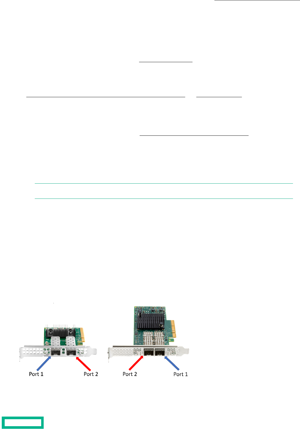
Because the order of the ports on a NIC can vary from model to model, you should record the specific port labeling to ensure
that you cable it correctly. For example, compare the port order on the following two 10/25 GbE NICs:
Figure 1: Example of port differences on 10/25 GbE NICs
Cabling for Array OS Versions 6.0.0.0 and Later
Cabling for Array OS Versions 6.0.0.0 and Later
Setting up the System 12
Documentation Feedback: [email protected]
When dHCI is deployed on an array running release 6.0.0.0 or later, the deployment tool uses ports 1 and 3 for Management.
It uses ports 2 and 4 for iSCSI 1 and iSCSI 2.
Note: When the ports are discovered in VMware ESXi and your array is running array OS 6.1.0.0 or later, the deployment
tool uses ports 1 and 3 for management (MGMT) and network (VM Network). Port 2 for iSCSI 1 and port 4 for iSCSI
2.
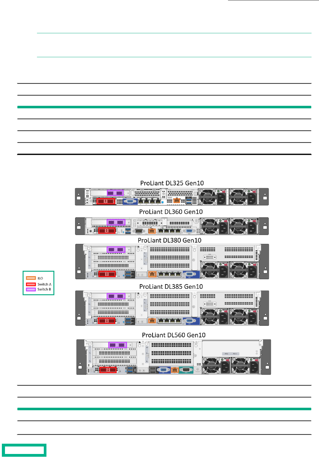
The following tables provide information about the default port assignments and the switch they must connect to. This
information depends on the server generation.
HPE ProLiant DL Gen 10 Servers for Array OS Versions 6.0.x and Later
SwitchRolePort OrderNetwork Card and Port
Switch AManagementPort 1FlexLOM Port 1
Switch AiSCSI 1Port 2FlexLOM Port 2
Switch BManagementPort 3PCI NIC Port 1
Switch BiSCSI 2Port 4PCI NIC Port 2
Figure 2: Example 1 of Port Assignments for HPE ProLiant DL Servers for Array OS Versions 6.0.x and Above
HPE ProLiant DL Gen 10 Plus / Gen10 Plus v2 Servers for Array OS Versions 6.0.0.0 and Later
SwitchRolePort OrderNetwork Card and Port
Switch AManagementPort 1PCI NIC Port 1
Switch AiSCSI 1Port 2PCI NIC Port 2
Setting up the System 13
Documentation Feedback: [email protected]
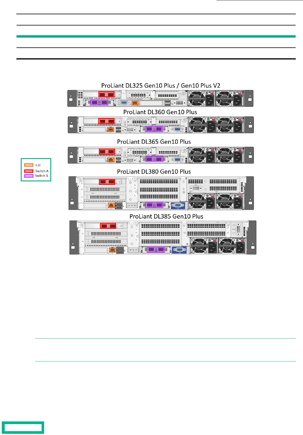
HPE ProLiant DL Gen 10 Plus / Gen10 Plus v2 Servers for Array OS Versions 6.0.0.0 and Later
SwitchRolePort OrderNetwork Card and Port
Switch BManagementPort 3OCP Port 1
Switch BiSCSI 2Port 4OCP Port 2
Figure 3: Example 2 of Port Assignments for HPE ProLiant DL Servers for Array OS Versions 6.0.x and Above
You do not need to use the FlexLOM or OCP network cards for deployment. Installing and deploying on multiple 10Gbps+
PCI NICs is supported. The same port assignment scheme will be used for deployment. It is important that you carefully plan
which ports on which NICs will be connected to ensure maximum resiliency.
If the first discovered 10Gbps+ card has more than two ports, only two ports on each of the two cards should be connected
at the time of deployment. The best practice is to connect only the two ports on each of the two cards that are intended to
be used for management and iSCSI traffic by the dHCI system. Any additional 10Gb ports beyond the first four are not
configured during deployment, but you can configure them after you deploy dHCI.
dHCI does not support 1 Gbps ports. It does not use the four 1 Gbps ports that are embedded in the HPE ProLiant series.
These ports will be ignored if they are active.
Note: When adding servers to an existing dHCI deployment, the original cabling schema is used. This means that, if
the OS version on the array when dHCI was deployed was prior to 6.0.0.000 and you update the OS version to 6.1.x
or later, dHCI will to use the pre-6.0.0.0 cabling methodology.
Cabling for Array OS Versions Before 6.0.0.0
If the operating system version for your array is prior to 6.0.0.0, the dHCI deployment tool uses ports 1 and 2 for Management
and ports 3 and 4 for iSCSI 1 and iSCSI 2.
Setting up the System 14
Documentation Feedback: [email protected]

Note: If your storage network card configuration differs from the one described in the section on the HPE Nimble
Storage Network Card Configuration on page 15), remember that, if your array is running a version of the array OS
prior to 6.0.0.0, the deployment tool uses ports 1 and 2 for Management (MGMT) and ports 3 and 4 for iSCSI 1 and
iSCSI 2 when the ports are discovered in VMware ESXi.
The following table provides the default values:
HPE ProLiant DL Gen 10 Servers for Array OS Versions Prior to 6.0.0.0
SwitchRolePortNetwork Card and Port
Switch AManagementPort 1FlexLOM Port 1
Switch BManagementPort 2FlexLOM Port 2
Switch AiSCSI 1Port 3PCI NIC Port 1
Switch BiSCSI 2Port 4PCI NIC Port 2
HPE ProLiant DL Gen 10/ Gen10+ v2 Servers for Array OS Versions Prior to 6.0.0.0
SwitchRolePortNetwork Card and Port
Switch AManagementPort 1PCI NIC Port 1
Switch BManagementPort 2PCI NIC Port 2
Switch AiSCSI 1Port 3OCP Port 1
Switch BiSCSI 2Port 4OCP Port 2
Note: When adding servers to an existing dHCI deployment, the original cabling schema is used. This means that, if
the OS version on the array when dHCI was deployed was prior to 6.0.0.000 and you update the OS version to 6.1.x
or later, dHCI will to use the pre-6.0.0.0 cabling methodology.
HPE Nimble Storage Network Card Configuration
You must make sure your HPE Storage network card is correctly configured for the Management (MGMT) and iSCSI 1 and
iSCSI 2 ports.
The MGMT and iSCSI ports are shown in the following figures. Your array might differ from the ones shown. The installation
guide for your array provides instruction for cabling.
Note: The HPE Alletra 6000,Alletra 5000, Nimble Storage Documentation Portal on HPE InfoSight and the HPE
Support Center contain the installation guides and numerous other documents to help you as you set up dHCI to
work with HPE Storage arrays.
Setting up the System 15
Documentation Feedback: [email protected]
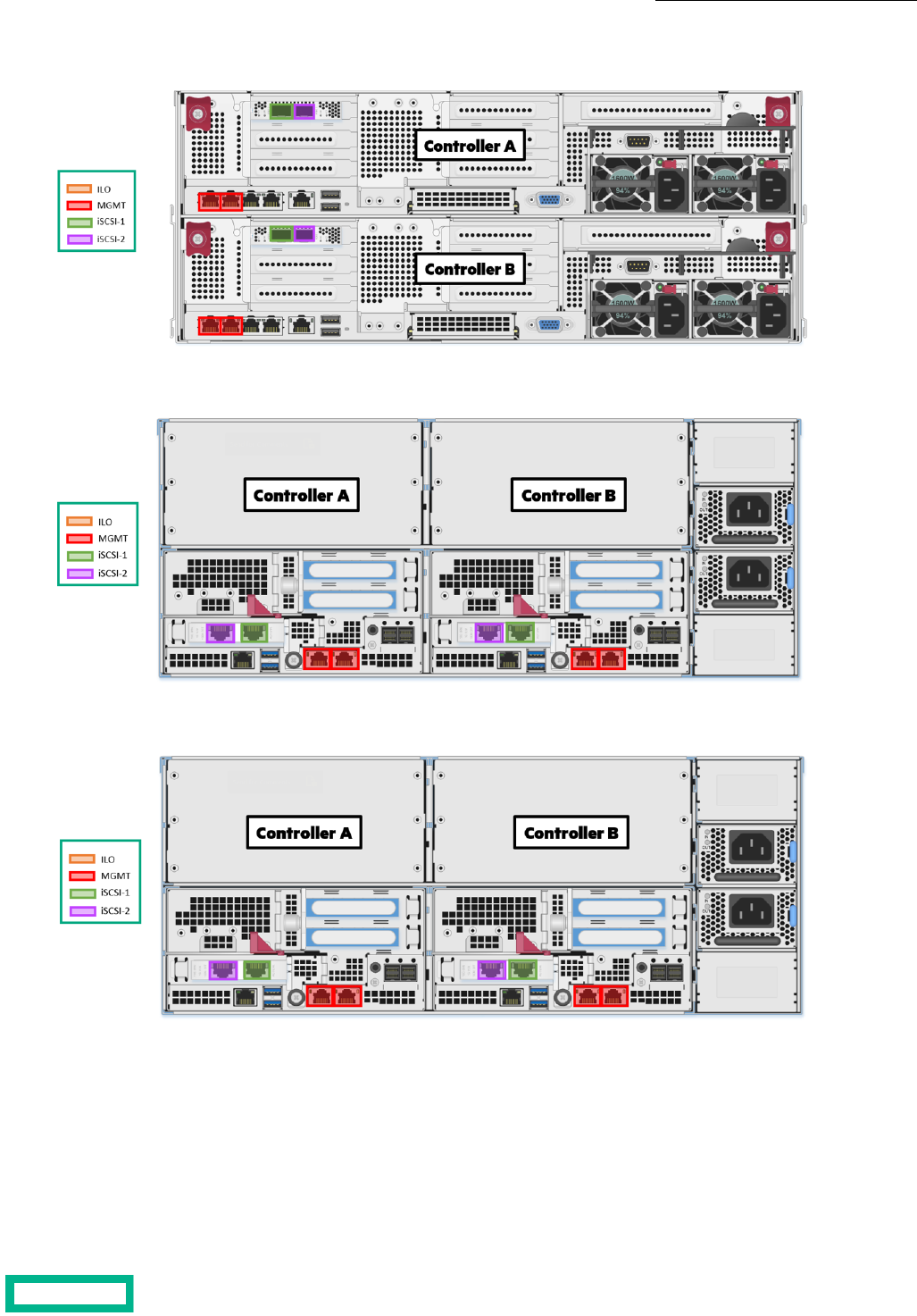
Figure 4: An example of an HPE Alletra 6000 array with two 10 Gbps iSCSI ports on each controller
Figure 5: An example of an HPE Alletra 5000 array with two 10 Gbps iSCSI ports on each controller
Figure 6: An example of an HPE Nimble Storage HF or AF array with two 10 Gbps iSCSI ports on each controller
Server, Array, and Switch Cabling Example
Use the methodology shown in the following figure to cable your HPE ProLiant server, HPE Storage array, and network switch.
Additional configuration examples are in the HPE Alletra dHCI Solution Network Considerations Guide, which is available on
the Documentation Portal on HPE InfoSight..
Setting up the System 16
Documentation Feedback: [email protected]
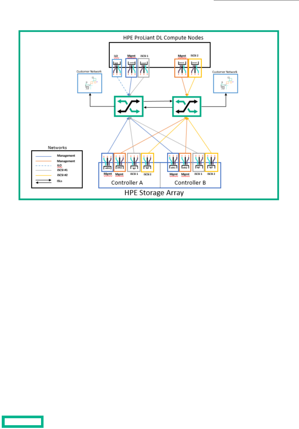
Figure 7: Cabling example: HPE ProLiant server with four 10 Gbps ports
Network Requirements for Configuring the Ethernet Switch
While different Ethernet switches can have different requirements, in general you must set up the following features:
• Maximum transmission unit (MTU)
• Flow control
• Jumbo frames
• VLAN
• Link Layer Discovery Protocol (LLDP)
MTU
Many switches define MTU differently from the way the initiator or target defines it. Switches often define MTU as the frame
size. End hosts almost universally define MTU as the packet size. The configured frame size on the switch might need to be
larger than the packet size or the MTU value defined on the host and the array. For example, a value of 9000 on the host
might require a value of 9014 or higher on the switch. This difference might vary by manufacturer.
Setting the switch MTU value to a number that is higher than the MTU value on the host or initiator does not cause problems.
The switch MTU setting causes problems only when the MTU value on the intermediate device (the switch) is set to a number
that is lower than the MTU value on one or both of the end devices.
Flow Control
Flow control provides a mechanism for temporarily pausing the transmission of data on Ethernet networks if a sending node
transmits data faster than the receiving node can accept it. Whenever possible, you should enable flow control on all host,
switch, and array ports to ensure graceful communication between network nodes. HPE Storage array network interface cards
(NICs) support flow control by default.
Setting up the System 17
Documentation Feedback: [email protected]

Jumbo Frame
Ethernet frames that transport data are typically 1500 bytes in size. Anything over 1514 bytes (or 1518 with VLAN tagging)
in the Ethernet frame is typically referred to as a jumbo frame. Jumbo frames are generally better suited to handle the flow
of iSCSI SAN traffic. They typically consist of 9000-byte frames. Enabling jumbo frames can help to improve storage throughput
and reduce latency.
HPE recommends using jumbo frames with new server deployments of dHCI.
VLAN
dHCI requires at least three VLANs:
• A management VLAN
The management VLAN must be the native VLAN in the trunk port (untagged).
• Two iSCSI VLANs
You should have one per switch. The best practice is to use two different VLANs for iSCSI traffic:
• One VLAN should map to one 10 Gbps port of your server.
• The other should map to the second 10 Gbps port.
If your server has four 10 Gbps ports, you should dedicate two ports to the use of iSCSI traffic only. These two ports should
be configured in access mode (no VLAN tag). Each port should map to one VLAN only.Configure the iCSI VLANs in access
mode only (no VLAN tag).
If your server has two 10 Gbps ports, you must trunk your iSCSI VLANs onto your existing ports and tag the VLANs
accordingly.
A dedicated VLAN for iLO is recommended based on the deployment option you use.
The following table lists the requirements:
NoteVLAN /ModeVLAN IDVLAN Description
Management/vMotion VLAN
must be the native VLAN.
mgmt_vlan = nativemgmt_vlanManagement/vMotion
Native VLAN onlyiscsi1_vlan = accessiscsi1_vlaniSCSI 1 IP address range
Native VLAN onlyiscsi2_vlan = accessiscsi2_vlaniSCSI 2 IP address range
VM Network can be trunked
on the Management interface.
vm_network = trunkvm_networkVM network
Optional VLAN. Only required
if Split Management is select-
ed during deployment; that is
a separate management net-
work for iLO.
ilo_vlan = accessilo_vlaniLO Network
LLDP
Link Layer Discovery Protocol (LLDP) must be enabled on each switch. dHCI uses LLDP during deployment to verify your
environment.
Network Configuration Example for Using Peer Persistance
Before you deploy dHCI, you must complete the network configuration between your sites. Peer Persistence with dHCI requires
that you configure the Management VLAN and both iSCSI VLANs so that they are available between the two solutions.
Setting up the System 18
Documentation Feedback: [email protected]
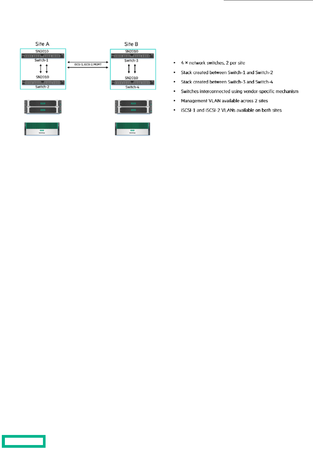
You networking configuration should be similar to the one shown in the following figure.
Figure 8: Network Configuration Example
Setting up the System 19
Documentation Feedback: [email protected]

Configuration Examples
The following sections contain examples of setting up HPE M-Series, HPE Aruba, HPE FlexFabric, and Cisco Nexus switches.
Keep in mind that these are just examples. They are not the exact scripts required to set up your configuration. You must
tailor your deployment based on your configuration. Follow the best practices and documentation provided with your switch.
HPE M-Series Configuration Example
The following tasks step you through the process of configuring HPE M-Series ONYX switches to work in a dHCI environment.
Note: The steps in these tasks are examples. The steps you perform depend on the switches you use and your system
configuration. You should follow the best practices and documentation provided by your switch vendor.
Before you configure the switches, make sure that they are running a supported version of HPE ONYX (ONYX-3.8.2204 or
later revisions). Refer to the Validated Configuration Matrix on HPE InfoSight for information about system requirements.
A base dHCI deployment requires a minimum of two network switches. The switches must be the same model. The task
examples in this guide use HPE M-series SN2010M switches.
Note: In addition to two switch MGMT0 IP addresses, you must also have a third IP address for the MLAG VIP. This
address must be on the same subnet as the MGMT0 ports. MLAG requires that the MGMT0 ports on the switches
communicate. It will not work if you use MGMT1. For more information about the HPE M-Series Switch Series, see the
HPE Support Center website.
To set up the switches, you must perform the following tasks:
1 Set up the initial configuration on new and factory-default HPE M-Series switches.
2 Update both switches to the latest ONYX release.
3 Set up the inter-peer link (IPL) port-channel and the MLAG configuration.
4 Configure Network Time Protocol (NTP).
5 Create the VLANs needed.
6 Add individual port descriptions for troubleshooting.
7 Assign the VLANs and configure jumbo frames and flow control.
8 Configure spanning tree.
9 Configure an MLAG port-channel uplink for the VM hosts (the example uses one 2x40 Gbps MLAG port-channel).
10 Secure the remaining interfaces.
Task 1: Set Up the Initial HPE M-Switch Configuration
The HPE M-switches come with the default factory configuration. You must configure them for your environment. .
Note: Keep in mind that this is an example of setting up HPE M-Series switches. The steps you perform and the
values you provide may differ based on your configuration.
You must be in configuration-terminal mode when you perform the switch commands.
Procedure
1. Verify that the HPE M-Series setup wizard started automatically and attempted to enter automatic configuration after
the initial boot where the host connected to the serial or console port on the switch.
2. Log in as admin. Use the password admin.
You must enter a password, even if it is the default password.
Configuration Examples 20
Documentation Feedback: [email protected]

3. Run the following commands on HPE M-Series switch 1.
Note: The following example uses [0.0.0.0/0] for the IPv4 address and the mask len. You must enter the value
that is correct for your system, not the values used in this example.
Do you want to use the wizard for initial configuration? y
Step 1: Hostname? [switch-5256f0] net_switch1_mgmt
Step 2: Use DHCP on mgmt0 interface? [yes] no
Step 3: Use zeroconf on mgmt0 interface? [no]
Step 4: Primary IPv4 address and masklen? [0.0.0.0/0]
Step 5: Default gateway? mgmt_net_gw_IP
Step 6: Primary DNS server? mgmt_net_DNA_IP
Step 7: Domain name? mgmt_net_domain_name
Step 8: Enable IPv6? [yes]
Step 9: Enable IPv6 autoconfig (SLAAC) on mgmt0 interface? [no]
Step 10: Enable DHCPv6 on mgmt0 interface? [yes]
Step 11: Admin password (Must be typed)? net_switch_admin_password
Step 11: Confirm admin password? net_switch_admin_password
Step 12: Monitor password (Must be typed)? net_switch_admin_password
Step 12: Confirm monitor password? net_switch_admin_password
The startup wizard should prompt you. If it does not, you might need to perform a factory reset.
4. Run the following commands on HPE M-Series switch 2.
Note: The following example uses [0.0.0.0/0] for the IPv4 address and the mask len. You must enter the value
that is correct for your system, not the values used in this example.
Do you want to use the wizard for initial configuration? y
Step 1: Hostname? [switch-525710] net_switch2_mgmt
Step 2: Use DHCP on mgmt0 interface? [yes] no
Step 3: Use zeroconf on mgmt0 interface? [no]
Step 4: Primary IPv4 address and masklen? [0.0.0.0/0]
Step 5: Default gateway? mgmt_net_gw_IP
Step 6: Primary DNS server? mgmt_net_DNA_IP
Step 7: Domain name? mgmt_net_domain_name
Step 8: Enable IPv6? [yes]
Step 9: Enable IPv6 autoconfig (SLAAC) on mgmt0 interface? [no]
Step 10: Enable DHCPv6 on mgmt0 interface? [yes]
Step 11: Admin password (Must be typed)? net_switch_admin_password
Step 11: Confirm admin password? net_switch_admin_password
Step 12: Monitor password (Must be typed)? net_switch_admin_password
The startup wizard should prompt you. If it does not, you might need to perform a factory reset.
Task 2: Set up the IPL Port-Channel and the MLAG Configuration
After you perform the initial configuration for the HPE M-Series switches, you must set up the IPL port-channel and configure
the MLAG and buffer traffic pools to segregate iSCSI data from the network data.
You must have two switch MGMT0 IP addresses and a third IP address for the MLAG VIP. These addresses must be on the
same subnet as the MGMT0 ports. MLAG requires that the MGMT0 ports on the switches communicate.
Note: Keep in mind that this is an example of setting up HPE M-Series switches. The steps you perform and the
values you provide may differ based on your configuration.
You must be in configuration-terminal mode when you perform these commands.
Configuration Examples 21
Documentation Feedback: [email protected]

Procedure
1. Run the following commands on HPE M-Series switch 1:
enable
configuration terminal
ping net_switch2_mgmt ##– verify responses and enter <ctrl> c
ip routing vrf default
ip igmp snooping
protocol mlag
lacp
lldp
logging monitor events notice
cli default auto-logout 60
traffic pool TCP type lossless
traffic pool iscsi type lossless
traffic pool TCP map switch-priority 0
traffic pool iscsi map switch-priority 4
interface ethernet 1/21-1/22 shutdow
interface ethernet 1/21-1/22 speed 40G force #speed 100G is the default
interface ethernet 1/21 description mlag ipl
interface ethernet 1/22 description mlag ipl
dcb priority-flow-control enable force
dcb application-priority tcp iscsi 4
dcb priority-flow-control priority 4 enable
interface ethernet 1/15-1/16 qos trust port
interface ethernet 1/15-1/16 qos default switch-priority 4
interface ethernet 1/15-1/16 qos rewrite pcp
interface ethernet 1/2 qos trust port
interface ethernet 1/2 qos default switch-priority 4
interface ethernet 1/2 qos rewrite pcp
interface ethernet 1/4 qos trust port
interface ethernet 1/4 qos default switch-priority 4
interface ethernet 1/4 qos rewrite pcp
interface port-channel 10 ipl 1
interface ethernet 1/21-1/22 channel-group 10 mode active
interface port-channel 10 dcb priority-flow-control mode on force
vlan 4094 name "MLAG ipl VLAN"
exit
interface vlan 4094 ip address mlag_private_ip1/mlag_private_netmask
interface vlan 4094 ipl 1 peer-address mlag_private_ip2
mlag-vip MLAG-FOO1 ip mlag-vip /mlag-netmask force
interface ethernet 1/21-1/22 no shutdown
no mlag shutdown
write memory
show interface port-channel summary
show mlag
show traffic pool
show buffer pool
2. Run the following commands on HPE M-Series switch 2:
enable
configuration terminal
ip routing vrf defaault
ip igmp snooping
protocol mlag
lacp
lldp
logging monitor events notice
cli default auto-logout 60
traffic pool TCP type lossless
traffic pool iscsi type lossless
Configuration Examples 22
Documentation Feedback: [email protected]

traffic pool TCP map switch-priority 0
traffic pool iscsi map switch-priority 4
interface ethernet 1/21-1/22 shutdow
interface ethernet 1/21-1/22 speed 40G force #speed 100G is the default
interface ethernet 1/21 description mlag ipl
interface ethernet 1/22 description mlag ipl
dcb priority-flow-control enable force
dcb application-priority tcp iscsi 4
dcb priority-flow-control priority 4 enable
interface ethernet 1/15-1/16 qos trust port
interface ethernet 1/15-1/16 qos default switch-priority 4
interface ethernet 1/15-1/16 qos rewrite pcp
interface ethernet 1/2 qos trust port
interface ethernet 1/2 qos default switch-priority 4
interface ethernet 1/2 qos rewrite pcp
interface ethernet 1/4 qos trust port
interface ethernet 1/4 qos default switch-priority 4
interface ethernet 1/4 qos rewrite pcp
interface port-channel 10 ipl 1
interface ethernet 1/21-1/22 channel-group 10 mode active
interface port-channel 10 dcb priority-flow-control mode on force
vlan 4094 name "MLAG ipl VLAN"
exit
interface vlan 4094 ip address mlag_private_ip2/mlag_private_netmask
interface vlan 4094 ipl 1 peer-address mlag_private_ip1
mlag-vip MLAG-FOO1 ip mlag-vip /mlag-netmask force
interface ethernet 1/21-1/22 no shutdown
no mlag shutdown
write memory
show interface port-channel summary
show mlag
show traffic pool
show buffer pool
Task 3: Configure NTP
You must configure the local time and date and enable NTP.
Note: Keep in mind that this is an example of setting up HPE M-Series switches. The steps you perform and the
values you provide may differ based on your configuration.
You must be in configuration-terminal mode when you perform these commands.
Procedure
Run the following commands on both switches. Adjust the ports as needed:
enable
configuration terminal
ntp server <<mgmt_net_ntp1>>
ntp enable
write memory
show clock
Task 4: Create the VLANs
You must create the required VLANs and the necessary VLAN interfaces.
Note: Keep in mind that this is an example of setting up HPE M-Series switches. The steps you perform and the
values you provide may differ based on your configuration.
Configuration Examples 23
Documentation Feedback: [email protected]

You must be in configuration-terminal mode when you perform these commands.
Procedure
Run the following commands on both switches. Adjust the ports as needed.
enable
configuration terminal
vlan <<mgmt_net_vlan>> name MGMT-VLAN
exit
vlan <<iscsi_san_a_vlan>> name iSCSI-SAN-A-VLAN # Both iSCSI VLANS should
be defined in both M-Series switches
exit
vlan <<iscsi_san_b_vlan>> name iSCSI-SAN-B-VLAN # Both iSCSI VLANS should
be defined in both M-Series switches
quit
vlan <<vm_production_net_1_vlan>> name VM-Production-VLAN1
exit
vlan <<dead_net_vlan>> name Dead-Network #Dead-Network for unused
ports
exit
write memory
Task 5: Add Individual Port Descriptions for Troubleshooting
You should include individual port descriptions for troubleshooting activity and verification.
Note: Keep in mind that this is an example of setting up HPE M-Series switches. The steps you perform and the
values you provide may differ based on your configuration.
You must perform all these steps in configuration-terminal mode.
Procedure
1. Run the following commands on HPE M-Series switch 1:
enable
configuration terminal
interface ethernet 1/15 description <hpe1_system_name>-CA-tg1a
interface ethernet 1/16 description <hpe1_system_name>-CB-tg1a
interface Ethernet 1/21 description MLAG DO NOT MODIFY
interface Ethernet 1/22 description MLAG DO NOT MODIFY
interface ethernet 1/ description <mgmt_server_1_hostname>-Port1
interface ethernet 1/2 description <mgmt_server_1_hostname>-iSCSI-Port1
interface ethernet 1/3 description <mgmt_server_2_hostname>-Port1
interface ethernet 1/4 description <mgmt_server_2_hostname>-iSCSI-Port1
interface ethernet 1/5 description <mgmt_server_1_hostname>-ILO
interface ethernet 1/7 description <hpe_system_name>-MGMT-CA-Port1
interface ethernet 1/8 description <nhpe_system_name>-MGMT-CB-Port1
write memory
2. Run the following commands on HPE M-Series switch 2:
enable
configuration terminal
interface ethernet 1/15 description <hpe1_system_name>-CA-tg1b
interface ethernet 1/16 description <hpe1_system_name>-CB-tg1b
interface Ethernet 1/21 description MLAG DO NOT MODIFY
interface Ethernet 1/22 description MLAG DO NOT MODIFY
Configuration Examples 24
Documentation Feedback: [email protected]

interface ethernet 1/1 description <mgmt_server_1_hostname>-Port2
interface ethernet 1/2 description <mgmt_server_1_hostname>-iSCSI-Port2
interface ethernet 1/3 description <mgmt_server_2_hostname>-Port2
interface ethernet 1/4 description <mgmt_server_2_hostname>-iSCSI-Port2
interface ethernet 1/5 description <mgmt_server_2_hostname>>-ILO
interface ethernet 1/7 description <hpe_system_name>-MGMT-CA-Port2
interface ethernet 1/8 description <hpe_system_name>-MGMT-CB-Port2
write memory
Task 6: Assign the VLANs and Configure Jumbo Frames and Flow Control
You must configure the Management and VM Network VLANs for each HPE ProLiant server in your environment. .
Note: Keep in mind that this is an example of setting up HPE M-Series switches. The steps you perform and the
values you provide may differ based on your configuration.
You must perform all these steps in configuration-terminal mode.
Procedure
1. (Management and VM Network VLANs for each HPE ProLiant server) Run the following commands on both switches,
adjusting the ports as needed:
enable
configuration terminal
interface ethernet 1/1-1/18 speed 10G force #speed 25G is the default
interface ethernet 1/5 speed 1G force #ilo speed is a 1G port
interface ethernet 1/1 switchport mode hybrid
interface ethernet 1/1 switchport hybrid allowed-vlan none
interface ethernet 1/1 switchport hybrid allowed-vlan add <vm_produc►
tion_net_1_vlan>
interface ethernet 1/1 switchport access vlan <mgmt_net_vlan>
interface ethernet 1/3 switchport mode hybrid
interface ethernet 1/3 switchport hybrid allowed-vlan none
interface ethernet 1/3 switchport hybrid allowed-vlan add <vm_produc►
tion_net_1_vlan>
interface ethernet 1/3 switchport access vlan <mgmt_net_vlan>
write memory
2. (Management VLANs for the HPE Storage management interface and server iLO VLAN) Run the following commands
on both switches, adjusting the ports as needed:
interface ethernet 1/7-1/8 switchport access vlan <mgmt_net_vlan>
interface ethernet 1/5 switchport access vlan <ilo_vlan> #ilo connection to
M-series assumed
write memory
3. (iSCSI VLANS, flow control, and jumbo frames for each HPE ProLiant server) Run the following commands on HPE
M-Series switch 1:
interface ethernet 1/2
switchport access vlan <iscsi_san_a_vlan>
flowcontrol receive on force
flowcontrol send on force
mtu 9216 force
no shutdown
exit
Configuration Examples 25
Documentation Feedback: [email protected]

interface ethernet 1/4
switchport access vlan <iscsi_san_a_vlan>
flowcontrol receive on force
flowcontrol send on force
mtu 9216 force
no shutdown
exit
write memory
4. (iSCSI VLANS, flow control, and jumbo frames for each HPE ProLiant server) Run the following commands on HPE
M-Series switch 2:
interface ethernet 1/2
switchport access vlan <iscsi_san_b_vlan>
flowcontrol receive on force
flowcontrol send on force
mtu 9216 force
no shutdown
exit
interface ethernet 1/4
switchport access vlan <iscsi_san_b_vlan>
flowcontrol receive on force
flowcontrol send on force
mtu 9216 force
no shutdown
exit
write memory
5. (iSCSI VLANS, flow control, and jumbo frames for each array port) Run the following commands on HPE M-Series
switch 1:
interface ethernet 1/15-1/16
switchport access vlan <iscsi_san_a_vlan>
flowcontrol receive on force
flowcontrol send on force
mtu 9216 force
no shutdown
exit
write memory
6. (iSCSI VLANS, flow control, and jumbo frames for each array port) Run the following commands on HPE M-Series
switch 2:
interface ethernet 1/15-1/16
speed 10G force
switchport access vlan <iscsi_san_b_vlan>
flowcontrol receive on force
flowcontrol send on force
mtu 9216 force
no shutdown
exit
write memory
Task 7: Configure Spanning Tree for HPE M-Series
You must configure a spanning tree for each HPE ProLiant and HPE Storage interface that is used for iSCSI. When you set
the interfaces to edge ports in a spanning tree and enable the spanning tree on the HPE M-Series switch, you ensure that
these ports will transition directly to the forwarding state in the spanning tree topology.
Configuration Examples 26
Documentation Feedback: [email protected]

Note: Keep in mind that this is an example of setting up HPE M-Series switches. The steps you perform and the
values you provide may differ based on your configuration.
You must be in configuration-terminal mode when you perform these commands.
Procedure
Run the following commands on both switches. Adjust the ports as needed.
spanning-tree mode rpvst
spanning-tree port type edge default
interface ethernet 1/1-1/5 spanning-tree port type edge
interface ethernet 1/7-1/8 spanning-tree port type edge
interface ethernet 1/15-1/16 spanning-tree port type edge
write memory
Task 8: Uplink into the Existing Network Infrastructure
Depending on your network infrastructure and connectivity requirements, you might use various layer 2 or layer 3 methods
to connect dHCI to the network.
This is an example of how to create an MLAG port-channel to uplink the HPE M-Series switch to your existing switch
environment. You must configure one uplink per HPE M-series switch to be aggregated in an MLAG port-channel.
Note: Keep in mind that this is an example of setting up HPE M-Series switches. The steps you perform and the
values you provide may differ based on your configuration.
Make sure you are in configuration-terminal mode when you perform the commands.
Procedure
Run the following commands on both switches. Adjust the ports as needed.
interface mlag-port-channel 80
interface ethernet 1/20 speed 40G force
interface ethernet 1/20 lacp rate fast #”no lacp rate fast” is slow and depends
on upstream switch
interface ethernet 1/20 mlag-channel-group 80 mode active #“mode on” depends
on upstream switch
interface mlag-port-channel 80 spanning-tree port type edge
interface mlag-port-channel 80 spanning-tree bpdufilter enable
interface mlag-port-channel 80 switchport mode hybrid
interface mlag-port-channel 80 switchport hybrid allowed-vlan none
interface mlag-port-channel 80 switchport hybrid allowed-vlan add <vm_produc►
tion_net_1_vlan>
interface mlag-port-channel 80 switchport access vlan <mgmt_net_vlan>
interface mlag-port-channel 80 flowcontrol send on force
interface mlag-port-channel 80 flowcontrol receive on force
interface mlag-port-channel 80 mtu 9216 force #mtu 1520 is the default;
depends on upstream switch
interface mlag-port-channel 80 no shutdown
show interfaces mlag-port-channel summary
Task 9: Secure the Remaining Interfaces for the HPE M-Series
The final task in setting up the HPE M-Series switches is to secure the rest of the switch by shutting down the unused ports
and putting them in your <dead_net_vlan>.
Configuration Examples 27
Documentation Feedback: [email protected]

Note: Keep in mind that this is an example of setting up HPE M-Series switches. The steps you perform and the
values you provide may differ based on your configuration.
Make sure you are in configuration-terminal mode when you perform the commands.
Procedure
1. Run the following commands on both switches. Adjust the ports as needed.
interface ethernet 1/6 shutdown
interface ethernet 1/9-1/14 shutdown
interface ethernet 1/17-1/19 shutdown
interface ethernet 1/6 switchport mode access
interface ethernet 1/9-1/14 switchport mode access
interface ethernet 1/17-1/19 switchport mode access
interface ethernet 1/6 switchport access vlan <dead_net_vlan>
interface ethernet 1/9-1/14 switchport access vlan <dead_net_vlan>
interface ethernet 1/17-1/19 switchport access vlan <dead_net_vlan>
2. Save a copy of the configuration file or capture a show run output to a text file from each switch for future reference.
HPE Aruba 8320 or 8325 Configuration Example to Prepare for Network Automation
If you are creating a new cluster, you can use the dHCI network automation feature to complete your switch setup. This feature
uses the dHCI wizard to gather information from your array about the connected HPE Aruba 8320 or 8325 switches and then
prompts you for information to complete the setup.
Note: If you do not set up the initial cabling correctly, you will not be able to use the dHCI network automation feature.
The dHCI wizard checks to see that you have a management port and data port connected to one switch and a second
management port and data port connected to another switch.
To use the network automation feature, you must have:
• Made sure that the switches are running the HPE firmware version specified in the Validated Configuration Matrix. A base
HPE Storage dHCI deployment must use a minimum of two network switches of the same model that are running the same
version of firmware.
• Created a new cluster. This feature does not work with existing clusters.
• Provided a password for the dHCI switch administrator, which has the user name switch_admin.
• You must complete the following manual steps on the array before you start the dHCI setup. The dHCI wizard uses this
information when you select the dHCI network automation feature.
1 Set up the initial configuration on Aruba 83xx switches 1 and 2.
2 Set up the virtual switching extension (VSX) configuration.
3 Configured a management network VLAN on all remaining ports under access (do not configure tag or trunk ports).
4 Interconnected the Aruba 83xx switches with the customer network.
Task 1: Set Up the Initial Configuration on the HPE Aruba 83xx Switches
To use the dHCI network automation feature, you must perform the initial configuration of the HPE Aruba 8320 or HPE Aruba
8325 switch pair before you start the dHCI setup.
Note: The steps in these tasks are examples. The steps you perform depend on the switches you use and your system
configuration. You should follow the best practices and documentation provided by your switch vendor.
You must be in configuration-terminal mode when you perform the commands on the switches.
Configuration Examples 28
Documentation Feedback: [email protected]

Procedure
1. Configure HPE Aruba 83xx switch 1:
• If you are using serial cable to connect to the console, specify 115,200 baud as the speed.
• Interconnect your two switches by using QSFP+ or SFP+, depending on the switch model.
• Specify three ports at minimum: two for VSX and one for the VSX keepalive mechanism.
2. Configure switch 1. Log in as admin. Press Enter when prompted for a password.
Run the following commands:
config
user admin password
interface mgmt
interface mgmt
no shutdown
ip static net_switch1_mgmt_ip/mgmt_net_netmask
default-gateway mgmt_net_gw
exit
write memory
3. Configure switch 2.Log in as admin. Press Enter when prompted for a password.
Note: If you are using serial cable to connect switch 2 to the console, specify 9600 baud as the speed.
Run the following commands:
config
user admin password
interface mgmt
interface mgmt
no shutdown
ip static net_switch2_mgmt_ip/mgmt_net_netmask
default-gateway mgmt_net_gw
exit
write memory
4. Enable an interface group.
Both switches: Run the following commands, adjusting the ports as needed:
config
system interface-group 1 speed 10g
system interface-group 2 speed 10g
system interface-group 3 speed 10g
system interface-group 4 speed 10g
write memory
Your interface group might differ from what is shown in the example. For more information, see the user's guide for your
HPE Aruba switch.
5. Set the management address to IPv4 on both switches .
Both switches: Run the following commands, adjusting the ports as needed:
config terminal
lldp management-ipv4-address <switch_ip_address>
write memory
Configuration Examples 29
Documentation Feedback: [email protected]

Task 2: Set up the VSX Configuration for the HPE Aruba Switches
When you use the automation feature, dHCI checks for information about the virtual switching extension (VSX) configuration.
You must have it configured on the HPE Aruba 83xx switch pair that you are using.
Note: The steps in these tasks are examples. The steps you perform depend on the switches you use and your system
configuration. You should follow the best practices and documentation provided by your switch vendor.
You must be in configuration-terminal mode when you perform the following commands.
Procedure
1. Configure the link aggregation group (LAG) that will be used for VSX.
Both switches: Run the following commands, adjusting the ports as needed:
config
interface lag 99
no shutdown
no routing
lacp mode active
vlan trunk native 1 tag
vlan trunk allowed all
int 1/1/48
lag 99
int 1/1/49
lag 99
2. Configure an interface to be used for the VSX keepalive connection.
Switch 1: Run the following commands:
interface 1/1/43
no routing
ip address net_switch1_vsx_ip/vsx_net_netmask
Switch 2: Run the following commands:
interface 1/1/43
no routing
ip address net_switch2_vsx_ip/vsx_net_netmask
3. Configure the VSX role.
Switch 1: Run the following commands:
config
vsx
role primary exit
write memory
Switch 2: Run the following commands:
config
vsx
role secondaryexit
write memory
4. Enable the VSX keepalive interface.
Configuration Examples 30
Documentation Feedback: [email protected]

Switch 1: Run the following commands:
config
vsx
keepalive peer net_switch2_vsx_ip source net_switch1_vsx_ip
exit
write memory
Switch 2: Run the following commands:
config
vsx
keepalive peer net_switch1_vsx_ip source net_switch2_vsx_ip
exit
write memory
5. Verify that VSX is enabled and configured.
Run the sh vsx status command to request a status report:
config
sh vsx status
VSX Operational State
---------------------
ISL channel : In-Sync
ISL mgmt channel : operational
Config Sync Status : in-sync
NAE : peer_reachable
HTTPS Server : peer_reachable
Attribute Local Peer
------------ -------- --------
ISL link lag99 lag99
ISL version 2 2
System MAC 54:80:28:fd:31:00 54:80:28:fc:fd:00
Platform 8325 8325
Software Version GL.10.02.0001 GL.10.02.0001
Device Role secondary primary
Task 3: Configure a Management Network VLAN on Ports for HPE Aruba 83xx Switches
dHCI requires that you configure a management network VLAN on all the remaining ports on the HPE Aruba 83xx switch pair
that you are using.
Note: The steps in these tasks are examples. The steps you perform depend on the switches you use and your system
configuration. You should follow the best practices and documentation provided by your switch vendor.
You must be in configuration-terminal mode when you perform the following commands.
Procedure
1. Create the required management network VLAN on switch 1. The vsx-sync command then syncs the VLANs to switch 2.
config terminal
vlan <mgmt_net_vlan>
description MGMT-VLAN
vsx-sync
exit
Configuration Examples 31
Documentation Feedback: [email protected]

2. Configure all remaining ports (expect VSX ports) in access mode with the VLAN ID to the same as the management network
VLAN. Adjust the ports as needed.
Perform these commands on both switch 1 and switch 2:
configure terminal
int 1/1/1-1/1/44,1/1/49-1/1/56
-if-<1/1/1-1/1/44,1/1/49-1/1/56>)# vlan access 3530
-if-<1/1/1-1/1/44,1/1/49-1/1/56>)# end
write memory
Task 4: Interconnect the HPE Aruba Switches with the Customer Network
dHCI requires that you connect the HPE Aruba 83xx switch pair with the customer network. If you do not perform this task,
the switches will not be able to reach the customer environment,which includes DNS, NTP, and the vCenter plugin.
Note: The steps in these tasks are examples. The steps you perform depend on the switches you use and your system
configuration. You should follow the best practices and documentation provided by your switch vendor.
You must be in configuration-terminal mode when you perform the following commands.
Procedure
1. Create MC-LAG interface. Adjust the lag ID as required.
Run the following commands on each switch:
configure terminal
interface lag 1 multi-chassis
vsx-sync vlans
description MC-LAG
no shutdown
no routing
vlan trunk native <mgmt_net_vlan>
vlan trunk allowed all (or Trunk only VLANs you want)
lacp mode active
2. Add physical interfaces into the multichassis interface.
Run the following commands on each switch:
configure terminal
interface 1/1/<MC_LAG_PORT_ID>
no routing
no shutdown
lag 1
HPE Aruba 8320 or 8325 Configuration Example Using Manual Steps
If you do not want to use the dHCI network automation feature, you can manually set up the HPE Aruba 8320 or 8325 switches.
The tasks in this section guide you through the steps to perform a manual configuration.
Note: The steps in these tasks are examples. The steps you perform depend on the switches you use and your system
configuration. You should follow the best practices and documentation provided by your switch vendor.
Before you configure the switches, make sure that they are running a supported version of the HPE firmware. Refer to the
Validated Configuration Matrix on HPE InfoSight for information about system requirements.
Configuration Examples 32
Documentation Feedback: [email protected]

A base dHCI deployment requires a minimum of two network switches. The switches must be the same model. The task
examples in this section use HPE Aruba 83xx switches.
Important: After you set up your configuration file, copy or capture a show run output to a text file from each switch
for future reference.
To manually configure the HPE Aruba 83xx switches for dHCI, perform the following tasks:
1 Set up the initial configuration on Aruba 83xx switches 1 and 2.
2 Set up the virtual switching extension (VSX) configuration.
3 Configure NTP.
4 Create the VLANs needed.
5 Add individual port descriptions for troubleshooting.
6 Assign the VLANs and configure jumbo frames and flow control.
7 Configure the spanning tree.
8 Interconnect the Aruba 83xx switches with the customer network.
9 Secure the remaining interfaces.
Task 1: Set Up the Initial Configuration on the HPE Aruba 83xx Switches
The first task in manually setting up your HPE Aruba 83xx switches is to create the initial configuration of the HPE Aruba
83xx switch pair.
Note: The steps in these tasks are examples. The steps you perform depend on the switches you use and your system
configuration. You should follow the best practices and documentation provided by your switch vendor.
You must be in configuration-terminal mode when you perform the commands on the switches.
Procedure
1. Set up HPE Aruba 83xx switch 1:
• If you are using serial cable to connect to the console, specify 115,200 baud as the speed.
• Interconnect your two switches by using QSFP+ or SFP+, depending on the switch model.
• Specify three ports at minimum: two for VSX and one for the VSX keepalive mechanism.
2. Configure switch 1: Log in as admin. Press Enter when prompted for a password.
Run the following commands:
config
user admin password
interface mgmt
interface mgmt
no shutdown
ip static net_switch1_mgmt_ip/mgmt_net_netmask
default-gateway mgmt_net_gw
exit
write memory
3. Configure switch 2: Log in as admin. Press Enter when prompted for a password.
Note: If you are using serial cable to connect switch 2 to the console, specify 9600 baud as the speed.
Run the following commands:
config
user admin password
interface mgmt
Configuration Examples 33
Documentation Feedback: [email protected]

interface mgmt
no shutdown
ip static net_switch2_mgmt_ip/mgmt_net_netmask
default-gateway mgmt_net_gw
exit
write memory
4. Enable an interface group.
Both switches: Run the following commands, adjusting the ports as needed:
config
system interface-group 1 speed 10g
system interface-group 2 speed 10g
system interface-group 3 speed 10g
system interface-group 4 speed 10g
write memory
Your interface group might differ from what is shown in the example. For more information, see the user's guide for your
HPE Aruba switch.
Task 2: Set Up the VSX Configuration on HPE Aruba 83xx Switches
As part of the manual setup of the HPE Aruba 83xx switches, you must configure the virtual switching extension (VSX)
configuration.
Note: The steps in these tasks are examples. The steps you perform depend on the switches you use and your system
configuration. You should follow the best practices and documentation provided by your switch vendor.
You must be in configuration-terminal mode when you perform the following commands.
Procedure
1. Configure the link aggregation group (LAG) that will be used for VSX.
Both switches: Run the following commands, adjusting the ports as needed:
config
interface lag 99
no shutdown
no routing
lacp mode active
vlan trunk native 1 tag
vlan trunk allowed all
int 1/1/48
lag 99
int 1/1/49
lag 99
2. Configure an interface to be used for the VSX keepalive connection.
Switch 1: Run the following commands:
interface 1/1/43
no routing
ip address net_switch1_vsx_ip/vsx_net_netmask
Configuration Examples 34
Documentation Feedback: [email protected]

Switch 2: Run the following commands:
interface 1/1/43
no routing
ip address net_switch2_vsx_ip/vsx_net_netmask
3. Configure the VSX role.
Switch 1: Run the following commands:
config
vsx
role primary exit
write memory
Switch 2: Run the following commands:
config
vsx
role secondaryexit
write memory
4. Enable the VSX keepalive interface.
Switch 1: Run the following commands:
config
vsx
keepalive peer net_switch2_vsx_ip source net_switch1_vsx_ip
exit
write memory
Switch 2: Run the following commands:
config
vsx
keepalive peer net_switch1_vsx_ip source net_switch2_vsx_ip
exit
write memory
5. Verify that VSX is enabled and configured.
Run the sh vsx status command to request a status report:
config
sh vsx status
VSX Operational State
---------------------
ISL channel : In-Sync
ISL mgmt channel : operational
Config Sync Status : in-sync
NAE : peer_reachable
HTTPS Server : peer_reachable
Attribute Local Peer
------------ -------- --------
ISL link lag99 lag99
ISL version 2 2
System MAC 54:80:28:fd:31:00 54:80:28:fc:fd:00
Platform 8325 8325
Software Version GL.10.02.0001 GL.10.02.0001
Device Role secondary primary
Configuration Examples 35
Documentation Feedback: [email protected]

Task 3: Configure NTP on HPE Aruba 83xx Switches
You must configure the local time and date, and enable NTP on the HPE Aruba 83xx switch pair that you are using.
Note: The steps in these tasks are examples. The steps you perform depend on the switches you use and your system
configuration. You should follow the best practices and documentation provided by your switch vendor.
You must be in configuration-terminal mode when you perform the following commands.
Procedure
Configure the local time and date, and enable NTP.
Both switches: Run the following commands, adjusting the ports as needed:
config
ntp server <mgmt_net_ntp1>
ntp enable
write memory
Task 4: Create the VLANs needed
You must configure all the required VLANs and VLAN interfaces for the HPE Aruba 83xx switch pair that you are using.
Note: The steps in these tasks are examples. The steps you perform depend on the switches you use and your system
configuration. You should follow the best practices and documentation provided by your switch vendor.
You must be in configuration-terminal mode when you perform the following commands.
Procedure
Run the following commands on switch 1. When you create VLANs on switch 1, the vsx-sync command then syncs them
to switch 2.
config
vlan <mgmt_net_vlan>
description MGMT-VLAN
vsx-sync
exit
vlan <iscsi_san_a_vlan>
description iSCSI-SAN-A-VLAN
vsx-sync
exit
vlan <iscsi_san_b_vlan>
description iSCSI-SAN-B-VLAN
vsx-sync
exit
vlan <vm_production_net_1_vlan>
description VM-Production-VLAN1
vsx-sync
exit
vlan <ilo_vlan>
description ILO-VLAN
vsx-sync
exit
vlan <dead_net_vlan>
Configuration Examples 36
Documentation Feedback: [email protected]

description Dead-Network for unused ports
vsx-sync
exit
write memory
Task 5: Add Individual Port Descriptions for Troubleshooting
You should add individual port descriptions to the HPE Aruba 83xx switches. These descriptions can assist you when you
perform troubleshooting activities and verification.
Note: The steps in these tasks are examples. The steps you perform depend on the switches you use and your system
configuration. You should follow the best practices and documentation provided by your switch vendor.
You must be in configuration-terminal mode when you perform the following commands.
Procedure
Add descriptions to both switches
Switch 1: Run the following commands:
config
interface 1/1/15
description <nimble1_system_name>-CA-tg1a
exit
interface 1/1/16
description <nimble1_system_name>-CB-tg1a
exit
interface 1/1/43
description VSX Keep Alive DO NOT MODIFY
exit
interface 1/1/48
description VSX DO NOT MODIFY
exit
interface 1/1/49
description VSX DO NOT MODIFY
exit
interface 1/1/1
description <mgmt_server_1_hostname>-Port1
exit
interface 1/1/2
description <mgmt_server_1_hostname>-iSCSI-Port1
exit
interface 1/1/3
description <mgmt_server_2_hostname>-Port1
exit
interface 1/1/4
description <mgmt_server_2_hostname>-iSCSI-Port1
interface 1/1/7
description <<nimble_system_name>>-MGMT-CA-Port1
exit
interface 1/1/8
description <nimble_system_name>-MGMT-CB-Port1
exit
interface 1/1/5
description <mgmt_server_1_hostname>-ILO
exit
write memory
Configuration Examples 37
Documentation Feedback: [email protected]

Switch 2: Run the following commands:
config
interface 1/1/15
description <nimble1_system_name>-CA-tg1b
exit
interface 1/1/16
description <nimble1_system_name>-CB-tg1b
exit
interface 1/1/43
description VSX Keep Alive DO NOT MODIFY
exit
interface 1/1/48
description VSX DO NOT MODIFY
exit
interface 1/1/49
description VSX DO NOT MODIFY
exit
interface 1/1/1
description <mgmt_server_1_hostname>-Port2
exit
interface 1/1/2
description <mgmt_server_1_hostname>-iSCSI-Port2
exit
interface 1/1/3
description <mgmt_server_2_hostname>-Port2
exit
interface 1/1/4
description <mgmt_server_2_hostname>-iSCSI-Port2
interface 1/1/7
description <nimble_system_name>-MGMT-CA-Port2
exit
interface 1/1/8
description <nimble_system_name>-MGMT-CB-Port2
exit
interface 1/1/5
description <mgmt_server_2_hostname>-ILO
exit
write memory
Task 6: Assign the VLANs and Configure Jumbo Frames and Flow Control for HPE Aruba 83xx Switches
Assign individual VLANs to different ports and configure jumbo frames and flow control for both HPE Aruba 83xx switches.
Note: The steps in these tasks are examples. The steps you perform depend on the switches you use and your system
configuration. You should follow the best practices and documentation provided by your switch vendor.
You must be in configuration-terminal mode when you perform the following commands.
Procedure
1. Configure the Management and VM Network VLANs for each HPE ProLiant server in your environment.
Both switches: Run the following commands, adjusting the ports as needed:
config
interface 1/1/1
no routing
vlan trunk native <mgmt_net_vlan>
vlan trunk allowed <vm_production_net_1_vlan>
exit
interface 1/1/3
Configuration Examples 38
Documentation Feedback: [email protected]

no routing
vlan trunk native <mgmt_net_vlan>
vlan trunk allowed <vm_production_net_1_vlan>
write memory
2. Configure management VLANs for the HPE Storage management interface for each management port on your array.
Both switches: Run the following commands, adjusting the ports as needed:
config
interface 1/1/7
no routing
vlan access <mgmt_net_vlan>
exit
interface 1/1/8
no routing
vlan access <mgmt_net_vlan>
exit
write memory
3. Configure management or iLO VLANs for the HPE ProLiant server iLO interface for each iLO port in your environment.
Both switches: Run the following commands, adjusting the ports as needed:
config
interface 1/1/5
no routing
vlan access <mgmt_net_vlan> or <ilo_vlan>
exit
write memory
4. Configure iSCSI VLANs, flow control, and jumbo frames for each HPE ProLiant server in your environment.
Switch 1: Run the following commands:
config
interface 1/1/2
no routing
vlan access <iscsi_san_a_vlan>
flow-control rx
mtu 9198
interface 1/1/4
no routing
vlan access <iscsi_san_a_vlan>
flow-control rx
mtu 9198
exit
write memory
Switch 2: Run the following commands:
config
interface 1/1/2
no routing
vlan access <iscsi_san_b_vlan>
flow-control rx
mtu 9198
Configuration Examples 39
Documentation Feedback: [email protected]

interface 1/1/4
no routing
vlan access <iscsi_san_a_vlan>
flow-control rx
mtu 9198
exit
write memory
5. Configure iSCSI VLANs, flow control, and jumbo frames for each port on your array.
Both switches: Run the following commands, adjusting the ports as needed:
config
interface 1/1/15
no routing
vlan access <iscsi_san_a_vlan>
flow-control rx
mtu 9198
interface 1/1/16
no routing
vlan access <iscsi_san_b_vlan>
flow-control rx
mtu 9198
exit
write memory
Task 7: Configure the Spanning Tree
When you set up the pair of HPE Aruba 83xx switches, it is important to set the interfaces to edge ports in the spanning tree.
When the spanning tree is enabled on the switch as part of the configuration, these ports directly transition to the forwarding
state in the spanning tree topology.
Note: The steps in these tasks are examples. The steps you perform depend on the switches you use and your system
configuration. You should follow the best practices and documentation provided by your switch vendor.
You must be in configuration-terminal mode when you perform the following commands.
Procedure
Configure spanning tree for each HPE ProLiant server and HPE Storage interface that is used for iSCSI:
Both switches: Run the following commands, adjusting the ports as needed:
spanning-tree mode rpvst
interface 1/1/2
spanning-tree port-type admin-edge
interface 2/1/2
spanning-tree port-type admin-edge
interface 1/1/4
spanning-tree port-type admin-edge
interface 2/1/4
spanning-tree port-type admin-edge
interface 1/1/15
spanning-tree port-type admin-edge
interface 2/1/15
spanning-tree port-type admin-edge
Configuration Examples 40
Documentation Feedback: [email protected]

interface 1/1/16
spanning-tree port-type admin-edge
interface 2/1/16
spanning-tree port-type admin-edge
write memory
Task 8: Interconnect the Aruba Switches with the Customer Network
dHCI requires that you connect the HPE Aruba 83xx switch pair with the customer network. If you do not perform this task,
the switches will not be able to reach the customer environment,which includes DNS, NTP, and the vCenter plugin.
Note: The steps in these tasks are examples. The steps you perform depend on the switches you use and your system
configuration. You should follow the best practices and documentation provided by your switch vendor.
You must be in configuration-terminal mode when you perform the following commands.
Procedure
1. Create MC-LAG interface. Adjust the lag ID as required.
Run the following commands on each switch:
configure terminal
interface lag 1 multi-chassis
vsx-sync vlans
description MC-LAG
no shutdown
no routing
vlan trunk native <mgmt_net_vlan>
vlan trunk allowed all (or Trunk only VLANs you want)
lacp mode active
2. Add physical interfaces into the multichassis interface.
Run the following commands on each switch:
configure terminal
interface 1/1/<MC_LAG_PORT_ID>
no routing
no shutdown
lag 1
Task 9: Secure the Remaining Interfaces for HPE Aruba 83xx Switches
To complete the HPE Aruba 83xx switch setup, you must secure the remaining interfaces.
Note: The steps in these tasks are examples. The steps you perform depend on the switches you use and your system
configuration. You should follow the best practices and documentation provided by your switch vendor.
You must be in configuration-terminal mode when you perform the following commands.
Procedure
Secure the rest of the switch by shutting down the unused ports and putting them into your dead_net_vlan:
Both switches: Run the following commands, adjusting the ports as needed:
config
interface 1/1/9-1/1/14
Configuration Examples 41
Documentation Feedback: [email protected]
no routing
vlan access <dead_net_vlan>
write memory
HPE Aruba 6300 Configuration Example
The following tasks step you through the process of configuring HPE Aruba 6300 switches for use in a dHCI environment.
Note: The steps in these tasks are examples. The steps you perform depend on the switches you use and your system
configuration. You should follow the best practices and documentation provided by your switch vendor.
Before you configure the switches, make sure that they are running a supported version of the HPE firmware. Refer to the
Validated Configuration Matrix on HPE InfoSight for information about system requirements.
A base dHCI deployment requires a minimum of two network switches. The switches must be the same model. The task
examples in this section use HPE Aruba 6300 switches.
Important: After you set up your configuration file, copy or capture a show run output to a text file from each switch
for future reference.
The HPE Aruba 6300 switch configuration consists of the following tasks::
1 Set up the initial configuration on Aruba 6300 switches 1 and 2.
2 Set up the virtual switching framework (VSF) configuration.
3 Configure NTP.
4 Create the VLANs needed.
5 Add individual port descriptions for troubleshooting.
6 Assign the VLANs and configure jumbo frames and flow control.
7 Configure spanning tree.
8 Secure the remaining interfaces.
Task 1: Set Up the Initial Configuration on HPE Aruba 6300 Switches
The HPE Aruba 6300 switches come with a default factory configuration. You must configure them for your environment.
The steps that follow provide the initial configuration.
Note: Keep in mind that this is an example of setting up HPE Aruba 6300 switches. The steps you perform and the
values you provide may differ based on your configuration.
You must be in configuration-terminal mode when you perform the switch commands.
Procedure
1. Configure HPE Aruba 6300 switch 1:
• If you are using serial cable to connect to the console, specify 9600 baud as the speed.
• Interconnect your two switches by using QSFP+ or SFP+, depending on the switch model.
• Specify two ports for VSF.
2. Switch 1: Log in as admin. Enter admin as the password.
Run the following commands:
config
user admin password
interface mgmt
Configuration Examples 42
Documentation Feedback: [email protected]

interface mgmt
no shutdown
ip static net_switch1_mgmt_ip/mgmt_net_netmask
default-gateway mgmt_net_gw
exit
write memory
3. Configure HPE Aruba 6300 switch 2:
If you are using serial cable to connect to the console, specify 9600 baud as the speed..
4. Switch 2: Log in as admin. Enter admin as the password.
Run the following commands:
config
user admin password
interface mgmt
interface mgmt
no shutdown
ip static net_switch2_mgmt_ip/mgmt_net_netmask
default-gateway mgmt_net_gw
exit
write memory
Task 2: Set Up the VSF Configuration for HPE Aruba 6300 Switches
One of the tasks for setting up the HPE Aruba 6300 switches is to configure the ports that will be used with VSF.
Note: The steps in these tasks are examples. The steps you perform depend on the switches you use and your system
configuration. You should follow the best practices and documentation provided by your switch vendor.
You must be in configuration-terminal mode when you perform the following commands.
Procedure
1. Run the following commands on switch 1.
configure
vsf member 1
link 1 1/1/25
link 2 1/1/26
2. Run the commands on switch 2 to configure it and enable it to join the stack.:
After the renumber command, the switch reboots. This action causes the second switch (member 2) to join the stack with
the first switch (member 1) as the master. You must have the VSF link cables connected or the operation will fail.
configure
vsf member 2
link 1 1/1/25
link 2 1/1/26
exit
vsf renumber-to 2
This will save the VSF configuration and reboot the switch.
Do you want to continue (y/n) ? y
3. Verify that the second switch (member 2) is now linked, with the first switch (member 1) as the master:
Configuration Examples 43
Documentation Feedback: [email protected]

Run the show vsf command on switch 1 (member 1):
show vsf
MAC Address : 38:21:c7:5d:d0:c0
Secondary :
Topology : Ring
Status : No Split
Split Detection Method : None
Mbr Mac Address Type Status
ID
--- ------------------- ----------- ---------------
1 38:21:c7:5d:d0:c0 JL668A Master
2 38:21:c7:6a:10:c0 JL668A Member
2
Note: After the two switches are linked, you only perform configuration tasks on switch 1.
4. Configure VSF split detection.
Switch 1: Enter the following command on switch 1:
vsf split-detect mgmt
Task 3: Configure NTP for HPE Aruba 6300 Switches
You must configure the local time and date and enable NTP.
Note: The steps in these tasks are examples. The steps you perform depend on the switches you use and your system
configuration. You should follow the best practices and documentation provided by your switch vendor.
You must be in configuration-terminal mode when you perform the following commands.
Procedure
Configure the local time and date, and enable NTP:
Both switches: Run the following commands, adjusting the ports as needed:
config
ntp server <mgmt_net_ntp1>
ntp enable
write memory
Task 4: Create the VLANs Needed for HPE Aruba 6300 Switches
You must configure all the required VLANs and VLAN interfaces for the HPE Aruba 6300 switch pair that you are using.
Note: The steps in these tasks are examples. The steps you perform depend on the switches you use and your system
configuration. You should follow the best practices and documentation provided by your switch vendor.
You must be in configuration-terminal mode when you perform the following commands.
Procedure
Run the following commands on switch 1.
vlan <mgmt_net_vlan>
description MGMT-VLAN
exit
Configuration Examples 44
Documentation Feedback: [email protected]

vlan <iscsi_san_a_vlan>
description iSCSI-SAN-A-VLAN
exit
vlan <iscsi_san_b_vlan>
description iSCSI-SAN-B-VLAN
exit
vlan <vm_production_net_1_vlan>
description VM-Production-VLAN1
exit
vlan <dead_net_vlan>
description Dead-Network for unused ports
exit
write memory
Task 5: Add Individual Port Descriptions for Troubleshooting HPE Aruba 6300 Switches
You should add individual port descriptions to the HPE Aruba 63xx switches. These descriptions can assist you when you
perform troubleshooting and verification activities.
Note: The steps in these tasks are examples. The steps you perform depend on the switches you use and your system
configuration. You should follow the best practices and documentation provided by your switch vendor.
You must be in configuration-terminal mode when you perform the following commands.
Procedure
Add descriptions to both switches
config
interface 1/1/15
description <nimble1_system_name>-CA-tg1a
exit
interface 2/1/15
description <nimble1_system_name>-CB-tg1a
exit
interface 1/1/16
description <nimble1_system_name>-CB-tg1b
exit
interface 2/1/16
description <nimble1_system_name>-CB-tg1b
exit
interface 1/1/25
description VSF DO NOT MODIFY
exit
interface 1/1/26
description VSF DO NOT MODIFY
exit
interface 2/1/25
description VSF DO NOT MODIFY
exit
interface 2/1/26
description VSF DO NOT MODIFY
exit
interface 1/1/1
description <mgmt_server_1_hostname>-Port1
exit
Configuration Examples 45
Documentation Feedback: [email protected]

interface 1/1/2
description <mgmt_server_1_hostname>-iSCSI-Port1
exit
interface 2/1/1
description <mgmt_server_1_hostname>-Port2
exit
interface 2/1/2
description <mgmt_server_1_hostname>-iSCSI-Port2
exit
interface 1/1/3
description <mgmt_server_2_hostname>-Port1
exit
interface 1/1/4
description <mgmt_server_2_hostname>-iSCSI-Port1
exit
interface 2/1/3
description <mgmt_server_2_hostname>-Port2
exit
interface 2/1/4
description <mgmt_server_2_hostname>-iSCSI-Port2
exit
interface 1/1/5
description <mgmt_server_1_hostname>-ILO
exit
interface 2/1/5
description <mgmt_server_2_hostname>-ILO
exit
interface 1/1/7
description <nimble_system_name>-MGMT-CTRLA-Port1
exit
interface 2/1/7
description <nimble_system_name>-MGMT-CTRLB-Port1
exit
interface 1/1/8
description <nimble_system_name>-MGMT-CTRLA-Port2
exit
interface 2/1/8
description <nimble_system_name>-MGMT-CTRLB-Port2
exit
write memory
Task 6: Assign the VLANs and Configure Jumbo Frames and Flow Control for HPE Aruba 6300 Switches
You must assign individual VLANs to different ports and configure jumbo frames and flow control for both HPE Aruba 6300
switches.
Note: The steps in these tasks are examples. The steps you perform depend on the switches you use and your system
configuration. You should follow the best practices and documentation provided by your switch vendor.
You must be in configuration-terminal mode when you perform the following commands.
Procedure
1. Configure the Management and VM Network VLANs for each HPE ProLiant server in your environment.
Switch 1: Run the following commands, adjusting the ports as needed:
config
interface 1/1/1
no routing
Configuration Examples 46
Documentation Feedback: [email protected]

vlan trunk native <mgmt_net_vlan>
vlan trunk allowed <vm_production_net_1_vlan>
exit
interface 1/1/3
no routing
vlan trunk native <mgmt_net_vlan>
vlan trunk allowed <vm_production_net_1_vlan>
write memory
interface 2/1/1
no routing
vlan trunk native <mgmt_net_vlan>
vlan trunk allowed <vm_production_net_1_vlan>
exit
interface 2/1/3
no routing
vlan trunk native <mgmt_net_vlan>
vlan trunk allowed <vm_production_net_1_vlan>
exit
write memory
2. Configure management VLANs for the HPE Storage management interface for each management port on your array.
Switch 1: Run the following commands, adjusting the ports as needed:
config
interface 1/1/7
no routing
vlan access <mgmt_net_vlan>
exit
interface 2/1/7
no routing
vlan access <mgmt_net_vlan>
exit
interface 1/1/8
no routing
vlan access <mgmt_net_vlan>
exit
interface 2/1/8
no routing
vlan access <mgmt_net_vlan>
exit
write memory
3. Configure management or iLO VLANs for the HPE ProLiant server iLO interface for each iLO port in your environment.
Switch 1: Run the following commands, adjusting the ports as needed:
config
interface 1/1/5
no routing
vlan access <mgmt_net_vlan> or <ilo_vlan>
interface 2/1/5
no routing
vlan access <mgmt_net_vlan> or <ilo_vlan>
Configuration Examples 47
Documentation Feedback: [email protected]

exit
write memory
4. Configure iSCSI VLANs, flow control, and jumbo frames for each HPE ProLiant server in your environment.
Switch 1: Run the following commands, adjusting the ports as needed:
config
interface 1/1/2
no routing
vlan access <iscsi_san_a_vlan>
flow-control rxtx
mtu 9198
exit
interface 2/1/2
no routing
vlan access <iscsi_san_a_vlan>
flow-control rxtx
mtu 9198
interface 2/1/4
no routing
vlan access <iscsi_san_b_vlan>
flow-control rxtx
mtu 9198
interface 2/1/4
no routing
vlan access <iscsi_san_b_vlan>
flow-control rxtx
mtu 9198
write memory
5. Configure iSCSI VLANs, flow control, and jumbo frames for each port on your array.
Switch 1: Run the following commands, adjusting the ports as needed:
config
interface 1/1/15
no routing
vlan access <iscsi_san_a_vlan>
flow-control rxtx
mtu 9198
exit
interface 2/1/15
no routing
vlan access <iscsi_san_a_vlan>
flow-control rxtx
mtu 9198
config
interface 1/1/16
no routing
vlan access <iscsi_san_b_vlan>
flow-control rxtx
mtu 9198
exit
interface 2/1/16
no routing
Configuration Examples 48
Documentation Feedback: [email protected]

vlan access <iscsi_san_b_vlan>
flow-control rxtx
mtu 9198
write memory
Task 7: Configure Spanning Tree for HPE Aruba 6300 Switches
When you set up the pair of HPE Aruba 6300 switches, it is important to set the interfaces to edge ports in the spanning tree.
When the spanning tree is enabled on the switch as part of the configuration, these ports directly transition to the forwarding
state in the spanning tree topology.
Note: The steps in these tasks are examples. The steps you perform depend on the switches you use and your system
configuration. You should follow the best practices and documentation provided by your switch vendor.
You must be in configuration-terminal mode when you perform the following commands.
Procedure
Configure spanning tree on each HPE ProLiant and HPE Storage interface that is used for iSCSI:
Switch 1: Run the following commands:
spanning-tree mode rpvst
interface 1/1/2
spanning-tree port-type admin-edge
interface 2/1/2
spanning-tree port-type admin-edge
interface 1/1/4
spanning-tree port-type admin-edge
interface 2/1/4
spanning-tree port-type admin-edge
interface 1/1/15
spanning-tree port-type admin-edge
interface 2/1/15
spanning-tree port-type admin-edge
interface 1/1/16
spanning-tree port-type admin-edge
interface 2/1/16
spanning-tree port-type admin-edge
write memory
Task 8: Secure the Remaining Interfaces for HPE Aruba 6300 Switches
To complete the HPE Aruba 6300 switch setup, you must secure the remaining interfaces.
Note: The steps in these tasks are examples. The steps you perform depend on the switches you use and your system
configuration. You should follow the best practices and documentation provided by your switch vendor.
You must be in configuration-terminal mode when you perform the following commands
Procedure
Secure the rest of the switch by shutting down the unused ports and putting them into your dead_net_vlan:
Switch 1: Run the following commands, adjusting the ports as needed:
config
interface 1/1/9-1/1/14
Configuration Examples 49
Documentation Feedback: [email protected]

no routing
vlan access <dead_net_vlan>
write memory
HPE FlexFabric Configuration Example
The following tasks step you through the process of configuring HPE FlexFabric switches for use in a dHCI environment.
Note: The steps in these tasks are examples. The steps you perform depend on the switches you use and your system
configuration. You should follow the best practices and documentation provided by your switch vendor.
Before you configure the switches, make sure that they are running a supported version of the HPE firmware. Refer to the
Validated Configuration Matrix on HPE InfoSight for information about system requirements.
A base dHCI deployment requires a minimum of two network switches. The switches must be the same model.
Important: After you set up your configuration file, copy or capture a show run output to a text file from each switch
for future reference.
The following example uses HPE FlexFabric 5700; however, you can adapt the example to a different HPE FlexFabric model
by adjusting the ports accordingly.
1 Set up the initial configuration on HPE FlexFabric switches 1 and 2.
2 Set up the IRF configuration.
Note: After you set up the IRF configuration, you only need to perform the remaining tasks on switch 1. No further
configuration is needed on switch 2 because the control and management planes have been merged as a part of
the IRF configuration.
3 Configure multi-active detection (MAD) and remote access to the switch.
4 Configure the IRF priority.
5 Configure a local user and enable SSH.
6 Configure NTP.
7 Create the VLANs needed.
8 Configure the management interface.
9 Specify the switch name.
10 Convert the chassis working mode.
11 Add individual port descriptions for troubleshooting.
12 Assign the VLANs and configure jumbo frames and flow control.
13 Configure the spanning tree.
14 Secure the remaining interfaces.
15 Uplink into the existing network infrastructure.
Task 1: Set up the Initial Configuration on the HPE FlexFabric Switches
You must perform an initial configuration on the HPE FlexFabric switch pair.
Note: The steps in these tasks are examples. The steps you perform depend on the switches you use and your system
configuration. You should follow the best practices and documentation provided by your switch vendor.
You must be in configuration-terminal mode when you perform the commands on the switches.
Configuration Examples 50
Documentation Feedback: [email protected]

Procedure
1. Set up the initial configuration on HPE FlexFabric switches 1 and 2 through the serial port:
1 If you are using serial cable to connect to the console, specify 9600 baud as the required speed.
2 Interconnect the two switches by using QSFP+ or SFP+, depending on the switch model.
3 Verify that at initial boot and connection to the serial or console port on the switch, the HPE Comware setup automatically
started and attempted to enter automatic configuration.
4 When the instructions call for network configuration in the system-view context and you are at the <HPE> prompt,
run the system-view command to get to the [HPE] prompt.
2. Run automatic configuration on both HPE FlexFabric switches.
Startup configuration file does not exist.
Started automatic configuration, press CTRL_C or CTRL_D to break.
Automatic configuration attempt: 1.
Not ready for automatic configuration: no interface available.
Waiting for the next...
Automatic configuration attempt: 2.
Interface used: M-GigabitEthernet0/0/0.
Enable DHCP client on M-GigabitEthernet0/0/0.
Automatic configuration is aborted.
Line aux0 is available. Press ENTER to get started. <HPE> system-view
System View: return to User View with Ctrl+Z.
Task 2: Set Up the IRF Configuration on the HPE FlexFabric Switches
You must set up the initial IRF configuration for the HPE FlexFabric switches 1 and 2 through the serial port.
After you complete these steps in this task, all configuration is be performed on switch 1 only. Switch 2 does not need additional
configuration because the control and management planes have been merged as a part of the IRF configuration.
Note: The steps in these tasks are examples. The steps you perform depend on the switches you use and your system
configuration. You should follow the best practices and documentation provided by your switch vendor.
Procedure
1. Configure the IRF ports on HPE FlexFabric switch 1.
interface range FortyGigE 1/0/41 to FortyGigE 1/0/42
shutdown
quit
irf-port 1/1
port group interface FortyGigE 1/0/41
port group interface FortyGigE 1/0/42
quit
save
The current configuration will be written to the device. Are you sure? [Y/N]:y
Please input the file name(*.cfg)[flash:/startup.cfg]
(To leave the existing filename unchanged, press the Enter key):
Configuration Examples 51
Documentation Feedback: [email protected]

2. On HPE FlexFabric switch 2, change the IRF member ID and reboot the switch.
irf member 1 renumber 2
Renumbering the member ID may result in configuration change or loss. Contin►
ue?[Y/N]: y
save
The current configuration will be written to the device. Are you sure? [Y/N]:
y
Please input the file name(*.cfg)[flash:/startup.cfg]
(To leave the existing filename unchanged, press the enter key):
Validating file. Please wait...
Saved the current configuration to mainboard device successfully.
quit
reboot
Start to check configuration with next startup configuration file, please
wait.........DONE!
This command will reboot the device. Continue? [Y/N]: y
Now rebooting, please wait...
3. When the switch reboot is complete, configure the IRF ports on HPE FlexFabric switch 2.
system-view
interface range FortyGigE 2/0/41 to FortyGigE 2/0/42
shutdown
quit
irf-port 2/2
port group interface FortyGigE 2/0/41
port group interface FortyGigE 2/0/42
quit
irf-port-configuration active
interface range FortyGigE 2/0/41 to FortyGigE 2/0/42
undo shutdown
quit
save
The current configuration will be written to the device. Are you sure? [Y/N]:y
Please input the file name(*.cfg)[flash:/startup.cfg]
(To leave the existing filename unchanged, press the enter key):
flash:/startup.cfg exists, overwrite? [Y/N]: y
Validating file. Please wait...
Saved the current configuration to mainboard device successfully.
4. Return to HPE FlexFabric switch 1 to enable the IRF ports. Allow switch 2 to reboot to merge into the IRF fabric.
system-view
irf-port-configuration active
interface range FortyGigE 1/0/41 to FortyGigE 1/0/42
undo shutdown
quit
5. Wait for HPE FlexFabric switch 2 to reboot.
Task 3: Configure MAD and Remote Access to the HPE FlexFabric Switches
HPE recommends that you implement a MAD mechanism on the HPE FlexFabric switches to detect the presence of multiple,
identical IRF fabrics, handle collisions, and recover from faults in the unlikely event of an IRF split or failure. For more information,
see the HPE FlexFabric 5700 IRF Configuration Guide. This guide uses the management links to configure the MAD Bidirectional
Forwarding Detection (BFD) network protocol.
Configuration Examples 52
Documentation Feedback: [email protected]

MAD IP addresses must be in a different subnet from the rest of the solution management. You cannot assign IP addresses
for MAD or management by using the management port on the same subnet as the rest of the solution.
Note: The steps in these tasks are examples. The steps you perform depend on the switches you use and your system
configuration. You should follow the best practices and documentation provided by your switch vendor.
Procedure
1. In system-view, run the following commands on switch 1, substituting the values shown here with the values from the
configuration worksheet:
interface M-GigabitEthernet 0/0/0 mad bfd enable
mad ip address <net_switch1_mad_ip> <mad_net_netmask> member 1
mad ip address <net_switch2_mad_ip> <mad_net_netmask> member 2
quit
ip route-static 0.0.0.0 0.0.0.0 <mgmt_net_gw>
save
Task 4: Configure the IRF Priority for the HPE FlexFabric Switches
You must configure the domain and IRF parameters for the HPE FlexFabric switches. The <net_switch_domain_id> value is
an arbitrary number, but it must be unique from other IRF domains.
Note: The steps in these tasks are examples. The steps you perform depend on the switches you use and your system
configuration. You should follow the best practices and documentation provided by your switch vendor.
Procedure
In system-view, run the following IRF commands on switch 1:
irf domain <net_switch_domain_id>
irf member 1 priority 32
irf member 2 priority 30
irf mac-address persistent always
Task 5: Configure a Local User and Enable SSH for the HPE FlexFabric Switches
To secure access to the HPE FlexFabric switches and provide remote access, you must create a local user and enable SSH.
Note: The steps in these tasks are examples. The steps you perform depend on the switches you use and your system
configuration. You should follow the best practices and documentation provided by your switch vendor.
Procedure
1. Create the local administrator user and configure the virtual console and physical console ports for user name and password
authentication. From within system-view, run, the following commands on switch 1:
local-user admin
password simple <net_switch_admin_password>
authorization-attribute user-role network-admin
service-type ssh terminal
quit
user-interface vty 0 63
authentication-mode scheme
Configuration Examples 53
Documentation Feedback: [email protected]

protocol inbound ssh
quit
user-interface aux 0 1
authentication-mode scheme
quit
save
2. Create the public keys and enable SSH on the switch. From within system-view, run:the following commands on switch 1:
public-key local create rsa
Input the modulus length [default = 1024]:2048
public-key local create dsa
Input the modulus length [default = 1024]:2048
public-key local create ecdsa secp256r1
ssh server enable
save
Task 6: Configure NTP for the HPE FlexFabric Switches
You must configure the local time and date as well as enable NTP on the HPE FlexFabric switches.
Note: The steps in these tasks are examples. The steps you perform depend on the switches you use and your system
configuration. You should follow the best practices and documentation provided by your switch vendor.
Procedure
In system-view, run the following commands on switch 1:
clock protocol none
return
clock datetime time<formatted as hh:mm:ss> date<formatted as MM/DD/YYYY>
system-view
ntp-service unicast-server <mgmt_net_ntp1> priority
clock protocol ntp
save
Task 7: Create the VLANs for HPE FlexFabric Switches
You must create the required VLANs and the VLAN interfaces on the HPE FlexFabric switches.
Note: The steps in these tasks are examples. The steps you perform depend on the switches you use and your system
configuration. You should follow the best practices and documentation provided by your switch vendor.
Procedure
In system-view, run the following commands on switch 1:
vlan <mgmt_net_vlan>
name MGMT-VLAN
quit
vlan <iscsi_san_a_vlan>
name iSCSI-SAN-A-VLAN
Configuration Examples 54
Documentation Feedback: [email protected]

quit
vlan <iscsi_san_b_vlan>
name iSCSI-SAN-B-VLAN
quit
vlan <vm_production_net_1_vlan>
name VM-Production-VLAN1
quit
vlan <dead_net_vlan>
name Dead-Network for unused ports ?
quit
Task 8: Configure the Management Interface for the HPE FlexFabric Switches
You must configure the management interface that enables you to use SSH to manage the FlexFabric switches.
Note: The steps in these tasks are examples. The steps you perform depend on the switches you use and your system
configuration. You should follow the best practices and documentation provided by your switch vendor.
Procedure
In system-view, run the following commands on switch 1:
interface M-GigabitEthernet0/0/0
ip address <net_switch1_mgmt_ip><mgmt_net_netmask>
ip route-static 0.0.0.0 0.0.0.0 <mgmt_net_gw>
save
Task 9: Specify the HPE FlexFabric Switch Name
You must set the HPE FlexFabric switch name of the compute switch IRF to uniquely identify it. Changing the switch name
changes the prompt from HPE to <net_switch1_hostname>.
Note: The steps in these tasks are examples. The steps you perform depend on the switches you use and your system
configuration. You should follow the best practices and documentation provided by your switch vendor.
Procedure
1. Access the switch using SSH by providing <net_switch1_mgmt_ip>, the user name admin, and the password
<net_switch_admin_password>.
2. In system-view, set the switch name by running the following commands on switch 1:
sysname <net_switch1_hostname>
save
Task 10: Convert the Chassis Working Mode for the HPE FlexFabric Switches
You must convert the chassis working mode for the HPE FlexFabric switches.
Note: The steps in these tasks are examples. The steps you perform depend on the switches you use and your system
configuration. You should follow the best practices and documentation provided by your switch vendor.
Configuration Examples 55
Documentation Feedback: [email protected]

Procedure
In system-view, run the following command on switch 1:
system-working-mode advance
Do you want to change the system working mode? [Y/N]:y
The system working mode is changed, please save the configuration and reboot
the system to make it effective.
return `
save
reboot
Task 11: Add Individual Port Descriptions for Troubleshooting HPE FlexFabric Switches
It is a good practice to add individual port descriptions for troubleshooting switch activity and verification.
Note: The steps in these tasks are examples. The steps you perform depend on the switches you use and your system
configuration. You should follow the best practices and documentation provided by your switch vendor.
Procedure
In system-view, run the following commands on switch 1:
Configuration Examples 56
Documentation Feedback: [email protected]

1 interface Ten-GigabitEthernet 1/0/15
description <nimble1_system_name>-CA-tg1a
quit
interface Ten-GigabitEthernet 1/0/16
description <nimble1_system_name>-CB-tg1a
quit
interface Ten-GigabitEthernet 2/0/15
description <nimble1_system_name>-CA-tg1b
quit
interface Ten-GigabitEthernet 2/0/16
description <nimble1_system_name>-CB-tg1b
quit
interface range FortyGigE 1/0/41 to FortyGigE 1/0/42 FortyGigE 2/0/41 to
FortyGigE 2/0/42
description IRF DO NOT MODIFY
quit
interface Ten-GigabitEthernet 1/0/1
description <mgmt_server_1_hostname>-Port1
quit
interface Ten-GigabitEthernet 1/0/2
description <mgmt_server_1_hostname>-iSCSI-Port1
quit
interface Ten-GigabitEthernet 2/0/1
description <mgmt_server_1_hostname>-Port2
quit
interface Ten-GigabitEthernet 2/0/2
description <mgmt_server_1_hostname>-iSCSI-Port2
quit
interface Ten-GigabitEthernet 1/0/3
description <mgmt_server_2_hostname>-Port1
quit
interface Ten-GigabitEthernet 1/0/4
description <mgmt_server_2_hostname>-iSCSI-Port1
quit
interface Ten-GigabitEthernet 2/0/3
description <mgmt_server_2_hostname>-Port2
quit
interface Ten-GigabitEthernet 2/0/4
description <mgmt_server_2_hostname>-iSCSI-Port2
quit
interface Ten-GigabitEthernet 1/0/5
description <mgmt_server_1_hostname>-ILO
quit
interface Ten-GigabitEthernet 2/0/5
description <mgmt_server_2_hostname>-ILO
quit
interface Ten-GigabitEthernet 1/0/7
description <nimble_system_name>-MGMT-CA-Port1
quit
interface Ten-GigabitEthernet 1/0/8
description <nimble_system_name>-MGMT-CB-Port1
quit
interface Ten-GigabitEthernet 2/0/7
description <nimble_system_name>-MGMT-CA-Port2
quit
interface Ten-GigabitEthernet 2/0/8
description <nimble_system_name>-MGMT-CB-Port2
quit
Task 12: Assign the VLANs and Configure Jumbo Frames and Flow Control for HPE FlexFabric Switches
Configuration Examples 57
Documentation Feedback: [email protected]

As part of the HPE FlexFabric switch setup, you must assign individual VLANs to different ports and configure jumbo frames
and flow control.
Note: The steps in these tasks are examples. The steps you perform depend on the switches you use and your system
configuration. You should follow the best practices and documentation provided by your switch vendor.
Procedure
1. Configure the Management and VM network VLANs on each HPE ProLiant server in your environment by running the
following commands in system-view on switch 1:
interface ethernet Ten-GigabitEthernet 1/0/18
port link-type trunk
undo port trunk permit vlan 1
port trunk permit vlan <mgmt_net_vlan> <vm_production_net_1_vlan>
port trunk pvid vlan <mgmt_net_vlan>
quit
interface ethernet Ten-GigabitEthernet 1/0/3
port link-type trunk
undo port trunk permit vlan 1
port trunk permit vlan <mgmt_net_vlan> <vm_production_net_1_vlan>
port trunk pvid vlan <mgmt_net_vlan>
quit
interface ethernet Ten-GigabitEthernet 2/0/18
port link-type trunk
undo port trunk permit vlan 1
port trunk permit vlan <mgmt_net_vlan> <vm_production_net_1_vlan>
port trunk pvid vlan <mgmt_net_vlan>
quit
interface ethernet Ten-GigabitEthernet 2/0/3
port link-type trunk
undo port trunk permit vlan 1
port trunk permit vlan <mgmt_net_vlan> <vm_production_net_1_vlan>
port trunk pvid vlan <mgmt_net_vlan>
quit
save
2. Configure management VLANs for the HPE Storage management interface. In system-view, run the following commands
on switch 1 for each management port on your array:
interface range Ten-GigabitEthernet 1/0/7 to Ten-GigabitEthernet 1/0/8
port access vlan <mgmt_net_vlan>
quit
interface range Ten-GigabitEthernet 2/0/7 to Ten-GigabitEthernet 2/0/8
port access vlan <mgmt_net_vlan>
quit
save
3. Configure iSCSI VLANs and flow control for each HPE ProLiant server in your environment. In system-view, run the following
commands on switch 1:
interface ethernet Ten-GigabitEthernet 1/0/2
port access vlan <iscsi_san_a_vlan>
flow-control
quit
Configuration Examples 58
Documentation Feedback: [email protected]

interface ethernet Ten-GigabitEthernet 1/0/4
port access vlan <iscsi_san_a_vlan>
flow-control
quit
interface ethernet Ten-GigabitEthernet 2/0/2
port access vlan <iscsi_san_b_vlan>
flow-control
quit
interface ethernet Ten-GigabitEthernet 2/0/4
port access vlan <iscsi_san_b_vlan>
flow-control
quit
save
4. Configure iSCSI VLANs and flow control for each port on your array. In system-view, run the following commands on switch
1:
interface range Ten-GigabitEthernet 1/0/15 to Ten-GigabitEthernet 1/0/16
port access vlan <iscsi_san_a_vlan>
flow-control
quit
interface range Ten-GigabitEthernet 2/0/15 to Ten-GigabitEthernet 2/0/16
port access vlan <iscsi_san_b_vlan>
flow-control
quit
save
Task 13: Configure the Spanning Tree for the HPE FlexFabric Switches
To optimize the flow of storage traffic though the switches, you should configure flow control on the switch. Also, if you set
the interfaces to edge ports in the spanning tree, you ensure that, if spanning tree is enabled on the switch as part of the
configuration, these ports will transition directly to the forwarding state in the spanning tree topology.
You must configure the spanning tree on each HPE ProLiant server and HPE Storage interface that is used for iSCSI.
Note: The steps in these tasks are examples. The steps you perform depend on the switches you use and your system
configuration. You should follow the best practices and documentation provided by your switch vendor.
Procedure
In system-view, run the following commands on switch 1:
burst-mode enable
interface range Ten-GigabitEthernet 1/0/15 to Ten-GigabitEthernet 1/0/16 Ten-
GigabitEthernet 2/0/15 to Ten-GigabitEthernet 2/0/16
stp edged-port
interface ethernet Ten-GigabitEthernet 1/0/2
stp edged-port
interface ethernet Ten-GigabitEthernet 1/0/4
stp edged-port
interface ethernet Ten-GigabitEthernet 2/0/2
stp edged-port
interface ethernet Ten-GigabitEthernet 2/0/4
stp edged-port
Configuration Examples 59
Documentation Feedback: [email protected]

quit
Task 14: Secure the Remaining Interfaces for the HPE FlexFabric Switches
You secure the rest of the HPE FlexFabric switch by shutting down the unused ports and putting them in your
<<dead_net_vlan>>.
Note: The steps in these tasks are examples. The steps you perform depend on the switches you use and your system
configuration. You should follow the best practices and documentation provided by your switch vendor.
Procedure
In system-view, run the following commands on switch 1:
1 interface range Ten-GigabitEthernet 1/2/9 Ten-GigabitEthernet 1/2/9 to Ten-
GigabitEthernet 1/2/14
port access vlan <dead_net_vlan>
shutdown
quit
save
Task 15: Uplink into the Existing Network Infrastructure for FlexFabric Switches
Depending on your network infrastructure and connectivity requirements, you might use various layer 2 or layer 3 methods
to connect the HPE Storage dHCI solution to the network. If you have layer 2 connectivity, HPE recommends that you use
bridge aggregations to uplink the HPE FlexFabric Series switches in the dHCI environment into the network infrastructure.
Cisco Nexus Configuration Example
The following tasks step you through the process of configuring Cisco Nexus switches for use in a dHCI environment.
Note: The steps in these tasks are examples. The steps you perform depend on the switches you use and your system
configuration. You should follow the best practices and documentation provided by your switch vendor.
Before you configure the switches, make sure that they are running a supported version of the HPE firmware. Refer to the
Validated Configuration Matrix on HPE InfoSight for information about system requirements.
A base dHCI deployment requires a minimum of two network switches. The switches must be the same model.
Important: After you set up your configuration file, a copy or capture a show run output to a text file from each
switch for future reference.
The following example uses Cisco Nexus 3000 Series switches. You can adapt it to a different model of Cisco Nexus by adjusting
the ports as needed.
To configure the Cisco Nexus switches for dHCI, you must complete the following tasks:
1. Set up the initial configuration on Cisco Nexus switches 1 and 2.
2. Enable the license.
3. Configure NTP.
4. Create the VLANs needed.
5. Add individual port descriptions for troubleshooting.
6. Assign the VLANs and configure jumbo frames and flow control.
Configuration Examples 60
Documentation Feedback: [email protected]

7. Create port-channels.
8. Configure virtual port-channels (vPCs).
9. Confirm that the vPC is active
10. Secure the remaining interfaces.
11. Uplink into the existing network infrastructure.
Task 1: Set Up the Initial Configuration on Cisco Nexus Switches
You perform an initial configuration on the Cisco Nexus switch pair through the serial port.
Note: The steps in these tasks are examples. The steps you perform depend on the switches you use and your system
configuration. You should follow the best practices and documentation provided by your switch vendor.
You must be in configuration-terminal mode when you perform the commands on the switches.
Procedure
1. Set up the initial configuration for Cisco Nexus switches 1 and 2 through the serial port:
1 If you are using serial cable to connect to the console, specify 9600 baud as the required speed.
2 Interconnect the two switches by using QSFP+ or SFP+, depending on the switch model.
3 Verify that at initial boot and connection to the serial or console port on the switch, the NX-OS setup automatically
starts and attempts to enter Power on Auto Provisioning.
2. Run the following commands on Cisco Nexus switch 1:
Abort Auto Provisioning and continue with normal setup? (yes/no) [n]: yes
Disabling POAP
---- System Admin Account Setup ----
Do you want to enforce secure password standard (yes/no) [y]: yes
Enter the password for "admin": <net_switch_admin_password>
Confirm the password for "admin": <net_switch_admin_password>
---- Basic System Configuration Dialog VDC: 1 ----
This setup utility will guide you through the basic configuration of the
system.
Setup configures only enough connectivity for management of the system.
Would you like to enter the basic configuration dialog (yes/no): yes
Create another login account (yes/no) [n]: Enter
Configure read-only SNMP community string (yes/no) [n]: yes
Enter the switch name: <net_switch1_hostname>
Continue with Out-of-band (mgmt0) management configuration? (yes/no) [y]:
Enter
Mgmt0 IPv4 address: <net_switch1_mgmt_ip>
Mgmt0 IPv4 netmask: <mgmt_net_netmask>>
Configure the default gateway? (yes/no) [y]: Enter
IPv4 address of the default gateway: <mgmt_net_gw>
Configure advanced IP options? (yes/no) [n]: Enter
Enable the telnet service? (yes/no) [n]: Enter
Enable the ssh service? (yes/no) [y]: Enter
Type of ssh key you would like to generate (dsa/rsa): rsa
Configuration Examples 61
Documentation Feedback: [email protected]

Number of rsa key bits <1024-2048> [1024]: 2048
Configure the ntp server? (yes/no) [n]: y
NTP server IPv4 address: mgmt_net_ntp1
Configure default interface layer (L3/L2) [L2]: Enter
Configure default switchport interface state (shut/noshut) [noshut]: shut
Configure CoPP system profile (strict/moderate/lenient/dense) [strict]: strict
3. Run the following commands on Cisco Nexus switch 2:
Abort Auto Provisioning and continue with normal setup? (yes/no) [n]: yes
Disabling POAP
---- System Admin Account Setup ----
Do you want to enforce secure password standard (yes/no) [y]: yes
Enter the password for "admin": <net_switch_admin_password>
Confirm the password for "admin": <net_switch_admin_password>
---- Basic System Configuration Dialog VDC: 1 ----
This setup utility will guide you through the basic configuration of the
system.
Setup configures only enough connectivity for management of the system.
Would you like to enter the basic configuration dialog (yes/no): yes
Create another login account (yes/no) [n]: Enter
Configure read-only SNMP community string (yes/no) [n]: yes
Enter the switch name: <net_switch2_hostname>
Continue with Out-of-band (mgmt0) management configuration? (yes/no) [y]:
Enter
Mgmt0 IPv4 address: <net_switch2_mgmt_ip>
Mgmt0 IPv4 netmask: <mgmt_net_netmask>
Configure the default gateway? (yes/no) [y]: Enter
IPv4 address of the default gateway: <mgmt_net_gw>
Configure advanced IP options? (yes/no) [n]: Enter
Enable the telnet service? (yes/no) [n]: Enter
Enable the ssh service? (yes/no) [y]: Enter
Type of ssh key you would like to generate (dsa/rsa): rsa
Number of rsa key bits <1024-2048> [1024]: 2048
Configure the ntp server? (yes/no) [n]: yes
NTP server IPv4 address: mgmt_net_ntp1
Configure default interface layer (L3/L2) [L2]: Enter
Configure default switchport interface state (shut/noshut) [noshut]: shut
Configure CoPP system profile (strict/moderate/lenient/dense) [strict]: strict
Task 2: Enable the License for the Cisco Nexus Switches
You must enable the license on each Cisco Nexus switch.
Configuration Examples 62
Documentation Feedback: [email protected]

Note: The steps in these tasks are examples. The steps you perform depend on the switches you use and your system
configuration. You should follow the best practices and documentation provided by your switch vendor.
You must be in configuration-terminal mode when you perform the commands on the switches.
Procedure
1. Log in to each switch with the user name admin and the password net_switch_admin_password
2. Run the following commands on both switches, adjusting the ports as needed:
feature lacp
feature vpc
feature lldp
exit
copy running-config startup-config
Task 3: Configure NTP for Cisco Nexus Switches
Configure the local time and date and enable NTP on each Cisco Nexus switch.
Note: The steps in these tasks are examples. The steps you perform depend on the switches you use and your system
configuration. You should follow the best practices and documentation provided by your switch vendor.
You must be in configuration-terminal mode when you perform the commands on the switches.
Procedure
Run the following commands on each switch, adjusting the ports as needed:
ntp server <mgmt_net_ntp1> prefer use-vrf management
ntp source-interface mgmt 0
clock protocol ntp vdc 1
copy running-config startup-config
config
Task 4: Create the VLANs Needed for Cisco Nexus Switches
You must create the required VLANs and the interfaces on each Cisco Nexus switch.
Note: The steps in these tasks are examples. The steps you perform depend on the switches you use and your system
configuration. You should follow the best practices and documentation provided by your switch vendor.
You must be in configuration-terminal mode when you perform the commands on the switches.
Procedure
Run the following commands on each switch, adjusting the ports as needed:
Configuration Examples 63
Documentation Feedback: [email protected]

1 vlan <mgmt_net_vlan>
name MGMT-VLAN
exit
vlan <iscsi_san_a_vlan>
name iSCSI-SAN-A-VLAN
exit
vlan <iscsi_san_b_vlan>
name iSCSI-SAN-B-VLAN
exit
vlan <vm_production_net_1_vlan>
name VM-Production-VLAN1
exit
vlan <dead_net_vlan>
name Dead-Network for unused ports
exit
copy running-config startup-config
Task 5: Add Individual Port Descriptions for Troubleshooting Cisco Nexus Switches
You should add individual port descriptions to the Cisco Nexus switches. These descriptions can assist you when you perform
troubleshooting activities and verification.
Note: The steps in these tasks are examples. The steps you perform depend on the switches you use and your system
configuration. You should follow the best practices and documentation provided by your switch vendor.
You must be in configuration-terminal mode when you perform the following commands.
Procedure
1. Run the following commands on switch 1:
interface Ethernet 1/15
description <nimble1_system_name>-CA-tg1a
exit
interface Ethernet 1/16
description <nimble1_system_name>-CB-tg1a
exit
interface Ethernet 1/30
description Switch1-PeerLink-Switch2-PeerLink-1/30
exit
interface Ethernet 1/31
description Switch1-PeerLink-Switch2-PeerLink-1/31
exit
interface Ethernet 1/1
description <mgmt_server_1_hostname>-Port1
exit
interface Ethernet 1/2
description <mgmt_server_1_hostname>-iSCSI-Port1
exit
interface Ethernet 1/3
Configuration Examples 64
Documentation Feedback: [email protected]

description <mgmt_server_2_hostname>-Port1
exit
interface Ethernet 1/4
description <mgmt_server_2_hostname>-iSCSI-Port1
exit
interface Ethernet 1/5
description <mgmt_server_1_hostname>-ILO
exit
interface Ethernet 1/7
description <nimble_system_name>-MGMT-CA-Port1
exit
interface Ethernet 1/8
description <nimble_system_name>-MGMT-CB-Port1
exit
copy running-config startup-config
2. Run the following commands on switch 2:
interface Ethernet 1/15
description <nimble1_system_name>-CA-tg1b
exit
interface Ethernet 1/16
description <nimble1_system_name>-CB-tg1b
exit
interface Ethernet 1/30
description Switch1-PeerLink-Switch2-PeerLink-1/30
exit
interface Ethernet 1/31
description Switch1-PeerLink-Switch2-PeerLink-1/31
exit
interface Ethernet 1/1
description <mgmt_server_1_hostname>-Port2
exit
interface Ethernet 1/2
description <mgmt_server_1_hostname>-iSCSI-Port2
exit
interface Ethernet 1/3
description <mgmt_server_2_hostname>-Port2
exit
interface Ethernet 1/4
description <mgmt_server_2_hostname>-iSCSI-Port2
exit
interface Ethernet 1/5
description <mgmt_server_2_hostname>-ILO
exit
interface Ethernet 1/7
description <nimble_system_name>-MGMT-CA-Port2
exit
interface Ethernet 1/8
description <nimble_system_name>-MGMT-CB-Port2
exit
copy running-config startup-config
Configuration Examples 65
Documentation Feedback: [email protected]

Task 6: Assign the VLANs and Configure Jumbo Frames and Flow Control for Cisco Nexus Switches
Assign individual VLANs to different ports and configure jumbo frames and flow control for both Cisco Nexus switches.
Note: The steps in these tasks are examples. The steps you perform depend on the switches you use and your system
configuration. You should follow the best practices and documentation provided by your switch vendor.
You must be in configuration-terminal mode when you perform the following commands.
Procedure
1. Configure the management and VM Network VLANs for each HPE ProLiant server in your environment by running the
following commands on each switch. Adjust the ports as needed.
interface Ethernet 1/1
switchport mode trunk
switchport trunk allowed vlan <mgmt_net_vlan> <vm_production_net_1_vlan>
switchport trunk native vlan <mgmt_net_vlan>
exit
interface Ethernet 1/3
switchport mode trunk
switchport trunk allowed vlan <mgmt_net_vlan> <vm_production_net_1_vlan>
switchport trunk native vlan <mgmt_net_vlan>
exit
copy running-config startup-config
2. Configure management VLANs for the HPE Storage management interface for each management port on your array by
running the following commands on each switch. Adjust the ports as needed.
interface Ethernet 1/7
switchport access vlan <mgmt_net_vlan>
exit
interface Ethernet 1/8
switchport access vlan <mgmt_net_vlan>
exit
3. Configure iSCSI VLANs, flow control, and jumbo frames for each HPE ProLiant server in your environment
Run the following commands on switch 1:
interface Ethernet 1/2
switchport access vlan <iscsi_san_a_vlan>
flowcontrol receive on
flowcontrol send on
mtu 9216
no shutdown
interface Ethernet 1/4
switchport access vlan <iscsi_san_a_vlan>
flowcontrol receive on
flowcontrol send on
mtu 9216
no shutdown
exit
copy running-config startup-config
Configuration Examples 66
Documentation Feedback: [email protected]

Run the following commands on switch 2:
interface Ethernet 1/2
switchport access vlan <iscsi_san_b_vlan>
flowcontrol receive on
flowcontrol send on
mtu 9216
no shutdown
exit
interface Ethernet 1/4
switchport access vlan <iscsi_san_b_vlan>
flowcontrol receive on
flowcontrol send on
mtu 9216
no shutdown
exit
copy running-config startup-config
4. Configure iSCSI VLANs for each port on your array:
Run the following commands on switch 1:
interface Ethernet 1/15
switchport access vlan <iscsi_san_a_vlan>
flowcontrol receive on
flowcontrol send on
mtu 9216
no shutdown
exit
interface Ethernet 1/16
switchport access vlan <iscsi_san_a_vlan>
flowcontrol receive on
flowcontrol send on
mtu 9216
no shutdown
exit
copy running-config startup-config
Run the following commands on switch 2:
interface Ethernet 1/15
switchport access vlan <iscsi_san_b_vlan>
flowcontrol receive on
flowcontrol send on
mtu 9216
no shutdown
exit
interface Ethernet 1/16
switchport access vlan <iscsi_san_b_vlan>
flowcontrol receive on
flowcontrol send on
mtu 9216
no shutdown
exit
copy running-config startup-config
Configuration Examples 67
Documentation Feedback: [email protected]

Task 7: Create Port-Channels for Cisco Nexus Switches
As part of the Cisco Nexus switch setup, you must create the port-channels needed for vPC.
Note: The steps in these tasks are examples. The steps you perform depend on the switches you use and your system
configuration. You should follow the best practices and documentation provided by your switch vendor.
You must be in configuration-terminal mode when you perform the following commands.
Procedure
Run the following commands on both switches, adjusting the ports as needed:
interface Ethernet 1/30-31
channel-group 100 mode active
no shutdown
exit
interface port-channel 100
description vPC peer-link
switchport mode trunk
switchport trunk allowed vlan <mgmt_net_vlan>, <vm_production_net_1_vlan>
spanning-tree port type network
exit
copy running-config startup-config
Task 8: Configure Virtual Port-Channels for Cisco Nexus Switches
To configure virtual port-channels for Cisco Nexus switches, you must set and configure the domain ID and the vPC.
Note: The steps in these tasks are examples. The steps you perform depend on the switches you use and your system
configuration. You should follow the best practices and documentation provided by your switch vendor.
You must be in configuration-terminal mode when you perform the following commands.
Procedure
1. Run the following commands on switch 1:
vpc domain <net_switch_domain_id>
role priority 10
peer-keepalive destination <net_switch2_mgmt_ip> source <net_switch1_mgmt_ip>
delay restore 150
auto-recovery
exit
interface port-channel 100
vpc peer-link
exit
copy running-config startup-config
2. Run the following commands on switch 2:
vpc domain <<net_switch_domain_id>>
role priority 10
peer-keepalive destination <net_switch1_mgmt_ip> source <net_switch2_mgmt_ip>
Configuration Examples 68
Documentation Feedback: [email protected]

delay restore 150
auto-recovery
exit
interface port-channel 100
vpc peer-link
exit
copy running-config startup-config
Task 9: Confirm that the vPC is Active for Cisco Nexus Switches
You must make sure that the vPC is active for the Cisco Nexus switches.
Note: Keep in mind that this is an example of setting up switches. The steps you perform and the values you provide
may differ based on your configuration.
Procedure
1. Run the show vpc command on both switches to verify that the vPC peer link is active.
2. Review the output from <net_switch1_hostname>.
cisco# show vpc
Legend:
(*) - local vPC is down, forwarding via vPC peer-link
vPC domain id : 1
Peer status : peer adjacency formed ok
vPC keep-alive status : peer is alive
Configuration consistency status : success
Per-vlan consistency status : success
Type-2 inconsistency reason : Consistency Check Not Performed
vPC role : primary
Number of vPCs configured : 3
Peer Gateway : Disabled
Dual-active excluded VLANs : -
Graceful Consistency Check : Enabled
Auto-recovery status : Enabled, timer is off.(timeout = 240s)
Delay-restore status : Timer is off.(timeout = 150s)
Delay-restore SVI status : Timer is off.(timeout = 10s)
vPC Peer-link status
---------------------------------------------------------------------
id Port Status Active vlans
-- ---- ------ --------------------------------------------------
1 Po100 up 210
Task 10: Secure the Remaining Interfaces for Cisco Nexus Switches
Secure the rest of the switch by shutting down the unused ports and putting them into your <dead_net_vlan>.
Note: The steps in these tasks are examples. The steps you perform depend on the switches you use and your system
configuration. You should follow the best practices and documentation provided by your switch vendor.
Make sure you are in configuration-terminal mode when you perform the commands.
Configuration Examples 69
Documentation Feedback: [email protected]

Procedure
Run the following commands on both switches, adjusting the ports as needed:
interface Ethernet 1/9-14
switchport access vlan <dead_net_vlan>
exit
copy running-config startup-config
Task 11: Uplink Cisco Nexus Switches Into the Existing Network Infrastructure
Refer to the Cisco documentation for instructions on uplinking the Cisco Nexus switches into your network infrastructure.
Configuration Examples 70
Documentation Feedback: [email protected]

Installing and Configuring dHCI
Installing and configuring dHCI involves multiple steps. The sections that follow provide information about different steps.
It is a good practice to complete the configuration worksheet before deploy dHCI to a new or existing installation. The
configuration worksheet contain lists of values that are required to complete the tasks described in this deployment guide.
You can expand the worksheets in Appendix A: Configuration Worksheets on page 87 as needed for your configuration.
Note: Before starting the deployment, review the requirements. The Setup Checklist on page 9 provides information
about the requirements.
During deployment, dHCI verifies the ESXi server configuration to confirm that your environment is configured properly.
FQDN versus IP Addresses
It is important that all components deployed in dHCI have proper forward and reverse DNS entries entered in the network’s
DNS server.
The examples in this guide assume that your dHCI site has a DNS server and that you will modify the server to accommodate
dHCI.
You can also deploy and configure a DNS server just for dHCI; however, those steps are not documented in this guide.
You can enter either a component’s IP address, a DNS name, or a fully qualified domain name (FQDN).
HPE recommends that you use the FQDN of the components whenever possible.
Note: This information applies to setting up your vCenter. If you want to use an FQDN with your server, you must
enter the FQDN instead of an IP address when you set up the server. You cannot go back later and change the server
designation from an IP address to an FQDN.
DNS
Use the same DNS server across the servers and the HPE Storage array configuration to ensure that all relevant host names
resolve to the same IP addresses.
NTP
Use the same NTP server across the servers and the HPE Storage array to ensure that the time is set the same for all
components.
DHCP Server
The best practice when deploying dHCI is to include a DHCP server in the management VLAN. You only need this for the
initialization of the dHCI solution. After you deploy dHCI, you can remove the DHCP server from the management VLAN.
You should already have a a DHCP server that you can use for dHCI at the dHCI deployment site.
Note: If you do not want to use a DHCP server, you can just configure the static IP addresses before you deploy dHCI.
For more information about configuring static IP addresses, see Appendix C: Configure Static IP Addresses on the
ESXi Hypervisor on page 92 Appendix C: Configure static IP addresses on the ESXi Hypervisor. Both static IP
addresses and IP addresses from DHCP servers are temporary. New IP addresses are assigned during deployment.
Installing and Configuring dHCI 71

IP Address Range
During deployment, you must provide at least three different ranges of IP addresses. The number of servers in your environment
determines the number of contiguous IP addresses that are needed in each range.
Use the following table to determine how many contiguous IP addresses are needed.
Number of Contiguous IP
Addresses
VLANVariableIP Address Range
Description
Depending on the deployment
mode, each HPE ProLiant
server requires two IP address-
es:
• One for iLO
• One for the ESXi manage-
ment interface
mgmt_vlan<mgmt_ip_range>Management IP address range
Each HPE ProLiant server re-
quires one IP address.
iscsi1_vlan<iSCSI1_ip_range>iSCSI 1 IP address range
Each HPE ProLiant server re-
quires one IP address.
iscsi2_vlan<iSCSI2_ip_range>iSCSI 2 IP address range
Depending on the deployment
mode, each HPE ProLiant
server requires an IP address
for iLO.
ilo_vlan<ilo_ip_range>iLO IP address range
The following example shows how to determine the number of IP addresses needed for a dHCI solution with six HPE ProLiant
servers:
• Management IP address range: 6 HPE ProLiant servers × 2 IP addresses = 12 contiguous IP addresses in the management
range
• iSCSI 1 IP address range: 6 HPE ProLiant servers × 1 IP address = 6 contiguous IP addresses in the iSCSI 1 range
• iSCSI 2 IP address range: 6 HPE ProLiant servers × 1 IP address = 6 contiguous IP addresses in the iSCSI 2 range
Hardware iSCSI
HPE does not currently support using the iSCSI offload functionality on HPE FlexFabric adapters with HPE arrays. To establish
iSCSI communication, the dHCI solution creates the VMware iSCSI initiator as part of the deployment.
VMware vCenter Server License
dHC requires a minimum of a VMware vCenter Server Standard license and a VMware vSphere Standard license. If you want
to use the dHCI One-Click catalog upgrade feature, you must have at a miminum a VMware vCenter Standard license and a
VMware vSphere Enterprise Plus license.
Firewall
If you plan to use an existing vCenter, make sure that all firewall ports are open for communication between your existing
vCenter to your new vSphere ESXi servers.
Installing and Configuring dHCI 72
Documentation Feedback: [email protected]

Note: For more information, see the VMware KB article Required ports for configuring an external firewall to allow
ESX/ESXi and vCenter Server traffic (1005189).
Make sure that your firewall allows communication in both directions:
• HPE array communication to the vCenter instance through port 443 and port 8443
• VMware vCenter communication to the HPE Storage array through port 443 and port 8443
• HPE array communication to ESXi over SSH port 22
• iLO communication to the array through port 443
ESXi Servers Discovery
The array uses Service Location Protocol (SLP) to discover the ESXi servers. By default, SLP should be running on all ESXi
hosts without any user interaction. However, you might need to enable multicast on switches.
To enable multicast, use the following commands to disable IGMP snooping on the dHCI-management VLAN of the switch.
• Cisco switches. By default, IGMP snooping is turned on.
configure terminal
vlan 100
no ip igmp snooping
do write memory
• FlexFabric switches. By default, IGMP snooping is turned off.
system-view
# display igmp-snooping
# vlan 100
# undo igmp-snooping enable
# quit
# save
If no servers are discovered during deployment, take the following steps:
1 Make sure that IGMP snooping is turned off on the dHCI-management VLAN of the switches.
2 Make sure that each ESXi host has an IP address on the management VLAN.
3 Make sure you have not cabled any 1 Gb ports on ESXi hosts for the deployment. (They can be used after deployment.)
4 Make sure that the VMNIC selected for the management interface is the first port connected at 10 Gb:
1 From the server console, press F2 and log in as root using the default password.
2 Select the Configure Management network.
3 Select Network adapters.
4 Change the adapter to the first 10 Gb port (by pressing the space bar to add or remove adapters).
5 Press Enter, press ESC, and apply the setting.
5 Restart the SLP server on each ESXi host:
1 Log in as root and enter root as the default password.
2 Run /etc/init.d/slpd restart.
Enable SSH
You must have SSH enabled on each ESXi host. You use SSH for deployment and post deployment management.
Installing and Configuring dHCI 73
Documentation Feedback: [email protected]

Procedure
1. On the ESXi host, select Manage.
Leave the default selections for all the other settings.
2. Select Security Profile.
3. In the Services section, select Edit.
4. Select SSH.
5. Select Start.
6. Select OK.
HPE Storage Connection Manager for VMware
You must deploy the HPE Storage Connection Manager for VMware on each host where you plan to deploy dHCI. Do this
before you deploy dHCI.
For information about installing the Connection Manager, refer to the VMware Integration Guide, which is on the HPE Alletra
6000,Alletra 5000, Nimble Storage Documentation Portal on HPE InfoSight.
Installing and Configuring dHCI 74
Documentation Feedback: [email protected]

Deploying dHCI
To deploy dHCI, you must first discover the array by using DNS resolution and then configure the solution.
You must have Bonjour services installed on your Windows host before you connect to the dHCI-enabled array
The configuration worksheet contains lists of values that are required to complete the deployment tasks described in this
guide. It is a best practice to complete worksheets so with the validated values before you deploy dHCI.. You can expand the
sample worksheets in Appendix A: Configuration Worksheets on page 87as needed.
For information about setting up your array, see the array installation guide. The hardware guides are available from thee
HPE Alletra 6000,5000, Nimble Storage Documentation Portal on HPE InfoSight.
Discover the Array
You must enable your system to discover the array. Then you must set up the array..
Procedure
1. Connect your computer (laptop or desktop) to the management VLAN.
2. Open a browser and enter https://<Array Serial Number>.local in the address bar.
For example, if your serial number is AF-123456, you would enter https://AF-123456.local.
3. Set up the array:
1 Review the array's serial number to confirm that you are configuring the correct array.
2 Select Set up this array (but do not join a group) and select Next.
3 Set the following values:
• Array name: <system_name>
• Group name: <group_name>
• Management IP: <mgmt_ip>
• Netmask: <mgmt_net_netmask>
• Default gateway: <mgmt_net_gw>
• Domain name: <mgmt_net_domain_name>
• Create and confirm password: <admin_pwd>
4. Click Finish and wait a few minutes for the array to initialize.
5. When initialization is complete, click Continue.
6. Log in to the array with the user name admin and the password <admin_pwd> (the administrator password for you
system)..
7. Click Add and set the following values:
• Subnet label: iSCSI-A
• Network: <iscsi1_network>
• Netmask: <scsi1_netmask>
• Traffic type: Data only
• Traffic assignment: iSCSI + Group
• Discovery IP: <iscsi_a_discovery_ip>
• IP address zone: Single
• MTU: Jumbo (if your switch supports jumbo frames)
Deploying dHCI 75

8. Click Add again, set the following values, and then click Next:
• Subnet label: iSCSI-B
• Network: <iscsi2_network>
• Netmask: <iscsi2_netmask>
• Traffic type: Data only
• Traffic assignment: iSCSI + Group
• Discovery IP: <iscsi_b_discovery_ip>
• IP address zone: Single
• MTU: Jumbo (if your switch supports jumbo frames)
9. Select the traffic type Mgmt only for the management subnet.
10. On the Network Settings page, set the following values (adjusting these sample values with the correct ones for your
environment) and then click Next:
Interface assignments:
Data IP addressSubnetInterface
N/AManagementeth0
N/AManagementeth1
<iscsi_a_data_ip>iSCSI-Atg1
<iscsi_b_data_ip>iSCSI-Btg2
• Controller A diagnostic IP address: <iscsi_a_data_ip>
• Controller B diagnostic IP address: <iscsi_b_data_ip>
11. On the Domain page, set the following values and then click Next:
• Domain name: <mgmt_net_domain_name>
• DNS servers: <mgmt_net_dns1>
12. Set the appropriate time zone and management network NTP server (<mgmt_net_ntp1>) and click Next.
13. On the Support page, set the appropriate values for the customer environment in which the array will be deployed and
click Finish.
14. When setup is complete and the Setup Complete dialog box appears, click Continue to be redirected to the dHCI setup
page.
Configure the dHCI Solution
The dHCI Stack wizard starts after you set up the array. It takes you through the steps you must perform to configure you
dHCI environment.
Procedure
1. The Welcome page appears and displays information about the prerequisites. Review that information and click Next.
2. Follow the steps for your dHCI configuration.
Option 1: Create a new vCenter Server:
1 Click Create a new vCenter Server and set the following values:
• vCenter host name: <vcenter_fqdn>
• vCenter IP address: <vcenter_mgmt_ip>
Deploying dHCI 76
Documentation Feedback: [email protected]

• vCenter root password: <vcenter_administrator_password>
• SSO administrator password: <vcenter_sso_password>
2 Read and accept each EULA, Then click Next.
Option 2: Use an existing vCenter Server instance:
1 a. Click Use an existing vCenter Server and set the following values:
• vCenter host name: <vcenter_fqdn>
• Administrator user name: <administrator_name>
• Administrator password: <vcenter_administrator_password>
2 Read and accept each EULA. Then click Next.
3. Select Create new cluster from the discovered ProLiant Servers.
4. Choose the appropriate option for provisioning dHCI. You can either create a new VMware datacenter or use an existing
datacenter.
Option 1: If you choose to create a new datacenter, set the following values and click Next:
• New datacenter: <dhci_new_dc>
• New cluster: <dhci_new_cluster>
Option 2: If you use an existing datacenter, set the following value and click Next:
• New cluster: <dhci_new_cluster>
5. You can choose either vSphere Standard Switch (VSS) or vSphere Distributed Switch (VDS) when you create a new
cluster on a configuration using array OS 6.0.0.300 or later. By default, VSS is checked. If you are not creating a new cluster,
dHCI does not display this option. Instead, it automatically uses VSS. Arrays running earlier versions of the array OS
automatically use VSS.
To use VDS, you must have a vSphere Enterprise Plus license for ESXi hosts.
6. When you create a new cluster and are using either HPE Aruba 8320 and 8325 switches, you can use the dHCI network
automation feature to complete the switch setup. This feature requires that you perform the initial setup manually. See
the section HPE Aruba 8320 or 8325 Configuration Example to Prepare for Network Automation on page 28 for information
about preparing for network automation
Network automation pre-populates the Network Configuration screen with the switch IP addresses and VLAN management
ID.
• To use network automation, uncheck Skip Network Automation.
If the cabling is incorrect, you cannot uncheck this box. The deployment tool checks to make sure the array is connected
to a management port and data port on one switch and a different management port and data port on the second
switch.
• To add another pair of either Aruba 8320 switches or Aruba 8325 switches, click Add a Switch Pair.
• Set the following values:
• Rack: <Specify the appropriate switch path>
• Username: <Specify the appropriate name for each switch>
• Password: <Specify the current password for each switch>
• Validate the switches and ensure that the passwords work.
• Configure the VLAN IDs.
The Stack wizard enters the VLAN ID. You cannot change this. Supply the following values:
• iLO: To have ESXi and iLO on the same management network, enter the same ID as the VLAN ID. To have iLO on
a different subnet, enter a different ID.
Deploying dHCI 77
Documentation Feedback: [email protected]

• iSCSI1: <Specify the appropriate ID>
• iSCSI2: <Specify the appropriate ID>
• Dead-Network: <Specify the appropriate VLAN ID>
Note: Adding Dead-Network IDs is optional; however, it adds security to your configuration.
• New password: <Specify the dHCI switch administrator password>
7. The Stack wizard discovers all servers that can be used with your dHCI configuration and validates them against criteria
that includes cabling and switch paths. Select each server you want and click Next.
8. Decide whether you want to have ESXi and iLO on the same management IP address range or separate ones. Enter the
correct information for your configuration and click Next:
• Management IP address range: <mgmt_ip_range>
ESXi and iLO can use the same management subnet or different subnets. You specify the subnet information during
network automation. If you did not use network automation, you can specify the ESXi and iLOsubnet information here.
• ESXi and iLO on the same management subnet
You must provide two contiguous IP address ranges for each server (one for ESXi and one for iLO).
• iLO on a dedicated subnet
To have iLO on a dedicated subnet, the array must be running array OS 5.3.1.0 or later.
When you choose to have iLO on a separate subnet than the ESXi management interface, you must provide one
contiguous IP address range for each server on each subnet (one in the ESXi subnet and one in the iLO subnet).
It is recommended that you have a dedicated VLAN for iLO traffic.
• iSCSI IP address range 1: <iscsi1_ip_range>
• iSCSI IP address range 2: <iscsi2_ip_range>
• ESXi root password: <esxi_root_password>
• iLO HPE Storage dHCI admin password: <ilo_dhci_admin_password>
9. In the Provision Datastores section, click Add Datastore.
10. Click Select a datastore type and select either VMFS or vVol.
• For VMFS: Provide the following information and click Next:
1 Enter a datastore name.
2 Specify the datastore size in MiB, GiB, or TiB.
3 Select one of the protection templates from the list.
• For vVol: Provide the following information and click Next:
1 Enter a datastore name.
2 Specify the datastore size in MiB, GiB, or TiB.
11. Review the information and click Finish.
12. When deployment is complete, you can log in to vCenter and manage your solution.
Deploying dHCI 78
Documentation Feedback: [email protected]

Managing the HPE Alletra dHCI Solution
After deployment is successfully completed, you can perform a number of tasks from the HPE Alletra dHCI dashboard that is
included with the HPE Storage vCenter plugin:
• Add a new server.
• Create a new VMFS datastore.
• Grow a VMFS datastore.
• Clone a VMFS datastore.
• Create a snapshot of a VMFS datastore.
• Create a vVol datastore.
Add a New Server
You can add servers to your dHCI environment either manually or by having dHCI perform a discovery operation. This procedure
provides instructions for manually adding a server.
The new server will be added to the group for the virtual switch you set up during deployment. This will be either a vSphere
Distributed Switch (VDS) or a vSphere Standard Switch (VSS).
You will have the option to add physical switches as you add the server.
Before you begin
Perform the following tasks to prepare for adding a new server:
• Confirm that the cabling is set up correctly. See the section HPE ProLiant Network Card Configuration on page 12.
• Review the information about Ethernet switches. See the section Network Requirements for Configuring the Ethernet
Switch on page 17.
• Configure the switches. You must assign the correct VLAN and assign an IP address to the ESXi management interface.
See the sections:
• VLAN on page 18
• IP Address Range on page 72.
• DHCP Server on page 71 or Appendix C: Configure Static IP Addresses on the ESXi Hypervisor on page 92
• ESXi Servers Discovery on page 73
• Add the server in the vSphere cluster by using the HPE vCenter plugin.
Procedure
1. From the VMware vSphere Web Client, select HPE Storage link.
Note: This link can vary depending on the which version of the software you are running. For example, in some
versions, this link is HPE Alletra 6000 and HPE Nimble Actions
2. Click the link for HPE Storage groups and select your group.
3. Click Inventory
4. Select Servers.
5. . Click the plus sign (+).
6. Configure the switches.
You can have up to four racks. Each rack must have two switches. Click ADD A SWITCH PAIR to another pair of switches.
Managing the HPE Alletra dHCI Solution 79

If you are using HPE Aruba 83xx switches, the Add Server wizard pulls in the current switch information.
Enter passwords for the switches and click Next.
Note: The dHCI Stack wizard sets up a dHCI switch administrator with a name that uses the format
dhci_admin_$<array_serial_number>; for example, the dHCI switch administrator might have the name
dhci_admin_af12345. The dHCI switch administrator uses the password that you supply here.
7. The wizard displays switches that you can use with your dHCI configuration. Take one of the following actions:
• Select one of the servers displayed in the list.
• Click Refresh to tell dHCI to perform another discovery operation to look for new servers.
• Click Add Server to manually add a server. This button displays the Add new server pop-up box.
When you add servers, make sure you add either all Intel-based servers or all AMD-based servers to a dHCI cluster.
You cannot have servers with different processors in the same cluster.
To add a server, enter the following information and then click Add:
• ESXi IP Address
• ESXi User Name. This must always be root.
• ESXi Password
8. Click Next.
9. After you add a server, you must provide configuration information.
When you supply a starting IP address, that becomes the first address in the range. The setup wizard calculates the end
address. All IP addresses in the range must be available for use. The range cannot include IP addresses that are already
in use. The IP addresses must be sequential and on the same network so that the server can talk with other servers. The
IP addresses must use IPv4.
1 Provide information for ESXi Management:
• The starting IP address in the network
2 Provide the iLO information:
• To keep ESXi and iLO on the same management network, select Same network as ESXi management and enter
the starting management IP address.
Note: If the array is running release 5.3.1.0 or later, you have the option of specifying separate management
networks for ESXi and iLO. The default is to use the same management network. If the array is running an
earlier version of the array OS, you do not have this option.
• To use a separate management IP address, select Different network. You must enter:
• The IP range.
• The subnet mask.
• The gateway.
3 Enter the data IP addresses for iSCSI IP Range 1 and iSCSI range 2.
4 Create new ESXi and iLO passwords. You must specify a new passwords for the ESXi root user and the iLO dHCI
prostack_admin user.
5 Click Next.
10. Review information and click Add. dHCI configures the server and adds it to vSphere cluster automatically.
This step can take several minutes if the vCenter Server has a heavy load. You can use the task panel in the vCenter to
monitor this task. After the task completes, you must refresh the view to see the server that has been added.
Managing the HPE Alletra dHCI Solution 80
Documentation Feedback: [email protected]

Create a New VMFS Datastore
You can use the HPE Alletra 6000 and HPE vCenter Plugin to create VMFS datastores that are mapped to volumes on an
array. The vCenter plugin always uses the latest VMFS version available to provision a datastore.
It is a best practice to use the plugin to grow the datastores. Using the plugin prevents you from selecting the wrong device
during a grow operation.
Note: Configurations using dHCI with VMware Cloud Foundation must use vVols.
Procedure
1. From the VMware vSphere Web Client, select HPE Storage.
Note: This link can vary depending on the which version of the software you are running. For example, in some
versions, this link is HPE Alletra 6000 and HPE Nimble Actions.
2. Click Groups and select your group.
3. Click Datastores and select VMFS.
4. Click the plus sign (+) to add a new datastore.
5. In the Datastore dialog box, provide the following information:
1 Specify a name for the datastore.
2 Provide a short description of the datastore.
3 Select the datacenter where you want the VMFS datastore to be created.
4 Under Protocol, select iSCSI.
5 Under Host, select your dHCI cluster.
6 After you enter the information, click Next.
6. Specify a size for the VMFS datastore (leaving the other default parameters unchanged), and click Next.
7. Select from the following protection and synchronization options to use with this datastore, and click Next.
1 No volume collection. No protection schedule is set up for the datastore.
2 Join volume collection. Use the search option or the drop-down list to select an existing volume collection. When you
select a volume collection, the wizard displays its protection schedule.
3 Create new volume collection. The dialog box expands to enable you to create a volume collection and a schedule
for it. You must provide a name for the volume collection. You can then use that volume collection with another
datastore, if you choose to. Next, complete the information in the Create Volume Collection section of the dialog box.
You might need to use the scroll bar to see all the options:
• Start from protection template. Decide whether to use one of the default protection templates as the basis for
the volume collection you are creating. Otherwise, select No protection template.
• Replication type. If you have a replication partner set up, you can select Periodic snapshot. The vCenter plugin
takes snapshots of the datastore that can be used for a backup based on the schedule you specify.
• Replication partner. If you select Periodic snapshot as the replication type, you must supply a value in this field.
• Synchronization service. From the drop-down list, select the application that provides the synchronization. If you
select VMware vCenter, you must provide a host IP address or a host name, the port number to be used for
communication (default: 443), and a user name and password for the host.
• Schedule name. Provide a name that you can use to identify the schedule. It is a good practice to include a summary
of the schedule in the name; for example, Retain-30Daily indicates that backups are made daily and are retained
for 30 days. In this section of the dialog box, you can specify when backups will be taken, how often they will be
taken, and how long they will be retained. You can also specify how frequently to update the replication partner
by using one of the backup snapshots.
Managing the HPE Alletra dHCI Solution 81
Documentation Feedback: [email protected]

4 Protect as standalone volume. The dialog box expands to enable you to create a volume collection and a schedule
that is specific to that datastore. You do not need to provide a name for this schedule; however, you must supply the
other information that you would supply if you had selected Create a new volume collection.
8. Set limits for IOPS and MBps, and click Next.
You can select either No Limit or Set Limit, which allows you to enter a value for that option.
9. Verify the settings summary, and click Finish.
Grow a VMFS Datastore
You can use the HPE Alletra 6000 and HPE Nimble Storage vCenter Plugin to grow or resize a traditional datastore. You must
have the correct permissions to perform this task.
It is a best practice to use the plugin to grow the datastores. Using the plugin prevents you from selecting the wrong device
during a grow operation.
Procedure
1. From the VMware vSphere Web Client, select HPE Storage.
Note: This link can vary depending on the which version of the software you are running. For example, in some
versions, this link is HPE Alletra 6000 and HPE Nimble Actions.
2. Click Menu and select HPE Storage.
3. Click Groups and select your group.
4. Click Datastores and select VMFS.
5. Select the datastore that you want to grow.
6. Click the Grow sign.
7. Type in the new size and select the unit type.
8. Click Grow.
Clone a VMFS datastore
You can use the HPE Alletra 6000 and HPE Nimble Storage vCenter Plugin to clone VMFS datastores that reside on an array.
You create clones from snapshots.
Procedure
1. From the VMware vSphere Web Client, select HPE Storage.
Note: This link can vary depending on the which version of the software you are running. For example, in some
versions, this link is HPE Alletra 6000 and HPE Nimble Actions.
2. Click Menu and select HPE Storage.
3. Click Groups and select your group.
4. Click Datastores and select VMFS.
5. Select the datastore you want to clone.
6. Click the Clone sign.
7. Specify a name for the clone.
8. Select the number of clones that you want to create.
9. Choose whether you want to use an existing snapshot or create a new one:
Managing the HPE Alletra dHCI Solution 82
Documentation Feedback: [email protected]

• If you choose to use an existing snapshot, the wizard displays a list of existing snapshots.
• If you choose to create a new one, enter the name for the new snapshot.
10. Click Clone.
Create a snapshot of a VMFS datastore
You can use the HPE Alletra 6000 and HPE Nimble Storage vCenter Plugin to create snapshots of VMFS datastores that are
mapped to volumes on an array.
Procedure
1. From the VMware vSphere Web Client, select HPE Storage.
Note: This link can vary depending on the which version of the software you are running. For example, in some
versions, this link is HPE Alletra 6000 and HPE Nimble Actions.
2. Click Menu and select HPE Storage.
3. Click Groups and select your group.
4. Click Datastores and select VMFS.
5. Select the datastore for which you want to create a snapshot.
6. Click the Snapshot sign.
7. Provide a name for the snapshot.
8. Enter a description.
9. Click Create.
Create a vVol datastore
The Create Datastore wizard enables you to create a vVol datastore and map it to a folder on an array.
For other tasks related to vVols, see the appropriate VMware Integration Guide for your version of the array OS. This
documentation is, available on HPE Infosight.
Procedure
1. From the VMware vSphere Web Client, select HPE Storage.
Note: This link can vary depending on the which version of the software you are running. For example, in some
versions, this link is HPE Alletra 6000 and HPE Nimble Actions.
2. Click Menu and select HPE Storage.
3. Click Groups and select your group.
4. Click Datastores and select vVol.
5. Click the green plus sign (+) to add a datastore.
6. Provide the following information and then click Next:
• Specify a name for the datastore.
• Provide a description of the datastore.
• Identify the datacenter where you want the vVol to be created.
• Under Protocol, select iSCSI.
• Under Host, select your dHCI cluster.
7. Set a space limit for your vVol folder and click Next.
Managing the HPE Alletra dHCI Solution 83
Documentation Feedback: [email protected]

8. Set limits for IOPS and MBps and click Next.
You can select either No Limit or Set Limit, which allows you to enter a value for that option.
9. Click Create.
Managing the HPE Alletra dHCI Solution 84
Documentation Feedback: [email protected]

Using HPE InfoSight with dHCI
HPE InfoSight is an artificial intelligence (AI) platform that provides an approach to data collection and analysis, an approach
that goes beyond depending on the logs and obvious metrics used in traditional infrastructure. HPE InfoSight collects and
analyzes millions of sensors from its globally connected installed base. It collects thousands of embedded sensors that are
built into every storage system and pulls in data from VMware for full-stack visibility.
This data is sent to the cloud, where HPE applies advanced machine learning to drive its predictive analytics and recommendation
engines. The predictive analytic capabilities of HPE InfoSight extend across the lifecycle and range from planning to managing
to expanding. Its recommendation engine tells IT administrators how to avoid issues, how to improve their environment, and
how to get more out of their resources. The ability of HPE InfoSight to learn from every system enables it to identify ideal
operating environments and to recognize abnormal patterns in infrastructure, configurations, and workloads.
This platform then drives predictive support automation, which transforms the support experience by both predicting problems
and also preventing them from happening. This approach to managing infrastructure through the HPE InfoSight cloud portal
tells IT how to improve their environment. In addition, it offers a unique product experience in which the infrastructure that
is supported by HPE InfoSight continues to get smarter and more reliable.
The dHCI Dashboards on HPE InfoSight
HPE InfoSight provides two dHCI dashboards that allow you to get insights into the health of your system:
• The HPE Storage dHCI Overview Dashboard offers views of dHCI solutions and shows CPU, memory, and capacity
utilization for each HPE dHCI solution you have. You can get a quick health check across your dHCI environment.
• The HPE Storage dHCI Cluster Dashboard shows an overview of the environment. Each section of the dashboard offers
a specialized view of the system:
• The Virtualization section offers views of the host utilization from a CPU and memory perspective. It also shows which
VMs are top-performing in terms of latency and IOPS.
• The Compute section shows the CPU and memory utilization of your HPE Storage dHCI cluster. It also predicts when
you will run out of CPU or memory.
• The Storage section displays the used capacity and overall space savings that can be achieved through various
data-savings techniques.
• The Wellness section summarizes problems related to the array, switches, and servers.
Create an HPE Storage Account
By default, the first enrolled user of an HPE account is given the superuser role. Subsequent enrolled users are given the
standard user role. Only a superuser can associate a new email address with an account in HPE InfoSight. As a new user, you
must create an
HPE account (if you do not already have one) to access the account on HPE InfoSight.
Procedure
1. Go to HPE InfoSight.
2. Click Create Account to register for an HPE account, which enables you to log into HPE InfoSight.
3. Complete the fields and click Create account.
4. Wait to receive an email with steps for you to verify your new account.
Using HPE InfoSight with dHCI 85

Note: If you are a new customer and your email address is not recognized by the system, email
[email protected] for assistance.
Register Your HPE Storage Assets
Before you can register your HPE Storage assets, you must have created an account. If you are not associated with an HPE
Storage account, you must be invited by another member of your organization.
Procedure
1. Go to HPE InfoSight.
If your account is not associated with any assets, a banner appears saying that you must register your systems with HPE
InfoSight to associate those systems with your account.
2. Take one of the following actions:
• Click one of the links in the banner.
• In the settings menu (the gear icon), under Nimble, click Register.
3. Follow the steps to complete the registration.
Enable Streaming for HPE InfoSight and Cross-Stack Analytics
For data to be streamed over to HPE InfoSight, you must log in to the HPE InfoSight portal and make some modifications.
Procedure
1. Log in to HPE InfoSight.
2. From the settings menu (the gear icon), select Telemetry Settings.
3. Locate the array you want to monitor and click the Streaming button to On. This button enables data streaming from the
array.
4. In the same row, click the VMware button to On. This button allows data to be collected from VMware.
5. Wait for HPE InfoSight to process the vCenter registration and start streaming VMware and array data. This can take up
to 48 hours.
Using HPE InfoSight with dHCI 86
Documentation Feedback: [email protected]

Appendix A: Configuration Worksheets
The configuration worksheets list the values meeded to complete the procedures in this guide.
Enter the correct and validated values on these sheets before you deploy dHCI. You can expand the sample configuration
worksheets as needed to suit your situation.
Certain products have naming or password character restrictions. Before you fill in this sheet, refer to the documentation for
each component to understand whether there are restrictions associated with it.
Table 2: Global networking configuration worksheet
ValueVariableGlobal networking description
<mgmt_net_vlan>Management network VLAN
<mgmt_net_netmask>Management network netmask
<mgmt_net_gw>Management network gateway
<mgmt_net_dns1>Management network DNS server
<mgmt_net_domain_name>Management network domain name
<mgmt_net_ntp1>Management network NTP server
<vm_production_net_1_vlan>VM production network VLAN
<dead_net_vlan>Dead VLAN
<iscsia_vlan>iSCSI A VLAN
<iscsib_vlan>iSCSI B VLAN
<iscsia_network>iSCSI A network
<iscsib__network>iSCSI B network
<iscsia_netmask>iSCSI A netmask
<iscsib_netmask>iSCSI B netmask
Table 3: Table 5. HPE Storage configuration worksheet
ValueVariableHPE Storage description
<system_name>HPE Storage system name
<group_name>HPE Storage group name
<mgmt_ip>HPE Storage management IP address
<ctrl_a_diag_ip>HPE Storage controller A diagnostic IP
address
<ctrl_b_diag_ip>HPE Storage controller B diagnostic IP
address
<fqdn>HPE Storage management FQDN
<admin_pwd>HPE Storage admin password
Appendix A: Configuration Worksheets 87

ValueVariableHPE Storage description
<iscsi_a_discovery_ip>HPE Storage iSCSI A discovery IP ad-
dress
<iscsi_b_discovery_ip>HPE Storage iSCSI B discovery IP address
<iscsi_a_data_ip>HPE Storage iSCSI A data IP address
<iscsi_b_data_ip>HPE Storage iSCSI B data IP address
Table 4: HPE FF switches configuration worksheet
ValueVariableHPE FF switches description
<net_switch1_mgmt_ip>Network switch management IP address
<net_switch1_hostname>Network switch host name
<net_switch1_mad_ip>Network switch 1 MAD IP address
<net_switch2_mad_ip>Network switch 2 MAD IP address
<mad_net_netmask>MAD network netmask
<net_switch_admin_password>Network switch admin password
<net_switch_domain_id>Network switch IRF domain ID
Table 5: HPE M-Series switches configuration worksheet
ValueVariableHPE M-Series switches description
<net_switch1_mgmt_ip>Network switch 1 management IP ad-
dress
<net_switch2_mgmt_ip>Network switch 2 management IP ad-
dress
<mlag-vip>Network switch MLAG VIP
<mlag_private_ip1>Network switch 1 MLAG IP address
<mlag_private_ip2>Network switch 2 MLAG IP address
<mlag_private_netmask>MLAG network netmask
<net_switch_admin_password>Network switch admin password
Table 6: HPE Aruba 83xx switches configuration worksheet
ValueVariableHPE Aruba switches description
<net_switch1_mgmt_ip>Network switch 1 management IP ad-
dress
<net_switch2_mgmt_ip>Network switch 2 management IP ad-
dress
<net_switch1_vsx_ip >Network switch 1 VSX IP address
<net_switch2_vsx_ip >Network switch 2 VSX IP address
<vsx_net_netmask >VSX network netmask
Appendix A: Configuration Worksheets 88
Documentation Feedback: [email protected]

ValueVariableHPE Aruba switches description
<net_switch_admin_password>Network switch admin password
Table 7: HPE Aruba 6300 switches configuration worksheet
ValueVariableHPE Aruba switches description
<net_switch1_mgmt_ip>Network switch 1 management IP ad-
dress
<net_switch2_mgmt_ip>Network switch 2 management IP ad-
dress
<net_switch_admin_password>Network switch admin password
Table 8: Cisco Nexus switches configuration worksheet
ValueVariableCisco Nexus switches description
<net_switch1_mgmt_ip>Network switch 1 management IP ad-
dress
<net_switch2_mgmt_ip>Network switch 2 management IP ad-
dress
<net_switch1_hostname>Network switch 1 hostname
<net_switch2_hostname>Network switch 2 hostname
<net_switch_domain_id>vPC domain id
<net_switch_admin_password>Network switch admin password
Table 9: IP address range configuration worksheet
ValueVariableHPE ProLiant IP address range
description
<mgmt_ip_range>Management IP address range
<iSCSI1_ip_range>iSCSI 1 IP address range
<iSCSI2_ip_range>iSCSI 2 IP address range
Table 10: VMware vCenter configuration worksheet
ValueVariableVMware vCenter description
<vcenter_vm_name>vCenter VM name
<vcenter_mgmt_ip>vCenter IP address
<vcenter_fqdn>vCenter FQDN
<vcenter_root_password>vCenter appliance root password
<vcenter_admin_password>vCenter administrator password
<vcenter_sso_password>vCenter SSO password
<vcenter_sso_site_name>vCenter SSO site name
Appendix A: Configuration Worksheets 89
Documentation Feedback: [email protected]

ValueVariableVMware vCenter description
<vcenter_dc_name>vCenter datacenter name
Table 11: HPE Storage dHCI configuration worksheet
ValueVariableHPE Storage dHCI description
<dhci_new_dc>HPE Storage dHCI VMware datacenter
name
<dhci_new_cluster>HPE Storage dHCI VMware cluster name
<esxi_dHCI_admin_password>ESXi root password
<ilo_dHCI_admin_password>ILO dHCI admin password
Appendix A: Configuration Worksheets 90
Documentation Feedback: [email protected]

Appendix B: Resources for Automation
This guide provides the manual steps for building an HPE Alletra dHCI solution based on the verified configuration. No
automation is provided except for automation that is built into products. Most components of a dHCI solution have some type
of library (REST, Python, Java, PowerShell, and so on) that can be used for automation efforts. The following list identifies
resources that can be used to streamline deployments:
VMware
• VMware API and SDK documentation (https://www.vmware.com/support/pubs/sdk_pubs.html)
HPE Storage
• (Login required) HPE Storage API documentation, available on the HPE Alletra 6000,5000, Nimble Storage Documentation
Portal and the HPE Support Center
HPE iLO
• HPE iLO RESTful API (https://www.hpe.com/us/en/servers/restful-api.html)
• Managing Hewlett Packard Enterprise Servers Using the RESTful API
(https://support.hpe.com/hpesc/public/docDisplay?docId=c04423967)
• HPE iLO SDK and libraries on GitHub
Appendix B: Resources for Automation 91

Appendix C: Configure Static IP Addresses on the ESXi Hypervisor
If you do not have a DHCP server, use the following procedure to configure static IP addresses for all components before
beginning the deployment of your HPE Storage dHCI solution. Instead, follow the instructions in this guide.
Note: If you have a DHCP server in the management VLAN, do not use this appendix.
You must perform the following steps on each HPE ProLiant DL rack server in your configuration.
Before you begin
Before you begin, verify that you have the correct versions of all firmware components as specified in the .dHCI QuickSpec
Guide and the HPE Storage Validated Configuration Matrix.
Procedure
1. Connect the keyboard and monitor to the HPE ProLiant DL rack server.
2. Power up the server.
3. After the server reboots, press F2 to open the RBSU and customize the system.
4. Select Configure Management Network and press Enter.
5. Select Network Adapters and press Enter.
6. In the Network Adapters dialog box, select your correct vmnic interface (for example, vmnic4 or vmnic5).
7. Press Enter to confirm the network adapter selections.
8. Select IPv4 Configuration.
9. In the IPv4 Configuration dialog box, provide the following information about your network and then press Enter:
1 Set the IPv4 address.
2 Specify the subnet mask.
3 Identify the default gateway.
10. Select DNS Configuration.
11. In the DNS Configuration dialog box, provide the following information and then press Enter:
1 Specify the primary DNS server.
2 Specify the host name.
12. Select Custom DNS Suffixes.
13. In the Custom DNS Suffixes dialog box, specify the suffixes and press Enter.
14. Press Esc to exit the Configure Management Network submenu.
15. Press Y to confirm the changes and return to the main menu.
16. Select Troubleshooting Options and press Enter.
17. In the Troubleshooting Options dialog box, select Enable SSH and press Enter.
18. Press Esc to exit the Troubleshooting Mode Options submenu.
19. Press Esc to return to the login screen.
20. Restart the SLP server on each ESXi host.
1 Log in as root and use Prostack123! as the password.
2 Run /etc/init.d/slpd restart.
21. Repeat this procedure for all other HPE ProLiant servers in the configuration.
Appendix C: Configure Static IP Addresses on the ESXi Hypervisor 92
Documentation Feedback: [email protected]
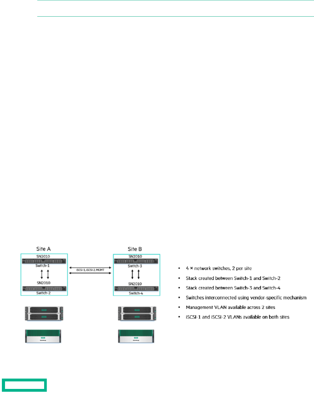
Appendix D: Configure Peer Persistence with dHCI
dHCI supports Peer Persistence with some limitations.
Note: Some documentation uses the term "synchronous replication with Automatic Switchover (ASO)" to refer to
Peer Persistence.
For information about setting up and using Peer Persistence, refer to the following documentation:
• The Peer Persistence deployment guide, which is available from the Documentation Portal on HPE InfoSight
• The GUI and CLI Administration Guides, which are available from the Documentation Portal on HPE InfoSight
• Synchronous Replication Witness, which is available on the HPE InfoSight Software Download page
Limitations When Using Peer Persistence with dHCI
HPE Storage support for Peer Persistence has the following limitations:
• Two HPE Storage dHCI arrays are required
• The arrays must be of the same model (for example, AF40 and AF40).
• The arrays must be running the same version of the array OS.
• No more than 32 servers can be used for dHCI. (This maximum total does not mean 20 per site, but 20 for both sites
together.)
• A VMware vSphere cluster can be spread across only two sites.
• One VMware vCenter server is required.
Other limitations might apply. Check HPE Infosight for the most recent HPE Storage array documentation.
Network Configuration Example for Using Peer Persistance
Before you deploy dHCI, you must complete the network configuration between your sites. Peer Persistence with dHCI requires
that you configure the Management VLAN and both iSCSI VLANs so that they are available between the two solutions.
You networking configuration should be similar to the one shown in the following figure.
Figure 9: Network Configuration Example
Appendix D: Configure Peer Persistence with dHCI 93

Appendix E: Configure vSphere Enhanced Linked Mode with dHCI
dCHI supports vSphere Enhanced Linked mode. This VMware feature allows you to join multiple vCenter Server instances for
unified monitoring and management purposes. This capability enables centralized virtual machine (VM) administrators to
perform management tasks transparently across sites, regardless of the vCenter Server and datacenter boundaries.
You should configure vSphere Enhanced Linked mode before starting the first dHCI deployment, unless you want to deploy
new or multiple new vCenter Server instances during that deployment.
Before you begin
Setting up vSphere Enhanced Linked Mode requires that you:
• Are running array OS 5.1.3.100 or later.
• Created a new vCenter Server instance when you set up and configured the first dHCI system. Review the sections Installing
and Configuring dHCI on page 71 and Deploying dHCI on page 75.
Procedure
1. Before you install your second dHCI system, make sure you deploy the new vCenter Server instance that you created when
you set up the first dHCI system.
Refer to the VMware documentation for instructions on doing this.
2. Configure Enhanced Linked Mode for a vCenter Server with an external platform.
Refer to the VMware documentation for instructions on doing this.
3. On the second dHCI system, configure the solution using the existing vCenter Server instance and point it to the second
vCenter Server instance that you deployed manually.
4. Check your configuration by logging in to your first vCenter Server instance.
5. Select Menu.
6. Select HPE Storage. You should now be able to browse among all the vCenter Server instances that were configured using
vSphere Enhanced linked mode.
Appendix E: Configure vSphere Enhanced Linked Mode with dHCI 94
Documentation Feedback: [email protected]

Appendix F: HPE FlexFabric 5700 Ethernet Networking Cabling
The following table provides an overview of how to cable a dHCI solution with six HPE ProLiant DLs and one HPE Storage
hybrid flash array. All ports are Base-T for HPE Storage arrays, HPE ProLiant servers, and HPE FlexFabric switches.
Note: If your array is running release 6.0.0.0 or later, use server ports 1 and 3 for vSwitch 0 (MGMT) and server ports
2 for iSCSI 1 and 4 for iSCSI 2. If the array is running an earlier version of the array OS, use ports 1 and 2 for vSwitch
0 (MGMT) and port 3 for iSCSI 1 and 4 for iSCSI 2.
Table 12:
Cable TypePortDevicePortSwitch
HPE X240 40 Gbps
QSFP+ DAC
MGMT1HPE FF5700 Switch 2QSP+ 1HPE FF5700 switch 1
HPE X240 40 Gbps
QSFP+ DAC
MGMT2HPE FF5700 Switch 2QSP+ 2HPE FF5700 switch 1
RJ45 – cat6MGMT1HPE Storage controller
A
1HPE FF5700 switch 1
RJ45 – cat6MGMT2HPE Storage controller
A
1HPE FF5700 switch 2
RJ45 – cat6DATA1HPE Storage controller
B
2HPE FF5700 switch 1
RJ45 – cat6DATA2HPE Storage controller
B
2HPE FF5700 switch 2
RJ45 – cat6DATA1HPE Storage controller
A
3HPE FF5700 switch 1
RJ45 – cat6DATA2HPE Storage controller
A
3HPE FF5700 switch 2
RJ45 – cat6iLOHPE Storage controller
B
4HPE FF5700 switch 1
RJ45 – cat6iLOHPE Storage controller
B
4HPE FF5700 switch 2
RJ45 – cat6iLOiLO – HPE ProLiant #18HPE FF5700 switch 1
RJ45 – cat6iLOiLO – HPE ProLiant #28HPE FF5700 switch 2
RJ45 – cat6iLOiLO – HPE ProLiant #39HPE FF5700 switch 1
RJ45 – cat6iLOiLO – HPE ProLiant #49HPE FF5700 switch 2
RJ45 – cat6iLOiLO – HPE ProLiant #510HPE FF5700 switch 1
RJ45 – cat6iLOiLO – HPE ProLiant #610HPE FF5700 switch 2
RJ45 – cat6LOM1HPE ProLiant #116HPE FF5700 switch 1
RJ45 – cat6PCI1HPE ProLiant #116HPE FF5700 switch 2
RJ45 – cat6LOM1HPE ProLiant #217HPE FF5700 switch 1
Appendix F: HPE FlexFabric 5700 Ethernet Networking Cabling 95

Cable TypePortDevicePortSwitch
RJ45 – cat6PCI1HPE ProLiant #217HPE FF5700 switch 2
RJ45 – cat6LOM1HPE ProLiant #318HPE FF5700 switch 1
RJ45 – cat6PCI1HPE ProLiant #318HPE FF5700 switch 2
RJ45 – cat6LOM1HPE ProLiant #419HPE FF5700 switch 1
RJ45 – cat6PCI1HPE ProLiant #419HPE FF5700 switch 2
RJ45 – cat6LOM1HPE ProLiant #520HPE FF5700 switch 1
RJ45 – cat6PCI1HPE ProLiant #520HPE FF5700 switch 2
RJ45 – cat6LOM1HPE ProLiant #621HPE FF5700 switch 1
RJ45 – cat6PCI1HPE ProLiant #621HPE FF5700 switch 2
RJ45 – cat6LOM2HPE ProLiant #124HPE FF5700 switch 1
RJ45 – cat6PCI2HPE ProLiant #124HPE FF5700 switch 2
RJ45 – cat6LOM2HPE ProLiant #225HPE FF5700 switch 1
RJ45 – cat6PCI2HPE ProLiant #225HPE FF5700 switch 2
RJ45 – cat6LOM2HPE ProLiant #326HPE FF5700 switch 1
RJ45 – cat6PCI2HPE ProLiant #326HPE FF5700 switch 2
RJ45 – cat6LOM2HPE ProLiant #427HPE FF5700 switch 1
RJ45 – cat6PCI2HPE ProLiant #427HPE FF5700 switch 2
RJ45 – cat6LOM2HPE ProLiant #528HPE FF5700 switch 1
RJ45 – cat6PCI2HPE ProLiant #528HPE FF5700 switch 2
RJ45 – cat6LOM2HPE ProLiant #629HPE FF5700 switch 1
RJ45 – cat6PCI2HPE ProLiant #629HPE FF5700 switch 2
Appendix F: HPE FlexFabric 5700 Ethernet Networking Cabling 96
Documentation Feedback: [email protected]

Appendix G: HPE M-Series SN2010M Ethernet Networking Cabling
The folllowing table provides an overview of how to cable a dHCI solution that has five HPE ProLiant DLs and one HPE Storage
hybrid flash array.
Some points to keep in mind when working with the cabling:
• You must have two switch MGMT0 IP addresses and a third IP address for the MLAG VIP that is in the same subnet as
the MGMT0 ports. MLAG requires that the MGMT0 ports on the switches communicate. It will not work if you use MGMT1.
For more information about the HPE M-Series Switch Series, see the HPE Support Center website.
• If your array is running release 6.0.0.0 or later, use server ports 1 and 3 for vSwitch 0 (MGMT) and server port 2 for iSCSI
1 and port 4 for iSCSI 2.
If the array is running an earlier version of the array OS, use ports 1 and 2 for vSwitch 0 (MGMT) and port 3 for iSCSI 1
and port 4 for iSCSI 2.
Table 13:
Transaction TypePortDevicePortSwitch
HPE X240 100 Gbps
QSFP+ DAC
QSP+ 19HPE SN2010M switch
2
QSP+ 19HPE SN2010M switch
1
HPE X240 100 Gbps
QSFP+ DAC
QSP+ 19HPE SN2010M switch
2
QSP+ 20HPE SN2010M switch
1
HPE 10GBASE-T SFP+
RJ45
MGMT1HPE Storage controller
A
1HPE SN2010M switch
1
HPE 10GBASE-T SFP+
RJ45
MGMT1HPE Storage controller
B
2HPE SN2010M switch
1
HPE 10GBASE-T SFP+
RJ45
MGMT2HPE Storage controller
A
1HPE SN2010M switch
2
HPE 10GBASE-T SFP+
RJ45
MGMT2HPE Storage controller
B
2HPE SN2010M switch
2
HPE X240 10 Gbps
SFP+ DAC
iSCSI1HPE Storage controller
A
3HPE SN2010M switch
1
HPE X240 10 Gbps
SFP+ DAC
iSCSI1HPE Storage controller
B
4HPE SN2010M switch
1
HPE X240 10 Gbps
SFP+ DAC
iSCSI2HPE Storage controller
A
3HPE SN2010M switch
2
HPE X240 10 Gbps
SFP+ DAC
iSCSI2HPE Storage controller
B
4HPE SN2010M switch
2
HPE X120 1G SFPiLOiLO – HPE ProLiant #15HPE SN2010M switch
1
HPE X120 1G SFPiLOiLO – HPE ProLiant #25HPE SN2010M switch
2
HPE X120 1G SFPiLOiLO – HPE ProLiant #36HPE SN2010M switch
1
Appendix G: HPE M-Series SN2010M Ethernet Networking Cabling 97

Transaction TypePortDevicePortSwitch
HPE X120 1G SFPiLOiLO – HPE ProLiant #46HPE SN2010M switch
2
HPE X120 1G SFPiLOiLO – HPE ProLiant #57HPE SN2010M switch
1
HPE X240 10 Gbps
SFP+ DAC
LOM1HPE ProLiant #18HPE SN2010M switch
1
HPE X240 10 Gbps
SFP+ DAC
PCI1HPE ProLiant #18HPE SN2010M switch
2
HPE X240 10 Gbps
SFP+ DAC
LOM1HPE ProLiant #29HPE SN2010M switch
1
HPE X240 10 Gbps
SFP+ DAC
PCI1HPE ProLiant #29HPE SN2010M switch
2
HPE X240 10 Gbps
SFP+ DAC
LOM1HPE ProLiant #310HPE SN2010M switch
1
HPE X240 10 Gbps
SFP+ DAC
PCI1HPE ProLiant #310HPE SN2010M switch
2
HPE X240 10 Gbps
SFP+ DAC
LOM1HPE ProLiant #411HPE SN2010M switch
1
HPE X240 10 Gbps
SFP+ DAC
PCI1HPE ProLiant #411HPE SN2010M switch
2
HPE X240 10 Gbps
SFP+ DAC
LOM1HPE ProLiant #512HPE SN2010M switch
1
HPE X240 10 Gbps
SFP+ DAC
PCI1HPE ProLiant #512HPE SN2010M switch
2
HPE X240 10 Gbps
SFP+ DAC
LOM2HPE ProLiant #114HPE SN2010M switch
1
HPE X240 10 Gbps
SFP+ DAC
PCI2HPE ProLiant #114HPE SN2010M switch
2
HPE X240 10 Gbps
SFP+ DAC
LOM2HPE ProLiant #215HPE SN2010M switch
1
HPE X240 10 Gbps
SFP+ DAC
PCI2HPE ProLiant #215HPE SN2010M switch
2
HPE X240 10 Gbps
SFP+ DAC
LOM2HPE ProLiant #316HPE SN2010M switch
1
HPE X240 10 Gbps
SFP+ DAC
PCI2HPE ProLiant #316HPE SN2010M switch
2
HPE X240 10 Gbps
SFP+ DAC
LOM2HPE ProLiant #417HPE SN2010M switch
1
HPE X240 10 Gbps
SFP+ DAC
PCI2HPE ProLiant #417HPE SN2010M switch
2
HPE X240 10 Gbps
SFP+ DAC
LOM2HPE ProLiant #518HPE SN2010M switch
1
Appendix G: HPE M-Series SN2010M Ethernet Networking Cabling 98
Documentation Feedback: [email protected]

Transaction TypePortDevicePortSwitch
HPE X240 10 Gbps
SFP+ DAC
PCI2HPE ProLiant #518HPE SN2010M switch
2
Appendix G: HPE M-Series SN2010M Ethernet Networking Cabling 99
Documentation Feedback: [email protected]

Appendix H: Resources
The section Finding More Information on page 8 contains pointers that can be helpful as you are configuring and using dHCI.
Here are some additional resources:
• HPE Storage Validated Configuration Matrix
https://infosight.hpe.com/org/urn%3Animble%3A0013400001QfUyiAAF/resources/nimble/validated-configuration-matrix
• HPE Support Site for HPE ProLiant DL360 Gen10 Servers
hpe.com/us/en/mobile/iss/index.aspx?product=HPE_ProLiant_DL360_Gen10
• HPE Support Site for HPE ProLiant DL380 Gen10 Servers
hpe.com/us/en/mobile/iss/index.aspx?product=HPE_ProLiant_DL380_Gen10
• HPE Integrated Lights Out (iLO 4) – Configuring the NIC Settings
support.hpe.com/hpsc/doc/public/display?docId=emr_na-a00045457en_us&docLocale=en_US
• HPE Support Site for HPE FlexFabric 5700 Switch Series
support.hpe.com/hpsc/doc/public/display?docId=emr_na-c04406873
• HPE Alletra 6000, 5000, Alletra documentation page of the HPE InfoSight portal (login required)
infosight.hpe.com/org/urn%3Animble%3A0013400001QfUyiAAF/resources/nimble/docs
• Installation Guide – HFxx
https://infosight.hpe.com/InfoSight/media/cms/active/pubs_Array_Installation_-_HFxx.pdf
• Installation Guide - AFxx
https://infosight.hpe.com/InfoSight/media/cms/active/pubs_Array_Installation_-_AFxx.pdf
• VMware API and SDK documentation vmware.com/support/pubs/sdk_pubs.html
http://vmware.com/support/pubs/sdk_pubs.html
• HPE iLO RESTful API
hpe.com/us/en/servers/restful-api.html
• Managing Hewlett Packard Enterprise Servers Using the RESTful API
http://support.hpe.com/hpsc/doc/public/display?docId=c04423967
Appendix H: Resources 100
Documentation Feedback: [email protected]
