Emotron VSB
AC Drive
0.4kW to 3.7kW / 0.54Hp to 5Hp
Instruction manual
English

Thank you for choosing Emotron VSB Series General Purpose AC Motor Drives from CG
Drives & Automation. This user manual presents a detailed description of Emotron VSB series
with respect to product features, structural characteristics, functions, installation, parameter
setting, troubleshooting, commissioning and daily maintenance, etc. Be sure to carefully read
through the safety precautions before use, and use this product on the premise that personnel
and equipment safety is ensured.
IMPORTANT NOTES
Please assure the intactness of product enclosure and all safety covers before
installation .Operation must conform to the requirements of this manual and local industrial
safety regulations and/or electrical codes.
Contents of this manual may be subject to appropriate modification as a result of product
upgrade, specification change and update of the manual.
In the event of damage or loss of user manual, users may ask local distributors, offices or
our Technical Service Department for a new one.
If any item as stated in this manual is not clear, please contact our Technical Service
Department.
If any anomaly occurs after power up or during the operation, it is essential to stop the
machine and identify the fault or seek technical services as soon as possible.
Emotron VSB
Instruction manual - English
400V: Software type/version: 50101/08.01.0085 (main drive and control board)
50201/08.01.0086 (Aux terminal control board)
230V: Software type/version: 50101/08.01.0087 (main drive and control board)
50201/08.01.0088 (Aux terminal control board)
Document number: 01-5577-01 Edition: r0
Date of release: 30-05-2014
© Copyright Crompton Greaves Ltd 2014
Crompton Greaves Ltd retains the right to change specifications and
illustrations in the text, without prior notification. The contents of this document may
not be copied without the explicit permission of Crompton Greaves Ltd.
CONTENTS
Chapter 1 Safety Precautions ................................................... - 1 -
1.1 Safety Considerations .............................................................................................. - 1 -
1.2 Other Considerations ............................................................................................... - 6 -
Chapter 2 Product Information ................................................. - 9 -
2.1 Model Explanation ................................................................................................... - 9 -
2.5 Parts Drawing ........................................................................................................ - 14 -
2.6 Appearance, Mounting Dimensions and Weight ..................................................... - 14 -
2.7 External Dimensions of Keypad ............................................................................. - 16 -
Chapter 3 Installation and Wiring ........................................... - 17 -
3.1 Installation Environment ......................................................................................... - 17 -
3.2 Minimum Mounting Clearances .............................................................................. - 17 -
3.3 Remove & Mount Keypad and Cover ..................................................................... - 18 -
3.4 Selection of Peripheral Devices .............................................................................. - 20 -
3.5 Terminal Configuration ........................................................................................... - 21 -
3.6 Main Circuit Terminals and Wiring .......................................................................... - 22 -
3.7 Control Terminal Wiring .......................................................................................... - 24 -
3.8 Control Terminal Specification ................................................................................ - 26 -
3.9 Control Terminal Usage .......................................................................................... - 27 -
Chapter 4 Operation and Run Instructions ............................ - 36 -
4.1 Operation of Keypad .............................................................................................. - 36 -
4.2 Potentiometer Setting ............................................................................................ - 39 -
4.3 Prompt Message Status ........................................................................................ - 39 -
4.4 Parameter Setting ................................................................................................. - 40 -
4.5 Initial Power up ..................................................................................................... - 41 -
Chapter 5 List of Parameters .................................................. - 47 -
Chapter 6 Specification of Parameters .................................. - 70 -
Group A System Parameter and Parameter Management ......................................... - 70 -
Group b Setting of Running Parameters .................................................................... - 71 -
Group C Input and Output Terminals ............................................................................ - 95 -
Group d Motor and Control Parameters ...................................................................... - 111 -
Group E Enhancement Function and Protection Parameters ......................................- 124 -
Group F Application ....................................................................................................- 131 -
Group H Communication Parameters .........................................................................- 138 -
Group L Keys and Display of Keypad ..........................................................................- 140 -
Group U Monitoring .....................................................................................................- 143 -
Chapter 7 Troubleshooting ................................................... - 148 -
7.1 Fault Causes and Troubleshooting ........................................................................- 148 -
Chapter 8 Maintenance ......................................................... - 155 -
8.1 Routine Inspection ................................................................................................- 155 -
8.2 Regular Maintenance ............................................................................................- 156 -
8.3 Replacement of Vulnerable Parts ..........................................................................- 158 -
8.4 Storage .................................................................................................................- 159 -
Emotron VSB Instruction Manual Chapter 1 Safety Precautions
Chapter 1 Safety Precautions
Safety Precautions
Safety signs in this manual:
WARNING
: indicates the situation in which the failure to follow operating requirements
may result in fire or serious personal injury or even death
.
ATTENTION: indicates the situation in which the failure to follow operating requirements
may cause moderate or slight injury and damage to equipment.
Users are requested to read this chapter carefully when installing, commissioning and repairing
this product and perform the operation according to safety precautions as set forth in this
chapter without fail. CG Drives & Automation will bear no responsibility for any injury and loss
as a result of any violation operation.
1.1 Safety Considerations
1.1.1 Prior to Installation
WARNING
Do not touch control terminals, circuit boards and any other electronic parts and
components with bare hands.
Do not use the drive whose component(s) is/are missing or damaged. Failure to comply
with may result in more faults and/or personal injury even death.
ATTENTION
Check if the product information indicated on the nameplate is consistent with the order
requirements. If not, do not install it.
Do not install the drive in the event that the packing list does not match with real
equipment.
- 1 -
Emotron VSB Instruction Manual Chapter 1 Safety Precautions
1.1.2 Installation
WARNING
Only qualified personnel familiar with adjustable frequency AC drives and associated
machinery should plan or implement the installation. Failure to comply may result in
equipment damage and/or personnel injury even death.
This equipment must be mounted on metal or other flame retardant objects. Failure to
comply may result in fire.
This equipment must be mounted in an area which is away from combustibles and heat
sources. Failure to comply may result in fire.
This equipment must in no case be mounted in the environment exposed to explosive gases.
Failure to comply may result in explosion.
Never adjust mounting bolts of this equipment, especially the ones with red markers. Failure
to comply may result in equipment damage.
ATTENTION
Handle the equipment gently and take hold of its sole plate so as to avoid foot injury or
equipment damage.
Mount the equipment where its weight can be withstood. Failure to comply may result in
equipment damage and/or personnel injury if falling happens.
Make sure the installation environment conforms to the requirements as stated in
Section 2.4. If not, de-rating is necessary. Failure to comply may result in equipment
damage.
Prevent drilling residues, wire ends and screws from falling into the equipment during
installation. Failure to comply may result in faults or equipment damage.
When mounted in a cabinet, this equipment should be provided with appropriate heat
dissipation. Failure to comply may result in faults or equipment damage.
- 2 -
Emotron VSB Instruction Manual Chapter 1 Safety Precautions
1.1.3 Wiring
WARNING
Only qualified personnel familiar with adjustable frequency AC drives and associated
machinery should plan or implement the wiring. Failure to comply may result in personnel
injury and/or equipment damage.
Wiring must strictly conform to this manual. Failure to comply may result in personnel
injury and/or equipment damage.
Make sure the input power supply has been completely disconnected before wiring.
Failure to comply may result in personnel injury and/or equipment damage.
All wiring operations must comply with EMC and safety regulations and/or electrical
codes, and the conductor diameter should conform to recommendations of this manual.
Failure to comply may result in personnel injury and/or equipment damage.
Since overall leakage current of this equipment may be bigger than 3.5mA, for safety's
sake, this equipment and its associated motor must be well grounded so as to avoid risk
of electric shock.
Be sure to implement wiring in strict accordance with the marks on this equipment’s
terminals. Never connect three-phase power supply to output terminals U/T1, V/T2 and
W/T3. Failure to comply may result in equipment damage.
Install braking resistors at terminals
/B1 and B2 only. Failure to comply may result in
equipment damage.
Wiring screws and bolts for main circuit terminals must be screwed tightly. Failure to
comply may result in equipment damage.
AC 220V signal is prohibited from connecting to other terminals than control terminals
RA, RB and RC. Failure to comply may result in equipment damage.
- 3 -
Emotron VSB Instruction Manual Chapter 1 Safety Precautions
ATTENTION
Since all adjustable frequency AC drives from CG Drives & Automation have been
subjected to hi-pot test before delivery, users are prohibited from implementing such a
test on this equipment. Failure to comply may result in equipment damage.
Signal wires should to the best of the possibility be away from main power lines. If this
cannot be ensured, vertical cross-arrangement shall be implemented, otherwise
interference noise to control signal may occur.
If motor cables are longer than 100m, it is recommended output AC reactor be used.
Failure to comply may result in faults.
1.1.4 Running
WARNING
Drives which have been stored for more than 2 years should be used with voltage
regulator to gradually boost the voltage when applying power to the drives. Failure to
comply may result in equipment damage.
Be sure to confirm the completion and correctness of the drive wiring and close the
cover before applying power to the drive. Do not open the cover after applying power.
Failure to comply may result in electric shock hazard.
After applying the power, never touch the drive and peripheral circuits no matter what
state the drive is under, otherwise there will be electric shock hazard.
Prior to the running of the drive, check there is no person in surrounding area who can
reach the motor so as to prevent personal injury.
Only qualified technicians familiar with adjustable frequency AC drives are allowed to
perform signal test during operation. Failure to comply may result in equipment damage
and/or personal injury.
Never change the drive parameters at will. Failure to comply may result in equipment
damage.
- 4 -
Emotron VSB Instruction Manual Chapter 1 Safety Precautions
ATTENTION
Make sure the number of phases of power supply and rated voltage are consistent with
product nameplate. If not, contact the seller or CG Drives & Automation.
Check there are no short circuits in peripheral circuits connected with the drive, and
make sure the connection is tight. Failure to comply may result in equipment damage.
Make sure the motor and associated machinery are within allowable range of service
prior to operation. Failure to comply may result in equipment damage.
Never touch fans, heat sink and braking resistor with bare hands. Failure to comply may
result in equipment damage and/or personal injury.
It is not allowed to start & stop the driver frequently via direct switching power on or off.
Failure to comply may result in equipment damage.
Make sure the drive is in a non-output status before switch-on/switch-off of the drive
output and/or contactor. Failure to comply may result in equipment damage.
1.1.5 Maintenance
WARNING
Only qualified technicians are allowed to implement the
maintenance, and
troubleshooting.
Never implement the maintenance, and troubleshooting before power supply has been
turned off and discharged completely. Failure to comply may result in equipment
damage and/or personal injury.
To avoid an electric shock hazard, wait at least 10 minutes after the power has been
turned off and make sure the residual voltage of the bus capacitors has discharged to
0V before performing any work on the drive.
After the replacement of the drive, be sure to perform the same procedures in strict
accordance with above-noted rules.
ATTENTION
Do not touch the electric components with bare hands during maintenance, and
troubleshooting. Failure to do this may result in component damage due to ESD.
All pluggable components can be inserted or pulled out only when power has been
turned off.
- 5 -

Emotron VSB Instruction Manual Chapter 1 Safety Precautions
1.2 Other Considerations
1.2.1 Input Power Supply
This series of drives are not applicable to applications out the range of operating voltage as set
forth in this manual. If necessary, please use booster to rise or drop the voltage to regulated
voltage range.
1.2.2 Surge Protection
This series of drives are furnished with surge suppressor that has certain resistance to lightning
induction. However, users in areas with frequent occurrence of lightning need to mount an
external surge suppressor in front of the drive power input side.
1.2.3 Operation of Contactor
As to the configuration of peripheral devices recommended by this manual, it is necessary to
mount a contactor between the power supply and this drive input side. Such a contactor should
not be used as a control device for start and stop of the drive, as frequent charging &
discharging shall reduce the service life of internal electrolytic capacitors.
When it is necessary to mount a contactor between the drive output and the motor, it
should be ensured the drive is in a non-output status before switch-on/switch-off of such a
contactor. Failure to comply may result in drive damage.
1.2.4 Output Filter
Since the drive output is PWM high frequency chopping voltage, mounting filter devices such
as an output filter and an output AC reactor between the motor and the drive shall effectively
reduce output noise, avoiding interference to other surrounding equipments.
If the length of cable between the drive and the motor exceeds 100m, an output AC reactor
is recommended to use with the purpose of preventing drive fault as a result of overcurrent
caused by excessive distributed capacitance. An output filter is optional depending on field
requirements.
Be sure not to mount phase-shifting capacitor or surge absorber at output side of the drive
since this may result in drive damage as a result of over-temperature.
1.2.5 Insulation of the motor
In view of the fact that the drive output is PWM high frequency chopping voltage accompanied
by higher harmonics, the noise, temperature rise and vibration of the motor is higher compared
with sinusoidal voltage. Particularly this debases motor insulation. Therefore, the motor should
be subjected to insulation inspection before initial use or reuse after being stored for a long
- 6 -

Emotron VSB Instruction Manual Chapter 1 Safety Precautions
period of time. The motor in regular service should also be subjected to regular insulation
inspection so as to avoid the drive damage as a result of motor insulation damage.
1.2.6 Derating
Due to the thin air in high-altitude areas, the radiating performance of the drive with forced air
cooling may degrade while the electrolyte of electrolytic capacitors is more volatile, which can
result in reduction in product life. Drive should be derated when used in an area at the altitude
above 1000 meters. It is recommended to derate 1% for every 100m when the altitude is above
1000 meters.
- 7 -

Emotron VSB Instruction Manual Chapter 1 Safety Precautions
- 8 -

Emotron VSB Instruction Manual Chapter 2 Product Information
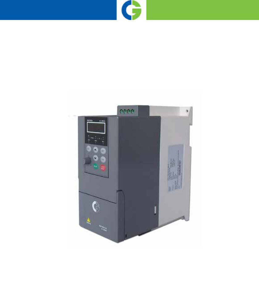
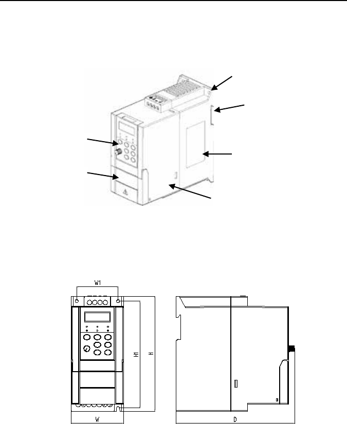
Chapter 2 Product Information
2.1 Model Explanation
Model shown on product nameplate indicates the series name, applicable type of power supply,
power class and hardware, etc. via the combination of numbers, symbols and letters.
Fig. 2-1 Nameplate information
Fig. 2-2 Product model explanation
- 9 -

Emotron VSB Instruction Manual Chapter 2 Product Information
2.3 Information of Product Model
Table 2-1 Product model and technical data Emoton VSB23
Drive model
Heavy Duty
150% 1 min. every 10 min.
Light Duty
120% 1 min.
Max
input
Fuse
A
Brake
unit
Ω
Rated
output
current
A
Rated
input
current
1-phase/
3-phase
A
Typical
motor
kW*
Rated
output
current
A
VSB23-003-20CNB
2.6
5.5/3.2
0.4
**
16
>200
VSB23-005-20CNB
4.5
9.2/6.3
0.75
25
>200
VSB23-008-20CNB
7.5
14.5/9
1.5
32
>100
VSB23-011-20CNB
11
23/15
2.2
40
>75
Note: The models VSB23-### can be used for either 1-phase or 3-phase.
* Power at 230V **= Contact CG for information.
Table 2-2 Product model and technical data Emotron VSB48
Drive model
Heavy Duty
150% 1 min. every 10 min.
Light Duty
120% 1 min
Max
input
Fuse
A
Brake
unit
Ω
Rated
output
current
A
Rated input
current
A
Typical
motor
kW*
Rated
output
current
A
VSU48-003-20CNB
2.5
3.5
0.75
**
16
>150
VSU48-004-20CNB
3.8
6.2
1.5
16
>100
VSU48-006-20CNB
5.5
9.2
2.2
16
>75
VSU48-009-20CNB
9
14.9
3.7
40
>75
* Power at 400 - 415V. ** = Contact CG for information
- 10 -

Emotron VSB Instruction Manual Chapter 2 Product Information
2.4 Technical Features of Emotron VSB
Table 2-3 Technical Features of Emotron VSB
Power input
Rated input voltage
3-phase
AC208V/AC220V/AC230V/AC240V/AC380V/A
C400V/AC415V/AC440V/AC460V/AC480V
1-phase
AC220V/AC230V/AC240V
Rated input current
See Section 2.3
Frequency
50Hz/60Hz, tolerance ±5%
Allowable range of
voltage
Continuous voltage fluctuation ±10%, short
fluctuation -15% to +10%, i.e. 323V - 528V;
Voltage out-of-balance rate <3%, distortion rate
as per the requirements of IEC61800-2
Power output
Standard applicable
motor (kW)
See Section 2.3
Rated current (A)
See Section 2.3
Output voltage (V)
3-phase: 0 - rated input voltage, error < ±3%
Output frequency (Hz)
0.00 - 600.00Hz; unit: 0.01Hz
Overload capacity
150% - 1min; 180% - 10s; 200% - 0.5s
Control
characteristics
V/f patterns
V/f control
Sensor-less vector control 1
Range of speed
regulation
1:100 ( V/f control, sensor-less vector control 1)
Speed accuracy
±0.5% (V/f control)
±0.2% (sensor-less vector control 1)
Speed fluctuation
±0.3% (sensor-less vector control 1)
Torque response
< 10ms (sensor-less vector control 1)
Starting torque
0.5Hz: 180% (V/f control, sensor-less vector
control 1)
- 11 -

Emotron VSB Instruction Manual Chapter 2 Product Information
Basic
functions
Start frequency
0.00 - 600.00Hz
Accel/Decel
time
0.00 - 60000s
Carrier
frequency
0.7kHz - 12kHz
Frequency
setting sources
Digital setting + keypad ∧ / ∨
Digital setting + terminal UP/DOWN
Potentiometer
Communication
Analogue setting (AI)
Motor started
methods
Started from starting frequency
DC braking and then started
Motor stopped
methods
Ramp to stop
Coast to stop
Ramp stop + DC brake
Basic
functions
Dynamic
braking
capacity
Brake unit threshold voltage:
400V input: 650V~750V
200V input: 325V~375V
service time: 0.0~100.0s
DC braking
capacity
DC braking start frequency: 0.00 - 600.00Hz
DC braking current: 0.0 - 100.0%
DC braking time: 0.0 - 30.00s
Input terminals
4 digital inputs
1 analog, current/voltage type selectable
Output
terminals
1 digital output
1 relay output
1 analog output, voltage/current output selectable; can
output signals such as setting frequency, or output
frequency, etc
- 12 -

Emotron VSB Instruction Manual Chapter 2 Product Information
Featured
functions
various master & auxiliary commands and their switch, a variety of
Accel/Decel curves optional, analog auto correction, 8-step speed
programmable, three faults history, over excitation brake, over voltage stall
protection, under voltage stall protection, restart upon power loss, skip
frequency, frequency binding, four kinds of Accel/Decel time, process PID,
autotuning, field-weakening control
Protection
functions
Refer to Chapter 7- Troubleshooting
Environment
Place of
operation
Indoors, no direct sunlight, free from dust, corrosive
gases, flammable gases, oil mist, water vapor, water
drop or salt, etc.
Altitude
0 - 2000m
De-rate 1% for every 100m when the altitude is above
1000 meters
Ambient
temperature
-10°C - 50°C
Relative
humidity
0 - 95%, no condensation
Vibration
Less than 5.9m/s
2
(0.6g)
Storage
temperature
-40°C to +70°C
Others
Efficiency at
rated Amps
At rated Amps ≥93%
Installation
Wall-mounted, DIN-rail
IP grade
IP20
Cooling
method
Forced air cooling
- 13 -
Emotron VSB Instruction Manual Chapter 2 Product Information
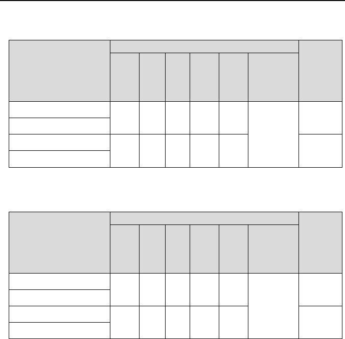
Table 2-4 Appearance, mounting dimensions and weight for
Emotron VSB23
Model
External and installation dimensions (mm)
Weight
(kg)
W H D W1 H1
Mounting
hole dia.
d
VSU23-003-20CNB
75 166 168 59 154
4.5
1.4
VSU23-005-20CNB
VSU23-008-20CNB
85 188 172 69 175 2.0
VSU23-011-20CNB
Table 2-5 Appearance, mounting dimensions and weight for
Emotron VSB48
Model
External and installation dimensions (mm)
Weight
(kg)
W H D W1 H1
Mounting
hole dia.
d
VSU48-003-20CNB
75 166 168 59 154
4.5
1.4
VSU48-004-20CNB
VSU48-006-20CNB
85 188 172 69 175 2.0
VSU48-009-20CNB
- 15 -
Emotron VSB Instruction Manual Chapter 2 Product Information
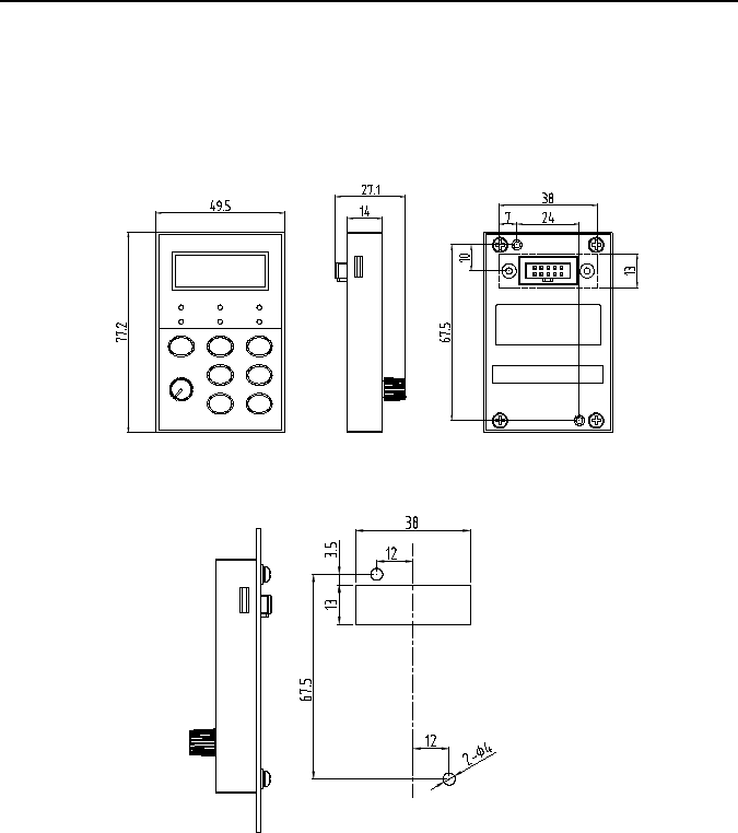
2.7 External Dimensions of Keypad
Keypad model of general purpose Emotron VSB series AC motor drive is KBU-BX2
whose appearance and external dimensions are shown in Fig. 2-5.
Fig. 2-5 External dimensions of KBU-BX2
Fig. 2-6 Cabinet hole dimensions when remote keypad mounting required
- 16 -

Emotron VSB Instruction Manual Chapter 2 Product Information
Chapter 3 Installation and Wiring
3.1 Installation Environment
1) Ambient temperature is in the range of -10°C - 50°C.
2) Drive should be installed on surface of flame retardant object, with adequate surrounding
space for heat dissipation.
3) Installation should be performed where vibration is less than 5.9m/s
2
(0.6g).
4) Protect from moisture and direct sunlight.
5) Do not install in areas with
grease dirt, dust, metal particles, or salty substances
6) Do not expose to an atmosphere with flammable gases, corrosive gases, explosive gases
or other harmful gases.
3.2 Minimum Mounting Clearances
To ensure favorable heat dissipation, mount the drive upright on a flat, vertical and level surface
as per Fig. 3.1.
Emotron VSB series can be wall-mounted or DIN-rail mounted. When installation is performed
inside cabinet, the product shall be mounted side by side to the greatest extent while adequate
surrounding space shall be preserved for favorable heat dissipation.
Fig. 3-1 Minimum mounting clearances
Ventilation
clearance
Ventilation
clearance
Fixing buckle
DIN-rail
- 17 -
Emotron VSB Instruction Manual Chapter 3 Installation and wiring
ATTENTION:
If a number of drives are mounted in one cabinet, parallel side-by-side mounting is
recommended
3.3 Remove & Mount Keypad and Cover
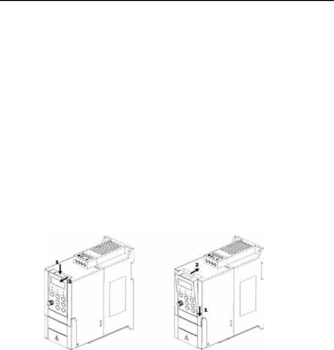
3.3.1 Remove and Mount Keypad
Remove keypad
Press the buckle of keypad as indicated by number "1" in Fig. 3-2, then pull the keypad out
to release as indicated by "2".
Mount keypad
Slightly slant the keypad in the direction as indicated by number "1" in Fig. 3-3 and align it
to clamping port at lower part of keypad bracket, then press it in as indicated by "2". When
a "click" sound heard, it indicates clamping has been properly made.
Fig. 3-2 Remove keypad Fig. 3-3 Mount keypad
- 18 -
Emotron VSB Instruction Manual Chapter 3 Installation and wiring
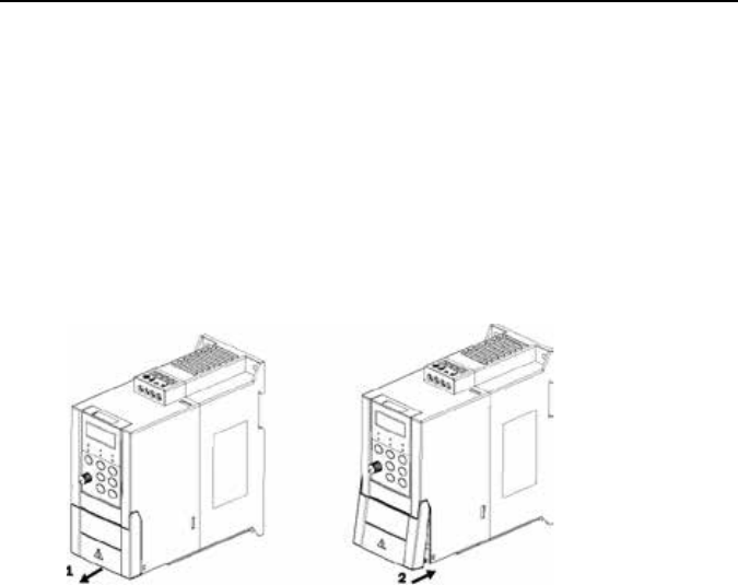
3.3.2 Open & Close Cover
Open the cover
Pull out as indicated by “1” in Fig. 3-4 a) with thumb.
Close the cover
After the completion of wiring, press the cover as indicated by “1” in Fig. 3-4 b). When there
is a “click” sound, it indicates clamping has been well completed.
a) open the cover b) close the cover
Fig. 3-4 Open and close the cover
- 19 -

Emotron VSB Instruction Manual Chapter 3 Installation and wiring
3.4 Selection of Peripheral Devices
Table 3-1 S election of peripheral devices
Model Breaker(A) Contactor(A)
Brake unit
Power(W) Resistor(Ω)
VSU23-003-20CNB
16 10 70 ≥200
VSU23-005-20CNB
25 16 70 ≥200
VSU23-008-20CNB
32 25 260 ≥100
VSU23-011-20CNB
40 32 260 ≥75
VSU48-003-20CNB 16 10 300 ≥150
VSU48-004-20CNB
16 10 450 ≥100
VSU48-006-20CNB
16 10 600 ≥75
VSU48-009-20CNB
40 32 600 ≥75
* All models have inbuilt brake unit, and brake resistors should be sourced. Strictly conform to the requirement in the
form.
Failure to comply may result in equipment damage.
- 20 -
Emotron VSB Instruction Manual Chapter 3 Installation and wiring
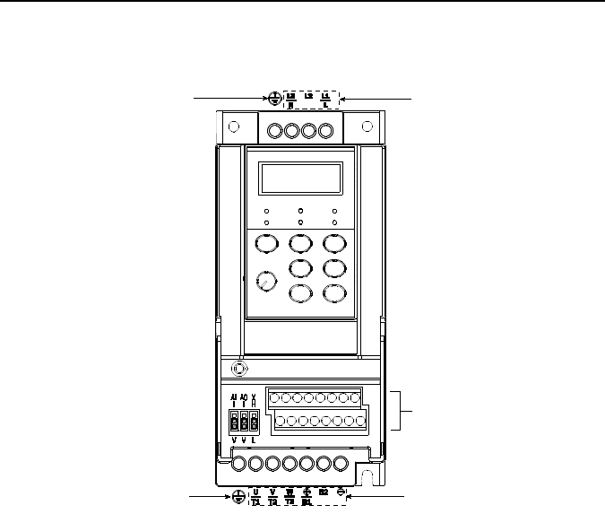
3.5 Term inal Configuration
Fig. 3-5 Terminal configuration.
Control circuit terminals
Main circuit
input
terminals
Grounding terminal
Grounding terminal
Main circuit
output
terminals
- 21 -

Emotron VSB Instruction Manual Chapter 3 Installation and wiring
3.6 Main Circuit Terminals and Wiring
WARNING
Only qualified personnel familiar with AC motor drives are allowed to implement wiring.
Failure to comply may result in equipment damage and/or personnel injury even death.
Wiring should be in strict accordance with this manual, otherwise hazard of electric
shock or equipment damage exists.
Make sure input power supply has been completely disconnected before wiring
operation. Failure to comply will result in personnel injury even death.
All wiring operations and lines should comply with EMC and national and local industrial
safety regulations and/or electrical codes. The conductor diameter should
be in
accordance with recommendations of this manual. Otherwise, hazard of equipment
damage, fire, and/or personnel injury exists.
Since leakage current of the drive may exceed 3.5mA, for safety's sake, the drive and
the motor must be grounded so as to avoid hazard of electric shock.
Be sure to perform wiring in strict accordance with the drive terminal marks. Never
connect three-phase power supply to output terminals U/T1, V/T2 and W/T3. Failure to
comply will result in equipment damage.
Only mount braking resistors at terminals /B1and B2.
Wiring screws and bolts for main circuit terminals must be screwed tightly. Failure to
comply may result in faults and/or equipment damage.
ATTENTION
Signal wires should to the best of possibility be away from main power lines. In the
event that this cannot be ensured, vertical cross arrangement should be adopted,
reducing EMI interference to the signal wires as much as possible.
In case the motor cable exceeds 100m, an appropriate output reactor should be
mounted.
- 22 -
Emotron VSB Instruction Manual Chapter 3 Installation and wiring
3.6.1 Main Circuit Terminals
Fig. 3-6 Main circuit terminals
3.6.4 Terminal Screws and Wiring Requirement
Table 3-2 Terminal screws and wiring requirement
Drive model
Power terminal Ground terminal
Cable
requirement
mm
2
Screw
Torque
Nm/Lb-In
Cable
requirement
mm
2
Screw
Torque
Nm/Lb-In
VSB23-003-20CNB
2.5 M3.5
0.8 ±0.05/
7 ±0.5
2.5 M3.5
0.8 ±0.05/
7 ±0.5
VSB23-005-20CNB
2.5 M3.5 2.5 M3.5
VSB23-008-20CNB
4 M3.5 2.5 M3.5
VSB23-011-20CNB
6 M3.5 4 M3.5
VSB48-003-20CNB
2.5 M3.5 2.5 M3.5
VSB48-004-20CNB
4 M3.5 4 M3.5
VSB48-006-20CNB
6 M3.5 6 M3.5
VSB48-009-20CNB
6 M3.5 6 M3.5
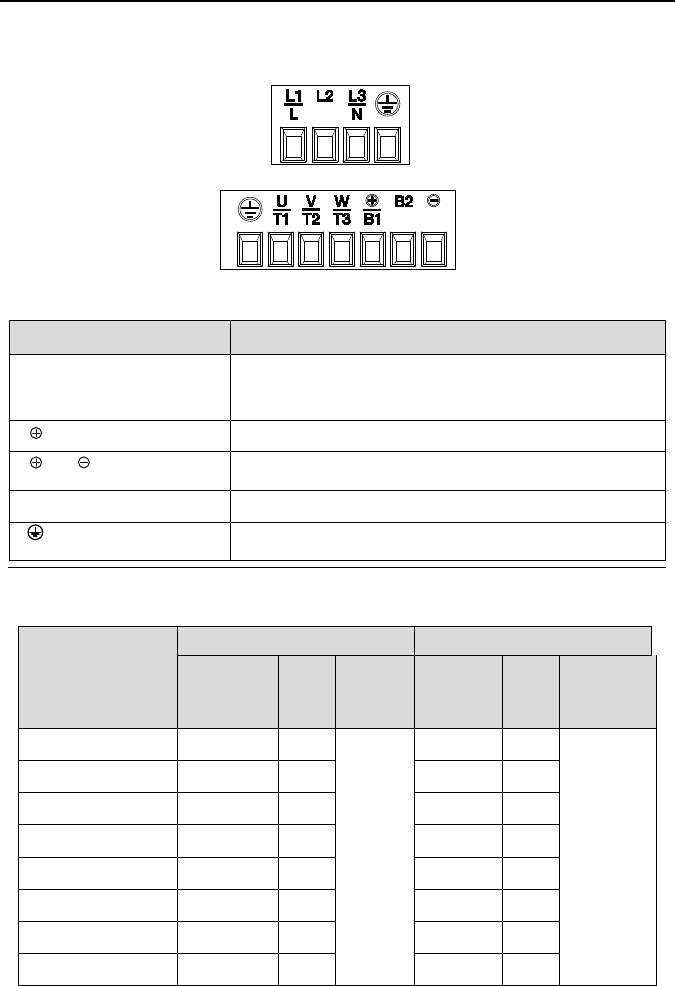
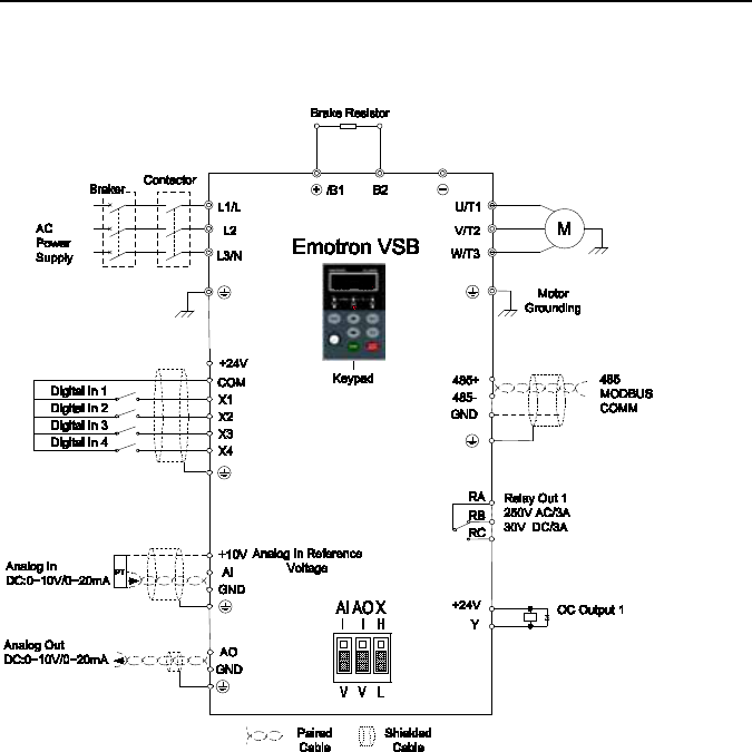
Terminal marks Designation and function of terminals
L1/L、L2、L3/N
Uniphase/Triphase AC power supply input (connect L1/L,
L3/N when the input is uniphase)
/B1
、
B2
Brake resistor wiring terminals
/B1
、
DC power supply input terminals
U/T1、V/T2、W/T3 Triphase AC output terminals
Ground terminal PE
- 23 -
Emotron VSB Instruction Manual Chapter 3 Installation and wiring
3.7 Control Terminal Wiring
WARNING
Only qualified personnel familiar with AC motor drives are allowed to implement wiring.
Failure to comply may result in equipment damage and/or personnel injury even death.
Wiring should be in strict accordance with this manual, otherwise hazard of electric
shock or equipment damage exists.
Make sure input power supply has been completely disconnected before wiring
operation. Failure to comply will result in personnel injury even death.
All wiring operations and lines should comply with EMC and national and local industrial
safety regulations and/or electrical codes. The conductor diameter should
be in
accordance with recommendations of this manual. Otherwise, hazard of equipment
damage, fire, and/or personnel injury exists.
Screws or bolts for terminal wiring must be screwed tightly.
AC 220V signal is prohibited from connecting to other terminals than control terminals
RA, RB and RC.
ATTENTION
Signal wires should to the best of possibility be away from main power lines. If this
cannot be ensured, vertical cross arrangement should be adopted, reducing EMI
interference to the signal wires as much as possible.
- 24 -
Emotron VSB Instruction Manual Chapter 3 Installation and wiring
3.7.2 Wiring Diagram
Fig. 3-7 Wiring diagram.
- 25 -

Emotron VSB Instruction Manual Chapter 3 Installation and wiring
3.8 Control Terminal Specification
Table 3-3 C ontrol terminal specification
Category
Terminal
Terminal
designation
Specification
Analog
input
+10V
Analog input
reference voltage
10.3V ±3%
Maximum output current 25mA
The resistance of external potentiometer
should be larger than 400Ω
GND Analog ground Connect with GND interiorly
AI Analog input
0~20mA: input impedance - 500Ω, maximum
input current - 25mA
0~10V: input impedance - 100kΩ, maximum
input voltage - 12.5V
Can be jumped between 0~20mA and 0~10V,
factory default: 0~10V
Analog
output
AO Analog output
0~20mA: impedance - 200Ω-500Ω
0~10V: impedance- 10kΩ
Can be jumped between 0~20 mA and 0
~
10V, factory default: 0
~
10V
GND Analog ground Connect with GND interiorly
Digital
input
+24V +24V
24V±10%
Maximal load 100mA
COM +24V ground Connect with COM interiorly
X1~X4
Digital input
Terminal 1~4
Input: 24VDC, 5mA
Freq range: 0~200Hz
Voltage range: 22V~26V
Digital
output
Y
Open collector
output
Voltage range: 0~24V
Current voltage: 0~50mA
Relay
output
RA/RB/R
C
Control board
relay output
RA-RB: NC; RA-RC: NO
Contact capacity: 250VAC/3A, 30VDC/3A
Terminal
RS485
Interface
485+
RS485
differential signal
+
Rate:
4800/9600/19200/38400/57600/115200bps
485−
RS485
differential signal
-
Maximum distance - 500m (standard network
cable used)
GND
RS485
communication
shileded
grounding
Connected with GND interiorly
- 26 -
Emotron VSB Instruction Manual Chapter 3 Installation and wiring
Category
Terminal
Terminal
designation
Specification
Keypad
interface
GND
485 communication
shield grounding
Isolated from COM interiorly
CN4 Keypad interface
Maximum communication distance is 5m
when connected to Keypad
GND
485
communication
shield grounding
Use GTAKE dedicated cable
3.9 Control Terminal Usage
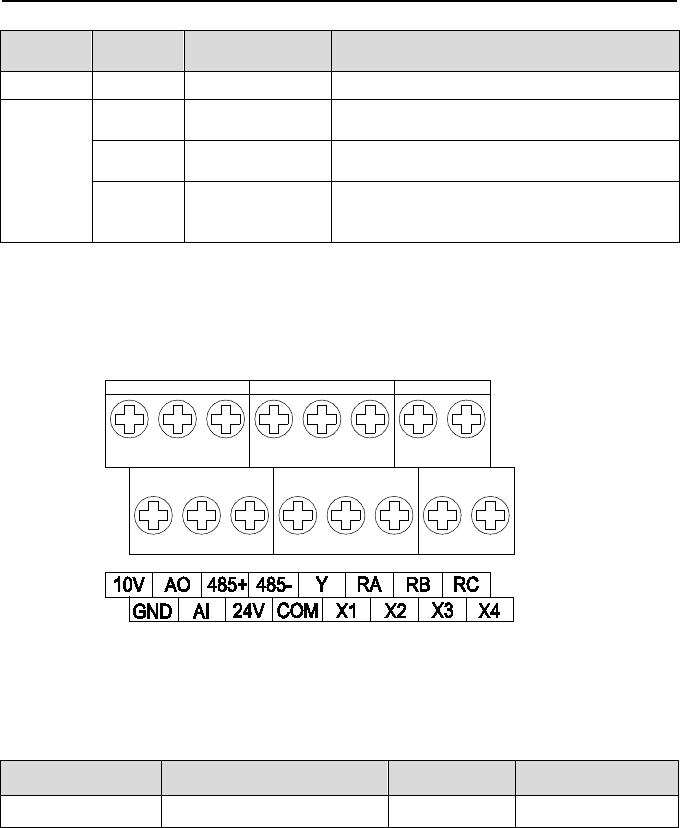
3.9.1 Lay-out of Control Terminals
Fig. 3-8 Lay-out of control terminals
3.9.2 Control Te rm inal S crew and W iring Requirement
Table 3-4 Terminal screw and wiring specification
Cable type Cable requirement (mm
2
) Screw Torque (Nm/Lb-In)
Shielded cable 1.0 M3 0.5 / 4.3
3.9.3 Instructions of Analogue Input/Output Terminals
Being particularly vulnerable to noise, analog input & output signals cables should be as short
as possible, shielded, and their shielded layers should be properly grounded close to the side
of drive. The cables should not exceed 20m.
Control cables shall be kept no less than 20cm away from main circuit and strong current
- 27 -
Emotron VSB Instruction Manual Chapter 3 Installation and wiring
lines (e.g. power lines, motor lines, relay lines and contactor lines) and should not be arranged
in parallel with strong current lines. In case it is inevitable to intersect strong current line,
vertical wiring is recommended to avoid drive faults as a result of noise.
Where analog input & output signals are severely interfered, the side of analog signal
source should be provided with filter capacitor or ferrite core.
3.9.4 Instructions of Digital Input/Output Terminals
Digital input & output signals cables should be as short as possible, shielded, and their
shielded layers should be properly grounded close to the side of drive. The cables should not
exceed 20m. When active drive is selected, take necessary filtering measures against power
crosstalk, for which dry contact control is recommended.
Control cables shall be kept no less than 20cm away from main circuit and strong current
lines (e.g. power lines, motor lines, relay lines and contactor lines) and should not be arranged
in parallel with strong current lines. In case it is inevitable to intersect strong current line,
vertical wiring is recommended to avoid drive faults as a result of noise. Operating instructions
for switching value input terminal
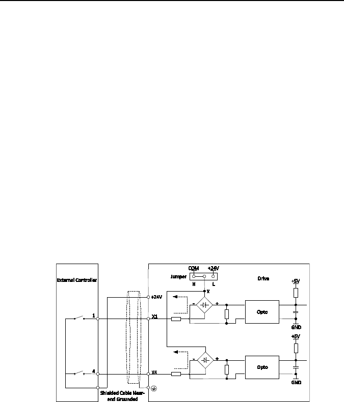
Instructions of digital input terminal
Dry contact
Fig. 3-9 X terminal high activated
- 28 -

Emotron VSB Instruction Manual Chapter 3 Installation and wiring
Fig. 3-10 X terminal low activated
Open collector
Fig. 3-11 Open collector PNP wiring
ATTENTION:
When selecting OC PNP wiring, dip switch should be switched to H terminal.
X
1
X
4
+
5V
GND
Drive
Shielded Cable
Near-end Grounded
+
-
+24V
Opto
+5V
GND
+-
Opto
1
4
External Controller
Jumper
L
X
H
COM
+24V
- 29 -
Emotron VSB Instruction Manual Chapter 3 Installation and wiring
X1
X4
COM
+5V
GND
Drive
Shielded Cable
Near-end Grounded
+
-
Opto
+5V
GND
+-
Opto
1
4
External Controller
LH
COM
+24
V
Jumper
X
Fig. 3-12 Open collector PNP wiring
ATTENTION:
When selecting OC NPN wiring, dip switch should be switched to L terminal.
- 30 -
Emotron VSB Instruction Manual Chapter 3 Installation and wiring
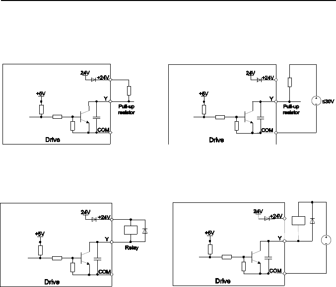
Instructions of digital o utput term inal
Instructions of Y output terminal
a) Internal power supply b) External power supply
Fig. 3-13 Wiring when Y output with pull-up resistor
a) Internal power supply b) External power supply
Fig. 3-14 Wiring when Y output drive relay
ATTENTION:
When relay coil voltage is lower than 24V, a resistor as voltage divider selected based on
coil impedance should be mounted between relay and output terminal,.
W iring instruction of relay output terminal
RA/RB/RC are relay contacts. RA and RB are normally closed, while RA and RC are
normally open. See parameter C1-02 for details.
ATTENTION:
In case inductive load (e.g. electromagnetic relay or contactor) is to be driven, a surge
voltage absorbing circuit such as RC absorbing circuit, piezoresistor or fly-wheel diode etc.
shall be mounted. Absorbing devices should be mounted close to the end of relay or
contactor.
- 31 -
Emotron VSB Instruction Manual Chapter 3 Installation and wiring
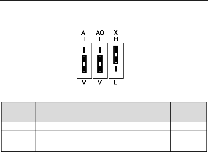
3.10 Instruction of Signal Switches
Fig. 3-15 Jumper diagram of signal switching
3.11 EMI Solutions
Due to its working principle, the drive will inevitably produce certain noise that may influence
and disturb other equipment. Moreover, since the internal weak electric signal of drive is also
susceptible to the interference of drive itself and other equipment, EMI problems shall be
inevitable. In order to reduce or avoid the interference of drive to external environment and
protect drive against interference from external environment, this section makes a brief
description of noise abatement, ground handling, leakage current suppression and the
application of power line filters.
3.11.1 Noise Abatement
When peripheral equipment and drive share the power supply of one system, noise from
drive may be transmitted to other equipment in this system via power lines and result in
misoperation and/or faults. In such a case, the following measures could be taken:
1) Mount input noise filter at input terminal of the drive;
2) Mount power supply filter at power input terminal of affected equipment;
3) Use isolation transformer to isolate the noise transmission path between other
equipment and the drive.
As the wiring of peripheral equipment and drive constitutes a circuit, the unavoidable
earthing leakage current of inverter will cause equipment misoperation and/or faults.
Designation Function
Default
setting
AI I: current input (0 - 20mA); V: voltage input (0 - 10V) 0 - 10V
AO I: current output (0 - 20mA); V: voltage output (0 - 10V) 0 - 10V
X
H means X terminal high input activated, while L low
activated
H
- 32 -
Emotron VSB Instruction Manual Chapter 3 Installation and wiring
Disconnect the grounding connection of equipment may avoid this misoperation and/or
faults
Sensitive equipment and signal lines shall be mounted as far away from drive as possible.
Signal lines should be provided with shielded layer and reliably grounded. Alternatively,
signal cable could be put into metallic conduits between which the distance shall be no
less than 20cm, and shall be kept as far away from drive and its peripheral devices, cables
as possible. Never make signal lines in parallel with power lines or bundle them up.
Signal lines must orthogonally cross power lines if this cross inevitable.
Motor cables shall be placed in thick protective screen like more than 2mm-thick pipelines
or buried cement groove, also, power lines can be put into metallic conduit and grounded
well with shielded cables.
Use 4-core motor cables of which one is grounded at close side of the drive and the other
side is connected to motor enclosure.
Input and output terminals of drive are respectively equipped with radio noise filter and
linear noise filter. For example, ferrite common mode choke can restrain radiation noise of
power lines.
3.11.2 Grounding
Recommended ground electrode is shown in the figure below:
Fig. 3-16 Ground
Use to the fullest extent the maximum standard size of grounding cables to reduce the
impedance of grounding system;
Grounding wires should be as short as possible;
Grounding point shall be as close to the drive as possible;
One wire of 4-core motor cables shall be grounded at the drive side and connected to
grounding terminal of motor at the other side. Better effect will be achieved if motor and drive
are provided with dedicated ground electrodes;
When grounding terminals of various parts of system are linked together, leakage current
turns into a noise source that may influence other equipment in the system, thus, grounding
terminals of the drive and other vulnerable equipment should be separated.
Grounding cable shall be kept away from inlet & output of noise-sensitive equipment.
3.11.3 Leakage Current Suppression
Leakage current passes through the line-to-line and ground distributed capacitors at input &
output sides of drive, and its size is associated with the capacitance of distributed capacitor and
变频器
其它设备
PE PE
Drive
Other
Devices
- 33 -

Emotron VSB Instruction Manual Chapter 3 Installation and wiring
the carrier frequency. Leakage current is classified into ground leakage current and line-to-line
leakage current.
Ground leakage current not only circulates inside drive system, but may also influence other
equipment via ground loop. Such a leakage current may result in malfunction of RCD and
other equipment. The higher the carrier frequency of drive is, the bigger the ground leakage
current would be. The longer the motor cables and the bigger the parasitic capacitance are,
the bigger the ground leakage current would be. Therefore, the most immediate and effective
method for suppression of ground leakage current is to reduce carrier frequency and
minimize the length of motor cables.
The higher harmonics of line-to-line leakage current that passes through between cables at
output side of drive will Accel the aging of cables and may bring about malfunction of other
equipment. The higher the carrier frequency of drive is, the bigger the line-to-line leakage
current would be. The longer the motor cables and the bigger the parasitic capacitance are,
the bigger the line-to-line leakage current would be. Therefore, the most immediate and
effective method for suppression of ground leakage current is to reduce carrier frequency and
minimize the length of motor cable. Line-to-line leakage current can also be effectively
suppressed by mounting additional output reactors.
3.11.4 Use of Power Supply Filter
Since AC drives may generate strong interference and are also sensitive to outside
interference, power supply filters are recommended. Pay close attention to the following
instructions during the use:
Enclosure of the filter needs to be reliably grounded;
Input lines of the filter shall be kept as far away from output lines as possible so as to avoid
mutual coupling;
Filter shall be as close to the drive side as possible;
Filter and drive must be connected to the same common ground.
- 34 -

Emotron VSB Instruction Manual Chapter 4 Operation and Run instructions
Chapter 4 Operation and Run Instructions
4.1 Operation of Keypad
As a human-machine interface, keypad is the main part for the drive to receive command and
display parameters.
Fig. 4-1 Keypad
- 36 -
Emotron VSB Instruction Manual Chapter 4 Operation and Run instructions
4.1.1 Key Functions on Keypad
On keypad there are 7 keys and 1 knob whose functions are as shown in Table 4-1.
Table 4-1 Key functions on keypad
Symbol
Key name
Meaning
Enter key
1) Parameter code edition enter
2) Confirmation of parameter value settings
Escape key
1) Return
2) Invalidate parameter editing value
Up key
1) Increment of selected digital of parameter code
2) Increment of selected digital of parameter value
3) Increment of set frequency
Down key
1) Decrement of selected digital of parameter code
2) Decrement of selected digital of parameter value
3) Decrement of set frequency
Shift key
1) Selection of parameter code serial digital
2) Selection of parameter value edited digital
3) Selection of stop/run-status displayed parameters
4) Fault status switched to parameter displayed status
Run key Run
Stop/reset key
1) Stop
2) Fault reset
Potentiometer
1) Frequency command source
2) Process PID setting
RUN
STOP
RESET
- 37 -

Emotron VSB Instruction Manual Chapter 4 Operation and Run instructions
4.1.2 Keypad Indicators
Keypad is furnished with 6 indicators whose descriptions are as stated below
Table 4-2 Description of indicators
Indicator Designation Meaning
Hz Frequency indicator
ON: currently displayed parameter is run frequency
or the unit of current parameter is frequency
Flash: currently displayed parameter is set
frequency
A
Current indicator
ON: currently displayed parameter is current
V
Voltage indicator
ON: currently displayed parameter is voltage
Hz+A Run speed indicator
ON: currently displayed parameter is run speed
Flash: currently displayed parameter is set speed
A+V
Percentage indicator
ON: currently displayed parameter is percentage
All OFF
No unit
No unit
RUN Run status indicator
ON: Run
OFF: Stopped
Flash: Stopping
FWD Forward indicator
ON: If the drive in stop status, forward command
enabled. If the drive in run status, the drive is
running forward
Flash: Forward is switching to reverse
REV Reverse indicator
ON: If the drive in stop status, reverse command
enabled. If the drive in run status, the drive is
running reversely.
Flash: Reverse is switching to forward
- 38 -

Emotron VSB Instruction Manual Chapter 4 Operation and Run instructions
4.2 Potentiometer Setting
Potentiometer could be frequency setting source or process PID setting programmed by
related parameters. When b0-01 is set to 3, potentiometer is source of master frequency
command. When b0-03 is set to 4, potentiometer is source of auxiliary frequency command.
When unit’s place, decade, or hundreds’ place of b1-01 is set to 4, potentiometer would be
working as frequency setting source of corresponding run command source.
4.3 Prompt Message Status
Prompt message status shall be displayed at the completion of some certain operations. For
instance, "dEFt2" would be displayed upon the completion of “restore to factory default (motor
parameters inclusive)
Table 4-3 Prompt messages
Characters Meaning Characters Meaning
LoC-1
Keypad locked 1 (full locked)
P-SEt
Password has been set
LoC-2
Keypad locked 2
(all locked except RUN,
STOP/RESET)
P-CLr Password cleared
LoC-3
Keypad locked 3
(all locked except STOP/RESET)
TUNE Autotuning
LoC-4
Keypad locked 4
(all locked except shift key)
CLr-F Clear fault record
PrtCt Keypad protection dEFt1
Restore to factory default
(motor parameters
exclusive)
UnLoC Unlock keypad dEFt2
Restore to factory default
(motor parameter inclusive)
LoU Drive undervoltage
Table 4-3 shows meanings of the characters displayed on Keypad.
- 39 -
Emotron VSB Instruction Manual Chapter 4 Operation and Run instructions
4.4 Parameter Setting
4.4 .1 Parameter System
Emotron VSB series drive parameter group: A0, b0~b2, C0~C4, d0~d2, E0~E1, F0~F1, H0,
L0~L1, U0~U1. Each parameter group contains a number of parameters. Parameter codes are
identified by the combination "parameter group character + parameter subgroup number +
parameter number". For instance, "F1-07" indicates the seventh parameter code at subgroup 1,
group F.
4.4 .2 Parameter Displayed Structure
Parameters and the parameter values are subject to a two-tier structure. Parameters
correspond to first-tier display, while parameter values correspond to second-tier display.
The first-tier display is as shown in Fig. 4-2, while the second-tier as Fig. 4-3:
Fig. 4-2 First-tier parameter display
Fig. 4-3 Second-tier parameter display ("3" is the value of b0-00)
- 40 -

Emotron VSB Instruction Manual Chapter 4 Operation and Run instructions
4.5 Initial Power up
Perform wiring in strict accordance with technical requirements as set forth in Chapter 3 -
Installation and Wiring.
4.5 .1 Examples for Quick setup
The following are examples for Quick setup with wiring and parameter settings. For more
detailed information, see “Chapter 6 Specification of parameters”.
4.5 .1.1 Analogue speed reference 0-10V to AI
1. Set Signal switch AI to V see chapter 3.10 Instruction of Signal Switches.
2. Connect analogue reference signal + to AI and - to GND. If manual potentiometer
(10kOhm) is used connect the mid point to AI and ends to +10V and GND. see Fig
4.4.
3. Connect start signals: RunFWD to DigitalIn1 and Run REV to DigitalIn2. If none or both
DigIn1 and DigIn2 are activated = Stop
Fig 4-4 Connect pot. to +10V, GND and AI terminal
- 41 -

Emotron VSB Instruction Manual Chapter 4 Operation and Run instructions
Application parameter settings as below.
Table 4-4
Parameter
Designation Set Value Comment
b0-01 Master frequency reference source 2: AI
b0-08 Maximum frequency set value 50Hz *
b0-10 Minimum frequency set value 0Hz *
b1-00 Run command source 1: Terminal
control
Digital inputs
b2-01 Acceleration time 1 set value 6s *
b2-02 Deceleration time 1 set value 6s *
C0-01 Digital input X1 function 3: FWD
C0-02 Digital input X2 function 4: REV
C2-00 Analogue input curve 00 * AI curve 1
(2 point curve)
C2-01 Maximum input of curve 1 100% *
C2-02 Set value(reference) corresponding to
maximum input of
curve 1
100% *
C2-03 Minimum input of curve 1 0% *
C2-04 Set value (reference) corresponding to
minimum input of curve 1
0% *
* = default value
- 42 -
Emotron VSB Instruction Manual Chapter 4 Operation and Run instructions
4.5 .1.2 Analogue speed reference 4-20 mA to AI
1. Set Signal switch A0 to I, see chapter 3.10 Instruction of Signal Switches.
2. Connect analogue reference signal: + to AI and - to GND
3. Connect start signals: Run FWD to DigitalIn1and Run REV to DigitalIn2. If none or both
DigIn1 and DigIn2 are activated = Stop.
Fig 4-5. Connection for Analogue speed reference 4-20mA to AI
- 43 -

Emotron VSB Instruction Manual Chapter 4 Operation and Run instructions
Application parameter settings as below.
Table 4-5
Parameter Designation Set Value Comment
b0-01 Master frequency reference
source
2: AI
b0-08 Maximum frequency set value 50Hz *
b0-10 Minimum frequency set value 0Hz *
b1-00 Run command source 1: Terminal control Digital inputs
b2-01 Acceleration time 1 set value 6s *
b2-02 Deceleration time 1 set value 6s *
C0-01 Digital input X1 function 3: FWD
C0-02 Digital input X2 function 4: REV
C2-00 Analogue input curve 00 * AI curve 1
(2 point curve)
C2-01 Maximum input of curve 1 100% * 20mA
C2-02 Set value corresponding to
maximum input of curve 1
100% *
C2-03 Minimum input of curve 1 20% * =4/20
C2-04 Set value corresponding to
minimum input of curve 1
0% *
* = default value
- 44 -

Emotron VSB Instruction Manual Chapter 4 Operation and Run instructions
4.5 .1.3 4 preset speeds and Start/Stop by Digital Inputs
1. Connect RUN contact SB2 between +24V and Digital Input 1.
2. Connect REVERSE selection contact between +24V and Digital Input 2.
3. Connect Preset bit0 contact between +24V and Digital Input 3.
4. Connect Preset bit1 contact between +24V and Digital Input 4.
Fig. 4-6. Connection for 4 preset speeds and start/stop by DI
- 45 -

Emotron VSB Instruction Manual Chapter 4 Operation and Run instructions
Application parameter settings as below.
Table 4-6
Parameter
Designation
Set Value
Comment
b0-01
Master frequency reference source
8: Multi-step speed
Preset speeds
b0-08 Maximum frequency set value 50Hz *
b0-10 Minimum frequency set value 0Hz *
b1-00 Run command source 1: Terminal control Digital inputs
b2-01 Acceleration time 1 set value 6s *
b2-02 Deceleration time 1 set value 6s *
C0-01 Digital input X1 function 3: FWD Start button SB2
C0-02 Digital input X2 function 4: REW Reverse direcion
C0-03 Digital input X3 function 5: Multi-step Bit 0, speed selection
C0-04 Digital input X4 function 15:Multi-step
Bit 1, speed selection
C0-19 FWD/REV terminal control mode 3: Two-wire mode 2
F1-00 Source for Preset frequency 0 0*: Digital setting F1-02
F1-01 Source for Preset frequency 1 0*: Digital setting F1-03
F1-02 Preset frequency 0 Set <Speed 0> Bit1=0, Bit0=0
F1-03 Preset frequency 1 Set <Speed 1> Bit1=0, Bit0=1
F1-04 Preset frequency 2 Set <Speed 2> Bit1=1, Bit0=0
F1-05 Preset frequency 3 Set <Speed 3> Bit1=1, Bit0=1
* = default value
- 46 -

Emotron VSB Instruction Manual Chapter 5 List of Parameters
Chapter 5 List of Parameters
Emotron VS parameter groups are listed below:
Category
Parameter group
Related pages
Group A: system parameter
A0: system parameters
P- 48 -; P- 70 -
Group b: setting of running
parameters
b0: frequency command
P- 48 -; P- 71 -
b1: start/stop control
P- 50 -; P- 84 -
b2: Accel/Decel parameters
P- 51 -; P- 89 -
Group C: input and output
terminals
C0: digital input
P- 52 -; P- 95 -
C1: digital output
P- 54 -; P- 95 -
C2: analog input
P- 55 -; P- 102 -
C3: analog output
P- 56 -; P- 107 -
C4: automatic correction of
analog input
P- 56 -; P- 109 -
Group d: motor and control
parameters
d0: motor parameter
P- 57 -; P- 111 -
d1: motor V/f control parameters
P- 58 -; P- 115 -
d2: motor vector control
parameters
P- 59 -; P- 120 -
Group E: enhanced
function and protection
parameters
E0: enhanced function
P- 59 -; P- 124 -
E1: protection parameters P- 60 -; P- 126 -
Group F: application
F0: process PID
P- 61 -; P- 131 -
F1: multi-step frequency
P- 62 -; P- 136 -
Group H: communication
parameters
H0: MODBUS communication
parameters
P- 63 -; P- 138 -
Group L: keypad keys and
display
L0: keypad keys
P- 64 -; P- 140 -
L1: LED display setting
P- 65 -; P- 141 -
Group U: monitoring
U0: status monitoring
P- 66 -; P- 143 -
U1: fault history
P- 67 -; P- 146 -
- 47 -

Emotron VSB Instruction Manual Chapter 5 List of Parameters
ATTENTION:
Change attribute:
"△" means the value of this parameter can be modified in stop and running status of drive;
"×" means the value of this parameter cannot be modified when drive is running;
"■" means this parameter is a measured value that cannot be modified;
Factory default value: The value when restored to factory default. Neither measured
parameter value nor recorded value will be restored.
Scope: the scope of setting and display of parameters
Param
Designation Range
Factory
default
Attr
Group A: System Parameter
Group A0: System Parameter
A0-00
Setting of user password
0~FFFF
0000
△
A0-02
Parameter
protection
0: All parameter programming
allowed
1: Only A0-00 and this parameter
programming allowed
0 ×
A0-03
Parameter
initialization
0: No operation
1: Clear fault history
2: Restore all parameters to factory
default (motor parameters
exclusive)
3: Restore all parameters to factory
default (motor parameters
inclusive)
0 ×
A0-09
Motor control technique
0: V/f control
1: Sensor-less vector control
0 ×
Group b Setting of Run Parameters
Group b0 Frequency Command
b0-00
Frequency
command pattern
0: Master frequency command
1: Master & auxiliary computation
result
2: Switch between master and
auxiliary command
3: Switch between master frequency
command, and master & auxiliary
computation result
4: Switch between auxiliary
frequency command, and master &
auxiliary computation result
0 ×
- 48 -

Emotron VSB Instruction Manual Chapter 5 List of Parameters
Param
Designation Range
Factory
default
Attr
b0-01
Master frequency command source
0: Digital setting (b0-02) +
adjustment on keypad
1: Digital setting (b0-
02) + terminal
UP/DOWN adjustment
2: Analog input AI
3: Potentiometer
6: Process PID output
8: Multi-step speed
9: Communication
3 ×
b0-02
Digital setting of
master frequency
Lower limit frequency ~ upper limit
frequency
50.00Hz △
b0-03
A
uxiliary frequency command
source
0: No command
1: Digital setting (b0-04) + ∧/∨
adjustment on keypad
2: Digital setting (b0-04) + terminal
UP/DOWN adjustment
3: Analog input AI
4: Keypad potentiometer input
7: Process PID output
9: Multi-step speed
10: Communication
0 ×
b0-04
Digital setting of
auxiliary frequency
Lower limit frequency ~ upper limit
frequency
0.00Hz △
b0-05
R
ange of auxiliary frequency
0: Relative to maximum frequency
1: Relative to master frequency
0 ×
b0-06
Coeff of auxiliary frequency
0.0%~100.0%
100.0%
×
b0-07
Computation of master and auxiliary
frequency
0: Master + auxiliary
1: Master - auxiliary
2: Max {master, auxiliary}
3: Min {master, auxiliary}
0 ×
b0-08
Maximum frequency
Upper limit frequency ~600.00Hz
50.00Hz
×
b0-09
Upper limit frequency
Lower limit frequency ~ maximum
frequency
50.00Hz ×
b0-10
Lower limit frequency
0.00Hz~upper limit frequency
0.00Hz
×
b0-11
Operation
when command
frequency lower than lower limit
frequency
0: Run at lower limit frequency
1: Run at 0 Hz
2: Stop
0 ×
b0-12
Time-delay of stop when command
frequency lower than lower limit
frequency
0.0s ~ 6553.5s 0.0s ×
b0-13
Lower limit of skip frequency band 1
0.00Hz~upper limit frequency
0.00Hz
×
b0-14
Upper limit of skip frequency band 1
0.00Hz~upper limit frequency
0.00Hz
×
- 49 -

Emotron VSB Instruction Manual Chapter 5 List of Parameters
Param
Designation Range
Factory
default
Attr
b0-15
Lower limit of skip frequency band 2
0.00Hz~upper limit frequency
0.00Hz
×
b0-16
Upper limit of skip frequency band 2
0.00Hz~upper limit frequency
0.00Hz
×
b0-17
Lower limit of skip frequency band 3
0.00Hz~upper limit frequency
0.00Hz
×
b0-18
Upper limit of skip frequency band 3
0.00Hz~upper limit frequency
0.00Hz
×
b0-19
Jog frequency
0.00Hz~upper limit frequency
5.00Hz
△
Group b1 Start/Stop Control
b1-00
Run command
0: Keypad control
1: Terminal control
2: Communication control
0 ×
b1-01
Binding of run command and
frequency
command
Unit's place: frequency command
source bundled under keypad
control:
0: No binding
1: Digital setting (b0-02) + ∧/∨
adjustment on keypad
2: Digital setting (b0-02) + terminal
UP/DOWN adjustment
3: Analog input AI
4: Keypad potentiometer input
7: Process PID output
9: Multi-step frequency
A: Communication input
Decade: frequency command source
bundled under terminal control
(same
as unit's place)
Hundreds place: frequency
command source bundled under
communication control (same as
unit's place)
000 ×
b1-02
R
un direction
0: Forward
1: Reverse
0 △
b1-03
Reverse disabled
0: Reverse enabled
1: Reverse disabled
0 ×
b1-04
Dead time of forward and reverse
0.0s~3600.0s
0.0s
△
b1-05
Start method
0: From start frequency
1: DC injection brake then start
3: Flying start (Spin start)
0 ×
b1-06
Start frequency
0.00Hz~upper limit frequency
0.00Hz
×
b1-07
Holding time of start frequency
0.0s~3600.0s
0.0s
△
b1-08
DC brake current at start
0.0%~100.0%
0.0%
△
b1-09
DC brake time at start
0.00s~30.00s
0.00s
△
- 50 -

Emotron VSB Instruction Manual Chapter 5 List of Parameters
Param
Designation Range
Factory
default
Attr
b1-10
Flying start current
0.0% - 200.0%
100%
△
B1-11
Flying start time
0.1s – 20.0s
2.0s
△
b1-13
Stop
method
0: Ramp to stop
1: Coast to stop
2: Ramp to stop + DC brake
0 ×
b1-14
Start frequency of DC brake stop
0.00Hz~upper limit frequency
0.00Hz
×
b1-15
Brake current
0.0%~100.0%
0.0%
△
b1-16
Brake time
0.00s~30.00s
0.00s
△
b1-17
O
verexcitation brake
0: Disabled
1: Enabled
1 ×
b1-18
D
ynamic brake
0: Disabled
1: Enabled
0 ×
b1-19
Dynamic brak
e threshold voltage
200V: 325V~375V, default: 375V
400V: 650V~750V, default: 720V
Model
defined
×
b1-20
Auto restart when power up again
after power loss
0: Disabled
1: Enabled
0 ×
b1-21
Waiting time
of auto restart when
power up again
0.0s~10.0s 0.0s △
Group b2 Accel/Decel Parameters
b2-00
Accel/Decel
time resolution
0: 0.01s
1: 0.1s
2: 1s
1 ×
b2-01
Accel time 1
0s~600.00s/6000.0s/60000s
6.0s
△
b2-02
Decel time 1
0s~600.00s/6000.0s/60000s
6.0s
△
b2-03
Accel time 2
0s~600.00s/6000.0s/60000s
6.0s
△
b2-04
Decel time 2
0s~600.00s/6000.0s/60000s
6.0s
△
b2-05
Accel time 3
0s~600.00s/6000.0s/60000s
6.0s
△
b2-06
Decel time 3
0s~600.00s/6000.0s/60000s
6.0s
△
b2-07
Accel time 4
0s~600.00s/6000.0s/60000s
6.0s
△
b2-08
Decel time 4
0s~600.00s/6000.0s/60000s
6.0s
△
b2-09
Decel time when emergency stop
enabled
0s~600.00s/6000.0s/60000s
6.0s △
b2-10
Jog Accel time
0s~600.00s/6000.0s/60000s
6.0s
△
b2-11
Jog Decel time
0s~600.00s/6000.0s/60000s
6.0s
△
b2-12
Accel
/Decele curve selection
0: Linear Accel/Decel
1: Broken-line Accel/Decel
2: S-curve Accel/Decel
0 ×
b2-13
Accel time switching frequency of
broken-line Accel/Decel
0.00Hz~upper limit frequency 0.00Hz △
b2-14
Decel time switching frequency of
0.00Hz~upper limit frequency
0.00Hz
△
- 51 -

Emotron VSB Instruction Manual Chapter 5 List of Parameters
Param
Designation Range
Factory
default
Attr
broken-line Accel/Decel
b2-15
Time of first segment of Accel
S-curve
0.00s~60.00s 0.20s
△
b2-16
T
ime of last segment of Accel
S-curve
0.00s~60.00s 0.20s
△
b2-17
Time of first segment of Decel
S-curve
0.00s~60.00s 0.20s
△
b2-18
T
ime of last segment of Decel
S-curve
0.00s~60.00s 0.20s
△
Group C Input and Output Terminals
Group C0 Digital Input
C0-00
Enabled condition of run command
terminals
when power up
0: Trigger edge detected + ON
detected
1: ON detected
0 ×
C0-01
F
unction of terminal X1
0: No function
1: JOG forward
2: JOG reverse
3: Run forward (FWD)
4: Run reverse (REV)
5: Three-wire control
6: Run suspended
7: External stop
8: Emergency stop
9: Stop command + DC brake
10: DC brake stop
11: Coast to stop
12: Terminal UP
13: Terminal DOWN
14: Clear UP/DOWN (including
keypad ∧/∨) adjustment
15: Multi-step frequency terminal 1
16: Multi-step frequency terminal 2
17: Multi-step frequency terminal 3
19: Accel/Decel time determinant 1
20: Accel/Decel time determinant 2
21: Accel/Decel disabled(ramp stop
not inclusive)
22: External fault input
23: Fault reset (RESET)
27: Run command switched to
keypad control
28: Run command switched to
3 ×
C0-02
F
unction of terminal X2 4 ×
C0-03
F
unction of terminal X3 1 ×
C0-04
F
unction of terminal X4 23 ×
C0-08
F
unction of terminal AI (Digital
enabled
)
0 ×
- 52 -

Emotron VSB Instruction Manual Chapter 5 List of Parameters
Param
Designation Range
Factory
default
Attr
terminal control
29: Run command switched to
communication control
30: Frequency command pattern shift
31: Master frequency command
switched to digital setting b0-02
32: Auxiliary frequency command
switched to digital setting b0-04
33: PID adjustment direction
34: PID paused
35: PID integration paused
36: PID parameter switch
68: Run prohibited
69: DC brake in running
C0-09
Run or not when drive restored
0: Run if trig edge +ON
1: Run as long as
Run terminal is ON
0
x
C0-11
Filtering time of digital input terminal
0.000s~1.000s
0.010s
△
C0-12
Delay time of terminal X1
0.0s~3600.0s
0.0s
△
C0-13
Delay time of terminal X2
0.0s~3600.0s
0.0s
△
C0-14
Digital
input terminal enabled status
setting 1
Unit's place: X1
0: Negative logic
1: Positive logic
Decade: X2 (same as unit's place)
Hundreds place: X3 (same as unit's
place)
Thousands
place: X4 (same as unit's
place)
1111 ×
C0-16
Digit
al input terminal enabled status
setting
2
Unit's place: AI
0: Positive logic
1: Negative logic
0 ×
C0-17
Terminal UP/DOWN frequency
adjustment
treatment
Unit's place: action when stop
0: Clear
1: Holding
Decade: action on power loss
0: Clear
1: Holding
Hundreds place: integral
function
0: No integral function
1: Integral function enabled
Thousands place: run direction
0: run direction can not be changed
0100 △
- 53 -

Emotron VSB Instruction Manual Chapter 5 List of Parameters
Param
Designation Range
Factory
default
Attr
1: run direction can be changed
C0-18
T
erminal UP/DOWN frequency
adjustment
step size
0.00Hz/s~100.00Hz/s
0.10 Hz/s
△
C0-19
FWD/REV terminal control
mode
0: Two-wire mode 1
1: Two-wire mode 2
2: Three-wire mode 1
3: Three-wire mode 2
0 ×
C0-20
Option
of virtual input terminal
000~10F
0: Actual terminal in effect
1: Virtual terminal in effect
Unit's place: BIT0~BIT3: X1~X4
Decade: Reserved
Hundreds place: AI
000 ×
Group C1 Digital Output
C1-00
Y output function
0: No output
1: Drive undervoltage
2: Drive running preparation
completed
3: Drive is running
4: Drive in 0Hz running (no output at
stop)
5: Drive in 0Hz running (output at
stop)
6: Run direction
7: Frequency attained
8: Upper limit frequency attained
9: Lower limit frequency attained
10: Frequency higher than FDT 1
11: Frequency higher than FDT 2
12: Reserved
13: Torque limited
14: Fault output
15: Alarm output
16: Drive (motor) overloaded
prealarm
17: Drive overtemperature prealarm
18: Zero current detection
19: X1
20: X2
25: Consecutive running time
attained
0
△
C1-02
C
ontrol board relay output function 14 △
- 54 -

Emotron VSB Instruction Manual Chapter 5 List of Parameters
Param
Designation Range
Factory
default
Attr
26: Accumulative running time
attained
C1-04
Y output time delay
0.0s~3600.0s
0.0s
△
C1-06
Relay output time delay
0.0s~3600.0s
0.0s
△
C1-08
Enabled
state of digital output
Unit's place: Y
0: Positive logic
1: Negative logic
Decade: Reserved
Hundreds place: control board relay
output (same as unit's place)
000 ×
C1-09
Detective
object of frequency
doubling technology
(FDT)
Unit's place: FDT1 detective object
0: Set value of speed (frequency
after Accel/Decel)
1: Detected speed value
Decade: FDT2 detective object
0: Set value of speed (frequency
after Accel/Decel)
1: Detected speed value
00 △
C1-10
FDT1 upper bound
0.00Hz~maximum frequency
50.00Hz
△
C1-11
FDT1 lower bound
0.00Hz~maximum frequency
49.00Hz
△
C1-12
FDT2 upper bound
0.00Hz~maximum frequency
25.00Hz
△
C1-13
FDT2 lower bound
0.00Hz~maximum frequency
24.00Hz
△
C1-14
Detection w
idth of frequency
attained
0.00Hz~maximum frequency 2.50Hz
△
C1-15
Zero current detection level
0.0%~50.0%
5.0%
△
C1-16
Zero current detection time
0.01s~50.00s
0.50s
△
Group C2 Analog Input
C2-00
A
nalog input curve selection
Unit's place: AI input curve
0: Curve 1 (2 points)
1: Curve 2 (4 points)
Decade: Potentiometer input curve
(same as unit's place)
00 ×
C2-01
Maximum input of curve 1
Minimum input of curve 1 ~ 110.0%
100.0%
×
C2-02
Corresponding s
et value of curve 1
maximum input
-100.0%~100.0% 100.0% ×
C2-03
Minimum input of curve 1
-110.0% ~ maximum input of curve 1
0.0%
×
C2-04
Corresponding s
et value of curve 1
minimum input
-100.0%~100.0% 0.0% ×
C2-05
C
urve 2 maximum input
Range: Inflection point A input of
curve 2~110.0%
100.0% ×
- 55 -

Emotron VSB Instruction Manual Chapter 5 List of Parameters
Param
Designation Range
Factory
default
Attr
C2-06
C
orresponding set value of curve 2
maximum input
Range: -100.0%~100.0%
100.0% ×
C2-07
C
urve 2 inflection point A input
Curve 2 inflection point B input ~
curve 2 maximum input
0.0% ×
C2-08
Corresponding s
et value of curve 2
i
nflection point A input
Range: -100.0%~100.0%
0.0% ×
C2-09
C
urve 2 inflection point B input
Range: Curve 2 minimum input ~
curve 2 inflection point A input
0.0% ×
C2-10
Corresponding s
et value of curve 2
inflection point B input
Range: -100.0%~100.0%
0.0% ×
C2-11
Curve 2 m
inimum input
Range: -110.0%~ curve 2 inflection
point B input
0.0% ×
C2-12
C
orresponding set value of curve 2
minimum input
Range: -100.0%~100.0%
0.0% ×
C2-20
AI out of –limit detection time
0.00s – 100.00s
0.50s
△
C2-21
AI input filtering time
0.000s~10.000s
0.01s
△
C2-22
Potentiometer input filtering time
0.000s~10.000s
0.01s
△
Group C3 Analog Output
C3-00
AO output function
0: No output
1: Command frequency
2: Output frequency
3: Output current
4: Output torque
5: Output voltage
6: Output power
7: Bus voltage
9: Torque current
10: Magnetic flux current
11:AI
16:Communication input percentage
17: Output frequency before
compensation
2 △
C3-03
AO offset
-100.0%~100.0%
0.0%
×
C3-04
AO gain
-2.000~2.000
1.000
×
C3-05
AO filtering time
0.0s~10.0s
0.0s
△
Group C4 Automatic Correction of Analog Input
C4-00
Analog correct
ed channel
0: No correction
1:Correct AI
2:Correct potentiometer
0 ×
- 56 -

Emotron VSB Instruction Manual Chapter 5 List of Parameters
Param
Designation Range
Factory
default
Attr
C4-01
Sampl
ing value of AI calibration
point 1
Range: 0.00V~10.00V
1.00V ■
C4-02
Input value of AI calibration point 1
Range: 0.00V~10.00V
1.00V
×
C4-03
Sampl
ing value of AI calibration
point 2
Range: 0.00V~10.00V
9.00V ■
C4-04
Input value of AI calibration point 2
Range: 0.00V~10.00V
9.00V
×
C4-05
Sampl
ing value of potentiometer
calibration point 1
Range: 0.00V~10.00V
1.00V ■
C4-06
Input value
of potentiometer
calibration point 1
Range: 0.00V~10.00V
1.00V ×
C4-07
Sampl
ing value of potentiometer
calibration point 2
Range: 0.00V~10.00V
9.00V ■
C4-08
Input value
of potentiometer
calibration point 2
Range: 0.00V~10.00V
9.00V ×
Group d Motor and Control Parameters
Group d0 Motor parameters
d0-00
Motor type
0: Ordinary motor
1: Variable frequency motor
0 ×
d0-01
Motor p
ower rating 0.4kW~6553.5kW
Model
defined
×
d0-02
Mo
tor rated voltage
200V: 0V~260V default: 220V
400V: 0V
~
480V default: 380V
Model
defined
×
d0-03
Motor r
ated current 0.0A~6553.5A
Model
defined
×
d0-04
Motor r
ated frequency 0.00Hz~maximum frequency 50.00Hz ×
d0-05
Motor pole number
1~80
4
×
d0-06
Motor r
ated speed 0~65535r/min
Model
defined
×
d0-07
Motor s
tator resistance R1 0.001Ω~65.535Ω
Model
defined
×
d0-08
Motor l
eakage inductance L1 0.1mH~6553.5mH
Model
defined
×
d0-09
Motor r
otor resistance R2 0.001Ω~65.535Ω
Model
defined
×
d0-10
Motor m
utual inductance L2 0.1mH~6553.5mH
Model
defined
×
d0-11
Motor n
o-load current 0.0A~6553.5A
Model
defined
×
d0-12
Motor flux weakening coeff 1
0.0000~1.0000
Model
×
- 57 -

Emotron VSB Instruction Manual Chapter 5 List of Parameters
Param
Designation Range
Factory
default
Attr
defined
d0-13
Motor f
lux weakening coeff 2 0.0000~1.0000
Model
defined
×
d0-14
Motor f
lux weakening coeff 3 0.0000~1.0000
Model
defined
×
d0-22
Motor parameter autotune
0: No autotune
1: Static autotune
2: Rotating autotune
0 ×
d0-23
Motor o
verload protection mode
0: No protection
1: Judged from motor current
1 ×
d0-24
Motor o
verload protection detection
time
0.1min~15.0min 5.0min ×
d0-27
Flying start Kp
0.00 – 655.35 0 ×
d0-28
Flying start Ki
0.00 – 655.35 2.00 ×
Group d1 Motor V/f Control Parameters
d1-00
V/f curve setting
0: Linear V/f
1: Multi-stage V/f (d1-01~d1-
08)
0 ×
d1-01
V/f frequency value f3
0.00Hz~motor rated frequency
50.00Hz
×
d1-02
V/f voltage value V3
0.0%~100.0%
100.0%
×
d1-03
V/f frequency value f2
d1-05~d1-01
0.00Hz
×
d1-04
V/f voltage value V2
0.0%~100.0%
0.0%
×
d1-05
V/f frequency value f1
d1-07~d1-03
0.00Hz
×
d1-06
V/f voltage value V1
0.0%~100.0%
0.0%
×
d1-07
V/f frequency value f0
0.00Hz~d1-05
0.00Hz
×
d1-08
V/f voltage value V0
0.0%~100.0%
0.0%
×
d1-09
Torque boost
0.0%~30.0%
0.0%
△
d1-10
Slip compensation gain
0.0%~400.0% 100.0%
△
d1-12
C
urrent limited source
0: Disabled
1: Set by d1-13
2: Set by AI
1 ×
d1-13
Digital setting of current limited
value
20.0%~200.0% 160.0% ×
d1-14
Current limited coeff at flux
weakening
0.001~1.000 0.500
△
d1-15
Energy saving percentage
0%~40.0%
0.0%
△
d1-16
V/f oscillation suppression gain 1
0~3000
8
△
- 58 -

Emotron VSB Instruction Manual Chapter 5 List of Parameters
Param
Designation Range
Factory
default
Attr
d1-17
V/f oscillation suppression gain 2
0~3000
10
△
Group d2 Motor Vector Control Parameters
d2-01
ASR high
-speed proportional gain
Kp1
0.0~20.0 2.0
△
d2-02
ASR high-speed integration time Ti1
0.000s~8.000s
0.500
△
d2-03
ASR low
-speed proportional gain
Kp2
0.0~20.0 2.0
△
d2-04
ASR low
-speed integration time Ti2
0.000s~8.000s 0.500
△
d2-05
ASR switch frequency 1
0.00Hz~d2-06
5.00Hz
△
d2-06
ASR switch frequency 2
d2-05~upper limit frequency
10.00Hz
△
d2-07
ASR input filtering time
0.0ms~500.0ms
0.3ms
△
d2-08
ASR output filtering time
0.0ms~500.0ms
0.3ms
△
d2-09
ACR proportion coeff Kp
0.000~4.000
1.000
△
d2-10
ACR integration coeff Ki
0.000~4.000
1.000
△
d2-11
Pre-excitation time
0.000s~5.000s
0.200s
△
d2-12
E
lectric-driven torque limited source
0: d2-14 digital setting
1: AI
5: Communication
0 ×
d2-13
B
rake torque limited source
0: d2-15 digital setting
1: AI
5: Communication
0 ×
d2-14
Digita
l setting of electric-driven
torque
0.0%~200.0% 180.0%
△
d2-15
Digital setting of brake torque
0.0%~200.0%
180.0%
△
d2-16
T
orque limited coeff in flux
weakening
0.0%~100.0% 50.0%
△
d2-17
Electric-driven slip compensation
gain
10.0%~300.0% 100.0%
△
d2-18
Brake slip compensation gain
10.0%~300.0%
100.0%
△
Group E Enhanced Function and Protection Parameters
Group E0 Enhanced Function
E0-00
Carrier frequency
0.7kHz~12.0kHz
8.0kHz
△
E0-01
PWM optimization
Unit's place: carrier frequency
adjusted with temperature
0: Auto-adjusted
1: Not adjusted
Decade: PWM modulation mode
0: Five-segment and seven-
segment
auto-shift
1: Five-segment mode
020 ×
- 59 -

Emotron VSB Instruction Manual Chapter 5 List of Parameters
Param
Designation Range
Factory
default
Attr
2: Seven-segment mode
Hundreds place: over-modulation
adjustment
0: Disabled
1: Enabled
E0-02
Selection when r
un time attained
Unit's place: selection when
consecutive running time attained:
0: Continue to run
1: Stop and fault alarm
Decade: selection when
accumulative run time attained:
0: Continue to run
1: Stop and fault alarm
Hundreds place: unit of run time
0: Second
1: Hour
000 ×
E0-03
Consecutive run time setting
0.0s(h)~6000.0s(h)
0.0
×
E0-04
Accumulative running time setting
0.0s(h)~6000.0s(h)
0.0
×
Group E1 Protection Parameters
E1-00
Overvoltage stall
0: Prohibited
1: Allowed
1 ×
E1-01
Overvoltage stall protection voltage
200V: 100%~120% default: 116%
400V: 120%~150% default: 135%
Model
Defined
×
E1-02
Undervoltage stall
0: Disabled
1: Enabled
0 ×
E1-03
Overload
prealarm
Unit's place: detection option:
0: Always detect
1: Detect at constant speed only
Decade: compared object:
0: Motor rated current
1: Drive rated current
Hundreds place: alarm option
0: Continue to run
1: Protection enabled and coast to
stop
000 ×
E1-04
Overload prealarm threshold
20.0%~200.0%
180.0%
△
E1-05
Overload prealarm detected time
0.1s~60.0s
5.0s
△
E1-06
Protect
ed action 1
Unit's place: reserved
Decade: temperature sampling
disconnection action:
0: Protection enabled and coast
stop
1: Continue to run
0000 ×
- 60 -

Emotron VSB Instruction Manual Chapter 5 List of Parameters
Param
Designation Range
Factory
default
Attr
Hundreds place: reserved
Thousands place: abnormal terminal
communication:
0: Protection enabled and coast stop
1: Continue to run
E1-07
Protect
ed action 2
Unit's place: reserved
Decad: current detection circuit failed
0: Protection enabled and coast
stop
1: Continue to run
Hundreds place: reserved
Thousands place: output phase loss:
0: Protection enabled and coast
stop
1: Continue to run
0000 ×
E1-08
F
ault memorized at power loss
0: Not memorized at power loss
1: Memorized at power loss
0 ×
E1-09
Times of automatic reset
0~20
0
×
E1-10
Interval of automatic reset
2.0s~20.0s
2.0s
×
E1-11
R
elay action on drive fault
Unit's place: when undervoltage fault
occurs
0: No action
1: Action enabled
Decade: when fault locked
0: No action
1: Action enabled
Hundreds place: interval of automatic
reset
0: No action
1: Action enabled
010 ×
E1-13
D
rive overtemperature prealarm
threshold
0.0 °C ~100.0 °C 80.0 °C △
Group F Application
Group F0 Process PID
F0-00
PID setting
0: F0-01 digital setting
1: AI
2: Potentiometer
5: Communication
0 ×
F0-01
PID digital setting
0.0%~100.0%
50.0%
△
F0-02
PID feedback
0: AI
8: Communication
0 ×
F0-03
PID adjustment
Unit's place: output frequency
0: Must be the same direction as
setting run direction
10 ×
- 61 -

Emotron VSB Instruction Manual Chapter 5 List of Parameters
Param
Designation Range
Factory
default
Attr
1: Opposite direction allowed
Decade: integration selection
0:
Integral continued when frequency
attains upper/lower frequency
1: Integral stopped when frequency
attains upper/lower limit
F0-04
PID positive and negative
adjustment
0: Positive adjustment
1: Negative adjustment
0 ×
F0-05
Filtering time of PID setting
0.00s~60.00s
0.00s
△
F0-06
Filtering time of PID feedback
0.00s~60.00s
0.00s
△
F0-07
Filtering time of PID output
0.00s~60.00s
0.00s
△
F0-08
Proportional gain Kp1
0.0~100.0
50.0
△
F0-09
Integration time Ti1
0.001s
~
50.000s
0.500s
△
F0-10
Differential time Td1
0.0s~100.0s
0.0s
△
F0-11
Proportional gain Kp2
0.0~100.0
50.0
△
F0-12
Integration time Ti2
0.001s
~
50.000s
0.500s
△
F0-13
Differential time Td2
0.0s~100.0s
0.0s
△
F0-14
PID parameter switch
selection
0: No switch, determined by
parameters Kp1, Ti1 and Td1
1: Auto switch on the basis of input
offset
2: Switched by terminal
0 ×
F0-15
PID auto-switch Input offset
0.0%~100.0%
20.0%
△
F0-16
Sampling period T
0.006s
~
50.000s
0.008s
△
F0-17
PID offset limit
0.0%~100.0%
0.0%
△
F0-18
PID differential limit
0.0%~100.0%
0.5%
△
F0-19
PID initial value
0.0%~100.0%
0.0%
×
F0-20
Holding time of PID initial value
0.0s~3600.0s
0.0s
△
F0-21
PID feedback loss detection value
0.0%~100.0%
0.0%
△
F0-22
PID feedback loss detection time
0.0s~30.0s
1.0s
△
F0-23
Maximum frequency when opposite to
command run direction
0.00Hz~mximum frequency 50.00Hz △
F0-24
PID
computation option
0: No computation in stop status
1: Computation continued in stop
status
0 △
Group F1 Multi-step Frequency
F1-00
F
requency command source of
multi
-step 0
0: Digital setting F1-02
1: Digital setting b0-02 + keypad ∧/∨
adjustment
2: Digital setting b0-02 + terminal
0 ×
- 62 -

Emotron VSB Instruction Manual Chapter 5 List of Parameters
Param
Designation Range
Factory
default
Attr
UP/DOWN adjustment
3: AI
7: Process PID output
8: Communication
F1-01
Frequency command
source of
multi
-step 1
0: Digital setting F1-03
1: Digital setting b0-04 + keypad ∧/∨
adjustment
2: Digital setting b0-04 + terminal
UP/DOWN
3: AI
7: Process PID output
8: Communication
0 ×
F1-02
Multi
-step frequency 0
Lower limit frequency ~ upper limit
frequency
0.00Hz △
F1-03
Multi
-step frequency 1
Lower limit frequency ~ upper limit
frequency
0.00 Hz △
F1-04
Multi
-step frequency 2
Lower limit frequency ~ upper limit
frequency
0.00 Hz △
F1-05
Multi
-step frequency 3
Lower limit frequency ~ upper limit
frequency
0.00 Hz △
F1-06
Multi
-step frequency 4
Lower limit frequency ~ upper limit
frequency
0.00 Hz △
F1-07
Multi
-step frequency 5
Lower limit frequency ~ upper limit
frequency
0.00 Hz △
F1-08
Multi
-step frequency 6
Lower limit frequency ~ upper limit
frequency
0.00 Hz △
F1-09
Multi
-step frequency 7
Lower limit frequency ~ upper limit
frequency
0.00 Hz △
Group H Communication Parameters
Group H0 MODBUS Communication Parameters
H0-01
RS
-485 port communication
configuration
Unit's place: baud rate
0: 4800bps
1: 9600bps
2: 19200bps
3: 38400bps
4: 57600bps
Decade: data format
0: 1-8-2-N format, RTU
1: 1-8-1-E format, RTU
2: 1-8-1-
O Format, RTU
3: 1-7-2-
N format, ASCII
4: 1-7-1-E format, ASCII
0002 ×
- 63 -

Emotron VSB Instruction Manual Chapter 5 List of Parameters
Param
Designation Range
Factory
default
Attr
5: 1-7-1-
O format, ASCII
Hundreds place: connection type
0: D
irect cable connection (232/485)
1: MODEM (232)
Thousands place: storage
0: Not stored at power loss
1: Stored at power loss
H0-02
RS-485 communication address
0~247, 0 is broadcast address
1
×
H0-03
Time out detection
0.0s~1000.0s
0.0s
×
H0-04
Communication time delay
0ms~1000ms
0ms
×
H0-05
M
aster/Slave option
0: Independently used
1: As master
2: As slave
0 ×
H0-06
Parameter storage
address
0:b0-02
1:F0-01
0 ×
H0-07
Proportional
factor of received
frequency
0.0%~1000.0% 100.0% △
Group L Keys and Display of Keypad
Group L0 Keys of Keypad
L0-01
Key
s locked selection
0: Not locked
1: Full locked
2: Keys locked other than RUN,
STOP/RESET
3: Keys locked other than
STOP/RESET
4: Keys locked other than >>
0 △
L0-02
Function of STOP key
0: STOP key valid only when under
keypad control
1: STOP key valid under any run
command source
0 △
- 64 -

Emotron VSB Instruction Manual Chapter 5 List of Parameters
Param
Designation Range
Factory
default
Attr
L0-03
∧
/∨ frequency adjustment
Unit's place: selection on stop
0: Clear on stop
1: Holding on stop
Decade: selection on power loss
0: Clear on power loss
1: Holding on power loss
Hundreds place: integral selection
0: Integral disabled
1: Integral enabled
Thousands place: run direction
0: Run direction not allowed to
change
1: Run direction allowed to change
0100 △
L0-04
Step size of
∧/∨frequency
adjustment
0.00Hz/s~10.00Hz/s 0.10 Hz/s △
Group L1 LED Display Setting
L1-00
LED display
ed parameter settings
on running status
Setting of binary system:
0: Display disabled
1: Display enabled
Unit's place:
BIT0: Running frequency (Hz)
BIT1: Command
frequency (Hz)
BIT2: Bus voltage (V)
BIT3: Output current (A)
Decade:
BIT0: Output torque (%)
BIT1: Output power (kW)
BIT2: Output voltage (V)
BIT3: Motor speed (r/min)
Hundreds place:
BIT0: AI (V)
BIT1: Potentiometer (V)
BIT2: Input terminal status
BIT3: Output terminal status
Thousands place:
BIT0: PID setting (%)
BIT1: PID feedback (%)
BIT2: Reversed
BIT3: Reserved
Note: when this parameter is set to
0000, running frequency (Hz) would
000F △
- 65 -

Emotron VSB Instruction Manual Chapter 5 List of Parameters
Param
Designation Range
Factory
default
Attr
be displayed as default
L1-02
LED display
ed parameter settings
on stop status
Setting of binary system:
0: Display disabled
1: Display enabled
Unit's place:
BIT0: Command frequency (Hz)
BIT1: Bus voltage (V)
BIT2: Input terminal status
BIT3: Output terminal status
Decade:
BIT0: AI (V)
BIT1: Potentiometer (V)
BIT2: Reserved
BIT3: Reserved
Hundreds place:
BIT0: PID setting (%)
BIT1: PID feedback (%)
BIT2: Reserved
BIT3: Reserved
Thousands place: Reserved
Note: when this parameter is set to
0000, the set frequency would be
displayed as default (Hz)
0003 △
Group U Monitoring
Group U0 Status Monitoring
U0-00
Run frequency
0.00Hz~600.00Hz
0.00Hz
■
U0-01
Set frequency
0.00Hz~600.00Hz
0.00Hz
■
U0-02
Bus voltage
0V~65535V
0V
■
U0-03
Output voltage
0V~65535V
0V
■
U0-04
Output current
0.0A~6553.5A
0.0A
■
U0-05
Output torque
0.0%~300.0%
0.0%
■
U0-06
Output power
0.0%~300.0%
0.0%
■
U0-09
Master frequency setting
0.00Hz~600.00Hz
0.00Hz
■
U0-10
Auxiliary frequency setting
0.00Hz~600.00Hz
0.00Hz
■
- 66 -

Emotron VSB Instruction Manual Chapter 5 List of Parameters
Param
Designation Range
Factory
default
Attr
U0-11
Drive
status
Unit's place: run status
0: Accelerating
1: Decelerating
2: Constant speed running
Decade: drive status
0: Stop
1: Run status
2: Autotuning
00 ■
U0-12
AI input voltage
0.00V~10.00V
0.00V
■
U0-13
Potentiometer input voltage
0.00V~10.00V
0.00V
■
U0-15
AO output
0.0%~100.0%
0.0%
■
U0-18
Status of digital input terminal
0~F
0
■
U0-19
Status of digital output terminal
0~5
0
■
U0-20
PID set
0.0%~100.0%
0.0%
■
U0-21
PID feedback
0.0%~100.0%
0.0%
■
U0-22
PID input offset
-100.0%~100.0%
0.0%
■
U0-30
Cumulative power-up time
0h~65535h
0h
■
U0-31
Cumulative run time
0h~65535h
0h
■
U0-33
IGBT temperature
-40.0 °C ~100.0 °C
0.0 °C
■
U0-36
Run command record at LoU
0~1
0
■
U0-37
Fault code record at LoU
0~100
0
■
U0-39
Curr
ent detection fault source
0: No fault source
1: IU
2: IV
3: IW
0 ■
U0-42
Higher of keypad
∧
/
∨
stored
value
0,- 0 ■
U0-43
Lower of keypad ∧/∨ stored
value
-999.9Hz~600.0Hz 0.00Hz ■
U0-44
Higher of terminal UP/DOWN stored
value
0,- 0 ■
U0-45
Lower of terminal UP/DOWN
stored value
-999.9Hz~600.0Hz 0.00Hz ■
Group U1 Fault History
U1-00
Fault 1 code(latest)
0: No fault
1: Accel overcurrent
2: Constant-
speed overcurrent
3: Decel overcurrent
4: Accel overvoltage
5: Constant-speed overvoltage
0 ■
- 67 -

Emotron VSB Instruction Manual Chapter 5 List of Parameters
Param
Designation Range
Factory
default
Attr
6: Decel overvoltage
7: Module protection
8: Autotuning failed
9: Drive overloaded
10: Motor overloaded
11: Current detection abnormal
12: Ground short-
circuit protection at
output side
13: Input power source abnormal
14: Phase loss
at output side
16: Heat sink overtemperature
protection
18: Module temperature detection
disconnection
24: External equipment malfunction
26: Consecutive run time attained
27: Accumulative run time attained
28: Power supply abnormal in
running
31: Port communication abnormal
37: Reference protection
38: 5V power supply out-of-
limit
40: AI input out-of-limit
41: Undervoltage protection
45: PID feedback loss
46: Interior communication abnormal
U1-01
Fault 1 run frequency
0.00Hz~600.00Hz
0.00Hz
■
U1-02
Fault 1 output current
0.0A~6553.5A
0.0A
■
U1-03
Fault 1 bus voltage
0V~10000V
0V
■
U1-05
Fault 1 IGBT temperature
-40.0 °C ~100.0 °C
0.0 °C
■
U1-06
Fault 1 input terminal status
0~FFFF
0000
■
U1-07
Fault 1 output terminal status
0~FFFF
0000
■
U1-08
Fault 1cumulative run time
0h~65535h
0h
■
U1-09
Fault 2 code
Same as U1-00
0
■
U1-10
Fault 2 run frequency
0.00Hz~600.00Hz
0.00Hz
■
U1-11
Fault 2 output current
0.0A~6553.5A
0.0A
■
U1-12
Fault 2 bus voltage
0V~10000V
0V
■
U1-14
Fault 2 IGBT temperature
-40.0 °C ~100.0 °C
0.0 °C
■
U1-15
Fault 2 input terminal status
0~FFFF
0000
■
U1-16
Fault 2 output terminal status
0~FFFF
0000
■
U1-17
Fault 2 cumulative run time
0h~65535h
0h
■
- 68 -

Emotron VSB Instruction Manual Chapter 5 List of Parameters
Param
Designation Range
Factory
default
Attr
U1-18
Fault 3 code
Same as U1-00
0
■
U1-19
Fault 3 run frequency
0.00Hz~600.00Hz
0.00Hz
■
U1-20
Fault 3 output current
0.0A~6553.5A
0.0A
■
U1-21
Fault 3 bus voltage
0V~1000V
0V
■
U1-23
Fault 3 IGBT temperature
-40.0 °C ~100.0 °C
0.0 °C
■
U1-24
Fault 3 input terminal status
0~FFFF
0000
■
U1-25
Fault 3 output terminal status
0~FFFF
0000
■
U1-26
Fault 3 cumulative run time
0h~65535h
0h
■
- 69 -

Emotron VSB Instruction Manual Chapter 6 Specification of Parameters
Chapter 6 Specification of Parameters
Group A System Parameter and Parameter Management
Group A0 System Parameters
A0-00 Setting of user password Range: 0 - FFFF
Factory default:
0000
Setting of password:
A non-zero four-digital number could be set as a user password by entering this password into
A0-00 and pressing ENT key to confirm once, then reenter and reconfirm it once again within
10 seconds. Once this password has been successfully set, the word "P-SEt" would be
displayed. The password setting will take effect as long as there is no operation on keypad
within 5 minutes, or cutting the power off and power up again .
Change password:
Access A0-00 after entering the original four-digit password (at this point, A0-00 displays 0000)
and set the new password following the above-noted procedure.
Password clearance:
Access A0-00 after entering the original four-digit password (at this point, A0-00 displays 0000),
enter 0000 twice and press ENT key to make confirmation. In this way, password is
successfully cleared and the word "P-CLr" is displayed.
A0-02 Parameter protection Range: 0 - 1
Factory default:
0
0: All parameter programming allowed
1: Only A0-00 and this parameter programming allowed
When this parameter is set to 1, all parameters other than A0-00 and A0-02 are not allowed to
modify. Set A0-02 to 0 before the modification of other parameters.
A0-09 Motor control technique Range: 0 - 1
Factory default:
0
control technique of motor
0: V/f control
Constant Volt/Hertz ratio control: Applicable to such cases in which the performance
requirement to the drive is not rigorous, or using one drive to drive several motors, or it is
- 70 -

Emotron VSB Instruction Manual Chapter 6 Specification of Parameters
difficult to identify motor parameters correctly, etc. When motor under V/f control is selected,
need to set related parameters group d1 well.
1: Sensor-less vector control 1
This helps achieve high-performance control without encoder and provides strong
adaptability of load. Under this selection, please correctly set motor parameters of Group d0
and vector control parameters of Group d2.
Group b Setting of R unning P arameters
Group b0 Frequency C ommand
Frequency command is set by parameter Group b0. See Fig. 6-1 for logical relation of
frequency command.
- 71 -
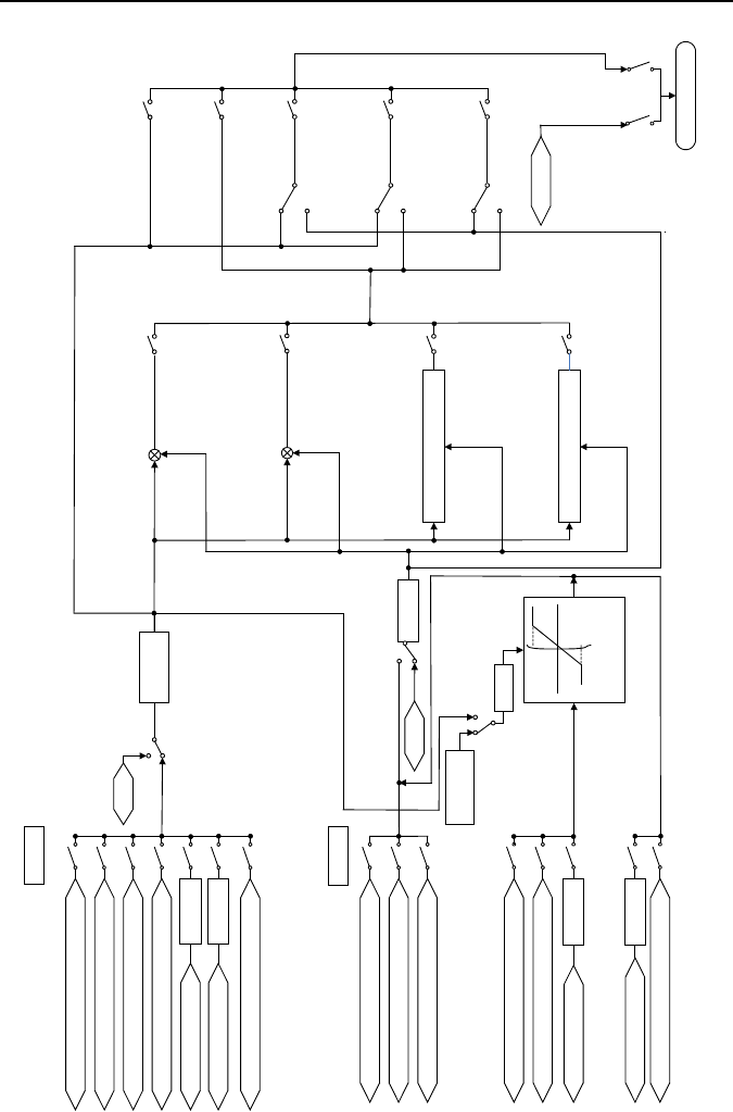
Emotron VSB Instruction Manual Chapter 6 Specification of Parameters
Ter
minal a
nalog i
nput A
I
Multi-s
tep fr
eq cont
rol
Proc
ess PID
contr
ol
Keypad
analo
g input
Communication input
PID
output
Mu
lti
-ste
p f
req
outp
ut
b0-02
“M
aster freq co
mmand switche
d to
digital s
etting
b0-02”t
ermin
al
0
An
alo
g i
nput
AI
Mul
ti-s
tep
fr
eq
cont
rol
Pr
oc
e
ss
PI
D
c
on
tr
o
l
Di
gita
l s
ettin
g (b0-
04) +
ke
ypa
d∧/
∨adj
ust
men
t
D
igi
tal
set
tin
g (
b0-0
4)
+ t
erm
inal
UP
/DO
WN
adju
stment
Keypad potentiometer input
Communication input
b0
-04
“Au
xil
iar
y f
req
com
man
d sw
itc
hed
to
dig
ita
l s
etti
ng
b0-
04”
termin
al
0
No co
mmand,
output
0
B0-08
maximu
m
freq
×b0-06
AuxFreqMax
- A
uxFr
eqM
ax
A
ux
Fr
e
qM
ax
X
axi
s
Y
axi
s
b0-05 = ?
0
1
9
8
6
3
2
1
0
b0-03 =
?
10
9
7
4
3
1
0
2
X and Y linear
computation. Y
ou
tpu
ts
auxi
lia
ry
f
r
eq
c
o
mm
an
d
Auxil
iary f
req
com
mand
Master
freq
command
b0-01 = ?
+
-
+
+
Ma
x (
mast
er
fre
q c
omma
nd,
au
xili
ary
freq co
mmand)
Mi
n (
mas
ter
fre
q c
omm
and,
au
xil
iary
fr
eq c
omm
and
)
1
Computation
option b0-07=
?
0
1
2
3
0
1
0
1
1
0
0
1
2
3
4
Jog freq
Jog
en
abl
ed/
dis
able
d
01
Fre
q f
ina
l c
omma
nd
Freq command b0-00=?
Xi
Xi
Xi
Freq command switch terminal
1
Digit
al setting (b
0-02) + te
rminal
UP/DOW
N
adjustm
ent
PI
D o
utp
ut
Multi-step freq
ou
tpu
t
Fi
g.
6-1
Digital setting (b0-02) + keypad∧/∨adju
stment
- 72 -

Emotron VSB Instruction Manual Chapter 6 Specification of Parameters
b0-00
Frequency command
pattern
Range: 0 - 4
Factory default:
0
0: Master frequency command
Output frequency of drive is determined by master frequency command source b0-01. Refer
to parameters b0-01 and b0-02 for further information.
1: Master & auxiliary computation result
Frequency command is the result of master & auxiliary computation. The master & auxiliary
computation relation is determined by b0-07. Main command is set by b0-01, while auxiliary
is set by b0-03.
2: Switch between master frequency command, and auxiliary frequency command
When b0-00 is set to 2, the switch between master frequency command, and master &
auxiliary computation result can be realized through digital input terminal "frequency
command switchover". When terminal "frequency command switchover" is invalid, command
frequency of the drive will be determined by b0-01. When terminal "frequency command
switchover" is valid, command frequency of the drive will be determined by b0-03 (Auxiliary
frequency command source).
3: Switch between master frequency command, and master & auxiliary computation result
When b0-00 is set to 3, command frequency will de determined by master frequency
command, or master & auxiliary computation result through digital input terminal "frequency
command switchover". When terminal "frequency command switchover" is invalid, command
frequency is determined by b0-01 (master frequency command source). When terminal
"frequency command switchover" is valid, command frequency is determined by master &
auxiliary computation result. The master & auxiliary computation relation is determined by
b0-07.
4: Switch between auxiliary frequency command, and master & auxiliary computation result
When b0-00 is set to 4, command frequency will de determined by auxiliary frequency
command, or master & auxiliary computation result through digital input terminal “frequency
command switchover”. When terminal "frequency command switchover" is invalid, command
frequency is determined by b0-03 (auxiliary frequency command source). When terminal
"frequency command switchover" is valid, command frequency is determined by master &
auxiliary computation result. The master & auxiliary computation relation is determined by
b0-07.
b0-01
Master frequency
command source
Range: 0 - 9
Factory default:
0
0: Digital setting (b0-02) + ∧ / ∨ adjustment on keypad
When the drive is powered up, the value of b0-02 is taken as the master frequency command
which can be adjusted through ∧ / ∨ keys on keypad no matter the drive is running or in
stop.
- 73 -
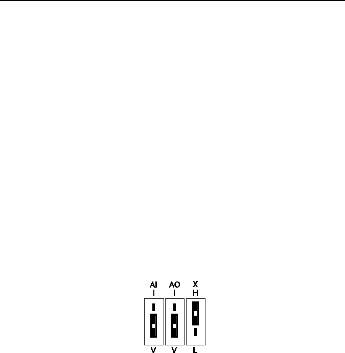
Emotron VSB Instruction Manual Chapter 6 Specification of Parameters
ATTENTION:
Frequency adjustment via ∧ / ∨ on keypad can be cleared through terminal "UP/DOWN (including
∧ / ∨ key) adjustment clear " . Refer to C0-01 - C0-08 for details.
1: Digital setting (b0-02) + terminal UP/DOWN adjustment
When the drive is powered up, the value of b0-02 is taken as the master frequency command.
This frequency can be adjusted via “terminal UP” and “terminal DOWN” no matter the drive is
running or in stop.
When this parameter value is selected, following parameter setting should be performed:
1) Set the two digital input terminals to "terminal UP" and "terminal DOWN" respectively.
Refer to C0-01 - C0-08 for further information.
2) Set terminal UP/DOWN frequency change step size (C0-18).
3) Set C0-17 (terminal UP/DOWN frequency adjustment treatment).
ATTENTION:
Frequency adjustment via terminal UP and DOWN can be cleared through terminal "UP/DOWN
(including ∧ / ∨ key) adjustment clear" . Refer to C0-01 - C0-08 for details.
2: Analogue input AI
(0 - 10V) voltage input and (0 - 20mA) current input are optional for AI, which can be selected
using toggle switch AI on control board.
Fig. 6-2
Refer to specification of C2-00 - C2-12 for corresponding relation between analogue input
and output frequency.
See parameter Group C4 for automatic correction of analogue quantity input.
3: Keypad potentiometer input
Keypad potentiometer input is 0~5V input.
Refer to detailed description of C2-00~C2-20 for corresponding relation between analog
value and frequency.
See parameter group C4 for automatic correction of analog input
6: Process PID output
Command frequency is determined by process closed-loop PID computation result. See
parameter Group F0 for details.
- 74 -

Emotron VSB Instruction Manual Chapter 6 Specification of Parameters
8: Multi-step speed
A total of 8-step speed settings can be realized through status combination of "multi-step
frequency terminal 1 - 3". See the table below for details. Command frequency can be
switched via different combination of multi-step frequency terminals no matter in running or in
stop.
Table 6-1
Multi-step
frequency
terminal 3
Multi-step
frequency
terminal 2
Multi-step
frequency
terminal 1
Command Frequency
OFF
OFF
OFF
Multi-step frequency 0 (F1-00)
OFF
OFF
ON
Multi-step frequency 1 (F1-01)
OFF
ON
OFF
Multi-step frequency 2 (F1-04)
OFF
ON
ON
Multi-step frequency 3 (F1-05)
ON
OFF
OFF
Multi-step frequency 4 (F1-06)
ON
OFF
ON
Multi-step frequency 5 (F1-07)
ON ON OFF
Multi-step frequency 6 (F1-08)
ON
ON
ON
Multi-step frequency 7 (F1-09)
9: Communication
Upper computer is the master frequency command source of the drive through standard
RS485 communication interface on the drive..
refer to Group H0 and appendix on this manual for further information about
communication protocol, and programming, etc.
ATTENTION:
Master frequency command can be forcibly switched to b0-02 via terminal "master
frequency command switched to digital setting b0-02". When this terminal is disabled,
master frequency command is determined by b0-01. When terminal is enabled, master
frequency command shall be the value of b0-02.
b0-02
Digital setting of master
frequency
Range: lower limit frequency -
upper limit frequency
Factory default:
50.00Hz
When master frequency command source b0-01 is set to either 0 or 1, this parameter value will
be the initial value of master frequency command.
b0-03
Auxiliary frequency
command source
Range: 0 - 10
Factory default:
0
- 75 -

Emotron VSB Instruction Manual Chapter 6 Specification of Parameters
0: No command
Auxiliary frequency command is disabled, and auxiliary frequency is 0.
1: Digital setting (b0-04) + ∧ / ∨ adjustment on keypad
When the drive is powered up, the value of b0-04 is auxiliary frequency command, also can
be adjusted through ∧ / ∨ on keypad no matter the drive is running or in stop status.
ATTENTION:
When master frequency command involves ∧ / ∨ adjustment on keypad, ∧ / ∨ involving
auxiliary frequency command shall be disabled.
2: digital setting (b0-04) + terminal UP/DOWN adjustment
When the drive is powered up, the value of b0-04 is current auxiliary frequency command.
Whether the drive is running or stopped, current auxiliary frequency setting can be adjusted
through digital input terminals "UP" and "DOWN”. Just set “terminal UP/DOWN frequency
adjustment treatment” and “terminal UP/DOWN frequency change step size” through C0-17
and C0-18.
ATTENTION:
When master frequency command involves terminal UP/DOWN adjustment, UP/DOWN
adjustment involving auxiliary frequency command shall be disabled.
3: Analogue input AI4: Keypad potentiometer input
7: Process PID output
Auxiliary frequency command is determined by process PID computation result. See
parameter Group F0 for details.
ATTENTION:
In case PID output is also set for master frequency command, the process PID output
for auxiliary frequency command would be disabled.
See b0-05 and b0-06 for information about frequency relation that corresponds to
maximum value of process PID output for auxiliary frequency command.
9: Multi-step speed
A total of 8-step speed settings can be realized through status combination of "multi-step
frequency terminal 1 - 3". Command frequency can be switched via different combination of
multi-step frequency terminals no matter in running or in stop.
ATTENTION:
In case master frequency command is also set to multi-step speed, the multi-step speed
output for auxiliary frequency setting would be disabled.
- 76 -

Emotron VSB Instruction Manual Chapter 6 Specification of Parameters
10: Communication
Upper computer is the auxiliary frequency command source of the drive through standard
RS485 communication interface on the drive. Refer to Group H0 and appendix on this
manual for further information about communication protocol, and programming, etc.
ATTENTION:
Auxiliary frequency command can be forcibly switched to b0-04 via terminal "auxiliary
frequency command switched to digital setting b0-04". When this terminal is disabled,
master frequency command is determined by b0-03. When terminal is enabled, master
frequency command shall be the value of b0-04.
b0-04
Digital setting of
auxiliary frequency
Range: lower limit frequency -
upper limit frequency
Factory default:
0.00Hz
When auxiliary frequency command is set to either 1 or 2, this parameter value should be the
initial value of auxiliary frequency command.
b0-05
Range of auxiliary
frequency
Range: 0 - 1
Factory default: 0
0: Relative to maximum frequency
1: Relative to master frequency
See b0-06 specification for details.
b0-06
Coeff of auxiliary
frequency command
Range: 0.0% - 100.0%
Factory default:
100.0%
When b0-03 selects AI, keypad potentiometer input, or process PID output as auxiliary
frequency command sources, b0-05 and b0-06 will determine the final output value of auxiliary
frequency command.
When b0-05 is set to 0 (relative to maximum frequency):
When AI or keypad potentiometer input is selected for auxiliary frequency command, the
frequency that corresponds to maximum value of the source should be (b0-08×b0-06).
- 77 -
Emotron VSB Instruction Manual Chapter 6 Specification of Parameters
Example:
Select AI as auxiliary frequency command source (set b0-03 to 3) and set AI to curve 1 (unit's
place of C2-00 is 0) as shown in Fig. 6-5. In such a case, the frequency that corresponds to the
maximum input of curve 1 should be: (C2-02) × [(b0-08) × (b0-06)].
Fig. 6-3
When X6/DI pulse input is selected as auxiliary frequency command (set b0-03 to 6), the
frequency that corresponds to maximum DI input should be: (C2-25) × [(b0-08) × (b0-06)].
When PID is selected for auxiliary frequency command, the frequency that corresponds to
maximum value of PID output should be (b0-08) × (b0-06).
PID output diagrammatic sketch is as shown in Fig. 6-4.
Fig. 6-4
When b0-05 is set to 1 (relative to master frequency):
When AI, AI2, EAI, or X6/DI pulse input is selected for auxiliary frequency command
source, the frequency that corresponds to maximum value of these sources should be:
[master frequency × (b0-06)].
Set value that corresponds to
minimum input of curve 1
(C2-04)
Minimum input of
curve 1 (C2
-03)
Maximum
input of curve
1 (C2
-01)
Frequency output
PID output
Maximum value
Corresponding set value
Set value that corresponds to
maximum input of curve 1
(C2-02)
AI analogue
-
-
- 78 -
Emotron VSB Instruction Manual Chapter 6 Specification of Parameters
Example:
When selecting AI as auxiliary frequency command source (set b0-03 to 3) and setting AI to
curve 1 (unit's place of C2-00 is 0), the frequency that corresponds to maximum input of curve
1 should be: (C2-02) × [master frequency × (b0-06)].
When X6/DI pulse input is selected as auxiliary frequency command source (set b0-03 to
6), the frequency that corresponds to maximum DI input should be: (C2-25) × [master
frequency × (b0-06)].
When PID is selected for auxiliary frequency command, the frequency that corresponds to
maximum value of PID output should be [master frequency × (b0-06)].
PID output diagram is as shown in Fig. 6-5.
Fig. 6-5
b0-07
Computation of master
and auxiliary frequency
Range: 0 - 3
Factory default: 0
0: Master + auxiliary
The sum of master and auxiliary frequency is taken as frequency command. Output result is
subject to limitation of upper and lower limit frequency.
1: Master - auxiliary
The difference between master and auxiliary frequency is taken as frequency command.
Output result is subject to limitation of upper and lower limit frequency.
2: Max {master, auxiliary}
Master frequency or auxiliary frequency (whichever has a larger absolute value) is taken as
frequency command. Output result is subject to limitation of upper and lower limit frequency.
3: Min {master, auxiliary}
Master frequency or auxiliary frequency (whichever has a smaller absolute value) is taken as
frequency command. Output result is subject to limitation of upper and lower limit frequency.
Maximum value
PID output
Frequency output
Master command
value × (b0-06)
- 79 -
Emotron VSB Instruction Manual Chapter 6 Specification of Parameters
b0-08 Maximum frequency
Range: Upper limit frequency -
600.00Hz
Factory default:
50.00Hz
b0-09 Upper limit frequency
Range: Lower limit frequency -
maximum frequency
Factory default:
50.00Hz
b0-10 Lower limit frequency
Range: 0.00Hz - upper limit
frequency
Factory default:
0.00Hz
Maximum frequency of b0-08 is the maximum allowable output frequency of drive and is
indicated by fmax in the figure.
B0-09 upper limit frequency is the user-defined maximum allowable running frequency and
represented by fH in Fig. 6-8.
B0-10 lower limit frequency is user-defined minimum allowable running frequency and
marked with fL in Fig. 6-8.
In Fig. 6-8, fN represents rated frequency of motor while VN means the rated voltage of
motor.
Fig. 6-6
ATTENTION:
Maximum frequency, upper limit frequency and lower limit frequency should be set with care
in accordance with nameplate parameters of motor and operation requirements.
Jog and motor parameter identification is free from limitations of upper and lower limit
frequency.
In addition to limitation of upper limit frequency and lower limit frequency, the output
frequency is also subject to limitations of starting frequency, stop DC brake initial frequency,
skip frequency and other parameter settings.
The rank relation between maximum frequency, upper limit frequency and lower limit
frequency is shown as Fig. 6-8.
Upper and lower limit frequencies restrict actual output frequency to motor. If command
frequency is higher than upper limit frequency, the running would be at upper limit frequency.
In case command frequency is lower than lower limit frequency, the running should be in
accordance with the setting of b0-11.
Output voltage
Output frequency
Output frequency
fmax
f
N
fH
fL
0
V
N
- 80 -

Emotron VSB Instruction Manual Chapter 6 Specification of Parameters
b0-11
Operation when command
frequency
lower than lower limit frequency
Range: 0 - 2
Factory default: 0
0: Run at lower limit frequency
In case command frequency is lower than lower limit frequency, the running should be at
lower limit frequency.
1: Run at 0Hz
In case the frequency command is lower than lower limit frequency, the running should be at
0Hz.
2: Stop
If frequency command is lower than lower limit frequency, stop would be activated after the
time delay set by b0-12. When lower limit frequency is 0, this limitation is invalid.
ATTENTION:
This parameter is disabled under PID control mode.
b0-12
Time-delay of stop when
command frequency lower
than lower limit frequency
Range: 0.0s - 6553.5s
Factory default:
0.0s
When b0-11 is set to 2, and command frequency is lower than lower limit frequency, the drive
will stop running after this parameter value.
b0-13
Lower limit of skip
frequency band 1
Range: 0.00Hz - upper limit
frequency
Factory default:
0.00Hz
b0-14
Upper limit of skip
frequency band 1
Range: 0.00Hz - upper limit
frequency
Factory default:
0.00Hz
b0-15
Lower limit of skip
frequency band 2
Range: 0.00Hz - upper limit
frequency
Factory default:
0.00Hz
b0-16
Upper limit of skip
frequency band 2
Range: 0.00Hz - upper limit
frequency
Factory default:
0.00Hz
b0-17
Lower limit of skip
frequency band 3
Range: 0.00Hz - upper limit
frequency
Factory default:
0.00Hz
b0-18
Upper limit of skip
frequency band 3
Range: 0.00Hz - upper limit
frequency
Factory default:
0.00Hz
Skip frequency is a function designed to prevent the drive running at resonance zone of
mechanical system.
At most 3 skip zones can be defined. See Fig. 6-7.
- 81 -

Emotron VSB Instruction Manual Chapter 6 Specification of Parameters
Fig. 6-7
Once parameters of skip zones are set, the output frequency of the drive would
automatically get out of these skip zones even if the command frequency is within these zones.
调节后的频率
设定频率
b
0-13
b0
-14
b0
-
15
b
0
-16
b
0-
17
b0-18
跳跃频率
1
跳跃频率2
跳跃频率3
Frequency after adjustment
Skip frequency band 3
Skip frequency band 2
Skip frequency band 1
Command frequency
- 82 -
Emotron VSB Instruction Manual Chapter 6 Specification of Parameters
ATTENTION:
Output frequency of drive can normally pass through skip zones during Accel and Decel.
b0-19 Jog frequency
Range: 0.00Hz - upper limit
frequency
Factory default:
5.00Hz
This parameter sets the running frequency during jog. Jog Accel time is set by parameter b2-10
while its Decel time by parameter b2-11.
Jog run command control could be performed through keypad, control terminals or
communication input.
Multifunction MF key can be set as forward jog or reverse jog key through parameter
L0-00.
Jog can be realized using "forward jog terminal” and "reverse jog terminal” of DI.
Jog can be realized via communication input. See drive communication protocol for further
information.
See Jog diagrammatic sketch 6-8.
Fig. 6-8
Thereof:
f1 is jog frequency b0-19
t1 represents the ACC time from zero to jog frequency; t1 = (b2-10) × f1/(b0-08); b0-08 is
the maximum frequency.
t2 is the DEC time from jog frequency to 0; t2 = (b2-11) × f1/(b0-08).
ATTENTION:
Set value of jog frequency is free from limitations of upper and lower limit frequency.
Jog is started from starting frequency and its start is not subject to limitation by b1-05.
f
1
运行频率
时间
t1
t2
Running frequency
Time
- 83 -

Emotron VSB Instruction Manual Chapter 6 Specification of Parameters
Group b1 Start/Stop C ontrol
b1-00
Run command
Range: 0 - 2
Factory default: 0
This parameter sets run command source. Run commands include "start, stop, forward and
reverse", etc.
0: Keypad control
Control run command through RUN, STOP/RESET and MF keys on keypad (set
multifunction key MF to JOG by L0-00). Refer to Chapter 4 about the operation of keypad.
1: Terminal control
Control run command via DI terminals. Perform FORWARD and REVERSE by DI terminals.
The control mode are two-wire mode and three-wire mode selectable. See Group C0 for
details of designation and wiring regulation of DI terminals.
2: Communication control
Master device is able to control run command through built-in RS485 serial communication
interface of drive. Refer to parameters Group H0 and appendix for further information about
programming.
Run command from keypad, terminals and communication can be switched by terminals "run
command switched to keypad control", "run command switched to terminal control" and "run
command switched to communication control".
Multifunction key MF can be set to "run command sources shifted" key through parameter
L0-00. When MF key is pressed under this setting, run command will be shifted during keypad
control, terminal control and communication control circularly.
b1-01
Binding of run command
and frequency
command
Range: 000 - AAA
Factory default:
000
This parameter defines the bundled combination of three run command sources and frequency
command sources with the purpose of facilitating simultaneous switching.
For example: frequency command source AI (unit's place of b1-01 is set to 3) bundled with
keypad control, while the frequency command source X6/DI pulse input (ten's place of b1-01 is
set to 6) bundled with terminal control. In such a case, when run command is controlled by
keypad, frequency command source would be AI, while when run command is controlled via
terminals, frequency command source will be automatically switched to X6/DI pulse input.
- 84 -

Emotron VSB Instruction Manual Chapter 6 Specification of Parameters
Unit's place: frequency command source bundled under keypad control
0: No binding
1: Digital setting (b0-02) + ∧ / ∨ adjustment on keypad
2: Digital setting (b0-02) + terminal UP/DOWN adjustment
3: Analogue input AI
4: Keypad potentiometer
7: Process PID output
9: Multi-step frequency
A: Communication input
Refer to parameter b0-01 for details regarding above-mentioned sources of frequency
command.
Decade: frequency command source bundled under terminal control (same as unit's place)
Hundreds place: frequency command source bundled under communication control (same
as unit's place)
ATTENTION:
Different run command sources can be bundled with the same frequency command
source.
The priority of frequency command sources bundled with run command overrides
Group b0.
b1-02
Running direction
Range: 0 - 1
Factory default: 0
This parameter applies to run command controlled by keypad, and disabled under terminal and
communication control.
0: Forward
1: Reverse
b1-03
Reverse disabled
Range: 0 - 1
Factory default: 0
0: Reverse enabled
1: Reverse disabled
In some applications, reverse is likely to result in equipment damage. This parameter is used to
prevent reverse running
.
b1-04
Dead time of forward
and reverse
Range: 0.0s - 3600.0s
Factory default:
0.0s
The dead time with 0Hz output during the transition from forward to reverse, or from reverse to
forward is indicated by letter "t" in Fig. 6-9.
- 85 -
Emotron VSB Instruction Manual Chapter 6 Specification of Parameters
Fig. 6-9 Dead time between forward and reverse
b1-05
Start method
Range: 0 - 3
Factory default: 0
This parameter takes effect during the process of transition from stop status to running status.
0: From start frequency
When drive starts to run from stop status, it starts from start frequency (b1-06) and keeps this
frequency for a period of time set by b1-07, and then accelerated to command frequency in
accordance with the Accel method and time.
1: DC braking then start
To make the motor stop completely, the drive will perform DC braking with a certain period of
time, as specified by b1-08 and b1-09, then start from start frequency (b1-06), keeping a
period of time as specified by b1-07, and then Accelerate to command frequency.
3: Flying start
Trace the actual speed of motor that is rotating and perform smooth start from the traced
speed. This start method is applicable to restart on momentary power loss. To make sure the
accuracy of flying start speed, please correctly set motor parameters, and b1-10~b1-11.
b1-06 Start frequency
Range: 0.00Hz - upper limit
frequency
Factory default:
0.00Hz
b1-07
Holding time of start
frequency
Range: 0.0s - 3600.0s
Factory default:
0.0s
Start frequency is initial output frequency of drive start from stop status. Start frequency holding
time is the continuous running time with start frequency. After this holding time, the drive will
Accelerate to command frequency. Usually appropriate start frequency and holding time assure
the starting torque of heavy-duty load.
ATTENTION:
Provided that command frequency is lower than start frequency, drive output frequency is 0
Hz. Start frequency also works on the transition of forward and reverse, but starting frequency
输出频率
时间
t
Output frequency
Time
- 86 -

Emotron VSB Instruction Manual Chapter 6 Specification of Parameters
holding time is disabled during transition between forward and reverse. Accel time of Group
b2 excludes holding time of start frequency.
b1-08
DC braking current
when start
Range: 0.0% - 100.0%
Factory default:
0.0%
b1-09
DC braking time when
start
Range: 0.00s - 30.00s
Factory default:
0.00s
When the motor is started by the method "DC braking then start", it is essential to set the these
two parameters.100% corresponds to rated current of drive. If braking time is set to 0.0s, DC
braking when start shall be disabled.
b1-10
Flying start
current
0.0%~200.0%
Factory default:
100.0%
Sets flying start current. 100% corresponds to drive rated current.
b1-11
Flying start
deceleration
time
0.1s~20.0s Factory default: 2.0s
Sets flying start output frequency deceleration time, the time from maximum frequency to 0Hz.
The shorter the time is, the faster the flying start operation will be. But shorter flying start
deceleration time will cause unsmoother flying start.
b1-13
Stop method
Range: 0 - 2
Factory default: 0
0: Ramp to stop
Upon the receipt of stop command, drive will gradually decrease output frequency according
to the set Decel time, and stop when frequency attains 0.
1: Coast to stop
Upon the receipt of stop command, drive will immediately lock the output and the motor will
stop with its mechanical inertia.
2: Ramp to stop + DC brake
Upon the receipt of stop command, drive will decrease output frequency in accordance with
the rate of Decel time setting. Once the output frequency attains set value of b1-14, DC
braking will be enabled, and the drive will stop after the finish of DC braking.
b1-14
Start frequency of DC
brake stop
Range: 0.00Hz - upper
limiting frequency
Factory default:
0.00Hz
- 87 -

Emotron VSB Instruction Manual Chapter 6 Specification of Parameters
b1-15 DC brake current Range: 0.0% - 100.0%
Factory default:
0.0%
b1-16 DC brake time Range: 0.00s - 30.00s
Factory default:
0.00s
During the process “ramp to stop + DC braking", DC brake would be started when output
frequency attains set value of b1-14. b1-15 defines brake level, in amps, applied to the motor.
100% corresponds to rated current of drive. B1-16 sets the length of time that DC brake current
is “injected” into the motor when b1-13 is set to 2. In case brake time is set to 0.0s, DC brake
shall be disabled.
If "DC brake stop" terminal enabled, time length of this terminal or b1-16 set time
(whichever is longer) would be taken as stop brake time.
b1-17
Overexcitation brake
Range: 0 - 1
Factory default: 1
0: Disabled
1: Enabled
When overexcitation brake is enabled in case of stop by Decel, the motor shall transform the
electric energy generated during Decel into heat energy by increasing magnetic flux so as to
attain rapid stop. If this parameter is enabled, the Decel time will be shortened. If
overexcitation brake is disabled, the Decel current of motor will decrease and the Decel time
will be lengthened.
b1-18
Dynamic brake
Range: 0 - 1
Factory default: 0
0: Disabled
1: Enabled
When dynamic brake is enabled, the electric energy generated during Decel shall be
converted into heat energy consumed by brake resistor, so as to attain rapid Decel. This
brake method applies to brake of high-inertia load or the situations that require quick stop. In
such a case, it is necessary to select appropriate dynamic brake resistor and brake unit.
b1-19
Dynamic brake
threshold voltage (230V)
Range: 325V~375V
Factory default:
375V
Dynamic brake
threshold voltage (400V)
Range: 650V~750V
Factory default:
720V
When b1-18 is set to 1, when the bus voltage reaches the value set by b1-19, the energy will be
consumed by externally-mounted brake resistor, to guarantee the fast stop. This parameter is
for brake effect setting, according to application requirement.
- 88 -

Emotron VSB Instruction Manual Chapter 6 Specification of Parameters
b1-20
Auto restart when power up
again after power loss
Range: 0 - 1 Factory default: 0
Defines the drive status when power up again after power loss during running
0: Disabled
The drive will not run automatically when power is up after power loss.
1: Enabled.
When run command is controlled by keypad or communication, the drive will run
automatically when power is up again after power loss. When run command is controlled by
terminals, the drive will run automatically only if ON signal from run command terminal is
detected
ATTENTION:
Enable this parameter with caution for safety consideration.
b1-21
Waiting time of auto restart
when power up again
Range: 0.0s - 10.0s
Factory default:
0.0s
This time setting is on the basis of work restoration time of relative devices in the system when
power is up again after power loss, if b1-20 is set to 1.
Group b2 Accel/Decel Parameters
b2-00
Accel/Decel time
resolution
Range: 0 - 2 Factory default: 1
0: 0.01s; the setting range of Accel/Decel time is 0.00s - 600.00s
1: 0.1s; the setting range of Accel/Decel time is 0.0s - 6000.0s
2: 1s; the setting range of Accel/Decel time is 0s - 60000s
Accel/Decel time resolution takes effect on b2-01 - b2-11.
b2-01 Accel time 1 Range: 0s - 60000s
Factory default:
6.0s
b2-02 Decel time 1 Range: 0s - 60000s
Factory default:
6.0s
b2-03 Accel time 2 Range: 0s - 60000s
Factory default:
6.0s
b2-04 Decel time 2 Range: 0s - 60000s
Factory default:
6.0s
b2-05 Accel time 3 Range: 0s - 60000s
Factory default:
6.0s
- 89 -

Emotron VSB Instruction Manual Chapter 6 Specification of Parameters
b2-06 Decel time 3 Range: 0s - 60000s
Factory default:
6.0s
b2-07 Accel time 4 Range: 0s - 60000s
Factory default:
6.0s
b2-08 Decel time 4 Range: 0s - 60000s
Factory default:
6.0s
These parameters b2-01 - b2-08 set the rate of Accel/Decel for speed increase/decrease.
Maximum Freq (b0-08) / Accel time X = Accel Rate X
Maximum Freq (b0-08) / Decel tim e X = Decel Rate X
As the formula sets forth above, Accel time means required time for drive to Accelerate to
maximum frequency b0-08 from zero frequency, while Decel time refers to the time required for
drive to Decelerate to zero frequency from maximum frequency b0-08.
These four types of Accel/Decel time can be selected through the ON/OFF combination of
DI terminals" Accel/Decel time determinant 1" and " Accel/Decel time determinant 2". See
Table 6-5.
Table 6-5
Accel/Decel time
determinant 2
Accel/Decel time
determinant 1
Accel/Decel time
OFF
OFF
Accel/Decel time 1(b2-01, b2-02)
OFF
ON
Accel/Decel time 2(b2-03, b2-04)
ON
OFF
Accel/Decel time 3(b2-05, b2-06)
ON
ON
Accel/Decel time 4(b2-07, b2-08)
ATTENTION:
When the drive is running under simple PLC, the Accel time and Decel time are
determined by simple PLC related parameters, not by the DI terminals. See Group F2
for details.
When Accel/Decel of broken-line style is selected, Accel/Decel time is automatically
switched to Accel/Decel time 1 and 2 according to switching frequency (b2-13 and
b2-14). Under this circumstance, Accel/Decel time selection terminals are disabled.
b2-09
Decel time for
emergency stop
Range: 0s - 60000s
Factory default:
6.0s
In case of emergency stop via multifunction MF key on keypad (MF key has been set to
emergency stop 1 through parameter L0-00), or via DI terminal "emergency stop", Decel is
conducted according to this time. This parameter sets the rate of Decel for speed decrease,
similar with b2-01 - b2-08.
- 90 -

Emotron VSB Instruction Manual Chapter 6 Specification of Parameters
b2-10 Jog Accel time Range: 0s - 60000s
Factory default:
6.0s
b2-11 Jog Decel time Range: 0s - 60000s
Factory default:
6.0s
b2-10 and b2-11 set the rate of Accel/Decel of Jog, similar with b2-01 - b2-08.
b2-12
Accel/Decele curve
Range: 0 - 2
Factory default: 0
0: Linear Accel/Decel
Outputs frequency increases or decreases with a constant rate as shown in Fig. 6-10.
Fig. 6-10
fmax is maximum frequency b0-08.
1: Broken-line Accel/Decel
Accel/Decel time is shifted based on output frequency during Accel/Decel.
When output frequency during Accel is higher than or equal to b2-13 (Accel time switching
frequency of broken-line Accel/Decel), b2-01 (Accel time 1) is enabled. When lower than b2-13,
b2-03 (Accel time 2) will be enabled.
When output frequency during Decel is higher than or equal to b2-14 (Decel time switching
frequency of broken-line Accel/Decel), b2-02 (Decel time 1) is enabled. When lower than b2-14,
b2-04 (Decel time 2) will be enabled.
输出频率
时间
fmax
t2
(减速时间)
t1
(加速时间)
Output frequency
Accel time
Decel time
Time
- 91 -
Emotron VSB Instruction Manual Chapter 6 Specification of Parameters
ATTENTION:
When broken-line Accel/Decel is enabled, " Accel/Decel time determinant 1" and "
Accel/Decel time determinant 2" will be disabled.
Broken-line Accel/Decel is as shown in Fig. 6-11.
Fig. 6-11
t1 = (b2-03)×(b2-13)/(b0-08) t2 =(b2-01)×[f-(b2-13)]/(b0-08)
t3 = (b2-02)×[f-(b2-14)]/(b0-08) t4 = (b2-04)×(b2-14)/(b0-08)
f is current frequency command, and b0-08 is maximum frequency.
2: S-curve Accel/Decel
By adding a period of S-curve time to the initial and ending segments of Accel/Decel, it can
improve the smoothness of start/stop and prevent mechanical impact. See Fig. 6-12:
Fig. 6-12
Accel/Decel rate changes gradually at the initial and ending segments of S-curve time. At
the middle segment of S-curve, it is linear Accel/Decel rate, which is determined by enabled
Accel/Decel time 1 - 4. Therefore, the actual Accel/Decel time is longer than linear Accel/Decel
输出频率
t1
(加速时间)
f
b2-14
b2-13
t2
(加速时间)
t3
(减速时间)
t4
(减速时间)
时间
输出频率
时间
b2-15
b2-16 b2-17
b2-18
f
t1
t2
直线
加速
Output frequency
Time
Accel time
Accel time
Decel time
Decel time
Output frequency
Time
Linear
Accel
- 92 -

Emotron VSB Instruction Manual Chapter 6 Specification of Parameters
if this parameter value is selected.
Actual Accel tim e = linear Accel tim e + (T im e of initial segment of Accel S -curve
+ T ime of last segment of Accel S -curve)/2
Actual Decel time = linear Decel time + (Tim e of initial segment of Decel S -curve + Tim e
of last segment of Decel S -curve)/2
Example:
Assuming that the maximum frequency b0-08 is 50Hz and the Accel time set is 6s, the linear
Accel time from initial status 10Hz to 40Hz = 6s × (40Hz-10Hz)/50Hz = 3.6s
Assuming b2-15 = 0.20s and b2-16 = 0.40s, the actual Accel time under “S-curve
Accel/Decel ” = 3.6s + (0.20s + 0.40s)/2 = 3.9s.
ATTENTION:
Provided the above-noted calculated linear Accel time is less than (Time of initial segment of
Accel S-curve + Time of last segment of Accel S-curve)/2, there will not be linear part. Decel is
the same as above.
b2-13
Accel time switching
frequency of broken-line
Accel/Decel
Range: 0.00Hz -
maximum frequency
Factory default:
0.00Hz
b2-14
Decel time switching
frequency of broken-line
Accel/Decel
Range: 0.00Hz -
maximum frequency
Factory default:
0.00Hz
When b2-12 is set to 1:
b2-01 (Accel time 1) is enabled when output frequency during Accel is more than or equal
to set value of b2-13, while b2-03 (Accel time 2) is enabled when output frequency during Accel
is less than set value of b2-13.
b2- 02 (Decel time 1) is enabled when output frequency during Decel is more than or equal
to set value of b2-14, while b2-04 (Decel time 2) is enabled when output frequency during Accel
is less than set value of b2-14.
ATTENTION:
When broken-line Accel/Decel is selected, terminals "Accel/Decel time determinant 1" and
"Accel/Decel time determinant 2" will be disabled.
- 93 -

Emotron VSB Instruction Manual Chapter 6 Specification of Parameters
b2-15
Time of initial segment of
Accel S-curve
Range: 0.00s - 60.00s Factory default: 0.20s
b2-16
Time of last segment of
Accel S-curve
Range: 0.00s - 60.00s Factory default: 0.20s
b2-17
Time of initial segment of
Decel S-curve
Range: 0.00s - 60.00s Factory default: 0.20s
b2-18
Time of last segment of
Decel S-curve
Range: 0.00s - 60.00s Factory default: 0.20s
- 94 -

Emotron VSB Instruction Manual Chapter 6 Specification of Parameters
Group C Input and O utput Term inals
Group C0 Digital Input
C0-00
Enabled condition of run
command terminals when
power up
Range: 0 - 1 Factory default: 0
This parameter is only for digital terminals with parameter value 1 - 4 (forward/reverse jog, and
forward/reverse running), and also is only for initial running after power up.
0: Trigger edge detected + ON detected
When run command is controlled by terminals, the drive will start to run when it detects that
the terminal jumps from OFF to ON and is kept ON after power up.
If run command terminal is in ON state before power up, the drive will not run after power
up. Under this circumstance, only when the ON state is shifted to OFF and then ON again,
and maintain ON, the drive will start running.
1: ON detected
When run command is controlled by terminals, the drive will start to run when detecting the
command terminal at ON state after power up.
ATTENTION:
When “1: ON detected” selected, the drive will start to run after power up as long as ON of run
command terminal detected. Make sure of the safety of personnel and equipment before this
setting.
C0-01
Function of terminal X1
Range: 0 - 99
Factory default: 3
C0-02
Function of terminal X2
Range: 0 - 99
Factory default: 4
C0-03
Function of terminal X3
Range: 0 - 99
Factory default: 1
C0-04
Function of terminal X4
Range: 0 - 99
Factory default: 23
C0-08
Function of terminal AI (Digital
enabled)
Range: 0 - 99 Factory default: 0
Analogue input terminal AI, can also be used as digital input terminals set by C0-08. When AI is
used as analogue input, C0-08 shall be set to 0.
- 95 -

Emotron VSB Instruction Manual Chapter 6 Specification of Parameters
Table 6-2
Multi-step
frequency
terminal 3
Multi-step
frequency
terminal 2
Multi-step
frequency
terminal 1
Command frequency
OFF OFF OFF
Multi-step frequency 0
(F1-00)
OFF OFF ON
Multi-step frequency 1
(F1-01)
OFF ON OFF
Multi-step frequency 2
(F1-04)
OFF ON ON
Multi-step frequency 3
(F1-05)
ON OFF OFF
Multi-step frequency 4
(F1-06)
ON OFF ON
Multi-step frequency 5
(F1-07)
ON ON OFF
Multi-step frequency 6
(F1-08)
ON ON ON
Multi-step frequency 7
(F1-09)
C0-09
Run or not when drive
restored
0: Run if trig edge +ON
1: Run as long as Run terminal
is ON
Factory default:
0
This parameter works only when Run command is given by terminal.
0: Run if trig edge +ON
When the drive has been restored from fault, external stop, coast stop, emergency stop, etc.,
the drive will start to run when trig edge and ON are both detected.
1: Run as long as Run terminal is ON
When the drive has been restored from fault, external stop, coast stop, emergency stop, etc.,
the drive will start to run as long as the Run terminal is ON.
C0-11
Filtering time of digital
input terminal
Range: 0.000s - 1.000s
Factory default:
0.010s
Set the filtering time of X1~X4, and AI (when used as digital input terminal). Interference
immunity of digital input terminals can be improved by appropriate filtering time. However, the
response time of digital input terminal will become slower when filtering time is increased.
- 96 -

Emotron VSB Instruction Manual Chapter 6 Specification of Parameters
ATTENTION:
Terminal delay time and C0-11 filtering time can be used at the same time. X1 and X2
terminal signals first go through filtering time, then through delay time set by C0-12 and
C0-13. However there is no delay time set for X3 and X4..
C0-12 Delay time of terminal X1 Range: 0.0s - 3600.0s
Factory default:
0.0s
C0-13 Delay time of terminal X2 Range: 0.0s - 3600.0s
Factory default:
0.0s
The delayed response time of digital input terminals X1 and X2 is set by these two parameters.
ATTENTION:
Terminal delay time and C0-11 filtering time can be used at the same time. X1 and X2
terminal signals first go through filtering time, then through delay time set by C0-12 and
C0-13. However there is no delay time set for X3 and X4.
C0-14
Digital input terminal enabled
status setting 1
Range: 0000~1111
Factory default:
1111
Unit's place: X1
0: Positive logic; ON when current passes through
1: Negative logic; ON when no current passes through
Decade: X2 (same as X1)
Hundreds place: X3 (same as X1)
Thousands place: X4 (same as X1)
C0-16
Digital input terminal
enabled status setting 3
Range: 0 - 1 Factory default: 0
This parameter sets the enabled condition of AI as digital input terminal (need to be defined by
C0-08).
Unit's place: AI
0: Positive logic; < 3V, ON; > 7V, OFF
1: Negative logic; < 3V, OFF; > 7V, ON
C0-17
Terminal UP/DOWN frequency
adjustment setting
Range: 0000 - 1111
Factory default:
0100
Unit's place: action when stop
0: Clear
Terminal UP/DOWN frequency adjustment value is cleared when the drive stops.
- 97 -

Emotron VSB Instruction Manual Chapter 6 Specification of Parameters
1: Holding
Terminal UP/DOWN frequency adjustment value is maintained when the drive stops.
Decade: action on power loss
0: Clear
Terminal UP/DOWN frequency adjustment value is cleared in case of power loss.
1: Holding
Terminal UP/DOWN frequency adjustment value is saved in case of power loss.
Hundreds place: integral function
0: No integral function
Adjustment step size is kept constant during terminal UP/DOWN adjustment, in compliance
with C0-18.
1: Integral function enabled
When frequency is adjusted through terminal UP/DOWN, initial step size is set by C0-18.
With the effective lasting time of the terminals, adjustment step size will increase gradually.
Thousands place: UP/DOWN REV setting
0: FWD/REV switch not allowed for UP/DOWM adjustment
UP/DOWN adjustment couldn’t change the run direction
1: FWD/REV switch allowed for UP/DOWM adjustment
UP/DOWN adjustment can change the run direction
C0-18
Terminal UP/DOWN frequency
change step size
Range: 0.00Hz/s -
100.00Hz/s
Factory default:
0.10Hz/s
When frequency command is "digital setting + terminal UP/DOWN adjustment", this parameter
is used to set the step size of frequency adjustment UP/DOWN. The step size is defined as
frequency change per second, and the smallest step size is 0.01 Hz/s.
C0-20
Option of virtual input
terminal
Range: 000 - 10F
Factory default:
000
This parameter is a 9-bit binary numeral. The terminals that correspond respectively to bit8 (the
highest bit of binary system) through bit0 (the lowest bit of binary system) are as follows:
Table 6-3
Hundreds place
Decade
Unit’s place
bit8
bit7
bit6
bit5
bit4
bit3
bit2
bit1
bit0
AI
Reserved
X4
X3
X2
X1
Unit's place: bit0 - bit3 : X1 - X4
0: Actual terminal takes effect
1: Virtual terminal takes effect
- 98 -

Emotron VSB Instruction Manual Chapter 6 Specification of Parameters
Decade:reserved
Hundreds place: bit8 : AI
0: Actual terminal takes effect
1: Virtual terminal takes effect
Virtual terminals simulate actual terminals via communication. Each bit represents one
terminal. When selecting virtual terminal, corresponding bit should be set to 1 in C0-20.
Group C1 Digital O utput
C1-00
Y output function
Range: 0 - 99
Factory default: 0
C1-02
Control panel relay
output function
Range: 0 - 99 Factory default: 14
These two parameters define the function of digital output terminal and control panel relay
output
C1-04
Y output delay time
Range: 0.0s - 3600.0s
Factory default: 0.0s
C1-06
Control board relay
output delay time
Range: 0.0s - 3600.0s Factory default: 0.0s
These two parameters define the time delay of Y output terminal and control board relay output.
C1-08
Enabled state of digital
output
Range: 000 - 101
Factory default:
000
Unit's place: Y
0: Positive logic; ON when current passes through
1: Negative logic; ON when no current passes through
Decade: Reversed
Hundreds place: control board relay output
0: Positive logic; ON when there is coil excitation
1: Negative logic; ON when there is no coil excitation
Fig. 6-1 3
+24V
变
频
器
COM
(i=1,2)
Y(i)
继电器
Drive
Relay
- 99 -

Emotron VSB Instruction Manual Chapter 6 Specification of Parameters
C1-09
Detected object of frequency
doubling technology(FDT)
Range: 00 - 11
Factory default:
00
Unit's place: FDT1 detective object
0: Set value of speed (frequency after Accel/Decel)
FDT1 output frequency is the command frequency after Accel/Decel.
1: Detected speed value
FDT1 output frequency is actually detected or identified frequency. If the drive is under V/f
pattern, it should be output frequency.
Decade: FDT2 detective object
0: Set value of speed (frequency after Accel/Decel)
FDT2 output frequency is the command frequency after Accel/Decel.
1: Detected speed value
FDT2 output frequency is actually detected or identified frequency. If the drive is under V/f
pattern, it should be output frequency.
C1-10 FDT1 upper bound Range: 0.00Hz - maximum FREQ
Factory default:
50.00Hz
C1-11 FDT1 lower bound Range: 0.00Hz - maximum FREQ
Factory default:
49.00Hz
C1-12 FDT2 upper bound Range: 0.00Hz - maximum FREQ
Factory default:
25.00Hz
C1-13 FDT2 lower bound Range: 0.00Hz - maximum FREQ
Factory default:
24.00Hz
These parameters should be set with digital output terminals "FDT1" and "FDT2".
Take FDT1 for example, the drive outputs ON signal when output frequency exceeds upper
bound of FDT1 and will not output OFF signal unless output frequency drops to below lower
bound of FDT1. Please set C1-10 to be larger to some certain extent than C1-11, avoiding
status change frequently. See Fig. 6-14:
- 100 -
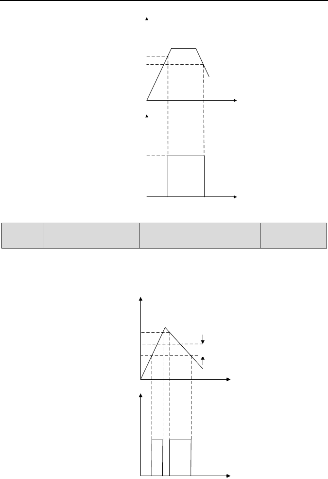
Emotron VSB Instruction Manual Chapter 6 Specification of Parameters
Fig. 6-14
C1-14
Detection width of
frequency attained
Range: 0.00Hz - maximum
FREQ
Factory default:
2.50Hz
This parameter should be set with digital output terminal "frequency attained". When the
difference between output frequency and command frequency is less than this value, terminal
"frequency attained" aoutputs ON. See Fig. 6-15:
Fig. 6-15
时间
输出频率
时间
FDT1电平下限
FDT1
电平上限
FDT1端子
时间
输出
时间
频率到达端子
设定频率
频率检出宽度
Output frequency
FDT1 upper limit
FDT1 lower limit
FDT1 terminal
Time
Time
Output
Command
frequency
Frequency detection width
Time
Frequency attained
terminal
Time
- 101 -

Emotron VSB Instruction Manual Chapter 6 Specification of Parameters
C1-15
Zero current detection
level
Range: 0.0% - 50.0%
Factory default:
5.0%
C1-16 Zero current detection time
Range: 0.01s - 50.00s
Factory default:
0.50s
The two parameters should be set with digital output terminal "zero current detection". When
the drive output current is less than C1-15 and its lasting time attains the value of C1-16,
terminal "zero current detection" outputs ON signal. See Fig. 6-16:
Fig. 6-16
Group C2 Analogue and Pulse Input
C2-00
Analogue input curve
Range: 00 - 11
Factory default: 00
Curves of analogue input AI is selected by this parameter.
Unit's place: AI input curve
0: Curve 1 (2 points)
Defined by C2-01 - C2-04.
1: Curve 2 (4 points)
Defined by C2-05 - C2-12.
Decade: Potentiometer input curve
Same as AI above.
时间
输出电流
时间
零电流检测端子
零电流检出水平
零电流检出
时间
运行
停机
Output current
Run
Stop
Zero current detection level
Time
Zero current detection terminal
Zero
current
detection
time
Time
- 102 -

Emotron VSB Instruction Manual Chapter 6 Specification of Parameters
C2-01 Maximum input of curve 1
Range: minimum input of curve
1 - 110.0%
Factory default:
100.0%
C2-02
Set value corresponding to
maximum input of curve 1
Range: -100.0% to 100.0%
Factory default:
100.0%
C2-03 Minimum input of curve 1
Range: -110.0% to maximum
input of curve 1
Factory default:
0.0%
C2-04
Set value corresponding to
minimum input of curve 1
Range: -100.0% to 100.0%
Factory default:
0.0%
Curve 1 is defined by above-noted 4 parameters.
Input values C2-01 and C2-03:
AI can select 0~10V voltage input or 0~20mA current input by jumper.
If 0~10V is selected: 0V corresponds to 0%, while 10V corresponds to 100%.
If 0~20mA is selected: 0mA corresponds to 0%, while 20mA corresponds to 100%.
Keypad potentiometer only support 0~5V, 0V corresponds to 0%, 5V corresponds to
100%.
Corresponding set values C2-02 and C2-04:
When the corresponding set value is frequency: 100% is the maximum frequency, while
-100% is the maximum negative frequency.
When the corresponding set value is current: 100% means 2 times the rated current of
drive while "less than or equal to 0%" corresponds to zero current.
When corresponding set value is torque: 100% means 2 times the rated torque, while
-100% means negative "2 times the rated torque".
When the corresponding set value is output voltage (e.g. the voltage setting in case of V/f
separated pattern): 100% corresponds to rated voltage of motor. "Less than or equal to
0%" corresponds to 0V voltage.
- 103 -
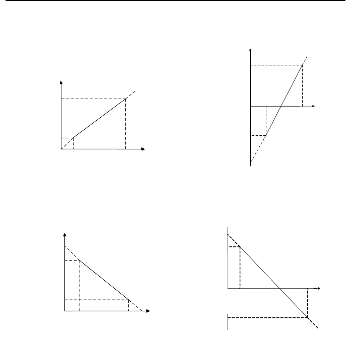
Emotron VSB Instruction Manual Chapter 6 Specification of Parameters
Curve diagram is shown as below:
Fig. 6-17 Fig. 6-18
Fig. 6-19 Fig. 6-20
1
曲线
1
最
小
输入
(
C
2
-
03
)
-
-
Maximum
input of curve
1 (C2-01)
AI
analogue
Corresponding set value
对应设定值
AI
模拟量
曲线1最大输入
(C2-01)
曲线1最
小输入
(
C2-
03)
曲线1
最大输入
对应设定值
(C
2-02
)
曲线1最
小输入
对应设定值
(
C2-04)
对应设定值
AI模拟量
曲线1最大输入
(C2-01)
曲线1最小输入
(C2-03)
曲线1最小输入
对应设定值
(C2-04)
曲线1最大输入
对应设定值
(C2-02)
对应设定值
AI模拟量
曲线1最大输入
(C2-01)
曲线1最小输入
(C2-03)
曲线1最大输入
对应设定值
(C2-02)
曲线1最小输入
对应设定值
(C2-04)
Corresponding set value
Set value that
corresponds to
maximum input of
curve 1 (C2-02)
Set value that
corresponds to
minimum input of
curve 1 (C2
-04)
Minimum
input of curve
1 (C2-03)
Maximum
input of curve
1 (C2-01)
AI analogue
Corresponding set value
Set value that
corresponds to
maximum input of
curve 1 (C2-02)
Set value that
corresponds to
minimum input of
curve 1 (C2
-04)
Minimum
input of
curve 1
(C2
-03)
Maximum
input of curve
1 (C2
-01)
AI analogue
Corresponding set value
Corresponding set value
Set value that
corresponds to
minimum input of
curve 1 (C2
-04)
Set value that
corresponds to
maximum input of
curve 1 (C2-02)
Set value that
corresponds to
minimum input of
curve 1 (C2-
04)
Minimum
input of curve
1 (C2
-03)
Maximum
input of curve
1 (C2-01)
AI
analog
Minimum
input of curve
1 (C2-03)
Set value that
corresponds to
maximum input
of curve 1
(C2-
02)
- 104 -

Emotron VSB Instruction Manual Chapter 6 Specification of Parameters
C2-05
Maximum input of curve 2
Range: input of inflection
point A of curve 2 - 110.0%
Factory default:
100.0%
C2-06
Set value corresponding to
maximum input of curve 2
Range: -100.0% to 100.0%
Factory default:
100.0%
C2-07
Input of inflection point A of
curve 2
Input of inflection point B of
curve 2 - maximum input
of curve 2
Factory default:
0.0%
C2-08
Set value corresponding to
input of inflection point A of
curve 2
Range: -100.0% to 100.0%
Factory default:
0.0%
C2-09
Input of inflection point B of
curve 2
Range: minimum input of
curve 2 - Input of
inflection point A of curve 2
Factory default:
0.0%
C2-10
Set value corresponding to
input of inflection point B of
curve 2
Range: -100.0% to 100.0%
Factory default:
0.0%
C2-11 Minimum input of curve 2
Range: -110.0% to input of
inflection point B of curve 2
Factory default:
0.0%
C2-12
Set value corresponding to
minimum input of curve 2
Range: -100.0% to 100.0%
Factory default:
0.0%
Description of input value of curve 2: Voltage input:
1) With regard to AI, 0% corresponds to 0V or 0mA, while 100% corresponds to 10V or
20mA.
2) Regarding to keypad potentiometer, 0% corresponds to 0V, while 100% corresponds to
5V.
Curve 2 is defined by C2-05~C2-12. The input of curve 2 and the definition of
corresponding set value is the same as AI. The difference is that curve 1 is a straight line
while curve 2 is a broken line with two inflection points. Diagram of curve 2 is shown as
below:
- 105 -
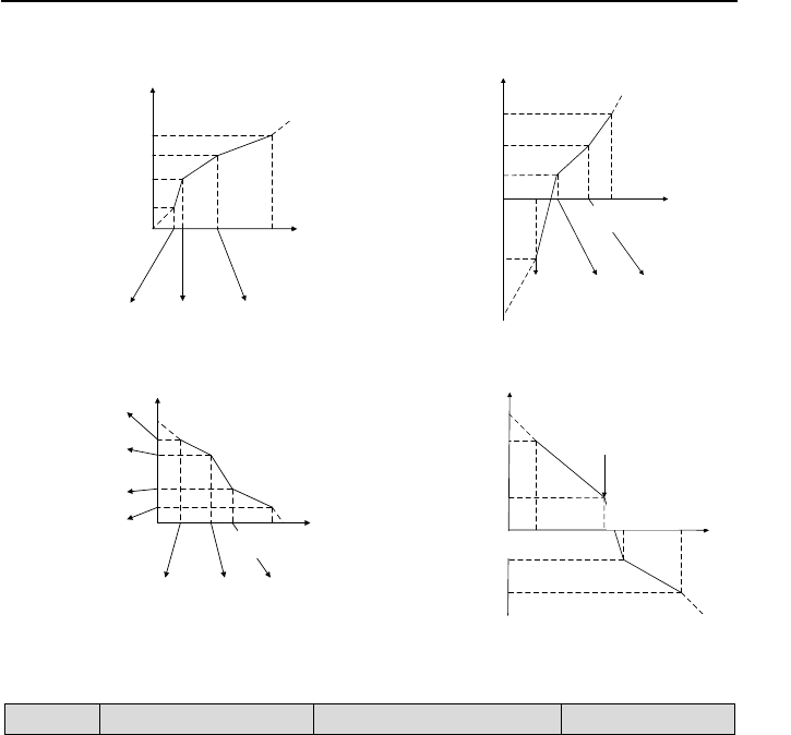
Emotron VSB Instruction Manual Chapter 6 Specification of Parameters
Fig. 6-21 Fig. 6-22
Fig. 6-23 Fig. 6-24
.
C2-20
Interrupt detection time
Range: 0.00s - 100.00s
Factory default: 0.50s
When this parameter value is set to 0.00z it means no interrupt line detection (means no alarm
even out of MIN-MAX).
对应设定值
AI
模拟量
曲线
2最大输入
(C
2
-05
)
曲线2
最
小输入
(
C
2
-11
)
曲线2
最大输入对应
设定值
(C2
-06)
曲线2
最小输入
对应
设定值
(C2
-
12)
A
点
输入
(
C2
-07)
B
点输入
(
C2-
09)
A
点
输入对应
设定值
(
C2
-
08)
B
点
输入
对应
设定值(
C
2-
10
)
对应设定值
AI模拟量
曲线2最大输入
(C2-05)
曲线2最小输入
(C2-11)
曲线2最小输入对应
设定值(C2-12)
曲线
2最大
输入对应
设定值(C2-06)
A点输入
(C2-07)
B点输入
(C2-09)
A点
输入对应设定值
(C2-08)
B点输入对应设定值
(C2-10)
对应设定值
AI模拟量
曲线2最大输入
(C2-05)
曲线2最小输入
(C2-11)
曲线2最小输入对应
设定值(C2-12)
曲线2
最大输入对应
设定值(C2
-06)
A点输入
(C2-07)
B点输入
(C2-09)
A点输入对应的
设定值(C2-08)
B点输入对应的
设定值(C2-10)
对应设定值
AI
模拟量
曲线2最大输入
(C2
-
05)
曲线
2最小输入
(C2-11)
曲线2
最大输入对应
设定值(C2-06
)
曲线2
最小输入
对应
设定值(C2-12
)
A点输入
(C2
-07
)
B点输入
(
C2
-09
)
A点
输入对应
设定值(C2-08)
B点
输入对应
设定值(C2-10)
Corresponding set value
Corresponding set value
Set value that corresponds
to maximum input of curve 2
(C2-06)
Set value corresponds to
point B input (C2-10)
Set value corresponds to
point A input (C2-08)
Set value that corresponds
to minimum input of curve 2
(C2-12)
Minimum input of
curve 2 (C2-11)
Point A input
(C2-07)
Point B input
(C2-09)
Set value that corresponds
to maximum input of curve 2
(C2-06)
Set value corresponds to
point B input (C2-10)
Set value corresponds to
point A input (C2-08)
Maximum input of
curve 2 (C2
-05)
AI analogue
Set value that corresponds
to minimum input of curve 2
(C2-12)
Maximum input of
curve 2 (C2
-05)
AI analogue
Minimum input
of curve 2
(C2-11)
Poi nt A
input
(C2
-07)
Point B input
(C2-09)
Corresponding set value
Corresponding set value
Set value that corresponds
to minimum input of curve 2
(C2-12)
Set value corresponds to
point A input (C2-08)
Set value corresponds to
point B input (C2-10)
Set value that corresponds
to maximum input of curve 2
(C2-06)
Minimum input of
curve 2 (C2-11)
Point A input
(C2-07)
Point B input
(C2
-09)
Maximum input of
curve 2 (C2
-05)
AI analogue
Set value that corresponds
to minimum input of curve 2
(C2-12)
Set value corresponds to
point A input (C2-08)
Set value corresponds to
point B input (C2-10)
Set value that corresponds
to maximum input of curve 2
(C2-06)
Point A input
(C2-07)
Point B input
(C2-09)
Maximum input of
curve 2 (C2
-05)
AI analogue
Minimum input of
curve 2 (C2
-11)
- 106 -
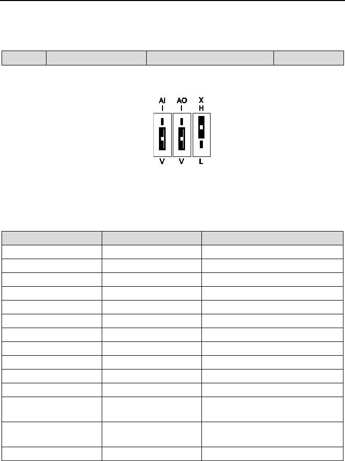
Emotron VSB Instruction Manual Chapter 6 Specification of Parameters
Group C3 Analogue and P ulse O utput
C3-00
AO output function
Range: 0 - 99
Factory default: 2
AO is analog output terminal, whose voltage/current output type can be selected by dip
switch AI. The output is 0~10V as illustrated in Fig. 6-25.
Fig. 6-25
Output range of DO pulse frequency is 0 - C3-09 (maximum output pulse frequency).
The ranges of corresponding digital output of AO, EAO and DO are as shown in the table 6-4.
Table 6-4
Parameter value
Function
Range
0
No output
No output
1
Command frequency
0 - maximum power
2
Output frequency
0 - maximum frequency
3
Output current
0 - 2 times the rated current of inverter
4
Output torque
0 - 2 times the rated torque
5
Output voltage
0 - 2 times the rated voltage of motor
6
Output power
0 - 2 times the rated power
7
Bus voltage
0 - 1000V
9
Torque current
0 - 2 times the rated current of motor
10
Magnetic flux current
0 - 2 times the rated current of motor
11
AI
0 - 10V/0 - 20mA
16
Communication input
percentage
0 - 65535
17
Output frequency before
compensation
0 - maximum frequency
18 - 99
Reserved
- 107 -
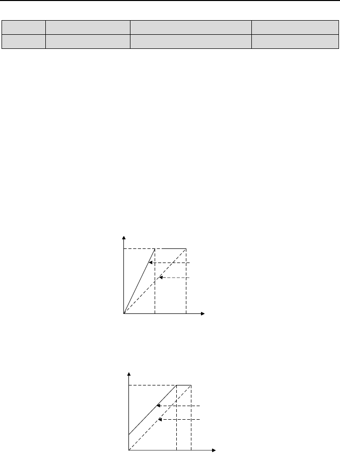
Emotron VSB Instruction Manual Chapter 6 Specification of Parameters
C3-03
AO offset
Range: -100.0% to 100.0%
Factory default: 0.0%
C3-04
AO gain
Range: -2.000 to 2.000
Factory default: 1.000
When users need to chang AO measurement range or correct the error of the meter, it can be
realized by setting of C3-03 and C3-04. If using factory default, 0~10V (or 0~20mA) of AO
corresponds to “0~maximun”. See table 6-4 for details. By expressing standard output of AO as
x, the adjusted AO1 output as y, the gain as k, and the offset as b (100% of offset corresponds
to 10V or 20mA), there is the equation: y=kx+b
Example:
C3-00 is set to 2: output frequency. Standard AO output: AO outputs 0V when output frequency
is 0, and outputs 10V when output frequency is the maximum frequency. If AO is requested to
output 2V when output frequency is 0Hz, and to output 8V when output frequency is the
maximum frequency.
There is: 2=k×0+b; 8=k×10+b. Through these two equations, we obtain: k = 0.6, b = 2V, i.e.
C3-03 is set to 20.0% while C3-04 is set to 0.600.
Additional examples are shown as below:
Fig. 6-26 AO gain influence on output
Fig. 6-27 AO offset influence on output
AO1调整后输出
AO1标准输出
10V
0
10V
5V
(C3-04) = 100%
(C3-04) = 200%
AO1调整后输出
AO1标准输出
10V
0
10V8.5V
(C3-03) = 0%
(C3-03) = 15%
1.5V
AO output after adjustment
AO standard output
AO output after adjustment
AO standard output
- 108 -

Emotron VSB Instruction Manual Chapter 6 Specification of Parameters
C3-05 AO filtering time Range: 0.0s - 10.0s
Factory default:
0.0s
Define output filtering time of AO terminal.
Group C4 Autom atic C orrection of Analogue Input
Parameter Group C4 is used to perform automatic correction of analogue input channels,
obtaining the gain and offset of corresponding channel automatically. They can automatically
modify the measuring range of corresponding channel or correct meter error.
C4-00
Analogue corrected
channel
Range: 0 - 2 Factory default: 0
0: No correction
No correction to any channels.
1: Correct AI
Automatically correct analogue AI channel.
2: Correct AI2
Automatically correct analogue AI2 channel.
C4-01
Sampling value of
calibration point 1 of AI
Range: 0.00V - 10.00V
Factory default:
1.00V
C4-02
Input value of calibration
point 1 of AI
Range: 0.00V - 10.00V
Factory default:
1.00V
C4-03
Sampling value of
calibration point 2 of AI
Range: 0.00V - 10.00V
Factory default:
9.00V
C4-04
Input value of calibration
point 2 of AI
Range: 0.00V - 10.00V
Factory default:
9.00V
C4-05
Sampling value of
calibration point 1 of
Potentiometer
Range: -10.00V to 10.00V
Factory default:
1.00V
C4-06
Input value of calibration
point 1 of Potentiometer
Range: -10.00V to 10.00V
Factory default:
1.00V
C4-07
Sampling value of
calibration point 2 of
Potentiometer
Range: -10.00V to 10.00V
Factory default:
9.00V
C4-08
Input value of calibration
point 2 of Potentiometer
Range: -10.00V to 10.00V
Factory default:
9.00V
- 109 -

Emotron VSB Instruction Manual Chapter 6 Specification of Parameters
Tak e keypad potentiometer for example, automatic correction is as follows
1) Set C4-00 to 2 in stop status and press ENT key to confirm. In this way, keypad
potentiometer is selected as correction channel.
2) Input a relatively low analog voltage (e.g. about 1V) via potentiometer, and input the
theoretical value of this analog voltage by C4-06 after the stabilization of this voltage
input, and then press ENT key to confirm.
3) Input a relatively high analog voltage (e.g. about 5V) via potentiometer, and input the
theoretical value of this analog voltage by C4-08 after the stabilization of this voltage
input, and then press ENT key to confirm.
4) Upon the successful correction, C4-00 parameter will be restored to zero.
ATTENTION:
Set the theoretical value or actual value of analog voltage in C4-06 and C4-08. This
value can be either the set value of analog output of peripheral equipment, or the actual
voltage value of analog input measured by a multimeter or other instruments.
C4-05 and C4-07 are the sampling values of analog input voltage. These values is for
reference only. Do not write the value of C4-05 directly into C4-06, or write the value of
C4-07 directly into C4-08.
- 110 -

Emotron VSB Instruction Manual Chapter 6 Specification of Parameters
Group d Motor and Control Parameters
Group d0 Parameters of Motor
When motor is selected as current load motor, please set motor parameters in Group d0.
d0-00
Type of motor
Range: 0 - 1
Factory default: 0
0: Ordinary motor
1: Variable frequency motor
The major difference between ordinary motor and variable frequency motor lies in the handling
of motor overload protection. Under low speed running, ordinary motor has poor heat
dissipation, so motor overload protection shall be derated at low speed. Since fan-based heat
dissipation of variable frequency motor is not affected by motor speed, low-speed overload
protection is not necessarily derated. Therefore, please set d0-00 to 0 when driving ordinary
asynchronous motor so as to protect the motor reliably.
d0-01 Power rating of motor
Range: 0.4kW -
6553.5kW
Factory default:
model defined
d0-02
Motor rated voltage (220V)
Range: 0V~260V
Factory default: 220V
Motor rated voltage (380V)
Range: 0~480V
Factory default: 380V
d0-03 Rated current of motor Range: 0.0A - 6553.5A
Factory default:
model defined
d0-04 Rated frequency of motor
Range: 0.00Hz -
600.00Hz
Factory default:
50.00Hz
d0-05
Number of poles of motor
Range: 1 - 80
Factory default: 4
d0-06 Rated speed of motor Range: 0 - 65535 r/min
Factory default:
model defined
Above-noted motor parameters must be correctly set according to motor nameplate. Please
select the motor that suits the power class of the drive, or the control performance of the drive
will drop dramatically.
- 111 -

Emotron VSB Instruction Manual Chapter 6 Specification of Parameters
d0-07
Stator resistance R1 of
motor
Range: 0.001Ω - 65.535Ω
Factory default:
model defined
d0-08
Leakage inductance L1 of
motor
Range: 0.1mH - 6553.5mH
Factory default:
model defined
d0-09
Rotor resistance R2 of
motor
Range: 0.001Ω - 65.535Ω
Factory default:
model defined
d0-10
Mutual inductance L2 of
motor
Range: 0.1mH - 6553.5mH
Factory default:
model defined
d0-11 No-load current of motor Range: 0.0A - 6553.5A
Factory default:
model defined
d0-12
Flux weakening coeff 1 of
motor
Range: 0.0000 - 1.0000
Factory default:
model defined
d0-13
Flux weakening coeff 2 of
motor
Range: 0.0000 - 1.0000
Factory default:
model defined
d0-14
Flux weakening coeff 3 of
motor
Range: 0.0000 - 1.0000
Factory default:
model defined
The drive needs above-noted paramters to control its matching motor. If the parameters of
motor is known, just write the actual value into d0-07 - d0-14 correspondingly.
After the identification of parameters of motor, above-noted parameters are automatically
updated and saved. Parameters d0-07 - d0-09 are obtained through static identification, and
parameters d0-07 - d0-14 are obtained through rotation identification. If above-noted
parameters are unknown and it is not allowed to perform motor parameter identification, please
input the parameters manually by referring to parameters of like motors.
If motor power rating d0-01 is changed, d0-02 - d0-14 will be automatically restored to
default setting of the standard motor.
d0-22
Parameter identification of
motor
Range: 0 - 2 Factory default: 0
Parameters for controlling the motor performance are automatically obtained through
parameter identification, and the result will be automatically saved upon the completion of
identification.
Be sure to correctly input motor parameters d0-01 - d0-06 before parameter identification.
0: No action
1: Static identification
Static identification applies to the cases where rotating identification cannot be favorably
performed due to the fact that it is impossible to disengage the motor from its load. After
d0-22 is set to 1 and confirmed, press the key RUN to start static identification. d0-22 will be
restored to 0 upon the successful completion of identification. In this way, parameters d0-07 -
d0-09 are obtained.
- 112 -

Emotron VSB Instruction Manual Chapter 6 Specification of Parameters
2: Rotating identification
To perform rotation identification, it is essential to disengage the motor from its load.
Identification is prohibited when motor is loaded. After d0-22 is set to 2 and confirmed, press
RUN to perform static identification, upon the completion of which, the motor would
accelerate to a fixed frequency in the set ramp-up time, maintaining a period of time, and
then stop by ramp down according to the set ramp down time. In this way, the identification
comes to an end, and d0-22 will be restored to 0. Parameters d0-07 - d0-14 have be
obtained after the successful completion of rotating identification. To perform rotating
identification, please set appropriate ramp-up and ramp-down time (i.e. Accel/Decel time. If
overcurrent or overvoltage fault occurs during identification, please prolong Accel/Decel time
accordingly.
ATTENTION:
Please make sure the motor is in a stationary state before the identification, or
parameter identification cannot be performed normally.
Keypad displays "TUNE" and RUN indicator light is on during identification. RUN
indicator light is off upon the completion of parameter identification.
Once parameter identification fails, the fault code "tUN" shall be displayed.
d0-23
Overload protection mode of motor
Range: 0 - 1
Factory default: 1
This parameter determines motor overload protection mode.
0: No protection
Once 0 is selected, it would be impossible to perform motor overload protection. Please take
care.
1: Judged from motor current
Provide overload protection judged from output current and its lasting time. Overload
protection detection time is set by d0-24..
d0-24
Overload protection
detection time of motor
Range: 0.1min - 15.0min
Factory default:
5.0min
When d0-23 is set to "1: judged from motor current", overload protection time is determined by
this parameter on the basis of the running current being 150% of motor rated current. An alarm
of motor overload fault "oL2" shall be displayed once the lasting time exceeds this parameter
value. Protection time when the running current is other value is automatically calculated
according to inverse time lag characteristic curve. See Fig. 6-28.
- 113 -
Emotron VSB Instruction Manual Chapter 6 Specification of Parameters
Fig. 6-28 Motor protection curve for ordinary motor running at 50Hz
Overload protection is performed for variable frequency motor according to the curve as
shown in Fig. 6-28 at either high or low rotation speed. Due to the fact that fan-based heat
dissipation of ordinary motors become poor at low speed, the protection is derated at low
speed.
Example: when d0-24 is set to 10.0 minutes, and the motor is running at 10Hz input, motor
overload fault "oL2" shall be displayed when the running current is 150% of the motor rated
current with lasting time 4 minutes.
Fig. 6-29 Overload protection curve for ordinary motor running at 10Hz
1
5
10
100% 150% 200%
(d0-24) =10分钟
0
(d0-24) =5分钟
(d0-24) =1分钟
电机电流
电机过载时间
4.0
100% 150% 200%
0
电机电流
电机过载时间
(d0-24) =10分钟
Motor overload time
(d0-24) = 10 minutes
(d0-24) = 5 minutes
(d0-24) = 1 minutes
Motor current
Motor overload time
(d0-24) = 10 minutes
Motor current
- 114 -

Emotron VSB Instruction Manual Chapter 6 Specification of Parameters
d0-27
Flying start Kp
Range: 0.00~655.35
Factory default: 0
d0-28
Flying start Ki
Range: 0.00~655.35
Factory default: 2.00
d0-27 and d0-28 are PI parameters for software-based flying start. Appropriate parameter
values should be set according to real application for a decent flying start.
Group d1 V/f Control Parameters of Motor
Set control parameters in Group d1 when motor is selected as current load motor on which V/f
control is performed.
d1-00
V/f curve setting
Range: 0 - 1
Factory default: 0
Set the relation between output voltage and output frequency of the drive when the motor is
under V/f control.
0: Linear V/f
Applies to general constant-torque load. When drive output frequency is 0, output voltage will
be 0, while when output frequency is rated frequency of motor, the output voltage would be
rated voltage of motor.
1: Broken line V/f (determined by d1-01 - d1-08)
Applies to spin drier, centrifuge, industrial washing machine and other special loads. When
drive output frequency is 0, output voltage will be 0, while when output frequency is rated
frequency of motor, the output voltage would be rated voltage of motor. What is different is
this pattern can set 4 inflection points by d1-01 - d1-08. See Fig. 6-30.
V0, V1, V2, V3 and f0, f1, f2 and f3 in the figure are voltage value and frequency value set by
parameters d1-01 - d1-08.
Fig. 6-30 User-defined segmented V/f curve
输出电压(V)
输出频率(Hz)
f00 f1 f2 f3
电机额定频率
V0
V1
V2
V3
电机额定电压
Output voltage (V)
Rated voltage of
Output frequency (Hz)
Rated frequency of motor
- 115 -
Emotron VSB Instruction Manual Chapter 6 Specification of Parameters
Parameter values 2 - 6 apply to torque-dropped loads such as fans and water pumps. See Fig.
6-31.
Fig. 6-31 1.2 - 2.0 power V/f curve
d1-01 V/f frequency value f3
Range: 0.00Hz - rated
frequency of motor
Factory default:
50.00Hz
d1-02 V/f voltage value V3 Range: 0.0% - 100.0%
Factory default:
100.0%
d1-03 V/f frequency value f2 Range: d1-05 - d1-01
Factory default:
0.00Hz
d1-04 V/f voltage value V2 Range: 0.0% - 100.0%
Factory default:
0.0%
d1-05 V/f frequency value f1 Range: d1-07 - d1-03
Factory default:
0.00Hz
d1-06 V/f voltage value V1 Range: 0.0% - 100.0%
Factory default:
0.0%
d1-07 V/f frequency value f0 Range: 0.00Hz - d1-05
Factory default:
0.00Hz
d1-08 V/f voltage value V0 Range: 0.0% - 100.0%
Factory default:
0.0%
d1-01 - d1-08 is used for broken line V/f mode. Voltage value 100% corresponds to rated
voltage of motor. Please rationally set the values of frequency and voltage at knees on the
basis of characteristics of motor and load. Improper setting may rise output current even burn
0
输出频率(Hz)
输出电压(V)
直线V/f
1.2次幂
1.4次幂
1.6次幂
1.8次幂
2.0次幂
电机额定电压
电机额定频率
Output voltage (V)
power
Rated voltage of motor
SL V/f
Rated frequency of
motor
Output frequency (Hz)
power
power
power
power
- 116 -
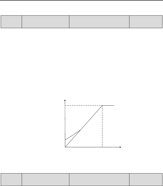
Emotron VSB Instruction Manual Chapter 6 Specification of Parameters
the motor.
d1-09 Torque boost Range: 0.0% - 30.0%
Factory default:
0.0%
Under V/f pattern, output voltage at low frequency can be compensated by this parameter,
improving the torque output. 0.0% corresponds to automatic torque boost, and drive output
voltage is automatically compensated via detection of load current. Automatic torque boost is
valid only for linear V/f pattern.
100% of torque boost corresponds to rated voltage of motor. A non-zero value means the
output voltage rises on the basis of V/f curve and this takes effect at parameter values 0 - 6 of
d1-00. It is suggested this parameter value be gradually increased from zero until the starting
requirement is met. Boost value is not suggested to be set to a relatively big one, as it is likely
to bring about a bigger drive current and higher motor temperature.
Torque boost diagram is shown in Fig. 6-32:
Fig. 6-32
d1-10 Slip compensation gain Range: 0.0% - 400.0%
Factory default:
100.0%
Used under V/f control. When the motor is driving an electric-driven load, motor speed drops
with the increase of load. When the motor is driving a power generating load, motor speed will
increase with the increase of load. Appropriate slip compensation gain can maintain constant
motor speed when the motor load is changing.
To ensure the performance of slip compensation gain, setting motor rated speed d0-06 is
essential. The difference between d0-06 and the motor running speed without load is the rated
slip. Through real-time detection of motor load, slip compensation automatically adjusts the
drive output frequency on the basis of rated slip and motor load, reducing the impact of
changing load on motor speed.
0
输出频率(Hz)
输出电压(
V)
电机额定频率
电机额定电压
提升量
Output frequency (Hz)
Output voltage (V)
Rated voltage of motor
Boost value
Rated frequency of motor
- 117 -
Emotron VSB Instruction Manual Chapter 6 Specification of Parameters
Gain adjustment method: please make the adjustment around 100%. When motor is
driving an electric-driven load: if motor speed is relatively lower, the gain should be
appropriately increased; if motor speed is relatively higher, reduce the gain appropriately. When
motor is driving a power generating load: if motor speed is relatively lower, the gain should be
decreased; if motor speed is relatively higher, increase the gain appropriately.
Diagram of slip compensation gain is shown as Fig. 6-33 and 6-34.
Fig. 6-33 Diagram of slip compensation on electric driven load
Fig. 6-34 Diagram of slip compensation on power generating load
0
电机负载
电机转速
额定负载
n1
= 电机额定转速
n3 = 电机额定转速-额定转差
n2
= 电机额定转速-额定转差
/
2
n
1
n2
n3
转差补偿增益
(d1-10)=100%
转差补偿增益
(d1-10)=50%
转差补偿增益
(d1-10)=0%
0
电机负载
电机转速
额定负载
n1 = 电机额定转速
n3 =
电机额定转速+额定转差
n2 = 电机额定转速+额定转差/2
n1
n2
n3
转差补偿增益
(
d1-10)=100%
转差补偿增益
(d1-10)=0%
转差补偿增益
(d1-10)=50%
Motor speed
Slip compensation gain (d1-10) = 100%
Slip compensation gain (d1-10) = 50%
Slip compensation gain (d1-10) = 0%
n1 = rated speed of motor
n2 = rate
d motor speed - rated slip/2
n3 = rate
d motor speed - rated slip
Rated load
Motor load
Slip compensation gain (d1-10) = 0%
Motor speed
n3 = rated motor speed + rated slip
n2 = rated motor speed + rated slip/2
n1 = rated motor speed
Slip
com
pensation
gain
(d1-
10)
= 100%
Slip
compensation
gain (d1
-
10) =
50%
Rated load
Motor load
- 118 -

Emotron VSB Instruction Manual Chapter 6 Specification of Parameters
d1-12
Current limitation source
Range: 0 - 2
Factory default: 1
0: Disabled
1: Set by d1-13
2: Set by AI
When a non-zero value is set by d1-12, the current limitation is enabled. When output
current rises dramatically because of sharp change of load, instant adjustment of output
frequency will keep the output frequency below the set limitation. When the load is reduced,
output frequency will recover promptly. If the setting speed or motor load change dramatically,
this function can effectively reduce over-current fault.
When current limitation is enabled, the output frequency at constant speed may change at
times and the Accel/Decel time may probably be automatically prolonged. Therefore, this
function should not be used where output frequency or Accel/Decel time is not allowed to
change.
d1-13
Digital setting of current
limit value
Range: 20.0% - 200.0%
Factory default:
160.0%
When d1-12 is set to "1: set by d1-13", the drive keeps output current less than this current limit
value through instantaneous adjustment of output frequency. 100% current limit value
corresponds to rated current of the drive. If this parameter value is set to a relatively big one, it
will increase the chances of over-current. If this parameter value is set to a relatively small one,
it will affect the loaded capability of the drive.
d1-14
Current limit coeff on flux
weakening
Range: 0.001 - 1.000
Factory default:
0.500
When the drive runs at the frequency higher than rated frequency of motor, Accel/Decel
characteristic and output torque can be effectively improved by setting this parameter
appropriately.
d1-15 Energy saving percentage
Range: 0% - 40.0%
Factory default:
0.0%
During no-load or light-load application, load current is detected so as to appropriately reduce
output voltage, reducing the copper loss and iron loss of motor with the purpose of energy
saving. The larger the energy-saving percentage is, the better the energy-saving effect will be,
but the response will be slower. This parameter is applicable to loads such as fan and pump or
light-load for a long time. Where rapid change is required, this parameter is suggested to be
default set 0.0%.
- 119 -

Emotron VSB Instruction Manual Chapter 6 Specification of Parameters
d1-16
V/f oscillation suppression
gain 1
Range: 0 - 3000 Factory default: 8
d1-17
V/f oscillation suppression
gain 2
Range: 0 - 3000 Factory default: 10
Under V/f control, speed and current oscillation is likely to occur due to load vibration, and may
lead to system failure even over current protection. This is particularly obvious during no-load
or light-load applications. The appropriate setting of parameter values of d1-16 and d1-17
would effectively suppress speed and current oscillation. In many case it is not necessary to
modify the default setting. Please make progressive change around default setting, since
excessive setting will influence V/f control performance.
Group d2 Vector Control Parameters of Motor
Set control parameters in Group d2 when motor is selected as current load motor on which
sensor-less vector control is performed.
d2-00
Reserved
Reserved
Reserved
d2-01
ASR high-speed
proportional gain Kp1
Range: 0.0 - 20.0 Factory default: 2.0
d2-02
ASR high-speed
integration time Ti1
Range: 0.000s - 8.000s Factory default: 0.500
d2-03
ASR low-speed
proportional gain Kp2
Range: 0.0 - 20.0 Factory default: 2.0
d2-04
ASR low-
speed integration
time Ti2
Range: 0.000s - 8.000s Factory default: 0.500
d2-05
ASR switching frequency 1
Range: 0.00Hz - d2-06
Factory default: 5.00Hz
d2-06 ASR switching frequency 2
Range: d2-05 - upper
limiting frequency
Factory default:
10.00Hz
Under sensor-less vector control (SVC), motor speed is kept at set value by automatic speed
regulator (ASR). ASR parameters should be set in d2-01 - d2-06.
The proportional gain Kp and integration time Ti of ASR can be set through d2-01 - d2-04
so as to change the speed response characteristic under SVC.
Increment of proportional gain Kp can bring in fast response of the system. However,
bigger Kp value will bring about larger system oscillation.
Reduction of integration time Ti can also quicken response time, but small Ti value will
result in big system overshooting and may easily bring about oscillation.
Principle for adjustment of proportional gain Kp and integration time Ti: proportional gain
Kp is usually adjusted prior, maximizing Kp at the premise of ensuring the system is subject to
no oscillation, and then adjust integration time Ti to provide the system with both instant
- 120 -
Emotron VSB Instruction Manual Chapter 6 Specification of Parameters
response characteristic and less overshooting.
d2-01 - d2-02 are the proportional gain and integration time of the drive at high speed.
d2-03 - d2-04 are the proportional gain and integration time of the drive at low speed.
Distinction between high speed and low speed is determined by d2-05 - d2-06. The
diagram is as shown in Fig. 6-35.
Fig. 6-35
ASR parameters are normally adjusted in the following order: select appropriate switching
frequency. Adjust proportional gain d2 -01 and integration time d2-02 at high speed, ensuring
the system has no oscillation and meets the requirements of dynamic response characteristics.
Adjust proportional gain d2-03 and integration time d2-04 at low speed, ensuring there is no
oscillation at low speed and requirements of dynamic response characteristics are met.
ATTENTION:
Inappropriate parameters of Kp, Ti may bring about overcurrent or overvoltage faults.
Usually, fine adjustment should be performed close to factory default parameter.
d2-07 ASR input filtering time Range: 0.0ms - 500.0ms
Factory default:
0.3ms
Sets the input filtering time of ASR. No need to modify its default setting if there is no special
requirement.
d2-08 ASR output filtering time Range: 0.0ms - 500.0ms
Factory default:
0.3ms
Sets the output filtering time of ASR. No need to modify its default setting if there is no special
requirement.
0
频率
速度环KP
d2-03
d2-01
d2-05 d2-06
0
速度环KI
d2-04
d2-02
d2-05 d2-06
频率
ASR KP
Frequency
ASR KI
Frequency
- 121 -

Emotron VSB Instruction Manual Chapter 6 Specification of Parameters
d2-09
ACR proportion coefficient
Kp
Range: 0.000 - 4.000
Factory default:
1.000
d2-10
ACR integration coefficient
Ki
Range: 0.000 - 4.000
Factory default:
1.000
These two parameters determine the characteristics of automatic current regulator (ACR)
under SVC pattern. Increment of proportion coefficient and/or integration coefficient can
shorten torque response time. Reduction of proportion coefficient an/or integration coefficient
can increase the stability of the system. Inappropriate setting may bring about system
oscillation. Factory default is not needed to be changed in most cases.
d2-11 Pre-excitation time Range: 0.000s - 5.000s
Factory default:
0.200s
Applies to asynchronous motor. To attain quick start, it is necessary to perform pre-excitation
before the running of motor, and the pre-excitation time is set by this parameter. Properly
establish stable flux prior and then ramp up quickly. The set value of 0.000s means "no
pre-excitation" and ramp up at the moment of the receipt of run command. Pre-excitation time
is not included in Accel/Decel time. Factory default is suggested to maintain in most cases.
d2-12
Electric-driven torque
limitation source
Range: 0 - 5 Factory default: 0
Under the pattern of SVC speed control, and when the motor is driving an electric-driven load, it
usually needs to restrict the output torque of the motor. This parameter sets the limitation
command source.
0: d2-14 digital setting
Restrict output torque through digital set parameter d2-14. 100% corresponds to motor rated
torque.
1: Analogue input AI
5: Communication
A superior device sets the limitation value of the output torque through standard RS485
communication interface at the drive. Refer to parameter Group H0 and appendix for details
of communication.
d2-13
Brake torque limitation
source
Range: 0 - 5 Factory default: 0
Under the pattern of SVC speed control, and when the motor is driving a power generating load,
it needs to restrict the output brake torque of the motor. This parameter sets the limitation
command source.
0: d2-15 digital setting
Restrict output brake torque through digital set parameter d2-15. 100% corresponds to rated
torque of the motor.
- 122 -

Emotron VSB Instruction Manual Chapter 6 Specification of Parameters
1: Analogue input AI
5: Communication
A superior device sets the limitation value of the output torque through standard RS485
communication interface at the drive. Refer to parameter Group H0 and appendix for details
of communication.
d2-14
Digital setting of
electric-driven torque
Range: 0.0% - 200.0%
Factory default:
180.0%
When 0 is selected for d2-12, this parameter value limits the maximum output electric-driven
torque. 100% corresponds to rated torque of the motor.
d2-15
Digital setting of brake
torque
Range: 0.0% - 200.0%
Factory default:
180.0%
When 0 is selected for d2-13, this parameter value limits the maximum output brake torque.
100% corresponds to rated torque of the motor.
d2-16
Torque limit coefficient in
flux weakening
Range: 0.0% - 100.0%
Factory default:
50.0%
Under the pattern of SVC speed control, and when the drive is running at frequency higher than
rated frequency (flux weakening zone), appropriate torque limit coefficient can effectively
improve the performance of output torque and Accel/Decel characteristics.
d2-17
Electric-driven slip
compensation gain
Range: 10.0% - 300.0%
Factory default:
100.0%
Under SVC pattern, adjustment of this parameter value can improve the speed accuracy when
driving electric-driven load. If the load is becoming heavier and the motor speed is relatively
lower, set a bigger value, while the motor speed is relatively higher, set a smaller value.
d2-18
Brake slip compensation
gain
Range: 10.0% - 300.0%
Factory default:
100.0%
Under SVC pattern, adjustment of this parameter value can improve the speed accuracy when
driving power generating load. If the load is becoming heavier and the motor speed is relatively
higher, set a bigger value, while the motor speed is relatively lower, set a smaller value.
- 123 -

Emotron VSB Instruction Manual Chapter 6 Specification of Parameters
Group E Enhancement Function and Protection Parameters
Group E0 Enhancement Function
E0-00
Carrier frequency
Range: 0.7 - 12.0kHz
Model defined
With lower carrier frequency, output current of the drive produces higher harmonics, motor loss
increases, and temperature and motor noise rise, but drive temperature, drive leakage current,
and drive interference to external devices are lower or less.
with higher carrier frequency, drive temperature will rise, drive leakage current is bigger,
and drive interference to external devices is bigger. However, motor loss and noise will be lower,
and motor temperature will drop.
The table below specifies the setting range and factory default of PWM carrier frequency of
the drives at different power ratings:
Table 6-5
Power rating of the drive
Setting Range
Factory Default
≤12kW
0.7kHz - 12kHz
8kHz
PWM carrier frequency setting method:
1) When the motor line is too long, reduce carrier frequency.
2) When torque at low speed is unstable, reduce carrier frequency.
3) If the drive produces severe interference to surrounding equipment, reduce carrier
frequency.
4) Leakage current of the drive is big, reduce carrier frequency.
5) Drive temperature rise is relatively high, reduce carrier frequency.
6) Motor temperature rise is relatively high, increase carrier frequency.
7) Motor noise is relatively big, increase carrier frequency.
E0-01 PWM optimization Range: 000 - 021
Factory default:
020
Unit's place: PWM carrier frequency adjusted with temperature
0: Auto-adjust
1: No adjustment
When automatic adjustment of PWM carrier frequency is selected, the drive will
automatically reduce carrier frequency with the temperature rise, protecting itself against
overtemperature. Set to 1 where PWM carrier frequency change is not allowed.
Decade: PWM modulation mode
0: five-segment and seven-segment automatic switchover
1: five-segment mode
- 124 -

Emotron VSB Instruction Manual Chapter 6 Specification of Parameters
2: seven-segment mode
This selection is valid only for V/f control. When five-segment mode is selected, the drive has
low temperature rise but relatively higher output current harmonic. Under seven-segment
mode, it has relatively higher temperature rise but lower output current harmonic. Under
vector control mode pattern, PWM is seven-segment mode.
Hundreds place: over-modulation adjustment
0: Disabled
1: Enabled
At low grid voltage or long-term heavy-duty operation, over-modulation can improve the
voltage utilization and enhance the maximum voltage output capacity of the drive. This
parameter takes effect only for V/f control, while over-modulation is enabled all the time
under vector control pattern.
E0-02
Command when running
time attained
Range: 000 - 111
Factory default:
000
Unit's place: command when consecutive running time attained
0: Continue to run
When consecutive running time of the drive attains the set value of E0-03, the drive will
continue to run.
1: Stop and fault alarm
When consecutive running time of the drive attains the set value of E0-03, the drive will display
fault code "to2" and coast to stop. Digital output terminal "consecutive running time attained"
will output ON. When E0-03 is set to 0, this parameter value is enabled.
Decade: command when accumulative running time reached
0: Continue to run
When accumulative running time of the drive attains the set value of E0-04, the drive will
continue to run.
1: Stop and fault alarm
When the accumulative running time of the drive attains the set value of E0-04, the drive will
display fault code "to3" and coast to stop. Digital output terminal "accumulative running time
attained" will output ON. When E0-04 is set to 0, this parameter value is enabled.
Hundreds place: unit of running time:
0: Second
1: Hour
Sets the unit of E0-03 consecutive running time and E0-04 accumulative running time.
- 125 -

Emotron VSB Instruction Manual Chapter 6 Specification of Parameters
E0-03 Consecutive running time
Range: 0.0 - 6000.0s(h)
Factory default:
0.0 s(h)
When consecutive running time attains this set value, the drive will perform the action set by
unit's place of E0-02. Time unit is set at hundreds place of E0-02. When this parameter value is
set to 0, this function is enabled.
E0-04 Accumulative running time Range: 0.0 - 6000.0s(h)
Factory default:
0.0 s(h)
When accumulative running time of attains this set value, the drive will perform the action set
by decade of E0-02. Time unit is set at hundreds place of E0-02. When this parameter value is
set to 0, this function is enabled.
Group E1 Protection Parameters
E1-00
Overvoltage stall
Range: 0 - 1
Factory default: 1
0: Prohibited
1: Allowed
When the motor is decelerating with a high-inertia load or short-term regenerative braking
occurs during the running, the energy feedback to the drive may raise DC bus voltage, and
thus resulting in overvoltage protection.
When this parameter value is set to 1, the drive will detect its bus voltage and compare
with parameter set by E1-01. If the bus voltage exceeds value of E1-01, drive output
frequency shall be adjusted instantaneously and the deceleration time shall be automatically
prolonged, to maintain the stability of DC bus voltage. Set this parameter to 0 if frequency
fluctuation or Decel time prolonging is not allowed.
- 126 -

Emotron VSB Instruction Manual Chapter 6 Specification of Parameters
E1-01
Overvoltage stall protection
voltage (220V)
Range: 100%~120%
Factory default:
116%
Overvoltage stall protection
voltage (380V)
Range: 120%~150%
Factory default:
135%
When E1-00 is set to 1, if DC bus voltage exceeds this parameter value, it will dynamically
adjust output frequency, prolong deceleration time. This value is a percentage value compared
to standard DC bus voltage.
E1-02
Undervoltage stall
Range: 0 - 1
Factory default: 0
0: Disabled
1: Enabled
Under momentary voltage drop or momentary power loss, the drive will accordingly drop
output frequency, and compensate the voltage drop via the energy feedback from load, so as
to maintain consecutive running, no trip. This function applies to fans and centrifugal pumps
and such.
E1-03 Overload alarm Range: 000 - 111
Factory default:
000
Unit's place: detection option
0: Always detect
Overload alarm works all the time during drive running.
1: Detect at constant speed only
Overload pre-alarm only works during constant-speed running of inverter.
Decade: compared object
0: Rated current of motor
Compared object is the rated current relative to motor, and display "oL2" when the alarm is
given under this setting
1: Rated current of drive
Compared object is the rated current of drive, and display "oL1" when the alarm is given
under this setting.
Hundreds place: alarm option
0: Alarm and continue to run
When drive output current exceeds the level set by E1-04 and the lasting time attains
parameter value of E1-05, the drive will alarm but continue its running.
1: Protection enabled and coast to stop
When drive output current exceeds the level set by E1-04 and the lasting time attains
parameter value of E1-05, the drive will display overload fault and coast to stop.
- 127 -

Emotron VSB Instruction Manual Chapter 6 Specification of Parameters
E1-04 Overload alarm threshold Range: 20.0% - 200.0%
Factory default:
130.0%
When 0 is set at decade of E1-03, this set value is a percentage compared to rated current of
motor. When 1 is set of that, this set value is a percentage compared to rated current of drive.
E1-05
Overload alarm activated
time
Range: 0.1s - 60.0s
Factory default:
5.0s
Sets the lasting time that overload alarm is activated when output current of drive is bigger than
the threshold set by E1-04.
E1-06 Protection action 1 Range: 0000 - 1010
Factory default:
0000
E1-07 Protection action 2 Range: 0000 - 1010
Factory default:
0000
These two parameters set the drive protection action in the following abnormal status.
Specification of E1-06:
Unit's place: reserved
Decade: temperature sampling disconnection action
0: Protection enabled and coast to stop
1: Continue to run
Hundreds place: reversed
Thousands place: abnormal terminal communication
0: Protection enabled and coast to stop
1: Continue to run
Specification of E1- 07:
Unit's place: reserved
Decade: current detection circuit failed
0: Protection enabled and coast to stop
1: Continue to run
Hundreds place: reversed
Thousands place: output phase loss
0: Protection enabled and coast to stop
1: Continue to run
- 128 -

Emotron VSB Instruction Manual Chapter 6 Specification of Parameters
ATTENTION:
Please set "protection action" with caution since inappropriate setting may extend the fault
E1-08
Fault memory after power
loss
Range: 0 - 1 Factory default: 0
Determine whether or not the previous fault code is to be memorized and displayed upon the
power up of the drive after power loss.
0: Not memorized after power loss
1: Memorized after power loss
ATTENTION:
Undervoltage fault "LoU" is not memorized after power loss.
E1-09
Times of automatic reset
Range: 0 - 20
Factory default: 0
E1-10 Interval of automatic reset Range: 2.0s - 20.0s
Factory default:
2.0s
When a fault occurs during the running, the drive will run at 0Hz with the time set by E1-10, and
then the fault will be reset and the drive continues to run. Times of automatic reset is set by
E1-09. Automatic reset is prohibited and fault protection shall be executed immediately when
E1-09 is set to 0.
ATTENTION:
1) Automatic fault reset is not performed at the following types of faults:
Module protection "FAL"
Parameter identification failed "tUN"
Current detection abnormal "CtC"
Ground short circuit protection at output side "GdP"
Analog terminal function conflict “TEr”
External equipment error "PEr"
Consecutive run time attained "to2"
Accumulative run time attained "to3"
Reference protection "oCr"
5V power supply out-of-limit "SP1"
Low voltage protection “LoU”
PID detection out of limit “Plo”
2) Please use automatic fault reset function with caution, or fault expansion may occur.
- 129 -

Emotron VSB Instruction Manual Chapter 6 Specification of Parameters
E1-11 Relay action on drive fault Range: 000 - 111
Factory default:
010
Unit's place: when undervoltage fault occurs
0: No action
1: Action enabled
Set whether or not fault relay acts when undervoltage occurs.
Decade: when fault locked
0: No action
1: Action enabled
Set whether or not the relay acts when the fault locked at latest power loss after power up.
Hundred's place: time of automatic reset
0: No action
1: Action enabled
Set whether or not the relay is to operate when fault occurs in automatic reset status.
E1-13
Drive thermal alarm
threshold
Range: 0.0 °C - 100.0 °C
Factory default:
80.0 °C
Sets the threshold of drive thermal alarm. When the maximum internal temperature of drive is
higher than this value, the drive displays thermal alarm code "oH1", but won’t influence the
running.
- 130 -

Emotron VSB Instruction Manual Chapter 6 Specification of Parameters
Group F Application
Group F0 Process PID
The purpose of process PID control is to make feedback value consistent with the set value.
PID control diagram is as shown in Fig. 6-36.
K
eypad potenti
ometer
AI
AI
Communication input
PID feedback F0-02
+
-
-1
0
1
Proportional gain
Integral gain
0
1
Integral selected by F0-03 decade
Differential gain
Differential limit F0-18
Last integral value
0
1
PID output limit
PID output filter F0-07
Last PID output
0
1
PID stop
Output voltage
0
1
Relationship of freq direction
and run command: the unit of
F0-03
PID initial value F0-19
0
1
PID initial value holding time
0: not attained 1: attained
O
utpu
t f
req
uen
cy
+
+
+
PID feedback
filt
er F0-
06
Proportional gain, integral gain, differential gain decided by F0-08~F0-13
PID integral pause switched
by
di
git
al i
npu
t t
ermi
nal
#3
5
PID pause switched by digital input terminal #34
PID ouTpuT freQuenCy limit: It Is upper limit frequency when the direction is the same
with run command, while it is determined by F0-23 when the direction is opposite
F0-01 digital setting
Communica
tion input
PID setting F0-00
PID setting filter
F0-05
Offset limit F0-17
PID positive and negative
adjustment
Integral stop
Fig. 6-36
V/f separation activated
- 131 -

Emotron VSB Instruction Manual Chapter 6 Specification of Parameters
F0-00
PID setting
Range: 0 - 5
Factory default: 0
Select the setting source of PID control.
0: F0-01 digital setting
1:AI
2:Potentiometer
5: Communication
F0-01 PID digital setting Range: 0.0% - 100.0%
Factory default:
50.0%
When F0-00 is set to 0, this parameter value is taken as set value of PID.
F0-02
PID feedback
Range: 0 - 8
Factory default: 0
Select the feedback source of PID control.
0:AI
8: Communication
F0-03
PID adjustment
Range: 00 - 11
Factory default: 10
Unit's place: output frequency
0: Must be the same direction as setting running direction
When PID frequency output direction is opposite to run command direction, PID output is 0.
1: Opposite direction allowed
PID frequency output direction can be opposite to run command direction, and PID output
performs normally.
Decade: integration selection
0: Integral continued when frequency attains upper/lower frequency
Under PID control, when output frequency attains upper/lower limit of frequency or
parameter value of F0-23 (maximum frequency if it is opposite to command running direction),
PID integral continues. This mode requires longer time of quitting saturation.
1: Integral stopped when frequency attains upper/lower limit
Under PID control, when output frequency attains upper/lower limit of frequency or
parameter value of F0-23 (maximum frequency if it is opposite to command running direction),
PID integral will cease. This mode can quit integral saturation status rapidly.
- 132 -

Emotron VSB Instruction Manual Chapter 6 Specification of Parameters
F0-04
PID positive and negative
adjustment
Range: 0 - 1 Factory default: 0
0: Positive adjustment
1: Negative adjustment
This parameter can be used with digital input terminal "PID adjustment direction" to select
positive or negative adjustment of PID.
Table 6-6
F0-04 PID adjustment direction
terminal
Adjustment
0
OFF
Positive
0
ON
Negative
1
OFF
Negative
1
ON
Positive
Positive adjustment: when feedback signal is smaller than PID setting, output frequency of the
drive will rise to reach PID balance.
when feedback signal is bigger than PID setting, output frequency of the
drive will drop to reach PID balance.
Negative adjustment: when feedback signal is smaller than PID setting, output frequency of the
drive will drop to reach PID balance.
when feedback signal is bigger than PID setting, output frequency of the
drive will rise to reach PID balance.
F0-05 Filtering time of PID setting
Range: 0.00s - 60.00s
Factory default:
0.00s
F0-06
Filtering time
of PID
feedback
Range: 0.00s - 60.00s
Factory default:
0.00s
F0-07 Filtering time of PID output
Range: 0.00s - 60.00s
Factory default:
0.00s
Set the filtering time of PID setting, feedback and output.
F0-08 Proportional gain Kp1 Range: 0.0 - 100.0
Factory default:
50.0
F0-09 Integration time Ti1 Range: 0.001s - 50.000s
Factory default:
0.500s
F0-10 Differential time Td1 Range: 0.0s - 100.0s
Factory default:
0.0s
- 133 -

Emotron VSB Instruction Manual Chapter 6 Specification of Parameters
Process PID is provided with two groups of proportion, integral and differential parameters set
by F0-14. F0-08~F0-10 are the first group of parameters.
Proportional gain Kp: dynamic response of the system can be quickened by increasing
proportional gain Kp. However, excessive Kp value would bring about system oscillation. Only
proportional gain control cannot eliminate steady state error.
Integration time: dynamic response of the system can be quickened by reducing
integration time Ti. However, excessively small Ti value would result in serious system
overshooting and may easily bring about oscillation. Integral control can be used to eliminate
steady state error but is unable to control sharp changes.
Differential time Td: it can predict the change trend of offset and thus can rapidly respond
to the change, improving dynamic performance. However, this is vulnerable to interference.
Please use differential control with caution.
F0-11 Proportional gain Kp2 Range: 0.0 - 100.0
Factory default:
50.0
F0-12 Integration time Ti2 Range: 0.001s - 50.000s
Factory default:
0.500s
F0-13 Differential time Td2 Range: 0.0s - 100.0s
Factory default:
0.0s
Process PID is provided with two groups of proportion, integral and differential parameters set
by F0-14. F0-11 - F0-13 are the second group of parameters.
F0-14
PID parameter switchover
Range: 0 - 2
Factory default: 0
Process PID is provided with two groups of proportional, integral and differential parameters,
which is set by this parameter.
0: No switch, determined by parameters Kp1, Ti1 and Td1
Always determined by Kp1, Ti1 and Td1 set at F0-08 - F0-10.
1: Auto switched on the basis of input offset
When the offset between setting and feedback is less than the set value of F0-15, PID
adjustment is determined by Kp1, Ti1 and Td1. When the offset between setting and
feedback is bigger than the set value of F0-15, PID adjustment is determined by Kp2, Ti2 and
Td2 set at F0-11 - F0-13.
2: Switched by terminal
When digital input terminal "PID parameters switch" is O FF, it is determined by Kp1, Ti1 and
Td1. When "PID parameters switch" is ON, it is determined by Kp2, Ti2 and Td2
F0-15
Input offset under
PID auto switch
Range: 0.0% - 100.0%
Factory default:
20.0%
When F0-14 is set to 1, this parameter sets the switching point of the two groups of PID
- 134 -

Emotron VSB Instruction Manual Chapter 6 Specification of Parameters
parameters.
When the offset between setting and feedback is less than this set value, it is determined
by Kp1, Ti1 and Td1.
When the offset between setting and feedback is bigger than this set value, it is
determined by Kp2, Ti2 and Td2.
F0-16 Sampling period T Range: 0.006s - 50.000s
Factory default:
0.008s
Sampling period aims at feedback. PID controller performs the sampling and compute once in
each sampling period. The longer the sampling period T is, the slower the response time will
be.
F0-17
PID offset limit
Range: 0.0% - 100.0%
Factory default:
0.0%
If the offset between PID feedback and setting is more than this set value, PID regulator will
implement regulation. If the offset between PID feedback and setting is less than this set value,
PID will stop the regulation and the PID controller output will be kept unchanged. This function
can improve the stability of PID performance.
F0-18 PID differential limit Range: 0.0% - 100.0%
Factory default:
0.5%
Sets differential output limit of PID control.
F0-19 PID initial value Range: 0.0% - 100.0%
Factory default:
0.0%
F0-20
Holding time of PID initial
value
Range: 0.0s - 3600.0s
Factory default:
0.0s
PID does not make adjustment when the drive starts its running, but outputs the value set by
F0-19 and maintains the holding time set by F0-20, then starts PID adjustment. When F0-20 is
set to 0, PID initial value is disabled. This function makes PID adjustment get into stable status
fast.
F0-21
PID feedback loss
detection value
Range: 0.0% - 100.0%
Factory default:
0.0%
F0-22
PID feedback loss
detection time
Range: 0.0s - 30.0s
Factory default:
1.0s
When offset between feedback and setting of PID is bigger than set value of F0-21 and the
lasting time attains the set time of F0-22, the drive reports fault "Plo". If F0-22 is set to 0,
feedback loss detection is disabled.
- 135 -

Emotron VSB Instruction Manual Chapter 6 Specification of Parameters
F0-23
Maximum FREQ when
opposite to command direction
Range: 0.00Hz - maximum
frequency
Factory default:
50.00Hz
When run command direction is forward, while PID output is reverse, the maximum reverse
frequency will be determined by F0-23.
When run command direction is reverse, while PID output is forward, the maximum
forward frequency will be determined by F0-23.
F0-24
PID computation option
Range: 0 - 1
Factory default: 0
0: No computation in stop status
1: Computation continued in stop status
Group F1 Multi-step Frequency
F1-00
F
requency command
source of multi-step 0
Range: 0 - 8 Factory default: 0
0: Digital setting F1-02
1: Digital setting b0-02 + keypad ∧ / ∨ adjustment
2: Digital setting b0-02 + terminal UP/DOWN adjustment
3:AI
7: Process PID output
8: Communication
At most 8-step of frequency can be set through the combination of "multi-step frequency
terminals 1 - 3" of digital input. Multi-step frequency 2 - 7 are only digital setting while a number
of setting sources can be selected for multi-step frequency 0 - 1. Parameter value of F1-00
determines command source of step 0.
F1-01
Frequency command
source of multi-step 1
Range: 0 - 8 Factory default: 0
0: Digital setting F1-03
1: Digital setting b0-04 + keypad ∧ / ∨ adjustment
2: Digital setting b0-04 + terminal UP/DOWN adjustment
3:AI
7: Process PID output
8: Communication
At most 8-step of frequency can be set through the combination of "multi-step frequency
terminals 1 - 3" of digital input. Multi-step frequency 2 - 7 are only digital setting while a number
of setting sources can be selected for multi-step frequency 0 - 1. Parameter value of F1-01
determines command source of step 1.
- 136 -

Emotron VSB Instruction Manual Chapter 6 Specification of Parameters
F1-02
Multi-step frequency 0
Lower limit frequency -
upper limit frequency
Factory default:
0.00Hz
F1-03
Multi-step frequency 1
Lower limit frequency -
upper limit frequency
Factory default:
0.00 Hz
F1-04
Multi-step frequency 2
Lower limit frequency -
upper limit frequency
Factory default:
0.00 Hz
F1-05 Multi-step frequency 3
Lower limit frequency -
upper limit frequency
Factory default:
0.00 Hz
F1-06 Multi-step frequency 4
Lower limit frequency -
upper limit frequency
Factory default:
0.00 Hz
F1-07 Multi-step frequency 5
Lower limit frequency -
upper limit frequency
Factory default:
0.00 Hz
F1-08 Multi-step frequency 6
Lower limit frequency -
upper limit frequency
Factory default:
0.00 Hz
F1-09 Multi-step frequency 7
Lower limit frequency -
upper limit frequency
Factory default:
0.00 Hz
At most 8 steps of multi-step frequency can be set by different status combinations of
"multi-step frequency terminals 1 - 4" of digital input, as shown in Table 6-7.
Table 6-7
Multi-step
terminal 4
Multi-step
terminal 3
Multi-step
terminal 2
Multi-step
terminal 1
Command frequency
OFF OFF OFF OFF
Multi-step frequency
0(F1-00)
OFF OFF OFF ON
Multi-step frequency
1(F1-01)
OFF OFF ON OFF
Multi-step frequency
2(F1-04)
OFF OFF ON ON
Multi-step frequency
3(F1-05)
OFF ON OFF OFF
Multi-step frequency
4(F1-06)
OFF ON OFF ON
Multi-step frequency
5(F1-07)
OFF ON ON OFF
Multi-step frequency
6(F1-08)
OFF ON ON ON
Multi-step frequency
7(F1-09)
- 137 -

Emotron VSB Instruction Manual Chapter 6 Specification of Parameters
Group H Communication Parameters
Group H0 MODBUS Communication Parameters
Support universal Modbus protocol. Please refer to appendix for detailed description of
communication protocol.
H0-01
RS-485 port communication
configuration
Range: 0000 - 1154
Factory default:
0002
Unit's place: baud rate
0: 4800bps
1: 9600bps
2: 19200bps
3: 38400bps
4: 57600bps
Decade: data format
0: 1-8-2-N format, RTU
1: 1-8-1-E format, RTU
2: 1-8-1-O format, RTU
3: 1-7-2-N format, ASCII
4: 1-7-1-E format, ASCII
5: 1-7-1-O format, ASCII
Hundreds place: connection type
0: Direct cable connection (232/485)
1: MODEM (232) (reserved)
Thousands place: save type
0: Not saved at power loss
1: Saved at power loss
H0-02
RS-485 communication
address
Range: 0 - 247 Factory default: 1
Sets this drive address. 0 is broadcast address, while available addresses are 1 - 247.
H0-03 Time out detection Range: 0.0s - 1000.0s
Factory default:
0.0s
This parameter sets communication error detection time. When it's set to 0, no communication
error will be reported.
- 138 -

Emotron VSB Instruction Manual Chapter 6 Specification of Parameters
H0-04 Communication time delay Range: 0ms - 1000ms
Factory default:
0ms
Sets response time delay of this drive to the master.
H0-05
Master/Slave option
Range: 0 - 2
Factory default: 0
0: PC controls the drive
PC as master controls the drive. This supports all communication protocols.
1: As master
This drive as master sends current running frequency data through RS-485 port. Data cannot
be received but sent, and the sending data is only running frequency.
2: As slave
Put the received data into b0-02 (digital setting of master frequency) or F0-01 (PID digital
setting) through communication. b0-02/F0-01 is selected by parameter H0-06. Other
communication data addresses are not supported. As slave, this drive can only receive the
data.
H0-06
Parameter store address
Range: 0 - 1
Factory default: 0
0: b0-02
1: F0-01
Enabled when H0-05 is set to 2. This parameter sets the store address of received data when it
works as slave.
H0-07
Proportional factor of received
frequency
Range: 0.0% - 100.0%
Factory default:
100.0%
Enabled when H0-05 is set to 2. Received data is multiplied by H0-07 and then put the result
into the address set by H0-06. This parameter setting is very useful when a master drive control
a number of slave drives and needs to allocate the frequency.
- 139 -

Emotron VSB Instruction Manual Chapter 6 Specification of Parameters
Group L Keys and Display of Keypad
Group L0 Keys of K eypad
L0-01
Keys locked option
Range: 0 - 4
Factory default: 0
0: Not locked
1: Full locked
2: Keys locked other than RUN, STOP/RESET
3: Keys locked other than STOP/RESET
4: Keys locked other than >>
Please refer to Chapter 4 for locking operation of keys.
L0-02
Function of STOP key
Range: 0 - 1
Factory default: 0
0: STOP key valid only when under keypad control
1: STOP key valid under any run command source
L0-03
Frequency adjustment through
keys
∧ / ∨
Range: 0000 - 1111
Factory default:
0100
Unit's place: option on stop
0: Clear on stop
Keys ∧ / ∨frequency adjustment step size is cleared at the stop of drive.
1: Holding on stop
Keys ∧ / ∨frequency adjustment step size is held at the stop of drive.
Decade: option on power loss
0: Clear on power loss
Keys ∧ / ∨ frequency adjustment step size is cleared at power loss.
1: Holding on power loss
Keys ∧ / ∨frequency adjustment step size is saved on power loss.
Hundreds place: integrating option
0: Integrating disabled
Adjustment step size is kept constant when frequency is adjusted by keys ∧ / ∨, and the
adjustment will be performed always with the step size set by L0-04.
1: Integrating enabled
When frequency is adjusted by keys ∧ / ∨, the initial step size is the set value of L0-04. With
the press increase of ∧ / ∨, adjustment step size shows cumulative integrating effect and will
increase gradually.
Thousands place: run direction
0: Run direction not allowed to change
1: Run direction allowed to change
- 140 -

Emotron VSB Instruction Manual Chapter 6 Specification of Parameters
L0-04
Step size of frequency
adjustment through keys
∧ / ∨
Range: 0.00Hz/s -
10.00Hz/s
Factory default:
0.10 Hz/s
When frequency command pattern is "digital setting + keypad ∧ / ∨ adjustment", progressive
increase and decrease of command frequency is realized through ∧ or ∨ on keypad. This
parameter is used to set the step size of frequency adjustment through ∧ / ∨. The step size is
defined as frequency variation per second, and the smallest step size is 0.01 Hz/s.
Group L1 LED Display Setting
L1-00
LED displayed parameters
setting 1 on running status
Range: 0000 – 3FFF
Factory default:
000F
Sets LED displayed parameters on running status. When a number of parameters are selected to be
displayed, skim-through could be performed using key >> on keypad.
0: Display disabled
1: Display enabled
Unit’s place
BIT0: Running frequency (Hz)
BIT1: Command frequency (Hz)
BIT2: Bus voltage (V)
BIT3: Output current (A)
Decade
BIT0: Output torque (%)
BIT1: Output power (kW)
BIT2: Output voltage (V)
BIT3: Motor speed (r/min)
Hundreds place
BIT0: AI (V)
BIT1: Keypad Potentiometer (V)
BIT2: Input terminal status
BIT3: Output terminal status
Thousands place
BIT0: PID setting (%)
BIT1: PID feedback (%)
BIT2: Reserved
BIT3: Reserved
- 141 -

Emotron VSB Instruction Manual Chapter 6 Specification of Parameters
ATTENTION:
When this parameter is set to 0000, running frequency (Hz) is displayed as default.
Example:
To display running frequency, output current, motor speed and AI sampled value, L1-00 should
be: 0000 0001 1000 1001, i.e. set L1-00 to 0189.
L1-02
LED displayed setting on
stop status
Range: 0000 - 033F
Factory default:
0003
Sets LED displayed parameters on stop status. When a number of parameters are selected,
skim-through could be realized via key >> on keypad.
0: Displayed disabled
1: Displayed enabled
Unit's place
BIT0: Command frequency (Hz)
BIT1: Bus voltage (V)
BIT2: Input terminal status
BIT3: Output terminal status
Decade
BIT0: AI (V)
BIT1: Keypad potentiometer (V)
BIT2: Reserved
BIT3: Reserved
Hundreds place
BIT0: PID setting (%)
BIT1: PID feedback (%)
BIT2: Reserved
BIT3: Reserved
Thousands place
BIT0: Reserved
BIT1: Reserved
BIT2: Reserved
BIT3: Reserved
Note: when this function code is set to 0000, the set frequency would be displayed as default
(Hz).
Example:
To display command frequency, bus voltage, AI sampled value, L1-02 should be: 0000 0000 0001
0011, i.e. set L1-02 to 0013.
- 142 -

Emotron VSB Instruction Manual Chapter 6 Specification of Parameters
Group U Monitoring
Group U0 Status Monitoring
All parameters of Group U0 are for display purpose only and can’t be set.
U0-00 Running frequency Range: 0.00Hz - 600.00Hz
Factory default:
0.00Hz
U0-01 Set frequency Range: 0.00Hz - 600.00Hz
Factory default:
0.00Hz
U0-02 Bus voltage Range: 0V - 65535V
Factory default:
0V
U0-03 Output voltage Range: 0V - 65535V
Factory default:
0V
U0-04 Output current Range: 0.0A - 6553.5A
Factory default:
0.0A
U0-05 Output torque Range: 0.0% - 300.0%
Factory default:
0.0%
U0-06 Output power Range: 0.0% - 300.0%
Factory default:
0.0%
U0-09 Master frequency setting Range: 0.00Hz - 600.00Hz
Factory default:
0.00Hz
U0-10 Auxiliary frequency setting Range: 0.00Hz - 600.00Hz
Factory default:
0.00Hz
U0-11 Drive status Range: 0 - 22
Factory default:
00
Unit's place: Running status
0: Accelerating
1: Decelerating
2: Constant speed running
Decade: drive status
0: Stop
1: Running status
2: Auto tuning
- 143 -
Emotron VSB Instruction Manual Chapter 6 Specification of Parameters
U0-12 AI input voltage Range: 0.00V - 10.00V
Factory default:
0.00V
U0-13
Potentiometer input
voltage
Range: -10.00V - 10.00V
Factory default:
0.00V
U0-15 AO output Range: 0.0% - 100.0%
Factory default:
0.0%
U0-18
Status of digital input
terminal
Range: 0 - 7F Factory default: 0
Digital input terminals that correspond to the bits of U0-18 are as shown in Table 6-8:
Table 6-8
Unit’s place
bit3
bit2
bit1
bit0
X4
X3
X2
X1
0 means terminal input status is OFF, while 1 means terminal input status is ON.
For example:
If 3 (i.e. 0011) is displayed at U0-18, it means the input status of terminals X1 and X2 is ON and
that of the other terminals is OFF.
If 5 (i.e. 0101) is displayed at U0-18, it means the input status of terminals X1 and X3 is ON,
while that of the other terminals is OFF.
U0-19
Status of digital output
terminal
Range: 0 - 5 Factory default: 0
Corresponding relationship between digital output terminals and the bits of U0-19 is shown in Table 6-9:
Table 6-9
bit2
bit1
bit0
Control board relay
Reserved
Y
0 means terminal output status is OFF, while 1 means terminal output status is ON.
For example:
If 4 (i.e. 100) is displayed at U0-19, it means control board relay output is ON while that of the
other terminals is OFF.
U0-20 PID set Range: 0.0% - 100.0%
Factory default:
0.0%
- 144 -

Emotron VSB Instruction Manual Chapter 6 Specification of Parameters
U0-21 PID feedback Range: 0.0% - 100.0%
Factory default:
0.0%
U0-22 PID input offset Range: -100.0%
to
100.0%
Factory default:
0.0%
U0-30 Cumulative power-up time Range: 0h - 65535h
Factory default:
0h
U0-31 Cumulative running time Range: 0h - 65535h
Factory default:
0h
U0-33 Inverter bridge temperature Range: -40.0 °C to 100.0 °C
Factory default:
0.0 °C
U0-36
Run command record at LoU
Range: 0 - 1
Factory default: 0
U0-37
Fault code record at LoU
Range: 0 - 100
Factory default: 0
U0-39
Current detection fault source
Range: 0 - 3
Factory default: 0
0: No fault source
1: IU
2: IV
3: IW
U0-42
Higher-place numeric of
keypad ∧ / ∨ stored
value
Range:0, - Factory default: 0
U0-43
Lower-place numeric of
keypad ∧ / ∨ stored
value
Range: -999.9 - 600.0Hz
Factory default:
0.0Hz
U0-44
Higher-place numeric of
terminal UP/DOWN stored
value
Range:0, - Factory default: 0
U0-45
Lower-place numeric of
terminal UP/DOWN stored
value
Range: -999.9 - 600.0Hz
Factory default:
0.0Hz
- 145 -

Emotron VSB Instruction Manual Chapter 6 Specification of Parameters
Group U1 Fault R ecord
U1-00
Code of fault 1
Range: 0 - 46
Factory default: 0
U1-01
Running frequency when the
latest fault occurred
Range: 0.00Hz - 600.00Hz
Factory default:
0.00Hz
U1-02
Output current when the
latest fault occurred
Range: 0.0A - 6553.5A Factory default: 0.0A
U1-03
Bus voltage when the latest
fault occurred
Range: 0V - 10000V Factory default: 0V
U1-05
Inverter bridge temperature
when the latest fault
occurred
Range: -40.0 °C
to
100.0 °C
Factory default:
0.0 °C
U1-06
Status of input terminal when
the latest fault occurred
Range: 0000 - FFFF Factory default: 0000
U1-07
Status of output terminal
when the latest fault
occurred
Range: 0000 - FFFF Factory default: 0000
U1-08
Cumulative running time
when the latest fault
occurred
Range: 0h - 65535h Factory default: 0h
Check the information of the latest fault. See Chapter 7 for details of fault codes.
U1-09
Code of fault 2
Range: 0 - 46
Factory default: 0
U1-10
Running frequency when
previous fault occurred
Range: 0.00Hz - 600.00Hz
Factory default:
0.00Hz
U1-11
Output current when
previous fault occurred
Range: 0.0A - 6553.5A Factory default: 0.0A
U1-12
Bus voltage when previous
fault occurred
Range: 0V - 10000V Factory default: 0V
U1-14
Inverter bridge temperature
when previous fault occurred
Range: -40.0 °C to 100.0 °C
Factory default:
0.0 °C
U1-15
Status of input terminal when
previous fault occurred
Range: 0000 - FFFF Factory default: 0000
U1-16
Status of output terminal
when previous fault occurred
Range: 0000 - FFFF Factory default: 0000
U1-17
Cumulative running time
when previous fault occurred
Range: 0h - 65535h Factory default: 0h
Check the information of previous fault. See Chapter 7 for details of fault codes.
- 146 -

Emotron VSB Instruction Manual Chapter 6 Specification of Parameters
U1-18
Code of fault 3
Range: 0 - 46
Factory default: 0
U1-19
Running frequency when
before-previous fault
occurred
Range: 0.00Hz - 600.00Hz
Factory default:
0.00Hz
U1-20
Output current when
before-previous fault
occurred
Range: 0.0A - 6553.5A Factory default: 0.0A
U1-21
Bus voltage when
before-previous fault
occurred
Range: 0V - 10000V Factory default: 0V
U1-23
Inverter bridge temperature
when before-previous fault
occurred
Range: -40.0 °C
to
100.0 °C Factory default: 0.0 °C
U1-24
Status of input terminal
when
before-previous fault
occurred
Range: 0000 - FFFF Factory default: 0000
U1-25
Status of output terminal
when before-previous fault
occurred
Range: 0000 - FFFF Factory default: 0000
U1-26
Cumulative running time
when before-previous fault
occurred
Range: 0h - 65535h Factory default: 0h
Check the information of before-previous fault (the fault sequence: before-previous fault,
previous fault, latest fault). See Chapter 7 for details of fault codes
- 147 -

Emotron VSB Instruction Manual Chapter 7 Troubleshooting
Chapter 7 Troubleshooting
7.1 Fault Causes and Troubleshooting
Once drive fault occurs, please identify the causes of fault carefully and make a detailed record
of fault symptom. To seek services, please contact the dealer.
Parameters U1-00, U1-09 and U1-18 are used to view the fault history of fault 1 (fault 1 =
the most recent fault), fault 2 (fault 2 = the second most recent fault), and fault 3 (fault 3 = the
third most recent fault). Faults are recorded with numeric codes (0~46), while the fault
information that corresponds to each numeric fault code is specified in the table below.
ATTENTION:
When a fault occurs, please identify the causes and seek solutions according the guidance
in the table. If the fault fails to be solved, do not apply power to the drive again. Contact the
supplier for service in time
Table of Fault C odes
Fault
code
Fault
Display
Fault description Causes Solutions
1 oC1
Accel
overcurrent
Torque boost is too big
under V/f control
Reduce torque boost
value
Starting frequency is too
high
Drop starting frequency
Accel time is too short
Prolong the Accel time
Motor parameters are
improperly set
Set the parameters
correctly according to
motor nameplate
Output short circuit
(phase-to-phase short
circuit or output ground
short circuit)
Check motor connection
and output ground
impedance
Overload is too heavy
Reduce the load
Inappropriate V/f curve
under V/f control
Set V/f curve correctly
Restart the rotating
motor
Reduce current limited
value or start through
speed search
- 148 -

Emotron VSB Instruction Manual Chapter 7 Troubleshooting
Fault
code
Fault
Display
Fault description Causes Solutions
2 oC2
Constant-speed
overcurrent
Output short circuit
(phase-to-phase short
circuit or output ground
short circuit)
Check motor connection
and output ground
impedance
Overload is too heavy
Reduce the load
Power rating of the drive
is relatively small
Select appropriate drive
power rating
Input voltage is too low
Check power grid
voltage
3 oC3
Decel
overcurrent
Output short circuit
(phase-to-phase short
circuit or output ground
short circuit)
Check motor connection
and output ground
impedance
Load inertia is too big
Use dynamic brake
Decel time is too short
Prolong the Decel time
Input voltage is too low
Check power grid
voltage
4 ov1
Accel
overvoltage
Load inertia is too big
Use dynamic brake
Abnormal input voltage
Check power grid
voltage
Output short circuit
(phase-to-phase short
circuit or output ground
short circuit)
Check motor connection
and output ground
impedance
5 ov2
Constant-speed
overvoltage
Load variation is too big
Check the load
Abnormal input voltage
Check power grid
voltage
Output short circuit
(phase-to-phase short
circuit or output ground
short circuit)
Check motor connection
and output ground
impedance
Improper parameter
setting of regulator under
SVC control
Properly set regulator
parameters
6 ov3
Decel
overvoltage
Load inertia is too big
Use dynamic braking
Abnormal input voltage
Check power grid
voltage
- 149 -

Emotron VSB Instruction Manual Chapter 7 Troubleshooting
Fault
code
Fault
Display
Fault description Causes Solutions
Output short circuit
(phase-to-phase short
circuit or output ground
short circuit)
Check motor connection
and output ground
impedance
Improper parameter
setting of regulator under
SVC control
Properly set regulator
parameters
Decel time is too short
Prolong the Decel time
7 FAL
Module
protection
Output short circuit
(phase-to-phase short
circuit or output ground
short circuit)
Check motor connection
and output ground
impedance
Fan damaged or air duct
blocked
Clear the air duct or
replace the fan
Direct connection of
inverter module
Seek services
Switching power supply
damaged
Seek services
Control board abnormal
Seek services
Ambient temperature is
too high
Reduce ambient
temperature
Loose connection of
control board
Pull out and reinsert the
cables of control board
Overvoltage or
overcurrent
Handle it with the
solutions of overvoltage
or overcurrent
8 tUN
Parameter
identification
failed
Bad motor connection
Check motor connection
Identification during
rotation of the motor
Identification in
stationary status of the
motor
Bias between motor
parameters and their
setting is too big
Set the parameters
correctly according to
motor nameplate
9 oL1
Drive
overloaded
Torque boost is too big
under V/f control
Reduce torque boost
value
Starting frequency is too
high
Drop starting frequency
- 150 -

Emotron VSB Instruction Manual Chapter 7 Troubleshooting
Fault
code
Fault
Display
Fault description Causes Solutions
Accel/Decel time is too
short
Prolong the Accel/Decel
time
Motor parameters are
improperly set
Set the parameters
correctly according to
motor nameplate
Output short circuit
(phase-to-phase short
circuit and output ground
short circuit)
Check motor connection
and output ground
impedance
Load is too heavy
Reduce the load
Inappropriate V/f curve
under V/f control
Set V/f curve correctly
Restart the rotating
motor
Reduce current limited
value or start through
speed search
10 oL2
Motor
overloaded
Torque boost is too big
under V/f control
Reduce torque boost
value
Inappropriate V/f curve
under V/f control
Set V/f curve correctly
Motor parameters are
improperly set
Set the parameters
correctly according to
motor nameplate
Improper setting of motor
overloaded protection
time
Properly set the motor
overloaded protection
time
Motor stalled or sharp
variation of load
Identify the causes of
motor stalling or check
the load condition
Long-term running of
ordinary motor at low
speed with heavy load
Select variable
frequency motor
11 CtC
Current
detection
abnormal
Abnormal connection of
control board
Seek services
Switching power supply
damaged
Seek services
Hall device damaged
Seek services
Output ground leakage
Seek services
- 151 -

Emotron VSB Instruction Manual Chapter 7 Troubleshooting
Fault
code
Fault
Display
Fault description Causes Solutions
current is too big
12 GdP
Output ground
short-circuit
protection
Output connection
ground short circuit
Check motor connection
and output ground
impedance
Motor insulation
abnormal
Check the motor
Inverter module
abnormal
Seek services
Output ground leakage
current is too big
Seek services
13 ISF
Input power
supply abnormal
Serious voltage
imbalance among three
phases of power supply
Check power grid
voltage
Abnormal bus
capacitance
Seek services
Abnormal input wiring of
power supply
Check power supply
input wiring
14 oPL
Output phase
loss
Motor cable connection
abnormal
Check motor connection
Imbalance among motor
three phases
Check or replace the
motor
Incorrect setting of vector
control parameters
Correctly set vector
control parameters
16 oH1
Heat sink
thermal
protection
Ambient temperature is
too high
Drop ambient
temperature
Fan damaged
Replace the fan
Air duct blocked
Clear air duct
Temperature sensor
abnormal
Seek services
Inverter module
abnormal
Seek services
18 oH3
Module
temperature
detection
undisconnected
Module detection circuit
damaged
Seek services
Thermistor damaged Seek services
Ambient temperature is
Raise ambient
- 152 -

Emotron VSB Instruction Manual Chapter 7 Troubleshooting
Fault
code
Fault
Display
Fault description Causes Solutions
too low
temperature
24 PEr
External
equipment error
External fault terminal is
enabled
Check the status of
external fault terminal
Stall condition lasts too
long
Check if the load is
abnormal
26 to2
Consecutive
running time
attained
"Consecutive running
time attained" enabled
See specification of
Group E0
27 to3
Cumulative
running time
attained
"Cumulative running time
attained" enabled
See specification of
Group E0
31 TrC
Port
communication
abnormal
Improper setting of baud
rate
Set properly
Communication port
disconnection
Reconnect
Upper computer/device
does not work
Make upper
computer/device work
Drive communication
parameter error
Set properly
37 oCr
Benchmark
protection
Switching power supply
damaged
Seek services
Control board damaged
Seek services
38 SP1
5V power supply
out-of-limit
Switching power supply
damaged
Seek services
Control board damaged
Seek services
40 AIP
AI input
out-of-limit
Control board damaged
Seek services
AI input is too high or low
Set AI input within
correct range
41 LoU
Undervoltage
protection
Input voltage abnormal
Check input power grid
voltage
Switching power supply
abnormal
Seek services
45 Plo
PID detection
out-of-limit
PID feedback channel
abnormal
Check the feedback
channel
Inappropriate setting of
PID parameters
Set properly
- 153 -

Emotron VSB Instruction Manual Chapter 7 Troubleshooting
Fault
code
Fault
Display
Fault description Causes Solutions
46 ICF
Inside
communication
fault
Drive chip abnormal
Seek services
Severe noise on site
Take corresponding
countermeasures to the
noise or seek service
- 154 -

Emotron VSB Instruction Manual Chapter 8 Maintenance
Chapter 8 Maintenance
Ambient temperature, humidity, salt mist, dust, vibration, aging and wear of internal
components may result in drive faults. Routine maintenance shall be performed during the use
and storage.
ATTENTION:
Please make sure the power supply of the drive has been cut off, and DC bus voltage has
discharged to 0V before the maintenance.
8.1 Routine Inspection
Please use the drive in the environment recommended by this manual, and perform routine
inspection in accordance with the table below.
Inspection
items
Inspection aspects
Inspection
methods
Criteria
Operating
environment
Temperature
Thermometer
-10 °C to 50 °C
Humidity Hygrometer
5% - 95%, condensation not
allowed
Dust, oil stains,
moisture and
water-drop
Visual
inspection
No filthy mud, oil stains and water
drop
Vibration Observation
Smooth running. No abnormal
vibration
Gas
Smell
, visual
inspection
No peculiar smell and abnormal
smoke
Drive
Noise
Listen
No abnormal noise
Gas
Smell
, visual
inspection
No peculiar smell and abnormal
smoke
Appearance
Visual
inspection
No defect and deformation
Heat dissipation and
temperature rise
Visual
inspection
No dust and/or fiber particles in
air duct, normal working of fans,
normal air speed and volume, no
abnormal temperature rise
- 155 -

Emotron VSB Instruction Manual Chapter 8 Maintenance
Inspection
items
Inspection aspects
Inspection
methods
Criteria
Motor
Thermal status Smell
No abnormal heating and
scorching smell
Noise Listen No abnormal noise
Vibration
Observe,
listen
No abnormal vibration and sound
Running
status
parameters
Power supply input
current
Ammeter In the range of requirement
Power supply input
voltage
Voltmeter In the range of requirement
Drive output current
Ammeter
In the range of requirement
Drive output voltage Voltmeter In the range of requirement
Temperature Thermometer
The difference between U0-33
displayed temperature and
ambient temperature does not
exceed 40 °C
8.2 Regular Maintenance
Users should perform regular inspection of the drive every 3 - 6 months, so as to eliminate the
potential faults.
ATTENTION:
Please make sure power supply of the drive has been cut off, and DC bus voltage has
been discharged to 0V prior to maintenance.
Never leave screws, gaskets, conductors, tools and other metal articles inside the drive.
Failure to comply may result in equipment damage.
Never modify the interior components of the drive in any condition. Failure to comply
may result in equipment damage.
Inspection items Measures
Check if control terminal screws are loose Tighten
Check if main circuit terminal screws are loose Tighten
Check if ground terminal screws are loose Tighten
Check if copper bar screws are loose Tighten
Check if drive mounting screws are loose Tighten
- 156 -

Emotron VSB Instruction Manual Chapter 8 Maintenance
Inspection items
Measures
Check if there are damage on power cables and
control cables
Replace the damaged cables
Check if there is dust on circuit board Clear it up
Check if air duct is blocked Clear it up
Check if drive insulation is damaged
Test the ground terminal with
500V megameter after all input
and output terminals are
short-
circuited via conductors.
Ground test on individual
terminals is strictly prohibited
since this may cause damage to
inverter.
Check if motor insulation is damaged
Remove input terminals U/V/W of
motor from drive
and test the
motor alone with 500V
megameter.
Failure to comply
may result in drive damage.
Check if the storage period of the drive is over two
years
Carry out power-on test, during
which, the voltage should be
boosted to rated value gradually
using a voltage regulator; be
sure to run at no load for more
than 5 hours.
- 157 -

Emotron VSB Instruction Manual Chapter 8 Maintenance
8.3 Replacement of Vulnerable Parts
Vulnerable parts of drive include cooling fan, electrolytic capacitor, relay or contactor etc. The
service lives of these parts are subject to environment and working conditions. To maintain a
favorable operating environment is conducive to improving the service life of parts and
components; routine inspection and maintenance also contributes to effective improvement of
parts' service life. To prolong the service life of entire drive, the cooling fan, electrolytic
capacitor, relay or contactor and other vulnerable parts should be subjected to routine
inspection according to the table below. Please replace the abnormal parts (if any) in time.
Vulnerable
parts
Service life Cause of damage Criteria
Fan
30,000 -
40,000h
Wear of bearing and
aging of blade
Check if fan blades have
cracks
Check if there is abnormal
vibration and noise on working
- 158 -

Emotron VSB Instruction Manual Chapter 8 Maintenance
8.4 Storage
Storage environment should meet the requirements as set forth in the table below.
Items Requirements
Recommended storage method and
environment
Storage
temperature
-40 to +70 °C
In case of long-term storage, areas with an
ambient temperature of less than 30 °C are
recommended
Avoid the storage in areas where
temperature shock may result in
condensation and freezing
Storage
humidity
5 - 95%
Product could be sealed with plastic film and
dessicant
Storage
environment
A space with low vibration and
low content of salt where there
is no direct exposure to
sunlight, dust, no corrosive or
flammable gas, oil stain, vapor
and water drop
Product could be sealed with plastic film and
dessicant
ATTENTION:
Since long-term storage may lead to the deterioration of electrolytic capacitor, the inverter
must be powered on once in case storage period exceeds 2 years. During the power-on,
input voltage must be boosted to rated value gradually using a voltage regulator, and be
sure to have the inverter operate at no load for more than 5 hours.
- 159 -

CG Drives & Automation, 01-5577-01r0, 2014-05-30
CG Drives & Automation
www.cgglobal.com / www.emotron.com
