
UPS3
Installation and operating instructions
GRUNDFOS INSTRUCTIONS

English (GB)
2
English (GB) Installation and operating instructions
Original installation and operating instructions
These installation and operating instructions describe Grundfos
UPS3.
Sections 1-4 give the information necessary to be able to unpack,
install and start up the product in a safe way.
Sections 5-12 give important information about the product, as
well as information on service, fault finding and disposal of the
product.
CONTENTS
Page
1. General information
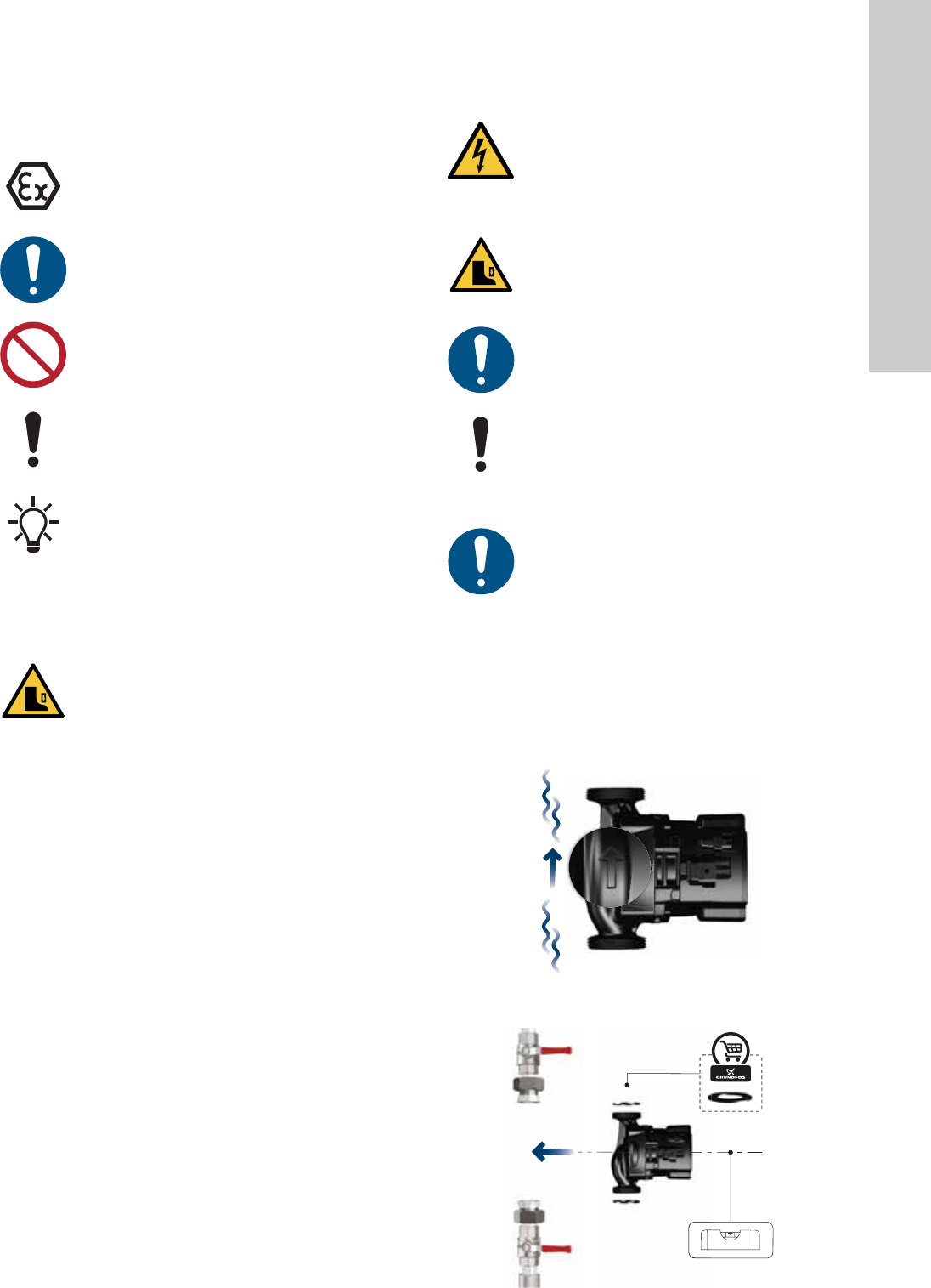
1.1 Hazard statements
The symbols and hazard statements below may appear in
Grundfos installation and operating instructions, safety
instructions and service instructions.
The text accompanying the three hazard symbols DANGER,
WARNING and CAUTION is structured in the following way:
The hazard statements are structured in the following way:
1. General information
2
1.1 Hazard statements
2
1.2 Notes
3
2. Receiving the product
3
2.1 Inspecting the product
3
2.2 Scope of delivery
3
3. Installing the product
3
3.1 Mechanical installation
3
3.2 Pump positions
4
3.3 Control box positions
4
3.4 Electrical connection
5
3.5 Assembling the installer plug
5
3.6 Insulating the pump housing
6
4. Starting up the product
7
4.1 Before startup
7
4.2 Starting up the pump
7
4.3 Venting the pump
7
5. Product introduction
8
5.1 Product description
8
5.2 Applications
8
5.3 Pumped liquids
8
5.4 Identification
8
5.5 Accessories
9
6. Control functions
11
6.1 Operating panel
11
6.2 Control modes
11
6.3 Control signal
12
6.4 Pump performance
14
7. Setting the product
15
7.1 Setting the PWM input signal
15
8. Servicing the product
16
8.1 Dismantling the product
16
8.2 Dismantling the plug
16
9. Fault finding the product
17
9.1 Deblocking the shaft
17
10. Technical data
18
10.1 Dimensions, UPS3 15-50/65
18
11. Performance curves
19
11.1 Curve conditions
19
11.2 Performance curve, UPS3 15-50/65
19
12. Disposing of the product
20
Read this document and the quick guide before you
install the product. Installation and operation must
comply with local regulations and accepted codes of
good practice.
This appliance can be used by children aged from 8
years and above and persons with reduced physical,
sensory or mental capabilities or lack of experience
and knowledge if they have been given supervision
or instruction concerning use of the appliance in a
safe way and understand the hazards involved.
Children shall not play with the appliance. Cleaning
and user maintenance shall not be made by children
without supervision.
DANGER
Indicates a hazardous situation which, if not avoided,
will result in death or serious personal injury.
WARNING
Indicates a hazardous situation which, if not avoided,
could result in death or serious personal injury.
CAUTION
Indicates a hazardous situation which, if not avoided,
could result in minor or moderate personal injury.
SIGNAL WORD
Description of hazard
Consequence of ignoring the warning.
- Action to avoid the hazard.
English (GB)
3
1.2 Notes
The symbols and notes below may appear in Grundfos
installation and operating instructions, safety instructions and
service instructions.
2. Receiving the product
2.1 Inspecting the product
Check that the product received is in accordance with the order.
Check that the voltage and frequency of the product match
voltage and frequency of the installation site. See section
5.4.1 Nameplate.
2.2 Scope of delivery
The box contains the following items:
• UPS3 pump
• installer plug
•two gaskets
• quick guide.
3. Installing the product
3.1 Mechanical installation
3.1.1 Mounting the product
1. The arrows on the pump housing indicate the flow direction
through the pump. See fig. 1.
2. Fit the two gaskets supplied with the pump when you mount
the pump in the pipe. Install the pump with a horizontal motor
shaft within ± 5 °. See fig. 2. See also section 3.3 Control box
positions.
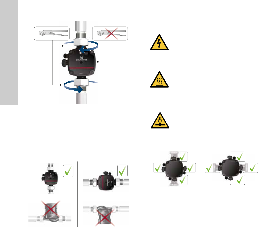
3. Tighten the fittings. See fig. 3.
Fig. 1 Flow direction
Fig. 2 Pump installation
Observe these instructions for explosion-proof
products.
A blue or grey circle with a white graphical symbol
indicates that an action must be taken.
A red or grey circle with a diagonal bar, possibly with
a black graphical symbol, indicates that an action
must not be taken or must be stopped.
If these instructions are not observed, it may result in
malfunction or damage to the equipment.
Tips and advice that make the work easier.
CAUTION
Crushing of feet
Minor or moderate personal injury
- Wear safety shoes when opening the box and
handling the product.
DANGER
Electric shock
Death or serious personal injury
- Switch off the power supply before starting any
work on the product. Make sure that the power
supply cannot be accidentally switched on.
CAUTION
Crushing of feet
Minor or moderate personal injury
- Wear safety shoes when opening the box and
handling the product.
Installation must be carried out by trained persons in
accordance with local regulations.
The pump must always be installed with a horizontal
motor shaft within ± 5 °.
Mechanical installation must be carried out by trained
persons in accordance with local regulations.
TM07 0368 1518TM07 0369 1518
English (GB)
4
Fig. 3 Tightening the fittings
3.2 Pump positions
Always install the pump with a horizontal motor shaft within ± 5 °.
Do not install the pump with a vertical motor shaft. See fig. 4,
bottom row.
• Pump installed correctly in a vertical pipe. See fig. 4, top row,
left.
• Pump installed correctly in a horizontal pipe. See fig. 4, top
row, right.
Fig. 4 Pump positions
3.3 Control box positions
The control box can be mounted in all positions. See fig. 5.
Fig. 5 Possible control box positions
TM07 0370 1518TM07 0371 1518
DANGER
Electric shock
Death or serious personal injury
- Switch off the power supply before starting any
work on the product. Make sure that the power
supply cannot be accidentally switched on.
CAUTION
Hot surface
Minor or moderate personal injury
- The pump housing may be hot due to the pumped
liquid being scalding hot. Close the isolating valves
on both sides of the pump and wait for the pump
housing to cool down.
CAUTION
Pressurised system
Minor or moderate personal injury
- Before dismantling the pump, drain the system or
close the isolating valves on both sides of the
pump. The pumped liquid may be scalding hot
and under high pressure.
TM06 7297 0918
English (GB)
5
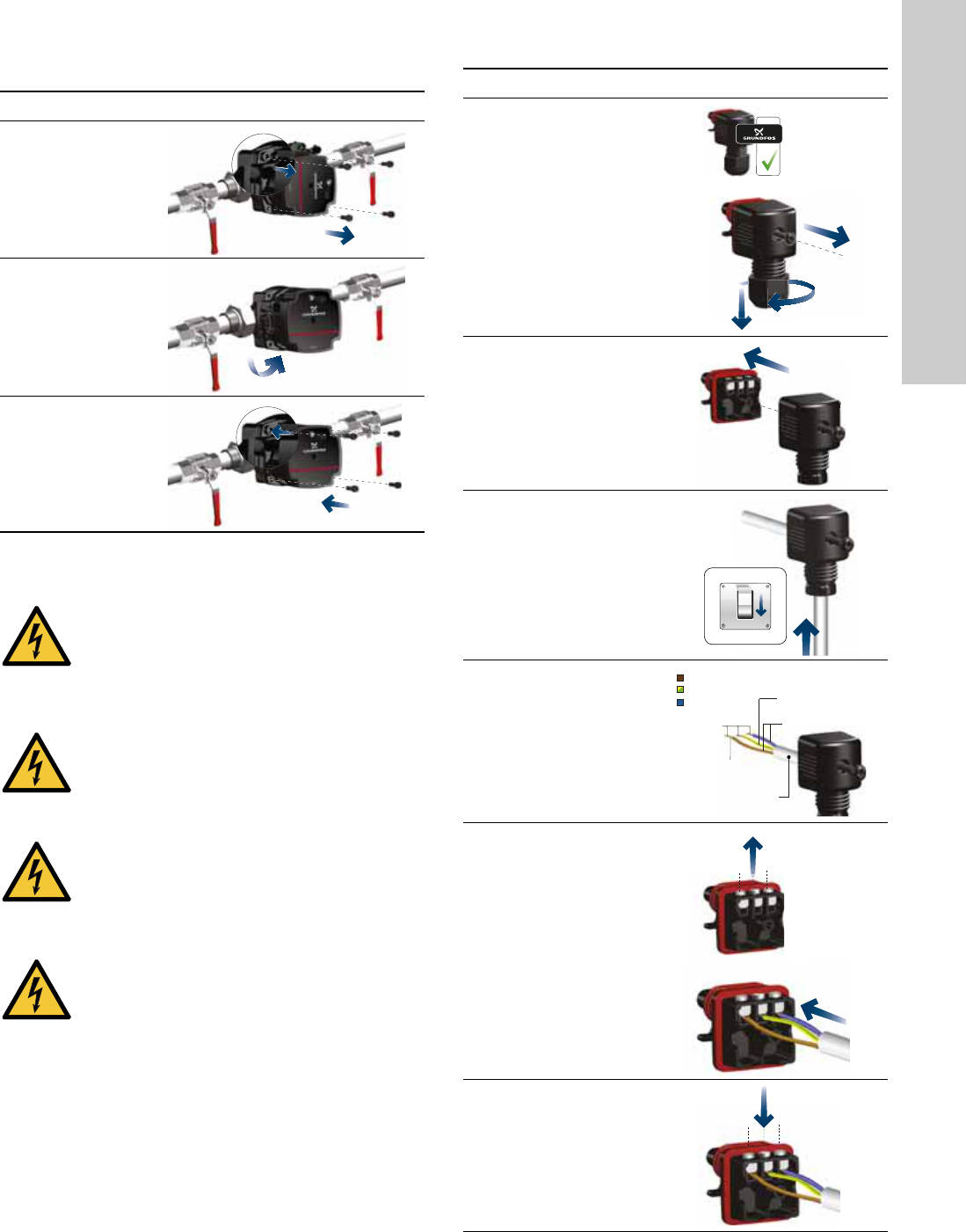
3.3.1 Changing the control box position
3.4 Electrical connection
• The motor requires no external motor protection.
• Check that the supply voltage and frequency correspond to
the values stated on the nameplate. See section
5.4.1 Nameplate.
• Connect the pump to the power supply with the plug supplied
with the pump. See steps 1 to 7.
3.5 Assembling the installer plug
Step Action Illustration
1
Make sure that
the inlet and
outlet valves are
closed.
Unscrew the
screws on the
pump head.
TM07 0372 1518
2
Turn the pump
head to the
desired position.
TM07 0373 1518
3
Refit the screws
on the pump
head.
TM07 0374 1518
DANGER
Electric shock
Death or serious personal injury
- All electrical connections must be carried out by a
qualified electrician in accordance with local
regulations.
DANGER
Electric shock
Death or serious personal injury
- Switch off the power supply before starting any
work on the product. Make sure that the power
supply cannot be accidentally switched on.
DANGER
Electric shock
Death or serious personal injury
- Connect the pump to earth.
DANGER
Electric shock
Death or serious personal injury
- In case of an insulation fault, the fault current may
be a pulsating DC. Observe national legislation
about requirements for and selection of Residual
Current Device (RCD) when installing the pump.
Step Action Illustration
1
Loosen the cable
gland and unscrew
the union nut in the
centre of the terminal
cover.
TM06 8542 0918
2
Detach the terminal
cover.
TM06 8543 0918
3
Pull the power cable
through the cable
gland and terminal
cover.
TM06 8544 0918
4
Strip the cable
conductors as
illustrated.
TM06 8545 0918
5
Loosen the screws
on the power supply
plug and connect the
cable conductors.
TM06 8546 0918 - TM06 8547 0918
6
Tighten the screws
on the power supply
plug.
TM06 8548 0918
0/Off
1/On
42 mm
32 mm
Ø 5.5 - 10 mm
0.5 - 1.5 mm
2
8 mm
L
PE
N
x 3
x 3
English (GB)
6
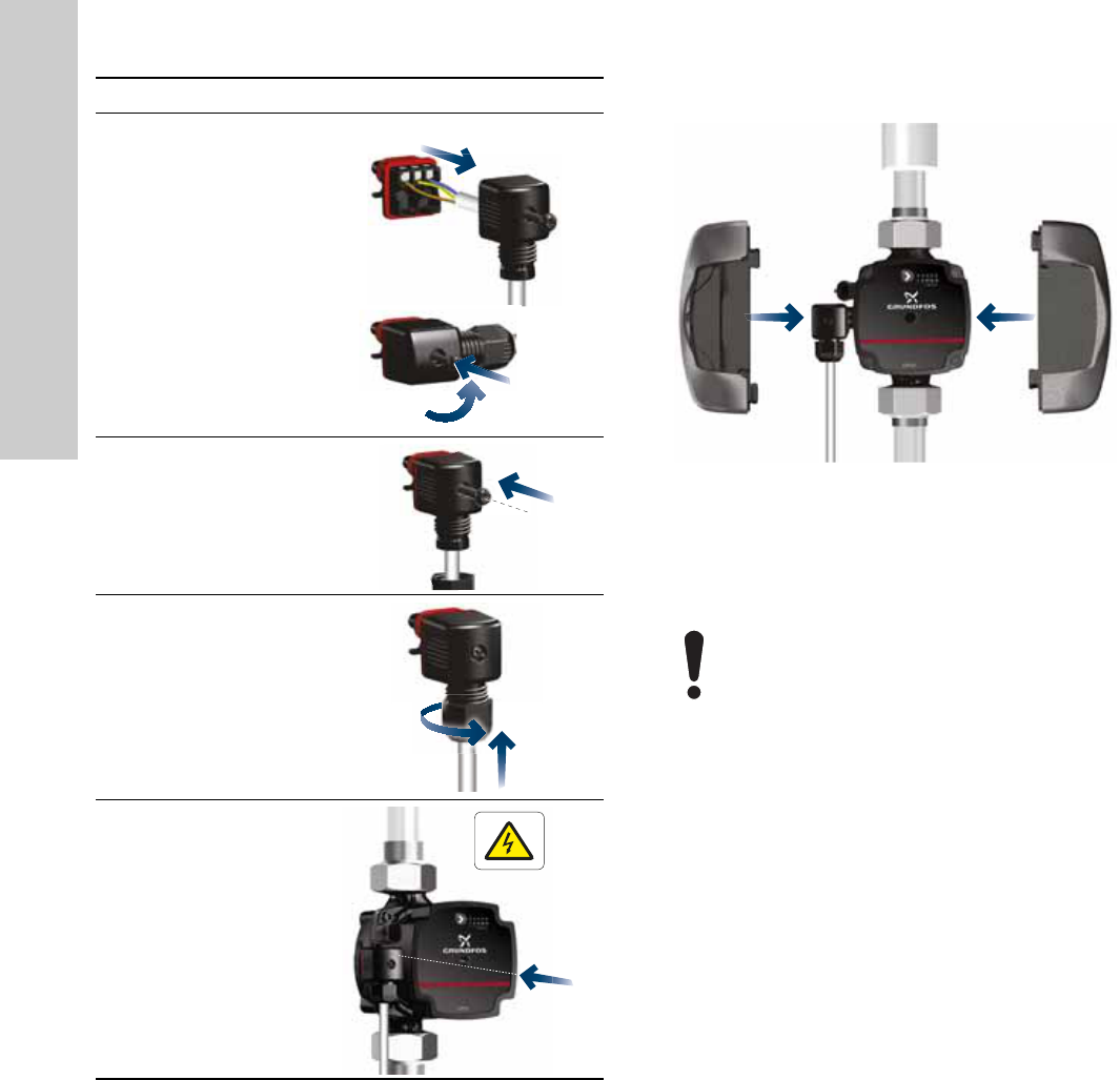
3.6 Insulating the pump housing
Fig. 6 Insulating the pump housing
You can reduce the heat loss from the pump and pipe by
insulating the pump housing and the pipe with insulating shells,
which can be ordered as an accessory. See section
5.5.2 Insulating shells.
7
Refit the terminal
cover. See A.
Note: It is possible to
turn the power
supply plug on the
side for a 90 ° cable
entry. See B.
TM06 8549 0918 - TM06 8550 0918
8
Tighten the union
nut.
TM06 8551 0918
9
Tighten the cable
gland onto the power
supply plug.
TM06 8552 0918
10
Insert the power
supply plug into the
male plug on the
pump.
TM07 0376 1518
Step Action Illustration
B
A
TM07 0375 1518
Do not insulate the control box or cover the operating
panel.
English (GB)
7
4. Starting up the product
4.1 Before startup
Do not start the pump until the system has been filled with liquid
and vented. Make sure that the required minimum inlet pressure
is available at the pump inlet. See section 10. Technical data.
When using the pump for the first time, the system must be
vented. See section 4.3 Venting the pump. The pump is
self-venting through the system.
4.2 Starting up the pump
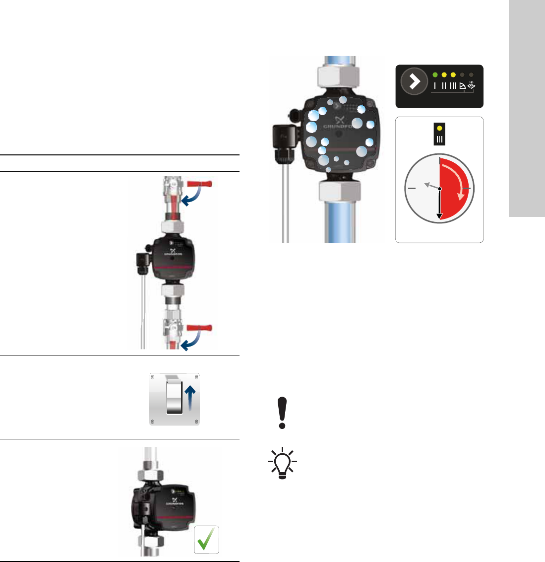
4.3 Venting the pump
Fig. 7 Venting the pump
Small air pockets trapped inside the pump may cause noise when
starting up the pump. However, because the pump is self-venting
through the system, the noise ceases over a period of time.
To speed up the venting process, do as follows:
1. Set the pump to speed III using the button on the operating
panel.
2. Let the pump run for minimum 30 minutes. How fast the pump
is vented depends on the system size and design.
When you have vented the pump, that is when the noise has
ceased, set the pump according to the recommendations. See
section 6. Control functions.
Step Action Illustration
1
Open the inlet and
outlet valves.
TM07 0377 1518
2
Switch on the power
supply.
TM06 8555 1317
3
The lights in the
operating panel
indicates that the
power supply has
been switched on
and the pump is
running.
TM07 0378 1518
0/Off
1/On
TM07 1416 1618
The pump must not run dry.
The pump is from factory set to constant curve III.
Hold 3 sec.
Minimum 30 min.
English (GB)
8
5. Product introduction
5.1 Product description
UPS3 can be used as stand-alone or integrated circulator pump
in existing systems as replacement or in new systems with either
variable or constant flow rate.
The speed can be controlled by a low-voltage PWM (Pulse Width
Modulation) signal.
High-efficiency ECM (Electronically Commutated Motor) pumps,
such as UPS3, must not be speed-controlled by an external
speed controller varying or pulsing the supply voltage.
5.1.1 Model type
These installation and operating instructions cover UPS3. The
model type is stated on the packaging and nameplate.
5.2 Applications
The pump is designed for circulating liquids in all heating
systems. The pumps are suitable for the following systems:
• Systems with constant or variable flows where it is desirable to
optimise the pump duty point.
• Installation in existing systems where the differential pressure
of the pump is too high during periods of reduced flow
demand.
• Installation in new systems for automatic adjustment of the
performance to flow demands without the use of bypass
valves or similar expensive components.
5.3 Pumped liquids
The pump is suitable for clean, thin, non-aggressive and
non-explosive liquids, not containing solid particles, fibres or
mineral oil.
In heating systems, the water must meet the requirements of
accepted standards on water quality in heating systems, for
example the German guideline VDI 2035.
Mixtures of water with antifreeze media such as glycol with a
kinematic viscosity lower than 10 mm2/s (10 cSt). When selecting
a pump, the viscosity of the pumped liquid must be taken into
consideration. If the pump is used for a liquid with a higher
viscosity, the hydraulic performance of the pump is reduced.
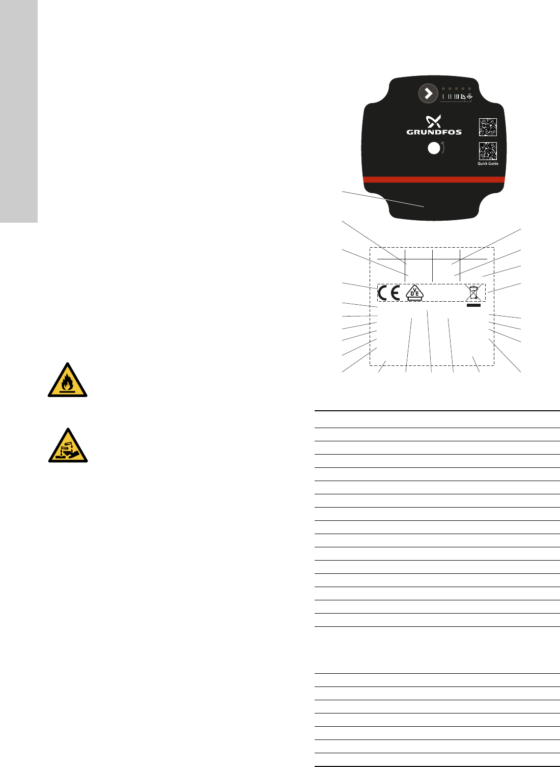
5.4 Identification
5.4.1 Nameplate
Fig. 8 Nameplate
CAUTION
Flammable material
Minor or moderate personal injury
- Do not use the pump for flammable liquids, such
as diesel oil and petrol.
CAUTION
Corrosive substance
Minor or moderate personal injury
- Do not use the pump for aggressive liquids, such
as acids and seawater.
TM07 0791 1618
Pos. Description
1 Pump name
2 Minimum current [A]
3 Maximum current [A]
4 CE mark and approvals
5 Energy Efficiency Index, EEI
6 Voltage [V]
7 Average power input PL, avg (Ecodesign regulation)
8 Model designation
9 Product number
10 Serial number
11 Country of origin
12 Frequency [Hz]
13 Part, according to EEI
14 Enclosure class
15 Manufacturer’s name and address
16
Production code:
• 1st and 2nd figures: Production site code
• 3rd and 4th figures: year
• 5th and 6th figures: week
17 Minimum liquid temperature
18 Product mark (legal product code)
19 TF class
20 Crossed-out wheeled bin according to EN 50419
21 Maximum system pressure
22 Maximum input power [W]
23 Minimum input power [W]
1
l
1
/
1
(A)
Grundfos Holding A/S
DK-8850 Bjerringbro
P
1
(W) MPa
Min.
Max.
X.XX
X.XX
XX
XXX X.X
((,0.XX - Part X
XXXV ~ XX/XXHz IPXXX TFXXX
P/N:XXXXXXXX
S/N:XXXXXXXX
Made in XXXXXXX
PL.avg.<XXW
Denmark
2
3
4
5
6
8
7
9
10
23
22
21
20
19
18
17
16
14 1511 12 13
Min.XX°CModel:XXXXXX X
GFNXX
UPS3
Hold 3 sec.
PC:P1XXXX
English (GB)
9
5.4.2 Type key
5.5 Accessories
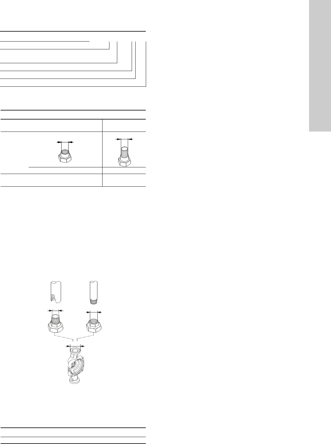
5.5.1 Unions and valve kits
Note: The product numbers are always for one complete set,
including gaskets. The product number for the standard sizes is
printed in bold.
G-threads have a cylindrical form in accordance with the EN ISO
228-1 standard and are not sealing the thread. It requires a flat
gasket. You can only screw male G-threads (cylindrical) into
female G-threads. The G-threads are standard thread on the
pump housing.
R-threads are tapered external threads in accordance with the EN
10226-1 standard.
Rc- or Rp-threads are internal threads with either tapered or
cylindrical (parallel) threads. You can screw male R-threads
(conical) into female Rc- or Rp-threads. See fig. 9.
Fig. 9 G-threads and R-threads
5.5.2 Insulating shells
The accessory set is tailored to the individual pump type. The
insulating shells enclose the entire pump housing and are easy to
fit around the pump.
Example UPS3 15 50/65 130
Pump type
Nominal diameter (DN) of inlet and outlet ports
[mm]
Maximum head [dm]
[ ]: Cast-iron pump housing
Port-to-port length [mm]
Product numbers, unions
Union nut with internal threads
Union nut with
external threads
UPS3
Connection
3/4 1 1 1/4 1 1 1/4
15-xx
G 1
1/2
529921 529922 529821 529925 529924
TM07 7425
Pump type Product number
UPS3 15-50/65 99270706
Rp
R
R
Rp
G
English (GB)
10
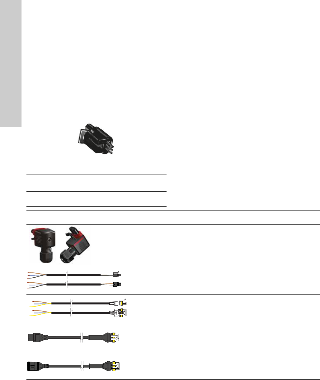
5.5.3 Cables and plugs
The pump has two electrical connections: the power supply and
the control signal connection.
Power supply connection
The installer plug is supplied with the pump and is available as an
accessory.
Power cable adapters are also available as accessories.
Control signal connection
The control signal cable connection has three conductors: the
signal input, the signal output and the signal reference. Connect
the cable to the control box by a mini superseal plug. See
7.1 Setting the PWM input signal. The optional signal cable is
available as an accessory. The cable length must not exceed 3
metres.
Fig. 10 Mini superseal plug
TM06 4414
Conductor Colour
Signal input Brown
Signal reference Blue
Signal output Black
Product Product description
Length
[mm]
Product
number
Installer plug 99439948
Mini superseal signal cable (PWM input
signal)
2000 99165309
Superseal power cable 2000 99198990
Power cable adapter: Superseal Molex cable
adapter, overmoulded
150 99165311
Power cable adapter: Superseal Volex cable
adapter, overmoulded
150 99165312
English (GB)
11
6. Control functions
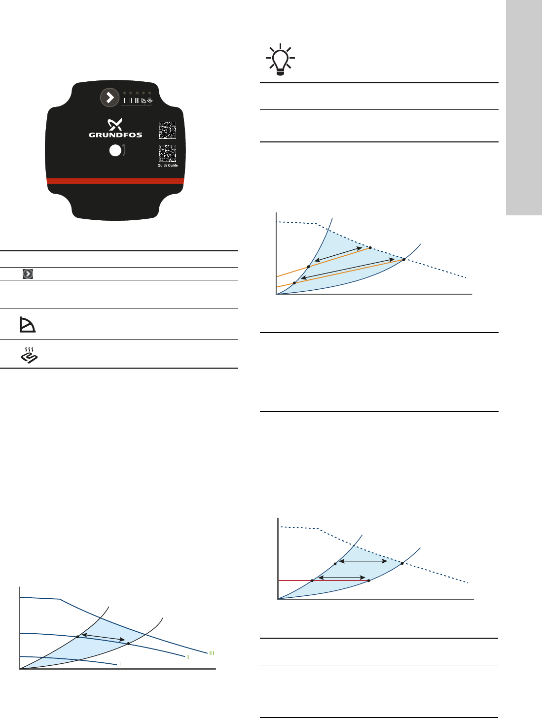
6.1 Operating panel
Fig. 11 Operating panel
The operating panel shows the following:
• The control mode, after pressing the button
•Alarm status
6.1.1 Alarm or warning
If the pump has detected one or more alarms or warnings, the
first LED switches from green to red. When the fault has been
resolved the operating panel switches back to operating status.
See section 9. Fault finding the product.
6.2 Control modes
The pump has seven different control modes. Learn more about
them in the following sections.
6.2.1 Constant curve or constant speed, I, II or III (factory
setting)
At constant-curve or constant-speed operation, the pump runs at
a constant curve. The pump performance follows the selected
performance curve, I, II or III. See fig. 14 where II has been
selected.
Fig. 12 Constant-curve/-speed curve
The selection of the constant-curve or constant-speed setting
depends on the characteristics of the heating system in question.
6.2.2 Proportional pressure I, II
In proportional-pressure mode the pump performance follows the
selected performance curve I or II and adjusts the pump
performance to the actual heat demand in the system following
the proportional-pressure curve.
Fig. 13 Proportional-pressure curve
* Proportional pressure mode is not recommended in heating
systems that include an automatic bypass valve to ensure a
minimum flow for the heating appliances.
6.2.3 Constant pressure I, II
In constant-pressure mode the pump follows the selected
constant-pressure curve I or II, adjusts the pump performance to
the actual heat demand in the system following the selected
constant-pressure curve.
Fig. 14 Constant-pressure curve
TM07 1516 1618
Symbol Description
Button
I, II, III
Constant curve or constant speed curve I, II and
III
Proportional-pressure mode I, II
Constant-pressure mode, I, II
TM06 8822 1217
UPS3
Hold 3 sec.
Q
H
The pump is factory-set to constant curve III.
System
type
Recommended control
mode
Alternative control
mode
One-pipe
heating
system
Constant-pressure mode.
See section 6.2.3 Constant
pressure I, II.
Constant curve or
constant speed, I, II
or III.
TM07 1552 1618
System
type
Recommended
control mode
Alternative control mode
Two-pipe
system
Proportional-
pressure mode*
Constant curve or constant
speed I, II, III, see section
6.2.1 Constant curve or
constant speed, I, II or III
(factory setting).
TM07 1553 1618
System
type
Recommended
control mode
Alternative control mode
Underfloor
heating
system
Constant-pressure
mode
Constant curve or constant
speed I, II, III, see section
6.2.1 Constant curve or
constant speed, I, II or III
(factory setting).
Q
H
I
II
Q
H
I
II
English (GB)
12
6.2.4 Changing from recommended to alternative pump
setting
Heating systems are relatively slow systems that cannot be set to
the optimum operation within minutes or hours.
If the recommended pump setting does not give the desired
distribution of heat in the rooms of the house, change the pump
setting to the shown alternative.
6.2.5 Selecting the control modes
Proportional pressure
We recommend proportional-pressure mode in variable flow
systems with relatively large pressure losses in the distribution
pipes such as:
• two-pipe heating systems with thermostatic valves and long
distribution pipes
• two-pipe heating systems with thermostatic valves and high
pressure losses in system parts with total flow
• primary circuit pumps in systems with large pressure losses in
the primary circuit.
Note: Proportional-pressure mode is not recommended in
heating systems that includes an automatic bypass valve to
ensure a minimum flow for the heating appliances.
Constant pressure
We recommend constant-pressure mode in variable flow systems
with relatively small pressure losses in the distribution pipes such
as:
• two-pipe heating systems with thermostatic valves and
dimensioned for natural circulation (former gravity systems)
• two-pipe heating systems with thermostatic valves and low
pressure losses in system parts with total flow
• one-pipe heating systems with thermostatic valves or pipe
balancing valves
• underfloor heating systems with zone valves
• primary circuit pumps in systems with small pressure losses in
the primary circuit.
Constant curve
We recommend constant-curve mode in constant-flow systems,
where both a constant flow rate and a constant head are required,
such as:
• heat surfaces
• replacement for uncontrolled circulator pumps, for instance
integrated in boilers.
6.3 Control signal
The pump can be controlled via a digital low-voltage pulse-width
modulation (PWM) signal.
The square-wave PWM signal is designed for a 100 to 4,000 Hz
frequency range. The PWM signal is used to select the speed
(speed command) and as feedback signal. The PWM frequency
on the feedback signal is fixed at 75 Hz in the circulator pump.
For instructions on how to set the connection, see section
7.1 Setting the PWM input signal.
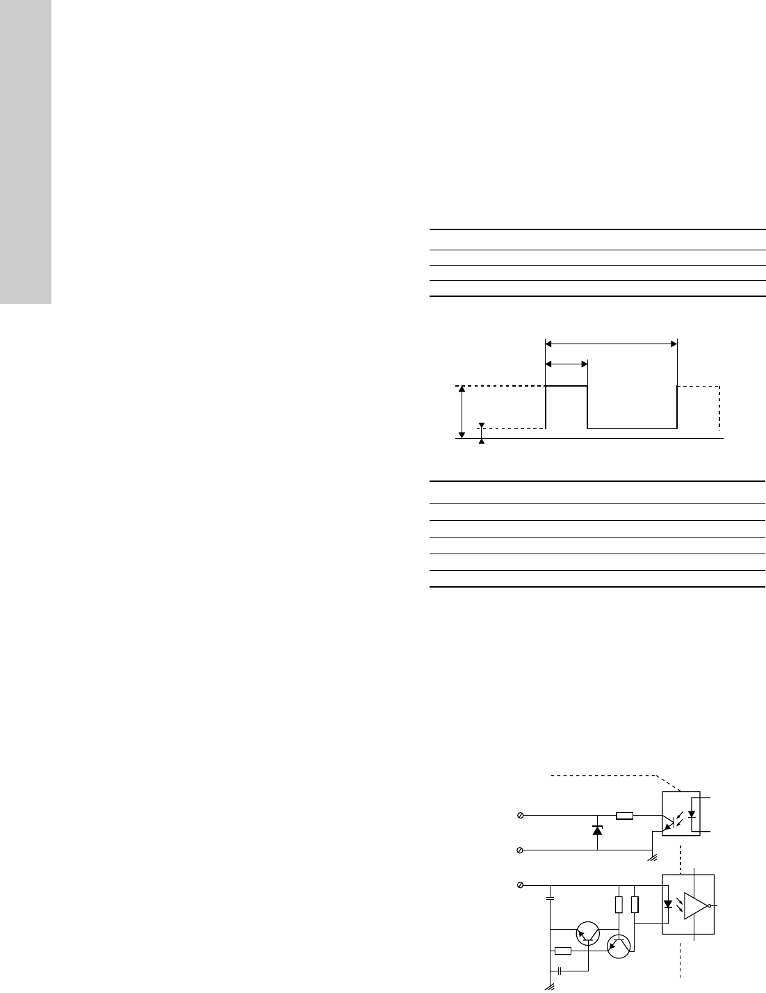
Duty cycle
d % = 100 x t/T
Example
Fig. 15 PWM signal
6.3.1 Interface
The pump’s interface consists of an electronic part connecting the
external control signal to the circulator pump. The interface
translates the external signal into a signal type that the
microprocessor can understand.
In addition, the interface ensures that the user cannot get into
contact with dangerous voltage if touching the signal wires when
power is connected to the circulator pump.
Note: "Signal ref." is a signal reference with no connection to
protective earth.
Fig. 16 Schematic drawing, interface
Example Rating
T = 2 ms (500 Hz) U
iH
= 4-24 V
t = 0.6 ms U
iL
≤ 1 V
d % = 100 x 0.6 / 2 = 30 % I
iH
≤ 10 mA (depending on U
iH
)
TM04 9911 0211
Abbreviation Description
T Period of time [sec.]
d Duty cycle [t/T]
U
iH
High-level input voltage
U
iL
Low-level input voltage
I
iH
High-level input current
TM06 0787 0914
T
t
U
iH
U
iL
5
9
S
5
%&%
%&%
7/3
7/3
N
N
+
-
PWM output
PWM input
Signal ref.
Galvanic isolation
Pump electronics
English (GB)
13
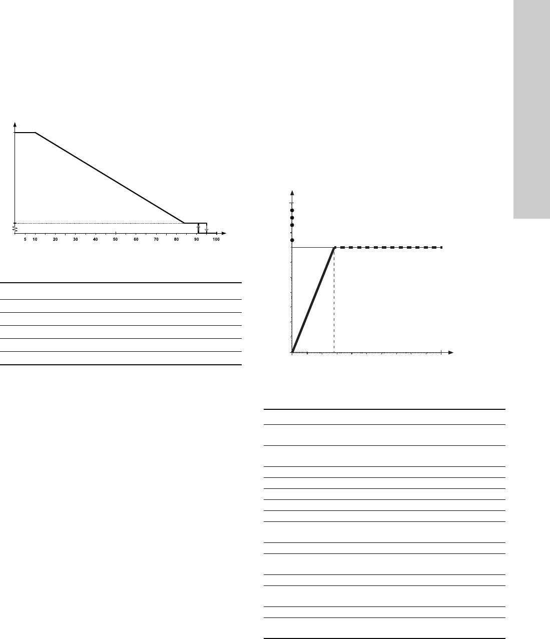
6.3.2 PWM input signal profile A (heating)
The pump runs on constant-speed curves depending on the PWM
input signal. The speed decreases when the PWM value
increases. If the PWM signal equals zero (0 VDC), the pump will
switch to the control mode selected before connecting to a PWM
signal.
Fig. 17 PWM input signal profile A (heating)
6.3.3 PWM feedback signal
The PWM feedback signal offers pump information like in bus
systems:
• current power consumption (accuracy ± 2 % of PWM signal)
• warning
•alarm.
Alarms
Alarm output signals are available because some PWM output
signals are dedicated to alarm information. If a supply voltage is
measured below the specified supply voltage range, the output
signal is set to 75 %. If the rotor is locked due to deposits in the
hydraulics, the output signal is set to 90 % because this alarm
has a higher priority. See fig. 18.
Fig. 18 PWM feedback signal - power consumption
Data
TM06 9136 1617
PWM input signal [%] Pump status
≤ 10 Maximum speed: max.
> 10 / ≤ 84 Variable speed: min. to max.
> 84 / ≤ 91 Minimum speed: IN
> 91/95 Hysteresis area: on/off
> 95 or ≤ 100 Standby mode: off
PWM input signal [%]
Max.
Speed
PWM input signal
Max.
Speed
TM07 1313 1118
Maximum rating Symbol Value
PWM frequency input with high-speed
optocoupler
f 100-4000 Hz
Guaranteed standby power
consumption
< 1 W
Rated input voltage - high level U
iH
4-24 V
Rated input voltage - low level U
iL
< 1 V
High-level input current I
iH
< 10 mA
Input duty cycle PWM 0-100 %
PWM frequency output, open collector f 75 Hz ± 5 %
Accuracy of output signal regarding
power consumption
-
± 2 % (of
PWM signal)
Output duty cycle PWM 0-100 %
Collector emitter breakdown voltage on
output transistor
U
c
< 70 V
Collector current on output transistor I
c
< 50 mA
Maximum power dissipation on output
resistor
P
R
125 mW
Zener diode working voltage U
z
36 V
Maximum power dissipation in Zener
diode
P
z
300 mW
25 50 100 150 200 250
10
20
30
40
50
60
70
80
90
100
Power [W]
Standby (stop)
Alarm stop: fault, blocked pump
Alarm stop: electrical fault
Warning Saturation at 70 Watt
S
l
o
p
e
:
1
W
/
%
P
W
M
English (GB)
14
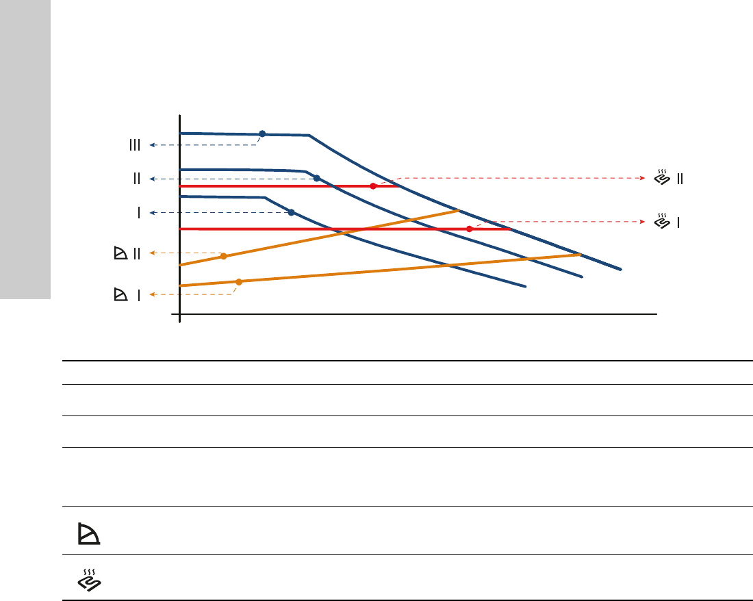
6.4 Pump performance
Figure 19 shows the relation between pump setting and pump performance by means of curves.
Fig. 19 Pump setting in relation to pump performance
TM07 1541 1618
Q
H
Setting Pump curve Function
I
Constant curve or constant
speed I
The pump runs at a constant speed and consequently on a constant curve.
At speed I, the pump is set to run on the minimum curve under all operating conditions.
II
Constant curve or constant
speed II
The pump runs at a constant speed and consequently on a constant curve.
At speed II, the pump is set to run on the intermediate curve under all operating conditions.
III
Constant curve or constant
speed III (factory setting)
The pump runs at a constant speed and consequently on a constant curve.
At speed III, the pump is set to run on the maximum curve under all operating conditions.
Quick venting of the pump can be obtained by setting the pump to speed III for a short
period.
Proportional-pressure mode I,
II
The duty point of the pump will move up or down on a proportional-pressure curve,
depending on the heat demand in the system.
The head (pressure) is reduced at falling heat demand and increased at rising heat demand.
Constant-pressure mode I, II
The duty point of the pump will move out or in on a constant-pressure curve, depending on
the heat demand in the system.
The head (pressure) is kept constant, irrespective of the heat demand.
English (GB)
15
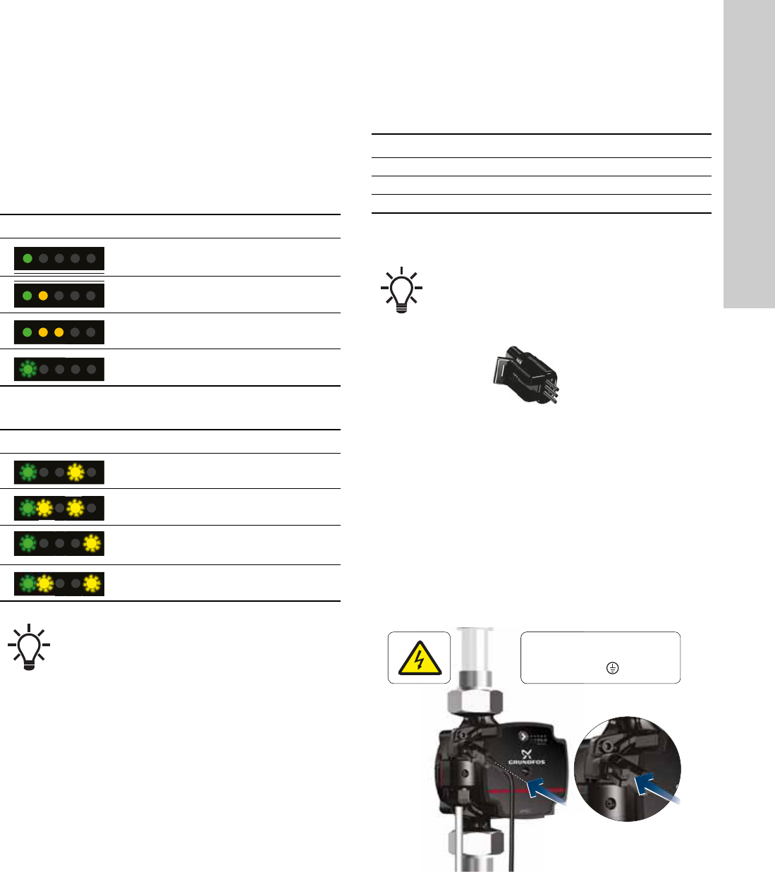
7. Setting the product
To set the product use the button on the operating panel. Every
time you press the button, the pump setting is changed. The
LEDs will indicate the chosen control mode. To learn more about
each control mode, see section 6.2 Control modes.
To select a proportional-pressure or constant-pressure curve,
press and hold the button for 3 seconds. To return to
constant-curve settings, press and hold the button for 3 seconds.
Control modes for constant curve
Control modes for proportional-pressure and
constant-pressure curve
7.1 Setting the PWM input signal
To enable the external control mode (PWM profile A), you need a
signal cable connected to an external system. The cable
connection has three conductors: the signal input, the signal
output and the signal reference.
The cable is not supplied with the pump but can be ordered as an
accessory.
Fig. 20 Mini superseal plug
Set the signal connection
1. Make sure that the pump is turned off.
2. Locate the PWM signal connection on the pump.
The three pins inside the signal connection are not energised.
3. Connect the signal cable with the mini superseal plug.
4. Switch on the power supply.
5. The pump automatically detects if a valid PWM signal is
available after which it enables the control mode on the pump.
See fig. 8. If the pump does not detect a PWM signal or if the
signal equals 0, the pump will switch to the control mode
selected before connecting to a PWM signal.
Fig. 21 Connecting the signal cable to UPS3
Display Control mode
Constant curve 1
Constant curve 2
Constant curve 3
PWM profile A
The LED flashes.
Display Control mode
Proportional pressure 1
The LEDs flash.
Proportional pressure 2
The LEDs flash.
Constant pressure 1
The LEDs flash.
Constant pressure 2
The LEDs flash.
The pump is factory set to constant curve III.
Conductor Colour
Signal input Brown
Signal reference Blue
Signal output Black
The cable must be connected to the control box via a
mini superseal plug. See fig. 20.
TM064414TM07 0379 1518
1 x 230 V - 15 %/+ 10 %
∽ 50/60 Hz
1 x 230 V
∽ 50
/6
0

English (GB)
16
8. Servicing the product
8.1 Dismantling the product
1. Switch off the power supply.
2. Pull out the plug. For instructions on how to dismantle the
plug, see section 8.2 Dismantling the plug.
3. Close the two isolating valves on both sides of the pump.
4. Loosen the fittings.
5. Remove the pump from the system.
8.2 Dismantling the plug
1. Loosen the cable gland and unscrew the union nut in the
centre of the terminal cover.
2. Detach the terminal cover.
3. Loosen the screws on the power supply plug and disconnect
the cable conductors.
4. Pull the power cable back through the cable gland and
terminal cover.
DANGER
Electric shock
Death or serious personal injury
- All electrical connections must be carried out by a
qualified electrician in accordance with local
regulations.
DANGER
Electric shock
Death or serious personal injury
- Switch off the power supply before starting any
work on the product. Make sure that the power
supply cannot be accidentally switched on.
CAUTION
Hot surface
Minor or moderate personal injury
- The pump housing may be hot due to the pumped
liquid being scalding hot. Close the isolating valves
on both sides of the pump and wait for the pump
housing to cool down.
CAUTION
Pressurised system
Minor or moderate personal injury
- Before dismantling the pump, drain the system or
close the isolating valves on both sides of the
pump. The pumped liquid may be scalding hot
and under high pressure.
All service must be carried out by an instructed
service technician.
English (GB)
17
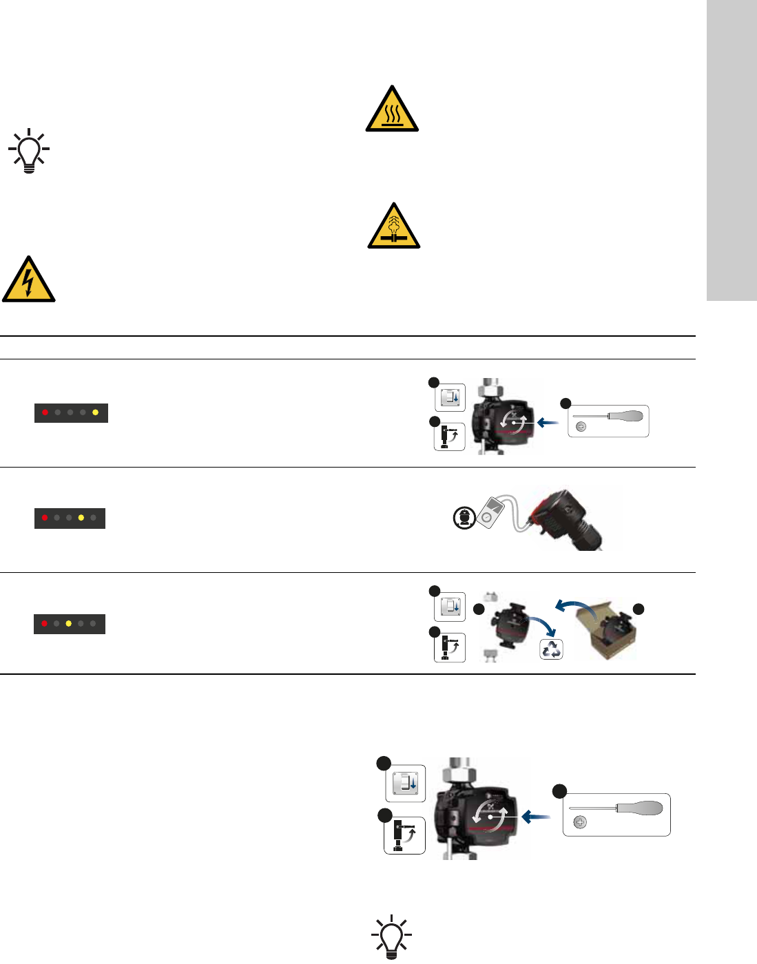
9. Fault finding the product
If the pump has detected one or more alarms, the first LED
switches from green to red. When an alarm is active, the LEDs
indicate the alarm type as defined in fig. 22.
When there is no active alarm anymore, the operating panel
switches back to operating status and the first LED switches from
red to green.
Fig. 22 Fault finding table
9.1 Deblocking the shaft
If the pump is blocked it is necessary to deblock the shaft. The
pump deblocking device is accessible from the front of the pump
without having to demount the control box. The force of the
device is high enough to deblock pumps, which are seized by
lime, for example if the pump has been turned off during summer.
Course of action:
1. Switch off the power supply.
2. Close the valves.
3. Locate the deblocking screw in the centre of the control box.
Use a star screwdriver with a size 2 Phillips tip to push the
deblocking screw inwards.
4. When the screw can be turned counterclockwise, the shaft
has been deblocked. Repeat step 3, if necessary.
5. Switch on the power supply.
Fig. 23 Deblocking the shaft
If multiple alarms are active at the same time, the
LEDs only show the error with the highest priority.
The priority is defined by the sequence of the table.
DANGER
Electric shock
Death or serious personal injury
- Switch off the power supply before starting any
work on the product. Make sure that the power
supply cannot be accidentally switched on.
CAUTION
Hot surface
Minor or moderate personal injury
- The pump housing may be hot due to the pumped
liquid being scalding hot. Close the isolating valves
on both sides of the pump and wait for the pump
housing to cool down.
CAUTION
Pressurised system
Minor or moderate personal injury
- Before dismantling the pump, drain the system or
close the isolating valves on both sides of the
pump. The pumped liquid may be scalding hot
and under high pressure.
Display Status Solution
Alarm
The pump stops.
The pump is
blocked.
Deblock the shaft. See
section 9.1 Deblocking
the shaft.
Warning
The pump keeps
running.
The supply voltage
is low.
Make sure that there is
sufficient voltage
supply to the pump.
Alarm
The pump stops.
Electrical error.
Replace the pump and
return the pump your
supplier.
2
3
0/Off
1/On
1
No.2
5 mm
2
3 4
0/Off
1/On
1
TM07 0387 1518
Before, during and after the deblocking, the device is
tight and must not release any water.
2
3
0/Off
1/On
1
No.2
5 mm
English (GB)
18
10. Technical data
To avoid condensation in the stator, the liquid temperature
must always be higher than the ambient temperature.
Reduced supply voltage
The pump operation is ensured above 160 VAC with
reduced performance. If the voltage falls below 190 VAC,
a low-voltage warning is sent via the PWM signal. If the
voltage falls below 150 VAC, the pump stops and shows
an alarm.
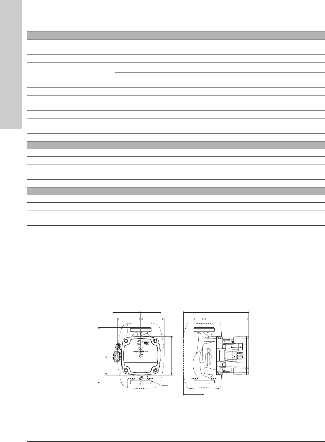
10.1 Dimensions, UPS3 15-50/65
Fig. 24 UPS3 15-50/65
Operating conditions
Sound pressure level The sound pressure level of the pump is lower than 32 dB(A).
Relative humidity Maximum 95 %, non-condensing environment
System pressure PN 10: Maximum 1.0 MPa (10 bar)
Inlet pressure
Liquid temperature Minimum inlet pressure
75 °C 0.005 MPa, 0.05 bar, 0.5 m head
95 °C 0.05 MPa, 0.5 bar, 5 m head
Maximum inlet pressure 1 MPa (10 bar)
Ambient temperature 0-55 °C
Liquid temperature 2-95 °C
Liquid Maximum water/propylene glycol mixture is 50 %
Viscosity Maximum 10 mm
2
/s
Maximum altitude of installation 2000 m above sea level
Electrical data
Supply voltage 1 x 230 V - 15 %/+ 10 %, 50/60 Hz, PE
Insulation class F
Standby power consumption < 1 W
Inrush current < 4 A
Minimum switching time power on/off No specific requirements
Miscellaneous data
Motor protection The pump requires no external motor protection.
Enclosure class IPX4D
Temperature class (TF) TF95
Specific EEI values UPS3 15-50/65: EEI ≤ 0.20
TM07 0792 1518
H2H1
H4
H3
B4
L3
B2B1
B3
G
L4
L
UPS3
Pump type
Dimensions [mm]
L L3 L4B1B2B3B4H1H2H3H4 G
UPS3 15-50/65 130 89 45 54 54 64 47 25 102 47 149 G 1 1/2
English (GB)
19
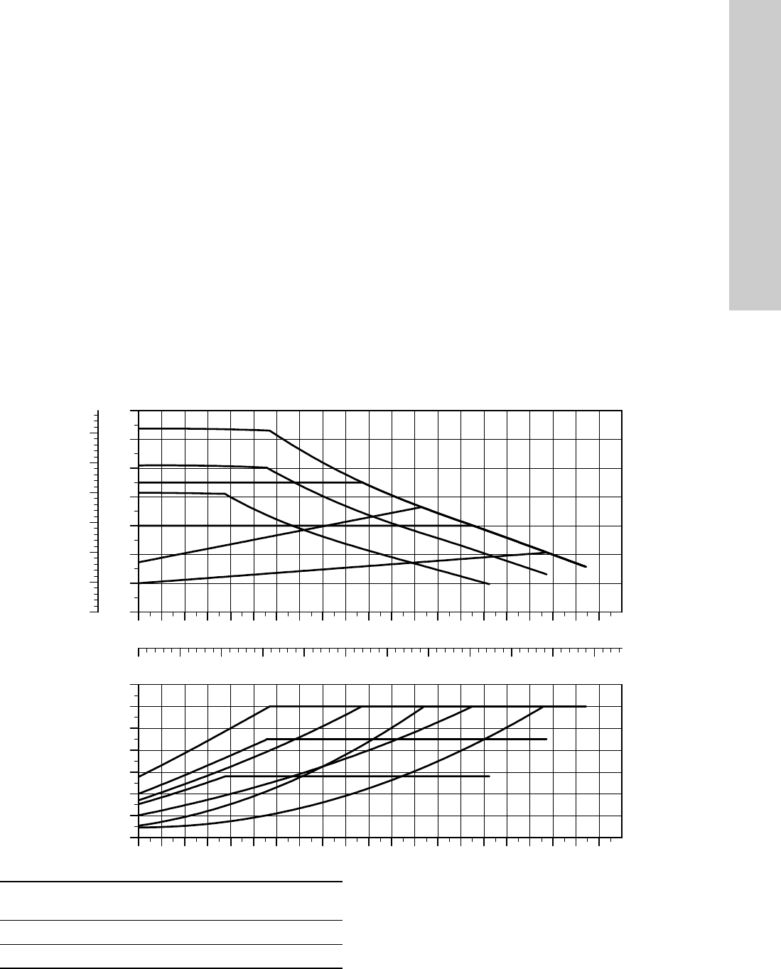
11. Performance curves
Each pump has its own performance curve.
A power curve, P1, belongs to each performance curve. The
power curve shows the pump power consumption in watt at a
given performance.
11.1 Curve conditions
The guidelines below apply to the performance curves on the
following pages:
• Test liquid: airless water.
• The curves apply to a density of ρ = 983.2 kg/m
3
and a liquid
temperature of 60 °C.
• All curves show average values and must not be used as
guarantee curves. If a specific minimum performance is
required, individual measurements must be made.
• The curves for speeds I, II and III are marked.
• The curves apply to a kinematic viscosity of
= 0.474 mm
2
/s
(0.474 cSt).
• The EEI values obtained according to EN 16297 part 3.
11.2 Performance curve, UPS3 15-50/65
TM07 0800 1318
0.0 0.2 0.4 0.6 0.8 1.0 1.2 1.4 1.6 1.8 2.0 2.2 2.4 2.6 2.8 3.0 3.2 3.4 3.6
Q [m³/h]
0
1
2
3
4
5
6
[m]
H
0
10
20
30
40
50
60
[kPa]
p
0.0 0.1 0.2 0.3 0.4 0.5 0.6 0.7 0.8 0.9 1.0
Q [l/s]
0.0 0.2 0.4 0.6 0.8 1.0 1.2 1.4 1.6 1.8 2.0 2.2 2.4 2.6 2.8 3.0 3.2 3.4 3.6
Q [m³/h]
0
10
20
30
40
50
60
[W]
P1
Setting
P1
[W]
I
1
[A]
Min. 40.05
Max. 60 0.52

English (GB)
20
12. Disposing of the product
This product or parts of it must be disposed of in an
environmentally sound way:
1. Use the public or private waste collection service.
2. If this is not possible, contact your supplier.
The crossed-out wheelie bin symbol on a product
means that it must be disposed of separately from
household waste. When a product marked with this
symbol reaches its end of life, take it to a collection
point designated by the local waste disposal
authorities. The separate collection and recycling of such
products will help protect the environment and human health.
See also end-of-life information at
www.grundfos.com/product-recycling.

Grundfos companies
Argentina
Bombas GRUNDFOS de Argentina S.A.
Ruta Panamericana km. 37.500 Centro
Industrial Garin
1619 Garín Pcia. de B.A.
Phone: +54-3327 414 444
Telefax: +54-3327 45 3190
Australia
GRUNDFOS Pumps Pty. Ltd.
P.O. Box 2040
Regency Park
South Australia 5942
Phone: +61-8-8461-4611
Telefax: +61-8-8340 0155
Austria
GRUNDFOS Pumpen Vertrieb Ges.m.b.H.
Grundfosstraße 2
A-5082 Grödig/Salzburg
Tel.: +43-6246-883-0
Telefax: +43-6246-883-30
Belgium
N.V. GRUNDFOS Bellux S.A.
Boomsesteenweg 81-83
B-2630 Aartselaar
Tél.: +32-3-870 7300
Télécopie: +32-3-870 7301
Belarus
Представительство ГРУНДФОС в
Минске
220125, Минск
ул. Шафарнянская, 11, оф. 56, БЦ
«Порт»
Тел.: +375 17 397 397 3
+375 17 397 397 4
Факс: +375 17 397 397 1
E-mail: minsk@grundfos.com
Bosnia and Herzegovina
GRUNDFOS Sarajevo
Zmaja od Bosne 7-7A,
BH-71000 Sarajevo
Phone: +387 33 592 480
Telefax: +387 33 590 465
www.ba.grundfos.com
e-mail: grundfos@bih.net.ba
Brazil
BOMBAS GRUNDFOS DO BRASIL
Av. Humberto de Alencar Castelo Branco,
630
CEP 09850 - 300
São Bernardo do Campo - SP
Phone: +55-11 4393 5533
Telefax: +55-11 4343 5015
Bulgaria
Grundfos Bulgaria EOOD
Slatina District
Iztochna Tangenta street no. 100
BG - 1592 Sofia
Tel. +359 2 49 22 200
Fax. +359 2 49 22 201
email: bulgaria@grundfos.bg
Canada
GRUNDFOS Canada Inc.
2941 Brighton Road
Oakville, Ontario
L6H 6C9
Phone: +1-905 829 9533
Telefax: +1-905 829 9512
China
GRUNDFOS Pumps (Shanghai) Co. Ltd.
10F The Hub, No. 33 Suhong Road
Minhang District
Shanghai 201106
PRC
Phone: +86 21 612 252 22
Telefax: +86 21 612 253 33
COLOMBIA
GRUNDFOS Colombia S.A.S.
Km 1.5 vía Siberia-Cota Conj. Potrero
Chico,
Parque Empresarial Arcos de Cota Bod.
1A.
Cota, Cundinamarca
Phone: +57(1)-2913444
Telefax: +57(1)-8764586
Croatia
GRUNDFOS CROATIA d.o.o.
Buzinski prilaz 38, Buzin
HR-10010 Zagreb
Phone: +385 1 6595 400
Telefax: +385 1 6595 499
www.hr.grundfos.com
GRUNDFOS Sales Czechia and
Slovakia s.r.o.
Čajkovského 21
779 00 Olomouc
Phone: +420-585-716 111
Denmark
GRUNDFOS DK A/S
Martin Bachs Vej 3
DK-8850 Bjerringbro
Tlf.: +45-87 50 50 50
Telefax: +45-87 50 51 51
E-mail: info_GDK@grundfos.com
www.grundfos.com/DK
Estonia
GRUNDFOS Pumps Eesti OÜ
Peterburi tee 92G
11415 Tallinn
Tel: + 372 606 1690
Fax: + 372 606 1691
Finland
OY GRUNDFOS Pumput AB
Trukkikuja 1
FI-01360 Vantaa
Phone: +358-(0) 207 889 500
France
Pompes GRUNDFOS Distribution S.A.
Parc d’Activités de Chesnes
57, rue de Malacombe
F-38290 St. Quentin Fallavier (Lyon)
Tél.: +33-4 74 82 15 15
Télécopie: +33-4 74 94 10 51
Germany
GRUNDFOS GMBH
Schlüterstr. 33
40699 Erkrath
Tel.: +49-(0) 211 929 69-0
Telefax: +49-(0) 211 929 69-3799
e-mail: infoservice@grundfos.de
Service in Deutschland:
e-mail: kundendienst@grundfos.de
Greece
GRUNDFOS Hellas A.E.B.E.
20th km. Athinon-Markopoulou Av.
P.O. Box 71
GR-19002 Peania
Phone: +0030-210-66 83 400
Telefax: +0030-210-66 46 273
Hong Kong
GRUNDFOS Pumps (Hong Kong) Ltd.
Unit 1, Ground floor
Siu Wai Industrial Centre
29-33 Wing Hong Street &
68 King Lam Street, Cheung Sha Wan
Kowloon
Phone: +852-27861706 / 27861741
Telefax: +852-27858664
Hungary
GRUNDFOS Hungária Kft.
Tópark u. 8
H-2045 Törökbálint,
Phone: +36-23 511 110
Telefax: +36-23 511 111
India
GRUNDFOS Pumps India Private Limited
118 Old Mahabalipuram Road
Thoraipakkam
Chennai 600 096
Phone: +91-44 2496 6800
Indonesia
PT. GRUNDFOS POMPA
Graha Intirub Lt. 2 & 3
Jln. Cililitan Besar No.454. Makasar,
Jakarta Timur
ID-Jakarta 13650
Phone: +62 21-469-51900
Telefax: +62 21-460 6910 / 460 6901
Ireland
GRUNDFOS (Ireland) Ltd.
Unit A, Merrywell Business Park
Ballymount Road Lower
Dublin 12
Phone: +353-1-4089 800
Telefax: +353-1-4089 830
Italy
GRUNDFOS Pompe Italia S.r.l.
Via Gran Sasso 4
I-20060 Truccazzano (Milano)
Tel.: +39-02-95838112
Telefax: +39-02-95309290 / 95838461
Japan
GRUNDFOS Pumps K.K.
1-2-3, Shin-Miyakoda, Kita-ku,
Hamamatsu
431-2103 Japan
Phone: +81 53 428 4760
Telefax: +81 53 428 5005
Korea
GRUNDFOS Pumps Korea Ltd.
6th Floor, Aju Building 679-5
Yeoksam-dong, Kangnam-ku, 135-916
Seoul, Korea
Phone: +82-2-5317 600
Telefax: +82-2-5633 725
Latvia
SIA GRUNDFOS Pumps Latvia
Deglava biznesa centrs
Augusta Deglava ielā 60, LV-1035, Rīga,
Tālr.: + 371 714 9640, 7 149 641
Fakss: + 371 914 9646
Lithuania
GRUNDFOS Pumps UAB
Smolensko g. 6
LT-03201 Vilnius
Tel: + 370 52 395 430
Fax: + 370 52 395 431
Malaysia
GRUNDFOS Pumps Sdn. Bhd.
7 Jalan Peguam U1/25
Glenmarie Industrial Park
40150 Shah Alam
Selangor
Phone: +60-3-5569 2922
Telefax: +60-3-5569 2866
Mexico
Bombas GRUNDFOS de México S.A. de
C.V.
Boulevard TLC No. 15
Parque Industrial Stiva Aeropuerto
Apodaca, N.L. 66600
Phone: +52-81-8144 4000
Telefax: +52-81-8144 4010
Netherlands
GRUNDFOS Netherlands
Veluwezoom 35
1326 AE Almere
Postbus 22015
1302 CA ALMERE
Tel.: +31-88-478 6336
Telefax: +31-88-478 6332
E-mail: info_gnl@grundfos.com
New Zealand
GRUNDFOS Pumps NZ Ltd.
17 Beatrice Tinsley Crescent
North Harbour Industrial Estate
Albany, Auckland
Phone: +64-9-415 3240
Telefax: +64-9-415 3250
Norway
GRUNDFOS Pumper A/S
Strømsveien 344
Postboks 235, Leirdal
N-1011 Oslo
Tlf.: +47-22 90 47 00
Telefax: +47-22 32 21 50
Poland
GRUNDFOS Pompy Sp. z o.o.
ul. Klonowa 23
Baranowo k. Poznania
PL-62-081 Przeźmierowo
Tel: (+48-61) 650 13 00
Fax: (+48-61) 650 13 50
Portugal
Bombas GRUNDFOS Portugal, S.A.
Rua Calvet de Magalhães, 241
Apartado 1079
P-2770-153 Paço de Arcos
Tel.: +351-21-440 76 00
Telefax: +351-21-440 76 90
Romania
Grundfos Pompe România SRL
S-PARK BUSINESS CENTER, Clădirea
A2,
etaj 2, Str. Tipografilor, Nr. 11-15, Sector 1,
Cod 013714, Bucuresti, Romania,
Tel: 004 021 2004 100
E-mail: romania@grundfos.ro
www.grundfos.ro
Russia
ООО Грундфос Россия
ул. Школьная, 39-41
Москва, RU-109544, Russia
Тел. (+7) 495 564-88-00 (495) 737-30-00
Факс (+7) 495 564 8811
E-mail grundfos.moscow@grundfos.com
Serbia
Grundfos Srbija d.o.o.
Omladinskih brigada 90b
11070 Novi Beograd
Phone: +381 11 2258 740
Telefax: +381 11 2281 769
www.rs.grundfos.com
Singapore
GRUNDFOS (Singapore) Pte. Ltd.
25 Jalan Tukang
Singapore 619264
Phone: +65-6681 9688
Telefax: +65-6681 9689
Slovakia
GRUNDFOS s.r.o.
Prievozská 4D
821 09 BRATISLAVA
Phona: +421 2 5020 1426
sk.grundfos.com
Slovenia
GRUNDFOS LJUBLJANA, d.o.o.
Leskoškova 9e, 1122 Ljubljana
Phone: +386 (0) 1 568 06 10
Telefax: +386 (0)1 568 06 19
E-mail: tehnika-si@grundfos.com
South Africa
Grundfos (PTY) Ltd.
16 Lascelles Drive, Meadowbrook Estate
1609 Germiston, Johannesburg
Tel.: (+27) 10 248 6000
Fax: (+27) 10 248 6002
E-mail: lgradidge@grundfos.com
Spain
Bombas GRUNDFOS España S.A.
Camino de la Fuentecilla, s/n
E-28110 Algete (Madrid)
Tel.: +34-91-848 8800
Telefax: +34-91-628 0465
Sweden
GRUNDFOS AB
Box 333 (Lunnagårdsgatan 6)
431 24 Mölndal
Tel.: +46 31 332 23 000
Telefax: +46 31 331 94 60
Switzerland
GRUNDFOS Pumpen AG
Bruggacherstrasse 10
CH-8117 Fällanden/ZH
Tel.: +41-44-806 8111
Telefax: +41-44-806 8115
Taiwan
GRUNDFOS Pumps (Taiwan) Ltd.
7 Floor, 219 Min-Chuan Road
Taichung, Taiwan, R.O.C.
Phone: +886-4-2305 0868
Telefax: +886-4-2305 0878
Thailand
GRUNDFOS (Thailand) Ltd.
92 Chaloem Phrakiat Rama 9 Road,
Dokmai, Pravej, Bangkok 10250
Phone: +66-2-725 8999
Telefax: +66-2-725 8998
Turkey
GRUNDFOS POMPA San. ve Tic. Ltd. Sti.
Gebze Organize Sanayi Bölgesi
Ihsan dede Caddesi,
2. yol 200. Sokak No. 204
41490 Gebze/ Kocaeli
Phone: +90 - 262-679 7979
Telefax: +90 - 262-679 7905
E-mail: satis@grundfos.com
Ukraine
Бізнес Центр Європа
Столичне шосе, 103
м. Київ, 03131, Україна
Телефон: (+38 044) 237 04 00
Факс.: (+38 044) 237 04 01
E-mail: ukraine@grundfos.com
United Arab Emirates
GRUNDFOS Gulf Distribution
P.O. Box 16768
Jebel Ali Free Zone
Dubai
Phone: +971 4 8815 166
Telefax: +971 4 8815 136
United Kingdom
GRUNDFOS Pumps Ltd.
Grovebury Road
Leighton Buzzard/Beds. LU7 4TL
Phone: +44-1525-850000
Telefax: +44-1525-850011
U.S.A.
GRUNDFOS Pumps Corporation
9300 Loiret Blvd.
Lenexa, Kansas 66219
Phone: +1-913-227-3400
Telefax: +1-913-227-3500
Uzbekistan
Grundfos Tashkent, Uzbekistan The Repre-
sentative Office of Grundfos Kazakhstan in
Uzbekistan
38a, Oybek street, Tashkent
Телефон: (+998) 71 150 3290 / 71 150
3291
Факс: (+998) 71 150 3292
Addresses Revised 09.09.2020

99423997 12.2020
ECM: 1303119
Trademarks displayed in this material, including but not limited to Grundfos, the Grundfos logo and “be think innovate” are registered trademarks owned by The Grundfos Group. All rights reserved. © 2020 Grundfos Holding A/S, all rights reserved.
www.grundfos.com
