
MODEL 750, 1250, 2000, & 3000
ION BEAM SYSTEMS
INSTRUCTION MANUAL
Copyright © TELEMARK, 1995-2021 – All rights reserved.
Manual Rev 1.0.0 July 2021
telemark.com
Current interface and software options might be different. Contact manufacturer for current manual
release if the software interface or functions are different from this manual or download the current
version of this manual at
https://telemark.com/ion-beam-sources/ion-sources/
Brand and product names are trademarks or registered trademarks of their respective companies.

Ion Beam System Manual
Telemark.com 2 of 130 Rev 1.0.0
TABLE OF CONTENTS
1 INTRODUCTION .......................................................................... 9
1.1 INTENDED USE ............................................................................................ 9
1.2 SYSTEM DESCRIPTION ............................................................................... 9
1.3 CUSTOMER SERVICE INFORMATION ...................................................... 10
1.4 LIABILITIES AND WARRANTY ................................................................... 11
1.5 SAFETY ...................................................................................................... 11
1.5.1 Personnel Qualifications ...................................................................................... 11
1.5.2 Illustration of Residual Dangers ........................................................................... 11
1.6 GENERAL SAFETY INSTRUCTIONS ......................................................... 12
1.7 IMPORTANT NOTE ..................................................................................... 13
2 TECHNICAL DATA .................................................................... 15
2.1 GENERAL DATA ......................................................................................... 15
2.1.1 Mechanical Data .................................................................................................. 15
2.1.2 Ambience ............................................................................................................. 17
2.1.3 Use and Operating Modes ................................................................................... 17
2.1.4 Standards ............................................................................................................. 17
2.2 MAINS CONNECTION ................................................................................ 18
2.3 SPECIFICATIONS ....................................................................................... 18
2.4 SOURCE SPECIFICATIONS ....................................................................... 19
2.5 MINIMUM WATER FLOW ........................................................................... 19
3 INSTALLATION ......................................................................... 22
3.1 UNPACKING ............................................................................................... 22
3.2 MECHANICAL INSTALLATION ................................................................... 23
3.2.1 Required Components ......................................................................................... 23
3.3 INSTALLATION ........................................................................................... 23
3.3.1 Rack Installation ................................................................................................... 23
3.4 INSTALLATION NOTES .............................................................................. 24
3.5 INSTALLATION OF WATER FLOW MONITOR ........................................... 25
3.6 INTERLOCK CONNECTION & RACK MOUNTING ..................................... 26

Ion Beam System Manual
Telemark.com 3 of 130 Rev 1.0.0
3.7 SYSTEM INSTALLATION ............................................................................ 26
3.7.1 What we Supply ................................................................................................... 27
3.7.2 Mounting Ion Source ............................................................................................ 28
3.8 Water and Gas Connections – Ion Source ................................................... 30
3.9 Installation of Electrical Feedthrough ........................................................... 32
3.10 Electrical Connections – Ion Source ............................................................ 33
3.11 Installing the Filament/s ............................................................................... 33
3.12 Installation of the Mass Flow Controller (MFC) ............................................ 35
3.13 MFC mounting using Mounting Hardware (MB) supplied ............................. 35
3.14 Installation without Optional Mounting Hardware MB ................................... 36
3.15 Dual Gas Option (DG) ................................................................................. 36
3.16 Installation of the Power Supply ................................................................... 37
3.17 POWER SUPPLY CONNECTING ............................................................... 39
3.17.1 Front Panel ........................................................................................................... 39
3.17.2 Rear Panel ........................................................................................................... 40
3.17.3 Mains Connection ................................................................................................ 41
3.17.4 Grounding ............................................................................................................ 42
3.18 PIN ASSIGNMENTS .................................................................................... 42
3.18.1 Power Cable to Vacuum Chamber ...................................................................... 42
3.18.2 Remote comms pin assignments, RS-232 .......................................................... 43
3.18.3 Mass Flow Controller connector pin assignments ............................................... 43
3.18.4 Water Flow pin assignments ................................................................................ 44
3.18.5 Interlock pin assignments .................................................................................... 44
4 USING THE ION BEAM SYSTEM ............................................. 45
4.1 FRONT PANEL ........................................................................................... 45
4.1.1 Main Power Switch............................................................................................... 46
4.1.2 LCD Touchscreen ................................................................................................ 46
4.2 MAIN SCREEN ............................................................................................ 46
4.2.1 Initial Power Up .................................................................................................... 46
4.2.2 Details .................................................................................................................. 49
4.3 SYSTEM SETUP ......................................................................................... 50
4.3.1 Setup .................................................................................................................... 51
4.3.2 Enable/Disable ..................................................................................................... 51
4.3.3 Selection .............................................................................................................. 51
4.4 ANODE SETUP ........................................................................................... 51

Ion Beam System Manual
Telemark.com 4 of 130 Rev 1.0.0
4.5 FILAMENT SETUP ...................................................................................... 53
4.6 GAS SETUP ................................................................................................ 53
4.6.1 Single Gas ............................................................................................................ 53
4.6.2 DUAL GAS ........................................................................................................... 53
4.6.3 Gas Select ............................................................................................................ 55
4.6.4 GAS PURGE ........................................................................................................ 55
4.7 WATER SETUP ........................................................................................... 57
4.8 CLEAN SETUP ............................................................................................ 57
4.9 PULSE SETUP ............................................................................................ 59
4.10 AUTO SETUP .............................................................................................. 61
4.11 TIMED SETUP ............................................................................................ 61
4.12 CLEAN ENABLE/DISABLE .......................................................................... 62
4.13 PULSE ENABLE/DISABLE .......................................................................... 62
4.14 AUTO ENABLE/DISABLE ............................................................................ 62
4.15 TIMED ENABLE/DISABLE .......................................................................... 62
4.16 ANODE DC ENABLE/DISABLE ................................................................... 63
4.17 SERVICE ..................................................................................................... 63
4.18 PROGRAMS ................................................................................................ 64
4.19 FIRST TIME OPERATION ........................................................................... 65
4.19.1 Recommended Procedures for First Time Operation .......................................... 65
4.20 DUAL FILAMENT FACILITY ........................................................................ 66
5 BEAM DIAGNOSTICS & MONITORING ................................... 68
6 ION CURRENT MONITOR ......................................................... 70
6.1 SYSTEM OVERVIEW .................................................................................. 71
6.1.1 The Sensor Head ................................................................................................. 71
6.1.2 Monitoring Card .................................................................................................... 71
6.2 THE DETECTION OF CHARGED PARTICLES ........................................... 72
6.2.1 The Detection of Charged Particles during PVD Processes................................ 72
6.3 INSTALLATION ........................................................................................... 72
6.4 Mounting the Sensor Head .......................................................................... 73
6.5 Electrical connections .................................................................................. 73
6.6 Connecting the Monitoring Unit .................................................................... 74

Ion Beam System Manual
Telemark.com 5 of 130 Rev 1.0.0
6.7 CURRENT MONITORING ........................................................................... 75
6.8 ICM MAINTENANCE ................................................................................... 75
6.8.1 Removing the Sensor Head from the Vacuum Chamber .................................... 75
6.8.2 Cleaning ............................................................................................................... 76
6.8.3 Reassembly ......................................................................................................... 76
6.8.4 Checking the Signal Line contact ......................................................................... 76
6.9 ICM TROUBLE SHOOTING ........................................................................ 77
6.10 SETTING THE BIAS VOLTAGE .................................................................. 77
6.11 ICM ELECTRONICS SPECIFICATIONS ..................................................... 78
6.12 Sensor Head Specifications – Vacuum ........................................................ 78
7 MAINTENANCE ......................................................................... 79
7.1 Removal of the Ion Source from Mounting ................................................... 80
7.2 Disassembly ................................................................................................ 81
7.3 Dismantling the Water Flow Manifold Assembly and Magnet ....................... 83
7.4 Inspection and Cleaning of the ion source ................................................... 84
7.5 Re-assembly of the Source Head ................................................................ 85
7.6 Power Supply .............................................................................................. 85
8 ASCII NO CHECK SUM INTERFACE ........................................ 87
8.1 GENERAL ................................................................................................... 87
8.2 RS-232 SERIAL INTERFACE ...................................................................... 87
8.3 ASCII NO CHECK SUM PROTOCOL .......................................................... 87
8.3.1 Error codes. .......................................................................................................... 89
8.3.2 COMMAND FORMAT .......................................................................................... 89
8.4 COMMANDS ............................................................................................... 89
9 COLON INTERFACE ............................................................... 101
9.1 GENERAL ................................................................................................. 101
9.2 RS-232 SERIAL INTERFACE .................................................................... 101
9.3 COLON PROTOCOL ................................................................................. 102
9.4 Command code, p1, p2, p3 ........................................................................ 104
9.4.1 Example 1: ......................................................................................................... 104
9.4.2 Example 2: ......................................................................................................... 105

Ion Beam System Manual
Telemark.com 6 of 130 Rev 1.0.0
9.4.3 Example 3: ......................................................................................................... 106
9.5 COMMANDS (decimal): ............................................................................. 107
9.6 ALARM CODES ........................................................................................ 119
9.6.1 Alarm group 0x80+0x00 ..................................................................................... 119
9.6.2 Alarm group 0x80+0x10 ..................................................................................... 119
9.6.3 Group 0x80+0x20 .............................................................................................. 120
9.6.4 Alarm group 0x80+0x40 ..................................................................................... 120
10 ALARM MESSAGES ............................................................... 121
11 TROUBLE SHOOTING ............................................................ 126
12 STORAGE AND DISPOSAL .................................................... 128
12.1 PACKAGING ............................................................................................. 128
12.2 STORAGE ................................................................................................. 128
12.3 DISPOSAL ................................................................................................ 128
12.4 WEEE ........................................................................................................ 128
13 WARRANTY CONDITIONS ..................................................... 130
13.1 LIMITED WARRANTY ............................................................................... 130

Ion Beam System Manual
Telemark.com 7 of 130 Rev 1.0.0
TABLE OF FIGURES
Figure 1-1, Ion Source Diagram ................................................................................................10
Figure 1-2, Keep Foreign Material Out of The Power Supply ....................................................12
Figure 1-3, Ruined Anode .........................................................................................................14
Figure 2-1, Ion Beam PS Reference Dimensions ......................................................................16
Figure 2-2, Model 750 Minimum Water Flow Chart ...................................................................20
Figure 2-3, Model 1250 Minimum Water Flow Chart .................................................................20
Figure 2-4, Model 2000 Minimum Water Flow Chart .................................................................21
Figure 2-5, Model 3000 Minimum Water Flow Chart .................................................................21
Figure 3-1, Water Flow Monitor and Feedthrough .....................................................................26
Figure 3-2, Power Supply and Cable .........................................................................................27
Figure 3-3, Water Feedthrough and Monitor .............................................................................27
Figure 3-4, MFC Assembly........................................................................................................28
Figure 3-5, Ion Source ..............................................................................................................28
Figure 3-6, Mounting Bracket ....................................................................................................29
Figure 3-7, Water and Gas Connections ...................................................................................31
Figure 3-8, Electrical Feedthrough ............................................................................................32
Figure 3-9, Installing a Dual Filament ........................................................................................34
Figure 3-10, Mass Flow Controller ............................................................................................35
Figure 3-11, Dual Gas Option ...................................................................................................36
Figure 3-12, Connecting the Power Supply to Vacuum System Schematic ...............................37
Figure 3-13, Front Panel Connections .......................................................................................39
Figure 3-14, Rear panel Connections ........................................................................................40
Figure 3-15, Three-conductor cable with protective ground (example) ......................................41
Figure 3-16, Output Power Pinouts ...........................................................................................42
Figure 3-17, Output Power Cable, Feedthough End ..................................................................42
Figure 3-18, RS-232 Connection ...............................................................................................43
Figure 3-19, Mass Flow Pinout ..................................................................................................43
Figure 3-20, Water Flow Pinout .................................................................................................44
Figure 3-21, Interlock Pinout .....................................................................................................44
Figure 4-1, Front Panel .............................................................................................................45
Figure 4-2, Main Screen ............................................................................................................47
Figure 4-3, Gas Flow Setup ......................................................................................................48
Figure 4-4, Anode Current & Beam Power Monitoring...............................................................49
Figure 4-5, Details Screen ........................................................................................................50
Figure 4-6, System Setup .........................................................................................................50
Figure 4-7, “ANODE” Voltage Select .........................................................................................52
Figure 4-8, Filament Setup ........................................................................................................53
Figure 4-9, Single Gas Setup ....................................................................................................53
Figure 4-10, Dual Gas Setup .....................................................................................................54
Figure 4-11, Select Pure Gases ................................................................................................54
Figure 4-12, Select Mixed Gases ..............................................................................................55

Ion Beam System Manual
Telemark.com 8 of 130 Rev 1.0.0
Figure 4-13, Gas Select ............................................................................................................55
Figure 4-14, Gas Purge .............................................................................................................56
Figure 4-15, Water Setup ..........................................................................................................57
Figure 4-16, Clean Setup ..........................................................................................................58
Figure 4-17, Clean Mode ..........................................................................................................59
Figure 4-18, Pulse Setup ..........................................................................................................59
Figure 4-19, Auto Setup ............................................................................................................61
Figure 4-20, Timed Setup .........................................................................................................61
Figure 4-21, Clean Enable ........................................................................................................62
Figure 4-22, Pulse Enabled .......................................................................................................62
Figure 4-23, Auto Enabled ........................................................................................................62
Figure 4-24, Timed Enabled ......................................................................................................63
Figure 4-25, Anode DC Option Enabled ....................................................................................63
Figure 4-26, Service Unlock - Factory use only .........................................................................63
Figure 4-27, Program Load/Save ..............................................................................................64
Figure 4-28, Keyboard ..............................................................................................................65
Figure 4-29, Dual Filament ........................................................................................................67
Figure 5-1, Beam Diagnostics ...................................................................................................68
Figure 6-1, Ion Current Display .................................................................................................70
Figure 6-2, Sensor Head ...........................................................................................................71
Figure 6-3, Monitoring Card ......................................................................................................71
Figure 6-4, ICM Installation Kit ..................................................................................................72
Figure 6-5, ICM Installation Diagram .........................................................................................74
Figure 6-6, Parts of the Sensor Head ........................................................................................75
Figure 7-1, Parts of the Ion Source ...........................................................................................80
Figure 7-2, Ion Source Disassembly .........................................................................................81
Figure 7-3, Unscrewing the knurled assembly nut .....................................................................82
Figure 7-4, Removing the Anode ..............................................................................................83
Figure 7-5, Dismantling the Water Flow Manifold Assembly ......................................................84
Figure 12-1, WEEE Symbol .................................................................................................... 129

Ion Beam System Manual INTRODUCTION
Telemark.com 9 of 130 Rev 1.0.0
1 INTRODUCTION
Please read this manual carefully to ensure optimum operating conditions right from the start.
This user manual contains important information about the functionality, installation, start-up,
and operation of the Telemark Ion Beam System Models 750, 1250, 2000, & 3000.
The Ion Beam System is referred to as “IBS”, or by model number, or as “Power Supply” for
the remainder of this manual.
1.1 INTENDED USE
The Telemark Ion Beam System comprises a high-energy broad beam ion source and a
dedicated and integrated power system. The ion source is mounted in a vacuum system and
can direct a beam of positively charged gas particles toward a target area – typically, the
substrates.
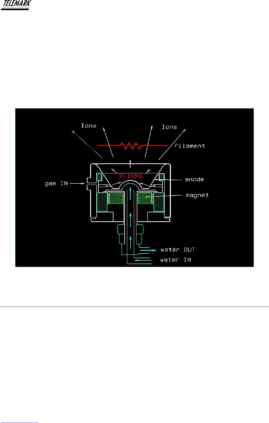
1.2 SYSTEM DESCRIPTION
Ion Source. A plasma of the process gas is produced in the conical volume of the ion
source. Positive ions, produced in the plasma, are accelerated from the source under the
influence of electrostatic and magnetic fields. The plasma is initiated and maintained by
accelerating a high current of electrons from a heated cathode to the anode. Gas is injected
through a series of ports located within the anode and into a region coincident with the
primary electron beam. The same cathode also serves to maintain beam charge neutrality by
emitting an excess of electrons to that required to produce the desired beam current.
Gas Flow. The Mass Flow Controller supplies the process gas to the ion source to a factory
set maximum flow. The flow controller is powered by the electronic system and the flow can
Ion Beam System Manual INTRODUCTION
Telemark.com 10 of 130 Rev 1.0.0
be controlled by the touch screen. The gas flow bears a direct relationship to the beam
current and the resulting ion current.
Filament Power. An AC current supplied by the power system heats the filament. The
filament power can be preset to an optimum value and does not normally require regular
adjustment. The lifetime of cathodes depends on the species of process gas used. In pure
oxygen, cathodes have typical lifetimes of between 6 to 12 hours depending on beam power,
and many more hours in less reactive gases such as nitrogen or argon.
The figure below shows schematically the principle of operation of the grid-less ion source.
Figure 1-1, Ion Source Diagram
1.3 CUSTOMER SERVICE INFORMATION
When contacting the above for service, please provide the Source Model Number and Serial
Number and the Power Unit Serial Number. The source model and serial numbers are
engraved on the source shroud. To assist with the diagnosis of any problems it is useful to
include all operating parameters such as anode voltage, gas flows as well as the mode of
operation. For example: Pulse, Continuous, or Auto Beam, anode voltage, chamber
pressure, waterflow, gas flow, and species of gas, etc.
Ion Beam System Manual INTRODUCTION
Telemark.com 11 of 130 Rev 1.0.0
1.4 LIABILITIES AND WARRANTY
Telemark is not liable for damages resulting from improper use of the device and the
guarantee expires, if the user, or third party:
• ignores information contained in this manual,
• utilizes the product in a manner inconsistent with intended purpose,
• makes any modification or alteration of the product,
• unit should not be used with unauthorized accessories (compatible accessories, types
and models can be found in the product documentation)
Telemark reserves the right to make changes without prior notice. Illustrations may vary
depending on the version of the device.
1.5 SAFETY
1.5.1 Personnel Qualifications
All work described in this document may only be carried out by persons who have suitable
technical training and the necessary experience or who have been instructed by the end user
of the product.
1.5.2 Illustration of Residual Dangers
This Operating Manual illustrates safety notes concerning residual dangers as follows:
Information on preventing any kind of physical injury.
Information on preventing extensive equipment and environmental damage.
DANGER
!
WARNING
!
Ion Beam System Manual INTRODUCTION
Telemark.com 12 of 130 Rev 1.0.0
Information on correct handling or use. Disregarding safety notes can lead to malfunctions or
equipment damage.
Note: Indicates particularly important, but not safety-relevant information.
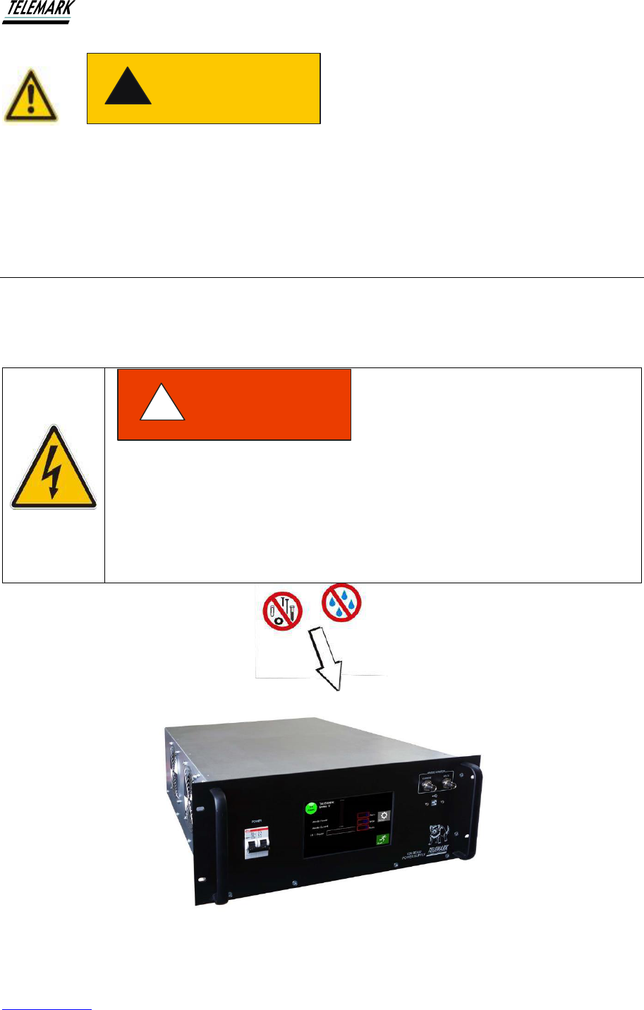
1.6 GENERAL SAFETY INSTRUCTIONS
For all work you are going to do, adhere to the applicable safety regulations. Also observe all
safety notes given in this document and forward the information to all other users of the
product. Pay attention to the following safety notes:
Figure 1-2, Keep Foreign Material Out of The Power Supply
CAUTION
!
Mains voltage.
Contact with live parts is extremely hazardous when any objects are
introduced, or any liquids penetrate the device.
Make sure that no objects enter the device. Keep the device dry.
DANGER
!
Ion Beam System Manual INTRODUCTION
Telemark.com 13 of 130 Rev 1.0.0
Improper use.
Improper use can damage the Ion Beam System.
Use the Ion Beam System only as intended by the manufacturer.
Improper installation and operation data.
Improper installation and operation data may damage the Ion Beam
System.
Strictly adhere to the stipulated installation and operation data.
1.7 IMPORTANT NOTE
Each Telemark Ion Beam System is factory fitted with a Water Flow Monitor. This device is
provided to protect the equipment against use of the Ion Beam Equipment in the event of
insufficient cooling-water flowing. The devices are factory-set for the flow considered to be the
minimum required to ensure damage will not occur within the power range of the Ion Beam
System.
The equipment is not warranted against damage that may occur
should the water flow device be removed or tampered with, set-
points altered, disconnected or improperly installed and maintained.
WARNING
!
WARNING
!


Ion Beam System Manual TECHNICAL DATA
Telemark.com 15 of 130 Rev 1.0.0
2 TECHNICAL DATA
2.1 GENERAL DATA
2.1.1 Mechanical Data
Dimensions:
19-inch (483mm) rack 5U, 7” (178mm) high x
22” (559mm) deep, See Fig. 2-1
Net Weight:
750: 20 kgs (44lbs)
1250: 22 kgs (48lbs
2000: 28 kgs (62lbs)
3000: 35 kgs (76lbs)
Rack Installation: 19” Rack standard


Ion Beam System Manual TECHNICAL DATA
Telemark.com 17 of 130 Rev 1.0.0
2.1.2 Ambience
Temperature Storage: -20…+60 °C
Operation Temperature: +5…+40 °C
Relative Humidity: Max. 80 % (up to 31 °C), decreasing to
max. 50 % (above 40 °C)
Use indoor only
Altitude: max. 2000 m n.p.m.
The degree of dust standard: II
Humidity resistance: IP20
2.1.3 Use and Operating Modes
There are two common operation modes:
1. Manual control, with the touchscreen on the front panel
2. Hardware remote control with I/O interface
2.1.4 Standards
Conformity with the Directive relating to electrical equipment designed for use within certain
voltage limits 73/23/EWG
Conformity with the Directive relating to electromagnetic compatibility 89/336/EWG
Harmonized and international/national standards and specifications:
EN 61010-1 (Safety requirements for electrical equipment for measurement, control and
laboratory use)
EN 61000-6-2 (Electromagnetic compatibility generic immunity standard)
EN 61000-6-3 (Electromagnetic compatibility generic emission standard)
Ion Beam System Manual TECHNICAL DATA
Telemark.com 18 of 130 Rev 1.0.0
2.2 MAINS CONNECTION
Voltage: 208VAC (Two Phase), or 230VAC (Single Phase) depending on configuration.
Frequency: 50/60 Hz
Max Current consumption:
Model
208V
230V
750
5A
6
1250
9A
8
2000
15A
13
3000
20A
18
Overvoltage category II
Protection class 1
Connection US
Appliance connector IEC 320 C19
Circuit breaker:
Model
2-pole Mains
750
13A
1250
16A
2000
20A
3000
25A
2.3 SPECIFICATIONS
Electrical
Input Supply Voltage
Voltage: 208VAC (Two Phase), or 230VAC (Single Phase)
depending on configuration.
Input Current
See table above
Mode of operation
Ion Beam Source Power Supply
Methods of control
Local or remote through Communication Interface

Ion Beam System Manual TECHNICAL DATA
Telemark.com 19 of 130 Rev 1.0.0
Power supply output circuit breakers on back of chassis.
Model
1 pole Filament
1 pole Anode
750
4A
6
1250
4A
10
2000
6A
13
3000
6A
16
2.4 SOURCE SPECIFICATIONS
750
1250
2000
3000
Source
Diameter
63mm diameter by
64mm long
(2.48” x 2.53”)
74mm diameter by
61mm long
(2.91” x 2.4”)
114mm diameter by
93mm long
(4.49” x 3.66”)
114mm diameter by
93mm long
(4.49” x 3.66”)
Source
Weight
1.4 kgs
(approx. 3 lbs)
1.4 kgs
(approx. 3 lbs)
4 kg (approx. 8.5 lbs)
4 kg (approx. 8.5 lbs)
Beam
Power
Anode volts
selectable to 225
volts; anode power
750 W
Anode volts
selectable to 225
volts; anode power
1250 W
Anode volts
selectable to 300
volts; anode power
2000W
Anode volts
selectable to 300
volts; anode power
3000 W
Anode
Current
Maximum 5 amps
under manual or
automatic beam
control
Maximum 5 amps
under manual or
automatic beam
control
Maximum 7 amps
under manual or
automatic beam
control
Maximum 10 amps
under manual or
automatic beam
control
Beam
Divergence
Wide beam
divergence in excess
of 80 degrees
Wide beam
divergence in excess
of 80 degrees
Wide beam
divergence in excess
of 80 degrees
Wide beam
divergence in excess
of 80 degrees
Gas Flow
Approximately
7sccm argon
required to produce
2 amps (typical)
Approximately
7sccm argon
required to produce
2 amps (typical)
Approximately 8sccm
argon required to
produce 2 amps
(typical)
Approximately 8sccm
argon required to
produce 2 amps
(typical)
Cooling
Water
See chart below
See chart below
See chart below
See chart below
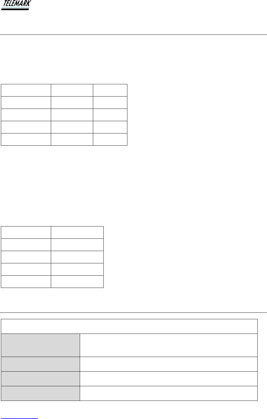
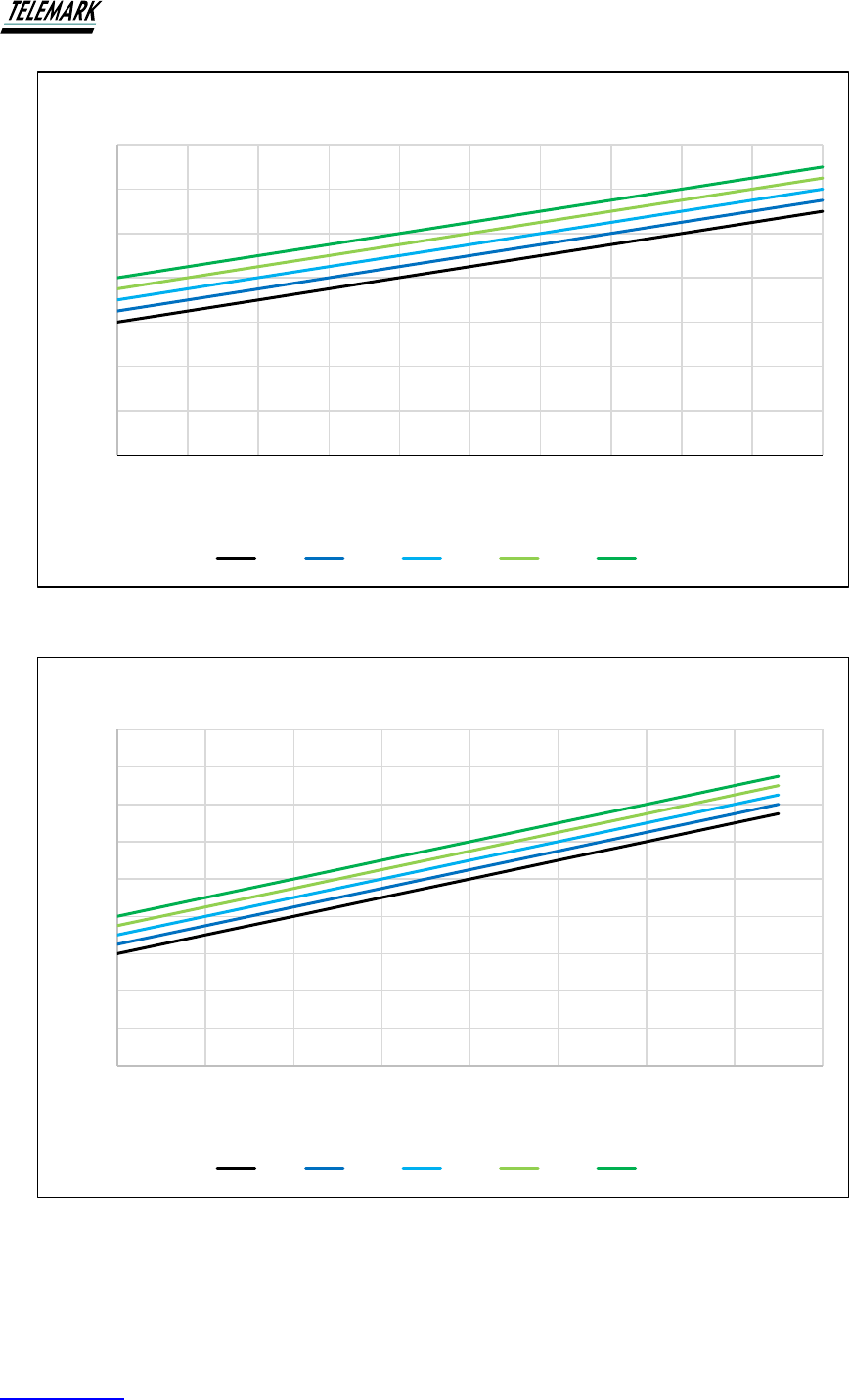
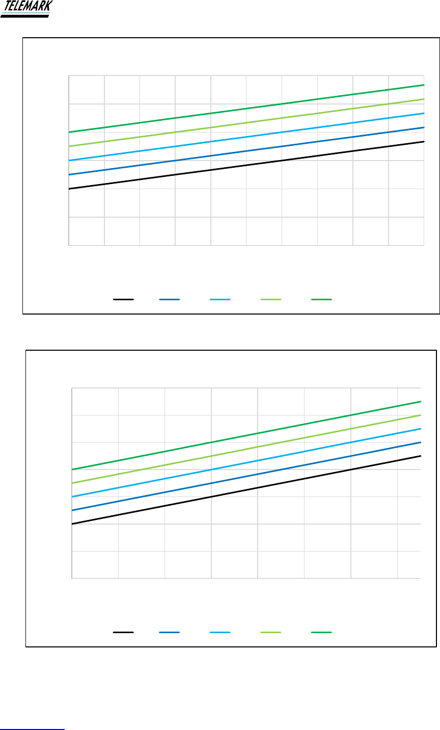
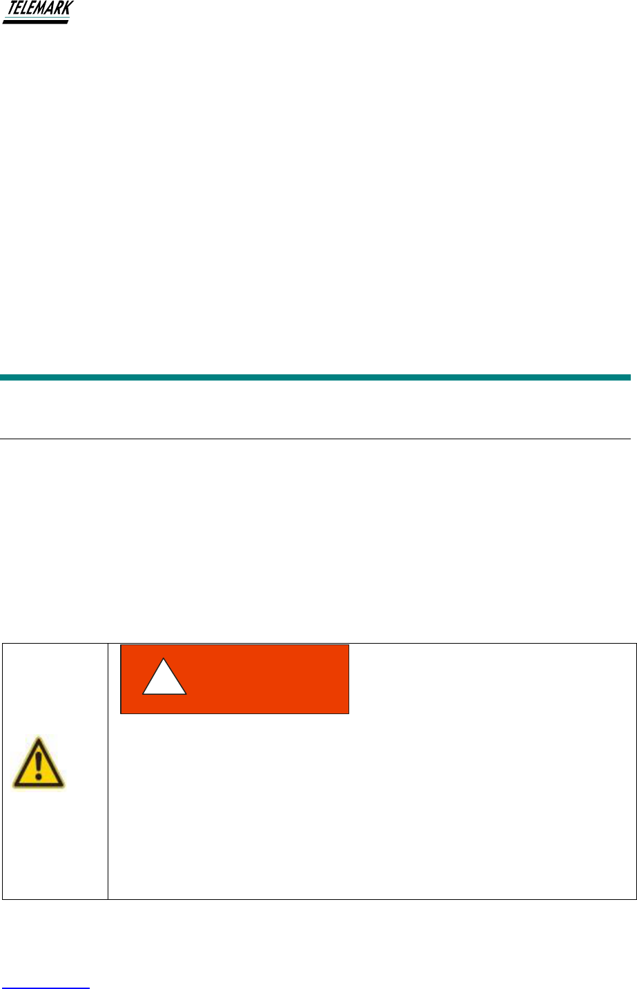
2.5 MINIMUM WATER FLOW
See the charts below to determine the minimum water flow in liters/minute for your ion source
based on model, beam current, and peak ANODE Voltage Selected. Water flow is constantly
monitored.
Ion Beam System Manual TECHNICAL DATA
Telemark.com 20 of 130 Rev 1.0.0
Figure 2-2, Model 750 Minimum Water Flow Chart
Figure 2-3, Model 1250 Minimum Water Flow Chart
0
1
2
3
4
5
6
7
0 0.5 1 1.5 2 2.5 3 3.5 4 4.5 5
Water Flow Requirement (LPM)
Beam Current (A)
Model 750
90V 110V 140V 180V 225V
0
1
2
3
4
5
6
7
8
9
0 1 2 3 4 5 6 7 8
Water Flow Requirement (LPM)
Beam Current (A)
Model 1250
90V 110V 140V 180V 225V
Ion Beam System Manual TECHNICAL DATA
Telemark.com 21 of 130 Rev 1.0.0
Figure 2-4, Model 2000 Minimum Water Flow Chart
Figure 2-5, Model 3000 Minimum Water Flow Chart
0
2
4
6
8
10
12
0 1 2 3 4 5 6 7 8 9 10
Water Flow Requirement (LPM)
Beam Current (A)
Model 2000
90V 130V 180V 230V 300V
0
2
4
6
8
10
12
14
0 2 4 6 8 10 12 14
Water Flow Requirement (LPM)
Beam Current (A)
Model 3000
90V 130V 180V 230V 300V
Ion Beam System Manual INSTALLATION
Telemark.com 22 of 130 Rev 1.0.0
3 INSTALLATION
3.1 UNPACKING
1. Visually inspect the transport packaging for signs of external damage
2. Unpack the ion beam system and put the packaging material aside
Note: Keep the packaging material for later use. The ion beam system must be stored and
transported in the original packaging material only.
3. Examine the ion beam system for completeness
4. Visually inspect the ion beam system for signs of damage
Damaged product.
Putting a damaged product into operation can be extremely dangerous.
Never attempt to put a damaged product into operation. Secure the
damaged product from unintended operation. Send a damage report to the
haulage company or the insurer.
DANGER
!
Ion Beam System Manual INSTALLATION
Telemark.com 23 of 130 Rev 1.0.0
3.2 MECHANICAL INSTALLATION
The ion beam system is intended for rack mounting. For maximum operating ease it should
be mounted at approximately eye level. If the ion beam system is mounted in a rack
containing other heat generating equipment, care should be taken that there is adequate
ventilation to assure that the ambient temperature does not exceed the ion beam system’s
ambient temperature rating.
The temperature of the environment.
Exceeding the allowable temperature of the device may damage the unit.
Make sure that the maximum permissible ambient temperature is not
exceeded, and the air can circulate freely through the ventilation slots.
Do not expose the device to direct sunlight.
3.2.1 Required Components
The following is the list of components required for setting up the ion beam system for safe
operation.
• Vacuum system.
• 19-inch rack with 208 or 230VAC, 50/60 Hz power to house the power supply
• The 5-pin power cable to feedthrough has the green wire connected to chamber.
• The ground stud on back of power supply should connect to 19" cabinet earth..
3.3 INSTALLATION
The ion beam power supply is designed to be mounted in a standard 19-inch electronic
instrument cabinet. Other suitable places on a vacuum system may be used. The installation
procedures are described below.
3.3.1 Rack Installation
The ion beam system is designed for installation into a rack according to DIN 41 494 (19", 3
HU).
WARNING
!
Ion Beam System Manual INSTALLATION
Telemark.com 24 of 130 Rev 1.0.0
Ambient temperature.
Exceeding the maximum permitted ambient temperature may damage the
device.
Make sure that the maximum permitted ambient temperature is not
exceeded. Do not expose the device to direct sunlight.
Protection class of the rack.
If the product is installed in a rack, it is likely to lower the protection class of
the rack (protection from foreign bodies and water) e.g. according to the EN
60204-1 regulations for switching cabinets.
Take appropriate measures to restore the required protection class of the
rack.
3.4 INSTALLATION NOTES
The ion generating plasma of the ion source produces very high-power densities. To avoid
damage to the ion source various protections have been built into the power supply.
Notes:
1. Water Flow Monitoring. The ion source will be damaged if insufficient cooling
water is flowing in the anode. To prevent this situation, the water flow is directly and
continuously monitored by an integrated Water Flow Monitor (WFM). The WFM
produces a pulsed electronic output signal with the pulse frequency directly
proportional to water flow. To enable the power supply to power ON, the WFM must
register a minimum flow. The minimum flow for each model is listed in the following
table. Below this limit, the power supply will not power on and an audible alarm will
sound. For the correct installation and monitoring of the WFM, see figures 2-2, 2-3,
2-4 or 2-5
2. Correct Filaments. The source requires tungsten wire of 0.020” diameter. While
straight wire filaments can be used, to obtain optimum performance it is
recommended to use multi-coiled filaments – see further information below.
WARNING
!
DANGER
!

Ion Beam System Manual INSTALLATION
Telemark.com 25 of 130 Rev 1.0.0
3. Ion Beam Power Display. The power supply provides monitoring of the ion beam
power. The power is displayed on the top right-hand side of the touch screen as a
bar graph. The bar graph display will be fully lit when the power supply is delivering
close to the maximum. When maximum power is reached, the display will “flash”.
Any attempt to increase power beyond the set limit will result in a decrease of
power.
4. Grounding of Power Supply. Neither of the filament leads should be earthed.
When installing the ion source, make sure that neither of the filament legs are
connected to earth (ground).
5. Cooling Water Requirements. The temperature of the process cooling water
should not exceed 25 degrees Centigrade and be not lower than the dew point* for
the ambient conditions. Typically, the lower temperature limit will be approximately
16 to 18 Cº. If water is observed to be condensing on water-cooled fittings, the
water temperature should be increased, or consideration should be given to
shutting off the water flow prior to venting the vacuum chamber to atmosphere.
Interlocks should always be installed to ensure flow is re-started before the process
begins again.
* The dew point is the temperature below which atmospheric water vapor will condense on
metallic surfaces maintained at that temperature.
3.5 INSTALLATION OF WATER FLOW MONITOR
The system comes equipped with a water flow monitor – see photo below. This device is
provided to protect the ion beam system in the event of insufficient water flow. The WFM
produces a pulsed output that is proportional to the water flow. The signal is passed to the
power supply which interprets and calculates the instantaneous water flow. The power supply
is factory-set to disable the START function if the water flow is below the set limit.
Notes on Installation:
1. The WFM is intended to be mounted directly in the cooling water lines on the air-side
of the water feedthrough.
2. Do not connect the WFM in parallel or series flow with any other device e.g., electron
guns, crystal monitors, etc.
3. The water flow monitors can register correct flow independent of direction of flow. It is
best practice to monitor the flow of water leaving the ion source.
4. Connection is by appropriate compression fittings such as Swagelock straight unions
as indicated in the photo below. For convenience of dis-assembly, Teflon or Nylon
ferrules may be used.
5. When tightening any compression fittings, do not apply excessive force to the plastic
WFM body – use recommended manufacturers procedures.
6. There are no serviceable parts inside of the WFM.
7. Do not apply too much force to the cable as the electronics inside the WFM may be
damaged.

Ion Beam System Manual INSTALLATION
Telemark.com 26 of 130 Rev 1.0.0
Figure 3-1, Water Flow Monitor and Feedthrough
Figure 3-1 shows the water flow monitor in relative position to the vacuum feedthrough and
connected using a Swagelock straight union. Note that the actual WFM shown above may be
of different design or manufacture to that supplied.
3.6 INTERLOCK CONNECTION & RACK MOUNTING
The power supply is fitted with an interlock connector on rear panel. The interlock circuitry is
to be connected in series. The interlock interface requires connection to a closed contact
element - switch or relay. It cannot be passed through any other series interlock circuits.
Installation of Power Supply in racks.
The Ion Beam System should not be used without correct installation in these electrical
equipment enclosures.
3.7 SYSTEM INSTALLATION
To complete the installation of the Telemark Ion Beam System you will need:
1. Sufficient lengths of” stainless steel tubing – short lengths of both sizes are supplied.
2. Various compression (Swagelock, or similar) fittings.
3. Source of High or Ultra-high purity gases
4. Gas regulator(s) suited to delivery and control of high purity gases.
5. Stainless steel bellows tubing is recommended to allow some flexibility to the ion
source mounting

Ion Beam System Manual INSTALLATION
Telemark.com 27 of 130 Rev 1.0.0
3.7.1 What we Supply
The complete system package supplied by Telemark Ion Beam Systems contains all the
required components and fittings to complete the installation. The figures below show most of
the components and sub-systems typically included in the shipment. Please refer to shipping
documents for actual inclusions.
Figure 3-2, Power Supply and Cable
Figure 3-3, Water Feedthrough and Monitor


Ion Beam System Manual INSTALLATION
Telemark.com 29 of 130 Rev 1.0.0
The ion source should not be mounted near any extended source of
ferromagnetic material or strong magnetic fields. This includes permanent or
electro-magnets as in magnetron sputtering heads and electron beam
evaporators. A minimum separation of approximately 100 mm should be
maintained from such magnetic sources. Failure to do so may affect the
operation of the ion source.
A mounting bracket spigot is provided on the shroud of the source, and it is recommended
that this should be the principal means of attachment and support. The mounting bracket
should be made from non-magnetic material such as aluminum or stainless steel – see figure
below.
Figure 3-6, Mounting Bracket
Figure shows use of the optional Mounting Brackets to secure the ion source to special gas
feedthrough. Note that mounting bracket hardware is available from Telemark. The brackets
can be supplied in a range of lengths and offsets.
CAUTION
!

Ion Beam System Manual INSTALLATION
Telemark.com 30 of 130 Rev 1.0.0
3.8 Water and Gas Connections – Ion Source
Stainless steel tubing (or bellows type stainless tubing terminations) should be used between
the water vacuum chamber feedthrough and the ion source. The water delivery tubes are
electrically connected to the anode so that a suitable electric break is required (supplied).
It is recommended that ceramic breaks should not be mounted directly to the ion source as
they can be easily damaged if regularly dismounted. When installing or demounting the
compression fittings always use the recommended procedures of the manufacturer
(Swagelock). Due to the rigidity of the larger sizes of stainless-steel tubing, it is
recommended that short stainless-steel bellows be used between the feedthrough and ion
source.
The ceramic tubes used in the electrical water breaks are sealed using Swagelok NYLON
ferrules. Use of any other ferrule material will either crush the ceramic tubes (e.g. SS) or
cause water leaks (e.g. Teflon). Under normal conditions, the ceramic breaks should not
require disassembly.
For gas connections, all models use 1/8” diameter stainless steel tubing between the vacuum
feedthrough and the ion source. Bending of the 1/8” tubing can be easily accomplished by
hand.
Note that electrical breaks are NOT required in the gas line as the gas line is at ground
potential.
It is recommended that stainless steel ferrules should be used for all Swagelock connectors.
However, for ease of disassembly, nylon or Teflon ferrules could be used on the gas line
fittings.
Care should be taken to ensure that the water and gas lines are not strained by the
mounting. To avoid chance of this it is preferable to use stainless steel bellows in the water
lines.

Ion Beam System Manual INSTALLATION
Telemark.com 31 of 130 Rev 1.0.0
Figure 3-7, Water and Gas Connections
Picture shows the main electrical connections to an ion source head. The Mounting Bracket
attaches to the Mount Spigot. It is good practice to periodically apply a small amount of
vacuum compatible lubricant to the screw threads. This includes the filament clamp nuts and
the filament leads. Ideal lubricants are moly-disulfide or copper-based dry lubricants.
Note: The vacuum side of the electrical feedthrough has four (4) connectors. One of
the connectors is fitted with a BLUE sleeve. This connector is connected to the
ANODE connection on the base of the ion source head. The opposite connector has a
BLACK sleeve fitted and this one is connected to the FILAMENT COMMON, i.e., the
one filament post by itself. The other two connectors can be attached to either of the
two filament posts.

Ion Beam System Manual INSTALLATION
Telemark.com 32 of 130 Rev 1.0.0
3.9 Installation of Electrical Feedthrough
Figure 3-8, Electrical Feedthrough
The ion beam system is supplied with an electrical feedthrough assembly to ensure ease of
installation and safe and secure operation. The assembly comprises a 1” (or 32mm) standard
baseplate 4-pin electrical feedthrough and a high current power connector. Figure above
shows the complete assembly.
Take note of the location slot in the feedthrough. The slot ensures correct orientation of the
feedthrough adapter when connection is made.
Installation procedures
1. Install 4-pin feedthrough to the chamber baseplate port. Secure feedthrough with
spanner.
2. Connect the Power Cable to the feedthrough. Take care to ensure the connector is
properly aligned with the slot. Gently push the connector onto the feedthrough pins
until it stops. The coupling sleeve can now be screwed to the feedthrough. Do not
tighten with anything other than finger pressure.
3. Connect the green wire coming from the power cable to the chamber earth. Make
sure a sound connection is established. Most vacuum chambers have a single
earthing stud, and it is preferred to use this earth point.
4. The other end of the power cable can now be connected to the connector on the rear
of the power supply.

Ion Beam System Manual INSTALLATION
Telemark.com 33 of 130 Rev 1.0.0
3.10 Electrical Connections – Ion Source
Electrical connections to the ion source are made with the cables supplied. For the Dual
Filament Ion Source (models 1250, 2000 & 3000 only), three of the copper connecting wires
(supplied) are terminated at the three filament legs. The filament leads attach to the 5mm cap
screws on the side of the filament legs. The other ends of the cables are secured to the
vacuum-side conductors of the vacuum feedthrough using the screwed BeCu connectors
provided. Ceramic insulator beads (supplied) should be used to protect the copper leads of
the vacuum feedthrough.
Note that, when installing the electrical connections between the electrical feedthrough and
the ion source connection points:
• determine the shortest length of the copper wires and cut to length. Do not leave
excess length of wire as this can be the cause of instability.
• Do not remove the enamel insulation from the copper wires except at the end where
they are connected to the feedthrough.
• Once the length of each wire is determined and cut, feed ceramic beads along the
complete length.
• Try to route the filament and anode wires together between the ion source and the
feedthrough.
3.11 Installing the Filament/s
Use a 10mm nut driver. Finger pressure is only required. For optimum performance and
extended filament life, the use of approved coiled filaments should be used. Following is the
installation procedures.
Ion Beam System Manual INSTALLATION
Telemark.com 34 of 130 Rev 1.0.0
Figure 3-9, Installing a Dual Filament
DO NOT USE WRENCHS – DO NOT USE EXCESSIVE FORCE TO TIGHTEN
THE FILAMENT POSTS – DAMAGE MAY RESULT
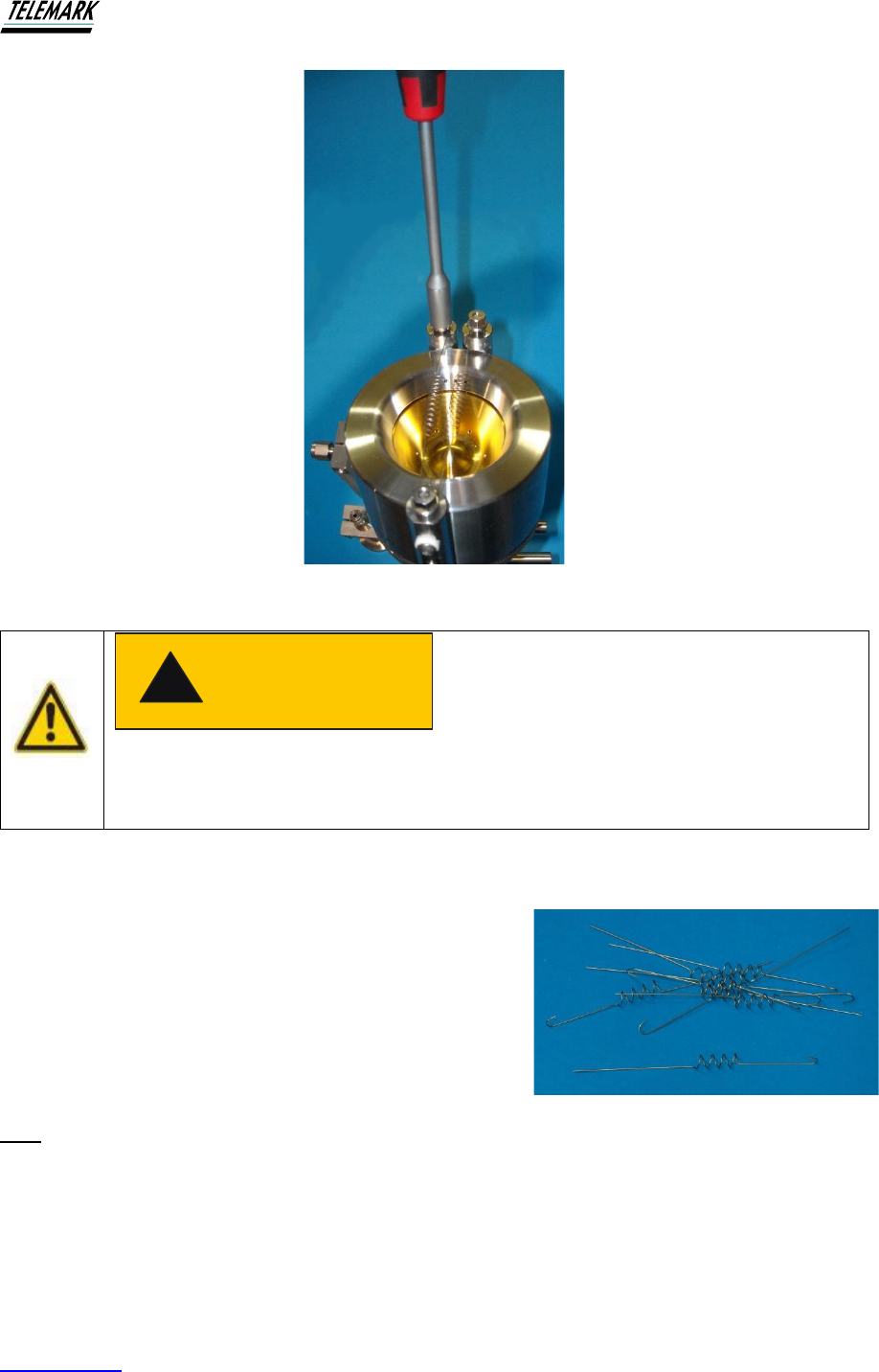
Dual Filament Installation – using approved coiled filaments (1250, 2000 & 3000)
Figure 3-9 shows the installation of coiled filaments to
the 3000.
The figure below shows the Telemark coiled filaments
for the 1250. They have a hook on one end and
straight on the other. When installing dual filaments, it
is important to secure the straight wire end to the
common filament post, i.e., the post that terminates
both filaments. Start by locating the hooks of each filament around the filament post and
secure both clamps using a 10mm box end wrench. The straight ends are then located one
each on either side of the screw post. Before clamping the common filament post, apply a
small extension to both filaments by gently pulling on the wires so that the coils are slightly
stretched. While applying the tension, secure the common filament clamp post. The reason
for this is to avoid distortion of the filaments when first heated.
CAUTION
!

Ion Beam System Manual INSTALLATION
Telemark.com 35 of 130 Rev 1.0.0
3.12 Installation of the Mass Flow Controller (MFC)
Note that the following instructions for the single MFC system are still relevant to the Dual
MFC installation. The single gas system is provided with one Mass Flow Controller.
3.13 MFC mounting using Mounting Hardware (MB) supplied
If using the MB supplied, the mounting hardware will be as shown below. The special
mounting hardware is designed to simplify the MFC installation while ensuring that a minimal
internal volume is provided between the MFC and the ion source.
Figure 3-10, Mass Flow Controller
The mounting kit is designed for installation immediately below the baseplate feedthrough
(shown to the right of the figure). Note that the vacuum side of the gas feedthrough also
provides mounting for the ion source head. Correct procedures for mounting the MFC
assembly are as follows:
1. Install the gas feedthrough into the relevant baseplate feedthrough port and secure in
place. Remove the 1/8” Swagelock nut and ferrules from the vacuum side of the
fitting.
2. On the air side of the feedthrough, attach the bracket under the nut provided – as
indicated in above photo.
3. Assemble the MFC to the mounting bracket provided using two screws. Note that the
correct gas flow direction is maintained (refer to above figure).
4. Mount the ¼” ball shut-off valve (supplied) to a short length (approx. 30mm) of ¼”
stainless steel tubing. This is followed by the ¼” x 1/8” straight reducer (Swagelock –
supplied). Note that these components are normally delivered pre-assembled.
5. To the 1/8” Swagelock fitting, secure the 1/8” tube.
6. The complete assembly can now be installed with the 1/8” tubing passing up through
the gas feedthrough. The MFC bracket is mounted onto the metal bracket, using the
four mounting screws, by using the key-hole shaped holes. Lightly secure the four
cap screws.

Ion Beam System Manual INSTALLATION
Telemark.com 36 of 130 Rev 1.0.0
7. In the vacuum chamber, re-install the Swagelock ferrules and nut to the fitting on the
feedthrough - check for the correct orientation of both ferrules. Bend the 1/8” gas tube
to the Swagelock fitting located on the end of the mounting lug on the side of the ion
source shroud and cut the tube to length. Terminate the gas tube into the Swagelock
fitting.
8. Install the ¼” stainless steel tube(s) from the gas regulators to the delivery side of the
MFC.
9. Check that all connections have been secured and check for leaks in the complete
assembly.
3.14 Installation without Optional Mounting Hardware MB
The single MFC should be mounted as close as practicable to the vacuum feedthrough. The
ball valve and reducing union are supplied pre-assembled and the MFC should be mounted
onto a firm base using the appropriate screws – check the MFC manufacturer’s installation
manual supplied.
Secure the 1/8” stainless steel tube into the reducing union and pass the tube through the
1/8” Swagelock fitting that is welded into the combined water and gas feedthrough.
3.15 Dual Gas Option (DG)
If the Dual Gas option (DG) is purchased, the special mounting bracket hardware will be
provided as shown below. The two MFCs will be shipped ready mounted and tested. Care
should always be taken when handling the MFCs -they are precision and sensitive
instruments.
Figure 3-11, Dual Gas Option
Figure shows a Dual gas module with two MFCs. The MFCs should be mounted as close as
practicable to the vacuum feedthrough to minimize the gas delivery volume between the
MFCs and the ion source. This is particularly important for optimum operation of the system
during Pulse operation and when changing gases during operation.
Ion Beam System Manual INSTALLATION
Telemark.com 37 of 130 Rev 1.0.0
3.16 Installation of the Power Supply
The power supply should be properly mounted and secured into a standard 19” instrument
rack. The power supply should be mounted at a suitable height to ensure ease of operation
and avoid operator fatigue.
Check that the rear of the cabinet provides ease of connection for the cables to route to the
vacuum chamber, MFC, water flow monitor, etc.
The power supply does not require forced ventilation (cabinet fans, etc.) as very little heat is
generated within the power supply however there should be adequate clearance above and
below the power supply to provide natural convective ventilation.
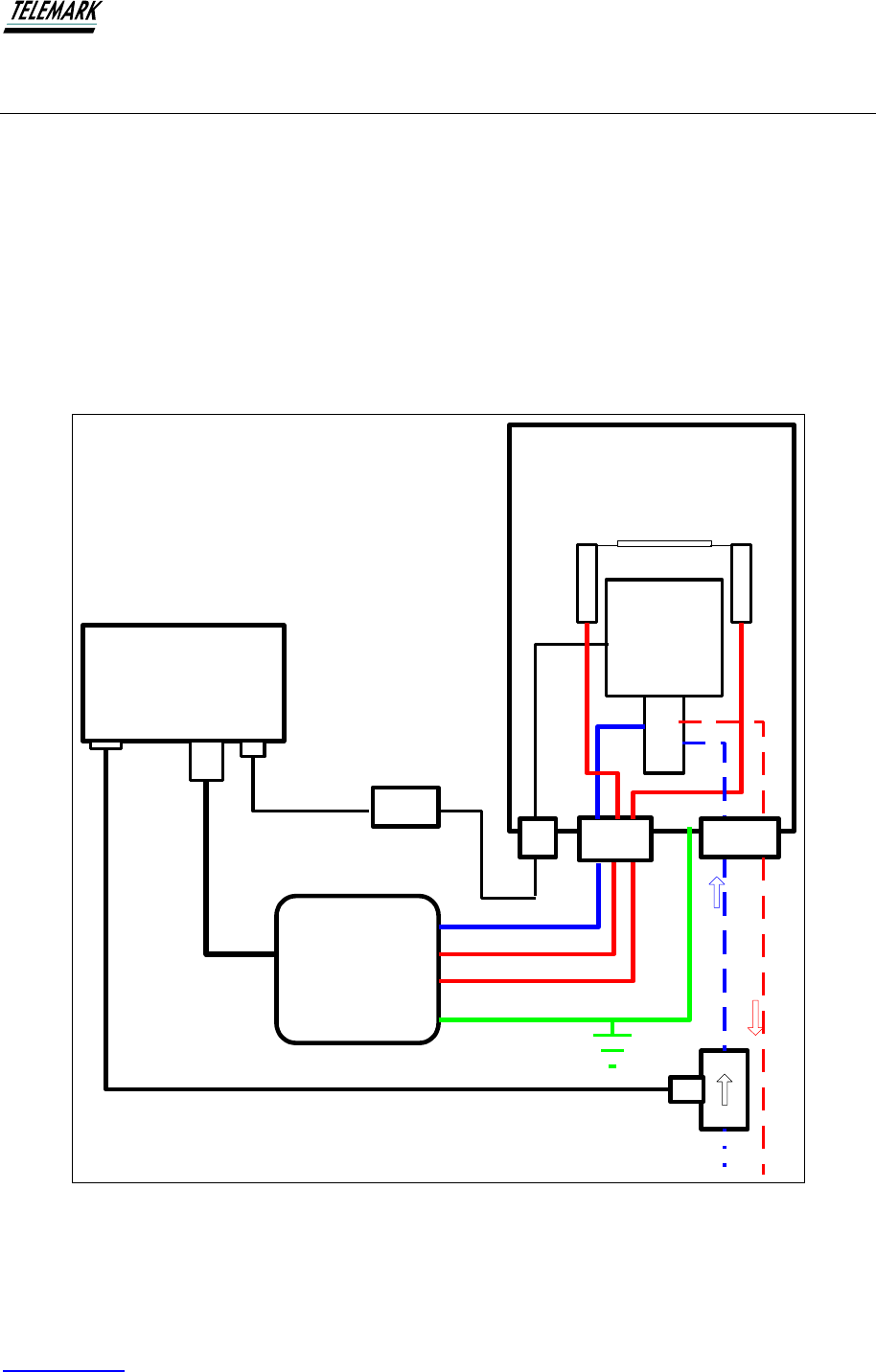
Vacuum
Chamber
Ion Source
Ion Beam Power
Supply
Terminate
Power lead
at feedthrough
MFC
Power cable 5-core
Anode
Filament
Filament
Connect to Chamber Earth
Vacuum
Chamber
water in
water out
water flow
monitor
Figure 3-12, Connecting the Power Supply to Vacuum System Schematic
Ion Beam System Manual INSTALLATION
Telemark.com 38 of 130 Rev 1.0.0
Make sure that neither of the filament connections are connected to earth. If either are
connected, there will be an audible warning that will sound until the earth connection is
removed.
Procedure for Connecting the Power Supply (refer to above schematic)
1. Mass Flow Controller (or MFCs if Dual gas option supplied).
The appropriate connecting cable(s) will be supplied depending on the MFC(s) supplied.
2. Ion Source Power. Connect the black cable with the 5-pin Amphenol connector to the 5-
pin outlet (marked ‘Ion Source Power’) on the rear of the power supply see figure below.
The other end of the power cable terminates at the vacuum feedthrough. See instruction
earlier in this manual.
3. Water Flow Monitor and Interlock. The Water Flow Monitor (WFM) is intended to be
mounted directly in series with the cooling water inlet pipe. The white cable from the
WFM is connected to the black connector marked “Water Flow”. It is essential that the
WFM is correctly installed otherwise the system will not operate correctly.
4. Mains Power Connection. Provision is made for an international IEC mains power
connection on the rear panel – see above figure. Each power supply is factory set to one
of two mains voltages ranges, e.g., 200 to 220VAC and 220 to 240 VAC. Check the rear
panel of each power supply to check the power requirements. If your mains AC voltage is
outside of the range from that indicated on the rear panel, check with Telemark before
proceeding.
5. Vacuum & Chamber Door Interlock. It is strongly recommended that the Power Supply
Interlock is connected to appropriate vacuum and chamber door interlock switches. See
WARNING and CAUTION below. To connect the interlock circuit to the supplied
connector, various safety interlocks are then connected in series with the Interlock
Circuit.
Failure to connect the Power Supply Interlock to vacuum and chamber
door switches may risk personal injury to operators. Lethal voltages are
connected to some exposed elements of the ion source.
WARNING
!
Ion Beam System Manual INSTALLATION
Telemark.com 39 of 130 Rev 1.0.0
3.17 POWER SUPPLY CONNECTING
A B
C
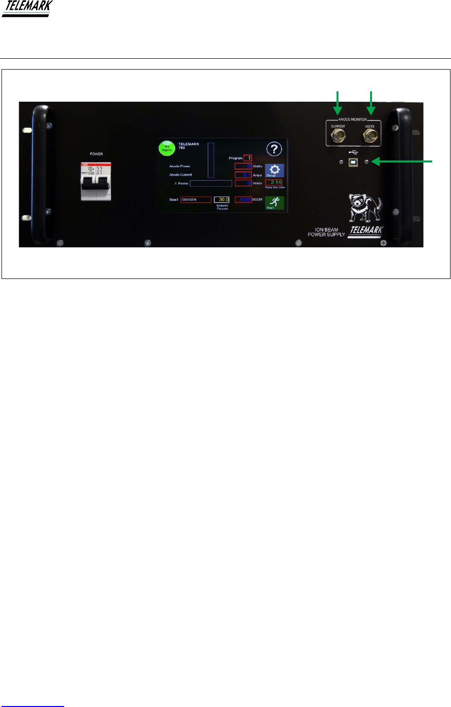
Figure 3-13, Front Panel Connections
3.17.1 Front Panel
A – BNC, Anode Monitor, Current Output. Optional connection to an oscilloscope for
diagnostics.
B – BNC, Anode Monitor, Volts Output. Optional connection to an oscilloscope for
diagnostics.
C – USB connection for updating software.
Ion Beam System Manual INSTALLATION
Telemark.com 40 of 130 Rev 1.0.0
3.17.2 Rear Panel
FILAMENT ANODE
WATER FLOW
INTERLOCK
AUX
LINE INPUT
OUTPUT
POWER
J
F
L
K
E
G
REMOTE I/O
MFC 1
MFC 2
IH
D
C
B
A
ICM
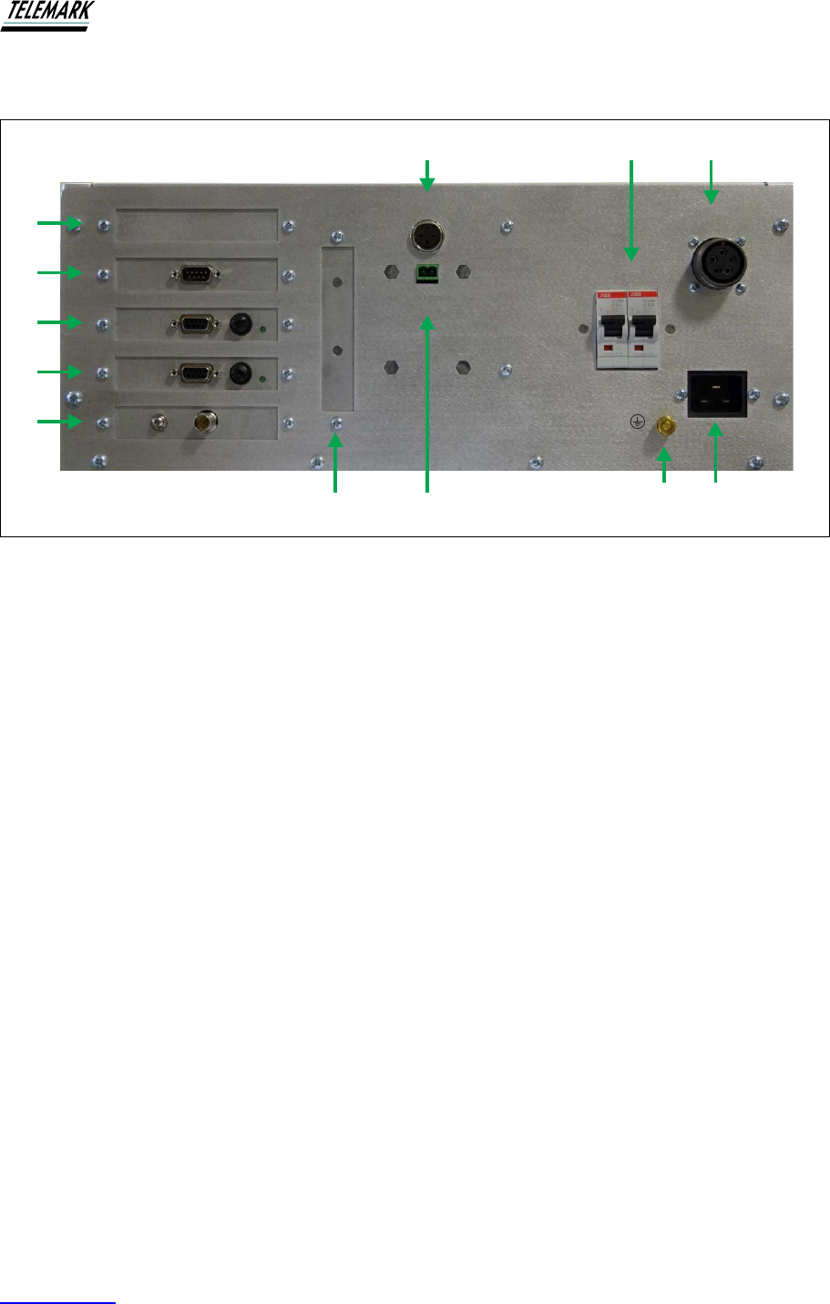
Figure 3-14, Rear panel Connections
A – AUX, Auxiliary
B – Remote IO, RS-232 interface
C – MFC1, Mass Flow Controller 1
D – MFC2, Mass Flow Controller 2 (optional)
E – ICM, Ion Current Monitor (optional)
F – No connection
G – Interlock, System
H – Interlock, Water Flow
I – Filament and Anode Breakers
J – Output Power
K – Ground Stud
L – Line Input, Mains Connection

Ion Beam System Manual INSTALLATION
Telemark.com 41 of 130 Rev 1.0.0
3.17.3 Mains Connection
The mains connection is designed for a mains cable which contains IEC 320 connector on
the device side. A mains cable is supplied with the device. If the plug is not compatible with
your wall socket, you should replace it with a suitable mains cable:
Three-conductor cable with protective ground
Conductor cross-section 3x1.5 mm
2
or larger (750, 1250, and 2000) and 3x2 mm
2
or larger
(3000)
Figure 3-15, Three-conductor cable with protective ground (example)
Mains power.
Improperly grounded devices can be extremely dangerous in the event of a
fault. Use three-wire mains or extension cables with protective ground only.
Plug the mains cable into wall sockets with protective ground only.
1. Connect the appliance connector of the mains cord with the mains connection of the
device
2. Connect the plug of the mains cable with the wall socket
Note: If the device is installed in a switching cabinet, the mains power can be supplied via a
switchable central power distributor.
DANGER
!
Ion Beam System Manual INSTALLATION
Telemark.com 42 of 130 Rev 1.0.0
3.17.4 Grounding
Grounding screw (Fig. 3-14, the reference K) should be used to connect the ion beam
system with the main grounding system in which it operates. It is recommended to use a
cable with a minimum section of 2.5 mm
2
.
3.18 PIN ASSIGNMENTS
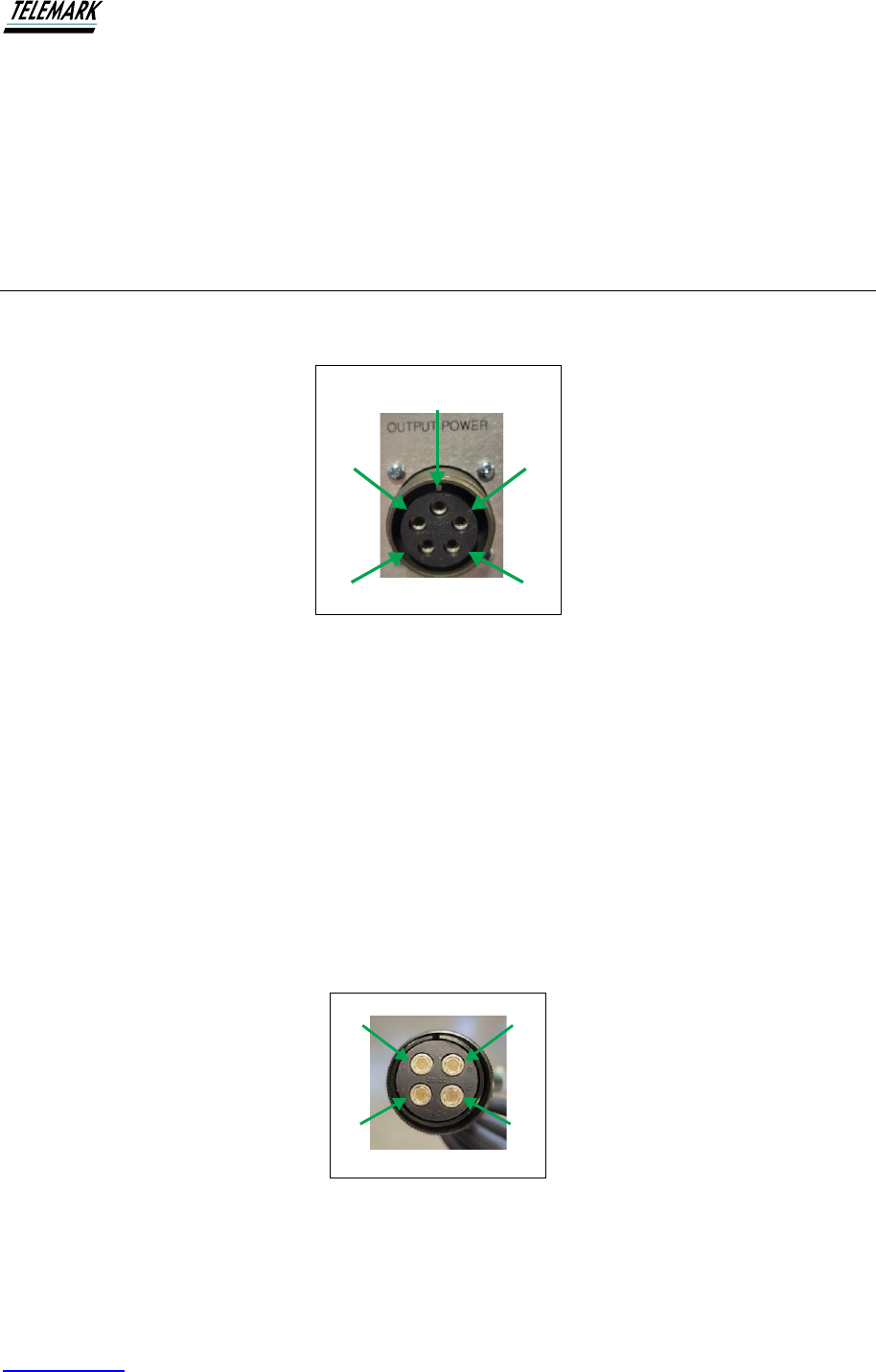
3.18.1 Power Cable to Vacuum Chamber
E
DA
B
C
Figure 3-16, Output Power Pinouts
Black covered 5-core cable
E - BLACK Filament common - Connect to feedthrough D
A - WHITE Filament one - Connect to feedthrough A
D - BROWN Filament two - connect to feedthrough C
B - BLUE +ANODE VOLTS - connect to feedthrough B
C - GREEN CHAMBER EARTH - connect to chamber earth (on air-side of chamber) and
connect to feedthrough D
DA
B C
Figure 3-17, Output Power Cable, Feedthough End
Ion Beam System Manual INSTALLATION
Telemark.com 43 of 130 Rev 1.0.0
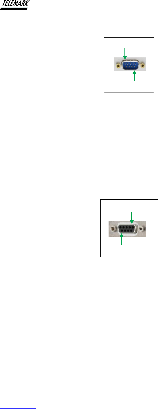
3.18.2 Remote comms pin assignments, RS-232
1
9
Figure 3-18, RS-232 Connection
Connection is via a DE9 connector located on the rear panel.
PIN2 RX232 data receive input
PIN3 TX232 data transmit output
PIN5 RS232 ground
Pins 1, 4, 6-9 not used
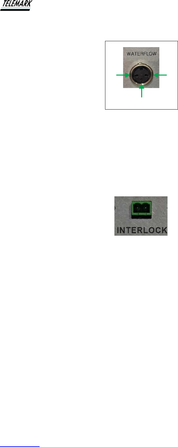
3.18.3 Mass Flow Controller connector pin assignments
1
9
Figure 3-19, Mass Flow Pinout
Connection is via a DE9 connector located on the rear panel.
PIN1 not used
PIN2 and 3 +24V Power
PIN4 and 5 Power ground
PIN6 RS485 RX+
PIN7 RS485 RX-
PIN8 RS485 TX-
PIN9 RS485 TX+
Ion Beam System Manual USING THE ION BEAM SYSTEM
Telemark.com 46 of 130 Rev 1.0.0
4.1.1 Main Power Switch
Switching On the power button (position 'I') activates the main power circuit of the device.
Switching off the unit (position 'O' switch) completely cuts the power to the internal circuits -
controller is safe to make rear panel connections.
4.1.2 LCD Touchscreen
Interaction with the user takes place by means of a graphical LCD Touchscreen display.
4.2 MAIN SCREEN
4.2.1 Initial Power Up
Switch on the power switch located on the lower left-hand front panel. The Touch Screen will
be seen to power up within a few seconds. Once powered up, the screen below will be
presented (the numbers in various boxes may be different from shown).
Before applying power to the ion beam system for the first time check that all
connections have been made as outlined in the Installation Manual and that
the ion source has been installed correctly in the vacuum environment. Check
also that a filament(s) have been installed correctly in the ion source.
CAUTION
!
Risk of the electric shock!
All connection to the devices may only be carried out with the unit is turned off -
the main power switch in 'O' position.
Failure to do so may cause electric shock
DANGER
!

Ion Beam System Manual USING THE ION BEAM SYSTEM
Telemark.com 47 of 130 Rev 1.0.0
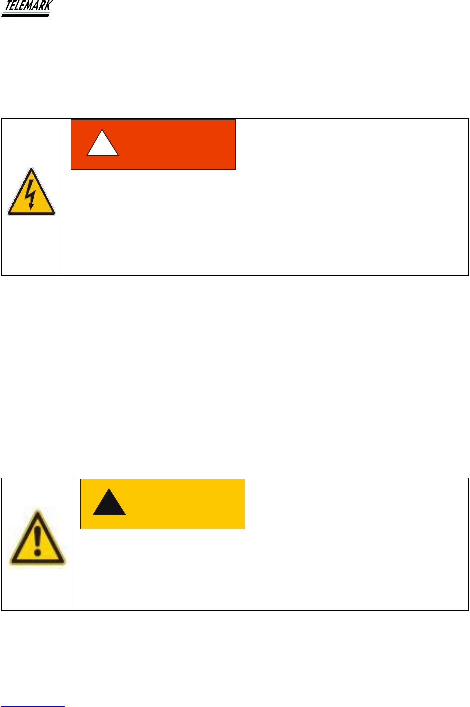
Figure 4-2, Main Screen
Figure 4-2 shows the main screen. This screen provides all functions to operate the Ion Beam
System in the normal continuous mode.
Notes on Functions – starting from top left counter-clockwise:
1. “3000” refers only to the model of the ion beam system – not active
2. “NO ALARM” status of alarm. If an alarm becomes activated, the power supply will be
disabled. The alarm icon will change to a red flashing icon. Touching the ALARM icon will
display another screen indicating the ALARM error message. For a list of ALARM messages –
see chapter 10.
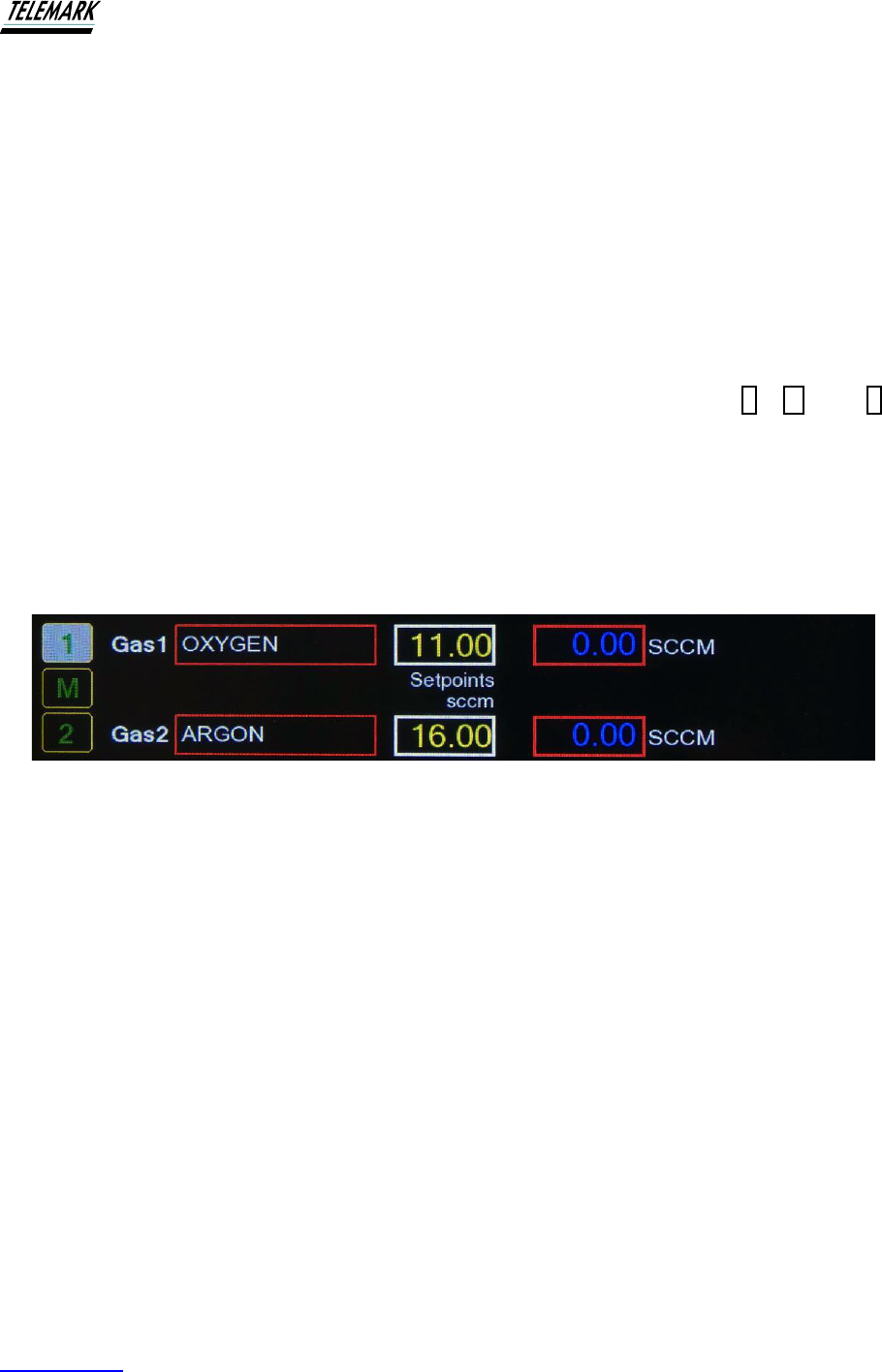
3. Gas 1 “OXYGEN”. This window displays the selected gas. To change gas, go to Settings –
see below.
4. Setpoint sccm “15.0”. The window shows the gas flow setting in percentage points. To
change set-point, go to settings – see below.
5. SCCM “0.00”. This window actively displays the actual gas flow during normal operation.
6. START. The green button starts the pre-set operation of the ion system. Touch the START
button to activate. Once activated, the START button changes to a flashing “STOP” button. At
any time, a single touch of the button powers down the ion source.
7. Water Flow G/min “2.25”. The window displays the instantaneous water flow. The flow must
be above a minimum otherwise an ALARM will result. The flow can be configured to display in
Gallons per minute or Liters per minute. To change the configuration, go to the SETUP window.
8. SETUP. The SETUP button is an active button that will display a new window showing all
operational parameters. See Section 4.3 SYSTEM SETUP below for details.
Ion Beam System Manual USING THE ION BEAM SYSTEM
Telemark.com 48 of 130 Rev 1.0.0
9. ? QUESTION MARK. The question mark button is an active button that will display a new
window called the DETAILS SCREEN.
“Gas flow control. (See GAS SETUP 4.6 to configure for percent or SCCM) As per the Filament
power control, the gas flow control can be similarly set. A number pad pops up when the white
bordered (“500”) button, when touched, will bring up a numeric keypad from which can be
entered the required gas flow. The number to be entered is within a range of 0 to 1000 where
1000 represents the maximum flow of the selected MFC. In the example shown above, a
number of 500 sets the flow of Gas 1 (selected) to be one half of the maximum flow of 30 sccm
(= 15 sccm). The three small buttons to the right of the active area marked as “1”, “M” and “2”
are provided to select either of the pure installed gases, Gas 1 or Gas 2, or Mixed gases of the
two installed gases. This two-gas facility is only available if the Dual Gas Option (DG) is
installed. For a detailed description of setting the Dual Gas Mixtures, see further in this manual
under Dual Gas Control. Gas flow setpoint can be entered in sccm (absolute) or percent
(logical full scale of selected gas) with a resolution of 0.1%. Unit selection on gas config
screen.
Figure 4-3, Gas Flow Setup
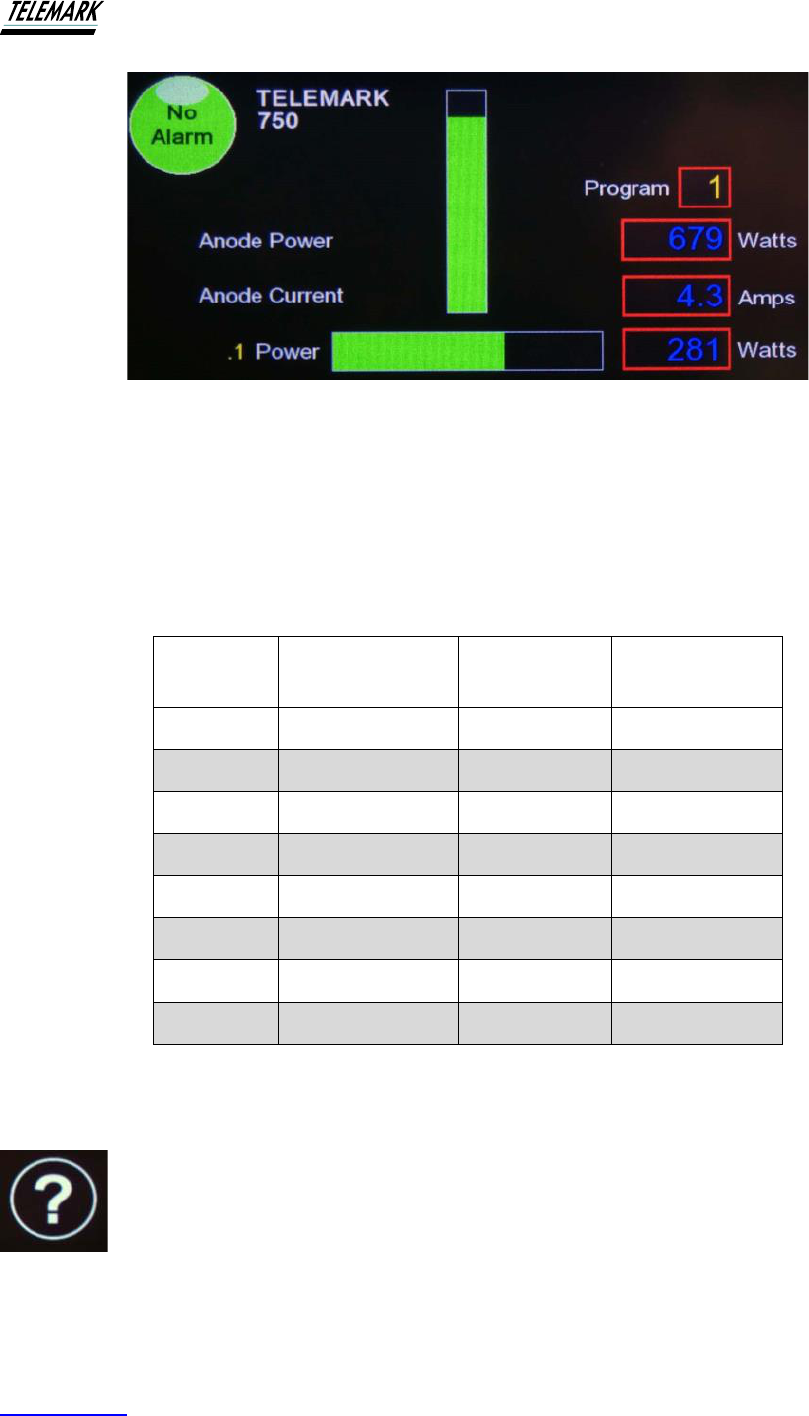
Anode Current & Beam Power Monitoring. This section of the Main screen provides
instantaneous monitoring of the Anode (or plasma) current as well as the beam power. The
beam power is calculated as the instantaneous product of the anode current and the RMS
anode voltage and is displayed as watts. In the current example, the product of the RMS of 184
volts and multiplied by 4.1 amps = 539 watts. For visual convenience, the instantaneous power
is also displayed in the green bar graph to the right of the screen. As the power level increases
the green ‘bar’ rises in the window. If the maximum allowable power is achieved, the green
display changes to red and the
Amps changes to red or Watts changes to red. Any attempt to
further increase beam power by increasing gas flow will be unsuccessful.
Ion Beam System Manual USING THE ION BEAM SYSTEM
Telemark.com 49 of 130 Rev 1.0.0
Figure 4-4, Anode Current & Beam Power Monitoring
Additional notes on Maximum Power There are two separate maximum power levels: Power
threshold is model dependent.
Maximum power is available when using the three highest anode voltages but limits the current.
When using the two lower anode voltages, the maximum power is limited but maximum current
is available. This is designed to protect the system against excessively high anode current.
Model
Anode Voltage
Power Limit
Beam Current
Limit
750
225, 180, 140
765W
5
750
110, 90
612W
5
1250
225, 180, 140
1275W
7.5
1250
110, 90
1020W
7.5
2000
300, 230, 180
2040W
10
2000
130, 90
1632W
10
3000
300, 230, 180
3060W
15
3000
130, 90
2550W
15
Power Limit Table
4.2.2 Details
Details screen

Ion Beam System Manual USING THE ION BEAM SYSTEM
Telemark.com 50 of 130 Rev 1.0.0
Figure 4-5, Details Screen
4.3 SYSTEM SETUP
Touching the “SETUP” button on the Main Screen will open the following screen:
System Setup Screen. To return to Main Screen simply touch “X” at the top of the screen. The
system Setup screen provides access to other windows for setting parameters for the various
Modal Operations, e.g. Pulse, Gas, Purge, Clean, etc.
Figure 4-6, System Setup

Ion Beam System Manual USING THE ION BEAM SYSTEM
Telemark.com 51 of 130 Rev 1.0.0
4.3.1 Setup
Anode Setup – Touch this button to open the Anode Setup screen
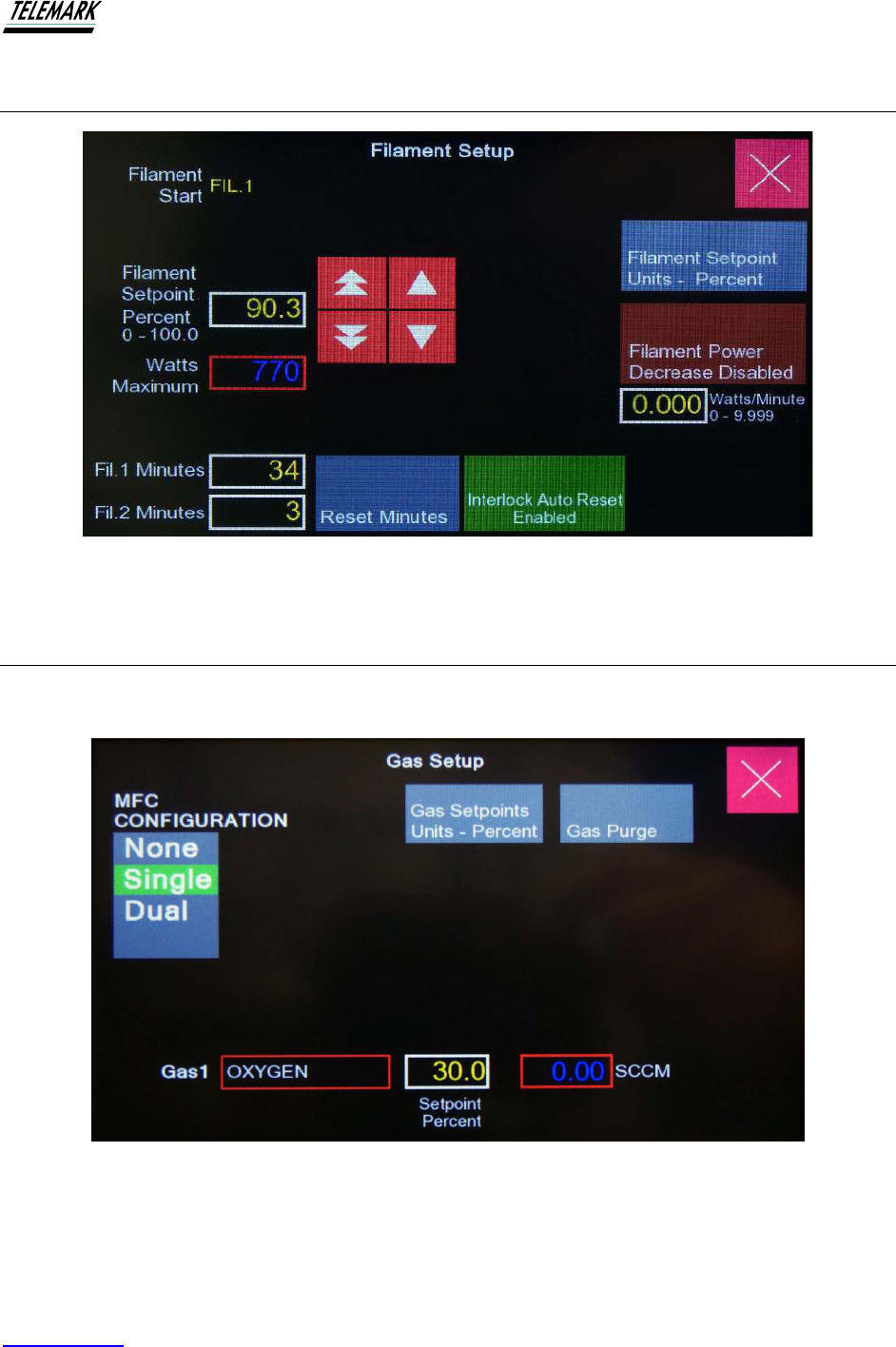
Filament Setup – Touch this button to open the Filament Setup screen
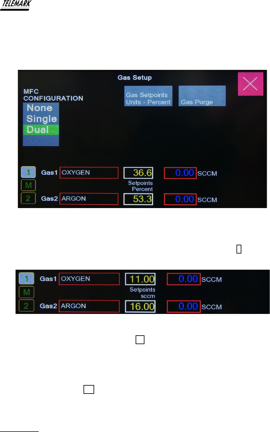
Gas Setup – Touch this button to open the Gas Setup screen
Water Setup – Touch this button to open the Water Setup screen
Clean Setup – Touch this button to open the Clean Function screen.
Pulse Setup – Touch this button to open the parameter set screen for the Pulse.
Auto Setup – Touch this button to open the Automatic Control Function screen.
Timed Setup – Touch this button to open the Timed Setup screen
4.3.2 Enable/Disable
Clean Enable/Disable –
Pulse Enable/Disable –
Auto Enable/Disable –
Timed Enable/Disable –
4.3.3 Selection
Service – Touch this button to open the Service screen. Password protected for factory use.
Programs – This button provides access to the screen where regularly used programs can be
saved and loaded.
Control –
The following pages of this manual will describe each of the functions available through this
screen.
Note that this screen also displays the version of software currently installed.
4.4 ANODE SETUP
ANODE Voltage Select. To change the Anode voltage, simply touch the white bordered Anode
Volts button on the Main screen. This action will bring up an Anode Volts selection menu as
shown. To make the selection, touch the appropriate voltage button. The new selection will
appear immediately, however, it will not be applied until the next time the START button is

Ion Beam System Manual USING THE ION BEAM SYSTEM
Telemark.com 52 of 130 Rev 1.0.0
activated. This means that, if the anode voltage change is made while the power is ON, the
change will not be effected until the STOP button is first touched and START is initiated again.
Figure 4-7, “ANODE” Voltage Select
Note that the voltage displayed while the power supply is in standby, is the ‘nominal’ anode
voltage. The actual and instantaneous anode voltage is shown once the power is ON. The
voltage shown will then be either Peak or RMS, anode voltage depending on selection and will
generally be slightly higher than the nominal voltage when no beam current is produced. It is
normal for the anode voltage to reduce as beam current increases and may be seen to be lower
than the nominal voltage at high power levels.
Note also that selection of the “OFF” button will return a zero anode voltage. This may be useful
when setting other operational parameters without the need to operate the source.
Model
750/1250
Model
2000/3000
225
300
180
230
140
180
110
130
90
90
Andode Voltage Select Options
Ion Beam System Manual USING THE ION BEAM SYSTEM
Telemark.com 54 of 130 Rev 1.0.0
(All Models)
The Dual Gas option, if installed, provides the facility to operate the ion beam system using
either of the installed gases alone – as pure gases or both gases together in a fixed, pre-set
mixture.
Figure 4-10, Dual Gas Setup
Select Pure gases
Either of the two installed gases can be used as pure gases. Simply select Gas 1 (O2) or Gas 2
(Ar). The following section of the Main screen shows the use of Gas 1:
Figure 4-11, Select Pure Gases
To use Gas 2 (argon) simply touch the Gas 2 2 button. Gas flow adjustments will now relate
only to argon gas. Note that, if the source gas is changed (Gas 2 → Gas 1), the last used Gas 1
setting will now be selected.
Select Mixed Gases
To use Mixed Gases, touch M and the following screen will appear:
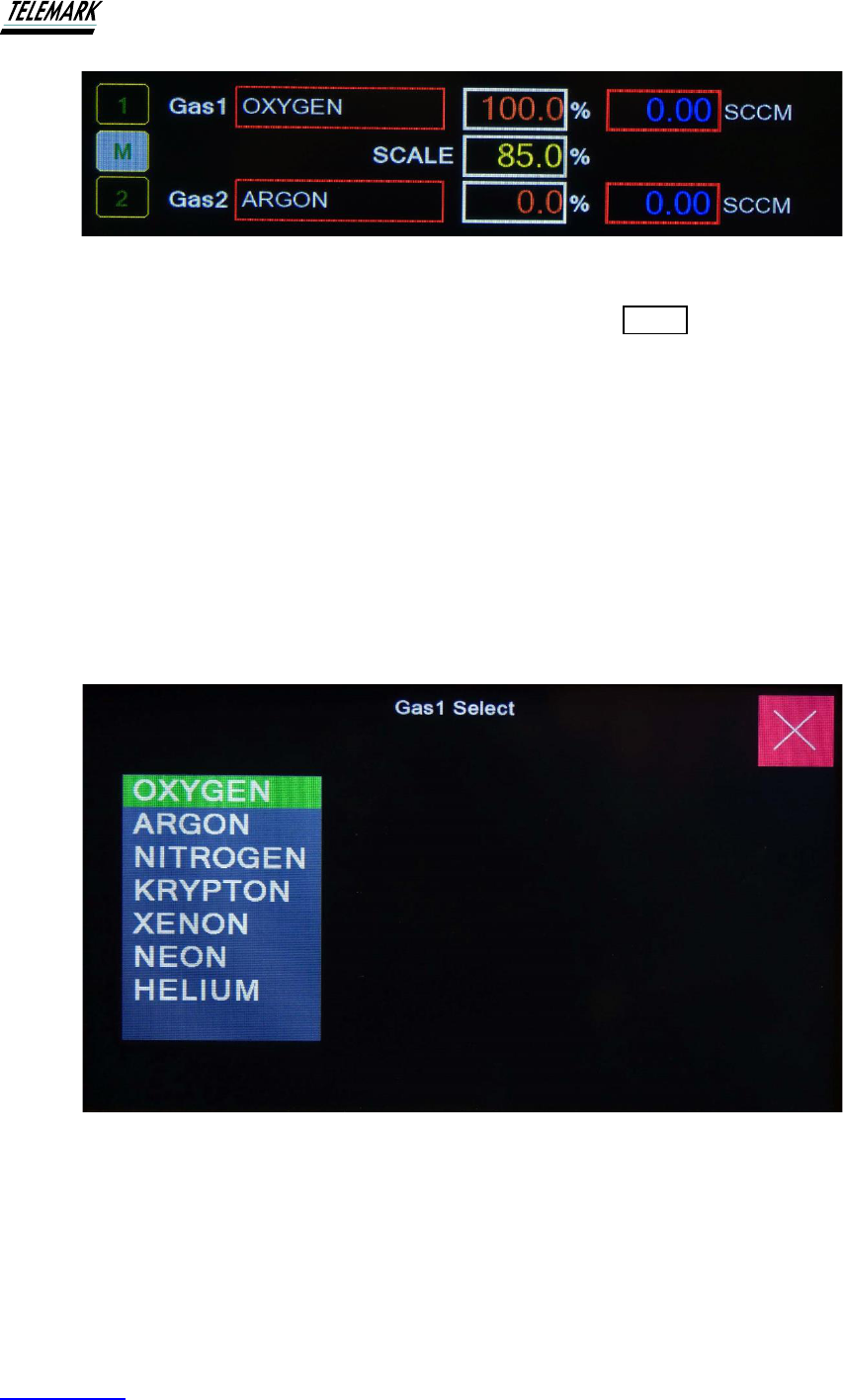
Ion Beam System Manual USING THE ION BEAM SYSTEM
Telemark.com 55 of 130 Rev 1.0.0
Figure 4-12, Select Mixed Gases
To establish the ratio between the two gases, touch either of the 0.0 % buttons. A numeric
keypad will open. Enter the percentage value for the gas, e.g., 25% of gas 1. Once entered,
Gas 2 will be set to [100 – 25]% = 75%.
The percentages relate to the actual gas flow in sccm. This means that for 100% of the total gas
flow entering the ion source, 25% will be Gas1.
Example: Set Gas 2 at 9% (thus making Gas 1 to be 91%). Now touch START and establish a
beam. The beam should stabilize within a few seconds. As can be seen below, there is a total of
13.6sccm of gas flowing. A simple calculation will verify that 91% of 13.6sccm is close to
12.3sccm within the accuracy of the MFCs.
4.6.3 Gas Select
Figure 4-13, Gas Select
4.6.4 GAS PURGE
This function is provided to ensure the integrity of the process gas. The Gas Purge Mode is
entered by touching the Gas Purge button on the Mode Select screen.
The following recommendation is worth consideration.
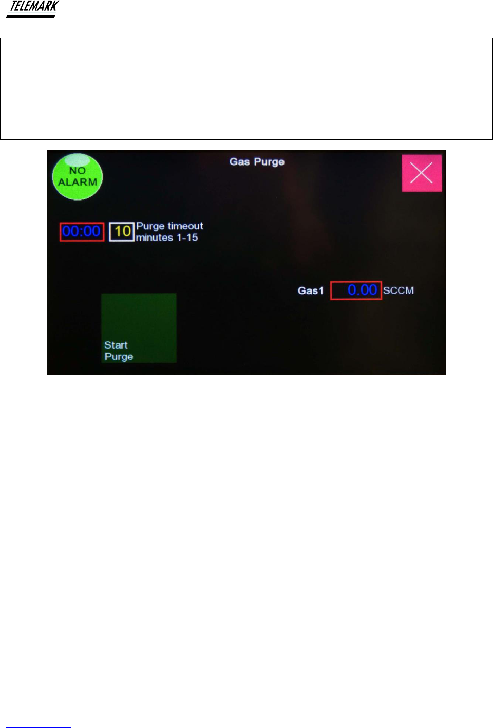
Ion Beam System Manual USING THE ION BEAM SYSTEM
Telemark.com 56 of 130 Rev 1.0.0
Recommendation
It is very important that the purity of the gas is always maintained. At the start of each day or
shift or at any time where the ion system has not been used regularly or new gas tank installed,
the gas lines should be purged to ensure high purity gas is being introduced to the plasma.
Remember, the IAD process will ionize any condensable gas - including impurities
Figure 4-14, Gas Purge
Purge Timeout
Once started, the Purge operation will be terminated by either of two timeouts.
▪ Preset timeout – max. 15 minutes
▪ Gas flow limit (1%) achieved
The purge timeout can be preset to a maximum of 15 minutes. Generally, this time will be set to
the ‘normal’ time required to pump out the gas in delivery lines between the gas storage facility
and the MFC. This will vary considerably between different installations. Initially, the purge
timeout should be set to 15 minutes and the time noted when the gas flow reaches approx. 1-
2% of the initial flow. Set the timeout for about 1 minute longer. If a flow of 1 – 2% cannot be
reached the possibility of a leak should be investigated.
The purge facility offers an easy method to check the integrity of the gas delivery system. For
example, if the purge time is typically 3 minutes but on some occasion the purge is not complete
by the timeout, suspect a leak somewhere in the gas delivery lines.
Using the Gas Purge facility
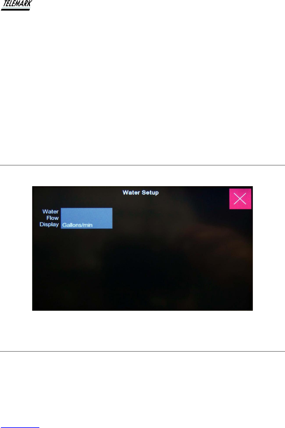
Ion Beam System Manual USING THE ION BEAM SYSTEM
Telemark.com 57 of 130 Rev 1.0.0
The Gas purge screen provides the facility to purge either or both installed gases. Note that
both gases can be purged at the same time (for a Dual Gas Facility). The gas to be purged is
simply selected by engaging either “Gas 1 ON” or “Gas 2 ON”. Touch the “START PURGE”
green button and the gas flow(s) will be shown in the appropriate windows. Note that, to speed
up the purge process, the MFCs will be set to operate at the maximum flow as set by the
manufacturer. The MFCs supplied by Telemark IBS normally have a full flow range of 50 sccm
although they are set to operate at 30sccm (oxygen) or 20sccm (argon) under software control.
For the purge operation they are operated at the full 50sccm and 74sccm for the argon MFC.
Routine Purging
The Telemark Digital system makes the purging operation very simple. Simply shut off the valve
at the point of the gas source, e.g., gas regulator, open the Gas purge window and touch the
START PURGE button. When finished, do not forget to re-open the gas supply valve.
4.7 WATER SETUP
Figure 4-15, Water Setup
4.8 CLEAN SETUP
For almost every thin film deposition, it is normal practice to carry out a pre-deposition
bombardment of the substrates. The purpose and benefit of this practice is very well
documented although the primary function is to remove remaining surface contaminants as an
aid to promote film adhesion.
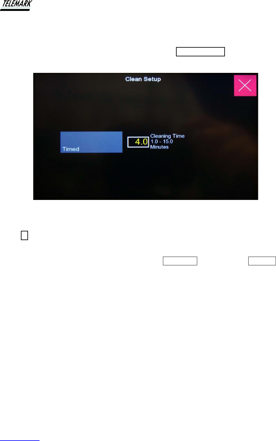
Ion Beam System Manual USING THE ION BEAM SYSTEM
Telemark.com 58 of 130 Rev 1.0.0
Due to the importance of this routine operation, Telemark IBS has included a separate function
that can be pre-set and activated with the touch of the touch screen.
The Clean Mode function can be initiated by selecting the CLEAN SETUP from the SELECT
screen. The following window will be opened:
Figure 4-16, Clean Setup
The required pre-deposition bombardment time can be set by touching the white bordered
button 4. This will open a numeric keypad. Type the required time (max. 15 mins.) and touch
‘ENTER’ on the keypad.
When ready for the operation to be started, touch the DISABLED button. This will ENABLE the
timing mode. Press START to operate. When the process times out, the beam turns OFF and
the CLEAN Mode will automatically DISABLE.
To establish a program that will automatically enable the CLEAN Mode whenever the ion beam
is started up, touch the “CLEAN MODE NORMAL” button. Activating this button will maintain the
ion beam system in the “CLEAN MODE”. This means the ion beam will operate for the set time
and power off every time the START button is activated. This function would be of value for
metal depositions where the ion beam operation is only required to pre-clean the substrates.
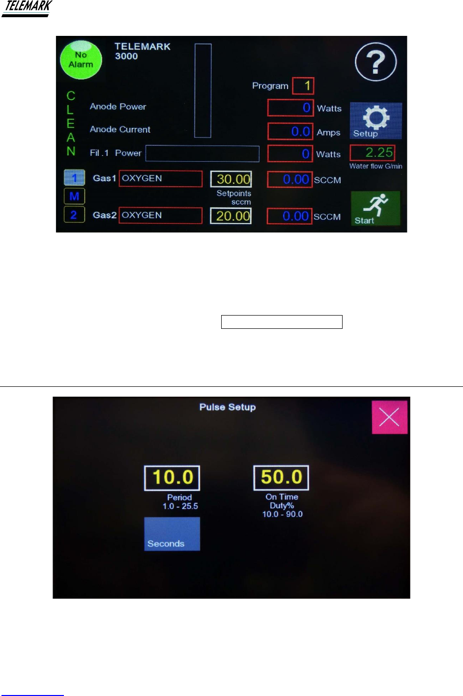
Ion Beam System Manual USING THE ION BEAM SYSTEM
Telemark.com 59 of 130 Rev 1.0.0
Figure 4-17, Clean Mode
While the CLEAN MODE is activated, the Main Screen will show “CLEAN” as a flashing display.
Figure at right shows the Main Screen with the “CLEAN” indicator
Exit the CLEAN MODE setup by touching the CLEAN MODE setup exit bar at the top of the
screen.
4.9 PULSE SETUP
Figure 4-18, Pulse Setup
From the MODE SELECT screen touching the “PULSE SETUP” button will bring up the
parameter setup screen for the Pulse Mode operation.

Ion Beam System Manual USING THE ION BEAM SYSTEM
Telemark.com 60 of 130 Rev 1.0.0
Two parameters may be set with this window as shown in figure 4-18.
The “PERIOD” is the time for a complete cycle, i.e., the time from the start of one pulse, or ON
time, to the start of the next pulse. The maximum period is 25.5 seconds or minutes depending
on selection. The “ON TIME DUTY%” is the percent of time that the Mass Flow Controller
(MFC) is activated. This percent can be set to a maximum of 90%. In general, it is normal to
select an ON time that is no more than about 60% of the Period.
The other factor to be considered is the response time of the system. The response time is
influenced by several factors such as:
➢ Speed of response of the MFC. This can vary considerably between different MFCs
however, Telemark supply MFCs with fast response times of the order << 1 second.
➢ Length and volume of gas delivery lines (tubing) between the MFC and the ion source.
Telemark IBS always recommends the mounting of the MFC to be as close to the gas
feedthrough as practicable. Telemark IBS also recommends the use of small gauge
tubing to transport the gas between the MFC and the ion source. The optimum size is
1/8” stainless steel. Smaller size tubing does not provide any further benefit due to the
reduced conductance.
When establishing the Pulse ON time, the preferred technique to monitor the ON time is to use
a Cathode Ray Oscilloscope (CRO). The CRO signal can be obtained from the Anode Current
signal available from the BNC connector located on the right-hand front panel. It is difficult to
establish the true settings by observing the pulsing behavior of the Anode Current because of
the refresh rate of the digital display.
Both the Period and ON times may be set or adjusted with the popup screen.
Once adjustments have been made, exit the Pulse Mode Setup by touching the EXIT bar at the
top of the screen.
Pulse Mode parameters are saved with all other parameters when the SAVE FILE functions
are used – see below for further information on saving files.
The system may be powered on from the Pulse Setup screen by touching “START” as normal.
Once started, it may be stopped from this screen by touching the “STOP” button.
Once the Pulse parameters have been set, exiting this screen will return to the MODE SELECT
screen. On this screen, the Pulse Mode switch can be activated. The next time the power
supply is powered ON, it will be in Pulse Mode.
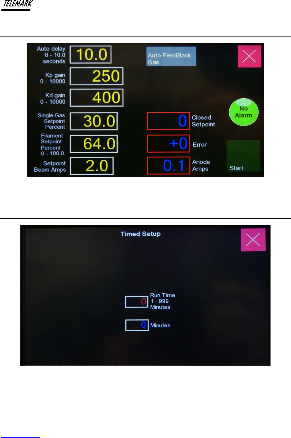
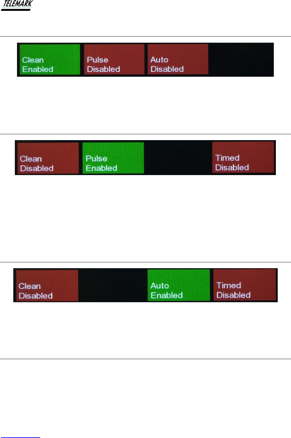
Ion Beam System Manual USING THE ION BEAM SYSTEM
Telemark.com 62 of 130 Rev 1.0.0
4.12 CLEAN ENABLE/DISABLE
Figure 4-21, Clean Enable
Press the Clean Disable (red) to change to Clean Enable (green).
4.13 PULSE ENABLE/DISABLE
Figure 4-22, Pulse Enabled
Press the Pulse Disabled (red) to change to Pulse Enable (green). Pulse enable button will
always be green if PERMINANT mode is selected on pulse config setup. Enabling pulse
automatically disabled auto mode, and similarly, enabling auto disables pulse mode.
They are mutually exclusive - only the enabled button is displayed.
4.14 AUTO ENABLE/DISABLE
Figure 4-23, Auto Enabled
Press the Auto Disabled (red) to change to Auto Enable (green).
4.15 TIMED ENABLE/DISABLE
Press the Timed Disabled (red) to change to Timed Enable (green).

Ion Beam System Manual USING THE ION BEAM SYSTEM
Telemark.com 63 of 130 Rev 1.0.0
Figure 4-24, Timed Enabled
4.16 ANODE DC ENABLE/DISABLE
Figure 4-25, Anode DC Option Enabled
For the optional Anode DC press the Anode DC Disabled (red) to change to Anode DC Enable
(green). Anode DC can only be enabled when stopped. Enabling or disabling will occur
when actual anode voltage is below 25V. Allow time for storage capacitor to discharge.
4.17 SERVICE
Service unlock screen for factory use only.
Figure 4-26, Service Unlock - Factory use only
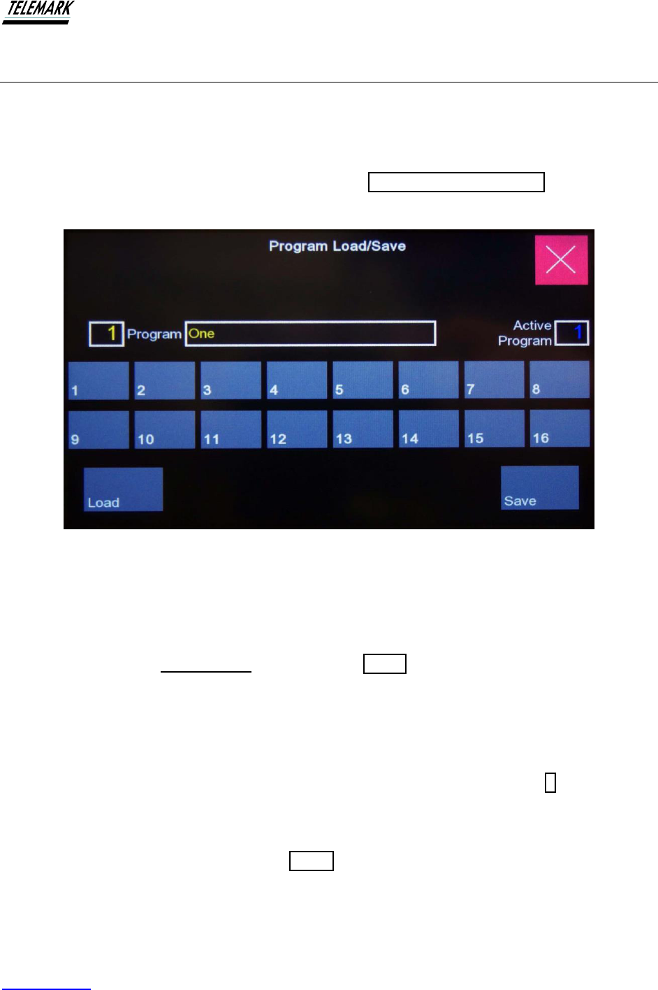
Ion Beam System Manual USING THE ION BEAM SYSTEM
Telemark.com 64 of 130 Rev 1.0.0
4.18 PROGRAMS
The LOAD/SAVE program facility is provided to allow saving regularly used operational
procedures. This saves valuable time and ensures consistency of product in production facilities
by loading already saved programs. Up to 16 programs can be stored.
The LOAD/SAVE screen is accessed by touching the LOAD/SAVE PROGRAM button on the
Mode Select screen. The following screen is shown:
Figure 4-27, Program Load/Save
Saving a Program Name. The program Name can have up to 26 alpha numeric characters.
To enter a new program name, first touch the name bar which will open a keypad – see figure
below. Enter the file name and, when finished, touch ‘ENTER’. The keypad disappears although
the file parameters are not yet saved. Now touch the SAVE button. Upon touching the SAVE
button the word “DONE” will appear momentarily on the screen. All operational parameters are
now saved under the new file name.
Loading a Pre-saved Program. First, enter the LOAD/SAVE screen as above. All saved
programs will have a File Number between 1 and 16. There are two ways to display the required
File Number. If the File Number is known, simply touch the File Number button (1 in this
example) A numeric keypad will appear – type in the required File Number. An active program
of zero indicates no program has been loaded or saved yet.
Once the required File is displayed, touch LOAD. The word “DONE” will momentarily appear.
The File is loaded and in operation.
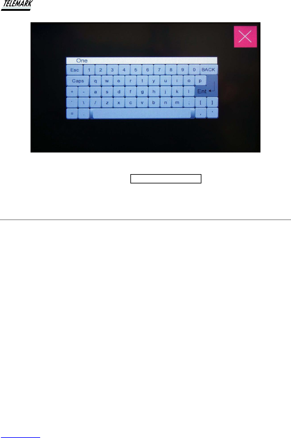
Ion Beam System Manual USING THE ION BEAM SYSTEM
Telemark.com 65 of 130 Rev 1.0.0
Figure 4-28, Keyboard
Exit the Load/Save screen by touching the PROGRAM MODE exit button on the top of the
screen.
4.19 FIRST TIME OPERATION
4.19.1 Recommended Procedures for First Time Operation
First Step - Purge the gas delivery line.
1. Shut off gas supply at gas source. This may be a gas pressure regulator
2. Open Gas Purge window at power supply
3. Touch gas purge
4. Wait till all gas pumped and Purge function is complete
5. Open gas supply
6. Return to Main Screen
Second Step – Start up power to obtain beam
1. Select zero anode voltage from Main Screen
2. Start power supply
3. Check that the filament power is controlling. Adjust filament current to 20 amps
4. Check gas flow is controlling. Adjust flow to 6 sccm (750); 10 sccm (1250); 12 sccm
(2000/3000)
5. Select anode volts to 180 (750 & 1250); 200 volts (2000/3000)
6. Power OFF and re-start – (this step required to invoke anode voltage change)
7. After about 10-12 seconds beam should be established

Ion Beam System Manual USING THE ION BEAM SYSTEM
Telemark.com 66 of 130 Rev 1.0.0
Alternate start up procedure for Second Step above.
1. From the Main Screen select MODE
2. From Setup screen select PROGRAM
3. Scroll the available saved programs and select and LOAD “Standard Conditions”*
4. Return to Main Screen and press START
* “Standard Conditions” are a set of parameters pre-loaded to one of the memory slots. The
various parameters are considered best suited for each model that will ensure operation within a
safe operating range for the model. With experience, the operator may decide on a modified
parameter set that better suits their application. The new parameter set may be saved over the
original for later use.
4.20 DUAL FILAMENT FACILITY
(1250, 2000 and 3000 only)
If your ion beam system is fitted with the Dual Filament option, the power supply will
continuously monitor the status of the first filament. When the first filament fails, the power
supply will automatically re-establish power to the second filament at the same power setting as
the first filament. The operation of changeover can be expected to take up to about 8 - 10
seconds.
The photo below shows the correct assembly of the coiled filaments. Install the hooked end of
the filaments around filament legs 1 and 2. The straight end of the filaments are clamped at the
common filament post. Slightly extend both ends at the common filament post before clamping.
This maintains a slight tension in the filaments so that they will remain straight when heated for
the first time.
Be aware that tungsten wire becomes very brittle once heated to emission temperatures. Any
attempt to re-shape a filament once used will most likely break the filament.

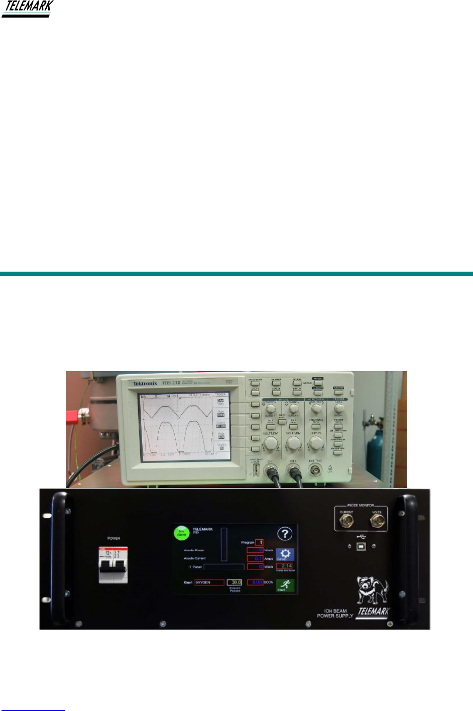
Ion Beam System Manual BEAM DIAGNOSTICS & MONITORING
Telemark.com 68 of 130 Rev 1.0.0
5 BEAM DIAGNOSTICS & MONITORING
Provision is made for monitoring the Anode Voltage and Anode Current. BNC connectors are
located on the right-hand front panel that provide scaled signals suitable for display on a
cathode ray oscilloscope (CRO) or similar voltage-time display. Valuable information is available
by visualizing either or both parameters. The voltage waveforms provide information on
neutralization and allow the operator to optimize ion source performance.
Figure 5-1, Beam Diagnostics

Ion Beam System Manual BEAM DIAGNOSTICS & MONITORING
Telemark.com 69 of 130 Rev 1.0.0
The above photo shows both anode voltage and current waveforms displayed on a Dual Beam
CRO. The upper trace is the anode voltage.
Both signals are scaled. The Anode Voltage is scaled by 1:100 and the Anode Current scaled to
1 volt per amp.
If using the Pulse Mode of operation, it is useful to view the Anode Current signal (the lower
trace on the CRO above). This waveform will very precisely indicate when the beam is on and
off.
.
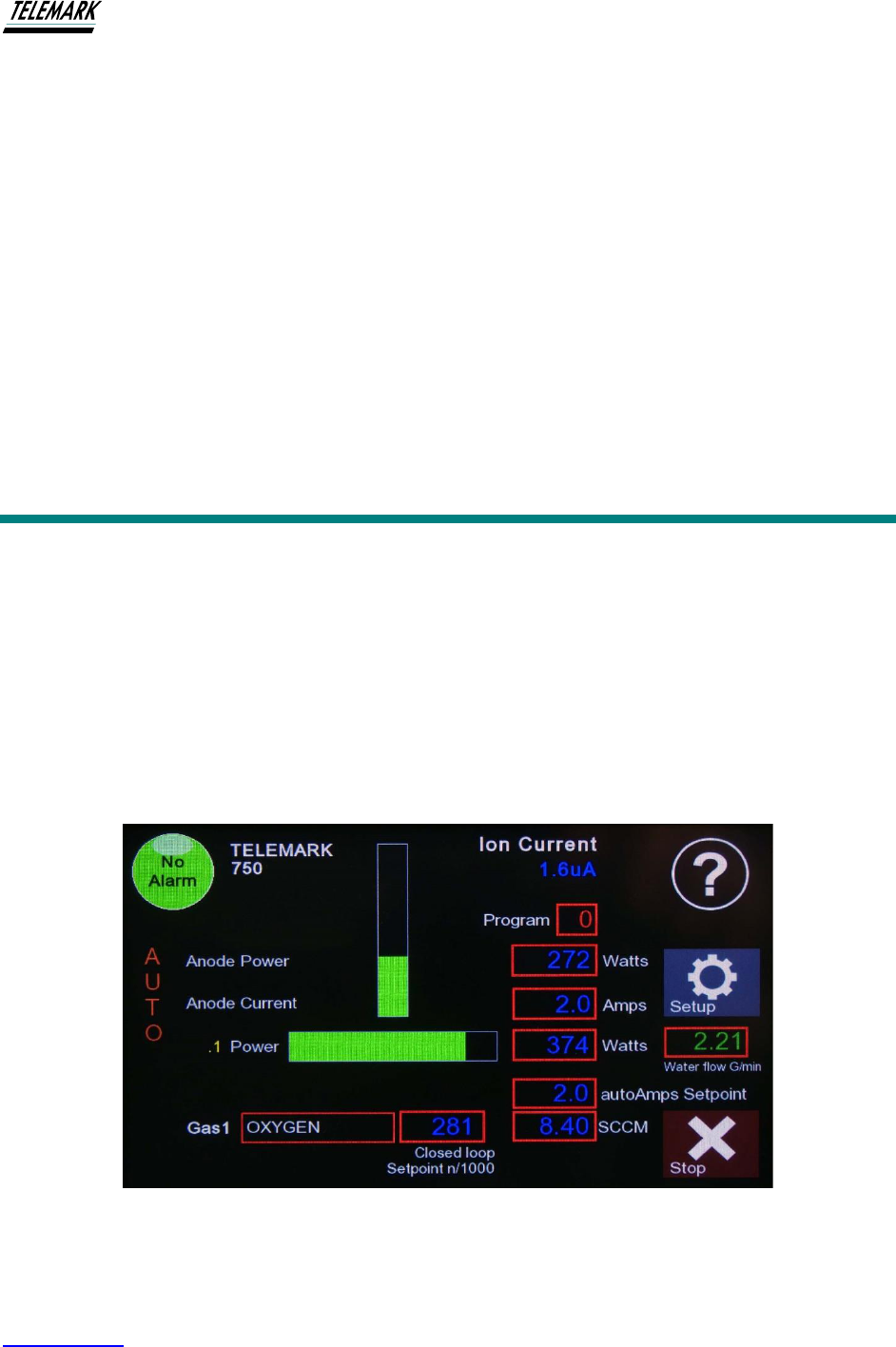
Ion Beam System Manual ION CURRENT MONITOR
Telemark.com 70 of 130 Rev 1.0.0
6 ION CURRENT MONITOR
If the Telemark Ion Beam System was purchased with the optional Integrated ICM installation of
the ICM with the power supply is very simple. Install a BNC terminated coax cable to the BNC
socket located on the rear panel.
When the power supply is powered on the next time, it will recognize the installation
automatically. The bias voltage can be adjusted over the full range by adjusting the small
potentiometer located adjacent to the BNC connector on the rear panel.
The Main Screen will now show the ICM monitor signal displayed as shown below (showing
1.6uA in this example)
Figure 6-1, Ion Current Display

Ion Beam System Manual ION CURRENT MONITOR
Telemark.com 71 of 130 Rev 1.0.0
The digital data from the ICM is auto-ranging and covers the range from 1 microamp to 2
milliamps. The data displayed is the RMS ion current as measured in the ICM sensor.
6.1 SYSTEM OVERVIEW
The Telemark Ion Current Density Monitor is designed to measure the ion current flux from ion
sources such as the Telemark/Saintech grid-less ion sources, cold-cathode ion sources, anode
layer ion sources or Kaufman gridded type ion sources. The system comprises a sensor head
that provides a current signal to a monitoring unit. The sensor head is mounted in the vacuum
chamber and measures the ion current deposited across the sensor element by positively
charged ions entering the sensor head through an aperture pointed in the general direction of
the ion source. The monitoring unit, situated outside of the vacuum chamber displays an
amplified RMS signal on an LCD digital panel meter. A front panel mounted BNC connector
provides a signal suitable for display on an oscilloscope or similar display device.
6.1.1 The Sensor Head
The Sensor Head is specially designed for use in harsh
coating environments to maintain constant current
monitoring capacity despite the accumulation of dielectric
coatings onto the Sensor Element. The sensor head is
mounted downstream of the ion source to provide an
accurate measure of the ion current density incident on
the deposition substrates. A stainless-steel shielded
Type-K Thermocouple Cable connects the sensor head to
a coaxial electrical feed-through for transmitting the ion
current signal.
6.1.2 Monitoring Card
Figure 6-3, Monitoring Card
ICM is installed in the Ion Source Power Supply. In the rear of the Ion Source Power Supply a
BNC connector and Bias adjustment are shown.
Figure 6-2, Sensor Head

Ion Beam System Manual ION CURRENT MONITOR
Telemark.com 72 of 130 Rev 1.0.0
6.2 THE DETECTION OF CHARGED PARTICLES
Ion sources are designed to produce a charge neutral beam of energetic ions and electrons that
can be directed toward the substrates and sensor. To repel the electrons, a negative bias
voltage is applied to the sensor so that only the positive ion current is detected. The bias
voltage is adjustable between –5 and –55 Volts (see ‘Setting the Bias Voltage’, section 6.10).
Ions incident at the sensor element cause a current to flow in the signal line which connects to
the Monitoring Unit. The signal current is amplified by a charge amplifier which produces a
voltage proportional to the input signal current. An RMS to DC converter produces a DC signal
proportional to the time varying AC signal. Three outputs of the signal are available. The RMS
current is displayed on the front panel LCD display. Alternatively, where time varying signals are
produced in the sensor, the waveform is made available through an alternative BNC connection.
The AC signal can best be observed on an oscilloscope.
6.2.1 The Detection of Charged Particles during PVD Processes
The Telemark/Saintech Ion Current Density Monitor operates on the same principal of a
Faraday cup. A Faraday cup measures the flux of charged particles as they enter the cup. As
the charged particles impinge the electrically conducting surfaces of the sensor element, they
are neutralized thus inducing an electric current.
6.3 INSTALLATION
Figure 6-4, ICM Installation Kit
The complete Ion Current Density Monitor package includes the following items:
* Sensor Head w/ Sensor Element*
* High temperature, stainless-steel shielded, Type-K Thermocouple cable (vacuum side)
* BNC connecting cable 1.5m (~5ft.)
* Coaxial BNC 1” (Bolt type) vacuum feed-through (Other options available.)

Ion Beam System Manual ION CURRENT MONITOR
Telemark.com 73 of 130 Rev 1.0.0
6.4 Mounting the Sensor Head
A mounting bracket with a 5mm stud is provided to attach the sensor head to a support bracket
inside the chamber. The support bracket would be made by the installer to suit the particular
requirements of the installation. It is recommended that the support be made from stainless
steel. If aluminum is used, care should be taken to ensure that the body of the sensor head is
properly grounded due to the high surface resistance of the native oxides of aluminum.
6.5 Electrical connections
1. Install the coax electrical feed-through.
2. Connect the non-threaded side of the shielded cable assembly to the vacuum side of the
coax connector. (Note that the connector just pushes onto the feed-through.)
3. Install the mounting bracket onto the support bracket within the vacuum chamber.
4. Mount the sensor head end (threaded) of the shielded cable assembly onto the mounting
bracket within the vacuum chamber. Tighten the set screw on the mounting bracket to
hold the cable end in place.
5. Install the sensor head to the shielded cable assembly. Gently push the sensor onto the
mounting bracket and then turn the sensor to engage the screw which retains the sensor
in place.
6. Make sure the sensor head is aligned with the aperture facing towards the ion source. (If
not loosen the mounting bracket setscrew and nut, re-align the sensor head, and re-
tighten.
7. Using a continuity tester, do the following:
a) Test that there is continuity (virtually no resistance) from the inner sensor element to
the connection at the atmospheric side of the feed-through;
b) Test that there is continuity between the body of the sensor head and chamber ground;
c) Test that there is NO continuity (high resistance) between the inner detector element
and chamber ground.
NOTE : Typically, the body of the sensor head will be earthed by connection through the mounting
bracket. However, if this is not the case, ensure a suitable connection of the sensor head body
to chamber ground has been established.
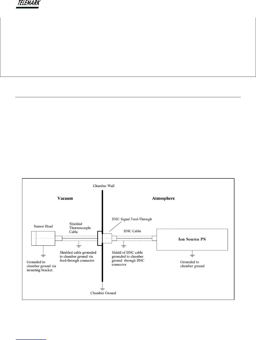
Ion Beam System Manual ION CURRENT MONITOR
Telemark.com 74 of 130 Rev 1.0.0
RECOMMENDATION
To provide the most accurate indication of the substrate ion current density, the detector head
should be mounted at approximately the same distance from the ion source as the substrates. In
a typical coating set-up, the detector head will be most conveniently mounted adjacent to a quartz
crystal deposition monitor or similar. Do not mount the front face of the detector behind the
alignment of the work plate.
6.6 Connecting the Monitoring Unit
1. (a) Connect the BNC cable (supplied) to the BNC feed-through.
(b) Check to ensure that the ground connection of the BNC feed-through is connected to
chamber ground.
2. Connect the BNC connection of the co-axial cable to the CURRENT SIGNAL IN connection
on the rear panel of the Monitoring Unit (see picture below).
3. Turn the power on Ion Current Monitor.
When complete, the installation should be represented as follows :
Figure 6-5, ICM Installation Diagram

Ion Beam System Manual ION CURRENT MONITOR
Telemark.com 75 of 130 Rev 1.0.0
6.7 CURRENT MONITORING
1. Turn the Ion Source PS on using the POWER switch on the front panel.
2. Initially, set the bias voltage to approximately -35 Volts (see SETTING THE BIAS
VOLTAGE section later in this manual).
3. Establish the ion beam as appropriate.
4. Observe the Digital display of the Ion Current reading. Depending on the magnitude of
the ion current, the ICM will auto-select the correct range.
The Aperture area is 1 cm
2
allowing the meter reading to be interpreted as a current per cm
2
.
6.8 ICM MAINTENANCE
Apart from occasional cleaning of the sensor collector, there should be no need for
maintenance of the head.
Figure 6-6, Parts of the Sensor Head
The picture above shows main parts of the Sensor Head. Included is the stainless steel shielded
Type-K Thermocouple cable assembly and mounting bracket.
6.8.1 Removing the Sensor Head from the Vacuum Chamber
1. Disconnect the signal line at the vacuum feed-through. The coax connector can be pulled
from the vacuum side of the feed-through. Do not apply force to the coax cable when removing
the connector.
2. Remove the sensor head from the shielded cable assembly connected to the mounting
bracket. The sensor head is screwed onto the cable assembly. It should not be necessary to
remove the cable assembly to clean the sensor head.

Ion Beam System Manual ION CURRENT MONITOR
Telemark.com 76 of 130 Rev 1.0.0
6.8.2 Cleaning
The sensor collector and the sensor head body should be periodically cleaned to remove
coating deposits.
1. With the sensor head removed as instructed above, unscrew the sensor aperture.
2. Remove the ring insulator and sensor collector element.
The ring insulator is made of ceramic and is therefore fragile. Take care not to
drop it on hard surfaces
3. Brush the collector and inner surfaces of the body with a light abrasive pad, e.g. Scotch Brite.
DO NOT GLASS BEAD. The sensor collector element is coated with Titanium Nitride (TiN).
Although TiN is a very hard coating, it will be permanently damaged by abrasive bead blasting.
RECOMMENDATION
It is not essential (also not recommended) to remove the complete sensor head from the
vacuum chamber for cleaning when only routine cleaning of the collector element is all that is
required
6.8.3 Reassembly
1. Insert the sensor element into the body so that the mesh engages the metal contact screw.
2. Locate the ring insulator in the sensor body aperture cover.
3. Screw the sensor body aperture cover against the sensor body. Tighten to light finger
pressure only – do not over-tighten as it will deform the collector
6.8.4 Checking the Signal Line contact
1. Using a standard continuity tester, make contact with one probe to the sensor (mesh) and the
other probe to the center contact of the BNC connector on the air side of the feed-through.
2. Check also for no continuity between the sensor and ground.
CAUTION
!

Ion Beam System Manual ION CURRENT MONITOR
Telemark.com 77 of 130 Rev 1.0.0
6.9 ICM TROUBLE SHOOTING
Problem
Likely or possible cause
No ion current
detected
1. Detector body not correctly earthed
2. No continuity for current wire
3. Check for proper bias voltage
Unstable current
readings
Detector may require cleaning
6.10 SETTING THE BIAS VOLTAGE
In order to prevent charging of dielectric surfaces in the vacuum chamber, ion beams for ion
assisted deposition must be charge neutral. Charge neutrality is achieved by additional
electrons from the ion source filament, hollow cathode electron source, or from an additional
neutralizer.
In order to measure the positive ion current, the electrons must be removed from the beam prior
to reaching the sensor. The monitoring unit is equipped to provide a negative voltage bias to the
sensor. The bias voltage control is located on the back panel next to the ICM BNC connector.
The bias voltage is adjustable between -5 and –55 V. Standard adjustment is -36V.

Ion Beam System Manual ION CURRENT MONITOR
Telemark.com 78 of 130 Rev 1.0.0
6.11 ICM ELECTRONICS SPECIFICATIONS
Operating ambient temp. range
0 – 35 C
Bias Voltage
Adj. between -5VDC and -55VDC
Input capacitance max.
Typ. 1000 pF, allows for 10 meters of coax.
@ 100pF/meter
Output signal: AC output
+/- 10V full scale (Output load > 2k)
0 to +10V represents positive ion current.
Negative volts represents electron current.
0 to approx. 16kHz (-3db) bandwidth.
Input ranges
0 - 200μA full-scale (20μA/volt output)
0 - 2mA full-scale (200μA/volt output)
Accuracy: AC output
+/- 1% of full-scale
Accuracy: RS232 Digital Output
+/- 5.2% of full-scale
6.12 Sensor Head Specifications – Vacuum
Operating temp. range
maximum 350 degrees C
Range change conditions:
1. RMS signal > 115% of full scale – change to next higher range
2. RMS signal < 5% of full scale – change to next lower range
3. AC input signal clipping (> 245% of full scale) for one second AND RMS signal > 55% of
full scale – change to next higher range
Ion Beam System Manual MAINTENANCE
Telemark.com 79 of 130 Rev 1.0.0
7 MAINTENANCE
In general, the source requires little routine maintenance. Apart from regular replacement of
filaments, it is only required to periodically clean the anode. Occasionally, the anode will require
cleaning to remove any build-up of scattered coating materials and contaminants.
When cleaning the anode, NEVER USE SOLVENTS. If alcohol or acetone is
used on the anode, fluid may penetrate the gas injection ports. The source will
become unstable due to outgassing and the desorbed hydrocarbon gases will
likely degrade the performance of coatings for some time following.
CAUTION
!
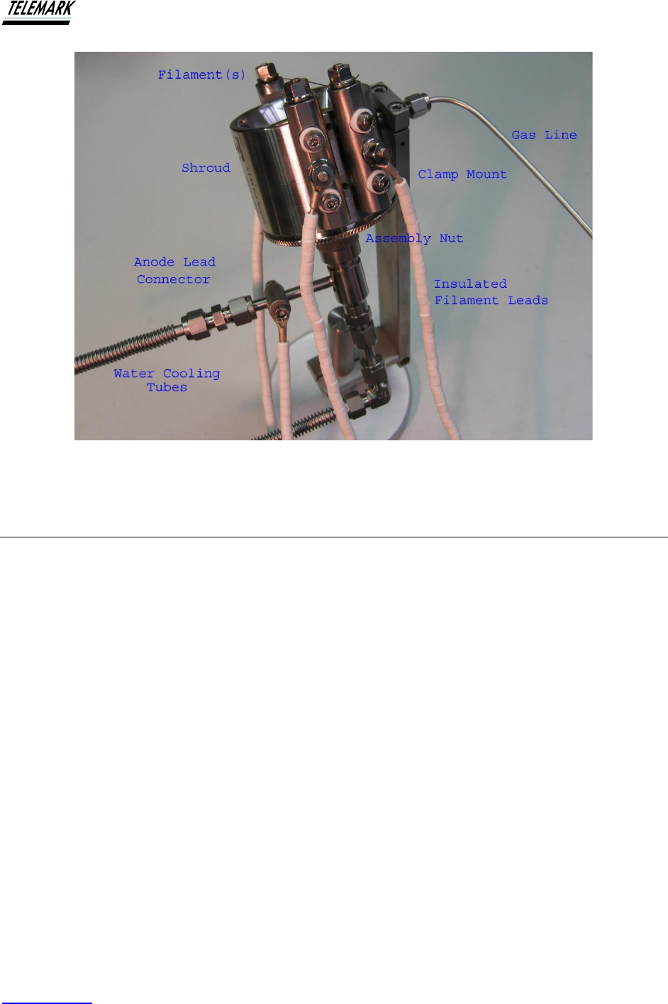
Ion Beam System Manual MAINTENANCE
Telemark.com 80 of 130 Rev 1.0.0
Figure 7-1, Parts of the Ion Source
7.1 Removal of the Ion Source from Mounting
If it is required to dismantle the ion source the following points should be observed:
1. Check that the power supply is safely shut down (remove the IEC (mains) plug). As an
extra precaution, unscrew and remove the Amphenol cable connection between the
power supply and the deposition chamber.
2. Turn off the cooling water. Use compressed gas to blow through any remaining water from
the cooling lines otherwise cooling fluid may leak into the vacuum chamber when fittings
are disconnected.
3. Disconnect the anode lead and filament leads – two for a Single Filament assembly and
three for a Dual Filament assembly (as shown above).
4. Disconnect the Swagelock gas entry connector from the mounting bracket of the ion
source. Note, this is not necessary if it is not required to remove the shroud.
5. Do not disconnect the fittings of the ceramic water breaks. Breakage of the ceramic tube
may result. Support the ion source by hand while removing the clamp screws from the
mounting bracket.
6. Remove the ion source from the vacuum chamber.
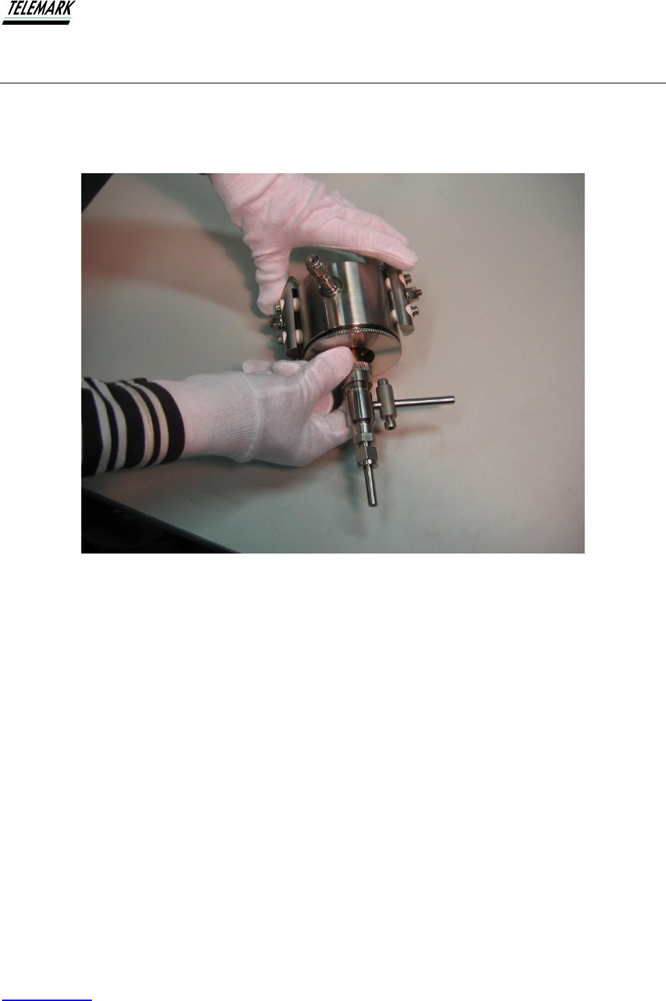
Ion Beam System Manual MAINTENANCE
Telemark.com 81 of 130 Rev 1.0.0
7.2 Disassembly
With the ion source removed from the mounting brackets. Disassemble the ion source over a
clean flat surface. First remove the knurled nut from the water assembly as shown in the photo
below
Figure 7-2, Ion Source Disassembly
Step 1 Remove water assembly. The water manifold remains attached to anode assembly by
circlip. See below for disassembly of the water manifold assembly.

Ion Beam System Manual MAINTENANCE
Telemark.com 82 of 130 Rev 1.0.0
Figure 7-3, Unscrewing the knurled assembly nut
Step 2. Unscrew the knurled assembly nut from the base of the ion source.
With the large stainless nut removed, carefully withdraw the anode assembly from the shroud.
Take care that the ceramic ring (anode insulator) does not drop. It is very brittle and may shatter
if dropped on a hard surface.

Ion Beam System Manual MAINTENANCE
Telemark.com 83 of 130 Rev 1.0.0
Figure 7-4, Removing the Anode
The anode (TiN coated – ‘gold’ colored component) can now be lifted away from the base
insulator.
7.3 Dismantling the Water Flow Manifold Assembly and Magnet
Under normal operation of the ion beam system, there should be no need to remove the magnet
from its position in the rear of the anode and it is generally much safer to leave it in its housing.
However, should it be necessary to remove the magnet, first remove the circlip from the
stainless-steel tubing – use suitable external circlip pliers. With the circlip removed, the knurled
nut of the compression-seal fitting can be removed followed by the Teflon plasma shield (if
installed). The magnet can now be withdrawn from its housing in the back of the anode. See
photo below showing an exploded view of the anode and water manifold.
Take care not to drop the magnet or to allow it too close to other magnetic material as it will
SNAP on very firmly and is likely to break.

Ion Beam System Manual MAINTENANCE
Telemark.com 84 of 130 Rev 1.0.0
Take care in handling the magnet. Personal injury can result if fingers etc. get
between the magnet and magnetic material. Keep the magnet away from other
electronic devices e.g., watches, computers, magnetic storage media, etc.
Figure 7-5, Dismantling the Water Flow Manifold Assembly
7.4 Inspection and Cleaning of the ion source
1. Check the anode insulator for coating deposits on the inner face. Providing the deposits
are electrically non-conducting no cleaning should be necessary.
2. Clean the conical face of the anode. DO NOT USE SOLVENTS. ScotchBrite scouring
pads can be used dry or, alternatively, fine (400 or 600 grit) abrasive paper (as used in
the automobile body finishing industry) can be used. Vacuum clean the anode to remove
any dust and/or blow with compressed gas to remove dust.
3. Check for any build-up of ‘sludge’ inside the electrical water breaks. Build-up will reduce
the water flow. Clean as appropriate. If the electrical water breaks require disassembly, it
CAUTION
!

Ion Beam System Manual MAINTENANCE
Telemark.com 85 of 130 Rev 1.0.0
will be necessary to replace the Nylon ferrules in the Swagelock fitting. only use 3/8”
nylon ferrules and back washers for sealing to the ceramic. The assembled breaks may
require helium leak-checking following assembly.
7.5 Re-assembly of the Source Head
Re-assembly is essentially the reverse of the above procedures taking note of the following:
1. Replace anode into base insulator.
2. Replace ring anode insulator (annulus) on to anode. It may be easier to first locate the
ceramic anode insulator into the shroud.
3. Slide the stainless-steel shroud over the anode assembly. Re-secure the large locking ring
hand tight only – DO NOT USE OTHER MECHANICAL DEVICES otherwise damage to
the assembly will result.
4. Install the filament legs. It is recommended that a small amount of molybdenum or copper-
based vacuum grease can be applied to all screws prior to assembly.
5. Install the ion source into the chamber using the mounting bracket.
6. Secure both water-cooling lines and the gas line. Use recommended procedures for the
Swagelock fittings.
7. Make sure that the water-cooling supply has been reconnected and turned on
before applying power. Check for water leaks before pumping chamber.
8. Connect anode and filament leads.
Special Note for Dual Filament System. Make certain that the correct lead is attached to the
common filament leg.
9. Install a new filament(s). Use nut driver supplied – do not use excessive force.
Note that after removal and cleaning, the source may outgas. Until normal operation
can be established it may be necessary to use a lower Beam Voltage on the anode
(say, 140 volts) until the source has run for several minutes and stabilized. It may be
useful to run the filament without any gas flow for say 5 minutes to warm the assembly.
7.6 Power Supply
The power supply has no servable parts inside.


Ion Beam System Manual ASCII NO CHECK SUM INTERFACE
Telemark.com 87 of 130 Rev 1.0.0
8 ASCII NO CHECK SUM INTERFACE
8.1 GENERAL
The ion beam system comes standard with RS-232 serial interface. The computer interface of the
Telemark ion beam system permits remote control using a personal computer or process
controller.
There are two types of protocols: ASCII no Check Sum and Colon. No selection is needed, both
are available all the time. This chapter explains the ASCII NO CHECK SUM protocol.
8.2 RS-232 SERIAL INTERFACE
The standard RS-232 serial interface of the ion beam system allows one ion beam system to be
connected to any other device with a RS-232 serial interface. A D9P connector is provided on the
rear panel for permanent connection to the host computer. See figure 3-5.
The ion beam system’s RS-232 port is automatically set up to operate with the following
specifications:
8 Bit data, No Parity, 1 Stop bit, No flow control
Baud rate is 19200.
8.3 ASCII NO CHECK SUM PROTOCOL
Remote access to the IAD power supply requires transmission of a command string
terminated by ASCII ACK (d06). The Power Supply will acknowledge by transmitting an

Ion Beam System Manual ASCII NO CHECK SUM INTERFACE
Telemark.com 88 of 130 Rev 1.0.0
acknowledge string terminated by ASCII ACK (d06) if the command was valid or an error
string terminated by ASCII NAK (d21) if the command was invalid or wanting.
ASCII nulls, spaces, tabs, carriage returns and line feeds are ignored when received.
At powerup the operational variables are loaded from non-volatile touch screen variables.
To establish a connection to the power supply, use the following settings/procedure. The
Pseudocode is not elegant but should indicate what to do.
BAUD RATE = 19200
8 DATA BITS
NO PARITY
1 STOP BIT
NO FLOW CONTROL
Tries = 0
Do
{
Transmit Ping command to power supply.
“!”+chr(d06)
Wait 150mS capture time.
If (AcknowledgeString == “!”+chr(d06))
{
Exit Do // Received valid acknowledge.
}
ELSE
{
Tries += 1
If (3 == Tries) goto cannot connect
}

Ion Beam System Manual ASCII NO CHECK SUM INTERFACE
Telemark.com 89 of 130 Rev 1.0.0
}
Engage…
8.3.1 Error codes.
Code Description
A Illegal command.
B Illegal value/argument.
F Invalid ready – power supply must be stopped.
Program load/save or touch screen update in operation – must wait until
complete.
8.3.2 COMMAND FORMAT
“CommandCharacter”, parameter1, paramter2 … chr(d06)
“CommandCharacter” is a single ASCII printable character followed by possible command
parameter values/strings. The first parameter does not necessarily need any leading white
space (as indicated by commas), but any succeeding parameters do.
The valid range for each parameter is shown within curly brackets: n{min…max}. If the
parameter value is out of range a “B”+NAK response is returned.
Commands that return values, return the command character followed by each value
preceded by a space delimiter. Chr(d06) is the final character.
There is one exception to this rule: The command character “:” is reserved for the older
protocol which has a totally different format.
8.4 COMMANDS
“!”
Ping
No functional action other than to acknowledge.
“B”, feedback{‘G’ or ‘F’}

Ion Beam System Manual ASCII NO CHECK SUM INTERFACE
Telemark.com 90 of 130 Rev 1.0.0
Turn auto mode on. After a start command is issued and Status flag bit6 == 1, auto control
of the beam current will commence. This ensures the correct operational set points for
filament power and initial gas flow have been established for the required beam current.
Feedback control will be gas if “G” is supplied as the ‘feedback’ argument, filament control
if “F” is supplied. If the ‘feedback’ argument is not supplied, program configuration bit15
defines the feedback control – see page 11.
“C”
Turn auto mode off.
“A”, n{0…100}
Set the auto anode current set point = ‘n’{AMPS*10}.
“E”, n{0…100}
Set the auto anode current set point = ‘n’{AMPS*10}. This command overrides local mode
transfer of touch screen variable to operational variable. Touch screen variable is not
affected. Override is voided when source is off. Intended for use by some auto beam
control impulse response test program.
“K”, n1{0…10000}, n2{0…10000}
Set the auto anode Proportional = ‘n1’, Derivative = ‘n2’ gain coefficients. The general
starting values are: Kp = 100, Kd = 400. This is intended for process engineer use only.
“T”
STOP the power supply.
“R”, n{1…2}
START the power supply with filament = ‘n’. Filament1 defaults if ‘n’ is not supplied.
“V”, n{0…5}
Set anode voltage secondary tapping = ‘n’, 0=off.
“Y”, n1{0…9999}, n2{0…9999}

Ion Beam System Manual ASCII NO CHECK SUM INTERFACE
Telemark.com 91 of 130 Rev 1.0.0
Set filament1 life counter = ‘n1’{minutes}, filament2 life counter = ‘n2’{minutes}. If ‘n2’ is not
supplied zero defaults for n2. If ‘n1’ and ‘n2’ are not supplied both default to zero.
“D”, n{0…9999}
Set filament power decrease rate = ‘n’{watts/minute*1000}.
“U”, n{0…100}
Set auto mode start delay = ‘n’{seconds*10}.
“s”
Transmit short status. ‘s’ + n1…5 + chr(d06)
n1{0…255} Filament controller flags
n2{0…255} Filament controller PWM duty cycle control register high bits.
n3{0…255} Flags3
n4{0…255} Alarm flags
n5{0…255} Status flags
“e”
Transmit limited status. ‘e’ + n1…9 + chr(d06)
n1{0…12000} Ion current, µA
n2{0…1000} Anode current, Amps*40, RMS (0.025A resolution)
n3{0…5000} Gasflow1 sccm*100
n4{0…5000} Gasflow2 sccm*100
n5{0…255} Filament controller flags
n6{0…255} Filament controller PWM duty cycle control register high bits.
n7{0…255} Flags3
n8{0…255} Alarm flags
n9{0…255} Status flags

Ion Beam System Manual ASCII NO CHECK SUM INTERFACE
Telemark.com 92 of 130 Rev 1.0.0
“t”
Transmit full status. ‘t’ + n1…14 + chr(d06)
n1{0…12000} Ion current, µA
n2{0…250} Anode current, Amps*10, RMS
n3{0…300} Anode volts, Peak/RMS
n4{0…1500} Anode power, Watts, RMS
n5{0…250} Filament current, Amps*10, RMS
n6{0…500} Filament Volts*10, RMS
n7{0…255} Waterflow Gallons/minute*10 or Liter/minute*10
n8{0…5000} Gasflow1 sccm*100
n9{0…5000} Gasflow2 sccm*100
n10{0…255} Filament controller flags
n11{0…255} Filament controller PWM duty cycle control register high bits.
n12{0…255} Flags3
n13{0…255} Alarm flags
n14{0…255} Status flags
Flag/Status Bit Definitions for Commands “e”, “f” and “s” above.
Filament controller flag bit definitions:
Bit7 0=ok, 1=filament primary circuit breaker tripped.
Bit6 0=ok, 1=running on changeover filament.
Bit5 0=ok, 1=filament open circuit.
Bit4 0=ok, 1=water flow < threshold.
Bit3 0=ok, 1=second filament active AND open circuit.
Bit2 0=ok, 1=filament current > maximum.
Bit1 0=default, 1=2nd filament selected.

Ion Beam System Manual ASCII NO CHECK SUM INTERFACE
Telemark.com 93 of 130 Rev 1.0.0
Bit0 0=stopped, 1=closed loop running.
Flags3 bit definitions:
Bit7 0=ok, 1=anode primary circuit breaker tripped.
Bit6 0=ok, 1=anode POWER limiter active
Bit5 0=ok, 1=FRAM water parameters check sum error.
Bit4 0=ok, 1=FRAM registers check sum error.
Bit3 0=ok, 1=interlock open.
Bit2 0=ok, 1=anode CURRENT limiter active
Bit1 0=ok, 1=FRAM ADC calibration check sum error.
Bit0 0=no, 1=Anode DC modification has been installed.
Alarm flag bit definitions:
Bit7 0 returned.
Bit6 0 returned.
Bit5 0 returned.
Bit4 0=ok, 1=Touch screen receive timeout.
Bit3 0=ok, 1=Remote receive timeout.
Bit2 0=ok, 1=OR of BIT1+BIT0+ICMalarms+MFCalarms == ALARMS ALL.
Bit1 0=ok, 1=OR of alarm bits that STOP but can restart.
Bit0 0=ok, 1=OR of alarm bits that FORCE STOP condition.
Status flag bit definitions:
Bit7 0=off, 1=Auto mode on.
Bit6 1=Start up sequence complete.
Bit5 1=Mass Flow Controller 2 error.
Bit4 1=Mass Flow Controller 1 error.

Ion Beam System Manual ASCII NO CHECK SUM INTERFACE
Telemark.com 94 of 130 Rev 1.0.0
Bit3 1=Program Load or Save in progress, Remote program upload in progress or
Controller transferring data to touch screen, updating set points.
Bit2 0=off, 1=Purge mode on.
Bit1 0=STOPPED, 1=STARTED
Bit0 Reserved for future use.
“b”
Transmit the anode voltage select index. ‘b’ + n + chr(d06)
n{0…5} Anode voltage select index. Zero means off.
“a”
Transmit anode voltage tap selections. ‘a’ + n1…5/8 + chr(d06)
n1{0…300} 1st anode volt selection, lowest available voltage.
n2{0…300}
n3{0…300}
n4{0…300}
n5{0…300} 5th anode volt selection, highest voltage.
“m”
Transmit the model descriptor. ‘m’ + chr(d34) + str+ chr(d34) + chr(d06)
‘str’ will have a maximum length of 22 characters.
“p”
Transmit the logical full-scale flows for Gas1 and Gas2. ‘p’ + n1…2 + chr(d06)
n1{0…255} Gas1 full scale logical (sccm).
n2{0…255} Gas2 full scale logical (sccm).
“f”
Transmit the current filament set point. ‘f’ + n + chr(d06)

Ion Beam System Manual ASCII NO CHECK SUM INTERFACE
Telemark.com 95 of 130 Rev 1.0.0
n{0…1000/Watts} Filament set point.
“g”
Transmit the current gas1 set point. ‘g’ + n + chr(d06)
n{0…1000/Gas1Logical*100} Gas1 set point.
“h”
Transmit the current gas2 set point. ‘h’ + n + chr(d06)
n{0…1000/Gas2Logical*100} Gas2 set point.
“y”
Transmit the current filament1 and filament2 life time counts. ‘y’ + n1 + n2 + chr(d06)
n1{0…65535} Filament1 life count - minutes.
n2{0…65535} Filament2 life count - minutes.
“d”
Transmit the filament power decrease rate. ‘d’ + n + chr(d06)
n{0…9999} Filament power decrease rate (watts/minutes*1000).
“u”
Transmit the auto mode start delay. ‘u’ + n + chr(d06)
n{0…100} Auto mode start delay (seconds*10).
“j”
Transmit the dual gas scale and gas1%. ‘j’ + n1 + n2 + chr(d06)
n1{0…1000} Dual gas scale.
n2{0…1000} Gas1%.
“?”

Ion Beam System Manual ASCII NO CHECK SUM INTERFACE
Telemark.com 96 of 130 Rev 1.0.0
Transmit the system setup word. ‘?’ + n + chr(d06)
n{0…65535} System setup word.
System setup word bit definitions for above command “?”.
These bits are read only. Only accessible from the SETUP > CONTROL screen.
Bit15 0=DISABLED, 1=NORMAL Lock button.
Bit14 0=ENABLED, 1=DISABLED Alarm buzzer.
Bit13 0=DISABLED, 1=ENABLED Filament power decrease.
Bit12 0=DISABLED, 1=ENABLED Filament life counters auto reset.
Bit11 Reserved.
Bit10 Reserved.
Bit9 Reserved.
Bit8 0=PEAK, 1=RMS. Anode volts display.
Bit7 0=US GALLONS, 1=LITRES. Water flow display.
Bit6 Reserved.
Bit5 Reserved.
Bit4 Reserved.
Bit3 Reserved.
Bit2 Reserved.
Bit1 0=SINGLE, 1=DUAL Gas control.
Bit0 0=ENABLED, 1=DISABLED MFC operation.
A filament set point of 100.0% (Setpoint Units = percent) corresponds to full power, 288W
for model UHV, 440W for model 750/1250 and 770W for model 2000/3000. Most
conditions only require a set point value of approximately half full power for a new filament.
This allows for filament degradation.
A gas set point of 100.0% (Setpoint Units = percent) corresponds to Logical full-scale flow;
30sccm for Oxygen, 20sccm for Argon, 30sccm for Nitrogen, 20sccm for Krypton, 20sccm
for Xenon, 20sccm for Neon, 20sccm for Helium.

Ion Beam System Manual ASCII NO CHECK SUM INTERFACE
Telemark.com 97 of 130 Rev 1.0.0
There are two DE9F connectors (Gas1 and Gas2) on the back of the power supply that
connect to Mass Flow Controllers. These correspond to GAS1 and GAS2 parameter
buttons on the SYSTEM SETUP screen.
Set point parameters referring to “gas1” or “gas2” correspond to the MFC’s connected to
the Gas1 and Gas2 DE9F back panel connectors respectively.
“F”, n{0…1000/Watts}
Set the filament set point = ‘n’.
“G”, n{0…1000/Gas1Logical*100}
Set the gas1 set point = ‘n’.
“H”, n{0…1000/Gas2Logical*100}
Set the gas2 set point = ‘n’.
“J”, n1{0…1000}, n2{0…1000}
Set the dual gas setpoint = ‘n1’ and gas1% = ‘n2’.
“W”, n1{0…5}, n2{0…1000/Watts},
n3{0…1000/Gas1Logical*100}, n4{1…2}
Set the anode tap = ‘n1’, filament set point = ‘n2’, gas1 setpoint = ‘n3’ and start with
filament = n4. Filament1 defaults if n4 is not supplied.
“O”, n1{0…5}, n2{0…1000/Watts},
n3{0…1000/Gas2Logical*100}, n4{1…2}
Set the anode tap = ‘n1’, filament set point = ‘n2’, gas2 setpoint = ‘n3’ and start with
filament = n4. Filament1 defaults if n4 is not supplied.
“X”, n1{0…5}, n2{0…1000/Watts}, n3{0…1000},
n4{0…1000}, n5{1...2}
Set the anode tap = ‘n1’, filament set point = ‘n2’, dual gas scale = ‘n3’, gas1% = ‘n4’ and
start with filament = n5. Filament1 defaults if n5 is not supplied.

Ion Beam System Manual ASCII NO CHECK SUM INTERFACE
Telemark.com 98 of 130 Rev 1.0.0
“M”
Turn pulse mode on.
“N”
Turn pulse mode off.
“P”, n{10…255}
Set pulse period*10 = ‘n’, 1.0 to 25.5 seconds/minutes.
0.1 second resolution if CONFIG bit8 == 0
0.1 minute resolution if CONFIG bit8 == 1
“Q”, n{10…90}
Set the ON time duty% = ‘n’, 10% to 90% of pulse period.
Pulse mode is not recommended when the anode power is greater than 1500 watts
otherwise the anode circuit breaker may trip. The start up procedure normally ramps up
the filament and gas over a 3.2 second period. When pulse mode is engaged this ramp up
is voided and full gas flow set point steps are applied.
Pulse mode is primarily intended for use in small chambers depositing Magnesium
Fluoride to improve optical properties where the work plate area is fully exposed to ion
bombardment.
“v”
Transmit software version. “v” + chr(d34) + str + chr(d34) + n1 + n2 + n3 + chr(d06)
str Product name
n1{0…255} Major version.
n2{0…255} Minor version.
n3{0…65535} Julian Build Date. YYDDD.
“L”, n{0…15}
Load program ‘n’, even if power supply is STARTED. The program is loaded directly into
the operational variables.

Ion Beam System Manual ASCII NO CHECK SUM INTERFACE
Telemark.com 99 of 130 Rev 1.0.0
“S”, n{0…15}, name{26 characters maximum}
Save operating variables to program ‘n’ renaming if name string if supplied otherwise
existing name is kept. Name is truncated if there are more than 26 characters. The power
supply must be STOPPED otherwise an “F”+NAK response is returned.
“|”, n{0…15}
Set program configuration bit ‘n’
“&”, n{0…15}
Clear program configuration bit ‘n’
“=”, n{0…65535}
Load program configuration bits = ‘n’
Program configuration bit definitions for above Commands “|”, “&”, “=”
Bit15 0=GAS, 1=FILAMENT Auto mode closed loop feedback select.
Bit14 not used
Bit13 not used
Bit12 not used
Bit11 0=PERCENT(n/1000), 1=WATTS Filament setpoint units.
Bit10 0=PERCENT(n/1000), 1=SCCM Gas setpoints units.
Bit9 not used
Bit8 0=0.1 second, 1=0.1 minute Pulse mode timer resolution.
Bit7 not used
Bit6 0=OFF, 1=ON Timed mode.
Bit5 0=NO, 1=YES Clean mode is permanent.
Bit4 0=OFF, 1=ON Dual gas purge – Gas2 enabled.
Bit3 0=OFF, 1=ON Dual gas purge – Gas1 enabled.
Bit2 0=OFF, 1=ON Auto anode control.

Ion Beam System Manual ASCII NO CHECK SUM INTERFACE
Telemark.com 100 of 130 Rev 1.0.0
Bit1 0=OFF, 1=ON Pulse mode.
Bit0 0=OFF, 1=ON Anode DC mode.
If auto anode control has been enabled (Bit2=1) then after a start command is issued and
Status flag bit6 == 1, auto control of the beam current will commence. This ensures the
correct operational set points for filament power and initial gas flow have been established
for the required beam current.
“Z”
Clear alarms that can be reset. Will also turn off the alarm buzzer. The alarm buzzer will
turn back on if any additional alarms are raised or the alarm pattern has changed for the
same number of alarms. The alarm buzzer will turn off when all alarms have been
removed.

Ion Beam System Manual COLON INTERFACE
Telemark.com 101 of 130 Rev 1.0.0
9 COLON INTERFACE
9.1 GENERAL
The ion beam system comes standard with RS-232 serial interface. The computer interface of the
Telemark ion beam system permits remote control using a personal computer or process
controller.
There are two types of protocols: ASCII no Check Sum and Colon. No selection is needed, both
are available all the time. This chapter explains the COLON protocol.
9.2 RS-232 SERIAL INTERFACE
The standard RS-232 serial interface of the ion beam system allows one ion beam system to be
connected to any other device with a RS-232 serial interface. A D9P connector is provided on the
rear panel for permanent connection to the host computer. See figure 3-5.
The ion beam system’s RS-232 port is automatically set up to operate with the following
specifications:
8 Bit data, No Parity, 1 Stop bit, No flow control
Baud rate is 19200.

Ion Beam System Manual COLON INTERFACE
Telemark.com 102 of 130 Rev 1.0.0
9.3 COLON PROTOCOL
Remote access to the IAD power supply requires transmission of a command record. The
Power Supply will acknowledge by transmitting an acknowledge record. The format of a
command or acknowledge record is:
‘:’ Header character, ASCII colon.
0x01...0x41 Record data Length (at least one), dependent on command.
0x00…0x3F Command code, maximum of 64 commands.
DataBytes[] Data bytes specific to command or acknowledge.
0x00…0xFF CheckSum, Negative of (Sum MOD 256)
Sum = 0
Sum += Record data length
Sum += Command code
Sum += DataBytes[0] + … DataBytes[n]
CheckSum = (-Sum) AND 0xFF
Each byte of the record (i.e. what comes after the colon header character) is transmitted
as two ASCII hexadecimal characters, high order nibble first. E.g. sending ASCII
character ’3’ followed by ‘F’ means transmitting data byte 0x3F.
ASCII nulls, spaces, tabs, carriage returns and line feeds are ignored when received.
The header character (ASCII colon) defines the start of the record. Upon receipt, you have
5 seconds to complete the record transfer otherwise the record is discarded and the
search for a new record commences. The search for a new record requires a dead time of
at least 13mS. I.e. there must be no character received for at least 13mS before the
search proper commences otherwise a new 13mS timeout is initiated.
The Record data Length includes the command code plus any data bytes for that
command or acknowledge; if greater than 1+64 the record is discarded and search for a
new record commences.
Commands acknowledge when completed, NOT necessarily in order of reception.

Ion Beam System Manual COLON INTERFACE
Telemark.com 103 of 130 Rev 1.0.0
The minimum time between commands is 20mS, i.e. the minimum time between the last
byte of command N and the first byte of command N+1; this allows the receive buffer to be
flushed if any errors. NB: The receive buffer is only 255 bytes in length.
There is a maximum of 64 user commands, 0x00…0x3F. If a command is valid the power
supply will respond with an acknowledge record whose command = your command plus
0x40. Errors and alarms have their own codes beginning at 0x80. If alarm conditions
persist; an alarm record will be sent every second - if enabled. See command 49.
If a command code is not recognized the acknowledge command = 192 with the first data
byte = command code in question. If a command parameter value is out of range the
acknowledge command = 193 with the first data byte = command code. If a command is
issued while a previous command has not completed the acknowledge command = 194
with the first data byte = command code. It may be necessary to check the alarm and/or
status bits before issuing a command. Commands that change set points or configuration
MUST be done while the power supply is in remote mode otherwise the acknowledge
command = 197 with the first data byte = command code.
At powerup the operational variables are loaded from non-volatile touch screen variables.
To establish a connection to the power supply, use the following settings/procedure. The
Pseudocode is not elegant but should indicate what to do.
BAUD RATE = 19200
8 DATA BITS
NO PARITY
1 STOP BIT
NO FLOW CONTROL
Tries = 0
Do
{
Transmit command Ping0 to power supply.
‘:’, ‘0’, ‘1’, ‘0’, ‘0’, ‘F’, ‘F’
Wait 150mS capture time.
If (first DataByte[] received == 0x00+0x40)

Ion Beam System Manual COLON INTERFACE
Telemark.com 104 of 130 Rev 1.0.0
{
Exit Do // Received valid acknowledge.
}
ELSE
{
Tries += 1
If (Tries == 3) goto cannot connect
}
}
Engage…
9.4 Command code, p1, p2, p3
Where p1, p2, p3 are parameters if required by the command.
A parameter designated by “B” means a byte value {0…255 decimal}. Two transmitted
ASCII characters. High nibble followed by low nibble.
A parameter designated by “B[1…n]” means a byte array of at least one byte and a
maximum of ‘n’ bytes.
A parameter designated by “W” means a word value {0…65535 decimal), LOW byte
followed by HIGH byte. Four transmitted ASCII characters.
Values enclosed within curly brackets {} designate the valid range for the command, if
outside this range an “INVALID_DATA” response command of 193 is returned.
9.4.1 Example 1:
Command 0
Ping0.
Send ":", "0", "1", "0", "0", "F", "F".
The ":" is the start of header character.
The "0", "1" = 0x01 (hex) = 1 (decimal). The record data length.

Ion Beam System Manual COLON INTERFACE
Telemark.com 105 of 130 Rev 1.0.0
The "0", "0" = 0x00 (hex) = 0 (decimal). The ping0 command code.
Sum = 1+0 (decimal) = 1 (decimal) = 0x01 (hex 8bit). The sum of data record.
-(Sum) = -1 (decimal) = 0xff (hex 8bit) = 0xffff (hex 16bit) = 0xffffffff (hex 32bit). The
negative sum of data record.
The "F", "F" = CHECKSUM = -(Sum) = 0xff (hex 8bit). The (negative sum of data record)
AND 0xff.
The valid response from the power supply would be ":", "0", "1", "4", "0", "B", "F"
A command code with bit6=1 indicates an acknowledge by the power supply. 64 is added
to the received command code by the power supply. Do not send a command with bit6 set
to the power supply as this is a command code out of range.
The "4", "0" = 64+0 = 64 (decimal) = 0x40 (hex). The acknowledge command code.
Sum = 1+64 (decimal) = 65 (decimal) = 0x41 (hex 8bit). The sum of data record.
The "B", "F" = CHECKSUM = -(Sum) = -65 = 0xbf (hex 8bit). The (negative sum of data
record) AND 0xff.
9.4.2 Example 2:
Command 23
START the power supply. Defaults to filament1 selected.
Send ":", "0", "1", "1", "7", "E", "8".
The ":" is the start of header character.
The "0", "1" = 0x01 (hex) = 1 (decimal). The record data length.
The "1", "7" = 0x17 (hex) = 23 (decimal). The start command code.
Sum = 1+23 (decimal) = 24 (decimal) = 0x18 (hex 8bit). The sum of data record.
-(Sum) = -24 (decimal) = 0xe8 (hex 8bit) = 0xffe8 (hex 16bit) = 0xffffffe8 (hex 32bit). The
negative sum of data record.
The "E", "8" = CHECKSUM = -(Sum) = 0xe8 (hex 8bit). The (negative sum of data record)
AND 0xff.
The valid response from the power supply would be ":", "0", "1", "5", "7", "A", "8"

Ion Beam System Manual COLON INTERFACE
Telemark.com 106 of 130 Rev 1.0.0
A command code with bit6=1 indicates an acknowledge by the power supply. 64 is added
to the received command code by the power supply. Do not send a command with bit6 set
to the power supply as this is a command code out of range.
The "5", "7" = 64+23 = 87 (decimal) = 0x57 (hex). The acknowledge command code.
Sum = 1+87 (decimal) = 88 (decimal) = 0x58 (hex 8bit). The sum of data record.
The "A", "8" = CHECKSUM = -(Sum) = -88 = 0xa8 (hex 8bit). The (negative sum of data
record) AND 0xff.
9.4.3 Example 3:
Command 24, W{0…5/8}
Select an anode voltage secondary tapping, 1…5/8, 0=off.
Send ":", "0", "3", "1", "8", "0", "2", "0", "0", "E", "3"
The ":" is the start of header character.
The "0", "3" = 0x03 (hex) = 3 (decimal). The record data length - command code plus two
bytes for word parameter.
The "1", "8" = 0x18 (hex) = 24 (decimal). The command code.
The "0", "2", "0", "0" = 0x0002 (Low/High hex 16bit) = 2 (decimal). The 16bit word
parameter – secondary tap 2.
Sum = 3 + 24 + 0 + 2 + 0 + 0 (decimal) = 29 (decimal) = 0x1D (hex 8bit). The sum of data
record.
The "E", "3" = CHECKSUM = -(Sum) = -29 (decimal) = 0xe3 (hex 8bit). The (negative sum
of data record) AND 0xff.
The valid response from the power supply would be ":", "0", "1", "5", "8", "A", "7"
The "0", "1" = 0x01 (hex) = 1 (decimal). The record data length.
The "5", "8" = 0x58 (hex) = 64+24 = 88 (decimal). The acknowledge command code.
Sum = 1+88 (decimal) = 89 (decimal) = 0x59 (hex 8bit). The sum of data record.
The "A", "7" = CHECKSUM = -(Sum) = -89 = 0xa7 (hex 8bit). The (negative sum of data
record) AND 0xff.

Ion Beam System Manual COLON INTERFACE
Telemark.com 107 of 130 Rev 1.0.0
9.5 COMMANDS (decimal):
0…2
Ping0…2.
No functional action other than to acknowledge.
3
Ping_No_pong.
No functional action other than to NOT acknowledge.
4, W{0…15}
Load program W, even if power supply is STARTED. Previous versions acknowledged
with the program number as the first DataByte when the program transferred to the touch
screen. This version acknowledges immediately with the program number. The program is
loaded directly into the operating variables.
5, W{0…15}, B[1…26]
Save settings to program W. The power supply must be STOPPED otherwise an
‘INVALID_READY’ response command of 194 is returned. If the byte array is supplied then
the program will be saved with that name. The name will truncate to 26 characters length
maximum.
6, W{0…15}
Upload program W to remote.
The power supply must be STOPPED otherwise an ‘INVALID_READY’ response
command of 194 is returned. DataBytes[] sent as follows:
B[64] An array of 64 bytes, the first 26 being the ASCII name.
7
Set auto mode off.
8, B{‘G’ or ‘F’}

Ion Beam System Manual COLON INTERFACE
Telemark.com 108 of 130 Rev 1.0.0
Set auto mode on. After a start command is issued and Status flag bit6 == 1, auto control
of the beam current will commence. This ensures the correct operational set points for
filament power and initial gas flow have been established for the required beam current.
Feedback control will be gas if “G” is supplied as the ‘feedback’ argument, filament control
if “F” is supplied. If the ‘feedback’ argument is not supplied, program configuration bit15
defines the feedback control – see commands 52…54. Note: If program configuration bit2
is set this command will have no effect – see commands 52...54.
9, W{0…100}
Set the auto beam current set point {AMPS*10}. Acknowledges with limited status, see
command 10 for data details.
10
Transmit limited status. DataBytes[] returned as follows:
W{0…12000} Ion current, µA
W{0…1000} Anode current, Amps*40, RMS (0.025A resolution)
W{0…5000} Gasflow1 sccm*100
W{0…5000} Gasflow2 sccm*100
B{0…255} Filament controller flags
B{0…255} Filament controller PWM duty cycle control register high bits.
B{0…255} Flags3
B{0…255} Alarm flags
B{0…255} Status flags
11, W{0…10000}, W{0…10000}
Set the auto beam Kproportional, Kderivative gain coefficients. The general starting values
are: Kp = 100, Kd = 400. This is intended for process engineer use only.
12, W{0…100}
Set the auto beam current set point {AMPS*10}. Acknowledges with limited status, see
command 10 for data details. This command overrides local mode transfer of touch screen
variable to operational variable. Touch screen variable is not affected. Override is voided

Ion Beam System Manual COLON INTERFACE
Telemark.com 109 of 130 Rev 1.0.0
when source is off. Intended for use by some auto beam control impulse response test
program.
13, W{0…100},
Set auto mode start delay {seconds*10}.
14…15
Reserved for use by Visual Basic “Calibrate” program for ADC calibration.
16…19
Reserved for use by Visual Basic "BootLoader” program for downloading new code.
20…21
Reserved for test purposes.
22
STOP the power supply.
23, W{1…2}
START the power supply with the selected filament, either 1 or 2. Filament1 defaults if ‘W’
is not supplied.
24, W{0…5}
Select an anode voltage secondary tapping, 0…5, 0=off.
25
Transmit full status. DataBytes[] returned as follows:
W{0…12000} Ion current, µA
W{0…250} Anode current, Amps*10, RMS
W{0…300} Anode volts, Peak/RMS
W{0…1500} Anode power, Watts, RMS

Ion Beam System Manual COLON INTERFACE
Telemark.com 110 of 130 Rev 1.0.0
W{0…250} Filament current, Amps*10, RMS
W{0…500} Filament Volts*10, RMS
W{0…255} Waterflow Gallons/minute*10 or Litre/minute*10
W{0…5000} Gasflow1 sccm*100
W{0…5000} Gasflow2 sccm*100
B{0…255} Filament controller flags
B{0…255} Filament controller PWM duty cycle control register high bits.
B{0…255} Flags3
B{0…255} Alarm flags
B{0…255} Status flags
26
Transmit short status. DataBytes[] returned as follows:
B{0…255} Filament controller flags
B{0…255} Filament controller PWM duty cycle control register high bits.
B{0…255} Flags3
B{0…255} Alarm flags
B{0…255} Status flags
Flag/Status Bit Definitions for Commands 10, 25 and 26 above
Filament controller flag bit definitions:
Bit7 0=ok, 1=filament primary circuit breaker tripped.
Bit6 0=ok, 1=running on changeover filament.
Bit5 0=ok, 1=filament open circuit.
Bit4 0=ok, 1=water flow < threshold.
Bit3 0=ok, 1=second filament active AND open circuit.
Bit2 0=ok, 1=filament current > maximum.

Ion Beam System Manual COLON INTERFACE
Telemark.com 111 of 130 Rev 1.0.0
Bit1 0=default, 1=2nd filament selected.
Bit0 0=stopped, 1=closed loop running.
Flags3 bit definitions:
Bit7 0=ok, 1=anode primary circuit breaker tripped.
Bit6 0=ok, 1=anode POWER limiter active
Bit5 0=ok, 1=FRAM water parameters check sum error.
Bit4 0=ok, 1=FRAM registers check sum error.
Bit3 0=ok, 1=interlock open.
Bit2 0=ok, 1=anode CURRENT limiter active
Bit1 0=ok, 1=FRAM ADC calibration check sum error.
Bit0 0=no, 1=Anode DC modification has been installed.
Alarm flag bit definitions:
Bit7 0 returned.
Bit6 0 returned.
Bit5 0 returned.
Bit4 0=ok, 1=Touch screen receive timeout.
Bit3 0=ok, 1=Remote receive timeout.
Bit2 0=ok, 1=OR of BIT1+BIT0+ICMalarms+MFCalarms == ALARMS ALL.
Bit1 0=ok, 1=OR of alarm bits that STOP but can restart.
Bit0 0=ok, 1=OR of alarm bits that FORCE STOP condition.
Status flag bit definitions:
Bit7 0=off, 1=Auto mode on.
Bit6 1=Start up sequence complete.
Bit5 1=Mass Flow Controller 2 error.
Bit4 1=Mass Flow Controller 1 error.

Ion Beam System Manual COLON INTERFACE
Telemark.com 112 of 130 Rev 1.0.0
Bit3 1=Program Load or Save in progress, Remote program upload in progress or
Controller transferring data to touch screen, updating set points.
Bit2 0=off, 1=Purge mode on.
Bit1 0=STOPPED, 1=STARTED.
Bit0 Reserved for future use.
27
Transmit revision status. DataBytes[] returned as follows:
B{86} ASCII “V”
B{80} ASCII “P”
B{82} ASCII “R”
B{83} ASCII “S”
B{0}
B{0}
B{0…255} Major software revision
B{0…255} Minor software revision
B{86} ASCII “V”
B{80} ASCII “P”
B{82} ASCII “R”
B{83} ASCII “S”
B{0}
B{0}
B{0}
B{0}
28
Transmit the current anode voltage select index, 0…5.

Ion Beam System Manual COLON INTERFACE
Telemark.com 113 of 130 Rev 1.0.0
DataBytes[] returned as follows:
B{0…5} Anode voltage select index, 0=off
29
Transmit anode voltage tap selections. DataBytes[] returned as follows:
W{0…300} 1st anode volt selection, lowest voltage.
W{0…300}
W{0…300}
W{0…300}
W{0…300} 5th anode volt selection, highest voltage.
30
Transmit the 22 character model descriptor.
DataBytes[] returned as follows:
B[22] An array of 22 ASCII bytes including trailing spaces.
31
Transmit the register values. DataBytes[] returned as follows:
B[100] An array of 100 bytes.
Commands 32…39 acknowledge with full status. See command 25 for data details.
Commands 32…34 are grouped for single gas systems.
Commands 35…39 are grouped for dual gas systems.
A filament set point of 100.0% (Setpoint Units = percent) corresponds to full power, 288W
for model UHV, 440W for model 750/1250 and 770W for model 2000/3000. Most
conditions only require a set point value of approximately half full power for a new filament.
This allows for filament degradation.
A gas set point of 100.0% (Setpoint Units = percent) corresponds to Logical full-scale flow;
30sccm for Oxygen, 20sccm for Argon, 30sccm for Nitrogen, 20sccm for Krypton, 20sccm
for Xenon, 20sccm for Neon, 20sccm for Helium.

Ion Beam System Manual COLON INTERFACE
Telemark.com 114 of 130 Rev 1.0.0
There are two DE9F connectors (Gas1 and Gas2) on the back of the power supply that
connect to Mass Flow Controllers. These correspond to GAS1 and GAS2 parameter
buttons on the SYSTEM SETUP screen.
Set point parameters referring to “gas1” or “gas2” correspond to the MFC’s connected to
the Gas1 and Gas2 DE9F connectors respectively.
32, W{0…1000/Watts}, W{0…1000/Gas1Logical*100}
Set the filament and gas1 set points.
33, W{0…1000/Watts}
Set the filament set point.
34, W{0…1023/Gas1Logical*100}
Set the gas1 set point.
35, W{0…1000/Watts}, W{0…1000/Gas1Logical*100}
Set the filament, gas1 set points.
36, W{0…1000/Watts}
Set the filament set point.
37, W{0…1000/Watts}, W{0…1000/Gas2Logical*100}
Set the filament and gas2 set points.
38, W{0…1000/Gas1Logical*100}
Set the gas1 set point.
39, W{0…1000/Gas2Logical*100}
Set the gas2 set point.
40
Turn pulse mode on.

Ion Beam System Manual COLON INTERFACE
Telemark.com 115 of 130 Rev 1.0.0
41
Turn pulse mode off.
42, W{10…255}
Set pulse period*10, 1.0 to 25.5 seconds, 0.1 second resolution if CONFIG bit8 == 0
Set pulse period*10, 1.0 to 25.5 minutes, 0.1 minute resolution if CONFIG bit8 == 1
43, W{10…90}
9.5.1.1.1 Set the ON time duty%, 10% to 90% of pulse period.
Pulse mode is not recommended when the anode power is greater than 1500 watts
otherwise the anode circuit breaker may trip. The start-up procedure normally ramps up
the filament and gas over a 3.2 second period. When pulse mode is engaged this ramp up
is voided and full gas flow set point steps are applied.
Pulse mode is primarily intended for use in small chambers depositing Magnesium
Fluoride to improve optical properties where the work plate area is fully exposed to ion
bombardment.
44…47
Reserved for test purposes.
48
Transmit the system configuration word settings. DataBytes[] returned as follows:
W{0…65535} System setup word.
System setup word bit definitions for above command 48.
These bits are read only. Only accessible from the SETUP > CONTROL screen.
Bit15 0=DISABLED, 1=NORMAL Lock button.
Bit14 0=ENABLED, 1=DISABLED Alarm buzzer.
Bit13 0=DISABLED, 1=ENABLED Filament power decrease.
Bit12 0=DISABLED, 1=ENABLED Filament life counters auto reset.

Ion Beam System Manual COLON INTERFACE
Telemark.com 116 of 130 Rev 1.0.0
Bit11 Reserved.
Bit10 Reserved.
Bit9 Reserved.
Bit8 0=PEAK, 1=RMS. Anode volts display.
Bit7 0=US GALLONS, 1=LITRES. Water flow display.
Bit6 Reserved.
Bit5 Reserved.
Bit4 Reserved.
Bit3 Reserved.
Bit2 Reserved.
Bit1 0=SINGLE, 1=DUAL Gas control.
Bit0 0=ENABLED, 1=DISABLED MFC operation.
49
Transmit the logical full-scale flows for Gas1 and Gas2.
DataBytes[] returned as follows:
B{0…255} Gas1 full scale logical (sccm).
B{0…255} Gas2 full scale logical (sccm).
50
Enable sending full status to remote every 100mS. Once enabled, a full status record with
a command code of 160 will be transmitted every 100mS, see command 25 for data
details. This command is intended for data logging.
51
Disable sending full status to remote every 100mS.

Ion Beam System Manual COLON INTERFACE
Telemark.com 117 of 130 Rev 1.0.0
52, W{0…15}
Set configuration bit0…15.
53, W{0…15}
Clear configuration bit0…15.
54, W{0…65535}
Load configuration bits0…15.
Program configuration bit definitions for Commands 52 to 54 above.
Bit15 0=GAS, 1=FILAMENT Auto mode closed loop feedback select.
Bit14 not used
Bit13 not used
Bit12 not used
Bit11 0=PERCENT(n/1000), 1=WATTS Filament setpoint units.
Bit10 0=PERCENT(n/1000), 1=SCCM Gas setpoints units.
Bit9 not used
Bit8 0=0.1 second, 1=0.1 minute Pulse mode timer resolution.
Bit7 not used
Bit6 0=OFF, 1=ON Timed mode.
Bit5 0=NO, 1=YES Clean mode is permanent.
Bit4 0=OFF, 1=ON Dual gas purge – Gas2 enabled.
Bit3 0=OFF, 1=ON Dual gas purge – Gas1 enabled.
Bit2 0=OFF, 1=ON Anode auto beam enabled.
Bit1 0=OFF, 1=ON Pulse mode.
Bit0 0=OFF, 1=ON Anode DC mode.

Ion Beam System Manual COLON INTERFACE
Telemark.com 118 of 130 Rev 1.0.0
If auto anode beam control has been enabled (Bit2=1) then after a start command is
issued and Status flag bit6 == 1 (See commands 25…26), auto control of the beam current
will commence. This ensures the correct operational set points for filament power and
initial gas flow have been established for the required beam current.
___________________________________________________
55
Clear alarms that can be reset. Will also turn off the alarm buzzer. The alarm buzzer will
turn back on if any additional alarms are raised or the alarm pattern has changed for the
same number of alarms. The alarm buzzer will turn off when all alarms have been
removed.
Commands 56…61 acknowledge with full status. See command 25 for data details.
Commands 56…61 are grouped for dual gas systems operating in MIXED% mode.
A filament set point of 100.0% (Setpoint Units = percent) corresponds to full power, 288W
for model UHV, 440W for model 750/1250 and 770W for model 2000/3000. Most
conditions only require a set point value of approximately half full power for a new filament.
This allows for filament degradation.
A gas scale of 1000 allows for maximum flow of both gasses if gas1%=500 and
gas2%=500. This corresponds to 50.0% for each gas.
There are two DE9F connectors (Gas1 and Gas2) on the back of the power supply that
connect to Mass Flow Controllers. These correspond to GAS1 and GAS2 parameter
buttons on the SYSTEM SETUP screen.
Set point parameters referring to “gas1%” or “gas2%” correspond to the MFC’s connected
to the Gas1 and Gas2 DE9F connectors respectively.
56, W{0…1000/Watts}, W{0…1000}, W{0…1000}
Set filament, mixed% gas scale and gas1%.
57, W{0…1000/Watts}, W{0…1000}
Set filament and mixed% gas scale.
58, W{0…1000/Watts}
Set filament set point.

Ion Beam System Manual COLON INTERFACE
Telemark.com 119 of 130 Rev 1.0.0
59, W{0…1000}
Set mixed% gas scale.
60, W{0…1000}
Set mixed% gas1%.
61, W{0…1000}
Set mixed% gas2%.
62
Reserved. Used by external remote control interface.
63, W{0…1} Single gas.
63, W{0…3} Dual gas.
Purge gas lines. Zero turns purge mode off.
For dual gas, GAS1==1, GAS2==2 and both gas lines == 3.
The power supply must be STOPPED and the MODE screen not active and furthermore
no PLC remote control interface connected otherwise an ‘INVALID_READY’ response
command of 194 is returned.
9.6 ALARM CODES
Alarms are divided into four groups, each group having a maximum of 16 codes. Alarm
codes always have bit7 set=1
9.6.1 Alarm group 0x80+0x00
128
General alarm. DataBytes[] returned as per command 26, short status.
9.6.2 Alarm group 0x80+0x10
144

Ion Beam System Manual COLON INTERFACE
Telemark.com 120 of 130 Rev 1.0.0
Internal error, code fall through when decoding BootLoad source bits.
9.6.3 Group 0x80+0x20
160
Not technically an alarm. DataBytes[] returned = full status, see command 25 for data details. Sent
when command 50 has been issued and will repeat every 100mS until disabled by command 51.
9.6.4 Alarm group 0x80+0x40
192
Invalid command. First DataByte[] returned = received command code.
193
Invalid data. One or more of the command parameters are out of range. First DataByte[] returned =
received command code.
194
Invalid ready. A previous command has not completed its operation. This can occur if a program
load/save is in progress or new set-point(s) have not been transmitted to the touch screen. First
DataByte[] returned = received command code.
196
Not ready status. Similar to Alarm 194 but is used where only one command is ever sent, therefore
known. DataBytes[] returned are same as short status command 26.

Ion Beam System Manual ALARM MESSAGES
Telemark.com 121 of 130 Rev 1.0.0
10 ALARM MESSAGES
When the power supply is powered on, a buzzer located on the printed circuit board will sound for
sixteen half power cycle times, i.e. at 50Hz the buzzer will sound for 0.16 seconds and at 60Hz will
sound for 0.13 seconds. This indicates the zero crossing detect circuits are working. This is the
first beep you hear.
Approximately 2.2 seconds after power on, water flow status is deemed valid. The ‘REGISTERS’
are then read from EEPROM - these are stored parameters specific to a particular model. Once the
REGISTERS have been read, the buzzer will sound for 0.2 seconds, this is the second beep.
When the model description, current program name and local parameter entry minimum:
maximums have been transmitted to the touch screen the buzzer will sound for 0.5 seconds, this
is the third and final beep; the power supply is now ready for operation.
Note: If the power supply is turned off for any reason, please allow at least 5 seconds for
the internal storage capacitors to discharge before turning back on, otherwise the above-
mentioned power up sequences may not occur, and the power supply may not function
correctly.
Alarm messages with an asterisk “*” forcibly STOP the power supply and the alarm source MUST
be removed before the power supply can be re-started, these alarm messages are displayed in red
on the touch screen. A red ring with a slash overlays the ‘START’ button to indicate non-access.
Alarm messages that do not show an asterisk may restart the power supply; the alarm message is
removed when the restart occurs. If the alarm re-occurs, the problem will need to be resolved.
Alarm messages displayed in orange may be reset by pressing the “Clear/ACKNOWLEDGE”
button on the Alarm message window. Pressing this button also turns off the alarm buzzer. The
buzzer will turn back on again if additional alarms are raised or the alarm pattern has changed for
the same number of alarms. The buzzer will turn off when all alarms are removed.

Ion Beam System Manual ALARM MESSAGES
Telemark.com 122 of 130 Rev 1.0.0
All alarms that forcibly stop the power supply except “External interlock open” will sound the alarm
buzzer; the buzzer will be on for 0.3 seconds and off for 0.7 seconds, this on/off duty cycle will
repeat until the alarm is removed. If the external interlock goes open while the source is on, the
buzzer will sound until the interlock is reengaged or the “Clear/ACKNOWLEDGE” button is
pressed. The buzzer will not normally sound if the interlock is open when the source is off.
ICM input clipping
Occurs when the Ion Current Monitor input current signal clips by 100% of full scale, for more than
0.2 seconds. The ion current display value is not updated.
ICM input current is ELECTRON
Occurs when the Ion Current Monitor input signal is negative due to electron pickup and NOT
positive, i.e., giving up electrons. This usually indicates the bias voltage is set too low. The ion
current display value is not updated.
ICM bias power supply too low
Occurs when the Ion Current Monitor bias power supply has too great an instantaneous load. This
would only occur if the ion current exceeds the bias supply delivery current, this can only occur on
the highest range under severe conditions. The ion current display value is not updated.
ICM EEPROM CRC error
Occurs when the Ion Current Monitor is powered on and the calibration check sum does not verify.
A default set of values are used and normal operation is resumed. The ion current display value is
updated but could be in error by as much as six percent worst case but typically only 1-2 percent.
Filament open circuit
Occurs when the change over to the second filament has failed or the second filament has expired.
A new filament or filaments are required.
Filament current > 25amps
Can occur when a straight wire filament is used instead of a coil filament; please do not use
straight wire filaments as this will most likely open the filament circuit breaker. This can also occur
if filament1 has not actually broken but the second filament changeover has occurred and so
filament1 is now in parallel with filament2 – this would only occur if the first filament is being
operated in a high-pressure gas environment and therefore oxidizing (thinning) over its entire linear
length. It may also occur momentarily during start up. This strictly is not an alarm – only an
indicator message.

Ion Beam System Manual ALARM MESSAGES
Telemark.com 123 of 130 Rev 1.0.0
Anode power limiter active
Occurs when the anode power exceeds the threshold level set for the anode voltage setting. The
power supply will attempt to servo the gas controls to keep the anode power level at or about the
threshold. Reduce your gas set-point(s) to remove the alarm.
Anode current limiter active
Occurs when the anode current exceeds the threshold level. See similar above.
Mass Flow Controller1 timeout
Occurs when Power Supply has not received any flow data from MFC1 (cable connected to Gas1
connector); this would normally only occur if the MFC cable is not plugged in. If errors are detected
the flow reading is not changed, the previous value is displayed. If nothing is received the
displayed flow with be zero. If the MFC is receiving the power supply set point correctly it should be
observable by checking the chamber pressure.
Mass Flow Controller2 timeout
Occurs when Power Supply has not received any flow data from MFC2 (cable connected to Gas2
connector). Refer description as above.
Filament setpoint < 87.5%
Occurs when the filament controller is turned on and power is increasing toward the chosen set
point but has not reached the 87.5% mark within 12.5 seconds. If alarms are cleared and the
filament does not reach 87.5% of the set point within another 12.5 seconds, the alarm re-occurs.
This strictly is not an alarm – only an indicator message.
*FRAM water parameters CRC err.
Occurs when the power supply is turned on and the FRAM water parameters check sum does not
verify. The only way to overcome this error is to download known FRAM water parameters using
the Visual Basic BootLoader program (tick water, un-tick CODE include) and specifying the
upgrade .HEX file.
FRAM ADC calibration CRC err.
Occurs when the power supply is turned on and the FRAM ADC calibrate check sum does not
verify. The only way to overcome this error is to download known FRAM calibrate settings using
Visual Basic BootLoader program (tick calibrate, un-tick CODE include) and specifying the
upgrade .HEX file. When this error occurs, a default set of parameters are used, and normal

Ion Beam System Manual ALARM MESSAGES
Telemark.com 124 of 130 Rev 1.0.0
operation is resumed. The accuracy of any touch screen readings may be out by as much as ten
percent but typically only 1-2 percent.
*FRAM registers CRC err.
Occurs when the power supply is turned on and the FRAM register check sum does not verify. The
only way to overcome this error is to download known FRAM registers using the Visual Basic
BootLoader program (tick registers, un-tick CODE include) and specifying the upgrade .HEX file.
*FRAM register’s structure err.
Occurs when the power supply is turned on and the FRAM register’s structure identifier is not
compatible with the software revision.
*Filament circuit breaker open
Occurs when there is too great a load on the filament power transformer, usually due to both
filament legs shorted to earth/ground.
*INTERLOCK open
Occurs when the two-wire circuit loop is broken, or the wires are shorted to earth/ground. The
buzzer will be silent if the source is off, except if the alarm was raised when the source was on.
The buzzer will automatically turn off when the interlock is reconnected.
*Water flow too low
Occurs when the water flow to the IAD Head is below the minimum threshold.
*Water flow low
Occurs when the water flow to the IAD Head is above the minimum threshold but lower than
optimal.
*Anode primary circuit breaker open
Occurs when there is too great a load on the anode power transformer, usually due to continuous
excessive anode current. This can result from chamber short circuits to earth/ground or the
filament. It can also result from a grossly under-neutralized beam, giving rise to plasma oscillations.
*ZERO CROSS error

Ion Beam System Manual ALARM MESSAGES
Telemark.com 125 of 130 Rev 1.0.0
Occurs when the zero cross interrupt is not received. Should only occur if the ribbon cable to the
“FILAMENT&ZC&TD” printed circuit board is unplugged or line power browns out. This alarm is
raised if active and the source is off. This alarm will not be raised if active and the source is on.
*HMI receive timeout
Occurs when the controller does not receive data from the Touch screen when it should, usually a
timing issue introduced by the software author but can include an unplugged cable.
*Remote receive timeout
Occurs when the controller does not fully receive a valid remote command from the remote system
within five seconds.

Ion Beam System Manual TROUBLE SHOOTING
Telemark.com 126 of 130 Rev 1.0.0
11 TROUBLE SHOOTING
Problem
Possible Cause
Remedy
No Beam Current
▪ No gas flow
▪ No electron
emission
▪ Filament broken
▪ No anode voltage
▪ Magnet de-
magnetized
▪ Check regulator pressure,. Also
check chamber pressure increases
with MFC
▪ Check filament current
▪ Check anode connections
▪ Check anode fuse & circuit
breaker
▪ Check for magnetic field strength
Ion beam unstable,
fluctuating
(It may be noticed that
more gas flow is required
to achieve the same beam
current)
▪ Anode surface
coated
▪ Gas delivery
volume too high
▪ Chamber pressure
fluctuating
▪ Clean anode
▪ Shorten line between MFC &
chamber, reduce volume of
delivery line
▪ Fluctuations can result from
evaporation methods
Power does not come on
when START button
pressed
▪ Water flow too low
Check water flow on screen.
Minimum of 2.5 l/min required

Ion Beam System Manual TROUBLE SHOOTING
Telemark.com 127 of 130 Rev 1.0.0
Anode circuit breaker trips
when START button
pressed
Rectifiers or power
control devices faulty
Check & replace as necessary
Variable film properties,
poor adhesion of metal
films
▪ Beam not
neutralized
▪ Gases
contaminated
▪ Check neutralization
procedures
▪ Check for contamination
Plasma glow discharge in
chamber, beam cannot be
established
▪ Magnet may be de-
magnetized. If ion
source has been
overheated, the
magnet may be
reduced in strength.
This may occur if the
magnet has been
raised to above 120 C
▪ Chamber pressure
too high
Check magnet field strength and
replace magnet or re-magnetize
as appropriate.
• Check source of high chamber
pressure
• Check pumping speed of high
vacuum pump
• Ensure that ion source electrical
leads are not unnecessarily long
Filament life too short
Filament power set too
high
Check proper operating
parameters
If the above tips do not sufficiently answer your problem, please contact Telemark for advice.

Ion Beam System Manual STORAGE AND DISPOSAL
Telemark.com 128 of 130 Rev 1.0.0
12 STORAGE AND DISPOSAL
12.1 PACKAGING
Please keep the original packaging. The packaging is required for storing the ion beam system
and for shipping it to a Telemark service center.
12.2 STORAGE
The ion beam system may only be stored in a dry room. The following requirements must be
met:
Ambient temperature: -20….+60 °C
Humidity: as low as possible. Preferably in an air-tight plastic bag with a desiccant.
12.3 DISPOSAL
The product must be disposed of in accordance with the relevant local regulations for the
environmentally safe disposal of systems and electronic components.
12.4 WEEE
The use of the Waste Electrical and Electronic Equipment (WEEE) symbol (see Figure 16-1)
indicates that this product may not be treated as household waste. By ensuring this product is
disposed of correctly you will protect the environment. Recycling information of this product can


Ion Beam System Manual WARRANTY CONDITIONS
Telemark.com 130 of 130 Rev 1.0.0
13 WARRANTY CONDITIONS
13.1 LIMITED WARRANTY
The Source ion beam system is guaranteed against faulty materials, function, and workmanship
for a period of 12 months after delivery from Telemark. Components which are purchased by
Telemark from other manufacturers will be guaranteed for any lesser time that such
manufacturer warrants its products to Telemark. This warranty is valid only for normal use
where regular maintenance is performed as instructed. This warranty shall not apply if repair
has been performed or an alteration made by anyone other than an authorized Telemark
representative or if a malfunction occurs through abuse, misuse, negligence or accident. No
charge will be made for repairs made under warranty at Telemark’s facilities. Freight costs both
ways will be at customer’s expense. Telemark reserves the right for final warranty adjustment.
