SRI SHANMUGHA COLLEGE OF ENGINEERING AND TECHNOLOGY
(Approved by AICTE, Affiliated to Anna University and Accredited by NAAC & NBA (ECE)
Pullipalayam, Morur (P.O), Sankari (T.k), Salem (D.T) – 637 304
DEPARTMENT OF MECHANICAL ENGINEERING
ME8681 - CAD / CAM Laboratory

Vision and Mission of the institute
VISION
To be an Institute of repute in the field of Engineering and Technology by implementing the best
educational practices akin to global standards for fostering domain knowledge and developing
research attitude among students to make them globally competent
MISSION
M1: Achieving excellence in Teaching Learning process using state of the art resources.
M2: Extending opportunity to upgrade faculty knowledge and skills.
M3: Implementing best student training practices for requirements of Industrial scenario of the
State.
M4: Motivating faculty and students in research activity for real-time application.
Vision and Mission of the Department
VISION
To prepare competent mechanical engineers capable of working in an interdisciplinary environment
contributing to society through innovation, leadership and entrepreneurship
MISSION
M1: To offer quality education which enables them in professional practice and career
M2: To provide learning opportunities in the state-of-the-art research facilities to create, interpret,
apply and disseminate knowledge in their profession
M3: To prepare the students as professional engineers in the society with an awareness of
environmental and ethical values

PROGRAMOUTCOMES (POs):
PO1 Engineering knowledge: Apply the knowledge of mathematics, science, engineering
fundamentals and an engineering specialization to the solution of complex engineering problems.
PO2 Problem analysis: Identify, formulate, review research literature, and analyze complex
engineering problems reaching substantiated conclusions using first principles of mathematics,
natural sciences and engineering sciences.
PO3 Design/development of solutions: Design solutions for complex engineering problems and
design system components or processes that meet the specified needs with appropriate
consideration for the public health, safety, cultural, societal and environmental considerations.
PO4 Conduct investigations of complex problems: Use research-based knowledge and research
methods including design of experiments, analysis, and interpretation of data and synthesis of the
information to provide valid conclusions.
PO5 Modern tool usage: Create, select, apply appropriate techniques, resources, modern
engineering and IT tools including prediction and modeling to complex engineering activities with
an understanding of the limitations.
PO6 The engineer and society: Apply reasoning informed by the contextual knowledge to assess
societal, health, safety, legal, cultural issues and the consequent responsibilities relevant to the
professional engineering practice.
PO7 Environment and sustainability: Understand the impact of the professional engineering
solutions in societal, environmental contexts, demonstrate the knowledge and need for sustainable
development.
PO8 Ethics: Apply ethical principles, commit to professional ethics, responsibilities and norms of
the engineering practice.
PO9 Individual and team work: Function effectively as an individual, as a member or leader in
diverse teams and in multidisciplinary settings.
PO10 Communication: Communicate effectively on complex engineering activities with the
engineering community with society at large being able to comprehend, write effective reports,
design documentation, make effective presentations and receive clear instructions.
PO11 Project management and finance: Demonstrate knowledge, understanding of the
engineering and management principles and apply these to one’s own work, as a member and
leader in a team, to manage projects and in multidisciplinary environments.
PO12 Life-long learning: Recognize the need, ability to engage in independent and life-long
learning in the broadest context of technological change.
PROGRAM SPECIFIC OUTCOMES (PSOs)
PSO1 Manufacturing: Modelling, Simulation and Analysis in the field of Manufacturing.
PSO2 Design: Develop and implement new ideas on product design with help of modern CAD tools.
PROGRAM EDUCATIONAL OBJECTIVES (PEOs)
PEO1: To prepare students to take up career in Industry, Academia as well as in Public services.
PEO2: To provide core domain and interpersonal skills to design & develop mechanical systems
for Interdisciplinary applications following ethical code.
PEO3: To develop qualities to progress in entrepreneurship and research activities.
COURSE OUTCOMES:
Upon the completion of this course the students will be able to
CO-PO MAPPING MATRIX:
Course
Outcomes
Program Outcomes
PO
1
PO
2
PO
3
PO
4
PO
5
PO
6
PO
7
PO
8
PO
9
PO
10
PO
11
PO
12
PSO
1
PSO
2
C320.1
3
2
3
1
1
1
1
1
3
2
3
C320.2
3
3
3
3
1
2
1
3
2
3
C320.3
3
2
3
2
1
2
2
3
3
2
3
C320.4
3
2
3
3
2
1
2
2
3
2
3
C320.5
3
2
3
3
2
1
2
2
3
2
3
C320
3.0
2.2
3.0
3.0
2.0
1.0
1.8
1.8
1.7
3.0
2.0
3.0
C320.1
Understand and interpret machine manufacturing drawings
C320.2
Develop 2D and 3D models using high end modeling software’s
C320.3
Apply engineering drawing standards as per BIS conventions
C320.4
Understand the CNC control in modern manufacturing system
C320.5
Prepare CNC part programming and perform manufacturing

LIST OF EXPERIMENTS
Sl.
No
K
Level
Name of the Experiment
Relevance
to COs
Page No
1.
K2
Introduction- Role of CAD in product design process-
GD&T,Limits,Fits- Basics
CO1
2.
K4
Detailing and assembly of flange coupling
CO1,CO2,CO3
3.
K4
Detailing and assembly of universal coupling
CO1,CO2,CO3
4.
K4
Detailing and assembly of screw jack
CO1,CO2,CO3
5.
K4
Detailing and assembly of stuffing box
CO1,CO2,CO3
6.
K4
Detailing and assembly of Plummer block
CO1,CO2,CO3
7.
K2
Introduction-CAM-Manual part programming-Computer
aided part programming basics
CO4
8.
K4
Manual part programming for step turning operation in CNC
turning center
CO4,CO5
9.
K4
Manual part programming for taper turning operation in
CNC turning center
CO4,CO5
10.
K4
NC code generation for step turning and facing operation
using cadem software
CO4,CO5
11.
K4
NC code generation for grooving and thread cutting
operation using cadem software
CO4,CO5
12.
K4
Manual part programming for drilling operation
CO4,CO5
13.
K4
NC code generation for drilling operation using cadem
software
CO4,CO5
14.
K4
NC code generation for side milling operation using cadem
software
CO4,CO5
15.
K4
NC code generation for pocket milling, drilling and tapping
operation using cadem software
CO4,CO5
16.
K3
NC code generation for mirroring and pocket milling
operation using cadem software
CO4,CO5
Content Beyond the Syllabus
1.
K4
NC code generation for industry components
CO4,CO5
COMPUTER AIDED DESIGN (CAD)
EX NO: 1 INTRODUCTION-DESIGN PROCESS AND ROLE OF CAD
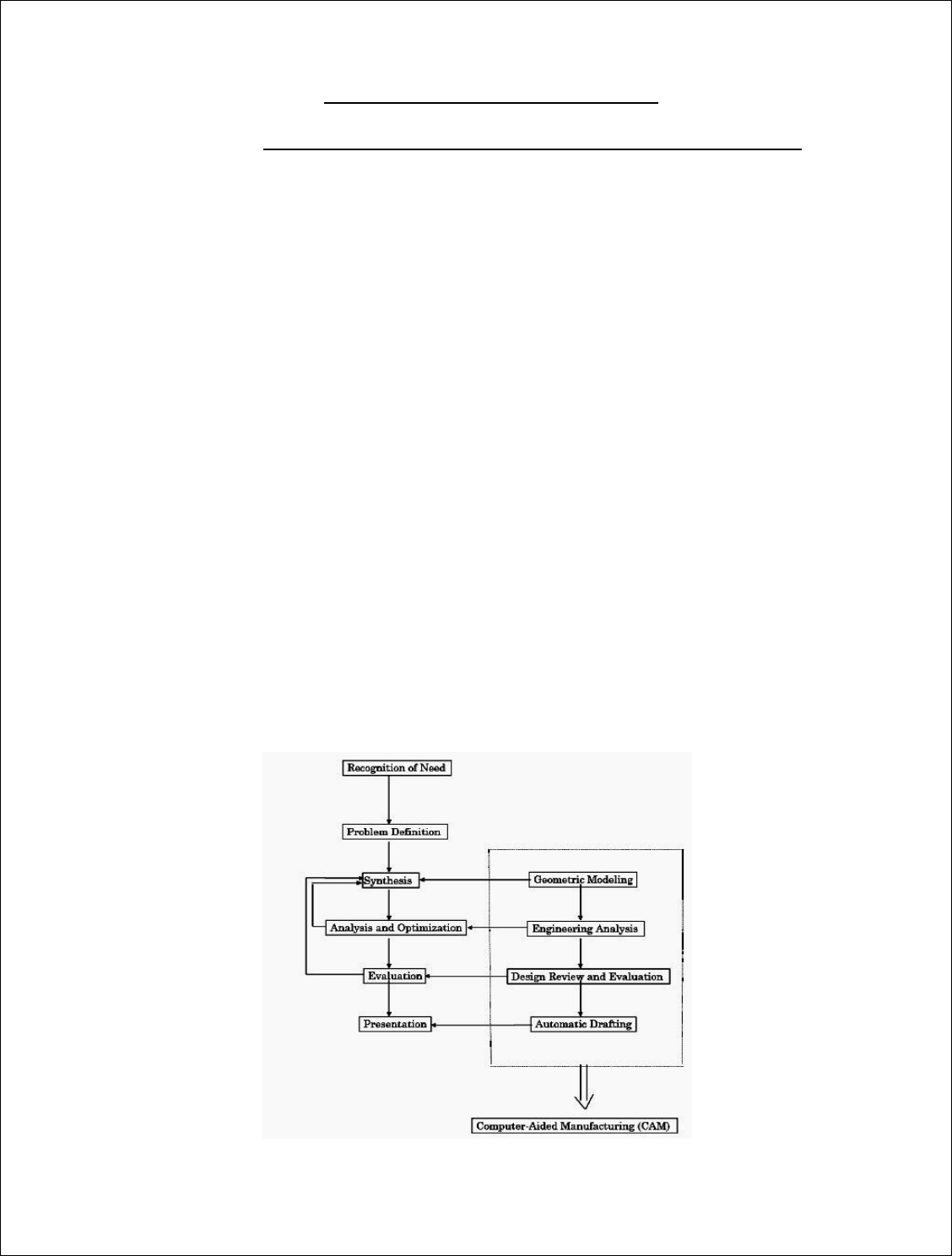
According to Shingly, the design process is an iterative procedure involving the
following six phases:
1. Recognition of need
2. Definition of problem
3. Synthesis
4. Analysis and optimization
5. Evaluation
6. Presentation
Phase 3 (synthesis) includes defining the design problem, design
conceptualization, searching for design information, modeling and simulation.
Phase 4 (analysis and optimization) may include parameter study, finite
element analysis, etc. Although computers are being utilized more and more in the
design process, their use is still limited to the last four steps in the design and they
are mainly used as a tool that helps the designer, rather than as a replacement for
the designer.
BENEFITS OF USING CAD:
(1)Increasing productivity
(2)Improving quality of design
(3)Improving communications
(4)Creating data-base for manufacturing
The Design Process and Computer-Aided Design

GEOMETRIC MODELING
The term geometric modeling (or representation) means a method of
describing commonly used curves and surfaces in terms of values of a few
parameters.
THREE TYPES OF GEOMETRIC MODELS
Wireframe Model: connect 3D vertex points, sometimes ambiguous.
Surface Model : define surface to form an object.
Solid Model: various representation schemes are used to describe a solid object
SOLID MODELING
A solid modeling system is usually an interactive computer graphics system
that is intended to create true three-dimensional components and assemblies.
Recent advances in CAD software, computers, and graphical displays have made it
possible to use solid representations of components being considered in the design
process. These solid models can be employed innumerous ways.
ADVANTAGES OF SOLID MODELING
A realistic visual display: By producing a shaded visible surface image of
the solid, solid modeling allows a designer to see exactly what has been created.
Easy to deal with different views: Once a part has been created, we have the ability
to rotate, shade, section, or produce almost any view required by a designer. Single
associated model database: The solid modeler provides the only database suitable
for all CAD operations. Almost all information needed for part generation is
contained in the solid model. The algorithm should be able to ensure that it
represents physically possible shape that is complete and unambiguous
Applications. e.g., automatic generation of a mesh for a finite element analysis.
REQUIREMENTS FOR MODELING ASSEMBLING
1.Part modeling and analysis
The part analysis includes the material type, mass and inertial properties,
functional properties of the faces, etc.
2.Hierarchical relationships
An assemble tree and assemble sequence must be given.
3.Mating conditions.

There are two methods for specifying mating conditions: Specify the
location and orientation of each part in the assembly, together with the
representation of the part itself, by providing a 4 x 4 homogeneous transformation
matrix. (i.e., transformation from MCS to WCS)Specify the spatial relationships
between its individual parts as mating conditions. For example, a mating condition
can consist of planar faces butting up against one another or requiring centerlines
of individual parts to be collinear (―fits‖ condition).
CAD/CAE/CAM Data Exchange
Computer databases are now replacing paper blueprints in defining product
geometry and non-geometry for all phases of product design, analysis, and
manufacturing. It becomes increasingly important to find effective procedures for
transferring data among CAD/CAE/CAM systems. The need to exchange modeling
data is directly motivated by the need to integrate and automate the design and
manufacturing process to obtain the maximum benefits from CAD/CAE/CAM
systems.
FOUR TYPES OF MODELING DATA TO BE TRANSFERRED
(1)Shape
(2)Non shape
(3)Design
(4)Manufacturing
(1) Shape data consists of both geometrical and topological information as well
as part features. Entity attributes such as font, color, and layers as well as
annotation are considered part of the entity geometrical information.
Topological information applies only to products described via solid modeling.
Features allow high-level concept communication about parts. Examples are
hole, flange, web, pocket, chamfer, etc.
(2) Non shape data includes graphics data such as shaded images, and model
global data as measuring units of the database and the resolution of storing the
database numerical values.
(3) Design data has to do with the information that designers generate from
geometric models for analysis purposes. e.g., mass property and finite element
mesh data.

(4) Manufacturing data consists of information such as tooling, NC tool paths,
tolerance, process planning, tool design, and bill of materials.
Commonly Used CAD Data Exchange Format IGES (Initial Graphics Exchange
Specification) PDES (Product Data Exchange Using STEP) IGES is focused on
CAD-to-CAD exchange where primarily shape and non-shape data were to be
transferred from one system to another. PDES is previous called Product Data
Exchange Standard. It is for the exchange of complete product descriptions which
covers the four types of modeling data (i.e., shape, non-shape, design and
manufacturing).Other data exchange interfaces include: STL, Neutral, SET,
ECAD, VDA, STEP, PDGS, CATIA, Render, CGM, VRML, PATRAN, TIFF, etc.
LIMITS, TOLERANCES AND FITS
The manufacture of interchangeable parts requires precision. Precision is the
degree of accuracy to ensure the functioning of a part as intended. However,
experience shows that it is impossible to make parts economically to the exact
dimensions. This may be due to, (i) inaccuracies of machines and tools, (ii)
inaccuracies in setting the work to the tool, and (iii) error in measurement, etc. The
workman, therefore, has to be given some allowable margin so that he can produce
a part, the dimensions of which will lie between two acceptable limits, a maximum
and a minimum. The system in which a variation is accepted is called the limit
system and the allowable deviations are called tolerances. The relationships
between the mating parts are called fits.
Tolerance -The permissible variation of a size is called tolerance. It is the
difference between the maximum and minimum permissible limits of the given
size. If the variation is provided on one side of the basic size, it is termed as
unilateral tolerance. Similarly, if the variation is provided on both sides of the basic
size, it is known as bilateral tolerance.
Limits-The two extreme permissible sizes between which the actual size is
contained are called limits. The maximum size is called the upper limit and the
minimum size is called the lower limit.
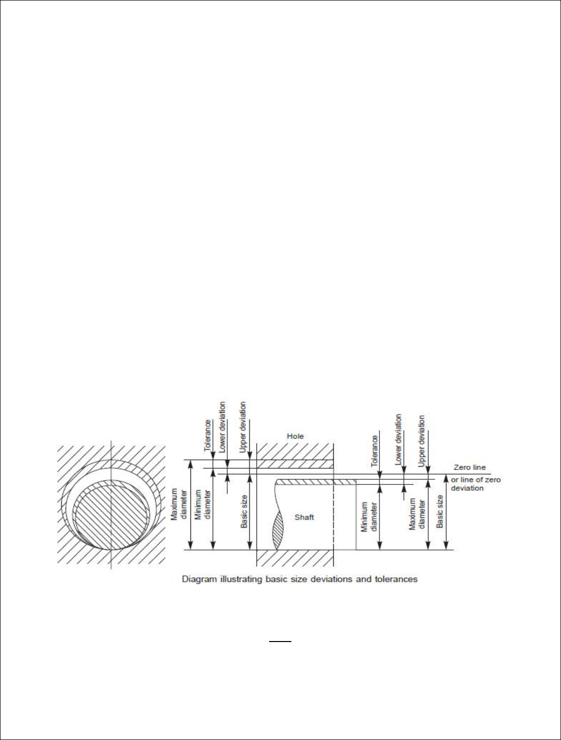
Deviation-It is the algebraic difference between a size (actual, maximum, etc.) and
the corresponding basic size.
Actual deviation-It is the algebraic difference between the actual size and the
corresponding basic size.
Upper deviation-It is the algebraic difference between the maximum limit of the
size and the corresponding basic size.
Lower deviation-It is the algebraic difference between the minimum limit of the
size and the corresponding basic size.
Allowance -It is the dimensional difference between the maximum material limits
of the mating parts, intentionally provided to obtain the desired class of fit. If the
allowance is positive, it will result in minimum clearance between the mating parts
and if the allowance is negative, it will result in maximum interference.
Basic size -It is determined solely from design calculations. If the strength and
stiffness requirements need a 50mm diameter shaft, then 50mm is the basic shaft
size. If it has to fit into a hole, then 50 mm is the basic size of the hole. Figure
illustrates the basic size, deviations and tolerances.
Fits
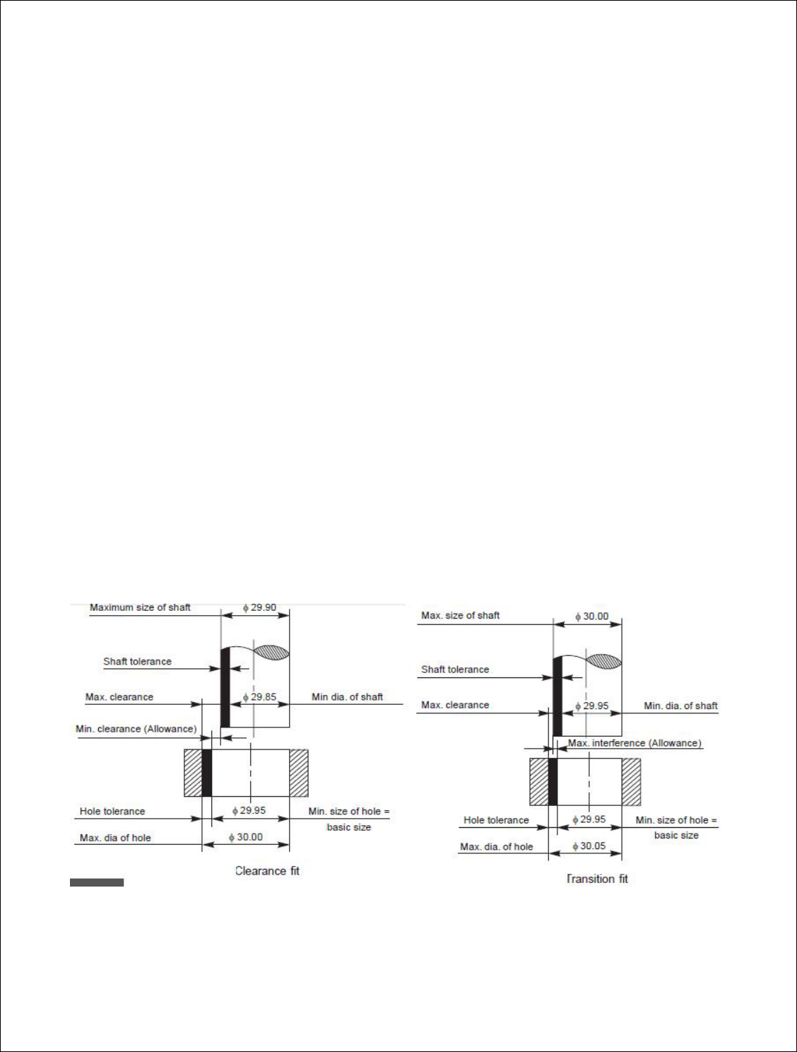
The relation between two mating parts is known as a fit. Depending upon the
actual limits of the hole or shaft sizes, fits may be classified as clearance fit,
transition fit and interference fit.
Clearance fit-It is a fit that gives a clearance between the two mating parts.
Minimum clearance-It is the difference between the minimum size of the hole
and the maximum size of the shaft ina clearance fit.
Maximum clearance-It is the difference between the maximum size of the hole
and the minimum size of the shaft in a clearance or transition fit.
Transition fit-This fit may result in either interference or a clearance, depending
upon the actual values of the tolerance of individual parts. The shaft in Fig. may be
either smaller or larger than the hole and still be within the prescribed tolerances. It
results in a clearance fit, when shaft diameter is 29.95 and hole diameter is 30.05
(+ 0.10 mm) and interference fit, when shaft diameter is 30.00 and hole diameter
29.95 (– 0.05 mm).
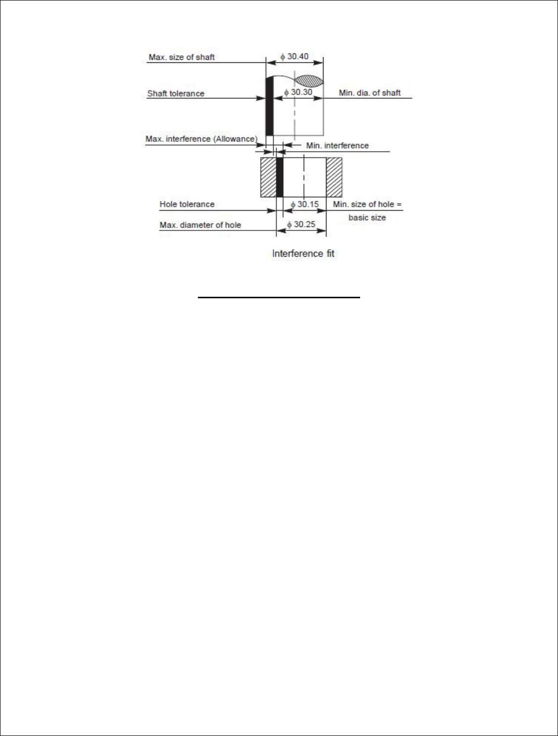
Interference fit-If the difference between the hole and shaft sizes is negative
before assembly; an interferencefit is obtained.
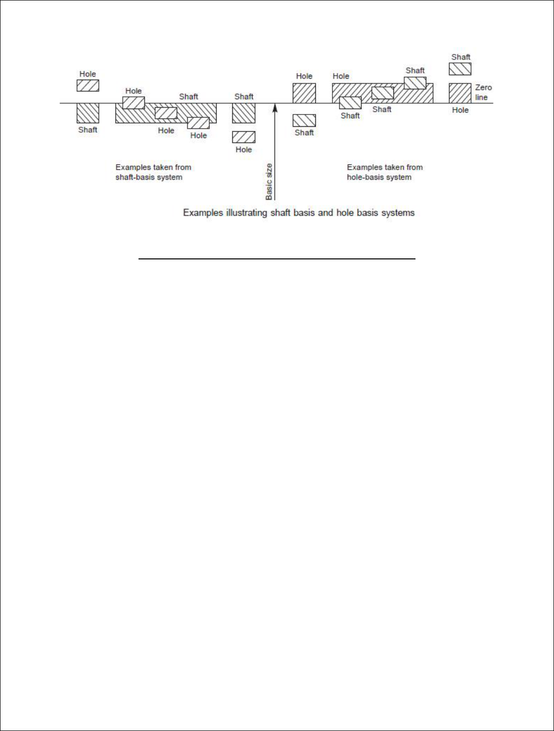
Hole and shaft basis system
Hole basis system-In this system, the size of the shaft is obtained by subtracting the
allowance from the basic size of the hole. This gives the design size of the shaft.
Tolerances are then applied to each part separately. In this system, the lower
deviation of the hole is zero. The letter symbol for this situation is ‘H’. The hole
basis system is preferred in most cases, since standard tools like drills, reamers,
broaches, etc., are used for making a hole.
Shaft basis system-In this system, the size of the hole is obtained by adding the
allowance to the basic size of the shaft. This gives the design size for the hole.
Tolerances are then applied to each part. In this system, the upper deviation of the
shaft is zero. The letter symbol for this situation is ‘h’. The shaft basis system is
preferred by (i) industries using semi-finished shafting as raw materials, e.g.,
textile industries, where spindles of same size are used as cold-finished shafting
and (ii) when several parts having different fits but one nominal size is required on
a single shaft.
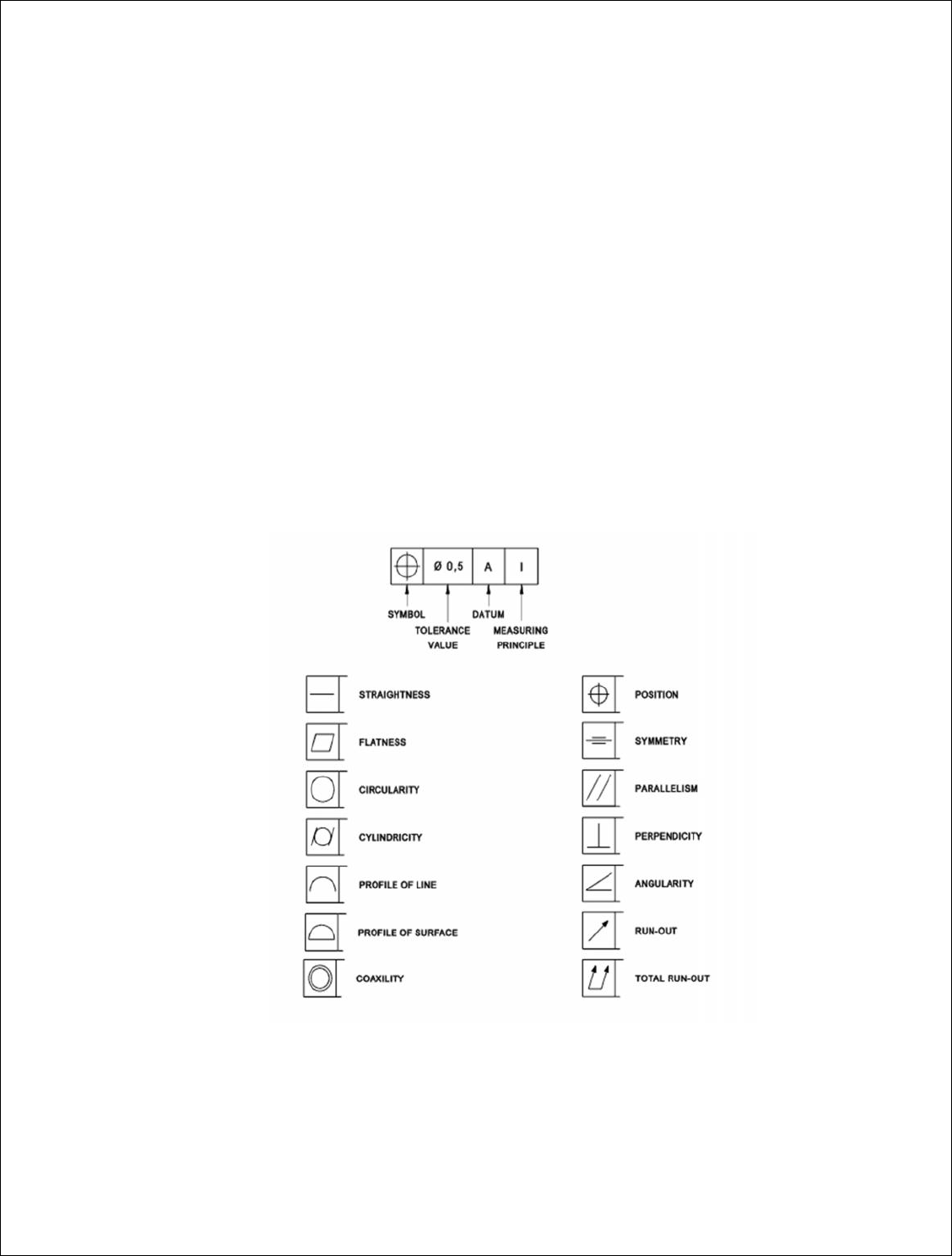
Geometric Dimensioning & Tolerance (GD&T)
Geometric dimensioning and tolerance (GD&T) is a language used on mechanical
engineering drawings composed of symbols that are used to efficiently and
accurately communicate geometry requirements for associated features on
components and assemblies. GD&T is, and has been, successfully used for many
years in the automotive, aerospace, electronics and the commercial design and
manufacturing industries. In today’s modern and technically advanced design,
engineering and manufacturing world, effective and accurate communication is
required to ensure successful end products. Success oriented industries and
organizations which require accurate and common lines of communications
between engineering, design, manufacturing and quality should consider geometric
dimensioning and tolerance (GD&T) as their mechanical drawing standard. Some
advantages of GD&T (geometric dimensioning and tolerance) are;
1. Provides a clear and concise technique for defining a reference coordinate
system (datum's) on a component or assembly to be used throughout the
manufacturing and inspection processes.
2. Proper application of geometric dimensioning closely dovetails accepted and
logical mechanical design process and design for manufacturing
considerations.
3. Geometric dimensioning dramatically reduces the need for drawing notes to
describe complex geometry requirements on a component or assembly by
the use of standard symbol that accurately and quickly defines design,
manufacturing and inspection requirements.
4. GD&T concepts such as MMC (maximum material condition) when applied
properly will facilitate and simplify the design of cost saving functional
check gages, manufacturing fixtures and jigs.

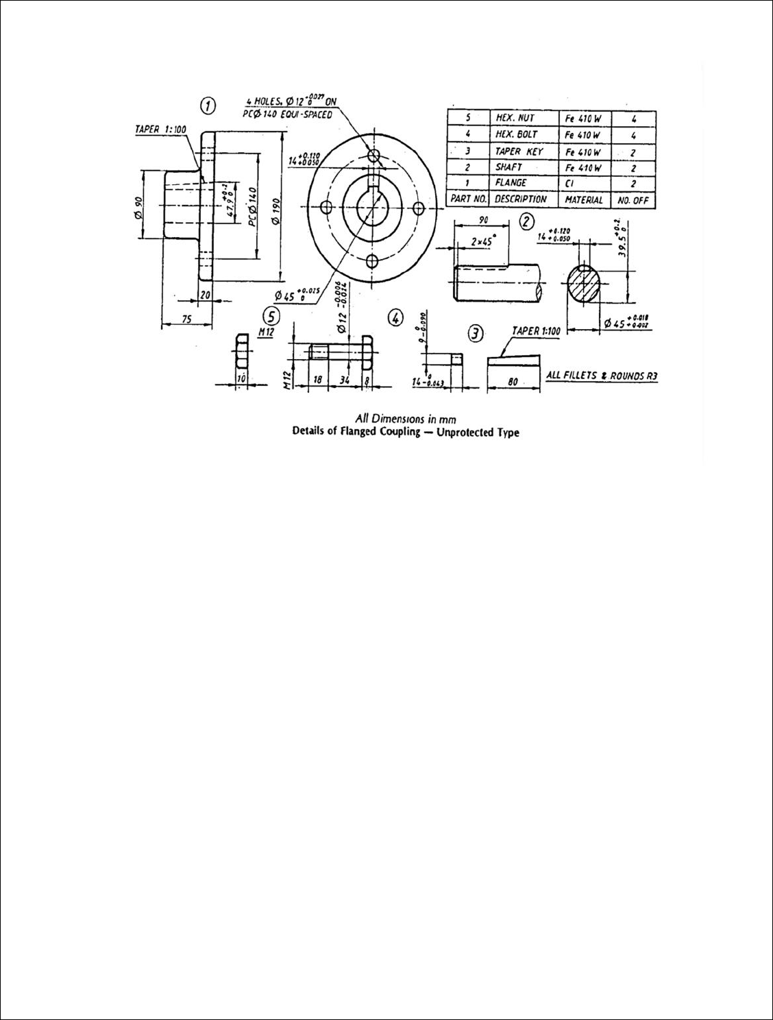
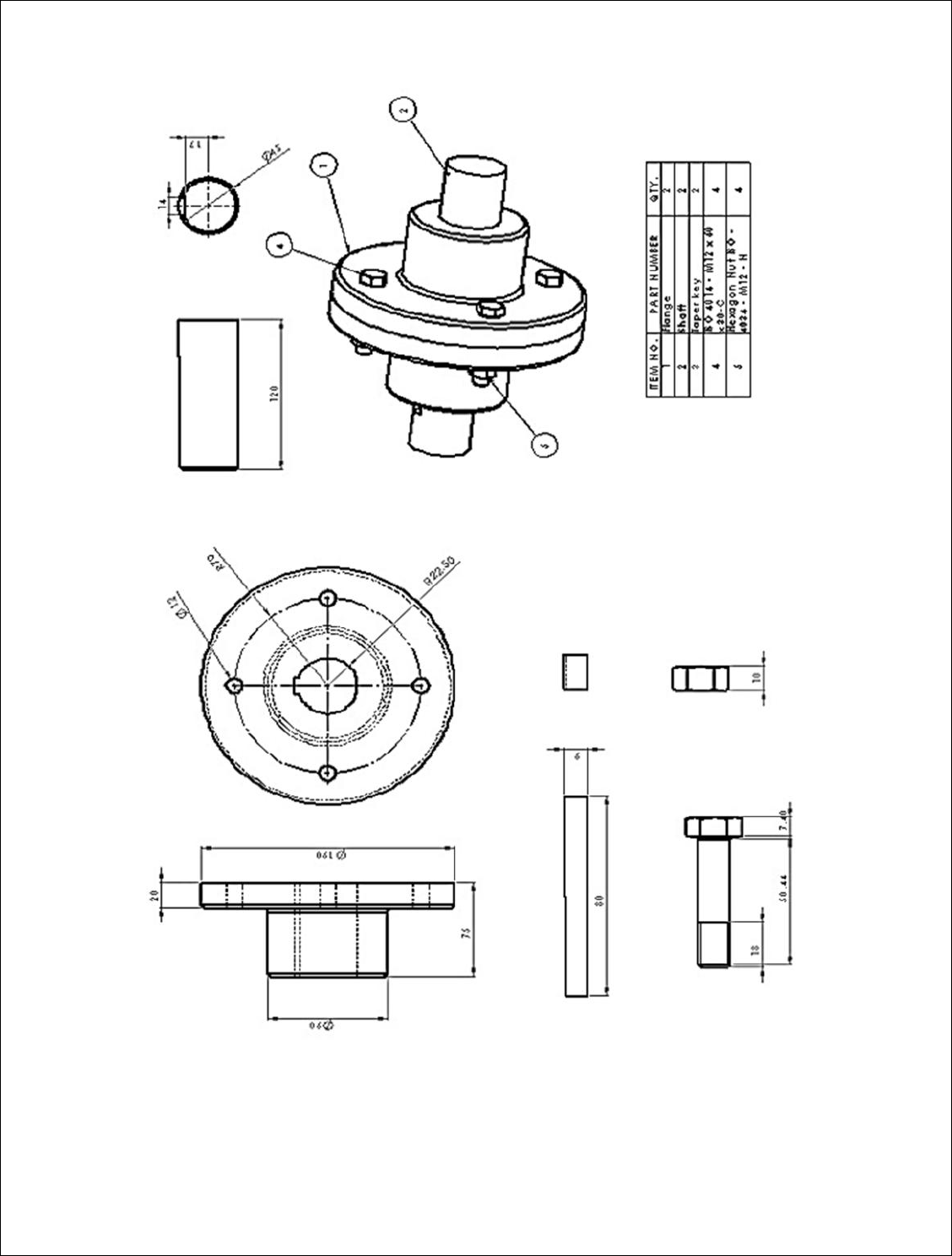
EX.NO:2 FLANGE COUPLING ASSEMBLY
DATE:
AIM:
To draw the detail view of the flange coupling and assemble the parts
by using the Pro-E software and obtain its respective views.
PROCEDURE:
The drawings of Flanges, Shaft, Taper key, Hexagonal Bolt and Nut are
studied
3D models of Flanges, Shaft, Taper key, Hexagonal Bolt and Nut are created
using Pro-E software.
The Assembly of Flanged Coupling was created as per the drawing
specification
Detail all the components of the assembly as per the drawing standards.
COMMANDS USED:
Sketcher Commands: Line, Circle, Arc, Fillet, Trim, Smart Dimension,
Relations, Show, and View
Features Commands: Extrude and Cut, Revolve, Fillet/Round, Chamfer, Hole -
Simple, Pattern Fastening Features
Assembly Commands: Insert, Component, Existing Part/Assembly
Mating Commands: Coincident, Concentric, Distance
RESULT: Thus the Detail View of the flange coupling assembly and its respective
views has been drawn.

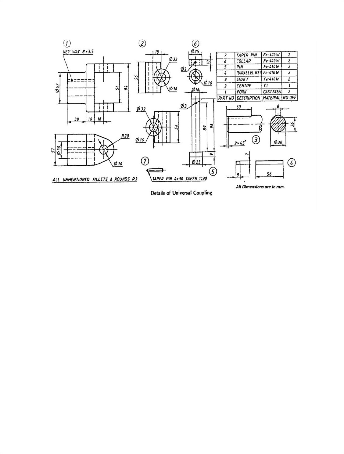
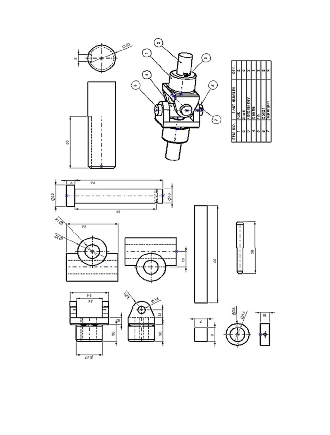
EX.NO:3 UNIVERSAL COUPLING ASSEMBLY
DATE:
AIM:
To draw the detail view of the universal coupling and assemble the
parts by using the Pro-E software and obtain its respective views.
PROCEDURE:
The drawings of Fork, Shaft, Centre, Parallel key, Pin, Collar and Taper pin
are studied.
3D models of all the parts are created using Pro-E software.
The Assembly of Universal Joint was created as per the drawing
specification.
Detail all the components of the assembly as per the drawing standards.
COMMANDS USED:
Sketcher Commands: Line, Circle, Arc, Fillet, Trim, Smart Dimension,
Relations, Show, and View
Features Commands: Extrude and Cut, Revolve, Fillet/Round, Chamfer, Hole -
Simple, Pattern Fastening Features
Assembly Commands: Insert, Component, Existing Part/Assembly
Mating Commands: Coincident, Concentric, Distance
RESULT: Thus the Detail View of the universal coupling assembly and its
respective views has been drawn.

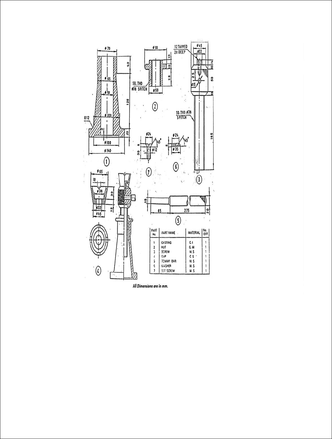
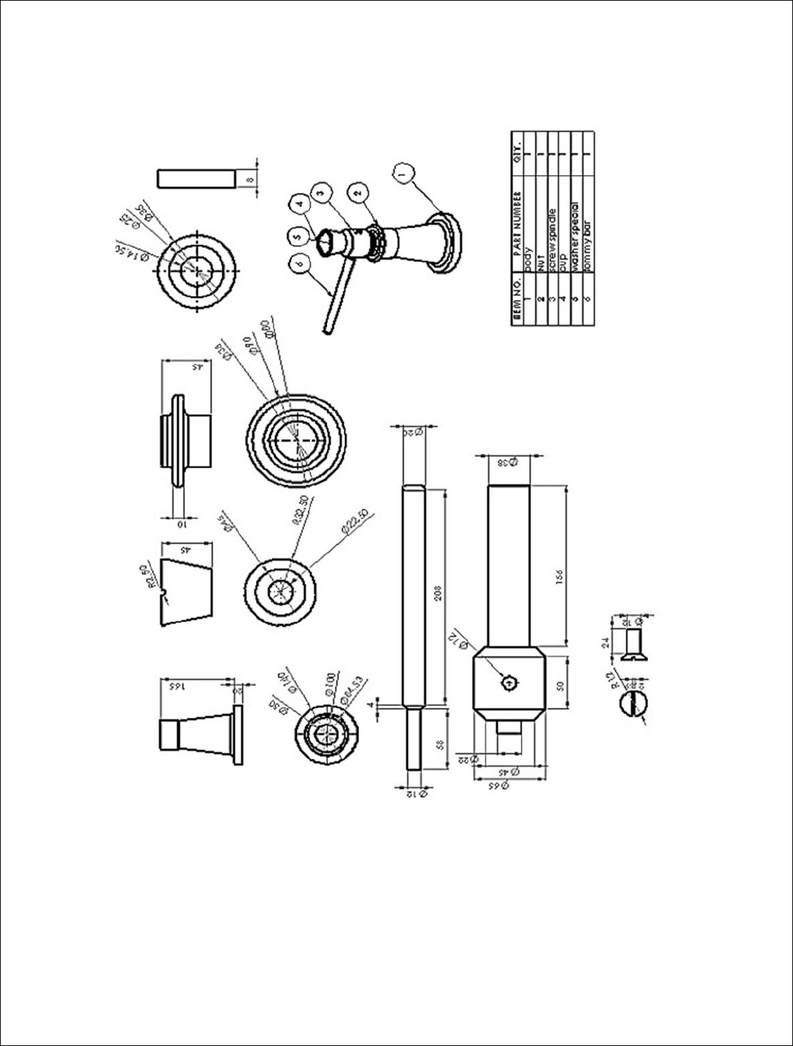
EX.NO:4 SCREW JACK ASSEMBLY
DATE:
AIM:
To draw the detail view of the screw jack and assemble the parts by
using the Pro-E software and obtain its respective views.
PROCEDURE:
The drawings of Body, Nut, Screw Spindle, Cup, Washer Special, CSK
Screw, and Tommy Bar are studied
3D models of Body, Nut, Screw Spindle, Cup, Washer Special, CSK Screw,
and Tommy Bar are created using Pro-E software.
The Assembly of Screw Jack was created as per the drawing specification
Detail all the components of the assembly as per the drawing standards.
COMMANDS USED:
Sketcher Commands: Line, Circle, Arc, Fillet, Trim, Smart Dimension,
Relations, Show, and View
Features Commands: Extrude and Cut, Revolve, Fillet/Round, Chamfer, Hole -
Simple, Pattern Fastening Features
Assembly Commands: Insert, Component, Existing Part/Assembly
Mating Commands: Coincident, Concentric, Distance
RESULT: Thus the Detail View of the screw jack assembly and its respective
views has been drawn.

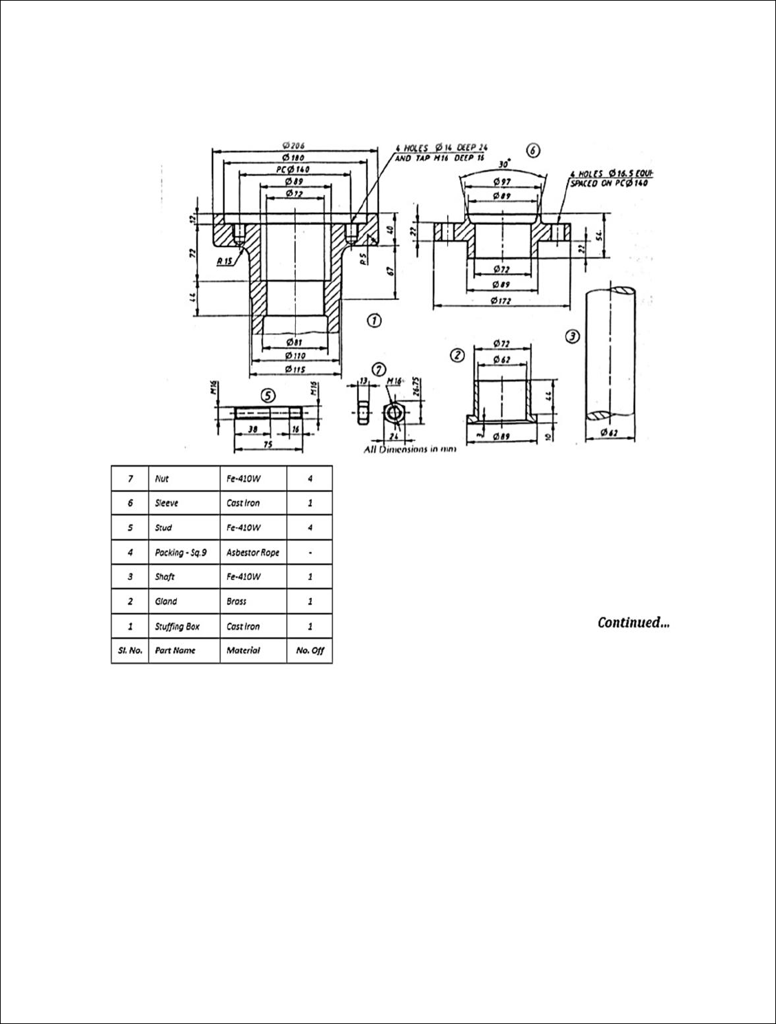
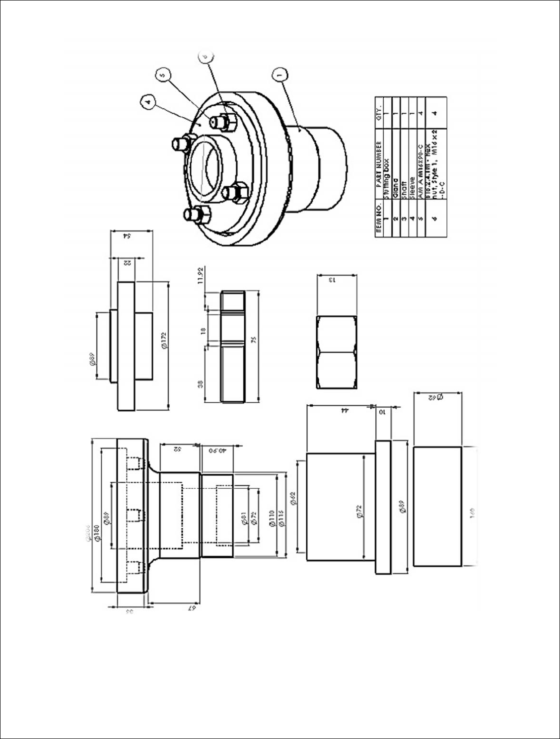
EX.NO:5 STUFFING BOX ASSEMBLY
DATE:
AIM:
To draw the detail view of the stuffing box and assemble the parts by
using the Pro-E software and obtain its respective views.
PROCEDURE:
The drawings of stuffing box, Nut, Gland, Piston rod, and Packing are
studied.
3D models of all the parts are created using Pro-E software.
The Assembly of Stuffing Box was created as per the drawing specification.
Detail all the components of the assembly as per the drawing standards.
COMMANDS USED:
Sketcher Commands: Line, Circle, Arc, Fillet, Trim, Smart Dimension,
Relations, Show, and View
Features Commands: Extrude and Cut, Revolve, Fillet/Round, Chamfer, Hole -
Simple, Pattern Fastening Features
Assembly Commands: Insert, Component, Existing Part/Assembly
Mating Commands: Coincident, Concentric, Distance
RESULT: Thus the Detail View of the stuffing box assembly and its respective
views has been drawn.

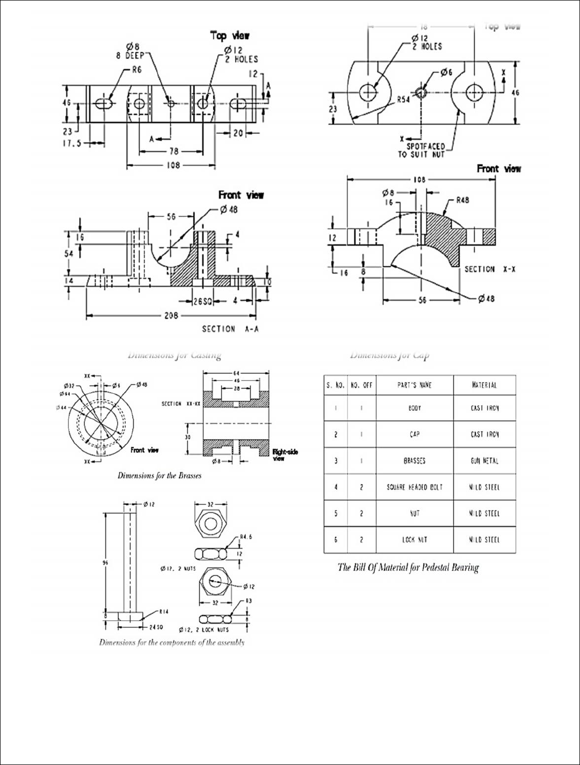
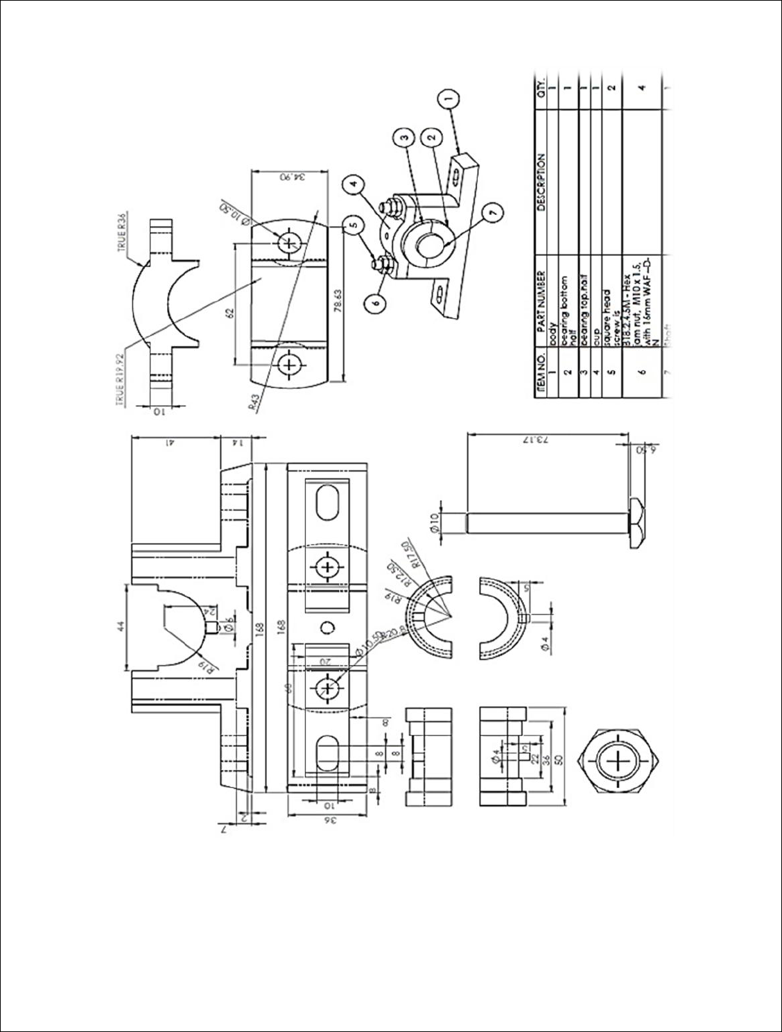
EX.NO:6 PLUMMER BLOCK ASSEMBLY
DATE:
AIM:
To draw the detail view of the Plummer block and assemble the parts
by using the Pro-E software and obtain its respective views.
PROCEDURE:
The drawings of Body, Cap, Bearing top & Bottom half, Nuts and shaft are
studied
3D models of Body, Cap, Bearing top & Bottom half Nuts and shaft are
created using Pro-E software.
The Assembly of Plummer block was created as per the drawing
specification.
Detail all the components of the assembly as per the drawing standards.
COMMANDS USED:
Sketcher Commands: Line, Circle, Arc, Fillet, Trim, Smart Dimension,
Relations, Show, and View
Features Commands: Extrude and Cut, Revolve, Fillet/Round, Chamfer, Hole -
Simple, Pattern Fastening Features
Assembly Commands: Insert, Component, Existing Part/Assembly
Mating Commands: Coincident, Concentric, Distance
RESULT: Thus the Detail View of the Plummer block assembly and its respective
views has been drawn.

COMPUTER AIDED MANUFACTURING (CAM)
EX.NO:7 INTRODUCTION
The part program is a sequence of instructions, which describe the work, which has
to be done on a part, in the form required by a computer under the control of a
numerical control computer program. It is the task of preparing a program sheet
from a drawing sheet. All data is fed into the numerical control system using a
standardized format. Programming is where all the machining data are compiled
and where the data are translated into a language which can be understood by the
control system of the machine tool. The machining data is as follows:
(a) Machining sequence classification of process, tool start up point, cutting
depth, tool path, etc.
(b) Cutting conditions, spindle speed, feed rate, coolant, etc.
(c) Selection of cutting tools.
While preparing a part program, need to perform the following steps :
(a) Determine the startup procedure, which includes the extraction of
dimensional data from part drawings and data regarding surface quality
requirements on the machined component.
(b) Select the tool and determine the tool offset.
(c) Set up the zero position for the work piece.
(d) Select the speed and rotation of the spindle.
(e) Set up the tool motions according to the profile required.
(f) Return the cutting tool to the reference point after completion of work.
(g) End the program by stopping the spindle and coolant.
The part programming contains the list of coordinate values along the X, Y and Z
directions of the entire tool path to finish the component. The program should also
contain information, such as feed and speed. Each of the necessary instructions for
a particular operation given in the part program is known as an NC word. A group
of such NC words constitutes a complete NC instruction, known as block. The
commonly used words are N, G, F, S, T, and M. The same is explained later on
through examples.

Hence the methods of part programming can be of two types depending upon the
two techniques as below:
(a) Manual part programming, and
(b) Computer aided part programming.
MANUAL PART PROGRAMMING
The programmer first prepares the program manuscript in a standard format.
Manuscripts are typed with a device known as flexo writer, which is also used to
type the program instructions. After the program is typed, the punched tape is
prepared on the flexo writer. Complex shaped components require tedious
calculations. This type of programming is carried out for simple machining parts
produced on point-to-point machine tool.
To be able to create a part program manually, need the following information:
(a) Knowledge about various manufacturing processes and machines.
(b) Sequence of operations to be performed for a given component.
(c) Knowledge of the selection of cutting parameters.
(d) Editing the part program according to the design changes.
(e) Knowledge about the codes and functions used in part programs.
FUNDAMENTAL ELEMENTS FOR DEVELOPING MANUAL PART PROGRAMME
Type of Dimensioning System
Axis Designation
NC Words
Standard G and M Codes
Tape Programming Format
Machine Tool Zero Point Setting
Coordinate Word
Parameter for Circular Interpolation
Spindle Function
Feed Function
Tool Function
Work Settings and Offsets
Rapid Positioning
Linear Interpolation
Circular Interpolation

MANUAL PART PROGRAMMING IN CNC LATHE
G-CODES (PREPARATORY FUNCTIONS)
CODE
FUNCTION
G00
Rapid positioning
G01
Linear interpolation
G02
Circular interpolation clockwise (CW)
G03
Circular interpolation counterclockwise (CCW)
G20
Inch input (in.)
G21
Metric input (mm)
G24
Radius programming
G28
Return to reference point
G29
Return from reference point
G32
Thread cutting
G40
Cutter compensation cancel
G41
Cutter compensation left
G42
Cutter compensation right
G43
Tool length compensation positive (+) direction
G44
Tool length compensation minus (-) direction
G49
Tool length compensation cancels
G 53
Zero offset or M/c reference
G54
Settable zero offset
G84
canned turn cycle
G90
Absolute programming
G91
Incremental programming

M-CODES (MISCELLANEOUS FUNCTIONS)
CODE
FUNCTION
M00
Program stop
M02
End of program
M03
Spindle start (forward CW)
M04
Spindle start (reverse CCW)
M05
Spindle stop
M06
Tool change
M08
Coolant on
M09
Coolant off
M10
Chuck - clamping
M11
Chuck - unclamping
M12
Tailstock spindle out
M13
Tailstock spindle in
M17
Tool post rotation normal
M18
Tool post rotation reverse
M30
End of tape and rewind or main program end
M98
Transfer to subprogram
M99
End of subprogram

MANUAL PART PROGRAMMING IN CNC MILLING
G-CODES (PREPARATORY FUNCTIONS)
CODE
FUNCTION
G00
Positioning (Rapid traverse)
G01
Linear interpolation (Cutting feed)
G02
Circular interpolation / Helical CW
G03
Circular interpolation / Helical CCW
G04
Dwell Exact stop
G20
Imperial units (inches)
G21
Metric units (mm)
G28
Return to reference point
G40
Tool radius compensation cancel
G41
Left hand radius compensation
G42
Right hand radius compensation
G49
Tool length compensation cancel
G90
Absolute command
G91
Incremental command
G92
Set datum
G94
Feed per minute
G94
Feed per rotation
G
1
70-G
1
71
Circular Pocketing
G
1
72-G
1
73
Rectangular Pocketing

M-CODES (MISCELLANEOUS FUNCTIONS)
CODE
FUNCTION
M00
Program Stop
M02
Program End
M03
Spindle Forward
M04
Spindle Reverse
M05
Spindle Stop
M06
Tool Change
M70
X Mirror on
M71
Y Mirror on
M80
X Mirror Off
M81
Y Mirror Off
M98
Subprogram Call
M99
Subprogram Exit

COMPUTER AIDED PART PROGRAMMING
If the complex-shaped component requires calculations to produce the component
are done by the programming software contained in the computer. The
programmer communicates with this system through the system language, which is
based on words. There are various programming languages developed in the recent
past, such as APT (Automatically Programmed Tools), ADAPT, AUTOSPOT,
COMPAT-II, 2CL, ROMANCE, SPLIT is used for writing a computer
programme, which has English like statements. A translator known as compiler
program is used to translate it in a form acceptable to MCU.
The programmer has to do only following things :
(a) Define the work part geometry.
(b) Defining the repetition work.
(c) Specifying the operation sequence.
Over the past years, lot of effort is devoted to automate the part programme
generation. With the development of the CAD (Computer Aided Design)/CAM
(Computer Aided Manufacturing) system, interactive graphic system is integrated
with the NC part programming. Graphic based software using menu driven
technique improves the user friendliness. The part programmer can create the
geometrical model in the CAM package or directly extract the geometrical model
from the CAD/CAM database. Built in tool motion commands can assist the part
programmer to calculate the tool paths automatically. The programmer can verify
the tool paths through the graphic display using the animation function of the CAM
system. It greatly enhances the speed and accuracy in tool path generation.
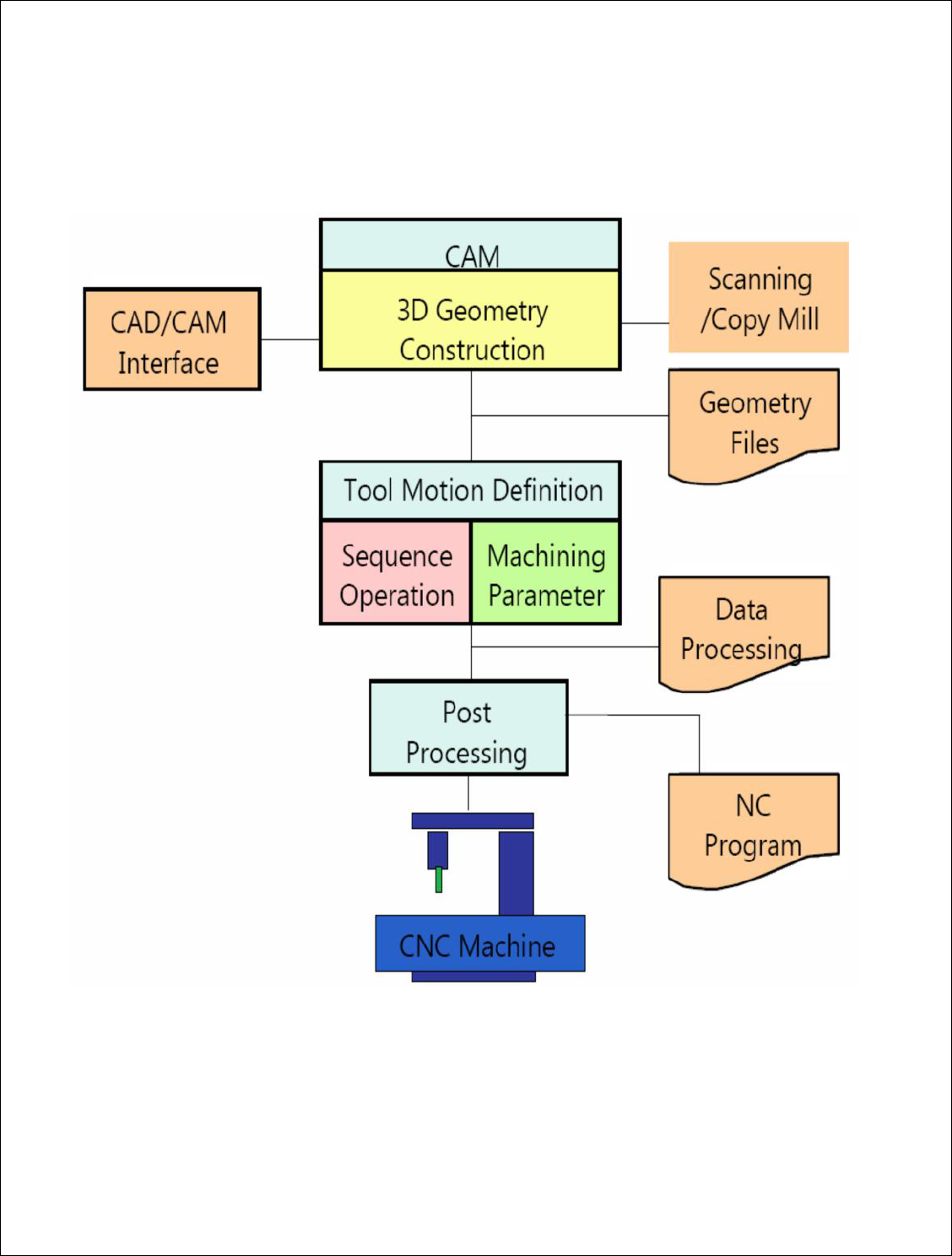
INTERACTIVE GRAPHIC SYSTEM IN COMPUTER AIDED PART
PROGRAMMING

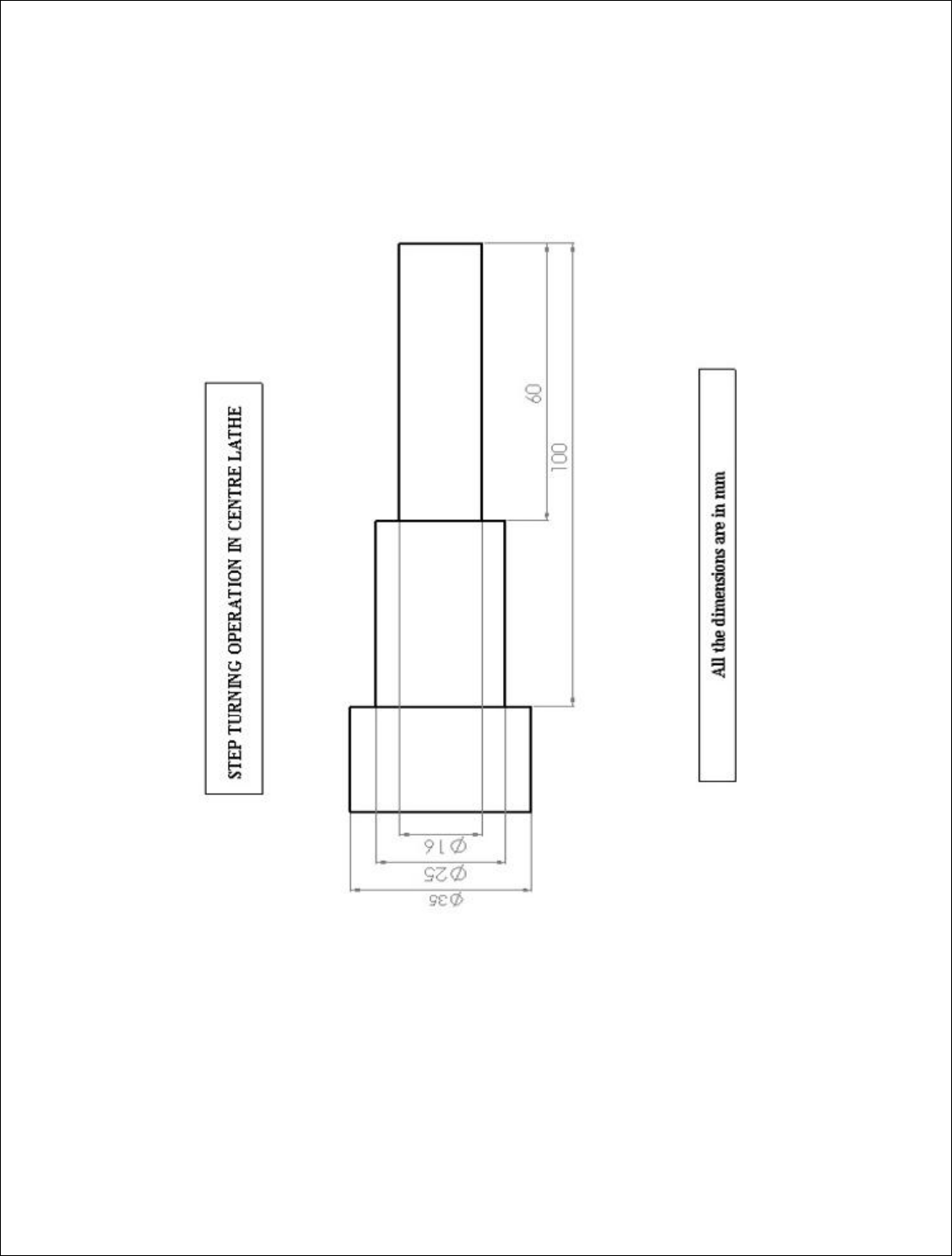
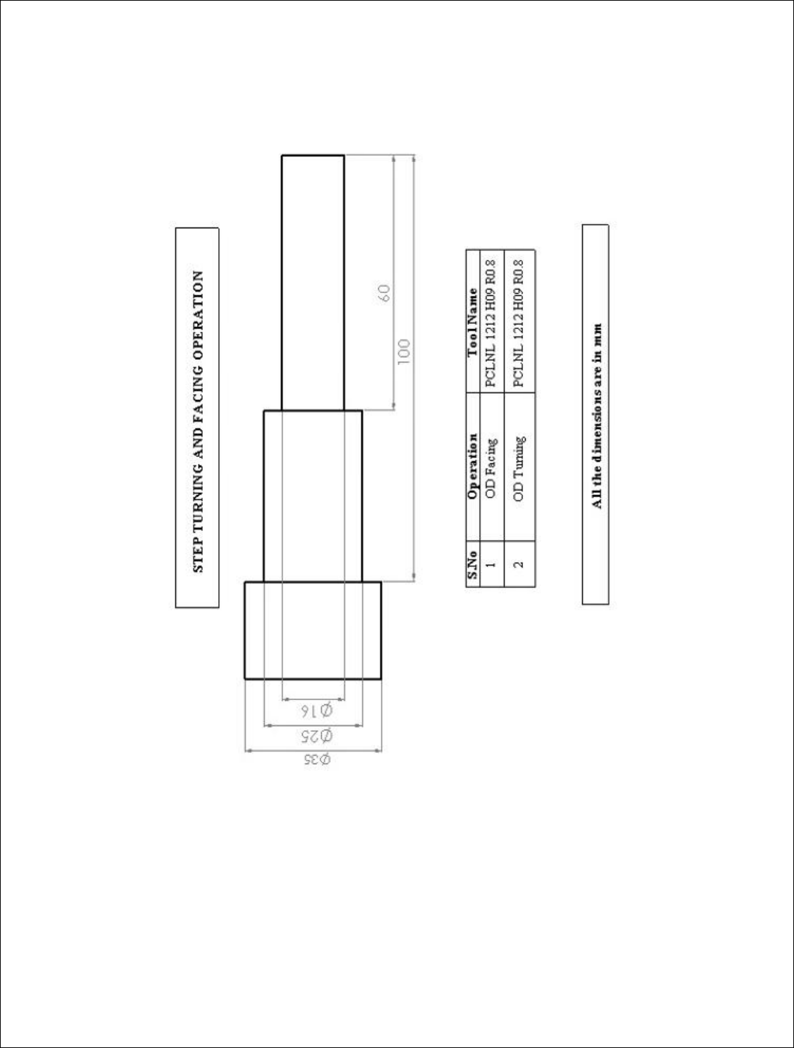
EX.NO:8 MANUAL PART PROGRAMMING FOR STEP TURNING OPERATION IN CNC
TURNING CENTER
DATE:
AIM:
To write the manual part programming for the given diagram and execute
the same by using CNC lathe.
MATERIALS REQUIRED:
Mild steel Size
Diameter 35 mm
Length 100 mm
MANUAL PART PROGRAM:
N01 G54 G90 G71 G94 M03 S800;
N05 G01 X-12.5 Z0 F2;
N10 G00 Z1;
N15 G00 X00;
N20 G01 Z-100;
N25 G00 X1 Z1;
N30 G00 X-2;
N35 G01 Z-60;
N40 G00 X-1 Z1;
N45 G00 X-3;
N50 G01 Z-60;
N55 G00 X-2 Z1;
N60 G00 X-4;

N65 G01 Z-60;
N70 G00 X-3 Z1;
N75 G00 X-4.5;
N80 G01 Z-60;
N85 G00 X5 Z5;
N90 M02;
RESULT:
Thus the part program has been written and executed by using the CNC Lathe.

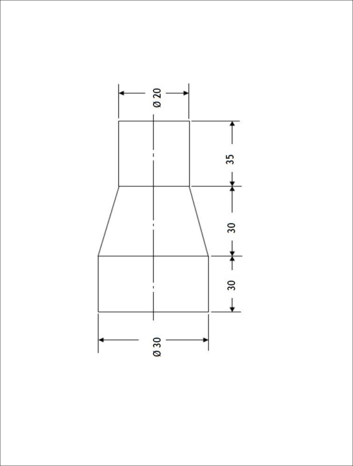
EX.NO:9 MANUALPART PROGRAMMING FOR TAPER TURNING OPERATION IN IN
CNC TURNING CENTER
DATE:
AIM:
To write the manual part programming for the given diagram and execute
the same by using CNC lathe.
MATERIALS REQUIRED:
Mild steel Size
Diameter 30 mm
Length 95 mm
MANUAL PART PROGRAM:
N01 G54 G91 G71 G94 M03 S800;
N05 G01 X-15 Z0 F2;
N10 G00 Z1;
N15 G00 X10;
N20 G01 Z-36;
N25 G01 X5 –Z30;
N30 G00 X1 Z66;
N35 M02;
RESULT:
Thus the part program has been written and executed by using the CNC Lathe.

EX.NO:10 NC CODE GENERATION FOR STEP TURNING AND FACING
OPERATION BY USING CADEM SOFTWARE
DATE:
AIM:
To generate the NC code for step turning and facing operation by using cadem-
capsturn software.
PROCEDURE:
Step 1: open the capsturn software
Step 2: Create the required part as per the given diagram in geometry mode
Step 3: Define the blank as per the requirement
Step 4: Select the suitable tool for turning and facing operation in machining mode
Step 5: Select the required machining operation and define the data
Step 6: Simulate the tool path for the given part
Step 7: Generate the NC code and save the program
NC CODE GENERATION:
%
O1234
G21 G95
G0 X200 Z100
N1 T11 (PCLNL 1616H12 R0.8)
G50 S3000
G96 S139 M04
(PLAIN FACE)
X38 Z4 M08
X39

G72 W3 R0.5
G72 P25 Q40 U0 W0 F0
N25 G0 Z0
N30 G01 X35 Z0
N35 X0
N40 Z2
G0 X38
(CONTOUR TURN)
Z2
X39
G71 U3 R0.5
G71 P45 Q80 U0 W0 F0
N45 G00 X16
N50 G01 X16 Z0
RESULT:
Thus the NC code has been generated by using the cadem-capsturn software.

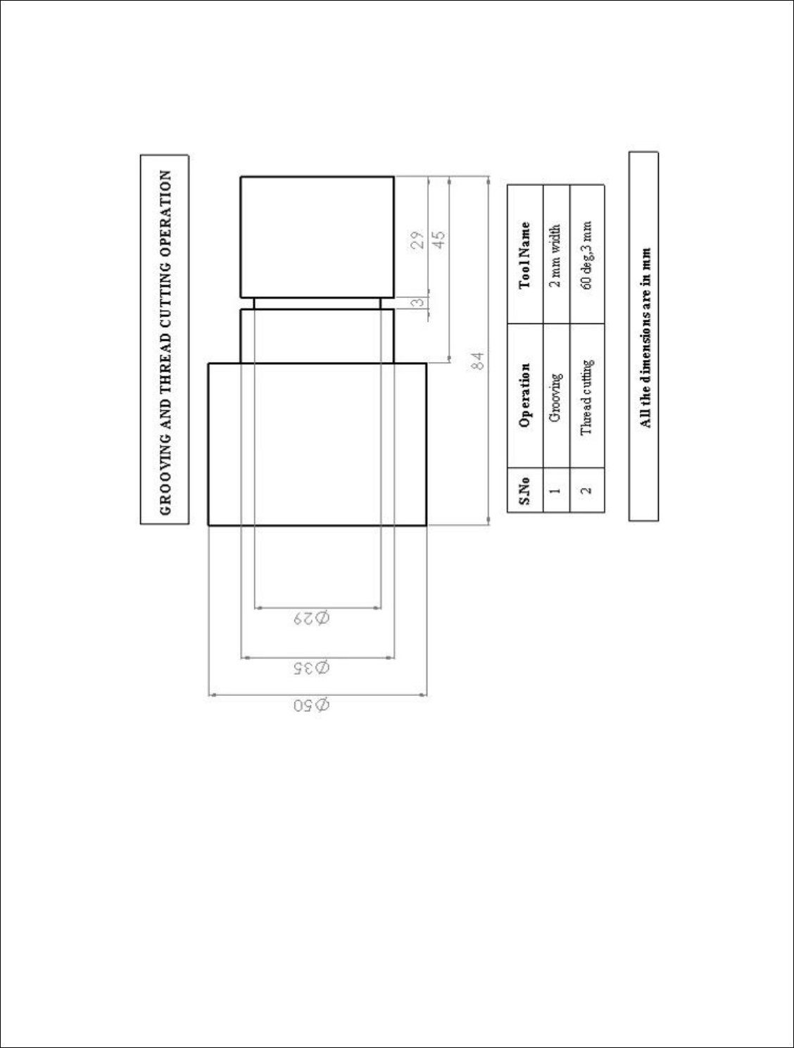
EX.NO:11 NC CODE GENERATION FOR GROOVING AND THREAD CUTTING
OPERATION BY USING CADEM SOFTWARE
DATE:
AIM:
To generate the NC code for grooving and thread cutting operation by using
cadem-capsturn software.
PROCEDURE:
Step 1: open the capsturn software
Step 2: Create the required part as per the given diagram in geometry mode
Step 3: Define the blank as per the requirement
Step 4: Select the suitable tool for grooving and thread cutting operation in
machining mode
Step 5: Select the required machining operation and define the data
Step 6: Simulate the tool path for the given part
Step 7: Generate the NC code and save the program
NC CODE GENERATION:
%O1234
G21 G95
G0 X200 Z100
N1 T11 (PCLNL 2525M12 R0.8)
G50 S3000
G96 S139 M04
(PLAIN FACE)
X38 Z4 M08
X56
G72 W3 R0.5
G72 P25 Q40 U0 W0 F0
N25 G0 Z0
N30 G01 X52 Z0
N35 X0
N40 Z2
G0 X38

(CONTOUR TURN)
Z2
X56
G71 U3 R0.5
G71 P45 Q90 U0 W0 F0
N45 G00 X35
N50 G01 X35 Z0
N55 Z0
N60 Z-29
N65 Z-32
N70 Z-45
N75 X50
N80 Z-84
N85 X52
N90 X55 Z-84
G0 X38
M09
M05
M01
G0 X200 Z100
N2 T22 (12X12, 2.00W, 0.20R, 08DEPTH, LH)
G50 S3000
G96 S190 M04
(EXTERNAL GROOVE)
X39 Z-31 M08
Z-31
G01 X29 F0
G04 X0
G0 X39
Z-31
G01 X29 F0
G04 X0
G0 X39
Z-31
G01 X29
G04 X0
G0 X39
M09
M05
M01

G0 X200 Z100
N3 T33 (THREAD 16 X 16, 60 DEG., DEPTH 3.0, LH)
G97 S1182 M04
(THREADING)
X38 Z-31 M08
X39
G76 P20060 Q0 R0
G76 X29 Z0 R0 P3000 Q1732 F2
X38
M09
M05
X200 Z100
M30
%
RESULT:
Thus the NC code has been generated by using the cadem-capsturn software.

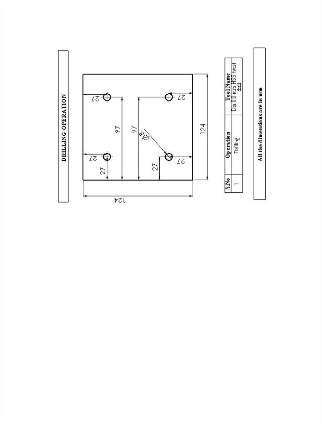
EX.NO:12 MANUALPART PROGRAMMING FOR DRILLING OPERATION
DATE:
AIM:
To write the manual part programming for the given diagram and execute
the same by using CNC milling center.
MATERIALS REQUIRED:
Mild steel Size
Breadth 124 mm
Length 124 mm
Thick 24 mm
MANUAL PART PROGRAM:
N5 G17 G71 G90 G94 G55;
N10 T1 L90;
N15 G00 D5 Z5 M3 S600 X27 Y27;
N20 G81 R02=5, R03=-33, R11=3, F50 M7;
N25 X97;
N30Y97;
N35 X27;
N40 G00 G80 Z100 M9;
N45 M02;
RESULT:
Thus the part program has been written and executed by using the CNC milling
center.
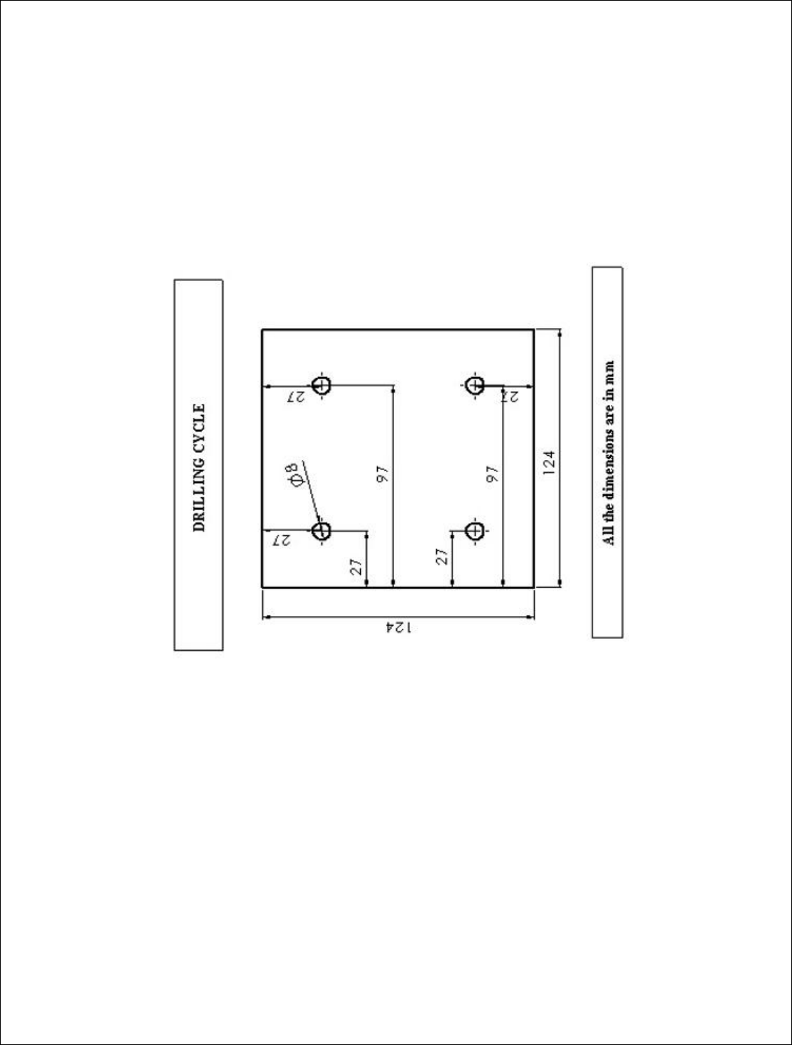

EX.NO:13 NC CODE GENERATION FOR DRILLING OPERATION BY USING
CADEM SOFTWARE
DATE:
AIM:
To generate the NC code for drilling operation by using cadem-capsmill software.
PROCEDURE:
Step 1: open the capsmill software
Step 2: Create the required part as per the given diagram in geometry mode
Step 3: Define the blank as per the requirement
Step 4: Select the suitable tool for drilling operation in machining mode
Step 5: Select the required machining operation and define the data
Step 6: Simulate the tool path for the given part
Step 7: Generate the NC code and save the program
NC CODE GENERATION:
%
O1234
N1 T1 (8.00 MM. DIA. TWIST DRILL)
M98 P9999
T1
(PECK DRILL)
G90 G00 G54 X27 Y27 M8
G43 H1 Z100
Z3
S3342 M3
G99 G73 Z-12 R3 Q5 F434
Y97

X97
Y27
G80
M5
M9
Z100
M30
%
RESULT:
Thus the NC code has been generated by using the cadem-capsmill software.

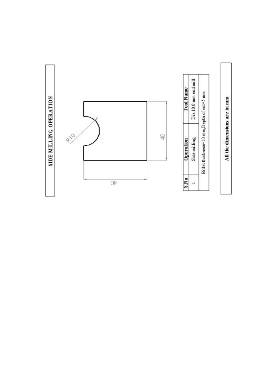
EX.NO:14 NC CODE GENERATION FOR SIDE MILLING OPERATION BY USING
CADEM SOFTWARE
DATE:
AIM:
To generate the NC code for side milling operation by using cadem-capsmill
software.
PROCEDURE:
Step 1: open the capsmill software
Step 2: Create the required part as per the given diagram in geometry mode
Step 3: Define the blank as per the requirement
Step 4: Select the suitable tool for side milling operation in machining mode
Step 5: Select the required machining operation and define the data
Step 6: Simulate the tool path for the given part
Step 7: Generate the NC code and save the program
NC CODE GENERATION:
%
O1234
N1 T1 (10.00 MM. DIA. END MILL-ROUGH-3 FLUTE)
M98 P9999
T1
(SIDE MILLING)
S891 M3
G90 G00 G54 X17 Y40 M8
G43 H1 Z100
Z3
G01 Z-5 F131

G03 X23 I3 J0 F187
G00
Z3
X15
G01 Z-5 F131
G03 X25 I5 J0 F187
G00
Z3
M5
M9
Z100
M30
%
RESULT:
Thus the NC code has been generated by using the cadem-capsmill software.

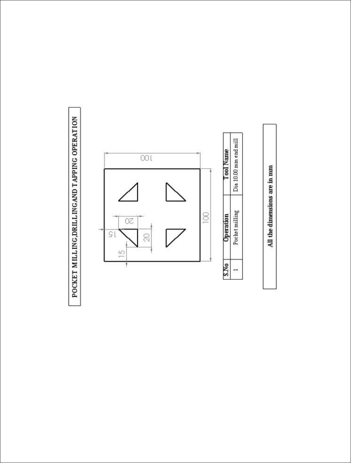
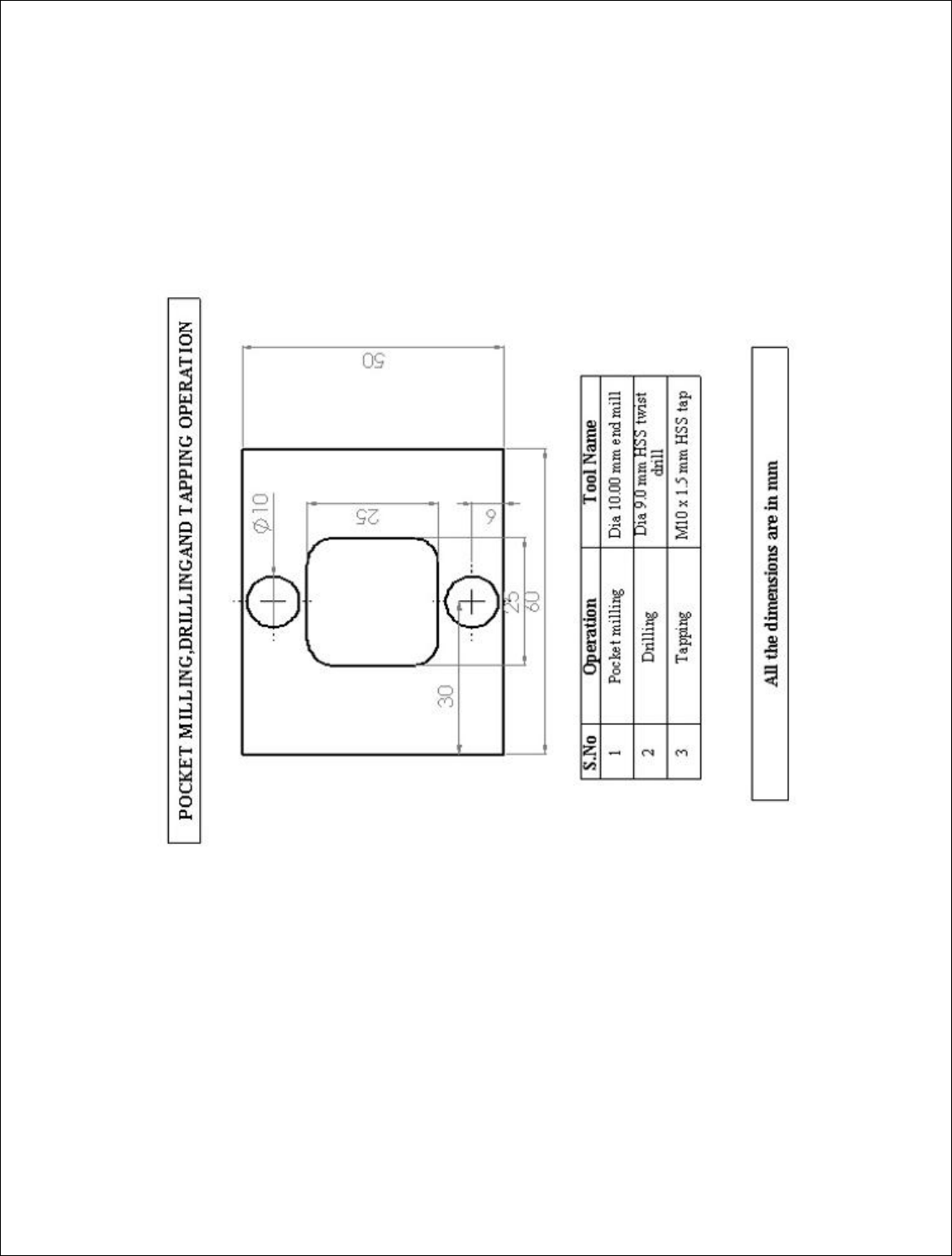
EX.NO:15 NC CODE GENERATION FOR POCKET MILLING, DRILLING AND
TAPPING OPERATION BY USING CADEM SOFTWARE
DATE:
AIM:
To generate the NC code for pocket milling, drilling and tapping operation by
using cadem-capsmill software.
PROCEDURE:
Step 1: open the capsmill software
Step 2: Create the required part as per the given diagram in geometry mode
Step 3: Define the blank as per the requirement
Step 4: Select the suitable tool for milling, drilling and tapping operation in
machining mode
Step 5: Select the required machining operation and define the data
Step 6: Simulate the tool path for the given part
Step 7: Generate the NC code and save the program
NC CODE GENERATION:
%
O1234
N1 T1 (10.00 MM. DIA. END MILL-ROUGH-3 FLUTE)
M98 P9999
T2
(POCKET MILLING)
S891 M3
G90 G00 G54 X26 Y21 M8
G43 H1 Z100
Z3

G01 Z-4 F131
M98 P155
G90 G00 X22 Y29
Z3
X26 Y21
Z-3
G01 Z-8 F131
M98 P155
G90 G00 X22 Y29
Z3
X26 Y21
Z-7
G01 Z-10 F131
M98 P155
G90 G00 X22 Y29
Z35
M5
M9
Z100
M01
N2 (9.00 MM. DIA. TWIST DRILL)
M98 P9999
T3
(PECK DRILL)
G54 X30 Y6 M8
G43 H2 Z100
Z3

S2970 M3
G99 G73 Z-17 R3 Q5 F445
Y44
G80
M5
M9
Z100
M01
N3 (M10.00 X 1.50 TAP)
M98 P9999
T1
(TAP)
G54 X30 Y6 M8
G43 H3 Z100
Z3
S477 M3
G99 G84 Z-8 R3 F715
Y44
G80
M5
M9
Z100
M30
%
RESULT:
Thus the NC code has been generated by using the cadem-capsmill software.

EX.NO:16 NC CODE GENERATION FOR MIRRORING AND POCKET MILLING
OPERATION BY USING CADEM SOFTWARE
DATE:
AIM:
To generate the NC code for mirroring and pocket milling operation by using
cadem-capsmill software.
PROCEDURE:
Step 1: open the capsmill software
Step 2: Create the required part as per the given diagram in geometry mode
Step 3: Define the blank as per the requirement
Step 4: Select the suitable tool for pocket milling operation in machining mode
Step 5: Select the required machining operation and define the data
Step 6: Simulate the tool path for the given part
Step 7: Generate the NC code and save the program
NC CODE GENERATION:
%
O1234
N1 T1 (10.00 MM. DIA. END MILL-ROUGH-3 FLUTE)
M98 P9999
T1
(POCKET MILLING)
S891 M3
G90 G00 G54 X30 Y27 M8
G43 H1 Z100
Y27
Z3
G01 Y27 Z-2 F131
M98 P155

G90 G00 X30 Y27
Z3
(POCKET MILLING)
X27 Y70
G01 X27 Z-2 F131
M98 P156
G90 G00 X27 Y70
Z3
(POCKET MILLING)
X72
G01 X72 Z-2 F131
M98 P157
G90 G00 X72 Y70
Z3
(POCKET MILLING)
X70 Y27
G01 Y27 Z-2 F131
M98 P158
G90 G00 X70 Y27
Z3
M5
M9
Y27
Z100
M30
%
RESULT:
Thus the NC code has been generated by using the cadem-capsmill software.