U.S. Department
of Transportation
i/
Federal Aviation
AdrGnistration
-;
!
Subject: PLANNING AND DESIGN
GUIDELINES FOR AIRPORT
TERMINAL FACILITIES
Date:
4/22/88
AC No:
150/5360-13
Initiated
by:
AAS-
100
change:
1.
PURPOSE.
This advisory circular (AC) provides guidelines for the planning and design of airport ter-
minal buildings and related access facilities.
I
2. CANCELLATION. The following advisory circulars are canceled:
a. AC
150/5360-6,
Airport Terminal Building Development with Federal Participation, dated
October 5, 1976.
b.
AC
150/5360-7,
Planning and Design Considerations for Airport Terminal Building Development,
dated October 5, 1976.
3. RELATED READING MATERIAL. Appendix 1 contains a listing of documents with supplemental
material relating to the planning and design of airport terminal facilities and how they may be obtained.
Leonard E. Mudd
Director, Offke of Airport Standards
\
Portions of this AC are under review for update.
Please contact the appropriate Regional Office or
Airports District Office for assistance.
.
4/22/88
AC
150/5368-13
CONTENTS
CHAPTER
1.
INITIAL
PLANNING CONSIDERATIONS
1.
Introduction..
...........................................................................................................................................
1
2. Airport Master Plans
..............................................................................................................................
1
3.
Factors Influencing Terminal
Configuration and
Size..
......................................................................
1
4. Terminal Siting Considerations
.............................................................................................................
3
5. Project Coordination
..............................................................................................................................
4
6.-19.
Reserved
...............................................................................................................................................
4
CHAPTER
2.
DESIGN
METHODOLOGIES
20.
General
....................................................................................................................................................
7
21.
Forecasts
..................................................................................................................................................
7
22.
Translating Forecasts to Peak Demands
..............................................................................................
7
23.
Peak
Daily Activity..
..............................................................................................................................
7
24.
Peak Hourly Activity
.............................................................................................................................
7
25.
Equivalent Aircraft (EQA) Factors
......................................................................................................
11
26.
Base Year Total Gate EQA
...................................................................................................................
12
27.
Future Total Gate EQA
........
.
...............................................................................................................
12
28.
EQA Arrivals
..........................................................................................................................................
13
29.
Forecast Reasonability Checks
..............................................................................................................
13
30.
Reserved
..................................................................................................................................................
14
31.
32.
33.
34.
35.
36.
37.
38.
CHAPTER
3.
FUNCTIONAL RELATIONSHIPS AND TERMINAL
CONCEPTS
Major Terminal Components
.................................................................................................................
Functional Relationships of Terminal
Components
.............................................................................
Objectives in Selecting Terminal
Concepts
..........................................................................................
Centralized and Unit Terminals
.............................................................................................................
Alternative Terminal Building Concepts
..............................................................................................
Single-Level/Multilevel Terminals
.......................................................................................................
Terminal Concept Combinations and Variations
.................................................................................
Concept-Evaluation
................................................................................................................................
39.-40.
Reserved
. . . . . . . . . . . . . . . . . . . . . . . . . . . . . . . . . . . . . . . .
. . . . . . . . . . . . . . . . . . . . . . . . . . . . . . . . . . . . . . . . . . . . . . . . . . . ..*...........
. . . . . . . . . . . . . . . . . . . . . . . . . . . . . . . . . . . .
CHAPTER
4.
TERMINAL APRON AREAS
41.
General
....................................................................................................................................................
29
42.
Terminal Apron Gate Types
.................................................................................................................
29
43.
Estimating Aircraft Gate Positions
.......................................................................................................
29
44.
Gate Parking Procedures
.......................................................................................................................
30
45.
Aircraft Gate Clearances
.......................................................................................................................
30
46.
Taxilanes
..................................................................................................................................................
36
47.
Apron Gradients
.....................................................................................................................................
36
48.
Aircraft Parking Guidance Systems
......................................................................................................
36
49.
Loading Bridges
......................................................................................................................................
36 ,
15
16
16
19
19
23
23
25
28
iii
.
AC
150/5360-13
CHG 1
l/19/94
50.
Transporters
..................................................................
46
51.
Fixed Utilities.
...............................................................
48
’
52.
Apron Area Lighting
48
53.
BlastFences
...........................................................................................................................
51
54.-65.
Reserved
...................................................................
51
.
CHAPTER
5.
TERMINAL
BUILDING
SPACE
AND
FACILITY
GUIDELINES
66.
General
..................................
............
........... ...........
53
67.
Gross Terminal Building Area Estimates
............................................
53
68.
Space Allocations
.............................................................
53
69.
PublicLobby Areas
............................................................
53
70.
Airline Ticket Counter/Offices
......................
............ .................
58
71.
Outbound Baggage Facilities
.....................................................
63
72.
Public Corridors
..............................................................
74
73. Security Inspection Stations
.....................................................
75
74.
DepartureLounges
............................................................
77
75.
Baggage Claim Facilities
........................................................
79
76.
Airline Operations Areas
.......................................................
84
77.
Food and Beverage Services
...........................
;
.....
:
..............
89
78.
Concessionaire and Building Services
.........................................
:
:
:
:
:
90
79.-90. Reserved
..................................................................
91
CHAPTER
6.
FEDERAL
INSPECTION
SERVICES
(FIS)
FACILITIES
91.
General ...........................................................
95
92.
FederalInspectionServices..
...........................................
:::::::::
95
93.
Passenger Flow Sequence
........................................................
95
94.
Preclearnnce Facilities.
.........................................................
96
95.
96.
General Design Considerations and Requirements
....................................
96
INS Requirements
...............................
.I
.....................
100
97.
USCSRequirements..
...................................................
98.
:::::
100
PHS Requirements
...........................................................
101
99.
APHIS Requirements
.........................................................
102
100. Joint FIS Employee Requirements
...............................................
102
101. Space and Facility Requirements.
.................................................
103
102. Approval of FIS Facility Plans
103.-115.Reserved
103
..
......
....................................
.:.
..................
:‘::““““““““““’
103
.....................
1
I
CHAPTER
7.
ACCESSIBILITY
TO
INDIVIDUALS
WITH
DISABILITIES
AND
SPECIAL
NEEDS
USERS
116. General
.........................
.............. .................
...........
105
1
117. Minimum Building Design Standards
..........................
118. Specific Requirements for Airport Terminals
...................
105
......
119. Existing Terminals
.................................
105
1
....
.............................
120. Other Users With Special Needs
..........................
106
......................
121.-130.Reserved....................................::::::::
......................................
106
106
CHAPTER
8.
MISCELLANEOUS
DESIGN
CONSIDERATIONS
131. Airport Security
.............................................................
132. Architectural Treatment
107
)
.................... .....................
..............
133. Energy Conservation
108
.............................
.
...........................
108
iv
l/19/94
AC
150/5360-13
CHG 1
134.SeismicSafety ...............................................................
109
I
.
u
135-145. Reserved
...............................................................
109
CHAPTER
9.
AIRPORT
ACCESS
SYSTEMS
146.General
:
..................................................................
111
147. Planning Studies
..............................................................
111
148. Circulations System Configurations
...............................................
111
149.AirportRoads
..............................................................
114
150. Terminal Curb Areas
.........................................................
120
151. Public Parking Facilities
.......................................................
121
152. Employee and Tenant Parking
..................................................
122
153. Public Transportation and Rental Car Areas
........................................
123
154. Access System Signs
..........................................................
124
155. Transit System Links and Automated People Mover (APM) Systems
.....................
124
156.-160.
Reserved
..............................................................
124
CHAPTER
10.
FEDERAL
PARTICIPATION
IN
THE
COSTS
OF
TERMINAL
DEVELOPMENT
.-
161.General
.....................................
.
........................
.
.....
125
162.Background
................................................................
125
163. Financial Assistance
..........................................................
125
164. Special Requirements
..........................................................
125
165. Proration of Terminal Building Development Costs
...................................
125
166. Bond Retirement
............................................................
125
167. Application of Federal Guidance
.................................................
126
168.-170.
Reserved
...............................................................
126
APPENDICES
Appendix 1.
Bibliography (2 pages)
Appendix 2.
Project Planning and Design (16 pages)
Appendix 3.
Federal Inspection Services Approval Offices (1 page)
FIGURES
Figure l-l
Terminal Siting/Runway Configuration Relationships.
.............................
5
Figure l-2
Functional View of an Airport
..............................................
6
I
Figure 2-l
Hypothetical Aircraft Schedule and Arriving Passenger/Visitor Population Plot
..........
8
Figure 2-2
Percent of Daily Operations in Peak Hour vs Annual Enplaned Passengers
............
10
Figure 2-3
Percent of Daily Passengers in Peak Hour vs Annual Enplaned Passengers
............
10
Figure 2-4
Estimated Peak Hour Operations vs Annual Enplaned Passengers
...................
11
Figure 3-l
Functional Adjacency Diagram
.............................................
17
Figure 3-2
Functional Adjacency Matrix.
..............................................
18
Figure 3-3
TheLinearConcept
...................
.
..................................
20
Figure 3-4
ThePierConcept
.......................................................
21
Figure 3-5
The Satellite Concept
....................................................
22
Figure 3-6
The Transporter Concept
..........................
r
.......................
24
Figure 3-7
Concept Combinations and Variations
.......................................
26
V
AC
150/5360-i3
4/22/88
Figure 3-8
Figure 4-l
Figure 4-2
Figure 4-3
Figure 4-4
Figure 4-5
Figure 4-6
Figure 4-7
Figure 4-8
Figure 4-9
Figure 4-10
Figure 4-l 1
Figure 4-l 2
Figure 4-13
Figure
4-
14
Figure
4-
15
Figure
4-
16
Figure
4-
17
Figure 5-l
Figure 5-2
Figure 5-3
Figure 5-4
Figure 5-5
Figure 5-6
Figure 5-7
Figure 5-8
Figure 5-9
Figure 5- 10
Figure 5- 11
Figure 5-12
Figure 5-13
Figure 5-14
Figure 5-15
Figure 5-16
Figure 5-17
Figure
5-
18
Figure 5-19
Figure 5-20
Figure 5-2 1
Figure 5-22
Figure 5-23
Figure 5-24
Figure’ 5-25
Figure 5-26
Figure 5-27
Figure 5-28
Figure 5-29
Figure 5-30
Figure 5-3 1
Figure 5-32
,Figure
6-
1
Figure 6-2
Figure 9-l
Figure 9-2
Figure 9-3
Vi
Matrix of Concepts Related to Airport Size
.........................................................................
Enplanements Per Gate
(IO-Year
Forecast
-
Low
Utilization) .........................
i..
..............
Enplanements Per Gate (IO-Year Forecast
-
High Utilization)
..........................................
Enplanements Per Gate
(20-Year
Forecast
-
Low
Utilization). .........................................
Enplanements Per Gate (20-Year Forecast
-
High Utilization)
.........................................
Estimated Gate Positions vs Annual Enplaned Passengers
.................................................
Aircraft Maneuvering Area
Taxi-Out
Configuration
..........................................................
Aircraft Maneuvering Area
Taxi-Out
Configuration
..........................................................
Linear Configuration Pushout Gate Positioning
..................................................................
Pier Configuration Pushout Gate Positioning
.......................................................................
Typical Clearances Inboard Pier Gate
...................................................................................
Satellite
Configuration
Pushout
Gate Positioning..
...............................................................
Transporter Configuration Taxi-Through or
Pushout Gate
Positioning..
..........................
Dual- vs Single-Taxilane Layout
...........................................................................................
Typical
Passenger
Loading
Bridges .......................................................................................
Aircraft Sill Heights
.................................................................................................................
Transporter Requirements
.......................................................................................................
Common Fixed Utility Locations
-
Composite
Aircraft
Parking
Envelope
......................
Gross Terminal Area Per Gate
-
Intermediate Planning
....................................................
Gross
Terminal Area
Per
Gate
-
Long-Range
Planning..
.................................
.
...........
.
....
Gross Terminal Area Space Distribution
..............................................................................
Ticket Lobby and Counter Area
............................................................................................
Waiting Lobby Area
...............................................................................................................
Linear Counter
.........................................................................................................................
Flow-Through Counter..
........................................................................................................
Island Counter
..........................................................................................................................
Typical AT0 Layouts
-
Single-Level Terminals
................................................................
Terminal Counter Frontage
.....................................................................................................
AT0 Office and Support Space
..............................................................................................
Outbound Baggage Area
-
Less than Five EQA
..................................................................
Outbound Baggage Area
-
Five or More EQA
....................................................................
Outbound
Baggage
Room Typical Raw
Belt
Conveyor Installation..
................................
Outbound Baggage Recirculating Belt
-
Parallel Parking
...................................................
Outbound Baggage Recirculating Sloping Bed
-
Perpendicular Parking
...........................
Semiautomated Linear Belt Sorter
..........................................................................................
Tilt-Tray Sorter
.......................................................................................................................
Destination-Coded Vehicle
.....................................................................................................
Public Corridor Effective Design Width
...............................................................................
Security Inspection Station Layouts
.......................................................................................
Typical Departure Lounge Layout
........................................................................................
Typical Combined Security/Departure Lounge Layout
......................................................
Departure Lounge Passenger Processing Area
.....................................................................
Departure Lounge Typical Seating/Aisle Layout
................................................................
Mechanized Claim Devices
.....................................................................................................
Inbound Baggage Claim Frontage
-
Less than Five EQA Arrivals in Peak 20 Minutes . .
Inbound Baggage Claim Frontage
-
Five or More EQA Arrivals in Peak
20
Minutes
....
Baggage Claim Area
................................................................................................................
Non-Public Baggage Claim Input Area
.................................................................................
Food and Beverage Services
...................................................................................................
Concessions and Building Services
.........................................................................................
FIS Facility Functional Adjacency Diagram
.......................................................................
FIS Preclearance Facility Functional Adjacency Diagram
................................................
Outline
of the Ground
Access
System Planning
Process..
..................................................
Centralized Ground Access Concept
....................................................................................
Segmented Ground Access Concept
.....................................................................................
27
;
31
32
33
34
35
37
38
39
40
41
42
43
44
45
47
49
50
54
54
55
56
57
59
60
‘61
62
)
64
65
66
67
69
70
71
71
.
72
73
76
77
.
80
81
81
82
83
85.
86
87
88
92
93
97
99
112
1
113
115
l/19/94
AC
150/5360-13
CHG 1
Figure 9-4
Figure 9-5
Figure 9-6
Figure 9-7
i
Figure 9-8
Table l-l
Table 2-1
Table 2-2
Table 4-l
Table 5-l
Table 5-2
Table 5-3
Table 6-l
Table 9-l
Decentralized Ground Access Concept
......................................
116
Unitized Ground Access Concept
..........................................
117
TerminalCurbArea
....................................................
119
Vehicular Island Curb
...................................................
120
Estimated Requirements for Public Parking at U.S. Airports
.......................
122
1
TABLES
Hub Classifications
.......................................................
2
Base Year Total Gate EQA Computation
.....................................
;
12
Sample
-
Future Design Year Total Gate EQA Computation
..............
$.
......
13
General Lighting Requirements
............................................
51
Recommended Selection Criteria Outbound Baggage Equipment
...................
74
Corridor Capacity in Persons Per Unit Width Per Minute
.........................
75
Departure Lounge Area Space Requirements
..................................
78
FIS Space and Facility Requirements at International Airports
....................
104
Typical Curb Frontage Dwell Times and Vehicle Slot Lengths
.....................
121
..
vii (and viii)
l/19/94
AC
150/5360-13
CHG 1
CHAPTER
1.
INITIAL
PLANNING
CONSIDERATIONS
1.
INTRODUCTION.
a.
This advisory circular (AC) presents guidance material for the planning and design of airport terminal
buildings and related access facilities.
.
b.
The material and nomographs included herein provide general guidelines and approximations for
determiningspace and terminalfacilityrequirementsfor planningpurposes.
It is not intendedthat theybc used
to replace the detailed engineering analyses necessary for the specific design of individuhl airport terminal
facilities.
.
c.
Much of the material contained in this AC appears in various documents listed in Appendix 1.
Architectural, engineering, and planning consultants are advised to review the referenced documents, as they
contain supplemental information and provide more in-depth treatment of much of this material. The
Transportation Research Board’s (TRB) Special Report 215, Measuring Airport Landside Capacity, is
particularly recommended.
d.
AC
l-50/5360-9,
Planning and Design of Airport Terminal Building Facilities at Nonhub Locations,
containsguidance material for use in planningterminal facilities at low activity airports. It may be used in lieu
of or in conjunctionwith this document, as appropriate.
2.
AIRPORT MASTER PLANS.
a.
Prior to initiatingan airport terminal building design project, the master
planningrcporl
for the airport
under study should be reviewed. Most airports will have such a report on file.
b. Airport master plans (see AC
150/5070-6,
Airport Master Plans) contain considerable information
useful to the terminal planner/designer. Typically, these plans will contain the following data and analyses: an
inventoryof relevant data pertainingto the service area and existing airport facilities;activity forecasts; capacity
analyses; estimates of facility requirements; environmental studies; various plans on airport layout, land use,
terminal area, and intermodal surface access; etc. Planning horizons for master planning studies usually cover
I
5, 10, and 20 years into the future.
c.
The terminal plan contained in an airport master plan is normally limited to layouts and drawings
delineatinggeneral location, overall area, and basic configuration of the terminal area.
For new airports or
terminals, this plan may be limited to conceptual studies, layouts, and schematic drawings depicting the basic
flow of passengers, cargo, and the various modes of airport surface access.
I
d.
In most cases, the planner/architect should design the terminal facility to conform to the broad
framework and guidelines established in the master plan.
However, the master plan should be reviewed
periodically, reevaluated, and, if necessary, appropriately revised to account for subsequent developments or
definitive planning.
3.
FACTORS INFLUENCING TERMINAL CONFIGURATION AND SIZE.
In addition to historical
traffic volumes, each airport has its own combination of individual characteristics to be considered in
configuring and sizing terminal facilities.
Similarly, each airline serving an airport has internal procedures,
policies, and staffing criteria which influence facility planning.
Some of the basic considerations which may
significantly impact the planning and design of an airport terminal are discussed in following paragraphs.
a.
Service Area.
A form of reference often used to describe an airport’s service area is the air traffic hub
structure developed by the Federal Aviation Administration(FAA) to measure the concentrationof
1
AC
150/5360-13
CHG 1
l/19/94
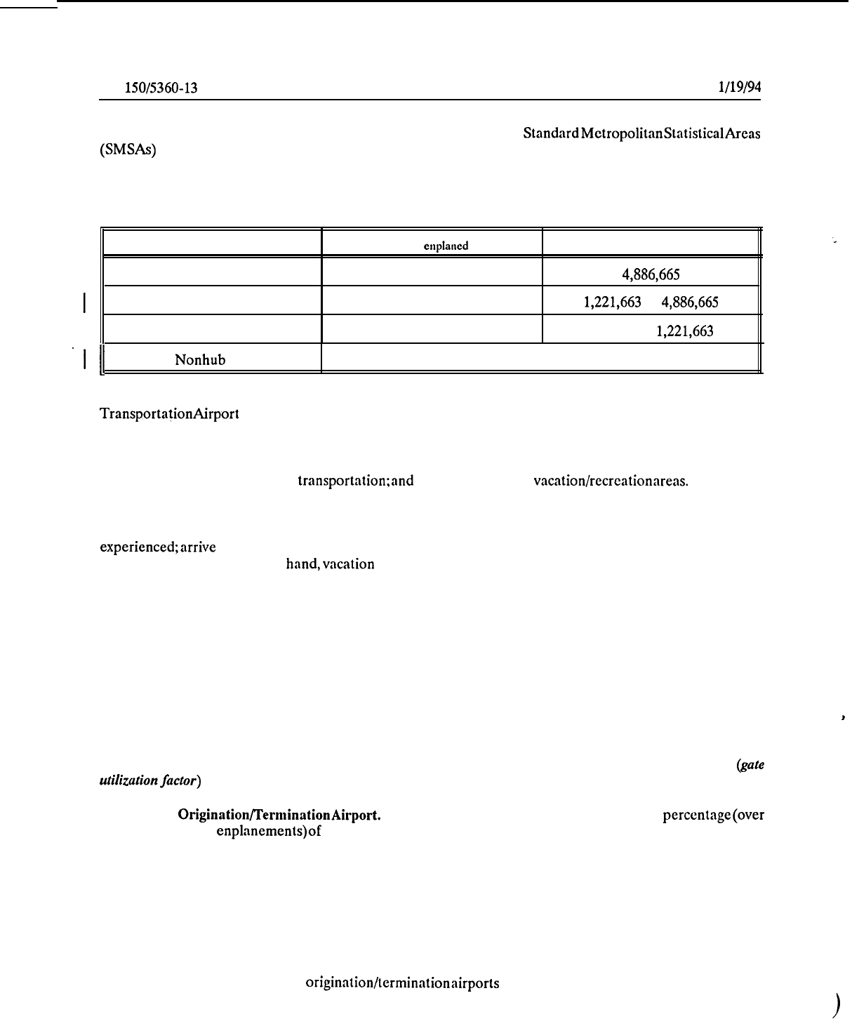
civil air traffic. Air traffic hubs are not airports; they are the cities and StandardMetropolitanStatisticalAreas
(SMSAs)
requiring aviation service.
Individual communities fall into four hub classifications (see Table l-l)
as determinedby each community’spercentageof the total U.S. enplaneddomesticrevenue passengerscarried.
I
Table l-l. Hub Classifications
I
Hub size
Percent of total
enplaned
passengers
1991 enplanenients
I
Large (L)
1.0 percent or more
4,886,665
I
Medium (M)
0.25 to 0.9999 percent
1,221,663
to
4,886,665
I
Small (S)
0.05 to 0.249 percent
244,333
to
1,221,663
‘I
11
Nonhub (N)
Less than 0.05 percent
I
Less than 244,333
The location and number of air traffic hubs can be obtained from the latest issue of the Department of
TransportationAirport
Activity Statistics. Apart from obvious influences, such as physical size and topography,
some of the more significantcharacteristicsof the airport service area which may influence the airport terminal
design include: population and per capita income and their growth potential;geographic location and distance
from other airports with similar or larger service areas; concentration of commercial activity that involves a
relatively high propensity for air transportation:and proximity of major vacation/recreationareas.
b. Passenger Characteristics. Two basic categories of passengers are those who travel for business
purposes and those traveling as tourists or for personal reasons. Business passengers are usually more travel
experienced;arrive just prior to flight time; and are more apt to use the full range of public terminal services
and concessions. On the other hand,vacation travelers are more likely to arrive much earlier, relative to flight
departuretime, compared to business travelers; depart from the destinationairport later; and, generate a larger
number-of visitors/greeters. Consequently, significant variations in the characteristics and ratio of these two
passenger types can influence space requirements and staffing. A small airport serving a vacation/ resort area
with a relatively short season will involve different requirements than an airport handling comparable
peak-monthvolumes of predominantlybusiness travelers. Similarly, an airport close to a military installation,
or serving a college town, may generate a significant volume of standby traffic, thus warranting additional .
facilities and services.
c. Airline Station Characteristics. The route structures of the scheduled airlines serving an airport
influence its character and, consequently, its facility requirements. Airports can generally be categorized into
I
three types ‘on the basis of the route structures of the using airlines.
These categories and their related
characteristics are discussed in succeeding paragraphs. The peak hour movements per gate specified
(gale
ufilizuhwzfacfor) are typical for airports averaging six or more daily departures per gate.
(1)
Origination/TernGnationAirport.
This category of airport usually involves a high
percentage(over
70 percent of total enplanements)of originatingpassengers and a preponderanceof turnaround flights. Ground
times range from 45 to 90 minutes, or more.
The high flow of passengers between aircraft and ground
transportationvehicles generates a relatively high requirement for ticket counter area, curb length, and parking
spaces per enplanedpassenger. Passengerswill usually require maximum baggage-handlingservices for checking
and claiming baggage. Typical domesticpeaks will average about 0.9 to 1.1 hourly aircraft movements per gate.
Boarding load factors at this category of airport often range between 65 and 80 percent.
(2) Through Airport. This category has a relatively high percentage of originating passengers
combined with a low percentageof originatingflights, resulting in the shortest aircraft ground times.
Boarding
load factors may be lower than origination/terminationairports (ranging from 40 to 60 percent), thereby
reducing departure lounge space requirements. Typical domestic peaks will average 1.5 to 2.0 hourly aircraft
movements per gate.
,
2
l/19/94
AC
150/5360-13
CHG 1
:ti
(3) Transfer Airport.
This Category of airport has a significant proportion of passengers, at least 30
percent of total enplanements, transferring between on-line and off-line flights.
Aircraft ground servicing times
average30 to 60 minutes, dcpendingupon connectingpatternsand airlineoperatingpolicics. Typicaldomestic
peaks average 1.2 to 1.4 hourly aircraft movements per gate. Compared to the same volume of enplanements
at the other two categories of airports, the transfer airport has
less
ground transportation activity and a lower
requirement for curb frontage; less need for airline counter positions serving normal ticketing and baggage
check-in (although more positions may be required for flight information and ticket changes); less requirement
for baggage claim area; more space for baggage transfer (on-line and/or interline taggage); increased
requirements for concessions and public services; and increased need for centralized security locations.
d.
Aircraft Mix.
The
forecast mix of aircraft expected to use an airport can significantly impact terminal
design. For instance, airports serving a large variety of aircraft types and sizes require terminal facilitiesmore
flexible and complex than those serving predominantly one class of aircraft. The latter are more conducive
to standardizing the area and facilities at each gate position. Terminals at airports serving wide-body-aircraft
require the ability to accommodate the large passenger
surges
which normally occur when these aircraft load
or unload.
e. Nonscheduled Service.
In addition to scheduled operations, most airports
serve
a variety of
non-scheduled operations such as charter flights, group tour flights, and air-taxi operations. At some airports,
a relatively high volume of airline charter or other nonscheduled operations may warrant consideration of
separate, modest, terminal facilities for supplemental carriers.
Occasionally, scheduled carriers may desire
separate apron hardstands and buildings to serve charter operations which exceed the capabilitiesof facilities
required for normal scheduled operations. Any such proposal should be evaluated thoroughly, since a separate
facility can often create inefficiencies in such aspects as logistics, staffing, and ground equipment utilization.
f. International Service. Airports with international flights may have other characteristics which
influence terminal planning and design. One characteristic is a tendency toward higher aircraft activity peaks
because of the heavy dependence on schedules for city pairs related to time zone crossing. Another
characteristic is the relatively long ground service times (2 to 3 hours for turnarounds, 1 hour for through
flights) required for long range aircraft servicing. The additional space requirements for Federal Inspection
Services
(FE)
facilities will also affect terminal planning and design. (See Chapter 6.)
4.
TERMINAL SITING CONSIDERATIONS.
Since most terminal development involves the expansion or
modernization of an existing facility or terminal
complex,
its location will more or less bc
fixed.
However,
in the case of a new airport or major airport redevelopment, a new terminal site may be necessary or
desirable. There are a number of basic considerations which will affect the ultimate terminal site selection.
Some of the more important of these considerations
include:
a. Runway Configuration. The runway configuration at an airport has a significant impact on the
location of the apron-terminal complex. The terminal
site
should be located to minimize aircraft taxiing
distances and times and the number of active runway crossings required between parking aprons and runways.
At airports with a single runway or very simple runway configuration (for instance, airports with a primary plus
crosswind runway or single set of parallel runways), this may dictate locating the passenger terminal centrally
with respect to
th,e
primary runway(s). At airports with more complex runway configurations, siting may
require detailed analyses to determine runway use, predominant landing and takeoff directions, location and
configuration of existing taxiways, and the most efficient
taxiway
routings. The runway configuration may also
restrict ground access to certain areas of the airport and thus limit alternative terminal sites. Figure l-l
depicts the relationship between runway configurations, terminal locations, and ground access facilities.
b.
Access to Transportation Network. While the motor vehicle will remain the major mode of ground
transportation to and from the airport, other public transit modes are expcctcd to assume an increasing role.
The passenger terminal should
be
located, when possible, to provide the most direct/shortest routing to the
access transportation
system
serving the population center gcncrating the major source of passengers and
freight. Adequate arca and distance should be provided bctwcen the transportation
access
network and the
3
AC
150/5360-13
CHG 1
l/19/94
I
primary terminal building (and within the terminal building) to accommodate the ultimate terminal
development and necessary‘future ground access systems and improvements.
1
c. Expansion Potential. To assure the long-term success of an airport terminal facility, potential
expansion beyond forecast requirementsshould always be taken into consideration. In the planning stage, the
terminal should be conceived in its ultimate form with reasonable allowance for growth and changes in
operation beyond forecasted needs. Use of this principal in selecting a terminal site or expansion scheme will
promote the provision of adequate space around the terminal (both on the airside and landside) for orderly
construction of succeeding stages.
d.
FAA Geometric Design Standards.
Terminal facilities require a location which will assure adequate
distances from present and future aircraft operational areas in order to satisfy FAA airport geometric design
standards. These standards include such minimum separation distances as those between a runway centerline
and aircraft parking aprons, buildings, and airport property lines; and those between a
taxiway
centerline and
fixed/movableobjects and other taxiways. Refer to AC
150/5300-13,
Airport Design, for information on FAA
airport geometric design standards.
e. Existing and Planned Facilities.
Existing and planned structures and utilities should be carefully
inventoriedand taken into account when planning new or expanded terminal facilities. In some cases, existing
facilities or utilities, which are not related to and are restrictive to terminal development, can be demolished,
abandoned, or relocated to a more suitable area. In other instances, existing conditions may limit the number
of possible alternative terminal sites. In all cases, existing or planned locations of a FAA control tower,
navigational aids, weather equipment, etc., should be analyzed to assure that terminal development will not
interfere with line-of-sight or other operational restrictions associated with these facilities.
f.
Terrain. Topographical conditions should be considered in the selection of a terminal building site.
For instance, potential drainage problems can be reduced if the terrain lends itself to naturally carrying water
away from the building.
Developing the terminal site on relatively flat land can prove economically
1
advantageous by reducing grading or quantities of fill. However, an existing terrain feature, such as a grade
differential between the landsidc of the terminal and an aircraft parking apron, can be incorporated into a
multi-level terminal concept.
g.
Environmental Impacts.
The location of a terminal facility or major expansionof an existingone may
result in significant environmental impacts which must be analyzed and weighed, if capacity is increased by
25 percent or more, in considering alternative terminal sites. The FAA airport layout plan (ALP) approval
process associated with terminal facility planning includes necessary environmental assessment.
I
h.
General. Figure 1-2 illustrates the terminal facility’s role as the transfer mode from airport landside
to airport airside.
5.
PROJECT COORDINATION.
Planning and designing an airport terminal complex requires consider-
able coordination and input involving a number of airport users and other interested parties. Participants in
such a process include: airport management; the consultants engaged to perform the planning and/or design;
tenant airlines; the FAA; Federal Inspection Services (FIS) representatives (if international service is
involved); local governmental planning agencies; building concessionaires; and, other airport tenants. The
requirementsof each of these parties may differ somewhat and in some cases conflict with each other or with
the design concept. These differences require resolution and/or compromise as early in the planning/design
stage as possible. For this reason, it is advisable to establish a terminal facility advisory committee composed
of representatives of airport management, planning consultants, airlines, and other principal airport tenants.
This committee can meet periodically to
review
the terminal design and provide input as a project progresses.
6.
-
19. RESERVED.
4
.
E
(‘--
i11,L
-.-----
_
--
?’
--
J
I
,
“““““”
-
7
-1
i;;i;;;;;;!,/
7
/
3
:_:::.
if’,
,:
’
,’
;
$-*
;I
WIDELY SPACED PARALLEL
RUNWAYS WITH INTERSECTING
CROSSWIND
RUNDAY
OR TAXIWAY;
LIMITING APRON TERMINAL
ON THREE
SIOES
WIOELY SPACELI PARALLEL
.
RUNWAYS WITH NO INTERSECTING
CROSSWIND RUNJYAI’. LIMITING APRGk
TEHMINAL ON
TNI-l
SIDES.
EXCEl’f
AS LIMITED BY TAXKJAYS
SINGLE OR CLOSELY PLACE0
RUNWAYS WITH INTERSECTING
PARALLEL RUNWAYS: LIMITING
AXES; LIMITING APRON TERMINAL
APRON TERMINAL ON ONE SIDE
ON TWO SIDES
POSSIBLE ACCESS FROM TWO
POINTS USING TWO-WAY AXIAL
ROAO WITH ONE.WAY LOOP ROAOS
SERVING EACH APRON.TERMINAL AREA
ACCESS FROM SINGLE POINT
USING ONE.WAY LOOP ROAD
ACCESS FROM SINGLE POINT
USING ONE-WAY LOOP
ROAD
ACCESS FROM SINGLE POINT
l@NG
ONE.WAY LOOP ROAD
RUNWAY AN0 ROAOWAY LIMIT
EXPANSION TO TWO DIRECTIONS
RUNWAY AN0 ROADWAY LIMIT
EXPANSION TO TWO DIRECTIONS
RUNWAY AN0 ROAOWAY LIMIT
EXPANSION TO TWO DIRECTIONS
RUNWAYS LIMIT EXPANSION TO
TVJO
DIRECTIONS
SMALL, MEDIUM, OR LARGE
VOLUMES
USUALLY (BUT NOT LIMITEO TO)
SMALL OR MEDIUM VOLUMES
MEDIUM OR LARGE VOLUMES
MEDIUM OR LARGE VOLUMES
APRON
m
77
TERMINAL
0
RUNWAYS
t-3
GROUND
ACCESS
REcxMl
AccEs3
.RDADS
.lluNm
-
-
-
-
-
-
-
-
-
_
_
_._,’
_.-..
I:,&”
yy)E
:~~~~~‘~.~:‘-~l~,~.:,~~~~~:::.::~~;;:
:,,.;
::/.T.-
.&..:.
-
.
.
-
:+....
..I
4.m.:.
.-
.?f....n~
‘..““..‘..:
.&
.
.
.
...<
.:
:;..::.;:i:.
,::‘.~.~:~:~~....;..:~~.:~:.
”
:
_,:
;..A.
:
:,
.\
;
,./
:.
.y,-.::;.
,:
.:
,:
:,,,,,.
.;;.
/
.:i
;,..:
.:
:..,.:.
.’
,,
:,
.
“.‘.
I
.
.
.C.
;.,,
:...
:
,._.
:.,:..y:
..,,
:..
x.::.;:
.‘:..
“..
”
:
:;
..,,,.:,.~~
:*...::.
,..
.
. .
.
..,
1;
.;
,..,
.
.
I
~
.I:‘.:’
“”
::‘uNDS[DE
‘!‘;;,:
.-I.-
L”’
,.’
:::.:.:::.-
.
.
.
.
.
.
:,:.
,.
/
.::,.:;:
;
.),I::‘.I,.:,.::
i,‘,.,::.:.:::..:..‘,...,.:
“”
“’
”
”
. . .
..‘......,
.:.
. .
,.,
,.
. . . .
::..
. . . .
.:,;,
,.;,
.,
,.
,..,
. . .
.,.
.
..I.
. .
UlMTlES,
MUNICIPAL SERVICES,
LAND
“...
. . . .
:,_
-,
,:::~-,.~~:.i’~~~~
:...:
.:.
.:...
.:.
.:....
.
SHWLE
SEIIVKE
TERYNAL
CURS
4
PARKIND
t
+
4
4
t
I
t
I
ARPDRYBOUIDARY
I
I
I
B--e--
4
RESIDENYML AND COMMEIWAL
INlEfWS
AFFECTED BY AllU’ORY
ECONOhSC,
:.
. . .
..:..:
. .
. .
:
. .
_
. .
---.-.
---- --------
---m~llmMn(ELIPLOYYENT.NOME.ETC.)
i
:*.m.$..
-.‘z’:&.:
‘:‘>:>‘.“:
“’
“?
-
..‘.‘:”
..:+..:::::.::..,:
. . . . .
;.:;::::;g.;
::.:
(
.‘.:
7
.::
i”.
y..
:
i
..:.:.
. . . . .
~
,...
.::..:..
:..
:.
. . . .
..?
..:..
:
I
SaaAl,
NJ40
ENVRONME
AIRPORT-RELATED
COMMUNlTy
SOURCE: ADAPTED FROM TRANSPORTATION RESEARCH BOARD SPECIAL REPORT 215
L
.,Y
.
.

4122188
AC
150/5380-13
CHAPTER 2. DESIGN METHODOLIGIES
tb
20.
GENERAL.
Effective planning and design of the terminal area involve the active participation of air-
port management, the airlines, concessionaires, and the consultants engaged by the parties. The process nor-
mally includes: compiling surveys, questionnaires, and forecasts, usually for short and intermediate periods;
developing design day and peak hour activity tables; establishing passenger, aircraft, and vehicular traffic
relationships; taking inventory and evaluating existing facilities; analyzing space requirements for alternative
layouts; and estimating costs and developing financial plans. Sample forms for collecting design data ‘are
;
provided in Appendix 2. From this data collection, the designer can analyze alternative concepts and select
the most economically feasible and practical terminal facilities.
21.
FORECASTS.
Airport terminal facilities are planned on the basis of activity forecasts. Depending on
the various types of facilities being planned, the principal annual forecasts include passenger enplanements,
passenger originations, and aircraft movements (by aircraft size). The most useful sources for this informa-
tion include: the current airport master plan; the FAA published terminal area forecasts; forecasts developed
by the Air Transport Association
(ATA);
and those forecasts developed by the individual airlines serving
the airport. The airlines should be consulted for assumptions on trend changes in the ratio of originators to
enplanements in scheduled service. Normally, nonscheduled operations are not considered the primary basis
for terminal planning and should be evaluated separately.
22. TRANSLATING FORECASTS TO PEAK DEMANDS. Airport terminal facilities are planned, sized,
and designed to accommodate peak passenger demands for a selected forecast period. Generally, the initial
stage of construction is designed for a selected year (or years) within 5 to 10 years of the current period.
Master plans look 20 years into the future. Planning for absolute peak demands, i.e., the greatest demands
anticipated, will result in facilities impractically oversized and underutilized. Accordingly, the planner
should be cautious in the use of data on absolute peak traffic volumes. Methodologies for converting annual
forecast data to daily and hourly demand are discussed in paragraphs 23 and 24.
23. PEAK DAILY
ACJXVITY.
The Average Day/Peak Month (ADPM) represents the most common
method of converting planning statistics to a daily and ultimately to an hourly demand baseline. A determi-
nation of the ADPM demand for the design year involves first identifying peak month enplanements as a
percent of annual enplanements based on historical data. This percentage may be adjusted up or down as
local circumstances and/or other factors dictate (seldom necessary). Applying this percentage to the annual
enplanement forecast for the design year results in a peak month demand forecast for that year. Demand for
the average day of the peak month of the design year is determined simply by dividing the peak month
demand by the number of days in that month. The same ratio of annual originating passengers (or transfers)
to annual enplanements can be assumed for ADPM passengers unless indicated otherwise by seasonal data
or surveys. This ratio may vary during the peak hour at some airports.
24. PEAK HOURLY ACTIVITY. Many aspects of terminal facility planning require hourly volumes or
statistics consistent with the average day baseline. An airport may have peak hour operations as high as 12
to 20 percent of daily total operations. As schedules increase, peaks tend to spread out over the day. A
theoretical absolute low is 6.25 percent which assumes uniform distribution of domestic operations over 16
hours. Such a theoretical
lo+
normally never happens. In actual practice, some peaking will always occur,
both in aircraft movements and, even more so, in passenger activity. The latter occurs even with a relatively
uniform distribution of aircraft movements, since larger aircraft are normally scheduled in the prime hours
of the day so as to best meet public demand. Several procedures for arriving at peak hour activities are
discussed in the following paragraphs.
‘L
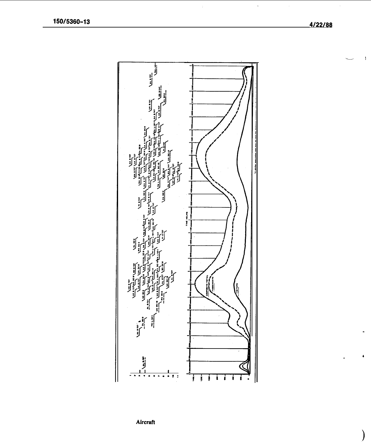
a. Hypothetical Design Day Activity Method. The recommended procedure for determining design
peak hour activity statistics involves the use of aircraft movement data and load factors (historic and projec-
tions) obtained from the airline to develop a hypothetical design day activity table. This table is comprised
of data columns depicting hypothetical arrival and departure clocktimes for the various airline flights, air-
craft types, and passenger enplanements and deplanements for the average day/peak month of the selected
design year. From these tables, passenger/visitor population plots can be developed for enplaning, deplaning
and total passengers. An example of an Enplaning Passenger/Visitor Population Plot is shown in Figure 2-
1.
7
9:
, ,
lt
, , , ,
l
, ,
-“‘......$:
-
I
AC
150/5380-13
4/22/88
Figure 2-l.
Hypothetical Aircraft Schedule and Arriving Passenger/Visitor Population Plot
8

4122188
AC
150/5380-13
b. Historical Peaking Factors.
(1)
In lieu of developing a detailed design day activity analysis as discussed in the preceding para-
graph, a simple method of estimating peak hour demand involves the use of the most recent data on peak
hour demands at the airport under study. This information can be obtained from airline records of hourly
enplanements and deplanements (total passengers) during the most recent peak month. If such information is
not available, current data can be collected.for a minimum 2-week period and then adjusted upward propor-
tionately to correspond with the most recent peak month activity. From an analysis of the hourly counts
obtained, a typical peak hour level of activity can be selected. This peak hour/peak month count can then
be converted to a percentage (peaking factor) of the current ADPM enplanements. The peaking factor is
then multiplied by the design year ADPM to arrive at a total passenger peak hour forecast for the design
year.
’
(2) The peaking factor methodology requires judgment in application. Studies have shown that,
with an increasing total passenger volume, the peak hour percentage decreases, since the peaks tend to
spread out more over a day. Accordingly, a downward adjustment to the design peak hour count may be
appropriate. This methodology is less accurate than the hypothetical design day activity (HDDA) method;
The HDDA procedure is highly sensitive to passenger surges occurring in time increments of less than one
hour (e.g., ticket counters, baggage systems, etc.). It also may be insensitive to the peaking conditions cre-
ated by the future introduction of larger aircraft service which, in all likelihood, will be scheduled during
peak hours.
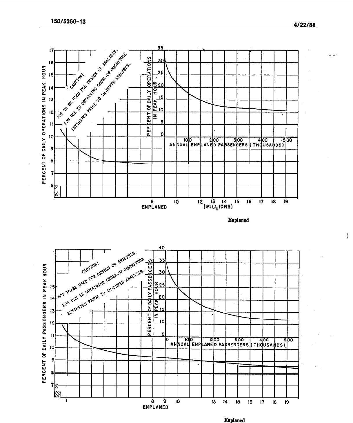
c.
Peaking Graphs.
Peaking graphs have been developed for the purpose of making order-of-magni-
tude estimates of passenger and aircraft activity. They are not satisfactory for design and/or detailed analyses of
a particular airport. Each has been developed largely by examining data from a number of airports and are
representative of “averages.” They do not represent an average condition for an individual airport and
should not be used as such.
(1) Figure 2-2 provides a rough estimate of the percentage of peak day aircraft operations to be
expected in the busiest hour of the day. The curve was developed from airline schedules. Airports with
substantial international, tourist, and long-haul traffic often exhibit unusually high peak hour activity. Con-
versely, those with a large proportion of short-haul traffic and those with runway or gate capacity restric-
tions have less sharply defined peaks.
(2)
The information shown in Figure 2-3 relates passenger peaking factors to annual
enplaned
pas-
sengers. Passenger peaking more or less parallels aircraft activity. However, passenger peaks may be more
sharply defined than aircraft peaks because larger-than-average aircraft are introduced in prime times. The
values shown were developed largely from reported passenger volumes, supplemented with’ values derived
from aircraft operations at smaller airports.
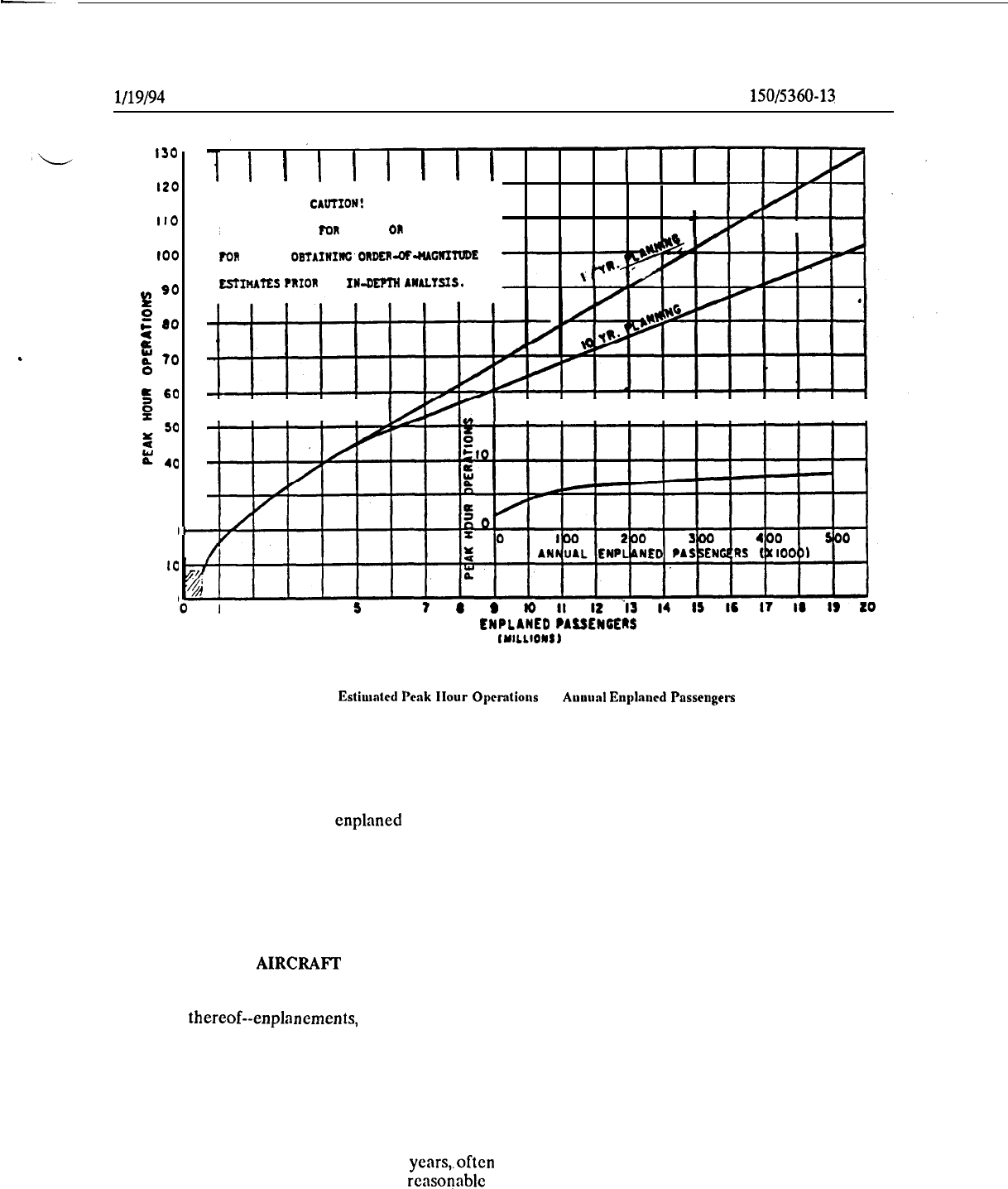
(3)
Figure 2-4 presents peak hour operations related to annual enplaned passengers. Shown are an
average relationship based on 1975 schedules and one based on IO-year projected increases in average fleet
seating and load factors. Since terminal development is generally sized for a forecasted passenger volume, it
is important that changes in the average fleet size be considered.
9
AC
150/5360-13
4/22/88
7
6+
;>
I
2 3 4 5 6 7
6
9
IO
II
12 13
I4
I5 I6
.I7
I8 I9
20
ANNUAL
ENPLANED
PASSENGERS
(MILL_lONS)
Figure 2-2.
Percent of Daily Operations in Peak Hour vs. Annual
Enplaaed
Passengers
I
7
7’
VJ
1
2 3
4 5
6 7
6
9
IO
II
12 13
14
I5
16
I7
I8
I9 20
ANNUAL
ENPLANED
PASSENGERS (MILLIONS)
Figure 2-3.
Percent of Daily Passengers in Peak Hour vs. Annual
Enplaned
Passengers
10
.
l/19/94
AC
150/5360-13
CHG 1
I30
120
I10
too
w
90
z
.
F
60
2
L
70
0
30
20
IO
a
I-
I-
I-
/-
l-
I
I
I
I I
I
I
I
CUlTION!
I
NOT TO BE USED
FOR
DESIGN
OR
ANALYSIS.
1x1
I
PO1
USE IN
O9fAININCORDER-OF-NA~6
E.STfPUTEf
?RIOR
TO IN-DEMI
AWALYSIS.
I I
I
I
I
IAwl
I I I I I I I I I I I
I
2 3 4
5
6
7
e s
ANNUAL
ENPLANED
PAUENCERS
IMILLIONS
J
Figure 2-J.
Esthnted
Peak
Hour
Oprntions
vs.
Auuurl
Enlhucd
Pnsseugers
d. Rules-of-Thumb. In the absence of historical data, the rules-of-thumb discussed in the following
paragraphs may be used for roughly estimating activity levels. Their use should be similar to the “peaking”
graphs, that is, they are not intended for a detailed design analysis of an individual report.
(1)
Either peak hour enplaned or deplaned passengers may be assumed to represent approximately
60 to 70 percent of the total peak hour passengers.
(2)
Peak month passengers may be approximated as 10 percent of the annual passengers.
(3)
Average day-peak month aircraft operations may be estimated as 1.05 times the average daily
activity for the year.
25. EQUIVALENT AIRCRAm (EQA) FACTORS.
a. The sizing of most terminal elements is based on passenger volumes for a selected design hour or
some part thereof--enplanements, deplanements, peak 20 minutes, etc.
However, forecasts of these activities
are not always readily available. When they are not, approximations can be developed by considering aircraft
seating capacities, as estimated for the peak hour of the average day-peak month. Applying EQA factors,
which represent the aircraft’s passenger capacity (seats divided by 100) is useful in estimating the impact of
future growth on various terminal components.
b. The EQA methodology is based on aircraft movements as the primary generators of passenger flows.
The magnitude of each flow is related to aircraft seating capacities and load factors. However, average seats
per aircraft movement increase in future years,.often with larger aircraft being introduced first during peaks
for prime time flights. Accordingly, it is reasonnblc to assume that boarding load factors and gate utilization
will also increase in the future.
11
AC
150/5360-13
CMG 1
l/19/94
c.
The EQA technique provides a common denominator for numbers of gates and aircraft seats useful
for sizing terminal components and evaluating capacities in airport master planning.
Specific sizing
applicationsof EQA in this document include airline ticket office, ticket counter frontage areas, baggage areas,
lobbies, departure lounges, etc., and are discussed in Chapter 5.
d. Tables and charts provided in this documentation for use in obtaining terminal facility sizing
approximations require a knowledge of the following EQA factors: Base Year,Total Gate EQA, Future Total
Gate EQA; and, EQA Arrivals. The methods for calculating these factors are discussed in following
paragraphs.
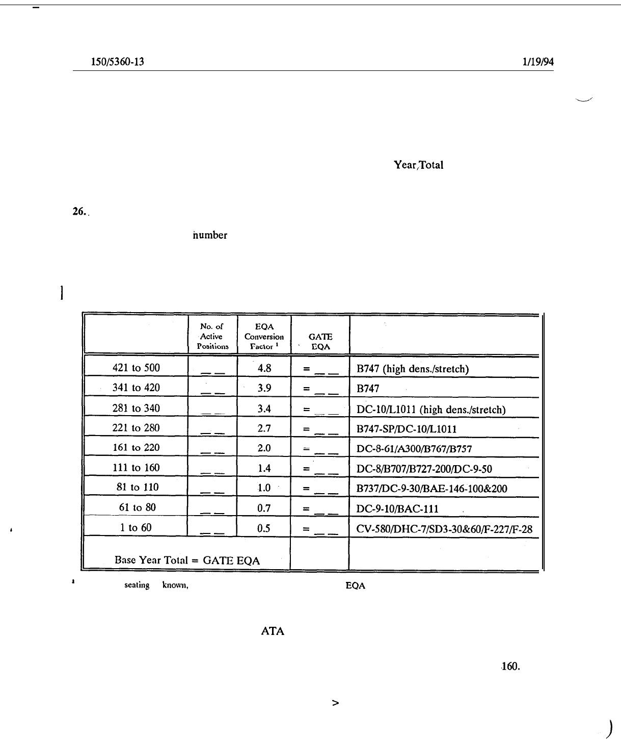
26..
BASE YEAR TOTAL GATE EQA. To obtain this value, identify the appropriate category of aircraft
seating capacity for each active gate position. Note that the number of base year active gate positions may
be greater or less than the humber of actual gates. Consistent double parking of aircraft at one gate should
count as two active gate positions.
Conversely, a new terminal facility may not have all its gates “active.”
Multiply the total number in each category by the appropriate EQA Conversion Factor, and sum the results.
Table 2-l illustrates this computation.
I
.
Table 2-1. Bsse Year Total Gate EQA Computation
Aircraft Seating Capacity
Aircraft Type
’
When actual
seatiq
is known, divide the number by 100 to determine the
EQA
Factor.
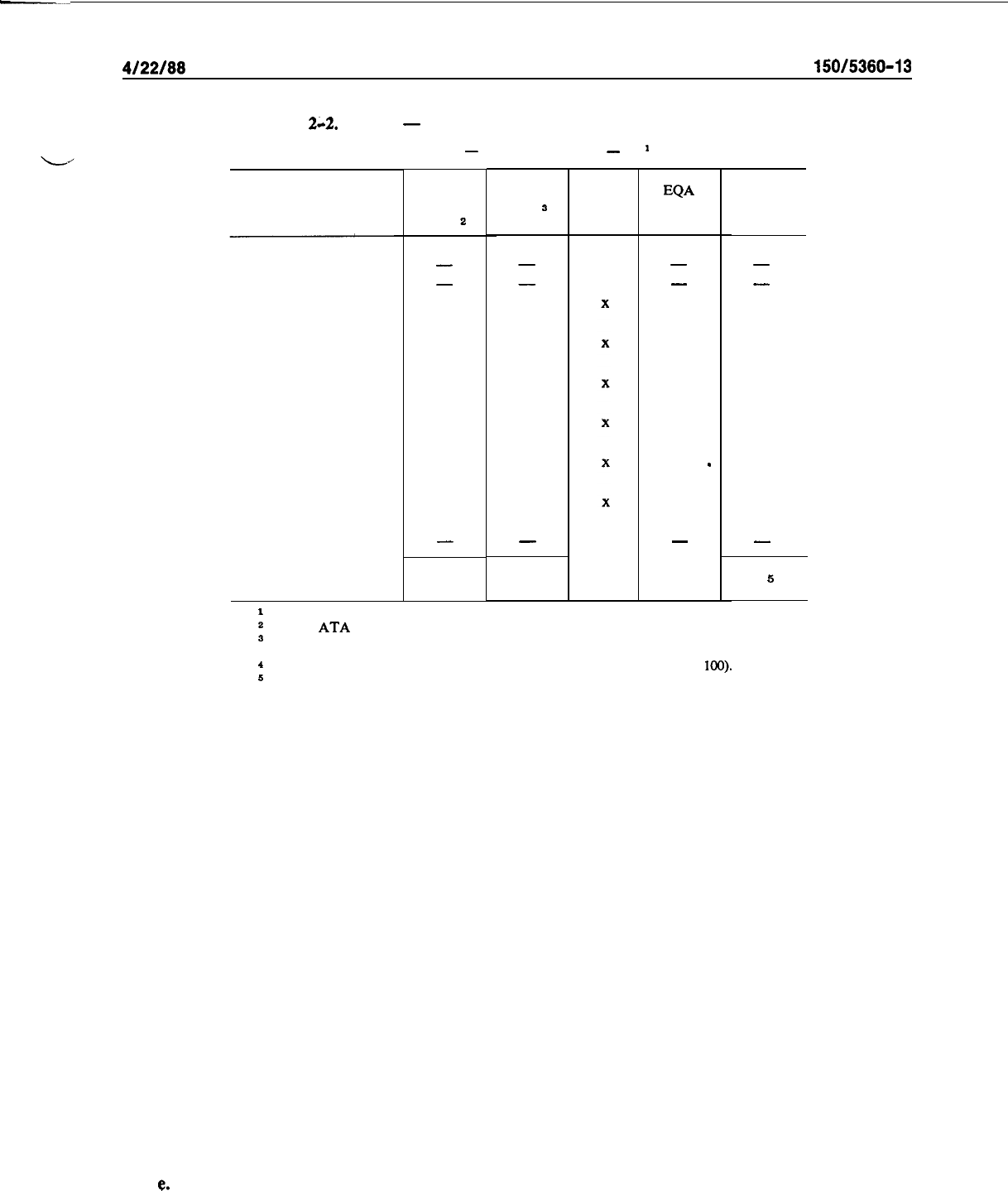
27.
FUTURE TOTAL GATE EQA. To compute a future design year Total Gate EQA, it is first necessary
to know the forecasted peak hour ADPM movements for each aircraft type (based on seating capacities). This
information can either be obtained from ATA Airline Airport Demand Forecast Reports or from master
planning studies, as appropriate. Additionally, the total number of forecast aircraft gates for the future design
year must be known or calculated (see paragraph 43). To determine Future Total Gate EQA, first allocate
future gates at one per peak hour movement for all seating capacity aircraft categories above
,160.
Then,
proportionately allocate the remaining gates among the remaining categories. (Note that in the case where
peak hour utilization is less than 1.0, the additional number of gates in excess of the peak hour movements
are to be added to the aircraft groups with seating capacity > 160.) Then, multiply the number of gates by the
EQA Conversion Factor for each aircraft seating group and add the products. Table 2-2 depicts a sample
calculation.
12
4122188
AC
150/5380-13
Table
2~2.
Sample
-
Future Design Year Total Gate EQA Computation
[Design Year
-
1995; Forecast Gates
-
21
1
A/C Seating Capacity
.
,
421
to 500
341
to 420
281
to 340
221
to 280
161
to 220
111
to 160
81
to 110
61
to 80
1
to 60
Total
. . . . . . . . . . . . . . . . . . .
.
. . . .
.
.
. . .
1995 Per
Hr ADPM
Move-
ments
a
No.
Gates
s
EQ
A
Conv.
Factor l
Gate EQA
-
-
-
-
-
-
-
-
1 1
3.4 3.4
4
4
2.7
10.8
3
3
2.0 6.0
9
7.
1.4
9.8
6
4
1.0
I
4.0
3
2
0.7
1.4
-
-
- -
26
21
5
35.4
1
See paragraph 43.
*
Source:
ATA
Airline Airport Demand Forecast.
a
Allocate one gate per movement for seating capacity categories > 160 and then allocate
remaining gates proportionally to equal total of 21 gates.
4
Use actual conversion factors when available (seating capacity divided by
100).
5
Total Gate EQA for 1995.
28.
EQA Arrivals.
The term “EQA Arrivals” is synonymous with “EQA Inbound” and is used primarily
for sizing baggage claim facilities. Passenger aircraft arrivals in periods of peak 20 minutes are the basis for
these calculations. This can be approximated by assuming that 50 percent of the total gates are used in those
periods for arriving aircraft. To determine EQA Inbound, allocate projected design year gates beginning
with the largest aircraft until 50 percent of the gates are used. (This will ensure adequate facilities for the
highest potential peak 20 minute passenger load.) The number of gates occupied by each aircraft type is then.
multiplied by the appropriate EQA Conversion Factor and the sum of these products is the EQA Inbound.
29. FORECAST REASONABILITY CHECKS. Activity forecasts and variables which influence sizing
should be examined for reasonability. The following are key examples:
a. Passenger Traffic Growth (Scheduled Operations).
Local airport growth should be compared
against that forecast for the U.S. domestic market.
b.
Ratio of Originating Passengers to Total Enplanements.
Assumptions used in forecasting a change
to the current ration should be explained. This information is particularly important for planning auto park-
ing facilities, curb lengths, airline counters, and baggage claim areas.
c. Boarding Load Factor. The number of boarding passengers versus available seats should be com-
pared. Any ADPM load factors outside the range of 55 percent to 60 percent should be reviewed with the
airlines. Peak hour average load factors may be 15 to 25 percentage points higher.
d. Aircraft Growth Trends. Projected growth in aircraft seating capacities should be compared with
boarding load factors.
e.
Gate Utilization. Existing and forecast annual enplanements per gate and daily arrivals per gate
should be identified and checked for reasonableness of any projected change.
13
AC
150/5380-13
4/22/88
f. Aircraft
Movements.
Peak hourly operations as a percent of daily operations for ADPM should be
verified. Forecast changes up or down from the existing ratio, should be explained, recognizing that the
ratio of peak hourly to daily operations tends to decline as traffic increases. The relationship between peak
--
!
hourly passengers and daily passengers may not follow an identical trend, since larger aircraft are usually
introduced into prime time or peak periods.
g. Nonscheduled Operation& The forecast ratio of passengers carried in nonscheduled operations
versus those for scheduled service should be reviewed. Separate statistics should be kept when existing vol-
umes or forecast growth represent a significant percentage of total operations. Assumptions used in forecast-.
ing a significant impact of nonscheduled traffic growth in terminal operations or in proposing separate facili-
ties to accommodate this growth should be explained.
h.
Number of Scheduled Carriers.
Assumptions for any anticipated increase or decrease in the number
of carriers require an explanation. The facilities needed by four airlines to serve 100,000 domestic
enplane-
ments will usually be more than those for two or three carriers handling the same volume.
30. RESERVED.
14
r
4122188
AC
150/5380-13
CHAPTER 3. FUNCTIONAL RELATIONSHIPS AND TERMINAL CONCEPTS
31.
MAJOR TERMINAL COMPONENTS.
The terminal complex functions as an area of interchange be-
tween ground and air transportation modes. To accomplish this interchange, the following major compo-.
nents are required:
a. Apron.
The apron comprises the area and facilities used for aircraft gate parking and aircraft sup-
port and servicing operations. It includes the following sub-components:
(1) Aircraft Gate Parking Positions--used for parking aircraft to enplane and deplane passengers.
.
The passenger boarding device is part of the gate position.
(2)
Aircraft Service Areas--on or adjacent to an aircraft parking position. They are used by airline
personnel/equipment for servicing aircraft and the staging of baggage, freight, and mail for loading and
un-
loading of aircraft.
(3)
Taxilanes--reserved to provide taxiing aircraft with access to and from parking positions.
(4)
Service/Fire Lanes--identified rights-of-way on the apron designated for aircraft ground serv-
ice vehicles and tire equipment.
b. Connector. The connector consists of the structure(s) and/or facilities normally located between
the aircraft gate position and the main terminal building. At low activity airports, i.e., less than approximate-
ly 200,000 annual enplaned passengers;this component is often combined with’the terminal building compo-
nent. It normally contains the following elements:
(1)
Concourse--a passageway for circulation between aircraft gate parking positions and the main
terminal building.
(2)
Departure Lounge--an area for assembling and holding passengers prior to a flight departure. In
some instances, it may be a mobile’lounge also used to transport passengers to a parked aircraft.
(3)
Security Inspection Station--a control point for passenger and baggage inspection and control-
ling public access to parked aircraft.
(4)
Airline Operational Areas--areas set aside for airline personnel, equipment, and servicing activi-
ties related to aircraft arrivals and departures.
(5) Passenger Amenities--areas normally provided in both the connector as well as the terminal
components, particularly at the busier airports with relatively long connectors. These amenities include rest
rooms, snack bars, beverage lounges, and other concessions and passenger services.
(6)
Building Maintenance and Utilities--areas often included in the connector component to provide
terminal building maintenance and utilities.
c.
Main Terminal Building.
The following elements comprise this component:
(1)
Lobbies--public areas for passenger circulation, services, and passenger/visitor waiting.
.
(2) Airline Ticket Counters/Office Areas--areas required for ticket transactions, baggage check-in,
flight information, and administrative backup.
(3)
Public Circulation Areas--areas for general circulation which include stairways, escalators, ele-
vators, and corridors.
(4) Terminal Services--facilities, both public and nonpublic, which provide services incidental to
aircraft flight operations. These facilities include rest rooms, restaurants and concessions, food preparation
and storage areas, truck service docks, and miscellaneous storage.
(5)
Outbound Baggage Facility--a nonpublic area for sorting and processing baggage for departing
flights.
(6) Intraline and Interline Baggage Facility--a nonpublic area for processing baggage transferred
from one flight to another.
15

AC
150/5380-13
4122188
(7)
Inbound Baggage Facility-La nonpublic area for receiving baggage from an arriving flight and
public areas for baggage pickup by arriving passengers.
-
)
(8)
Federal Inspection Services--a control point for processing passengers arriving on international
flights.
(9)
Airport Administration and Services--areas set aside for airport management, operations, and
maintenance functions.
.
d. Airport Access System. This component is composed of the functional elements which enable
ground ingress and egress to and from the airport terminal facility. They include the following:
(1)
Curb--platforms and curb areas (including median strips) which provide passengers and visitors
with vehicle loading and unloading areas adjacent to the terminal.
(2)
Pedestrian Walkways--designated lanes and walkways for crossing airport roads, including
tun-
nels and bridges which provide access between auto parking areas and the terminal.
.
(3) Auto Parking--areas providing short-term and long-term parking for passengers, visitors, em-
ployees, and car rental.
(4)
Access Roads--vehicular roadways providing access to the terminal curb, public and
employee
parking, and to the community roadway/highway system.
(5)
Service Roads--public and nonpublic roadways and fire lanes providing access to various sub-
elements of the terminal and other airport facilities, such as air freight, fuel tank stands, postal facility, and
the like.
32.
FUNCTIONAL RELATIONSHIPS OF TERMINAL COMPONENTS.
a. Activities within the terminal building can be categorized primarily into three functional areas:
processing and servicing passengers; handling and processing of belly cargo (including passenger baggage);
and, aircraft servicing. Consequently, a good terminal design necessitates a layout in which the various com-
ponents are located in a sequence or pattern which coincides with the natural movement and services each
requires, and those activities and operations which are functionally dependent on each other. Such a
.design
will minimize passenger walking distances, airline servicing and processing times, and congestion caused by
the intermingling of nonrelated activities.
b. Figure 3-l presents the usual functional components of a typical terminal from curb to aircraft
parking apron in terms of sequence of flow. For simplicity, only two relationships are used in the figure;
that in which functional adjacency is essential for good design; and that in which it is merely recommended.
The relationships, although graphically depicted in a single plane, apply equally to multilevel terminals. It
should not be implied that every terminal should provide for all of the functions shown or that each func-
tion must have has an individually defined area. For example, at low activity airports, one general space
may suffice for multiple functions, such as a combined lobby, ticket counter area, and waiting lounge.
Figure 3-2 shows these same functional adjacency relationships in a matrix format.
33.
OBJECTIVES IN SELECTING TERMINAL CONCEPTS.
a.
The objective of the terminal area plan should be to achieve an acceptable balance between passen-
ger convenience, operating efficiency, facility investment, and aesthetics. The physical and psychological
comfort characteristics of the terminal area should afford the passenger an orderly and convenient progress
from.an automobile or public transportation through the terminal to the aircraft and vice versa. Some of the
objectives to be considered in the development of a terminal area plan are minimum walking distance, con-
venient auto parking, and convenient movement of passengers through the terminal complex. Conveyances
such as moving walks and automated baggage handling systems should be considered for high volume air-
ports.
18
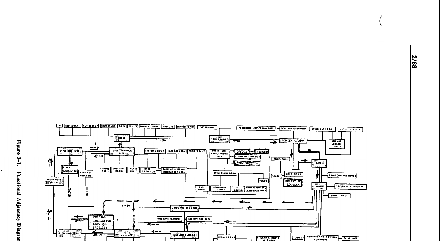
r
t
1
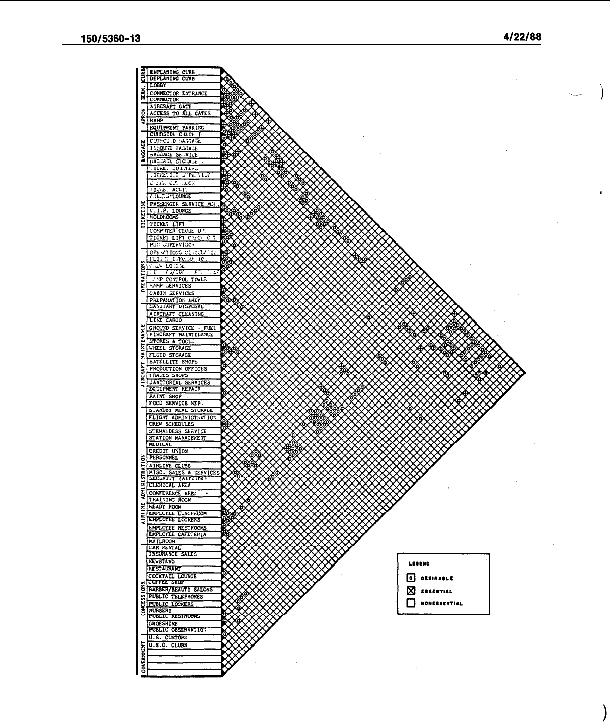
AC
150/5360-13
4/22/88
Figure 3-2. Functional Adjacency Matrix
18

4122188
AC
150/5380-13
.
b.
The terminal complex’s functional arrangement should be flexible enough for expeditiously handling
passengers and ground-servicing aircraft to achieve minimum gate occupancy time and maximum airline
operating economy. The ultimate plan should strive to meet these objectives within acceptable funding
levels while considering not only capital investment but also maintenance and operating costs. Regardless of
the scheme selected, the importance of complete planning flexibility to permit expansion both horizontally
and vertically at minimum cost and with as little interference as possible to existing facilities cannot be over-
emphasized.
34.
CENTRALIZED AND UNIT TERhIINALS. There are two basic concepts for the arrangement of the
terminal area. In a centralized terminal, all passengers and baggage are processed in one building. Most air-
ports utilize this arrangement. At some high activity airports, however, each airline (or several airlines com-
bined) may be located in a separate terminal building. This is referred to as a unit terminal concept. These
two design concepts are often combined in varying degrees. Examples of airports having a unit terminal
concept include John F. Kennedy International, Kansas City International, and Dallas-Ft.Worth Regional
airports. A single centralized terminal building has many advantages and for most situations is preferable. It
represents a reasonably compact operation without the significant problem of transferring passengers and
baggage between buildings. Building maintenance and operating costs for the centralized terminal will gen-
erally be significantly lower than the total costs for operating all unit terminals. A unit terminal concept can
be justified only at the very high activity airports, particularly where the percentage of airline transfer pas-
sengers is relatively low. An efficient transportation system for passenger and baggage transfer between
buildings is a must and should be incorporated in the design at an early stage.
35. ALTERNATIVE TERMINAL BUILDING CONCEPTS. A terminal building design can be catego-
rized as one of five basic concepts or a variation or combination of them. The connector is the single ele-
ment that distinguishes between the various concepts, since it is different in each case. Terminal building
concepts are categorized in the following manner:
a. Simple Terminal Concept. The simple terminal consists of a single common waiting and ticketing
area with exits leading to the aircraft parking apron. It is suitable at airports with low airline activity with
an apron providing close-in parking for three to six commercial transport aircraft. A simple terminal nor-
mally consists of a single level structure with two to four gates with access to aircraft by walking across the
aircraft parking apron. The layout of the simple terminal should take into account the possibility of pier or
linear extensions for terminal expansion.
b.
Linear Concept.
In the linear concept (Figure
3-3),
aircraft are parked along the face of the termi-
nal building. Concourses connect the various terminal functions with the aircraft gate positions. This con-
cept offers ease of access and relatively short walking distances if passengers are delivered to a point near
gate departure by vehicular circulation systems. Expansion may be accomplished by linear extension of an
existing structure or by developing two or more linear-terminal units with connectors.
c. Pier Concept.
The pier concept (Figure 3-4) provides interface with aircraft along piers extending
from the main terminal area. In the pier concept, aircraft are usually arranged around the axis of the pier in
a parallel or perpendicular parked relationship. Each pier has a row of aircraft gate positions on both sides,
with the passenger right-of-way or concourse running along the axis of the pier and serving as the circula-
tion space for enplaning and deplaning passengers. Access to the terminal area is at the base of the connec-
tor (pier). If two or more piers are used, spacing for aircraft maneuvering between the piers by means of an
apron taxilane( as discussed in paragraph 46, is required.
d.
Satellite Concept.
The satellite concept (Figure 3-5) consists of a building, surrounded by aircraft,
which is separated from the terminal and usually reached by a surface, underground, or above-grade con-
nector. Aircraft are normally parked in radial or parallel positions around the satellite. The satellite can have
common or separate departure lounges. Since enplaning and deplaning of aircraft are accomplished from
a~
common area, mechanical systems may be employed to transport passengers and baggage between the termi-
nal and satellite.
19
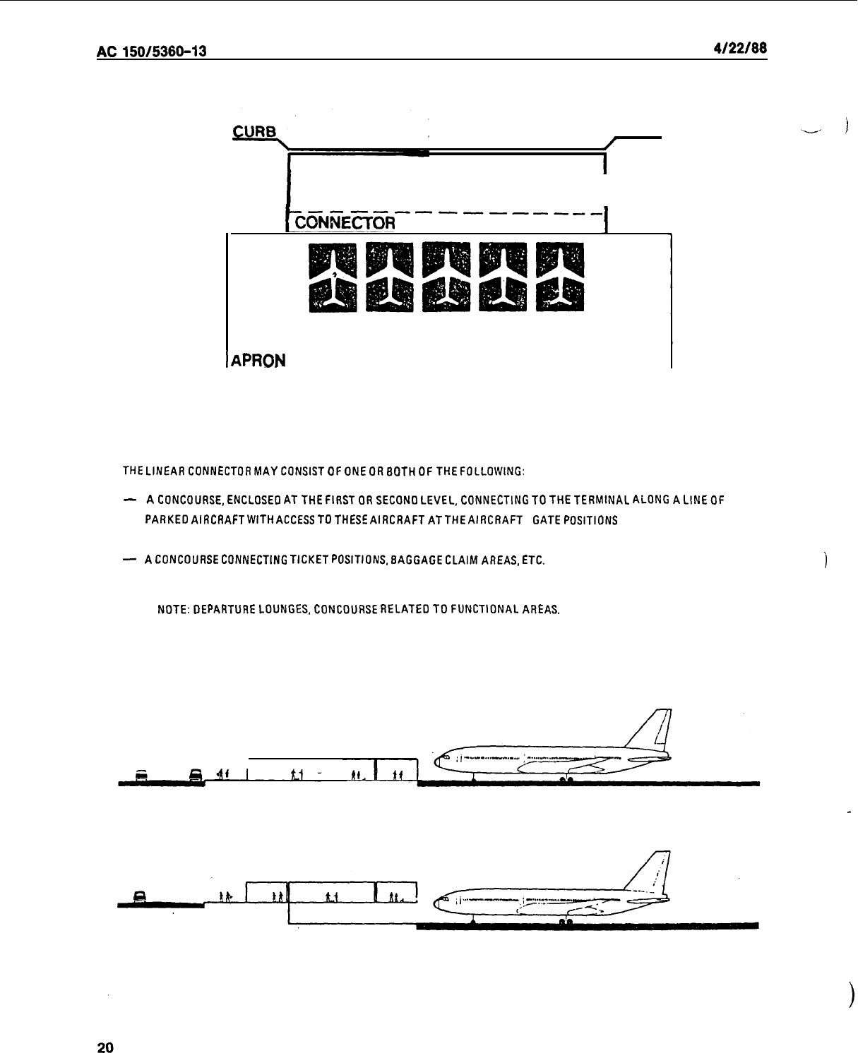
AC150/5360-13
4/22/66
I
TERMINAL
I
--------------
~~NNECTOFI
I
APRON
THE
LINEAR
CONNECTOR
MAY
CONSIST
OF
ONE
OR
BOTH OF THE FOLLOWING:
--
i
-
A CONCOURSE, ENCLOSED AT THE FIRST
OR
SECONO
LEVEL,
CONNECTING TO THE
TERMINAL
ALONG
A
LINE
OF
PARKE0
AIRCRAFT
WITH
ACCESS
TO THESE
AIRCRAFT
AT
THE
AIRCRAFT
GATE POSITIONS
-
A
CONCOURSE CONNECTING
TICKET
POSITIONS. BAGGAGE
CLAIM
AREAS,
ETC.
1
NOTE: DEPARTURE LOUNGES, CONCOURSE
RELATE0
TO
FUNCTIONAL
AREAS.
Figure 3-3. Tbe Linear Concept
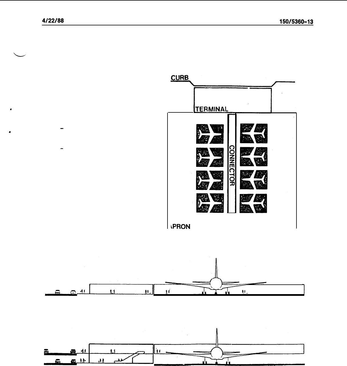
.
4/22/66
AC
150/5360-13
THE PIER CONNECTOR MAY CONSIST OF:
-
A COVERED CONCOURSE AT
GRADE LEVEL.
-
A COVERED CONCOURSE ENCLOSED
AT SECONO LEVEL.
[TERMINAI
Figure 3-4. The Pier Concept
21
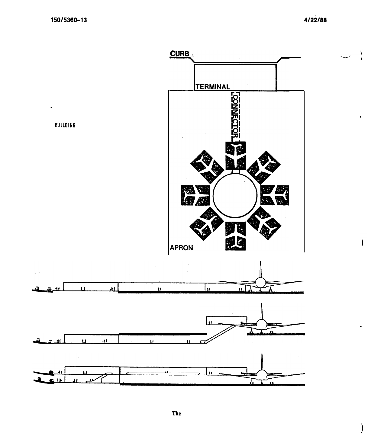
AC
150/5360-13
4/2i/68
THE SATELLITE CONNECTOR MAY CONSIST OF:
-
A CONCOURSE BELOW, AT OR ABOVE GRAOE
CONNECTING THE SATELLITE
BUILOING
WITH THE TERMINAL.
Figure 3-5.
.Tbe
Satellite Concept
22

4/22/88
AC
150/5360-13
e. Transporter Concept. Aircraft and aircraft-servicing functions in the transporter concept (Figure
3-6) are remotely located from the terminal. The connection to the terminal is provided by vehicular trans-
port. The advantages of the transporter concept include flexibility in providing additional aircraft parking
positions to accommodate increases in schedules; ease and speed in maneuvering aircraft in and out of park-
ing positions under their own power; separation of aircraft servicing activities from the terminal; and re-
duced walking distances for passengers. Transporters may also be used in establishing remote gates for char-
ter flights. The disadvantages mainly relate to the initial, operational, and maintenance costs associated with
the transporter vehicles, although the increased transfer times required in changing airplanes can also be
detrimental to airport efficiency.
,
36. SINGLE-LEVEL/MULTILEVEL TERMINALS. The decision on whether the terminal building
design should incorporate single or multilevels for processing passengers and baggage is influenced primarily
by the volume of traffic.
,Variations
of these designs are shown in the bottom elevations depicted on
l
Figures 3-3 through 3-6 and are discussed as follows:
a.
Single-level Terminal.
The single level terminal is the preferred design at the majority of small and
nonhub airports. The processing of passengers and baggage takes place at the same level as the apron, and
the entire layout is quite simple and economical.
b. Multilevel Terminal. At a traffic level of over 500,000 annual enplaned passengers, structures of
more than one story should be investigated. In this concept, arriving and departing passengers are vertically
separated. Enplaning passengers are usually processed on the upper level and deplaning passengers on the
lower level. The fingers or piers leading to the aircraft are usually two stories, whereas, the terminal
enplan-
ing and deplaning curbs may be on single or multilevels, as discussed in the following paragraph. The prin-
cipal advantage of a multilevel terminal is the reduction of congestion by segregating opposing flows of
passengers and baggage. The disadvantages are the higher initial investment and the continuing higher oper-
ation and maintenance costs. In evaluating the design of a multilevel terminal, the physical limitations of the
site, terrain, and airline station characteristics are important considerations.
c. Multilevel Curbs. While single level curbs may be utilized with all concepts and traffic volumes,
multilevel curbs are appropriate only at multilevel terminals. Construction of multilevel curbs should be con-
sidered when passenger volumes exceed one million enplanements or when physical limitations within the
terminal area or building frontage make curb separation desirable. Multilevel curbs, with their corresponding
structural roads and ramps, are costly to construct and should be considered only after investigation of
single-level alternatives.
.
d. Second Level Aircraft Boarding.
Boarding and deplaning aircraft from the second story is the usual
procedure at multilevel terminals for reasons of simplicity and efficiency, unless limited by terrain features.
Conversely, for the same reasons, apron-level boarding is the norm for single-level terminals. However,
severe or extreme weather conditions, or other considerations, may justify second-level boarding at a
single-level terminal. In such cases, two story connectors, raised pier structures, or inclined loading bridges
can be utilized. Airports with over 500,000 annual enplanements are candidates for second-level boarding
installations. In some situations, a combination of apron and second-level boarding gates may be a desirable
alternative.
37.
TERMINAL CONCEPT COMBINATIONS AND VARIATIONS.
a.
Combinations and variations
of
terminal concepts often result from the changing conditions experi-
enced at an airport during its lifespan. An -airport may have many types of passenger activity, varying from
originating and terminating passengers using the full range of terminal services to passengers using limited
services on commuter flights. The predominant type of activity usually affects the initial terminal concept
selected. In time,
the
amount of
traffic
may increase, necessitating
modiftcation
or expansion of the facilities.
Growth of aircraft size, a new combination of aircraft types serving the airport, or a change in the type of
service may affect the suitability of the initial concept. Similarly, physical limitations of the site may cause a
pure conceptual form to be modified by additions or combinations of other concepts.
23
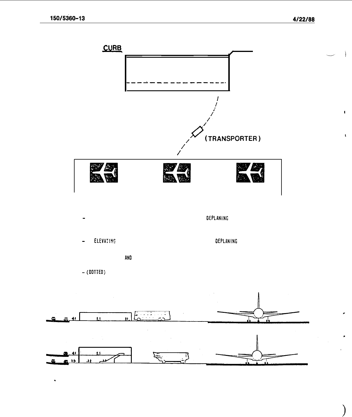
AC
150/5360-13
4/22/88
CURS_
TERMINAL
---A-----------.-.
CONNECTOR
I
:
I’
/
/
/I
/
#
CONNECTOR
/’
(TRANSPORTER
)
THE TRANSPORTER CONNECTOR MAY CONSIST OF:
-
A NON-ELEVATING VEHICLE THAT PERMITS ENPLANING AND
OEPLANING
AT
APRON LEVEL AT THE AIRCRAFT AND AT THE TERMINAL.
-
AN
ELEVATILI!:
VEHICLE THAT PERMITS DIRECT ENPLANING AND
OEPLANINC
TO THE AIRCRAFT
AND TERMINAL BY MOVING THE PASSENGER CAB VERTICALLY TO MATCH ENTRANCE LEVELS
AT THE AIRCRAFT
AN0
TERMINAL
-
(OOTTEO;
A SECONOARY CONCOURSE CONNECTING TRANSPORTER POSITIONS.
.
Figure 3-6. The Transporter Concept
24
4122188
AC
150/5380-13
b.
Combined concepts acquire some of the advantages and disadvantages of each basic concept used.
A combination of concept types can be advantageous where more costly
modifications
would be necessary
to maintain the original concept. For example, while an airline may be suitably accommodated within an
existing transporter concept terminal, a commuter operation with rapid turnovers is best served by a linear
concept extension. In this case, concept combination is desirable. Thus, the appearance of concept variations
and combinations in a total apron-terminal plan may reflect an evolving situation in which altering needs,
growth, or physical limitations have determined the final terminal configuration. Figure 3-7 depicts concept
combinations and variations typically utilized in airport terminal designs.
.
38.
CONCEPT EVALUATION.
Particularly at high activity’locations, a thorough analysis of the type of
terminal concept to be utilized at an airport should be conducted before a final decision is made. Initial
evaluation efforts should narrow the choices down to two or more alternative schemes before development
of preliminary layouts and drawings. The final choice should be made only after indepth analyses are com-
pleted. Quantifiable aspects of each concept (walking distances, areas required, etc.) should be compared;
efficiency studies of passenger and aircraft flows, ground vehicular movements, and operational/functional
sequences conducted; and cost estimates made. At very high activity airports with complex inter-relation-
ships, the application of simulation techniques may be warranted. Some of the principal factors which
should be considered in the overall evaluation of alternatives are discussed in following paragraphs. A more
thorough discussion on concept evaluation may be found in Report No. FAA-RD-73-82, The Apron-Ter-
minal Complex
-
Analysis of Concepts for Evaluation of Terminal Buildings.
a. Airport Design Activity Levels. Figure 3-8 provides a matrix for identifying applicable terminal
concepts related to design activity levels. The rationale behind the formulation of this matrix is as follows:
(1)
For airports with projected design activity levels up to 200,000 annual
enplaned
passengers,
simple or linear concepts with varying degrees of complexity at the higher enplanement levels appear to be
the most appropriate. Low activity airports warrant a simple, compact structure incorporating all activities,
including airfreight. As traffic increases, consideration should be given to providing covered walkways from
the terminal element.
(2)
For a design activity level between 200,000 and one million annual enplaned passengers, linear,
pier, and satellite concepts are used. The linear concept, however, begins to exhibit an increasing degree of
decentralization. The result is greater connecting distances for transfer passengers, while passengers who
departed on one airline and returned on another are placed at greater distances from their parked automo-
biles. In addition, the linear concept, after reaching this activity level, requires a sophisticated signing and
graphics system for identifying airlines, gate positions, and other activity centers.
(3)
When the activity level exceeds one million annual enplaned passengers, pier, satellite, and trans-
porter concepts are applicable. The first two concepts offer an additional alternative of utilizing multiple
terminal units or a larger centralized terminal to accommodate the entire traffic load. At transfer airports, a
multiple unit terminal or transporter concept may be inappropriate. This is due to inefficiencies resulting
from transferring passengers and baggage between aircraft (e.g., transporter) or between airlines (e.g.,
multiple unit terminal).
b.
Passenger Walking Distances.
In evaluating alternate terminal concepts and building designs, major
consideration should be directed toward keeping passenger walking distances to a minimum. This is particu-
larly important at locations where there is considerable transfer between aircraft. Under these circumstances,
walking distances become more time critical. Relationships between passenger walking distances and termi-
nal concept selections are discussed in following paragraphs.
(1)
A passenger activity level up to one million annual enplanements represents approximately a six
to eight gate simple or linear terminal, normally, serving an aircraft mix up to B-727 size, and requires an
average overall gate width of 110 to 130 feet (33 to 40 m). Aircraft park in front of the terminal, usually in a
taxi-in/power-out operating mode. The terminal itself provides the common areas for the main functions,
such as ticket counters, waiting space with concessions, and baggage-claim areas. The total overall length is
approximately 700 to 1,000 feet (210 to 300 m). This means that the walking distance from the general areas
in the terminal to the farthest gate is not more than 350 to 500 feet (105 to 150 m).
25
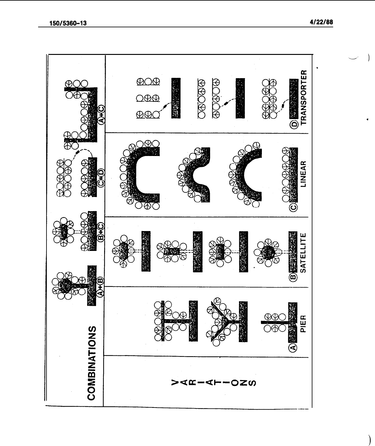
AC
150/5380-13
4122188
-.-’
)
Figure 3-7. Concept Combinations and Variations
.
.
28
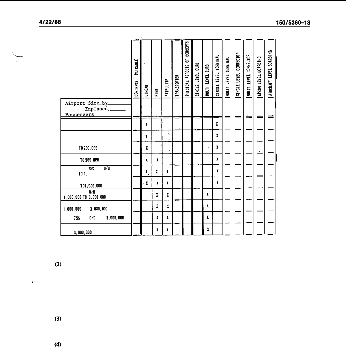
4/22/88
AC
150/5360-13
AirportSiz~lw
Annual
Enplaned
._
Passeneers
FEEDER UNDER 25.000
SECONDARY 25.000 TO 75.000
75.000 TO
2oo.ooc
200.000 TO 500.0@0
PRIMARY OVER
7%
PAX
OiO
500.000 TO
I.
000.000
OVER 25: PAX TRANSFER
500.000
TO
I.ooo.oco
OVER 75% PAX O/O
1.000.000
i0
3.000.000
OVER 25: PAX TRANSFER
1.000.000
TO
3.000.000
OVER
752
PAX O/O OVER
3.000.000
OVER 25% PAX TRANSFER
OVER
3.000.000
-
2
2
U
i
4
“c
2
z
=:
-
=
-
-
-
-
-
-
-
-
-
-
-
B
&I
E
9
E
7
=
,
-
-
-
-
-
L
X
-
-
X
-
-
-
=
B
2
E
!t
Y
el
T
"
=
X
-
X
-
X
-
X
-
X
-
X
-
X
-
X
-
X
-
X
-
-
2
E
z
E
iz
Z
2
5
P
-
=
-
-
-
-
-
-
X
-
X
-
X
-
X
-
-
z
z
g
z
ti
z
2
2
9
”
=
-
-
X
-
X
-
X
-
X
-
X
-
X
-
X
-
X
-
-
53
z
is
K
u
s
Z
2
E
P
-
=
-
-
-
-
X
-
X
-
X
-
X
-
X
-
X
-
-
::
=
5
m
2
z
5
z42
is
",
-
=
X
-
X
-
X
A
X
-
X
-
X
-
X
-
X
-
X
-
-
-
::
=
5
m
ii
Z
a
E
Z
z
r;
-
=
-
-
-
-
X
-
X
-
X
-
X
-
X
-
X
-
Figure 3-8.
Matrix of Concepts Related to Airport Size
(2)
With au annual enplanement level between one million and three million, a mix of larger aircraft,
including wide-body aircraft, will operate from the apron-terminal complex. Average gate widths will
range from 150 to 180 feet (45 to 55 m). As a result, a unit of six to eight gates will reach an overall apron
’
length of 1,000 to 1,500 feet (300 to 450 m). The overall walking distances will become even greater if
aircraft are parked in a continuous single line, nose to tail. The common area will become individualized and
walking distances and the distance between the terminal units will increase. Other concepts, such as the pier,
satellite, and transporter, will become more appropriate for reducing walking distances.
(3)
When the annual enplanement level reaches three million, with 25 percent or more transfer pas-
sengers, the transporter concept becomes less applicable since this concept increases the passenger transfer
time between flights.
(4)
When concept selection is limited, excessive walking distances can be made more tolerable by
the installation of moving walkways, escalators, guideways, and other mechanized people moving systems.
c. Airline Station Characteristics.
The characteristics of the route structure of the airlines serving the
airport can be important factors influencing the selection of a terminal concept (e.g., transfer versus originat-
ing, domestic versus international, scheduled versus nonscheduled, etc.). Other factors include the size and
type of aircraft used, aircraft ground and turnaround times, airline equipment and policies, and the like.
d. Physical Characteristics. The terminal concept selection is influenced by the physical characteris-
tics of the terminal site such as the available area for expansion, existing facilities, terrain, airport layout, and
access road systems.
27

AC
150/5360-13
4122188
e. Climatic
Conditiork
Extreme weather conditions of heat and cold, precipitation, wind, etc., can
influence the selection of a terminal concept to provide optimum sheltering of passengers, baggage, and air-
craft servicing areas.
-_A
‘)
f. Growth Potential. The potential for the growth of the airport requires considerable attention by
the planner in choosing a terminal plan. Growth potential includes physical growth and airline growth. Air-
line growth takes into account future aircraft sizes, potential for increased flights, service equipment, and the
introduction of new airlines.
39.
-
40. RESERVED.
I
J
28
l/19/94
AC
150/5360-13
CHG 1
CHAPTER
4.
TERMINAL
APRON
AREAS
41.
GENERAL. Four primary considerations govern
efficient
apron
arca
design: the movement and physical
characteristics of the aircraft to be served; the maneuvering, staging, and location of ground service equipment and
underground utilities; the dimensional relationships of
parked
aircraft to the terminal building; and, the safety,
security, and operational
practices
related to apron control.
The
primaly
objective of
these
considerations is the
ready accommodation of either a changingor static mix of aircraft. This
involves
maximizing the total
areain
te’rms
of aircraft parking (interchangeability of types) with comparable relationships between these aircraft and the
building. The optimum apron design for a specific airport will
depend
upou
available space, aircraft mix, and
terminal configuration.
42.
TERMINAL APRON GATE TYPES. The terminal
gate
types
used in this chapter relate to the wing spans
and
fusclagc
lengths of the aircraft which they
accommodate.
For dimensions of specific aircraft, refer to
AC
150/5300-13,
Airport Design.
The aircraft
included
in
thcsc
gate
types
make up
the
bulk of the U.S.
1
commercial aviation fleet. These aircraft
scrvc
all types and lengths of domestic and international route structures.
The four gate
types
are:
a.
Gate
Type
A.
Tbc
aircraft using
this
gate
type
arc
those
found in Airplane
Design
Group III, wing span
between
79
feet
(24 m) and 118
feet
(36 m). (Rcfcr to AC
lSO/S300-13,
for information on Airplane Design
1
Groups.) The route structures of thcsc aircraft vary from short
range/loW
density to medium range/ high density.
b.
Gate
Type
B.
Airplane Design Group IV aircraft, wing span bchvecn 118 feet (36 m) and 171 feet (52
m),
with a
fuselage
length less
llrrrrr
160
feet
(49 m),
use
this gate type. These aircraft
serve
longer range routes
than
those
sctved
by aircraft using
Gate
Type
A, but
have
similar
,passengcr
demands.
c.
Gate
Type
C.
This gate type sclvcs Airplane Design Group IV aircraft with a fuselage lengthgreater
Z/ZUII
160 feet (49 m). The typical route structure is similar to that for
those
aircraft using Gate Type B, although with
a higher passenger volume.
d.
Gate Type
D.
Aircraft in Airplane Design Group V, wing span between 171 feet
(52
m) and 213 feet (65
m), use this gate type. Thcsc aircraft operate on a long-range route
structure
and carry a high volume of
passengers.
43.
ESTIMAllNGNRCRAFT
GATE
POSITIONS. The rcquircd number of aircraft gate positions will influence
the sclcction of both the terminal concept and the building
design.
Similarly, the size and type of aircraft serviced
at the airport and the airline parking arrangement and
proccdurcs
will affect the apron area requirements and,
ultimately, the size and layout of
the
terminal building.
Several
methodologies for estimating the number of
required aircraft gate positions arc discussed in succeeding paragraphs. These methodologies are applicable to
domestic scheduled operations. Gates for international and commuter aircraft should be estimated separately. It
is recommended that all of the first three methods bc utilized for comparative purposes and appropriate judgment
exercised on
estimating
the final
number.
a.
Peak
Hour
Utilization.
The
current
(base
year) peak hour gate utilization factor is obtained by dividing
the
number
of peak hour movcmeuts by the number‘of
active
gates.
(NOTE: See paragraph 26 concerning the
counting of base year
active
gates.) Through discussions with the local airlines, a determination should be made
on whether this base year utilization factor is applicable to
the
design
year
or whether an upward or downward
adjustment is
warranted.
For rough
estimates,
the
gate utilization factors
specified
in paragraph
3c
can be used
for the three basic airline stations.
These
factors are typical for airports with domestic operations averaging
six
or more daily departures per gate.
Future
total gates arc
cstimatcd
by dividing
the
forecasted
design year peak
hourly aircraft movements by the sclccted gate utilization factor.
b.
Daily Utilization. Future total
gate
rcquircmcnts can bc
estimated
by dividing the forecast
design
year
ADPM aircraft
departures
(one-half
the
aircraft movcmcnts) by a
projcctcd
daily utilization factor.
The
latter is
determined by dividing current ADPM aircraft dcparturcsby total active
gatcsand
applying a reasonable additional
factor to account forgrcatcr future gate utilization. Industry incrcascs normally considcrcd appropriate range from
1.5 to 3.0 departures per gate for the 10 and 20 year master planning
forecasts,
rcspcctivcly. Thcsc incrcascs are
29
AC
150/5360-13
CHG 1
l/19/94
to be applied when the base year daily utilization is very low (four or less departures per gate). Generally, a daily
utilization factor of 9 to 10 represents a ceiling for airport master planiiing purposes.
v/I
c. Annual Utilization.
Future
gatescan
be estimated from base year annual utilization and forecasted annual
passenger enplanements by use of the nomographs in Figures 4-l through 4-4. These figures provide intermediate
(10 year) and long-range (20 year) forecasts of industry enplanements per active gate for high (Figures 4-2, 4-4)
and low (Figures 4-1,4-3) utilization airports. Low utilization averages
less
than six daily,departures per gate and
high utilization seven or more daily departures per gate for the average day of the peak month. After selecting
the applicable nomograph, determine the current (base year) animal enplanements per active gate and enter this
figure on the left side of the graph. On the right side, enter the ratio of forecast annual enplanements for the
design year to the current year enplanements. A straight line comtecting the two points will intersect the middle
scale to estimate the design year
ammal
enplanements per active gate.
This number divided into the forecast
design year annual enplancments will provide an estimate for total gate requirements.
d. Historical Data.
Figure 4-5 provides a method for approximating gate requirements for initial planning
and estimating purposes only.
It is based on historic relationships between
animal
enplaned passengers and
required gate positions.
44.
GATE
PARKING PROCEDURES. The parking procedures used by the airlines at an airport have
considerable effect on the sizing and spacing requirements for gate positions.
a. Taxi-in, Push-out/Power-out Parking.
This is the most common procedure used at high activity locations.
It involves the taxiing of arriving aircraft directly into gate positions under their own power. Parking is generally
nose-in and perpendicular to the building or pier finger.
Departing aircraft either self power-out or are
towed/pushed out by tractor/tug to a clear apron area where they can safely proceed under their own power. The
procedure where an aircraft must be pushed or towed out is generally the most costly, from an operational
standpoint. However, there are offsetting considerations which make its use both practical and advantageous at
many locations. For one, it utilizes minimum gate area and therefore permits more gates for the same building
or pier finger length. It also results in shorter loading
bridges
(hence,
shorter passenger walking distances) and
more efficient use of apron
space
and service equipment.
b.
Taxi-in, Taxi-out Pnrkiug.
This procedure is typically used at lower activity airports. Although it is less
costly operationally, it requires more apron area and permits less gates per pier
finger/building
length. Aircraft
taxi into and away from gate positions under their own power. Parking is either parallel to the building/pier finger
or at 30,45, or 60 degree angles. The choice is influenced by airline prcferencc and physical or other constraints.
Angle parking requires less ramp frontage than parallel parking.
45. AIRCRAFT GATE CLEARANCES.
The
sizing and clearances required for the design of aircraft gate positions
can vary considerably. Airline policies and procedures, type of towing and service equipment used, type of aircraft,
and terminal configuration all play a role. However, for planning purposes, the following guidelines are provided:
a.
Nose to Building Clcarauccs. In the push-out/power-out configuration, the distance between the nose
of an aircraft and the building may vary anywhere between 15 to 30 feet (4.5 to 9
m),
or more. This dimension
is dependent on
the
method of push-out employed and whether the building is single or multi-level. A minimal
15 to 20 feet (4.5 to 6
m)
clearance is practical either when a tug
bencath
the aircraft pulls the aircraft from the
gate or when tug maneuvering space is available in front of the aircraft beneath the second level of a building.
Larger nose-to-building
dimensions
are frequently required when a tug must operate in front of the aircraft
(pushing out). The actual dimension involved in each case
depends
on the aircraft nose gear’s position relative
to its nose, the tug length, and associated maneuvering or parking requirements. For plamiing purposes, 30 feet
(9 m) should be used for gate type A; 20
feet
(6
m)
for gate types B and
C,
and 15 feet (4.5 m) for gate type D.
b.
Nose to Tail Clear&es.
For taxi-in/out, in addition to separation for maneuvering, separation is required
to accommodate the adverse effects of jet blast. Clearances on the order of up to 490 feet (149 m) for gate type
D; 370 feet (113
m)
for gate type
C,
and, 120 feet (37
m)
for gate types A and B may need to bc established to
account for a SO mph
(80
km/b) jet blast. Use of
jet
blast fcnccs and low break-away thrust operating procedures
can considerably
rcducc
these
separations.
30
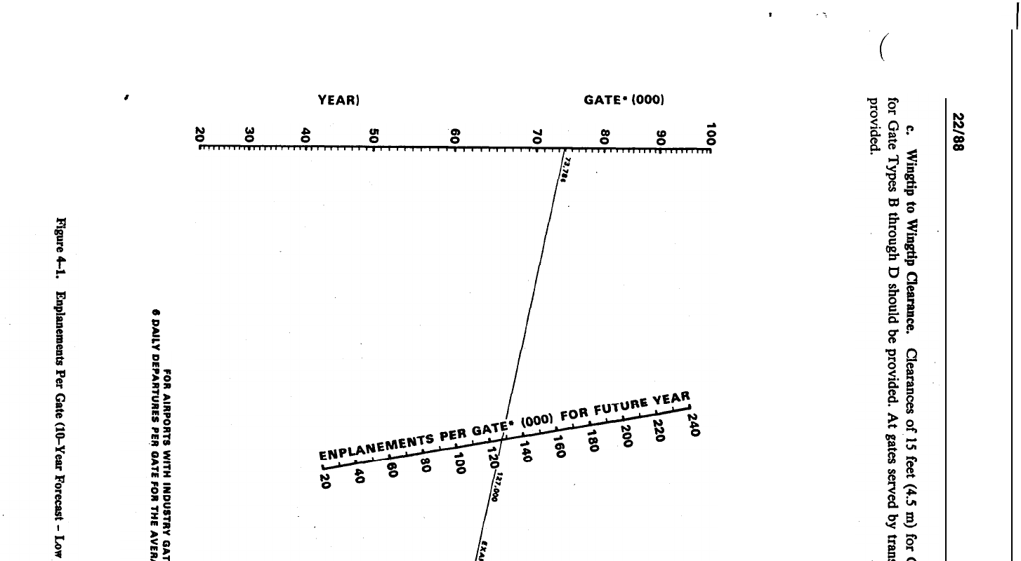
a
e
f
CURRENT (BASE
YEAR)
ANNUAL ENPLANEMENTS PER
GATE.
(000)
FOR U.S. DOMESTIC SCHEDULED OPERATIONS
ANNlJiiL ENPIANEMENTS FOR
lo-YEAR FORECAST
i
CURRENTYEAR
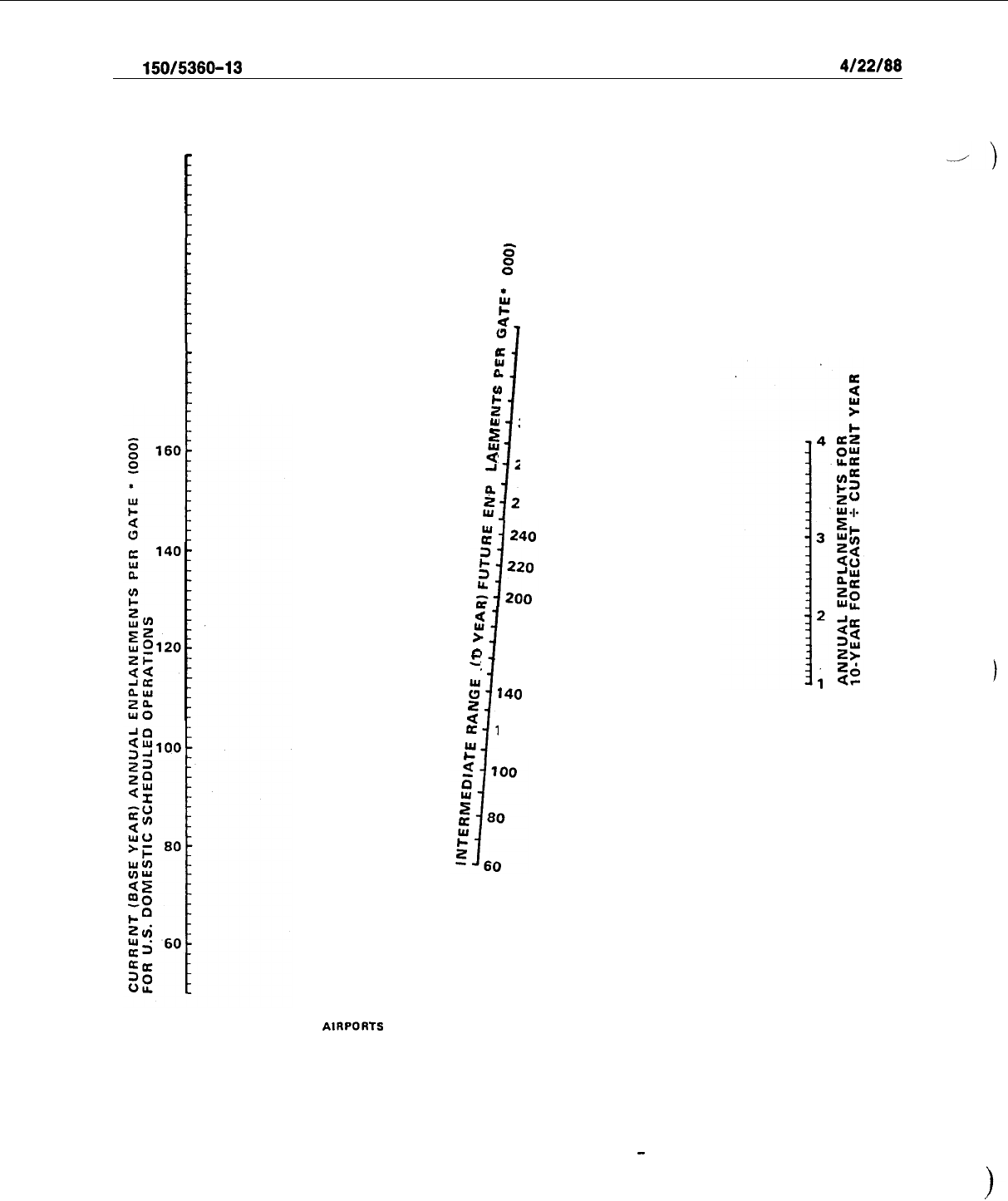
AC
150/5360-13
4/22/66
220
I
200
1
180
1
0”
0”
G4
G
(3
340
a
’
320
v)
zc
w
300
i
B
2”
,4
280
ii
260
w
z
$
180
o
22
160
:
740
5
a
120
c”
i
FOR
AlRPORTS
WITH INDUSTRY GATE USE AVERAGING 6 OR MORE DAILY DEPARTURES
PER GATE FOR THE AVERAGE DAY OF THE PEAK MONTH.
‘ACTIVE POSITION
Figure 4-2. Enplanements Per Gate (IO-Year Forecast
-
High Utilization)
32
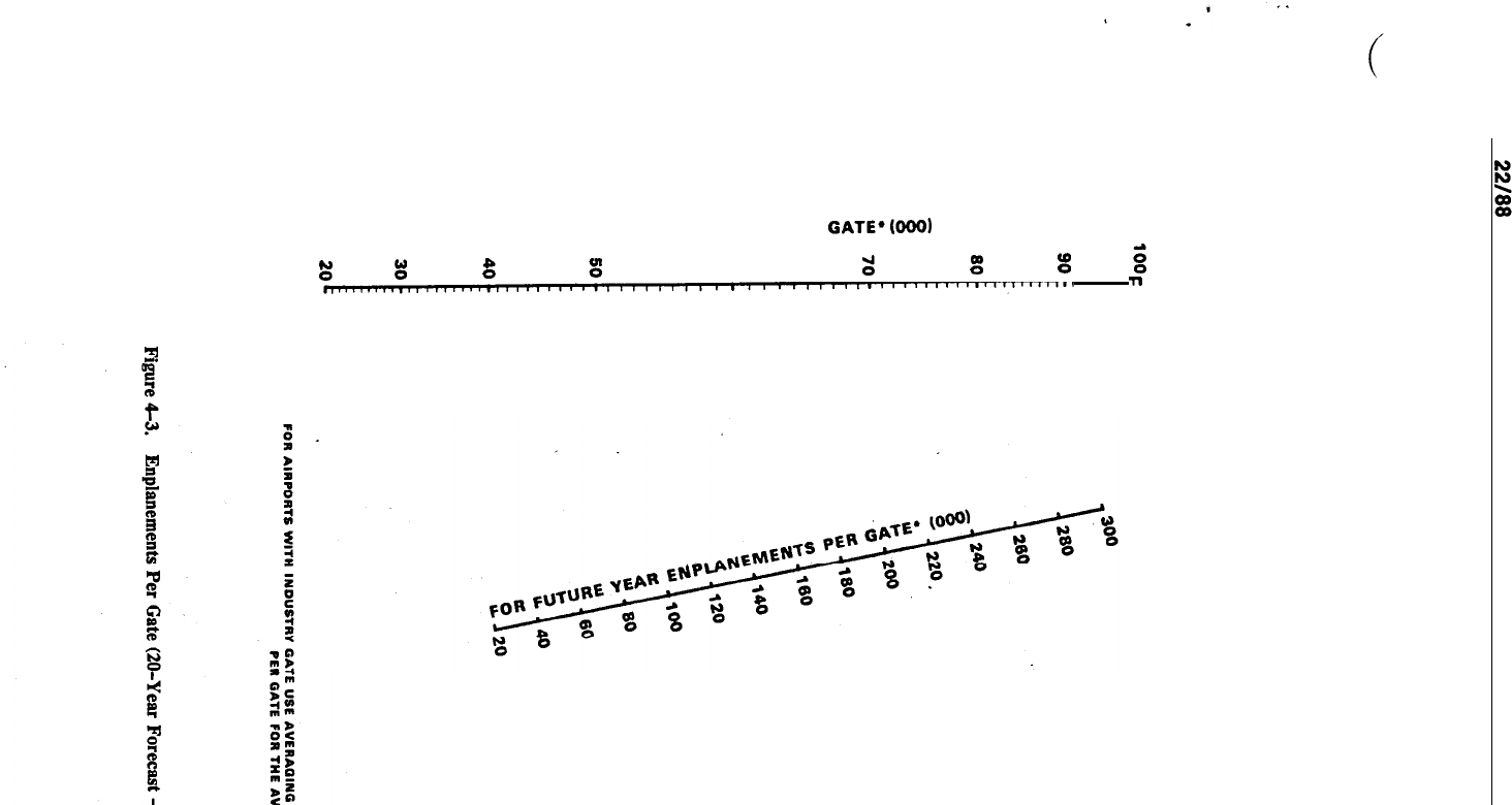
CURRENT (BASE YEAR) ANNUAL ENPLANEMENTS PER
GATE*@GO)
FOR U.S. DOMESTIC SCHEDULED OPERATIONS
r:
g
g
g
8
;:
g
:
n.1111111.111111~~~~~~~~~~~~~~~~~~~~~~~~~~~~~~~~~~“11”““1””’1””
ll
I’
~~~*~~*~~**ao*a~
d
N
0
1p
in
P
ill
b
in
P
P
PPO
0
0
ol
omo
ANNUAL ENPLANEMENTS FOR
20-YEAR
FORECAST +
CURRENT
YEAR
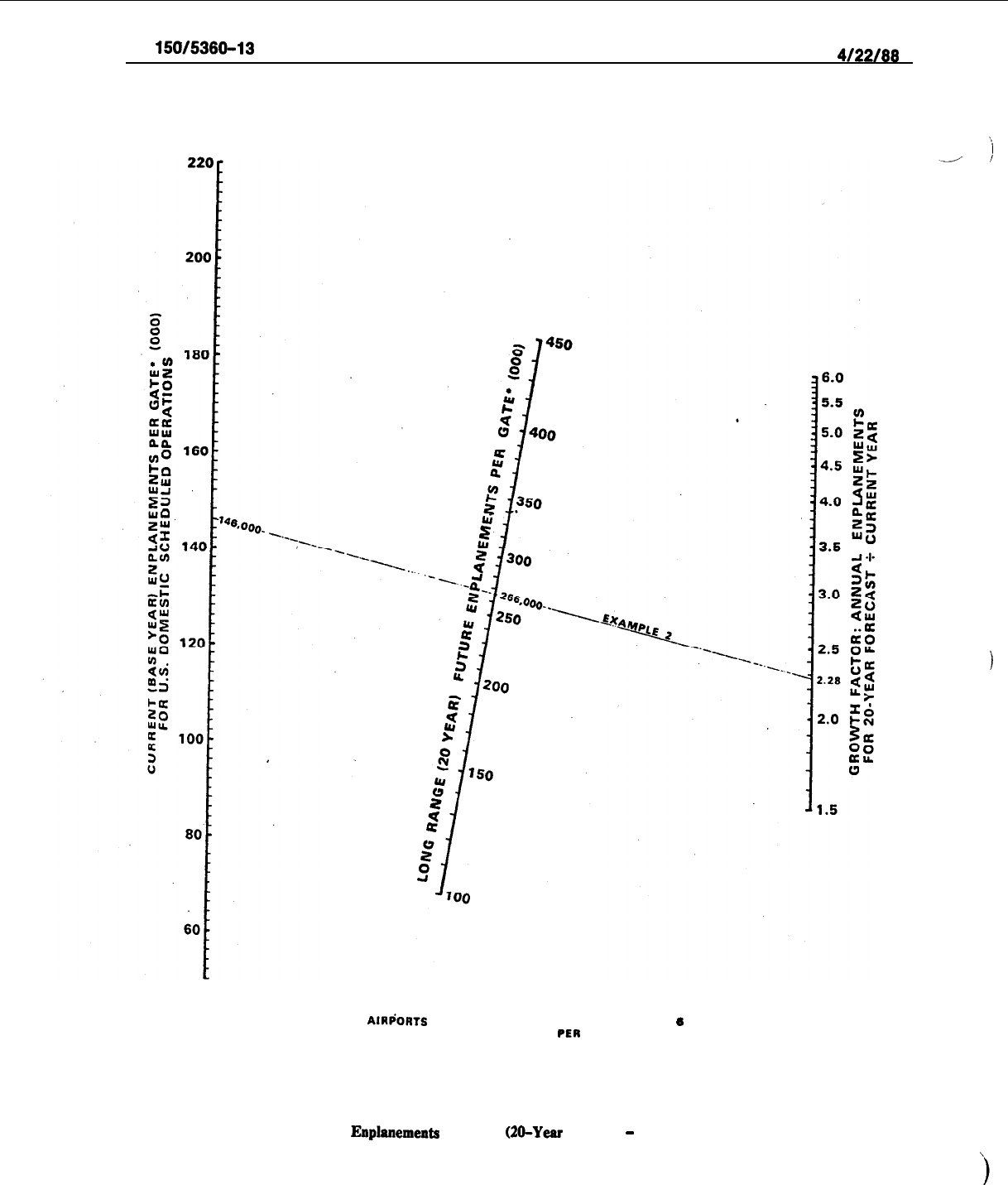
AC
160/5360-13
4/22/68
FOR
AIRfiORTS
WITH INDUSTRY GATE USE AVERAGING
6
OR MORE DAILY OEPARTURES
PER
GATE FOR THE AVERAGE DAY OF PEAK MONTH
‘ACTIVE POSITION
Figure 4-4.
Enplanements
Per Gate
(20-Year
Forecast
-
High Utilization)
34
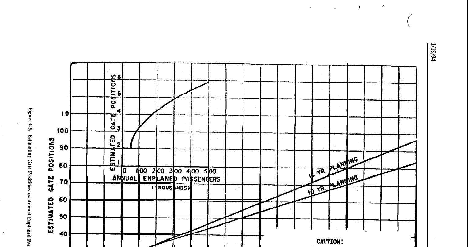
I
I(
I
’
NOT TO BE USED
fQR
DES
1,
FOR USE
IN
OBTAINIffi
ORDER4'44AGNIfU)E
3c
za
IO
a
EN
OR ANALYSIS.
-
ESTIMATES PRIOR TO IN-DEPTH ANALYSIS.
I
I
I
I
1
I I
I
0
I
2
3
4
5
6
7
8
4
9
IO
II
I2
I3
I4
IS
I6
It
I8
I9
20
ANNUAL
ENPLANEO
PASSENGERS
(MILL’IONSI
AC
150/5360-13
CHG 1
l/19/94
d.
Aircraft Extremity to Building Clearances. A 20 feet (6 m) value is satisfactory, except that 45 feet
\
(14 m) should be provided for inboard pier gates.
d/J
e. Gate Sizing. At very high activity airports, airlines will often segregate gates by assigning their use
to one or several aircraft types. This permits the airline to design the gate position and provide appropriate
service equipment to meet the needs of
specific
aircraft. At the less active airports, such segregation is often
impractical and the gates serve a variety of aircraft types. In sizing a gate position, the planner/designer should
first ascertain the anticipated type(s) of aircraft which will use the gate and the docking procedure to be used.
Gates serving a variety of aircraft, should be designed for the largest expected aircraft. Taxi-in,
push-out/power-out gates are generally the easiest to size, since the critical dimensions are limited to air- craft
length, wingspan, and appropriate clearances. In designing a taxi-out gate, such additional factors as aircraft
maneuverability (turning radii), jet blast, and parking angle require consideration.
f.
Gate Position Layout. Figures4-6 through 4-12 illustrate some typical gate position layouts. Airplane
characteristics manuals published by aircraft manufacturers should be consulted to determine the precise
aircraft turning radii associated with taxi-out gate positions.
46.
I
TAXILANES.
Taxilnnesarc used on aprons by aircraft taxiingbetween
taxiways
and gate positions. The
required taxilaneobject free area
(QFA)
widths (refer to AC
150/5300-13)
and provision of dedicated
rights-
of-way for apron service
vchiclc
roads affect the minimum spacing between parked aircraft and between pier
fingers. Both single and dual taxilanes are used between pier fingers, depending on the pier lengths and
number of aircraft positions.
When a dual
taxilane
is under consideration, the frequency of use by each
aircraft type, as well as the number of aircraft parking positions on each side, should be considered. As a rule,
a row of four aircraft on each side will not require a dual taxilane. For larger arrangements, a detailed
I
analysis of aircraft movements and traffic delays may bc necessary. Figure 4-13 provides dimensioning
information on pier separation with
single
and dual taxilancs. Figure
A9-4
in AC
150/5300-13
illustrates apron
taxilane
layouts with provision of dedicated space for service vehicle roads.
47.
APRON GRADIENTS. For fueling,
east
of towing, and taxiing, apron gradients should be kept to the
1
minimum, consistent with local drainage rcquircments. The slope should not exceed 1.0 percent and should
be directed away from the face of the terminal. Refer to AC
150/5300-13
for further guidance.
48.
AIRCRAFT PARKING GUIDANCE SYSTEMS. Aircraft parking guidance systems are usually a visual
aid to the pilot for final parking of aircraft in the gate position. These visual aids arc
tither
painted guidelines
on the apron or mechanical or light-emitting guidance
dcviccs
mounted at cockpit height on the facing
structure.
Systems using lights are becoming more popular.
Lights are used to inform the pilot of the
aircraft’s location with respect to the ccntcrlinc position desired and when to stop the aircraft at the desired
nose-to-building distance. Apron installed switching devices are occasionally required at the final nosewheel
location. Refer to AC 120-57, Surface Movcmcnt Guidance and Control System, and the related reading
material cited
therein
for additional guidance.
49. LOADING BRIDGES. At
very
low activity airports, pnsscngers usually board aircraft using integral
aircraft stairs or mobile passcngcr stairs. At more
active
airports, the use of passenger loading bridges is quite
common. Two
types
of loading bridges arc illustrated in Figure 4-14. They are used for boarding passengers
from an upper level and have many possible design variations. At some airports, loading bridges are employed
to load passengers from grade level by constructing a stairway or ramp connection at the loading bridge
entrance. Some characteristics of loading
bridges
which influence terminal design are discussed as follows:
a. The primary constraint in considering passenger boarding now rates normally is one of three
elements: the entrance doorway to the loading
bridge;
the aircraft door; or the aircraft aisle width. If stairs
are used at the loading bridge cntrancc, a fourth constraint is added. The width of the loading bridge usually
is not a constraining factor.
36
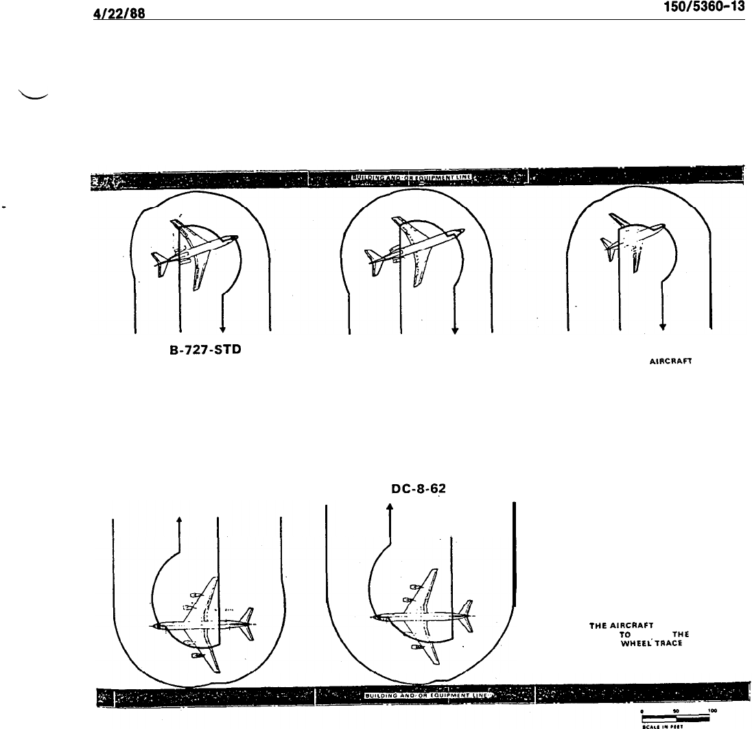
4J22JBB
AC
150/5360-13
B-727~STD
b-727-200
B-737-200
AND OTHER
GROUP
A
AlRCRAn
DC-8-STD
DC-8-6s
t
I
NOTE:
FOR PUSH-OUT OPERATIONS
THE AiRCRAFT CAN SE MADE
TO
FOLLOW THE SAME
NOSE
WHEEiTRACE
AS FOR
THE POWER-IN OPERATIONS
Figure 4-6.
Aircraft Maneuvering Area Taxi-Out Configuration
37
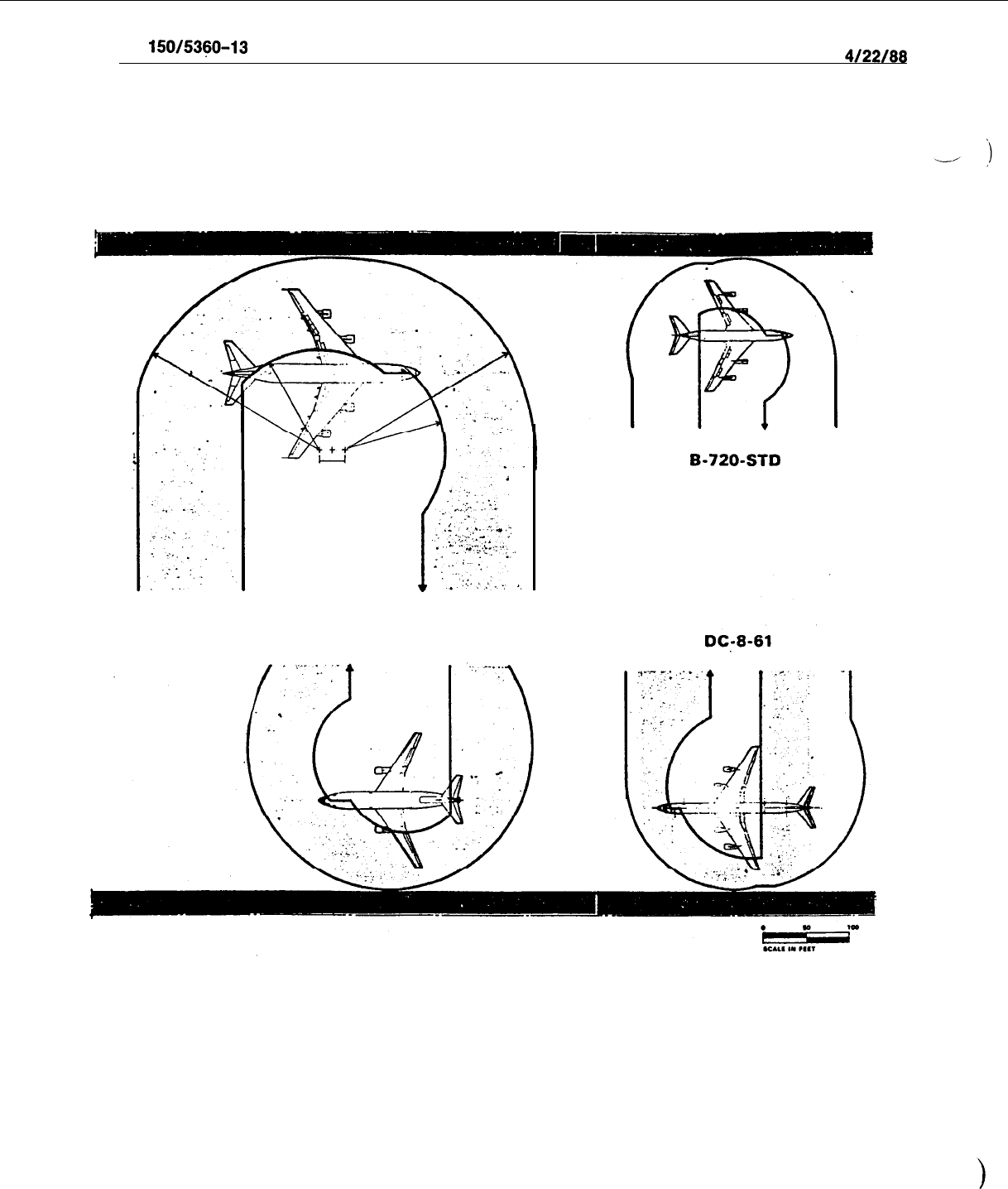
AC
150/53~0-13
4/22/68
.I
::
^,
+.,-
.
w
:
_
r
..:
.
._
:
*
y
.
.
;;::.
.
. .
.
.
.
.,
.
.
.
.+..:
.I
_.
-:.:
_
.i
.,
.
:.
:..
,,
747
DC-10
B-720-STD
Figure 4-7.
Aircraft Maneuvering Area Taxi-Out Configuration
38
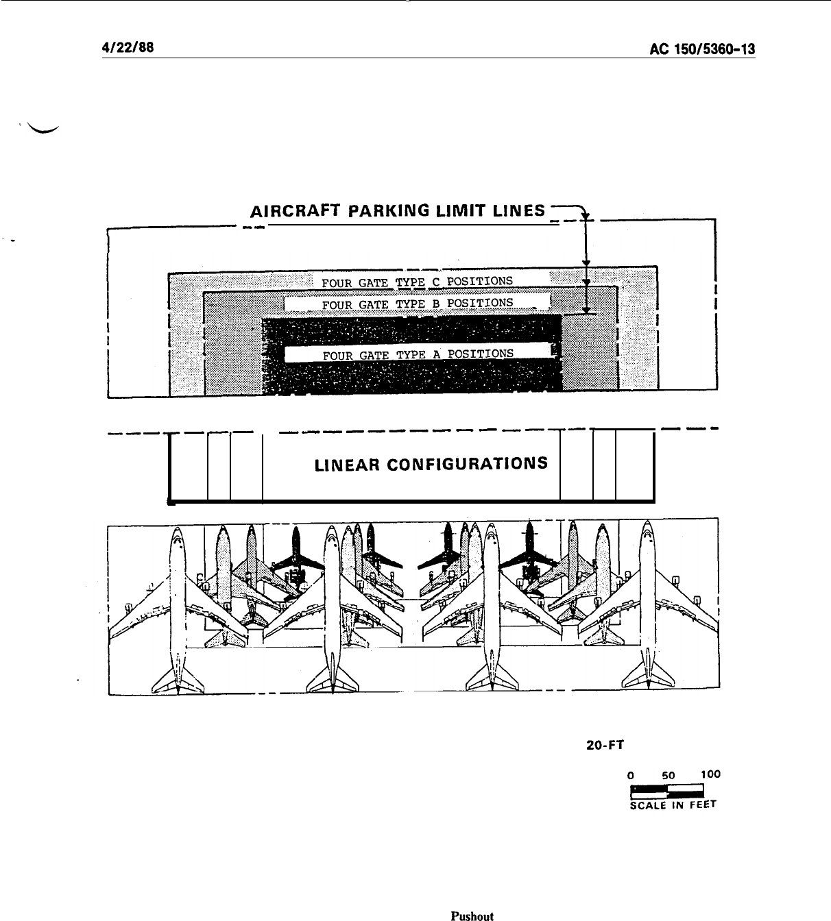
-
4/22/W
AC150/5360-13
AIRCRAFT
PARKING LIMIT LINES
7
--
FOUR GATE TYPE D POSITIONS
--d-cB-B
-e----B---
-m---
--a
LINEAR
CONFIGURATIONS
ALL WINGTIPS SHOW
20-FT
CLEARANCE
Figure 4-8.
Linear Configuration
Pushout
Gate Positioning
39
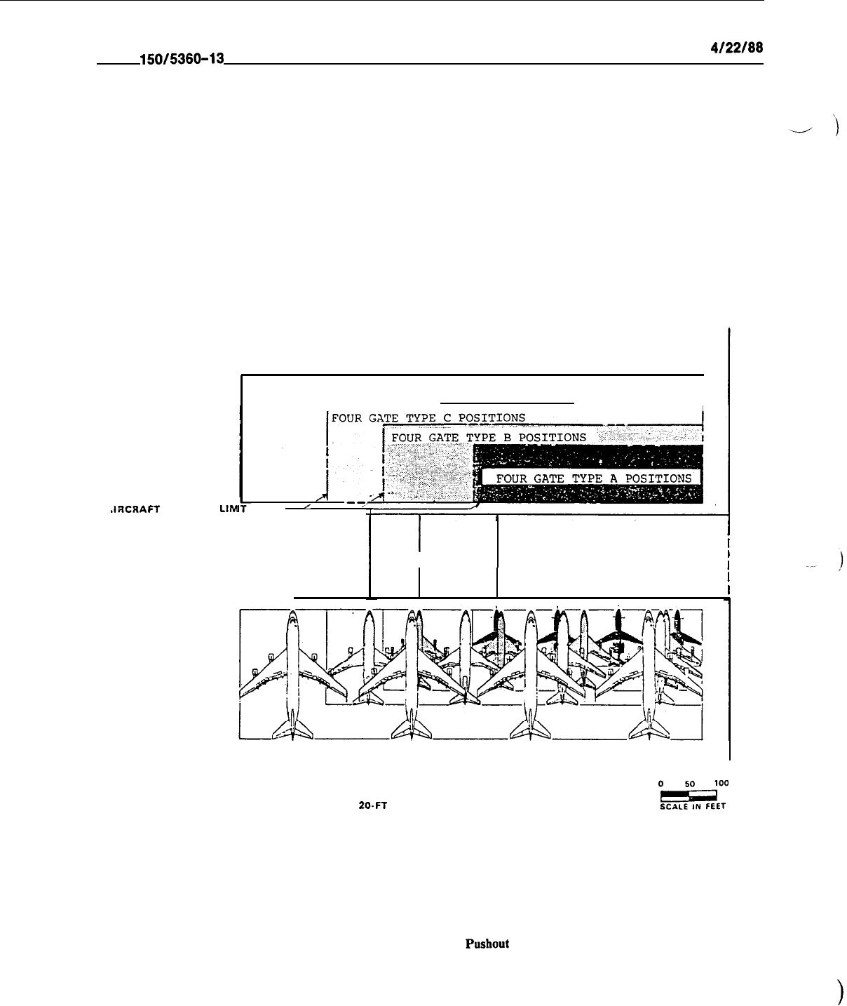
AC
150/5360-13
4122166
JRCRAFT
PARKING
LIM
FOUR GATE TYPE D POSITIONS
I--
---I
LINES
’
-7.
r
I
PIERS
ALL WINGTIPS SHOW
20.FT
CLEARANCES
Oar
Figure 4-9.
Pier Configuration Pushout Gate Positioning
40
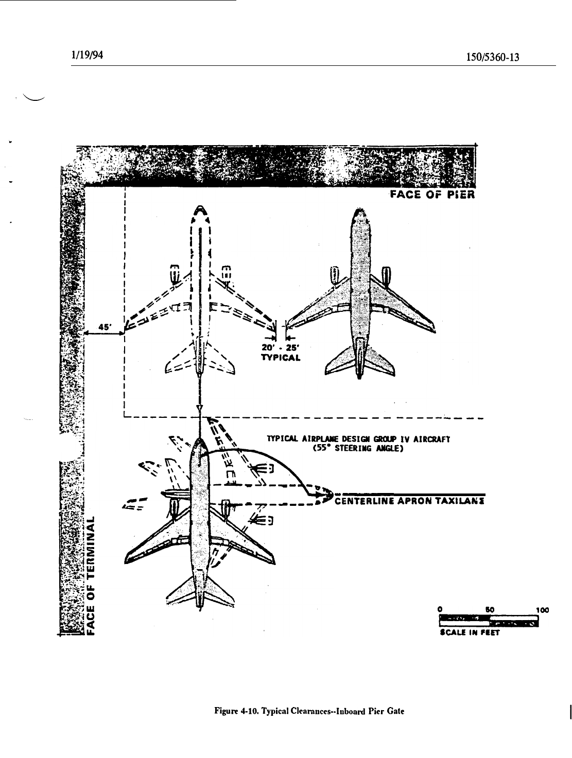
l/19/94
AC
150/5360-13
CHG 1
i
i
I
i
t
I
4
--------------------L--,
YPICM AIRPINIE
DESIGR
CROUP
IV
AIRCRAFT
(55’
STEERING
ARGLE)
SENTERLINE
APRON
TAXILANE
Od”
SCALR
IN
FRRY
Figure
4-10.
Typical
Cleamuces-Ahoard Pier
Gate
41
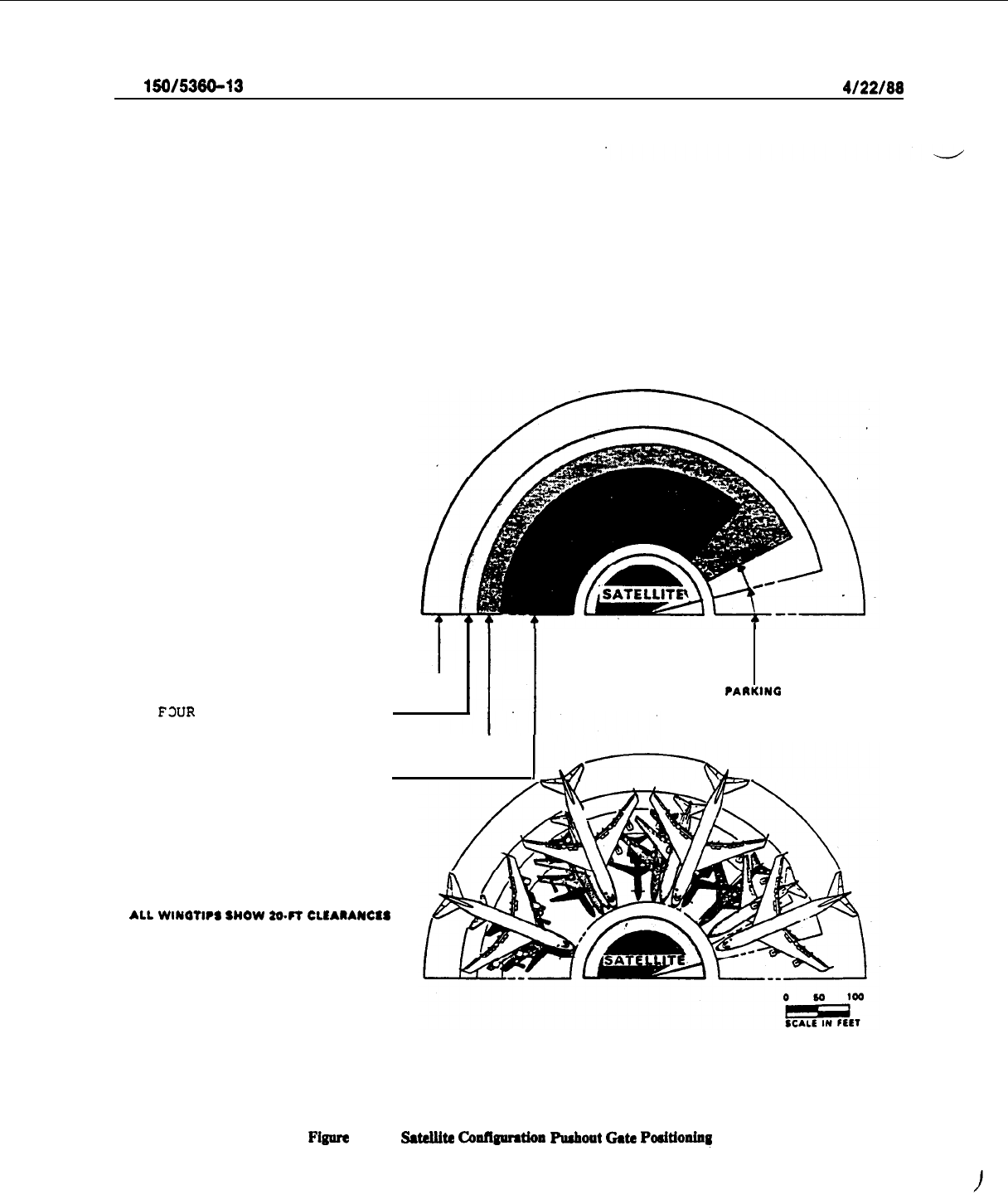
AC
150/5380-13
4/22/88
FOUR GATE TYPE D
POSITIONS-
FWR
GATE TYPE C POSITIONS
FOUR GATE TYPE B
POSITIONS-
FOUR GATE TYPE A POSITIONS
AIRCRAFT
?AAKINC
LIMIT LINES
ALL
WINQTWS
SNOW
M.FT CLLAIANClS
Fignre
4-11.
WeUite
c0nft~tio11
F’uahout
Gate
Positioninq
42
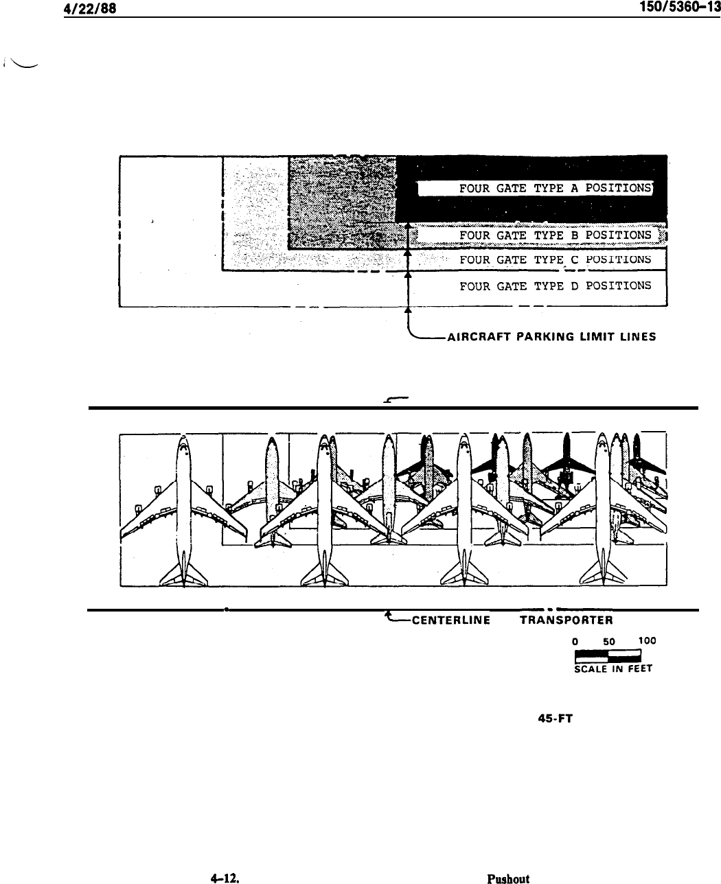
4/22/88
AC
150/5360-13
r
CENTERLINE OF TRANSPORTER ROAD
.
CCENTERLINE
OF
TRAiSPORTER
ROAD
ALL WINGTIPS HAVE 45-FT CLEARANCE
FORTRANSPORTER MANEUVERING
FOR SERVICE BUILDINGS
SEE CHAPTER 3, CONNECTOR ELEMENT
Figure
4-U.
Transporter Configuration Taxi-Through or
Pushout
Gate Positioning
43
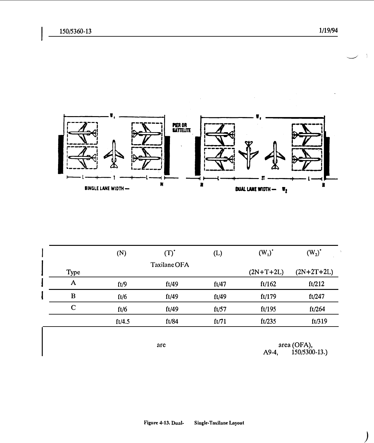
I
AC
150/5360-13
CHG 1
l/19/94
-1-1
-t----r
)I-
tlNGLELANEWlDlH-
I,
w
II
aluuJttwlml-
I*
N
I
Gate
Nose to Bldg.
Taxilnne
OFA Airplane
Type
Distance
Width
Length
(2N+T+2L)
(2N+2T+2L)
I
A
30
ftl9 m
162
ft/49 m
155
ft/47 m
532 ft/162 m
694
ft/212 m
1
B
20
ftf6
m
225
ft/49 m
160
ft/49
m
585
ft/179
m
810
ft/247
m
I
c
20
ft/6
m
225
ft/49 m
188
ft/57 m
641
ft/195 m
866
ft/264
m
I
D
15
fV4.5
m
276
ft/84 m 232
ft/71
m
770
ft/235
m 1.046
ftI319
m
l Note: Service vehicle roads on aprons are located outside of the tnxilaneobject free area (OFA), and must
be accounted for as a separate entity in determining W, or W,. (See Figure
A9-4,
AC
150/5300-13.)
Figum
4-13.
Dud-
vs.
Siugle-Taxilone
Layout
44
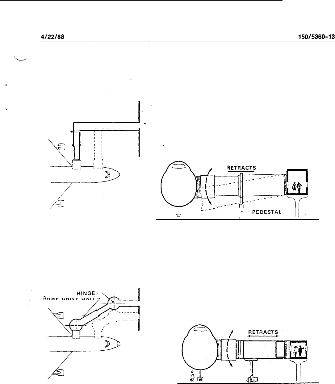
4/22/88
AC
150/5360-13
HINGE-
WALKWAY -
7-l
:
I
PLAN
PEDESTAL BRIDGE
AMP DRIVE UNIT
PLAN
APRON DRIVE BRIDGE
iETRACTS
Lo---
‘-1
+--PEDESTAL
I
SECTION
SECTION
Figure 4-14.
Typical Passenger Loading Bridges
45
AC
150/5360-13
CI-IG
1
l/19/94
b.
Aircraft door widths range from 32 inches
(&I
cm) to 42 inches (107 cm). Their rcspcctivc flow rates
are approximately 25 pnsscngcrs and 40 passengers per minute. A 36-inch (91 cm) entrance doorway
/
accommodates approximately 37 pnsscngcrs per minute.
c.
Since aircraft aisle width can influence the flow rate of a loading bridge. Airline studies indicate a
flow rate of 30 passengers per minute for a single-aisle aircraft.
d.
A stairway at the loadingbridgc entrance reduces flow rates to approximately 20-25
passengers
per
minute, the same rate achicvcd when integral aircraft or
mobile
stairs arc employed. A stairway or ramp not
constructed within the terminal building should bc provided with an cnclosurc for weather protection.
I
e.
The maximum ramp gradient to comply with Americans with Disabilities Act (ADA) requirements
is
1:20.
f.
The length and type of loading bridge
(fixed
pcdcstal, apron
drive,
or suspcndcd) arc functions of
a number of variables. Thcsc include apron dimensions, airline docking procedures, wingspan, door locations,
fixed aircraft services, adjacent aircraft positions, and economics. For instance, an apron drive bridge, when
in a stowed position, will allow a taxi-out operation,
while
pcdcstal or suspcndcd
types
are limited to
push-
out operations. A determination on which bridge
design
to apply in
each
cast
should bc
based
on the specific
characteristics of the aircraft mix as well as airline opcrnting requirements.
g. Two loading bridges for larger
type
aircraft are
used
at some airports to facilitate loading and
deplaning. In most cases, however, one bridge is adequate. The decision to USC more than one bridge should
take into account the average peak-hour “boarding” load factor by type of aircraft at each aircraft position.
At through stations, it is very likely that the boarding load factor will bc low enough that only one bridge will
be required for a B-747 position.
4
h.
Figure 4-15 depicts various aircraft sill heights and door locations. The positioning of an individual
aircraft is, to a great extent, a product of its door alignment with doors of other aircraft types. This facilitates
the utilization of one type of loading
bridge
to
scrvc
a variety of aircraft.
Howcvcr,
this is not the only
consideration to be met in determining the interchangcabilityof a series of aircraft parked on one apron area.
Normally, an apron area will be rcstrictcd for various reasons to a limited number of usually similar aircraft
types. This greatly
simplifies
loading-bridge mancuvcring requirements, as
well
as the positioning of fixed
utilities.
i. Designers should be aware of the National Fire Protection Association (NFPA) criterion (refer to
paragraph 2-2.6 of NFPA 417, Standard on Construction and Protection of Aircraft Loading Walkways) which
stipulates that any door in the
egress
path through the loading walkway to the terminal building swing in the
direction of egress from the aircraft towards the terminal building and be cquippcd with panic hardware on
the aircraft side.
50.
TRANSPORTERS.
a. Transporters arc used at some airports to carry passcngcrs between the terminal building and
remotely parked aircraft. A nonelevating transporter may simply be a bus or similar vehicle, possibly modified
for airport use.
A stair boarding device is required to complement its operation for passcngcr boarding, crew
access, cabin service
access,
and emergency egress. This type of vehicle is generally more appropriate for use
on an interim basis or to supplement gate loading during
very
heavy
peak periods. Elevating transporters are
designed to mate with the terminal dock and aircraft for loading and unloading passengers. One type of
elevating transporter uses an clcvating gangplank with a 6 to 10 foot (1.8 to 3 m) extension which adjusts to
various aircraft sill heights. This
type
gcncrally has a capacity of 50-80 pnsscngcrs. Another type uses an
elevating passcngcr compnrtmcnt or pod and a loading bridge-type coupling to ensure compatibility with
practically all aircraft currently used by nirlincs. This vchiclc gcncrally has a capacity of S5 to 120 passengers.
)
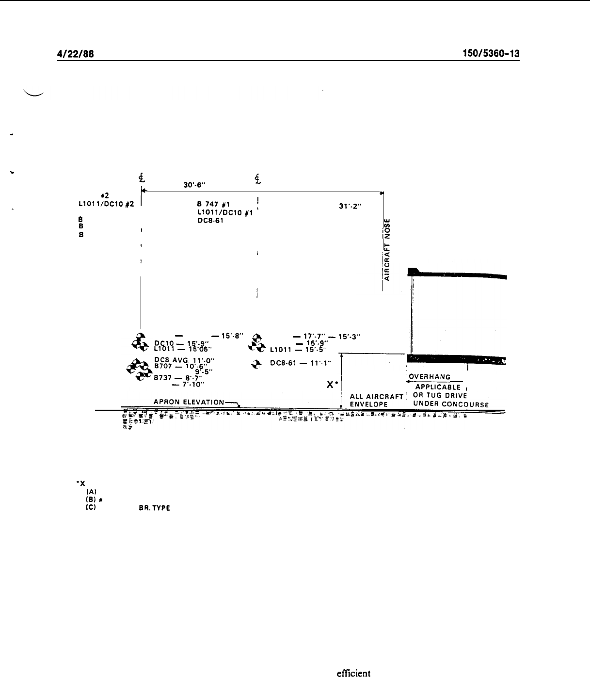
4122188
AC
150/5360-13
w
DOOR
4.
30’~6”
DOOR
4.
VARIES
0747
u2
LlOl
l/DC10
#2
DISTANCE RANGE 14’.5” TO
’
_
DC0 AVG.
B747#1
j
31’.2”
B
707 AVG.
I
Ll011/DC10
fl
B
737
DC%61
:
I
B
727
2
oc-9
!
I
I
t
I
I
DOOR SILL HEIGHT
0747
-
17’.2”
-
15’.8”
p,qJ;“l
=
y&y;.*
@
0747
-
17’-7”
-
15’.3”
6?
DC-10
-
15’s9”
LlOll
-
15’.5”
p7Av~.
11*-o**
-
,0’.6”
B727 AVG.
9’.5”
a
DC&61
-
ll’.,”
0737
-
8..7”
DC9
-
7’.10”
X’
PVERHANC
AS,
LIMIT LINE- APPLICABLE
‘X
AVERAGE FLOOR. HEIGHT DEPENDS ON:
IA) A/C TYPES
IB)
*
DOOR SERVE
ICI LOADING
BRTYPE
USED
Figure
4-15.
Aircraft Sill Heights
b.
The number of transporters and docks required can be determined by developing and analyzing an
aircraft flight-line scheduling plan and determining transporter cycle times for peak periods. The flight line
scheduling plan includes arrival and departure times and ground time for each aircraft during peak periods
for the projected design year. Transporter cycle time is defined as the time for the transporter to complete a
cycle from dock to aircraft to dock. It is dependent on transporter average speed (generally from 8 to 15
miles per hour), the travel distance between terminal and the aircraft parking area, and vehicle maneuver-
ability and docking procedures. Cycle time also depends on the
efficient
organization of the transporter op-
eration. For instance, a transporter which has completed enplaning one flight at the flight line can position
for an arriving flight without returning to the dock. Thus, the normal cycle has been interrupted, a new
cycle established, time saved, and a more efficient operation promoted. Such interrupted cycle times are
accountable in determining transporter requirements. Consideration for peaks within peaks is also required if
47
AC
150/5360-13
CHG 1
l/19/94
unacceptable de’lays arc to be avoided. For
example,
50 percent of a peak hour’s traffic volume may occur
in 15 or 20 minutes, thereby overloading the system. Figure 4-16 provides a nomograph for estimating
-d
transporter requirements. The nomograph can be
used
in the early
stages
of planning to determine general
requirements. Design requirements will necessitate the more precise analysis discussed previously. At the
higher activity locations, simulation models may bc necessary to test future
schedules,
variations in trans-
porter runs, cycle times, and other alternatives.
51. FIXED UTILITIES. Figure 4-17
depicts
the most common
fixed
utilities located at aircraft parking
positions; namely, fueling and power systems. Optimum locations are shown for most aircraft in the U.S. air
carrier fleet. Descriptions and
uses
of several of the more common fixed utilities are as follows:
a.
Fueling. The advantages of underground fueling systems are the reduction in the amount and size
of ground equipment and corresponding decrease in ramp congestion with large numbers of aircraft during
the design hour.
Primarily, a shift from fuel trucks to an underground system is justified on a cost versus
volume basis. A further development of a pure underground system for each aircraft position is a common
hydrant fueling point in proximity to several aircraft. In such a system, hydrant fueling trucks are used instead
of large-capacity tankers. In both cases, however, trucks are required. With underground fueling, fuel is
pumped from a central tank farm to a pit. The hydrant truck then connects a hose to the pit and into the
aircraft.
The maximum allowable fuel-truck hose lengths vary between 30 and 50 feet (9 and 15 m).
AC
150/5320-4,
Aircraft Fuel
Storage,
Handling, and Dispensing, provides additional relevant guidance.
I>.
Water. The
lied
water supply at each gate position is usually an easily ndaptcd
fixed
utility. Most
existing terminal configurations, whcrc aircraft park next to the building structure, arc already supplied with
potable water. Provided that capacitiesarc adequate, this supply may be tapped and linked to the aircraft with
a hose-reel cart.
c. Ground Power. Providing a fixed ground power unit for
cnch
gate position may be desirable.
Recently, the approach has been simply to provide a ground power source with the loading bridge (apron-
drive or fixed pedestal). This eliminates additional ramp congestion (cables, etc.) or more costly under-
ground installations.
Power
requirements for each aircraft position vary and should be justified on an
individual airline basis.
d.
Air Start. Pressurized air is required for aircraft without an auxiliary power unit
(API-J).
Although
it is the
least
commonly available
fixed
utility, it can be permanently installed in a manner similar to other
utility systems. In actual practice however, truck-mounted units are by far the most commonly used to provide
this service. The air requirements for various aircraft range from 120 to 270
lb/mitt.
(54.5 to 122.7
kg/min)
at 40 psi (275.8
kPa).
I
e.
Air Conditiming. An option exists for airlines to elect to introduce
fixed
air-conditioning units on
the apron. However, APU-supplied air conditioning and centrally furnished low pressure preconditioned air
are most commonly used.
I
52. APRON AREA LIGHTING. Most outdoor areas associated with the’ apron require some degree of
illumination. Table 4-l presents criteria for lighting in foot-candles
(lux
(lx)) for apron/apron related areas.
Lighting levels should be of sufficient intensity to allow observation of
a11
pedestrian activity. Mounted
floodlights are the usual preferred method of lighting the apron area. They are typically mounted at a height
of 25 to 50 feet (8 to 15 m) with a maximum spacing of 200 feet (60 m). Floodlight location requires
coordination with the specific type(s) of aircraft using the parking position. Floodlights should be aimed and
shielded to avoid glare to pilots and air traffic controllers without reducing the required illumination in critical
areas.
,’
48
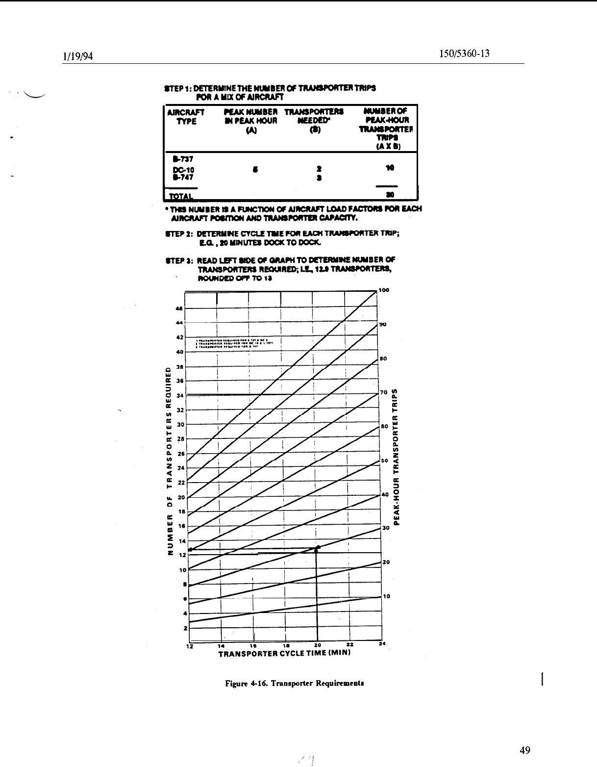
l/l
9194
AC
150/5360-13
CIIG 1
8TEP
1:
DETERMlNE
THE
WBER
OF
B
fl#PS
PoaAutx#AlncMPT
AmcnAFf
PEAKNUMBEll
TRAMSPOWER
UWIER
OP
TYPE
NPEAKHOUR
WEDnr
w
t.1
t6
(AXII)
,727
11
1
11
DGlO
6
l6
8-747
6
f
a
Figure
4-16.
Transporter
Rcquircmcntr
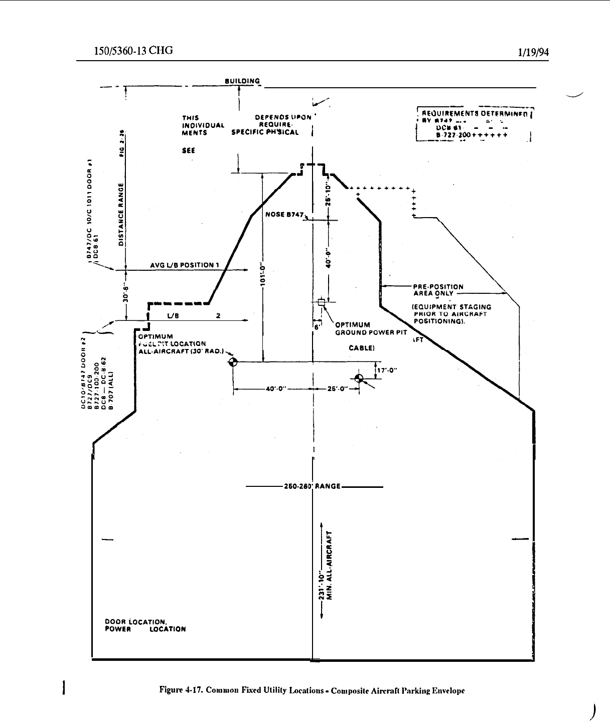
AC
150/5360-13
CHG 1
l/19/94
TERMINAL
lUlLDING
LINE
---‘-7--
I
I
d.,
ALL-AIRCRAFT CENTERLINE
-
--
-------‘7
THIS
DIMENSION
OEPCNOS
UPJN
’
’
REOUIREMLNTS
OCtFRhrlN~~
1
INOIVIOUAL
AIRLINE
REOUIWL.
;
IV
**4*
-.-
ii’
i
I
MENTS
AN0
SptiClFlC
PHV
SICAL
(
uc*ol~
-
-
.-
CONSTRAINTS
L
6.721.200++++++
--.--
.-
.
.-
.
.I
2
SEE FIGURE 2.1 DIMENSION- ‘0
*
PRE.POSITION
m-11-m
1
AVG
L/B
POSITION 2
LOCATION ALL-AIRCRA
(30’ CABLE1
FUEL PIT FOR 8727
THIS SIDE ONLY
260.26t
-
ALL-AIRCRAFTPARKING ENVELOPE
NOTE.
FINAL AIRCRAFT POSITION IS
A RESULT OF FUELING POINTS.
DOOR
iOCATION.
AND GROUNO
POWER
PIT
~0cAnoN
IANGE
1:
R
i
I
I
t
d
ALL-AIRCRAFT PARKING ENVELOPE
-
0
E
-?
b,
5
z*
zr
I
50
Figure
4-17.
COIUUIOU
Fiicd Utilily
Locations
-
Coulpositc
Airwd~ I’arkiag
Ihdopc
4/22/88
AC
150/5380-13
Table 4-l.
General Lighting Requirements
Area
Fences, gates, guard-shelters, building exteriors, apron
areas, associated equipment parking areas, building
entrances, and exits.
Foot-candles (LX)
*
5.0 (54.0)
Pedestrian entrances to aircraft operations area
l
2.0 (22.0) max.
General aircraft operations area
l
Dock Areas
0.15 (1.6)
10.0 (108.0)
Roadways 1.5 (16.0)
1
FAA AC 107-1, Aviation Security-Airports.
*
Measured at most remove points of areas involved,
+200
ft (60 m) 36 inches (91 cm)
above ground; light target perpendicular to the direction of the light rays.
53. BLAST FENCES. Passenger and aircraft servicing facilities ground equipment should be located in
areas not affected by aircraft engine blast. Blast fences are often used on terminal aprons to protect ground
equipment, personnel, buildings, or other .aircraft from aircraft blast, particularly when aircraft taxi to and
from gate parking positions. They may also be used in push-out/power-out contigurations where blast is a
potential problem. The positioning of blast fences depends on aircraft or ground-equipment maneuvering
patterns, while their size depends on the extent of blast requiring control. Chapter 6 of AC
150/5300-12
discusses aircraft jet blast and the design and location of blast fences.
54.
-
65. RESERVED.
51
(and
52)

4122188
AC
150/5380-13
CHAPTER 5. TERMINAL BUILDING SPACE AND FACILITY GUIDELINES
’
66. GENERAL. This chapter provides guidance on spatial requirements for functions carried out in an
airport terminal building. The guidance is indicative of the design range in use at U.S. airports to accommo-
date domestic scheduled passenger operations. Adjustments may be necessary for international, charter, non-
scheduled, or third level operations. Airport terminals should be designed for a capacity to meet the project-
ed needs of the community being served. This guidance should only be applied after consultation with the
airlines, FAA, other users, and tenants. Modifications to the guidance may be warranted after such
discussions.
67.
GROSS TERMINAL BUILDING AREA ESTIMATES.
L
a.
Gross Terminal Area Per Gate.
The relationship between annual
enplaned
passengers and gross
ter-
minal area per gate for a IO-year and 20-year forecast is approximated in Figures 5-l and 5-2, respectively.
The profile of the curves is based on predicted growth in seats per aircraft for each forecast period; specifi-
cally, the growth in predicted aircraft mix during the peak hour of the average day of the peak month of
the design year. With a 10 or 20 year forecast of annual enplanements and an approximate required number
of gates determined by the procedures discussed in paragraphs 25 through 27, an approximation of gross
terminal area can be made.
b.
Rule-of-Thumb.
A rule-of-thumb of about 150 square feet (14
m”)
of gross terminal building area
per design peak-hour passenger is sometimes used for rough estimating purposes Another rule using 0.08 to
0.12 square feet (0.007 to 0.011
m’)
per annual enplanement at airports with over 250,000 annual
enplane-
ments can similarly be applied. At small airports with less than 250,000 enplanements, estimates should be
based on peak hour considerations and simple sketches (see AC
150/5360-g).
68.
SPACE ALLOCATIONS.
The terminal building area is comprised of both usable and unusable space.
Unusable space involves those areas required for building columns and exterior and interior walls, about 5
percent of the total gross area. The usable space can be classified into the two broad categories of rentable
and nonrentable space. Usually, 50 to 55 percent is allocated to rentable space and 45 to 50 percent to
non-
rentable space. Figure 5-3 presents a further breakdown of these basic categories.
69.
PUBLIC LOBBY AREAS.
Lobbies provide public circulation and access for carrying out the follow-
ing functions: passenger ticketing; passenger and visitor waiting; housing concession areas and other passen-
ger services; and baggage claim.
a. Ticketing Lobby.
.
(1)
As the initial objective of most passengers, the ticketing lobby should be arranged so that the
enplaning passenger has immediate access and clear visibility to the individual airline ticket counters upon
entering the building. Circulation patterns should allow the option of bypassing counters with minimum in-
terference. Provisions for seating should be minimal to avoid congestion and encourage passengers to pro-
ceed to the gate area.
(2)
Ticket lobby sizing is a function of total length of airline counter frontage; queuing space in
front of counters; and, additional space for lateral circulation to facilitate passenger movements. Queuing
space requires a minimum of 12 to 15 feet (4 to 5 m). Lobby depths in front of the ticket counter range from
20 to 30 feet
(12
to 15 m) for a ticket area serving 50 gates or more.
53
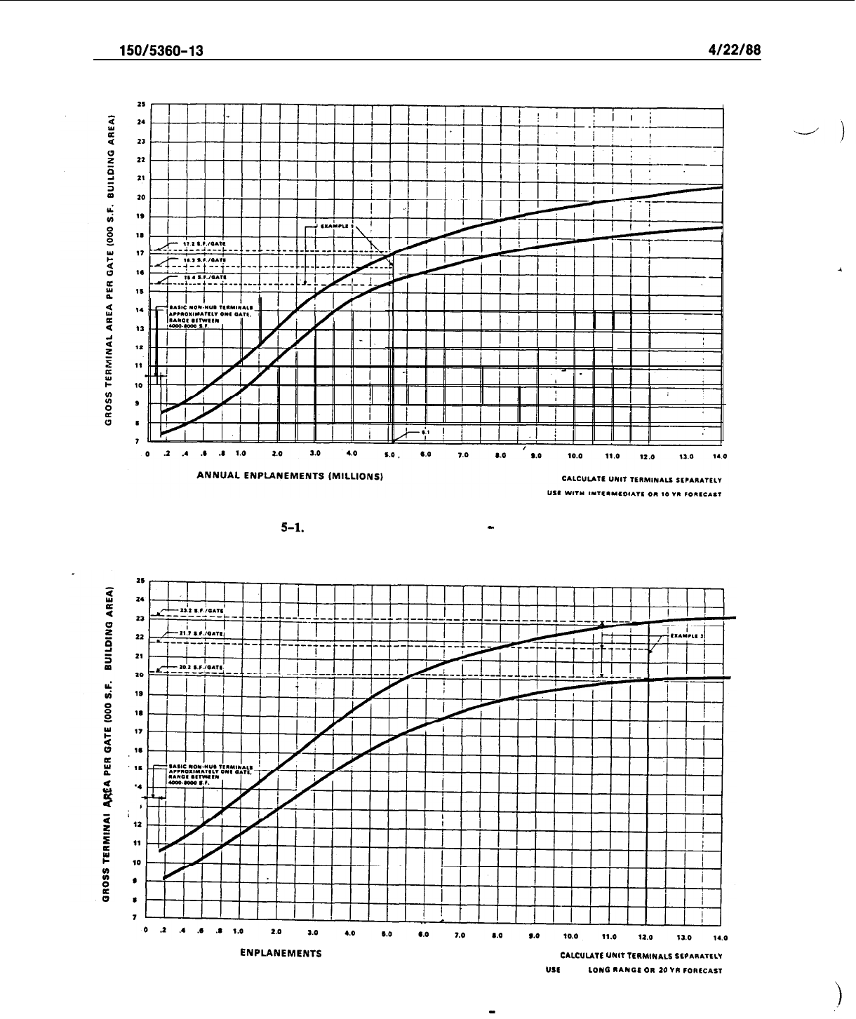
AC
150/5360-13
4/22/88
Figure
5-l.
Gross Terminal
Area
Per Gate
-
Intermediate Planning
ANNUAL
ENPLANEMENTS
(MILLIONS)
c*LCULATL
“Nlf
lLllM,NICI
SLP*I*TLLI
“II
WITH
LONG
RANGE
ON
10
IN
rGReCA,T
Figure 5-2.
Gross Terminal Area Per Gate
-
Long-Range Planning
54
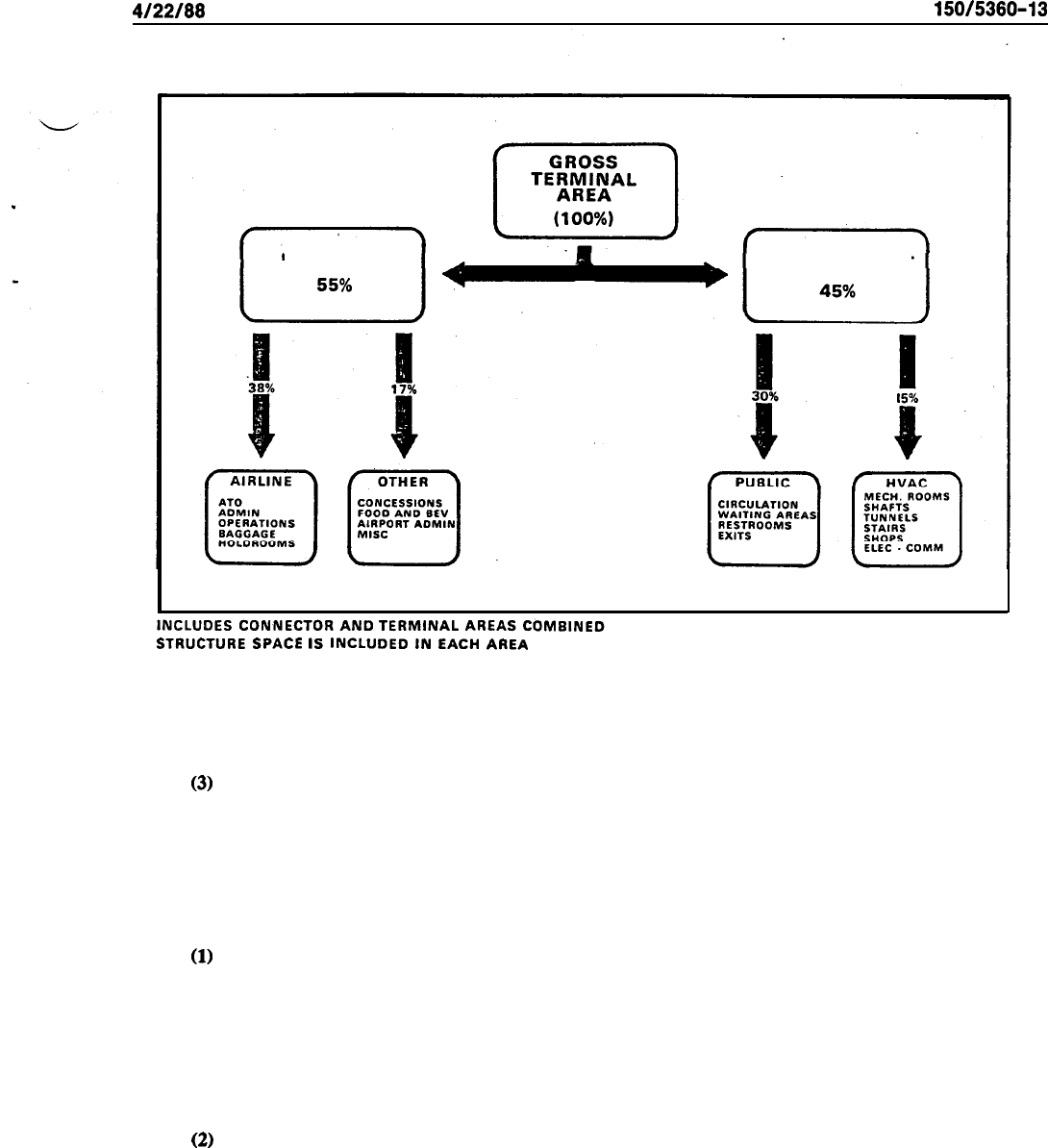
4122188
AC 150/5360-13
RENTABLE NON RENTABLE
STRUCTURE
SPACE
IS
INCLUDED
IN
EACH
AREA
Figure 5-3.
Gross Terminal Area Space Distribution
(3)
Figure 5-4 contains a nomograph for approximating ticket lobby area for initial planning pur-
poses. This nomograph includes the ticket counter and area behind the ticket counter as part of the lobby
area. It is necessary to subtract the counter area when estimating only the public lobby area used for passen-
ger queuing and circulation. Inventories at some existing large hubs indicate that additional area to that
shown in the figure should be provided at the extreme ends of the ticket counters for additional circulation.
b. Waiting Lobby.
(1)
Apart from providing for passenger and visitor circulation, a centralized waiting area usually
provides public seating and access to passenger amenities, including rest rooms, retail shops, food service,
etc. The sizing of a central waiting lobby is influenced by the number, seating capacity, and location of
individual gate waiting areas. If all gate areas have seating, the central waiting lobby may be sized to seat 15
to 25 percent of the design peak hour enplaning passengers plus visitors. However, if no gate seating areas
are provided or planned, seating for 60 to 70 percent of design peak hour enplanements plus visitors should
be provided.
(2)
Visitor-passenger ratios are best determined by means of local surveys. In the absence of such
data, an assumption of one visitor per peak hour originating passenger is reasonable for planning purposes.
55
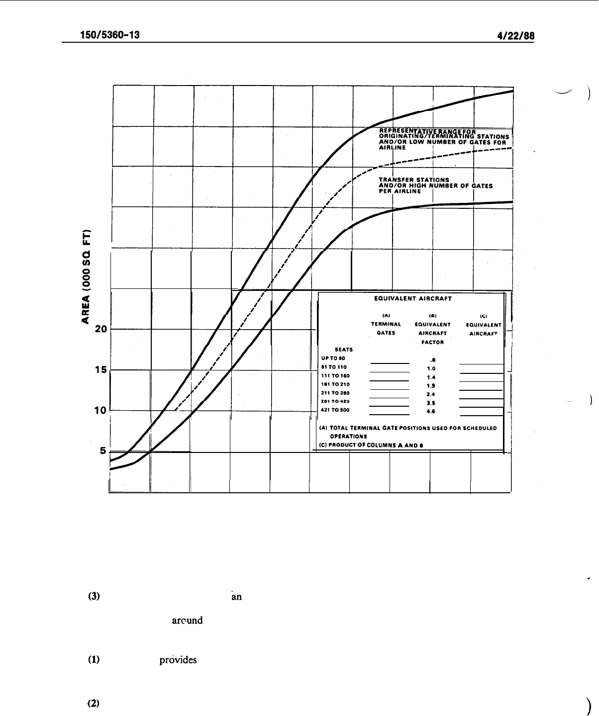
AC 150/5360-13
4122188
50
45
40
35
30
25
TATIVE
RANGE
FOR
.(I
1.0
I..
t.9
2.4
3.1
4,s
IA,
TOTAL TERMINAL
GATE
POSITIONS USED
FOR
SC”ED”LE0
OPERATIONS
ICI
PRODUCT
OF
COLUMNS
A
AND
I
0
10
20 30 40 60
60 70 80 90
100
EQUIVALENT AIRCRAFT (GATES X EQUIVALENT AIRCRAFT FACTOR)
Figure 5-4.
Ticket Lobby and Counter Area
,
(3)
Figure 5-5 may be used as
in
approximation for converting seating requirements to lobby area.
The area obtained from this nomograph provides for circulation around two sides of seating. Additional area
is required for circulation around three sides.
c. Baggage Claim Lobby.
(1)
This lobby
p&ides
public circulation space for access to baggage claim facilities and for egress
from the claim area to the deplaning curb and ground transportation. It also furnishes space for such passen-
ger amenities and services as car rental counters, telephones, rest rooms, limousine service, etc.
(2)
Space required for the baggage claim facility is discussed in paragraph 75. Allowance for public
circulation and passenger amenities outside the claim area ranges from 15 to 20 feet (5 to 6 m) in depth at
>
56
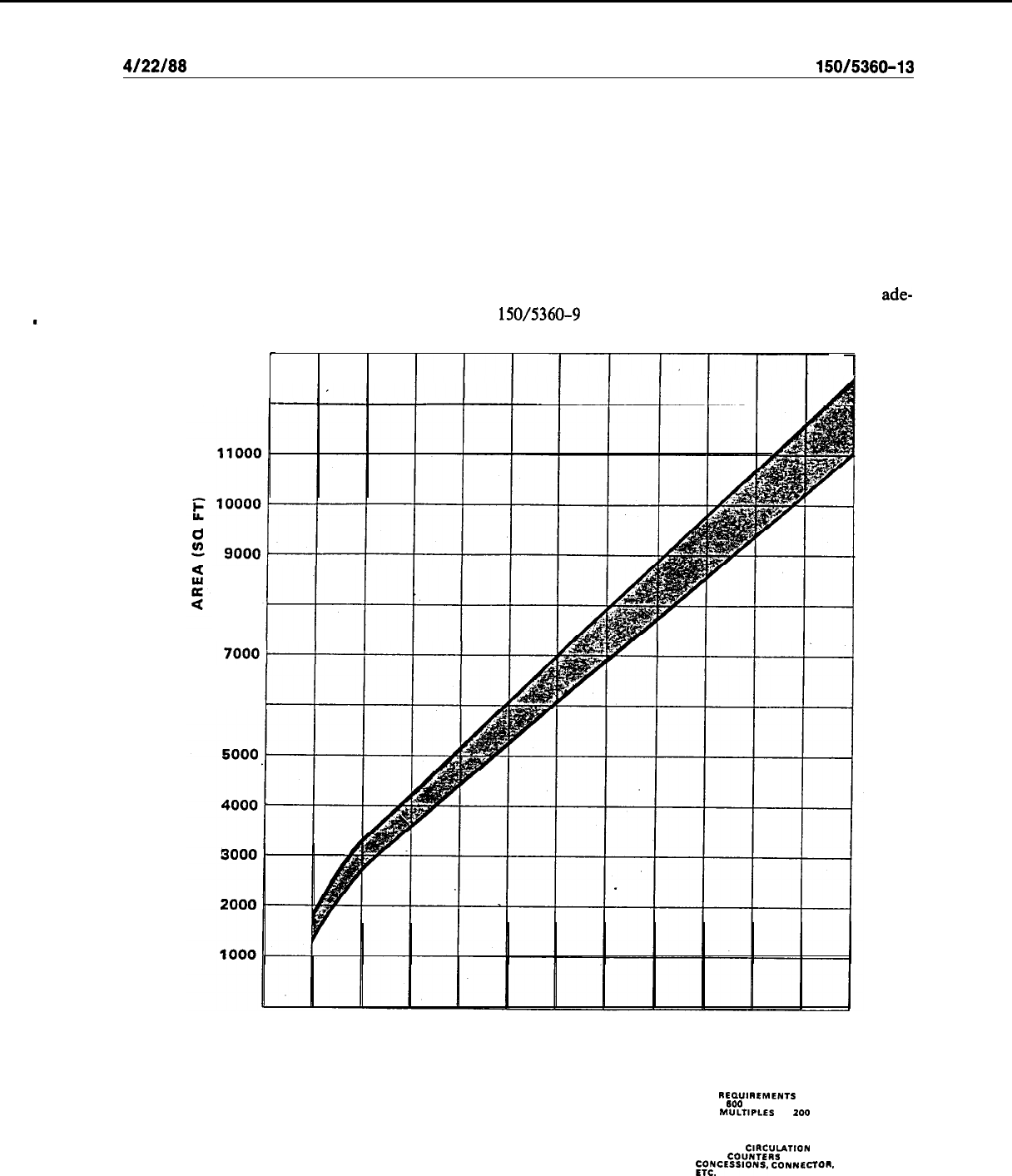
4122188
AC
150/5360-13
small hub airports,. 20 to 30 feet (6 to 9 m) at medium hubs, and 30 to 35 feet (9 to 11 m) at those airports
serving large hubs. Lobby lengths range from 50 to 75 feet (15 to 23 m) for each baggage claim device. For
approximating lobby length and area, one claim device per 100 to 125 feet (30 to 38 m) of baggage claim
frontage should be assumed.
.
d. Combined Lobbies.
(1) Airports handling less than 100,000 annual enplanements frequently provide a single combined
lobby for ticketing, waiting, and baggage claim. Figure 5-5, with an assumed seating for 100 percent of peak
hour enplanements, may be used to obtain a gross approximation for lobby space. This usually allows
ade-
quate space for visitors and circulation. Also, AC
150/5360-9
presents space requirements for low activity
airports.
13000
-
I
12000
8000
6000
0
100
200
300
400
600
600
SEATS REQUIRED
NOTE:
FOR REQUIREMENTS
OVER
SW
SEATS,
USE
MULTlPLES
OF
200
OR MORE
Figure 5-5. Waiting
Lobby
Area
GRAPH INCLUDES
PRIMARY
ClRCULATlON
AREAS
FROM
COUNTSRS
TO
;O&CESSIONS.
co~~~cron.
57

AC
150/5360-13
4/22/88
(2)
For a combined lobby serving 100,000 to 200,000 annual enplanements, space requirements for
various functions should be identified and sized separately, as discussed in preceding paragraphs.
-
(3)
Above 200,000 annual enplanements, each of the three lobby types should be identifiable as dis-
tinct elements and space requirements estimated accordingly.
70. AIRLINE TICKET COUNTER/OFFICES. The Airline Ticket Counter
(ATO)
area is the primary
location for passengers to complete ticket transactions and check-in baggage. It includes the airline
counters, space and/or conveyors for handling outbound baggage, counter agent service areas, and related
administrative/support offices. In almost all cases, ticket counter areas are leased by an airline for its exclu-
sive use. Therefore, the planning, design, and sizing of these areas should be closely coordinated with indi-
vidual airlines.
a. Ticket Counter Configurations.
Three ticket counter configurations are in general use. They in-
clude:
(1) Linear. Linear configuration is the most frequently used one (see Figure 5-6). Multi-purpose
positions indicated are those in which the agent performs several functions such as ticketing, baggage
check-in, and the other services an airline may consider appropriate. During peak periods, multi-purpose
positions may be utilized for a single function to expedite passenger processing for those requiring only one
type of service. At high volume airports, permanent special-purpose positions may be justified.
(2)
Flow-through Counters.
Flow-through counters, as depicted in Figure 5-7, are used by some
airlines, particularly at high-volume locations with a relatively high percentage of “baggage only” transac-
tions. This configuration permits the passenger to check-in baggage before completing ticketing transaction
and increases outbound baggage handling capability by providing additional belt conveyors. This type of
counter requires more floor space, an additional 50-70 square feet (4.7-5.1
m2),
than the linear type and
involves increased investment and maintenance costs. Future application will probably be limited to relative-
ly few airports.
(3)
Island Counters.
The island counter shown in Figure 5-8 combines some features of the flow-
through and linear arrangements. The agent positions form a
“U”
around a single baggage conveyor belt (or
pair of belts) permitting interchangeability between multipurpose or specialized positions. As with flow-
through counters, this configuration has relatively limited application.
b. Office Support. The airline ticket counter/office provides space for a number of airline support
activities. These activities include: accounting and safekeeping of receipts; agent supervision; communica-
tions; information display equipment; and personnel areas for rest, personal grooming, and training. At low
activity locations, the ticket counter area may provide space for all company administrative and operational
functions, including outbound baggage. Figure 5-9 depicts two typical layouts for low activity airports with
single-level terminals. At high activity locations, there is more likelihood that additional space for airline
support activities will be remotely located from the ticket counters.
I)
58
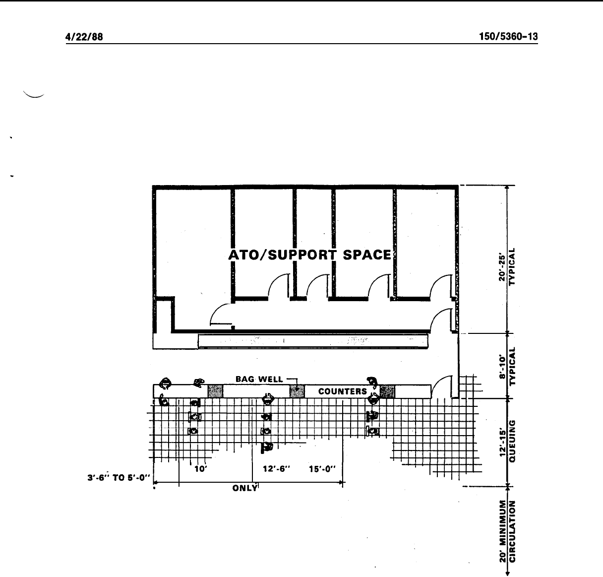
4/22/88
AC
150/5360-13
‘-
I
CONVEYOR
3’4”
TO
5*-O”
TICKETING ONLY
-
’
io;
TO 12’
12’.6”
TO
15’.0”
(TYPICAL PAIR) . (TYPICAL PAIR)
BAGGAGE
ONL+
MULTIPURPOSE
POSITIONS
Figure 5-6. Linear Counter
59
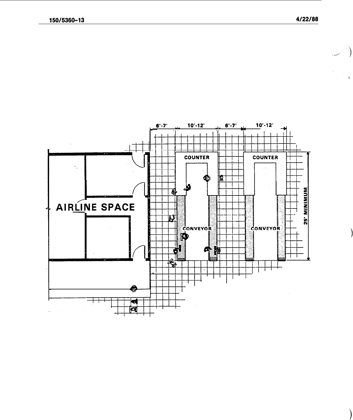
AC
150/5360-13
4122188
l--J
AlRL/rNE
SPACE
COUNTERS
6’-7’
-L-
10’-12’
~
6’-7’
rl-
10’.12’
--.
+I
Figure 5-7. Flow-Through Counter
60
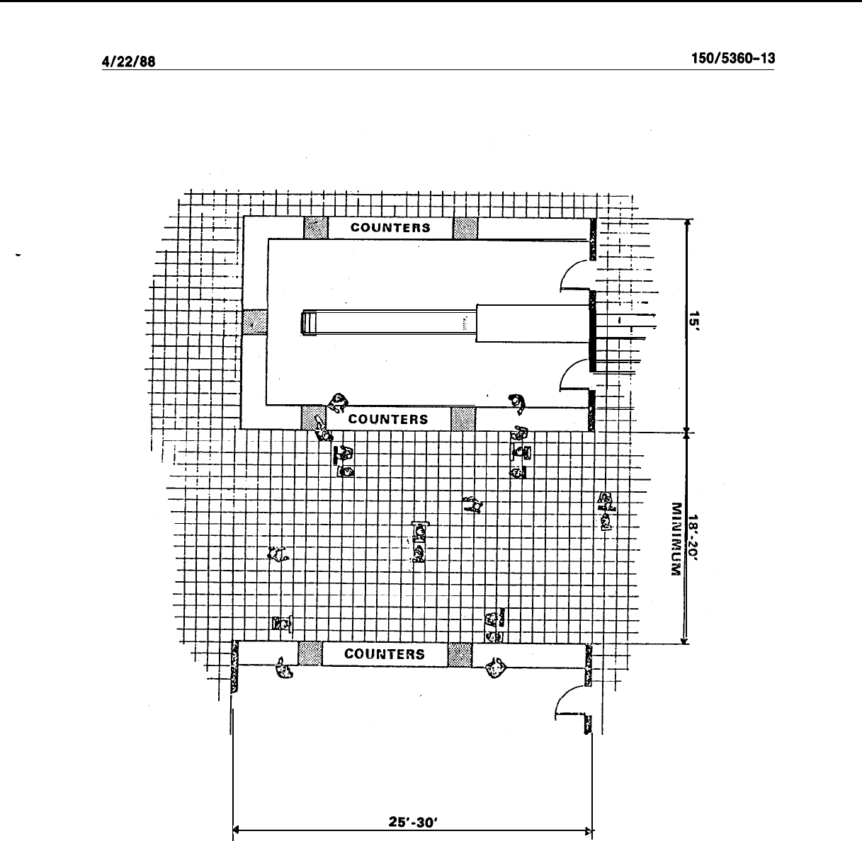
4/22/88
AC
150/5360-13
I
----+
.-
I
CONVEYOR
f
I
-
I
!
4
25'-30'
b
Figure 5-8. Island Counter
61
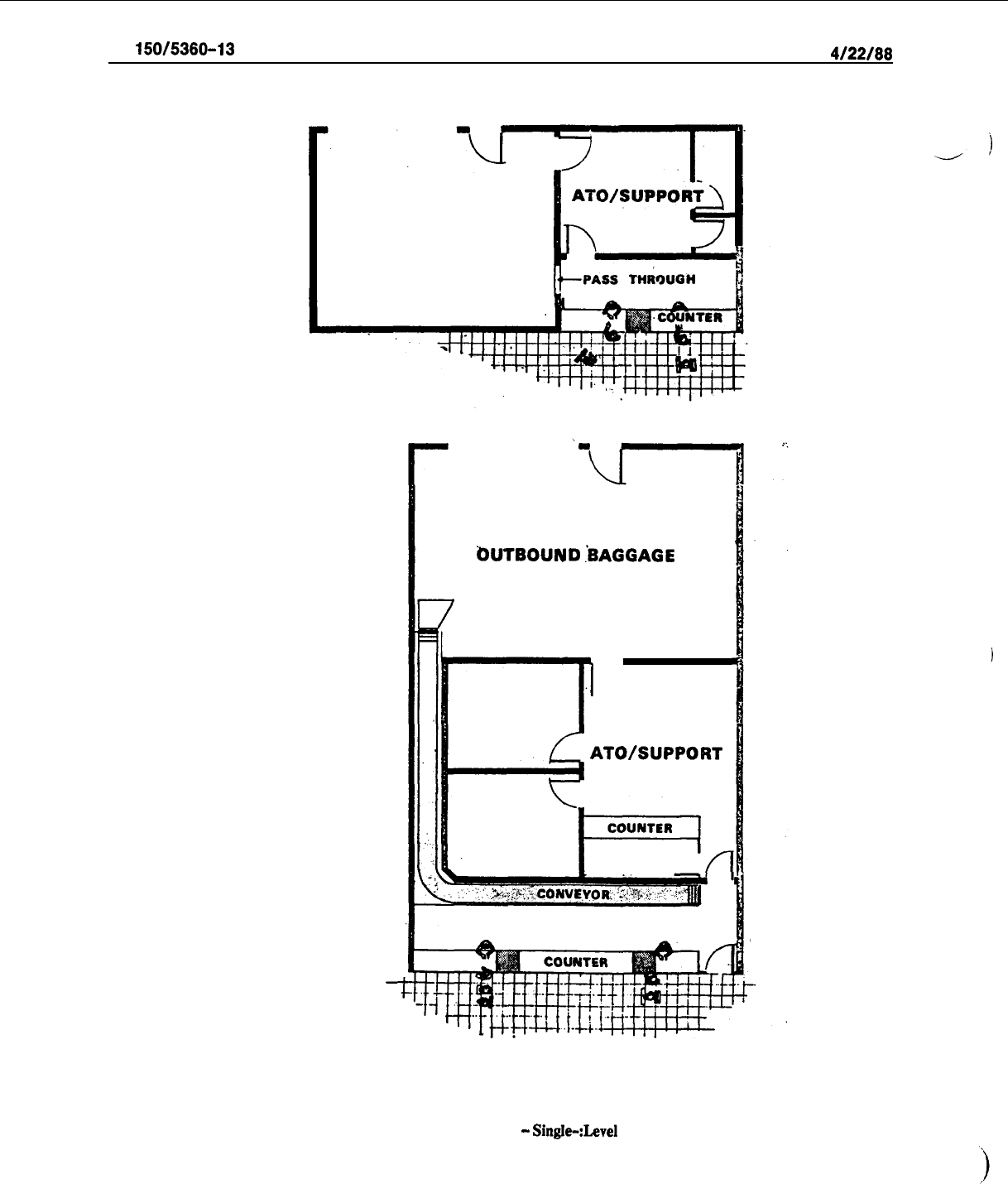
AC
150/5360-13
4/22/88
BAGGAGE AREABAGGAGE AREA
-
bUTBOUND
.kAGGAGE
7
1
r
ATO/SUPPORT
f
Figure 5-9.
Typical AT0 Layouts
-
Single-:Level
Terminals
62

4/22/88
AC
150/5360-13
b
c.
Sizing.
Figure 5-10 may be used in estimating airline ticket counter frontage for the three counter
configurations previously discussed. It utilizes the EQA factors discussed in paragraph 25,. The frontage
ob-
tained from the chart is based on counter positions typically required for airline peaking activities. The
values determined from the chart do not include conveyor belt frontage at flow-through counter configura-
tions. Less frontage may be required when individual airlines provide curb check-in and ticketing at gates:
In determining the counter working area, the frontage obtained from the chart is multiplied by a depth of
10
feet (3 m). Figure 5-l
1
shows typical ranges of AT0 support space. This is presented separately from
counter working area since many of these support functions are remotely located at higher activity loca-
tions. For gate or gate equivalents exceeding those shown in this figure, quantities appropriate to the sepa-
rate lobbies ‘or sections of lobbies, unit terminals, and the like, should be used. This normally occurs at air-
ports with over 50 gates.
7l.
OUTBOUND BAGGAGE FACILITIES.
a.
The outbound baggage facility is that area where baggage is received by mechanical conveyor from
the ticket counters, online and offline connecting flights, and curb-side check-in. It is sorted and loaded into
containers or carts for subsequent delivery to aircraft. At low-volume airports, bags may be manually
moved through a wall opening.
b.
At most airports, outbound baggage areas are located in building spaces leased by the tenant airlines
for exclusive use. Each airline provides its own baggage processing equipment and conveyors. The out-
bound baggage area should be located in -reasonably close proximity to the ticket counters to facilitate the
movement of baggage between these locations. The area should also have convenient access to the aircraft
parking apron by means of carts or other mobile or mechanical conveyors.
--
c.
On-line and inter-line transfer baggage is best handled in the same area with other outbound bag-
gage for optimal use of personnel, space, and equipment. An area or conveyor for receiving transfer bag-
gage from other airlines should be considered. Often, this area is adjacent to a primary traffic aisle. Security
for delivered baggage makes a conveyor or pass-through into the outbound baggage area advisable. At
sta-
tions where the airlines contract with a third party for all interline deliveries, a pick-up area for baggage to
be delivered to other carriers should be provided with similar provisions for baggage security and control.
d.
Since outbound baggage area requirements are determined by individual airline policy, early input
from the airlines is essential. The minimum size for an outbound baggage room is approximately 400 to 450
sq. ft. (37 to 42
m’)
per airline. Figures 5-12 and 5-13 can be used for initial estimating of outbound baggage
area requirements. These nomographs were developed on the basis of an average of 1.3 bags checked per
passenger. Caution should be used in applying these nomographs as ‘substantial variance in the number of
bags per passenger at different airports can range from 0.8 to 2.2. Business passengers will usually average
less than 1.3, whereas vacationers needs may be substantially greater.
e.
At locations where an airline proposes using some type of automated sorting, additional area to that
indicated in Figure 5-13 will be necessary. The required area should be increased by at least 150 to 200
percent for tilt-tray sorting systems and 100 percent for destination-coded vehicle systems.
f. Following are some common types of outbound baggage equipment:
(1)
Belt conveyors represent the most commonly used mechanized component for baggage systems,
operating at speeds of 80 to 150 fpm (25 to 46 mpm) over short distances, and providing transport capacities
of 26 to 50 bags per minute.
63
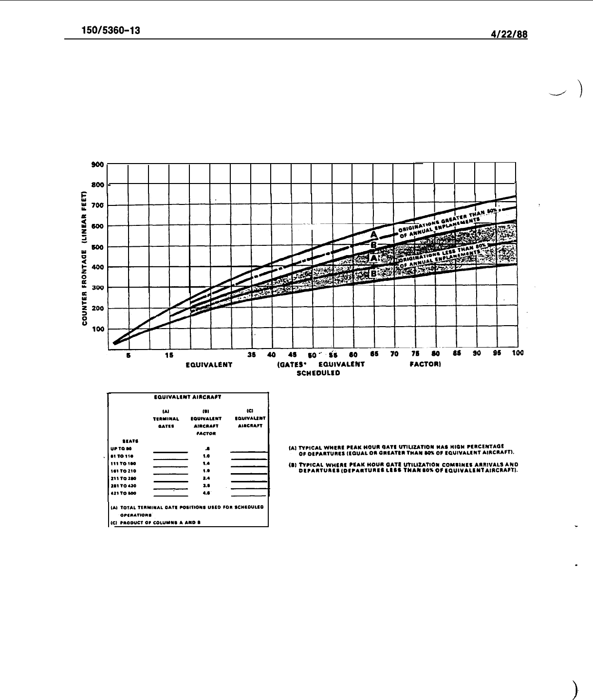
AC
150/5360-13
4122188
so0
800
-
I
I
1
0
5
10
16
20
26
30
3s
4a
41
60”.
dS
60
EDUIVALENT
AIRCRAFT
(DATES*
X
LDUlVALENf
AIRCRAFT
FACTORb
FOR DOMESTIC
SCWEOUl.EO
OPERATIONS
1
cauIv4Lf*T
AlRClAFT
I
IBI
WIICAL
W”f”f
,fAM
MOUI
OATS
“W.IZATIOY
COY.,Wf‘
AI”,VALSANO
Of,A”,“~fs
IDf?AIlUnfS
LISS
TMAN
IO’%
OF
fO”IV4L‘NI
AIRCRAFTI.
Figure S-10. Terminal Counter Frontage
64
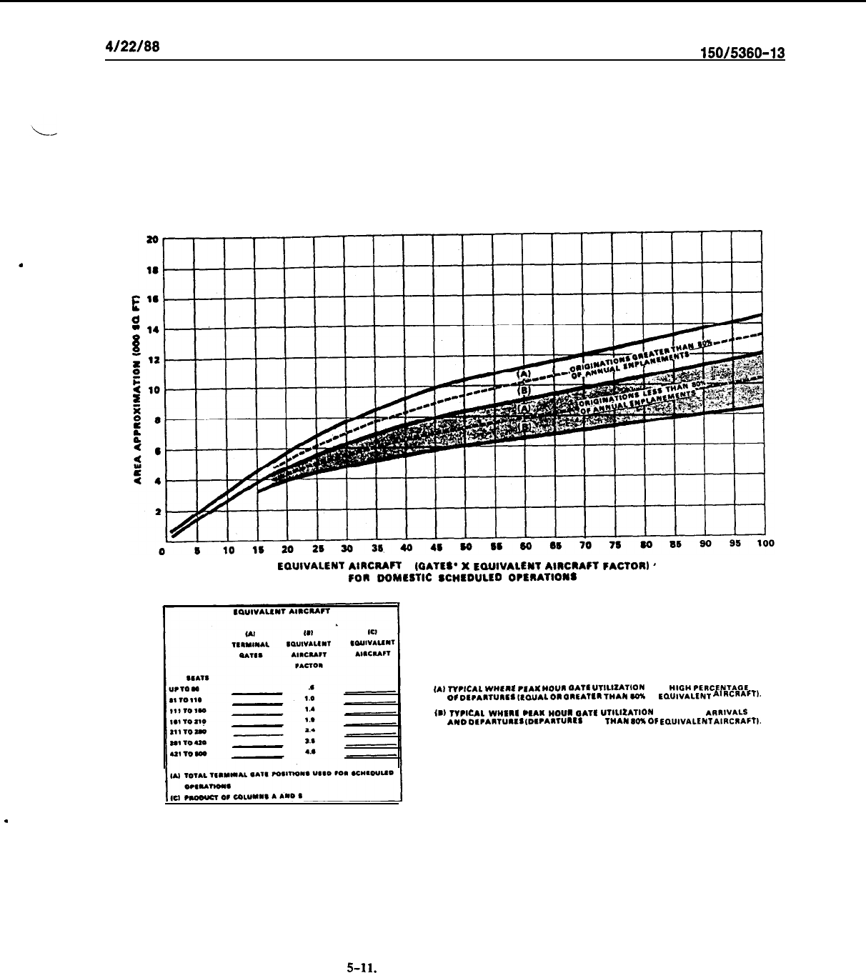
.
4122188
AC
150/5360-13
EQUIVALENT
AIRCRAFT
IQATES’
X
EQUIVALENT
AIRCRAFT
FACTOR)
’
FOR
OOMESTIC
SCMEDULEO
OPtRATIONS
(A,
lr,,CAL
W”E”E
PENI
“0””
OATE
UTlLlZATlOn WAS
“IO”
PERCENTAOE
0‘
DIcAIWIE,
(,.O”AL
0”
OREATER
TWIN
ML
Of
ECAUIVALENT
At
ItCRAFT,.
IBI
,“,ICAL
WHE”E .EAK
“0””
OATE
UTILILATION
COMBINES ARRIVALS
AWD
OECA”,““ES
(D‘CA”W”ES
LESS
WAN
SOXOF
EOUWALENT
AIRCRAFTI.
.
Figure 5-11.
AT0 Office and Support Space
65
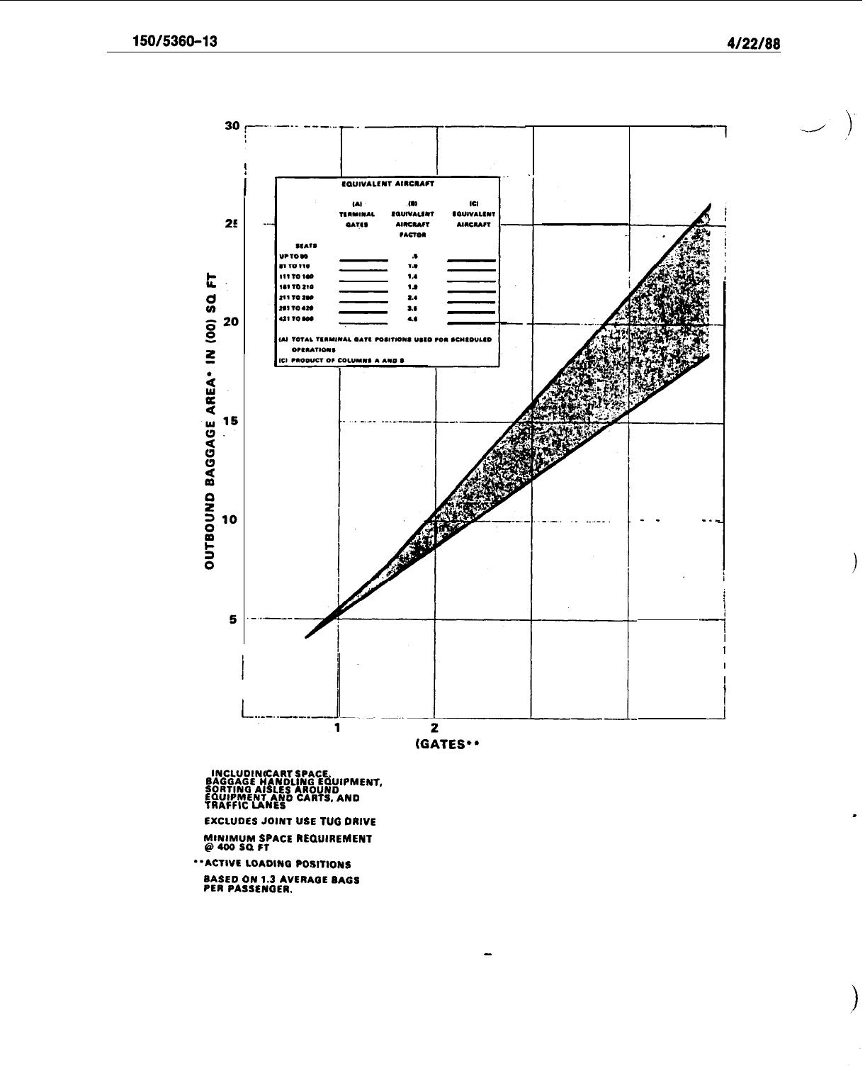
Ad
150/5360-13
4/22/66
-.
1
I
/
i-
-
-
_
.
-
1
.-
1
I
I
I
J
I
L
..--.
.--_--_
3
4
EQUIVALENT AIRCRAFT (GATES.6 x EQUIVALENT AIRCRAFT FACTOR)
.
l
INCLUDING
CARTSPACE.
BAGGAGE
HANDLING
EOUlPMENT,
SORTINCI AISLES
AROUND
EQUIPMENT
AND
CARTS,
AND
TRAFFIC
LANES
.
EXCLUDES
JOINT
USE TUG DRIVE
MINIMUM
SPACE
REQUIREMENT
@4OOSQFf
“ACTIVE
LOADINQ
POSITIONS
BASED ON
1.3
AVERAOE
SAGS
PER
PASSENQER.
Figure 5-12. Outbound Baggage Area
-
Less Than Five EQA
66
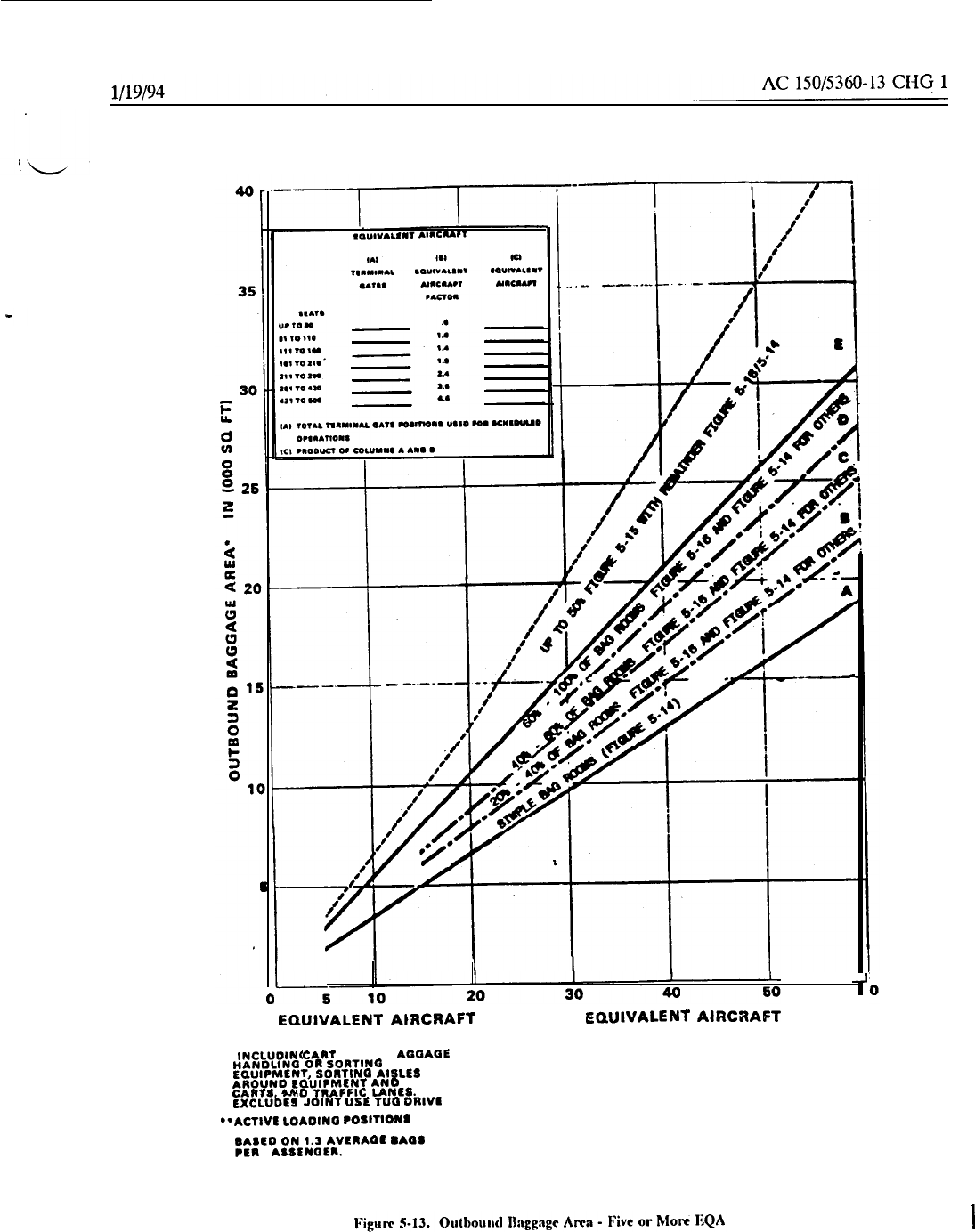
EGUIVALENT
AtRCRAFT
(GATES
l * x
EQUtVALENT
AtRCRAPT
FACTOR).
l
INCLUOINO
CART
SPACE. l
AOGAOE
HANDLlNO
OR SORTING
EQUIPMENT, SORTINO AISLES
AROUND EOUIPMENT
AN0
CARTS AND TRAFFIC LANES.
rxcrubes
JOINT USE
TUQ
DRIVE
**ACTIVE LOADINO POSITIONS
SASED ON
1.3
AVERAQE
8AflS
PER
l
ASSENTER.
J
6
I
67
AC
150/5360-13
CHG 1
1/19/94
(a)
Raw belt
consreyors
with spill plntcs (Figure
S-
14) tend to
become
less efficient as
the
length
of unloading section is increased to process simultaneous departures. In such casts, bags not removed by the
baggage handler at his normal working position must be retrieved later from the end of the spill plate. That
end becomes progressively more distant as the number of flights and size of aircraft increase. This condition
may bc alleviated somcwhnt by using belt conveyors with indexing features activated by photoelectric switches.
p” ,
t
(b)
Uelt
conveyor capacities can be incrcnscd by adding conveyors between counter inputs and
I
outbound baggage rooms or, marginally, by merging multiple input
conveyors
into a higher-speed mainline
conveyor. Long
segments
may operate at speeds up to 300 fpm (90 mpm), with acceleration and deceleration
belts at each end. This represents a practical maximum for current technology and maintenance. Accordingly,
high-speed belts are primarily used to rcducc transport times for long conveyor runs and seldom, if ever,
increase system capacity.
(2) Inclined belts, vertical lift devices, or chutes are used with baggage rooms located on a different
floor level from the
AT0
counters. Chutes arc the least cxpcnsivc but lack the mcnns for controlling baggage
‘movement and increase the potcntinl for damaged bags. Inclined belts should not exceed
a
22-degree slope
and are usually designed for 90 to 100 fpm (28 to 31 mpm) maximum.
Vertical lift devices arc available with
capacitiesof 18 to
45
bags per minute.
(3) Recirculating devices for sorting and loading
baggage
arc normally considered
when
the number
of departures processed concurrently excccdsthe practical capabilitiesof a raw belt and spill plate. Equipment
types include belt conveyors utilizing straight and
curved
segments, flat-bed
devices,
or sloping-bed plates
devices.
Each of these may be fed by more than one input conveyor
:md
may require indexing belts and
accumulators to control input flow. The recirculating feature faciiitatessorting bags into carts for more flights
and larger aircraft by fixing rclntivcly stationary work positions for baggage handlers with “dynamic storage”
of bags until they can be sorted into carts or containers.
(4) Elongated
owl
configurations tend to be
used
in
lieu
of circular devices as the number
of
cds
increases. Figure
5-1-F
shows carts and container dollies pnrkcd
pnrallcl
to
a
bolt-loop or flat-bed sorting
device. Figure 5-16 shows the same carts parked at right nnglcs to
i\
sloping-bed device. The sloping bed may
accommodate two rows of bags to increase overall storage capacity. This can offset the reduction in perimeter
frontage from that afforded with
pnrnllcl
parking. Although right-angle parking can reduce lloor space by 30
to 50 percent, some carriers prefer parallel parking to minimize time and manpower for maneuvering and
positioning of carts.
In either cast, the input conveyors need to be elevated to permit
l~~sage
of carts and
contnincrs within the
space.
(5) Semiautomated sorting utilizes mechanical equipment lo move bags onto
a
latcrnl
slide or
conveyor
dcsignatcd for concurrently processing separate dcparturcs. Figure 5-17 shows
n
linear belt sorter
capable of handling about 30 bags per minute, usually
when
the maximum number of dcpnrtures processed
concurrently does not exceed 12 to
IS.
The operator dcsignntcs the appropriate lateral after reading the tag
on each passing bag. A separate sorter is needed for each input conveyor
lint
from the
ATO.
I
(6) Tilt-tray sorters, as shown in Figure S-18, are considered appropriate for very high volume
stations requiring multiple inputs ami greater capncitics than possible with the prcccding
types.
These systems
are custom designed with relatively sophisticated coding and sorting features as well as Jntcral conveyors
accumulating baggage for each departing flight.
Terminal designs should allow the flexibility for future
installation of such systems.
(7)
Destinntion-codedvehiclesystems(FigurcS-19)
rcprcscnthigl~lyndvancedtcchnologicalpropos~~1s
for handling the higher volumes, longer distances, interline transfers, and clcvntion changes encountered in
terminals serving large hubs.
Although the
vehicles
and propulsion methods vary, all have similar design
criteria.
T~KSC
are:
speeds up to 880
ft/min
(268
m/min);
elevation change capability (up to 33 degrees);
fixed
rights-of-way; programmable control systems and vehicle encoding; and interface with load/unload stations.
68
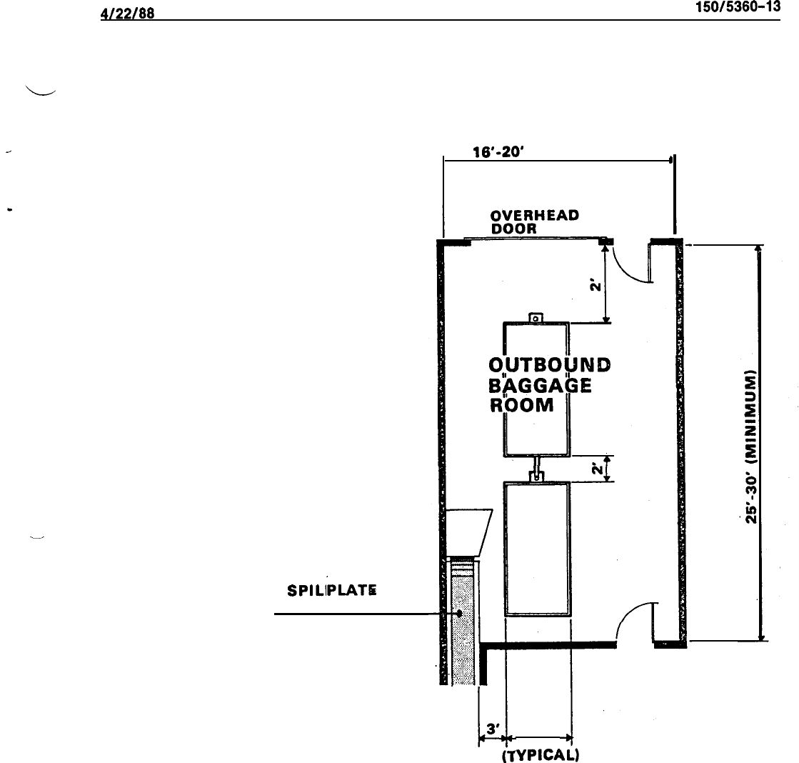
4122188
AC
150/5380-13
RAW BELT AN
D
SPILL
QLATE
-
HAND PASS-THROUGH OPENING IS
AN ALTERNATIVE
16’-20’
(MINIMUM)
I
:‘.;::,..>~
..‘..‘.,
;;:
.t:>
..:
~
j:...
cy;
.:.
,”
.:..:.:
.,:.:;‘~,~:;:
,:
:::,
..s
I
::.
.q.>::::
.
.
.
.
.
.
:.:..
,...
..:::.
:.:
.:::
:‘:‘l:,$,.
c
3'
OUTBOUND
B’hGGAb
E
5'
‘Y
PICE
Figure 5-14.
Outbound Baggage Room Typical Raw Belt Conveyor Installation
69
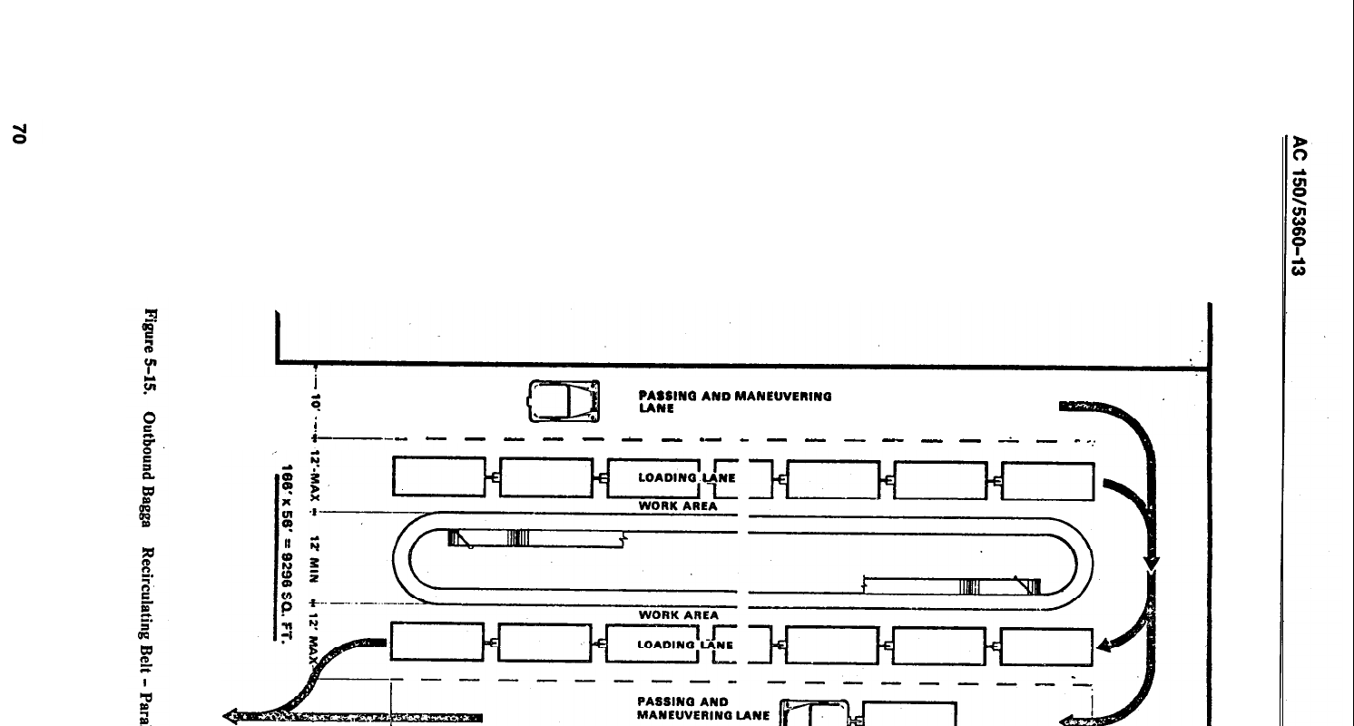
I
r
4
m
PASSINO
AND
MANEUVERINQ
LANE
i
.
+---
-
-
-
-
-
-
-
.-
-
-
-
-
-
-
-
A
-
-__
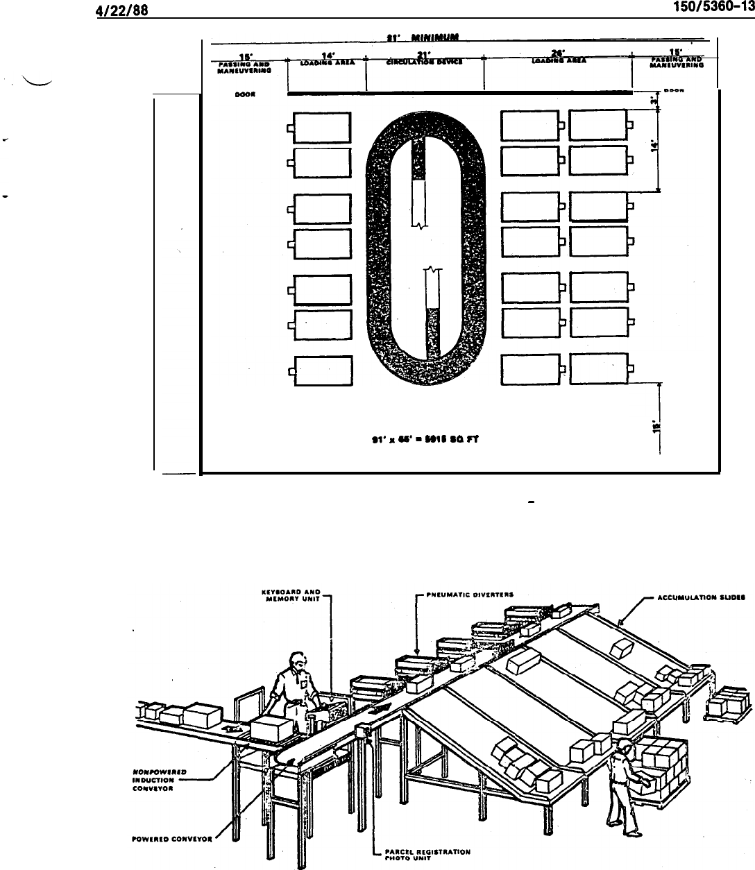
4122188
AC
150/5360-13
ww
1
ial
Sl’
‘
u’
-
Ball
so
FT
1
Figure 5-16.
Outbound Baggage Recirculating Sloping Bed
-
Perpendicular Parking
Figure 5-17.
Semiautomated Linear Belt Sorter
71
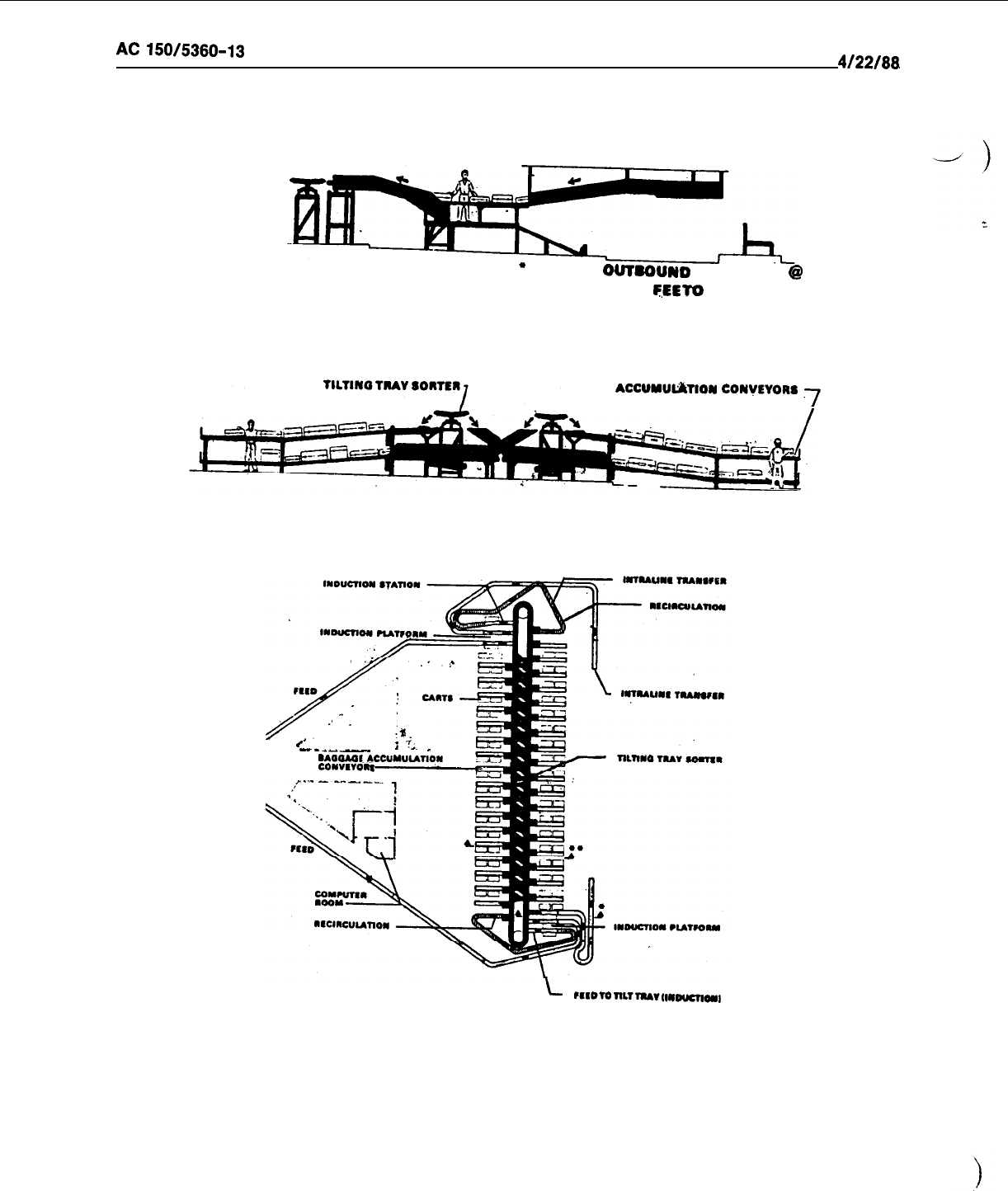
AC
150/5360-13
4/22/88
’
SECTION: OUTBDUND
l
ADDAQE
@
TEED
To
TILT TRAY
ACCUMUtiTlON
CONvEYORI
7
~-
l
’ CROSS SECTION
/
.’
-
:
t’
em----
;
‘T,.
---
-
SAOOAOI
CONVIVOlt------
L
lIIoTonLTlNAvIl*mlcnoNl
PLAN
Figure 5-18. Tilt-Tray Sorter
72
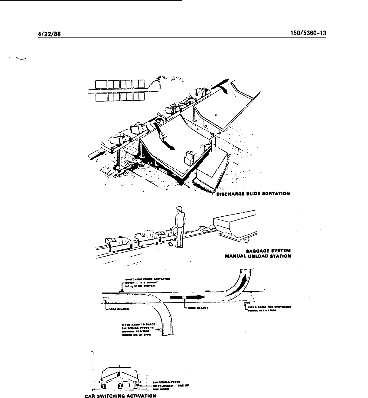
4/22/88
AC
150/5360-13
ISCIIAIOE
SUDS SOllTATlON
MANUAL UNLOAD
STATION
-,
;:
CAR
sWITCHIN
ACTIVATION
Figure 5-19. Destination-Coded Vehicle
g.
Table 5-l relates enplanement criteria and outbound baggage equipment.
73
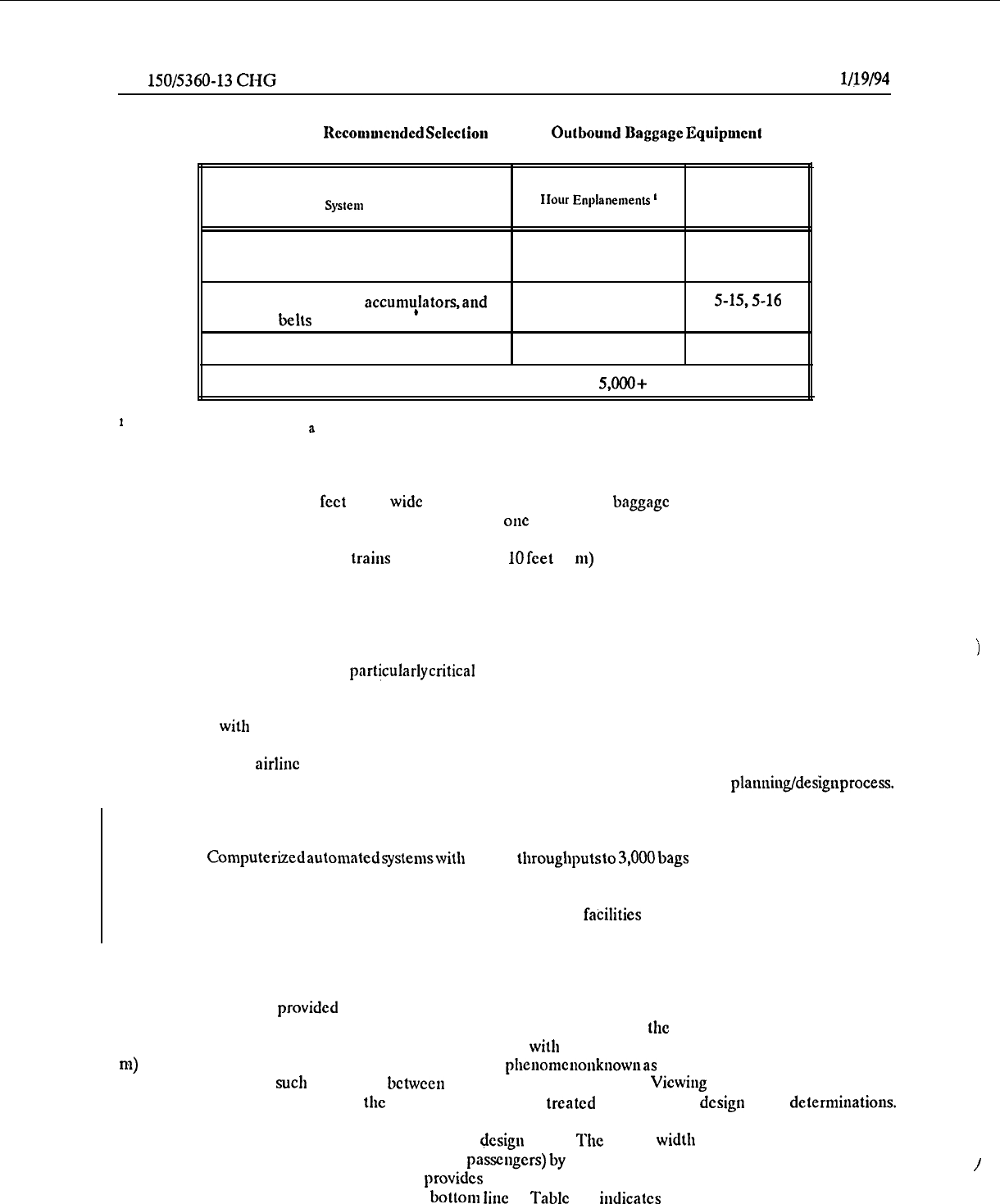
AC
150/5360-13
CHG 1
l/19/94
Table 5-1. RecoululelldcdSelcclion Criteria
Outbouud
BaggageEquipmeut
System
type
Application Range Peak
IIour Enylanements
’
Average Day/Peak Month
Reference Figure
No.
Manual (pass-through or raw belt with
spill plate)
Recirculationdevices, accumulators,and
indexing bells
*
Linear belt sorter
up to 200
5-14
150 to 1,500
5-15,5-16
300 to 800
5-17
Tilt-tray sorter
I
800 to
5,000+
I
5-18
’
For one or more airlines sharing
B
single system.
h.
Some noteworthy building design features in the outbound baggage area arc provided below:
(1)
Aisles at least 3 feet (1 m)
wide
are usually required around
baggage
sorting device and between pairs
of carts parked at right angles (unless carts only open on one side).
(2)
Traffic lanes for cart trains normally require
10
feet (3
m)
with provisions for a 21 foot (6.5 m) outside
radius at turns. Variations are such that airlines should bc consulted.
(3) Vehicular door locations relative to the apron or restrictions in the number of such doors may
necessitate additional space to manually maneuvercarts or dollies.
(4)
Column spacingsarc partjcularlycritical and should be reviewedwith airlines early in the planningstage.
i
(5) Minimum clear heights of 8 to 8.5 feet (2.4 to 2.6 m) are required by most airlines for containerson
dollies for use
with
wide-body aircraft, although a 10 foot (3 m) clearance is often recommended.
(6) Since aidinc tugs/tractors have internal combustion engines, local code regulations and Federal
standards for mechanicalventilation of enclosed areas should receive attention early in the planning/designprocess.
i.
Trends in future outbound baggage handling systems include:.
(1)
Computerizedautomatedsystemswith
hourly
throughputsto
3,OOObags
per hour. Sorting error, other
than human error, is expected to be reduced to 1 percent. Baggage is sorted by barcode tags read by a laser scanner.
(2) Large underground baggage handling facilities. These
fabilities
will usually be located under aprons
areas in order to provide the very large space needed by the baggage handling facility.
72. PUBLIC CORRIDORS.
a.
Corridors are provided for public circulationbetwcen aircraft boarding gates and various lobbies and other
areas within the terminal building.
The effective corridor design width is
the
total width less obstacles (e.g.,
telephones, wastebaskets, benches, protruding displays, etc.)
with
a minimum clcaranceof approximately2 feet (0.6
m)
on each side.
This clearance is providedbecausc of the
pllellomcllollkllow~~as
“boundary layer” in which a person
will normally maintain
such
a clearance bctwcen corridor, walls and obstacles.
Viewing
areas for video displays and
passengerqucue areas extendinginto the corridor should also bc
treated
as obstacles in design width delerminations.
b.
Figure 5-20 illustrates an effective corridor
+sign
width. The design width is determinedby dividing the
peak corridor population per minute (visitors and
passengers)
by
the corridor width capacity factor expressed in
people per unit width per minute. Table 5-2 provides a corridor capacity matrix based on an average walk rate of
242 feet (74 m) per minute. For example, the
bosom
line
of
Table
5-2 indicates a capacity of 330 to 494 persons
/
74
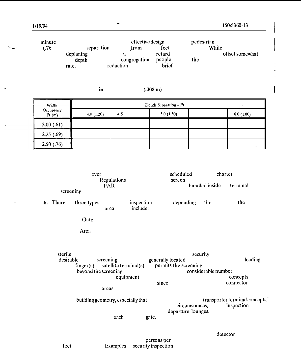
mm
l/19/94
AC
150/5360-13
CHG 1
per minute for a corridor with a 20 foot (6 m)
cffcctivc
design
width, for a pcdcstrian occupancy width of 2.5
*-
feet
(.76
m) and depth scparalion ranging
,from
4 to 6 feet (1.2 to 1.8 m). While a relatively abrupt
introduction of deplaning passcngcrs into
a
corridor may retard the walk rate, it will bc
offset
somewhat
by
a decrease in their depth separation.
A congregation of pcoplc awaiting the arrival of passcngcrs may also
retard the flow rate. This capacity reduction is usually only brief and local in nature and does not ultimately
affect the overall corridor design capacity. This congestion can bc minimized by providing areas for flow surge
and greeters in the corridor width.
L
Table 5-2. Corridor Capacity
iu
Persons Per Foot
(.305
m)
Width Per Minute
Depth
Scpmtior~
-
1’1
(m)
E/-
4.0(120)
4.5
(1.35)
S.O(l.50)
5.5 (1.65)
6.0(1.80)
’
30.9
27.5
24.7 22.5
20.6
27.4 24.4
22.0 20.0
18.3
24.7
22.0
19.8 18.0
16.5
_
73. SECURITY INSPECTION STATIONS.
a. Air carriers using over 60 passcngcr scat aircraft in schcdulcd or public charter operations are
required by Federal Aviation Regulations (FAR) 121.538 to screen all passcngcrs prior to boarding in
accordance with the provisions of FAR Part 108. This activity is normally
handled
inside the
terminal
building
at a security screening station.
-
-b.
There are three
types
of passcngcr
inspection
stations, dcpcnding on the location of the station in
relation to the aircraft boarding arca. Thcsc
include:
(1) Boarding Gate Station;
(2) Holding Arcn Station: and
(3) Sterile Concourse Station.
c.
A
stcrilc
concourse station, from both the standpoint of passenger
security
facilitation and economics,
is the most desirable type of screening station.
It is gcncrally located in a concourse or corridor leading to
one or several pier
finger(s)
or satellite terminal(s) and permits the screening and control of all passengers
and visitors passing beyond the screening location. It thus can control a considerable number of aircraft gates
with a minimum amount of inspection equipment and pcrsonncl. Pier and satellite terminal concepts arc well
suited for application of the Stcrilc Concourse Station,
since
the single-point entrance connector element
facilitates isolation of boarding
arcas.
d.
Becauseof buildinggcometry,especiallythat associatedwith lincarand transporterterminalconcepts,)
the Sterile Concourse Station is not always fcasiblc. Under these circumstances, several inspection stations
may be required to control a number of holding areas or dcparturc
lounges.
In the worst situation, a
screening station may be required at each boarding
gate.
e. Except at low activity airports, where manual search procedures may be cmploycd, a security
inspection station will generally include a minimum of one walk-through weapons detector and onc’x-ray
device. Such a station has a capacity of 500 to 600 persons per hour and requires an area ranging from 100
to 150 square
feet
(9 to 14 sq.m). Examples of security
inspection
station layouts arc illustrated in Figure 5-21.
75
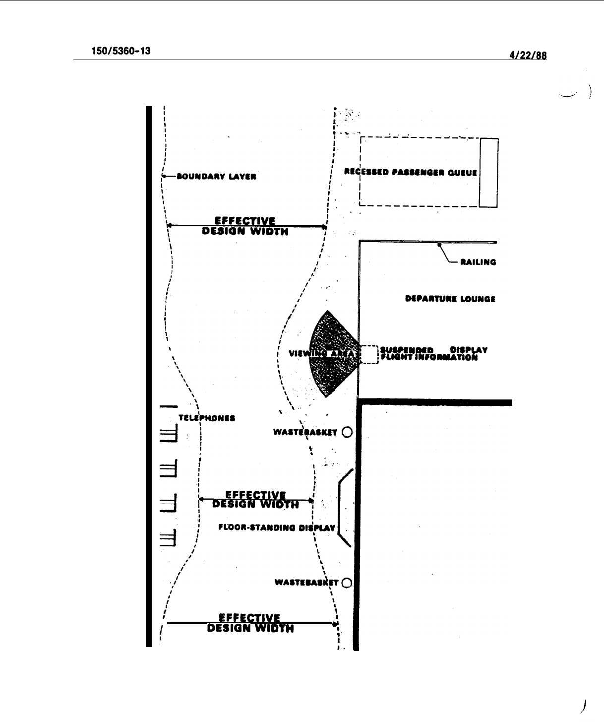
AC
150/5360-13
4/22/66
i
I
I
I
I
\
\
I
\
\
.’
\
-\
\..
’
‘,
.
.
\
w*s+KET
0
\
c
‘.
I
I
i
'
i
\
I
EFFECTlVE
I
I
DESIGN
WtDTH
Y
f
:
1
---:suweN#D
TV
OIWUY
:
luorn
IN~oMuTlow
---,
Figure S-20.
Public Corridor Effective Desip Width
76
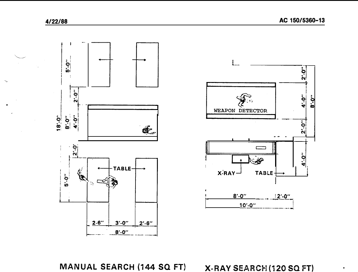
4122166
AC150/5360-13
TABLE
1
I-1
WEAPON DETECTOR
.4L
MANUAL
SEARCH
(144
SQ
FT)
r
NEAREST OBSTACLE
n-
-
-
-
.
_
f
I
1
BELT
I
XhAY
-I
TABLEb
1
i
1
I
I
I
I
1
L,
8’-0”
_._.
.-
..2’-0”.
luL--..---.-J
X-RAY
SEARCH
(120
SQ
FT)
-
Figure
5-21.
Security Inspection Station Layouts
f.
Space leading to the security inspection station should allow room for queuing as the flow of pas-
sengers through security is often interrupted when a passenger requires a rescreening or physical search.
Queuing space should not extend into or block other circulation elements.
g. The boarding area beyond a security screening checkpoint, whether a holding area concourse or
departure lounge, requires a design which will enable security to be maintained. In this respect, the design
and location of entrances, exits, fire doors, concessions, etc., require special consideration.
h.
Other security considerations are discussed in Chapter 8.
74. DEPARTURE LOUNGES.
a.
The departure lounge is the waiting or holding area for passengers immediately prior to boarding
an aircraft. At most airports (excepting some low activity airports), departure lounges are normally included
in the space leased and controlled by individual airlines.
b. The departure lounge normally includes: space for one or more airline agent positions for ticket
collections, aircraft seat assignment, and baggage check-in; a seating and waiting area; a queuing area for
aircraft boarding; and an aisle or separate corridor for aircraft deplaning. Figures 5-22, 5-23, 5-24, and 5-25
illustrate typical departure lounge layouts.
77
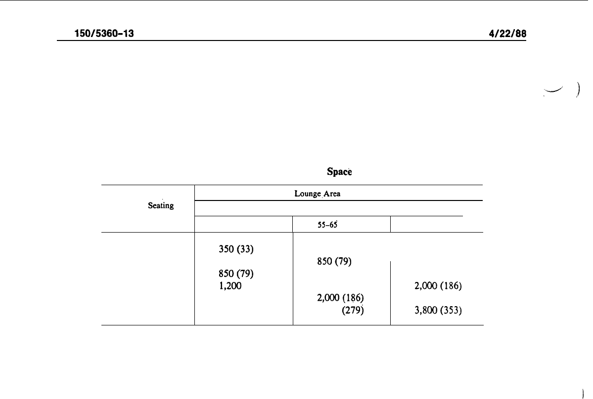
AC
150/5360-13
4/22/88
c.
The number of agent positions/desks is determined by the user airlines on the basis of individual
airline standards for passenger waiting, processing, and boarding procedures. A queue length of at least 10
feet (3 m) in front of agent positions should be provided in departure lounges at larger airports.
.-
1
d.
The departure lounge area is a function of the number of passengers anticipated to be in the lounge
15 minutes prior to aircraft boarding. Table 5-3 presents information for estimating departure lounge areas
on the basis of aircraft seating capacity and load factors. The average depth of lounge area generally consid-
ered to be reasonable is 25 to 30 feet (8 to 9 m).
Table 5-3. Departure Lounge Area Spa& Requirements
Aircraft Seating
Capacity
Departure
Lounge,Area
Square Feet (Square Meters)
Boarding Load Factors
--
35-45 percent 55-65 percent
75-85 percent
I I
Up to 80
350(33)
81 to 110
600 (56)
111 to 160
SSO(79)
161 to 220
1,200
(111)
221 to 280
1,500 (139)
281 to 420
2,200 (204)
515 (48)
SSO(79)
1,175 (109)
1,600 (149)
2,000(186)
3,000
(279)
675 (63)
1,110 (102)
1,500 (139)
2,000(186)
2,500 (232)
3,800(353)
78
4/22/88
AC
150/5360-13
e. When
g
lounge area serves more than one aircraft gate position, the estimated total lounge area
shown in Table 5-3 may
be
reduced 5 percent for each aircraft gate position, up to a maximum of six gates.
’
‘l-l
f,
Departure lounge seats are not generally provided to accommodate all passengers boarding an air-
craft. A number of passengers will elect to remain standing in the waiting area while others will only.arrive
shortly before or during the boarding process. Between 15 and 20 square feet (1.4 to 1.9
m2),
including aisle
,
.
space, is required per seat.
g.
The deplaning
irea
is generally a roped aisle or separate corridor directly leading deplaning
passkn-
gers from the loading bridge or apron gate to a public corridor. Separation from the rest of
.the
departure
lounge is provided to avoid interference and congestion between deplaning passengers and those waiting to
board the aircraft. Six feet (2 m) is an acceptable width for this area.
75. BAGGAGE CLAIM FACILITIES.
a. Inbound baggage handling requires both public and nonpublic building areas. The public space
(claiming area) is that in which passengers and visitors have access to checked baggage displayed for identi-
fication and claiming. Nonpublic space is used to off-load bags from carts and containers onto claim devices
or conveyor systems for moving into the public area.
b. The claiming area should be located adjacent to a deplaning curb and have convenient access to
ground transportation service and auto parking facilities. Passenger access from arriving flights should be
direct and avoid conflicting with enplaning passengers. The claim area should also be readily accessible
from the aircraft apron by means of carts, tractors, or mechanical conveyors for quick and direct baggage
delivery.
--
c.
At low activity airports, a simple claim shelf is the most common baggage claim scheme. As passen-
ger activity increases, several types of mechanical claim devices, as illustrated in Figure 5-26, may be uti-
lized to help reduce the overall required claim area length. A discussion of the more common claim schemes
follows.
(1) The
simple shelf or counter is merely a shelf or counter provided in a public area on which bag-
gage from an arriving aircraft is placed for passenger identificalion and retrieval. Width of the shelf is gener-
ally 30 to 36 inches (75 to 90 cm). Passengers merely move laterally along the shelf until their
,baggage
is
located and claimed.
(2)
Flat-bed plate devices are particularly applicable when direct feed loading areas are immediately
adjacent and parallel to the claiming area and on the same floor level.
(3)
Sloping-bed devices are somewhat more adaptable for remote feed
.situations
where the loading
area cannot be immediately adjacent to the claiming area or must be located on a different floor level. In
some cases, the width of the sloping bed is sufficient to provide storage of two rows of bags.
d.
At low volume airports, exclusive-use facilities are not usu$ly economically justified and claim fa-
cilities are shared or assigned preferentially to several airlines. The use of a Design Day Activity Analysis
(see paragraph 24) is recommended to size baggage claim facilities. In this analysis, passenger arrivals in
periods of peak 20 minutes are used as the basis for sizing. However, when exclusive facilities are planned,
each airline determines its baggage claim frontage and space requirements according to its own criteria for
sizing space, systems, and staffing.
79
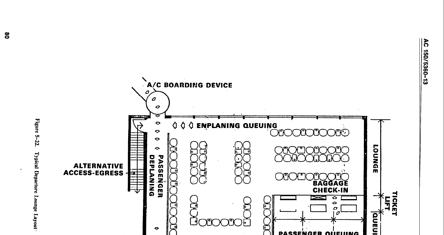
ALTERNATIVE
ACCESS-EGRESS
o
(I
0
(l
EN;PLANINq
QUEUING
ki’lll
n
~O?WOURSE/Pll&ILlC
COIUW3Ori
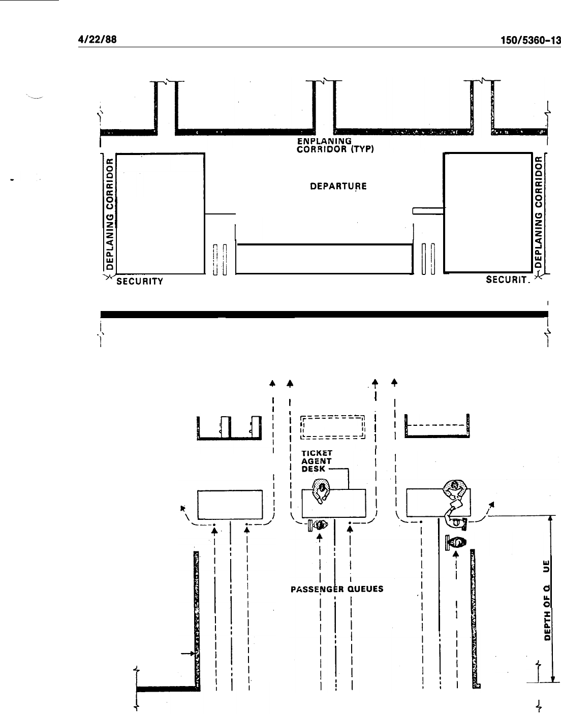
4/22/88
AC
150/5380-13
TO AIRCRAFT
TO AIRCRAFT
TO AIRCRAFT
I
CORRIDOR
k-
CORRIDOR
(STERILE AREA) .
z
I
I
CONCESSION
:
OR
OFFICE
Ti:URITY
COMBINED
DEPARTUPE
LOUNGE
(STERILE AREA)
CONCESSION
CONCESSION
O’R
OFFICE
SECURIT
.i\
I
1
Figure S-23.
Typical Combined Security/Departure Lounge Layout
PASSENGER
LOUNGE
WALL OR RAILING
f
4
I
TELEPHONES
1
4
.t
I
LAST-MINUTE
1
1
BAG DELIVERY ,
’
ry========$
j
I
II
I
,
Lb=;=====2
1
+
I
1
GARMENT BAGS
/
~------_
-$
I
m
4
I
I
I
I
I
5
5
PASSENGER
d
LOUNGE
t;
z
t:
0
‘,
,I
i
PUBLIC CORRIDOR
4
Figure S-24.
Departure Lounge Passenger Processing Area
81
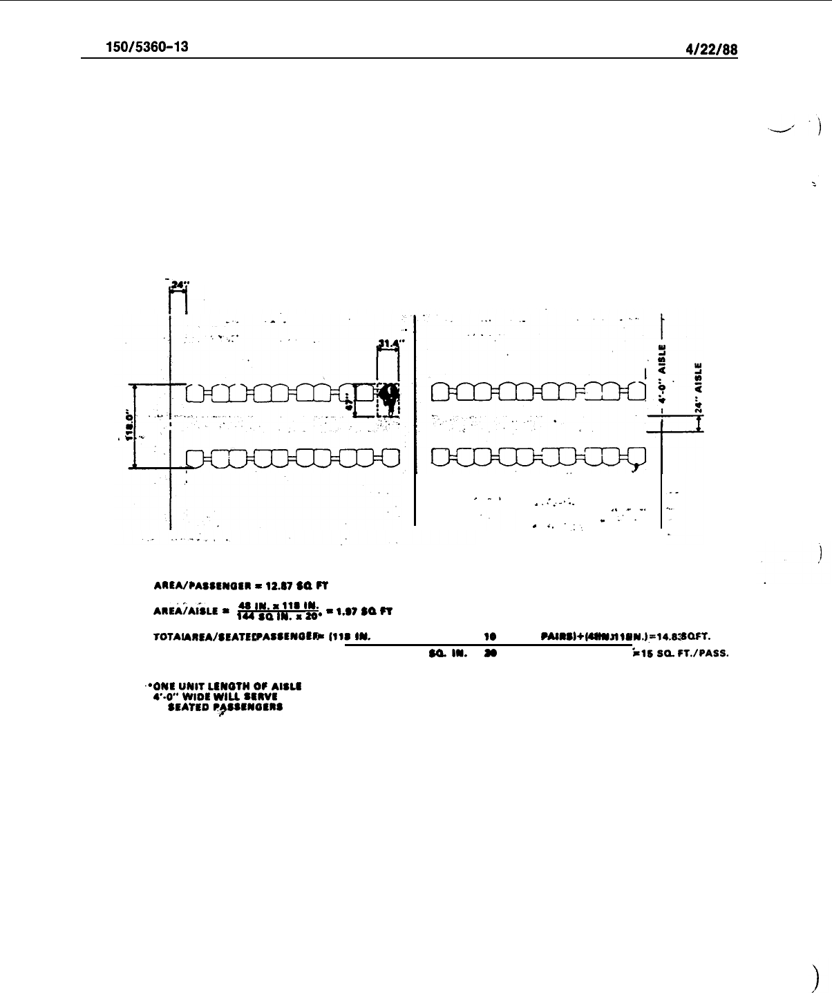
AC
150/5380-13
4/22/88
-24-
t-v
I
^.
.
.
.
.
.
.
.
.
.
.
,a
-.
-.
.
_’
.
.
i,
.:.,
ARtA/PASSCWOSR
=
12.07
SQ
FT
ASEijAiSLE
-
48
IN.
a
11S
IN.
144
so
IN.
x
2S*
-
‘.@’
sa
FT
TOTAL
Nl6A/sCAT6D
PASS6WO6X
-
(118
IW.
X 21.4 IN..
98
l ASR
PAlRS)+l4S
IN.
a
118
lW=14.63
SO.
FT.
114
$a.
la.
a
20
l 88eIom8
il6
SQ
FT./PASS.
,*ONt
UNBT
LEWQWI
OF
AISLS
4--O”
WIDE
WILL
SRSVL
20
SEAT6D
P~SSSWOERS
Figure 5-25.
Departure Lounge Typical Seating/Aisle Layout
82
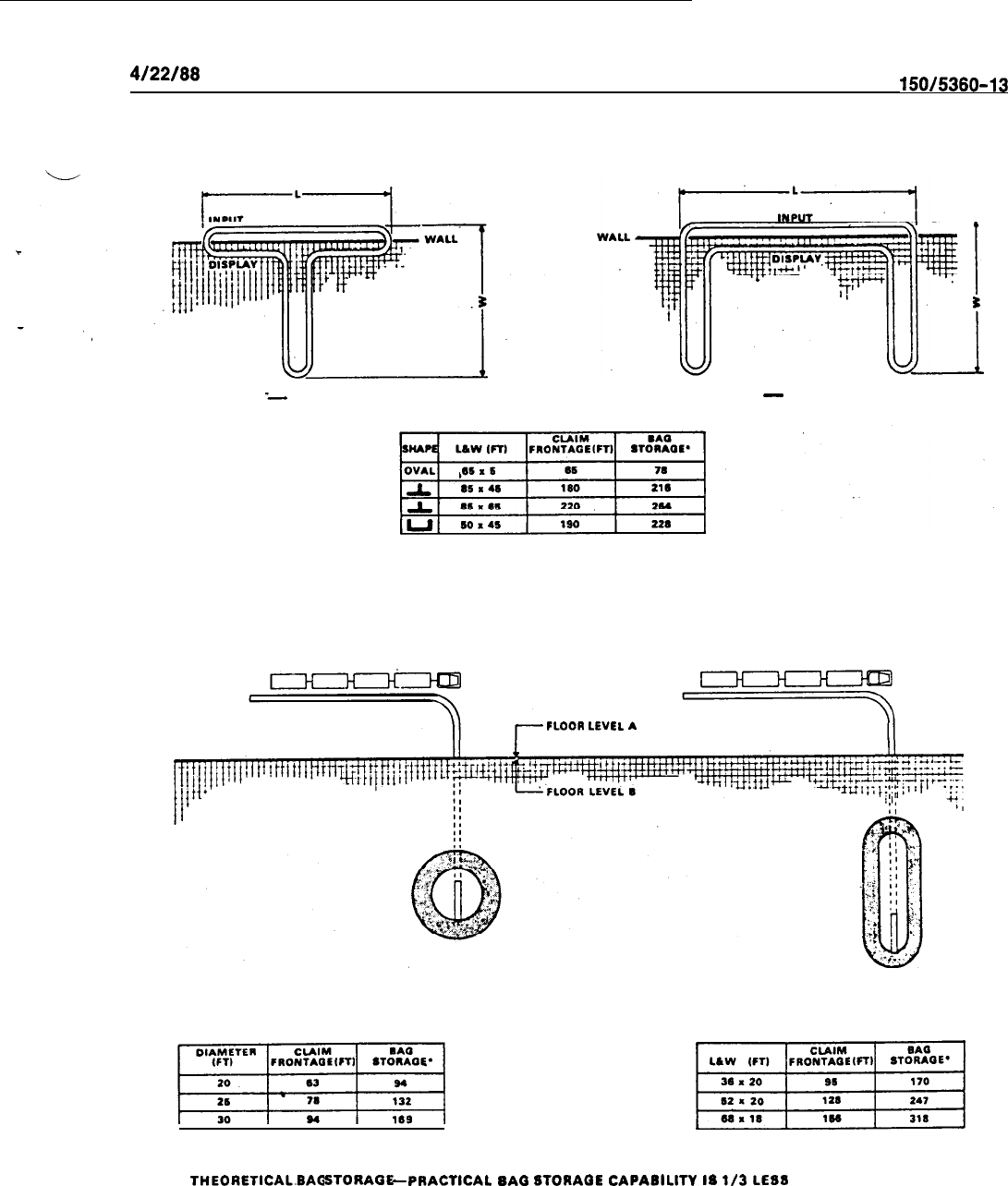
4/22/88
AC
150/5380-13
FLATBED
-
‘DIRECT FEED
FLATBED
-
DIRECT FEED
FLOOR
LEVEL
A
CIRCULAR
REMOTE FEED SLOPING BED
OVAL
REMOTE FEED SLOPING BED
\,i_
l
THEORETICAL.BAG
STORAGE
-
PRACTICAL
BAG
6TORAGE
CAPABILITY
IS
l/3
LEB8
Figure S-26. Mechanized Claim Devices
83

AC
150/5360-13
4122188
e.
A public claiming area may require railings or similar separation from other public space and con-
trolled egress to enable inspection of removed baggage for assurance of “positive claim.” At some terminals,
additional space may be needed adjacent to the claiming area for storage and security of unclaimed baggage
and for airline baggage service facilities (lost and found).
f. -For planning purposes, claim display frontage can be estimated by the use of either Figure 5-27 or
5-28. These nomographs utilize “Equivalent Aircraft Arrivals” (see paragraph 28) to approximate deplaning
passengers in a 20 minute peak period, assuming an average of 1.3 bags per deplaning passenger. The claim-
ing frontage requirements may be converted to baggage claim facility area requirements by, using Figure 5-
29. The value presented includes: space for public circulation; area normally required within a controlled
“positive-claim*’ facility; and space for airline baggage service facilities. It should be recognized that consid-
erable variance in space requirements occurs between airports due to airline company policies and the
number of airlines using a claim area.
.
g.
Figure 5-30 can be used to approximate the nonpublic space required to input and load bags onto
claim devices. The figure assumes a 22 foot (7 m) depth, 20 feet 6 m) for the
fixed
shelf, behind the input
section or belt for offloading carts and for passing/maneuvering. At many airports in mild climates, the non-
public baggage input area may be satisfied without complete enclosure in the’terminal building through use
of overhead canopies. This can also apply to the public baggage claim area at some low volume airports.
h.
The area approximations developed from Figures 5-29 and
5-30
assume a relatively efficient use of
building space. At existing terminals being modified to accept a claim device installation, additional space
per foot of claim display may be required because prior column locations limit the efficient area use.
i. The baggage claim lobby area for public circulation and passenger amenities and services is dis-
cussed in paragraph
69~.
76. AIRLINE OPERATIONS AREAS.
a.
Airline operations areas are those areas occupied by airline personnel for performing the functions
related to aircraft handling at the gate. Composition of functions will vary among individual airports. The
following areas are most commonly required:
I
(1)
Cabin Service or Commissary
-
an area for the storage of immediate need items for providing
service to the aircraft cabin.
(2)
Cabin Service and Ramp Service Personnel
-
an area for training facilities and a ready/lunch
room.
(3)
Aircraft Line Maintenance
-
for supplies, tools, storage, personnel, etc.
84
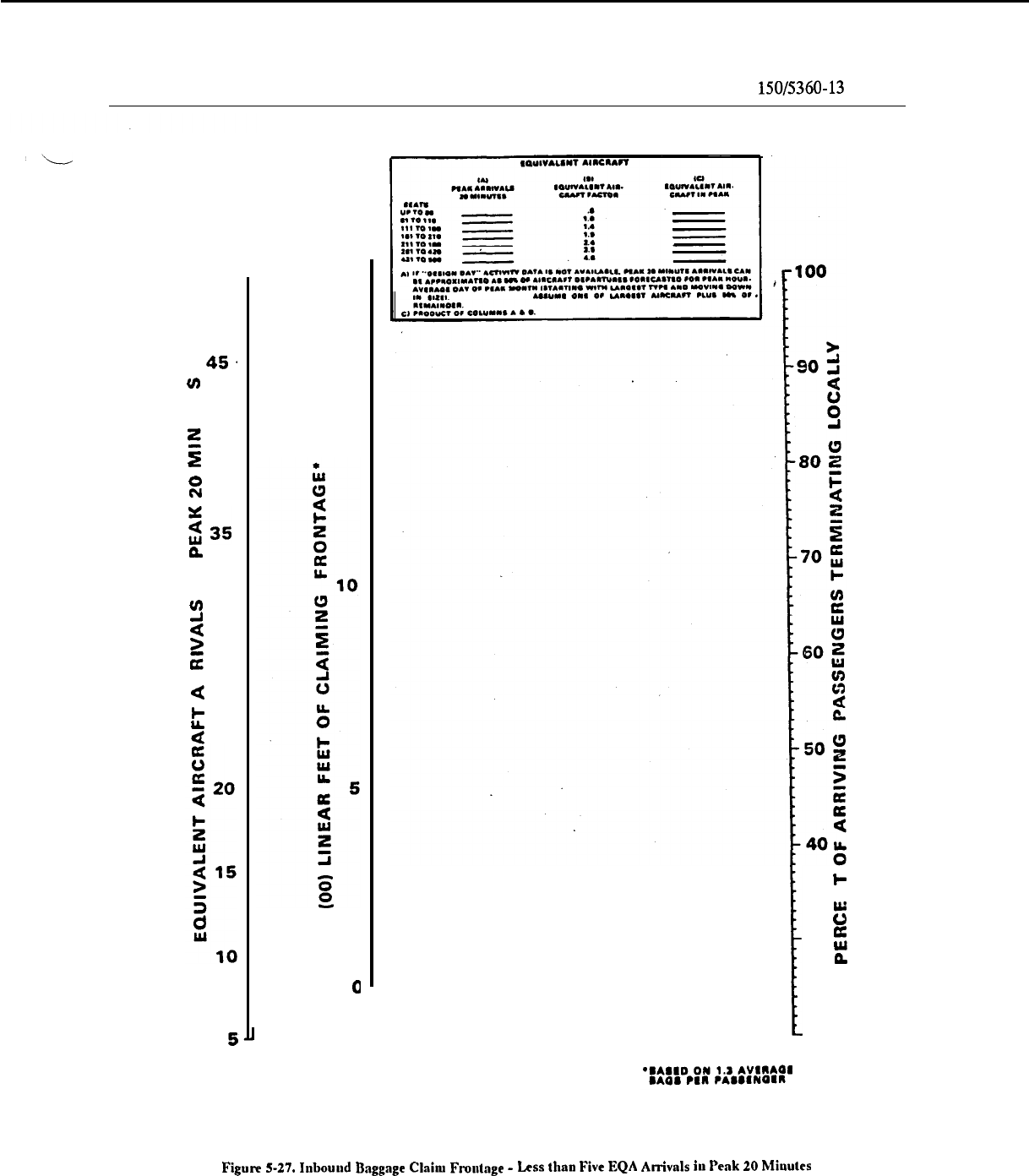
i/19/94
AC
150/5360-13
CHG 1
50 .
45.
cn
5
;
40
::
z35
nm
2
w
2
30
5
z
c
’
25
t
a
15
a
I
I-
2
s
30 E
P
20
Figulp
S-27.
Inbound
Bsggnge
Claim
Frontage
-
Less
tlmn
Five
EQA
Arrivnls
iu
Peuk
20
Miuutcs
85
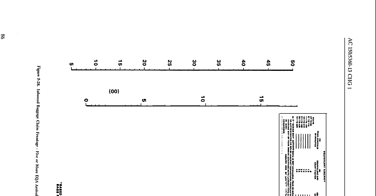
EQUIVALENT AIRCRAFT ARRIVALS IN PEAK 20 MINUTES
(00)
LINEAR FEET OF CLAIMING FRONTAGE*
0
VI
0”
ii
1.
*
*.
. .
.‘.
1..
.
*.
. . .
.I..
. .
..a
L
*
1.
.
..-.
l”““‘~‘I”“““‘I”““‘~‘I’~“‘~“‘,“““”’,””””’I””””~l’~~~~*~
ii
ow
g
El
8 2
g
iii
E;
PERCENi
OF ARRIVING PASSENGERS TERMINATING LOCALLY
0
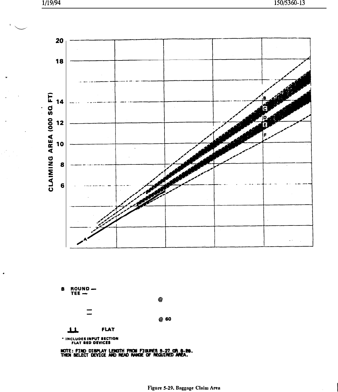
l/19/94
AC
150/5360-13
CHG 1
16
.
4
2
0
100
200
300
400
500
LINEAR FEET OF CLAIM DISPLAY
AREAS’ FOR OPTIMUM CONFIGURATIONS OF:
A FIXED SHELF
B
Ki~No
-
SLOPING BED/REMOTE FEED
-
FLAT BED/DIRECT FEED
C
TEE AND U-SHAPE ALTERNATING
@
75’
(FLAT BED/DIRECT FEED)
0 OVAL
-
FLAT BED/DIRECT FEED
OVAL
-
SLOPING BED/REMOTE FEED
E
TEE-AND U-SHAPE ALTERNATING
@
50
(FLAT BED/DIRECT FEED)
F
IJ.
-SHAPE
FLAT
BED/DIRECT FEED
*
INCLUDtS
INPUT
SECTION
Of
FIAT
110
DavlcIs
ROTE:
FIm
DImAY
l.aolH
RIQl
FIQRES
s-n
m
6-m
TlEN5ELEcTEvIcEmfEmRMcEaF#onlEo~.
Figuw
S-29.
Bnggnge
Clnilu
Area
87
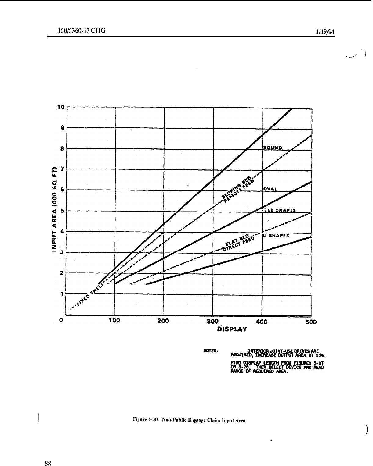
AC
150/5360-13
CHG 1
l/l
9194
LINEAR FEET OF CLAIM
dlSPLAY
noTE9:
WERE
IMTERIOR
JOINT-ILSE
CRIVES
ME
REamED,
I-
MFUT
MEA
BY
354.
.
88
4/22/aa
AC
150/5360-l
3
(4)
Oftke.Area
-
for managerial personnel and clerks.
(5)
Flight Operations Facilities
-
includes a message center, area for meteorological data and flight
‘U
plans, and flight operations personnel.
(6)
Flight
Crew
and Flight Attendant Facilities
-
includes an area for resting, toilet facilities, and per-
sonal grooming area.
(7)
Secure Area Storage
-
for items requiring secure storage because of either the value or fragility
of the items.
(8) Volatile Storage
-
fdr items requiring extra precautionary storage due to instability in handling
and storage.
b.
Storage and administrative areas often can and are combined. Depending on flight schedules, flight
crew and flight attendant facilities may not be required or can be combined with facilities for other airline
personnel. Similarly, facilities for flight operations and administrative personnel can be combined.
c.
The area required for airline operations may be estimated for planning purposes on the basis of 500
square feet (46.5
m’)
per equivalent peak hour aircraft departure. This factor includes all of the operations
areas previously described. However, at some airports one or more airlines may use additional terminal
space for regional or airline system functions and/or other support services beyond those functions common
to daily airport operations.
77. FOOD AND BEVERAGE SERVICES.
a.
These s&vices include snack bars, coffee shops, restaurants, and bar lounges. The basic service of-
fered at small airports is the coffee shop, although separate restaurants at some smaller city airports can be
successfil, depending on the community and restaurant management. Large airports usually can justify sev-
eral locations for snack bars, coffee shops, bar lounges, and restaurants. Requirements for more than one of
each type are highly influenced by the airport size and terminal concept involved. Unit terminals, for in-
stance, may require coffee shops and/or snack bars at each separate terminal.
-
b.
Generally speaking, a coffee shop seating less than 80 is considered an uneconomical operation at
airports enplaning over one million passengers annually. At smaller airports, the seating capacity minimum
may be somewhat lower, depending on such factors as local labor costs and concessionaire lease
arrangements.
c.
The following ranges appear representative for food and beverage services:
(1)
Turnover rates: 10 to 19 average daily per seat.
Some
operators appear satisfied averaging 10 to
14 daily.
(2)
Space per seat: 35 to 40 square feet (3.3 to 3.7
m’)
per coffee shop/restaurant seat, including
support space.
(3)
Snack bars: 15 to 25 percent of coffee shop/restaurant overall space requirements.
(4)
Bar lounges: 25 to 35 percent of coffee shop/restaurant overall space requirements.
d. The sizing of food and beverage services involves applying “use factors.“ Use factors are deter-
mined by dividing the average daily transactions by average daily enplanements. Figure 5-31 shows ranges
of food and beverage service areas for coffee shop and restaurants, snack bar, bar lounge and kitchen sup:
port space for various “use factors.”
e.
For estimating and for initial planning purposes, the following average daily use factors are suggest-
ed:
(1)
40 to 60 percent at terminal airports with a high percentage of long-haul flights;
(2)
20 to 40 percent at transfer airports and through airports; and,
(3)
15
to 25 percent at terminal airports with a low percentage of long-haul flights.
a9

AC
150/5360-13
4/22/86
78. CONCESSIONAIRE AND BUILDING SERVICES. The following building and concessionaire serv-
ices are provided at airport terminals as appropriate for the size and activity of the airport. General area
ranges for many of these services are presented for planning purposes. Larger areas may be required. Figure
-/)
5-32 provides a nomograph for approximating total area requirements for those services discussed in sub-
paragraphs a. through s. The requirements presented in paragraphs t. through v. are determined separately
on a case-by-case basis.
a. News and tobacco are physically separate at most airports where annual enplanements exceed
200,000 per year, and may be combined with other services at airports with lesser traffic. Space allowance:
150 square feet minimum, and averaging 600 to 700 square feet (56 to 66
m’)
per million annual enplane-
ments.
b.
Gift and apparel shops
operations are combined with a newsstand at smaller airports. Separate facili-
ties normally become feasible when annual enplanements exceed one million. Space allowance: 600 to 700
square feet (56 to 66
m’)
per million annual enplanements.
.
c.
Drug store, including sale of books, cards, and liquor, may be feasible as separate operation when
annual enplanements exceed 1.5 million. Space allowance: 700 square feet (66 m’, minimum and averaging
600 to 700 square feet (56 to 66
m”)
per million enplanements.
d.
Barber and shoe shine operations at some large airports allow one chair per million annual enplane-
ments. The most successful operations range from three to seven chairs. Space allowance: 110 to 120 square
feet (10.2 to 11.2
m’)
per chair with 150 square feet (14
m”)
for a minimum facility.
e. Auto rental counters vary according to the number of companies. Space allowance: 350 to 400
square feet (33 to 37
m”)
per million annual enplanements.
f.
Florist shop operation as a separate function may become feasible when annual enplanements exceed
2 million. The usual space allowed is 350 to 400 square feet (31.5 to 32
m’)
per terminal.
g.
Displays (including courtesy phones for hotels). Space allowance: 90 to 100 square feet (8.4 to 9.3
m’)
per million annual enplanements.
h.
Insurance (including counters and machines). Space allowance: 150 to 175 square feet (14 to 16
m’)
per million annual enplanements.
i.
Public lockers require in the range of 70 to 80 square feet (6.5 to 7.4
m’)
per million annual enplane-
ments.
j. Public telephones space requirement is 100 to 110 square feet (9.3 to 10.2
m’)
per million annual
enplanements.
k. Automated post offices may be found desirable to the extent of providing one station, 125 square
feet (11.6
m”)
for each terminal serving at least 2.75 million annual enplanements.
1.
Vending machine items supplement staffed facilities, especially when extended hours of operation are
not justified by low volumes or multiplicity of locations. When vending machines are provided, they should
be grouped and/or recessed to avoid encroaching upon circulation space for primary traffic flows. Space
allowance: 50 square feet (4.7
m’)
minimum or 150 square feet (14
m”)
per million annual enplanements.
m.
Public toilets are sized for building occupancy in accordance with local codes. Space allowances
applied at airports vary greatly. They range from 1,500 to 1,800 square feet (140 to 167
m”)
per 500 peak-
hour passengers (in and out) down to 1,333 square feet (124
m’)
per million annual enplanements at large
hub airports.
n.
Airport management offices’ space requirements vary greatly according to the size of staff and the
extent to which airport authority headquarters are located in the terminal. Accordingly, Figure 5-32 ex-
cludes space requirements for airport authorities and includes only such
sljace
as is representative of an air-
port manager and staff.
o.
Airport Police/Security Office space needs vary according to based staff and nature of arrangements
with local community law enforcement agencies.
90
4/22/88
AC
150/5360-13
p.
Medical aid facilities’ space requirements range from that needed for first-aid service provided by
airport police to that for branch operations at off-airport clinics.
:-
q.,
USO/Travelers
Aid facilities vary considerably. Space requirements are relatively minor, 80 to 100
square feet (7.4 to 9.3
m2),
except at airports with annual enplanements of over one million.
r.
Nursery facilities for travelers with small infants have been provided at airports with annual
enplan-
ements of over 1 million. The most practical solutions include a private toilet room of 50 to 60 square feet
(4.7 to 5.6
m’)
with facilities for changing and feeding. The number of such facilities may range from two
w
up, depending upon terminal size and configuration.
s. Building
n@ntenance
and storage varies, depending upon the types of maintenance (contracted
versus authority operated) and storage facilities available in other authority-owned buildings.
t. Building mechanical systems (HVAO space ranges from 12 to 15 percent of the gross total space
approximated for all other terminal functions. A value of
‘10
to 12 percent is used in relation to the connec-
tor element space. This allowance does not cover separate facilities for primary source heating and refrigera-
tion (H&R plants).
II.
Building structure space allowance for columns and walls is 5 percent of the total gross area ap-
proximated for all other functions.
v.
Other space, as determined on a case-by-case basis, may be required at some airports for informa-
tion services, government offices, contract service facilities and the like.
79.
-
90. RESERVED.
91
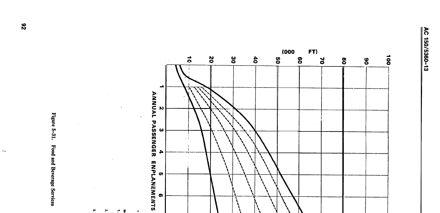
GROSS AREA
(000
SQ
FT)
0”
g
%
::
Fi
0’
L
L
\
\
\
\
‘\
k----t-
\
\
\
\
!
‘,
I\
-+-
\
\
b
%
‘i.
%*
3
1
‘\\
‘\
\
r
\
\
\
\
\
\
\
\
\
‘,
\
\
\
-
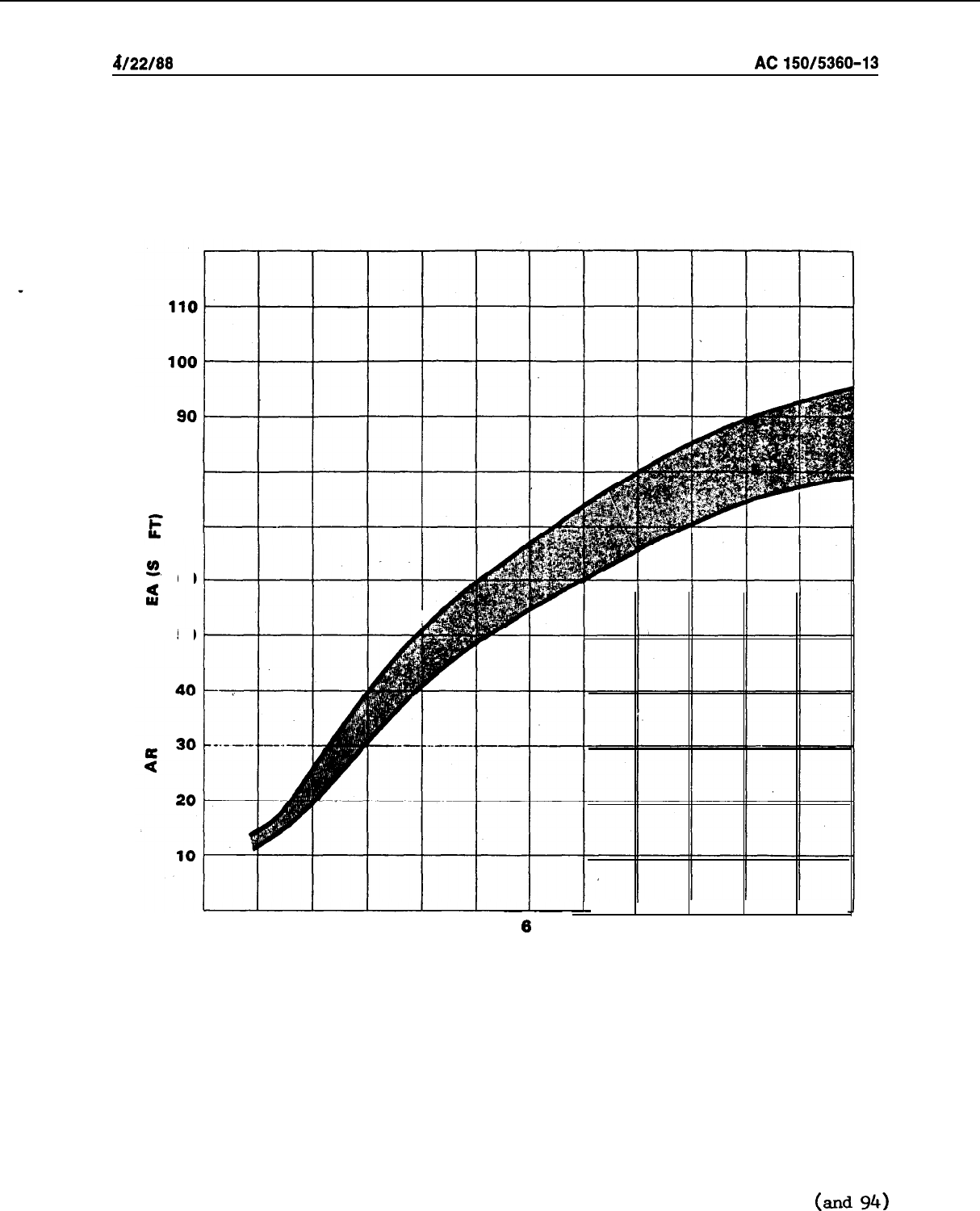
d/22/88
AC
150/5360-13
80
E
70
d
%
60
lu
9
50
I
I
I
I
I
1
2
3
4
5
0
7
8
9
10
11
12
ANNUAL PASSENGER ENPLANEMENTS (IN MILLIONS)
Figure 5-32.
Concessions and building Services
93 (and
94)
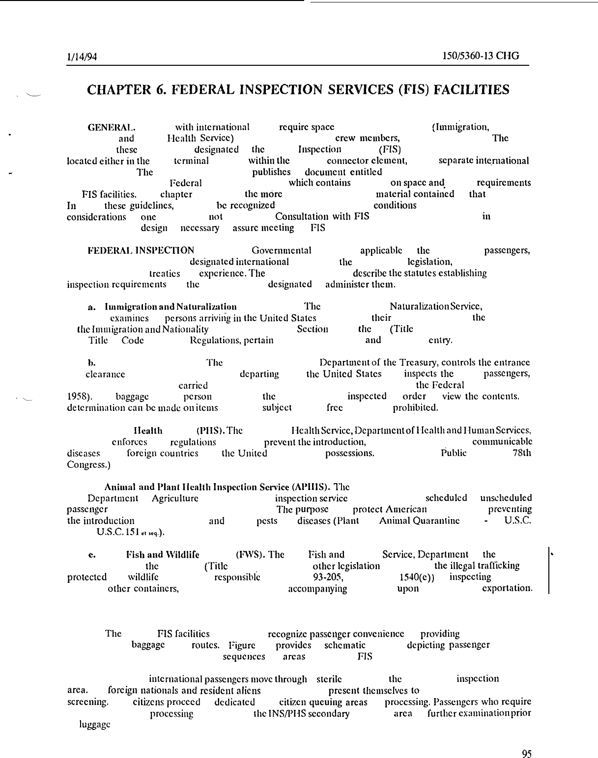
l/14/94
AC
150/5360-13
CIiG
1
,L
CHAPTER
6.
FEDERAL
INSPECTION
SERVICES
(FIS)
FACILITIES
91.
GENISRM. Airports with
intcrnntional
traffic rcquirc space for Fcdcral inspections
(lmmi~ralion,
Customs,
Agriculture,
and
Public
I-lcaltl~
Schvicc)
of passcngcrs, aircraft, crew mcmbcrs, baggage, and cargo. The area
rcquircd for thcsc proccdurcs is dcsiguntcd as the Fcdcral
luspcction
Scrviccs (FIS) facility. This facility is generally
located
either
iu
the main terminal building, within the terminal
connector
clcu~~~t,
or in a scparatc intc,ruational
-
arrival building. The U.S. Customs Scrvicc publishes a
docuwxlt
eutitlcd
“Airports--U.S.A. and Prcclcarance
Facilities-- Guidclincs for
Federal
lnspcction Scrviccs,” which
contaius
guidance
011
space
and.
facility requirements
for FIS facilities. This
chapter
summarizes the mdrc important aspects and
material
contained
in
that
document.
In using these guidclincs, it should
bc
rccoguizcd that variations in local
couditions
may require special facility
considerations
at one airport, but uot at another.
Consultatiou
with FIS and airline rcprcscutatives in the early
stages of terminal dcsigu is
~~cccssary
to assure mcetiug all FIS rcquiremcnts.
92.
FEI~ERAL
INSl~lX’I’ION
SERVICES.
Governmental
proccdurcs applicable to tllc clcaraucc of passengers,
baggage, and cargo arriving at dcsignatcd
intcruational
airports are the outgrowth of Icgislation, law, administrative
regulations, bilateral trcatics and cxpcriencc. The following paragraphs dcscribc the
statutes
establisl~ing
applicable
inspcctiou
rcquircmcnts
and the Fcdcral services dcsignntcd to ndministcr
tl~cm.
a.
lwnigra~ion
and
Natur:tliultiou
Scrviccs (INS).
‘I’hc
Immigration and
NaturnlizationScrvicc,
Departmeut
of Justice, cxamincs all persons
arrivilig
in
t!lc
United
States to dctcrminc
their
admissibility under the provisions
of
tltc
Immigration
artd
Nntiouality Act (66 Stntutc 163). Scctiou 239 of
tllc
Act (Title 8, U.S. Code 1229) and Part
239, Title 8, Code of Fcdcral
llcgulations,
pertain
specifically to aircraft aud airports of entry.
1).
Customs Service (USCS). The U.S. Customs Scrvicc,
Dcpartmcntof
the Treasury, coutrols the
entrauce
and clcarancc of aircraft arriving in and dcpnrting from the
United
States and inspects the crew, passcugers,
baggage, slorcs, and cargo carried thereon (Tariff Act of 1930 and Section 1109 of the
Federal
Aviation Act of
1958).
The
bnggagc
of any pcrsou arriving in
tltc
country may bc iuspcctcd in
order
to
view
the
contents.
A
detcrmiuatiou
cnu
lx
made
011
items which arc subject to duty, free of duly, or
proh/bitcd.
c.
Public
Ile:~lth
Scrvicc
(PIIS).
The U.S. Public l~caltl~Sclvicc,Dcl~artmct~tof
IIcnltltand
I-lumnnScrviccs,
mnkcs and
cnforccs
such rcgulntions rcquircd to prcvcut the
iutroduction,
transmission, or spread of communicable
discascs from foreign
countries
into the
United
Stntcs or its possessions.
(Scctiou 361,
lhblic
Law 410, 78th
Congress.)
.
d.
Aniu1:11
:md
Pl:rt~l
llcsltl~ lnspcction
Service
(APIllS).
1’11~
Animal and Plant Health lnspcction Scrvicc,
U.S.
Dcpartmcnt
of Agriculture (USDA), provides inspection
scrvicc
at all airports with schcdulcd or
unscheduled
passcngcr aircraft arrivals from forcigii couiitries.
The
l~urposc
is to
protect
Amcricati agriculture by prcvciitiiig
the
iutroduction
of injurious plant atld animal pests and discascs (Plaut and
Animal
Quarantine
Acts
-
21
USC.
111. 7 U.S.C.
151
e,
seq.).
e.
U.S.
Fish
and
Wildlife
Scrvicc
(FWS).
The U.S. Fish
aud
Wildlife Sctvicc.
Dcpartmcnt
of the Interior,
in accordaucc with tllc Lnccy Act (Title 16 USC 3372) and
other
lcgislatiou dealing with the illegal traffickiug of
protected
fish, wildlife and plants, is rcsponsibic (Public Law
93-2OS,
Title 16 USC
1540(c))
for inspecting packages,
crates, or
other
containers,
including contents and all accompattyitlg documents,
upon
importation or
exportation.
93. PASSENGER FLOW SEQUENCE.
a. The internal FIS facilities layout should rccognizc passcngcr couvcuicucc by providing simple and direct
passenger and baggage flow routes.
Figure 6-l provides a schematic diagram depicting passcngcr flow and
functional adjacency rcquiremeuts and sequcuccs for
arcas
at a typical FIS facility.
b.
Deplaning
iutcruationnl
passcngcrs move through a stcrilc corridor to
tllc
INS primary inspcclion queuing
arca. All foreigu
nationals
aud
rcsidcnt
nlicns arc rcquircd to
prcscnt
tl~cmsclvcs
to an INS officer for primary
screening. U.S. citizens proceed to
dcdicntcd
U.S. citizcu queuiug arcas for processing. I’asscngcrs
who
require
additional INS/PI-IS processing arc rcfcrrcd to the INS/PHS secondary iuspcction arca for
further
cxamiiintioitprior
to
luggage
rctricval.
95
AC
150/,(360-13
CHG 1
l/19/94
c.
Upon completion of INS processing, passengers move to the baggage claim area for luggage retrieval.
Passengers
then
move to the USCS primary inspection queuing area for USCS/APHIS primary screening.
Passengers requiring additional USCS or APHIS processing arc referred to the appropriate secondary counter.
After all necessary
scrccnlndprocessing
is complete, passengers go directly to the cashier and/or exit.
94.
PRECLEARANCE FACILITIES. The FIS staff
operate
predcparture (preclearance) inspection facilities in
certain foreign countries for flights destined to the U.S. However, these prcclearance facilities differ in certain
aspects of the inspection sequence and required facilities from those in the U.S.
a. Passengers processing through a prcclearance facility flow through the terminal area not controlled by the
FIS to the airline check-in counters. After check-in, all passengers and their baggage should be
directed
toward
the USCS counters in the FIS controlled area for primary screening.
b.
Passengers not requiring additional USCS/APHlS processing go directly to the cashier or the baggage
drop-off area, which is
immediately
adjacent to the USCS processing area.
Passcngcrs requiring additional
USCS/APHIS processing arc
directed
to the appropriate
sccondafycounterlocatcd
immediately behind the primary
inspection area. After this processing, passengers proceed to the cashier or baggage drop-off area,
c.
After Customs processing, passengers
dc.posit
their
baggage onto baggage conveyors for transport to a
sterile holding arca until
ready
for loading onto
their
aircraft. The baggage is dchvcrcd to the aircraft under such
physical and procedural controls
required
by the USCS to ensure its sterility.
d.
From baggage drop-off, passengersprocecd to the INS primary
counters
for primary screening. Passengers
not requiring additional screening proceed to the stcrilc
dcparturc
area.
e.
Those passengers requiring additional
INS/PI-IS
processing are
dircctcd
to the INS secondary inspection
area. Upon completion of all INS/PI-IS processing, passengers admitted to the U.S. go to the stcrilc departure area.
f.
All FIS cleared passengers are required to remain in a sterile waiting area until boarding the aircraft.
No downstream concessions or
unauthorized
personnel arc allowed in this arca.
The
enplaning of passengers and
loading of baggage requires a
proccdurc
which prohibits contact with
unauthorized
persons or objects when in
transit from their respective sterile areas to the aircraft. Loading bridges (jetways) and corridor security
requirements are the same as those for FIS facilities located in the United States.
h.
Figure 6-2 provides a schematic diagram showing passenger flow and functional adjacency requirements
aud sequences at a typical preclearance FIS facility.
95. GENERAL DESIGN CONSIDERATIONS AND REQUIREMENTS.
a. Passenger routings should bc as short and straight as possible and
unimpeded
by any form of obstruction,
including crossflow traffic.
b.
Strict segregation of deplaning passengers bctwecn the aircraft and the exit from the FIS is required. This
is done to eliminate the possibility of items being passed from
international
passengers to the waiting public or the
bodily substitution of a disembarking passenger by a member of the waiting public. Two flow routes for deplaning
passengers are required; one for international traffic and one for domestic traffic. To the extent possible, flow
routes for international traffic deplaning through each carrier’s gate should fumtcl into a common passageway
before entering the FIS area.
Passenger routing should be so designed that there is
no
possibility of a crew
member or passenger being able to bypass the inspection area.
c. Multilingual signs and pictorial
(intcrnationnl)
signs to
direct
traffic arc required.
AC
150/5360:12,
Airport Signing and Graphics.)
(Refer to
d.
The
Federal
inspection area requires
separation
by a physical barrier from domestic passenger facilities.
In the case of prcclearance
operations,
the FIS arca also requires scgrcgation from
other
international
traffic.
96
.
l/19/94
AC
150/5360-13
CI-IG
1
STATESIDE
f!S
f
ACIUTY
HoLolNG
MEA
I
PMS
ANTE
ROOM
7
ISOUTION
nOOM
TOUtiUV
/SnOwER
4
I
UaoaATav
I
97
AC
150/5360-13
CHG 1
l/19/94
e.
Entrances and exits in the FIS area require controlled status. Adequate security precautions, including
the installation of alarm devices on unlocked windows and doors, are required. Alarms sounding at a central point
within the FIS complex are required.
1.
At airports with sizable continuing passenger traffic (in-transit) to a foreign country or an onward
U.S.
port of entry (progressive clearance), a sterile waiting area should be provided to avoid needless congestion around
the baggage claim area. The sterile area requires a design which
wili
prevent co-mingling of in-transit passengers
with domestic or previously cleared passengers.
g.
It is necessary that baggage be delivered from the aircraft to the claim area in a manner which precludes
access by unauthorized personnel and/or mixing with domestic or interline baggage. A secure, temporary storage
facility close to the FIS area is required for baggage awaiting USCS inspection.
h. The arrival of baggage and deplaning passengers in the baggage claim area should coincide as nearly as
possible. Only those passengers terminating at this facility should be in the are?.
i.
The baggage claim area should be of ample dimensions to prevent impediment in the flow of
passengers
from baggage claim to the FIS area.
i
In the FIS area, airline activities such as on-line or inter-line baggage processing, ticketing,
etc.;
are not
authorized.
In.
Baaage
carts should be made available for passenger use to facilitate movement through the
in-
spectional process.
1.
Glare-free lighting is required at inspection points and in examination rooms. Indirect lighting of at least
90
foot candles (972 lux) is preferred. The FIS should be appropriately heated and air conditioned.
m.
FIS facilities should normally be confined to one floor of the terminal building, preferably on the same
level where the passengers deplane.
Convenient access to the ground transportation vehicle loading platform on
the
landside
of the terminal is highly desirable.
n.
The cashier’s‘booths need to be located so that they will not obstruct the
generaiflow
of passengers from
the FIS area.
o.
All doors leading out of the FIS area are required to be opaque to prevent visitors from observing the
inspection process.
p. The main passenger exits need at least one set of double outward opening doors, preferably of an
automatic type, located to facilitate the flow of passengers out of the area.
Also,
the area immediately outside the
exit doors should be kept clear
from
congregation of
pertins
so that passenger egress is not hindered.
q.
All doors
noi
designated for passenger use iri the FIS a&a require automatic
doo;closers
ahd dead bolts.
r. Those doors in the FIS area which serve as emergency exits require: alarm exit lockswith a crowd release
bar, a loud gong alarm when the release bar is activated; and a mortise cylinder key lock which will deactivate the
I
gong but will register on a remote indicator panel. Battery operated alarms are not acceptable on emergency alarm
exit locks. A
cppabilify
for evacuating non-cleared passengers j-om the
FIS
area to a nearby holding area until
resolution
of
an
emergency should be
consiciered
in
rhe
buikiing
design
process.
s.
If a visitors waiting room is provided, it should be at a sufficient distance from the FIS exit(s) so that
passenger egress is not restricted.
The room should be sized to house the normal volume of visitors. As
visitor/passenger ratios vary among airports, a visitor/passenger ratio study should be accomplished before a waiting
room is designed.
98
l/19/94
AC
150/5360-13
CHG 1
’
‘-
SUPERVISOR’S
OfCICE
INS
GENERAL
OFFICE
L
I
I
Figuw
6-2. FIS
I’pccIca~-;~~~ce
F;lcility
Il~nchnl
hdcquncy
Dingmu
99

AC
150/5360-13
4/22/88
t. A closed circuit television system should be installed with cameras placed in all areas of concern to
FIS agencies. These areasinclude loading bridges, sterile concourses, baggage delivery areas, the apron, and
the entire FIS inspection area. Monitors should be located in an elevated command module.
u.
Public telephones are not authorized in the FIS area.
v.
Public toilets provided for deplaning passengers are required to meet FIS security standards and to
be located prior to the INS inspection area.
96. INS REQUIREMENTS.
a. Off-Line Secondary Inspection Waiting.
Secondary inspection counters, an interviewing room or
rooms, and a waiting area are
.required.
b. General Office.
Office
space to accommodate inspectors when not at inspection counters is re-
quired. The minimum need is for one desk space per primary inspection booth and secondary position.
.
c. Automated Equipment Room.
A lockable room with conduit connections for computer terminals to
the primary and secondary inspection booths is required.
d.
Supervisor’s Office.
The supervisor’s
office
requires a location to permit the supervisor to view the
primary inspection area through a clear glassed wall.
e. Other Rooms.
Primary inspection booths, detention rooms, and lab equipment rooms are required.
The INS should be consulted for details.
97. USCS REQUIREMENTS.
a. Treasury Enforcement Communications System
(TECS)
Room.
The primary work station houses a
cathode ray tube (CRT) unit connected to TECS. The rear of the secondary work station houses a
high-
speed printer which is connected to the CRT. This equipment is supplied, installed, and maintained by the
USCS. However, provision for electrical/signal line hook-ups is required, free of charge, as part of the fa-
cility construction.
i
b. Baggage Inspection Belts/Counters.
(I)
The USCS secondary inspection counters are located directly behind the USCS primary inspec-
tion area. The use of stainless steel counters is acceptable.
(2) A visual signaling system, able to be activated by the inspector, is required in a conspicuous
location which is also visible from the exit side of the secondary inspection counters.
(3)
At preclearance sites, a call button or similar arrangement for FIS
offcers
to summon assistance
from airport/local police is required.
(4)
Provision of an intercom to facilitate communication between FIS primary, secondary areas, su-
pervisors’ offices and the command module is recommended.
c.
Searchrooms.
At least two windowless searchrooms are required within the USCS office area.
These rooms require a minimum of 80 square feet (7.4
m”)
each and a location beyond the baggage inspec-
tion area. For the safety of the USCS
offtcers,
each room needs: a push button to actuate a trouble buzzer
and a call-light; outward opening doors; and a table (without drawers) and a bench both anchored or bolted
to the floor or wall. The room cannot contain unsecured objects which can be used as weapons. The room’s
interiors should be aesthetically in keeping with other airport facilities.
d.
Cashier Booths.
At airports with USCS cashiers, a booth is required near the exit door positioned
to not cause congestion at the exit area. The booth should be large enough to accommodate two cashiers
and have proper heating ventilation, and lighting.
e. Office Area for USCS Supervisors.
The principal supervisors’
offtce
should be so located in the
USCS inspection area as to permit observation of the baggage inspection counters and the entire USCS area
from the
office.
Space is required for an audio/visual indicator panel linked to USCS primary and secondary
inspection areas. There should be no means of access to this office by, the general public (as distinguished
/
100

4/22/88
AC
150/5380-13
‘\-
from arriving passengers). At high-volume airports, with an airport director or officer-in-charge, additional
office space is necessary for this person and a secretary.
f.
General Office Area.
There should be some means of access by the general public (as distinguished
from arriving passengers) to the
WCS
office without passing through the inspection area. This is to
facili-
tate claiming of unaccompanied baggage, registration of personal effects, requests for USCS information,
and providing for the entrance and clearance needs/requirements of the airlines.
g. Vault. A security vault is required in the USCS office area at major airports. The vault’s walls,
floor, and ceiling require a minimum of 8 inches (20 cm) of steel-reinforced concrete, or structural equiva-
lent thickness, with a steel door and combination lock. The door and frame unit have the following specifi-
cations:
(1)
Thirty man-minutes against surreptitious entry;
(2) Ten man-minutes against forced entry;
(3)
Twenty man-minutes against lock manipulation; and
(4) Twenty man-minutes against radiological techniques;
At small general aviation airports, a steel safe with combination lock is required.
h. Agent Space. At airports with assigned Customs agents,
office
space commensurate with the
number of officers assigned is required and should include lockable cabinetry to store service weapons.
i.
Security Requirements.
The security of the area is essential for protecting the integrity of baggage
inspection. Structural treatment to support this need is required. Basic security requirements are as follows:
(1)
Visual or physical contact between waiting friends and relatives with arriving passengers is not
authorized until after FIS processing. Glass partitions are not authorized in new facilities. Glass partitions in
existing facilities are required to be painted, frosted, or otherwise covered, to ensure privacy of the baggage
examination.
(2)
Appropriate measures to screen the processing area should be taken to eliminate visual or physi-
cal contact by friends or relatives of enplaning or deplaning passengers.
.(3)
The FIS area is a restricted area and may be used only for processing passengers. No airline
interline counters, baggage return belts or other counters for commercial transactions are authorized within
this area. Baggage carts should be provided by the airport since skycaps are not allowed in the area.
(4)
A visual signaling system
iS
required to enable the inspector to signal for assistance. These lights
should not be readily visible to passengers.
98. PHS REQUIREMENTS.
a.
The PHS requires office space and an isolation area. It is imperative that the PHS office, especially
the isolation area, be located contiguous to the FIS inspection area. The isolation area consists of an ante-
room with a lavatory and shower, an isolation room, and an adjacent private toilet with shower, water
closet and lavatory. The
offlice
area and the entire isolation area may have their air supply (heating and
cooling) needs met by the facility ventilation system. However, exhausted air from this area is required to be
vented directly to the outside (without recirculation within the area or facility) by ,a separate
,exhaust
system. The isolation area requires an area of not less than 160 square feet (14.9
m’)
and the capability of
accommodating a hospital bed, bedside stand, and chair.
b.
The PHS requires primary inspection booths, similarly constructed to INS booths, in the INS pri-
mary inspection area at all airports which receive refugees.
c.
PHS approval of proposed projects concerns the availability’of adequate human waste removal and
disposal from international
.aircraft
arrivals. The PHS should be contacted for specific definition of
requirements.
101

6
AC
150/5360-13
4/22/88
99.
APHIS REQUIREMENTS.
a.
APHIS inspection personnel examine cargo and aircraft for pests and for items of agricultural
inter-
est and cooperate with the USCS in the inspection of passengers’ baggage. The space and facilities from
which they operate require a location adjacent to the USCS baggage inspection area, with both physical and
visual access to that area. The office and laboratory are ordinarily separated with a full partition and a door.
Adequate lighting and electrical outlets are required. A clear glass panel (not floor to ceiling) with Venetian
blinds is required in the wall between the office and baggage examination counters. Additional space for
first line and higher level supervisors and administrative staff, as well as a small climated controlled room
for detector dogs, may be required on a case-by-case basis.
.
b. The special equipment to be provided as part of the APHIS laboratory space consists of the
following:
(I)
Double drainboard and stainless steel sink;
(2) Undercounter storage cabinets;
(3) Commercial type, heavy-duty garbage disposal unit (the size requirement based on peak hour
passenger criteria);
(4)
Toilet facilities with shower (male and female); and
(5)
Counter top work space for microscopes and other such equipment.
c.
APHIS requires secondary ‘inspection counters in conjunction with Customs’ secondary inspection
counters. At some designated locations, their configuration will require a design to support secondary x-ray
screening systems. A work counter is required in the USCS/APHIS baggage inspection area at those loca-
tions where 400 or fewer passengers per hour are processed. Diagrammatic details for the work counter are
available from the APHIS.
d. APHIS approval of proposed projects is subject to availability of adequate international aircraft
garbage and refuse disposal facilities. Adequate facilities consist of either an incinerator, garbage cooking or
sterilizing apparatus, or equipment that grinds garbage and refuse for discharge into an approved sewage
system. The system or combination of systems selected requires a capability of handling all the garbage and
refuse from arriving international carriers on a daily basis. The sewage system utilized by the airport, as well
as the method of collection and transport of the garbage and refuse, require APHIS approval. Disposition of
any part of foreign garbage at landfills is not-authorized unless it has
first
been processed in an acceptable
manner. Without approved garbage handling facilities, galley cleaning or recatering is not permitted, and,
after passenger disembarkment, aircraft are required to fly either to an approved U.S. airport or a foreign
destination.
e.
A predeparture clearance for agriculture purposes only is presently carried out in Hawaii, Puerto
Rico,‘and the U.S. Virgin Islands. This clearance includes examination of passengers’ baggage, cargo, and
the aircraft’s quarters, stores, and cargo pits. Such inspections in Hawaii and Puerto Rico are conducted by
APHIS personnel. At airports where this predeparture inspection is performed, adequate examination
counters (configured to support x-ray systems, as required) queuing space, checked baggage security, and
accompanying
office
and laboratory facilities are required. Details regarding these requirements can be ob-
tained from the APHIS.
100. JOINT FIS EMPLOYEE REQUIREMENTS.
a.
Employee Locker Rooms.
Rooms of sufficient size to permit one locker for each full-time
inspec-
tional employee assigned to passenger processing are required for male and female employees.
b.
Employee Toilets.
sible to the public.
Men’s and women’s toilets are required for employees and should not be
acces;
.
c.
Lunch/Break Room. The area provided for inspection personnel requires a counter type sink and
space for the installation of a stove and refrigerator. It is recommended that this room be in close proximity
to the passenger processing area to minimize passenger processing delays.
)
102

4/22/88
AC
150/5360-13
d. Conference/Training Room. A conference training room should be provided at major airports for
meetings and the training of inspection personnel.
‘L
.
,
101. SPACE AND FACILITY REQUIREMENTS. Table 6-l depicts space and facility requirements for
typical FIS facilities at international airports. These requirements are based on one inspection area in a ter-
minal and
one
terminal at an airport. Detailed drawings and specifications for all work stations, inspection
belts, and electrical requirements are available through the respective FIS national headquarters.
102. APPROVAL OF FIS FACILITY PLANS. Approval of FIS facility plans and specifications is the
joint responsibility of the
USCS,
APHIS, and INS. INS approves for INS and PHS. Approvals for FIS
plans may only be obtained from the national headquarters. Addresses and phone numbers of the national
headquarters of the FIS are listed in appendix 3.
103.
-
115. RESERVED.
103
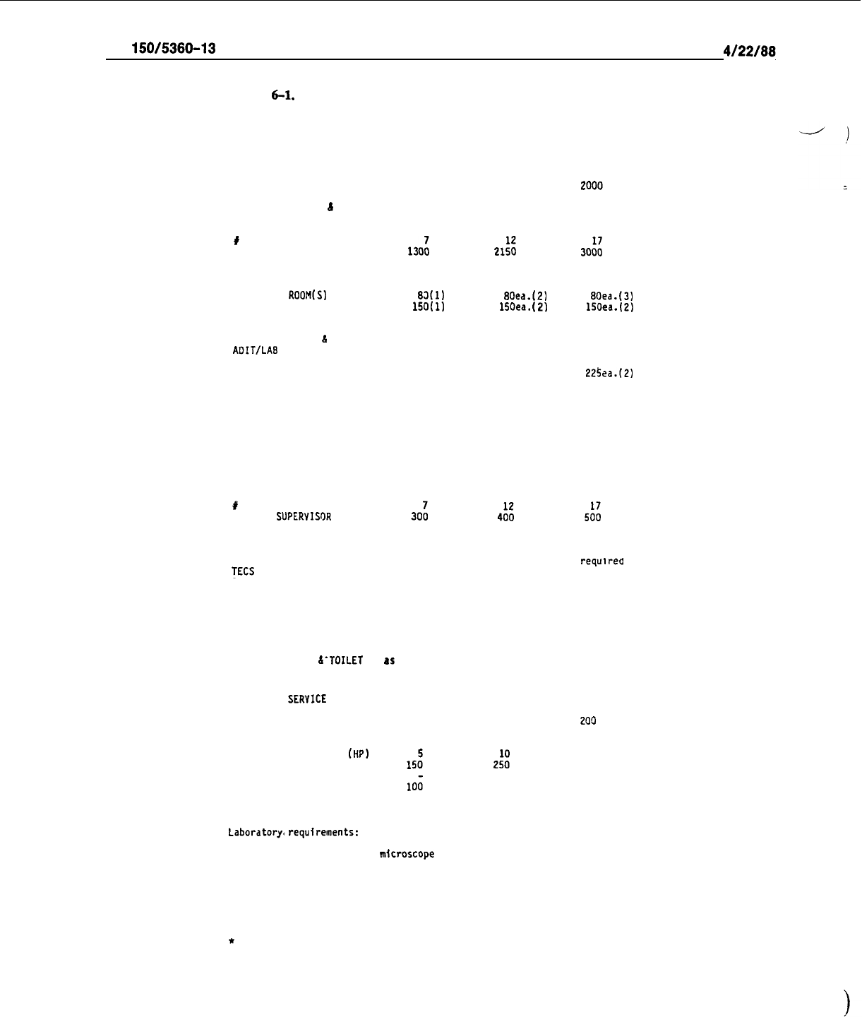
AC
150/5360-13
4/22/88.
Table
6-l.
FIS Space and Facility Requirements at International Airports
FEOERAL INSPECTION SERVICES
SPACE AND FACILITY REQUIREMENTS AT INTERNATIONAL AIRPORTS
l
Passengers Per Hour
U.S. INMIGRATION
6
NATURALIZATION SERVICE
800
1400
#
OF PIGGYBACK BOOTHS
GENERAL OFFICE SPACE
130:
CONFERENCE/TRAINING
200
BREAK/LUNCH ROOM
200
SECONDARY INSPECTION AREA
250
INTERVIEW
ROOM(S)
83(I)
SUPERVISOR'S
OFFICE(S)
150(l)
PORT
DIRECTOR’S OFFICE
200
CLERK/RECEPTION
I60
EMPLOYEE LOCKER
6
TOILET
as required
AOIT/LAB
150
STORAGE
100
HOLD ROOM'S W/TOILET FACILITIES 225
COMPUTER ROOM
100
U.S. PUBLIC HEALTH
SERYICE
21::
250
200
375
80ea.(2)
15Oea.
(21
200
160
as required
150
100
225
100
30::
300
300
600
80ea.(3)
150ea.(2)
225
160
as required
150
100
225ea.(2)
100
SUPERVISOR’S OFFICE
CLERK/RECEPTION
GENERAL OFFICE SPACE
ISOLATION
AREA
U.S. CUSTOMS SERVICE
200
200
200
150
150 150
400
400 400
160
160 160
#
OF PIGGYBACK BOOTHS
CUSTOMS
SUPERYISOR
30:
CUSTOMS OFFICE
800
IN-BONO ROOM
(not required for preclearance) 200
CASHIER(S)
as required
TECS ROOM (lockable room)
150
4::
1400
400
as required
200
5::
2000
500
. .
as
requirea
200
SEARCH ROOMS
80 square feet. Should be located near the front
PUBLIC SPACE W/COUNTER
of baggage modules. Minimum 2 per
FIS
facility
150
200
250
STORAGE ROOM
150 200
200
AIRPORT DIRECTOR AN0 SECRETARY
350
350
350
CONFERENCE
AND TRAINING
ROOM
400 500
600
CUSTOMS PATROL
300 400
500
EMPLOYEE LOCKER &-TOILET
as
required
as required
as required
ANIMAL 6 PLANT HEALTH
INSPECTION
SERYICE
OFFICER IN CHARGE
INSPECTOR'S OFFICE
LABORATORY
GARBAGE
DISPOSAL UNIT
(HP)
SUPERVISOR'S OFFICE
CLERK-STENOGRAPHER
STORAGE
CONFERENCE/TRAINING
BREAK/LUNCH ROOM
200
440
220
15:
10;
150
150
200
750
400
2::
150
100
200
200
1200
450
10
or larger
300
250
100
200
200
Laboratory,)requirements:
Stainless steel or formica counter top and drain-
board stainless steel double sink, garbage disposal unit, under-counter
cabinets, counter space for
nicroscope
and identification work, lockers, and
at least two 220Y outlets.
At locations not having or expecting scheduled
service office-laboratory space size requirements will vary from above
requirements depending upon expected volume of charter traffic. Space
requirements under these conditions will usually be less than shown and will
be negotiated with
the
headquarters office of the Animal and Plant Health
Inspection Service noted on frontispiece.
*
This ratio can only be achieved under optimum conditions. Factors such as
baggage delays, origin of flight, passenger mix. etc. are key determinants
which could possibly mitigate against achieving these figures. These
issues must be considered during early planning phases.
104
l/19/94
AC
150/5360-13
CHG 1
’
,b
CHAPTER
7.
ACCESSIBILITY
TO
INDIVIDUALS
WITH
DISABILITIEs
AND
SPECIAL
NEEDS
USERS
116. GENERAL. This chnptcr
summnrizcs
the requircmcnts imposed on airport terminal fncilitics to assure
full accessibility to individuals with disabilities.
Thcsc rcquircmcnts nre contained in the Americnns with
Disabilities Act (ADA) of 1990. 14 CFR
Pat
382, Nondiscrimination on the Basis of Handicap in Air Travel,
which implements the Air Carrier Access Act of 1986, and 49 CFR Parts 27, Nondiscriminntion on the Basis
of Handicap in Programs and Activities Receiving or Bcncfitting from Federal Financial Assistance, which
implements the Rehabilitation Act of 1973, as amended, and the ADA, and 37, Trnnsportntion Services for
Individualswith
Disnbilitics(ADA),w%ich
implcmentsthc ADAwithin the air transportationindustry, include
conditions applicable to airport terminal buildings.
117. MINIMUM BUILDING DESIGN STANDARDS.
ADA
rcquircments
apply to nny fncility occupied after
January 26, 1993 for which the
last
npplicntion
for
;I
buitding
permit or pcrmit extension is certified as
complete nfter January 26, 1992. 49 CFR Part 27 rcquircs
new
airport terminal fncilitics designed nnd
constructed with Fcdcrnl funds to meet the ADA standards
set
forth in Appendix A of 49 CFR Part 37.
118. SPECIFIC REQUIREMENTS FOR AIRPORT TERMINALS.
In addition to mccting minimum ADA
building standards, 49 CFR Part 27 imposts the following facility nnd cquipmcnt rcquirementsfor
new
airport
terminals:
,
a.
That the basic tcrminnl
‘design
shall pcrmit efficient cntrnnce and movement of persons with
disabilities, while at the snmc time giving consideration to their convenience, comfort, and safety. It is
I
essential that the design,
cspccinlly
concerning the location of
elevators,
escalators, and similar
devices,
minimize
nny
extrn distance that whcclchnir
users
must
travel
compnrcd to persons without
n
disability, to
reach ticket counters,
waiting
arcas,
baggage
handling
arcas,
and boarding locations.
I
b.
That the international ncccssibility symbol is
displnycd
nt
accessible
cntrnnccs to terminal buildings.
c.
That the ticketing
system
is dcsigncd to provide persons with
disrtbiliticswith
the opportunity to use
the primary
fnrc
collection
nllcn
for purchasing tickets.
I
d.
That baggnge areas arc accessible to persons with disnbilitics, and the facility is designed to provide
for efficient handling
nnd
retrieval of baggage by all
persons.
I
e.
That boarding by jctwnys and by passenger lounges arc the
prcfcrrcd
methods for movement of
persons with disabilitiesbetwecn
tcrmin:ll
buildings and aircraft. Whcrc this is not practicable, operators may
1
accommodnte this rcquircmcnt by providing lifts, ramps, or other suitable
devices
not normally used for
movement of freight, which arc
nvnilnble
for enplaning and deplaning whcclchnir users.
f.
That at each public t&phone ccntet in
a
tcrminnl,
nt
least
one clearly mnrkcd t&phone is equipped
with a volume control or sound booster device nnd with a
device
nvnilablc
to persons with disabilities,which
makes telephone communication
possible
for persons with hearing impairment and/or using wheelchairs.
g.
That each airport ensures
thnt
there is sufficient teletypewriter (TTY) service to permit
hearing-impaired persons to communicate readily with nirlinc nnd other airport personnel.
I
h. That several
spaces
ndjnccnt to the tcrminnl building entrance, scpnrnted from the main
flow
of
traffic, and
clenrly
marked, are made available for the loading and unloading of
pnsscngcrs
with disabilities
from motor vehicles; and that the
spaces
allow
individuals in whcclchnirs or with brnccs or crutchcs to get in
and oui of automobiles on to
n
lcvcl
surf:rcc
suitable
for wheeling and walking.
105
AC
150/5360-13
CHG 1
l/19/94
i.
That curb cuts or ramps with grades not exceeding 8.33 percent arc provided at crosswalks between
parking areas and the terminal.
-)
j. That with multi-level parking, ample and clearly marked
space
is rcservcd for ambulatory and
semi-ambulatory individuals with disabilities on the
Icvel
nearest to the ticketing and boarding portion of the
terminal facilities.
k. That in multi-level parking areas, elevators, ramps, or other
dcviccs
which can accommodate
wheelchair users are easily available. [Note: AC
150/5220-21,
Guide Spccificntions for Lifts Used to Board
Airline Passengers with Mobility Impairments, should be consulted for additional information in this matter.]
I.
That the environment in the waiting area/public space of the airport terminal facility gives confidence
and security to the person with a disability using the facility. This means that not only is the space to be
designed to accommodate individuals with a disability, but that it is also to contain clear directions for using
all passenger facilities.
m. That airport terminal information systems take into consideration the needs of individuals with
disabilities. Although the primary information mode required is visual (words, letters, or symbols), using
lighting and color, coding, airport
terminnls
arc
nlso
required to have facilities providing oral information.
II.
That public service facilities,such as toilets, drinking fountains, telephones, travelers nid, nnd first-aid
medical facilities are designed in accordnnce with the Uniform Federal
Accessibility
standards (UFAS), as
supplemented or superseded by the ADA Accessibility Guidelines (ADAAG)
set
forth in 49 CFR Part 37,
Appendix A.
119. EXISTING TERMINALS. The ADA of 1990 requires all existing tcrminnls to have incorporated the
required non-structural accessibility features by Janunry 26, 1992. Structural changes should be accomplished
as soon as practicable, but no later than
Jnnunry
26, 1995.
120. OTHER USERS WITH SPECIAL NEEDS. Some airport terminals may serve significant numbers of
older travellers, families trnvelling with infants or young children, or others, not normally considered having
a disability, but having special facility and services requirements.
a.
Higher proportions of older travellers may warrant more seating in gate lounge and terminal waiting
areas than otherwise provided. Mobility aids such
as
moving walkways or airline courtesy carts may be more
frequently justified, and may require wider concourse designs.
However, slightly slower moving rates may be
necessary to facilitate access and egress, and keeping anxiety at a minimum. Emphasis on appropriate lighting,
high visibility signing nnd other public information systems may also be wnrmntcd.
b. Airports serving major tourism areas are likely to accommodate increased numbers of children.
Passengerwaiting areas may be designed with
space
for children to plny.
Public lavatories, drinking fountains,
and other amenities should be easily accessible by children. The provision of diaper changing, baby bottle
warming, and private
infrmt
feeding facilities should be considered.
121.
-
130. RESERVED.
106

4/22/88
AC
150/5360-13
CHAPTER
8.
MISCELLANEOUS
DESIGN
CONSIDERATIONS
.
131. AIRPORT SECURITY. FAR Part 107, Airport Security, imposes aviation security requirements on
operators of the scheduled passenger operations of a certificated holder (airline) required to have a security
program by FAR Part
‘108
or a foreign carrier required to have a security program by FAR 129.25.
FARs
121.538 and 129.25 impose certain security responsibilities on air carriers operating into U.S. airports. These
require the screening of passengers and baggage before entering an aircraft or areas accessible to an aircraft.
The terminal designer
.should
take these requirements into account in developing an effective terminal
design. Some important aspects of airport security are discussed in succeeding paragraphs.
a. Security Inspection Stations.
Requirements for security inspection stations are discussed in para-
graph 73. Although primarily the responsibility of the individual airlines, their location and impact on termi-
nal operations requires consideration by the terminal planner.
b. Access to Air Operations Area. The Air Operations Area (AOA), as per FAR Part 107, is that
portion of an airport designed and used for landing, taking off, or surface maneuvering of airplanes. Airport
operators have the responsibility to secure this area and prevent access
by
unauthorized persons and vehi-
cles. This can be done by installing security fencing, and limiting and controlling the use of gates, doors, and
passageways providing direct or indirect access to the AOA. Passengers are permitted access to the AOA
only after undergoing screening. Vehicles using service roads are required to pass through controlled gates.
c. Doors.
Doors leading from unsecured areas of the terminal to the AOA which are not under the
visual control of authorized personnel are required to be locked or equipped with alarms signalling unau-
thorized use. Fire codes usually permit the locking of emergency exits provided they contain panic knock-
out devices.
d. Security Fencing.
Security fencing can vary in design, height, and type, depending on local
securi-
ty needs. Generally, it is recommended that the fencing be, as a minimum, No. 10 gauge, galvanized steel,
chain link fabric installed to a height of 8 feet (2.5 m), and topped with a three strand (12 gauge) barbed
wire overhang. The latter should have a minimum 6-inch (15 cm) separation between strands and extend
outward at a 45 degree angle from the horizontal. Fence posts should be installed at no greater than IO-foot
(3 m) intervals and be located within 2 inches (5 cm) of any wall or structure forming part of the perimeter.
It is suggested that a 10 to 20 feet (3 to 6 m) wide cleared area be provided adjacent to and immediately
outside of the perimeter fencing. Gates should be constructed with materials of comparable strength and
durability and open to an angle of at least 90 degrees. Hinges should be such as to preclude unauthorized
removal. Gates providing access to and from public roads require controlled
u&
procedures to prevent un-
authorized access to the AOA. Additional guidance is available in AC
150/‘5370-10,
Standards for Specify-
ing Construction of Airports.
e. Observation Decks. Terminal observation areas or decks should be enclosed or contain effective
barriers to deter and prevent unauthorized AOA access or the hurling of dangerous objects at parked air-
craft.
f.’
Security Lighting.
Security lighting of airports and terminal areas is generally an inexpensive means
of providing additional deterrence/protection against unauthorized intrusion into aircraft operating areas.
Lighting requirements are dependent on the local situation and the areas to be protected. For perimeter
lighting, lighting units should be located within the protected area and above the perimeter fence to light
areas on both sides of the fence. Light units should be oriented and shielded to prevent an unwanted glare
safety hazard to aircraft operations and adjacent vehicular roadways and unnecessary irritation to nearby
residences. It is recommended that security lighting systems be connected to an emergency power source.
g. Lockers. Coin-operated lockers provide a valuable and desired service to the traveling public.
However, they can be a convenient place for the storing and detonation of bombs and incendiary devices.
From a security viewpoint, the best location for these lockers is within sterile
are&s
beyond the security
screening station area. If such sterile areas are not practicable, the lockers should be so located in public
areas to minimize the
delete&us
effects of an explosion. The construction of blast-proof barriers around the
locker area is advisable and should be considered.
107

AC
150/5360-13
CHG 1
l/19/94
h.
Security Office.
Lockers, toilets, and rest rooms should be provided for security screening personnel.
In addition, an area for a security/police office and a detention/interrogationroom is recommended. At large
-
i
airports, those facilities may be a part of the airline leased space; at small airports the use of common facilities
may make an area under direct airport control preferable.
.
I.
General Aviation Access. Airport legislation requires that passengers using general aviation aircraft
be provided access to the terminal building if Federal funds were utilized for terminal development. For
security reasons, such access also requires control so that the screening system within the terminal building
is not circumvented. Separate general aviation parking areas adjacent to the terminal building with con-
trolled terminal building access can satisfy the access requirement and maintain security of the AOA. FAA
security personnel should be consulted in designing the terminal building and aircraft parking aprons to satisfy
this requirement.
j.
Guidance. FAA regional aviation security personnel should be contacted for advice on the location
and design of security facilities. In addition, the following publications, current editions, as applicable, should
be reviewed:
(1) AC
107-1,
Aviation Security-Airports;
(2) AC
108-1,
Air Carrier Security;
(3) AC 129-3, Foreign Air Carrier Security; and
I
(4) Technical Report, Recommended Security Guidelines for New Airport Construction and Major
Renovation.
132. ARCHITECTURAL TREATMENT.
a.
It is Federal policy to support projects which contribute to the architectural and cultural heritage of
local communities. In accordance with this policy, airport sponsors are encouraged to develop, use, and
incorporate design, art, and architectural treatment to reflect local customs and community history. This can
be accomplished in conjunction with a functional, safe, and efficient airport terminal facility.
b.
Architectural treatments for the exteriorsof terminal buildings and structures should avoid materials
and configurations which can interfere with the airport’s operational activities. For example, the use of
mirrored exterior glass walls on or adjacent to airports may adversely affect airport operations. The thin
metallic coating used in mirrored glass can reflect back signals from various airport navigational and
communications equipment and cause inaccuracies in their use.
Mirrored glass walls facing aircraft
operational areas can also cause undesirable and unsafe glare and reflections to a pilot’s vision.
By selective
siting, orientation, and shielding, these adverse effects can be. eliminated.
c.
The Department of Transportation publication “A Study of Airports
-
Design, Art,
&
Architecture”
is directed at those airport operators and their architects who are considering the design and construction of
new and expanded airport terminal facilities.
Concepts related to design, art, and architecture in public
airports are illustrated and discussed.
133. ENERGY CONSERVATION. Airport terminals require higher energy consumption than most public
buildings; This is primarily due to their generally unprotected locations, the high heat loss/gain resulting from
the movement of people and baggage through the building, and their usual 24 hours a day operation. The
designer should consider energy conservation early in the planning of a terminal building in order to reduce
dependence on increasingly costly fossil fuels. AC
150/5360-11,
Energy Conservation for Airport Buildings,
provides guidance in promoting energy conservation measures for airport buildings. As a minimum, the
following suggested considerations should be made in designing a terminal facility with energy conservation
in mind:
108
l/19/94
AC
lSO/S360-13
CI-IG
1
a.
For terminal additions, the existing mechanical
systems
should bc
analyzed
to dcterminc whether
rcplacemcnt
systems
or improvcmcnt to the present
system
can bc made to make the
system
more energy
efficient.
.
b. Ample insulation and sclccl building materials,
system
components, and design/construction tech-
niques which place a low demand on energy consumption and require minimal maintenance should be utilized.
c.
Building
design
should incorporate
vcstibulc
automatic doors and wind
shields,
as appropriate, at
building cntranccs, loading/unloading arcas, and, openings for
baggage
conveyors and carts.
d. The use of large window arcs should bc limited, particularly at localities which arc
subject
to
temperature extremes.
e.
Adequate controls for heating, cooling, and lighting to permit varying the USC of thcsc
systems
and
the implcmcntation of cncrgy conservation measures should bc provided.
f.
The potential and
cost/bcncfits
for designing and installing an
active
or
passive
solar system for
heating and/or cooling the building should bc analyzed.
Such systems can bc
used
ctfcctivcly
to provide
primary or supplcmcntal heating/cooling and thcrcby rcducc opcrationnl costs.
134. SEISMIC SAFETY. Airport terminal buildings should be structurally designed to appropriate seismic
standards. With rcspcct to Fcdcrally owned, lcascd, assisted, or rcgulnted buildings, Exccutivc Order (E.O.)
12699, Seismic
Safety
of Fcdcrally Assisted or Rcgulatcd
New
Ruilding
Construction, January 5, 1990, under
the authority of The Earthquake IIazards Reduction Act of 1977 (42 U.S.C. 7701
d
seq.)
rcquircs the use of
nationally rccognizcd
privntc
sector
seismic
safety standards and
practices.
A rule under 49 CFR Part 41,
implementing E.O. 12699 in the U.S. Department of Transportation, was issued on June 14, 1993. The
rule
states that any building
constructed
with
Federal
financial assistance
after
July 14, 1993, must be
designed
and
constructed in accordance with
seismic
standards approved by the Fcdcral Aviation Administration under
49 CFR 41.120.
.
135.
-
145. RESERVED.
109 (and 110)
l/19/94
AC
150/5360-13
CHG 1
CHAPTER
9.
AIRPORT
GROUND
ACCESS
AND
CIRCULATION
SYSTEMS
146. GENERAL. Ground
access
systems
serve passengers, employees, and other airport users traveling to and
from the airport. Circulation
systems
within the airport boundaries should minimize congestion and support
efficient access to the passcngcr terminal. Ground
access
systems extend beyond the airport boundaries and
must function within the
context
of regional transportation
systems
and the policies of government agencies
typically unrelated to the airport’s operation.
A thorough analysis of motor vehicle traffic flows associated
with current and projected future air passenger demand is csscntial to assure that ground congestion does not
become an unanticipated constraint on a passenger terminal’s performance.
147. PLANNING STUDIES.
a. Ground access facilities--including access roads and interchanges, transit links, parking facilities,
staging arcas for taxis and
other
public transport scrviccs, and the terminal curb--arc generally addressed as
a major element of
overall
airport master planning or terminal building design
(set
Chapter 1). The
assumptions about demand that guide access
system
decisions must bc consistent with those used for airport
master planning and terminal building design.
b.
Ground access systems generally depend upon regional highway and transit facilities that carry traffic
unrelated to the airport.
Periods of peak demand and resulting congestion on these regional facilities may
not correspond to those for the airport, but may influence airport facilitiesplanning and design. Accordingly,
local add regional transportation authorities,
as
well
as private and public operators of ground transport
services,
should bc included in the planning and
design
process.
c.
Figure 9-l outlines the
process
typically
followed
in ground access
systems
planning and design. This
process
may be followed in
par&I
with planning and design of other elements of the passenger terminal, or
as an indcpcndent activity
when
ground
access
problcms.arc
faced
at an othcrwisc adequate airport facility..
The inventory phase collects data on projcctcd air transport demand, airline schcdulcs, airport operating
policies, and ground transport
facilities
and scrviccs.
Demand forecasting uses these data to develop
projections of motor vehicle traffic, passcngcr demand, and parking demand on annual, seasonal, monthly,
daily, hourly, and peak hour
bases.
Demand-capacity analyses determine the facilities required to
accommodate these demand
forecasts
and identify alternate facilities feasible for application at
the,
airport.
Evaluation of the service quality of facility alternatives and their comparison to performance and cost
standards leads to the sclcction of the optimum altcrnntivc.
148. CIRCULATION SYSTEM CONFIGURATIONS. The layout and
types
of terminal concepts at an airport
determine the integration of the components to form the airport circulation system. The following paragraphs
discuss some of the more typical airport circulation configurations:
a.
Centralized Layout. When the terminal complex consists of a single building or a contiguous series
of buildings, the ground transportation
system
usually consists of sequentially and centrally located
components. Except for vertical or horizontal separation, which may exist for originating and terminating
passenger
vehicles,
all passenger-related
vehicles
normally pass through the same series of roadways. Also,
public parking and car rental facilities are centrally located. Many commercial service airports in the United
States use this
type
of system, known as the ccntralizcd ground access concept. Some
example
airports are
Chicago O’Hare, San Francisco International, Los
Angeles
International, Atlanta IIartsfield, Washington
National, and Fort Laudcrdalc-Ilollywood International. Figure 9-2 schcmaticallyprescnts this concept. This
concept permits terminal unit
expansion
along the existing terminal arca
access
road without
10s~
of the
original ground
access
system
concept.
111
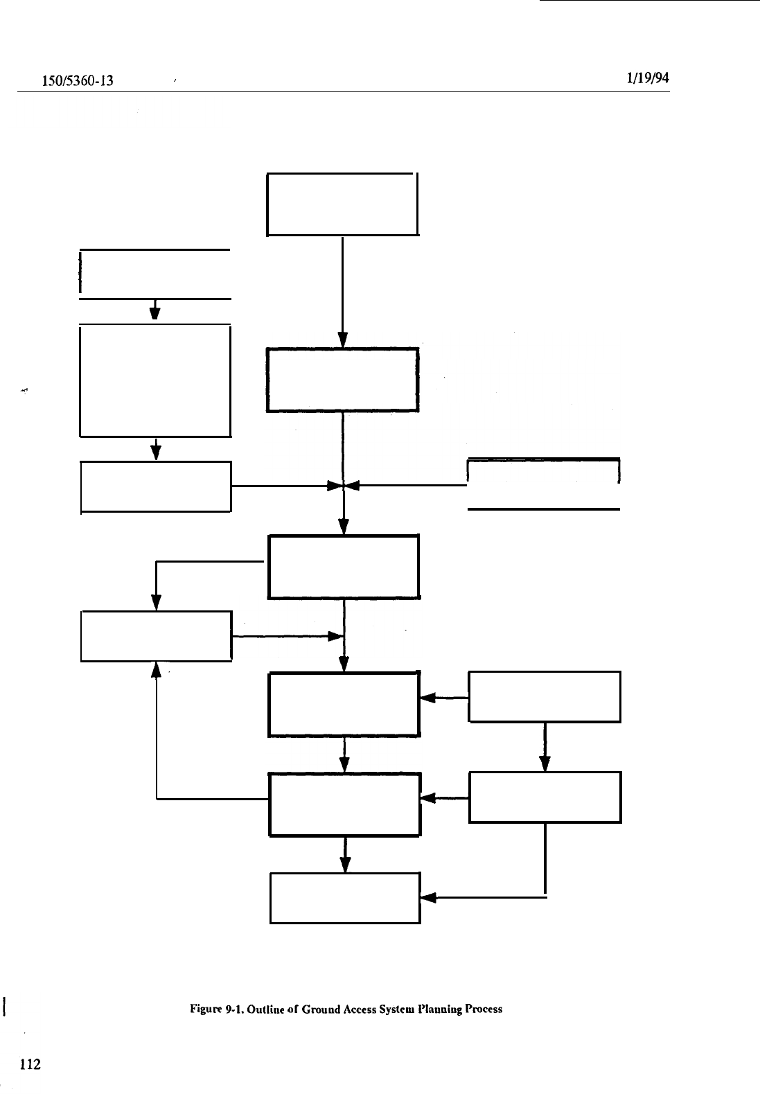
AC
150/5360-13
CI-IG ‘1
’
I
Base Year
Traffic
I
Relationships Among
Motor Vehicles,
Passengers, and
Aircraft Operations
t
Study Purpose
INVENTORY AND
DATA COLLECTION
CH
I
Access Mode
I
‘I
DEMAND
FORECASTING
AND ALLOCATION
v
4
DEMAND-CAPACITY
w
Level of Service
ANALYSIS
Standards
.
Design Year
Forecasts
v
Facility
Requirements
4.
EVALUATION OF
+w-
Decision
ALTERNATIVES
Criteria
4
Selection of
Alternative
4
Figure
P-l.
Outline
of
Grouud
Access
System
Plnuoing
Process
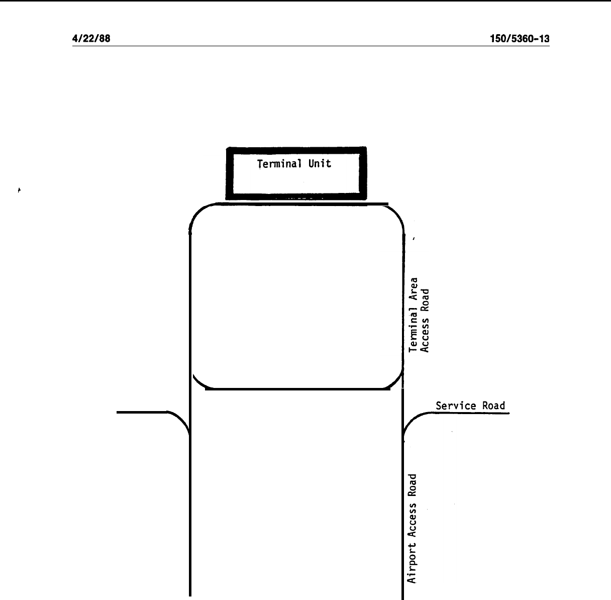
4/22/88
AC
150/5360-13
/
Terminal Frontage
Road
Parking
\
Recirculation Road
Rental Car Facilities
Figure 9-2. Centralized Ground Access Concept
113

AC
150/5360-13
4/22/88
b. Segmented Layout. Division of the terminal building into originating and terminating passenger
sides or grouping of airlines on either side of the building achieves flow separation on a horizontal basis.
Originating passengers use one set of terminal frohtage roads.and terminating passengers the other; or
specif-
v’
‘)
ic airlines may group themselves on either side of the terminal unit. Orlando International, Jacksonville, and
Greater Cincinnati airports use this type of ground access system layout called the segmented ground access
concept. (See Figure 9-3.) This layout.also permits expansion through terminal unit extension with retention
of the same ground access system concept.
c. Decentralized Layout.
When the terminal complex consists of unit terminal buildings, vehicle flow
separation on terminal access and frontage roads is possible. Airport access and terminal. access roads funnel
traffic to and from separate terminal facilities. Parking and car rental facilities are grouped on a terminal unit
basis. Examples of this type of system use, the decentralized ground access concept, include Kennedy Inter-
national and Kansas City International airports. (See Figure 9-4.) Expansion of the system is by addition of
terminal units around the terminal access road with separate terminal frontage roads.
I
d. Unitized Layout. In some cases, the terminal system’ may consist of a series of terminal building
located in linear fashion. Access is from a centrally ‘located roadway. Dallas-Fort Worth International and
Houston Intercontinental airports use this type of system, the unitized ground access system concept. (See.
Figure 9-5.) System expansion is usually accomplished by adding terminal units between terminal area
access roads.
149.
AIRPORT ROADS.
The four types of airport roads are primary airport access roads, terminal area
access roads, terminal frontage roads, and service roads.
a. Primary airport access roads provide access to the airport from the neighboring community road
system. A capacity per lane of 700 to 800 vehicles per- hour should be provided for at-grade interrupted
flow conditions. This value approximates the flow relationship for urban arterial highways with signalized
intersections; average speed range of 20 to 25 miles per hour (30 to 35 km/h); and, a demand volume to
capacity ratio of approximately 0.80. For limited access highways with grade separations under uninterrupt-
ed flow conditions, the recommended design is one lane for each 1,200 to 1,600 vehicles per hour. This
value approximates the flow relationship for urban freeways; average speeds from 40 to 50 miles per hour
(60 to 80 km/h); and a demand volume to capacity ratio approximating 0.60. A lane width of 12 feet (3.6 m),
with a minimum of two lanes in each direction, is recommended.
b.
Terminal area access roads service airport passengers, visitors, and employees and connect primary
airport access roads with terminal buildings and,parking facilities.
(1)
These roads should be sufficiently long to permit smooth channeling of traffic into appropriate
lanes for safe access to terminal curbs, parking lots, and other public facilities. To avoid driver confusion,
ample separation should be provided at locations where drivers must make directional choices. Not more
than two choices should be required of a driver at any location. Traffic circulation in front of the terminal
should, normally, be one-way and counter-clockwise for convenience of right-side loading and unloading
of vehicles. Recirculation of vehicles to the passenger terminal should be permitted by providing road sec-
tions to link the ingress and egress lanes of the access road. When several buildings exist, it may be advisable
to provide more than one terminal road.
114
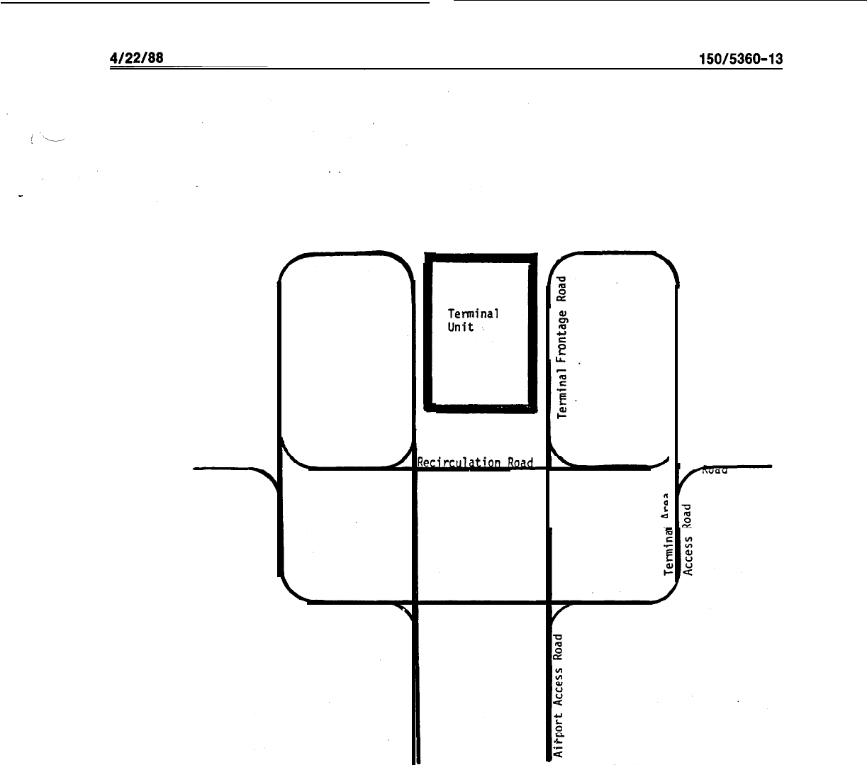
4/22/88
AC
150/5360-13
Parking
Terminal
Unit
7
k%
::
Parking
E
t
Rental Car
1
Facilities c
Service
Figure 9-3.
Segmented Ground Access Concept
115
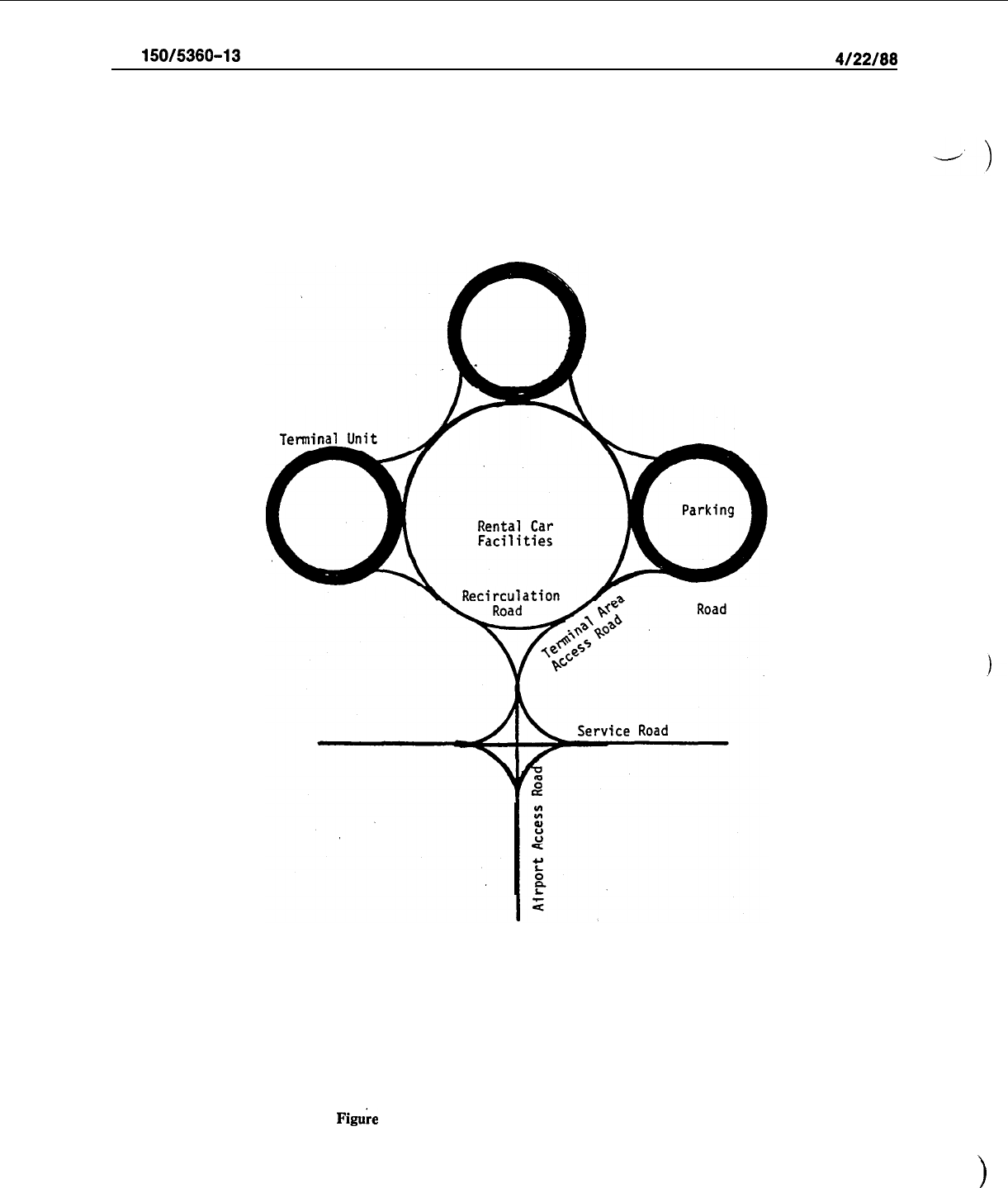
AC
150/5360-13
4/22/88
Terminal Unit
Terminal Unit
Terminal Frontage
Fig&e
9-4.
Decentralized Ground Access Concept
116
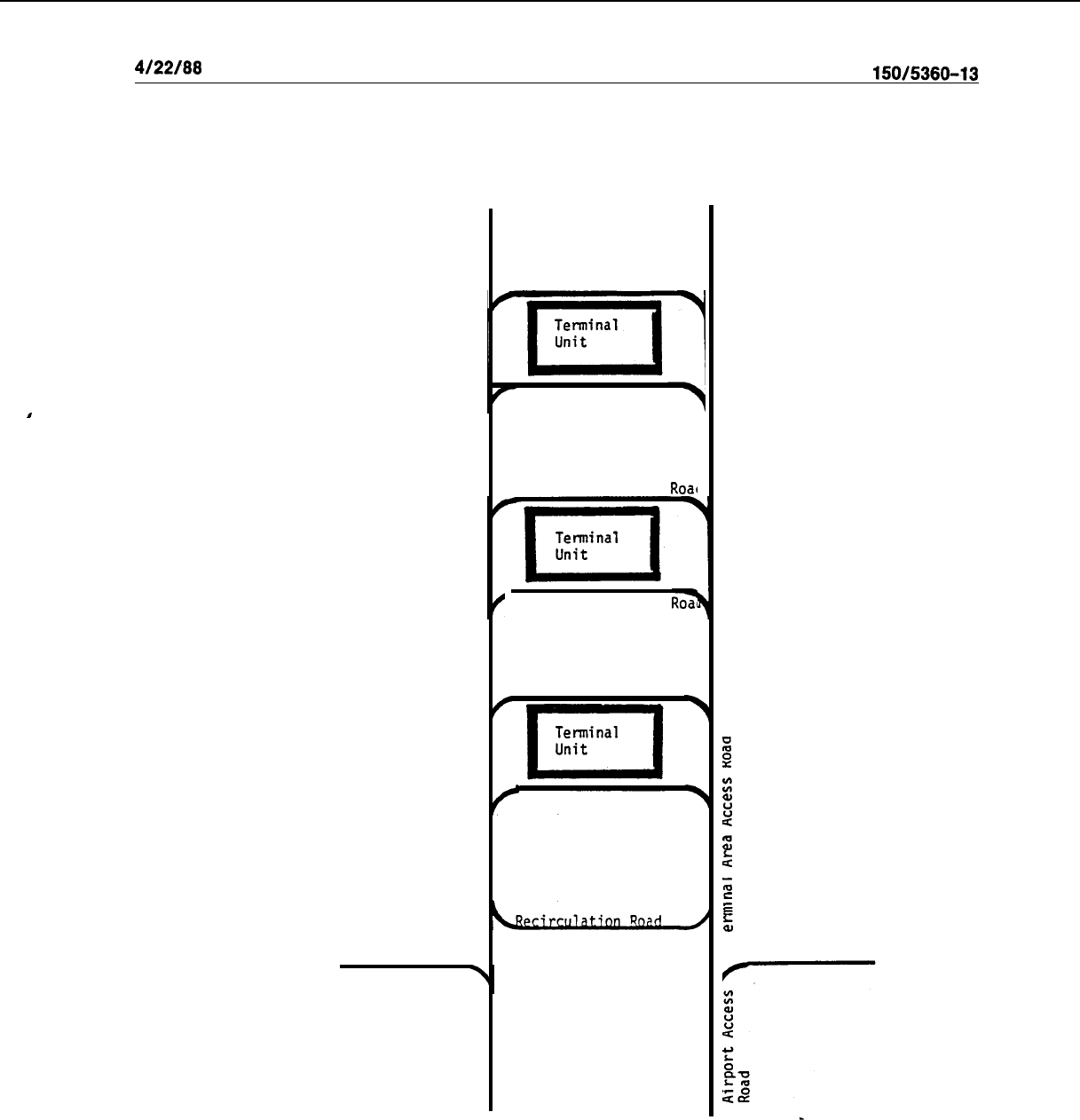
I
4/22/88
AC
150/5360-13
Parking
Tewinal Frontage
Roac
'Terminal Frontage
Rz
Parking
Figure 9-5.
Unitized Ground Access Concept
ii
B
z
J
2
2
2
II,
Rental Car
5
Facilities
5
Service Road
117
AC
150/5360-13
4/22/88
(2)
Traffic streams should be separgted at an early stage with appropriate signing to avoid conges-
tion and assure lower traffic volumes on each of the terminal frontage roads. Terminal area access roads
should be planned to accommodate 900 to 1,000 vehicles per lane per hour. A minimum of two 12 foot (3.6
-
m) lanes should be provided. For recirculation roads, each lane should serve 600 vehicles per hour. If only
one recirculation lane is provided, its width should be 20 feet (6 m) to accommodate stalled vehicles. For
multiple recirculation lanes, the standard lane width is 12 feet (3.6 m).
,
c.
Terminal frontage roads distribute vehicles directly to terminal buildings.
Sincei
considerable merg-
ing from through lanes to and from the
.curbfront
occurs
,on
these roadways, at least
i’.vo
lanes should be
provided adjacent to the curb. The inside lane, sized at 8 feet (2.4 m), provides terminal curbfrontage and
the 12 foot (3.6 m) outside lane serves through traffic and maneuvering to the terminal curbfrontage. While
planned capacity for the outside lane should be 300 vehicles per hour, the inside lane is considered to have
no throughput capacity. Additional 12 foot (3.6 m) through lanes should be provided at a rate of 600 vehi-
cles per lane per hour. The terminal frontage is a critical element in the performance of the airport ground
access system. Accordingly, to avoid the dongestion caused by the inevitable double parking, a minimum of
four lanes adjacent to the terminal curb is recommended. Four lanes are also recommended when terminal
arrivals and departures are on the same level. (See Figures 9-6 and 9-7.)
d.
Service roads are divided into two user categories
-
general and restricted.
(1)
General-use service roads are used for the delivery of goods, services, air cargo, flight kitchen
.
supplies, and the like. At very large airports, to relieve congestion on airport terminal access roads, it is
desirable to provide’ service road entrances and interchanges either before or shortly after entering the air-
port site. At low activity airports, the service and primary airport access roads may be coincidental.
(2)
Restricted-use service roads and traffic lanes are limited to such traffic as maintenance, tire and
rescue, fuel, baggage, freight, and aircraft service vehicles. Those roads or sections of roads providing
access to aircraft operating and parking areas require control points for adequate area security.
(3)
The recommended hourly lane capacity is 600 to 1,200 vehicles. Since a major portion of the
road traffic is from trucks, the lower value should be used in preliminary design. The typical vehicle speed
is 15 to 20 miles (25 to 33’ km) per hour and frequent curb cuts are required for access to airport service
facilities. Usually, these roads are two-way in nature with 12 foot (3.6 m) lane widths.
118
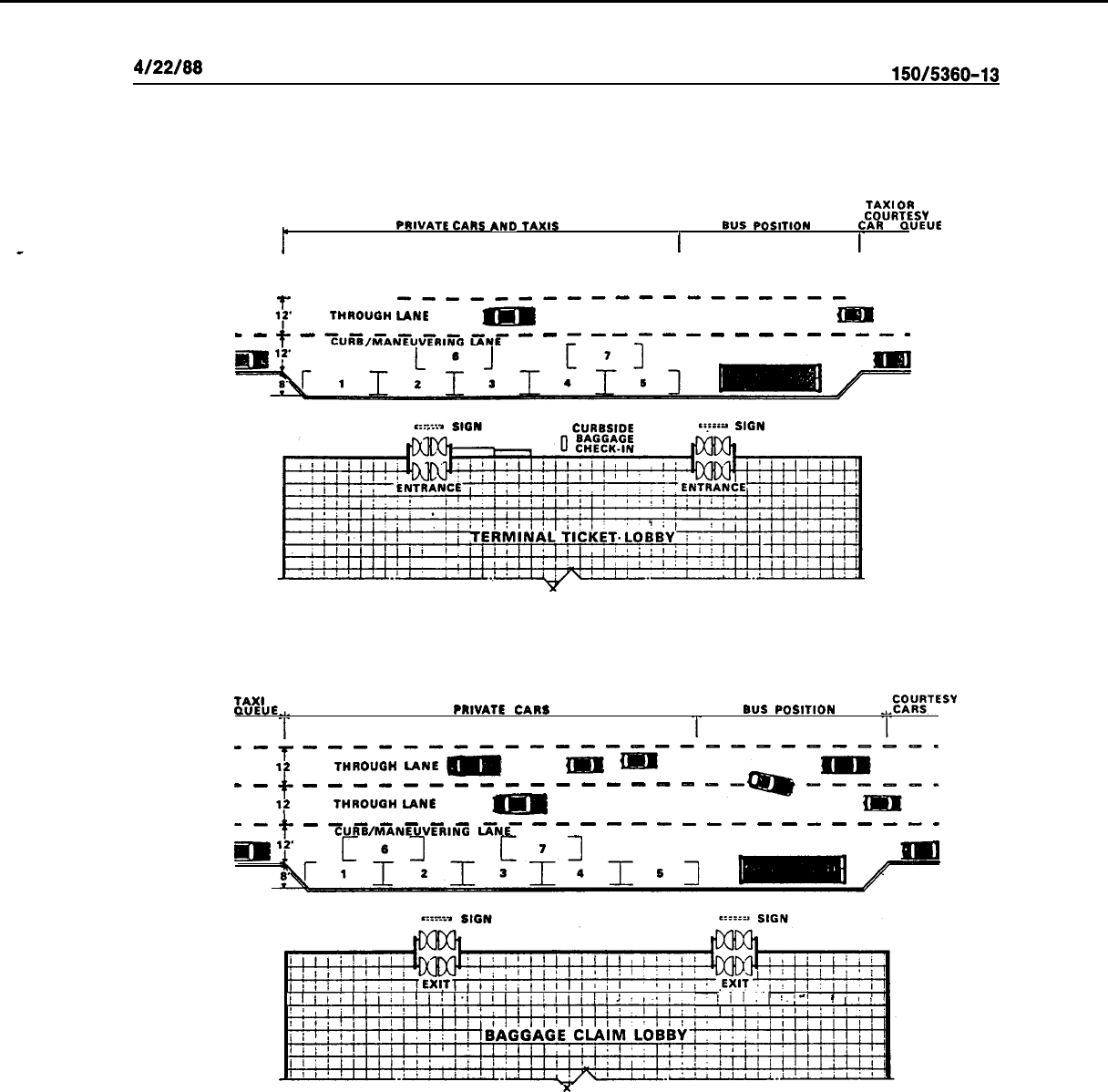
4/22/88
AC
150/5360-13
t
PRIVATE
CARS
AND TAXIS
TAXI
OR
COURTESY
BUS
POSITION CAR
GUEUE
I
I_
-- ----
T
--------------~
Y’
THROUGH
LANE
il
m
--
t
-
-
-
=
-
-
-.
-
-
-
-
-
-
-
-
-
-
-
CURBSIDE
Enplaning Curb
TAXI
GUEUE.,.
T
PRIVATE
CARS
BUS
POSITION
.,.CC!%~TESv
T
T
mm
--------------------_____I
T
12
t
THROUGH LANE
-
iEm-
m-
-------m-v------
l?
THROUGH LANE
t
-
~uR~~ANruvrR,N~
GNE-
-
-
Gl2.
[6J
-
-
-
-
-
-
-
-
-
-
-
-
-
-
-
[7-J
Jl~l;l!l;!(l~~.illli~~i~~!~~‘l~i,~
jiI.1
;,
!_‘-I .
!
,
Deplaning Curb
Figure 9-6. Terminal Curb Areas
119
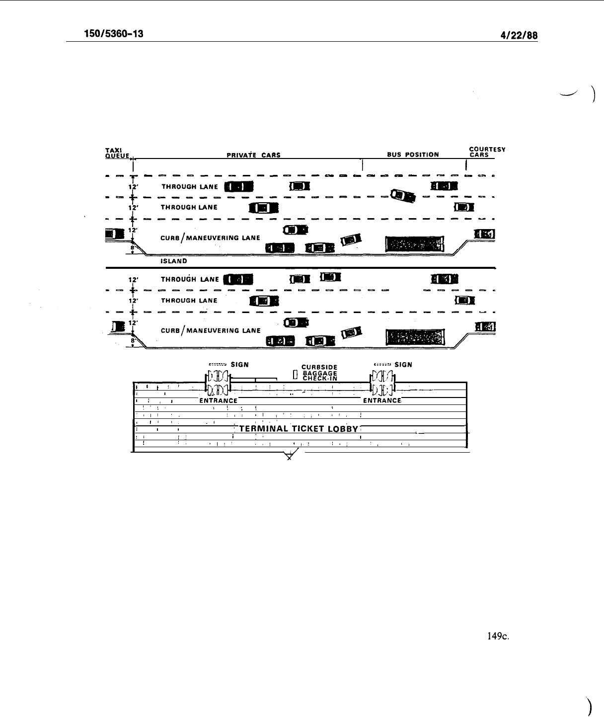
AC
150/5360-13
4/22/88
x%JE.,.
T
PRlVAiE
CARS
BUS
POSITION
p4gTESY
1
I
m-
z
-
p;“,u,ENfti-
-
-.-
-
-
-
-
-
-
-
-c
-
-
c
s-
----------------
f
l?’
THROUGH LANE
------iii--
ISLAND
t
'f'
THROUdH
LANE
-
mm
-
EZ:Z::->
S,GN c::z:c.
S&N
x
r
,
0
CHECK-IN
Jt#lj
,
I
,
:
1
--
,
/
__
-
-
--
-
I
1
/
I
ENTRANCE ENTRANCE,
)‘S,
’
!
:
!
I
‘,,I
.,
‘,.
II
!”
,,I
II,
!
I
I*
I.
.I
,‘.’
\
:
I
,
I
TERMINAL’TICKET
LOB’sY’
I/
,
,’
,
i
1,
,-
:
I
!
I,
.I!,
,,,
4,:
I,;
‘,
,,
I
Figure 9-7. Vehicular Island Curb
150.
TERMINAL CURB AREAS.
Curb areas are required at terminals for loading and unloading of pas-
sengers and their baggage.
a. Curbfrontage. The roadway area adjacent to the curb area is discussed in paragraph
149~.
‘The
length of curb to be provided is related to the mix of vehicle types and expected curb dwell time. Table 9-l
shows typical curb dwell times and required vehicle slot lengths for different types of vehicles. It should be
noted that, in the case of deplaning passengers, larger volumes of passengers, baggage, and ground transpor-
tation requirements peak over shorter periods of time. Strict policing is highly effective in optimizing the
vehicle curb slot occupancy rate.
120
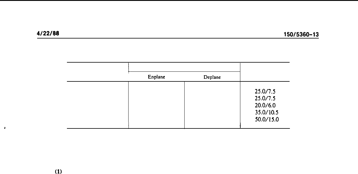
4/22/88
AC
150/5360-13
Table 9-j.
Typical Curbfrontage Dwell Times and Vehicle Slot Lengths
Vehicle
Curb Dwell Time (Minutes)
Enplane
I
Dep!ane
Vehicle Slot Length
(Feet/Meters)
Private Auto
1.0
to
3.0
2.0
to
4.0
25.0/7.5
Rental Car
1.0
to
3.0
2.0
to
4.0
25.0/7.5
Taxi
1.0
to
2.0
1.0
to
3.0
20.0/6.0
Limousine
2.0
to
4.0
2.0
to
5.0
35.0/10.5
bus
2.0
to
5.0
5.0
to
10.0
50.0/15.0
I
1
I
b. Sidewalk Platforms. Sidewalk platforms are located immediately adjacent to curb/maneuvering
lanes and terminal building entrances and exits to provide passenger walkways and safety areas for loading
and unloading of vehicles.
(1)
At high activity airports, traffic curb islands are often provided to increase the curb area and, in
some cases, to segregate different types of ground transportation vehicles. Airports with relatively low pas-
senger levels may be able to accommodate both enplaning and deplaning passengers from one curb face.
(2)
Generally, the curb area is divided functionally into enplaning and deplaning curbs. It is separat-
ed physically, either horizontally at each end of the terminal building or vertically by means of structural
vehicular ramps (see paragraph 36c).
(3) With a one level operation, the deplaning curb is located at the far end of the terminal with
respect to approaching vehicular traffic. In the case of vertical separation, deplaning is on the lower level.
Such separation minimizes the congestion which will result if opposing flows and volumes of persons, bag-
gage, and ground vehicles are concentrated in the same curb area.
(4) At most terminals, specific curb areas are designated for buses, limousines, courtesy cars, and
taxi queues. These designated areas should be located at reasonable distances from terminal exits to reduce
congestion. Overhead coverings are desirable to protect disembarking passengers from inclement weather.
c.
Curbside Baggage Check-in.
Curbside baggage check-in permits baggage to be checked directly to
the appropriate airline flight. The area which accommodates this service normally requires space for a bag-
gage check-in desk (usually portable), baggage handtrucks, and a baggage conveyor or belt. Baggage may
be either taken by handtruck to the ticket counter or transported directly by an adjacent conveyor belt to
the outbound baggage room. The system used is economically related to passenger activity volumes, man-
power, and installation cost. Terminal plans should consider design provisions to facilitate both present and
future conveyor installations.
d. , Terminal Entryways.
Terminal entrances should be located at enplaning curb areas and open di-
rectly into airline ticket counter lobbies. Similarly, terminal exits should be located in close proximity to
baggage claim facilities and open to deplaning curbs. Automatic doors are highly recommended for: passen-
ger baggage carrying convenience; as a weather buffer; and to increase the efficiency of passenger move-
ment in energy conservation measures.
e. Pedestrian Crossings and Walkways.
Pedestrian crossings and walkways from terminal curbs to
island platforms and parking facilities should be well marked. At high activity locations, consideration
should be given to traffic-controlled crosswalks or, preferably, to grade separation by means of overpasses
and tunnels.
151.
PUBLIC PARKING FACILITIES.
Surveys at some major airports in the United States indicate that
from 40 to 85 percent of the originating passengers arrive in private automobiles. Consequently, adequate
public parking facilities are essential to good terminal design. Some general guidelines and recommendations
for designing these facilities are discussed in succeeding paragraphs.
121
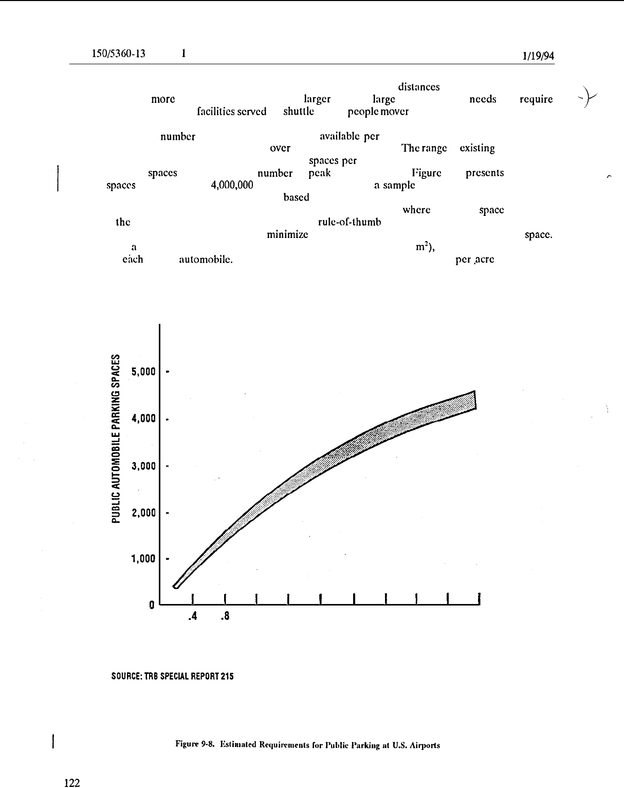
AC
lSO/S360-13
CIIG
1
l/19/94
a.
Locations. Public parking lots should be located to limit walking distances from parked automobiles
to terminals to no more than 1,000 feet (300 m). At larger airports,
large
volume parking needs may require
-
)
provision of remote parking
facilities
scrvcd by shuttlc bus or pcoplc
mover
systems.
b. Sizing. The number of public parking spaces
nvailnblc
per million originating pnssengcrs varies
between airports, particularly at airports with over 1.5 million originations. The range at
existing
airports may
vary from under 1,000 to as high as 3,300 parking
spaces
per million originations. Another methodology
provides parking
spaces
for I.5 times the number of peak hour passcngcrs. Figure 9-8, presents a range of
parking
spaces
for 100,000 to
4,000,OOO
originating passcngcrs at
a
sample
of airports. A better way for
cstimatingparkingneeds is through a simulation
based
on existingparkingchnractcristicsand forecasted future
needs. While simulation is cxpcnsivc and time consuming, it can be justified
where
expansion space is severely
limited or the cost of additional spaces is very high. A rule-of-thumb suggests an increase of 15 percent in
the number of estimated parking spaces to
minimize
the amount of time required to find a parking
space.
In developing
a
parking lot plan, approximately350 to 400 sq. ft. (31.5 to 36.0
m’),
including lanes, should be
allowed for each parked automobile. This is the cquivnlcnt of 109 to 124 parked cars per
acre
(269 to 306
per hectare) for on-grade parking.
r
6,000
.
I I
I
1
I
I
I
I
I
I
.4 .8
1.2
1.6
2.0
2.4 2.8
3.2 3.6 4.0
ORIGINATINGPASSENGERS (MILLIONS)
SOlJRCE:TRBSPEClALREPORT215
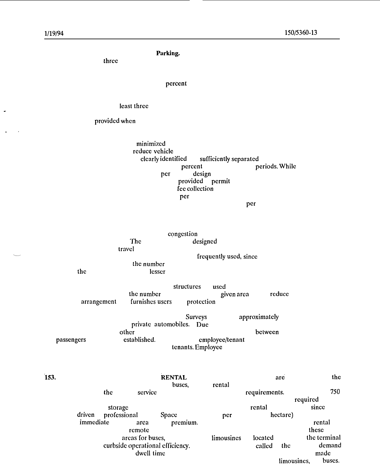
AC
150/5360-13
CHG 1
,
c. Short-Term Versus Long-Term
P:rrking.
The gencrally accepted definition for short-term parking
--
is anything less than three hours.
Approximately 70 to 85 percent of all parking lot users are short-term
parkers, mainly greeters and well-wishers.
However, this amounts to full time use of only 20 to 30 percent
of the total parking requirements.
Long-term parkers, the remaining 15 to 30 percent of parking lot users,
are almost all travelers and occupy 70 to 80 percent of the available parking spaces. Through actual surveys
and analysis of parking stubs conducted over several consecutive days, utilization charts can be developed
showing vehicle volumes and length of stay.
Short-term parking is usually provided nearest the terminal, since
its turnover rate is often at
lcast
three times that of long-term lots.
Short-term rates are high to discourage
_
long-term parkers from clogging close in lots. A rule-of-thumb suggests that separate short and long-term
parking should be provided when the total annual passenger volume exceeds the 150,000 to 200,000 range.
d.
Parking Lot Entrances and Exits. Parking lot entrances and exits can easily become points of con-
gestion. This congestion can be minimized by providing appropriate ticket dispensing and fee collection
facilities and queuing lnncs to reduce vehicle intcrfcrcnce with access roads and parking lot circulation.
Entrance and exit points should bc
clearly
identified and
sufficiently
separated to avoid confusion. The total
in and out airport parking lot flow can approach 25
percent
of capacity in peak
periods.
While
automatic ticket
dispensers can process up to 400 vehicles per hour, a
design
capacity of 240 is recommcndcd. At least two
ticket dispensingmachinespcr entrance should be provided to permit equipment maintenanccwithout severely
restricting parking operations. Attendant parking fee collection booths can process 120 to 150 vchiclcs hourly
with variable fee parking and about 250 vehicles per hour with a flat fee. One collection position should be
provided per 105 vehicles hourly in manual mode and one position per 185 vchiclcs per hour in a
computerized operation.
e.
Circulation. Counter-clockwise circulation within the parking lot is usually preferable and one-way
traffic control is recommcndcd to minimize congestion and hazards. Aisle widths should be generous and
parking stalls clearly marked. The layout should be designed to minimize the number of turns and both
vehicular and pedestrian
travel
distnnccs. Parking lot aisles should be laid out in the direction of
-
pedestrian-parker destination. Pcrpcndicular parking is frcqucntly
used,
since
it permits parking from each
side of the aisle and maximizes the number of stalls in a given area.
Howcvcr, parking stall layout mainly
depends on the area’s shnpc and, to a
lcsscr
cxtcnt, on local parking habits.
f.
Parking Structures.
Multilcvclparking
structures
arc
used
at high activity airports, albeit with higher
construction costs, to incrcnsc the number of parking slots in a
given
arca and to reduce walking distances.
This parking arrangcmcnt also
furnishes
users
with protection from inclement wcathcr.
152. EMPLOYEE AND TENANT PARKING.
Surveys
show that approximately 90 percent of airport
employees travel to work in private automobiles. Due to the variation among airports for aircraft
maintenance, air cargo, and
other
servicing activities, a consistent relationship between numbers or employees
and passengers has not been
established.
The number of employee/tenant parking spaces should be obtained
by surveying airport management and tcrminnl tenants. Employee and tenant parking should be provided near
working areas which are not in or near terminal buildings, Otherwise, remote parking with a shuttle service
to work areas is required.
153.
PUBLIC TRANSPORTATION AND
kENTAL
CAR AREAS.
Parking facilities arti also required for
the
short-term parking of taxis, vans, limousines, busts, and for rental car ready and storage lots.
Discussions
should be held with
the
various
scrvicc
operators to establish parking requirements. Approximately
750
originating passengers arc accommodated per rental car ready stall. The space per vehicle required for taxi
.
parking and rental car storage facilities is less than for public parking or rental car ready lots,
since
these
vehicles are driven by professional drivers.
Space
for 160 vchiclcs per acre (395 per hectare) is rccommcndcd.
Land in the immcdiatc tcrminnl arca is at a premium.
Accordingly, a trend is that on-airport rental car
agencies are basing vehicles at rcmotc locations and using vans to shuttle customers to and from thcsc areas.
Usually, short-term parking arcas’for busts, taxis, vans, and
limousines
arc located away from the terminal
curbfront to increase curbside operational
cfficicncy.
Thcsc vchiclcs can be called to the curb in a demand
responsive mode and curbfront
dwell
time
considerably reduced.
Similarly, provisions can bc made for
exclusive lanes or dedicated auxiliary curbs for high occupancy vchiclcs such as vans,
limousines,
and busts.
123
AC
150/5360-13
CHG 1
l/14/94
154.
ACCESS SYSTEM SIGNS.
Directional and identification signs are extremely important in designing an
_,
efficient airport access system.
Clearly visible signs should be positioned on roads and in terminal curb areas
/
well in advance of desired destinations to permit vehicle operations without a need for abrupt movements.
Signs should be properly lighted for night use and painted with lettering and background colors which enhance
clarity and visibility. Mcssnges should be concise, quickly identifiable, and easily understood. Color coding
for unit terminals, airlines, parking facilities, etc., is recommended, particularly for complex terminal areas.
The Institute of Transportation Engineers (ITE) Technical Council Committee Report
5D-1,
Airport Road
Guide Signs
(1991),
may be consulted for further information.
155. TRANSIT SYSTEM LINKS AND AUTOMATED PEOPLE MOVER (APM) SYSTEMS.
a.
Public transit system service
ground access to the
airport,preferably
the airport terminal area, should
be considered. High quality public transit service, as provided by rail systems or express bus operations, can
attract significant ridership and help alleviate vehicular traffic congestion in the terminal area., Easy direct
access to terminal buildings, as well as baggage transport and security, are essential to encourage substantial
passenger use.
b.
Automated people mover (APM) systems
(automated,driverlessvehiclesoperatingon
fixedguideways
along an exclusive right-of-way) have demonstrated the potential to be an important element in the airport
circulation system.
They can
serve
to provide ;I convenient and efficient interface for public transit ground
access to the airport, as well as means of linking passenger terminals with each other and parking and car
rental facilities, hotels, and other airport activity ccntcrs.
At airports with lnndside constraints limiting
expansion due to high levels of pollution, or a lack of availableconstruction sites, or a lack of adequate transit
and highway capacity,
ARMS
can, in some cases, diminish
these
constraints by skillful arrangement of facilities
and reduction of airport vehicular traffic.
156.
-
160. RESERVED.
124
l/19/94
AC
150/5360-13
CHG 1
\
CHAPTER
10.
FEDERAL
PARTICIPATION
IN
THE
COSTS
OF
1
TERMINAL
DEVELOPMENT
”
161. GENERAL. This chapter contains information pertaining to Federal participation in the costs of airport
terminal development, including surface access, under the terms of the Airport and Airway Improvement Act
of 1982 (P.L.
97-
248),
as amended.
In particular, the Airport and Airway Safety, Capacity, Noise
Improvement, and Intermodal Transportation Act of 1992 has amended the 1982 Act with a focus on
international and intermodal issues.
.
.
162. BACKGROUND. The 1982 Act (P.L.
97-248),
successor to the-Airport and Airway Development Act
of 1970, provides financial support for necessary improvements to the Nation’s airport and airway system. The
Act’s Airport Improvement Program (AIP) provides Federal funds through airport grants to finance
improvements to eligible public-use airports in the United States. Section 5 13 of the Act authorizes funds for
airport terminal development and establishes requirements and limitations for funding these facilities,
including multimodal terminal development.
163. FINANCIAL ASSISTANCE. Airport surface access, multimodal terminals, and other terminal area
facilities may be developed with Federal grants-in-aid. Many projects related to the movement of passengers
and baggage within the boundaries of the airport may be
AIP,
eligible.
Passenger Facility Charge (PFC)
program funds may be used for AIP-eligible work and certain other projects.
Recently, several changes have
been made to eligibility by the Congress. Sponsors, consultants, and interested parties should contact FAA
Airports offices for current financial assistance and technical guidance with surface access or terminal
development.
164. SPECIAL
REQUIREMENTS.
a.
All safety and security equipment required by rule or regulation is required to be acquired prior to
approval of an AIP project for terminal development.
b.
Provision of access to the terminal building for passengers enplaning or deplaning from aircraft other
than air carrier is required (see paragraph 131).
c.
New and
existing
terminal buildings and facilities are required to be made accessible to persons with
disabilities (see Chapter 7).
.
165. PRORATION OF TERMINAL BUILDING DEVELOPMENT COSTS.
In computing the Federal share
for participation, a determination of eligible/ineligible areas is made by the FAA based on engineering
judgment and a reasonable review of the areas and facilities dedicated to the movement of passengers and
baggage. The procedures used in making this determination should be discussed with the FAA Airports
offtce.
166. BOND RETIREMENT. Federal grant funds may not ordinarily be used to pay financing costs, such as
debt services for bonds issued for airport or terminal development.
The only exception is for terminal
development financing costs which meet the following criteria:
*
a. The airport met the definition of an air carrier airport under the previous Airport and Airway
Improvement Act;
b.
The terminal development was carried out on or after July 1, 1970, and before July 12, 1976;
c.
The airport sponsor ccrtifics that the airport has all the safety and security equipment required (see
paragraph 131);
125
AC
150/5360-13
CI-IG 1
l/19/94
d. The Sccrctary of Transportation dctcrmines that no project for airport dcvelopmcnt outside the
terminal arca will be dcfcrrcd if such sums arc used for bond rctircmcnt; and
e.
It is agreed that no funds
avnilablc
for airport dcvclopmcnt will be obligated for any additional
terminal dcvclopmcnt at such airport for a period of 3 years beginning on the date any such sums are used
for bond retirement.
167. APPLICATION OF FEDERAL GUIDANCE. Each terminal is a unique facility designed to meet the
individual requirements and desires of the particular community in which it is located. The final design will
reflect various demands, constraints, and
compromises,
as
well
as physical and financial limitations.
Consequently, it is both impractical and undesirable to
impose
rigid Federal standards for determining space
and facility requirements for terminal facilities as a condition for receiving Federal funds.
It is neither the
intent or dcsirc of the Federal Government to utilize a “cookbook” approach in the
design
of airport terminals
or to impose a particular architectural style. Accordingly,
except
for the requirements established by
legislation or regulation (see paragraph
164),
the matcrinl contained in this advisory circular is presented as
general guidance to assist airport sponsors and their consultants in the planning and design of airport
terminals. It is not intended for use in cstnblishing minimum or maximum limits for determining Federal
participation. The final
review
and approval of Fcdcral funds for terminal development will consider whether
the
design
is reasonable, functional, and not
overly
cxtmvagant
or
wasteful.
168.
-
170. RESERVED.
126
l/19/94
AC
150/5360-13
CHG 1
Appendix 1
,
\
._-
APPENDIX
1
-
BIBLIOGRAPHY
1.
Advisory Circulars. The latest issuance of
fret
advisory circulars (AC(s)) may be obtained from the
Department of Transportation, Gcncral Services
Section,
M-443.2, Washington, D.C. 20590.
For sale
ACs
may be ordered from the Supcrintcndent of Documents, P.O. Box 371954, Pittsburgh, PA 15250-7954.
AC-00-02, Advisory Circular Checklist, lists and contains the prices od for sale documents.
a.
00-2, Advisory Circular Checklist. Contains a listing of all current advisory circulars.
b.
150/5057-6,
Airport Master Plans.
Provides guidance for the preparation of airport master plans,
pursuant to the provisions of the Airport and Airway Improvement Act of 1982.
c.
150/5200-11,
Airport Terminals and the Physically Handicapped. Discusses the problems of the
physically handicapped air trnvclcr and
suggcsls
features which can be incorporated into modifications of
existing as
well
as construction of
new
buildings.
’
d.
lSO/5220-21,
Guide Specifications for Lifts Used to Board Airline Passengers With Mobility
Impairments. Provides
subject
guidance.
e.
150/5230-4,
AircrPft
Fuel
Storage,
Handling and
Dispensing
on Airports. Provides information on
fuel deliveries to airport storage and the handling,
cleaning,
and dispensing of fuel into aircraft.
f.
lSO/S300-13,
Airport Design.
I’rcscnts
standards and recommendations for the design of airports.
-.-
g. lSO/5360-9,
Planning and
Design
of Airport Terminal Facilities at Non-hub
L.ocations.
Provides
guidance matcrinl for terminal facilities at low activity airports.
h.
150/5360-11,
Energy Conservation for Airport Buildings. Provides guidance on cncrgy conservation
in the design and operation of airport buildings.
i.
15O!S360-12,
Airport Signing and Graphics. Prcscnts guidance on airport related signs and graphics.
j.
150/5370-10,
Standards for Specifying Construction of Airports.
Provides construction standards used
to specify grading, drainage, paving, lighting, fencing, and turfing items of work on civil airports.
k.
70/7460-l,
Obstruction Marking and Lighting. Dcscribcs FAA standards on obstruction marking and
lighting and cstablishcsthc methods, procedures, and cquipmcnt types for both aviation red and high intensity
white obstruction lights.
I.
107-1, Aviation Security-Airports. Furnishes guidnncc to those individuals and organizations who
have
responsibilities
under FAR Pad 107. Provides rccommcndations for cstnblishing and improving security
for restricted or critical facilities and arcas not covered in Part 107.
m. 108-1, Air Cnrricr Security. Provides information and guidance on the implcmentationof FAR 108,
Airplane Opcrntor Security.
n.
1.20-S7,
Surface Movcmcnt Guidance and Control
System.
Provides
guidance on dcvelopinga Surface
Movcmcnt Guidance and Control
System
(SMGCS)
plan.
o.
129-3, Foreign Air Cnrricr
Security.
Provides
information and guidance on the implcmcntntion of
seclions
129.25, 129.26, and 129.27 of FAR 129.
AC
150/5360-13
CI-IG
1
Appendix 1
l/19/94
2.
Government Reports.
Government reports may bc obtained from the National Technical Information
Service (NTIS),
Springfield,
Virginia 22151. The number in brackets following the report title represents the
NTIS ordering number.
‘l’he NTIS should be contacted for current costs of each report.
a.
FAA-RD-73-82, The Apron-Terminal Complex [AD-771
1861.
b.
FAA-RD-75-191, The Apron and Terminal Building Planning Report
[AD-AO!8
1201.
z
c. A Study of Airport Design,
[AIj-A099
8521.
Art, and Architccturc, U.S. Department of Transportation
I
d.
Recommcndcd
Security
Guidelines for New Airport Construction and Major Renovation [Available
from FAA Office of Civil Aviation Security Policy and Planning].
3. Miscellaneous Reports.
,
a.
Airports--U.S.A. and Preclenmncc, Facilities Guidclincs for Federal Inspection Services. This doc-
ument is free and may be
ordered
from the U.S. Customs
Service,
1301 Constitution Avenue, NW.,
Washington, D.C. 20229.
b.
Airline Aircraft Gates and Passenger Terminal Space Approximations. Order from the Air Trans-
port Association of America, 1079 New York Avenue, NW., Washington, D.C. 20006.
c.
Airport TerminalsRefcrenceMnnual. Order from the Intcrnntional Air Transport Association, P.O.
Box 550, 2000
Peel
Street, Montreal, Quebec, Canada I-13A 2114.
,
d.
American With
Disabilities
Act Accessibility Guidelines for Buildings and Facilities; Transportation
Facilities and Transportation Vchiclis (ADMG). Order from the U.S. Architectural and Transportation
Barriers Compliance Board, 1331 E
Street,
N.W., Washington, DC 20004-1111.
e.
Special Report 215
-
Measuring Airport Landside Capacity. Transportation Research Board, 2101
Constitution Avenue, NW, Washington, D.C. 20418.
f.
ITE Technical Council Committee Report SD-l, Airport Roadway Guide Signs (1988)
[RR-014A].
Institute of Transportation Engineers,
525
School Street, SW, Washington, DC 20025.
2
.
4/22/66
AC
150/5360-13
Appendix 2
APPENDIX
2-PROJECT
PLANNING AND DESIGN
s
This Appendix provides a suggested questionnaire for consultants and planners preparing for the
construc-
.
tion of a new passenger terminal or the expansion of an existing building. Because either type of project
eventually requires some type of lease and/or rental commitment by building tenants, the sizing of all tenant
space (exclusive or joint-use) should be consistent with the requests of prospective tenants. Information on
airline tenant space requirements can be obtained from airlines by using this planning data questionnaire.
Project planning may also involve situations where it is desirable to review the basic
trafftc
flows and func-
tional relationships existing at a number of other comparable passenger terminals.
1 (and 2)
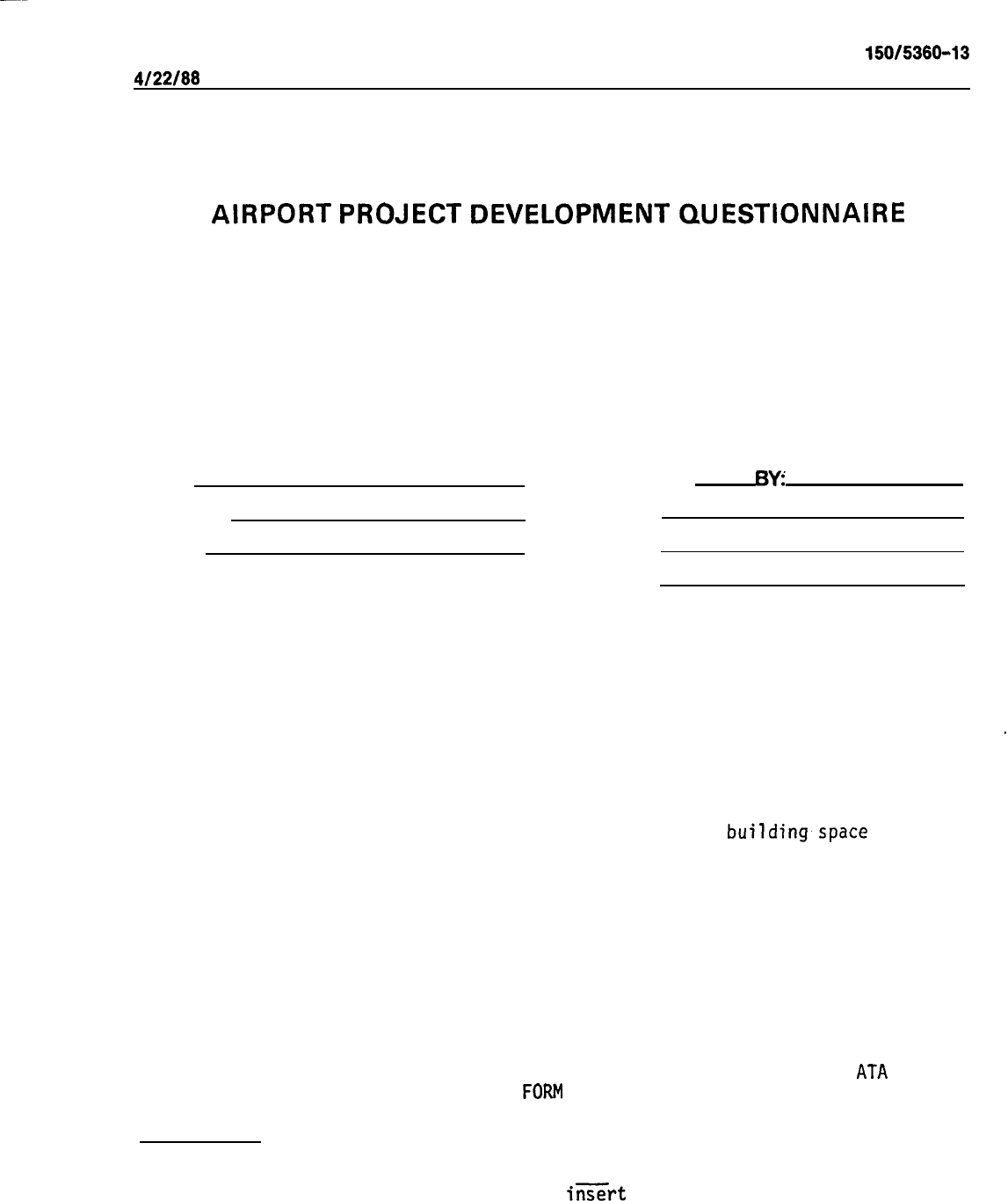
4122166
AC 150/5360-13
Appendix 2
AIRPORT
PROJECT
DEVELOPMENT
QUESTIONNAIRE
AIRPORT PROJECT DEVELOPMENT QUESTIONNAIRE
CITY:
AIRPORT:
STATE:
PREPARED
6Yz’
AAAC REP:
AAFC REP:
AAPC REP:
This questionnaire is intended to provide individual airline data necessary for
planning, design and construction of Apron-Terminal Facilities.
The submission of this questionnaire
, and the data contained herein, does not
constitute a commitment by the airline/or airlines to support expenditures for
acquisition of land or construction of improvements, lease
building,space
or
real property, or incur any other commitments.
Facility requirements shown are
based
on the number of passengers forecasted for
that year.
However, specific construction programs are normally dictated by
economics and their affect upon airport operations.
Accordingly, these construc-
tion programs are normally based on facility sizing for passenger volumes forecasted.
during the two to five year period after occupancy. The design year for these
construction programs should be mutually agreed upon in advance by the airlines and
the Airport Authority.
Section 4 has been added for the purpose of providing basic information on future
requirements for support facilities.
It is similar to Section 7 of the ATA Airport
Master Planning Questionnaire (AD/SC
FORM
74-Z).
INSTRUCTIONS:
When completing this questionnaire, fill in all the blanks. If the requested infor-
mation is not available or not applicable,
insert
N/A in the appropriate space(s).
Do not leave any blank spaces.
3
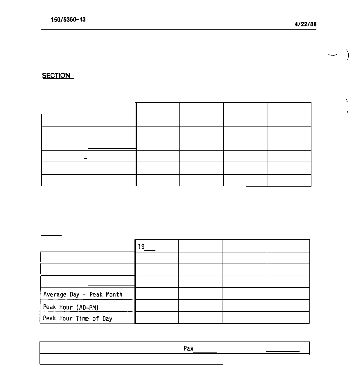
AC
150/5360-13
Appendix 2
4/22/88
SECTION
1 GENERAL PLANNING
PART 1
ENPLANEMENTS
2
19
19
19
19
\
Annual
Percent Transfer
Peak Month Is
Average Day
-
Peak Month
Peak Hour (A
D
-P
M
)
Peak Hour Time of Day
DEPLANEMENTS
PART 2
I
Annual
I
Percent Transfer
Peak Month Is
19-
19
19
19
Ratio of Visitors to Passengers: Enplaning
Pax
Ratio of Checked Bags to Passengers:
; Deplaning Pax
I
4
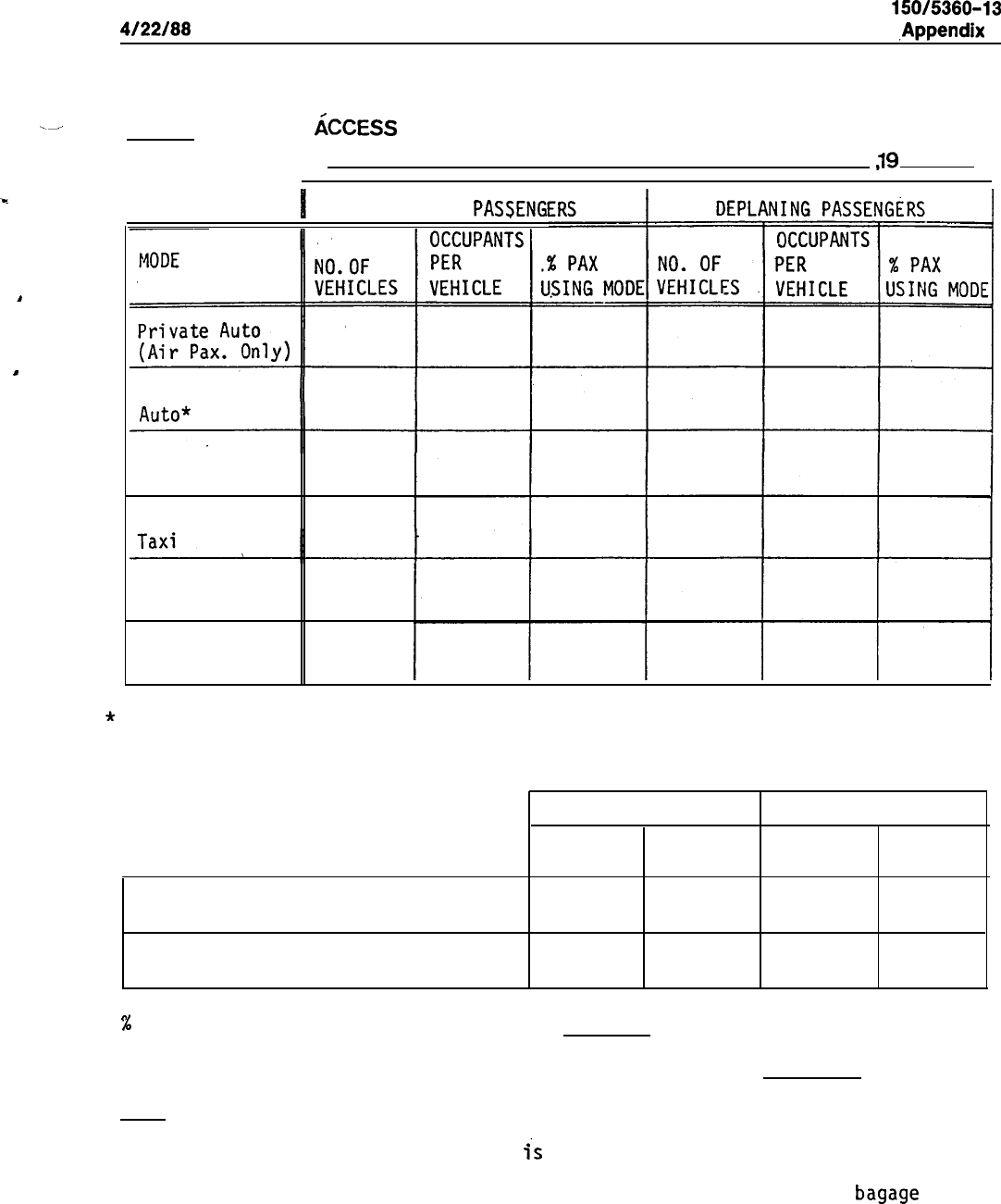
4/22/88
AC 150/5360-13
,Appendix
2
.-
’ PART 3 GROUND
d;CCESS
INFORMATION
BASED ON
19
h
1
.
ENPLANING
PASSENG
~~
Serve-Private
Rental Car
Bus
Other
*
Serve-Private Auto =
Trip purpose of seeing, meeting, dropping off, picking up,
greeting or well-wishing an air passenger.
ENPLANING PASSENGERS DEPLANING PASSENGERS
NO. OF
NO. OF
VEHICLES
PERCENTAGE VEHICLES
PERCENTAGE
Private autos using only the curb
Private autos using curb before
going to parking facility
%
of Private Autos Using Parking Facility
%
Maximum Vehicle Storage Accumulation in the Parking Facility Vehicles
NOTE:
a) This information for Section 1
is
generally required to determine the
elements of the Apron-Terminal which are or may be in common use, such
as public corridors, terminal lobby and public waiting areas,
bagage
claim, vehicle curb length and parking facilities.
b) Most of the data on vehicular traffic can only be obtained through the
Airport Authority.
information.
Surveys may be required in the absence of any updated
5
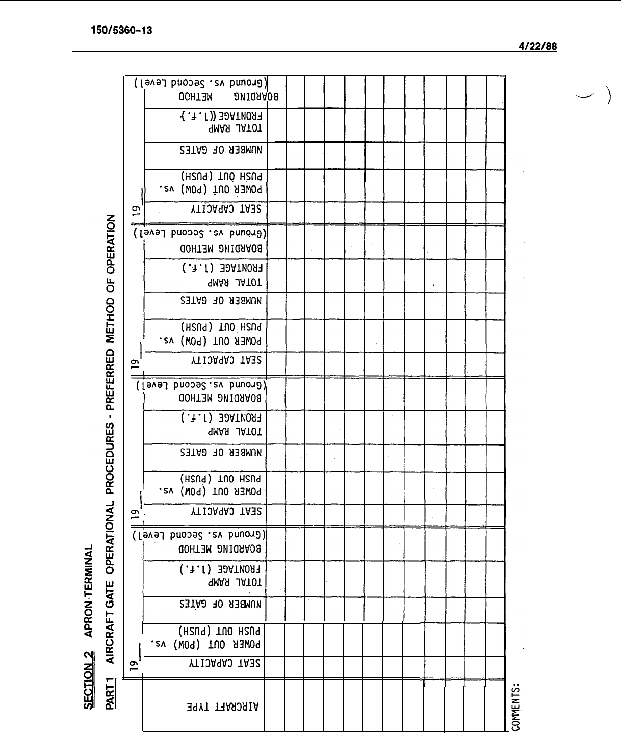
AC 150/5360-13
Appendix 2
4/22/88
(~aq
puo3a.s
-5~
puno.tg)
([allal
puo3a.s
‘SA
puno.tg)
aCH13W
3NIOYVOfl
aCH13W
3NIOYVOfl
-(
'4
-
1)
39WlNOdJ
-('d-L)
39WlNOtfJ
dWRi
lWlO1dWRi
lWlO1
S31W9
30
EKlWnNs31w9
30
EKlwnN
(HSnd)
1nQ
Hslld
(HSnd)
1nQ
Hslld
'SA'SA
(Mod)(Mod)
InO
UMOd
InO
UMOd
00H13W
E)NIawoa
00H13W
E)NIawoa
(HSnd)
InO
HSnd
(HSnd)
InO
HSnd
II
'SA
(Mod)
InO
ti3MOd'SA
(Mod)
InO
ti3MOd
mm
AlI3WdV3
IDS
AlI3WdV3
IDS
--
3dAl
LJt'UtlIV
3dAl
LJt'UtlIV
6
PART 2 INDIVIDUAL DEPARTURE LOUNGE
SIZING PER AIRCRAFT GATE
Lounge No
1
.
I
-.
,_
19
-19
19
19
--
Gate Capability-
Gate
Capabil?ty
-
Gate Capability
-
Gate Capability-
Specify range of Area in
Specify
range of Area
in
Specify
ragge
of Area in Specify range of Area ir
aircraft size
Sq. Ft. aircraft size
Sq. Ft. aircraft size
Sq. Ft.
aikraft
size
Sq. Ft.
NOTE:
Specify when departure lounge serves multiple gates.
COMMENTS:
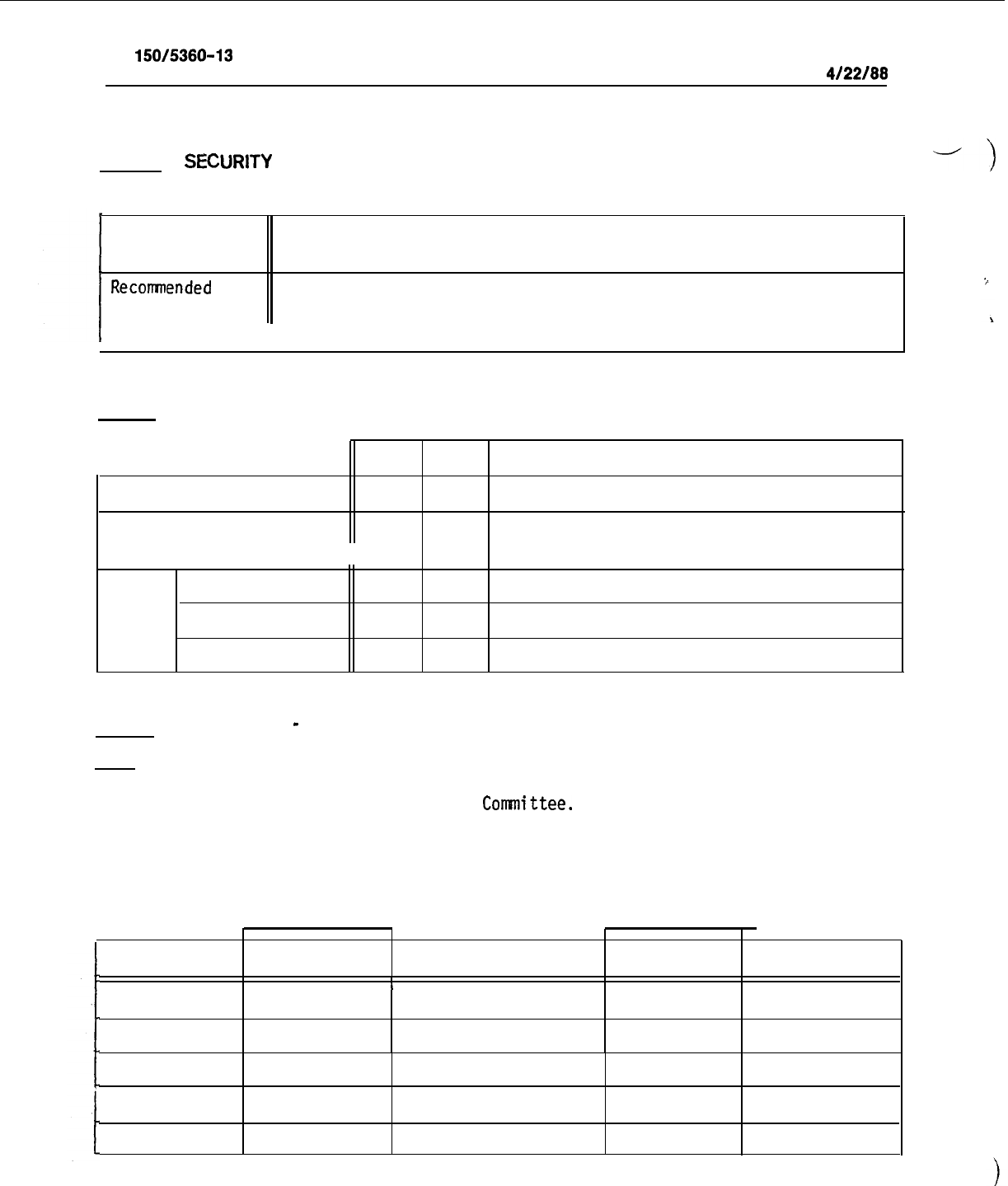
AC
150/5360-13
Appendix 2
4/22/88
PART 3
SECURlTY
-j
INDICATE REQUIREMENTS OR RECOMMENDATIONS FOR SECURITY
Suggested
Locations:
Recommended
Type
of Equipment
(Manual, X-Ray, or other)
PART 4 COMMUNICATIONS AND FLIGHT INFORMATION
.YES NO
COMMENTS
Public Address System
Flight Information
(Describe type under comments)
Roadway
Signs
Terminal
Gates
PART 5
DESIGN DAY
-
ACTIVITY TABLE
NOTE:
a) This information can be given for one term (five year forecast period).
However, the selected period of time is to be agreed upon jointly by
the Airline Airport Planning
Committee.
b) Design Day is defined as the Average Day of the Peak Month.
c) Complete the Table for a minimum of 18 hours of activity.
FORECAST YEAR
PEAK MONTH
ARRIVAL TIME
PASSENGERS OFF
AIRCRAFT
TYPE
PASSENGERS ON DEPARTURE
TIME
L
8
4/22/88
AC 150/5360-13
Appendix 2
.~-
PART
5
DESIGN DAY
-ACTIVITY
T&E
(CoNT’D)
ARRIVAL TIME
PASSENGERS OFF AIRCRAFT TYPE
PASSENGERS ON DEPARTURE TIME
I
L
.
!
I
i
,
NOTE:
The above table conforms with Figure 2-4, Page 2-11 in The Apron-Terminal
COmPlexi
DOT/FAA Report No. FAA-RD-73-82; September, 1973.
COMMENTS:
9
PART 6
AIRLINE TERMINAL TICKET OFFICE
a) TICKET COUNTER
19
Type (Specify Linear vs. Through)
Ticket Counter Length
Number of
Ticket Counter in Terminal
Positions
Curbside Baggage. Check-In
Modular Length per Position in Terminal
I
b) BACK OFFICES (behind ticket counter)
Supervisory Office(s)
Other Offices
Check-out
Area
Area
No. of People
Work Space
Locker/Lounge
Area
Storage Area
Other (Specify):
TOTAL AREA
19
19
19
LOCATION
If If
If
If
If
If
lf If
\
sf sf
sf
sf
sf
sf
sf
sf
sf
sf
sf
. sf
sf
sf
sf
sf
sf
sf
sf
sf
sf
sf
Sf
sf
sf
sf
sf
sf
sf
sf
sf
sf
PART 7 TICKET LIFT SUPPORT FACILITY
Specify: Required in Terminal
Required in Connector (Specify 2nd vs. Ground Level)
19
19
19
19
LOCATION
Flight Close-out Room
sf
sf
sf
sf
Check-out Room
sf
Sf-
sf
sf
No. of People Checking out Simultaneously
Storage
Sf’
sf
sf
sf
Supervisory Offices
sf
sf
sf.
sf
Lounge
sf
sf
sf
sf
Locker Room
sf
sf.
sf
sf
Training Room
sf
sf
sf
sf
Other (Specify):
sf
sf
sf
sf
I
TOTAL AREA
sf
sf
Sfl
sf
A
PART 8PASSENGER SERVICE MANAGER
I
Office
1
Lounge
PART 9 SPECIAL PASSENGER
FACIL
.ITIES
19-
19
19-
19-
LOCATION
I
Customer Service Lounge
1
Club Room(s)
-
sfl
Sfl
sfl
sfl
sfl
sfl
19
19
19
19
LOCATION
-
_
sf
sf
sf
sf
sf.
sf
sf
sf
-.-
p-4
PART 10OUTBOUND BAGGAGE ROOM
\
19
19
79
19
LOCATION
Type (Specify Shared vs. Exclusive)
Clear Height
ft. ft.
ft.
ft.
Clear Length
ft.
ft. ft. ft.
Clear Width
ft.
ft.
ft.
ft.
Sort
Available from One Side
If.
If.
If.
If.
Device(s)
II
Available from Both Sides
If. If. If.
If.
Special* (Skis, Oversize
Parcels, etc.)
sf.
sf.
sf.,
sf.
PART 11 INBOUND BAGGAGE
19
Width
Wmw
Unloading
length
Device
81
Claim Device(sj Device
#2
(Passenger
Device
#3
Retrieval .
of Bags)
Device
#4
Provisions for
odd-size Baggage
saggage
Service
Offices(Including
storage for unclaimed baggage)
"
Special*(Skis,Oversize Parcels,etc.)
,I
19
19
19
LOCATION
ft.
ft.
ft.
ft.
ft.
ft.
ft.
ft.
If. If.
If.
If.
If.
If.
If.
If.
If.
If.1
If.
If.
If.
If. If.
_
If.
sf. sf.
sf.
sf.
sf.
sf.
sf.
sf.
sf.
sf.
sf.
sf.
*NOTE:
'
This
prwision
is not required at all'stations.
.
PART 12
MISCELLANEOUS
Mail and Express Transfer Areas
Skycaps Room
Other
(Specify):
19
119
119
119
ILOCATION
sf.1
sf.1
sf.1
sf.
sf.
sf.
sf.
sf.
sf.
sf.
sf.
19
Flight Info. Center/Load and Clearance
ComunicationslTeletype
Area
Telephone Equipment Rooms
I
Flight Plan Area(No. of positions@ 3 ft.)
Weather Display
Operations Crew Area
Crew Ready Room
Crew Kit Bag Area (No. of
bags]
Crew Mail Box Area (No. of boxes)
Crew Briefing Room
Storage
Flight Administration
Dispatch Weather Service
19
19
19
LOCATION
sf.
sf.
sf.
sf.
sf.
sf.
.sf.
sf.
sf. .
sf.
sf.
sf.
sf.
sf.
sf.
sf.
sf.
sf. sf.
sf.
sf.
sf.
sf.
Sf.
sf.
sf.
sf.
sf.
\
sf. sf.
sf.
sf,
sf.
sf.
sf.
s
F.
sf.
sf.
sf.
sf.
-L
AIRLINE
~PEFIAT~~NS
(C~NT’D)
P
-
._-_-----
__I--
-.--
---..
.-
..--
-
_..-.
--.--
-.-.-.
-
-
.._.-.
-----
..-_.
_
_
._
-- .
-_._.
-
..__
-.-.
.-
..-.
-.---
Stewardess Administration .
sf
sf
sf
sf
-
-
-
.---
.
_
_._
.L
.__
~--_--_---~-_
-.....-
~_-.------.-_-__
Training Room
sf
sf
sf sf
--
--
--
-
Food Bank/Top-off Area
sf
sf
sf
sf
Other (Specify):
sf
sf
sf
sf
PART 14 LINE CARGO FACILITIES
Storage
Supervisory Offices
Ready Room
Locker Rooms
Lunch Rooms
Clerical
Training
Other (Specify):
F--
-
-
-
19
19
19
LOCATION
sf
sf
sf
sf
sf
sf
sf
sf
sf
sf
sf sf
sf
sf
sf
sf
sf
sf
sf
sf
sf
sf
sf
sf
Sf
sf
sf
sf
sf
sf
ff
sf
PART 15 CABIN SERVICES
I
Administrative Offices
I
Cabin, Services Room
I
Other (Specify):
i9
19
19 19
LOCATION
sf
sf
sf
sf
sf
sf sf sf
-’
J
.
PART
15
FACILITIES MAINTENANCE
Shop
Storage
Other (Specify):
19
19
19 19
LOCATION
sf
sf
sf
sf
sf
sf
sf
sf
A
PART 17 AIRCRAFT LINE MAINTENANCE SUPPORT AREA
I
19
I
19
I
19
-
I
,I
l9
1
LOCATION
I
Stores and Tools
Technical Services
Production Offices
I I
I
1
I
sf
sf
sf
sf
I
Satellite Shops
I
Sfl
sf
I
4
sfl
I
Wheel Storage Area
*WE
Depending
upon
the configurations of the various areas and specific
official requirements, locker rooms, lounges, lunchrooms and rest-
rooms can be located in one area. If not, indicate the requirements
for each section.
Fluids Area
Supervisory Offices
Other (Specify):
Locker Room*
Lounge *
Lunchroom*
Restrooms*
sf
sf
SS
sf
sf
sf
sf
sf
sf
sf . sf
sf
sf
sf
sf
sf
sf
sf
sf
sf
s
PART 18
ADMlNlSTRATlON
-_-
City Manager's Office
Secretarial
Personnel Management
Secretarial
Controller including secretarial
Offices
Conference Room
Miscellaneous
Areas (Specify)
-.-
..I_.
19
19
19
19
LOCATION
sf
sf sf
sf
sf
sf
sf
sf
sf
sf sf
sf
sf sf
sf
sf
sf
sf
sf
sf
sf
sf
sf
sf
sf
sf
sf
sf
sf
'sf
sf
sf
sf
sf
sf
sf
PART 19 EMPLOYEE CAFETERIA
19
I19
1
19
1
19-
1
LOCATION
I
I
I
sf
sf
sf
sf
I
Total
Area
(Joint Use)
'
PART 20 EMPLOYEE PARKING
Maximum No. of Parking Spaces Required
Time of Day for
Req.'d
Max. Spaces
I
Preferential Parking Spaces for
Carpoo]ls
19
19
19
LOCATION
I
I
1
I
-t
I
I
I
I
I
-J
SECTION 3 APRON
FIXED APRON FACILITIES
NO
1
YES
ICOMMENTS
Guide-In System
Potable Water
Electrical Power for Aircraft
Type:
Ground Rods
Hydrant Fueling
Aircraft Sewage Disposal Facility
11
Ramp Lighting
Ground Equipment Parking Off-Gate
Aircraft
Parking
No. of positions at terminal
;
Specify Aircraft Size:
N
O
. of positions Off-gate
;
Specify Aircraft Size:
Overnight parking positions in addition to above
;
Specify Aircraft Size:
SECTION 4 REMOTE ‘SUPPORT FACILITIES (Total Area)
19
119
LOCATION
acres
Cargo Facility
Aircraft
MTC/Hangar/Shops
acres
acres1
acres1
acres
acres
acres
acres
acres
acres
acres
acres
Automotive/GSE Maintenance Shops
Remote Aircraft Parking
acres
acres
acres.1
acres1
I
Sfl
Sfl
Flight Kitchen
II
sf
sf
Employee Parking (No. Spaces)
II
Other(s)
(Specify)

l/19/94
AC
150/5360-13
CHG 1
Appendix 3
i
APPENDIX 3
-
FEDERAL INSPECTION SERVICES APPROVAL OFFICES
The following is a listing of addresses
aud
phone numbers of the national headquarters offices of the Federal
Inspection Services (FIS).
0
Commissioner of Customs, U.S. Customs Service
1301 Constitution Avenue, N.W.
Washington, D.C. 20229
Attn: Director, Passenger Enforcement and Facilitation
Telephone No.: 202-566-5607
o Associate Commissioner, Management
Immigration and Naturalization Setvice
425 I Street, N.W.
\
Washington, D.C. 20536
Attn: Chief, Facilities and Engineering Branch
Telephone No.: 202-633-3110
o Plant Protection and Quarantine
Animal and Plant Health Inspection Service
6505 Belcrest Road, Room 635, Federal Building
Hyattsville, Maryland 20782
Attn: Chief, Port Operations
Telephone No.: 301-436-8295
o
Director, Division of Quarantine
Public Health Service
Center for Prevention Services
Centers for Disease Control
Atlanta, Georgia 30333
Attn: Chief, Programs Operation Branch
Telephone No.: 404-639-1437
.
o
U.S. Fish’ and Wildlife Service
Division of Law Enforcement
4401 N. Fairfax Drive, Room 500
Arlington, Virginia 22203
Attn: Desk Officer for International Trade
Telephone ‘No.: 703-358-1949
.
1 (and 2)
