
SEI TECHNICAL REVIEW · NUMBER 77 · OCTOBER 2013 · 33
FEATURED TOPIC
1. Introduction
Nowadays, the environment surrounding cable-TV op-
erators is undergoing major challenges. One of such chal-
lenges is the growing competition with other business
operators such as major carriers or satellite broadcast op-
erators. Cable-TV operators have been faced with intense
competition particularly with carriers, who have developed
the FTTH systems and provided the video streaming serv-
ices including terrestrial, BS, and CS broadcasts with the
FTTH system and the high-speed communication service
with GE-PON systems as their strength. Another challenge
is that the existing hybrid fiber coaxial (HFC) system used
by cable-TV operators will need to be renewed in the near
future. Many cable networks have been in use for about ten
to twenty years, and there are growing concerns about serv-
ice suspension or quality loss due to the deterioration of
the equipment. Towards the renewal of the aging cable
network equipment, some of cable-TV operators have in-
troduced the FTTH systems as carriers have in order to pro-
vide more competitive services, even though their facility
circumstances and operational conditions are different
from those of the carriers. In the future, this will likely be
the mainstream replacement method for cable network
equipment. Broad Net Mux Corporation (BNMUX) has
been providing the best products and systems for adopting
the FTTH system to the cable networks by combining
Sumitomo Electronic Group’s optical fiber technology and
high-speed communication access technology, including
the GE-PON system with BNMUX’s acquired HFC trans-
mission technology.
This paper describes the features of these products
and systems, as well as our development efforts in this field.
2. FTTH System in Cable-TV Industry
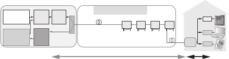
The HFC system shown in Fig. 1 is a commonly used
cable network. In the HFC system, signals for TV, the Inter-
net, and telephone services are transmitted to an optical
node on the outdoor cable network via an optical fiber,
and the optical signals are converted into electronic signals
on the optical node, then various service signals are trans-
mitted to the customer premises equipment (CPE) via a
coaxial cable. Since there is active equipment on the out-
door cable network, such as an optical node and a coaxial
amplifier, a power supply is necessary to feed them.
The FTTH system will be increasingly used by cable-
TV operators in the future. There are two FTTH system in-
stallation methods, one uses the GE-PON system as shown
in Fig. 2, and the other uses an RFoG
*1
system that can be
A large number of cable-TV operators in Japan are intensely competing with carriers. Also, cable-TV operators are
currently considering installing the FTTH systems as an effective solution since their current aging HFC (Hybrid Fiber
Coaxial) systems need to be replaced. Broad Net Mux Corporation (BNMUX) has offered the best solution for these
cable-TV operators. This paper introduces the features of the FTTH products developed based on the combination of
BNMUX's HFC technology and Sumitomo Electric Industry Group’s optical fiber and high-speed communication
technologies.
Keywords: cable-TV, FTTH, optical transmitter/receiver, optical amplifier, GE-PON, ONU
Commercialization of FTTH System for
Cable-TV Operators
Tadayoshi SENOU
*
, Eisuke IZUMI, Takashi YANO, Mitsutoshi IMADA, Hiroshi MURANAKA
and Naoto KOMAZAKI
Reverse
path optical
receiver
Node
HFC
TVTVTV
Forward
path optical
transmitter
Analog/Digital
Broadcast
equipment
NET/TEL/VOD
Communication
equipment
(CMTS, Edge-QAM)
PCPCPC
TELTELTEL
STB
C/M
EMTA
Headend equipment Outdoor equipment
PS
Coaxial
ampifier
Tap-off
Optical Fiber Coaxial Cable
Fig. 1. HFC System
Optical Fiber
Various types
of cables
FTTH (GE-PON)
Headend equipment Outdoor equipment
1550nm1550nm1550nm
Analog/Digital
Broadcast
equipment
TVTVTV
PCPCPC
TELTELTEL
Forward
path optical
transmitter
GE-PON
OLT
Optical
amplifier
Splitter
NET
VoIP
L2/L3
SW
Splitter Splitter Splitter
STB
TA
V-ONU
D-ONU
1490nm
1310nm
Optical Splitter
Fig. 2. FTTH System with GE-PON
used with the existing communication system equipment
(cable modem equipment) as shown in Fig. 3. The cable-
TV operators can choose either of them depending on
their situation in the market, installation scale of existing
communication equipment, and the number of CPE.
3. Overview of FTTH Major Equipment Functions
and System Requirements
3-1 Overview of broadcast equipment
A forward path transmitter and an optical amplifier
have been used in both systems, GE-PON and RFoG, on
the broadcast equipment at the headend. Only the RFoG
system requires a reverse path receiver. V-ONUs are used
for receiving a video signal in the GE-PON system, and R-
ONUs, for the video and data signals in the RFoG system.
(1) Forward path transmitter
This transmitter can convert RF signals for TV, the In-
ternet, and telephone services provided by cable-TV oper-
ators into optical signals, using an optical wavelength range
of 1550 to 1560 nm.
(2) Optical amplifier
This unit can amplify an optical signal received from
an optical transmitter. The FTTH system requires from
hundreds to thousands of optical output ports; therefore
a large number of optical amplifiers are needed.
(3) Reverse path receiver (in the RFoG system)
This receiver can convert an optical signal received
from CPE into an electronic signal, and is used in the RFoG
system only.
(4) V-ONU (video-optical network unit)
This unit is installed on CPE, and can convert a video
optical signal into an electronic signal. Currently, a high-
sensitive V-ONU is commonly used under the condition
that only a digital modulation TV signal (OFDM/QAM
modulation) is received.
(5) R-ONU (RFoG-optical network unit)
This unit for the RFoG system is installed on CPE. It is
equipped with a video receiver function as well as a laser
diode (LD) to convert an electronic signal into an optical
signal. The LD is automatically switched to a burst emission
mode to output an optical signal, only when a forward RF
signal is sent from CPE.
3-2 Overview of communication equipment (GE-PON)
In the cable-TV industry, an IEEE802.3ah-compliant
GE-PON system is commonly used in the FTTH system for
communication services. The GE-PON system consists of
an optical line terminal (OLT) installed at the headend
and data-optical network units (D-ONUs) installed at the
ONU.
(1) OLT
This unit is installed at the headend, handling multi-
ple D-ONUs connected to optical fiber feeder lines divided
by an optical splitter. It can provide broadband access lines,
such as Internet access. A cost-effective communication
network can be built with only one optical fiber by multi-
plexing the optical signal on the forward and reverse paths
between the OLT and D-ONUs.
(2) D-ONU
This unit is for data communication with an OLT via
optical fiber. It is equipped with an Ethernet LAN to con-
nect to a PC, broadband routers at CPE, or VoIP terminal
adapter.
(3) GE-PON management system
This system is equipped with necessary functions for
cable-TV operations to make it easier to configure an
OLT and D-ONUs, manage equipment conditions, search
records, and consolidate multiple OLTs and D-ONUs.
3-3 Requirements of FTTH system for cable-TV
Cable-TV operators and major carriers use different
FTTH equipment and systems as shown in Table 1, and ac-
cordingly the operational conditions and requirements for
FTTH products are different.
The requirements for communication equipment in-
cludes not only installing functions to provide an equiva-
lent level of services and operations as cable modem
communication services provided by cable-TV operators,
but also cost effectiveness. In the cable-TV industry, an IP
address is generally assigned by DHCP
*2
. Therefore, in-
stalling a function to support such an assignment is a key
to the development of GE-PON systems for the cable-TV
market.
4. Features of BNMUX FTTH system
BNMUX has developed an advanced FTTH system,
which further enhances the satisfaction of cable-TV opera-
tors more than the requirements stated in Table 1 and sup-
ports flexible operation. The features of the BNMUX
products for the broadcast and communication services are
as follows:
4-1 Broadcast equipment
(1) BN8200C Series (optical transmitter/receiver, optical
amplifier)
In the past, BNMUX assembled the chassis structures
based on functions. However, to achieve further high-den-
sity mounting, BNMUX has developed major FTTH broad-
cast equipment, such as the optical transmitter, receiver,
and amplifier on the assumption that all of them are
mounted on one chassis to enable further high-density
mounting. This integrated headend equipment, BN8200C
Series shown in Photo 1, can be mounted on a 3U chassis
with up to 12 units. This is the highest mounting efficiency
in this industry. Also, it can be operated by Simple Network
34 · Commercialization of FTTH System for Cable-TV Operators
FTTH (RFoG)
Headend equipment Outdoor equipment
Wavelength
multiplexing
Wavelength
multiplexing
Wavelength
multiplexing
Analog/Digital
Broadcast
equipment
Communication
equipment such as
NET/TEL/VOD
(CMTS, Edge-QAM)
PCPCPC
Optical Fiber
Coaxial cable
Forward
path optical
transmitter
Optical
amplifier
Splitter Splitter Splitter Splitter
STB
C/M
EMTA
TELTELTEL
R-ONU
Optical Splitter
TVTVTV
Reverse
path optical
reciver for
RFoG
Fig. 3. FTTH System with RFoG
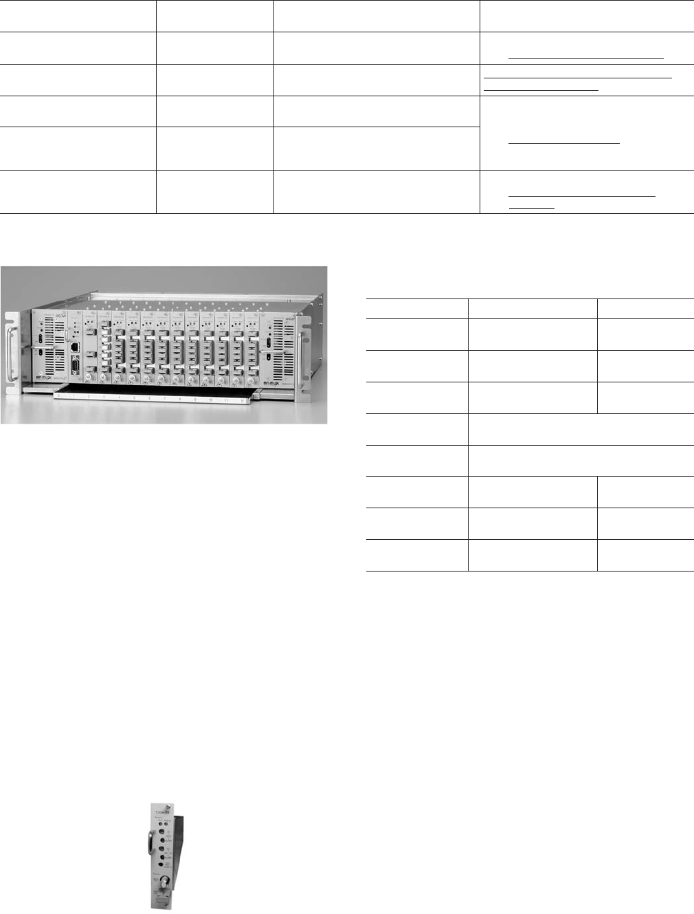
Management Protocol (SNMP) and Web-IF. Thus, it can
contribute to the efficiency in installation adjustment, re-
pair, and maintenance work.
(a) Forward path transmitter (BN8200C-T2G6)
This directly-modulated optical transmitter can trans-
mit BS and CS-IF signals (950 to 2602 MHz) in addi-
tion to cable-TV signals (70 to 770 MHz) which have
been conventionally used. To respond flexibly to vari-
ous installation circumstances and FTTH operation
forms that cable-TV operators have, this forward path
transmitter is equipped with two RF signal input ports
so that it can be used in multiple ways. In the case of
the RFoG system, it can transmit not only TV, Internet,
and telephone signals, but also BS and CS-IF signals.
One of these three types of signals can be input inde-
pendently into the circuit if needed. Conventionally,
the optical launch level is limited due to Stimulated
brillouin scattering (SBS), which is a non-linear phe-
nomenon, and for that reason the number of outdoor
optical branches per fiber is limited to 64.
However, this transmitter can control SBS, and can
achieve the optical launch level of +17 dBm and re-
duce the number of optical fibers installed in the serv-
ice area by increasing the number of outdoor optical
branches up to 128. Table 2 shows the main specifica-
tions of this transmitter.
(b) Optical amplifier (BN8200C-AMP Series)
In response to a request for the efficient optical signal
amplification and distribution in the FTTH system,
which requires huge quantities of the optical output
ports, BNMUX has adopted the multi-port method
with a two-stage amplifier configuration, pre-amplifier
and post-amplifier, as shown in Fig. 4. This helps in al-
lowing for 40 ports if the output power is +20 dBm, and
80 ports, if +17 dBm for one optical input port. This is
the highest distribution efficiency in this industry.
SEI TECHNICAL REVIEW · NUMBER 77 · OCTOBER 2013 · 35
Photo 1. Integrated Headend Equipment (BN8200C Series)
Photo 2. Forward Path Transmitter (BN8200C-T2G6)
Table 1. Comparison with carriers
Item Carrier CATV operators
FTTH requirement
for CATV
QTY of video channels 60 to 70ch More than 100ch
High-quality video signal transmission
⇒ Differrent fiber by video or data
Communication equipment
operational requirement
GE-PON equipment
(Operation: PPPoE)
Cable modem equipment
(Operation: DHCP)
Continuous use of the exsiting method
(DHCP) and equipment
Headend equipment
capacity
Small/Medium scale
(1 hub per town)
Large scale
(1hub per city)
Installation space can be reduced
⇒ High density packaging
Equipment type FTTH equipment only
HFC & FTTH equipment
(Dual equipment can be used until
HFC is replaced with FTTH equipment)
Area geographical
characteristics
Urban to rural areas
Many of the operators cover only
urban areas
Limiting the number of fibers
⇒ QTY of outdoor branchings is
increased
Table 2. Main Specification of Forward Path Transmitter
(BN8200C-T2G6)
Item CATV band BS/CS-IF band
Frequency
bandwidth
70 to 770 MHz 950 to 2602 MHz
QTY of
channels
Analog: 11 channels
Digital: 80 channels
BS/CS 36 channels
RF input
level
Analog: 78 dBµV
Digital: 68 dBµV
68 dBµV
Optical
wavelength
C25: 1557.36 nm / C27: 1555.75 nm
C29: 1554.13 nm / C31: 1552.52 nm
Optical
output level
+8.5 dBm (7.0 mW) Typ.
Noise performance
(CNR)
Analog: 46 dB or more
Digital: 34 dB or more
28 dB or more
Second distortion
characteristics
Analog: -59 dB or less
Digital: -49 dB or less
-31 dB or less
Third distortion
characteristics
Analog: -58 dB or less
Digital: -48 dB or less
-59 dB or less
(Fully populated optical amplifier shown in Photo 3
can support 10,240 subscribers.) In addition, BNMUX
has adopted the single cladding-pumped method with
high device reliability for this amplifier. The post-am-
plifier has a four or eight port configuration to avoid a
large-scale shutdown at the time of replacement. Such
a configuration enhances device reliability, and even if
equipment replacement is necessary due to certain
contingencies, the influence can be limited to 1,024
households, equivalent to that of the HFC system. The
pre-amplifier used in combination with a 1 × 10 splitter
has a one port-type output configuration to support a
system suitable for single output as with a transmission
between the hendends. Thus, except for the multi-port
method, this amplifier can be used in the various op-
eration forms that cable-TV operators have. Table 3
shows the main specifications of this amplifier.
(c) Reverse path receiver (BN8200C-4R100)
Unlike the HFC system, in the case of the RFoG sys-
tem, an optical fiber is divided into 32 to 64 branches
outdoors, then these divided optical fibers are con-
nected to R-ONUs located farther on. Therefore, the
optical operating level is significantly low. This receiver
was developed for the RFoG system to achieve an op-
tical operating level of -28 to -15 dBm, improving the
responsivity and expanding the input range to be bet-
ter than the HFC system. Also, compared to the HFC
system, a large number of reverse optical input ports
can be placed more effectively on this receiver by in-
creasing the number of input ports from two to four,
and installing up to 48 input ports on one chassis.
Moreover, it is equipped with a function to block ther-
mal noise generated inside the equipment, breaking
an output circuit if there is no reverse signal. Thus far
no Japanese manufacturers have been able to develop
such a function. This development can significantly
contribute to the improvement in noise elimination
for reverse RF signals and to high-quality reverse path
transmission. Table 4 shows the main specifications of
this receiver.
(2) V-ONU (BNX1036SN)
This unit has transmission bandwidth that includes
cable-TV, BS, and CS-IF bands, as with a forward path trans-
36 · Commercialization of FTTH System for Cable-TV Operators
Photo. 3 Fully-populated Optical Amplifier (BN8200C-AMP Series)
(Output at +17dBm with 80 ports)
Pre-amp
Post-
amp
#1
Post-
amp
#2
Post-
amp
#10
1 Port
80 Port
Optical
input
8 Port
9 Port
16 Port
73 Port
1 x 10 optical splitter
Fig. 4. Optical Amplifier Configuration
(Output at +17dBm with 80 ports)
Table. 3 Main Specifications of Optical Amplifier (BN8200C-AMP Series)
Item
Equipment
name
Pre-optical
amplifer
Post-optical
amplifer
Post-optical
amplifer
10 distribu-
tion optical
splitter
Model
code
AMP22URN-
P01-01
AMP20DSN-
P04-01
AMP17DSN-
P08-01
OPS1W210
Optical
output
+22 dBm
× 1 output
+20 dBm
× 4 output
+17 dBm
× 8 output
10
distributions
Unit
config.
Pre-amplifer:
1 unit + 1 × 10 splitter: 1 unit + Post-amplifer: 10 units
Noise
figure
4.5 dB or less 7 dB or less 7 dB or less
12.5 dB or less
(insertion loss)
6.5 dB or less (Pre+Post-optical amplifer)
Photo 4. Reverse Path Receiver (BN8200C-4R100)
Table 4. Main Specifications of Reverse Path Receive (BN8200C-4R100)
Item
Frequency bandwidth 5 to 100 MHz
Optical wavelength
1270 to 1610 nm (CWDM 18 wavelengths)
QTY of optical input port 4 ports
Optical input level -28 to -15 dBm
RF output level 95 dBµV
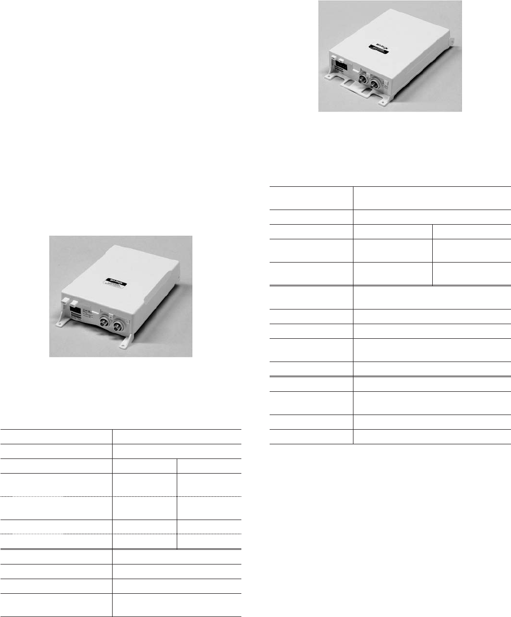
mitter. It is specialized for receiving digital modulation TV
signals; therefore, compared to the conventional V-ONU,
its responsivity is improved by 6 dB, and it can be operated
at an input level of -14 to -6 dBm. With the improvement
of the responsivity, the number of optical branches can be
increased up to four times as much as the conventional
ones (about 256 branches), and the number of optical
fibers and optical amplifiers installed at the headend can
be reduced. This achievement can contribute to cost-effec-
tive system establishment. Also, it can support various types
of broadcast services that cable-TV operators provide, re-
ceiving analog signals under definite conditions and sup-
porting the increase in the number of digital channels.
Moreover, it is equipped with a function to control
ON/OFF of RF output for cable-TV, BS, and CS-IF bands
by V-ONU from control equipment installed at a headend.
Table 5 shows the main specifications of this unit.
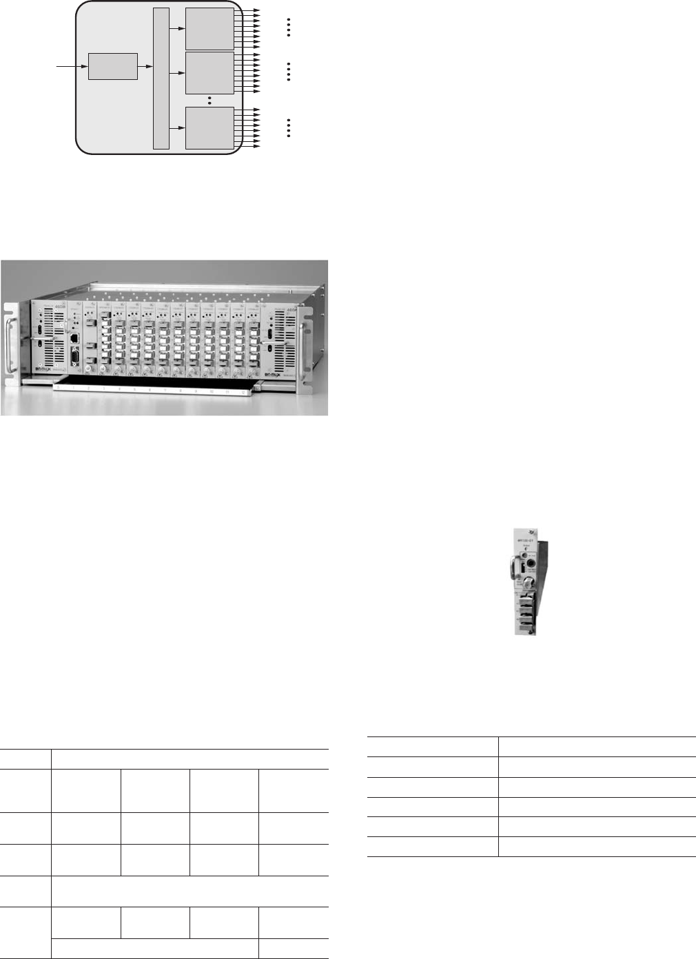
(3) R-ONU (BNX1230SN)
This unit has the following frequency bandwidth, for-
ward: 2.6 GHz as with V-ONU, and reverse: 10 to 60 MHz.
It is equipped with two modes: a burst light mode and an
always-on mode. The burst light mode is known as a stan-
dard method for reverse transmission in the RFoG system.
The always-on mode is controlled remotely to turn the light
on even if there is no RF signal.
In the always-on mode, a stable optical signal can be
received at the headend at the time of the R-ONU initial
installation and adjustment. That reduces the adjustment
workload and time. The remote control function also con-
trols the forward path, and “Through,” “ATT6dB,” and
“Cut” of a reverse RF signal, as well as ON/OFF of optical
output. Table 6 shows the main specifications of this unit.
(4) MDU Node (BNX1310SN)
The RFoG system has an operational issue of optical
beat interference (OBI) occurring when multiple reverse
optical signals on R-ONUs are transmitted in synchroniza-
tion with simultaneous transmission of multiple reverse RF
signals for a communication service. The cause of this issue
is that all the reverse optical signals on R-ONUs use a single
wavelength, 1610 nm. In the case, such as the multid-
welling units where one R-ONU supports a large number
SEI TECHNICAL REVIEW · NUMBER 77 · OCTOBER 2013 · 37
Photo 5. V-ONU (BNX1036SN)
Table 5. Main Specifications of V-ONU (BNX1036SN)
Photo 6. R-ONU (BNX1230SN)
Forward path bandwidth spec.
Optical input level -14 to -6 dBm
Frequency bandwidth 70 to 770 MHz 950 to 2602 MHz
QTY of channels (Mode 1)
Digital
80 channels
BS/CS
36 channels
(Mode 2)
Digital
112 channels
BS/CS
36 channels
RF output level (Mode 1) 85 dBµV 85 dBµV
(Mode 2) 83 dBµV 85 dBµV
Other
Power consumption 5.5 W or less (100 V AC input)
Dimension H: 224 × W: 139 × D: 56 mm
Weight
Approx. 0.5 kg
(excluding accessaries)
Table 6. Main Specifications of R-ONU (BNX1230SN)
Forward path
bandwidth spec.
Optical input level -8 to -2 dBm
Frequency bandwidth 70 to 770 MHz 950 to 2602 MHz
QTY of channels
Analog: 11channels
Digital: 80 channels
BS/CS 36 channels
RF output level
Analog: 95 dBµV
Digital: 85 dBµV
85 dBµV
Reverse path
bandwidth spec.
Optical output level +3 dBm
Optical wavelength 1610 nm
Frequency
bandwidth
10 to 60 MHz
RF input level 90 dBµV
Other
Power
consumption
6 W or less (100 V AC input)
Dimension H: 226 × W: 142 × D: 50 mm
Weight Approx. 0.7 kg (excluding accessaries)

of subscribers, OBI between this R-ONU and another R-
ONU for other subscribers is a concern, since the emission
frequency of this R-ONU increase. The MDU node can op-
erate much the same way as the R-ONU; however, it was de-
veloped to avoid OBI in the RFoG system, and 18
wavelengths (1270 to 1610 nm) are available on the menu
to support Coarse Wavelength Division Multiplexing
(CWDM). This node with reverse wavelengths different
from that of the R-ONU helps provide stable reverse trans-
mission and communication services, preventing OBI be-
tween R-ONUs even if the emission frequency increases. In
addition, this node can control the forward or reverse RF
and optical signals when used with the remote control sys-
tem as with R-ONU. Table 7 shows the main specifications
of this node.
4-2 Communication system equipment
(1) OLT (FSU6300)
In general, 16 PON line cards can be installed on one
chassis; however, a PON line card (FCM6060-TS) with two
PON ports was recently developed to increase the density
of PON ports, and released for the cable-TV market. This
development makes it possible to handle up to 2,048 D-
ONUs per OLT chassis, reducing the number of necessary
OLTs, and cut a rack space by half. Moreover, the following
software functions are additionally installed to achieve sim-
38 · Commercialization of FTTH System for Cable-TV Operators
Photo 7. MDU Node (BNX1310SN)
Table 7. Main Specification of MDU Node (BNX1310SN)
Photo 8. OLT (FSU6300)
Table 8. Main Specification of OLT: FSU6300
Forward path
bandwidth spec.
Optical input level -8 to -2 dBm
Frequency
bandwidth
70 to 770 MHz 950 to 2602 MHz
QTY of channels
Analog: 11channels
Digital: 80 channels
BS/CS 36 channels
RF output level
Analog: 95 dVµV
Digital: 85 dVµV
85 dBµV
Reverse path
bandwidth spec.
Optical output level +3 dBm
Optical wavelength 1270 to 1610 nm (CWDM 18 wavelengths)
Frequency
bandwidth
10 to 60 MHz
RF input level 90 dBµV
Other
Power
consumption
6 W or less (100 V AC input)
Dimension H: 151 × W: 132 × D: 79 mm
Weight Approx. 1.2 kg (excluding accessaries)
Item Spec.
Chassis
Size Dimension
Approx. W: 483 × D: 420
× H: 222 mm
Hight: 5U
Power
supply
Input voltage 100V AC ± 10%
Power consumption
With fully-populated:
400 W or less
Configuration
2 port redundancy
cofiguration
QTY of Installable line cards
and ports
Line card: up to 16 cards
PON port: 32 port
Line
card
PON I/F
QTY of ports 2 ports
Physical I/F SC connector
Compliance standard
1000BASE-PX20
Optical output
signal wavelength
1480 to 1500 nm
Optical output
power range
+3.5 to +7 dBm
Allowable wavelength range
of optical input signals
1260 to 1360 nm
Allowable power range
of optical input signals
-29.5 to -11 dBm
Power budget 29 dB
Optical link module type
SFP type
SNI I/F
QTY of ports 2 port
Physical I/F RJ-45
Compliance standard
1000BASE-T/100BASE-TX
Control
card
Interface
for
monitoring
control
QTY of ports 2 port
Physical I/F RJ-45
Compliance standard
100BASE-TX/10BASE-T

ilar operation to a cable modem, as requested by cable-TV
operators. ①The tracing function for an IP address that a
subscriber uses under DHCP operation: internet providers
are obliged to identify a sender of information and provide
the information related to the sender. It is also necessary
to manage the records of IP addresses used. For this reason,
the OLT can trace the IP address and ONU used by moni-
toring the packets of ARP
*3
/NDP
*4
to be sent. ②The IP
masquerade prevention function: An IP source guard func-
tion has recently been developed to block any communica-
tion with an IP address other than the IP address assigned
by DHCP to prevent a subscriber from deliberately using a
static IP address without authorization. ③The broadcast
storm detection/prevention function: This function auto-
matically detects a failure and stops D-ONU, which is a
source of the failure, to prevent a large-scale communica-
tion failure caused by a large amount of undesired broad-
cast packets generated due to improper connections.
(2) D-ONU (FTE6083)
In the cable-TV market, it is necessary that one D-ONU
should provide both an Internet access service and a pri-
mary telephone service. FTE6083 has two LAN ports so that
it can be connected to a terminal for Internet access, such
as a PC, and to a VoIP terminal adapter for the primary
telephone service. Quality of Service (QoS) can be also set
for each port. As with a cable modem, this D-ONU has a
circuit to measure optical input and output power levels.
Thus, this function can help maintain the GE-PON system
by monitoring power levels remotely from the manage-
ment system at the headend.
(3) GE-PON management system (GPMS1000)
This system is equipped with functions listed in Table 10
to configure an OLT and D-ONUs individually, monitor
equipment operational conditions, and search a specific
ONU. In response to particularly strong requests from
cable-TV operators, an automatic entry function has been
developed to install D-ONUs without the prior confirma-
tion and registration of an OLT. With this function, the in-
dividual configuration information of each D-ONU can be
automatically entered to the OLT port when this manage-
ment system receives a connection request SNMP trap mes-
sage from unregistered D-ONUs. This function enables a
similar operation to that of a cable modem as cable-TV op-
erators requested.
SEI TECHNICAL REVIEW · NUMBER 77 · OCTOBER 2013 · 39
Table 9. Main Specification of D-ONU FTE6083
Table 10. GE-PON Management System Function List
Photo 10. GE-PON Management System Screen Sample (ONU setting)
Photo 9. D-ONU (FTE6083)
Item Spec.
Size
Dimension W: 114 × D: 158 × H: 37 mm
Weight Approx. 300 g
Power supply 100 VAC ± 10%
Power consumption 5 W or less
I/F
LAN1
Physical I/F RJ-45
Compliance standard
1000BASE-T/100BASE-TX/
10BASE-T
LAN2
Physical I/F RJ-45
Compliance standard 100BASE-TX/10BASE-T
PON
Physical I/F SC connector
Compliance standard
FTE6083-BAN: 1000BASE-PX10
FTE6083-BAL: 1000BASE-PX20
Optical output signal
wavelength
1260 to 1360 nm
Optical output signal
power
-0.5 to +4 dBm
Allowable wavelength
of input optical signals
1480 to 1500 nm
Allowable power of
input optical signals
-25.5 to -3 dBm
Optical power monitor
Optical input signal power can
be monitored
Software function Spec.
OLT management
function
OLT setting, Registration of Splitter to be
connected
D-ONU management
QoS for ONU setting,
Auto registration of ONU
Search function Search of ONU, VoIP-TA and Subscribers
Master management
function
Registration of Master data for
OLT operation
Operation support
function
OLT configration backup and restore,
Firmware version upgrade
Failure monitoring
function
OLT condition monitoring, ONU condition
monitoring, Alarm summary display
Syncronization with
other systems
Syncronize with Subscriber management
system
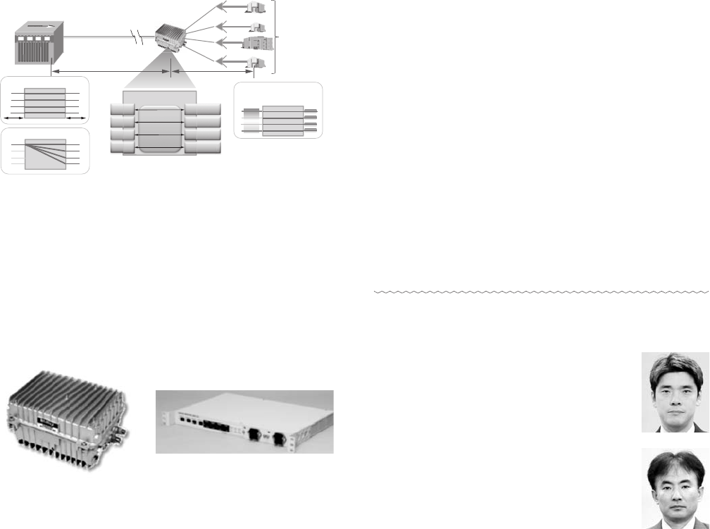
(4) GE-PON repeater (BN7000N-GPR-1901/GPR-1101)
The GE-PON system can support a larger number of
subscribers by increasing the number of distributions per
optical fiber. However, if the number of the distributions
increases, the transmission distance becomes short due to
power budget limitations, and as a result, one optical
fiber’s service area will be reduced.
To solve this issue, BNMUX has developed an ad-
vanced GE-PON repeater that can transmit a GE-PON sig-
nal over a long distance with no constraint of distribution
loss. This repeater installed between an OLT and D-ONUs
has a 3R regeneration function (re-shaping, re-timing, re-
generating), and can relay an optical signal without signal
degradation. In addition, it can extend four GE-PON sig-
nals up to 60 km and support up to 256 D-ONUs. This
makes it possible to expand high-speed communication
services to rural areas far from a headend without using
hubs, and contributes in building a cost-effective network.
Moreover, it has an electronic distribution function to
distribute PON signals converted into electronic signals
and can reduce the number of fibers necessary to support
the multiple-wavelength transmission of four PON signals
between the OLT and the repeater; therefore, a wider net-
work can be built at a low cost.
The outdoor GE-PON repeater can be equipped with
an optical amplifier for a video signal. It can be installed as
a strand-mounted hub or a power pole as with an outdoor
transmitter on the HFC system to use it as a pole-mounted
hub. One outdoor repeater can expand the FTTH system
to support approximately 500 households (when the com-
munication service penetration rate is 50%); therefore,
cable-TV operators who have an extra optical fiber in a cur-
rently used HFC system do not have to install a new optical
fiber between a headend and this repeater.
5. Summary
This paper describes the features and specifications
of the major products for the FTTH system that can
achieve high-speed and large capacity networks for cable-
TV operators. The Sumitomo Electric Group will endeavor
to provide constant support for cable-TV operators amid
intensifying competition by providing them with more sat-
isfactory systems and products.
Technical Terms
*
1 RFoG (Radio Frequency over Glass): A system, one of
the FTTH network forms, to transmit an RF signal via
an optical fiber. It allows the existing equipment, such
as the communication headend equipment and cable
modems to be used as it is.
*
2 DHCP (Dynamic Host Configuration Protocol): A pro-
tocol to automatically assign an IP address to a PC, and
be used for the cable-TV system operation.
*
3 ARP (Address Resolution Protocol): A protocol to obtain
a corresponding MAC address from an IPv4 address.
*
4 NDP (Neighbor Discovery Protocol): A protocol to obtain
a corresponding MAC address from an IPv6 address.
Reference
(1) Umeda et al., “Development of GE-PON Repeater,” SEI Technical
Review No.169 (2006)
Contributors (The lead author is indicated by an asterisk (
*
).)
T. SENOU
*
• System Planning/Promotion Dept., Net-
work Systems Division, Broad Net Mux
Corporation
E. IZUMI
• IP System Technology Dept., Network
Systems Division, Broad Net Mux Corpo-
ration
40 · Commercialization of FTTH System for Cable-TV Operators
GE-PON OLT GE-PON
repeater
4 PON x
64 D-ONU
= 256 Sub.
Up to 40 kmUp to 40 kmUp to 40 km 20 km20 km20 km
Ultralong-haul transmission
4 input 4 output
Wavelength division
multiplexing
Electrical distribution
InIn OutOut
OutOut
OutOut
OutOut
InIn
InIn
InIn
GE-PON Repeater
λ
1
λ
2
λ
3
λ
4
10~20 km10~20 km10~20 km~40 km~40 km~40 km
One Fiber
Fig. 5. Example of System Configuration with GE-PON Repeater
GPR-1101
(Indoor type)
BN7000N-GPR-1901
(Outdoor type)
Photo 11. BN7000N-GPR-1901/GPR-1101

T. YANO
• IP System Technology Dept., Network
Systems Division, Broad Net Mux Corpo-
ration
M. IMADA
• Transmission Equipment Development
Dept., Network Systems Division, Broad
Net Mux Corporation
H. MURANAKA
• Transmission Equipment Development
Dept., Network Systems Division, Broad
Net Mux Corporation
N. KOMAZAKI
• Suminet Communication Co., Ltd.
(Shanghai)
SEI TECHNICAL REVIEW · NUMBER 77 · OCTOBER 2013 · 41
