
Instruction manual
General instructions digital
Mass Flow / Pressure instruments
laboratory style / IN-FLOW
Doc. no.: 9.17.022AF Date: 06-04-2021
ATTENTION
Please read this instruction manual carefully before installing and operating the instrument.
Not following the guidelines could result in personal injury and/or damage to the equipment.

BRONKHORST
®
SCOPE OF THIS MANUAL
This manual covers the general part of digital mass flow / pressure instruments for gases or
liquids. It handles the general instructions needed for the instruments.
More information can be found in other documents.
Multibus instruments have modular instruction manuals consisting of:
- General instructions digital Mass Flow / Pressure instruments
laboratory style / IN-FLOW (document no. 9.17.022)
- Operation instructions digital instruments (document no. 9.17.023)
- Fieldbus/interface description:
- FLOW-BUS interface (document no. 9.17.024)
- PROFIBUS DP interface (document no. 9.17.025)
- DeviceNet interface (document no. 9.17.026)
- RS232 interface with FLOW-BUS protocol (document no. 9.17.027)
- Modbus interface ASCII / RTU / TCP (document no. 9.17.035)
- EtherCAT interface (document no. 9.17.063)
- PROFINET interface (document no. 9.17.095)
- CANopen interface (document no. 9.17.131)
- EtherNet/IP interface (document no. 9.17.132)
- POWERLINK interface (document no. 9.17.142)

BRONKHORST
®
Even though care has been taken in the preparation and publication of the
contents of this manual, we do not assume legal or other liability for any
inaccuracy, mistake, misstatement or any other error of whatsoever nature
contained herein. The material in this manual is for information purposes only,
and is subject to change without notice.
Warranty
The products of Bronkhorst are warranted against defects in material and
workmanship for a period of three years from the date of shipment, provided they
are used in accordance with the ordering specifications and the instructions in
this manual and that they are not subjected to abuse, physical damage or
contamination. Products that do not operate properly during this period may be
repaired or replaced at no charge. Repairs are normally warranted for one year or
the balance of the original warranty, whichever is the longer.
See also paragraph 9 of the Conditions of sales.
The warranty includes all initial and latent defects, random failures, and
undeterminable internal causes.
It excludes failures and damage caused by the customer, such as contamination,
improper electrical hook-up, physical shock etc.
Re-conditioning of products primarily returned for warranty service that is partly or
wholly judged non-warranty may be charged for.
Bronkhorst High-Tech B.V. prepays outgoing freight charges when any party of
the service is performed under warranty, unless otherwise agreed upon
beforehand. However, if the product has been returned collect to Bronkhorst
High-Tech B.V., these costs are added to the repair invoice. Import and/or export
charges, foreign shipping methods/carriers are paid for by the customer.

BRONKHORST
®
Short-Form Operation Instruction
Before installing your Mass Flow or Pressure Meter/Controller it is important to
read the attached label and check:
- flow/pressure rate
- fluid to be metered
- up- and downstream pressures
- input/output signal
Check the red-coloured sticker and make sure the test pressure is in agreement
with normal safety factors for your application.
Check if the piping system is clean. For absolute
cleanliness always install filters to assure a clean, moisture- and oil-free gas
stream.
Install the Meter/Controller in the line and tighten the fittings according to the
instructions of the supplier of the fittings. Choose the mounting position according
to the directions given in this manual.
Check the system for leaks before applying fluid pressure
In systems with corrosive or reactive fluids, purging with an inert gas is absolute
necessary before use. Complete purging after use with corrosive or reactive
fluids is also required before exposing the system to air.
Electrical connections must be made with a standard cable or according to the
hook-up diagram in the back of this manual.
Short form start-up
Install instrument in your process.
Provide instrument with correct pressure(s)
! Caution
If the instrument is not performing as expected please contact Bronkhorst High
Tech B.V. or your distributor for instructions.
Analog operation
Connect the instrument to the power supply/readout unit with the 9-pin cable at
the DB-9 connector / 8 DIN connector

BRONKHORST
®
BUS/digital operation
For this procedure: See description for specific fieldbus
Send a setpoint to the instrument and check the measured value
Let the instrument warm-up for 30 minutes for best accuracy
Your Mass Flow/Pressure Meter/Controller is now ready for operation.
! Caution
Operation via fieldbus is done by means of a flat conductor cable connected with
the main PC board. Although all functionality is possible by means of RS232
and the switch on top of the instrument, it is important that care should be taken
when removing the upper part of the housing.
Safety Precautions
The following safety precautions should be observed before using this product
and any associated instrumentation.
This product is intended for use by qualified personnel who recognize shock
hazards and are familiar with the safety precautions required to avoid possible
injury. Read the operating information carefully before using the product.
Before operating, make sure the line cord is connected to a properly grounded
power receptacle. Inspect the connecting cables, test leads, cracks, or breaks
before each use.
The module and accessories must be used in accordance with its specifications
and operating instructions or the safety of the equipment may be impaired.
If required, replace fuses with the same type and rating for continued protection
against fire hazard.
Opening of the equipment is not allowed. There are no repairable parts inside. In
case of a defect please return the equipment to Bronkhorst High-Tech.
The symbol
on an instrument indicates that the user should refer to the
operating instructions located in the manual.
Surfaces near the
symbol may be hot.
To maintain protection from electric shock and fire, replacement components
must be obtained from Bronkhorst High-Tech B.V. Standard fuses, with
applicable national safety approvals, may be used if the rating and type are the
same. Other components that are not safety related may be obtained from other
suppliers as long as they are equivalent to the original component. (Note that
selected parts should be obtained only through Bronkhorst to maintain accuracy
and functionality of the product.) If you are unsure about the applicability of a
replacement component, call a Bronkhorst
®
office for information.

BRONKHORST
®

BRONKHORST
®
TABLE OF CONTENTS
1
Introduction ................................................................................................................................................... 9
1.1 General description ................................................................................................................................ 9
1.1.1 Gas flow .......................................................................................................................................... 9
1.1.2 Liquid flow ....................................................................................................................................... 9
1.1.3 Pressure ......................................................................................................................................... 9
1.1.4 Housings ......................................................................................................................................... 9
1.1.5 Valves ........................................................................................................................................... 11
1.2 Sensor principles ................................................................................................................................. 12
1.2.1 Gas flow sensors (by-pass measurement) ................................................................................... 12
1.2.2 Gas flow sensors (direct mass flow measurement, CTA based) ................................................. 12
1.2.3 Liquid flow sensors ....................................................................................................................... 12
1) The
µ
-FLOW model for flowrates up to 2 g/h. ......................................................................................... 12
2) The CTA based LIQUI-FLOW™ series L10 / L20 model for flow rates up to approximately 1000 g/h. . 13
1.2.4 Pressure sensor ........................................................................................................................... 13
1.3 Valve principles .................................................................................................................................... 13
1.3.1 Solenoid valve .............................................................................................................................. 13
1.3.2 Vary-P valve ................................................................................................................................. 13
1.3.3 Pilot operated valve ...................................................................................................................... 14
1.3.4 Bellows valve ................................................................................................................................ 14
1.4 K
v
-value calculation ............................................................................................................................. 14
1.4.1 For gases ...................................................................................................................................... 14
1.4.2 For liquids ..................................................................................................................................... 15
1.4.3 Maximum pressure drop ............................................................................................................... 16
1.5 Sensors and laminar flow devices ....................................................................................................... 16
1.6 Conversion factors ............................................................................................................................... 17
1.6.1 Gas conversion factors (by-pass measurement).......................................................................... 17
1.6.2 Gas Conversion Factors (direct mass flow measurement, CTA-based) ...................................... 18
1.6.3 Liquid Conversion Factors ............................................................................................................ 19
1.6.4 Software for conversion factor calculation .................................................................................... 19
2 Installation ................................................................................................................................................... 20
2.1 Receipt of equipment ........................................................................................................................... 20
2.2 Return shipment................................................................................................................................... 20
2.3 Service ................................................................................................................................................. 20
2.4 Mounting .............................................................................................................................................. 21
2.5 In-line filter ........................................................................................................................................... 21
2.6 Fluid connections ................................................................................................................................. 22
2.7 Piping ................................................................................................................................................... 22
2.8 Electrical connections .......................................................................................................................... 22
2.8.1 Disconnection from supply source ............................................................................................... 23
2.9 Caution ................................................................................................................................................. 23
2.10 Supply pressure ............................................................................................................................... 23
2.11 System purging ................................................................................................................................ 23
2.12 Seals ................................................................................................................................................ 23
2.13 Equipment storage ........................................................................................................................... 24
2.14 Electromagnetic compatibility........................................................................................................... 24
2.14.1 Conditions for compliance with EMC requirements ..................................................................... 24
3 OPERATION ............................................................................................................................................... 26
3.1 General ................................................................................................................................................ 26
3.2 Power and warm-up ............................................................................................................................. 26
3.3 Zeroing ................................................................................................................................................. 26
3.4 Start-up ................................................................................................................................................ 27
3.5 Operating conditions ............................................................................................................................ 27
3.6 Instrument performance ....................................................................................................................... 27
3.6.1 Sensors......................................................................................................................................... 27
3.6.2 Controllers .................................................................................................................................... 27
3.7 Manual operation ................................................................................................................................. 28
3.8 Analog operation .................................................................................................................................. 28
3.9 BUS / digital operation ......................................................................................................................... 29
4 Maintenance ................................................................................................................................................ 30
4.1 General ................................................................................................................................................ 30

BRONKHORST
®
4.2 Gas flow sensor ................................................................................................................................... 30
4.3 Liquid flow sensor ................................................................................................................................ 30
4.4 Pressure sensor ................................................................................................................................... 30
4.5 Controllers ............................................................................................................................................ 30
4.6 Control valves ...................................................................................................................................... 30
4.6.1 Solenoid valves ............................................................................................................................ 30
4.6.2 Vary-P valve ................................................................................................................................. 31
4.6.3 Pilot operated valve ...................................................................................................................... 31
4.6.4 Bellows valve ................................................................................................................................ 31
4.7 Calibration procedure .......................................................................................................................... 31
4.8 Cleaning ............................................................................................................................................... 31
5 Digital instrument ........................................................................................................................................ 32
6 Interface description .................................................................................................................................... 33
7 TROUBLESHOOTING ................................................................................................................................ 34
7.1 General ................................................................................................................................................ 34
7.2 Troubleshooting summary general ...................................................................................................... 35
Appendices
1 Gas conversion table
2 Enclosures (if applicable)
BRONKHORST
®
9.17.022
page 9
1 Introduction
1.1 General description
1.1.1 Gas flow
The Bronkhorst
®
series mass flow meter for gases is an accurate device for measuring gas flows up to 700
bar depending on body rating, virtually independent of pressure and temperature changes.
The system can be completed with a control valve and flexible readout to measure and control gas flows
from 1 ml
n
/min up to several thousand m
3
n
/h, depending on the specific type of instrument.
For limited flow ranges a metal sealed model is available.
1.1.2 Liquid flow
The Bronkhorst
®
mass flow meter for liquids is an accurate device for measuring liquid flows up to 400 bar
depending on body rating, virtually independent of pressure and temperature changes. The system can be
completed with a control valve to measure and control liquid flows from 2g/h up to 1000g/h.
1.1.3 Pressure
The Bronkhorst
®
pressure meter measures pressures from 100 mbar up to 400 bar depending on body
rating, either absolute pressure or gauge pressure and in the range 0 to 15 bar differential pressure too. The
pressure controller controls pressure with a very high accuracy and repeatability. The controller is available
in forward control (P-600 series) and backward control (P-700 series) and process pressure control (P-800
series).The flow going through the pressure controller depends on up and downstream pressures, the orifice
diameter of the valve and kind of fluid.
1.1.4 Housings
Each instrument housing style incorporates several provisions to comply with EMC requirements.
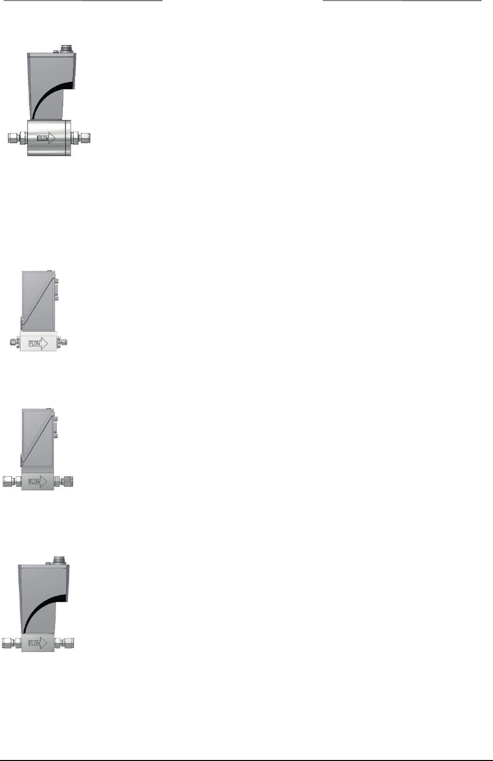
EL-FLOW
®
, EL-PRESS
The p.c.board is placed in a metalized plastic cover. For electrical connection the
instrument has a male 9-pin miniature sub-D connector for analog/RS232
operation. For digital operation the instrument has various connectors on top. These
instruments are suited for dry (indoor) applications, like laboratories and in well
protected (OEM) housings.
EL-FLOW
®
, EL-PRESS metal seal
This series has the same housing as the standard EL-FLOW
®,
EL-PRESS series,
but this series distinguish itself by metal-to-metal seals.
BRONKHORST
®
page 10
9.17.022
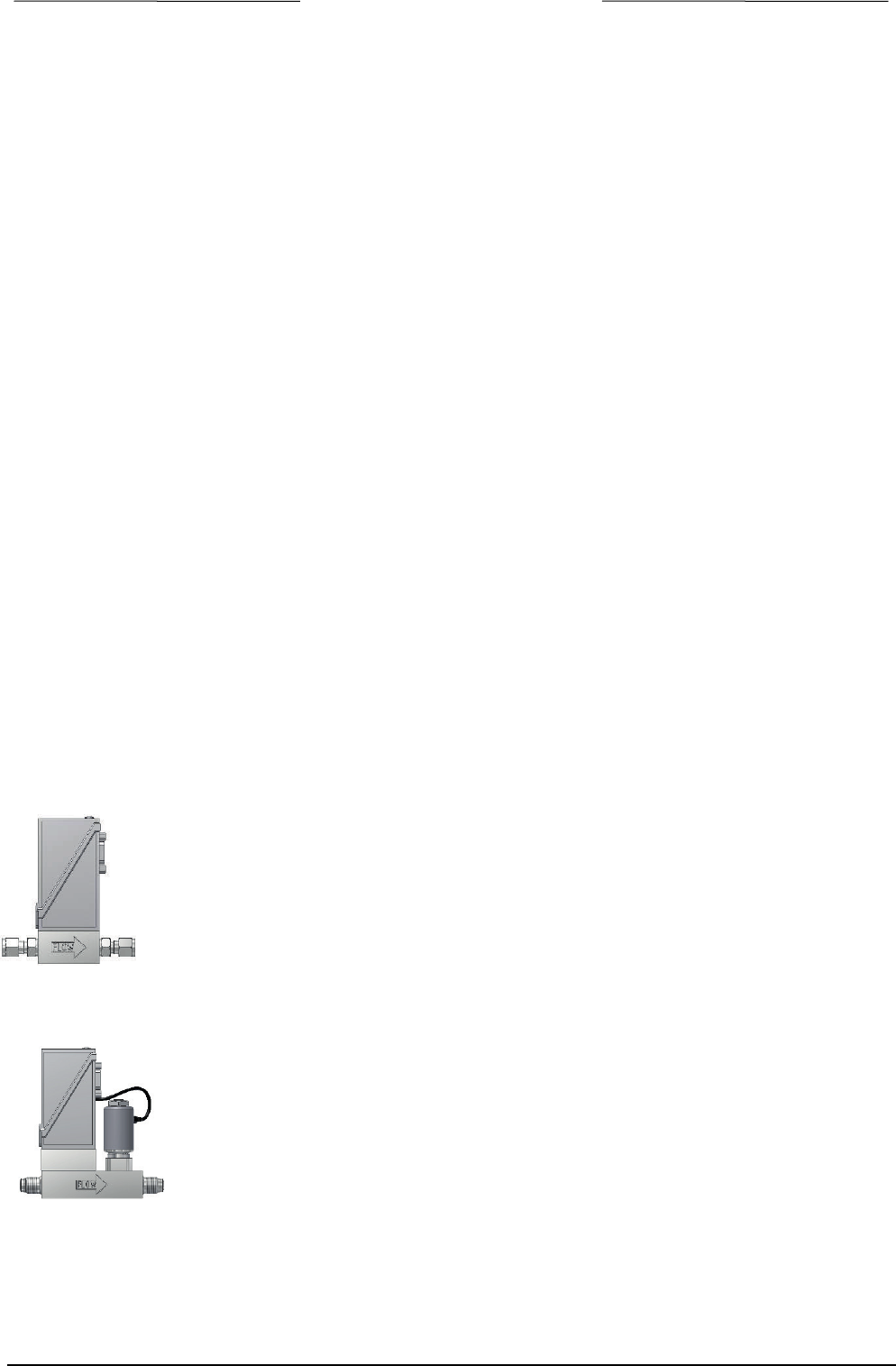
IN-FLOW , IN-PRESS
To comply with the IP65 ingress protection standard, the p.c. board is housed in a
sealed casted metal housing. For electrical connections the instrument has a 8DIN
male connector for analog/RS232 operation and for digital operation various
connectors on top. These instruments are suited for light industrial (outdoor) use to
IP65.
LIQUI-FLOW
Two different digital-liquid flow meters can be distinguished:
µ-FLOW model
The µ-FLOW model for up to 2 g/h, basically a straight capillary tube with a sensor.
For electrical connection the instrument is equipped with a male 9-pin sub D-
connector. The instrument is suited for dry (indoor) applications like laboratories.
CTA based LIQUI-FLOW™ series L10 / L20
The CTA based LIQUI-FLOW™ series L10 / L20 model for flow rates up to
approximately 1000 g/h. For electrical connection the instrument is equipped with a
male 9-pin sub D-connector. The instrument is suited for dry (indoor) applications
like laboratories.
To comply with the IP65 ingress protection standard, the p.c. board is housed in a
sealed casted metal housing. For electrical connections the instrument has a 8DIN
male connector for analog/RS232 operation and for digital operation various
connectors on top. These instruments are suited for light industrial (outdoor) use to
IP65.
BRONKHORST
®
9.17.022
page 11
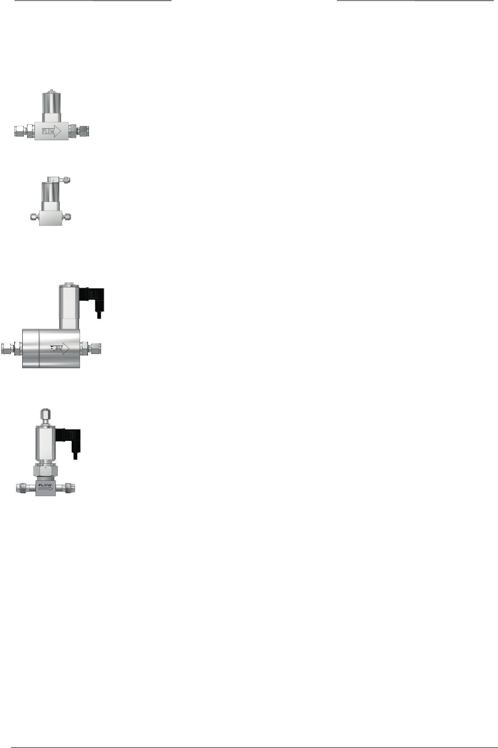
1.1.5 Valves
Laboratory style
For gases:
The solenoids of these valves have an IP50 ingress protection class.
This means that the valves are suited for dry (indoor) use.
For liquids:
The solenoids of these valves have an IP50 ingress protection class.
This means that the valves are suited for dry (indoor) use.
This valve is equipped with a purge connector.
Industrial style
For gases:
The solenoids of these valves have an IP65 ingress protection class. This means
that they are suited for light industrial (outdoor) use.
For liquids:
The solenoids of these valves have an IP65 ingress protection class. This means
that they are suited for light industrial (outdoor) use.
This valve is equipped with a purge connector.

BRONKHORST
®
page 12
9.17.022
1.2 Sensor principles
1.2.1 Gas flow sensors (by-pass measurement)
The majority of gas flow sensors operate according to the by-pass measurement principle. These types of
instruments operate on a principle of heat transfer by sensing the delta-T along a heated section of a
capillary tube. Part of the total flow is forced through the capillary by means of a laminar flow device in the
main stream generating a delta-p.
The design of the laminar flow device is such that flow conditions in both the capillary and laminar flow
device are comparable, thereby resulting in proportional flow rates through the meter. The delta-T sensed by
the upstream and downstream temperature sensors on the capillary depends on the amount of heat
absorbed by the gas flow.
The transfer function between gas mass flow and signal can be described by the equation:
V
signal
= output signal
c
p
= specific heat
V K
c
signal p
m
=
⋅
⋅ Φ
K = constant factor
Φ
m
= mass flow
The temperature sensors are part of a bridge circuit and the imbalance is linearised and amplified to the
desired signal level.
1.2.2 Gas flow sensors (direct mass flow measurement, CTA based)
The IN-FLOW CTA models operate on the principle of direct thermal mass flow measurement. The thru-flow
design sensor consists of a heater resistor and a temperature sensing resistor. Both resistors are made of
temperature sensitive resistive material that is covered with a stainless steel tube. The heating power
required to keep the temperature difference between the heater resistor and the sensing resistor at a
constant level is proportional to the mass flow. A different and unique heater current is produced for each
value of the flow. The measurement principle described is called Constant Temperature Anemometry (CTA).
The transfer function between mass flow and output signal can be described by the equation:
n
m
signal
KSS Φ
⋅+≅
0
S
signal
= output signal
S
0
= offset (zero flow) signal
K = constant factor (includes λ – heat conductivity, C
p
– specific heat, μ – dynamic viscosity and ρ –
density of the gas)
Φ
m
= mass flow
n = dimensionless constant (typically of order 0.5)
1.2.3 Liquid flow sensors
Two digital-liquid flow measurements and two sensor arrangements can be distinguished. They have in
common that there is no bypass system involved, which means that they are of the type: “thru flow”. The
following sensor arrangements can be distinguished:
1) The µ-FLOW model for flowrates up to 2 g/h.
Basically this is a small capillary tube with two sensing elements placed on the tube. The two elements both
serve as heater as well as temperature sensing elements. The delta-T sensed by the upstream and
downstream temperature sensors on the capillary depends on the amount of heat absorbed by the mass of
the liquid. The temperature sensors are part of a bridge circuit and the unbalance is amplified to the desired
signal level. The transfer function between liquid mass flow and signal can be described by the equation:
V
signal
= output signal
c
p
= specific heat
V K c
signal p m
= ⋅ ⋅ Φ
K = constant factor
Φ
m
= mass flow
BRONKHORST
®
9.17.022
page 13
2) The CTA based LIQUI-FLOW™ series L10 / L20 model for flow rates up to
approximately 1000 g/h.
The CTA based LIQUI-FLOW™ series L10 / L20 model basically consists of a small capillary tube with two
sensing elements placed around it. The upstream sensing element is a temperature sensor that is used to
measure the temperature of the liquid flowing through the tube. The downstream sensing element is a
heater, which is heated up to a certain temperature ∆T over the medium temperature. A patent application on
the flow sensor design has been submitted.
The heater power necessary to keep ∆T at a constant level is dependent on the mass flow. In the case of no
flow, a constant and negligibly small heating power is necessary. When a certain mass flow occurs, the
heater is cooled down. Therefore, the heating power has to be increased to maintain the adjusted
temperature difference. Thus, a different and unique heater power is produced for each value of the flow.
The measurement principle described is called Constant Temperature Anemometry (CTA).
The heater and temperature sensing element are electrically connected via a Wheatstone bridge
configuration that performs two features: first, it provides the heater with the necessary heater power and
second, it takes care of the temperature compensation. Finally, a signal conditioning circuit provides a linear
output signal. The transfer function between the liquid mass flow and the linear output signal can roughly be
described with the equation:
V
signal
= output signal
K = calibration constant
mp
signal
c
K
V Φ
⋅⋅
⋅
≅
2
λ
c
p
= specific heat
λ = heat conduction coefficient
Φ
m
= mass flow
1.2.4 Pressure sensor
The EL-PRESS / IN-PRESS pressure sensor is formed by a piezo-resistive bridge on the surface of a silicon
crystal. The sensor is mounted in a stainless steel construction and separated from the fluid by a thin metal
membrane. The chamber around the sensor is filled with oil to couple the pressure from the fluid to the
sensor.
1.3 Valve principles
Control valves are not designed to provide positive shut-off, although some models have excellent
capabilities for this purpose.
It is recommended to install a separate shut-off valve in the line if so required. Also pressure surges, as may
occur during system pressurisation must be avoided. The following models can be distinguished:
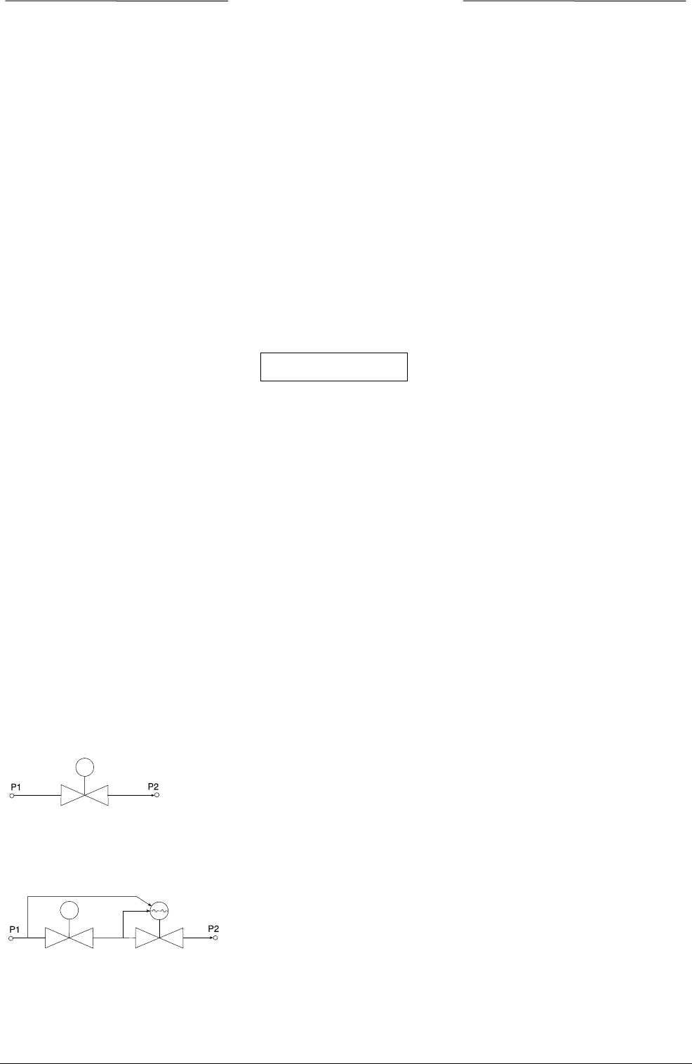
1.3.1 Solenoid valve
This is considered to be the standard (direct operated) control valve. In
general it is a normally closed solenoid valve. The plunger is lifted by the
force of the magnetic field of the coil. The orifice under the plunger is
removable for optimising the orifice diameter. Also a normally opened
solenoid valve is available.
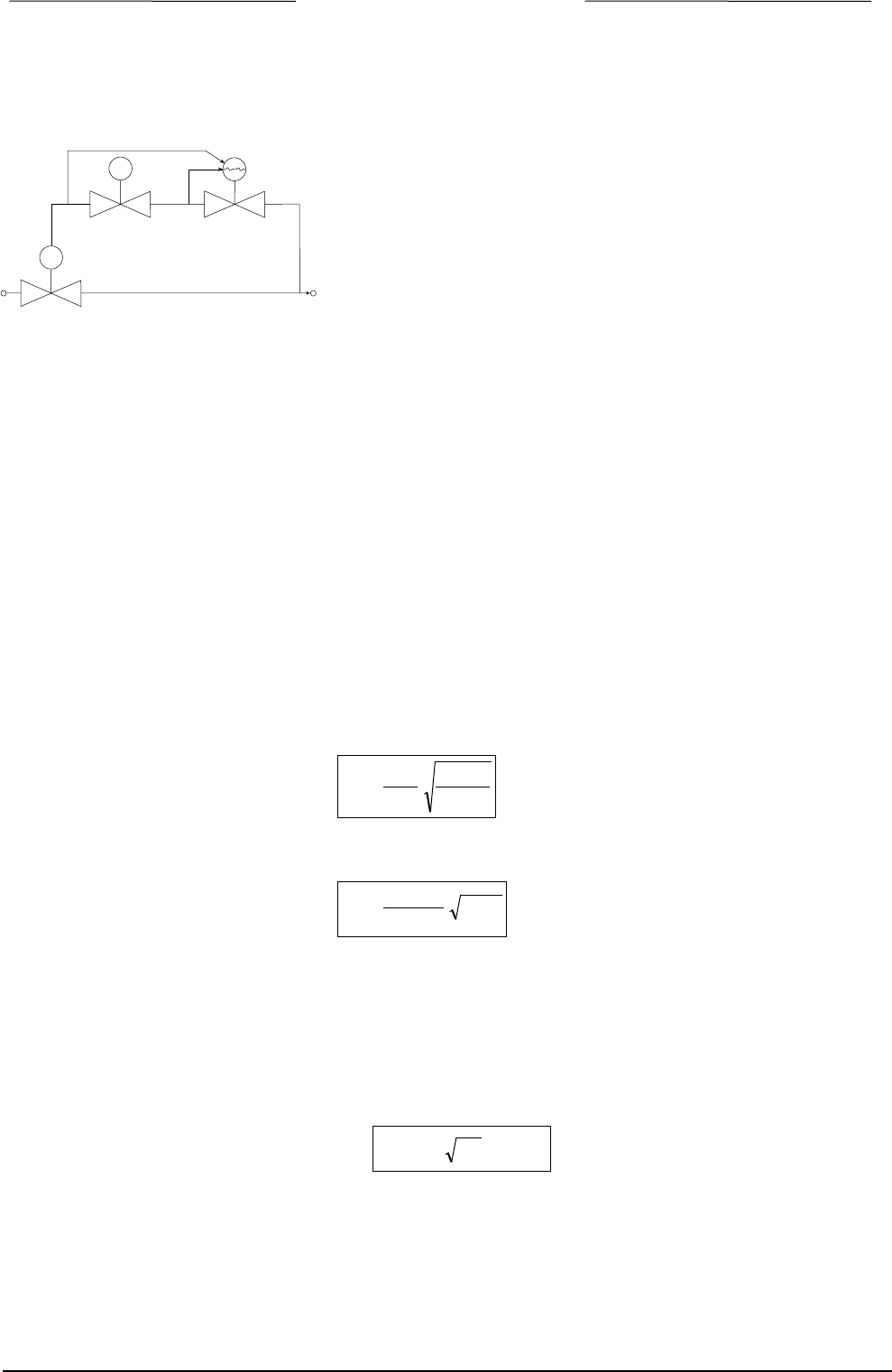
1.3.2 Vary-P valve
For process conditions where up- and downstream pressure
vary much, a special type of valve, VARY-P has been designed.
This valve consists of two valves, a solenoid operated control
valve and a fixed adjusted pressure compensation valve.
flowcontrol
valve
pressure
compensating
valve
flowcontrol
valve
BRONKHORST
®
page 14
9.17.022
1.3.3 Pilot operated valve
For high flow rates the pilot operated valve has been designed. A
solenoid driven control valve controls the pressure difference
across a piston, which lifts the main plunger.
1.3.4 Bellows valve
This valve type is a direct driven, low power, solenoid operated control valve. A special design, incorporating
a metal bellows allows for a relatively large orifice opening to be controlled. The design is suited for low
pressure or vacuum applications.
1.4 K
v
-value calculation
This calculation method can be used to determine the K
v
-value of the main orifice of a control valve.
1.4.1 For gases
Determine desired ∆p across valve.
∆p must be at least 20% of supply pressure, or in closed loop systems, of total pressure difference in loop.
If ∆p is 20-50% of supply pressure, use formula:
K
T
p p
v
vn n
=
⋅
⋅
Φ
∆514
2
ρ
undercritical
If ∆P is 50-100% of supply pressure, use formula:
K
p
T
v
vn
n
=
⋅
⋅
Φ
257
1
ρ
overcritical
Units:
Φ
vn
= flow [m
n
3
/h]
p
1
= supply pressure [bara]
p
2
= downstream pressure [bara]
∆p = pressure difference (p
1
- p
2
) [bara]
T = temperature [K]
ρ
n
= density [kg/m
n
3
]
The orifice diameter can be determined by: d= 7.6
K
v
[mm]
P1
pilot valve
pressure
compensating
valve
P2
flow control valve
BRONKHORST
®
9.17.022
page 15
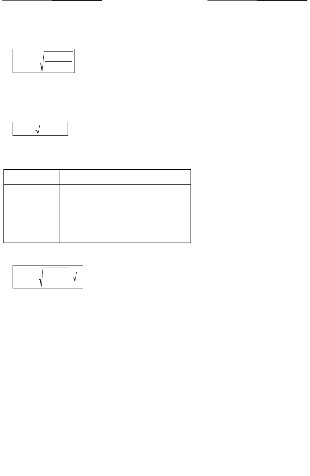
1.4.2 For liquids
This calculation method can be used to determine the K
v
-value of the main orifice of a control valve.
1000
⋅∆
Φ
=
p
K
vv
ρ
Units:
Φ
v
= volume flow [m
3
/h]
ρ = density at 20°C and 1 atm [kg/m
3
]
∆p = delta p [bard]
The orifice bore diameter can be determined by:
[mm]7.6
v
Kd =
On LFC's only one type of normally closed valve is available. Diameter of orifice can be calculated or looked
up in the table.
Diameter [mm]
K
v
Normally closed
∆p max. [bard]
0,10
0,14
0,20
0,30
0,37
0,50
0,70
1,00
1,73 x 10
-4
3,39 x 10
-4
6,93 x 10
-4
1,56 x 10
-3
2,37 x 10
-3
4,33 x 10
-3
8,48 x 10
-3
1,73 x 10
-2
10
10
10
10
10
10
10
10
* For liquids having a dynamic viscosity: 15 cP <
µ
< 100 cP the K
v
value should be calculated according to:
K
p
v v
=
⋅
⋅Φ
∆
ρ
µ
1000
Units:
Φ
v
= volume flow [m
3
/h]
ρ = density at 20°C and 1 atm. [kg/m
3
]
∆p = delta p [bard]
µ = dynamic viscosity [c
p
]
For maximum possible viscosity apply to factory

BRONKHORST
®
page 16
9.17.022
1.4.3 Maximum pressure drop
For (pilot) solenoid operated control valves with small orifices the maximum allowable pressure drop for
gases is according to the table.
Diameter [mm]
K
v
Normally closed
∆p max. [bard]
Normally opened
∆p max. [bard]
0,05
0,07
0,10
0,14
0,20
0,30
0,37
0,50
0,70
1,00
1,30
1,50
1,70
2,00
4,33 x 10
-5
8,48 x 10
-5
1,73 x 10
-4
3,39 x 10
-4
6,93 x 10
-4
1,56 x 10
-3
2,37 x 10
-3
4,33 x 10
-3
8,48 x 10
-3
1,73 x 10
-2
2,93 x 10
-2
3,90 x 10
-2
5,00 x 10
-2
6,63 x 10
-2
40
30
30
30
30
30
30
30
24
12
8
6
5
3,6
30
20
20
20
20
20
20
20
15
8
5
n.a.
n.a.
n.a.
For pilot operated valves the maximum pressure drop is limited to 20 bard. If the pressure drop during start-
up is higher, it is preferred to install a bypass valve. During start-up this valve should be opened. Also the
minimum pressure drop is limited. For exact figures consult factory or proceed according to the technical
data and/or additional instructions given by the sales office or department.
1.5 Sensors and laminar flow devices
Flow devices are used to determine the total flow rate of a gas flow meter or controller.
Mind that liquid flow sensors, CTA-based sensors and pressure sensors do not require a flow device.
Depending on the application the flow sensors have different removable capillaries, requiring a different
laminar flow device.
Furthermore for flow rates higher than 1250 l
n
/min the main laminar flow device is used in combination with a
capillary / flow device arrangement in order to compensate for the non ideal transfer function of the main
flow device.
In general 3 types of capillary tubes are available:
- Small bore (C-type)
The following notes apply to this type of sensor:
- These sensors have a pressure drop of approx. 35 mbar
- The laminar flow device consists of a stack of discs with precision etched flow channels.
Each flow channel represents approx. 10 ml
n
/min airflow at 35 mbar delta-P.
- In all instruments with a pressure rating above 100 bar (M-type) the sensor is fitted with metal
seals.
- In general instruments with these sensors may be mounted horizontal, as well as in a vertical
position, at low operating pressures. At high pressures (>10 bar) the instruments should be
mounted in a horizontal position.
- The EL-FLOW, EL-PRESS metal seal series are fitted with a metal sealed sensor.
- Large bore (D-type)
To this type of sensor the following remarks apply:
- These sensors are preferably used for reactive gases and at low pressure applications.
- The pressure drop is less than 0.5 mbar.
- The laminar flow device forms together with the main channel an annular channel. The dimensions
of this annular channel determine the flow capacity of the instrument.
- The instrument must always be mounted in a horizontal position.
- Medium bore (E-type)
This sensor is used in the “EL-FLOW series” and is used for increasing the flow range of the “low deltaP
series”. The same remarks as the D-type apply to this sensor, only:
-The pressure drop is approx. 2.5 mbar.

BRONKHORST
®
9.17.022
page 17
1.6 Conversion factors
1.6.1 Gas conversion factors (by-pass measurement)
The general formula for determining the relationship between signal and mass flow is:
V K c K c
signal p m p v
= ⋅ ⋅ = ⋅ ⋅ ⋅Φ Φρ
in which:
V
signal
= output signal
K = constant
ρ = density
c
p
= specific heat
Φ
m
= mass flow
Φ
v
= volume flow
As soon as the c
p
value and density of the gas to be metered change, the signal must be corrected. The
conversion factor C is:
C
c
c
p
p
=
⋅
⋅
1
2
1
2
ρ
ρ
in which:
c
p
= specific heat
ρ
n
= density at normal conditions
(1) gas calibrated
(2) gas to be measured
Note:
The c
p
value used for the calculation of the conversion factor must be taken at a temperature approx. 50°C.
higher than the required temperature.
This factor is called c
p
cal.
The conversion factors for commonly used gases related to N
2
at normal conditions are stated in the Gas
Conversion Table in the appendix 1.
Example:
Meter calibrated on N
2
(200 ml
n
/min).
Gas flow passing the meter is CO
2
.
Output signal reads 80.0%.
Actual CO
2
flow = 80.0
⋅
0.74
1.00
= 59.2%
so
59 2
100
.
⋅
200 = 118.4 ml
n
/min
* n means normal conditions
At normal conditions volumes are converted to a temperature of 0°C and pressure of 1 atm
or 1013,25 mbar. (760 Torr)
Note:
Best accuracy is always achieved by performing calibration under operating conditions. Should this not be
possible or practical, then the use of a theoretical conversion factor is a means to determine the flow rate of
the instrument on the gas to be metered, however, it will introduce inaccuracies.

BRONKHORST
®
page 18
9.17.022
The approximate accuracy of the conversion factors listed is:
typical for conversion factors; > 1 2% x factor
< 1 2% / factor
However, as the accuracy of the factor also depends on viscosity, pressure and temperature, special
attention should be taken for gases in the gas/liquid state where specific heat, density and viscosity can vary
tremendously. Apply to factory for more detailed information.
For gas mixtures a good approach is the following simplified equation:
1
1
1
2
2
C
V
C
V
C
mix
= +
+
..
.
..
V
C
n
n
C
mix
= Conversion factor for gas mixture
C
n
= Conversion factor for gas n
V
n
= Volumetric part of gas n in the mixture
Example Gas mixture contains:
(1) 10% N
2
C1 = 1,00
(2) 30% Ar C2 = 1,40
(3) 50% CH
4
C3 = 0,76
(4) 10% He C4 = 1,41
1
0
10
1
00
0
30
140
0
50
0
76
010
141
1
043
C
mix
= +
+ +
=
,
,
,
,
,
,
,
,
,
C
mix
= 0,959
When the original meter has been calibrated on 500 ml
n
/min N
2
, 100% means:
500
00
,1
959,0
⋅
= 480 ml
n
/min mixture.
When the original meter has been calibrated on 500 ml
n
/min Argon, then 100% means:
500
40,1
959,0
⋅
= 343 ml
n
/min gas mixture.
1.6.2 Gas Conversion Factors (direct mass flow measurement, CTA-based)
For CTA-based gas flow sensors the general relationship between signal and mass flow is:
n
msignal
KSS Φ⋅+≅
0
In which:
S
signal
= output signal
S
0
= offset (zero flow) signal
K = constant factor (includes λ – heat conductivity, C
p
– specific heat, μ – dynamic viscosity
and ρ – density of the gas)
Φ
m
= mass flow
n = dimensionless constant (typically of order 0.5)
Due to the offset signal (which is also dependent on fluid properties) and the non-linear relationship between
signal and mass flow, a single conversion factor for a custom fluid that covers the entire flow range of an
instrument cannot be obtained. However, a complex and partially empirical conversion model is available for

BRONKHORST
®
9.17.022
page 19
most common gases, which is accurate at both lower and higher flow ranges. Consult Bronkhorst for
applications.
At nominal flow ranges for each instrument, a good approximation is the use of the so-called “CFDirect”
conversion method, which comes with the FLUIDAT software.
Consult FLUIDAT for the most optimal conversion factor.
1.6.3 Liquid Conversion Factors
1) µ-FLOW models
The general formula for determining the relationship between signal and mass flow reads:
in which:
V
signal
= output signal
V k c
signal p
m
= ⋅ ⋅ Φ
k = calibration constant
c
p
= heat capacity at constant pressure of the fluid
Φ
m
= mass flow
A conversion factor must be used if the liquid flow meter is not used on the calibrated liquid.
This conversion factor reads:
in which:
c
p1
= heat capacity of the calibration liquid
12
mm
Cf Φ⋅=Φ
Cf
c
c
p1
p2
=
c
p2
= heat capacity of the new liquid
For application of this formula consult Bronkhorst High-Tech BV.
2) CTA based LIQUI-FLOW series L10 / L20
For the CTA based LIQUI-FLOW series L10 / L20 liquid mass flow sensor, the transfer function between the
liquid mass flow and the linear output signal can roughly be described with the equation:
mpsignal
cKV Φ⋅λ⋅⋅≅
2
V
signal
= output signal
K = calibration constant
c
p
= specific heat
λ = heat conduction coefficient
Φ
m
= mass flow
A conversion factor must be used if the liquid flow meter is not used on the calibrated liquid (reference liquid)
but on another liquid (custom liquid). The conversion factor CF can roughly be calculated with the equation:
( )
( )
FLUIDCUSTOM
p
FLUIDREFERENCE
p
c
c
CF
2
2
λ
λ
≅
For application of this equation, please consult Bronkhorst High-Tech BV.
1.6.4 Software for conversion factor calculation
Bronkhorst
®
gathered the physical properties of over 600 fluids in a database called FLUIDAT
.
Application software, such as FLUIDAT
on the Net (FOTN), enable the user to calculate accurate
conversion factors, not only at 20°C/1 atm (as shown in the conversion table, App.1) but at any
temperature/pressure combination.
Apply to your distributor for more details of this software.

BRONKHORST
®
page 20
9.17.022
2 Installation
2.1 Receipt of equipment
Check the outside packing box for damage incurred during shipment. Should the packing box be damaged,
then the local carrier must be notified at once regarding his liability, if so required. At the same time a report
should be submitted to:
BRONKHORST HIGH-TECH B.V.
RUURLO HOLLAND
If applicable, otherwise contact your distributor.
Remove the envelope containing the packing list; carefully remove the equipment from the packing box.
Do not discard spare or replacement parts with the packing material and inspect the contents for damaged or
missing parts.
2.2 Return shipment
When returning material, always describe the problem and if possible the work to be done, in a covering
letter.
It is absolutely required to notify the factory if toxic or dangerous fluids have been metered with the
instrument!
This to enable the factory to take sufficient precautionary measures to safe-guard the staff in their repair
department. Take proper care of packing, if possible use the original packing box; seal instrument in plastic
etc.
All instruments must be dispatched with a completely filled in 'declaration on contamination form'.
Instruments without this declaration will not be accepted.
Note:
If the instruments have been used with toxic or dangerous fluids the customer should pre-clean the
instrument.
Important:
Clearly note, on top of the package, the customer clearance number of Bronkhorst High-Tech B.V., namely:
NL801989978B01
If applicable, otherwise contact your distributor for local arrangements.
2.3 Service
If the equipment is not properly serviced, serious personal injury and/or damage to the equipment could be
the result. It is therefore important that servicing is performed by trained and qualified service personnel.
Bronkhorst
®
has a trained staff of servicemen available.
BRONKHORST
®
9.17.022
page 21
2.4 Mounting
The mounting position depends on the type of instrument. For flowmeters the preferred position is horizontal,
and at high pressures all meters should be mounted in this position. Avoid installation in close proximity of
mechanic vibration and/or heat sources.
Mount instruments using the threaded mounting holes at the bottom of the instrument, as indicated in the
applicable dimensional drawing. Use stainless steel bolts with minimum strength class 70 (not included). The
recommended torque values can be found in the table below.
Recommended torque in Nm for stainless steel bolts with strength class 70
Bolt size
M4
M5
M6
M8
M10
M12
Torque [Nm]
2.0
4.1
7.0
17.0
33.0
57.0
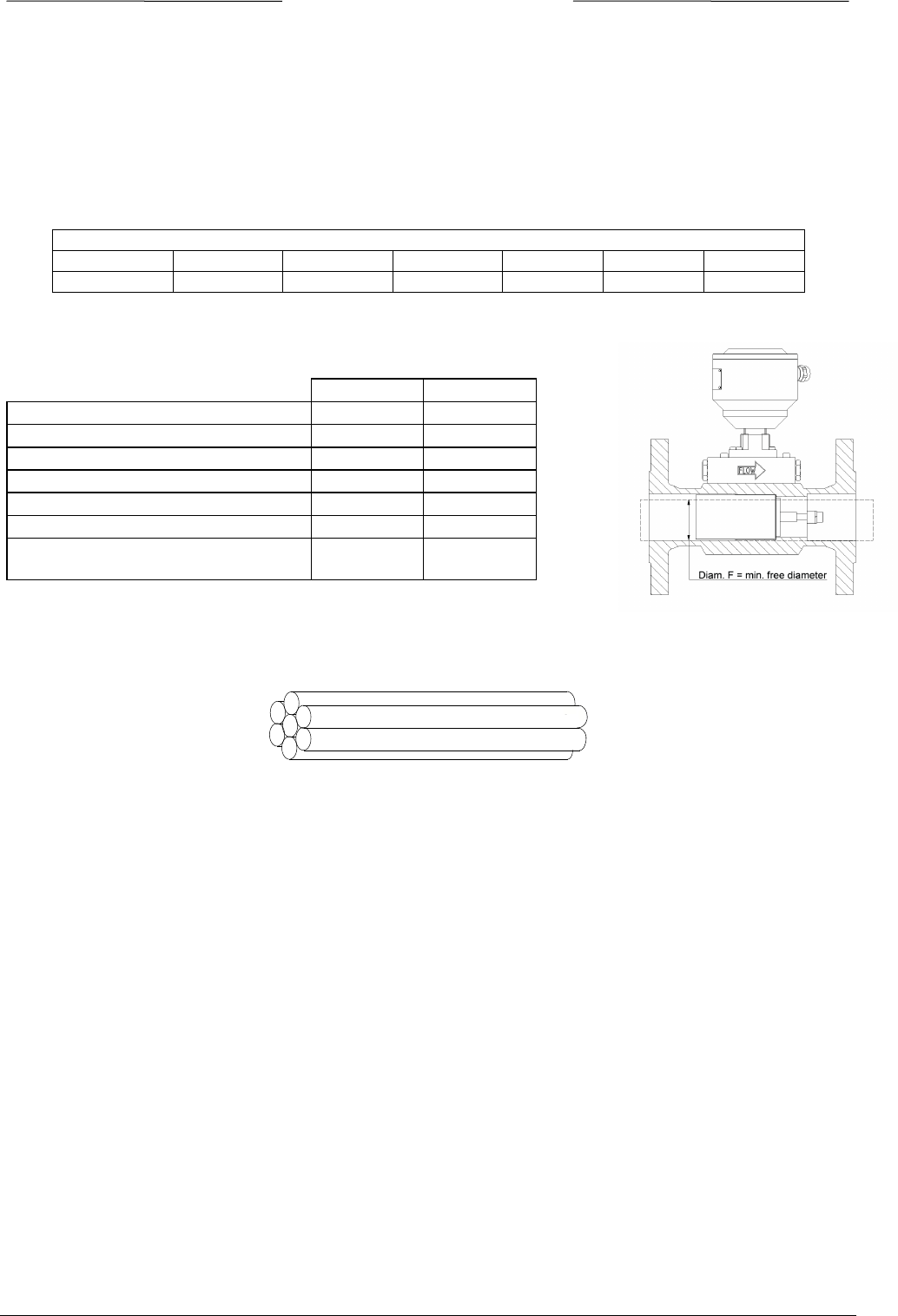
For mounting the F-106/F-107 series handle the following rules:
STRAIGHT PIPE LENGTH REQUIREMENTS (in number of diameters F)
Upstream
Downstream
one 90° bend before meter
10
4
two 90° bend before meter
13
4
two 90° bend in two planes
20
4
three 90° bend in three planes
30
4
reduction before meter
10
4
expansion before meter
20
4
pressure reducing valve / control valve /
partially closed valve before meter
30
4
For further information see dimensional drawing.
In general flow straighteners have a suspicious influence on the free length of the meter.
A flow straightener can be imagined as a bundle of parallel tubes which is placed in the tube.
In general, these flow straighteners must be placed at least 6 à 8 D upstream of the meter.
In general, use a flow straightener in case of control valves and curves in unequal levels.
Next to these prescriptions for free length, the flow has to be steady, shock and pulsation free.
2.5 In-line filter
Although fluids to be measured should be absolutely free of dirt, oil ,moisture and other particles, it is
recommended to install an in-line filter upstream of the flowmeter / controller, and if backflow can occur, a
downstream filter is recommended too. Be aware of the pressure drop caused by the filter.
On the inlet of some instruments a screen is placed to prevent foreign matter from entering the instrument
and to maintain a good flow pattern. This device cannot be seen as a filter element.
Contact your distributor for further information.

BRONKHORST
®
page 22
9.17.022
2.6 Fluid connections
Bronkhorst
®
meters / controllers are equipped with compression type or face-seal-fittings. For most of the
instruments these fittings are BSP parallel threads types which have to be used in combination with
elastomeric O-rings to seal to the instrument. For some instruments these fittings are orbital welded to the
body. For leak tight installation of compression type fittings be sure that the tube is inserted to the shoulder in
the fitting body and that no dirt or dust is present on tube, ferrules or fittings. Tighten the nut finger tight;
while holding the instrument, then tighten the nut 1 turn. If applicable follow the guidelines of the supplier of
the fittings.
Special types of fittings are available on request.
The flanges also must fit good to each other and there may not stick seals into the tube.
* Note: Always check your system for leaks, before applying fluid pressure. Especially if toxic, explosive or
other dangerous fluids are used.
2.7 Piping
BE SURE THAT PIPING IS ABSOLUTELY CLEAN!
DO NOT install small diameter piping on high flowrates, because the inlet jet flow will affect the accuracy.
DO NOT mount abrupt angles direct on in- and outlet, especially not on high flowrates. We recommend at
least 10 pipe diameters distance between the angle and the instrument.
DO NOT mount pressure regulators direct on the inlet of gas flow meters/controllers, but allow some meters
of piping (at least 25 D). Special attention should be taken at high flow rates with flow controllers. An up- and
downstream buffer is needed with a volume calculated according to the following formula:
V
d
≥
0
15
2
,
ρ
in which:
V = Volume in litres
d = orifice diameter in mm
ρ = density at normal conditions
d = 7,6
k
v
Example:
Flow controller at 500 l
n
/min Air and orifice diameter d = 4 mm, needs for stable control a buffer volume of:
V ≥ ⋅ =015 4
129 21
2
, : ,
,
litres
Also the capacity of the pressure regulator should be at least 2 times the flow controller, so in this case
2 ⋅ 500 = 1,000 l
n
/min.
2.8 Electrical connections
Installation advice: to prevent damage to the instrument as result of reversed polarity, Bronkhorst®
recommends the use of a 2A fuse in the direct +Us line.
Electrical connection must be made with standard cables or according to the applicable hook-up diagrams.
The connections of the factory installed 8 DIN and optional M12 connector are indicated on the hook-up
diagram of the instrument. Make sure that the power supply is suitable for the power ratings as indicated on
the instrument label and that double or reinforced insulation is used for the power supply.
Applicable hook-up diagrams for IN-FLOW can be found at: http://www.bronkhorst.com/en/downloads
IN-FLOW instruments are powered with +15…+24 Vdc.
Do not power the instrument simultaneously from two different power sources (e.g. bus connection and Plug-
in Power Supply (PiPS)). Doing so will blow the fuse on the pc-board, requiring the return of the instrument
for repair.
To comply with the IP classification it is necessary to follow the assemble guidelines of the connector
manufacturer. To lock the 8 DIN / M12 cable connector to the equipment connector, the threaded ring is
tightened until it is ‘finger-tight’ (approx. 50 cNm).

BRONKHORST
®
9.17.022
page 23
The instruments contain electronic components that are susceptible to damage by electrostatic discharge.
Proper handling procedures must be taken during installation, removing and connecting the electronics.
The instruments described in this manual carry the CE-mark and are compliant with the EMC requirements.
However compliance with the EMC requirements is not possible without the use of proper cables and
connector/gland assemblies.
Bronkhorst recommends the use of their standard cables. These cables have the right connectors and if
loose ends are used, these will be marked to prevent wrong connection. When using other cables, cable wire
diameters should be sufficient to carry the supply current and voltage losses must be kept as low as
possible. When in doubt: contact your distributor. When connecting the system to other devices (e.g. PLC),
be sure that the integrity of the shielding is not affected. Do not use unshielded wire terminals.
2.8.1 Disconnection from supply source
Bronkhorst recommends to use a circuit breaker or switch being installed in the end application.
2.9 Caution
Each meter/controller is pressure tested to at least 1.5 times the working pressure of the process
conditions stipulated by the customer, with a minimum of 8 bar.
For pressure meter/controllers. The test pressure depends on the range of the pressure transducer.
In general 2 x F.S. value for ranges 1 and 2 bar
1.5 x F.S. value for ranges up to 200 bar
1.25 x F.S. value for ranges up to 400 bar
The tested pressure is stated on the flow meter/controller with a RED COLOURED sticker. Check test
pressure before installing in the line.
If the sticker is not available or the test pressure is incorrect, the instrument should not be mounted in the
process line and be returned to the factory.
Each instrument is helium leak tested to at least 2⋅10
-9
mbar l/s Helium.
2.10 Supply pressure
Do not apply pressure until electrical connections are made. When applying pressure to the system, take
care to avoid pressure shocks in the system and increase pressure gradually, especially on high pressure
units incorporating a piston operated control valve.
For instruments used above 10 barg:
Bronkhorst recommends a maximum decompression rate of 70 bar/min, according NACE TM0297.
Exceeding this rate can have negative influence on the lifetime of the sealing materials.
2.11 System purging
If explosive gases are to be used, purge the process with inert dry gas like Nitrogen, Argon etc. for at
least 30 minutes.
In systems with corrosive or reactive fluids, purging with an inert gas is absolutely necessary, because if the
tubing has been exposed to air, introducing these fluids will tend to clog up or corrode the system due to a
chemical reaction with oxygen or moist air.
Complete purging is also required to remove such fluids from the system before exposing the system to air. It
is preferred not to expose the system to air, when working with these corrosive fluids.
2.12 Seals
Bronkhorst has gathered a material compatibility chart from a number of sources believed to be reliable.
However, it is a general guide only. Operating conditions may substantially change the accuracy of this
guide. Therefore there is no liability for damages accruing from the use of this guide.
The customers application will demand its own specific design or test evaluation for optimum reliability.
So check if the seals like O-rings, plunger and packing gland of capillary are correct for the process.
BRONKHORST
®
page 24
9.17.022
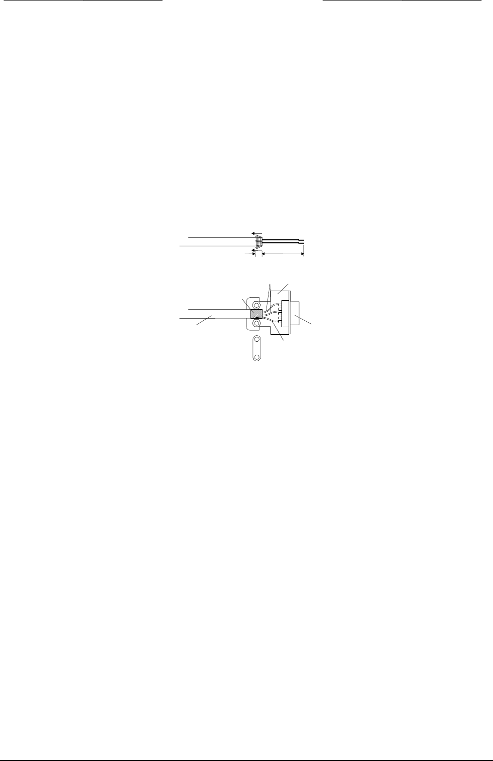
Fold the shield of the cable back over the cable (the shield must be around the cable).
Wind a copper tape around the shield
Solder a black wire on the tape and
connect to pin 9 of the connector.
copper tape
shielded cable
e.g. LAPP LiYCY
other wires
D-connector housing
metalized.
connector
8 mm
20 mm
Black wire
(shield)
2.13 Equipment storage
The equipment should be stored in its original packing in a cupboard warehouse or similar. Care should be
taken not to subject the equipment to excessive temperatures or humidity.
2.14 Electromagnetic compatibility
2.14.1 Conditions for compliance with EMC requirements
All instruments described in this manual carry the CE-mark.
Therefore they have to comply with the EMC requirements as are valid for these instruments.
However compliance with the EMC requirements is not possible without the use of proper cables and
connector/gland assemblies.
For good results Bronkhorst
®
can provide standard cables. Otherwise follow the guidelines as stated below.
D-Connector assembly
BRONKHORST
®
9.17.022
page 25
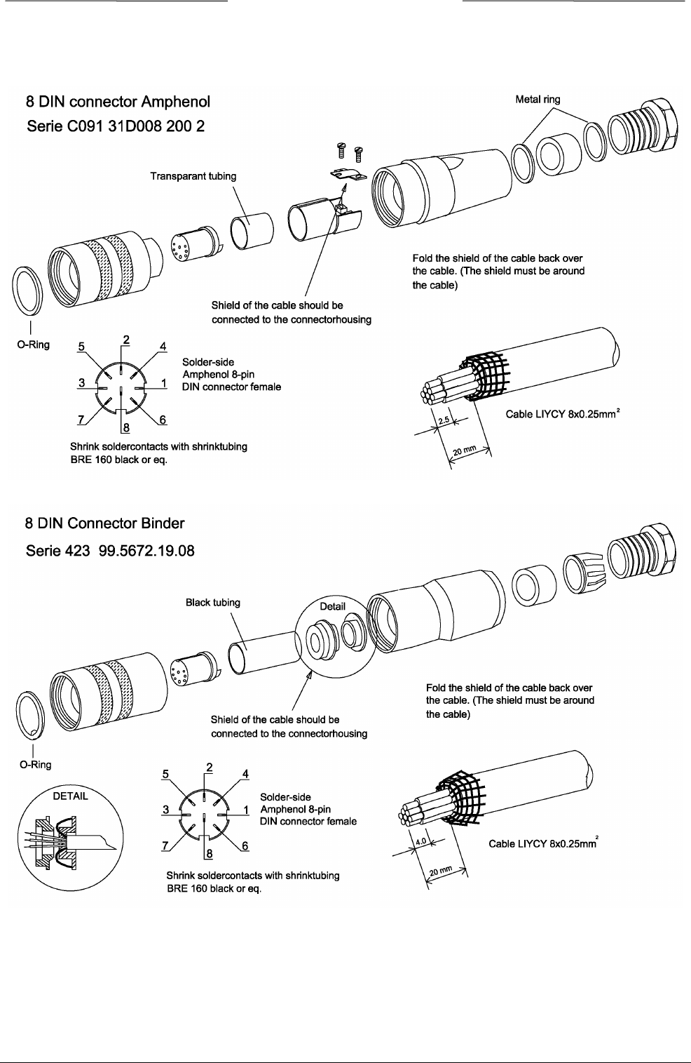
8DIN connector assembly
Notes:
1. When connecting the system to other devices (e.g. to PLC), be sure that the integrity of the shielding is
not affected. Do not use unshielded wire terminals.
2. For FLOW-BUS S(F)TP data (patch) cable connection to RJ45 connectors follow the instructions of the
supplier. It is important to use shielded twisted pair cables and shielded RJ45 modular jack connectors.
3. For PROFIBUS DP or DeviceNet data cable connections follow the instructions of the cable suppliers for
the specific field-bus system.

BRONKHORST
®
page 26
9.17.022
3 OPERATION
3.1 General
The Bronkhorst
®
instruments are designed in such a way that they will meet user process requirements in
the best possible way.
Basically all digital meters/controllers are powered with +15 Vdc to +24 Vdc.
When providing your own power supply, be sure that voltage and current ratings are according to the
specifications on the instrument(s) label. A double or reinforced insulation power supply must be used.
When providing your own power supply be sure that voltage and current rating are according to the
specifications of the instrument(s) and furthermore that the source is capable of delivering enough energy to
the instrument(s).
Cable wire diameters should be sufficient to carry the supply current and voltage losses must be kept as low
as possible. When in doubt: consult factory.
Digital instruments can be operated by means of:
1. Analog interface (0...5 Vdc/0...10 Vdc/0...20 mA/4...20 mA)
2. RS232 interface (connected to COM-port by means of special cable)
3. FLOW-BUS
4. PROFIBUS DP
5. DeviceNet
6. Modbus ASCII / RTU / TCP
7. EtherCAT
8. PROFINET
9. CANopen
10. EtherNet/IP
11. POWERLINK
Option 1 and 2 are always present on multibus instruments. An interface to any available fieldbus is optional.
Operation via analog interface, RS232 interface and an optional fieldbus can be performed at the same time.
A special parameter called “control mode” indicates to which setpoint the controller should listen: analog or
digital (via fieldbus or RS232). The RS232 interface behaves like a FLOW-BUS interface.
When using more interfaces at the same time, reading can be done simultaneously without problems.
When changing a parameter value, the last value send by an interface will be valid.
Also the micro push-button switch and the LED’s on top of the instrument can be used for manual operation
of some options.
The green LED will indicate in what mode the instrument is active.
The red LED will indicate error/warning situations.
3.2 Power and warm-up
Before switching on power check if all connections have been made according to the hook-up diagram which
belongs to the instrument.
It is recommended to turn on power before applying pressure on the instrument and to switch off power after
removing pressure.
Check fluid connections and make sure there is no leakage. If needed purge the system with a proper fluid.
For a gas instrument only purging with gases is allowed. Liquid instruments may be purged with either a gas
or a liquid, whatever is needed for the purpose.
Turn on power and allow at least 30 minutes to warm up and stabilize. In cases where no electronics are
involved (valves only) warming up is not needed.
During warm-up period, fluid pressure may either be on or off.
3.3 Zeroing
In general the zero point of each instrument is factory adjusted. If so required the zero point of the instrument
may be re-adjusted.

BRONKHORST
®
9.17.022
page 27
After warm-up, with no gas flow, use the micro push-button switch on top of the instrument to start the
automatic zero adjustment procedure, if required.
For flow controllers setpoint must be zero. Be sure there is no fluid flow.
For information how to start the automatic zero procedure by means of the micro push-button switch, see
manual operation, document number 9.17.023.
It is also possible to start the automatic zero adjustment procedure through the FLOW-BUS, using a
readout/control unit or a software program on a PC, connected to a FLOW-BUS interface module.
See the appropriate documentation for more detailed information.
3.4 Start-up
Turn on fluid supply gently. Avoid pressure shocks, and bring the instrument gradually up to the level of the
actual operating conditions. Also switch off fluid supply gently. In case of liquid control be sure to remove all
trapped gas bubbles from the system. The purge connection on top of the control valve can be used for this
purpose.
3.5 Operating conditions
Each instrument has been calibrated and adjusted for customer process conditions.
Controllers or valves may not operate correctly, if process conditions vary too much, because of the
restriction of the orifice in the valve.
For flowmeters performance and accuracy may be affected tremendously if physical fluid properties such as
heat capacity and viscosity change due to changing process conditions.
3.6 Instrument performance
3.6.1 Sensors
Assuming that the transfer function of a system is an exponential shaped curve, the time constant is defined
as follows:
time constant = time for the signal to reach 63.2 % of its final output value. Approx. five time constants is the
time to reach the final value.
The time constant of flow sensors depends on the type of instrument and settings.
Pressure sensors have a time constant of some milliseconds. However the actual response is determined by
the pneumatic response of the system which the pressure meter is part of.
3.6.2 Controllers
The dynamic response of a controller is factory set. Standard settling time is defined as the time to reach the
setpoint (and stay) within ± 2% of the initial setpoint.
The control mode is factory set in such a way that after a step change, there will be little overshoot.
Note:
In pressure control systems the system widely determines the response behaviour of the control loop. During
testing the customer system is simulated as closely as possible. In some cases however readjustment is
needed for optimum performance under actual conditions.
BRONKHORST
®
page 28
9.17.022
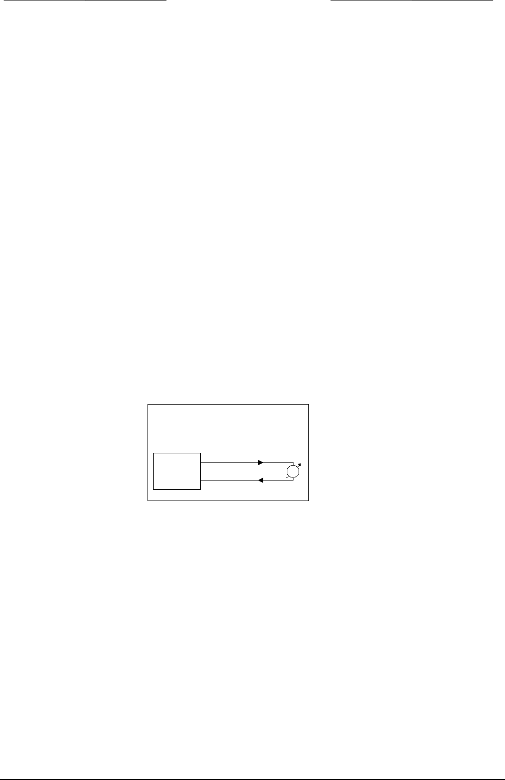
0V common
-
Current output signals
Sourcing
instrument
output I
+
mA
3.7 Manual operation
By means of manual operation of the micro push-button switch some important actions for the instrument
can be selected/started. These options are available in both analog or BUS/digital operation mode.
(see also manual operation in document number 9.17.023)
These functions are:
- reset (instrument firmware-program reset)
- auto-zeroing (remove zero-drift offset in sensor bridge)
- restore factory settings (in case of unintended change of the settings)
for FLOW-BUS only:
- automatic installation to FLOW-BUS (installs instrument to free address)
- remote installation to FLOW-BUS (instruments will be installed by PC-software)
3.8 Analog operation
Digital instruments can be operated with analog signals through the 9-pin sub-D connector or 8DIN
connector. The instruments are compatible in use with analog instruments on this point.
Analog operated instruments can be hooked-up using an 8-wire shielded cable with 9-pin D-connectors or
8DIN connectors, connected according to the Bronkhorst
®
standard.
Each electronic p.c.board is set for one of the following output (and corresponding input) signals:
Signal output (sensor) input (setpoint)
code signal signal
A 0…5 Vdc 0…5 Vdc
B 0…10 Vdc 0…10 Vdc
F 0…20 mA (sourcing) 0…20 mA (sinking)
G 4…20 mA (sourcing) 4…20 mA (sinking)
For meters only the output signal is available.
At analog operation following parameters are available:
- measured value
- setpoint (controllers only)
- valve voltage (controllers only)
Note:
When operating the instrument through the analog interface it is possible to connect the instrument to any
supported fieldbus system (or RS232-interface with special cable) for reading/changing parameters (e.g.
controller response or other fluid selection).
For FLOW-BUS versions of the instruments a readout/control module for digital instruments can be
temporarily connected to the RJ45 modular jack plug.

BRONKHORST
®
9.17.022
page 29
3.9 BUS / digital operation
Operation via fieldbus reduces the amount of cables to build a system of several instruments and offers more
parameter values to be monitored/changed by the user.
See instruction manual: operating digital mass flow / pressure instruments for more details (document nr.
9.17.023).
Operation by means of a fieldbus adds a lot of extra features (compared to analog operation) to the
instruments.
Such as:
- setpoint slope (ramp function on setpoint for smooth control)
- 8 selectable fluids (calibration settings for high accuracy)
- direct reading at readout/control module or host computer
- testing and self diagnosis
- response alarm (|setpoint-measure| too high for too long time)
- several control/setpoint modes (e.g. purge/close valve)
- master/slave modes for ratio control (FLOW-BUS only)
- identification (serial number, model number, device type, user tag)
- adjustable minimal and maximal alarm limits
- (batch) counter
- adjustable response time for controller when opening from zero
- adjustable response time for normal control
- adjustable response time for stable control (|setpoint-measure| < 2%)
Note:
Special RS232 cable consists of a T-part with 1 male and 1 female sub-D 9 connector / 8DIN connector on
one instrument-side and a normal female sub-D 9 connector on the side of the computer. See hook-up
diagram for the correct RS232 cable which should be used.
By means of this cable it is possible to offer RS232 communication and still be able to connect power-supply
and analog interface through the (analog) sub-D 9 connector / 8DIN connector.
RS232 communication is possible with a baudrate of 38400 Baud (default baudrate) and can be used for
either:
• Uploading new firmware by means of a special program (for trained BHT-service personnel only)
• Servicing your instrument using BHT-service programs (for trained BHT-service personnel only)
• Operating your instrument using FLOWDDE, FLOWB32.DLL or RS232-ASCII protocol (end user)

BRONKHORST
®
page 30
9.17.022
4 Maintenance
4.1 General
At normal use, no routine maintenance is required to be performed on the meters or controllers. Units may
be flushed with clean, dry inert gas.
For further information contact supplier or factory.
4.2 Gas flow sensor
The gas flow sensor is constructed in such a way that for a change in range, the laminar flow element can be
removed. It is not recommended for the user to disassemble the instrument other than for removing the
laminar flow element for inspection, or range changing only. After replacing the laminar flow element it
becomes necessary to recalibrate the flow meter. When doing so proceed according to a suitable calibration
procedure. Depending on the model number laminar flow elements can be ordered separately.
4.3 Liquid flow sensor
The user cannot change the flow range of a liquid flow sensor. The sensor is an integral part of the
instrument and cannot be removed from it. For occasional cleaning the instrument may be flushed with a
cleaning fluid.
4.4 Pressure sensor
It is not recommended for the user to disassemble the pressure sensor, because the thin metal membrane is
very delicate.
4.5 Controllers
All sensor types can be combined with a control valve to be operated together as a control loop. Controller
systems are either available as separate units; a sensor and a control valve, or as an integrated unit.
If applicable maintenance procedures are described under “control valves”
4.6 Control valves
Control valves cannot be used for shut-off and/or on-off applications. Pressure surges, as may occur during
system pressurisation or deflation must be avoided.
4.6.1 Solenoid valves
These are considered to be the direct operated control and pilot valves.
Instruments (meter and/or valve) need no regular maintenance if operated properly, with clean media,
compatible with the wetted materials, avoiding pressure and thermal shocks and vibrations. Units may be
purged with a clean, dry and inert gas (for gas instruments) or a non-aggressive and non-corrosive solvent
(for liquid instruments).
In case of severe contamination, cleaning of the inside of the instrument and of the valve orifice (if
applicable) may be required. After cleaning, recalibration of the instrument is recommended.
Inexpertly servicing instruments can lead to serious personal injury and/or damage to the instrument or the
system it is used in. Servicing must therefore be performed by trained and qualified personnel. Contact your
Bronkhorst representative for information about cleaning and calibration. Bronkhorst has a trained staff
available.

BRONKHORST
®
9.17.022
page 31
4.6.2 Vary-P valve
The vary-P valve is designed to cope with extremely varying process conditions on either upstream or
downstream side of the valve or a combination of these. ∆p can vary over a wide range. The basic control
valve is a direct operated solenoid control valve.
The design has been patented.
For orifice selection and maintenance other than the pilot valve consult the factory.
4.6.3 Pilot operated valve
This control valve is an indirect control valve, consisting of a spring loaded membrane/orifice system which is
positioned by a solenoid operated direct control (pilot valve). The two devices are integrated in one block.
Basically follow the same procedures for dis-assembly as stipulated under “Solenoid valves”
For cleaning purposes it may be required to dis-assemble further, i.e. also remove the membrane assembly.
Note:
When pressure testing a system incorporating a pilot operated control valve, a special procedure must be
followed in order to prevent damage to the valve. In such cases it is necessary to contact the factory prior to
do this.
4.6.4 Bellows valve
These valves are suited for low pressure or vacuum applications. Preferably this model should not be
disassembled by the user.
Bronkhorst
®
strongly advises to mount the bellows valves in an upright position.
4.7 Calibration procedure
All instruments are factory calibrated. For re-calibration or re-ranging contact supplier or factory.
4.8 Cleaning
Cleaning of the instrument may only be done by a dry cloth.

BRONKHORST
®
page 32
9.17.022
5 Digital instrument
See document number 9.17.023 for detailed description.
This document is available as PDF on the Multibus documentation/software tool CD.

BRONKHORST
®
9.17.022
page 33
6 Interface description
For a description of the available interfaces see document numbers:
9.17.024 for FLOW-BUS
9.17.025 for PROFIBUS DP
9.17.026 for DeviceNet
9.17.027 for RS232
9.17.035 for Modbus ASCII / RTU / TCP
9.17.063 for EtherCAT
9.17.095 for PROFINET
9.17.131 for CANopen
9.17.132 for EtherNet/IP
9.17.142 for POWERLINK
These documents are available as PDF on the Multibus documentation/software tool CD.
BRONKHORST
®
page 34
9.17.022
7 TROUBLESHOOTING
7.1 General
For a correct analysis of the proper operation of a flow/pressure meter or controller it is recommended to
remove the unit from the process line and check it without applying fluid supply pressure. In case the unit is
dirty, this can be ascertained immediately by loosening the compression type couplings and, if applicable the
flange on the inlet side.
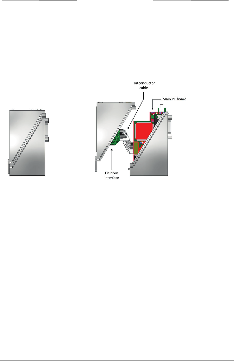
Bronkhorst
does not recommend to open the housing, but in case that the housing has to be opened, it
should be done with great care, because the connection of the fieldbus and main p.c.board is accomplished
by a small flat conductor cable.
Energizing or de-energizing of the instrument of the instrument indicates whether there is an electronic
failure.
After that, fluid pressure is to be applied in order to check behaviour.
If there should be suspicion of leakage, do not check for bubbles with a leak detection liquid as this may lead
to a short-circuit in the sensor or p.c.board.

BRONKHORST
®
9.17.022
page 35
7.2 Troubleshooting summary general
Symptom
Possible cause
Action
No output signal
No power supply
1a) check power supply
1b) check cable connection
Output stage blown-up due to long
lasting shortage and/or high-voltage
peaks
1c) return to factory
Supply pressure too high, or differential
pressure across meter too high
1d) lower supply pressure
Valve blocked/contaminated
1e) connect 0 .. 15 Vdc to valve and
slowly increase voltage while supply
pressure is ‘on’. The valve should open
at 7V ± 3V; if not open, then cleaning
parts and adjust valve (qualified
personnel only)
Screen in inlet fitting blocked
1f) clean screen
Sensor/capillary failure
1g) return to factory
Maximum output signal
Output stage blown-up
2a) return to factory
Sensor/capillary failure
2b) return to factory
Output signal much lower than
setpoint signal or desired flow
Screen blocked/contaminated
3a) clean screen
LFD blocked/contaminated and/or liquid
in meter
3b) remove LFD and clean; dry meter
with air or
N
2
Valve blocked/contaminated
3c) clean valve
Valve internals damage (swollen seat in
plunger)
3d) replace plunger assembly and adjust
valve or return
Incorrect type of gas is used and/or
pressure/diff. pressure
3e) try instrument on conditions for
which it was designed
Flow is gradually decreasing
Condensation, occurs with
NH
3
,
hydrocarbons such as
C
H ,
C
H
3 8 4
10
etc.
4a) decrease supply pressure and/or
heat gas to be measured
Valve adjustment has changed
4b) see ‘1e’
Oscillation
Supply pressure/diff. pressure too high
5a) lower pressure
Pipeline too short between pressure
regulator and MFC
5b) increase length or diameter of piping
upstream
Pressure regulator is oscillating
5c) replace pressure regulator or try ‘5b’
Valve sleeve or internals damaged
5d) replace damaged parts and adjust
valve, see ‘1e’ or return to factory
Controller adjustment wrong
5e) adjust controller
Small flow at zero setpoint
Valve leaks due to damaged plunger or
dirt in orifice
6a) clean orifice and/or, when replacing
plunger assembly, see ‘1e’
Pressure too high or much too low
6b) apply correct pressure
Note: For other (more specific) problems see also troubleshooting parts in other documents.
APPENDIX 1
GAS CONVERSION TABLE
Doc. no.: 9.02.071
11

GAS CONVERSION FACTOR
Nr.:
Name:
Symbol
Density
ρ
n
g l[ / ]
0°C, 1 atm.
Heat capacity*
c
cal cal
g K
p
− [
/
. ]
20°C, 1 atm.
Conversion
factor
20°C, 1 atm.
1
2
3
4
5
Acetylene (Ethyne)
Air
Allene (Propadiene)
Ammonia
Argon
C
2
H
2
Air
C
3
H
4
NH
3
Ar
1.172
1.293
1.832
0.7693
1.784
0.438
0.241
0.392
0.524
0.125
0.61
1.00
0.43
0.77
1.40
6
7
8
9
10
Arsine
Boron trichloride
Boron trifluoride
Bromine pentafluoride
Butadiene (1,3-)
AsH
3
BCl
3
BF
3
BrF
5
C
4
H
6
3.524
5.227
3.044
7.803
2.504
0.133
0.136
0.188
0.156
0.405
0.66
0.44
0.54
0.26
0.31
11
12
13
14
15
Butane
Butene (1-)
Butene (2-) (Cis)
Butene (2-) (Trans)
Carbonylfluoride
C
4
H
10
C
4
H
8
C
4
H
8
C
4
H
8
COF
2
2.705
2.581
2.503
2.503
2.983
0.457
0.415
0.387
0.421
0.194
0.25
0.29
0.32
0.30
0.54
16
17
18
19
20
Carbonylsulfide
Carbon dioxide
Carbon disulfide
Carbon monoxide
Chlorine
COS
CO
2
CS
2
CO
Cl
2
2.724
1.977
3.397
1.25
3.218
0.175
0.213
0.152
0.249
0.118
0.65
0.74
0.60
1.00
0.82
21
22
23
24
25
Chlorine trifluoride
Cyanogen
Cyanogen chloride
Cyclopropane
Deuterium
ClF
3
C
2
N
2
ClCN
C
3
H
6
D
2
4.125
2.376
2.743
1.919
0.1798
0.188
0.275
0.185
0.374
1.73
0.40
0.48
0.61
0.43
1.00
26
27
28
29
30
Diborane
Dibromo difluoromethane
Dichlorosilane
Dimethylamine
Dimethylpropane (2,2-)
B
2
H
6
Br
2
CF
2
SiH
2
Cl
2
C
2
H
6
NH
C
5
H
12
1.248
9.361
4.506
2.011
3.219
0.577
0.17
0.17
0.417
0.462
0.43
0.20
0.41
0.37
0.21
31
32
33
34
35
Dimethylether
Disilane
Ethane
Ethylene (Ethene)
Ethylene oxide
C
2
H
6
O
Si
2
H
6
C
2
H
6
C
2
H
4
C
2
H
4
O
2.105
2.857
1.355
1.261
1.965
0.378
0.352
0.468
0.414
0.303
0.39
0.31
0.49
0.60
0.52
36
37
38
39
40
Ethylacetylene (1-Butyne)
Ethylchloride
Fluorine
Freon-11
Freon-113
C
4
H
6
C
2
H
5
Cl
F
2
CCl
3
F
C
2
Cl
3
F
3
2.413
2.878
1.696
6.129
8.36
0.401
0.263
0.201
0.145
0.174
0.32
0.41
0.91
0.35
0.21
41
42
43
44
45
Freon-1132A
Freon-114
Freon-115
Freon-116
Freon-12
C
2
H
2
F
2
C
2
Cl
2
F
4
C
2
ClF
5
C
2
F
6
CCl
2
F
2
2.889
7.626
7.092
6.251
5.547
0.244
0.177
0.182
0.2
0.153
0.44
0.23
0.24
0.25
0.37
46
47
48
49
50
Freon-13
Freon-13B1
Freon-14
Freon-21
Freon-22
CClF
3
CBrF
3
CF
4
CHCl
2
F
CHClF
2
4.72
6.768
3.946
4.592
3.936
0.165
0.12
0.18
0.154
0.168
0.40
0.38
0.44
0.44
0.47
51
52
53
Freon-23
Freon-C318
Germane
CHF
3
C
4
F
8
GeH4
3.156
9.372
3.45
0.191
0.222
0.16
0.52
0.15
0.56
*
c
p
- cal (T,p) =
c
p
(T + 50°C, p)

GAS CONVERSION FACTOR
Nr.:
Name:
Symbol
Density
ρ
n
g l[ / ]
0°C, 1 atm.
Heat capacity*
c
cal cal
g K
p
− [
/ .
]
20°C, 1atm.
Conversion
factor
20°C, 1atm.
54
55
56
57
58
Helium
Helium (3-)
Hydrogen
Hydrogen bromide
Hydrogen chloride
He
3He
H
2
HBr
HCl
0.1785
0.1346
0.08991
3.646
1.639
1.24
1.606
3.44
0.0869
0.192
1.41
1.44
1.01
0.98
0.99
59
60
61
62
63
Hydrogen cyanide
Hydrogen fluoride
Hydrogen iodide
Hydrogen selenide
Hydrogen sulfide
HCN
HF
HI
H
2
Se
H
2
S
1.206
0.8926
5.799
3.663
1.536
0.345
0.362
0.0553
0.109
0.246
0.75
0.96
0.97
0.78
0.82
64
65
66
67
68
Isobutane
Isobutylene (Isobutene)
Krypton
Methane
Methylacetylene
C
4
H
10
C
4
H
8
Kr
CH
4
C
3
H
4
2.693
2.60
3.749
0.7175
1.83
0.457
0.429
0.058
0.568
0.399
0.25
0.28
1.43
0.76
0.43
69
70
71
72
73
Methylbromide
Methylchloride
Methylfluoride
Methylmercaptan
Molybdenum hexafluoride
CH
3
Br
CH
3
Cl
CH
3
F
CH
3
SH
MoF
6
4.35
2.3
1.534
2.146
9.366
0.118
0.212
0.29
0.272
0.156
0.61
0.64
0.70
0.53
0.21
74
75
76
77
78
Mono-ethylamine
Monomethylamine
Neon
Nitric oxide
Nitrogen
C
2
H
5
NH
2
CH
3
NH
2
Ne
NO
N
2
2.011
1.419
0.9002
1.34
1.250
0.436
0.424
0.246
0.239
0.249
0.36
0.52
1.41
0.97
1.00
79
80
81
82
83
Nitrogen dioxide
Nitrogen trifluoride
Nitrosyl chloride
Nitrous oxide
Oxygen
NO
2
NF
3
NOCl
N
2
O
O
2
2.053
3.182
2.984
1.978
1.429
0.204
0.194
0.17
0.221
0.222
0.74
0.50
0.61
0.71
0.98
84
85
86
87
88
Oxygen difluoride
Ozone
Pentane
Perchlorylfluoride
Perfluoropropane
OF
2
O
3
C
5
H
12
ClO
3
F
C
3
F
8
2.417
2.154
3.219
4.653
8.662
0.201
0.207
0.455
0.165
0.22
0.64
0.70
0.21
0.41
0.16
89
90
91
92
93
Performa- ethylene
Phosgene
Phosphine
Phosphorous pentafluoride
Propane
C
2
F
4
COCl
2
PH
3
PF
5
C
3
H
8
4.523
4.413
1.53
5.694
2.012
0.206
0.149
0.277
0.183
0.456
0.33
0.47
0.73
0.30
0.34
94
95
96
97
98
Propylene (Propene)
Silane
Silicon tetrafluoride
Sulfurylfluoride
Sulfur dioxide
C
3
H
6
SiH
4
SiF
4
SO
2
F
2
SO
2
1.915
1.443
4.683
4.631
2.922
0.408
0.349
0.18
0.175
0.157
0.40
0.62
0.37
0.38
0.68
99
100
101
102
103
Sulfur hexafluoride
Sulfur tetrafluoride
Trichlorosilane
Trimethylamine
Tungsten hexafluoride
SF
6
SF
4
SiHCl
3
C
3
H
9
N
WF
6
6.626
4.821
6.044
2.637
13.29
0.175
0.192
0.157
0.424
0.092
0.27
0.34
0.33
0.28
0.25
104
105
106
107
Vinylbromide
Vinylchloride
Vinylfluoride
Xenon
C
2
H
3
Br
C
2
H
3
Cl
C
2
H
3
F
Xe
4.772
2.865
2.08
5.899
0.141
0.229
0.305
0.0382
0.46
0.47
0.49
1.38
*
c
p
- cal (T,p) =
c
p
(T + 50°C, p)
