
374BombCalorimetry-Callis16.docx 1Mar2016
1
Bomb Calorimetry: Heat of Combustion of Naphthalene
Most tabulated H values of highly exothermic reactions come from “bomb” calorimeter
experiments. Heats of combustion are most common, in which the combustible material is
explosively burned in a strong, steel container (the “bomb”). From the temperature increase of
the system and the heat capacity of the system, H of the reaction may be calculated.
Click on this link for a simplified overview of the experiment.
http://highered.mcgraw-hill.com/sites/9834092339/student_view0/chapter48/bomb_calorimeter.html
Recall that, by definition, H = U + pV, where H = enthalpy, U = energy, p = pressure, and V =
volume, all for the system. H was defined this way because when three common conditions are
met: p=p
ext
= constant, and only pV work on or by the atmosphere due to expansion or
contraction of the system is done, then—and only then—H = q, the heat absorbed by the
system. During an explosive reaction, p and p
ext
are uncontrollable, so one resorts to finding
H
reaction
= U
reaction
+(pV)
reaction
using the First Law.
The First Law states that U = q + w, where q = energy transferred from the surroundings as
heat (energy transferred by thermal contact by virtue of a temperature difference between
system and surroundings, and w = work done on the system, as measured by a mechanical
change in the surroundings (including electric current).
Choice of system and surroundings is somewhat arbitrary. For this experiment, we choose to call
everything within the insulated shell to be the system. That is, the system consists of the
hardware (the bomb and water bucket) + sample + fuse wire + water.
Thus, no heat is absorbed, q = 0, i.e., adiabatic. The system is not quite isolated because a small
amount of electricity (considered work) enters the system to ignite the reaction. This work is
quickly converted to heat due to the resistance of the small wire in the circuit, which becomes
“white” hot and ignites the sample.
The surrounding consists of the electrical source only, in this case.
U = q + w = U
hardware
+ U
water
+ U
reaction
+U
fuse
= 0 + w
Electricity
The sample and the fuse both undergo combustion. The electricity from the surroundings (work)
heats the wire to a high temperature, and heats the system slightly before it and the sample
explode in the nearly 40 atm of O
2
gas.
U
reaction
= w
Electricity
– [U
hardware
+ U
water
+ U
fuse
]
H
reaction
= U
reaction
+(pV)
reaction
By far the largest item is U
water
which we get from the mass, heat capacity, and temperature
change,
374BombCalorimetry-Callis16.docx 1Mar2016
2
U
water
= C
p,water
T ; U
fuse
comes from the measured mass of fuse burned and known U
per gram.
We know C
p,water
and measure the water mass and T caused only by the reaction.
U
hardware
will be determined by doing the experiment on benzoic acid, for which we know
H
reaction
. In addition, the manufacturer states: “The factor for the 1341 calorimeter with an 1108 Oxygen
Combustion Vessel will usually fall within a range from 2410 to 2430 calories per degree Celsius, with the exact
value for each installation to be determined by the user.” Note: THIS INCLUDES THE WATER.
Thus, U
hardware
= 410-430 cal/
o
C
w
Electricity
and U
fuse
: Formally, w
Electricity
is estimated from the voltage x current x time = 23
J/coulomb x 4 couloubs/second x 0.5 seconds/4.184 J/cal. This number will be small, which is
good because we don’t really know the numbers at all well. The manufacturer states: “It can be
assumed that the heat input from the electric firing current will be the same when standardizing the
calorimeter as when testing an unknown sample, and this small amount of energy therefore requires no
correction. However, it will be found that the amount of wire consumed will vary from test to test, therefore
a correction must be made to account for the heat of combustion of the metal.”
U
fuse
: From the manufacturer: “The amount of wire taking part in the combustion is determined by
subtracting the length of the recovered unburned portion from the original length of 10 cm. The correction is
then computed for the burned portion by assuming a heat of combustion of 2.3 calories per cm. for Parr
45C10 (No. 34 B & S gage “Chromel C”) wire, or 2.7 calories per cm for No. 34 B & S gage iron wire.”
Finally, we use the common approximation that the volume change comes virtually all from the
change in numbers of moles of gas combined with the ideal gas law:
(pV)
reaction
= n
reaction
RT
Data:
C
7
H
6
O
2
Molar mass
122.12 g mol
−1
Heat of formation.
Heat of combustion=
This gives -3228 kJ mol
-1
/(4.184 kJ kcal
-1
/122.12 g = 6.318 kcal/g The factor for the 1341 calorimeter with
an 1108 Oxygen Combustion Vessel will usually fall within a range from 2410 to 2430 calories per degree
Celsius, with the exact value for each installation to be determined by the user.
Δ
f
H°
solid
-384.8 ± 0.50
kJ/mol
Δ
c
H°
solid
-3228. ± 4.
kJ/mol

374BombCalorimetry-Callis16.docx 1Mar2016
3
MANDATORY READING FOR ALL PARTICIPANTS!
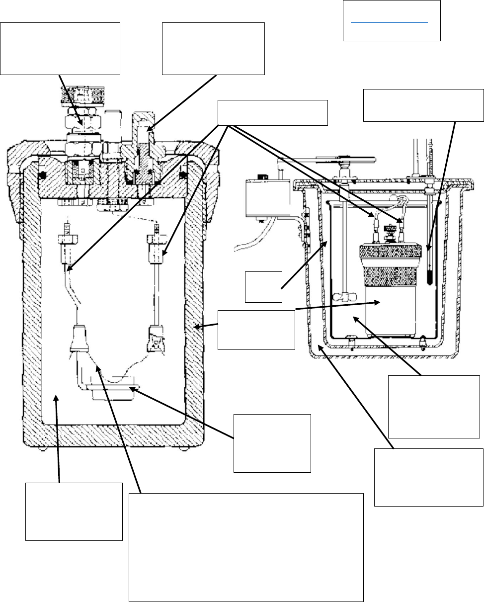
Operating the 1108 Oxygen Combustion Vessel (Bomb)
(see diagrams on next page)
Precautions reprinted from Parr Instrument Co. instruction manual 205M
Combustion with oxygen in a sealed bomb is a very effective and reliable method for releasing all
heat energy obtainable from a sample and for preparing hydrocarbon compounds and carbonaceous
materials for analysis, but there are certain precautions which must always be observed when
using this equipment. In particular:
Do not overcharge the bomb with too much sample or with a sample which might react with
explosive violence.
Do not overcharge the bomb with too much oxygen. The initial charging pressure should not
exceed 40 atm (590 psig).
Do not fire the bomb alone on an open bench without providing a protective cooling medium.
The bomb should be completely submerged in water during firing.
Do not fire the bomb if gas bubbles are released from any point on the bomb when it is
submerged in water.
Do not ignite a volatile sample without using one of the sealed sample holders described on
pages 8-9.
Stand away from the bomb during and do not handle the bomb for at least 6 minutes
after firing.
Keep the bomb in good condition at all times. Any parts that show signs of weakness or
deterioration must be replaced promptly.
Read the maintenance and safety instructions beginning on page 12 before starting to use
the bomb, and urge all operating personnel to re-read these instructions often.
Screw caps and cylinders are stamped so that each cylinder and screw cap can be identified
as a matched set. We recommend that you maintain the match of cylinders and screw caps for
your safety and ease of use.
374BombCalorimetry-Callis16.docx 1Mar2016
4
Diagrams from
http://mason.gmu.edu/
~pcooper6/expt2-2.pdf
“Bomb”
Sample
holder
Fuse wire:
Heated to white hot with 4 amps
of current, which ignites the
sample
35 atm of
O
2
gas
2 liters of
water
Insulation
Thermometer
O
2
inlet
valve
O
2
outlet
valve
Electric leads
Air

374BombCalorimetry-Callis16.docx 1Mar2016
5
General Procedure
0. Read the MANDATORY READING SECTION if you have not already done so. There are
strict safety procedures that must be followed.
All operations required to test a sample or to standardize the 1341 Plain Jacket Calorimeter should
proceed step-wise in the following manner:
1. Prepare the sample and charge the oxygen combustion vessel as described in Instruction
Manual No. 205M.
2. Fill the calorimeter bucket by first taring the dry bucket on a solution or trip balance; then add
2000(+/-0.5) grams of water. Distilled water is preferred, but demineralized or tap water containing
less than 250 ppm of dissolved solid is satisfactory. The water temperature should be approximately
1.5°C below room temperature, but this can be varied to suit the operator’s preference. It is not
necessary to use exactly 2000 grams, but the amount selected must be duplicated within +/-0.5
gram for each run. Instead of weighing the bucket it can be filled from an automatic pipet or
from any other volumetric device if the repeatability of the filling system is within +/-0.5 ml.
and the water temperature is held within a 1ºC range. (We will use a 2 L volumetric flask)
3. Set the bucket in the calorimeter. Attach the lifting handle to the two holes in the side of the
screw cap and partially lower the bomb in the water. Handle the bomb carefully during this operation
so that the sample will not be disturbed. Push the two ignition lead wires into the terminal sockets on
the bomb head. Orient the wires away from the stirrer shaft so they do not become tangled in the
stirring mechanism. Lower the bomb completely into the water with its feet spanning the circular
boss in the bottom of the bucket. Remove the lifting handle and shake any drops of water into the
bucket and check for gas bubbles.
4. Set the cover on the jacket. Turn the stirrer by hand to be sure that it runs freely; then slip the
drive belt onto the pulleys and start the motor. Turn on the 6775 Digital Thermometer.
5. Let the stirrer run for 5 minutes to reach equilibrium before starting a measured run. At the end
of this period record the time on the timer of the 6775 Digital Thermometer and read the tempera-
ture.
6. Read and record temperatures at one-minute intervals for 5 minutes. Then, at the start of the
6th minute…
7. Stand back from the calorimeter and fire the bomb by pressing the ignition button and holding
it down until the indicator light goes out. Normally the light will glow for only about ½ second but
release the button within 5 seconds regardless of the light.
Caution!
Do not have your head, hands, or any other
parts of your body over the calorimeter when
firing the bomb; and continue to stand clear for
30 seconds after firing.
374BombCalorimetry-Callis16.docx 1Mar2016
6
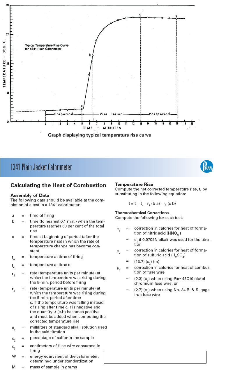
8. The bucket temperature will start to rise within 20 seconds after firing. This rise will be rapid
during the first few minutes; then it will become slower as the temperature approaches a stable
maximum as shown by the typical temperature rise curve below. It is not necessary to plot a similar
curve for each test, but accurate time and temperature observations must be recorded to identify
certain points needed to calculate the calorific value of the sample.
9. Measure the time required to reach 60 percent of the total rise by estimating the temperature
at the 60% point and observing the time when the temperature reading reaches that point. If the 60%
point cannot be estimated before ignition, take temperature readings at 45, 60, 75, 90 and 105
seconds after firing and interpolate between these readings to identify the 60% point after the total
rise has been measured.
10. After the rapid rise period (about 4 or 5 minutes after ignition) record temperatures at one
minute intervals until the difference between successive readings has been constant for five
minutes. Usually the temperature will reach a maximum; then drop very slowly. But this is not
always true since a low starting temperature may result in a slow continuous rise without reaching a
maximum. As stated above, the difference between successive readings must be noted and the
readings continued at one-minute intervals until the rate of the temperature change becomes
constant over a period of 5 minutes.
11. After the last temperature reading, stop the motor, remove the belt and lift the cover from the
calorimeter. Wipe the thermistor shaft and stirrer with a clean cloth and set the cover on the A37A
support stand. Lift the bomb out of the bucket; remove the ignition leads and wipe the bomb with a
clean towel.
12. Open the knurled knob on the bomb head to release the gas pressure before attempting to
remove the cap. This release should proceed slowly over a period of not less than one minute to
avoid entrainment losses. After all pressure has been released, unscrew the cap; lift the head out of
the cylinder and place it on the support stand. Examine the interior of the bomb for soot or other
evidence of incomplete combustion. If such evidence is found, the test will have to be discarded.
13. Wash all interior surfaces of the bomb with a jet of distilled water and collect the washings in a
beaker.
14. Remove all unburned pieces of fuse wire from the bomb electrodes; straighten them and
masure their combined length in centimeters. Subtract this length from the initial length of 10
centimeters and enter this quantity on the data sheet as the net amount of wire burned. Alternatively,
the correction in calories is located on the card of the 45C10 fuse wire.
15. Titrate the bomb washings with a standard sodium carbonate solution using methyl orange or
methyl red indicator. A 0.0709N sodium carbonate solution is recommended for this titration to
simplify the calculation. This is prepared by dissolving 3.76 grams Na2CO3 in water and diluting to
one liter NaOH or KOH solutions of the same normality may be used.
16. Analyze the bomb washings to determine the sulfur content of the sample if it exceeds 0.1 per
cent. Methods for determining sulfur are discussed in Instruction Manual No. 207M.
Caution!
Do not have any part of the body in the pressure relief path.
374BombCalorimetry-Callis16.docx 1Mar2016
7
NOTE: W includes the water

374BombCalorimetry-Callis16.docx 1Mar2016
8
Specific Procedure for this experiment
1. Carefully weigh a 1-gram pellet of benzoic acid to 4 significant figures. Run the above steps
and use the known
c
H for benzoic acid to extract the heat capacity for the hardware.
2. Create a 0.7-1 gram pellet (possibly by carefully melting a crumbly lump) of naphthalene and
run the above steps, using the heat capacity for the hardware obtained in 1. to find the
c
H for
naphthalene.
In both steps 1. and 2., use the density and volume of water at the temperature of the water at
which the volume is measured to determine the mass of water. (the small amount of water left in
the volumetric flask does not matter provided it is essentially the same in all the measurements)
3. Repeat steps 1 and 2 at least one more time.
Report
1. Follow the general instructions for written laboratory reports.
2. Write the balanced chemical equation for the combustion of benzoic acid and naphthalene,
paying special attention to whether what is liquid, solid, and calculate n
gas
and (pV) to be used
in getting
c
H.
3. From the vapor pressure of water at the temperature of the products after the combustion,
make a rough calculation to determine what fraction of the product water is liquid, given a
volume of the bomb = 0.5 L.
4. Compare the result for naphthalene with a tabulated value that is close to the average
temperature of your experiment. Discuss the agreement with experiment relative to the standard
deviation from the multiple runs and from your estimated errors in the temperature change, the
mass of water, and mass of sample.

374BombCalorimetry-Callis16.docx 1Mar2016
9
Appendix
Example calibration following (sort of) the Parr instruction manual:
Assuming that 1.1651 g benzoic acid, 2000 g water with C
p
=1 cal g
-1
o
C
-1
and specific H
reaction
= -6318 cal/ g gave a temperature rise = 3.047
o
C; C
p, hardware
= 420 cal/
o
C and 8 cm of fuse wire
with U = 2.3 cal/cm
From above:
H
reaction
= U
reaction
+(pV)
reaction
= w
Electricity
– [U
hardware
+ U
water
+ U
fuse
] +(pV)
reaction
U
hardware
= w
Electricity
– [–H
reaction
+ U
water
+ U
fuse
] +(pV)
reaction
= 11 –[ +6318 cal g
-1
x 1.1651 g + 2000 g x 1 cal
o
C
-1
g
-1
x 3.047
o
C + 8 cm x 2.3 cal/cm]
= 1260 cal for a 3.047
o
C
-1
temperature rise
therefore, C
p, hardware
= 1260 cal/3.047
o
C = 413 cal
o
C
-1
(ignoring unreacted benzoic acid that could have been found by titration with base)
Example determination of H
combustion
for benzoic acid (assuming C
p, hardware
=
420 cal
o
C
-1
)
U
reaction
= w
Electricity
– [U
hardware
+ U
water
+ U
fuse
]
H
reaction
= U
reaction
+ (pV)
reaction
U
reaction
= 11 –[420 cal
o
C
-1
x 3.047
o
C + 2000 g x 1 cal
o
C
-1
x 3.047
o
C + 8 cm x 2.3 cal/cm ]
= -7381 cal for 1.1651 g (ignoring ~ 10 cal of unreacted benzoic acid found by titration of the
residual material in the bomb)
specific U
reaction
= -7381 cal/1.1651 g = -6335 cal/g = -3237 kJ/mol
To this add (pV)
reaction
in kJ/mol to get and obtain:
the molar
c
H = -3244 kJ/mol (compared to -3225 kJ/mol expected)
