
The Basics
of UV-Vis
Spectrophotometry
A primer

1 Basic Principles of UV-Vis Measurement 3
1.1 The electromagnetic spectrum 3
1.2 Wavelength and frequency 3
1.3 UV-visible spectra 3
1.4 Transmittance and absorbance 4
1.5 Summary 4
2 How Does a Modern UV-Vis Spectrophotometer Work? 5
2.1 Instrumental design 7
3 Selecting the Optimum Parameters for your 13
UV-Vis Measurements
3.1 Optical cell selection 13
3.2 Thermostatting your samples 16
3.3 Stirring your sample 16
3.4 Measurements at low temperatures 16
3.5 Solvent transparency 17
3.6 Optimum spectral band width 18
3.7 Stray light 19
3.8 The linear range of a UV-Vis instrument 19
3.9 Other useful information 20
3.10 Wavelength or inverse centimeters 20
4 Overview of Common UV-Vis Applications 21
4.1 Identification—spectra and structure 21
4.2 Confirmation of identity 22
4.3 Quantifying a molecule 22
4.4 Kinetics 24
4.5 Color measurement 26
4.6 Structural changes of compounds 28
4.7 Protein and nucleic acid melting temperature 28
4.8 Multi-component analysis 30
4.9 Software requirements 32
5 Glossary 34
Contents
2
3
1.1 The electromagnetic spectrum
Ultraviolet (UV) and visible radiation are a small part of the electromagnetic
spectrum, which includes other forms of radiation such as radio, infrared
(IR), cosmic, and X rays.
wavelength UV light has the highest energy. Sometimes, this energy may
be sufficient to cause unwanted photochemical reactions when measuring
samples that are photosensitive.
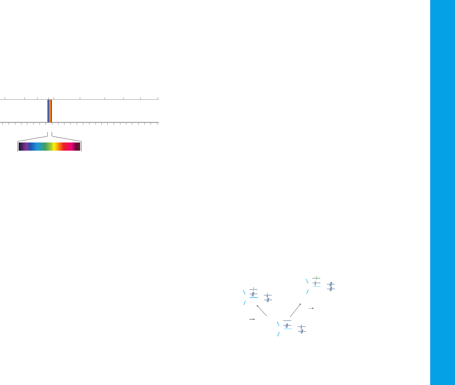
1.3 UV-visible spectra
When radiation interacts with matter, several processes can
occur, including reflection, scattering, absorbance, fluorescence/
phosphorescence (absorption and re-emission), and photochemical
reactions (absorbance and bond breaking). Typically, when measuring
samples to determine their UV-visible spectrum, absorbance is measured.
Because light is a form of energy, absorption of light by matter causes
the energy content of the molecules (or atoms) in the matter to increase.
The total potential energy of a molecule is represented as the sum of its
electronic, vibrational, and rotational energies:
E
total
= E
electronic
+ E
vibrational
+ E
rotational
The amount of energy a molecule possesses in each form is not a
continuum but a series of discrete levels or states. The differences in
energy among the different states are in the order:
E
electronic
> E
vibrational
> E
rotational
In some molecules and atoms, incident photons of UV and visible light have
enough energy to cause transitions between the different electronic energy
levels. The wavelength of light absorbed has the energy required to move an
electron from a lower energy level to a higher energy level. Figure 2 shows
an example of electronic transitions in formaldehyde and the wavelengths
of light that cause them.
1. Basic Principles of UV-Vis Measurement
Figure 1. The electromagnetic spectrum, with the visible light section expanded.
The energy associated with electromagnetic radiation is defined as:
E = hν
where E is energy (in joules), h is Planck’s constant (6.62 × 10
-34
Js), and
ν is frequency (in seconds).
Spectroscopy allows the study of how matter interacts with or emits
electromagnetic radiation. There are different types of spectroscopy,
depending on the wavelength range that is being measured. UV-Vis
spectroscopy uses the ultraviolet and visible regions of the electromagnetic
spectrum. Infrared spectroscopy uses the lower energy infrared part of
the spectrum.
1.2 Wavelength and frequency
Electromagnetic radiation can be considered a combination of alternating
electric and magnetic fields that travel through space in a wave motion.
Because radiation acts as a wave, it can be classified in terms of either
wavelength or frequency, which are related by the following equation:
ν = c/λ
where ν is frequency (in seconds), c is the speed of light (3 ×
108
ms
-1
), and
λ is wavelength (in meters).
In UV-Vis spectroscopy, wavelength is usually expressed in nanometers
(1 nm = 10
-9
m). It follows from the equations that radiation with shorter
wavelength has higher energy, and, for UV-Vis spectroscopy, the low (short)
Figure 2. Electronic transitions in formaldehyde. UV light at 187 nm causes excitation of
an electron in the C-O bond and light at 285 nm wavelength causes excitation and transfer
of an electron from the oxygen atom to the C-O bond.
Ultraviolet Visible Infrared
LOWER
ENERGY
HIGHER
ENERGY
10
-14
10
-12
10
-10
10
-8
10
-6
10
-4
10
-2
1 10
2
10
4
10
6
10
8
10
10
Wavelength [m]
Cosmic ray
Gamma ray
X ray
Ultraviolet
Infrared
Microwave
Radar
Television
NMR
Radio
Visible
10
22
10
19
10
17
10
15
10
14
10
3
10
6
10
-3
10
10
Frequency [Hz]
1
H
H
C O
n pi*
transition
(285 nm)
pi pi*
transition
(187 nm)
H
H
C O
H
H
C O
I
λ
electronic energy levels
vibrational energy levels
rotational energy levels
electronic transition
E
S
2
S
1
S
0
4
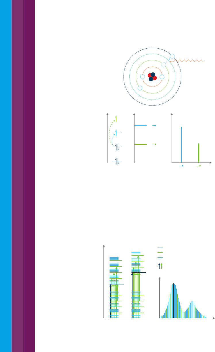
Figure 3. Incident light of a specific wavelength causes excitation of electrons in an atom.
The type of atom or ion (i.e. which element it is) and the energy levels the electron is
moving between determines the wavelength of the light that is absorbed. Transitions can
be between more than one energy level, with more energy i.e. lower wavelengths of light,
required to move the electron further from the nucleus.
However, for molecules, vibrational and rotational energy levels are
superimposed on the electronic energy levels. Because many transitions with
different energies can occur, the bands are broadened (see Figure 4). The
broadening is even greater in solutions owing to solvent-solute interactions.
1.4 Transmittance and absorbance
When light passes through or is reflected from a sample, the amount of
light absorbed is the difference between the incident radiation (I
o
) and
the transmitted radiation (I). The amount of light absorbed is expressed
as absorbance. Transmittance, or light that passes through a sample, is
usually given in terms of a fraction of 1 or as a percentage and is defined
as follows:
T = I / I
o
or %T = I/I
o
× 100
Absorbance is defined as follows:
A = –logT
For most applications, absorbance values are used since the relationship
between absorbance and both concentration and path length is normally
linear (as per the Beer Lambert law, described in section 1.9).
1.5 Summary
– UV and visible light are part of the electromagnetic spectrum
– In UV-Vis spectroscopy wavelength is expressed in nanometers (nm)
– Light can be reflected, scattered, transmitted or absorbed from matter,
and can cause photochemical reactions to occur
– Energy from incident light causes electrons to transition to different
energy levels. Electronic transitions also occur between the vibrational
and rotational energy levels of molecules
– Absorbance of light is used for most UV-Vis spectroscopy applications.
It is defined as A=-logT, where T is transmittance.
These transitions result in very narrow absorbance bands at wavelengths
highly characteristic of the difference in energy levels of the absorbing
species. This is also true for atoms, as depicted in Figure 3.
Figure 4. Electronic transitions and UV-visible spectra in molecules (I is intensity and
λ is wavelength).
λ
I∆E
S
0
S
1
S
2
S
0
S
2
S
0
S
0
S
1
S
2
S
0
S
1
E
Energy level 0
Light of specific
wavelength absorbed
–
Energy level 1
Energy level 2
Energy level 3
–
–
–
–
5
Ultraviolet visible (UV-Vis) spectrophotometers use a light source to
illuminate a sample with light across the UV to the visible wavelength
range (typically 190 to 900 nm). The instruments then measure the light
absorbed, transmitted, or reflected by the sample at each wavelength.
Some spectrophotometers have an extended wavelength range, into the
near-infrared (NIR) (800 to 3200 nm).
2. How Does a Modern UV-Vis Spectrophotometer Work?
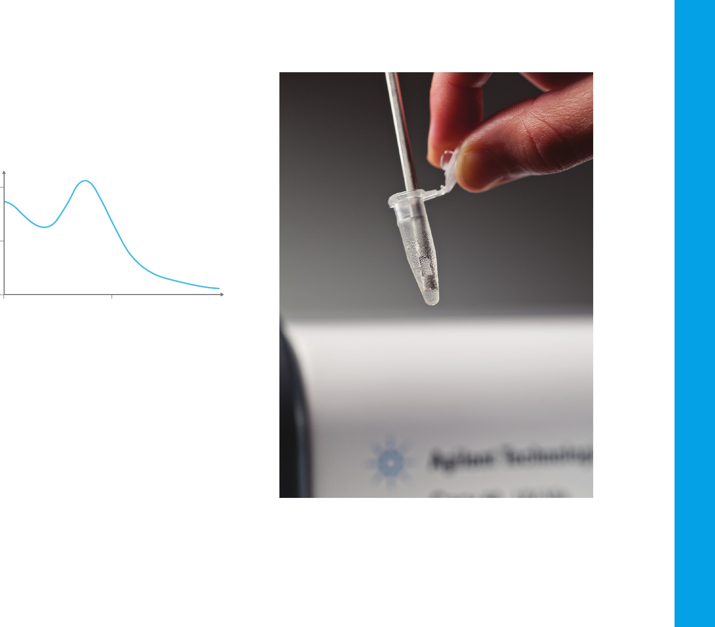
Figure 5. A UV absorbance spectrum, showing an absorbance peak at approximately 269 nm.
From the spectrum obtained, such as the one shown in Figure 5, it is
possible to determine the chemical or physical properties of the sample.
In general, it is possible to:
– Identify molecules in a solid or liquid sample
– Determine the concentration of a particular molecule in solution
– Characterize the absorbance or transmittance through a liquid or solid—
over a range of wavelengths
– Characterize the reflectance properties of a surface or measuring the
color of a material
– Study chemical reactions or biological processes.
Various types of measurements can be performed by combining different
accessories and sample holders with the UV-Vis spectrophotometer.
Different accessories exist for different measurement capabilities and
sample types, e.g., solids versus liquids, and for different measurement
conditions (Figure 6 and 7).
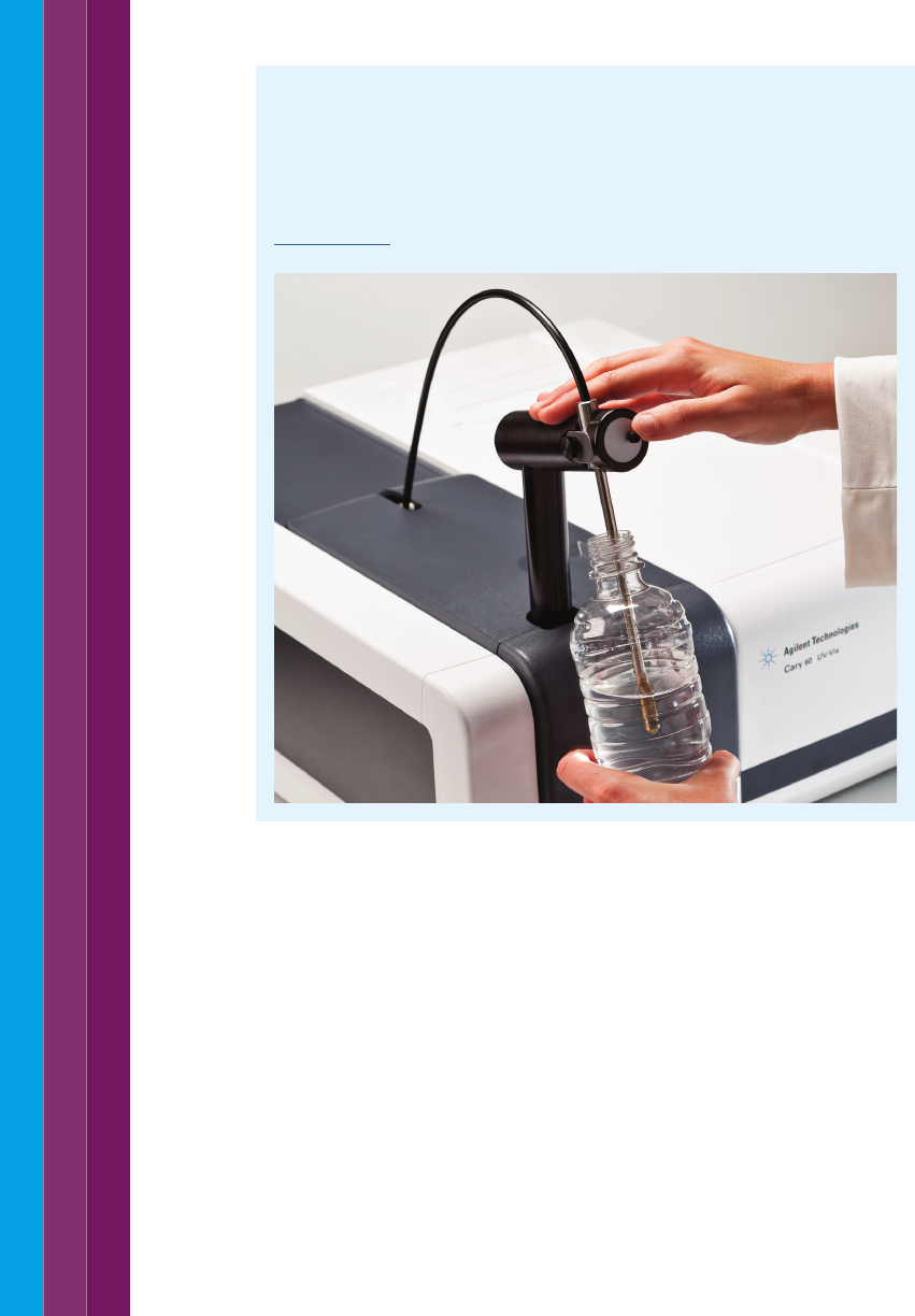
Figure 6. A fiber-optic probe accessory can be fitted to a UV-Vis spectrophotometer
to measure liquid samples in a range of containers.
UV-Vis spectrophotometry is a versatile technique and has been used for
close to a century in a wide range of fields. UV-Vis spectrophotometers are
in common use in material testing/research, chemistry/petrochemistry,
and biotechnology/pharmaceuticals laboratories.
265 270
0.4
0.2
0.0
Abs
Wavelength (nm)

6
Figure 7. A solid sample, like this
polycrystalline photovoltaic solar cell,
can be measured using a
UV-Vis spectrophotometer.
7
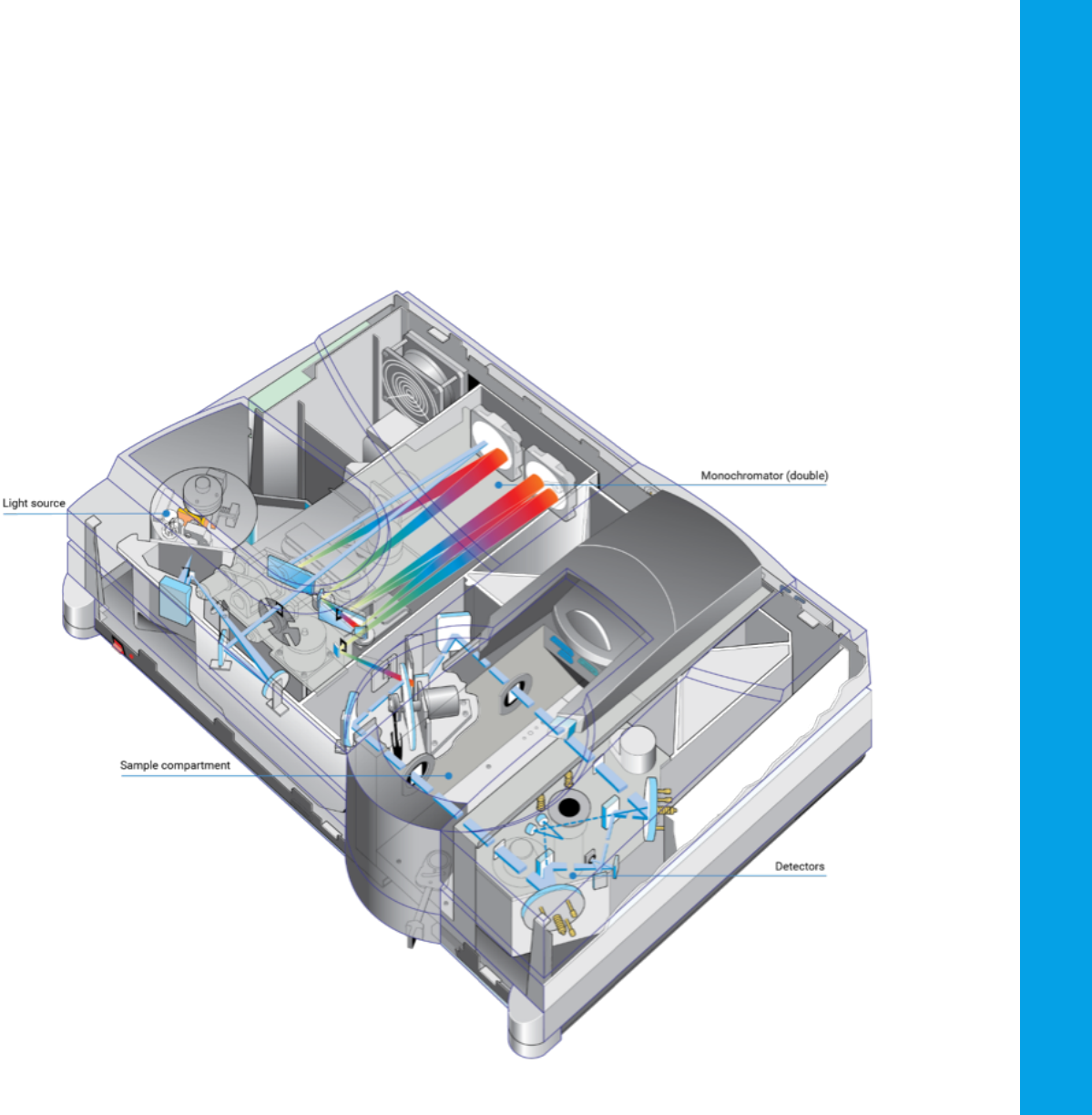
2.1 Instrumental design
Components
The key components of a spectrophotometer are:
– A light source that generates a broadband of electromagnetic radiation
across the UV-visible spectrum
– A dispersion device separates the broadband radiation into wavelengths
– A sample area, where the light passes through or reflects off a sample
– One or more detectors to measure the intensity of the reflected or
transmitted radiation
Other optical components, such as lenses, mirrors, or fiber-optics,
relay light through the instrument.
Figure 8. Schematic of the internal layout
of an Agilent Cary 5000 UV-Vis-NIR
spectrophotometer, showing the
main components. Note that this is a
high-performance instrument.
UV-Vis spectrophotometers for routine
measurements have a simpler optical design.
8
10
1
0.1
0.01
Spectral irradiance
200
Wavelength (nm)
400 600 800 1000
Tungsten-halogen lamp
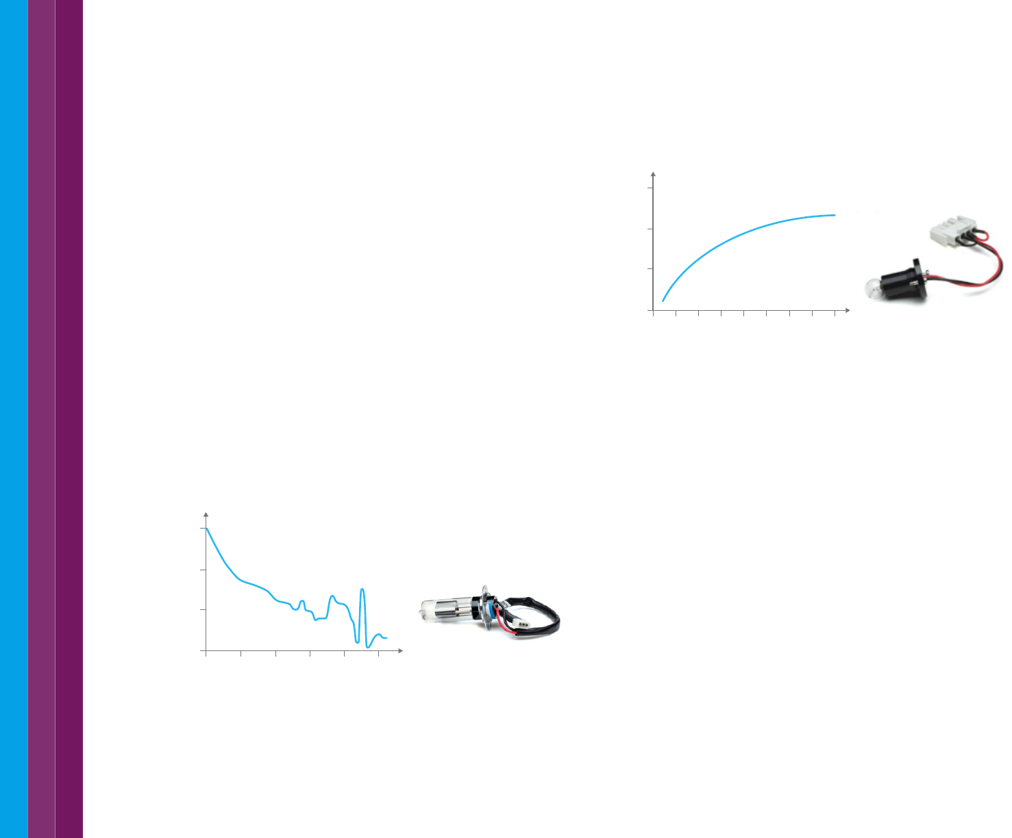
The tungsten-halogen lamp uses a filament. When a current is passed
through the filament, it becomes heated and emits light (see Figure 10).
The lamp yields good intensity over part of the UV spectrum and over the
entire visible and NIR range (350 nm- 3000 nm). This type of lamp has
very low noise and low drift and typically has a functional life of 10,000 h.
Figure 10. Intensity spectrum of the tungsten-halogen lamp.
In UV-visible spectrophotometers using both a D
2
and a tungsten-halogen
lamp, either a source selector is used to switch between the lamps as
appropriate, or the light from the two sources is mixed to yield a single
broadband source.
Xenon flash lamp
Unlike the D
2
or tungsten-halogen lamps, which provide a constant light
source, a Xenon flash lamp emits light for an extremely short time,
in flashes. Since it emits only for a short time and only during sample
measurement, it has a long life. The sample is only irradiated with light at
the time of measurement. This short illumination time makes the Xenon
flash lamp suitable for measuring samples that may be sensitive to
photobleaching. Photobleaching can be observed on sensitive samples
when exposed to a constant long exposure by a continuous light source.
The Xenon flash lamp emits high intensity light from 185 – 2500 nm, which
means no secondary light source is required (Figure 11). The Xenon flash
lamp may be used for many years before requiring replacement, which
makes it a popular choice compared to systems using D
2
or tungsten-
halogen lamps. An extra benefit is that it does not require warmup time,
unlike D
2
or tungsten-halogen lamps.
Light sources
The ideal light source would yield a constant intensity over all wavelengths
with low noise and long-term stability of the output. Unfortunately, such
a source does not exist. Two different light sources have historically been
used in UV-visible spectrophotometers:
– The deuterium arc lamp was used to provide a good intensity
continuum in the UV region and useful intensity in the visible region
– The tungsten-halogen lamp yielded good intensity over the entire visible
range and part of the UV spectrum
More recently, a single Xenon flash lamp has been used more widely.
The use of a Xenon flash lamp as a single source has significant
advantages over the use of the two conventional lamps.
Deuterium (D
2
) arc lamp
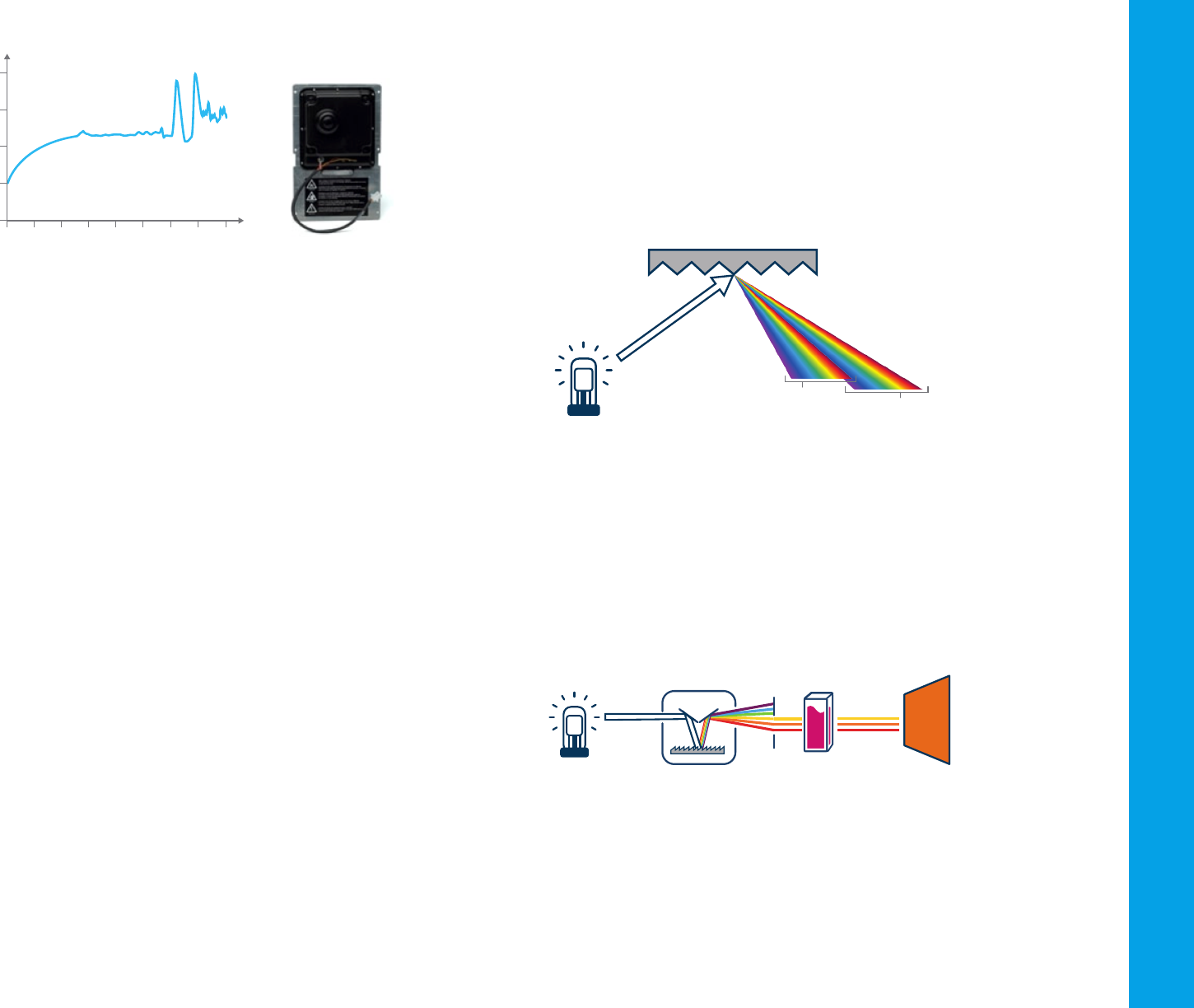
The deuterium arc lamp uses arc discharge from deuterium gas and yields
a good intensity continuum in the UV region and useful intensity in the
visible region, 185 to 400 nm (see Figure 9). Although modern deuterium
arc lamps have low signal noise, noise from the lamp is often the limiting
factor in overall instrument noise performance. Over time, the intensity of
light from a deuterium arc lamp decreases steadily. Such a lamp typically
has a half-life (the time required for the intensity to fall to half of its initial
value) of approximately 1,000 hours. This short half-life means the D
2
lamp
needs to be replaced relatively frequently.
Figure 9. Intensity spectrum of the deuterium arc lamp.
1
0.1
0.01
0.00
Spectral irradiance
200
Wavelength (nm)
300 400 500 600 700
9
100
1
0.1
0.01
10
Spectral irradiance
200
Wavelength (nm)
400 600 800 1000
Figure 11. Intensity spectrum of the Xenon lamp.
The monochromator
All the light sources produce a broad-spectrum white light. To narrow the
light down to a selected wavelength band, the light is passed through a
monochromator. A monochromator consists of:
– An entrance slit,
– A dispersion device, to spread the light into different wavelengths
(like a rainbow) and allow the selection of a nominated band of
wavelengths, and
– An exit slit where the light of the nominated wavelengths passes
through and onto the sample.
An easy way to think about a monochromator is to think of a room, with
the sun shining through a window. The sunlight hits a prism that separates
the white light into a rainbow. The rainbow falls onto a window on the
opposite side of the room. As the prism is turned, light of different colors
i.e. different wavelengths, pass out of the room through the window.
Ideally, the output from a monochromator is light of a single wavelength.
In practice, however, the output is always a band of wavelengths.
Most spectrophotometers on the market today contain holographic
gratings as the dispersion device. These optical components are made
from glass, onto which extremely narrow grooves are precisely etched onto
the surface. The dimensions of the grooves are of the same order as the
wavelength of light to be dispersed. Finally, an aluminum coating is applied
to create a reflective surface.
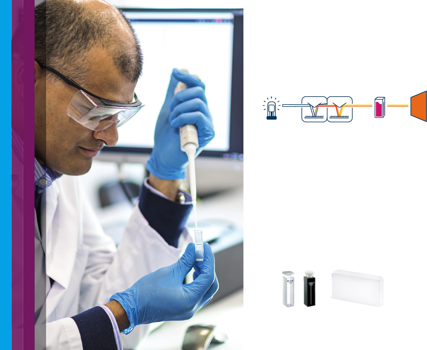
Interference and diffraction of the light falling on the grating is reflected at
different angles, depending on the wavelength. Holographic gratings yield a
linear angular dispersion with wavelength and are temperature insensitive.
However, they reflect light in different orders, which overlap (see Figure 12).
As a result, filters must be used to ensure that only the light from the
desired reflection order reaches the detector. A concave grating disperses
and focuses light simultaneously.
Figure 12. How a holographic grating disperses white light into light of different
wavelengths.
Single monochromator spectrophotometers
A single monochromator spectrophotometer is used for general-purpose
spectroscopy and can be integrated into a compact optical system.
Figure 13 shows a schematic diagram of a single monochromator optical
system. A single monochromator spectrophotometer cannot select the
wavelengths of light as narrowly as a double monochromator system,
but this ability may not be required for many applications, for example
when measuring samples that have broad absorption peaks.
Figure 13. Single monochromator spectrophotometer.
DetectorSampleLight source Monochromator
Grating
First order
Second order
10
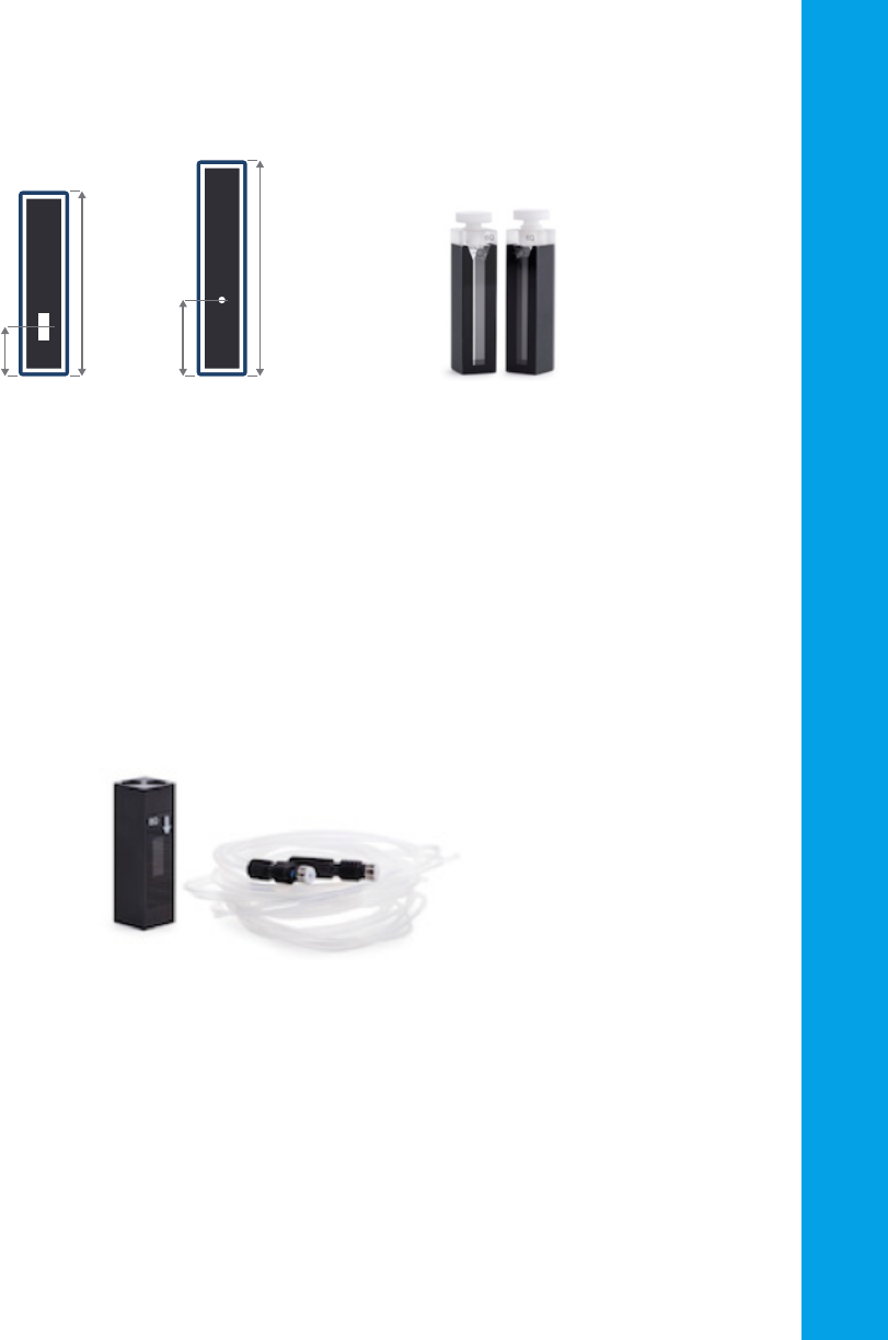
Figure 15. Cuvettes for measuring liquid samples. From left to right: A standard 10 mm
pathlength, 3 mL cuvette, an ultramicro cell for measuring very low volumes, and a long
pathlength cuvette for dilute solutions.
Double monochromator spectrophotometers
A double monochromator is typically found in high-performance
instruments. The two monochromators are arranged in series. The source
light is split by the first monochromator and then further split by the
second. Stray light, light that leaks into the system, is reduced, and the
spectral accuracy (the ability to accurately select a particular wavelength)
is increased. Figure 14 shows a schematic diagram of the double-
monochromator optical system.
Figure 14. Schematic diagram of a double monochromator spectrophotometer.
Sample compartment
In the sample compartment, the sample is positioned to allow the
beam from the monochromator to pass through the sample. For the
measurement of absorbance, liquid samples would typically be held
in a cuvette with a known, fixed pathlength. A cuvette is a rectangular
liquid holder as shown in Figure 15. They are made from glass, quartz,
plastic or another material that transmits UV or visible light. Standard
cuvettes have a 10 mm pathlength and are made from quartz, to ensure
good transmittance of UV wavelengths. Cheaper plastic cuvettes can
also be used, but generally do not transmit UV light so are only useful if
measurements in the visible wavelength region are required. A multitude
of cuvettes for special applications are available – from cuvettes that hold
tiny volumes of liquids through to those that have much longer pathlengths,
for use with very dilute samples.
Mono 1 Mono 2 DetectorSampleLight source

11
Solid samples can be held in place for simple transmission measurements.
They can also be measured at various angles of incidence. For more
complex measurements, like diffuse reflectance or transmission, other
accessories may be installed into the sample compartment.
Single beam spectrophotometer
The simplest UV-Vis spectrophotometer has a single beam optical system.
In a single-beam system, the light from the monochromator passes
through the sample and then to the detector. This simple design means
less optical components are used, and it makes it possible to reduce the
size of the instrument and thus the cost.
However, before a sample can be measured, a baseline or blank sample
must be measured. For liquid measurements, the baseline reading is
taken to allow for any absorbance of the cuvette and solvent used.
With a single beam system, the baseline needs to be measured separately
from the sample. The separate readings mean that if there is any variation
of light intensity, or system optical performance, between the baseline
and sample being read, the measurement may be less accurate.
This inaccuracy is a concern for sample measurements that take a long
time, or where the blank may vary over time. In practice this means that
a baseline/blank measurement should be run frequently and regularly
during a measurement session if using a single beam system.
Double beam spectrophotometer
Many UV-Vis systems use a double beam optical system. In the
double beam type, the light emitted from the monochromator is split into
two beams: a reference beam and a sample beam. The light is usually split
with an optical component such as a rotating wheel which has a mirrored
segment, or a half-silvered mirror called a beam splitter. Each beam enters
the sample chamber through separate optical paths. Since two beams
of the same wavelengths are available, the reference/blank and sample
can be measured at the same time. This means the sample
measurement can be corrected for any instrument fluctuations in real time.
This real time correction delivers a highly accurate measurement.
Figure 16. Schematic diagram of double beam optical system, with dual detectors.
Dual beam spectrophotometer
Another, more recent, spectrophotometer design uses a dual-beam optical
layout with a sample and reference detector. The reference detector is used
to correct lamp brightness fluctuations for each measurement, while the
solvent or blank (in the case of a solid sample) is measured in the sample
position and then subtracted from the sample spectrum after collection.
With improvements in electronics and software, this design keeps the
measurement process simple and reduces the chance of user error due to
mismatched cuvettes or incorrect sample placement. Dual beam design has
the same performance as a routine double beam instrument, while double
beam design is now typically reserved for research-grade instruments.
Sample compartment
The sample compartment of a UV-Vis spectrophotometer is typically a
black-colored box with a closing lid. The matt black inside the compartment
helps to absorb stray light that may enter the compartment.
In the sample compartment, the sample is positioned to allow the beam
from the monochromator to pass through the sample. As discussed above,
glass, plastic, or quartz cuvettes (Figure 15) are used for liquid samples.
Solid samples are held in position by a holder attached to the floor of
the sample compartment. The light can also be taken out of the sample
compartment using fiber optics. Fiber optics are useful when measuring very
large, hot, cold, radioactive, or other dangerous samples. As shown in
Figure 6, fiber optics can take the light from the spectrophotometer through a
fiber optic probe, to measure solutions outside of the sample compartment.
Alternatively, a fiber optic device that allows the measurement of light
reflectance, fluorescence or transmission through a solid sample can be used.
Detector 1Reference
Detector 2Sample
Light source Monochromator
12
Silicon diode (Si)
Silicon photodiode detectors (Figure 18) are extensively used as detectors
in modern spectrophotometers. Photodiode detectors have a wider
dynamic range and are more robust than PMT detectors. In a photodiode,
light falling on the semiconductor material allows electrons to flow through
it, depleting the charge in a capacitor connected across the material.
The amount of charge needed to recharge the capacitor at regular
intervals is proportional to the intensity of the light. The limits of detection
for silicon-based detectors are approximately 170 to 1100 nm.
The detector
A detector converts the light from the sample into an electrical signal.
Like the light source, it should give a linear response over a wide
wavelength range, with low noise and high sensitivity. Spectrophotometers
normally contain either a photomultiplier tube detector or a photodiode
detector. Other specialized detectors are found on high-performance
systems to improve wavelength coverage or sensitivity.
Each detector has a different sensitivity and wavelength range.
For systems with multiple detectors, the system will switch to the detector
corresponding to the required wavelength range for the measurement.
Photomultiplier tube (PMT)
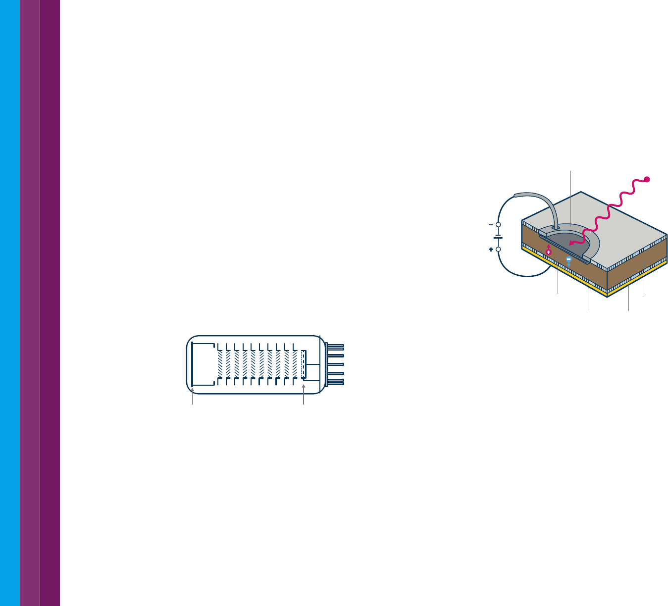
The photomultiplier tube (Figure 17) combines signal conversion with
several stages of amplification within the body of the tube. The nature
of the cathode material determines spectral sensitivity. A single PMT
yields good sensitivity over the entire UV-visible range from 200 to 900
nm. A PMT detector provides high sensitivity at low light levels. For dilute
samples, most of the light hitting the sample will pass through to the
detector. To accurately detect small differences between blank and
sample measurements, the detector must have low signal noise at these
high light intensity levels.
Figure 17. A photomultiplier tube detector.
Figure 18. A silicon photodiode detector.
Indium gallium arsenide (InGaAs) photodiode
The InGaAs detector is a specialized detector that provides excellent
performance for the visible and the NIR wavelength range. InGaAs
detectors are available in narrow band (800 to 1700 nm) and wide band
(800 to 2500 nm) options. These detectors are useful for their linear
response and sensitivity in the near infrared region.
Lead sulfide (PbS) detector
The most common NIR detector used in spectrophotometers is the PbS
detector. This detector is sensitive between 1000 to 3500 nm. In high
performance, wide wavelength range spectrophotometers, the PbS
detector is often combined with a PMT detector for UV-visible coverage.
Where high sensitivity is required at the low NIR frequencies, a PbS
detector may be combined with a narrow band InGaAs detector.
Cathode Anode
p layer
n layer Gold block
Intrinsic region
Metal contact Photon
SiO
2
V
13
Selecting the most suitable sample holder, solvent and instrument
parameters is critical for the success of your measurement.
3.1 Optical cell selection
Liquid samples are usually contained in a cuvette (which is another name
for an optical cell, or just ‘cell’). Cuvettes come in a variety of designs to suit
the application. These include:
– A ‘standard’ 10 mm pathlength optical cell (refer to Figure 15).
Holding around 3.5 mL, the cell has two optical windows, parallel to
each other. Typically, the other sides are frosted or grooved to indicate
that these sides are to be used for handling the cell. The optical
windows should be kept as clean as possible and never touched.
Avoid scratching the optical surfaces when not in use. Disposable,
limited use, cells are also available. These are manufactured from
polystyrene or polymethyl methacrylate (PMMA) and cannot be used
at elevated temperatures. Polystyrene does not transmit UV light which
allows only measurements between 340 to 800 nm to be performed.
PMMA cells can be used down to 300 nm.
– For small volumes, up to around 0.5 mL, a semi-micro cell can be used.
These have similar external dimensions to a standard cell but have a
narrow channel on the inside to reduce the required sample volume.
Ultra-micro cells are also available, holding as little as 0.5 µL. The black
masking either side of the optical window (as shown in Figure 19 and
Figure 20) prevents internal reflection within the cuvette. Care needs to
be taken to ensure the cells align to the optical height of the beam in the
UV-Vis instrument. This is referred to as the z-height. The z-height is a
measurement from the base of the cuvette to the centre of the optical
path length.
Semi or ultra-micro cells are useful when sample volumes are limited.
Figure 19. “Masked” cuvettes ensure that the
optical beam is passed through the sample.
Ensuring the z-height of the cuvette is
compatible with your UV-Vis spectrophotometer
design is critical.
Figure 20. A 10 mm pathlength,
1.4 mL volume semi-micro cell.
3. Selecting the Optimum Parameters for your UV-Vis Measurements
To measure multiple liquid samples a flow-through cell can be used.
Flow-through cells are also available in a variety of internal cell volumes and
pathlengths. The cells are usually connected to a peristaltic pump and can
be connected to an autosampler. The pump pushes the sample through
tubing connected to the cell, filling the cell for the measurement. A rinse
solution is then pushed through to clean the cell before the next sample is
pumped into the cell.
Figure 21. Flow cell, with 4 x 11 mm rectangular apertures, 10 mm pathlength.
Shown with connectors and tubing.
Most optical cells are provided with a cap or lid. The cap is designed to both
reduce accidental spillage of the sample and evaporation of the sample.
The use of a cap is strongly recommended when measuring volatile or
dangerous samples.
45mm
Z
15mm
38.5mm
Z
8.5mm
14
Cell pathlengths
The pathlength is the distance that the incident light travels through a
sample. Cuvettes are available with different pathlengths. The pathlength
you should use is dependent upon the absorbance of your sample:
– Concentrated samples with high absorbance (>3 Abs) need a short
pathlength cuvette (less than or equal to 5 mm) – or they need to be
diluted. Short pathlength cuvettes can also be used to compensate for
solvents with high absorbance.
– Dilute samples with low absorbance (<0.2 Abs) need a long pathlength
cell (up to 100 mm) which will increase the absorbance reading.
This can also help reduce the level of error.
Most UV-Vis spectrophotometer systems are provided with a cuvette
holder suitable for a standard cuvette with a 10 mm pathlength. Longer
pathlength cuvettes will require an appropriate long pathlength cell holder.
Shorter pathlength cells are available in the same dimensions as the
standard 10 mm pathlength cuvette. They will fit into the standard cell
holder supplied with the instrument. Cell spacers are also available to
securely fit a smaller pathlength cuvette into the standard cuvette holder.
Material
The optical properties of the material used in the cuvette windows needs
to be considered. For the widest wavelength range quartz glass is
preferred. As quartz glass is more expensive, optical glass or plastic
(polystyrene) can be used when measurements below 340 nm
(polystyrene) and 350 nm (optical glass) are not required. Polystyrene cells
are not suitable for use at elevated temperatures. Care also needs to be
taken when using polystyrene cells to ensure that samples/solvents will
not damage the cells. Polystyrene cells are often referred to as disposable,
or plastic cell. They are easily scratched and are designed for a single use.
Table 1 shows the transmission of common materials over the UV to NIR
wavelength range.
Table 1. Transparency windows for common cuvette materials.
Material Suitable Wavelength (nm)
Quartz 170–2700
Infrasil quartz (NIR) 220–3800
Optical glass 334–2500
Polystyrene (disposable) 340–800
Cuvette matching
Some cuvettes are sold as matched pairs and are used for most UV-Vis
and UV-Vis-NIR routine analyses. Matched pairs ensure both cuvettes
provide a similar absorbance or transmission reading when empty or
filled with water. The match code is like a batch number. It reflects the
transmission characteristics of the batch (melt) of raw material that the
cuvettes are made from.
For a pair of cuvettes to be matched they must be within the acceptable
transmission tolerance at a particular wavelength. For example,
a pair should transmit within 1.5% of each other at 200 nm. Cuvette
manufacturers specify the transmission matching tolerances at measured
wavelengths for the materials they supply.
The matching codes are only of real value when comparing new cells.
Transmission characteristics change during use because of surface
contamination or wear due to cleaning processes or mishandling.
Therefore, a brand-new cell will not necessarily match an older used cell
of the same match code.
Modern production and fusing techniques have improved flatness,
parallelism, and construction tolerances. Together with more attention to
quality assurance of raw materials, this has resulted in a virtual elimination
of the need for transmission matching in regular standard high grade
quartz cells.
0
20
40
60
80
100
0 300 500 2000 2200 2400 2600 2800 3000 3200 nm
Transparency of different cell materials
plastic
optical glass
suprasil
%T
Figure 22. Transparency of common optical cell materials.

15
Cleanliness
The oils in fingerprints are significant absorbers in the UV region.
Fingerprints left on optical surfaces can cause erroneous results.
Wipe off all fingerprints and contaminants using a clean soft cloth before
using a cell. Ensure that the cloth is free of detergents or lubricants.
Lens tissues for glasses or other uses often contain detergents or
lubricants which can affect your measurements.
Do not use an ultrasonic cleaner to clean your glass or quartz cuvettes.
Each ultrasonic bath generates ultrasonic waves at a different frequency
and if your bath operates at the resonant frequency of the cell, the cell
will break.
Fluorinated acids such as hydrofluoric acid (HF) in all concentrations
should be avoided as they will attack the quartz and glass. Strong basic
solutions (pH 9.0 and above) will also degrade the surface of the windows
and shorten the life of the cuvette.
Once a blank measurement has been made avoid cleaning the optical
windows of your cell. If cleaning is required, take a new blank measurement
before continuing your measurements.
Other cuvette handling tips
Some simple steps can be taken to ensure the longevity of cuvettes:
– Consider removing samples from cuvettes immediately after use.
This will prevent your sample from drying out and sticking to your
cuvette. Take particular care with proteins and strong dyes as they are
known to adhere to the inside surfaces of the cuvette. Remove these
sample from the cell immediately after testing and rinse thoroughly
with your solvent between samples.
– If measuring the same sample over a long period of time, keep the
sample capped and at an appropriate temperature to minimize
evaporation. Some samples may require continuous stirring.
– Clean all cuvettes thoroughly at the end of each day and either:
• store them in a suitable container after drying or,
• store the cuvettes wet in a mildly acidic solution (1% nitric acid or
hydrochloric acid), in an acid resistant beaker. Only store one cuvette
per beaker to avoid chipping the cuvette. Always rinse with copious
amounts of water immediately before use again.
Measuring mobile phone displays
Designers of the screens used on mobile phones, tablets, laptops and
televisions strive to make them as thin as possible. Reducing the thickness
by even tens of microns can make a significant difference to reducing the
overall size of a device. These screens use light emitting diodes (LED) and
liquid crystal displays (LCD) to control the colors of the display, with a back
light reflector to provide the illumination. Back light reflectors are usually
made from a transparent polymer material with a reflector film applied to one
surface. They look like a sheet of plastic mirror. Measuring the reflectance
and transmission of the back light reflector is a critical part of developing
a new design. It is also an important quality control measurement during
their manufacture. The reflectance and transmission of a back light reflector
is measured with a UV-Vis spectrophotometer. The back light reflector
is mounted vertically in the sample compartment and rotated around its
central axis, allowing the measurement of its reflectance and transmission at
different angles of incidence.
Here are the details of the measurement

16
3.3 Stirring your sample
Stirring of a thermostatted sample is important and ensures that both
solution and temperature homogeneity is always maintained. Stirring is
particularly important for viscous samples or to ensure consistently mixed
solutions when studying a chemical reaction within the cuvette.
The effectiveness of stirring to achieve thermal (and chemical) homogeneity
is strongly dependent upon the sample, solvent, and viscosity of the
solution. It is important to note that viscosity changes with temperature
and this may influence stirring efficiency, and the measurements, when the
temperature is ramped over time.
To stir solutions a magnetic stirring bead or star, is placed at the bottom of
the sample cuvette. Specially designed cuvettes with a recessed base are
available. This circular recess contains the stirring bead and increases the
stirring efficiency.
Care should be taken when developing the analytical method to ensure that
the stir speed is suitable for the solutions. If the stirring speed is too slow
the sample may not mix properly. If the speed is too high, air bubbles can be
trapped in the sample, causing erroneous results.
It is recommend that test experiments are conducted on all samples to
find the optimum stir speed for your experiment. When measuring liquid
of similar viscosities to water, stir speeds of 800 to 900 rpm generally
yield the best temperature uniformity within standard cuvettes. Lower the
stirring speed for higher viscosity samples and increase the speed for lower
viscosity samples.
3.4 Measurements at low temperatures
When measuring samples at lower than ambient temperature,
condensation may form on the outside of cuvettes. This can interfere with
the measurement. Condensation can be prevented by purging the sample
compartment of the UV-Vis spectrophotometer with a clean dry gas.
Some systems have specialized purging ports to allow entry of the gas
into the sample compartment without introducing any light. An alternative
for measuring cool samples is to use a fiber optic dip probe. A fiber optic
coupler is inserted into the sample compartment and directs the light from
the system through a fiber optic cable, through a dip probe directly inserted
in the sample (as shown in Figure 6). The light is then directed back to the
detector through a return fibre optic cable. For high throughput sampling
this technique may be preferred when multiple samples are being measured
at a fixed temperature.
3.2 Thermostatting your samples
Many samples can be measured at room temperature, but there are some
circumstances that require samples to be heated or cooled. These include:
– Cooling of volatile samples to reduce evaporation
– Heating of viscous samples to improve sample handling or
homogeneity
– Samples that are sensitive to chemical change when heated
– Observing changes in samples as they are heated or cooled.
UV-Vis spectrophotometers can be fitted with accessories to control the
temperature of samples. The simplest temperature control systems are
suited for fixed temperature measurements. Typically, these systems use
a thermostatted water circulator to pass heated water through a manifold
holding the sample cuvette. For more precise temperature control a Peltier
heater/cooler is embedded into the sample manifold. Peltier devices allow
greater temperature control and allow temperature ramping measurements
to be undertaken. An air-cooled Pelter system requires less maintenance
than a water-cooled Peltier system or a water circulation system. Water
circulating systems need periodic maintenance, including checking water
hoses for leaks and topping up of the coolant solution. Another advantage
to the Peltier system is their quiet operation as no pumping of coolant
solution is needed.
When using either temperature control options your system should provide
you with temperature monitoring. As a minimum the system should report
the temperature of the sample manifold. This is particularly important
for an external water heated system. Heat losses from the temperature
set on the water bath may occur between the circulator and the sample
manifold. For Peltier controlled systems the sample manifold temperature
is monitored providing feedback to keep the temperature stable.
When temperature control is critical, taking measurements of the sample
directly provides a more accurate reading. Small temperature probes
are inserted into the sample, inside the cuvette. The probes are carefully
positioned out of the light path. When monitoring the temperature directly
in the samples your UV-Vis control software should allow you to record the
temperature of each cuvette at each measurement.

17
3.5 Solvent transparency
When measuring liquid samples, or dissolving solid samples for UV analysis,
solvent transparency needs to be considered. Solvents are selected based
on sample solubility, stability, pH requirements, and the UV-visible cut-off
wavelength. For aqueous soluble compounds water is an excellent choice
as it allows measurement throughout the UV wavelengths. The use of
organic solvents does limit the effective useable UV wavelength range.
When selecting a solvent, consider both the solubility of your sample in the
solvent as well as the transparency of the solvent in the wavelength range
of interest (as shown in Figure 23).
Figure 23. Transparency ranges of common solvents in the UV region. While water is
preferred for UV analysis, another solvent may be required if your sample is not soluble
in water.
Useful transparency ranges of common solvents in the UV region
Acetone
Tetrachloroethylene
M-Xylene
Toluene
Benzene
N.N-Dimethylformamide
Ethyl Propionate
Carbon Tetrachloride
Ethyl Formate
Butyl Acetate
Ethyl Acetate
Methyl Formate
Chloroform
1.2-Dichloromethane
Dichloromethane
Glycerol
Dioxane
Hexane
Iso-Octane
2.2.4-Trimethylpentane
Acetonitrile
Cyclohexane
Methanol
Ethanol
Methyl Cyclohexane
Iso-Propyl Alcohol
Water
190 nm 210 230 250 270 290 310 330 350 370
One molecule with a very important role
The protoporphyrin molecule forms the basis of life for many plants and
animals. The body stabilizes the molecule by inserting zinc atoms into its
ring structure in immature red blood cells (reticulocytes). As the reticulocytes
mature, the zinc is replaced by iron. The mature red cells then combine with
globin-forming hemoglobin, the oxygen carrying molecule in the blood of
many animals and humans.
In plants, magnesium is inserted into the protoporphyrin ring to form
chlorophyll, one of the primary compounds needed for photosynthesis.
Protoporphyrin absorbs UV light – no surprise there, given its importance in
photosynthesis. The molecule also fluoresces. These characteristics make
protoporphyrin ideal for analysis with spectroscopy. In fact, it forms the basis
of the primary screening test for childhood lead poisoning (1).
1. Clinical and Laboratory Standards Institute, Erythrocyte Protoporphyrin Testing; Approved Guideline,
Volume 16, No. 8, 1996
18
2
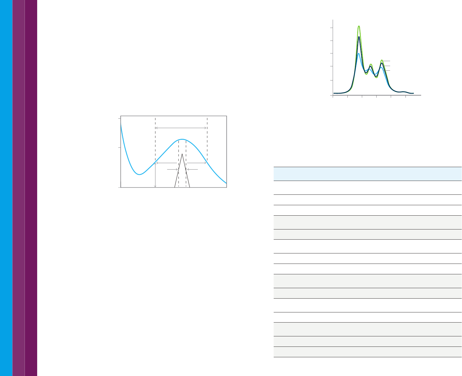
0
270 310 350 390
Molecular band width
Spectral
Band Width
½ peak height
A
B
Wavelength (nm)
Absorbance (A)
1
As a guideline the SBW should be set at one tenth of the molecular band
width of the sample (examples in Table 2).
3.6 Optimum spectral band width
When measuring a sample consideration should be given to the
measurement resolution required. Most solid or liquid samples analyzed
by UV-Vis spectroscopy have naturally broad peaks, in the order of 20 nm
or more from side to side. It is good practice to use an instrument with a
spectral bandwidth (SBW) setting approximately one tenth of the natural
bandwidth of the analyte. The SBW of the instrument is defined as the width
of the band of light at one-half the peak maximum (as shown in Figure 24),
and sometimes referred to as full width at half maximum (FWHM).
The SBW of the UV-Vis spectrophotometer is related to the physical slit
width of the monochromator design.
Figure 24. Spectrum A shows a peak maximum close to 345 nm. The spectral bandwidth
is shown. The spectral slit width of the UV-Vis spectrophotometer will always be narrower
than the required spectral band width.
Depending on the spectrophotometer design, the physical slit can be either
a fixed or variable width. For most mid-range UV-Vis spectrophotometers,
a fixed spectral bandwidth of 1.5 nm is common and sufficient for resolving
the peaks of most liquid and solid samples. Using a larger SBW allows more
light through the sample and can give better quality data and less noise, but
will not resolve narrow or close together sample peaks. Using a smaller SBW
will provide better resolving power but can result in increased data collection
times to achieve the same data quality due to less light reaching the sample.
High performance or research grade spectrophotometer systems are more
frequently designed to allow the user to select the slit width, and thereby
adjust the resolution of the system. This is useful when measuring more
challenging samples. The slit width can be maximized to allow greater light
throughput in highly absorbent samples where high resolution of the peak is
not necessary. Greater light throughput to the detector allows better method
repeatability, accuracy, and precision of the results. When high resolution is
required the slit width can be reduced (as shown in Figures 25 and 26).
Abs
440.0
430.0 450.0 460.0 470.0 480.0 nm
4.0 nm
2.0 nm
0.2 nm
3.000
2.400
1.800
1.200
0.600
0.000
Observed Absorbance
Figure 25. Overlaid scans, each measured using a different instrument slit.
As the slit widens the signal-to-noise ratio improves, however resolution decreases.
Table 2. Recommended spectral band width settings for common UV-Vis
measurement types.
Representative Compound Peak nm Band Width nm Optimum (SBW) nm
Amino Acids
tryptophan
279
45
4.5
tyrosine 275, 195 40, 10 4.0, 1.0
phenylalanine 258 2.2 0.2
Nucleotides
adenosine
260
28
2.8
thymine 265 30 3
Proteins
cytochrome c, oxidized
410
25
2.5
rhodopsin 500, 278 ~90, 25 9, 2.5
ribonuclease 278 20 2
Pigments and Dyes
ß-carotene
480 35
3.5
chlorophyll a 660 20 2
Coenzymes
Nicotinamide adenine dinucleotide
260
35
3.5
NADH 340, 260 50, 25 5, 2.5
Simple Organics
benzene, vapor
253
<<0.1
<<0.01
benzene, solution 253 2 0.2
anthracene 375 3 0.3
19
When optimizing spectral resolution, the data interval of the collection
also needs to be considered. A minimum of three data points across the
peak should be collected. While a smaller data interval can provide better
resolution there will be a trade-off between how long the data takes to
collect and the data interval.
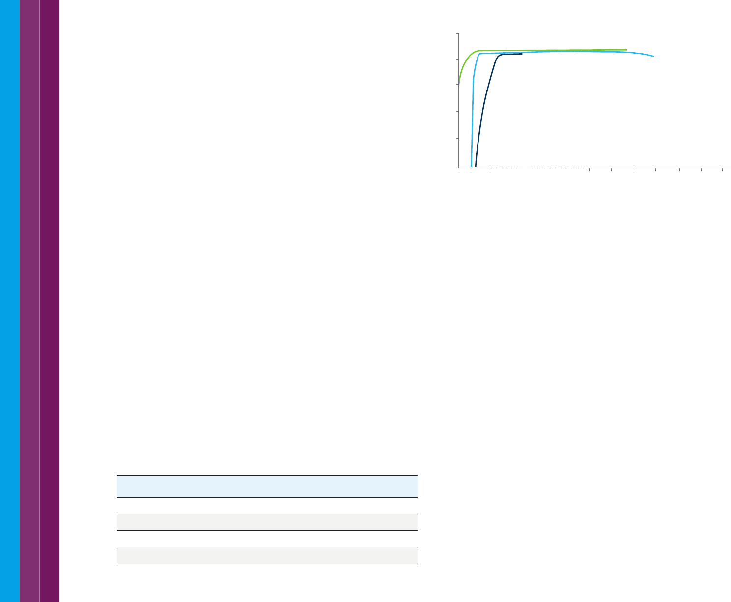
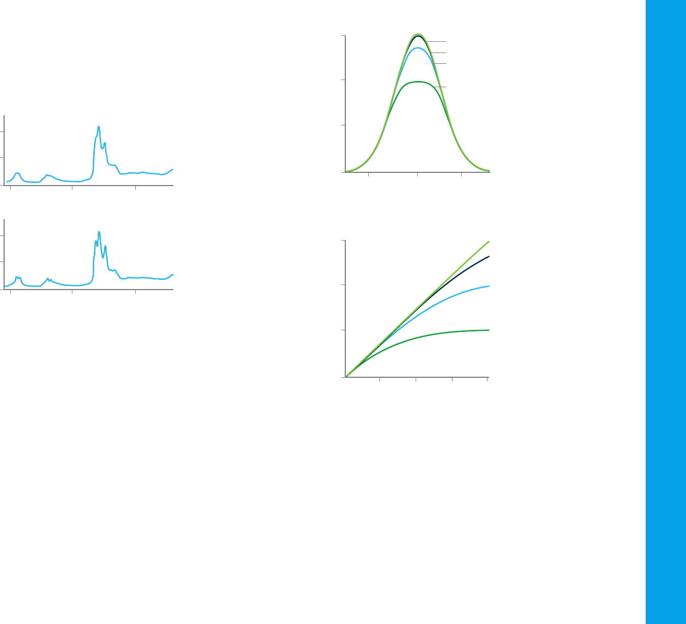
Figure 27. The maximum absorbance of peaks will be lower and the curve will flatten as
stray light in the instrument increases.
Figure 28. A UV-Vis system with poor stray light performance will show deviations from
Beer’s Law. This makes concentration calculations unreliable.
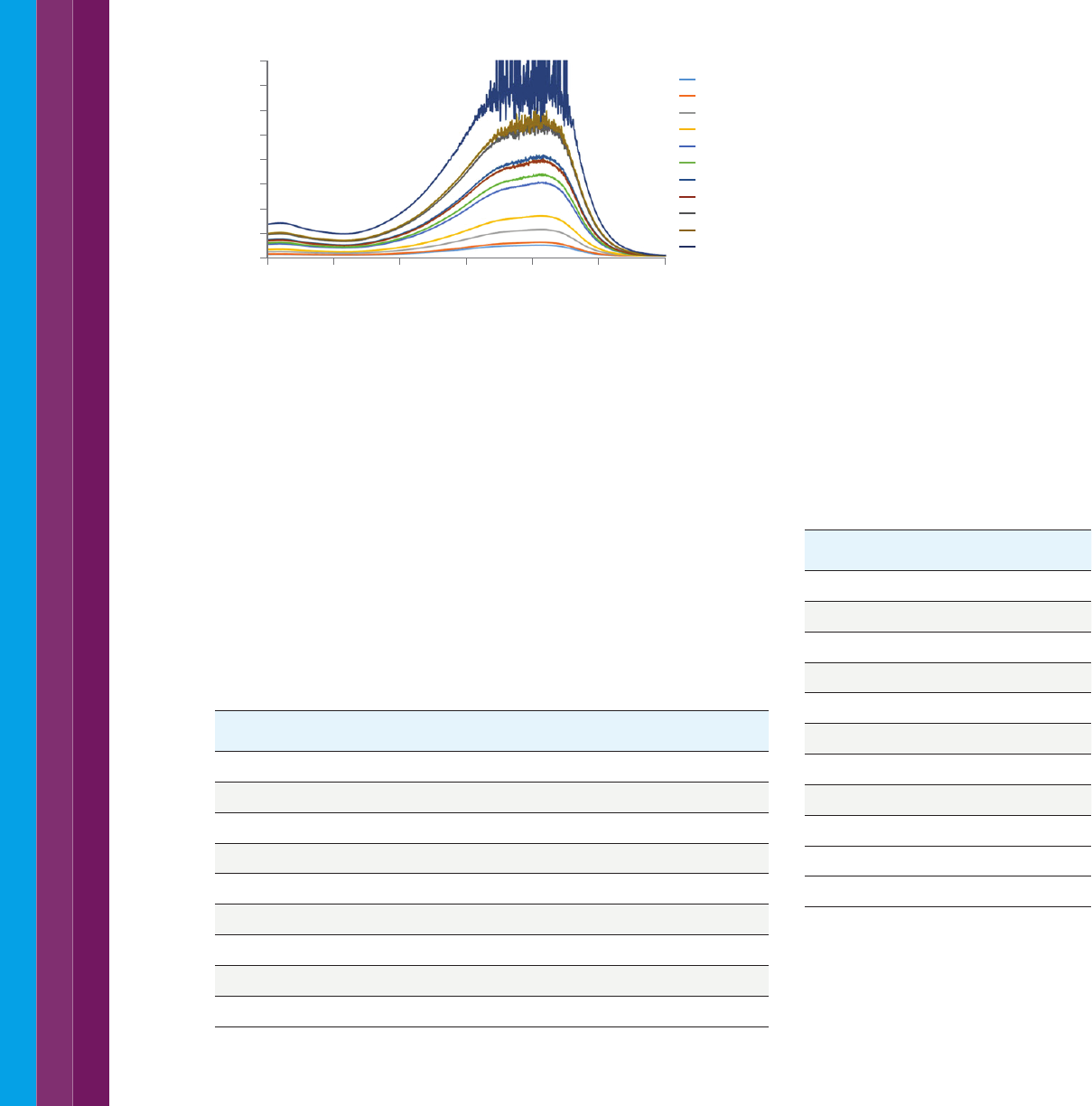
3.8 The linear range of a UV-Vis instrument
Both instrument design and the measurement parameters used will
determine the maximum absorbance an instrument will be able to measure
at a specific wavelength. At high absorbance very little light is reaching the
detector which decreases the signal to noise ratio (refer to the characteristic
'fringe' on the spectrum in Figure 29). Understanding the limits of your
system allows you to avoid measuring samples or performing calibrations
which are outside the capabilities of your instrument. For liquid samples,
diluting the sample is a way to get the measurement into the linear range of
the instrument. Alternatively, you can use a short pathlength cuvette.
Figure 26. These two scans demonstrate the effect on resolution of varying the SBW.
At a SBW of 15 nm (upper graph), little structural detail is observed in the spectrum.
At a SBW of 3 nm (lower graph), the peaks are much more defined.
3.7 Stray light
Stray light or stray radiant energy (SRE) is defined as the percentage of
radiation reaching the detector whose wavelengths are outside the selected
spectral band. It is caused by poor instrument design (light leaking into the
instrument from the laboratory lights or daylight through windows, or the
light not being well separated by the monochromator) or from damage to
the instrument. Most systems are provided with instrument performance
checks that identify stray light issues. This is done using a test solution.
The solutions used to test stray light levels are non-transmitting at the
indicated wavelengths (they do transmit at other wavelengths), so the
observed transmittance is due only to stray light.
Stray light causes decreased absorbance readings and changes the
observed peak shape (as shown in Figure 27). As a result, stray light causes
deviation from the Beer-Lambert law (as shown in Figure 28), making
concentration measurements unreliable. The stray light performance
of a UV-Vis instrument also determines the maximum absorbance the
instrument can measure.
1.0 2.0 3.0 4.0
10% Stray Light
Beer’s Law
1% Stray Light
0.1% Stray Light
2.0
1.0
0.0
3.0
Concentration
Observed Absorbance
0-10 10
2.0
1.0
0.0
3.0
Relative Wavelength (nm)
Absorbance
True (Gaussian)
0.01% SRE
0.1% SRE
1% SRE
1200.00 1600.00 2000.00 nm
2.0000
1.0000
Abs
0.0000
1200.00 1600.00 2000.00 nm
2.0000
1.0000
Abs
0.0000
20
Figure 29. As sample absorbance increases progressively less light reaches the detector.
This increases noise in the results and an obvious spiky signal will be observed in
scanning mode.
3.9 Other useful information
Absorbance (A or Abs) is frequently measured in UV-Vis spectroscopy
due to the linear relationship between concentration and absorbance as
described by the Beer-Lambert law. For other applications, the percentage
of light transmitted or absorbed may be more meaningful. When comparing
the optical properties of a material for example it may be more useful to
compare the percent transmission or absorbance difference.
Most UV-Vis spectrophotometer systems will enable you to convert your
collected data between the commonly used parameters. The relationship
between these parameters is shown in Table 3.
3.10 Wavelength or inverse centimeters
Most UV-Vis measurements are reported against wavelengths measured
in nanometres (1×10
−9
m). in some older literature the reciprocal length
or wavenumber (cm
-1
) is used. Wavenumber is often used in infrared (IR)
spectroscopy measurements. Using a wavenumber scale is useful as
it conveys the change in energy levels of the incident radiation. A lower
wavelength gives a larger wavenumber and a higher energy (as shown in
Table 4).
The use of wavenumber for infrared spectroscopy also allows for easier
visualization of spectral differences as the wavelength gets progressively
shorter.
For UV-Vis spectroscopy, wavelength is generally preferred as a convenient
way to visualize the displayed spectrum over a spectral range.
Most UV-Vis spectrophotometer systems will enable you to collect a
spectrum in either wavelength or wavenumber.
Table 3. The relationship between percent transmission and absorbance can be hard to
visualize. The table shows that a sample measuring 7 Abs transmits just 0.00001% of the
light through the samples.
%T T Abs %A LogA
100 1.0 0 0 –
50 0.5 0.3 50 -0.52
10 0.1 1 90 0
1 0.01 2 99 0.3
0.1 0.001 3 99.9 0.48
0.01 0.0001 4 99.99 0.60
0.001 0.00001 5 99.999 0.70
0.0001 0.000001 6 99.9999 0.78
0.00001 0.0000001 7 99.99999 0.85
Table 4. Conversion between wavelength (nm)
and wavenumber (cm
-1
).
λ nm cm
-1
3300 3030
3000 3300
2500 4000
2000 5000
1500 6666
1000 10000
800 12500
600 16667
400 25000
200 50000
175 57143
400 500 600 700 800 900 1000
3.5
3.0
2.5
2.0
1.5
1.0
0.5
4.0
0.0
2 mgml
3 mgml
5 mgml
7 mgml
10 mgml
12 mgml
14 mgml
16 mgml
18 mgml
21 mgml
25 mgml
21
4.1 Identification—spectra and structure
UV-visible spectra generally show only a few broad absorbance peaks.
Compared with techniques such as infrared spectroscopy, which produces
many narrow peaks, UV-visible spectroscopy provides a limited amount of
qualitative information. With only a few broad peaks, it’s difficult to identify
a compound based on a characteristic spectrum.
Most absorption by organic compounds results from the presence of π
(that is, unsaturated) bonds. A chromophore is a molecular group usually
containing a π bond. When inserted into a saturated hydrocarbon (which
exhibits no UV-visible absorbance spectrum), it produces a compound with
absorption between 185 and 1000 nm. Table 5 lists some chromophores
and the wavelengths of their absorbance maxima.
Table 5. Selected chromophores and the wavelength of their absorbance maxima.
Chromophore Formula Example λmax (nm)
Carbonyl (ketone) RR’C=O Acetone 271
Carbonyl (aldehyde) RHC=O Acetaldehyde 293
Carboxyl RCOOH Acetic acid 204
Amide RCONH
2
Acetamide 208
Ethylene RCH=CHR Ethylene 193
Acetylene RC=CR Acetylene 173
Nitrile RC=N Acetonitrile <160
Nitro RNO
2
Nitromethane 271
The presence of an absorbance band at a particular wavelength often is a
good indicator of the presence of a chromophore. However, the wavelength
position of the absorbance maximum is not fixed but depends partially on
the molecular environment of the chromophore and on the solvent in which
the sample is dissolved. Other parameters, such as pH and temperature,
also may cause changes in both the intensity and the wavelength of the
absorbance maxima.
4. Overview of Common UV-Vis Applications
Conjugating the double bond with additional double bonds increases
both the intensity and the wavelength of the absorption band. For some
molecular systems, such as conjugated hydrocarbons or carotenoids,
the relationship between intensity and wavelength has been systematically
investigated. Transition metal ions also have electronic energy levels that
cause absorption of 400–700 nm in the visible region.
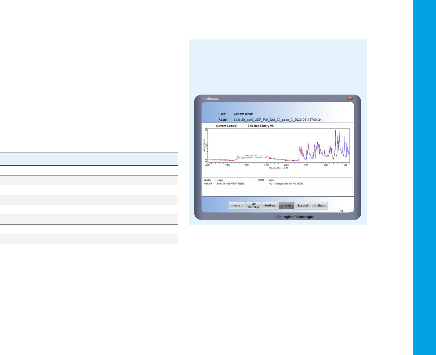
FTIR spectra can be used to identify compounds
Fourier Transform Infrared (FTIR) spectra contain a lot more detail than
UV-Vis spectra. A spectrum like the one shown here (red) can be matched
against a library of FTIR spectra to identify the compound. In this case,
a pharmaceutical—salicylic acid (the library spectrum of which is shown
in blue).
22
4.3 Quantifying a molecule
Beer’s law
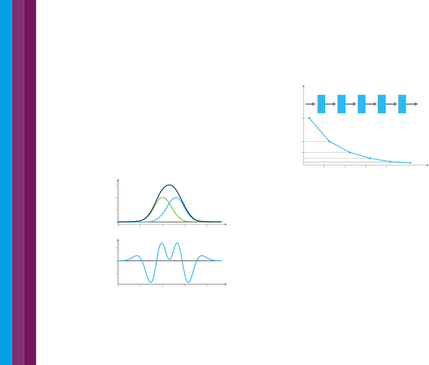
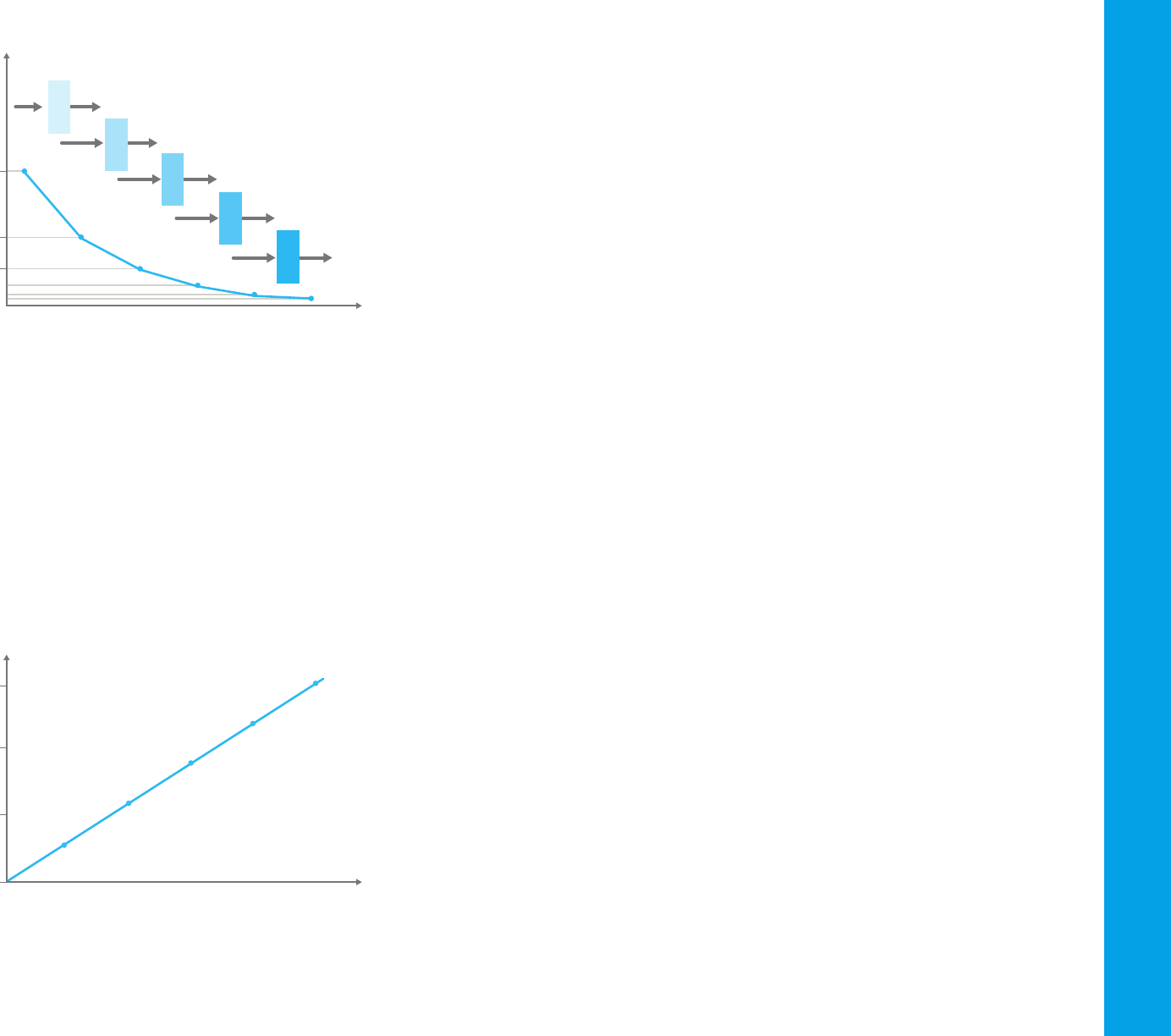
If 100 photons of light enter a cuvette and only 50 emerge from the other
side, the transmittance is 0.5, or 50 %. If these 50 photons then pass
through an identical cuvette, only 25 will emerge, and so forth. Figure 31
shows the plot of transmittance against path length of the cuvette.
4.2 Confirmation of identity
Although UV-visible spectra do not enable absolute identification of an
unknown, they are used to confirm the identity of a substance through
comparison of the measured spectrum with a reference spectrum.
Where spectra are highly similar, derivative spectra may be used.
As shown in Figure 30, the number of bands increases with higher orders
of derivatives. These complex derivative spectra can be useful in qualitative
analysis, either for characterizing materials or for identification purposes.
For example, the absorbance spectrum of the steroid testosterone shows
a single, broad, featureless band centered at around 330 nm, whereas the
second derivative shows six distinct peaks. The resolution enhancement
effect may be of use as well in identifying an unknown. Figure 30 shows
a computer simulation. When two Gaussian bands with a 40 nm natural
spectral bandwidth (NBW), separated by 30 nm, are added in absorbance
mode, a single band with a maximum midway between the two component
bands results. The two components are not resolved. Using a fourth
derivative of the spectrum, these two bands are clearly visible, with maxima
centered close to the λ
max
of the component bands.
Figure 30. Resolution enhancement using derivative analysis. The original, overlapping
peaks resulted in a single, broad peak. By taking the 4th derivative of the spectrum,
a spectrum with much higher resolution of the peaks results.
Figure 31. Transmittance and path length—the Bouguer-Lambert law.
Lambert (1760) generally is credited with the first mathematical expression
of this effect, although it now appears that Bouguer first stated it in 1729.
The equation is:
T= I/I
o
= e
–kb
Where:
– I
o
is the incident intensity
– I is the transmitted intensity
– e is the base of natural logarithms
– k is a constant
– b is the path length (usually in centimeters).
Beer’s law is identical to Bouguer’s law, except that it is stated in terms of
concentration. The amount of light absorbed is proportional to the number
of absorbing molecules through which the light passes. Figure 32 shows a
plot of transmittance against concentration.
400
500 600
400
500 600
1.5
0.0
0.5
1.0
0.0
-5.0x10
-6
5.0x10
-6
4th derivative
Wavelength (nm)
Absorbance (A)
1.0 2.0 3.0 4.0
100%
50%
25%
Transmission
Path length
100% 50% 25% 12.5% 6.75% 3.125%
I
0
I
1
I
2
I
3
I
4
I
5
23
Figure 32. Transmittance and concentration—Beer’s law
Combining the two laws gives the Beer-Bouguer-Lambert law:
T= I/I
o
= e
–kbc
Where c is the concentration of the absorbing species (usually expressed in
grams per liter or milligrams per liter). This equation can be transformed into
a linear expression by taking the logarithm and is usually expressed in the
decadic form:
A = –logT = –log(I ⁄ I
o
) = log(I
o
⁄ I) = ∑bc
Where A is the absorbance and ∑ is the molar absorption or extinction
coefficient. This expression is commonly known as Beer’s law. Figure 33
shows a plot of absorbance against concentration.
The extinction coefficient (ε) is characteristic of a given substance under
a precisely defined set of conditions, such as wavelength, solvent, and
temperature. In practice, the measured extinction coefficient also depends
partially on the characteristics of the instrument used. For these reasons,
predetermined values for the extinction coefficient usually are not used
for quantitative analysis. Instead, a calibration or working curve for the
substance to be analyzed is constructed using one or more standard
solutions with known concentrations of the analyte.
For electronic transitions, the difference in energy between ground and
excited states is relatively large. Therefore, at room temperature, it is highly
likely that all molecules are in the electronic ground state. Absorption and
return to ground state are fast processes, and equilibrium is reached very
quickly. Thus, absorption of UV-visible light is quantitatively highly accurate.
The simple linear relationship between absorbance and concentration and
the relative ease of measurement of UV-visible light have made UV-visible
spectroscopy the basis for thousands of quantitative analytical methods.
Assuming Beer’s law is obeyed for the zero-order spectrum, a similar linear
relationship exists between concentration and amplitude for all orders of
derivative spectra:
Zero order: A = εbc
First derivative: dA/dλ = (dε/dλ)bc
nth derivative: d
n
A/dλ’ = (d
n
ε/ dλ’)bc
at λ, where A is absorbance, ε is the extinction coefficient, b is the sample
path length, and c is the sample concentration.
For single-component quantification, the selection of wavelengths is
more difficult with derivative spectra than with absorbance spectra since
both positive and negative peaks are present. The even-order derivatives
have a peak maximum or minimum at the same λmax as the absorbance
spectrum, but for the odd-order derivatives, this wavelength is a zero-
crossing point. Taking the difference between the highest maximum and
the lowest minimum gives the best signal to noise (S/N) but may result in
increased sensitivity to interference from other components.
For accurate results, the sample to be analyzed must contain only the
absorbing component for which the calibration has been performed.
If the sample is a solution, a pure sample of the solvent should be used as
a blank. It may be possible to correct for an interfering component with a
second wavelength.
100%
50%
25%
Transmission
Concentration
100% 50%
25%
12.5%
6.75%
3.125%
I
0
I
1
I
2
I
3
I
4
I
5
100%
100%
100%
100%
C
2C
3C
4C
5C
0.5
0.0
1.5
1.0
Absorbance (A)
Concentration
Figure 33. The Beer–Bouguer-Lambert law describes a linear relationship between
absorbance of incident light and the concentration of the molecule.
24
4.4 Kinetics
Analysis of reaction kinetics is fundamental for understanding how
reactions occur in chemistry and biochemistry. UV-Vis spectrophotometry
is an ideal technique for this application as the sample is not destroyed.
It can be used when the change in reactant or products produces a change
in absorbance at a specific wavelength over time. With a fast scanning
UV-Vis system, multiple scans can be taken during the reaction to allow the
reaction to be visualised and aid in the selection of wavelengths selected
for the rate calculation.
Single point kinetics
Single point kinetics analysis is the simplest method of determining a
reaction rate. A single wavelength is selected, usually the maximum
absorbance of the analyte of interest, and, after initiating the reaction, the
absorbance is continuously monitored at that wavelength. This results in a
plot of absorbance versus time, as shown for four samples in Figure 34.
Monitoring the change in absorbance over time allows you to study a
reaction – when the absorbance stops changing, this is usually an indication
that the reaction is complete. Figure 34 shows four different samples over
30 minutes.
The advantage of a single point measurement is that for fast reactions near
continuous data can be collected as the system does not need to move to
another wavelength during measurement. The data collection speed of the
instrument and the signal averaging time is the limiting factor in the amount
of data that can be collected.
Multiple wavelengths can also be monitored for kinetics measurements.
This may provide you with an insight into the creation of a reaction product
at one wavelength and depletion at another.
Concentration measurements
One of the most common applications for the UV-Vis spectrophotometer is
for simple quantification of concentration. Coupled with a fiber optic dip probe
accessory, a UV-vis spectrophotometer can be used to take measurements
directly in the sample container, without the need to decant to a cuvette.
Find out more.
25
Figure 34. Monitoring the change in absorbance over time allows you to study a reaction
– when the absorbance stops changing, this is usually an indication that the reaction is
complete. This graph shows four different samples over 30 minutes.
Scanning kinetics
Scanning a wavelength range over time can provide additional information
when performing kinetics measurements. Apart from providing a visual
impression of the reaction as it occurs (as shown in Figure 34), this
measurement allows the flexibility to select any number of wavelengths
over the scan range to perform a reaction rate calculation. This could
include analysing the consumption of reactants or the production of
reaction products as the reaction progresses. When performing scanning
kinetics it is important to ensure that the UV-Vis system can rapidly scan
the wavelength range selected. Slower scanning will limit the amount of
data collected at any wavelength during the reaction.
Rapid-mix kinetics
To monitor the reaction rate or two rapidly reacting solutions may require
the use of a specialised rapid-mix or stopped flow accessory. When fitted to
a UV-Vis spectrophotometer, these accessories provide accurate delivery of
two or more solutions to a flow cell inside the UV-Vis, where mixing occurs.
The stopped flow accessory triggers the UV-Vis system to start the analysis
as soon as the solutions are mixed in the flow cell. Options include the ability
to change the mixing ratio of the solutions and the ability to thermostat both
the flow cell and reactants. As the collection speed is critical it is important
to select a UV-Vis system with a data collection rate that is fast enough to
collect a series of data points within the reaction time frame. The example
shown in Figure 36 shows a reaction monitored over three seconds.
0
15
20105 25 30
2.0
1.0
3.0
Time (mins)
Absorbance (A)
0.12
0.13
0.14
0.15
1 2 30
Time (sec)
Abs
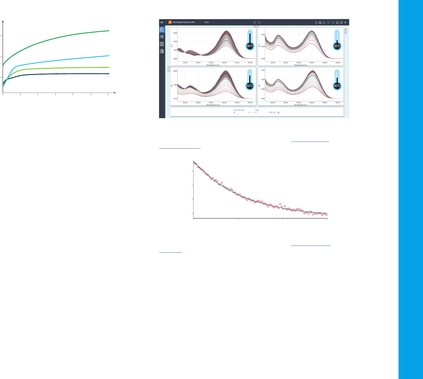
Figure 35. Scanning kinetics: UV-vis spectrophotometers provide powerful insight into
reaction chemistry. The impact of temperature on chemical reactions can be observed
quickly and easily with rapid scanning at multiple temperatures. Here’s a scanning
kinetics experiment.
Figure 36. Using a modern UV-Vis spectrometer and a rapid mix accessory allows
measurement of reactions over the time span of mere seconds. Here’s an example
experiment.
26
4.5 Color measurement
Color is an important property of a material. The color of matter is related
to its absorptivity or reflectivity of specific wavelengths of light. The human
eye sees the complementary color to that which is absorbed, as shown in
Figure 37 and Figure 38.
Kinetics measurement considerations
The rate of a reaction can be influenced by temperature. For this reason,
it can be important to maintain a sample at a constant temperature,
for example, body temperature (37 degrees) is usually selected for
biological reactions. Peltier cooled/heated cuvettes or water thermostatted
cuvette holders are commonly used with a UV-Vis system for this purpose.
These accessories can either keep a sample at a specific temperature or
change (ramp) the temperature over time.
The temperature accuracy and reproducibility need to be considered
carefully, as slight variations in temperature or the temperature change rate
can have a significant impact on results. Some systems provide the ability
to measure the temperature of the samples from directly within the
cuvette (rather than just measuring the temperature of the cuvette holder).
When combined with feedback to the temperature control system, this
typically provides better temperature control of the sample. Temperature
probes in the sample can also be used to record the sample temperature
along with absorbance data.
Consistent and reproducible stirring of samples is also important. When
measuring reactions at room temperature, stirring ensures the reactants
are mixed consistently during the reaction. For thermostatted samples,
stirring ensures there is no temperature gradient across the sample.
When measuring complex systems, the use of a fiber optic probe may be
preferred. A fiber optic cable allows the light from the spectrophotometer
to be directed to a sample outside the UV-Vis spectrophotometer. This can
be useful for measurements of a flowing manufacturing process, where the
sample is at extremes of temperature or pressure, or when the sample is
physically unable to fit inside the spectrophotometer sample compartment.
A demonstration of kinetics experiments can be viewed on the
agilent.com site.
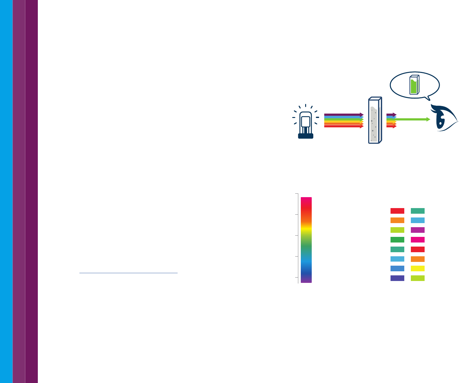
Figure 37. Transmission and color. Much like the spectrophotometer detector, our eye
sees the light transmitted through or bounced off a surface. We perceive this as the color
of the object.
Figure 38. The wavelengths of light associated with different colors (left) and the color
of absorbed light and the associated complementary color the human eye sees (right).
red blue-green
orange greenish blue
yellow green purple
green red-purple
bluish green red
greenish blue orange
blue yellow
violet yellow-green
Absorbed color Complementary Color
650-780
595-650
560-595
500-560
490-500
480-490
435-480
380-435
Wavelength (nm)
800
700
600
500
400
Light source Absorbance
by sample
Detector
(eye)
27
In practice, both the generation and sensation of color are highly complex
and depend on many factors, including:
– The spectrum of the light falling on the object (consider the difference
in colors seen at sunset versus the middle of the day)
– The surface structure of a solid material (the scales of a fish or the
feathers of a bird are two examples where the physical structure of the
surface changes the color seen)
– The viewing angle (some surfaces, such as pearlescent paints, change
color as the angle you are viewing the surface at changes)
Specialized color measurement systems, such as the CIE L*a*b, and
instrumentation to measure color have been developed. When equipped
with the appropriate software, most spectrophotometers can be used to
measure color. Color perception is also influenced by the surface and its
ability to produce specular (mirror like) reflectance or diffuse (scattering)
reflectance. Because of these factors, color measurement may require
special accessories which allow specular and diffuse reflectance to be
collected and observed at different viewing angles.
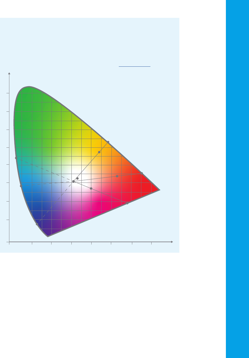
A color measuring instrument will take the UV-Vis spectrum of a sample
and convert it into three color coordinates that locate the color in three-
dimensional color space (refer to the image in the side panel). The three
coordinates define the sample’s lightness, chroma and hue. Lightness is
a measure of how light or dark a color is. Chroma is a measure of ‘color
purity’, and hue is the dominant spectral color -similar to the colors seen in
a rainbow.
As well as being used for color matching measurements e.g. measuring
paint colors on a manufactured item, a UV-Vis spectrophotometer can also
be used to measure a change of color in a solution. UV-Vis measurements
are often used for this purpose to assess whether a reaction has taken place
or is proceeding, without visual inspection. Color based assays are one of
the widest used applications for UV-Vis spectrophotometry.
Measuring color
UV-Vis spectrophotometers are used to measure the color of liquids and
solids. By measuring the visible light that is transmitted through a solution or
material, or the light that is reflected from a surface, the color of the liquid or
material can be calculated. A series of three numbers is used to indicate the
coordinates of the measured color in a ‘color space’. Find out more.
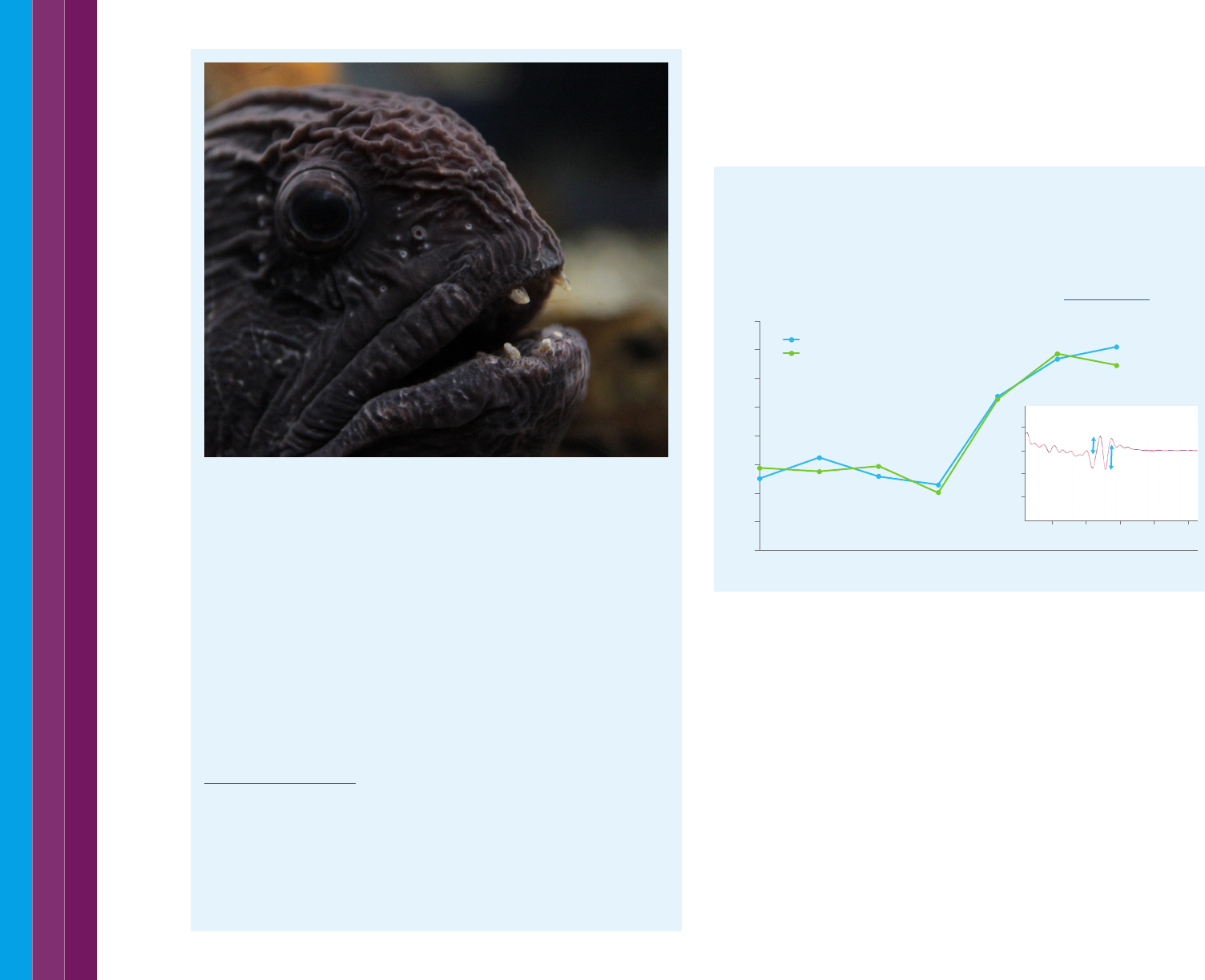
How black is black? Ask a deep-sea fish
Researchers have found many deep-sea fishes with ultra-black skin – that
which reflects less than 0.5% of incident light. The fish use their ultra-black
skin to remain undetected while they hunt for prey. In the deep, dark sea
creatures often use the glow of bioluminescence to help them see their prey
or their attackers. Ultra-black skin absorbs the light of bioluminescence,
allowing the fish to remain out of sight.
Researchers from the Smithsonian National Museum of Natural History
and Duke University measured the reflection of the fish skin, which absorbs
99.5% of light. This compares to the superb bird of paradise (99.95%) and the
blackest material ever made - Vantablack, which absorbs 99.96%.
The mechanism used by the fish to absorb light could have applications in
solar panels, telescopes, camera and camouflage systems.
Read the research results
28
4.6 Structural changes of compounds
UV-visible spectroscopy can be used to determine many physicochemical
characteristics of compounds. These measurements can identify a
compound or determine specific properties.
Conformational studies
UV-Vis spectroscopy can provide insight into protein structure. UV-Vis
spectrophotometry is also non-destructive, so precious samples will not be
sacrificed. This makes UV-Vis an ideal for use prior to analysis by techniques
such as LC or mass spectroscopy. This is demonstrated in the comparison
of an innovator and biosimilar monoclonal antibody pair. Find out more.
4.7 Protein and nucleic acid melting temperature
UV-Vis spectroscopy is commonly used in the life sciences for analysis
of biomolecules such as proteins and nucleic acids. The absorbance
spectra of proteins is due to the absorbance of the aromatic amino acids
tryptophan, tyrosine, and phenylalanine. Multicomponent analysis can be
used to determine how many of each aromatic amino acid are present in
an intact protein.
A protein at room temperature has a specific tertiary structure or
conformation that in turn creates a specific electronic environment for the
aromatic amino acids. Another application of UV-Vis spectroscopy exposes
proteins to heat or chemical denaturants. This will, at a certain temperature
or concentration, cause the protein to unfold or melt and lose its structure.
Innovator
Biosimilar
[GdnHCl] (M)
0.90
0.95
1.00
1.05
1.10
1.15
1.20
1.25
1.30
0 1 2 3 4 5 6 7
a/b Ratio
a
b
260 280 300 320 340
-0.04
-0.02
0
0.02
Wavelength (nm)
d2 (Absorbance)/d2 (nm)
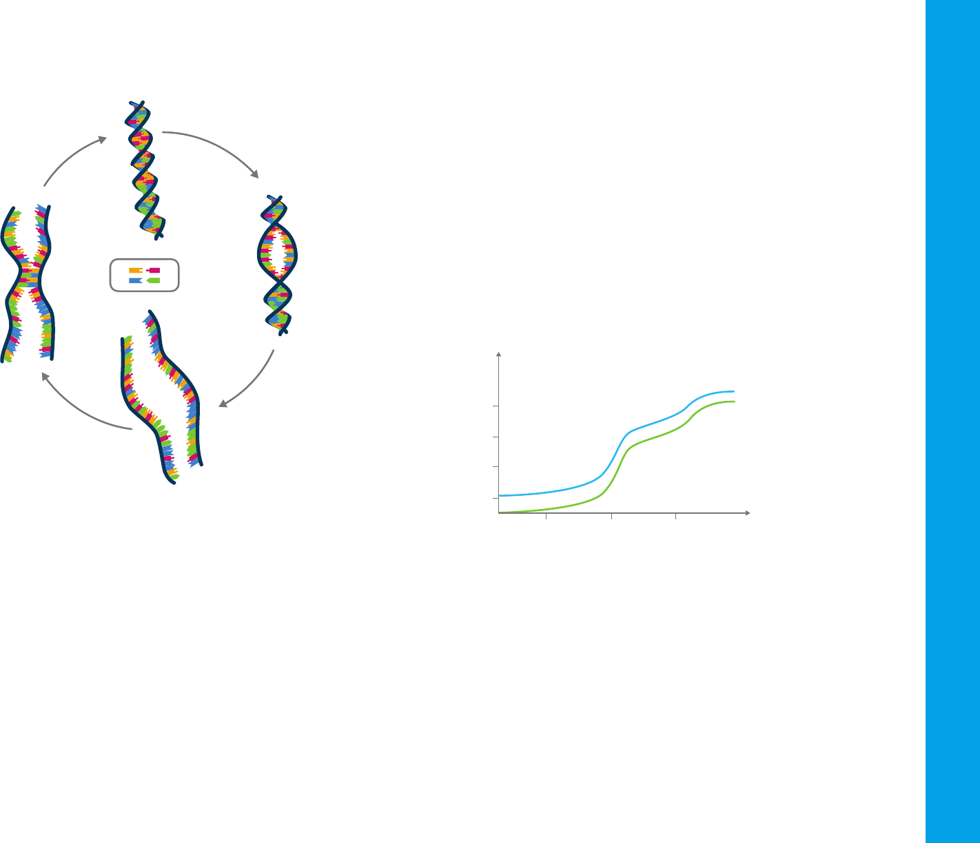
29
In this process, the electronic environment of the aromatic amino acids
changes, which in turn results in spectral changes or shifts.
Figure 39. The strands of the DNA double helix unwind as the DNA is heated. This increases
the absorbance of UV light at 260 nm. As the DNA is cooled, the strands rejoin.
Deoxyribonucleic acid (DNA) in its native state comprises two strands
of deoxyribose molecules helically wound around the same axis.
The strands are linked by hydrogen bonds between the purine and
pyrimidine bases—adenine is joined to thymine (A-T), and guanine to
cytosine (G-C). These bases are primarily responsible for the UV absorbance
of DNA and the other types of nucleic acids, with a peak maximum at
260 nm. As in any multicomponent system, the observed absorption of any
nucleic acid molecule should equal the sum of the individual absorbances:
A
DNA
= A
adenine
+ A
guanine
+ A
cytosine
+ A
thymine
However, the observed absorbance is always significantly less than
expected because the hydrogen bonding between the bases changes their
electronic environment. When a molecule is heated, the hydrogen bonds
break, the double helix unwinds, and the absorbance increases so that it
approaches that expected from the sum of all bases (refer to Figure 39).
This denaturation process is known as melting or thermal melt. In a thermal
melt experiment, the temperature of a double stranded nucleic acid solution
is increased in a stepwise fashion, and the absorbance at 260 nm at each
temperature is measured and plotted as a melting curve (as shown in
Figure 40). The midpoint of the temperature range over which the melting
occurs is the T
m
value. The T
m
value of a particular nucleic acid sample
depends primarily on the percentage of G-C pairs in the sample, each of
which contains three hydrogen bonds (in contrast, each A-T pair contains
two hydrogen bonds). The higher the percentage of G-C pairs in the sample,
the higher the observed T
m
.
Figure 40. Measuring the absorbance at 260 nm, whilst increasing the temperature results
in this characteristic graph of a DNA ‘melt’. The change in absorbance indicates the multiple
transitions as the DNA helix unwinds.
To perform protein and DNA melt analyses the UV-Vis spectrophotometer
must have a means to change the sample temperature accurately and
reproducibly. Recent advances in spectrophotometric instrumentation offer
significant reductions in elapsed times for thermal melt measurements,
as well as higher temperature accuracy than previously possible. UV-Vis
thermal melt analysis systems are available with integrated in-cuvette
temperature probes, which can be used to accurately control the
temperature of the solutions during the experiment. In-cuvette stirring is
also provided to ensure samples are heated homogeneously. When there
are large numbers of samples for analysis a multicell holder is built into or
806040
0.50
0.40
0.45
0.55
Temperature (°C)
Absorbance (A)
Once nucleation
has occurred,
renaturation is rapid
due to zippering.
Temperature increase
causes the bases to
unstack, and hydrogen
bonds break.
When the solution
is returned to lower
temperatures,
the DNA strands
start to reconnect.
Duplex
DNA
Partially
unwound
DNA
Totally
denatured DNA
(separate strands)
A T
G C
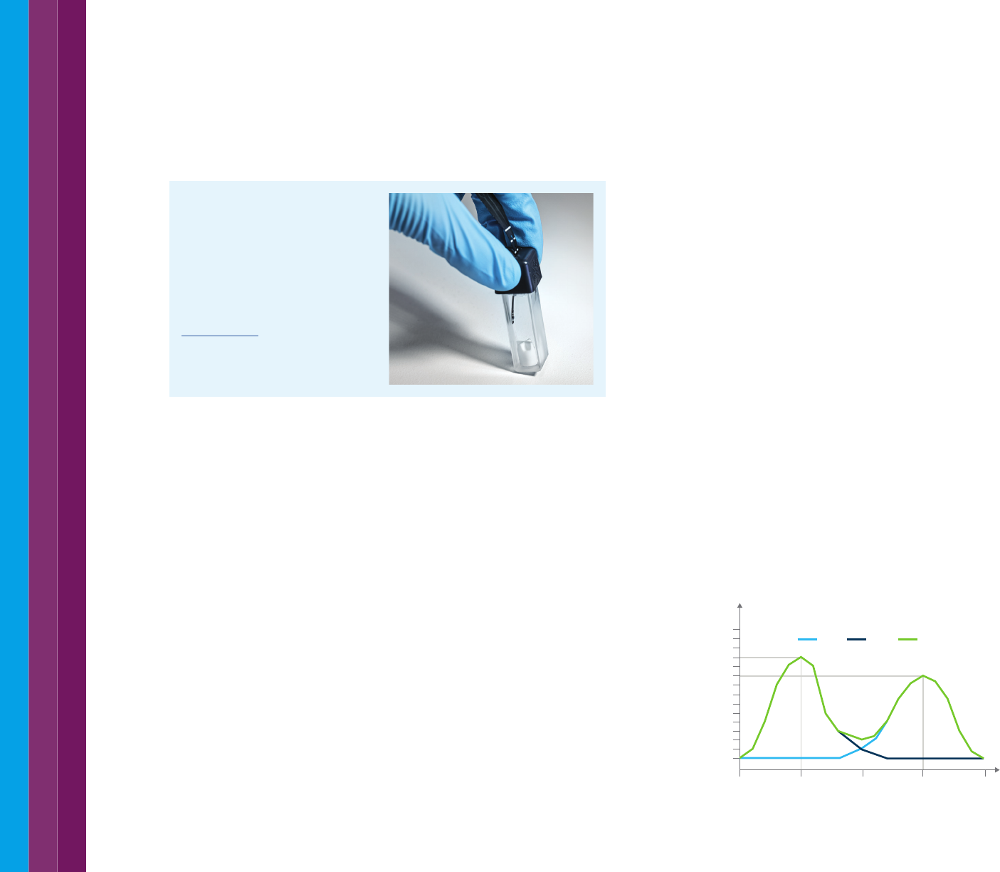
30
the absorbance of standards of known concentrations of pure
components are measured to determine the extinction coefficient for
each component at each wavelength selected. The absorbance of
the mixture at each wavelength is the sum of the absorbance of each
component at that wavelength, which in turn depends on the
extinction coefficient and the concentration of each component.
Thus for two components x and y, the equations are:
A′
(x + y)
= A′
x
+ A′
y
= e′
x
bc
x
+ e′
y
bc
y
and
A″
(x + y)
= A″
x
+ A″
y
= e″
x
bc
x
+ e″
y
bc
y
Where:
– A′ is absorbance at wavelength ′
– A′′ is absorbance at wavelength ′′
– e′ is molar absorptivity at wavelength ′
– e′′ is molar absorptivity at wavelength ′′
– c is concentration
– b is path length.
These equations are easily solved to determine the concentration of each
component. If measurements were always perfect, accurate results
could be obtained even for complex mixtures of components with very
similar spectra. In practice, however, measurement errors always occur.
Such errors can significantly affect the accuracy of results when there
is major spectral overlap. Figure 41 shows a simulated two-component
mixture with no overlap of the spectra at the absorbance maxima.
230 240220210200
0.5
1.0
0.0
Wavelength (nm)
Absorbance (A)
x y x + y
Nucleic acid thermal melt
analysis
Sample temperature control is a key
requirement of the UV-Vis thermal
melt system. Rapid and reproducible
heating can be assisted by the use
of an in-cuvette temperature probe.
Find out more.
provided with the instrument. Most Peltier driven temperature accessories
require a circulating water bath to cool the Peltier elements. Again, recent
innovations have enabled the use of air-cooled peltiers in the cell block.
The required temperature range is typically between 0 and 110 °C and along
with the inbuilt temperature monitoring and stirring provide the ability to
ramp temperatures of the sample during analysis as rapidly as possible.
4.8 Multi-component analysis
Multicomponent analyses using UV-visible spectra have been performed
for almost as long as single-component analyses. However, because
the techniques used in multicomponent analysis often gave incorrect
results they were not widely applied. A well-designed modern UV-Vis
spectrophotometer yields more precise data, and modern curve-fitting
techniques give more accurate results and—perhaps more importantly—
indicate when results are incorrect.
Principle of additivity
According to Beer’s law, absorbance is proportional to the number of
molecules that absorb radiation at the specified wavelength. This principle
is true if more than one absorbing species is present. All multicomponent
quantitative methods are based on the principle that the absorbance at
any wavelength of a mixture is equal to the sum of the absorbance of
each component in the mixture at that wavelength.
The simple approach to multicomponent analysis is based on
measurements at a number of wavelengths—equal to the number
of components in the mixture. The wavelengths chosen are usually
those of the absorbance maximum of each component. For calibration,
Figure 41. A two-component mixture with little spectral overlap.
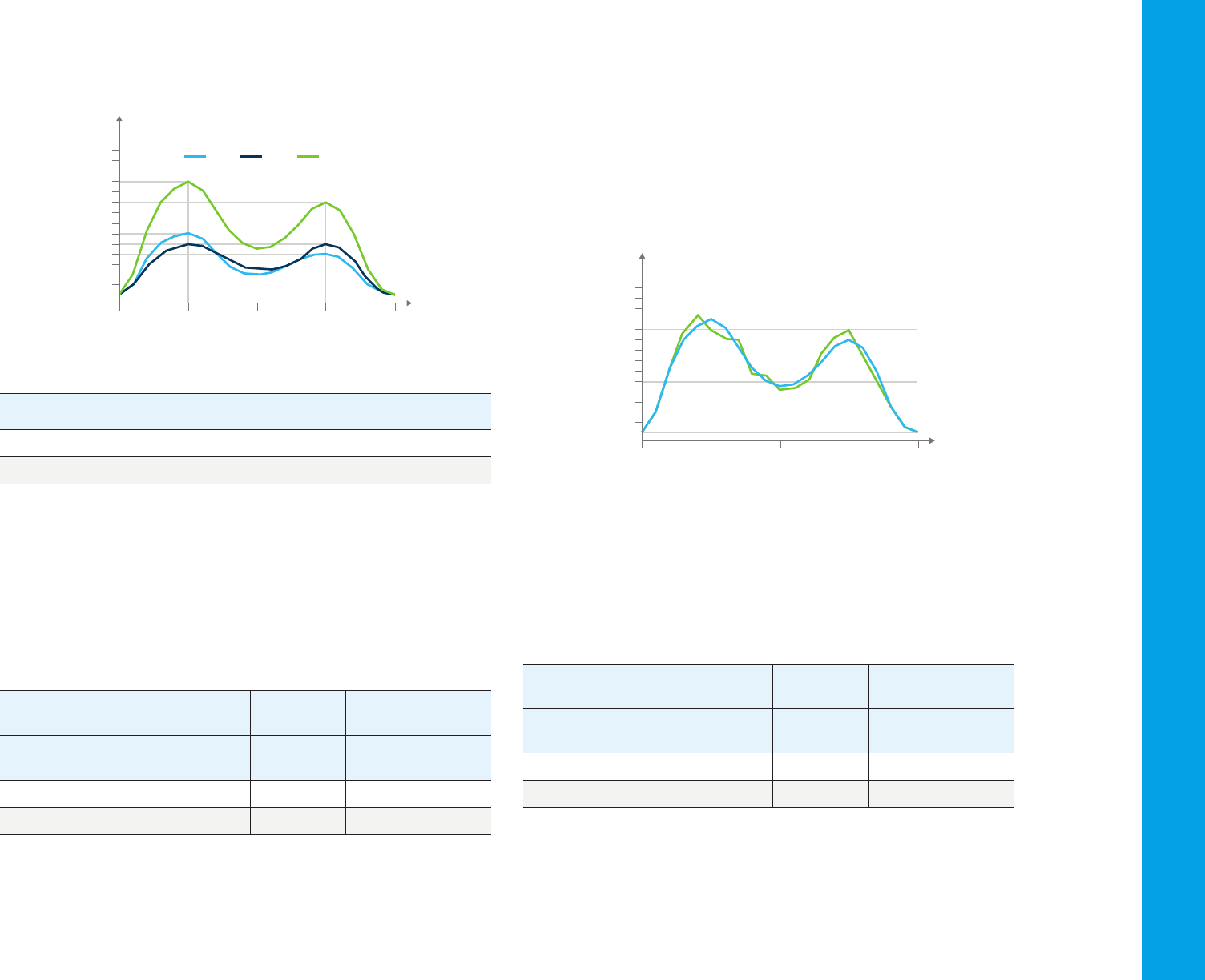
31
In contrast, Figure 42 shows a simulated two-component mixture with
significant overlap of the spectra at the absorbance maxima.
With little spectral overlap With substantial spectral overlap
A’(x + y) = 1.1 + 0.0 = 1.1 A’(x + y) = 0.6 + 0.5 = 1.1
A’’(x + y) = 0.0 + 0.9 = 0.9 A’’(x + y) = 0.4 + 0.5 = 0.9
For a mixture of x and y where cx = cy = 1, the measured absorbances
should be:
If a 10 % error occurs in the measurement of A′
(x + y)
and A′′
(x + y)
, that is,
A′
(x + y)
= 0.99 (- 10 %) and A′′
(x + y)
= 0.99 (+ 10 %), the quantitative calculation
yields the results shown in Table 6:
Least squares method
The effect of random noise can be reduced by using additional spectral
information, that is, a series of data points can be used for quantification
instead of only two. In this so-called overdetermined system, a least
squares fit of the standard spectra to the spectrum of the measured
sample yields quantitative results (1,2). Figure 43 depicts a spectrum for
the two-component mixture shown in Figure 42 with a 10 % random error
at each measurement point.
Table 6. Comparison of multicomponent analysis results for examples with little and
substantial spectral overlap.
Little
spectral overlap
Substantial
spectral overlap
Component
Nominal
concentration
Calculated
concentration
% error
Calculated
concentration
% error
x 1 0.9 -10% 0.0 -100%
y 1 1.1 +10% 1.98 +98%
Table 7. Comparison of multicomponent analysis results from simple simultaneous
equations and least squares methods.
Using 210 and
230 nm only
Using 200–
240 nm
Component
Nominal
concentration
Calculated
concentration
% error
Calculated
concentration
% error
x 1 0.0 -100% 1.003 +0.3%
y 1 1.98 +98% 0.995 -0.5%
Figure 43. Mixture spectrum with 10 % random error at each wavelength.
With 21 data points (2 nm intervals over 200 to 240 nm), the quantitative
results from the least squares method have an error of < 1 % compared
with an error of approximately 100 % from the usual measurements at
two wavelengths, as shown in Table 7.
230 240220210200
0.5
1.0
0.0
Wavelength (nm)
Absorbance (A)
x y x + y
230 240220210200
0.5
1.0
0.0
Wavelength (nm)
Absorbance (A)
Figure 42. A two-component mixture with significant spectral overlap.
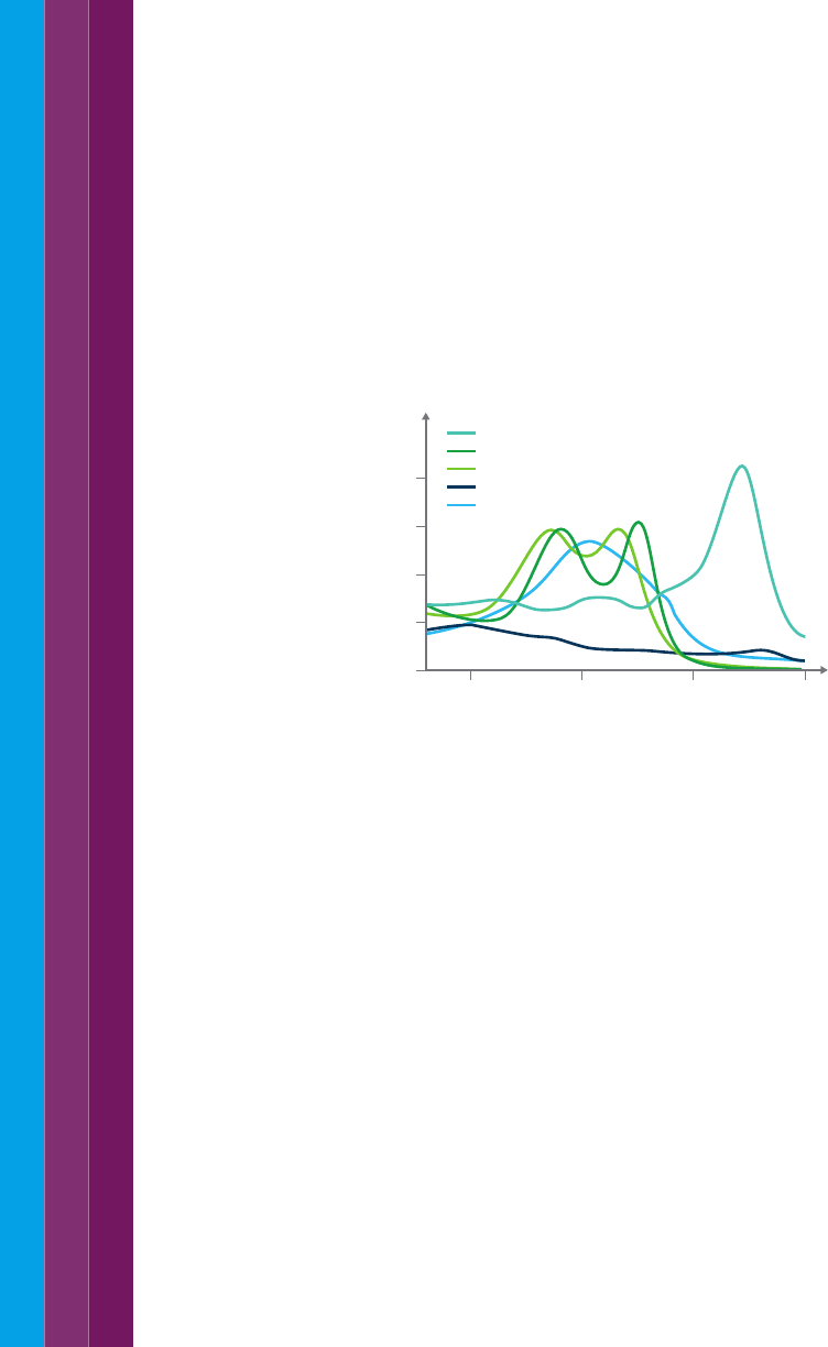
32
Instrumental requirements
Single-component quantification is normally performed by measuring
with the same instrument a standard or series of standards followed by
an unknown. This calibration process should eliminate instrumental bias,
making absolute wavelength accuracy and absolute photometric accuracy
relatively unimportant. On the other hand, photometric reproducibility is
essential for precise results. If measurements are performed only at the
absorbance maximum, wavelength reproducibility is also of little importance
because the rate of change of absorbance with wavelength is low. However,
if a wavelength on the side of the band is used, wavelength reproducibility
becomes particularly important. Finally, the instrumental linear range is
critical, as the calibration process relies on a linear relationship. Accurate
multicomponent analyses require excellent signal to noise performance,
especially if the simple simultaneous equations method is used. In the least
squares method, data from the sides of absorbance bands is incorporated
into the calculation, making excellent wavelength reproducibility essential as
well. Moreover, because more data is required, fast scanning is necessary
for productivity.
4.9 Software requirements
Specialized multicomponent software is available to help with the creation
of data models to analyse collected data. These software packages
can either be incorporated into the instrument software control and
reporting software or as stand-alone packages. Most UV-Vis systems
available can export data in a standard format that can be imported into
a multicomponent software package for processing.
References:
1. Kisner, H.; Brown, W.; Kavarnos, G.“Multiple analytical frequencies and
standards for the least-squares analysis of serum lipids. Anal. Chem. 1983,
55, 1703.
2. Maris M.; Brown, C.; Lavery, D. Nonlinear multicomponent analysis by
infrared spectrophotometry. Anal. Chem. 1983, 55, 1694.
3. Zwart, A.; van Kampen, E.; Zijlstra, W. Multicomponent analysis of
hemoglobin derivatives with a reversed-optics instrument. Clin. Chem.,
1984, 30, 373.
This method enables the analysis of more complex mixtures and of simple
mixtures of components with similar spectra. The residual from the least
squares calculation is a good indicator of how well the standard spectra
fit the sample spectra and is therefore a good indicator of the probable
accuracy of the results.
An example of multicomponent analysis is the quantification of five
hemoglobins in blood with minimum sample preparation (3). Figure 44
shows the absorption spectra of hemoglobin derivatives. This analysis
was previously performed using various analytical techniques, including
spectroscopy and titrations.
Figure 44. Absorption spectra of hemoglobin derivatives.
Other methods
Other statistical approaches to multicomponent analysis include the
partial least squares (PLS), principle component regression (PCR), and
multiple least squares (MLS) methods. In theory, these methods offer some
advantages over those described above, however the calibration process
can be much more complex.
Sample requirements
The simple simultaneous equations and least squares methods yield
accurate results only if calibration is performed using pure standards or
mixtures of standards for each component in the sample that contributes
to the UV-visible spectrum. The unknown sample must not have any
additional absorbing capacity.
650600550500
0.1
0.2
0.0
Wavelength (nm)
Absorbance (A)
Oxyhemoglobin
Carboxyhemoglobin
Sulfhemoglobin
Hemoglobin (pH 7.0-7.4)
Deoxyhemoglobin
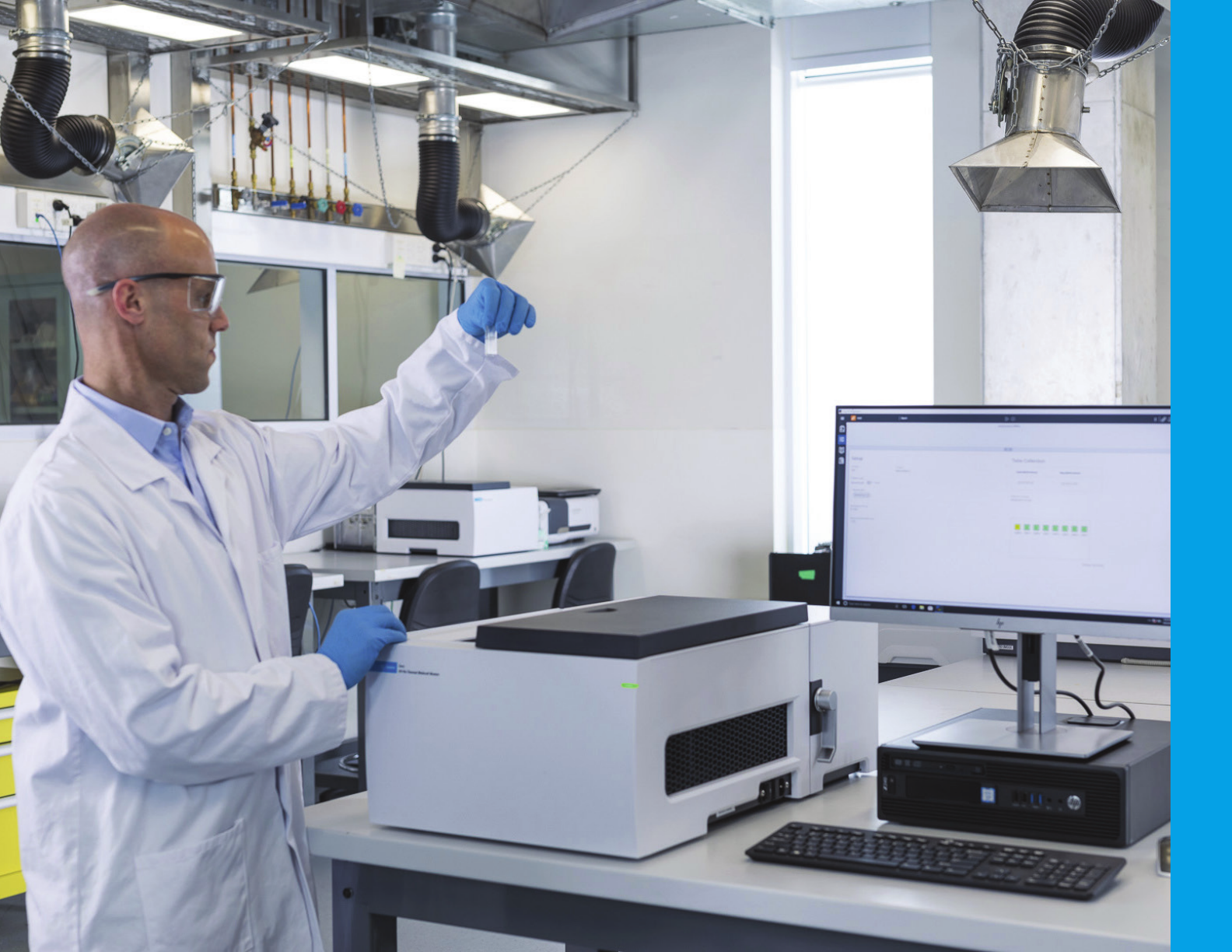
33
34
absorbance: 1. characteristic of a substance to absorb light 2. Unit for light
absorbance, represented as A or Abs.
arc (lamp): Creates light by an electric or voltaic arc through an inert gas.
baseline: This is a measurement collected under the same parameters
as the sample measurement, but without the sample in place. A blank is
usually used for a baseline measurement as this allows the contributions of
the instrument, the solvent, the cuvette etc to be subtracted from the final
sample measurement.
blank: The solvent or substrate of the sample, without the absorbing
species. When measuring liquid samples, this will be the solvent (often
water) in a cuvette. The absorbance of the blank can then be subtracted
from that of the sample to determine the absorbance due purely to the
sample.
carotenoids: Chromophore linked to photosynthesis in some plants, algae
and some bacteria.
chromophore: Part of a molecule which absorbs light
CRM: abbreviation. Certified reference material. In reference to standards
supplied that have been certified to a primary standard for comparison.
cuvette: Commonly referred to as a cell, the cuvette is the container
that holds liquid samples. Cuvette are available in different volumes and
pathlengths. The cuvette material determines their optical transparency.
dispersion: In optical design refers to the ability of the optical device to split
light into its constituent wavelengths. E.g. white light on a prism creates a
rainbow effect through dispersion.
fluorescence: A form of luminescence and characteristic of some
molecules to absorb light at a frequency and emit short lived light of another
wavelength.
GMP: abbreviation. Good manufacturing practice. Commonly used in
pharmaceutical and other regulated manufacturing industries.
5. Glossary
holographic (optics): Holographic optics are created by etching an
interference pattern on an optic surface. Holographic optics can be used in
place of lenses, mirrors, and other optical devices. Their design makes them
easy to accurately replicates and small and light.
noise: In spectrophotometer terms, noise refers to the background
electrical signal contributed by the instrument itself. If this is too great,
it can overshadow the measurement signal, making it hard to differentiate
between the two signals. An easy way to think about this is when you are
looking at the stars from a city location, compared to a remote location.
The background light (‘noise’) contributed by the city lights makes it hard
to see the stars. In a remote location, there is little background light, so the
light from the stars can be easily seen.
peltier: A Peltier is a heating/cooling device operated by a thermoelectric
coupling. The device transfers heat from one side of the device to the other.
It can provide accurate temperature control of a sample.
pharmacopeia: Regulatory document listing pharmaceutical details and
required or recommended testing procedures for the pharmaceutical
industry.
phosphorescence: A form of luminescence related to fluorescence.
It is characteristic of some molecules to absorb light at a frequency and
emit a delayed, light of another wavelength.
photochemical (reactions): Chemical reaction caused by the absorption
of light.
photosensitivity: Sensitivity of a substance to react when exposed to light.
QA/QC: abbreviation. Quality control or quality assurance
qualitative (measurement): Measurement providing non-numerical
information about the sample, e.g. identification of a molecule in solution
quantitative (measurement): Measurement resulting in a numerical value.
e.g. concentration.
35
rare earth oxides: Holmium, didymium and samarium oxides are referenced
by standards organizations and pharmacopoeia to be used for wavelength
validity measurements.
reflection: Describes the path of light a sample which is deflected at the
angle of incidence.
scattering: Effect of light bouncing from a surface at random angles.
SOP: abbreviation. Standard operating procedure. Document written to
ensure measurement can be formed safely and repeatably.
spectrum: plural, spectra. Range of wavelengths. The electromagnetic
spectrum. Also refers to a usually graphical output of wavelength vs
intensity (or absorbance, as measured by a spectrophotometer).
SST: abbreviation. System suitability tests. Test to determine the system is
fit for purpose.
transmittance: Percentage of incident light that is transmitted through
a sample.
zero: This is equivalent to the 'Tare' function on a set of scales – it sets the
instrument reading to 0 Abs.

DE.8623263889
This information is subject to change without notice.
© Agilent Technologies, Inc. 2021
Published in the USA, July 23, 2021
5980-1397EN
Learn more:
www.agilent.com/chem/
Buy online:
www.agilent.com/chem/store
Get answers to your technical questions and
access resources in the Agilent Community:
community.agilent.com
U.S. and Canada
1-800-227-9770
Europe
Asia Pacific
