BiPAP
®
S/T
User Manual
This BiPAP system is covered by one or more of the following patents: U.S.
Patent Nos. 5,148,802; 5,313,937; 5,433,193; 5,632,269; 5,803,065; 6,029,664;
6,305,374 and 6,539,940; Australian Patent Nos. 638054, 661575, 698519,
723681, 734319, and 733655; Canadian Patent Nos. 2,162,981 and 2,259,795;
European Patent Pub. No. 0425092B1; and Japanese Patent Nos. 2832812,
2137336, and 2926392. Other U.S. and Foreign Patents Pending.
© 2008 Respironics, Inc, and its afliates. All rights reserved.
Ta b l e o f Co n T e n T s
Ch a p t e r 1: pa C k a g e Co n t e n t s ........................................................................... 1
Ch a p t e r 2: Wa r n i n g s a n d Ca u t i o n s ................................................................. 2
2.1 Wa r n i n g s ................................................................................................ 2
2.2 Ca u t i o n s ................................................................................................. 4
2.3 in t e n d e d us e ........................................................................................... 4
2.4 Co n t r a i n d i C a t i o n s ................................................................................. 5
2.5 pr e C a u t i o n s ............................................................................................ 5
Ch a p t e r 3: in t r o d u C t i o n .................................................................................... 6
3.1 de f i n i t i o n s .............................................................................................. 6
3.2 Wh a t i s t h e Bipap s/t?........................................................................ 7
3.3 sy m B o l s .................................................................................................... 9
3.4 ho W t o Co n t a C t re s p i r o n i C s ................................................................ 9
Ch a p t e r 4: Co n t r o l s a n d di s p l a y fe a t u r e s .................................................... 10
4.1 pr e s s u r e on/of f Bu t t o n .................................................................... 10
4.2 Co n t r o l pa n e l ..................................................................................... 11
4.2.1 Co n t r o l Bu t t o n s ....................................................................... 11
4.2.2 al a r m a n d po W e r in d i C a t o r s ................................................... 12
4.2.3 di s p l a y sC r e e n ............................................................................ 13
4.2.4 Br e a t h i n g Ci r C u i t Co n n e C t i o n ................................................. 15
4.2.5 re a r pa n e l ................................................................................. 15
Ch a p t e r 5: se t t i n g u p t h e de v i C e .................................................................... 17
5.1 in s t a l l i n g t h e ai r fi l t e r s .................................................................... 17
5.2 Wh e r e t o pl a C e t h e Bipap s/t ......................................................... 18
5.3 Co n n e C t i n g t h e Br e a t h i n g Ci r C u i t .................................................... 19
5.4 Co m p l e t e t h e se t u p .............................................................................. 21
5.5 pl u g g i n g it in ....................................................................................... 21
5.5.1 us i n g aC po W e r ........................................................................ 22
5.5.2 us i n g dC po W e r ........................................................................ 23
Ch a p t e r 6: op e r a t i n g t h e Bipap s/t ............................................................ 24
6.1 st a r t i n g t h e de v i C e ............................................................................. 24
6.2 Ch a n g i n g t h e de v i C e se t t i n g s ............................................................ 26
6.2.1 Ch a n g i n g t h e hu m i d i f i e r se t t i n g ............................................ 27
6.2.2 nav i g at i n g t h e us e r di s p l a y sC r e e n s ...................................... 27
6.2.2.1 Ch a n g i n g t h e fl e x se t t i n g ............................................. 28
6.2.2.2 Ch a n g i n g t h e ri s e ti m e se t t i n g ..................................... 29
6.2.2.3 Ch a n g i n g t h e ra m p st a r t i n g pr e s s u r e ......................... 30
6.2.2.4 Ch a n g i n g t h e led Ba C k l i g h t se t t i n g .......................... 31
Ch a p t e r 7: al a r m s ............................................................................................ 32
7.1 in t r o d u C t i o n t o al a r m s ...................................................................... 32
7.2 Wh a t t o do Wh e n a n al a r m oC C u r s ............................................... 34
7.3 al a r m ta B l e s ........................................................................................ 35
7.3.1 hi g h pr i o r i t y al a r m s ................................................................ 35
7.3.2 me d i u m pr i o r i t y al a r m s ........................................................... 36
7.3.3 lo W pr i o r i t y al a r m s ................................................................. 36
Ch a p t e r 8: tr o u B l e s h o o t i n g ............................................................................ 37
Ch a p t e r 9: Cl e a n i n g a n d ma i n t e n a n C e ........................................................ 41
9.1 Cl e a n i n g t h e de v i C e ............................................................................ 41
9.2 Cl e a n i n g o r re p l a C i n g t h e in l e t fi l t e r s ........................................... 41
9.3 Ca r r y i n g Ca s e ...................................................................................... 43
Ch a p t e r 10: aC C e s s o r i e s .................................................................................. 44
10.1 ad d i n g a hu m i d i f i e r .......................................................................... 44
10.2 ad d i n g ox y g e n t o t h e de v i C e .......................................................... 44
Ch a p t e r 11: sp e C i f i C a t i o n s ................................................................................ 45
en v i r o n m e n t a l ........................................................................................... 45
ph y s i C a l ...................................................................................................... 45
el e C t r i C a l ................................................................................................... 45
pr e s s u r e ....................................................................................................... 46
Co n t r o l aC C u r a C y .................................................................................... 46
di s p o s a l ....................................................................................................... 46
ap p e n d i x a: emC in f o r m a t i o n ........................................................................ 47
1
User Manual
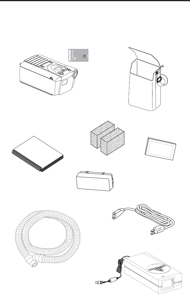
Ch a p T e r 1: pa C k a g e Co n T e n T s
Your BiPAP S/T should include the following items. If any of these items
are missing, contact your home care provider.
BiPAP S/T with
Encore
®
Pro SmartCard
™
Power Cord
Filter Cap
Gray Foam Filters
Flexible Tubing
1.83 m (6 ft.) X 22 mm i.d.
Ultrane Filter
User Manual
External AC Power Supply
Carrying Case

2
User Manual
Ch a p T e r 2: Wa r n i n g s a n d Ca u T i o n s
WARNING: Indicates the possibility of injury to the user or operator.
CAUTION: Indicates the possibility of damage to the device.
NOTE: Places emphasis on an operating characteristic.
2.1 Wa r n i n g s
• Thismanualservesasareference.Theinstructionsinthis
manual are not intended to supersede the instructions of your
health care professional.
• Youshouldreadandunderstandthisentiremanualbeforeusing
the device.
• Thedeviceisnotintendedtoprovideyourtotalventilatory
requirement.
• Theprescriptionmustonlybeadjustedbyatrainedhomecare
provider.
• The device should be used only with masks and connectors
recommended by Respironics or with those recommended by
the health care professional or respiratory therapist. A mask
should not be used unless the device is turned on and operating
properly. The exhalation port(s) associated with the mask should
never be blocked.
Explanation of the Warning: The BiPAP S/T is intended to be
used with special masks or connectors that have exhalation
portstoallowcontinuousowofairoutofthemask.Whenthe
device is turned on and functioning properly, new air from the
deviceushestheexhaledairoutthroughthemaskexhalation
port. However, when the device is not operating, enough fresh
air will not be provided through the mask, and exhaled air may
be rebreathed. Rebreathing of exhaled air for longer than several
minutes can in some circumstances lead to suffocation. This
warning applies to most models of CPAP machines.
• Useonlythebreathingcircuitprovidedbyyourhomecare
provider.
• Whenusingabreathingcircuitthatcontainsamaskwithan
integrated exhalation port or a circuit with a separate exhalation
device, do not tape, seal, or otherwise block the vent openings.
Doing so could result in suffocation.

3
User Manual
• Ifoxygenisusedwiththedevice,theoxygenowmustbe
turned off when the device is not in use.
Explanation of the Warning: Whenthedeviceisnotinoperation
andtheoxygenowislefton,oxygendeliveredintothe
ventilator tubing may accumulate within the device’s enclosure.
Oxygen accumulated in the ventilator enclosure will create a risk
ofre.
• Ifyouareusingoxygen,theBiPAPS/Tmustbeequippedwith
the Respironics Pressure Valve (Part number 302418). Failure to
usethePressureValvecouldresultinarehazard.
• Oxygensupportscombustion.Oxygenshouldnotbeusedwhile
smokingorinthepresenceofanopename.
• Donotusethedeviceinthepresenceofaammableanaesthetic
mixture in combination with oxygen or air, or in the presence of
nitrous oxide.
• Donotusethedeviceiftheroomtemperatureisabove95ºF
(35°C). If the device is used at room temperatures above 95° F,
thetemperatureoftheairowmayexceed106ºF(41°C),which
could cause irritation to your airway.
• Donotoperatethedeviceindirectsunlightornearaheating
appliance because these conditions can increase the temperature
of the air coming out of the device.
• Whenusingthisproduct,IEC60601-1-1requirements(safety
requirements for medical electrical systems) must be met.
• Forproperuse,thepowersupplymust be placed feet down, in
the upright position.
• WhentheBiPAPS/Tisusedwithahumidier,positionthe
humidiersothatthewaterlevelinthehumidierislowerthan
you,andthehumidierisonthesamelevelorlowerthanthe
BiPAP S/T.
• Donotattempttowearyourmaskwithoutthedeviceturnedon.
Doing so could result in CO
2
rebreathing.
• Ifyounoticeanyunexplainedchangesintheperformanceofthe
BiPAP S/T, if it is making unusual or harsh sounds, if it and/
or the power supply has been dropped or mishandled, if the
enclosure is broken, or if water has entered the unit, discontinue
use and contact your home care provider.
• RepairsandadjustmentsmustbeperformedbyRespironics
-authorizedservicepersonnelonly.Unauthorizedservicecould
cause injury, invalidate the warranty, or result in costly damage.
• Periodicallyinspectelectricalcords,cables,andthepower
supply device for damage or signs of wear.

4
User Manual
• Toavoidelectricalshock,unplugthedevicebeforecleaningit.
• PinsofconnectorsidentiedwiththeESDwarningsymbol
should not be touched. Connections should not be made to
these connectors unless ESD precautionary procedures are used.
Precautionaryproceduresincludemethodstopreventbuild-up
ofelectrostaticdischarge(e.g.,airconditioning,humidication,
conductiveoorcoverings,non-syntheticclothing),discharging
one’s body to the frame of the equipment or system or to earth or
a large metal object, and grounding oneself by means of a wrist
strap to the equipment or system or to earth.
2.2 Ca u T i o n s
CAUTION! U.S. federal law restricts this device to sale by or on the
order of a physician.
• TheBiPAPS/Tmayonlybeoperatedattemperaturesbetween
41ºF(5°C)and95ºF(35°C).
• Aproperlyinstalled,undamagedreusablefoaminletlteris
required for proper operation.
• Donotimmersethedeviceorallowanyliquidtoenterthe
enclosureortheinletlter.
• Condensationmaydamagethedevice.Alwaysallowthedevice
to reach room temperature before use.
NOTE: Additional warnings, cautions, and notes are located
throughout this manual.
2.3 in T e n d e d us e
The BiPAP S/T is intended to provide noninvasive ventilation for pediatric
patients 7 years or older > 40 lbs (18.2 kg) and adult patients > 66 lbs (30 kg)
withrespiratoryinsufciencyorobstructivesleepapnea.Thisdevicemaybe
used in the hospital or home.
NOTE: Thedeviceisintendedforusewithnasalmasksandfull-face
masks as recommended by Respironics.
NOTE: The device is to be used only on the instruction of a trained
health care professional.
WARNING: TheeffectivenessofBi-Flextherapyhasnotbeen
established for pediatric patients at this time.

5
User Manual
2.4 Co n T r a i n d i C a T i o n s
The BiPAP S/T should not be used if you have severe respiratory
failure without a spontaneous respiratory drive. If any of the following
conditions apply to you, consult your physician before using the device:
• Inability to maintain a patent airway or adequately clear
secretions
• At risk for aspiration of gastric contents
• Diagnosed with acute sinusitis or otitis media
• Allergy or hypersensitivity to the mask materials where the
riskfromallergicreactionoutweighsthebenetofventilatory
assistance
• Epistaxis, causing pulmonary aspiration of blood
• Hypotension
2.5 pr e C a u T i o n s
• Immediatelyreportanyunusualchestdiscomfort,shortnessof
breath, or severe headache.
• Ifskinirritationorbreakdowndevelopsfromtheuseofthe
mask, refer to the mask instructions for appropriate action.
• Thefollowingarepotentialsideeffectsofnoninvasivepositive
pressure therapy:
— Ear discomfort
— Conjunctivitis
— Skin abrasions due to noninvasive interfaces
— Gastric distention (aerophagia)

6
User Manual
Ch a p T e r 3: in T r o d u C T i o n
This chapter contains the following information:
• Denitionsforcommontermsusedthroughoutthismanual
• Anoverviewofthedevice
• Anexplanationofthesymbolsusedonthedeviceand
throughout this manual
• Contactinformation
3.1 de f i ni T i o n s
The following terms appear throughout this manual:
Apnea A condition marked by the cessation of
spontaneous breathing.
BPM Breaths Per Minute
CPAP Continuous Positive Airway Pressure
EPAP Expiratory Positive Airway Pressure
FLEX A therapy feature that provides pressure relief
during exhalation to improve patient comfort.
High Priority Alarm Alarm signal indicating a condition that
requires immediate attention.
IPAP Inspiratory Positive Airway Pressure
LED Light Emitting Diode
Low Priority Alarm Alarm signal indicating an informational
message.
Medium Priority Alarm Alarm signal indicating a condition that
requires operator awareness.
Operate State The state of the device when the unit and the
airowarebothon.
Standby State The state of the device when the unit is on,
buttheairowisoff.
OSA Obstructive Sleep Apnea
Ramp A feature that may increase patient comfort when
therapy is started. The ramp feature reduces the
pressure and then gradually increases (ramps)
the pressure to the prescription setting, so you
can fall asleep more comfortably.
7
User Manual
Rise Time The time it takes for the device to change from
EPAP to IPAP. You can adjust this time for
your comfort.
RR Respiratory Rate
Spontaneous(S) Abi-levelmodewhichrespondstoboth
your inhalation and exhalation by increasing
pressure when you start to inhale and
decreasing pressure when you start to exhale.
There is no automatic delivery of a breath if
you do not inhale.
Spontaneous/Timed
(S/T) Abi-levelmodewhichrespondstoboth
your inhalation and exhalation by increasing
pressure when you start to inhale and
decreasing pressure when you start to exhale.
If you do not start inhaling within a set time,
the device automatically starts inhalation.
Whenthedevicestartsinhalation,itcontrols
the time of inhalation and automatically
decreases the pressure for exhalation within a
set time.
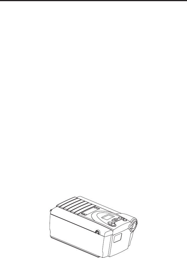
3.2 Wh a T i s T h e bipap s/T?
The BiPAP S/T, shown in Figure 3–1, supplies air pressure through a
breathing circuit.
Figure 3–1 The BiPAP S/T Unit

8
User Manual
The circuit, shown in Figure 3–2, consists of:
• Circuittubingtodeliverairfromthedevicetoyourinterface
(e.g., mask)
• Amaskorotherpatientinterfacedevicetodelivertheprescribed
pressure to your nose or nose and mouth, depending on which
interface has been prescribed for you
• Anexhalationdevicetoventexhaledairfromthecircuit
Circuit
Tubing
Exhalation
Device
Patient Interface
(Typical)
Circuit with Separate
Exhalation Device
Circuit with Mask with
Integrated Exhalation Port
Flexible
Tubing
Connector
Mask's
Connector
Exhalation
Port
Figure 3–2 Typical Breathing Circuits
NOTE: The exhalation port may be part of the mask or may be part of
aseparateexhalationdevice,butisrequiredtominimizethe
potential for CO
2
rebreathing.
The system senses your breathing effort and changes pressure levels
when you inhale and exhale depending on the mode of operation.
WARNING: The device can operate on AC or DC power. The DC
power option is not intended as a battery backup.
CAUTION: WhenDCpowerisobtainedfromavehiclebattery,the
device should not be used while the vehicle’s engine is
running.
9
User Manual
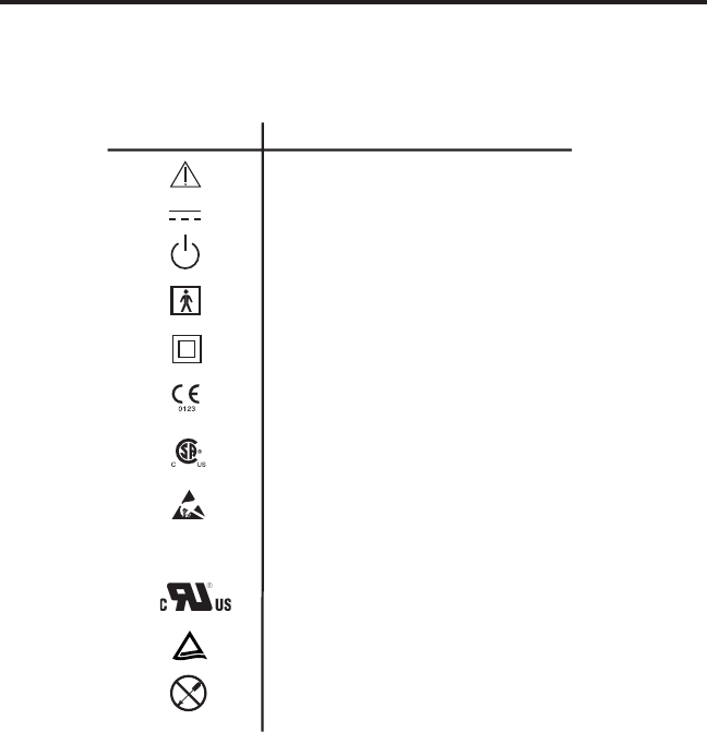
3.3 sy m b o l s
The symbols shown below are used on the device and throughout this
manual.
Attention, consult accompanying documents
DC Power
Pressure On/Off
Type BF Applied Part
Class II (Double Insulated)
European CE Declaration of Conformity
Canadian/US Certification
Electrostatic Discharge
Drip Proof Equipment
UL Recognized for Canada and the United States
TUV Safety Standard Compliance
No User Serviceable Parts
Symbol Meaning
IPX1
3.4 ho W T o Co n T a C T re s p i r o n i C s
To have your device serviced, contact your home care provider. If you
need to contact Respironics directly, call the Respironics Customer Service
departmentat1-724-387-4000or1-800-345-6443.Youcanalsousethe
following address:
Respironics
1001 Murry Ridge Lane
Murrysville, PA 15668
Visit Respironics web site at: www.respironics.com

10
User Manual
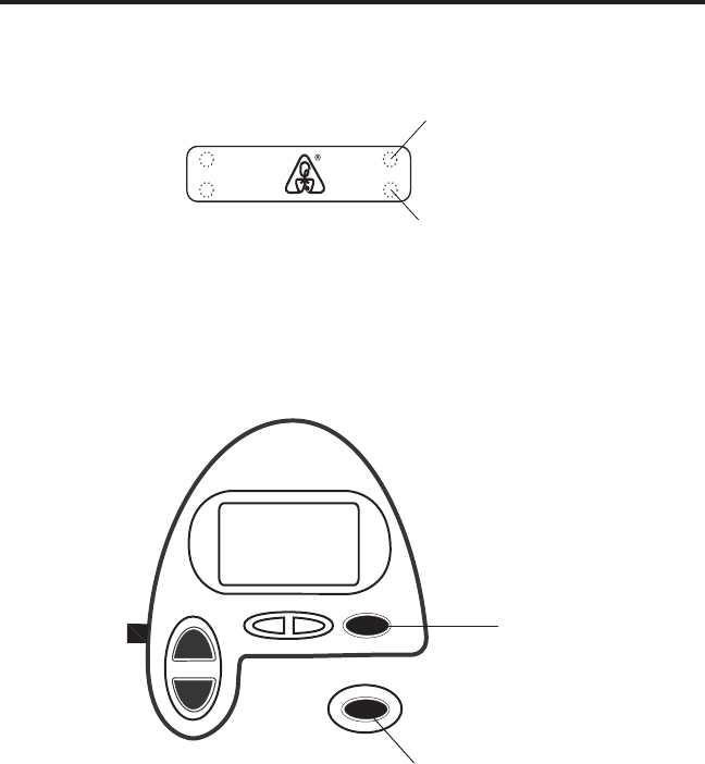
Ch a p T e r 4: Co n T r o l s a n d
di s p l a y fe a T u r e s
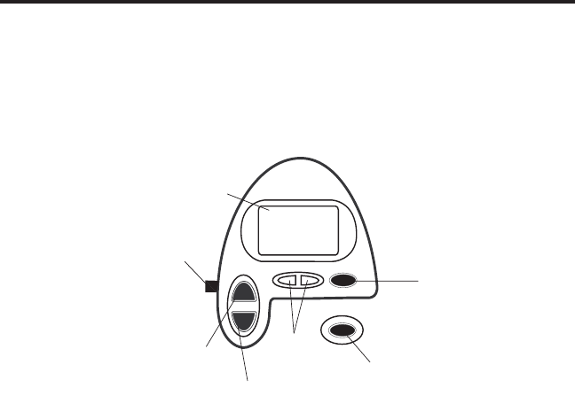
Figure 4–1 shows the location of the device’s alarm power indicators,
control panel, Pressure On/Off button, and breathing circuit connection.
Breathing Circuit
Connection
Control Panel
Pressure On/Off
Button
Alarm and Power Indicators
Figure 4–1 Front and Top
4.1 pr e s s u r e on/of f bu T T o n
The Pressure On/Off button, located on the side of the unit, starts and
stopstheunit’sairow.Pressthebuttonintoturntheairowon.This
puts the device in the Operate state. Depress the button to turn the
airowoffandputthedeviceintheStandby state.
WhenthedeviceisinStandby,anyrampinprogressisterminated,the
alarmsarereset(exceptfortheSystemErrorsalarm),andthehumidier
is turned off.
The Pressure On/Off button is independent of the display screen.
11
User Manual
4.2 Co n T r o l pa n e l
The control panel contains the following control buttons and indicators.
4.2.1 Co n T r o l bu T T o n s
The control buttons on the control panel are shown in Figure 4–2.
Alarm
Silence
Button
Ramp
Button
Heated
Humidifier
Button
User
Buttons
RAMP
HEAT
SILENCE
RESET
Alarm
Reset
Button
Display
Screen
Pressure On/Off
Button
Figure 4–2 Control Panel
HEAT WhentheoptionalREMstarheatedhumidieris
prescribed,thisbuttoncontrolsthehumidier’sheater
plate setting. Follow the instructions provided with the
humidier.Youcanalsousethisbuttontoadjustthe
settings shown in the user menu screens.
RAMP Whentheairowisturnedonandtherampfunction
isenabled,thisbuttonlowerstheairowpressure,
allowing you to fall asleep more easily. You can also use
this button to adjust the settings shown in the user menu
screens.
USER The left and right user buttons allow you to navigate the
display screens.
SILENCE This button silences the audible portion of an alarm for
one minute. You can also use this button to exit the user
menu screens.
RESET This button allows you to clear an alarm and reset the
device for alarm detection.
12
User Manual
4.2.2 al a r m a n d po W e r in d i C a T o r s
Figure 4–3 shows the device’s alarm and power indicators.
AC Power
Indicator (Green)
DC Power
Indicator (Green)
High Priority
Alarm LED (Red)
Low/Medium Priority
Alarm LED (Yellow)
AC
DC
Alarms
Power
Figure 4–3 Alarm and Power Indicators
AC Power Indicator This green LED lights up when the device is
connected to AC Power.
DC Power Indicator This green LED lights up when the device is
connected to DC power.
Red Alarm Indicator The red LED lights up when a high priority
alarm occurs.
Yellow Alarm Indicator This yellow LED lights up when a medium or
low priority alarm occurs.
NOTE: AllLEDindicatorstemporarilyturnonwhentheunitisrst
plugged in.
13
User Manual
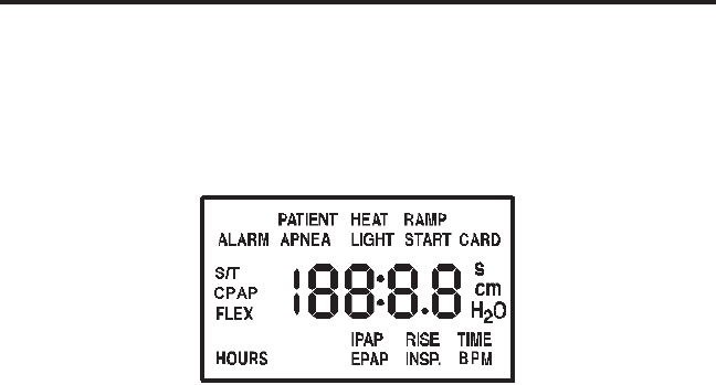
4.2.3 di s p l a y sC r e e n
The display shows you the measured pressure and displays alarm
messages. A backlight activates when any of the keys are pressed and
remains on until there are no keystrokes for one minute.
Figure 4–4 shows the display screen.
Figure 4–4 Display Screen
Theinformationshownonthedisplayscreenisdenedasfollows:
ALARM Indicates that the device requires user
attention as indicated on the screen.
APNEA Indicates that an apnea alarm has occurred.
BPM Indicates that a breath rate setting is being
displayed. BPMashesonthescreenwhen
the device is providing timed backup breaths
in S/T mode.
CARD Indicates that a SmartCard is inserted and
detected.
CPAP Indicates that the device is in the Continuous
Positive Airway Pressure (CPAP) mode.
cm H
2
O Indicates that the alphanumeric digits are
displaying a pressure value.
EPAP Indicates that an EPAP pressure setting is
being displayed.
FLEX IndicatesthataBi-Flexcomfortsettingis
being displayed.
HEAT Indicatesthatthehumidieristurnedon
and/or its setting is displayed.
HOURS Indicates that the Therapy Hour Meter is
being displayed.

14
User Manual
INSP. TIME Indicates that the inspiratory time setting is
being displayed.
IPAP Indicates that an IPAP pressure setting is
being displayed.
LIGHT Indicates that the keypad LED backlight
setting is being displayed or is active.
PATIENT Indicates that a Patient Disconnect alarm is
active.
RAMP Indicates that the Ramp function is in
progress.
RAMP START Indicates that the Ramp Starting Pressure is
being displayed.
RISE TIME Indicates that a rise time setting is being
displayed.
S The “s” on the right side of the display, above
“cm H
2
O”, indicates that the alphanumeric
digits are displaying a time value, in seconds.
S or S/T Indicates that the device is in the Spontaneous
mode if only the S appears, or the
Spontaneous/Timed mode if the S/T appears.
15
User Manual
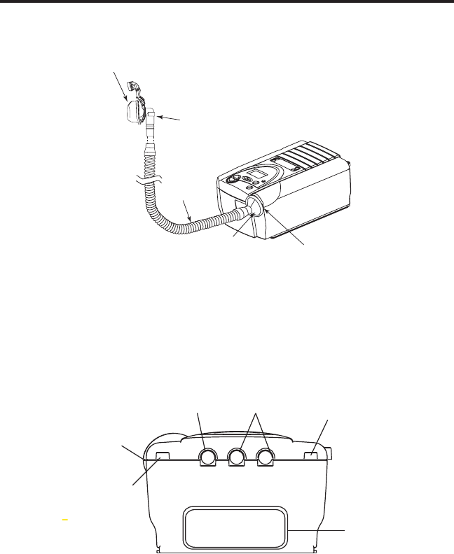
4.2.4 br e a T h i n g Ci r C u i T Co n n e C T i o n
Figure 4–5 shows where the circuit tubing connects to the device.
Breathing
Circuit
Connection
Circuit
Tubing
Patient Interface
Bacteria
Filter
(Optional)
Exhalation Port
Figure 4–5 Typical Breathing Circuit Connection
4.2.5 re a r pa n e l
Figure 4–6 shows the rear panel.
Communications
Connector Port
Power Inlets
SmartCard
Connector
Filter Cap
Cord Retainer
Cord Retainer
Figure 4–6 Rear Panel
NOTE: The SmartCard Connector is located on the side of the device.
WARNING: In order to ensure proper protection against electric shock,
onlycommunicationsaccessorieswithanIEC60601-1
approved power supply may be connected through the
SleepLink interface. All IEC 950 devices must only be
connectedtothe7-pinconnectorwiththeRespironics
Isolation cable (Part Number 1012865).

16
User Manual
The rear panel contains the following:
Communications Connector This connector accepts the Respironics
Communications cable for computer and
external communications, or a remote alarm.
(Use only with an IEC 60950 approved
computer.)
Power Inlets There are two power inlets on the rear panel,
one for connecting the external AC power
supply and another for connecting the
external DC power adapter.
Filter Cap Theltercapcanberemovedtoinspectthe
inletairlters.
Cord Retainers Two cord retainers are located on the rear
panel to provide strain relief for the power
cord.

17
User Manual
Ch a p T e r 5: se T T i n g u p T h e de v i C e
This chapter provides instructions on how to:
• Installtheairlters
• Positiontheunit
• Connectthebreathingcircuit
• PlugthedeviceinusingACorDCpower
5.1 in s T a l l i n g T h e ai r fi l T e r s
CAUTION: Aproperlyinstalled,undamagedfoamlterisrequired
for proper operation.
TheBiPAPS/Tusesagrayfoamlterthatiswashableandreusable,and
anoptionalwhite,ultra-nelterthatisdisposable.Onelterofeach
kind is supplied with the unit.
Ifyourhomecareproviderdidnotinstalltheinletairlters,youmust
installatleastthegrayfoamlterbeforeusingthedevice.
1. Placethegrayfoamlterontopoftheultra-nelter(ifusingthe
ultra-nelter).
2. Slidetheltersintotheairinletattherearofthedevice,andpush
themdownintotherecessasshowninFigure5-1.
Reusable Gray
Foam Filter
(required)
Disposable Ultra-fine
Filter (optional)
Filter
Cap
Figure 5–1 Installing the Filters
18
User Manual
3. AttachtheltercapasshowninFigure5–2.Positionthecapsothat
the small opening on the cap is facing down. Insert the caps bottom
tabsintotheopeningsbelowthelterarea.Snapthecapintoplace.
Figure 5–2 Attaching the Filter Cap
NOTE: Theltercapshouldbeinstalledwiththeairinletopeningat
the bottom.
SeeChapter9tocleanorreplacethelters.
5.2 Wh e r e T o pl a C e T h e bipap s/T
Place the device on its base somewhere within easy reach of where
you will use it. Make sure that the air inlet on the rear of the unit is not
blocked.Placetheunitonahard,atsurface.Ifyoublocktheairow
around the unit, the device may not work properly.
WARNING: Positionthehumidiersothewaterlevelislowerthan
you,andthehumidierisonthesamelevelorlowerthan
thedevice.Seethehumidierinstructionsforcomplete
setup information.
19
User Manual
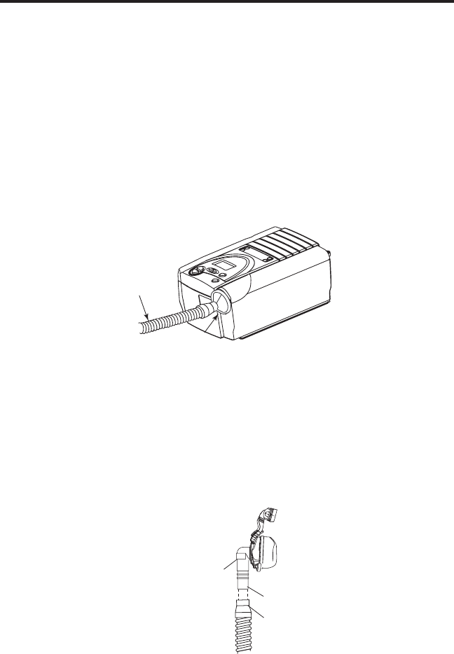
5.3 Co n n e C T i n g T h e br e a T h i n g Ci r C u i T
To connect your breathing circuit to the device, complete the following
steps:
1. Connect one end of the circuit tubing to the outlet of the bacteria
lter(ifusingone)andconnecttheinletofthebacterialtertothe
large connector on the device as shown in Figure 5–3.
Ifyouarenotusingabacterialter,connecttheendofthecircuit
tubing directly to the outlet connector on the device.
NOTE: Follow the recommendations of your home care provider for
usingtheoptionalbacterialter.
Circuit
Tubing
Bacteria
Filter
(Optional)
Figure 5–3 Connecting the Tubing to the Outlet
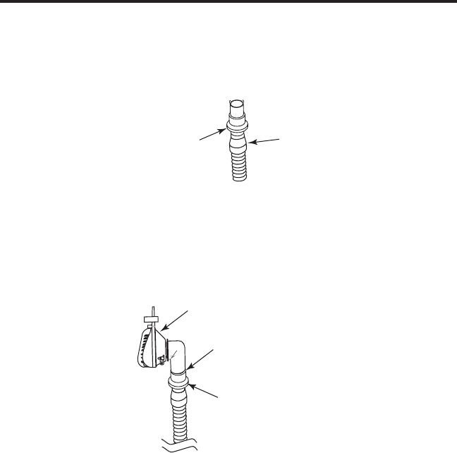
2. Connect the tubing to the mask:
A. Ifyouareusingamaskwithabuilt-inexhalationport,
connect the mask’s connector to the circuit tubing, as shown
in Figure 5–4.
Flexible
Tubing
Connector
Mask's
Connector
Exhalation Port
Figure 5–4 Connecting a Mask with a Built-In Exhalation Port
20
User Manual
B. If you are using a mask with a separate exhalation device,
connect the open end of the circuit tubing to the exhalation
device as shown in Figure 5–5. Position the exhalation
device so that the vented air is blowing away from your
face.
Exhalation
Device
Circuit
Tubing
Figure 5–5 Connecting an Exhalation Device
Connect the mask’s connector to the exhalation device, as
shown in Figure 5–6. See the mask instructions for complete
setup information.
Exhalation Device
Mask Connector
Mask or Other
Interface
Figure 5–6 Connecting the Mask
WARNING: The exhalation device is designed to exhaust CO2 from
the patient circuit. Do not block or seal the ports on the
exhalation device.
3. Attach the headgear to the mask. See the instructions that came with
your headgear.
21
User Manual
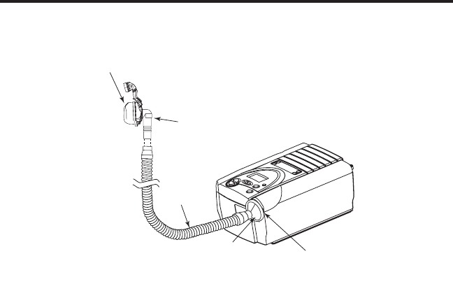
5.4 Co m p l e T e Th e se T u p
Figure 5–7 shows the completed breathing circuit setup.
Breathing
Circuit
Connection
Circuit
Tubing
Patient Interface
Bacteria
Filter
(Optional)
Exhalation Port
Figure 5–7 Complete Breathing Circuit
5.5 pl u g g i n g iT in
You can use AC or DC power to operate the device.
WARNING: The DC power option is not intended as a battery backup
when using AC power.
WARNING: For proper use, the power supply must be placed feet
down, in the upright position, as shown in Figure 5–7.
22
User Manual
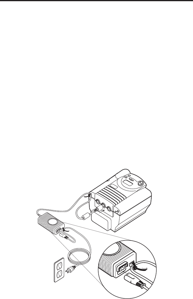
5.5.1 us i n g aC po W e r
Complete the following steps to operate the device using AC power:
1. Plug the pronged end of the AC power supply’s cord into an
electrical outlet.
2. The external AC power supply features a cord retainer to provide
strainrelieffortheACpowercord.WrapthecordaroundtheAC
power supply’s cord retainer, using the wire tie supplied with your
power supply.
WARNING: Never plug the AC power supply into an outlet that is
controlled by a wall switch.
WARNING: Route the wires to avoid tripping.
3. Leaving a small amount of slack in the cord, connect the cord on
the other side of the power supply to one of the power inlets on
the device, as shown in Figure 5–8. The power cord has a locking
connector. To properly plug the cord in:
a. Pull the locking mechanism back.
b. Push the connector into place.
c. Release the lock.
Figure 5–8 Plugging in the AC Power Supply

23
User Manual
NOTE: You can plug the cord into either of the power inlets on the
back of the device.
4. Wrapthecordaroundthedevice’spowercordretainer,which
provides strain relief for the power cord.
5. Ensure that all connections are secure.
NOTE: If you need to disconnect the power cord from the device,
slide the locking connector back and then remove the power
cord.
5.5.2 us i n g dC po W e r
You can operate the device on DC power by using the Respironics DC
power adapter accessory (when available). See the DC power adapter
instructions for more information.
CAUTION: Only use the Respironics DC power adapter available
from your home care provider. Use of any other system
may cause damage to the device or the vehicle.
CAUTION: WhenDCpowerisobtainedfromavehiclebattery,the
device should not be used while the vehicle’s engine is
running. Damage to the device or the vehicle may occur.
24
User Manual
Ch a p T e r 6: op e r a T i n g T h e de v i C e
This chapter explains how to start the device and change the settings.
6.1 sT a r T i n g T h e bipap s/T
1. Plug in the device to an AC or DC power source to power up the
unit.Aconrmationalarmsounds,andthecontrolpadbuttonslight
up.
NOTE: If the alarm does not sound or the buttons do not light up, the
device requires servicing. Contact your home care
provider.
Several screens appear initially during this step:
a. TherstscreenthatappearsistheSelfTestscreen,shownin
Figure 6–1. This is the internal test performed by the device.
Figure 6–1 Self Test Screen
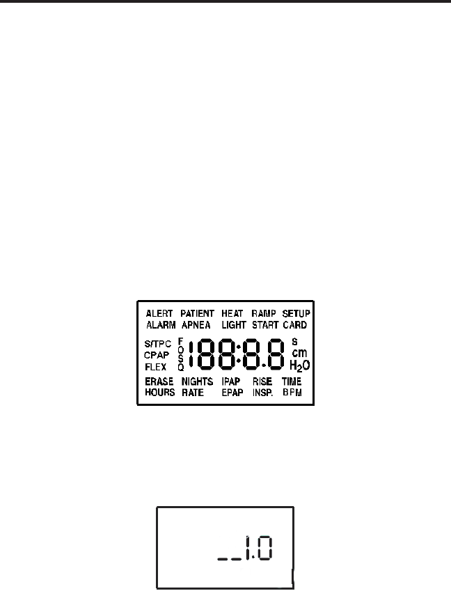
b. The next screen displays the software version, as shown in
Figure 6–2:
Figure 6–2 Software Version Screen
NOTE: Version 1.0 shown in Figure 6–2 is an example. Your device
may have a higher software version installed.
25
User Manual
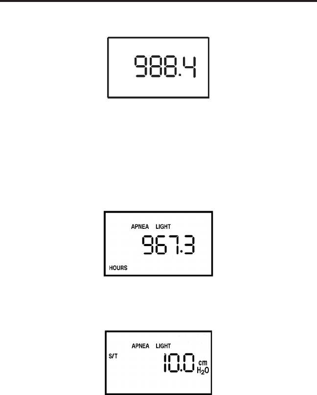
c. The third screen to appear is the Blower Hours screen, which
displays the blower hours time meter:
Figure 6–3 Blower Hours Screen
NOTE: WiththeexceptionofthePressure On/Off button, the control
padisinactiveduringtheserstthreescreens.Eachofthese
screensappearsforapproximately1-3seconds.
d. The next screen that appears is the Standby screen, shown in
Figure 6–4. This indicates that the device is in the Standby state.
Figure 6–4 Standby Screen
2. Press the Pressure On/Off button to put the unit into the Operate
state. The Monitoring screen, shown in Figure 6–5, appears.
Figure 6–5 Monitoring Screen
Both the Monitoring and the Standby screens display the Patient
Disconnect, Apnea, and LED backlight icons if these features are
enabled. Additionally, the SmartCard icon displays if a SmartCard is
inserted.
The Monitoring screen also displays the actual measured pressure
and the Flex icon if Flex is enabled.

26
User Manual
3. Putonyourmaskassemblywhentheairstartstoow.
4. Make sure that no air is leaking from your mask into your eyes. If
it is, adjust the mask and headgear until the air leak stops. See the
instructions that came with your mask for more information.
NOTE: A small amount of mask leak is normal and acceptable.
Correct large mask leaks or eye irritation from an air leak as
soon as possible.
5. If you are using the device while sleeping, try placing the tubing
from the device over your headboard. This may reduce tension on
the mask.
6. Relax. Take normal, relaxed breaths through your nose.
NOTE: If you are having trouble with your mask, see Chapter 8,
Troubleshooting, for some suggestions.
6.2 Ch a n g i n g T h e de v i C e se T T i n g s
You can view the following settings and indicators on the device display screen:
• Measuredpressure
• Mode
• SmartCard
• Patientalarms
Additionally, you can view and modify the following settings using the
display screens:
• Humidierheat
• Flex
• RiseTime
• Rampstartpressure
• LEDbacklight
NOTE: Whenchanginganysetting(exceptfortheRampStart
Pressure setting), once a maximum setting is reached, the
setting rolls back over to the minimum setting, and likewise,
once a minimum setting is reached, it rolls back over to the
maximum setting provided. For example, the minimum
humidiersettingis1 and the maximum is 5. Once the
humidiersettingisincreasedto5, if you press the Heat
button again, the setting will go back to 1. Or, once the
humidiersettingisdecreasedto1, if you press the Ramp
button again, the setting will go back to 5.
27
User Manual
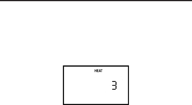
6.2.1 Ch a n g i n g T h e hu m i d i f i e r se T T i n g
IfyouareusingtheREMstarHeatedHumidierwithyourBiPAPS/T,
youcanadjustthehumidierheatsettingbycompletingthefollowing
steps:
1. From either the Standby or Monitoring screen, press and hold the
Heat buttonforapproximately4seconds.TheHumidierSetting
screen appears, as shown in Figure 6–6.
Figure 6–6 Humidier Setting Screen
2. Press the Heat buttontoincreasethehumidiersetting,orpressthe
Ramp button to decrease the setting. You can adjust the setting from
1 to 5. The change takes effect immediately as you adjust the setting.
3. You can exit this screen by pressing the Left or Right User buttons or
the Silence button.
Foradditionalinformationonusingahumidierwiththedevice,see
Chapter 10.
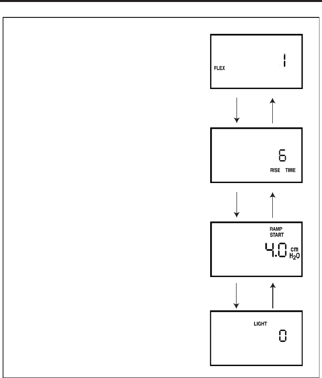
6.2.2 na v i g a T i n g T h e us e r di s p l a y sC r e e n s
You can navigate the rest of the user display screens by pressing the Left
and Right User buttons.
You can change the settings on any of the display screens by pressing the
Heat and Ramp buttons to increase or decrease the setting.
You can exit any of the user display screens by pressing the Silence
button.
28
User Manual
Figure 6–7 shows how to navigate the user display screens.
Right User
Button
Right User
Button
Right User
Button
Left User
Button
Left User
Button
Left User
Button
Only displayed if the Flex feature
is prescribed for you.
Only displayed if the rise time feature
is prescribed for you.
Only displayed if the ramp feature
is prescribed for you.
Flex Setting Screen
Rise Time Setting Screen
Ramp Start Pressure Setting Screen
LED Backlight Setting Screen
Figure 6–7 Navigating the User Display Screens
6.2.2.1 Ch a n g i n g T h e fl e x se T T i n g
The Flex setting allows you to adjust the level of air pressure relief that
you feel when you exhale during therapy.
WARNING: TheeffectivenessofBi-Flextherapyhasnotbeen
established for pediatric patients at this time.
NOTE: The Flex feature is not prescribed for all users. If the screen
shown in Figure 6–8 does not appear on your display, you
cannot adjust this setting.

29
User Manual
To change the Flex setting, complete the following steps:
1. From either the Monitoring or Standby screens, press the Right User
button. The Flex Setting screen appears, as shown in Figure 6–8.
Figure 6–8 Flex Setting Screen
2. To increase or decrease the Flex setting, press the Heat or Ramp
button until the correct setting appears. You can choose from 1 to 3.
NOTE: It is recommended that you start with the minimum setting of
1, which provides the least relief. Levels 2 and 3 progressively
increase the pressure relief.
6.2.2.2 Ch a n g i n g T h e ri s e Ti m e se T T i n g
Rise time is the time it takes for the device to change from EPAP to IPAP.
Youcanadjusttherisetimetondthesettingthatprovidesyouwiththe
most comfort.
NOTE: The rise time feature is not prescribed for all users. If the
screen shown in Figure 6–9 does not display, you cannot
adjust this setting.
Additionally, if the Flex feature has been prescribed for you,
whenFlexisenabled,therisetimeisxedatasettingof3.
The Rise Time screen will not display, and you won’t be able
to adjust the setting.

30
User Manual
To change the rise time setting, complete the following steps:
1. From either the Monitoring or Standby screens, press the Right User
button until you reach this screen. The Rise Time Setting screen is
shown in Figure 6–9.
Figure 6–9 Rise Time Setting Screen
2. Increase or decrease the rise time setting from 1 to 6 by pressing the
Heat or Ramp buttonuntilyoundtherightsetting.Asettingof1 is
the fastest rise time, while 6 is the slowest.
6.2.2.3 Ch a n g i n g T h e ra m p sT a r T i n g pr e s s u r e
The device is equipped with an optional ramp feature. This feature will
reduce the pressure and then gradually increase (ramp) the pressure to
the prescription pressure setting so you can fall asleep more comfortably.
NOTE: The ramp feature is not prescribed for all users. If the screen
shown in Figure 6–10 does not appear on your display, you
cannot adjust this setting.
To change the ramp starting pressure setting, complete the following steps:
1. From either the Monitoring or Standby screens, press the Right User
button until the Ramp Start Setting screen appears, as shown in
Figure 6–10.
Figure 6–10 Ramp Start Setting Screen
2. Press the Heat or Ramp button to increase or decrease the ramp
starting pressure as needed. You can adjust the setting from 4.0 cm
H
2
O to your EPAP or CPAP setting.
31
User Manual
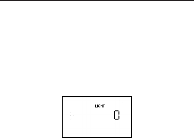
6.2.2.4 Ch a n g i n g T h e led ba C k l i g h T se T T i n g
WhenairowisturnedonandthedeviceisintheOperatestate,youcan
turn the control pad lighting behind the buttons on or off using the LED
backlight setting.
NOTE: Thelightsarealwaysonwhentheairowisoffandtheunitis
in Standby.
To change the LED backlight setting, complete the following steps:
1. From either the Monitoring or Standby screens, press the Right User
button until the LED Backlight Setting screen appears, as shown in
Figure 6–11.
Figure 6–11 LED Backlight Setting Screen
2. Press the Heat or Ramp button to select a new setting. A setting of 1
means the light is on, while 0 means the light is off.

32
User Manual
Ch a p T e r 7: al a r m s
This chapter describes the BiPAP S/T alarms and what you should do if
an alarm occurs.
7.1 in T r o d u C T i o n T o al a r m s
The device provides three alarm levels: high, medium, and low priority.
High Priority These alarms require immediate response.
The alarm signal consists of a red LED
indicator and a sound that is either a periodic
patternconsistingofatwo-secondbeep
followedbytwo-secondsofsilenceora
pattern of three beeps, a pause, and then two
more beeps. The display has the message
ALARM at the top of the screen. The tables
in Section 7.3 display these sounds using the
following symbols: or•••••
Medium Priority These alarms require prompt response. The
alarm signal consists of a yellow LED and a
sound that repeats a pattern of three beeps.
The display has the message ALARM at the
top of the screen. The tables in Section 7.3
display these sounds using the following
symbols:•••
Low Priority These alarms require your awareness. The
alarm signal consists of a yellow LED and a
sound that repeats a pattern of two beeps. The
display has the message ALARM at the top
of the screen. The tables in Section 7.3 display
thesesoundsusingthefollowingsymbols:••
Someaudiblealarmsareself-cancellable.Thismeansthatthealarm
sound stops when the cause of the alarm is corrected.
33
User Manual
The alarm LED indicators are located on the right side of the control pad,
as shown in Figure 7–1.
High Priority
Alarm LED (RED)
Low/Medium Priority
Alarm LED (Yellow)
AC
DC
Alarms
Power
Figure 7–1 Alarm LED Indicators
In addition to the alarm LED indicators, the control pad also contains
Alarm Reset and Alarm Silence buttons, as shown in Figure 7–2.
Alarm
Silence
Button
RAMP
HEAT
SILENCE
RESET
Alarm
Reset
Button
Figure 7–2 Alarm Buttons
34
User Manual
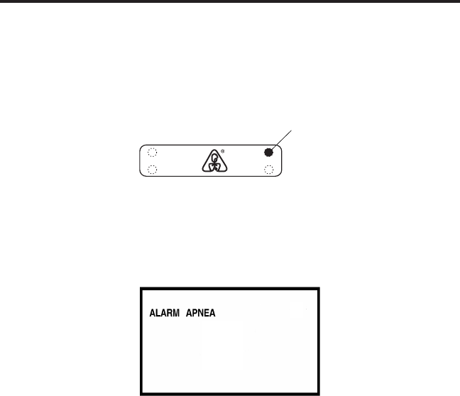
7.2 Wh a T T o do Wh e n a n al a r m oC C u r s
The following example applies to most alarm conditions. Follow these
steps unless otherwise directed by the alarm tables that follow.
1. Look at the alarm indicators and listen to the alarm sound.
Alarm LED
Lights Up
AC
DC
Alarms
Power
Figure 7–3 Alarm LED Lights Up
NotethecoloroftheLEDandwhethertheLEDissolidorashing.
2. Look at the display for text.
Figure 7–4 Sample Alarm Display
The word ALARM appears at the top of the screen to indicate an
alarm. Additional codes and icons may also appear depending on
the type of alarm.
3. Press the Silence button to temporarily silence the alarm (for one
minute). The display returns to the screen that was showing when
the alarm occurred.
4. Look up the alarm in the alarm tables in Section 7.3 and perform the
actionspecied.
5. Press the Reset button to clear the alarm.

35
User Manual
7.3 al a r m Ta b l e s
Thefollowingtablessummarizethehighpriority,mediumpriority,and
low priority alarms.
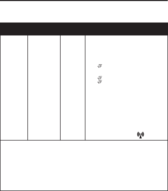
7.3.1 hi g h pr i o r i T y al a r m s
Alarm
LED
Alarm
Sound
Display
Message
Action
Possible
Cause
Your
Action
Red Flash
• • • • •
ALARM and
PATIENT
icons
flash
Operates Breathing circuit is
disconnected or has
a large leak.
Reconnect the circuit
or fix the leak.
Red Flash
• • • • •
ALARM
and APNEA
icons flash
Operates
An apnea event
occurred during
therapy.
Continue using the
device. Report the
alarm to your home
care provider.
Red Flash
• • • • •
ALARM
flashes and
an error
code ("Exx")
displays
Shuts down.
Blower cannot
be restarted.
Device failure
Press the
RESET button to
reset the alarm.
Remove power from the
unit. Restore power. If
the alarm continues,
contact your home care
provider.
Red Flash
• • • • •
ALARM
and
cm H
2
O
icons flash
Operates
Excessive leak
or blockage;
malfunctioning unit.
Press the RESET
button to reset the
alarm. Check for the
following: dirty inlet
filters, blocked air
intake, excessive leak
in the circuit. If the
alarm continues, call
your home care
provider.
Red Solid
Blank
screen
Shuts down
Battery is discharged.
-or-
Power was lost
while the unit was
providing therapy.
Remove the DC power
source from the unit.
Replace the battery and
restore power to the
unit. Or, seek a reliable
AC power source.
Press the Pressure On/
Off button to silence
the alarm. Restore
power.

36
User Manual
7.3.2 me d i u m pr i o r i T y al a r m s
Alarm
LED
Alarm
Sound
Display
Message
Harmony
Action
Possible
Cause
Your
Action
Ye llow Flash
• • •
DC Power
LED Flashes
Operates Battery nearly
discharged.
Press the RESET button to
reset the alarm. Replace
the battery. If the alarm
continues, contact your
home care provider.
7.3.3 lo W pr i o r i T y al a r m s
Alarm
LED
Alarm
Sound
Display
Message
Device
Action
Possible
Cause
Your
Action
Yellow Solid
• •
CARD
flashes
and
card error
code ("Cxx")
displays
Operates
There is a problem
with the SmartCard
inserted in the
SmartCard
connectivity slot.
Perhaps the
SmartCard is
inserted upside down
or backwards.
Confirm that the
SmartCard is properly
inserted.
If the alarm continues
to occur, remove the
SmartCard from the
device and contact
your home care
provider.
Operates
Device lost AC
power and is now
operating on DC
power.
Press the RESET
button to reset the
alarm. Check the
AC power. Seek a
reliable power
source. Provide AC
power if you do not
want to use a battery;
otherwise, no further
action is needed.
At start-up only,
alarm notifies you
that a battery is
being used
to provide power.
Yellow Solid
DC power
LED flashes
• •
Unchanged
Operates
Operates
Yellow Solid
AC power
LED flashes
Yellow Solid
• •
• •
The device
has successfully
downloaded the
prescription from
the SmartCard.
Remove the
SmartCard from the
device. If alarm
continues to occur,
contact your home
care provider.
ALARM,
CARD and
cm H
2
O
symbols
flash
The DC output
voltage from the AC
power supply is out
of spec (< 22 VDC)
or there is a
defective battery
sense line on the
DC power adapter.
Remove AC power
from the power supply
and then restore
power. If alarm
continues to occur,
contact your home
care provider.

37
User Manual
Ch a p T e r 8: Tr o u b l e s h o o T i n g
This chapter describes problems that you may experience with your
BiPAP S/T or mask and provides possible solutions.
Problem Why It Happened What To Do
Check the outlet
power and verify
that the device
is plugged in. If the
problem continues,
call your home care
provider.
Theinletltersmay
be dirty.
The unit may be
operating in direct
sunlight or near a heater.
Clean or replace the
inletairltersas
described in Chapter
9. Make sure the unit is
away from bedding or
curtains that could
blocktheowofair
around the device.
Make sure the unit is
away from direct
sunlight and heating
equipment.
If the problem
persists, contact your
home care
provider.
The air out of
the mask is
much warmer
than usual.
This could be due to
improper headgear
adjustment or improper
masktting.
Check the headgear
adjustment as
described in the
headgear instructions.
Refer to your mask
instructions to make
sure the mask is
properlytted.Ifthe
problem continues,
contact your home care
provider for a
rettingoradifferent
sizemask.
The mask feels
uncomfortable
to wear.
If the power LED is off,
there’s no power at the
outlet or the device is
unplugged. If the power
LED is on, the problem is
in the device.
The device does
not operate
when you press
the Pressure On/
Off button.

38
User Manual
Problem Why It Happened What To Do
Be sure to rinse the mask
thoroughly after cleaning
to remove residue. See
the mask cleaning
instructions for detailed
information. If the
problem continues,
contact your home care
providerforaretting
oradifferentsizemask.
Irritation or allergic
reaction to the mask
material.
Use a barrier between
your skin and the mask,
such as 3M’s Microfoam
®
or Squibb’s Duoderm
®
.
Refer to your mask
instructions for additional
information.
Redness occurs
when the mask
cushion accessory
comes in contact
with the skin.
The mask may not be
positioned correctly, or
the mask is not
properlytted.
Check the headgear
adjustment as described
in the headgear
instructions. Refer to your
mask instructions to make
sure the mask is properly
tted.Iftheproblem
continues, contact your
home care provider
forarettingora
differentsizemask.
Sore or dry eyes.
This could be due to
impropermasktting
or improper mask
cleaning.
This could be due to
improper headgear
adjustment or
improper
masktting.
Check the headgear
adjustment as
described in the
headgear instructions.
Refer to your mask
instructions to make
sure the mask is
properlytted.Ifthe
problem continues,
contact your home care
provider for a
rettingoradifferent
sizemask.
There is
signicant
air leakage
around
the mask.
Redness occurs
when the mask
cushion comes
in contact with
the skin.

39
User Manual
Discontinue use.
Contact your home
care provider or
Respironics for
directions on how to
have your unit
serviced.
Please have the serial
number ready when
you call.
The tubing has become
disconnected from the
system.
Press the RESET button
to reset the alarm.
Reconnect the tubing
and press the Pressure
On/Off button to
restarttheairow.If
theairowdoesnot
restart, the device
may not be operating
correctly. Contact your
home care provider
or Respironics for
directions on having
the unit serviced. Please
have your serial number
ready when you call.
A patient
disconnect alarm
occurs.
Problem Why It Happened What To Do
The unit or power
supply has been
dropped or mishandled,
or water has been
spilled onto or into the
device or
the power supply.
There are
unexplained
changes in the
performance of
the unit.
Runny nose.
Nasal reaction to the
airow.
Call your health care
professional.

40
User Manual
The unit or power supply
has been dropped or
mishandled, or the unit or
power supply is in an
area with high EMI
emissions.
Unplug the unit and
the power supply.
Relocate the unit to
an area with lower EMI
emissions.
The unit’s
display is erratic.
Problem Why It Happened What To Do
The SmartCard is not
inserted properly. It may
be inserted upside down
or backwards.
Remove the SmartCard
and reinsert it so that
the printed side of the
card is facing up and
the end with the arrow
goes into the device
rst.Iftheerror
message appears again,
contact your home
care provider or
Respironics for
directions on having
your unit
serviced. Please have
your serial number
ready when you call.
A SmartCard
error occurs.

41
User Manual
Ch a p T e r 9: Cl e a n i n g a n d ma i n T e n a n C e
This chapter provides information on how to clean and maintain your
BiPAP S/T system.
9.1 Cl e a n i n g T h e de v i C e
Before cleaning or performing any routine maintenance, always make
sure the unit is not operating and disconnect the device from the power
source.
NOTE: The following cleaning instructions are for the BiPAP S/T
unit only. To clean the accessories, refer to each accessory’s
instruction sheet.
CAUTION: Do not immerse the unit or allow any liquid to enter the
enclosure,inletlter,oranyopenings.
Clean the front panel and exterior of the enclosure as needed using a
cloth dampened with water and a mild detergent. Allow the device to
dry completely before plugging in the power cord.
Gently wash the reusable circuit tubing in a solution of warm water and
a mild detergent. Rinse thoroughly and allow to air dry.
9.2 Cl e a n i n g o r re p l a C i n g T h e in l e T fi l T e r s
Thedevicehastworemovableltersattheairinlet.Thegrayfoam
lteriswashableandreusable.Theoptionalwhite,ultra-nelteris
disposable.Thegrayfoamltershouldbecleanedatleastonceevery
two weeks under normal usage and replaced with a new one every six
months.Thewhiteultra-nelterisdisposableandshouldbereplaced
after 30 nights of use or sooner if it appears dirty. Do not attempt to clean
theultra-nelter.Itwilldamagethelter.
NOTE: Dirtyinletltersmaycausehighoperatingtemperaturesand
mayaffectperformance.Regularlyexaminetheinletltersas
needed for integrity and cleanliness.
42
User Manual
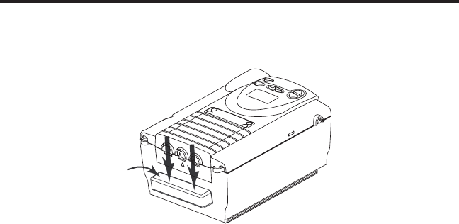
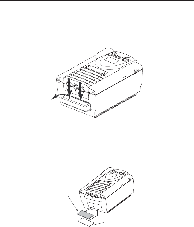
1. Make sure the device is not operating, and disconnect the power
cord from the wall outlet or DC source.
2. AsshowninFigure9–1,removetheltercapbygentlypressing
down on the top panel and pulling the cap out, away from the
device.
Figure 9–1 Removing the Filter
3. RemovetheltersfromtheenclosureasshowninFigure9–2.The
toplteristhereusablegrayfoamlter.Thebottomlteristhe
optionaldisposable,white,ultra-nelter.
Reusable Gray
Foam Filter
Disposable Ultra-fine
Filter
Figure 9–2 Removing the Air Filters
4. Checkthelterstoseeiftheyaredirtyortorn.

43
User Manual
5. Ifneeded,washthegrayfoamlterinwarmwaterandamild
detergent.Rinsethelterthoroughlytoremovealldetergentresidue.
Allowtheltertocompletelydrybeforereinstallingit.Ifthepollen
lteristorn,replaceit.
6. Iftheultra-nelterisdirtyortorn,replaceit.
7. Reinstallthelters,withtheultra-nelteronthebottom.Slidethe
ltersintotheairinletattherearofthedeviceandpushthemdown
into the recess.
8. Replacetheltercap.
Contactyourhomecareprovidertoorderadditionallters.
NOTE: To clean the breathing circuit accessories, refer to each
accessory’s instruction sheet.
9.3 Ca r r y i n g Ca s e
A carrying case is now included with your BiPAP S/T system (reorder
number: 1005965). The case is designed to hold your BiPAP S/T system,
alongwithyourbreathingcircuitaccessoriesandhumidier.
Whenyouaretraveling,thecarryingcasecanbeusedforcarry-on
luggage only. The carrying case will not protect the device if it is put
through checked baggage.
NOTE: Iftravelingwithyourhumidier,makesureyouemptythe
water chamber before placing it in the carrying case.

44
User Manual
Ch a p T e r 10: aC C e s s o r i e s
There are several accessories you can use with the device.
10.1 ad d i n g a hu m i d i fi e r
TheREMstarHeatedHumidier,REMstarPass-overHumidier,and
H2HeatedHumidierareavailablefromyourhomecareprovider.The
humidiersmayreducenasaldrynessandirritationbyaddingmoisture
(andheat,ifapplicable)totheairow.
CAUTION: Forsafeoperation,thehumidiermustalwaysbe
positioned below the circuit connection at the mask and
theairoutletonthedevice.Thehumidiermustbelevel
for proper operation.
Refertothehumidierinstructionsforcompletesetupinformation.
10.2 ad d i n g ox y g e n T o T h e de v i C e
Oxygen may be added to the mask connection. Please note the warnings
listed below when using oxygen with the device.
WARNING: If you are using oxygen, your BiPAP S/T must be
equipped with the Respironics Pressure Valve (Part
number 302418). Failure to use the Pressure Valve could
resultinarehazard.
WARNING: Oxygenacceleratesres.Keepthedeviceandthe
O
2
containersawayfromheat,openames,anyoily
substance, or other sources of ignition. Do not smoke in
the area near the device or the O
2
container.
WARNING: Whenusingoxygenwithyourdevice,theoxygensupply
must comply with the local regulations for medical
oxygen.
WARNING: Whenusingoxygenwiththissystem,turnthedevice
on before turning the oxygen on. Turn the oxygen off
before turning the device off. This will prevent oxygen
accumulation in the device.

45
User Manual
Ch a p T e r 11: sp e C i f i C a T i o n s
en v i r o n m e n T a l
Operating Storage
Temperature 41ºFto95ºF -4ºFto140ºF
Relative Humidity 15 to 95%
(non-condensing)
15 to 95%
(non-condensing)
Atmospheric Pressure
(5600 feet to sea level)
83 to 102kPa
ph y s i C a l
Dimensions: 9.75”Lx6.625”Wx4.4”H
Weight: Approximately 4 lb.
el e C T r i C a l
AC Voltage Source: 100to240V,50/60Hz
DC Voltage Source: 12 VDC (when operated with the
external DC power adaptor accessory)
AC Current: 1.25 A maximum
DC Current: 3.0 A maximum
Protection against electric shock: Class II
Degree of protection against electric shock: Type BF Applied Part
Degree of protection against harmful ingress of water:
S/T unit: Ordinary Equipment, IPX0
AC Power Supply (Reorder number 1012832): Drip Proof, IPX1
DC Power Adapter (Reorder number 1012975): Drip Proof, IPX1
Modes of Operation: Continuous
Electromagnetic Compatibility: The BiPAP S/T meets the requirements
ofEN60601-1-2,secondedition(2001).
Fuses: Therearenouser-replaceablefuses.

46
User Manual
pr e s s u r e
Output: 4 to 30 cm H
2
O
Co n T r o l aC C u r a C y
Parameter Range Accuracy
IPAP 4 to 30 cm H
2
O* ±5 cm H
2
O**
EPAP 4 to 25 cm H
2
O* ±5 cm H
2
O**
CPAP 4 to 20 cm H
2
O ±5 cm H
2
O**
Breath Rate 0 to 30 BPM Greater of ± 1 BPM or
±10% of the setting
(when measured over a
4 minute period)
Timed Inspiration 0.5 to 3.0 seconds ±(0.1 + 10% of the
setting) seconds
Ramp Duration 0 to 45 minutes ±10% of the setting
Rise Time 1 to 6*** ±25%****
* Limited to 20 cm H
2
OwhenusingtheBi-FlexfeatureinSmode.
** Dynamic pressure accuracy is ± 5 cm H
2
O measured at the patient end
ofthecircuitwithaWhisperSwivelIIandvaryingowconditions.
Static pressure accuracy is ± 2 cm H
2
O measured at the patient end of
thecircuitwithaWhisperSwivelIIandnopatientow.
*** The range of values correspond to tenths of seconds (e.g., a setting of
4 indicates a Rise Time of 0.4 seconds).
****MeasuredatthepatientendofcircuitwithaWhisperSwivelII
exhalationdeviceandnopatientow.
di s p o s a l
Whennecessary,disposeoftheBiPAPS/Tandaccessoriesinaccordance
with local regulations.

47
User Manual
ap p e n d i x a: emC in f o r m a T i o n
Gu i d a n c e a n d Ma n u f a c t u r e r ’s de c l a r a t i o n - el e c t r o M a G n e t i c eM i s s i o n s : is device
is intended for use in the electromagnetic environment specified below. e user of this device should
make sure it is used in such an environment.
eM i s s i o n s te s t co M p l i a n c e el e c t r o M a G n e t i c en v i r o n M e n t - Gu i d a n c e
RF emissions
CISPR 11
Group 1 The device uses RF energy only for its internal function.
Therefore, its RF emissions are very low and are not likely
to cause any interference in nearby electronic equipment.
RF emissions
CISPR 11
Class B The device is suitable for use in all establishments,
including domestic establishments and those directly
connected to the public low-voltage power supply
network.
Harmonic emissions
IEC 61000-3-2
Class A
Voltage uctuations/Flicker
emissions
IEC 61000-3-3
Complies

48
User Manual
Gu i d a n c e a n d Ma n u f a c t u r e r ’s de c l a r a t i o n - el e c t r o M a G n e t i c iM M u n i t y : is device
is intended for use in the electromagnetic environment specified below. e user of this device should
make sure it is used in such an environment.
iM M u n i t y te s t iec 60601 te s t
le v e l
co M p l i a n c e le v e l el e c t r o M a G n e t i c en v i r o n M e n t
-
Gu i d a n c e
Electrostatic
Discharge (ESD)
IEC 61000-4-2
±6 kV contact
±8 kV air
±6 kV contact
±8 kV air
Floors should be wood, concrete
or ceramic tile. If oors are covered
with synthetic material, the relative
humidity should be at least 30%.
Electrical Fast
Transient/Burst
IEC 61000-4-4
±2 kV for power supply lines
±1 kV for input-output lines
±2 kV for supply mains
±1 kV for input/output lines
Mains power quality should be
that of a typical home or hospital
environment.
Surge
IEC 61000-4-5
±1 kV dierential mode
±2 kV common mode
±1 kV dierential mode
±2 kV for common mode
Mains power quality should be
that of a typical home or hospital
environment.
Voltage dips, short
interruptions and
voltage variations
on power supply
input lines
IEC 61000-4-11
<5% U
T
(>95% dip in U
T
)
for 0.5 cycle
40% U
T
(60% dip in U
T
) for
5 cycles
70% U
T
(30% dip in U
T
) for
25 cycles
<5% U
T
(>95% dip in U
T
)
for 5 sec
<5% U
T
(>95% dip in U
T
)
for 0.5 cycle
40% U
T
(60% dip in U
T
) for
5 cycles
70% U
T
(30% dip in U
T
) for
25 cycles
<5% U
T
(>95% dip in U
T
)
for 5 sec
Mains power quality should be
that of a typical home or hospital
environment. If the user of
the device requires continued
operation during power mains
interruptions, it is recommended
that the device be powered from
an uninterruptible power supply
or a battery.
Power frequency
(50/60 Hz)
magnetic eld
IEC 61000-4-8
3 A/m 3 A/m Power frequency magnetic elds
should be at levels characteristic
of a typical location in a typical
hospital or home environment.
NOTE: U
T
is the a.c. mains voltage prior to application of the test level.
49
User Manual
Gu i d a n c e a n d Ma n u f a c t u r e r ’s de c l a r a t i o n - el e c t r o M a G n e t i c iM M u n i t y : is device
is intended for use in the electromagnetic environment specified below. e user of this device should
make sure it is used in such an environment.
iM M u n i t y te s t iec 60601 te s t
l
e v e l
co M p l i a n c e
l
e v e l
e
l e c t r o M a G n e t i c en v i r o n M e n t - Gu i d a n c e
Conducted RF
IEC 61000-4-6
Radiated RF
IEC 61000-4-3
3 Vrms
150 kHz to 80 MHz
3 V/m
80 MHz to 2.5 GHz
3 Vrms
3 V/m
Portable and mobile RF communications equipment
should be used no closer to any part of the device,
including cables, than the recommended separation
distance calculated from the equation applicable to the
frequency of the transmitter.
Recommended separation distance:
d = 1.2
150 kHz to 80 MHz
d = 1.2
80 MHz to 800 MHz
d = 2.3
800 MHz to 2.5 GHz
Where P is the maximum output power rating of the
transmitter in watts (W) according to the transmitter
manufacturer and d is the recommended separation
distance in meters (m).
Field strengths from xed RF transmitters, as
determined by an electromagnetic site survey
a
,
should be less than the compliance level in each
frequency range
b
.
Interference may occur in the vicinity of equipment
marked with the following symbol:
NOTE 1: At 80 MHz and 800 MHz, the higher frequency range applies.
NOTE 2: These guidelines may not apply in all situations. Electromagnetic propagation is aected by absorption
and reection from structures, objects, and people.
a: Field strengths from xed transmitters, such as base stations for radio (cellular/cordless) telephones and land
mobile radios, amateur radio, AM and FM radio broadcast and TV broadcast cannot be predicted theoretically
with accuracy. To assess the electromagnetic environment due to xed RF transmitters, an electromagnetic
site survey should be considered. If the measured eld strength in the location in which the device is used
exceeds the applicable RF compliance level above, the device should be observed to verify normal operation.
If abnormal performance is observed, additional measures may be necessary, such as re-orienting or relocating
the device.
b: Over the frequency range 150 kHz to 80 MHz, the eld strengths should be less than 3 V/m.
50
User Manual
r
e c o M M e n d e d se p a r a t i o n di s t a n c e s b e t w e e n po r t a b l e a n d Mo b i l e rf co M M u n i c a t i o n s
eq u i p M e n t a n d th i s de v i c e : e device is intended for use in an electromagnetic environment in
which radiated RF disturbances are controlled. e customer or the user of this device can help prevent
electromagnetic interference by maintaining a minimum distance between portable and mobile RF
communications equipment (transmitters) and this device as recommended below, according to the
maximum output power of the communications equipment.
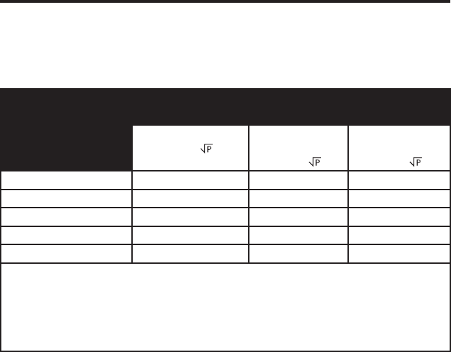
ra t e d Ma x i M u M po w e r
ou t p u t o f tr a n s M i t t e r
(w)
se p a r a t i o n di s t a n c e ac c o r d i n G t o fr e q u e n c y o f tr a n s M i t t e r
(M)
150
khz t o 80 Mhz
d = 1.2
80 Mhz t o 800
Mhz
d = 1.2
800 Mhz t o 2.5
Ghz
d = 2.3
0.01 0.12 0.12 0.23
0.1 0.38 0.38 0.73
1 1.2 1.2 2.3
10 3.8 3.8 7.3
100 12 12 23
For transmitters rated at a maximum output power not listed above, the recommended separation distance
d in meters (m) can be estimated using the equation applicable to the frequency of the transmitter,
where P is the maximum output power rating of the transmitter in watts (W) according to the transmitter
manufacturer.
Note 1: At 80 MHz and 800 MHz, the separation distance for the higher frequency range applies.
Note 2: These guidelines may not apply in all situations. Electromagnetic propagation is aected by
absorption and reection from structures, objects, and people.
li m i T e d Wa r r a n T y
Respironics, Inc. warrants that the BiPAP S/T system shall be free from defects
of workmanship and materials and will perform in accordance with the product
specications for a period of two (2) years from the date of sale by Respironics,
Inc. to the dealer. If the product fails to perform in accordance with the product
specications, Respironics, Inc. will repair or replace – at its option – the
defective material or part. Respironics, Inc. will pay customary freight charges
from Respironics, Inc. to the dealer location only. This warranty does not cover
damage caused by accident, misuse, abuse, alteration, and other defects not
related to material or workmanship.
Respironics, Inc. disclaims all liability for economic loss, loss of prots,
overhead, or consequential damages which may be claimed to arise from any
sale or use of this product. Some states do not allow the exclusion or limitation
of incidental or consequential damages, so the above limitation or exclusion may
not apply to you.
This warranty is given in lieu of all other express warranties. In addition, any
implied warranties – including any warranty of merchantability or tness for
the particular purpose – are limited to two years. Some states do not allow
limitations on how long an implied warranty lasts, so the above limitation may
not apply to you. This warranty gives you specic legal rights, and you may also
have other rights which vary from state to state.
To exercise your rights under this warranty, contact your local authorized
Respironics, Inc. dealer or contact Respironics, Inc. at:
1001 Murry Ridge Lane
Murrysville, Pennsylvania 15668-8550
1-724-387-4000

1006776
JR 1/4/08
EN-DOM
