Fluorescent
Sand
as
a
Tracer
of
Fluvial
Sediment
GEOLOGICAL
SURVEY
PROFESSIONAL
PAPER
562-E
Fluorescent Sand
as
a
Tracer
of
Fluvial
Sediment
By
VANCE
C.
KENNEDY
and
DOROTHY
L.
KOUBA
SEDIMENT
TRANSPORT
IN
ALLUVIAL
CHANNELS
GEOLOGICAL
SURVEY
PROFESSIONAL
PAPER
562-E
An
investigation
of
sand
movement
in
a
gravel-bed
stream
UNITED
STATES
GOVERNMENT
PRINTING
OFFICE,
WASHINGTON
:
1970
UNITED
STATES
DEPARTMENT
OF
THE
INTERIOR
WALTER
J.
HICKEL,
Secretary
GEOLOGICAL
SURVEY
William
T.
Pecora,
Director
For
sale
by
the
Superintendent
of
Documents,
U.S.
Government
Printing
Office
Washington,
D.C.
20402
-
Price
30
cents
(paper
cover)
CONTENTS
Abstract-.-
-_---___-------------------_-
Introduction.
___________________________
Acknowledgments__
____________________
Methods
used
in
this
study_____________
Coating
of
grains
with
fluorescent
paint.
Sampling
of
stream
sand____________
Sample
processing.__________________
The
experiment_______________________
Results_-_-______---__-____--_-----___
Page
El
1
2
2
2
2
2
3
3
Results Continued
Relation
of
grain
velocity
to
grain
size___-_--____-
E5
Mixing
of
fluorescent
grains.-____________________
7
Estimation
of
sediment
discharge.________________
10
Experiment
with
batch
addition__________________
11
Estimation
of
sediment
in
active
storage
within
a
reach______________________________________
12
Other
possible
uses
for
fluorescent
solids
in
stream
studies.
12
Conclusions._______________________________________
13
References
cited.___________________________________
13
ILLUSTRATIONS
Page
FIGURE
1.
Sketch
map
of
study
reach
on
Clear
Creek
at
Golden,
Colo_._______--_____-_----____-_-
El
2.
Sketch
of
equipment
used
in
sampling
transported
sand______________________________
2
3-10.
Graphs
showing
concentration
of
fluorescent grains
at
station
3
resulting
from
addition
at
station
1:
3.
Size
range
0.99-1.29
mm-_-_-_____-_---_-___----_---__-__--_---_-----_--__-
4
4.
Size
range
0.86-0.99
mm-__-______-____-____-___-_-_____---____--_-----___-
4
5.
Size
range
0.52-0.86
mm_--_-_-_____-____-----_----_-_-_-------_-----_-_-_-
5
6.
Size
range
0.38-0.52
mm__-_________________-_-_-_-_-_-------_-_---________
6
7.
Size
range
0.30-0.38
mm__-_____________________---_-_--__-_-_-_--__-______
6
8.
Size
range
0.25-0.30
mm-___-_--_______--_-_---_-_-_-_---_-__----_-----___-
7
9.
Size
range
0.18-0.25
mm_______________________-__________-_--___-_________
8
10.
Size
range
0.15-0.18
mm._______________________________-------_-_-___-____
9
11-14.
Graphs
showing:
11.
Relation
of
traveltime to
grain
size
for
fluorescent
sand
in
Clear
Creek..________
9
12.
Lateral
mixing
of
fluorescent
sand
as
related
to
grain
size.._____________________
9
13.
Sediment
discharge
in
relation to
grain
size
as
determined
by
depth-integrated
sampling
and
the
fluorescent-tracer
method__________-_-__-_---_-___-____.
10
14.
Variation
in
concentration
of
0.25
to
0.52
mm
blue
fluorescent
sand
at
station
3
after
batch
addition
at
station
1_______________________________________
11
TABLES
TABLE
1.
Average
number
of
fluorescent
grains
per
minute
added to
Clear
Creek
in
various
size
fractions.-______________________________________________________---_-______
2.
Comparison
of
sediment
discharge
in
Clear
Creek
calculated
from
depth-integrated
samples
and
fluorescent-sand
measurements
____________________________________________
3.
Time
to
reach
peak
concentration
of
blue
grains
at
station
3
as
related
to
grain
diameter.
_ _
4.
Sediment
in
active
storage
in
Clear
Creek.___________________________________________
Page
E5
10
12
12

SEDIMENT
TRANSPORT
IN
ALLUVIAL
CHANNELS
FLUORESCENT
SAND
AS
A
TRACER
OF
FLUVIAL
SEDIMENT
By
VANCE
C.
KENNEDY
and
DOROTHY
L.
KOUBA
ABSTRACT
Stream
sand
coated
with
fluorescent
paint
was
added
at
a
constant
known
rate
to
dear
Creek
at
Golden,
Colo.,
during
a
28-hour
period,
and the
concentration
of
fluorescent
grains
was
monitored
at
a
point
810
meters
downstream from
the
point
of
introduction.
Stream
width
in
the
study
reach
averaged
about
21
meters,
mean
velocity
about
1.4
meters
per
second,
and
mean
discharge
8.2
cubic
meters
per
second.
Flow
was
very
turbulent
over
a
gravel
bed.
First-arrival
time
of
fluorescent
sand
correlated
with
the
square
of
grain
diameter
in
the
range
0.15-0.86
millimeters.
Al-
though
Clear
Creek
meanders
gently,
complete
lateral
mixing
of
fluorescent
sand
was
not
achieved
within
the
study
reach.
How-
ever,
steady-state
conditions
apparently
were
achieved
for
the
finer
particles,
with
highest concentrations
on
the
north
side
and
lowest
concentrations
on
the
south
side
of
the
stream.
Lateral
mixing
of
coarser grains
was
much
better than
for
finer
grains.
Suspended-sediment
discharges
for
various
size
ranges
were
computed
from
suspended-sediment
samples
which
do
not
in-
clude
sand-sized
particles
moving
near
or
on
the
bed
and
from
"dilution"
of
fluorescent
sand
which
presumably
measures
total
sediment
discharges.
The
sediment
discharge
computed
from
the
tracer-dilution
method
was
about
30
percent
greater
than
the
suspended-sediment
discharge
computed
from
suspended
samples
for
the
0.15-0.18
millimeter
range
and
about
200
percent
greater
for
the
0.38-0.52
millimeter
range.
INTRODUCTION
A
study
of
the
movement
of
fluorescent
sand
in
Clear
Creek
about
24
km
(kilometers),
or
15
miles,
west
of
Denver,
Colo.,
was
made
during
the
period
May
26-28,
1965.
The
0.8
km
(half-mile)
study
reach
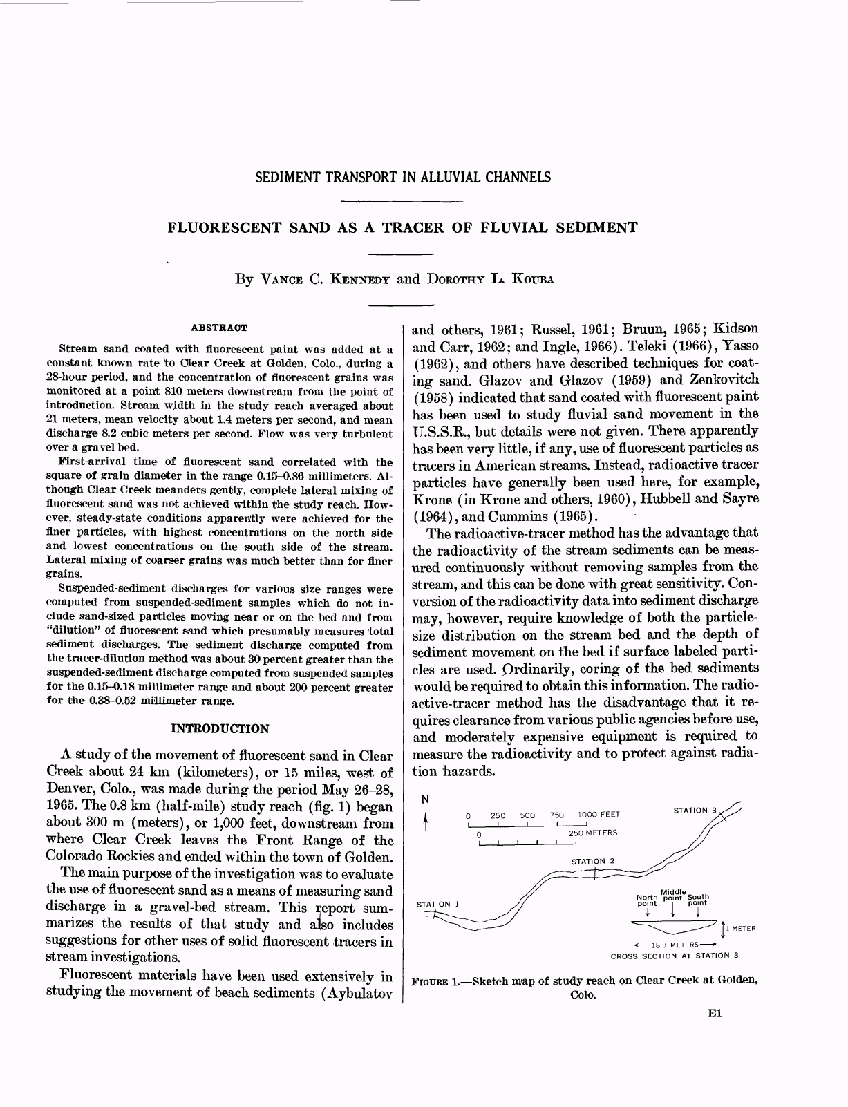
(fig.
1)
began
about
300
m
(meters),
or
1,000
feet,
downstream
from
where
Clear
Creek
leaves
the
Front
Eange
of
the
Colorado
Eockies
and
ended
within
the
town
of
Golden.
The
main
purpose
of
the
investigation
was
to
evaluate
the
use
of
fluorescent
sand
as
a
means
of
measuring
sand
discharge
in
a
gravel-bed
stream.
This
report
sum-
marizes
the
results
of
that
study
and
also
includes
suggestions
for
other
uses
of
solid
fluorescent
tracers
in
stream
investigations.
Fluorescent
materials
have
been
used
extensively
in
studying the
movement
of
beach
sediments
(Aybulatov
and
others,
1961;
Eussel,
1961;
Bruun,
1965;
Kidson
and
Carr,
1962;
and
Ingle,
1966).
Teleki
(1966),
Yasso
(1962),
and
others
have
described
techniques
for
coat-
ing
sand.
Glazov
and
Glazov
(1959)
and
Zenkovitch
(1958)
indicated
that
sand
coated
with
fluorescent
paint
has
been
used
to
study
fluvial
sand
movement
in
the
U.S.S.E.,
but
details
were
not
given.
There
apparently
has
been
very
little,
if
any,
use
of
fluorescent
particles
as
tracers
in
American
streams.
Instead,
radioactive
tracer
particles
have
generally
been
used
here,
for
example,
Krone
(in
Krone
and
others,
1960),
Hubbell
and
Sayre
(1964),
and
Cummins
(1965).
The
radioactive-tracer
method
has
the
advantage
that
the
radioactivity
of
the
stream
sediments can
be
meas-
ured
continuously
without
removing
samples
from the
stream,
and
this
can
be
done
with
great
sensitivity.
Con-
version
of
the
radioactivity
data
into
sediment
discharge
may,
however,
require
knowledge
of both
the
particle-
size
distribution
on
the
stream
bed
and
the
depth
of
sediment
movement
on
the
bed
if
surface
labeled
parti-
cles
are
used.
Prdinarily,
coring
of
the
bed
sediments
would be
required
to
obtain
this
information.
The
radio-
active-tracer
method
has
the
disadvantage
that
it
re-
quires
clearance
from
various
public
agencies
before
use,
and
moderately
expensive
equipment
is
required
to
measure
the
radioactivity
and
to
protect
against
radia-
tion
hazards.
K
.
.
Middle,,
_
North
point
South
point
I
point
I
I
183
METERS »
CROSS
SECTION
AT
STATION
3
FIGUBE
1. Sketch
map
of
study
reach
on
Clear
Creek
at
Golden,
Colo.
El
E2
SEDIMENT
TRANSPORT
IN
ALLUVIAL
CHANNELS
Fluorescent-sand
tracers
are
also
easily
detected,
and
sensitivity
is
limited
mainly
by
the
size
of
the
sample
collected.
Aybulatov, Boldyrev,
and
Griesseier
(1961)
claim
a
sensitivity
of
1
part
per
10
million.
Except
in
clear
shallow
water,
samples
of
sediment
must
be
taken
from
the
stream before
the
fluorescent
particles
can
be
detected.
An
ultraviolet
light
is
all
that
is
required
for
detection,
and
several
different
fluorescent
colors
can
be
used
simultaneously
to
identify
grains
differing
in
size,
shape,
or
specific
gravity.
When
quantitative
re-
sults
are
needed,
relatively
simple
counting
equipment
can
be
used
on
fractions
separated
on
the
basis
of
sieve
size
or
fall
diameter.
Both
Teleki
(1965)
and
DeVries
(1966)
have
described
instruments
for
counting
fluor-
escent
grains
automatically.
ACKNOWLEDGMENTS
This
experiment
would
have
been
impossible
with-
out
the
help
of
R.
L.
Malcolm,
E.
A.
Jenne,
R.
C.
Scott,
F.
C.
Ames,
F.
C.
Canney,
and
J.
O.
Johnson.
Exten-
sive
discussions
of
the
results
with
C.
Nordin,
W.
W.
Sayre,
E.
V.
Richardson,
and
F.
C.
Ames
have
greatly
aided
in
clarifying
the
significance
of
the
data.
A.
T.
Miesch
supervised
computer
testing
of
the
equations
for
lateral
mixing
of
sediment.
Professor
R.
B.
Krone,
of
the
University
of
California,
kindly
read
the
manu-
script
and
made
several
constructive
suggestions.
To
these
individuals
the
authors
express
their
great
appreciation.
Personnel
from
the
U.S.
Bureau
of
Reclamation
provided
the
washed
sized
sand
from
Clear
Creek.
METHODS
USED
IN
THIS
STUDY
COATING
OF
GRAINS
WITH
FLUORESCENT
PAINT
Sand
from
Clear
Creek
was
washed
and
sieved
into
three
size
fractions:
0.15-0.30, 0.30-0.52,
and
0.52-1.29
mm
(millimeters).
Each
size
fraction
of
thoroughly
dried
sand
was
coated
with
a
different
colored
paint
by
placing
it
in
a
small
motor-driven
cement
mixer
along
with
an
acetone
solution
of
a
water-insoluble
fluorescent
pigment.
1
As
soon
as
a
thin
layer
of
the
acetone
solu-
tion
had
coated
the
grains,
they
were
spread
out
to
dry
on
a
polyethylene
sheet.
The
resulting
poorly
cemented
aggregates
were
passed
between
rubber
rollers
to
reduce
them
to
single
grains.
The
number
of
fluorescent
grains
per
gram
in
each
size
fraction
was
then
determined
by
counting
under
ultraviolet
light.
Cost
of
such
coating
can
be
less
than
4.5
cents
per
kilogram
(10
cents
per
Ib)
if
lots
of
several
hundred
kilograms
are
prepared.
1
Care
was
taken
to
do
the
coating
outside
in
a
strong
breeze
in
order
to
reduce
buildup
of
acetone
vapors.
In
the
pnoiper
proportions
air-
acetone
m'ixtures
are
explosive
and
can
be
ignited
by
sparks
from
a
motor
turning
the
cement
mixer.
SAMPLING
OF
STREAM
SAND
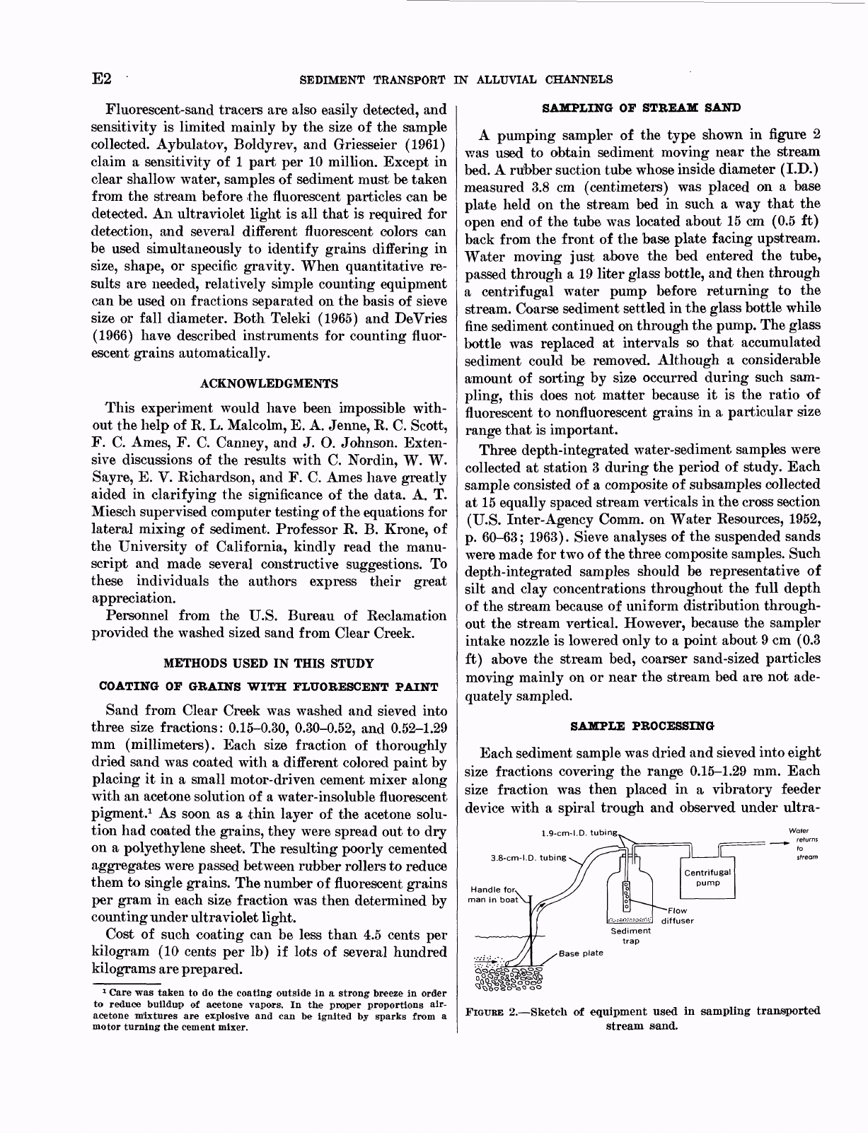
A
pumping
sampler
of
the
type
shown
in
figure
2
was
used
to
obtain
sediment
moving
near
the stream
bed.
A
rubber
suction
tube
whose
inside
diameter
(I.D.)
measured
3.8
cm
(centimeters)
was
placed
on
a
base
plate
held
on
the
stream
bed
in
such
a
way
that
the
open
end
of
the
tube
was
located
about
15
cm
(0.5
ft)
back
from
the
front
of
the
base
plate
facing
upstream.
Water
moving
just
above
the
bed
entered
the
tube,
passed
through
a
19
liter
glass
bottle,
and
then
through
a
centrifugal
water
pump
before
returning
to
the
stream.
Coarse
sediment
settled
in
the
glass
bottle
while
fine
sediment
continued
on
through
the
pump.
The
glass
bottle
was
replaced
at
intervals
so
that
accumulated
sediment
could
be
removed.
Although
a
considerable
amount
of
sorting
by
size
occurred
during
such
sam-
pling,
this
does
not
matter
because
it
is
the
ratio
of
fluorescent
to
nonfluorescent
grains
in
a
particular
size
range
that
is
important.
Three
depth-integrated
water-sediment
samples
were
collected
at
station
3
during
the
period
of
study.
Each
sample
consisted
of
a
composite
of
subsamples
collected
at
15
equally
spaced
stream
verticals
in
the
cross
section
(U.S.
Inter-Agency
Comm.
on
Water
Resources,
1952,
p.
60-63;
1963).
Sieve
analyses
of
the
suspended sands
were
made
for
two
of
the
three
composite
samples.
Such
depth-integrated
samples
should
be
representative
of
silt
and
clay
concentrations
throughout
the
full
depth
of
the stream
because
of
uniform
distribution
through-
out
the
stream
vertical.
However,
because
the
sampler
intake
nozzle
is
lowered
only
to
a
point
about
9
cm
(0.3
ft)
above
the
stream
bed,
coarser
sand-sized
particles
moving
mainly
on
or
near
the
stream
bed
are
not
ade-
quately
sampled.
SAMPLE
PROCESSING
Each
sediment
sample
was
dried
and
sieved
into
eight
size
fractions
covering
the
range
0.15-1.29
mm.
Each
size
fraction
was
then
placed
in
a
vibratory
feeder
device
with
a
spiral
trough
and
observed
under
ultra-
1.9-cm-I.D.
tubing
3.8-cm-I.D.
tubing
Handle
for,
man
in
boat
Water
_
returns
FIGURE
2. Sketch
of
equipment
used
in
sampling
transported
stream
sand.
FLUORESCENT
SAND
AS
A
TRACER
OF
FLUVIAL
SEDIMENT
E3
violet
light
as
the
grains
moved
out
of
the
feeder
in
virtually
single
file.
The
number
of
fluorescent
grains
of
each
color
was
recorded
using
a
hand
tabulator.
THE
EXPERIMENT
The
study
reported
here
was
intended
to
test
the
use-
fulness
of
the
"steady-dilution"
method
(Clayton
and
Smith,
1963;
Lean
and
Crickmore,
1963,
1966)
as
ap-
plied to
the
measurement
of
sediment
discharge
in
Clear
Creek
at
Golden,
Colo.
The
test
was
made
using
fluores-
cent
particles instead
of
radioactive
materials
as
de-
scribed
in
the
articles
mentioned,
but
the
same
general
principles
apply.
If
a
tracer
of
concentration
d
is
added
to
a
moving
stream
of
material
at
a
constant
rate
<?,
the
tracer
will
mix
with
the
moving
material,
and
at
some
point
down-
stream
a
uniform
concentration
of
the
tracer
in
the
ma-
terial
will
be
achieved.
If
C
0
is
the
concentration
of
the
tracer
in
the material
before
addition
of
tracer
in
the
experiment,
Q
is
the
rate
of
transport
of
material,
and
C
2
is
the
concentration
of
tracer
after
uniform
mixing
occurs,
the
following
equation
applies
:
If
C
0
is
taken
as
zero
and
Q
is
very
large
compared
to
q,
then
the
equation
is,
in
effect:
Where
stream
sand
is
transported
mainly
in
suspen-
sion,
samples
collected
at
a
station
downstream
from
the
point
of
tracer
addition
would
be
expected
to
show
tracer
concentrations
increasing
rather
rapidly
at
first,
then
gradually
reaching
a
"plateau"
of
constant
concen-
tration.
If
the
tracer
is
moving
on,
or
just
above,
the
bed,
the
speed
of
movement
may
be
low,
and
the
con-
centration
of
tracer
may
increase
slowly
at
the
sampling
point.
When
the
constant
concentration
is
reached,
it
is
assumed
that
as
many
grains
are
passing
the
sampling
point
as
are
being
added
upstream.
Normally,
in
order
that
such
a
constant
concentration
be
reached,
not
only
must
the
tracer
be
added
at
a
constant
rate,
but
the
sand
discharge
being
measured
must
also
remain
constant.
In
this
study
a
mixture
containing
89
grams
each
of
red
0.52-1.29-mm
sand,
yellow
0.30-0.52-mm
sand,
and
green
0.15-0.30-mm
sand
was
tossed
into
the
middle
of
Clear
Creek
every
3
minutes
beginning
at
2
p.m.
May
26
and
ending
at
6
p.m.
May
27,
1965.
The
fluorescent
sand
was
added
at
station
1
(fig.
1)
,
and
moving
sediment
was
sampled
intermittently
at
station
3
about
800
m
(2,650
ft)
downstream,
during
the
periods
from
2
:
05
p.m.
May
26
until
5
:
42
p.m.
May
27
and
from
10
:
12
a.m.
until
5
:
30
p.m.
May
28,
1965.
One
set
of
three
sam-
ples
was
obtained
at
station
2,
about
400
m
(1,300
ft)
downstream
from
the
point
of
fluorescent-sand
addi-
tion,
between
1:00
and
3:
00
p.m.
on
May
27,1965.
Blue
fluorescent
sand
of
0.30-0.52-mm
diameter
was
added
in
two
batches,
one
at
6
p.m.
May
26
and
the
other
at
6
a.m.
May
27.
During
the
first
28
hours
of
the
experiment
while
fluorescent
sand
was
being
added,
water
discharge
changed
from
about
8.8
to
7.8
m
3
per
sec
(cubic
meters
per
second),
or
from
310
cfs
(cubic
feet
per
second)
to
275
cfs.
At
the
end
of
62
hours,
when
the
final
sampling
was
completed,
discharged
was
about
6.6
m
3
per
sec
(235
cfs).
Average
velocity
of
the
water
was
approxi-
mately
1.4
m
per
sec
(meters
per
second),
or
4.5
fps
(feet
per
second),
but
maximum
velocities
were
probably
in
the
range
2
m
per
sec,
or
6-7
fps,
within
the
study
reach.
Depth
integrated
samples
collected
at station
3
indi-
cated
72
mg/1
(milligrams
per
liter)
suspended
sand
19
hours
after
the
beginning
of
the
experiment
and
65
mg/1
at
26.5
hours,
suggesting
that
there
may
have
been
some
decrease
in
sediment
discharge. However,
this
dif-
ference
may
be
within
the
accuracy
of
the
sediment
sam-
pling
method
and,
hence,
have
little
significance.
A
sam-
ple
collected
1
hour
after
beginning the
experiment
was
lost
in
processing.
Flow
was
over
sediment
whose
average
size
was
esti-
mated
to
be
a
few
centimeters
but
which
contained
cob-
bles
as
much
as
about
1
decimeter
in
diameter.
Although
some
scattered
showers
occurred
during
and
prior
to
the
study
period,
the
stream
water
remained
relatively
clear.
Presumably,
the
natural
sand
being
transported
was
derived
from
the
bed
and
bank
material
in
the
chan-
nel
system
upstream from
the
study
reach.
Sediment
samples
were
also
collected
at
station
3
(fig.
1)
by
a
pumping
sampler
for
15-minute
periods
during
the
first
2
hours.
Thereafter,
almost
all
samples
were
collected
by
pumping
for
30-minute
periods.
Al-
though
most
samples
were
collected
at
or
near
the
mid-
point
of
the
stream,
several
were
obtained
near
the
north
and
south
quarter
points
in
order
to
determine
the
dis-
tribution
of
fluorescent
material
across
the
stream.
RESULTS
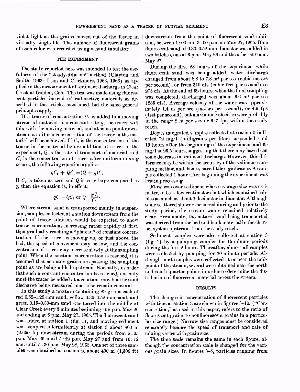
The
changes
in
concentration
of
fluorescent
particles
with
time
at
station
3
are
shown
in
figures
3-10.
("Con-
centration,"
as
used
in
this
paper,
refers
to
the
ratio
of
fluorescent
grains
to
iionfluorescent
grains
in
a
particu-
lar
size
range.)
Narrow
size
ranges
must
be
considered
separately
because
the
speed
of
transport
and
rate
of
mixing
varies
with
grain
size.
The time
scale
remains
the
same
in
each
figure,
al-
though
the
concentration
scale
is
changed
for
the
vari-
ous
grain
sizes.
In
figures
3-5,
particles
ranging
from
E4
SEDIMENT
TRANSPORT
IN
ALLUVIAL
CHANNELS
e.^
</)
2
<
20
CD
8
E
15
w
z
<
cc
H
10
Z
UJ
o
w
UJ
a:
c
0
5
3
_i
u.
EXPLANATION
I I
|
At
midpoint
-
O
5-10
feet
south
of midpoint
N
0
S
At north
po
nt
S
At
south
point
S
-
»
N
_
9
O
0
*
»N
°.SOO|
*Si.N
|.N
^
|
0
S.N
8
o
B
"z
100
*2
UJ
°-
0.
CD
W
7
55
<
o
CD
UJ
^
50
y
3
2z
^
o
o
z
3
-J
u.
0
04
8 12 16
20
24
28
32 36 40 44 48
52
TIME,
IN
HOURS
FIGURE
3.
Concentration
of
fluorescent
grains
at
station
3
resulting
from
addition
at
station
1.
Size
range
is
0.99-1.29
mm.
90
-
"
*
80
70
w
2
2
60
CD
o
o
1-1
Z
-
50
w
z
<
cc
CD
h-
40
z
UJ
o
w
UJ
OL
0
30
_i
u.
20
10
EXPLANATION
At
midpoint
S
0
*
5-10
feet
south
of
midpoint
N
At
north
po
nt
.S
%
_
At
south
point
.S
A
V
0
*
N
'
'
N
V
/
.
s
/
/
/
O
»
~
o
/
>N
0
D
X
X
s
I
s
150
w
z
125
<
cc
O
(-
z
UJ
o
w
UJ
tr
100
O
3
-J
u.
Z
o
z
o
8
75
g
cc
UJ
Q_
w
z
50
|
h-
UJ
O
w
UJ
cc
o
25
3
u.
n
0
-
-
0 4 8 12
16
20 24
28 32 36 40 44
48
52
TIME,
IN
HOURS
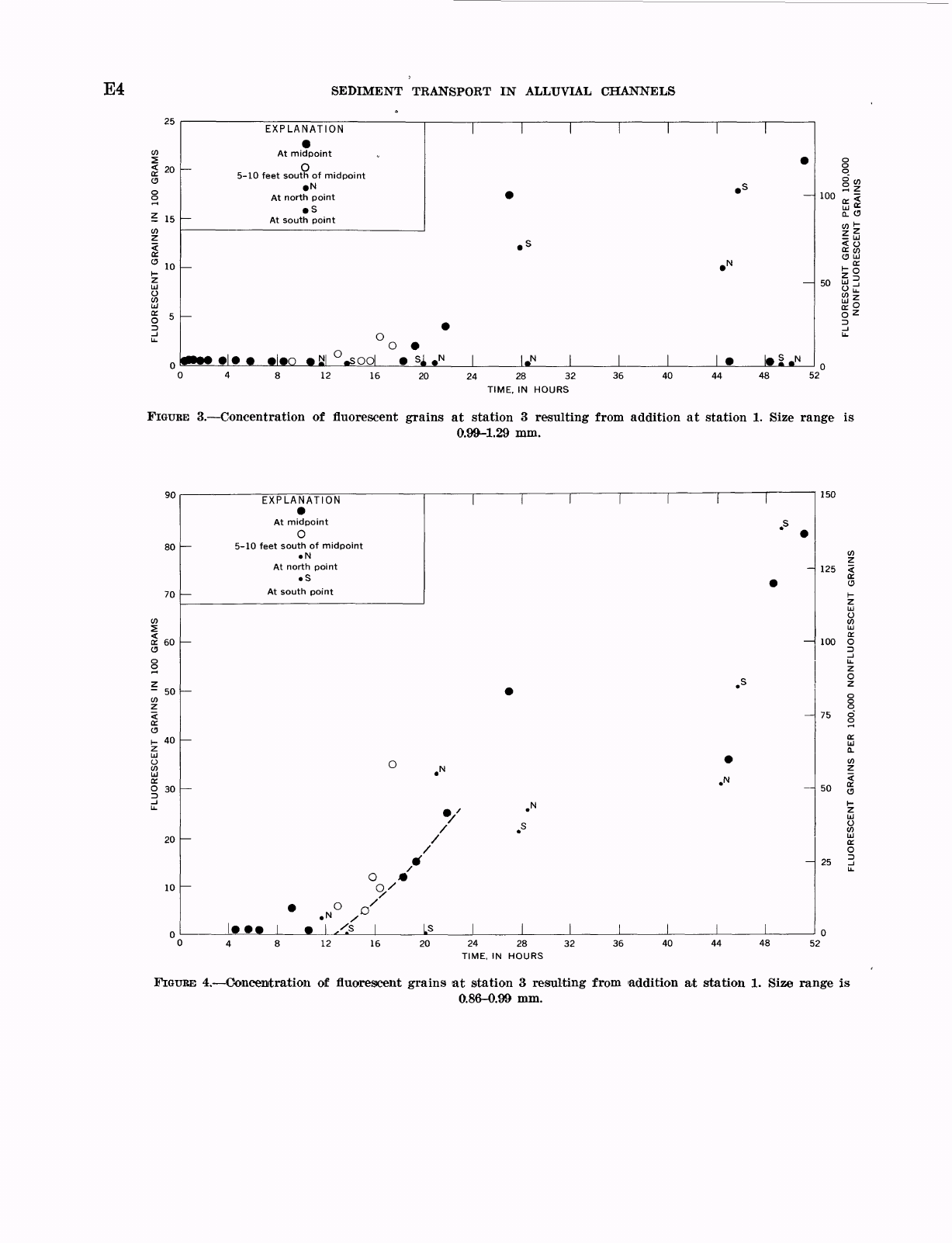
FIGURE
4. Concentration
of
fluorescent
grains
at
station
3
resulting
from
addition
at
station
1.
Size
range
is
0.86-0.99
mm.
FLUORESCENT
SAND
AS
A
TRACER
OF
FLUVIAL
SEDIMENT
E5
280
240
<
200
160
EXPLANATION
At
midpoint
o
5-10
feet
south
of
midpoint
N
At
north
point
S
At
south
point
/
.S
/CD
0
o
s
150
100
75
50
25
16
24
28
32
TIME,
IN
HOURS
36
40
48
52
FIGURE
5. Concentration
of
fluorescent
grains
at
station
3
resulting
from
addition
at
station
1.
Size
range
0.52-0.86
mm.
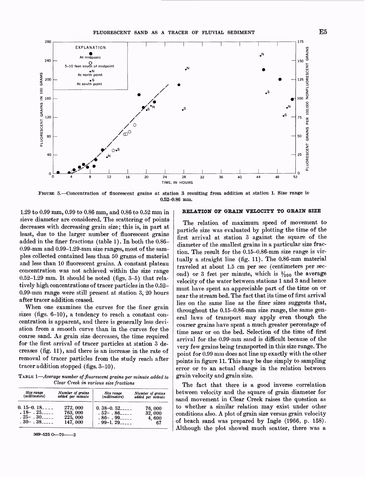
is
1.29
to
0.99
mm,
0.99
to
0.86
mm,
and
0.86
to
0.52
mm
in
sieve
diameter
are
considered.
The
scattering
of
points
decreases
with
decreasing
grain
size;
this
is,
in
part
at
least,
due
to
the
larger
number
of
fluorescent
grains
added
in
the
finer
fractions
(table
1).
In
both
the
0.86-
0.99-mm
and
0.99-1.29-mm
size
ranges,
most
of
the
sam-
ples
collected
contained
less
than
50
grams
of
material
and
less
than
10
fluorescent
grains.
A
constant
plateau
concentration
was
not
achieved
within
the
size
range
0.52-1.29
mm.
It
should
be
noted
(figs.
3-5)
that
rela-
tively
high
concentrations
of
tracer
particles
in
the
0.52-
0.99-mm
range
were
still
present at
station
3,
20
hours
after
tracer
addition
ceased.
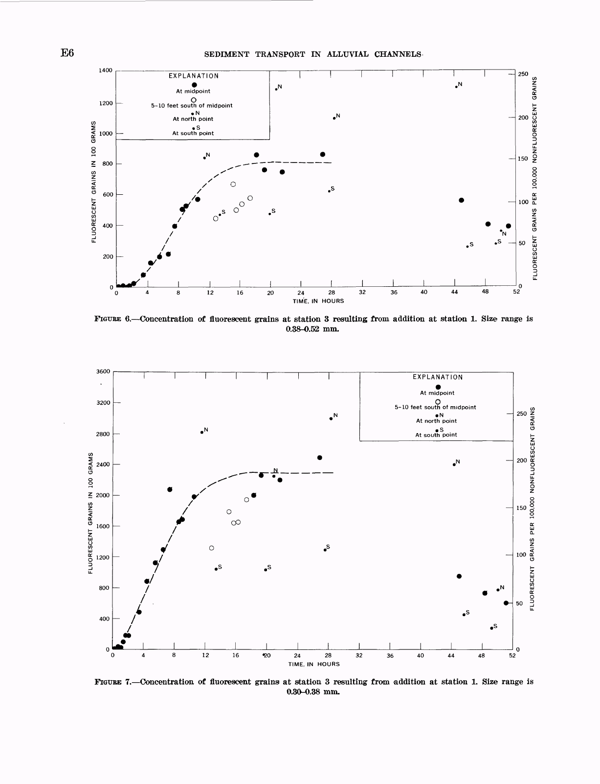
When
one
examines
the
curves
for
the
finer
grain
sizes
(figs.
6-10),
a
tendency
to
reach
a
constant
con-
centration
is
apparent,
and
there
is
generally
less
devi-
ation
from
a
smooth curve
than
in
the
curves
for
the
coarse
sand.
As
grain
size
decreases,
the
time
required
for
the
first
arrival
of
tracer
particles
at
station
3
de-
creases
(fig.
11),
and
there
is
an
increase in
the
rate
of
removal
of
tracer
particles
from
the
study
reach
after
tracer
addition
stopped
(figs.
3-10).
TABLE
1
Average
number
of
fluorescent
grains
per
minute
added
to
Clear
Creek
in
various
size
fractions
Size
range
(millimeters)
<
0.
15-0.
18____
.
18-
.25-
_
.
25-
.
30 __
.
30-
.
38____-
Number
of
grains
idded
per
minute
272,
000
763,
000
225,
000
147,
000
Size
range
(millimeters)
0.38-0.
52
__
_
.
52-
.86
__
_
.86-
.99
_
__
.99-1.
29_____
Number
of
grains
added
per
minute
76,
000
qo
nnn
4,600
67
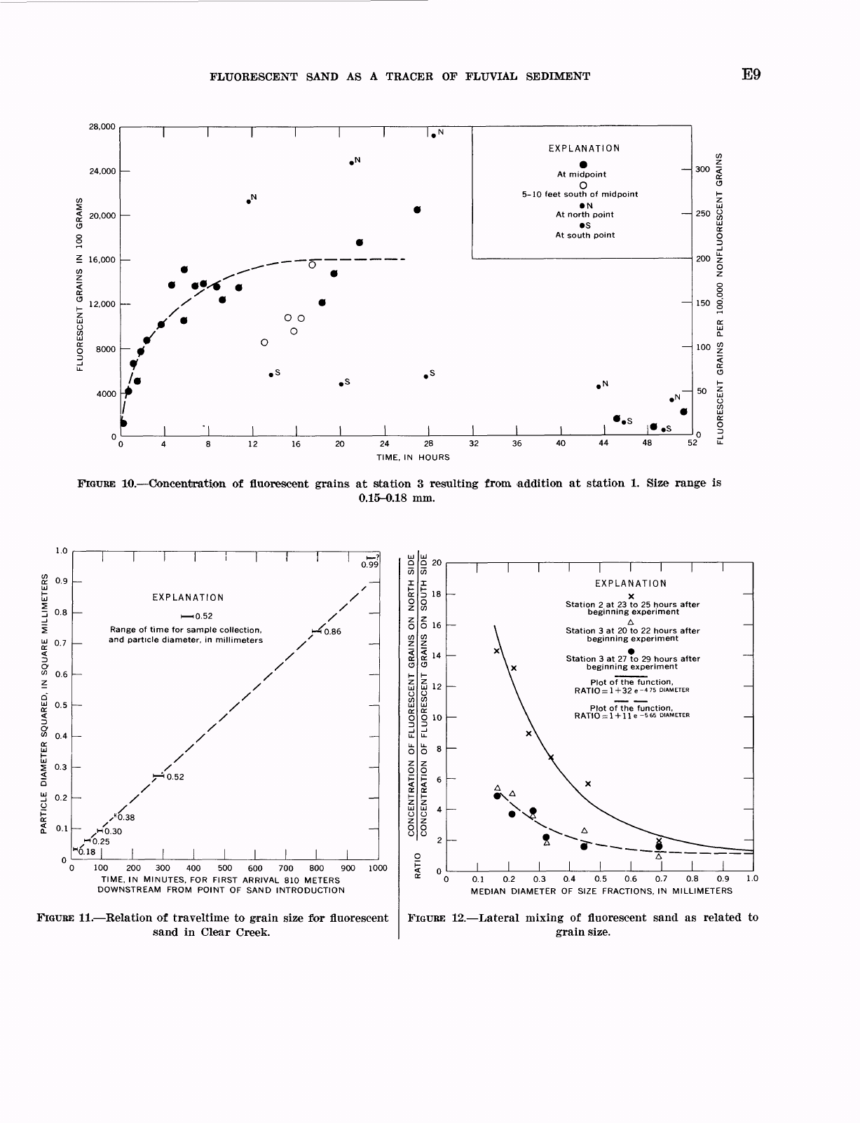
RELATION
OF
GRAIN
VELOCITY
TO
GRAIN
SIZE
The
relation
of
maximum
speed
of
movement
to
particle
size was
evaluated
by
plotting
the
time
of
the
first
arrival
at
station
3
against
the
square of
the
diameter
of
the
smallest
grains
in
a
particular
size
frac-
tion.
The
result
for
the
0.15-0.86-mm
size
range
is
vir-
tually
a
straight
line
(fig.
11).
The
0.86-mm
material
traveled
at
about
1.5
cm
per
sec
(centimeters
per
sec-
ond)
or
3
feet
per
minute,
which
is
%
0
o
the
average
velocity
of
the
water
between
stations
1
and
3
and
hence
must
have
spent
an
appreciable
part
of
the
time
on
or
near
the
stream
bed.
The
fact
that
its
time
of
first
arrival
lies
on
the
same
line
as
the
finer
sizes
suggests
that,
throughout
the
0.15-0.86-mm size
range,
the
same
gen-
eral
laws
of
transport
may
apply
even
though
the
coarser
grains
have
spent
a
much
greater
percentage
of
time
near
or
on
the
bed.
Selection
of
the
time
of
first
arrival
for
the
0.99-mm
sand
is
difficult
because
of
the
very
few
grains
being
transported
in
this
size
range.
The
point
for
0.99
mm
does
not
line up
exactly
with
the
other
points
in
figure
11.
This
may
be
due
simply
to
sampling
error
or
to
an
actual
change
in
the
relation
between
grain
velocity
and
grain
size.
The
fact
that
there
is
a
good
inverse
correlation
between
velocity
and the
square
of
grain
diameter
for
sand
movement
in
Clear
Creek
raises
the
question
as
to
whether
a similar
relation
may
exist
under
other
conditions
also.
A
plot
of
grain
size
versus
grain
velocity
of
beach
sand
was
prepared
by
Ingle
(1966,
p.
158).
Although
the
plot
showed
much
scatter, there
was
a
369-125
O 7C
E6
SEDIMENT
TRANSPORT
IN
ALLUVIAL
CHANNELS
ituu
1200
<
1000
8
Z
800
(/>
Z
<
ct
0
600
1-
z
HI
O
a
g
400
D
H.
200
EXPLANATION
At
midpoint
O
5-10
feet
south
of
midpoint
N
At
north
point
S
At
south
point
N
.
N
'^
.N
.N
^,-^~~
^
/
o
/
o
Jt
°
«r
,
s
o
,
s
/
0
^
^
/
N
/
.s
«
s
A
/*
-^*
/
*
1
250
w
Z
ct
0
1-
z
HI
200
0
w
HI
ct
o
_J
H.
Z
150
§
o
8
o"
o
oa
100
CL
w
Z
ct
0
1-
50
g
o
w
HI
ct
0
_J
H.
n
0
4
8
12
16
20
24 28
32
36 40
44
48
52
TIME,
IN
HOURS
FIGUBE
6. Concentration
of
fluorescent
grains
at
station
3
resulting
from
addition
at
station
1.
Size
range
is
0.38-0.52
mm.
3600
3200
2800
<
2400
Z
2000
1200
800
400
_
«
-H
_
_
_
_
__
00
EXPLANATION
At
midpoint
O
5-10
feet
south
of
midpoint
N
At
north
point
S
At
south
point
12
16
«20
24 28
32
TIME,
IN
HOURS
36
40
48
250
Z
150
100
a:
o
50
52
FIGUBE
7. Concentration,
of
fluorescent
grains
at
station
3
resulting
from
addition
at
station
1.
Size
range
is
0.30-0.38
mm.
FLUORESCENT
SAND
AS
A
TRACER
OF
FLUVIAL
SEDIMENT
E7
ouuu
7200
6400
W
5600
cc
o
o
4800
z
w
<
4000
cc
o
1-
Ul
0
3200
W
UJ
OS
0
_l
"
2400
1600
800
1 1 1 1 1 1 1
_
N
*
.N
EXPLANATION
At
midpoint
O
5-10
feet
south
of
midpoint
N
At
north
point
S
At
south
point
_____
______
^^
/^
o
v
-
/
*
°
/
/
(~\
7
*
°
-
./
/
.s
.s
/
.s
4
9
/
^
A
/
~
*
.s
.«
I/
1
1
1
1
1
1
1
200
W
z
<
cr
o
i-
UJ
o
150
2
tr
0
D
_l
u.
Z
O
z
0
100
g
o
a
UJ
0.
w
z
<
K
50
0
\r
Z
UJ
o
w
UJ
cr
0
3
u.
n
o
-
0
4
8
12
16
20
24
28
32
36
40
44
48 52
TIME,
IN
HOURS
FIGURE
8. Concentration
of
fluoresicent
grains
at
station
3
resulting
from
addition
at
station
1.
Size
range
is
0.25-0.30
mm.
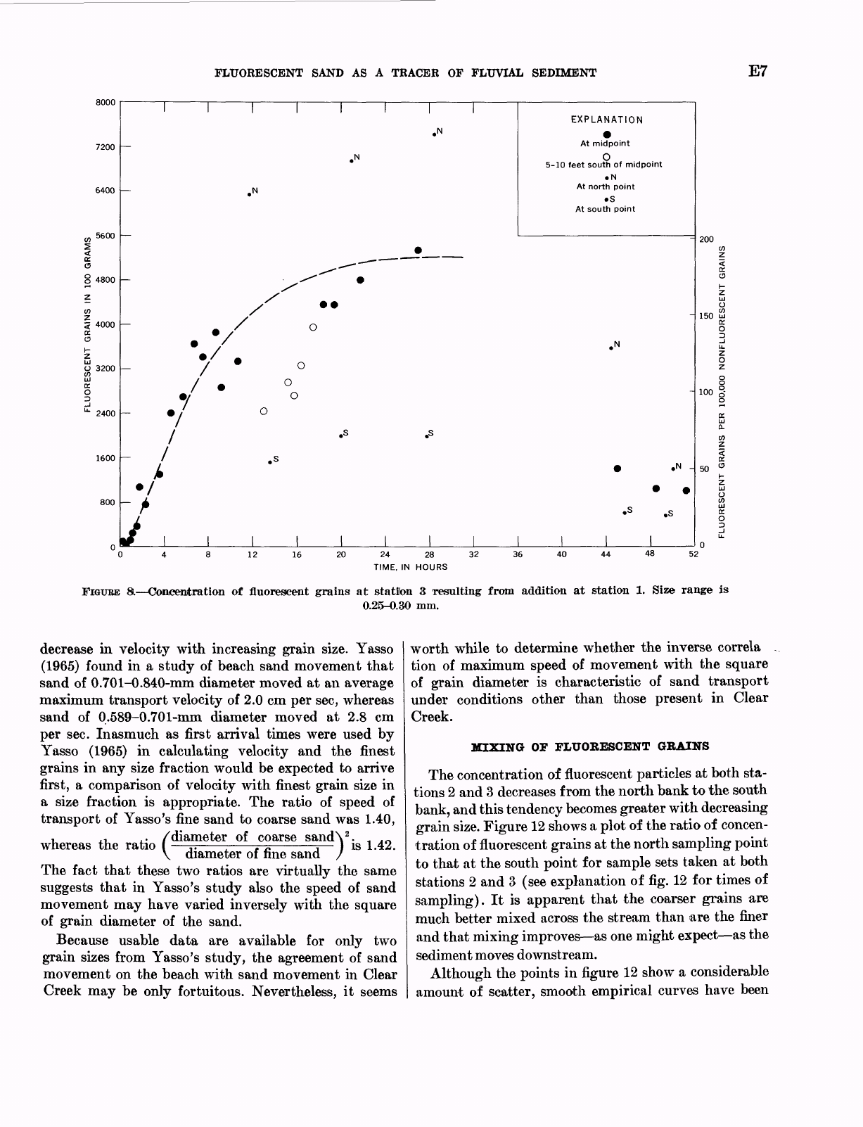
decrease
in
velocity
with
increasing
grain
size.
Yasso
(1965)
found in
a
study
of
beach
sand
movement
that
sand
of
0.701-0.840-mm
diameter
moved
at
an
average
maximum
transport
velocity
of
2.0
cm
per
sec,
whereas
sand
of
0.589-0.701-mm
diameter
moved
at
2.8
cm
per
sec.
Inasmuch
as
first
arrival
times
were
used
by
Yasso
(1965)
in
calculating
velocity
and
the
finest
grains
in
any
size
fraction
would
be
expected
to
arrive
first,
a
comparison
of
velocity
with
finest
grain
size
in
a
size
fraction
is
appropriate.
The
ratio
of
speed
of
transport
of
Yasso's
fine
sand
to
coarse
sand
was
1.40,
of
coarse
sandV.
-,
*
n
-
]
is
1.42.
u
j-u
A-
/diameter
whereas
the ratio
(
diameter
of
fine
sand
The
fact
that
these
two
ratios
are
virtually
the
same
suggests
that
in
Yasso's
study
also
the
speed
of
sand
movement
may
have
varied
inversely
with
the
square
of
grain
diameter
of
the
sand.
Because
usable
data
are
available
for
only
two
grain
sizes
from
Yasso's
study,
the
agreement
of
sand
movement
on
the
beach
with
sand
movement
in
Clear
Creek
may
be
only
fortuitous.
Nevertheless,
it
seems
worth
while
to
determine
whether
the
inverse
correla
tion
of
maximum
speed
of
movement
with
the
square
of
grain
diameter
is
characteristic
of
sand
transport
under
conditions
other
than
those
present
in
Clear
Creek.
MIXING
OF
FLUORESCENT
GRAINS
The
concentration
of
fluorescent
particles
at
both
sta-
tions
2
and
3
decreases
from the
north
bank
to
the
south
bank,
and
this
tendency
becomes
greater
with
decreasing
grain
size.
Figure
12
shows
a
plot
of
the
ratio
of
concen-
tration
of
fluorescent
grains
at
the
north
sampling
point
to
that
at
the
south
point
for
sample
sets
taken
at
both
stations
2
and
3
(see
explanation
of
fig.
12
for
times
of
sampling).
It
is
apparent
that
the
coarser
grains are
much
better
mixed
across
the
stream
than
are
the
finer
and
that
mixing
improves as
one
might
expect as
the
sediment
moves
downstream.
Although
the
points
in
figure
12
show
a
considerable
amount
of
scatter,
smooth
empirical
curves
have
been
E8
SEDIMENT
TRANSPORT
IN
ALLUVIAL
CHANNELS
20,000
18,000
16,000
14,000
12,000
10,000
2
8000
4000
.N
EXPLANATION
At
midpoint
O
5-10
feet
south
of
midpoint
N
At
north
point
S
At
south
point
/
.S
.3
300
250
C3
150
100
|
50
16
20
24
28
32
TIME,
IN
HOURS
40
48
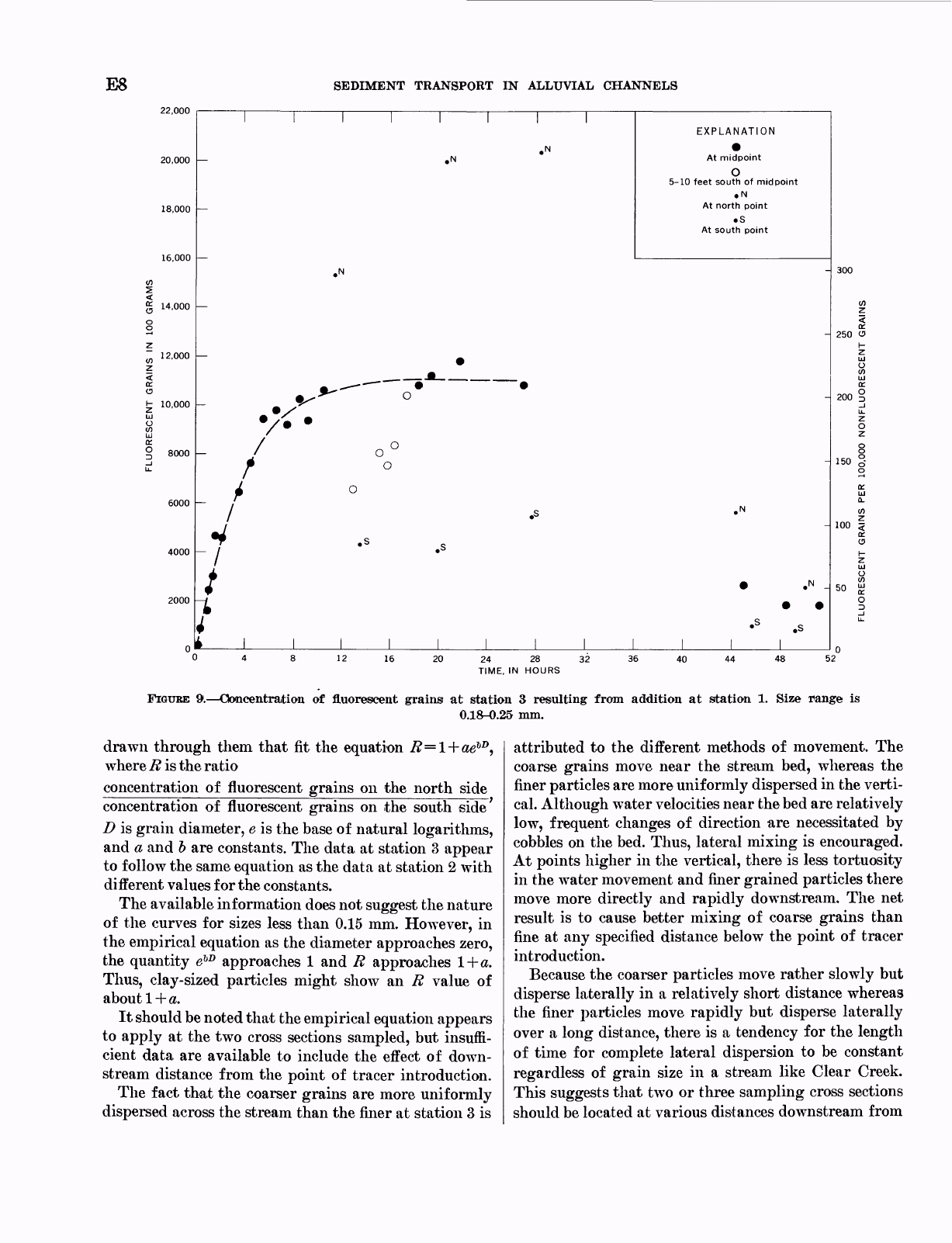
FIGURE
9. Concentration
of
fluorescent
grains
at
station
3
resulting
from
addition
at
station
1.
Size
range
is
0.18-0.25
mm.
attributed
to
the
different
methods
of
movement.
The
coarse
grains
move
near
the
stream
bed,
whereas
the
finer
particles
are
more
uniformly
dispersed in
the
verti-
cal.
Although
water
velocities
near
the
bed
are
relatively
low,
frequent
changes
of
direction
are
necessitated
by
cobbles
on
the
bed.
Thus,
lateral
mixing
is
encouraged.
At
points
higher
in the
vertical,
there
is
less
tortuosity
in
the water
movement
and
finer
grained
particles
there
move
more
directly
and
rapidly
downstream.
The
net
result
is
to
cause
better
mixing
of
coarse
grains
than
fine
at
any
specified
distance
below
the
point
of
tracer
introduction.
Because
the
coarser
particles
move
rather
slowly
but
disperse
laterally
in
a
relatively
short
distance
whereas
the
finer
particles
move
rapidly
but
disperse
laterally
over
a
long
distance,
there
is
a
tendency
for
the
length
of
time
for
complete
lateral
dispersion
to
be
constant
regardless
of
grain
size
in
a
stream
like
Clear
Creek.
This
suggests
that
two
or
three
sampling
cross
sections
should
be
located
at
various
distances
downstream
from
drawn
through
them
that
fit
the
equation
R=
where
R
is
the
ratio
concentration
of
fluorescent
grains
on
the
north
side
concentration
of
fluorescent
grains
on
the
south
side'
D
is
grain
diameter,
e
is
the
base
of
natural
logarithms,
and
a
and
b
are
constants.
The
data
at
station
3
appear
to
follow
the
same
equation
as
the
data
at
station
2
with
different
values
for
the
constants.
The
available
information
does
not
suggest
the
nature
of
the
curves
for
sizes
less
than
0.15
mm.
However,
in
the
empirical
equation
as
the
diameter
approaches
zero,
the
quantity
e
lD
approaches
1
and
R
approaches
1
+
a.
Thus,
clay-sized
particles
might
show
an
R
value
of
about
1
+
#.
It
should
be
noted
that
the
empirical
equation
appears
to
apply
at
the
two
cross
sections
sampled,
but
insuffi-
cient
data
are
available
to
include
the
effect
of
down-
stream
distance
from
the
point
of
tracer
introduction.
The
fact
that
the
coarser
grains
are
more
uniformly
dispersed
across
the
stream
than
the
finer
at
station
3
is
FLUORESCENT
SAND
AS
A
TRACER
OF
FLUVIAL
SEDIMENT
E9
28,000
24,000
<
20,000
C3
Z
16,000
12,000
8000
4000
EXPLANATION
At
midpoint
O
5-10
feet
south of
midpoint
N
At
north
point
S
At
south
point
/
O O
o
300
<
{£.
C3
250
200
150
8
12
20
24
28
32 36 40
44
48
TIME,
IN
HOURS
FIGURE
10. Concentration
of
fluorescent
grains
at
station
3
resulting
from
addition
at
station
1.
Size
range
is
0.15-0.18
mm.
2
0.9
1
0.8
5
£
0.7
O
<"
0.6
0.5
0.3
0.1
0.99
EXPLANATION
i 10.52
Range
of
time
for
sample
collection,
_
and
particle
diameter,
in
millimeters
/
/
.HQ.30
4
0.18
100
200 300
400
500
600
700 800
900
TIME,
IN
MINUTES,
FOR
FIRST
ARRIVAL
810
METERS
DOWNSTREAM
FROM
POINT
OF
SAND
INTRODUCTION
1000
FIGURE
11. Relation
of
traveltime
to grain
size
for
fluorescent
sand
in
Clear
Creek.
Q
20
O
16
uj
12
O
O
10
I
I
I
EXPLANATION
X
Station
2
at
23
to
25
hours
after
beginning
experiment
A
Station
3
at
20
to
22
hours
after
beginning
experiment
Station
3
at
27
to
29
hours
after
beginning
experiment
Plot
of
the
function,
RATIO
=
1+32
e-475
DIAMETER
Plot
of
the
function,
R
ATIO
=
1
+
1 1
e
-5
65
DIAMETER
0.1
0.2
0.3 0.4
0.5 0.6 0.7 0.8 0.9
MEDIAN
DIAMETER
OF
SIZE
FRACTIONS,
IN
MILLIMETERS
1.0
FIGURE
12. Lateral
mixing
of
fluorescent
sand
as
related
to
grain
size.
E10
SEDIMENT
TRANSPORT
IN
ALLUVIAL
CHANNELS
the
point
of
tracer
introduction.
The
closest
cross
sec-
tion
would
be
intended
for
study
of
the
coarser
sizes
and
the
farthest
cross
section
for
the
finest
sizes.
The
period
of
sampling
would
be
approximately
the
same
at
all
cross
sections.
ESTIMATION
OF
SEDIMENT
DISCHARGE
Uniform
mixing
of
tracer
particles
and
constant
sedi-
ment
discharge
are
required
if
an
accurate
calculation
of
sediment
discharge
is
to
be
made
using
tracer
techniques.
Also,
the
concentration
of
fluorescent
particles
at
the
sampling
point
must
reach
a
constant
value.
None
of
these
requirements
were
met
perfectly
in
this
study,
and
the
lateral
mixing
of
tracers
was
poor
in
the
finer
grain
sizes.
Nevertheless,
calculations
based
on
available
data
are
enlightening.
Although
tracer
concentrations
tended
to
be
high
on
the
north
side
of
the
stream
and
low
on
the
south
side,
an
average
of
the
two
gave
concentrations
close
to
those
found
for
samples
collected
at
the
midpoint
(figs.
6-10).
Therefore,
the
midpoint
concentrations
may
closely
ap-
proximate
those
which
would
be
found with
uniform
mixing.
Because
water
discharge
decreased
11
percent
during
the
first
28
hours
of
the
experiment,
it
is
probable
that
sand
discharge
decreased
also.
The
suspended-sediment
concentrations
mentioned previously
suggest
this,
but
the
concentration
curve
of
fluorescent
particles
(fig.
9)
for
the
0.18-0.25-mm
size
range
indicates
in
that
size
range
the
sand
discharge
was
for
the
most
part
constant.
If
the
sand
discharge
had
decreased
gradually
during
the
experiment,
the
degree
of
tracer
dilution
would
have
been
reduced
and
tracer
concentration
slowly
increased.
For
purposes
of
calculation
it
has
been
assumed
(1)
that
the
tracer
concentrations
found
at
the
midpoint
at
station
3
are
the
same
as
those
that
would
be
found
with
uniform
mixing
and
(2)
that
the
error
due
to
changing
sediment
discharge
is
small
compared
to
other
possible
errors
in
the
experiment.
The
remaining
requirement,
that
is,
that
the
concentration
of
tracer
particles
at
the
sampling
point
reach
a
constant
value,
was
apparently
achieved
for
some
size
fraction
and
not
for
others.
The
apparent
"plateau"
or
constant
concentrations
are
shown
by
dashed
lines
in
figures
6-10
and
are
used
in
calculating the
sediment
discharge
in
the
various
size
ranges.
The
results
of
such
calculations
are
given
in
table
2
and
also
in
figure
13
as
a
cumulative
curve.
The
sediment
discharge
in
each
size
fraction
is
meas-
ured
independently
in
the
fluorescent-tracer
method,
so
the
fact
that
a
smooth
curve
results
from
combining
the
discharge
data
for
several
individual
fractions
suggests
that
there
is
at
least
internal
consistency
between
the
discharge
estimates.
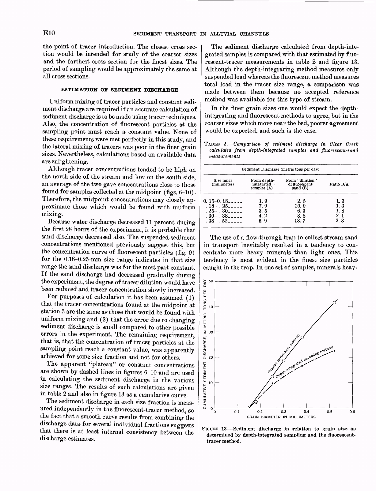
The
sediment
discharge
calculated
from
depth-inte-
grated
samples
is
compared
with
that
estimated
by
fluo-
rescent-tracer
measurements
in
table
2
and
figure
13.
Although
the
depth-integrating
method
measures
only
suspended
load
whereas
the
fluorescent
method
measures
total
load
in
the
tracer
size
range,
a
comparison
was
made
between
them
because
no
accepted
reference
method
was
available
for
this
type
of
stream.
In
the
finer
grain
sizes
one
would
expect
the
depth-
integrating
and
fluorescent
methods
to
agree,
but
in
the
coarser
sizes
which
move
near
the
bed,
poorer
agreement
would
be
expected,
and
such
is
the
case.
TABLE
2.
Comparison
of
sediment
discharge
in
Clear
Creek
calculated
from
depth-integrated
samples
and
fluorescent-sand
measurements
Sediment
Discharge
(metric
tons
per
day)
Size
range
(millimeter)
0.
15-0.
18
_
__
.
18-
.25
____
.25-
.30
___.
.30-
.
38_____
.38-
.
52___._
From
depth-
integrated
samples
(A)
1.9
7.9
3.5
4.2
5.9
From
"dilution"
of
fluorescent
sand
(B)
2.5
10.0
6.3
8.8
13.
7
Ratio
B/A
1.3
1.3
1.8
2.1
2.3
The
use
of
a
flow-through
trap
to
collect
stream
sand
in
transport
inevitably
resulted
in
a
tendency
to
con-
centrate
more
heavy
minerals
than
light
ones.
This
tendency
is
most
evident
in
the
finest
size
particles
caught
in
the
trap.
In
one
set
of
samples,
minerals
heav-
0
0.1 0.2
0.3 0.4 0.5
0.6
GRAIN
DIAMETER,
IN
MILLIMETERS
FIGUBE
13. Sediment
discharge
in
'relation
to
grain
size
as
determined
by
depth-integrated
sampling
and
the
fluorescent-
tracer
method.
FLUORESCENT
SAND
AS
A
TRACER
OF
FLUVIAL
SEDIMENT
Ell
ier
than
bromoform
(sp
gr=2.9)
were
found to
com-
prise
10.2
and
7.7
percent
of
the
0.15-0.18-mm
and
0.18-
0.25-mm
size
ranges,
respectively.
If
it
is
assumed
that
no
more
than
about
1
percent
heavy
minerals
would
be
present
in
an
unsorted
sample
of
any
size
fraction
of
stream
sand
in
Clear
Creek,
based
on
an
estimate
by
Pettijohn
(1957,
p.
129)
of
heavy
minerals
in
rocks,
the
revised
estimate
of
sediment
discharge
from
fluores-
cent-sand measurements
would
be
2.2
metric
tons
(2.4
tons)
per
day
for
the
0.15-0.18-mm
size
range
and
9.4
metric
tons
(10.3
tons)
per
day
for
the
0.18-0.25-mm
size
range.
This
brings
the
estimates
of
sediment
dis-,
charge
for
the
0.15-0.18-mm
size
fraction
by
the
two
methods
to
within
about
15
percent
of
each
other.
The
possible
errors
in
the
two
methods
of
measuring
sedi-
ment
discharge
as
used
here
may
be
greater
than
15
percent;
therefore,
one
method
can
be
said
to
provide
an
approximate
check
on
the
other
for
this
particular
size
range.
EXPERIMENT
WITH
BATCH
ADDITION
The
method
of
continuous
addition
used
in
this
ex-
periment
requires
that
sediment
discharge
remain
con-
stant
long
enough
for
the
fluorescent
material
to mix
thoroughly
in
the
stream
cross
section
and
also
attain
a
constant
concentration
at
some
downstream
sampling
point.
If
the
stream
is
narrow
and
turbulent
enough
for
rapid
lateral
mixing
(vertical
mixing
is
assumed
to
be
very
rapid),
these
requirements
may
be
met
in
a
reason-
able
time and
distance.
However,
in
many
streams
these
requirements
probably
will
not
be
met,
and
constant
concentrations
at
the
sampling
site
will
not
be
achieved
before
the
sediment
discharge
changes
significantly.
One
possible
way
to
reduce
the
effects
of
varying
sedi-
ment
discharge
is
to
add
one
color
of
fluorescent
sand
(color
A)
at
a
constant
known
rate
and
also
a
series
of
different
colors
(colors
B,
C,
D,
E,
etc.)
of
the
same
size
in
batches
at
perhaps
6-12-hour
intervals.
When
batch
material
of
color
B
is
dumped
into
the
stream,
it
will
label
the
sand
passing
the
introduction
point
at
time
T
and,
when
half
of
that
batch
(or
perhaps
the
peak
concentration,
as
a
rough
approximation)
has
passed
the
sampling
point
downstream,
the
dilution
fac-
tor
of
color
A
would
then
yield
an
estimate
of
the
sedi-
ment
discharge
at
time
T
at
the
point
of
tracer
intro-
duction
(assuming
thorough
lateral
mixing).
A
series
of
such
time
points
should
permit
the
calculation
of
sedi-
ment
discharge
at
intermediate
times
by
interpolation
using
concentrations
of
color
A.
If
the
amount
of
mate-
rial
in
the
batches
were
known
and
the
concentration
of
color
A
remained
constant
for
a
suitable
length
of
time,
the
sediment
discharge
could
also
be
calculated
from
the
area
under
the
time-versus-concentration
curve
for
colors
B,
C.
D,
etc.
This
multiple-color
technique
would
be
most
applicable
under
circumstances
where
longi-
tudinal
dispersion
was minimal.
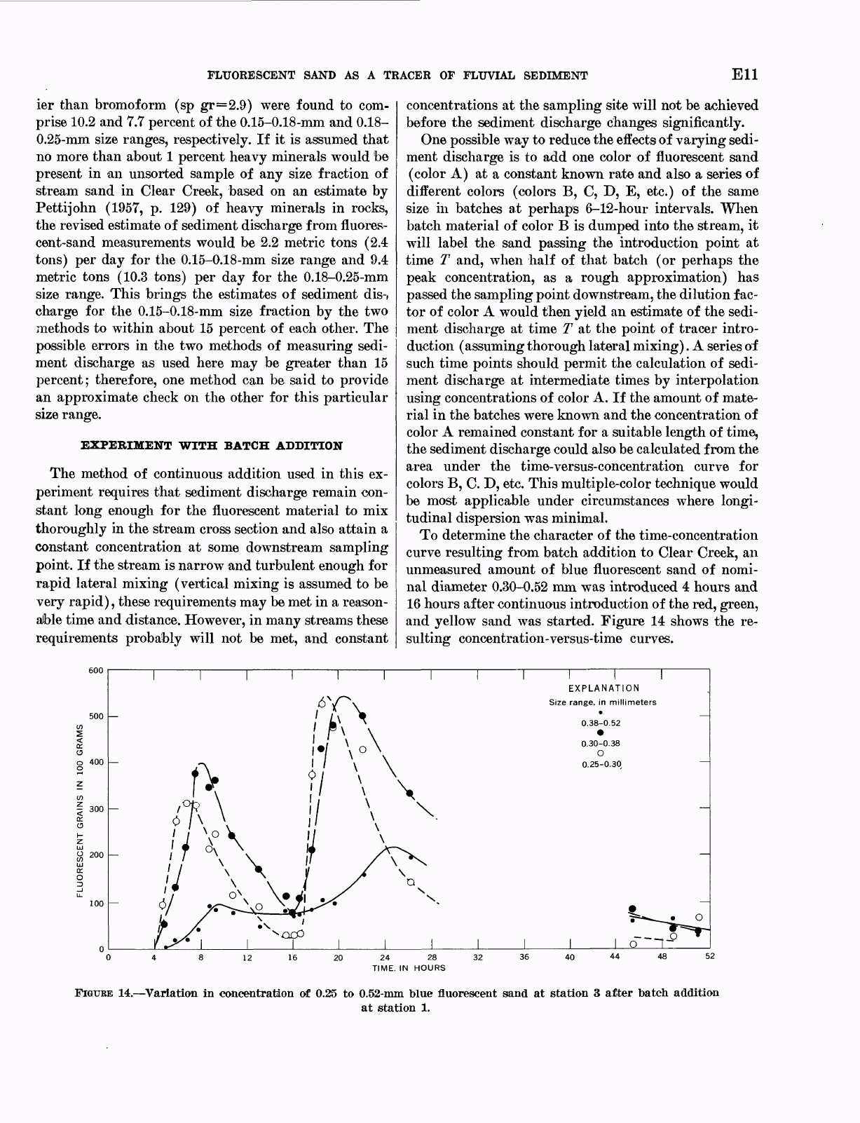
To
determine
the
character
of
the
time-concentration
curve
resulting
from
batch
addition
to
Clear
Creek,
an
unmeasured
amount
of
blue
fluorescent
sand
of
nomi-
nal
diameter
0.30-0.52
mm
was
introduced
4
hours and
16
hours
after
continuous
introduction
of
the
red,
green,
and
yellow
sand
was
started.
Figure
14
shows
the
re-
sulting
concentration-versus-time
curves.
500
O
o
400
-
300
EC
o
O
200
100
EXPLANATION
Size
range,
in
millimeters
0.38-0.52
0.30-0.38
O
0.25-0.30
20
24
28
32
TIME.
IN
HOURS
40
44
FIGUBE
14. Variation
in concentration
of
0.25
to
0.52-mm
blue
fluorescent
sand
at
station
3
after
batch
addition
at
station
1.
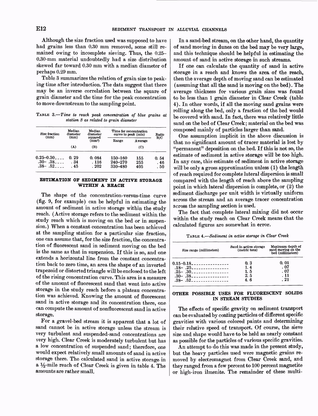
E12
SEDIMENT
TRANSPORT
IN
ALLUVIAL
CHANNELS
Although the
size
fraction
used
was
supposed
to
have
had
grains
less
than
0.30
mm
removed,
some
still
re-
mained
owing
to
incomplete
sieving.
Thus,
the
0.25-
0.30-mm
material
undoubtedly
had
a
size
distribution
skewed
far
toward
0.30
mm
with
a
median
diameter
of
perhaps
0.29
mm.
Table
3
summarizes
the
relation
of
grain
size
to
peak-
ing
time
after
introduction.
The
data
suggest
that
there
may
be
an
inverse
correlation
between
the
square
of
grain
diameter
and
the
time
for
the
peak concentration
to
move
downstream
to
the
sampling
point.
TABLE
3.
Time
to
reach
peak
concentration
of
blue
grains
at
station
8
as
related
to
grain
diameter
Median Median
Size
fraction
diameter
diameter
Time
for
concentration
curve
to
peak
(min)
Ratio
0.25-0.30-
___
.30-
.38-__-
.38-
.52____
(A)
0.29
.34
.45
(B)
0.084
.
116
.202
Range
150-160
240-270
330-480
Average
(C)
155
255
405
0.54
.46
.50
ESTIMATION
OF
SEDIMENT
IN
ACTIVE
STORAGE
WITHIN
A
BEACH
The
shape
of
the
concentration-versus-time
curve
(fig.
9,
for
example)
can
be
helpful
in
estimating
the
amount
of
sediment
in
active
storage
within
the
study
reach.
(Active storage
refers
to
the
sediment
within
the
study
reach
which
is
moving
on
the
bed
or
in
suspen-
sion.)
When
a
constant
concentration has
been
achieved
at
the
sampling
station
for
a
particular
size
fraction,
one
can
assume
that,
for
the
size
fraction,
the
concentra-
tion
of
fluorescent
sand
in
sediment
moving
on
the
bed
is
the
same
as
that
in
suspension.
If
this
is
so,
and
one
extends
a
horizontal line
from the
constant
concentra-
tion
back
to
zero
time,
an
area the
shape
of
an
inverted
trapezoid
or
distorted
triangle
will
be
enclosed
to
the
left
of
the
rising
concentration
curve.
This
area
is
a
measure
of
the
amount
of
fluorescent
sand
that
went
into
active
storage
in
the
study
reach
before
a
plateau
concentra-
tion
was achieved.
Knowing
the
amount
of
fluorescent
sand in
active
storage
and
its
concentration
there,
one
can
compute
the
amount
of
nonfluorescent
sand
in
active
storage.
For
a
gravel-bed
stream
it
is
apparent
that
a
lot
of
sand
cannot
be
in
active
storage
unless
the
stream
is
very
turbulent
and suspended-sand
concentrations
are
very
high.
Clear
Creek
is
moderately
turbulent
but
has
a
low
concentration
of
suspended
sand;
therefore,
one
would
expect
relatively
small
amounts
of
sand
in
active
storage
there.
The
calculated sand
in
active
storage
in
a
%-mile
reach
of
Clear
Creek
is
given
in
table
4.
The
amounts
are
rather
small.
In
a
sand-bed
stream,
on
the
other
hand, the
quantity
of
sand moving
in
dunes
on
the
bed
may
be
very
large,
and
this
technique
should
be
helpful
in
estimating
the
amount
of
sand in
active
storage
in
such streams.
If
one
can
calculate
the
quantity
of
sand
in
active
storage
in
a
reach
and
knows
the
area
of
the
reach,
then
the
average
depth
of
moving
sand
can
be
estimated
(assuming
that
all the
sand
is
moving
on
the
bed).
The
average
thickness
for
various
grain
sizes
was
found
to
be
less
than
1
grain
diameter
in
Clear
Creek
(table
4).
In
other
words,
if
all
the
moving sand
grains
were
rolling
along
the
bed,
only
a
fraction
of
the
bed
would
be
covered
with
sand.
In
fact,
there
was
relatively
little
sand
on
the
bed
of
Clear
Creek;
material
on
the
bed
was
composed
mainly
of
particles
larger
than
sand.
One
assumption
implicit
in
the
above
discussion
is
that
no
significant
amount
of
tracer
material
is
lost
by
"permanent"
deposition
on
the
bed.
If
this
is
not
so,
the
estimate of
sediment
in
active
storage
will
be
too
high.
In
any
case,
this
estimate
of
sediment
in
active
storage
will
be
only
a
gross
approximation
unless
(1)
the
length
of
reach
required
for
complete
lateral
dispersion
is
small
compared
with
the
length
of
reach
above
the
sampling
point
in
which
lateral
dispersion
is
complete,
or
(2)
the
sediment
discharge
per
unit
width
is
virtually
uniform
across
the
stream
and
an
average
tracer
concentration
across
the
sampling
section
is
used.
The
fact
that
complete
lateral
mixing
did not
occur
within
the
study
reach
on
Clear
Creek means
that
the
calculated
figures
are
somewhat
in
error.
TABLE
4.
Sediment
in
active
storage
in
Clear
Creek
Size
range
(millimeters)
Sand
in
active
storage
Maximum
depth
of
(metric
tons)
sand
moving
on
the
bed
(millimeters)
0.15-0.18.
.18-
.25.
.25-
.30.
.30-
.38.
.38-
.52.
0.3
1.4
1.5
2.5
4.6
0.01
.07
.07
.
11
.21
OTHER
POSSIBLE
USES
FOR
FLUORESCENT SOLIDS
IN
STREAM
STUDIES
The
effects
of
specific
gravity
on
sediment
transport
can
be
evaluated
by
coating
particles
of
different
specific
gravities with
various
colored
paints
and determining
their
relative
speed
of
transport.
Of
course,
the
sieve
size
and
shape
would
have
to
be
held
as
nearly
constant
as
possible
for
the
particles
of
various
specific
gravities.
An
attempt
to
do
this
was
made
in the
present
study,
but
the
heavy
particles
used
were
magnetic
grains
re-
moved
by
electromagnet
from
Clear
Creek
sand,
and
they
ranged
from
a
few
percent
to
100
percent
magnetite
or
high-iron
ilmenite.
The
remainder
of
these
multi-
FLUORESCENT
SAND
AS
A
TRACER
OF
FLUVIAL
SEDIMENT
E13
granular
magnetic
particles
were
commonly
composed
of
quartz
or
feldspar,
thus
giving
a
wide
range
of actual
specific
gravities.
The
results,
therefore,
were
quite
un-
satisfactory.
Shape
effects
can
also
be
evaluated
using
an
approach
similar
to
that
proposed
for
determining
the
effects
of
specific
gravity.
Yet
another
potential
use
of
fluorescent
sand
is
that
of
determining
the
depth
of
scour
in
a
stream
bed
dur-
ing
a
rise.
If
fluorescent
sand
equal
in
size
to
the
median
diameter
of
the
bed
material
were
added
continously
at
a
point
upstream
from
the
area
of
interest,
the
sedi-
ment in
transit
would
be
labeled
with
fluorescent
par-
ticles.
As
discharge
decreased
the
labeled
sediment
would
be
deposited
on
the
bed.
After
the
flow
had
sub-
sided,
one
could
take
cores
of
the
bed
sediment
and
determine
the
maximum
depth
of
scour
by
examining
the
cores
under
ultraviolet
light.
In
addition,
if
one
added
a
series
of
colors
in
sequence
during the
time
of
decreasing
discharge,
different
colored
layers
of
sand
would
result
showing
the
approximate
time
dur-
ing
which
"permanent"
deposition
on
the
bed
occurred.
CONCLUSIONS
An
experiment
conducted
in
Clear
Creek
at
Golden,
Colo.,
showed
that
the
maximum
speed
of
transport
of
fluorescent
sand-sized
particles
added
steadily to
the
stream
correlated
inversely
with
the
square
of
the
grain
diameter
under
conditions where
sand
was
being
trans-
ported
by
turbulent
water
above
a
gravel
bed..
There
is
a
suggestion
that
the
modal
speed
of
transport
of
sand
added
to
the
stream
in
batches
may
show
a
similar
rela-
tion
to
grain
size.
Lateral
mixing
improved
with
increas-
ing
grain
size.
Although
complete
lateral
mixing
of
fluorescent
particles
did
not
occur,
an
estimate
of
sediment
discharge
by
the
fluorescent-tracer method
for
medium
to
fine
sand
showed
reasonable
agreement
with
sediment
discharge
calculated
from
depth-integrated
samples
after
the
differences
inherent
in
the
two
methods
were
taken
into
consideration.
The
results
of
this
study
suggest
that
much more
effort could
be
profitably
devoted
to
the
use
of
fluorescent
tracers
in
studies
of
sediment
movement
in
the
fluvial
environment.
REFERENCES
CITED
Aybulatov,
N.,
Boldyrev,
V.,
and
Griesseier,
H.,
1961,
Das
studium
der
sedimentbewegung
in
flussen
und
meeren
mit
hilfe
von
lumineszierenden
farbstoffen
und
radioactiven
isotopen:
Petermann's
Geog.
Mitt.
1.
105,
no.
3,
p.
177-186;
no.
4,
p.
254-263.
Bruun,
P.,
1965,
Quantitative
tracing
of
littoral
drift,
in
Fed.
Inter-Agency
Sedimentation
Conf.,
1963,
U.S.
Dept.
Agr.
Misc.
Pub.
970,
p.
756-765.
Clayton,
C.
G.,
and
Smith,
D.
B.,
1963,
A
comparison
of
radto-
isotope
methods
for
river
flow
measurements,
in
Radio-
isotopes
in
Hydrology:
Vienna,
Internat.
Atomic
Energy
Agency,
p.
1-24.
Cummins,
R.
S.,
Jr.,
and
Ingram,
L.
F.,
1965,
Use
of
radioisotopes
in
sediment
transport
studies,
in
Fed.
Inter-Agency
Sedi-
mentation
Conf.,
1963:
U.S.
Dept.
Agriculture
Misc.
Pub.
970,
p.
578-592.
DeVries,
M.,
1966,
Applications of
luminophores
in
sand
trans-
port
studies:
Delft
Hydraulic
Lab.,
Delft, The
Netherlands.
Pub.
39.
Glazov,
N.
V.,
and
Glazov,
A.
N.,
1959,
New
Instruments
and
methods
of
engineering
geology:
New
York,
Consultants
Bureau,
91
p.
Hubbell,
D.
W.,
and
Sayre,
W.
W.,
1964,
Sand
transport
studies
with
radioactive
tracers:
Jour.
Hydraulics
Div.
Am.
Soc.
Civil
Engineers,
v.
90,
no.
HY3,
p.
39-68.
Ingle,
J.
C.,
Jr.,
1966,
The
movement
of
beach
sand:
New
York,
Elsevier
Pub.
Co.,
221
p.
Kidson,
C.,
and
Carr,
A.
P.,
1962,
Marking
beach
materials
for
tracing
experiments:
Jour.
Hydraulics
Div.
Am.
Soc.
Civil
Engineers,
v.
88,
No.
HY4,
pt.
1,
p.
43-60.
Krone,
R. B.,
Einstein
H.
A.,
Kaufman,
W.
J.,
and
Orlob,
G.
T.,
1960,
Methods
for
tracing
estuarial
sediment
trans-
port
processes:
California
Hydraul.
Bng.
Lab.
and
Sanita-
tion
Eng.
Research
Lab.,
57
p.
Lean,
G.
H.,
and
Crickmore,
M.
J.,
1963,
Methods
for
measur-
ing
sand
transport
using
radioactive
tracers,
in
Radio-
isotopes
in
Hydrology:
Vienna,
Internat
Atomic
Energy
Agency,
p.
111-131.
1966,
Dilution
methods
of
measuring
transport
of
sand
from
a
point
source:
Jour.
Geophys.
Research,
v.
71,
No.
24,
p.
5843-5855.
Pettijohn,
F.
J.,
1957,
Sedimentary
Rocks:
New
York,
Harper
Bros.,
718
p.
Russell,
R.
C.
H.,
1961,
The
use
of
fluorescent
tracers
for
the
measurement
of
littoral
drift:
Coastal
Eng.
Conf.,
7th,
The
Hague,
Netherlands,
August
1960,
Proc.,
p.
418-444.
Teleki,
P.
G.,
1965,
A
summary
of
the
production
and
scanning
of
fluorescent
tracers,
in
Fed.
Inter-Agency
Sedimentation
Conf.
1963:
U.S.
Dept.
Agriculture
Misc.
Pub.
970,
p.
765-
768.
1966,
Flourescent sand
tracers:
Jour.
Sed.
Petrology,
v.
36,
no.
2,
p.
468-485.
U.S.
Inter-Agency
Committee
on
Water
Resources,
1952,
The
design
of
improved
types
of
suspended
sediment
samplers:
Washington
Govt.
Printing
Office,
Rept
6.
1963,
Determination
of
fluvial
sediment
discharge:
Washington
Govt.
Printing
Office,
Rept
14.
Yasso,
W.
E.,
1962,
Fluorescent
coatings
on
coarse
sediments:
An
integrated
system:
U.S.
Navy,
Office
of
Naval
Research,
Geography
Br.,
Project
NR
388-057,
Tech.
Rept
1,
29
p.
(Columbia
Univ.
Dept.
Geology).
1965,
Fluorescent
tracer
particle
determination
of
the
size
velocity
relation
for
foreshore
sediment
transport,
Sandy
Hook,
New
Jersey:
Jour.
Sed.
Petrology,
v.
35,
no.
4,
p.
989-993.
Zerikovitch,
V.
P.,
1958,
Emploi
des
luminophores
pour
1'etude
du
mouvement
des
alluvions
sablonneuses:
Inf.
Comite
Cent.
Oceanographie
Etude
des
Cotes,
Bull.
10,
p.
243-253.
