
Feeling the Spark for AutoCAD Electrical
(For AutoCAD Users)
Tiffany Tucker – TATA Technologies
MD6033
If you are currently using AutoCAD® to develop controls drawings or if you have AutoCAD® Electrical
but you are still primarily using it as vanilla AutoCAD to complete your controls drawings, this is the class for you.
Learn key tips and tricks to get you quickly up and running with AutoCAD Electrical, so that you can start utilizing all
of its amazing automation! Hot Topics will include template development, support file step up, and user friendly
automated commands. This class will be electrifying and have you feeling the spark of love for ACADE!
Learning Objectives
At the end of this class, you will be able to:
• Understand the benefits of moving to AutoCAD Electrical
• Understand the basic concepts of starting an AutoCAD Electrical Project
• Understand the basic support files that can be made company-specific
• Understand the key items for converting AutoCAD templates to ACADE templates
About the Speaker
Tiffany has been an Autodesk Consultant for Tata Technologies for the last eight years. Her primary
focus is as a technical instructor/consultant for AutoCAD, AutoCAD Electrical, and Inventor. She, along
with two other consultants, has won awards for developing a full line of online live instructor-led training
classes for the Autodesk manufacturing products. Before becoming a consultant, she earned her
Bachelor’s degree from Michigan State University and she has worked in many different industries
gaining valuable CAD experience, including Electrical Engineering, Interior Design/Architecture,
Mechanical Engineering, Software Engineering, and was part of MSU’s CAD development team. She
started on AutoCAD R10 and has carried a strong passion for Autodesk products ever since.
tiffany.tucker@tatatechnologies.com
Tiffany Tucker, ACI | Autodesk Consultant
41050 W. Eleven Mile Road | Novi, MI 48375-1302
p: +1 248.699.1988 | f: +1 248.426.8498
email: tiffany.tucker@tatatechnologies.com
website: www.tatatechnologies.com
Feeling the Spark for AutoCAD Electrical
(For AutoCAD Users)
2
Table of Contents
Learning Objective 1: Benefits of Moving from AutoCAD to AutoCAD Electrical ............................................... 3
Learning Objective 2: The AutoCAD Electrical Project ................................................................................................ 4
Definition of an ACADE Project File ...................................................................................................................................... 4
Relative Drawing File Paths ................................................................................................................................................... 4
Guidelines for Project Files ..................................................................................................................................................... 4
Workflow: Creating a New Project ....................................................................................................................................... 6
Learning Objective 3: Customizing AutoCAD Electrical Support Files ................................................................... 8
Component Reference Files ..................................................................................................................................................... 8
Setting Up Automated Title Block Updating ....................................................................................................................10
Workflow: Creating a Title Block Mapping File .............................................................................................................16
Workflow: Updating a Title Block ......................................................................................................................................17
Learning Objective 4: Creating AutoCAD Electrical Templates from vanilla AutoCAD Templates ........... 19
Drawing Templates and CAD Standards (for AutoCAD and AutoCAD Electrical) ................................................19
Preset Drawing Graphics .......................................................................................................................................................19
Example of Drawing Templates...........................................................................................................................................19
Template Properties and Settings ......................................................................................................................................20
AutoCAD Electrical Templates .............................................................................................................................................20
Storage Location of Drawing Templates ..........................................................................................................................20
Template Options Dialog Box ...............................................................................................................................................21
Workflow: Creating Drawing Templates ..........................................................................................................................22
Workflow: Creating Wire Types .........................................................................................................................................26
EXERCISE: Exploring the Basics of AutoCAD Electrical ..............................................................................................27
Deployment & Implementation Steps
........................................................................................................................
41

Feeling the Spark for AutoCAD Electrical
(For AutoCAD Users)
3
Learning Objective 1: Benefits of Moving from AutoCAD to AutoCAD Electrical
1. AutoCAD® Electrical was specifically designed for electrical engineers who design industrial control
systems, but it can be used for many different electrical applications.
2. It is built right into the AutoCAD® environment, which makes for a very easy transition, with a task based
user interface of Electrical-specific commands that gives the user access to many industry specific tools that
automate the electrical design process, including Electrical symbol libraries for creating schematics, layouts,
and related reports faster and more accurately than doing it manually in AutoCAD software. A recent study
showed up to an 80 percent increase in productivity when moving to AutoCAD Electrical from AutoCAD.
1
3. Many different design workflows are supported in ACADE. For example, you can draw your schematics and
then extract a list of all of those components to create your layouts and the associations are automatically
made between the components, so you only have to edit in one spot. You could also start with a layout
(perhaps to choose and order components that require a long lead time) and then extract a footprint list from
the layout to design the schematics.
4. You can do ladder style schematics, or you can design schematics in a point-to-point style (direct connect),
placing components in empty areas of the drawing and then connecting the components with wires, or even
create drawings that are a composite of both styles.
5. Creating electrical controls designs with generic software (i.e. doing everything manually) can be quite
tedious, time-consuming, and can be far more prone to errors, and those errors are often not caught before
the designs hit the shop floor and could cause even more delays.
6. The manual creation of reports can also cause a lot of time-consuming extra work and delays, especially
with an inaccurate bill of materials (BOM).
7. Reusing designs in future projects or even just working on a project with other people in your organization
can be very cumbersome, error-prone, and the use of design standards can become quite inconsistent.
Top 10 Reasons to Move from AutoCAD to AutoCAD Electrical
2
1. Comprehensive symbol libraries
2. Automatic wire numbering and component tagging
3. Automatic project reports
4. Real-time error checking
5. Real-time coil and contact cross-referencing (Parent-Child
relationships)
6. Smart panel layout drawings
7. Electrical-specific drafting features
8. Ability to automatically create PLC I/O drawings from
spreadsheets
9. Ability to share drawings with customers and suppliers and track
their changes
10. Reuse existing drawings to easily find and reuse designs
1
The AutoCAD Electrical Productivity Study compares the time required to complete 10 tasks in both basic AutoCAD and AutoCAD Electrical. The conclusion: switching to AutoCAD
Electrical can help increase your productivity by as much as 80 percent. To learn more, visit www.autodesk.com/autocadelectrical-whitepapers.
1
2
Execrpt from the ACADE_JIC_Overview_broch_us.pdf
2
Feeling the Spark for AutoCAD Electrical
(For AutoCAD Users)
4
Learning Objective 2: The AutoCAD Electrical Project
AutoCAD Electrical uses a project-based system to manage the multiple drawings and inter-drawing relationships
contained in most electrical projects. Understanding how this system works is essential to increasing your efficiency
and creating accurate electrical designs.
Definition of an ACADE Project File
A project file is an ASCII text file with a .wdp extension that stores information about a project. A project file contains
some of the following information:
Project description lines (most commonly used for automatically updating all title blocks)
Project default settings (design standards)
Project drawing list, including: Complete path information, Drawing description lines, Section and subsection
assignments
Other miscellaneous catalog and symbol library settings
Folder structure of the project drawings
To ensure consistency throughout the project drawings, the project settings you store in the project file are
referenced when you create or add new drawings to a project. A single project file can find an unlimited number of
drawings located in many different directories (though this is not a best practice).
By default, project files are stored in the directory pointed to by the WD_PROJ setting in your environment file
(defined during installation), but the project files can be stored in any subdirectory. The location of the project file is
used early in the file search path. Custom drawing files, symbol libraries, and other reference files can be stored in
the project directory so that you can easily change configurations for different project needs.
Relative Drawing File Paths
Relative path information is used to save the drawing file location. If the drawing is stored in the same directory as
the project file, only the file name is stored in the project file. If the drawing is stored in a different directory than the
project file, the drawing name information includes both the file name and complete relative path information.
Note: Absolute or fixed paths to drawing files can also be used. To use an absolute path to a drawing file, you must
manually edit the project file using any text editor. You cannot enter a fixed path using the project manager.
Guidelines for Project Files
Follow these guidelines when working with project files:
A single project file can have drawings located in many different directories. There is no limit to the number
of drawings in a project.
• The recommended location for the project file is in the same directory as the project drawing files.
Although this is not required, it allows the project to be moved to different directories or entered into
file management programs, such as Autodesk® Vault, with little or no management of file paths.
Although you can use any text editor to edit a project file, in most cases it is recommended that you use the
Project Manager to make changes.
When archiving or backing up the project drawing files, it is important to include the project file.
Feeling the Spark for AutoCAD Electrical
(For AutoCAD Users)
5
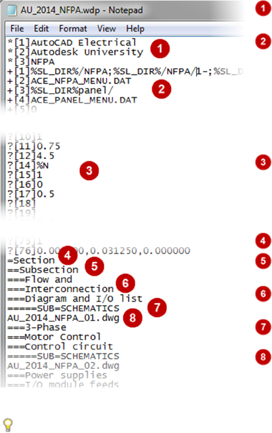
This is an example of a typical ACADE project file:
Lines starting with "*[n]" are project description lines.
Lines starting with "+[n]" are project-wide settings.
Lines starting with "?[n]" are drawing default settings.
Lines starting with "=" are drawing section labels.
Lines starting with "= =" are drawing subsection
labels.
Lines starting with "= = =" are drawing description
lines.
Lines without a prefix are project drawing files.
A project drawing file that is stored in the same
directory as the project file. Only the drawing file name is
listed.
TIPS:
A project file is not needed if the project consists of a single drawing.
For more details on what is contained in a project file, go to AutoCAD Electrical Help > Projects and
Drawings
Feeling the Spark for AutoCAD Electrical
(For AutoCAD Users)
6
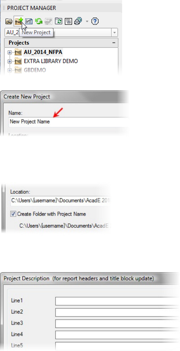
Creating a New Project Workflow:
1. In the
Project Manager
, click
New Project
.
2. For Name, enter the name for the new project.
3. Select the Create Folder with Project Name
check box to create a new folder for the project with the same
name that you entered for the project. The folder is created in the path that is specified in Location. The
location is also the path where the project file is saved. If left empty, AutoCAD Electrical uses the path to
the wd.env file.
4. If you want to copy project settings from an existing project, click Browse to select the existing project file.
5. Click Descriptions to enter project information that can be included in report headers and title blocks.
(Described later in this document)
Feeling the Spark for AutoCAD Electrical
(For AutoCAD Users)
7
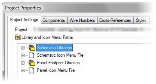
6. Click
OK
-
Properties
to create the new project, the
Project Properties
dialog box will open.
Note:
This is
where you can make changes to the project settings if needed.
7. Click OK to create the new project without making changes to the settings.
Feeling the Spark for AutoCAD Electrical
(For AutoCAD Users)
8
Learning Objective 3: Customizing AutoCAD Electrical Support Files
Various reference files are supported by AutoCAD Electrical to help annotate your drawings. ASCII text files are used
as reference files for many different purposes. Only a few of the more frequently used files are briefly explained here.
Knowledge of these files, how they are used, and how they can be made project-specific can help make tasks, such
as changing drawing descriptions or mapping title block attributes, easier to understand and complete and when they
are customized to your company’s needs, they set the foundation for everyone creating these drawings to follow the
same standards.
Component Reference Files
Description (wd_desc.wdd), installation (default.inst), and location (default.loc) files are generic ASCII text files
that contain either common values or your company's standard nomenclature for these fields. Instead of reentering
values for each field, you can select the entry from a list.
You can use wizards in the software, or any external text editor, such as Notepad, to edit these files.
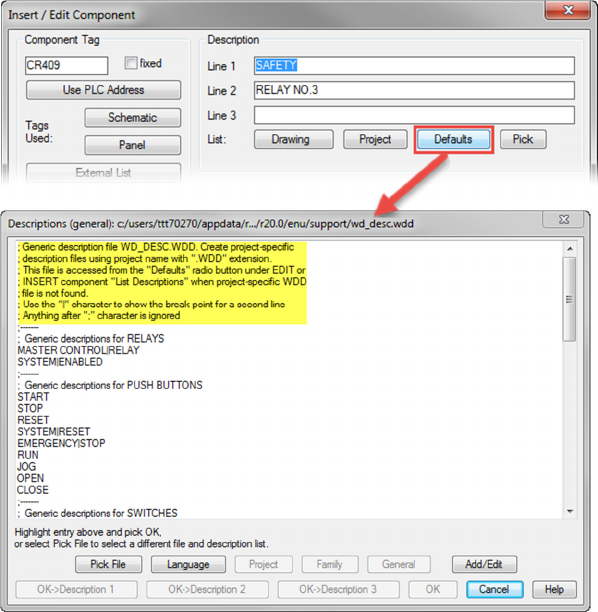
Component Description file (wd_desc.wdd)
• Used for defining standard descriptions for components
• Can be accessed and edited via the Insert/Edit Component dialog box or can be edited via
external text editor
Out-of-the-box component reference file wd_desc.wdd
Feeling the Spark for AutoCAD Electrical
(For AutoCAD Users)
9
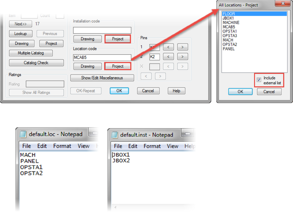
Location (default.loc) and Installation (default.inst) files
• Used for defining standard Location/Installation codes for components
• Accessed via the Insert/Edit Component dialog box and checking marking Include external list in
the All Locations - Project dialog box or All Installations – Project dialog box
• Edited via external text editor
Multiple versions of these files can exist. You can make the files project-specific by replacing wd_desc or default with
the project name. For example, wd_desc.wdd can also be labeled <projectname>.wdd or default.loc can be labeled
<projectname>.loc.
Multiple versions can exist because of the how ACADE searches for these files. First, the project directory, where the
project's WDP file is stored, is searched for a file with the same name as the project. If a project-named file is not
found, the software searches the project directory for the default file. If a project default file is not found, then the
software searches for a default file in the support directory (defined at installation).
Example Use of Project Specific Files
You work for a company that completes schematic designs and builds panels for many different companies. Your
clients use different nomenclature, and in some cases, different languages for the component descriptions and
labels.
Feeling the Spark for AutoCAD Electrical
(For AutoCAD Users)
10
You create project-specific reference files for each client containing the data specified by the client. You store these
files in the same directory as the project file. As you move between projects, the different reference files for each
customer are automatically referenced.
Setting Up Automated Title Block Updating
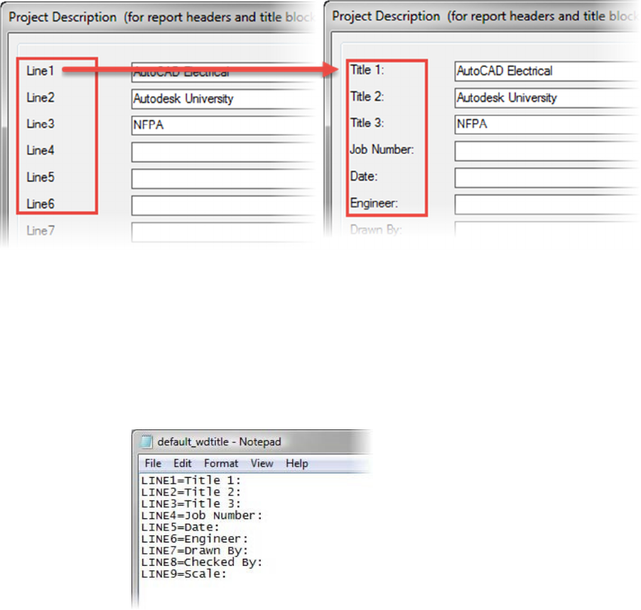
Define Project Line Labels (default_wdtitle.wdl).
• Project line description label mappings are stored in a project reference WDL file. These values
replace the generic Line 1, Line 2, and so forth, values used in the Project Description dialog box.
An unlimited number of lines can be stored in the file.
• Typically, these values are changed to match the attribute values of the drawing title block, making
the title block mappings much easier. They can also be used for many other purposes, including
revisions, drawing descriptions, and report information.
Generic line labels: Custom line labels:
• Either a project-based mapping file or a default mapping file can be used for this purpose. You name
these files <projectname>_wdtitle.wdl or default_wdtitle.wdl, respectively. The software searches
first for a file that matches the current project name. If a file is not found, the default file is used.
• A wizard is not provided to edit this file; therefore, you must create the file manually, using any ASCII
text editor. The entries do not have to be in order and line numbers may be skipped. The file should
contain one line per label in the format LINEx=label as shown in the following examples:
LINE1=Title 1:
LINE2=Title 2:
LINE4=Job Number:
Feeling the Spark for AutoCAD Electrical
(For AutoCAD Users)
11
Title Block Mapping
• Before updating title blocks in your project, you must define how the project and drawing data is
mapped to the matching title block attributes. To accomplish this task, you need to understand the
formatting involved when using the internal attribute or the external ASCII file.
• You can map project and drawing information to attributes in your title block in several ways. You
can use the following:
Any text editor to create an external ASCII-formatted mapping file with a WDT extension.
The Title Block Setup wizard to create an external ASCII-formatted mapping file with a
WDT extension.
The Title Block Setup wizard to store the mapping on your title block in an invisible WD_TB
attribute.
• When you use the Title Block Setup wizard all mapping formats are maintained
automatically whether you use the internal or external mapping methods.
Typically all drawings in a project share the same title block that contains basically the same
information. With the Title Block Update utility, you can automatically update title block
attributes with mapped information at any time. You can update the current drawing or
selected drawings project-wide.
• Mapping File Options
You have the option to store the mapping information in an external file or in an invisible
attribute in the title block.
Each method of storing mapping information has advantages and disadvantages:
• External File
o Advantage:
External files are easy to edit and change, especially when working
with client title blocks, because no changes to the title block are
necessary. You can edit these files at any time with any ASCII
editor or the Title Block Setup utility. This method is used more
frequently when you work with a variety of title blocks from different
companies.
o Disadvantage:
External files must be in the project search path. Because the data
is not contained in the drawing itself, it is not necessarily transferred
when the drawing is moved.
• Internal Attribute
o Advantage:
Because the invisible attribute WD_TB is embedded in the title
block definition, the mapping information goes wherever the title
block goes. This mapping information is seldom lost and is more
difficult to change unintentionally.
o Disadvantage:
Because internal attributes are stored in title block definitions, title
blocks must be exploded to edit these attributes' mappings with the
Title Block Setup utility. You can manually edit the mappings,
without exploding the block, using an attribute editing command.
This method is used more frequently with internal title blocks that
change less frequently.
Tip: You can also use a combination of both methods. If available on a title block, an internal
attribute is used first. If the internal attribute is not found, the default search path is used to
locate an external mapping file.
Feeling the Spark for AutoCAD Electrical
(For AutoCAD Users)
12
• External File Options
When using an external title block update mapping file, you have three file options to choose
from:
• <Projectname>.wdt: Has the same name as the active project and is stored in the
active project directory. Used only for the project title blocks.
• Default.wdt: Stored in the current project directory. If a project-specific file
(<projectname>.wdt) is not available, this file is used for any project in the same
directory.
• Default.wdt: Final option, located in the search path. Used if either the
<projectname>.wdt or default.wdp file cannot be located in the active project
directory.
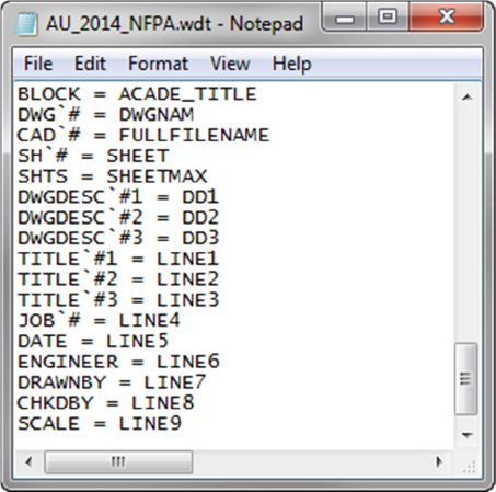
External File Mapping Format
• The external WDT file has a single line that defines each attribute's mapping. The
first line defines the block name where the attributes are found as shown in the
following example:
o BLOCK=TITLE
o PROJ_TITLE=LINE1
o DRAW_TITLE=LINE2
• As with most configuration files, a project-specific file can be used. The software first
searches for a file extension matching the current project name, for example,
<PROJECTNAME>.wdt. If the WDT file with the project name is not found, the
default.wdt file is used.
Example of external project specific WDT file
Feeling the Spark for AutoCAD Electrical
(For AutoCAD Users)
13
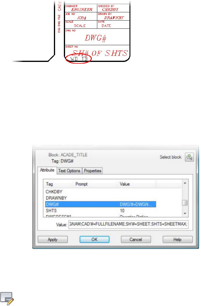
• Internal Attribute Format
If the internal attribute is used, it must be named WD_TB. The attribute must be a part of the
block definition itself. If the title block consists of nested blocks, the attribute must be located
on the first sublevel; it cannot be a part of a nested block definition.
Note: The location of the WD_TB attribute within the title block is not important for the
function of the software, but it is recommended to keep the attribute within or very near to
the title block border. This helps if the title block is exploded and you are looking for the
attribute.
When manually entering mapping information using an attribute editor, the following format
is used:
• Attribute Name = Project or Drawing Variable
• Each mapping entry is separated by a semicolon, as shown in this example.
• Title Block Setup Tool
The Title Block Setup tool automates the formatting of the mapping data and makes the
mapping process easier by listing the available project and drawing data as well as the
available block attributes.
Command Access:
Title Block Setup
Ribbon: Project tab > Other Tools panel > Title Block Setup
Feeling the Spark for AutoCAD Electrical
(For AutoCAD Users)
14
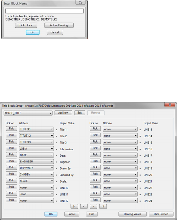
Enter Block Name
o After you select the mapping method in the Setup Title Block Update dialog
box, the Enter Block Name dialog box is displayed. You use this dialog box to
enter the title block names to search for attributes to map information to. You
can select only a single drawing using the Pick Block button, but you can
manually enter several names. For example, your company may use different
title blocks for different-sized drawings, such as Title A, Title B, and Title C. As
long as all three use the same attribute names, the same mapping can be used
for all three title blocks.
o In the Block Name field, enter Title A, Title B, Title C. Each time the title block is
updated, the drawing is searched for all entered title blocks. Any that are found
are updated with the mapped values. You can also use this feature for other
blocks that you want to update, such as revision blocks.
o You use the Project Values, Drawing Values, and User Defined buttons to move
between dialog boxes in the Title Block Setup tool. Each dialog box is specific to
the type of data being mapped to the block attributes.
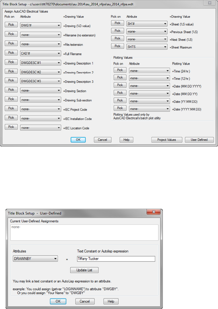
Project Values
o The Title Block Setup - Project Values dialog box is used to map project
description lines to the title block attributes. The Attribute list displays all
available attributes in the selected title blocks. Select an attribute from the list to
map it to the project description value.
o You use Pick to select the attribute in the drawing on the title block itself.
Feeling the Spark for AutoCAD Electrical
(For AutoCAD Users)
15
Drawing Values
o Use the Title Block Setup - Drawing Values dialog box to map information
from the individual drawings to the title block attributes. This information
changes for each drawing. The title block is updated with information only from
the same drawing that the title block is located in.
o Some information in the dialog box is generated automatically. For example,
Sheet Maximum is the total number of drawings listed as part of the project in
the Project Manager.
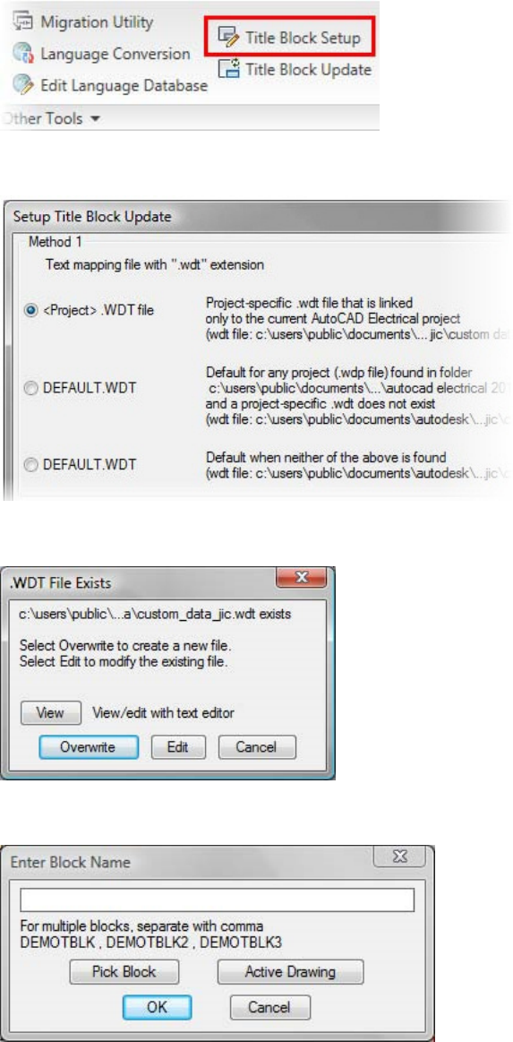
User-Defined Values
o You use the Title Block Setup - User-Defined dialog box to map custom
information to title block attributes. You can enter a fixed value, such as your
name, or you can enter LISP expressions to generate calculated values.
o In this example, you enter your name in the Text Constant box, mapping it to
the DrawnBy attribute. Whenever you run the Title Block Update command
your name is automatically mapped to the attribute.
Feeling the Spark for AutoCAD Electrical
(For AutoCAD Users)
16
Workflow: Creating a Title Block Mapping File
1. On the
Project
tab of the Ribbon,
Other Tools
panel, click
Title Block Setup
.
2. In the
Setup Title Block Update
dialog box, click a mapping option.
3. If an external mapping file exists, the .WDT File Exists dialog box is displayed. Choose the desired option.
4. In the
Enter Block Name
dialog box, enter or select the title block files to be referenced.
Feeling the Spark for AutoCAD Electrical
(For AutoCAD Users)
17
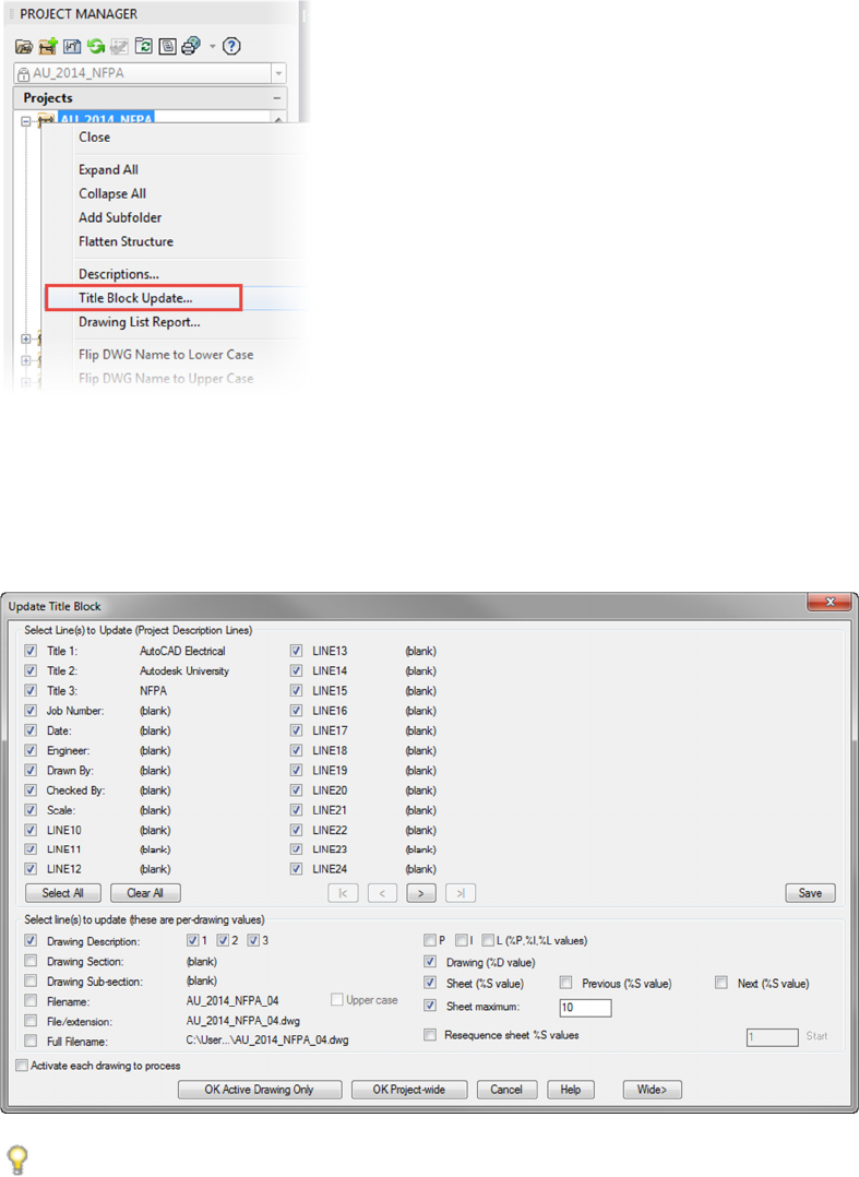
Workflow: Updating a Title Block
1. Start the Title Block Update command.
2. In the Update Title Block dialog box, select the information values you want to use to update the title block attributes.
Only the selected mappings are updated.
If you select values that are blank, or if the appropriate attribute is not found on the title block, the mapping for that item is
ignored.
TIPS: In the Update Title Block dialog box, click Save to save your update selections as the default for the next time
the dialog box is opened.
Feeling the Spark for AutoCAD Electrical
(For AutoCAD Users)
18
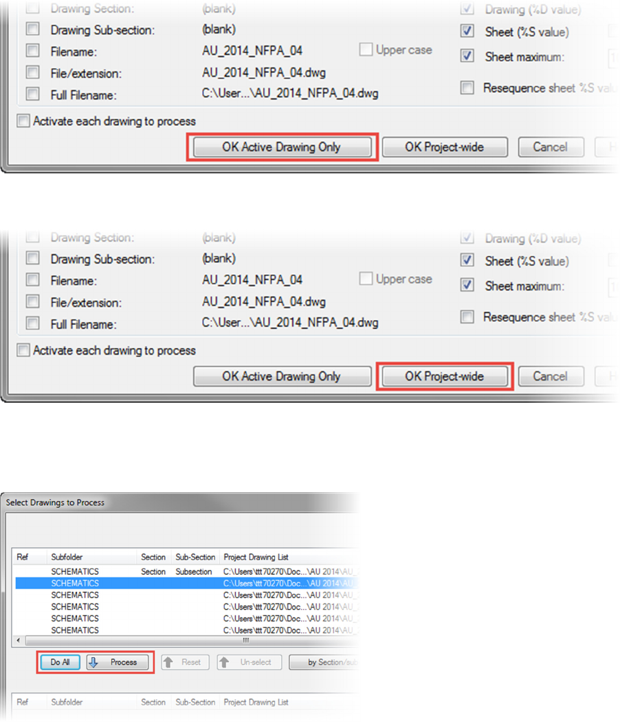
3. Click OK Active Drawing Only to update title block attributes on the active drawing title block. (The command ends.)
4. Click OK Project-Wide to update title block attributes on multiple drawings in the active project.
5. In the Select Drawings to Process dialog box, select the drawings you want to update and add them to the
Drawings to Process list or click Do All. Click OK. The title block is updated in each selected drawing in the
background and the drawing is saved. When all drawings are processed, the command prompt is blank.

Feeling the Spark for AutoCAD Electrical
(For AutoCAD Users)
19
Learning Objective 4: Creating AutoCAD Electrical Templates from vanilla AutoCAD
Templates
Drawing templates are extremely helpful in situations where you need to create your drawings with predefined
drawing standards, such as layers and drawing properties. Using drawing templates enables you to save the time
that you would have to otherwise spend in setting the required standards every time you begin a drawing. In
organizations, CAD managers create template drawings and make them available for their team.
Definition of Drawing Templates (for AutoCAD and AutoCAD Electrical)
A drawing template is a collection of standard predefined settings, such as units, title blocks, layers, text styles, and
dimension styles, which you can use for creating many drawings. Drawing template files have a .dwt file extension.
Drawing Templates and CAD Standards (for AutoCAD and AutoCAD Electrical)
When you work in a project in which many people are involved in creating a design, you must ensure that all team
members consistently follow the same drawing settings. Therefore, to maintain consistency across drawings, you
can establish CAD standards by sharing and using DWT files.
For creating a DWT file, you define the required drawing settings and save the file as a drawing template. You can
also save a DWT file as a drawing standard (DWS) file. You can then use a DWS file to check and map a drawing
with a drawing template for any violation of the set standards
.
Preset Drawing Graphics
Templates can also include partially completed or preset drawings. These are useful when a drawing or part of the
drawing is a standard component that is frequently used in your company design projects.
Note: After creating a drawing that is based on a DWT file, if you modify the new drawing, the changes do not affect
the DWT file.
Example of Drawing Templates
The following images show various examples of electrical drawing templates.
An electrical drawing template that includes title block and two ladders.
Feeling the Spark for AutoCAD Electrical
(For AutoCAD Users)
20
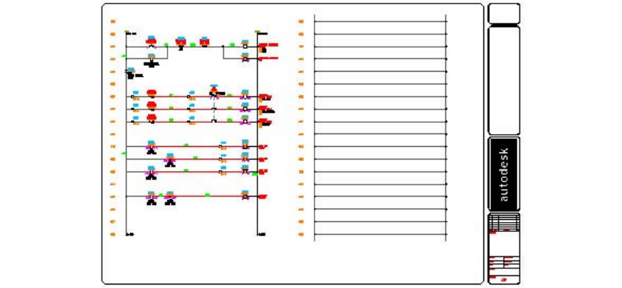
An electrical drawing template with a title block, basic circuits, and a ladder.
When creating drawing templates, you can save all or some of the template properties and settings based on the
type of drawings that you can create with a new template. You can modify these properties later, if required.
Template Properties and Settings
You use drawing templates to provide a starting point for all the new drawings that you create. In most design
environments, your drawings share some common properties and settings. When you save a drawing template, you
can save
all the drawing commonalities, thereby eliminating the need to create or adjust properties and settings each
time you create a new drawing.
AutoCAD Electrical Templates
For templates created for use with AutoCAD® Electrical, it is recommended that you have the wd_m.dwg block
inserted and the drawing properties set to match the template purpose.
You can include wire layers, ladders, partial circuits, symbols, and other graphical information to provide a preset
starting drawing that matches company standards or commonly used designs.
The following are some of the properties and settings that you should save in a drawing template:
Drawing properties settings for electrical configuration
WD_M Block
Wire Layers, colors, and names
Snap and grid mode settings
Dimension, text, and table styles
Title blocks and borders
The following are some of the other items that you can save in a drawing template:
Blocks, such as symbols or other objects that you commonly use in your drawings
Ladders, circuits, and other graphical entities
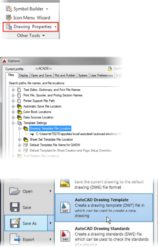
Storage Location of Drawing Templates
Before you create your drawing templates, you need to specify their storage location.
Feeling the Spark for AutoCAD Electrical
(For AutoCAD Users)
21
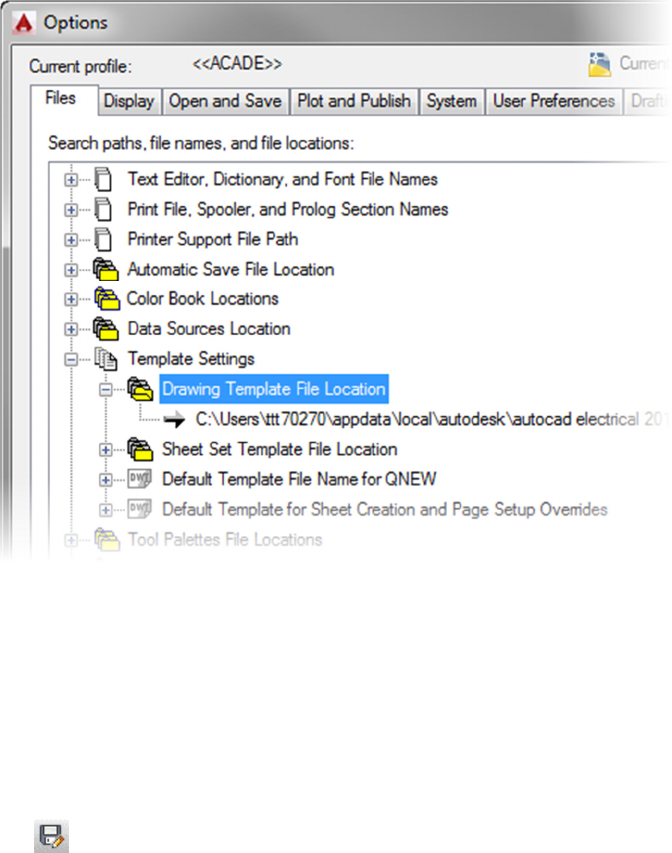
You specify the path to the DWT files on the
Files
tab of the
Options
dialog box. A path on the local hard drive may
work if you are working in a single user environment. However, if you are working as a part of a design team, you
should set the path to a network location where all project drawing templates are consolidated.
The path that you specify as the file location of drawing templates controls the default location that appears when
you select the Drawing Template (*.dwt) format in the Files of Type list in the Save Drawing As, Select Template
,
and the Select File dialog boxes.
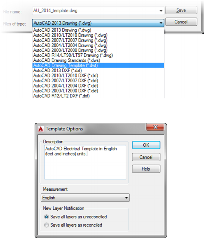
Template Options Dialog Box
By using the Template Options dialog box, you can set the drawing units to either imperial or metric, provide a
description for the template, and control new layer notification.
To access the Template Options dialog box, you select the AutoCAD Drawing Template (*.dwt) option from the
Files of Type list in the Save As dialog box.
Command Access
Save As
Application menu: Save As > AutoCAD Drawing Template
Command line: SAVEAS
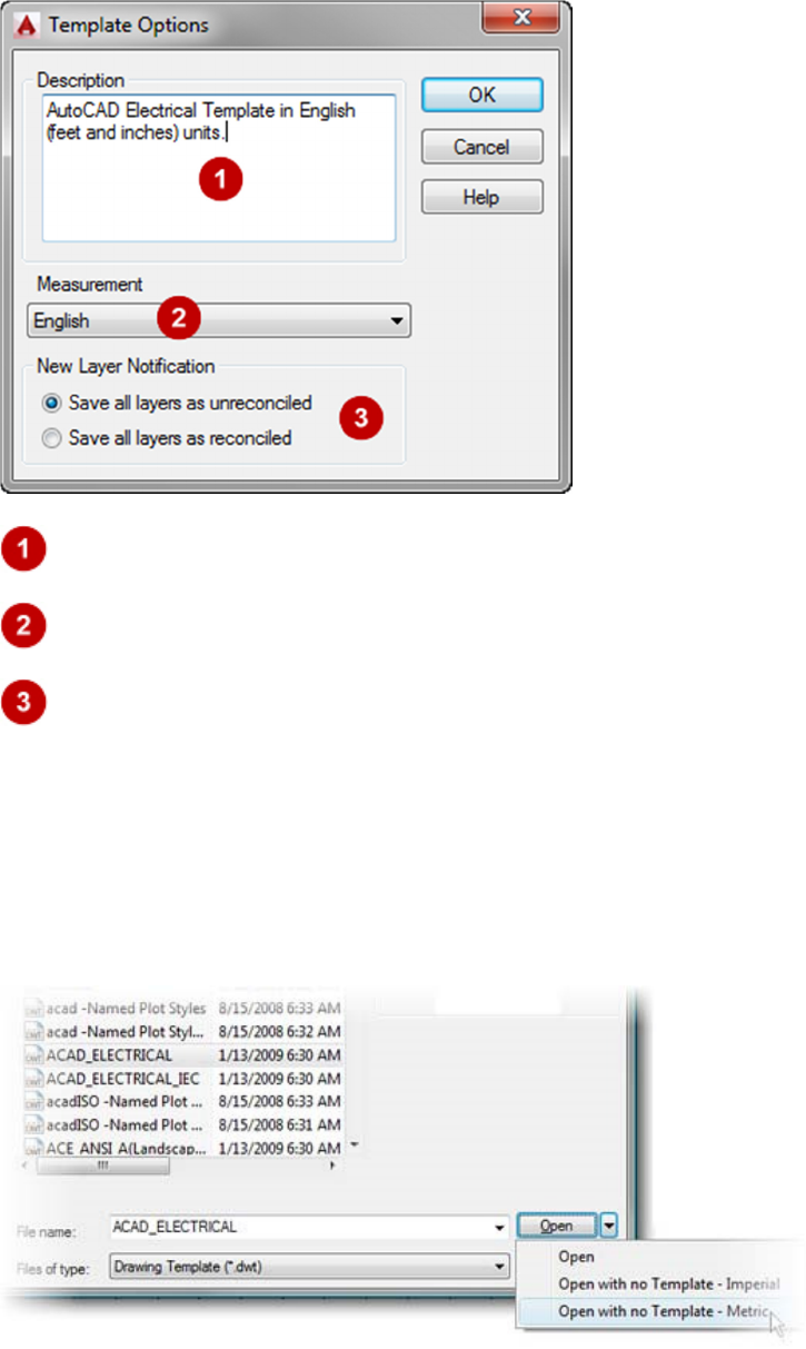
The following image shows the Template Options dialog box.
Feeling the Spark for AutoCAD Electrical
(For AutoCAD Users)
22
Description: Specifies a description for the DWT file.
Measurement: Determines whether drawings based on this template use English or Metric units.
New Layer Notification: Saves all layers as unreconciled or reconciled. When you save a DWT
file with unreconciled layers, the layer baseline is not created; therefore, the new layer notification is not
displayed. When you save a template with reconciled layers, a layer baseline is created; therefore the
software notifies you of any new layers in the drawing.
Note: All the layers in a DWT file are saved as unreconciled by default.
Creating Drawing Templates Workflow
1. Create a new drawing by using an existing template or by using the no template options.
Feeling the Spark for AutoCAD Electrical
(For AutoCAD Users)
23
2. Modify the drawing to include the required layers (see Create Wire Types workflow below), styles,
layout settings, title blocks, and set drawing properties. Starting any AutoCAD® Electrical command,
such as Drawing Properties, automatically inserts the wd_m.dwg block.
3. Adjust the
Drawing Template File Location
path in the
Options
dialog box, if required.
4. On the
Application menu
, click
Save As
>
AutoCAD Drawing Template
.
Feeling the Spark for AutoCAD Electrical
(For AutoCAD Users)
24
5. In the
Save Drawing As
dialog box, verify that
AutoCAD Drawing Template
(*.dwt
) is selected from
the Files of Type list.
6. In the
Template Description
dialog box, enter a description, select the measurement unit, and
specify the new layer notification.
Feeling the Spark for AutoCAD Electrical
(For AutoCAD Users)
25
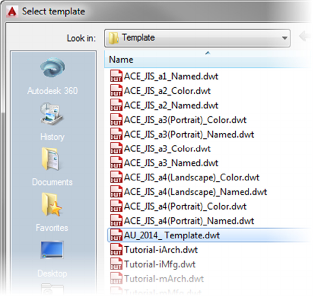
7. Open the newly created template and verify that the drawing contains the settings that you
created.
Feeling the Spark for AutoCAD Electrical
(For AutoCAD Users)
26
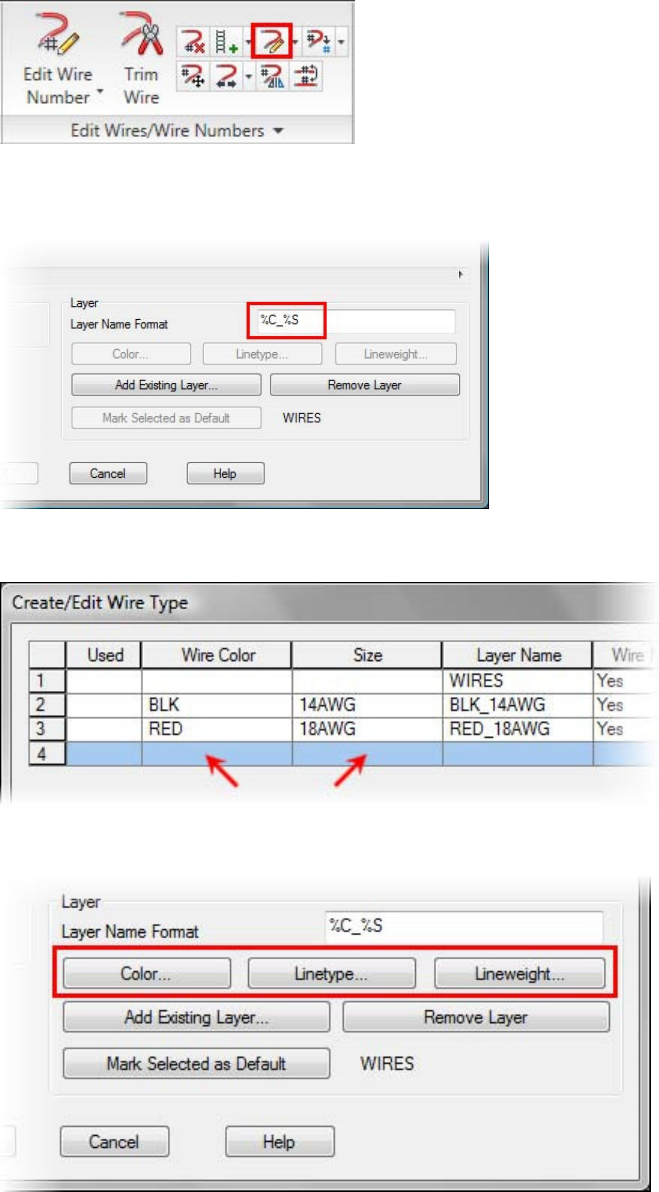
Creating Wire Types
Workflow
1. Start the
Create/Edit Wire Type
command.
2. Enter the desired layer name format.
Note: You must change the format before creating a new layer if you want it to affect the
layer name.
3. Enter data for the new wire type in the grid.
4. Change the layer properties for the selected layer(s) as desired.
Feeling the Spark for AutoCAD Electrical
(For AutoCAD Users)
27
EXERCISE: Exploring the Basics of AutoCAD Electrical
Objective: This exercise will take you through all of the basics of creating schematic drawings. You will
complete the following:
■ Insert ladder rungs and a relay coil component.
■ Insert push-button components and add part-catalog information.
■ Add wire branches and relay coil and child contacts.
■ Add wire numbers and generate a Bill of Material report.
Instructions
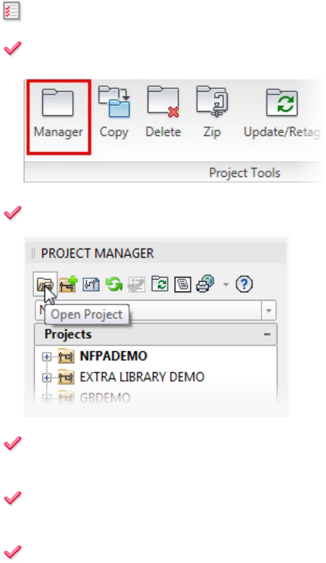
1: If the
Project Manager
is not displayed, on the
Project
tab,
Project Tools
panel, click
Manager
.
2: In the
Project
Manager
, click
Open Project
.
3: Browse to where you saved the project files from the AU website. Select AU_2014_NFPA.wdp
. Click
Open.
4: In the
Project Manager
, click the expansion node to the left of AU_2014_NFPA to expand the
drawing list.
5: Double-click AU_2014_NFPA _04.dwg to open the drawing.
Feeling the Spark for AutoCAD Electrical
(For AutoCAD Users)
28
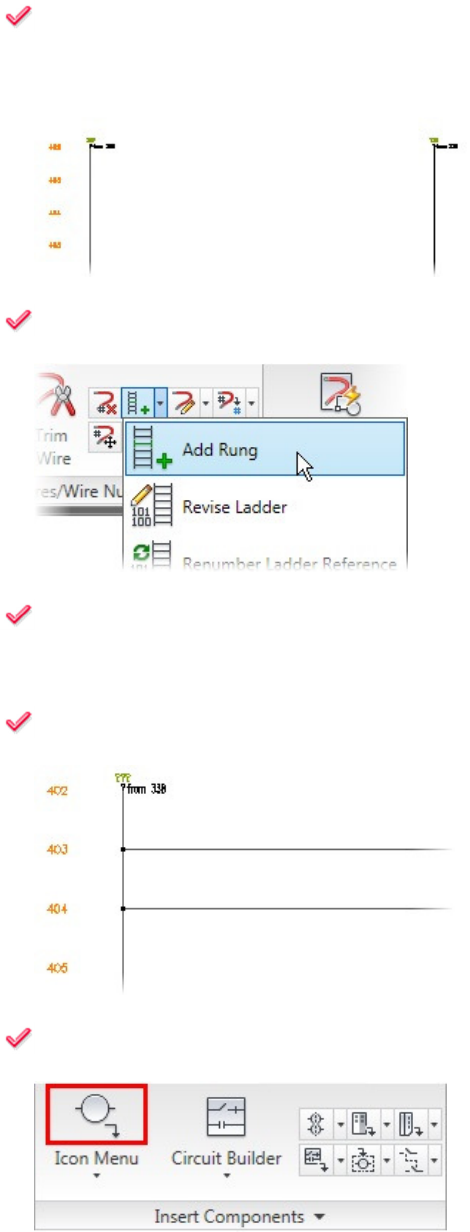
6: To begin you will insert Ladder Rungs and a Relay Coil:
Zoom in to the upper-left corner of the drawing to rungs 403-404. Make sure both the hot and neutral
vertical wires are displayed.
7: On the
Schematic
tab,
Edit Wires/Wire Numbers
panel, click
Add Rung
.
8: Select insertion points for two rungs at rung references 403 and 404.
Note: Be sure to click anywhere between the vertical buses, not on the bus.
9: Notice that the rung automatically snaps to the nearest rung reference, and connection symbols are
added as necessary.
10: On the
Schematic
tab,
Insert Components
panel, click
Icon Menu
to insert the first component, a
relay coil.
Feeling the Spark for AutoCAD Electrical
(For AutoCAD Users)
29
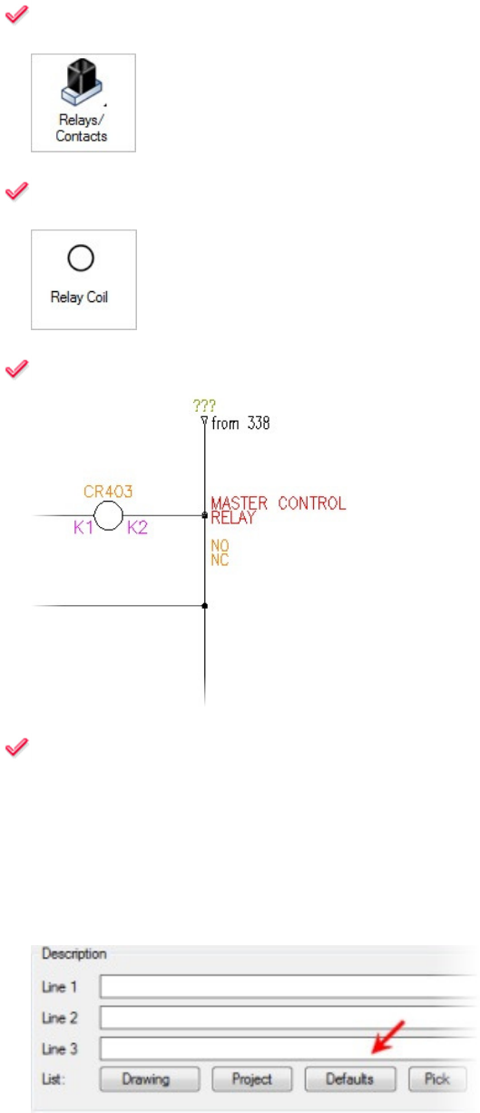
11: In the
Insert Component
dialog box, click
Relays/Contacts
.
12: In the
NFPA: Relays and Contacts
window, click
Relay Coil
.
13: Select the insertion point for the relay coil on rung 403, near the right side, directly above
CR407
.
14: Now you annotate the component, adding description and catalog information. You can manually
type the desired information, but many tools are provided for typing the information from various
reference files automatically. Do the following:
■ Notice the tag name is automatically assigned CR403.
■ In the Insert/Edit Component dialog box, under the Description area, click Defaults.
Feeling the Spark for AutoCAD Electrical
(For AutoCAD Users)
30
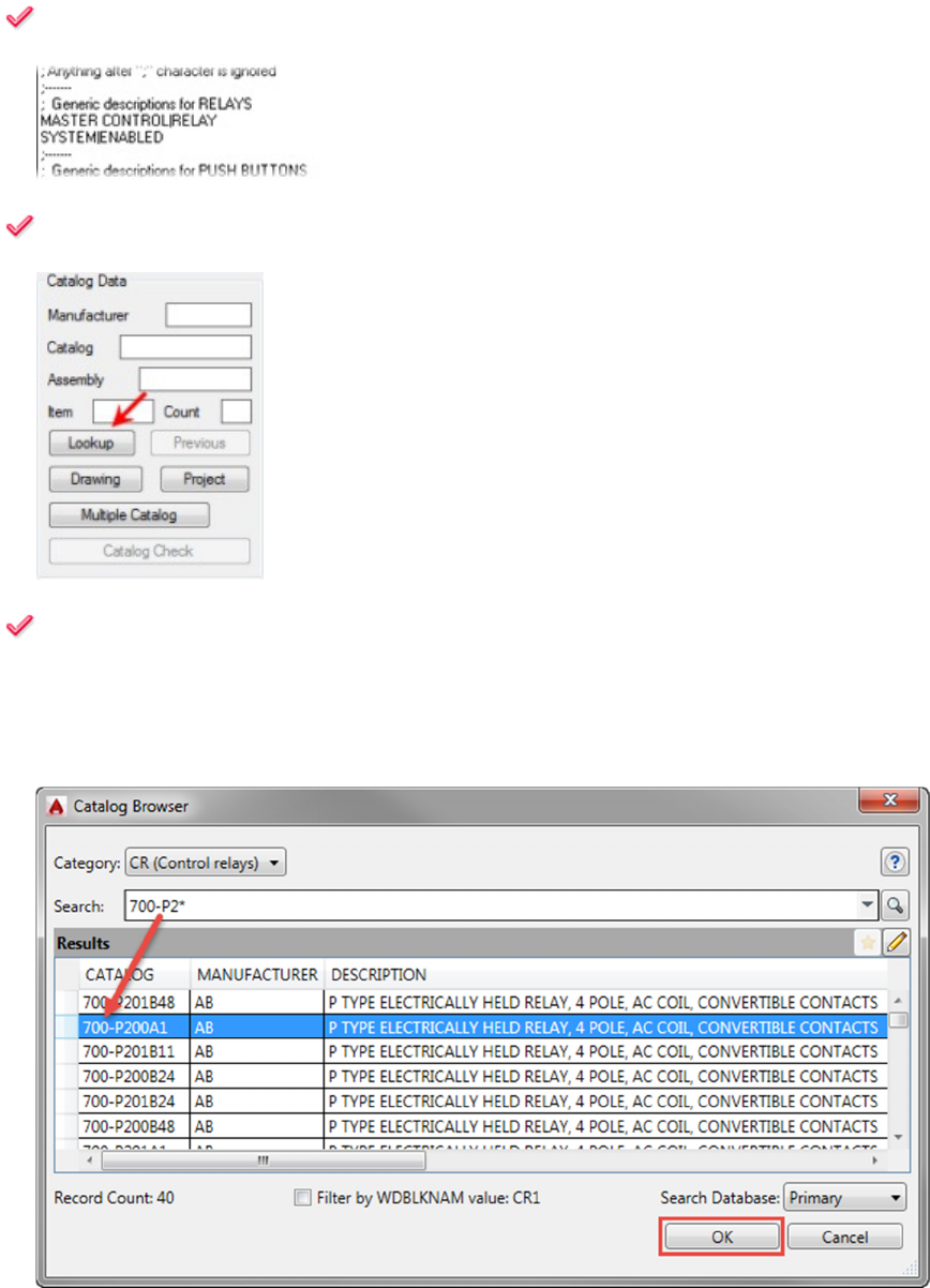
15: In the
Descriptions
dialog box, select
Master Control|Relay
. Click
OK
.
16: In the
Insert/Edit Component
dialog box, under
Catalog Data
, click
Lookup
.
17: In the
Catalog Browser
dialog box, browse the parts catalog database to find the desired part
number. You filter the available options using search bar at the top of the dialog box.
■ Type 700-P2* in the Search field.
■ Select part number 700-P200A1 then click OK.
Feeling the Spark for AutoCAD Electrical
(For AutoCAD Users)
31
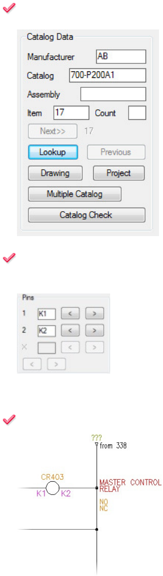
18: Notice that the information is transferred to the
Insert/Edit Component
dialog box.
19: Notice that the selected part number also contains pin-number information, which is automatically
entered in the Pins area of the Insert/Edit Component dialog box.
Click OK.
20: Notice that the information is transferred to attributes on the inserted component.
This completes the insertion of the relay coil. This basic process is repeated for most component
insertions.
Feeling the Spark for AutoCAD Electrical
(For AutoCAD Users)
32
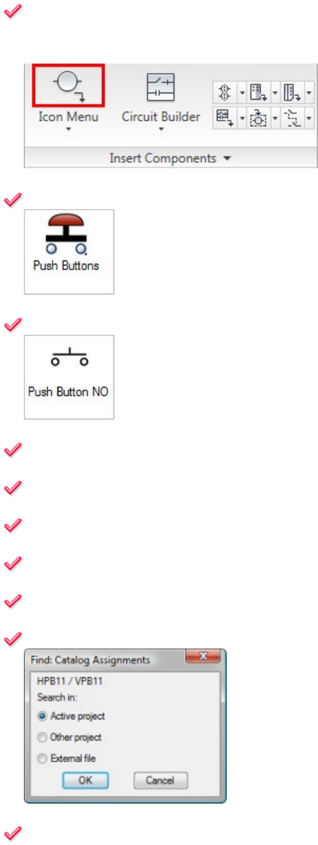
21: This next section inserts push buttons and adds part catalog information:
On the Schematic tab, Insert Components panel, click Icon Menu to add a push button to reset the
circuit.
22: In the
Insert Component
dialog box, click
Push Buttons
.
23: In the Symbol preview window, click
Push Button NO
.
24: Select the insertion point on rung
403
, near the left side.
25: Notice that the tag name is automatically entered as
PB403
.
26: In the
Insert/Edit Component
dialog box, under
Descriptions
, click
Defaults
.
27: In the
Descriptions
dialog box, click
System| Reset
. Click
OK
.
28: Under
Catalog Data
, click
Project
.
29: In the
Find: Catalog Assignments
dialog box, click
Active Project
. Click
OK
.
30: In the
Qsave
dialog box, click
Always QSave
.
Note: AutoCAD Electrical always stores and works with the data that is saved in the drawings
themselves. To ensure that the data is up to date, you are requested to save the current drawing.
Feeling the Spark for AutoCAD Electrical
(For AutoCAD Users)
33
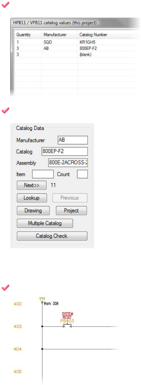
31: All drawings in the current project are searched, and any push buttons found are listed in the
HPB11/VPB11 Catalog Values (this project) dialog box. Select AB, 800EP-F2.
32: Click
OK
. The catalog data, including subassembly information, is transferred to the
Insert/Edit
Component dialog box.
Note: You seldom need to type information more than once. In this project's dataset, push buttons are
already used elsewhere in this project. You want to search for and use the same part numbers that
have been selected.
33: Click
OK
. This completes the push-button insertion.
Feeling the Spark for AutoCAD Electrical
(For AutoCAD Users)
34
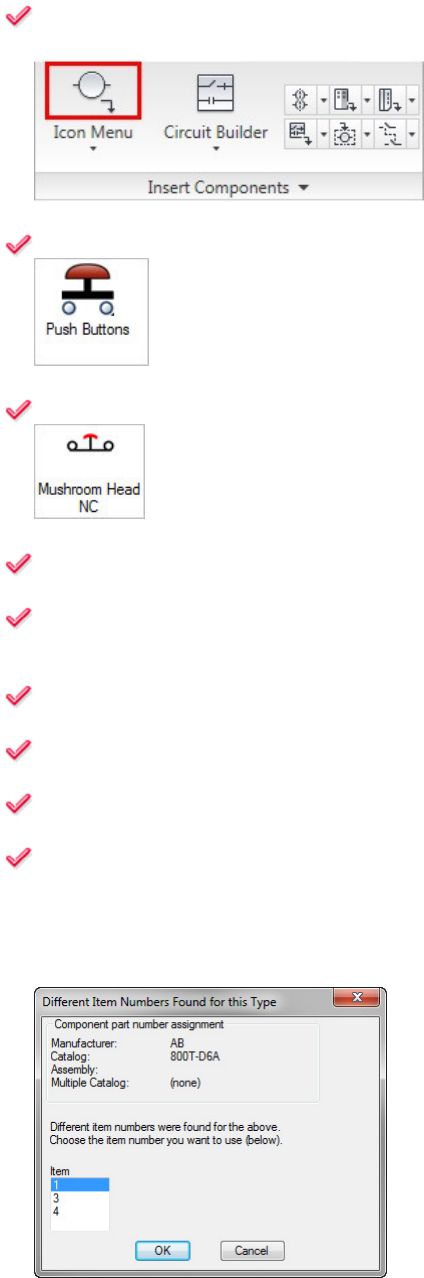
34: On the
Schematic
tab,
Insert Components
panel, click
Icon Menu
to add an emergency stop
push button.
35: In the
Insert Component
dialog box, click
Push Buttons
.
36: In the Symbol preview window, click
Mushro
om Head NC
.
37: Select the insertion point approximately in the middle of rung
403
.
38: Notice the tag name is automatically entered as
PB403A
. Because this is the second push button
on the 403 rung, the tag receives an A as a suffix.
39: In the
Insert/Edit Component
dialog box, under
Descriptions
, click
Defaults
.
40: In the
Descriptions
dialog box, select
Emergency|Stop
. Click
OK
.
41: In the
Insert/Edit Component
dialog box, in the
Catalog Data
area, click
Lookup
.
42: In the
Catalog Browser
dialog box:
■ Type 800T* in the Search field.
■ Select part number 800T-D6A then click OK.
■ If the Different Item Numbers Found for this Type dialog box pops up, select an Item Number from
the list then click OK.
Feeling the Spark for AutoCAD Electrical
(For AutoCAD Users)
35
43: In the
I
nsert/Edit Component
dialog box, click
OK
.
■ If asked to Update other drawings? Click OK.
■ If a Mismatched Item Number warning pops up, click OK.
This completes the push-button insertion.
44: In the next section you will add Wire Branches and Relay Coil Child Contacts:
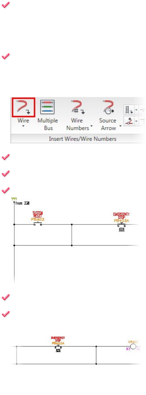
On the Schematic tab, Insert Wires/Wire Numbers panel, click Wire to add two wires that create
connecting branches for the circuit.
45: For the wire start point, select a point on rung
403
between
PB403
and
PB403A
.
46: Select the wire endpoint on rung
404
directly below the wire start point.
47: Notice that connecting dots are added automatically.
48: For the second wire branch, select the wire start point on rung
403
between
PB403A
and
CR403
.
49: Select the wire endpoint on rung
404
directly below the wire start point. Press
ENTER
to end the
command.
Feeling the Spark for AutoCAD Electrical
(For AutoCAD Users)
36
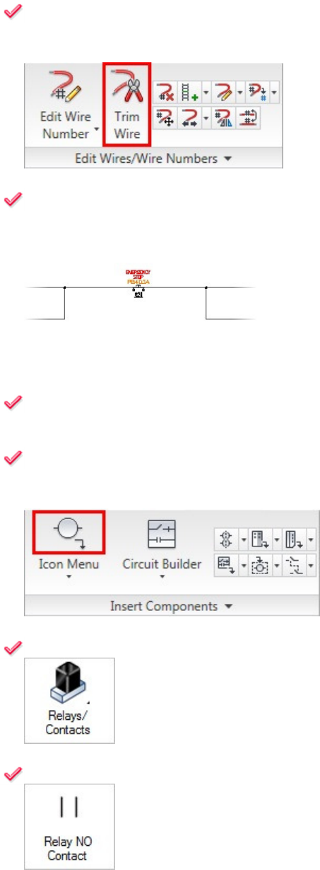
50: On the
Schematic
tab,
Edit Wires/Wire Numbers
panel, click
Trim Wire
to trim the wire on rung
404 between the two wire branches that you added.
51: Select a point on rung
404
between the two wire branches that you added. Press
ENTER
to end
the command.
52:
Notice that the selected wire is removed. If the connecting dots are no longer needed, they are also
removed.
53: On the
Schematic
tab,
Insert Components
panel, click
Icon Menu
to add a contact from
CR403
to latch the circuit after CR403 is activated.
54: In the
Insert Component
dialog box, click
Relays/Contacts
.
55: In the Symbol preview window, click
Relay NO Contact
.
Feeling the Spark for AutoCAD Electrical
(For AutoCAD Users)
37
56: Select the insertion point on rung
404
directly below
PB403
.
This is a child contact of the parent coil.
57: In the
Insert/Edit Child Component
dialog box, under
Component
Tag
, click
Parent/Sibling
to
select the parent coil and transfer data from the parent to the child.
58: Select a point anywhere on
CR403
.
Note: Anywhere on the text works best.
59: In the
Insert/Edit Child Component
dialog box, click
OK
to transfer data, such as tag, description,
and pin numbers, to the child component from the parent.
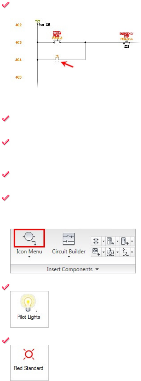
60: The remaining steps will add Wire Numbers and Generate a BOM Report:
On the Schematic tab, Insert Components panel, click Icon Menu to insert a red light to signal when
the circuit is engaged.
61: In the
Insert Component
dialog box, click
Pilot Lights
.
62: In the Symbol preview window, click
Red Standard
.
Feeling the Spark for AutoCAD Electrical
(For AutoCAD Users)
38
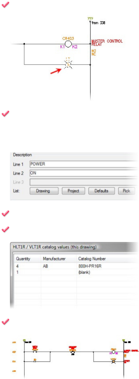
63: Select the insertion point on rung 404 directly below CR403.
64: Instead of using the description defaults, you can manually type the description:
In the Insert/Edit Component dialog box, under Description:
■ For Line 1, type POWER
■ For Line 2, type ON
65: Under
Catalog Data
, click
Drawing
.
66: In the
HLT1R/VLT1R Catalog Values
dialog box, select
AB
,
800H
-
PR16R
. Click
OK
.
67: In the
Insert/Edit Component
dialog box, click
OK
.

Feeling the Spark for AutoCAD Electrical
(For AutoCAD Users)
39
68: On the
Schematic
tab,
Insert Wires/Wire Numbers
panel, click
Wire Numbers
to add wire
numbers.
69: In the
Wire Tagging
dialog box, click
Drawing
-
Wide
.
The drawing is searched for wire networks. A wire number is placed on each network found.
70: The last step is to extract a Bill of Material report from the components in the drawing. On the
Reports tab, Schematic panel, click Reports.
71: In the
Schematic Reports
dialog box, under
Report Name
, select
Bill of Material
.
72: In the
Bill of Material
area, click
Active Drawing
. Click
OK
.
Feeling the Spark for AutoCAD Electrical
(For AutoCAD Users)
40
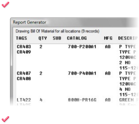
73: Notice the Bill of Material report is generated from component data within the drawing. You can
save the report to any of five different file formats, or place it on the drawing in the form of a table.
74: In the
Report Generator
dialog box, click
Close
.
This completes the exercise.

Feeling the Spark for AutoCAD Electrical
(For AutoCAD Users)
41
AutoCAD Electrical
Installation Guide
Deployment & Implementation Prerequisites
For this implementation to be successful, you must have:
Working knowledge of AutoCAD
®
.
A background in electrical design.
Have taken an AutoCAD
®
Electrical Essentials course at an Autodesk Authorized Training Center
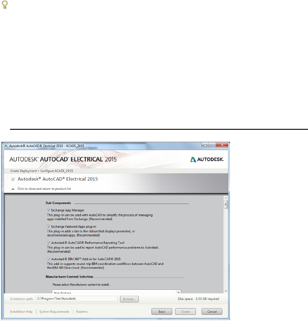
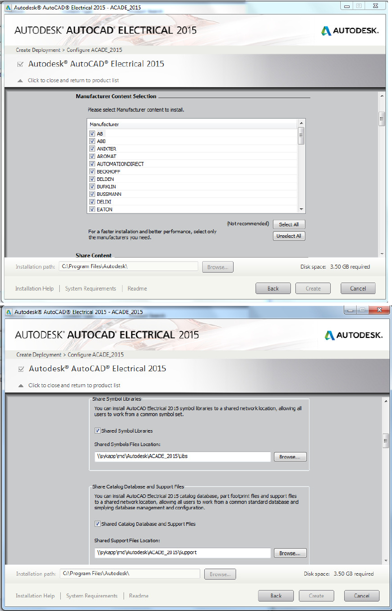
Deployment & Implementation Steps
Deployment (see images below)
Configure Deployment
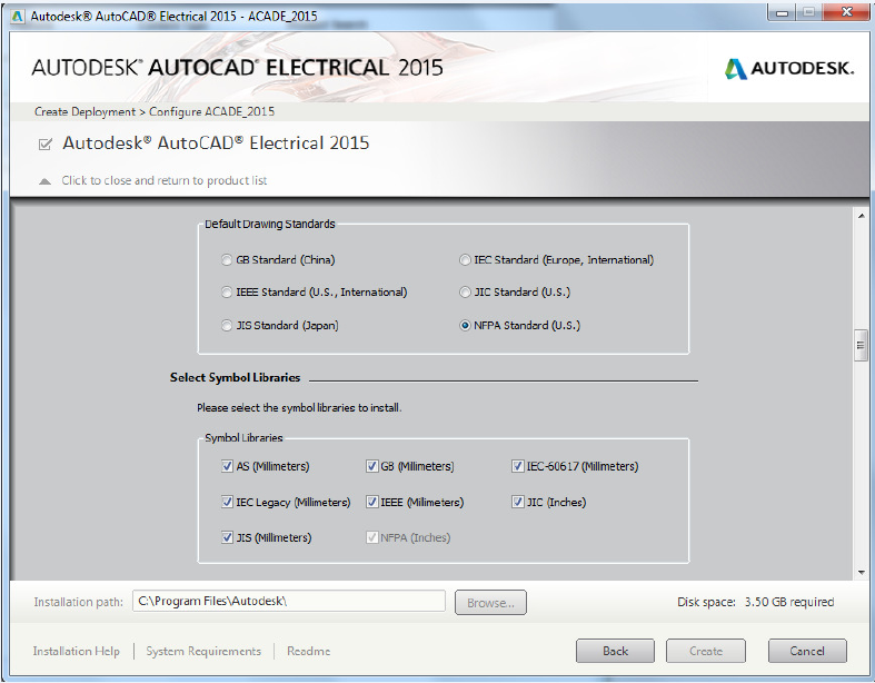
• Decide on which Symbol Libraries and Manufacturers to include from the lists provided
• Decide which Symbol Library will be the Default
• Decide on Installation and Search Paths for your ACADE Support Files (Network location
vs. Local)
Create Deployment
Install on users’ machines
Implementation
Create Drawing Template(s)
• Create/Define Wire Types
• Define Standard Drawing Properties
• Make sure your title block is in Paper Space
Create Project Template(s)
• Define Standard Project Properties
Decide what ACADE Support Files to utilize and create
• Examples
Project Line Descriptions: default_wdtitle.wdl
Title Block Setup: default.wdt
Default Descriptions: wd_desc.wdd
Installation/Location Code External Files: default.inst, default.loc
Feeling the Spark for AutoCAD Electrical
(For AutoCAD Users)
42
Create a complete Standard Project(s) to be used as a template for all future projects
• Creation of custom schematic symbols, as needed
Add symbols to the Icon Menu, as needed
• Creation of custom panel footprints, as needed
Update the Footprint Database, as needed
• Create new part numbers in the Part Catalog Database, as needed
• If you use your own company part numbers in association with Manufacturer catalog
numbers, fill in the User Fields in the Part Catalog Database
TIPS:
Try to work as “out of the box” as you can with ACADE. It will make your implementation much
smoother. (Even if it means, changing the way some of your symbols look, etc.)
Although your project files can access drawings from many different folders, it is a best practice to
keep the project file, all of its drawings, and project-specific support files in the same place.
Implementation Steps for a Vaulted Environment
Step 1: AutoCAD Electrical Essentials Training
Step 2: AutoCAD Electrical Implementation
Step 3: Vault Implementation
Step 4: Vault Basic Training
Step 5: Vault inside of AutoCAD Electrical Training
Feeling the Spark for AutoCAD Electrical
(For AutoCAD Users)
43
Feeling the Spark for AutoCAD Electrical
(For AutoCAD Users)
44
