Operaon & Installaon Instrucons
OWNERS MANUAL
www.chandlersystemsinc.com

2|Page
Congratulaons on purchasing this ultraviolet disinfecon system. By
purchasing a CHANDLER UV Disinfecon system you are receiving not
only a high quality product but also peace of mind. Protecng your water
supply with a UV system gives you reassurance that your family will have
access to safe drinking water throughout your enre home with no chance
of microbiological contaminaon. This is a chemical free process which is
simple in its concept and eecve in its ability to inacvate microorganisms
present in the water supply. Simple maintenance, connuous
disinfecon and ulmately safe water, CHANDLER makes it that easy.

3|Page
TABLE OF CONTENTS
Safety Consideraons ......................................................................................................... 4
Before You Begin ................................................................................................................ 4
Water Quality Parameters .................................................................................................. 5
Assembly ............................................................................................................................ 6
System Sizing ...................................................................................................................... 8
Locaon .............................................................................................................................. 8
Installaon ......................................................................................................................... 9
System Disinfecon .......................................................................................................... 12
Cleaning the Quartz Sleeve .............................................................................................. 12
Cleaning the UV Sensor .................................................................................................... 13
Temperature Management Devices ................................................................................. 14
Operaon ......................................................................................................................... 14
Controller ............................................................................................................... 14
Power-up Sequence ............................................................................................... 14
Operaonal Screens ............................................................................................... 16
Operaonal Screens with UV Monitor Upgrade .................................................... 16
UV Intensity (with UV Monitor Upgrade) .............................................................. 16
Lamp Countdown Sequence .................................................................................. 17
Lamp Countdown Reset Sequence ........................................................................ 17
Failure Modes ........................................................................................................ 18
QR Codes .......................................................................................................................... 18
Expansion Modules .......................................................................................................... 19
CHANDLER Standard Output System Specicaons ......................................................... 20
CHANDLER High Output System Specicaons ................................................................ 21
Limited Warranty Statement ............................................................................................ 22
Warranty Registraon ...................................................................................................... 23

4|Page
Safety Consideraons
Although your UV system has been manufactured to the highest safety standards, care must be
followed when operang and/or maintaining your system.
1. Before servicing this equipment, disconnect the power cord from the electrical outlet.
2. Energy given o by the UV lamp can be harmful to your eyes and skin. NEVER look
directly at an illuminated UV lamp without adequate eye protecon and always protect
your skin from direct exposure to the UV light.
3. For complete disinfecon, use ONLY genuine replacement parts.
4. Do not operate the unit if it has any damaged or missing components.
5. To avoid possible electrical shock, use only with a properly grounded electrical outlet.
6. Never perform any maintenance to the system unless you are comfortable in doing so.
Contact the manufacturer for service instrucons if required.
7. Do not use this system for any purpose other than what it was intended for. Misuse of this
system could potenally cause harm to the user or others.
8. Your system is intended to be installed indoors and away from leaking plumbing. DO NOT
plug the unit in if the system or any of the components are wet.
9. The disinfecon system should be directly installed into a ground fault circuit interrupter
(GFCI). If the use of an extension cord is required, the cord must be manufactured with a
minimum of 16 gauge wire and care should be taken to avoid potenal tripping hazards.
10. We recommend that a licensed plumber or cered technician install the system.
Before You Begin
The following will be needed for installing the UV system:
Tools
• Pipe cuer, hacksaw or other specialised tools required to cut into your exisng plumb-
ing
• Soldering tools (torch, ux, emery cloth and solder)
• Wrench (for ghtening ngs)
Other Materials
• Inlet/outlet connecons
• Teon™ tape

5|Page
Water Quality Parameters
UV disinfecon is extremely eecve against microorganisms but only if the UV light can pass
through the water it needs to treat. This means that the quality of your water is very important
in order to ensure complete disinfecon.
Treated water should be tested for at the least the parameters listed below. If the water exceeds
the listed parameters CHANDLER strongly recommends that appropriate pretreatment equip-
ment be installed (equipment required will depend on parameters being treated):
Hardness:
<7 gpg (120 mg/L) – if hardness level is 7 gpg or slightly below the
quartz sleeve must be cleaned periodically in order to ensure e-
cient UV penetraon; if above the water should be soened.
Iron (Fe):
<0.3 ppm (0.3 mg/L)
Manganese (Mn):
<0.05 ppm (0.05 mg/L)
Turbidity:
< 1 NTU
Tannins (organics):
<0.1 ppm (0.1 mg/L)
UVT (transmiance):
>85% (Please contact CHANDLER if water has a UVT that is less than
80% for pre-treatment recommendaons)
You can have your water tested at a private analycal laboratory or by your local dealer. It is
always recommended to install pre-ltraon of at least 5 microns prior to a CHANDLER disinfec-
on system.
6|Page
Assembly
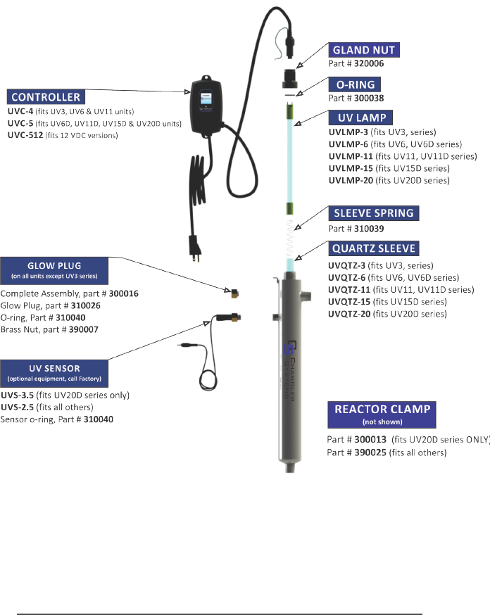
Unpack the system and ensure all the components are included with the system. Your system is
shipped with the following components:
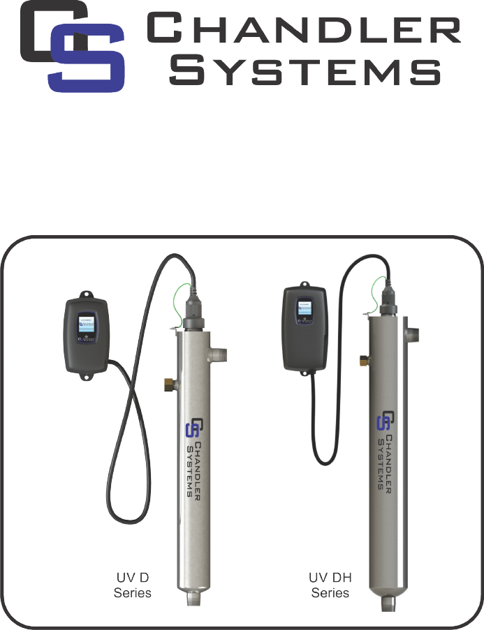
“UV/UV D” Series (Standard output lamp systems)
7|Page
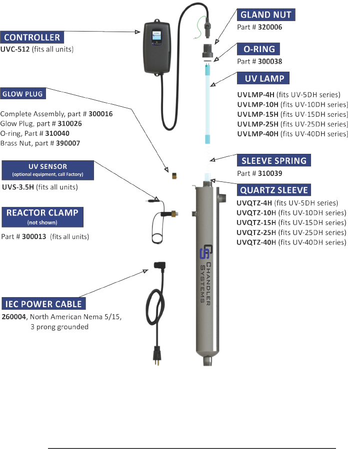
“UV DH” Series (High output lamp systems)
8|Page
System Sizing
All CHANDLER systems are rated for a specic ow rate in water that meets the quality param-
eters on page 5. PLEASE NOTE that increasing the ow above this rang or disinfecng water
that does not meet the quality paramaters will decrease the dose and therefore compromise the
microorganism inacvaon. To determine the ow rate, follow these simple steps:
1.Be sure no water is being used in the home.
2.Open a faucet or tap nearest the pressure system and run unl the well pump starts.
3.Close the faucet and using a second hand watch, record the length of me in seconds unl the
pump stops. This is known as the cycle me.
4.Then using a container of known volume, preferably in US Gallons, open the faucet or tap
nearest the pressure system and measure the amount of water drawn o unl the pump starts
again. Depending on the size of the container used, it is acceptable to turn the faucet on and o
to empty the container. This measurement is known as the draw down.
To calculate the pressure system ow rate divide the draw down by the cycle me and mulply
that by 60.
Draw Down__________÷ Cycle Time____________ x 60=__________Pumping Rate in USGPM
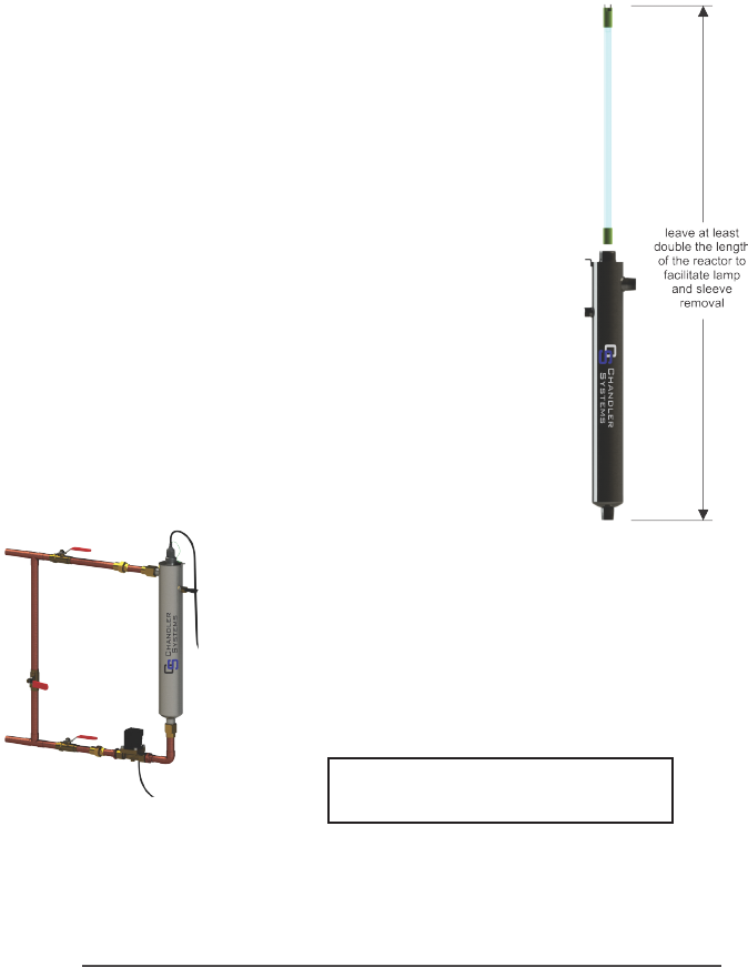
Locaon
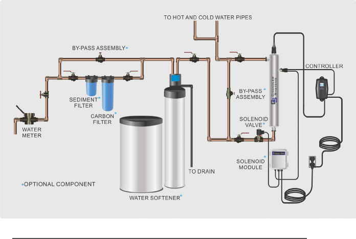
For Point of Entry (POE) systems, choose a locaon where the main cold water line is accessable.
The system must be installed aer other water treatment equipment (soener or lters), but
before any branches (See Figure 1). For Point of Use (POU) systems, install the unit just before
the tap. CHANDLER recommends that a 20 micron lter be installed before the UV system for a
nal polishing step before the water is disinfected.
Figure 1. Recommended POE Installaon Locaon
9|Page
To facilitate lamp removal, ensure there is enough space at the lamp connector end of the UV
chamber to safely remove the UV lamp and/or quartz sleeve (See Figure 2).
The controller will require a ground fault circuit interrupter (GFCI or GFI) outlet and should be
mounted beside or above the reactor.
PLEASE NOTE: All CHANDLER disinfecon systems are intended for indoor use only as they
should not be exposed to the elements.
Installaon
Step 1: The reactor can be installed either horizontally or ver-
cally using the clamps provided. Vercal installaon is the pre-
ferred method with the inlet at the boom (lamp connecon at
the top) as it allows any air that may be in the pipework to be
easily purged from the system.
Step 2: The use of a by-pass assembly is recommended as it
will allow you to isolate the UV reactor. This will allow for easier
access in case maintenance is required (See Figure 3).
Step 3: Use the supplied fasteners to mount the UV reactor to
wood or drywall. If mounng to an alternate material you will
need to purchase the proper corresponding fasteners.
Step 4: For water supplies where the maximum ow rate is un-
known, a ow restrictor is recommended so that the rated ow
of your parcular CHANDLER system is not exceeded. The ow
restrictor should be installed on the outlet port of the reactor.
Step 5: It is recommended to have a licensed plumber connect
the UV reactor to the water supply and may be a requirement
depending on where you are located.
Figure 2. Lamp Removal
Spacing
Note: Installaon of your CHANDLER
disinfecon systems should comply with
applicable local regulaons.
Figure 3.
By-pass assembly
10|Page
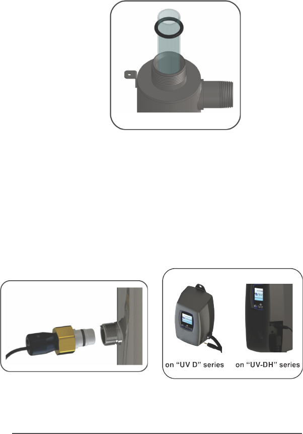
Step 6: Once the system has been plumbed in, gently remove the quartz sleeve from its pack-
aging being careful not to touch the length with your hands. The use of coon gloves is recom-
mended for this procedure as oils from the hands can leave residue on the sleeve and lamp
which can ulmately block the UV light from geng to the water.
Carefully slide the sleeve into the reactor unl you can feel it hit the opposite end of the reactor.
Align the sleeve so it centered along the length of the reactor, then gently push it in to lock it into
the internal centering springs in the far side of the reactor. CAUTION: Pushing too hard when the
sleeve is not aligned can damage the centering springs. Slide the o-ring onto the sleeve unl it is
bued up against the reactor.
Figure 4. Quartz Sleeve Installaon
Step 7: Hand ghten the provided gland nut over the quartz sleeve onto the threaded end of
the reactor. It has a posive stop to prevent over-ghtening. A rm force may be required to fully
ghten the gland nut, but DO NOT USE TOOLS for this step. Insert the provided stainless steel
compression spring into the quartz sleeve. The spring works with the lamp and lamp connector
to create the proper lamp alignment. PLEASE NOTE: DO NOT install a UV lamp inside the quartz
sleeve without the sleeve spring in place.
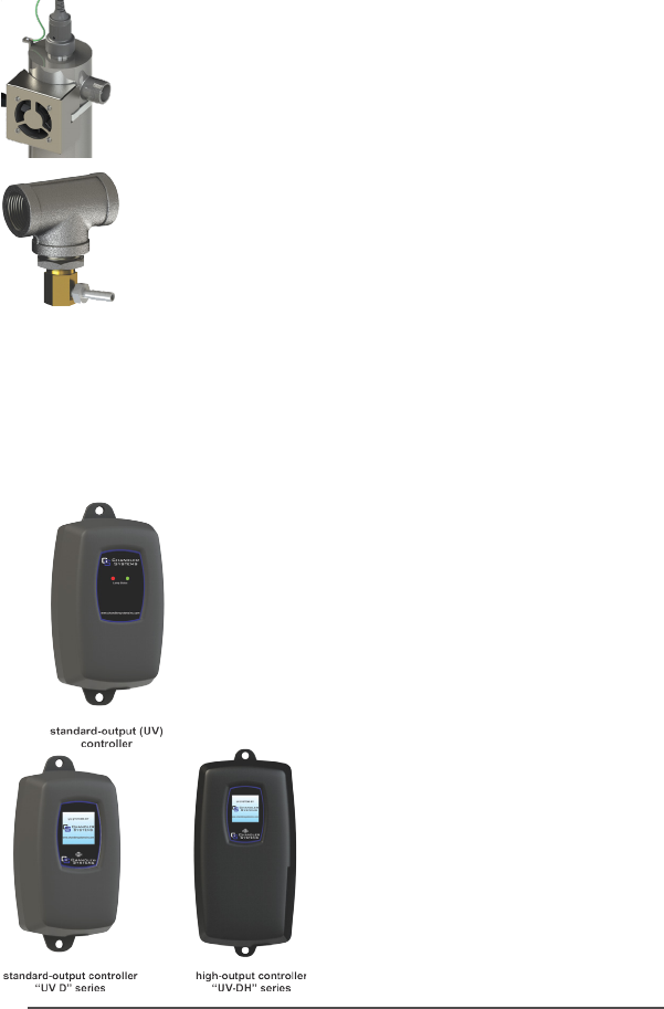
Step 8: Install the UV sensor (only with UV monitor upgrade). Align the at poron so it faces
the gland nut end and matches up with the half metal lip on the sensor port (see Figure 5). Insert
the sensor so it is fully seated and hand ghten the sensor nut.
Figure 5. UV Sensor Installaon Figure 6. IEP Connecon
11|Page
Step 9: The reactor is now ready for water ow. When all plumbing connecons have been
completed, slowly turn on the water supply and check for leaks. Make sure the by-pass valves are
funconing properly and that the water is owing through the reactor. The most common leak
is from the o-ring not making a proper seal on the reactor. For new installaons, review steps 7
and 8. For older systems drain the reactor, remove the o-ring, dry it and reapply silicon grease.
Reinstall the o-ring ensuring that it is properly sealed against the reactor and check again for
leaks.
Step 10: Mount the controller to the wall so it is above or beside the reactor to ensure that no
moisture can deposit on any of the connecons (see Figure 1). Always mount the controller ver-
cally. For monitored systems, insert the sensor connector into the IEP port located on the right
side of the controller (Figure 6). For the sensor to be recognised by the controller, the controller
power must be plugged in last. Do not plug the controller power cord in before the last step.
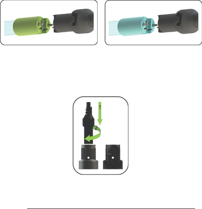
Step 11: Always hold UV lamps by their ceramic ends, not by the lamp quartz. Remove the lamp
from its packaging. Again, the use of coon gloves is recommended. Insert the UV lamp into the
reactor, being careful not to drop it.
Step 12: Plug the lamp connector into the lamp. Note the keying for proper alignment (see Fig-
ure 7a, 7b). Insert the lamp connector into the gland nut and turn the connector approximately
¼ turn to lock the connector to the gland nut as in Figure 8.
Figure 8. Lamp Connector
Figure 7a. Standard Output UV
Lamp Connecon
Figure 7b. High Output UV
Lamp Connecon
12|Page
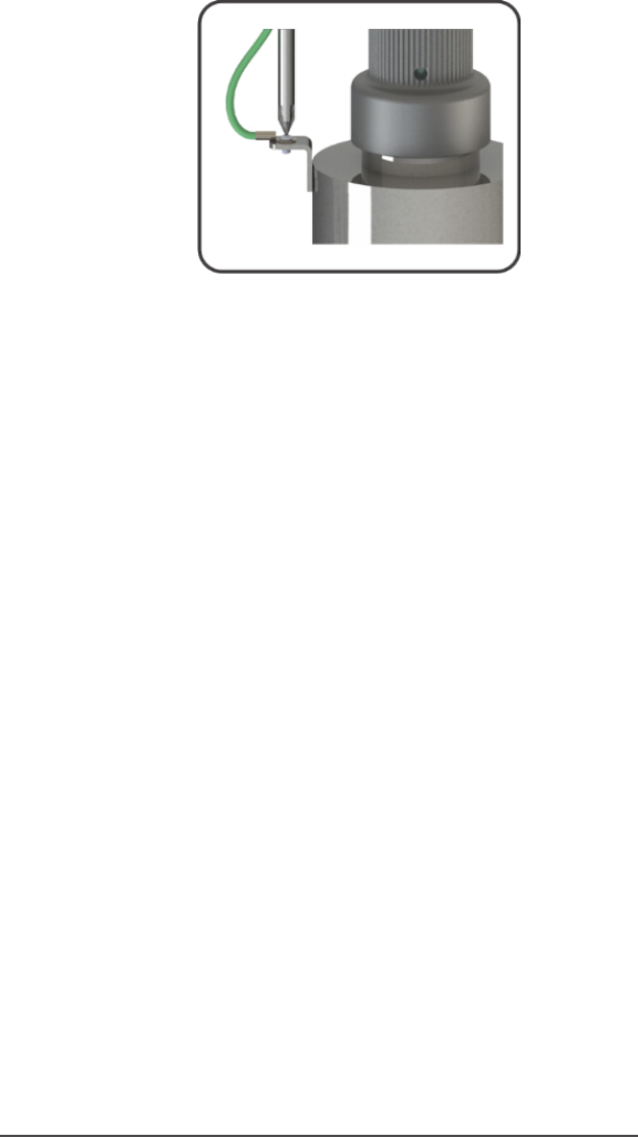
Step 13: Tighten the capve ground screw to the ground lug on the UV reactor to ensure proper
grounding.
Figure 9. Ground Screw Connecon
Step 14: Your system is now ready to be plugged into the appropriate GFCI protected outlet.
Refer to the following secon before any water is allowed to ow through the system.
System Disinfecon
With a new installaon, or any me the UV system is shut down for service, without power, or
is inoperave for any other reason, the pipework in the home or facility could be contaminated.
Use the following steps to fully disinfect the pipework throughout the enre home or facility.
Step 1: Check for and remove any “dead ends” in the pipework throughout the home as these
can harbor bacteria. Plug in the UV system and wait unl it is ready for operaon.
Step 2: Remove the lter cartridge from the last lter housing and ll it with 1-2 cups of house-
hold bleach (most are 5.25% chlorine). Replace the lter housing and slowly turn on the water
supply.
Step 3: At a water outlet, run the water unl bleach can be smelled. Repeat this for all taps,
toilets, shower heads, refrigerators, outdoor taps, the washing machine, dishwasher, etc. at the
home or facility. Once nished, wait a minumum of 30 minutes before connuing.
Step 4: Reinstall the lter cartridge into the lter housing and ush the chlorine soluon by
opening all taps unl chlorine can no longer be detected. Your home has now been completely
disinfected with your CHANDLER system ready to inacvate any microorganisms that enter the
home.
Cleaning the Quartz Sleeve
Depending on the water quality, the quartz sleeve may require periodic cleaning. At a minimum,
the quartz sleeve should be cleaned on an annual basis. The following steps outline a basic clean-
ing procedure.
Step 1: If a by-pass assembly is installed, shut the inlet valve o to prevent water ow through
the system. Otherwise, turn o main water inlet valve (and/or turn o the water pump).
Step 2: Disconnect power cord of UV system from electrical outlet.

13|Page
Step 3: Release water pressure by opening a downstream tap and then close the outlet shut-
o valve (if any). If there is no outlet shut-o valve, expect water to drain from the system as the
head pressure in the system will cause the water to ow back down.
Step 4: Remove the capve ground screw from the ground lug on the UV reactor.
Step 5: Remove the lamp connector from the reactor (gland nut) by pushing the lamp connec-
tor in and turning it ¼ turn counter-clockwise. Disconnect the lamp connector from the lamp.
CAUTION: the lamp may be hot!
Step 6: Being careful to touch only the ceramic ends, remove the lamp out of the reactor.
Step 7: Unscrew the gland nut from the reactor exposing the end of the quartz sleeve.
Step 8: Remove the quartz sleeve and o-ring by gently twisng and pulling the quartz sleeve.
Step 9: Using a so, lint-free cloth or towel wipe the sleeve down using a commercial scale
cleaner (i.e. CLR® or LIME-A-WAY®). This removes scaling or iron deposits that may be on the
outside of the quartz sleeve. Be careful not to get any moisture or liquids inside of the sleeve.
Step 10: Dry the sleeve with a separate cloth.
Step 11: Replace the o-ring and slide the sleeve back into the reactor following steps 7 and 8
from the installaon secon of the manual.
Cleaning the UV Sensor
Depending on the water quality, the UV sensor may require periodic cleaning. At a minimum,
the UV sensor should be cleaning on an annual basis. The following steps outline a basic clean-
ing procedure.
Step 1: If a by-pass assembly is installed, shut the inlet valve o to prevent water ow through
the system. Otherwise, turn o main water inlet valve (and/or turn o the water pump).
Step 2: Disconnect power cord of UV system from electrical outlet.
Step 3: Release water pressure by opening a downstream tap and then close the outlet shut-
o valve (if any). If there is no outlet shut-o valve, expect water to drain from the system as the
head pressure in the system will cause the water to ow back down.
Step 4: Place something under the reactor to catch any water that may come out of the reac-
tor during the removal of the UV sensor.
Step 5: Unscrew (counterclockwise) sensor nut from the reactor and pull the sensor slowly out
of the sensor port.
Step 6: Holding the sensor in your hand wipe the at poron (sensor face) of the sensor with
isopropyl alcohol using a clean lint-free cloth.
Step 7: Replace sensor following step 9 from the installaon secon of the manual.
14|Page
Temperature Management Devices
Your CHANDLER system is designed to run connuously to ensure opmal disinfecon. However,
during periods when no water is drawn through the system, the energy from the disinfecon
process can cause the temperature of the water inside the chamber to rise. In extreme situaons
elevated water temperature or the uctuaon in temperature can lower the output of the UV
lamp. In these cases, or if the elevated water temperature is a nuisance, it is recommended to
use one of the following forms of temperature management devices.
Cooling Fan
Designed for use on the UV DH systems, the fan runs connuously to cool the
water by forced convecon. The long-life fan is powered independently using a
compact modular power adapter that operates from 90-265V (47-63Hz). Order
PN UV-FAN3.5
Temperature Relief Valve (TRV)
On reaching a higher temperature, the TRV is designed to drain a small amount
of water to allow fresh, cooler water to enter the system. The TRV works without
power and comes complete with 10’ of drain line. Order PN 130031 for 1/2”
ports, PN 130032 for 3/4” ports, PN 130033 for 1” ports and PN 130034 for 1
1/2” ports.
Operaon
The CHANDLER system comes with a feature laden controller that incorporates both the lamp
driver (ballast) and control features in one water-ght case. Two controllers are available for the
CHANDLER systems (depending on your model).
Controllers
The “UV” series controller features a power factor corrected, constant
current lamp driver with a universal power input. Simplisc in opera-
on, this system features two LEDs that show lamp status. When the
UV lamp is on, the green LED will be illuminated. When the UV lamp
is not on, the red LED will be illuminated and an audible buzzer will
be sounding. This system does not measure the level of disinfecon;
it simply measures the “on-o” status of the lamp. Please have your
water checked for microbiological contaminants on a regular basis.
The “UV D” and “UV DH” controllers feature a power fac-
tor corrected, constant current lamp driver with a univer-
sal power input. A full colour LCD screen provides the user
with a detailed descripon of the system’s performance in
addion to providing any applicable fault messages and
system diagnoscs. The controllers used in both the moni-
tored and non-monitored systems are idencal. All con-
trollers include an “innite expandability port” located on
the right side of the controller. Oponal modules like the
UV sensor can be plugged into the expandability port of a
CHANDLER controller to give addional features.
15|Page
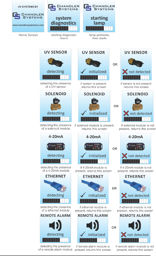
Power-up Sequence
On start up, the controller will run through a diagnosc start-up and the sequence will be dis-
played as follows on the colour LCD:
Next, the controller checks for and inializes any oponal modules that may be aached to the
system.
UV Sensor
Module Check
Solenoid
Module Check
4-20 mA
Module Check
Ethernet
Module Check
Remote Alarm
Module Check
16|Page
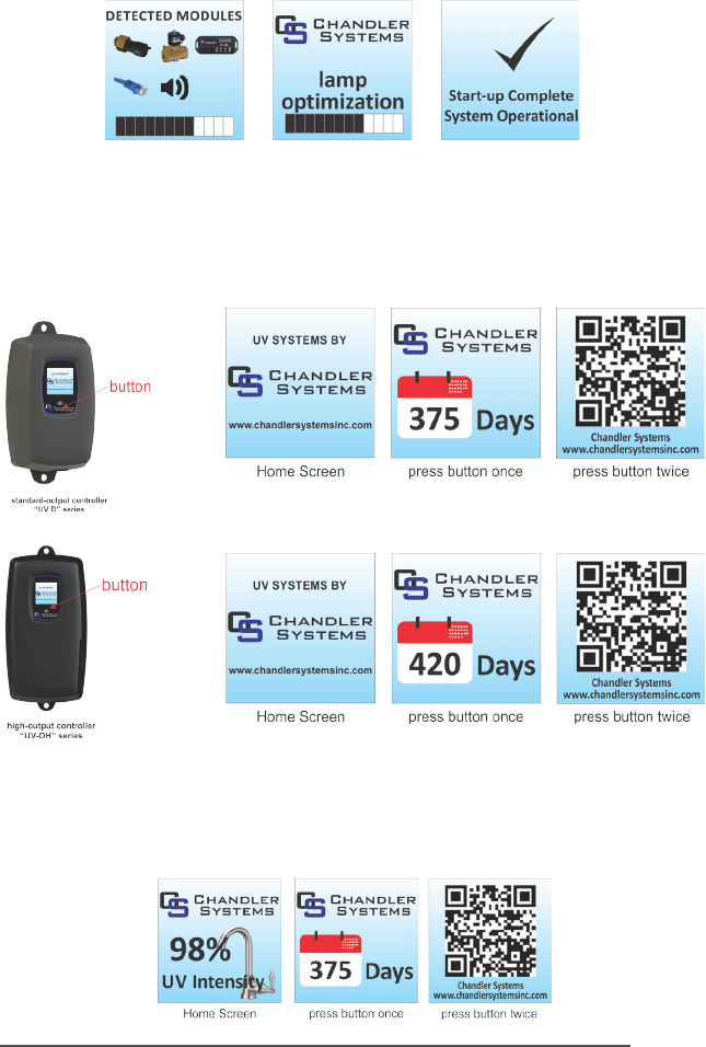
A nal module screen is displayed showing which specic modules were inialised.
The controller then displays the lamp opmisaon screen for 60 seconds to allow the lamp to
reach its opmum output, followed a nal “start-up complete” screen. The system will now be
ready to disinfect water ow.
Operaonal Screens
On systems without the UV monitor, the default screen shows the CHANDLER Home Screen. At
any point during operaon the user is able to scroll through the CHANDLER Home Screen, Lamp
life remaining and QR Code/Contact Info screens by pressing the push buon located on the
front of the controller.
Operaonal Screens with UV Monitor Upgrade
On systems that have the UV sensor installed, the default screen shows the UV Intensity. At any
point during operaon the user is able to scroll through the UV Intensity, Lamp life remaining
and QR Code screens by pressing the buon located on the front of the controller.
17|Page
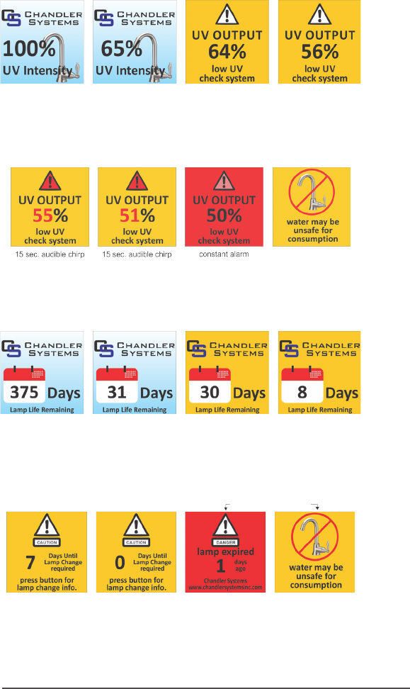
UV Intensity (with UV Monitor Upgrade)
The UV Intensity screens display the level of UV light detected by the sensor. UV intensity can be
aected by poor water quality, scaling on the quartz sleeve and/or sensor, lamp failure or lamp
expiring. The following screens show the UV Intensity dropping.
Below 56%, the numbers and warning sign turn red and an audible chirp is given by the ballast
every 15 seconds. Below 51%, the screen is solid red and a constant audible alarm is given. This
alternates with a screen indicang “water may be unsafe for consumpon”. With the solenoid
module, the controller de-acvates the solenoid valve, shung o all water ow.
Lamp Countdown Sequence
The system counts down the number of days unl a lamp change is required.
At seven days remaining, the screen changes to a yellow cauon screen with an audible chirp ev-
ery 15 seconds. Past the zero day threshold, the screen changes to solid red and cycles between
a red “lamp expired” screen and a “water may be unsafe for consumpon” screen. The same
intermient audible chirp is heard throughout this lamp expired sequence.
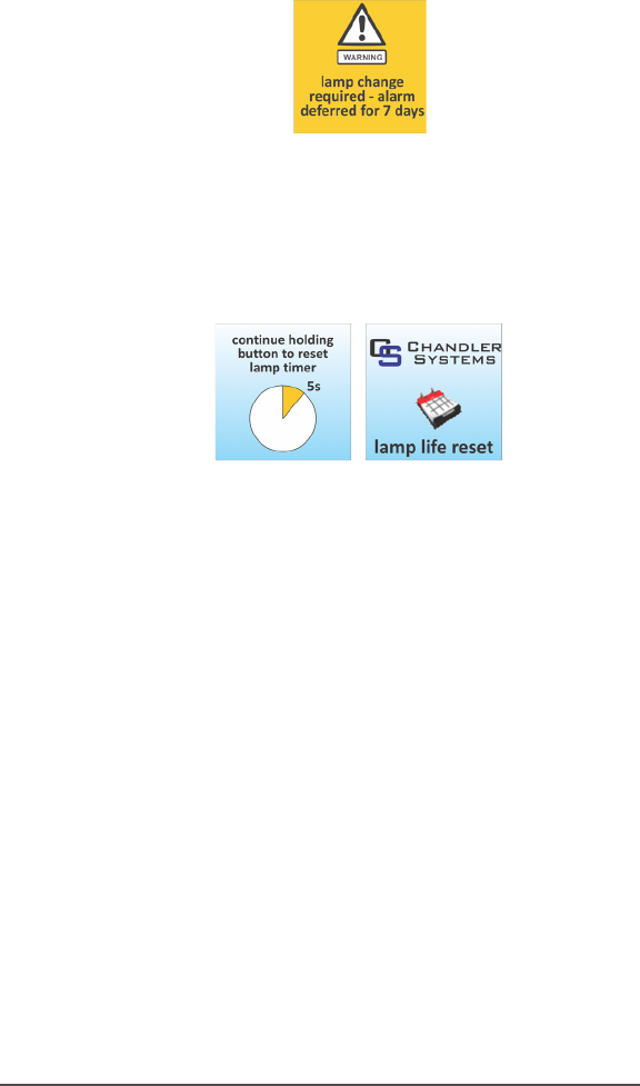
18|Page
At any point during this sequence, the audible chirp can be deferred by holding the controller
buon down for a period of ve seconds, aer which the screen below will be displayed. Aer
the seven days deferral expires, the alarm will sound once again. The deferral can be repeated
as many mes as you wish. PLEASE NOTE: At any point aer lamp expiraon, the water may
be unsafe for consumpon and should not be consumed without another form of disinfecon.
Lamp Countdown Reset Sequence
When changing the lamp, the day countdown mer must be reset to match the newly installed
lamp. To reset, rmly hold down the buon on the controller while plugging the power cord back
into the outlet. Connue holding down the buon for ve seconds as indicated unl you hear an
audible chirp conrming the mer has been reset. The following two screens will be displayed
during this process.
19|Page
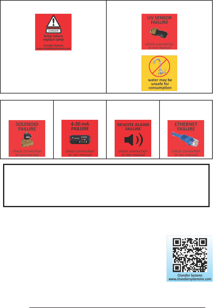
Failure Modes
Hard Alarms: The following give a constant audible alarm. If present, the solenoid valve is closed,
and the 4-20, Volt free and ethernet module transmit the alarm.
Lamp Failure UV Sensor Failure
So Alarms: The following remaining errors give a 15 second audible chirp only
Solenoid Module
Failure
4-20mA Module
Failure
Volt Free module
failure
Ethernet module
Failure
Boil Water Advisory: If any failure occurs on a CHANDLER system, the water
must not be used for human consumpon unl the system is returned to a
safe operaonal mode. If the water is used for human consumpon during this
period, the water must be boiled (minimum 20 minutes at a full boil) prior to
consumpon.
QR Codes
A QR code (Quick Response code) is a matrix barcode rst designed
for the automove industry. CHANDLER uses the QR code to store
a link to a specic page on our website. Users with a camera phone
equipped with the correct reader applicaon can scan the image of
the QR code and over a wireless network connect to a CHANDLER web
page in the phone’s browser. CHANDLER’s QR webpage has informa-
on on how to purchase replacement components as well as a helpful
video directory on system servicing (i.e. How to change a UV lamp or
quartz sleeve). To access the QR code on the CHANDLER controller,
press the control buon twice and the QR code screen will appear
as follows:
20|Page
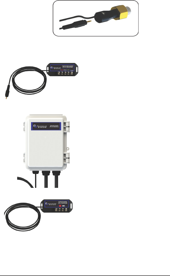
Expansion Modules
CHANDLER controllers incorporate an “Innite Expandability Port” (IEP) which allows for expan-
sion to the UV sensor and all other modules. Each module (including the sensor) comes with
both a male and female connecon. Connect any device to the controller and all subsequent
devices are then connected into the female end of last device added in a “daisy chain” congura-
on.
The following oponal expansion modules are available for use on CHANDLER
controllers. Con-
tact your authorised distributor for purchasing informaon.
DRY CONTACT (VOLT FREE) CONNECTION MOD-
ULE: Allows for a connecon to a remote device
such as a buzzer, light, alarm system, PLC, etc., via
a pair of contacts. In normal operaon the OK and
COM contacts will be connected, and in a fault
condion (Low UV, Lamp fail, Power Fail), the Fault
and COM contacts will be connected. Maximum
Contact Rang is 1A-120-230V AC/DC (use 16-22
AWG). Order PN UV-MODRAM
SOLENOID CONNECTION MODULE: Connects a
NORMALLY CLOSED line voltage solenoid valve to
the system. On a non-monitored system, the sole-
noid will only close on a lamp failure error. On a
monitored system, the solenoid is closed when the
UV level drops below 50%. Also note that in cases
where emergency use of untreated water is re-
quired, the controller can be placed into a manual
override mode allowing for the ow of water in an
alarm condion. Order PN UV-MODSOL
4-20 mA MODULE: Outputs a 4-20mA signal of the
UV output to a remote device such as a data logger
or computer. Order PN UV-MOD420
ETHERNET MODULE: Allows for all controller func-
ons to be connected to a computer via an Ether-
net cable (LAN) or via WiFi.
Coming Soon
21|Page
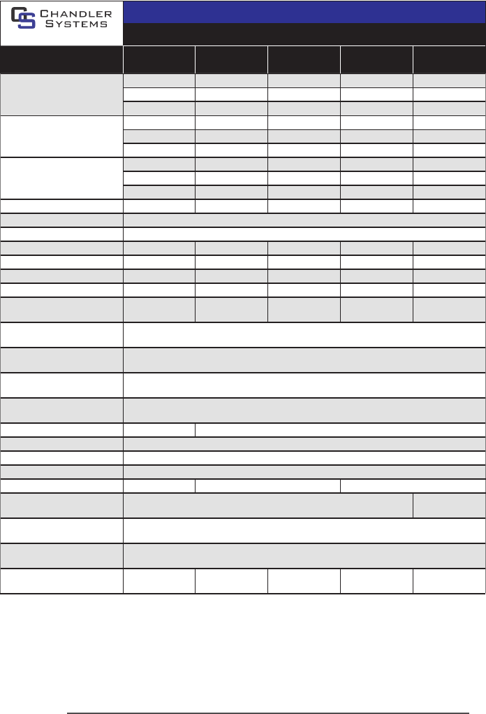
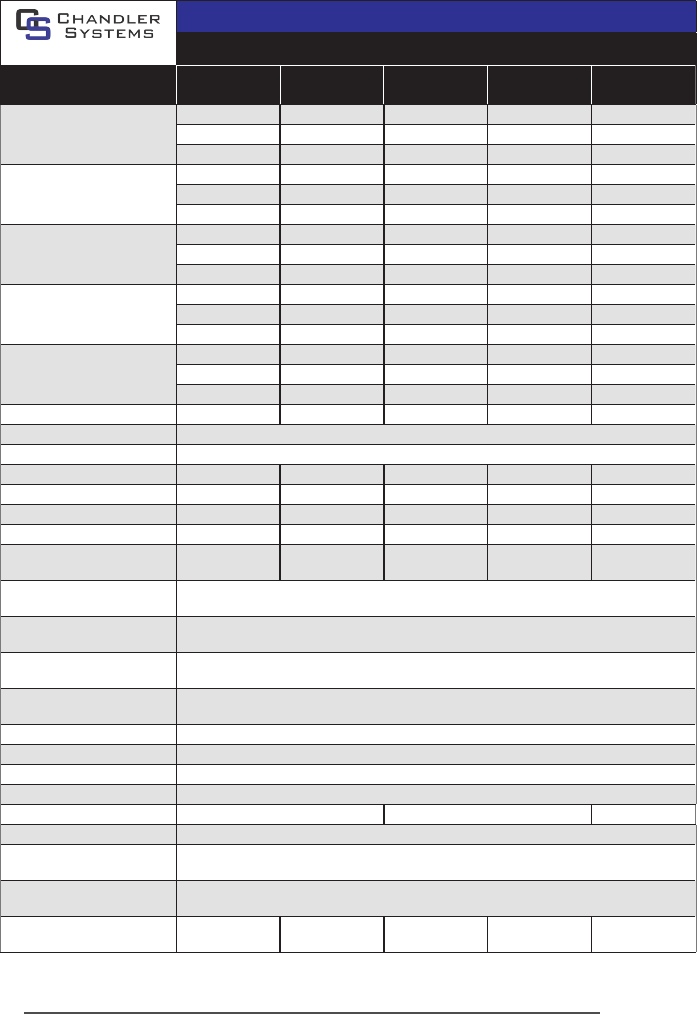
CHANDLER Standard Output System Specicaons
CHANDLER EQUIPMENT SPECIFICATIONS
Residenal systems (standard output lamps)
MODEL
UV3D
UV6D
UV6DM
UV11D
UV11DM
UV15D
UV15DM
UV20D
UV20DM
Flow Rate
30mJ/cm
2
@ 95% UVT
3.1 gpm 5.8 gpm 11 gpm 15 gpm 21 gpm
11.4 lpm 22.7 lpm 41 lpm 57 lpm 79 lpm
0.7 m
3
/hr 1.4 m
3
/hr 2.5 m
3
/hr 3.4 m
3
/hr 4.8 m
3
/hr
Flow Rate
(@16mJ/cm
2
)
6 gpm 11 gpm 20 gpm 30 gpm 39 gpm
23 lpm 41 lpm 77 lpm 114 lpm 150 lpm
1.4 m
3
/hr 2.5 m
3
/hr 4.6 m
3
/hr 6.8 m
3
/hr 8.9 m
3
/hr
Flow Rate
40mJ/cm
2
@ 95% UVT
2.4 gpm 4.4 gpm 8.3 gpm 12 gpm 16 gpm
9.1 lpm 17 lpm 31 lpm 45.4 lpm 59 lpm
0.5 m
3
/hr 1.0 m
3
/hr 1.9 m
3
/hr 2.7 m
3
/hr 3.6 m
3
/hr
Port Size ½”MNPT ¾”MNPT ¾”MNPT 1”MNPT 1”MNPT
Electrical 90-265V/50-60Hz.
Plug Type American: NEMA 5-15P
Lamp Power (Was) 15 22 39 50 42
Power (Was) 20 30 49 62 51
Replacement Lamp UVLMP-3 UVLMP-6 UVLMP-11 UVLMP-15 UVLMP-20
Replacement Sleeve UVQTZ-3 UVQTZ-6 UVQTZ-11 UVQTZ-15 UVQTZ-20
Reactor
Dimensions
6.4 x 36.4 cm
(2.5 x 14.3”)
6.4 x 54.2 cm
(2.5 x 21.3”)
6.4 x 89.5 cm
(2.5 x 35.2”)
6.4 x 101.6 cm
(2.5 x 40.0”)
8.9 x 91.7 cm
(3.5 x 36.1”)
Chamber
Material
304 Stainless Steel, A249 Pressure Rated Tubing
Controller
Dimensions
17.2 x 9.2 x 7.6 cm (6.8 x 3.6 x 3”)
Operang
Pressure
0.7-10.3 bar (10-150 psi)
Operang Water
Temperature
2-40° C (36-104° F)
UV Monitor Port NO YES on all “DM” models. Upgrade available for all others
Solenoid Output YES (oponal solenoid module (UV-MODSOL) sold separately)
Dry Contacts YES (remote alarm module (UV-MODRAM) sold separately)
4-20mA Output YES (4-20mA module (UV-MOD420) sold separately)
Temperature Mgmt. Valve PN# 130131 PN# 130132 PN# 130133
Cooling Fan NO
OPTIONAL
(UV-FAN3.5)
Lamp Change Reminder
(audible & visual)
YES
Lamp Out Indicator
(audible & visual)
YES
Shipping Weight
3.3 kg
(7.3 lbs)
4.2 kg
(9.3 lbs)
6.8 kg
(15.0 lbs)
8.0 kg
(17.6 lbs)
7.5 kg
(16.5 lbs)
22|Page
CHANDLER High Output System Specicaons
CHANDLER EQUIPMENT SPECIFICATIONS
Mul-Use Systems (high output lamps)
MODEL
UV-5DH
UV-5DHM
UV-10DH
UV-10DHM
UV-15DH
UV-15DHM
UV-25DH
UV-25DHM
UV-40DH
UV-40DHM
Flow Rate
30mJ/cm
2
@ 95% UVT
4.0 gpm 10 gpm 14 gpm 25 gpm 40 gpm
15 lpm 38 lpm 53 lpm 95 lpm 151 lpm
1.1 m
3
/hr 2.3 m
3
/hr 3.2 m
3
/hr 5.7m
3
/hr 9.1m
3
/hr
Flow Rate
40mJ/cm
2
@ 95% UVT
3.0 gpm 7.0 gpm 11 gpm 19 gpm 31 gpm
15 lpm 27 lpm 41 lpm 72 lpm 117 lpm
0.7 m
3
/hr 1.6 m
3
/hr 2.5 m
3
/hr 4.3 m
3
/hr 7.0 m
3
/hr
Flow Rate
Hot Water (-HW sux) model
30mJ/cm
2
@ 75% UVT
2.8 gpm 7.0 gpm 9.8 gpm 16 gpm 28 gpm
11 lpm 26 lpm 37 lpm 61 lpm 110 lpm
0.6 m
3
/hr 1.6 m
3
/hr 2.2 m
3
/hr 3.6 m
3
/hr 6.4 m
3
/hr
Flow Rate
Low UVT (-50 sux) model
30mJ/cm
2
@ 50% UVT
1.7 gpm 4.2 gpm 6.0 gpm 10 gpm 17 gpm
6.4 lpm 16 lpm 23 lpm 38 lpm 64 lpm
0.4 m
3
/hr 1.0 m
3
/hr 1.4 m
3
/hr 2.3 m
3
/hr 3.9 m
3
/hr
Flow Rate
TOC (-TOC sux) model
150mJ/cm
2
@ 98% UVT
0.8 gpm 2.0 gpm 2.8 gpm 5.0 gpm 8.0 gpm
3.0 lpm 7.6 lpm 11 lpm 19 lpm 30 lpm
0.2 m
3
/hr 0.5 m
3
/hr 0.6 m
3
/hr 1.1 m
3
/hr 1.8 m
3
/hr
Port Size ¾”MNPT ¾”MNPT 1”MNPT 1”MNPT 1 ½”MNPT
Electrical 90-265V/50-60Hz.
Plug Type American: NEMA 5-15P
Lamp Power (Was) 18 34 45 67 101
Power (Was) 20 36 48 72 108
Replacement Lamp UVLMP-4H UVLMP-10H UVLMP-15H UVLMP-25H UVLMP-40H
Replacement Sleeve UVQTZ-4H UVQTZ-10H UVQTZ-15H UVQTZ-25H UVQTZ-40H
Reactor
Dimensions
8.9 x 29.8 cm
(3.5 x 11.7”)
8.9 x 41.8 cm
(3.5 x 16.5”)
8.9 x 50.8 cm
(3.5 x 20.0”)
8.9 x 68.3 cm
(3.5 x 26.9”)
8.9 x 103.4 cm
(3.5 x 40.7”)
Chamber
Material
316L Stainless Steel, A249 Pressure Rated Tubing
Controller
Dimensions
21.7 x 10.8 x 8.9 cm (8.6 x 4.2 x 3.5”)
Operang
Pressure
0.7-10.3 bar (10-150 psi)
Operang Water
Temperature
2-40° C (36-104° F)
UV Monitor Port YES (oponal UV monitor (UVS-3.5) sold separately)
Solenoid Output YES (oponal solenoid module (UV-MODSOL) sold separately)
Dry Contacts YES (remote alarm module (UV-MODRAM) sold separately)
4-20mA Output YES (4-20mA module (UV-MOD420) sold separately)
Temperature Mgmt. Valve PN# 130132 PN# 130133 PN# 130134
Cooling Fan OPTIONAL (UV-FAN3.5 sold separately)
Lamp Change Reminder
(audible & visual)
YES
Lamp Out Indicator
(audible & visual)
YES
Shipping Weight
4.5 kg
(9.9 lbs)
5.4 kg
(11.9 lbs)
6.0kg
(13.2 lbs)
7.2 kg
(15.9 lbs)
9.7 kg
(21.4 lbs)

23|Page
Chandler Systems Limited Warranty Statement
Products manufactured by CHANDLER are warranted to the original user only to be free of de-
fects in material and workmanship for a period as specied below. This warranty only applies to
the original purchaser and is not transferable.
UV SYSTEMS
Ten (10) year Limited Warranty on the stainless steel reactors, from the date of original
purchase, or installaon (proper documentaon required for vericaon).
ELECTRONICS
Three (3) year Limited Warranty on the ballasts and controllers, from the date of origi-
nal purchase, or installaon (proper documentaon required for vericaon).
UV LAMPS, UV SENSORS & QUARTZ SLEEVES
One (1) year Limited Warranty on all CHANDLER ultraviolet lamps, UV sensors and
quartz sleeves from the date of original purchase, or installaon (proper documenta-
on required for vericaon).
This CHANDLER Ultraviolet Disinfecon System will be repaired or replaced, at our sole opon,
providing that the ultraviolet system or any component is defecve in materials or workman-
ship for the periods outlined above and subject to the “Limitaons of Warranty” as outlined
below. CHANDLER’s liability under this warranty shall be limited to repairing or replacing the
product, without charge, F.O.B. CHANDLER’s closest Distribuon Facility or authorized service
depot. CHANDLER will not be liable for any costs of removal, installaon, transportaon, or any
other charges which may arise in connecon with a warranty claim. CHANDLER will not be liable
for damage or wear to products caused by abnormal operang condions, accident, abuse, mis-
use, unauthorized alteraon or repair, or if the product was not installed in accordance with the
Manufacturers printed installaon and operang instrucons.
LIMITATIONS OF WARRANTY
This warranty does not apply to any of the following:
• Water Quality Parameters lie outside of the following ranges
• Hardness > 120 mg/L (7 gpg)
• Iron > 0.3 mg/L (ppm)
• Manganese > 0.05 mg/L (ppm)
• Tannins > 0.1 mg/L (ppm)
• Turbidity > 1 NTU
• Transmiance (UVT) < 75%
• A product that has been incorrectly installed according to the technical installaon
manual.
• A product that has been modied in any manner, unless approved by the manufacturer.
• A product where the serial number has been altered defaced or removed.
• Damage caused by the use of parts that are not compable, suitable and/or authorized
by CHANDLER for use with the product (e.g. non-original lamps or sleeves).
• Damage caused during shipment of the product.
• Water damage is found inside ballast housing or controllers.
• Product is installed outdoors in direct contact with the environment (rain).
• Product is installed in freezing temperatures.
• Product is used in condions that exceed CHANDLER’s specicaons.

24|Page
TO GET WARRANTY SERVICE
To obtain service under this warranty, you must rst contact CHANDLER Customer Service at
(888) 363-9434 to obtain a Warranty Return Authorizaon. You will then need to return the
product through the CHANDLER Dealer or Distributor where the product was originally pur-
chased, together with proof of purchase and installaon date, failure date, and supporng in-
stallaon data. Unless otherwise provided, the Dealer or Distributor will contact CHANDLER for
instrucons on returning the product. Any defecve product to be returned to CHANDLER must
be sent freight prepaid; documentaon supporng the warranty claim and/or a Return Material
Authorizaon must be included if so instructed.
CHANDLER INC. WILL NOT BE LIABLE FOR ANY INCIDENTAL OR CONSEQUENTIAL DAMAGES,
LOSSES, OR EXPENSES ARISING FROM INSTALLATION, USE, OR ANY OTHER CAUSES. THERE ARE
NO EXPRESS OR IMPLIED WARRANTIES, INCLUDING MERCHANTABILITY OR FITNESS FOR A PAR-
TICULAR PURPOSE, WHICH EXTEND BEYOND THOSE WARRANTIES DESCRIBED OR REFERRED TO
ABOVE.
THIS LIMITED WARRANTY IS THE SOLE AND EXCLUSIVE WARRANTY MADE BY CHANDLER WITH
RESPECT TO THIS ULTRAVIOLET DISINFECTION PRODUCT, AND IS GIVEN IN LIEU OF ANY OTHER
WARRANTY. TO THE EXTENT ALLOWED BY APPLICABLE LAW, ANY AND ALL EXPRESS OR IMPLIED
WARRANTIES NOT SET FORTH HEREIN ARE WAIVED AND DISCLAIMED, INCLUDING ANY IMPLIED
WARRANTY OF MERCHANTABILITY OR FITNESS FOR A PARTICULAR USE. CHANDLER’S LIABILITY
UNDER THIS LIMITED WARRANTY IS LIMITED SOLELY TO THOSE LIABILITIES SET FORTH ABOVE.
IN THE EVENT THAT ANY PROVISION OF THIS LIMITED WARRANTY SHOULD BE FOUND TO BE
OR BECOME INVALID OR UNENFORCEABLE UNDER APPLICABLE LAW, THE REMAINING TERMS
AND CONDITIONS HEREOF SHALL REMAIN IN FULL FORCE AND EFFECT AND SUCH INVALID OR
UNENFORCEABLE PROVISION SHALL BE CONSTRUED IN SUCH A MANNER AS TO BE VALID AND
ENFORCEABLE.
Warranty Registraon
It is imperave that you complete the warranty registraon process. This not only registers your
UV disinfecon system for the provided manufacturer’s warranty, but also allows the factory to
provide you with any important product updates or technical bullens concerning your prod-
uct. To register, completely ll out the included warranty card, including a valid e-mail address.
PLEASE NOTE: This informaon is for the sole purpose of technical support for your disinfecon
system and will not be used, or sold, to any other organizaon for any other purpose.
Chandler Systems
710 Orange Street
Ashland, OH 44805
Phone (888) 363-9434
www.chandlersystemsinc.com
PN#910181
