
Engineering Requirements Management
DOORS Next
IBM

Contents
Welcome............................................................................................................... 1
Overview...............................................................................................................1
Engineering Requirements Management DOORS
®
Next.............................................................................1
Comparison of DOORS and DOORS Next.................................................................................................... 4
Conguration management capabilities..................................................................................................... 6
Video tours................................................................................................................................................... 9
Engineering Requirements Management DOORS Next overview......................................................... 9
Getting started...................................................................................................... 9
Administering RM projects........................................................................................................................ 12
Creating and managing requirements.......................................................................................................13
Installing.............................................................................................................14
Installing the RM application.....................................................................................................................14
Upgrading........................................................................................................... 14
Upgrading the RM application................................................................................................................... 14
Integrating.......................................................................................................... 14
DOORS........................................................................................................................................................15
Conguring RM as a consumer.............................................................................................................16
Associating RM projects with DOORS modules...................................................................................17
Conguring the Requirements Management application as a provider and DOORS as a
consumer.........................................................................................................................................17
Rational ClearQuest
®
................................................................................................................................. 19
Rational Change.........................................................................................................................................20
Administering......................................................................................................21
Administering IBM Engineering Lifecycle Management servers..............................................................21
Administering requirements projects or components..............................................................................21
Permissions.......................................................................................................................................... 21
Creating projects.................................................................................................................................. 26
Managing project or component properties........................................................................................ 28
Copying artifacts between projects..................................................................................................... 62
Deleting artifacts from the repository................................................................................................. 65
Administering link validity....................................................................................................................66
Baselines.............................................................................................................................................. 66
Enabling Electronic signatures for a baseline..................................................................................... 67
Administering components..................................................................................................................68
Managing query workload....................................................................................................................79
Backing up and restoring the RM index les....................................................................................... 80
Analyzing and validating TRS feeds.....................................................................................................81
Initialize the publish services.............................................................................................................. 81
Extending product function....................................................................................................................... 82
Extending the RM application.............................................................................................................. 82
Extending by using OSLC services....................................................................................................... 83
Managing............................................................................................................ 87
ii
Dashboards in the RM application.............................................................................................................87
Composing and managing requirements.................................................................................................. 87
Joining a requirements project............................................................................................................87
Dening requirements..........................................................................................................................90
Managing requirements..................................................................................................................... 188
Managing artifacts by using congurations.......................................................................................224
Reporting.......................................................................................................... 254
Reporting in the Requirements Management (RM) application.............................................................254
Creating document-style reports.......................................................................................................255
Running data warehouse reports...................................................................................................... 257
Reports in the RM application............................................................................................................257
RM reportable REST API.................................................................................................................... 258
Compare conguration report........................................................................................................... 258
Troubleshooting.................................................................................................260
Troubleshooting the RM application....................................................................................................... 260
Log le locations................................................................................................................................ 261
Enabling web client logging............................................................................................................... 261
Fixing a converter issue in the server in headless mode.................................................................. 262
Recovering missing artifacts from congurations.............................................................................263
Fixing le preview font issues in other languages.............................................................................263
Opening artifacts in multiple tabs or windows..................................................................................264
Opening artifacts in new tabs in the same window.......................................................................... 264
Redirecting HTTP requests................................................................................................................264
Pasting invalid XHTML text................................................................................................................ 265
Cutting, copying, and pasting text..................................................................................................... 265
Updating custom Word templates.....................................................................................................266
Creating a hyperlink to a local le......................................................................................................266
Moving artifacts from a folder............................................................................................................266
Creating a project template for a large project................................................................................. 267
Support information for the Requirements Management application..............................................267
Troubleshooting local congurations......................................................................................................268
Glossary ........................................................................................................... 268
A............................................................................................................................................................... 268
B............................................................................................................................................................... 271
C............................................................................................................................................................... 273
D............................................................................................................................................................... 277
E............................................................................................................................................................... 279
F................................................................................................................................................................280
G............................................................................................................................................................... 282
H............................................................................................................................................................... 282
I................................................................................................................................................................ 283
J................................................................................................................................................................285
K............................................................................................................................................................... 285
L................................................................................................................................................................285
M...............................................................................................................................................................287
O............................................................................................................................................................... 288
P............................................................................................................................................................... 289
Q............................................................................................................................................................... 291
R............................................................................................................................................................... 291
S............................................................................................................................................................... 294
T................................................................................................................................................................298
U............................................................................................................................................................... 300
V............................................................................................................................................................... 300
W.............................................................................................................................................................. 301
iii
X............................................................................................................................................................... 302
Z............................................................................................................................................................... 302
Notices..............................................................................................................303
Index................................................................................................................ 306
iv
Welcome
Overview
This section provides overview and getting started information.
Overview of DOORS Next
IBM Engineering Requirements Management DOORS Next (DOORS Next) is a requirements management
tool that helps you store, categorize, link, and share product requirements with stakeholders such as
reviewers, designers, testers, and developers.
DOORS Next is the Requirements Management (RM) application in the IBM Engineering Lifecycle
Management (ELM) solution, which integrates IBM products to provide a complete set of applications
for software or systems development. The RM application uses a web client and the Jazz platform to
dene, manage, and report on requirements.
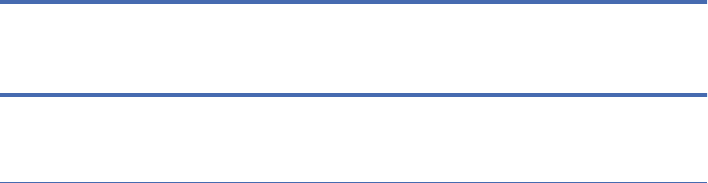
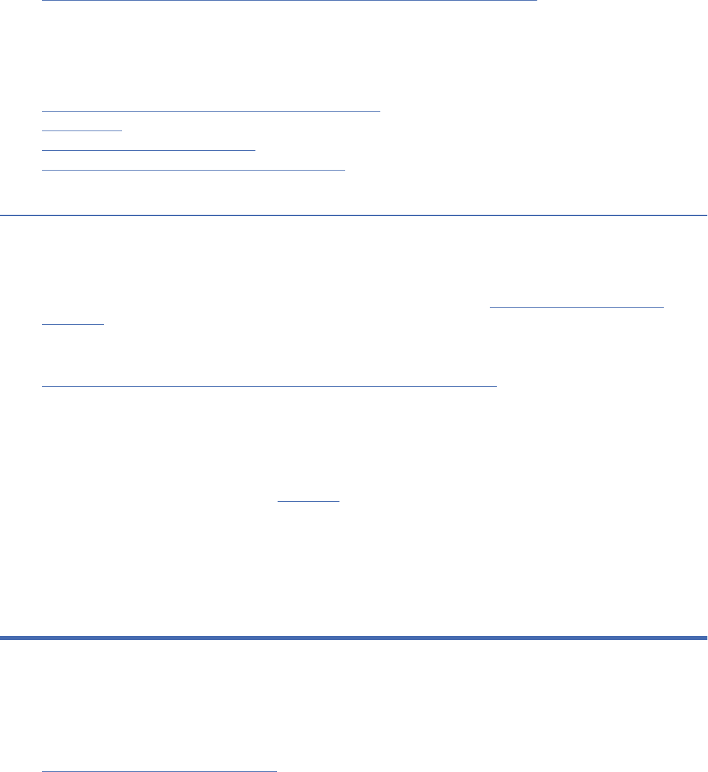
The following diagram shows the development lifecycle that the solutions support. To see overviews of
the applications that are represented in the image, click the boxes. For example, click Validate and verify
to see an overview of IBM Engineering Test Management (ETM).
Welcome
1
1. Overview of Engineering Requirements Management DOORS Next
2. Overview of Engineering Rhapsody
®
Model Manager
3. Overview of Engineering Workflow Management
4. Overview of Engineering Test Management
5. Overview of Global Conguration Management
6. Overview of Reporting
7. Overview of Engineering Insights
Create a single view of requirements
Stakeholder, business, system, product, hardware, software, and other requirements represent business
needs from different perspectives with different levels of detail. Requirements have several formats, such
as diagrams, tables, forms, and text. Usually, several people are involved in creating, analyzing, reviewing,
approving, designing, and developing requirements.
2
Engineering Requirements Management DOORS Next

DOORS Next can store multiple types of requirements in a common repository. Bringing all requirements
together in a single place, removing redundancy, and connecting related content is essential to effectively
managing requirements in large projects.
For an interactive workflow diagram of the requirements denition and management process, see Getting
started with requirements management.
Trace linkages between requirements
Requirements are often related in many ways. Business requirements drive product requirements,
which in turn drive hardware and software requirements. Product requirements cascade to component
requirements and granular requirements are linked to more comprehensive requirements. The result is a
web of relationships with many dependencies.
With DOORS Next, you can create relationships between requirement artifacts. You can then use grid or
tree views to see top-level or drilled-down views of those links.
For details, see Traceability.
Evaluate the impact of changes to requirement
As a product evolves, initial requirements can change or be removed during development. Because
requirements are linked, a change in one requirement can affect other requirements. The Links Explorer in
DOORS Next graphically displays the links between artifacts. When an artifact changes, the Links Explorer
automatically flags all links from that artifact as suspect. By tracing the suspect links, you can identify all
requirements that are affected by a change.
For details, see Linking to development, design, test, and requirements artifacts
.
Create review workflows
DOORS Next encourages collaboration through reviews. You can set up reviews of requirements and
identify reviewers. As a review owner, you can see the progress, comments, and status of all participants
in the review. You can broadcast emails, leave instructions, or even change the status of the review. As a
reviewer, you can leave comments and vote.
For details, see Requirement workflows.
Monitor project performance with metrics
By default, metrics are collected at regular intervals to provide the most recent view of data, as well
as trends over time, which can help you evaluate the ongoing health of your project. For example, the
“Requirements covered by test cases” metric monitors the extent to which requirements are covered by
test cases over time.
The data warehouse can also provide detailed traceability for requirements. For example, you can see
all work items that implement a set of requirements, along with properties such as status, priority, story
points, and due date.
For details, see Reporting in the RM application.
Baseline projects and track change history
DOORS Next tracks and records metadata to measure project efciency and churn, such as who modied
information, and which changes occurred when.
You can capture baselines of your project requirements for a snapshot of your project at a point in time.
You can compare projects against a previous baseline to determine what’s changed.
DOORS Next stores the history of changes to artifacts. You can access all revisions of an artifact to see
which modications occurred when. You can also use the historical record of an artifact to undo any
changes and restore the artifact to a previous state.
For details, see Baselines in RM projects.
Extend functionality with APIs
Overview
3

DOORS Next provides a client extension API that you can use to extend tool functionality by using
technologies such as HTML and JavaScript. You can create and host a catalog of extensions on a server so
that your team can share them.
For details, see Extending the RM application.
Conguration management
You can use conguration management in the RM application to create versions of requirement
artifacts and to link them to other team artifacts, such as test cases and designs. Use congurations
(streams and baselines) to manage reuse, traceability, and parallel development. Teams by using
conguration management enabled ELM applications can contribute requirements, design, test, and
source congurations to global congurations. Global congurations ensure artifact links resolve to the
correct versions, and also facilitate reuse across versions or variants of your software or product line. For
more information about congurations, see Getting started with conguration management.
Exchange requirements data with OSLC and ReqIF
The software architecture for the RM application is based on the Open Services for Lifecycle Collaboration
(OSLC) specication, which uses a common set of resources, formats, and REST architectural services to
enable data sharing between applications. You can use the OSLC integration protocol to link requirements
in IBM Engineering Requirements Management DOORS with artifacts in DOORS Next.
You can exchange requirements data between the two products by using ReqIF, which is an evolution of
the Requirements Interchange Format that is governed by the Object Management Group (OMG). With
ReqIF, teams in different organizations can use different requirements management tools to work on
shared specications to construct a consistent view of a solution. For details, see Importing and Exporting
ReqIF les.
Part of the Jazz community
The ELM products are developed transparently on the open and extensible Jazz platform. On Jazz.net,
you can download the products and their milestones, track development schedules, join discussion
forums, open enhancement requests, and interact with the product developers. To learn more about
the products, see the developer-written articles in the Jazz.net library or the topics about complex
deployment scenarios on the Deployment wiki.
Related information
Overview of the solution
Client access license management overview
Planning to deploy and install
Interactive installation guide
Getting started with requirements management
Security considerations for IBM Engineering Lifecycle Management
Tips for requirements management
Troubleshooting the RM application
PDF documentation of Doors Next
Comparison of DOORS and DOORS Next
IBM Engineering Requirements Management DOORS (DOORS) and IBM Engineering Requirements
Management DOORS Next (DOORS Next) are requirements management (RM) products with many
similar capabilities. However, the products offer different implementations and strategic opportunities
for requirements analysts and design, development, and test teams.
DOORS, which is in version 9, is a market-leading RM solution. It provides a wide range of RM capabilities
and a rich scripting language. DOORS also integrates with other products and has a large, active
community of users. This product works well for the largest programs and projects and also for smaller
teams.
4
Engineering Requirements Management DOORS Next
DOORS Next is an RM collaboration platform with a web client. This product includes capabilities such as
visual requirements denition, work item and test integration, and planning. It runs as an application on
the Jazz
®
server and can be installed and integrated with other IBM Engineering Lifecycle Management
(ELM) products.
Both products provide traceability to manage requirements across the development lifecycle, support
requirements-driven development and testing, and link to design and modeling resources. In addition, the
products can be used together. For example, you can link requirements and related artifacts across the
two products. Modules and objects that are exported from DOORS can be imported into DOORS Next.
Capabilities and strengths
DOORS helps teams in complex, high-compliance, systems engineering programs. It provides mature
capabilities, such as structured requirements specication modules, roundtrip data import and export,
electronic signatures, baselines, and customizable requirements views with multi-level traceability.
For offline work or printing, views can be exported to document formats or spreadsheets. DOORS
also supports requirements change management which is driven by a process dened in a change
management tool. This product can be scaled to large development projects with tens of thousands of
objects or hundreds of concurrent users.
DOORS offers a user-programmable, extensible API called the DOORS eXtension Language (DXL). DXL
provides a way to customize these activities:
• Automating administration
• Creating multi-level traceability views
• Calculating metrics
• Implementing business logic
• Extending the user interface
• Integrating with other tools
Along with the RM capabilities of the DOORS client and built-in database, the optional IBM Engineering
Requirements Management DOORS - Web Access (DWA) component supports review and common
editing tasks in a web browser. DWA is ideal for distributed teams that do not require the full capabilities
of the DOORS client.
DOORS Next uses the capabilities of Jazz Team Server to support team collaboration through dashboards,
reviews, and comments. Users, projects, data types, artifact types, attributes, and tags have a common
administration. These common services and type systems help project teams consistently dene and
manage requirements.
In ELM, project areas, team members, and processes are managed across associated applications:
Requirements Management (RM), Quality Management (QM), and Change and Conguration Management
(CCM). Because a commercial database is used, system and project administrators can follow flexible and
standardized operational procedures.
The web client for DOORS Next provides tools to dene requirements in rich-text documents and visual
representations in business process diagrams, use case diagrams, storyboards, user interface sketches,
and screen flows. Requirement artifacts can be organized and reused in views, collections, and modules.
The web client supports traceability links to related requirements artifacts and across ELM applications to
development plans, work items, test plans, test cases, designs, and models.
For document generation, DOORS and DOORS Next use the capabilities of Engineering Document
Generation and IBM Engineering Lifecycle Optimization - Publishing to create customizable, dashboard-
based graphical reports.
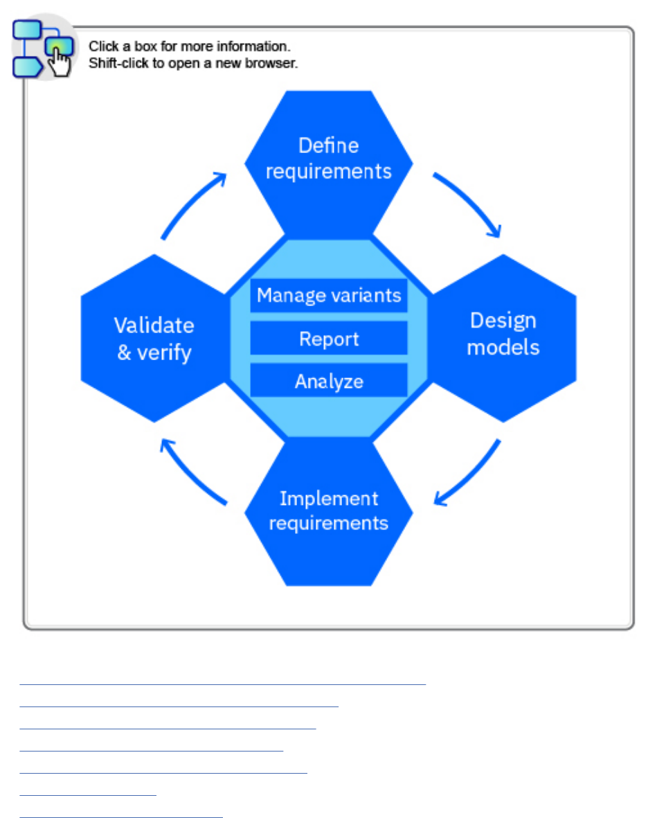
For a high-level comparison of the client and server architecture in both tools, see the next diagram.
Overview
5
For more information about DOORS, see the DOORS documentation.
For information about using the ELM, see “Getting started with DOORS Next” on page 9.
For information about the development of DOORS Next as a Jazz.net project, see the DOORS Next page
and this blog post.
Conguration management in the RM application
Use conguration management in the Requirements Management (RM) application to manage
components, streams, baselines, and change sets, to compare congurations, and to complete other
conguration management tasks.
This high-level overview briefly describes the conguration management capabilities in the RM
application. For comprehensive and task-related information, see Getting started with conguration
management.
Before your team can use conguration management capabilities, an administrator must read the
considerations for enabling conguration management, and then obtain an activation key:
• For pilot environments, read the considerations and generate an activation key.
Note: Conguration management capabilities of RM and QM, and global conguration management is
an added service for IBM Engineering Lifecycle Management Base SaaS and IBM Engineering Lifecycle
Management Extended SaaS customer environments, and should only be enabled by the SaaS provider.
Software conguration management (SCM) in CCM is included in Cloud offerings at no additional cost.
• For production environments, discuss your plans with your IBM Client representative or contact
IBMSupport.
6
Engineering Requirements Management DOORS Next
Use the conguration management capabilities in the RM application to set up unique working
environments for individuals or teams. For example, you can create components to represent collections
of artifacts, instead of working with all the artifacts from the project in one stream. You can create
streams and baselines of projects at specic points in time, review and approve changes to artifacts, and
make changes visible to other teams or individuals. You can also enable link validity in a conguration
management enabled project.
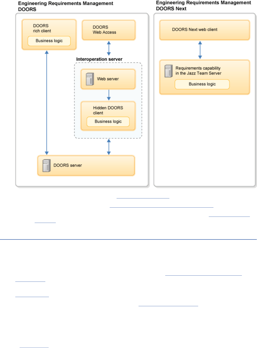
Streams and baselines are referred to as congurations. You can create and view baselines in a project
even if you do not have conguration management enabled. However, after you enable a project for
conguration management, the Current Conguration menu contains conguration-related options that
you can use to create and compare baselines and streams, and optionally create change sets, as seen in
this example:
Streams, baselines, and change sets in conguration management
A stream is a conguration in which you create and modify artifacts at a specic development level. For
example, you might create a stream when you start a new release or branch of a design, project, or
product.
A baseline is an immutable conguration that provides a snapshot of your project at a specic point in
time. Baselines are useful for capturing the state of a stream, and are typically used to record important
stream congurations so that they can be re-created. When you create a new stream, a baseline of the
previous stream is created automatically.
A change set is a grouping of changes that remains separate from the stream in which it was created until
you deliver the change set to the stream. After you deliver your change set to the originating stream, you
can then deliver the change set to other streams. Using change sets is an optional but convenient way to
track and deliver changes in your development environment.
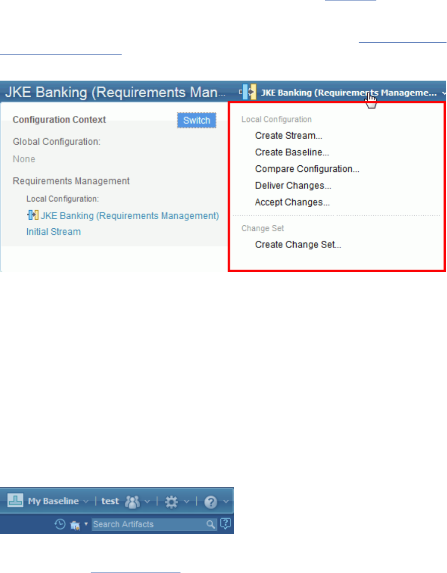
The name of the stream, baseline, or change set that you select to work in is shown at the top of the
Current Conguration menu. For example, if you create and switch to a baseline called My Baseline, it
appears on the Current Conguration menu, as shown in this example:
To work in a different conguration, expand the Current Conguration menu, click Switch, click
Requirements Management Conguration and search for another conguration in which to work. You
can also switch to a global conguration from this menu.
When you rst create a project, an initial component and stream are automatically created that manage
the artifact versioning information for the project. You can create more components to organize artifacts
based on your project needs. To manage components and congurations, from the Administration menu,
select Manage Components and Congurations.
Overview
7
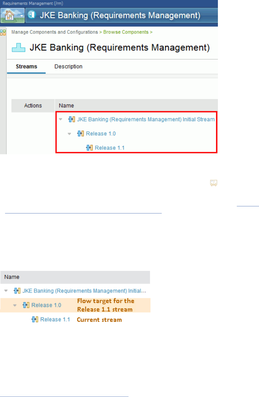
The streams in a component are shown on the Component window, on the Streams tab, based on their
relationship to each other:
Tip:
• To see the baselines that were created in a stream, click the stream and then click the Baselines tab. To
compare the contents of two streams, select the streams and click Compare .
• If your team uses global congurations, you can create a baseline of an RM stream from the
conguration tree view in the Global Conguration Management (GCM) application. See Creating
baselines of streams contributed by other ELM applications.
If you are working in a parallel development environment, you might have individual streams whose
contents are derived from a common stream. To make changes in your stream visible to other team
members, you deliver your changes to the common stream, which also known as the flow target. From the
common stream, team members can accept changes into their own streams to ensure that they have the
most recent versions of artifacts.
The hierarchy of the streams in the indicates the flow target for streams. For example, if you create a
Release 1.1 stream from a Release 1.0 stream, the streams are shown as follows:
In this example, the Release 1.0 stream is the flow target for the Release 1.1 stream, which was created
from Release 1.0. If you double-click the Release 1.1 stream and select to compare the stream with the
flow target, you can compare the contents of Release 1.0 with the contents of Release 1.1.
For more information about conguration management, see the video Conguration Management
Overview for CLM v6 releases.
Related concepts
“Baselines in requirements projects” on page 66
8
Engineering Requirements Management DOORS Next
In a requirements project, a baseline captures the entire project at a moment in time. For example, you
might create a project baseline before you create an artifact review to ensure that the artifacts do not
change during the review. A baseline includes all artifacts, folder trees, and public tags.
“Managing artifacts by using congurations in the RM application” on page 224
You can manage changes to artifacts and work in a parallel, multi-stream environment by using
conguration management capabilities. These capabilities include creating baselines of projects at
specic points in time, reviewing and approving changes to artifacts, and making changes visible to other
teams or individuals.
Related information
Conguration management: concepts and capabilities
Components
Global conguration management
Managing changes to artifacts using change sets
Video tours
To learn more about IBM Engineering Requirements Management DOORS Next, see this Guided Tour for
DOORS Next:
If you are evaluating or getting started with the RM application, see the Requirements Management
Scenarios on Jazz.net. These scenarios guide you through installing and setting up projects, creating
modules and requirement artifacts, and creating reports.
Related information
Learning resources for the IBM Engineering Lifecycle Management (ELM)
Engineering Requirements Management DOORS Next overview
Watch this tour to get an overview of IBM Engineering Requirements Management DOORS Next (DOORS
Next).
You can download this video from theVideo link
You can watch the below video to get an overview of DOORS:
Getting started with DOORS Next
This topic presents an example of a typical process for project managers, product managers, and
requirements analysts who must assess a business problem and develop requirements for a proposed
solution. The process is represented here in outline form. Your process might vary depending on the state
of the subject system, your stakeholders, your team structure, and your tools.
For an introduction to IBM Engineering Requirements Management DOORS Next (DOORS Next), see
“Overview of DOORS Next” on page 1.
The following diagram shows a simplied workflow for the requirements denition and management
process, which includes traceability relationships between requirements and development and test
artifacts. The process is explained in more detail in a later section. Click a box in the diagram for more
information on a specic task.
Getting started with DOORS Next
9
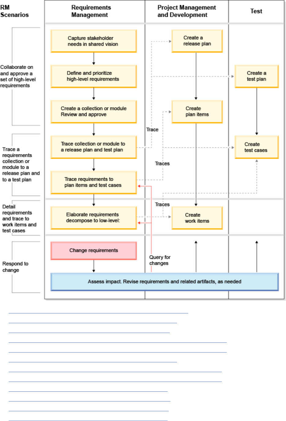
1. Click this area to get information about creating vision documents
2. Click this area to get information about creating requirements
3. Click this area to get information about creating collections
4. Click this area to get information about linking to development and test artifacts
5. Click this area to get information about linking to development and test artifacts
6. Click this area to get information about creating requirements
7. Click this area to get information about modifying and managing requirements
8. Click this area to get information about modifying and managing requirements
9. Click this area to get information about working with plans
10. Click this area to get information about creating work items
11. Click this area to get information about creating a test plan
12. Click this area to get information about creating test cases
10
Engineering Requirements Management DOORS Next

1: Setting up the project
The project manager or requirements analyst sets up a project by completing these tasks:
1. Create a requirements project. Use a project template to establish a starting point for artifact types,
attributes, link types, and folder structure.
2. Customize artifact types, attributes, link types, folder structure, artifact queries (lters), and
dashboards, as required.
3. Work with project managers and team leaders to plan team organizations and roles, security,
communications, and iteration and milestones schedules.
4. Coordinate with project managers and team leaders to plan for associating requirements with
development and test artifacts throughout the application lifecycle.
See “Creating requirements projects” on page 26, “Project dashboards” on page 88, “Managing project
or component properties in requirements projects” on page 28, Managing users, Administering ELM
project areas, IBM Engineering Lifecycle Management (ELM), and “Linking to development, design, test,
and requirement artifacts” on page 201.
2: Assessing the problem
The requirements analyst collects input about the business problem by completing these tasks:
1. Interview stakeholders and users of the system.
2. Gather documentation on the current system.
3. Import documents into a requirements project.
The documents that you produce in the preceding steps must address the following topics:
• Current process and problems
• Goals and objectives
• Stakeholder requirements
• Issues and risks
• Thoughts and ideas
See “Importing and exporting les” on page 152
.
3: Creating requirements
The requirements analyst creates requirements that are based on assessment documents and these
requirements denition activities. The analyst and other team members create traceability by linking
between artifacts.
1. Create a vision document to address stakeholder needs and business goals with high-level project
requirements. Use business process diagrams and high-level use case diagrams to describe proposed
solutions.
2. Create a collection or a module that contains high-level requirements. Review and approve the
requirements collection or module, as described in the next section.
3. Link high-level requirements collections and modules with development release plans and test plans.
4. Dene detailed requirements that support the high-level requirements. Create use case diagrams,
storyboards, user interface sketches, and other resources to support the requirement denition.
5. Review and approve the requirements.
6. Link requirements to individual development plan items and test cases.
See “Vision document” on page 122, “Creating collections” on page 175, “Linking to development,
design, test, and requirement artifacts” on page 201, and “Dening requirements” on page 90.
Getting started with DOORS Next
11

4: Reviewing requirements
The requirements analyst creates a collection of requirements or a module and invites other team
members to review them by completing these tasks:
1. Create a project baseline and create a review from the baseline.
2. Add artifacts and participants to the review.
3. Participants add comments as they approve or disapprove artifacts.
4. Revise requirements to incorporate review comments.
5. Participants review revised requirements and approve them.
6. Finalize the review.
See “Creating reviews” on page 185
and “Baselines in requirements projects” on page 66.
5: Managing requirements
Manage requirements by using traceability links, tags, attributes, ltering, and dashboards. Use these
capabilities to do these activities:
• Create relationships between requirements and other artifacts, including release plans, work items, test
plans, and test cases.
• Categorize requirements.
• Assign properties to requirements.
• Create and compare project baselines.
• Monitor relationships for status, suspect traceability using the Link Validity feature, and the impact of
changes among teams and throughout the application lifecycle.
See “Managing requirements” on page 188
, “Linking to development, design, test, and requirement
artifacts” on page 201, “Baselines in requirements projects” on page 66, and “Dening requirements”
on page 90.
6: Enabling Conguration Management (optional)
Enable conguration management capabilities. Use these capabilities to do these activities:
• Create streams and change sets in addition to baselines.
• Deliver change sets to streams.
• Deliver changes between streams.
• Compare congurations.
• Work in global congurations.
See Conguration Management in the RM application, https://www.ibm.com/docs/en/elms/elm/7.0.2?
topic=SSYMRC_7.0.2/com.ibm.jazz.vvc.doc/topics/c_cm_assess.html, Global conguration management
Getting started for requirements management project
administrators
If you are a requirements project administrator or requirements analyst lead, these guidelines can help
you get started.
Before you begin
• After the Requirements Management (RM) application is installed, run the Jazz Team Server Setup
wizard. That wizard completes several important functions, such as conguring the requirements
management server, and guides you through the creation of an administrative user.
• Your repository administrator must create users and assign licenses at the repository level.
12
Engineering Requirements Management DOORS Next

• Read Getting started with project areas and lifecycle projects. You might also want to review
Understanding user access control.
Tip: If you are interested in using the optional conguration management capabilities in the RM
application, refer to Administering congurations.
Procedure
1. Create a requirements project. Select a project template to populate the project with predened
artifact types and a project structure. For more information, see “Creating requirements projects” on
page 26.
2. Add users to the project and assign them project roles. For more information, see Adding and
modifying users as members of project areas and team areas.
3. Optional: Assign permissions at the project level or at a team level. For more information, see
Permissions for requirements projects.
4. Optional: To meet specic project needs, customize the artifact types, attributes, data types, and
link types. For more information, see “Managing project or component properties in requirements
projects” on page 28 and “Creating link types for requirements projects” on page 36.
5. Organize the artifacts in the project by modifying the project folder.
What to do next
You can now begin to create and manage requirements
.
Getting started with creating and managing requirements
If you are a product manager or requirements analyst lead, follow these guidelines to get yourself and
your team started with creating and managing requirements.
Before you begin
Administrators must complete the administrative tasks that are associated with creating the Jazz
repository and a requirements management project area. Product managers and requirements analysts
must review the requirements management process to see an example of the workflow to get started.
Procedure
1. Use the Artifacts page and other project pages to create, view, and manage project artifacts.
2. Upload external documents
and import comma-separated values (CSV), Microsoft Word,
OpenDocument, and Rich Text Format documents to the project, as needed. The documents can
include preliminary information such as problem statements, stakeholder needs, and a project
management plan. You can extract requirement artifacts from documents as you import them or from
documents that are already in the project.
3. Create requirements. Create high-level requirements to describe the product features. Create detailed
requirements to elaborate the feature requirements. You can create requirements as individual
artifacts in rich-text documents or in the structured content of a module. You can also run reports.
4. Create supporting artifacts to help elaborate and give context for the requirements.
5. Use the Project Dashboard to track recent activities and other project properties. You can also use
saved views and lters to manage requirements on the Artifacts page and other project pages.
6. Create traceability by linking high-level requirements, detailed requirements, and supporting artifacts.
You can also trace requirements to other applications across the software development lifecycle to
complete these tasks:
• Implement requirements with development plans and work items
• Validate requirements with test plans and test cases
Getting started with DOORS Next
13
7. Create collections or modules to organize requirements into related groups to prepare for requirement
reviews and other management activities. You can use collections and modules to link requirements to
development plans and test plans.
8. Initiate requirements reviews. Create review for requirements collections or modules or individual
artifacts, and add team members to serve as reviewers and approvers.
Installing
This section describes how to install the Requirements Management (RM) application.
Installing the Requirements Management application
For information about installing Jazz Team Server and the Requirements Management (RM) application,
see the related help topics for the IBM Engineering Lifecycle Management (ELM).
About this task
For information about installing the RM application, see Installing Jazz Team Server and the ELM
applications.
Note: The capabilities that are provided by the RM application are licensed as IBM Engineering
Requirements Management DOORS Next (DOORS Next).
Related information
Upgrading
This section contains instructions to upgrade the Requirements Management (RM) application for the IBM
Engineering Lifecycle Management (ELM).
Upgrading the Requirements Management application
For information about upgrading Jazz Team Server and the Requirements Management (RM) application,
see the related help topics about upgrading the IBM Engineering Lifecycle Management (ELM). The
capabilities that are provided by the RM application are licensed as IBM Engineering Requirements
Management DOORS Next (DOORS Next).
Note: If you are using version-aware reporting, after upgrading the RM application, you must perform a
TRS 2.0 full rebase. For details, see the associated section of the interactive upgrade guide.
Related information
Upgrading ELM
Integrating the Requirements Management (RM)
application with other products
You can integrate the Requirements Management (RM) application with other products.
Note that for projects that have been enabled for conguration management, the integration product
must support linking to versioned artifacts.
14
Engineering Requirements Management DOORS Next

Integrating the Requirements Management application and DOORS
You can integrate IBM Engineering Requirements Management DOORS (DOORS) with the Requirements
Management (RM) application in the IBM Engineering Lifecycle Management (ELM). You can link
requirement artifacts in the RM application to requirement objects in DOORS modules. After you create
links, you can display a summary of the linked object or go to the object. You can also add a widget to your
dashboard to monitor the status of linked objects.
Before you begin
• Make sure that you have the host name and IP address for the Jazz Team Server where the RM
application is registered.
• You must have an installation of DOORS and IBM Engineering Requirements Management DOORS - Web
Access (DWA) version 9.5 or later.
• You must know the URL for the DWA root services. That URL is in the following format: https://
host-name:8443/dwa/public/rootservices.
• You must have login credentials for DOORS as a database manager or as a custom user who has the
power to manage the database and open the database properties.
Note: The operating system of the DOORS server and the RM server must have the same date and time,
with a difference of 5 minutes or less.
About this task
Note: The capabilities that are provided by the RM application in ELM are licensed as IBM Engineering
Requirements Management DOORS Next (DOORS Next).
You can use this integration to add and remove traceability links between the RM application and DOORS.
You can include these traceability links in traceability reports in the RM tools. RM integrations with DOORS
and other external RM applications use the References link type. You can create links in either the RM
application in ELM or in DOORS. When you work in one application, you are prompted to log in to the
other application repository to gain access to existing links and gain permission to create new links. Links
are stored in the source application where they are created. The target application queries the source
application for any integration links and then displays those links. You can place your cursor over a link
to display a summary of the linked object or click the link to go to the object. After you log in, if the
integrated repository becomes unavailable, a message is displayed.
Permissions for creating links between the RM application and DOORS are controlled at the project level
in RM. Permissions are checked for the local project not the remote project or module.
If you try to remove a link that is stored in DOORS from the RM application in ELM, an error is displayed if
the module in DOORS is open. You can delete the link in DOORS or close the module and delete the link in
the RM application.
Complete the integration tasks as they are listed below.
Related concepts
“Importing migration package les” on page 166
You can import requirements from an IBM Engineering Requirements Management DOORS (DOORS)
migration package le into IBM Engineering Requirements Management DOORS Next (DOORS Next). The
migration package le must be in your le system.
Related tasks
“Linking to development, design, test, and requirement artifacts” on page 201
Integrating the Requirements Management (RM) application with other products
15

Conguring the Requirements Management application as a consumer and
DOORS as a provider
To enable linking between IBM Engineering Requirements Management DOORS (DOORS) and the
Requirements Management (RM) application, you must congure the RM application as a consumer and
DOORS as a provider.
Before you begin
You must be able to log on to the Jazz server as a user who has Jazz Administrator privileges.
Procedure
1. Log on to the Jazz server as a user who has Jazz Administrator privileges. For the RM application, go to
https://host-name:9443/rm/admin.
2. On the Server tab, select the Friends (Outbound) page.
3. At the Friends List, click Add.
4. In the Add Friend window, type a name for the IBM Engineering Requirements Management DOORS -
Web Access (DWA) server, such as DWA.
5. Enter the URL for the DWA root services in this format: https://host-name:8443/dwa/public/
rootservices.
6. Enter an OAuth secret.
The OAuth secret code phrase is associated with the new OAuth consumer key. This code phrase can
contain one or more words and special characters. It cannot exceed 50 characters, and it is never
shown in the user interface. This code phrase acts as a password to access the friend server.
7. Click Create Friend and then click Next.
A provisional key is created.
8. Copy the provisional key for later use and click Finish.
9. To verify that the consumer key was created in DOORS:
a) Log on to DOORS as a database manager or a custom user who has the power to manage the
database, and open the database properties.
b) In the DOORS client, do one of these steps:
• For DOORS version 9.5.1 and later, click File > OSLC > Local Keys.
• For earlier versions of DOORS 9.5, right-click the database node in the left panel and click
Properties. Click the Local Keys tab.
c) In the Local Keys window, click Add to add RM as an OAuth consumer.
d) For the consumer name, type a recognizable name for the consumer, such as RM.
e) For the consumer key, enter the provisional key that was created in the friend entry on the Jazz
Team Server.
f) Type and conrm the OAuth secret.
g) Click Register.
What to do next
You can now associate an RM project with a DOORS module
.
16
Engineering Requirements Management DOORS Next

Associating an RM project with a DOORS module
To enable linking between IBM Engineering Requirements Management DOORS (DOORS) and the
Requirements Management (RM) application, you must associate an RM project area with a DOORS
module.
About this task
In the RM application, associations are made at the project level. In DOORS, associations are made to
modules, but not to projects or module views. To create links to objects in multiple modules in DOORS,
each module must be associated to the RM project. When you create a link from an RM artifact, all
modules in the repository might be displayed in the selection list, even though some modules might not
be associated. If you select an object in a module that is not associated with the RM project, the link is not
created.
Procedure
1. Open a project in the RM application.
2. From the Adminstration menu, click Manage This Project Area.
3. In the Associations section, click Add.
4. In the Add Association window, from the Application list, select DOORS Web Access.
5. From the Association list, select a Related Requirement association, which supports the References
link type.
6. In the Artifact Containers section, select a module in a DOORS project and click OK.
7. To verify the association:
a) Open a requirement in the RM application.
b) In the Links section of the sidebar, click Create Link icon.
c) In the Create Link window, select the References link type.
d) From the Artifact Container list, select Services for Project Requirements Document and click
Choose Existing.
e) Select a requirement that is in the DOORS project and click Open.
What to do next
You can now congure Requirements Management as a provider and DOORS as a consumer
.
Conguring the Requirements Management application as a provider and
DOORS as a consumer
To enable linking between IBM Engineering Requirements Management DOORS (DOORS) and the
Requirements Management (RM) application, you must congure RM as a provider and DOORS as a
consumer.
Before you begin
You must be able to log on to Jazz Team Server as a user with Administrator privileges.
Procedure
1. Log on to Jazz Team Server as an Administrator by navigating to https://host-name:9443/jts/
admin.
2. Click Manage Server.
3. On the Server tab, click Consumers (Inbound).
4. In the Register Consumer section, type a consumer name, such as DOORS, and a consumer secret.
5. Click Register.
Integrating the Requirements Management (RM) application with other products
17
A new entry is created in the Authorized Keys section. Copy the consumer key that was generated for
that entry.
6. To enable all users, members, and non-members to access and perform tasks in the project area that
you registered, complete these steps:
a) Log on to the RM server by navigating to https://host-name:9443/rm/admin.
b) Click Advanced Properties.
CAUTION: It is important to note that, if the
DisableLoginRequestForAssociatedProjects property is enabled by setting the
value to True, any links that exist in RM projects on another server, links to Quality
Management projects, and the links that exist in the associated DOORS projects are not
displayed in IBM Engineering Requirements Management DOORS Next (DOORS Next) links
sidebar.
c) On the Advanced Properties page, search for the property called
DisableLoginRequestForAssociatedProjects, click the associated Current Value entry
and change it to True. This property controls whether users must log in to projects that are
associated with the current RM project. If you enable this property, users who do not have access
to the associated projects are not prompted for credentials.
d) Click Save.
7. Log on to DOORS as a database manager or a user with permissions to manage the database and
open the database properties.
8. In the DOORS client, complete one of the following steps:
• For DOORS version 9.5.1 and later, click File > OSLC > Remote Services.
• For earlier versions of DOORS 9.5, right-click the database node in the left pane and click
Properties. Click the Remote Services tab.
9. In the Remote Services window, next to the Server list, click Add.
10. Create an entry for the RM application:
a) Enter a name, such as RM.
b) In the Location eld, enter the URI to the RM application root services.
For example, enter https://host-name:9443/rm/rootservices.
c) For DOORS 9.5 and 9.5.0.1, select OSLC version 2.0.
For later versions of DOORS, the highest OSLC version is detected from the provider automatically.
d) Enter the consumer key that you copied when you registered the new consumer in step “5” on
page 17.
e) Click Register.
11. In the Remote Services window, next to the Collaboration Links list, click Add.
12. In the Add Service Link Type window, from the Server list, select the RM application server. If you
are prompted, log on to the RM server.
13. From the Service Providers list, select an RM project.
14. From the Link Types list, select an association that supports the References link type and then click
Add.
What to do next
To verify the integration, open a module in DOORS and create a References link from the Link menu for an
object to a requirement in an RM project.
18
Engineering Requirements Management DOORS Next

Integrating the Requirements Management application and
Rational ClearQuest
When IBM Rational ClearQuest is integrated with the Requirements Management (RM) application in
the IBM Engineering Lifecycle Management (ELM), you can associate requirements with defects, tasks,
requests for enhancements, and other record types. The capabilities that are provided by the RM
application in ELM are licensed as IBM Engineering Requirements Management DOORS Next (DOORS
Next).
Before you begin
• Install the RM application and congure Jazz Team Server.
• Install the compatible version of the Rational ClearQuest web server component. You can install the
Rational ClearQuest web server on the same computer as the RM application or on a remote computer.
For more information, see "Deploying and installing Rational ClearQuest" in the Installing section of the
Rational ClearQuest documentation
.
• Congure the integration in Rational ClearQuest. For instructions, see Rational ClearQuest
documentation. This conguration requires that you apply the OSLCLinks package to your Rational
ClearQuest schema. Optionally, you can apply the RequirementsChangeRequest package to the
schema.
• Obtain an Analyst Client Access License or a license with similar requirements management
capabilities.
• Create or access a requirements management project to integrate with a Rational ClearQuest schema
repository. You must have project administrator permissions in the requirements management project.
If a requirements management project does not exist, see Creating requirements projects.
• Use public host names rather than aliases or proxies for the Rational ClearQuest web server and Jazz
Team Server.
• Disable any software that blocks pop-up windows in your browser.
Procedure
1. Set up cross-server communication with Rational ClearQuest.
a) In a web browser, go to https://fully qualified hostname:9443/jts/admin.
b) On the Server Administration page, click the Server tab.
c) In the Communication section, click Friends (Outbound). The Friends page opens.
d) Click Add. The Add Friend window opens.
e) Type the name to use to identify the Rational ClearQuest web server.
f) For the root services URI, type the concatenation of the public URI and the Rational ClearQuest
discovery context information.
For example, https://cq-hostname/cqweb/oslc/repo/schema-repository/discovery,
where cq-hostname is the name of your Rational ClearQuest web server and schema-repository is
the name of your Rational ClearQuest schema repository.
g) For the OAuth secret, enter a code to associate with the new OAuth consumer key of the server.
Note: Do not enter the key itself; enter a shorter phrase to associate with the actual key.
h) In the Re-type Secret eld, retype the OAuth Secret code phrase.
i) Select Trusted to designate the Rational ClearQuest web server as a Trusted consumer. Trusted
consumers can share authorization with other trusted consumers and do not require user approval
to access data.
j) Click Create Friend. If the connection to the root services URI was successful, a message conrms
that the friend was added and that a provisional key was generated. Click Next.
Integrating the Requirements Management (RM) application with other products
19
k) Click the Grant access for the provisional key link.
l) Enter an administrator user ID. Click Continue and log in to the Rational ClearQuest web server.
m) Click Yes to approve the consumer key. Click Finish.
2. Complete the steps in "Conguring ClearQuest Web server for cross-server communication", which is
in the Integrating section of the Rational ClearQuest documentation. If you already completed those
steps, skip to the next step.
3. In the RM application, create a link between the Rational ClearQuest user database and the
requirements management project area.
a) In the RM application, from the Administration menu click Manage Project Areas.
b) Click the project area to congure.
c) Scroll to the Associations section, and then click Add.
The Add Association page opens.
d) From the Application list, select your Rational ClearQuest web server and log in to the server when
you are prompted.
e) From the Association list, select an association type to use for the integration.
For example, Uses - Implementation Requests or Uses - Requirements Change Requests.
f) In the Artifact Container section, click the Rational ClearQuest databases.
g) Click OK and then save the changes to the project area. If needed, add another association type.
What to do next
Team members in your project can now start creating links between requirement artifacts and Rational
ClearQuest records.
Related information
Rational ClearQuest documentation
Integrating the Requirements Management application with IBM
Rational Change
You can integrate IBM Rational Change with the Requirements Management (RM) application in the IBM
Engineering Lifecycle Management (ELM). You can link RM requirement artifacts with change requests in
Rational Change.
Note: The capabilities of the RM application in ELM are provided by IBM Engineering Requirements
Management DOORS Next (DOORS Next).
Conguring the integration
For information about conguring the integration, see these help topics in the Rational Change
documentation:
• Using the OSLC-CM REST API
• Integrating with OSLC consumers
• Integrating with an OSLC provider
The Rational Change documentation uses the integration with IBM Engineering Test Management
(ETM) as an example. Other OSLC integrations are congured in a similar way. If you need to supply
the root services URI for the RM application, the typical format is https://host-name:9443/rm/
rootservices.
Optionally, you can modify a Rational Change lifecycle so that the RM application can automatically create
links from change requests (CRs) back to their related RM requirements. In Rational Change, add these
string attributes to your lifecycle and show forms with the OSLC_LINK web type:
• tracksRequirement
20
Engineering Requirements Management DOORS Next
• affectsRequirement
For more information, see a similar integration with ETM that is described in Integrating with OSLC
consumers in the Rational Change documentation.
Linking requirement artifacts and change requests
After the integration is congured, your team can create links between ELM RM artifacts and CRs in
Rational Change.
In Rational Change, change requests can be congured as various types, such as defect, task, or
enhancement. You can add links in Rational Change CR show forms in the relatedChangeRequests
attribute. Select the RM application from the Friends list and create a link to a requirement artifact. For
more information, see Integrating with an OSLC provider
.
In the RM application, use the Implemented By link type to link requirement artifacts to CRs in Rational
Change. You cannot link requirement modules or collections to CRs, but you can link artifacts in a module
or a collection. For information about similar lifecycle linking from the RM application, see “Linking to
development, design, test, and requirement artifacts” on page 201.
Administering
This section describes how to administer servers and project areas in the Requirements Management
(RM) application.
Administering IBM Engineering Lifecycle Management servers
After you install and start your IBM Engineering Lifecycle Management server and applications, you can
perform administrative tasks such as managing users and conguring or troubleshooting the server.
For more information, see Administering servers.
Administering requirements projects or components
Administrators can create, congure, and manage requirements projects or components.For information
about conguring a UNIX system for image generation, see the Jazz.net wiki.
Permissions for Requirements Management (RM) projects
Permissions to complete operations in the Requirements Management (RM) application are assigned to
individual roles on the Permissions page of the project area. You can assign permissions at the project
level, or for more granular control, at a team level. Then, use the project area process sharing feature
to standardize and reuse across projects. After you assign permissions, you can view or change the
permissions in the Team Ownership Overview window.
Note: To know more about setting permissions for projects in which conguration management is
enabled, see Setting permissions for congurations in lifecycle management products.
You can assign create, modify, and delete permissions that are based on artifact types, artifact attributes,
link types, and on locations such as a folder, artifact, or module. As shown in the following table, two
classes of permissions exist: project conguration and team conguration.
Administering
21
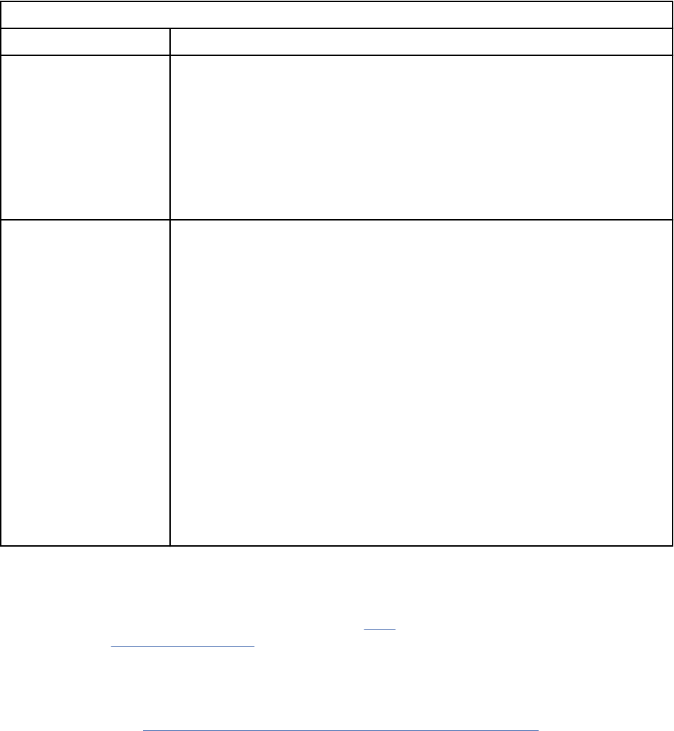
Table 1. Permission classes in the Requirements Management application
Permission class Description
Project conguration This class is for setting high-level project permissions. The permissions in this
class enable these operations:
• Setting project-level permissions
• Modifying types
• Creating templates
• Creating baselines
• Creating change sets
Team conguration This class is for setting permissions on a more granular level. You can use this
permission class to set location-based permissions. The permissions in this
class enable these operations:
Artifact operations
Create, delete, or modify artifacts by type.
Modify artifacts by attribute.
Folder operations
Create, delete, or modify folders.
Link operations
Create, delete, or modify links by type.
Team ownership operations
Modify team ownership.
Lock operations
Manually lock artifacts and override locks of other users.
View operations
Create, delete, or modify shared views.
Permissions on a project level
To set permissions on a project level, you dene role actions at the project level. For a description of the
project process roles for requirements management, see roles. For detailed instructions on how to set
permissions, see modifying permissions.
Permissions on a team level for location-based granular control
To set permissions on a team level for more granular control, you must rst create a team area. For a
detailed example, see “Workflow for setting location-based permissions” on page 23
.
When you create team areas, remember this information:
• Team areas are created as children of the project.
• Multiple team areas can be created in each project.
• Team areas are hierarchical. Users who are members of the parent project or team area are effectively
members of the child team areas. If users need to have permissions set in multiple team areas, you can
add them to a parent team area.
22
Engineering Requirements Management DOORS Next
Tip: Because project-level permissions take precedence over team level permissions, in certain
situations you might want to forgo adding users at the project level and add them to team areas only.
• Team areas are optional. If you do not need to set permissions on a granular level, you can set security
at the project level.
Workflow for setting location-based permissions
General workflow to create location-based permissions by using a team area is as follows:
1. Create a team area.
2. Add users to the team area.
3. Assign process roles to the users in the team area.
4. Modify the process roles for the roles in that team area.
5. Assign team ownership based on location in the folder hierarchy or to specic artifacts or modules.
Permissions on a project level for process sharing
IBM Engineering Requirements Management DOORS Next (DOORS Next) supports process sharing
between projects. You can share the following between projects:
• User roles
• Workflow
• Permissions
To enable process sharing:
1. Select the project for sharing the project's permissions, user roles, and workflow.
2. On the Administration menu, click Manage This Project Area.
3. On the Overview page, in Process Sharing, select Allow other project areas to use the process
conguration from this project area.
See the tutorial on Creating a provider project area
. You can use the process conguration of the modied
project in new and updated projects. If you update existing projects, go to the Workflow page and the
Roles page and clear the overrides.
For permissions specic to individual types, you can import types from projects by using the
process conguration. To import project properties, on the Administration menu, click Import Project
Properties.
Example - Giving a group of users exclusive permission to create a specic artifact
type
Suppose that you have a Business Goals folder in your requirements project, and you want to give a
group of users exclusive permission to create Business Goal artifacts in that folder. To do so, complete the
following steps:
1. Remove the permission to create business goals for everyone in the Administrator role.
2. Enable that permission for a team area.
3. Assign team ownership of the team area to the folder.
Administering
23
The following procedure provides more details about this example. It also describes how to see an
overview of the team ownership of folders and artifacts in a project in the Team Ownership Overview
window.
1. Log in to the Administration page of Jazz Team Server.
2. In the Manage Application Artifacts section, click Manage Project Areas.
3. Click an active project area.
4. Click Permissions and then click Administrator role.
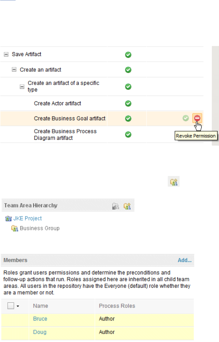
5. Under Permissions For Administrator, expand Save Artifact. To Create Business Goal artifact, click
the Revoke Permissions icon.
6. Click Save. The permission to create a business goal is removed from all Administrators. However,
that permission is enabled by default for the Author role.
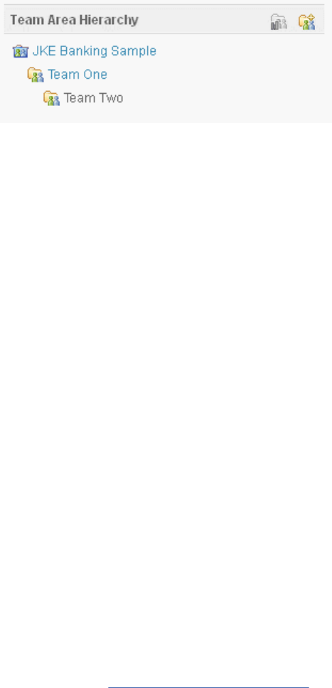
7. Click Overview.
8. In the Team Area Hierarchy section, click the Create Team icon and create a team area named
Business Group.
9. Add members to the Business Group team area, and assign the Author process role to each member,
and click Save.
10. Assign team ownership of the Business Group team area to the Business Goals folder:
a. Open the RM application, and click the menu of the Business Goals folder.
b. Click Assign Team Ownership.
24
Engineering Requirements Management DOORS Next
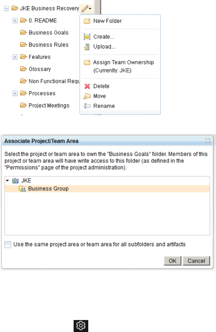
The Associate Project/Team Area window opens.
c. Select the Business Group team area, and then click OK.
Now only the members of the Business Group team area have permission to create Business Goal
artifacts in the Business Goal folder. You can assign team ownership to modules and to artifacts in a
similar manner.
Complete the following steps to see an overview of the team ownership of folders and artifacts in a
project:
1. From the Administration menu , click Manage Project Properties.
2. Click the Team Ownership Overview tab. The Team Ownership Overview window opens.
Administering
25
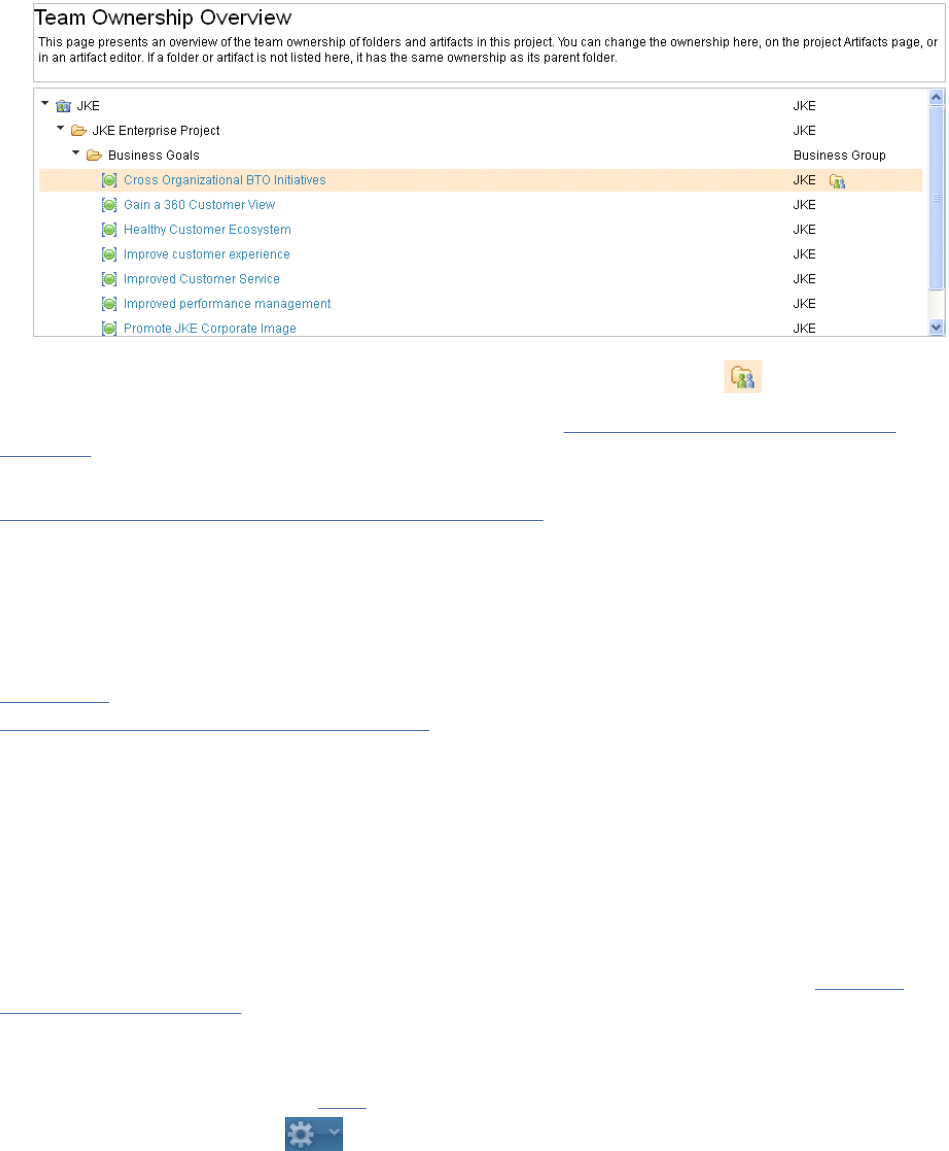
You can change the ownership in this window by clicking the Set Ownership icon .
If you enabled conguration management for your project, see Creating global conguration process
templates.
Related tasks
Creating templates for requirements projects or components
You can create a project or component template, and select the elements to include in it. When
conguration management is not enabled, you create templates for a project. When conguration
management is enabled, you create templates for a component. You can include or exclude artifacts,
artifact templates, artifact types and attributes, links between artifacts, link types, folder structure, tags,
and shared saved lters. After you create templates, you cannot modify them.
Related information
Permissions
Administering global conguration project areas
Creating requirements projects
Jazz project administrators can create projects and modify project structure and team membership.
Before you begin
To create a project, you must log in to the repository as a user with JazzAdmins or JazzProjectAdmins
repository permissions. You must also be assigned the IBM Engineering Requirements Management
DOORS Next (DOORS Next) Analyst role and the associated client access license. If you want to
enable conguration management, an RM administrator must enter a valid license key. See Activating
conguration management.
Procedure
1. If you have not already done so, log in
to a requirements project repository.
2. On the Administration menu , click Manage Project Areas.
3. On the Active Project Areas page, click Create Project Area.
4. In the New Project window, enter a project name and optional description.
5. Optional: To apply the process conguration from another project area to the new one, enable the Use
the process conguration from another project area for this project area option, click Change, and
choose a project area in the list.
6. Click Save.
A new project is created and the Application Administration page opens.
26
Engineering Requirements Management DOORS Next
7. Optional: To enable conguration management for the new project area, on the Application
Administration page, in the navigation pane, click Conguration Management and click Enable
Conguration Management.
8. Optional: To add content to a project area, you can use one of the following options depending upon
whether conguration management is enabled for the project area:
• Apply a project or component template
a. Click Explore Project.
b. Click either the Project name or Component name, Explore Dashboard, or Show Modules.
c. In the Project Setup or Component Setup window, click Apply a project template or Apply a
component template. The Apply Template dialog box appears.
d. Select a template and click Finish. For a list of available templates, see “Requirements project
templates” on page 48.
e. To access this option later, click the Administration menu, and select Apply Template.
However, the option disappears after types or requirements are created.
Note: You must have a template that is already dened in the application. For more information,
see “Creating templates for requirements projects or components” on page 46 and “Managing
templates for requirements projects or components” on page 47.
• Import project or component properties from an existing component
a. Click Explore Project.
b. Click either the Project name or Component name, Explore Dashboard, or Show Modules.
c. In the Project or Component Setup window, click Import Project properties or Import
Component properties from an existing project or component. Choose your source project or
component.
d. To access this option later, click the Administration menu and select Manage Project
Properties or Manage Component Properties and then select Import Project Properties or
Import Component Properties.
Note:
– You can access this option after requirements or types are created since it is able to merge
the type systems from the source and target project area or component.
– Use this option to copy the type system from an existing project area or component to your
current project area or component. For more information, see “Importing properties from
another Requirements Management (RM) project or component” on page 61.
• Manually dene artifact types
a. To manually dene artifact types, click Explore Project.
b. Click either the Project name or Component Name, Explore Dashboard, or Show Modules. In
the Project Setup or Component Setup window, select Manually dene artifact types.
c. To access this option later, click the Administration menu, select Manage Project Properties or
Manage Component Properties. You can access this option anytime. For more information, see
Managing project or component properties in requirements projects.
9. Click Finish.
Important: You cannot create project areas from the Administration menu on the All Projects page,
or from an existing project area. To create project areas, use Application Administration. You can
apply project templates using the Administration menu in existing project areas.
Note: You can also create content in a project area by using an import operation. To import content,
click Explore Project. Click the Project Name or Component Name, Explore Dashboard, or Show
Modules. If there are no types that are created, the system displays the Project Setup or Component
Setup wizard. You must create the new project area. The Project Setup or Component Setup wizard is
not available after creating the requirements or types.
Administering
27
Results
A new project is created. If conguration management is enabled, the new project contains a component
and there is an initial stream for the component.
What to do next
You can add team members
to the project and begin adding artifacts. You can also add folders and dene
artifact types and attributes. You can also use an import operation to create artifact types or attributes.
For more information, see Importing and exporting les. You can use only the ReqIF import if there are
no artifact types already created by using any one of the options that are listed in step 8. To return to the
Artifacts page, click the project name on your Project Dashboard page or on the Home drop-down menu.
If conguration management is enabled, you can now use the component to represent a collection of
versioned artifacts within the project area. For example, instead of working with all the artifacts from
the project in one stream (for example, that represents a physical piece that is called a Handheld Meter
Reader), you can use a component to represent a smaller collection of artifacts (for example, to represent
a smaller physical piece such as a Sensor in the handheld meter reader).
To start working in the initial stream of the component, click the project name. Your conguration context
is set to the initial stream of the component. To create and see links to artifacts in other applications
(QM, RM, DM, and CCM applications), a Global Conguration Management conguration lead must add
a conguration of the component and congurations from the other applications to the same global
conguration.
Related concepts
“Permissions for Requirements Management (RM) projects” on page 21
Related tasks
“Creating templates for requirements projects or components” on page 46
You can create a project or component template, and select the elements to include in it. When
conguration management is not enabled, you create templates for a project. When conguration
management is enabled, you create templates for a component. You can include or exclude artifacts,
artifact templates, artifact types and attributes, links between artifacts, link types, folder structure, tags,
and shared saved lters. After you create templates, you cannot modify them.
“Creating artifacts” on page 91
In a requirements project, you can create rich-text and graphical artifacts.
Related reference
“Requirements project templates” on page 48
Related information
Components
Managing project or component properties in requirements projects
Each project template contains predened artifact types. You can also create customized artifact types,
artifact attributes, and artifact data types for a project or component. Those artifacts types can then
be used by team members to create project or component requirements or related artifacts, such as
customized collections.
Before you begin
You must be assigned to the administrator process role to do these tasks.
About this task
When customizing artifact types and their related elements, you might want to begin with the most basic
elements of the artifact, which are artifact data types. You can use those customized data types to create
custom artifact attributes. You can then add those customized attributes to custom artifact types.
28
Engineering Requirements Management DOORS Next
To watch a video that shows how to create custom artifact types, click the Show Me link at the beginning
of the topic.
Related concepts
“Requirement artifacts” on page 92
“Link constraints in the RM application” on page 42
Link constraints are rules that an administrator can set up to specify which kinds of links are allowed in a
project or across projects. If no rules are created, all links are allowed. However, if you create rules, only
the links in the rules are allowed.
“Requirement workflows” on page 195
A Requirements workflow is a state transition model in which you dene the state that artifacts of a
specied type can be in and the actions that users can select to move these artifacts from one state to
another. You can nd topics that are in a specic state by creating a lter.
Related tasks
“Creating link types for requirements projects” on page 36
“Importing properties from another Requirements Management (RM) project or component” on page 61
You can import the properties from one Requirements Management (RM) project or component into
another project or component. When conguration management is not enabled, you import properties
from project to project. When conguration management is enabled, you import properties from
component to component. The properties that are imported by default include all the artifact types,
attribute data types, link types, and link constraints that are dened in the project or component.
Creating requirement artifact types
Artifact types classify requirements and related artifacts and provide a consistent set of attributes for
each type. You can use the artifact types that come with the sample project templates, or you can create
custom artifact types and assign predened and custom attributes to them.
Before you begin
You must have administrator permission to create and modify artifact types.
Procedure
1. From the Administration menu
, click Manage Project Properties.
Note: If conguration management is enabled for your project, on the Administration menu, click
Manage Component Properties.
2. Click the Artifact Types tab, and then click New Type.
3. Enter a name and description.
4. Optional: To change the default icon for the artifact type, click Change.
If you select a different icon, all artifacts of this type are shown with that icon.
5. Select a default artifact format.
6. If you selected Module as the format, in the Preferred Module Content eld, select multiple artifact
types to use and specify how they are ordered.
When other team members add artifacts to modules, the preferred artifact types are shown by
default. You can change the order of the preferred artifact types or remove them. The order of
preferred artifact types is used in several menus:
• Create button
• Artifact row menu
• Type menu on the inline editor toolbar for modules
Tip: If you plan to use headings in the module, include a type that is identied as a heading type.
Administering
29
7. Optional: Select Preferred Link Types. If you select preferred link types, you limit the link types that
are available when you create a link.
8. Optional: To place a frequently used artifact type at the top of the list when you create an artifact
by using the Create button, select Make this artifact type a preferred artifact type check box.
Infrequently used artifact types are available under the Other option.
9. Optional: To enable the Lookup Term feature for text-based artifact types, select Use artifacts of this
type as glossary terms check box . You can use the Lookup Term feature to search for term artifacts
from within text-based artifacts.
10. Optional: If you want artifacts of this type to be shown as headings when you add them to a module,
select In modules, display artifacts of this type as headings by default check box.
11. Optional: If this artifact type is a supporting document that you frequently upload, select the Make
this artifact type a preferred upload option check box. When you upload an artifact, the supporting
document is the default artifact type.
12. Optional: To select a workflow for an artifact type, click Workflow and select a workflow from the list.
You can select the default workflow or also create a custom workflow.
Note: If you create an artifact and the artifact type is associated with a workflow, the newly created
artifact is populated with the initial workflow state.
13. Optional: In the URI eld, specify a unique URI to identify the artifact type across RM projects.
You must use a unique URI for each artifact type within a project. If another project has an equivalent
artifact type, you can use the URI of the equivalent artifact type to ensure consistency across
projects. In a project that is enabled for conguration management, you can use the same URI for
equivalent artifact types that are in different components.
For example, Project_A has an artifact type named "Functional Requirement". When you create
Project_B, you dene an attribute that is named "Requirement - Functional". Your organization
considers these attributes equivalent even though their names and enumeration values differ. Assign
the same URI to both artifact types to ensure consistent meaning across projects.
Note: URIs and Type names are also important for cross-team reporting on artifact types. If the
Type name or URI changes in reporting, the results depend on which content is accessed from
Lifecycle Query Engine (LQE). For more information, see Scenarios for maintaining Rational DOORS
Next Generation type systems for baselines and editable congurations.
14. To add an attribute to the artifact type, click Add Attribute.
15. Click Save.
Related concepts
“Requirement artifacts” on page 92
“Requirement workflows” on page 195
A Requirements workflow is a state transition model in which you dene the state that artifacts of a
specied type can be in and the actions that users can select to move these artifacts from one state to
another. You can nd topics that are in a specic state by creating a lter.
Related tasks
“Managing project or component properties in requirements projects” on page 28
Each project template contains predened artifact types. You can also create customized artifact types,
artifact attributes, and artifact data types for a project or component. Those artifacts types can then
be used by team members to create project or component requirements or related artifacts, such as
customized collections.
“Importing properties from another Requirements Management (RM) project or component” on page 61
You can import the properties from one Requirements Management (RM) project or component into
another project or component. When conguration management is not enabled, you import properties
from project to project. When conguration management is enabled, you import properties from
component to component. The properties that are imported by default include all the artifact types,
attribute data types, link types, and link constraints that are dened in the project or component.
“Creating a glossary and terms” on page 178
30
Engineering Requirements Management DOORS Next
A glossary is a group of terms that you have dened to build consistent, common terminology for your
project.
Related information
Repository and role-based permissions
Creating attributes for requirement artifacts
When you create requirements in a project, you can create custom artifact attributes to use in custom
artifact types. Custom attributes are based on predened and custom artifact data types, which dene the
properties of the attribute, such as textual entries, integers, date, time, or team member names.
Before you begin
You must have administrator permissions to create and modify artifact attributes, and you must be in a
Requirements Management (RM) application project.
Procedure
1. From the Administration menu , click Manage Project Properties.
Note: If conguration management is enabled for your project, on the Administration menu, click
Manage Component Properties.
2. Click the Artifact Attributes tab, and then click New Attribute.
3. Enter a name and description.
4. Select a data type.
You can also create a new data type. For more information, see “Creating requirement attribute data
types” on page 32.
5. If you want users to be able to select multiple values from the list of attribute values, select Multiple
values allowed.
6. Optional: Enter an initial value that is shown when you create a requirement artifact that contains an
attribute of this type.
7. Optional: In the URI eld, specify a unique URI to identify the artifact attribute across RM projects,
with the syntax http://hostname/domain/myLabel.
Restriction: When you specify a URI, ensure that it follows these conventions:
• Complies with the RFC 3986 specication (with support for Unicode characters in the path, query,
and fragment only, as specied by RFC 3987).
• Species an absolute URI.
Note: If you use Lifecycle Query Engine as your data source, specify a URI to ensure consistency for
reporting across projects.
In a project, use a unique URI for each artifact attribute. If another project has an equivalent attribute,
use the equivalent attribute's URI to enable a shared vocabulary for reporting. Also, dene URIs for
each of the enumerated values, and use the same URIs to denote equivalent values. In a project that is
enabled for conguration management, you can use the same URI for equivalent attributes that are in
different components.
If the Requirements Management (RM) projects dene a "Priority" property, use the same URI
for it in each project, such as http://my.org/ns/rm/Priority. If another project denes an
"Importance" property that is the same as "Priority", use the same URI for both properties.
8. Click Save.
Administering
31
Creating requirement attribute data types
You can create custom attribute data types that can be used in custom attributes. Attribute data types
dene the properties of the attribute values. They provide structure and consistency to custom attributes
by offering the administrator a limited set of data types that have a predened behavior and constraints.
Before you begin
You must have administrator permissions to create and modify attribute data types.
About this task
Custom attribute data types are available for use in all custom and non-custom attributes in the project.
New custom attribute data types must be based on one of three kinds:
• Simple
• Enumerated list of values
• Bounded range of values
Simple data types use one of the following base data types:
integer
An integer.
float
A number that can contain decimal digits.
boolean
A check box (marked or cleared).
date
A calendar entry.
time
A 24-hour time selection or an entry in this format: hours:minutes:seconds.
dateTime
Calendar and time entries.
string
Alphanumeric text.
duration
A time duration entry (integers) in hours, days, or weeks.
user
Search the repository team members and select one.
An enumerated list of values is a numbered list of values with textual labels. You can add and remove
numbered entries and arrange entries in any order.
Tip: If a data type uses an enumerated list of values, note the order of the values in the table. That
order is the same order that the values will be in when you assign the attribute value to any artifact;
for example, in the artifact sidebar. The number that is assigned in the value eld is the number that is
used when artifacts are sorted by that attribute. When you order artifacts by an attribute (ascending), the
enumerations with the lowest value will be rst.
For a bounded range of values, you must specify a minimum and maximum for a range of any of the
following base data types:
integer
An integer.
float
A number that can contain decimal digits.
date
A calendar entry.
32
Engineering Requirements Management DOORS Next

dateTime
Calendar and time entries.
Procedure
To create a custom attribute data type:
1. Click the Administration menu , and then click Manage Project Properties.
Note: If conguration management is enabled for your project, on the Administration menu, click
Manage Component Properties.
An administrative page opens that has tabs for artifact types, attributes, data types, link types, and
templates.
2. Click the Attribute Data Types tab.
3. Click New Data Type.
4. Enter a name and description for the data type.
5. Select a kind of value and a base data type, where applicable.
6. If you plan to work with an enumerated list or a bounded range of values, create entries as needed.
7. Optional: In the URI eld, specify a unique URI to identify the attribute data type across RM projects.
Within a project, you must use a unique URI for each attribute data type. If another project has
an equivalent data type, you should use the equivalent type's URI to ensure consistency across
projects and enable a shared vocabulary for reporting. In a project that is enabled for conguration
management, you can use the same URI for equivalent attribute data types that are in different
components.
For example, Project_A has an attribute named "Glossary_visibility", which has an enumerated list
of values: Enterprise, Organization, or Project, each corresponding to an integer. When you create
Project_B, you dene an attribute named "Denition_scope". Possible values are Corporation, Division,
and Team. Your organization considers these data types equivalent even though their names and
enumeration values differ. Assign the same URI to both data types to ensure consistent meaning
across projects and so that you can report on equivalent data types across projects.
8. Click Save.
Module options
A module is a structured document that is composed of multiple artifacts. These artifacts or content of
the modules are stored by default in a folder which is created in the same directory as the module. In
the Modules Options tab, an administrator can change this default to specify another folder to store the
multiple artifacts of a module. You can use drag-and-drop to move one or more folders and re-organize
them. If your project area has not been enabled for conguration management, an administrator can
schedule a refresh of the module view to ensure that the latest module content is loaded from the data
warehouse.
Before you begin
If you have conguration management enabled for your project, you must have JazzAdmin or
JazzProjectAdmin permission to create and modify modules.
If you have conguration management enabled for your project, you must have JazzAdmin or
JazzProjectAdmin or have the Create Component permission to create and modify module content
folder behavior.
Procedure
1. From the Administration menu
, click Manage Project Properties.
Administering
33
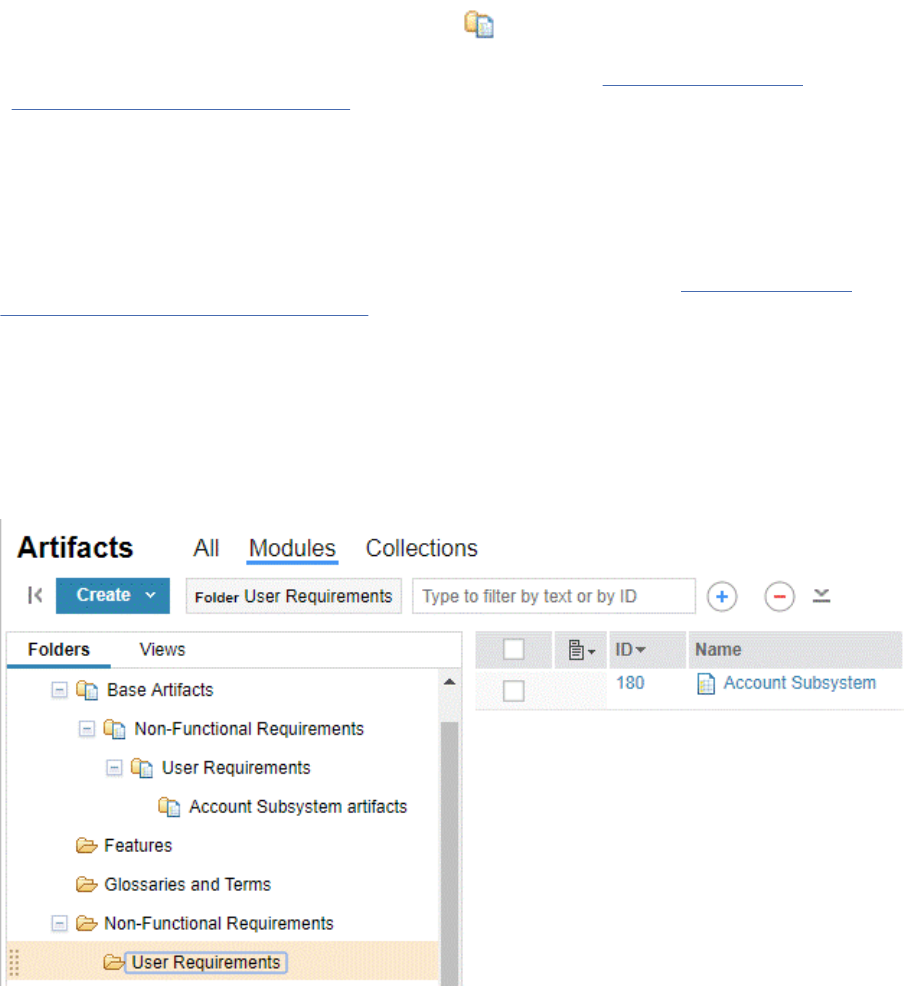
Note: If conguration management is enabled for your project, on the Administration menu, click
Manage Component Properties.
2. Click the Modules Options tab.
3. In the Module Content folder set the default location to where the artifacts of a module are stored.
Select any one of the options:
• Same folder as the module, to save the artifacts in the same folder as the module.
• Specied folder, to save the artifacts in a different folder. When a folder is selected as the common
content folder, it is displayed with a different icon in the folder hierarchy.
Note: If the Folder Structure option is selected for templates (see Creating templates for
requirements projects or components) and the Specied folder option is used, the module
template is saved in the Specied folder .
4. Click Save.
Note:
• The Module Content folder setting will only affect new modules. The location of the content folders
for existing modules will not be changed when the setting is changed.
• To include the Module Content folder setting when creating templates (see Creating templates
for requirements projects or components), make sure to include the project or component Folder
Structure in the template.
• When you Import Project or Component Properties, the Module Content folder setting does not
get imported.
Considerations when selecting Specied folder for module content:
• When a Specied folder is selected for module content, the content for all modules will
be saved under the common folder. In order to provide organization to the common folder,
when a module is created, its folder hierarchy will be duplicated under the common folder.
In this example, a common module content folder named Base Artifacts is used for module
content artifacts. A module Account Subsystem is created under User Requirements within the
Non-Functional Requirements folder. Within the common module content folder, the module’s folder
hierarchy is duplicated and the module’s content folder Account Subsystem artifacts is created.
Note:
34
Engineering Requirements Management DOORS Next
– The Base Artifacts folder is not available on the Modules or Collections tab. You can access the
folder on the All tab.
– The folder hierarchy will only be duplicated when the module is created. If a module is moved to
another folder or if a folder containing modules is moved, the common folder hierarchy will not be
updated.
– When folders are duplicated under the common module folder, the folders are assigned the same
team area as the original folders.
• When a Specied folder is selected for module content, the folder cannot be deleted. If you want
to delete the folder, either select another folder as the common content folder or select the Same
folder as the module option.
• When a Specied folder is selected for module content, any user that has permission to create
modules will automatically have permission to create folders under the common content folder
when a module is created.
Refresh Module Views
Before you begin
To schedule module view refreshing, you must have the Manage View Schedule permission.
About this task
If your project area has not been enabled for conguration management, you can schedule to Refresh
Module Views. Module views are loaded as collections into the data warehouse during the ETL process.
A view can become outdated if someone updates its contents without editing the view itself. In Refresh
Module Views schedule when the system checks for updates each day.
Procedure
1. From the Administration menu
, click Manage Project Properties.
2. Click the Modules Options tab.
3. Use Add Module View to list the module views that need to be checked and ensure that they contain
the latest content. When you add a view to the list, it is shown only if it is unique to the module and is
shared.
See Filters and views in modules.
Related tasks
Creating modules
You can create modules and module content directly in a project or by importing a Microsoft Word
document, ReqIF le, or rich-text document.
Mapping Contexts
You can use the mapping contexts feature for exchanging requirements between IBM Engineering
Requirements Management DOORS Next (DOORS Next) and IBM Engineering Requirements Management
DOORS (DOORS).
About this task
You can use the mapping contexts feature to automatically map identical type elements from DOORS into
a single instance of each identical type. This feature helps in removing or reducing type duplication when
you import requirements in DOORS Next. You can create mapping contexts and use the contexts while
importing or exporting ReqIF les.
Administering
35
Procedure
1. From the Administration menu , click Manage Project Properties.
Note: If conguration management is enabled for your project, on the Administration menu, click
Manage Component Properties.
2. Click the Mapping Contexts tab.
3. Click New Context.
4. Specify a name for the mapping contexts.
5. Optional: Provide additional information as description.
6. Click Save.
You can view the mapping contexts in the Mapping Contexts list. You can apply the mapping
context to an imported package. For more information, see “Importing artifacts from ReqIF les to
a requirements project or component” on page 168.
You can also use the mapping context to a subsequent export of the same package. For more
information, see “Exporting artifacts from a requirements project or component into ReqIF les” on
page 173.
Related tasks
“Importing and exporting ReqIF les” on page 167
Requirements Interchange Format (ReqIF) les are XML les that you can use to exchange requirements
and associated metadata between requirements tools or requirements repositories. For example, you
can exchange data between IBM Engineering Requirements Management DOORS (DOORS) and IBM
Engineering Requirements Management DOORS Next (DOORS Next). When the exchange is nished, a
report is generated that shows the data that was imported or exported. Using ReqIF to migrate multiple
components or a single component with multiple streams from one environment to another is not
supported. The supported method to migrate a repository to a new environment is Server Rename. If
you want to migrate a partial Requirements Management repository to another environment, you need
to consider engaging IBM Expert Labs, or an IBM Business Partner to explore options that comprise of
custom utilities in addition to ReqIF.
Creating link types for requirements projects
You can create link types to customize the linking relationships between artifacts. Links can show
relationship properties such as artifact origin, derivation, dependency, hierarchy, and associations
between requirements, development, and test artifacts.
Link relationships are directional, and labels typically differ at either end of the link; for example,
requirement A links to requirement B; and requirement B is linked from requirement A. The direction
of each link is also indicated by an icon. For more information, see “Link direction” on page 41
.
You can use custom link types and system-dened link types to link artifacts in the same project, across
different projects, or across different servers.
Before you begin
You must have administrator permissions to create and modify link types.
About this task
Depending on the project template that was used to create your project, the project might have an
extensive list of predened link types, such as the following types:
• Link - Link To/Link From
• Decomposition - Parent Of/Child Of
• ELM development - Implemented By/Implements
• ELM test - Validated By/Validates
36
Engineering Requirements Management DOORS Next
Predened link types in templates can include both system-dened and custom link types. You can use
the predened link types as examples for creating custom link types.
Procedure
1. On the Administration menu , click Manage Project Properties.
Note: If conguration management is enabled for your project, on the Administration menu, click
Manage Component Properties.
2. Click Link Types.
All link types in the project are listed. System-dened link types are designated in the Description
eld.
3. Click Add.
4. In the New Link Type window, enter a name, and optionally description. Create a name that describes
the relationship in a general way and includes the logic from both directions.
5. Enter a unique URI value, for example, https://hostname.com/domain/myLabel. This value is
needed for cross-project linking. For cross-project links, both the projects or components must dene
the same link types, with the same external RDF URIs. If you are using link constraints, you must
dene equivalent URI for the requirement types.
Restriction: When you specify a URI, ensure that it follows these conventions:
• Complies with the RFC 3986 specication (with support for Unicode characters in the path, query,
and fragment only, as specied by RFC 3987).
• Species an absolute URI.
6. To add directional labels, select the Provide directional labels for the relationship check box.
7. Enter labels in the Outgoing and Incoming elds.
8. Click Save.
Related concepts
Linking artifacts in different projects or components
A link represents a relationship between artifacts. Link relationships are directional and indicated by an
icon. Link types help you dene and customize the linking relationships between artifacts. Each link type
has an Outgoing and an Incoming role. You can create links between artifacts in different projects on
the same server or on different servers. If you enable conguration management, you can create links
between artifacts in different components.
Related tasks
“Importing properties from another Requirements Management (RM) project or component” on page 61
You can import the properties from one Requirements Management (RM) project or component into
another project or component. When conguration management is not enabled, you import properties
from project to project. When conguration management is enabled, you import properties from
component to component. The properties that are imported by default include all the artifact types,
attribute data types, link types, and link constraints that are dened in the project or component.
“Linking between artifacts in modules” on page 136
You can link artifacts that are in the same module or artifacts that are in different modules.
Link types in requirements projects
Requirements projects include several predened link types for traceability.
Administrators can view the link types for a project and create link types on the Link Types page, which
they can access by clicking the Administration menu and then clicking Manage Project Properties > Link
Types. If you have conguration management that is enabled for your project, on the Administration
menu, click Manage Component Properties.
Note: For traceability to work in cross-project links, link types in both the projects or components must
specify the same external RDF URIs. See Creating link types
to learn how to assign an URI to a link type.
Administering
37
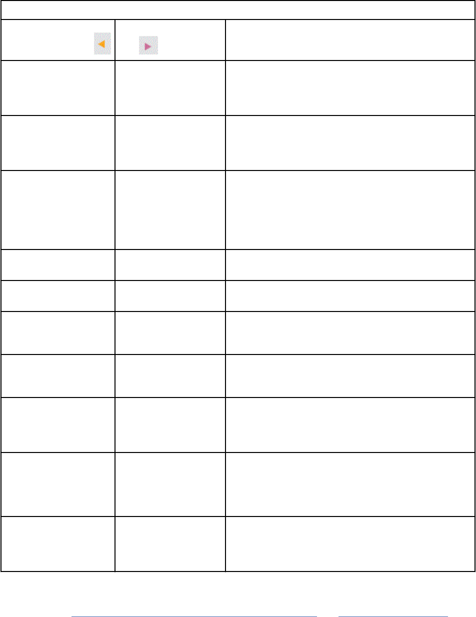
The following table provides descriptions of most of the traceability link types in the Requirements
Management (RM) application.
Table 2. Requirements management link types
Incoming link type
Outgoing link
type Description
Constrained By Constrains Captures the relationship between requirement
artifacts when one artifact limits or holds back
the other artifact. For example, an artifact can be
constrained by a requirement that it must conform to.
Embedded In Embeds Tracks a containment relationship between RM
artifacts. These types of relationships occur when you
complete operations such as inserting an artifact and
inserting an image for a text artifact.
Extracted From Extracted Extraction captures when the content of a
requirement artifact was created from the contents
of another requirement artifact. This type of link
is created during extraction-based operations; for
example, when you create an artifact by saving an
existing artifact as a new artifact.
Illustrated By Illustrates Illustrates the relationships between graphical and
text artifacts.
Link From Link To Tracks a general relationship between requirement
artifacts.
Mitigates Mitigates Captures the relationship between requirements and
risks. A requirement mitigates one or more risks, and
a risk is mitigated by one or more requirements.
Parent Of Child Of Decomposition captures part-whole relationships
between requirement artifacts. Typically, these types
of links represent artifact hierarchies.
Satised By Satises Captures how the different levels of requirements
are elaborated. For example: an approved vision
statement in a vision document can be satised by
one or more stakeholder requirements.
Synonym Synonym Relates requirement term artifacts that are
synonymous.
This link type is bidirectional. The link is shown as
Synonym from either endpoint.
Term Referenced From References Term Artifact Term Reference captures glossary-based
relationships between requirement artifacts. This
type of link is created during term-based operations
for text artifacts, such as when you create a term.
Link types in RM also include links to other IBM Engineering Lifecycle Management (ELM) applications.
This link type is available only through an OSLC integration. For more information about OSLC link type
denitions, see The OSLC Requirements Management (RM) Vocabulary and RM Resource Denitions.
Incoming links are when the link is created in the RM application and Outgoing links are when the link is
created outside of the RM application.
38
Engineering Requirements Management DOORS Next
Important: To make sure that all the link types that are described in the following table are available in a
project:
• Establish project association denitions. See Adding associations.
• Integrate RM with the other application.
In addition, Outgoing link types are shown only if the link is created by the other application. Such as an
Affects link is visible only if the link is created in the change management application.
Table 3. Requirements management link types across ELM applications
Incoming link type Outgoing link type
Description
Change and Conguration Management (CCM) application
Affected By Affects Captures the relationship between a
requirement artifact and a change management
work item that affects the implementation of
the requirement artifact. For example, a defect
in the Change and Conguration Management
(CCM) application can affect the implementation
of a requirement artifact.
Note: The Affected By link type is not available
for modules and collections.
Implemented By Implements Captures the relationship between a
requirement artifact and a change management
work item that describes the implementation
of the requirement artifact. For example, a
story in the CCM application can describe the
implementation of a requirement artifact. In the
CCM application, links of this type are shown as
Implements links.
Note: For modules and collections the
Implemented By link type is only available to
plan items in the CCM application.
Tracked By Tracks Captures the relationship between a
requirement artifact and a change management
item that tracks the implementation of the
requirement artifact. For example, a plan
item in the CCM application can track the
implementation of a requirement artifact. In the
CCM application, links of this type are shown as
Tracks links.
Note: The Tracked By link type is not available
for modules and collections.
Architecture Management (AM) application Note: As of version 7.0.0, DM is no longer part of the ELM
solution.
Derives Architecture
From Element
Derives Architecture
Element
Captures the relationship between a
requirement artifact and a model element. For
example, a UML use case in an architecture
management application can represent a
requirement artifact. The requirement artifact
derives from the UML use case.
Administering39

Table 3. Requirements management link types across ELM applications (continued)
Incoming link type Outgoing link type
Description
Rened By Architecture
Element
Renes Architecture
Element
Captures the relationship between a
requirement artifact and a design element.
Design resources can be linked to requirements
management artifacts by using the Rened By
Architecture Element link type. These link types
are visible in RM as the Renes Architecture
Element link type.
Satised By Architecture
Element
Satises Architecture
Element
Captures the relationship between a
requirement artifact and an architecture
management item that represents a model of
the requirement artifact.
Traced By Architecture
Element
Trace Architecture Element Traces the relationship between a requirement
artifact and an architecture management
item that traces the model element to the
requirement artifact.
Links in another RM instance or another RM project area
Referenced By References Tracks a relationship between requirement
artifacts. These types of relationships
occur when requirement artifacts reference
requirement artifacts in another RM instance or
another project area.
Quality Management (QM) application
Validated By Validates Captures the relationship between a
requirement artifact and a test artifact that
validates the implementation of the requirement
artifact. For example, a test plan in the Quality
Management (QM) application can validate the
implementation of a requirement artifact. In the
QM application, links of this type are displayed
as Validates links. Validated By links point from
the RM application to IBM Engineering Test
Management (ETM).
Related concepts
“Links between artifacts” on page 203
A link represents a relationship between artifacts. Links are mechanisms for referring to related
information. You create some links manually. Other links are created automatically when you complete
certain tasks. There are different properties for trace links, content links, links to base artifacts, and links
in modules.
Link constraints
Link constraints are rules that an administrator can set up to specify which kinds of links are allowed in a
project or across projects. If no rules are created, all links are allowed. However, if you create rules, only
the links in the rules are allowed.
Related tasks
“Creating link types for requirements projects” on page 36
Related reference
“Links across OSLC domains ” on page 85
40
Engineering Requirements Management DOORS Next
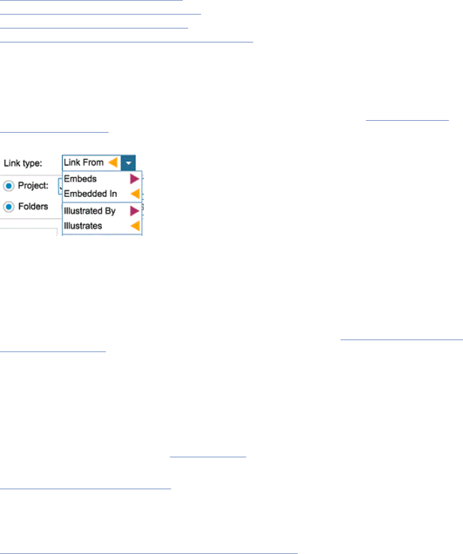
The Requirements Management (RM) application in the IBM Engineering Lifecycle Management (ELM)
integrates with other application domains by using standard link types as implementations of the OSLC
specications.
Related information
Open Services for Lifecycle Collaboration
Linking between artifacts in the Eclipse client
Linking between artifacts in the web client
Linking to requirements and development artifacts in QM
Link direction
Link types help you dene and customize the linking relationships between artifacts. Each link type has an
Outgoing and an Incoming role.
You can set labels that explain the directional relationship of the link, for example Illustrates and
Illustrated By. To set labels for the Incoming and Outgoing roles for link types, see Creating link types
for requirements project.
When link types are displayed in the user interface, icons indicate the direction of the link type role.
Note: For OSLC link types, direction icons are only shown for IBM Engineering Workflow Management
(EWM), IBM Engineering Test Management (ETM), and References links.
You can also lter or group artifacts according to the direction of the link type role in the Links Sidebar.
From the ltering drop-down menu select Link Type and select Show all, Show Outgoing, or Show
Incoming to lter artifacts by the direction of its associated links. From the grouping drop-down menu,
select Group by Link Type to group artifacts that have Incoming and Outgoing links.
For more details on cross-project or cross-component links for artifacts, see Linking artifacts in different
projects or components.
Utilities to change links and repair incorrectly stored links
• Link swapper tool: Changes the direction of an existing custom link type into a new link type that you
specify.
• Link storage tool: Ensures that cross-component links are stored in the component with the outgoing
endpoint of the link.
You can download these utilities from DOORS Next wiki
.
Related concepts
“Links between artifacts” on page 203
A link represents a relationship between artifacts. Links are mechanisms for referring to related
information. You create some links manually. Other links are created automatically when you complete
certain tasks. There are different properties for trace links, content links, links to base artifacts, and links
in modules.
“Linking artifacts in different projects or components” on page 206
A link represents a relationship between artifacts. Link relationships are directional and indicated by an
icon. Link types help you dene and customize the linking relationships between artifacts. Each link type
has an Outgoing and an Incoming role. You can create links between artifacts in different projects on
the same server or on different servers. If you enable conguration management, you can create links
between artifacts in different components.
Administering
41
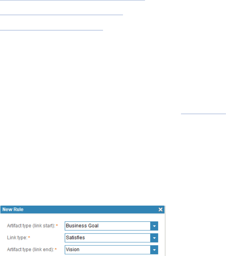
“Conguration management in the RM application” on page 6
Related tasks
“Linking between artifacts in modules” on page 136
You can link artifacts that are in the same module or artifacts that are in different modules.
“Reusing artifacts in modules” on page 146
Artifacts can be reused in multiple contexts in a project, including collections and modules. You can edit
artifact content in a module or by opening the artifact outside the module. Content changes are reflected
in all contexts. Links, tags, and comments are specic to the context in which they are created. If you
want links, tags, and comments to reflect in all contexts, edit the artifact outside the module as a base
artifact.
Link constraints in the RM application
Link constraints are rules that an administrator can set up to specify which kinds of links are allowed in a
project or across projects. If no rules are created, all links are allowed. However, if you create rules, only
the links in the rules are allowed.
Administrators can create link rules on the Link Constraints tab in the project properties. These rules
govern the creation of links in Requirements Management (RM) projects and across RM projects on the
same server.
Note:
• Link constraints cannot span applications.
• Link constraints are supported only for RM Link types such as Link To and RM user-dened link types.
Link types that are OSLC-based such as Referenced By or Validated By or that are used for linking to
other applications are not supported.
Link creation with link constraints
After you create link rules, the options for creating links from context menus and in the Create Link
window are affected by those rules.
In the following example, a single rule species that a Business Goal artifact has a Satises link to a Vision
artifact:
Because this is the only rule in the project, no other links are allowed. If you are creating a link from a
Vision artifact or Business Goal artifact, only the Satises and Satised By link types are available. No
other link types are available from any other artifacts.
For example, if you create a link from a Business Goal artifact, only the Satises link type appears as a
menu option:
42
Engineering Requirements Management DOORS Next
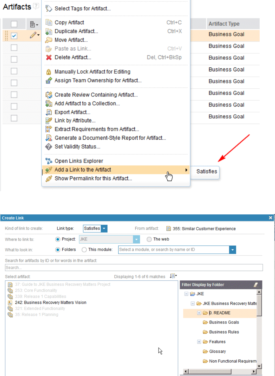
In addition, in the Create Link window, you can select only those artifact types that are allowed based on
the initial artifact type and the selected link type, as shown in the following image:
In the Create Link window, you can also select certain components and artifact types based on dened
link constraints, including the artifact types that contain a cross-component artifact type.
Administering
43
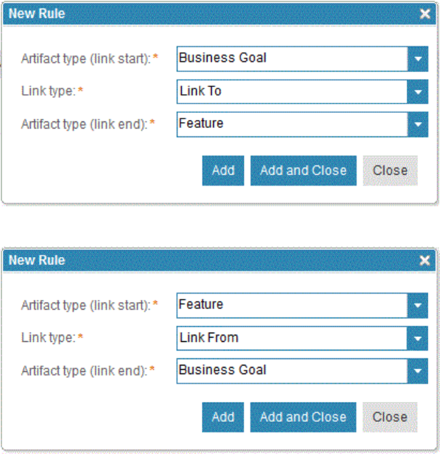
Tip: Link rules constrain only new links that are created. Links that existed before you created or changed
the rules are not affected by the new rules. However, you can search for and manually modify links that
don't adhere to any new or changed constraints; for example, if the link type is no longer allowed, but the
artifact types do satisfy the constraints, then you can change the link type. However, if the artifact type is
not allowed, then you can only delete the link type.
Cross-project linking
To enable linking between artifacts in different projects, you must dene a rule that allows linking for the
particular link type in both projects, and the rules must match. When you create cross-project links, rather
than using ANY as the link end, you can select a specic artifact type in target project.
For example, for the "Link (Link To/Link From)" link type, if you want Business Goal artifacts in Project 1
to link to Feature artifacts in Project 2 (which also implies that Feature artifacts in Project 2 can link from
Business Goals in Project 1), you must dene the rules as follows:
Project 1:
Project 2:
These rules match because both directions of the link type are allowed in each project.
Note: If a project does not have any constraints, it is compatible with all rules. For example, suppose
Project 1 has a rule that a Feature artifact can link to any artifact type. If Project 2 does not have any
constraints that are dened, the Feature artifact in Project 1 can link to any artifact in Project 2. However,
if Project 2 has constraints that are dened, an explicit matching rule must exist in Project 2.
When you create link constraints, you can also select a cross-project or cross-component type as a link
end. The cross-project or cross-component name is displayed after the artifact type name. For example,
you can create a constraint such as Business Goal (Project A) Link To Vision (Project B), where Business
Goal is the source artifact type, (Project A) is the source cross project type, Link To is the link type, Vision
is the target artifact type, and (Project B) is the target cross project type.
Note: If you add a link constraint for a remote project, and that project is enabled for conguration
management, you must be working in a global conguration.
Cross-component linking
44
Engineering Requirements Management DOORS Next
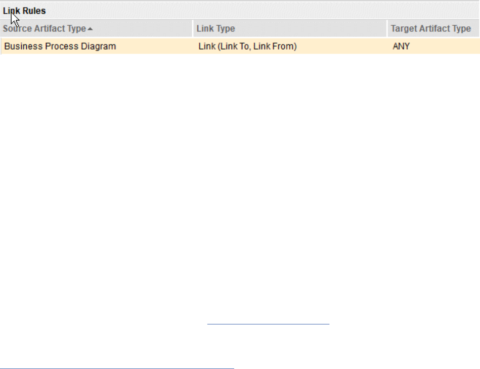
To enable linking between components, you must dene a rule that allows linking for the particular link
type in both components. When you create cross-component links, you can select a cross-component
type as a link end. The cross-component name is displayed after the type name in cross-component
types.
Note: If you want to enforce link constraints for remote components, you must be working in a global
conguration that supports cross-component linking.
Cross-project or cross-component linking is automatically enabled for system-dened link types.
However, if link constraints are set the cross-project and cross-component linking is governed by the
link constraint rules.
Cross-project linking and Cross-component linking for a custom link type
For cross-project or cross-component linking for a custom link type, you dene a URI for the link type.
For example, https://hostname.com/domain/myLabel. If you use link constraints, you must dene
equivalent URIs for the requirement types. If the URI of an artifact included in a link constraint is edited,
the link constraint is not updated with the new URI. Since the link constraint is not updated the custom
link type will no longer have the link constraint that is applied to. It is invalid since no type matches
previous RDF URI and therefore it will not be displayed under link constraints section.
Flexibility for link rules
You can make link rules more flexible by using ANY as the target artifact type. For example, if you create
a "Link" link type for a Business Process Diagram artifact, and you specify ANY as the target artifact type,
you can create links from a Business Process Diagram artifact to any artifact type in the current project.
In addition, you can specify ANY in a link rule to enable links to web resources or to artifacts in another
RM project.
Automatic generation of link constraints
As a project administrator, you can automatically generate link constraint rules based on the existing link
relationships by clicking Generate Rules. The link constraint rules that are required to satisfy existing
link relationships are identied and appended to the list. If your project includes cross-project links, the
cross-project rules are also automatically created for the specify project. To create the corresponding
rule, you must click Generate Rules in the linked project.
You cannot automatically generate link constraints for custom types. If you create two projects that each
have their own custom type, and create a link between them, when you click Generate Rules, the rules
are created by using the ANY keyword. For example, the rst project would contain a Project1CustomType
Link to ANY rule, and the second project would contain an ANY Link To Project2CustomType rule.
Preferred link types
Preferred link types that you specify for an artifact type are subject to the link rules that are in effect. For
example, if you have a preferred link type of Satises for an artifact type, but your link rules do not allow
this link type, the Satises link type is ignored.
Versioning constraints
Constraints are versioned and handled by the conguration management capabilities; they can vary
across congurations, be delivered in change sets, and can be compared and merged.
Related concepts
Linking artifacts in different projects or components
A link represents a relationship between artifacts. Link relationships are directional and indicated by an
icon. Link types help you dene and customize the linking relationships between artifacts. Each link type
has an Outgoing and an Incoming role. You can create links between artifacts in different projects on
Administering
45
the same server or on different servers. If you enable conguration management, you can create links
between artifacts in different components.
“Links between artifacts” on page 203
A link represents a relationship between artifacts. Links are mechanisms for referring to related
information. You create some links manually. Other links are created automatically when you complete
certain tasks. There are different properties for trace links, content links, links to base artifacts, and links
in modules.
Related tasks
“Creating link types for requirements projects” on page 36
“Managing project or component properties in requirements projects” on page 28
Each project template contains predened artifact types. You can also create customized artifact types,
artifact attributes, and artifact data types for a project or component. Those artifacts types can then
be used by team members to create project or component requirements or related artifacts, such as
customized collections.
Related reference
“Link types in requirements projects” on page 37
Creating templates for requirements projects or components
You can create a project or component template, and select the elements to include in it. When
conguration management is not enabled, you create templates for a project. When conguration
management is enabled, you create templates for a component. You can include or exclude artifacts,
artifact templates, artifact types and attributes, links between artifacts, link types, folder structure, tags,
and shared saved lters. After you create templates, you cannot modify them.
Before you begin
To create requirements templates, you must have an Analyst client access license. You must also have at
least one of the following prerequisites:
• JazzAdmins repository permissions
• The Administrator role in the project
Important: Applying project templates from a version n of DOORS Next to a n-1 is not supported. For
example, you cannot apply a project template from 7.x version to 6.x version for creating project areas.
To view your repository permissions and client access license, open a project. From the User Prole
menu
, click View My Prole and Licenses. To view your project role, from the Administration
menu , click Manage This Project Area.
About this task
To create templates, you open an existing project or component and create the template.
Procedure
To create a template, open an existing project or component and complete these steps:
1. Click the Administration menu
and click Manage Project Properties.
If conguration management is enabled for your project, on the Administration menu, click Manage
Component Properties.
2. On the project administration page, click the Templates tab.
3. From the list on the left, select Project Templates.
If conguration management is enabled for your project, on the Administration menu, click
Component Templates.
46
Engineering Requirements Management DOORS Next
4. Click New Template.
5. In the Create Template window, specify the name, description, and the items to include in the
template, and then click OK.
Some items in the list have dependencies on other items; therefore, some items are selected by
default when you select others.
What to do next
The next time that you create a requirements project or component, you can select the new template
from the New Project wizard. To know more about how to edit, delete, download, or upload a template,
see Managing requirements project templates
.
Note: After you create a template, you cannot modify it. You also cannot modify any predened templates
that are provided with the application. To create a revised version of a template, create a project or
component from the template, modify and save the project or component, and then create a template
from it.
The default size limit for templates is approximately 10,000 artifacts, although this value varies by
product version. If you have several thousand artifacts, you can override the default size limit.
Related concepts
“Error occurs during project template creation for a large project” on page 267
If an error occurs when you try to create a project template, you can resolve the error by using one of the
following solutions:
Related tasks
“Managing artifact templates” on page 59
You can delete or edit artifact templates from the project administration Templates page. You can also
update the template with any changes in the artifact that the template is based on.
Related information
Creating components
Managing templates for requirements projects or components
You can delete, download, modify, and upload templates for requirements projects or components.
When conguration management is not enabled, you manage templates for projects. When conguration
management is enabled, you manage templates for components. You use the download and upload
capabilities to copy a template to another Jazz repository.
Before you begin
To delete, modify, or upload a template, you must have the following prerequisites:
• An Analyst client access license
• JazzAdmins repository permissions
To view your repository permissions and client access license, open a project. In the upper-right corner,
from the User Prole menu
, click View My Prole and Licenses. To view your project role, from
the Administration menu , click Manage This Project Area. To complete this task, you must be in
a project or component, or dashboard.
Important: You cannot use a template as a backup because the artifact history, comments, reviews, and
access controls are not preserved. Templates do not preserve the links that are outside of the artifacts.
About this task
The following procedure is for managing project templates. The process for managing component
templates is similar, but the names and labels are specic to components. In projects enabled for
congurations, you manage component templates.
Administering
47
Procedure
• To edit, delete, or download a project template by using the web client:
a) Open a project, click the Administration menu , and select Manage Project Properties.
Note: If conguration management is enabled for your project, on the Administration menu, click
Manage Component Properties.
b) On the project administration page, click the Templates tab.
c) In the Templates list, click Project Templates.
d) Select a template in the list, click the Edit menu
to the right of the entry, and select one of the
following options:
– Click Edit to open the Manage Template window where you can change the template name and
description.
– Click Delete to remove the template from the repository.
– Click Download to save the template to your computer as a template archive le. Templates that
you download do not include comments, reviews, history, or access controls.
• To upload a template:
Important: Project templates from a different DOORS Next version are not supported.
a) Click Upload Template.
b) In the Upload Project Template window, browse to and select the template archive le to upload.
c) Click Upload. After the upload is complete, click Close.
The uploaded template is displayed in the template list.
Related tasks
“Creating templates for requirements projects or components” on page 46
You can create a project or component template, and select the elements to include in it. When
conguration management is not enabled, you create templates for a project. When conguration
management is enabled, you create templates for a component. You can include or exclude artifacts,
artifact templates, artifact types and attributes, links between artifacts, link types, folder structure, tags,
and shared saved lters. After you create templates, you cannot modify them.
Related information
Modifying a Lifecycle Project Application template to access a requirements project template
Requirements project templates
You can use several different templates to create new requirements projects.
Important: Applying project templates from a version n of DOORS Next to a n-1 is not supported. For
example, you cannot apply a project template from 7.x version to 6.x version for creating project areas.
The following table provides a brief description of some of the sample project templates. However, for
a more comprehensive list of the artifact types, artifact attributes, attribute data types, link types, and
templates that comprise each sample, create a project by using a project template and then click Manage
Project Properties from the Administration menu.
Note: If conguration management is enabled for your project, on the Administration menu, click
Manage Component Properties.
Note: SAFe 6.0 templates for IBM Engineering Lifecycle Management (ELM) are available on Jazz.net.
You can download the templates from SAFe 6.0 templates for IBM Engineering Lifecycle Management.
The available predened process templates are Full SAFe 6.0 and Essential SAFe 6.0. You can use
them to congure tooling environment for SAFe Portfolio, Large Solution, Portfolio, or Essential SAFe 6.0
conguration in ELM. For more information, see Say Hello to SAFe 6.0!.
48
Engineering Requirements Management DOORS Next
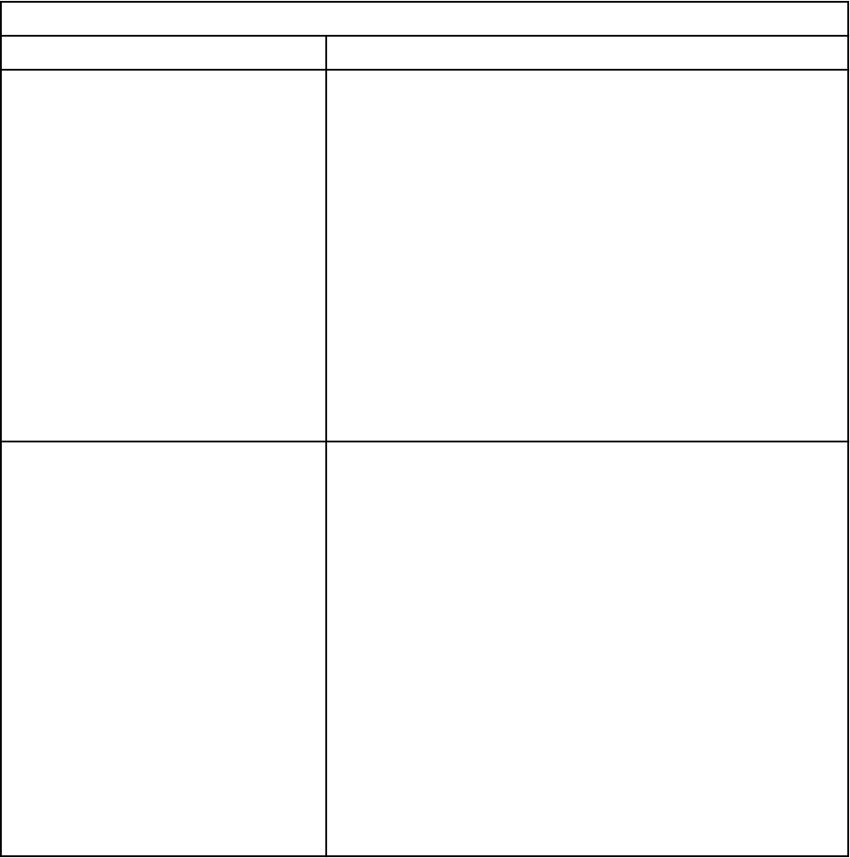
Table 4. Project templates
Project Template Description
Agile Requirements Sample Provides a sample agile component that contains the user
stories and requirements for a ctitious company. The following
artifact types are included in this sample:
• Feature
• Non-Functional
• Part
• Personal Collection
• Release Collection
• Simple Flow Diagram
• Wireframe
• Supporting Resource
• Term
• User Story Elaboration
Agile Requirements Template Provides artifact types, attributes, data types, and a project
folder structure to support the agile process. It includes
an artifact type and a document template for user story
elaboration. The following artifact types are included in this
template:
• Feature
• Non-Functional
• Part
• Personal Collection
• Release Collection
• Simple Flow Diagram
• Sketch
• Supporting Resource
• Term
• User Story Elaboration
Administering49
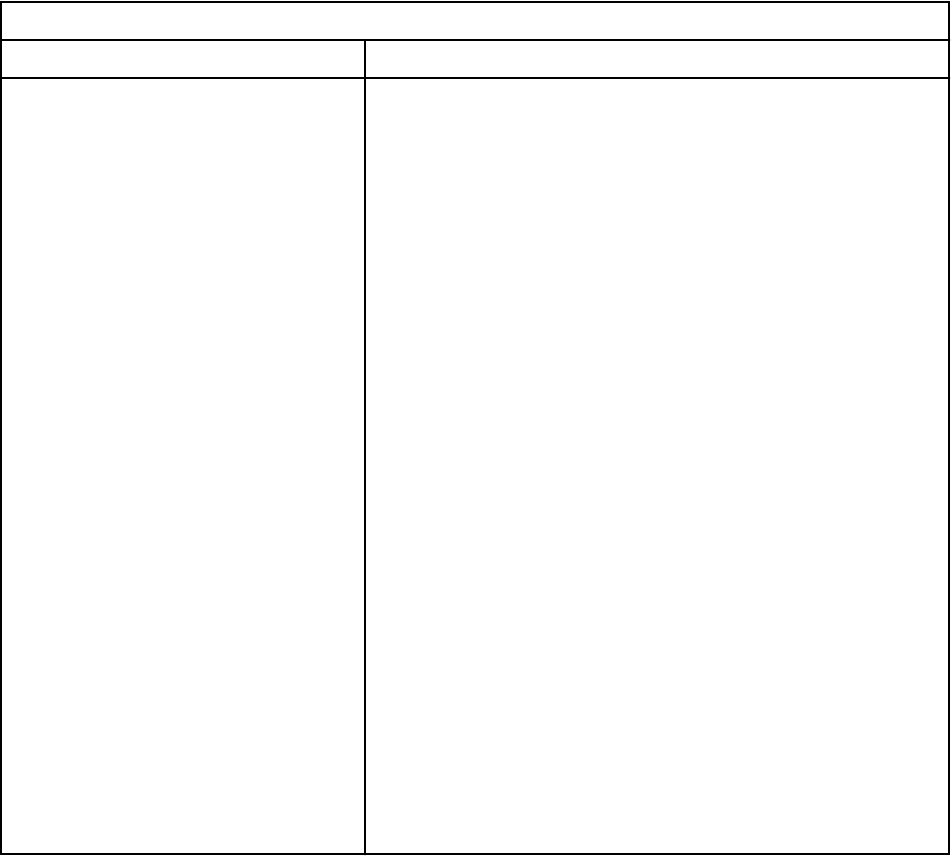
Table 4. Project templates (continued)
Project Template Description
JKE Banking Sample Provides a sample application that includes a full project
structure with folders and sample artifacts to support a
ctitious banking program. If you are a rst-time user, use
this option to look at sample artifacts and to see how artifacts
can be linked. The following artifact types are included in this
template:
• Actor
• Business Goal
• Business Process Diagram
• Business Rule
• Collection
• Feature
• Goal
• Graphical Artifact
• Heading
• Non Functional
• Process Guidance
• Requirement
• Supporting Resource
• Term
• Use Case Diagram
• Use Case Requirement
• Use Case Specication
• User Story Elaboration
• Vision
50
Engineering Requirements Management DOORS Next
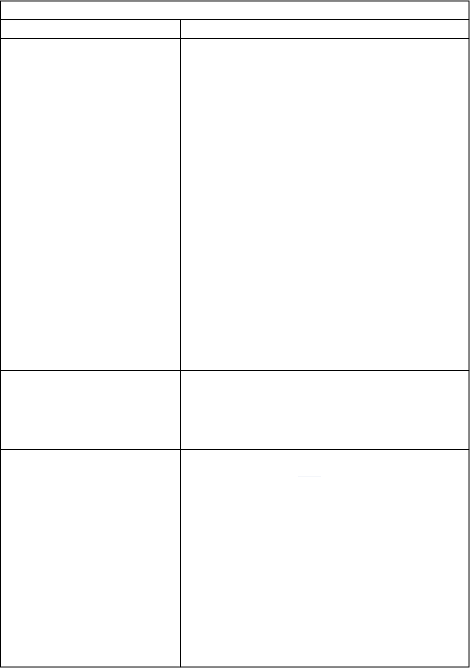
Table 4. Project templates (continued)
Project Template Description
Medical Devices Template Provides a structure to support medical device developers
in meeting FDA Design Control requirements. The following
artifact types are included in this template:
• Document - Module
• FMEA - Object
• Glossary Term
• Heading
• Information
• Reference - Module
• Risk
• Risk - Module
• Stakeholder Denition
• Stakeholder Requirement
• Stakeholder Requirements - Module
• System Function
• System Requirement
• System Requirements - Module
• Trade Study Document
• Trade Study Assessment Criterion
• Vision Document - Module
• Vision Statement
Requirement Template for Testers
Provides a structure to support testers. Includes a folder called
Testers. The following artifact types are included in this
template:
• Requirement
• Test Plan Collection
SAFe 4.0 Portfolio Component
Template
Provides a structure to support a project with Scaled Agile
Framework environment (SAFe ) artifact types, link types,
templates, folder structure, and views. The following artifact
types are included in this template:
• [SAFe] Lightweight Business Case
• [SAFe] Strategic Theme
• [SAFe] Value Stream
• Free-Form Diagram
• Heading
• Information
• Program Increment Collection
• Role
• Supporting Doc
• Term
Administering51
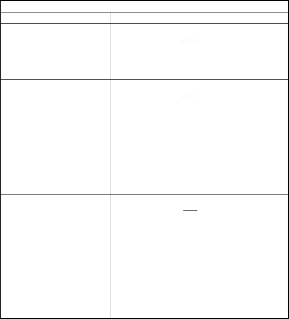
Table 4. Project templates (continued)
Project Template Description
SAFe 4.5 Essential Component
Template
Provides a structure to support a project with Scaled Agile
Framework environment (SAFe ) artifact types, link types,
templates, folder structure, and views. The following artifact
types are included in this template:
• Program
• Vision
SAFe 4.5 Portfolio Component
Template
Provides a structure to support a project with Scaled Agile
Framework environment (SAFe ) artifact types, link types,
templates, folder structure, and views. The following artifact
types are included in this template:
• Strategic Theme
• Value Stream, Program
• Vision, Solution Intent
• Solution Context
• Lean Business Case
• Lifecycle Scenario
• Scenario Act
• Scenario Scene
SAFe 4.5 Large Solution Component
Template
Provides a structure to support a project with Scaled Agile
Framework environment (SAFe ) artifact types, link types,
templates, folder structure, and views. The following artifact
types are included in this template:
• Value Stream
• Program
• Vision
• Solution Intent
• Solution Context
• Lean Business Case
• Lifecycle Scenario
• Scenario Act
• Scenario Scene
52 Engineering Requirements Management DOORS Next
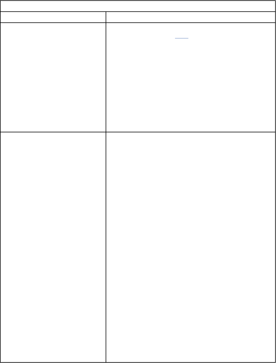
Table 4. Project templates (continued)
Project Template Description
SAFe 4.5 Full Component Template Provides a structure to support a project with Scaled Agile
Framework environment (SAFe ) artifact types, link types,
templates, folder structure, and views. The following artifact
types are included in this template:
• Strategic Theme
• Value Stream, Program
• Vision, Solution Intent
• Solution Context
• Lean Business Case
• Lifecycle Scenario
• Scenario Act
• Scenario Scene
System Requirements Sample Provides a sample application that includes a full project
structure with folders, modules, and sample artifacts to
support a ctitious program called Automated Meter Reader.
The following artifact types are included in this sample:
• Actor
• Diagrams and sketches
• Hardware Requirement
• Hardware Specication
• Hazard and Risk
• Hazard and Risk Register
• Heading
• Information
• Personal Collection
• Release Collection
• Requirements Specication
• Software Requirement
• Software Specication
• Stakeholder Requirement
• Stakeholder Specication
• System Requirement
• System Specication
• Term
• Use Case Module
• Vision Statement
• Vision Document
Administering
53

Table 4. Project templates (continued)
Project Template Description
System Requirements Template Provides a structure to support a systems engineering
component. The following artifact types are included in this
template:
• Actor
• Diagrams and sketches
• Hardware Requirement
• Hardware Specication
• Hazard and Risk
• Hazard and Risk Register
• Heading
• Information
• Personal Collection
• Release Collection
• Requirements Specication
• Software Requirement
• Software Specication
• Stakeholder Requirement
• Stakeholder Specication
• System Requirement
• System Specication
• Term
• Use Case Module
• Vision Statement
• Vision Document
54
Engineering Requirements Management DOORS Next

Table 4. Project templates (continued)
Project Template Description
Traditional Requirements Sample Provides a sample enterprise component that contains the
enterprise requirements, terms, and other artifacts for a
ctitious company. The following artifact types are included in
this sample:
• Actor
• Business Goal
• Business Process Diagram
• Business Rule
• Collection
• Feature
• Heading
• Non Functional
• Persona
• Process Guidance
• Storyboard
• Supporting Resource
• Term
• Use Case Diagram
• Use Case Requirement
• Use Case Specication
• User Story Elaboration
• Vision
Traditional Requirements Template
Provides a structure to support traditional requirements
projects. Artifact types include features, software
requirements, stakeholder requests, sketches, parts, use case
diagrams, and terms. The following artifact types are included
in this template:
• Feature
• Heading
• Information
• Personal Collection
• Release Collection
• Requirement Specication
• Software Requirement
• Stakeholder Request
• Term
Administering55

Table 4. Project templates (continued)
Project Template Description
Use Case Requirements Sample Provides a sample use case component that contains the use
cases, diagrams, and requirements for a ctitious company.
The following artifact types are included in this sample:
• Actor
• Feature
• Heading
• Information
• Personal Collection
• Process Diagram
• Release Collection
• Requirement Specication
• Sketch
• Stakeholder Request
• Supplementary
• Term
• Use Case
• Use Case Diagram
Use Case Requirements Template Provides a structure to support use-case-driven requirements
projects. Artifact types include features, use cases, business
process diagrams, supplementary requirements, stakeholder
requests, sketches, parts, use case diagrams, and terms. The
following artifact types are included in this template:
• Actor
• Feature
• Heading
• Information
• Personal Collection
• Process Diagram
• Release Collection
• Requirement Specication
• Sketch
• Stakeholder Request
• Supplementary
• Term
• Use Case
• Use Case Diagram
Scaled Agile Framework (SAFe) project templates
The Scaled Agile Framework (SAFe) methodology is an industry standard framework for helping
organizations scale agile and lean practices to an enterprise level. The framework denes roles, activities,
artifacts, and workflows that provide best practices and guidance for enterprises to use lean and agile
principles across the organization, which spans both business and engineering roles. This helps to deliver
value across agile portfolios that includes solutions, programs, and teams.
56
Engineering Requirements Management DOORS Next
Requirements management is a key aspect of the SAFe methodology that takes a systems view of
the features that are being delivered, capturing expected behavior, models, wireframes, and related
requirements to drive an iterative approach to feature delivery.
Note: SAFe 6.0 templates for IBM Engineering Lifecycle Management (ELM) are available on Jazz.net.
You can download the templates from SAFe 6.0 templates for IBM Engineering Lifecycle Management.
The available predened process templates are Full SAFe 6.0 and Essential SAFe 6.0. You can use
them to congure tooling environment for SAFe Portfolio, Large Solution, Portfolio, or Essential SAFe 6.0
conguration in ELM. For more information, see Say Hello to SAFe 6.0!.
Related information
Scaled Agile Framework (SAFe) 5.0 Essential process template
Scaled Agile Framework (SAFe) 5.0 Full process template
Scaled Agile Framework (SAFe) 5.0 Quality Management process templates
Scaled Agile Framework (SAFe) 5.0 Requirement Management process templates
Requirements management is a key aspect of the SAFe
®
methodology that takes a systems view of
the features that are being delivered, capturing expected behavior, models, wireframes, and related
requirements to drive an iterative approach to feature delivery.
This release provides two predened process templates that support Scaled Agile Framework (SAFe) to
help you capture expected behavior and related requirements across all the congurations:
• Full: Portfolio level and Large Solution level
• Essential: Program level and Team level
You can use each template to create a Requirement Management project area that includes the necessary
roles, artifact templates and categories, and dashboard for that conguration.
Requirement Management for Full SAFe 5.0
Use this SAFe template to establish a requirements management environment that contains the artifacts
that are required to support design, development and delivery of a Portfolio including multiple Large
Solutions, or Value Streams, orchestrating delivery of Features across Programs.
The SAFe artifacts that are included with this template are Portfolio Canvas, Value Stream Canvas, SWOT
Analysis, TOWS Options Matrix, Strategic Theme with Objectives and Key Results (OKR), Value Stream,
Program, Vision, Solution Intent, Solution Context, Lean Business Case, Lifecycle Scenario, Scenario Act,
and Scenario Scene. This environment might be associated with one or more Essential SAFe tooling
environments.
Requirement Management for Essential SAFe 5.0
Use this SAFe template to establish a requirements management environment that contains the artifacts
that are required to support design, development, and delivery of Program Features and Stories. The SAFe
artifacts that are included with this template are Program, Vision, and Solution Context. This environment
might be associated with a Portfolio, Large Solution, or Full SAFe tooling environment.
For more information, see IBM support for SAFe
.
Scaled Agile Framework (SAFe) 4.6 Requirements Management process templates
Requirements management is a key aspect of the SAFe
®
methodology that takes a systems view of
the features that are being delivered, capturing expected behavior, models, wireframes, and related
requirements to drive an iterative approach to feature delivery.
This release provides two predened process templates that support Scaled Agile Framework (SAFe) to
help you capture expected behavior and related requirements across all the congurations:
• Full: Portfolio level and Large Solution level
• Essential: Program level and Team level
Administering
57
You can use each template to create a Requirement Management project area that includes the necessary
roles, artifact templates and categories, and dashboard for that conguration.
Requirement Management for Full SAFe 4.6
Use this SAFe template to establish a requirements management environment that contains the artifacts
that are required to support design, development and delivery of a Portfolio including multiple Large
Solutions, or Value Streams, orchestrating delivery of Features across Programs. The SAFe artifacts that
are included in this template are Portfolio Canvas, Value Stream Canvas, Strategic Theme, Value Stream,
Program, Vision, Solution Intent, Solution Context, Lean Business Case, Lifecycle Scenario, Scenario Act,
and Scenario Scene. This environment might be associated with one or more Essential SAFe tooling
environments.
Requirement Management for Essential SAFe 4.6
Use this SAFe template to establish a requirements management environment that contains the artifacts
that are required to support design, development, and delivery of Program Features and Stories. The SAFe
artifacts that are included in this template are Program and Vision. This environment might be associated
with a Portfolio, Large Solution, or Full SAFe tooling environment.
For more information, see IBM support for SAFe
.
Creating artifact templates
You can create an artifact template from an existing artifact. Artifact templates offer an easy way to reuse
artifact content and related properties as a basis for new artifacts.
Before you begin
You must have project administrator permission to create an artifact template.
About this task
Artifact templates:
• Are tied to the artifact type and format of the artifact on which they are based.
• Include the artifact content, attributes, attribute values, and links.
• Do not include tags and comments.
• Can be used only to create new artifacts of the same type and format.
For information on creating templates from modules, see Creating module templates
.
Procedure
For a quick way to create a template from an open artifact, click the Create Artifact Template icon
in the toolbar, or perform the following steps.
To create an artifact template from the Administration page:
1. Open a project by using the web client and click the drop-down menu at the Administration icon
and select Manage Project Properties.
Note: If conguration management is enabled for your project, on the Administration menu, click
Manage Component Properties.
An administrative page opens.
2. Click the Templates tab.
3. In the Templates list, click Artifact Templates.
4. Click New Template.
5. In the Create Template window, specify the name and optional description for the template.
58
Engineering Requirements Management DOORS Next
6. In the Create template based on eld, click Browse to locate an artifact for the basis of the template.
7. In the Search for artifacts eld, enter a partial name for an artifact.
All artifacts that match the partial entry are displayed in the Select artifact list.
8. Select an artifact as the basis for the new template and click OK.
9. On the Create Template window, click Create. After the operation is complete, click Close.
What to do next
When you create a new artifact, you can base it on this artifact template. Lists of templates are organized
by artifact type and artifact format. When creating an artifact, you must select the artifact type to view all
templates associated with that type.
Note: You can view templates in the Template eld of the Create an artifact with attributes
dialog.
After you create an artifact from the template, the content of that artifact is independent of the template
and the original artifact that the template was based on. Any changes to the original artifact and its
template are not reflected in the new artifact.
Managing artifact templates
You can delete or edit artifact templates from the project administration Templates page. You can also
update the template with any changes in the artifact that the template is based on.
About this task
You must have project administrator permissions to delete or edit an artifact template.
Procedure
To delete or edit an artifact template using the web client:
1. Open a project, click the drop-down menu at the Administration icon
and select Manage
Project Properties.
Note: If conguration management is enabled for your project, on the Administration menu, click
Manage Component Properties.
A project administration page opens.
2. Click the Templates tab.
3. In the Templates list, click Artifact Templates.
4. Select a template in the list and click the drop-down menu at the Edit icon at the right end of the
entry and select Delete or Edit.
5. If you select Edit, the Manage Template window opens and you can do any of the following actions:
• Change the template name.
• Change the template description.
• Update the contents of the artifact template with any changes that have been made in the artifact
since it was used to create the template.
6. Click OK to complete the operation.
Creating module templates
You can create a module template from an existing module. Module templates offer an easy way to reuse
structure and content as a basis for new modules. When you create a module template, you have options
Administering
59

to create copies of the headings and other artifacts from the source module, or reuse and share the
source content in the new module.
Before you begin
You must have project administrator permissions to create templates.
About this task
In a module template, you can reuse the headings and other artifacts that are in the source module, or
you can copy (duplicate) them to create headings and other artifacts in the template.
When you create a module template, the content of the module is not saved in the template. If the
module that the template is based on is changed, the next artifact that is created based on that template
contains the changes.
When you create an artifact template, the content of the artifact is saved in the template. If the artifact
that the template is based on is changed, the next artifact that is created based on that template will not
contain the changes.
Procedure
1. Open a project in the web client, click the Admin menu (
), and click Manage Project
Properties.
2. Click the Templates tab.
3. In the Templates list, click Artifact Templates.
4. Click New Template.
The Create Template window opens.
5. Specify the name and optional description for the template.
6. Next to the Create template based on eld, click Browse to locate a module for the basis of the
template.
7. In the Search for artifacts eld, enter a partial name or ID for a module.
All artifacts that match the partial entry or ID are displayed in the Select artifact list.
8. Select a module as the basis for the new template and click OK.
9. In the Create Template window, in the Duplication policy eld, select one of the following options to
copy or reuse content in the new module:
• Duplicate all artifacts: Creates headings and other artifacts. These are copies of the headings
and artifacts that are in the source module.
• Duplicate no artifacts: Reuses all existing headings and other artifacts. The only new artifact is
the module that a user creates from the template.
• Duplicate all heading artifacts: Creates headings that are copies of the existing ones, and reuses
other existing artifacts.
• Re-use all heading artifacts: Reuses existing headings. Creates copies of all other artifacts.
• Duplicate all artifacts specied by a view, re-use all other artifacts: Creates headings and
other artifacts that are copies of existing ones if they match the criteria of lters in a saved view.
All other headings and artifacts are reused. If you use this option, a menu is displayed from which
you can select the view to use.
10. Click Create.
What to do next
For options to manage the template, from the Project Properties page, click Template. You can select
commands from the menu
to the right of any module template in Artifact Templates list.
60
Engineering Requirements Management DOORS Next

• To edit the template, click Edit. In the Manage Template window, you can change the template name,
description, or duplication policy.
• To modify the content of the module that is the source for the template, click Edit Content. The source
module opens. Any changes that you make to reused content affects all instances of that content in the
project. Any changes to duplicated content is reflected in any modules that are created subsequently
from the template.
• To remove the template from the project, click Delete.
Related tasks
“Reusing artifacts in modules” on page 146
Artifacts can be reused in multiple contexts in a project, including collections and modules. You can edit
artifact content in a module or by opening the artifact outside the module. Content changes are reflected
in all contexts. Links, tags, and comments are specic to the context in which they are created. If you
want links, tags, and comments to reflect in all contexts, edit the artifact outside the module as a base
artifact.
Importing properties from another Requirements Management (RM) project
or component
You can import the properties from one Requirements Management (RM) project or component into
another project or component. When conguration management is not enabled, you import properties
from project to project. When conguration management is enabled, you import properties from
component to component. The properties that are imported by default include all the artifact types,
attribute data types, link types, and link constraints that are dened in the project or component.
Before you begin
To import properties, you must have both the administrator role and permissions:
• In the project area settings, you must be listed in the Administrators section.
• In the project area settings, you must be listed in the Members section and have the Administrator role
assigned.
About this task
To import properties, you open a project or component and then import the properties from another
project or component into the current one.
Note: Only the default properties such as artifact types, artifact attributes, attribute data types, link types,
and link constraints that are dened in the project or component are imported.
Note: If an artifact type is associated with the workflow, the association is not preserved in the current
component after the import.
Procedure
1. In RM, open the project into which you want to import project properties.
2. From the Administration menu
, click Manage Project Properties or Manage Component
Properties.
3. In the upper right of the screen, click Import.
4. In the Import Project Properties window, click Browse and select the project from which you want to
import the type system.
Important: If you import a type system into two different streams in a component, the type system
is duplicated when changes are delivered between these streams. The application does not recognize
that the type system is same and creates a duplicate type system. To avoid this problem, use a special
stream in each component for the type systems in that component. Then, merge any type system
Administering
61
changes from that special stream to all of the development streams in that component. For best
practices and additional information about the type systems, see the following articles:
• Maintaining the Rational DOORS Next Generation type system in a conguration-management-
enabled environment. Part 1: Manual procedures
• Maintaining the Rational DOORS Next Generation type system in a conguration-management-
enabled environment. Part 2: Automation
• Maintaining the Rational DOORS Next Generation type system in a conguration-management-
enabled environment. Part 3: Automation tool deep dive
5. Click OK and then click Next.
6. Review the property changes and click Finish.
Note: If both projects have properties with the same name, the properties are merged in the current
project.
Results
When the import process is complete, refresh the project to see the new properties.
Related tasks
“Copying artifacts between projects” on page 62
You can copy artifacts between projects in the Requirements Management (RM) application.
“Managing project or component properties in requirements projects” on page 28
Each project template contains predened artifact types. You can also create customized artifact types,
artifact attributes, and artifact data types for a project or component. Those artifacts types can then
be used by team members to create project or component requirements or related artifacts, such as
customized collections.
“Creating link types for requirements projects” on page 36
Copying artifacts between projects
You can copy artifacts between projects in the Requirements Management (RM) application.
Before you begin
Before you copy artifacts between projects, verify the following items:
• You are logged in as a user with JazzAdmins or JazzProjectAdmins repository permissions. You are
assigned the Administrator role.
• Both projects have the same setting for conguration management: either both are enabled or both are
disabled.
• If you use global congurations, ensure that you are using a global conguration that has contributions
from both projects.
• The target project contains the same artifact types, artifact attributes, and attribute data types as the
artifacts in the source project.
Important: To copy artifacts, the target project must contain the same artifact types as the source
artifacts that are being copied, including URIs or artifact names. Otherwise, no artifacts are copied.
If the target project does not contain the same artifact attributes or attribute data types, the source
artifacts are copied, but the attribute values are not.
Note: When copying and pasting modules or collections across components or projects, the shared and
private views of the module or collection are copied. If the target component or project contains views
that are shared across all modules or collections of the same type or shared across all modules or
collections. And have the same name as the reused views in the copied module or collection, the copied
views are not resolved. Instead, multiple views with the same name exist after the paste operation is
run and must be resolved manually.
In projects that are enabled for conguration management, conrm whether you want to copy artifacts
between components or clone them. To help you decide, see Cloning artifacts between components.
62
Engineering Requirements Management DOORS Next

About this task
You can copy most artifacts between projects, including collections, modules, embedded artifacts, and
diagrams. However, the copy function does not support copying the following items:
• Graphical artifacts that require a browser plug-in, such as sketches, storyboards, screen flows, and
business and use case diagrams
• Tags
• Comments
Note: Copying and pasting of artifacts between streams in the same component is not allowed. A more
appropriate way to move data from one stream to another is to deliver the change set(s) that contain that
data. This ensures you get the same concept in both places and that the version history is correct. At that
point, if you want to copy the artifact somewhere else within the stream you may do so. Alternatively, you
can also copy or paste within your current stream and then deliver the change set.
Procedure
1. Verify that the target project contains the same artifact types, artifact attributes, and attribute data
types as the artifacts that you plan to copy. To view the project properties, complete these steps:
a) Open the target project, click the drop-down menu for the Administration icon and select
Manage Project Properties.
Note: If conguration management is enabled for your project, on the Administration menu, click
Manage Component Properties.
b) Click the Artifact Types tab, the Artifact Attributes tab, and the Attribute Data Types tab.
Tip: If your target project does not contain the necessary project properties, you can import the
artifact type system from the source project. For information about importing the type system from
another project, see Importing project properties
.
Important: To copy artifacts between projects, the value in the URI eld for artifact types or the
artifact names in both the source and target projects must match. The URI value or name must also
match between source and target artifact attributes and between artifact data types.
The value in the URI elds must be in this format:
https://hostname/word1/word2
For example, if you work for a company that is called Big-Bank, and you want to copy artifacts of
type Actor from a source project, you might put the following value in the Actor artifact type URI
eld:
https://www.big-bank.com/types/actor
If you copy the type system from the source project to the target project, you ensure that the value
in the source URI eld gets propagated to the target URI eld in the target project.
2. In the target project, right-click the folder into which to copy the artifacts and click Copy from a
project.
3. In the wizard that opens, follow the prompts to select the project, and the artifacts or modules to copy.
When you select modules, all the views from those modules will be copied from the source to the
target.
Tip: You can also view the collections that need to be copied or cloned to the target project by clicking
the Add Collection button.
4. If the servers are hosted by the same domain server or different domain servers, you can also use the
Paste as Link option between components on different servers.
a) Copy the source artifact.
b) Select the target artifact and click Paste as Link.
Administering
63
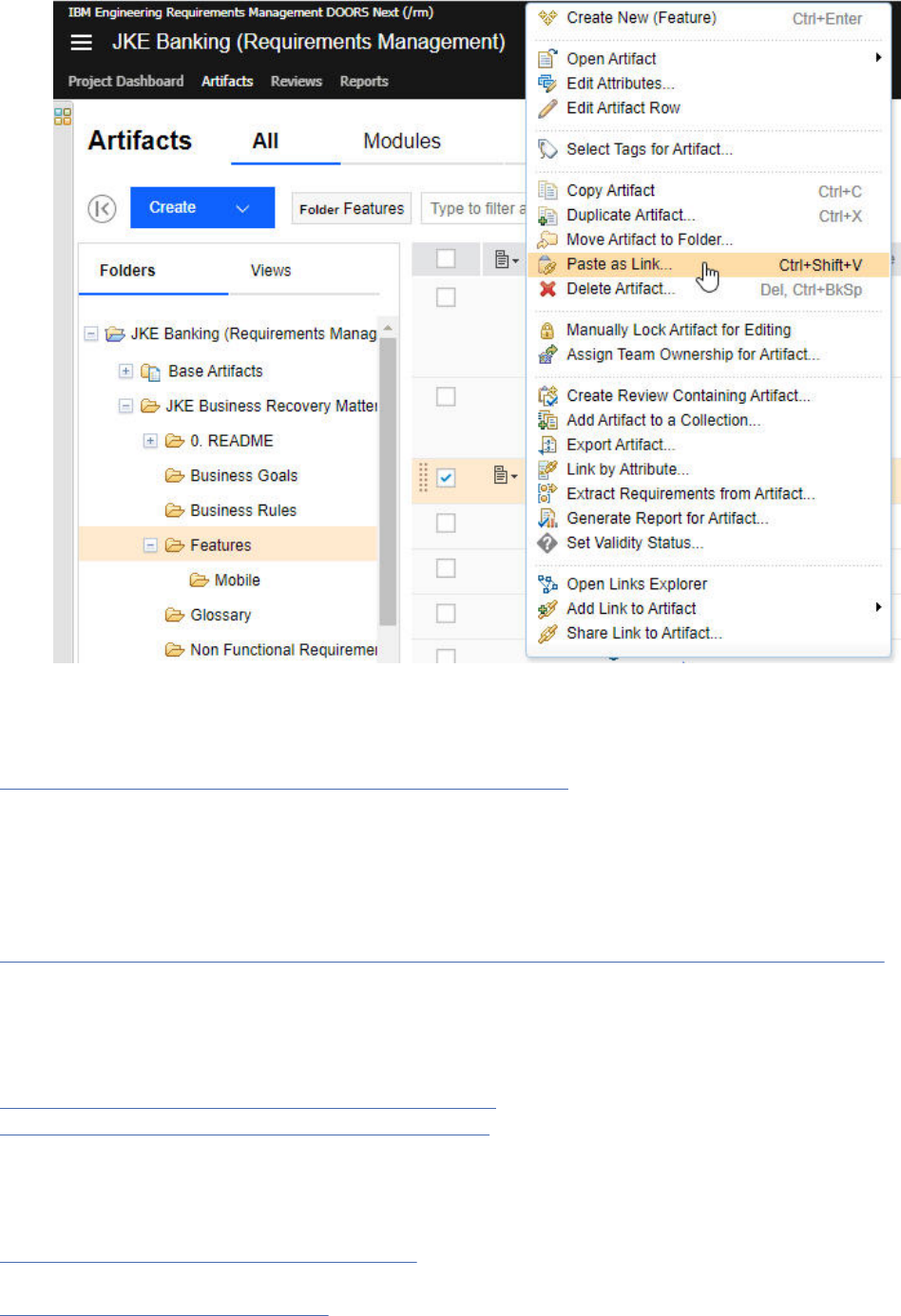
c) In the Create Link window, select the link type.
d) Click OK and a Link has been created message will be displayed.
Related concepts
“Linking artifacts in different projects or components” on page 206
A link represents a relationship between artifacts. Link relationships are directional and indicated by an
icon. Link types help you dene and customize the linking relationships between artifacts. Each link type
has an Outgoing and an Incoming role. You can create links between artifacts in different projects on
the same server or on different servers. If you enable conguration management, you can create links
between artifacts in different components.
Related tasks
“Importing properties from another Requirements Management (RM) project or component” on page 61
You can import the properties from one Requirements Management (RM) project or component into
another project or component. When conguration management is not enabled, you import properties
from project to project. When conguration management is enabled, you import properties from
component to component. The properties that are imported by default include all the artifact types,
attribute data types, link types, and link constraints that are dened in the project or component.
“Creating link types for requirements projects” on page 36
“Creating attributes for requirement artifacts” on page 31
When you create requirements in a project, you can create custom artifact attributes to use in custom
artifact types. Custom attributes are based on predened and custom artifact data types, which dene the
properties of the attribute, such as textual entries, integers, date, time, or team member names.
Related reference
“Link types in requirements projects” on page 37
Related information
Cloning artifacts between components
64
Engineering Requirements Management DOORS Next
Deleting artifacts from the repository
You can permanently delete artifacts from a Requirements Management (RM) application repository by
using the Delete from Repository feature. Use this procedure to delete sensitive data or to resolve a data
spill.
Before you begin
Warning: This feature is intended only as a mechanism to carefully and permanently delete
sensitive data from a repository and should not be used for reducing database size or deleting
general resources.
To enable this feature, you must meet the following conditions:
• Use version 6.0.2 or later (for 6.x versions).
• Use version 7.0.2 or later (for 7.x versions).
• Have the JazzAdmins permission.
• Set the data.purge.enabled advanced property to true.
• Set the dump.dir advanced property to an absolute le system path.
• Have access to the RM application server le system.
Important:
• In previous 6.x versions, data was stored by using the Jazz Foundation Service (JFS) APIs only and was
referred to as JFS data. The JFS data was deleted by using the delete feature. However, starting with the
7.0 version, most of the data is created and managed by using the 0.6 API storage mechanism and is
referred to as 0.6 data. The deletion process and behavior for 0.6 data is different as compared to JFS
data. When you use the delete feature, the 0.6 data is redacted or edited in-place while the JFS data is
deleted. For more information, see Difference between JFS data and 0.6 data.
• The Delete Resource Data wizard is no longer available in the application under the Delete from
Repository tab. You must use a repotools command to delete the data due to restrictions on the
API that manages and updates 0.6 data. DOORS Next server must not be online when you run this
command. For more information, see Running the purge repotools command.
About this task
Typically, when you delete an artifact from an RM project, the artifact is removed from the project and is
archived in the repository. However, if you have sensitive data that you want to permanently delete from
the repository, you can use the Delete from Repository feature to accomplish this task.
The Delete from Repository process for JFS data and 0.6 data includes three main steps.
1. Identify the artifacts for deletion. You can use the Export Data Dump option to export resources to the
le system where you can analyze them for sensitive data.
For 0.6 data, all the data for the
selected component or project is exported. For JFS data, you might choose to limit it to only a subset
of the storage areas most likely to contain sensitive data or export the content of all storage areas. You
can search through these exported les to identify which resources contain sensitive information. The
search result creates a list of URLs for the versions that require deletion.
Note: A project area is selected for export, by default.
2. Create a list of version URLs for the system to delete JFS data. For 0.6 data, append a set of
serialized-item-handles to redact the 0.6 data. This list must be stored in a plain text le and have only
one URL per line. For more information, see Running the purge repotools command.
3. After the system deletes or redacts the specied URLs and their history, you verify that all the sensitive
data was purged from the repository. To do this, you export the data to the le system again, repeat the
search for sensitive data, and then delete all the les that were exported.
Administering
65
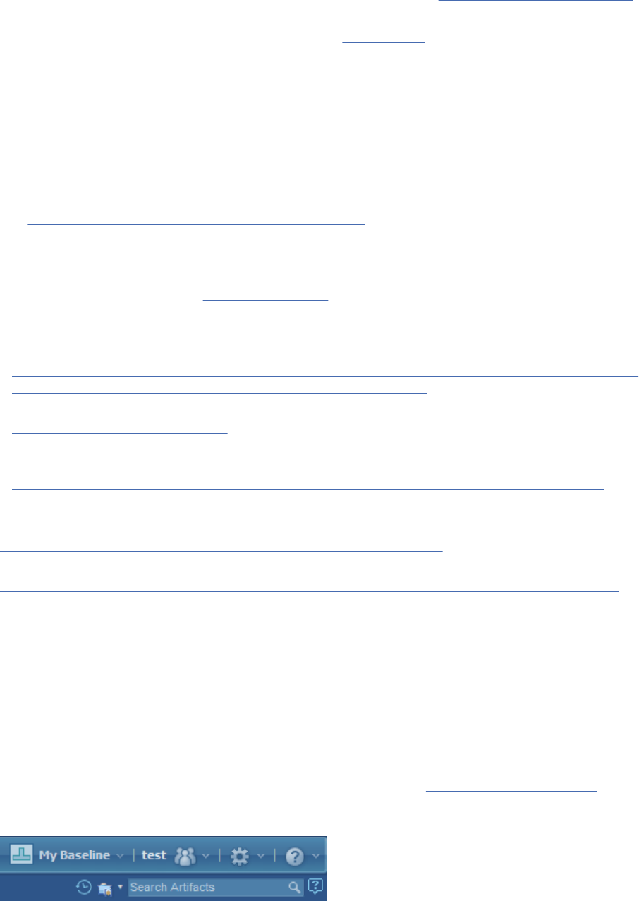
For more information and instructions for deleting sensitive data, see Delete from Repository feature on
Jazz.net.
Note: Content on Jazz.net is governed by the Jazz.net Terms of Use and is provided as-is without
warranties of any kind.
Administering link validity in ELM applications
As a conguration lead or application administrator, you decide whether to show or hide link validity
and validity summary information for your project area. These tasks are common to the IBM Engineering
Lifecycle Management (ELM) applications that use link validity.
About this task
See Enabling link validity in AM, QM, and RM project areas to read about showing and hiding link validity
information in your project area.
Quality Management application: If your project area does not have conguration management
capabilities enabled, you cannot use this feature. Project areas not enabled for congurations use suspect
link traceability. For details, see Suspect traceability.
To learn more about link validity, see the related links.
To learn more about conguration management:
• https://www.ibm.com/docs/en/elms/elm/7.0.2?topic=SSYMRC_7.0.2/com.ibm.jazz.vvc.doc/topics/
c_cm_assess.htmlGetting started with conguration management: Learn about conguration
management and local congurations.
• Global Conguration Management: Learn how global congurations provide a view of all the artifacts
that are contained in a set of related local congurations. Global congurations are managed by the
Global Conguration Management (GCM) application.
• Introduction to conguration management with IBM Engineering Lifecycle Management (ELM): YouTube
playlist on the Software Education channel.
Related tasks
Granting access to link validity data for building Report Builder reports
Related information
YouTube video: Achieving consistency across linked data by using link validity (Software Education
channel)
Baselines in requirements projects
In a requirements project, a baseline captures the entire project at a moment in time. For example, you
might create a project baseline before you create an artifact review to ensure that the artifacts do not
change during the review. A baseline includes all artifacts, folder trees, and public tags.
To create baselines, you must have the appropriate permissions. By default, the Conguration
Administrator role has permission to create baselines, but the Administrator and Author roles do not.
Important: To work with streams and change sets in addition to baselines, you must enable conguration
management capabilities for the project. For more information, see Conguration Management.
You can create a baseline from the Current Conguration menu. When you are working in a baseline, the
name of the baseline appears at the top of the menu, as shown in this example.
Note: When you create a new baseline, it does not appear in the list of baselines until you refresh the
application.
66
Engineering Requirements Management DOORS Next

After you create a project baseline,baseline you can perform the following tasks:
• View the content of the project as it existed when the baseline was created
• Search for and display other baselines
• Compare the contents of two baselines
Restriction: You cannot modify a project baseline or the version of an artifact that is part of a baseline.
However, you can modify the most recent version of that artifact.
To compare two baselines, you must rst switch to an initial baseline. After the name of the rst baseline
appears at the top of the Current Conguration menu, click Compare Congurations, click Baseline in
the Conguration Context window, and search for and select the second baseline. A wizard opens in
which you can compare the two baselines.
Related concepts
“Modules in the Requirements Management application” on page 129
A module is a structured document that is composed of multiple artifacts. You can create structure in a
module by modifying the order and hierarchy of its artifacts. The artifacts that are created for modules
are stored as module content in a folder. Base artifacts can be used to manage the module artifacts
independent of the module.
Related tasks
“Comparing collections” on page 177
You can use the Requirements Management application to compare two different collections.
Related information
Permissions
Enabling Electronic signatures for a baseline
For compliance purposes, your organization might require you to validate and sign a baseline. You can
congure a project to require electronic signatures on baselines. This helps for audit purposes.
About this task
An administrator can set project-level settings for electronic signatures. The administrator has permission
to:
• Display text that explains the signicance of signing.
• Determine if users must provide a comment when signing.
• Determine if users must select a reason for signing.
• Use the Add option, to enter a list of reasons for signing. An user can select an option from the displayed
list.
Procedure
1. On the Administration menu, click Manage Project Areas page.
2. On the Active Project Areas page, click your project.
3. Under Requirements, click Electronic Signature.
4. In the text box, provide an explanation for why the signature is required for the project.
5. If team members must add a comment when they electronically sign the baseline, select the Require
a comment check box.
6. If team members must provide a reason for signing the baseline, select the Require the user to select
a reason for signing check box.
7. Click Add Reason, and enter a new reason to add to the Value list. You can add as many reasons as the
project requires and then use the Move Up and Move Down controls to change the list order.
Related tasks
Signing a baseline electronically
Administering
67

If your project or organization requires validation of baselines you can add an electronic signature to
validate and sign it.
Administering components in the RM application
In projects that are enabled for conguration management, as a conguration lead, you complete the
tasks that are related to managing components for your project.
Before you begin
• An RM project administrator must enable conguration management
for the project.
• You must be assigned the Conguration Lead role or have permission to manage components. On the
Permissions page in the application administration section, see the Conguration Management group
for the permissions related to managing components. Assign permissions based on the tasks that you
must complete.
About this task
In addition to the tasks listed below, you can dene team areas to control artifact creation and
modication for specic components: see the Save Artifact and Save Link permission groups on the
Permissions page in the application administration. You might do this to maintain strict control over
changes to an artifact type's denition and the denitions of the artifact's attributes. For example, you
might give Authors specic permissions for Components A, B, and C in a project:
• Authors can create user requirements in Component A
• Authors cannot create system requirements in Component B, but they can modify the public tags and
the content of system requirements
• Authors can modify actors in Component C
For all other permissions, the settings apply to all the components in a project; you can't apply them to
specic components.
Related concepts
Team areas
Related tasks
Administering components and congurations in applications
Creating a team area
Related information
Cloning RM artifacts between components
Components
Components represent a collection of versioned artifacts within a project area. For example, instead of
working with all the artifacts from the project in one stream (for example, that represents a physical piece
called a Handheld Meter Reader), you can use a component to represent a smaller collection of artifacts
(for example, to represent a smaller physical piece such as a Sensor in the handheld meter reader).
You can split a project into multiple pieces called components. Each component is like a building block
that represents a physical or logical part of your project. Components make it easier to reuse and work
with parts of a project. After you plan and create components, organize project artifacts into them based
on your project needs, instead of working with all the artifacts in one collection (conguration).
Before version 6.0.3, the project area was the top-level container for artifacts. You couldn’t split a project
into smaller pieces. Each conguration (stream or baseline) in the project contained one version of each
artifact in the project. If you wanted smaller collections of project artifacts, you had to create projects to
correspond with each grouping, which had much administrative overhead.
Starting in version 6.0.3, the ability to split a project into ner-grained components gives you these
benets:
68
Engineering Requirements Management DOORS Next
• It’s easier to create versions and variants of a product or system by reusing its parts.
You can quickly respond to market demands or changing regulations in different geographies.
• Teams can work independently on different components on different schedules.
For each IBM Engineering Lifecycle Management (ELM) application, carefully plan which components
to create, to ensure flexibility in assembling products and their variants. If you don’t plan, you will
encounter problems when you assemble the components into global conguration hierarchies that
represent products and their variants.
See the related topics for details, benets of using components, and examples.
Related concepts
GCM application: Creating the global conguration hierarchy
Related tasks
QM application: Administering components
RM application: Administering components
RM application: Cloning artifacts between components
Related information
GCM application: Creating a context to establish a work context
Dening your component strategy (Jazz.net article)
Organizing the components for your RM project
You can divide the artifacts in a project among multiple pieces called components. Each component is
like a building block that represents a physical or logical part of your project. Components are smaller
collections of artifacts that can be reused easily or delivered on independent schedules or to other teams.
Before you begin
• Ensure that you are familiar with components, project areas, congurations, baselines, and streams.
• Ensure that you are familiar with global congurations and personal streams (if your organization uses
them).
About this task
Although IBM Engineering Lifecycle Management (ELM) applications have ways of grouping artifacts
into smaller collections, such as Requirements Management (RM) modules and folders and Quality
Management (QM) test suites and test plans, you can’t easily mix and match them, reuse them, or deliver
them independently.
For example, managing congurations requires more attention if Team1 wants to work with Stakeholder
Requirements Baseline 1 and Functional Requirements Baseline 1, but Team2 wants to work with
Stakeholder Requirements Baseline 2 and Functional Requirements Baseline 1.
Now you can divide the different requirement types into separate components so that you can mix and
match them, and deliver them independently.
Consider using separate components for sets of artifacts when you’re in these situations:
• The collection of artifacts is intended for reuse in more than one larger assembly: more than one
product or product variant, or in more than one place in a complex product or system.
Examples: an engine control unit that is used in both the 2019 and 2020 models of a car; a screen used
for a car’s navigation system and its infotainment system.
• The collection of artifacts is delivered to another party as a separate delivery.
Examples: delivering an updated radio component to the team working on the luxury model of a car;
delivering a radio component to a third-party vendor so they can add proprietary satellite technology.
• The collection of artifacts is delivered by a separate team, or on a different cadence.
Administering
69

• The collection of artifacts has a separate delivery cycle (such as different test stages or approval
cycles) .
For each ELM application, carefully plan which components to create to ensure flexibility in assembling
products and their variants. If you don’t plan, you will encounter problems when you assemble the
components into hierarchies that represent products and their variants.
This topic follows the example of a car, which includes both physical pieces and software including an
engine, sunroof, infotainment system, brakes, and so on.
Components are smaller collections of artifacts
Before version 6.0.3, the project area was the container for artifacts. You couldn’t divide a project into
smaller pieces. Each conguration (stream or baseline) in the project contained one version of each
artifact in the project. Continuing with the car example:
• Each conguration in an RM Car project contained a version of all the stakeholder, safety, performance,
and environmental compliance requirements
• Each conguration in a QM Car project contained a version of all the safety, performance, and
environmental compliance tests
And so on.
If you wanted smaller collections of project artifacts, you had to create projects to correspond with each
collection, which had much administrative overhead.
Starting in version 6.0.3, a component becomes the container for artifacts. The ability to divide a project
into components gives you these benets:
• It’s easier to create versions and variants of a product or system by reusing its parts. You can quickly
respond to market demands or changing regulations in different geographies.
Example: While developing a luxury car with seat heaters and all-wheel drive that can withstand a harsh
climate, you can quickly respond to a market shift that demands a simpler, less expensive car with
fewer automated systems and sensors, and a different combination of existing parts.
• Teams can work independently on different components on different schedules. They can develop and
deliver new features or xes without affecting other teams working on other components.
Example: Replace a non-IoT fuel sensor with one that sends IoT data on fuel consumption back to
engineers. High consumption rates might indicate a problem that must be xed; engineers can then
develop and deliver the x to reduce overall fuel consumption. The teams working on other parts of the
car (infotainment, sunroof, and so on) are not interrupted and forced to update the stream (version of
the car) they are working in.
Team members with administrative roles dene and create components
In ELM applications (RM, QM, Change and Conguration Management (CCM)), administrators create
components. In the GCM application, a conguration lead typically creates components. On the
Permissions page in the application administration section, see the Conguration Management group
for the permissions related to managing components and congurations, and assign those permissions
based on your project needs.
Use components to organize the artifacts in your project
After you create a project in the GCM and ELM applications, follow these high-level steps to use
components to organize the logical and physical pieces of your project.
Procedure
1. Design and create components
.
70
Engineering Requirements Management DOORS Next
a) Plan the components your project needs by thinking about the building blocks that make up your
product or system. You must plan them so that components do not share artifacts, or, overlap.
You’ll see an example later in this topic.
b) Organize any existing artifacts into the new components. In the RM and QM applications, this action
is called cloning, and is described later in this topic. If you clone shared artifacts into separate
components to avoid overlap, remember that in the RM application, you can link between artifacts
in different components.
c) For each component, create the congurations (streams and baselines) that teams need to do their
work. Each conguration of the component contains one version of each artifact in that component.
2. Assemble the relevant congurations of components to build the product or variant that you need.
Typically, a GCM conguration lead does this step.
a) Create the global congurations for the project.
b) Add the appropriate local congurations of components to the global congurations, to build the
hierarchy of congurations components for the project in the GCM application
Related concepts
Components
Components represent a collection of versioned artifacts within a project area. For example, instead of
working with all the artifacts from the project in one stream (for example, that represents a physical piece
called a Handheld Meter Reader), you can use a component to represent a smaller collection of artifacts
(for example, to represent a smaller physical piece such as a Sensor in the handheld meter reader).
Related tasks
Administering requirement components
In projects that are enabled for conguration management, as a conguration lead, you complete the
tasks that are related to managing components for your project.
“Cloning requirement artifacts” on page 250
Reorganize how artifacts are grouped in your project area by cloning them from one component into
another. When you clone an artifact, a new version is added to the stream of the component that you work
in.
Related information
Dening your component strategy (Jazz.net article)
Creating the global conguration hierarchy
1. Design and create components
About this task
Consider the building blocks that your project needs. For example, in an RM project for a Car, you might
have several types of requirements: stakeholder, safety, performance, environmental compliance. Each of
these types might be in their own module. You might decide to create a component that corresponds with
each module.
You can always create more components later if you need more building blocks, and reorganize the
artifacts again by cloning them into the new components.
When you clone artifacts from one component to another, to prevent team members from using the
incorrect versions of artifacts, consider archiving the component you clone from.
1a. Plan components so they don't contain the same artifacts
About this task
Each project artifact can be in only one component. When two components contain any version of the
same artifact, they overlap. You cannot add congurations of those components to the same global
conguration, and this might prevent you from building the version or variant that you need.
Administering
71
Consider a requirements project in which you’ve created ner-grained components and organized the
requirements from the initial project so that the new components contain the following artifact versions:
• Component A: requirement1-v1, requirement2–v1, requirement3–v1
• Component B: requirement1-v2, requirement4–v1, requirement5–v1
• Component C: requirement5-v2, requirement6–v1
• Component D: requirement1-v3, requirement7–v1
• Component D overlaps with A (both have versions of requirement1)
The following components overlap:
• Component A overlaps with B and D (all have versions of requirement1)
• Component B overlaps with A and C (B and A contain versions of requirement1; B and C contain
versions of requirement 5)
• Component C overlaps with B (both have versions for requirement5)
Note: Just because component A overlaps with B, and B overlaps with C, does not imply that A overlaps
with C.
Using the car example, you might have different categories of requirement: safety, performance,
stakeholder, and environmental compliance, but some requirements belong to multiple categories:
“Airbags must nish deploying within 0.025 seconds” might be considered both a safety and performance
requirement. To avoid overlap you must add it (by cloning it) to only one component.
You can’t add congurations of overlapping components to the same global conguration, so it is difcult
to build versions and variants of a product. Reconsider either the components you’ve dened or how
you’ve assigned artifacts to each component.
Preventing the overlap. You might organize the artifacts this way instead:
• Add requirement1 to component D only
• Add requirement5 to component C only
The components now contain these artifacts:
• Component A: requirement2–v1, requirement3–v1
• Component B: requirement4–v1
• Component C: requirement5-v2, requirement6–v1
• Component D: requirement1-v3, requirement7–v1
If you later decide that requirement1 should be in component A, you can clone it into that component, but
you’ll have to x the new overlap between A and D. Here’s how:
1. Create another component named E.
2. Clone requirement7 from component D to component E.
3. Archive component D so that its artifacts are no longer visible to team members.
Your components now have these artifacts:
Remember: When you clone an artifact, it creates a new version of it in the stream you clone into.
• Component A: requirement1-v4 (cloned requirement1-v3 from Component D), requirement2–v1,
requirement3–v1
• Component B: requirement4–v1
• Component C: requirement5-v2, requirement6–v1
• New: Component E: requirement7–v2 (cloned requirement7-v1 from component D)
• Archived: Component D: requirement1-v4, requirement7–v1 (archived to remove the overlap with
Component A)
72
Engineering Requirements Management DOORS Next
Even though these are general guidelines, RM and QM have a few differences to consider when you
organize your artifacts into components as described in the next step.
1b. Organize existing artifacts and link to shared artifacts across components
About this task
You can create links between artifacts in different requirement components. For example, if two modules
share a requirement, you can clone the shared requirement into its own component to prevent overlap,
but still link that artifact to its related artifacts that are in other components.
Continuing with the car example, assume an initial project-level component in an RM project named Car,
which has the following artifacts:
• Module A: includes requirements R1, R2, and R-shared
• Module B: includes requirements R3, R4, and R-shared
You decide to create components to correspond with each module. If the global conguration that
represents a future version or variant of the car might need congurations of both modules, consider
cloning R-shared into its own component; otherwise, you won’t be able to add a conguration of Module A
and Module B to the same global conguration. The following steps elaborate on this example.
Procedure
1. In the RM Car project, a conguration lead denes ner-grained components for this project: Safety,
Performance, and Environmental. Each component contains an empty initial stream.
2. In the GCM application, a conguration lead creates a Car project. He then creates ner-grained
components such as Car2020, Engine, Infotainment System, Sunroof, and so on. Each component
contains an empty initial stream.
The team is currently building a product named “Car 2020”. The GCM conguration lead completes
these steps:
a) Open the Car 2020 initial stream.
b) Build the conguration hierarchy for the Car 2020 variant: He adds the initial stream of each of the
Safety, Performance, and Environmental components from RM.
3. An RM conguration lead reorganizes the artifacts in the RM Car project. He starts by cloning Module A
from the Car project-level component to the new Safety component.
a) He clones R1 and R2 into the initial stream of the Safety component.
b) He clones R-shared into the Environmental component, to prevent overlap between the Safety and
Performance requirements.
At this point, the following components overlap:
• Project-level component and the Safety component
• Project-level component and the Environmental component
The GCM conguration lead cannot add congurations of the overlapped components to the Car
2020 global conguration.
4. The RM conguration lead continues to reorganize artifacts by cloning Module B from the Car
component to the Performance component.
a) He clones R3 and R4 into the initial stream of the Performance component.
5. He creates the links from the R-shared artifact in the Environment component to its related artifacts in
the other components.
Administering
73

Results
At this point, the project-level component overlaps with the new Safety, Performance, and Environmental
components. The GCM conguration lead cannot construct the Car2020 stream to contain congurations
from the project-level component and any of the Safety, Performance, or Environmental components.
To remove this restriction, the RM conguration lead should clone all the artifacts from the project-level
component into ner-grained components, and then optionally archive the project-level component to
prevent team members from accessing the wrong versions.
1c. Create the congurations (streams and baselines)
About this task
After any existing artifacts are organized into components, the RM conguration lead can create the local
streams and baselines that teams need to work on the correct versions of the artifacts. For teams to get
a holistic view of all the artifacts in a project, and to see and create links between artifacts in other ELM
applications, they must work in a global conguration context.
2. Building the global conguration hierarchy
About this task
After components and congurations are created, and the artifacts are organized into the correct
components, teams can work on the artifacts and congurations for the version or variant.
The GCM conguration lead works with the RM (and other ELM) conguration leads to build and maintain
the hierarchies that teams need for the versions and variants of the product. For details, see the related
topics.
Creating components in the RM application
In projects that are enabled for conguration management, you can create components to represent sets
of versioned artifacts within a project area. For example, instead of working with all the artifacts from the
project in one stream, you can use a component to represent a smaller set of artifacts. You can use a
template to add properties to the component, or import them from another component.
Before you begin
• Conguration management must be enabled
for the project.
• You must be a conguration lead or have permission to create components.
• Reusing types and attributes from other components: If you plan to populate the new component either
by choosing a template or by importing a type system from another component, make sure that the
URIs in the template or type system are dened for these items:
– Artifact types
– Artifact attributes
– Attribute data types, including all enumeration type values
– Link types
For details, see the related tasks about templates or importing properties.
Reusing types and attributes makes these tasks easier:
– Cross-component linking by using the link type.
– Reporting in Report Builder: Make sure that the URIs and names of the preceding items are set and
have the same value across components. Report Builder then considers these items equivalent for
reporting.
74
Engineering Requirements Management DOORS Next

For example, if Component1 and Component2 both use the Business Priority artifact attribute, make
sure the components use the name and URI values:
1. Click Administration > Manage Component Properties;
2. Click a tab that contains attribute types (Artifact Types, Artifact Attributes, Attribute Data Types,
Link Types, and so on).
3. Set the name in the Name eld and the URI in the URI eld. Typically, a URI looks like this:
https://hostname/domain/myLabel
4. Click Save.
For details, see the related task about managing project properties: although the procedures are for
project properties, the procedures for managing component properties are similar.
Procedure
1. Create components in one of these ways:
• From the All Projects view
a. Open a project from the All Projects view: https://example.com:9443/rm/web
b. Under a project name, click Show Components.
c. In the Components section, click Create Component.
• From the Home menu
a. Click a project name.
b. In the Components section, click Create Component.
• While working in a project
a.
On the toolbar, click Administration
> Create Component.
• From the component editor
a.
On the toolbar, click Administration > Manage Components and Congurations.
b. Click Browse Components, and click Create Component.
2. Optional: Select a template to add properties such as artifact types, attribute data types, link types,
and so on from another component. By using a template, you don't have to recreate the properties
manually.
• Remember, make sure the URIs are dened in the template, as described in the "Before you begin"
section.
• You can use a sample template provided in the product, or create or upload your own. See the
related template tasks for details.
Tip:
– To add URIs, edit the template properties.
– By default, most process templates do not contain URI values. You can edit process template
properties after you create a project area.
• If you don't select a template, no properties or artifacts are dened in the new component.
Results
• The system creates the component with the name that you specify, and an initial stream named
component_name Initial Development. If you selected a template, the component contains the
properties that the template denes.
Administering
75
• The component opens, and you can begin work in its initial stream.
Tip: If you created the component in the component editor, click Explore Component to begin work in
its initial stream.
What to do next
• You can now create artifacts in the component, or clone or copy them from other components. To help
you decide whether to clone or copy artifacts, see the table in the related task about cloning.
• Tag artifacts in components to further categorize them.
• View or manage the details of the new initial stream: in the component editor, click the stream name, or
choose an option from the Actions menu beside the stream name.
• To import more properties later, click Administration
> Manage Component Properties > Import
Component Properties; but remember, changes that you made to the type system of this component
will be overwritten.
Related tasks
RM sample templates
Importing properties from another RM project or component
Managing project properties in a requirements project
Adding tags to artifacts and viewing tagged artifacts
Related reference
“Requirements project templates” on page 48
Related information
Components
Dening your component strategy (Jazz.net article)
Cloning RM artifacts between components
Fixing overlapping components
After you clone artifacts, two components overlap if they have any artifacts in common, regardless of
those artifact versions. The system prevents you from adding congurations of those components to
the same global conguration. Fix the component overlap and then add the congurations to the global
conguration.
Before you begin
You must be an RM project administrator.
About this task
Consider a project that has a component called Sensor_US, and another component called Sensor_UK.
Several of the requirements are the same, so you clone them from a baseline of Sensor_US into a change
set that you will deliver to a stream of Sensor_UK. These components now overlap because they contain
the same artifacts, even if you haven't delivered the change set yet. You cannot add congurations of
these components to the same global conguration.
If you deliver the change set, you cannot x the overlap. You must create two or more empty components,
and clone the artifacts again so that each one exists in only one component.
Procedure
Complete one of the following sets of steps:
• If you cloned the artifacts into a change set but have not yet delivered it:
a. Discard the change set.
76
Engineering Requirements Management DOORS Next
b. On the toolbar, click Administration > Manage Component Properties.
c. On the Conguration Management tab, under Refresh Component Overlap Data, click Refresh.
d. Optional: Create another change set, and clone into it a set of artifacts that does not overlap with
the conguration you clone from; then, deliver the change set.
• If you delivered the change set that contains the cloned artifacts:
a. Create two or more components.
b. Clone the artifacts again: into each component, clone a set of artifacts, making sure that each
artifact exists in only one component.
c. Optional: Archive the congurations that cause the overlap, so that other team members cannot do
additional work in them.
What to do next
You can now add congurations of the different components to the same global conguration.
Related tasks
“Creating components in the RM application” on page 74
In projects that are enabled for conguration management, you can create components to represent sets
of versioned artifacts within a project area. For example, instead of working with all the artifacts from the
project in one stream, you can use a component to represent a smaller set of artifacts. You can use a
template to add properties to the component, or import them from another component.
Related information
Components
Cloning RM artifacts between components
Archiving and restoring components in the RM application
Archive components that you no longer use or that are obsolete to simplify the list of components
that you see and prevent team members from adding congurations of those components to global
congurations. Archiving a component does not delete it. You can restore it when you need it again.
Before you begin
• Conguration management must be enabled for the project.
• You must be a conguration lead or have permission to archive and restore components.
About this task
You might archive components that are no longer in use, that were created for temporary use only or by
mistake, or whose artifacts were cloned to newer components.
When you archive a component, the system rst archives all of the congurations (streams and baselines)
of that component. Archived components and congurations are hidden from view in the application,
though you see archived congurations when they are referenced by an active conguration. Archived
congurations have a gray icon beside their name, as in this example of an archived stream:
.
You can show or hide archived components only from the Manage Components and Congurations >
Browse Components page.
You cannot edit archived components or congurations, and you cannot add archived congurations to
global congurations. Archived items are not displayed in search and query results and Report Builder
reports.
Administering
77
Procedure
1. Open a project from the Home menu
or the All Projects view: https://
example.com:9443/rm/web
2. On the toolbar, click Administration
> Manage Components and Congurations.
Details of the component you are working in are shown.
3. Optional: To work with a different component in the project, click the Browse Components
breadcrumb link and click the component name.
4. Complete the steps for the action you want to take.
• To archive components:
a. Beside the component name, click Archive this component so it is hidden from use
.
The component and its congurations are archived.
• To restore components:
a. Click the Browse Components breadcrumb link.
b.
Click Show archived components
above the table.
c. Click the component name.
d. Beside the component name, click Restore this component .
The component and its congurations are now visible in the application.
What to do next
To return to the list of components, click the Browse Components breadcrumb link. To show or hide
archived components, click Show archived components or Hide archived components above
the table.
To resume work in the current project, click Artifacts on the toolbar. Check that the Current Project
Component and Current Conguration menus on the toolbar are set to the component and conguration
that you want to work in.
To resume work in another project, select it from the Home menu or the All Projects view.
Related tasks
“Showing and hiding archived components in the RM application” on page 78
Show and hide archived components from the Browse Components page. Archived components are
hidden from view in the application and you cannot use them until you restore them.
Related information
Components
Cloning RM artifacts between components
Showing and hiding archived components in the RM application
Show and hide archived components from the Browse Components page. Archived components are
hidden from view in the application and you cannot use them until you restore them.
Before you begin
Conguration management must be enabled for the project.
78
Engineering Requirements Management DOORS Next
About this task
Components are archived for several reasons: they are no longer in use, created for temporary use only or
by mistake, or their artifacts were cloned to newer components.
Procedure
1. Open a project from the Home menu
or the All Projects view: https://
example.com:9443/rm/web
2. On the toolbar, click Administration > Manage Components and Congurations.
3. Click Browse Components.
4. To show or hide archived components, click Show archived components or Hide archived
components
above the table.
What to do next
To resume work in the current project, click Artifacts on the toolbar. Check that the Current Project
Component and Current Conguration menus on the toolbar are set to the component and conguration
that you want to work in.
To resume work in another project, select it from the Home menu
or the All Projects view.
Related information
Components
Cloning RM artifacts between components
Archiving and restoring components
Managing query workload
If your organization runs sophisticated or complex custom view queries, you might encounter issues with
server performance. These kinds of queries consume a signicant amount of memory and CPU time,
which slows down the server. This heavy query load results in the queries taking longer to complete than
the default duration. If you run several of these complex queries, or refresh queries that are already
running, the system can get overloaded and stop responding. A system administrator can prevent these
kinds of situations from happening by controlling and managing the query workload.
Before you begin
You must have administrator permission to view and modify server properties, and you must be in the
Requirements Management (RM) application.
About this task
Although you cannot cancel a running query, as an administrator, you can proactively manage the query
load on the server. You can monitor the current query work volume, queue length, average execution time,
and time spent waiting for the query to complete, and adjust the values for the query size and the thread
pool size.
When view queries are submitted, they are added to the queue. When the queue reaches the dened
maximum count, any additional queries are rejected, and a message is displayed that states that the
server is busy and to try again later.
The system also prevents duplicate queries from being added to the queue. For example, if you resubmit a
query because the rst one is taking too long to complete, the request is ignored.
Administering
79
The following types of operations are queued and controlled by the server:
• Running saved views
• Sorting and ltering on the Artifacts page
• Sorting and ltering on the Modules page
• Running dashboard widget queries
• Submitting requests to the OSLC query API
• Accessing internal system paths that leverage "view service"; for example, exporting to CSV
You can perform the following operations when the queue is full:
• Basic navigation on the Artifacts, Modules, and Collections pages
• Basic (default) queries on the Modules and Collections pages
• Creating, reading, and editing artifacts, including modules and collections
• Participating in reviews
• Creating, reading, and editing links, comments, folders, and tags
Procedure
• To view statistics about the thread pool, complete the following steps:
a) On the Administration menu , click Manage Server Administration.
b) On the RM Application Administration page, click Debug.
c) On the Statistics page, scroll down to the ThreadPools section and view the details for the
ViewQueryThreadPool component.
• To modify the size of the query queue and thread pool, complete the following steps:
a) On the Administration menu
, click Manage Server Administration.
b) On the RM Application Administration page, click Application and, under Conguration, click
Advanced Properties.
c) On the Advanced Properties page, scroll to the DOORS Next Grid Views Component section.
d) Click Edit and modify the current values for the query queue and the query thread pool.
The default query queue is 10 times the size of the thread pool value. The default query thread pool
size is 75% of the number of processors on the server, or a minimum of 4.
e) To save the updated values, click Preview.
Backing up and restoring the RM index les
The Requirements Management (RM) application uses Jazz Foundation Service (JFS) les for various
query and search operations; these les must be backed up. As the server administrator, you can use the
repository tools (repotools) commands to back up and restore the JFS indexes.
For information about the preferred steps for backing up and restoring the index les, see Backup and
restoration of Jazz Foundation Service index les for IBM Engineering Requirements Management DOORS
Next (DOORS Next) on the Deployment wiki.
Note: This process creates and restores backups of the JFS indexes only; it does not create a backup
of the DOORS Next database. For information about performing a full backup, see Backing up the IBM
Engineering Lifecycle Management (ELM) on the Deployment wiki.
80
Engineering Requirements Management DOORS Next
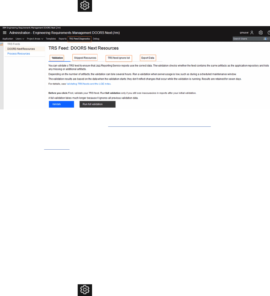
Analyzing and validating TRS feeds
You can view the list of resources that were skipped from the Requirements Management (RM) data
source in the Lifecycle Query Engine (LQE). On the TRS Feed Diagnostics page, you nd out why the
resources were skipped, and decide which resources to ignore in the feed.
Procedure
1. Log in to the server administration page of your web client, for example: https://<host-
name>:<port number>/rm/admin.
2. On the Administration menu
, click Manage Server Administration.
3. In the top navigation pane, click TRS Feed Diagnostics.
4. To validate the TRS feed against the data in the repository, on the Validation page, click Validate >
Validate now. For more information, see Validating TRS feeds and the LQE index.
5. To see the list of skipped resources grouped by VDI codes, on the Skipped Resources page. The VDI
codes help you to determine why the resources are skipped by LQE. The VDI code denitions are
available on this Wiki page.
6. To ignore specic resources in the TRS feed, on the TRS feed ignore list page, click Select an action >
Ignore the selected resources, and then click Submit.
You can add resources back to the TRS feed by removing them from the ignore list. Select the
resources, and click Select an action > Remove the selected resources from the ignore list.
7. To share the list of skipped resources with IBM Support, on the Export Data page, click Export and
download.
Initialize the publish services
IBM Engineering Requirements Management DOORS Next (DOORS Next) have multiple reports. Each of
the reports has an Engineering Document Generation (.dta) report design le. The design les need to be
initialized to store them into the database. Each time when you upgrade to a newer version, you need to
run the publish initialize services.
Procedure
1. Log in to the server administration page of your web client, for example: https://<host-
name>:<port number>/rm/admin.
2. On the Administration menu
, click Manage Server Administration.
3. In the top navigation pane, click Debug.
Administering
81
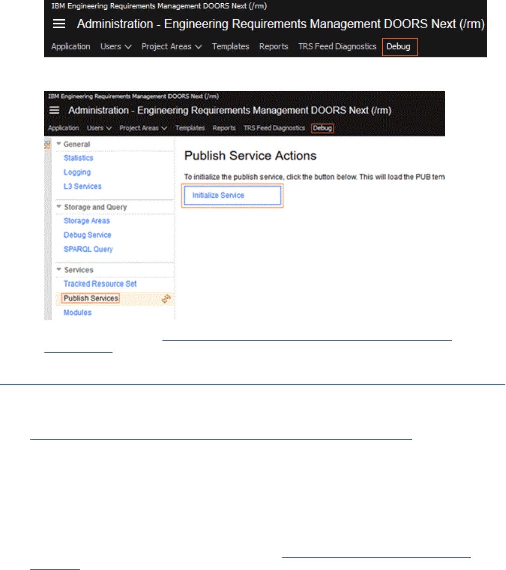
4. In the left pane, under Services, click Publish Services.
5. On the Publish Service Actions page, click Initialize Service.
For more information, see Rational Reporting for Document Generation report from the API
documentation.
Extending product function
This section describes how to extend the functionality of the Requirements Management (RM)
application.
Related information
IBM Engineering Requirements Management DOORS Next Server API Documentation
Extending the Requirements Management (RM) application
You can enhance the Requirements Management (RM) application by authoring extensions for it. The
extensions can enhance productivity and are useful for analysis.
You can add the extensions to your mini dashboard and remove them as needed. Extensions are authored
by using a combination of JavaScript, HTML, and CSS les. The extensions access data within the RM
application by using an RM API.
For full details about the client extension capability, see Extending the Requirements Management
application on Jazz.net.
Migrating graphical artifacts created in the graphical editor browser add-on
As of version 6.0.3, the graphical editor browser add-on is no longer available. If you created graphical
artifacts by using the browser add-on and want to make changes to those artifacts, you can install and
use the graphical artifact migration utility to convert them.
The migration utility converts the artifacts that you created with the graphical editor browser add-on to
a format that can be used with the HTML-based diagram editor, which was introduced in version 6.0.
The utility is an OpenSocial gadget that server administrators can host, and then users can add to their
mini-dashboards in IBM Engineering Requirements Management DOORS Next (DOORS Next). It utilizes
82
Engineering Requirements Management DOORS Next
the extensions API to read the model of an existing graphical artifact and convert it in-place to the newer
diagram format, which you can then edit.
For full details about the graphical artifact migration utility, see Extending the Requirements Management
application on Jazz.net.
Extending DOORS Next by using OSLC services
Open Services for Lifecycle Collaboration (OSLC) is a community that is standardizing the way that
lifecycle tools work together. IBM Engineering Requirements Management DOORS Next (DOORS Next)
supports the OSLC data sharing specication as a provider for the Requirements Management (RM)
domain and as a consumer of other domains in the IBM Engineering Lifecycle Management (ELM). Data
sharing is also supported by other RM tools that support OSLC integration, such as IBM Engineering
Requirements Management DOORS (DOORS).
The sharing of OSLC data between domains is based on a common set of resources, formats, and REST
architectural services.
The data sharing supports these transactions:
• Linking that is based on HTTP protocol
• Identication of resources by URIs
• Information retrieval that uses industry standard media types
DOORS Next supports OSLC data sharing with the domains and specications that are listed in the
following table.
Table 5. OSLC domains and
specications that DOORS Next supports
OSLC domain RM consumes RM provides
Change Management (CM) V1, V2 None
Quality Management (QM) V1, V2 None
Requirements Management (RM) V1, V2 V1, V2
Conguration Management None See Oasis Working Draft
Related information
OSLC overview
RM as an OSLC service consumer
The Requirements Management (RM) application in the IBM Engineering Lifecycle Management (ELM)
consumes common services that other OSLC domains provide for data sharing.
The RM application consumes services that these OSLC domains and specications provide:
• Change Management V1, V2
• Quality Management V1, V2
• Requirements Management* V1, V2
• Architecture Management V2
*Do not congure the RM application to consume its own OSLC interface. The support is for cross-
repository and cross-tool communication only.
RM consumes these OSLC core services that the supported domains provide:
• These services display delegated user-interface dialog boxes:
– Resource creation: Displays a dialog box that enables a user of a web application to create a resource
in an OSLC service provider.
Administering
83
– Resource selection: Displays a dialog box that enables a user of a web application to select a
resource that an OSLC service provider manages.
• User-interface previews (compact rendering, rich hover): Display summary information about linked
resources when a user hovers over a link.
Related information
OSLC Core Specication Version 3.0
OSLC Requirements Management 2.1
OASIS OSLC Change and Conguration Management specication
RM as an OSLC service provider
The Requirements Management (RM) application in the IBM Engineering Lifecycle Management (ELM)
provides user interface (UI) elements and operations to applications that consume services from the RM
domain for data sharing.
UI elements that RM provides
The RM application provides the following UI elements for other products to consume in compliance with
the RM domain specications V1 and V2:
• Delegated UI dialog box for the selection of requirement resources
• Delegated UI dialog box for the selection of requirement collection resources (views)
• Delegated UI dialog box for the creation of requirement resources
• UI previews (compact rendering, rich hover) at displayed links to requirement resources
• UI previews (compact rendering, rich hover) at displayed links to requirement collection resources
• Factory resource for the programmatic creation of requirement resources
OSLC operations that RM provides
The following table lists the operations that RM provides in compliance with the indicated RM domain
specications.
Table 6. OSLC operations that the RM application provides as an RM provider
Operation RM V1 RM V2 Oasis Working Draft
Service Discovery Yes Yes
POST for requirement
creation
Yes Yes
GET on a Requirement Yes Yes
GET on a Requirement
Collection
Yes Yes
Resource Shape No Yes
QUERY on Requirement
and Requirement
Collection
No Yes
QUERY on OSLC links No Yes
POST for baseline
creation
Yes
GET for baselines and
streams
Yes
84 Engineering Requirements Management DOORS Next
Note: For information about conguration management operations, refer to the Oasis Working Draft.
• The POST operation creates a requirement as the rst artifact in a requirements collection. POST is not
available at the database level of the service discovery tree.
• RM internal links are not included in the results of the V1 GET operation.
• RM external links are not included in the results of the V1 GET operation.
• RM internal outgoing links are included in the results of the V2 GET operation.
• RM external links are included in results for the V2 GET operation.
Modules that are located within a collection are not available to OSLC consumers through a GET
operation. An attempt to add a module to a collection through a PUT operation will fail.
For basic instructions for using OSLC in RM, see the article Using OSLC capabilities for requirements
management on Jazz.net.
Note: Content on Jazz.net is a development site that is governed by the Jazz.net Terms of Use and is
provided as-is without warranties of any kind.
For more information about the OSLC RM implementation in ELM and other products that are based on
Jazz technology, see the Open Services for Lifecycle Collaboration Workshop in the Library on the Jazz
Community Site. The workshop includes instructions and examples for the following RM topics:
• Introduction to the OSLC RM API
• Accessing OSLC RM APIs programmatically
For information about developing OSLC-compliant Eclipse applications, see the Eclipse Lyo web site
.
For information about enabling links between RM and other ELM applications and other RM tools, see
“Linking to development, design, test, and requirement artifacts” on page 201.
For information about conguring the integration with IBM Engineering Requirements Management
DOORS, see “Integrating the Requirements Management application and DOORS” on page 15.
Related information
OSLC Requirements Management Specication Version 1.0
OSLC Requirements Management Specication Version 2.1
Links across OSLC domains
The Requirements Management (RM) application in the IBM Engineering Lifecycle Management (ELM)
integrates with other application domains by using standard link types as implementations of the OSLC
specications.
OSLC link relationships
Table 7. Linking across domains from and to the RM application
Domain Link relationships in RM
Link relationships in external
applications
Change Management (CM)
RM artifacts can be linked to CM
artifacts by using one of these
link types:
Implemented By
Affected By*
Tracked By*
CM artifacts can be linked to RM
artifacts by using one of these
link types:
Implements
Affects*
Tracks*
Administering85
Table 7. Linking across domains from and to the RM application (continued)
Domain Link relationships in RM
Link relationships in external
applications
Quality Management (QM)
RM artifacts can be linked to QM
artifacts by using this link type:
Validated By
QM artifacts can be linked to RM
artifacts by using one of these
link types:
Validates (a requirement)
Validates* (a requirement
collection)
Requirements Management (RM)
RM artifacts can be linked to
external RM artifacts by using
one of these link types.
*
This link type is used for the
integration between the RM
application and IBM Engineering
Requirements Management
DOORS (DOORS) objects.
References
External RM artifacts can be
linked to RM artifacts by using
one of these link types.
*
This link type is used for the
integration between the RM
application and DOORS objects.
Referenced By
Architecture Management (AM)
RM artifacts can be linked to
AM artifacts by using these link
types:
Rened By Architecture Element
Traced By Architecture Element
Satised By Architecture Element
Derives Architecture Element
AM artifacts can be linked to
RM artifacts by using these link
types:
Renes
Trace
Satises
Derives From
*Support for this link relationship was added in V2 of the domain specications.
For more information about Architecture Management, see Overview of Rhapsody Model Manager.
Note: In projects that are enabled for congurations, links are directional and are owned by an
application. For more information about link ownership, see Overview of cross-application artifact linking.
Related tasks
Linking to development, design, test, and requirement artifacts
Additional OSLC integration services and requirements
Root services provides the entry point for the OSLC service discovery documents. OAuth security is
required for OSLC authentication.
Root services
Although the root services document is not part of the OSLC specication, it provides the entry point for
the OSLC service discovery documents and the conguration URLs that are needed to consume OSLC
services.
The root services document is located by a URL, based on the server location of the RM server:
https://host-name:9443/rm/rootservices. For example, if the RM server is installed at http://
rm.example.com/, then the root services document is at https://rm.example.com:9443/rm/
rootservices
86
Engineering Requirements Management DOORS Next
Secure authentication
Security is required for OSLC and is provided by OAuth 1.0a. OAuth is an open protocol that provides
secure API authorization in a simple, standard method from desktop and web applications. To access
most OSLC URIs, including URIs for service discovery, requirements, requirement collections, you must
be an authenticated user. OAuth authentication is not required for the root services URI. For more
information, see the OAuth 1.0a Specication.
OASIS OSLC Change and Conguration Management Specication
For information on how to represent and recognize versioned artifacts and congurations, see the OASIS
OSLC CCM TC specication.
Managing
This section describes how to work with dashboards in the Requirements Management (RM) application.
Dashboards in the Requirements Management application
You can work with both project dashboards and personal dashboards in the Requirements Management
(RM) application. Project dashboards are composed of widgets that provide high-level overviews of
artifacts and requirements that are scoped to a specic RM project. Personal dashboards are useful
for tracking action items and workloads across projects, and to display other widgets, such as calendars,
time zone clocks, news feeds, and search engines.
If your project is enabled for conguration management, you can report on versioned artifacts using
conguration-related information in dashboard widgets.
Related concepts
Conguration Management
Related reference
Project Dashboard
A project dashboard in the Requirements Management (RM) application is composed of widgets that
provide high-level overviews of artifacts and requirements that are scoped to a specic RM project. Only
the members of a project can view its dashboard.
Related information
Personal dashboards
Managing dashboards
Composing and managing requirements
You can use the Requirements Management (RM) application to dene the requirements for your system
or application, and then manage those requirements by using mechanisms such as traceability links, tags,
attributes, and dashboards.
Related tasks
“Administering requirements projects or components” on page 21
Joining a requirements project
To join a requirements project, a project administrator must use the web client to add you to the project
as a team member. You can then use web client to open a project from your User Dashboard.
Before you begin
Before you start to work in the client, you must have a Requirements Management repository server
installed locally on your computer or have access to one on a network server. For information
Managing
87

on installing and conguring the server and client, see https://www.ibm.com/docs/en/elms/elm/7.0.2?
topic=SSYMRC_7.0.2/com.ibm.jazz.install.doc/topics/c_planning_install.html. If the team that you are
joining has a repository server on a network, contact the server administrator to get access information.
Related tasks
Creating requirement projects using the web client
Jazz project administrators can create projects and modify project structure and team membership.
Logging in to a requirements project repository
Log in to a requirements project repository in the web client by using the web address and user
credentials that your administrator provides.
Before you begin
Obtain a URL and your user name and password from your project administrator.
Procedure
1. To log in, type the following URL into your browser address eld:
https://hostname:port number/rm/web/
In this example, hostname is the fully-qualied hostname of the server that your administrator
provided, and port number is the port number on that server. For example, enter a URL such as this:
https://myhost.com:9443/rm/web/
2. Log in using the user name and ID that your administrator provided. Authentication can be congured
to use an external LDAP registry, a custom/federated WebSphere Application Server user directory. For
more information, contact your administrator.
Results
The All Projects window opens, which lists all the projects of which you are a member. The All Projects
page has a page navigator when over 100 projects are displayed. You can use the page navigator at the
top of the page to see your projects in increments of 100.
Click Explore Dashboard to display the project dashboard or click Show Artifacts to open the project
Artifacts page.
Related information
Setting up User Management for the IBM Engineering Lifecycle Management (ELM) server
Project dashboards
A project dashboard in the Requirements Management (RM) application is composed of widgets that
provide high-level overviews of artifacts and requirements that are scoped to a specic RM project. Only
the members of a project can view its dashboard.
You can open a project dashboard on the All Projects page or from the Home menu. The dashboard can
be modied only by a user who has administrative access to the project.
To modify the number of columns that are shown on the dashboard, click the arrow on a tab and click
Layout. To add a page to a dashboard, click the Add New Tab icon.
To learn how to customize the project dashboard, see Adding and organizing content on a dashboard.
To add an extension to the mini dashboard using a URL, watch the following video.
Dashboard widgets
To modify the properties of a widget, click Settings on the widget heading menu. To modify the widget
title and color, click Appearance.
88
Engineering Requirements Management DOORS Next
You can add widgets to your dashboard to customize your view of the projects that you are a member
of. If you are integrated with the IBM Engineering Lifecycle Management (ELM) applications, you can add
widgets to display RM artifacts that are linked to development and test artifacts. You can also add widgets
from the RM, Quality Management (QM), and Change and Conguration Management (CCM) applications
to your personal dashboards.
To add a widget, click Add Widget. Select a catalog and then click the Add Widget icon for the widget
to add. You can add multiple instances of a widget and customize its title and properties. Widgets are
organized in categories.
These widgets provide information about requirements projects:
• Projects Members: Lists all members of the project.
• Recent Changes: Lists recently modied artifacts in the project.
• Comments: Lists recent comments that are related to the project. You can lter the comments by those
that are addressed to you or those that you made.
• Reviews: Lists recently modied reviews in the project. You can limit the display to only your active
reviews or all active reviews. You can lter or group the results by status, role, or review name.
• Requirements View: Shows the result of a single view. The view is chosen from a list relative to a
particular requirements project.
• Requirements Tracing: List RM artifacts that link to CCM or QM applications. Linked development or
test artifacts are displayed as indented entries below each RM artifact.
To know more about Adding widgets to the widgets catalog, watch the following video.
Related concepts
“Reviews” on page 181
“Traceability” on page 199
Traceability is used to trace a project element to related project elements, especially those
related to requirements. Traceability helps determine that a requirement is satised from inception
through implementation and testing. Create traceability relationships by linking requirements to other
requirements and to development and test artifacts.
Related tasks
Creating personal dashboards
You can create an unlimited number of personal dashboards to suit different needs.
“Commenting on artifacts” on page 179
A comment is a textual discussion item that you can add to an artifact or an element within an artifact.
You can use comments to provide team feedback during the development of an artifact. In the web client,
comments are displayed in the Comments section of an artifact sidebar, in the Recent Comments section
of the Artifacts page sidebar, and in Recent Comments for Me on the user dashboard.
“Creating requirements projects” on page 26
Jazz project administrators can create projects and modify project structure and team membership.
Creating personal dashboards
You can create an unlimited number of personal dashboards to suit different needs.
About this task
You can customize personal dashboards to serve various purposes:
• Track action items, such as open high-severity work items, pending approvals, and new work items that
need to be triaged.
• Track workload in a project.
• Track workload across multiple projects, including those projects from other applications.
Managing
89
• Display useful widgets to help you work, such as calendars, time zone clocks, news feeds, and search
engines.
New dashboards are pre-populated with a set of widgets that are designed to help a user get started with
the dashboard. Personal dashboards are stored on the Jazz Team Server.
Important:
• To perform this task, you must have read/write access to the Jazz Team Server project area, which is
available to members of the JazzUsers repository group and most other groups. It is not available to
members of the JazzGuests group.
• If you change your user ID, your personal dashboard will not function properly.
Procedure
1. To create a personal dashboard, click the Home icon (
).
Note: If you previously created a personal dashboard, this action takes you to your default personal
dashboard. To create another personal dashboard, click Personal Dashboards > Create Dashboard.
2. In the Create Dashboard page, select the dashboard template, and click Next.
3. In the Select Project Area page, select the project area, and click Finish.
4. A dashboard is created with the default title Your-contributor-name’s Dashboard. If you have multiple
personal dashboards, you can create unique and descriptive titles for each one to prevent confusion.
To change this title, click the dashboard title, and then edit the text.
5. The dashboard is populated with a set of widgets. You can add, remove, organize, or edit widgets
to customize your personal dashboard. For more information about using widgets, see Adding and
conguring widgets.
6. Optional: To set any personal dashboard as the default, click the Set as default dashboard icon ( )
in the dashboard toolbar, and then click OK.
7.
Optional: To access all of your personal dashboards, click the arrow next to the Home icon ( ) to
display the menu. All of the personal dashboards that you created are listed under Current Personal
Dashboards.
8. Optional: To share a personal dashboard and make it visible to a project or team, click the Sharing
Options icon ( ) in the toolbar, and then click OK to conrm sharing.
Important: Shared personal dashboards display in the All Personal Dashboards list (Dashboards >
All Personal Dashboards), and they can be displayed in search results in the web client. When a
personal dashboard is shared, the Shared dashboard icon ( ) is displayed next to the dashboard in
the Personal Dashboards menu.
9. Optional: To delete a personal dashboard, click the Delete icon ( ) in the dashboard toolbar.
Note: It is possible to delete all of your personal dashboards. If you do, you can create one by clicking
the Home icon ( ).
Dening requirements
You can use rich-text artifacts to dene requirements and requirements documents. You can also create
and link to supporting artifacts, such as business process diagrams, use case diagrams, and wireframes,
to elaborate requirements and put them in the broader context of the system and business processes.
Related tasks
“Administering requirements projects or components” on page 21
90
Engineering Requirements Management DOORS Next
Creating artifacts
In a requirements project, you can create rich-text and graphical artifacts.
Before you begin
Before you can create an artifact, the artifact type must exist in the project. If you are an administrator,
you can view or create the artifact types for a project by clicking the Administration menu and
then clicking Manage Project Properties.
Note: If conguration management is enabled for your project, on the Administration menu, click
Manage Component Properties.
About this task
When you create an artifact, the artifact can be new or based on another artifact. You can also create an
artifact by extracting text from a text-based artifact. After you create an artifact, you can capture its URL
to make it easy for other team members to access it. Watch a video about creating requirement artifacts.
When you create an artifact by extracting text from a text-based artifact, the text that you extract
becomes a link to the new artifact. You select the text and then either use the toolbar or right-click the
text to create an artifact.
If you right-click the text and use the menu to create the artifact, you can quickly save the selected text as
a new artifact. However, this method uses a truncated form of the selected text as the artifact name and
uses the same artifact type and location as the initial artifact.
Procedure
• To create an artifact:
a) On the Artifacts page, click Create, and select an artifact type.
b) In the Create Artifact window, enter information about the new artifact and click OK.
You can also create artifacts from the Folder menu. You can click the pencil icon
or right-click
a folder in the Folder menu. The Create Artifact option on the Folder menu displays the preferred
artifact types.
• To create an artifact that is based on another artifact:
a) On the Artifacts page, select the check boxes of one or more artifacts that you want the new
artifact to be based on.
b) Click the pencil icon and click Duplicate Artifact.
c) In the Duplicate Artifact to Folder window, enter a new name for the artifact and choose a
destination folder.
d) Optional: To copy links and tags from the original artifact to the new one, select the corresponding
check boxes.
e) Optional: To create a link between the original artifact and the new one, select the corresponding
check box.
• To create an artifact by extracting text from a text artifact:
a) Open a text-based artifact and click Edit.
b) Highlight the text to base the new artifact on, and then complete one of these steps:
– Right-click the text and, on the menu, click either Save as New "Artifact" and Link or Save as
New "Artifact" and Insert.
– From the toolbar, click the Save Selection as New Artifact and Link icon or the Save Selection
as New Artifact and Insert icon.
Managing
91
c) Provide the information about the new artifact, click Finish, and then click Done.
Results
The newly created artifacts or content of the modules are stored by default in a folder. Use the drag-and-
drop action to move one or more folders and re-organize them. You can also double-click in the content
area of a text artifact or diagram artifact to put it into edit mode. After making the required changes save
the artifact.
To edit an artifact, you can double-click in the content area of a text artifact or diagram artifact, make
changes, and then save the artifact.
What to do next
After you create an artifact, you can capture the URL of the artifact to make it easy for your team members
to directly access the artifact. You can capture the URL in a format that includes both the artifact name
and ID. You can capture URLs in a rich hover from the Artifacts page, from dashboard widgets, or from the
full-text search widget.
Related tasks
“Creating templates for requirements projects or components” on page 46
You can create a project or component template, and select the elements to include in it. When
conguration management is not enabled, you create templates for a project. When conguration
management is enabled, you create templates for a component. You can include or exclude artifacts,
artifact templates, artifact types and attributes, links between artifacts, link types, folder structure, tags,
and shared saved lters. After you create templates, you cannot modify them.
“Managing project or component properties in requirements projects” on page 28
Each project template contains predened artifact types. You can also create customized artifact types,
artifact attributes, and artifact data types for a project or component. Those artifacts types can then
be used by team members to create project or component requirements or related artifacts, such as
customized collections.
“Creating link types for requirements projects” on page 36
Requirement artifacts
A requirement describes a condition or capability to which a system must conform. A requirement is
either derived directly from user needs or stated in a contract, standard, specication, or other formally
imposed document.
In the Requirements Management (RM) application, you use artifacts and artifact types to dene
requirements and support and enhance the denition of requirements.
For example, you can use features and use cases to describe the requirements, and then enhance the
denition by creating diagrams, wireframes, or storyboards.
Artifact is a general term for an object in a repository. You can manage artifacts in projects and folders, or
you can use tags to lter groups of artifacts for a specic purpose. Click Recently viewed artifacts to
quickly navigate to the artifacts that you have accessed lately.
Artifacts and artifact types
Artifacts can be of various types, which have customizable attributes and data types.
While there is no default artifact type called "requirement," you can create one or use the default artifact
types that are in the sample project templates.
Many artifact types are included in the sample project templates, including these types:
• Requirements
• Use cases
• Design documents
• Business process diagrams
92
Engineering Requirements Management DOORS Next

• Use case diagrams
For a list of sample project templates and their included artifact types, see “Creating requirements
projects” on page 26.
If you are a project administrator, you can view the artifact types that are in a project and create
artifact types, attributes, data types, and links types. See “Managing project or component properties in
requirements projects” on page 28.
Artifact formats
Artifact formats can be specic to individual artifact types or can be used for multiple types. For example,
you might use the text format for a feature or a use case specication or a custom artifact type. However,
the diagram format is typically used exclusively for creating diagrams.
You can create and populate artifacts that are based on several formats, including these:
Text
Use this format to create rich-text requirement content that can contain text, images, and
embedded artifacts. This format is useful for text-based artifacts types, such as actor and use case
specications, user stories, features, business goals, and glossary terms.
Collection
Use this format to group a set of related artifacts in a collection.
Module
Use this format to create a structured document that consists of artifacts in a module.
Diagram
Use this format to create graphical artifacts such as wireframes, business process diagrams, and use
case diagrams.
Documents: Rich-text requirement artifacts
You can capture text-based content in rich-text artifacts that are called documents. Documents use the
same rich-text capabilities that are used for requirements, use case specications, actor specications,
and all other textual artifacts. These capabilities include controls for text styles, paragraph justication
and indentation, bullets, and links.
If your browser supports spell checking, you can edit and check the spelling in rich-text artifacts.
Misspelled words are marked with a red wavy underline.
In a document, you can link to artifacts, and can mark and embed other artifact types, comments,
requirements, and images. Embedded requirements and inserted artifacts are updated as the artifacts are
modied and saved.
To provide context for presenting multiple requirements, you can embed requirements and graphics in a
document. An example of a rich-text artifact that typically contains multiple high-level requirements is a
vision document.
Viewing the artifact's history
From the More actions
menu, click Open History > Audit History tab to view the changes in the
artifact. This tab shows a complete history of changes that goes back to the creation of the artifact. To
return to the artifact, click Close History. You can also access the artifact history from Open Artifact >
Open Artifact History
Related tasks
“Creating requirements projects” on page 26
Jazz project administrators can create projects and modify project structure and team membership.
“Creating artifacts” on page 91
Managing
93

In a requirements project, you can create rich-text and graphical artifacts.
“Managing requirements” on page 188
You can manage requirements by using traceability links, tags, attributes, ltering, workflows, and
dashboards. With these capabilities, you can create relationships between requirements and other
artifacts, categorize requirements, assign properties to requirements, and monitor relationships and
status among team applications. To learn how to optimize requirements management, reduce rework and
avoid delays by using AI from Watson, go to the IBM Engineering Requirements Management site.
Related reference
Vision document
A vision document denes the high-level scope and purpose of a program, product, or project. A clear
statement of the problem, proposed solution, and the high-level features of a product helps establish
expectations and reduce risks. This topic provides an outline of potential content for a vision document.
Creating diagrams to support requirements
In IBM Engineering Requirements Management DOORS Next (DOORS Next), you can create diagrams that
support requirements. Use the diagram editor to quickly create graphical representations of artifacts by
dragging shapes from a palette onto a canvas. You can also use the diagram editor to create a graphical
artifact in a module. When you create a graphical artifact in a module, you can open and edit that artifact
by selecting the Open Artifact check box in the Create Artifact window.
Note: As of version 6.0.3, the graphical editor browser add-on is no longer available. However, you can
create the same artifact types by using palettes in the diagram editor.
To learn about creating diagrams, see the video IBM Rational DOORS Next Generation: Collaboration
through diagramming:
About this task
You can use the diagram editor to create several different types of graphical artifacts; choose the most
appropriate palette for the type of diagram that you want.
Procedure
1. On the Artifacts page, click Create and click Graphical artifact or any artifact type with a format of
diagram.
2. In the Create Artifact window, type a name for the new diagram.
3. Provide any optional information, such as a description, a folder, or tags.
4. Optional: To open the new artifact in the diagram editor, select the Open Artifact check box.
5. Click OK.
If you selected the Open Artifact check box in the previous step, the new artifact opens in the
diagram editor. You can also edit the diagram-based artifact by using the diagram editor.
6. To create a diagram, open the graphical artifact that you created. The shapes that you can use in your
diagrams are grouped in palettes.
94
Engineering Requirements Management DOORS Next
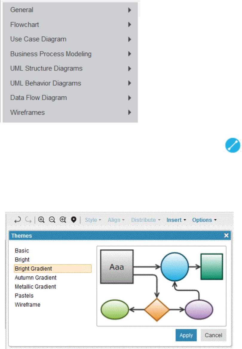
7. Expand a palette and drag the shapes onto the canvas.
8. To create connections between the shapes, select a shape, click the connector icon
and drag it
to a target shape.
To change the properties of the connection, right-click the connection, click Properties, and specify
how you want the line and text to look. For example, you can choose a link style and add arrows.
9. Use the toolbar menu or the context menus to perform the following tasks:
• Control the look of your diagram by applying a theme. In the diagram editor, click Options >
Themes.
• Align groups of selected shapes in different positions on the canvas.
Managing
95
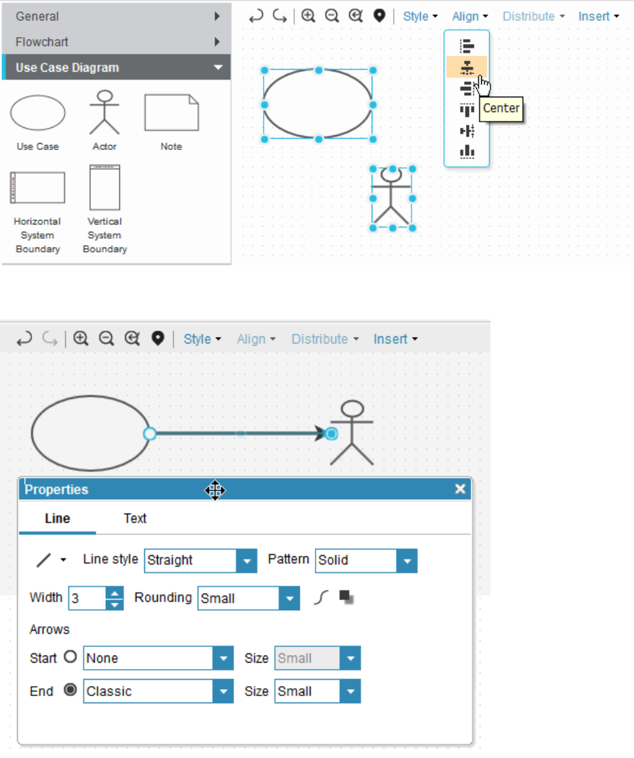
• Set shape and line properties, such as such as font, alignment, background color, line style, and
rounding.
• Create links between shapes and other requirement artifacts.
96
Engineering Requirements Management DOORS Next
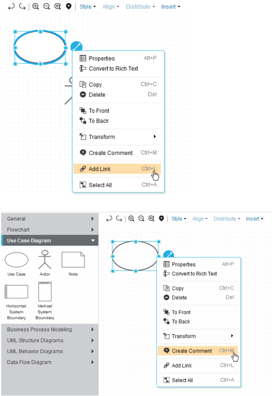
• Create comments on shapes.
• Download diagrams as PNG les.
Managing
97
Tip: If you add links or comments to shapes in your diagram, you can display indicators to show that
there are associated links or comments. To enable the comment indicators, open the Comments pane
and click the Highlight All Comments icon . To enable the links indicators, open the Links pane
and click the Highlight All Links icon
. For example, the following Text shape shows that one
comment and one link are associated with it.
10. To paste a link in the diagram, complete the following steps:
a) Select the artifact in the grid and click Copy Artifact.
b) Open the diagram in edit mode.
c) Right-click the shape and click Paste as Link.
The link is added to the diagram and you can see the link in the link panel in the sidebar.
Tip:
• You can also paste a link on shapes in a diagram.
• If you copy multiple artifacts and paste the link on multiple shapes, multiple links are created.
Business process diagrams
You can use business process diagrams to depict business process flows. A business process diagram is a
diagram that depicts a directed flow of activities that are specied by using a subset of Business Process
Modeling Notation (BPMN).
A simple process represents the internal processes that occur within one organizational unit or business
entity. These are sometimes referred to as workflow processes. In web services, they are referred to
as orchestration of services. If swimlane notation is used, the process is contained within a single pool,
which is assumed and therefore not shown in the diagram. Simple processes can include multiple lanes to
represent roles or internal participants in the process.
A business-to-business process represents global processes that span more than one organizational unit
or business entity. This process is represented by multiple swimlane pools. Message flows connect the
activities across the pools.
98
Engineering Requirements Management DOORS Next
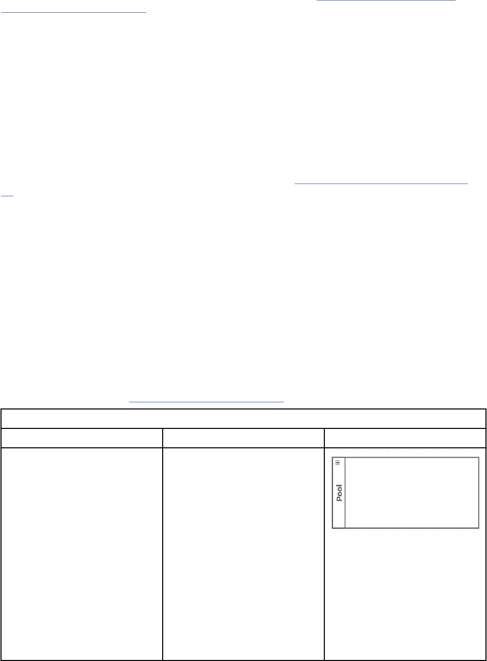
For details about how to create a simple process representation, see “Getting started with business
process diagrams” on page 104.
Business process elements
You can use four categories of elements that you can use in business process diagramming:
• "Swimlane" dividers: Group the activities of participants, roles, and systems. These divisions include
pools and lanes.
• Flow objects: Identify the main graphical elements that dene the behavior of a business process.
These objects include events, activities (tasks and subprocesses), data objects, and gateways.
• Connectors: Connect flow objects. These elements include sequence flows, message flows, and
associations.
• Annotations: Add supportive elements that add information to the diagram.
For detailed descriptions of the available process elements, see “Business process elements” on page
99.
Business rules
A business rule is a policy, constraint, or required operation that applies to a specic set of business
conditions or dependencies. An example of a business rule for a bank is that a credit check is not required
when an existing customer opens an account.
Business rules can be described in documents. Individual rules can be linked to elements in business
process diagrams or use case diagrams, which show the rule in the context.
Business process elements
A business process diagram is a graphical representation of a business process flow, which consists
of a sequence of activity elements and flow controls elements. The Requirements Management (RM)
application supports a subset of elements from the core element set of Business Process Modeling
Notation (BPMN) standard.
Explanations of the business process diagram elements are based on the Business Process Modeling
Notation Specication from Object Management Group (OMG)
.
Table 8. Business process swimlane dividers
Element Explanation Graphical Representation
Pool A pool represents a participant in
a business-to-business process.
A participant is a business
entity (such as a company,
company division, or customer)
or a business role (such as
a buyer or a seller), which
controls or is responsible for a
business process. High-level or
complex processes can include
multiple participants, each of
whom controls a process in an
organization. Each participant is
associated with one pool.
Pools are not used in simple
processes.
Managing99
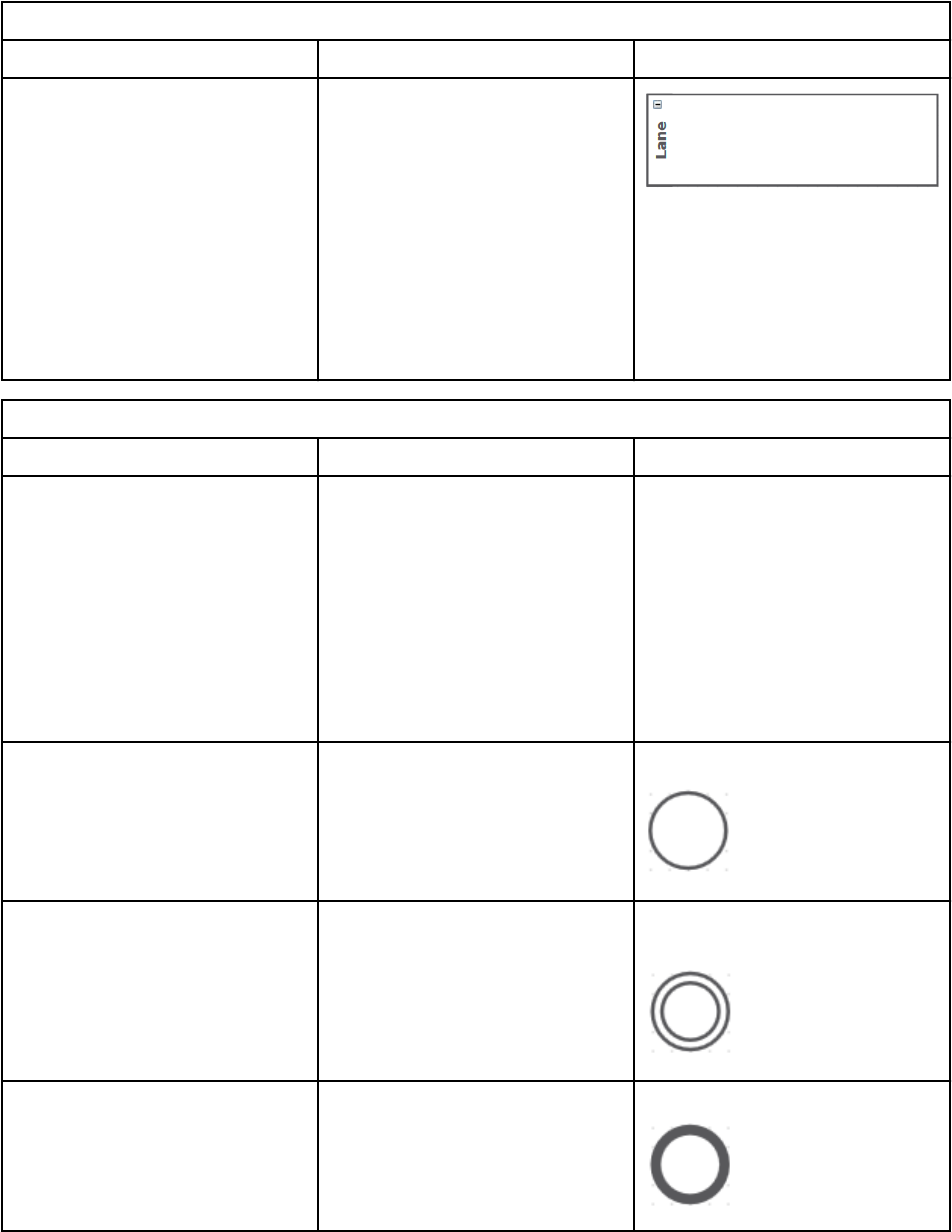
Table 8. Business process swimlane dividers (continued)
Element Explanation Graphical Representation
Lane A lane is a subpartition within
a pool in a business-to-business
process or a separate grouping
of elements in a simple
process. Lanes organize and
categorize activities. Lanes are
often used for internal roles
(such as manager, associate),
systems (such as an enterprise
application) or an internal
department (such as shipping or
nance).
Table 9. Business process flow object elements
Element Explanation Graphical representation
Event
An event is something that
occurs during the course of a
business process. Events affect
the flow of the process and
usually have a cause (trigger)
and an impact (result). There
are three types of events, which
are based on when they affect
the flow: start, intermediate, and
end.
Start event
Start events begin a process. Start event
Intermediate event
An intermediate event occurs
during a process. The event
affects the flow of the process,
but does not start or directly
terminate the process.
Intermediate send or receive
event
End event The end event ends the flow of
a process and does not have any
outgoing sequence flows.
End event
100 Engineering Requirements Management DOORS Next
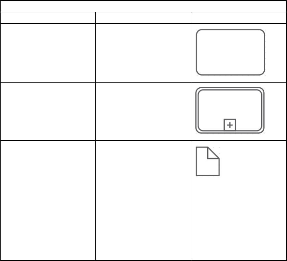
Table 9. Business process flow object elements (continued)
Element Explanation Graphical representation
Task
A task is a single activity that
is included in a process. A task
is used when the work in the
process is not broken down to a
ner level of process detail.
Subprocess A subprocess is a single flow
object element that represents a
set of activities.
Data object Data objects do not have a direct
effect on the sequence flow or
message flow of the process,
but they do provide information
about functions within the
process, such as how documents,
data, and other objects are
used and updated during the
process. Data objects can provide
information that is required or
output by the process. They
can be used to represent many
different types of objects, both
electronic and physical. All data
objects must be contained by a
process or a subprocess.
Managing101
Table 9. Business process flow object elements (continued)
Element Explanation Graphical representation
Decision point (gateway) A decision point (or gateway)
controls the divergence and
convergence of multiple
sequence flows. It determines
branching, forking, merging, and
joining of paths. Icons in the
diamond shape indicate the type
of flow control behavior. The
types of control are as follows:
• Decision point (inclusive): An
inclusive (OR) decision and
merging gateway. This decision
represents a branching point
where alternatives are based
on conditional expressions
that are contained within the
outgoing sequence flow. In
some sense it is a group
of related independent binary
(yes or no) decisions. Because
each path is independent, all
combinations of the paths
can be taken, from 0 to all.
However, set up the gateway so
that at least one path is taken.
A default condition could be
used to ensure that at least one
path is taken.
• Decision point (exclusive): A
data-based exclusive decision
and merging gateway. Data-
based decisions represent
a branching point where
alternatives are based on
conditional expressions that
are contained in the outgoing
sequence flow. An exclusive
gateway restricts the flow so
only one of a set of alternatives
can be chosen during run time.
• Parallel: A parallel (AND)
gateway that provides a
mechanism to synchronize
parallel flow and to create
parallel flow. These gateways
are not required to create
parallel flow, but they can be
used to clarify the behavior
of complex situations where a
string of gateways are used and
parallel flow is required.
Each type of control affects both
the incoming and outgoing flow.
Inclusive Gateway
Exclusive Gateway
Parallel Gateway
102 Engineering Requirements Management DOORS Next
Table 10. Business process connector elements.
Note: In previous versions of the RM application, the following connector elements were shapes that
you could choose from the palette. As of version 6.0.3, those shapes are no longer available. You must
create the connections between the shapes in your business process diagrams. For details, see step 8 in
Creating diagrams to support requirements.
Element Explanation Graphical representation
Sequence flow
A sequence flow is represented
by a solid line with a solid
arrowhead. Sequence flows show
the order in which activities
are performed in a single
process. Flow connectors show
the direction of flow from a
source to a target. The sequence
flow can cross the boundaries
between lanes, but cannot cross
the boundaries of a pool.
Sequence flow:
Message flow
A message flow is represented
by a dashed line with an open
arrowhead. Message flows depict
the contents of a communication
and the flow of messages
between two participants (in
separate pools) that are prepared
to send and receive the
messages. Flow connectors show
the direction of flow from a
source to a target. A message
flow crosses pool boundaries to
show the interactions between
these separate participants.
Message flows are not available
in simple processes.
Message event:
Association An association is represented by
a dotted line and is used to
associate information in the form
of text annotations with flow
objects.
Table 11. Business process supportive elements
Element Explanation Graphical representation
Annotation Annotations are mechanisms for
the designer to provide additional
textual information for the reader
of a business process diagram.
Managing103

Getting started with business process diagrams
Business process diagramming is a flexible requirements-denition technique. When you start, it is best
to use the most simple process representation. Begin with a basic structure and the clearly identiable
elements in the process. As your diagram develops, add detail.
Your representation will incorporate process elements whose behavior is designed in accordance with the
Business Process Modeling Notation (BPMN) guidelines. These elements, which are described in detail
in “Business process elements” on page 99, help you to recognize the activities in the process and to
organize your diagram.
Choosing a nite process
Begin with a clear objective. The business process diagram should represent a nite, clearly bounded
process, even if it contains subprocesses. A complex process, such as "Processing a customer order"
can have many participants and many subprocesses; a simpler process might be "Look up customer
information." Consider these guidelines for diagramming:
• For a complex process, plan to create a summary only. Represent subprocesses with a single
subprocess element; avoid adding too much detail at this point.
• For smaller, simpler processes, create detail as needed, but be sure to limit the detail to those activities
that are performed completely within the process.
Using pools and lanes
Two types of process are supported: simple and business-to-business processes.
• A simple process represents the internal processes within one organizational unit or business entity.
The process does not include swimlane pools; however, it can include multiple lanes to represent roles
or internal participants in the process.
• A business-to-business process represents global processes that span multiple organizational units or
business entities. This process is represented by multiple swimlane pools. Message flows connect the
activities across the pools
If your process involves multiple participants (such as different organizations, customers, or systems),
create a business-to-business process and separate the participants in different pools. Use separate
pools to represent participants who control their own processes. For example, a customer is one pool
and a seller is another; each has separate processes, yet they must communicate outside their own
organizations (across pools) when an order is placed.
Within a simple process or a single pool in a business-to-business process, there might be multiple roles,
each of which is represented by a separate lane in the diagram. For example, customer service, billing,
and shipping each have their own lane within one pool.
Identifying activities
Identify the tasks and subprocesses that are included in the process. These activities are descriptions of
work. The task is a nite (atomic) activity that cannot be subdivided into smaller activities. A subprocess
represents a collection of tasks that are treated as one activity in this process diagram. Place each activity
in the pool or lane that represents the participant, role, or system that performs the activity.
Activities can share data objects, which are containers for data. Connecting activities to data objects
generates data associations, which are used to place data into or retrieve data from a data object.
Positioning the start, intermediate, and end events
Place the start and end events in the correct pool and lane, relative to the initial and nal activities in the
process. Add intermediate events that affect activities within the process.
104
Engineering Requirements Management DOORS Next
Adding flow connectors and gateways
As you add flow connectors to the diagram, the tool assigns a connector that is appropriate for
the context. Sequence flow connectors connect activities in a simple process or within a pool in a
business-to-business process. Message flow connectors connect activities across two pools. As you
add a connector between two elements, the business process diagram editor determines which type of
connector to use based on the selected source and target. Associations connect text annotations with
activities and events. A gateway controls the divergence and convergence of sequence flow; the gateway
can determine branching, forking, merging, and joining of paths.
Adding groups and annotations
Add a text annotation to clarify a specic activity or event. Use a connector to associate the annotation
with other elements.
Dening use cases
A use case is an artifact that denes a sequence of actions that yields an observable result of value.
Use cases provide a structure to express functional requirements within the context of business and
system processes. Use cases can be represented as a graphical element in a diagram and as a use case
specication in a textual document.
A business use case denes a sequence of actions that a business performs that yields an observable
result of value (a work output) to a particular business actor or that shows how the business responds to a
business event.
A system use case is a sequence of actions that a system performs that yields an observable result of
value to a particular actor (someone or something outside the system that interacts with the system).
A use case diagram can include multiple use cases and the relationships between use cases and the
persons, groups, or systems that interact to perform the use case.
You can create an actor artifact that provides textual detail for an actor in a use case diagram. An actor
artifact can be used in multiple use case diagrams.
Use case specications share the same rich-text behavior that is present in all artifacts based on the text
artifact format. The specications often include content that is based on a template or process guidance.
For a sample use case specication outline, see “Use case specication outline” on page 105
.
Use case specication outline
A use case specication provides textual detail for a use case. You can use this sample outline to create
your own use case specication documents.
Table 12. Sample outline of a use case
specication
Section Description
Use case name States the use case name. Typically, the name expresses the objective or
observable result of the use case, such as "Withdraw Cash" in the case of an
automatic teller machine.
Brief description Describes the role and purpose of the use case.
Flow of events Presents the basic flow and alternative flows. The flow of events describes
the behavior of the system; it does not describe how the system works, the
details of the presentation, or the details of the user interface. If information is
exchanged, the use case must be specic about what is passed back and forth.
For example, instead of describing an action as "the actor enters customer
information", indicate that "the actor enters the customer name and address."
Basic flow Describes the ideal, primary behavior of the system.
Managing105
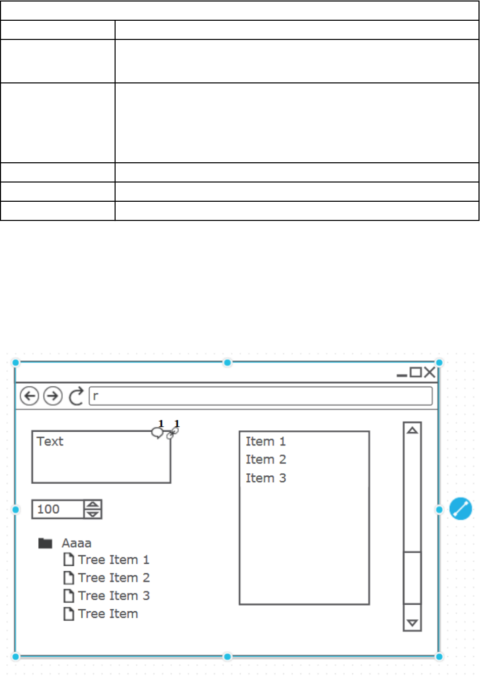
Table 12. Sample outline of a use case specication (continued)
Section Description
Alternative flows Describes exceptions or deviations from the basic flow, such as how the
system behaves when the actor enters an incorrect user ID and the user
authentication fails.
Special requirements Nonfunctional requirements that are specic to a use case but are
not specied in the text of the use case flow of events. Examples
of special requirements include these factors: legal and regulatory
requirements; application standards; quality attributes of the system, including
usability, reliability, performance, and supportability; operating systems and
environments; compatibility requirements; and design constraints.
Preconditions A state of the system that must be present before a use case starts.
Post conditions A list of possible states for the system immediately after a use case is nished.
Extension points A point in the use case flow of events at which another use case is referenced.
Wireframes
In the Requirements Management (RM) application, you can use wireframes to design web-based and
rich-client applications. A wireframe is a simple line diagram, or schematic, for mocking up user interfaces
or web pages.
The diagram editor includes a wireframe palette and themes that you can use to create wireframes.
The wireframe palette contains several container-based shapes. The wireframe shapes also have custom
properties that you can congure.
The following image shows how you can use wireframe shapes to sketch your ideas:
.
106
Engineering Requirements Management DOORS Next
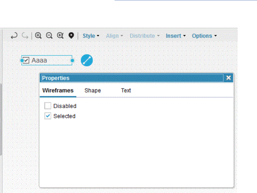
• In container elements, such as list boxes and vertical menus, you can arrange and organize the contents
by dragging the items from one location to another.
• In tree structures, you can drag items to organize and nest them.
When you create diagrams, you can choose a theme to control the look of the shapes. A theme is available
specically for wireframe. For details, see step 9 in Creating diagrams to support requirements.
When you create a wireframe, you can control how the shapes are rendered by specifying properties for
each one. You can also specify the state of a wireframe shape. For example, you can show check boxes as
selected or cleared in your wireframe.
As with the other diagram palettes, you can use the context menu, or toolbar, to perform various actions
on a shape. The following image shows a context menu for a wireframe shape.
Managing
107
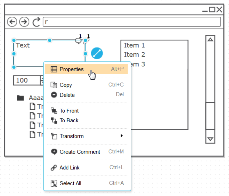
In the wireframe palette, most items are single-line text elements, which means that the text you enter
in the eld does not flow beyond the limits of the eld, and it does not wrap to the next line. In
these elements, you can press Enter to nish editing. The height of these elements in your wireframe is
controlled by the size of the font that you choose.
When you add tables to your wireframe, you can control the line width, header row, and other
characteristics by specifying properties for the table. You can select and add rows and columns to a
table by using the context menu, and then organize them by dragging them within the table. The following
image shows the context menu for a wireframe table.
108
Engineering Requirements Management DOORS Next
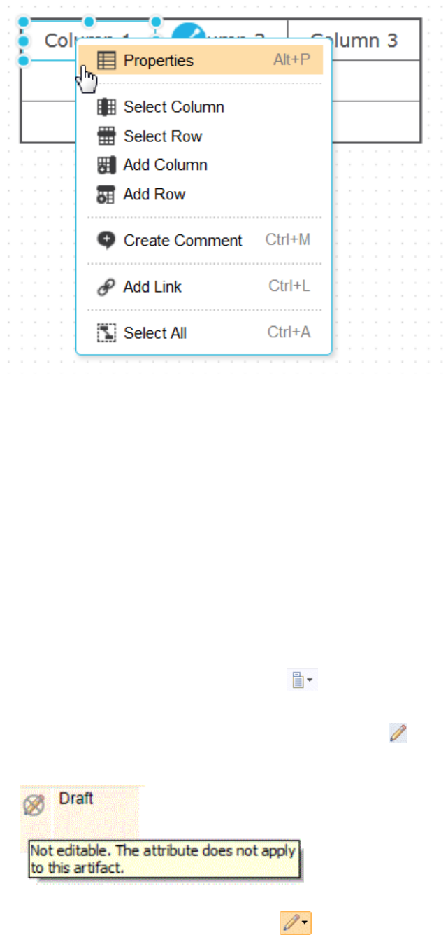
Editing attributes that have multiple values in a requirements project
If an attribute has multiple attribute values, you can edit the attribute values on the Artifacts page. On
that page, you can also edit the attribute values for multiple artifacts at the same time.
Before you begin
You must have dened an attribute
with an attribute type that has an enumerated list of values.
About this task
To watch a video of this procedure, click the Show Me link at the beginning of the topic.
Procedure
1. On the Artifacts page, display the artifacts to edit.
2. If the attribute to edit does not have a column on the Artifacts page, add one:
a) Click the Congure Page Settings icon
and then click Congure Columns to Display.
b) In the window that opens, add the attribute so that it is displayed as a column.
3. In the attribute column, click the cell for the artifact to edit .
From the list that opens, you can lter and select artifacts to add or remove. The following icon
indicates that cell is not editable:
4. To edit attributes for multiple artifacts, select the artifacts to which you want to apply the change and
from the edit menu of one of the artifacts dropdown, click Edit attributes.
Managing
109
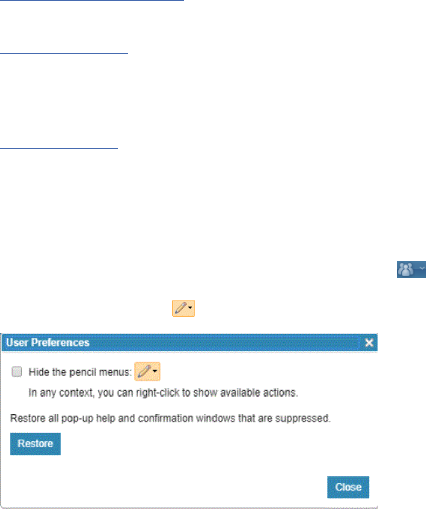
The Edit Attributes dialog box displays a progress message while processing the updates. Using bulk
update, you can update multiple attributes and apply the attribute changes to all the artifacts that you
saved as view in a collection or module. The following system attributes can also be changed with the
bulk update function:
• Artifact types
• Folder
• Workflow
• Tags
• Team Ownership
Related concepts
Filters and views in requirement artifacts
Filters and views are useful for sorting and displaying artifacts that are based on specic criteria. You can
use lters and the congure page settings to display artifacts, and then save this conguration as a view
to use later.
Filters and views in modules
In modules, you can modify the column settings, lter the artifacts that are shown, and then save the
column and lter settings as a view. You can modify columns to show specic attributes or link types, and
you can lter by artifact type, artifact tags, attribute values, and link types.
“Locks in the Requirements Management (RM) application” on page 116
Locks prevent multiple people from editing the same artifact at the same time. When you edit an artifact,
it is automatically locked.
“Collections” on page 176
A collection is a set artifacts that you create for a specic purpose.
“Modules in the Requirements Management application” on page 129
A module is a structured document that is composed of multiple artifacts. You can create structure in a
module by modifying the order and hierarchy of its artifacts. The artifacts that are created for modules
are stored as module content in a folder. Base artifacts can be used to manage the module artifacts
independent of the module.
User preferences
You can set preferences for requirements management by clicking the User Prole icon
, and then
clicking My User Preferences. Preferences are applied to the ID of the user that is logged in.
The drop-down beside the pencil icon lists all the available actions. If your screen is getting
cluttered, you can set your preferences to hide the pencil menus.
110
Engineering Requirements Management DOORS Next

Filters and views for artifacts in requirements projects
Filters and views are useful for sorting and displaying artifacts that are based on specic criteria. You can
use lters and the congure page settings to display artifacts, and then save this conguration as a view
to use later.
Watch a video that shows how to construct a lter and save a view.
Filters
On the Artifacts, Collections, and Modules pages, you can lter artifacts by entering the artifact ID or text.
Filters on string attribute values only consider the rst 449 characters. Full-text and search consider all
characters. See Searches for artifacts in requirements projects. You can also add lter criteria such as
Artifact Type, Created by, and so on by selecting an attribute in the Add Filter window.
1. Open the Artifacts, Collections, or Modules page.
2. Click the Add lter icon .
3. In the New Filter window, all the attributes available for ltering are displayed. Select the attribute
and the attribute value to lter by and click Add. You can add more than one lter.
If you select Link Type as the lter attribute, you can specify more lters for the linked artifacts. Click
the Edit icon and add conditions.
In this example, the lter returns all artifacts that have a Link To or Link From link to an artifact of type
Feature.
In this example, the lter returns all artifacts that do not have a Satises link to an artifact of type
Heading.
Folders
You can use the Folders tab in the left navigation to display the required artifacts. On the Folders tab, you
can select the folder to see the artifacts in that folder. When you click the folders on the Folders tab, any
lters in the lter eld are cleared and artifacts in the selected folder are displayed.
Managing
111

Views
On the Views tab, you can select a view to see artifacts. On the Views tab, you can also search views
by using the Search Views eld. When you click a view on the Views tab, the lters in the lter eld are
cleared and artifacts for the selected view are displayed.
Views are a subset of the artifact content. The Artifacts page has a default sort order. If you do not select
a sort order, the artifacts are sorted by artifact ID in descending order. After you dene lter criteria,
you can customize your column settings on the page. You can also sort a column by clicking the column
header. Then, you can save your conguration of lters and columns as a view for future use.
A shared view is a view that can be used by all project members. Shared views can be created or changed
only by an administrator or a user who has the required permissions. You can manage or lter shared
views by associating them with a process area and roles from that process area. Then, users can see
shared views only when they open an artifact and the view that is associated with that process area. Users
must have at least one role in that artifact's process area that is also assigned to the view.
Any project member can create a personal view for private use. The Save Personal Saved View
permission is enabled for everyone by default, but you can modify this permission.
You can mark any view as preferred view. When you mark view as a preferred, it appears in a bold font in
the View column. When you open a module for the rst time, the preferred view is shown as the default
view because there are no cached preferences in the local storage of your browser. When you open
the same module again, the previously selected (or non-selected) view is displayed as the default view
because your browser retains that information. If multiple preferred views exist, one view is automatically
chosen as the default view.
After you save a view, you can edit the view and work with it in other ways. For example, you can send
another user a link to view, to generate a report about the view, and to export artifacts from the view. For
more information about exporting artifacts from a view, see Exporting requirement artifacts to a CSV le
.
You can manage views to be available in a specic collection or module type. If you save a view in a
collection or module, that view is available from that collection or module only. See also “Filters and views
in modules” on page 148.
Page settings
To organize and sort the content that is displayed on the Artifacts page, use any of these methods:
• Click Congure page settings
> Congure columns to display or More > Change Column Display
Settings and select the columns that you want displayed.
• Use the Move Up and Move Down options to organize the column display.
• Use the Format option to customize the column display. You can select attributes of the artifacts and
wrap or trim the link text.
View a specic page of artifacts results
When you view a list of artifacts on All, Collections, or Modules tabs, a page navigator is shown at the
bottom if the list spans multiple pages. If there are six or more pages, the page navigator includes an
ellipsis. Click the ellipsis to open the Go To Page dialog box. In the dialog box, type a specic page
number to navigate to the required page. The following image shows the dialog box to view a specic
page:
112
Engineering Requirements Management DOORS Next
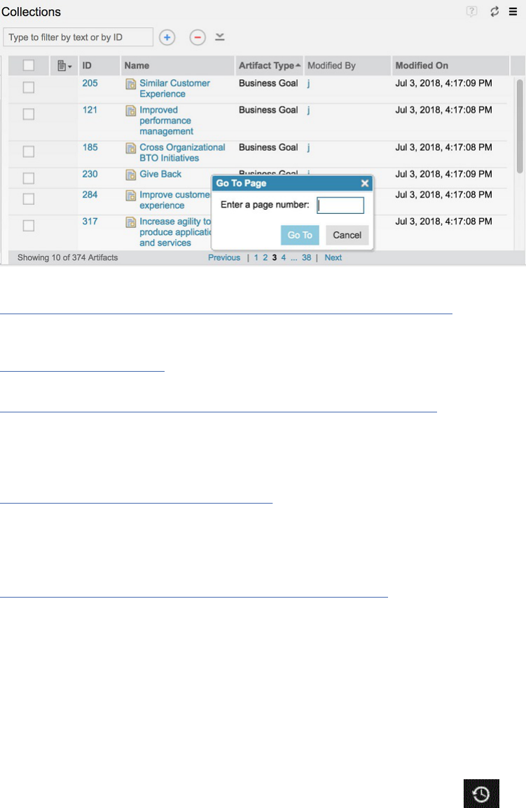
Related concepts
“Locks in the Requirements Management (RM) application” on page 116
Locks prevent multiple people from editing the same artifact at the same time. When you edit an artifact,
it is automatically locked.
“Collections” on page 176
A collection is a set artifacts that you create for a specic purpose.
“Modules in the Requirements Management application” on page 129
A module is a structured document that is composed of multiple artifacts. You can create structure in a
module by modifying the order and hierarchy of its artifacts. The artifacts that are created for modules
are stored as module content in a folder. Base artifacts can be used to manage the module artifacts
independent of the module.
“Filters and views in modules” on page 148
In modules, you can modify the column settings, lter the artifacts that are shown, and then save the
column and lter settings as a view. You can modify columns to show specic attributes or link types, and
you can lter by artifact type, artifact tags, attribute values, and link types.
Related tasks
“Filtering artifacts for links to other applications” on page 218
When viewing artifacts, collections, and modules in the Artifacts, Collections, or Modules pages, you
can lter artifacts that are linked to other applications integrated in the IBM Engineering Lifecycle
Management (ELM).
Searches for artifacts in requirements projects
You can nd artifacts by using quick search, full-text search, and lters. Search can be done with the
artifact ID or with text within the artifact.
Quick Search
To see recently viewed artifacts, click the Recently Viewed Artifacts icon .
Use the Quick Search feature to quickly search for artifacts in projects or components. You can search
in the current project or component, another project or component, or all projects or components. In
a conguration-enabled project, the Quick Search feature is only supported in a global conguration
context.
1. Click the project or component icon to set the scope of the Quick Search. By default, the scope is the
Current Project.
Managing
113

2. In the Search Artifacts eld, enter an ID or text string to search for. If you enter an ID, the search
returns the artifact with that ID. If you enter a string, a full-text search is performed. For more details
on full-text search, see the Full-text search section.
Note: In 6.x, Quick Search results were ordered by each match's relevance to the query. In 7.x,
however, the results are now ordered by artifact ID in descending order.
3. Specify more options to further limit the search, such as modication details, the artifact type, and
whether to search in modules, folders, or both.
The Quick Search options are saved across browser sessions.
Filters
Use the Type to lter by text or by ID eld to lter and search for artifacts. To lter based on ID, enter an
ID and the search returns the artifact with that ID.
Note: To search for an artifact by ID, in the Type to lter by text or by ID eld, enter the complete ID.
When you search by ID, the search operation performs a full-text search and uses whole-word matching
to nd the exact match for the ID. The search eliminates partial matches from the results and displays the
artifact with that exact ID.
To lter artifacts based on text in the artifact, enter a single search string or multiple strings. A full-text
search looks for the specied word or phrase within the content of the artifact and in attributes that are
String data type. If you enter multiple search terms, the search returns artifacts that match all the terms.
See the following section on full-text search for more details.
You can narrow the search results further by adding lters such as the artifact type, modication date, and
tag criteria. You can also sort and group the results and add or suppress artifact details from the results.
See “Filters and views for artifacts in requirements projects” on page 111
for details on ltering, page
settings, and column display.
Full-text search
A full-text search looks for the specied word or phrase within the content of the artifact and in attributes
that are String data type. For example, Name and Description. The search returns artifacts that contain
a word that starts with the search string. By default, the full-text search operation uses word stemming.
The stemming tokenizer reduces words to a root. For example, iteration is reduced to "iter". The search
operation looks for roots that are an exact match of the search term. To perform a starts with search
without using word stemming, append an asterisk to your search term.
Note:
• Searches are not case-sensitive.
• If you enter multiple search strings, artifacts that contain any of the search strings are returned.
You can preface each search term with an asterisk (*) to do a contains search instead of a starts with
search.
Use double quotation marks to search for an exact phrase. The search returns artifacts that contain all the
words and in the exact order that you have entered them.
Note: When you search using double quotation marks, word stemming provides the closely matched
artifacts along with the exactly matched artifacts in the search results.
The following table shows some example artifacts with some textual content. The next table has some
search entries and their resulting search returns.
114
Engineering Requirements Management DOORS Next
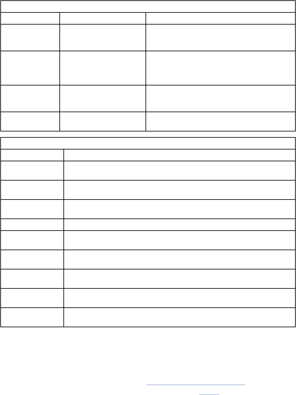
Table 13. Example artifact content
Artifact Number Artifact Name Artifact content
1 Automatic Meter Reader A system to automatically collect data on
consumption, pressure or other diagnostic, and
status from a meter.
2 Meter Reading The ability to walk by the locations where the
meters are installed, and the meter is automatically
registered by a handheld computer that is carried
by the meter reader.
3 Usage Scenario The Meter Reader is unable to collect usage data
from the Water Meter due to lack of connection or a
fault.
4 Fault Scenario The Meter Reader sends a command to retrieve the
fault status.
Table 14. Example search entries and their results
Search entry Search results
read* Artifacts 1, 2, 3, and 4. These artifacts have the words reader and reading, which
start with the search string read.
held No artifacts. None of the artifacts have words that start with the search string
held.
*held Artifact 2. This artifact has the word handheld, which contains the search string
held.
"collect data" Artifact 1. This artifact has the exact phrase collect data.
auto* Artifacts 1 and 2. These artifacts have the words automatic and automatically,
which start with the search string.
automat Artifacts 1 and 2. These artifacts have the words automatic and automatically,
which have a root of “automat” and will match the search string.
auto No artifacts. The word stems for the words automatic and automatically, which
do not match the search term.
scenario Artifacts 3 and 4. These artifacts have the word scenario, which starts with the
search string scenario.
press*coll* Artifact 1. This artifact has the words pressure and collect, which start with both
the search strings press and coll.
Restriction:
• Full-text search does not support special characters. If any of these characters ( ) { }[ ] < > /
\ : ; ? ! _ - | & . , ' « » ~ ^ are included in the search string, the results are inconsistent.
Also, since these characters are not indexed, they do not affect search results. For example, if your
search entry is test, you get matches for <test>, {test} even though the search is a starts with search.
For more information on this limitation, review the workarounds and limitations article on jazz.net.
• Full-text search does not index "*" and """. For more information, see Table 2.
• Full text search does not index these common words: "a", "an", "and", "are", "as", "at", "be", "but",
"by", "for", "if", "in", "into", "is", "it", "no", "not", "of", "on", "or", "such", "that", "the", "their", "then",
"there", "these", "they", "this", "to", "was", "will", and "with". When you perform a search by using these
common words, the search does not return any result.
Managing
115
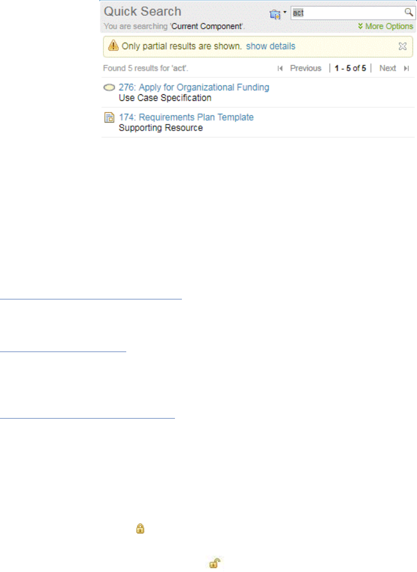
• Full text search does not index single letter words. For example, if an artifact has the name
"Requirement X", searching for "x" does not return a match for the artifact.
Setting a limit to the full-text search results
If the full-text search results exceed the limit that is specied in Advanced properties, a warning
message is displayed.
.
Note: When you add lters to the full-text search query, the specied limit is rst applied to the full-text
search results. These results are then ltered by the additional conditions.
To specify the number of artifacts that are returned when doing a full-text search, on the Administration
menu, click Manage Server Administration > Advanced Properties. You can set the limit for modules in
Text search maximum results – Module and for other requirement artifacts in Text search maximum
results – General. When a text search scope is not set to a module, the general maximum limit is applied.
When a text search scope is set to a module, the module maximum limit is applied.
If you perform a search and the query does not return any result, a message appears to indicate that no
results were found.
Related concepts
Filters and views in requirement artifacts
Filters and views are useful for sorting and displaying artifacts that are based on specic criteria. You can
use lters and the congure page settings to display artifacts, and then save this conguration as a view
to use later.
Filters and views in modules
In modules, you can modify the column settings, lter the artifacts that are shown, and then save the
column and lter settings as a view. You can modify columns to show specic attributes or link types, and
you can lter by artifact type, artifact tags, attribute values, and link types.
Related tasks
Dening requirements in the web client
You can use rich-text artifacts to dene requirements and requirements documents. You can also create
and link to supporting artifacts, such as business process diagrams, use case diagrams, and wireframes,
to elaborate requirements and put them in the broader context of the system and business processes.
Locks in the Requirements Management (RM) application
Locks prevent multiple people from editing the same artifact at the same time. When you edit an artifact,
it is automatically locked.
In the web client, a lock icon (
) is displayed in the editor toolbar while you edit. If you click Save, the
artifact remains locked because it is still in editing mode. However, when you click Done, the artifact is
unlocked and saved. Then, the unlocked icon ( ) is displayed on the artifact editor toolbar. When an
artifact is locked, a lock icon is displayed next to the artifact on the Artifacts page. If an artifact is locked
by another user, you can hover over the icon to see who locked the artifact.
Note: Users can add tags, comments, and links when an artifact is locked for editing, or manually locked.
116
Engineering Requirements Management DOORS Next

Manual locks
If you have certain permissions, you can manually lock and unlock artifacts, including modules and
collections. When you manually lock an artifact, it remains locked until you unlock it, even if you are not
actively editing it. Manual locks can be useful for preventing other users from editing an artifact for an
extended time. For more information about permissions, see “Permissions for Requirements Management
(RM) projects” on page 21.
Locks in conguration management
You can work for enabled project in conguration management
. If you lock an artifact either manually or
automatically, the artifact is locked in the current stream.
Overriding locks
You need certain permissions to manually lock artifacts and to override someone else's lock. You might
override a lock when you must edit a locked artifact or when artifacts are locked by users who can no
longer unlock them.
Warning: If you override a lock, you might cause save conflicts or prevent users from saving
their work. The ability to override locks is primarily used to unlock an artifact when the user who
locked the artifact cannot unlock it. If you are an administrator, grant permission to override locks
sparingly.
Locked modules and collections
In a locked module or collection, you cannot add or remove artifacts unless you have permission to
override locks. In addition, you cannot restructure the artifacts in a locked module. However, you might
still be able to modify the artifacts that are in the module or collection. The ability to modify the artifacts
is governed by the locks on the artifacts themselves.
Sorting and ltering artifacts by lock status
In the web client, you can create a lter or change the column settings to display lock information. For
example, to create a lter that displays locked artifacts, on the Artifacts page, lter the artifacts by
attribute, and then select the Locked by attribute.
For more information about creating lters, see “Filters and views for artifacts in requirements projects”
on page 111.
In addition, you can change the columns in a view to display who locked an artifact or module and when it
was locked.
Managing
117

Related concepts
“Permissions for Requirements Management (RM) projects” on page 21
“Filters and views for artifacts in requirements projects” on page 111
Filters and views are useful for sorting and displaying artifacts that are based on specic criteria. You can
use lters and the congure page settings to display artifacts, and then save this conguration as a view
to use later.
Uploading les to a requirements project or component
You can upload les from your le system to a requirements project or component. After you upload a le,
depending on its le type, you can modify it, convert its contents to a rich-text artifact, or extract artifacts
from it.
Before you begin
You can upload various types of les, including Microsoft Word documents, Microsoft Excel spreadsheets,
image les, comma-separated values (CSV) les, and HTML les. When you start the upload process, you
can view the supported le types from a list of MIME types.
Note: DOORS Next code sanitizes the uploaded HTML and removes content that is deemed as browser
security risk and may contain the following:
• <script> block
• <style> block
• Any in-line JavaScript
It may also expand empty self-closing tags. For example, <table /> becomes <table> </table>
About this task
When you rst upload a le, the contents of the le are not imported and the le is not changed. The
upload process creates a resource artifact that contains the uploaded le. However, after you upload
certain types of documents, you can do one of these tasks:
• Open the le in an external application and optionally lock the artifact that contains the le. When you
lock an artifact, it remains locked until you upload a new version of the artifact or you manually unlock
it. You might want to lock an artifact so that you can work on a document in offline mode or prevent
other users from modifying it. If you have the required permissions, you can also unlock an artifact that
someone else locked and upload a new version of it.
• Convert the contents of the le into a rich text artifact.
• Extract artifacts from textual elements in the le.
• If the le is a preview-supported le, you can preview its contents. For a complete list of preview-
supported les, see the Jazz.net wiki
.
Note: If a processing option is not supported for the le that you are uploading, the option is unavailable.
For example, if you upload a PDF le, the option to extract artifacts is unavailable.
Procedure
• You can upload artifacts and update uploaded artifacts. You can also upload multiple les at the same
time.
• To upload an artifact, use the Artifacts menu.
• To update an artifact that was uploaded to the project or component, on the Artifacts page,
right-click the artifact and in the context menu, click Other Actions > Upload a New Version.
• To upload multiple les at the same time, in the Upload File window, click Add Another File. In
Firefox V3.6 or later, you can upload multiple les at the same time by dragging them from the
Windows desktop to a list of artifacts, a collection, or a text-based artifact.
118
Engineering Requirements Management DOORS Next
Related concepts
“Locks in the Requirements Management (RM) application” on page 116
Locks prevent multiple people from editing the same artifact at the same time. When you edit an artifact,
it is automatically locked.
“Importing requirements artifacts from CSV and spreadsheet les” on page 159
You can import data from comma-separated values (CSV) and spreadsheet les into folders and modules
in an RM project.
“Importing documents into requirements projects or components” on page 153
You can import documents of various types, including Microsoft Word, from your le system to a
requirements project or component.
Related tasks
“Importing artifacts from ReqIF les to a requirements project or component” on page 168
You can import the data in a Requirements Interchange Format (ReqIF) le from your le system to a
requirements project or component.
“Importing and extracting requirement artifacts from documents” on page 157
When you import a document to a requirements project or component, you can specify that certain parts
of the document are imported and extracted as specic artifact types. You can also extract artifacts from
a document that is already in a project or component.
Inserting les into requirement artifacts
You can insert artifacts from your project or your le system into an artifact. You can insert any type of le
into an artifact. If you insert a le that has preview support, an inline preview of the le contents is shown,
which you can also view in full screen mode. If you insert a le that does not have preview support, a
thumbnail is shown.
Before you begin
The le types that are supported for preview include Microsoft Word documents, Microsoft Excel
spreadsheets, Microsoft Visio les, and image les. For a complete list of les that have preview support,
see the Jazz.net wiki
. The wiki also contains information about font display issues with international
characters.
About this task
When you upload and insert any kind of le from your le system, the contents of the le are not imported
and the le is not changed. The upload process creates a resource artifact that contains the uploaded le.
If you insert a preview-supported le, you can complete these tasks:
• Preview the le in full screen mode
• Download the le for viewing
• Download and lock the le for editing
• Create links from the le
• Upload a new version of the le
• Convert the contents of the le into a rich-text artifact
• Extract artifacts from textual elements in the le
Note: If a processing option is not supported for the le that you are uploading, the option is unavailable.
For example, if you insert a PDF le and then open it, the option to extract artifacts is unavailable.
Procedure
• Complete one of these steps:
Managing
119
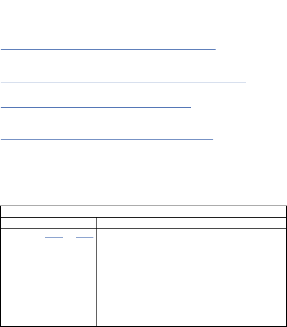
• To insert an artifact into another artifact, open the artifact that you want to insert into and click
Edit. From the toolbar, click the Insert Artifact icon. In the window that opens, select the artifact to
insert.
• To insert an external le into an artifact, open the artifact and click Edit. From the toolbar, click the
Insert Artifact icon. In the window that opens, click Upload a new artifact. Browse to the le to
insert and then enter information about the uploaded le.
• Drag one or more les from the desktop to an artifact.
Restriction: Dragging artifacts to artifacts is not currently supported in Internet Explorer.
Related concepts
“Locks in the Requirements Management (RM) application” on page 116
Locks prevent multiple people from editing the same artifact at the same time. When you edit an artifact,
it is automatically locked.
“Importing requirements artifacts from CSV and spreadsheet les” on page 159
You can import data from comma-separated values (CSV) and spreadsheet les into folders and modules
in an RM project.
“Importing documents into requirements projects or components” on page 153
You can import documents of various types, including Microsoft Word, from your le system to a
requirements project or component.
Related tasks
“Importing artifacts from ReqIF les to a requirements project or component” on page 168
You can import the data in a Requirements Interchange Format (ReqIF) le from your le system to a
requirements project or component.
“Uploading les to a requirements project or component” on page 118
You can upload les from your le system to a requirements project or component. After you upload a le,
depending on its le type, you can modify it, convert its contents to a rich-text artifact, or extract artifacts
from it.
“Importing and extracting requirement artifacts from documents” on page 157
When you import a document to a requirements project or component, you can specify that certain parts
of the document are imported and extracted as specic artifact types. You can also extract artifacts from
a document that is already in a project or component.
Comparison of data exchange methods in requirements management
You can exchange or transfer data in or out of the Requirements Management (RM) application in several
ways. The methods of data exchange are described in the following table. For more information about a
method, click the method name.
Table 15. Comparison of data exchange methods in the RM application
Method Description
CSV, XLS, XLSX import and export You can import and export CSV les or spreadsheets in Microsoft
Excel and Ofce Open XML format. Imports and exports support:
• Embedded artifacts, including graphical artifacts such as sketches,
storyboards, and diagrams.
• Links, including Open Services for Lifecycle Collaboration (OSLC)
links.
• Round trips, in which you update existing artifacts. When you
import CSV les or spreadsheets, you can update existing artifacts
that match imported content, or you can create new artifacts.
Before you import data, you can modify a CSV le by using a third-
party tool. Imported les must be encoded in UTF-8.
120 Engineering Requirements Management DOORS Next
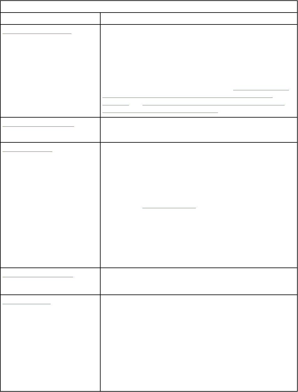
Table 15. Comparison of data exchange methods in the RM application (continued)
Method Description
ReqIF import and export You can use ReqIF import and export to exchange requirement
artifacts and associated metadata between software tools, including
IBM Engineering Requirements Management DOORS (DOORS)
products. The ReqIF specication provides a means for tools that
implement this specication to exchange requirements information.
You can use ReqIF import and export for round trips, in which you
update existing exported artifacts.
For a list of supported and restricted data, see “Importing artifacts
from ReqIF les to a requirements project or component” on
page 168 and “Exporting artifacts from a requirements project or
component into ReqIF les” on page 173.
Migration package import You can use migration package import to migrate data from DOORS.
For more information, click the link in the left column.
Project templates You can copy project templates to other servers; for example, from a
staging server to a production server. Project templates are useful
for creating requirements projects. You can create or modify a
template by using another template. Project templates are also
useful for sharing custom project templates that are applicable to
other repositories.
For a list of items that can be included in or excluded from a
template, see Creating templates.
Restriction:
• A project template cannot be used as a project backup because
artifact history, comments, reviews, and access controls are not
preserved.
• A project template does not preserve the links that are outside of
the artifacts in the template.
Project properties import You can import the project properties from a requirements
management project into another requirements management
project.
Project baselines You can use project baselines for these purposes:
• To capture an entire requirement project at a specic moment in
time, including artifacts, folder trees, and the public tag list.
• To dene scope and manage change by using collections that are
captured in baselines.
• To track development progress and milestones.
• To view specic versions of artifacts, with intact links and
comments, that were captured at specic point in time.
Restriction: Project baselines cannot be used to transfer data
outside of a project.
Managing121
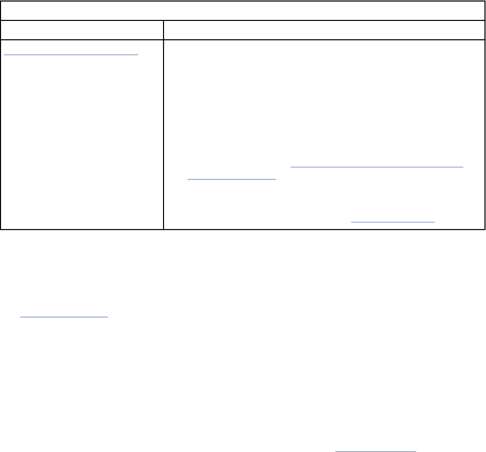
Table 15. Comparison of data exchange methods in the RM application (continued)
Method Description
Database backup and restore Typically, only a product administrator can back up and restore the
database.
Backing up and restoring the database is useful for these purposes:
• To mitigate data loss by backing up the database and indexed les.
• For serviceability, including these tasks:
– Backing up before an upgrade
– Moving data between test and production environments. For
more information, see Backup the IBM Engineering Lifecycle
Management (ELM) on Jazz.net.
Backup is assumed to be at the level of the whole requirements
management repository. Restore is assumed to be targeted to the
same URI. To change the URI, you must rename the server.
Vision document
A vision document denes the high-level scope and purpose of a program, product, or project. A clear
statement of the problem, proposed solution, and the high-level features of a product helps establish
expectations and reduce risks. This topic provides an outline of potential content for a vision document.
See Developing a vision for an explanation of how the product owner or business analyst works with
stakeholders to develop a vision document. That topic, which is part of the IBM Engineering Lifecycle
Management (ELM) scenario guidance, describes the vision-development process. This topic outlines
typical content for the document. You can copy this outline, paste it into a new document, and use it as
the basis for your vision document. Use those portions of this outline that are relevant for your project.
When a team uses the Requirements Management (RM) capability in the ELM, the vision document can
be expressed in one or more rich-text documents or modules. You can embed requirements and related
artifacts in rich-text documents or use the numbered hierarchical structure of a module to organize
content. Team members can set attributes, such as priority and status, on each artifact and create trace
links between related documents, modules, and individual artifacts.
To review the steps for creating and linking documents and modules, see Creating modules.
The vision document outline
1: Introduction
This introduction provides an overview of the entire vision document. It includes the purpose, scope,
denitions, acronyms, abbreviations, references, and an overview of the full document.
1.1 Purpose: State the purpose of this vision document.
1.2 Scope: Briefly describe the scope of this vision document, including which programs, projects,
applications, and business processes the document is associated with. Include anything else that this
document affects or influences.
1.3 Denitions, acronyms and abbreviations: Dene all terms, acronyms, and abbreviations that are
required to interpret the vision correctly. This information might be provided by reference to the project
glossary, which can be developed online in the RM repository.
1.4 References: List all documents that the vision document refers to. Identify each document by title,
report number (if applicable), date, and publishing organization. Specify the sources from which readers
can obtain the references; the sources are ideally available in RM or in other online repositories. This
information might be provided by reference to an appendix or to another document.
122
Engineering Requirements Management DOORS Next
1.5 Overview: Describe the vision-document contents and explain how the document is organized.
2: Positioning
2.1 Business opportunity: Briefly describe the business opportunity that is addressed by this project.
2.2 Problem statement: Summarize the problem that this project solves. Use the following statements as
a model, providing project details to replace the parenthetical elements:
The problem of (describe the problem) affects (the stakeholders affected by the problem). The impact of
the problem is (what is the impact of the problem). A successful solution would include (list some key
benets of a successful solution).
2.3 Product position statement: Provide an overall statement that summarizes at the highest level the
unique position the product intends to take in the marketplace. Use the following statements as a model,
providing project details to replace the parenthetical elements:
For the (target customer), who (statement of the need or opportunity). The (product name) is a
(product category) that (statement of key benet, that is, the compelling reason to buy). Unlike (primary
competitive alternative), our product (statement of primary differentiation).
A product position statement communicates the intent of the application and the importance of the
project to all concerned stakeholders.
3: Stakeholder and user descriptions
To provide products and services that meet stakeholders' and users' needs, you must identify and involve
all stakeholders as part of the requirements-denition process. You must also identify the system users
and ensure that the stakeholder community represents them adequately.
This section provides a prole of the stakeholders and users who are involved in the project. This
section also identies the key problems that stakeholders and users consider that the proposed solution
must address. This section does not describe specic requests or requirements; a separate stakeholder
requests artifact captures these items. The key-problem description provides the background and
justication for requirements.
3.1 Market demographics: Summarize the key market demographics that motivate your product
decisions. Describe and position target market segments. Estimate the market size and growth by using
the number of potential users. Alternatively, estimate the amount of money that your customers spend
trying to meet the needs that your product or enhancement would fulll. Review major industry trends
and technologies. Answer these strategic questions:
• What is the reputation of your organization in these markets?
• What would you like the reputation to be?
• How does this product or service support your goals?
3.2 Stakeholder summary: List all the identied stakeholders. For each stakeholder type, provide this
information:
• Name: Name the stakeholder type.
• Represents: Briefly describe which individuals, teams, or organizations this stakeholder type
represents.
• Role: Briefly describe the role this stakeholder type plays in the development effort.
3.3 User summary: List all the identied user types. For each user type, provide this information:
• Name: Name the user type
• Description: Briefly describe the relationship of this type of user to the system under development.
• Stakeholder: List which stakeholder type represents this user type.
3.4 User environment: Detail the working environment of the target user. Here are some suggestions:
• How many people are involved in completing the task? Is this changing?
Managing
123
• How long is a task cycle? How much time do users spend in each activity? Is this changing?
• What unique environmental constraints affect the project? For example, do users require mobile
devices, work outdoors, or work during flights?
• Which system platforms are in use today? Are there future platforms planned?
• What other applications are in use? Does your application need to integrate with them?
In this section, you might include extracts from the business model to outline the task and workers who
are involved.
3.5 Stakeholder proles: Describe each stakeholder in the project by completing the following table for
each stakeholder. Remember: Stakeholder types can be users, strategy departments, legal or compliance
departments, technical developers, operations teams, and others. A thorough prole covers the following
topics for each stakeholder type:
• Representative: State who represents the stakeholder to the project (This information is optional if it is
documented elsewhere.) Enter the representatives' names.
• Description: Briefly describe the stakeholder type.
• Type: Qualify the expertise of the stakeholder, such as "guru", "business expert" , or "casual user." This
designation can suggest technical background and degree of sophistication.
• Responsibilities: List the key responsibilities of the stakeholder on the system under development; list
their interests as a stakeholder.
• Success criteria: State how the stakeholder denes success. How is the stakeholder rewarded?
• Involvement - Describe how the stakeholder is involved in the project. Where possible, relate the
involvement to the process roles; for example, a stakeholder might be a requirements reviewer.
• Deliverables: Identify additional deliverables that the stakeholder requires. These items might be
project deliverables or output from the system under development.
• Comments or issues: State problems that interfere with success and any other relevant information.
3.6 User proles: Describe each user of the system here by completing the following table for each
user type. Remember user types can be experts and novices; for example, an expert might need a
sophisticated, flexible tool with cross-platform support, while a novice might need a tool that is easy to
use. A thorough prole covers these topics for each type of user:
• Representative: State who represents the user to the project. (This information is optional if it is
documented elsewhere.) This representative often refers to the stakeholder who represents a set of
users; for example, Stakeholder: Stakeholder1.
• Description: Briefly describe the user type.
• Type: Qualify the expertise of the user, such as "guru" or "casual user". This designation can suggest
technical background and degree of sophistication.
• Responsibilities: List the key user responsibilities with respect to the system; for example, state who
captures customer details, produces reports, and coordinates work, and so on.
• Success criteria: State how the user denes success. How is the user rewarded?
• Involvement: Describe how the user is involved in the project. Where possible, relate the involvement to
process roles; for example, a stakeholder might be a requirements reviewer.
• Deliverables: Identify the deliverables that the user produces and for whom.
• Comments or issues: State problems that interfere with success and any other relevant information.
Describe trends that make the user's job easier or harder.
3.7 Key stakeholder or user needs: List the key problems with existing solutions as the stakeholder
perceives them. Clarify these issues for each problem:
• What are the reasons for this problem?
• How is the problem solved now?
• What solutions does the stakeholder want?
124
Engineering Requirements Management DOORS Next
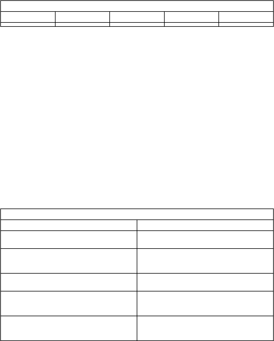
You must understand the relative importance that the stakeholder places on solving each problem.
Ranking and cumulative voting techniques help indicate the problems that must be solved versus issues
that stakeholders would like to be addressed. Use this table to capture the stakeholder needs.
Table 16. Stakeholder needs
Need Priority Concerns Current solution Proposed solution
3.8 Alternatives and competition: Identify alternatives that the stakeholder perceives as available.
These alternatives can include buying a competitor's product, building a homegrown solution, or
maintaining the status quo. List any known and available competitive choices. Include the major strengths
and weaknesses of each competitor as the stakeholder perceives them.
4: Product overview
This section provides a high-level view of the product capabilities, interfaces to other applications, and
systems congurations. This section typically consists of three subsections:
• Product perspective
• Product functions
• Assumptions and dependencies
4.1 Product perspective: Put the product in perspective with regards to other related products and
the user's environment. If the product is independent and completely self-contained, state it here. If
the product is a component of a larger system, relate how these systems interact and identify the
relevant interfaces between the systems. One way to display the major components of the larger system,
interconnections, and external interfaces is to use a business process or use case diagram.
4.2 Summary of capabilities: Summarize the major benets and features that the product will provide.
For example, a customer support system might use this part to address problem documentation, routing,
and status reporting without elaborating on detail that these functions require. Organize the functions
so that the list is understandable to the customer or to anyone else who reads the document for the
rst time. A simple table that lists the key benets and their supporting features might sufce, as in the
following example.
Table 17.
Benets and features example
Customer benet Supporting features
New support staff can quickly learn how to use the
product.
A knowledge base assists support personnel in
quickly identifying known xes and workarounds.
Customer satisfaction is improved because nothing
falls through the cracks.
Problems are uniquely itemized, classied,
and tracked throughout the resolution process.
Automatic notication occurs for any aging issues.
Management can identify problem areas and gauge
staff workload.
Trend and distribution reports enable a high-level
review of problem status.
Distributed support teams can work together to
solve problems.
With a replication server, current database
information can be shared throughout the
enterprise.
Customers can help themselves, lowering support
costs and improving response time.
A knowledge base can be made available over the
Internet. The knowledge base includes hypertext
search capabilities and a graphical query engine.
4.3 Assumptions and dependencies: List each of factor that affects the features that the vision
document includes. List assumptions that, if changed, will alter the vision document. For example, an
assumption might state that a specic operating system will be available for the designated hardware for
the software product. If the operating system is not available, the vision document will require change.
Managing
125
4.4 Cost and pricing: Record relevant cost and pricing impacts and constraints. For example, distribution
costs (the number of CDs and CD mastering) or other cost-of-goods-sold constraints (manuals and
packaging) might be material or irrelevant to project success, depending on the nature of the application.
4.5 Licensing and installation: Licensing and installation issues can also directly affect the development
effort. For example, the need to support serializing, password security, or network licensing will
create additional system requirements that must be considered in the development effort. Installation
requirements might also affect coding, or create the need for separate installation software.
5: Product features
List and briefly describe the product features. Features are the high-level capabilities of the system
that are required to deliver benets to the users. Each feature is a requested service that typically
requires a series of inputs to achieve a satisfactory result. For example, a feature of a problem-tracking
system might be the ability to provide trending reports. As the use case model takes shape, update the
description to refer to the use cases.
Because the vision document is reviewed by a wide variety of involved personnel, keep the level of detail
general enough for everyone to understand. However, offer sufcient detail to provide the team with the
information it needs to create a use case model or other design documents.
To manage application complexity, for a new system or an incremental change, list capabilities at such
a high level that you include approximately 25-99 features. These features provide the basis for product
denition, scope management, and project management. Each feature will be expanded into greater
detail in the use case model.
Throughout this section, make each feature relevant to users, operators, or other external systems.
Include a description of functions and usability issues that must be addressed. The following guidelines
apply:
• Avoid design. Keep feature descriptions at a general level. Focus on required capabilities and why (not
how) they should be implemented.
• Designate all features as requirements of a specic feature type for easy reference and tracking.
5.1 Feature 1.
5.2 Feature 2.
6:Constraints
Note any design constraints, external constraints, such as operational or regulatory requirements, or
other dependencies.
7: Quality ranges
Dene the quality ranges for performance, robustness, fault tolerance, usability, and similar
characteristics that the feature set does not describe.
8: Precedence and priority
Dene the priority of the different system features.
9: Other product requirements
At a high level, list applicable standards, hardware or platform requirements, performance requirements,
and environmental requirements.
9.1 Applicable standards: List all standards that the product must comply with. The list can include
these standards:
• Legal and regulatory standards (FDA, UCC)
• Communications standards (TCP/IP, ISDN)
• Platform compliance standards (Windows, UNIX, and so on)
126
Engineering Requirements Management DOORS Next
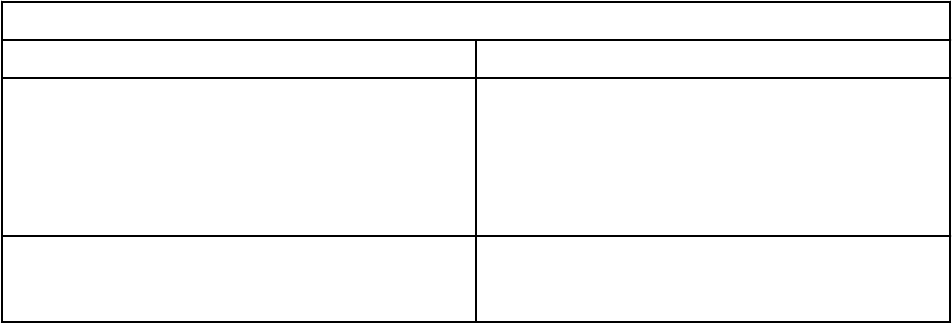
• Quality and safety standards (UL, ISO, CMM)
9.2 System requirements: Dene the system requirements for the application. These can include the
supported host operating systems and network platforms, congurations, memory, peripheral devices,
and companion software.
9.3 Performance requirements: Detail performance requirements. Performance issues can include such
items as user-load factors, bandwidth or communication capacity, throughput, accuracy, reliability, or
response times under various load conditions.
9.4 Environmental requirements: Detail environmental requirements as needed. For hardware-based
systems, environmental issues can include temperature, shock, humidity, and radiation. For software
applications, environmental factors can include use conditions, user environment, resource availability,
maintenance issues, error handling, and recovery.
10: Documentation Requirements
This section describes the documentation that you must develop to support successful application
deployment.
10.1 Release notes, read me le: Release notes or an abbreviated read me le can include a "What's
new" section, a discussion of compatibility issues with earlier releases, and installation and upgrade
alerts. The document can also contain or link to xes in the release and any known problems and
workarounds.
10.2 Online help: Many applications provide an online help system to assist the user. The nature of these
systems is unique to application development as they combine aspects of programming (searchable
information and web-like navigation) with aspects of technical writing (organization and presentation).
Many teams nd that developing an online help system is a project within a project that benets from
scope management and planning at the project outset.
10.3 Installation guides: A document that includes installation, conguration, and upgrade instructions
is part of offering a full solution.
10.4 Labeling and packaging: A consistent look and feel begins with product packaging and applies
to installation menus, splash screens, help systems, GUI dialog boxes, and so on. This section denes
the needs and types of labeling to be incorporated in the code. Examples include copyright and patent
notices, corporate logos, standardized icons, and other graphic elements.
11: Appendix 1 - Feature attributes
Give features attributes that can be used to evaluate, track, prioritize and manage the product items that
are proposed for implementation. Outline all requirement types and attributes in a separate requirements
management plan. However, you might want to list and briefly describe the attributes for features that
have been chosen. The following subsections represent a set of suggested feature attributes.
11.1 Status: Teams set feature status after negotiation and review by the project management team.
Status tracks progress throughout the life of the project. The following table provides an example of
typical status-attribute values.
Table 18. Status value examples
Status Description
Proposed Describes features that are under discussion but
have not been reviewed and accepted by the
"ofcial channel." The ofcial channel might be
a working group that consists of representatives
from the project team, product management, and
user or customer community.
Approved Capabilities that are deemed useful and feasible
and have been approved for implementation by the
ofcial channel.
Managing127
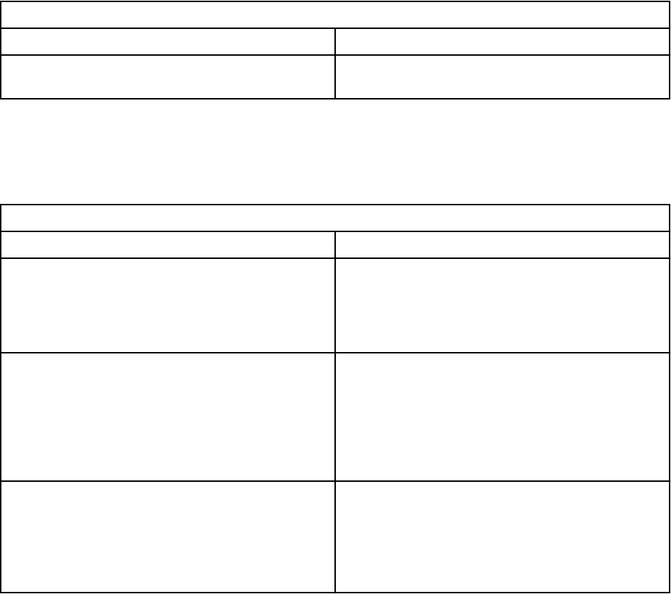
Table 18. Status value examples (continued)
Status Description
Incorporated Features that have been incorporated into the
product baseline.
11.2 Benet: The marketing group, the product manager, or the business analyst sets the feature
benets. All requirements are not created equal. Ranking requirements by their relative benet to the
user opens a dialog with customers, analysts, and members of the development team. Use benets in
managing project scope and determining development priority. The following table provides an example
of typical benet or priority attribute values.
Table 19. Benet priority examples
Priority Description
Critical Essential features. Failure to implement a critical
feature means that the system will not meet
customer needs. All critical features must be
implemented in the release or the schedule will
slip.
Important Features important to the effectiveness and
efciency of the system for most applications. The
functions cannot be easily provided in some other
way. Omitting an important feature might affect
customer or user satisfaction, or even revenue.
However, the release will not be delayed because
an important feature is not included.
Useful Features that are useful in less typical applications,
are used less frequently, or that can be met with
reasonably efcient workarounds. No signicant
revenue or customer satisfaction impact can be
expected if such an item is not included in a
release.
11.3 Effort: The development team estimates the effort that is required to implement features. Some
features require more time and resources than others. Estimating the time, required code, or functions,
helps gauge complexity and set expectations of what can be accomplished in a given time frame. Use the
estimate in managing scope and determining development priority.
11.4 Risk: The development team establishes risk levels, based on the probability that the project will
experience undesirable events, such as cost overruns, schedule delays, or even cancellation. Most project
managers nd categorizing risks as high, medium, and low is sufcient, although ner gradations are
possible. Risk can often be assessed indirectly by measuring the uncertainty (range) of the project team's
schedule estimate.
11.5 Stability: The analyst and development team establish feature stability based on the probability
that the feature will change or the team's understanding of the feature will change. Stability is used to
help establish development priorities and determine those items for which additional elicitation is the
appropriate next action.
11.6 Target release: Teams record the earliest intended product version that will include the feature.
You can use this eld to allocate features from a vision document into a particular baseline release.
When combined with the status eld, your team can propose, record, and discuss various features of the
release without committing them to development. Only features whose status is set to "incorporated"
and whose target release is dened will be implemented. With scope management, the target release
version number can be increased, and the item remains in the vision document but is scheduled for a later
release.
128
Engineering Requirements Management DOORS Next
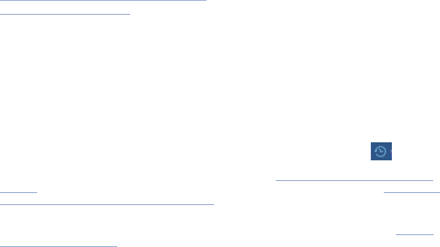
11.7 Assigned to: In many projects, features are assigned to feature teams that are responsible for
further elicitation, writing the software requirements, and implementation. The process helps everyone
on the project team better understand responsibilities.
11.8 Reason: Teams use this text eld to track the source of the requested feature. Requirements exist
for specic reasons. This eld records an explanation or a reference to an explanation. For example, the
reference might point to a page and line number of a product requirement specication or point to a
minute marker on a customer-interview video.
Creating modules
You can create modules and module content directly in a project or by importing a Microsoft Word
document, ReqIF le, or rich-text document.
About this task
For various ways of creating modules and adding content to them, see the following topics and related
links.
These artifacts or content of the modules are stored by default under Folders. Use the drag-and-drop
action to move one or more folders and re-organize them.
Related information
Watch tutorial movies about creating modules
Importing and exporting les
Modules in the Requirements Management application
A module is a structured document that is composed of multiple artifacts. You can create structure in a
module by modifying the order and hierarchy of its artifacts. The artifacts that are created for modules
are stored as module content in a folder. Base artifacts can be used to manage the module artifacts
independent of the module.
You can create a module in different ways. For example, you can create an empty module and add
artifacts to it, or, you can create a module by importing a Microsoft Word document or rich-text le. When
you import a le, a wizard identies and creates artifacts from the document content. The artifacts are
identied and created based on structure, keyword, or text delimiter, such as a semicolon or a square
bracket. To see recently viewed artifacts, click the Recently Viewed Artifacts icon .
To watch a video that shows you how to create a module, see Lesson 1: Create a module and add
artifacts. To compare capabilities and potential uses for collections and modules, see “Differences
between collections and modules” on page 131.
Tip: You can associate modules with preferred artifact types so that when team members add artifacts
to modules, the preferred artifact types are shown by default. For more information, see Creating
requirement artifact types.
Module capabilities
In the web client, you can perform the following activities in a module:
• View and edit the content of artifacts. When you open a module, the Selected Artifact tab is shown by
default. However, the tab that you select is preserved across browser sessions. If you select the Module
tab, the next time you open that module, the Module tab is selected.
• Add, delete, move, and indent artifacts to create order and a hierarchy with numbered headings.
• Add a new or existing artifact before, after, or as a child of the selected artifact. When you create a new
module, the Open Artifact option opens the newly created module in view mode.
Note: When you create an artifact before or after the selected artifact, the new artifact is created with
the same artifact type as the selected artifact.
Managing
129

• Remove artifacts from a module. If the artifacts have child artifacts, the Conrm Removal dialog box
indicates the number the child artifacts that will be removed. To permanently delete artifacts that are
not used in other modules, select the If the artifacts are not in other modules, permanently delete
them check box.
• Set attribute values at the module level and on artifacts in the module.
• Edit the attributes of artifacts in the module and change the artifact type of the artifacts.
Note: When you create an artifact type, you can show artifacts of that type as a heading by default. For
more information, see “Creating requirement artifact types” on page 29.
• Set an attribute value for multiple artifacts in the module.
• Create links, comments, tags, and reviews for the module or for artifacts in the module.
• Change the default display settings to include links, comments, tags, and comments from base artifacts.
For more information, see Reusing artifacts in modules.
• Filter your view of the module content by tag, artifact type, and other attributes.
• Create, save, and reuse views that are based on lters and display properties.
• Generate a document-style report in PDF, Microsoft Word, HTML, or XSL-FO format.
The Administrator can control the caching for modules by specifying the following properties in the
module:
• Number of artifacts in a module page: The number of artifacts requested from the server per page in a
module. The default value is 30 artifacts.
• Number of pages to cache per module: The total number of pages to cache when scrolling through a
module. The minimum value is 3 pages and the default value is 10 pages.
• Number of pages to prefetch in a module: The number of pages to prefetch in either direction from the
current scroll position. This value is limited to between 1 and 3 pages. The maximum is 2 pages if over
50 rows are loaded per page, and 1 page if over 100 artifacts are loaded per page.
Modules and base artifacts
Artifacts can be created and managed in a project independently from a module. These are called base
artifacts. Base artifacts can also be used in one or more modules. You can link base artifacts with other
base artifacts or with artifacts in the context of a module. Links to and from base artifacts are available in
all modules in which those artifacts are used. See Base artifacts
.
Modules and module content
The artifacts that are created for modules are stored by default in the same folder as the module.
However, you can change this default setting and specify another module content folder to store all the
artifacts that are created for new modules. When a common module content folder is used, any user that
has permission to create a module also has permission to create a module content folder in the common
module folder regardless of any existing permissions or team area ownership settings. If a common
Module Content Folder is being used, it can be copied or cloned, but the project or component property
of the Module Content Folder is not copied or cloned. If you import project properties or component
properties, the module content folder is not imported.
Modules and ELM artifacts
From modules and module views, you can link to artifacts in other IBM Engineering Lifecycle Management
(ELM) applications. For example, you can link from a module to development plans and test plans. You
can also link to artifacts in other modules. In the Change and Conguration Management (CCM) and
Quality Management (QM) applications, you can generate plan items and test cases that correspond to
the artifacts in the module. For more information, see Linking collections, modules, and module views to
development and test plans.
130
Engineering Requirements Management DOORS Next
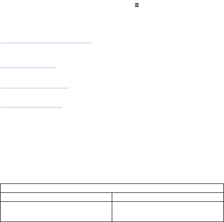
Viewing module history
To view the changes in the module, on the More actions menu , click Open History > Audit History
tab. This tab shows a complete history of changes that goes back to the creation of the module. To return
to the module, click Close History. You can also access the artifact history by clicking Open Artifact >
Open Artifact History.
Related concepts
“Filters and views in modules” on page 148
In modules, you can modify the column settings, lter the artifacts that are shown, and then save the
column and lter settings as a view. You can modify columns to show specic attributes or link types, and
you can lter by artifact type, artifact tags, attribute values, and link types.
“Collections” on page 176
A collection is a set artifacts that you create for a specic purpose.
Related tasks
“Creating modules” on page 129
You can create modules and module content directly in a project or by importing a Microsoft Word
document, ReqIF le, or rich-text document.
“Module options” on page 33
A module is a structured document that is composed of multiple artifacts. These artifacts or content of
the modules are stored by default in a folder which is created in the same directory as the module. In
the Modules Options tab, an administrator can change this default to specify another folder to store the
multiple artifacts of a module. You can use drag-and-drop to move one or more folders and re-organize
them. If your project area has not been enabled for conguration management, an administrator can
schedule a refresh of the module view to ensure that the latest module content is loaded from the data
warehouse.
Differences between collections and modules
Collections and modules offer different ways to group and manage a set of artifacts. Both of these artifact
types are flexible but they do offer different capabilities. This topic summaries these capabilities and
presents typical uses of each artifact type to help you get started. Adjust your usage to suit the needs of
your team and your project.
Table 20. Comparing capabilities of collections and modules
Collection Module
Denition: A group of artifacts with no particular
order or hierarchy.
Denition: A structured artifact that is composed
of other artifacts. Structure is created by modifying
the order and hierarchy of the artifacts.
Managing131

Table 20. Comparing capabilities of collections and modules (continued)
Collection Module
Possible uses:
• Produce a quick, informal group of artifacts.
• Identify a set of artifacts based on a common
focus, such as requirements and related artifacts
for an iteration, milestone, feature, function,
team ownership, or other related purpose.
• Capture a set of artifacts for reviews, reports.
• Create a glossary (collection of term artifacts).
• Associate a set of requirements with a
development plan or test plan. Generate
development work items and test cases, based
on requirements in the collection.
Possible uses:
• Present and manage a requirements
specication.
• Create a structured, hierarchical requirements
document with numbered section headings and
subheadings. View in outline form or with full
content.
• Manage the requirements document with views,
lters, artifact types, attributes, tags, links, and
comments.
• Create separate modules for high-level
requirements, detailed requirements, particular
systems and subsystems, or for some other
common layer of abstraction, and create
traceability between requirements in these
specications.
• Associate a requirements specication with
a development plan or test plan. Generate
development work items and test cases, based
on the contents of the module.
Other capabilities:
• Create a collection by adding existing artifacts or
by creating new artifacts within the collection.
• Create a review of the collection and its artifacts.
• Export the collection contents to CSV format.
• Generate a document-style report in PDF,
Microsoft Word, HTML, or XSL-FO format.
• Create a group of modules, or modules and other
artifacts.
Other capabilities:
• Create a module by adding existing artifacts or by
creating new artifacts within the module. Create
a module by importing information from text
documents. While importing, you can use the
wizard to identify and create artifacts from the
document content based on structure, key word,
or text delimiter, such as a semicolon or square
bracket.
• Create links, tags, and comments that are
associated with the entire module, or that are
specic to individual artifacts and only viewable
in the context of the module.
• View in outline form (headings only) or with full
content.
• Search and replace text in all artifacts in the
module.
• Export a module view to CSV format.
• Create a collection from a saved view in a
module.
• Generate a document-style report in PDF,
Microsoft Word, HTML, or XSL-FO format.
Notes:
Collections are represented as collections in the
Open Services for Lifecycle Collaboration (OSLC)
Requirements Management specication version
2.0 API.
Notes:
Modules are represented as collections in the
Open Services for Lifecycle Collaboration (OSLC)
Requirements Management specication version
2.0 API.
132 Engineering Requirements Management DOORS Next
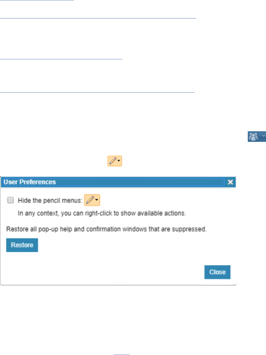
Related concepts
“Collections” on page 176
A collection is a set artifacts that you create for a specic purpose.
“Modules in the Requirements Management application” on page 129
A module is a structured document that is composed of multiple artifacts. You can create structure in a
module by modifying the order and hierarchy of its artifacts. The artifacts that are created for modules
are stored as module content in a folder. Base artifacts can be used to manage the module artifacts
independent of the module.
“Filters and views in modules” on page 148
In modules, you can modify the column settings, lter the artifacts that are shown, and then save the
column and lter settings as a view. You can modify columns to show specic attributes or link types, and
you can lter by artifact type, artifact tags, attribute values, and link types.
“Filters and views for artifacts in requirements projects” on page 111
Filters and views are useful for sorting and displaying artifacts that are based on specic criteria. You can
use lters and the congure page settings to display artifacts, and then save this conguration as a view
to use later.
User preferences
You can set preferences for requirements management by clicking the User Prole icon , and then
clicking My User Preferences. Preferences are applied to the ID of the user that is logged in.
The drop-down beside the pencil icon
lists all the available actions. If your screen is getting
cluttered, you can set your preferences to hide the pencil menus.
Duplicating a module
When you duplicate a module, you have options to create copies of the content from the original module,
or reuse and share the original content in the new module.
About this task
After investing effort in creating a module, you can duplicate it and use the copy as a starting point for
a new module. In the new copy, you can reuse
the headings and other artifacts that are in the original
module, or you can copy (duplicate) them to create new headings and other artifacts in the new module.
When you reuse content, any changes to the name, primary text, or diagram content that are made to
those artifacts in other modules or in the base artifacts are reflected in the new module. When you
duplicate a module, you can also choose to reproduce the links in the new and reused artifacts.
To summarize:
• In all cases when you duplicate a module, a new module is created.
Managing
133
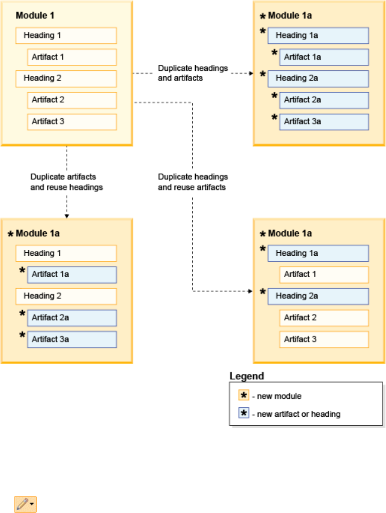
• When you duplicate headings or other artifacts, new artifacts are created that are based on the contents
of the original module.
• When you reuse headings and other artifacts, their content is shared by the instances of those artifacts
in the original module, as well as in the base artifacts outside of the modules.
The following graphic shows three options for copying all content, copying only headings, and copying
only non-heading artifacts. Additional options are described in the procedure that follows the graphic.
Figure 1. Examples of three options for copying a module
Procedure
1. On the Modules page, place your cursor in the left column of any module in the list, click the Edit menu
, and select Duplicate Artifact.
2. In the Duplicate Artifact to Folder window, type a name, and select a folder for the new module.
3. In the Duplicating or reusing artifacts in modules section, select one of the following options to copy
or reuse content in the new module:
• Duplicate all artifacts: Creates new headings and other artifacts. These are copies of the headings
and artifacts that are in the original module.
134
Engineering Requirements Management DOORS Next
• Duplicate no artifacts: Reuses all existing headings and other artifacts. The only new artifact is the
module itself.
• Duplicate all heading artifacts. Creates new headings that are copies of the existing ones, and
reuses other existing artifacts.
• Re-use all heading artifacts: Reuses existing headings. Creates copies of all other artifacts.
• Duplicate all artifacts specied by a view, re-use all other artifacts: Creates new headings and
other artifacts that are copies of existing ones if they match the criteria of lters in a saved view. All
other headings and artifacts are reused.
4. Optional: In the Copy items from the original artifact section, select the Copy links and Copy tags
check box to copy items from the original artifact.
5. Optional: In the Link the artifacts section, select the check box to create a link from the original
artifact to the copied artifact and select the link type from the list.
6. To save the new module and any new artifacts, click OK.
A link is created between the original module artifact and the copied module artifact. All the artifacts in
the new module have links to the artifact in the original module.
Related tasks
“Creating modules” on page 129
You can create modules and module content directly in a project or by importing a Microsoft Word
document, ReqIF le, or rich-text document.
Searching for artifacts in a module
You can search for an artifact in a module and replace one text string with another. You can also search for
an artifact by section number or artifact ID.
About this task
During the Find operation:
• Visible content in the module is searched. Content in collapsed sections and string attributes that are
not displayed in the module view are not searched.
• String attributes and content for text artifacts are identied in a search. Embedded artifacts, such as
graphical artifacts, are not searched.
Tip: If you have recently opened the artifact, click the Recently Viewed Artifacts
icon to locate the
artifact from a module.
Procedure
• Complete the following steps to search for an artifact in a module:
a) Open the module.
b) Click the Find/Go To icon
.
c) In the window that opens, on the Find tab, type the text to search for and specify other options as
needed. To nd an exact text phrase, type the text within quotation marks.
Important:
– Specifying search strings that are composed of only special characters is not supported.
– The Find operation is an exact phrase search. Partial words and multiple words can be used as
search strings in the Find tab, but wildcards are not supported.
– The Find operation ignores the following common words: "a", "an", "and", "are", "as", "at", "be",
"but", "by", "for", "if", "in", "into", "is", "it", "no", "not", "of", "on", "or", "such", "that", "the",
"their", "then", "there", "these", "they", "this", "to", "was", "will", and "with". If you perform a
Find operation by using any of these words, no matches are found.
Managing
135
• To nd and replace text across all of the artifacts in a module, open the module and click the Find/Go
To icon . Type the text that you want to replace and the replacement text, and then click Find,
Replace, or Replace/Find as needed.
Note: Only string attributes and content for text artifacts are identied in a search. Use the Go To tab
when you know the section number or the artifact ID.
• To locate and select an artifact in a module when you know the section number or the artifact ID,
click the Find/Go To icon . Click the Go To tab, and type either an artifact ID number or a section
number and then, click Go To.
To show section numbers, click the More actions icon
, select Congure Columns to Display, and
add the Section column.
Results
In the search results, a vertical blue bar indicates that the artifact is in a module, and the module name is
shown in the result description.
Related concepts
“Modules in the Requirements Management application” on page 129
A module is a structured document that is composed of multiple artifacts. You can create structure in a
module by modifying the order and hierarchy of its artifacts. The artifacts that are created for modules
are stored as module content in a folder. Base artifacts can be used to manage the module artifacts
independent of the module.
“Filters and views for artifacts in requirements projects” on page 111
Filters and views are useful for sorting and displaying artifacts that are based on specic criteria. You can
use lters and the congure page settings to display artifacts, and then save this conguration as a view
to use later.
“Searches for artifacts in requirements projects” on page 113
You can nd artifacts by using quick search, full-text search, and lters. Search can be done with the
artifact ID or with text within the artifact.
Linking between artifacts in modules
You can link artifacts that are in the same module or artifacts that are in different modules.
Before you begin
You can link from an artifact in a module to another artifact in a module by using a bidirectional link
type. Labels explain the directional relationship of the link. See Link direction. If you create links only
between artifacts in the context of modules, the links exist only in those modules and in any copies
you make of the module. To link two artifacts that are in different modules by using the drag-and-drop
method, you must be working in a Mozilla Firefox, Microsoft Internet Explorer, or Google Chrome browser.
In Microsoft Internet Explorer, the drag-and-drop method is supported only between modules that are
open in different browser windows.
Note: You can link base artifacts with other base artifacts or with artifacts in the context of a module.
Links to and from base artifacts are available in all modules in which those artifacts are used. A blue icon
over the artifact type icon indicates linking with a base artifact .
For information about linking in base artifacts, see “Base artifacts” on page 146.
Procedure
• To create a link between artifacts that are in the same module:
a) Open a module.
136
Engineering Requirements Management DOORS Next
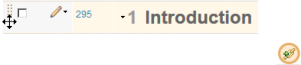
b) Hover the mouse over the left side of an artifact until the cursor becomes a four-sided arrow.
c) Drag the artifact under the target artifact. When the link icon is shown to the right of the
artifact, drop the artifact on the icon.
d) Select the type of link to create, and then click OK.
You can also paste the copied artifacts as links in the Link column. To paste as a link, right-click in
the Links column and click Paste as Link.
Tip: If a link column is shown on the page, you can create a link of that type by dragging an artifact
to that column. You are not prompted to select a link type.
• Firefox, Internet Explorer, or Chrome browsers only: To link between two artifacts that are in
different modules by using the drag-and-drop method:
a) Click Modules > Browse Modules.
b) Press Ctrl and click a module.
The module opens in a browser tab.
c) Press Ctrl and click the module to link to. If you are working in Internet Explorer, you must open the
module in a separate window.
d) In the module that you opened rst, hover the mouse over the left side of an artifact until the cursor
becomes a four-sided arrow.
e) Drag the artifact to the browser tab that contains the target module; then continue to drag the
artifact to the target artifact. When the link icon is shown to the right of the artifact, drop the artifact
on the icon.
Note: You cannot drag and drop artifacts to a module that has a sort column or at least one lter
and receive a warning message if you attempt to.
Tip: You can also link between artifacts in two different modules by opening each module in a separate
window and dragging artifacts between the two modules. To open a module in a separate window,
right-click the module name, and then click Open in new window.
• To create a link between two artifacts that are in different modules by using the copy-and-paste
method:
a) Select the artifact to link from and then click Copy Artifact.
b) Select an artifact in another module and click Paste Special.
The Paste Special window opens.
c) Click Create a link to this artifact and then follow the prompts.
• To link to an artifact in a module by using the Create Link option:
a) From the Link type list, select the link type.
b) In the Where to link to eld, select Project.
c) From the Project list, select the project where you want to link the artifact. If conguration
management is enabled for the project, from the Component list, select the required component.
You can also view the project that is associated with each component.
Managing
137
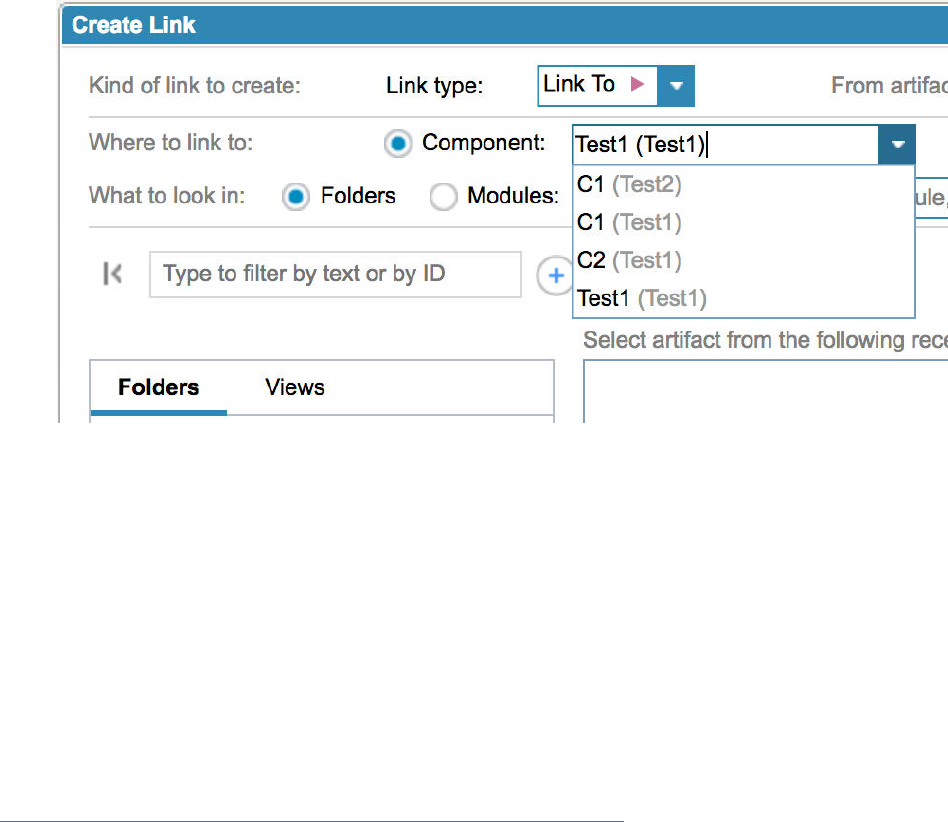
Tip: To search for projects or components, you can type the name of the project or component in
the Project or Component eld. Project or component names that match the search keywords are
shown in the list.
d) Optional: To link the artifact to a web link, select the The web option. You can dene the link label
and the URL link to link the artifact.
e) Select the Folders or Modules option and select the destination artifact.
f) Click OK.
When you delete links from modules within a project or a component, the link is removed from the
source module and the target module. For module links across projects or components, you can delete
Outgoing links and the link is removed from the source module and the target module. However, if you
delete an Incoming link, the link is deleted from the source module but not the target module. So, in
the target module, the link appears as an Outgoing link with an inaccessible target.
Related concepts
“Modules in the Requirements Management application” on page 129
A module is a structured document that is composed of multiple artifacts. You can create structure in a
module by modifying the order and hierarchy of its artifacts. The artifacts that are created for modules
are stored as module content in a folder. Base artifacts can be used to manage the module artifacts
independent of the module.
Linking by attribute
You can quickly and automatically create links between multiple artifacts by artifact attribute.
Before you begin
You can use the Link by Attribute function to automatically create, update, and delete links between
artifacts based on an attribute value. To use this feature, type the artifact IDs of the target artifacts
(separated by commas) in a custom string attribute type, select Link by Attribute and then follow the
prompts. You can use this function in a module, a collection, or in any artifact view.
Note: This feature can also be used in conjunction with the CSV round-trip support to handle creating and
changing links when you import data.
The following example provides a more thorough explanation of how the Link by Attribute function
works. The examples show how to create links between multiple artifacts in a single module and between
artifacts in different modules. First, the example shows how to complete these tasks:
• Create a custom attribute called MyString.
• Add the MyString attribute to a Feature artifact type.
138
Engineering Requirements Management DOORS Next
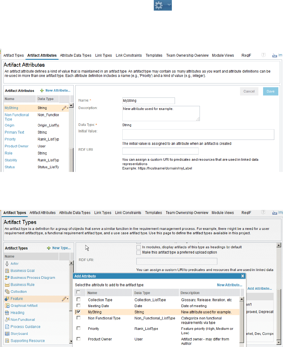
• Change the column headings in a sample module to display the MyString attribute.
Then, the example shows how to add artifact IDs of the artifacts to link to in the MyString attribute, and
how to run the Link by Attribute function to automatically create the links.
Procedure
1. Click the drop-down menu for the Administration icon and select Manage Project Properties.
Note: If conguration management is enabled for your project, on the Administration menu, click
Manage Component Properties.
2. On the Artifact Attributes page, click New Attribute and create a custom attribute that is called
MyString with a data type of string, as shown in the following image:
Note: You can use any custom attribute type as long as the type is string and is not a predened
system attribute.
3. Add the newly created MyString attribute to a Feature artifact type, as shown in the following
image:
4. Create a sample module that contains several Feature artifacts.
5. Change the column headings in the module to show the new MyString attribute column and the
Linked To column, as shown in the following image:
Managing
139
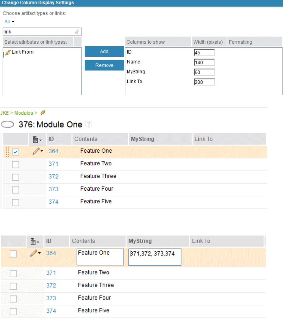
The sample module is displayed with the new columns:
6. To create links from Feature One to Feature Two, Feature Three, Feature Four, and Feature Five.
To create these links, type the ID of each target artifact (separated by commas) in the MyString
column, as shown in the following image:
7. Then, to automatically create the links, select the check boxes for the artifacts and click Other
Actions > Link By Attribute, as shown in the following image:
140
Engineering Requirements Management DOORS Next
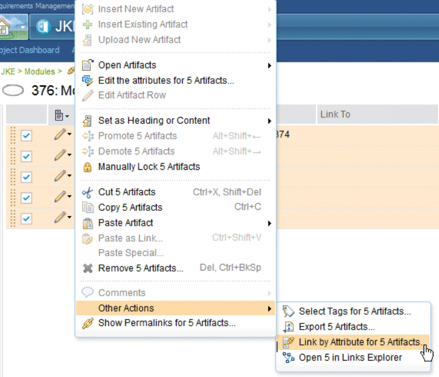
8. In the Link by Attribute window, in the Attribute eld, select MyString and, in the Link type eld,
select Link To. Click OK.
Managing
141

The links that you specied are automatically created, as shown in the Link To column in the
following image:
9.
10. To create a link from Feature 3 to an artifact in another module, such as to Feature 10 in Module Two,
enter the artifact ID of Module Two (377) and the ID of Feature 10 (378), separated by a period, as
shown in the following image:
142
Engineering Requirements Management DOORS Next
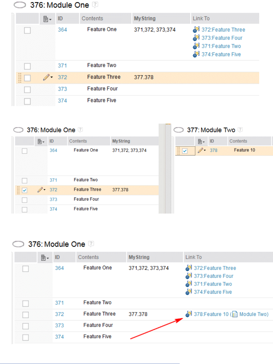
11. Then, select Feature Three (in Module One) and Feature 10 (in Module Two) as shown in the following
side-by-side view of both modules:
12. Then, run Link By Attribute and enter the Attribute and Link To data in the Link by Attribute
window. When you click OK, the link is automatically created in the Link To column in Module One, as
shown in the following image:
Related concepts
“Modules in the Requirements Management application” on page 129
A module is a structured document that is composed of multiple artifacts. You can create structure in a
module by modifying the order and hierarchy of its artifacts. The artifacts that are created for modules
Managing
143
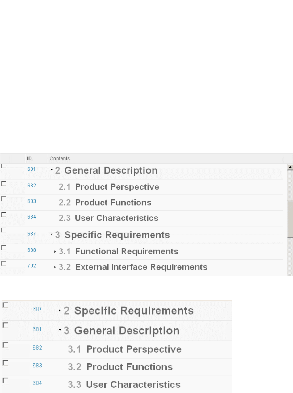
are stored as module content in a folder. Base artifacts can be used to manage the module artifacts
independent of the module.
“Importing requirements artifacts from CSV and spreadsheet les” on page 159
You can import data from comma-separated values (CSV) and spreadsheet les into folders and modules
in an RM project.
Modifying the hierarchy of artifacts in a module
You can modify the hierarchy of artifacts in a module by moving an artifact or a section of artifacts, or by
promoting or demoting artifacts.
About this task
Watch a video about modifying the hierarchy of artifacts in a module
.
You can select how many hierarchy levels to show in a module from the Congure Page Settings list.
When you select a level, only rows with a depth at or below that level are shown. After you specify the
hierarchy levels of artifacts, you can modify the levels.
When you demote an artifact, you place it in a lower hierarchy level than its preceding artifact. Demoted
artifacts are indented. When you promote an artifact, you move an indented artifact to a higher level in the
hierarchy. You can move artifacts within one module or between two modules.
If you move an artifact that is at the top level of the hierarchy, all the artifacts in its section are also
moved. For example, this image shows a module that contains the General Description artifact and its
child artifacts, and the Specic Requirements artifact and its child artifacts:
If you move the General Description artifact below the Specic Requirements artifact, the General
Description artifact and all its child artifacts are moved. In addition, the numbering of the hierarchy is
reordered.
144
Engineering Requirements Management DOORS Next

Tip:
You can move an artifact by dragging it to a new position in the module. However, the drop behavior
changes based on whether you drop the artifact on a collapsed or expanded section. If the target section
is collapsed, the artifact is dropped as a sibling artifact. If the target section is expanded, the artifact is
dropped as a child artifact.
You can control whether a section is collapsed or expanded before or while you move an artifact. To
expand a collapsed section while you are dragging an artifact, hover the cursor in front of the section
number, as shown in this image:
.
Procedure
You can move artifacts by cutting and pasting them or by dragging them. You can also promote or demote
them in the module hierarchy.
• To move an artifact by cutting and pasting it:
a) Hover the cursor over the left column of the artifact to move, click the menu
, and then click
Cut Artifact.
b) Hover the cursor over the left column of another artifact, click the menu , and click Paste
Artifact to paste the artifact in the same hierarchy level as the selected artifact. For more paste
options, click Paste Special, and then click one of these menu items:
– Click Paste Artifact Below to paste in the hierarchy level that is below the selected artifact.
– Click Paste Artifact Before to paste in the same hierarchy level as the selected artifact. The
pasted artifact is displayed above the selected artifact.
– Click Paste Artifact After to paste in the same hierarchy level as the selected artifact. The
pasted artifact is displayed under the selected artifact.
• To move an artifact by dragging it:
a) Hover the cursor in front of an artifact until it changes to a four-sided arrow, as shown in this image:
b) Drag the artifact to a new position in the hierarchy.
The numbering of the hierarchy changes to reflect the new position of the artifact.
Tip: If you press the Ctrl key while you drag the artifact, the Paste Special window opens, in which you
can duplicate or reuse the artifact instead of moving it.
• To promote or demote an artifact:
•
Hover over the artifact, click the menu , and select either Promote Artifact or Demote
Artifact.
• While you edit an artifact row, from the toolbar that opens, click the Promote Artifact or Demote
Artifact icons.
• To duplicate or reuse an artifact in one module in another module:
a) On the Modules page, select two modules.
b) From an artifact's menu, click Open Artifacts > Open 2 Artifacts Side-by-Side.
The modules open in two separate browser windows.
c) Drag the artifact in the rst module to a new position in the hierarchy of the second module.
The Paste Special window opens, in which you can specify duplication or reuse options.
Managing
145
Reusing artifacts in modules
Artifacts can be reused in multiple contexts in a project, including collections and modules. You can edit
artifact content in a module or by opening the artifact outside the module. Content changes are reflected
in all contexts. Links, tags, and comments are specic to the context in which they are created. If you
want links, tags, and comments to reflect in all contexts, edit the artifact outside the module as a base
artifact.
About this task
To reuse artifacts in a module, you can add existing artifacts to a module or create new artifacts in the
module. You can also reuse an artifact by copying it from one module and pasting to another module.
You can also select and insert an existing artifact from another module into a module. The base artifact is
reused and added to the module.
Note: When you open an artifact in a module, a light blue banner at the top of the page indicates that the
view is associated with an artifact in a module, rather than a base artifact. The name and ID of the module
displays in the blue banner.
When you work with an artifact outside a module, you are working with the base artifact.
After you add or create artifacts in modules, you can work with the artifacts in the module or on the
Artifacts page. Changes to the artifact name, content, attributes are reflected in all contexts: in the base
artifact and in all modules that include the artifact.
Procedure
Viewing artifacts in a module that are reused in other modules:
• Click the Congure Page Settings menu
icon.
• Select Used in Modules.
The Used in Modules column appears. In that column, the artifacts that are used in other modules are
indicated by the reuse icon . To view a list of links to modules that the artifact is reused in, hover
your cursor over the icon.
Tip: You can also view reuse in these places:
– The Where Used section of an artifact sidebar
– The Used in Modules column on the Artifacts page
– The artifact summary that is shown when you hover over a link
Related concepts
“Base artifacts” on page 146
Artifacts that are created and managed in a project independently from a module are called base artifacts.
Base artifacts can be used in one or more modules.
Related tasks
“Creating modules” on page 129
You can create modules and module content directly in a project or by importing a Microsoft Word
document, ReqIF le, or rich-text document.
“Linking between artifacts in modules” on page 136
You can link artifacts that are in the same module or artifacts that are in different modules.
Base artifacts
Artifacts that are created and managed in a project independently from a module are called base artifacts.
Base artifacts can be used in one or more modules.
When you work with an artifact outside a module, you are working with the base artifact. From a module
you can navigate to the base artifact:
146
Engineering Requirements Management DOORS Next
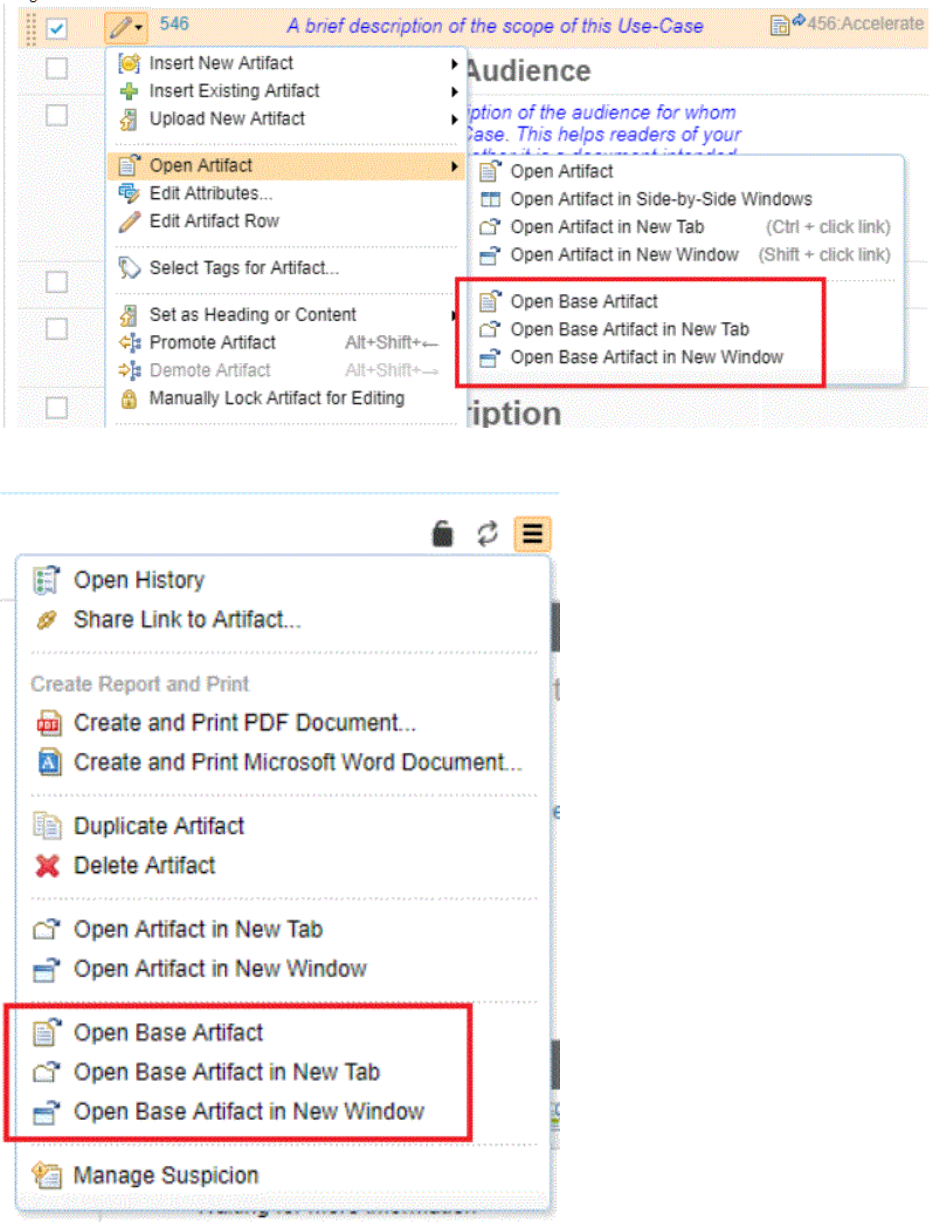
• From the Edit menu
.
• From the More Actions menu
.
If you edit a base artifact, you can see whether the artifact is in a module by viewing the Overview section
of the sidebar.
Managing
147
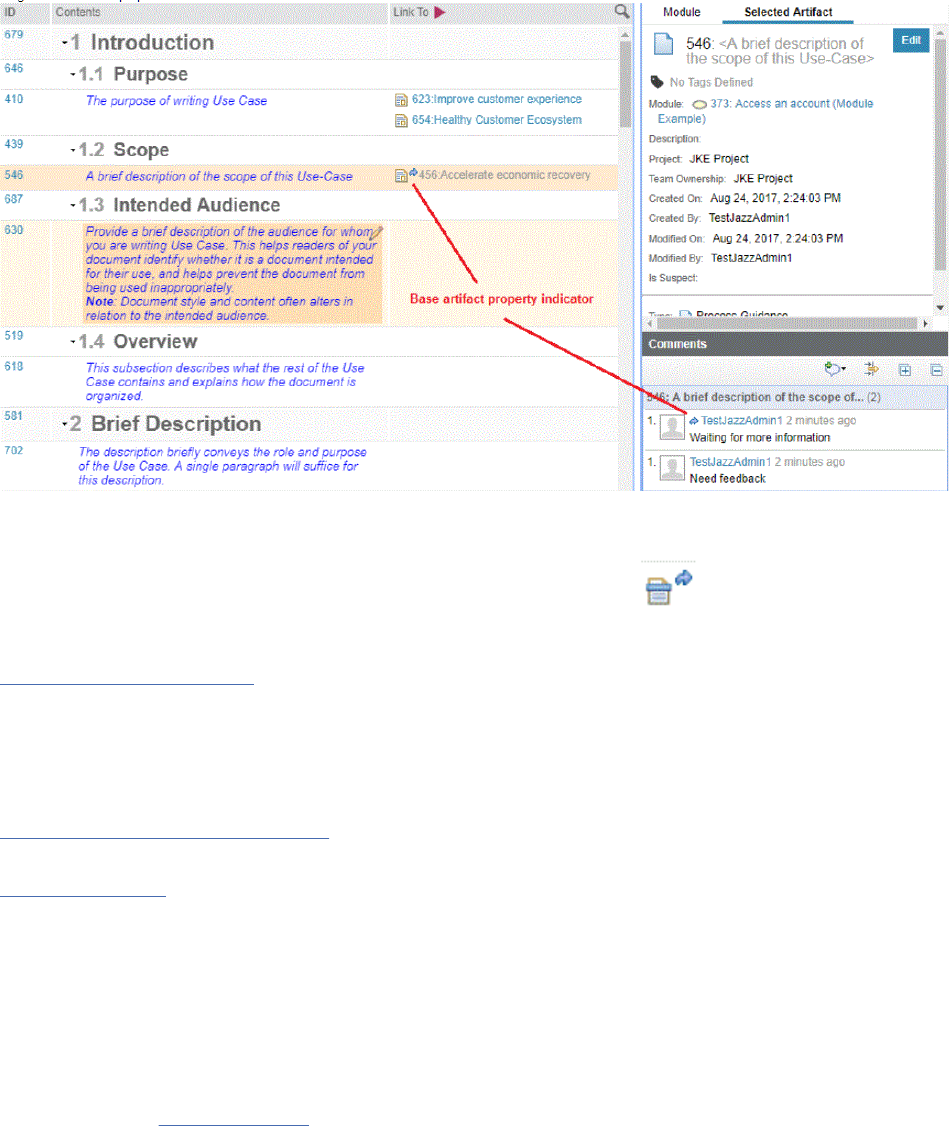
When you create links, tags, and comments for base artifacts, those elements apply to the artifact in all
contexts in the project. Base artifact properties are indicated with a blue arrow:
.
If you create links to or from base artifacts, those links are available in every module that the base
artifacts are used in. The blue icon indicates linking with a base artifact
.
Related tasks
Reusing artifacts in modules
Artifacts can be reused in multiple contexts in a project, including collections and modules. You can edit
artifact content in a module or by opening the artifact outside the module. Content changes are reflected
in all contexts. Links, tags, and comments are specic to the context in which they are created. If you
want links, tags, and comments to reflect in all contexts, edit the artifact outside the module as a base
artifact.
Linking between artifacts in modules
You can link artifacts that are in the same module or artifacts that are in different modules.
Creating link types
Filters and views in modules
In modules, you can modify the column settings, lter the artifacts that are shown, and then save the
column and lter settings as a view. You can modify columns to show specic attributes or link types, and
you can lter by artifact type, artifact tags, attribute values, and link types.
You can lter artifacts in modules by using the same techniques that you use on the Artifacts page and
the Collections page. When you lter artifacts in a module, the lter summary displays the number of the
ltered artifacts. You can name and save views, including the column settings and ltering criteria. For
more details, see Filters and views.
Module views
Module views are a subset of the module content. Module views are a simple way to lter content from
the module and can help you reuse and share requirement artifacts. Using consistent sets of criteria,
module views are a quick method to share common requirement entries across the team. You can create
a personal view for private use, or a shared view for use by the project team. When you create a view in a
module, you can either show the view in only the current module or in all the modules.
148
Engineering Requirements Management DOORS Next
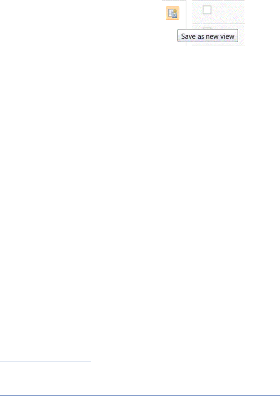
To create a module view:
1. Select an artifact or entry within the module.
2. In the View column to the left, click Save as new view .
3. In the New view dialog box, enter a name.
4. Under Type, select Personal or Shared.
Any project member can create a personal view for private use. A shared view is a view that can be
used by all project members. Shared views can only be created or changed by an administrator or a
user who has the required permissions.
5. Select where you want this view to be visible: Just this module, All modules of this type (Module
Specication), or All modules.
Tip: If you plan to link the module view to development and test plans, select Shared in step 4 and
Just this module in step 5.
6. In the Who can see this view option, select the roles. Users must have at least one role in the artifacts
process area that is also assigned to the view.
7. To easily identify and retrieve a view, select the Make this view preferred check box. When a view is
marked as a preferred, it appears in bold font in the View column and is also the default view that is
displayed. If you have multiple preferred views, the default one is chosen by a predened algorithm.
8. Enter a description to summarize the contents of the view.
Tip: You can also use the Edit View option to select roles, modify the view name, or make the view
preferred.
With module views, you have more control over which artifacts in a module are available for reuse or
linking. To nd a module view quickly, enter the module ID or module name that contains the module view
in the Search View eld.
Important: Module views are loaded as collections into the data warehouse during the ETL process. A
view can become outdated if someone updates its contents without editing the view itself. To ensure that
these module views contain the latest content, you can add them to a list in the Refresh Module Views
section. You must have permission to add views to the list. Click Manage Project Properties > Module
Views, and in the Refresh Module Views page, add the views to the list. When you add a view to the list,
it is shown only if it is unique to the module and is shared.
Related concepts
Filtering requirement artifacts and creating views
Filters and views are useful for sorting and displaying artifacts that are based on specic criteria. You can
use lters and the congure page settings to display artifacts, and then save this conguration as a view
to use later.
“Reporting in the Requirements Management (RM) application” on page 254
You can run and view reports that are based on a data warehouse and create document-style reports that
are about requirement and other lifecycle data.
Related tasks
“Creating modules” on page 129
You can create modules and module content directly in a project or by importing a Microsoft Word
document, ReqIF le, or rich-text document.
Related information
Associating test plans with requirement collections, modules, and module views in the Requirements
Management application
Managing
149
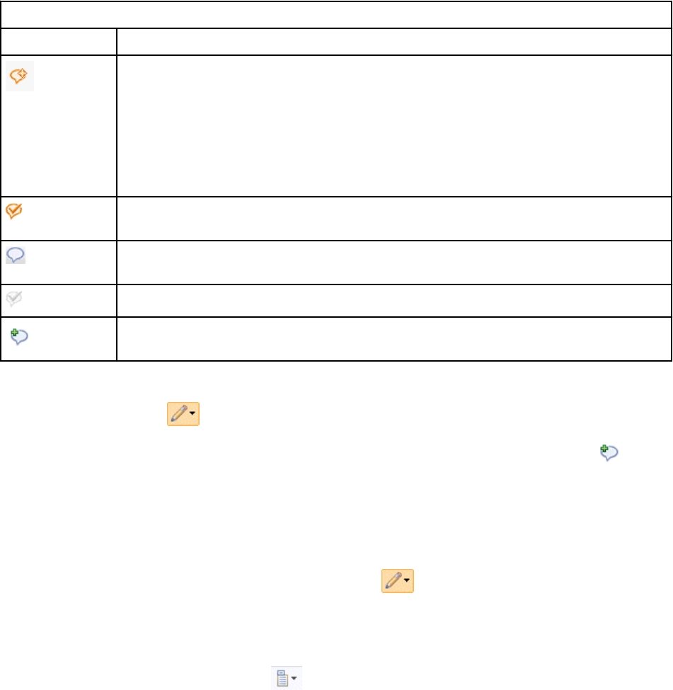
Adding comments to artifacts in a module
A comment is a textual discussion item that you can add to an artifact in a module. You can use comments
to provide team feedback during the development of a module, and can direct comments to other team
members.
About this task
When you add comments to an artifact in a module, the comments appear in the artifact comments
sidebar, which you can view in the sidebar one artifact at a time. However, if you add the Comments
column to your display settings, comment icons are displayed next to all the artifacts in the module that
have comments. These icons indicate the state of the comment. You can hover over a comment icon to
display a hover window in which you can either view the comment, create a new comment, or show all
the comments for the artifact. The following table describes the comment icons that can appear in the
Comments column:
Table 21. Comment icons that can appear in the comments column
Comment Icon Description
Indicates that there are one or more recent comments and one or more unresolved
comments. A recent comment is a comment that was created, modied, resolved, or
reopened within the last 14 days.
Note: You can modify the duration period for comments on the server, in the
teamserver.properties server conguration le. You can also modify this
conguration property to specify which comments to display in the Recent Comments
widget.
Indicates that there are one or more recent comments, but that all comments are
resolved.
Indicates that there are no recent comments, but that some comments are still
unresolved.
Indicates that there are no recent comments, and all the comments are resolved.
Indicates that there are no comments. This icon appears when you hover over a row.
You can click this icon to add a new comment to the artifact.
To add a comment to an artifact in a module:
1. Click the artifact menu and then click Comments > Create comment for this artifact.
Tip: You can also add a comment by hovering over a row and clicking the no comment icon .
2. In the Create Comment for Artifact window, enter subject and comment text.
3. In the Directed To eld, search for and select the user to whom to direct the comment.
4. From the Priority list, select a priority.
5. Click OK. Your comment appears in the Artifact Comments section of the sidebar.
To show the comment for an artifact, click the artifact menu and then click Comments > Show
comments for artifact. The comments appear in the sidebar.
To see all of the artifacts in the module that have comments, add the Comments column to the module. To
add the Comments column:
1. Click the Congure Page Settings icon
and then click Congure Columns to Display.
2. In the Change Column Display Setting window, add Comments to the Columns to Show eld and then
click OK.
150
Engineering Requirements Management DOORS Next
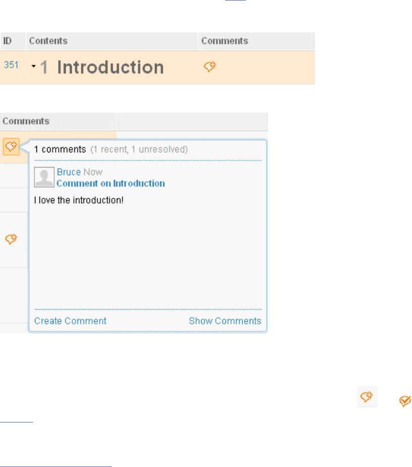
Tip: You might want to save your changes as a view to make it convenient to return to this display
setting.
If there is a recent comment for an artifact, the recent comment icon appears in the Comments eld:
If you click this icon, all the comments for the artifact are displayed in the sidebar; however, you can also
hover over the icon to display the most recent comment that was made for the artifact:
From the hover window, you can create new comments or show all the comments for the artifact.
Sorting comments
To sort the Comments column, click the top of the column. When you sort the column, artifacts are
displayed in this order: artifacts with recent comment activity (indicated by the and icons from
Table 1), artifacts with recent comments, artifacts with unresolved comments, artifacts with resolved
comments, and artifacts with no comments.
Related tasks
Commenting on artifacts
A comment is a textual discussion item that you can add to an artifact or an element within an artifact.
You can use comments to provide team feedback during the development of an artifact. In the web client,
comments are displayed in the Comments section of an artifact sidebar, in the Recent Comments section
of the Artifacts page sidebar, and in Recent Comments for Me on the user dashboard.
Exporting artifacts from modules to CSV and spreadsheet les
You can export the artifacts from a module to a CSV le or a spreadsheet in Microsoft Excel (XLS) and
Ofce Open XML (XLSX) format.
About this task
You can export artifacts from a module in two ways:
• Export a module view. When you export a module view, you can customize the attributes and link types
in the view before you export the artifacts.
• Export one or more artifacts from within a module.
Exports to CSV and spreadsheet formats now include special markup for links and embedded artifacts.
This markup can be used to retain or create links and embedded artifacts if the le imported later. You
Managing
151
can export links by including a link column in the view. Links, images, or embedded artifacts can also be
present in the primary text of the requirement, which can be shown in the view and exported.
Exporting base artifacts links
You can export base artifacts links to a CSV le or a spreadsheet in Microsoft Excel (XLS) and Ofce
Open XML (XLSX) format. You can create links between base artifacts and artifacts that are included in a
module. You can then create a module view to export these base artifacts to a CSV le or XLS le.
You must enable an advanced property to complete this action. To enable the property, click the
Administration icon, and then click Manage This Project Area. Click Application.
In the Conguration section, set the value of the EnableCoreBaseArtifactLinksWhenExporting property
to true. After you enable the advanced property, you can export the base artifacts to a CSV le.
Procedure
• To export a module view to a CSV le or spreadsheet le:
a) If you do not already have a module view to export, create a view:
a. In an open module, click the Congure Page Settings icon to display the menu. Select
Congure Columns to Display, and then follow the prompts to congure the attributes and link
types to include in the view.
b. Optional: In the left sidebar, select and congure lter settings. For more information about
lters, see the related links below.
c. In the left sidebar, click the Save View icon, type a name for the view, and then click OK.
The new view is displayed in the Views section of the sidebar.
b) Hover over the view, expand the View Options menu, and click Export. Follow the prompts to save
the data into a new CSV le or new spreadsheet le in Microsoft Excel (XLS) and Ofce Open XML
(XLSX) format.
• To export one or more artifacts from within a module to a CSV le or to a spreadsheet le:
a) Open a module and select one or more artifacts to export.
b) Click an artifact menu, and then click Other Actions > Export Artifacts. Follow the prompts to save
your data into a CSV le or spreadsheet le in Microsoft Excel (XLS) and Ofce Open XML (XLSX)
format.
What to do next
For information about the elds that are included in an exported CSV le, see Export process for CSV and
spreadsheet les.
Related concepts
“Filters and views for artifacts in requirements projects” on page 111
Filters and views are useful for sorting and displaying artifacts that are based on specic criteria. You can
use lters and the congure page settings to display artifacts, and then save this conguration as a view
to use later.
Importing and exporting les
You can exchange requirements and associated metadata between requirements tools or requirements
repositories by importing and exporting several different types of les. You can import Microsoft Word
documents into requirements projects or components. You can also import and export comma-separated
value (CSV) les, spreadsheet (.xls or .xlsx) les, IBM Engineering Requirements Management DOORS
(DOORS) migration packages, and ReqIF (.reqif or .reqifz) les as textual artifacts.
152
Engineering Requirements Management DOORS Next
Importing documents into requirements projects or components
You can import documents of various types, including Microsoft Word, from your le system to a
requirements project or component.
In the import wizard, if you click Import a text document and convert to a rich text artifact, the wizard
imports the entire document and converts it to one rich-text artifact. You can import these document
types:
• Microsoft Ofce (.doc and .docx)
• Open Ofce (.odt)
• Rich text format (.rtf)
To watch a video that shows how to import a document, see "Lesson 4: Import Microsoft Word
documents" in the related links.
Import planning
Planning and awareness of limitations are key to a successful import. Before you begin the import
process, make sure that you are familiar with the structure of your document. Then, plan how you want
the content to be structured in the new artifact. For information about planning to import, see “Planning
to import documents” on page 153.
Comments and links
When you import a Microsoft Word document that contains comments, you can specify that the wizard
create comments in the new artifact from the comments in the document. Otherwise, you can add
comments after you import the document. You can add comments to the whole document or to specic
paragraphs. You can also add links to the imported document and embed other artifacts in it. If the
imported document contains images, a folder is created that contains the images.
Related concepts
“Requirement artifacts” on page 92
“Modules in the Requirements Management application” on page 129
A module is a structured document that is composed of multiple artifacts. You can create structure in a
module by modifying the order and hierarchy of its artifacts. The artifacts that are created for modules
are stored as module content in a folder. Base artifacts can be used to manage the module artifacts
independent of the module.
Related tasks
“Importing and extracting requirement artifacts from documents” on page 157
When you import a document to a requirements project or component, you can specify that certain parts
of the document are imported and extracted as specic artifact types. You can also extract artifacts from
a document that is already in a project or component.
“Uploading les to a requirements project or component” on page 118
You can upload les from your le system to a requirements project or component. After you upload a le,
depending on its le type, you can modify it, convert its contents to a rich-text artifact, or extract artifacts
from it.
Related information
Lesson 4: Import Microsoft Word documents
Planning to import documents
You can import entire documents or parts of documents to requirement artifacts by using the import
wizard. To avoid issues when the artifacts are extracted and imported, ensure that you plan the import
before you run the wizard.
When you plan your import, you can more efciently organize and structure the modules and artifacts that
you want to create. Based on the content of your document, you must determine the folder structure,
location, and name of the module, and the types of requirement artifacts. To identify requirement artifacts
Managing
153
in your document, the wizard uses four criteria: headings, images, keywords, and delimiters. You can
specify the artifact type that is created for each criterion.
Headings
In a document, if a heading style is applied to one or more entire paragraphs, you can specify that those
paragraphs are imported as artifacts of a specic type. In addition, if the document contains delimiters or
keywords, you can import them as specic types. For more information, see the following Keywords and
Delimiters sections.
All other text in the document that is not a heading, delimiter, or keyword can be imported as an
artifact type that you specify. For example, you can specify that all headings are converted into use case
specication artifacts and that all other text is converted into feature artifacts.
Importing document text to modules: If you create a module from a document, the heading levels in the
imported document are used to create the numbering for the module hierarchy. For example, a document
might have a line of text at Heading 1 and a line of text at Heading 2. If you import that document to a
module, the numbering for the module hierarchy might look like this example:
If you import data into a module and the data contains a name but no primary text, the name is used to
populate the primary text. If the data contains primary text but no name, the name is created from either
the rst 156 characters or the rst paragraph of the primary text.
Importing options
When you import a word document, you can specify the import option according to the document viewing
criterion. The types of import options are:
• Optimize for editing: This option imports the word document and converts the style information to
match the styling and functionality of the rich text editor. For example, if a font is not supported by the
editor, it is converted to a supported font. Some style information might be lost with this option, but this
option will offer the best editing experience.
• Maintain original style: This option imports the word document without converting any style
information. The document can be edited, but with limited editing features. For example, unsupported
fonts are not listed in the fonts drop down. This option is best suited for viewing documents.
Formatting
The rich text editor attempts to maintain the imported artifacts in a format that is as close as possible to
their original format when the Import for editing and viewing option is selected. However, formatting is
limited in a few ways:
• Most fonts are supported. Unsupported fonts are converted to Arial or to a font and size that closely
matches the specied font family.
• Spacing between sentences might differ from the original document. However, spacing is maintained as
close to the original formatting as possible.
• Object anchors and text wrapping around images and other content is not supported. Any layout or
formatting that is based on these Microsoft Word features is not preserved.
154
Engineering Requirements Management DOORS Next
• Tabs are converted to a sequence of spaces and paragraph indentation is rounded to the nearest
multiple of 40 pixels. Any formatting or layout that uses tabs or indentation is not preserved exactly like
the original document.
• If a numbered list contains fractional or segmented parts, the list is converted to a paragraph.
• Web address links that begin with http or https are imported as RM links. All other links are converted
to text.
• If any cell in a table has a border or a partial border, a full cell border is used.
• For an imported table to be displayed correctly, its outer border must be perfectly aligned. Any slight
misalignments in the left or right border of the original table can cause display issues after the table is
imported.
• If a document is structured into columns of text, that structure is not preserved in the imported content.
Images
You can map images to specic artifact types. When you import a document that contains images, a
folder is created. These image formats are not supported, but are converted to .png format and might be
missing some details such as the following items:
• DrawingML content, such as diagrams and charts
• Embedded images that are in .emf, .wmf, or .pict format
• Word art
Keywords
If you use keywords throughout a document or table, you can use them to indicate specic artifact types.
Before you start the import process, ensure that you know how keywords are affected:
• Keywords are not extracted from tables.
• Keywords cannot be used within tables. Lists and tables are extracted as a whole, not per item.
• If a keyword is in a list, the entire list is assigned the artifact type that is associated with the keyword.
• In version 4.0.4 and later, keywords are case-insensitive.
• Keywords that are used for sentences are supported in English only.
• During the import process, the white space around any keywords that you dened is ignored. As a
result, text that contains keywords might be inadvertently identied as keywords. To avoid this issue,
use infrequently used text as keywords. For example, if " he " is a keyword, commonly used text such
as the, they, and them are inadvertently associated with that keyword's type.
Delimiters
Documents can be tagged with special characters, delimiters, to identify information, such as glossary
terms. The delimiters that you use throughout a document can identify specic artifact types. The text
that is within both sides of a delimiter becomes an artifact of the type that is associated with that
delimiter. Any text that is before the opening side of the delimiter or after the closing side is treated as
separate artifacts.
If you use delimiters in a document or table, before you start the import process, ensure that you know
how delimiters are affected:
• Delimiters cannot be used within tables. Lists and tables are extracted as a whole, not per item.
• Delimiters cannot be nested. Only the delimiter that is specied rst is used.
• In version 4.0.4 and later, delimiters are case-insensitive.
• During the import process, if you dened a delimiter, and either or both of its opening and closing
parts are surrounded by white space, that white space is ignored. As a result, text that contains
delimiters might be inadvertently identied as delimiters. To avoid this issue, use infrequently used text
Managing
155
as delimiters. For example, if the rst part of a delimiter is " (" and the second part of the delimiter is
" ) ", commonly used formatting such as that(s) are split by the delimiter.
All other text
Any content in your document that is not a heading, image, keyword, or delimiter can be assigned to
specic artifact types. You can change the artifact types after the import is complete.
Unsupported items
These additional items are not supported in a document import:
• Tables of contents
• VBA macros
• Mail merge elds, eld codes, and frames
• Text boxes
• Table styles
• OLE embedded documents, such as Microsoft Visio contents
• Embedded XML
• Document properties
• Password-protected documents
Organizing data for import process
The size of the document determines the time that is required for the import process. If the size of the
document is large, the time that is required to import the document might increase. Other elements in
the document such as images, shapes, and OLE objects might also increase the import time. If the import
process creates more than 10,000 artifacts, split the document further before the import. If you split the
documents, the smaller sections get imported faster. This also speeds up the word import requests from
other users. The resulting module or import folder that is created after the import also gets loaded faster.
For more information, see Organizing requirements for best performance
.
Related concepts
“Requirement artifacts” on page 92
“Modules in the Requirements Management application” on page 129
A module is a structured document that is composed of multiple artifacts. You can create structure in a
module by modifying the order and hierarchy of its artifacts. The artifacts that are created for modules
are stored as module content in a folder. Base artifacts can be used to manage the module artifacts
independent of the module.
“Importing documents into requirements projects or components” on page 153
You can import documents of various types, including Microsoft Word, from your le system to a
requirements project or component.
Related tasks
“Importing and extracting requirement artifacts from documents” on page 157
When you import a document to a requirements project or component, you can specify that certain parts
of the document are imported and extracted as specic artifact types. You can also extract artifacts from
a document that is already in a project or component.
“Uploading les to a requirements project or component” on page 118
156
Engineering Requirements Management DOORS Next

You can upload les from your le system to a requirements project or component. After you upload a le,
depending on its le type, you can modify it, convert its contents to a rich-text artifact, or extract artifacts
from it.
Importing and extracting requirement artifacts from documents
When you import a document to a requirements project or component, you can specify that certain parts
of the document are imported and extracted as specic artifact types. You can also extract artifacts from
a document that is already in a project or component.
Before you begin
Planning and awareness of limitations are key to a successful import. Before you begin the import
process, make sure that you are familiar with the structure of your document. Then, plan how you want
the content to be structured in the new artifact. For information about planning to import, see “Planning
to import documents” on page 153.
Restriction: You can import only one document at a time. If you try to start a second import before the
previous import is completed, the second import cannot start until the previous import is completed.
About this task
Artifacts are extracted based on criteria, such as headings, images, keywords, and text delimiters. You can
specify where the artifacts are saved and whether to include them in modules.
You can extract artifacts from documents that are in or outside of a project or component. If you extract
artifacts from a document that is outside of a project or component, you must import the document, and
the document content is extracted during the import process.
You can import these document types:
• Microsoft Ofce (.doc and .docx les)
• Open Ofce (.odt les)
• Rich Text Format (.rtf les)
• Compressed (.zip les that contain a supported document type)
You can extract these document types:
• Microsoft Ofce (.doc and .docx les)
Procedure
• To import a document from outside of the project or component and extract artifacts from that
document:
a) Open the project or component.
b) Click Artifacts.
c) On the Artifacts page, click Create to expand the menu and click Import Artifact.
d) In the Import wizard, click Import requirements from within a text document and follow the
prompts in the wizard to complete the import and extract the artifacts.
• To extract artifacts from a document that is already in the project or component:
a) On the Artifacts page, select an artifact.
b) Click the Edit icon for the artifact and click Extract Requirements from Artifact.
c) In the Extract Requirements wizard, specify the details about the artifacts to create, and follow the
prompts to extract the artifacts.
Related concepts
“Requirement artifacts” on page 92
“Modules in the Requirements Management application” on page 129
Managing
157
A module is a structured document that is composed of multiple artifacts. You can create structure in a
module by modifying the order and hierarchy of its artifacts. The artifacts that are created for modules
are stored as module content in a folder. Base artifacts can be used to manage the module artifacts
independent of the module.
“Importing documents into requirements projects or components” on page 153
You can import documents of various types, including Microsoft Word, from your le system to a
requirements project or component.
“Importing requirements artifacts from CSV and spreadsheet les” on page 159
You can import data from comma-separated values (CSV) and spreadsheet les into folders and modules
in an RM project.
Related tasks
“Uploading les to a requirements project or component” on page 118
You can upload les from your le system to a requirements project or component. After you upload a le,
depending on its le type, you can modify it, convert its contents to a rich-text artifact, or extract artifacts
from it.
Importing and exporting CSV and spreadsheet les
You can import or export text-based artifacts to and from requirements projects by using comma-
separated values (CSV) les or spreadsheets (XLS and XLSX) les. Round trip importing and exporting
is also supported. For example, you can export artifacts to a CSV le, change the attribute values in the
le, and then import that le back into IBM Engineering Requirements Management DOORS Next (DOORS
Next).
Important: You must be aware about the following restrictions on the importing and exporting process:
• Although the import is an asynchronous process, if you log out during the import process, you might
encounter problems. For example, imported data might be truncated since the import process is not
completed after you log out.
• If you export a view that includes system-dened and OSLC links, and then delete those links in the
exported le, the links are not deleted when you import that le into the RM application.
• You can create new tags for artifacts by importing a le, but if tags exist in the artifacts, they are ignored
during the import process. You cannot delete tags from artifacts by importing a le.
• You cannot export or import comments in requirement artifacts.
• You can create text, heading type, module, collection, and diagrams when you import a CSV XLS, or
XLSX le. When you import into a module, you can import text and diagrams only.
• Rich text is not supported when you import or export CSV les. If the artifacts that you are importing or
exporting contain styles or formatting, the resulting content is plain text. (The rich text in spreadsheet
les is imported or exported.)
• Exporting and importing of horizontal lines in text is not supported. If you include horizontal lines in a
text artifact, export that artifact to Microsoft Excel, and then import the le, the horizontal lines are lost.
• If you modify text format in a Microsoft Excel le, but do not change the text itself, when you import the
le, those format changes are not imported. The format is only changed when the text is also changed.
• Bullets that are used within the cell of a Microsoft Excel spreadsheet are not supported. If you export or
import these les, the bullets are removed.
• Text alignment is not supported when you import or export artifacts.
• Indents are not supported when you export CSV les or Microsoft Excel les. If you import the CSV
les or Microsoft Excel les that you exported, the indent is removed and the content is left aligned.
If you are working in a conguration-enabled project area, these changes are flagged as unexpected
differences.
• When exporting a module view, if you select the Include links, tags, and comments from base
artifacts option, the base artifacts themselves are not exported; only the bindings are included in the
exported le.
158
Engineering Requirements Management DOORS Next

• You can export artifacts to a CSV or spreadsheet le, change the attribute values in the le, and then
import that le back using Update artifacts that match entries and create artifacts for new entries.
The Update artifacts that match entries and create artifacts for new entries process is only for
creating new entries or for updating attributes for artifacts that are part of the module. If you remove
any of the exported artifacts from the module and then import the modied le the update option will
not work.
• Nested levels are not supported when importing or exporting a Microsoft Excel le. Even if there have
been no changes to the original artifacts comparison with the original artifact will indicate changes.
• You can export a module with identical artifact IDs. When you import a module, you cannot delete the
artifacts with the identical IDs that are removed from the exported le.
Importing requirements artifacts from CSV and spreadsheet les
You can import data from comma-separated values (CSV) and spreadsheet les into folders and modules
in an RM project.
You can import and export CSV les or spreadsheets in Microsoft Excel (XLS) and Ofce Open XML
(XLSX) format. When you import requirements that were previously exported from IBM Engineering
Requirements Management DOORS Next (DOORS Next), they can include markup text for links and
embedded artifacts. During the import process, this markup text is used to create or update the links and
embedded artifacts.
When you export requirements to CSV or spreadsheet les, metadata is created during the export
process.
Note: You must not delete the metadata before the reimport process. If you delete the metadata and
remove any artifacts from the spreadsheet les and reimport requirements, the artifacts are not deleted
after the reimport process.
Prerequisites for importing CSV and spreadsheet les
• Review the limitations described in the “Importing and exporting CSV and spreadsheet les” on page
158 topic.
• Read the “CSV le format and examples” on page 163 topic.
Note: Spreadsheet les must conform to the same content rules as CSV les.
• Make sure that the le to import is encoded in UTF-8. If you are working with data in an external
application, make sure that the application supports UTF-8.
• Make sure that the project has an artifact type that is dened for each unique type name in the Type
column. If type errors occur when you import a CSV le, limit the le to only one artifact type at a time.
Also, you might want to divide large CSV les into smaller chunks. If other errors occur, make sure that
special characters are escaped, as described in the RFC 4180 document.
• If you created the CSV le in another application, remove extra spaces or unsupported elds from the
le before you import it.
• Escape any apostrophes or quotation marks in the le, as described in the RFC 4180 document.
• Depending on your needs, you might assess and create custom attributes. For more information, see
“Managing project or component properties in requirements projects” on page 28.
• To import a CSV le that has attribute values of the enumeration type, verify that those values are
dened for the corresponding attribute type in the target project. Otherwise, the import fails.
• To import a CSV le into a DOORS Next module, the CSV le must include the isHeading, parentBinding,
and Artifact Type columns. The prerequisite is applicable regardless the application where the CSV le
is generated.
Import process
To build a correctly formed CSV le for import, export from a view that contains columns that correspond
to the content to import. If you export from a view, the exported le contains unsupported system-
maintained elds. However, these elds are ignored if they are included in an import operation. For more
Managing
159
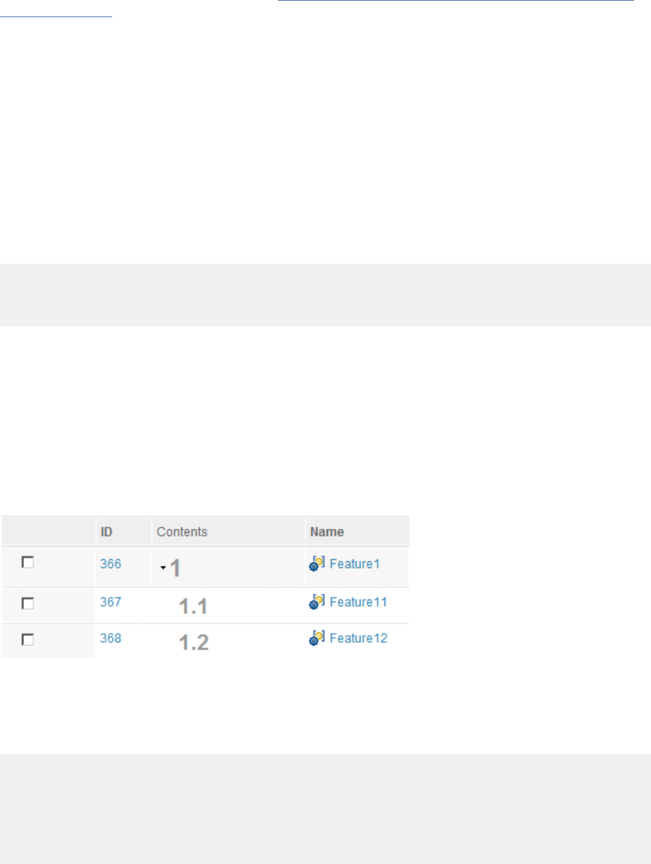
information about exporting from a view, see “Exporting requirements artifacts to CSV and spreadsheet
les” on page 161.
If you export the hierarchy of artifacts in a module, remove a parent artifact, but not the associated child
artifacts, and then try to import the le, the import fails. You can prevent this by either removing the child
artifacts from the parent artifact, or promoting the child artifacts to the nearest parent artifacts.
To start an import, open the Artifacts page and at the Create or More Actions menu, click Import
Artifact. Click Import requirements from a CSV le or spreadsheet. After you select a CSV le or
spreadsheet, you can choose to import requirements into a folder or into a module. You can choose
to update artifacts that match the imported requirements, or create new artifacts. When you update
existing artifacts, you can ignore imported requirements that do not match existing artifacts or create new
artifacts from the new imported content. After you make your selections, click Finish.
You can import artifacts in a hierarchical import by using special elds in the CSV le.
Example 1
The following sample CSV le represents the module artifacts, Feature 1, Feature 11, and Feature 12:
Identifier,Artifact Type,Name,parentBinding
100,Feature,Feature1,""
101,Feature,Feature11,100
102,Feature,Feature12,100
The Identier column is required for module-related imports. The identier is used to establish a parent
relationship between the CSV records representing the module artifacts. The identier is also used to
group the module artifacts with their modules.
The parentBinding column is also used for module related imports along with Identier.
The module column is used for module related imports and dictates which modules that are dened in
the CSV le are the intended target for the records that represent module artifacts. The module column
can be ignored when there are nomodules that are dened in the CSV le.
When imported, Feature 11 and Feature 12 are placed under Feature 1 and the artifacts are hierarchically
arranged in a module:
Example 2
The following sample CSV le denes two modules, Module 1 and Module 2. The module artifacts Feature
1, Feature 11, and Feature 12 belongs to Module 1. The module artifacts Feature 2 and Feature 4 belongs
to Module 2.
Identifier, Artifact Type, Name, parentBinding
99, Module, Module1, ""
100, Feature, Feature1, ""
101, Feature, Feature11, 100
102, Feature, Feature12, 100
103, Module, Module2, ""
104, Feature, Feature2, ""
105, Feature, Feature4, ""
After the import, the Feature 11 and Feature 12 will be placed under Feature 1. If the order of CSV record
is changed, the import result is different. For example, if the modules are dened rst, the Feature 1,
160
Engineering Requirements Management DOORS Next
Feature 11, Feature 12, Feature 2, and Feature 4 are imported in the Module 2. In this case, to obtain
desired result, the module column can be used:
Identifier, Artifact Type, Name, parentBinding, module
98, Module, Module1, "", ""
99, Module, Module2, "", ""
100, Feature, Feature1, "", 98
101, Feature, Feature11, 100, 98
102, Feature, Feature12, 100, 98
104, Feature, Feature2, "", 99
105, Feature, Feature4, "", 99
For information about the special elds and setting up a CSV le before you import data into a module,
see Importing and exporting using the CSV format
on Jazz.net. Content on Jazz.net is governed by the
Jazz.net Terms of Use and is provided as-is without warranties of any kind.
Warning: When importing a CVS le, if there is an error in any row or column, then the entire
import fails and no data will be imported.
Related concepts
“Exporting requirements artifacts to CSV and spreadsheet les” on page 161
You can export text-based artifacts from a requirements project into comma-separated values (CSV) les
or into spreadsheet (XLS and XLSX) les. The content of the exported le is governed by the columns that
are in the current view.
Related tasks
“Uploading les to a requirements project or component” on page 118
You can upload les from your le system to a requirements project or component. After you upload a le,
depending on its le type, you can modify it, convert its contents to a rich-text artifact, or extract artifacts
from it.
Related reference
“CSV le format and examples” on page 163
Before you import a comma-separated values (CSV) le, ensure that the le adheres to the CSV format. In
addition, CSV les, as well as spreadsheet les, must follow the content rules for rows and columns and
must be encoded in UTF-8.
Exporting requirements artifacts to CSV and spreadsheet les
You can export text-based artifacts from a requirements project into comma-separated values (CSV) les
or into spreadsheet (XLS and XLSX) les. The content of the exported le is governed by the columns that
are in the current view.
When you export text-based artifacts, you must specify whether to write the data into CSV, XLS, or XLSX
format. You can then import the artifacts into the same project or into another project. If you import into
another project, the target project types and their predened values must match the types in the project
that you exported from.
You can export artifacts from many places, including the Artifacts page and from within collections and
modules. To export artifacts, select the artifacts to export, click the pencil icon
for a selected
artifact, and then click Export.
The following columns cannot be included when you export data:
• Collections
• Comments
• Reviews
• Team Ownership
• Used in Modules
Note:
Managing
161

• You can add the Team Ownership column to a view; however, the export of Team Ownership information
is not currently supported. If you include the column in an export operation, the Team Ownership eld
in the resulting CSV or spreadsheet le is empty.
• You can add the Validity Summary column to a view, but the validity summary and link validity
information are excluded from the resulting CSV or spreadsheet le.
You can also export from a view to capture the column settings and artifacts that are dened in that view.
You can create and export artifact views, collection views, or module views; the steps to create any type
of view are similar. For detailed instructions to create and export a module view, see Exporting artifacts
from modules to CSV les.
Exports to CSV and spreadsheet formats include special markup for links and embedded artifacts. This
markup can be used to retain or create links and embedded artifacts if the le is imported later. You
can export links by including a link column in the view. Links, images, or embedded artifacts can also be
present in the primary text of the requirement, which can be shown in the view and exported.
Contents of exported CSV and spreadsheet les
The exported CSV or spreadsheet le contains the contents that are shown in the view that you exported
from. Tags are also included in exports. In some instances, your exported le might contain UTF-8
representations of non-breaking spaces that are shown as  characters. To remove those characters, load
the exported le into a text or spreadsheet program and remove them by using the search and replace
function.
When you export artifacts from a saved view on the Artifacts page or the Collections page, the Artifact
Type column is included by default. If the saved view contains the Artifact Type column, the column is
displayed in the same position in the exported le as in the saved view. If the saved view does not include
that column, the column is added at the end of the exported elds.
When you export artifacts from a saved view in a module, the following columns are included in the
exported le. The columns preserve information about the module structure, which might be used during
an import to another module. The columns cannot be added or removed by editing the view.
• isHeading
• parentBinding
• Artifact Type
Important: If you remove any of the listed columns from a CSV le and then import the CSV le in a
module, the import fails, and an error message is displayed. For example, if you export a module view
to a CSV le, remove the "parentBinding" column from the le, and then import the CSV le, the import
operation fails. To resolve this issue, ensure that you import the CSV le that contains all the required
columns.
Tip: For more flexibility in importing CSV data, you can manually modify the columns in the exported CSV
le by using an external tool. For example, by manually modifying columns in CSV les, you can import
the artifacts from multiple modules into a folder. You can also combine the artifacts from multiple module
exports into a one module. For more information, see Importing and exporting using the CSV format
on
Jazz.net. Content on Jazz.net is governed by the Jazz.net Terms of Use and is provided as-is without
warranties of any kind.
Note: When you import CSV data, you can instruct the import wizard to perform these actions:
• Create new requirements
• Update matching requirements and create new requirements for new entries
• Update matching requirements and ignore new entries
Related concepts
“Importing requirements artifacts from CSV and spreadsheet les” on page 159
162
Engineering Requirements Management DOORS Next
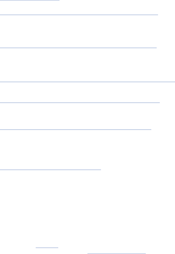
You can import data from comma-separated values (CSV) and spreadsheet les into folders and modules
in an RM project.
“Collections” on page 176
A collection is a set artifacts that you create for a specic purpose.
“Modules in the Requirements Management application” on page 129
A module is a structured document that is composed of multiple artifacts. You can create structure in a
module by modifying the order and hierarchy of its artifacts. The artifacts that are created for modules
are stored as module content in a folder. Base artifacts can be used to manage the module artifacts
independent of the module.
“Filters and views for artifacts in requirements projects” on page 111
Filters and views are useful for sorting and displaying artifacts that are based on specic criteria. You can
use lters and the congure page settings to display artifacts, and then save this conguration as a view
to use later.
Related tasks
“Exporting artifacts from modules to CSV and spreadsheet les” on page 151
You can export the artifacts from a module to a CSV le or a spreadsheet in Microsoft Excel (XLS) and
Ofce Open XML (XLSX) format.
“Uploading les to a requirements project or component” on page 118
You can upload les from your le system to a requirements project or component. After you upload a le,
depending on its le type, you can modify it, convert its contents to a rich-text artifact, or extract artifacts
from it.
“Adding tags to artifacts and viewing tagged artifacts” on page 191
You can add user-dened shared or personal tags to new and existing artifacts. Use tags to categorize
artifacts in a project area. You can view all artifacts that have the same tag by creating a lter for that tag.
If you save that view, you can use that view in your project dashboard. Shared tags are available to all
users in the project. Personal tags are only available to the user who creates them.
Related reference
“CSV le format and examples” on page 163
Before you import a comma-separated values (CSV) le, ensure that the le adheres to the CSV format. In
addition, CSV les, as well as spreadsheet les, must follow the content rules for rows and columns and
must be encoded in UTF-8.
CSV le format and examples
Before you import a comma-separated values (CSV) le, ensure that the le adheres to the CSV format. In
addition, CSV les, as well as spreadsheet les, must follow the content rules for rows and columns and
must be encoded in UTF-8.
CSV format
IBM Engineering Requirements Management DOORS Next (DOORS Next) implements the CSV format as
specied in the RFC 4180 document from the Network Working Group of the Internet Society. For general
information about CSV le format, see Comma-separated values on the RFC Editor website.
CSV and spreadsheet content rules
To successfully import a CSV or spreadsheet le, the content must adhere to these rules:
Rows
Each row in the le must contain the same number of cells. This rule also applies to the header row.
Header row
The rst row must contain column headers. These headers must not contain escaped characters or
apostrophes.
Managing
163
Columns of the rst row
The following table contains the requirements for the columns of the rst row. You can have as many
columns as needed to correspond to the elds in an artifact type. The artifact type that the columns
map to is determined by the entry in the Type column of each content row.
Table 22. Content rules for rows and columns: columns of the rst row
Column name Presence
Artifact Type Required. Each row in the CSV le must contain an entry in this
column that corresponds to an artifact type in the system.
Name Required if the primary text is omitted. By default, each artifact
in the system has a Name eld. The data in this eld is
displayed when you view the folder hierarchies or view search
and lter results.
Primary Text Required if the name is omitted. Each text-based artifact type in
the system contains a Primary Text eld, which corresponds
to the primary content that is associated with the artifact.
For example, if the artifact is a requirement, its primary text
represents the actual requirement, such as "The vehicle must
have two wheels."
Description Recommended. By default, each artifact in the system has a
Description eld. The description is displayed in a tooltip when
you hover over a title.
The following example shows a CSV entry for an artifact with a custom artifact type named
MyRequirementType:
Artifact Type, Primary Text, Name, Description, Owner
MyRequirementType, "The vehicle must have two wheels.", "Vehicle wheels", "This requirement
defines the rules for vehicles", "Joe Blogs"
For information about creating a custom artifact type, see Creating requirement artifact types.
In the exported le, links in link columns are represented by markup that is similar to this example:
{LINK id=3129 uri=https://server/rm/resources/_abaf26f172a149b2aaf8f22933be1661}
Links in the Primary Text column are similar to this example:
"The text contains a link:{LINK id=3129 title=""3129: AMR Information Architecture""
uri=https://server/rm/resources/_abaf26f172a149b2aaf8f22933be1661}."
Images and embedded artifacts are similar to these examples:
{EMBEDDED id=3498 title=""new requirement"" uri=https://server/rm/resources/
_klHmkbljEeWqUL0WZ--HjQ}
{IMAGE id=3496 title=""watson-analytics-logo.png"" uri=https://server/rm/wrappedResources/
_dyVrMLljEeWqUL0WZ--HjQ}
Content rows
A CSV le can have multiple rows after the header row. Each row corresponds to an artifact that will
be created. The entry in the Type column corresponds to the artifact type in the system that will be
created. The other cells in the row correspond to the matching elds on the artifact.
Important: If a cell that contains content for a column does not match the specied artifact type, as
denoted by the Type value, the cell is ignored. Even if a CSV import is complete, certain data might
not be included because the corresponding columns do not exist for an artifact type. To avoid this
164
Engineering Requirements Management DOORS Next

situation, import the content by artifact type. For example, you can import different artifact types
separately, in which case all rows will contain the same value in the Type column.
Unsupported elds
The following elds are system-maintained and are not supported in the CSV import function. If you
import a CSV le that contains any of these elds, the elds are ignored on import.
• Identier
• Creator
• Created By
• Created On
• Contributor
• Modied By
• Modied On
Note: You can add the Team Ownership column to a view; however, the export of Team Ownership
information is not currently supported. If you include the column in an export operation, the Team
Ownership eld in the resulting CSV or spreadsheet le is empty.
Date formats
Several date formats are supported for all locales that are typically dened by various standards, such
as ANSIC, XSD, RFC822, and RFC3339. The date formats are included for scenarios where CSV les
are generated programmatically. Examples:
2011-08-01T10:54:12+01002011-08-01T10:54:12.203Z
2011-08-01T10:54:12Z
Mon, 01 Aug 2011 10:54:12 BST
Monday, 01-Aug-11 10:54:12 BST
Aug 01, 2011 10:54:12 AM BST
2011-08-01T10:54:12
Mon Aug 1 10:54:12 2011
2011-08-01
10:54:12 AM BST
10:54:12
In addition, the long, medium, and short forms that are dened on the locale by the International
Components for Unicode (ICU) are supported. This example shows the long forms for the locales at
Berlin:
de_DE Montag, 1. August 2011 11:58:36 Deutschland
de_DE Montag, 1. August 2011 11:58:36 MESZ
de_DE Montag, 1. August 2011 11:58:36
de_DE Montag, 1. August 2011 11:58
de_DE 1. August 2011 11:58:36 Deutschland
de_DE 1. August 2011 11:58:36 MESZ
de_DE 1. August 2011 11:58:36
de_DE 1. August 2011 11:58
de_DE 01.08.2011 11:58:36 Deutschland
de_DE 01.08.2011 11:58:36 MESZ
de_DE 01.08.2011 11:58:36
de_DE 01.08.2011 11:58
de_DE 01.08.11 11:58:36 Deutschland
de_DE 01.08.11 11:58:36 MESZ
de_DE 01.08.11 11:58:36
de_DE 01.08.11 11:58
This example shows the long forms for the locales at Chicago:
en_US Monday, August 1, 2011 5:08:17 AM CT
en_US Monday, August 1, 2011 5:08:17 AM CDT
en_US Monday, August 1, 2011 5:08:17 AM
en_US Monday, August 1, 2011 5:08 AM
en_US August 1, 2011 5:08:17 AM CT
en_US August 1, 2011 5:08:17 AM CDT
en_US August 1, 2011 5:08:17 AM
en_US August 1, 2011 5:08 AM
en_US Aug 1, 2011 5:08:17 AM CT
en_US Aug 1, 2011 5:08:17 AM CDT
en_US Aug 1, 2011 5:08:17 AM
Managing
165
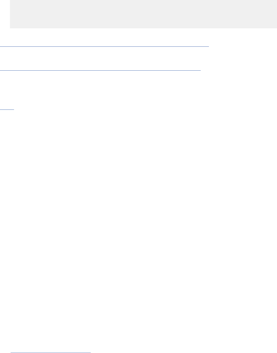
en_US Aug 1, 2011 5:08 AM
en_US 8/1/11 5:08:17 AM CT
en_US 8/1/11 5:08:17 AM CDT
en_US 8/1/11 5:08:17 AM
en_US 8/1/11 5:08 AM
Related concepts
“Importing requirements artifacts from CSV and spreadsheet les” on page 159
You can import data from comma-separated values (CSV) and spreadsheet les into folders and modules
in an RM project.
“Exporting requirements artifacts to CSV and spreadsheet les” on page 161
You can export text-based artifacts from a requirements project into comma-separated values (CSV) les
or into spreadsheet (XLS and XLSX) les. The content of the exported le is governed by the columns that
are in the current view.
Related information
UTF8
Importing migration package les
You can import requirements from an IBM Engineering Requirements Management DOORS (DOORS)
migration package le into IBM Engineering Requirements Management DOORS Next (DOORS Next). The
migration package le must be in your le system.
Importing data from a migration package le is a one-way, non-destructive migration method for moving
requirements from DOORS into DOORS Next. Historical data is not migrated; however, the import process
creates URIs in DOORS Next that link back to the corresponding records in DOORS. These links provide
access to history, baselines, and other non-migrated data. During the import process, the wizard searches
for existing compatible types to use. If an existing type cannot be found, a new type is created.
Migration options for incoming packages:
• On entering the artifact type, for Attribute for imported modules, all attribute values are imported
successfully, regardless if the attributes are mapped to the types before migration.
• On entering the artifact type, for Attribute for imported artifacts and Attribute for imported modules,
the attribute values are imported successfully only if the attributes are mapped to the types before
migration.
• On not entering any artifact type for Attribute for imported artifacts, all attribute values are imported
successfully, regardless if the attributes are mapped to the types before migration.
To import data from a migration le:
1. Click Artifacts > Import Artifacts.
2. In the import wizard, click Import requirements from a migration package.
3. Browse for and select the migration option and le to import, and then complete the steps in the
wizard. The migration options are:
• Attribute for imported artifacts
• Attribute for imported modules
The migration package le must have a .migiz le extension.
After the import process is complete, a migration report is generated. You can access the report at any
time from the project properties Migration page. For information about how to create a migration package,
see Migrating data to DOORS Next.
You can watch a short overview video below, to learn about Migrating data from IBM Rational Doors to
IBM Rational Doors Next Generation:
You can also watch the detailed video below, to learn about Migrating data from IBM Rational Doors to
IBM Engineering Requirements Management DOORS Next:
166
Engineering Requirements Management DOORS Next

Related tasks
“Integrating the Requirements Management application and DOORS” on page 15
You can integrate IBM Engineering Requirements Management DOORS (DOORS) with the Requirements
Management (RM) application in the IBM Engineering Lifecycle Management (ELM). You can link
requirement artifacts in the RM application to requirement objects in DOORS modules. After you create
links, you can display a summary of the linked object or go to the object. You can also add a widget to your
dashboard to monitor the status of linked objects.
Related reference
“Comparison of data exchange methods in requirements management” on page 120
Importing and exporting ReqIF les
Requirements Interchange Format (ReqIF) les are XML les that you can use to exchange requirements
and associated metadata between requirements tools or requirements repositories. For example, you
can exchange data between IBM Engineering Requirements Management DOORS (DOORS) and IBM
Engineering Requirements Management DOORS Next (DOORS Next). When the exchange is nished, a
report is generated that shows the data that was imported or exported. Using ReqIF to migrate multiple
components or a single component with multiple streams from one environment to another is not
supported. The supported method to migrate a repository to a new environment is Server Rename. If
you want to migrate a partial Requirements Management repository to another environment, you need
to consider engaging IBM Expert Labs, or an IBM Business Partner to explore options that comprise of
custom utilities in addition to ReqIF.
About this task
You can import or export data to and from a requirements project or component by using ReqIF (.reqif
or .reqifz) les. Exporting and importing data back into the original requirements project or component is
also supported. You can export data from a requirements project or component, to another requirements
project or component. On making changes to the data, you can import the data back into the original
requirements project or component. For example, you can export objects to a ReqIF le from DOORS and
then import that le into DOORS Next. You can change attribute values, export the artifacts to a ReqIF le,
and then import that le back into DOORS. If you import a ReqIF le into DOORS Next after you already
imported or exported the data, the data is merged and updated.
Note:
• In DOORS Next, you can specify write restrictions on attributes in a ReqIF denition from the ReqIF
properties tab. The write restrictions are used while exporting data to a DOORS repository, and enables
the DOORS repository to merge the imported data.
• You can restrict or lock attributes while exchanging requirements between DOORS Next and DOORS
version 9. If you specify the attributes as locked in the denition, they are locked on the DOORS side of
the ReqIF exchange and this enables the DOORS ReqIF merge algorithm to correctly update attribute
content. The feature does not add locks of any kind to the exporting DOORS Next repository.
If the ReqIF packages contains attributes and types associated with a workflow in DOORS Next, these
associated attributes and types are supported during the export process of the package, but are ignored
during the import process.
For information about supported and restricted data, see “Importing artifacts from ReqIF les to a
requirements project or component” on page 168 and “Exporting artifacts from a requirements project or
component into ReqIF les” on page 173.
After you import or export a ReqIF package, a report is automatically generated. Information in the
reports is grouped by module. Any artifacts that are not in a module are listed separately in the reports.
The following information is included in the reports:
• For each module, the report displays attribute denitions, artifact types, and artifacts.
• The summary, data types, artifact types, links, and folder for a specic import or export of a ReqIF
package are displayed at the root level.
Managing
167

• Artifact types are displayed at both the root level and the module level. Artifact types for the root level
are specic to the ReqIF package and artifact types for the module level are specic to that module.
For information about moving the contents of a server, such as moving a pilot deployment to a production
server or moving a production deployment to a different server, see Supported scenarios for using server
rename. The server rename operation moves all existing projects or component and artifacts from one
deployment to another. The operation does not support a selected project or component move function;
that is, you cannot move only selected projects or components when you rename a server.
Related information
Migrating and Integrating DOORS with DOORS Next
Importing artifacts from ReqIF les to a requirements project or component
You can import the data in a Requirements Interchange Format (ReqIF) le from your le system to a
requirements project or component.
Before you begin
Before you import a ReqIF (.reqif or .reqifz) le, ensure that the le that you are importing is
encoded in UTF-8.
To import a ReqIF le, you must have write access and the Import ReqIF permission.
About this task
When you import a ReqIF le (.reqif or .reqifz), you use a wizard in which you select the ReqIF le
to upload and import. After you upload the le, you can either import the ReqIF data or close the wizard
and import the ReqIF data at another time. After the import process is complete, a report is displayed that
shows a list of the imported data. You can go to imported artifacts in the project or component by using
the links that are generated in the report.
You can use the standard import option, where you can select the ReqIF le to import and follow the
instructions. For more information, see Using the standard import option
.
You can also use the advanced import option, where you can specify more import options. For more
information, see “Using the advanced import option” on page 172.
Important: The rst time that you import ReqIF data, types, and artifacts are created. If you import
the same data later, all data is updated except for the view column information. During an import,
system attributes and system data types are merged. If a mapping context is selected, then the importer
attempts to match attributes and data types by their title. Artifact types, attributes, data types, and
folders that were not already imported from a ReqIF le are created in the project or component that
you are importing to. If an imported type resource has the same name as an existing type resource, then
the incoming type is renamed by adding a sufx. "[DNG-Renamed-<X>]" where <X> is the next available
number for the type name and sufx. For example, the le that you are importing and the project or
component that you are importing to might both contain a Priority attribute. In that case, an attribute
named Priority [DNG-Renamed-1] is created during the import.
You can import several types of data from a ReqIF le, including these types:
• Textual artifacts
• Graphical artifacts
• Diagram artifacts
• Attribute denitions
• Data types
• Folders and folder hierarchies
• Links
• Link types
• Tags
168
Engineering Requirements Management DOORS Next

• Modules
• Artifact types
• Collections
• View column information, which is imported during the rst import only.
If you import the following types of items in a conguration-enabled environment, the import creates
a new version of the resource. Also, it maps it to the import conguration if the resource was already
imported into another conguration in the component or project.
• Data types
• Attributes
• Artifact types
• Modules
• Artifacts
• Folders
• Links
• View column information
For more information about ReqIF usage scenarios, see ReqIF Usage Scenarios.
Important:
• If a resource was previously imported into a different stream or change set in a component or project,
the import completes the following actions:
1. Creates a version of the resource in the stream or change set at the import location.
2. Updates the resource if it is already available at the import location.
• If a resource was not previously imported into any of the streams or change sets in a component or
project, the import creates the resource at its import location.
• If a resource was previously imported into the stream or change set in a component or project, the
import updates the resource if it was changed.
Note: If any items imported into the conguration are deleted, a new version of the deleted resource is
created and mapped to the imported conguration.
The following types of data cannot be imported:
• View ltering information
• Comments
• Reviews
• Audit histories
You can import ReqIF les in XML format or a compressed le format. If a ReqIF le references
external attachment les or embedded OLE les, which occur in some exports from IBM Engineering
Requirements Management DOORS (DOORS), the ReqIF le, and the referenced external les must be
in one compressed le to ensure that the correct associations are created in the requirements project
or component. When you import a ReqIF le that contains embedded OLE objects from DOORS, the OLE
objects are created as le resources in the requirements project or component.
When you import a ReqIF package, existing artifact types are updated and the attributes are retained:
they are not removed.
For example, you have an existing artifact that is named Artifact Type A, with attributes A and B. You
import a package that contains Artifact Type A, with attributes A and C, the updated artifact is Artifact
Type A, with attributes A, B, and C.
If the package includes only portions of a module, when the package is imported, new artifacts are added
to the existing module structure. Artifacts that are not included in the package but exist in the module
structure are never deleted.
Managing
169
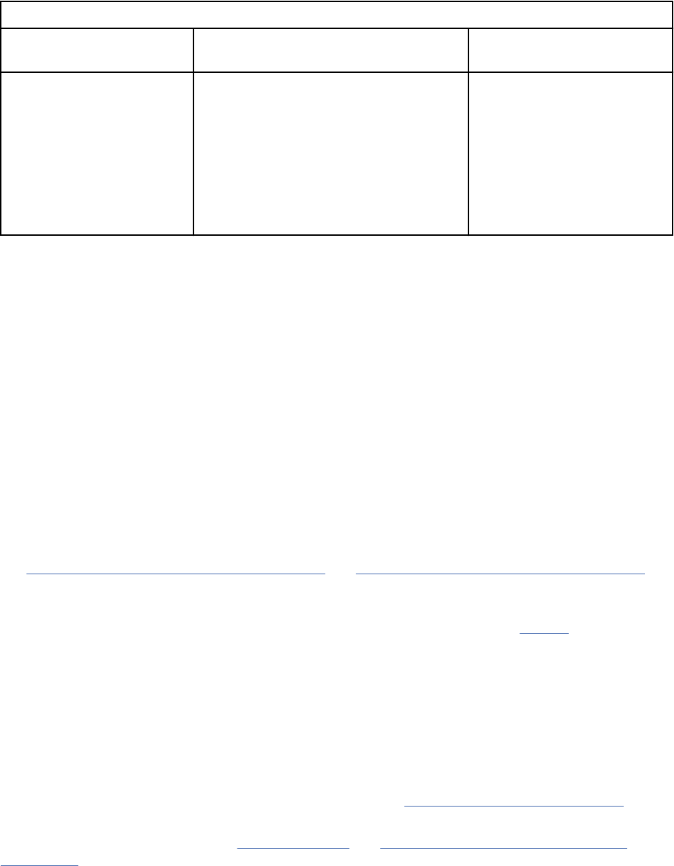
If child artifacts are moved to new parent artifacts as described in the imported package, the previous
parent is also included in the package. If the previous parent is not included in the package, the child
artifact is not moved. The following example shows that how a child artifact can move during the import
process:
Table 23. Example of how the structure of artifacts can change during the import process
Existing package Package being imported
Resulting structure (moved
artifacts are in bold)
Parent artifact 1
• Child artifact A
Parent artifact 2
• Child artifact B
Parent artifact 3
• Child artifact C
Parent artifact 1
• Child artifact A
• Child artifact B
• Child artifact C
Parent artifact 2
Parent artifact 1
• Child artifact A
• Child artifact B
Parent artifact 2
Parent artifact 3
• Child artifact C
If you import a ReqIF package that has only one link endpoint, and you later import another ReqIF
package that has the other endpoint and the link. As a result, the link is created between the two
endpoints. Incremental links are supported for the following imports:
• Artifact to artifact
• Artifact to module
• Artifact to collection
• Module to module
• Module to collection
• Collection to collection
Packages from IBM Engineering Requirements Management DOORS Next (DOORS Next) contain a link
when either endpoint is exported. Packages from DOORS contain a link only when both endpoints are
exported.
You can also import data by using ReqIF from DOORS to DOORS Next. You can create a ReqIF denition
in DOORS and export the denition to a ReqIF package. You can then import the ReqIF package in DOORS
Next to get the required data. For more information about exchanging requirements data that uses ReqIF,
see Exchanging requirements with other databases
and Migrating DOORS project data to DOORS Next.
Some ReqIF packages contain system properties. If the system property values are not usable, they are
not displayed in the comparison wizard. This principle applies to packages from DOORS, DOORS Next,
and tools in the ProSTEP ReqIF Implementation Guide. For more information, see prostep. The following
attribute values are set only when, from an import, an artifact is created for the rst time in a component:
• ForeignID
• ForeignCreatedOn
• ForeignCreatedBy
For example, when you import a new artifact, the ForeignModiedOn and ForeignModiedBy attribute
values are set. But, when you import an existing artifact, the ForeignModiedOn and ForeignModiedBy
attribute values are only set when one or more values change.
For more information about the ReqIF format specication, see Requirements Interchange Format.
When you export ReqIF data from DOORS to DOORS Next, you must map system attributes to URIs
in DOORS. For more information, see System attributes and Mapping attributes to URIs for external
applications.
170
Engineering Requirements Management DOORS Next

Procedure
1. Open a requirements project or component.
2. On the Artifacts page, click Create and click Import Artifact.
3. In the Import wizard, select Import requirements from a ReqIF le and click Next.
You can use this standard import option where you can select the ReqIF le to import and follow the
instructions.
Tip: You can also use the advanced import option with extended options to congure the import. For
more information, see “Using the advanced import option” on page 172.
4. Browse the le to import and click Import.
5. After the le is fully uploaded, complete one of the following steps:
• To close the Import wizard and continue the import later, click Close. When you are ready to
continue the import, start the Import wizard and click Import requirements from a ReqIF le in
this component or project.
• To continue the import, click Next and follow the prompts in the wizard.
6. Optional: Specify the import options for the import:
a) Specify the folder or module where you want to import the ReqIF le. To place new artifacts that
do not dene module hierarchy in the specied module, select the Place new artifacts with no
module hierarchy in a module checkbox.
Important: When you select the folder or module to place the new artifacts in, that folder or
module is used only for artifacts that do not have a dened folder or module hierarchy. If a ReqIF
le was exported with the Include Folders option that is selected, that folder hierarchy is used
starting from the root folder, regardless of the folder that you specify. This premise also applies to
ReqIF les exported by DOORS because they always include the folder structure.
b) To tag the existing artifacts that are not present in the ReqIF package, under the Import Tagging
Options section, select the Tag artifacts that are present in repository modules being updated,
but are not present in the package checkbox. Use one of the following options:
• To dene a new tag for the artifacts, select Create new tag. Specify the new tag.
• To use an existing tag, select Use Existing tag. Click Pick Tag. In the Select Tag window, type the
name of the tag or select an existing tag from the list and then click OK.
Note:
• The Import Tagging Options feature determines whether an artifact that was previously imported
in a module is absent in a subsequent import. The most common reason for an artifact to be
absent in subsequent import is that the artifact is deleted on the sender side of the ReqIF
exchange.
• Tagging Options work on artifacts only and you cannot apply them to any modules that are
deleted.
c) To apply mapping context to an imported package, under the Apply Mapping Context section,
select Select Context. Select an existing context from the Available Contexts list and then click
OK.
For more information about mapping contexts, see “Mapping Contexts” on page 35.
7. Optional: Select the attributes to import. You can select either all attributes or specic attributes.
8. Optional: To see a list of the data that is imported, click Show Report.
The report includes the name, ReqIF ID, and URI of the data, and other information. You can access
the report at any time from the project or component properties ReqIF page.
Managing
171
Using the advanced import option
About this task
You can use the advanced import option to import artifacts from ReqIF les to your requirements project
or component. The following steps describe the procedure of using the advance import option.
Procedure
1. Open a requirements project or component.
2. On the Artifacts page, click Create and click Import Artifact.
3. In the Import wizard, select the Import requirements from a ReqIF le (Advanced) checkbox and
then click Next.
Note: You can upload a package (compressed le) that contains multiple .reqifz les. If you use the
Import requirements from a ReqIF le (Advanced) option wizard to import the package, the import
settings apply to all les in the package.
4. Select the le to import and click Upload. After the le is uploaded, detailed information for each
uploaded ReqIF le is available. You can see a summary of the package and ReqIF les, and view
how many specications, artifacts, types, and attributes are in the uploaded package. Click Next to
continue the import. To view the import report, click Analysis Results. The analysis report shows
information about these types of errors if they occur in an incoming ReqIF package:
• A specication hierarchy in a specication points to a specication object that isn't in the package.
• An attribute denition points to a data type that doesn't exist in the package, or the types of both are
mismatched.
• A specication object value points to an attribute denition that doesn't exist in the package, or the
types of both are mismatched.
5. Optional: Specify the following import options for the import:
a) To select the location to which to import the new module les, select the Choose location for new
modules checkbox and specify the location.
b) To add new artifacts that are not in a module hierarchy in the selected module, select the Place
new artifacts with no module hierarchy in a module checkbox.
c) To restrict the creation of artifacts, clear the Allow artifact creation checkbox in the Advanced
Import Options section of the page.
d) To prevent artifacts in modules from being moved to other modules, clear the Allow artifact move
(within modules) checkbox.
e) To prevent modications to artifact types, clear the Allow modication of existing artifact types
checkbox. This option prevents changes to the title, description, and RDF URI of all the artifact
types.
f) To prevent modications to attribute denitions, clear Allow modication of existing attribute
denitions checkbox. This option prevents changes to the title, description, and RDF URI of all the
attribute denitions.
g) To prevent changes to the title, description, and RDF URI of all the data types, clear the Allow
modication of existing data types checkbox.
h) Click Next.
6. Select the specications to import to the current project or component and click Next. If you hover
over a specication in the import wizard, a preview window shows the details of the specication and
the artifact types in it.
7. If mapping context is not specied, select the attributes to import and click Next. You can select either
all attributes or specic attributes. After you specify the advanced import options, the ReqIF le is
imported. You can view the status of the import on the Importing Requirements page.
172
Engineering Requirements Management DOORS Next

Results
Artifacts get successfully imported from ReqIF les from your system to a requirements project or
component.
You can watch the below video, to learn more about Data migration from DOORS to the RM application:
Related concepts
“Modules in the Requirements Management application” on page 129
A module is a structured document that is composed of multiple artifacts. You can create structure in a
module by modifying the order and hierarchy of its artifacts. The artifacts that are created for modules
are stored as module content in a folder. Base artifacts can be used to manage the module artifacts
independent of the module.
Related information
Data migration from DOORS to the RM application
Exporting artifacts from a requirements project or component into ReqIF les
You can export artifacts, modules, and folders from a requirements project or component into a ReqIF
(Requirements Interchange Format) le by creating a denition and then exporting the artifacts. The
artifacts that are exported are determined by the content in the denition.
Before you begin
To export data to a ReqIF le (.reqif or .reqifz), you must have:
• Export ReqIF permission
• A ReqIF denition in the ReqIF editor. To create a ReqIF denition, you must have the Manage ReqIF
permission.
About this task
You can export several types of data from a requirements project or component to a ReqIF le, including
these types:
• Attribute denitions
• Data types
• Textual artifacts
• Graphical artifacts
• Diagram artifacts
• Artifact types
• Modules
Important: To export a module to a reqIF le, the default artifact format of that module must be
"Module".
• Tags
• Links to other artifacts in the RM project or component
• Link types
• Folders
• Folder hierarchy
• View column information
The following types of data cannot be exported:
• Comments
• View ltering information
Managing
173
• Reviews
• Audit History
• Links to artifacts in applications that are integrated by using OSLC, such as IBM Engineering Workflow
Management (EWM) and IBM Engineering Test Management (ETM)
• Date
• Time
• User
If you are exporting artifacts to IBM Engineering Requirements Management DOORS (DOORS), the
following data types are not supported. These data types are from the Requirements Management (RM)
application for the IBM Engineering Lifecycle Management (ELM).
• Full rich-text formatting.
• Graphical artifacts, such as business process diagrams, use case diagrams, and wireframes.
• Requirements that include embedded collections.
If you use modules to capture information about your project or component requirements, you can export
specic artifacts in the module. Start by creating a view of the module that contains only those artifacts
that you want to export; then, during the export process, you can add the new view to the denition. If
the view is a non-personal, single-module view (non-module shared), only the artifacts in the view are
exported to the ReqIF output package.
Important: During the export process, any embedded artifacts or images that are added from a different
component, which is linked through a global conguration are not exported.
Procedure
1. On the Administration menu , click Manage Project Properties.
Note: If conguration management is enabled for your project, on the Administration menu, click
Manage Component Properties.
2. Click the ReqIF tab.
3. Click New Denition.
4. Type a name for the denition. If necessary, specify other information, such as a description or
whether to include links or folders in the export.
5. Click Add Artifact or Add Module and follow the prompts to add the artifacts to include in the export.
When you add a module, you can use a shared view to describe exported artifacts and attributes from
the module, as dened by the view's lter and columns.
Note: You can add shared views and shared module views to a denition for export. However, doing
so exports the view query and not the artifacts in the view.
6. Optional: Specify attributes to be restricted during export to aa version 9. Click the attributes
restricted link and select the attributes that you want to restrict and add them in the Selected
Attributes list. Click OK. For more information, see restricting attributes.
7. After you nish adding artifacts, click Save. The denition is displayed in the ReqIF Denitions
section.
8. To start the export, click the pencil icon (
) that is next to the ReqIF denition, and then click
Export.
9. Optional: To apply a mapping context during export, click Export with context. Select an existing
context from the Available Contexts list and then click OK.
For more information about mapping contexts, see “Mapping Contexts” on page 35.
10. When the export is complete, click Download to save the export to a le on your computer.
174
Engineering Requirements Management DOORS Next
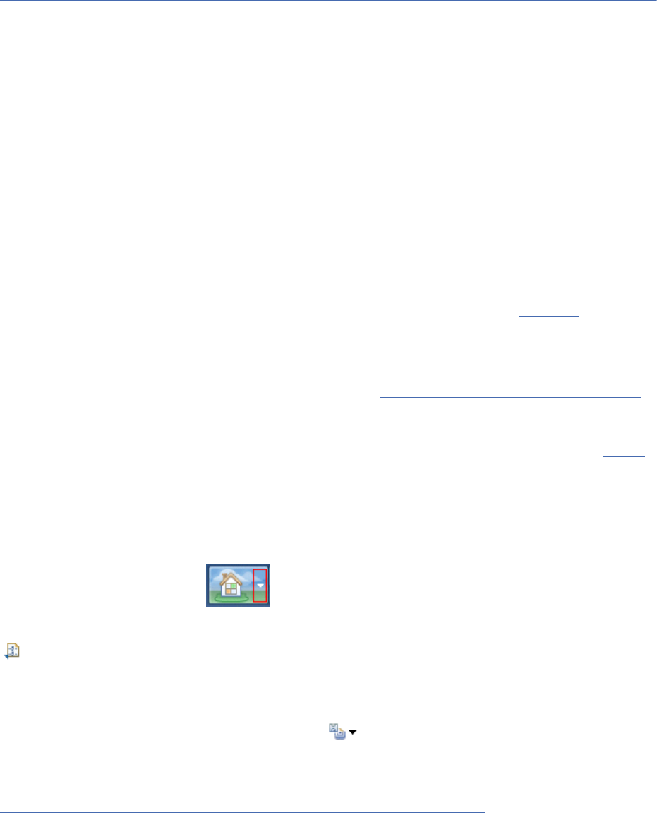
The downloaded ReqIF le has the (.reqifz) extension. To see the data that was exported, click
Show Report.
What to do next
You can download packages and view report information in the ReqIF Manager window. Click the action
icons in the ReqIF Files section of the editor.
Related tasks
“Importing properties from another Requirements Management (RM) project or component” on page 61
You can import the properties from one Requirements Management (RM) project or component into
another project or component. When conguration management is not enabled, you import properties
from project to project. When conguration management is enabled, you import properties from
component to component. The properties that are imported by default include all the artifact types,
attribute data types, link types, and link constraints that are dened in the project or component.
Creating collections
A collection is a set of artifacts that you create for a specic purpose.
Procedure
1. Open either the Artifacts page or the Collections page.
2. In the Collections menu, click Create Collection.
3. Type a name for the collection plus any optional information. Optionally, select the Open Artifact
check box if it is not already checked.
4. Click Finish. If you selected the Open Artifact check box, the Collection Editor is displayed.
5. Click Add Artifact, and select the artifacts you want to add. (Refer to keyboard shortcuts
for
information on how to select multiple artifacts.)
6. Click Add and Close. The selected artifacts open in the Collections editor.
Note: If you are using a supported browser, you can upload a le into a collection by dragging the le
from the Windows desktop into the collection editor. See Uploading les to a requirements project for
more information.
7. Select Save or if you are done with this editor, select Done.
8. Optional: Click the Create Review from Collection icon in the toolbar if you want to create a review of
the collection.
Results
After you save your collection, it is displayed in both the Artifacts page and in the Collections page. To
return to the Artifacts page after saving a collection, either click the project name breadcrumb or click the
project name in the Home menu
.
You can export the artifacts in a collection to a CSV le by selecting the Export collection to CSV le icon
or by selecting individual artifacts and then selecting Export from the pop-up menu.
Saving collections to other formats
You can save a collection to a Microsoft Word or to a PDF document from within the collection editor by
selecting a choice from the Create and Print menu .
Related concepts
“Requirement artifacts” on page 92
“Exporting requirements artifacts to CSV and spreadsheet les” on page 161
Managing
175
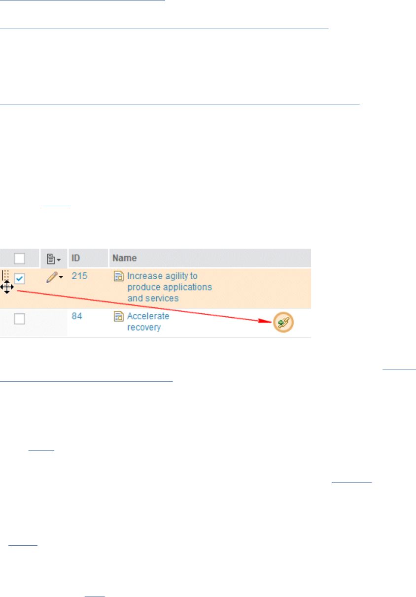
You can export text-based artifacts from a requirements project into comma-separated values (CSV) les
or into spreadsheet (XLS and XLSX) les. The content of the exported le is governed by the columns that
are in the current view.
Related tasks
“Comparing collections” on page 177
You can use the Requirements Management application to compare two different collections.
“Creating templates for requirements projects or components” on page 46
You can create a project or component template, and select the elements to include in it. When
conguration management is not enabled, you create templates for a project. When conguration
management is enabled, you create templates for a component. You can include or exclude artifacts,
artifact templates, artifact types and attributes, links between artifacts, link types, folder structure, tags,
and shared saved lters. After you create templates, you cannot modify them.
“Managing project or component properties in requirements projects” on page 28
Each project template contains predened artifact types. You can also create customized artifact types,
artifact attributes, and artifact data types for a project or component. Those artifacts types can then
be used by team members to create project or component requirements or related artifacts, such as
customized collections.
Collections
A collection is a set artifacts that you create for a specic purpose.
After you create
a collection, you can link the collection to and from other artifacts, embed the collection
in a text-based artifact, create reviews from the collection, and perform other actions.
Tip: You can create links between artifacts in a collection by dragging an artifact and dropping it on the
link icon of another artifact, as shown here:
Collections do not display artifacts in any particular order or hierarchy, nor do they contain context
specic links, attributes, or comments. If you need these features, you should create a module. Also see
comparison of collections and modules for more information.
Reasons for creating collections:
You might want to create a collection for the following reasons:
• Identify a group of related artifacts to work with
• Add terms to the collection to use as a glossary
• Group artifacts that are now mature and ready to be reviewed
• Capture a set of requirements that are ready for review or that have been reviewed and approved
• Identify artifacts related to a common goal
• Link collections to release plans and test plans
• Link requirements in the collection to development work items and test cases
• Export the artifacts in a collection to a CSV le
Other information about collections:
• Note that you cannot add a collection to a collection; however, you can add a module to a collection.
• When you save a view from within the collection editor, the view appears in the current collection and in
all other collections in the project. The view will not appear in any other context within the project.
176
Engineering Requirements Management DOORS Next
• To compare capabilities and potential uses for collections and modules, see “Differences between
collections and modules” on page 131.
Related concepts
“Requirement artifacts” on page 92
“Reviews” on page 181
Related tasks
“Comparing collections” on page 177
You can use the Requirements Management application to compare two different collections.
“Managing project or component properties in requirements projects” on page 28
Each project template contains predened artifact types. You can also create customized artifact types,
artifact attributes, and artifact data types for a project or component. Those artifacts types can then
be used by team members to create project or component requirements or related artifacts, such as
customized collections.
“Linking to development, design, test, and requirement artifacts” on page 201
Comparing collections
You can use the Requirements Management application to compare two different collections.
About this task
To compare two different collections:
1. Open a collection.
2. Click the Compare Collection icon
in the toolbar. The Compare Collection window opens.
3. On the left side of the window click the collection name. The Compare Collections Selection window
opens. Search for and select a collection.
4. On the right side of the window click Select Collection. The Compare Collection Selection window
opens. Search for and select another collection.
5. Click Compare.
If you want to compare two versions of the same collection, you must be working in a project that has
been enabled for conguration management.
Related concepts
“Collections” on page 176
A collection is a set artifacts that you create for a specic purpose.
Related tasks
“Creating collections” on page 175
A collection is a set of artifacts that you create for a specic purpose.
Managing terminology and glossaries
Develop a glossary of terms that are drafted and published as part of the project process. A glossary
provides the context for agreeing on consistent project terminology. This is especially important as teams
grow and become more geographically distributed and projects become more complex. Create terms and
add them to one or more glossaries.
Glossaries
A glossary is a group of terms that you create to build consistent, common terminology for a project.
You can display the terms that constitute your glossary:
• Create a lter
that displays artifacts by artifact type.
• Add terms to a collection.
Managing
177

You can look up terms from within the artifact editor using the Lookup Term icon, which becomes
visible whenever you open and edit a text-based artifact.
You can link to a glossary term or create a new glossary term from selected text within a text based
artifact.
Glossaries can contain attribute settings and comments. Glossary terms can be dened with the following
content:
• Name
• Denition
• Synonyms
• Alternative spelling
• Links to new and existing artifacts, including requirements
• Comments
• Custom attributes
Creating a glossary and terms
A glossary is a group of terms that you have dened to build consistent, common terminology for your
project.
About this task
You can create a glossary by rst dening the terms to include in the glossary. After you have dened
terms, you can then either:
• Add the terms to a collection.
• Use tags to keep track of your glossary terms.
• Put the terms in a folder and create a view to display relevant attributes.
Glossary terms can contain links to new and existing artifacts, related terms, and synonyms. They also
can contain comments and alternative spellings. You can assign attributes to the glossary and view, lter,
and sort links to other artifacts using the sidebar.
Creating Terms
Before you can create a term, make sure that a term artifact type has been created for the project and
that the Use Artifacts of this Type as Glossary Terms check box is selected. To display or create artifact
types for a project, click Manage Project Properties from the Administration icon menu.
Note: If conguration management is enabled for your project, on the Administration menu, click
Manage Component Properties.
To create a term:
1. From the Artifacts page, click the Create Artifact menu, and select Term (or whatever type name that
was created for glossary use). The "Create an artifact with attributes" window opens.
2. Type a name for the term.
3. Ensure the artifact type is Term (or whatever type name that you congured to be used as a term) and
the Artifact Format is Text. For more information, see Creating artifact types.
4. Provide optional information, such as a description, a folder, or tags.
5. Optional: Check the Open Artifact check box if it is not already checked.
6. Click Finish. If you selected the Open Artifact check box, the rich-text editor opens.
7. To start editing the term, click Edit.
Note: You can also import an existing set of terms using the requirements management import facility.
Dening alternative spellings and synonyms for a term
178
Engineering Requirements Management DOORS Next
To dene alternative spellings for a term, edit the term, and enter a value in the Alternative Spelling
attribute. To dene more than one alternative spelling, separate entries by a comma. To dene a synonym
of a term, create a Synonym link type between two term artifacts.
For more information on creating glossaries, refer to the documentation on the Jazz.net development site.
Note: Content on Jazz.net is governed by the Jazz.net Terms of Use and is provided as-is without
warranties of any kind.
Commenting on artifacts
A comment is a textual discussion item that you can add to an artifact or an element within an artifact.
You can use comments to provide team feedback during the development of an artifact. In the web client,
comments are displayed in the Comments section of an artifact sidebar, in the Recent Comments section
of the Artifacts page sidebar, and in Recent Comments for Me on the user dashboard.
About this task
The following table provides instructions for how to comment on artifacts by using the web client. You can
also watch a video that shows how to comment on artifacts.
You can comment on an artifact as a whole (by using artifact-level comments) and on specic elements
in the artifact. Comments on artifacts become part of the stream and must be delivered before they are
visible in other streams in a conguration. In rich-text artifacts, you can comment on the whole document
(by using document-level comments), a paragraph, or an item in a bulleted list within the document.
Comments are accessible to all team members who have access to the artifact.
When you create a comment, you can direct it to one or more users, so that it is displayed on their
project dashboard
. If your server has email notications set up, you receive an email when comments are
directed to you. For more information, see Conguring email settings.
A comment and its replies are maintained as a group in the comments section. Replies to a comment are
indented under the top-level comment. The number next to the Comments icon on an artifact toolbar
displays the total number of comments on the artifact. Click the icon to highlight the comments on the
artifact or to add a new comment. You can also view comment totals on the Artifacts page when you view
the artifacts list with details. You can add a comment there without opening the artifact.
Note: Comments on reviews or on artifacts in a review behave differently and are not part of any stream
or baseline.
When you select a comment on an artifact, its associated element is selected in the editor. When you
select an element in an artifact editor, its associated comment is selected in the sidebar.
The following table describes additional tasks for managing comments.
Table 24. Controls and associated tasks in the Comments section of the sidebar in the web client
Task Icon Steps
Expand or collapse a
comment.
Click the header portion of the top-level comment.
The comment text and replies are shown or
hidden.
Expand or collapse all
comments.
Click the Expand All or Collapse All icons to show
or hide the text and the replies for all comments in
the Comments section.
Managing179
Table 24. Controls and associated tasks in the Comments section of the sidebar in the web client
(continued)
Task Icon Steps
Add or reply to a comment in
an artifact.
To create a comment that applies to a whole
artifact, in the Comments section of the sidebar,
click the Comment icon and click Create a
New Comment for the Artifact.
You can also add a comment to a selected element
by clicking the Comment icon in the sidebar
and using the option Create a New Comment for
<element>.
To create a reply, select a comment and click the
Reply icon
.
Highlight elements or
paragraphs in the editor that
have associated comments.
Click the highlight elements icon to highlight
all elements in the artifact editor that have
comments. When you are working with a
document, all paragraphs that contain comments
are highlighted.
The number of comments that are associated with
each element or paragraph is also shown in the
editor; this number is adjusted depending on your
lter settings for the Comments section of the
sidebar.
To remove the highlighting, click the icon again.
Filter the comments in this
view.
Click the Filter icon to limit the display to only
those comments that include or match your
criteria.
The lter criteria includes priority, comment
author (By), targeted recipient for the comment
(For), resolution state (unresolved only, by
default), and a date range for recent comments
only.
Click the Filter icon to collapse the lter section.
Collapsing the lter section does not clear the
ltering conditions; only those comments that
match the lter criteria are displayed.
To show all comments, click Show All.
Resolve a comment to
indicate that the comment
requires no further actions or
replies.
To resolve a comment, select the comment,
and click the Resolve Comment icon. Resolved
comments are displayed with light gray text. After
a comment is resolved, you can reopen it and reply
to it.
Resolve a discussion thread,
which resolves a comment
and all replies to it.
To resolve a discussion thread, select the
comment and click the Resolve Discussion
Thread icon.
180 Engineering Requirements Management DOORS Next
Table 24. Controls and associated tasks in the Comments section of the sidebar in the web client
(continued)
Task Icon Steps
Edit a comment. To edit a comment, select the comment and click
the Edit Comment icon. Only the user who created
the comment can edit it.
Sort and group comments. Click the Sort and Group icon in the Comments
section to access sorting and grouping options.
The Author refers to who created the original
comment. The Date refers to when the last activity
occurred on the comment, including replies.
Display the Recent
Comments section in the
Artifacts page sidebar.
Open a project by selecting it from the Home
menu. If necessary, expand the sidebar on the
Artifacts page by clicking the arrow on the right.
Expand the Recent Comments section sidebar.
Display the Recent
Comments for Me section in
the Artifacts page sidebar.
Open your dashboard by clicking the Dashboard
menu. Comments that were recently directed to
you are displayed in the Recent Comments for Me
section.
Delete comments. To delete a comment, select the comment, and
click the Delete Comment icon. A comment can
only be deleted by its author, and only if it
has no replies. Comments are not deleted if the
associated element is deleted. These comments
are marked with (element not in this revision)
in the comment title. To hide these comments in
the comment section, click Hide comments on
orphaned elements in the lter panel.
Reviewing artifacts
You can create a review of selected artifacts or a module or collection. You can designate other team
members as participants in the review. Participants receive requests and, depending on their designated
role in the review, they can approve, disapprove, review, or abstain from reviewing each artifact.
Reviews
You can create a review for specic team members to review artifacts, collections, or modules. The status
of a review changes as participants complete the review. You can create a review from within a stream or
a baseline.
You can generate reports about reviews and send email notications to participants when reviews start
and when certain events occur in a review. For instructions on how to create a review, see “Creating
reviews” on page 185.
Remember: You can modify artifacts in a stream, but not in a baseline.
• Reviews in a stream or baseline
• Reviewer roles
• Lifecycle review states
• Review editor
• Reports and email notications
• Collection reviews
• Module reviews
Managing
181
Reviews in a stream or baseline
When you create a review in an editable stream, the artifacts in the review can change. For example, if a
team member edits the artifacts in the stream, those changes are reflected in the review. Therefore, you
should create a review in a stream only if you know that the artifacts are not going to change signicantly
during the review.
If you have projects that are not enabled for conguration management, and you do not want the artifacts
in a review to change, you should create the review from within a baseline.
If your project or organization requires validation of baselines you can congure a project to require
electronic signatures (e-signatures) on baselines. See Enabling Electronic signatures for a baseline
for details on how to congure a baseline to require electronic signatures and Signing a baseline
electronically for details on how to add an electronic signature to validate and sign a baseline.
Note: In projects enabled for conguration management (CM), the baseline contains the artifacts in a
component, not the project.
Tip: Reviews are visible on the Reviews page, regardless of the conguration (stream or baseline) you are
currently working in. When you click a review, you automatically switch to the conguration in which the
review was created.
Reviewer roles
When you add a participant to a review, you assign a role to the participant that determines the actions
required to complete the review. The following table describes the roles and actions.
Table 25. Reviewer role and required action
Reviewer role Required action
Approver Approvers must approve, disapprove, or abstain for each artifact in the review
before the artifact can move to the reviewed or the nalized state. The icon that
corresponds with an approver's choice is shown in the status column in the review
editor window.
Reviewer Reviewers must either review an artifact or abstain from reviewing it before the
review can move to the reviewed or nalized state.
Optional reviewer Optional reviewers can review or abstain from reviewing an artifact; however, their
progress is not calculated in the overall progress of the review. The review can move
to the reviewed or nalized state regardless of what optional reviewers do.
Lifecycle review states
The state of the review changes based on its level of completeness. Typically, a review moves through this
order in its lifecycle:
Draft > In Progress > Reviewed > Finalized
This table describes the lifecycle states for a review.
Table 26. Lifecycle review states
Review state Description
Draft This state is the initial state of a review. The creator of the review assigns a due
date, adds review instructions, adds participants, assigns roles to participants,
and adds artifacts to the review. Participants are not notied when the review is
in the draft state.
182 Engineering Requirements Management DOORS Next

Table 26. Lifecycle review states (continued)
Review state Description
In progress When the creator of the review clicks Start Review, the review moves to the
in-progress state. Participants join the review by clicking the review title, which
is shown on their dashboards. When all participants are nished reviewing the
artifacts, the review moves to the reviewed state.
Paused Paused is an interim state in which the review is paused. This state is useful
when the creator of the review needs to change the participants, their roles, or
the artifacts in the review. In a formal review, the creator can also get the latest
version of the artifacts. In that case, all the artifacts that were initially captured in
the review are replaced with the latest versions of the artifacts.
When a review is paused, participants cannot add review comments or mark
artifacts as reviewed. The creator of the review must click Continue Review to
resume the review.
Reviewed In this state of the review, the reviewers have added comments to the artifacts
and clicked Done for their reviews. To continue the review, the creator of the
review or a project administrator can change the review and then click Continue
Review.
Overdue A review request is overdue after 11:59 p.m. on its due date. At 12:00 a.m., the
review is marked as overdue. This default setting cannot be modied.
Finalized To reach this state, all the necessary reviewers must complete the review and
the creator must click Finalize Review. The review is saved and can no longer be
modied.
Review editor
When you open a review, the Review editor opens with two collapsible sections: Participant Review and
Overall Review. You can switch between the two sections by clicking either section header.
In the Overall Review section, you can view the number of review comments for an artifact.
Reports and email notications
To generate a document-style report about the details of the review, click the Generate a document-
style report for this view icon
in the header, and follow the prompts in the wizard.
You can manually add comments to a review in the Review editor sidebar. However, most events
automatically send email notications to review participants. If email was not congured when the
product was rst installed, you must rst congure email settings on the server to enable automatic email
notications. For instructions, see Conguring email settings.
This table describes the events that cause email notications to be sent.
Table 27. Email
notication events
Notication recipient Events that cause email notications to be sent
All participants A review that was in the Draft state starts for the rst time.
All participants Artifacts are added to or removed from the review.
Specic participants Participants are added to or removed from the review.
Specic participants Changes occur that affect the participants, the status of the
participants, or the status of an artifact. This event occurs when
the creator of the review resets the participant status.
Managing183
Table 27. Email notication events (continued)
Notication recipient Events that cause email notications to be sent
Specic participant The role of the participant changes.
Collection reviews
In addition to creating a review for individual artifacts, you can create a review for a collection. You create
a review of a collection from within the collection editor or from the collection menu. When you create a
review of a collection, remember this information:
• You cannot add a collection to a review in the Review editor.
• When you create a review of a collection, the review includes all the artifacts that are in the collection.
• The list of artifacts in the review is dened by the collection. You cannot add or remove artifacts in the
Review editor.
• If the artifacts list in the collection is modied during the review, you can pause and then continue the
review to get the latest list of artifacts.
Module reviews
You can add modules to a review. You cannot add artifacts in the module. However, you can add
comments to the artifacts in the module. You can mark the module as approved or reviewed. You can use
the Review Comments column for adding the review comments. You can view the Review Comments
column and the associated review comments only when you are in a review.
If you want reviewers to review specic artifacts in the module (and not the entire module), you can
dene a view that identies the artifacts to review. For example, you can show attributes or tags that
identify what to review, or lter out artifacts that do not require review. To dene this view, you must open
the module from the review; otherwise, you cannot include the Review Comments column.
Related concepts
“Collections” on page 176
A collection is a set artifacts that you create for a specic purpose.
Modules
A module is a structured document that is composed of multiple artifacts. You can create structure in a
module by modifying the order and hierarchy of its artifacts. The artifacts that are created for modules
are stored as module content in a folder. Base artifacts can be used to manage the module artifacts
independent of the module.
Signing a baseline electronically
If your project or organization requires validation of baselines you can add an electronic signature to
validate and sign it.
Before you begin
Your project area must be congured to require electronic signatures on baselines, see Enabling
Electronic signatures for a baseline.
Restriction: If your Jazz Authorization Server is congured to use SCIM (System for Cross-domain
Identity Management), you will be unable to use electronic signatures.
Procedure
1. On the Administration menu, click Manage Baselines.
If your project area has been enabled for conguration management:
a. On the Administration menu, click Manage Components and Congurations.
b. Click the stream to open it and then click the Baseline tab.
184
Engineering Requirements Management DOORS Next
2. Click the baseline to open it in the baseline editor.
3. In the Electronic Signatures tab, click Add Electronic Signature.
4. Depending on the project-level settings, on entering your user name and password, you can enter a
comment and select a reason for signing the baseline.
Note: If you have saved your username and password in the browser, the username and password
elds may be automatically lled in.
5. Click OK.
Results
On signing a baseline, the electronic signature attaches to the baseline and displays in the baseline editor,
on the Electronic Signatures tab. You can view the following information about the signature:
• Signed by
• Signed on
• Reason for signing
• Associated comment
IBM Engineering Requirements Management DOORS Next (DOORS Next) has a new Reportable REST
API that enables users who create or modify templates with IBM Engineering Lifecycle Optimization
- Publishing (PUB) to report on electronic signature information. The new API only displays electronic
signatures if the report is run against artifacts in a baseline that has been signed. For details about the
API, see DOORS Next REST API
.
Creating reviews
You can create a review of artifacts so that other team members can review or optionally approve the
artifact content.
About this task
You can create a review of individually selected artifacts or you can create a review of a collection of
artifacts.
Tip: When you work in projects that are enabled for conguration management
, you must be aware of the
following information:
• Reviews are associated with congurations. When you open a review, it opens in a separate browser tab
in the conguration context it was created in.
• Review comments for an artifact are only shown when you view the artifact in the context of the
associated review.
Procedure
• To create a review of individual artifacts:
1. Decide whether you want to create the review in the current stream or in a baseline. Artifacts in
the current stream can still be modied by anyone who is working in the stream, while artifacts in a
baseline are frozen and cannot be changed.
Note: If your project or organization requires validation of baselines, you can congure a project
to require electronic signatures on baselines. See Enabling Electronic signatures for a baseline
for details on how to congure a baseline to require electronic signatures and Signing a baseline
electronically for details on how to add an electronic signature to validate and sign a baseline.
2. On the Artifacts page, open the Reviews section in the sidebar and click the Create Review
icon .
Managing
185
Tip: You can also start a review by selecting artifacts from the Artifacts page, clicking the down
arrow, and clicking Create Review. This method can be a faster way to add artifacts to the New
Review window.
3. In the New Review window, type a name and description for the review and then click OK. The
Review page opens with the name in the window header. Notice that the state of the review is
Draft.
4. Specify a review due date and any special instructions.
5. Add reviewers to the review:
a. Click Add Participants.
b. In the Select Users window, enter a partial username or wildcard to access a list of team
members to participate in the review.
c. In the Matching users section, select one or more users. Press Ctrl and click to select more than
one name.
d. Specify whether the members are reviewers, approvers, or optional reviewers. For more
information, see the Reviews topic.
e. To add the users as participants in the review, click Add.
f. Search for other users, if necessary. When your selections are complete, click Close.
6. If the artifacts are not already there, add the artifacts to review.
a. Click Add Artifacts.
b. In the Select Artifacts window, search for artifacts by type, name, text, or folder.
c. Select one or more artifacts and click Add. The artifacts that you selected are displayed in the
Artifacts section.
d. When your selections are complete, click Close.
7. Optional: To send a review request, select one or more participants and click Send Email. If the
email service is not congured, click Start email program to open your default email application.
The email addresses of the selected users are added to the recipients list of the new email
message. Add text as needed in your email program and send the email.
8. Click Save Review or Start Review. When you start the review, the following actions occur:
– If you congured email notication, all participants are notied by email.
– The review is listed on the participants' dashboard in the Reviews widget.
– The review is displayed in the Reviews section in the sidebar of the Artifacts page.
– The state of the review changes from Draft to Started.
9. When participants join the review, they double-click the artifacts to view them, and then, depending
on the role that is assigned to them, click Approve, Disapprove, Mark as Reviewed, or Abstain from
reviewing the artifact.
• Creating a Review of a Collection. The steps for creating a review of a collection are similar to those for
creating a review of individual artifacts. You can watch a video that shows how to create a review of
a collection. To create a review of a collection, open the collection, and click the Create Review from
Collection icon in the toolbar.
• Deleting a Review. To delete a review, open the review and click the Delete icon in the toolbar.
• Renaming a Review. To rename a review, open the review and click the Rename icon in the
toolbar.
186
Engineering Requirements Management DOORS Next
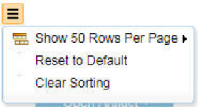
Participating in reviews
Team members can request that you Participate in a review of artifacts. The initiator of the review can
designate you as an approver, reviewer, or optional reviewer. Optional reviewers have the full review
capability, but their progress does not affect the status of the review.
Procedure
1. Click the name of a review on the Reviews page or in the Reviews widget on your dashboard.
2. In the Participant’s Review window, select a check box for an artifact and use the adjacent push
buttons and menus to select one of the following options. The available options depend on your role in
the review (approver, reviewer, or optional reviewer).
• Approve.
• Disapprove.
• Reviewed.
• Approve with Comments. Enter your comments in the window and click Approve.
• Reviewed with Comments. Enter your comments in the window and click Reviewed.
• Disapprove.
• Disapprove with Comments. Enter your comments in the Disapprove Artifact window and click
Disapprove.
• Abstain.
• Abstain with Comments. Enter your comments in the Abstain from Reviewing Artifact window and
click Abstain.
Note: If you print an artifact in a review and include comments, the report prints only comments that
are specic to the review.
3. Optional: To set a page size to view a specic number of artifacts on the page, click the More Actions
icon. You can also sort or resize the columns on the Participant's Review and Overall Review pages of a
review. The changes that you make are preserved across sessions so that the next time you start your
browser and open a review, the same sort column, column widths, and page size are displayed.
4. Optional: To reset the page size, reset columns to their default widths, and remove any sort columns,
click the More Actions icon and then click Reset to Default. If an artifact table is sorted, click the More
Actions icon and then click Clear Sorting.
5. After you review all artifacts, click Done. After you click Done, you cannot change your review
decisions; however, the review owner can reopen the review.
Results
The overall review status indicates the following:
• Approved: when at least one approver has approved and no approver has abstained.
• Disapproved: when at least one approver has disapproved.
• Reviewed: when there are no approvers and all reviewers have reviewed.
• Approved: but with abstentions when at least one approver has approved and at least one approver has
abstained.
• Reviewed: but with abstentions when there are no approvers and at least one reviewer has abstained.
• Not approved: when there's at least one approver, but no approver has approved.
Managing
187
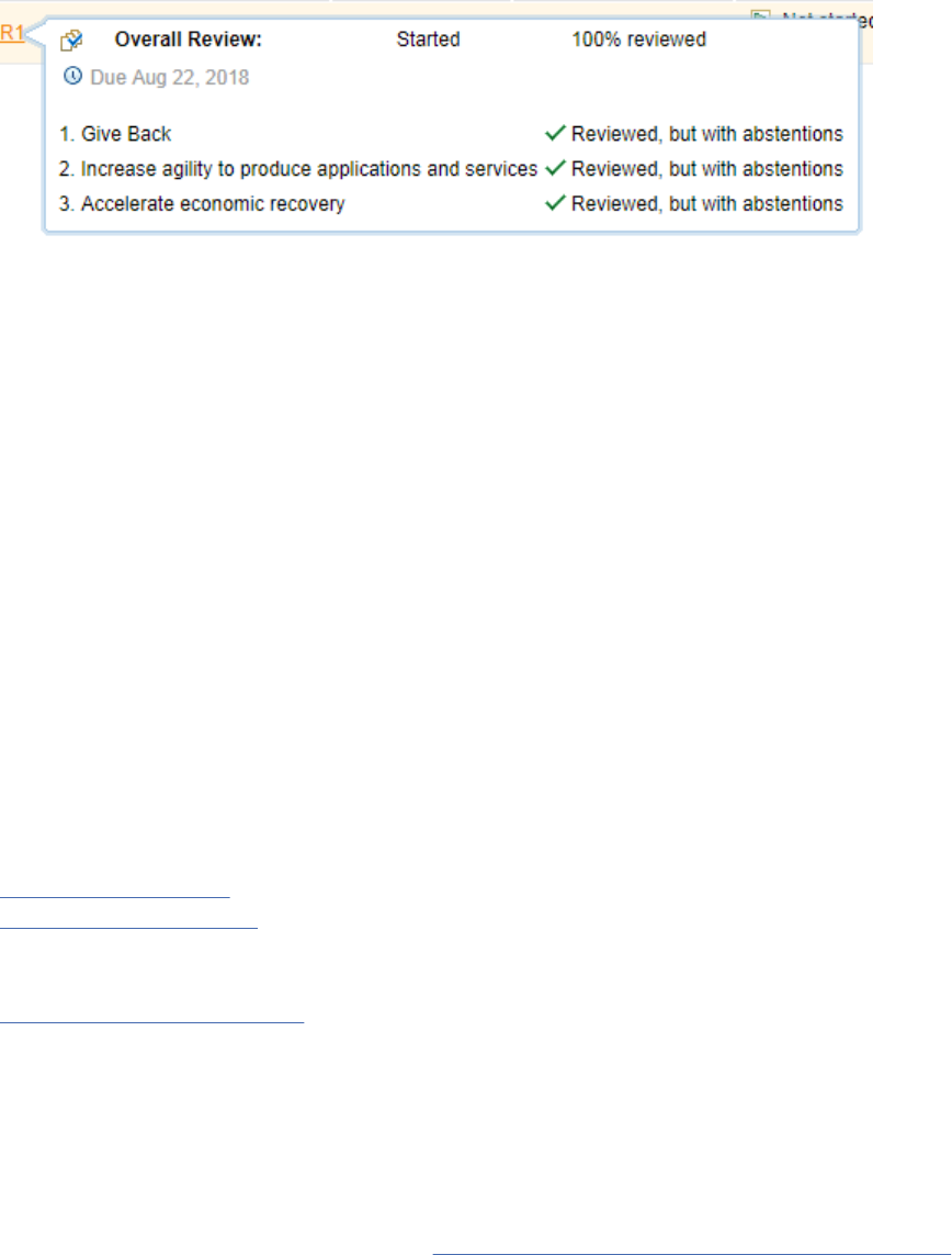
You can see the overall status of the review and any abstentions by hovering over the review name on the
Reviews page. The following image shows the overall status of a review:
Editing artifacts while reviewing a requirement collection
In a Requirements Management (RM) project, when you review a requirement collection, you can edit the
artifacts.
Before you begin
You must have reviewer permissions to review and edit the artifacts.
Procedure
1. On the Artifacts page, select a requirement collection.
2. Review the list of artifacts in the requirement collection.
3. Right-click an artifact and select how to open it for editing:
• Open Link in New Tab
• Open Link in New Window
Note: You must right-click the artifact. If you click it instead, the artifact opens in review mode and you
cannot edit it.
4. On the artifact page that opens, click Edit.
5. Make the required edits and click Save.
Related concepts
“Reviews” on page 181
“Collections” on page 176
A collection is a set artifacts that you create for a specic purpose.
Related tasks
“Creating artifacts” on page 91
In a requirements project, you can create rich-text and graphical artifacts.
Managing requirements
You can manage requirements by using traceability links, tags, attributes, ltering, workflows, and
dashboards. With these capabilities, you can create relationships between requirements and other
artifacts, categorize requirements, assign properties to requirements, and monitor relationships and
status among team applications. To learn how to optimize requirements management, reduce rework and
avoid delays by using AI from Watson, go to the IBM Engineering Requirements Management site.
About this task
Requirements management is a set of techniques (supported by tools) that a team uses to determine
what a program, product, or project needs to deliver to accomplish these goals:
• Ensure that goals are successfully met
• Provide visibility into the completeness of the requirements development effort
188
Engineering Requirements Management DOORS Next

• Control changes to requirements over time
Requirements denition is a subset of the requirements management process that focuses on elicitation
and validation. In some industries, the term "requirements engineering" is used to refer to the full
range of requirements denition and management activities. Application lifecycle management applies
requirements methods and tools to the full lifecycle, including traceability to authorized project work
activities and test results that prove requirements have been met.
Related tasks
“Administering requirements projects or components” on page 21
Managing artifacts with attributes
You can assign attribute values to requirements and other artifacts to manage properties such as status,
priority, and owner. You can lter artifact lists by attribute values.
About this task
All artifacts have attributes, which are consistent for each artifact type. You can use attributes to track
project status and organize artifacts by common properties such as owner, priority, and risk. Changes to
attribute values can affect traceability relationships.
Attributes can include these elements:
• Lists of predened values, such as Priority (Must, Should, Could, Won't)
• User-entered text elds, such as Business Value
• Selections from repository resources, such as Owner, which is selected from a search of team members
Artifact types can be customized with user-dened attributes and attribute values.
To set attribute values in the sidebar of an open artifact, expand the Overview section, set the attribute
values, and click Save.
After setting attributes, you can lter a list of artifacts by attribute values. You can click the Add lter icon
to add lters on the Artifacts, Collections, or Modules pages, and in a collection or module. You can lter
based on the following criteria:
• Name
• Artifact Type
• Modied by: Filters on the user who last modied the artifact
• Modied on: Filters on the date of the last modication
• Where Used (Modules): Filters on artifacts in specied modules
• Lifecycle status: Filters on linked lifecycle artifacts
– Development work items, by using the Implemented By link type
– Defects, by using the Affected By link type
– Tasks, by using the Tracked By link type
– Test cases, by using the Validated By link type
• Link type Filters on internal link types in the RM application
At the More attributes selection, you can also lter by attributes that are specic to an artifact type, such
as difculty, priority, and status.
Procedure
To lter a list of artifacts, collections, or modules based on attribute criteria:
1. Click the Add Filter icon
.
Managing
189

2. Select the attribute in the list and add values.
3. Click Add and Close.
4. Click Apply to apply the selected values to the lter.
5. Click the Edit lter icon to modify the lter criteria.
6. Click the Remove lter icon to delete the lter criteria.
Example
To view the artifacts that have high-priority features and that are linked to other artifacts by child of
relationship:
1. Click the Add lter icon
.
2. Click the Artifact Type entry and select Feature. Click Add.
3. Select Priority, click High and then click Add.
4. Select Link type, click Child Of and then click Add.
5. Click Apply.
Example:
To display artifacts that are used in specied modules:
1. Click the Add lter icon
.
2. Click the Where Used (Modules) entry and select either the is any of or the is all of operator, and
then select one or more modules. You can display a list of modules by typing a search keyword or by
clicking the Browse button and manually selecting specic modules.
190
Engineering Requirements Management DOORS Next
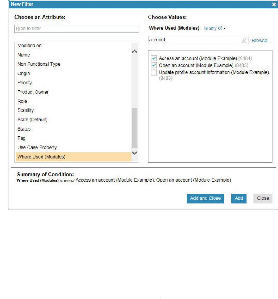
3. Click Add and Close and then click Apply. All the artifacts in the specied modules are displayed on
the Artifact page.
Conversely, to display artifacts that are not used in modules, select the is not any of or the is not all of
operators.
You can access the Where Used (Modules) lter in the Filter by Attribute section on the Artifacts page or
in the artifact and link selection windows.
You can also view artifact attributes for cross-component links when you apply a format to a specic link
type.
Related concepts
“Conguration management in the RM application” on page 6
Adding tags to artifacts and viewing tagged artifacts
You can add user-dened shared or personal tags to new and existing artifacts. Use tags to categorize
artifacts in a project area. You can view all artifacts that have the same tag by creating a lter for that tag.
If you save that view, you can use that view in your project dashboard. Shared tags are available to all
users in the project. Personal tags are only available to the user who creates them.
Procedure
• To add a tag to a new artifact:
1. Click Create Artifact on the Artifacts page.
2. Type a name for the artifact, and then click Add Tags. The Apply Tags window opens.
3. In the Apply Tags window, do one of these actions:
Managing
191

– Select an existing tag, and then click OK.
– Create a tag by clicking New Tag. Type a tag name and optionally, a description. Select the
Shared or Personal tag type. Click OK.
4. Click OK in the Create an artifact with attributes window.
• To add a tag to an existing artifact:
1. Open an artifact and in the Overview pane, click the Select Tags icon in the artifact toolbar. The
Select Tag window opens.
2. In the Select Tags window, do one of these actions:
– Select an existing tag, and then click OK.
– Create a tag by clicking New Tag. Type a tag name and optionally, a description. Select the
Shared or Personal tag type. Click OK.
3. Click OK to save the tag selection for the artifact.
• To remove a tag from an artifact, in the artifact editor, click Select Tags. In the Apply Tags dialog, click
the selected tags to deselect them.
• To view all artifacts that have the same tag, from the Artifacts page, or the module editor, click Add
Filter and select Tag as the lter attribute.
• To add tags to a project without adding a tag to an artifact, from the Artifacts page, or the module
editor, click More Actions > Manage Tags > New Tag.
• To edit or delete a tag, from the Artifacts page, or the module editor, click More Actions > Manage
Tags and select Edit Tag or Delete Tag.
Copying artifacts between projects
You can copy artifacts between projects in the Requirements Management (RM) application.
Before you begin
Before you copy artifacts between projects, verify the following items:
• You are logged in as a user with JazzAdmins or JazzProjectAdmins repository permissions. You are
assigned the Administrator role.
• Both projects have the same setting for conguration management
: either both are enabled or both are
disabled.
• If you use global congurations, ensure that you are using a global conguration that has contributions
from both projects.
• The target project contains the same artifact types, artifact attributes, and attribute data types as the
artifacts in the source project.
Important: To copy artifacts, the target project must contain the same artifact types as the source
artifacts that are being copied, including URIs or artifact names. Otherwise, no artifacts are copied.
If the target project does not contain the same artifact attributes or attribute data types, the source
artifacts are copied, but the attribute values are not.
Note: When copying and pasting modules or collections across components or projects, the shared and
private views of the module or collection are copied. If the target component or project contains views
that are shared across all modules or collections of the same type or shared across all modules or
collections. And have the same name as the reused views in the copied module or collection, the copied
views are not resolved. Instead, multiple views with the same name exist after the paste operation is
run and must be resolved manually.
In projects that are enabled for conguration management, conrm whether you want to copy artifacts
between components or clone them. To help you decide, see Cloning artifacts between components.
192
Engineering Requirements Management DOORS Next
About this task
You can copy most artifacts between projects, including collections, modules, embedded artifacts, and
diagrams. However, the copy function does not support copying the following items:
• Graphical artifacts that require a browser plug-in, such as sketches, storyboards, screen flows, and
business and use case diagrams
• Tags
• Comments
Note: Copying and pasting of artifacts between streams in the same component is not allowed. A more
appropriate way to move data from one stream to another is to deliver the change set(s) that contain that
data. This ensures you get the same concept in both places and that the version history is correct. At that
point, if you want to copy the artifact somewhere else within the stream you may do so. Alternatively, you
can also copy or paste within your current stream and then deliver the change set.
Procedure
1. Verify that the target project contains the same artifact types, artifact attributes, and attribute data
types as the artifacts that you plan to copy. To view the project properties, complete these steps:
a) Open the target project, click the drop-down menu for the Administration icon and select
Manage Project Properties.
Note: If conguration management is enabled for your project, on the Administration menu, click
Manage Component Properties.
b) Click the Artifact Types tab, the Artifact Attributes tab, and the Attribute Data Types tab.
Tip: If your target project does not contain the necessary project properties, you can import the
artifact type system from the source project. For information about importing the type system from
another project, see Importing project properties
.
Important: To copy artifacts between projects, the value in the URI eld for artifact types or the
artifact names in both the source and target projects must match. The URI value or name must also
match between source and target artifact attributes and between artifact data types.
The value in the URI elds must be in this format:
https://hostname/word1/word2
For example, if you work for a company that is called Big-Bank, and you want to copy artifacts of
type Actor from a source project, you might put the following value in the Actor artifact type URI
eld:
https://www.big-bank.com/types/actor
If you copy the type system from the source project to the target project, you ensure that the value
in the source URI eld gets propagated to the target URI eld in the target project.
2. In the target project, right-click the folder into which to copy the artifacts and click Copy from a
project.
3. In the wizard that opens, follow the prompts to select the project, and the artifacts or modules to copy.
When you select modules, all the views from those modules will be copied from the source to the
target.
Tip: You can also view the collections that need to be copied or cloned to the target project by clicking
the Add Collection button.
4. If the servers are hosted by the same domain server or different domain servers, you can also use the
Paste as Link option between components on different servers.
a) Copy the source artifact.
b) Select the target artifact and click Paste as Link.
Managing
193

c) In the Create Link window, select the link type.
d) Click OK and a Link has been created message will be displayed.
Related concepts
“Linking artifacts in different projects or components” on page 206
A link represents a relationship between artifacts. Link relationships are directional and indicated by an
icon. Link types help you dene and customize the linking relationships between artifacts. Each link type
has an Outgoing and an Incoming role. You can create links between artifacts in different projects on
the same server or on different servers. If you enable conguration management, you can create links
between artifacts in different components.
Related tasks
“Importing properties from another Requirements Management (RM) project or component” on page 61
You can import the properties from one Requirements Management (RM) project or component into
another project or component. When conguration management is not enabled, you import properties
from project to project. When conguration management is enabled, you import properties from
component to component. The properties that are imported by default include all the artifact types,
attribute data types, link types, and link constraints that are dened in the project or component.
“Creating link types for requirements projects” on page 36
“Creating attributes for requirement artifacts” on page 31
When you create requirements in a project, you can create custom artifact attributes to use in custom
artifact types. Custom attributes are based on predened and custom artifact data types, which dene the
properties of the attribute, such as textual entries, integers, date, time, or team member names.
Related reference
“Link types in requirements projects” on page 37
Related information
Cloning artifacts between components
194
Engineering Requirements Management DOORS Next
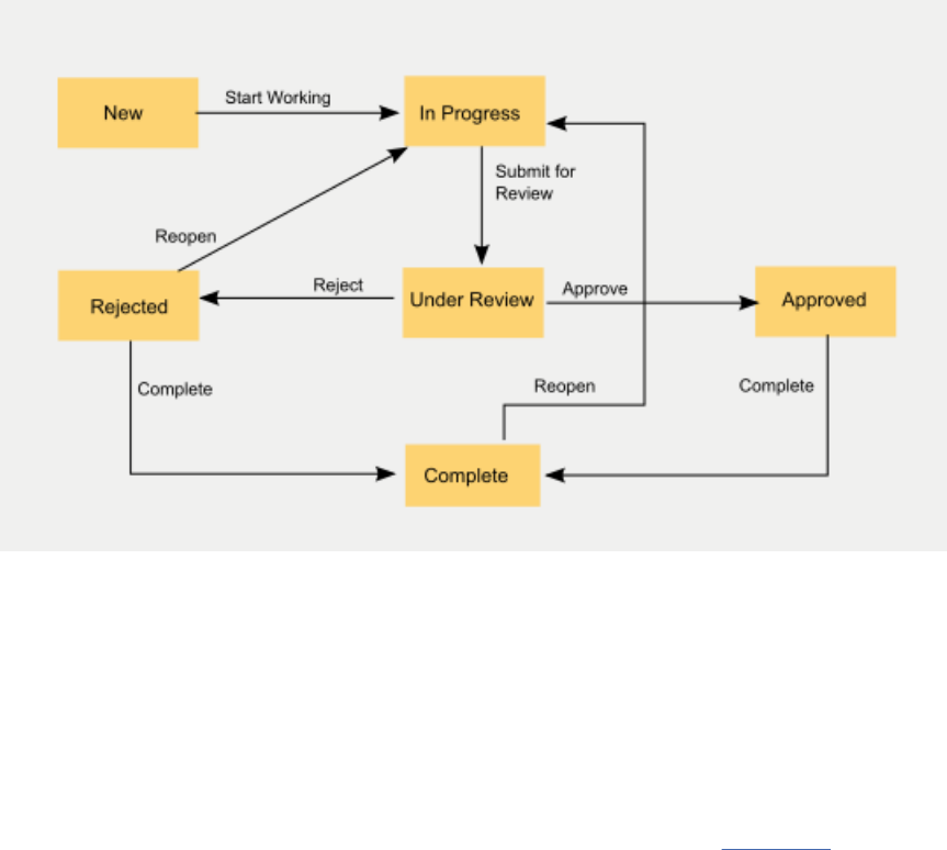
Requirement workflows
A Requirements workflow is a state transition model in which you dene the state that artifacts of a
specied type can be in and the actions that users can select to move these artifacts from one state to
another. You can nd topics that are in a specic state by creating a lter.
You can use the default workflow that comes with the Requirements Management (RM) application or you
can create your own custom workflows.
Note: The default workflow is available only in new projects in new installations of IBM Engineering
Requirements Management DOORS Next (DOORS Next). Workflows are not currently available if you
upgrade the RM application from previous versions.
In the default workflow, an artifact begins its life cycle in the New state, but users can select actions
that move the artifact to In Progress, Under Review, Approved, Rejected, and Complete. The following
diagram shows all the actions and states in the default workflow:
You can use the default workflow as is, or you can modify it for your particular needs.
Associating a workflow with an artifact type
Before you can use the default workflow or a custom workflow, you must rst associate the workflow with
an artifact type. To make this association:
1. Click Administration > Manage Project Properties.
2. In the Artifact Type tab, click an artifact type.
3. Select a workflow in the Workflow eld.
After a workflow is associated with an artifact type, users with the proper permission can select actions
that move artifacts through the states that are dened in the workflow.
Creating or modifying workflows
You can create or modify a workflow in the workflow editor. To open the workflow editor, click
Administration > Manage This Project Area > Requirements > Workflows. The Requirements -
Workflows window appears with on-screen instructions on how to create a workflow.
Tip: Keeping actions and transitions separate provides flexibility for how you dene permissions. For
example, you can set a permission to control every way to get into a particular state by using a single
action for every transition to that state. Then you only have to dene the permission once. You can also
Managing
195
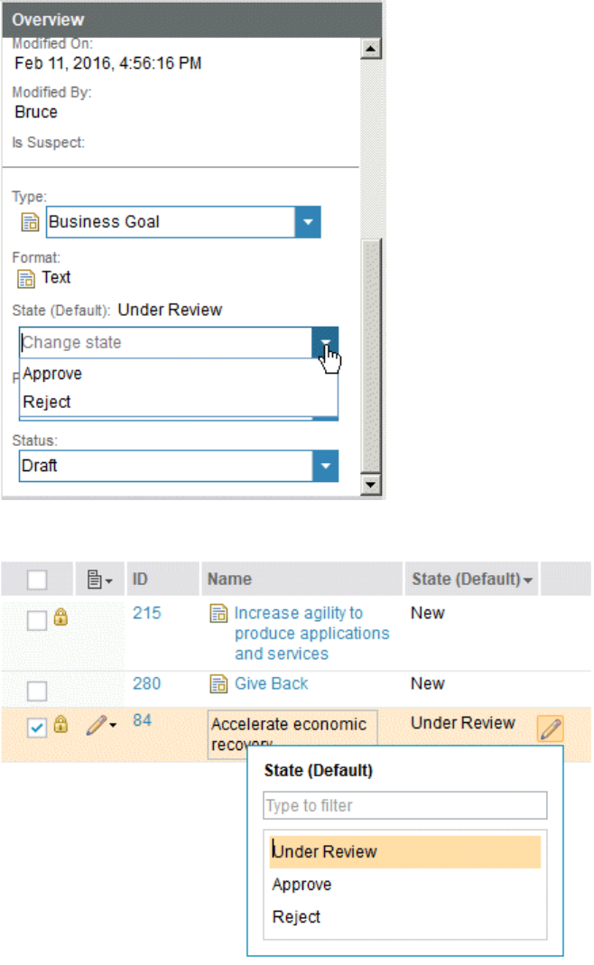
have different permissions for different ways to get to a given state by using different actions for the
different transitions into that state.
Using Workflows
After a work flow is created and is associated with an artifact type, users with the proper permission can
use workflows by changing the state of artifacts in the artifact editor and in the Artifacts window.
To change an artifact state in the artifact editor, open the artifact in the artifact editor, click Edit, and in
the Overview section of the sidebar, select a state in the State eld, as shown in this example:
To change the artifact state in the Artifacts window, rst congure the Artifacts window to display the
State column, and then select a state from the State drop down menu, as shown in this example:
Note: The states that appear for selection in the State eld and in the State drop down menu are
determined by the user's role and the permissions that have been granted to that role.
Tip: You can create a lter that displays artifacts that are in a specic state, as shown in this example:
196
Engineering Requirements Management DOORS Next
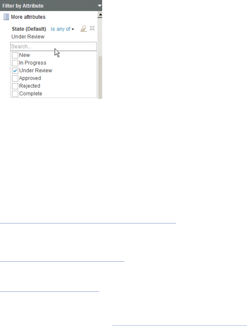
Workflow Permissions
By setting permissions on workflow actions, you can control which user roles can move or transition an
artifact to a particular state. To set permissions for workflow actions:
1. From the Administration menu, click Manage this project area.
2. Click the project name.
3. Click Permissions.
4. Select a role.
5. Expand Modify Requirements Resources > Save artifact > Modify artifact > Trigger a workflow
action and under the work flow name, click either the Grant access button or the Revoke access
buttons for a particular action.
Note: You can also set permissions that dene which roles can modify artifact content, attributes, and
tags in each state of a workflow.
Related concepts
“Filters and views for artifacts in requirements projects” on page 111
Filters and views are useful for sorting and displaying artifacts that are based on specic criteria. You can
use lters and the congure page settings to display artifacts, and then save this conguration as a view
to use later.
Related tasks
“Creating requirement artifact types” on page 29
Artifact types classify requirements and related artifacts and provide a consistent set of attributes for
each type. You can use the artifact types that come with the sample project templates, or you can create
custom artifact types and assign predened and custom attributes to them.
“Managing requirements” on page 188
You can manage requirements by using traceability links, tags, attributes, ltering, workflows, and
dashboards. With these capabilities, you can create relationships between requirements and other
artifacts, categorize requirements, assign properties to requirements, and monitor relationships and
status among team applications. To learn how to optimize requirements management, reduce rework and
avoid delays by using AI from Watson, go to the IBM Engineering Requirements Management site.
Comparison of artifact grouping methods in requirements management
There are several methods by which you can create and work with groups of artifacts in the Requirements
Management application. The following table provides information about these methods, which can help
you decide when to use a particular method.
For more information about a method, click on the method name.
Managing
197

Table 28. Comparison of grouping methods in the requirements management application
Method Purpose and Use
Collections
One primary use of collections to provide a group of artifacts with a unique
name and URL. The collection can then be used to:
• populate development plans in the Change and Conguration application
• create an association with test plans in the Quality Management application.
In both cases, the goal is to establish traceability between individual
requirements and other project artifacts. In this context, you can use
collections to create a set of requirements that you can deliver in a release
or milestone.
Collections are artifacts like any other artifact, and can thus have their own
unique name, URL, attributes and tags.
Modules
Used in much the same way as collections, but with added capabilities.
See modules and differences between collections and modules for more
information.
Tags
You can use tags to categorize artifacts in a project and to view commonly
tagged artifacts using lters in the Artifact page or displaying the results of a
saved view in the project dashboard.
You might want to use tags for informal or temporary designations.
Attributes
You can use attributes to track project status and to organize artifacts by
common properties such as owner, priority and risk. Changes to attribute
values can indicate an impact on traceability relationships. (See attributes for
more information.)
You might want to use attributes for formal and persisting designations.
You must create a lter to view artifacts based on attributes.
Folders
You can use folders to quickly group and lter artifacts.
Folders are convenient to use, but they can be more rigid than other grouping
methods. For example, an artifact can only be added to one folder, but it can
be added to multiple collections, can have multiple tags, and can optionally
have multiple attribute values.
Questions to ask when deciding on a grouping method
When deciding whether to use collections, tags, attributes or folders to organize data, it can be helpful to
ask specic use questions. For example,
Is it easy to make mistakes when organizing data?
If so, it might be best to select an organizational system that helps people do the correct thing or that
makes mistakes visually apparent.
Which kinds of queries does the tool make it easy for me to ask?
Filters make it easy to include or exclude tags, attribute values, and folders, though they are a little
less flexible than collections.
Is it a big or small effort to maintain the organizational system?
If your information categories are stable year-to-year, maintenance should be minimal; otherwise
maintenance could be very time consuming.
198
Engineering Requirements Management DOORS Next

Traceability
Traceability is used to trace a project element to related project elements, especially those
related to requirements. Traceability helps determine that a requirement is satised from inception
through implementation and testing. Create traceability relationships by linking requirements to other
requirements and to development and test artifacts.
Traceability supports these activities:
• Derivation, elaboration, and coverage analysis. Trace between requirements to specify the source,
derivation, or dependencies between the requirements; for example, detailed requirements can trace to
high-level, more general feature requirements or stakeholder needs. Detailed requirements elaborate
high-level requirements. Use traceability to verify that all requirements have the required elaboration to
fully describe the objectives.
• Impact analysis. Assess the impact of change (or proposed change) by using traceability. When
requirements change mid-project based on input from stakeholders, traceability helps assess the
impact (and cost) of change. When suspect artifact proles are implemented, changes that occur in
linked artifacts can produce suspect indicators on the artifacts. Suspect indicators alert team members
of potential impact of change. Traceability can be the basis for negotiating the change. This helps
expose dependencies and "hidden" costs of change.
• Lifecycle coverage analysis. Verify that all the necessary development and test items are in place for
implementing and validating requirements.
• Progress analysis. Track progress and completion status of linked requirements, development items,
and test cases.
• Reporting. Track the above mentioned activities plus other activities, such as sign-off, audit records, etc.
Use link types to specify types of traceability relationships. See Linking artifacts.
Use the Links Explorer to view linked artifact information, to create, delete, and explore linked artifacts,
and to remove and modify links.
To link to development and test artifacts, see Linking to artifacts in Jazz-based products. To view
traceability to development and test artifacts on your dashboard, add a Requirements Tracing widget
to your user dashboard. See adding a widget .
Related concepts
“Reporting in the Requirements Management (RM) application” on page 254
You can run and view reports that are based on a data warehouse and create document-style reports that
are about requirement and other lifecycle data.
Link validity in ELM applications
Link validity is a status on a link between artifacts to indicate whether the contents of two artifacts meet
the intended meaning of their link. Learn about using this information to achieve consistency across, and
propagate changes through, linked data.
For IBM Engineering Test Management (ETM or QM) applications only: Before you can view link validity
status information, you must have conguration management enabled
for the project. If your project does
not use conguration management, you can enable suspect link traceability for the project. For more
information, see Suspect traceability in ETM application.
Note: If you enabled conguration management in all your ELM applications, enable link validity in
both IBM Engineering Requirements Management DOORS Next (DOORS Next or RM) and or ( or or QM)
applications. Starting from 7.0.0 release suspicion proles are no longer supported for DOORS Next
projects that do not use conguration management. You must enable link validity in the DOORS Next
application. In ETM, use suspect traceability in test artifacts for projects that do not use conguration
management and enable link validity for projects that use conguration management.
Related concepts
Link validity
Managing
199
Related tasks
Enabling link validity in AM, QM, and RM project areas
Related information
YouTube video: Achieving consistency across linked data by using link validity (Software Education
channel)
Engineering Test Management application - suspect traceability
Managing requirements status and other properties
Use artifact attributes and tags to record the status and other properties of requirements and related
artifacts. Use attributes that are provided by the project template or create custom attributes and tags for
managing project artifacts. You can track the status and properties of requirements and related artifacts
by customizing and ltering the Artifacts page.
Procedure
1. Use attributes to set properties for each artifact, including status.
2. Add tags to artifacts to classify and retrieve related artifacts.
3. To customize and lter the Artifacts page for monitoring requirements properties:
• Add columns to the list of artifacts to display attributes, such as status, approval, milestone.
• Filter the list
of artifacts by tag or attribute to display related artifacts or specic attribute settings.
Analyzing the impact of change
To analyze changes in the project, you can create baselines after reviews, iterations, and other project
milestones are completed. You can lter artifact views to track the status of artifacts. Use link validity to
watch for the impact of changes in links between requirements and other artifacts.
About this task
Changes can come in various forms and from various sources. Some teams use change-management
systems to record and submit stakeholder needs, enhancement requests, and defects on approved
requirements. The IBM Engineering Lifecycle Management (ELM) helps teams record these types of
requests as work items and link them to related requirements. When accepted, these requests can drive
not only changes to the requirements, but also changes to linked plan items and test cases. Teams must
implement processes to be aware of changes to requirements and linked artifacts and respond to those
changes as they affect related artifacts.
Typically, your team denes processes for establishing baselines and artifact approvals. Your project
lead can create a project baseline when requirement reviews, formal approvals, iterations, and other
milestones have been completed. Baselines can provide a basis for analyzing change in the project. You
can lter project artifacts lists for artifacts that have changed since a baseline date. You can also lter
artifact views to show artifact status and other attributes.
You can use to monitor the potential impact of changes to linked artifacts.
Important: Starting from the 7.0.0 release, suspicion proles are no longer supported for RM projects.
Procedure
1. Complete reviews
of signicant requirements and their related artifacts.
2. Create project baselines to record milestones in the project development.
3. Filter your Artifacts page to display artifacts that have changed since a particular milestone date.
Create views for tracking artifact linking, tags, status, and other attributes. Add requirements views to
the project dashboard.
200
Engineering Requirements Management DOORS Next
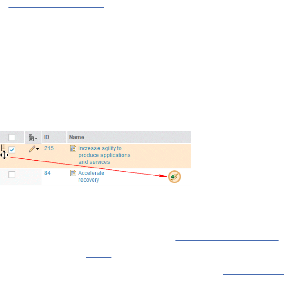
4. Congure and use to watch for the impact of changes in linked requirements and other artifacts.
For information on cross-application linking in ELM, see “Linking to development, design, test, and
requirement artifacts” on page 201.
Related information
Using link validity in ELM applications
Linking to development, design, test, and requirement artifacts
You can use the IBM Engineering Lifecycle Management (ELM) product integration and other OSLC
lifecycle integrations to create traceability links to new and existing artifacts in other products.
You can link from collections, modules, saved module views, and other individual requirements artifacts
to development, models and designs, and test artifacts.
You can link requirements artifacts to requirements in IBM Engineering Requirements Management
DOORS (DOORS) modules and in other Requirements Management (RM) applications. After creating links,
you can display a summary of the linked artifact or navigate to the artifact. You can also add a widget to
your dashboard to monitor the status of linked artifacts.
Tip: You can also create links by dragging an artifact and dropping it on the link icon of another artifact, as
shown here:
Before you begin
The product integration must be congured before you can perform this task.
• For more information about integrating with ELM applications on the same Jazz Team Server, see
Registering applications with the Jazz Team Server and Administering lifecycle projects.
• To integrate with applications on other Jazz Team Servers, see Integrating products on separate Jazz
Team Servers.
• To integrate with DOORS, see this topic.
• As of version 7.0.0, Design Management (DM) is no longer part of ELM. You can use the extension for
Change and Conguration Management (CCM) application. For more details, see Overview of Rhapsody
Model Manager.
About this task
As you link collections, modules, and individual artifacts to development and test artifacts, the link types
dene the traceability relationships. In ELM, requirement artifacts are located in the RM application,
development artifacts are located in the Change and Conguration Management (CCM) application, and
test artifacts are located in the Quality Management (QM) application. The traceability relationships
between RM and the other applications are described in the following graphic.
Managing
201
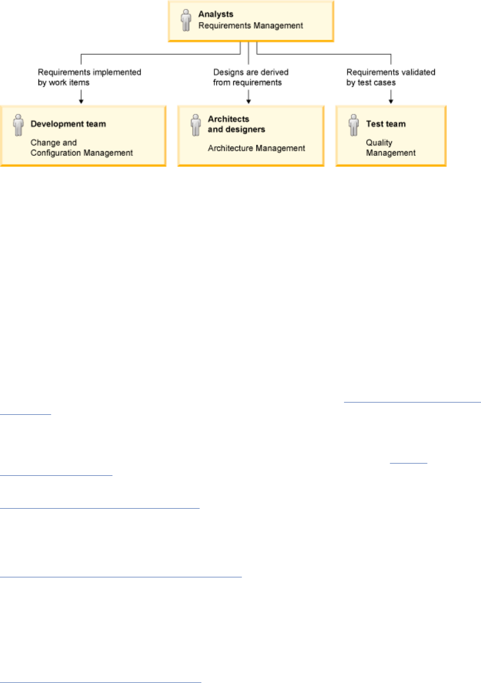
Typically, groups of requirements are organized in collections or modules for review, approval, and
management purposes. For example, the high-level requirements that constitute the project vision
are often grouped in a single collection or module. The requirements analyst, project manager, or
development manager links the collection or module to a development plan in the CCM application.
The development manager can generate plan items from the each of the requirements in this collection
or module. The test manager links the same collection or module to the test plan for the project. The
test manager can generate high-level test cases from the each of the requirements in this collection or
module.
High-level requirements are then elaborated by detailed requirements and associated artifacts, such as
business process diagrams, use cases, user interface sketches. Detailed requirements can be grouped in
collections or modules, and linked to the development plan and test plan. Plan items and test cases can
be generated for each artifact in the linked collection or module. Individual requirements and artifacts can
also be linked directly to work items, test cases, software and systems models and designs.
You can also create links between RM application artifacts and objects in external RM applications, such
as DOORS or other installations of RM applications in ELM, to reference related requirement artifacts in
both tools.
For a chart of all cross-application linking types for the RM application, see “Links across OSLC domains ”
on page 85.
What to do next
To add a widget to your project dashboard to monitor the status of the ELM links, see “Project
dashboards” on page 88.
Related concepts
“Filters and views in modules” on page 148
In modules, you can modify the column settings, lter the artifacts that are shown, and then save the
column and lter settings as a view. You can modify columns to show specic attributes or link types, and
you can lter by artifact type, artifact tags, attribute values, and link types.
Related reference
Extending the RM application by using OSLC services
Open Services for Lifecycle Collaboration (OSLC) is a community that is standardizing the way that
lifecycle tools work together. IBM Engineering Requirements Management DOORS Next (DOORS Next)
supports the OSLC data sharing specication as a provider for the Requirements Management (RM)
domain and as a consumer of other domains in the IBM Engineering Lifecycle Management (ELM). Data
sharing is also supported by other RM tools that support OSLC integration, such as IBM Engineering
Requirements Management DOORS (DOORS).
Related information
Engineering Lifecycle Management scenario
202
Engineering Requirements Management DOORS Next
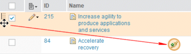
Links between artifacts
A link represents a relationship between artifacts. Links are mechanisms for referring to related
information. You create some links manually. Other links are created automatically when you complete
certain tasks. There are different properties for trace links, content links, links to base artifacts, and links
in modules.
Trace links and content links
You can create links from an artifact or from content within the artifact to another artifact or to a URL. All
links must indicate whether they are stored locally or externally. Links are created automatically when you
embed one artifact within another. For example, links are created when you embed an artifact in a text
document, add a part to a sketch, or embed a sketch in a storyboard.
Tip: You can also create links by dragging an artifact and dropping it on the link icon of another artifact, as
shown here:
Content links are simple hyperlinks between content within an artifact or to another artifact. You can
create a content link from a text string in a textual artifact to an artifact in the repository or to a URL. You
can create multiple content links from a graphical element in a diagram, sketch, part, or storyboard to
other artifacts or to URLs. You do not designate a traceability type for content links and the link is included
in the content only.
When you create a link from content within an artifact, such as a range of text or a diagram element,
you can assign a link type that denes a traceability relationship for the link. In addition to basic
hyperlink behavior, the trace link type can convey relationships such as dependency, origin, derivation,
implementation, or validation. Each trace link has a label that denes its traceability relationship
type. Trace link types are based on the Open Services for Lifecycle Collaboration (OSLC) specication.
Project administrators can also create custom link types to meet the needs of a particular project and
organization.
Restriction:
• You cannot create a link if another link to the same target with the same link type exists. However, you
can create multiple content-based links. For example, you can create a link from a document to a term
multiple times or embed an image in a document multiple times.
• You cannot create links to external lifecycle applications from elements in graphical artifacts, such
as business process diagrams, use case diagrams, and sketches. For example, when you create
Implemented By links to work items that are in a Change and Conguration Management (CCM) project,
you can link from the graphical artifact, which contains the entire diagram, but not from elements in the
diagram.
This restriction also applies to links from Requirement Management (RM) graphical elements to artifacts
in the Quality Management (QM) and in requirements management applications that are not part of the
IBM Engineering Lifecycle Management (ELM).
To create traceability for elements in graphical artifacts, link an element to an artifact in your project
that describes the activity for that element, and then link that artifact to a work item, test case, design
object, or requirement in an external lifecycle application.
If you designate a traceability relationship for a link, a matching trace link is displayed in the Links section
of the artifact sidebar. You can also display and lter artifacts that contain trace links on the Artifacts
page and in dashboard widgets. Trace links and the relationships that they represent are also visible in
Managing
203
the artifact summary when you hover over a link that includes traceability. When you click the
Show More link, you can see the link information.
Trace links help to manage and monitor the status of requirements and their related artifacts, such as
parent and child requirements, development work items, or test cases.
You can use Link types to dene and customize the linking relationships between artifacts. Link
relationships are directional. When link types are displayed in the user interface, icons indicate the
direction of the link type. For more information, see “Creating link types for requirements projects” on
page 36.
Content links have no matching trace link in the artifact sidebar or on the Artifacts page or dashboard.
They provide simple hyperlinks within an artifact without adding nonessential link information in the
sidebar and project pages.
You can add a matching trace link to an existing content link, or remove it. When you delete a matching
trace link, the content link remains in the artifact content. If you delete a rich-text content link that has a
matching trace link, the trace link is deleted when you save the artifact. If you delete a content link from a
graphical element in a diagram, the trace link is not affected.
If you create a link in the Links section of an artifact sidebar, you are creating a trace link for the artifact
and must designate a traceability link type. These trace links are independent of any specic content in
the artifact editor; they represent the entire artifact.
Trace links that are associated with a content link are displayed in the Links section with the Content link
icon. When you view the artifact that contains the content link and you click the icon, the content link is
highlighted in the artifact editor.
You can track changes to linked artifacts by using link validity.
Links to base artifacts and artifacts in modules
Artifacts can be created and managed in a project independently from a module. They are called base
artifacts. Base artifacts can also be used in one or more modules. You can link base artifacts with other
base artifacts or with artifacts in the context of a module. Links to and from base artifacts are available
in all modules in which those artifacts are used. A blue icon over the artifact type icon indicates linking
with a base artifact
. Links that are created in the context of modules are only available in those
modules. If you create links to or from base artifacts, those links are available in every module that the
base artifacts are used in. For more information about how to create links, see Linking between artifacts in
modules.
Linking between projects after enabling conguration management
To work with links across project areas, team members must work in the context of a global conguration.
For an overview of cross project linking, see Cross-project links to versioned artifacts.
Deleting artifacts that have links
How a link between two artifacts is impacted when one artifact is deleted? When you delete an artifact
that contains links:
• If the artifacts are in the same project or component area, the deleted artifact is automatically removed
as a link from the artifact it is linked to or linked from. In other words, incoming and outgoing links are
updated to reflect the deletion.
• If the artifacts are in different project or component areas, it is deleted only if it is an outgoing link for
the artifact that is being deleted. If the link is an incoming link, it appears as an outgoing link for the
artifact, but the link's target artifact do not work as the artifact is deleted.
Example 1: A and B are two artifacts that are created within the same project or component area. A and B
are linked to each other.
204
Engineering Requirements Management DOORS Next
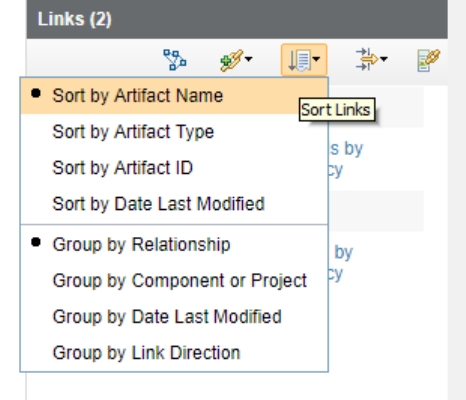
• If Artifact A is deleted, the link is deleted and it no longer appears as an incoming link for Artifact B.
• If Artifact B is deleted, the link is deleted and it no longer appears as an outgoing link for Artifact A.
Example 2: A and B are two artifacts that are created in different project or component areas. A and B are
linked to each other.
• If Artifact A is deleted, the link is deleted, since it is an outgoing link, and it no longer appears as an
incoming link for Artifact B.
• If Artifact B is deleted, the link is not deleted, since it is an incoming link, and the link still appears as an
outgoing link for Artifact A. But the link's target is not accessible, since Artifact B is deleted.
Sorting and ltering links
You can sort, group, or lter links by using the Links section of the artifact sidebar.
You can sort the artifacts by name, type, ID, or last modied date by clicking the Sort Links
icon. You can also group the artifact links by relationship, component or project, last modication
date, or link direction. The following image shows the sort and group options for artifact
links:
Note: The Requirements Management (RM) application does not manage artifacts that are associated
with Open Services for Lifecycle Collaboration (OSLC) and external. When you sort these types of links,
the following rules apply to each sorting option:
• Sort by Artifact Name: The full OSLC or external link label is used, which might or might not start with
an artifact name.
• Sort by Artifact Type: An external link is used as the artifact type name.
• Sort by Artifact ID: The full OSLC or external link label is used, which might or might not start with an
ID.
• Sort by Date Last Modied: The last modied date of the link is used instead of the modied date of the
linked artifact.
Additionally, you can lter artifacts by link type, artifact type, or project or component, by clicking the
Filter Links icon. You can lter artifact links by link type, artifact type, or component or project. The
following image shows the lter options for artifact links:
Managing
205
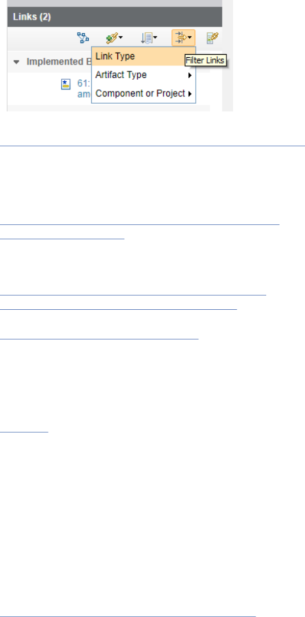
Related concepts
“Linking artifacts in different projects or components” on page 206
A link represents a relationship between artifacts. Link relationships are directional and indicated by an
icon. Link types help you dene and customize the linking relationships between artifacts. Each link type
has an Outgoing and an Incoming role. You can create links between artifacts in different projects on
the same server or on different servers. If you enable conguration management, you can create links
between artifacts in different components.
“Conguration management in the RM application” on page 6
“Link direction” on page 41
Link types help you dene and customize the linking relationships between artifacts. Each link type has an
Outgoing and an Incoming role.
Related tasks
“Creating link types for requirements projects” on page 36
“Linking between artifacts in modules” on page 136
You can link artifacts that are in the same module or artifacts that are in different modules.
“Reusing artifacts in modules” on page 146
Artifacts can be reused in multiple contexts in a project, including collections and modules. You can edit
artifact content in a module or by opening the artifact outside the module. Content changes are reflected
in all contexts. Links, tags, and comments are specic to the context in which they are created. If you
want links, tags, and comments to reflect in all contexts, edit the artifact outside the module as a base
artifact.
Related reference
Link Types
Linking artifacts in different projects or components
A link represents a relationship between artifacts. Link relationships are directional and indicated by an
icon. Link types help you dene and customize the linking relationships between artifacts. Each link type
has an Outgoing and an Incoming role. You can create links between artifacts in different projects on
the same server or on different servers. If you enable conguration management, you can create links
between artifacts in different components.
Cross-project or cross-component linking is automatically enabled for system-dened link types.
However, if link constraints are set the cross-project and cross-component linking is governed by the
link constraint rules.
To enable cross-project or cross-component linking for a custom link type, a URI must be dened for
the link type. For example, https://hostname.com/domain/myLabel. Dene the same link type with
the same URI for the projects or components that you want to link. To create link from both ends, see
Creating RDF vocabulary documents and assigning URIs. If you enable cross-project or cross-component
linking in only one project or component, but not in others, you can still create the link but only from the
project or component where the link is dened. This is because the link direction for a cross-project or
cross-component link determines where the link is stored. Cross-project or cross-component links are
stored in the source artifact's project or component area. The outgoing role represents the source of the
link. If you use link constraints, you must dene equivalent URIs for the requirement types.
When viewed in the context of a local baseline, rich hovers for links to artifacts outside that baseline say
that the artifact cannot be found in conguration. The Links sidebar section shows the links' information.
206
Engineering Requirements Management DOORS Next
To create links across projects that reside on different servers:
• The Link Index Provider (LDX) application must be installed and registered with the Jazz Team Server.
• If you are using a topology with multiple Jazz Team Server (JTS) instances, you must set up bidirectional
friend relationships between the Requirements Management (RM) servers, and between LDX and any
RM servers that are running on a different Jazz Team Server than LDX.
• The data source for all RM servers must be added to LDX.
• All participating project areas must be enabled for conguration management.
• The user must be working in a global conguration context.
• Project areas that link to each other must be associated with the Related Requirements association on
the Overview page for project area administration.
Note: If the projects on remote servers are not displayed in the linking dialog box, you might need
to create a URL allowlist entry for the common JTS server, which handles the authentication of ELM
application servers.
When you enable cross-server linking between projects:
• You can view, create, modify, and delete cross-server links in both grid columns and the Links pane in
the sidebar.
• When you hover over a cross-server link, information is displayed about the artifact at the other end of
the link.
• You can use a drag-and-drop operation to create cross-server links.
• The reports that are generated when you export comma-separated value (CSV) les and spreadsheet
les contain the cross-server links.
• Link validity is fully supported for cross-server links.
Note: When creating links between two different RM servers, drag and drop supports only the creation of
outgoing cross-server links.
For a cross-project or cross-component link, the link direction determines where the link is stored.
Cross-project or cross-component links are stored in the source artifact's project or component area. The
Outgoing role represents the source of the link.
For the following operations, when you create cross-project or cross-component links for artifacts, both
Outgoing and Incoming roles are available. The links are stored according to the role selected:
• Import CSV
• Link By Attribute
• Duplicate Artifact
In the following cases, when you create a cross-project or cross-component links for artifacts, links are
always stored in the source or component, so only Outgoing roles are available:
• When you create a cross-component link to an artifact in a baseline component, the new link cannot be
stored in the baseline component.
• When you create a link to the web, the new link is stored in IBM Engineering Requirements Management
DOORS Next (DOORS Next).
• When you create a cross-component or cross-project link by using a link type that is only dened in one
of the projects or components that are involved in the link, the new link must be stored in the project or
component that denes the link type.
• When you Clone from Component only Outgoing links are cloned and stored in the source artifact.
• When you Copy from Component only Outgoing links are copied and stored in the source artifact.
Link direction and change sets
Links are always stored on the outgoing side of the link. When you create a cross-project or cross-
component, depending on where the link is stored, messages that are related to change sets might be
Managing
207
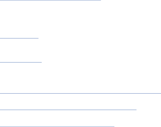
displayed and the available link types might be ltered to show only the outgoing link types. The following
conditions apply:
• If the other component that is involved in the link requires that all changes occur in changes sets, but a
change set does not exist, the list of available link types is ltered to show only outgoing link types.
• If the other component that is involved in the link is using a change set, a warning message is displayed
that explains that you must deliver the other component's change set after the link is created.
• If the specied link type is incoming, and you switch the component to one for which a change set is
required but does not exist, an error is displayed and the list of available link types is ltered to show
only the outgoing link types.
Editing existing cross-project or cross-component links
If you are editing existing cross-project or cross-component links and change the direction of the link type
from outgoing to incoming or vice versa, the storage location of the link changes since cross-project and
cross-component links are stored in the project or component of the source, or outgoing, artifact. When
the direction of a link is changed, it is deleted from the project or component where it is stored and it is
created in the project or component of the source, or outgoing, artifact. Since editing a link can change
where the link is stored, the following conditions apply when editing a cross-component or a cross-project
link if change sets are active:
• If the link is incoming from an artifact in a component for which change sets are required, and no
change sets exist, an error message is displayed that explains why you cannot edit that link.
• If the link is outgoing to an artifact in a component from which change sets are required, and no change
sets exist, the list of available link types is ltered to show only outgoing links. A warning message is
displayed that explains why you cannot specify an incoming link type.
• If you change an outgoing link to an incoming link, and the link originates in a component that is in a
change set, a warning message is displayed that explains that you must deliver the change set to see
the changes to the link.
• If you edit an incoming link, and the link originates in a component that is in a change set, a warning
message is displayed that explains that you must deliver that change set to see the changes to the link.
Related concepts
“Links between artifacts” on page 203
A link represents a relationship between artifacts. Links are mechanisms for referring to related
information. You create some links manually. Other links are created automatically when you complete
certain tasks. There are different properties for trace links, content links, links to base artifacts, and links
in modules.
Link directions
Link types help you dene and customize the linking relationships between artifacts. Each link type has an
Outgoing and an Incoming role.
Link constraints
Link constraints are rules that an administrator can set up to specify which kinds of links are allowed in a
project or across projects. If no rules are created, all links are allowed. However, if you create rules, only
the links in the rules are allowed.
“Conguration management in the RM application” on page 6
Related tasks
“Linking between artifacts in modules” on page 136
You can link artifacts that are in the same module or artifacts that are in different modules.
“Reusing artifacts in modules” on page 146
Artifacts can be reused in multiple contexts in a project, including collections and modules. You can edit
artifact content in a module or by opening the artifact outside the module. Content changes are reflected
in all contexts. Links, tags, and comments are specic to the context in which they are created. If you
want links, tags, and comments to reflect in all contexts, edit the artifact outside the module as a base
artifact.
208
Engineering Requirements Management DOORS Next
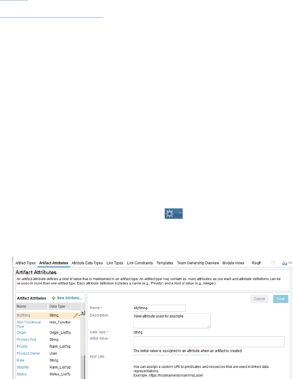
Related reference
Link types
Related information
Using link validity in ELM applications
Linking by attribute
You can quickly and automatically create links between multiple artifacts by artifact attribute.
Before you begin
You can use the Link by Attribute function to automatically create, update, and delete links between
artifacts based on an attribute value. To use this feature, type the artifact IDs of the target artifacts
(separated by commas) in a custom string attribute type, select Link by Attribute and then follow the
prompts. You can use this function in a module, a collection, or in any artifact view.
Note: This feature can also be used in conjunction with the CSV round-trip support to handle creating and
changing links when you import data.
The following example provides a more thorough explanation of how the Link by Attribute function
works. The examples show how to create links between multiple artifacts in a single module and between
artifacts in different modules. First, the example shows how to complete these tasks:
• Create a custom attribute called MyString.
• Add the MyString attribute to a Feature artifact type.
• Change the column headings in a sample module to display the MyString attribute.
Then, the example shows how to add artifact IDs of the artifacts to link to in the MyString attribute, and
how to run the Link by Attribute function to automatically create the links.
Procedure
1. Click the drop-down menu for the Administration icon and select Manage Project Properties.
Note: If conguration management is enabled for your project, on the Administration menu, click
Manage Component Properties.
2. On the Artifact Attributes page, click New Attribute and create a custom attribute that is called
MyString with a data type of string, as shown in the following image:
Note: You can use any custom attribute type as long as the type is string and is not a predened
system attribute.
Managing
209
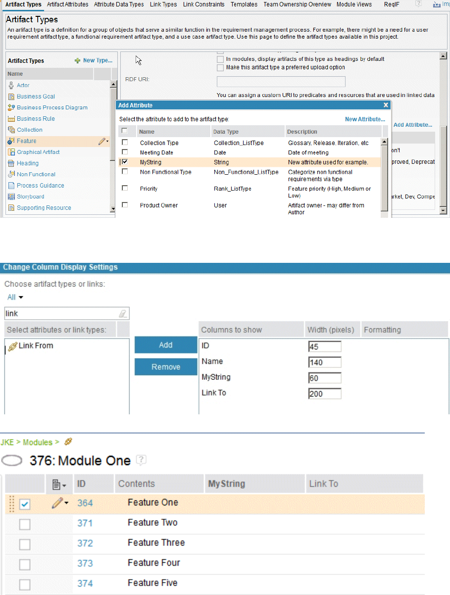
3. Add the newly created MyString attribute to a Feature artifact type, as shown in the following
image:
4. Create a sample module that contains several Feature artifacts.
5. Change the column headings in the module to show the new MyString attribute column and the
Linked To column, as shown in the following image:
The sample module is displayed with the new columns:
6. To create links from Feature One to Feature Two, Feature Three, Feature Four, and Feature Five.
To create these links, type the ID of each target artifact (separated by commas) in the MyString
column, as shown in the following image:
210
Engineering Requirements Management DOORS Next
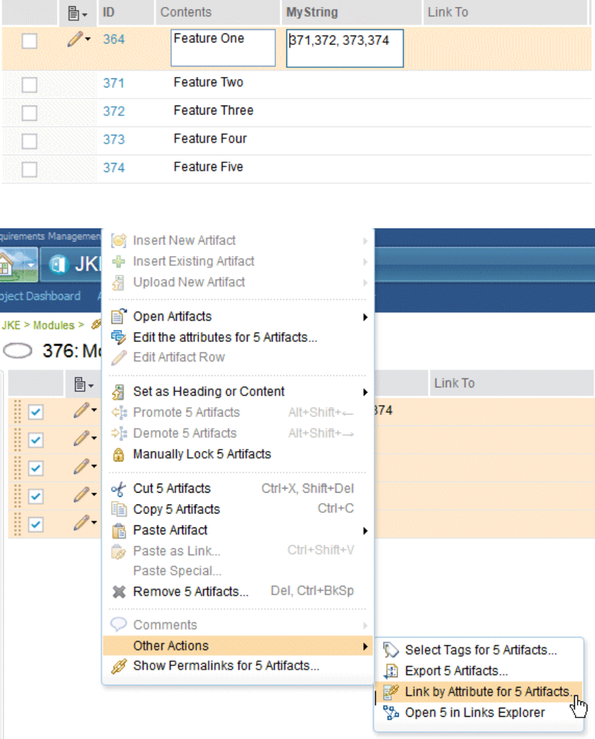
7. Then, to automatically create the links, select the check boxes for the artifacts and click Other
Actions > Link By Attribute, as shown in the following image:
8. In the Link by Attribute window, in the Attribute eld, select MyString and, in the Link type eld,
select Link To. Click OK.
Managing
211
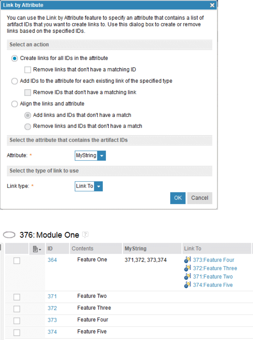
The links that you specied are automatically created, as shown in the Link To column in the
following image:
9.
10. To create a link from Feature 3 to an artifact in another module, such as to Feature 10 in Module Two,
enter the artifact ID of Module Two (377) and the ID of Feature 10 (378), separated by a period, as
shown in the following image:
212
Engineering Requirements Management DOORS Next

11. Then, select Feature Three (in Module One) and Feature 10 (in Module Two) as shown in the following
side-by-side view of both modules:
12. Then, run Link By Attribute and enter the Attribute and Link To data in the Link by Attribute
window. When you click OK, the link is automatically created in the Link To column in Module One, as
shown in the following image:
Related concepts
“Modules in the Requirements Management application” on page 129
A module is a structured document that is composed of multiple artifacts. You can create structure in a
module by modifying the order and hierarchy of its artifacts. The artifacts that are created for modules
Managing
213
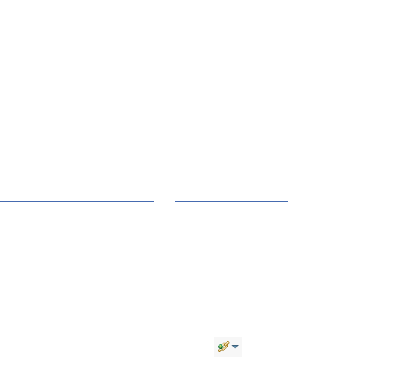
are stored as module content in a folder. Base artifacts can be used to manage the module artifacts
independent of the module.
“Importing requirements artifacts from CSV and spreadsheet les” on page 159
You can import data from comma-separated values (CSV) and spreadsheet les into folders and modules
in an RM project.
Linking to requirements artifacts in lifecycle applications
By integrating the applications of the IBM Engineering Lifecycle Management (ELM) and other lifecycle
applications, you can create links to artifacts in Change and Conguration Management (CCM), Quality
Management (QM), Rhapsody Model Manager (RMM), and Requirements Management (RM) applications.
You can link requirements artifacts, collections, modules, or module views to artifacts in other ELM
lifecycle applications.
When you link from module views, you have more control over which artifacts in a module are available
for test case development and execution.
You can also sort, group, or lter artifact links in the Links section for an artifact.
Before you begin
The ELM integration must be congured before you can do this task. For more information, see
Engineering Lifecycle Management
and Running the setup wizard.
Important:
• If you are linking a module view to artifacts in other ELM applications, the module view must be Shared
and the view must not be used in other modules. For more information, see Filters and views
.
• If link results exceed the maximum allowed value and all the links are not displayed, a warning message
is displayed. In Link Index Provider, you can set a maximum links result restriction to display more links,
if necessary.
Procedure
1. Open a requirement or other RM artifact and expand the Links section in the sidebar and click the
down arrow by the Add Link to Artifact icon .
2. Select the link type that corresponds to the integrated lifecycle application. For more information, see
Link Types.
• Implemented By, Tracked By, or Affected By to link to development plan items, work items, and
defects in CCM.
• Validated By to link to QM test cases.
• Derives Architecture From Element, Rened By Architecture Element, Satised By Architecture
Element, and Traced By Architecture Element to link to RMM models and design resources.
• References to link to RM objects in another RM instance or in another RM project area.
If you are linking from a module view, from the view menu, select Add a Link.
3. In the Create Link window, select an Artifact Container (project area).
a) Click Choose Existing to select an existing artifact to link to.
b) Click Create New to create a new artifact to link to.
• If you are linking to the Change and Conguration Management (CCM) application, you can
choose a work item or create a new one.
• If you are linking to the Quality Management (QM) application, you can choose a test case or
create a new one.
c) Click OK.
Restriction: For modules and collections:
214
Engineering Requirements Management DOORS Next
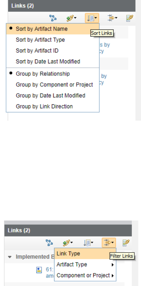
• Implemented By link type is only available to plan items in the CCM application.
• Affected By and Tracked By link types are not available.
4. To sort the artifacts by name, type, ID, or last modied date, click the Sort Links icon.
Note: The Requirements Management (RM) application does not manage artifacts that are associated
with Open Services for Lifecycle Collaboration (OSLC) and external. When you sort these types of links,
the following rules apply to each sorting option:
• Sort by Artifact Name: The full OSLC or external link label is used, which might or might not start
with an artifact name.
• Sort by Artifact Type: An external link is used as the artifact type name.
• Sort by Artifact ID: The full OSLC or external link label is used, which might or might not start with
an ID.
• Sort by Date Last Modied: The last modied date of the link is used instead of the modied date of
the linked artifact.
5. To lter artifacts by link type, artifact type, or project or component, click the Filter Links icon.
What to do next
To view a summary of the linked plan, hover over the link in the Links section of the sidebar. To open
the plan in the related product, click the link. In development projects, you can generate plan items that
correspond to each artifact in the collection, module, or module view. In test projects, you can generate
test cases that correspond to each artifact in the collection, module, or module view.
Managing
215
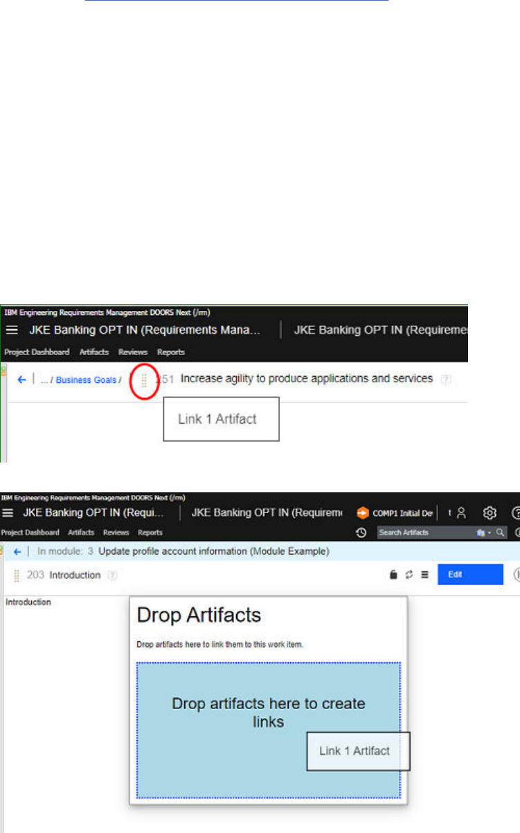
Linking artifacts by using the drag-and-drop method
You can link requirement artifacts with other artifacts across ELM applications by using the drag-and-drop
and copy-and-paste methods.
Before you begin
When you link requirement artifacts, OSLC link types are created between the applications. For more
information, see “Link types in requirements projects” on page 37
. Make sure that the project areas in the
ELM applications are registered with each other for link creation.
About this task
You can link requirements artifacts within a single artifact editor, dashboard list, module, or links explorer
by using the drag-and-drop method. You can also use these methods to link requirement artifacts to
work items in IBM Engineering Workflow Management (EWM) or test artifacts in IBM Engineering Test
Management (ETM).
Note: You cannot link artifacts between different global congurations. If you select a conguration in the
EWM application, you cannot create a link to another artifact in a different global conguration.
Procedure
1. Open a requirement artifact in the editor mode.
2. Hover the mouse over the left side of an artifact ID until the cursor becomes a four-sided arrow.
3. Use the drag handle to drag the artifact into another tab or window that uses the same browser
instance.
4. Drop the artifact into the Drop Artifacts window of an editor or grid view.
216
Engineering Requirements Management DOORS Next
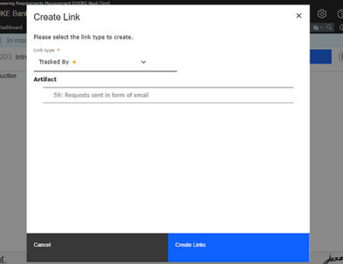
5. In the Select the link type list, select the link type.
6. Click Create Links.
7. In the Links sidebar section, you can view the linked artifact and the link type.
8. Optional: To link single or multiple requirement artifacts to work items in EWM, drag the requirement
artifacts into another tab or window and drop the requirement artifact in the work item editor. Specify
the link type and save the work item. Similarly, you can drag work items and drop them into an artifact
editor to create OSLC links.
9. Optional: To link single or multiple requirement artifacts to test artifacts in ETM, drag the requirement
artifacts into another tab, or window and drop the requirement artifact in the test artifact editor. Only
requirement collections or modules can be dropped into the test plan editor, while only requirements
can be dropped into the test case editor or test script editor. For the test script editor, drop the
requirement artifacts into the specic manual script step directly to create the Validates Requirement
links, provided that the Test Script Preferences project property has the option enabled to Allow
linking between test script steps and requirements. Similarly, you can drag test plans or test cases
and drop them into an artifact editor to create OSLC links.
Using copy-and-paste method
About this task
You can use the existing Copy Artifact option in a module or artifact list, and the existing Paste As Link
option on another artifact to create a new link. You can use the new menu options of Copy Artifact and
Paste As Link in a single artifact editor to carry out the same operations.
You can use the following keyboard shortcuts for the copy-and-paste feature everywhere drag and drop is
available:
• Copy Link: Ctrl+C (Windows) or Command+C (Mac)
• Paste as link: Ctrl+Shift+V (Windows) or Command+Shift+V (Mac)
Procedure
1. Select the artifact to link from and then click Copy Artifact.
2. Select an artifact in another artifact and click Paste As Link.
3. Click Create Links.
Managing
217
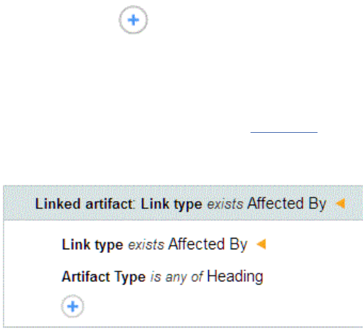
Filtering artifacts for links to other applications
When viewing artifacts, collections, and modules in the Artifacts, Collections, or Modules pages, you
can lter artifacts that are linked to other applications integrated in the IBM Engineering Lifecycle
Management (ELM).
Before you begin
Your project must be congured for ELM integration and you must have links to artifacts in other
applications.
About this task
You can lter and display columns for the following link types:
• Implemented By, Tracked By, or Affected By links to development artifacts in the Change and
Conguration Management application.
• Validated By links to test artifacts in the Quality Management application.
• References and Referenced by links to requirement artifacts in any other Requirements Management
application.
You can display columns, but you cannot lter by the link types for the Rhapsody Model Manager
application.
Procedure
1. Open the Artifacts, Collections, or Modules page.
2. Click the Add lter icon
.
• To lter artifacts based on their links to other ELM applications, in the New Filter window, select
Link type from the Choose an attribute column.
a. In the Choose values column select the value that corresponds to the lifecycle application that
you want to lter by and click Add. See Link Types for the list of all the link types associated to
ELM applications.
b. To specify additional lters to the Link type attribute, click the Edit icon and add conditions.
In this example, the lter will return all artifacts that have an Affected by link to an artifact of
type Heading .
• To lter artifacts based on the status of the linked test and development items. In the New Filter
window, select Limit by lifecycle status attribute. From the Choose an attribute column, select:
– None to display artifacts with no linked work items.
– Open or Resolved to display linked work items with those statuses.
– All Resolved to display requirement artifacts where all associated work items are resolved.
– Passed, Failed, Unattempted to display all test items with those statuses.
– All Passed to display requirement artifacts where all associated test items have passed.
218
Engineering Requirements Management DOORS Next
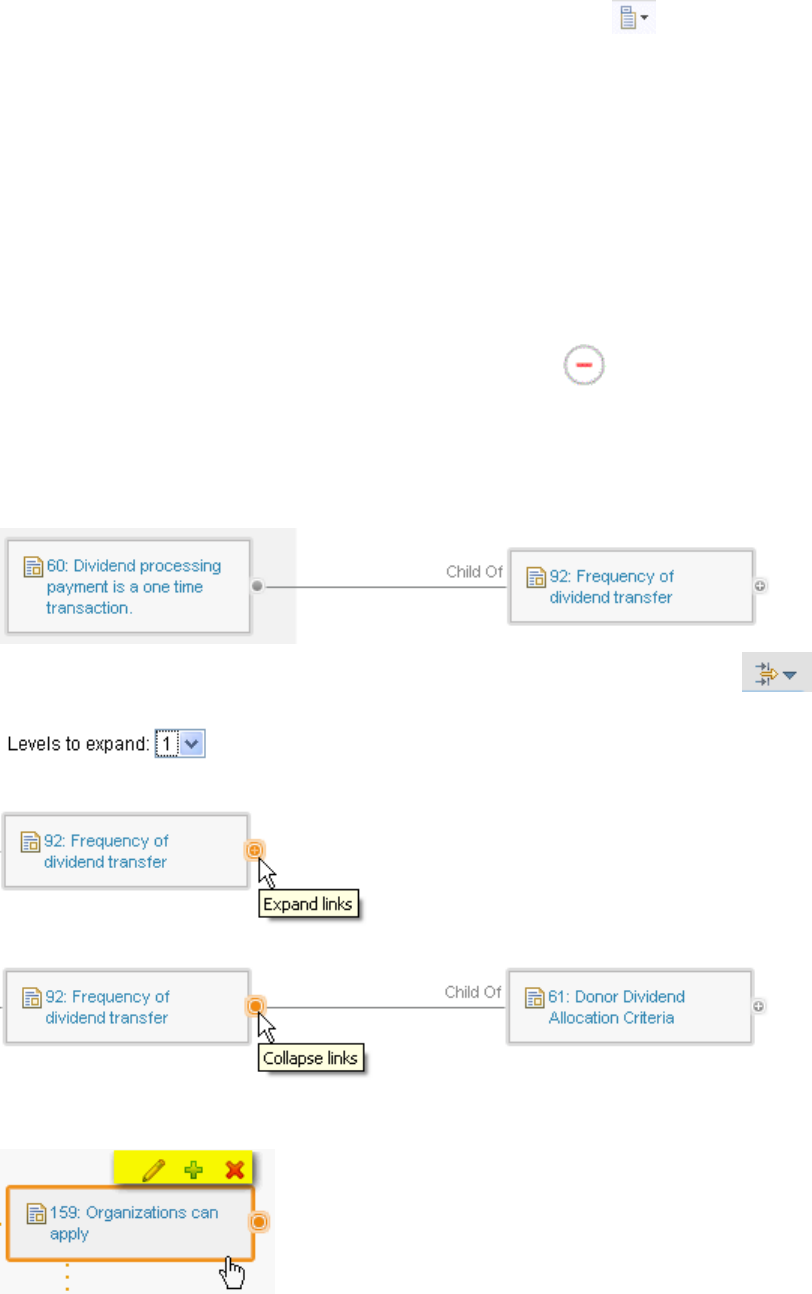
– All to display all development or test items
3. To display artifacts based on their links to ELM applications, click Congure page settings >
Congure columns to display. Select the link type that corresponds to the lifecycle application that
you want to lter by and click Add. For example, select any one of the following link type options:
• Implemented By, Tracked By, or Affected By to display associations with development artifacts.
• Validated By to display associations with test artifacts.
• References and Referenced by to display associations with requirement artifacts.
• Derives Architecture From Element, Rened By Architecture Element, Satised By Architecture
Element, and Traced By Architecture Element to display associations with design artifacts.
a) To organize the column display use the Move Up and Move Down options.
b) Use the Format option to customize the column display. You can select attributes of the artifacts
and wrap or trim the link text display.
4. To remove the lters applied, click the Clear all lters icon .
Links explorer
The links explorer displays linked artifacts in a graphical diagram. Use the links explorer to view linked
artifact information, to create, delete, and explore linked artifacts, and to remove and modify links.
When you open the links explorer, the artifacts you selected are displayed at a display level of 1.
To dynamically change the link level of the entire diagram, click the relations menu and from the
Levels to expand list, select a different link level.
To dynamically expand the link level of a specic artifact, click the Expand links icon of the artifact:
To dynamically collapse the link level of a specic artifact, click the Collapse links icon:
To view the details of a specic artifact, hover over the artifact; information is displayed in hover text. To
edit an artifact, add a link, or delete an artifact, highlight the artifact and click the respective artifact icon:
Managing
219
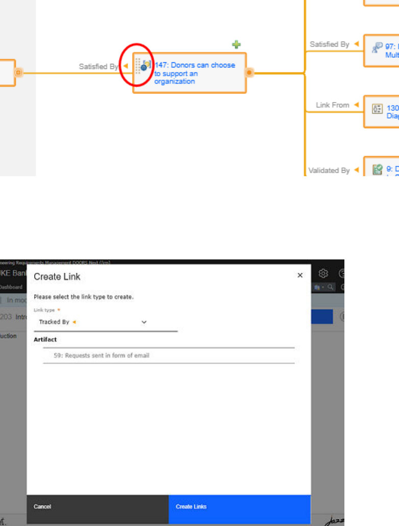
Linking requirement artifacts
You can create link between requirement artifacts with other artifacts across ELM applications by using
the drag-and-drop and copy-and-paste methods. When you link requirement artifacts, OSLC link types are
created between the applications.
You can drag the requirement artifact from the link explorer using the drag handle that appears when you
hover the artifact.
You can also use these methods to link requirement artifacts to work items in IBM Engineering Workflow
Management (EWM) or test artifacts in IBM Engineering Test Management (ETM).
You can drag the artifact into another tab or window that uses the same browser instance and drop the
artifact into an editor or grid view. When you drop an artifact on the drop target, you can create links
between the artifacts. You can select the link types from the Create Link dialog box and then click Create
Links.
Similarly, you can drag work items from EWM and test artifacts from ETM onto the Link explorer to link the
artifacts with requirements artifacts.
You can use the following keyboard shortcuts for the copy-and-paste feature everywhere drag and drop is
available:
• Copy Link: Ctrl+C (Windows) or Command+C (Mac)
220
Engineering Requirements Management DOORS Next
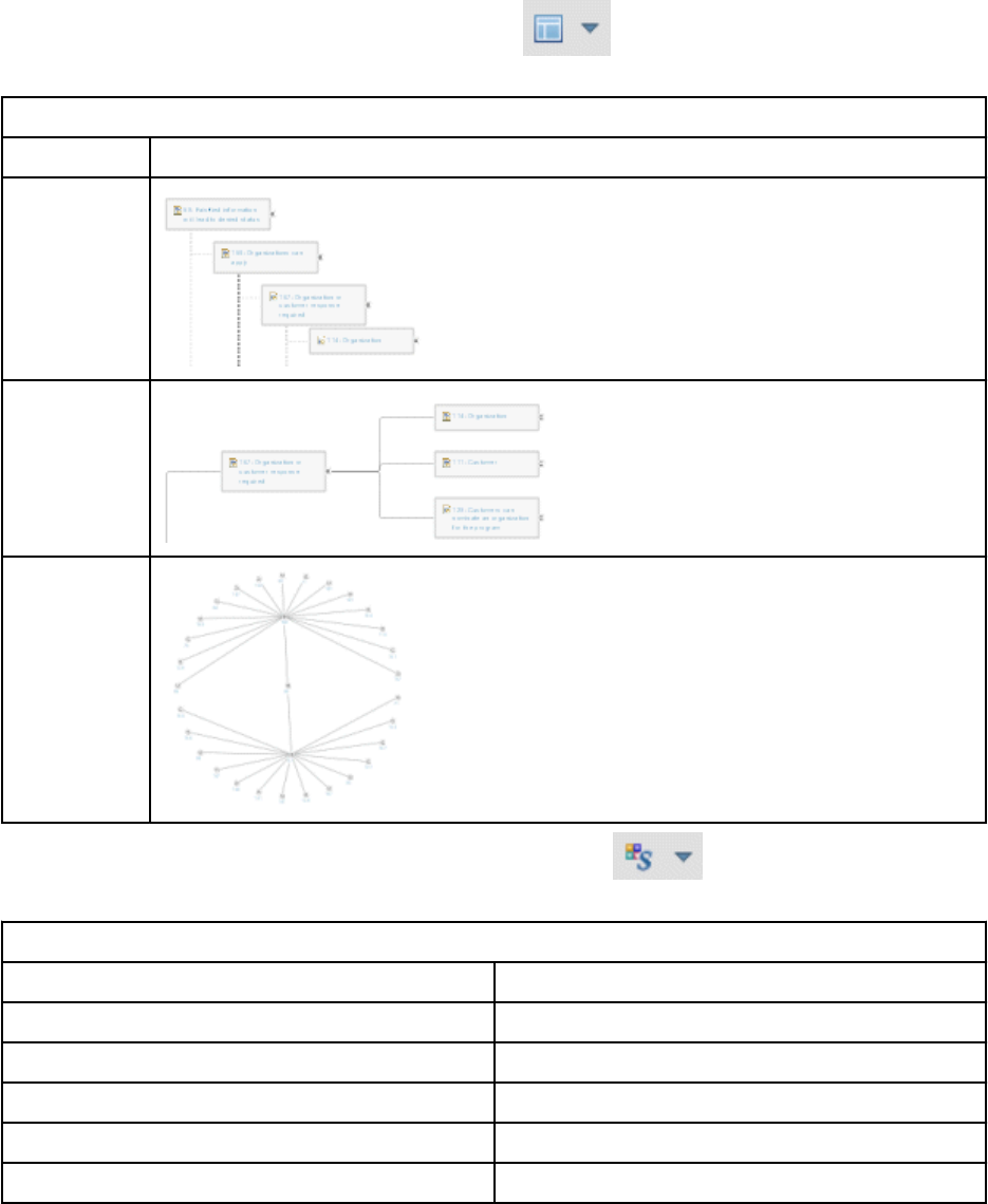
• Paste as link: Ctrl+Shift+V (Windows) or Command+Shift+V (Mac)
Other information display options
You can further change the information that is shown in the links explorer by clicking the following icons in
the toolbar.
• To change the layout type, click the Layout Type menu . You can choose from the layout types
that are shown in the following table.
Table 29. Links explorer layout types and examples
Layout Type Example
Basic
Walker
Radial
• To change the artifact arrangement, click the Appearance menu . You can choose from the
appearance choices that are shown in the following table.
Table 30. Links explorer appearance choices
Appearance choice Description
Portrait Display graphical artifacts in portrait style.
Landscape Display graphical artifacts in landscape style.
Paris Skyline Displays link lines as angular connections.
Curvy Wires Displays link lines as curved connections.
Enable Compact View Reduces the space that is used by artifacts.
Managing221
Table 30. Links explorer appearance choices (continued)
Appearance choice Description
Enable Quick Create Mode Enables the quick creation of artifacts. When you
enable this mode, you are prompted to select a
default link type, artifact type, and directory. After
making these selections, click the add link icon
on the toolbar of the tree nodes to create a new
blank artifact, which is represented through a tree
node that is in edit mode.
• To lter the diagram by link type, adjust the primary link levels that are displayed, or specify the link
level for the entire diagram, click the Congure Link Display menu .
For more information, see Shortcuts for the Requirements Management application.
Linking requirements to Rational ClearQuest records
You can link requirements with defects, tasks, requests for enhancements, and other record types in IBM
Rational ClearQuest. You can link to a new or existing record or artifact.
Before you begin
The Requirements Management (RM) application must be congured for integration with Rational
ClearQuest, as described in Integrating the RM application and Rational ClearQuest
.
About this task
The capabilities of the RM application in IBM Engineering Lifecycle Management (ELM) are provided by
the IBM Engineering Requirements Management DOORS Next (DOORS Next) product.
You can link any artifact type in the RM application, except collections and modules, with any record type
in Rational ClearQuest that has a required package applied. There are two link types available for the
integration: "Implemented By" and "Tracked By". A "Tracked By" link can only be created from within the
RM application.
Typically, teams use "Implemented By" links to associate requirements with development team activities,
represented by tasks records in Rational ClearQuest. You can also use "Implemented By" when linking
requirements and requests for enhancements. It is typical for teams to use the "Tracked By" link type to
track changes in requirements by linking them to defects or Requirements ChangeRequest records. You
can vary your team's use of RM artifact types and Rational ClearQuest record types to support your team's
process.
Procedure
1. Using the
web client, open a requirement or other artifact and expand the Links section in the sidebar.
2. Click the Add Link to Artifact icon and select a link type:
• Implemented By
• Tracked By
3. In the login window for Rational ClearQuest, enter your ID, password, and the schema repository that
is integrated with your Requirements Management application.
4. In the Create Link window, change the link type and artifact container (Rational ClearQuest database),
if necessary.
5. Do one of the following:
• Click Choose Existing. Use the Search Key eld the Full Text or By Unique Key buttons to search
for a record using a text string or a record ID. Select a record in the results list and click OK.
222
Engineering Requirements Management DOORS Next
• Click Create New. Enter the required information for the new record and click Save.
To create an "Implemented By" link to an RM artifact from within a Rational ClearQuest record, click
the Links tab. Click Add > Implements Requirement. In the Add Link window, link to a new or
existing artifact.
What to do next
After you create links, you can view and navigate to associated requirements and records from within
either tool. Hover over a link to view a summary of the linked artifact or record.
Viewing artifact history
You can view the history of most requirements artifacts. A revision is created each time that you save
an artifact. Read-only revisions are organized by time period, such as today, yesterday, past week, past
month, or earlier.
About this task
You can restore a previous revision of an artifact so that it becomes the current revision of the artifact, and
view the details of the changes that were made to the artifact over time.
Procedure
• To view the history of an artifact:
a) Open an artifact.
b) In the editor toolbar, click the Open History
icon. A history view of the artifact opens on the
Revisions tab. Each revision is represented by a revision icon.
c) To see details about a revision, hover over a revision icon in one of the time groups.
Note: The revision history only shows changes that are relevant to the current conguration.
d) To open a revision and view its contents, click a revision icon.
e) After you nish, return to the artifact editor by clicking the Open Current Version icon.
• To restore a previous revision of an artifact:
a) Open the history of the artifact and click the Revisions tab.
Note: You can only restore an artifact version while you are working in a stream.
b) Click the revision icon that corresponds to the revision to restore.
c) Click the Restore icon .
d) At the conrmation prompt, click Yes.
The history closes, and the artifact editor opens to show the revision that you selected. This
revision is now the latest, or current, revision of the artifact.
• To see a more detailed history of the changes that were made to the artifact, click the Audit History
tab. This tab shows a complete history of changes that goes back to the creation of the artifact. Scroll
to the date you are interested in, and click it to see the details of the change. To return to the artifact,
click Close History.
Related concepts
“Conguration management in the RM application” on page 6
Managing
223

Troubleshooting the Requirements Management application
The Requirements Management (RM) application provides information on troubleshooting different issues
and log messages.
For details about the log messages, see the Error messages documentation. Read the General
troubleshooting and support section to understand the general process for problem determination,
troubleshooting, and how to get support from IBM Software Support.
Note: The capabilities that the RM application provides in the IBM Engineering Lifecycle Management
(ELM) are licensed as IBM Engineering Requirements Management DOORS Next (DOORS Next).
In some cases, you or an administrator can use the application log les to diagnose problems. If you
cannot resolve a problem without help from IBM Software Support, the support representative can use
the application log les to nd more information about the problem.
If you le a defect or another type of work item about the RM application and want your request
addressed quickly, you must provide certain information. For details about what information to
provide, see "Guidelines for ling defects and other work items" at https://jazz.net/wiki/bin/view/Main/
FilingDefects.
Content on Jazz.net is governed by the Jazz.net Terms of Use and is provided as-is without warranties of
any kind.
Related information
Error messages overview
Managing artifacts by using congurations in the RM application
You can manage changes to artifacts and work in a parallel, multi-stream environment by using
conguration management capabilities. These capabilities include creating baselines of projects at
specic points in time, reviewing and approving changes to artifacts, and making changes visible to other
teams or individuals.
After an application administrator enables conguration management for a project area, teams can work
in a parallel, multi-stream environment.
If an application administrator also installs the Global Conguration Management application, team
members that are assigned as conguration leads can create global congurations and add local
congurations (streams and baselines) to them.
After a conguration lead creates global congurations, when you switch to a global conguration, you
can create and view links to artifacts in other RM project areas and other IBM Engineering Lifecycle
Management (ELM) project areas that support conguration management. You can also view all the
artifacts that make up a version of a product or system. To work in the context of a global conguration,
select the conguration that you want from the Current Conguration menu.
You can use following conguration management functions to manage the artifacts:
Select a conguration: The name of the conguration that you are working in is shown on the toolbar,
as part of the Current Conguration menu. Use this menu to switch congurations and to complete
conguration-related tasks, based on your permissions or role. To see and create links to artifacts in
related project areas in other ELM applications, select a global conguration. For more information, see
Selecting a conguration to work in.
Manage conguration details: You can open a conguration to see related congurations, manage
details, compare congurations, and create local congurations. For more information, see Managing
conguration details.
Create streams: A stream is modiable set of versioned artifacts. You can add, edit, and delete versions
of artifacts in a stream. All team members who have access to the project area can access its streams. For
more information, see Creating streams.
Create baselines from streams: A baseline is a read-only set of artifacts and their versions. Create
baselines to capture the state of a stream at a specic point in time, and to dene a starting point for new
224
Engineering Requirements Management DOORS Next
work. For example, create a baseline of a stream and use it as the basis of a new stream for new work.
You can create a baseline of a stream at any point during the project lifecycle, such as before or after a
project milestone is reached. For more information, see Creating baselines from streams.
Compare congurations: You can compare congurations in the same project area to determine whether
they contain different artifacts (identied by the URI or the name of an artifact), or different versions of
the same artifacts. For example, partway through a project, you might compare a stream with its flow
target to see which artifact versions are different. You can also compare collections of requirements. At
the end of a project milestone, you might compare a stream with its baseline. For more information, see
Comparing congurations.
Manage changes to artifacts: Create change sets to group related changes, and control where changes
are delivered to. You can link change sets to work items to help identify the changes that are related to a
specic purpose or problem. When you nish making changes, deliver your change set to its destination
stream. If you do not use change sets, your changes to artifacts or links in a stream are available to
everyone who shares the stream as soon as you save your changes. For more information, see Managing
changes to artifacts.
Deliver changes to other streams: You can either deliver all the change sets or only selected change sets
from one stream to another. For more information, see Delivering changes to other streams.
Accept changes from other congurations: In a collaborative development environment, you might
import changes from another stream or baseline so that you can use them in the stream you work in.
To import changes into a stream, you use the Accept Changes operation. For more information, see
Accepting changes from other congurations
.
Show and set link validity and validity summary information: Link validity is the status of links between
artifacts to indicate whether the contents of two artifacts meet the intended meaning of the link between
them. You can use the link validity status to achieve consistency across artifacts and links as you make
changes that propagate through the linked data. For more information, see Showing and setting link
validity and validity summary information.
Clone artifacts between RM components: Reorganize how artifacts are grouped in your project by
cloning them from one component into another. When you clone an artifact, a new version is added to the
component that you clone into. For more information, see .
Troubleshoot congurations: If you encounter errors or exceptions that are related to conguration
management or local congurations, review the log le for your ELM application. Other problems can
be solved by working in a global conguration context. For more information, see Troubleshooting
congurations.
For more information, see the video Effectively manage changes, baselines and engineering streams with
Global Congurations.
Related information
Cloning RM artifacts between components
Best practices for conguration management in ELM and the IBM Internet of Things Continuous
Engineering Solution
Selecting a component and conguration to work in
The name of the component that you are working in is shown on the toolbar, as part of the Current
Project Component menu. The name of the conguration that you are working in is shown as part
of the Current Conguration menu. Use these menus to switch components and congurations, and
to complete conguration-related tasks, based on your permissions or role. To see and create links to
artifacts in related project areas in other IBM Engineering Lifecycle Management (ELM) applications,
select a global conguration from the Current Conguration menu.
Managing
225
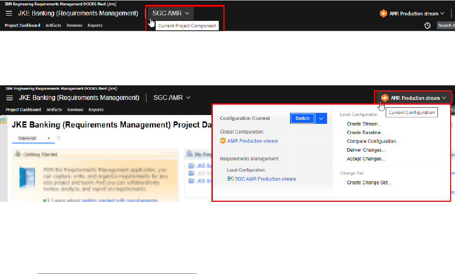
Before you begin
You must be a member of the project that contains the conguration you want to work in. For example,
to work in a Requirements Management (RM) stream, you must be a member of the project that contains
that stream. To work in a global conguration or a personal stream, you must be a member of that Global
Conguration Management (GCM) project.
About this task
In project areas that are enabled for congurations, use the menus on the toolbar to switch between
collections of artifacts:
• The Current Project Component menu shows the name of the component that you are working with. A
component is a like a building block that represents a physical or logical part of your project.
• The Current Conguration menu shows which collection of versioned artifacts you are working with
from the selected component, and whether you are working in a global conguration or a local
conguration. When you set the Current Conguration to a global conguration, you can create or
see links to artifacts in related congurations in other ELM applications. Consider this example:
Note: In IBM Engineering Lifecycle Optimization - Engineering Insights (ENI), to see all data, regardless
of conguration, select Current Conguration > None (All Congurations). Selecting this option shows
data from projects that are not conguration-enabled, and all congurations from project areas that are
enabled.
When you set the Current Conguration menu to a global conguration, you have a view of the entire
collection of requirements, tests, designs, and development artifacts that make up a version of a product.
You can create cross-application links to artifacts in the congurations that are part of this global
conguration. For example, if you create a test case and you want to link to a requirement, you see
only the requirements artifacts that are part of the version of the product or system that you are working
on. Working in a global conguration ensures that links resolve to the correct artifact version in another
conguration, which is important when teams develop multiple products or systems in parallel. If your
organization does development this way, you will likely do most of your work in the context of a global
conguration. If you do not work in a global conguration context, you cannot see or link to versioned
artifacts in other ELM applications.
Remember: Multiple components can contribute to a global conguration, so you might have to select
the component you want: Click Current Project Component, and if the component name isn't the in the
recently-viewed list, click Choose Another Component and follow the instructions. After you choose a
component, the Current Conguration menu changes to the conguration that this component contributes
to the global conguration. The conguration context is now set. In both the RM and QM applications,
explore these menus to see how changing one menu affects the other.
The Local Conguration section tells you which collection of artifacts you are working with from a
Requirements Management (RM) or Quality Management (QM) application. If the Global Conguration
section shows a global conguration, the Local Conguration section shows the conguration that you
are working in as part of that global conguration. When this section species a stream, you can edit the
226
Engineering Requirements Management DOORS Next
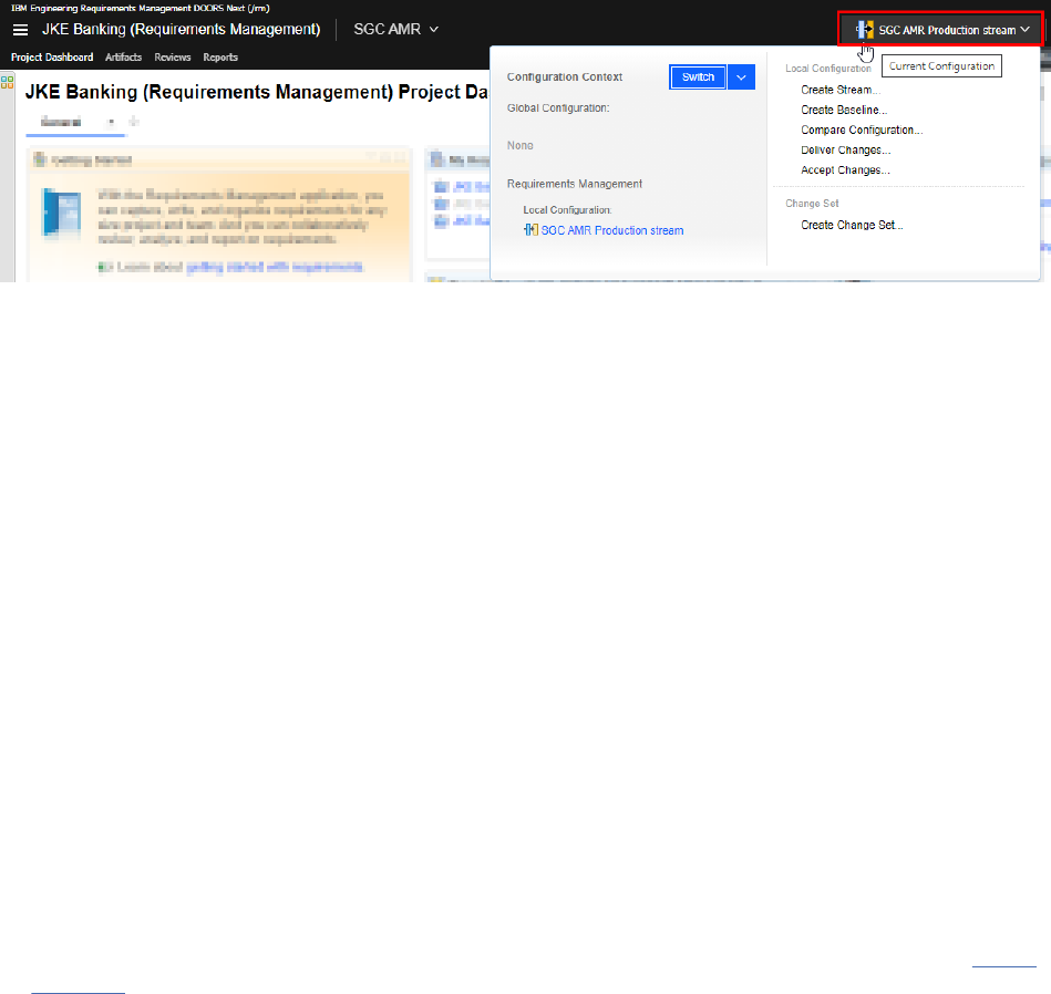
artifact versions in that conguration. When it species a baseline, you cannot edit the artifact versions in
that conguration.
When the Current Conguration menu species a local conguration, you are working only in the context
of a local conguration, as in this example:
Notice that the Global Conguration section does not indicate a global conguration: You can see only
the artifacts in the stream or baseline that you are working in. You cannot create or see links to artifact
versions in other ELM applications.
The tasks that are available on the menu depend on the conguration management permissions that a
conguration lead or team lead has assigned to you. If you think that you are missing permissions, see
your conguration lead, team lead, or application administrator.
Procedure
1. On the toolbar, click the Current Conguration menu, which shows the name of the conguration that
you are working in.
2. On the menu that is shown, beside Conguration Context, click Switch.
3. Select the type of conguration to switch to:
• Global Conguration: a conguration that contains other congurations, possibly from other ELM
applications. If you choose this option, you can rene your search by selecting a project area from
the Project Area menu.
• Local conguration: a conguration that contains artifacts from a conguration-enabled ELM
application such as RM or Quality Management (QM).
• All Data: Available only in ENI. Select to show all data: all congurations from conguration-
enabled project areas, and data from projects that are not enabled.
4. From the menu beside the search eld, select a modiable or frozen type of conguration to switch to:
for example, a stream or a baseline.
5. Search for a conguration by typing part of its name. If you chose Global Conguration in step “3” on
page 227 and then chose a project area, you can run a query to search for global congurations.
6. Select a conguration from the list.
7. Click OK.
Results
The toolbar shows the name of the conguration that you selected, and the context is now set to that
conguration.
Your selection applies across browser sessions.
Managing
227
Managing conguration details
You can open a local conguration to see related congurations, manage details, compare congurations,
and create local congurations.
Before you begin
• Ensure that you are familiar with project areas, components (if supported), baselines, streams, and
change sets (if supported).
• Ensure that you are logged in to a project.
Procedure
1. On the toolbar, click Administration
> Manage Components and Congurations.
2. Complete the steps depending on the IBM Engineering Lifecycle Management (ELM) application that
you use:
• Requirements Management (RM) application: Click a stream name.
Tip: To go to another component, click the Browse Components breadcrumb link and click a
stream name.
• Quality Management (QM) application: In the left navigation pane, click Streams or Baselines.
Results
The conguration editor opens. There are several things that you can do from this editor, depending on
the ELM application that you use.
In the RM application:
• To change the conguration name, click its name at the top of the page, type the new name, and then
click Save.
• To list the change sets, child streams, and baselines of this stream, click the corresponding tab name.
• To change the description, click the Details tab, provide text that uniquely identies the conguration,
and then click Save.
• See the icons near the upper right of the page for tasks that you can complete depending on the type of
conguration you are viewing.
• Where it exists, see the Actions menu beside the conguration name for the tasks that you can
complete.
• For streams:
– To view or edit artifacts for a stream, click Explore Stream.
– To see which streams are derived from this stream, click the Streams tab. For each stream on the
page, see the menu in the Actions column for actions that you can take.
– To see which baselines were created from this stream, click the Baselines tab. Then, to view the
baseline artifacts, click Actions > Explore Baseline.
In the QM application:
• To view the details of a conguration, hover over its name in the table.
• To change the conguration name or description, click its name in the table. Then, in the properties
window, provide text that uniquely identies the conguration, and click OK.
• See the Actions menu
beside the conguration name for the tasks that you can complete.
228
Engineering Requirements Management DOORS Next
• To work with the artifacts in a conguration, click its name or click Actions > Switch to This
conguration type.
• See the controls above the table to change how the page is shown.
What to do next
To return to an ELM project area, click Home Menu
, and select the application and project area
to return to. On the toolbar, verify that you are in the conguration that you want to work in. To switch
congurations, click the conguration name.
Creating streams in conguration-enabled projects
A stream is modiable set of versioned artifacts. You can add, edit, and delete versions of artifacts in a
stream. All team members who have access to the project area can access its streams.
Before you begin
• Ensure that you are familiar with project areas, components (if supported), baselines, streams, and
change sets (if supported).
• Log in to a project area in an IBM Engineering Lifecycle Management (ELM) application.
• In conguration-enabled projects, you must have permission to create streams.
• For Quality Management (QM) application to exclude test results and test execution records when you
create streams, set the corresponding conguration management preference
. You might exclude them if
the test results or test execution records from one project do not matter to another project.
• When you create a new stream, the test suite or test case results that are part of an in-progress test
suite or test case execution record are archived for the new stream. Complete or cancel the test in the
original stream.
• Understand how your organization uses streams and baselines that are based on how many teams need
to work in parallel on different versions of the same artifacts. To learn more, see Patterns for stream
usage on Jazz.net.
About this task
Multiple streams in a project area can contain a copy of the same artifact. Changing an artifact in your
stream does not affect the same version of that artifact in other streams until other team members
choose to bring your changes into their stream by using the Accept Incoming Changes operation in the
Requirements Management (RM) application or the Merge Conguration operation in the QM application.
Procedure
1. On the toolbar, click the current conguration name, and then click Create Stream.
2. Follow the prompts.
If your current conguration is a stream, a baseline of the stream is created automatically before
creating the new stream. The new baseline has the same name as the new stream, with "Initial
Baseline" appended. Then, the new stream is created from that baseline.
Results
The new stream is populated with the artifacts of the baseline that it was created from.
What to do next
• RM application only:
Managing
229

– Child streams inherit the change management constraints set on the Details tab of the
stream editor. For details, see https://www.ibm.com/docs/en/elms/elm/7.0.2?topic=SSYMRC_7.0.2/
com.ibm.jazz.vvc.doc/topics/t_admin_chgset_cntrl.html.
– If you do not use change sets, your changes are visible in the stream when you save your changes to
the artifacts. Use change sets to group your changes, which isolates your changes from other team
members who might use this stream.
• QM application only: To receive an email when artifacts are changed in specic streams, on the product
banner click User Prole; then, in the My Preferences for Quality Management dialog box, click
Change Notications > Send an email notication and select the streams.
To nd and switch to the new stream later, click Current Conguration on the toolbar and click Switch;
then, in the search eld of the Select the Conguration Context dialog box, enter an asterisk (*) to show
all the streams.
If you have permission, you or a conguration lead for the Global Conguration Management (GCM)
application might also add the stream to a global conguration, to provide a view of all the artifacts that
are used in a version of your product or system.
Related concepts
QM: Comparing and merging test artifacts
GCM application: Creating the global conguration hierarchy
Related tasks
RM: Managing changes to requirements artifacts
Creating baselines in conguration-enabled applications
A baseline is a read-only set of versioned artifacts. Create baselines to capture the state of a stream at
a specic point in time, and to dene a starting point for new work. For example, create a baseline of a
stream and use it as the basis of a new stream for new work. You can create a baseline of a stream at any
point during the project lifecycle, such as before or after a project milestone is reached.
Before you begin
• Ensure that you are logged in to a project.
• Your current conguration must be a stream.
• You must have the Conguration Lead role or have permission to create baselines.
• Understand how your organization uses streams and baselines that are based on how many teams need
to work in parallel on different versions of the same artifacts. To learn more, see Patterns for stream
usage on Jazz.net.
About this task
A baseline captures the current versions of artifacts in a stream. A baseline is a repository object that you
can use to return your stream to an earlier conguration; for example, you can preserve the state of a
stream when you released a project for testing.
Tip: If your team uses global congurations, you can create a baseline of a stream from the conguration
tree view in the Global Conguration Management (GCM) application. See Creating baselines of streams
contributed by other IBM Engineering Lifecycle Management (ELM) applications.
Procedure
1. On the toolbar, click the current conguration name; then, click Create Baseline.
2. Follow the prompts that you see.
Results
The current state of the stream that you are working in is captured.
230
Engineering Requirements Management DOORS Next
What to do next
To navigate to the baseline later, you must switch to it: see “Selecting a component and conguration to
work in” on page 225.
At this point, you might create a stream for new work, using the versions of the artifacts in this baseline.
If you have permission, you or a conguration lead for the GCM application might also add the baseline
to a global conguration, to provide a view of all the artifacts that are used in a version of your product or
system.
At any time during the project lifecycle, you can compare the baseline to a stream to see whether they
contain different versions of artifacts. See the topic about comparing artifacts or congurations that
corresponds to your ELM application.
Related concepts
Workflow for global congurations
Related tasks
Creating streams in projects enabled for conguration management
Comparing congurations in the RM application
You can compare congurations in the same project area to determine whether they contain different
artifacts (identied by the URI or the name of an artifact), or different versions of the same artifacts.
For example, partway through a project, you might compare a stream with its flow target to see which
artifact versions are different. You can also compare collections of requirements. At the end of a project
milestone, you might compare a stream with its baseline.
Before you begin
• Ensure that you are familiar with project areas, components (if supported), baselines, streams, and
change sets (if supported).
• Ensure that you are logged in to a project.
About this task
For details about comparing congurations in the Quality Management (QM) application, see the related
topic.
Procedure
1. Select a starting location and complete the associated steps:
Option
Description
Toolbar
Compare the current local
conguration (shown in the
Conguration Context section of
the Current Conguration menu)
to another local conguration.
Note: If conguration
management is not enabled, you
can still compare baselines with
each other or with the current
state of the artifacts in your
project by using this option.
a. On the toolbar, click the current conguration name, and then
click Compare Conguration.
b. Select the conguration to compare with, and complete the
steps in the wizard.
Note: This is the only way to compare two baselines. Set the
current conguration to a baseline; then, select another baseline
to compare to.
Managing231
Option Description
Conguration editor
Compare the conguration that
is open in the editor to
another related conguration.
Use this option to easily compare
the current stream with other
congurations in the project.
a. From the Administration menu , select Manage
Components and Congurations and click a stream name.
b. Select an icon near the upper right to compare the current
stream to the baseline that it was created from, or to its flow
target (destination stream).
Open other congurations in the editor by clicking their names.
If you open other streams in the editor, you can compare them to
other congurations by using the Actions menu on the Streams
and Baselines tabs.
If the conguration is an initial stream:
a. Complete step a above.
b. On the Streams or Baselines tab, select the conguration to
compare to the initial stream.
c. In the Actions column, select the compare operation.
Component overview page
Use this page to compare
only streams from the same
component.
a. From the Administration menu , select Manage
Components and Congurations.
b. In the Actions column, select the check boxes for the two
streams to compare.
c. Near the upper right, click Compare the selected
congurations .
d. Complete the steps in the Compare Congurations wizard.
Use the navigation icons in the upper right of the wizard
pages to explore the differences in the congurations.
2. Complete the steps in the Compare Congurations wizard. Use the navigation icons in the upper right
of the wizard pages to explore the differences in the congurations.
What to do next
The comparison is specic to your session, and can't be shared. If other team members want to see the
comparison, they must complete the preceding steps in their browser.
Related information
QM application: comparing congurations
Managing changes to artifacts
Create change sets to group related changes and to control where changes are delivered. You can link
change sets to work items to help identify the changes that are related to a specic purpose or problem.
When you nish making changes, deliver your change set to its destination stream. If you do not use
change sets, your changes to artifacts or links in a stream are available to everyone who shares the
stream as soon as you save your changes.
Before you begin
• Ensure that you are familiar with project areas, components (if supported), baselines, streams, and
change sets (if supported).
• Ensure that you are familiar with global congurations and personal streams (if your organization uses
them).
232
Engineering Requirements Management DOORS Next

• Ensure that you are logged in to a project.
• Ensure that you have permission to manage change sets.
• Understand how your organization uses streams, baselines, and change sets based on how many teams
need to work in parallel on different versions of the same artifacts. To learn more, see Patterns for
stream usage on Jazz.net.
About this task
A change set is a collection of related modications to shared artifacts that is delivered to a stream, and
can later be delivered to another stream. For example, you can manually create change sets to group
changes that resolve a specic problem. By grouping related changes and then delivering them as a unit
to a stream, you ensure that such groups of changes are made together or not at all.
Some teams might require you to manually create change sets as part of the organization's development
process. To prevent unauthorized changes, some teams might also require that change sets be linked to a
work item are approved before you can deliver your changes.
To minimize conflicts with other team members' changes, you can do the following actions:
• Use many small change sets and deliver them quickly.
• Modify in a separate stream, and then deliver all changes at once to the original stream.
• Assign one person to make edits to each module.
If you do not create change sets, each time that you save your changes to an artifact or link in a
stream, the application automatically creates and delivers a change set. Then, your changes are available
immediately to other team members who share the stream. Even though working this way is simple,
it can be harder to identify and deliver specic change sets to other streams. Ask your team lead or
conguration lead for guidance about whether to manually create change sets to manage your changes.
When your current conguration is a change set, you can see any changes made in the stream
immediately, unless the changes in the stream conflict with changes that you have made in your change
set. If you have not made any changes in a change set, you can see the same contents as the stream even
if the stream changes after you created your change set. If there is a conflict, resolve it before you can
deliver your change set to the stream. Some examples of conflicts include changes to the same artifact,
changing the order or contents of the same module, changing the contents of the same collection, and
modifying the same attribute denition or artifact type.
If you are working in a global conguration, see the Current Conguration menu on the toolbar. The
conguration context switches when you complete some change set operations:
• When you create a change set, it is added to your personal stream automatically, and the current
conguration is set to your personal stream. You can create or view links to artifacts in other project
areas while you work in your change set.
Note: Your personal stream can contain only one change set from a component (if supported) or project
area (if components aren't supported). Typically, you should have only one change set at a time in your
personal stream. To add a different change set to your personal stream, you must manually replace the
change set that is already there. See the related topic about working with multiple change sets.
• After you deliver the change set, it is removed from your personal stream.
For more information, see the related task links.
Procedure
You can work with change sets from the following locations:
• Current Conguration menu on the toolbar. In the Change Set section of the menu, see the change set
tasks.
• Change Sets editor:
Managing
233
a. From the Current Conguration menu, click the link to the stream shown in the Change Set
section.
b. See the change set tasks near the upper right.
• Change Sets tab of the conguration editor, when you open a stream in the editor:
a. From the Current Conguration menu, click the link to the stream shown in the Local
Conguration section.
b. In the conguration editor, click the Change Sets tab.
c. Use the available icons to create change sets and show different views of the change sets in the
stream.
d. In the Actions column, click Actions > action name to complete change set tasks:
– Deliver Change Set: Deliver the changes to the stream the change set was created from. You can
deliver only one change set at a time. You must deliver changes to this stream before you can
deliver those changes to other streams by using the Deliver Changes operation.
– Discard Change Set: You can discard only an entire change set; you cannot discard changes to
individual artifacts in a change set.
– Compare with Stream: Review the contents of a change set by comparing the versions of
artifacts in the change set with the versions of artifacts in the stream that the change set was
created from.
Related tasks
Selecting a component and conguration to work in
The name of the component that you are working in is shown on the toolbar, as part of the Current
Project Component menu. The name of the conguration that you are working in is shown as part
of the Current Conguration menu. Use these menus to switch components and congurations, and
to complete conguration-related tasks, based on your permissions or role. To see and create links to
artifacts in related project areas in other IBM Engineering Lifecycle Management (ELM) applications,
select a global conguration from the Current Conguration menu.
Controlling changes by enforcing change sets and links to work items in the RM application
Related information
Working with multiple change sets
Opening a local conguration from a global conguration
Working with multiple change sets
Creating change sets in the RM application
A change set is a collection of related modications to artifacts. You can create change sets to create
convenient groupings of changes; for example, a group of changes that resolves a problem. Other team
members can load your change set to review your changes before you deliver them.
Before you begin
• Ensure that you are familiar with project areas, components (if supported), baselines, streams, and
change sets (if supported).
• Ensure that you are familiar with global congurations and personal streams (if your organization uses
them).
• Ensure that you are logged in to a project.
• Ensure that the current conguration is a stream.
• You must have permission to create change sets.
• Understand how your organization uses streams, baselines, and change sets based on how many teams
need to work in parallel on different versions of the same artifacts. To learn more, see Patterns for
stream usage on Jazz.net.
234
Engineering Requirements Management DOORS Next
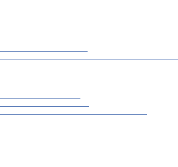
About this task
When you change artifacts in the context of a change set, all the changes that you make are grouped
into one logical unit. This grouping facilitates the review process and makes it easy to share changes with
other teams or team members that use different streams.
If you do not create change sets, each time that you save your changes to an artifact or link in a
stream, the application automatically creates and delivers a change set. Then, your changes are available
immediately to other team members who share the stream. Even though working this way is simple,
it can be harder to identify and deliver specic change sets to other streams. Ask your team lead or
conguration lead for guidance about whether to manually create change sets to manage your changes.
Procedure
On the toolbar, click Current Conguration > Create Change Set, and follow the prompts.
Results
The artifacts that you change or create are now grouped in this change set. When you nish changing
artifacts, deliver your changes to the stream.
If you are working in a global conguration, the change set is automatically added to your personal
stream, and the current conguration is set to your personal stream. You can create or view links to
artifacts in other project areas while you work in the change set. After you deliver the change set, it is
removed from your personal stream.
Note: Your personal stream can contain only one change set from a component (if supported) or project
area (if components aren't supported). Typically, you should have only one change set at a time in your
personal stream. To add a different change set to your personal stream, you must manually replace the
change set that is already there. See the related topic about working with multiple change sets.
To increase traceability in the development lifecycle and prevent the delivery of unauthorized changes,
you can link the change set to a work item.
Related tasks
Selecting a conguration
The name of the component that you are working in is shown on the toolbar, as part of the Current
Project Component menu. The name of the conguration that you are working in is shown as part
of the Current Conguration menu. Use these menus to switch components and congurations, and
to complete conguration-related tasks, based on your permissions or role. To see and create links to
artifacts in related project areas in other IBM Engineering Lifecycle Management (ELM) applications,
select a global conguration from the Current Conguration menu.
Linking change sets to work items
“Delivering change sets in the DOORS Next application” on page 239
After you nish adding or changing artifacts in a change set, you can deliver that change set to its stream.
The changes are then available to anyone who uses the stream. You can deliver only one change set at a
time.
Related information
Working with personal streams
Working with multiple change sets
Opening a local conguration from a global conguration
Linking change sets in the DOORS Next application to work items
To increase traceability in the development lifecycle and prevent the delivery of unauthorized changes,
you can track your work in change sets and create links between change sets in the IBM Engineering
Requirements Management DOORS Next (DOORS Next) application and work items in the IBM
Engineering Workflow Management (EWM) application.
• “Linking change sets to work items” on page 236
Managing
235

• “Viewing links between change sets and work items” on page 237
Before you begin
• Ensure that you are familiar with project areas, components (if supported), baselines, streams, and
change sets (if supported).
• Ensure that you are logged in to a project.
• You must have permission to manage change sets.
• A change set must exist.
About this task
You can link a change set to one or more work items.
An administrator can further control changes to artifacts by requiring team members to link change sets
to work items or change requests that have at least one approval. The governance of your project or
organization determines when this option is enabled. Suppose, at the start of a project or release, this
option might not be enabled so that team members might easily deliver many changes. Towards the end
of a milestone or release, linking change sets to work items can be enforced so that only authorized
changes are delivered. If this option is enabled, review the work item to ensure that it is approved (as
dened by the application that manages work items) before you deliver your change set. Dependent
change sets must also be linked to approved work items.
Linking change sets to work items
About this task
Links to work items are shown on the Current Conguration menu, and in the DOORS Next change set
editor. So, you can link your change sets to work items through one of the following ways:
• If a change set exists in the global conguration, or the conguration context is set to the change set
itself, click Current Conguration > Link to a Work Item. Then, follow the instructions in the dialog
box.
• If the conguration context is set to a global conguration or a stream that contains the change set, go
to the change set editor page to assign links to work items. Follow the procedure.
Procedure
1. On the banner, choose one of the following actions:
• Click Administration > Manage Components and Congurations. Then, click the stream name.
• Click Current Conguration. In the Local Conguration section, click the stream name.
Note: If the conguration context is set to another conguration, click Current Conguration >
Switch to switch to a conguration of your choice.
2. In the stream editor, select the Change Sets tab. Click the change set name.
3. Click Add link to work item
.
4. Follow the instructions in the Link to a Work Item dialog box. Click OK.
Results
Your change set is linked to the work item.
Tip: You can remove the link from either the work item in the EWM application, or from the change set
editor in the DOORS Next application.
236
Engineering Requirements Management DOORS Next
Viewing links between change sets and work items
About this task
You can see the links between DOORS Next change sets and EWM work items in the following places:
• DOORS Next application: Click the Current Conguration menu on the banner when you're working in
a change set, or open the change set editor.
• EWM application: Go to the Links tab of the work item. People can follow the link to the change set to
see its contents and compare it to the stream it originated from.
What to do next
After your change set is linked to the work item, you can resume your work or choose to deliver your
changes.
Related tasks
Selecting a conguration
The name of the component that you are working in is shown on the toolbar, as part of the Current
Project Component menu. The name of the conguration that you are working in is shown as part
of the Current Conguration menu. Use these menus to switch components and congurations, and
to complete conguration-related tasks, based on your permissions or role. To see and create links to
artifacts in related project areas in other IBM Engineering Lifecycle Management (ELM) applications,
select a global conguration from the Current Conguration menu.
“Delivering change sets in the DOORS Next application” on page 239
After you nish adding or changing artifacts in a change set, you can deliver that change set to its stream.
The changes are then available to anyone who uses the stream. You can deliver only one change set at a
time.
Related information
Opening a local conguration from a global conguration
Showing change set contents
View the list of changed resources for a change set on the Changed Resources tab of the change set
editor.
Before you begin
• Ensure that you are familiar with project areas, components (if supported), baselines, streams, and
change sets (if supported).
• Ensure that you are logged in to a project.
Procedure
1. Open the change set in the change set editor.
• If the change set is your current context, on the toolbar, click Current Conguration > Change Set
> change_set_name.
• If your context is not a change set, or to open another change set, complete these steps.
a. Click Administration
> Manage Components and Congurations.
b. Click the stream that contains the change set to view.
c. Click Change Sets > change_set_name.
2. In the change set editor, click the Changed Resources tab.
The resource changes are grouped into these categories: Types, Links, Folders, Artifacts, Tags, and
Comments.
Managing
237
What to do next
To resume working with resources, click a heading on the toolbar (Artifacts, Reviews, and so on).
To complete tasks that are related to the change set, use the icons near the upper right above the table.
Related tasks
“Discarding change sets in the RM application” on page 238
When you discard a change set, the changes that you made to the artifacts are discarded. You can discard
only an entire change set; you cannot discard changes to individual artifacts in a change set.
“Delivering change sets in the DOORS Next application” on page 239
After you nish adding or changing artifacts in a change set, you can deliver that change set to its stream.
The changes are then available to anyone who uses the stream. You can deliver only one change set at a
time.
Related information
Working with multiple change sets
Discarding change sets in the RM application
When you discard a change set, the changes that you made to the artifacts are discarded. You can discard
only an entire change set; you cannot discard changes to individual artifacts in a change set.
Before you begin
• Ensure that you are familiar with project areas, components (if supported), baselines, streams, and
change sets (if supported).
• Ensure that you are familiar with global congurations and personal streams (if your organization uses
them).
• Ensure that you are logged in to a project, and that the conguration is set to the change set to discard.
• You must have permission to manage change sets.
Procedure
On the toolbar:
• If the conguration is set to the change set to discard, click Current Conguration > Discard Change
Set.
• If the conguration is set to the stream that contains the change set to discard:
Note: To switch to the stream that contains the change set, click Current Conguration > Switch, and
search for the stream.
a. Click Current Conguration > conguration name.
b. In the stream editor, click the Change Sets tab.
c. In the Actions column beside the change set, click Discard change set
.
Results
All your changes in this change set are permanently lost.
If you are working in the context of a personal stream, after you discard your change set, it is also
removed from your personal stream.
Related tasks
Selecting a conguration
The name of the component that you are working in is shown on the toolbar, as part of the Current
Project Component menu. The name of the conguration that you are working in is shown as part
of the Current Conguration menu. Use these menus to switch components and congurations, and
238
Engineering Requirements Management DOORS Next
to complete conguration-related tasks, based on your permissions or role. To see and create links to
artifacts in related project areas in other IBM Engineering Lifecycle Management (ELM) applications,
select a global conguration from the Current Conguration menu.
“Showing change set contents” on page 237
View the list of changed resources for a change set on the Changed Resources tab of the change set
editor.
Related information
Working with multiple change sets
Working with personal streams
Opening a local conguration from a global conguration
Delivering change sets in the DOORS Next application
After you nish adding or changing artifacts in a change set, you can deliver that change set to its stream.
The changes are then available to anyone who uses the stream. You can deliver only one change set at a
time.
Before you begin
• Ensure that you are familiar with project areas, components (if supported), baselines, streams, and
change sets (if supported).
• Ensure that you are familiar with global congurations and personal streams (if your organization uses
them).
• Ensure that you are logged in to a project.
• You must have permission to deliver change sets.
• In some projects, an administrator might require you to link change sets to work items
that are
approved (as dened by the application that manages work items). If this option is enabled, review
the work item to ensure that this condition is met before you deliver the change set.
About this task
An administrator can prevent unauthorized changes to artifacts by requiring you to link change sets
to work items or change requests that have at least one approval. The governance of your project or
organization determines when this option is enabled. For example, at the start of a project or release,
the option might not be enabled so that team members can easily deliver many changes. Toward the end
of a milestone or release, the option might be enforced so that only authorized changes are delivered.
Dependent change sets must also be linked to approved work items.
Procedure
1. You can deliver a change set to its stream in different ways:
• If the conguration context is set to the change set to deliver, on the toolbar, click Current
Conguration > Deliver Change Set.
• If the conguration context is set to the stream that contains the change set to deliver:
Note: To switch to the stream that contains the change set, on the toolbar, click Current
Conguration > Switch, and search for the stream.
a. Click Current Conguration > Local Conguration: > stream name.
b. In the conguration editor, click the Change Sets tab.
c. In the Actions column on the left of the change set, click Deliver change set.
• If your team uses global congurations, you can deliver a change set from your personal stream
in the Global Conguration Management (GCM) application. Remember, personal streams contain
only one change set at a time. See the related topic about working with personal streams. For more
information about working with multiple change sets, see the related topic.
Managing
239
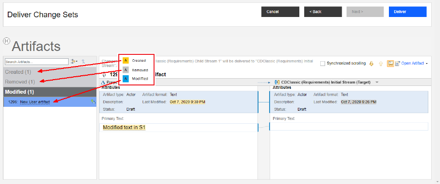
2. Follow the prompts and complete the steps in the wizard.
You can review all changes using the Standard delivery of change sets. Additionally, you can speed up
or customize the delivery process with the Express or Custom delivery options.
• Express: You have many changes to deliver and don't need to review them. Automatically deliver all
the changes without reviewing them; you are notied for any conflicts.
Automatically resolve conflicts where possible: Select to resolve conflicts that occur when
different attributes of an artifact are modied in each conguration. For instance, the primary text
modied in the source and the description modied in the target. If the same attribute is modied in
both congurations, delivery stops and you resolve the differences.
• Custom: You might have many changes or you want to control which ones are delivered. Select all or
a subset of them; choose to review them or not; and specify how the system handles conflicts.
Select Preview changes and manually resolve any conflicts to manually review the changes, or
choose from the following options:
– Notify me: When a conflict occurs between artifacts, the delivery stops and you resolve the
conflict.
– Automatically merge where possible: Select to resolve conflicts that occur when different
attributes of an artifact are modied in each conguration. For instance, the primary text modied
in the source and the description modied in the target. If the same attribute is modied in both
congurations, delivery stops and you resolve the differences.
– Always overwrite with source: When a conflict occurs between artifacts, the version in the
change set automatically overwrites the version in the target stream.
– Specify dominant source attributes: When a conflict occurs between artifacts, the conflict is
resolved by automatically delivering the values of attributes that you selected. When you deliver
your changes, if the system detects a conflict between the artifact versions in the source and
target congurations, it delivers only the selected attribute values for that artifact version to the
target stream.
If you choose to review your changes, use the controls on the Deliver Change Sets page.
• View the artifacts in the change set: Expand and collapse the sections on the left side of the page.
• See differences when artifacts changed in both the change set and the target stream: Expand
the Changed in both section, and click an artifact. Changes are color-coded in the changes section.
240
Engineering Requirements Management DOORS Next
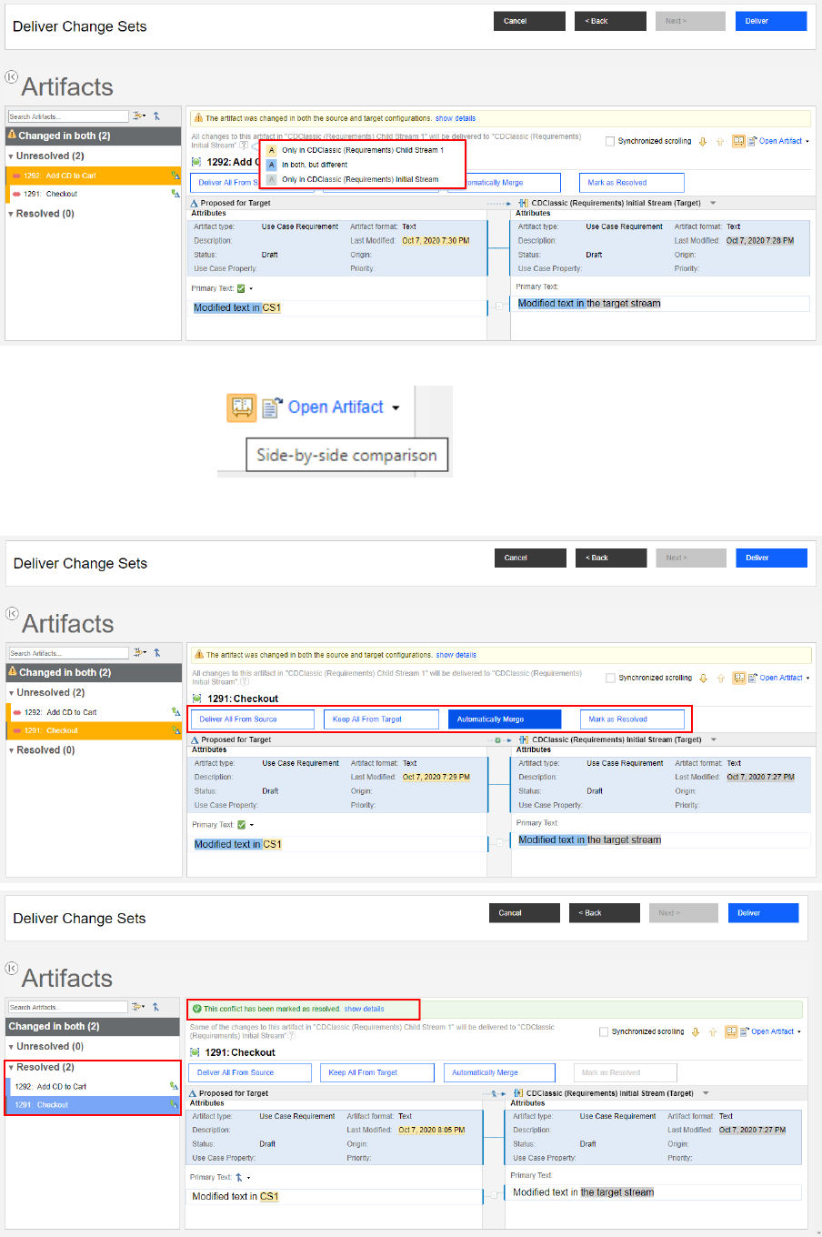
To toggle between a side-by-side comparison and single-pane view of the changed artifacts, click
Side-by-side comparison on the toolbar
• Deliver the changes for an artifact: Use the Changed in both section
and the options that are available on the page for delivering the changes.
Managing
241
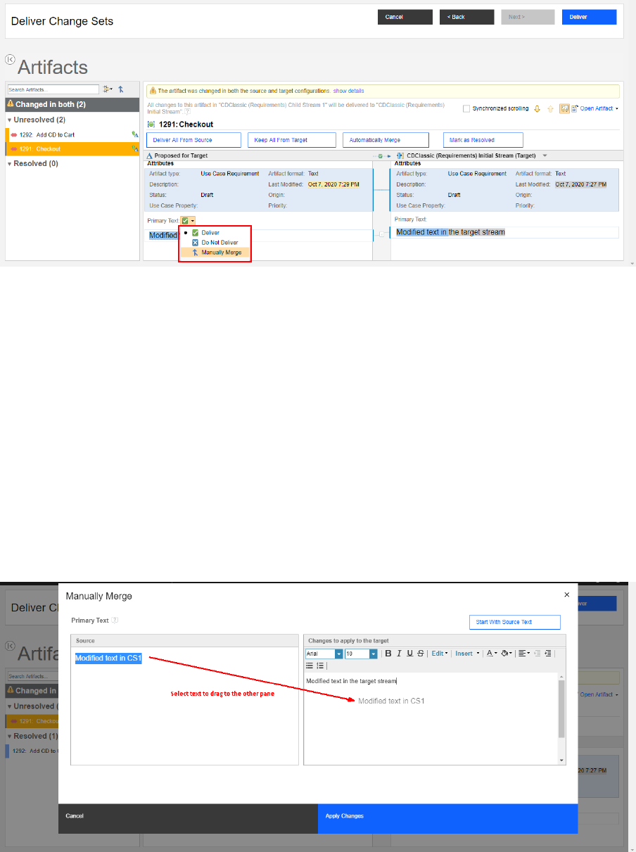
• Select or exclude individual changes for delivery: For each changed attribute, select an option.
• Manually merge changes using the Primary Text eld: When you select the Manually Merge menu
option for the Primary Text eld, a dialog box opens with an editable Primary Text eld. The eld
is populated with the target value, since that is what you can edit. The dialog box also shows the
read-only source value for comparison:
– You can use either the source or target text as the base to edit and make changes as needed. To
use the text of the source artifact as a starting point for your changes, click Start With Source
Text. The text of the target artifact moves to the other pane so that you can compare them.
– You can include existing embedded artifacts, links, and terms from both the source and the target
by using copy and paste or drag-and-drop.
– You can copy a link or an image to the clipboard without selecting the entire link text or image. In
the read-only primary text content on the left side of the dialog box, right-click a link or an image
and click Copy.
– You can also click and drag a link or an image from the left side and drop it into the editable
Primary Text eld on the right.
Click Apply Changes when you nish.
3. Click Deliver near the upper right of the page.
Results
The changes are now available in the stream and are visible to team members who use the stream.
242
Engineering Requirements Management DOORS Next
If you are working in a personal stream, after you deliver the change set, it is automatically removed from
your personal stream.
What to do next
You can now deliver those changes to other streams in the DOORS Next application. You can either deliver
all the change sets or only selected ones from one stream to another. For more information, see the
related topic.
Related tasks
Delivering change sets to other streams in DOORS Next
You can either deliver all the change sets or only selected change sets from one stream to another.
Selecting a conguration
The name of the component that you are working in is shown on the toolbar, as part of the Current
Project Component menu. The name of the conguration that you are working in is shown as part
of the Current Conguration menu. Use these menus to switch components and congurations, and
to complete conguration-related tasks, based on your permissions or role. To see and create links to
artifacts in related project areas in other IBM Engineering Lifecycle Management (ELM) applications,
select a global conguration from the Current Conguration menu.
“Linking change sets in the DOORS Next application to work items” on page 235
“Showing change set contents” on page 237
View the list of changed resources for a change set on the Changed Resources tab of the change set
editor.
“Showing where change sets were delivered” on page 243
View the list of streams that contain a specic change set on the Changes Contained In tab of the change
set editor.
Opening a local conguration from a global conguration
Related information
Working with personal streams
Working with multiple change sets
Showing where change sets were delivered
View the list of streams that contain a specic change set on the Changes Contained In tab of the change
set editor.
Before you begin
• Ensure that you are familiar with project areas, components (if supported), baselines, streams, and
change sets (if supported).
• Ensure that you are logged in to a project.
Procedure
1. Open the change set in the change set editor.
a) Click Administration
> Manage Components and Congurations.
b) Optional: To view change sets in another component, click Browse Components >
component_name.
c) Click the stream that contains the change set to view.
d) In the stream editor, click Change Sets.
Managing
243
e) Use the icons above the table to lter how change sets are shown. Change sets can only be
delivered to other streams after they were delivered to their own stream: click Include delivered
change sets .
f) Click a delivered change set ( ).
2. In the change set editor, click the Changes Contained In tab.
You see the all streams the change set was delivered to. Hover over a stream name to see more
details.
Results
If a change set is delivered to other streams, even as part of a stream-to-stream delivery, those streams
are also shown.
What to do next
To complete tasks that are related to the change set, use the icons near the upper right above the table.
To resume working with resources, click a heading on the toolbar (Artifacts, Reviews, and so on).
Related tasks
“Delivering change sets in the DOORS Next application” on page 239
After you nish adding or changing artifacts in a change set, you can deliver that change set to its stream.
The changes are then available to anyone who uses the stream. You can deliver only one change set at a
time.
“Delivering change sets to other streams in the DOORS Next application” on page 244
You can either deliver all the change sets or only selected change sets from one stream to another.
Related information
Working with multiple change sets
Delivering change sets to other streams in the DOORS Next application
You can either deliver all the change sets or only selected change sets from one stream to another.
Before you begin
• Ensure that you are familiar with project areas, components (if supported), baselines, streams, and
change sets (if supported).
• Ensure that you are familiar with global congurations and personal streams (if your organization uses
them).
• Ensure that you are logged in to a project.
• If your team requires you to manually create the change sets to group changes, you must rst deliver
the changes to the flow target (the stream that the change set was created in).
• You must have permission to deliver change sets.
• Understand how your organization uses streams, baselines, and change sets based on how many teams
need to work in parallel on different versions of the same artifacts. To learn more, see Patterns for
stream usage on Jazz.net.
Procedure
1. On the toolbar:
a) Ensure that the Current Conguration menu is set to the stream that contains the change sets to
deliver.
b) Click Current Conguration > Deliver Changes.
244
Engineering Requirements Management DOORS Next
A dialog box opens.
2. Select the stream to deliver the changes to, click OK.
3. Follow the prompts and complete the steps in the wizard.
You can review all changes using the Standard delivery of change sets. Additionally, you can speed up
or customize the delivery process with the Express or Custom delivery options.
• Express: You have many changes to deliver and don't need to review them. Automatically deliver all
the changes without reviewing them; you are notied for any conflicts.
Automatically resolve conflicts where possible: Select to resolve conflicts that occur when
different attributes of an artifact are modied in each conguration. For instance, the primary text
modied in the source and the description modied in the target. If the same attribute is modied in
both congurations, delivery stops and you resolve the differences.
• Custom: You might have many changes or you want to control which ones are delivered. Select all or
a subset of them; choose to review them or not; and specify how the system handles conflicts.
– Select Preview changes and manually resolve any conflicts to manually review the changes, or
choose from the following options:
- Notify me: When a conflict occurs between artifacts, the delivery stops and you resolve the
conflict.
- Automatically merge where possible: Select to resolve conflicts that occur when different
attributes of an artifact are modied in each conguration. For instance, the primary text
modied in the source and the description modied in the target. If the same attribute is
modied in both congurations, delivery stops and you resolve the differences.
- Always overwrite with source: When a conflict occurs between artifacts, the version in the
change set automatically overwrites the version in the target stream.
- Specify dominant source attributes: When a conflict occurs between artifacts, the conflict is
resolved by automatically delivering the values of attributes that you selected. When you deliver
your changes, if the system detects a conflict between the artifact versions in the source and
target congurations, it delivers only the selected attribute values for that artifact version to the
target stream.
– Choose change sets to deliver: Select and then click Add, and choose the change sets to deliver
to the target stream. To remove a change set from the list, from the menu on the left of the name,
click Don't Deliver.
Depends on Change Sets: If your changes depend on other change sets (including the change
sets from other team members), you must deliver them as well. Inspect the dependencies as
shown or by hovering over the link in the Dependents column to see which change sets would
also be delivered. The dependent change sets are delivered at the same time as yours. However,
you can choose to ignore a dependent change set by selecting the corresponding checkbox in the
Ignored column before delivering the changes.
If you don't choose specic change sets, the system delivers all the ones that were already delivered
to the source conguration.
4. Optional: If you choose to review your changes, click Next.
If you choose to review your changes, use the controls on the Deliver Change Sets page.
• View the artifacts in the change set: Expand and collapse the sections on the left side of the page.
Managing
245
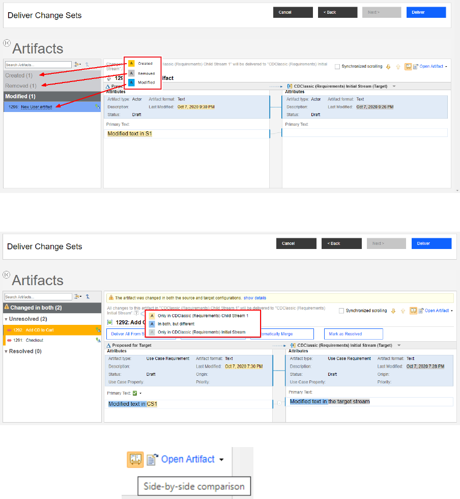
• See differences when artifacts changed in both the change set and the target stream: Expand
the Changed in both section, and click an artifact. Changes are color-coded in the changes section.
To toggle between a side-by-side comparison and single-pane view of the changed artifacts, click
Side-by-side comparison
on the toolbar
246
Engineering Requirements Management DOORS Next
• Deliver the changes for an artifact: Use the Changed in both section
and the options that are available on the page for delivering the changes.
• Select or exclude individual changes for delivery: For each changed attribute, select an option.
• Manually merge changes using the Primary Text eld: When you select the Manually Merge menu
option for the Primary Text eld, a dialog box opens with an editable Primary Text eld. The eld
is populated with the target value, since that is what you can edit. The dialog box also shows the
read-only source value for comparison:
Managing
247
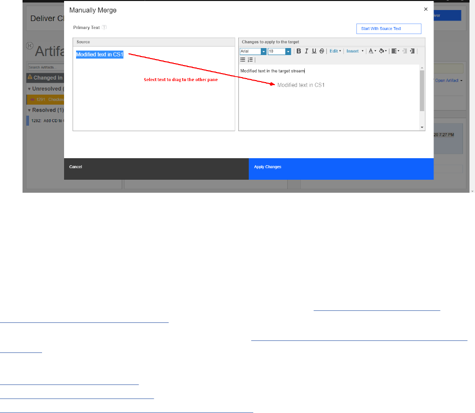
– You can use either the source or target text as the base to edit and make changes as needed. To
use the text of the source artifact as a starting point for your changes, click Start With Source
Text. The text of the target artifact moves to the other pane so that you can compare them.
– You can include existing embedded artifacts, links, and terms from both the source and the target
by using copy and paste or drag-and-drop.
– You can copy a link or an image to the clipboard without selecting the entire link text or image. In
the read-only primary text content on the left side of the dialog box, right-click a link or an image
and click Copy.
– You can also click and drag a link or an image from the left side and drop it into the editable
Primary Text eld on the right.
Click Apply Changes when you nish.
5. Click Deliver near the upper right of the page.
Results
The changes are now available in the stream that you selected to deliver them to. If you work in a
personal stream and deliver the change set, it is removed from the personal stream.
What to do next
To view the changes, switch to that stream. For more information, see “Selecting a component and
conguration to work in” on page 225.
To see which streams contain a specic change set, see “Showing where change sets were delivered” on
page 243.
Related information
Working with personal streams
Working with multiple change sets
Opening a local conguration from a global conguration
248
Engineering Requirements Management DOORS Next

Accepting changes from other congurations in the RM application
In a collaborative development environment, you might import changes from another stream or baseline
so that you can use them in the stream you work in. To import changes into a stream, use the Accept
Changes operation.
Before you begin
• Ensure that you are familiar with project areas, components (if supported), baselines, streams, and
change sets (if supported).
• Ensure that you are logged in to a project.
• The changes sets to accept were delivered to the flow target (the destination stream for the change
sets). You cannot accept open or active change sets from other streams.
• You must be working in a stream.
Procedure
Select an option:
• To accept changes from another stream or baseline into the current local conguration (shown on the
Current Conguration menu in the Conguration Context section):
a. On the toolbar, click conguration_name > Accept Changes.
b. Select the conguration to accept the changes from, and complete the steps in the wizard.
• To accept changes from a stream into a child stream:
a.
On the toolbar, click Administration
> Manage Components and Congurations.
b. Click a stream name.
c. Click the Streams tab.
d. In the Actions column, beside the stream to update, click Actions > Accept changes. This
operation accepts the changes from stream that is open in the stream editor.
e. Complete the steps in the wizard.
Results
The stream now contains the changes that you accepted.
What to do next
To resume working on artifacts in your project, ensure that the Current Conguration menu on the
toolbar is set to the conguration that you want to work in. To see links to artifacts in other projects or
applications, be sure to select a global conguration. If you do not see the links that you expect to see,
contact your conguration lead.
Showing and setting link validity and validity summary information in ELM
applications
Link validity is the status of links between artifacts to indicate whether the contents of two artifacts
meet the intended meaning of the link between them. You can use the link validity status to achieve
consistency across artifacts and links as you make changes that propagate through the linked data.
About this task
See “Link validity in ELM applications” on page 199
to read about link validity concepts and terminology,
setting link validity, and about using validity summary information in your project.
Managing
249
For IBM Engineering Test Management (ETM or QM) applications only: If your project is not enabled
for conguration management, you cannot see link validity information. Instead, your project would use
suspect link traceability. See the related topic to learn about the differences between these features.
Related information
ETM application: suspect traceability
Cloning requirement artifacts
Reorganize how artifacts are grouped in your project area by cloning them from one component into
another. When you clone an artifact, a new version is added to the stream of the component that you work
in.
Before you begin
• A Requirements Management (RM) project administrator must set up the project area:
– Enable conguration management for the project area.
– Import the component properties so that both components dene the same properties, such as
artifact types, artifact attributes, and link types.
• To clone artifacts into a component's folder within the same project area that contains the component:
– If the folder is owned by a project area, then you must be a project area administrator. If the folder is
owned by a team area, then you must be a team area administrator.
– You must have permission to create and deliver change sets.
• To clone artifacts from a component in another project area:
– You must be a member of that project area.
– The project area must be enabled for conguration management.
About this task
Each conguration-enabled project area that you create contains an initial component. You can create
other components to represent smaller logical or physical pieces of your project. Then, you can reorganize
the artifacts across the components by either cloning or copying them. Starting in version 6.0.3 when you
enable the project area for conguration management, you can create components and reorganize the
artifacts from an earlier project version so that you don't have all the artifacts in one conguration.
For example, you have an Airplane project area in a previous version of IBM Engineering Lifecycle
Management (ELM). After you upgrade to a version later than 6.0.3, you might reorganize that project
area into components such as Engine, Fuselage, Wing, Cockpit, and other components. Then, you can use
the clone task to reorganize the artifacts into the new components.
When you clone an RM artifact, a new version is added to the stream that you work in, and that artifact
now exists in two different congurations. You cannot add those congurations to the same global
conguration.
Use the following table to help you decide whether to clone artifacts or copy them. For details about
copying artifacts, see “Copying artifacts between projects” on page 62
, which also describes copying
between components in RM conguration-enabled project areas.
Table 31. Comparing cloning and copying operations
Decision points Cloning Copying
Create a new version of the
artifact (artifact URL stays the
same)
A new artifact is created with a
new URL.
250 Engineering Requirements Management DOORS Next
Table 31. Comparing cloning and copying operations (continued)
Decision points Cloning Copying
Preserve artifact history
The cloned artifact shows only
the history that is related to its
new conguration context. While
that history includes a text entry
(not a link) indicating the original
component and conguration,
you must manually go to that
source version to access the
history.
A new artifact is created; no
history to preserve.
Preserve outgoing links (RM
owns only the links to other RM
artifacts)
If link validity is enabled, the
link validity status of links from
the cloned artifacts is set to
Unknown. You must reset the
link validity status; see the
related topic.
If link validity is enabled, the
link validity status of links from
the copied artifacts is set to
Unknown. You must reset the
link validity status; see the
related topic.
Ability to view incoming
links (links from downstream
artifacts in other ELM
applications such as Quality
Management (QM) and Change
and Conguration Management
(CCM)
Incoming links to RM artifacts
are not cloned because the
downstream artifact (the one
that originates the link) owns
that link. However, because the
artifact URL doesn't change when
you clone the artifact, you can
still see incoming links. They
are visible when you work in a
global conguration that contains
both sides of the link - the
conguration with the cloned
artifacts and the congurations
from other applications that link
to them.
If link validity is enabled, the
status of the link to requirement
artifacts is set to Unknown. The
system detects that the cloned
artifact is a different version
(even though the URL is the
same) from the original artifact in
the source component. You must
reset the link validity status; see
the related topic.
Copied artifacts have a different
URL. You must re-create links
(and choose to reset the link
validity status) to related artifacts
in other ELM applications.
Managing251
Table 31. Comparing cloning and copying operations (continued)
Decision points Cloning Copying
Ability to work with artifacts in
other project areas
You can clone only across
components and project areas
that are enabled for conguration
management.
Both project areas must have
the same setting: either both are
enabled or both are disabled.
Procedure
1. Switch to the component and stream you want to clone artifacts into.
2. Optional: Consider taking a baseline of the stream so that you can create a new stream from the
baseline and discard the stream showing unexpected results.
3. Create a change set and switch to it.
Click Current Conguration > Create Change Set and complete the steps in the wizard. Your
conguration switches to the new change set, or, if you are using global congurations, your personal
stream. If you clone the wrong artifacts or the results are not what you expect, you can discard the
change set and not affect the stream, but you must x the component overlap information that the
system has. See the related topic about xing an overlap.
4. On the Artifacts page, in the Folders view, right-click the folder to clone artifacts into and click Clone
from a Component, and follow the steps in the wizard.
Remember:
• By default, all outgoing links from RM artifacts are also cloned. RM owns only links to other RM
artifacts, so outgoing links only go to other RM artifacts. To disable the cloning of outgoing links, clear
the Include Links option. You might disable this feature if you decide that existing links from the
artifact are no longer relevant for your project area.
• When you clone modules, the views from those modules are also cloned.
If you later decide to clone the artifacts again to get the links, any changes you made to the artifacts in
the target component are overwritten.
When you select a folder, all its artifacts and subfolders are also selected for cloning, but you don't see
them in the list. If you later add an artifact or subfolder that is already part of another folder in the list,
the artifact is still cloned only once.
For each artifact that you clone, a new version is added to the change set.
5. Deliver the change set that you created in step “3” on page 252.
Results
Items that are not included when you clone artifacts:
• Links to the cloned artifacts from artifacts in other applications because the links are owned by the
other artifact's application.
Because cloning preserves the URL of the artifact, you can still see links to the cloned artifact when you
work in a global conguration that includes the cloned artifacts and the artifacts that link to them.
• Tags and comments
• Reviews
If later you must add the source and target congurations of the component to the same global
conguration, see the related topic about xing component overlap.
If you clone those artifacts again from the source component into your change set, your changes to them
are overwritten.
252
Engineering Requirements Management DOORS Next
Related concepts
Links across project areas after enabling conguration management
Related tasks
“Fixing overlapping components” on page 76
After you clone artifacts, two components overlap if they have any artifacts in common, regardless of
those artifact versions. The system prevents you from adding congurations of those components to
the same global conguration. Fix the component overlap and then add the congurations to the global
conguration.
Related information
Components
Dening your component strategy (Jazz.net article)
Viewing and changing link validity status in ELM projects
Troubleshooting local congurations and conguration management
If you encounter errors or exceptions related to conguration management or local congurations, review
the log le for your IBM Engineering Lifecycle Management (ELM) application. Other problems can be
solved by working in a global conguration context.
Errors and exceptions related to conguration management are written to the log le of the
corresponding IBM Engineering Lifecycle Management (ELM) application. By default, this log le is named
ELM_application_name.log
Errors and exceptions related to links between artifacts are in the ldx.log le of the Link Index Provider
(LDX) application (/ldx).
Some problems, such as not seeing links between artifacts, are solved by switching to a global
conguration context from the Current Conguration menu on the toolbar.
For details and solutions to other problems that you might encounter, see Troubleshooting congurations
and conguration management .
Related concepts
Cross-project links to versioned artifacts after enabling conguration management
Related information
Unexpected local conguration in Current Conguration menu
Troubleshooting congurations and conguration management
Artifact recovery to resolve data inconsistencies
When a team works in multiple congurations, if change sets are delivered between congurations that
conflict, data inconsistencies can occur. To x those inconsistencies, you can recover the artifacts in a
conguration manually.
When working in a conguration management enabled project in which where there are multiple
congurations , data inconsistencies can occur if there are conflicts when delivering changes. To avoid
such conflicts, you should keep change sets relatively small and deliver them as soon as possible.
However, if a data inconsistency does occur, you can manually recover missing artifacts in your
conguration. For example, consider this scenario:
Artifact recovery scenario
You have three artifacts in the Artifacts folder in the 1.0 stream:
1. From the 1.0 stream, the 1.1 stream is created. The artifacts in both streams are identical.
2. In the 1.0 stream, a team member deletes the Artifact folder and the three artifacts.
3. In the 1.1 stream, you modify two of the artifacts in the Artifacts folder.
Managing
253
4. You accept changes from the 1.0 stream to the 1.1 stream. However, you do not deliver the changes
to the modied artifacts that are now in conflict. As a result, the modied artifacts no longer have a
parent folder in the current conguration.
5. If you search for the modied artifacts, you can still nd them, but you cannot nd them if you lter by
folder.
6. To x the problem, go to the Conguration Management tab of the project properties and recover the
artifacts manually. When you click Recover, all folders and artifacts that do not have a parent folder in
the current conguration are searched for.
Related concepts
“Conguration management in the RM application” on page 6
Reporting
This section describes how to create and view reports in the Requirements Management (RM) application.
Reporting in the Requirements Management (RM) application
You can run and view reports that are based on a data warehouse and create document-style reports that
are about requirement and other lifecycle data.
The Requirements Management (RM) application supports document-style reports and reports that are
based on a data warehouse.
Important: Projects that are enabled for conguration management do not populate the data warehouse
and are therefore not included in any data warehouse reports. For information on reporting on
conguration data, see reporting on data in congurations.
Document-style reports have these characteristics:
• You can generate them by using a report wizard. You can open the wizard from these places in the RM
application:
– The Reports page
– The Actions menu on the Artifacts and Reviews pages
– The Actions menu in the Modules editor
– The Actions menu in the Collections editor
• They come with a set of reports that you can select from the report wizard.
• They use live data, as opposed to data in a data warehouse.
For more information about document-style reports, see Creating document-style reports in the
Requirements Management application.
Reports that are based on a data warehouse have these characteristics:
• You can generate them using the Report Builder. This is the easiest and fastest way to generate data
warehouse reports.
• They use data from a data warehouse.
• They come with a set of reports that you can run and view.
Related concepts
“Modules in the Requirements Management application” on page 129
A module is a structured document that is composed of multiple artifacts. You can create structure in a
module by modifying the order and hierarchy of its artifacts. The artifacts that are created for modules
254
Engineering Requirements Management DOORS Next

are stored as module content in a folder. Base artifacts can be used to manage the module artifacts
independent of the module.
“Collections” on page 176
A collection is a set artifacts that you create for a specic purpose.
“Reviews” on page 181
Related information
Reporting
Creating document-style reports in the Requirements Management
application
IBM Engineering Requirements Management DOORS Next (DOORS Next) includes several document-style
reports that you can generate to view information about the artifacts, modules, collections, and module
views in your Requirements Management (RM) projects. If the available reports do not suit your needs,
you can create custom report templates.
Before you begin
You do not need to install extra components to generate the document-style reports that are included in
the RM application.
Note: If you are working in a project that is enabled for conguration management, document-style
reports are created by using data from the conguration in which you are currently working. If you are
using IBM Engineering Lifecycle Optimization - Publishing (PUB), you can specify the conguration in
which you want to create reports.
About this task
You can generate a document-style report on all the artifacts on a page, or on selected artifacts. The
following formats are supported:
• HTML
• PDF
The PDF font must be congured to one that has international character support for Linux or Windows
systems. Otherwise, special characters might not be shown in your PDF le.
For information about how to install fonts on Linux systems, consult the documentation for your specic
Linux distribution. As an alternative, if the fonts are available in a non-default directory, you can set
the true-type font directory by using the com.ibm.rational.rpe.pdf.truetypefontdirectory
Java parameter. After you set a directory, the formatting driver loads the fonts from that directory. If
the necessary font is not available on the operating system, you can set the substitution font on the PDF
output property to an available font.
• XSL-FO (XSL Formatting Objects)
This is a standard unied presentation language for documents. You can use this format with post-
processors to generate output that can be printed or rendered. You can also use it with scripts to
post-process your results. For more information about this format, see XSL Formatting Objects.
• Microsoft Word
When you generate a report in this format, if you see an error message about the table of contents,
right-click the message and click Update Field. If you use a Windows operating system, you can
congure Word stylesheets on the DOORS Next server to automatically run macros. However, if you
use macros on a non-Windows operating system, the following error message is written to the logs:
CRRPE3137W The Microsoft Word macro was ignored.
Note: A limitation in Microsoft Word prevents you from following any links in the generated report. To
view the linked artifact, copy the URL and paste it in your browser.
Reporting
255
Tip: Although Microsoft Excel is not supported for report generation, you can create a custom view and
export it to CSV format, which you can then import into an Excel spreadsheet.
If you insert a le into an artifact, you can download, open, and print the le in the application where it
was created. For more information, see “Inserting les into requirement artifacts” on page 119.
Procedure
1. You can generate a document-style report on the artifacts in your projects in several ways. Choose one
of the following approaches.
• If you are new to the RM application and want to try the reporting features, complete the following
steps.
a. In your RM project, click Reports.
b. On the Reports page, click Generate a report.
• If you are working with artifacts, modules, collections, or module views in the grid, you can
generate a report by completing the following steps.
a. On the Artifacts page, choose the artifacts to include in the report. You can use a lter to nd
and show specic artifacts. See “Filters and views for artifacts in requirements projects” on
page 111.
b. Click the Edit icon
and click one of the following menu items.
– To report on artifacts or collections, click Generate Report for Artifact.
– To report on modules, click Generate Module Report for Artifact.
– To report on module views, click Generate Report for View.
2. In the Create a report wizard, select the type of report to create. The list of available reports depends
on the artifacts that you selected.
When you generate a report from a module, the Create a Report dialog box stores your most recent
settings. These settings persist across sessions and can be reused for generating more reports.
3. Click Next and complete the steps in the wizard.
Results
The report is saved in the location that you specied.
Creating custom document-style reports
You can create custom report templates that are based on PUB, and then create your own document-style
reports from those templates.
You must be familiar with the REST APIs
for accessing report information. You must also have a full
PUB license. For more information, see Customizing document-style reports and Making document-style
reports available to viewers.
Note: Content on Jazz.net is governed by the Jazz.net Terms of Use and is provided as-is without
warranties of any kind.
Related concepts
“Reporting in the Requirements Management (RM) application” on page 254
You can run and view reports that are based on a data warehouse and create document-style reports that
are about requirement and other lifecycle data.
“Filters and views for artifacts in requirements projects” on page 111
256
Engineering Requirements Management DOORS Next

Filters and views are useful for sorting and displaying artifacts that are based on specic criteria. You can
use lters and the congure page settings to display artifacts, and then save this conguration as a view
to use later.
“Exporting requirements artifacts to CSV and spreadsheet les” on page 161
You can export text-based artifacts from a requirements project into comma-separated values (CSV) les
or into spreadsheet (XLS and XLSX) les. The content of the exported le is governed by the columns that
are in the current view.
Running data warehouse reports in the Requirements Management (RM)
application
You can run and view requirements management metrics reports that are based on the data in the data
warehouse. The reports show information about requirement artifacts and traceability information about
related quality management and change management data.
Before you begin
Before you can run or view a data warehouse report, you must install Report Builder.
Important: Projects that are enabled for conguration management do not populate the data warehouse
and are therefore not included in any data warehouse reports. For information on reporting on
conguration data, see reporting on data in congurations
.
About this task
Important: Metrics about requirements management are not collected in the data warehouse by default.
For information about enabling data collection, see Collecting data with the data collection component.
Tip: When an artifact is in a module, it represents a requirement in the context of that module and
generates two separate artifacts in the data warehouse. In certain reports, such artifacts might be shown
twice in the same report.
Procedure
Create a report in Report Builder
, selecting Data Warehouse as the data source.
Results
The report runs, the results are shown, and information about the report is shown.
Related concepts
“Reporting in the Requirements Management (RM) application” on page 254
You can run and view reports that are based on a data warehouse and create document-style reports that
are about requirement and other lifecycle data.
Related tasks
“Creating document-style reports in the Requirements Management application” on page 255
Related information
Report Builder
Collecting data with the Data Collection Component
Reports that are provided with the Requirements Management (RM)
application
The Requirements Management (RM) application includes document-style reports from the Create a
Document-Style Report wizard. You can use the reports to analyze requirements and identify trends in
projects.
The document-style reports that are available in the Create a Document-Style Report wizard are listed in
Table 1.
Reporting
257
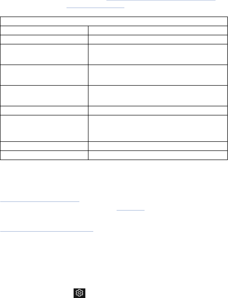
Important:
• Metrics about requirements management are not collected in the data warehouse by default. For
information about enabling data collection, see Collecting data with the data collection component.
• Projects that are enabled for conguration management do not populate the data warehouse and are
therefore not included in any data warehouse reports.
Table 32. Reports in the Document-Style Report wizard.
Name Description
Use Case Diagram Specication Shows organized requirements by use case diagram.
Requirements Specication Shows both functional requirements, such as use cases,
and non-functional requirements, such as supplementary
requirements.
Traceability Report Shows a requirement-centered view of links to work items that
implement the requirements and to test suites that validate the
requirements.
User Interface Specication (by Screen
Flow Diagram, by Sketches, and by
Storyboards)
Shows the artifact description, artifact type, and images of the
specied graphical artifacts.
Audit History Shows the history of changes to the selected artifacts.
Reviews Shows details about the progress and content of the reviews,
including the creator, project start date, due date, and overall
state. This report is in the Create a Document-Style Report
wizard only when you open the wizard from within a review.
Print Module as a Book Shows the module as a book that you can print.
Print Module as a Table Shows the module as a table that you can print.
Requirements management reportable REST API
The Requirements Management (RM) application provides a reportable REST API, which can be used by
live reports and by data collection jobs to access RM application data.
For information about reportable REST API resources that the RM application provides, see the
Reportable REST API documentation on Jazz.net.
Note: Content on Jazz.net is governed by the Jazz.net Terms of Use and is provided as-is without
warranties of any kind.
Related information
Requirements management data dictionary
Creating compare conguration report
You can create a conguration comparison report that contains the differences between two related
congurations, baselines, streams or change sets. The comparison report provides information that is
related to elements that are found in source and target congurations, and the elements that are found in
both congurations. The compare utility wizard is enhanced to create the comparison report.
Procedure
1. From the Administration menu
, select Manage Components and Congurations.
2. Click the current conguration name, and then click Compare Conguration.
258
Engineering Requirements Management DOORS Next
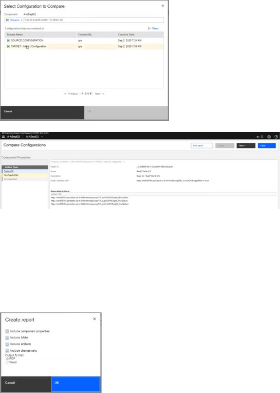
3. Select Conguration to Compare, which you want to compare with. (Source and target
congurations).
4. Click Print report to create the report of the selected congurations.
5. Select one of the various following options for creating the report:
a. Include component properties.
b. Include folder.
c. Include artifacts.
d. Include change sets.
Note: The change sets included in the report are the ones that are used for the comparison. If an
artifact is changed several times, then only the last change set is included in the list of change sets.
6. Select the output format in the Create report dialog box.
a. PDF
b. Word
7. Click OK.
Reporting
259
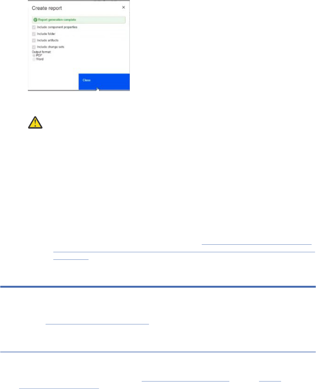
• The report is generated. The changes are visible in a special style. The gray elements are old changes
and the yellow highlighted changes are new changes that are available in source stream.
Warning: The Compare conguration report requires a large Java Virtual Machine (JVM) heap
setting in DOORS Next server. You must take note of the following points:
• A single report run can cause DOORS Next server to crash, if sufcient heap memory is not
available to the JVM.
• The API used to generate Word and PDF reports usually requires a large heap in the nal
stage of report generation. In addition, the amount of heap that is required to run your report
varies greatly depending on the comparison. If you are comparing a baseline to the current
stream and you choose an older baseline, it may multiply the amount of heap that is required
to process the report.
• Customers who perform many ReqIf or CSV or MS Word imports are likely to need more heap
to process the compare conguration report.
• Depending on the data shape, to successfully generate a compare conguration report of 500
MB may require 12-16 GB additional heap per concurrent report generation. To prevent the
generation from having a large impact on other server operations, a larger heap is advised.
• For more information, review the following technote: IBM Engineering Lifecycle Optimization
- Publishing: Aspose.Words out of memory error when generating document-style report from
DOORS Next
Troubleshooting
This section describes how to troubleshoot and nd support for the Requirements Management (RM)
application.
Read the General troubleshooting and support section to understand the general process for problem
determination, troubleshooting, and how to get support from IBM Software Support.
Troubleshooting the Requirements Management application
The Requirements Management (RM) application provides information on troubleshooting different issues
and log messages.
For details about the log messages, see the Error messages documentation. Read the General
troubleshooting and support section to understand the general process for problem determination,
troubleshooting, and how to get support from IBM Software Support.
Note: The capabilities that the RM application provides in the IBM Engineering Lifecycle Management
(ELM) are licensed as IBM Engineering Requirements Management DOORS Next (DOORS Next).
260
Engineering Requirements Management DOORS Next

In some cases, you or an administrator can use the application log les to diagnose problems. If you
cannot resolve a problem without help from IBM Software Support, the support representative can use
the application log les to nd more information about the problem.
If you le a defect or another type of work item about the RM application and want your request
addressed quickly, you must provide certain information. For details about what information to
provide, see "Guidelines for ling defects and other work items" at https://jazz.net/wiki/bin/view/Main/
FilingDefects.
Content on Jazz.net is governed by the Jazz.net Terms of Use and is provided as-is without warranties of
any kind.
Related information
Error messages overview
Log le locations for the Requirements Management (RM) application
If you encounter errors or exceptions while you are using the Requirements Management (RM)
application, you can use the generated log les to research the issues and nd resolutions for them.
The capabilities that are provided by the RM application are licensed as IBM Engineering Requirements
Management DOORS Next (DOORS Next).
Requirements management server logging information
The log les in the RM application include rm.log and jts.log.
If you use IBM
®
Rational
®
Quality Manager, the default rm.log le location is WebSphere Install
Dir/profiles/AppSrv01/logs.
Note: For ELM version 7.0.2 SR1 iFix015 and later, the logging property le name and conguration
parameters are changed because of the move to log4j2. For more information on the updates, see IBM
Support portal.
The location of a log le is determined by the log4j.properties le in the
JAZZ_HOME/log_file_name directory. The default setting for the JAZZ_HOME directory is
log4j.appender.logfile.File=logs. For example, for the jts.log le, the default setting is
log4j.appender.file.File=logs/jts.log.
The format of the log le is supported by IBM Tivoli
®
Log Analyzer. To analyze a log le, import the le into
that tool.
For the location of log les for other applications and servers, see Log le locations
Related information
Error messages overview
Enabling logging in the web client for the RM application
You can enable logging in the web client for the Requirements Management (RM) application to capture
information about events, processes, and other activities, which you can use for debugging purposes. To
access the log messages in the web client, you specify a log level in the URL for the application.
To enable logging in the web client, include the clientlog parameter in the RM application URL. This
parameter species the level and type of logging that occurs when the RM application is used. By default,
the log level is set to 4 (ERROR). For example, the following URL captures debugging-related information
and log messages about processes, events, and important decision points:
https://<host>:<port>/rdm/web?debug=true&clientlog=1
All log messages are written to the browser console.
The following table describes the different logging levels that you can set.
Troubleshooting
261
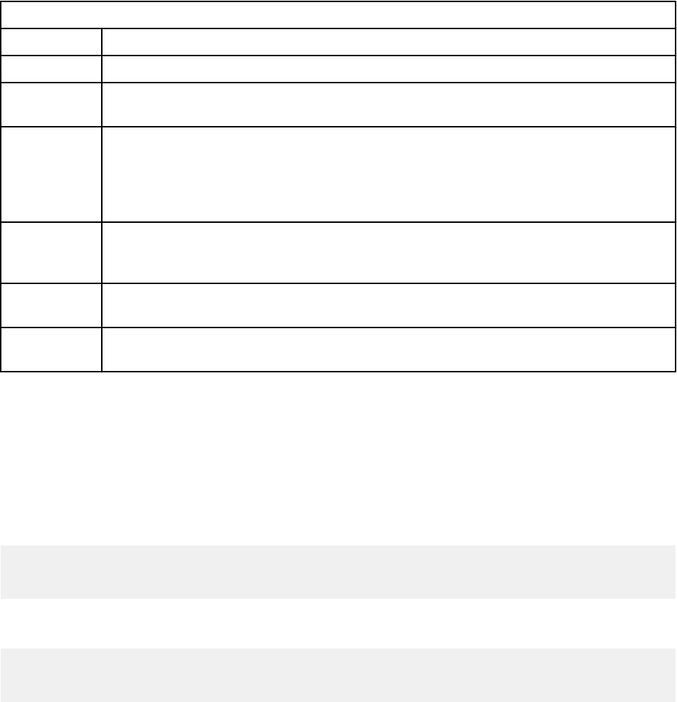
Table 33. Web client logging levels
Level Description
5 (SILENT) Nothing is logged.
4 (ERROR) Use this level to log only errors that break the normal workflow. Typically, his type of
error affects the user experience and requires human intervention.
3 (WARN) Use this level to capture details about unexpected inputs or situations that are not
typical, but that do not break the normal work flow. For example, the following
situations might generate messages at this level: the use of deprecated APIs, the
incorrect use of APIs, and other runtime situations that are undesirable or unexpected,
but not necessarily incorrect.
2 (INFO) Use this level to capture information about high-level events such as session lifecycle
calls, database calls, or remote API calls. Information at this level is an abstract of an
event: it does not include specic details that are covered by the debug level.
1 (DEBUG) Use this level to capture details that can help you troubleshoot problems, for example,
relevant information about processes, events, and important decision points.
0 (TRACE) Use this level to generate more detailed output about objects, data structures, and
environment compared to the DEBUG level.
Note: The logging levels for the web client are inclusive. For example, if you specify clientlog=3,
all warnings and errors are logged. To work with the RM application in debug mode, you can use the
clientlog parameter and set debug to true. If you do not work in debug mode, only the log messages
that are part of the RM application are included in the web client log.
Examples
If you include clientlog=1 in the RM application URL, and then open a project that includes link
constraint rules, you might see log entries like these:
LinkingConstraintsCache: Getting constraints for project <projectURL>
LinkingConstraintsCache: Get constraints for project finished in <#>ms.
LinkTypeUtils: Processing <#> link types for project.
If you include clientlog=1 in the RM application URL, and then open the audit history page for an
artifact, you might see log entries like these:
AuditHistoryRetriever: Getting artifact history.
AuditHistoryRetriever: Get artifact history finished in <#>ms.
AuditHistoryViewer: Populating <#> audit history change entries for detail pane.
Fixing a converter issue while using the server in headless mode on a Linux
system
On Linux systems, an error might occur when you start the Requirements Management (RM) server from a
command line (headless mode).
Problem
The RM application includes a converter that visually renders graphical artifacts, such as business process
diagrams, use case diagrams, parts, sketches, storyboards, and screenflows. The converter runs on the
server. When you start the RM server in headless, or console, mode on a Linux system, the action silently
fails and the CRRRW8010E error message is displayed.
262
Engineering Requirements Management DOORS Next
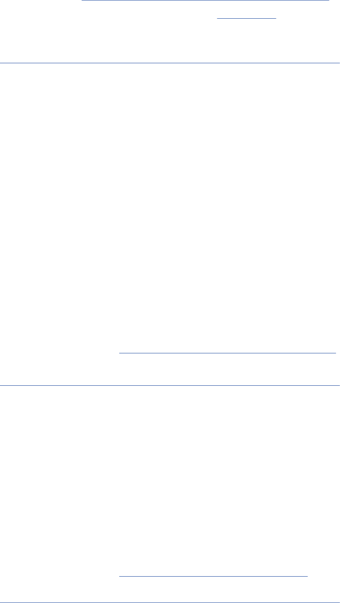
Solution
Before you can start the server, terminate the Java process and take remedial action. For more
information, see "Troubleshooting CRRRW8010E A server error prevented the generation of the content"
in Jazz.net article Requirements Management (RM) converter application.
Content on Jazz.net is governed by the Jazz.net Terms of Use and is provided as-is without warranties of
any kind.
Related concepts
“Troubleshooting the Requirements Management application” on page 224
The Requirements Management (RM) application provides information on troubleshooting different issues
and log messages.
Recovering missing artifacts from congurations
When a team works in multiple congurations, if change sets are delivered between congurations that
conflict, data inconsistencies can occur. To x those inconsistencies, you can recover the artifacts in a
conguration manually.
Problem
When working in a conguration management enabled project in which there are multiple congurations,
data inconsistencies can occur if there are conflicts when delivering changes. This could make it seem like
artifacts have disappeared from the conguration.
Solution
1. From the Administration menu, click Mange Project Properties.
2. Click the Conguration Management tab.
3. Under Recover Resources, click the Recover button.
Tip: You must complete the recovery process during off hours when other tasks or process are not
running as the recovery process might take long time for completion.
For more information, see Artifact recovery to resolve data inconsistencies
.
Related concepts
“Troubleshooting the Requirements Management application” on page 224
The Requirements Management (RM) application provides information on troubleshooting different issues
and log messages.
Fixing le preview font issues in other languages on a Linux system
If a preview image for a le looks different from the original document, the server might be missing fonts
that were used in the document. Chinese and other international characters do not display correctly by
default.
Problem
The le preview image does not display correctly in other languages on Linux systems.
Solution
For languages to display correctly, the administrator must install a font that supports those characters.
For more information, see Upload le preview - Adding fonts section.
Related concepts
“Troubleshooting the Requirements Management application” on page 224
Troubleshooting
263

The Requirements Management (RM) application provides information on troubleshooting different issues
and log messages.
Opening artifacts in multiple browser tabs or windows
If you try to open one or more artifacts in a new tab or window, only one tab or window opens. In addition,
a message about pop-up windows is displayed.
Problem
In the Requirements Management (RM) application, you can open one or more artifacts in a new tab
or window by using the Open Artifact menu. If you try to open artifacts in multiple tabs or windows,
after the rst tab or window opens, nothing else opens and a message states that pop-up windows are
blocked.
Solution
Congure your browser to allow pop-up windows to open. For example, to congure the Chrome browser,
when you see the message about pop-up windows, select Always allow pop-ups to allow them from the
specied location and then click Done. After you congure the browser, you can open artifacts in a new
tab or window without errors.
Related concepts
“Troubleshooting the Requirements Management application” on page 224
The Requirements Management (RM) application provides information on troubleshooting different issues
and log messages.
Opening artifacts in new tabs in the same browser window
If you try to open an artifact in a new tab in the same browser window, a new window opens.
Problem
In the Requirements Management (RM) application, you can open an artifact in a new tab by using the
Open Artifact menu. However, instead of opening in a tab in the same browser window, the artifact opens
in a new window.
Solution
Congure your browser to open new tabs within the same browser window. For example, to congure a
Firefox browser, open the browser preferences window. On the Tabs page, select Open new windows in
a new tab instead so that pages are opened in tabs instead of windows. After you congure the browser,
you can open artifacts in new tabs in the same browser window.
Related concepts
“Troubleshooting the Requirements Management application” on page 224
The Requirements Management (RM) application provides information on troubleshooting different issues
and log messages.
Redirecting HTTP requests in the Requirements Management application
HTTP requests are not automatically redirected to HTTPS.
Problem
In the Requirements Management (RM) application, HTTP requests are not automatically redirected to
HTTPS. When this problem occurs, you might see a message that starts with A connection to the
server cannot be established.
264
Engineering Requirements Management DOORS Next

Solution
Redirect HTTP requests to HTTPS by adding an entry to the web.xml le of the RM application. For more
information about how to redirect requests, see the HTTP requests are not automatically redirected to
HTTPS entry in the workaround article on Jazz.net.
Content on Jazz.net is governed by the Jazz.net Terms of Use and is provided as-is without warranties of
any kind.
Related concepts
“Troubleshooting the Requirements Management application” on page 224
The Requirements Management (RM) application provides information on troubleshooting different issues
and log messages.
Pasting invalid XHTML text from an external source in the Requirements
Management (RM) application
If you paste text from an external source into the Requirements Management (RM) application, the
text must be in valid XHTML format. The application validates all XHTML text that comes from external
sources.
Problem
If you paste invalid text, a message is displayed and prompts you to resolve the issue.
Solution
When the message is displayed, select an option for how to handle the text. You can try to x the text,
paste the XHTML text as plain text, or choose to not paste the text.
Related concepts
“Troubleshooting the Requirements Management application” on page 224
The Requirements Management (RM) application provides information on troubleshooting different issues
and log messages.
Cutting, copying, and pasting text in browsers with security limits
If you run the Requirements Management (RM) application in certain browsers, you cannot cut, copy, and
paste by using the editor menu. If you try to cut, copy, or paste, a security message is displayed.
Problem
For security reasons, some browsers limit application access to the operating system clipboard. For
example, in Firefox, you might receive this message: Your browser security settings prevent
automatic copying. Similarly, in Internet Explorer, you might receive this message: Do you want
to allow this web page to access your clipboard?
Solution
Use keyboard shortcuts to cut, copy, and paste text. Press Ctrl+X to cut, Ctrl+C to copy, and Ctrl+V to
paste. Alternatively, congure your browser to allow application clipboard access.
Related concepts
“Troubleshooting the Requirements Management application” on page 224
The Requirements Management (RM) application provides information on troubleshooting different issues
and log messages.
Related reference
DOORS Next keyboard shortcuts
Troubleshooting
265

Updating custom Word templates to use in version 4.0 or later of the
Requirements Management application
After you upgrade the Requirements Management (RM) application to version 4.0 or later from a release
of version 3.0 or earlier, problems occur in custom Microsoft Word templates.
Problem
In releases of version 3.0 and earlier, custom Word templates use the .dot extension. Starting in version
4.0, those templates use the .doc extension.
When you upgrade to version 4.0 or later, the templates that are included in the RM application are
automatically updated to the .doc extension. However, custom templates are not updated. As a result,
problems can occur in the custom templates.
Solution
An administrator must manually update the custom templates. For instructions to work around this issue,
see Custom Word templates are not updated in an upgrade
on Jazz.net.
Related concepts
“Troubleshooting the Requirements Management application” on page 224
The Requirements Management (RM) application provides information on troubleshooting different issues
and log messages.
Creating a hyperlink to a local le in the Requirements Management (RM)
application
When you create a hyperlink to a local le in the Requirements Management (RM) application, the link
might not work.
Problem
After you create a hyperlink to a local le, the link does not work.
Solution
For security reasons, some browsers require that you install a LocalLinks plug-in that enables local
link navigation. For more information, see Windows le URI scheme
. Alternatively, you can bypass the
problem by uploading the target le to the server.
Related concepts
“Troubleshooting the Requirements Management application” on page 224
The Requirements Management (RM) application provides information on troubleshooting different issues
and log messages.
Moving artifacts from a folder without save or edit permissions
A user who does not have save or edit permissions for a folder can still move artifacts out of the folder.
Problem
If you set up team permissions and assign team ownership to a folder, those permissions cannot prevent
users from moving artifacts out of the folder. Even if users do not have permission to save and edit
artifacts in the folder, they can still move artifacts out of the folder.
Solution
This functionality is working as designed.
Related concepts
“Troubleshooting the Requirements Management application” on page 224
266
Engineering Requirements Management DOORS Next

The Requirements Management (RM) application provides information on troubleshooting different issues
and log messages.
Error occurs during project template creation for a large project
If an error occurs when you try to create a project template, you can resolve the error by using one of the
following solutions:
Problem
Project templates have a default size limit. If you try to create a project template that exceeds the limit, a
processing error occurs.
Solution
The default size limit for project template creation is approximately 10,000 artifacts, although that
number varies based on the product version. You can override the default limit by placing the server in
debug mode.
To place the server in debug mode, follow these steps:
1. Log in as a JazzAdmin user and then go to https://host:port/rm/admin.
2. Select Advanced Properties.
3. Find the debug.enabled property.
4. Change the property's value to true.
5. Click Update Property.
6. Create the project template.
7. Disable debug mode for the server by repeating steps 1 - 3. Then, change the value of the
debug.enabled property to false.
Problem
Project templates have a maximum permissible le size of 1 GB. If you try to create a project template
that exceeds the 1 GB size limit, following message is displayed in the server log le- "CRRRS4289E: The
project template is too large."
Solution
Create a template with fewer resource types selected and delete any unnecessary large wrapper
resources such as compressed les, Visio les, Photoshop les, and then try creating the template again.
Note: Before you create the template, remove large les from the project.
Related concepts
“Troubleshooting the Requirements Management application” on page 224
The Requirements Management (RM) application provides information on troubleshooting different issues
and log messages.
Support information for the Requirements Management application
IBM Support provides information about software issues, including technotes, tips, and workarounds.
For more information, see the IBM Support community site.
Troubleshooting
267
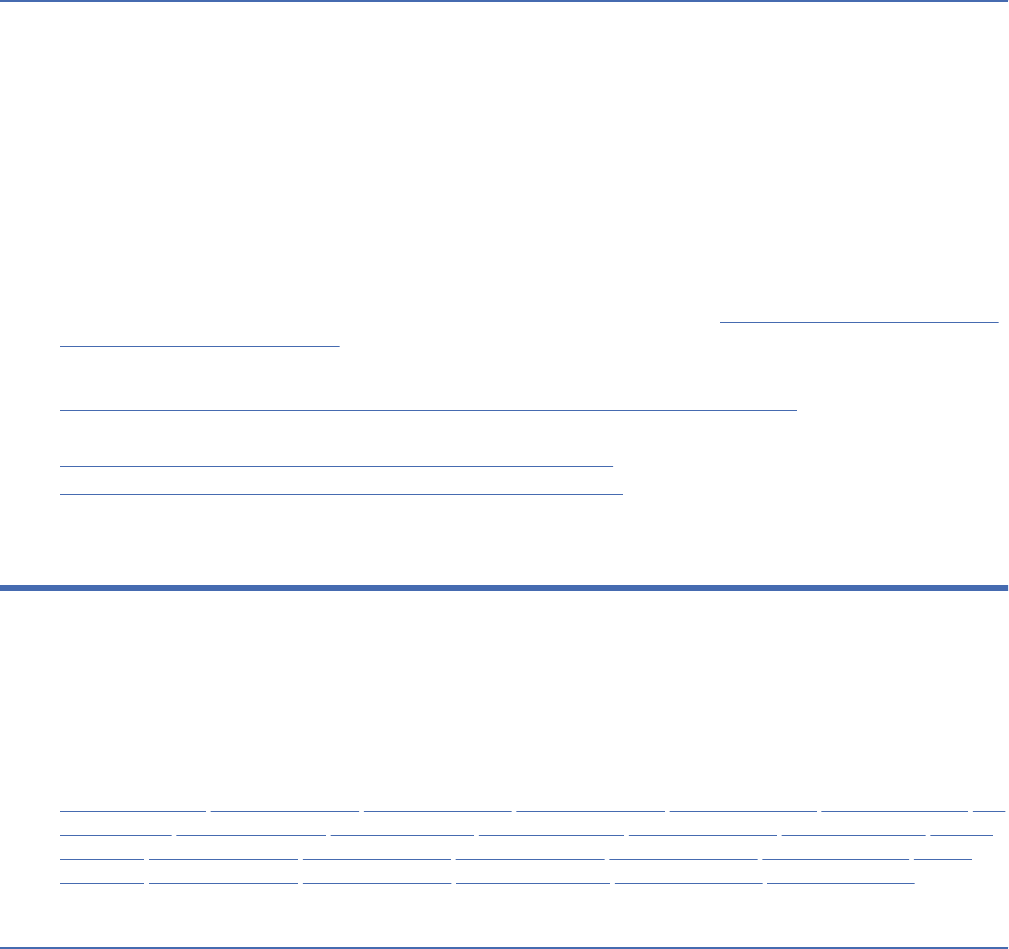
Troubleshooting local congurations and conguration
management
If you encounter errors or exceptions related to conguration management or local congurations, review
the log le for your IBM Engineering Lifecycle Management (ELM) application. Other problems can be
solved by working in a global conguration context.
Errors and exceptions related to conguration management are written to the log le of the
corresponding IBM Engineering Lifecycle Management (ELM) application. By default, this log le is named
ELM_application_name.log
Errors and exceptions related to links between artifacts are in the ldx.log le of the Link Index Provider
(LDX) application (/ldx).
Some problems, such as not seeing links between artifacts, are solved by switching to a global
conguration context from the Current Conguration menu on the toolbar.
For details and solutions to other problems that you might encounter, see Troubleshooting congurations
and conguration management .
Related concepts
Cross-project links to versioned artifacts after enabling conguration management
Related information
Unexpected local conguration in Current Conguration menu
Troubleshooting congurations and conguration management
Glossary
This glossary provides terms and denitions for IBM Engineering Lifecycle Management.
The following cross-references are used in this glossary:
• See refers you from a non-preferred term to the preferred term or from an abbreviation to the spelled-
out form.
• See also refers you to a related or contrasting term.
“A” on page 268 “B” on page 271 “C” on page 273 “D” on page 277 “E” on page 279 “F” on page 280 “G”
on page 282 “H” on page 282 “I” on page 283 “J” on page 285 “K” on page 285 “L” on page 285 “M” on
page 287 “O” on page 288 “P” on page 289 “Q” on page 291 “R” on page 291 “S” on page 294 “T” on
page 298 “U” on page 300 “V” on page 300 “W” on page 301 “X” on page 302 “Z” on page 302
A
abstract factory
A class that mediates between concrete classes and neutral interfaces by returning the concrete class
to an application and implementing a particular interface.
accept
1. In conguration management, to update a stream to take changes that someone else has
delivered.
2. In source control management, to add any change set to a repository workspace. The change set
can come from a stream, another repository workspace, or it can be attached to a work item.
access control
In computer security, the process of ensuring that users can access only those resources of a
computer system for which they are authorized.
268
Engineering Requirements Management DOORS Next

accessor method
A method that an object provides to dene the interface to its instance variables. See also mutator
method.
access permission
A privilege that permits the access or use of an object.
access right
A designation of the rights that users have, such as read, modify, create, delete, and admin (RMCDA).
access token
1. An object that contains security information for a process or thread, including the identity and
privileges of the user account that is associated with the process or thread.
2. A value used by the consumer to gain access to the protected resources on behalf of the user,
instead of using the user’s service provider credentials.
action pin
In activity diagrams, an element that represents information or physical objects flowing into, or out of,
action nodes.
actor
A representation of a user of a system, or an external component that sends information to, or
receives information from, the system.
actual
Pertaining to the project data such as costs, dates, and work that have occurred, as opposed to those
that are scheduled, or planned.
actual result
The behavior produced/observed when a component or system is tested. (ISTQB)
adapter
An intermediary software component that allows two other software components to communicate
with one another.
administrator user
A user account that bypasses all access rights checks. This account is used only when absolutely
necessary, such as in initial conguration tasks or if no other users can log in.
adoption item
A development work item that tracks when changes by one team must be adopted by another team.
agile software development
A software development methodology that focuses on collaboration and quality to produce complete
product increments at regular intervals, called iterations or sprints.
allowlist
A list of items, such as usernames, email addresses, or IP addresses, that are granted access to a
certain system or function. When an allowlist is used for access control, all entities are denied access,
except for those that are included in the allowlist.
ALM
See application lifecycle management
.
anchor
The rst item that is clicked when using multiple select actions to select a range of items.
Ant with Enterprise Extensions
A set of extensions to Apache Ant that makes it possible to build z/OS-based applications using Ant.
Apache Ant
A Java-based open-source tool from Apache Software Foundation that is used to automate build
processes.
application
One or more computer programs or software components that provide a function in direct support of a
specic business process or processes. See also application server.
Glossary
269

application lifecycle management (ALM)
An iterative and continuous process of coordinating people, processes, and tools with the goal of
delivering a software or systems project. This process involves planning and change management,
requirements denition and management, architecture management, software conguration
management, build and deployment automation, application security, and quality management.
The features of this process include traceability across lifecycle artifacts, process denition and
enactment, and reporting.
application server
A server program in a distributed network that provides the execution environment for an application
program. See also application.
archive
A backup copy of a module or project that can be stored on any computer and restored to a database.
argument
A value passed to or returned from a function or procedure at run time.
arithmetic operator
A symbol, such as + or -, that represents a fundamental mathematical operation. See also composite
expression.
array
A structure that contains an ordered collection of elements of the same data type in which each
element can be referenced by its index value or ordinal position in the collection.
artifact
An entity that is used or produced by a software or systems development process. Examples of
artifacts include designs, requirements, source les, plans, scripts, simulations, models, test plans,
and binary executable les. In an HTTP context, artifacts have a URI and are called resources. See
also back link
, baseline, component, conguration, conguration provider, conguration specication,
global conguration provider, revision, stream, version.
Artifacts page
A list of all of the artifacts in a project, as they exist at the project level.
artifact type
A class of objects that is specic to an artifact. For example, requirements management artifacts
include the following types: document, business process sketch, user interface sketch, user interface
sketch part, screen flow, storyboard, use case diagram, requirement, glossary, and term. See also
resource shape.
asset
InIBM Engineering Lifecycle Optimization - Publishing, an item that is used in or produced by the
document generation process. Assets include document templates, document specications, scripts,
and style sheets.
assign
To appoint or designate a prole or resource to an activity that is to be completed within a specied
period.
association
The semantic relationship between two or more classiers that species connections among their
instances.
association class
A model element that has both association and class properties. An association class can be seen as
an association that also has class properties, or as a class that also has association properties.
asynchronous
Pertaining to events that are not synchronized in time or do not occur in regular or predictable time
intervals.
attribute
1. A dened quality and values that can be assigned to an artifact. For example, a work item artifact
might have a 'priority' or 'severity' attribute.
270
Engineering Requirements Management DOORS Next

2. Descriptive information that provides important details about a module, requirement, discussion,
or element.
attribute data type
A descriptor of the information that can be stored in an attribute. Data types might dene integer
values, string values, date values, and other basic formats of data.
attribute denition
An object that users create to store information in addition to the system attributes where data is
stored.
attribute DXL
A scripting language that uses a DXL program to calculate the value of an attribute. One can use this
attribute in multiple columns and views.
attribute group
Convenience grouping of one or more attributes. For example, the attribute group "Address" might
include the attributes Street, City, State, and Zip.
attribute type
The specication in an attribute denition of the kind of data that can be stored in an instance of an
attribute. Examples include simple data types, such as string or number, as well as more complex
data types like currency or date.
audit
An examination of the changes that have been made to a artifact over time.
authorization
The process of granting a user, system, or process either complete or restricted access to an object,
resource, or function.
auto-deploy
1. An automated process that retrieves and packages build output, and then moves that output to
another location so that users can run or test it.
2. To automatically retrieve and package build output, then move that output to another location for
users to run or test it.
auto-resolve conflict
The automatic merging of conflicting changes to an item. Conflicts can only be automatically resolved
if the conflicting changes are made to two separate areas within the item.
away database
A database where a partition is imported and viewed or edited before being returned to the home
database.
B
back link
A relationship between artifacts in different products where each artifact stores a link that points to
the other artifact. See also artifact, back linking.
back linking
A process in which two links are used to dene a relationship between artifacts in different products.
Neither product has to query for these links because that information is provided in each product. See
also back link, link discovery.
backlog
In agile development, a list of features or technical tasks that are necessary for a project or release
that the development team assesses and prioritizes to assign work.
balanced binary tree
A tree structure that provides for rapid location of items in a text list.
base artifact
An artifact that is at the project level and not viewed as an embedded object in another artifact.
Glossary
271

base-aware mode
The process of comparing two units against each other, and against a base unit.
baseline
1. A read-only copy of a module, which contains the history of the module up to the time the baseline
was created.
2. In source control management, a permanent copy of a component in a particular repository
workspace or stream. A component baseline represents a conguration of a component at a
particular point in time.
3. An uneditable conguration of one or more components that captures a meaningful state of
artifacts. Teams can use baselines as a known conguration or an initial state for a new stream of
work. See also artifact, conguration, stream.
baseline comparison
A list that displays the differences between any two baselines of the same module, and includes
objects that have been modied, added, or deleted.
baseline set
A group of baselines that are treated as a single unit for project planning and management purposes.
baseline staging stream
See staging stream.
base type
A data type that controls the type of data that can be entered into an attribute. For example, an
attribute denition that is created using the Date base type can only store date values.
base unit
In a comparison of two projects, or portions of projects, a third project that acts as the basis of the
comparison.
batch mode
A command line option that allows Rational DOORS to start up without the graphical user interface
(GUI), run a specied DXL program, then stop. The product starts up by surpassing the login screen
and the database explorer.
behavioral model
A representation of the life-cycle behavior of the system as dened in statecharts.
black box
An abstraction of a device or system in which only its externally visible behavior is considered and not
its implementation or inner workings.
block denition diagram
A representation of the components of a system and the flow of information between components.
Block denition diagrams include blocks, actors, standard ports, dependencies, and flows. See also
block diagram
.
block diagram
A representation that denes the structure of a system and identies the large-scale organizational
parts of the system. Block diagrams show the flow of information between system components and
the interface denition through ports. See also block denition diagram, internal block diagram.
blocked
The status of a test case that cannot be run because the preconditions for running the test case have
not been met.
boilerplate text
Reusable text or code that is automatically added to a eld or template in response to an event.
branch
1. To create a stream for parallel or insulated development.
2. A distinct path leading to or originating from an element in a process model or UML diagram.
272
Engineering Requirements Management DOORS Next

breakpoint
A marked point in a process or programmatic flow that causes that flow to pause when the point is
reached, typically to allow debugging or monitoring.
build denition
An object that denes a build, such as a weekly project-wide integration build.
build engine
The representation of a build system that runs on a dedicated server.
business process sketch
A diagram that illustrates a directed flow of activities that are specied by using a subset of Business
Process Modeling Notation (BPMN). Two types of processes are supported: simple and business-to-
business.
business rule
A policy, constraint, or required operation that applies to a specic set of business conditions or
dependencies. An example of a business rule for a bank is that a credit check is not required when
opening an account for an existing customer.
C
callback function
Executable code that allows a lower-level software layer to call a function dened in a higher-level
layer.
calling thread
The task in progress in a multitasking environment.
call stack
The ordered list of all programs or procedures currently started for a job. The programs and
procedures can be started explicitly with the CALL instruction, or implicitly from some other event.
capability
A function or feature that is made available by an application, tool, or product.
CCM
See change and conguration management.
certicate
A digital document that binds a public key to the identity of the certicate owner, thereby enabling the
certicate owner to be authenticated. A certicate is issued by a certicate authority and is digitally
signed by that authority.
change and conguration management (CCM)
A systematic approach to establish and maintain the consistent performance of a system or product
throughout its lifecycle, and to effectively manage changes in that product or system.
change bar
An indicator that displays when an object was last changed.
change management
The process of controlling and tracking modications to artifacts.
change proposal system
A system that allows users to review modules and suggest changes to them.
change request
1. A request to change some aspect of the project, project plan, activity denition, or document.
2. A request from a stakeholder to change an artifact or process.
change set
A group of related changes to artifacts in a workspace or stream.
channel
A collection of test environment properties that describes a delivery platform in your test effort.
Glossary
273

check in
To save local changes in a change set that is part of a repository workspace. A checked-in change set
can later be shared with a team by delivering the change set.
class loader
Part of the Java virtual machine (JVM) that is responsible for nding and loading class les. A
class loader affects the packaging of applications and the runtime behavior of packaged applications
deployed on application servers.
class path
A list of directories and JAR les that contain resource les or Java classes that a program can load
dynamically at run time.
cleartool
The primary command-line interface to ClearCase and ClearCase LT version-control and conguration
management software.
clickjacking
The malicious practice of hiding links in clickable content to redirect users to an unexpected location.
CLM
See Collaborative Lifecycle Management.
CLM project
A project that was created using IBM Collaborative Lifecycle Management tools.
clone
1. To create a new version of an artifact in a different component. The new version has the same ID as
the original artifact. See also refactor
.
2. A new version of an artifact in a different component. The new version has the same ID as the
original artifact.
CM
See conguration management.
code churn
A report that shows the volume of changes in a project over time.
code respect
In programming, a feature that preserves the order of elements in the original code structure during
code generation.
cold standby
A recovery method in which backup servers with installed applications are in place and in a stopped
state.
Collaborative Lifecycle Management (CLM)
See Engineering Lifecycle Management.
comment
An annotation attached to an artifact, element, or a collection of elements.
compiler
A program that translates a source program into an executable program (an object program).
completed change set
A change set that can no longer be changed. Change sets can be shared with others only after they are
marked as a completed change set.
complexity attribute
An attribute that enables the selection of another attribute by which work items are sized. This
attribute is used in release plans to compute the progress of each plan.
component
1. In conguration management, a unit of organization for a reusable set of engineering artifacts. A
conguration of a component selects versions of the artifacts of that component. See also artifact,
component skew.
274
Engineering Requirements Management DOORS Next

2. In source control management, a grouping of related artifacts in a stream or repository workspace.
A component can contain any number of folders and les.
component skew
A situation that occurs when a conguration hierarchy contains different congurations of the same
component. See also component, conguration.
composite expression
In Q Language, a large expression that has been created from a series of smaller expressions. See also
arithmetic operator.
composite object
An object that contains other objects. For example a document object that contains not only text, but
also graphics, audio, image, and video objects, each of which can be manipulated separately as an
individual object.
composite type
A data type modeled using structural features instead of verbatim, language-specic text.
compress
To hide objects within a data hierarchy. A plus sign is used in a compressed section to indicate that
objects are hidden.
compression
The act of hiding child items of a selected object when the outline view is selected.
concrete class
A class that can be directly instantiated.
concrete factory
In object-oriented programming, a class that is used to create instances of another class. A concrete
factory isolates the creation of objects of a particular class into one place so that new functions can be
provided without widespread code changes.
concurrent-use license
A license that limits the number of users that can be connected to a resource concurrently.
cong spec
See conguration specication
.
conguration
1. A unique set of versions of artifacts. Congurations commonly identify one version of each
artifact in the set. The artifacts can be unchanging (from a baseline) or open to change (in
development). In some systems, congurations can be hierarchical, so that they contain other
congurations. See also artifact, baseline, component skew, conguration context, conguration
management, conguration provider, conguration specication, global conguration, global
conguration management, global conguration provider, local conguration, stream, version.
2. The set of artifacts in the component (not necessarily all of them), and the versions of those
artifacts that represents the state of a component.
conguration context
The current conguration that is being worked in, which is either a local conguration or a global
conguration. See also conguration, global conguration.
conguration layer
A customized set of metadata that can be used to congure data sources and variables.
conguration management (CM)
A process for grouping and tracking versioned artifacts across the development lifecycle to help
identify and track the artifacts in a specic version of a system. See also conguration, global
conguration management.
conguration provider
An application that manages sets of versioned artifacts, for example, change management or test
management artifacts. See also artifact, conguration.
Glossary
275

conguration specication (cong spec)
A set of rules that specify versions of artifacts. Commonly a conguration specication identies at
most one version of a given versioned artifact. See also artifact, conguration, version.
conflict
A situation in which two or more change sets independently modify the same item in a repository
workspace.
connection
1. A set of properties, such as host name, server launcher settings, and security settings that is
required to communicate with a specic remote system.
2. An asset that contains a data source URL and authentication details, which can be associated to
data sources.
3. In IBM Engineering Lifecycle Optimization - Engineering Insights views, the set of UI properties
that dene the look and feel of links between artifact containers.
consequence cost
The impact on cost if a risk is not addressed.
constraint block
An element that denes a generic or basic mathematical formula. Constraint blocks can be used to
create parametric diagrams.
constructor
In object-oriented programming, a special method used to initialize an object.
consumer
An entity that receives data from another entity.
content assist
A feature of some source editors that prompts the user with a list of valid alternatives for completing
the current line of code or input eld.
content link
A simple hypertext link in rich text or graphical artifacts that provides navigation only. See also trace
link.
content store
The database that contains the data needed to operate, such as report specications, published
models, and security rights.
context-aware search
A search function that uses natural language terms to search for work items and source code in Java,
C, C++, and COBOL. Regular expressions and wildcard characters are not required.
context root
The web application root, which is the top-level directory of an application when it is deployed to a
web server.
CR
See change request.
critical path
A series of activities that determines the earliest completion of a project; the critical path changes as
activities or tasks are completed ahead or behind the original schedule estimates.
CSV le
A text le that contains comma-separated values. A CSV le is commonly used to exchange les
between database systems and applications that use different formats.
custom user
A user type that has the same permissions of a standard user plus the ability to create projects,
archive data, partition data, create groups, create users, or manage the database.
cyclic array
An array whose elements are organized as a linked chain.
276
Engineering Requirements Management DOORS Next

D
dashboard
A user interface component that provides a comprehensive summary of pertinent information from
various sources to the user.
data collection
The process of collecting data from one or more sources, cleansing and transforming it, and then
loading it into a database.
data driven testing
A scripting technique that stores test input and expected results in a table or spreadsheet, so that
a single control script can execute all of the tests in the table. Data driven testing is often used
to support the application of test execution tools such as capture/playback tools. (ISTQB) See also
keyword driven testing.
data dump
A large amount of data transferred from one location or system to another.
data mart
A subset of a data warehouse that contains data that is tailored and optimized for the specic
reporting needs of a department or team. A data mart can be a subset of a warehouse for an entire
organization, such as data that is contained in online analytical processing (OLAP) tools.
data model
A common model that facilitates reporting of all types of data from multiple data sources.
data set denition
A Jazz model object that describes a data set on z/OS and is stored in the IBM Engineering Workflow
Management Jazz repository. If the data set already exists, the data set denition must specify just
the data set name. If the data set is new, the data set denition must specify both the name of the
data set, and the characteristics of the data set, such as record format. Every data set that a build
process references must correspond to a data set denition.
data set prex
An identier that, together with the data set name (indicated in the data set denition), species a
data set that is allocated to IBM Engineering Workflow Management. A data set prex can contain
multiple segments, including a high-level qualier (HLQ); for example, HLQ.PROD. With a prex
dened by a user, artifacts can be modied in isolation from other users.
data source
The source of data itself, such as a database or XML le, and the connection information necessary for
accessing the data.
data source schema
An XML or JSON based le that denes the structure and properties of the data source. See also XML
data conguration le.
data spill
An unintentional or unwanted disclosure of data.
data type
In programming languages, a descriptor of a set of values together with a set of permitted operations.
A data type determines the kind of value that a variable can assume or that a function can return.
data warehouse
A subject-oriented collection of data that is used to support strategic decision making. The warehouse
is the central point of data integration for business intelligence. It is the source of data for data marts
within an enterprise and delivers a common view of enterprise data.
decision node
A representation of an if-then-else condition. A decision node splits a single transition in a statechart
or activity diagram into several branch transitions.
defect
A project element that allows stakeholders to track bugs and bug xes.
Glossary
277

defect aging
A report that helps track patterns in defects, which can be used to take corrective action for reducing
both defect resolution time and number of defects.
defect report
A document reporting on any flaw in a component or system that can cause the component or system
to fail to perform its required function. (ISTQB)
delete
To mark an item to be purged from the database.
deliver
1. In source control management, to conduct an outgoing flow of change sets and baselines from a
repository workspace to a stream or to another repository workspace.
2. To add changes to a stream, or make them available to be accepted into a stream.
dependencies linker
An extension to the link wizard that allows dependencies to be created between particular model
elements.
dependency
A link between interrelated projects activities. Activities with these links depend on the start and
nish dates of at least one other element and therefore cannot be completed without taking the other
into consideration.
dependency build
A build denition that saves time and system resources by only building artifacts that need to be
rebuilt based on what has changed since the last successful build. Changes to a program's source
or dependencies, and deletion or modication of a program's output will be detected and cause the
program to be rebuilt.
deployment
A process that retrieves the output of a build, packages the output with conguration properties, and
installs the package in a pre-dened location so that it can be tested or run.
deployment plan
A template of a virtual service denition.
diagram connector
A connector that joins several segments in the same statechart to facilitate jumps to different parts of
a diagram without drawing complex transitions and cluttering the statechart.
difference element
An element that exists in both sides of a comparison, though some of its elds or properties are
different.
discard
To remove a change set from a repository workspace.
discussion
A mechanism for reviewers to exchange views about the content of a module or an object, within the
module or object itself.
document
1. An item that can be stored, retrieved, and exchanged among systems and users as a separate unit.
It can be any multimedia digital object. A single document can include varied types of content,
including for example, text, and images.
2. The output generated from current data with a single click that is formatted by a report denition.
Documents can be in Microsoft Word, Excel, HTML, PDF or XSL-FO formats. See also report
.
document generation
The process of applying a template to a data source to generate a document-style report.
document mode
A default display mode for formal modules. Data is displayed in a table with rows and columns.
278
Engineering Requirements Management DOORS Next

document specication
The denition of document templates, data sources, and output formats used to create a report.
DOORS extension language (DXL)
A scripting language used in Rational DOORS.
downstream
Pertaining to a direction that goes with the flow of a development process that moves from
requirements to designs to implementation to tests. For example, tests are downstream from
requirements. See also upstream.
duplicate set
A set consisting of one primary change proposal and any number of duplicates. In a duplicate set, only
the primary change proposal is reviewed and applied.
duration
A period of time during which a project element continues. It is calculated as the nish time minus the
start time.
DXL
See DOORS extension language.
DXL library
A library of DXL programs that can be used to manipulate and manage Rational DOORS data. The
library includes example programs and templates. User-dened DXL programs can also be stored in
the DXL library.
E
Eclipse
An open-source initiative that provides independent software vendors (ISVs) and other tool
developers with a standard platform for developing plug-compatible application development tools.
editable section
A section of objects in a module that does not inherit access from the parent and can be locked and
edited independently of other objects when the module is opened in shareable edit mode.
effort
The estimated hours of work required for an activity. Effort is calculated based on the specied
duration (in days) of the activity, and the number of working hours per day specied in the project
calendar. See also work.
electronic signature (eSignature)
An electronic stamp that is added to email messages, elds, or sections that veries that the person
who originated the message is the author and that no one has tampered with the data.
element
1. Palette items that can be added to a template,.
2. A constituent of a model.
ELM
See Engineering Lifecycle Management.
encapsulation
In object-oriented programming, the technique that is used to hide the inherent details of an object,
function, or class from client programs.
Engineering Lifecycle Management (ELM)
The integration of products on Jazz technology to connect the work of analysts with development and
test teams. These integrations provide a common approach to artifact linking, dashboards, security,
and user interface frameworks.
entity tag (ETag)
An HTTP header that is used for web cache validation and conditional requests from browsers for
artifact resources. These headers are unique and can be quickly compared to determine whether
Glossary
279
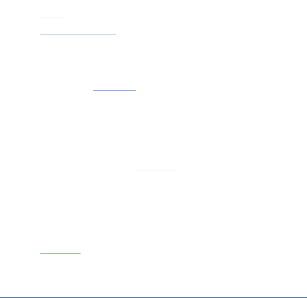
two artifact versions are the same. ETags can also help prevent artifacts from being overwritten by
simultaneous updates.
entry criteria
The set of generic and specic conditions for permitting a process to go forward with a dened task,
e.g. test phase. The purpose of entry criteria is to prevent a task from starting which would entail more
(wasted) effort compared to the effort needed to remove the failed entry criteria. (ISTQB)
epic
In agile development, a work item that denes a big use case with a large or unknown amount of
work, which is often completed over several sprints. Epics can be divided into stories.
eSignature
See electronic signature.
ETag
See entity tag.
ETL
See extract, transform, and load.
event
An occurrence of signicance to a task or system. Events can include completion or failure of an
operation, a user action, or the change in state of a process.
execution result
The behavior or response that is produced or observed when a component or system is tested. This
behavior and information regarding the test run such as the weight distribution and result details are
also recorded. See also expected result
.
exit criteria
The set of generic and specic conditions, agreed upon with the stakeholders, for permitting a process
to be ofcially completed. The purpose of exit criteria is to prevent a task from being considered
completed when there are still outstanding parts of the task which have not been nished. Exit criteria
are used to report against and to plan when to stop testing. (ISTQB)
expand
To display information collapsed under a category name or parent document.
expected result
The behavior predicted by the specication, or another source, of the component or system under
specied conditions. (ISTQB) See also execution result.
extension
A client-side element or function that is not installed with a system, but instead is authored by a
system user.
external contribution
The contribution of a global conguration that resides on one Global Conguration Management
server to a global conguration that resides on a different Global Conguration Management server.
external link
A connection from an object to an entity or resource that is outside the Rational DOORS database.
extract, transform, and load (ETL)
See data collection.
extra resource
A resource that is included in the Lifecycle Query Engine (LQE) index but not in the Tracked Resource
Set (TRS) feed.
F
factory
In object-oriented programming, a class that is used to create instances of another class. A factory is
used to isolate the creation of objects of a particular class into one place so that new functions can be
provided without widespread code changes.
280
Engineering Requirements Management DOORS Next

fail
A test is deemed to fail if its actual result does not match its expected result. (ISTQB)
failed patch
A patch that is out of sequence because the entity tags (ETags) of artifacts in the Lifecycle Query
Engine (LQE) index and artifacts in the Tracked Resource Set (TRS) feed do not match. LQE cannot
apply such patches to artifacts in the LQE index.
favorite
A project, folder, or module that is used frequently and stored in a specic list.
lter
A device or program that separates data, signals, or material in accordance with specied criteria.
ne-grained component
See component.
nish-to-start
A dependency type between two project elements where the predecessor element must nish before
the successor element can start.
flow
An arrangement between two workspaces or between a workspace and a stream that enables users
to deliver and accept change sets.
flow target
A source or destination of incoming and outgoing change sets. In a team setting, most workspaces
have flow targets. The flow target can be another repository workspace or a stream. Streams have
flow targets only if they are part of a stream hierarchy.
folder
A named collection of related modules that can be retrieved, moved, and otherwise manipulated as
one entity.
footprint
The amount of computer storage that is occupied by a computer program. For example, if a program
occupies a large amount of storage, it has a large footprint.
fork
In UML diagrams, a node that is used to model a single flow of control that divides into two or more
separate but simultaneous flows.
formal module
A module that stores objects and their associated attribute and link information.
formal review
A review characterized by documented procedures and requirements, e.g. inspection. (ISTQB)
friend
An entity that has an established connection to another entity for communication. For example, a
server can be a friend to another server.
friend class
A class in which all member functions are granted access to the private and protected members of
another class. It is named in the declaration of another class and uses the keyword friend as a prex
to the class.
full capacity licensing
A method of licensing in which the licensee must obtain PVU entitlements that are sufcient to cover
all activated processor cores in the physical hardware environment that are made available to or
managed by the licensed program.
functionality testing
The process of testing to determine the functionality of a software product. (ISTQB) See also security
testing.
Glossary
281

function call
An expression that transfers the path of execution from the current function to a specied function
(the called function). A function call contains the name of the function to which control is transferred
and a parenthesized list of values.
function object
See functor.
functor
An object that can be called or invoked as if it were a function.
functor class
The class that is generated when the functor-based code reuses code generation functionality for
activity diagrams of classes. The new class implements an activity diagram on the class level.
G
gadget
A proprietary widget that works under specic conditions or that is designed to a certain standard,
such as a dashboard widget based on the OpenSocial standard. See also widget.
Gantt chart
A graphical representation of a project timeline and duration in which schedule data is displayed as
horizontal bars along a time scale.
gap
In source control management, a state in which a target workspace or stream is missing preceding
change sets for a change set that is being accepted or delivered. When a gap occurs, the change set
cannot be accepted or delivered; it must be applied as a patch, which creates a new resulting change
set.
GCM
See global conguration management.
global conguration
A conguration that gathers congurations from multiple tools, so you can dene all the relevant
artifacts for a system. Global congurations can establish the same context across all tools when
each tool stores artifacts in otherwise unrelated congurations. See also conguration, conguration
context, global conguration management.
global conguration management (GCM)
A process for gathering congurations from multiple tools that helps visualize and manage
relationships in the development lifecycle by tracking artifact links across lifecycle tools and stages.
See also conguration, conguration management, global conguration.
global conguration provider
A conguration provider that coordinates contributions from multiple conguration providers. See also
artifact, conguration.
graphic difference
A visual difference that does not have an effect on the logic of a model.
graphics mode
An alternative display mode for formal modules. The module structure is displayed as a tree and each
object in the module is represented as a box showing a selected attribute.
group
A logical organization of users whose membership allows them to perform the same activities or
provide the same authority to access resources.
H
harden
To secure a system by reducing its vulnerabilty.
282
Engineering Requirements Management DOORS Next

heading
An artifact in a module that is automatically numbered and displayed prominently. A best practice is
for headings to be their own artifact type.
heap
An area of storage that is allocated with a lifetime unrelated to the execution of the current routine.
The heap consists of the initial heap segment and zero or more increments.
heartbeat
A signal that one entity sends to another to convey that it is still active.
history
The recorded changes to modules and objects, which can be viewed on module and object properties
sheets.
home database
A database where a partition denition is created. This is the database where the master copy of the
data is stored.
home GCM server
See home Global Conguration Management server.
home Global Conguration Management server (home GCM server)
The Global Conguration Management server that an application can contribute congurations to.
Typically, this server is the one registered with the Jazz Team Server that is associated with the
application.
hook
An empty script in which code can be entered.
hotspot
Text or a picture in a rich-text eld that a user can click to perform an action, run a formula or script, or
follow a link.
hot standby
See idle standby
.
I
idle standby
A recovery method in which backup servers with installed applications are in place and started, but in
an idle state.
idle timer
A timer used by the operating system factory for simulated-time modeling.
if-then-else statement
A statement that compares two or more sets of data and tests the results. If the results are true, the
THEN action is taken; if not, the ELSE else action is taken.
impact analysis
The identication of how a change to one item affects other, related items.
impediment
An item that prevents progress or a work item to track something that prevents progress.
incoming change set
A change set in a stream or repository workspace that flows to a user repository workspace. An
incoming change set is present in a workspace flow target, but not in the workspace itself.
incoming link
A link from the current (target) artifact to a source artifact, such as a Validated By link from a
requirement to a test case. See also outgoing link.
index
A set of URIs that point to resources in one or more lifecycle tool so that the set of URIs can be
queried together. Access depends on the identity of the authenticated user.
Glossary
283

inheritance
1. The process of passing access rights to a child item from a parent item by default.
2. An object-oriented programming technique in which existing classes are used as a basis for
creating other classes. Through inheritance, more specic elements incorporate the structure and
behavior of more general elements.
inherited value
An attribute value that is inherited from the parent object by a child object.
in-link
A link to an object in a module from another object in the same module, or from an object in a
different module in the database.
in-place editing
A function in which objects, graphs, or tables can be edited without exiting the currently active
application.
instance
An entity to which a set of operations can be applied and that has a state that stores the effects of the
operations.
instance line
A vertical timeline in a sequence diagram that shows the sequence of messages that an object
processes and the states that it enters over its lifetime.
internal block diagram
A diagram that shows the internal structure or decomposition of a block into its parts or subsystems.
See also block diagram
.
internal contribution
The contribution of a global conguration to another where both congurations reside on the same
Global Conguration Management server.
interrupt
Suspension of a process, such as execution of a computer program, caused by an external event and
performed in such a way that the process can be resumed.
interrupt service routine (ISR)
A software routine that receives and examines interrupts and determines how to handle them.
invalid
In linking and traceability, pertaining to a manually set status when two artifacts do not satisfy the
meaning of the link between them. The contents of at least one artifact must change to satisfy the
link. See also suspect, valid, validity summary.
ISPF client
An SCM client used for working with source code from the ISPF interface. The ISPF client can be used
to load, edit, check in, and deliver source. It can also be used to access build functions and associate
work items with changes.
ISR
See interrupt service routine.
iteration
In agile development, a set period of time in which work is completed. Sprints can vary in length, for
example, from 1 to 4 weeks, but typically have a xed duration within a project.
iteration plan
An artifact that shows the work items and additional unstructured information for a team or project
area within a development phase.
iterator
A class or construct that is used to step through a collection of objects one at a time.
284
Engineering Requirements Management DOORS Next
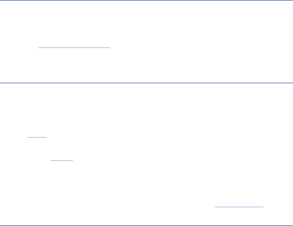
J
Java Database Connectivity (JDBC)
An industry standard for database-independent connectivity between the Java platform and a wide
range of databases. The JDBC interface provides a call level interface for SQL-based and XQuery-
based database access.
JDBC
See Java Database Connectivity.
join
In UML diagrams, a node that models two or more flows of control that unite into a single flow.
K
kernel
The part of an operating system that contains programs for such tasks as input/output, management
and control of hardware, and the scheduling of user tasks.
keystore
In security, a le or a hardware cryptographic card where identities and private keys are stored, for
authentication and encryption purposes. Some keystores also contain trusted or public keys. See also
keytool.
keytool
A utility used for creating SSL encryption keys and managing the keystores where they are maintained.
See also keystore.
keyword
A statement or group of statements that one can reuse in test scripts.
keyword driven testing
A scripting technique that uses data les to contain not only test data and expected results, but also
keywords related to the application being tested. The keywords are interpreted by special supporting
scripts that are called by the control script for the test. (ISTQB) See also data driven testing.
L
label specier type
An enumerated attribute type that the user selects to congure electronic signatures. The
enumerated attribute type is comprised of the values from which signatories can choose.
language denition
A Jazz model object that serially connects the translators used to build an artifact. The association of
a language denition to an artifact provides instructions for how the artifact should be built.
last mile
In communications, the nal part of the network that delivers services to end users.
layout DXL
A layout that uses a DXL program to calculate values, which are then shown in a column, typically to
construct traceability or impact analysis reports. The DXL program is associated with one column, not
with an attribute.
level
In a database, the successive vertical dependencies in a hierarchical structure.
library
A system object that serves as a directory to other objects. A library groups related objects, and
allows users to nd objects by name.
library denition
A system object that describes an IBM i Library, and is stored in the IBM Engineering Workflow
Management Jazz repository. Every library that a build process references must correspond to a
library denition.
Glossary
285

lifecycle
The complete process for planning, creating, testing, and deploying software or systems.
lifecycle application
A tool that manages the work for a phase of the development lifecycle. See also lifecycle tool.
lifecycle index
A set of URIs that point to resources in one or more lifecycle tools so that the set of URIs can be
queried together. Access depends on the identity of the authenticated user.
Lifecycle Query Engine (LQE)
A component that indexes and searches for assets that are stored in any tool that can support the
Tracked Resource Set (TRS) specication.
lifecycle tool
An application that manages the work for a phase of the development lifecycle. See also lifecycle
application.
lifeline
In a sequence diagram, a connectable element (an object or a role) that describes how each instance
participates in the interaction over a period of time.
link
1. A bidirectional indication of dependency between two or more requirements in the same module
or different modules.
2. In a linked data system, a relationship between two artifacts as expressed by a unique URI.
link discovery
A capability that enables external applications that are integrated with Rational DOORS to nd OSLC
links in Rational DOORS and make them visible in the external applications. See also back linking
.
linked data
A method of publishing structured data so that it can be linked to and from other data sets.
linker
A program that resolves cross-references among separately compiled object modules and then
assigns nal addresses to create a single executable program.
link index provider (LIP)
An application that indexes links to artifacts in contributing applications and makes those links
available to other applications.
linkset
A division of information in each module that contains information about the links from one particular
module to another.
linkset pairing
A specication for which link module should be used when links are created between certain
modules.
links explorer
A capability for visualizing relationships among artifacts and modifying those relationships.
link type
A denition of a relationship between artifacts. A link type has a relationship label that indicates how
the linked artifacts are related.
link validity
See validity.
LIP
See link index provider.
load rule
1. An entry in a load rule le that determines how an item from a repository workspace, such as a le,
folder, or symbolic link, is loaded into a local sandbox.
286
Engineering Requirements Management DOORS Next
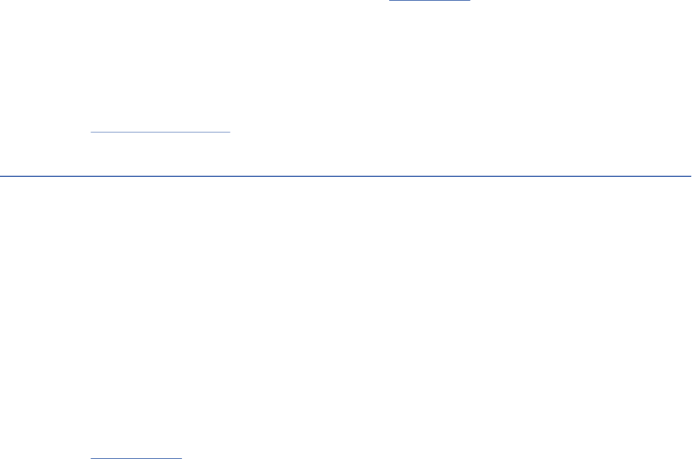
2. A statement in the cong spec that species an element or subtree to load into a snapshot view.
Cong specs can have more than one load rule.
local change
A change to an element that only exists in a sandbox and has not yet been committed to the
repository workspace.
local conguration
A conguration that's managed by one tool. See also conguration.
local heap
A preallocated, continuous, bounded chunk of memory that has the capacity to hold a user-dened
number of objects.
logical difference
A change that effects the logic of a model.
LQE
See Lifecycle Query Engine.
M
make command
A statement that can be used to build an application.
Managed Bean (MBean)
In the Java Management Extensions (JMX) specication, the Java objects that implement resources
and their instrumentation.
marshal
To convert an object into a data stream for transmission over a network.
master conguration
The conguration data held in a set of les that form the master repository for either a deployment
manager prole or a stand-alone prole. For a deployment manager prole, the master conguration
stores the conguration data for all the nodes in the network deployment cell.
master page
The denition of the header, footer, and watermark for a document to generate.
MBean
See Managed Bean.
merge
To combine some or all of the content of one stream or baseline into another stream.
metaclass
A class whose instances are classes. Metaclasses are typically used to construct metamodels.
metadata
Data that describes the characteristics of data; descriptive data.
metadata model
A set of related dimensions, query subjects, and other objects that represent data for reporting
applications.
migrator
In the asynchronous migration task, a process that runs to upgrade data for a specic artifact type.
milestone
A signicant event in a project or process that is used to determine progress toward goals.
minimap
In a large diagram, a view that shows a smaller version of the entire diagram to orient users to their
current location in the diagram.
missing resource
A resource that is included in the Tracked Resource Set (TRS) feed but not in the Lifecycle Query
Engine (LQE) index.
Glossary
287
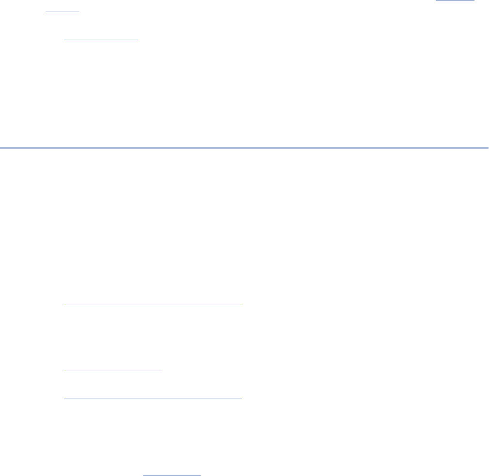
model
A representation of a process, system, or subject area, typically developed for understanding,
analyzing, improving, and replacing the item being represented. A model can include a representation
of information, activities, relationships, and constraints.
module
A structured document that is composed of multiple requirement artifacts. Structure can be created in
a module by modifying the order and hierarchy of the artifacts.
mutator method
A method that an object provides to dene the interface to its instance variables. See also accessor
method.
mutex
See mutual exclusion.
mutual exclusion (mutex)
A flag used by a semaphore to protect shared resources. The mutex is locked and unlocked by threads
in a program.
MXBean
An MBean (managed bean) that references a predened set of data types so that any client, including
a remote client, can use the bean.
O
OAuth
An HTTP-based authorization protocol that gives applications scoped access to a protected resource
on behalf of the resource owner, by creating an approval interaction between the resource owner,
client, and resource server.
object
A self-contained piece of information in a module that can be arranged in a hierarchy and linked to
show dependencies.
Object Request Broker (ORB)
In object-oriented programming, software that serves as an intermediary by transparently enabling
objects to exchange requests and responses.
Open Services
See Open Services for Lifecycle Collaboration.
Open Services for Lifecycle Collaboration (Open Services, OSLC)
An open community that facilitates collaboration and standardization across the delivery lifecycle by
building practical specications for integrating software.
ORB
See Object Request Broker.
OSLC
See Open Services for Lifecycle Collaboration.
outgoing change set
A change set in a repository workspace that flows to a stream or to another repository workspace. An
outgoing change set is present in a workspace, but not in a workspace flow target.
outgoing link
A link from the current (source) artifact to a target artifact, such as a Satises link from a test case to a
requirement. See also incoming link.
outgoing synchronization
A process by which changes that users make to work items are propagated to the ClearQuest user
database.
outlining
A method of reducing the amount of text that is displayed in a module so that the module structure
can be seen clearly.
288
Engineering Requirements Management DOORS Next

out-link
A link from an object in a module to another object in the same module, or to an object in a different
module in the database.
P
package
1. A product or component that is specically designed for installation by IBM Installation Manager.
2. A subset of a project that is created to make metadata available to users. Different packages can
be created so different user groups can create the reports they need.
3. A set of tasks that a person is allowed to perform.
page
In a graphical interface, a predened display image that typically provides elds and controls that
help users accomplish tasks.
parameter
1. In UML modeling, a specic argument that passes information between behavioral features of
models, such as operations.
2. A value or reference passed to a function, command, or program that serves as input or controls
actions. The value is supplied by a user or by another program or process.
parametric diagram
A diagram of the mathematical relationships among the parts of a system that are being designed.
parm
See parameter.
partition denition
A specication of the modules to be included in a partition le. It denes the access that is allowed
to each module in the partition, and the access that is allowed to the attributes and views in each of
those modules.
pass
1. A test is deemed to pass if its actual result matches its expected result. (ISTQB)
2. The status of a test when the actual results match the expected result.
patch
A type of change event in the Tracked Resource Set (TRS) feed that has information about minor
modications to artifacts.
pattern
A sequence of characters used either with regular expression notation or for path name expansion, as
a means of selecting various characters strings or path names, respectively. The syntaxes of the two
patterns are similar, but not identical.
personal stream
In conguration management, a modiable conguration of artifacts that is insulated from public
streams. Users can test their changes before delivering them to a public stream.
PLE
See product line engineering.
plug-in
A separately installable software module that adds function to an existing program, application, or
interface.
port
A distinct interaction point between a class and its environment or between the behaviour of a class
and its internal parts.
Glossary
289

post-command condition
Environmental and state condition that must be fullled after document generation. See also pre-
command condition.
postcondition
Environmental and state conditions that must be fullled after the execution of a test or test
procedure. (ISTQB) See also precondition.
pre-command condition
Environmental and state condition that must be fullled before document generation. See also post-
command condition.
precondition
Environmental and state conditions that must be fullled before the component or system can be
executed with a particular test or test procedure. (ISTQB) See also postcondition.
predecessor
An activity in a dependency relationship that logically precedes another.
priority
In software and systems development, a rank assigned to requirements or work items to determine
the order in which they are worked on.
processor core
A single processing unit on a chip with multiple processing units.
processor value unit (PVU)
A unit of measure that is assigned to each processor core for software licensing purposes. PVUs vary
according to chip architecture. See also subcapacity
.
product
Something produced that is marketed or sold. A product is formed from a particular conguration of
component parts, which can be software applications, physical parts, or services. A complex product
might contain multiple systems. A system might be made up of multiple products. See also product
line, system, variant.
product backlog
See backlog.
product family
See product line.
product line
A group of closely related products that are variants of each other. Products that make up a product
line are often produced from a common base or architecture. See also product, system, variant,
variation point.
product line engineering (PLE)
A method for designing and developing a line of products that are based on common components
with variations in features and functions to provide a diverse product line efciently at a reduced
development cost.
project
1. A temporary endeavor or initiative created and managed to achieve an organization's objectives.
2. An organized collection used to group folders or packages. Projects are used for building, version
management, sharing, and organizing resources related to a single work effort.
project area
An area in the repository whereinformation about one or more software projects is stored.
project area conguration
See local conguration.
project manager
A type of Rational DOORS user who can perform a limited set of management tasks.
290
Engineering Requirements Management DOORS Next
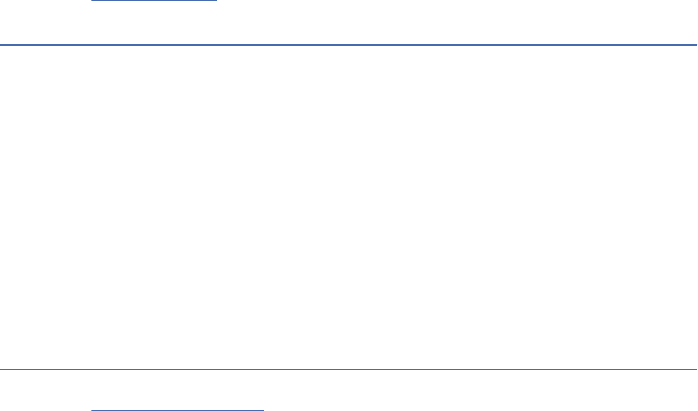
project release plan
An artifact that shows plan items and additional unstructured information for a team or project area
and all related child team areas and iterations.
project snapshot
A subset of a baseline that identies artifacts that have been approved or assigned to a milestone or
other meaningful event.
promotion
A mechanism for moving binaries, source code, source code data, build maps, output, Partitioned
Data Sets (PDS) on z/OS or libraries on IBM i, and other build artifacts up the development-test-
production hierarchy on a z/OS or IBM i system.
property
A characteristic of an object that describes the object. A property can be changed. Properties describe
an object name, type, value, or behavior, among other things.
proposal
An item that suggests a change to an object in a module.
purge
To permanently delete data from a location, system, or database.
PVU
See processor value unit.
Q
Q Language
A language used to write advanced conditions and create advanced statements about attributes.
QM
See quality management.
quality management (QM)
A systematic approach to build quality into a solution and assess the quality of deliverables and
processes throughout a project lifecycle.
query
1. A way of retrieving information from the lifecycle index of artifacts, such as products, work items,
requirements, design models, and test cases. The resulting list of artifacts can be used to populate
a view, run a report, perform an analysis, and more.
2. A specication for a set of data retrieved from a data source.
queue tail
The last item in a queue.
R
RDF URI
See Uniform Resource Identier.
reactive class
A composite class that has a statechart and consumes events.
reactive object
An object that is a composite, and can receive and process events. Reactive objects have state-based
behavior that is dened in a statechart.
realization relationship
In UML, a dependency relationship in which one class implements the behavior that another class
species.
Glossary
291

rebase
1. A source control operation that makes a development work area current with the set of versions
represented by a more recent baseline in another stream, usually the project's integration stream
or a feature-specic development stream.
2. To recalculate the base resources of a tracked resource set.
reconcile
To compare and optionally update the links in an artifact that point to other artifacts. When a source
artifact is reconciled, its links are compared with the states of its associated target artifacts in another
application. After reconciliation, the changes can be synchronized or ignored, or the associated
artifacts can be updated. See also synchronize.
redact
See scrub.
redline markup
A function in Rational DOORS that highlights both inserted and deleted text.
refactor
To make changes across a set of artifacts without changing the behavior of the application or its
relationships to other elements. See also clone.
repo
See repository
.
report
1. In Rational Publishing Engine, the specication fof the parts of a document to generate, as dened
by templates such as for the table of contents, front cover, body, index, and back cover. See also
document.
2. A set of data deliberately laid out to communicate business information.
reportable shape
A user-dened set of conditions that denes which attributes and link types are available for use by
external reporting tools.
report server
An application server that hosts reports and report editors.
report template
A template that is used to create reports. Parameters in the report template are specied when the
report is created or run.
repository (repo)
A persistent storage area for data and other application resources.
repository workspace
A repository object that includes one or more components. Repository workspaces are typically
used by individual team members to contain their changes in progress. Team members deliver their
changes from their repository workspace to the stream and accept changes from other team members
into their repository workspace from the stream. Every repository workspace has an owner, and only
the owner can make changes in the workspace. See also workspace.
Representational State Transfer (REST)
A software architectural style for distributed hypermedia systems like the World Wide Web. The term
is also often used to describe any simple interface that uses XML (or YAML, JSON, plain text) over
HTTP without an additional messaging layer such as SOAP.
ReqIF
See Requirements Interchange Format.
request token
A value that is used by the consumer to obtain authorization from the user and that is exchanged for
an access token.
292
Engineering Requirements Management DOORS Next

requirement
1. A condition or capability that a system must provide. This condition is either derived from user
needs or stated in a contract, standard, specication, or other document.
2. A condition or capability needed by a user to solve a problem or achieve an objective that must be
met or possessed by a system or system component to satisfy a contract, standard, specication,
or other formally imposed document. (ISTQB)
Requirements Interchange Format (ReqIF)
An XML le format and workflow to exchange requirements, metadata, and status between software
tools from different vendors.
requirements management (RM)
A systematic approach to eliciting, organizing and documenting the requirements of a system, and
establishing and maintaining agreement between the customer and the project team on changes to
those requirements.
Requirements Management Rich Text Format (RM-RTF)
The native format of textual requirements in the RM system.
resolve
To reconcile conflicts among change sets in a repository workspace.
resource
1. A specic XML entity in an XML data source. A resource can be associated with an XML schema and
can be used to map a data source to a relational database table to create reports.
2. See artifact
.
3. A person who can be assigned to work breakdown structure (WBS) elements.
resource denition
1. See data set denition.
2. See library denition.
resource group
A collection of XML sources from a product that share a common base web address. The web address
determines the connection between the product data and the relational database that is used to
create reports.
resource leveling
During plan scheduling, the process of resolving over-allocated resources by delaying tasks until the
assigned resources are available to work on them.
resource shape
In the Open Services for Lifecycle Collaboration (OSLC) specication, a high-level description of the
contents, properties, and constraints of a resource. See also artifact type.
response le
A le that can be customized with the setup and conguration data that automates an installation.
During an interactive installation, the setup and conguration data must be entered, but with a
response le, the installation can proceed without any intervention.
REST
See Representational State Transfer.
resume
To reinstate a previously suspended change set to a repository workspace.
reverse proxy
An IP-forwarding topology where the proxy is on behalf of the back-end HTTP server. It is an
application proxy for servers using HTTP.
revision
A version of an artifact that is designed to replace an earlier version, such as a model year of a car or a
revised requirement. See also artifact, version.
Glossary
293
rich hover
An in-context preview of the content that a link points to when the cursor hovers over the link.
risk
An ongoing or upcoming concern that has a signicant probability of adversely affecting the success of
major milestones.
RM
See requirements management.
RM-RTF
See Requirements Management Rich Text Format.
roll back
To revert a software package to a previously installed version.
roundtripping
A process of converting data from one type to another and then back to the rst type while preserving
the format and content of the data.
S
sandbox
An area on a le system where a developer can modify and test items in isolation, before returning
them to the source control component and sharing them with other developers. A sandbox is a
reflection of all or part of a repository workspace on disk.
scalar
Pertaining to a single data item.
schedule constraint
A limit to set controls on the start and nish dates on project tasks. Available constraints are as soon
as possible and nish-no-later-than.
schema
1. See XML schema.
2. A specication for the structure and semantics of some related data. The schema is used to
validate or otherwise understand a group of data.
SCIM
See System for Cross-domain Identity Management.
SCM
1. See source control management.
2. See software conguration management.
screen flow
A representation of a sequence of user-driven software processes that are presented as a series of
graphical user interfaces.
scrub
To permanently delete all instances of and references to specic data, such as removing all traces of
sensitive information from an application.
scrum
1. An agile software programming method that uses small, self-organizing, cross-functional teams,
and iterative, incremental practices.
2. A daily, informal meeting between stakeholders in an agile development project. Participants must
include a scrum master, the product owner, and the team and might include the product manager
and other stakeholders.
search path
A list of the libraries provided to a IBM Engineering Workflow Management build to locate artifacts for
the build, including the load library and object library for an i Project on IBM i.
294
Engineering Requirements Management DOORS Next

Secure Sockets Layer (SSL)
A security protocol that provides communication privacy. With SSL, client/server applications can
communicate in a way that is designed to prevent eavesdropping, tampering, and message forgery.
security certicate
A certicate containing information used by the SSL protocol to establish a secure connection. The
information can include who a certicate belongs to, who issued it, its unique serial number, its valid
dates, and its encrypted 'ngerprint’ that is used to verify the contents of the certicate.
security testing
Testing to determine the security of the software product. (ISTQB) See also functionality testing.
semaphore
An entity used to control access to system resources. Processes can be locked to a resource with
semaphores if the processes follow certain programming conventions.
server friend
A server that allows other servers to communicate with it. After cross-server communication is
congured, project areas and artifacts can be linked across servers.
severity
In software and systems development, a measurement of the importance for a unit of work, for
example, critical, high, medium, or low.
shareable edit
A method of editing where users can lock different sections in the same module and edit those
sections.
signature
The name and parameters of a behavioral feature.
silent installation
An installation that does not send messages to the console but instead stores messages and errors in
log les. A silent installation can use response les for data input.
Simple Cloud Identity Management
See System for Cross-domain Identity Management
.
single sign-on (SSO)
An authentication process in which a user can access more than one system or application by entering
a single user ID and password.
singleton
A class that can be instantiated only once. A singleton class cannot be an interface.
skeleton code
A server-side code.
skipped resource
A resource that cannot be fetched with an HTTP GET request to the application by Lifecycle Query
Engine.
smart card
An intelligent token that is embedded with an integrated circuit chip that provides memory capacity
and computational capabilities.
snapshot
1. In IBM Engineering Lifecycle Optimization - Engineering Insights, a saved, shareable instance of a
view that shows artifacts and their relationships at the moment that instance is saved. A snapshot
can be refreshed to show current artifacts and relationships.
2. See baseline.
3. In source control management, a collection of baselines that represents the conguration of a
repository workspace or stream at a point in time.
snippet
In Rational Publishing Engine, a document template that contains only the elements for reuse in other
document templates.
Glossary
295

socket
A communications handle used by TCP/IP.
software conguration management (SCM)
The tracking and control of software development. SCM systems typically offer version control and
team programming features. See also source control management.
source code data
Metadata, dependency properties, and other user-dened data that are created and updated
periodically by running scanners against the source code. The data can be queried, edited, and
used to analyze the impact of potential changes. Source code data is used by dependency builds
to determine which dependant artifacts have changed and therefore require that buildable les be
rebuilt.
source control
A tool that is used to manage source code, documents, and other artifacts to place under version
control and share with a team.
source control management (SCM)
An aspect of software conguration management that involves managing changes to collections of
les. See also software conguration management.
SPARQL
A query language for RDF that is used to express queries across diverse data sources. The W3
specication denes the syntax and semantic of the SPARQL query language.
sprint
See iteration
.
SSL
See Secure Sockets Layer.
SSO
See single sign-on.
stack
An area in memory that typically stores information such as temporary register information, values
of parameters, and return addresses of subroutines and is based on the principle of last in, rst out
(LIFO).
staging stream
A copy of a stream hierarchy that acts as a staging area for a new baseline.
stakeholder
An individual or organization that is involved in or may be affected by project activities.
stale resource
A resource that is out-of-date in the Lifecycle Query Engine index because a change made in the
application is not yet reflected in the index.
start date
A point in time associated with the start of work and usually qualied as actual, planned, estimated,
and scheduled. Start date combined with duration and dependencies permits the calculation of nish
date.
statechart
A chart, added at the class level, that describes the behavior of a particular class. Statecharts also
dene the behavior of objects by specifying how they react to events or operations.
stereotype
A meta-classication of an element. Stereotypes have semantic implications which can be specied
for every specic stereotype value.
story
A development work item that denes part of a use case or a specic contribution to the value of the
overall product.
storyboard
A sequential illustration of a user scenario that consists of numbered frames on a timeline.
296
Engineering Requirements Management DOORS Next

stream
1. In conguration management, a modiable set of versioned artifacts. See also artifact, baseline,
conguration.
2. In source control management, a repository object that includes one or more components.
Streams are typically used to integrate the work that is stored in repository workspaces. Team
members deliver their changes to the stream and accept changes from other team members into
their repository workspaces from the stream.
struct
An aggregate of elements having arbitrary types.
stub code
A piece of client-side code used for converting parameters.
stylesheet
A set of formatting rules that specify the standard appearance for a document.
subcapacity
Pertains to a software licensing scheme that bases charges on the capacity of the partition where the
licensed program is used, rather than on the total capacity in the server. See also processor value unit.
summary task
A container element that comprises a series of tasks.
suspect
In linking and traceability, pertaining to a status when two artifacts might not satisfy the meaning of
the link between them. The contents of the artifacts must be reviewed to verify that they satisfy the
link. See also invalid
, valid, validity summary.
suspend
To temporarily remove a change set from a repository workspace.
suspicion prole
A prole that identies a set of link types, artifact types, and attributes to watch for changes. When
artifacts that match the prole criteria are changed, the linked artifacts are marked with a suspicion
indicator.
sync
See synchronize.
synchronization engine
The process that synchronizes data between Rational ClearCase and IBM Engineering Workflow
Management source control.
synchronize (sync)
To add, subtract, or change one feature or artifact to match another. See also reconcile.
system
A set of individual components, such as people, machines, or methods, that work together to perform
a function. See also product, product line.
system attribute
An attribute that is automatically generated when a module or object is created.
system denition reference search
A search that is used to discover which artifacts are associated with a particular system denition. The
search can also re-reference a set of artifacts with a different system denition in one step.
system denitions
A collective term referring to a group of denitions in IBM Engineering Workflow Management,
including IBM i libraries, z/OS data set denitions, language denitions, and translators.
system denitions node
A project node that is used to organize IBM i libraries and search paths, z/OS data set denitions,
language denitions, and translators in the Team Artifacts view of IBM Engineering Workflow
Management.
Glossary
297

System for Cross-domain Identity Management (SCIM)
An Internet Engineering Task Force (IETF) specication and open API for managing user identities in
cloud-based applications and services.
system tick
The minimal interval of a system timer.
T
tag
An identier that groups related artifacts.
task
1. In agile development, a work item that denes a specic piece of work.
2. A scheduled project activity to which a resource can be assigned to perform work.
TC
See test case.
TCER
See test case execution record.
team area
A place within a project area for managing team membership, roles, assignments, and team artifacts.
team release plan
An artifact showing plan items and additional unstructured information for a team or project area and
a development iteration and the associated child iteration plans.
template
1. In UML modeling, a model element with unbound formal parameters that you can use to dene
families of classiers, packages, and operations. A parameterized model element that describes or
identies the pattern for a group of model elements of a particular type.
2. A reusable report layout that can be used to set the presentation of part of a query or report
denition. Each template includes information from data source schemas, variables, and styles.
test case (TC)
1. A set of tasks, scripts, or routines that automate the task of testing software.
2. A set of input values, execution preconditions, expected results and execution postconditions,
developed for a particular objective or test condition, such as to exercise a particular program path
or to verify compliance with a specic requirement. (ISTQB)
test case execution record (TCER)
A record of the execution environments for a specic instance of a test case. One can use this record
to run a test case instance and to track the status of each test run.
test conguration
A set of characteristics of the system that hosts the system under test. These characteristics affect
the conditions for test execution and the evaluation of test results.
test data
Data that exists (for example, in a database) before a test is executed, and that affects or is affected
by the component or system under test. (ISTQB)
test design specication
A document specifying the test conditions (coverage items) for a test item, the detailed test approach
and identifying the associated high level test cases. (ISTQB)
test environment
An environment containing hardware, instrumentation, simulators, software tools, and other support
elements needed to conduct a test. (ISTQB)
298
Engineering Requirements Management DOORS Next

test estimation
The calculated approximation of a result related to various aspects of testing (e.g. effort spent,
completion date, costs involved, number of test cases, etc.) which is usable even if input data may be
incomplete, uncertain, or noisy. (ISTQB)
test plan
A set of test cases that denes an area of testing.
test script
Commonly used to refer to a test procedure specication, especially an automated one. (ISTQB)
test suite
A collection of test cases that are grouped for execution purposes.
test suite execution record (TSER)
A record of the execution environments for a specic instance of a test suite. One can use this record
to run a test suite instance and to track the status of each test run.
thread
A stream of computer instructions that is in control of a process. In some operating systems, a
thread is the smallest unit of operation in a process. Several threads can run concurrently, performing
different jobs.
tick time
The interval of time that denes the basic system tick.
tick timer
A timer used by the operating system factory for real-time modeling.
time code
A code that is used by resources in the timesheet module to classify reported time.
timeline
An area of activity in a project that typically has its own schedule, deliverables, teams, and process.
timeout
An event that occurs at the end of a predetermined period of time that began at the occurrence of
another specied event.
timer
A task that produces output at certain points in time.
TLS
See Transport Layer Security
.
toolkit
A set of development tools used to write and test software applications.
topology
The physical or logical mapping of the location of networking components or nodes within a network.
trace link
A hyperlink that conveys relationships between the artifacts it links, such as dependency, origin,
derivation, implementation, or validation. Trace links have link types, which are dened by an Open
Services for Lifecycle Collaboration specication or by a project. See also content link.
track build item
A development work item that tracks required xes after a failed build.
tracked resource set (TRS)
The set of resources in a nite collection of artifacts, expressed as a set of members (a base) and a
change log.
translator
A Jazz model object that describes a single build step in which a translator executable program is
invoked with the required inputs and outputs. Inputs and outputs are the same as z/OS data sets or
IBM i libraries, so a translator must reference multiple data set or library denitions.
Glossary
299

Transport Layer Security (TLS)
A set of encryption rules that uses veried certicates and encryption keys to secure communications
over the Internet. TLS is an update to the SSL protocol.
traversal
The process of systematically visiting each node in a diagram or tree once.
traverse
To systematically visit each node in a diagram or tree once.
TRS
See tracked resource set.
trusted consumer
A consumer that can share authorization with other trusted consumers and does not require user
approval to access data. A consumer must be designated as trusted in an access request to become a
trusted consumer.
TSER
See test suite execution record.
type denition
An entry in the type system for an artifact type, attribute, data type, or link type.
type system
The set of types of artifacts and the denitions of their attributes, data types, and link types that are
available in an application.
type system model
A collection of types and property information that is gathered from a set of tools and their data
artifacts.
U
undelete
To restore an item to the database.
Uniform Resource Identier (URI)
A unique address that is used to identify content on the web. The most common form of URI is the
web page address, which is a particular form or subset of URI called a Uniform Resource Locator
(URL). A URI typically describes how to access the resource, the computer that contains the resource,
and the location of the resource on that computer.
upstream
Pertaining to a direction that goes against the flow of a development process that moves from
requirements to designs to implementation to tests. For example, requirements are upstream from
tests. See also downstream.
URI
See Uniform Resource Identier.
use case
The specication of a sequence of actions that a system can perform, interacting with users of the
system. Use cases are used in system analysis to identify system requirements.
user interface sketch
A mock-up of a graphical user interface at any one point in the application's operation.
V
valid
In linking and traceability, pertaining to a manually set status when two artifacts satisfy the meaning
of the link between them. See also invalid, suspect, validity summary.
300
Engineering Requirements Management DOORS Next

validity
In linking and traceability, an assessment of whether two artifacts satisfy the meaning of the link
between them. See also validity summary.
validity summary
In linking and traceability, an aggregate assessment of whether links for an artifact are valid. See also
invalid, suspect, valid, validity.
variable
1. In Rational Publishing Engine, a customized data attribute that is dened for a template and whose
value can be assigned or calculated when a document is generated.
2. In IBM Engineering Workflow Management, a user-dened parameter that can be included in the
command and option strings of the translator.
variant
A version of an artifact or a product that is identied by a specic set of characteristics that distinguish
it from other artifacts or products in the product line, where each variant can exist at the same time as
other versions of the artifact or product. See also product, product line, variation point.
variation point
An aspect of a design with multiple potential values that, when chosen, dene one of the
characteristics that distinguish one product from another within a product line. See also product
line, variant.
verbose logging
A logging option that records more information than standard logging to provide information for
troubleshooting.
version
The referenceable state of an artifact. In a linked data system, each version can be referenced with a
unique URI. See also artifact
, conguration, conguration specication, revision.
view
1. A subset of information that can be displayed by applying lters or sorting.
2. In Eclipse-based user interfaces, any pane in the workbench that is outside the editor area and can
be stacked (dragged and dropped) on top of other views. Views provide different ways to look at or
work with the resources in the workbench.
V process model
A visual representation of the systems development lifecycle as a modied waterfall methodology,
with the phases arrayed across a V shape to correlate development with testing.
W
WBS
See work breakdown structure.
web app
See web application.
web application (web app)
An application that is accessible by a web browser and that provides some function beyond static
display of information, for instance by allowing the user to query a database. Common components of
a web application include HTML pages, JSP pages, and servlets.
webify
To enable a model to work on the web.
widget
A portable, reusable application or piece of dynamic content that can be placed into a web page,
receive input, and communicate with an application or with another widget. See also gadget.
wireframe
A simple line diagram or schematic that is used to mock up user interfaces or web pages.
Glossary
301

work
An assignment to tasks with estimated or planned hours. See also effort.
work breakdown structure (WBS)
A grouping of project elements, organized in a hierarchical tree structure. It denes the total scope of
the project at the highest level in the tree and each descending level provides an increasingly granular
denition of each element.
workflow
A sequence of connected steps that moves an action to completion.
working set
A user-dened set of conditions that denes which projects, folders, and modules are available for
use by external reporting tools.
work item
An artifact representing a generalized notion of a development task, such as a task, defect report, or
enhancement request.
workspace
1. In Eclipse, the collection of projects and other resources that the user is currently developing
in the workbench. Metadata about these resources resides in a directory on the le system; the
resources might reside in the same directory. See also repository workspace.
2. A context that contains a collection of artifacts that a user with appropriate permission can modify.
workspace flow target
A source or destination of incoming and outgoing change sets.
wrapper thread
A thread used to wrap an external thread so it can be treated as one of the application threads on the
call stack. A wrapper thread can be suspended, resumed, can have its priority set, and can participate
in animation.
X
XDC le
See XML data conguration le.
XML data conguration le (XDC le)
A conguration le that denes the relationship between entities in a data source and columns in a
relational table. See also data source schema.
XML schema
A mechanism for describing and constraining the content of XML les by indicating which elements
are allowed and in which combinations. XML schemas are an alternative to document type denitions
(DTDs) and can be used to extend functionality in the areas of data typing, inheritance, and
presentation.
Z
zComponent
A logical group of z/OS artifacts that share a common context; for example, all of the artifacts in a
zComponent might comprise part of some application.
zComponent project
1. An Eclipse integrated development environment (IDE) project with specic z/OS IBM Engineering
Workflow Management components.
2. A container into which buildable artifacts, such as COBOL programs, can be grouped.
zFile
An artifact that represents a PDS member on MVS. A zFile can be associated with a language
denition for Ant builds or for Rational Developer for System z integration syntax checking.
302
Engineering Requirements Management DOORS Next

zFolder
A container for a group of artifacts within a zComponent Project, used to represent a partitioned data
set (PDS). Each zFolder is associated with a data set denition to create the source PDS on z/OS.
Documentation notices for ELM
©
Copyright IBM Corporation 2008, 2020.
U.S. Government Users Restricted Rights - Use, duplication or disclosure restricted by GSA ADP Schedule
Contract with IBM Corp.
This information was developed for products and services offered in the U.S.A.
IBM may not offer the products, services, or features discussed in this document in other countries.
Consult your local IBM representative for information on the products and services currently available in
your area. Any reference to an IBM product, program, or service is not intended to state or imply that
only that IBM product, program, or service may be used. Any functionally equivalent product, program, or
service that does not infringe any IBM intellectual property right may be used instead. However, it is the
user's responsibility to evaluate and verify the operation of any non-IBM product, program, or service.
IBM may have patents or pending patent applications covering subject matter described in this
document. The furnishing of this document does not grant you any license to these patents. You can
send license inquiries, in writing, to:
IBM Director of Licensing
IBM Corporation
North Castle Drive
Armonk, NY 10504-1785
U.S.A.
For license inquiries regarding double-byte (DBCS) information, contact the IBM Intellectual Property
Department in your country or send inquiries, in writing, to:
Intellectual Property Licensing
Legal and Intellectual Property Law
IBM Japan, Ltd.
19-21, Nihonbashi-Hakozakicho, Chuo-ku
Tokyo 103-8510, Japan
The following paragraph does not apply to the United Kingdom or any other country where such
provisions are inconsistent with local law: INTERNATIONAL BUSINESS MACHINES CORPORATION
PROVIDES THIS PUBLICATION "AS IS" WITHOUT WARRANTY OF ANY KIND, EITHER EXPRESS OR
IMPLIED, INCLUDING, BUT NOT LIMITED TO, THE IMPLIED WARRANTIES OF NON-INFRINGEMENT,
MERCHANTABILITY OR FITNESS FOR A PARTICULAR PURPOSE. Some states do not allow disclaimer of
express or implied warranties in certain transactions, therefore, this statement may not apply to you.
This information could include technical inaccuracies or typographical errors. Changes are periodically
made to the information herein; these changes will be incorporated in new editions of the publication.
IBM may make improvements and/or changes in the product(s) and/or the program(s) described in this
publication at any time without notice.
Any references in this information to non-IBM websites are provided for convenience only and do not in
any manner serve as an endorsement of those websites. The materials at those websites are not part of
the materials for this IBM product and use of those websites is at your own risk.
IBM may use or distribute any of the information you supply in any way it believes appropriate without
incurring any obligation to you.
Documentation notices for ELM
303
Licensees of this program who wish to have information about it for the purpose of enabling: (i) the
exchange of information between independently created programs and other programs (including this
one) and (ii) the mutual use of the information which has been exchanged, should contact:
Intellectual Property Dept. for Rational Software
IBM Corporation
5 Technology Park Drive
Westford, MA 01886
U.S.A.
Such information may be available, subject to appropriate terms and conditions, including in some cases,
payment of a fee.
The licensed program described in this document and all licensed material available for it are provided by
IBM under terms of the IBM Customer Agreement, IBM International Program License Agreement or any
equivalent agreement between us.
Any performance data contained herein was determined in a controlled environment. Therefore, the
results obtained in other operating environments may vary signicantly. Some measurements may have
been made on development-level systems and there is no guarantee that these measurements will be
the same on generally available systems. Furthermore, some measurements may have been estimated
through extrapolation. Actual results may vary. Users of this document should verify the applicable data
for their specic environment.
Information concerning non-IBM products was obtained from the suppliers of those products, their
published announcements or other publicly available sources. IBM has not tested those products and
cannot conrm the accuracy of performance, compatibility or any other claims related to non-IBM
products. Questions on the capabilities of non-IBM products should be addressed to the suppliers of
those products.
All statements regarding IBM's future direction or intent are subject to change or withdrawal without
notice, and represent goals and objectives only.
This information contains examples of data and reports used in daily business operations. To illustrate
them as completely as possible, the examples include the names of individuals, companies, brands, and
products. All of these names are ctitious and any similarity to the names and addresses used by an
actual business enterprise is entirely coincidental.
Copyright license
This information contains sample application programs in source language, which illustrate programming
techniques on various operating platforms. You may copy, modify, and distribute these sample programs
in any form without payment to IBM, for the purposes of developing, using, marketing or distributing
application programs conforming to the application programming interface for the operating platform
for which the sample programs are written. These examples have not been thoroughly tested under
all conditions. IBM, therefore, cannot guarantee or imply reliability, serviceability, or function of these
programs. The sample programs are provided "AS IS", without warranty of any kind. IBM shall not be
liable for any damages arising out of your use of the sample programs.
Each copy or any portion of these sample programs or any derivative work, must include a copyright
notice as follows:
©
(your company name) (year). Portions of this code are derived from IBM Corp. Sample Programs.
©
Copyright IBM Corporation 2015.
If you are viewing this information softcopy, the photographs and color illustrations may not appear.
Privacy policy considerations
IBM Software products, including software as a service solutions, (“Software Offerings”) may use cookies
or other technologies to collect product usage information, to help improve the end user experience, or
to tailor interactions with the end user or for other purposes. In many cases no personally identiable
304
Engineering Requirements Management DOORS Next
information is collected by the Software Offerings. Some of our Software Offerings can help enable you
to collect personally identiable information. If this Software Offering uses cookies to collect personally
identiable information, specic information about this offering’s use of cookies is set forth below.
This Software Offering does not use cookies or other technologies to collect personally identiable
information.
Trademark acknowledgments
IBM, the IBM logo, and ibm.com are trademarks or registered trademarks of International Business
Machines Corp., registered in many jurisdictions worldwide. Other product and service names might be
trademarks of IBM or other companies. A current list of IBM trademarks is available on the web at
www.ibm.com/legal/copytrade.shtml.
Documentation notices for ELM305

IBM®
