Important - Please read these instructions fully before starting assembly
If you need help or have damaged or missing parts, call the Customer Helpline:
Assembly Instructions - Please keep for future reference
1576674
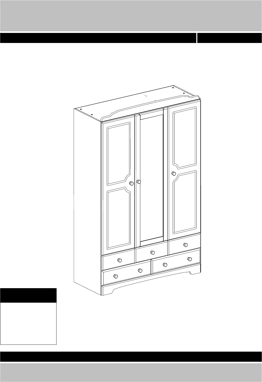
Nordic - 3 Door 5 Drawer Wardrobe
0845 640 30 30
- 20-11-2013
Dimensions
Width : 120,9 cm
Depth : 49,0 cm
Height : 191,3 cm
344112022
Important - Please read these instructions fully before starting assembly
Safety and Care Advice
Check you have all the
components and tools listed on
pages 3 and 4.
Remove all fittings from the
plastic bags and separate them
into their groups.
Keep children and animals
away from the work area, small
parts could choke if swallowed.
Make sure you have enough
space to layout the parts before
starting.
Do not stand or put weight on
the product, this could cause
damage.
Assemble the item as close to
its final position (in the same
room) as possible.
Assemble on a soft level
surface to avoid damaging the
unit or your floor.
Parts of the assembly will be
easier with 2 people.
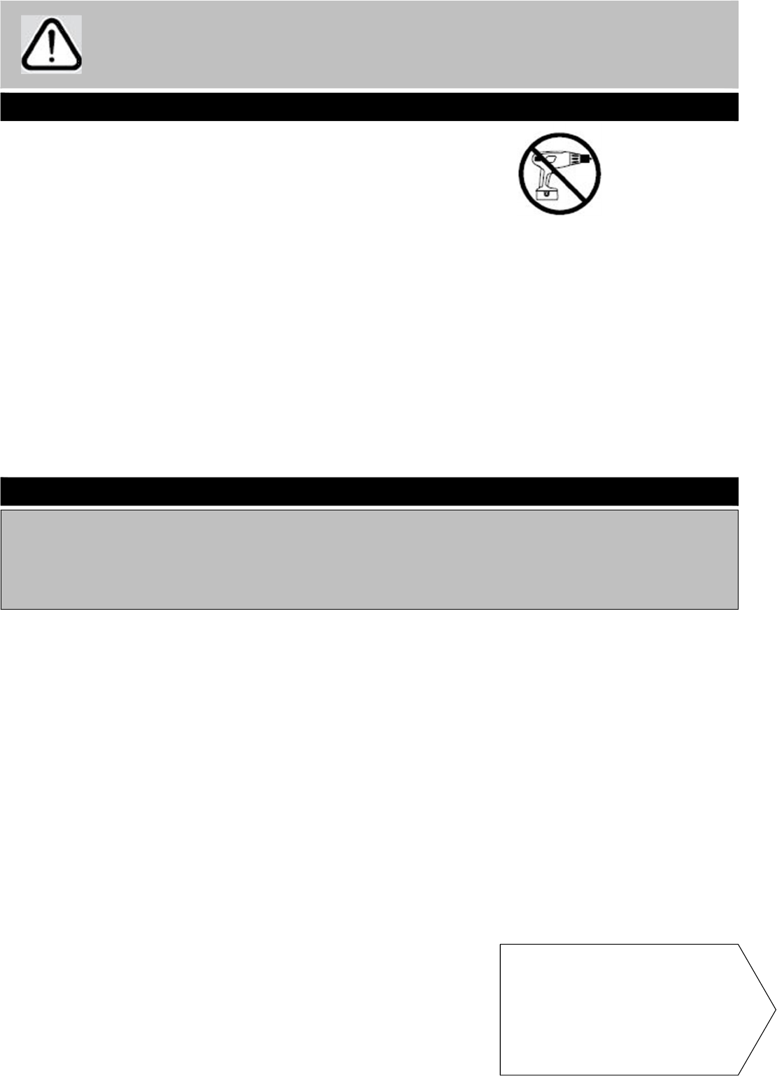
We do not recommend the use
of power drill/drivers for
inserting screws, as this could
damage the unit. Only use hand
screwdrivers.
Dispose of all packaging
carefully and responsibly.
This product should not be
discarded with household
waste. Take to your local
authority waste disposal centre.
From time to time check that
there are no loose screws on
this unit.
Only clean using a damp cloth
and mild detergent, do not use
bleach or abrasive cleaners.
Care and maintenance
Note: if required the next
page can be cut out and used
as reference throughout the
assembly. Keep this page with
these instructions for future
reference.
2
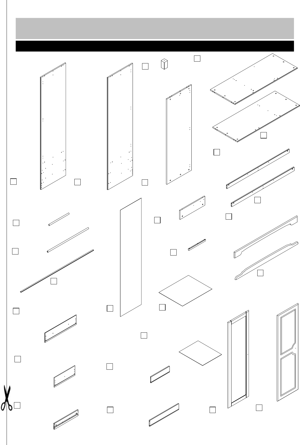
Door rail x4
V155827
316x25x15 mm
Drawer side, right/left x10
S120654
450x98x12 mm
Hanging rail
L220053 - 771
771x22x15 mm
Bottom
V155808
1179x470x15 mm
Top
V155857
1179x470x15 mm
Side, Right
V155839
1833x475x15 mm
Side, Left
V155842
1833x475x15 mm
Divider, small x3
V155830
145x470x15 mm
Divider
V155829
1394x470x15 mm
Foot
P500004
90x50x50 mm
Drawer bottom x2
NM415860
560x447x3 mm
H-profile x1
B81375 - 1375
4x1375 mm
Top rail
V155807
1190x80x15 mm
Door, mirror
V155821
1405x395x15 mm
Door Right/left x2
V155820
1405x395x15 mm
Plinth, front
V155801
1191x96x15 mm
Plinth, back x2
P155855
1179x60x15 mm
Plinth, painted x2
V155855
1179x60x15 mm
Drawer front, small x3
V155811
395x157x15 mm
Drawer front x2
V155812
594x157x15 mm
Drawer back x2
S120651
550x98x12 mm
Drawer back, small x3
S120650
351x98x12 mm
Drawer bottom, small x3
NM415861
361x447x3 mm
Back x3
NM415853
1741x397x3 mm
Hanging rail
L220052
375x22x15 mm
Please check you have all the panels listed below
Components - Panels
3
If you have damaged or missing components, call
the Argos Customer Helpline: 0845 640 30 30
1
2
3
4
5
6
7
8
9
10
11
12
13
14
15
16
17
7-1
18
19
20
21
22
23
24
BA10240
6,1x11,5 mm screw x10
BA10801
20x20x2 angle x5
BA10170
4,0x35 mm screw x30
BA10833
15x15x10 mm x10
BA10468
40x30 mm Wooden knob x10
BA10400
6x30 mm wooden dowel x20
BA10590
15x9,5 mm cam x42
BA10603
5/11x34 mm bolt x42
BA10390
8x30 mm wooden dowel x20
BA10270
5,8x8 mm screw x30
BA10731
15x22 mm support for hanger x4
BA10050
3,5x15 mm screw x34
BA10715-1
10x8 mm magnet x6
BA10715-2
10x8 mm magnet catch x6
BA10815
50x50x2 mm angle x3
BA10025
1,2x20 mm nail x100
BA10191
M4x9 mm screw x10
BA10508
26 cup hinge x9
BA10532
0 mm/37 mm crossplate x9
BA10130
4,0x35 mm screw x12
BA182002
wallstrap and instruction
Ba10688
500x250x Nail holder x1
B14359
17x246 mm Drawer runner x10
BA10137
4,0x60 mm screw x1
BA103062
5x40 mm screw x6
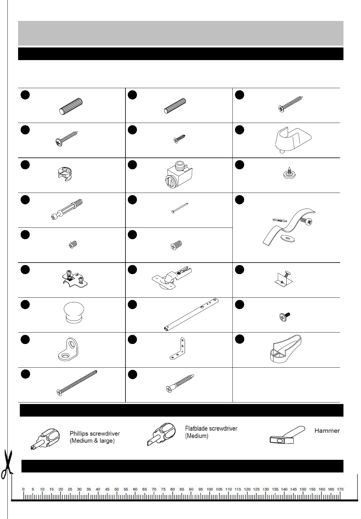
Please check you have all the panels listed below
Components - Fittings
If you have damaged or missing components, call
the Argos Customer Helpline: 0845 640 30 30
Note: The quantities below are the correct amount to complete the assembly. In some cases more
fittings may be supplied than are required.
Tools required
Ruler - Use this ruler to help correctly identify the screws
A B O
R T L
J
i
D
NMC
K E
4
P
Q
F
G S H
V
W
Y
U
Yd
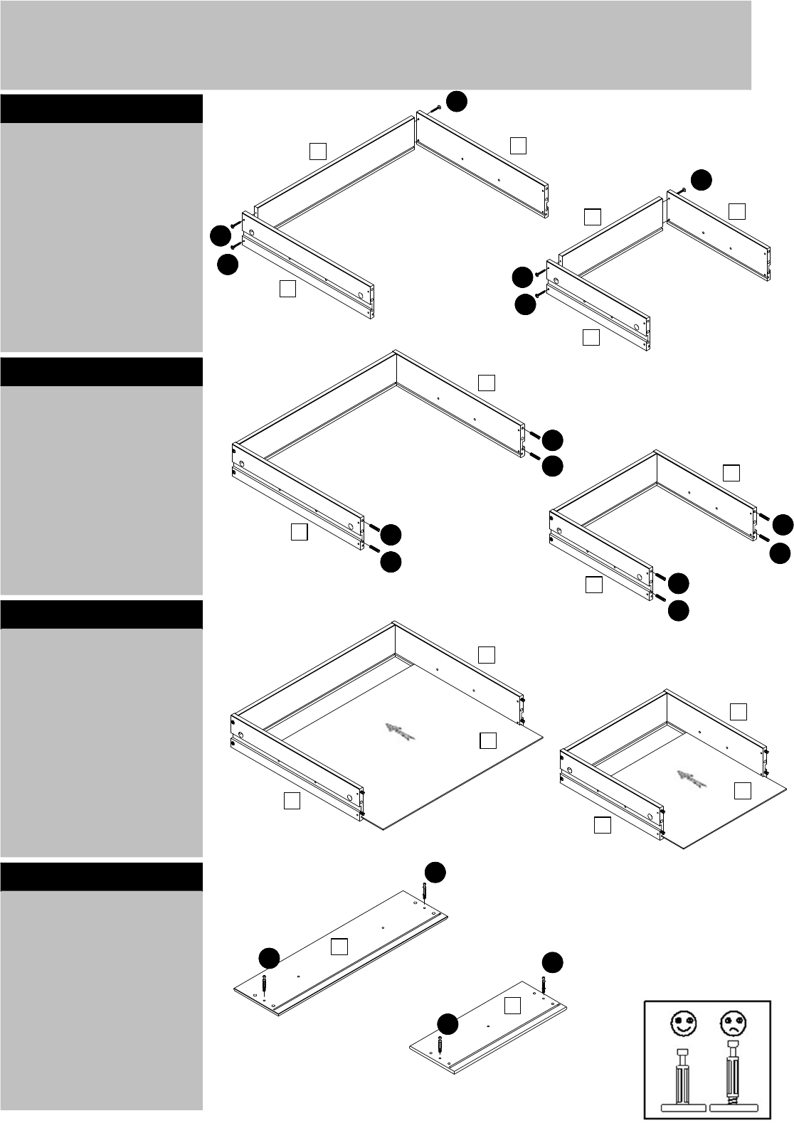
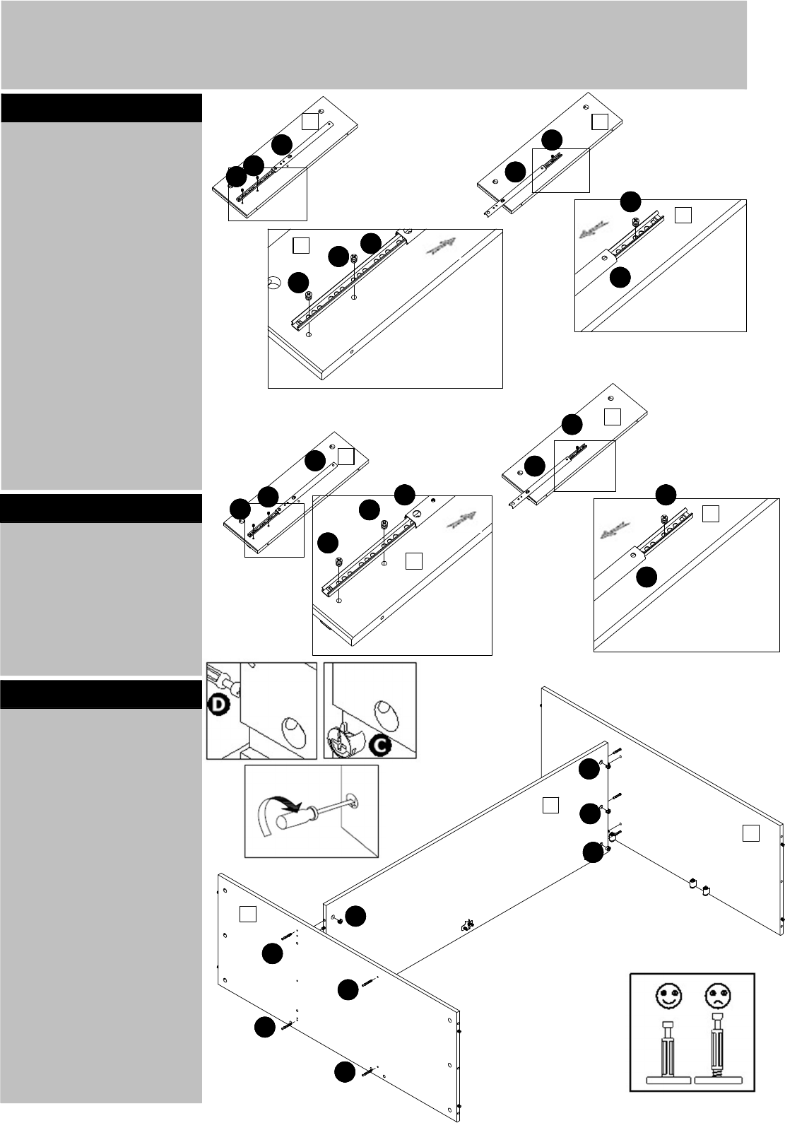
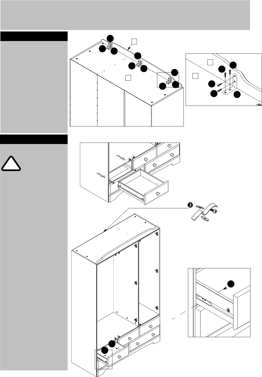
Step 1
Assembly Instructions
Fix the drawer sides 12
to the drawer back 13
and 14 as shown, using
screws R.
Knock down the dowels
B into the holes indicated
on the drawer sides 12,
using a small hammer.
Step 2
Step 3
Slide the drawer bottom
15 and 16 into the
drawer sides 12.
Step 4
Screw the bolts D into
the holes indicated on
the drawer fronts 10 and
11.
5
12
12
12
12
12
12
12
12
12
12
12
12
13
15
16
10
11
x2
x2
x2
x2
x3
x3
x3
x3
R
R
R
R
R
R
B
B
B
B
B
B
B
B
14
D
D
D
D
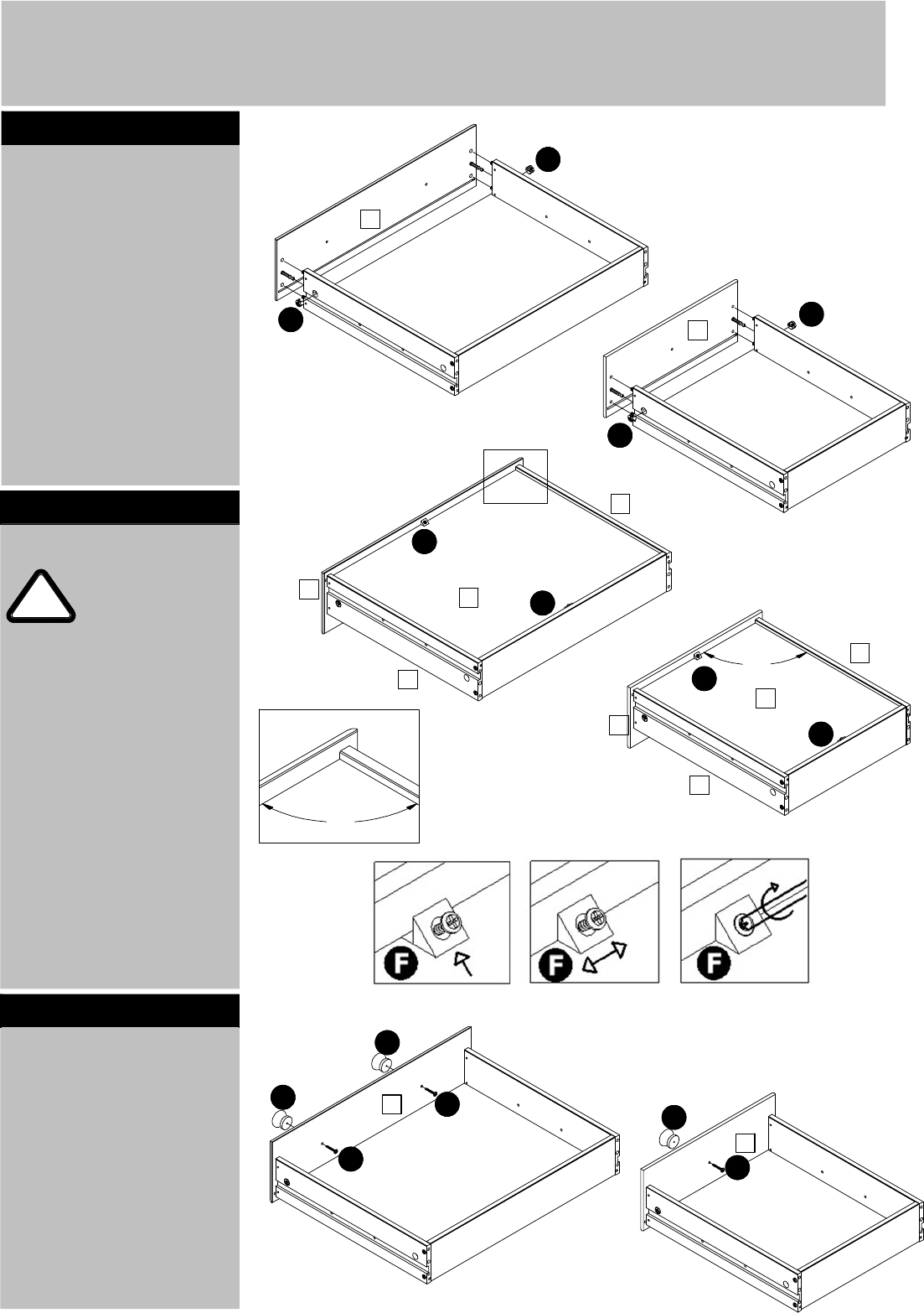
Assembly Instructions
Push the drawer front 10
and 11 onto the the
drawer sides 12 as
shown.
Push cams C into the
holes indicated. Arrow
pointing towards the
front.
Turn the cams C to the
right to fix the front 10
and 11.
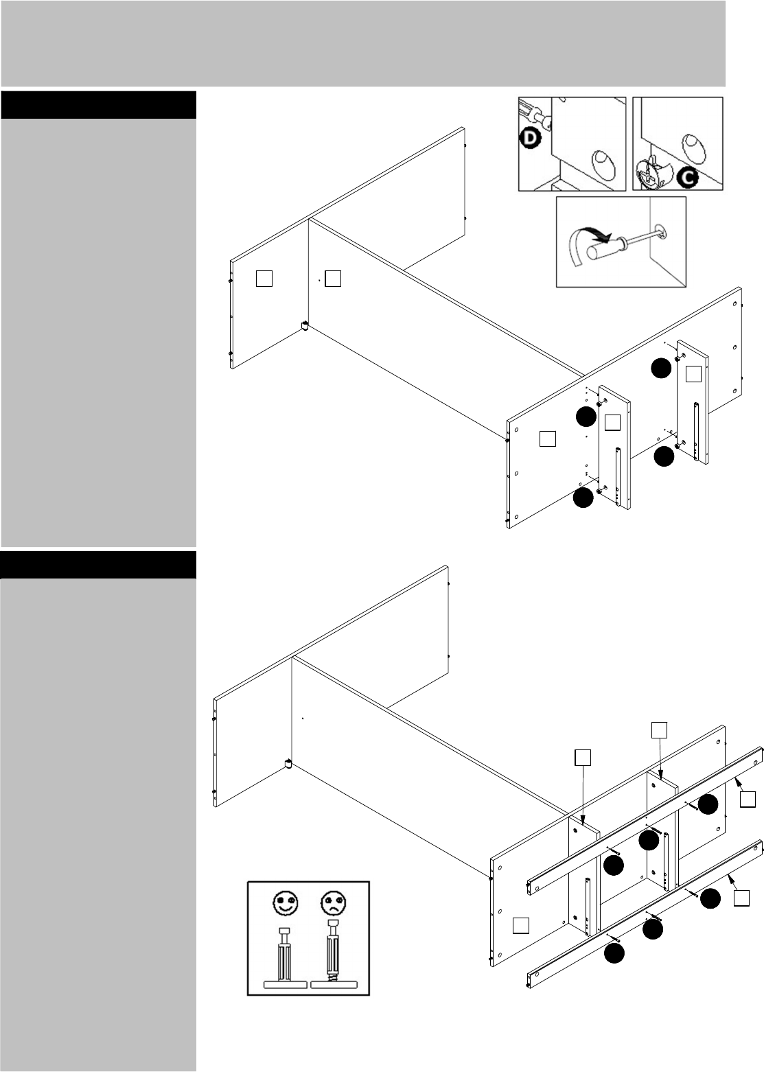
Step 5
Step 6
Step 7
Important!
Make sure the
angle between
the drawer front
Fix the wooden knobs G
to the drawer front 10
and 11 using screws R.
6
10 and 11 and the
drawer sides 12 is 90
before the drawer
bottom is fixed.
Fix the drawer bottom
15 and 16 to the drawer
back 13 and 14 and the
drawer front 10 and 11
using F.
To adjust the angle
between the drawer
sides and the drawer
front push the fitting F
sidewards. See details.
!
C
C
C
C
10
10
11
11
12
12
12
12
15
16
F
F
F
F
9
0
.
0
9
0
.
0
G
G
G
R
R
R
x3
x3
x3
x2
x2
x2
10
11
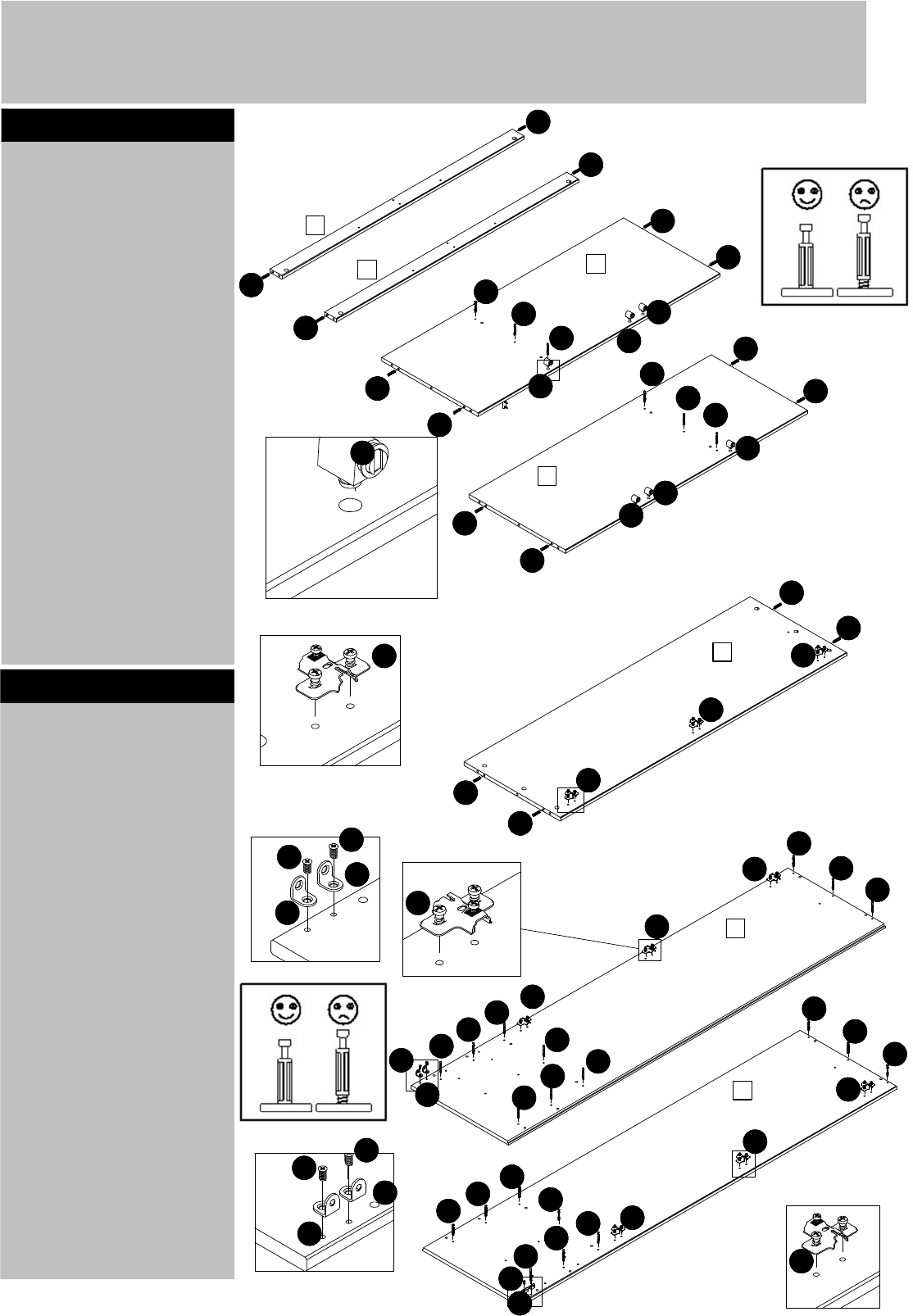
Assembly Instructions
Knock down the dowels
A into the holes
indicated on the back
plinths 7, the back
plinths 7-1, the top 5
and the bottom 6 using a
small hammer.
Screw the bolts C into
the holes indicated on
the top 5 and the
bottom 6.
Press the magnets M
into the holes indicated.
Step 8
Step 9
Knock down the dowels
A into the holes
indicated on divider 3.
Fix the crossplates P to
the divider 3 and the
sides 1 and 2 using the
premounted screws.
See details.
Position the crossplate
exactly as shown.
Fix the angles V to the
sides 1 and 2 using
screws E. Place the
angles as shown.
See details.
7
!
7
7-1
5
6
A
A
A
A
A
A
A
A
A
A
A
A
x2
x2
M
M
M
M
M
M
A
A
A
A
1
2
3
P
P
P
P
P
P
P
P
P
D
D
D
D
D
D
D
D
D
D
D
D
D
D
D
D
D
D
D
D
V
E
E
M
V
V
V
E
E
P
P
E
E
P
D
D
D
D
D
D
V
V
BY
CA
CD
CE
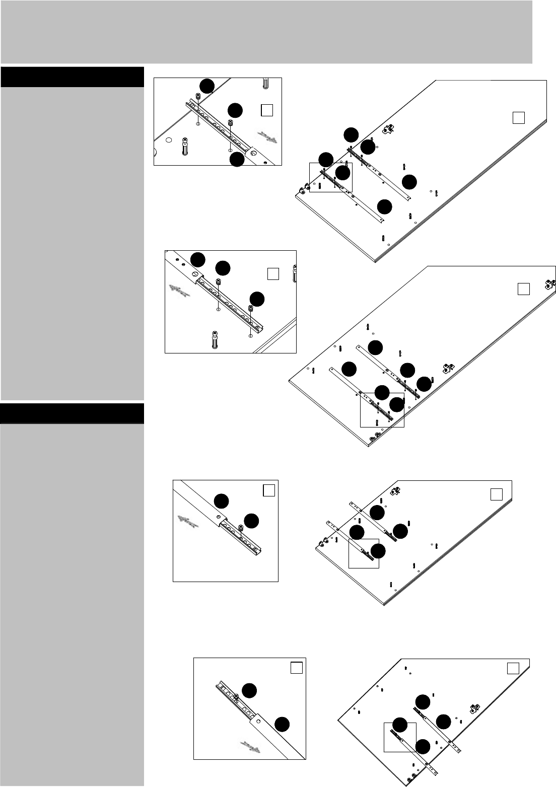
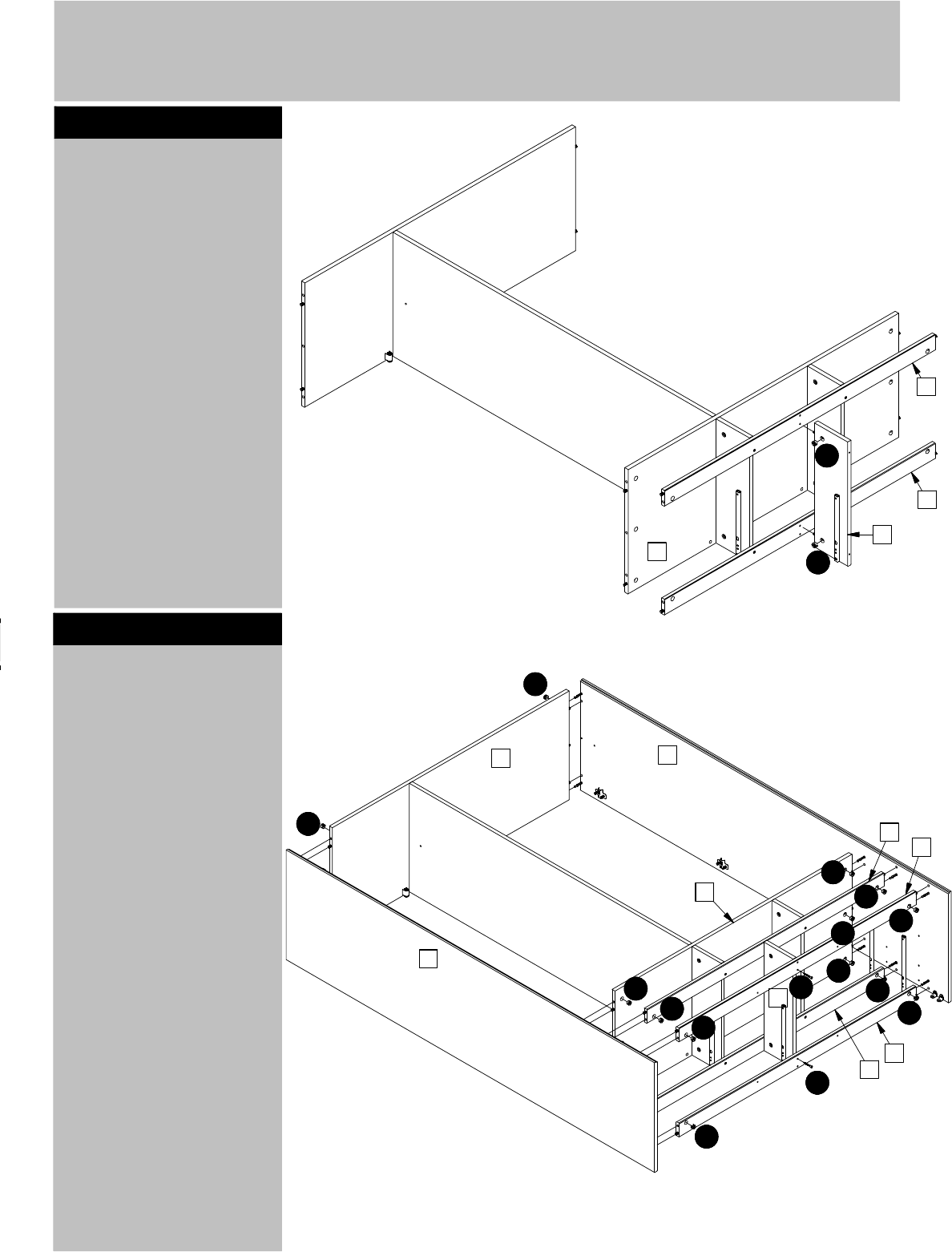
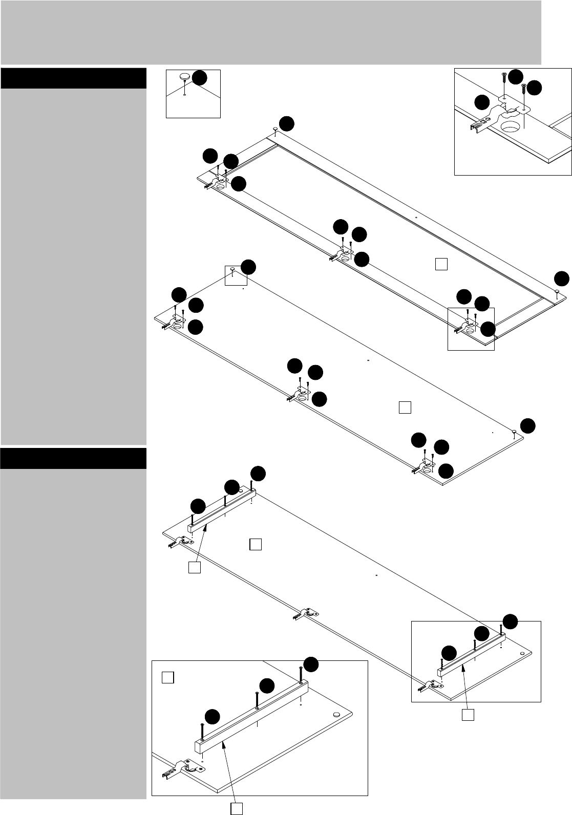
Assembly Instructions
Slide the top of the
drawer runners S
backwards.
Fix the front end of the
drawer runners S to the
sides 1 and 2 using
screws K into the holes
indicated.
See details.
Step 10
Step 11
Slide the top of the
drawer runners S
forwards.
Fix the backend of the
drawer runners S to the
sides 1 and 2 using
screws K into the holes
indicated.
See details.
8
!
1
1
2
2
S
S
S
S
S
S
K
K
K
K
K
K
K
K
K
K
K
K
1
2
1
2
S
S
S
S
S
S
K
K
K
K
K
K
Assembly Instructions
Slide the top of the
drawer runners S
backwards.
Fix the front end of the
drawer runners S to the
dividers into the holes
indicated 4 using screws
K. See details.
Slide the top of the
drawer runners S
forwards.
Fix the back end of the
drawer runners S to the
dividers 4 into the holes
indicated using screws K.
See details.
Step 12
Step 13
Step 14
Turn around the dividers
4.
Fix the drawer runners S
to the dividers 4 as
shown. Same procedure
as step 12.
Place the top 5 and the
bottom 6 onto the
divider 3.
Push the cams C into the
holes indicated on
divider 3. arrow pointing
towards the top 5 and
the bottom 6.
Turn the cams C to the
right to fix the top 5 and
the bottom 6.
Finally screw the bolts D
into the holes indicated
on the bottom 6.
9
!
4
4
4
4
S
S
S
S
K
K
K
K
K
K
S
S
S
S
K
K
K
K
K
K
4
4
4
4
6
5
3
C
C
C
C
D
D
D
D
x3
x3
x3
x3
Assembly Instructions
Place the dividers 4 onto
the bottom 6.
Push cams C into the
holes indicated. Arrow
pointing towards the
bottom.
Turn the cams C to the
right to fix the dividers 4.
Step 15
Step 16
Fix the plinth 7 and the
plinth 7-1 onto the
dividers 4 using screws
U.
Screw the bolts D into
the holes indicated on
the plinth 7 and the
plinth 7-1.
10
!
C
C
C
C
6
5 3
4
4
U
U
U
U
D
D
7
7-1
4
4
6
Assembly Instructions
Place the divider 4 onto
the plinth 7 and the
plinth 7-1.
Push cams C into the
holes indicated. Arrow
pointing towards plinths
7 and 7-1.
Turn the cams C to the
right to fix the divider 4.
Step 17
Step 18
11
Place the sides 1 and 2
onto the top 5, the
bottom 6 and the plinth
7 and 7-1.
Push cams C into the
holes indicated. Arrow
pointing towards the
sides 1 and 2.
Turn the cams C to the
right to fix the sides 1
and 2.
Fix the plinths 7 and
7-1 onto the divider 4
using screws U into the
holes indicated.
!
C
C
4
7
7-1
6
C
C
C
C
C
C
C
C
C
C
C
C
C
U
U
1
2
6
7
7
7-1
7-1
4
5
CP
Assembly Instructions
Place the backs 21 into
the rebates in the sides
1 and 2, the top 5 and
into the H-profile 18.
Step 19
Step 20
Fix the foot 24 to the
back plinth 7 using screw
Y.
12
!
Important!
Make sure the
angle between
the top and the
sides is 90 when
the back is
attached
Fix the backs 21 to the
top 5, the sides 1 and 2,
the divider 3 and the
plinth 7 using nails i.
Use the nail holder Yd
and a small hammer.
Fix the front plinth 8
onto the angles V using
screws E.
i
i
i
i
i
i
i
i
i
i
18
21
21
21
1
2
V
E
E
E
E
E
E
7
7-1
8
7-1
8
Y
Y
24
24
7
7
V
E
CT
CV
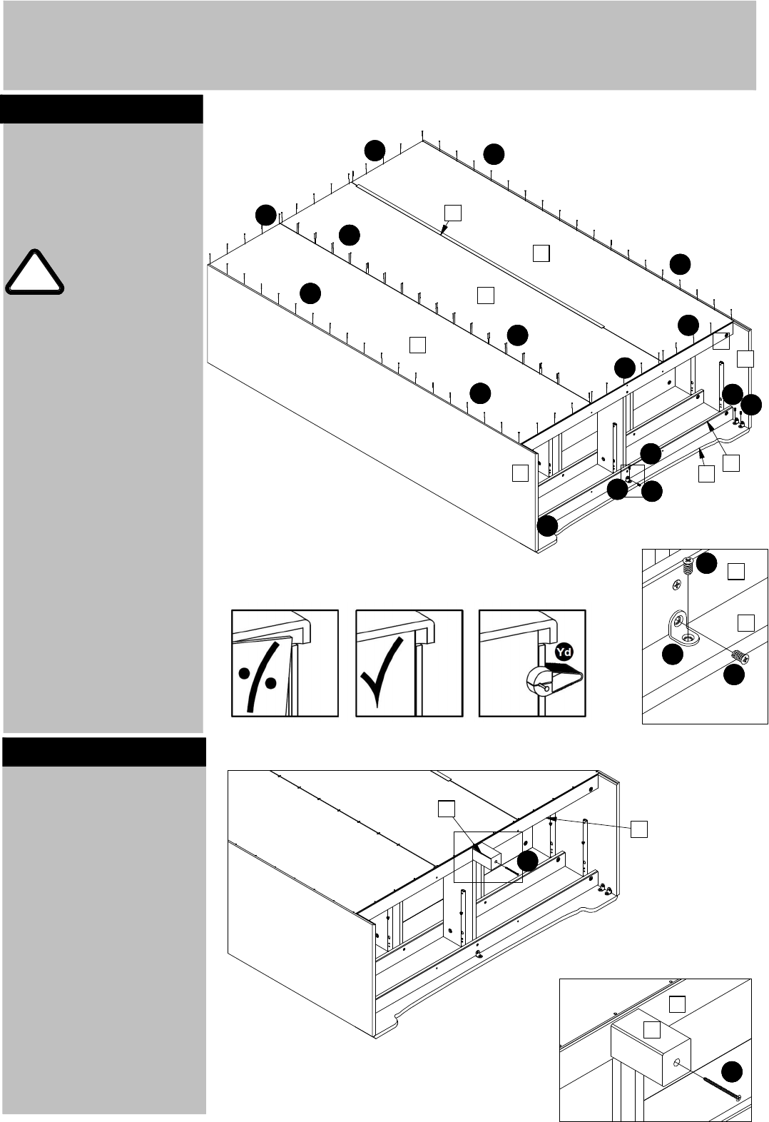
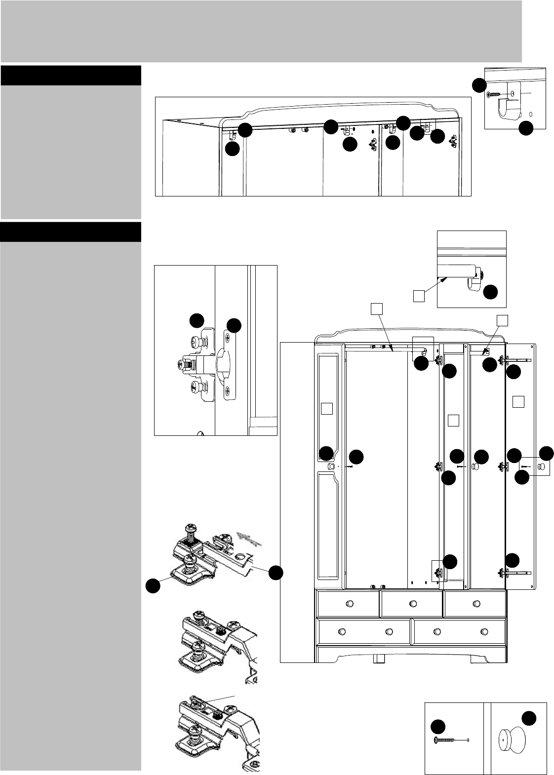
Assembly Instructions
Place the top rail 9 onto
the top 5.
Fix the top rail to the top
using angles W and
screws T.
Step 21
Step 22
Its is recommended that
the wardrobe is fixed to
the wall.
Use fittings J. Follow the
instructions included
with the fittings.
Pull out the drawer
runners. Slide the
drawers into the runners.
Fit and fix the lower
drawer first and work
your way up.
Fix the drawers to the
drawer runners using
screws H.
13
!
Warning!
The wardrobe is
heavy. Lift with
care.
T
T
T
T
T
T
T
T
W
W
Wallstrap and instruction
H
H
H
T
T
W
W
9
9
5
5
Assembly Instructions
Place the cup hinges Q
into the holes indicated
on the doors 19 and 20.
Fix the hinges using
screws T.
Place the magnet
catches N into the holes
indicated on the doors
using a small hammer.
Step 23
Step 24
Fix the door rails 24 into
the holes indicated on
the doors 20 using
screws O.
14
!
19
20
x2
N
N
N
N
N
Q
Q
Q
Q
Q
Q
Q
T
T
T
T
T
T
T
T
T
T
T
T
T
T
O
O
O
O
O
O
O
O
O
20
20
24
24
24
x2
DD
Assembly Instructions
Fx the supports for
hanger-rails L onto the
holes indicated on the
sides 1 and 2 and on
both sides of the divider
3 using screws T.
Step 25
Step 26
Place the hanger rail 22
and 23 into the supports
L.
To fix the doors 19 and
20, slide the cup hinges
Q onto the crossplates P.
Fix the hinges using the
premounted screw in the
crossplates.
See detail.
Fix the wooden knobs G
to the doors 19 and 20
using screws R
15
Tighten these screws
P
Q
L
L
L
L
L
T
T
T
T
T
L
L
L
Q
Q
Q
Q
Q
Q
Q
P
19
20
20
G
G
G
G
R
R
R
R
x3
23
22
22
Assembly Instructions
If you need help or have damaged or missing parts, call the Customer Helpline:
0845 640 30 30
Home Retail Group - 489-499 Avebury Boulevard - Saxon Gate West - Central Milton Keynes MK9 2NW
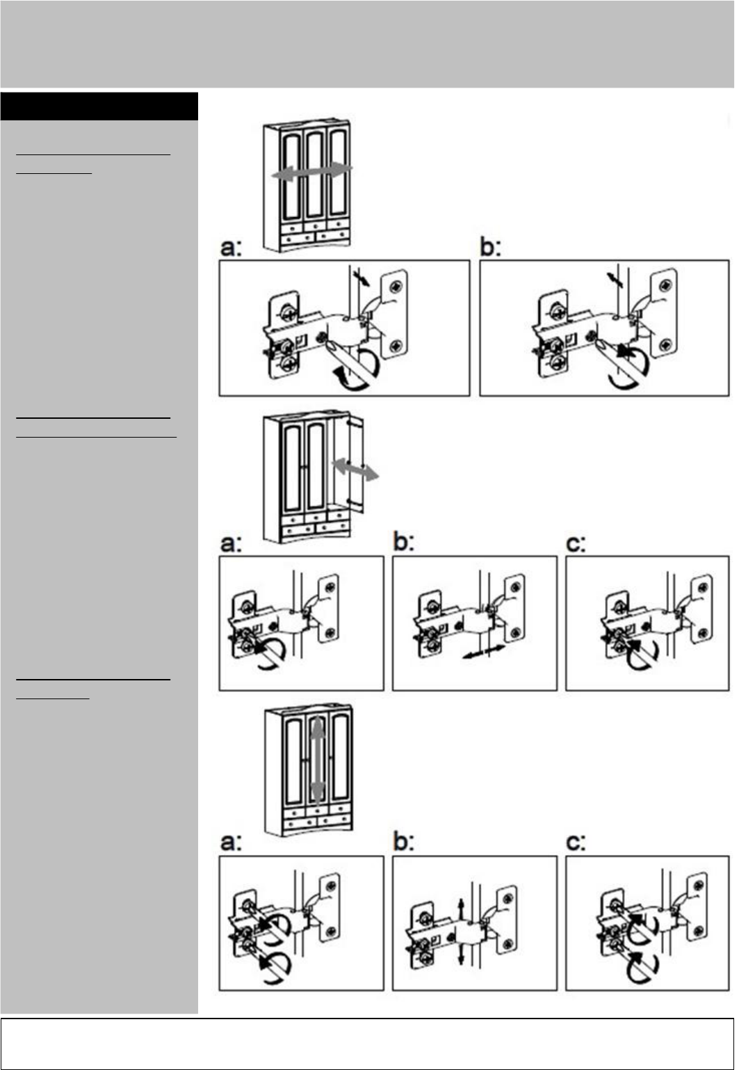
Adjusting the doors
left/right.
a:
To adjust the door
towards the left hand
side - turn the adjusting
screw to the right.
b:
To adjust the door
towards the right hand
side - turn the adjusting
screw to the left.
Adjusting the doors
forwards/backwards.
a:
Loosen the fixing screw.
b:
Push the cup hinge/the
door forwards or
backwards to adjust.
c:
Tighten the fixing screws
of ALL the crossplates.
Adjusting the doors
up/down.
a:
Loosen the two
pre-mounted screws of
each crossplates, BUT
ONLY as much as it will
allows the crossplates to
move up and down.
b:
Push the door up or down
to adjust.
c:
Tighten the pre-mounted
screws of ALL
crossplates.
Step 27
16
!
