
International Research Journal of Engineering and Technology (IRJET) e-ISSN: 2395-0056
Volume: 10 Issue: 04 | Apr 2023 www.irjet.net p-ISSN: 2395-0072
© 2023, IRJET | Impact Factor value: 8.226 | ISO 9001:2008 Certified Journal | Page 574
KITS OF VARIOUS TYPES OF BRIDGE CIRCUITS
Mr. Chandrakant Pradip Bhalekar
1
, Mr. Tanmay Anant Rawool
2
, Mr. Jayesh Kishor Desai
3
, Mr.
Rahul Narayan Gawas
4
, Mr. Harsh Chandrashekhar Sonsurkar
5
,
Prof. S. N. Nirmalkar
6
1, 2, 3, 4, 5
Students, Yashwantrao Bhonsale Polytechnic, Sawantwadi, Maharashtra, India
6
Faculty, Yashwantrao Bhonsale Polytechnic, Sawantwadi, Maharashtra, India
---------------------------------------------------------------------***---------------------------------------------------------------------
Abstract - Bridge circuits are important electronic circuits
that are commonly used in various applications, including
sensor measurements, strain gauges, and thermistors. There
are different types of bridge circuits, including Wheatstone,
Kelvin, Maxwell, Wien and H bridge circuits. A Wheatstone
bridge circuit is primarily used for measuring unknown
resistance values. A Kelvin bridge circuit is used for measuring
low-resistance values with high accuracy. A Wien bridge
circuit is used for measuring the frequency of an AC signal,
while a Maxwell bridge circuit is ideal for measuring the
inductance of an inductor. These different types of bridge
circuits involve different components, configurations, and
calculations. They are essential tools in the field of electronics,
providing accurate measurements and facilitating precise
control of electronic devices. The availability of different kits
for various bridge circuits enables enthusiasts and
professionals to build and experiment with these circuits,
further advancing the field of electronics.
Key Words: Bridge Circuits, Resistance, Inductance,
Capacitance, measurements.
1. INTRODUCTION
Bridge circuits are an essential component of electronic
circuits, and they are used to measure various parameters
such as resistance, capacitance, and inductance. A bridge
circuit is essentially a circuit that contains four arms, with
two of these arms containing variable components, such as
resistors, capacitors, or inductors. The objective of a bridge
circuit is to balance the circuit, equalizing the voltage across
the bridge. In this technical paper, we will explore various
types of bridge circuits, including Wheatstone, Kelvin,
Schering, Maxwell, and Wien Bridge circuits.
1.1 Wheatstone Bridge
The Wheatstone Bridge Circuit is perhaps the most
commonly used bridge circuit. It is named after Sir Charles
Wheatstone, who invented this circuit back in 1833. The
Wheatstone Bridge Circuit consists of four resistors, with two
resistors in each arm. The ratio of the resistors in the
Wheatstone Bridge Circuit can be varied to measure
unknown resistance with great precision. The Wheatstone
bridge is commonly used for DC resistance measurements,
and it is highly reliable due to its accuracy and simplicity.
1.2 Kelvin Bridge
The Kelvin Bridge Circuit is also known as the Thomson
Bridge Circuit, named after its creator William Thomson, who
was later known as Lord Kelvin. The Kelvin Bridge Circuit is
an extension of the Wheatstone Bridge Circuit and is
designed to eliminate the effects of lead resistance, which can
often be a source of error in measurements. The Kelvin
Bridge Circuit incorporates four additional resistors, two of
which are placed in series with each of the two arms of the
Wheatstone Bridge Circuit. The Kelvin Bridge Circuit is
commonly used for measuring low resistance values.
1.3 Maxwell Bridge
The Maxwell Bridge Circuit is type of AC bridge circuit,
which is used to measure inductance. The Maxwell Bridge
Circuit was first developed by James Clerk Maxwell. It
consists of four arms, with two of these arms containing a
variable inductor. The Maxwell Bridge is commonly used for
measuring the inductance of inductors, and it is highly
reliable due to its accuracy and simplicity.
1.4 Wien Bridge
The Wien Bridge Circuit is a type of AC bridge circuit that
is used to measure the frequency of a signal. The Wien Bridge
Circuit was invented by Max Wien. The Wien Bridge Circuit
consists of four resistors, with two resistors in series with a
capacitor in each arm. The Wien Bridge Circuit is commonly
used for testing audio frequency circuits, and it is highly
reliable due to its simplicity and precision.
1.5 H-bridge
An electrical circuit known as an H-bridge allows the
application of a voltage across a load in both directions. The
H-bridge circuit can control the direction of rotation and the
speed of the DC motor.

International Research Journal of Engineering and Technology (IRJET) e-ISSN: 2395-0056
Volume: 10 Issue: 04 | Apr 2023 www.irjet.net p-ISSN: 2395-0072
© 2023, IRJET | Impact Factor value: 8.226 | ISO 9001:2008 Certified Journal | Page 575
2. RESEARCH METHODOLOGY
1) Define the Research Problem: The first step is to define the
research problem, which, in this case, is to create kits of
various types of bridge circuits for use in a technical paper.
This requires an understanding of the different types of
bridge circuits, their applications, and the required
components.
2) Conduct a Literature Review: The next step is to conduct a
literature review to gather information about the different
types of bridge circuits, their specifications, and the
components required. This will involve researching books,
academic journals, and technical papers on the subject.
3) Formulate a Hypothesis: Based on the information
gathered from the literature review, formulate a hypothesis
about the design and development of kits of bridge circuits
for use in the technical paper.
4) Design the Kits: Using the hypothesis as a guide, design the
kits of various types of bridge circuits. This involves selecting
the necessary components, designing the circuit board layout,
and testing the circuit performance.
5) Conduct Experiments: Test the kits in various experiments
to verify their performance and efficiency. This will involve
measuring parameters such as voltage, current, resistance,
and frequency.
6) Analyze Results: Analyze the results obtained from the
experiments, compare them with the performance
specifications of the individual bridge circuits, and draw
conclusions about the effectiveness of the kits.
7) Draw Conclusions: Based on the results obtained from the
experiments, draw conclusions about the hypothesis, and
determine whether the design and development of kits of
various types of bridge circuits was successful.
8) Communicate Results: Finally, communicate the results
and conclusions in a technical paper or report, providing
detailed information about the kits design and development,
their performance, and their practical applications.
3. LITERATURE REVIEW
A bridge circuit is a fundamental electronic component that
is used to measure resistance, capacitance, and inductance. It
is a type of electrical circuit that is typically composed of
four resistive legs in a diamond shape, with an electrical load
placed across one of the vertices. There are several types of
bridge circuits that are commonly used in electronics,
including the Wheatstone bridge, the Kelvin Bridge and the
Maxwell Bridge. In this literature review, we will explore the
various types of bridge circuits, their advantages and
disadvantages, and their applications.
3.1 Wheatstone Bridge
The Wheatstone bridge is perhaps the most well-known
and widely used type of bridge circuit. Samuel Hunter
Christie designed it in 1833, and Sir Charles Wheatstone
modified it in 1843. The Wheatstone bridge consists of four
resistive elements that are connected in a diamond shape,
with an electrical load connected between two opposite
vertices. The bridge is balanced when the ratio of the two
resistive legs on one side of the bridge is equal to the ratio of
the two resistive legs on the other side. The Wheatstone
bridge is commonly used in applications where high accuracy
is required, and is particularly useful in measuring small
changes in resistance.
3.2 Kelvin Bridge
The Kelvin Bridge, also known as the Kelvin Double
Bridge or the Thomson Bridge, is a modification of the
Wheatstone bridge that is used to measure low resistance
values. It was developed by Lord Kelvin (William Thomson)
in the mid-19th century. The Kelvin Bridge uses two
additional resistive elements to reduce the effects of lead
resistance and contact resistance, which can cause errors in
resistance measurements. The Kelvin Bridge is commonly
used in applications such as measuring the resistance of
electrical contacts, measuring the resistance of conductive
coatings, and measuring the resistance of soldered
connections.
3.3 Maxwell Bridge
The Maxwell Bridge is a type of bridge circuit that is used
to measure small inductance values. It was developed by
James Clerk Maxwell in the mid-19th century. The Maxwell
Bridge consists of four resistive elements and an inductive
load. The bridge is balanced when the ratio of the two
resistive legs on one side of the bridge is equal to the ratio of
the two resistive legs on the other side, and when the product
of the two inductances on each side of the bridge is equal. The
Maxwell Bridge is commonly used in applications such as
measuring the inductance of small inductors, measuring the
self-inductance of coils, and measuring the mutual inductance
of transformers.
3.4 Wien Bridge
The Wien Bridge is a type of electronic circuit that is used
as a frequency generator and a filter in electronic and
communication systems. Its main advantage over other
circuits is that it provides a constant output amplitude over a
wide range of frequencies. The Wien Bridge circuit was
introduced in 1938 by Max Wien. Over the years, the circuit
has been modified and improved to suit various applications.
One popular modification is the Wien Bridge oscillator, which
is used to generate a stable sine wave. The oscillator consists
International Research Journal of Engineering and Technology (IRJET) e-ISSN: 2395-0056
Volume: 10 Issue: 04 | Apr 2023 www.irjet.net p-ISSN: 2395-0072
© 2023, IRJET | Impact Factor value: 8.226 | ISO 9001:2008 Certified Journal | Page 576
of a Wien Bridge circuit and an amplifier. The circuit is
designed to oscillate at the frequency determined by the
values of its components. The amplifier is used to compensate
for the lost energy in the circuit.
3.5 H-bridge
An electrical circuit known as an H-bridge allows the
application of a voltage across a load in both directions. The
H-bridge circuit can control the direction of rotation and the
speed of the DC motor.
4. DETAIL OF IMPLEMENTATION
Bridge circuits are very common in electrical engineering
and are used to measure or compare various electrical
parameters such as resistance, capacitance, and inductance.
There are various types of bridge circuits available, each
designed to perform a specific task. In this technical paper,
we will discuss the different types of bridge circuits and their
applications.
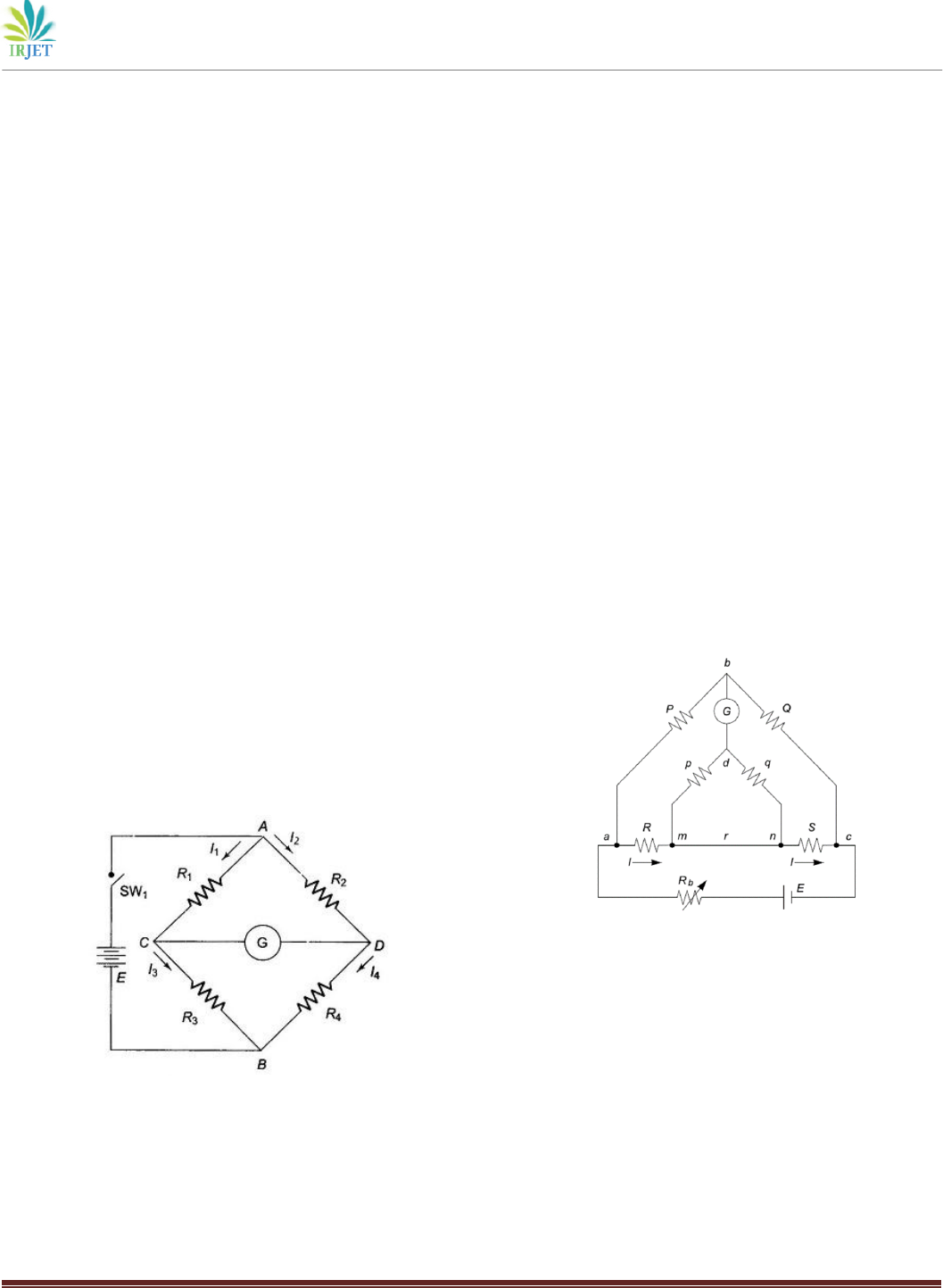
4.1 Wheatstone Bridge
The Wheatstone bridge is the most commonly used bridge
circuit in electrical engineering. It is named after Sir Charles
Wheatstone, who first described it in 1833. The Wheatstone
bridge can be used to measure an unknown resistance value.
The circuit consists of four resistors connected in a bridge
configuration. When the bridge is balanced, the current
through R1 and R2 is equal to the current through R3 and R4.
At this point, the voltage between point C and D is zero, and
the unknown resistance Rx can be calculated using the
following equation Rx = R2(R3/R4).
Fig -1: Wheatstone Bridge
The Wheatstone bridge is widely used in industry for the
measurement of very low resistances, and it is also commonly
used in strain gauge applications.
4.2 Kelvin Bridge
The Kelvin bridge is commonly used in electrical
engineering to measure low resistances, typically less than
one ohm. Its design includes four resistive arms instead of the
three in the Wheatstone bridge, which increases its accuracy
and sensitivity. The Kelvin bridge works by passing a known
current through two known resistances (P and Q) in series
with the unknown resistance Rx, and then measuring the
voltage drop across Rx using a highly sensitive voltmeter. The
voltage is measured at points A and B which are connected to
Rx. The resistance value at Rx can be calculated using the
equation Rx = P (Q/s), where s is the ratio of voltages
measured on either side of Rx. The Kelvin bridge is highly
effective at measuring low resistances because it uses four-
wire connections which eliminate any errors caused by
contact resistance in the connecting wires.
The Kelvin bridge is commonly used in industry for the
measurement of very low resistances such as contact
resistance. Kelvin bridges are commonly used for measuring
low resistances, typically in the range of milliohm or micro-
ohm. They are commonly employed in laboratories, scientific
research, and industrial applications where high-precision
measurements are necessary. Kelvin bridge is also known as
Thomson bridge or improved or modified bridge.
Fig -1: Kelvin Bridge
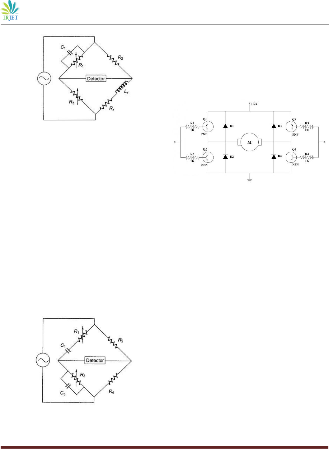
4.3 Maxwell Bridge
The Maxwell bridge is designed to measure the
inductance of an unknown inductor. The bridge consists of
three known resistors (R1, R2, and R3), an unknown inductor
(Lx), and a variable capacitor (Cx). When the bridge is
balanced, the equation for the inductance of the unknown
inductor is Lx = R2R3C4.
International Research Journal of Engineering and Technology (IRJET) e-ISSN: 2395-0056
Volume: 10 Issue: 04 | Apr 2023 www.irjet.net p-ISSN: 2395-0072
© 2023, IRJET | Impact Factor value: 8.226 | ISO 9001:2008 Certified Journal | Page 577
Fig -1: Maxwell Bridge
The Maxwell bridge is commonly used in radio frequency
applications to measure the inductance of coils and antennas.
4.4 Wien Bridge
The Wien bridge circuit is a type of electronic oscillator
that produces an output signal with a fixed frequency
determined by the components of the circuit. The circuit
consists of a bridge of four resistors and two capacitors, in
which an active element, typically an operational amplifier, is
connected.
The advantage of this circuit is that the frequency of
oscillation can be easily adjusted by varying the values of the
resistors and capacitors. The gain of the circuit at the
frequency of oscillation is ideally unity, which means that the
input and output signals are in phase. The circuit can be used
as a filter, or as a sine wave generator with low distortion. A
Wien bridge can be used as a measurement tool by adjusting
the variables in the circuit to match the impedance of the
unknown component. The Wien bridge is also commonly
known as the Wien oscillator or the Wien-Robinson
oscillator.
Fig -1: Wien Bridge
4.5 H-bridge
The H-bridge circuit is a type of electronic circuit that is
commonly used to control the direction and speed of a DC
motor. It consists of four switches that are arranged in the
shape of an "H" and a DC motor. By controlling the switches
properly, the H-bridge circuit can control the direction of
rotation and the speed of the DC motor.
Fig -1: H-bridge
The basic operation of an H-bridge circuit is that when
two switches on one side of the H-bridge are closed while the
other two on the opposite side are open, current flows
through the motor in one direction, causing it to rotate in one
direction. By reversing the position of the switches, the
polarity of the voltage supplied to the motor is reversed,
causing the motor to rotate in the opposite direction.
5. CONCLUSIONS
Bridge circuits are an essential tool in the field of electrical
engineering. They are used to measure various electrical
parameters such as resistance, capacitance, and inductance.
Each bridge circuit is designed to perform a specific task, and
it is important to understand the circuit's principles and
applications before using it for a specific task. The
Wheatstone bridge is the most commonly used bridge
circuit, while other bridges such as the Maxwell bridge,
Kelvin, Wien and H bridge are also very useful in specific
applications.
REFERENCES
[1] P. K. Jain and R. K. Gupta, "A Novel Approach for
Accurate Measurement of Resistance using Kits
Wheatstone Bridge Circuit," in IEEE Transactions on
Instrumentation and Measurement, vol. 61, no. 5, pp.
1375-1383, May 2012.
[2] A. H. Nayfeh and R. L. Draper, "Wheatstone Bridge
Circuit Design Using Modern Operational Amplifiers,"
IEEE Transactions on Education, vol. 27, no. 4, pp. 221-
223, November 1984.

International Research Journal of Engineering and Technology (IRJET) e-ISSN: 2395-0056
Volume: 10 Issue: 04 | Apr 2023 www.irjet.net p-ISSN: 2395-0072
© 2023, IRJET | Impact Factor value: 8.226 | ISO 9001:2008 Certified Journal | Page 578
[3] J. S. Vargas and J. A. Ramirez, "Development of a Kelvin
Bridge for Resistance Measurements in the Range of
10^-6 to 10^-3 Ohms," IEEE Transactions on
Instrumentation and Measurement, vol. 65, no. 8, pp.
1877-1886, Aug. 2016.
[4] R. Chen and H. R. Chang, "Design and analysis of a
precision Kelvin bridge for resistance measurement,"
IEEE Transactions on Instrumentation and
Measurement, vol. 64, no. 9, pp. 2363-2371, Sep. 2015.
[5] N. N. Ivanov, "Analysis and design of Kits Maxwell bridge
circuits," in IEEE Transactions on Instrumentation and
Measurement, vol. 65, no. 4, pp. 785-794, April 2016.
[6] G. H. Royer and A. R. Jha, "Design of a Stable Wien Bridge
Oscillator Circuit," in IEEE Journal of Solid-State Circuits,
vol. 14, no. 6, pp. 1084-1088, Dec. 1979.
[7] M. A. Hannan, M. A. Hoque, M. R. I. Sheikh and M. A. M. Al
Mahmud, "Design and Implementation of H-Bridge
Inverter for Residential Solar PV System," 2016 IEEE 6th
International Conference on Power and Energy Systems
(ICPS), Dhaka, 2016.
[8] Y. Zhang, R. A. Dougal, and D. M. Divan, “A High-
Efficiency MOSFET H-Bridge Configured Motor Drive for
Electric Vehicle Applications” IEEE Transactions on
Power Electronics, vol. 21, no. 3, pp. 646-655, May 2006.
