
www.ijcrt.org © 2020 IJCRT | Volume 8, Issue 4 April 2020 | ISSN: 2320-2882
IJCRT2004183
International Journal of Creative Research Thoughts (IJCRT) www.ijcrt.org
1383
Use of titanium and its alloy in aerospace and aircraft
industries
1
Nabharun Bhattacharya,
2
Janhavi Unde &
3
Kaustubh Kulkarni
1,2
Student, BE (Mechanical Engineering), MIT, Kothrud, Pune 411038
3
Assistant Professor, (School of Mechanical Engineering), MIT-World Peace University, Kothrud, Pune 411038
Abstract— In aerospace and aircraft construction it is essential that materials with a high strength to weight ratio be used. For this
reason, the designer tries to get the last ounce of strength out of each part. An increasing scarcity of resources and their growing expense
demands a reduction in energy consumption for passenger and goods transportation. Here, the aerospace and aviation sector plays a special
role with respect to the application of new materials. There is probably no other material more closely related to aerospace and aircraft
than titanium and its alloys. With a density of 4.Jg/cm³, titanium alloys are only about half as heavy as steel or Ni-based super alloys,
yielding a unique combination of strength and lightness. Furthermore, then have exceptional corrosion resistance favors the use of titanium
alloys in the aerospace and aviation sector.
INTRODUCTION
In the field of commercial aviation, a demand for more than 28,000 new large commercial aircraft on the global market is expected for the
period of 2012-2031. Roughly 10,000 of the old aircraft will have to be replaced. A global growth of 4.7 % per year in air traffic, measured in
passenger kilometers (RPK), is also estimated. Aviation programs ACARE 2020 (Advisory Council for Aviation Research and Innovation in
the EU) and Flightpath 2050 request a reduction of fuel consumption as well as CO
2
and NOx emissions over the course of the next years for
aircrafts. Multifaceted aerodynamic design, thermal loads and high mechanical, severe environmental and other working conditions produces
extraordinary magnitude of dynamic stresses in various components of airframe. The magnitude and nature of these stresses further varies
during different phases of flight. This administers the need to develop special materials having ability to withstand such variable stresses.
Further high fuel costs, scarcity of raw material sources, need of efficiency improvements, growing demand of new aircrafts (both military and
civil) are the few factors which enforced the engineers to create stronger but ‘as-light-as-possible’ frame, engine and other parts of aircrafts. In
order to fulfill current and future requirement, the aircraft industry must undergo considerable technological developments concerning
innovative materials and design techniques as well as new fabrication processes. To meet these requirements there is a clear trend to produce
light-weight, ‘stronger-but-lighter’ components for engines and structural parts of aircrafts by using titanium and its alloys for aerospace and
aviation application. Titanium and its alloys offers a exceptional set of physical, metallurgical, mechanical and composite compatibility features
which helps the aerospace sector to fulfill economy, fuel efficiency and other global standards in a wide range of temperatures and other service
conditions. This wonder metal becomes the desirable choice of aircraft fabricators. Titanium’s strength is equivalent to steel but 45 percent
lighter. It is also corrosion resistant. Titanium can form an alloy with a number of metals, such as iron, aluminum, molybdenum and vanadium.
Titanium falls in between aluminum and stainless steel when compared in terms of elasticity, density, and elevated temperature strength. It has
a melting point of from 1498.89°C to 1735°C, low thermal conductivity, and a low coefficient of expansion. It is light, strong, and resistant to
stress corrosion cracking. The ultimate yield strength of titanium drops rapidly above 426.66°C. Titanium is nonmagnetic and has an electrical
resistance equivalent to that of stainless steel. Some of the base alloys of titanium are pretty hard. Titanium can be found in large quantity in
the earth. As this metal becomes more extensively used, the cost per unit is expected to drop, making it the metal of choice for the industry.
Nomenclature:-
1. α - Alpha 9. UTS -Ultimate Tensile Strength
2. β - Beta 10. YS -Yield strength
3. ω - Omega 11. STA - Solution Treating and Aged
4. HCP - Hexagonal close packing 12. RMI - Reactive Metals Inc. company
5. BCC - Body cantered cubic 13.PMC - Polymer Matrix Composite
6. RT - Room Temperature 14.TMC - Titanium matrix composites
7. TIMET - Titanium Metals Corporation 15. HIP - Hot isostatic pressing
8. RPK - Passenger kilometers 16.TGM -Titanium gradient mechanism

www.ijcrt.org © 2020 IJCRT | Volume 8, Issue 4 April 2020 | ISSN: 2320-2882
IJCRT2004183
International Journal of Creative Research Thoughts (IJCRT) www.ijcrt.org
1384
I. TITANIUM ALLOYS AND CHARACTERISTICS
With 4.51 g cm ־³ density, titanium is ranked as ninth most abundant element in earth’s crest. This light metal also have the honor to be the
fourth most plentiful structural material available after aluminum, iron, and magnesium. Ti-alloys, a class of chemically very similar but
physically different materials, exhibits both hcp and bcc structures. Allotropy of both hcp and bcc structures widen the range of mechanical
properties and hence scope of Ti-alloys in aircraft and aerospace industry. There are three titanium alloy types based on the composition of the
alloy and the resultant predominant room temperature (RT) constituent phase(s), and each of these families of alloys serves a specific role. [1]
Alpha is the low temperature allotrope of titanium, and the microstructure of α and near-α alloys consists predominantly of the α-phase. The α
phase is of hcp structure. The α/β alloys are, for the most part, still mostly α at room temperature, but they do have more of the β-phase, the
high temperature allotrope, than the former class of alloys. β alloys titanium are capable of retaining 100% β when quenched from β phase
field. β phase alloys are high temperature alloys having bcc structure.
Fig. 1. Phase Diagram of Titanium Alloy
1.1. α Titanium Alloys:-
Quantity (wt. %) of α-stabilizer alloying elements in α-Ti alloys divides it into two classes i.e. super-α-alloys and near-α-alloys. Inherent
properties of α-Ti alloys like ductility and resistance to creep in hotter environments are always welcomed for aerospace and aircraft parts.
Super-α-alloys (containing > 5 wt. % of alloying element) composed only α-Ti grains. Ti-5Al-2.5Sn alloy belongs to this class. Near-α-alloys
contain β-stabilizers (< 2 wt. %) dispersed among large volume of α-Ti grains. Solid solution hardening, work hardening (rolling, extrusion
and other such plastic forming processes), grain size refinement etc. strongly affects the strength of α-Ti alloys. Plastic forming processes can
even double the tensile strength of these alloys. Presence of aluminum (up to 9%) in the valence shell of Ti stabilizes the α-phase thereby
rapidly increases its tensile strength. Adding more aluminum (> 9%) has adverse effect on ductility and fracture toughness. Important reason
for the use of α-Ti alloys in aerospace and aircraft parts is their ability to retain strength during most heat treatment processes. Both thermal
stability and thermal-aging resistance of α-Ti alloys does not allow appreciable change in mechanical properties during working in hotter
conditions for long duration. The commercially pure grades can be obtained with minimum yield strengths from 170 to 480 MPa, [1] with the
higher strength grades containing more oxygen and iron.
1.1.1. CP-Ti
In addition to low specific strength the moderate yield strength (normally in between 170-480 MPa) of CP-Ti restricts its use for the aero-
structural and engine parts. Presence of small traces of atomic O
2
and Fe as impurities in CP-Ti have both advantageous and disadvantageous
effects as on the one hand these impurities improves ultimate tensile strength (CP-Ti with 0.01% O
2
content have 250 MPa and 0.2-0.4% O
2
content have about 300-450 MPa), on the other hand these impurities reduces creep resistance, thermal stability and ductility of the material.
Properties like good toughness and strength at cryogenic temperatures (below -220°C) favors the use of CP-Ti for making fuel tanks to store
H
2
(in liquid form) in space vehicles. [2]
1.1.2. Ti-3Al-2.5V
Developed in 1950’s, this ductile alloy of good toughness, exhibits YS and UTS equals to 483 MPa and 620 MPa respectively. Both YS and
UTS of this cold workable alloy can be enhanced up to 830 MPa and 910 MPa respectively by STA treatment. However STA reduces its
elongation from 15% at normal temperature to 11% after STA. High pressure ducting tubes of aircraft made up of Ti-3Al-2.5V saves 40%
weight when compared to tubes made up of 21-6-9 steel. Cold workable characteristics of Ti-3Al-2.5V alloy made it feasible to replace CP-Ti
in fabrication of aircrafts’ honeycomb core. Acceptable corrosion resistance, good weld ability and ability to fabricate into seamless tubes
favors its’ use in aircraft hydraulic tubing. [2]
1.1.3. Ti-5Al-2.5Sn
Good stability of Ti-5Al-2.5Sn welded joints offer oxidation resistance up to 537.77°C temperature which makes Ti-5Al-2.5Sn suitable for
fabrication of blades for jet and steam turbines. Ti-5Al-2.5Sn is difficult to forge. Forged Ti-5Al-2.5Sn exhibits YS and UTS typically equal
to 758 MPa and 792 MPa respectively. Without any notable effect on elongation value the annealing of Ti-5Al-2.5Sn plate increases its YS
and UTS up to 779MPa and 827MPa respectively. Inherent capability of Ti-5Al-2.5Sn alloy to retain its ductility and fracture toughness up to
cryogenic temperatures makes it possible to use this alloy to store H
2
(in liquid form) in turbo pump of space vehicles. [2]
1.1.4. Ti-6-2-4-2 and Ti-5.5A1-3.5Sn-3Zr-1Nb-0.25Mo-0.3Si

www.ijcrt.org © 2020 IJCRT | Volume 8, Issue 4 April 2020 | ISSN: 2320-2882
IJCRT2004183
International Journal of Creative Research Thoughts (IJCRT) www.ijcrt.org
1385
540°C temperature of gas turbine engine requires much stronger, creep resistant and tougher material to manufacture its part/components. Ti-
6-2-4-2 forged bar (with UTS equals to 999 MPa and YS equals to 930 MPa) possess and retains all these characteristics up to 540°C. Jet-
engine parts i.e. rotors, discs and blades are manufactured from Ti-6-2-4-2 alloy. 960 MPa yield strength of Ti-5.5A1-3.5Sn-3Zr-1Nb-0.25Mo-
0.3Si is almost double than that for counterpart AL alloys. RB211-535-E4 engine of Boeing 757 aircraft utilizes Ti-5.5A1-3.5Sn-3Zr-1Nb-
0.25Mo-0.3Si alloy to manufacture its spacers, blades and compressor discs. This alloy with enhanced strength through β-STA treatment
withstands 540°C temperature of aircraft engine. [2]
1.2. α+β Titanium Alloys
Adding α-stabilizers (in between 2-6%) and β-stabilizers (in between 6-10%) during formation of grains of α-Ti and β-Ti at normal temperature
forms the most favorable class of titanium alloys (α+β-Ti) for aircraft component manufacturers. Fracture toughness, excellent creep strength,
ductility of α+β titanium alloys are superior to α-Ti alloys. Tensile strength and fatigue resistance of these alloys are superior to β-Ti alloys.
Grain boundary strengthening, solid solution hardening, and work hardening and to the most β-Ti grains precipitation hardening improves
strength of α+β-Ti-alloys. Thermal aging transforms some Ti-β-phase to ω precipitates and Ti-α-phase thereby improves strength of this class
of Ti alloys. Thermal aging (at 480-650°C) can double its proof strength compared to simple annealed alloy. These alloys can provide a weight
savings in place of the lower strength aerospace type steels and aluminum alloys, and have very superior corrosion resistance to the aluminum
alloys and low alloy steels.
1.2.1. Ti-6Al-4V
About 80-90% volume of total titanium used in airframe parts (skin panels, stiffeners, wing boxes, spares etc.) is made up of Ti-6Al-4V alloy.
This alloy have also major share by volume in jet engine parts (60% of total titanium consumed) and airframes (80-90% of total titanium
consumed). Cooler parts and fan of compressor, blisk of F-35 Lightening-II fighter and other parts working below 300°C made up of Ti-6Al-
4V. Impact strength needed (to withstand bird striking) in cockpit windows is often provided by forged Ti-6Al-4V. In helicopters (BK117 and
BK105) forged Ti-6Al-4V is extensively used in rotor heads. [2]
1.2.2. Ti-6Al-2Sn-2Zr-2Mo-2Cr + Si
RMI, in 1970s, developed Ti-6Al-2Sn-2Zr-2Mo-2Cr + Si alloy. This alloy is known for its superplastic formability, thermal stability and
oxidation resistance. Presence of 0.15% Si further improves its creep resistance. Its’ deep hardenability with UTS and YS equal to 1069 MPa
and 1034 MPa respectively (annealed conditions) make it useful to make aft fuselage, engine mounts, wing structures and bay bulkhead of
F/A-22 raptor fighter aircraft. Recently this alloy is restructured for Lockheed F-22 raptor. [2]
1.2.3. Ti-6-2-4-6 and Ti-5AI-2Sn-2Zr-4Mo-4Cr
Exceptional creep resistance and capacity to resist heat up to 450°C temperature made Ti-6-2-4-6 a unique choice for airplane engines
components. STA components of Ti-6-2-4-6 can be elongated up to 10% with YS of 1105MPa. Metallurgists succeed to develop Ti-5AI-2Sn-
2Zr-4Mo-4Cr alloy of tensile strength and yield strength of 1250 MPa and 1150 MPa respectively. Excellent fracture toughness, superior crack
propagation resistance and capacity to resist heat up to 350°C recommends this alloy for damage tolerance design of shaft and fan as a single
unit in aircraft. [2]
1.3. β Titanium Alloys
R.I. Jaffee was the first who categorized β-Ti alloys as a distinct class of Ti-alloys. Initial research efforts in this direction developed Ti-13V-
11Cr-3Al alloy which offered high strength (1276 MPa) but inconsistent response to heat treatment. Adding isomorphs β-stabilizers (Hf, V, Ta,
Cr, Nb, Mo etc.) to cooling Ti metal, with the purpose to resist martensitic decomposition of β-phase, shifts β→α+β transformation boundary
towards room temperature. Inherent properties of β-Ti alloys like extraordinary fatigue resistance and high tensile strength are always welcomed
for heavily loaded structural parts. Microstructural alterations in β-Ti alloys through heat treatment regimens offers verity in their mechanical
properties to suit for airframe components. When subjected to STA, all the Ti-β-alloys (except Ti-3Al-8V-6Cr-4Mo-4Zr) lead to develop
dispersed secondary α- precipitates which improves their tensile strength. β Titanium alloys have high stress corrosion resistance and offer
fabrication advantages, particularly for producing sheet, owing to their cold rolling capabilities.
1.3.1. Ti-10V-2Fe-3Al Alloy
TIMET, in 1974, filed a patent for the chemical composition of its newly developed titanium alloy Ti-10V-2Fe-3Al with exceptionally high
fracture toughness, ductility and tensile strength. Initial performance of this alloy was checked by making landing gear of Boeing 777 through
forging applications. Except outer and inner cylinders, all the components of landing gear were made from Ti-10V-2Fe-3Al alloy. Without
compromising the desired strength of these components, a total reduction of 270 kg weight was achieved in aircraft. Later on in 1980, its
exceptional properties (UTS = 1240 MPa, Kic = 44 Mpa√m, etc.) forced the design engineers to recommend its applications in Boeing 757
airframe as well as future aircraft designs. Dominating share of V (9.0-11.0 wt. %) and Fe (1.6-2.2 wt. %) makes these constituents as prominent
β-stabilizers. Presence of Fe makes it possible to manage micro segregation and promotes hardenability of this alloy. Al (2.6-3.4 wt. %) catalysis
hardening reaction by providing necessary α-phase whereas oxygen (0.13 wt. %) maintains the fracture toughness at optimum strength levels
needed in aerospace applications. [2]
1.3.2. Ti-15V-3Cr-3Al-3Sn Alloy
In 1970, Air Force supported a project to develop a titanium alloy for cold working applications to manage repair works. Lockheed and TIMET,
during experimentation, lowers the chromium level to the minimum to develop cold rolled coils and sheets of Ti-15V-3Cr-3Al-3Sn alloy.
During its first application, more than hundred parts (both nonstructural and structural) of Rockwell-B1B bomber were fabricated and tested
successfully. Excellent formability of this alloy results in net savings in fabrication cost when compared with its competitor alloys. In 1990s,
Ti-15V-3Cr-3Al-3Sn alloy replaced CPTi material in ducting tubes of Boeing 777 and the results were net savings of 63.5 kg weight of Boeing

www.ijcrt.org © 2020 IJCRT | Volume 8, Issue 4 April 2020 | ISSN: 2320-2882
IJCRT2004183
International Journal of Creative Research Thoughts (IJCRT) www.ijcrt.org
1386
airframe. Ti-15V-3Cr-3Al-3Sn springs are of less weight (up to 70%), less volume (up to 50%) and more corrosion resistant than that of steel
springs. [2]
1.3.3. Ti-3Al-8V-6Cr-4Mo-4Zr Alloy
In 1960s, RMI titanium Production Company took an assignment to develop Ti-3Al-8V-6Cr-4Mo-4Zr alloy as a substitute to Ti-13V-11Cr-3Al
alloy for airplane frames and components. Without compromising hot and cold workability, physical and mechanical properties etc., RMI
reduced chromium content to minimize segregation tendency of Ti-3Al-8V-6Cr-4Mo-4Zr alloy. Excellent deep hardenability (in more than 150
mm section size), good corrosion resistance, light weight and superior strength offered by this alloy cannot break the barrier of its limiting
production (of about 1% of total Ti production) due to its high initial cost and special attention involved in melting and fabrication. Traditionally
melted under plasma arc melting and processed by hot working processes (extrusion, rolling, gorging etc.) at above 795°C, Ti-3Al-8V-6Cr-
4Mo-4Zr alloy possesses good formability and deep hardenability. Solution treatment of Ti-3Al-8V-6Cr-4Mo-4Zr alloy at 790-925°C for about
one hour followed by suitable method of cooling (in normal air, in forced air or water quenching etc.) increases strength of this alloy. Further
suitable aging treatment (at 470-620°C for 4-12 hours) after solution treatment affects its mechanical properties. Ti-3Al-8V-6Cr-4Mo-4Zr
exhibits many metastable phases such as α phase, β phase, βʹ phase, ω phase, (Ti,Zr)5Si3 and TiCr2 etc. When put to applications in fasteners,
fittings and landing gear coiled actuation springs of aircraft, Ti-3Al-8V-6Cr-4Mo-4Zr offers improved corrosion resistance and about 70%
weight reduction when compared with same components manufactured from conventional 17-4PH steel. [2]
1.3.4. Ti-15Mo-3Al-3Nb-0.2Si Alloy
TIMET, in 1988, developed Ti-15Mo-3Al-3Nb-0.2Si alloy with unique properties like foil-producability, extraordinary strength with
environmental degradation resistance etc. and ability to maintain these properties at high temperatures. Produced through triple VAR, this alloy
is generally available to aerospace industries in solution heat-treatment condition with only β-structure (single phase). After forging, cold
rolling process can reduce its thickness less than 4mm for direct use in aircraft parts. Excellent cold-formability and good response to aging
treatments (without quick work hardening) makes it possible for compressive loads to reduce the Ti-15Mo-3Al-3Nb-0.2Si alloy part to 80%.
During these compressions part does not lose its inherent properties and any sort of crack initiations etc. After its first application with MMCs
in NAP program, number of components of both military and civil airplane engines’ exhausting parts like plug and nozzle arrangement of
Rolls-Royce Trent-400 engine on Airbus-A340 and Boeing 777 were manufactured. Practically 164 kg weight of Boeing 777 aircraft was
reduced when parts made up of Inconel-625 alloy ware replaced with Ti-15Mo-3Al-3Nb-0.2Si alloy. In another application, thrust reverser
inside wall of CFM leap 1B engine of Boeing 737-MAX aircraft performs better when made up of Ti-15Mo-3Al-3Nb-0.2Si alloy material. [2]
Fig. 2. Titanium usage in 787 Structural Material.
1.3.5. Ti-5Al-5Mo-5V-3Cr Alloy
Late 1990s was the time aerospace industry felt need of a material with improved process ability and in-work performance as compare to Ti-
10V-2Fe-3Al alloy. VSMPO made compositional alterations (decreased Fe wt. content and increased Cr wt. content) in the base material Ti-
5Al-5V-5Mo-1Cr-1Fe and developed Ti-5Al-5Mo-5V 3Cr alloy having more uniformity in microstructure as well as macrostructure. This new
alloy has added advantages like more hardenability and ultimate strength compared to conventional Ti-10V-2Fe-3Al alloy and Ti-5Al-5V-5Mo-
1Cr-1Fe alloy. Further the limited Fe content (wt. %) in Ti-5Al-5Mo-5V-3Cr minimizes segregation chances. Thermo mechanical processing
and heat treatment types affect α and/or β phases in microstructure and mechanical properties of this alloy. Aging treatment at low temperatures
affects uniformity of α-distributions and hence mechanical characteristics of this alloy. In Russian aircrafts, number of components like landing
gear parts, lift devices and fuselage parts the common applications of Ti-5Al-5Mo-5V-3Cr alloy. Forgings of Ti-5Al-5Mo-5V-3Cr fulfill the
requirements of landing gear and airframe of Boeing-787. Parts made from Ti55531 (a version of Ti-5Al-5Mo-5V-3Cr with added 1wt. % Zr)
are commonly used in Airbus 380 aircraft. [2]
1.3.6. Ti-35V-15Cr Alloy
In 1980s, failures were noted in exhaust nozzle assembly (made up of conventional Ti alloys) due to high thermal stresses of combustion in
Pratt and Whitney F-119 engine of F22-Raptor. TWCA developed a stable β alloy with compositional elements; V (35 wt. %) and Cr (15 wt.
%). It took almost five years to mature this alloy. There is no effect of aging treatment towards α-precipitation in Ti-35V-15Cr; alloy maintains
its stability and retains β-phase without quenching. Presence of Cr in higher wt. % helps to absorb thermal energy up to ‘heat of fusion’.

www.ijcrt.org © 2020 IJCRT | Volume 8, Issue 4 April 2020 | ISSN: 2320-2882
IJCRT2004183
International Journal of Creative Research Thoughts (IJCRT) www.ijcrt.org
1387
Presence of V stabilizes β-phase and strengthens the solid solution of Ti-35V-15Cr whereas carbon makes carbonitrides. Ti-35V-15Cr alloy
offers extraordinary resistance to thermal burning in aircraft’s exhausting system. This alloy maintains its strength at extreme temperature
conditions though the recommended temperature is up to 540°C. In the past decades, China and UK investigated a lot on burn resistant alloys
by making metallurgical alterations through the addition of Al and C contents [2]
II. PRIMARY REASONS FOR USING TITANIUM ALLOYS
The main reason for the use of titanium for aerospace and aircraft industries are as follows:-
● Weight reduction
● App1ication temperature
● Corrosion resistance
● ga1vanic compatibi1ity with po1ymer matrix composites
● Space limitation.
Weight savings is the obvious one with titanium's high strength-to-weight ratio. The lower density of titanium as compared to steel permits
weight savings substituting steels usage. As the strength of titanium alloys is significantly higher than A1 alloys, weight savings can be achieved
in their replacement in spite of the 60° higher density. Ti also has the capability to replace Al when the operating temperature exceeds nearly
up to 130 °C. These conditions exist in the nacelle and auxiliary power unit (APU) areas and wing anti-icing systems for airframe structures.
An examples worth mentioning is utilization of titanium because of volume constraints are the landing gear beams on the Boeing 747 and 757.
The 747 beam is one of the biggest titanium forgings made. The corrosion resistance of titanium is such that corrosion protective coatings or
paint are not required. (Paint is applied when Ti comes into contact with an Al or low alloy steel component to prevent galvanic corrosion of
the contact material.) Much of the floor support structure beneath the galleys and lavatories is in an extremely corrosive environment which
commands the use of Ti to provide high structural durability. The Ti is galvanically well-suited with the carbon fibers in the composites. Ti has
also been used with PMC structure due to its relatively good match of coefficient of thermal expansion.
III. Titanium Alloy Applications
Fig. 3. Structural materials on small transport aeroplane
Fig. 4. Percentage of aluminum, titanium, and steel alloys and Fig. 5. Titanium usage in Boeing aircraft from FRP of the
structural weight of modern large commercial the first commercial jet to the Boeing 757 aircraft and gas turbine
engines

www.ijcrt.org © 2020 IJCRT | Volume 8, Issue 4 April 2020 | ISSN: 2320-2882
IJCRT2004183
International Journal of Creative Research Thoughts (IJCRT) www.ijcrt.org
1388
3.1. Airframe
Oftentimes, saving weight is the major reason for choosing titanium a11oys in fuse1age app1ications, thus making use of the high specific
strength of the meta1. Frequent1y, the substitution for high-strength stee1s is worthwhi1e even if stee1’s strength is higher, or for a1uminum
based a11oys even if a1uminum’s density is 1ower. This has 1ed to increased use of titanium a11oys in fuse1ages over the past four decades.
Today, it accounts for approximate1y 9 % of the structura1 weight of the Boeing 777. Simi1ar numbers are found for Airbus aircraft. In the
fo11owing, typica1 fuse1age app1ications for titanium a11oys are high1ighted. Titanium a11oys are used to stop fatigue crack growth in aircraft
fuse1ages. They are app1ied as thin, narrow rings p1aced around the a1uminum aircraft fuse1age 1ike a “be11y band”, preventing potentia1
fatigue cracks from propagating catastrophica11y in the outer skin. Nowadays, Ti alloys are also utilized for hydraulic tubing of modern aircraft.
Compared to steel tubes, titanium gives a weight savings of up to 40 %. The a+ß alloy Ti-3AL-2.5V is primarily used for this application as it
is easily deformed and demonstrates sufficient strength. Where high corrosion resistance is required at moderate strengths, commercially pure
titanium is used. Aircraft floors surrounding on-board kitchens and toilets are an example where the corrosive environment dictates Ti use. The
piping system for deicing equipment is manufactured from unalloyed titanium. Here, strength is less important than thermal stability. Since
temperatures can well exceed 200 °C, aluminum alloys may no longer be used. Furthermore, exceptional corrosion resistance is essential since
warm aggressive media have to be transported. In spite of higher initial cost, primary components of aircraft landing gear are increasingly
manufactured from forged Ti alloys. The higher up front cost pays off over the Long term as high strength steels typically need to be replaced
at least once in an aircraft’s lifetime due to their susceptibility to stress corrosion. Landing gear component replacement is avoided if made
from titanium alloys and, the Boeing 777 has set the trend for their use. Here, the main landing gear is almost completely manufactured from
forged components of TIMETAL 10–2–S, which nearly doubled the amount of titanium used on the 777. The weight savings amounted to
roughly 270 kg per aircraft. Due to potentially high loads, e.g., from bird strikes, the frames of cockpit windows are manufactured from forged
titanium alloys, while aluminum-based alloys provide sufficient strength for other window frames. Titanium alloys are preferred to support the
vertical and horizontal stabilizer structure in a carbon fiber reinforced polymer (CFRP) tail assembly. This use is primarily governed by the
close match between Ti’s coefficient of thermal expansion, compared to Al’s, and that of polymer matrix composites. Additionally, Ti alloys
are chemically more compatible with carbon fibers than Al and are used to avoid galvanic corrosion problems. [3]
Compared with the commercial aircraft industry, the use of titanium alloys is considerably higher in military fighter aircraft. The greater use is
driven by design in response to the larger thermal and mechanical loads associated with greater maneuverability and supersonic cruise speed.
The proportion of Ti alloys in military aircraft fuselages can go beyond 50 %, for the SR-71 “Blackbird” it was 95 %. Due to the aero kinetic
heating of the surface skin, Ti alloys were used since the temperature capability of the most advanced elevated temperature Al alloys was
insufficient. Today, Ti accounts for around 35 to 50 % of the weight of a modern fighter aircraft. The most common area to find titanium is in
the engine bay of fighter aircraft, where temperatures can quickly exceed aluminum’s capability. For example, conventional titanium sheet and
rivet construction was used extensively in the aft end of the US F-15 aircraft. However, with the redesign to the F-15E model, advanced
techniques using superplastic forming and diffusion bonding (SPF-DB) were extensively employed for the same structure. This change in
manufacturing technique eliminated 726 part details and 10 000 fasteners, enhancing the maintainability of the aircraft. Newer alloys such as
Ti-6AL-2Zr-2fn-2Mo-2Cr-0.25fi are used in the airframes of the US F-22 and Joint strike fighter projects. This alloy has moderate temperature
capability and is used primarily in engine bay bulkheads of these aircraft where fuselage temperatures are highest. Generally speaking, meeting
the high performance requirements of military aircraft is of greater importance compared to commercial aircraft, where overall cost
effectiveness is the primary driver. The biggest, and probably also most spectacular, titanium structure in military aircraft is the wing box,
which carries the load from the wings and can sometimes incorporate a swing-wing design. For example of a mid-fuselage bulkhead for the
US F-22, which makes up part of the wing box. With a width of 4.90 m, a depth of 1.80 m, and a height of 0.2 m, it is one of the largest titanium
forgings ever produced. Although the final component only weighs about 150 kg, it was initially forged from a single cast ingot of almost 3000
kg. This example clearly exhibits the extremely high machining Losses, 95 %, which can be found in Ti forgings, and demonstrates the
opportunity for optimization of the forging process in the future. Titanium alloys are exceptionally well suited as a spring material. Here, in
comparison with high strength steels, the density-corrected modulus of elasticity can lead to weight savings of up to 70 %, a simultaneous
volume savings of up to 50 %, and improved corrosion resistance. Due to their higher strengths, ß-alloys such as Beta C or Ti-15V-3Cr-3Sn-
3AL are preferred alloy candidates. [3]
3.2. Gas Turbine Engines
The key area of application for aerospace Ti alloys is in the gas turbine engine. Roughly one third of the structural weight of modern turbine
engines is made up of Ti. Besides nickel-based super alloys, titanium alloys are the standard engine material. Indeed, the first jet engines
introduced at the beginning of the 1950s by Pratt & Whitney in the USA and Rolls-Royce in England contained titanium alloys. Since then the
titanium content has steadily increased. Furthermore, over the years an evolutionary trend in alloy design is observed from the a+ß alloys to
the elevated temperature near-α alloys. Compressor blades were the first engine components to be made from Ti, Ti compressor disks being
introduced next. The huge front fan blades of modern jet engines are now frequently made from Ti alloys too. Due to steadily increasing engine
by- pass ratios, the newest blade designs exceed lengths of one meter. At these dimensions, fan blade flutter can become a serious problem
since the blade tips may reach the velocity of sound and cause mixed supersonic/subsonic flow fields and cause associated shock waves. To
increase their stiffness, shrouds, or snubbers, were added to the middle of the blades. Although these mid-span shrouds were able to control
vibration, they adversely affected the aerodynamic efficiency of the fan and lowered fuel efficiency. Advanced fan designs have eliminated
shrouds by improving blade stiffness through an increase in chord width and have led to a reduction in the number of blades by about one third.
Today, these wide chord fan blades are used in the latest generation jet engines. However, the large mass of these blades dictates designs other
than the previously used solid titanium alloy forgings. The major engine manufacturers have pursued different concepts for the production of
lightweight wide chord fan blades for their latest large jet engines. General Electric was the first to use fiber reinforced polymer composites in
the fan blades of their GE90. However, to meet erosion resistance requirements, the blades are designed with leading edges made from titanium.
Rolls-Royce and Pratt & Whitney have continued to use designs based on titanium to reduce the weight of their engines, and both have moved
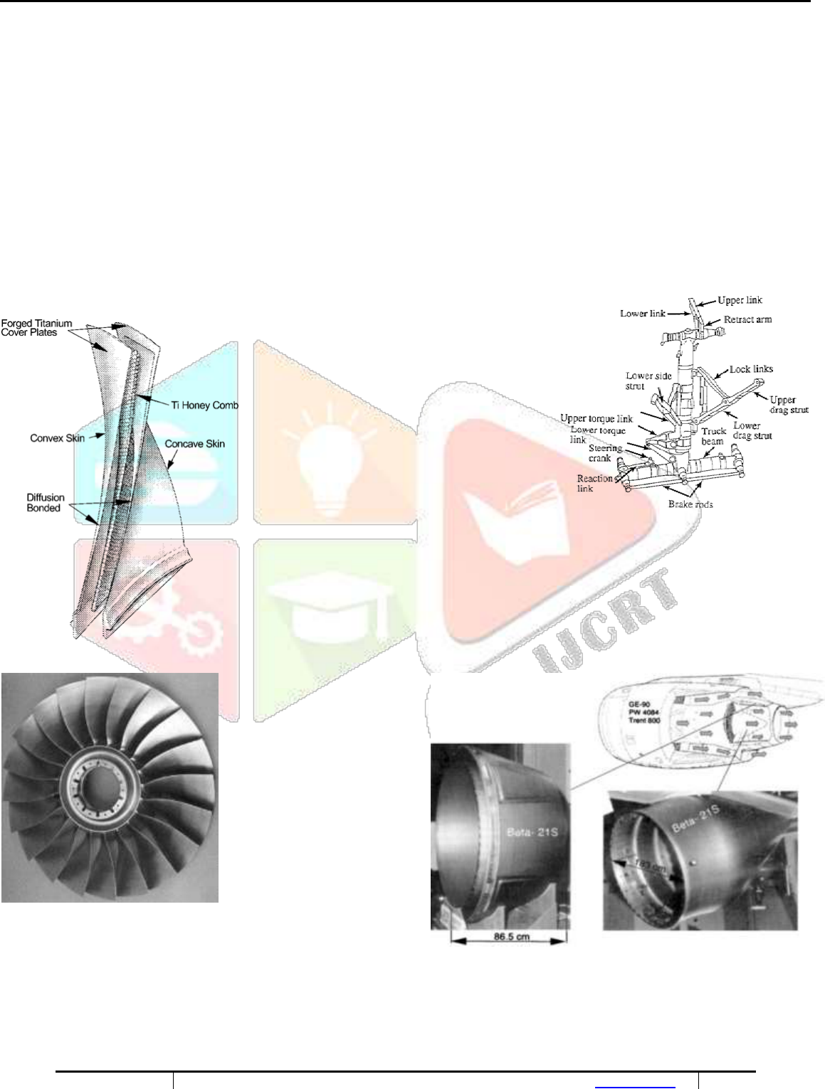
to hollow titanium fan blade technology. Early hollow fan blade designs were comprised of machined titanium face sheets that were Liquid
phase diffusion bonded to a titanium honeycomb core. Advances in manufacturing techniques now allow the blades to be produced from Ti

www.ijcrt.org © 2020 IJCRT | Volume 8, Issue 4 April 2020 | ISSN: 2320-2882
IJCRT2004183
International Journal of Creative Research Thoughts (IJCRT) www.ijcrt.org
1389
sheet via superplastic forming and solid-state diffusion bonding (SPF-DB). The new engines for the Airbus A 380 from both Rolls-Royce (Trent
900) and the GE/Pratt & Whitney Engine Alliance (GP7200) will have fan diameters of approximately three meters and will incorporate hollow
titanium fan blades. [3]
Evolutionary engine design lay emphasis on the need to further reduce the weight of the compressor blades and disks, while prolonging
component life or inspection intervals. This can be achieved using an integrally bladed disk, or “blisk”, design. The completed blisk is a single
assembly where disk and blades are metallurgically bonded with each other. For small blade heights up to about 60 to 80 mm, it is more cost
effective to machine a blisk from an oversized forged disk. Larger blades are mostly attached to the disk by linear friction welding. In addition
to the weight saving from a blisk design, the lack of a mechanical interface between the blades and the disks eliminates a common site for
fatigue crack initiation. This can result in extended inspection intervals. As fan blades and disks are used at low temperatures, they are generally
manufactured from Ti-6AL-4V. The maximum temperature limit for this alloy is about 315 °C. Therefore, the disks and blades of the first 4 to
5 stages of the compressor (Low-pressure compressor) can also be made from Ti-6AL-4V. However, elevated temperature near-α alloys are
used in the high-pressure compressor. Today, the max temperature limit for these alloys is about 540°C. This upper bound is not limited by the
elevated temperature strength or creep resistance of the near-α alloys, but by their moderate oxidation resistance, especially in comparison to
nickel based super alloys. In long-term elevated temperature applications titanium alloys form a “α-case” at the surface i.e., a zone with a brittle
α-phase caused by oxygen enrichment, which leads to a drastic reduction in ductility and fatigue strength. For rotating parts, Ti’s temperature
limit can be even lower due to its propensity to burn. This condition is created when a rotating blade rubs on the inside wall of the engine
casing causing localized heating at the blade tip. At elevated temperatures and in a high-pressure air environment, this can lead to very rapid
oxidation of the titanium. These conditions are encountered in the high-pressure compressor of the engine. The oxidation process, which is
exothermic, can become self-propagating and cause a titanium fire. To mitigate this problem, Pratt & Whitney developed a highly stabilized ß-
alloy called Alloy C (Ti-35V-15Cr) that is resistant to burning. This alloy is finding application in the F-22’s F119 engine in compressor stators
as well as augmentor and nozzle components. [3]
These temperature limitations for Ti alloys mean the hottest parts in the compressor i.e., the disks and blades of the last compressor stages,
have to be made from Ni-based super alloys at approximately twice the weight. Furthermore, problems arise associated with the dissimilar
thermal expansion behavior and the bonding methods of the two alloy systems. Hence, vast efforts are ongoing to develop a compressor made
completely of Ti. Ti alloys are necessary that can be used at temperatures of 600°C or higher. This has been the motivation for extensive
research and development work in the area of elevated temperature Ti alloys. The maximum application temperature of Ti alloys has been
increased from about 300°C to nearly 600°C over the last 40 years. Within the last few years, the near-α class of elevated temperature Ti alloys
has been the matter of particular development interest. An example of the state of the art of this development is IMI 834 (Ti-5.8Al-4Sn-S.5Zr-
0.7Nb-0.5Mo- 0.35Si), developed jointly in the United Kingdom by IMI Titanium Ltd. and Rolls-Royce in the 1980’s. With a potential use
temperature of almost 600 °C, the alloy was aimed at replacing the IMI 685 and IMI 829 alloys preferred in European jet engines. After IMI
was acquired by TIMET, this alloy was given the trade name TIMETAL 834 and has since found its way into European military jet engines.
Currently it is also used as a compressor disk material in the last two stages of the medium-pressure compressor, and the first four stages of the
high-pressure compressor in variants of the Rolls-Royce Trent series commercial jet engine. A bimodal microstructure with a primary a volume
fraction of 15 % has established to be an optimum microstructure for this particular application. In the US, the mature Ti-6-2- 4-2S is still the
desired high temperature alloy for jet engine applications. Despite the discussion of near-α titanium alloys, the objective to further increase
high temperature strength is addressed with the development of titanium aluminides. These materials, based on the intermetallic compounds
α₂(Ti₃ Al) and γ(TiAl), have been studied for their potential to raise the application temperatures of titanium alloys to 650 °C and 800 °C,
respectively. Their exceptional creep resistance is because of the ordered nature of the crystal structure. However, this structure also makes the
intermetallic relatively brittle and correspondingly hard to deform. Alloying with Cr, Nb, V, Mn, or Mo and microstructural optimization are
two methods to gain increased ductility. Another important aspect for the use of titanium aluminides in turbine engines is the resistance of these
materials to initiating a titanium fire. TiAL-based alloys in particular reduce the risk of Ti fire. Compressor blades of upcoming high-pressure
compressors are therefore a potential application of TiAl alloys. Sufficient damage tolerance, a satisfactory oxidation behavior, and
producibility (cost) are critical factors that will ultimately determine the use of titanium aluminizes in aerospace. The prospect for potential
application of TiAL-based alloys is much higher for jet engine components with less severe damage tolerance requirements. [3]
www.ijcrt.org © 2020 IJCRT | Volume 8, Issue 4 April 2020 | ISSN: 2320-2882
IJCRT2004183
International Journal of Creative Research Thoughts (IJCRT) www.ijcrt.org
1390
The reduced weight of the titanium aluminide blades would further permit an even lighter weight design of the complete turbine due to the
lower centrifugal forces imposed on the disk. Use of these alloys in a large jet engine like the GE90 might save more than 150 kg. Due to price,
the casting route is favored for the production of TiAl Low-pressure turbine blades. Increased stiffness and elevated temperature strength are
the crucial goals for the development of long fiber reinforced Ti matrix composites (TMCs). Potential areas for use in jet engines are high-
stiffness, high-strength fan blades, and thermally stable cylindrical components in the high-pressure compressor. Most research have been
carried out on SiC long fiber reinforced Ti-6AL-4V. Matrices of near-α alloys and titanium aluminides, stable at higher temperatures, are also
of interest. The availability of TMCs enables previously untenable design approaches, such as the integrally bladed compressor ring, or bling.
The bling design eliminates the hub of the disk, significantly reducing the component weight by up to 70 %. However, in order to accomplish
this, the strength of the material at the base of the blades must be much higher to support the centrifugal loads and cells for use of metal matrix
composite reinforcement. As with blisks, the number of parts is drastically reduced, substantially reducing maintenance costs compared to
conventionally bladed rotors. Such improvements are likely to justify the high manufacturing costs, and will allow compressors and jet engines
themselves to be built considerably more compact. Continued research and development, particularly in processing and component life
management techniques, still have to be completed before these composite materials are put into rotating components. The first aerospace use
of continuously reinforced titanium composite material is a low risk application as an actuator piston on the F-22’s F119 engine. Aerospace
hydraulic fluid is one of the few corrosive media to otherwise usually corrosion resistant titanium alloys. Above 130°C hydraulic fluid forms
an acid that etches the titanium and leads to hydrogen embrittlement of the component. One of the few alloys that appears to be immune to this
attack is the ß-alloy TIMETAL 21S. For this reason, the Boeing Company uses TIMETAL 21S for the plug and other parts of the nozzle
assembly on its 777 aircraft. The 777 uses the largest jet engines GE90, PW4084 and Trent 875. [3]
. Fig. 7. Main landing gear of the
Boeing 777 of forged TIMETAL 10-2-S parts
(Boeing Commercial Aircraft, Seattle, WA, USA).
Fig. 6. Hollow fan construction for the first generation of
‘Wide chord fan blades’ (Rolls-Royce plc. Derby, UK).
Fig. 8. Titanium blisks for compressor
applications (MTU Aero Engines, Munich, Germany).
Fig. 9. Applications of TIMETAL 21S in the nozzle area of the Boeing 777.
3.3. He1icopters

www.ijcrt.org © 2020 IJCRT | Volume 8, Issue 4 April 2020 | ISSN: 2320-2882
IJCRT2004183
International Journal of Creative Research Thoughts (IJCRT) www.ijcrt.org
1391
For helicopters, Ti alloys are used in the most severely stressed component the rotor head. Studies are ongoing for high-strength ß-alloy
replacements. For example, the ß-alloy TIMETAL 10-2-3 has replaced Ti-6AL-4V for the main rotor head of the Westland Super Lynx
helicopter. Today ß-alloys are also established in other helicopter programs. TIMETAL 10-2-3 is used for the rotor mast and rotor head for the
US RAH-66 Comanche helicopter. The same alloy is also being applied in the yoke assembly of the tilt rotor V-22 Osprey.
Fig. 10. Forged rotor head of the BO 105 and BK 117 helicopters.
3.4. Space Applications
Due to the comparatively small payload of space vehicles, saving weight in these structures is even more important than in aircraft. For this
reason, Ti alloys were used widely in the first Apollo and Mercury programs. Fuel and satellite tanks are regarded as a standard application for
Ti alloys. Ti’s high strength, low weight, and long term chemical compatibility with fuel give Ti alloys an advantage over high-strength steels.
Furthermore, the integrity of the tanks must be reliably non-destructively tested before being sent into orbit, which is most consistently done
for metallic tanks. Non-metallic components require additional efforts to ensure their integrity. The requirement for extremely Lightweight
satellite component construction dictates very intensive, weight optimizing manufacturing techniques. Under favorable conditions, the final
fuel tank wall thickness in commonly used satellite propulsion systems is machined from 25 mm thick forged half-shells to Less than 1 mm.
This exceptionally high degree of machining can be drastically reduced by superplastic forming. Ti sheet, 6 to 10 mm thick, can be
superplasticcally made into hemispheres and either simultaneously diffusion bonded or later conventionally welded to form a tank. Compared
to conventional production by forging and machining, clear cost savings are obtained. In addition to superplastic forming, cold-formable ß-
alloys provide another cost effective route. MAN Technologies AG uses such an approach to produce the fuel tanks for the ESA on the
Automated Transfer Vehicle (ATV) for the internal space station (ISS). The Ti-15-3 tank half-shells are formed by a special, patented cold
rolling process called counter-role spin forming. Compared to SPF processing, the required infrastructure and tooling are substantially cheaper.
Furthermore, the ß-alloy shows very good mechanical properties. Among others, spin forming is used for the construction of the half-shells of
the storable propellant stage (EPS) tanks for the upper stage of the Ariane 5. Ti-3Al-2.5V was developed, among others, for low temperature
uses and shows good toughness and ductility down to cryogenic temperatures. Therefore, it is used for high-pressure piping in the hydrogen
pumping systems of the US Space Shuttle. [3]
Fig. 11. Pressure tanks manufactured from titanium Fig. 12. Attitude Control System (SCA) tank of welded
Ti-6Al-4V
for space transportation systems SPF half shells (U. Rieck, Astrium GmbH, Bremen, and Germany)

www.ijcrt.org © 2020 IJCRT | Volume 8, Issue 4 April 2020 | ISSN: 2320-2882
IJCRT2004183
International Journal of Creative Research Thoughts (IJCRT) www.ijcrt.org
1392
(TIMET, Henderson, NV, USA).
Fig. 13. Ti-1J-S half shells (U. Rieck, Astrium GmbH, Bremen, Germany)
IV. Manufacturing Techniques of Titanium Alloys.
Selective Laser melting (SLM) is an additive manufacturing technology that uses
laser as a power source to sinter powdered metals to produce solid structures.
SLM allows a layer by layer fabrication of complex components directly out of
metal powder based on CAD-Data. An excellent advantage of SLM is the
possibility to create complex light weight structures that cannot be formed using
conventional processes. Light weight structures can contribute to the rise of
efficiency and also to reduce the fuel consumption and the emission levels of
gases by aircrafts.
Fig. 14. Workflow of the Pre-processing. Fig. 15. SLM-process flow
The significant parameters used for the manufacturing of testing geometries are the laser power PL, the scanning velocity vs and the focus
diameter ds, which depend on the focus position. Round specimens in 0°, 45° and 90° orientation are generated according to VDI 3405-2. The
last steps before the SLM-process begging are as follows: cleaning of the process chamber and the coater, adjust of the substrate plate and
application of the first layer.
After the additive manufacturing, the specimens have to cool down, be removed from the machine and get cleaned from the powder used
during the process. Moreover, a thermal post-processing is used before the hot isostatic pressing (HIP). Hot Isostatic Pressing according to
DIN 65083 “causes the healing up of internal structural defects such as micro blowholes and pores in castings, through annealing at high
temperatures and pressures”. So the HIP-process reduces the porosity and increases the density of the part. Thus fatigue properties get improved.
The static and dynamic strength, the breaking elongation and durability are increased and more uniform mechanical properties are achieved.
Fig. 16. SLM-exposure of the specimens (left) and generated specimens on the substrate plate (right).
V. Machining Of Titanium Alloys
Ti is an attractive material to aerospace designers due to its unique blend of strength and lightness. However, it poses considerable problems
in manufacturing because of its poor machinability. It is desirable to provide aero components made-up of titanium alloys with superior strength
without sacrificing machining performance. Keeping this in mind the cutting and feed forces and cutting tool temperature of orthogonally
machined titanium alloys should be investigated. The cutting speed was found to have statistically insignificant effect on feed force and thus
must be set at a level which is most appropriate and economical to industry. The optimum selection of the chemical composition of titanium
alloy is very important to ascertain the affable evolution of microstructure for attaining the minimum cutting and feed forces and cutting tool
temperature. Also, high cutting tool temperature during machining of alloy results in failure of carbide tools (for example, a high-cubic boron
CAD Model
STL
Format
Support
Generation
Slicing via
www.ijcrt.org © 2020 IJCRT | Volume 8, Issue 4 April 2020 | ISSN: 2320-2882
IJCRT2004183
International Journal of Creative Research Thoughts (IJCRT) www.ijcrt.org
1393
nitride content tool material (AMBORITE)) is used. Thus the lowest cutting and feed force and cutting tool temperature values are obtained
with the Ti6Al4V titanium alloy, thereby making it a desirable choice for aerospace and aircraft applications.
Ti aircraft component has been considering tough-to-cut not only for the poor machinability of material itself but also for the complexity of its
structure which generally consists of thin-ribs, thin-webs, corners, pockets, etc. Structural features are therefore as important as material
properties for the selection of cutting tools when machining titanium aircraft components. However, a new method of cutting performance
evaluation of end mills was proposed for the machining process of titanium aircraft components which comprises of fuzzy comprehensive
evaluation (FCE) models [9]. Utilizing the models, the users are at ease not only to evaluate the tool performance for every feature, but also to
assess the machinability of different structural features of the components.
5.1. Laser beam welding (LBW) technique
The use of laser beam welding (LBW) technique instead of conventional
riveting joints is a promising approach in the direction of cost and weight
reduction. Several alloying elements significantly increase the strength but
reduce the formability of titanium alloys. This is the main reason why
commercially pure titanium (Grade 2) is mostly used for the outer skin
material, whereas Ti-6Al-4V titanium alloy (Grade 5) is usually chosen as
stiffening stringer material. The welding and straightening equipment
consisted of an 8 kW continuous wave ytterbium.
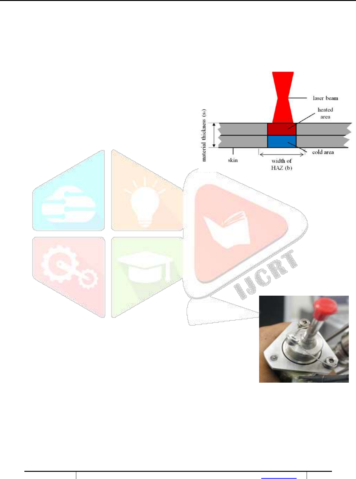
Due to the heat input during the welding process, plastic deformation of the
material is induced. This is developed by an originating moment due to
temperature differences between the upper and the lower side of the skin
sheet. The gradient causes the development of in homogeneously distributed
inner residual stresses which lead to an angular distortion of the sheet material. Fig. 17. The TGM in a simplified two layer model
To reconstruct the formerly flat surface of the material, post-forming processes
have to be conducted. In this work a non-contact post-forming procedure is performed using the temperature gradient mechanism (TGM) to
straighten the sheet material. Therefore, the rear side of the work piece was irradiated by a defocused laser of the same equipment as for the
LBW-process to induce the TGM again and reverse welding induced distortions. This technique is very efficient for small material thicknesses
due to a relatively fast process and minimum energy needs. Aim of the straightening process is to achieve a flat surface of the work piece
similar to the flatness before the LBW. The required laser power should be minimized in order to prevent the damage of the surface, oxidation
and microstructural changes. Therefore, the laser beam has to be defocused and the operating laser power has to be controlled precisely.
VI. Failure Analysis Of Titanium Alloys
6.1. Failure analysis of titanium alloy (Ti6-Al-V4) fastener-
Titanium alloy fasteners are being used in space program. These fasteners are coated with MoS
2
, which serves the purpose of solid lubricant.
During the trial assembly of flight spin motor to the bracket mounted on subsystem, one of the two fasteners failed such that the head of the
bolt had sheared off the shank.
6.1.1. Process of Manufacture:
The input rod of size of Φ9.0mm was processed by hot rolling at temperature 9550C followed by
annealing at 7000C for 1 hour thereafter by air cooling. The rods were further reduced to Φ5.6mm by
hot swaging. Finally, size of Φ4.5mm was achieved by center less grinding.
1. Head forging: Head forging was done by flame heating the head portion of feed stock followed by
swaging on the dies.
2. The head forged feedstock was heat treated to solution treatment at 940±100C with soaking period
of 45 minutes followed by water quenching. Further, aging was done at 535±100C for 5 hrs. - air
cooling. Socket head was punched by cold working.
3. Thread rolling: Threads were processed on the heat treated head forged feed stock by thread rolling.
Fig. 18.Assembly of the bolt

www.ijcrt.org © 2020 IJCRT | Volume 8, Issue 4 April 2020 | ISSN: 2320-2882
IJCRT2004183
International Journal of Creative Research Thoughts (IJCRT) www.ijcrt.org
1394
6.1.2. Observations on failed bolt:
As a qualification of bolt for flight assembly, the bolt assembly has undergone Proof pressure test at 2.4MPa, Vibration test at frequency range
of 20100Hz, ±3db/oct for 120sec in both lateral and longitudinal directions and flight acceptance test. During routine visual inspection before
electrical check, it was observed in one of the three fasteners that the head of the bolt had got sheared off from the shank portion of bolt. Further
failure analysis was carried out on the failed bolt. Visual inspection shows that the bolt used was having 25mm long thread portion and 75mm
plain shank portion. Further, crack portion of the head and shank portion was analyzed with stereo zoom microscope; it was observed that, a
hole was pierced into the shank. Dye penetrant test was carried out on the fresh bolts and it was observed that circumferential cracks were
present at the bottom of the head and some cracks extending to shank side. Metallurgical analysis was carried out on the head portion, failure
zone and shank portion of the bolt. In the head portion a crack was observed adjacent to the one corner of bolt. In general, failure in mechanical
fasteners occurs due to overload of static loading (tension, shear, bending, or torsion) and dynamic forces results from impact loading, cyclic
fatigue loading including vibration loads. In addition, other common cause of failure includes environmental effects, manufacturing
discrepancies, improper use and incorrect installation. For present case, primary reason for failure was socket head hole which has got pierced
into the shank portion thereby resulted in the reduction of effective load bearing area, which allowed more stress concentration zones at interface
zone. And it was compared with thread profile of metric socket head bolt standard. The cracks were started at interface region as pierced zone
acted as notch and it experienced dynamic loads due to vibration test. Surface cracks were present in interface region was due to uncontrolled
process parameters followed during head forging and socket head hole punching [10].
Fig.21 Fracture portion of the bolt Fig.22.Hole pierced Fig. 23.Nucleation in head Fig. 24. Propagation of cracks
in the head and shank in head and shank
6.2. The assessment of the aging process of titanium ducts for use in aircraft pneumatic system -
During service operation, the pneumatic system of a commercial aircraft is subjected to hot air pressure cycles, causing the stresses developed
in the material to be of cyclic nature. Commercially pure titanium is one of the various metallic materials selected for use in the pneumatic
system components. In order to provide information concerned with the service performance of the titanium ducts and their effects on material
behavior, a pneumatic workbench capable of reproducing the temperature and pressure cycles found in flight conditions was developed. It is
feasible to conduct laboratory tests aimed at simulating the aging process suffered by the pneumatic system ducts. Their tensile and fatigue
properties were observed to change in response to pressurization tests, and these changes were not related to chemical composition or surface
degradation.
6.2.1. Experimental procedure -
Fig. 19 shows the shape and dimensions of the tubular test piece adopted for cyclic pressurization tests [8]. A schema of the workbench is
shown in Fig. 20. It is composed by a piston compressor, a booster, a programmable controller connected to solenoid valves and a tube furnace
where the test-piece is inserted in. Flight cycle data obtained from a commercial aircraft were analyzed using the rain-flow cycle counting
method in order to establish the laboratory test parameters. The pressurization tests performed in this work were conducted at controlled
temperature (300 C and 400 C), with constant amplitude cycles having pressure ratio (min/max) of 0.1 and frequency of 0.3 Hz. Two distinct
maximum cyclic pressures were tested: 150 psi (corresponding to normal flight conditions) and 250 psi (ice flight conditions). According to
the von Mises criterion, these pressure levels correspond to effective stresses of, respectively, 31 MPa and 52 MPa in the straight sections of
the ducts. In each test, a number of 3x10
4
pressurization cycles were applied. Based on design parameters which establish that, for a regional
jet, two pressure cycles occur during a flight leg of approximately two hours, the number of cycleswhich establish that, for a regional jet, two
pressure cycles occur during a flight leg of approximately two hours, the number of cycles adopted for this work would correspond to 50% of
the 60,000 flight hours to which the pneumatic system components are expected to endure. After the pressurization cycles, the tubular test-
pieces were carefully sectioned so that material samples for mechanical, chemical and internal surface analyses were obtained. A tubular test
piece failed by cracking during cyclic pressurization was also investigated for fracture analysis [8].
Fig. 19.Diagram of the pneumatic workbench Fig. 20.the shape and dimensions of the tubular test piece

www.ijcrt.org © 2020 IJCRT | Volume 8, Issue 4 April 2020 | ISSN: 2320-2882
IJCRT2004183
International Journal of Creative Research Thoughts (IJCRT) www.ijcrt.org
1395
developed for the simulation of flight pressurization cycles
6.2.2. Observations-
Titanium ducts were submitted to cyclic pressurization tests at controlled temperature in order to reproduce aircraft service conditions. Their
tensile and fatigue properties were observed to change in response to these tests. The ducts submitted to a maximum pressure of 150 psi suffered
a slight cyclic softening, whereas the material pressurized at 250 psi presented cyclic hardening. The S/N curves indicate that the cycled
material suffered a drop of at least 50 MPa (circa 25%) in fatigue resistance at 10
5
cycles, leading to the conclusion that the material suffered
damage accumulation during the pressurization tests [8]. It was shown that these changes were not related to chemical composition or surface
degradation. The fractographic analysis of a failed duct revealed that fatigue cracks can nucleate in the vicinities of weld flaws and gradually
propagate through the wall, indicating that an improvement of the welding quality control is necessary.
20000 40000 60000 80000 100000 120000 140000 160000
N (cycles)
Fig. 25. Room temperature SN curves for various material conditions
VII. CONCLUSION
With the development of technology in the real world, the options of material for aeronautical application grow every day and there are a lot
of options to choose from but Titanium alloys play an important role in the aerospace industry. To maintain a prominent position in the industry,
future efforts must be directed toward the cost reduction of titanium structure. Development efforts need to be directed toward new alloys /
processes to reduce final component costs. Expansion of the titanium industry into industrial applications, which seems to appear more
promising, with the help of continuous process improvements it will be possible to produce parts that ensure the quality and safety required by
aeronautical industry it would also provide a benefit to the aerospace community by providing a more stable production base, which should
provide greater price stability.
7.1. Shortages of Titanium
– High manufacturing costs (~8x higher comparing Al)
– Chemical reactivity above 500 °C – intensive reactions with O
2
, H
2
, N
2
, etc
– Lower modulus of elasticity - comparing steel (E = 115 GPa against 210 GPa)
– Poor friction properties, tendency for seizing
– Poor machinability - low thermal conductivity, local overheating & adhering on tool
– Welding problems (reactivity with atmospheric gases welding, diffusion welding, laser beam welding, electron beam welding)
– Special manufacturing methods
7.2. Preferred use of titanium alloys
– If strength and temperature requirements are too high for Al or Mg alloys
– At conditions, when high corrosion resistance is required
– At conditions, when high yield strength and lower density comparing steel are required
– Increasing usage (Boeing 727 – 295 kg, Boeing 747 – 3400 kg)
140
160
180
200
220
240
260
280
300
320
ge Fa
A
vera
tigu
e Life
SR
150-
300
TD
TD
400
150-
TD
250-
300

www.ijcrt.org © 2020 IJCRT | Volume 8, Issue 4 April 2020 | ISSN: 2320-2882
IJCRT2004183
International Journal of Creative Research Thoughts (IJCRT) www.ijcrt.org
1396
VIII. REFERENCES
1. R.R. Boyer ,An overview on the use of titanium in the aerospace industry, Materials Science and Engineering A213, 1996, p. 103-114 [1]
2. Paramjit Singh, Harish Pungotra, Nirmal S. Kalsi , On thecharacteristics of titanium alloys for the aircraft applications, Materials Today:
Proceedings 4 ,2017, p. 8971–8982 [2]
3. Manfred Peters, Charles H. Ward and Christoph Leyens ,Titanium alloys for aerospace applications, Advaned Engineering Materials, 2003,
p. 419-426 [3]
4. M. Froend , F. Fomin , S. Riekehr , P. Alvarez , F. Zubiri , S. Bauer , B. Klusemann , N. Kashaev ,Fiber laser welding of dissimilar titanium
(Ti-6Al-4V/cp-Ti) T-joints and their laser forming process for aircraft application,
Optics and Laser Technology 96, 2017, p. 123–
131 [4]
5. N. Khanna, J.P. Davim, Design-of-experiments application in machining titanium alloys for aerospace structural components, Measurement
(2014) [5]
6. Farhad Nabhani, Machining of aerospace titanium alloys, Robotics and Computer Integrated Manufacturing 17 (2001), 2001, 99-100 [6]
7. Eckart Uhlmann, Robert Kersting, Tiago Borsoi Klein, Marcio Fernando Cruz, Anderson Vicente Borille, Additive manufacturing of
titanium alloy for aircraft components, 15th Machining Innovations Conference for Aerospace Industry ,2015 [7]
8. C.A.R.P. Baptista , M.J.R. Barboza , A.M.L. Adib ,M. Andrade ,C. Otani , D.A.P. Reis, High temperature cyclic pressurization of titanium
ducts for use in aircraft pneumatic systems,
Materials and Design, 2008, p. 1503-1510 [8]
9. Wei Zhao, Shengzhang Wan, Zhiwei Han, Ning He
,Cutting Performance Evaluation of End Mills for Titanium Aircraft Components, 15th
Machining Innovations Conference for Aerospace Industry, 2015 [9]
10. Vartha VenkateswarluDebashish TripathyK. RajagopalK. Thomas TharianP.V. Venkitakrishnan Failure Analysis and Optimization of
Thermomechanical Process Parameters of Titanium alloy (Ti-6Al-4V) Fasteners for Aerospace Applications (2013),
http://dx.doi.org/10.1016/j.csefa.2013.04.003, 2013 [10]
