
Field Performance of
Heat Pump Water Heaters
in the Northeast
Carl Shapiro and Srikanth Puttagunta
Consortium for Advanced Residential Buildings
February 2016

NOTICE
This report was prepared as an account of work sponsored by an agency of the United States
government. Neither the United States government nor any agency thereof, nor any of their employees,
subcontractors, or affiliated partners makes any warranty, express or implied, or assumes any legal
liability or responsibility for the accuracy, completeness, or usefulness of any information, apparatus,
product, or process disclosed, or represents that its use would not infringe privately owned rights.
Reference herein to any specific commercial product, process, or service by trade name, trademark,
manufacturer, or otherwise does not necessarily constitute or imply its endorsement, recommendation, or
favoring by the United States government or any agency thereof. The views and opinions of authors
expressed herein do not necessarily state or reflect those of the United States government or any agency
thereof.
Available electronically at SciTech Connect http:/www.osti.gov/scitech
Available for a processing fee to U.S. Department of Energy
and its contractors, in paper, from:
U.S. Department of Energy
Office of Scientific and Technical Information
P.O. Box 62
Oak Ridge, TN 37831-0062
OSTI http://www.osti.gov
Phone: 865.576.8401
Fax: 865.576.5728
Email: [email protected]
Available for sale to the public, in paper, from:
U.S. Department of Commerce
National Technical Information Service
5301 Shawnee Road
Alexandria, VA 22312
NTIS http://www.ntis.gov
Phone: 800.553.6847 or 703.605.6000
Fax: 703.605.6900
Email: [email protected]

iii
Field Performance of Heat Pump Water Heaters in the Northeast
Prepared for:
The National Renewable Energy Laboratory
On behalf of the U.S. Department of Energy’s Building America Program
Office of Energy Efficiency and Renewable Energy
15013 Denver West Parkway
Golden, CO 80401
NREL Contract No. DE-AC36-08GO28308
Prepared by:
Carl Shapiro and Srikanth Puttagunta
Steven Winter Associates, Inc.
of the
Consortium for Advanced Residential Buildings
61 Washington Street
Norwalk, CT 06854
NREL Technical Monitor: Cheryn Metzger
Prepared under Subcontract No. KNDJ-0-40342-03
February 2016
iv
The work presented in this report does not represent
performance of any product relative to regulated
minimum efficiency requirements.
The laboratory and/or field sites used for this work are
not certified rating test facilities. The conditions and
methods under which products were characterized for
this work differ from standard rating conditions, as
described.
Because the methods and conditions differ, the reported
results are not comparable to rated product performance
and should only be used to estimate performance under
the measured conditions.

v
Contents
List of Figures ............................................................................................................................................ vi
List of Tables ............................................................................................................................................. vii
Definitions ................................................................................................................................................. viii
Executive Summary ................................................................................................................................... ix
1 Introduction ........................................................................................................................................... 1
1.1 Background ...................................................................................................................................... 2
1.2 How Heat Pump Water Heaters Work ............................................................................................. 4
1.3 Space-Conditioning Interactions and Installation Considerations ................................................... 5
1.4 Model Operation and Control Logic ................................................................................................ 5
1.4.1 General Electric Control Logic ........................................................................................... 6
1.4.2 A.O. Smith Control Logic ................................................................................................... 6
1.4.3 Stiebel Eltron Control Logic ............................................................................................... 7
2 Recent Studies ...................................................................................................................................... 8
3 Technical Approach ............................................................................................................................. 9
3.1 Research Questions .......................................................................................................................... 9
3.2 Measurements .................................................................................................................................. 9
3.3 Equipment ...................................................................................................................................... 10
3.4 Analysis ......................................................................................................................................... 11
4 Performance Results .......................................................................................................................... 13
4.1 Impact of Water Use on Efficiency................................................................................................ 14
4.2 Impact of Air Temperature on Efficiency ...................................................................................... 16
4.3 Delivered Water Temperature ........................................................................................................ 19
4.4 Calculating Standby Losses ........................................................................................................... 23
4.5 Impact of Confined Spaces ............................................................................................................ 26
4.6 Impact on Space-Conditioning Systems ........................................................................................ 27
5 Energy and Cost Analysis ................................................................................................................. 30
6 Homeowner Surveys .......................................................................................................................... 35
7 Recommendations ............................................................................................................................. 36
8 Conclusion .......................................................................................................................................... 37
References ................................................................................................................................................. 40
Appendix A: A History of Heat Pump Water Heaters in the United States ......................................... 44
Appendix B: Alternative Water-Heating Calculations ........................................................................... 48
Appendix C: Monitored and Modeled Energy Use and Costs by Site ................................................. 49
Appendix D: Identifying Heating Events ................................................................................................. 51
Appendix E: Trifold Brochure for Consumers ....................................................................................... 53

vi
List of Figures
Figure 1. Timeline of HPWH development in the United States ............................................................. 3
Figure 2. How HPWHs work ....................................................................................................................... 4
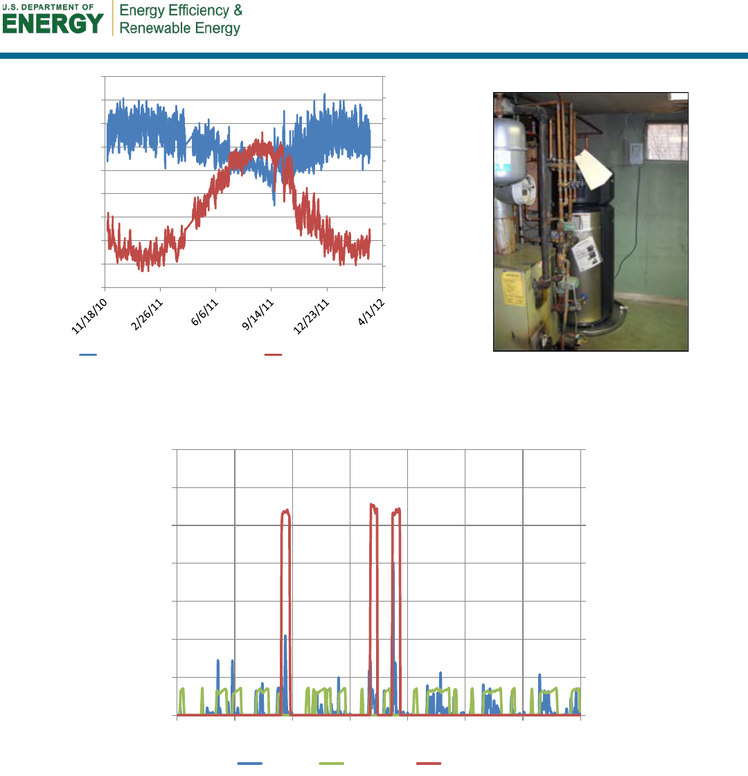
Figure 3. Example of an HPWH monitoring system installation .......................................................... 11
Figure 4. Ideal operation of the GE HPWH in hybrid mode (Site 9) ..................................................... 15
Figure 5. Low water use can reduce the overall benefit of an HPWH when the cost benefit is
assessed. ............................................................................................................................................. 15
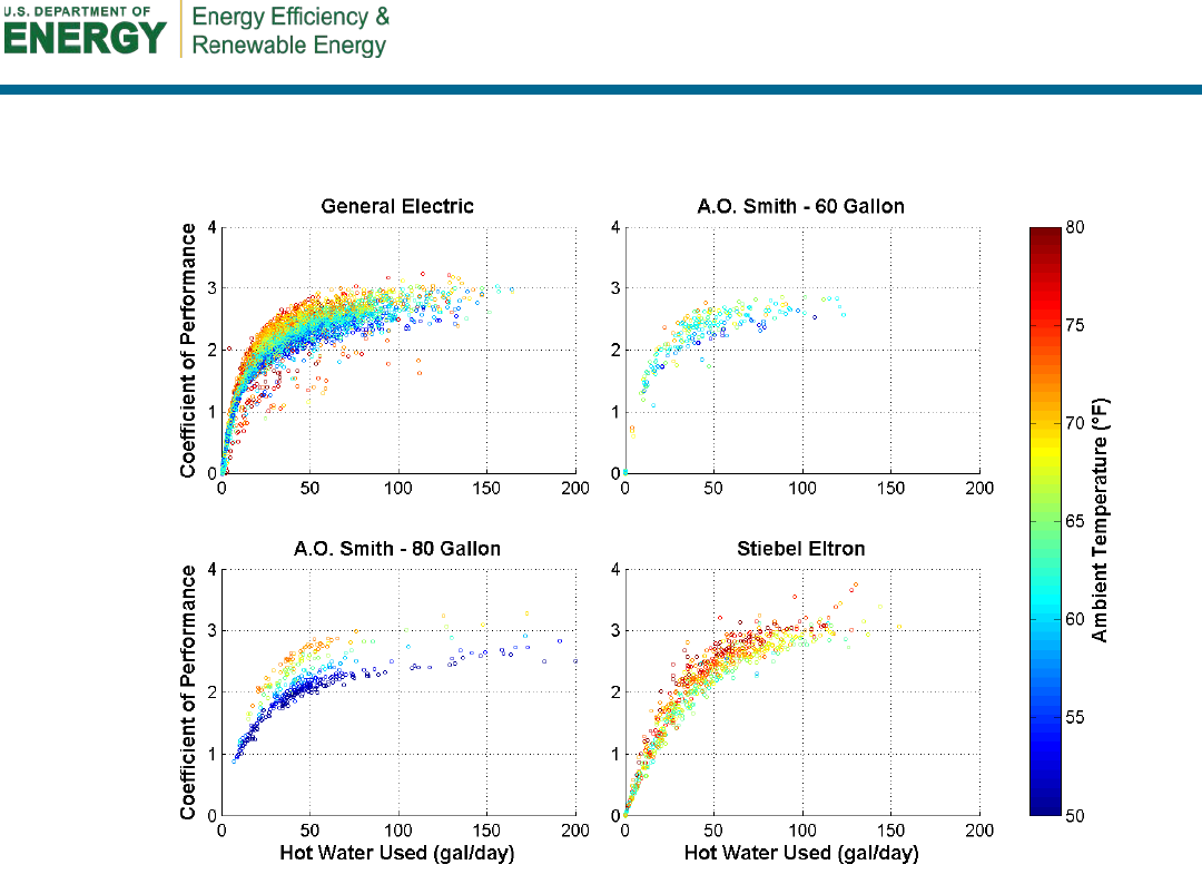
Figure 6. Scatter plots of daily hot water use versus COP color coded by electric resistance
fraction ................................................................................................................................................. 16
Figure 7. Because the Site 5 basement was too cold, this GE HPWH switched primarily to electric
resistance mode during the winter months. .................................................................................... 17
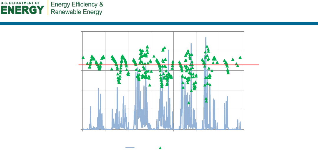
Figure 8. Ambient temperature at Site 11 ............................................................................................... 18
Figure 9. This HPWH benefited from the waste heat of the boiler used for space heating. ............. 18
Figure 10. Typical winter performance of the GE HPWH in the Site 11 warm mechanical room ..... 18
Figure 11. Scatter plots of COPs versus daily hot water use color coded by ambient temperature.
Periods with electric resistance fractions greater than 0.04 and Sites 5 and 13 were
excluded. ............................................................................................................................................. 19
Figure 12. This Stiebel Eltron HPWH was able to maintain high COPs during high water demand. 20
Figure 13. Even with high water demand, the hot water temperature dropped only as low as
118°F. ................................................................................................................................................... 21
Figure 14. Normalized histograms of delivered water temperature. Red line indicates set point
temperature. Green line indicates minimum delivery temperature (110°F). The percentage of
occurrences with water temperatures lower than 110°F is shown. .............................................. 22
Figure 15. Regression results and data points for GE standby losses. Temperature difference is
between the tank average temperature and ambient air. ............................................................... 26
Figure 16. Performance of the HPWH at Site 13 in a confined space .................................................. 27
Figure 17. Box plots of maximum potential space-conditioning impacts for monitored HPWHs .... 28
Figure 18. Annual operating cost of monitored HPWHs and alternative water heaters .................... 31
Figure 19. Annual source energy of monitored HPWHs and alternative water heaters .................... 32
Figure 20. Annualized energy-related costs of monitored HPWHs and alternative water heaters .. 34
Figure 21. First patented HPWH. Image from Wilkes and Reed 1937. ................................................. 44
Figure 22. Results from using daily data for analysis ........................................................................... 51
Figure 23. Example of five heating events as defined in this study .................................................... 52
Unless otherwise noted, all figures were created by CARB.

vii
List of Tables
Table 1. Performance Summary of Monitored HPWHs by Model .......................................................... ix
Table 2. Residential Water-Heating Energy Consumption and Operating Costs (per annum) ........... 1
Table 3. Key Specifications of Integrated HPWHs Currently Available in the U.S. Market ................. 2
Table 4. Installed Monitoring Equipment ................................................................................................ 11
Table 5. Summary Statics of Performance by Model ............................................................................ 13
Table 6. Summary Table of Performance by Site .................................................................................. 14
Table 7. Tank Heat Loss Robust Regression Results with Constant (number of observances = 113,
degrees of freedom = 111) ................................................................................................................. 25
Table 8. Tank Heat Loss Robust Regression Results without Constant (number of observances =
113, degrees of freedom = 112) ......................................................................................................... 25
Table 9. Alternative Water Heaters .......................................................................................................... 30
Table 10. Fuel Prices and Characteristics for Energy and Cost Analysis .......................................... 31
Table 11. Cost Analysis Assumptions .................................................................................................... 32
Table 12. Installation Costs and Lifetimes of Water-Heating Products ............................................... 33
Table 13. Installed HPWH Cost Estimates from Study .......................................................................... 33
Table 14. Survey Results of Whether the Homeowner or a Qualified Professional Performed any
Preventive Maintenance Procedures ................................................................................................ 35
Table 15. Survey Results of Homeowners .............................................................................................. 35
Table 16. Summary of Test Results by Model ........................................................................................ 37
Table 17. Key Specifications of Integrated HPWHs Currently Available in the U.S. Market ............. 47
Table 18. Annual Site Energy Consumption by Site ............................................................................. 49
Table 19. Annual Source Energy (MMBtu) Consumption by Site ........................................................ 49
Table 20. Annual Operating Costs ($) by Site ........................................................................................ 50
Table 21. Annualized Energy-Related Costs ($) by Site ........................................................................ 50
Unless otherwise noted, all tables were created by CARB.

viii
Definitions
Btu
British Thermal Unit
CO
2
Carbon Dioxide
COP
Coefficient of Performance
EF
energy factor
EPRI
Electric Power Research Institute
ERWH
Electric resistance water heater
FHR
First Hour Rating
ft
Foot
gal
Gallon
GE
General Electric
GPD
Gallons per Day
in.
inch
kW
Kilowatt
kWh
Kilowatt-Hour
lbm
Pound Mass
MBtu
Million British Thermal Units
HPWH
Heat Pump Water Heater
quad
Quadrillion British Thermal Units
SWA
Steven Winter Associates, Inc.
therm
100,000 British Thermal Units
Wh
Watt-Hour

ix
Executive Summary
Heat pump water heaters (HPWHs) are finally entering the mainstream residential water heater
market. Possible catalysts are increased consumer demand for more energy-efficient electric
water heating and a new federal water-heating standard that effectively mandates the use of
HPWHs for electric storage water heaters with nominal capacities higher than 55 gal. Compared
to electric resistance water heaters (ERWHs), the energy and cost savings potential of HPWHs is
tremendous. Converting all ERWHs to HPWHs could save American consumers $7.8 billion
annually ($182 per household) in water heater operating costs and cut annual residential source
energy consumption for water heating by 0.70 quads.
Steven Winter Associates, Inc., a partner of the U.S. Department of Energy’s Building America
research team Consortium for Advanced Residential Buildings, embarked on one of the first in
situ studies of these newly released HPWH products through a partnership with two sponsoring
electric utility companies, National Grid and NSTAR, and one sponsoring energy-efficiency
service program administrator, Cape Light Compact. Recent laboratory studies have measured
the performance of HPWHs under various operating conditions, but publically available field
studies have been less available. This evaluation attempts to provide publically available field
data about new HPWHs by monitoring the performance of three recently released products:
General Electric (GE) GeoSpring, A.O. Smith Voltex, and Stiebel Eltron Accelera 300. Fourteen
HPWHs were installed in Massachusetts and Rhode Island and monitored for more than 1 year.
Of these, 10 were GE models (50-gal units), 2 were Stiebel Eltron models (80-gal units), and 2
were A.O. Smith models (1 60-gal and 1 80-gal unit).
Although this study used a small sample size and all the water heaters were in unconditioned
basements, the HPWHs studied show great promise. Excluding one site, the monitored units had
coefficients of performance (COPs) ranging from 1.5 to 2.6. The excluded site had ambient air
temperatures lower than 50°F for much of the year that resulted in excessive electric resistance
backup use. The average COP for each model is provided in Table 1.
Table 1. Performance Summary of Monitored HPWHs by Model
Model
Capacity
(gal)
First Hour
Rating
(gal/h)
Measured
Average COP
COP Range
GE
50
63
1.82
1.5–2.1
A.O. Smith
60/80
68/84
2.12
2.1
Stiebel Eltron
80
78.6
2.32
2–2.6
The monitored data show that the primary variables that affect HPWH performance are hot water
use (daily volume and draw pattern) and ambient temperature. High hot water demand reduces
efficiency by increasing auxiliary electric resistance use. Higher ambient temperature increases
efficiency by increasing the efficiency of the heat pump and reducing standby losses. The GE
unit shows two distinct operating regions that correspond to large and small electric resistance
loads: the A.O. Smith and Stiebel Eltron units, which operate entirely in the low electric
resistance region. This is most likely a product of the larger tank volumes and the control logic

x
that allows the heat pump to reengage, in the case of A.O. Smith, or operate simultaneously, in
the case of Stiebel Eltron.
Despite the slower recovery rate of the heat pump compared to electric resistance elements, all
three models delivered hot water at temperatures higher than the minimum acceptable level
(110°F) during nearly all draws. The hybrid nature of these systems allows them to deliver hot
water reliably.
Unfortunately, the standby losses of the systems are higher than traditional ERWHs. Possible
causes are the additional piping, wraparound condensing unit, and inadequate insulation.
Installation of HPWHs in confined spaces also reduced efficiency by approximately 16%, which
is consistent with other studies.
The HPWH monitoring results were compared to several alternative natural gas, electric
resistance, fuel oil, and propane storage tank water heaters. Tankless water heaters were not
considered. With the exception of condensing storage natural gas water heaters, annual operating
costs and source energy consumption for the monitored HPWHs were lower than the alternative
storage tank water heaters considered. The annualized energy-related costs—which are a
measure of total lifetime costs and include first costs, operating costs, replacement costs, and the
time value of money—of the monitored HPWHs were slightly lower than ERWHs and
condensing natural gas water heaters. Annualized energy-related costs for HPWHs were
considerably lower than for propane- and fuel-oil-fired systems. Natural gas storage water
heaters, with the exception of condensing storage water heaters, had lower annualized energy-
related costs than all other options. Space-conditioning interactions for HPWHs, however, may
change the relative costs depending on the climate and location of the HPWH. Natural gas water
heaters, however, were still the lowest-cost storage water heater option on an annualized energy-
related cost basis.

1
1 Introduction
A confluence of regulatory and economic factors is rapidly pushing heat pump water heaters
(HPWHs) into the mainstream residential marketplace. The primary regulatory catalyst is a new
federal water-heating standard that mandates energy factors (EFs) around 2 for all new electric
storage water heaters with capacities higher than 55 gal (DOE 2010).
1
This regulation is a major
driver of change in residential water-heating technologies (Maynard 2011), because it effectively
requires HPWHs in applications that have large hot water loads and where electricity is used for
water heating. Also, for energy-conscious consumers who want to decrease energy use, HPWHs are
currently the only ENERGY STAR
®
-qualified electric water-heating products on the market
(EPA 2012).
In addition to a changing regulatory environment in the residential electric resistance water heater
(ERWH) market, financial factors are also pushing HPWHs into the mainstream. Inflation of
residential retail electricity prices significantly outpaced general inflation, as measured by the
consumer price index, between 2002 and 2009.
2
While electricity prices have since stabilized due to
a slowdown in economic growth and declining natural gas prices (EIA 2012a), the relative increase
in electricity prices over the past decade has played an important role in HPWH development.
Furthermore, even though HPWHs have higher first costs than traditional ERWHs, many utility
companies are offering sizable rebates for HPWH installations
3
in the hopes of making these units
more attractive in the residential marketplace.
The move to HPWHs from standard ERWHs is not trivial; energy used by electric water heaters is a
substantial fraction of total residential energy consumption, and HPWHs are significantly more
efficient than traditional ERWHs. Water heating is the second-largest contributor (2.11 quads or
20% of site energy) to residential energy consumption in the United States after space heating (EIA
2005), and nearly 44% of American households use electricity as their primary water-heating fuel
(EIA 2009). To demonstrate the magnitude of the energy consumed through residential water
heating, site energy, source energy, and annual operating costs are listed in Table 2.
Table 2. Residential Water-Heating Energy Consumption and Operating Costs (per annum)
Fuel
Number of
Households
(millions)
Site Energy
Source Energy
Operating Costs
Per
Household
U.S.
Total
(quads)
Per
Household
(MBtu)
U.S.
Total
(quads)
Per
House-
hold
($)
U.S.
Total
(billion $)
Electricity
43.3
2,813 kWh
0.42
32.3
1.40
330
14.28
Natural Gas
59.8
241 therms
1.44
26.3
1.57
265
15.80
Fuel Oil
4.3
226 gal
0.14
36.6
0.16
887
3.81
Propane
5.8
277 gal
0.15
29.2
0.17
790
4.58
Source: Adapted from EIA (2005).
1
The regulation specifies the minimum EF as a function of rated storage volume, EF = 2.057-0.00113V, which
corresponds to an EF range of 1.92 to 1.99 for rated tank volumes between 55 gal and 119 gal, respectively.
2
The average residential retail price of electricity increased 36% between 2002 and 2009 (EIA 2012b), while the
increase in the consumer price index was 19% over the same period (BLS 2012).
3
For example, Massachusetts utilities offer up to $1,000 (Mass Save 2012).
2
Because all new HPWHs have a listed EF of 2 or higher—compared to 0.9–0.95 for ERWHs
4
—if
all ERWHs were replaced with HPWHs and these water heaters performed at their rated
efficiencies, American consumers could save $7.8 billion annually (average of $182/household) in
water heater operating costs and cut annual residential source energy consumption for water heating
by 0.70 quads. HPWHs are not appropriate in all circumstances, however, and they may increase
space-conditioning loads in some cases, so these figures represent the upper limit of potential
savings based on EF ratings associated with the move from ERWHs to HPWHs.
In 2013, five major integrated
5
HPWH products were available in the American market. Key
specifications for these HPWHs are shown in Table 3. These specifications include the two U.S.
Department of Energy performance metrics—EF and first hour rating (FHR).
6
The EF represents
the efficiency of the electric heating elements and tank losses under a specific 24-hour test
procedure. The FHR represents the amount of hot water that can be supplied by a fully heated
storage water heater during the first hour of operation. Storage tank volume is often used as a proxy
for water-heating capacity, but FHR is the more appropriate metric. See Section 4.2 for more details
about the EF and FHR test procedures.
Table 3. Key Specifications of Integrated HPWHs Currently Available in the U.S. Market
7
Model
Capacity
(gal)
EF
FHR
(gal)
Electric Resistance
Elements
(kW)
General Electric (GE)
GeoSpring
50 2.35 63
Upper: 4.5
Lower: 4.5
A.O. Smith Voltex
60/80 2.33 68/84
Upper: 4.5
Lower: 2
Stiebel Eltron Accelera 300
80
2.51
78.6
Upper: 1
Rheem EcoSense
40/50 2.00 56/67
Upper: 2
Lower: 2
AirGenerate AirTap
Integrated
50/66 2.39/2.40 60/75 Upper: 4
1.1 Background
Although regulatory and economic factors may be finally pushing HPWHs into the mainstream
residential market, HPWHs are not new. The first patented HPWH dates back to 1935, and they
were first commercialized in the 1950s. For more than 50 years, HPWHs have followed a boom-
bust cycle of product development and subsequent abandonment that closely follows retail
4
EF is meant to represent the efficiency of residential water heaters as a fraction. For example, 0.92 EF water heaters
are expected to be 92% efficient when tested under the rating procedure. See Section 4.2 for more information about the
EF test.
5
Integrated refers to water heaters in which the heat pump and tank are packaged together as a one-piece, drop-in unit.
Add-on HPWHs can be plumbed into existing storage water heaters.
6
Recovery efficiency (RE) is also used to quantify the efficiency of natural gas, fuel oil, and propane water heaters. RE
is an approximate metric of the burn efficiency of the heating device. Because electric resistance elements have an
efficiency of 1, RE is not tested or reported.
7
Any omission of a manufacturer or product is unintentional, and no endorsement of any commercial product or
manufacturer is implied.
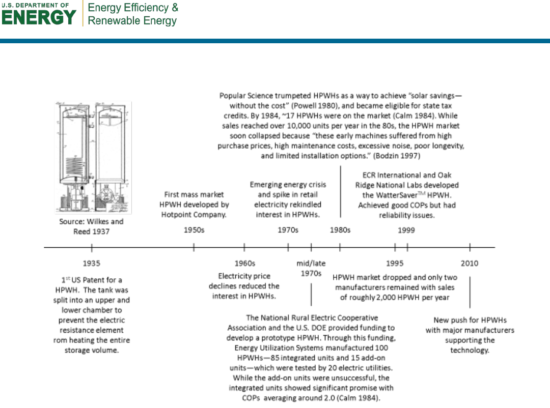
3
electricity prices and demonstrates the reliability issues of past products. See Figure 1 for a timeline
of the development of HPWHs in the United States and Appendix A for more detailed information.
Figure 1. Timeline of HPWH development in the United States
Because of regulatory and financial forces that have converged to push HPWHs into the mainstream
residential market and the magnitude of the savings potential represented by this market, Steven
Winter Associates, Inc. (SWA), a partner of the U.S. Department of Energy’s Building America
research team Consortium for Advanced Residential Buildings, embarked on one of the first in situ
studies of these newly released HPWH products. Recent laboratory studies have quantified the
performance of HPWHs under various operating conditions, but publically available field studies
have been less available. This evaluation attempts to provide publically available field data about
new HPWHs by quantifying the field performance of three products: GE GeoSpring, A.O. Smith
Voltex, and Stiebel Eltron Accelera 300.
Fourteen HPWHs were installed in Massachusetts and Rhode Island and monitored for more than 1
year. The sites were chosen in the residential markets of the sponsoring electric utility companies,
National Grid and NSTAR, and the sponsoring energy-efficiency service program administrator,
Cape Light Compact. Of the 14 units, 10 were GE models (50-gal units), 2 were Stiebel Eltron
models (80-gal units), and 2 were A.O. Smith models (1 60-gal and 1 80-gal unit). The 10 50-gal
units were intended to be split between the GE and Rheem HPWHs, but the Rheem units were not
available during the installation phase of this project.
4
1.2 How Heat Pump Water Heaters Work
HPWHs are primarily designed as replacements for traditional ERWHs and can achieve higher
efficiencies by using the vapor-compression heat pump cycle. Generally speaking, heat pumps are
devices—such as air conditioners and refrigerators—that move thermal energy from one location to
another. A refrigerator moves heat from the inside the appliance into the kitchen; the heat pump
inside an HPWH moves heat from the surrounding air into the hot water storage tank. By moving
thermal energy instead of converting electricity to heat, heat pumps are more efficient and usually
operate at efficiencies that exceed 200%.
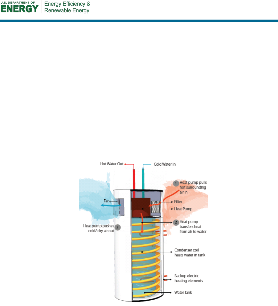
Most HPWHs, however, are hybrid devices that combine a heat pump, backup electric resistance
element(s), and a storage tank (Figure 2). Although the heat pumps in these hybrid water heaters
can heat water at high efficiencies, their recovery rate is significantly slower than traditional electric
resistance heating mechanisms. A typical 4.5-kW electric resistance element can reliably heat more
than 20 gal of water per hour. The heat pump has a lower heating rate; GE, for example, publishes a
rate of 8 gal/hour at 68°F air temperature (GE 2010). Auxiliary electric resistance elements are thus
also installed in HPWHs for reliability and quicker hot water recovery. Most HPWHs use the heat
pump whenever possible, but built-in controls switch to conventional resistance heating during
times of high hot water demand.
Figure 2. How HPWHs work
Historically, heat pumps have been differentiated into two categories: integrated (or “drop-in”) and
remote (or “add-on”). These categories describe the relationship between the heat pump and the
storage tank. Add-on devices are stand-alone heat pumps that are combined with traditional tank
ERWHs. Integrated devices include the heat pump, storage tank, and resistance element(s) in one
package and have the advantage of being able to control the operation of the heat pump and

5
resistance elements more precisely. Add-on devices can, however, be used as retrofits to existing
water heaters at a lower cost (Ashdown et al. 2004).
Integrated devices come in three configurations of heat exchangers. The most common in the
United States is a wraparound condenser. In this configuration, the refrigerant coils are wrapped
around the storage tank but are not in direct contact with the potable water inside the tank. The Air
Generate AirTap uses refrigerant immersion coils that are directly immersed in the potable water.
Finally, coaxial heat exchangers can be used, as with the Rheem EcoSense, wherein the water is
pumped through the heat exchanger to transfer energy from the heat pump to the potable water
(Sparn et al. 2011).
The most common arrangement of current HPWHs is an integrated water heater with a wraparound
condenser and two backup electric elements. Figure 2 illustrates this arrangement and describes the
typical components and operation of modern HPWHs in the U.S. market. Among the systems
evaluated in this study, the only model to deviate from this configuration is the Stiebel Eltron unit,
which has only one smaller (1.7-kW) upper element and always operates in hybrid mode.
1.3 Space-Conditioning Interactions and Installation Considerations
HPWHs move thermal energy from the surrounding air into the storage tank. Therefore, units
installed in conditioned spaces directly affect the space-conditioning loads of the building. During
the heating season, HPWHs increase loads on space-heating systems. Conversely, HPWHs reduce
cooling loads during the cooling season. When HPWHs are installed in unconditioned spaces such
as attics and garages (possible in warm climates only), space-conditioning impacts are minimal.
When in “quasi-conditioned” spaces—such as uninsulated basements—space-conditioning impacts
of HPWHs are very difficult to assess. Because most basements are thermally connected to
conditioned space, HPWHs still have an impact on conditioning loads. Finally, by using a vapor-
compression system, HPWHs typically remove moisture from the surrounding air, which can be a
significant benefit in hot-humid climates and damp basements.
Because these hybrid HPWHs are new to the mainstream market, installation is less straightforward
for installers than traditional ERWHs. HPWHs require special attention to airflow around the unit
and condensate collection. Furthermore, to improve the efficiency of the units, A.O. Smith and
Stiebel Eltron manufacture models that are substantially larger than typical ERWHs. Installers may
not be familiar with these units—or with heat pump models in general—and installing these units in
existing homes may be difficult.
During installation the team noted specific challenges the installer faced at the various sites. Many
of these details are discussed in more depth by Shapiro, Puttagunta, and Owens (2012). Installation
considerations are further discussed by SWA (2012). A trifold brochure for consumers (Appendix
E) was created for SWA’s rebate programs.
1.4 Model Operation and Control Logic
Although all three monitored HPWHs have similar components, the control logic differs
substantially among models. The GE and A.O. Smith tanks have two electric resistance (upper and
lower) elements in addition to the heat pump and operate in several modes; the Stiebel Eltron unit
has only one mode of operation and uses a small upper element to supplement the heat pump. All
three units have wraparound condensers and an integrated storage tank.

6
1.4.1 General Electric Control Logic
The GE model has two 4.5-kW electric resistance elements, one placed at the top third and one
placed at the bottom third of the unit. The unit can operate under five operating modes: Hybrid,
eHeat, Standard Electric, High Demand Mode, and Vacation Mode (GE 2009). The control logic for
these modes is described below:
• Hybrid Mode is the default operating mode. The control logic for the GE unit is
proprietary; however, the general operating principle behind the hybrid mode is to balance
energy savings and provide hot water at rates that are similar to comparably sized ERWHs.
Thus, the control logic tries to meet certain targets for the availability of hot water. The unit
uses the heat pump until approximately 75% of the available hot water has been depleted
and the heat pump cannot keep up with the hot water demand. Because the unit does not
measure average tank temperature or hot water flow rate directly and measures the
temperature at the top third of the tank only, the control logic uses the current and previous
values of the temperature at the top of the tank as a proxy for available hot water and hot
water flow rate. The system uses a closed-form model that employs autocorrelation
functions to map upper tank temperature to hot water availability (Tsai 2012).
In practice, this control strategy results in the electric elements being used in three
circumstances.
o If the ambient air temperature is outside the safe operating range (45°–120°F), the
system reverts to standard resistance mode.
o If the water in the tank is significantly lower than the set point, the upper element
operates. The difference between the tank temperature and the set point depends on
the circumstances, but it is generally 25°–30°F.
o If the system senses that the water use is too high, the lower element operates. In
general, 25–30 gal within a short time period is considered high water use. Once the
lower electric resistance element engages, the entire tank is reheated like a traditional
ERWH (Tsai 2011).
• eHeat Mode uses only the heat pump, unless the ambient temperature is outside the safe
operating range. This mode is more efficient but may fail to provide water at the set point
temperature. The temperature dead band at the top of the tank that regulates heat pump
operation is 1°F (Sparn et al. 2011).
• Standard Electric Mode operates like a traditional ERWH.
• High Demand Mode is similar to the hybrid mode, but the control logic changes from 75%
of the available hot water being depleted to 50% (Tsai 2012).
• Vacation Mode is similar to eHeat Mode but with a temperature set point of 50°F.
1.4.2 A.O. Smith Control Logic
The A.O. Smith model has two electric resistance elements: a 4.5-kW upper element and a 2-kW
lower element. The A.O. Smith model has four operating modes: hybrid mode, efficiency mode,
electric mode, and vacation mode (A.O. Smith 2010). The control logic of the A.O. Smith unit,
however, is quite different than that of the GE unit:

7
• Hybrid Mode of the A.O. Smith model uses a simple temperature dead-band algorithm. If
the average tank temperature—which is the weighted average of the upper and lower
thermostats, where the upper thermostat receives 75% weighting (Sparn et al. 2011)—drops
9°F below the set point, the heat pump is turned on to heat the water back to the set point. If,
however, the heat pump fails to heat the water sufficiently, and the average tank temperature
drops more than 20°F below the set point, the upper element replaces the heat pump as the
heating source. The lower element is not used in hybrid mode (A.O. Smith 2011). Unlike the
GE unit, the heat pump may reengage during the reheat cycle after the electric resistance
elements have been operating.
• Efficiency Mode does not use the electric resistance elements, unless the ambient
temperature is outside the safe operating range (45°–109°F) of the heat pump (A.O. Smith
2011).
• Electric Mode operates like a traditional ERWH. The upper element is used first to heat the
top of the tank, then the lower element is used to heat the bottom of the tank (A.O. Smith
2010).
• Vacation Mode is identical to efficiency mode with a set point of 60°F (A.O. Smith 2010).
1.4.3 Stiebel Eltron Control Logic
The Stiebel Eltron has only one operating mode. The hot water temperature set point is factory set
at 140°F and is not easily adjustable by the user. The unit has one 1.69-kW electric resistance
element installed vertically at the top of the tank and operates under a fixed mode. The heat pump is
turned on when the temperature 16 in. from the top of the internal tank drops more than 4°F below
the set point. If the heat pump cannot meet the demand and the temperature at the top of the tank
drops lower than 112°F, the upper element is used as a backup heat source. The upper element heats
only the top third of the water heater tank (approximately 27 gal). The Stiebel Eltron unit is the only
unit that allows simultaneous operation of the heat pump and booster resistance heater (Megliola
2011).

8
2 Recent Studies
Since the introduction of the most recent line of HPWHs, a growing body of literature has been
devoted to measuring the performance, energy and cost savings potential, and reliability of these
products.
Unfortunately, robust and publically available field-test results for the new HPWHs have been less
available than laboratory testing results. Pacific Gas & Electric monitored one GE HPWH in
Sonora, California. The unit was placed in an unconditioned basement with a floor area of
approximately 400 ft
2
. The average COP was 1.29 with average operating conditions of 68.6°F
ambient temperature, 62% relative humidity, 70.5°F inlet water temperature, 1.3 gal/minute flow
rate, 18.6 draw events per day, and 18.3 GPD (Hu and Davis 2011).
Electric Power Research Institute (EPRI) has worked with four electric utility companies—
Bonneville Power Administration, Kansas City Power & Light, Tennessee Valley Authority, and
Southern Company—to test 160 water heaters across the United States, mostly GE, A.O. Smith, and
Rheem HPWHs, but several ERWHs were installed as control units. EPRI has provided preliminary
results from the study, but the results are identified only as Model A, Model B, and Model C. The
COPs of these units were 0.7–2.7; their performance varied significantly. Their reliability has been
high so far, but EPRI saw only minimal peak demand savings (Amarnath and Bush 2012).
A 2009 Pacific Gas & Electric HPWH study (PG&E 2009) concluded that, in terms of source
energy
8
efficiency, an HPWH was more efficient (67%) than a standard natural gas (57%) or
electric (29%) tank water heater when the heating, ventilating, and air-conditioning interaction of
the HPWH is ignored. If this interaction is included, HPWHs are significantly more efficient (104%
source energy efficiency) than both standard systems in the cooling season and less efficient (44%
source energy efficiency) than natural gas tank water heaters in the heating season.
According to Franco et al. (2010), HPWHs have the lowest life cycle cost in roughly half of all
single-family homes that heat water with electricity. This study assumed that some houses need
venting for successful HPWH installation; thus, HPWHs could not be cost-effectively installed in
many older homes. Furthermore, HPWHs demonstrated a greater cost benefit in new, single-family
homes.
Hudon et al. (2012) modeled HPWH performance against gas water heaters and ERWHs in six U.S.
cities. HPWHs saved source energy compared to traditional ERWHs regardless of climate and
location of the unit (i.e. whether located in conditioned or unconditioned space). Savings over
natural gas depended on climate and location of the unit.
8
See Section 5 for discussion of source energy.

9
3 Technical Approach
This evaluation of HPWHs provides valuable information that can be used to advise consumers and
builders about efficient methods to provide electric water heating. This information can also be used
as validation by utilities and other program implementers throughout the United States that are
attempting to develop incentive programs for this technology. Although this study is primarily
applicable to colder climates, the measured performance of the HPWH units is relevant in many
climate zones. Even though the sample for this evaluation was relatively small, some clear results
were consistent with other ongoing field-testing across the country.
3.1 Research Questions
This research effort focused on answering the following questions about the efficiency, reliability,
and performance of each model evaluated:
• What is the measured efficiency of an HPWH located in unfinished basements of cold-
climate homes?
• What are the critical criteria that affect the installed performance of HPWHs, and how do
they impact the performance of each HPWH model?
• What are the standby losses for these HPWHs, and how do they compare to traditional
ERWHs?
• Does each model evaluated in this study effectively deliver hot water at the set point
temperature?
• Are homeowners satisfied with hot water delivery, efficiency, noise, and other
characteristics?
3.2 Measurements
Long-term performance data were collected at 14 sites in Massachusetts and Rhode Island in the
service districts of National Grid, NSTAR, and Cape Light Compact. Measurements were taken for
a minimum of 12 months at all sites to establish the annual efficiency and performance of each unit.
These measurements included water temperatures, flow rates, and electricity consumption. Sensors
were sampled at 5-second intervals and output at 15-minute intervals in the forms of averages,
minimums, maximums, and/or totals over that time period, depending on the desired outputs. An
additional data table captures the duration and volume of each hot water draw.
At each site, the following HPWH parameters were measured every 5 seconds:
• Inlet water temperature (°F)
• Outlet water temperature (°F)
• Ambient air temperature (°F)
• Ambient air relative humidity (%)
• Hot water flow (gal)
• Compressor energy consumption (Wh)

10
• Energy consumption of each electric resistance heating element (Wh)
• Entire system energy consumption (Wh).
At each 5-second interval, thermal heat delivered by the water heater was calculated based on water
flow and temperature differential.
The following values were output for each 15-minute logging period:
• Average water inlet temperature (°F)
• Average water outlet temperature (°F)
• Minimum water inlet temperature (°F)
• Maximum water outlet temperature (°F)
• Average inlet air temperature (°F)
• Average inlet air relative humidity (%)
• Total domestic hot water use (gal)
• Domestic hot water energy (Btu)
• Total compressor energy consumption (Wh)
• Total upper heating element energy consumption (Wh)
• Total lower heating element energy consumption (Wh)
• Total system energy consumption (Wh)
• Total heat pump energy (Wh)
• Total standby energy consumption (Wh)
The start time, volume, and duration of each hot water draw were also recorded. Details on how a
heating event was defined for this study is provided in Appendix D
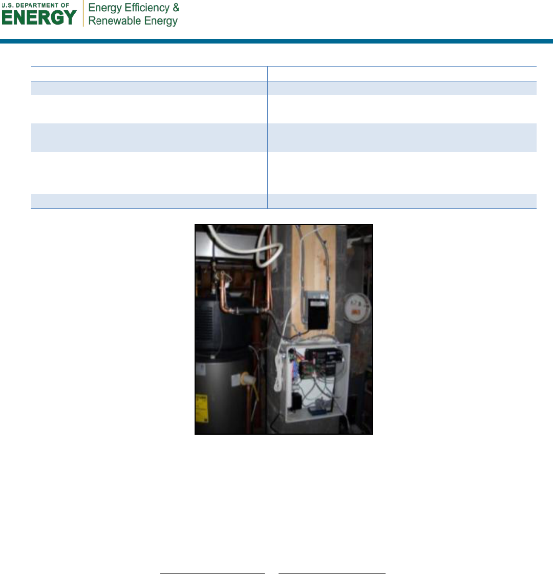
3.3 Equipment
As shown in Figure 3, a Campbell-Scientific CR-1000 data logger and various sensors (Table 4)
were used at each site to take measurements. A wireless modem was used to remotely download
data for evaluation throughout the monitoring period. Thermistors were used for all temperature
measurements. Cold water inlet and hot water outlet water temperatures were measured using an
Omega tubular immersion sensor with a 4.5-in. probe length and National Pipe Thread tapers. The
HPWH installer installed these directly in the water flow. Omega FTB4607 low-flow (0.22–20
gal/minute) turbine-type flow meters were used to measure domestic hot water flow. All flow
meters were installed by the HPWH installer and located on the cold water inlet side.
Air temperature and relative humidity in the space surrounding the HPWH were measured by a
Humirel HTM2500 located to minimize heat transfer from radiation and surrounding equipment.
All electrical energy consumption measurements used a Continental Control Systems WattNode and
right-sized current transformers. The WattNodes are true-root mean squared, alternating current,
watt‐hour transducers with pulse outputs.
11
Table 4. Installed Monitoring Equipment
Measurement
Equipment
Record and Output Measurements
Campbell-Scientific CR-1000 data logger
Inlet and Outlet Water Temperatures
Omega ON-910-44006 National Pipe Thread pipe
plug thermistor
Inlet Air Temperature and Relative
Humidity
Humirel HTM2500 Probe
Compressor Energy, Heating Element
Energy, and System Energy
Continental Control Systems WattNode WNB-3D-
240-P watt-hour transducer with appropriately sized
current transformers
Hot Water Flow
Omega FTB4607 low-flow, turbine-type flow meter
Figure 3. Example of an HPWH monitoring system installation
3.4 Analysis
The COP has been defined differently in numerous studies (AIL Research 2001, AIL Research
2002, Murphy and Tomlinson 2002, and Zogg 2002). For this evaluation the standard definition of
COP, which is the net heat delivered by the water heater to the domestic water load divided by the
total electrical energy consumed over a period of time was used:
Btu/Wh 413.3inputenergy net
energy heating useful
×
==
DHW
DHW
W
Q
COP
,
(1)
where
COP
= coefficient of performance (dimensionless)
Q
DHW
= useful heat energy (Btu)
W
DHW
= energy consumed by the HPWH (Wh).

12
The water-heating energy Q
DHW
was calculated by the data logger every 5 seconds using measured
data. These energy values were summed and logged at 15-minute intervals.
( )
inoutpDHW
TTVCQ −=
ρ
,
(2)
where
T
out
= outlet water temperature (°F)
T
in
= inlet water temperature (°F)
V
= hot water volumetric flow rate (ft
3
/h)
p
C
= specific heat of water (Btu/lbm∙°F)
ρ
= density of water (lbm/ft
3
).

13
4 Performance Results
Measured performance, rated capacity, EF, and FHR for each monitored model are shown in Table
5. All systems were set to hybrid mode, but set point temperatures varied. The electric resistance
percentage represents the fraction of electricity consumed by the electric resistance elements (rather
than the heat pump, controls, or peripherals). This is a small sample and many variables affect water
heater performance; however, the values do provide insight into some differences between the units.
Table 5. Summary Statics of Performance by Model
Model
Capacity
(gal)
FHR
a
Measured
Average
COP
COP
Range
% Electric
Resistance
GE
50
63
1.82
b
/1.61
1–2.1
32.7%
b
/44%
A.O. Smith
60/80
68/84
2.12
2.1–2.1
5.6%
Stiebel Eltron
80
78.6
2.32
2–2.6
5.5%
a
FHR is measured in gal/hour.
b
Average COP calculation for the GE units does not include Site 5 (cold air = high electric resistance use)
Average COPs over the entire monitoring period were influenced heavily by storage volumes, set
point temperature, and the ability to meet high demand over short periods of time. While the A.O.
Smith and Stiebel Eltron units used the heat pump to provide the vast majority of the load
(approximately 95% of the total electricity was consumed by the heat pump), the electric resistance
elements in the GE units consumed almost one-third of the measured electricity (excluding Site 5,
where low ambient temperatures forced the unit into resistance mode most of the time). The A.O.
Smith and Stiebel Eltron models benefit from larger storage tanks, and the Stiebel Eltron model
benefits from a factory-set set point temperature of 140°F, which increases the availability of hot
water. Increased hot water availability can increase COP by minimizing electric resistance use.
More detailed summary statistics for each site, which include operational conditions and efficiency
values, are shown in Table 6. Although the two A.O. Smith units had remarkably similar COPs, the
COPs of the Stiebel Eltron and GE units varied significantly between sites. The difference between
the COPs of the Stiebel Eltron sites is largely attributable to the large difference between the
average daily hot water draws at the two sites. The residents at Site 2 used an average of 73 GPD
with a COP of 2.6; the residents at Site 10 used an average of 41 GPD with a COP of 2. Larger hot
water draw volumes dilute the impact of tank thermal losses and elevate the COP of the unit—as
long as larger draws do not increase use of resistance heating. The differences between the
measured COPs at the sites with GE units were significantly larger than those of the other units.
With a smaller tank, the GE model seems to require more electric resistance heating to meet the
demand.
Analysis of the data collected during the year of monitoring uncovered key variables that affect
HPWH performance and the differences between the operations of the different units. Across all
models, ambient temperature, the volume of hot water draws, and the pattern of the hot water draws
were the most important variables that affected water heater performance. These variables,
particularly the effect of hot water use and electric resistance element operation, can have different
impacts on different HPWH models.
14
Table 6. Summary Table of Performance by Site
Site
HPWH
Model
Adults +
Children
Water Heater
Set Point Temp
(°F)
Days Monitored
Avg. Daily Hot
Water Use (gal)
Avg. Cold Water
Temp. (°F)
Avg. Hot Water
Temp. (°F)
% of Electricity
Consumption
from Electric
Resistance
b
Avg. Air Temp.
(°F)
a
Avg. Relative
Humidity (%)
a
Avg. Wet Bulb
(°F)
a
Total COP
1
A.O.
Smith-80
2 + 1 120 454 44 54 119 0% 59 47% 49 2.1
2
Stiebel
Eltron
5 + 0 140 438 73 57 136 8% 71 45% 58 2.6
3
GE
2 + 1
125
469
60
53
121
48%
64
38%
51
1.8
4
A.O.
Smith-60
3 + 0 120 445 45 53 119 11% 63 56% 54 2.1
5
GE
2 + 0
129
460
64
52
127
78%
53
62%
46
1
6
GE
2 + 0
122
475
35
53
118
5%
62
55%
53
2.1
7
GE
2 + 0
125
450
23
58
123
11%
66
49%
55
1.8
8
GE
2 + 1
125
430
33
55
122
15%
66
44%
54
2.1
9
GE
2 + 2
120
468
41
55
122
22%
62
48%
52
2
10
Stiebel
Eltron
2 + 0 140 424 41 57 138 2% 68 55% 58 2
11
GE
2 + 3
140
459
72
58
136
58%
76
34%
58
1.5
12
GE
2 + 1
130
492
42
56
128
29%
71
46%
58
1.9
13
GE
2 + 0
130
388
32
59
126
15%
70
57%
60
1.4
14
GE 2 + 0 120 433 32 53 119 15% 62 52% 52 1.9
a
Average of daily averages
b
Electric resistance percentage = % of total electricity kilowatt-hours that was used by electric resistance, NOT the
thermal energy fraction provided by electric resistance.
4.1 Impact of Water Use on Efficiency
As previously discussed, the smaller volume GE units used the electric resistance elements to
provide a much larger percentage of the needed energy than the other models. Figure 4 shows seven
days of operation for the GE unit at Site 9. These days are representative of typical operation across
many sites. During day 1 and days 3–6, the water draws from the tank were distributed throughout
the day and/or were relatively small. The heat pump could thus meet recovery needs for those days.
During 11/22 and 11/27, the water draws were more concentrated, and the electric resistance
element was needed to provide additional hot water.
Figure 4 shows how large and concentrated draws can reduce the efficiency of the unit; however,
low water use can also result in low COPs (Figure 5). In this figure, although the heat pump was
used to meet the entire hot water demand, the low load and relatively high standby losses resulted in
low daily COPs.
15
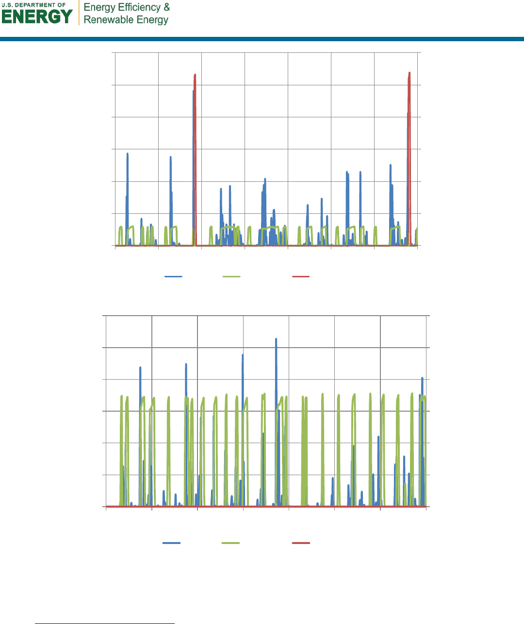
Figure 4. Ideal operation of the GE HPWH in hybrid mode (Site 9)
9
Figure 5. Low water use can reduce the overall benefit of an HPWH
when the cost benefit is assessed.
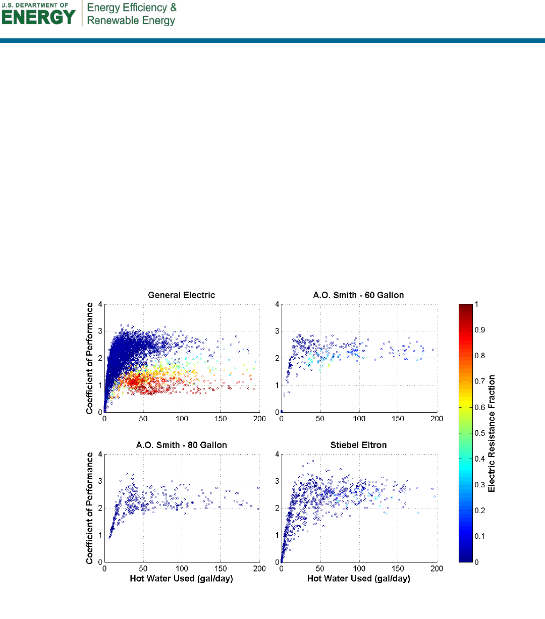
Scatter plots of the daily hot water use
10
versus the daily COP are shown in Figure 6. Each daily
observation is also color coded by the electric resistance fraction, where blue is zero electric
9
For this and similar figures, the vertical axes show discrete values for 15-minute intervals.
10
Daily values are misleading because the net energy content of the water in the tank can change throughout the day.
Thus, heating events with zero net tank energy change are identified from the 15-minute raw data. All heating events are
normalized to daily values and displayed graphically. See Appendix D for more information.
0
200
400
600
800
1,000
1,200
0
5
10
15
20
25
30
11/21 11/22
11/23 11/24 11/25
11/26 11/27 11/28
Energy Used (Wh)
HW Used (Gallons)
HW Use Heat Pump Electric Resistance
44 gals
2.1 COP
57 gals
1.4 COP
76 gals
2.6 COP
92 gals
2.4 COP
40 gals
2.4 COP
53 gals
2.4 COP
80 gals
1.5 COP
0
40
80
120
160
200
240
0
2
4
6
8
10
12
8/15 8/16 8/17 8/18 8/19 8/20 8/21 8/22
Energy Used (Wh)
HW Used (Gallons)
HW Use Heat Pump Electric Resistance
36 gals
1.7 COP
20 gals
0.9 COP
39 gals
1.9 COP
47 gals
1.4 COP
11 gals
1.3 COP
20 gals
1.5 COP
35 gals
1.4 COP
16
resistance use, and red is when the electric elements are used to reheat the entire recovery load. The
GE unit has the most observations; therefore, the operational patterns can be most directly observed
in the scatter plot. For the GE unit, the data could be interpreted as lying between two exponential
curves, where the upper curve has no electric resistance use and the lower curve is entirely electric
resistance operation. The scatter plot of the GE unit operation also shows that the electric resistance
fraction has a strong correlation with the hot water use. Days of lower hot water demand are far less
likely to have instances of electric resistance heating (e.g., less than 30 GPD). On the other hand,
days with high hot water demand are far more likely to have instances of electric resistance heating.
Although the scatter plots for the Stiebel Eltron and A.O. Smith units have fewer apparent trends—
because fewer sites were monitored—the scatter plots appear to agree with the trend observed for
the GE units, with one primary distinction. The GE unit shows two distinct operating regions that
correspond to large and small electric resistance loads, and the A.O. Smith and Stiebel Eltron units
operate entirely in the low electric resistance region. This is most likely a product of the larger tank
volumes and the control logic that allows the heat pump to reengage, in the case of A.O. Smith, or
operate simultaneously, in the case of Stiebel Eltron.
4.2 Impact of Air Temperature on Efficiency
Although hot water demand is a primary driver of efficiency, other factors still play a prominent
role (Figure 6). The efficiency of the heat pump is primarily a function of the ambient temperature
in the space. Two sites with cold and hot operating environments are compared to give a sense of
how ambient temperature affects overall efficiency. At Site 5, the HPWH was installed in a cold
Figure 6. Scatter plots of daily hot water use versus COP color coded by electric resistance fraction
17
basement with ambient air temperatures dropping lower than 50°F from December through April.
These temperatures are close to the cut-off temperature of the heat pump in the GE unit. As a result,
the HPWH at Site 5 operated like a traditional ERWH, as shown in Figure 7, but with an added
parasitic of the heat pump cycles on and off at the cut-off temperature of the unit.
Figure 7. Because the Site 5 basement was too cold, this GE HPWH
switched primarily to electric resistance mode during the winter months.
At the other end of the spectrum, Site 11 experienced higher COPs during the winter months,
because the HPWH was placed in a boiler room (Figure 9) with ambient temperatures around 80°F
(Figure 8). At the beginning of January, the unit was able to supply hot water in large quantities
with high COPs higher than the rated EF of 2.35 (Figure 10). On 2 days during this week of data,
high water use concentrations resulted in electric resistance operation to meet demand. Furthermore,
some periods had low hot water draws. As discussed in Section 4.2, lower draw quantities can
decrease overall COP, because standby losses account for a larger percentage of the recovery load.
The high ambient temperatures boost the efficiency of the heat pump and increase the
corresponding overall COP of the unit during these periods.
0
200
400
600
800
1,000
1,200
1,400
0
5
10
15
20
25
30
35
1/22 1/23 1/24 1/25 1/26 1/27
Energy Used (Wh)
HW Used (Gallons)
HW Use Heat Pump Electric Resistance
72 gals
0.7 COP
75 gals
0.7 COP
80 gals
0.7 COP
58 gals
0.7 COP
96 gals
0.8 COP
18
Figure 8. Ambient temperature at Site 11
Figure 9. This HPWH benefited from
the waste heat of the boiler used for
space heating.
Figure 10. Typical winter performance of the GE HPWH in the Site 11 warm mechanical room
To demonstrate the relationship between ambient temperature and efficiency, daily scatter plots
similar to those in Figure 7, but color coded by average ambient temperature, are shown in Figure
11. Periods with electric resistance fractions greater than 0.04 were excluded, as were data from
Sites 5 and 13, which had lower heat pump COPs than the other units. The scatter plots show a
strong correlation between ambient air temperature and efficiency. Everything else being equal,
higher ambient temperatures improve efficiency. At a 50 GPD recovery load increasing the ambient
0%
10%
20%
30%
40%
50%
60%
70%
80%
90%
100%
45
50
55
60
65
70
75
80
85
90
Relative Humidity
Temperature [°F]
HPWH Inlet Air Temp (°F) HPWH Inlet Air RH (%)
0
200
400
600
800
1,000
1,200
1,400
0
10
20
30
40
50
60
70
1/1 1/2 1/3 1/4 1/5 1/6 1/7 1/8
Energy Used (Wh)
HW Used (Gallons)
HW Use Heat Pump Electric Resistance
56 gals
3.1 COP
135 gals
1.3 COP
71 gals
2.6 COP
195 gals
1.2 COP
78 gals
2.6 COP
71 gals
2.7 COP
87 gals
2.8 COP
19
temperature from 50°F to 80°F can increase the COP of the GE and A.O. Smith units from around 2
to nearly 3.
Figure 11. Scatter plots of COPs versus daily hot water use color coded by ambient temperature.
Periods with electric resistance fractions greater than 0.04 and Sites 5 and 13 were excluded.
4.3 Delivered Water Temperature
The efficiency of water heating is important from a performance standpoint; however, the
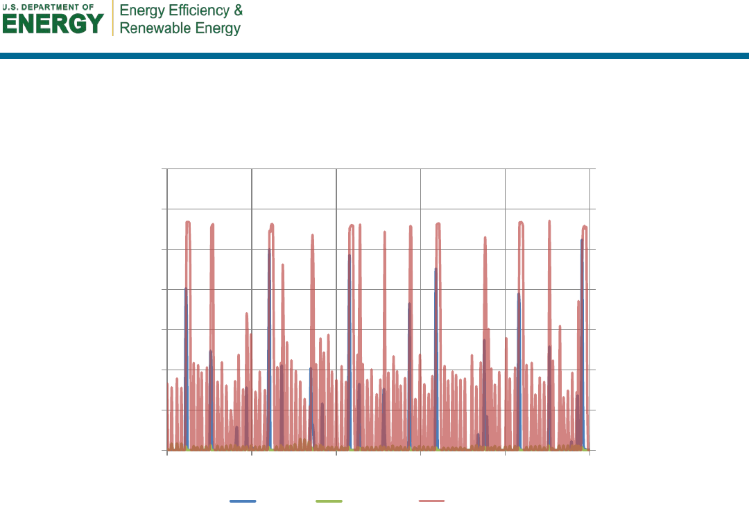
temperature of delivered water from the HPWH is also important for customer satisfaction.
Surprisingly, graphing several days of high water use at a site with a Stiebel Eltron HPWH revealed
that this unit was able to meet very large hot water demands at surprisingly high COPs, as shown in
Figure 12. While the electric resistance element was needed to supply additional heating, the unit
performed with COPs higher than 2.6 for the 4 days of high hot water use. The Stiebel Eltron unit is
distinguished from the other two models by its ability to simultaneously use the electric resistance
and heat pump heating elements to provide heating. Furthermore, the water heater was able to
deliver water temperatures in excess of 115°F during all 4 days of high hot water demand (Figure
13). The higher COPs for the Stiebel Eltron unit are probably a result of the large tank size and the
ability of the unit to only heat water for the load directly when the heat pump cannot meet the load
rather than heating the entire tank.
To determine the ability of the HPWHs to deliver water at an acceptable delivery temperature,
normalized histograms of maximum delivered water temperature for 15-minute periods with draws
larger than 1 gal were plotted for each site (Figure 14). The red and green vertical lines represent the
set point temperature and minimum acceptable delivery temperature of 110°F (Hendron and

20
Engebrecht 2010), respectively. The percentage of occurrences lower than the minimum acceptable
delivery temperature is shown in the upper left corner of each plot. The normalized histograms
show that all three units deliver water hotter than 110°F at a variety of set point temperatures.
However, many units did not maintain set point for all draw occurrences, and temperatures dropped
more than 10°F lower than set point for a significant fraction of the 15-minute periods.
Unfortunately, the aforementioned method of determining whether the HPWHs can maintain the
delivered water at a minimum acceptable temperature has flaws related to the 15-minute recording
interval used in this study. Because the average delivered water temperature includes water inside
the pipe before the draw, the maximum delivered water temperature for the interval must be used.
Thus, this analysis looks only at the delivery temperature at the beginning of the draw or at the
beginning of a 15-minute interval. If the water heater runs out of hot water, the user may end the
draw and the run-out may not be recorded using this method. However, the very small percentage of
run-outs recorded at the 110°F minimum acceptable delivery criteria means that delivery
temperature is probably not dropping significantly lower than usable temperatures.
Figure 12. This Stiebel Eltron HPWH was able to maintain high COPs during high water demand.
0
100
200
300
400
500
600
0
5
10
15
20
25
30
11/22 11/23 11/24 11/25 11/26 11/27 11/28 11/29
Energy Used (Wh)
HW Used (Gallons)
HW Use Heat Pump Electric Resistance
66 gals
2.6 COP
120 gals
3.1 COP
275 gals
2.6 COP
196 gals
2.7 COP
240 gals
3.0 COP
178 gals
2.6 COP
48 gals
1.7 COP
21
Figure 13. Even with high water demand, the hot water temperature dropped only as low as 118°F.
105
115
125
135
145
155
0
5
10
15
20
25
11/22 11/23
11/24 11/25 11/26 11/27 11/28
11/29
Hot Water Temp (°F)
HW Used (Gallons)
HW Use Delivered HW Temp
setpoint

22
Figure 14. Normalized histograms of delivered water temperature. Red line indicates set point temperature. Green line indicates
minimum delivery temperature (110°F). The percentage of occurrences with water temperatures lower than 110°F is shown.
85
105
125
145
0
0.5
1
Site 1
A.O. Smith
Probability Density
85
105
125
145
0
0.5
1
Site 2
Stiebel Eltron
85
105
125
145
0
0.5
1
Site 3
General Electric
85
105
125
145
0
0.5
1
Site 4
A.O. Smith
85
105
125
145
0
0.5
1
Site 5
General Electric
Probability Density
85
105
125
145
0
0.5
1
Site 6
General Electric
85
105
125
145
0
0.5
1
Site 7
General Electric
85
105
125
145
0
0.5
1
Site 8
General Electric
85
105
125
145
0
0.5
1
Site 9
General Electric
85
105
125
145
0
0.5
1
Site 10
Stiebel Eltron
Delivered Water
Temperature (°F)
Probability Density
85
105
125
145
0
0.5
1
Site 11
General Electric
Delivered Water
Temperature (°F)
85
105
125
145
0
0.5
1
Site 12
General Electric
Delivered Water
Temperature (°F)
85
105
125
145
0
0.5
1
Site 13
General Electric
Delivered Water
Temperature (°F)
85
105
125
145
0
0.5
1
Site 14
General Electric
Delivered Water
Temperature (°F)
Histogram
Setpoint Temp.
Min Delivery Temp.
0.13%
0.16%
1.44% 0.32%
1.65% 1.63% 0.85% 1.92% 1.7%
0% 0.84% 0.51% 0.32% 0.86%

23
4.4 Calculating Standby Losses
Tank losses to the ambient are important contributors to tank inefficiency; indeed, for ERWHs,
tank losses represent the entirety of water heat site energy inefficiencies. Unfortunately, tank
losses from HPWHs are hard to quantify without precise laboratory equipment. The data from
this study, in conjunction with laboratory HPWHs tests conducted by Sparn et al. (2011), can be
used to estimate the tank heat loss coefficient. This analysis was possible for the GE unit only,
because the Stiebel Eltron and A.O. Smith units did not provide enough data points to perform
this analysis.
The following analysis differs from the methods outlined in the U.S. Department of Energy’s test
procedure (DOE 1998) and the National Renewable Energy Laboratory’s field-testing protocol
(NREL 2012c). These methods measure the change in the average tank temperature during a
period of no draws. The National Renewable Energy Laboratory specifies that this period should
begin 10 minutes after the heat pump has shut off, because the condensing coil still gives off heat
immediately after the reheat period.
Because internal tank temperatures were not measured in this study, a different procedure was
used to measure standby losses. The basic procedure identified idle periods during which the
tank begins fully heated, experiences no water draws, and is finally reheated. The tank losses
during that period are simply the ratio of the thermal energy input to the product of the time
elapsed since the last reheat and the temperature difference between the tank and the ambient air.
( )
amb
tank
standby
T
Tt
Q
UA
−
∆
=
,
(3)
where
UA = overall heat transfer coefficient of the tank (Btu/h-°F)
Q
standby
= thermal energy to recover tank to set point (Btu)
T
tank
= average tank temperature (°F)
T
amb
= ambient temperature (°F)
Δt = time elapsed since the last reheat (h).
The average tank temperature was assumed be 2.5°F lower than the temperature set point, which
is equivalent to assuming an average tank temperature dead band of 5°F for recovery from an
idle period. For example, if the tank set point were 135°F, the tank would presumably start the
period at 135°F, drop to 130°F due to standby losses, and finally return to 135°F through the
recovery process. The average temperature would be 132.5°F, which is 2.5°F lower than the set
point temperature. This dead band temperature is consistent with graphs of the EF testing of the
GE unit by PG&E (2010) and other studies.
Idle periods followed by heat pump operation with no hot water demand were identified from the
15-minute data to measure the electric power necessary to recover from standby losses. These
periods satisfied the following conditions:

24
• No water was drawn during the period.
• The period began and ended with the termination of heat pump operation to ensure
similar stratification.
• The overall period exceeded 3 hours.
For ERWHs the electricity used is directly converted to thermal energy; for HPWHs, however,
the electricity input does not directly correspond to the thermal energy input into the tank. Thus,
laboratory performance maps discussed by Sparn et al. (2011) were used to convert electricity
energy used by the heat pump to the thermal energy delivered to the storage tank. The equation
for the efficiency of the GE heat pump is:
( )
tankwbtanktankwbwbratedhphp
TTCTCTCTCTCCCOPCOP
6
2
5
2
321,
4 +++++=
,
(4)
where
COP
hp
= efficiency of the heat pump (Btu/Btu)
COP
hp,rated
= rated COP
hp
at 57°F wet bulb and 120°F tank temperature (2.76)
T
tank
= average tank temperature (°F)
T
wb
= ambient wet bulb temperature (°F)
C
1
= 1.192E+00
C
2
= 4.247E-02
C
3
= –3.795E-04
C
4
= –1.110E-02
C
5
= –9.400E-07
C
6
= –2.657E-04.
The tank lost during the standby period is
( )
hphp
resstandby
COPE
ECQ +
=
,
(5)
where
Q
standby
= thermal energy to recover tank to set point (Btu)
COP
hp
= efficiency of the heat pump (kWh/kWh)
E
res
= electricity used by the resistance elements (kWh)
E
hp
= electricity used by the heat pump (kWh)
C = conversion factor for kWh to Btu (3.412 Btu/kWh).
The estimated time of electricity cutoff was determined by examining the previous data logging
period to correct for the error inherent in the 15-minute data logging interval. If the electricity
draw for the last interval i before cutoff was smaller than the previous interval i-1, the runtime
fraction for the cutoff interval was set as the ratio of the electricity draws, as shown in Eq. (6).
≥
<
=
−
−
−
1
1
1
for1
for
i
i
ii
i
i
EE
EE
E
E
f
(6)

25
Robust regression
11
analysis was used to estimate the thermal heat transfer coefficient of the
tank:
(
)
amb
tankstandby
TTt
UA
Q −
∆=
.
(7)
Regressions using Eq. (7) were performed with and without a constant (i.e., nonzero intercept).
Although the idle periods were chosen such that the water heater tank could be assumed to have
no net energy change from the beginning of the period to the end of the period, the inclusion of
the constant in one of the regressions is used to test whether this assumption is valid. Regression
results with and without a constant are shown in Table 7 and Table 8, respectively, and Figure 15
shows the two regression lines plotted against the observed data. Although the intercept estimate
is significant at the 95% confidence level and the tank loss coefficient is similar to that of other
studies, the model without the constant is arguably preferable.
Table 7. Tank Heat Loss Robust Regression Results with Constant
(number of observances = 113, degrees of freedom = 111)
Coefficient Estimate
95% Confidence
Interval
t
Statistic
p
Value
Intercept
52.821
(4.2826,101.3604)
2.1564
0.033211
Overall Heat Transfer Coefficient
3.5008
(2.7034, 4.2982)
8.6994
3.4555E-14
Table 8. Tank Heat Loss Robust Regression Results without Constant
(number of observances = 113, degrees of freedom = 112)
Coefficient Estimate
95% Confidence
Interval
t
Statistic
p
Value
Overall Heat Transfer Coefficient
4.369
(4.3169,4.4211)
166.15
6.907E-136
11
Robust regression is similar to a simple linear regression in this case, except points with high leverage are given
less weight in the regression analysis (Chatterjee and Price 1991). Two points (see Figure 15), which appeared to be
outliers, did not qualify for exclusion under the leverage criteria of 2/N (Chatterjee and Price 1991)—where N is the
number of observations—but did have a Cook’s distance greater than 4/N (Bollen and Jackman 1985), which
suggests that these have a large impact on the regression results. Robust regression allows these points to have lower
weights.
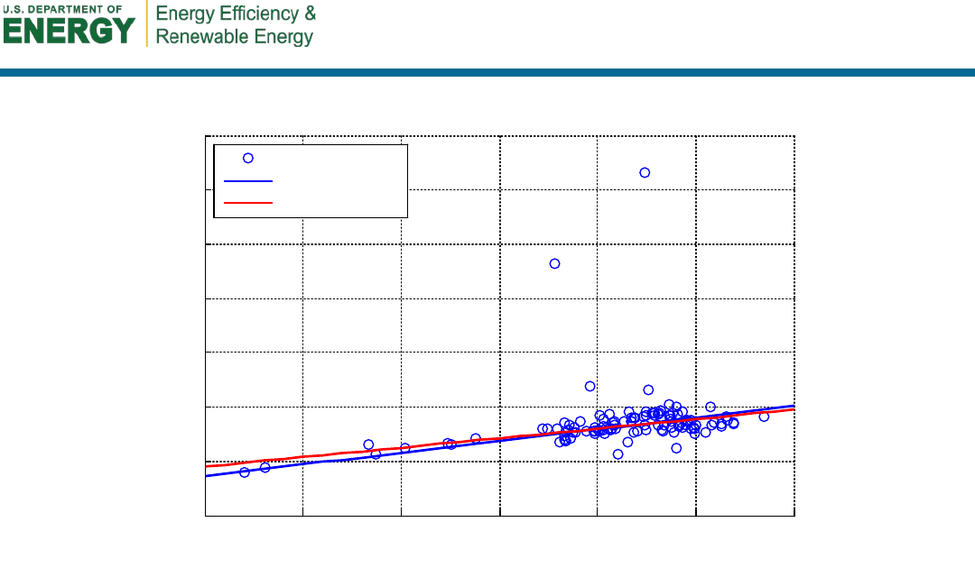
26
Figure 15. Regression results and data points for GE standby losses. Temperature difference is
between the tank average temperature and ambient air.
Because the estimate of the heat loss coefficient is the desired result from the regression, the
model with the more confined confidence interval for the slope coefficient is preferred. By
including the constant in the model, the error of the heat loss coefficient estimate at the 95%
confidence level is ±22.8%, meaning that calculations using this coefficient have an acceptably
higher error. The corresponding error for the model without the constant is only ±1.2%, which is
far more acceptable for energy balance calculations. One could also argue that a higher
confidence level should be used in this analysis, because the model represents a physical system
with a well-known response and should follow a well-described deterministic phenomenon. The
heat transfer coefficient for the model without the constant is 4.312 Btu/h-°F.
4.5 Impact of Confined Spaces
Because HPWHs remove heat from the ambient air, a sufficient volume of available air is needed
to ensure proper performance of the unit. Several laboratory studies have attempted to quantify
the impact of installing HPWHs in spaces without proper air volume. All these tests were
performed on the GE GeoSpring. Advanced Energy compared two HPWHs, one placed in a
220.5-ft
3
uninsulated space and another subjected to the default operating conditions. GE
recommends a volume of 750 ft
3
(GE 2010). The efficiency of the unit in the confined space was
10% lower than the control unit (Fitzpatrick and Murray 2011). The Florida Solar Energy Center
also tested an HPWH in a confined space (92.5 ft
3
) and saw a reduction in efficiency of 13%
(Colon 2012). The National Renewable Energy Laboratory’s laboratory tests included blocking
the airflow of the unit with tape. Blocking the airflow by 33% and 67% had only a minor impact
on the performance of the unit, most of which was attributable to the increased fan energy use
(Sparn et al. 2011). This suggests that the volume of air available to the unit is more important
than constriction of airflow.
40 45 50
55 60 65 70
100
200
300
400
500
600
700
800
Temperature Difference (°F)
Thermal Losses (BTU/hr)
Observances
Without Constant
With Constant

27
The HPWH at Site 13 was installed in a confined space with approximately 400 ft
3
of available
air. The heating event shown in Figure 16 resulted in a measured COP of 2.02; the resulting
performance drop was approximately 15.8% lower than an approximate expected COP of 2.4 at a
set point temperature of 130°F. The performance reduction is similar to those found by
Fitzpatrick and Murray (2011) and Colon (2012).
Figure 16. Performance of the HPWH at Site 13 in a confined space
4.6 Impact on Space-Conditioning Systems
Because HPWHs move heat from the air surrounding the water heater into the storage tank,
HPWHs have an impact on space-conditioning loads. HPWHs in conditioned space have a very
direct effect on space-conditioning loads. In the summer, HPWHs reduce the cooling load of the
building; conversely, the heating load increases in the winter. The combined impact of the
HPWH energy consumption and its impact on the space conditioning systems rely heavily on
climate, home configuration, HPWH location, and the space-conditioning systems used. For
more information about these impacts see the modeling results described by Hudon et al. (2012).
A less complex analysis was also presented by Shapiro, Puttagunta, and Owens (2012).
For HPWHs installed in unconditioned or “semiconditioned” spaces such as basements, the
space-conditioning impacts are harder to determine. These spaces act as buffers, so the heat
transferred from the space into the storage tank is not necessarily transferred from the
conditioned spaces. Air infiltration into the buffer space, ground coupling, solar gains, and heat
transfer from mechanical equipment can all affect heat transfer between the buffer space and
conditioned space. The transient effects of these heat transfer processes mean that the HPWH
space-conditioning impacts are potentially reduced.
15:00 18:00 21:00 00:00
0
1
2
3
4
5
6
Hot Water Flow Rate (gpm)
Site13; COP = 2.02; T = 69.6; RH = 55%; T
mains
= 57.7; T
set
= 130;
15:00 18:00 21:00 00:00
0
7.5
15
22.5
30
Cummulative
Volume (gal)
15:00 18:00 21:00 00:00
0
200
400
600
800
1000
1200
Electric Energy Used (Wh)
Flow Rate
Heat Pump
Lower Element
Upper Element
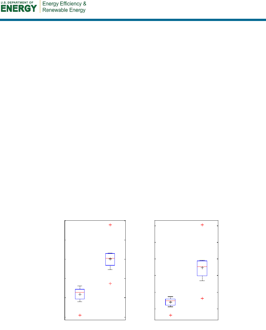
28
Because these transient heat transfer interactions cannot be directly addressed for the HPWHs
installed in unconditioned basements in this study, the space-conditioning impacts are addressed
as the maximum potential impact. The impact on the space-conditioning equipment is defined as
(NREL 2012c):
dhwinputspacenet,
QQQ −=
,
(8)
where
Q
net,space
= maximum potential thermal impact on space (Btu)
Q
input
= electric energy used by the water heater (Btu)
Q
dhw
= thermal energy removed from storage tank (Btu).
The maximum potential thermal impact on the space-conditioning equipment on the space is
negative when thermal energy is being removed from the space and positive when the energy is
being added to the space. In the case of standard water heaters, Q
net,space
is positive, but for
HPWHs the net energy to the space is negative.
Although the HPWHs remove energy from the space, the impact on the space-conditioning loads
depends on the season. For this analysis, the cooling season for these sites was considered to be
June through September, and all other periods were considered the heating season. Box plots of
the hourly load and seasonal space-conditioning impacts are shown in Figure 17 (negative values
reduce the space-conditioning loads and positive values increase the space-conditioning loads).
Box plots display the range of data for each of the categories. In the plots, the boxes represent the
inner two quartiles—also called the inner quartile range—where the lower quartile is the bottom
of the box and the upper quartile is the top of the box. The red line in the middle of the box
represents the median. At the top and bottom of the boxes are whiskers that represent the
smallest and largest observations within the 1.5 inner quartile range. Outliers are represented by
a red plus, and the mean is represented by a black plus.
Figure 17. Box plots of maximum potential space-conditioning impacts for monitored HPWHs
-1000
-500
0
500
1000
1500
Cooling Heating
Mean Hourly Change in Load (Btu/hr)
-2
0
2
4
6
8
Cooling Heating
Seasonal Change in Load (MMBtu)

29
As shown in the box plots, the magnitude of the mean hourly heating impact is slightly higher
than that of the mean hourly cooling impact. Similarly, the magnitude of total heating seasonal
impact is nearly twice that of the total cooling seasonal impact. These box plots show that the
homes in this study, which are all in northern climates, had maximum potential seasonal cooling
load reductions of approximately 1.5 MBtu and heating load increases of approximately 3 MBtu.
30
5 Energy and Cost Analysis
Energy and cost savings potentials of HPWHs were investigated against eight alternative storage
tank water heaters: electric resistance; standard natural gas, fuel oil, and propane; premium
natural gas, fuel oil, propane; and condensing natural gas. Tankless water heaters were not
considered, because a more complicated modeling procedure to account for the transient
response of these water heaters would be necessary. The assumed EFs, recovery efficiencies, and
pilot light energy are listed in Table 9, where all standard and premium fossil-fuel-based systems
are assumed to have the same operating characteristics except for the energy source used to
provide the heating energy.
Table 9. Alternative Water Heaters
Water Heater Fuel Types EF
Recovery
Efficiency
Pilot Light Energy
(Btu/h)
a
Electric
Resistance
Electricity 0.92 100% 0
Standard
Fossil Fuel
Natural gas, fuel
oil, and propane
0.59 78% 400
Premium
Fossil Fuel
Natural gas, fuel
oil, and propane
0.67 82% 400
Condensing
Fossil Fuel
Natural gas 0.83
b
95%
b
0
a
WATSMPL default (EPRI 2000)
b
Efficiencies from laboratory testing by PG&E (2008)
The alternative water heaters were simulated using the equations underlying the WATSMPL
simplified water heater software (EPRI 2000). The daily operating conditions at each site—set
point temperature, mains temperature, volume of water drawn, and ambient temperature—were
simulated for each using the equations in Appendix B. The monitored (in the case of the
HPWHs) and simulated energy consumption (in the case of the alternative water heaters) were
normalized to yearly energy consumption. The normalization procedure accounts for the fact that
the monitoring period at each site was different and some overlap occurred in the days that were
monitored.
Although energy use is usually measured in site energy—which is the energy used at the home
and is typically measured at a utility meter in kilowatt-hours (electricity)—therms (natural gas),
or gallons (fuel oil or propane), a better metric for measured energy use is source energy, which
is the sum of energy used at the home and the energy lost to extraction, conversion, or
transmission. Site energy is easily converted to source energy using site-to-source ratios (Deru
and Torcellini 2007), which are defined to the fuels studied in Table 10. Energy use is thus
reported in source energy and cost to consumers. The site energy consumption for each water
heater-site combination was converted to source energy and cost using the values listed in Table
10.
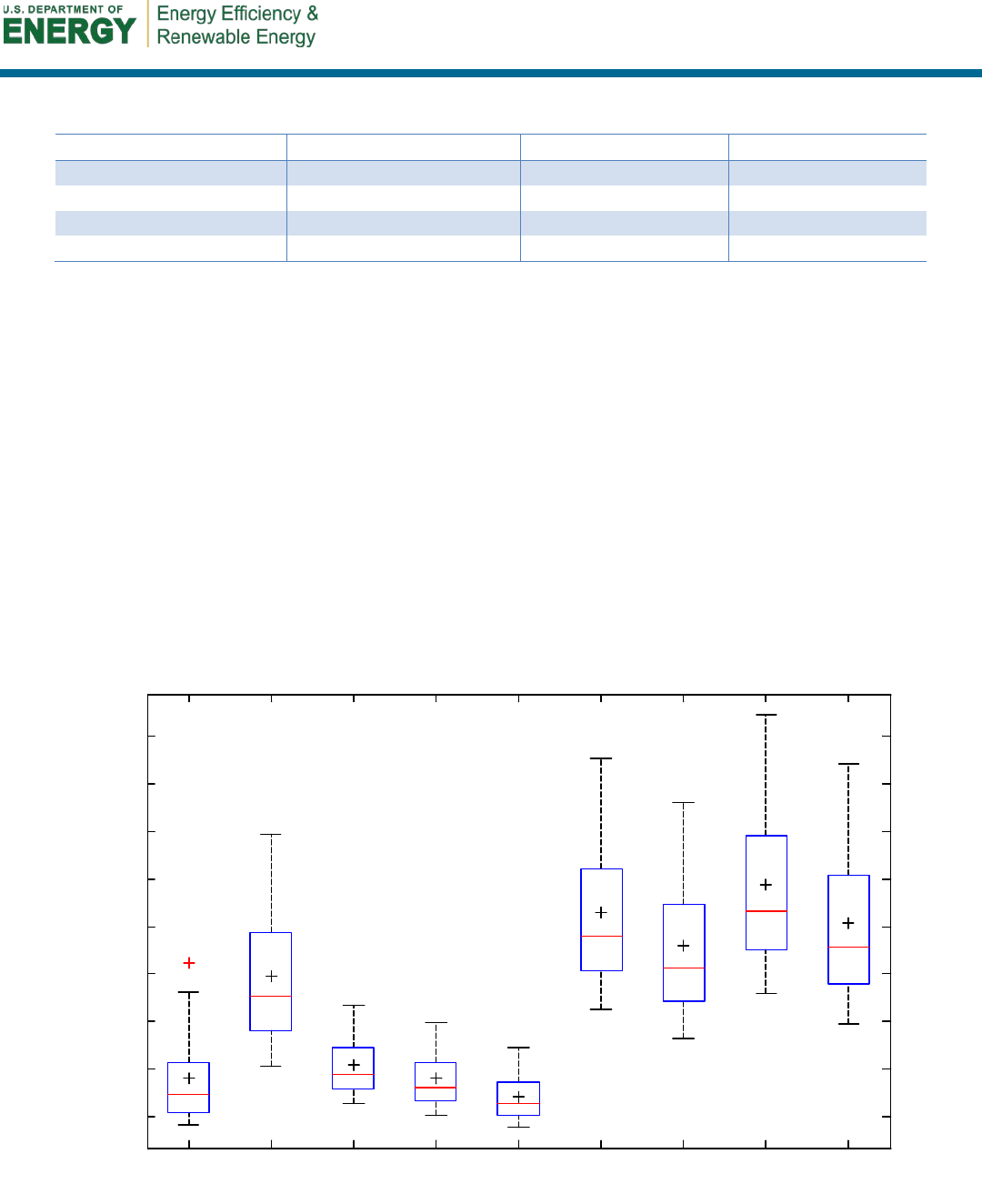
31
Table 10. Fuel Prices and Characteristics for Energy and Cost Analysis
Energy Source
Site-to-Source Ratio
a
Cost
b
Energy Content
c
Electricity
3.365
$0.1172/kWh
3,412 Btu/kWh
Natural Gas
1.092
$1.10/therm
100,000 Btu/therm
Fuel Oil
1.158
$3.93/gal
140,000 Btu/gal
Propane
1.151
$2.85/gal
91,600 Btu/gal
a
Deru and Torcellini (2007)
b
Prices obtained from EIA (2012b, 2012c, 2012d). Electricity and natural gas prices represent average national
prices for 2011. Fuel oil and propane prices are the average national prices for October 2011 through March 2012.
c
Thumann and Mehta (1991)
To compare the installed HPWHs and the simulated alternative water heaters, box plots of
annual source energy consumption and annual operating costs are shown in Figure 18 and Figure
19 (data tables provided in Appendix C). Figure 18 shows that HPWHs have significantly lower
operating costs than electric resistance, oil, and propane, and comparable operating costs to
natural gas systems. Furthermore, HPWHs have the lowest mean and median operating costs of
all water-heating systems except condensing natural gas. In terms of source energy consumption,
Figure 19 shows that HPWHs have the second-lowest source energy consumption of all water-
heating products (a natural gas condensing tank unit is the lowest). Unlike ERWHs, which have
the highest source energy consumption of all products by far, HPWHs can counteract the source
energy penalty of using electricity to provide water heating. The outlier for the HPWHs in both
plots is Site 5, which was operating in electric resistance mode throughout the winter months and
therefore has operating costs similar to the ERWH category.
Figure 18. Annual operating cost of monitored HPWHs and alternative water heaters
$100
$200
$300
$400
$500
$600
$700
$800
$900
Heat
Pump
Electric
Resistance
Gas
Standard
Gas
Premium
Gas
Condensing
Oil
Standard
Oil
Premium
Propane
Standard
Propane
Premium
Annual Operating Cost ($/yr)
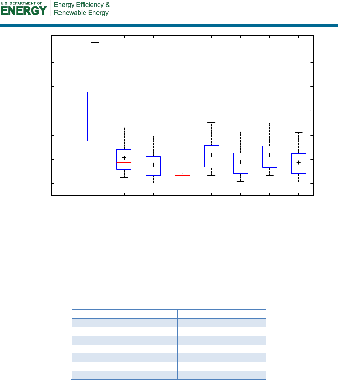
32
Figure 19. Annual source energy of monitored HPWHs and alternative water heaters
Although HPWHs have the second-lowest operating costs and source energy use of the water
heaters considered in this study, installation costs have an impact on the overall financial
outcome of HPWHs versus alternative water heaters. The cost analysis was performed as
described by Polly et al. (2011). The assumptions and results are listed in Table 11. The costs
were assumed to be wrapped into a 30-year mortgage at a 4.42% interest rate. These assumptions
are based on wrapping the cost of the water heaters into the cost of buying a new house or
mortgage refinance.
Table 11. Cost Analysis Assumptions
Cost Metric
Assumption
Analysis Period
30 years
a
Inflation Rate
3%
a
Real Discount Rate
3%
a
Real Fuel Escalation Rate
0%
a
Mortgage Rate
4.42%
b
Mortgage Period
30 years
b
Marginal Income Tax Rate
28%
a
a
Building Energy Optimization defaults (NREL 2012b)
b
Average rate for 2011 (Freddie Mac 2012)
Table 12 lists the installation costs and typical lifetimes of the various water-heating products
considered. Using these values, the annualized energy-related cost of each water-heating unit
was calculated. The annualized energy-related cost represents the equivalent annual cost of the
10
20
30
40
50
60
70
Heat
Pump
Electric
Resistance
Gas
Standard
Gas
Premium
Gas
Condensing
Oil
Standard
Oil
Premium
Propane
Standard
Propane
Premium
Annual Source Energy (MMBtu/yr)
33
complex cash flow and represents an equivalent annual cost of operating the water heater in
present dollars.
Table 12. Installation Costs and Lifetimes of Water-Heating Products
Water Heater Installation Cost
a
Typical Lifetime
(years)
c
Heat Pump (80 gal)
$3,300
10
Heat Pump (50-60 gal)
$2,100
10
Electric Resistance
$590
13
Standard Natural Gas
$700
13
Premium Natural Gas
$880
13
Condensing Natural Gas
$4,500
b
15
c
Standard Fuel Oil
$820
13
Premium Fuel Oil
$960
13
Standard Propane
$890
13
Premium Propane
$1,400
13
a
From National Residential Efficiency Measures Database (NREL 2012a).
b
From American Water Heaters (2008)
c
Estimated lifetime based on National Residential Efficiency Measures Database values for gas storage and
condensing tankless heaters.
The installation costs for the cost analysis were derived from the National Residential Efficiency
Measures Database, but HPWH installation costs reported for this study (Table 13) were
generally in line with the costs reported in the National Residential Efficiency Measures
Database. These reports show shorter lifetimes for the HPWHs than the other water heater
technologies, which is probably caused a desire to be conservative and rate the lifetime equal to
the product warranty period. The reliability of these units is as yet undetermined, however, so the
lifetime of HPWHs may be similar to other water heaters.
Table 13. Installed HPWH Cost Estimates from Study
Small Tank
(50–60 gal)
Large Tank
(80 gal)
Unit
$1,399
$2,403
Extra Labor
$69
$69
Condensate Pump
$154
$154
Electric and Plumbing Permit
$100
$100
Breaker
–
$54
Tempering Valve
–
$142
Labor
$200–$400
$400-$600
Total
$1,922–$2,122
$3,318-$3,518
A boxplot showing the spread of the annualized energy-related cost for the nine water-heating
technologies is shown in Figure 20. The HPWHs have lower annual energy-related costs than the
electric resistance, fuel oil, and propane water heaters, although the annualized energy-related
cost reduction over ERWHs is smaller than the annual operating cost savings due to the
increased first cost of HPWHs. As expected, the noncondensing natural gas water heaters are still
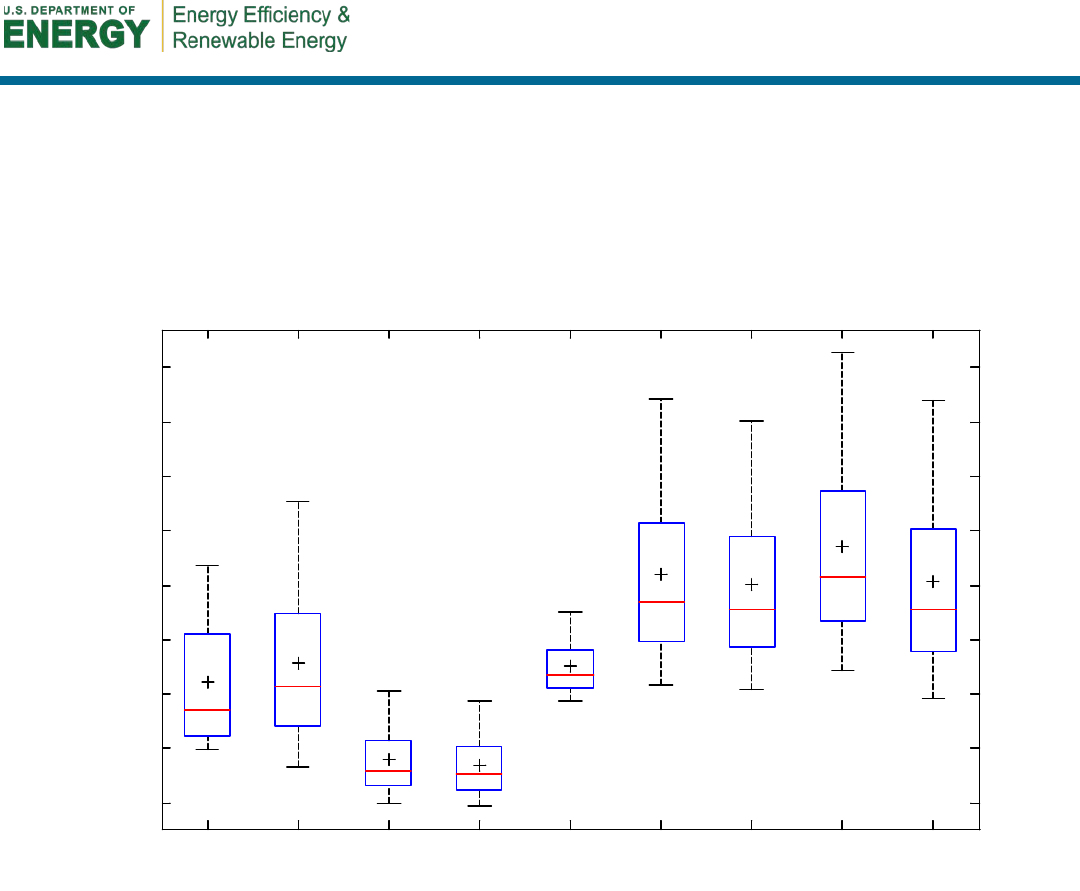
34
the lowest-cost option on a total life cycle basis. Space-conditioning interactions may change the
relative costs of HPWHs in relation to other water heaters, depending on the climate. These
interactions could not be measured in this study. Condensing tankless water heaters, which were
not investigated in this analysis, have lower operating costs than even condensing storage water
heaters, but the analysis method employed here does not account for the transient behavior of
tankless water heaters. Tankless units have other issues, so a direct comparison may not be
appropriate.
Figure 20. Annualized energy-related costs of monitored HPWHs and alternative water heaters
$200
$300
$400
$500
$600
$700
$800
$900
$1000
Heat
Pump
Electric
Resistance
Gas
Standard
Gas
Premium
Gas
Condensing
Oil
Standard
Oil
Premium
Propane
Standard
Propane
Premium
Annuallized Energy Related Cost ($/yr)
35
6 Homeowner Surveys
After complete monitoring of the HPWHs, residents at the 14 sites were surveyed about their
satisfaction with the units. All the homeowners were satisfied. The majority (70%) noticed
cooling and/or dehumidification. Some noted that noise was an issue (18%). Some homeowners
experienced running out of water (36%), though these were isolated incidences and were not a
significant concern. The majority (73%) noticed lower utility bills. One “No” response to
noticing utility bill savings was because the homeowner switched from oil and did not know how
to do the cost comparison. Another “No” response was that the homeowner was not sure if the
savings were a result of HPWH or lower electricity rate (the savings were indeed due to the
HPWH). Detailed survey results are shown in Table 14 and Table 15.
Table 14. Survey Results of Whether the Homeowner or a Qualified
Professional Performed any Preventive Maintenance Procedures
GE AO SE All
Y N Y N Y N Y N
Testing the temperature & pressure-relief valve?
0
8
0
1
0
2
0
11
Flushing and/or draining the tank?
0
8
0
1
0
2
0
11
Periodically inspecting and clearing the condensate strainer
and drain lines?
5 3 1 0 0 2 6 5
Visually inspecting the surrounding floor area, or the drain
pan for signs of water leakage?
3 5 1 0 2 0 6 5
Cleaning the air filter?
4
3
1
0
0
0
5
3
Cleaning the evaporator?
0
8
0
1
0
2
0
11
Checking the condition of the sacrificial anode rod?
0
8
0
1
0
2
0
11
Checking and descaling the heating elements?
0
8
0
1
0
2
0
11
Would you encourage a friend or family member to buy the
same water heater?
8 0 1 0 1 1 10 1
The ideal response is in green text and nonideal response is in red text. Questions in gray were not expected to be addressed because these units
have not been installed long enough to warranty this level of maintenance
Table 15. Survey Results of Homeowners
GE AO SE All
Y N Y N Y N Y N
Have you ever run out of hot water?
4 4 0 1 0 2 4 7
Has the water been hot enough?
8
0
1
0
2
0
11
0
Have you noticed a difference in your energy bills since the water
heater was installed?
6 2 1 0 1 1 8 3
Have you noticed the water heater cooling and/or dehumidifying
the space?
6 2 0 1 1 0 7 3
Has the water heater’s operating noise been a problem?
1
7
0
1
1
1
2
9
Has this water heater changed how you use hot water?
2
6
0
1
0
2
2
9
Are you satisfied with your HPWH’s performance?
8 0 1 0 2 0 11 0
Have you read your HPWH’s manual?
6
2
1
0
1
1
8
3
Do you know how to change the settings on your HPWH?
7
1
1
0
0
0
8
1
Have you ever changed the settings of the water heater?
5
3
1
0
0
2
6
5
Do you know what operating mode your HPWH is set to?
5
2
1
0
0
0
6
2
Has the water heater required servicing?
1
7
0
1
2
0
3
8
The ideal response is in green text, nonideal response is in red, and questions without an ideal response are in blue.

36
7 Recommendations
Based on the results of this report, the Consortium for Advanced Residential Buildings provides
several recommendations for successful installation of HPWHs. The efficiency of HPWHs is
profoundly affected by hot water use. When large quantities of hot water are used in clusters,
HPWHs revert to electric resistance mode, which reduces the efficiency of the unit. A
homeowner can reduce this effect by purchasing a larger HPWH, increasing the set point
temperature (only for high water draw users, low water draw users will be negatively impacted
by the higher standby loss resulting from a higher set point temperature), or changing behavior.
By increasing the size and temperature of an HPWH, more hot water can be delivered at a given
time before the resistance elements are needed. Spreading the water load over a longer period of
time may also provide similar benefits and reduce standby losses.
The location of an HPWH is also an important factor to consider during installation. HPWHs
operate at higher efficiencies when they are subjected to higher ambient temperatures. If
possible, HPWHs should not be installed in cold locations, such as garages in northern climates.
Furthermore, HPWHs require additional space to operate at peak efficiency. In this and other
studies, an efficiency reduction of more than 10% was observed when HPWHs are installed in
confined spaces. Finally, HPWHs remove heat from the surrounding air and can therefore affect
the space-conditioning loads of a building. In cold climates, this heat removal is typically
undesired, and installing an HPWH in a buffer space such as an unconditioned basement can
temper the space-conditioning affects. In hot climates, removing heat can be beneficial, and the
total building energy consumption can be reduced by placing HPWHs in the conditioned space.
Although HPWHs are a promising technology that may finally be here to stay, installers must
still address some hurdles. Successful installation requires careful consideration of clearance and
weight. With additional heating mechanisms, these HPWHs are markedly larger than ERWHs
with identical storage volumes. Because HPWHs remove humidity from the air, drain pans and
condensate pumps may be necessary to protect them and the floor from excess moisture. Finally,
the inclusion of a heat pump means that filters must be cleaned regularly and noise could be a
problem for some installations. Many of these details are discussed in more depth by Shapiro,
Puttagunta, and Owens (2012) and SWA (2012).
37
8 Conclusion
Though the study used a small sample set, the overall performance of these 14 HPWHs has been
enlightening and shows promise for this technology. To date, only one compressor for an HPWH
unit had to be replaced; the cause of this failure is unclear. No other major issues have been
identified about the durability and reliability of these units, but this will need to be followed up
as these systems age. This evaluation successfully answered the following research questions:
• What is the measured efficiency of an HPWH located in unfinished basements of cold-
climate homes?
Even when installed in unfinished basements of cold-climate homes, the measured
efficiency of these units was much higher than that of conventional ERWHs (Table 16).
Except for one unit that was placed in a basement with very low ambient temperatures,
the monitored units had COPs higher than 1.5, which represents more than a 50%
reduction in energy consumption compared to an ERWH. The highest COP was 2.6.
Table 16. Summary of Test Results by Model
Model
Units
Monitored
Capacity
(gal)
Measured
Average COP
COP
Range
GE
10
50
1.82
1.5–2.1
A.O. Smith
2
60/80
2.12
2.1
Stiebel Eltron
2
80
2.32
2.0–2.6
Annual operating costs and source energy consumption for the monitored HPWHs were
lower than those for the alternative storage tank water heaters considered. Annualized
energy-related costs for HPWHs were slightly lower than those for ERWHs and
considerably lower than those for propane- and fuel-oil-fired systems. Natural gas storage
water heaters, however, were still the lowest-cost storage water heater on an annualized
energy-related cost basis. Tankless water heaters were not considered here because of
their more complex modeling requirements.
• What are the critical criteria that affect the installed performance of HPWHs, and how do
they impact the performance of each HPWH model?
Determining the key variables that affect performance was based on the results of the
study data.. Domestic hot water use (daily volume and draw pattern) is the primary driver
of efficiency, but ambient temperature plays a considerable role in expected efficiency.
Lower water demand reduces the overall efficiency of the water heater by increasing the
fraction of the recovery load that is standby losses. High water demand also reduces
efficiency by requiring more electric resistance use. Higher ambient temperatures
increase the efficiency of the heat pump and reduce standby losses.
Although the GE unit shows two distinct operating regions that correspond to large and
small electric resistance loads, the A.O. Smith and Stiebel Eltron units operate entirely in
the low electric resistance region. This is most likely a product of the larger tank volumes
and the control logic that allows the heat pump to reengage, in the case of A.O. Smith, or

38
operate simultaneously, in the case of Stiebel Eltron. The Stiebel Eltron unit’s higher
factory-set set point temperature may also play a role.
• Does each model evaluated in this study effectively deliver hot water at the set point
temperature?
Despite the slower recovery rate of heat pump compared to electric resistance elements,
the HPWHs were surprisingly able to meet very high hot water demands. The Stiebel
Eltron unit in particular was able to meet large loads around 200 GPD of hot water at
high COPs. The outlet water temperature during these periods never dropped below the
minimum accepted water temperature of 110°F.
• What are the standby losses for these HPWHs, and how do they compare to traditional
ERWHs?
HPWHs are significantly more efficient than ERWHs; however, the standby losses of
these water heaters are considerably higher than those of ERWHs. Laboratory
measurements of these units in resistance mode showed values about 10% lower than a
comparably sized ERWH. Laboratory testing and analysis in this study also showed
higher overall heat transfer coefficient values than those for ERWHs. Tank loss
coefficients calculated in this study were about 25% higher than laboratory tests, which
may reflect the real-life performance of these units better than the laboratory installations.
A possible explanation for this difference is that thermal shorts were introduced by the
wraparound heat exchanger. Improvements in tank insulation would need to be made to
reduce the thermal heat loss for these tanks.
Although the efficiency numbers of these units are impressive, this study did not
completely address the interactions between the HPWHs and the space-conditioning
systems. Because the HPWHs were placed in unconditioned basements, which act as
buffer spaces, the total impact on the space-conditioning system cannot be measured
without more information. However, the maximum potential impact of the HPWH on the
conditioning loads of the houses was approximately 3 MBtu of increased heat load and
1.5 MBtu of decreased cooling load. In other climates, the overall effect may be quite
different.
• Are homeowners satisfied with hot water delivery, efficiency, noise, and other
characteristics?
Ten of the 11 survey respondents said that they would recommend an HPWH to a friend
or family member. The one dissenting homeowner had an issue with the noise of the
HPWH, because a home office was located in the room adjoining the basement
mechanical room.
Overall, this study provides considerable data about the performance of new HPWHs in
unconditioned basements in the Northeast. The efficiencies were remarkable in these
installations, and these units show considerable promise. However, more research is still
necessary in several areas. Understanding the affects of HPWH installation in unconditioned
basements is vital for quantifying HPWH impacts on the total building energy use. Calculating

39
the interactions among the HPWH, conditioned space, buffer space, ground, and ambient air
temperature is not a trivial task.
Furthermore, more information is needed to predict the effect of draw profiles on the efficiency
of these HPWHs. Although the concentration of draws clearly affects the switching between the
heat pump and the electric resistance elements, a direct connection between which draw profiles
trigger resistance operating and which do not has not been drawn. Understanding this connection
is particularly vital for developing test procedures that can accurately predict the field
performance of HPWHs.
Although HPWHs are a promising technology that may finally be here to stay, installers must
still address some installation hurdles. Successful installation requires careful consideration of
clearance and weight, drain pans and condensate pumps, maintenance, and noise. Many of these
details are discussed in more depth by Shapiro, Puttagunta, and Owens (2012) and SWA (2012).

40
References
Abdelaziz, O., K. Wang, E.A. Vineyard, and J. Roetker, J. 2012. “Development of
Environmentally Benign Heat Pump Water Heaters for the US Market.” ACEEE Summer Study
on Energy Efficiency in Buildings, 1.1–1.12.
AIL Research. 2001. Northeast Utilities Heat Pump Water Heater Field Test: 30 Crispaire
Installations. Princeton, NJ: AIL Research Inc.
AIL Research. 2002. Nyle Heat Pump Water Heat Evaluation. Princeton, NJ: AIL Research Inc.
Amarnath, A., and J. Bush. 2012. “HPWH Field Demonstration Project: Overview and Some
Interim Results.” Presented at ACEEE Hot Water Forum. May 21–23, 2012.
American Water Heaters. 2009. Polaris
®
High-Efficiency Commercial Gas Water Heater.
NCGSS00308 R April 09. Johnson City, TN: American Water Heaters.
A.O. Smith. 2010. A.O. Smith—Voltex
TM
Hybrid Electric Heat Pump Water Heater: Installation
Instructions and Use & Care Guide. 318257-000. February 2010. Ashland City, TN: A.O. Smith.
A.O. Smith. 2011. Personal Correspondence. March 11, 2011. A.O. Smith, Ashland City, TN.
Ashdown, B.G., D.J. Bjornstad, M. Boudreau, V. Lapsa, S. Schexnayder, B. Shumpert, and F.
Southworth. 2004. Heat Pump Water Heater Technology: Experiences of Residential Consumers
and Utilities (Technical Report, ORNL/TM-2004/81). Oak Ridge, TN: Oak Ridge National
Laboratory.
Baxter, V.D., and R.L. Linkous. 2004. Heat Pump Water Heater Durability Testing—Phase II
(Technical Report, ORNL/TM-2004/111). Oak Ridge, TN: Oak Ridge National Laboratory.
Bodzin, S.1997. “Air-to-Water Heat Pumps for the Home.” Home Energy. July/August 1997.
Bollen, K.A., and R.W. Jackman. 1985. “Regression Diagnostics: An Expository Treatment of
Outliers and Influential Cases.” Sociological Methods Research; 13(4): 510–542.
BLS. 2012. “CPI Inflation Calculator.” Washington, DC: U.S. Bureau of Labor Statistics.
Accessed October 31, 2012: www.bls.gov/data/inflation_calculator.htm.
Calm, J.M. 1984. Heat Pump Water Heaters. Palo Alto, CA: Electric Power Research Institute.
Changing Times. 1982. “Heating Water with a Heat Pump.” The Kiplinger Magazine: Changing
Times. August 1982; pp. 18–19.
Chatterjee, S., and B. Price. 1991. Regression Analysis by Example. 2
nd
Edition. New York: John
Wiley & Sons.
Colon, C. 2012. Side-by-Side Testing of Water Heating Systems: Results from the 2010-2011
Evaluation. FSEC-RR-386-12. Cocoa, FL: Florida Solar Energy Center.

41
DOE. 1998. “Energy Conservation Program for Consumer Products: Test Procedure for Water
Heaters.” Federal Register; 10 CFR Part 430; 63(90): 25996–26016. Washington, DC: U.S.
Department of Energy.
DOE. 2010. “Energy Conservation Program: Energy Conservation Standards for Residential
Water Heaters, Direct Heating Equipment, and Pool Heaters.” Federal Register; 10 CFR Part
430; 75(73): 20114–20236. Washington, DC: U.S. Department of Energy.
Deru, M., and P. Torcellini. 2007. Source Energy and Emission Factors for Energy Use in
Buildings (Technical Report, NREL/TP-550-38617). Golden, CO: National Renewable Energy
Laboratory.
EIA. 1996. The Changing Structure of the Electric Power Industry: An Update. DOE/EIA-
0562(96). Washington, DC: U.S. Energy Information Administration.
EIA. 2005. “2005 Residential Energy Consumption Survey.” Washington, DC: U.S. Energy
Information Administration. Accessed October 31,
2012: www.eia.gov/consumption/residential/data/2005/.
EIA. 2009. “2009 Residential Energy Consumption Survey.” Washington, DC: U.S. Energy
Information Administration. Accessed October 31,
2012: www.eia.gov/consumption/residential/data/2009/
.
EIA. 2012a. Annual Energy Outlook 2012: with Projections to 2035. DOE/EIA-0383.
Washington, DC: U.S. Energy Information Administration.
___ 2012b. “Electricity Data Browser.” Washington, DC: U.S. Energy Information
Administration. Accessed October 31, 2012: www.eia.gov/beta/enerdat/.
___ 2012c. “U.S. Natural Gas Prices.” Washington, DC: U.S. Energy Information
Administration. Accessed October 31,
2012: www.eia.gov/dnav/ng/ng_pri_sum_dcu_nus_m.htm
.
___ 2012d. “U.S. Weekly Heating Oil and Propane Prices.” Washington, DC: U.S. Energy
Information Administration. Accessed October 31,
2012: www.eia.gov/dnav/pet/pet_pri_wfr_dcus_nus_m.htm.
___ 2012e. “Custom Table Builder” Washington, DC: U.S. Energy Information Administration.
Accessed November 2, 2012: www.eia.gov/forecasts/steo/query/.
Environmental Building News. 2005. “WatterSaver Water Heater Halted.” Environmental
Building News. 14(11).
EPA. 2012. “Residential Water Heaters Key Product Criteria.” Washington, DC: U.S.
Environmental Protection Agency. Accessed October 31,
2012: www.energystar.gov/index.cfm?c=water_heat.pr_crit_water_heaters.
EPRI. 1995. “Energy Consumption and Operating Cost Comparison for Water Heaters.” Electric
Water Heating News. 7(4). Palo Alto, CA: Electric Power Research Institute.

42
EPRI. 2000. WATSMPL 2.0 User’s Manual: Simplified Energy and Operating Cost Analysis of
Storage Water Heaters. Palo Alto, CA: Electric Power Research Institute.
Fitzpatrick, S., and M. Murray. 2011. GE Heat Pump Water Heater Report. Raleigh, NC:
Advanced Energy.
Franco, V., A. Lekov, S. Meyers, and V. Letschert. 2010. “Heat Pump Water Heaters and
America Homes: A Good Fit?” Proceedings Summer Study on Energy Efficiency in Buildings
(9); American Council for an Energy-Efficient Economy; pp. 68–79.
Freddie Mac. 2012. “30-Year Fixed-Rate Mortgages Since 1971.” McLean, VA: Freddie Mac.
Accessed October 31, 2012: www.freddiemac.com/pmms/pmms30.htm.
GE. 2009. Hybrid Residential Water Heaters: Owner’s Manual & Installation Instructions. 49-
50254 10-09 JR. Louisville, KY: General Electric Appliances.
Hashimoto, K. 2006. “Technology and Market Development of CO
2
Heat Pump Water Heaters
(ECO CUTE) in Japan.” IEA Heat Pump Centre Newsletter; 24(3): 12–16.
Hendron, R., and C. Engebrecht. 2010. Building America House Simulation Protocols.
DOE/GO-102010-3141. Golden, CO: National Renewable Energy Laboratory.
Hu, S., and R. Davis. 2011. “PG&E Field Study on Heat Pump Water Heaters.” Presented at
ACEEE Hot Water Forum. May 10, 2011.
Hudon, K., B. Sparn, D. Christensen, and J. Maguire. 2012. “Heat Pump Water Heater
Technology Assessment Based on Laboratory Research and Energy Simulation Models.”
Preprint. NREL/CP-550-51433. Golden, CO: National Renewable Energy Laboratory.
Maynard, M. 2011. “Advances in Water Heating Technology.” AHRItrends. Fall 2011.
Megliola, M. 2011. Personal Correspondence. March 11, 2011. Stiebel Eltron, West Hatfield,
MA.
Murphy, R.W., and J.J. Tomlinson. 2002. Field Tests of a “Drop-in” Residential Heat Pump
Water Heater (Technical Report, ORNL/TM-2002/207). Oak Ridge, TN: Oak Ridge National
Laboratory.
NREL. 2012a. “National Residential Efficiency Measures Database.” Golden, CO: National
Renewable Energy Laboratory. Accessed October 30,
2012: www.nrel.gov/ap/retrofits/about.cfm.
____ 2012b. BEoptE+ 1.4. https://beopt.nrel.gov/home.
____ 2012c. Field Monitoring Protocol: Heat Pump Water Heaters. Golden, CO: National
Renewable Energy Laboratory (Forthcoming).
PG&E. 2008. Laboratory Testing of Residential Gas Water Heaters. ATS Report #491-08.5. San
Francisco: Pacific Gas & Electric Company.

43
PG&E. 2009. Energy Performance Analysis for Heat Pump Water Heaters. Application
Assessment Report #0916. San Francisco: Pacific Gas & Electric Company.
PG&E. 2010. Laboratory Evaluation and Field Testing of Residential Heat Pump Water Heaters.
ETP-10PGE1001. San Francisco: Pacific Gas & Electric Company.
Polly, B., M. Gestwick, M. Bianchi, R. Anderson, S. Horowitz, C. Christensen, and R. Judkoff.
2011. A Method for Determining Optimal Residential Energy Efficiency Retrofit Packages.
DOE/GO-102011-3261. Golden, CO: National Renewable Energy Laboratory.
Powell, E. 1980. “New Energy-Saving Heat-Pump Water Heater.” Popular Science, April 1980,
pp. 49–57.
Shapiro, C., S. Puttagunta, and D. Owens. 2012. Measure Guideline: Heat Pump Water Heaters
in New and Existing Homes (Subcontract Report, DOE/GO-102012-3456). Golden, CO:
National Renewable Energy Laboratory.
Sparn, B., K. Hudon, and D. Christensen. 2011. Laboratory Performance Evaluation of
Residential Integrated heat Pump Water Heaters (Technical Report, NREL/TP-550-52635).
Golden, CO: National Renewable Energy Laboratory.
Stiebel Eltron. 2010. Operating and Installation Manual: DHW Heat Pump Water Heater. West
Hatfield, MA: Stiebel Eltron.
SWA. 2004. Field Evaluation of WatterSaver
™
Heat Pump Water Heater. Norwalk CT: Steven
Winter Associates.
SWA. 2012. Heat Pump Water Heaters: Selection and Quality Installation Guide. Springfield,
MA: Mass Save. Accessed October 20,
2012:
www.masssave.com/~/media/Files/Residential/Information%20and%20Edu%20Docs/HP
WH_QI_Guide.ashx.
Thumann, A., and P. Mehta. 1991. Handbook of Energy Engineering. 2
nd
Ed. Lilburn, GA:
Fairmont Press.
Tomlinson, J.J. 2002. “All Pumped Up: New Heat Pump Water Heaters Consume Half the
Energy of Conventional Electric-Resistance Ones.” Home Energy. November/December; pp. 30–
35.
Wilkes G., and F.M. Reed. U.S. Patent No. 2,095,017 (October 5, 1937).
Zogg, R. 2002. “Residential Heat Pump Water Heater Technology and Markets Seminar.”
December 4–5, 2002; Portland, OR.
Zogg, R.A., W.J. Murphy, and J. Hoyt. 2004. Design Refinement and Demonstration of a
Market-Optimized Heat-Pump Water Heater. CEC-500-04-018. Sacramento, CA: California
Energy Commission.
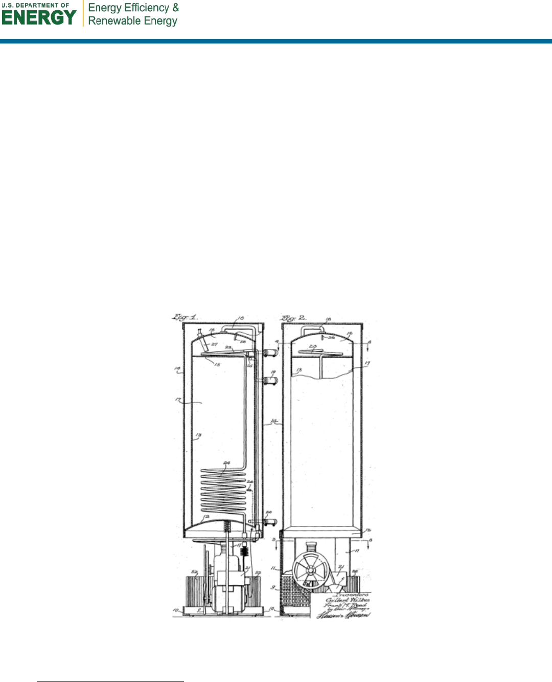
44
Appendix A: A History of Heat Pump Water Heaters in the United
States
HPWHs are not new, despite their recent reintroduction into the mainstream residential
marketplace. Since the first commercialization of HPWHs in the 1950s, HPWHs have followed a
boom-bust cycle of product development and subsequent abandonment that closely follows retail
electricity prices and demonstrates the reliability issues of past products. Even though HPWHs
failed to gain significant market traction in the past, the current confluence of regulatory,
economic, and market forces may be finally pushing HPWHs into the mainstream.
The Early Years: 1935–1970
The invention of HPWHs dates back at least to 1935, when the first HPWH was patented in the
United States (Wilkes and Reed 1937).
12
The HPWH described in the patent (Figure 21) looks
very similar to the current batch of HPWHs, with a supplemental electric resistance element, an
integrated storage tank, a motor-driven compressor, and an immersed coil condenser. A unique
feature of this HPWH, however, was the use of upper and lower chambers to prevent the electric
resistance element from heating the entire storage volume.
Figure 21. First patented HPWH. Image from Wilkes and Reed 1937.
12
The search term heat pump water heater was used in Google’s patent search, which has digitized every patent
application in the United States since 1790.

45
Development of the first mass-market, commercialized HPWH, however, did not begin until the
1950s. A prototype developed by the Hotpoint Company—now a division of GE—performed
well when monitored in collaboration with the Tampa Electric Company (Calm 1984).
Throughout the 1940s and 1950s electricity prices declined considerably
13
(EIA 1996), which
undoubtedly reduced the economic and commercial viability of the product. Development was
discontinued, and HPWHs would not return to the mainstream market for more than 20 years
(Calm 1984).
The Second Generation: 1970–1999
Interest in HPWHs subsided in the 1960s, during a period of low and falling electricity prices.
By the 1970s, however, the emerging energy crisis and a spike in retail electricity prices
rekindled interest in HPWHs as a mainstream, commercialized product. Retail electricity prices
began to rise as fossil fuel prices spiked, utility companies overbuilt capacity based on inaccurate
demand forecasts, and environmental regulation increased construction costs for capital
improvements (EIA 1996).
During the mid- to late 1970s, the National Rural Electric Cooperative Association and the U.S.
Department of Energy provided funding to develop a prototype HPWH. Through this funding,
Energy Utilization Systems manufactured 100 HPWHs—85 integrated units and 15 add-on
units—which were tested by 20 electric utilities. The add-on units were unsuccessful; however,
the integrated units showed significant promise. Average COPs were around 2, operating savings
approached 50%, the life span of the units matched similar natural gas water heaters and
ERWHs, and consumer satisfaction was high (Calm 1984).
By the 1980s, the successful pilot program had driven HPWHs into the mainstream marketplace.
Popular Science trumpeted HPWHs as a way to achieve “solar savings—without the cost”
(Powell 1980), and HPWHs were soon eligible for state tax credits. Electric utilities, such as the
Tennessee Valley Authority, pushed adoption through zero-interest loans and incentives
(Changing Times 1982). By 1984, at least 17 commercialized HPWHs were in the marketplace
under a multitude of trade names (Calm 1984).
These new units were met with enthusiasm during the early 1980s and sold more than 10,000
units per year. However, the HPWH market soon collapsed because “these early machines
suffered from high purchase prices, high maintenance costs, excessive noise, poor longevity, and
limited installation options.” By 1995, only two manufacturers remained, and sales sat at
approximately 2,000 units per year (Bodzin 1997). High first costs have been cited as a key
reason for the collapse of the market (Ashdown et al. 2004), and declining electricity prices (EIA
1996, EIA 2012e) certainly played a role in the diminishing economic viability of these HPWHs.
The Third Generation: 1999–2010
Facing a collapse of the HPWH market, Arthur D. Little, Inc., ECR International, and Oak Ridge
National Laboratory collaborated to develop a new integrated HPWH in the late 1990s to address
the aforementioned issues with the previous generation of products. At that time, the only
HPWHs on the market were add-on units to existing ERWHs. The first prototype was developed
13
All references to electricity price changes are relative to inflation (i.e., electricity price fluctuations are stated in
real terms).

46
in 1999, and within a year the final prototype was produced that had an EF of 2.47. The final
product, which was branded as the WatterSaver, was tested for durability and field performance
in subsequent years (Ashdown et al. 2004, Baxter and Linkous 2002, Tomlinson 2002).
During field testing of units across the United States, the average COP was 2, which is more than
double the efficiency of a comparable ERWH (Ashdown et al. 2004). In-house durability testing
at Oak Ridge National Laboratory uncovered no major durability issues (Baxter and Linkous
2002). Outside studies, however, had more mixed results from these products. A study in
California found an average COP of 1.27 for sites in California (Zogg, Murphy, and Hoyt 2004).
SWA performed field-testing of 20 WatterSaver HPWHs in 2002 in the northeast for
Connecticut Light & Power, which is a division of Northeast Utilities. With an average COP of
1.67, the efficiency of the unit was slightly lower for these field sites, and operational and
reliability issues with the units were uncovered (SWA 2004).
During the course of SWA’s monitoring, customer satisfaction was fairly high, and many
participants noted the dehumidification benefits. However, the study also identified some
consistent drawbacks with the daily operation of the systems. Many customers complained about
excessively hot water, and monitoring showed that water temperatures near the tops of the tanks
often exceeded 150°F. These high temperatures were partly due to excessive tank stratification—
water temperatures near the top could be 50°F higher than temperatures near the bottom—and in
many systems the high-temperature safety switches shut down the water heaters completely
(these were designed to shut down the system when temperatures reached 170°F). These issues
were communicated to the manufacturer (SWA 2004). Ultimately, the WatterSaver was removed
from the market because of the identified problems with installed performance and a nonexistent
service infrastructure (Environmental Building News 2005).
Current Products: 2010–Present
A variety of economic and regulatory factors are pushing HPWHs back into the mainstream
marketplace, as discussed in Section 1. Five major HPWH products are currently available in the
water heater market. Key specifications for these HPWHs are shown in Table 17. These
specifications include the two U.S. Department of Energy performance metrics: EF and FHR.
14
The EF represents the efficiency of the electric heating elements and tank losses under a
consistent, 24-hour test procedure. The FHR represents the amount of hot water that can be
supplied by a fully heated storage water heater during an hour of operation. Storage tank volume
is often used as a proxy for water-heating capacity, but FHR is the preferred metric. See Section
4.2 for more details about the EF and FHR test procedures.
14
RE is also used to quantify the efficiency of natural gas, fuel oil, and propane water heaters. RE is an approximate
metric of the burn efficiency of the heating device. Because electric resistance elements have an efficiency of 1, RE
is not tested or reported.
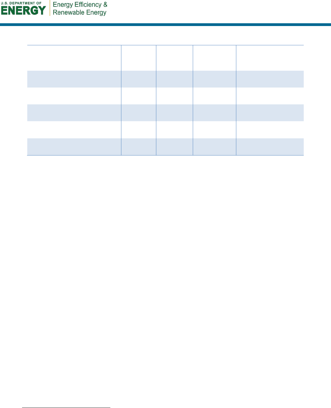
47
Table 17. Key Specifications of Integrated HPWHs Currently Available in the U.S. Market
15
Model
Capacity
(gal)
EF FHR (gal)
Electric Resistance
Elements
(kW)
GE GeoSpring
50 2.35 63
Upper: 4.5
Lower: 4.5
A.O. Smith Voltex
60/80 2.33 68/84
Upper: 4.5
Lower: 2
Stiebel Eltron Accelera 300
80 2.51 78.6
Upper: 1.7
Lower: None
Rheem EcoSense
40/50 2 56/67
Upper: 2
Lower: 2
AirGenerate AirTap
Integrated
50/66 2.39/2.4 60/75 Upper: 4
Outlook for the Future
While HPWH development in the United States focused on traditional refrigerants, Japanese
manufacturers, in conjunction with the Tokyo Electric Power Company, focused on developing
an HPWH based on the carbon dioxide (CO
2
) cycle. At the same time the WatterSaver was
being developed, a Japanese consortium started developing the CO
2
HPWH, which had a COP
of 3.4 when subjected to an ambient air temperature of 46.4°F and average tank temperature of
149°F. Marketed under the EcoCute brand, this CO
2
HPWH was released in 2001. The EcoCute
is a split system, meaning that it does not affect space-conditioning loads. Furthermore, the units
can be connected to a smart grid to try to move reheating periods to off-peak electricity periods.
COPs have increased to higher than 4 in more recent models, and sales of the EcoCute have
increased dramatically since its introduction (Hashimoto 2006).
The development of CO
2
HPWHs in the United States is just beginning. Market, technological,
regulatory, and structural hurdles still remain for this technology, but CO
2
HPWHs have been
actively pushed in recent years. Oak Ridge National Laboratory and GE have collaborated to
develop a prototype integrated HPWH based on the CO
2
cycle for the residential U.S. market.
Although this prototype is still in its early phases of development, future products may take
advantage of CO
2
as a more environmentally benign refrigerant (Abdelaziz et al. 2012).
15
Any omission of a manufacturer or product is unintentional, and no endorsement of any commercial product or
manufacturer is implied.

48
Appendix B: Alternative Water-Heating Calculations
Alternative water-heating products were evaluated using the equations underlying the
WATSMPL simulation program (EPRI 2000, 1995). For electric tanks the assumed recovery
efficiency is 1, and the pilot load is 0. The net water-heating load is computed using the hot
water load, inlet temperature, and outlet temperature:
( )
inoutpnet
TTVcQ −=
γ
,
(9)
where
Q
net
= net water-heating load (Btu)
V = hot water use (gal)
c
p
= specific heat of water (Btu/lb°F)
γ = specific weight of water (lb/gal)
T
out
= outlet temperature (°F)
T
in
= inlet temperature (°F).
The energy lost from the tank during the EF test Q
tank,EF
(Btu) is
−×= 1
EFtank,
EF
RE
QQ
water
,
(10)
where
Q
water
= thermal energy drawn during EF test (41,063 Btu/day)
RE = recovery efficiency
EF = energy factor.
The energy lost from the tank during operation minus the lost energy from the pilot load Q
tank
(Btu) is
pilot
ambout
QRE
TT
QQ ×−
−
−
×=
5.67135
EFtank,tank
,
(11)
where
Q
pilot
= pilot load (Btu)
T
amb
= ambient temperature (°F).
The tank combustion losses Q
combustionloss
(Btu) is
( )
−×+= 1
1
tankloss combustion
RE
QQQ
net
.
(12)
The gross water-heating load Q
net
(Btu) is
pilotnetgross
QQ
QQQ +++=
loss combustiontank
.
(13)

49
Appendix C: Monitored and Modeled Energy Use and Costs by
Site
Using the equations listed in Appendix B and the operating characteristics discussed in Section
5, the following site energy, source energy, and annual operating costs are listed in Table 18
through Table 21. HPWH numbers are annualized based on monitored data, and all other
systems are modeled using the operating conditions measured for each HPWH site.
Table 18. Annual Site Energy Consumption by Site
Site
HPWH
(kWh)
ERWH
(kWh)
Standard
Gas
(therms)
Premium
Gas
(therms)
Condensing
Gas
(therms)
Standard
Oil
(gal)
Premium
Oil
(gal)
Standard
Propane
(gal)
Premium
Propane
(gal)
1
1,155
3,045
173
149
117
124
106
189
163
2
1,969
5,899
304
271
221
217
193
331
295
3
1,838
4,152
222
195
157
158
139
242
213
4
1,186
2,981
169
145
115
120
104
184
159
5
3,612
4,739
258
225
180
184
161
281
246
6
892
2,502
149
126
98
106
90
162
137
7
714
1,756
116
95
71
83
68
126
103
8
909
2,403
144
122
94
103
87
157
133
9
1,169
2,665
154
132
103
110
94
168
144
10
1,475
3,434
198
169
133
141
121
216
185
11
3,080
5,927
303
271
222
216
193
330
296
12
1,380
3,114
176
151
120
125
108
192
165
13
1,317
2,393
145
122
94
104
87
158
133
14
922
2,235
136
114
88
97
82
148
125
Table 19. Annual Source Energy (MMBtu) Consumption by Site
Site
HPWH ERWH
Standard
Gas
Premium
Gas
Condensing
Gas
Standard
Oil
Premium
Oil
Standard
Propane
Premium
Propane
1
13.3
35.0
18.9
16.3
13.5
20.1
17.2
19.9
17.1
2
22.6
67.7
33.1
29.6
25.4
35.2
31.3
34.9
31.2
3
21.1
47.7
24.2
21.3
18.1
25.7
22.6
25.5
22.4
4
13.6
34.2
18.4
15.9
13.2
19.5
16.8
19.4
16.7
5
41.5
54.4
28.1
24.6
20.8
29.8
26.1
29.6
25.9
6
10.2
28.7
16.3
13.8
11.3
17.2
14.6
17.1
14.5
7
8.2
20.2
12.6
10.3
8.2
13.4
11.0
13.3
10.9
8
10.4
27.6
15.7
13.3
10.8
16.7
14.1
16.6
14.0
9
13.4
30.6
16.8
14.4
11.9
17.8
15.3
17.7
15.2
10
16.9
39.4
21.6
18.5
15.3
22.9
19.6
22.8
19.5
11
35.4
68.1
33.1
29.6
25.5
35.1
31.3
34.8
31.2
12
15.8
35.8
19.2
16.5
13.8
20.3
17.5
20.2
17.4
13
15.1
27.5
15.8
13.3
10.8
16.8
14.1
16.7
14.0
14
10.6
25.7
14.8
12.5
10.1
15.7
13.2
15.6
13.1

50
Table 20. Annual Operating Costs ($) by Site
Site
HPWH ERWH
Standard
Gas
Premium
Gas
Condensing
Gas
Standard
Oil
Premium
Oil
Standard
Propane
Premium
Propane
1
135
357
191
164
129
486
418
539
463
2
231
691
334
298
243
852
760
944
842
3
215
487
244
214
173
622
547
690
607
4
139
349
185
160
126
473
408
525
452
5
423
555
283
248
198
723
632
801
700
6
105
293
164
139
108
418
353
463
392
7
84
206
127
104
78
325
266
360
295
8
107
282
158
134
104
404
341
448
378
9
137
312
170
145
114
433
370
480
410
10
173
403
218
186
146
556
476
616
527
11
361
695
333
298
244
850
760
942
842
12
162
365
193
167
132
493
425
546
471
13
154
280
159
134
103
407
342
451
379
14
108
262
150
126
97
382
320
423
355
Table 21. Annualized Energy-Related Costs ($) by Site
Site
HPWH ERWH
Standard
Gas
Premium
Gas
Condensing
Gas
Standard
Oil
Premium
Oil
Standard
Propane
Premium
Propane
1
471
417
262
253
437
577
560
622
561
2
567
751
405
387
551
943
902
1,028
940
3
429
547
315
304
481
713
690
773
704
4
353
410
257
249
434
564
550
608
550
5
637
616
355
337
506
814
774
885
798
6
318
353
235
228
415
508
496
547
490
7
298
266
199
194
386
416
408
444
392
8
320
342
230
223
411
495
484
532
476
9
351
372
241
234
421
523
512
563
508
10
509
463
289
276
454
647
618
700
625
11
575
755
404
387
551
940
902
1,025
940
12
376
425
264
256
439
584
568
630
569
13
368
341
231
224
411
498
485
535
477
14
322
322
221
215
404
472
463
507
453
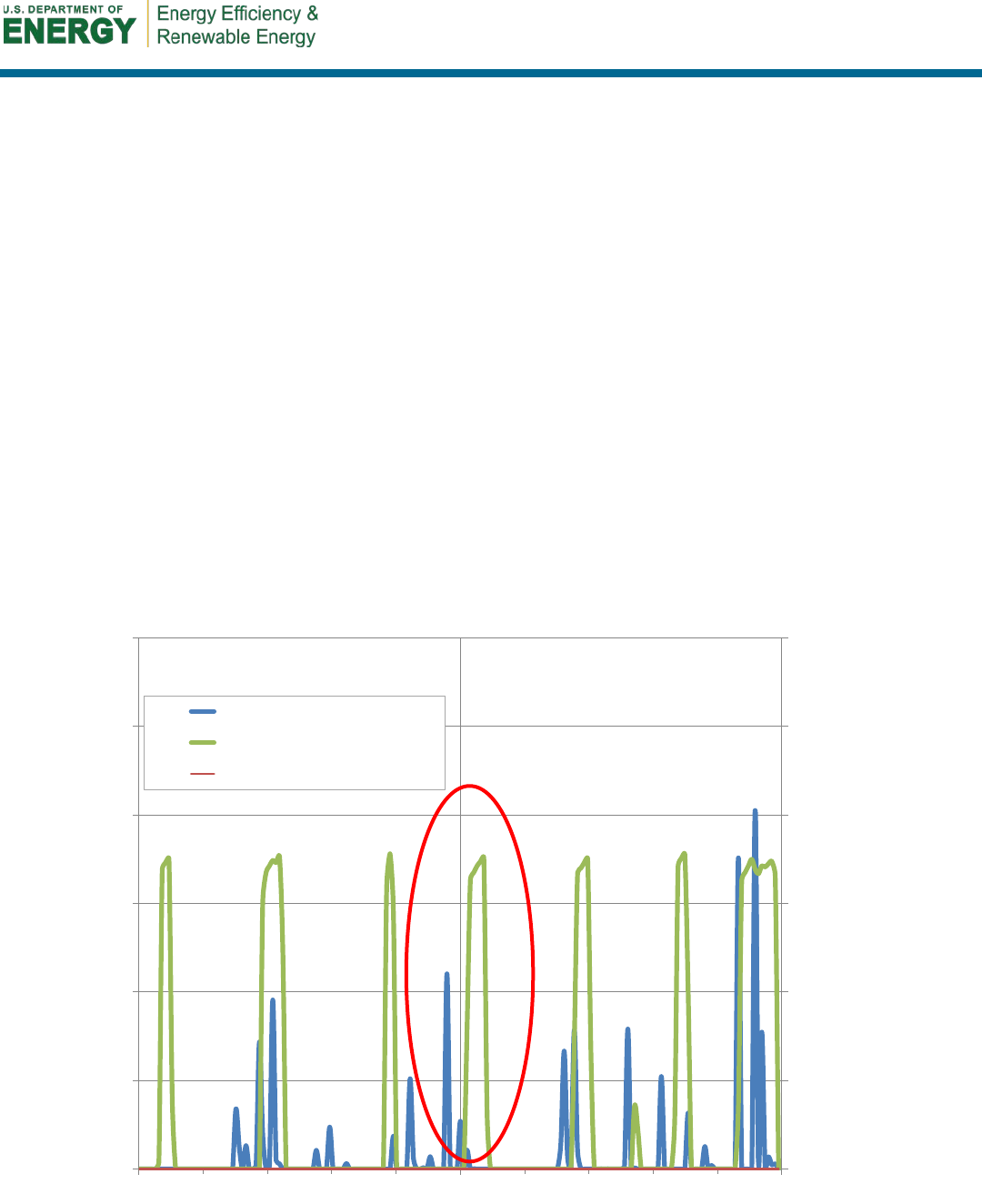
51
Appendix D: Identifying Heating Events
Choosing an appropriate analysis period to investigate the trends in the collected data is vital for
untangling the various input variables that can affect performance. Looking at the data on a
yearly site-by-site basis is inappropriate, because the sample size for this project is not large
enough and seasonal swings in operating conditions cannot be considered. Conversely, looking
at the 15-minute data is also inappropriate, because knowing the internal state of the tank, which
was not monitored in this study, would be necessary to understand the transient response of the
water heater to the operating conditions. Using daily data would be more appropriate, because
the system can be assumed to be in a steady state—i.e., the system operating variables do not
change considerably, but a larger sample size needs to be investigated.
Daily data, however, are not quite perfect, because the response rate of the heat pump system is
considerably slower than other heating mechanisms. A large draw at the end of one day can be
recovered entirely during the following day (Figure 22); the red ellipse highlights an incidence of
such a draw. As a result of this issue, the COP trends in relation to the draw volume are reversed.
One would expect the first day to have a lower COP than the second day because the draw
volume is smaller, which means that the standby losses account for a larger percentage of the
recovery load. The trend from using the daily data, however, is reversed, which confuses the
analysis.
Figure 22. Results from using daily data for analysis
0
40
80
120
160
200
240
0
2
4
6
8
10
12
8/20 8/21 8/22
Energy Used (Wh)
HW Used (Gallons)
HW Use
Heat Pump
Electric Resistance
20 gals
1.5 COP
35 gals
1.4 COP
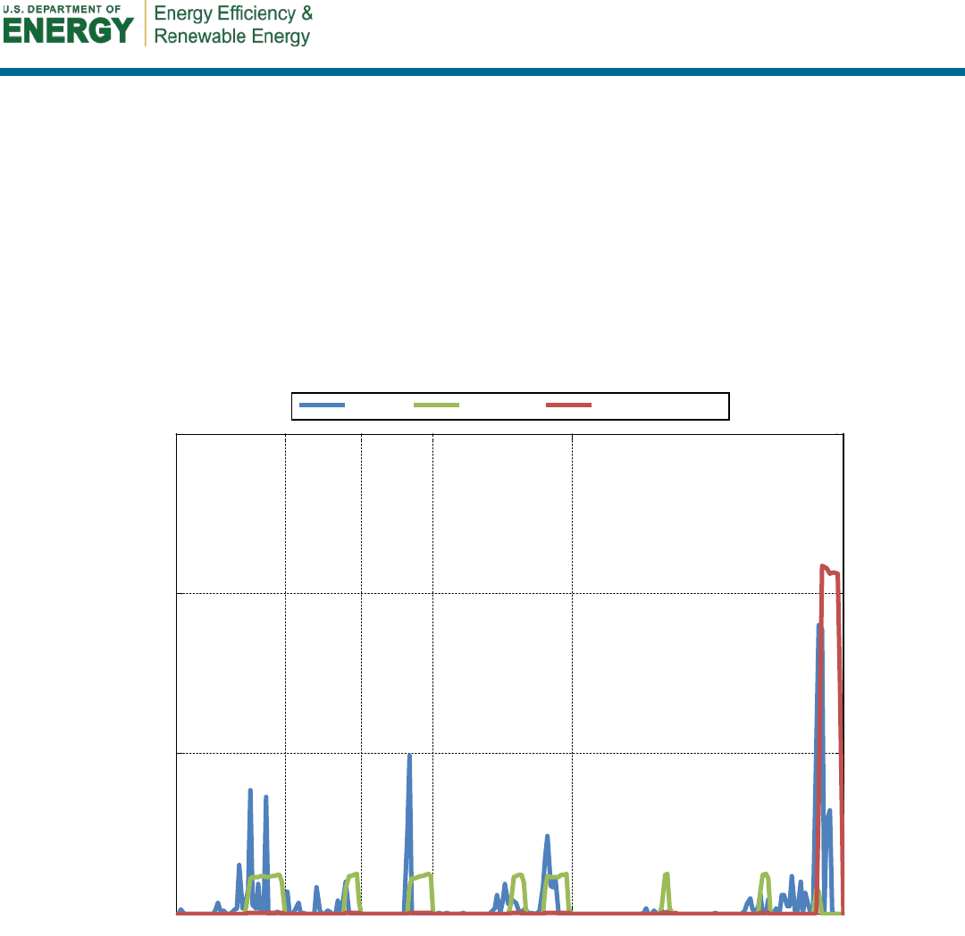
52
A solution to this problem is to find periods of time when the water-heating tank starts fully
heated and ends fully heated. The criteria for finding such periods, which are defined as heating
events in this study, are: (1) the heating event must be at least 4 hours long, and (2) the heating
event must begin and end after a reheat cycle that has a duration one of at least 1 hour during
which no draws occurred. There are some tolerances to allow for noise in the measurements.
To demonstrate how this works in practice, consider Figure 23. Five heating events are displayed
in this graph, four of which have no electric resistance use. Each heating event begins and ends
at the end of a reheat cycle. As shown in the figure above, the COPs are related to the draw
volumes, as expected. Furthermore, the heating events have the advantage of operating near
steady state, the same as the daily values but without the limitations of the daily values.
Figure 23. Example of five heating events as defined in this study
Fri 02:30 Fri 12:45
Fri 20:00 Sat 02:45 Sat 15:45 Sun 17:15
0
10
20
30
HW Used (Gallons)
Fri 02:30 Fri 12:45
Fri 20:00 Sat 02:45 Sat 15:45 Sun 17:15
0
500
1000
1500
Energy Used (Wh)
HW Use Heat Pump Electric Resistance
60 gals
2.6 COP
27 gals
2.2 COP
53 gals
2.4 COP
44 gals
2.4 COP
70 gals
1.1 COP

53
Appendix E: Trifold Brochure for Consumers
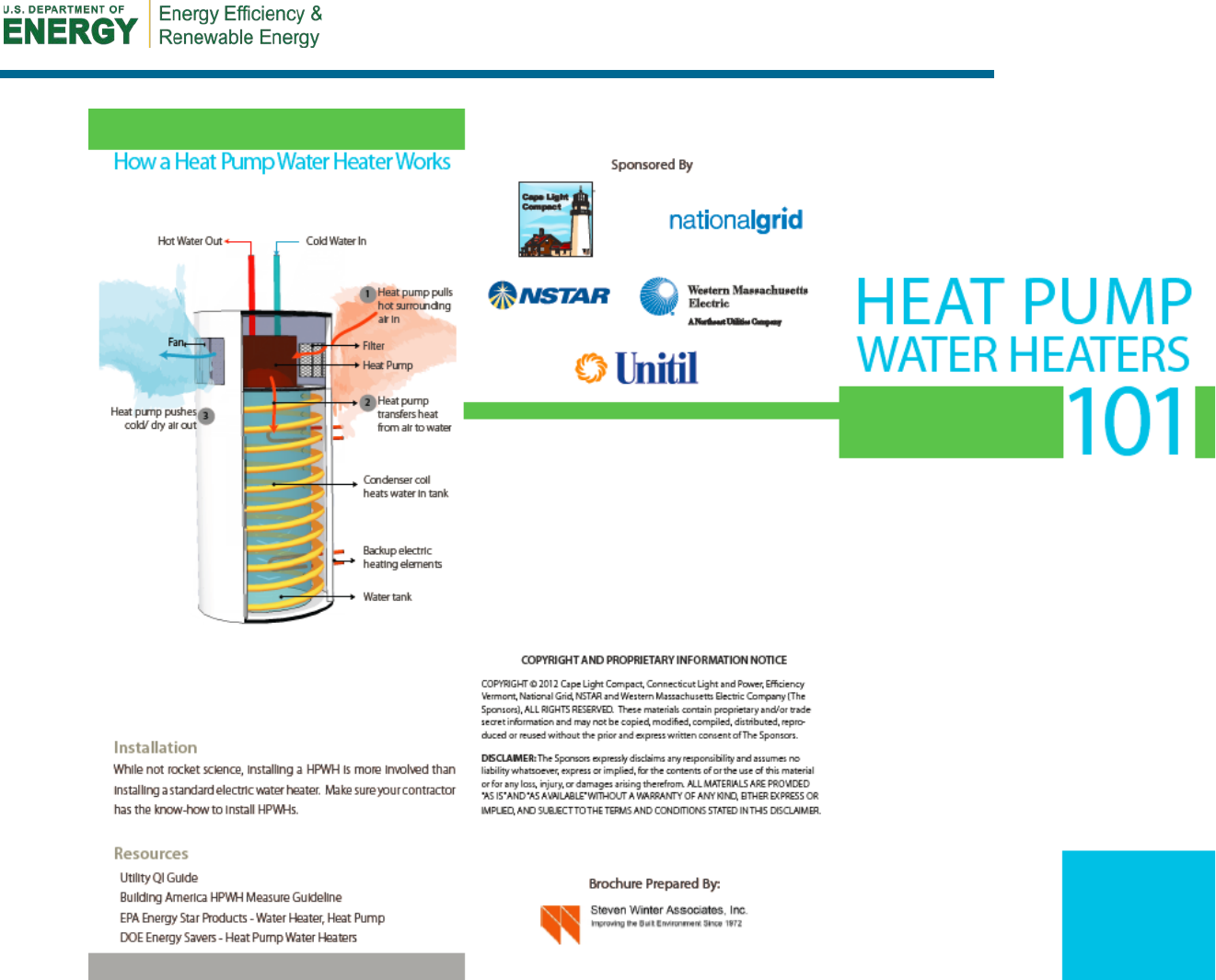
54
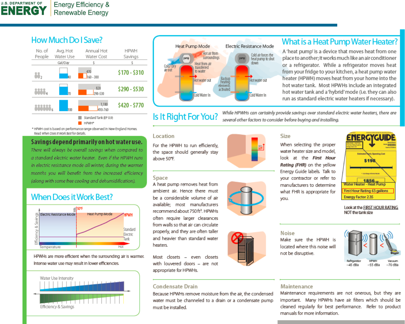
55

DOE/GO-102016-4759 ▪ February 2016
buildingamerica.gov
