

Important User Information
Read this document and the documents listed in the additional resources section about installation, configuration, and
operation of this equipment before you install, configure, operate, or maintain this product. Users are required to
familiarize themselves with installation and wiring instructions in addition to requirements of all applicable codes, laws,
and standards.
Activities including installation, adjustments, putting into service, use, assembly, disassembly, and maintenance are
required to be carried out by suitably trained personnel in accordance with applicable code of practice.
If this equipment is used in a manner not specified by the manufacturer, the protection provided by the equipment may
be impaired.
In no event will Rockwell Automation, Inc. be responsible or liable for indirect or consequential damages resulting from
the use or application of this equipment.
The examples and diagrams in this manual are included solely for illustrative purposes. Because of the many variables and
requirements associated with any particular installation, Rockwell Automation, Inc. cannot assume responsibility or
liability for actual use based on the examples and diagrams.
No patent liability is assumed by Rockwell Automation, Inc. with respect to use of information, circuits, equipment, or
software described in this manual.
Reproduction of the contents of this manual, in whole or in part, without written permission of Rockwell Automation,
Inc., is prohibited
Throughout this manual, when necessary, we use notes to make you aware of safety considerations.
Labels may also be on or inside the equipment to provide specific precautions.
WARNING: Identifies information about practices or circumstances that can cause an explosion in a hazardous
environment, which may lead to personal injury or death, property damage, or economic loss.
ATTENTION: Identifies information about practices or circumstances that can lead to personal injury or death, property
damage, or economic loss. Attentions help you identify a hazard, avoid a hazard, and recognize the consequence.
IMPORTANT Identifies information that is critical for successful application and understanding of the product.
SHOCK HAZARD: Labels may be on or inside the equipment, for example, a drive or motor, to alert people that dangerous
voltage may be present.
BURN HAZARD: Labels may be on or inside the equipment, for example, a drive or motor, to alert people that surfaces may
reach dangerous temperatures.
ARC FLASH HAZARD: Labels may be on or inside the equipment, for example, a motor control center, to alert people to
potential Arc Flash. Arc Flash will cause severe injury or death. Wear proper Personal Protective Equipment (PPE). Follow ALL
Regulatory requirements for safe work practices and for Personal Protective Equipment (PPE).

Rockwell Automation Publication PROCES-RM001M-EN-P - June 2019 3
Table of Contents
Preface
Purpose of the Reference Manual . . . . . . . . . . . . . . . . . . . . . . . . . . . . . . . . 7
Summary of Changes . . . . . . . . . . . . . . . . . . . . . . . . . . . . . . . . . . . . . . . . . . . 8
Additional Resources . . . . . . . . . . . . . . . . . . . . . . . . . . . . . . . . . . . . . . . . . . . 8
Chapter 1
System Architecture Overview Architecture Classes . . . . . . . . . . . . . . . . . . . . . . . . . . . . . . . . . . . . . . . . . . . 14
System Elements . . . . . . . . . . . . . . . . . . . . . . . . . . . . . . . . . . . . . . . . . . . . . . 14
Critical System Attributes . . . . . . . . . . . . . . . . . . . . . . . . . . . . . . . . . . . . . 15
System Procurement Tools. . . . . . . . . . . . . . . . . . . . . . . . . . . . . . . . . . . . . 16
Chapter 2
System Element
Recommendations
PlantPAx Software Components . . . . . . . . . . . . . . . . . . . . . . . . . . . . . . . 17
Process Automation System Server (PASS) . . . . . . . . . . . . . . . . . . . . . . 18
PASS Server Redundancy . . . . . . . . . . . . . . . . . . . . . . . . . . . . . . . . . . 19
Configure the FactoryTalk Directory . . . . . . . . . . . . . . . . . . . . . . . 20
Engineering Workstation (EWS) . . . . . . . . . . . . . . . . . . . . . . . . . . . . . . . 20
Engineering Workstation Application Server (AppServ-EWS) . . . . 21
Operator Workstation (OWS) . . . . . . . . . . . . . . . . . . . . . . . . . . . . . . . . . 21
Operator Workstation Application Server (AppServ-OWS) . . . . . . 22
Independent Workstation (IndWS) . . . . . . . . . . . . . . . . . . . . . . . . . . . . 23
AppServ-Info (Historian). . . . . . . . . . . . . . . . . . . . . . . . . . . . . . . . . . . . . . 24
AppServ-Info (VantagePoint) . . . . . . . . . . . . . . . . . . . . . . . . . . . . . . . . . . 24
AppServ-Info (SQL) . . . . . . . . . . . . . . . . . . . . . . . . . . . . . . . . . . . . . . . . . . 25
Asset Management Server (AppServ-Asset). . . . . . . . . . . . . . . . . . . . . . 25
Batch Management Server (AppServ-Batch). . . . . . . . . . . . . . . . . . . . . 26
Domain Controller. . . . . . . . . . . . . . . . . . . . . . . . . . . . . . . . . . . . . . . . . . . . 27
Controller Characteristics . . . . . . . . . . . . . . . . . . . . . . . . . . . . . . . . . . . . . 28
Simplex Controller . . . . . . . . . . . . . . . . . . . . . . . . . . . . . . . . . . . . . . . . 28
Redundant Controllers . . . . . . . . . . . . . . . . . . . . . . . . . . . . . . . . . . . . 29
Skid-based Controller. . . . . . . . . . . . . . . . . . . . . . . . . . . . . . . . . . . . . . 30
Determining I/O Count . . . . . . . . . . . . . . . . . . . . . . . . . . . . . . . . . . . 31
Sizing Control Strategies . . . . . . . . . . . . . . . . . . . . . . . . . . . . . . . . . . . 32

4 Rockwell Automation Publication PROCES-RM001M-EN-P - June 2019
Table of Contents
Chapter 3
System Application
Recommendations
Controller Recommendations. . . . . . . . . . . . . . . . . . . . . . . . . . . . . . . . . . 37
Task Configuration and CPU Utilization . . . . . . . . . . . . . . . . . . . 38
Estimate Controller CPU Utilization . . . . . . . . . . . . . . . . . . . . . . . 40
Use of Program Parameters. . . . . . . . . . . . . . . . . . . . . . . . . . . . . . . . . 43
Tag and Memory Allocation. . . . . . . . . . . . . . . . . . . . . . . . . . . . . . . . 44
Controller-to-Controller Communication . . . . . . . . . . . . . . . . . . 47
Controller I/O Considerations . . . . . . . . . . . . . . . . . . . . . . . . . . . . . 48
Using Add-On Instructions . . . . . . . . . . . . . . . . . . . . . . . . . . . . . . . . 51
FactoryTalk View Recommendations . . . . . . . . . . . . . . . . . . . . . . . . . . . 52
Rockwell Automation Library of Process Objects. . . . . . . . . . . . . . . . 53
Additional Application Resources . . . . . . . . . . . . . . . . . . . . . . . . . . . . . . 54
Chapter 4
Alarm System
Recommendations
FactoryTalk Alarm and Event Software . . . . . . . . . . . . . . . . . . . . . 55
Using the Library of Process Objects for Alarms. . . . . . . . . . . . . . 59
Alarm State Model . . . . . . . . . . . . . . . . . . . . . . . . . . . . . . . . . . . . . . . . 60
Monitoring Your Alarm System . . . . . . . . . . . . . . . . . . . . . . . . . . . . 63
Chapter 5
Infrastructure
Recommendations
Physical Access Control. . . . . . . . . . . . . . . . . . . . . . . . . . . . . . . . . . . . . . . . 65
Infrastructure Types. . . . . . . . . . . . . . . . . . . . . . . . . . . . . . . . . . . . . . . . . . . 66
Traditional . . . . . . . . . . . . . . . . . . . . . . . . . . . . . . . . . . . . . . . . . . . . . . . 66
Virtual. . . . . . . . . . . . . . . . . . . . . . . . . . . . . . . . . . . . . . . . . . . . . . . . . . . . 66
Virtual PlantPAx Configuration Recommendations . . . . . . . . . . . . . 67
Servers. . . . . . . . . . . . . . . . . . . . . . . . . . . . . . . . . . . . . . . . . . . . . . . . . . . . 67
Storage . . . . . . . . . . . . . . . . . . . . . . . . . . . . . . . . . . . . . . . . . . . . . . . . . . . 68
Virtual Networks. . . . . . . . . . . . . . . . . . . . . . . . . . . . . . . . . . . . . . . . . . 68
Resource Pool Allocation . . . . . . . . . . . . . . . . . . . . . . . . . . . . . . . . . . 69
Operating System Recommendations . . . . . . . . . . . . . . . . . . . . . . . . . . . 72
Domains and Workgroups . . . . . . . . . . . . . . . . . . . . . . . . . . . . . . . . . 72
Domain Recommendations . . . . . . . . . . . . . . . . . . . . . . . . . . . . . . . . 72
Windows Workgroup Recommendations . . . . . . . . . . . . . . . . . . . 73
Server and Workstation Time Synchronization . . . . . . . . . . . . . . 73
Operating System Optimization . . . . . . . . . . . . . . . . . . . . . . . . . . . . 74
Network Recommendations . . . . . . . . . . . . . . . . . . . . . . . . . . . . . . . . . . . 75
Ethernet Switches . . . . . . . . . . . . . . . . . . . . . . . . . . . . . . . . . . . . . . . . . 76

Rockwell Automation Publication PROCES-RM001M-EN-P - June 2019 5
Table of Contents
Chapter 6
Field Device Integration
Recommendations
Device Configuration Options . . . . . . . . . . . . . . . . . . . . . . . . . . . . . . . . . 78
FactoryTalk AssetCentre for Enterprise Solution . . . . . . . . . . . . 78
EtherNet/IP Recommendations. . . . . . . . . . . . . . . . . . . . . . . . . . . . . . . . 78
EtherNet/IP I/O Communication Options . . . . . . . . . . . . . . . . . 79
ControlNet Recommendations . . . . . . . . . . . . . . . . . . . . . . . . . . . . . . . . 80
ControlNet I/O Communication Options . . . . . . . . . . . . . . . . . . 80
DeviceNet Recommendations. . . . . . . . . . . . . . . . . . . . . . . . . . . . . . . . . . 81
DeviceNet Communication Options. . . . . . . . . . . . . . . . . . . . . . . . 81
HART Recommendations . . . . . . . . . . . . . . . . . . . . . . . . . . . . . . . . . . . . . 82
HART Communication Options. . . . . . . . . . . . . . . . . . . . . . . . . . . 82
FOUNDATION Fieldbus Recommendations . . . . . . . . . . . . . . . . . . 83
FOUNDATION Fieldbus Communication Options . . . . . . . . 83
PROFIBUS PA Recommendations . . . . . . . . . . . . . . . . . . . . . . . . . . . . . 85
PROFIBUS PA Communication Options. . . . . . . . . . . . . . . . . . . 85
Motor Control Recommendations . . . . . . . . . . . . . . . . . . . . . . . . . . . . . 87
Chapter 7
Batch Management and Control
Recommendations
FactoryTalk Batch Critical System Attributes . . . . . . . . . . . . . . . . . . . 90
Batch Guidelines for Logix . . . . . . . . . . . . . . . . . . . . . . . . . . . . . . . . . . . . . 90
Using a Redundant System with a FactoryTalk Batch Server . . . . . . 91
Chapter 8
Information Management
Recommendations
FactoryTalk Historian Overview . . . . . . . . . . . . . . . . . . . . . . . . . . . . . . . 93
Tips and Best Practices. . . . . . . . . . . . . . . . . . . . . . . . . . . . . . . . . . . . . 94
Architectural Best Practices . . . . . . . . . . . . . . . . . . . . . . . . . . . . . . . . 94
FactoryTalk VantagePoint Overview . . . . . . . . . . . . . . . . . . . . . . . . . . . 94
Tips and Best Practices. . . . . . . . . . . . . . . . . . . . . . . . . . . . . . . . . . . . . 94

6 Rockwell Automation Publication PROCES-RM001M-EN-P - June 2019
Table of Contents
Chapter 9
Maintenance
Recommendations
PlantPAx System Backup . . . . . . . . . . . . . . . . . . . . . . . . . . . . . . . . . . . . . . 96
Host Machine. . . . . . . . . . . . . . . . . . . . . . . . . . . . . . . . . . . . . . . . . . . . . 96
Virtual Image Disaster Recovery . . . . . . . . . . . . . . . . . . . . . . . . . . . . 96
Hypervisor Management Applications . . . . . . . . . . . . . . . . . . . . . . 97
Application Configuration. . . . . . . . . . . . . . . . . . . . . . . . . . . . . . . . . . . . . 97
Controller Project File . . . . . . . . . . . . . . . . . . . . . . . . . . . . . . . . . . . . . 98
FactoryTalk Directory . . . . . . . . . . . . . . . . . . . . . . . . . . . . . . . . . . . . . 99
PASS Servers. . . . . . . . . . . . . . . . . . . . . . . . . . . . . . . . . . . . . . . . . . . . . . 99
Network Switches . . . . . . . . . . . . . . . . . . . . . . . . . . . . . . . . . . . . . . . . . 99
Data Back up and Restore. . . . . . . . . . . . . . . . . . . . . . . . . . . . . . . . . . . . . 100
Historian Configuration and Data . . . . . . . . . . . . . . . . . . . . . . . . . 100
Batch Configuration and Data. . . . . . . . . . . . . . . . . . . . . . . . . . . . . 101
AssetCentre Data . . . . . . . . . . . . . . . . . . . . . . . . . . . . . . . . . . . . . . . . 101
SQL Server Data . . . . . . . . . . . . . . . . . . . . . . . . . . . . . . . . . . . . . . . . . 101
Backup Verification . . . . . . . . . . . . . . . . . . . . . . . . . . . . . . . . . . . . . . 102
Retention Considerations. . . . . . . . . . . . . . . . . . . . . . . . . . . . . . . . . . . . . 102
System Storage Rates. . . . . . . . . . . . . . . . . . . . . . . . . . . . . . . . . . . . . . 104
Security Audit Logs. . . . . . . . . . . . . . . . . . . . . . . . . . . . . . . . . . . . . . . 105
Microsoft Updates . . . . . . . . . . . . . . . . . . . . . . . . . . . . . . . . . . . . . . . . . . . 105
Use Antivirus Software . . . . . . . . . . . . . . . . . . . . . . . . . . . . . . . . . . . 106
Software Patches and Firmware Updates . . . . . . . . . . . . . . . . . . . . . . . 106
Use Proactive Industrial Security Advisory Index. . . . . . . . . . . . 106
Verify Software Patches . . . . . . . . . . . . . . . . . . . . . . . . . . . . . . . . . . . 106
Compare Latest Firmware Updates . . . . . . . . . . . . . . . . . . . . . . . . 107
Considerations for Software and Firmware Upgrades. . . . . . . . 107
Rockwell Automation Services and Support . . . . . . . . . . . . . . . . . . . . 108
Appendix A
Verify and Monitor Your System
Health
Additional Monitoring Resources. . . . . . . . . . . . . . . . . . . . . . . . . . 109
Appendix B
System Software Components . . . . . . . . . . . . . . . . . . . . . . . . . . . . . . . . . . . . . . . . . . . . . . . . . . . . . . . . . . . . . 111
Glossary
. . . . . . . . . . . . . . . . . . . . . . . . . . . . . . . . . . . . . . . . . . . . . . . . . . . . . . . . . . . . . 115
Index
. . . . . . . . . . . . . . . . . . . . . . . . . . . . . . . . . . . . . . . . . . . . . . . . . . . . . . . . . . . . . 119

Rockwell Automation Publication PROCES-RM001M-EN-P - June 2019 7
Preface
The PlantPAx® system provides a modern approach to distributed control. The
system shares common technology (Integrated Architecture® system) with all
other automation disciplines in the plant. This approach creates a seamless
information flow across the plant for optimization opportunities and enables a
Connected Enterprise.
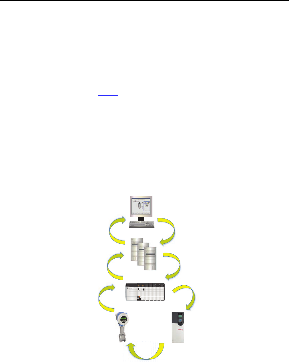
Our scalable platform provides you with the flexibility to implement a system
appropriate for your application. Figure 1
shows the documents (this manual in
the highlighted section) that are available to help design and implement your
system requirements.
Figure 1 - PlantPAx System Implementation and Documentation Strategy
• Define and Procure - Helps you understand the elements of the PlantPAx
system to make sure that you buy the proper components.
•Install - Provides direction on how to install the PlantPAx system.
•Prep - Provides guidance on how to get started and learn the best practices
to follow before you develop your application.
•Develop - Describes the actions and libraries necessary to construct your
application that resides on the PlantPAx system.
•Operate – Provides guidance on how to verify and maintain your systems
for efficient operation of your plant.
Purpose of the Reference Manual
The PlantPAx Reference Manual builds on the Selection Guide, which specifies
system sizing guidelines and catalog numbers for procurement. This manual
elaborates on the system sizing and application rules that you need to follow to
configure a PlantPAx system.
Dene and
Procure
Install Prep
Develop Operate
• Selection Guide
PROCES-SG001
• Virtualization User Manual
9528-UM001
• Infrastructure User Manual
PROCES-UM001
• Reference Manual
PROCES-RM001
• Application User Manual
PROCES-UM003
• Reference Manual
PROCES-RM001
• Library of Process Objects
PROCES-RM002
PROCES-RM013
PROCES-RM014
• Verify and Troubleshoot User Manual
PROCES-UM004
• Reference Manual
PROCES-RM001

8 Rockwell Automation Publication PROCES-RM001M-EN-P - June 2019
Preface
We strongly recommend that you use the PlantPAx virtual image templates and
Rockwell Automation® Library of Process Objects for best system performance
and functionality. If you are not able to use the templates or the library, you still
must follow the guidelines and rules from the Selection Guide and this Reference
Manual. These guide posts make sure that you achieve PlantPAx system
performance.
The PlantPAx system utilizes a set of Critical System Attributes (CSAs) as
performance metrics. Your system performance can meet the CSA metrics if you
follow the sizing guidelines and application rules that are defined in these
documents and the PlantPAx System Estimator (PSE).
Summary of Changes
This manual contains new and updated information as indicated in the
following table.
Additional Resources
These documents contain additional information concerning related products
from Rockwell Automation.
Topic Page
120 OWS clients available in distributed architecture 14
Updates characterized software releases 17
Adds hard disk size for virtual system elements 19, 20, 21, 22,
24, 25, 26, 27
Updates software components of system elements 111
Table 1 - System Core Resources
Resource Description
PlantPAx Distributed Control System Selection Guide,
publication PROCES-SG001
Provides basic definitions of system elements and sizing guidelines for procuring a PlantPAx system.
PlantPAx Distributed Control System Infrastructure
Configuration User Manual, publication PROCES-UM001
Provides screen facsimiles and step-by-step procedures to configure infrastructure components for your
system requirements.
PlantPAx Distributed Control System Application
Configuration User Manual, publication PROCES-UM003
Provides the steps necessary to start development of your PlantPAx Distributed Control System.
PlantPAx Distributed Control System Verification and
Troubleshooting User Manual, publication PROCES-UM004
Provides checklist worksheets to verify and document that your system design aligns with PlantPAx
system recommendations.
Rockwell Automation Library of Process Objects,
publication PROCES-RM002
Provides information on how to use the Rockwell Automation Library of Process Objects.
Rockwell Automation Library of Logix Diagnostic Objects,
publication PROCES-RM003
Provides Add-On Instructions for monitoring and diagnostic information of Logix controllers.
Rockwell Automation Library of Steam Table Instructions,
publication PROCES-RM004
Provides Add-On Instructions for calculating temperature and pressure steam tables.
Rockwell Automation Library of Process Objects: Logic
Instructions Reference Manual,
publication PROCES-RM013
Provides controller codes and tags for Rockwell Automation Library objects. The objects are grouped by family and
attached as Microsoft Excel® files to the manual PDF file.
Rockwell Automation Library of Process Objects: Display
Elements Reference Manual,
publication PROCES-RM014
Provides common display elements for the Rockwell Automation Library. For improved accessibility, the elements are
combined into one manual.
Rockwell Automation Publication PROCES-RM001M-EN-P - June 2019 9
Preface
PlantPAx Hardware Specifications and Certifications,
publication PROCES-SR027
Provides information on PlantPAx system hardware specifications and certifications.
PlantPAx Sequencer Object Reference Manual,
publication PROCES-RM006
Provides a flexible controller-based step sequencing solution that reduces engineering time by automating common
operator procedures.
FactoryTalk® View SE Edition User Manual,
publication VIEWSE-UM006
Provides details on how to use this software package for developing HMI applications that can involve multiple users
and servers, which are distributed over a network.
FactoryTalk View SE Installation Guide,
publication VIEWSE-IN003
Contains procedures for installing FactoryTalk View SE software.
FactoryTalk Alarms and Events System Configuration Guide,
publication FTAE-RM001
Provides details on how to install, configure, and use FactoryTalk Alarms and Events services as part of a
FactoryTalk-enabled automation system.
ControlLogix® System User Manual,
publication 1756-UM001
Explains how to use traditional and extreme environment ControlLogix controllers.
ControlLogix Enhanced Redundancy System User Manual,
publication 1756-UM535
Provides information on the installation and configuration for an enhanced redundancy controller system for
greater availability.
Logix5000™ Controllers Design Considerations Reference
Manual, publication 1756-RM094
Details how to design and optimize Logix5000 controller applications.
Logix5000 Controllers Common Procedures Programming
Manual, Publication 1756-PM001
Provides links to a collection of programming manuals that describe how you can use procedures that are common to all
Logix5000 controller projects.
Logix5000 Controllers General Instructions Reference
Manual, publication 1756-RM003
Provides programming controller applications by using relay ladder instructions.
Logix5000 Controllers Advanced Process Control and Drives
Instructions Reference Manual, publication 1756-RM006
Provides details on process control and drives instructions.
Logix 5000 Controllers Execution Time and Memory Use
Reference Manual, publication 1756-RM087
Provides a complete list of instruction execution time and memory usage information for Logix5000 controllers in your
Studio 5000 Logix Designer® programming software.
PlantPAx Logix Batch and Sequence Manager Reference
Manual, publication PROCES-RM007
Explains a controller-based batch and sequencing solution that leverages the Logix Control Platform and
FactoryTalk View software for integrated control and visualization.
Table 2 - Infrastructure Resources
Resource Description
PlantPAx Virtualization User Manual,
publication 9528-UM001
Describes how to use the PlantPAx virtual image templates for configuring virtual machines.
EtherNet/IP Network Configuration,
publication ENET-UM001
Explains Logix5000 tools that are used in EtherNet/IP topologies and network operation.
Ethernet Design Considerations Reference Manual,
publication ENET-RM002
Explains the infrastructure components that allow this open network to communicate seamlessly throughout a plant,
from shop floor to top floor.
Converged Plantwide Ethernet (CPwE) Design and
Implementation Guide, publication ENET-TD001
Provides collaborative design guidelines that are based on the Cisco Ethernet-to-the-Factory solution and the Rockwell
Automation Integration Architecture solution.
Troubleshoot EtherNet/IP Networks,
publication ENET-AT003
Provides guidelines for troubleshooting an EtherNet/IP network, such as setting speed and duplex.
1756 ControlLogix Communication Modules Specifications
Technical Data, publication 1756-TD003
Contains specifications for the ControlLogix network communication modules.
Application Note: Segmentation Methods within the
Cell/Area Zone, publication ENET-AT004
Provides design considerations of network segmentation methodologies for the ControlLogix and
CompactLogix™ 5370 controllers.
Stratix® Managed Switches User Manual,
publication 1783-UM007
Describes the embedded software features and tools for configuring and managing the Stratix 5410, Stratix 5400, and
the Stratix 5700 Ethernet managed switches.
Stratix Ethernet Device Specifications Technical Data,
publication 1783-TD001
Provides switch specifications, certifications, and the latest product information.
Stratix/Infrastructure Product Family Quick Reference
Drawing, publication IASIMP-QR029
Illustration that shows options for connecting your plant network by using standard Ethernet technology.
Table 1 - System Core Resources
Resource Description
10 Rockwell Automation Publication PROCES-RM001M-EN-P - June 2019
Preface
ControlNet Coax Media Planning and Installation Guide,
publication CNET-IN002
Provides procedures for planning, installing, and implementing a ControlNet network.
ControlNet Fiber Media Planning and Installation Guide,
publication CNET-IN001
ControlNet Modules in Logix5000 Control Systems User
Manual, publication CNET-UM001
Product Compatibility and Download Center at
http://www.rockwellautomation.com/
rockwellautomation/support/pcdc.page
Website helps you find product-related downloads including firmware, release notes, associated software, drivers, tools
and utilities.
Table 3 - Field Device Integration Resources
Resource Description
FactoryTalk AssetCentre Installation Guide,
publication FTAC-IN005
Provides installation instructions for monitoring your factory automation system.
FactoryTalk AssetCentre Product Profile,
publication FTALK-PP001
Explains this tool for securing, managing, versioning, tracking, and reporting automation-related asset information
across your entire enterprise.
EtherNet/IP and ControlNet to FOUNDATION Fieldbus
Linking Device, publication 1788-UM057
Describes the installation and operation of the 1788-EN2FFR and 1788-CN2FFR linking devices.
1788-EN2PAR User Manual, publication 1788-UM056 Describes the installation and operation of the 1788-EN2PAR linking device.
1788-CN2PAR User Manual, publication 1788-UM055 Describes the installation and operation of the 1788-CN2PAR linking device.
ControlLogix HART Analog I/O Modules User Manual,
publication 1756-UM533
Contains information on how to install, configure, and troubleshoot ControlLogix HART
analog I/O modules.
Promass 83 Flowmeter via PROFIBUS PA to the PlantPAx
Process Automation System, publication PROCES-AP022
Provides procedures for the design and implementation of PROFIBUS PA equipment.
DeviceNet System Quick Reference,
publication DNET-QR001
Provides procedures for configuring applications on the DeviceNet® network.
CENTERLINE® Motor Control Centers with EtherNet/IP,
publication 2100-TD031
Describes cable system construction and components that are associated with an EtherNet/IP network that is factory-
installed in CENTERLINE 2100 and CENTERLINE 2500 and IntelliCENTER® motor control centers (MCCs).
CENTERLINE 2500 Motor Control Centers with EtherNet/IP
Network, publication 2500-TD003
Integrate E+H Instruments in a PlantPAx System
Integration Document, publication PROCES-SG003
Provides a step-by-step approach to integrating HART devices from Endress+Hauser into the PlantPAx system.
Table 4 - Batch Resources
Resource Description
FactoryTalk Batch User's Guide, publication BATCH-UM011 Provides a complement of FactoryTalk recipe management, component guidelines, and software installation
procedures.
FactoryTalk Batch Installation Guide,
publication BATCH-IN002
Provides information and procedures for installing FactoryTalk Batch software.
PlantPAx Batch Design Considerations Reference Manual,
publication PROCES-RM008
Provides guidance on selected batch implementation topics in a PlantPAx system.
Batch Application Toolkit Quick Start,
publication IASIMP-QS042
Provides a framework for how to use the tasks to complete the components of the Toolkit.
PhaseManager™ User Manual, publication LOGIX-UM001 Explains how to define a state model for your equipment and develop equipment phases.
Table 2 - Infrastructure Resources
Resource Description

Rockwell Automation Publication PROCES-RM001M-EN-P - June 2019 11
Preface
You can view or download publications at
http://www.rockwellautomation.com/literature
. To order paper copies of
technical documentation, contact your local Allen-Bradley distributor or
Rockwell Automation sales representative.
Table 5 - Process Safety Resources
Resource Description
Using ControlLogix in SIL 2 Applications Safety Reference
Manual, publication 1756-RM001
ControlLogix components that are supported in SIL 2 configurations.
Redundant I/O System User Manual
publication 1715-UM001
Describes how to install and configure the 1715 Redundant I/O system with a ControlLogix Enhanced
Redundancy System.
AADvance Solutions Handbook, publication ICSTT-RM447
Explains the features, performance, and functionality of the AADvance controller and systems. It sets out some
guidelines on how to specify a system to meet your application requirements.
AADvance System Build Manual, publication ICSTT-RM448
Provides experienced panel builders with information on how to assemble a system, switch on and validate the
operation of a controller.
AADvance Configuration Guide, publication ICSTT-RM405 Defines how to configure an AADvance controller by using the AADvance Workbench to meet your Safety Instrument
Function (SIF) application requirements.
AADvance Safety Manual, publication ICSTT-RM446
Defines mandatory standards and makes recommendations to safely apply AADvance controllers for a SIF application.
Explains how to use traditional and extreme environment ControlLogix controllers.
AADvance Troubleshooting and Repair Manual, publication
ICSTT-RM406
Provides plant maintenance personnel with information on how to trace and repair a fault in an AADvance system and
perform routine maintenance tasks.

12 Rockwell Automation Publication PROCES-RM001M-EN-P - June 2019
Preface
Notes:
Rockwell Automation Publication PROCES-RM001M-EN-P - June 2019 13
Chapter 1
System Architecture Overview
The PlantPAx® system uses standard Rockwell Automation® Integrated
Architecture® (IA) products to build a distributed control system (DCS).
Our modern DCS is scalable, flexible, and open while still providing the
reliability, functionality, and performance expected from a DCS.
This section describes the system elements and architectures that you can use to
configure a PlantPAx system.
Rockwell Automation characterizes a DCS based on its size or architecture class.
A ‘characterized’ classification yields system performance data and recommended
hardware and software configurations.
Topic Page
Architecture Classes 14
System Elements 14
Critical System Attributes 15
System Procurement Tools 16
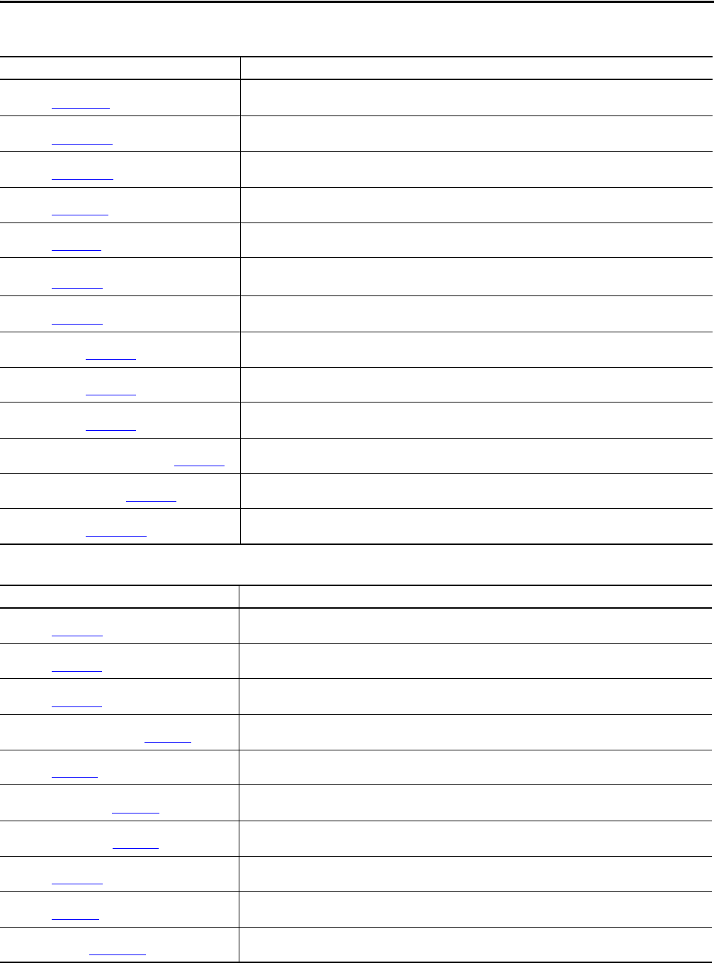
EWS PASS
Domain
Controller
Application Servers Multiple OWS
Device Level Ring Topology
14 Rockwell Automation Publication PROCES-RM001M-EN-P - June 2019
Chapter 1 System Architecture Overview
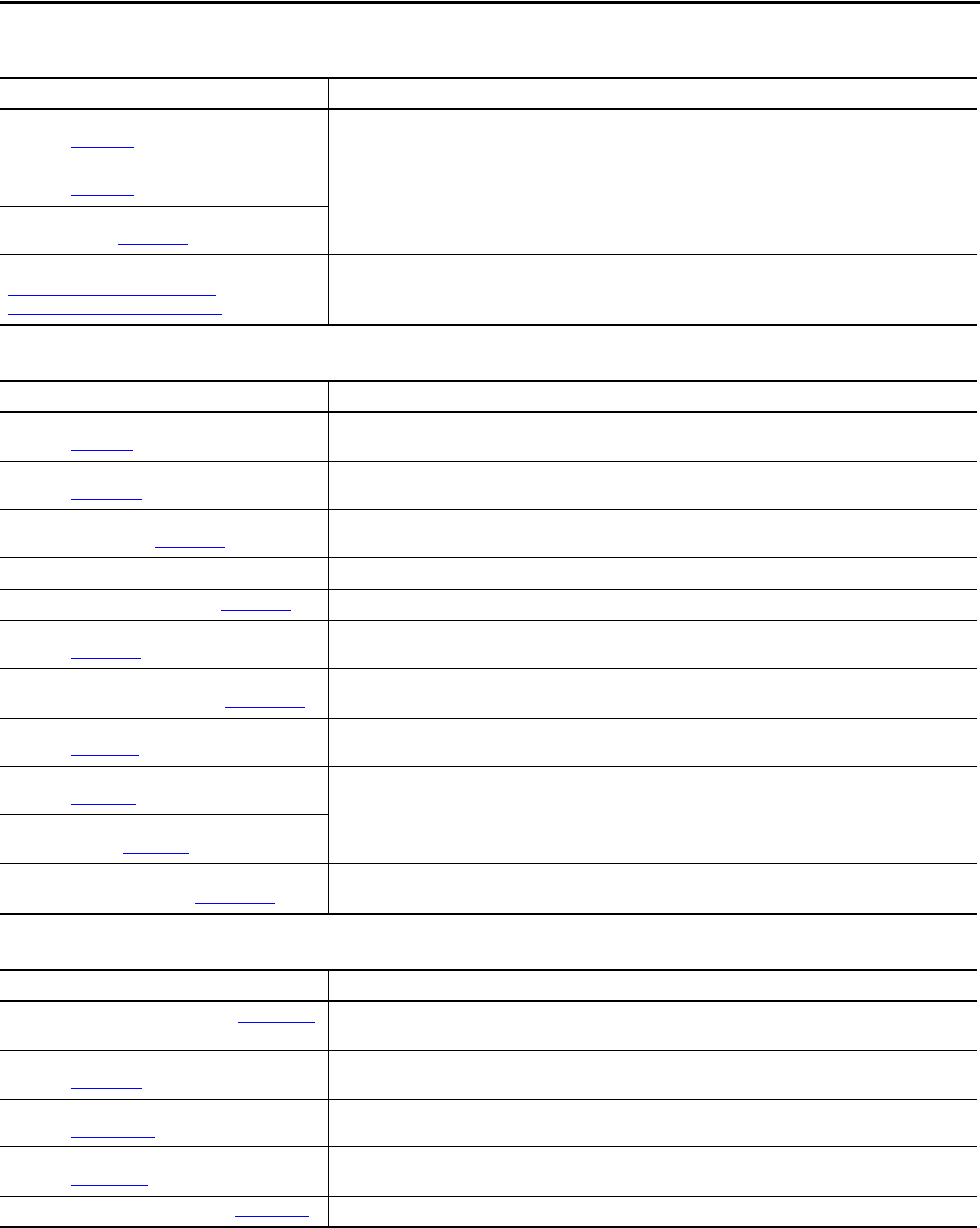
Architecture Classes
Architecture classes define reference architectures that are based on the size of the
required system.
System Elements
System elements are the different elements of a PlantPAx DCS. Elements can be
deployed on your system depending on the needs of the application.
Architecture Description
Skid Skid architecture with a skid controller and PanelView™ for monitoring data.
Station A single station that acts as a PlantPAx Automation System Server (PASS), Operator Workstation (OWS), and
Engineering Workstation (EWS).
Distributed - Single server This architecture has a single PASS server and supports multiple OWSs and EWSs.
Distributed - Multiple servers This architecture has multiple PASS servers and supports multiple OWSs and EWSs. You can add servers for more capacity or to
segregate servers by operating areas.
Station Architecture
Distributed Architecture- Multiple PASS Servers
Distributed Architecture- Single PASS Server
Skid Controller
S
ca
l
a
b
l
e
Table 6 - Architectures and System Elements
System
Element
Skid Architecture Station Architecture Distributed Architecture
(single PASS (consolidated))
Distributed Architecture
(single to multiple PASS servers)
PASS Not applicable. Single workstation serves as PASS, EWS,
and OWS in an independent workstation
For smaller systems, one PASS
(consolidated) is required that typically
includes the following:
• FactoryTalk® Directory server
• HMI server
• Data server
• Alarm and Event Server
The PASS-C supports functions that
otherwise are hosted on application
servers. The PASS-C single computer
includes the following in a single
workstation:
• PASS
• FactoryTalk Historian
• AppServ-Asset Management
• AppServ-VantagePoint
• AppServ-Info (SQL)
IMPORTANT: An additional PASS-C is
required for redundancy.
One PASS required and includes one or
more of the following:
• FactoryTalk Directory server
• HMI server
• Data server
• Alarm and Event Server
Additional PASS as needed (up to 10
servers or redundant server pairs).
(1)
EWS Included in independent workstation 1 EWS required. 1 EWS required.
Can have as many as 5 EWSs.

Rockwell Automation Publication PROCES-RM001M-EN-P - June 2019 15
System Architecture Overview Chapter 1
Critical System Attributes
A critical system attribute (CSA) is a visible performance indicator of a
system-wide characteristic. CSAs are used to define or identify specified levels of
system operation:
• Determine system limits
• Establish system rules
• Establish system recommendations
• Measure system element and system infrastructure performance
The following CSAs are used to verify performance during process
system characterization.
OWS Not applicable. Operator
interface typically
accomplished with PanelView
Plus operator terminal or thin
client connected to a
distributed architecture.
Included in independent workstation Included in PASS-C.
An .ISO file is available for any single,
physical computer.
IMPORTANT: PASS-C supports up to
10 clients.
Can have as many as 120 OWS clients.
(1)
Controllers CompactLogix controller. 1...5 ControlLogix® controllers. 1...5 ControlLogix controllers.
IMPORTANT: PASS-C supports up to five
redundant controllers.
Use the PlantPAx System Estimator to
verify your design. See page 16
.
There is no hard limit for the number of
controllers. The number of controllers
that can be supported per PASS (data
server) depends on controller selection,
controller loading, and number of OWS.
Application
servers
Not applicable. In chassis
historian and in controller
batch capabilities are available.
Can also be integrated with a
distributed architecture.
AppServ-Asset Management as needed.
AppServ-Batch as needed.
AppServ-Information Management (SQL,
Historian, or VantagePoint®) as needed.
Additional servers can be added as your
system scales. For example,
AppServ-Batch, AppServ-Information
Management.
IMPORTANT: An additional PASS-C is
required for redundancy.
AppServ-Asset Management as needed.
AppServ-Batch as needed.
AppServ-Information Management (SQL,
Historian, or VantagePoint) as needed
AppServ-OWS as needed.
(1) These values are product maximum limits. It’s possible that achieving these limits on your system is not feasible based on your system design. Use the PlantPAx System Estimator to make sure that your
system is sized properly (see page 16
).
Table 6 - Architectures and System Elements
System
Element
Skid Architecture Station Architecture Distributed Architecture
(single PASS (consolidated))
Distributed Architecture
(single to multiple PASS servers)
Table 7 - CSA Performance Indicators
Critical System Attribute
(1)
Performance
Display callup (paint time) A noncached display is called up by the operator and ready for operator use within 2 seconds.
Display update The display updates control information within 1 second.
Steady state alarm time Steady state alarms occurring at 20 per second are timestamped within 1 second.
Alarm burst time All alarms in a burst of 1000 alarms are timestamped within 3 seconds.
Recovery A system element returns to full operation within 5 minutes of the restoration after a failure or loss.
Operator-initiated control Operator-initiated actions are loaded into the controller and the feedback for the operator action is within 2 seconds.
Batch server: operator action time An operator batch command has been acted on by the controller in 1 second.
Batch server: server action time A server batch command has been acted on by the controller in 1 second.
Batch server: controller action time Batch status events display on the operator workstation within 1 second.
(1) CSA performance indicators are a nominal performance number. The actual system performance can intermittently deviate from the documented CSA due to system disturbances that can introduce
variability in the network or operating system performance.

16 Rockwell Automation Publication PROCES-RM001M-EN-P - June 2019
Chapter 1 System Architecture Overview
System Procurement Tools
The following chapters of this manual contain recommendations and
considerations for how to implement your system. If you have not selected or
procured your PlantPAx system architecture and components, see the
PlantPAx Selection Guide, publication PROCES-SG001
, for more information.
The PlantPAx System Estimator (PSE), which is a part of the Integrated
Architecture® Builder (IAB) software tool, helps you define a PlantPAx system.
The PSE wizard lets you specify your system architecture that is based on your
requirements, and verifies that your process control hardware is sized properly.
When the verification is complete, you can transfer the output of the PSE wizard
into the IAB tool to develop a bill-of-material for the system based on
your inputs.
See http://www.rockwellautomation.com/en/e-tools/configuration.html
to
access the IAB tool.

Rockwell Automation Publication PROCES-RM001M-EN-P - June 2019 17
Chapter 2
System Element Recommendations
PlantPAx® system elements refer to the individual servers, clients, and controllers
that comprise a PlantPAx system. This chapter describes each system element and
its components. A base installation of all server and workstation elements is
available as virtual appliances.
The following table lists where to find specific information.
PlantPAx Software
Components
Integrated Architecture® software components and versions that comprise the
PlantPAx system, include the following:
• Studio 5000 Logix Designer® application, version 31.x
• Studio 5000 Architect™ application, version 4.x
• FactoryTalk® View software, version 11.x
• FactoryTalk Batch software, version 13.x
• FactoryTalk AssetCentre software, version 9.x
• FactoryTalk® VantagePoint® software, version 8.x
• FactoryTalk Historian software, version 6.x
Performance guidelines are based on the use of the software versions listed.
For the latest compatible software information and to download associated
library tools, see the Product Compatibility and Download Center at http://
www.rockwellautomation.com/rockwellautomation/support/pcdc.page.
Topic Page
PlantPAx Software Components 17
Process Automation System Server (PASS) 18
Engineering Workstation (EWS) and Application Server (AppServ-EWS) 20
Operator Workstation (OWS) and Application Server (AppServ-OWS) 21
Independent Workstation (IndWS) 23
AppServ-Info (Historian) 24
AppServ-Info (VantagePoint) 24
AppServ-Info (SQL) 25
Asset Management Server (AppServ-Asset) 25
Batch Management Server (AppServ-Batch) 26
Domain Controller 27
Controller Characteristics 28

18 Rockwell Automation Publication PROCES-RM001M-EN-P - June 2019
Chapter 2 System Element Recommendations
Process Automation System
Server (PASS)
The Process Automation System Server (PASS) is a required system element that
hosts essential software components to run the system. The essential software
components include the data server, HMI server, and alarm server. The PASS can
be used as a data, HMI, and/or alarm server.
Software Components Description
FactoryTalk
Network Directory (FTD) server
(1)
Secures information from multiple Rockwell Automation® software components across multiple computers and
provides central administration throughout the PlantPAx system. Application components, such as display and security
settings, can be stored in their original environments and made available to the entire PlantPAx system without the
need for duplication.
FactoryTalk Activation server
(1)
The FactoryTalk Activation server is part of the FactoryTalk Services Platform. The server allows FactoryTalk-enabled
software products to be activated via files generated by Rockwell Automation over the Internet. This server essentially
manages the files that are required to license Rockwell Automation products on the PlantPAx system.
FactoryTalk View HMI server The human machine interface (HMI) server is configured within your FactoryTalk View Site Edition (SE) application. The
HMI server stores HMI project components, such as graphic displays, and serves these components to OWSs upon
request. The HMI server also can manage tag databases and log historical data. Multiple HMI servers can exist on the
PlantPAx system. Each HMI server must be on a separate PASS.
FactoryTalk View Data server The Data server component provides access to information from the process controllers to servers and workstations on
the PlantPAx system. FactoryTalk
View software supports two types of data servers: Rockwell Automation Device
servers (FactoryTalk Linx software) and OPC Data servers. The Data server that is mentioned in PlantPAx documentation
generally refers to the Rockwell Automation Device servers. Data servers are configured within your FactoryTalk View
SE application. Multiple data servers can exist on the PlantPAx system.
FactoryTalk View Alarm and Event server The Alarm and Event server publishes information from controllers and servers available to all subscribing OWSs. Alarm
and Event servers are configured within your FactoryTalk View SE application. There are two types of Alarm and Event
servers: device-based and server-based. Device-based Alarm and Event servers are configured as an option to the data
server. Server-based Alarm and Event servers are configured as a separate component. Each server-based Alarm and
Event server must be on a separate PASS.
The Alarm and Event server that is mentioned in PlantPAx documentation refers to the Alarm and Event server that is
server-based. See Alarm System Recommendations on page 55 for more information.
Optional
FactoryTalk Batch client software If a Batch Application server is being used on the system, FactoryTalk Batch client components are required to support
replication of batch-related objects on the displays to the OWS.
(1) In redundant PASS configurations, this component is included on the primary PASS only.

Rockwell Automation Publication PROCES-RM001M-EN-P - June 2019 19
System Element Recommendations Chapter 2
PASS Server Redundancy
PASS servers can be configured as redundant for the following software
components:
• HMI server
• Data server
• Alarm server
The FactoryTalk Directory server information is cached on each computer that is
participating in a distributed application. If the FTD server computer is
disconnected from the network or fails, the OWS, EWS, and other application
servers can continue to access everything within the application. This
functionality applies as long as the computer has already accessed the FTD server.
IMPORTANT
When you enable redundancy in FactoryTalk View Studio software, select the
option to ‘Continue using the secondary server even when the primary server
becomes available again’ to avoid excessive switchovers. This option lets you
manage replication of application changes made before or after the
switchover occurs. We recommend that you configure your HMI displays to
indicate when the system is running without backup.
Table 8.1 - PASS Virtual Requirements
Category Requirement
(1)
Virtual infrastructure Required:
• 4 vCPU
• 8 GB vRAM min
• 60 GB vHardDisk
Recommended CPU and memory allocation:
• High priority Resource pool
(2)
Operating system Windows Server 2016 operating system, 64 bit
(1) All numbers and figures are referenced for initial sizing only. The values can be adjusted for system performance if needed.
(2) See Resource Pool Allocation
on page 69.
Table 8.2 - PASS Traditional Requirements
Category Requirement
Traditional infrastructure The PASS must be installed on server-class hardware. The following are sample specifications that are based on PlantPAx
system characterization:
• Intel Xeon Multicore processor (4 cores or greater)
• 2.40 GHz CPU min
• 8 GB RAM min
• Ethernet card that supports redundant media if NIC-teaming is used (If you plan to use a motherboard-NIC make sure
that it supports redundant media)
PASS - C (for small and medium systems) For systems with fewer than 2000 I/O points, the PASS - Consolidated contains HMI, data collection, decision-making,
and asset management servers. These combined tools form a basic PlantPAx system in a single server, referred to|
as consolidated.
The PASS must be installed on server-class hardware. The following are sample specifications based on PlantPAx
system characterization:
• Intel® Xeon E-31270 v5
• 3.60 GHz CPU min
• 32 GB RAM min
• Ethernet card that supports redundant media if NIC-teaming is used (If you plan to use a motherboard-NIC make sure
it supports redundant media)
Operating system Windows Server 2016 operating system, 64 bit

20 Rockwell Automation Publication PROCES-RM001M-EN-P - June 2019
Chapter 2 System Element Recommendations
Configure the FactoryTalk Directory
Before starting a project, you must install FactoryTalk Directory (FTD) services
on the computer that is hosting the FTD or the PASS. The FTD server manages
applications that can exist on multiple clients and servers on separate computers
on the PlantPAx system.
Engineering Workstation
(EWS)
The EWS supports system configuration, application development, and
maintenance functions. This workstation is the central location for monitoring
and maintaining the system operation.
If a batch application server is used, the FactoryTalk Batch client and editor
components are required to configure the FactoryTalk Batch system and
configure the FactoryTalk objects on the displays.
IMPORTANT
To configure the FTD, see the PlantPAx Distributed Control System
Infrastructure Configuration User Manual, publication PROCES-UM001
.
Table 9.1 - EWS Virtual Requirements
Category Requirement
(1)
Virtual infrastructure Required:
• 2 vCPU
• 4 GB vRAM min
• 100 GB vHardDisk
Recommended CPU and memory allocation:
• Normal priority Resource pool
(2)
Operating system Windows 10 operating system, 64 bit
(1) All numbers and figures are referenced for initial sizing only. The values can be adjusted for system performance if needed.
(2) See Resource Pool Allocation
on page 69
Table 9.2 - EWS Traditional Requirements
Category Requirement
Traditional infrastructure The EWS must be installed on workstation-class hardware. The following are sample specifications based on PlantPAx
system characterization.
• Intel Core 2 Duo
• 2.40 GHz CPU min
• 4 GB RAM min
• Ethernet card that supports redundant media if NIC-teaming is used (If you plan to use a motherboard-NIC make
sure that it supports redundant media)
Operating system Windows 10 operating system, 64 bit

Rockwell Automation Publication PROCES-RM001M-EN-P - June 2019 21
System Element Recommendations Chapter 2
Engineering Workstation
Application Server
(AppServ-EWS)
The AppServ-EWS uses Microsoft® Remote Desktop Services (RDS) technology
to serve multiple instances of the EWS as thin clients from a single server. Thin
clients can run applications and process data on a remote computer. The
recommended limit is five RDS client connections per AppServ-EWS.
Operator Workstation (OWS)
The operator workstation (OWS) provides the graphical view and interface into
the process. The OWS supports operator interaction and is not meant to support
development or maintenance activities, although these activities are possible if
desired.
FactoryTalk View Site Edition (SE) client software must be installed on the
OWS. The OWS also can contain clients for non-core application servers, such
as FactoryTalk Batch, FactoryTalk Historian, or FactoryTalk AssetCentre.
Table 10 - AppServ-EWS Virtual Requirements
Category Requirement
(1)
Virtual infrastructure Required:
• 4 vCPU
• 8 GB vRAM min
• 100 GB vHardDisk
Recommended CPU and memory allocation:
• Normal priority Resource pool
(2)
Thin client We recommend a maximum of 5 FactoryTalk View SE clients per application server
Operating system Windows Server 2016 operating system, 64 bit
(1) All numbers and figures are referenced for initial sizing only. The values can be adjusted for system performance if needed.
(2) See Resource Pool Allocation
on page 69
Table 11.1 - OWS Virtual Requirements
Category Requirement
(1)
Virtual infrastructure Required:
• 2 vCPU
• 4 GB vRAM min
• 40 GB vHardDisk
Recommended CPU and memory allocation:
• High priority Resource pool
(2)
Operating system Windows 10 operating system, 64 bit
(1) All numbers and figures are referenced for initial sizing only. The values can be adjusted for system performance if needed.
(2) See Resource Pool Allocation
on page 69
Table 11.2 - OWS Traditional Requirements
Category Requirement
Traditional infrastructure The OWS must be installed on workstation-class hardware. The following are sample specifications based on PlantPAx
system characterization:
• Intel Core 2 Duo
• 2.40 GHz CPU min
• 4 GB RAM min
• Ethernet card that supports redundant media if NIC-teaming is used (If you plan to use a motherboard-NIC make
sure that it supports redundant media)
Operating system Windows 10 operating system, 64 bit
22 Rockwell Automation Publication PROCES-RM001M-EN-P - June 2019
Chapter 2 System Element Recommendations
Operator Workstation
Application Server
(AppServ-OWS)
The AppServ-OWS uses Microsoft Remote Desktop Services (RDS) technology
to serve multiple instances of the OWS as thin clients from a single server. Thin
clients can run applications and process data on a remote computer. The
recommended limit is 10 RDS connections per AppServ-OWS.
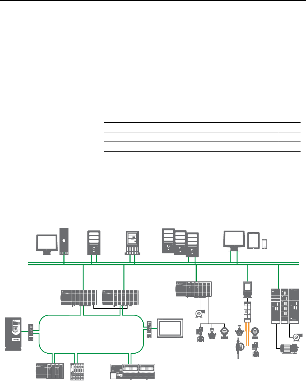
ThinManager Server Options
The AppServ-OWS system element virtual image template is pre-configured
with Remote Desktop Services (RDS). RDS includes the ThinManager® Server
installation file. You can configure the AppServ-OWS as your ThinManager
Server and deploy up to 10 OWS sessions to simplify the management of all
devices and users.
ThinManager increases your productivity, visualization, mobility, and security
from one easy-to-use, centralized, and scalable management platform
.
Table 12 - AppServ-OWS Virtual Requirements
Category Requirement
(1)
Virtual infrastructure Required:
• 8 vCPU
• 16 GB vRAM min
• 60 GB vHardDisk
Recommended CPU and memory allocation:
• High priority Resource pool
(2)
Thin client We recommend a maximum of 10 FactoryTalk View SE clients per application server
Operating system Windows Server 2016 operating system, 64 bit
(1) All numbers and figures are referenced for initial sizing only. The values can be adjusted for system performance if needed.
(2) See Resource Pool Allocation
on page 69
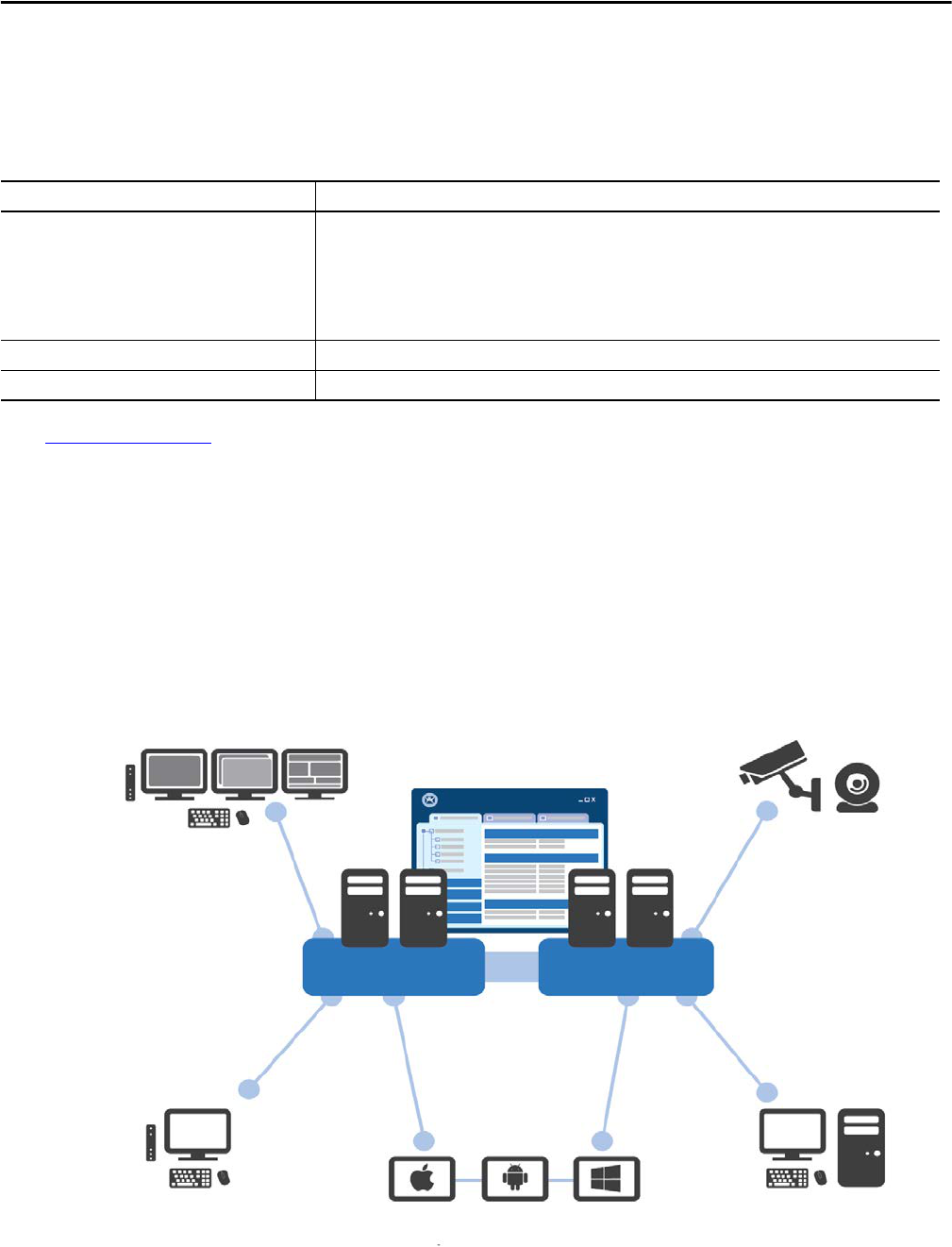
Deliver multiple sessions to multiple
monitors and customized virtual
screens on a single thin client.
Access feeds from USB and IP cameras.
Deliver applications based on
what is assigned to the
terminal or user.
Deliver content to the right person
at the right time and place.
Get mobile access to applications specific to a user’s role.
Manage and deliver virtual
desktops while running PCs
as a thin client.
ThinManager
Remote Desktop Servers Virtual Resources

Rockwell Automation Publication PROCES-RM001M-EN-P - June 2019 23
System Element Recommendations Chapter 2
Safely and securely deliver your content to any combination of device, user, and
location with the following features:
• Boost productivity by reducing the time that is spent to manage computers
• Enhance visualization by delivering your content to where you need it and
the way you want the content shown
• Extend security through encrypted communications, active directory, and
secure thin clients
• Smart mobility where QR codes, Bluetooth, Wi-Fi, and GPS make sure
that devices receive content in authorized areas
For more information, contact your Rockwell Automation representative.
Independent Workstation
(IndWS)
The independent workstation (IndWS) combines the roles of the PASS, EWS,
and OWS in one computer. This workstation can be used as a ‘shadow system’ for
emergency purposes
.
Table 13 - IndWS Traditional Requirements
Category Requirement
Traditional infrastructure The IndWS must be installed on workstation-class hardware. The following are sample specifications based on
PlantPAx system characterization:
• Intel Multicore processor (4 cores or greater)
• 2.40 GHz CPU min
• 8 GB RAM min
• Ethernet card that supports redundant media if NIC-teaming is used (If you plan to use a motherboard-NIC make
sure that it supports redundant media)
Operating system Windows 10 operating system, 64 bit

24 Rockwell Automation Publication PROCES-RM001M-EN-P - June 2019
Chapter 2 System Element Recommendations
AppServ-Info (Historian)
The Information Management server can include a historian application to
collect, manage, and analyze data.
AppServ-Info (VantagePoint)
The Information Management server can be used as a decision support tool by
installing VantagePoint software.
Table 14.1 - AppServ-Info (Historian) Virtual Requirements
Category Requirement
(1)
Virtual infrastructure Required:
• 2 vCPU
• 4 GB vRAM min
• 120 GB vHardDisk
Recommended CPU and memory allocation:
• Normal priority Resource pool
(2)
Operating system Windows Server 2016 operating system, 64 bit
(3)
(1) All numbers and figures are referenced for initial sizing only. The values can be adjusted for system performance if needed.
(2) See Resource Pool Allocation
on page 69
(3) To install FactoryTalk View SE Historian software, version 4.6, with Windows Server 2016, you must install a patch from the Product Compatibility and Download Center at
http://www.rockwellautomation.com/rockwellautomation/support/pcdc.page
.
Table 14.2 - AppServ-Info (Historian) Traditional Requirements
Category Requirement
Traditional infrastructure The Information Management server must be installed on server-class hardware:
• Intel Xeon Multicore processor (4 cores or greater)
• 2.40 GHz CPU min
• 4 GB RAM min
• Ethernet card that supports redundant media if NIC-teaming is used (If you plan to use a motherboard-NIC make
sure that it supports redundant media)
Operating system Windows Server 2016 operating system, 64 bit
Table 15.1 - AppServ-Info (VantagePoint) Virtual Requirements
Category Requirement
(1)
Virtual infrastructure Required:
• 2 vCPU
• 4 GB vRAM min
• 60 GB vHardDisk
Recommended CPU and memory allocation:
• Normal priority Resource pool
(2)
Operating system Windows Server 2016 operating system, 64 bit
(1) All numbers and figures are referenced for initial sizing only. The values can be adjusted for system performance if needed.
(2) See Resource Pool Allocation
on page 69.
Table 15.2 - AppServ-Info (VantagePoint) Traditional Requirements
Category Requirement
Traditional infrastructure The Information Management server must be installed on server-class hardware:
• Intel Xeon Multicore processor (4 cores or greater)
• 2.40 GHz CPU min
• 4 GB RAM min
• Ethernet card that supports redundant media if NIC-teaming is used (If you plan to use a motherboard-NIC make
sure that it supports redundant media)
Operating system Windows Server 2016 operating system, 64 bit

Rockwell Automation Publication PROCES-RM001M-EN-P - June 2019 25
System Element Recommendations Chapter 2
AppServ-Info (SQL)
An SQL server can be configured with the Information Management server.
Software such as FactoryTalk AssetCentre, FactoryTalk VantagePoint, and
FactoryTalk Batch use an SQL database to store and access process data.
Additionally, the FactoryTalk Alarm and Event server uses an SQL database to
store information
.
Asset Management Server
(AppServ-Asset)
An asset management server (AppServ-Asset) is an extension to the PlantPAx
system that adds maintenance and plant operations to the system. This server
provides the following to improve resource availability:
• Disaster recovery controller data
• Diagnostics
• Calibration
• Real-time monitoring
• Auditing equipment
• Network health
Table 16.1 - AppServ-Info (SQL) Virtual Requirements
Category Requirement
(1)
Virtual infrastructure Required:
• 2 vCPU
• 4 GB vRAM min
• 120 GB vHardDisk
Recommended CPU and memory allocation:
• Normal priority Resource pool
(2)
Operating system Windows Server 2016 operating system, 64 bit
(1) All numbers and figures are referenced for initial sizing only. The values can be adjusted for system performance if needed.
(2) See Resource Pool Allocation
on page 69.
Table 16.2 - AppServ-Info (SQL) Traditional Requirements
Category Requirement
Traditional infrastructure The Information Management server must be installed on server-class hardware:
• Intel Xeon Multicore processor (4 cores or greater)
• 2.40 GHz CPU min
• 4 GB RAM min
• Ethernet card that supports redundant media if NIC-teaming is used (If you plan to use a motherboard-NIC make
sure that it supports redundant media)
Operating system Windows Server 2016 operating system, 64 bit
Table 17.1 - AppServ-Asset Virtual Requirements
Category Requirement
(1)
Virtual infrastructure Required:
• 2 vCPU
• 4 GB vRAM min
• 60 GB vHardDisk
Recommended CPU and memory allocation:
• Normal priority Resource pool
(2)
Operating system Windows Server 2016 operating system, 64 bit
(1) All numbers and figures are referenced for initial sizing only. The values can be adjusted for system performance if needed.
(2) See Resource Pool Allocation
on page 69
26 Rockwell Automation Publication PROCES-RM001M-EN-P - June 2019
Chapter 2 System Element Recommendations
Batch Management Server
(AppServ-Batch)
The batch management server (AppServ-Batch) offers comprehensive batch
management, including recipe management, procedural control of automated
and manual processes, and material management.
Table 17.2 - AppServ-Asset Traditional Requirements
Category Requirement
Traditional infrastructure The Information Management server must be installed on server-class hardware:
• Intel Xeon Multicore processor (4 cores or greater)
• 2.40 GHz CPU min
• 4 GB RAM min
• Ethernet card that supports redundant media if NIC-teaming is used (If you plan to use a motherboard-NIC make
sure that it supports redundant media)
Operating system Windows Server 2016 operating system, 64 bit
Table 18.1 - AppServ-Batch Virtual Requirements
Category Requirement
(1)
Virtual infrastructure Required:
• 2 vCPU
• 4 GB vRAM min
• 60 GB vHardDisk
Recommended CPU and memory allocation:
• Normal priority Resource pool
(2)
Operating system Windows Server 2016 operating system, 64 bit
(1) All numbers and figures are referenced for initial sizing only. The values can be adjusted for system performance if needed.
(2) See Resource Pool Allocation
on page 69
Table 18.2 - AppServ-Batch Traditional Requirements
Category Requirement
Traditional infrastructure The Information Management server must be installed on server-class hardware:
• Intel Xeon Multicore processor (4 cores or greater)
• 2.40 GHz CPU min
• 4 GB RAM min
• Ethernet card that supports redundant media if NIC-teaming is used (If you plan to use a motherboard-NIC make
sure that it supports redundant media)
Operating system Windows Server 2016 operating system, 64 bit

Rockwell Automation Publication PROCES-RM001M-EN-P - June 2019 27
System Element Recommendations Chapter 2
Domain Controller
A domain controller is a server that responds to security authentication requests
(log in, verify permissions, and so forth) within the Windows server domain. A
domain grants you access to a number of network resources (such as applications
and printers) with the use of a single user name and password combination.
PlantPAx uses a domain controller to store user account information,
authenticate users, and enforce security policies.
Domain authentication is recommended, whether it’s an existing domain or a
new one. Follow these guidelines for the domain controller:
• Domain controllers are required if there are 10 or more workstations
or servers.
• The domain controllers are separate computers. Do not load any
application software on a domain controller. Load all system application
software on the other computers, such as the PASS, application server,
OWS, and EWS.
• Microsoft support does not recommend applications to be run on a
domain controller, and certainly not applications that require more than
Authenticated User privileges to run.
• The domain controllers must be local to the system workstations and
servers (within the local firewall) and not remote to the system.
For redundancy purposes, we recommend that you use at least two domain
controllers in the domain. These domain controllers replicate automatically to
provide high availability and an online configuration backup.
Table 19.1 - Domain Virtual Requirements
Category Requirement
(1)
Virtual infrastructure Required:
• 1 vCPU
• 4 GB vRAM min
• 40 GB vHardDisk
Recommended CPU and memory allocation:
• Low priority Resource pool
(2)
Operating system Windows Server 2016 operating system, 64 bit
(1) All numbers and figures are referenced for initial sizing only. The values can be adjusted for system performance if needed.
(2) See Resource Pool Allocation
on page 69.
Table 20 - Domain Traditional Requirements
Category Requirement
Traditional infrastructure
(1)
The Information Management server must be installed on server-class hardware:
• Intel Xeon Multicore processor (4 cores or greater)
• 2.40 GHz CPU min
• 4 GB RAM min
• Ethernet card that supports redundant media if NIC-teaming is used (If you plan to use a motherboard-NIC make
sure that it supports redundant media)
Operating system Windows Server 2016 operating system, 64 bit
(1) A Microsoft Excel software license is required.

28 Rockwell Automation Publication PROCES-RM001M-EN-P - June 2019
Chapter 2 System Element Recommendations
Controller Characteristics
This section describes the components and sizing attributes for simplex,
skid-based, and redundant controllers.
Simplex Controller
Non-redundant controllers are referred to as simplex controllers.
Table 21 - Simplex Controller Hardware Requirements
(1)
Category Cat. No.
Process controller
(2)
ControlLogix® 1756-L71, 1756-L72, 1756-L73, or 1756-L74, or 1756-L75 controller
EtherNet/IP interface • For direct DLR connection: 1756-EN2TR
• For direct PRP connection: 1756-EN2TP
• For secure connections: 1756-EN2TSC
• Otherwise: 1756-EN2T, 1756-EN2F (no DLR support)
• For converting topology or media: 1783-ETAP, 1783-ETAP1F, 1783-ETAP2F (supports DLR topology)
ControlNet interface (if applicable) • 1756-CN2, 1756-CN2R
• 1756-CNB, 1756-CNBR
(1) If environmental conditions warrant, you can use an extreme temperature controller, for example, the 1756-L74XT. Conformal coated options are also available for protection from harsh environments
that can contain moisture and or chemical contaminants.
(2) As the PlantPAx system release 4.6 uses controller firmware revision 31, implementation requires use of the 1756-L7x controller family. PlantPAx system release 4.6 can co-exist with older
generation controllers.
Table 22 - Simplex ControlLogix Controller Sizing
Category
(1)
1756-L71 1756-L72 1756-L73 1756-L74 1756-L75
(2)
User memory 2 MB 4 MB 8 MB 16 MB 32 MB
Total I/O recommended, max 375 750 1500 2250 2250
Recommended control strategies, max
(3)
60 125 250 450 450
Total control strategies @ 250 ms, max 60 125 250 250 250
Total control strategies @ 500 ms, max 60 125 250 450 450
Tags/sec delivered to data server, max 10,000 20,000 20,000 20,000 20,000
(1) These values are recommended maximum limits. It’s possible that achieving all of these values in a single controller is not doable. For more detailed sizing, you can use the PSE (see page 16).
(2) The advantages to using the 1756-L75 controller is to maintain common spare parts with redundant systems or if you are doing some memory intensive storage not accounted for in the sizing model.
(3) Recommended maximum control strategies are based on all controller strategies being simple regulatory control. See Controller I/O Considerations
on page 48.
Rockwell Automation Publication PROCES-RM001M-EN-P - June 2019 29
System Element Recommendations Chapter 2
Redundant Controllers
ControlLogix controllers support redundancy on ControlNet and EtherNet/IP
networks. In a redundant controller system on PlantPAx, you need these components:
• Two 1756 chassis each set up the same with the following:
– Number of slots
– Modules in the same slots
– Redundancy firmware revisions in each module
– Two additional ControlNet or Ethernet nodes outside the redundant
chassis pair
• One 1756-RM2 module per chassis with fiber media
Make sure that each redundant controller has enough memory to store twice the
amount of controller data and I/O memory to support program modifications.
The increased memory usage in a redundant controller provides for a bumpless
transfer during a switchover and makes sure the secondary Logix controller has
the same values in its output image as the primary Logix controller. The extra
memory helps prevent a switchover to a secondary controller with a mixture of
old and new data memory.
When using the PlantPAx System Estimator, the PSE accounts for additional
memory requirements required for redundancy as memory used.
Table 23 - Redundant Controller Hardware Requirements
(1)
Category Cat. No.
Process controller ControlLogix 1756-L73, 1756-L74, or 1756-L75 controller
Redundancy module 1756-RM2
(2)
Ethernet interface • For direct DLR connection: 1756-EN2TR
• For direct PRP connection: 1756-EN2TP
• For secure connections: 1756-EN2TSC
• Otherwise: 1756-EN2T, 1756-EN2F (no DLR support)
• For converting topology or media: 1783-ETAP, 1783-ETAP1F, 1783-ETAP2F (supports DLR topology)
ControlNet interface (if applicable) • 1756-CN2, 1756-CN2R
• 1756-CNB, 1756-CNBR
(1) If environmental conditions warrant, you can use an extreme temperature controller, for example, the 1756-L74XT. Conformal coated options are also available for protection from harsh environments
that can contain moisture and or chemical contaminants.
(2) The PlantPAx system recommendation is to use only one redundant controller in a chassis with a 1756-RM2 redundancy module. While a 1756-RM2 module can support two controllers, the resulting
performance of each controller is not easily predicted.
Table 24 - Redundant ControlLogix Controller Sizing
Category
(1)
1756-L73 1756-L74 1756-L75
(3)
User memory 8 MB 16 MB 32 MB
Total I/O recommended, max 750 1500 2250
Recommended control strategies, max
(2)
125 250 450
Total control strategies @ 250 ms, max 120 120 120
Total control strategies @ 500 ms, max 125 220 220
Tags/sec delivered to data server, max 20,000 20,000 20,000
(1) These values are recommended maximum limits. It’s possible that achieving all of these values in a single controller is not doable. For more detailed sizing, you can use the PSE (see page 16).
(2) Recommended maximum control strategies are based on all controller strategies being simple regulatory control. See Controller I/O Considerations
on page 48.
(3) The advantages to using the 1756-L75 controller is to maintain common spare parts with redundant systems or if you are doing some memory intensive storage not accounted for in the sizing model.

30 Rockwell Automation Publication PROCES-RM001M-EN-P - June 2019
Chapter 2 System Element Recommendations
Skid-based Controller
The PlantPAx process automation system is a complete, scalable system, from
single controller to a fully distributed set of equipment. You can easily integrate
skid-based equipment into the overall system.
The CompactLogix™ controller platform offers a solution for skid-based
equipment to be part of the overall PlantPAx system if the application requires
the following:
• Control of multiple loops for temperature, pressure, flow, or level
• Operating as a subsystem with sequencing and automation
• Controlled as part of the overall process, accepting reference inputs, and
delivering process variables to a supervisory controller
.
IMPORTANT
Be aware of memory usage within the CompactLogix family when
using Library objects. See the PlantPAx Distributed Control System
Application Configuration User Manual, publication PROCES-UM003
,
for guidance of how to configure controllers with the Library of
Process Objects.
Table 25 - Skid-based Controller Sizing
Category
(1)
CompactLogix
1769 -L24ER-QBFC1B
CompactLogix
1769-L19ER-BB1
CompactLogix
1769-L33ER
CompactLogix
1769-L36ERM
User memory 0.75 MB 1.0 MB 2.0 MB 3.0 MB
Total I/O recommended, max 80 125 250 350
Recommended control strategies, max
(2)
10 15 30 45
Total control strategies @ 250 ms, max 10 15 30 45
Total control strategies @ 500 ms, max 10 3000 30 45
Tags/sec delivered to data server, max 3000 3000 3000 3000
(1) These values are recommended maximum limits. To achieve all of these values in a single controller is likely not feasible. For more detailed sizing, you can use the PSE (see page 16).
(2) Maximum controller strategy is based on all controller strategies being simple regulatory control. See Controller I/O Considerations
on page 48.
Rockwell Automation Publication PROCES-RM001M-EN-P - June 2019 31
System Element Recommendations Chapter 2
Determining I/O Count
The I/O count for controller sizing is often determined directly from the
application P&ID or plant design. On existing systems where only classic I/O
(for example, 4…20 mA, 24V DC dry contacts, and so forth) is used, the I/O
count can be determined by the number of I/O channels available on the
I/O cards.
When you have integrated smart devices, such as drives or transmitters, on an
EtherNet/IP network, any signal from the device used by your control strategy is
considered an I/O point when using the PSE to size based on control strategies.
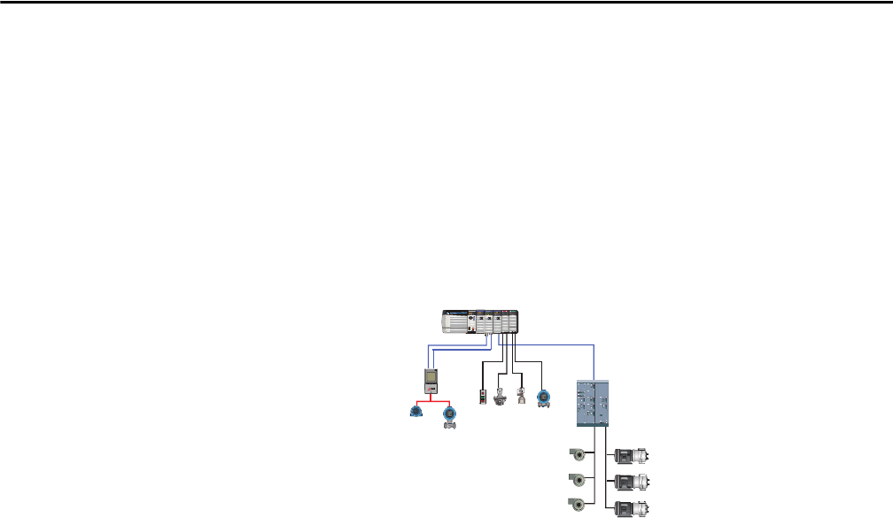
For example, an I/O count for a system comprised with the following:
• Two 8-channel 4…20 mA input cards
• One 8-channel 4…20 mA output cards
• Two 16-channel 24V DC dry-contact input cards
• One MCC with six drives
– Each drive provides six signals to the control strategy: speed reference,
actual speed, start, stop, running, and fault.
• Two Coriolis flowmeters on PROFIBUS PA, with each meter providing
three signals for flow, temperature, and density.
We can roughly calculate the following I/O count for the example system:
4…20 mA AI 2 x 8 = 16
4…20 mA AO 1 x 8 = 8
24V DC DI 2 x 16 = 32
MCC 6 x 6 = 36 (6 AI, 6 AO, 12 DI, 12 DO)
Smart instruments 2 x 3 = 6 (6 AI)
___
Controller I/O count 98
This example I/O count method enables you to enter I/O counts into the
PSE to determine an appropriate number of control strategy footprints to
determine sizing.
One I/O channel per
each device in a
networked, motor
control center.
One I/O channel per each I/O point on an I/O module.
One I/O channel per each device.
32 Rockwell Automation Publication PROCES-RM001M-EN-P - June 2019
Chapter 2 System Element Recommendations
Sizing Control Strategies
A control strategy encompasses all of the application code required to implement
a specific control function. The application code includes the I/O, controller
code, display elements, and faceplates.
The Rockwell Automation Library of Process Objects contains a Library of
Process Strategies. The process strategies include control strategies for I/O
processing, device control, and regulatory control.
Figure 2
shows devices that are being controlled and monitored in a loop via
pre-engineered logic in Process objects. The object instructions in the controller
send data to the HMI to visually evaluate on faceplates the function that is
being performed.
By using the control strategy model, we are able to estimate the following
system parameters:
• Potential alarms
• Visualization tags (affecting controller and server memory)
• Controller memory usage
• Controller execution time
Figure 2 - Control Strategy Example
By estimating the size of control strategies, you have a better prediction of
system performance.
POWER
ETHERNET
OKTXDRXD
A
B
ST
ST
DIAGNOSTIC
O
K
01 234 567
891011121314 15
AC OUTPUT
ST
ST
DIAGNOSTIC
O
K
01 234 567
891011121314 15
AC INTPUT ANALOG INPUT
CAL
OK
FLT
ST
FLT
ST
O
K
01 2345 67
01 234567
891011121314 15
89101112131415
DIAGNOSTIC
ANALOG INPUT
FLT
ST
FLT
ST
O
K
01 2345 67
01 234567
891011121314 15
89101112131415
DIAGNOSTIC
ANALOG INPUT
RUN
SD
OKFORCE
Logix5573
PASS/Application Servers
Process Information servers collect the process and
system data for use in managing the process.
Operator interface presents system information to the user.
Controllers execute application code to control the
process and communicate with the supervisory level.
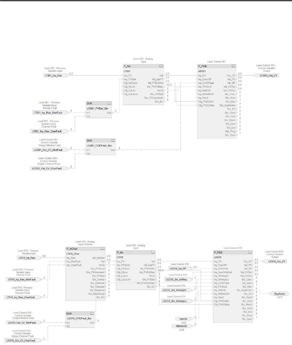
Rockwell Automation Publication PROCES-RM001M-EN-P - June 2019 33
System Element Recommendations Chapter 2
The amount of resources consumed by the system elements to support a control
strategy provides a ‘footprint’. To size systems, these base control strategies are
established as system footprints in the PSE:
•Simple regulatory: This strategy is a simple PID loop with a single analog
input and analog output.
•Complex regulatory: This strategy is a more complex regulatory loop
such as PID controllers in a cascade configuration with two analog inputs
and one analog output.
There are two routines associated with the typical complex regulatory
loop. Both routines are shown in the following examples.
Complex Regulatory — Primary (outer loop)
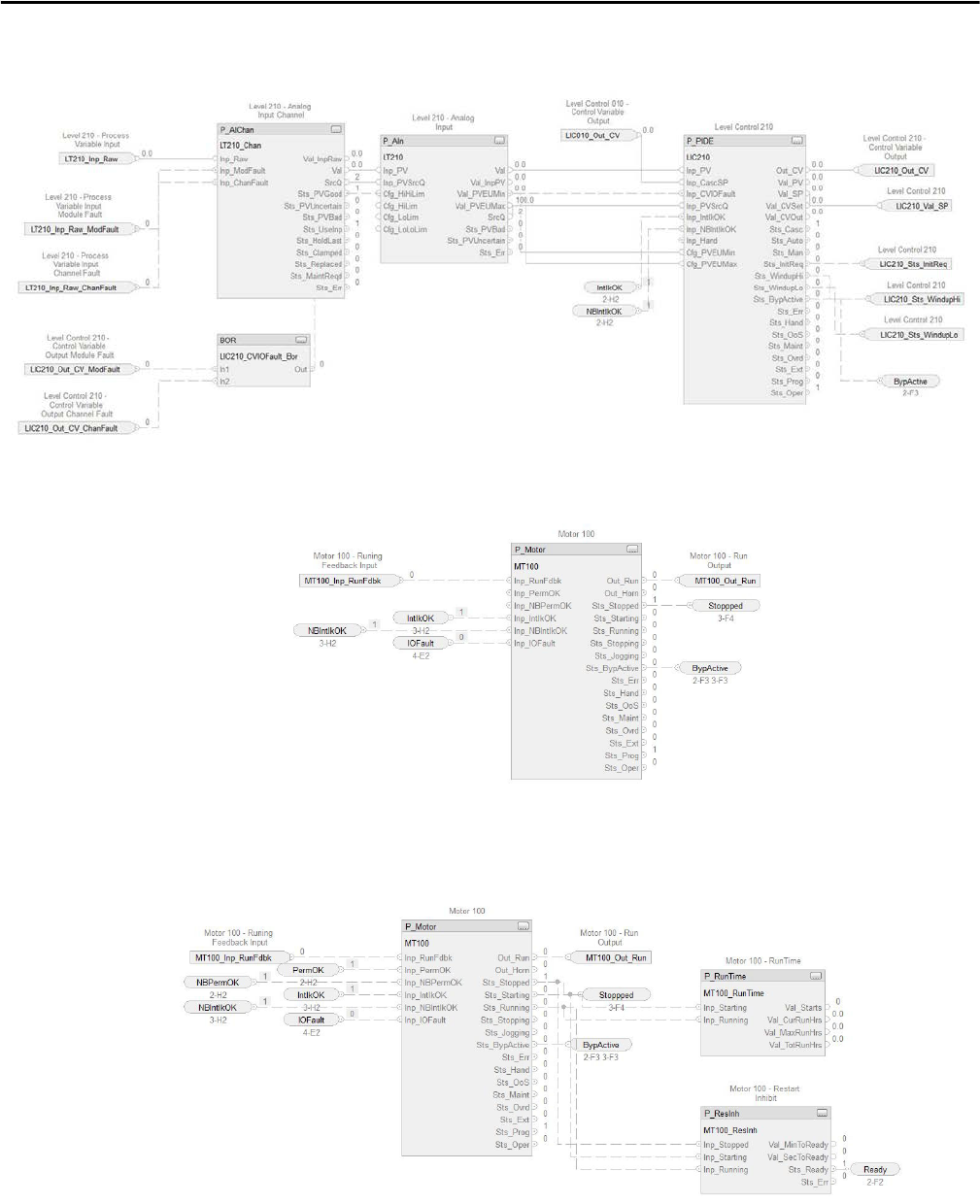
34 Rockwell Automation Publication PROCES-RM001M-EN-P - June 2019
Chapter 2 System Element Recommendations
Complex Regulatory — Secondary loop (inner loop)
• Simple 2-state discrete: A simple valve or motor with interlock logic and
as single digital input and output.
• Complex 2-state discrete: A valve or motor with complex interlock,
permissive, and runtime logic, which can have up to two digital inputs
and two digital outputs.
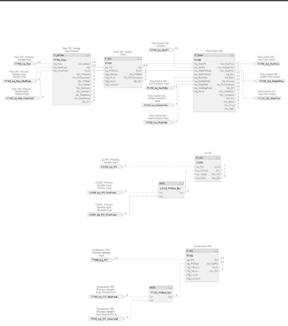
Rockwell Automation Publication PROCES-RM001M-EN-P - June 2019 35
System Element Recommendations Chapter 2
• Complex regulatory non-PID: This strategy can be a complex control
strategy, such as a loss in weight feeder, which can include an analog input,
valves, and a motor.
• Digital indicator: A digital input that is used for indication and/or
alarm only.
•Analog indicator: An analog input that is used for indication and/or
alarm only.
The examples are not a comprehensive list of the types of strategies used in an
application. But, the strategies do provide a reasonable set of examples that can be
used to approximate the loading of the majority of typical application code.

36 Rockwell Automation Publication PROCES-RM001M-EN-P - June 2019
Chapter 2 System Element Recommendations
For each control strategy, we can estimate the footprint based on the following:
•Visualization Tags: The number of tags within the control strategy that
can be visualized through a display or faceplate on the OWS (inclusive of
operation, maintenance, and debug activities). This number affects server
and controller memory utilization.
•Historian Tags: The number of tags within the control strategy that are
typically brought into the historian. This number affects communication
bandwidth, for example, active tags on scan/sec).
•# of Potential Alarms: The maximum number of alarms that can be
defined. It is assumed that not every alarm is configured for use. The
alarms that are used are configured in the server that contains the
controller.
•Memory, KB: The amount of memory an instance of the control strategy
and its associated tags uses inside of a simplex controller.
• Execution time (microseconds): The amount of controller CPU time it
takes to run an instance of the control strategy under simulated loading
(this is inclusive of the crossloading time for redundant controllers).
When a control strategy is instantiated, its impact to the controller is dependent
on task rate for the task tat contains a control strategy. A PID loop running every
250 milliseconds takes twice the CPU capacity as the same PID loop running
every 500 milliseconds.
Redundancy Considerations
If you are using redundant controllers, the scan rate and memory use
increases 1.5…2 times.
When you look at controller memory, you do not see the total memory usage for
redundancy. You need to calculate the actual memory that is used.
For more information, see the ControlLogix Enhanced Redundancy System User
Manual, publication 1756-UM535
.

Rockwell Automation Publication PROCES-RM001M-EN-P - June 2019 37
Chapter 3
System Application Recommendations
This section contains integral information to configure controllers and other
applications on your PlantPAx® system. We strongly recommend that you review
these topics to be sure that the system is built and performing properly.
The following table lists where to find specific information.
Controller Recommendations
Logix controllers must be configured for optimal performance in process
applications. From your EWS, follow these recommendations when configuring
your controllers:
• Use periodic tasks only, with minimum number of tasks that are used to
define execution speed, faster tasks getting higher priority (lower number).
• Set up monitoring of your controller utilization by using the L_CPU
Add-On Instruction.
• Specify a requested packet interval (RPI) that is two times faster than task
execution or based on inherent properties of the signal being measured.
For example, a 500 ms task requires a 250 ms RPI on each I/O card, but
temperature measurements can be set slower as they are unlikely to change
that quickly.
• Limit the number of synchronous copy commands (CPS) as these
commands act as an interrupt to the controller. Tasks that attempt to
interrupt a CPS instruction are delayed until the instruction is done.
• Use Compatible Keying for configuring I/O module cards. However, in a
validated environment that you can use an Exact Match for keying.
For more information, see Electronic Keying in Logix5000™ Control
Systems Application Technique, publication LOGIX-AT001
.
Topic Page
Controller Recommendations 38
FactoryTalk View Recommendations 52
Rockwell Automation Library of Process Objects 53
Additional Application Resources 54

38 Rockwell Automation Publication PROCES-RM001M-EN-P - June 2019
Chapter 3 System Application Recommendations
Table 26 shows memory and CPU recommendations for simplex and
redundant controllers.
Task Configuration and CPU Utilization
The controller operating system is a preemptive, multitasking system that is
IEC 61131-3 compliant. ControlLogix® and CompactLogix™ controllers define
the schedule and priority of how programs are executed by using tasks.
Periodic Task Configuration
As we stated earlier, controllers that are configured for the PlantPAx system must
use periodic tasks only. PlantPAx system sizing rules and tools are dependent on
this specific execution configuration. For example, a controller is typically
configured with three periodic tasks:
• Fast task (100…250 ms) for discrete control, such as motors and pumps
• Medium task (250…500 ms) for flow and pressure loops or analog inputs
• Slow task (1000…2000 ms) for temperature, phases, batch sequencing
As shown in Ta b l e 27
, a naming convention is used so that tasks are listed in the
Studio 5000 Logix Designer® application in the order of execution period: fastest
to slowest regardless of the tasks used. A dedicated task is created to monitor
status of the controller and other tasks. We recommend that you delete tasks that
are not used or create tasks that are required only by the application.
Table 26 - Simplex and Redundant Controller Memory Recommendations
Environment Simplex Controllers Redundant Controllers
Outside of production environment (before connecting
FactoryTalk® View and Historian clients)
50% free memory to support communication and
handling of abnormal conditions
>50% free memory at all times
50% free CPU time to handle communication, abnormal conditions, and other transient loads
In the production environment (while FactoryTalk View
and Historian are connected)
25% free memory to support handling of abnormal
conditions
>50% free memory at all times
25% free CPU time 50% free CPU time
Table 27 - Recommended Task Configurations
Name Type Period (ms) Priority (lower number
yields higher priority)
Watchdog (ms) Disable Automatic
Output Processing
Task_A_50ms Periodic 50 5 150 Unchecked
Task_B_100ms 100 6 300
Task_C_250ms 250 7 750
Task_D_500ms 500 8 1500
Task_E_1s 1000 9 3000
Task_F_2s 2000 10 6000
Task_G_5s 5000 11 15,000
Task_H_10s 10,000 12 30,000
_Controller_Status 1000 13 3000
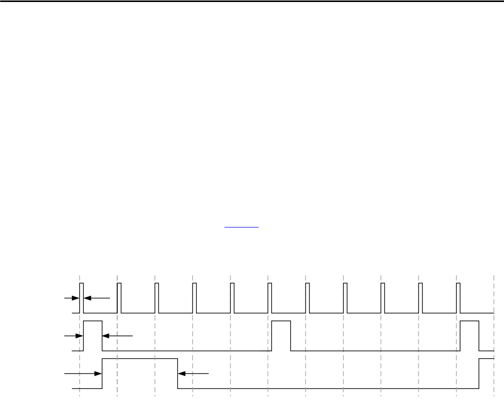
Rockwell Automation Publication PROCES-RM001M-EN-P - June 2019 39
System Application Recommendations Chapter 3
Each task that exists and is not inhibited has execution overhead. For sizing the
PlantPAx system, we estimate this overhead as 1000 μs per task. The PSE
calculates CPU utilization by calculating the required CPU time for the selected
quantity of control strategies in each task.
Although a project can contain multiple tasks, the controller executes only one
task at a time. If a periodic or event task is triggered while another task is
executing, the priority of each task tells the controller what to do. Make sure that
your periodic task priorities are unique.
We recommend that the total execution time of all tasks is less than half the
execution time of the lowest priority task or slowest task. For example, a fast loop
in a 100 ms task that executes every 10 ms., your other code could not be greater
than 50 ms.
As shown in Figure 3
, when you add the percentage for each task, the total
is 40% (10 + 10 + 20), which is less than 50% of the slowest task.
Figure 3 - Task Execution Example
Follow these guidelines for task execution:
•Never use continuous tasks. Use periodic tasks only, with minimum
number of tasks used to define execution speed, faster tasks getting higher
priority (lower number).
A continuous task is created by default in the Studio 5000 Logix Designer
application. This continuous task must be deleted. If left as the default, the
continuous task runs in the background of the controller as the lowest
priority task. Any controller CPU time that is not allocated to other
operations or tasks is used to execute the continuous task.
When the continuous task completes, it restarts automatically and can be
stopped only by a system overhead time slice. The system overhead time
slice defines the amount of time the controller has available for
communication. Thus, an overhead time slice interrupts the continuous
task for communicating to HMI devices, processing MSG instructions,
and alarm instruction processing.
Priority 1
100 ms Task
Runs for 10 ms
Priority 2
500 ms Task
Runs for 50 ms
Priority 3
1000 ms Task
Runs for 200 ms
to Finish
0
ms
100
200
10 ms
(10%)
50 ms (10%)
200 ms (20%)
300 400 500 600 700 800 900 1000

40 Rockwell Automation Publication PROCES-RM001M-EN-P - June 2019
Chapter 3 System Application Recommendations
This function limits the flexibility of the controller to apply resources to
handle abnormal conditions in communication. However, the overhead
time slice is ignored when a continuous task is not configured.
• Removal of the continuous task:
– Improves predictability of the controller CPU availability for
communication to the system
– Provides a more accurate view of the controller loading at runtime.
With continuous task, controller loading is always 100%
– Reduces the amount of task switching that improves overall application
and system performance
• Time-based operations, such as a PID algorithm, do not function
accurately when run in a continuous task
• Do not use more than three periodic tasks to maintain optimum CPU
performance. Batching can require more tasks, but we recommend that
periodic tasks be event tasks if not in a redundant controller.
Estimate Controller CPU Utilization
The PSE uses a sizing model to estimate controller CPU utilization in a
production environment. This calculation is as follows:
• Task Execution time is 1000 μs + sum of control strategy execution times
assigned to the task
• Total controller execution time is a summation of task execution times
normalized to the slowest task. For example:
250 ms Task Execution Time * 4 + 500 ms Task Execution Time * 2 +
1000 ms Task Execution time (if using 3 tasks: 250 ms, 500 ms,
and 1000 ms)
• Tasks without assigned control strategies are ignored. It is assumed that
these tasks are not created or are inhibited in the controller.
• CPU utilization is a percentage of the controller execution time/slowest
task rate
Higher priority tasks interrupt lower priority tasks if needed to run. When the
task interrupted is in progress, we call this task switching. A task switch adds
execution overhead as well. If your faster tasks have higher priority, task switching
does not occur in properly sized controllers. (A properly sized controller is when
the total execution time of all of the tasks is less than half of the fastest task rate.)
Hence, the PSE sizing model does not account for task switching when
estimating utilization.

Rockwell Automation Publication PROCES-RM001M-EN-P - June 2019 41
System Application Recommendations Chapter 3
When periodic tasks have the same priority, the controller task switches every
1 ms until tasks are completed, each switch adding 250 -> 25 μs. This
functionality is why it’s important that periodic tasks are given separate priorities.
In Logix, you have up-to 15 user-defined priorities.
Keep in mind we want CPU load in a production environment to be 75% or less
for a Simplex controller. For a redundant controller, we want CPU load in a
production environment to be 50% or less.
It's important to keep 25% CPU capacity as reserve to handle online edits, data
server switchover, and so forth. The PSE provides a warning when the calculated
CPU load approaches the stated limits.
A task overlap is when a task is interrupted too frequently or too long that it
doesn’t complete its execution before it is triggered again. Avoid task overlaps
that can be monitored by using the L_TaskMon Add-On Instruction.
For more general information on ControlLogix execution capabilities, see
the Logix5000 Controllers Design Considerations Reference Manual,
publication 1756-RM094
.
CPU Utilization Example Estimations
The following examples show how configuration affects the sizing model and
actual CPU utilization. For all scenarios, we are assuming a simplex 1756-L7x
controller that is running 80 PID loops (800 μs execution per loop).
Example 1: 80 PID loops in a single periodic task @ 100 ms:
Task Execution Time: 1000 μs + (80 PID loops * 800 μs) = 65,000 μs
CPU = 65,000 μs /100,000 μs = 65% load
Example 2: 80 PID loops evenly split for two periodic tasks, first @ 50 ms, second @ 250 ms:
Task 1 Execution Time: 1000 μs + (40 PID loops * 800 μs) = 33,000 μs
Task 2 Execution Time: 1000 μs + (40 PID loops * 800 μs) = 33,000 μs
Total Execution per 250 ms = ((33,000 μs *5)+33,000 μs) = 198,000 μs
CPU Utilization: 198,000 μs / 250,000 μs = 79.2%
In this scenario, loading is not okay (> 75%). However, this example
matches the PSE calculation that gives you a warning.
Example 3: Loops evenly split to 10 periodic tasks @ 100 ms and different priorities:
Task Execution per task: 1000 μs + (8 PID Loops * 800 μs) = 7400 μs
Total Execution time: 10 * 7400 μs = 74,000 μs
CPU = 74,000 μs / 100,000 μs = 74%
In this example, loading is near the desired limit but still okay (<75%). The
PSE assumes proper task configuration, but it doesn’t account for the
impact of the additional task overhead or the task switching (approximate
20% increase in CPU load).

42 Rockwell Automation Publication PROCES-RM001M-EN-P - June 2019
Chapter 3 System Application Recommendations
The goal of the PlantPAx system recommendations and PSE is to make it simple
to size the system and provide assurance that everything works as expected. This
is a critical need. While the examples are simple; they illustrate how
configuration can impact load.
Monitor Controller CPU Utilization
Free process controller CPU time is required to handle communication,
abnormal conditions, and other transient loads. Therefore, it’s important to
consider CPU utilization when implementing the application code.
When defining the application code, make sure that the CPU utilization of the
process controller can accommodate these values:
• In the development environment, CPU utilization is recommended to be
less than 50% to allow for the additional CPU load that is experienced in
the production environment.
• During the operation of the system, monitor the CPU utilization,
especially after a change to the application code, and it cannot exceed 75%
for a Simplex controller or 50% for redundant controllers.
• During the design of the application code, it’s important to account for
software components, such as FactoryTalk View or Historian. The
software is actively collecting data from the controller so be sure that CPU
utilization is less than stated limits to allow for communication with the
supervisory system elements (EWS, OWS, Information server).
There are two options for reviewing controller loading:
• Task Monitor - Available from the Studio 5000 Logix Designer
application on the EWS. If more than one task monitor is viewing
a controller simultaneously, its possible controller data is not
reporting correctly.
• Logix Controller CPU Utilization (L_CPU) Add-On Instruction - See
the Rockwell Automation Library of Logix Diagnostic Objects Reference
Manual, publication PROCES-RM003
.
Controller loading includes controller CPU utilization, communication usage,
memory usage, and task scan times. This data provides information for
diagnosing communication, controlling responsiveness issues, or in tuning the
performance of control tasks for optimum controller performance.
IMPORTANT
The L_CPU instruction is the preferred method to monitor controller
performance because the logic monitors the Logix controller that is being
executed. The controller is used in place of, or in addition to, the task monitor
to provide more system-specific controller loading information.
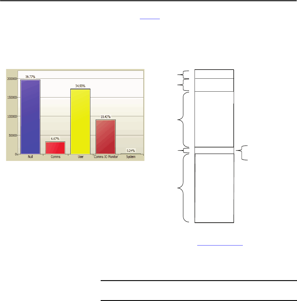
Rockwell Automation Publication PROCES-RM001M-EN-P - June 2019 43
System Application Recommendations Chapter 3
The diagram in Figure 4 shows a properly loaded Simplex controller for
the following:
• Application code execution is less than 50% CPU
• Total execution including comms is less than 75% CPU
Figure 4 - CPU Utilization
For more information, see the Rockwell Automation Library of Logix Diagnostic
Objects Reference Manual, publication PROCES-RM003
.
Use of Program Parameters
Input and Output parameters define the data that is passed by value into or out of
an executing program. Because these parameters are passed by value, their value
cannot change during the execution of the program.
We recommend that you use program parameters to exchange data between
your programs and between programs and I/O. Program parameters simplify
I/O mapping and can be modified online.
6.67%
34.90%
0.24%
39.77%
220 Packets/Second
Application Code
Execution (user)
System
Null Time
100 ms Task
250 ms Task
500 ms Task
System Processing Time
System Background
Task Time
Comms IO Monitor
18.42%
Comms
IMPORTANT
The number of program parameters—Input, Output, InOut, Public —are
limited to 512 parameters per program.
44 Rockwell Automation Publication PROCES-RM001M-EN-P - June 2019
Chapter 3 System Application Recommendations
Tag and Memory Allocation
Table 28 shows the memory of a controller is divided into several areas depending
on the type of controller.
When you configure displays, we recommend that you use direct tag referencing
to access data from the controller directly without creating an HMI tag. This
requires fewer configuration steps and is easier to maintain.
Use DINT and REAL data types whenever possible. Mathematical routines in
the controller consume less CPU resources when DINT and REAL data types
are used.
A user-defined data type (UDT) or Add-On Instruction data type lets you
organize data to match your machine or process. Additional advantages of using a
UDT or an Add-On Instruction include the following:
• One tag contains all the data related to a specific system activity. This
keeps related data together and easier to locate, regardless of its data type.
• Each individual piece of data (member) gets a descriptive name. This
automatically creates an initial level of documentation for your logic.
• You can use the data type to create multiple tags with the same data layout.
For example, you can use a UDT to store all the parameters for a tank,
including temperatures, pressures, valve positions, and preset values.
Create a tag for each of your tanks based on that data type.
You can create a UDT when online or offline. However, you can modify an
existing UDT definition when offline only.
Table 28 - Controller Memory Allocation
Controller Type Storage Memory
1756 ControlLogix
1768 CompactLogix
I/O tags I/O memory
Produced/consumed tags
Communication via message (MSG) instructions
Communication with workstations
Communication with polled (OPC/DDE) tags that use RSLinx® software
(1)
Tags other than I/O, produced, or consumed tags Data and logic memory
Logic routines (for example, control strategies)
Communication with polled (OPC/DDE) tags that use RSLinx® software
(1)
UDT and Add-On Instruction definition
1769-L2x CompactLogix
1769-L3x CompactLogix
1769-L19x CompactLogix
These controllers do not divide their memory. They store all of the elements in one common memory area
(1) To communicate with polled tags, the controller uses both I/O data and logic memory.

Rockwell Automation Publication PROCES-RM001M-EN-P - June 2019 45
System Application Recommendations Chapter 3
General Recommendations
• Define tags in arrays and a UDT whenever possible. Tag data that is
packed into an array is sent more efficiently to the HMI than if you were
using scattered tag data.
• When defining a UDT, group BOOL tags together whenever possible.
Inside the controller memory, BOOL tags must align on 8-bit boundaries.
But, if they are placed adjacent to each other they can share bytes and use
less memory and communication bandwidth.
• BOOL data types that are not members of an array or structure use 4 bytes
of controller memory. When communicating multiple BOOL tags
between controllers or to displays, use a UDT or array to consolidate
multiple BOOL tags into a single word.
• Define a tag naming convention that minimizes the length of the tag
names. Long tag names can decrease the bandwidth available for
communicating data.
For more information, see the Logix5000 Controllers I/O and Tag Data
Programming Manual, publication 1756-PM004
.
Estimate Controller Memory Utilization
The PSE uses a sizing model that is based on control strategies to estimate
controller memory utilization in a production environment. There are three
sources of memory that comprise this sizing model:
• Memory for base definitions - Base definition memory varies depending
on the amount of Add-On Instruction and UDT definitions in the
project. Loading all of the Rockwell Automation Library definitions takes
over 1 MB of memory, while loading the most common objects take much
less memory. By default, the PSE assumes a base load of 380 KB. This is
adjustable in the PSE system preferences, if needed.
• Memory used by control strategies - See Monitor Controller CPU
Utilization on page 42.
• Memory to support communication - The defined control strategies have a
number of visualization tags for each control strategy (inclusive of
operation, maintenance, and debug activities). During operation, the
controller uses controller memory to manage the connections to these tags
as they are accessed. The amount of memory used varies, but the PSE
estimates 16 bytes per tag.
When controller redundancy is used, memory usage increases and additional
spare capacity is required to allow for runtime edits. The PSE sizing model
accounts for these needs by increasing the estimated amount of memory.
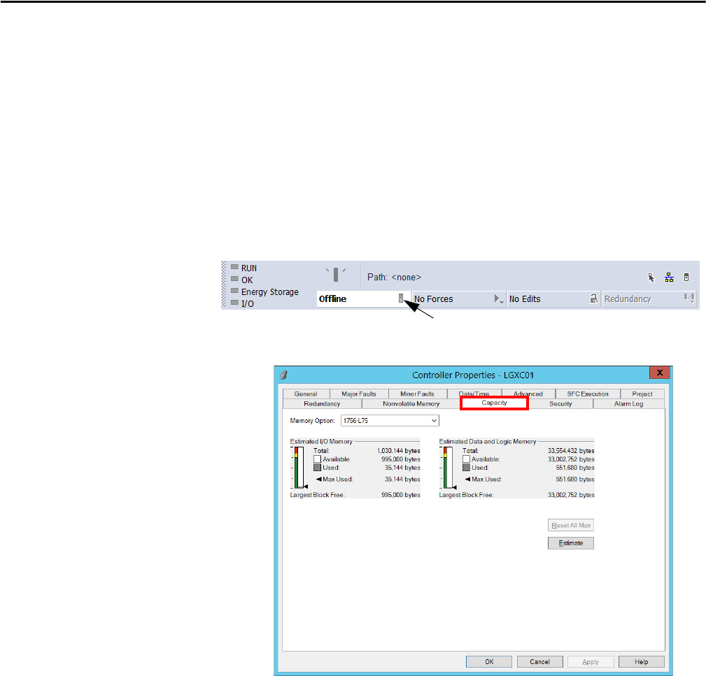
46 Rockwell Automation Publication PROCES-RM001M-EN-P - June 2019
Chapter 3 System Application Recommendations
Estimate Memory Information Offline
To estimate how much controller memory your project requires, use the Capacity
tab of the Controller Properties dialog box. For each of the memory areas of your
controller, the dialog box provides an estimate number of bytes for the following:
• Free (unused) memory
• Used memory
• Largest free contiguous block of memory
1. From the Studio 5000 Logix Designer application, click the controller
properties icon to access the Controller Properties dialog box.
2. Click the Capacity tab.
In the ‘Estimated Data and Logic Memory’ section, view the memory
information since the last estimate.
3. Click Estimate to re-estimate the amount of controller memory.
View Runtime Memory Information
When online with a controller, the Capacity tab shows the actual memory usage
of the controller. While the controller is running, it uses additional memory for
communication. The amount of memory the controller needs varies depending
on the state of the communication.
The Capacity tab of the controller includes a Max Used entry for each type of
memory. The Max Used values show the peak of memory usage as
communication occurs.
Controller Properties icon

Rockwell Automation Publication PROCES-RM001M-EN-P - June 2019 47
System Application Recommendations Chapter 3
Click Reset All Max on the Capacity tab to reset values.
For more information, see Chapter 2 in the Logix5000 Controllers Information
and Status Programming Manual, publication 1756-PM015
.
Monitor Controller Memory Utilization
We recommend that 50% of available logic and data memory to be reserved for
design time of communication, online editing, and handling of abnormal events.
For simplex controllers, we recommend maintaining 25% of available logic and
data memory to handle online editing and connection handling in operation.
For redundant controllers, we recommend that you maintain greater than 50% of
logic and data memory available to handle online changes.
Memory usage can be monitored by using the L_CPU Add-On Instruction
(see page 42
) or the Studio 5000 Logix Designer application (see page 46).
Controller-to-Controller Communication
There are two ways to set up communication between controllers:
• Produced/consumed tags
• Messages
We recommend that you use an array or user-defined tag for produce-consume
communication. As produce/consumed tags cannot be edited online, make sure
Table 29 - Compare Messages and Produced/Consumed Tags
Method Benefits Considerations
Read/write message • Programmatically initiated
• Communication and network resources used when needed only
• Support automatic fragmentation and reassembly of large data
packets, up to as many as 32,767 elements
• Some connections can be cached to improve retransmission time
• Generic CIP™ message useful for third-party devices
• Delay can occur if resources are not available when needed
• MSG instruction and processing impacts controller scan (system
overhead time slice)
• Data arrives asynchronous to program scan (use a programmatic
handshake or an UID/UIE instruction pair to reduce impact, no
event task support)
• Can add additional messages online in Run mode
Produced/consumed tag • Configured once and sent automatically based on requested
packet interval (RPI)
• Multiple consumers can simultaneously receive the same data
from a single produced tag
• Can trigger an event task when consumed data arrives
• ControlNet resources are reserved up front
• Does not impact the scan of the controller
• Support limited to Logix5000 and PLC-5® controllers, and the
1784-KTCS I/O Linx and a few third-party devices
• Limited to 500 bytes over the backplane and 480 bytes over
a network
• Must be scheduled when using ControlNet
• Data arrives asynchronous to program scan (use a programmatic
handshake or CPS instruction and event tasks to synchronize)
• Connection status must be obtained separately
• On an EtherNet/IP network, you can configure produced/
consumed tags to use multicast or unicast connections
• Cannot create additional produced/consumed tags online in
Run mode.

48 Rockwell Automation Publication PROCES-RM001M-EN-P - June 2019
Chapter 3 System Application Recommendations
to include extra capacity that can be populated by mapping logic so additional
information can be shared as needed without requiring a download.
Controller I/O Considerations
The requested packet interval (RPI) is a user-configured interval of time that
determines when the data from an I/O module is sent to a controller. This
interval defines the slowest rate that a module multicasts its data. When the
specified time frame elapses, the module multicasts data to the controller.
Setting the RPI faster (specifying a smaller number) than what your application
needs wastes network resources, such as ControlNet schedule bandwidth,
network processing time, and CPU processing time.
Table 30 - Process Controller Recommendations
Category Recommendation
Produced and consumed tags • A single produced and consumed tag can contain multiple combinations of data. For example, up to 120 REALs
or 100 REALs and 640 BOOLs.
• Group produced and consumed tags into a user-defined structure to reduce the number of connections to
the controller.
• Use the same data type for the produced and consumed tags in each controller that uses that data.
• Make sure the number of consumers configured for a produced tag is the actual number of controllers consuming it
to reduce the number of connections to the controller.
• On produced tags, the maximum consumers configured counts against your total connection count so make it the
actual number of connections or set it at the expected number to be in the future.
• Always use a handshake when transferring data between controllers through health data or manually
configured diagnostics.
Messaging • There is a maximum of 32 cached message connections from message instructions and block transfers combined.
• Cache messages when the message needs only to be maintained all the time. If a message instruction is infrequent,
then make sure cached connection is unchecked.
• Always use message reads, never do message writes. This makes it easier to troubleshoot code.
• When messaging between controllers, use DINTs where possible.
• Message instructions consume a connection when it is a CIP data table read, write, or generic (if selected).
Table 31 - I/O Considerations
Category Consideration
I/O configuration properties • Specify an RPI that is two times faster than task execution:
– 250 ms task requires a 125 ms RPI
– 100 ms task requires a 50 ms RPI
• Often RPI defined by the inherent properties of the signal being measured. For example temperature measurement
changes slower than pressure.
• Use compatible module for keying option on I/O cards configuration. In a validated environment, you can use an
exact match for keying.
ControlNet network • Set the network update time (NUT) equal to or less than the fastest RPI of the I/O modules and produced-consumed
tags in the system. For example, if your fastest RPI is 10 ms, set the NUT to 5 ms for more flexibility in scheduling
the network.
• Set the RPI to a binary multiple of the NUT. For example, if the NUT is 10 ms, select an RPI such as 10, 20, 40, 80,
160 ms, and so forth.
• Use unscheduled I/O to be able to add ControlNet modules at runtime. (See I/O Module Runtime/Online
Considerations.) Dedicate one ControlNet network to I/O communication only.
• Unscheduled I/O requires a connection to each module, so the number of modules supported depends on the
number of connections supported by the communication module. On the dedicated I/O network, make sure of the
following:
– No HMI traffic
– No MSG traffic
– No programming workstations
– No peer-to-peer interlocking in a multi-processor system architecture
EtherNet/IP network See Chapter 5 for infrastructure recommendations.
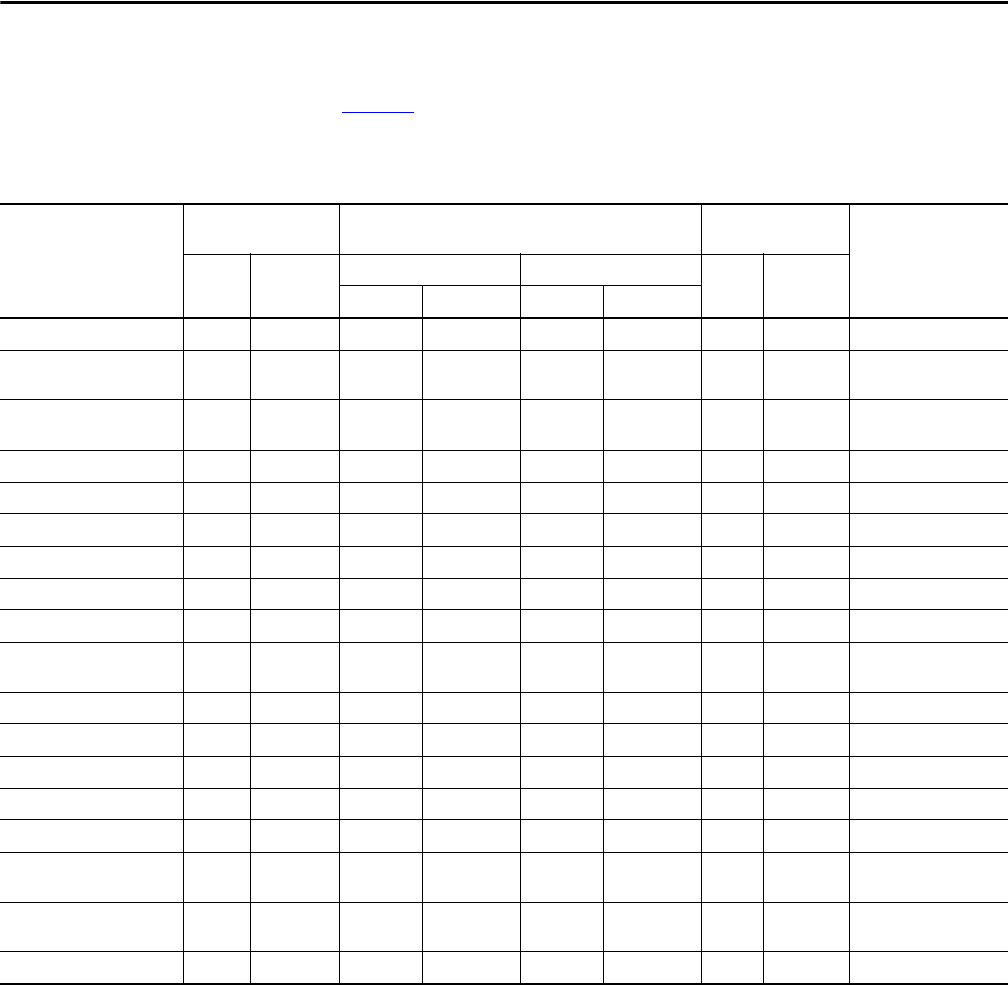
Rockwell Automation Publication PROCES-RM001M-EN-P - June 2019 49
System Application Recommendations Chapter 3
I/O Module Runtime/Online Considerations
Table 32 shows some of the modules that you can add to the Controller
Organizer in the Logix Designer application when the controller is in Run mode.
Table 32 - Online Addition of Module and Connection Types
Module Type and
Connection Method
In Local Chassis Remote Via a ControlNet Network Remote Via an
EtherNet/IP Network
Configure Hold Last
Output State
Offline Runtime Offline Runtime Offline Runtime
Scheduled Unscheduled Scheduled Unscheduled
Motion - direct Yes No N/A N/A N/A N/A N/A N/A N/A
Digital - direct Yes Yes Yes Yes No Yes Yes Yes Yes - 1756 I/O digital
output modules
Digital - rack-optimized N/A N/A Yes No Yes No Yes Yes Yes - 1756 I/O digital
output modules
Analog - direct Yes Yes Yes Yes No Yes Yes Yes Yes
Generic third-party - direct Yes Yes Yes Yes No Yes Yes Yes N/A
1756-DNB Yes No Yes No No No Yes Yes N/A
1756-DHRIO Yes No Yes No No No Yes Yes N/A
1756-CNx - no connection Yes Yes Yes Yes No Yes N/A N/A N/A
1756-CNx - rack-optimized N/A N/A Yes N/A N/A N/A N/A N/A N/A
Generic ControlNet third-party
- direct
N/A N/A Yes Yes No Yes N/A N/A N/A
1788HP-EN2PA-R N/A N/A N/A N/A N/A N/A Yes Yes N/A
1788HP-CN2PA-R N/A N/A Yes Yes No Yes N/A N/A N/A
1715 Redundant I/O No No No No No No Yes Yes N/A
1756-ENx - no connection Yes Yes N/A N/A N/A N/A Yes Yes N/A
1756-ENx - rack-optimized N/A N/A N/A N/A N/A N/A Yes Yes N/A
Generic EtherNet/IP
third-party - direct
N/A N/A N/A N/A N/A N/A Yes Yes N/A
1794 FLEX™ I/O N/A N/A Yes Yes No No Yes No Yes - Analog output
modules only
1734 POINT I/O™ N/A N/A Yes Yes No No Yes No Yes
(1)
(1) When you lose communication to the controller, POINT I/O™ ignores the last output state configuration, and sets the outputs to zero.

50 Rockwell Automation Publication PROCES-RM001M-EN-P - June 2019
Chapter 3 System Application Recommendations
When you design your network, review these considerations if you are going to
add I/O modules at runtime.
See the Logix5000 Controllers Design Considerations Reference Manual,
publication 1756-RM094
, for more information.
Table 33 - Adding I/O Modules at Runtime
Category Consideration
I/O modules Currently, 1756 I/O and 1715 modules can be added at runtime.
Leave space in the local chassis, remote chassis on a ControlNet network, or remote chassis on an EtherNet/IP network
for the I/O modules that you want to add.
Input transmission rate Make sure each RPI works for the data you want to send and receive.
Make sure the added I/O does not depend on change of state data. When adding discrete input modules, unselect
Change of State to reduce network traffic.
Network topology On a ControlNet network, install spare taps so you can add 1756 I/O modules at runtime and not disrupt the network.
Each tap must be terminated so as not to ground out the system. Check the ControlNet system requirements to
determine how many spare taps your network can support.
• In a ControlNet network with redundant cabling, you can break the trunk and add a tap, but redundant cabling is
lost during the module installation.
• In a ControlNet ring, add a new drop off the rung or add new nodes off the coax and disrupt only part of
the network.
• You could remove a single existing node and add a repeater off the drop. Then read the existing node and add any
new nodes off of the new segment.
On EtherNet/IP, reserve some connection points on the switch so that you can connect additional nodes or switches in
the future.
Network configuration On a ControlNet network, plan communication that can be scheduled or can be unscheduled.
On an EtherNet/IP network, all communication is Immediate and occurs based on a module’s RPI (also referred to as
unscheduled).
If you know that you need a new chassis with digital modules in the future, configure the network and add it to the
I/O configuration tree as rack-optimized. Inhibit the communication adapter until you need the chassis.
Network performance You can add I/O modules at runtime until you impact the capacity of the communication module. Make sure that you
have sufficient communication modules for the connections you plan to add.
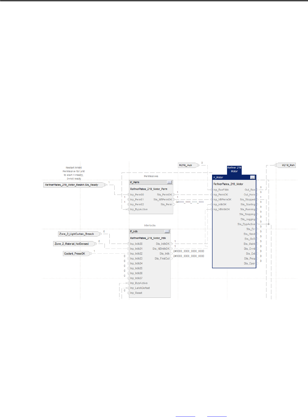
Rockwell Automation Publication PROCES-RM001M-EN-P - June 2019 51
System Application Recommendations Chapter 3
Using Add-On Instructions
Add-On Instructions are reusable code objects that contain encapsulated logic.
Each object is provided as an importable Add-On Instruction that can be shared
between projects to create a common library of instructions to accelerate
engineering from project to project. Add-On Instructions also can be signed with
a specific date and time, so that revisions of Add-On Instructions can be managed
between projects.
This functionality lets you create your own instruction set for programming logic
as a supplement to the instruction set provided natively in the ControlLogix and
CompactLogic firmware.
Add-On Instructions are defined once in each controller project, and can be
instantiated multiple times in your application code as needed. In the Studio
5000 Logix Designer application, you can view routines within an Add-On
Instruction instance online, animated with just the instance value as if it were an
individually defined routine.
Add-On Instructions can be source protected. Source protection does not let you
edit the definition of an instruction without a source key. To protect intellectual
property, routines and local tags also can be hidden on protected Add-On
Instructions.
Like a native instruction, the definition of an Add-On Instruction cannot be
modified online. Therefore, we do not recommend the use of Add-On
Instructions to implement control strategies. Control strategies are best
developed in a program, built from Add-On Instructions, and native
instructions. It’s also important that you fully test all configuration options
before implementing an Add-On Instruction on your production system.
The Rockwell Automation Library of Process Objects uses Add-On Instructions.
For related information, see page 53
and page 59.

52 Rockwell Automation Publication PROCES-RM001M-EN-P - June 2019
Chapter 3 System Application Recommendations
FactoryTalk View
Recommendations
For implementing FactoryTalk View SE software for a process system operator
interface, follow these guidelines:
• Run FactoryTalk View Studio software on the EWS during runtime.
• Configure the FactoryTalk View SE servers to start automatically on
startup on the PASS. Let the servers fully start up before starting the
client computers.
• In FactoryTalk View Studio software, areas can be used to organize your
distributed system. Configure an area for each server of any type. Areas can
contain areas. However, do not put more than one server in the root
location of an area. This helps prevent potential performance problems. In
addition, this name hierarchy can be visible externally, such as in the
historian or alarm database.
• Use global objects to display the status of a control module or device when
the information to be displayed is stored in a tag structure within Logix
(for example, UDT or Add-On Instruction) and there are many identical
instances. A global object is a display element that is created once and can
be referenced multiple times on multiple displays in an application. When
changes are made to the original (base) object, the instantiated copies
(reference objects) are automatically updated. Use of global objects, in
conjunction with tag structures in the ControlLogix system, can help to
make sure of consistency and save engineering time.
• When using global objects, observe the following recommendations to be
sure of optimal display call-up performance:
– Base global objects are stored in FactoryTalk View in displays (.ggfx
files). If you have a large number of base global objects defined, do not
put them all in a single display. Limit the number of global object
instances on a single display to 60 or less.
– As global objects can be instantiated multiple times, the performance
impact of their design is amplified by their number of instances.
Therefore, design global objects carefully to reduce the number of
objects, expressions, and animations that are used within the
base object.
• We do not recommend the use of data logs. If necessary, use data logs for
short-term data retention only.
• Do not create derived tags that depend on the results of other derived tags.
Derived tag processing is not sequential.
• Avoid use of VBA when possible. VBA runs as a single-threaded process so
it’s possible the application written in VB does not allow the HMI to
perform predictably.
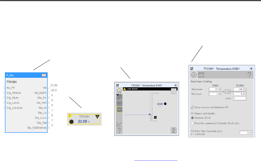
Rockwell Automation Publication PROCES-RM001M-EN-P - June 2019 53
System Application Recommendations Chapter 3
Rockwell Automation
Library of Process Objects
The Rockwell Automation Library of Process Objects is a predefined library of
controller code (Add-On Instructions), display elements (global objects), and
faceplates that let you quickly assemble large applications with proven strategies,
rich functionality, and known performance.
The PlantPAx Distributed Control System Application Configuration User
Manual, publication, PROCES-UM003,
describes how to import the process
strategies and map them to I/O by using program parameters.
The Library of Process Strategies helps you do the following:
• Makes sure of characterized performance with known control strategy
configurations
• Reduces implementation time
• Promotes consistent applications and user experience
When coupled to display elements and faceplates in the FactoryTalk View
Studio software program, these objects streamline device configuration in a
drag-and-drop environment (as shown in the illustration).
The display elements (global objects) have an associated faceplate that appears
when the display element is clicked. These faceplates let you operate and
configure the instructions. When additional support functions are added, such as
interlocks or permissives, the faceplates for these extended functions are directly
accessible for the faceplate of the associated object.
The Rockwell Automation Library of Process Objects includes a Library of
Process Strategies. Process strategies are pre-connected routines that use
Rockwell Automation Library of Process Objects in the context of their intended
use. The Library of Process Strategies includes routines for I/O processing,
device control, and regulatory control.
Step 1: Import the Library
into the project.
Step 2: Drop and configure the
Add-On Instruction.
Step 3: Drop the global object on
the display and assign it to an
Add-On Instruction instance.
Step 5: Access the full faceplate from
the global object at Runtime for
control, maintenance, and
configuration.
Step 4: Access small footprint ‘quick’
faceplates from the global object at
Runtime for basic operator control.
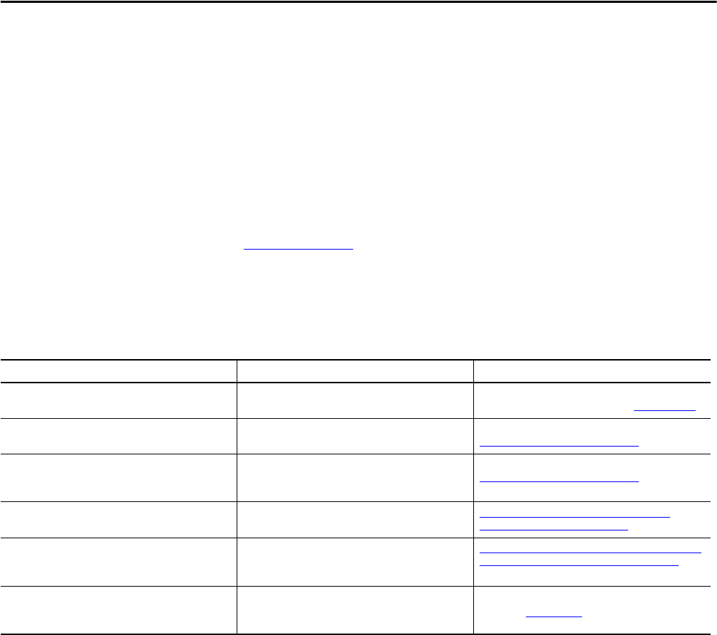
54 Rockwell Automation Publication PROCES-RM001M-EN-P - June 2019
Chapter 3 System Application Recommendations
The Library of Process Objects is supported through Technical Support
as long as the Add-On Instructions have not been modified from the
original deployment.
You can use library objects other than objects provided by Rockwell Automation.
For example, you can develop your own library or use the process objects as
guides. By using a library of consistent elements from Rockwell Automation, you
improve the maintainability and efficiency of your PlantPAx system.
For details on how to initiate objects and HMI displays, see the Rockwell
Automation Library of Process Objects Reference Manual, publication
PROCES-RM002
.
Additional Application
Resources
The following resources are available for use to assist with developing
your application.
Topics and Tools Description Where To Find Information
System deployment guide Provides procedures that are necessary to start
development of your PlantPAx system.
See the PlantPAx Distributed Control System Application
Configuration User Manual, publication PROCES-UM003
FactoryTalk Diagnostic sample displays Sample graphics to display FactoryTalk Linx
sample counters.
See the Knowledgebase Answer ID 30148 at
http://rockwellautomation.custhelp.com
Server status displays Sample code is provided to determine a server’s status
and state by using VBA and displaying the status on the
HMI display.
See the Knowledgebase Answer ID 44624 at
http://rockwellautomation.custhelp.com
Rockwell Automation Integrated Architecture® tools These tools can assist you in understanding, planning, and
configuring an Integrated Architecture System.
http://www.rockwellautomation.com/solutions/
integratedarchitecture/resources.html
Rockwell Automation sample code Sample code and tools for configuring and programming
Rockwell Automation products, including Rockwell
specific faceplates.
http://samplecode.rockwellautomation.com/idc/groups/
public/documents/webassets/sc_home_page.hcst
Batch implementation tools Videos, documentation, and sample code to help
guide you to the best design decisions for batch
system implementation.
See the Batch Application Toolkit Quick Start,
publication IASIMP-QS042

Rockwell Automation Publication PROCES-RM001M-EN-P - June 2019 55
Chapter 4
Alarm System Recommendations
In the process industries, alarms are a critical function of a control system.
Effective alarm systems alert the operator to abnormal situations, providing for a
quick response. Effective alarm handling improves the productivity, safety, and
environment of a process plant.
There are industry standards that govern alarm management design and
engineering practices. The standards help you develop effective alarm systems
(for example ANSI/ISA-18.2, Management of Alarm Systems for the Process
Industries). This section does not cover the practices that are defined by these
standards. We provide recommendations for implementing alarms on the
PlantPAx® system within the context of these standards.
The following table lists where to find specific information.
FactoryTalk Alarm and Event Software
The primary method for generating alarms in the PlantPAx system is
FactoryTalk® Alarm and Event software, herein referred to as the alarm system.
The alarm system supports device-based alarms (ALMA and ALMD instructions
in the controller) and tag-based alarms (digital, level, or deviation alarms).
Device-based and tag-based alarms co-exist in an application. PlantPAx system
sizing rules and critical system attributes are based on the use of tag-based alarms.
While device-based alarms can be used, we recommend limiting their use to
enhance system performance.
See page 57
for more information.
Topic Page
FactoryTalk Alarm and Event Software 55
Using the Library of Process Objects for Alarms 59
Alarm State Model 60
Monitoring Your Alarm System 63
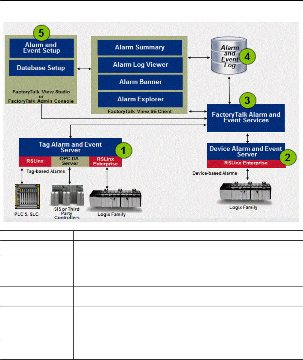
56 Rockwell Automation Publication PROCES-RM001M-EN-P - June 2019
Chapter 4 Alarm System Recommendations
Figure 5 - FactoryTalk Services Platform
Alarm Characteristic Description
1. Tag-based alarm monitoring Tag-based alarms (digital, level, or deviation) are configured in a Tag Alarm and Event server. When an alarm condition is detected by a
controller, the server publishes the information to FactoryTalk Alarm and Event services.
2. Device-based alarm monitoring The PlantPAx system sizing rules and Critical System Attributes are based on the use of FactoryTalk Alarm and Event tag-based alarms.
While device-based alarms can be used, we recommend a limited usage to enhance system performance. Device-based alarms, such as
ALMA, ALMD, are programmed via Studio 5000 Logix Designer® and then downloaded to Logix5000™ controllers. The controller detects
alarm conditions and notifies FactoryTalk Linx of alarm states. A Rockwell Automation® device server (FactoryTalk Linx software) extracts
the alarm information and publishes it to FactoryTalk Alarm and Event services.
3. FactoryTalk Alarm and Event services Both device-based and tag-based alarms and events are published to FactoryTalk Alarm and Event services. The Alarm and Event services
routes the information to FactoryTalk Alarm and Event objects that are hosted in FactoryTalk View software. The information also routes to
the alarm and event history log, and to diagnostic logs and audit logs.
4. Alarm and Event log The Alarm and Event log is a component that installs silently as part of the alarm and event software. It manages connections between
alarm servers and databases and logs data from each alarm server to an alarm history database. You can use the Alarm and Event Log
Viewer to view and print data from alarm history databases. Third-party database tools can also retrieve, view, analyze, and print alarm
history information.
To use alarm and event logging, install Microsoft® SQL Server separately, or use an existing Microsoft SQL Server database.
5. Alarm and event setup and monitoring FactoryTalk Alarm and Event includes a number of software components that let engineers and operators to do the following:
define alarm conditions; configure alarm servers; view and interact with alarm conditions; and view and run reports on historical
alarm information.

Rockwell Automation Publication PROCES-RM001M-EN-P - June 2019 57
Alarm System Recommendations Chapter 4
FactoryTalk Alarm and Event Features
As shown in Figure 5 on page 56, FactoryTalk Alarm and Event services have a
complete set of visualization components (alarm summary, alarm log viewer,
alarm banner, alarm status explorer).
Additional features include the following:
• Up to 10 alarm servers on the system; each server can be made redundant
for fault tolerance
• Native ability to log alarm history to SQL database
• Ability to associate up to four additional tags with each alarm to store
additional process information with each alarm occurrence
• Ability to associate FactoryTalk View commands with alarms. For
example, a command can be used to open the process display associated
with the alarm from the Alarm and Event Summary or from the Alarm and
Event Banner
• Language switching for alarm messages
• Logs alarm in UTC time
The alarm system does not support PanelView™ Plus terminals. But the Library of
Process Objects supports mixed architectures (PanelView Plus terminals plus
distributed HMI) while managing the alarm state in the controller. See page 59
for more on the Library.
FactoryTalk Alarm and Event Recommendations
• You can have up to 10 alarm servers in a PlantPAx system.
• The number of alarms per alarm server is limited to 20,000. This limit
could be affected when using handshaking with Process objects.
• Configure your alarms by using tag alarm and events on a server
connected to Process Objects for alarm detection. This configuration
provides integration with the displays and faceplates and makes sure
of performance.
The Library of Process Objects contains Alarm Builder, which automates
this configuration. See the Rockwell Automation® Library of Process
Objects Reference Manual, publication PROCES-RM002
, for more
information.
• Use alarm groups on tag-based alarm and event servers to organize alarms
by operator role.
• Use alarm expressions against user groups to provide rolled up indication
of alarms by role or display. For example, AE_InAlmUnackCount('T1*')
returns a count of unacknowledged alarms within groups that start
with T1.
See the FactoryTalk View Site Edition User's Guide,
publication VIEWSE-UM006,
for more information on
alarm expressions.

58 Rockwell Automation Publication PROCES-RM001M-EN-P - June 2019
Chapter 4 Alarm System Recommendations
• Use an alarm class to identify alarms that share common management
requirements (for example, testing, training, monitoring, and audit
requirements). Do not use alarm class to identify alarms by operator role or
display because you cannot retrieve an alarm count by class by using alarm
expressions in FactoryTalk View software. However, you can filter by class
on the alarm displays.
• Be aware that controller scan time and memory usage are variable with the
use of the ALMA or ALMD instructions, depending on the states of the
controller. Large alarm bursts can have a significant impact on controller
CPU utilization.
For example:
Controller memory used for buffering by each subscriber
(topic in the data server) = 100 KB
Example execution times:
– ALMD in a 1756-L73 controller with no alarm state changes: 7 μs
– ALMD in a 1756-L73 controller with alarm state changes: 16 μs
In redundant controller configurations, crossloading of redundancy can
add up to 70 μs per ALMD instruction.
• We recommend that you reserve the use of ALMA and ALMD
instructions for the most critical alarms. Although there are no hard-coded
limitations, we recommend limiting the number of instructions to
the following:
– 250 per redundant controller
– 2000 per simplex controller.
• We recommend that you limit the number of alarms to 1500 per
controller. Although there are no hard-coded limitations, you could
experience longer recovery time during system restoration.
You can use the PSE for sizing the number of alarm instructions for a more
accurate limit that is based on your specific configuration. Be sure to add
for additional memory that is required to maintain the alarm subscription
as it is not accounted for in the PSE memory calculations.

Rockwell Automation Publication PROCES-RM001M-EN-P - June 2019 59
Alarm System Recommendations Chapter 4
Using the Library of Process Objects for Alarms
The Library of Process Objects uses a dedicated Add-On Instruction, named
P_Alarm, for each alarm in each device for alarm detection and to provide an
interface to the tag-based alarm. Documentation is provided with the Process
Library to describe how to connect the Add-On Instruction instances with the
Tag Alarm and Event Server.
Following this method, P_Alarm is responsible for managing state and providing
status to process displays and faceplates. Each P_Alarm that is being used is
linked to a digital alarm on the alarm server to provide status to alarm displays
and alarm history.
Figure 6 - Alarms in PlantPAx Library
The Library of Process Objects approach includes the following advantages:
• Integration of alarms into library objects (Add-On Instructions, global
objects, and faceplates) for ease of engineering and deployment
• Supports mixed architectures (PanelView Plus terminals plus distributed
HMI) while managing the alarm state in the controller
• Flexible alarm management techniques are built in into the
P_Alarm instruction
When using the Library of Process Objects, both the controller and server
maintain alarm information to provide status information where needed. For this
reason, proper configuration is critical.
We provide tools to automate this configuration. See the Rockwell Automation
Library of Process Objects Reference Manual, publication PROCES-RM002
.

60 Rockwell Automation Publication PROCES-RM001M-EN-P - June 2019
Chapter 4 Alarm System Recommendations
Alarm State Model
The alarm system provides three mechanisms to help prevent prolonged
indications of an alarm in the alarm summary: Suppress, Shelve, and Disable.
The Shelve and Suppress states let you clear the alarm from the alarm summary or
banner while you are resolving a known alarm. You do not continue to view the
alarm information once the alarm is acknowledged.
The Shelve state has a configurable timeout, after which the alarm is
automatically Unshelved and returned to the alarm summary. The Suppress
state does not have an automatic timeout. If the alarm is unacknowledged at the
time it is Shelved or Suppressed, it continues to appear on the alarm summary
and banner until it has been acknowledged, and subsequently removed from
these lists.
A Shelved or Suppressed alarm is still able to transition alarm status (except
becoming unacknowledged), send alarm state changes to subscribers, log state
changes in the historical database, and is responsive to other programmatic or
operator interactions. Follow these rules:
• When an alarm is Suppressed or Shelved, it continues to function
normally, monitor the In parameter for alarm conditions, and respond to
Acknowledge requests. All subscribers are notified of this event, and any
alarm messages generated while the alarm is in the Suppressed or Shelved
state include the Suppressed or Shelved status. An alarm cannot become
Unacknowledged while Shelved or Suppressed.
• When an alarm is Unsuppressed or Unshelved, all subscribers are notified
and alarm messages to subscribers no longer include the Suppressed or
Shelved status. If the alarm is active when Unsuppressed or Unshelved and
Acknowledge is required, the alarm becomes Unacknowledged.
Disable an alarm to take the alarm out-of-service in the control program. A
disabled alarm does not transition alarm status or gets logged in the historical
database. If the alarm is unacknowledged at the time it is Disabled, it continues to
appear on the alarm summary and banner until it has been acknowledged, and
subsequently removed from view. A disabled alarm can be re-enabled in the
Alarm Status Explorer in FactoryTalk View SE software:
• When an alarm is Disabled, all of its conditions are inactivated (InAlarm
is cleared) except the acknowledged status if unacknowledged. The
In parameter is not monitored for alarm conditions, but responds to
an acknowledged event. All subscribers are notified of this event.
• When an alarm is Enabled, it begins to monitor the In parameter for
alarm conditions. All subscribers are notified of this event. If the alarm
is active when Enabled and acknowledge is required, the alarm
becomes unacknowledged.
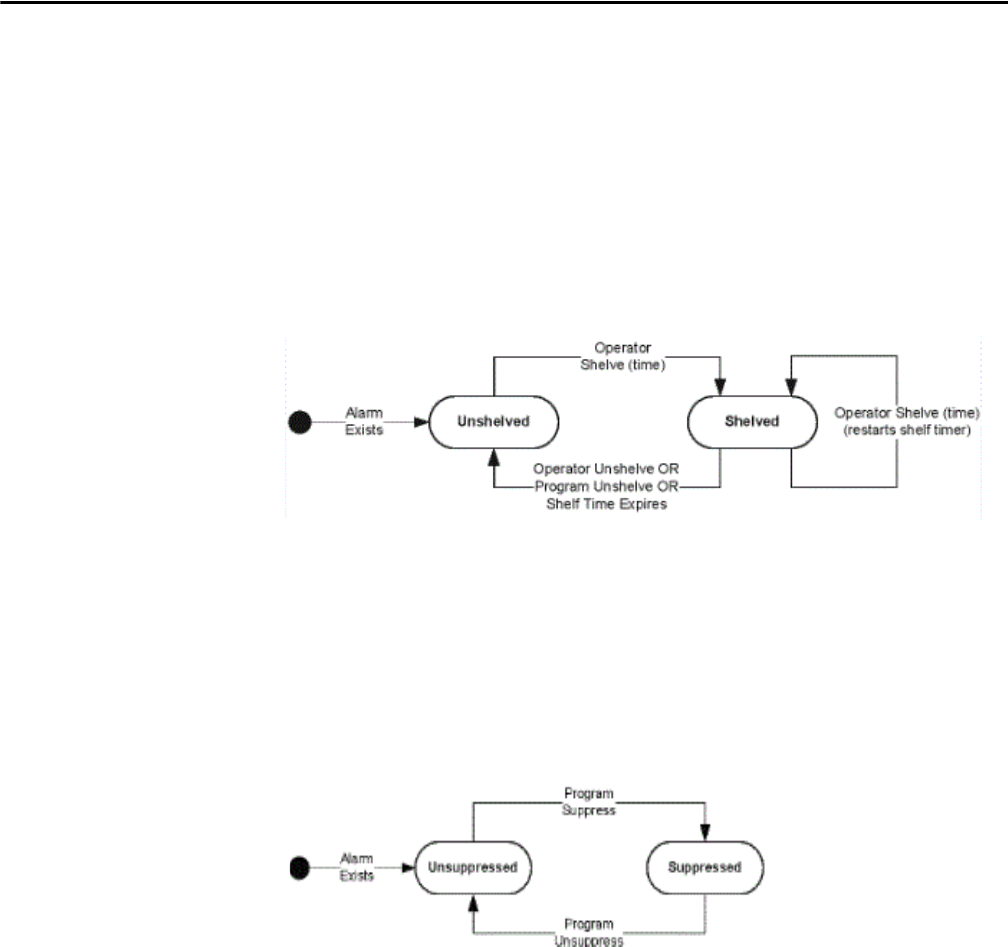
Rockwell Automation Publication PROCES-RM001M-EN-P - June 2019 61
Alarm System Recommendations Chapter 4
Shelve, Suppress, and Disable states are all methods to suppress indication of
alarms, following ANSI/ISA-18.2, Management of Alarm Systems for the
Process Industries. You can use Shelve, Suppress, and Disable functionality to
differentiate operator-initiated actions from design-initiated actions and
maintenance actions. See the following examples and accompanying notes.
Operator Actions
Use the Shelve state to initiate this action by the operator (equivalent to the
Shelve state in ISA 18.2).
The Program Unshelve command is provided so that the user has a means, by
using a small amount of programming, to Unshelve alarms based on an event, for
example End of Shift.
Program Actions
The controller must use the Suppress state to programmatically inhibit operator
notification (equivalent to the Suppress-by- Design state in ISA 18.2).
The Suppress state is intended for Suppress-By-Design functionality under
control of logic in accordance with ANSI/ISA-18.2. If logging of alarm
transitions during suppression is not desired, use logic to suppress the input
condition to the alarm. You also can use the P_Alarm Add-On Instruction in
the Library of Process Objects, which does not generate new alarm transitions
in the Suppress state.
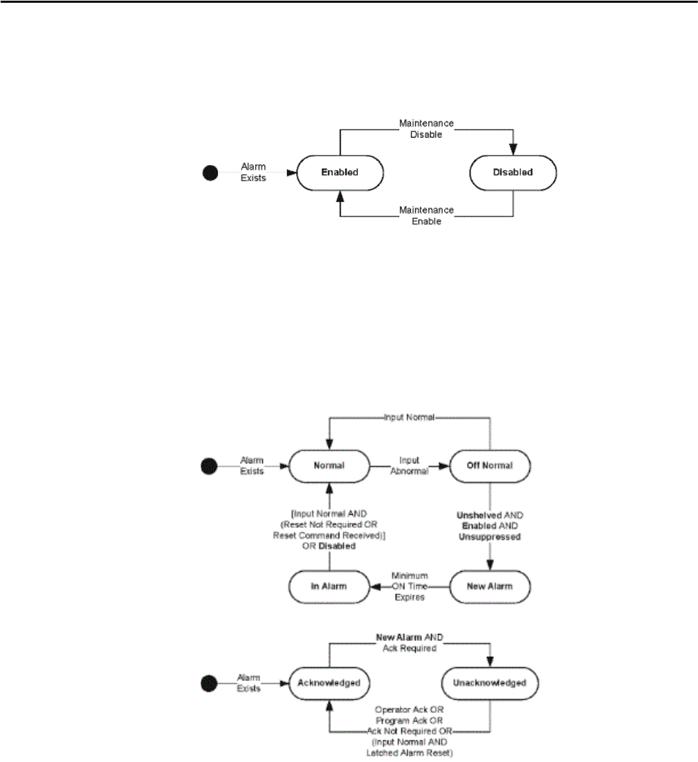
62 Rockwell Automation Publication PROCES-RM001M-EN-P - June 2019
Chapter 4 Alarm System Recommendations
Maintenance Actions
Use the Disable state to inhibit the alarm for maintenance purposes (equivalent
to Out-of-Service state in ISA 18.2).
The Disable state is intended for Out-of-Service functionality under control of
maintenance in accordance with ANSI/ISA-18.2. If logging of alarm transitions
during Disable is desired, the Suppress state of the ALMA or ALMD can be used
instead if not required for Suppress-by-Design functionality under control of
logic.
Alarm, Return to Normal, Latching, and Acknowledgement
While Disabled, Suppressed, or Shelved, an acknowledged alarm does not
become unacknowledged.
While Disabled, Suppressed, or Shelved, if acknowledge is required, an
unacknowledged alarm remains unacknowledged until it is acknowledged.
An alarm becomes unacknowledged if the alarm is InAlarm when an alarm
changes state to Enabled, Unsuppressed, and Unshelved.

Rockwell Automation Publication PROCES-RM001M-EN-P - June 2019 63
Alarm System Recommendations Chapter 4
Monitoring Your Alarm System
By using the alarm status explorer, you can browse all of your configured alarms
on a server or the entire system. Alarms also are filtered by the Shelved,
Suppressed, and Disabled options. The alarm explorer can be preconfigured as a
Shelved alarm display to let operators view a list of alarms.
ISA 18.2 provides alarm performance metrics and example target values that are
summarized in a single table of section 16.9 of the standard. Some key metrics
include the following:
1. Alarm rates: annunciated alarms per operator:
a. < 150…300 alarms per day
b. Average of 6…12 per hour
c. Average 1…2 per 10 minutes
2. Contribution of the top 10 most frequent alarms to the overall alarm load:
~<1…5% maximum, with action plans to address deficiencies
3. Number of alarms that remain in effect continuously for more than
24 hours (stale alarms): Less than 5, with plans to address
When using the FactoryTalk® VantagePoint® software with the alarm system,
reports are provided based on the described metrics.
1. Hourly Alarms Report (active count of alarms over 1- hour samples)
2. Alarm Distribution Report (percentage contribution of top 10 most
frequent alarms)
3. Alarm Frequency Report (top 10 most frequent alarms)
4. Standing Alarms Report (top 10 currently active alarms by duration)
5. Alarm Duration Report (top 10 alarms by duration)
Alarms can be filtered in FactoryTalk VantagePoint software by class, alarm name,
or alarm source so they can be broken down by operator role if required. More
information on these reports can be found on the Rockwell Automation
Knowledgebase Answer ID 68296
at http://www.rockwellautomation.custhelp.com
.

64 Rockwell Automation Publication PROCES-RM001M-EN-P - June 2019
Chapter 4 Alarm System Recommendations
Notes:

Rockwell Automation Publication PROCES-RM001M-EN-P - June 2019 65
Chapter 5
Infrastructure Recommendations
This chapter describes best practices for infrastructure, including virtualized
machines. We also include operating system and network recommendations.
Physical Access Control
We recommend implementing physical security to help protect your PlantPAx®
system. Physical securities are measures that guard against unauthorized access to
facilities, control rooms, equipment, and resources.
Consider policies and procedures to create layers of protection in their perimeter
for authorized access to the system. The standards generally categorize these
protections as the following:
• Passive physical security devices — This category includes physical
controls such as fences, walls, concertina wire (barbed wire, razor wire, and
so on). Physical controls also includes anti-vehicle ditches, concrete
barriers, earthen walls or mounds, and other access limiting devices. Passive
security devices are typically categorized as being of large size or mass, used
to either protect physical entities or help prevent access to specific
locations, and are active always. These devices require no manual
intervention to either engage or disengage their security activities.
• Active physical security devices — These devices play an active role in
physical security. These devices include doors, locks of various types, gates,
retractable road obstructions, or other devices that are intentionally
engaged or disengaged based on either time intervals, autonomous control,
or at specific intervention from an outside source. These devices are often
coupled with additional identification or monitoring devices to enhance
their functionality.
• Identification and monitoring devices — This category includes still and
video cameras, motion sensors, vibration sensors, heat sensors, biometric
authentication or recording devices, and various other devices. They do
not by themselves specifically control or limit access to a physical location
or system. The design and intended use of these devices are specific to
detecting, identifying, or recording physical entities. These devices include
the state of physical presence of individuals, vehicles, systems, or other
identifiable physical objects.

66 Rockwell Automation Publication PROCES-RM001M-EN-P - June 2019
Chapter 5 Infrastructure Recommendations
Infrastructure Types
The PlantPAx system infrastructure is built on an IT infrastructure based on
the following:
• Commercial off-the-shelf technologies, such as Microsoft Windows
and VMware
• Open network technologies, such as Stratix® switches
The platform provides seamless integration between system elements and
higher-level business systems.
When building your system, you must decide whether your server and client
workstations are in a virtual or traditional environment.
Traditional
In a traditional infrastructure, each server and workstation is installed on its own
physical machine. Software and hardware updates are performed on each server
and workstation individually. In addition, there is a conventional relationship
between switch ports and servers ports and a standard network management.
Virtual
Virtualization breaks the dependency between operating system and physical
hardware. Multiple virtual machines (VMs) can run different operating systems
and applications from various locations on the same server. You can upgrade
hardware without stopping your operation or replacing the operating system on
the server or workstation system elements, thus reducing downtime and
maintenance costs.
Before designing a virtualized PlantPAx system, we recommend that you have a
general understanding of the PlantPAx control system architectures and
sizing guidelines.
For more information, see the following:
• PlantPAx Distributed Control System Selection Guide,
publication PROCES-SG001
-- Provides descriptions of system elements,
architectures, and sizing guidelines for procuring a virtual PlantPAx system
• PlantPAx Virtualization User Manual, publication 9528-UM001
--
Contains step-by-step procedures for configuring virtual machines
The following table lists where to find specific information.
Topic Page
Virtual PlantPAx Configuration Recommendations 67
Operating System Recommendations 72
Network Recommendations 75

Rockwell Automation Publication PROCES-RM001M-EN-P - June 2019 67
Infrastructure Recommendations Chapter 5
Virtual PlantPAx
Configuration
Recommendations
Once the basic architecture is developed, a virtualized PlantPAx system benefits
from a number of fundamental VMware configuration choices. Most of these
choices start with automatic settings, with adjustments made as required to
increase speed and improve redundancy.
Servers
The latest Intel™ processors offer onboard virtualization support. The Intel
Virtualization Technology in the BIOS must be switched on to take advantage
of the performance gains.
Hosts in the same cluster that have different processors are recommended to have
Enhanced vMotion Compatibility (EVC) enabled to support the vMotion
between hosts. EVC is enabled at the Datacenter/Cluster level. EVC is a
fundamental technology that facilitates virtual machine modernization between
different generations of CPUs, while vMotion is the utility used to make the
modernization. The ability to modernize VMs between servers while they are
running with the process transparent to any users is one of the leading benefits
of virtualization.
IMPORTANT
The PlantPAx system does not require the use of the virtual image templates,
nor does their use infer the system design meets PlantPAx system
specifications. Use of the virtual image templates can save time and make
sure consistency of installation with the recommendations contained within
this manual.
IMPORTANT
Keep VMware Tools up-to-date inside each guest operating system. When
modernizing or converting a VM from an older version ESXI server, a best
practice is to remove the old Tools and install the latest version.

68 Rockwell Automation Publication PROCES-RM001M-EN-P - June 2019
Chapter 5 Infrastructure Recommendations
Storage
Network attached storage uses a software network adapter to connect with iSCSI
storage through Ethernet. Enable jumbo frames at the physical switch level and
also at the virtual switch port level. Jumbo Ethernet frames carry up to 9000 bytes
of payload (as opposed to the normal 1500) and can offer increased data
throughput with reduced CPU utilization. The network must be configured to
support jumbo frames from end to end.
When configuring the physical NICs on a host, set up NIC teaming in the virtual
switch configuration to enable greater bandwidth for storage traffic.
Each virtual hard disk drive on a network is assigned a logical unit number
(LUN) for unique identification. A LUN is a logical unit number of a virtual
partition in a storage array. When assigning virtual hard disk drives from VMs to
a LUN, be sure to balance intensive and non-intensive I/O applications. This
process improves performance by balancing I/O traffic across multiple hard disk
drives. A typical LUN size is 400...800 GB. The maximum number of virtual
machine hard disks (VMDK) on a LUN cannot exceed 30, as more VMDKs
could impact the performance because of disk queuing.
The LUN size is calculated by adding the total capacity (GB) of storage required
plus VM Swap File requirements and additional room for VM Snapshots. When
dividing the storage array into LUNs, the following equation can be used to
determine appropriate sizing.
Calculated LUN Size = GB Capacity + VM Swap File Requirements + Snapshot
Reservations
= 30*(average VM virtual disk size) + 30*(average VM RAM) + 15% of (30 x
average disk size).
Virtual Networks
Connect VMs that are on the same ESXi server and same VLAN to use the same
virtual switch. If separate virtual switches are used and connected to separate
physical NICs, traffic routes separately through the wire and incur unnecessary
CPU and network overhead.
Speed and duplex settings mismatches are common issues that can cause network
problems. For ESXi, VMware recommends autonegotiate for both devices on the
ends of a network link. It is also acceptable to set both ends for ‘1000 MB/full-
duplex’ or ‘100MB/full-duplex’ if required by the network hardware.
IMPORTANT
If you connect a manually configured device to an autonegotiate device
(duplex mismatch), a high rate of transmission errors can occur.

Rockwell Automation Publication PROCES-RM001M-EN-P - June 2019 69
Infrastructure Recommendations Chapter 5
VMware systems demand a high level of network performance by nature, so
methods to reduce bottlenecks are to be explored. One such method is NIC
teaming, where a single virtual switch can be connected to multiple physical
Ethernet adapters. A team that is defined in this way can share the traffic load and
provide a means of failover.
There are several options available for load balancing. The default is ‘route based
on the originating virtual switch port ID’, where traffic from a given virtual
Ethernet adapter is consistently sent to one physical adapter (unless there is a
failover). Another option gives the virtual switch the ability to load balance
between multiple physical adapters. This is set by configuring EtherChannel link
aggregation on the Cisco® switch and the load balancing setting is set to ‘route
based on IP hash’ in the virtual switch.
A combination of NIC teaming and the Cisco Switch load-balancing settings are
recommended for improved performance when you access networked storage.
Resource Pool Allocation
Resource pools group virtual machines (VMs) to provide dynamic allocation of
CPU and memory resources. Resource pools also contain child resource pools
that enable fine-grained resource allocation.
Resource allocation is done on an individual VM basis by using shares,
reservations, and limits. Setting these values on every VM is time-consuming, can
be error-prone, and doesn't scale effectively. Setting these values on a resource
pool is much more efficient, and the values dynamically readjust as VMs and host
resources are added and removed.
Generally, the hypervisor provides excellent scheduling. And, if hosts have
sufficient resources, you can leave the default settings alone. If you wish to control
the VMs that receive more priority or resources, it's more effective and less
error-prone to allocate the VMs at a resource pool level.
IMPORTANT
In a PlantPAx system, make sure that the PASS servers and workstations have
higher priority for consistent performance.
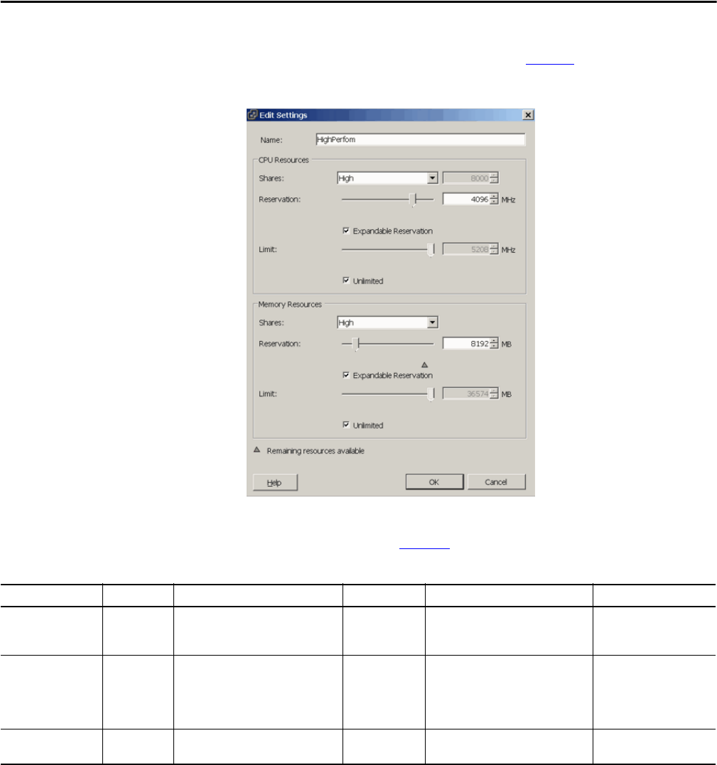
70 Rockwell Automation Publication PROCES-RM001M-EN-P - June 2019
Chapter 5 Infrastructure Recommendations
For each resource pool, you set CPU and memory shares, reservations,
expandable reservations, and limits, as shown in Figure 7
.
Figure 7 - Setting Resource Pool Allocation
We recommend that you build three resource pools with the server-type
allotment that is shown in Table 3 4
.
An allocation of zero means that no resources get locked from being used by the
hypervisor resource allocation algorithm. The Expandable and Unlimited boxes
need to be checked.
The CPU or memory shares are relative to any sibling resource pools or VMs.
Shares are used only during periods of contention and are always bound first by
any reservations or limits. In a well-designed PlantPAx system, sufficient
resources are available to all VMs in the resource pool, therefore, we suggest that
shares never be invoked. They are built to make sure that the PASS and
workstations can consistently supply data if there is contention.
Table 34 - Server Resource Pool Allocation
Resource Pool Name CPU Shares CPU Reservation Memory Shares Memory Reservation Server or Workstation
High High 50% of available host CPU Hz High Minimum as specified for each
virtual template
PAS S
OWS
AppServ-OWS
Normal Normal Zero Normal Zero EWS
AppServ-EWS
AppServ-Asset
AppServ-Batch
AppServ-Info
Low Low Zero Low Zero FactoryTalk® Directory
Domain Controller

Rockwell Automation Publication PROCES-RM001M-EN-P - June 2019 71
Infrastructure Recommendations Chapter 5
Resource Pool Sizing Example
This example shows how to allocate resources based on system requirements.
System:
• 1 server with 2 quad-core CPUs (each core is 2.0 GHz)
• 32 GB of RAM
• Server has a total of 16 GHz of CPU to allocate to virtual machines
PlantPAx system:
• 4 PASS servers and 1AppServ-OWS — High resource pool
• 1 AppServ-Hist, 1 EWS, and 1 AppServ-Asset — Normal resource pool
• 1 FactoryTalk Directory and 1 domain controller — Low resource pool
Following the guidelines above, the High resource pool with get 50% of the CPU
allocated, or 8 GHz. These 8 GHz are further divided into 5 shares of 20%
automatically for each server in the resource pool. Each server receives roughly
1.6 GHz (8 GHz/5 servers) of CPU minimum allocation. The minimum
memory for each server used in the High resource pool is 4 GB. Minimum
memory allocated is 20 GB (4 GB x 5 servers).
The remaining 8 GHz CPU and 12 GB of RAM is used by the hypervisor
resource allocation algorithm to use where needed. The Normal resource pool
has priority over the Low resource pool, but there is no minimum resource
allocation due to the zeroes used for CPU and memory reservation.

72 Rockwell Automation Publication PROCES-RM001M-EN-P - June 2019
Chapter 5 Infrastructure Recommendations
Operating System
Recommendations
The following recommendations apply regardless if you are using a virtual or
traditional environment and the size or complexity of the system operation.
Domains and Workgroups
We recommend that PlantPAx servers and workstations be members of a
Windows domain. However, workgroups are supported for systems with
10 or fewer workstations and servers.
Domain Recommendations
We recommend that all PlantPAx system servers and workstations be a member
of a domain. Follow these additional recommendations:
• Windows Active Directory (AD) domains include the concept of a ‘forest’
that can consist of a single ‘domain tree’ or multiple domain trees.
• We recommend configuring at least two domain controllers in the domain.
These domain controllers replicate automatically to provide high
availability and an online configuration backup. If you have a single
domain controller, and it goes offline, your system goes offline.
• The domain servers also must be configured to include Domain Name
Service (DNS) that lets you identify devices by name rather than
IP addresses.
• Configure time synchronization throughout a domain.
Configuration Details
Workgroup - decentralized administration
(allowed if 10 or fewer computers)
Workgroup advantages:
• No domain controller (Windows Server OS) to purchase or maintain.
• Recommended for small PlantPAx applications only where user accounts do not change often
Workgroup rules:
• Workstation and server system elements in a single PlantPAx system must be members of the same workgroup
• Users that participate in the workgroup must be members of the Administrators group
• Create the same set of user accounts and passwords on every computer in a FactoryTalk View application
Domain - centralized administration
(recommended)
Domain advantages:
• One place to manage users, groups, and security settings
• Recommended for larger PlantPAx applications, or environments with changing user accounts
Domain rules:
• All workstation and server system elements in a single PlantPAx system must be members of the same domain
• PlantPAx server system elements must not be used as domain controllers.
• Required for systems with more than 10 computers
• The domain controller must be its own independent computer with no other application software.
TIP
A domain tree can consist of a single (parent) domain or multiple
(child) domains. In a Windows 2016 Active Directory, both domains
and forests have individual functional levels.
IMPORTANT
Do not install the Windows domain controller on the PlantPAx PASS server or
application servers. For more information, see the PlantPAx Distributed Control
System Infrastructure Configuration User Manual, publication PROCES-UM001
.

Rockwell Automation Publication PROCES-RM001M-EN-P - June 2019 73
Infrastructure Recommendations Chapter 5
Windows Workgroup Recommendations
The PlantPAx system can use a Windows workgroup network environment for
systems with 10 or fewer computers.
For more information, see the Appendix section in the PlantPAx Distributed
Control System Infrastructure Configuration User Manual,
publication PROCES-UM001
.
Server and Workstation Time Synchronization
System time synchronization is important so that the internal clocks in the
controllers, workstations, and servers reference the same time for any event or
alarm that occurs. Configure the PASS, App-servers, OWS, and EWS to use a
single server (for example, a domain controller) as their time reference and keep
their clocks tightly synched to it.
Computer Time Synchronization
The Windows Time service uses the network time protocol (NTP) to
synchronize computer clocks on the network from the domain controller. Each
computer in the process system uses the domain controller as the authoritative
time source and synchronizes their clock to it. Check the Event Viewer System
log of each computer to verify that the time is updated properly.
After configuring the domain controller for time synchronization, you can use
the Windows w32tm command-line tool to identify any time difference between
an individual computer and the domain controller. This command measures the
time difference.
w32tm /stripchart /computer:<target>[/period:<refresh>] [/dataonly]
The w32tm/resync
command manually forces a computer to resynchronize its
clock to the domain controller as soon as possible and resets error statistics.
Parameter Identifies
computer:<target> The computer to measure the offset against.
period:<refresh> The time between samples, in seconds. The default is 2 s.
dataonly To display the data only without graphics.

74 Rockwell Automation Publication PROCES-RM001M-EN-P - June 2019
Chapter 5 Infrastructure Recommendations
Operating System Optimization
The following recommendations enhance the performance of your
operating system:
• Turn off Windows automatic updates to help prevent compatibility issues
with existing PlantPAx components on your workstations.
See Maintenance Recommendations
for more information on how to
apply Microsoft patches to your PlantPAx system.
• Disable operating system themes that provide personalized computer
effects such as sounds and icons. These types of elements diminish
processor speed when running some FactoryTalk View SE graphic
components, such as alarm summaries.
• Disable or uninstall all third-party firewalls on a workstation before
installing FactoryTalk View SE software, which is compatible only with
the built-in Windows operating system firewall.
• Remove Enhanced Security Configuration (ESC) from workstations
running FactoryTalk View SE software. The Windows 2016 security
settings help protect servers by limiting how users can browse the Internet
on a computer, but can hinder FactoryTalk clients connecting to
application servers.

Rockwell Automation Publication PROCES-RM001M-EN-P - June 2019 75
Infrastructure Recommendations Chapter 5
Network Recommendations
The Ethernet network provides the communication backbone for the
supervisory network for the workstations, servers, and the controllers:
• Configure all communication interfaces to operate at the fastest speed
possible for your hardware configuration, full-duplex for 100/1000
network adapters. See Important for autonegotiate settings.
• Disable power saving for the Network Interface Card (NIC) that connects
a workstation to other devices on the network. The power-saving feature
turns off the network card when not in use, which can interfere with
network throughput.
• If multiple DCOM protocols are installed and set up on a workstation, to
make sure that DCOM communication functions correctly, remove all
protocols other than TCP/IP.
For procedures, see the PlantPAx Distributed Control System
Infrastructure Configuration User Manual,
publication PROCES-UM001
.
• Consider cable type for environmental conditions.
See the following publications for additional information:
• For step-by-step configuration instructions, see the PlantPAx
Distributed Control System Infrastructure Configuration User
Manual, publication PROCES-UM001.
• For correcting a duplex mismatch, see Troubleshoot EtherNet/IP®
Networks, publication ENET-AT003
.
• For fiber cable specifications and an example of dB loss, see
Appendix C in the EtherNet/IP Modules Installation Instructions,
publication ENET-IN002
.
• For selecting architecture, see the Ethernet Design Considerations
Reference Manual, publication ENET-RM002,
or the PlantPAx Selection
Guide, publication PROCES-SG001
.
IMPORTANT
Use of autonegotiate settings is recommended to reduce chance of
mis-configuration and failures. However, it is desirable to operate at
the fastest speed possible at full-duplex. We recommend verifying
your switch settings during commissioning to make sure that the
system was able to autonegotiate properly. The speed and duplex
settings for the devices on the same Ethernet network must be the
same to avoid transmission errors.
Type Details
Fiber-optic • Long distances
• Near high magnetic fields, such as induction-heating processes
• For extreme high-noise environments
• For poorly grounded systems
• For outdoor applications
Shielded twisted-pair • Use Category 5e, 6, or 6a cables and connectors
• Use termination sequence 568A for industrial applications

76 Rockwell Automation Publication PROCES-RM001M-EN-P - June 2019
Chapter 5 Infrastructure Recommendations
Ethernet Switches
The supervisory network must have managed switches that direct specific
messages to multicast groups. Do not use unmanaged switches. The behavior of
an unmanaged switch is to flood multicast packets to all ports within the
same VLAN.
The first switch that Rockwell Automation equipment touches must have IGMP
snooping enabled. IGMP snooping enables switches to forward multicast packets
to ports that are only part of a particular multicast group.
Select the switch depending on the network functionality.
Additional Switch Information
See the Stratix Ethernet Device Specifications Technical Data,
publication 1783-TD001
, for information on these switch components:
• Stratix 5900 Security Appliance
• Embedded EtherNet/IP Taps
We also support the use of Cisco switches. To help make sure of performance, we
recommend that all system switches are Cisco or Stratix for common use
of protocols.
The following switches are also supported on the PlantPAx system:
• Cisco Catalyst® 3850 (Layer 3)
• Cisco Catalyst 4500x (Layer 3)
• Cisco Catalyst 2960G (Layer 2)
• Cisco Catalyst 9300 (Layer 3)
IMPORTANT
All applications require proper configuration to achieve the best system
performance. If you do not configure the managed switch, it’s possible that
system performance can be adversely affected. We recommend that you
contact your system administrator if there are any doubts on the installation
and configuration.
If Then
• Supervisory
• Routing information to other networks
Layer 3 switches
(1)
• Stratix 5410
• Stratix 5400
(1) For uplink cables between Layer 2-3, fiber is recommended for better system performance.
• Connecting control hardware, sensors, and workstations
• Isolated networks
Layer 2 switches
(1)
• Stratix 5410
• Stratix 5400
• Stratix 5700
High availability at switch level Layer 3 switch
(1)
• Stratix 5410

Rockwell Automation Publication PROCES-RM001M-EN-P - June 2019 77
Chapter 6
Field Device Integration Recommendations
Modern field devices, such as drives and flow transmitters, are often
microprocessor-based. These smart devices provide digital data that is used for
commissioning, maintenance, troubleshooting, and most importantly, control.
Smart field devices use two-way, digital protocols for communication. Common
field device communication options on the PlantPAx® system include
EtherNet/IP™, ControlNet®, DeviceNet®, FOUNDATION Fieldbus,
PROFIBUS PA networks or by using HART.
This section provides general recommendations for how to configure tools on the
networks and HART protocol. The tools help gather real-time information and
diagnostics to make well-informed business decisions.
Additionally, many other networks and I/O protocols can be integrated into the
PlantPAx system. For more information on Encompass™ third-party products, see
http://www.rockwellautomation.com/encompass
.
The following table lists where to find specific information.
Topic Page
Device Configuration Options 78
EtherNet/IP Recommendations 78
ControlNet Recommendations 80
DeviceNet Recommendations 81
HART Recommendations 82
FOUNDATION Fieldbus Recommendations 83
PROFIBUS PA Recommendations 85
Motor Control Recommendations 87

78 Rockwell Automation Publication PROCES-RM001M-EN-P - June 2019
Chapter 6 Field Device Integration Recommendations
Device Configuration Options
There are several options to configure field devices:
• Handheld devices for selected field device networks or protocols
• Manually configure some instruments by using the local interface
• Enterprise-wide solution by using FactoryTalk® AssetCentre
FactoryTalk AssetCentre for Enterprise Solution
FactoryTalk AssetCentre software can be used as a centralized tool to manage
field devices from multiple vendors, networks, and protocols from one common
platform. FactoryTalk AssetCentre software leverages FDT technology that
standardizes the communication interface between field devices and host
systems. This functionality accesses any device from FactoryTalk AssetCentre
software regardless of the communication method.
The FDT interface also enables FactoryTalk AssetCentre software to integrate
many different kinds of devices, including handheld diagnostic tools.
For more information, see the following publications:
• FactoryTalk AssetCentre Product Profile, publication FTALK-PP001
• FDT website at http://www.fdtgroup.org
EtherNet/IP
Recommendations
The EtherNet/IP protocol is a multi-discipline, control, and information
platform for use in industrial environments and time-critical applications.
EtherNet/IP uses standard Ethernet and TCP/IP technologies and an open,
application layer protocol that is called the Common Industrial Protocol (CIP).
A growing number of field devices, including flow transmitters and drives, are
available that support EtherNet/IP.
Table 29 - EtherNet/IP Interfaces
Category Product Description
ControlLogix® controller interface 1756-EN2T, 1756-EN2TR,1756-EN3TR,
1756-EN2F
1756-ENBT
ControlLogix EtherNet/IP bridge.
1788-EN2FFR EtherNet/IP to FOUNDATION Fieldbus linking device. Supports H1 FOUNDATION
Fieldbus network. Compatible with ControlLogix redundancy. Built-in functionality
for the Ethernet DLR.
1788-EN2PAR EtherNet/IP to PROFIBUS PA linking device. Supports PA media. Compatible with
ControlLogix redundancy. Built-in functionality for the Ethernet DLR.

Rockwell Automation Publication PROCES-RM001M-EN-P - June 2019 79
Field Device Integration Recommendations Chapter 6
EtherNet/IP I/O Communication Options
Follow these guidelines for EtherNet/IP networks:
Network
• Configure all communication interfaces to operate at the fastest speed
possible for your hardware configuration, full-duplex for 100/1000
network adapters. See the Important for autonegotiate settings.
• When expanding the I/O configuration tree, make sure your I/O module
RPI is two times faster than the periodic task that you are using.
• As you expand the I/O configuration tree, devices can affect the
CIP/TCP count differently. Never use more than 80% of the available
connections for the bridge modules.
• I/O packets per second (pps) describes an implicit message rate (Class 1).
An I/O Comms Utilization value approaching or above 80% can
necessitate an adjustment to the RPI.
• HMI packets per second (pps) describes an explicit message rate (Class 3).
FactoryTalk Linx connections and message instructions generate CIP
traffic. HMI traffic is TCP-based, not UDP-based.
• The combination of implicit and explicit messaging provides a total
utilization for a device. If you add implicit messaging (I/O), it takes
bandwidth from the HMI because it has higher priority than HMI
messaging. The combination of CIP implicit (highest priority) and CIP
explicit (second priority) cannot exceed 100% use.
Devices
• Consider packets per second (see network notes) for performance if you
use many devices.
• Use compatible keying on Ethernet communication modules. In a
validated environment, you can use an exact match for keying.
See the documentation that is listed in Additional Resources
on page 8 for
more information.
IMPORTANT
Use of autonegotiate settings is recommended to reduce chance of
mis-configuration and failures. However, it is desirable to operate at
the fastest speed possible at full-duplex. We recommend verifying
your switch settings during commissioning to make sure that the
system was able to autonegotiate properly. The speed and duplex
settings for the devices on the same Ethernet network must be the
same to avoid transmission errors.
80 Rockwell Automation Publication PROCES-RM001M-EN-P - June 2019
Chapter 6 Field Device Integration Recommendations
ControlNet
Recommendations
The ControlNet network is an open, control network that combines the
functionality of an I/O network and a peer-to-peer network, providing
high-speed performance for both functions.
ControlNet I/O Communication Options
In a PlantPAx system, the ControlNet network supports controller downlinks
and connections to remote I/O and field device interfaces. The network is
unaffected when devices are connected or disconnected from the network.
Follow these guidelines for ControlNet networks:
Network
• When you configure the ControlNet network with RSNetWorx™ for
ControlNet software, select Optimize and rewrite the schedule for
all connections.
If changes are made to the ControlNet configuration, upload the
configuration to make sure that it gets backed up to the Studio 5000
Logix Designer® project.
• Use a maximum of five controllers with a rack-optimized, listen-only
connection to the module.
• Use a maximum of 64 I/O modules on an unscheduled remote I/O
ControlNet network.
• Use a maximum of 20 ControlNet interface modules per controller.
Devices
• A ControlNet node can transmit 480 bytes of scheduled data in a single
network update time (NUT).
• I/O modules on ControlNet can be unscheduled to allow adding
I/O online.
• Do not leave any ControlNet node addressed 99 (default address on some
new devices).
See the documentation listed in Additional Resources
on page 8 for
more information.
Table 35 - ControlNet Interface
Category Product Description
ControlLogix controller interface 1756-CN2, 1756-CN2R
1756-CNB, 1756-CNBR
ControlLogix ControlNet scanner.
1788-CN2FFR ControlNet to FOUNDATION Fieldbus linking device. Supports H1 FOUNDATION
Fieldbus networks. Compatible with ControlLogix redundancy and redundant
ControlNet media.
1788-CN2PAR ControlNet to PROFIBUS PA linking device. Supports redundant PROFIBUS PA media
and redundant ControlNet media. Compatible with ControlLogix redundancy.

Rockwell Automation Publication PROCES-RM001M-EN-P - June 2019 81
Field Device Integration Recommendations Chapter 6
DeviceNet Recommendations
The DeviceNet network is an open, device-level network that provides
connections between simple industrial devices (such as sensors and actuators)
and higher-level devices (such as PLC controllers and computers).
DeviceNet Communication Options
In a PlantPAx system, the DeviceNet network connects networked
control devices.
Follow these guidelines for DeviceNet networks:
Network
• Connect up to 48 devices to the scanner when an average amount of data
input and outputs is used.
• Use a maximum of 80% of the available scanner input and output memory.
• If you use more input and output device data, we recommend that you
reduce the number of devices. For example, an MCC device, such as a soft
starter, with all the available data enabled can use up to 40 bytes for input
and 40 bytes for output. In this scenario, the maximum devices that we
recommend connecting to the scanner is 10.
• To make sure that the network is within limits, calculate the amount of
input and output memory that the scanner needs.
• We recommend disabling Auto Address Recovery. If enabled, in some
scenarios like a power outage, two devices can auto-recover to the
same address.
• Store EDS files in a common location; install on engineering workstations.
Scanner
• Keep DeviceNet communication modules in the local chassis. If the
communication module is in a remote chassis, set the input and output
sizes to match the data configured in RSNetWorx for DeviceNet software.
• Never have any device set to the default node address of 62 (reserved for
personal computer) or 63 (reserved for new device to be configured).
• Set the scanner address to node 0.
• Keep the Interscan Delay 5 ms.
• Set DeviceNet scanner RPI time to half the scan rate of the fastest task in
the controller that uses the DeviceNet network, but not less than 2 ms.
• Use Background poll when possible. Keep (Foreground to Background
Poll Ratio) * (Interscan Delay) > 75 ms.
See the documentation listed in Additional Resources
on page 8 for
more information.
Table 36 - DeviceNet Interface
Category Product Description
ControlLogix controller interface 1756-DNB ControlLogix DeviceNet scanner.

82 Rockwell Automation Publication PROCES-RM001M-EN-P - June 2019
Chapter 6 Field Device Integration Recommendations
HART Recommendations
HART is an open protocol designed to provide digital data over 4…20 mA
analog signals.
HART Communication Options
The PlantPAx system interfaces both directly and via remote I/O modules to
provide a single termination point to gather analog process variables and the
additional HART digital data.
.
Follow these guidelines for connectivity to a HART I/O card:
Network
• For 8-channel HART cards, only enable HART data on the channels that
are connected to HART devices and you want to receive HART data.
Enabling unused channels reduces system resources and performance.
• For 16-channel HART cards, there is no decrease in system performance
by enabling all channels.
Devices
• If using HART data for control, check the data quality bits.
• For controlling fast loops, use only the 4...20 mA output of the instrument
for control instead of the extended HART data.
For more information, see the following resources:
• Integrate E+H Instruments in a PlantPAx System Integration Document
Manual, publication PROCES-SG003
• Documentation listed in Additional Resources on page 8
Table 37 - HART Interface
Category Cat. No. Description
Chassis-based I/O modules 1756-IF8IH, 1756-IF16H, 1756-OF8H, 1756-OF8IH ControlLogix analog isolated I/O modules. These modules provide basic configuration
through the I/O tree, provide status and diagnostics information, and provide remote
configuration and troubleshooting.
Distributed I/O, high-channel density 1794-IE8H, 1794-OE8H,
1794-IF8IH, 1794-OF8IH,
1794-IF8IHNFXT
FLEX analog I/O modules with the following:
• Standard profiles in Studio 5000 Logix Designer
• DTMs
Distributed I/O, low-channel density 1734-sc-OE2CIH, 1734-sc-IF4H Spectrum Controls, analog input module with HART for the POINT I/O™ system.
1769-sc-IF4IH, 1769-sc-OF4IH Spectrum Controls, analog, isolated input and output modules with HART
for Compact I/O™ modules.
Distributed I/O, intrinsically safe 1719 Ex I/O Rockwell Automation, chassis-based design for Zone 2 or Class I, Div 2., via EtherNet/IP.
Multiplexers/gateways N/A See the Encompass website for Pepperl+Fuchs, ProSoft Technology, and Aparian
(1)
product offerings.
Network configuration Handheld device Endress+Hauser
(1)
, handheld configuration and diagnostic device.
See the Encompass website for Endress+Hauser product offerings.
(1) For more information on Encompass third-party products, see http://www.rockwellautomation.com/encompass.

Rockwell Automation Publication PROCES-RM001M-EN-P - June 2019 83
Field Device Integration Recommendations Chapter 6
FOUNDATION Fieldbus
Recommendations
The FOUNDATION Fieldbus network is a digital, two-way, multi-drop
communication link among multiple intelligent field devices and
automation systems.
FOUNDATION Fieldbus Communication Options
The PlantPAx system communicates with FOUNDATION Fieldbus devices
through EtherNet/IP and ControlNet linking devices.
Follow these guidelines for FOUNDATION Fieldbus networks:
Simplex Controllers
• We recommend a maximum of 32 fieldbus segments.
• Use 8…12 devices per segment.
• Use only two terminators per bus segment to help prevent distortion and
signal loss. Some linking devices have built-in terminators but typically
terminators are placed at the ends of the trunk.
Redundant Controllers
• We recommend a maximum of 16 fieldbus segments.
• Use 8…12 devices per segment.
Table 38 - FOUNDATION Fieldbus Interface
Category Cat. No. Description
EtherNet/IP interface 1788-EN2FFR EtherNet/IP to FOUNDATION Fieldbus linking device. Supports H1 FOUNDATION
Fieldbus network. Compatible with ControlLogix redundancy. Built-in functionality
for the Ethernet DLR.
ControlNet interface 1788-CN2FFR ControlNet to FOUNDATION Fieldbus linking device. Supports H1 FOUNDATION
Fieldbus networks. Compatible with ControlLogix redundancy and redundant
ControlNet media.
FOUNDATION Fieldbus network
components
Power conditioning Both linking devices have built-in power conditioning.
1788-FBJB4R Intelligent junction box supports redundancy, includes four drop ports.
1788-FBJB6 Intelligent junction box with six drop ports.
Additional components Pepperl+Fuchs
(1)
, FOUNDATION Fieldbus components, such
as valve couplers, surge protectors, and distributors.
See the Encompass website for Pepperl+Fuchs product
offerings.
Segment protection Helps protect against device or line faults with short- and open-
circuit protection.
Pepperl+Fuchs
(1)
, intrinsic safety components, such as isolated
barrier systems, hazardous area enclosures, and equipment.
See the Encompass website for Pepperl+Fuchs product
offerings.
(1) For more information on Encompass third-party products, see http://www.rockwellautomation.com/encompass.

84 Rockwell Automation Publication PROCES-RM001M-EN-P - June 2019
Chapter 6 Field Device Integration Recommendations
• Use only two terminators per bus segment to help prevent distortion and
signal loss. Terminators are placed at the ends of the trunk.
IMPORTANT
Each linking device, whether configured with a simplex or redundant
controller, can support one H1 segment.

Rockwell Automation Publication PROCES-RM001M-EN-P - June 2019 85
Field Device Integration Recommendations Chapter 6
Network
• To make sure that the fieldbus network is within limits, add up your field
device connections per segment to estimate controller I/O memory.
• Ground the network cable only to the distribution side. Do not
connect either conductor of the linking device to ground to help prevent
communication loss.
• Amount of load and voltage drop determine maximum cable length. For
example, the more field devices and junction boxes added to the cable
increases the load, which increases signal attenuation. Likewise, the bigger
the load and longer the cable, the bigger the voltage drop.
• The voltage specification for the H1 segment is 9…32V DC. We
recommend that you use a 24V DC, 1 A Fieldbus Foundation power
supply and be sure to keep the voltage above 13V DC at the farthest end of
the segment.
• Signal quality can be adversely affected by placing the cable near motors,
high-voltage, or high-current cables.
• The update time (macrocycle) for the H1 network is determined by the
bandwidth that each device fills. This data is provided in the device’s
DD files.
Devices
• The linking device is a direct link between field devices on a Logix
platform and the EtherNet/IP or ControlNet networks.
• Each linking device in the scanner uses four CIP connections in
the controller.
• Built-in power conditioners reduce installation space requirements and
open- and short-circuit protection guards against line faults.
• The Studio 5000® Add-on Profile (AOP) and graphical user-interface
provides for online device configuration. New devices are automatically
shown in the Live List.
• Add-on Profile (AOP) diagnostics that include an onboard oscilloscope
report linking device and network statistics, such as noise and signal level
and bad termination.
• Multiple levels of device and media redundancy are supported, including
ring and dual trunk.
See the documentation listed in Additional Resources
on page 8 for
more information.

86 Rockwell Automation Publication PROCES-RM001M-EN-P - June 2019
Chapter 6 Field Device Integration Recommendations
PROFIBUS PA
Recommendations
The PROFIBUS PA network connects automation systems and process control
systems with field devices such as flow, pressure, and temperature transmitters.
PROFIBUS PA Communication Options
The PlantPAx system communicates with PROFIBUS PA devices through
EtherNet/IP and ControlNet linking devices.
Follow these guidelines for PROFIBUS PA networks:
Simplex Controllers
• We recommend a maximum of 32 PROFIBUS segments.
• Use 15…20 devices per segment.
Redundant Controllers
• We recommend a maximum of 16 PROFIBUS segments.
• The PROFIBUS PA segment is split between two physical ports. Use
up to 10 devices per port.
Network
• PROFIBUS PA is a master-slave network.
• To make sure that the PROFIBUS network is within limits, add up your
field device connections per segment to estimate controller I/O memory.
• Ground the network cable only to the distribution side. Do not
connect either conductor of the linking device to ground to help prevent
communication loss.
Table 39 - PROFIBUS PA Interface
Category Cat. No. Description
PROFIBUS interface 1788-EN2PAR EtherNet/IP to PROFIBUS PA linking device. Supports redundant PROFIBUS PA media
and redundant ControlNet media. Compatible with ControlLogix redundancy.
Built-in functionality for the Ethernet DLR.
1788-CN2PAR ControlNet to PROFIBUS PA linking device. Supports redundant PROFIBUS PA media
and redundant ControlNet media. Compatible with ControlLogix redundancy.
PROFIBUS network components Power conditioning Both linking devices have built-in power conditioning.
1788-FBJB4R Intelligent junction box supports redundancy, includes four drop ports.
1788-FBJB6 Intelligent junction box with six drop ports.
Additional components Pepperl+Fuchs
(1)
, FOUNDATION Fieldbus components, such as valve couplers, surge
protectors, and distributors.
See the Encompass website for Pepperl+Fuchs product offerings.
Segment protection Helps protect against device or line faults with short- and open-circuit protection.
Pepperl+Fuchs
(1)
, intrinsic safety components, such as isolated barrier systems,
hazardous area enclosures, and equipment.
See the Encompass website for Pepperl+Fuchs product offerings.
(1) For more information on Encompass third-party products, see http://www.rockwellautomation.com/encompass.

Rockwell Automation Publication PROCES-RM001M-EN-P - June 2019 87
Field Device Integration Recommendations Chapter 6
• Amount of load and voltage drop determines maximum cable length. For
example, the more field devices and junction boxes added to the cable
increases the load, which increases signal attenuation. Likewise, the bigger
the load and longer the cable, the bigger the voltage drop.
• The voltage specification for the PROFIBUS PA segment is 9…32V DC.
We recommend that you use a 24V DC PA power supply and make sure to
keep the voltage above 13V DC at the farthest end of the segment.
• Signal quality can be adversely affected by placing the cable near motors,
high-voltage, or high-current cables.
Devices
• The linking device is a direct link between PROFIBUS PA devices and
the EtherNet/IP or ControlNet networks, with no intermediate
PROFIBUS DP (decentralized peripherals) layer required.
• Each linking device in the scanner uses four CIP connections in
the controller.
• Built-in power conditioners reduce installation space requirements and
open- and short-circuit protection guards against line faults.
• The Studio 5000 Add-on Profile (AOP) and graphical user-interface
provides for online device configuration. New devices are automatically
shown in the Live List.
• Add-on Profile (AOP) diagnostics that include an onboard oscilloscope
report linking device and network statistics, such as noise and signal level
and bad termination.
• Multiple levels of device and media redundancy are supported, including
ring and dual trunk.
See the documentation listed in Additional Resources
on page 8 for
more information.

88 Rockwell Automation Publication PROCES-RM001M-EN-P - June 2019
Chapter 6 Field Device Integration Recommendations
Motor Control
Recommendations
Rockwell Automation offers two low-voltage motor control centers (MCC) that
integrate control and power in one centralized location. The CENTERLINE®
2100 or CENTERLINE® 2500 MCCs can house starters, soft-starters, and drives
to meet IEC, UL, and NEMA standards.
Devices
• Each MCC EtherNet/IP device consumes one TCP and CIP connection.
Using the 1756-EN2TR module, the maximum connections supported
are 256 CIP connections and 128 TCP connections.
• Following the 1756-EN2TR module guidelines, we cannot exceed 80%
of the maximum connections. Therefore, it’s not recommended to
use more than 100 MCC EtherNet/IP devices in a single 1756-EN2TR
bridge module.
If it is necessary to use more than 100 MCC EtherNet/IP devices, it is
recommended to add one more 1756-EN2TR bridge module. The
additional module splits the communication and helps balance the
bridges’ load.
• It is not recommended to use more than 150 devices in a single Simplex
controller. Considering this limit, the expected CPU load is almost in
recommended limits. In this scenario, we are using only the MCC
EtherNet/IP components with the Rockwell Automation Library of
Process Objects.
But, in a typical application, it is necessary to have other devices and
objects in the same controller. This scenario means that there is a
possibility that you cannot achieve the maximum 150 EtherNet/IP MCC
components. It depends on your specific application. The PSE helps to
determine these loads.
• Another important consideration is to use an adequate requested packet
interval (RPI) to each device. We recommend that the RPI is half-speed of
the task that is using the device. The default RPI timing can sometimes
overuse the communication resources.

Rockwell Automation Publication PROCES-RM001M-EN-P - June 2019 89
Field Device Integration Recommendations Chapter 6
Notes:

Rockwell Automation Publication PROCES-RM001M-EN-P - June 2019 89
Chapter 7
Batch Management and Control
Recommendations
PlantPAx® batch management and control include two options for a
scalable solution:
• Controller-based single unit or multiple independent unit solutions, called
Logix Batch and Sequence Manager (LBSM)
• AppServ-Batch for a comprehensive batch solution (FactoryTalk® Batch)
LBSM is the controller-based solution consisting of controller code and
visualization elements for use on Logix5000™ and FactoryTalk View software.
See the PlantPAx Selection Guide
and Knowledgebase Answer ID 62366 at
http://www.rockwellautomation.custhelp.com
for more information on LBSM.
AppServ-Batch uses FactoryTalk Batch software for a comprehensive,
server-based solution that leverages Logix functionality (PhaseManager™). This
chapter provides basic setup information for a comprehensive batch solution by
using FactoryTalk Batch software.
The following table lists where to find specific information.
Topic Page
FactoryTalk Batch Critical System Attributes 90
Batch Guidelines for Logix 90
Using a Redundant System with a FactoryTalk Batch Server 91
90 Rockwell Automation Publication PROCES-RM001M-EN-P - June 2019
Chapter 7 Batch Management and Control Recommendations
FactoryTalk Batch Critical
System Attributes
The following critical system attributes (CSA) were used to verify performance
for FactoryTalk Batch during process system characterization.
Batch Guidelines for Logix
Phases can be developed by using PhaseManager to provide maximum
modularity and reusability.
• In each phase, the running routine can track what step it is executing
by using a step index variable (part of the equipment phase
user-defined structure).
• If you are using sequencer logic (SFC) for state logic programming, the
restarting state routine must reset the running SFC back to a specific
sequence step, based on the step the running SFC was in when the phase
received the Hold command. The function also depends on what actions
the Holding state routine took with the equipment controlled.
• A Prestate routine is a state that can be added to each phase and always
evaluated. The Prestate routine can be used to keep active or enable
functionality (for example, a phase that runs an agitator that does not stop
when Held, but you must keep track of the time the agitator ran).
• For SFC, any conditional code that is required for transitions (such as a
transition to the next step on a timer done) can be implemented by using
separately defined phase tags as opposed to step tag attributes. This task
helps to prevent errors when copying sequencer logic.
• For more information, see these resources:
• PhaseManager User Manual, publication LOGIX-UM001
.
– Instructions on how to configure and use a Logix5000 controller with
equipment phases.
• Factory Talk Batch PhaseManager Users Guide,
publication BATCH-UM011
.
– Specifics on how to use PhaseManager with FactoryTalk Batch
software.
Table 40 - FactoryTalk Batch CSA
Batch Critical System Attribute Performance
Batch server: operator action time An operator batch command has been acted on by the controller in 1 second.
Batch server: server action time A server batch command has been acted on by the controller in 1 second.
Batch server: controller action time Batch status events display on the operator workstation within 1 second.
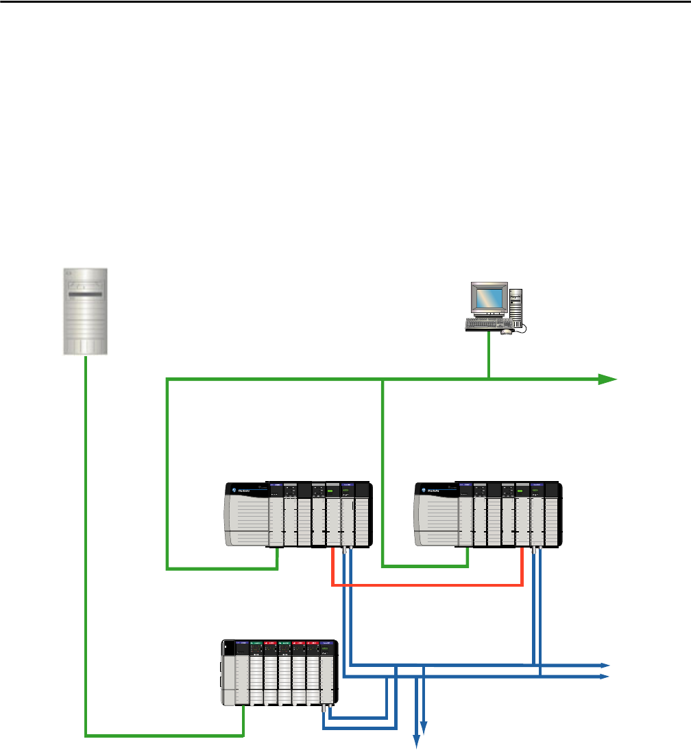
Rockwell Automation Publication PROCES-RM001M-EN-P - June 2019 91
Batch Management and Control Recommendations Chapter 7
Using a Redundant System
with a FactoryTalk Batch
Server
If your system requirements include the batch not going to hold on a controller
switchover, you need to use both a ControlNet® bridge module and an
EtherNet/IP™ bridge module to connect to the FactoryTalk Batch server. If batch
hold upon controller switchover is acceptable, you can connect to the
FactoryTalk Batch server directly from an EtherNet/IP module placed in the
redundant chassis.
This illustration demonstrates one method of bridging the ControlNet network
of the redundant system to the EtherNet/IP network that the FactoryTalk Batch
server is running on.
Logix 556x
Logix 556x
Logix 556x Logix 556x
%
.
4
,
#
.
2
2
-
%
.
4
#
.
2
2
-
#
.
2
%
.
4
,
,
,
FactoryTalk Batch Server Workstation or HMI
EtherNet/IP Network
Primary ControlLogix® Chassis Secondary ControlLogix Chassis
Fiber-optic Cable
ControlNet Redundant Module
To Remote I/O
EtherNet/IP Network
46286

92 Rockwell Automation Publication PROCES-RM001M-EN-P - June 2019
Chapter 7 Batch Management and Control Recommendations
Notes:

Rockwell Automation Publication PROCES-RM001M-EN-P - June 2019 93
Chapter 8
Information Management Recommendations
Information Management application servers (AppServ-Info) are used for data
collection (such as a FactoryTalk® Historian server) or decision support (such as a
FactoryTalk® VantagePoint® server).
The following table lists where to find specific information.
FactoryTalk Historian
Overview
This section provides fundamental best-practice guidelines for implementing
FactoryTalk Historian Site Edition (SE) software on PlantPAx® systems.
The FactoryTalk Historian SE product is co-developed with OSIsoft. While the
SE software shares many of the same features and functionality available in their
Plant Information (‘PI’) product, Rockwell Automation owns the development,
documentation, and support of the Historian SE software. References to
‘OSIsoft’ and ‘PI’ are included in the product and the documentation.
In a PlantPAx system, the FactoryTalk Historian SE software collects, stores, and
manages data from the plant in the PlantPAx system. The software includes these
hardware and software components:
• Data Sources - Plant floor devices and instruments that generate data,
typically controllers. Other Data Sources can include external databases.
• Historian SE Interfaces - Compresses and stores the collected data and
acts as a data server for Microsoft® Windows-based client applications. It’s
also possible to use the Historian SE server to interact with data that is
stored in external systems.
IMPORTANT
We recommend that you host FactoryTalk Historian and FactoryTalk
VantagePoint applications on separate information management servers.
Topic Page
FactoryTalk Historian Overview 93
Tips and Best Practices 94
Architectural Best Practices 94
FactoryTalk VantagePoint Overview 94
Tips and Best Practices 94

94 Rockwell Automation Publication PROCES-RM001M-EN-P - June 2019
Chapter 8 Information Management Recommendations
• Historian SE Server - Compresses and stores the collected data and acts as
a data server for Microsoft Windows-based clients applications. It is also
possible to use the Historian SE Server to interact with data that is stored
in external systems.
•Historian SE Clients - Microsoft Windows-based applications that are
used by plant personnel to visualize the Historian SE data.
Tips and Best Practices
For access to the collection of tips and best practices, refer to Knowledgebase
Answer ID 56070 - FactoryTalk Historian SE Tips and Best Practices TOC
at https://www.rockwellautomation.custhelp.com
Architectural Best Practices
The following distributed system is representative of how the components
can be configured:
• AppServ-Info Historian: Historian SE Server
• PASS: Historian SE Interface, FTLD
• AppServ-Info Reporting: Historian SE Client
• AppServ-OWS, OWS, EWS: Historian SE Client
FactoryTalk VantagePoint
Overview
FactoryTalk VantagePoint provides unified access to virtually all manufacturing
and plant data sources. The software produces web-based reports, such as
dashboards, trends, X-Y plots, and Microsoft Excel® software reports.
The FactoryTalk VantagePoint Trend tool and add-on alarm reports provide
advanced analytics.
Tips and Best Practices
For access to the collection of tips and best practices, refer to Knowledgebase
Answer ID 59149 - FactoryTalk VantagePoint EMI Tips and Best Practices TOC
at https://www.rockwellautomation.custhelp.com
.
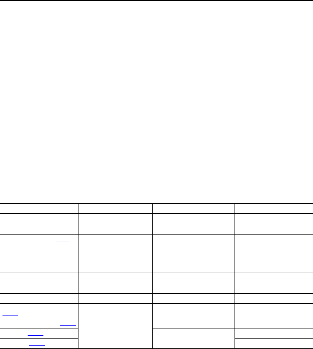
Rockwell Automation Publication PROCES-RM001M-EN-P - June 2019 95
Chapter 9
Maintenance Recommendations
Good control system maintenance keeps your PlantPAx® system operating
efficiently and helps protect the operation of your plant. This chapter provides
recommendations for monitoring, backing up data (application and process
data), and maintaining your PlantPAx system.
We suggest that you develop a plan to back up your control system configuration
and process data on a regular schedule. Consider involving your IT department
to develop this plan. An effective backup plan can help protect you from loss of
resources and revenue.
Table 40
summaries the types of backups and updates for routine and
annual maintenance. Click the link or see the page for a description of each type.
The time frames are examples, and can be modified based on the attributes and
risk factors in your plant.
Backup and update maintenance schedules are routine maintenance activities,
but they have different operational impacts. Updates typically affect system
operation while backups typically can be done without an impact on
system operation.
Table 40 - Maintenance Type Recommendations
Backups Why? When? What?
System - See page 96 Virtual infrastructure disaster recovery Periodic • Host machine
• PlantPAx virtual images
• Hypervisor management
Application configuration - See page 97 Roll back or file protection Periodic • Controllers
• PASS servers
– FactoryTalk® Directory
– HMI, FactoryTalk Linx data servers
– FactoryTalk Alarm and Event servers
• Network switches
Data - See page 100
Archive or project protection Periodic and on-demand • FactoryTalk Historian
• FactoryTalk Batch
• FactoryTalk AssetCentre
Updates Why? When? What?
Microsoft® operating system - See
page 105
Resolve known issue and system
protection
Periodic Servers and workstations
Antivirus - See page 106
Software -See page 106 Periodic and on-demand Rockwell Software
Firmware - See page 106 Controllers

96 Rockwell Automation Publication PROCES-RM001M-EN-P - June 2019
Chapter 9 Maintenance Recommendations
The PlantPAx system can be configured to back up control system configuration
data automatically. FactoryTalk AssetCentre software stores data in a SQL server.
This safeguard provides a roll back, or pulling back, of earlier protected data that
can be used to access data that has since been corrupted or lost.
Data backups for FactoryTalk software packages (Historian, VantagePoint®,
AssetCentre) can occur any time without impacting system operation. We
recommend that process data backups be routinely scheduled so that data loss is
minimized if computer issues occur.
We recommend that you verify operating system or software updates on a
non-production system or when the affected system components are not-active.
These precautions help to prevent unexpected results. For equipment monitoring
and safety, we recommend that you follow the procedures of the manufacturer.
PlantPAx System Backup
When using a virtual infrastructure, follow these consideration for
disaster recovery:
• We recommend that the configuration of each host machine is backed up.
• Make periodic backups of your server and workstation virtual images. If
using a traditional environment, backup your servers and workstations.
• If using a hypervisor, backup the hypervisor management software.
The following subsections expand on these considerations.
Host Machine
Host administrator credentials are to be stored in a secure location, respective to
each host that is backed up. ESXi server configuration can be backed up by using
the command-line interface of the ESXi server or by using a hypervisor
management application. The protected information includes the host IP address
or DHCP server address.
Virtual Image Disaster Recovery
To retain system configuration with patches and other custom operating system
(OS) configurations, we recommend that you back up each PlantPAx system
server or workstation. Servers and workstations can be backed up individually by
exporting and copying virtual machines (VMs). Each VM can be copied and
stored off-site for safekeeping. Do VM maintenance on a dedicated network to
prevent any input on your system operation.
Snapshots are not backups, they are change logs. Snapshots can be rendered
useless if the base is lost due to host or other system failures. To use storage
resources more effectively, back up virtual machines at the virtualization layer.

Rockwell Automation Publication PROCES-RM001M-EN-P - June 2019 97
Maintenance Recommendations Chapter 9
Hypervisor Management Applications
Many virtual environments leverage the use of a server management platform,
such as vCenter Server. Whether this server management is an appliance running
on a host or a Windows OS with installed management software, it is to be
backed up.
Host management appliances or installations store respective configurations on a
database server like SQL, which is typically a local instance. To back up your
server management platform, back up the SQL database in accordance with your
IT department or other published recommendations.
Application Configuration
Application configurations for PlantPAx system servers and workstations are to
be backed up separately and more regularly. The frequent backups mitigate the
risk of losing configuration and application information that was generated
between PlantPAx system backups. Frequent backups simplify the process of
restoring only a portion of your application, if needed.
Figure 8
shows PlantPAx system elements with data flow leading to and from the
system SQL server. The SQL server acts as a central repository for application
data in a PlantPAx system.
Figure 8 - Protect Vital Information with Routine Maintenance
Safe, IT-Managed Location
AppServ-Info (SQL)
AppServ-Asset
Alarm and Event
AssetCentre Data
Asset Framework Events
Audit Log
Data Backup
Data
Backup
Backup
Data Backup
Backup
FTD Backup
Backup
Backup
Backup
FactoryTalk Historian
Server
VantagePoint
Server
PAS S EWS Fac tor yTalk
Batch
FactoryTalk
Directory
VantagePoint Configuration
Asset Framework Configuration
Asset Backups
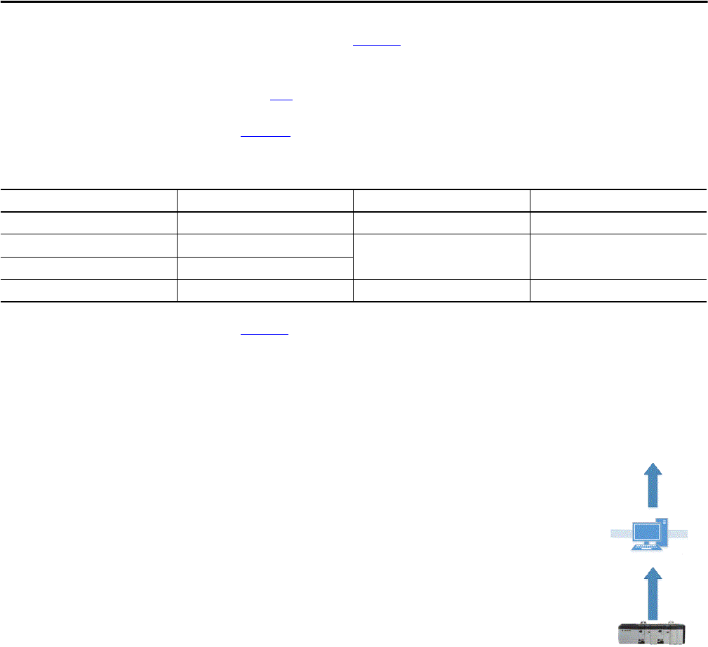
98 Rockwell Automation Publication PROCES-RM001M-EN-P - June 2019
Chapter 9 Maintenance Recommendations
The long arrows in Figure 8 represent the flow of data from FactoryTalk
Historian and FactoryTalk Batch servers directly to a safe, IT-managed location.
An IT-managed storage location accommodates continuous backup data. See
page 100
for more information.
Table 41
shows examples of project files that are to be backed up regularly. Some
files contain configuration scripts and collected data.
Figure 8
shows how the individual illustrations complement a comprehensive
maintenance schedule.
Controller Project File
Use FactoryTalk AssetCentre software on your
AppServ-Asset server to back up Logix5000™ software and
Studio 5000 Logix Designer® application project files
(.ACD). Logix5000 assets are created in the AssetCentre
project tree for each controller and files can be checked into
FactoryTalk AssetCentre software.
A schedule can be created to back up the project files on
common intervals. Use an EWS to perform check-out and
check-in features to make all modifications to the project
file. However, the Logix5000 agent can be hosted on any
computer with FactoryTalk AssetCentre Agent installed.
FactoryTalk AssetCentre software is integrated with the Logix Designer
application to let you move files back-and-forth without leaving the design
environment. Use change tracking on project files to capture all modifications.
Table 41 - Recommended Configuration Backup
Configuration Host Environment Tool Files Backed Up
Controller project file Studio 5000® application FactoryTalk AssetCentre Disaster Recovery .ACD
FactoryTalk Directory FactoryTalk Administration Console Distributed Application Manager .APB
PASS servers FactoryTalk View Studio software
Network switches System network User choice .TXT (based)
AppServ-Asset
Backup
Backup
EWS
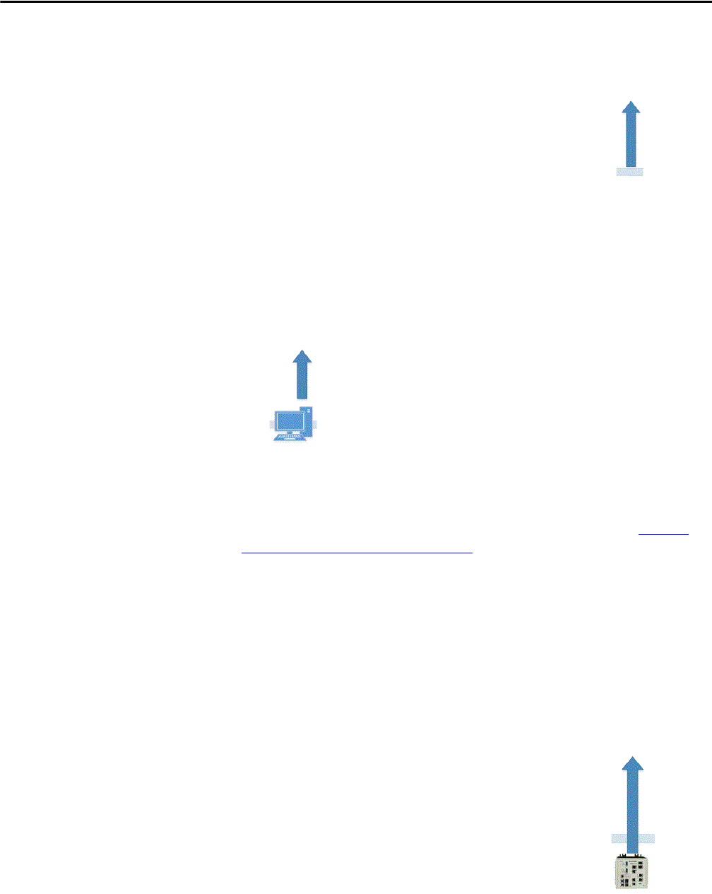
Rockwell Automation Publication PROCES-RM001M-EN-P - June 2019 99
Maintenance Recommendations Chapter 9
FactoryTalk Directory
Our recommendation is to back up the FactoryTalk
Directory regularly. The backup includes any
FactoryTalk security, users, and computers, among
other configurations.
The backup is contained in the output .APB file of the
Distributed Application Manager, which is installed on
the PASS with the FactoryTalk View software, version
8.1 and later.
PASS Servers
The core FactoryTalk View SE project servers need to be
backed up each time a change is made to the project,
and regularly. The PASS server can comprise HMI,
FactoryTalk Linx Data, and Alarm an Event servers.
If using an older version, a FactoryTalk AssetCentre custom asset can be created
by following the procedure in Knowledgebase Answer ID 818741 at https://
www.rockwellautomation.custhelp.com. The project servers store the output
.APB file to the FactoryTalk AssetCentre server. Schedule the custom asset to
run regularly.
Network Switches
If using an older version of AssetCentre software,
back up the network switch configuration to retain
the network architecture by using a custom asset.
An export of the switch configuration can be
generated by using various tools, including the
following:
• Studio5000 Logix Designer
application software
• Third-party applications, for example the
Cisco® Network Assistant Tool
• Command-line interface
• Other desired methods of your IT department
TIP
AssetCentre software, version 9, includes an asset
for FactoryView SE version 11. This new asset can
be created to support disaster recovery for a
FactoryTalk View SE application.
TIP
AssetCentre software, version 9, includes an asset for managed
Stratix switches.
AppServ-Asset
FactoryTalk Directory
Backup
PASS
AppServ-Asset
Backup
AppServ-Asset
Network Switch
Backup
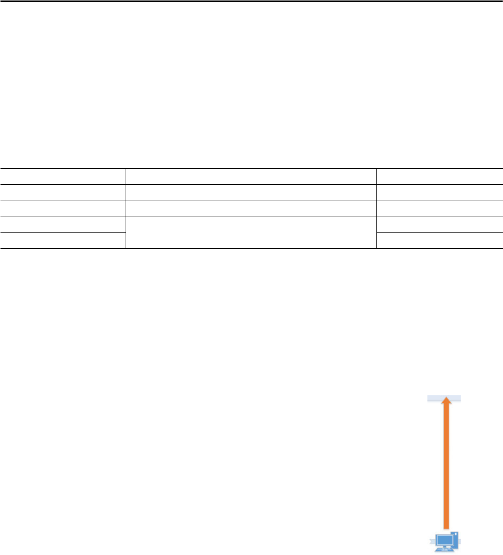
100 Rockwell Automation Publication PROCES-RM001M-EN-P - June 2019
Chapter 9 Maintenance Recommendations
The custom asset pulls the contents of the backup into the FactoryTalk
AssetCentre server. You specify the file location in the custom asset
configuration. Schedule the FactoryTalk AssetCentre software to back up the
exported switch configuration regularly.
Data Back up and Restore
FactoryTalk Historian and FactoryTalk Batch servers produce process system data
to document historic production data. The software configurations, which create
the system data, must be protected along with the data.
Consider the following when using FactoryTalk AssetCentre software:
• No single asset (verification or custom asset) is to exceed 1 GB.
• The system is not to exceed 100 assets that are scheduled in a
12-hour period.
Historian Configuration and Data
The FactoryTalk Historian server contains historian
points, configurations, and data that need to be
regularly backed up. As a part of the Historian
standard installation, a script file pibackup.bat is
installed on the Historian server. This script is used
to back up the Historian server.
The output of this tool is a folder hierarchy that
contains all components necessary to back up and
recover the Historian server. We suggest that you
consider separating the historical data from the
configuration for scheduling purposes.
The historical backup data, which is generated by
FactoryTalk Historian, is stored on the Historian
server. Consult with your IT department to
determine the appropriate location to move and store these files outside of the
AppServ-Info (Historian) server.
Table 42 - Recommended Data Backup
Configuration Host Environment Tool Files Backed Up
Historian configuration and data FactoryTalk Historian software Pibackup.bat Backup folder contents
Batch configuration and data FactoryTalk Batch software Batch system files System folder contents
AssetCentre data SQL server SQL Management Studio AssetCentre.BAK
SQL server data [DBName].BAK
Historian Server
Safe, IT-Managed Location
Data Backup
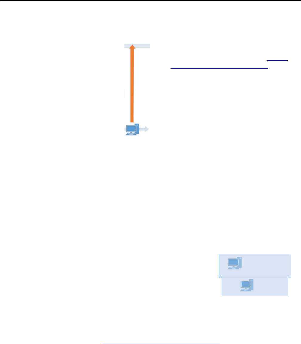
Rockwell Automation Publication PROCES-RM001M-EN-P - June 2019 101
Maintenance Recommendations Chapter 9
Batch Configuration and Data
There are multiple components of a FactoryTalk
Batch system that require a backup plan depending
on the implementation of your system. See
Knowledgebase Answer ID 538578 (at https://
www.rockwellautomation.custhelp.com) for a list of
the files that are to be backed up for each of the
following components of a batch system:
• Batch server files
• Batch client files
• eProcedure® files
• Material manager files
The file contents of the various Batch system
components need to be separated into two groups:
(1) configuration or system files and (2) data files.
The configuration files are all files that comprise the Batch project, such as area
models and recipes. The data files are the batch journals that are constantly
created by a running Batch server.
The configuration files and data can be backed up at different intervals to a safe,
IT-managed location outside of your AppServ-Batch server.
AssetCentre Data
FactoryTalk AssetCentre software
manages the information that is
produced by each of its assets and
processes the data into an SQL server.
When performing a backup of
AssetCentre software, nothing must be
done within AssetCentre. To back up
the AssetCentre configuration and data,
back up the AssetCentre database in your SQL server.
For guidelines on how to back up your AssetCentre database in SQL, see the
Knowledgebase Answer ID 59541 at
https://www.rockwellautomation.custhelp.com
.
SQL Server Data
The FactoryTalk Alarm and Event History software is configured to log to a SQL
database. In addition, the VantagePoint software configuration is natively stored
in the SQL server that is specified during the VantagePoint installation.
FactoryTalk Batch Server
Safe, IT-Managed Location
Data Backup
SQL Server
AssetCentre Server

102 Rockwell Automation Publication PROCES-RM001M-EN-P - June 2019
Chapter 9 Maintenance Recommendations
To back up the FactoryTalk VantagePoint software, see the Knowledgebase
Answer ID 62884 at https://www.rockwellautomation.custhelp.com
.
We recommend that you use the methodologies outlined in the Knowledgebase
Answer ID 62884 to backup other SQL server databases. These databases include
the following:
• For FactoryTalk Alarm and Event database, open FactoryTalk
Administration Console and expand System>Connections>Databases.
Double-click the database to view the information on the Alarm and Event
Historian Database Properties dialog box.
• For FactoryTalk Historian Asset Framework, the SQL Database ‘PIFD’
contains the Asset Framework data and configuration content.
Backup Verification
We recommend that your system use a dedicated, non-production environment
that is capable of accepting and validating backups. You need a strategy for how
frequently the backups are validated.
System Restore
We recommend that you consider a strategy for recovering and restoring your
PlantPAx system to a known secure state after a disruption or failure.
System recovery and restore to a known secure state means that all system
parameters (either default or configurable) are set to secure values. If any
security-critical information, such as patches, is installed after the last backup, the
information must be reinstalled. For example:
• Security-related configuration settings re-established
• System documentation and operating procedures available
• Application and system software that is reinstalled and configured
with secure settings
• Information from the most recent, known secure backup is loaded and the
system that is fully tested and functional.
Retention Considerations
There are two ways to retain data: archived records and a detailed backup policy.
While archiving provides historical records, backups are typically not useful
unless you can access the data for a restore. You must take the time to design a
retention policy for the reuse of dated materials.
For example, a backed up .ACD file from the Studio 5000 Logix Designer
application could possibly not be saved in the most current version of Studio
5000 environment. Accessing the contents of this .ACD file could be
problematic. But an archived printout of the logic that is stored in PDF format
could help restore a system project.

Rockwell Automation Publication PROCES-RM001M-EN-P - June 2019 103
Maintenance Recommendations Chapter 9
Secure archived data and make sure that you can search for the data if requested.
There are numerous reasons to archive data, including, but not limited to,
the following:
• Compliance with government regulations
• Retention of production knowledge
• Reduction of backup storage footprint
Your retention policy must apply to all backups that are reviewed in this chapter.
We recommend that you include your IT department in the backup retention
policy discussion.
Consider the following when developing a backup retention policy:
• Location – Backup information is only worthwhile if retrievable for a
restore. To mitigate risk, duplicate the backup contents to an off-site
location in the event an 'Act of God' renders the on-site copy unusable.
• Storage – The type of storage medium that is used to backup data can
affect how quickly you are able to restore data. Cloud storage provides
scalable backup potential and requires the least amount of on-site
hardware. But, the cloud requires additional steps if the process facility is
not connected to the enterprise cloud servers. Disk mirroring can provide
the fastest time to restore and smaller data loss intervals. This process can
cost more than periodic backups to a hard disk drive.
• Security – The confidentiality and importance of backup information
must be carefully evaluated. Limit access to the retained backup storage
devices and locations to help reduce the risk of threats. Password
protection and encryption can improve risk mitigation.
• Cost – The cost of backing up a process system can be justified with one
application configuration restore. The time alone to re-engineer a process
configuration can justify the cost of physical media and IT infrastructure.
Automated backup policies can reduce time and money for IT to complete
regular backups.
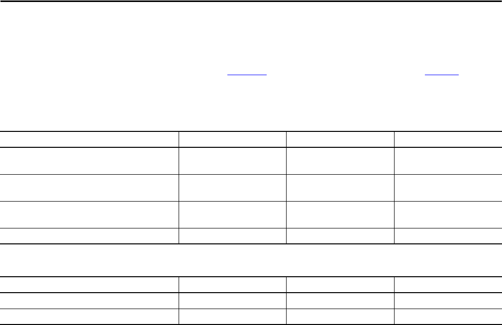
104 Rockwell Automation Publication PROCES-RM001M-EN-P - June 2019
Chapter 9 Maintenance Recommendations
System Storage Rates
The following tables provide an estimate of storage usage for a PlantPAx system.
The values in Figure 10
are estimates based on assumptions in Figure 9. Make
sure to evaluate your system size and adjust appropriately according to your
corporate policy.
Figure 9 - System Operating Assumptions
Description Small
(1)
(1) 3000 I/O points and 10 operator workstations
Medium
(2)
(2) 3000 I/O points and 25 operator workstations
Large
(3)
(3) 5000 I/O points and 50 operator workstations
Alarms SQL database
(alarms/min according to the ISA 18.2 peak alarm rate)
20 50 100
FactoryTalk Historian Event Frames SQL database
(event frames per hour)
250 500 1000
FactoryTalk AssetCentre SQL database
(commands/min per PlantPAx audit log guidelines)
2510
FactoryTalk Historian points 5000 10,000 20,000
Figure 10 - Storage Rates
Description Small
(1)
Medium
(2)
Large
(3)
Microsoft SQL server 4 GB/month 5 GB/month 9 GB/month
FactoryTalk Historian server 2 GB/month 3 GB/month 6 GB/month
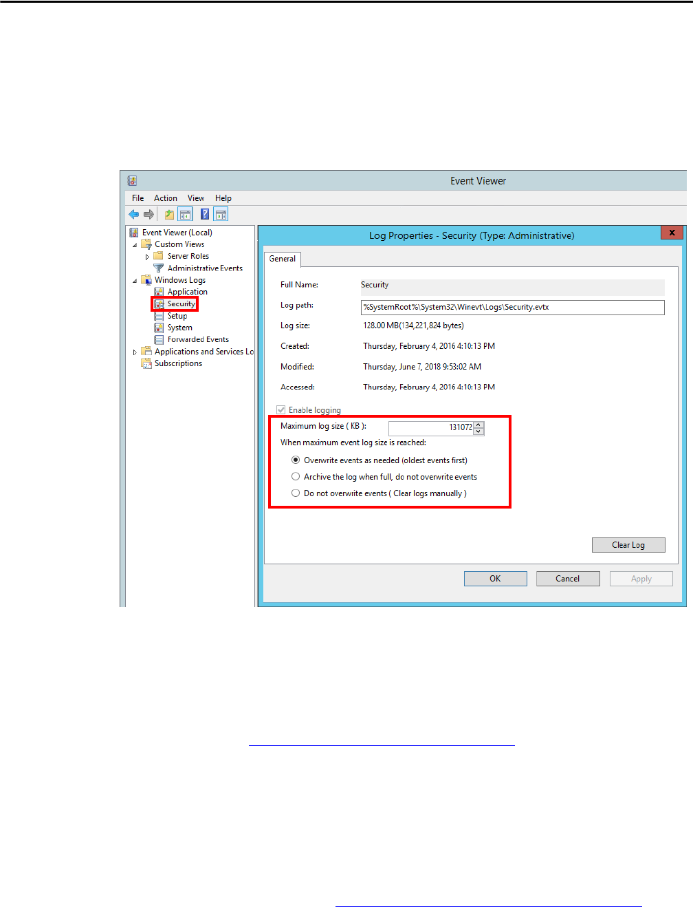
Rockwell Automation Publication PROCES-RM001M-EN-P - June 2019 105
Maintenance Recommendations Chapter 9
Security Audit Logs
Microsoft Windows OS captures security audit records locally for every
PlantPAx server and workstation. We recommend that you make sure the log is
sized adequately to capture sufficient records to satisfy your retention policy. In
Windows Event Viewer adjust the configuration of the security log according to
your system requirements.
Microsoft Updates
Microsoft releases a range of security updates, operating system, and other
software updates. Rockwell Automation qualifies certain Microsoft updates that
potentially impact Rockwell Automation software products. The results of these
patch qualifications are published on Knowledgebase Answer ID 35530
at http://www.rockwellautomation.custhelp.com
.
We recommend that you do not apply or install Microsoft updates until they are
qualified by Rockwell Automation. Before implementing qualified Microsoft
updates, we recommend that you verify them on a non-production system or
when the facility is non-active. This precaution helps to make sure that there are
no unexpected results or side effects.
For more information, contact Rockwell Automation Technical Support
representatives at http://www.rockwellautomation.com/global/support
.

106 Rockwell Automation Publication PROCES-RM001M-EN-P - June 2019
Chapter 9 Maintenance Recommendations
Use Antivirus Software
It is best practice to install antivirus software on your PlantPAx servers and
workstations. Keep the antivirus software up-to-date based on whether your
software is a managed or an unmanaged client.
A managed client communicates with an antivirus management server, which is
on the network. This antivirus management server configures the protection
settings for the client and downloads virus definition files to stay current.
An unmanaged client does not communicate with any management server and
the antivirus definition files are updated manually.
See Knowledgebase Answer ID 35330
at http://www.rockwellautomation.custhelp.com
for more information on
compatibility and considerations for antivirus software installation.
Software Patches and
Firmware Updates
We recommend that you periodically review and update the available software
patches and firmware updates for the Rockwell Automation® components on
your PlantPAx system. Before implementing Rockwell Automation updates, we
recommend that you verify them on a non-production system or when the
facility is non-active. This precaution helps to make sure that there are no
unexpected results or side effects.
Use Proactive Industrial Security Advisory Index
Rockwell Automation offers a subscription service. The Industrial Security
Advisory Index is a publicly available resource that points to specific
Rockwell Automation product security alerts, advisories, and security
recommendations. As new disclosures are added, subscribers to the service
receive a proactive notification.
There are related links to information to raise awareness of risks to affected
product operation or performance. The recommendations include how to reduce
or remove such risks. The advisory index is available at
https://rockwellautomation.custhelp.com
.
Verify Software Patches
For Rockwell Automation software (that is, FactoryTalk View, Factory Talk
Batch, FactoryTalk Historian SE, and FactoryTalk AssetCentre), Rockwell
Automation provides the Patch Validator tool. This tool verifies the current file
version that is installed, the expected file version (based on the version of Patch
Validator used), and completes installation of patch roll-up.

Rockwell Automation Publication PROCES-RM001M-EN-P - June 2019 107
Maintenance Recommendations Chapter 9
To install patches with the Patch Validator tool, see Chapter 4 in the PlantPAx
Distributed Control System Infrastructure Configuration User Manual,
publication PROCES-UM001
.
Compare Latest Firmware Updates
For Rockwell Automation firmware, Rockwell Automation provides a System
Ferret tool that can be installed on the EWS. The tool collects device serial
numbers, and revisions of all devices through RSLinx® Classic software. System
Ferret is available through ab.com as an Integrated Architecture® Productivity
Tool; see http://www.ab.com/go/iatools
.
The devices and firmware that are listed can be compared against the latest
firmware compatible with your Logix firmware revision by reviewing the
firmware compatibility. You also can download the latest firmware release at
http://www.rockwellautomation.com/support/ControlFlash/
.
Use the ControlFLASH™ Utility through the Studio 5000 Logix Designer
application to update firmware as documented in the ControlFLASH Firmware
Upgrade Kit User Manual, publication 1756-UM105
.
Considerations for Software and Firmware Upgrades
If you install a new PlantPAx system, we recommend that you use the
specifications in the PlantPAx Selection Guide, publication PROCES-SG001.
When you update software versions or firmware revisions, we recommend that
you verify the impact on performance and memory utilization before
implementing the upgrade on the production system. For FactoryTalk View or
ControlLogix® platforms, we recommend that you review the release notes and
verify the impact of the upgrade on performance and memory utilization.
You also can verify the compatibility of the upgraded version with the other
software and operating systems in use on your PlantPAx system. See the Product
Compatibility and Download Center at www.rockwellautomation.com
.
A comparison tool (http://www.rockwellautomation.com/compatibility/#/
scenarios) lets you compare features and compatibilities of different products and
firmware revisions. You can contact Rockwell Automation Technical Support
for assistance.

108 Rockwell Automation Publication PROCES-RM001M-EN-P - June 2019
Chapter 9 Maintenance Recommendations
Rockwell Automation
Services and Support
System Support offers technical assistance that is tailored for control systems.
Some of the features include the following:
• Highly experienced team of engineers with training and
systems experience
• Process support at a systems-level that is provided by process engineers
• Unlimited online support requests
• Use of online remote diagnostic tools
• Access to otherwise restricted TechConnect
SM
Knowledgebase content
• 24-hour, 7 days per week, 365 days per year of phone-support coverage
upgrade option
For more information, contact your local distributor or Rockwell Automation
representative or see http://www.rockwellautomation.com/support
.

Rockwell Automation Publication PROCES-RM001M-EN-P - June 2019 109
Appendix A
Verify and Monitor Your System Health
Rockwell Automation provides checklist worksheets to verify and document that
your system design aligns with PlantPAx® system recommendations. In addition,
we also provide examples on how to troubleshoot your system if performance
expectations are not being met.
For details, see the PlantPAx Distributed Control System Verification and
Troubleshooting User Manual, publication PROCES-UM004
.
Additional Monitoring Resources
The Counter Monitor tool is installed with the FactoryTalk® Services Platform
(FTSP) on the PASS. It is on the drive where FTSP is installed under Program
Files(x86)/Common Files /Rockwell/ftcountermonitor.exe.
Counter Monitor checks the runtime values of counters and strings that are made
available by network clients for diagnostic purposes. You also can use the Counter
Monitor tool to take a snapshot of the status and submit it to Rockwell
Automation Technical Support.
Rockwell Automation also provides tools to collect log files for submission to
technical support.
The Rockwell Software® Data Client program can browse the FactoryTalk
Directory to see all tags in the directory. It can also get live data from any tag. The
Rockwell Software® Data Client program does not automatically load the
application. Before you use it, make sure that the application is open by either
opening the application from any computer with RSView® Studio or by running
an RSView® SE Client™.

110 Rockwell Automation Publication PROCES-RM001M-EN-P - June 2019
Appendix A Verify and Monitor Your System Health
Notes:

Rockwell Automation Publication PROCES-RM001M-EN-P - June 2019 111
Appendix B
System Element Software Components
Table 44 lists the typical software for the system element components that
comprise your PlantPAx® system.
Table 44 - System and Software Requirements
Element Category Description
Process Automation
System Server (PASS)
Operating system Microsoft® Windows Server 2016 Standard
Rockwell Automation® software • FactoryTalk® Services Platform
– FactoryTalk Services platform software, version 6.11.00
– FactoryTalk Activation Manager software, version 4.03.03
– FactoryTalk Linx software, version 6.11.00
• FactoryTalk View Site Edition Client software, version 11.00.00
• FactoryTalk View Site Edition Server software, version 11.00.00
• FactoryTalk View Studio Enterprise software, version 11.00.00
• FactoryTalk Alarm and Event software, version 6.11.00
• FactoryTalk Diagnostics software, version 6.11.00
• FactoryTalk Historian SE Live Data Interface, version 6.00.00
• Rockwell Automation ® Windows Firewall Configuration Utility, version 1.00.12
Engineering
Workstation (EWS)
Operating system Microsoft Windows 10
Rockwell Automation software • FactoryTalk Services Platform
– FactoryTalk Services Platform software, version 6.11.00
– FactoryTalk Linx software, version 6.11.00
– RSLinx® Classic software, version 4.11.00
– FactoryTalk Activation Manager software, version 4.03.03
• FactoryTalk View Site Edition Client software, version 11.00.00
• FactoryTalk View Site Edition Server software, version 11.00.00
• FactoryTalk View Studio Enterprise software, version 11.00.00
• FactoryTalk Alarm and Event software, version 6.11.00
• FactoryTalk Diagnostics software, version 6.11.00
• RSLogix 5000® Professional software, versions 20.05.00
• Studio 5000 Logix Designer ® application, versions 31.01.00, 24.02.00
• Studio 5000 Architect Software, version 4.00.00
• RSNetWorx™
– RSNetWorx for EtherNet/IP™ software, version 28.00.00
– RSNetWorx for ControlNet® software, version 28.00.00
– RSNetWorx for DeviceNet® software, version 28.00.00
• FactoryTalk AssetCentre
– FactoryTalk AssetCentre Client software, version 9.00.00
• FactoryTalk Historian SE Management Tools, version 6.00.00
• Studio 5000® Logix Emulate™, version 31.01.00
• ControlFLASH Plus™ software, version 2.00.00
• ControlFLASH software, version 15.01.00
• Rockwell Automation Windows Firewall Configuration Utility, version 1.00.12
Additional third-party software • LOOP-PRO TUNER (Rockwell Automation Edition) software, version 1.9
• Microsoft SQL Server 2012 SP4 Management Tools
• Microsoft SQL Server 2012 SP4 Client Connectivity

112 Rockwell Automation Publication PROCES-RM001M-EN-P - June 2019
Appendix B System Element Software Components
Operator Workstation
(OWS)
Operating system Microsoft Windows 10
Rockwell Automation software • FactoryTalk Services Platform
– FactoryTalk Services Platform software, version 6.11.00
– FactoryTalk Linx software, version 6.11.00
– RSLinx Classic software, version 4.11.00
– FactoryTalk Activation Manager software, version 4.03.03
• FactoryTalk Diagnostics software, version 6.11.00
• FactoryTalk View Site Edition Client software, version 11.00.00
• FactoryTalk Alarm and Event software, version 6.11.00
• FactoryTalk AssetCentre Client software, version 9.00.000
• Rockwell Automation Windows Firewall Configuration Utility, version 1.00.12
Process Automation
Domain Controller
(PADC)
Operating system Microsoft Windows Server 2016 Standard
Application Server
OWS (AppServ-OWS)
Operating system Microsoft Windows Server 2016 Standard
Rockwell Automation software • FactoryTalk Services Platform
– FactoryTalk Services Platform software, version 6.11.00
– FactoryTalk Linx software, version 6.11.00
– RSLinx Classic software, version 4.11.00
– FactoryTalk Activation Manager software, version 4.03.03
• FactoryTalk View Site Edition Client software, version 11.00.00
• FactoryTalk Diagnostics software, version 6.11.00
• FactoryTalk Alarm and Event software, version 6.11.00
• FactoryTalk AssetCentre Client software, version 9.00.00
• Rockwell Automation Windows Firewall Configuration Utility, version 1.00.12
Application Server EWS
(AppServ-EWS)
Operating system Microsoft Windows Server 2016 Standard
Rockwell Automation software • FactoryTalk Services Platform
– FactoryTalk Services Platform software, version 6.11.00
– FactoryTalk Linx software, version 6.11.00
– RSLinx® Classic software, version 4.11.00
– FactoryTalk Activation Manager software, version 4.03.03
• FactoryTalk View Site Edition Client software, version 11.00.00
• FactoryTalk View Site Edition Server software, version 11.00.00
• FactoryTalk View Studio Enterprise software, version 11.00.00
• FactoryTalk Alarm and Event software, version 6.11.00
• FactoryTalk Diagnostics software, version 6.11.00
• RSLogix 5000® Professional software, versions 20.05.00
• Studio 5000 Logix Designer ® application, versions 31.01.00, 24.02.00
• Studio 5000 Architect Software, version 4.00.00
• RSNetWorx™
– RSNetWorx for EtherNet/IP software, version 28.00.00
– RSNetWorx for ControlNet software, version 28.00.00
– RSNetWorx for DeviceNet software, version 28.00.00
• FactoryTalk AssetCentre
– FactoryTalk AssetCentre Client software, version 9.00.00
• FactoryTalk Historian SE Management Tools, version 6.00.00
• Studio 5000® Logix Emulate™, version 31.01.00
• ControlFLASH Plus™ software, version 2.00.00
• C
ontrolFLA
SH software, version 15.01.00
• Rockwell Automation Windows Firewall Configuration Utility, version 1.00.12
Additional third-party software • LOOP-PRO TUNER (Rockwell Automation Edition) software, version 1.9
• Microsoft SQL Server 2012 SP4 Management Tools
• Microsoft SQL Server 2012 SP4 Client Connectivity
Table 44 - System and Software Requirements
Element Category Description

Rockwell Automation Publication PROCES-RM001M-EN-P - June 2019 113
System Element Software Components Appendix B
Application Server
Historian (AppServ-
Info Historian)
Operating system Microsoft Windows Server 2016 Standard
Rockwell Automation software • FactoryTalk ®Services Platform
– FactoryTalk Services Platform software, version 3.00.00
– FactoryTalk Activation Manager software, version 4.02.00
– FactoryTalk Diagnostics software, version 3.00.00
• FactoryTalk Alarm and Event software, version 3.00.00
• FactoryTalk Historian Site Edition Server, version 6.00.00
• FactoryTalk Historian ActiveView software, version 3.20.03
• FactoryTalk Historian DataLink software, version 4.20.02
• FactoryTalk Historian Management software, version 6.00.00
• FactoryTalk Historian ProcessBook software, version 3.20.03
• FactoryTalk Historian SE Live Data Interface, version 6.00.00
• Rockwell Automation Windows Firewall Configuration Utility, version 1.00.10
• FactoryTalk Linx software , version 6.00.00
Application Server
Asset Management
(AppServ-Asset)
Operating system Microsoft Windows Server 2016 Standard
Rockwell Automation software • FactoryTalk Services Platform
– FactoryTalk Services Platform software, version 6.11.00
– FactoryTalk Diagnostics software, version 6.11.00
– FactoryTalk Linx software, version 6.11.00
– RSLinx Classic software, version 4.11.00
– FactoryTalk Activation Manager software, version 4.03.03
– FactoryTalk Alarm and Event software, version 6.11.00
• FactoryTalk AssetCentre
– FactoryTalk AssetCentre Server software, version 9.00.00
– FactoryTalk Asset Centre Client software, version 9.00.00
• Rockwell Automation Windows Firewall Configuration Utility, version 1.00.12
Additional third-party software • Microsoft SQL Server Express 2012 SP4 Advanced (includes Management Studio)
Application Server
Information SQL
(AppServ-Info-SQL)
Operating system Microsoft Windows Server 2016 Standard
Microsoft software • Microsoft SQL Server Standard 2012 SP4 (includes Management Studio)
Application Server
Information
VantagePoint®
(AppServ-Info-
VantagePoint)
Operating system Microsoft Windows Server 2016 Standard
Rockwell Automation software • FactoryTalk Services Platform
– FactoryTalk Services Platform software, version 3.00.00
– FactoryTalk Activation Manager software, version 4.02.00
– FactoryTalk Diagnostics software, version 3.00.00
– FactoryTalk Linx software, version 6.00.00
• FactoryTalk VantagePointSystem Server software, version 8.10.00
• Rockwell Automation Windows Firewall Configuration Utility, version 1.00.10
Application Server
Batch Management
(AppServ-Batch)
Operating system Microsoft Windows Server 2016 Standard
Rockwell Automation software • FactoryTalk Services Platform
– FactoryTalk Activation Manager software, version 4.02.00
– FactoryTalk Diagnostics software, version 3.00.00
– FactoryTalk Services Platform software, version 3.00.00
– RSLinx Classic software, version 3.81.00
• F
actoryTalk Batch, version 13.00.02
• Rockwell Automation Windows Firewall Configuration Utility, version 1.00.10
Table 44 - System and Software Requirements
Element Category Description

114 Rockwell Automation Publication PROCES-RM001M-EN-P - June 2019
Appendix B System Element Software Components
Table 45 - Build Details for USB Devices
Element Category Description
PASS-C (consolidated) Operating system Microsoft Windows Server 2016 Standard
Rockwell Automation software • FactoryTalk Services Platform
– FactoryTalk Services platform software, version 6.11.00
– FactoryTalk Activation manager software, version 4.03.03
– FactoryTalk Linx software, version 6.11.00
– RSLinx Classic software, version 4.11.00
• FactoryTalk View Site Edition Client software, version 11.00.00
• FactoryTalk View Site Edition Server software, version 11.00.00
• FactoryTalk View Studio Enterprise software, version 11.00.00
• FactoryTalk Alarm and Event software, version 6.11.00
• FactoryTalk Diagnostics software, version 6.11.00
• FactoryTalk Historian SE Live Data Interface, version 6.00.00
• Rockwell Automation Windows Firewall Configuration Utility, version 1.00.12
• FactoryTalk Historian SE software, version 6.00.00
• FactoryTalk AssetCentre Server, version 9.00.00
• FactoryTalk AssetCentre Client, version 9.00.00
• Studio 5000 Logix Designer®, version 31.01.00
• Studio 5000 Logix Designer, version 24.02.00
• RSLogix 5000, version 20.05.00
• VantagePoint® System Server, version 8.10.00
• ControlFLASH software, version 15.01.00
• ControlFLASH Plus software, version 2.00.00
Additional software Microsoft SQL Server Express 2012 SP4 Advanced (includes Management Studio)
Operator Workstation
(OWS ISO)
Operating system Microsoft Windows 10
Rockwell Automation software • FactoryTalk Services Platform
– FactoryTalk Services platform software, version 6.11.00
– FactoryTalk Linx software, version 6.11.00
– RSLinx Classic software, version 4.11.00
– FactoryTalk Activation manager software, version 4.03.03
• FactoryTalk Diagnostics software, version 6.11.00
• FactoryTalk View Site Edition Client software, version 11.00.00
• FactoryTalk Alarm and Event software, version 6.11.00
• FactoryTalk AssetCentre Client, version 9.00.00
• Rockwell Automation 111Windows Firewall Configuration Utility, version 1.00.12

Rockwell Automation Publication PROCES-RM001M-EN-P - June 2019 115
Glossary
The following terms and abbreviations are used throughout this manual.
For definitions of terms that are not listed here, refer to the Allen-Bradley®
Industrial Automation Glossary, publication AG-7.1
.
Add-On Instruction Add-On Instructions are reusable code objects that contain encapsulated logic
that can streamline the implementation of your system. The objects let you create
your own instruction set for programming logic as a supplement to the
instruction set provided natively in the ControlLogix® firmware. An Add-On
Instruction is defined once in each controller project, and can be instantiated
multiple times in your application code as needed.
alarm An audible and/or visible means of indicating to the operator an equipment
malfunction, process deviation, or abnormal condition that requires a response.
alarm event A push notification from the alarm object to the alarm subscriber that indicates a
change in alarm state.
alarm management The processes and practices for determining, documenting, designing, operating,
monitoring, and maintaining alarm systems.
alarm object The alarm system element that owns the alarm; it is responsible to identify an
alarm, managing the state, and generating an alarm event.
alarm priority An attribute of In-Alarm event that informs you of the salience of the event.
alarm system The collection of hardware and software that detects an alarm state,
communicates the indication of that state to the operator, and records changes in
the alarm state.
application server The application server (AppServ) is a server on the Process Automation System
Server (PASS), which is typically a FactoryTalk® Directory client of the PASS.
Examples are AppServ-Batch for a FactoryTalk Batch application or
AppServ-Info for a Historian application.
architecture An architecture is a representation of a control and software system, as well as the
process and discipline for effectively implementing the designs for such a system.
An architecture conveys the information content of the related elements
comprising a system, the relationships among those elements, and the rules
governing those relationships.
characterization A characterization is the operation and collection of performance data for a
representative process system to determine scalability, stability, and usability of a
specific system configuration. A characterization is the following:
• Aimed at defining a complete system
• Used to determine if the system is performing at specified level
• Used to identify usability issues
• Used to check and create rules, relationships, limits, and recommendations
for system elements

116 Rockwell Automation Publication PROCES-RM001M-EN-P - June 2019
Glossary
client A client is hardware (personal computer) and software that provides an interface
with a link into a system server application. In the Rockwell Automation®
architecture, a client is a computer that is loaded with runtime software.
control strategy A control strategy is a system footprint to show the complexity of the following:
• Data servers
• Information storage
• Operator interface (graphics, faceplates)
• Control code (sequence, procedure, phases)
• I/O
Control strategies are used to determine a set of comprehensive process system
footprints. These footprints establish a representative system loading that can be
measured to identify the boundaries and limitations (implementation rules) of a
process system.
critical system attribute (CSA) A critical system attribute (CSA) is a customer-facing characteristic that defines
or identifies whether the system is performing as expected. CSAs are specific,
visible indicators of overall system performance and usability.
CSAs have specified parameters that must be maintained and that set the base
operational requirements for the system. There are many other attributes that are
associated with system elements such as controller loading, computer loading,
and network settings that must be configured properly to maintain system CSAs.
development software Development software is a program application that is used to configure various
system components and not required at runtime. For example, Studio 5000
Logix Designer®, FactoryTalk View Studio software.
display object A display object is a functional group of display elements with animations.
engineering workstation (EWS) The engineering workstation (EWS) provides system configuration,
development, and maintenance functions of the PlantPAx® system. The EWS
contains development software, including FactoryTalk View SE Studio and
Studio 5000 Logix Designer.
FactoryTalk directory software FactoryTalk Directory software defines where system data is stored for access.
FactoryTalk Directory software provides a common address book of factory
resources that are shared among FactoryTalk-enabled products.
FactoryTalk services platform The FactoryTalk Services Platform (FTSP) is a service-oriented architecture (see
SOA) that delivers value through FactoryTalk-enabled products. This platform
reduces the customer learning curve and project engineering time through
commonality and reuse. For example, activation, FactoryTalk Directory, security,
diagnostics, audit, live data, and alarms and events.
global object An object that is created once and can be referenced multiple times on multiple
displays in an application.

Rockwell Automation Publication PROCES-RM001M-EN-P - June 2019 117
Glossary
historian A historian is a data collection system with the following components: collection,
storage, compression, retrieval, reports, and analysis. Historian functions include
raw sampling, compression, storage, retrieval, reconstitute, analyze, summarize,
and present (reports and displays).
historical data Historical data is data that is used for the long-term analysis of past operation.
host machine A computer on which a hypervisor runs one or more virtual machines is called a
host machine.
integrated architecture® (IA) Integrated Architecture® (IA) is the identifying name of Rockwell Automation
group of products that use Rockwell Automation core-enabling technologies.
The PlantPAx system is a defined set of IA products that are configured in a
prescribed way to provide optimal performance as a distributed control system.
operator workstation (OWS) The operator workstation (OWS) provides the graphical view and interface into
the process. The workstation is a client of either a PASS or AppServ-HMI.
PlantPAx distributed control
system
The PlantPAx system has all the core capabilities that are expected in a
world-class distributed control system (DCS). The system is built on a
standards-based architecture by using Integrated Architecture components that
enable multi-disciplined control and premier integration with the Rockwell
Automation® intelligent motor control portfolio.
Process Automation System Server
(PASS)
The Process Automation System Server (PASS) is the core PlantPAx system
server that provides central administration throughout the PlantPAx system. The
PASS is a required component.
RSLinx software RSLinx® software is the communication driver (data server) for computer-based
programs to access information in Rockwell Automation controllers. There is
RSLinx Classic software and FactoryTalk Linx software. FactoryTalk View SE
software uses FactoryTalk Linx software to directly access tags in
a controller.
server Software component that serves data to an application (for example, data server).
Typically, server software components are installed on server-class computers.
system attribute A system attribute is an operational functionality that can be manipulated or
measured and is used to establish the operational boundaries or system capability.
For example workstation memory, number of parameters on a screen, and
number of control loops. A system attribute can be independent or dependent.
system element A system element is a distinctive system entity that is made up of a combination
of hardware and software products that support an identifiable system function
or role. A system element can be manipulated to vary system operation or
capability. For example, engineering workstation (EWS), operator workstation
(OWS), process automation system server (PASS), and controller.
system infrastructure System infrastructure is the commercial off-the-shelf hardware and software that
is required to enable system elements to work together as a system. For example,
network switches, computers, and so forth.

118 Rockwell Automation Publication PROCES-RM001M-EN-P - June 2019
Glossary
system server A system server expands the scope of a system by providing support for additional
system capacity or optional system functions. For example, the Process
Automation System Server (PASS) is a required component for all centralized
and distributed process systems. The PASS provides central name resolution and
system-wide, FactoryTalk services. The PASS provides the capability to distribute
information to the OWS and add to optional application servers to increase the
scope of the process system.
user-defined data type (UDT) Tag types that you create once and reuse in multiple tag templates, multiple
times.
workstation A workstation is a computer running development, configuration, and optional
maintenance software. A workstation is not a server.

Rockwell Automation Publication PROCES-RM001M-EN-P - June 2019 119
Index
A
activation
FactoryTalk
18
additional resources
8
virtualization
66
Add-On Instruction
definition
115
description 51
alarm
and event server
18
definition
115
event definition 115
management definition
115
object definition
115
priority definition 115
state model
60
system definition
115
system recommendations 55
allocation
resource pool
69
tag and memory
44
analog indicator
control strategies
35
antivirus
software
106
application
server
definition
115
system recommendations
37
AppServ-Asset
description
25
software 25
Windows Server 2012 R2
113
AppServ-Batch
description
26
software
26
AppServ-EWS
description
21
software
21
Windows Server 2012 R2
112
AppServ-Hist
Windows Server 2012 R2
113
AppServ-Info (Hist)
description
24
software
24
AppServ-Info (SQL)
description
25
software
25
AppServ-Info (VantagePoint)
description
24
software 24
AppServ-Info-SQL
Windows Server 2012 R2
113
AppServ-Info-VantagePoint
Windows Server 2012 R2
113
AppServ-OWS
description
22
software
22
Windows Server 2012 R2
112
architecture
builder tool
16
centralized
14
critical system attribute
15
definition
115
distributed
14
independent 14
multiple PASS servers
14
PlantPAx
13
recommendations 13
single PASS server
14
workstation
14
AssetCentre 78
software
78
attributes
CSA
15
FactoryTalk Batch
90
B
batch
critical system attribute
90
equipment phases
90
management 89
recommendations
89
server
18
best practices
FactoryTalk Historian
94
C
cable types 75
cache
messages
48
centralized
architecture
14
characterization
definition
115
client
definition
116
communication
controller-to-controller
47
complex 2-state discrete
control strategies
34
complex regulatory (primary)
control strategies
33
complex regulatory (secondary)
control strategies
34
complex regulatory non-PID
control strategies
35
components
FactoryTalk Historian
93
PASS
17
PlantPAx software 17
configuration
FactoryTalk directory
20
task
38
virtual recommendations 67

120 Rockwell Automation Publication PROCES-RM001M-EN-P - June 2019
Index
considerations
EtherNet/IP interface
79
process controller I/O
48
updates
107
control
batch management
89
strategies
32
analog indicator
35
complex 2-state discrete
34
complex regulatory (primary)
33
complex regulatory (secondary) 34
complex regulatory non-PID
35
digital indicator
35
simple 2-state discrete 34
simple regulatory
33
strategy
definition
116
ControlFLASH
tool
107
controller
48
recommendations
37
redundant 29
simplex
28
skid-based
30
to controller communication 47
ControlNet
recommendations
80
count
I/O determination
31
CPU
utilization
38
critical
system attribute
15, 90
definition
116
D
data
server
18
definition
infrastructure
66
description
Add-On Instruction
51
AppServ-Asset 25
AppServ-Batch
26
AppServ-EWS
21
AppServ-Info (Hist) 24
AppServ-Info (SQL)
25
AppServ-Info (VantagePoint
24
AppServ-OWS 22
domain controller
27
EWS
20
IndWS 23
OWS
21
PASS
17
development software
definition
116
DeviceNet
recommendations
81
digital indicator
control strategies
35
directory
FactoryTalk
18
display object
definition
116
distributed
architecture
14
domain
and workgroup
recommendations
72
controller
description
27
domain controller
software
27
E
element
recommendations
17
engineering workstation
definition
116
equipment phases
batch
90
estimate
controller memory utilization
45
CPU utilization
40
offline memory
46
Ethernet
switches
76
EtherNet/IP
recommendations
78
EWS
description
20
software 20
Windows 8.1
111
F
FactoryTalk
activation server
18
alarm and event server
18
batch server
18
data server
18
director
configuration
20
directory server
18
directory software
definition
116
HMI server
18
recommendations 52
services platform
definition
116
FactoryTalk AssetCentre
software
78
FactoryTalk Batch
CSA attributes
90
FactoryTalk Historian
best practices
94
components 93
overview
93
FactoryTalk VantagePoint
business intelligence
94
FactoryTalk View SE
OWS
21

Rockwell Automation Publication PROCES-RM001M-EN-P - June 2019 121
Index
field device
recommendations
77
fieldbus
recommendations
83
firmware
updates
107
footprint
control strategy
33
G
global object
definition
116
glossary
115
guidelines
PhaseManager
90
H
hardware
redundant controller
29
simplex controller
28
skid-based controller
30
HART
recommendations
82
historian
definition
117
information management
93
historical data
definition
117
HMI
server
18
host machine
definition
117
I
I/O
considerations
48
determining count
31
process controller considerations
48
runtime 49
IAB
tool
16
independent
architecture
14
IndWS
description
23
software
23
information management
Historian, VantagePoint
93
infrastructure
definition
66
recommendation
65
traditional
66
virtualization 66
integrated architecture
builder tool
16
definition
117
L
library
Rockwell Automation process objects
53
limits
program parameter
43
M
maintenance
recommendations
95
MCC
recommendations
87
messages
cache
48
monitor
controller memory utilization
47
CPU utilization
42
multiple PASS servers
architecture
14
N
network
recommendations
75
time protocol
73
virtualization 68
O
objects
process library
53
operating system
optimization
74
recommendations
72
operator workshop
definition
117
optimize
operating system
74
options
process library
53
OWS
description
21
FactoryTalk View SE
21
Windows 8.1 112
P
PADC
Windows Server 2012 R2
112
PASS
definition
117
description
17
redundancy
19
system element 17
Windows Server 2012 R2
111
patch validator
106
patches
updates
106
performance
critical system attribute
15

122 Rockwell Automation Publication PROCES-RM001M-EN-P - June 2019
Index
periodic
task
38
PhaseManager
guidelines
90
PlantPAx
architecture
13
infrastructure
65, 66
selection guide
16
software 17
system definition
117
process
controller sizing
28
library objects 53
procurement
tools
16
produced and consumed
controller tags
48
PROFIBUS
recommendations
85
program parameter
limits
43
R
recommendations
alarm system
55
architecture
13
batch
89
controller 37
ControlNet
80
DeviceNet
81
domain 72
EtherNet/IP
78
FactoryTalk
52
field device 77
fieldbus
83
HART
82
infrastructure 65, 66
maintenance
95
MCC
87
network
75
operating system 72
PROFIBUS
85
system application
37
system elements 17
workgroup
72, 73
redundancy
controller hardware
29
PASS configurations 18
PASS server
19
reference
manual scope
7
resource pool
allocation
69
Rockwell Automation
library of process objects
53
RSLinx software
definition
117
runtime
I/O considerations
49
S
scope
reference manual
7
server
definition
117
virtualization
67
simple 2-state discrete
control strategies
34
simple regulatory
control strategies
33
simplex
controller hardware
28
single PASS server
architecture
14
sizing
control strategies
32
process controller
28
skid-based
controller hardware
30
software
78
antivirus
106
AppServ-Asset
25
AppServ-Batch 26
AppServ-EWS
21
AppServ-Info (Hist)
24
AppServ-Info (SQL) 25
AppServ-Info (VantagePoint)
24
AppServ-OWS
22
domain controller 27
EWS
20
IndWS
23
PlantPAx 17
updates
105
state model
alarm
60
storage
virtualization
68
strategies
control sizing
32
support
services
108
switches
Ethernet
76
synchronization
commands
73
server and workstation time
73
system
alarm recommendations
55
application recommendations 37
attribute definition
117
element definition
117
ferret tool 107
infrastructure definition
117
procurement
16
server definition 118
support
108

Rockwell Automation Publication PROCES-RM001M-EN-P - June 2019 123
Index
T
tag and memory
allocation
44
task
configuration
38
technical
support
108
time
workstation and server synchronization
73
tool
ControlFLASH utility
107
IAB
16
procurement 16
system ferret
107
update software
106
traditional
infrastructure
66
U
UDT
definition
118
update
considerations
107
firmware
107
patches
106
software 105
tools
106
user-defined tag
definition
118
utilization
controller memory estimate
45
CPU
38
CPU estimate
40
CPU monitor 42
monitor controller memory
47
V
vantagepoint
information management
93
view
runtime memory
46
virtualization
additional resources
66
configuration recommendations
67
infrastructure 66
networks
68
resource pool
69
servers 67
storage
68
W
Windows 8.1
EWS
111
OWS
112
Windows Server 2012 R2
AppServ-Asset
113
AppServ-EWS
112
AppServ-Hist
113
AppServ-Info-SQL
113
AppServ-Info-VantagePoint
113
AppServ-OWS
112
PADC
112
PASS
111
workgroup
recommendations
72
workstation
architecture
14
definition
118

124 Rockwell Automation Publication PROCES-RM001M-EN-P - June 2019
Index
Notes:

Rockwell Automation Publication PROCES-RM001M-EN-P - June 2019 125
Index
Notes:

126 Rockwell Automation Publication PROCES-RM001M-EN-P - June 2019
Index
Notes:
Publication PROCES-RM001M-EN-P - June 2019
Supersedes Publication PROCES-RM001L-EN-P - August 2018 Copyright © 2019 Rockwell Automation, Inc. All rights reserved. Printed in the U.S.A.
Rockwell Automation Support
Use the following resources to access support information.
Documentation Feedback
Your comments will help us serve your documentation needs better. If you have any suggestions on how to improve this document, complete the
How Are We Doing? form at http://literature.rockwellautomation.com/idc/groups/literature/documents/du/ra-du002_-en-e.pdf
.
Technical Support Center
Knowledgebase Articles, How-to Videos, FAQs, Chat, User
Forums, and Product Notification Updates.
https://rockwellautomation.custhelp.com/
Local Technical Support Phone Numbers Locate the phone number for your country. http://www.rockwellautomation.com/global/support/get-support-now.page
Direct Dial Codes
Find the Direct Dial Code for your product. Use the code to
route your call directly to a technical support engineer.
http://www.rockwellautomation.com/global/support/direct-dial.page
Literature Library
Installation Instructions, Manuals, Brochures, and
Technical Data.
http://www.rockwellautomation.com/global/literature-library/overview.page
Product Compatibility and Download
Center (PCDC)
Get help determining how products interact, check
features and capabilities, and find associated firmware.
http://www.rockwellautomation.com/global/support/pcdc.page
.
Rockwell Otomasyon Ticaret A.Ş., Kar Plaza İş Merkezi E Blok Kat:6 34752 İçerenköy, İstanbul, Tel: +90 (216) 5698400
Rockwell Automation maintains current product environmental information on its website at http://www.rockwellautomation.com/rockwellautomation/about-us/sustainability-ethics/product-environmental-compliance.page.
Allen-Bradley, CENTERLINE, CompactLogix, ControlFLASH, ControlLogix, Encompass, FactoryTalk, Integrated Architecture, IntelliCENTER, Logix5000, PanelView, PhaseManager, PlantPAx, PLC-5, POINT I/O, Rockwell Automation,
Rockwell Software, RSLinx, RSLogix 5000, RSNetWorx, RSView, Stratix, Studio 5000 Architect, Studio 5000 Logix Designer, and VantagePoint are trademarks of Rockwell Automation, Inc.
Cisco is a trademark of Cisco Systems, Inc.
Common Industrial Protocol, ControlNet, DeviceNet, and EtherNet/IP are trademarks of ODVA, Inc.
Microsoft, Excel, and Windows are trademarks of the Microsoft Corporation.
Trademarks not belonging to Rockwell Automation are property of their respective companies.
