AHT Cooling Systems GmbH
08.10.2019 16:37
OP
ERATING MANUAL
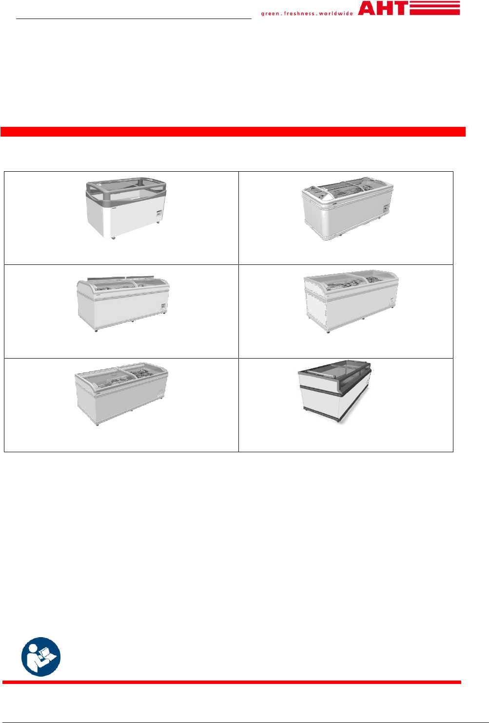
IBIZA
MALTA
MANHATTAN
MIAMI
PARIS
SYDNEY
Multi-mode commercial refrigeration
equipment
C
opyright © AHT Cooling Systems GmbH. All Rights Reserved.
SNr. 406054
Status: 10/19
AHT Cooling Systems GmbH
page 2
Original operating manual. Keep for future reference.
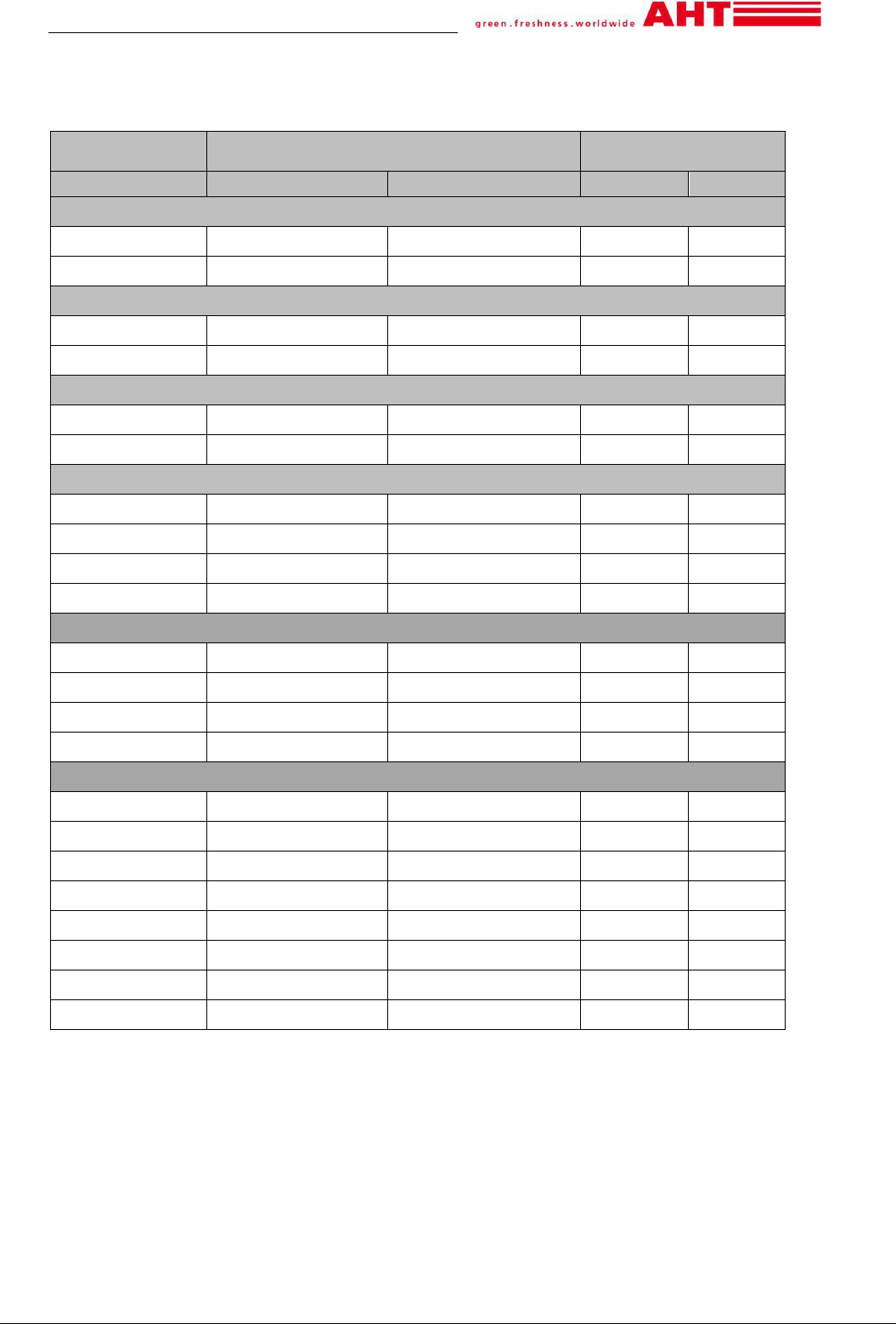
MODEL TYPES - OVERVIEW
Multi-mode commercial refrigeration equipment
Model
Dimensions
Length x Depth x Height
Maximum total weight
unit *
[mm]
[in]
[kg]
[lb]
IBIZA
100 NAM 1 000 x 851 x 925 39.37 x 33.50 x 36.42
95 209
145 NAM 1 456 x 851 x 925 57.32 x 33.50 x 36.42
115 254
MALTA
145 NAM 1 456 x 855 x 833 57.32 x 33.66 x 32.80
125 276
185 NAM 1 851 x 855 x 833 72.87 x 33.66 x 32.80
150 331
MANHATTAN
175 NAM 1 753 x 995 x 910 69.02 x 39.17 x 35.83
150 331
210 NAM 2 103 x 995 x 910 82.80 x 39.17 x 35.83
165 364
MIAMI
145 NAM 1 457 x 854 x 833 57.36 x 33.62 x 32.80
115 254
185 NAM 1 850 x 994 x 834 72.83 x 39.13 x 32.83
145 320
210 NAM 2 102 x 854 x 833 82.76 x 33.62 x 32.80
160 353
250 NAM 2 502 x 854 x 833 98.50 x 33.62 x 32.80
180 397
PARIS
145 NAM 1 457 x 853 x 833 57.36 x 33.58 x 32.80
110 243
185 NAM 1 854 x 853 x 833 72.99 x 33.58 x 32.80
140 309
210 NAM 2 102 x 853 x 833 82.76 x 33.58 x 32.80
160 353
250 NAM 2 502 x 853 x 833 98.50 x 33.58 x 32.80
175 386
SYDNEY
175 NAM 1 752 x 993 x 910 69.98 x 39.09 x 35.83
180 397
213 NAM 2 132 x 993 x 860 83.94 x 39.09 x 33.86
175 386
223 NAM 2 232 x 993 x 860 87.87 x 39.09 x 33.86
180 397
230 NAM 2 302 x 993 x 910 90.63 x 39.09 x 35.83
205 452
250 NAM 2 502 x 993 x 910 98.50 x 39.09 x 35.83
215 474
XL 175 NAM 1 752 x 1 043 x 910 69.98 x 41.06 x 35.83
160 353
XL 210 NAM 2 102 x 1 043 x 910 82.76 x 41.06 x 35.83
205 452
XL 250 NAM 2 502 x 1 043 x 910 98.50 x 41.06 x 35.83
225
496
*Execution-specific deviations possible. For details, please refer to the freight documents. These must be
carried out by the operator.
Technical specifications are subject to change without notice.

AHT Cooling Systems GmbH
page 3
Table of contents
MODEL TYPES - OVERVIEW ................................................................................................................ 2
1 Safety ....................................................................................................................................... 4
General information for the manual and safety ....................................................................... 4
Limitation of liability ................................................................................................................. 4
Explanation of symbols ............................................................................................................ 4
Intended purpose ..................................................................................................................... 5
Staff requirements ................................................................................................................... 6
Personal protective equipment ................................................................................................ 6
Specific hazards ...................................................................................................................... 6
Electricity ................................................................................................................................. 6
Refrigerant circuit..................................................................................................................... 7
Flammable refrigerant ............................................................................................................. 7
Mechanical hazards ................................................................................................................. 8
Residual risks .......................................................................................................................... 9
2 Product description ................................................................................................................ 10
General information ............................................................................................................... 10
Technical data ....................................................................................................................... 10
Serial plate and serial number ............................................................................................... 10
Intended purpose ................................................................................................................... 10
3 Layout and function ............................................................................................................... 10
Automatic defrost ................................................................................................................... 11
4 Operating and display elements ............................................................................................ 11
Temperature display .............................................................................................................. 11
Operating panel and display elements .................................................................................. 11
Electronic controller AHT (SECOP) ....................................................................................... 11
Switch refrigeration function on/off ........................................................................................ 11
Setting selection .................................................................................................................... 11
Semi-automatic defrost .......................................................................................................... 12
Alarm indication and acknowledgment .................................................................................. 12
5 Transport and storage ........................................................................................................... 12
6 Unpacking .............................................................................................................................. 12
7 Setup and installation ............................................................................................................ 13
Electrical connection .............................................................................................................. 14
Electrical protection ............................................................................................................... 14
8 Commissioning ...................................................................................................................... 15
9 Operation (use) ...................................................................................................................... 15
Loading .................................................................................................................................. 16
Decommissioning and Re- commissioning ........................................................................... 16
Decommissioning .................................................................................................................. 16
Re-commissioning ................................................................................................................. 16
Faults in operation ................................................................................................................. 16
10 Maintanance .......................................................................................................................... 17
Cleaning ................................................................................................................................. 17
Basic cleaning ........................................................................................................................ 17
Cleaning steps during operation ............................................................................................ 17
Cleaning steps only with cooling function switched off (manual defrost) ............................. 18
Maintenance, service and repair ........................................................................................... 18
What to do if … ...................................................................................................................... 19
Maintenance services ............................................................................................................ 19
11 Disposal ................................................................................................................................. 19
AHT Cooling Systems GmbH
page 4
1 Safety
General information for the manual and safety
This operating manual (hereinafter the “manual”) forms part of the device and enables a safe and efficient
operation. The safety section provides information about important safety aspects for the protection of persons,
things and materials. Task-related warnings/notes are contained in the individual chapters.
The complete manual can be found electronically on our website www.ahtusa.net
or contact us at:
AHT Cooling Systems USA, Inc.
7058 Weber Blvd.
Ladson, SC 29456 USA
Phone: +1 (0) 843/767 6855 Fax: +1 (0) 843/767 6858 Email: info@us.aht.at
This manual is intended for the following target groups:
Operator
Operating staff
Qualified staff: AHT service partner, AHT service technician, AHT customer service, AHT installation
service, AHT assembly service
Staff: This term is used when the manual is addressed to all target groups.
This manual must be available and accessible to the local staff.
The staff must read the manual carefully before use.
All figures represent symbolic representations.
Limitation of liability
All the details in this manual were compiled in consideration of the standards and legal regulations applicable at
this time, as well as the experience of the manufacturer and qualified staff. The manufacturer accepts no liability
for damage to persons or things (devices, goods, etc.) resulting from:
Non-observance of the manual and the regulations/safety instructions contained therein.
Failure to comply with the local safety regulations.
Inappropriate use (misuse)
Use of unauthorized and non-trained staff.
Unauthorized equipment conversions and technical modifications by the operator himself.
Use of non-approved spare parts by the manufacturer.
Failure of the power supply or electro technical safety devices.
Typesetting and print errors.
Failure to observe the above points will invalidate the warranty claims.
The contractual obligations agreed to under the contract, the general terms and conditions of sale and delivery
of the “AHT Cooling Systems GmbH” (hereinafter “AHT”) and the statutory provisions applicable at the
conclusion of the contract apply.
Technical specifications are subject to change without notice.
The local commercial law regulations and safety regulations/provisions and the essential health and safety
requirements of the unit apply.
Explanation of symbols
Safety and warning notices are indicated in this manual by symbols and signal words. Signal words refer to
the risk level of the hazard.
Signal word
Meaning
Hazard with moderate risk level.
Could result in danger to life or serious injury if not avoided.
Hazard with low risk level.
Could result in minor or moderate injury if not avoided.
Individual notes or important collective notes to avoid material or property
damage.
CAUTION
NOTICE
WARNING
AHT Cooling Systems GmbH
page 5
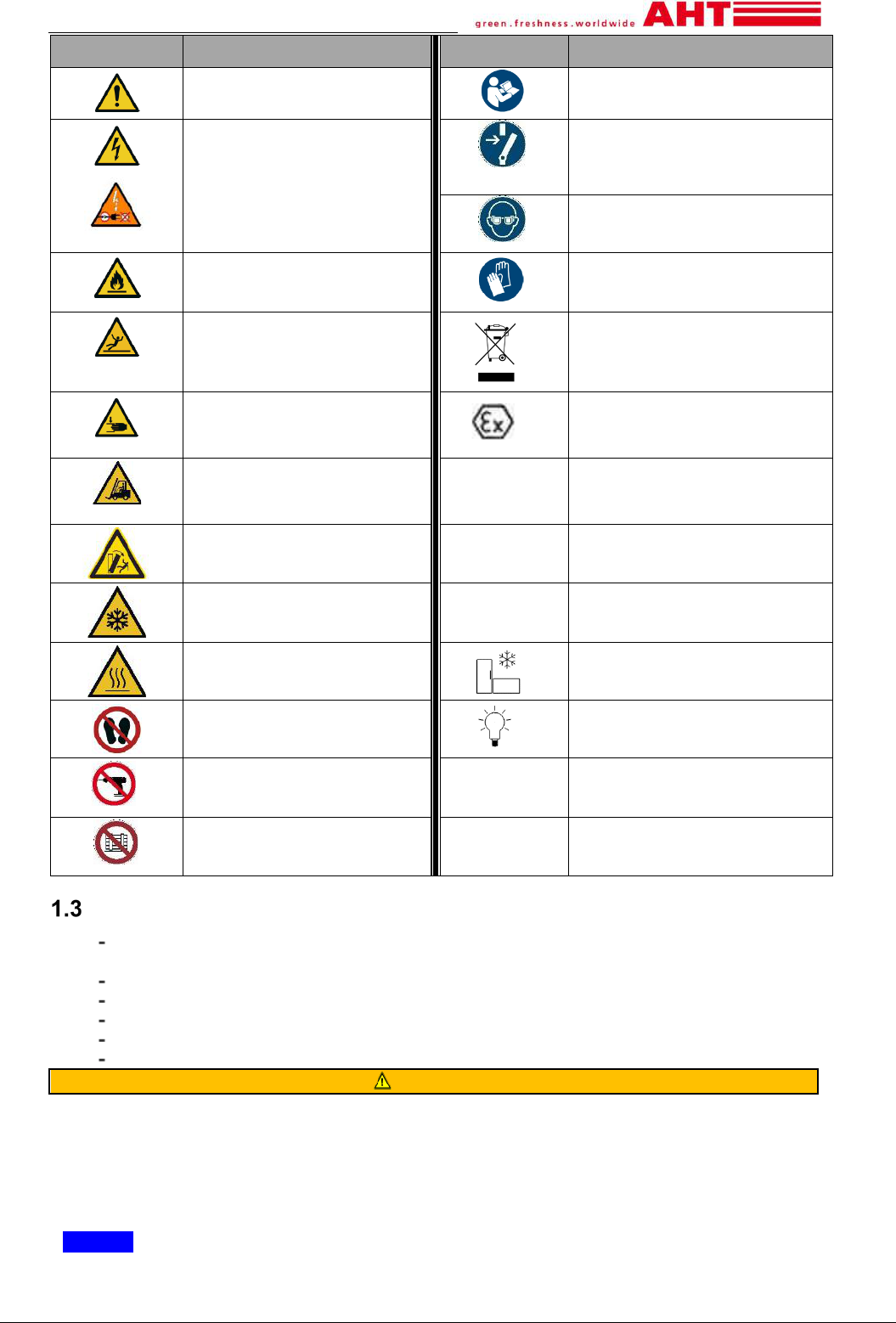
Symbol
Meaning
Symbol
Meaning
General warning sign
Refer to instruction
manual/booklet
Warning: Electricity
Warning: Electricity
Do not connect damaged
power cables to the circuit
Disconnect before carrying out
maintenance or repair
Wear eye protection
Warning: Flammable material
Wear protective gloves
Warning: Slippery surface
Separate collection for electrical
and electronic equipment
Warning: Crushing of hands
Marking of explosion protection
Warning: Forklift trucks and
other industrial vehicles
-
•
listing
listing notice/
safety and warnings
Warning: risk of tilting
►
Action/Measure/Prohibition
Warning: Low temperatures/
freezing conditions
→
Cross-reference to a different
place in the document
Warning: Hot surface
Unit-connection cable
Do not walk or stand here
Light-connection cable
Do not bore
Do not obstruct
Intended purpose
For storing, displaying or dispensing of pre-packed ice cream, pre-packed frozen or medium
temperature foods depending on setting (see → chapter 2.2 and
2.3).
The operator is responsible for the correct operation of the unit.
Operate the unit in a stable position (horizontal alignment).
Operate the unit only on the installed stilt or castors.
Observe installation instruction see → chapter 7.
Operate the unit only with glass lids.
WARNING
Hazards due to misuse.
►No technical modifications may be made to the unit.
►Steam or high-pressure cleaners may not be used for basic cleaning.
►Do not store explosive substances, e.g. aerosol containers with flammable propellant gas, in
this unit.
►The unit may only be operated if all the required safety devices are present and fully
functional.
NOTICE
• Material-and property damage due to misuse.
►Do not exceed ambient conditions shown at the serial plate (see → chapter 2.2.1).
AHT Cooling Systems GmbH
page 6
►The ambient temperature must not be less than 16°C (60.8°F).
►Regularly check that the unit is in good condition. Damage must be repaired immediately.
►Before storing the goods and during operation, the temperature must be checked for correctness (see →
chapter 4.1).
►Stored goods must be checked by the operator in the case of power failure (temperature control).
►Check regularly for foreign objects in the goods area. Incorrectly stored goods must be removed immediately.
►Check regularly that the glass lids are closed.
►Operation of a unit with a broken glass lid/glass element (crack, break) is no longer possible.
- Remove goods from the damaged unit and rearrange in a functional unit.
- Switch off the damaged unit after removing the goods (decommissioning → see chapter 9.2).
- Contact the maintenance service (see → chapter 10.4).
►Do not laminate glass surfaces with labels and foils.
►Observe the minimum distances to the boundary walls and to other units to avoid hindering the air
circulation (see → chapter 7).
►Do not use glass lids as a storage for various objects.
Staff requirements
WARNING
Insufficient qualification. Risk of injury.
►All activities may only be performed by qualified staff.
►The staff must read and understand this manual before starting work.
Operator:
• The operator must ensure that this manual has been read and understood by the operating staff
(training).
• The operator is responsible for the fact that faults during operation (e.g. alarms, temperature deviations, etc.) are
recognized by the operating staff and appropriate measures are taken (→ see chapters
9.3 and 10.3).
Operating staff:
• The operating staff must be trained by the operator on the transferred tasks and possible dangers with the aid of
this manual.
• Only trained operating staff are allowed to operate and clean the device.
Qualified staff:
• Only AHT-authorized, qualified staff and specialists are allowed to perform work on the unit, e.g.:
Servicing (maintenance, service and repair).
• Only staff trained in handling flammable refrigerants may perform work on the refrigerant circuit of R-290 units.
• Only qualified electricians are permitted to work on the electrical system.
Persons (including children) with limited physical, sensory or mental abilities are allowed to operate the unit only
under supervision and after instruction, and must not perform any maintenance work. Children must not play
with the unit.
Working under the influence of alcohol and drugs is prohibited.
Personal protective equipment
Wear protective gloves
►Protection against heavy unit parts during unpacking, set up and installation and disposal.
► Protection against sharp edges, rotating parts and hot surfaces during maintenance, service and
repair work.
► Protection from contact with fluid/leaking refrigerant in the case of a broken seal in the refrigerant
circuit.
►Protection against low temperatures during loading and cleaning.
►When removing pieces of glass and glass splinters after glass breakage.
Wear eye protection
► Protection from contact with fluid/leaking refrigerant in the case of a broken seal in the refrigerant
circuit.
Specific hazards
Electricity
Work on the electrical system may only be performed by qualified staff.
AHT Cooling Systems GmbH
page 7
In the case of fault messages or damage to the unit, contact the maintenance service immediately (see →
chapter 10.4).
WARNING
Contact with live parts may cause electric shock. Risk of fire due to sparks or overloading.
►Do not connect any damaged unit or damaged parts (e.g. power cables) to the circuit.
►Check the safety devices for completeness and functionality.
►Guards and covers on the unit must not be removed.
► Before connecting to power, note the following:
Applicable local electrical safety regulations
Applicable standards and safety notices.
Information on the serial plate (see → chapter 2.2.1).
►In the case of damage to the unit during operation or if the electrical protection was triggered and
before maintenance work, observe the following safety rules:
1. Disconnect the unit (switch off all pins on all sides).
2. Secure the unit against restarting.
►Damaged parts must be replaced only by professionals, e.g.:
power supply cables
►Do not squeeze or bend power supply cords.
►Do not use extension cords or multiple power strips.
►Steam or high-pressure cleaners may not be used for basic cleaning (see → chapter 10.1.1).
►Concealed electrical parts must not be damaged. Drilling or other work on the unit is not
permitted.
Refrigerant circuit
Work on the refrigerant circuit may only be performed by qualified staff.
In the case of fault messages or damage to the unit, contact the maintenance service immediately (see →
chapter 10.4).
Flammable refrigerant
Safety and warning notes for units with flammable refrigerants.
WARNING
• The refrigerant R-290 belongs to safety group A3 according to ASHRAE 34.
The refrigerant used and the fill quantity are indicated on the power rating plate (see → chapter
2.2.1).
• The refrigerant is highly flammable.
If leaks occur, the refrigerant can escape and create an explosive gas/air mixture. This can lead to fire and
explosion with subsequent fire risk.
► Keep away from ignition sources (heat, sparks, open flames, hot surfaces).
►To remove condensation and for cleaning, use a damp cloth or sponge.
Do not use dry clothes or sponges for rubbing dry.
(Danger of electrostatic charging and sparking).
• Requirements for the installation area:
►The device must only be installed in well-ventilated areas.
►Do not install the unit in basements or lowered areas.
►Ducts and wall penetrations must be sealed close to the unit in accordance with fire protection laws
.
• Fluid refrigerant causes frostbite on the skin.
►Protect hands and face from contact with fluid/leaking refrigerant.
►Wear protective goggles and gloves.
• Do not close the air vents in the unit housing. Use only original accessories.
• To accelerate the defrosting process, do not use any mechanical devices or other means (e.g. ice
scrapers).
• Do not damage the refrigerant circuit.
►Do not expose the unit during storage and transport to temperatures higher than 70°C (158°F).
►Avoid transmission of pulsations and vibrations to the unit.
►Avoid external force upon the unit such as careless movements with forklift trucks or floor
cleaning machines.
►Drilling or other work on the unit is not permitted.
►Do not squeeze or bend pipes
AHT Cooling Systems GmbH
page 8
• Do not operate any electrical devices (e.g. wet vacuum cleaners) within the refrigerator compartment that
are not of the type recommended by the manufacturer. Devices with explosion protection markings (see →
chapter
1.2) are permitted.
• Steam or high-pressure cleaners may not be used for the basic cleaning (see → chapter 10.1.1).
• Work on the electrical system and the cold system must only be performed by qualified staff (staff trained in
flammable refrigerants).
►Opening the refrigerant circuit and suctioning of the refrigerant may only be performed in a well-
ventilated area outside of business hours of the market (without customer traffic) or outdoors.
►Disconnect the unit before each maintenance/repair (see → chapter 9.2).
►Secure the unit against restarting.
►During repairs, a knowledgeable person who knows the local conditions must be available, as the
contact person, for the authorized AHT experts.
• Dispose of units with flammable refrigerant and units with insulating foam (thermal insulation polyurethane
foam with pentane) appropriately. Inquire with the responsible authorities about the safety and statutory
disposal regulations applicable to you.
The product was designed to take into account the environmental and disposal friendliness of AHT units. The
refrigerant R-290 and the propellant pentane (for the insulating foam) do not have any ozone depletion potential
and do not contribute directly to the greenhouse effect.
Mechanical hazards
WARNING
• Transport the unit with forklift trucks. Risk of injury to persons during collisions.
►Observe the transport routes for forklift trucks.
►Secure the cargo.
►Forklift trucks must only be operated by trained persons.
•
Danger of tilting of the unit. Persons can be pinched (see → chapter 7).
►Do not climb onto or into the unit.
•
Disposal of packaging material and films. Danger of suffocation.
►Keep packaging material and foils away from children.
►Do not let children play with them.
•
Missing and/or not fully functional safety devices. Danger of injury due to e.g. rotating parts.
►Check the safety devices for completeness and functionality.
► Guards and covers on the unit must not be removed.
CAUTION
•
Cutting injuries in the case of material breakage. Danger of falling.
►Do not climb onto or into the unit.
•
Falling objects. Impact injury. Cutting injury in the case of glass breakage.
►Do not place objects on the unit
•
Leakage of defrosted water. Slipping hazard.
►Check for puddle formation in front of and below the unit.
► Remove spilled defrosted water immediately.
•
Opening/Closing the glass lids. Hands (body parts) can be pinched.
►During opening/closing do not grip the gaps.
►When opening/closing pay attention to other people.
AHT Cooling Systems GmbH
page 9
Safety by handling of glass
CAUTION
• Glass breakage hazard. Cutting injuries to the body. Impact injury.
►Do not install units with multi-pane insulating glass at altitudes above 2000 m (6562 ft).
Multipane insulating glass can break due to air pressure differences.
►Do not apply a load onto the glass lids.
► Check for damage (crack, fissure, breakage) of the glass lids/glass elements. In the event
of damage, contact the maintenance service immediately (see → chapter 10.4).
►Do not climb onto or into the unit.
►It is prohibited to store glass containers when operating below 0°C (32°F).
►Check breakage of glass containers when operating above 0°C (32°F).
•
Disposal of broken glass. Cutting injuries to hands.
►Wear protective gloves to remove splintered glass parts and the possibly damaged goods.
►Remove all splintered glass parts and damaged goods carefully and completely.
Dispose of splintered glass parts in an environmentally friendly manner.
Residual risks
The manufacturer assumes no liability for any damage caused by failure to observe these instructions.
AHT Cooling Systems GmbH
page 10
2 Product description
General information
In the product design, the manufacturer has
considered the environmental and disposal-
friendliness of the device, in particular, for the
refrigerant propane (R-290) and the propellant
pentane (for the insulating foam). Propane does not
have any ozone depletion potential (ODP) and only a
very low Global Warming Potential (GWP) of 3.
Technical data
Important technical data can be found on the serial
plate (see → chapter 2.2.1).
External
dimension
Maximum tota
weight unit
See → Model-Types
overview
Airborne noise
emissions
Emission sound pressure
level < 70 dB(A)
Application/Operating mode
Setting
Customer specific
A1
Customer specific
A2
Refrigerator
A3
Freezer
A4
Ice cream freezer
A5
Technical interfaces
Power supply
AC 110-120V / 1PH/ 60 Hz
Connector types
NEMA L5-15
NEMA 5-15
Power cord or IEC-box with plugged-in cables (see
→ chapter 7.1)
Unit –
connection cables
Labeling flag with
snowflake
Light-
connection cables
Labeling flag with
lamp
combined Unit/Light-
connection cables
No labeling flag
Minimum requirement for power cords
Minimum cross-section
18AWG
cabling
3-pin cable
Electrical protection (see → chapter 7.2)
Fuses
Rated
current
[A]
Triggering
characteri
stics
Type
Fault
current
[mA]
for
110-120V
CB
15
C
(time-lag)
_ _
GFCI
≥ 40 _
Surge current
strength,
short-time
delayed
(e.g. G/AP-R)
30
RCBO
15
C
(time-lag)
Surge current
strength,
short-time
delayed
(e.g. G/AP-R)
30
Customized deviations possible.
Further information: Maintenance services (see →
chapter 10.4).
Serial plate and serial number
When handling the unit, the information on the serial
plate must be observed. The serial plate is located on
the back side of the unit and contains important
technical data:
Model,
Serial number (see → chapter 10.4),
Recommended operating ambient
temperature* (see → chapter
1.3),
Nominal voltage /frequency,
Nominal consumption
Nominal current,
Refrigerant and quantity,
Date of production,
Certification marks,
Further technical data
*These units are designed to meet ANSI/ NSF
®
Standard #7 requirements in air conditioned stores,
where temperature is maintained at or below the
specified levels and relative humidity is maintained at or
below 55%. Proper installation is required to maintain
certification.
Levels specified at
serial plate
Recommended operating
ambient temperature
Type I (75°F/24°C)
Between 16°C (61°F) and
24°C (75°F)
Type II (80°F/27°C)
Between 16°C (61°F) and
27°C (80°F)
Intended purpose
For storing, displaying or dispensing of pre-packed ice
cream, pre-packed frozen or medium temperature
foods depending on setting (setting see →chapter 2.2).
Further information see → chapter 1.3
3 Layout and function
The equipment is a self contained plug-in unit.
All individual units are delivered ready for operation
and have their own control unit.
All units are delivered with a customer specific factory
setting. Each unit contains one or more hermetically
sealed refrigerant circuits, the components of which
are technically connected to each other permanently.
The units can operate in 5 different operating modes
(see → chapter 4.2.1.2):
Two settings „Customer specific“,
Refrigerator,
Freezer or
Ice cream freezer.
The waste heat generated in the unit is discharged to
the ambient air via an air condenser.
The unit is defrosting automatically to keep the inner
tank free of frost and ice. The unit works properly
even when the frost/ice accumulates on the surface
of the inner tank. Automatic defrost and the button
[MAN. DEFROST] for semi-automatic defrost are set
inactive in freezer mode.
AHT Cooling Systems GmbH
page 11
A limited number of semi-automatic defrosts can be
performed (see → chapter 4.2.1.3).
Depending on the setting, individual variations of
interior equipment (air ducts, floor grilles, partition
grilles, standing baskets) are possible.
NOTICE
• Property damage due to missing interior.
►Wall grills must be used in every setting.
►Never operate in refrigerator setting without air
ducts and floor grills.
All units are equipped with load lines (see → chapter
9.1).
All units are classified in the equipment family
horizontal closed transparent (HCT).
Automatic defrost
Triggered by a factory-set time, the unit starts one
defrost cycle per week (during night time).
Defrost cycle stops automatically when ice/frost is
removed (triggered by the internal temperature sensor
or software based max. time out period).
During automatic defrost the display shows “dEF” (see
→ chapter 4.2.1).
The accumulated defrost water is drained to the engine
room and gets evaporated.
CAUTION
Leakage of defrosted water.
Slipping hazard.
►Check for puddle formation in front of
and below the device.
►Remove spilled defrosted water
immediately.
►Contact maintenance services (see →
chapter 10.4) immediately.
4 Operating and display elements
Temperature display
Indication of indoor temperature: (see → chapter
4.2.1).
Indoor temperature check:
Responsibility: operating staff
Frequency: several times a day
Operating panel and display elements
To get to the operating panel, remove the protection
acrylic cover with a screwdriver.
CAUTION
Removal of the protection acrylic cover with a
screwdriver. Stab injury.
►Carefully handling with tool.
►Select the proper size of the screwdriver to
avoid slipping.
►After use
ensure that the screwdriver is kept
neatly and safely.
NOTICE
• Property damage due to incorrect parameter
changes.
►Reinstall protection acrylic cover after operation.
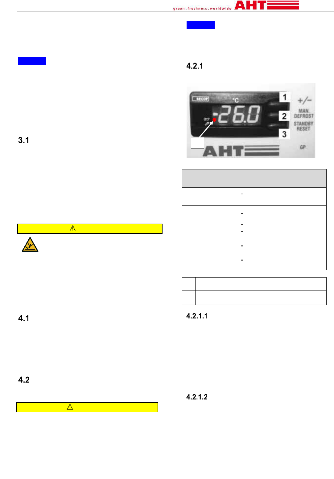
Electronic controller AHT (SECOP)
Three buttons are available as control elements.
Fig.1: Electronic controller
Nr.
Control
element
Function
1 Button [+/-]
Change of setting
(e.g. A1,A2)
2
Button [MAN.
DEFROST]
Semi-automatic defrost
3
Button
[STANDBY
RESET]
Manual defrost
Switch on/off refrigeration
function
Error code selection
(when red light is on)
Acknowledge acoustic
alarm
Nr. Display Meaning
4
luminous red
dot on
alarm
Switch refrigeration function on/off
Switch off (manual defrost):
Press Button [STANDBY RESET] for at least
3 seconds.
„---“ is shown at the display.
Switch on:
Press Button [STANDBY RESET] for at
least 3 seconds.
At the display the current temperature is
shown.
Setting selection
Available settings (see → chapter 2.2)
Show current setting:
Press button [+/-] briefly.
e.g. „A1“ is shown at the display.
Change setting:
By pressing button [+/-] several times, all
available settings can be addressed.
Confirm shown setting:
Wait 5 seconds.
4
AHT Cooling Systems GmbH
page 12
Semi-automatic defrost
Start semi-automatic defrost:
Press button [MAN. DEFROST] briefly
„dEF“ is shown at the display during entire
defrost cycle.
When the semi-automatic defrost is finished it returns
to normal operation. At the display the current
temperature is shown.
84-hour-defrost locker:
If „---“ is shown on the display, the defrost locker is
activated.
Alarm indication and acknowledgment
Alarm indication:
The error code is flashing alternatingly with the
current temperature. Simultaneously the red dot (see
→ Fig. 1 Nr.4) is on.
Some units are equipped with an acoustic alarm.
Alarm acknowledgment:
Error code and acoustic alarm:
Press button [STANDBY RESET] briefly.
On the display the current temperature and the red
dot is on. The red dot (see → Fig.1 Nr.4) remains
until the error is corrected.
Recall error code:
Press button [STANDBY RESET] briefly.
Error code is shown for 5 seconds on the
display. Afterwards the current temperature is
shown.
Error codes:
Error code meaning
F1
Sensor error
F2
Sensor error
F4
Sensor error
A90
Check clock settings
E20
High temperature alarm
E21
Evaporator temperature too high
E43
Low temperature alarm
E60
Temperature logger high alarm
E70
Electronic failure
E75
Controller temperature too high
E80
Motor error
E92
Compressor stop due to too high
Controller temperature
E93
Mains supply voltage out of range
E95
Mains supply frequency out of
range
Err
Display communication error
tst
Elektronics in test mode
5 Transport and storage
Examine the unit for transport damage after delivery.
Contact the maintenance service in case of damage
(see → chapter 10.4).
WARNING
Damage to refrigerant circuit.
The refrigerant can escape and create
an explosive gas/air mixture. Risk of
fire.
►Do not expose the device during
storage and transport to temperatures
higher than 70°C (158°F).
►Ensure good ventilation
►Observe the safety and warning
signs for devices with flammable
refrigerants (see → chapter 1.6.2.1).
►If the unit is damaged contact the
maintenance service (see→ chapter
10.4).
WARNING
Transport the unit with forklift trucks. Risk
of injury to persons during collisions.
►Follow the transport routes of forklift
trucks.
►Secure the cargo.
►Forklift trucks must only be operated
by trained persons.
►Follow maximum stacking heights on
packaging.
NOTICE
• Material damage due to transport und storage.
►Do not expose the unit during storage and
transport to temperatures higher than 70°C (158°F).
►Transport and store the unit only in the position of
use.
►Do not mix different types when you stack one
unit above the other.
►If the device was inclined during transport, wait a
minimum of 2 hours before commissioning.
►When delivering, ensure continuous accessibility
up to the installation room. (Observe the transit
heights/widths/installation space height and
adequate shunting radii.)
6 Unpacking
Check the unit for damage (bumps, scratches) before
and during unpacking. Contact the maintenance service
in case of damage (see → chapter 10.4).
WARNING
Disposal of packaging material and films.
Danger of suffocation.
► Keep packaging material and foils
away from children.
► Do not let children play with them.
WARNING
Damage to the refrigerant circuit. The
refrigerant can escape and create an
explosive gas/air mixture. Risk of fire.
► Ensure good ventilation.
► Observe the safety and warning signs
for devices with flammable refrigerants
(see → chapter 1.6.2.1).
►If the unit is damaged contact the
maintenance service (see→ chapter
10.4).
AHT Cooling Systems GmbH
page 13
CAUTION
Heavy unit components. Cutting injuries
to the hands. Hands can be jammed.
► When unpacking, take care with
fingers and hands.
► Wear protective gloves.
NOTICE
• Material and property damage due to missing
components of the unit.
►Check for loose components in the packaging.
►Do not dispose of loose components. If it cannot
be determined where the loose components belong,
check with the maintenance service (see→ chapter
10.4).
7 Setup and installation
The setup and installation of a unit can be conducted
by the operator.
For technical data for interfaces, see → chapter 2.2.
Technical modifications to the device can only occur
with the coordination and approval of the
manufacturer.
NOTICE
• Material and property damage due to congestion of
the warm exhaust air (heat accumulation).
►The exhaust air must be able to escape freely at
the backside of the unit.
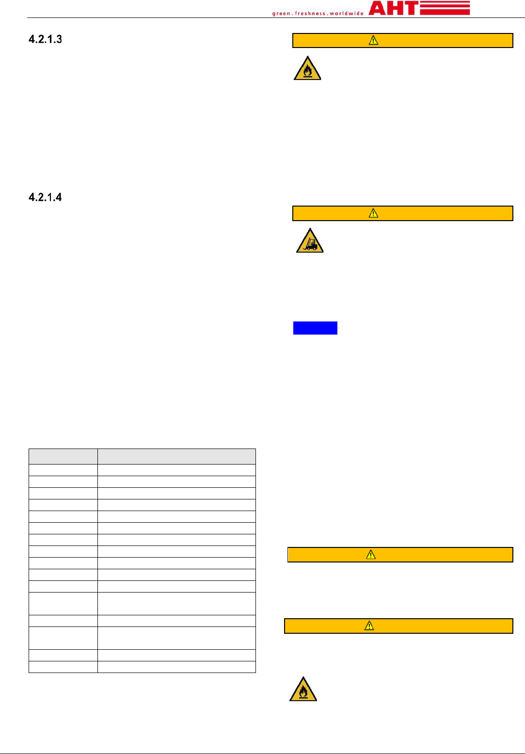
► Minimum distance for single unit installation
All around: 100 mm (3.9 in)
►Minimum distance for island arrangement (see → Fig.2.)
A= 0 mm (0 in)
B= 100 mm (3.9 in) /155 mm (6.1 in)
(type- specific)
Fig. 2: Minimum distance for island arrangement
►The air vents of the unit-cover must not be covered
for island arrangement.
►Superstructures can be attached only in agreement
with the manufacturer.
Minimum distance 100 mm (3.9 in).
The temperature display, safety instructions and
serial plate (see → chapter 2.2.1) must always be
kept clear.
WARNING
Danger of tilting of the unit. People’s bodies
can be jammed.
►Remove the transport pallet only when the
stable, final installation position has been
reached. If you have questions, contact the
maintenance service (see → chapter 10.4).
►Do not climb onto or into the device.
WARNING
If the refrigerant circuit is damaged, the
refrigerant can escape and create an
explosive gas/air mixture. Risk of fire.
►Do not close the air vents in the unit
housing. Use only original accessories.
►The unit must only be installed in well-
ventilated areas.
►Do not install the unit in basement or
lowered areas.
►Ducts and wall penetrations must be
sealed close to the unit in accordance with
fire protection laws.
► Drilling or other work on the unit is not
permitted.
CAUTION
Cutting injuries in the case of material
breakage. Danger of falling.
►Do not climb onto or into the unit.
CAUTION
Heavy units. Hands can be jammed.
►During setup and installation, pay
attention to fingers and hands.
►Wear protective gloves.
NOTICE
Material and property damage due to misuse.
►Setup the unit only in the position of use.
Do not remove existing stilt/castors.
►Do not expose the unit to heat radiation at the
installation site.
►Do not expose the unit to warm air current.
►Do not attach thick, insulating materials to the
unit. Advertising posters may only be thin foils.
Installation tasks for operator:
Block castor brake (if castors are present).
Installation and removal of glass lids:
The removal and installation can be necessary for
cleaning purposes.
Glass safety instructions see → chapter 1.6.3.
Units with glass sliding lids
Fig.3: Unit with glass sliding lids
Removal of glass sliding lids
1. Open upper sliding lid.
2. Start lifting upper sliding lid with both hands and
pull it out of the upper track.
3. Remove carefully with both hands.
4. Ensure proper and safe storage.
AHT Cooling Systems GmbH
page 14
Installation of glass sliding lids
1. Insert smaller, lower sliding lid.
2. Insert upper sliding lid.
3. Fully close the lids.
4. Check for smooth functionality.
Electrical connection
The connection to the power supply is provided by the
operator. For technical data, see → chapter 2.2.
WARNING
Connect the
unit to the power supply.
Contact with live parts may cause electric
shock. Risk of fire due to sparks or
overloading.
►Work on the electrical system may only be
performed by qualified staff.
►
Refer to the local electrical safety
regulations.
►
Follow the applicable standards and
safety instructions.
►
Follow the information on the serial plate
(see
→ chapter 2.2.1). The network voltage
and the network frequency must matc
h the
specifications on the serial plate.
►
Do not connect any damaged unit to the
power
circuit.
►
Damaged parts (such as power cords)
must only be replaced by trained staff.
Contact the maintenance service (see
→
c
hapter 10.4).
►
Do not squeeze or bend power supply
cords.
►
Observe the minimum requirement for
connection cables (see
→ chapter 2.2).
►
The unit must be electrically protected
according to the applicable laws and
regulations and the requirements of AHT
(see
→ chapter 7.2).
►
Connect the unit only to a network circuit
with protective grounding.
►
Do not use extension cords or multiple
power strips.
►
Concealed electrical parts must not be
damaged. Drilling or ot
her work on the
device is not permitted.
NOTICE
• Material and property damage caused by non-
AHT-approved deviations (voltage, frequency) in
the operator's electrical network.
►The manufacturer is not responsible for damage
to the electrical unit of the operator and the
subsequent damage caused thereby.
• Material and property damage due to a wrong
electrical connection.
►Load shedding circuits or device shutdowns are
not permitted.
Unit-connection cable
At the end of the unit-connection cable you can find a
labeling flag with a snowflake.
Fig. 4. Symbol snowflake
The unit-connection cable is used for cooling
purposes.
NOTICE
• Property damage due to missing connection
(cooling).
►Do not connect the unit-connection cable to the
power supply of the ambient light.
Light-connection cable (optional)
At the end of the light-connection cable you can find
a labeling flag with a lamp.
Fig. 5. Symbol lamp
Unit/Light- connection cable:
No labeling flag.
NOTICE
• Property damage due to missing connection
(cooling).
►Unit/Light- connection cable requires permanent
power supply.
Units with IEC-Box
For technical data, see → chapter 2.2.
Units can be equipped with a so-called IEC-Box.
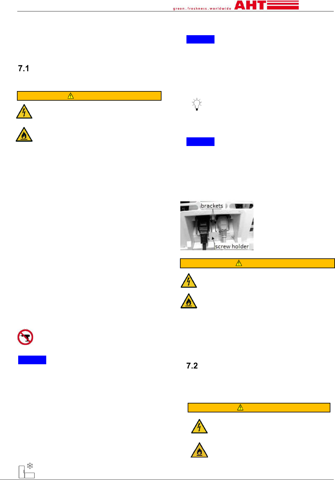
Fig.6: IEC-Box
WARNING
Wrong electrical connection to the IEC-Box.
Contact with live parts may cause electric
shock. Risk of fire due to sparks or
overloading.
►The brackets of the IEC-Box must be
properly fixed and secured by the screw holder
(see → Fig.6).
AHT recommends (e.g. island arrangement) the
usage of a cable duct with internal or external
sockets. In the case of floor mounting, do not exceed
lower edge of the ventilation grille on the backside.
Electrical protection
Each electrical supply circuit must be equipped with
appropriate protection means according to National
requirements and local regulations.
For technical data, see → chapter 2.2.
WARNING
Faulty/inadequate electrical fuse.
Contact with live parts may cause
electric shock. Risk of fire due to sparks
or overloading.
►Provide adequate protection.
►Observe applicable local
requirements (for example, for electrical
installation and operating of the device).
►Follow the applicable standards and
AHT Cooling Systems GmbH
page 15
safety instructions.
►Never connect more than 2 devices
to a Circuit Breaker (CB). AHT
recommends one device only.
One of the following electrical fuses must be used:
Circuit Breaker (CB) in combination with
Ground Fault Circuit Interrupter (GFCI)
Residual current operated Circuit-Breaker
with Overcurrent protection (RCBO).
Observe the applicable standards such as:
NEC 70
8 Commissioning
The unit must only be commissioned in the intended
installation room and after checking for
completeness. The commissioning of a unit can be
conducted by the operator.
WARNING
Damage to the electrical system and/or
the refrigerant circuit. Contact with live
parts may cause electric shock. The
refrigerant can escape and create an
explosive gas/air mixture. Risk of fire due
to sparks or overloading.
►Do not commission a damaged device.
►Do not connect damaged parts to the
circuit (such as power cords).
► Damaged parts (such as power cords)
must only be replaced by trained staff.
► Observe the safety and warning signs
for devices with flammable refrigerants
(see → chapter 1.6.2.1).
► If the unit is damaged contact the
maintenance service (see→ chapter 10.4).
NOTICE
• Property damage due to incorrect ambient
conditions
►Adjust the unit to the ambient temperature before
commissioning.
►The ambient temperature must not be less than
16°C (60.8°F).
Plug in the unit-connection cable or unit/light-
connection cable.
The cooling cycle starts working after a short delay of
max. 2 min.
If the operator retrofits a unit with internal LED-
lighting, the light-connection cable must be plugged
in.
Choose desired operating mode see → chapter 4.2.
3-4 hours after commissioning the desired
temperature can be achieved.
9 Operation (use)
Only trained operating staff are allowed to operate
the device.
WARNING
Damage to the electrical system and/or the
refrigerant circuit during operation. Contact
with live parts may cause electric shock. Risk
of fire due to sparks or overloading.
The refrigerant can escape and create an
explosive gas/air mixture. Risk of fire.
►If the unit is damaged or if the electrical
protection was triggered:
1. Disconnect the unit.
2. Secure the unit against restarting.
3. Contact the maintenance service (see→
chapter 10.4).
►Observe the safety and warning signs for
units with flammable refrigerants (see →
chapter 1.6.2.1).
►Avoid external force to the unit such as
careless movements with floor trucks or floor
cleaning machines.
►Avoid transmission of pulsations and
vibrations to the unit.
CAUTION
Cutting injuries in the case of material
breakage. Danger of falling.
►Do not load glass lids.
►Do not climb onto or into the unit.
►Check for damage to the glass elements and
plastics. If the unit is damaged contact the
maintenance service (see→ chapter
10.4).
►Check breakage of glass containers when
operating above 0°C (38°F).
CAUTION
Disposal of broken glass. Cutting injuries to the
hands.
►To remove the glass splinters and the
goods possibly damaged by them, wear
protective gloves
► Remove all glass splinters carefully.
NOTICE
• Material damage due to misuse.
►Operate the unit only in the position of use
(horizontal).
►Operate the unit only with existing stilt/castors.
►Regularly check that the unit is in good condition.
Damage must be repaired immediately.
►Avoid transmission of pulsations and vibrations to
the unit.
►Avoid external force to the device such as
careless movements with forklift or floor cleaning
machines.
• Property damage due to misuse.
►Do not exceed ambient conditions shown at the
serial plate (see → chapter
2.2.1).
►The ambient temperature must not be less than
16°C (60.8°F).
►Operate the unit only with glass lids.
►Check the temperature (see→ chapter 4.1).
►Stored goods must be checked by the operator in
the case of power failure (temperature control).
►Check regularly for foreign objects in the goods
area. Incorrectly stored goods must be removed
immediately.
►Remove food residues, such as spilled liquids
and packaging residues (see → chapter 10.1.1.1).
►Regularly check that the glass doors are closed.
AHT Cooling Systems GmbH
page 16
Loading
Access to the goods from the top.
The unit must only be loaded with goods when the
temperature specified for the product has been
reached. Temperature display (see → chapter 4.1).
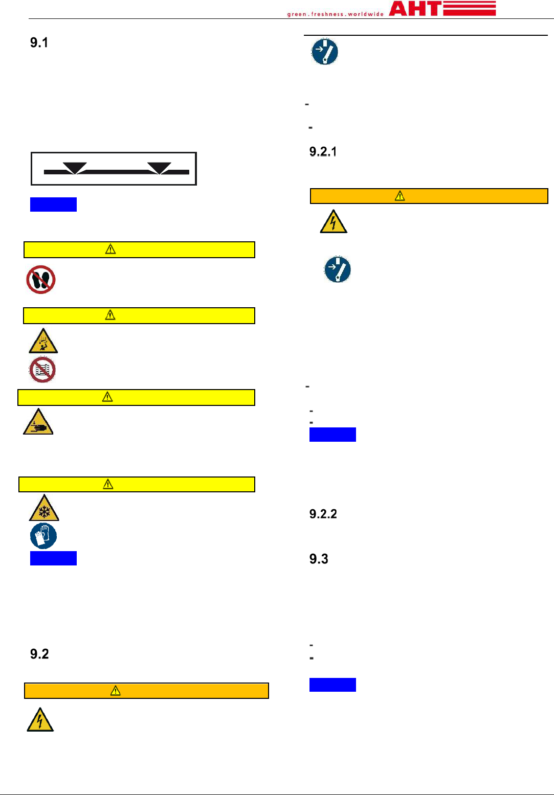
Loading is only permitted up to the load line indicated
inside the cabinet (see → Fig.7).
Lower load line: A3, A4
Upper load line: A1, A2, A5
Fig.7: Load line
NOTICE
• Property damage due to misuse.
►Do not load when display shows „dEF“.
CAUTION
Cutting injuries in the case of material
breakage.
►Do not climb onto or into the device
during loading.
CAUTION
Falling objects.
Impact injury. Cutting injury in
the case of
glass breakage.
► Do not place objects on the unit.
CAUTION
Opening/Closing the glass doors. Hands
(body parts) can be pinched.
►During opening/closing, do not grip the
gaps.
►When opening/closing, pay attention to
other people.
CAUTION
Low temperature. Frostbite on skin.
► Wear protective gloves during
loading.
NOTICE
• Property damage due to misuse.
►The unit must only be loaded with goods when
the temperature specified for the product has been
reached.
►Insert the goods carefully.
►Immediately close the glass doors after loading.
Decommissioning and Re-
commissioning
WARNING
Work on the electrical system.
Contact with live parts may cause electric
shock.
►Work on the electrical system may only
be performed by qualified staff.
►Observe the electrical safety rules
before starting work.
1. Disconnect the unit.
2. Secure the unit against restarting.
Reasons for decommissioning
by qualified staff:
Maintenance, service, repair (see → chapter 10.2)
by operating staff:
Damage to the unit (e.g. broken glass lids).
Decommissioning
The decommissioning must only be performed by
trained operating staff or qualified staff.
WARNING
Decommissioning of the unit. Contact
with live parts may cause electric
shock.
►Only previously trained staff must
turn off the unit.
►Disconnect the unit and secure
against restarting.
Steps for decommissioning for operating staff:
1. Transfer the goods to another unit.
2. Switch refrigeration function off (see → chapter
4.2).
3. Remove the power plug (disconnect the unit).
Prolonged decommissioning:
Perform steps for decommissioning (see →
above).
Perform basic cleaning (see → chapter 10.1.1).
Keep the lids open.
NOTICE
• Material damage due to prolonged
decommissioning.
►Do not expose the unit to any direct heat radiation.
►Do not place objects in or on the unit.
►Store the unit only in the position of use.
Re-commissioning
See commissioning → chapter 8
Faults in operation
Indication of alarms:
There are different types of alarms to indicate faults
in operation:
Display operating element:
Electronic controller (see → chapter 4.2.1):
Error code and buzzer (optional)
luminous red dot
NOTICE
Material- und property damage in case of
indication by error code/buzzer, luminous red dot.
►Move the goods to another unit.
►Contact the maintenance service (see→ chapter
10.4) immediately.
Remote monitoring can be requested at the
maintenance service (see→ chapter 10.4).
AHT Cooling Systems GmbH
page 17
10 Maintenance
Monitoring tasks by operating staff:
Monitoring tasks
Frequency
see →
chapter
Check
- good condition of the unit
- foreign objects in good area
- closed glass lids
continuously
1.3,
9
Check
Damage of glass lids/ glass
elements
Damage of glass containers
continuously
1.6.3,
9
Check Temperature
several times
daily
4.1,
9
Check correct loading of
goods
continuously
9.1
Check for contamination
Contamination of the unit
Food waste and packaging
waste
daily
10.1.1
Floor (around the unit)
daily
10.1.1
Puddle formation in front
of/under the unit (defrost water)
daily
3.1
Defrost water drain/ sieve
continuously
10.1.1
WARNING
Electrostatic discharge and sparking. Sparks
can ignite the leaking refrigerant when the
refrigerant circuit is damaged/not sealed. Risk
of fire.
►To remove water and for cleaning, use a
slightly damp cloth or sponge.
►Do not use dry clothes or sponges to wipe
dry (risk of electrostatic charging and
sparking).
►Do not operate any electrical devices (e.g.
wet vacuum cleaners) within the refrigerator
compartment that are not of the type
recommended by the manufacturer. Devices
with explosion protection markings (see →
chapter 1.2) are permitted.
Cleaning
Reasons for regular and thorough cleaning (basic
cleaning):
- Assurance of the required hygiene.
►Always keep the goods interior in a clean
condition.
- Lowest possible energy consumption.
- Trouble-free operation.
- Life- time extension.
WARNING
Damage to the electrical system and
refrigerant circuit by using steam and
high-pressure cleaners. Contact with
live parts may cause electric shock.
The refrigerant can escape and create
an explosive gas/air mixture. Risk of fire
due to sparks or overloading.
►For basic cleaning, do not use steam
and high-pressure cleaners (→ see
chapters 1.6.1 and 1.6.2.1).
CAUTION
Cutting injuries in the case of material
breakage.
Danger of falling.
►Do not climb onto or into the unit
during cleaning.
Safety in handling with glass see →chapter 1.6.3.
For cleaning use protective gloves.
Basic cleaning
Responsibility: Operating staff
Cleaning agent:
NOTICE
• Material damage due to excessive amounts of
cleaning agents.
►Use only cleaning devises moistened with
cleaning agents.
Cleaning agents
Cleaning area
Clean water
Unit and glass surfaces
outside and inside
Slightly alkaline cleaning
agent for heavier
contamination (e.g.
neutral soap and water).
Unit outside and inside
Glass surfaces outside
Glass cleaner
(recommended pH-value 5-7)
Glass surfaces outside
NOTICE
• Material damage due to wrong cleaning agents.
►Do not use abrasive, chemically aggressive,
strongly acidic (pH-value <4), strongly alkaline (pH-
value > 8) or highly flammable cleaning agents.
Cleaning devices:
All cleaning devices must be clean themselves.
Cleaning devices
Cleaning area
For cleaning
Damp soft cotton cloth
Unit and glass surfaces
outside and inside
Damp sponge cloth or
sponge
Unit inside
For drying
Lightly moistened soft
cotton cloth
Unit and glass surfaces
outside and inside
NOTICE
• Material damage due to wrong cleaning devices.
Damage to the surfaces.
►Never use hard, sharp objects.
►Never use hard, coarse cleaning devices (e.g.
steel wool).
Cleaning steps during operation
Frequency of cleaning (during operation):
If needed (see → chapter 10 „check for
contamination “).
AHT Cooling Systems GmbH
page 18
Cleaning steps:
1.
Clean exterior walls and the frame.
2.
If available clean the bumpers and water
protection strips.
3.
Clean glass surfaces outside.
4.
Remove food residues, such as spilled liquids
and packaging residues.
5.
Clean the tracks for the lids.
6.
Dry all cleaned surfaces and components.
7.
Clean the floor in front of the unit.
Cleaning steps only with cooling
function switched off (manual defrost)
Frequency of cleaning (cooling function switched
off): For hygiene reason at least twice a year.
1.
Move goods to another unit.
2.
Switch refrigeration function off.
Press Button [STANDBY RESET] for at least 3s.
„---“ is shown at the display.
See → chapter 4.2.1.1
3.
Removal of glass lids (see → chapter 7). Clean
before re-installation. Also clean the associated
plastic bezels/unit frame and seals. Do not apply
large amounts of cleaning agent to these
surfaces.
NOTICE
•
Material damage due to improper cleaning.
Damage to the surface of plastic bezels/unit
frame and impairment of the function of seals.
►There must not be any detergent residues
on the plastic bezels/unit frame and seals.
►Always clean plastic bezels/unit frame and
seals again with clean water.
4.
Remove all accessories from the interior of the
unit such as: air ducts, goods grilles. After use
ensure for a neat and safe storage.
Air-flow channel remains in the unit. Clean
before re-installing. Wait until all ice and frost is
melted from the inner walls of the tank.
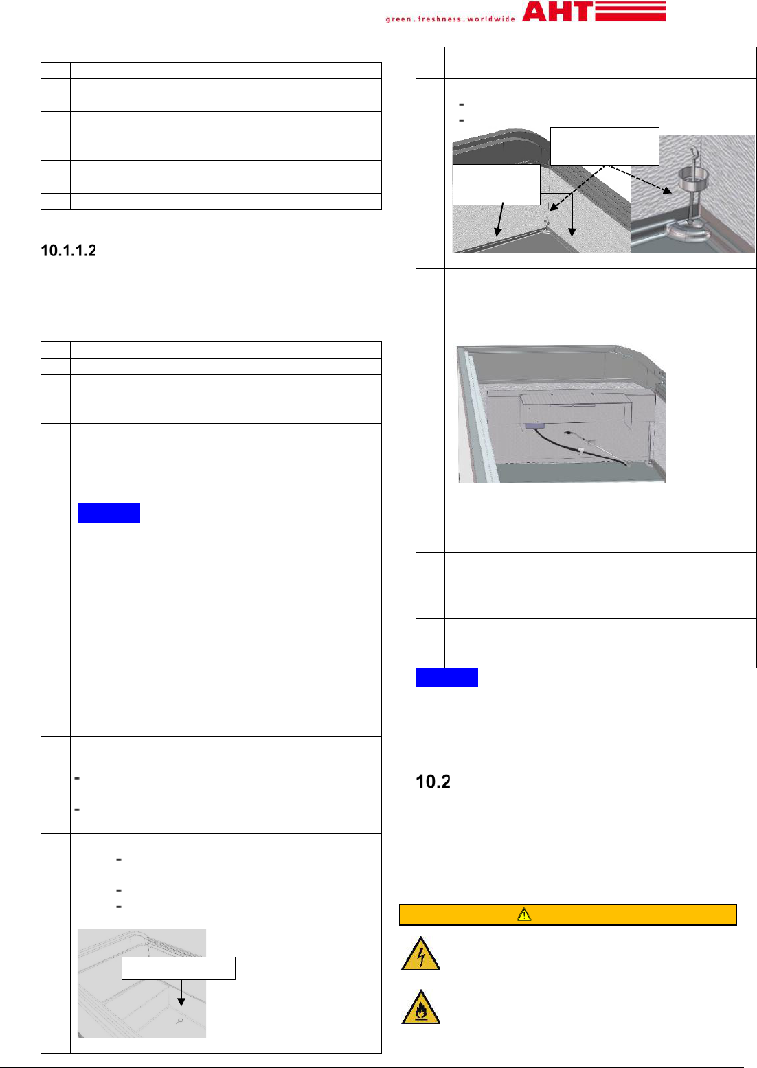
5.
Remove defrost water
(either by method 5a or 5b)
5.a
Wet vacuum cleaner / electrical devices with
marking of explosion protection or
Lightly moistened cloth (observe warning
notice see → chapter 10).
5.b
Units with defrost water plug
Place a pan under the drain.
Remove the defrost water plug.
Let the defrost water drain off
Close the drain with the defrost water
plug again.
Fig.8: Unit with view on defrost water plug
6.
Remove food residues, such as spilled liquids
and packaging residues
7.
Clean the interior of the unit
Clean the defrost drain
Remove and clean the defrost water sieve
Fig.9: Defrost water drain/sieve
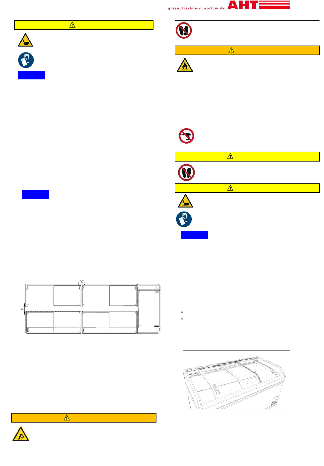
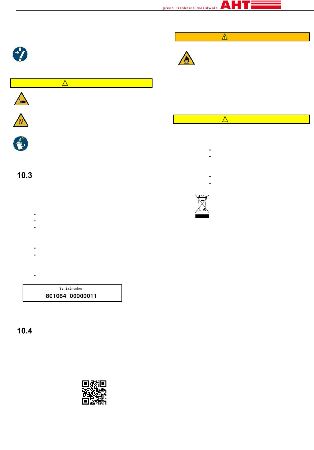
8.
If needed clean the air-flow channel (see →Fig.
10), for this purpose lift the air-flow channel up
and clean the areas below carefully with a
moistened cloth.
Fig.10: Air-flow channel
9.
All cleaned areas and components must be
dried again. Observe warning notice see →
chapter 10).
10.
Re-install all accessories correctly.
11.
Re-install the lids properly (see → chapter 7)
and close them completely.
12.
Switch refrigeration function on.
Press Button [STANDBY RESET] for at least
3s. The temperature is shown at the display.
See → chapter 4.2.1.1
NOTICE
• Property damage due to misuse.
►The unit must only be loaded with goods when the
temperature specified for the product has been
reached.
Maintenance, service and repair
Responsibility: qualified staff
The units are maintenance-free. The service and
repair work, including subsequent functional testing,
must be performed by qualified staff. For questions
about maintenance, please contact the maintenance
service (see → chapter 10.4).
WARNING
Work on the electrical system and refrigerant
circuit. Contact with live parts may cause
electric shock. The refrigerant can escape and
create an explosive gas/air mixture. Risk of
fire due to sparks or overloading.
►Work on the electrical system and
refrigerant circuit may only be performed by
qualified staff.
defrost water plug
Defrost drain
Defrost water
sieve
AHT Cooling Systems GmbH
page 19
► Follow the safety instructions in → chapter
1.6.
►Before any maintenance, service and repair
work.
1. Disconnect the unit.
2. Secure the unit against restarting.
►Re-commissioning and functional testing
must only be performed by qualified staff.
CAUTION
Sharp edges, rotating parts. Risk of
injury to the hands and body.
Hot surfaces. Risk of burns in case of
skin contact.
►Service and repair work on the unit
must only be performed by qualified
staff.
► Wear protective gloves.
►Touch hot surfaces (especially
compressor) only after cooling.
What to do if …
All units are thoroughly tested for performance and
safety in the AHT testing center.
Immediately contact the maintenance service (see →
chapter 10.4), if:
a fault occurs (see → chapter 9.3),
loud noises or vibrations occur,
failure of the operating- and display
elements (see → chapter
4.2.1.4)
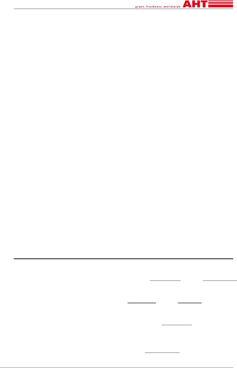
Report the following:
Unit type
Serial number of the unit (see serial plate →
chapter
2.2.1/additional sticker on the left
frame backside see → Fig.11),
Type of fault.
Fig.11. Example, sticker with 14-digit serial number
Maintenance services
For questions regarding maintenance (service, repair,
etc.), please contact your regionally competent AHT
service partner:
AHT-service line: See sticker on the unit
Email: product_support@aht.at
Online-contact: www.aht.at/service
s
QR-Code:
The maintenance services have access to all necessary
and current information for commissioning and
maintenance, e.g. spare parts lists.
11 Disposal
WARNING
Escaping refrigerant or residues of
refrigerant can create an explosive gas/air
mixture. Risk of fire.
►
Do not damage the pipes.
►
Open the refrigerant circuit correctly
before dismantling and disposal and suction
off the refrigerant safely and completely
.
There must not be any residues left in the
refrigerant circuit.
►Suctioning off of refrigerant must only be
performed by qualified staff.
CAUTION
Improper disposal. Environmental damage.
► Pay special attention to safe and
environmentally sound disposal
of the refrigerant,
of the insulating foam (e.g. heat-
insulating material is polyurethane
foam with pentane),
of the compressor oil,
of the battery
►Separate collection of electrical and
electronic devices according to the
applicable national disposal
regulations (e.g. WEEE within the
EU) and the provisions of the local
waste disposal partner.
►Units must not be disposed of with
household waste.
AHT Cooling Systems GmbH
A
HT Cooling Systems USA, Inc.
7058 Weber Blvd. Ladson, SC 29456 USA
Phone: +1 (0) 843/767 6855 Fax: +1 (0) 843/767 6858 Email: inf[email protected].at
Internet: www.ahtusa.net
A
HT Cooling Systems GmbH (Headquarter)
8786 Rottenmann Werksgasse 57Austria
AHT Cooling Systems Brasil Ltda.
Rua Onório Bortolato1065–Bairro Pedreiras Navegantes – SC - 88375-000Brasil
Phone: +55 (0) 11 4702 / 30 99 Fax: +55 (0) 11 4702 / 71 68 Email: info@br.aht.at
AHT Cooling Systems (Changshu) Co., Ltd.
215500 Changshu 88 Yangguang Avenue
Jiangsu Province P. R. China
Phone: +86 512 5236 7100 Fax: +86 512 5236 2393 Email: off[email protected].at
