
California Air Resources Board 1 1/11/19
Reporting Guidance for Electricity Generating and Cogeneration Units
for California’s Mandatory Greenhouse Gas Reporting Regulation
Introduction
This document describes the reporting requirements for operators of electricity
generating units (including cogeneration) subject to the Regulation for the Mandatory
Reporting of Greenhouse Gas Emissions (title 17, California Code of Regulations,
sections 95100-95158) (regulation or MRR).
Unlike MRR, this guidance does not have the force of law, does not establish new
mandatory requirements for greenhouse gas (GHG) reporting, and in no way supplants,
replaces, or amends any of the legal requirements of the Regulation. Conversely, an
omission or truncation of regulatory requirements in this guidance does not relieve
operators of their legal obligation to fully comply with all requirements of MRR.
The reporting requirements for Electricity Generation Units (EGU) are specified in
section 95112 of MRR, with references to Title 40, United States Environmental
Protection Agency (U.S. EPA) Code of Federal Regulation (CFR), Part 98 Subparts C
and D, and to section 95115 of MRR for emissions calculation methods and fuel
sampling and monitoring requirements. Because 40 CFR Part 98 does not require
reporting of the energy generation information required in section 95112, section 95112
requirements have no counterpart in 40 CFR Part 98. Although Subpart D of the U.S.
EPA regulation is titled “Electricity Generation,” it only provides instruction for emissions
reporting for Part 75 generation units. Under the federal reporting program, any
applicable non-Part-75 EGUs are treated as general stationary fuel combustion
sources, while MRR includes the same reporting requirements for both Part 75 and non-
Part 75 EGUs.
This document focuses on rule applicability, reporting requirements, system energy
accounting, verification requirements, and several example scenarios for various
generation configurations. The current document includes a correction to two figures
(example 3b and 4), along with a clarification for cooling energy (page 3).
1 Applicability
The reporting requirements in section 95112 of MRR apply to the following facilities:

Guidance for California’s Mandatory Greenhouse Gas Emissions Reporting
California Air Resources Board 2 1/11/19
• Part 75 power plants, regardless of emissions level, until cessation requirements
are met.
• Stand-alone power plants and cogeneration facilities with greater than or equal to
10,000 metric tons carbon dioxide equivalent (MTCO₂e) of emissions.
• Industrial, commercial, or institutional facilities with an on-site EGU that have
greater than or equal to 10,000 MTCO₂e of total facility emissions.
• Operators subject to reporting that have any non-fuel-based renewable electricity
generating unit, such as solar panels, with nameplate generating capacity of
greater than 0.5 megawatts (MW) (section 95112(g)).
• Operators applying for legacy contract transition assistance under section 95894
of the Cap-and-Trade Regulation (sections 95112(a) and (i) of MRR).
2 EGU Reporting Requirements
2.1 Options for <1 MW Facilities
Reporting of EGU data items listed in section 95112 is optional for operators with total
nameplate generating capacity less than 1 MW from fuel-based generation. However,
the operator still needs to report any fuel-combusting EGU as a stationary combustion
source pursuant to the first paragraph of section 95115 and 40 CFR Part 98 Subpart C.
Note: Legacy contract applicants, regardless of capacity, must comply with the
requirements of section 95112(i). Also, on-site renewable electricity generation with a
generating capacity greater than 0.5 MW has separate requirements as specified in
section 95112(g) of MRR (see section 2.8 of this document for more information).
2.2 Bigeneration versus Cogeneration
“Bigeneration” refers to an EGU that simultaneously produces electricity and steam from
the same fuel source but does not utilize waste heat as is done with a cogeneration
system. An example of bigeneration would be a boiler generating steam that is split into
two streams, where one stream powers a steam turbine to generate electricity, and the
other stream is used for other industrial, commercial, heating, and cooling purposes.
The definition of a “bigeneration unit” can be found in section 95102(a). See Example 4
for a graphical illustration of a bigeneration system.
2.3 Total Thermal Output
Operators of cogeneration and bigeneration units must report the unit’s “total thermal
output” as defined in section 95102(a), which is the total amount of usable thermal
energy that can potentially be made available for use in any industrial or commercial

Guidance for California’s Mandatory Greenhouse Gas Emissions Reporting
California Air Resources Board 3 1/11/19
processes, heating or cooling applications, or delivered to other end users. The total
thermal output value does not include any thermal energy used directly for electricity
generation (e.g., steam used to drive a steam turbine generator for electricity
generation), and it also excludes the heat content of returned condensate and makeup
water. The total thermal output includes the following:
• Thermal energy provided or sold to a particular end-user (section 95112(a)(5)(A))
• Separately quantify and report the subset of generated thermal energy that is
used to produce cooling energy e.g., chilled water) or distilled water for a
particular end-user outside of the facility boundary (section 95112(a)(5)(A))
• Parasitic thermal energy used for supporting power generation that has been
included in the quantity reported under section 95112(b)(3) but that is not
accounted for in the quantities reported under sections 95112(a)(5)(A) and (C).
These processes may include, but are not limited to, steam used for power
augmentation, NO
x
control, de-aerator, cooling tower. If the steam used at those
applications has not been included in the quantity reported under
section 95112(b)(3), this data item should be zero (section 95112(a)(5)(B)),
• Thermal energy used in other on-site processes or applications (e.g.,
manufacturing or production process, heating/cooling applications) that are not in
support of, or a part of, the electricity generation system (section 95112(a)(5)(C)),
and
• Thermal energy that is vented, radiated, wasted, discharged, or otherwise not
utilized.
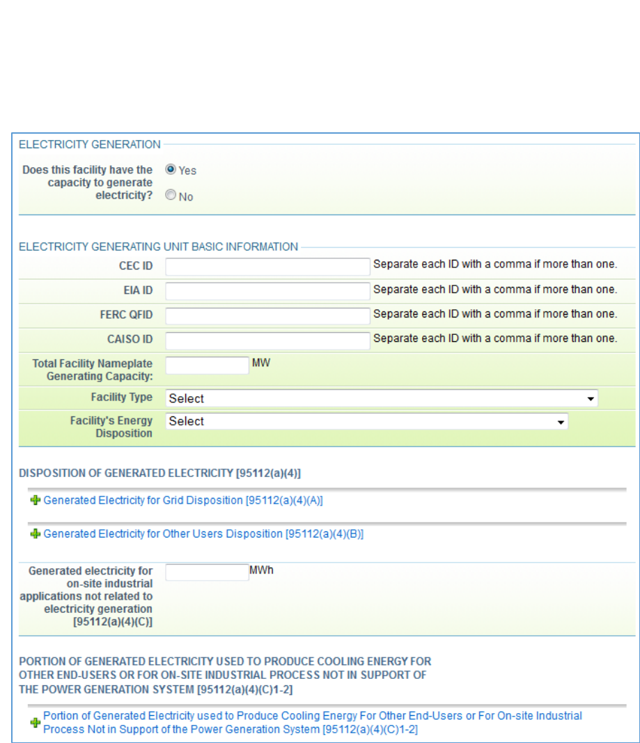
Data associated with these thermal outputs are entered into Subpart A of Cal e-GGRT,
as shown in Figures 1 and 2 which follow.
To understand how a facility uses and wastes generated thermal energy, “total thermal
output” can be compared to the disposition of thermal energy quantities reported under
section 95112(a)(5). The sum of the three quantities reported under
section 95112(a)(5) should be less than or equal to the total thermal output quantity
reported under section 95112(b)(3), with the difference between the two numbers being
the amount of thermal energy not utilized for any useful purpose. For example, for an
industrial facility with an on-site cogeneration unit that uses all the steam generated by
the cogeneration unit in manufacturing process in the facility, the amount of generated
thermal energy not utilized by other useful industrial applications would be calculated
as: “total thermal output” quantity reported under section 95112(b)(3), minus the
quantity reported under section 95112(a)(5)(C) for generated thermal energy that is
used by those on-site industrial processes or operations and heating or cooling
Guidance for California’s Mandatory Greenhouse Gas Emissions Reporting
California Air Resources Board 4 1/11/19
applications, and minus the quantity reported under section 95112(a)(5)(B) for thermal
energy used for supporting power production.
Figure 1 – Electricity Generation, Data Entry in Subpart A
Guidance for California’s Mandatory Greenhouse Gas Emissions Reporting
California Air Resources Board 5 1/11/19
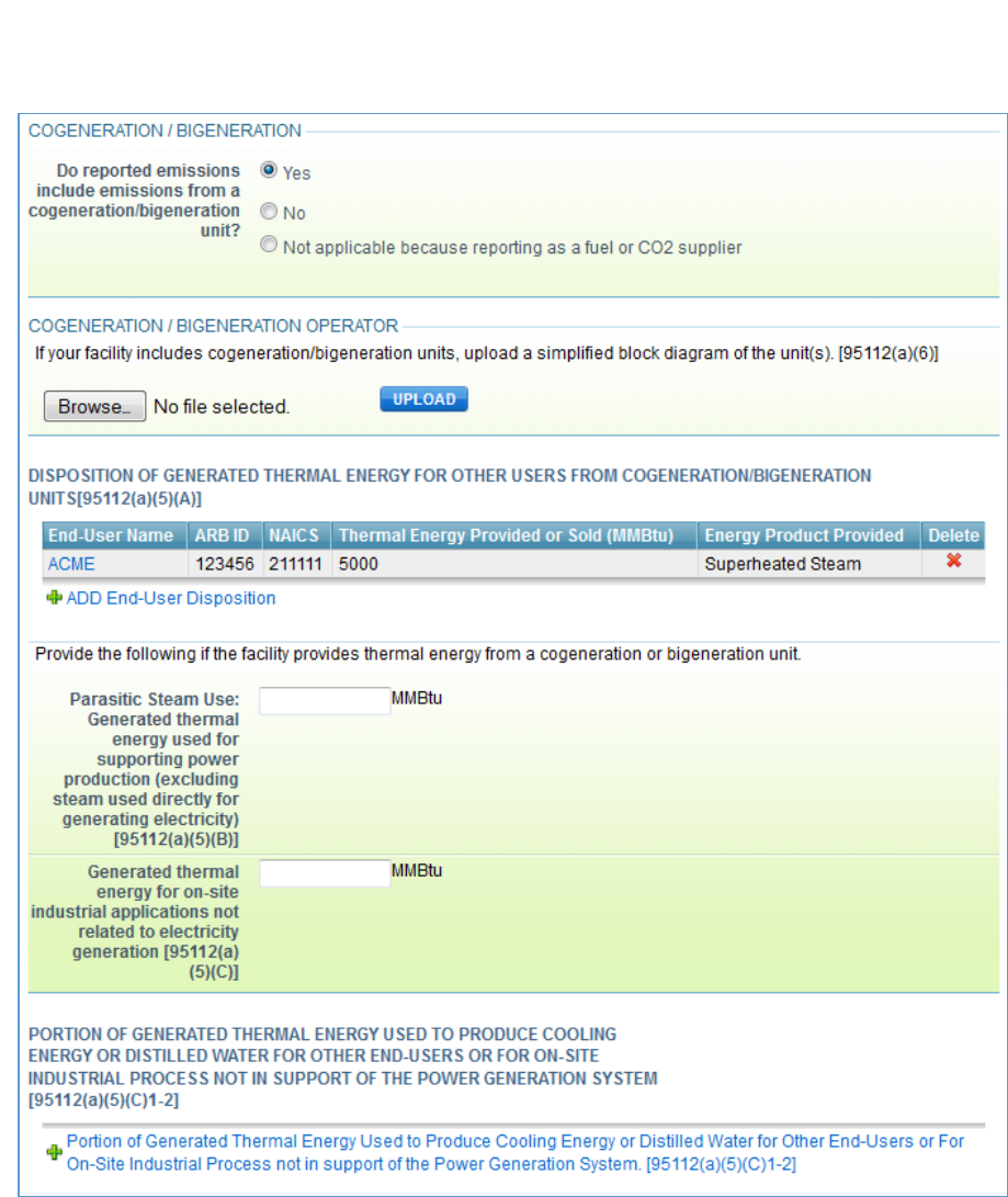
Figure 2 – Cogeneration, Data Entry in Subpart A
Guidance for California’s Mandatory Greenhouse Gas Emissions Reporting
California Air Resources Board 6 1/11/19
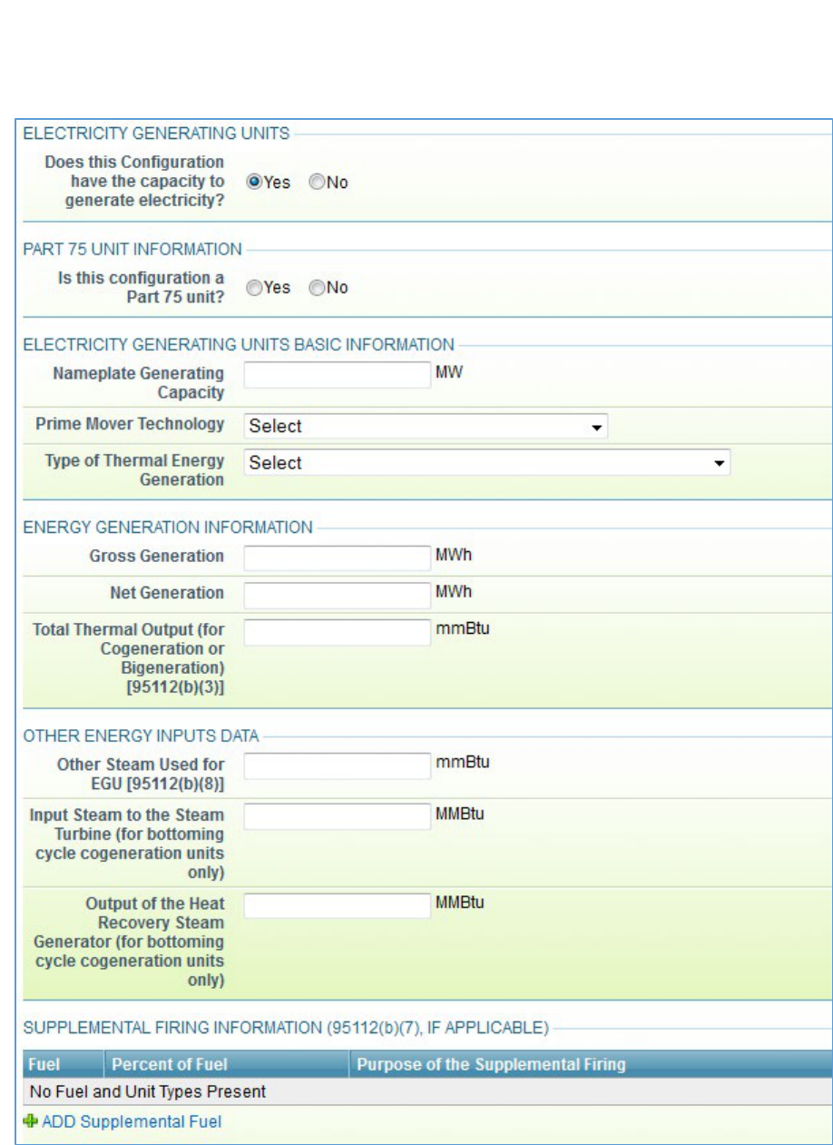
Figure 3 – Electricity Generating Unit, Data Entry in Subpart C

Guidance for California’s Mandatory Greenhouse Gas Emissions Reporting
California Air Resources Board 7 1/11/19
2.4 Net and Gross Electricity Generation
Gross generation is the total electrical output of the EGU, while net generation is gross
generation minus parasitic load. Gross and Net Generation are entered into Subpart C
of Cal e-GGRT, as shown in Figure 3, previously. In the case of cogeneration, net
power generated includes electricity generated that was consumed on-site for the
purposes of an industrial production process that is not power generation, power
provided directly to particular end users, as well as wholesale power provided to the
grid. An engineering estimate of station service or generating unit service power
requirements is acceptable. While this engineering estimate does not need to meet
calibration requirements of section 95103(k), because it is not emissions or covered
product data, the facility operator must be able to demonstrate to the verifier and CARB
that the chosen estimation method is reasonable and based on good engineering
principles.
Net power generation is used for evaluating efficiency of the generating units.
Electricity consumed at the facility when the EGUs were not operating should not be
counted against net generation, as doing so would make the EGU appear less efficient.
Electricity acquired from sources outside the facility boundary should also not be
counted against net generation, but should be accounted in the electricity
purchased/acquisition quantity under section 95104(d)(1). Excluding electricity from
sources outside the facility boundary is especially important for an EGU with a low
capacity factor.
1
Operators should not report a negative net generation number if the
station service power requirement is greater than total generation for the year. Instead,
operators should exclude from net power generation the power requirements during unit
downtime or unit standby, and report that electricity consumption under
section 95104(d)(1).
However, for an EGU with a high capacity factor, the facility operator may evaluate
whether performing an engineering calculation to separate the parasitic loads during
unit operation and unit downtime would result in a significant gain in the system
efficiency figure. If the gain in the system efficiency figure is insignificant, the facility
operator may report net generation quantity without disaggregating the electricity load
during unit operation and unit downtime.
1
As generally understood in relation to EGU, capacity factor is the ratio of the electrical energy produced
by a generating unit for a given period of time to the electrical energy that could have been produced at
continuous full power operation during the same period.

Guidance for California’s Mandatory Greenhouse Gas Emissions Reporting
California Air Resources Board 8 1/11/19
2.5 Electricity Generation System Aggregation
Facility operators may aggregate the individual units in an electricity generating system
if all the units are integrated into the system. An electricity generating system can be a
cogeneration system, a bigeneration system, a combined cycle electricity generation
system, or a system with boilers producing steam to feed steam turbine generators. As
a general rule, units are considered “integrated” into a single system if the units that
generate electricity or thermal energy are not the same units that consume fuels, and
the energy output from the system cannot be traced to fuel input at related fuel
combustion units in an undivided path in a system energy accounting diagram. If there
is more than one system present at the facility, each system must be reported
separately. See Section 3 of this document for additional guidance. Guidance for
reporting of electricity generation systems can also be found in Examples 1-6 in Section
5 of this document. The Guidance for Aggregation of Emitting Units also has additional
detail on unit aggregation.
2.6 Steam Requirements for Supporting the Electricity Generation System
An electricity generating facility may have power augmentation, de-aeration, NOx
control, or cooling towers that use some of the steam generated by the electricity
generating system. An operator must report these steam uses under
sections 95112(a)(5)(B) (parasitic steam use) or section 95112(b)(3) (total thermal
output) depending on how the electricity generation system boundary is drawn. These
data elements are reported in either Subpart A (see Figure 2) or Subpart C (see
Figure 3).
If a facility operator considers these thermal energy uses as outside of the electricity
generation system boundary, the operator must include the thermal energy in the “total
thermal output” quantity (section 95112(b)(3)) and separately report this thermal energy
amount in section 95112(a)(5)(B). The sum of the three quantities reported under
section 95112(a)(5) corroborate the total thermal output quantity in section 95112(b)(3).
However, if the operator considers these applications as within the system boundary,
such that the steam used for these applications has not been included in the “total
thermal output” quantity reported under section 95112(b)(3), the thermal energy amount
in section 95112(a)(5)(B) should be zero. The facility operator should review the
availability of the steam meters and the system configuration to decide which option to
choose. It is acceptable to use an engineering estimate to calculate the steam flows if
there are no steam meters to directly measure all the energy flows required by the
regulation. As explained above, the quantity reported under section 95112(b)(3) is the
amount of generated thermal energy that leaves the system boundary, and the three
quantities reported under section 95112(a)(5) describe what happens to the generated
thermal energy after it leaves the system boundary. Whichever way the operator draws

Guidance for California’s Mandatory Greenhouse Gas Emissions Reporting
California Air Resources Board 9 1/11/19
the system boundary and maps the energy flows to the data items in sections 95112(a)
and (b), the energy input and output must be fully accounted for.
2.7 Returned Condensate
Most electricity generation facilities with steam turbine generators or heat recovery
steam generators (HRSG) have a returned condensate loop to provide feedwater for the
boilers and HRSGs. To avoid double counting of the energy in the steam-water loop,
the enthalpy of the generated thermal energy must not include the enthalpy of the
returned condensate or any makeup water acquired from outside of the facility
boundary. The operator can exclude the enthalpy of the feedwater (including returned
condensate and makeup water) by simply using the temperature of the feedwater as the
reference temperature for the enthalpy calculation of the generated thermal energy. If
the steam meters and the computerized data acquisition system are set up such that
the reference temperature of the generated steam is different from the temperature of
the feedwater, the operator must make an adjustment calculation when reporting
thermal energy output.
2.8 Non-Fuel-Based Renewable EGU
To complete the facility energy accounting at facilities already subject to GHG reporting,
operators with on-site renewable energy generation systems greater than 0.5 MW must
report basic information on such systems, including nameplate capacity and electricity
sold to the grid or other end users (section 95112(g)). The data are reported in
Subparts A and C of Cal e-GGRT (see Figures 1-3), and this requirement completes the
facility energy balance and also ensures fair accounting of energy efficiencies among
facilities in the same industry sector. In the reporting tool, facility operators are to create
a Subpart C unit configuration with zero fuel and zero emissions, but fill out the EGU
and electricity generation data as required by section 95112. The nameplate generating
capacity of the non-fuel-based renewable EGU should be included in the facility total
nameplate capacity.
2.9 Facility Type and Facility Energy Disposition Selection
Section 95112(a)(3) of the regulation requires facility operators to indicate the type of
facility. Specifically, the selections are made for the Facility Type and the Facility’s
Energy Deposition fields in Subpart A of Cal e-GGRT, as shown in Figure 1. The
sections in the tool indicate whether the facility is a:
• stand-alone electricity generating facility;
• independently operated cogeneration facility co-located with the thermal host;

Guidance for California’s Mandatory Greenhouse Gas Emissions Reporting
California Air Resources Board 10 1/11/19
• independently operated bigeneration facility co-located with the thermal host;
• independently operated and sited cogeneration facility;
• independently operated and sited bigeneration facility;
• industrial/institutional/commercial facility with electricity generation capacity;
• reporting non-fuel-based renewable EGU only; or
• geothermal facility.
These terms are defined in section 95102(a). The difference between an independently
operated cogeneration/bigeneration facility co-located with the thermal host and an
independently operated and sited cogeneration/bigeneration facility is that the former is
located on contiguous property as the thermal host and/or is located within the same
property fence line; the latter is located on separate properties that are not contiguous.
Treatment of facility boundaries for both of these facility types is the same. However, if
the cogeneration/bigeneration operator and the thermal host have any common
operational control or common ownership, and they are located on contiguous or
adjacent properties, they must be included in a single facility boundary pursuant to the
“facility” definition (section 95102(a)). In this case, this facility becomes an
industrial/institutional/commercial facility with electricity generation capacity, and any
applicable emission sources of the thermal host must also be included in the combined
GHG report of the cogeneration/bigeneration facility and thermal host.
Section 95112(a)(3) also requires facility operators to indicate whether the electricity
generation facility is a grid-dedicated facility or a facility that does not provide any
generated energy outside of the facility boundary. The term “grid-dedicated facility” is
defined in section 95102(a). To be considered a “facility that does not provide any
generated energy outside of the facility boundary,” the facility must not provide or sell
any generated electricity and thermal energy to any entities outside of the facility
boundary. This selection is made in Subpart A of the tool, as shown in Figure 1. Note:
The facility boundary is defined by the “facility” definition in section 95102(a) and not
necessarily by the fence line of the physical property. Reporting under
sections 95112(a)(4)-(6) is optional for facilities that do not provide or sell any generated
energy outside of the facility boundary (see section 95112(a)). If a facility is neither a
“grid-dedicated facility” nor a “facility that does not provide or sell any generated energy
outside of the facility boundary,” the facility operator should select the “none of the
above” option in the Cal e-GGRT pull-down menu. Example 6 in Section 5 of this
document is a “grid-dedicated facility,” while facilities in Examples 1-5 would select
“none of the above” for the Facility’s Energy Disposition.

Guidance for California’s Mandatory Greenhouse Gas Emissions Reporting
California Air Resources Board 11 1/11/19
2.10 Reporting of Supplemental Firing Information
If there is supplemental firing within the boundary of an electricity generating system
that is being reported as an aggregated unit configuration, the fuel consumption for
supplemental firing must be reported in the total fuel quantity for the system along with
the primary fuel consumption. In Cal e-GGRT, data fields have been added for
reporting supplemental firing information. Reporters will report the total summed fuel
consumption of the electricity generating system in the Fuel-Specific Emissions
Information sub-module, and then separately indicate the portion of fuel consumption
(as a percentage of the total fuel use by the system) that is supplemental firing in the
supplemental firing data fields of the Configuration Information sub-module in the unit
configuration. See the bottom of Figure 3 for where the supplemental firing data is
entered in Cal e-GGRT. Cal e-GGRT does not double count the supplemental firing
fuel when summing the facility fuel use and emissions.
3 System Energy Accounting, Section 95112(a)-(b)
The requirements in sections 95112 and 95104(d) of MRR provide a framework to
comprehensively account for the energy inputs and outputs of the EGU and electricity
generating system. Section 95112(a) accounts for the disposition of the generated
energy at the facility level, while section 95112(b) accounts the energy inputs and
outputs of the electricity generating system. To ensure that system energy flows are
completely accounted for, a system energy diagram is critical. Facility operators should
follow the steps below in reporting the information in sections 95112(a) and (b).
Skipping any of these steps has led to instances of operators reporting erroneous
information in previous years.
1. Draw a simplified block diagram (sections 95112(a)(6) and 95102(a)) to
include the following:
• Equipment associated with the electricity generating system, and any
equipment outside of the electricity generating system that may inform
energy flows,
• Flows of energy (e.g., fuel input, electricity output, heat/steam output)
shown with arrows and labels, and
• Relative location of fuel meters and other fuel quantity measurement
devices. If necessary, use more than one diagram for legibility.
2. Draw the system boundary of each electricity generating system. See
Examples 1-6 in Section 5 of this document for graphical illustrations. Also

Guidance for California’s Mandatory Greenhouse Gas Emissions Reporting
California Air Resources Board 12 1/11/19
see the Guidance for Aggregation of Emitting Units for further guidance on
aggregating units in a system.
3. Identify the energy flows that cross the electricity generating system boundary
by identifying the energy flow “arrows” that cross the system boundary box.
Map the energy flows to the data items in section 95112(b).
4. Identify the processes, operations, and destinations to which generated
energy is supplied. Account for all the energy dispositions by identifying the
energy flows that cross the generating system boundary and the facility
boundary. Map them to the data items in section 95112(a).
5. Calculate the quantities required by sections 95112(a) and (b), and enter data
into the GHG report accordingly.
6. Beginning January 1, 2015, facility operators that are applying for legacy
contract assistance under the Cap-and-Trade Regulation have additional
block-diagram reporting requirements as specified in sections 95112(a) and
95112(i) of MRR and summarized below. These requirements apply
regardless of whether the facility provides any electricity outside the facility
boundary.
• The block diagram must indicate where each energy flow or product is
measured, and whether or not it was provided under the legacy contract.
All energy products must be labeled with the type of thermal energy
product such as steam, hot water, chilled water, or distilled water.
• All equipment in the system associated with the legacy contract transition
assistance, and equipment that produces or consumes energy that is sent
to or received from that system, must be separately included and identified
in the block diagram. The diagram must also include the amount of fuel
consumed in million British thermal units (MMBtu) by each piece of
equipment, as well as the associated CO₂e emissions, and the fuel
meter(s) where fuel is measured.
• The block diagram must include an outline showing the boundary of the
activities covered by the legacy contract.
Examples 1-6 in Section 5 of this document illustrate the system boundary, energy
inputs and outputs at the system level and the facility level, and mapping of the energy
flows to the reporting requirements of sections 95112(a) and (b) for six electricity
generating facility configurations.
There are many combinations of generating system configurations. Facility operators
may need to refer to more than one of these examples when working through the
system energy accounting of their specific facility. Also note that in the interest of

Guidance for California’s Mandatory Greenhouse Gas Emissions Reporting
California Air Resources Board 13 1/11/19
presenting a more legible graphical illustration of an energy system analysis, the
diagrams in these examples do not show the location of fuel measurement devices and
other equipment that may be associated with the system. Therefore, the example
diagrams do not meet the requirements for simplified block diagrams as specified in
section 95112(a)(6), which must be submitted by cogeneration and bigeneration
operators and legacy contract applicants.
4 Verification of Energy Disposition Data
The information required by section 95112 supports important Cap-and-Trade Program
activities and other CARB program activities. As required by section 95131(b)(8)(F)3.,
verifiers must conduct data checks for reported energy disposition (thermal energy and
electricity) to ensure conformance with the regulation (e.g., complete block diagrams
and data reporting) and determine whether the information is correctly reported in the
following three cases:
1. The facility belongs to an industry sector listed in Table 8-1 of section 95870 of
the cap-and-trade regulation;
2. The facility is applying for legacy contract transition assistance under the cap-
and-trade regulation; or
3. The facility is applying for the limited exemption of emissions from the production
of qualified thermal output pursuant to the cap-and-trade regulation.
In other cases, data checks for reported energy disposition must be conducted when
warranted by the verifier’s risk analysis and sampling plan. When evaluating
cogeneration systems for conformance with the requirements in section 95112,
verification bodies should first request a copy of the block diagram(s) or system energy
accounting diagram(s) in order to ensure full accounting of all thermal energy.
For example, if a detailed block diagram and system balance diagram are provided to
the verification body, along with calibration records for steam meters used to report
thermal energy, the verification body may identify the data in section 95112 as having a
low risk of reporting errors. However, if detailed information is not provided to the
verification body, and the accuracy of the metering system used to estimate thermal
energy is not well understood by the operator, the verification body may need to spend
more time evaluating the thermal energy data.
If a steam meter is not providing quality-assured values, either because it was not
calibrated, or because the meter is not designed to accurately measure the type of
steam being used in a process, the verification body can accept industry standard
engineering estimates or data from other similar meters and processes at other sites as
Guidance for California’s Mandatory Greenhouse Gas Emissions Reporting
California Air Resources Board 14 1/11/19
sufficient evidence that the reported thermal energy is a reasonable estimate and in
conformance with the regulation.
Verification bodies may also identify reported electricity data as low risk at most facilities
because of a lower uncertainty in metering devices. Like steam production, electricity
production is not evaluated for material misstatement.
5 Examples of System Energy Accounting and Reporting Requirements
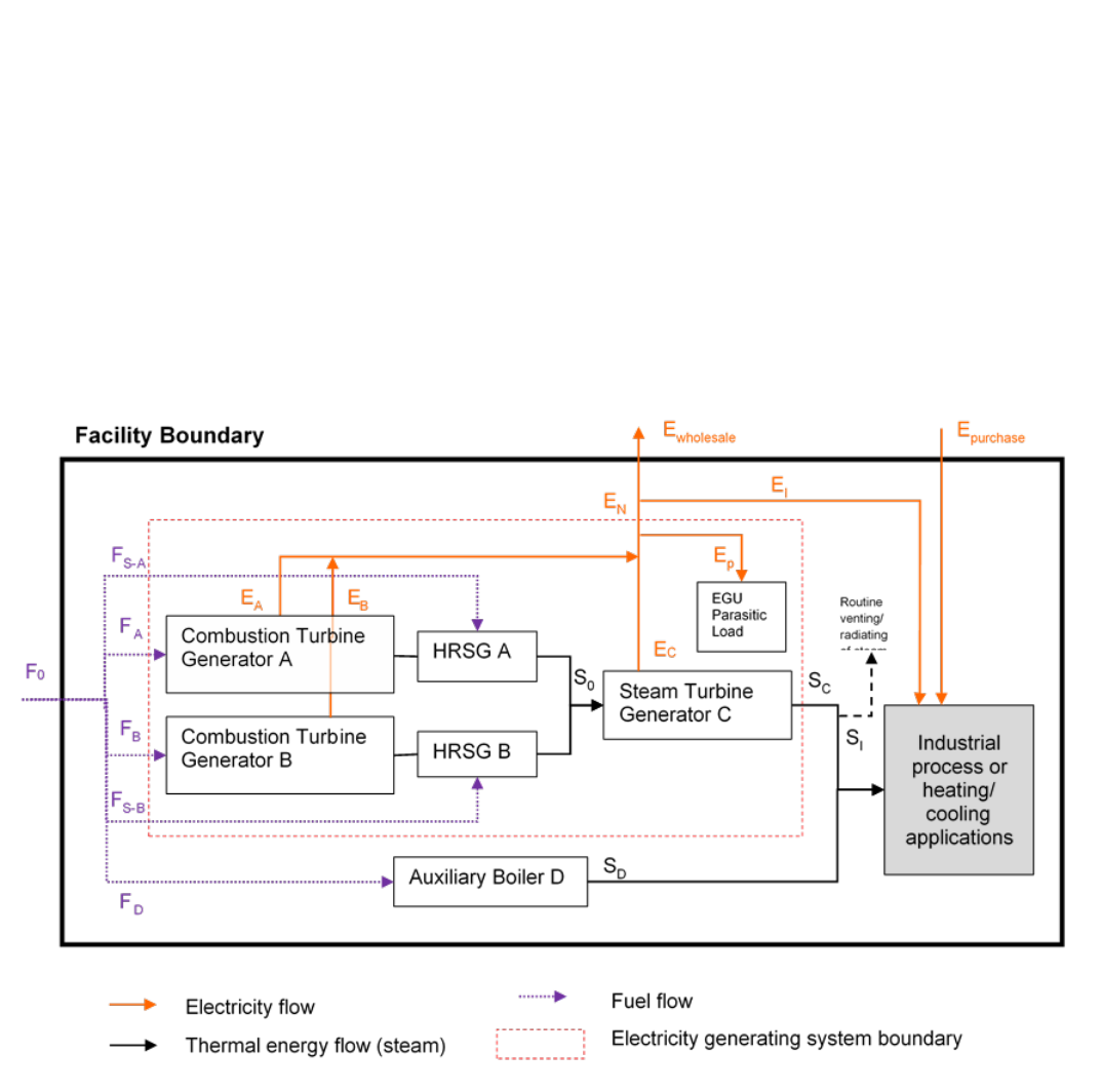
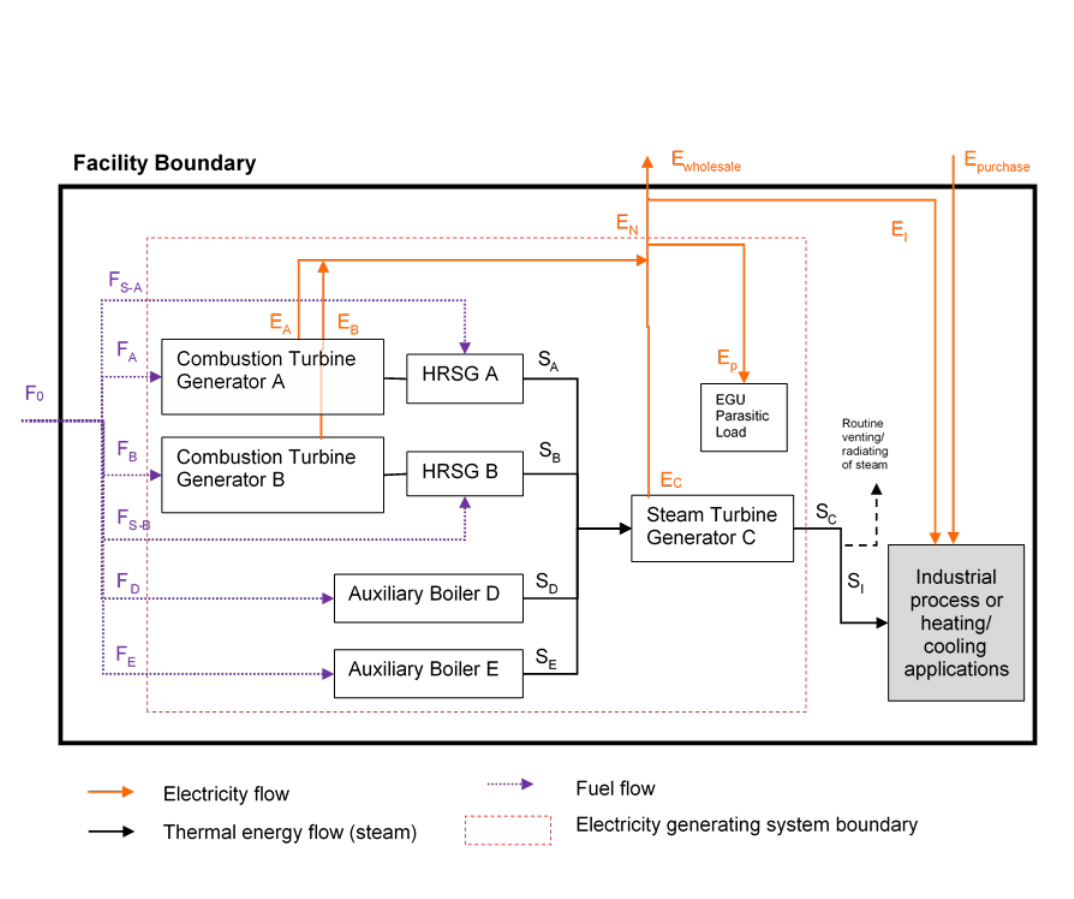
Example 1. A Cogeneration System and an Auxiliary Boiler
Note: In the interest of presenting a more legible graphical illustration of an energy system analysis, this diagram does not show the
location of fuel measurement devices and other equipment that may be associated with the system. Therefore, the diagram as
shown does not meet all the requirements of section 95112(a)(6) for a simplified block diagram.
This example shows a cogeneration facility that is an industrial/institution/commercial
facility with electricity generation capacity (sections 95112(a)(3); 95102(a)). The facility
includes two combustion turbine generators, each with a HRSG that produces steam to
power a steam turbine generator for electricity generation. When the cogeneration
system is not generating steam, an auxiliary boiler supplies steam to the on-site
industrial process or heating/cooling (IPHC) applications. Because the auxiliary boiler

Guidance for California’s Mandatory Greenhouse Gas Emissions Reporting
California Air Resources Board 15 1/11/19
does not contribute to electricity generation, it is not considered a part of the electricity
generating system and must be reported separately from the cogeneration system.
System Boundary: The cogeneration system boundary is drawn to include the two
combustion turbine generators, the two HRSGs, and the steam turbine generator, as
shown by the red dashed-line box in the diagram. To identify energy quantities to be
reported under section 95112(b), look for any arrows that cross the red dashed-line (F
S-
A
, F
A
, F
B
, F
S-B
, S
C
, and E
N
which is the net generation). Arrows that do not cross the
system boundary (S
0
and E
p
), should not be reported under section 95112(b) because
doing so would result in double counting of energy flows of the system. However, E
p
is
indirectly accounted for in section 95112(b)(2) by the reporting of gross generation and
net generation, which is the sum of gross generation from the three generators (E
A
, E
B
,
and E
C
) minus the parasitic load of the electricity generating system (E
p
).
Facility-Level Energy Input-Output: The energy quantities reported under
section 95112(a) account for the dispositions of the generated energy. In this example,
some of the electricity generated by the cogeneration system is sold to a retail provider
or electricity marketer who distributes the electricity over the grid
(section 95112(a)(4)(A)), and some of the generated electricity is used for on-site IPHC
applications (section 95112(a)(4)(C)). This facility does not sell generated electricity to
another “particular end-user” facility (as defined in section 95102(a)). Therefore, the
quantity reported under section 95112(a)(4)(B) is zero.
Thermal Output: All the steam generated by this cogeneration system is used for the
on-site IPHC applications within the facility boundary. If this system is designed to
match the steam demand of the IPHC applications, such that there is no routine venting,
radiating, wasting, or discharging of the generated steam, S
I
(section 95112(a)(5)(C))
and S
C
(section 95112(b)(3)) should match. If the system is designed to generate more
thermal energy than the IPHC applications require, and routine venting or wasting of
steam is done before the steam enters the steam-water loop of the IPHC process, the
operator must account for the portion of the generated steam that is not actually utilized
by the IPHC process. The generated steam that is not utilized is the difference between
S
C
(section 95112(b)(3)) and S
I
(section 95112(a)(5)(C)).
Steam Requirements of the Generation System: A cogeneration system like this may
have power augmentation, a de-aerator, NOx control, or cooling tower (not shown in the
diagram or in Table 1) that uses some of the steam generated by the cogeneration
system. If the operator includes these steam uses within the system boundary, such
that S
C
(section 95112(b)(3)) already excludes these steam requirements, the quantity
reported under section 95112(a)(5)(B) is zero. On the other hand, if the steam meter is
set up in such a way that these system uses are included in the quantity reported under

Guidance for California’s Mandatory Greenhouse Gas Emissions Reporting
California Air Resources Board 16 1/11/19
section 95112(b)(3), the operator must separately calculate these steam uses and
report them under section 95112(a)(5)(B). The operator may use an engineering
estimate to calculate the steam flows if there are no steam meters to directly measure
all the energy flows required by the regulation.
Unit Aggregation and Reporting Tool Configuration: Reporting this system as one
configuration is the most straight-forward and efficient way to complete the energy
system accounting for both the operator preparing the GHG report and the government
agency staff that analyzes the data. There are alternate ways to set up reporting tool
configurations that are also acceptable, but are not preferred. One option is to report as
two configurations: one includes the combustion turbine generator A, HRSG A, and the
portion of steam turbine generator C allocated to generator-HRSG A; and a second
configuration includes the combustion turbine generator B, HRSG B, and the portion of
the steam turbine generator C allocated to generator-HRSG B. If this option is chosen,
the operator must allocate the steam input and electricity output of the steam turbine
generator to the generator-HRSG sets A and B. The operator may use the fuel input as
a proxy for the allocation or any other operational parameters that may provide a
reasonable engineering estimation. The operator would draw two red dashed-line boxes
and identify all the arrows that cross each box to determine the energy quantities that
need to be reported under section 95112(b).
Another option is to report as three configurations: one includes the combustion turbine
generator A and HRSG A; another includes the combustion turbine generator B and
HRSG B; and a third configuration includes the steam turbine generator C. If this option
is chosen, the operator would report zero total thermal output for generator-HRSG A
and generator-HRSG B (because the steam output from the generator-HRSG is not
used for any IPHC applications that are not electricity generation), and report zero fuel
use for steam turbine generator. However, this option is not preferred because it
complicates the energy accounting exercise for the reporter and increases the likelihood
of making reporting errors.
Table 1 shows a mapping of the energy flows in and out of the system boundary with
the data items required by sections 95112(a) and (b).

Guidance for California’s Mandatory Greenhouse Gas Emissions Reporting
California Air Resources Board 17 1/11/19
Table 1. Example 1- Mapping of Energy Flows to the Required Data
Section 95112
Item Description
Quantity
(a)(4)(A)
Generated electricity provided to wholesale (grid)
E
wholesale
(a)(4)(B)
Generated electricity provided or sold directly to
particular end-user
0
(a)(4)(C)
Generated electricity used by on-site industrial
processes or operations that are neither in support of
or a part of the power generation system
E
I
(a)(5)(A)
Generated thermal energy provided or sold to
particular end-user
0
(a)(5)(B)
Generated thermal energy for supporting power
production
0 [Note 1]
(a)(5)(C)
Generated thermal energy used by on-site industrial
processes or operations (exclude any wasted energy)
S
I
(b)(2)
Gross generation
E
A
+ E
B
+ E
C
(b)(2)
Net generation
E
N
= (E
A
+ E
B
+ E
C
) -
E
P
(b)(3)
Total thermal output
S
C
(b)(4)
Fuel consumption by fuel type
F
A
+ F
B
+ F
S-A
+ F
S-B
[Note 2]
(b)(7)
Supplemental firing (in percentage of total fuels
combusted in this configuration)
(F
S-A
+ F
S-B
) / (F
A
+
F
B
+ F
S-A
+ F
S-B
)
[Note 2]
(b)(8)
Other heat input
0
Section 95104
Item Description
Quantity
(d)(1)
Electricity purchases or acquisition
E
purchased
(d)(2)
Thermal energy purchases or acquisition
0
(d)(3)
Electricity provided or sold. (Sections 95112(a)(4)(A)
and (a)(4)(B) satisfy this requirement.)
See
section 95112(a)
requirements
(d)(4)
Cogeneration/ bigeneration thermal energy provided
or sold. (Section 95112(a)(5)(A) satisfies this
requirement.)
0
(d)(4)
Non-cogen/bigen thermal energy provided or sold
0
Notes:
1. For alternate ways to report this quantity, see the Steam Requirements of the Generation System paragraph of this
example and the Steam Requirements for Supporting Electricity Generation System sub-section of Section 2 of this
document.
2. See the Reporting of Supplemental Firing Information sub-section of Section 2 of this document.
Guidance for California’s Mandatory Greenhouse Gas Emissions Reporting
California Air Resources Board 18 1/11/19
Example 2. A Cogeneration System with Boilers That Also Contribute to
Electricity Generation
Note: In the interest of presenting a more legible graphical illustration of an energy system analysis, this diagram does not show the
location of fuel measurement devices and other equipment that may be associated with the system. Therefore, the diagram as
shown does not meet all the requirements of section 95112(a)(6) for a simplified block diagram.
This example shows a cogeneration facility that is an industrial/institution/ commercial
facility with electricity generation capacity (sections 95112(a)(3) and 95102(a)). The
facility includes two combustion turbine generators with HRSG and two boilers that
produce steam to power a steam turbine generator. This example is similar to Example
1 except that the steam generated by the two auxiliary boilers also feeds into the steam
turbine generator, making the boilers an integral part of the cogeneration system.
System Boundary: The cogeneration system boundary is drawn to include the two
combustion turbine generators, the two HRSGs, the two auxiliary boilers, and the steam
turbine generator, as shown by the red dashed-line box. To identify energy quantities
reported under section 95112(b), look for any arrows that cross the red dashed-line (F
S-
A
, F
A
, F
B
, F
S-B
, F
D
, F
E
, S
C
, and E
N
which is the net generation). Arrows that do not cross

Guidance for California’s Mandatory Greenhouse Gas Emissions Reporting
California Air Resources Board 19 1/11/19
the system boundary (S
A
, S
B
, S
D
, S
E
, and E
p
), should not be reported under
section 95112(b) because doing so would result in double counting of energy flows in
the system. However, E
p
is indirectly accounted for in section 95112(b)(2) by the
reporting of gross generation net generation, which is the sum of gross generation from
the three generators (E
A
, E
B
, and E
C
) minus the parasitic load of the electricity
generating system (E
p
).
Facility-Level Energy Input-Output: The energy quantities reported under
section 95112(a) account for the dispositions of the generated energy. In this example,
some of the electricity generated by the cogeneration system is sold to a retail provider
or electricity marketer who distributes the electricity over the grid
(section 95112(a)(4)(A)), and some of the generated electricity is used for on-site IPHC
applications (section 95112(a)(4)(C)). This facility does not sell generated electricity to
another “particular end-user” facility (as defined in section 95102(a)). Therefore, the
quantity reported under section 95112(a)(4)(B) is zero.
Thermal Output: All the steam generated by this cogeneration system is used for the
on-site IPHC applications within the facility boundary. If this system is designed to
match the steam demand of the IPHC applications, such that there is no routine venting,
radiating, wasting, or discharging of the generated steam, S
I
(section 95112(a)(5)(C))
and S
C
(section 95112(b)(3)) should match. If the system is designed to generate more
thermal energy than the IPHC applications require, and routine venting or wasting of
steam is done before the steam enters the steam-water loop of the IPHC process, the
operator must account for the portion of the generated steam that is not actually utilized
by the IPHC process. The generated steam that is not utilized is the difference between
S
C
(section 95112(b)(3)) and S
I
(section 95112(a)(5)(C)).
Steam Requirements of the Generation System: A cogeneration system like this may
have power augmentation, a de-aerator, NOx control, or cooling tower (not shown in the
diagram or in Table 2) that uses some of the steam generated by the cogeneration
system. If the operator includes these steam uses within the system boundary, such
that S
C
(section 95112(b)(3)) already excludes these steam requirements, the quantity
reported under section 95112(a)(5)(B) is zero. On the other hand, if the steam meter is
set up in such a way that these system uses are included in the quantity reported under
section 95112(b)(3), the operator must separately calculate these steam uses and
report them under section 95112(a)(5)(B). The operator may use an engineering
estimate to calculate the steam flows if there are no steam meters to directly measure
all the energy flows required by the regulation.
Unit Aggregation and Reporting Tool Configuration: Reporting this system as one
configuration is the most straight-forward and efficient way to complete the energy

Guidance for California’s Mandatory Greenhouse Gas Emissions Reporting
California Air Resources Board 20 1/11/19
system accounting for both the operator preparing the GHG report and the government
agency staff that analyzes the data. There are alternate ways to set up reporting tool
configurations that are also acceptable, but are not preferred. One option is to report as
three configurations: one includes the combustion turbine generator A, HRSG A, and
the portion of steam turbine generator C allocated to generator-HRSG A; a second
configuration includes the combustion turbine generator B, HRSG B, and the portion of
the steam turbine generator C allocated to generator-HRSG B; and a third configuration
includes the two auxiliary boilers and the portion of the steam turbine generator C
allocated to the auxiliary boilers. If this option is chosen, the operator must allocate the
steam input and electricity output of the steam turbine generator to generator-HRSG A,
generator-HRSG B, and Auxiliary Boilers D+E. The operator would draw three red
dashed-line boxes and identify all the arrows that cross the box to determine the energy
quantities that need to be reported under section 95112(b).
Another option is to report as four configurations: one includes the combustion turbine
generator A and HRSG A; a second configuration includes the combustion turbine
generator B and HRSG B; a third configuration includes Auxiliary Boilers D and E; and a
fourth configuration includes the steam turbine generator. If this option is chosen, the
operator would report zero total thermal output for generator-HRSG A, generator-HRSG
B, Boiler D, and Boiler E (because S
A
, S
B
, S
D
, and S
E
are not being used for other IPHC
applications that are not electricity generation), report zero fuel use for steam turbine
generator, and report the steam extracted from the steam turbine generator as the total
thermal output. This option is not preferred because it complicates the energy
accounting exercise for the reporter and increases the likelihood of making reporting
errors.
Table 2 shows the mapping of the energy flows in and out of the system boundary with
the data items required by sections 95112(a) and (b).

Guidance for California’s Mandatory Greenhouse Gas Emissions Reporting
California Air Resources Board 21 1/11/19
Table 2. Example 2- Mapping of Energy Flows to the Required Data
Section 95112
Item Description
Quantity
(a)(4)(A)
Generated electricity provided to wholesale (grid)
E
wholesale
(a)(4)(B)
Generated electricity provided or sold directly to
particular end-user
0
(a)(4)(C)
Generated electricity used by on-site industrial
processes or operations that are neither in support of
or a part of the power generation system
E
I
(a)(5)(A)
Generated thermal energy provided or sold to
particular end-user
0
(a)(5)(B)
Generated thermal energy for supporting power
production
0 [Note 1]
(a)(5)(C)
Generated thermal energy used by on-site industrial
processes or operations (exclude any wasted energy)
S
I
(b)(2)
Gross generation
E
A
+ E
B
+ E
C
(b)(2)
Net generation
E
N
=(E
A
+ E
B
+ E
C
) -
E
P
(b)(3)
Total thermal output
S
C
(b)(4)
Fuel consumption by fuel type
F
A
+ F
B
+ F
S-A
+ F
S-B
+ F
D
+ F
E
[Note 2]
(b)(7)
Supplemental firing (in percentage of total fuels
combusted in this configuration)
(F
S-A
+ F
S-B
) / (F
A
+
F
B
+ F
S-A
+ F
S-B
+ F
D
+ F
E
) [Note 2]
(b)(8)
Other heat input
0
Section 95104
Item Description
Quantity
(d)(1)
Electricity purchases or acquisition
E
purchased
(d)(2)
Thermal energy purchases or acquisition
0
(d)(3)
Electricity provided or sold. (Sections 95112(a)(4)(A)
and (a)(4)(B) satisfy this requirement.)
Same as
section 95112(a)
requirements
(d)(4)
Cogeneration/ bigeneration thermal energy provided
or sold. (Section 95112(a)(5)(A) satisfies this
requirement.)
0
(d)(4)
Non-cogen/bigen thermal energy provided or sold
0
Notes:
1. For alternate ways to report this quantity, see the Steam Requirements of the Generation System paragraph of this
example and the Steam Requirements for Supporting Electricity Generation System sub-section of Section 2 of this
document.
2. See the Reporting of Supplemental Firing Information sub-section of Section 2 of this document.
Guidance for California’s Mandatory Greenhouse Gas Emissions Reporting
California Air Resources Board 22 1/11/19
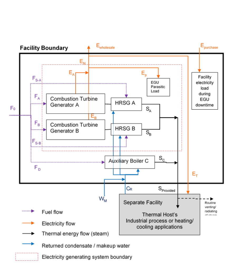
Example 3a. An Independently Operated Cogeneration Facility with a Thermal
Host (Aggregated)
Note: In the interest of presenting a more legible graphical illustration of an energy system analysis, this diagram does not show the
location of fuel measurement devices and other equipment that may be associated with the system. Therefore, the diagram as
shown does not meet all the requirements of section 95112(a)(6) for a simplified block diagram.
Facility Boundary: This example shows a cogeneration facility that may be either an
independently operated cogeneration facility co-located with the thermal host or an
independently operated and sited cogeneration facility (sections 95112(a)(3); 95102(a)).
For either case, because the facility boundary does not include the thermal host, the
operator would account for the energy input and output the same regardless of whether
the cogeneration facility is within the same physical fence line on contiguous or adjacent
property as the thermal host, or located near the thermal host on non-contiguous or
non-adjacent property. For an independently operated cogeneration facility co-located

Guidance for California’s Mandatory Greenhouse Gas Emissions Reporting
California Air Resources Board 23 1/11/19
with the thermal host, the cogeneration facility must have no common operational
control and no common ownership as the thermal host. If there is common operational
control OR common ownership, OR both, the cogeneration facility and the thermal host
must be pulled into the same facility boundary.
The facility in this example includes two combustion turbine generators, each with a
HRSG that produces steam for the thermal host. The facility also has an auxiliary boiler
to supply additional steam to the thermal host if the cogeneration system does not
generate enough steam to meet the thermal host’s steam demand. Because the
auxiliary boiler is not a part of the electricity generation system, it must be reported
separately.
System Boundary: The cogeneration system boundary is drawn to include the two
combustion turbine generators and their HRSGs, as shown by the red dashed-line box.
To identify energy quantities to be reported under section 95112(b), look for any arrows
that cross the red dashed-line (F
S-A
, F
A
, F
B
, F
S-B
, the sum of S
A
and S
B
, and E
N
which is
the net generation). Arrows that do not cross the system boundary (e.g., E
p
), should not
be reported under section 95112(b) because doing so would result in double counting of
energy flows of the system. However, E
p
is indirectly accounted for in
section 95112(b)(2) by the reporting of net generation, which is the sum of gross
generation from the two generators (E
A
and E
B
) minus the parasitic load of the electricity
generating system (E
p
).
Facility-Level Energy Input-Output: The energy quantities reported under
section 95112(a) account for the dispositions of the generated energy. In this example,
some of the electricity generated by the cogeneration system is sold to a retail provider
or electricity marketer who distributes the electricity over the grid
(section 95112(a)(4)(A)), and some of the generated electricity is provided or sold to the
thermal host (“particular end user,” sections 95112(a)(4)(B) and 95102(a)). Within this
facility’s boundary, there is no on-site industrial process or operations that are either in
support of or a part of the power generation system. Therefore, the quantity specified in
section 95112(a)(4)(C) is zero.
Thermal Output: All the steam generated by this cogeneration system is sent to the
thermal host. If this system is designed to match the steam demand of the thermal
host, such that there is no routine venting, radiating, wasting, or discharging of the
generated steam, the operator may report the sum of S
A
and S
B
as the quantities
reported under both sections 95112(b)(3) and 95112(a)(5)(A). If the system is designed
to generate more thermal energy than the thermal host requires, and the cogeneration
operator must routinely vent, waste, or discharge steam before sending the steam to the
thermal host (not as shown in the diagram), the operator must account for the portion of

Guidance for California’s Mandatory Greenhouse Gas Emissions Reporting
California Air Resources Board 24 1/11/19
the generated steam that is wasted, which is the difference the cogeneration steam
provided/sold (section 95112(a)(5)(A)) and the sum of S
A
and S
B
(section 95112(b)(3)).
However, if the routine venting, wasting, and discharged of the steam is done by the
thermal host and outside of the control of the cogeneration facility operator (as shown in
the diagram), the operator does not need to account for the wasted steam in its GHG
report, and may report the sum of S
A
and S
B
as the quantities reported under both
sections 95112(b)(3) and 95112(a)(5)(A).
Steam Requirements of the Generation System: A cogeneration system like this may
have a de-aerator, NOx control, or cooling tower that uses some of the steam generated
by the cogeneration system (not shown in the diagram). If the operator includes these
cogeneration system steam requirements within the system boundary, such that the
sum of S
A
and S
B
(section 95112(b)(3)) that crosses the system boundary already
excludes the system steam requirements, the quantity reported under
section 95112(a)(5)(B) is zero. On the other hand, if the steam meter is set up in such a
way that the system steam requirements are included in the total thermal output
quantity reported under section 95112(b)(3), the operator must separately calculate the
system steam requirements and report them under section 95112(a)(5)(B). This way
the three quantities reported under section 95112(a)(5) corroborate the total thermal
output quantity reported under section 95112(b)(3). The operator may use an
engineering estimate to calculate the steam flows if there are no steam meters to
directly measure all the energy flows required by the regulation.
Returned Condensate: This cogeneration system receives returned condensate from
the thermal host. To avoid double counting of the energy in the steam-water loop of the
system, the enthalpy of the generated steam (S
A
and S
B
) should not include the
enthalpy of the returned condensate and any makeup water added to the HRSG
feedwater. The operator can exclude the enthalpy of the feedwater into the boiler and
the HRSGs by simply using the temperature of the feedwater as the reference
temperature for the enthalpy calculation of the generated steam (S
A
and S
B
). If the
steam meters and the computerized data acquisition system are set up such that the
reference temperature of the generated steam is different from the temperature of the
returned condensate, the operator must make an adjustment calculation when reporting
total thermal output.
Table 3a shows the mapping of the energy flows in and out of the system boundary with
the data items required by sections 95112(a) and (b).

Guidance for California’s Mandatory Greenhouse Gas Emissions Reporting
California Air Resources Board 25 1/11/19
Table 3a. Example 3a- Mapping of Energy Flows to the Required Data
Section 95112
Item Description
Quantity
(a)(4)(A)
Generated electricity provided to wholesale (grid)
E
wholesale
(a)(4)(B)
Generated electricity provided or sold directly to a
particular end-user
E
T
(a)(4)(C)
Generated electricity used by on-site industrial
processes or operations that are neither in support of
or a part of the power generation system
0
(a)(5)(A)
Generated thermal energy provided or sold to
particular end-user
S
A
+ S
B
(a)(5)(B)
Generated thermal energy for supporting power
production
0 [Note 1]
(a)(5)(C)
Generated thermal energy used by on-site industrial
processes or operations (exclude any wasted energy)
0
(b)(2)
Gross generation
E
A
+ E
B
(b)(2)
Net generation
E
N
=(E
A
+ E
B
) - E
P
(b)(3)
Total thermal output
S
A
+ S
B
(b)(4)
Fuel consumption by fuel type
F
A
+ F
B
+ F
S-A
+ F
S-B
[Note 2]
(b)(7)
Supplemental firing (in percentage of total fuels
combusted in this configuration)
(F
S-A
+ F
S-B
) / (F
A
+
F
B +
F
S-A
+ F
S-B
)
[Note 2]
(b)(8)
Other heat input
0
Section 95104
Item Description
Quantity
(d)(1)
Electricity purchases or acquisition
E
purchased
(d)(2)
Thermal energy purchases or acquisition
0
(d)(3)
Electricity provided or sold. (Sections 95112(a)(4)(A)
and (a)(4)(B) satisfy this requirement.)
Same as
section 95112(a)
requirements
(d)(4)
Cogeneration/ bigeneration thermal energy provided
or sold. (Section 95112(a)(5)(A) satisfies this
requirement.)
S
A
+ S
B
(d)(4)
Non-cogen/bigen thermal energy provided or sold
S
C
Notes:
1. For alternate ways to report this quantity, see the Steam Requirements of the Generation System paragraph of this
example and the Steam Requirements for Supporting Electricity Generation System sub-section of Section 2 of this
document.
2. See the Reporting of Supplemental Firing Information sub-section of Section 2 of this document.
Guidance for California’s Mandatory Greenhouse Gas Emissions Reporting
California Air Resources Board 26 1/11/19
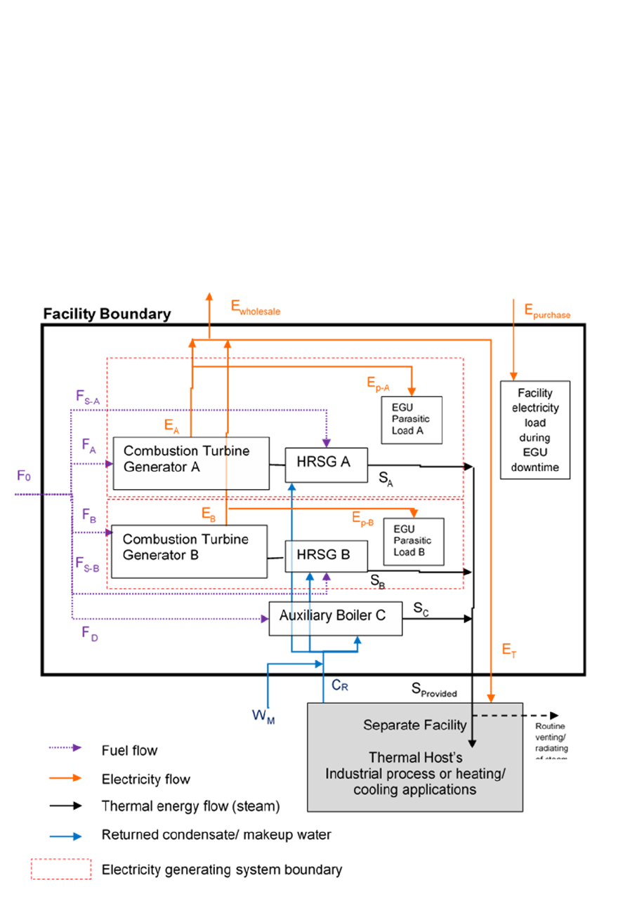
Example 3b. An Independently Operated Cogeneration Facility with a Thermal
Host (Disaggregated)
In Example 3a, the two combustion turbine generators and HRSGs have been
combined into one system. Alternately, the operator may also report them as two
separate configurations in the reporting tool. (In contrast to Examples 1 and 2, where
there is a steam turbine generator that makes disaggregated reporting complicated, unit
disaggregation can be easily done in a cogeneration system without a steam turbine
generator, such as in this example.) Example 3b shows the system boundary of
disaggregated reporting configurations, and Table 3b enumerates the mapping of the
energy flows to the reporting requirements.
Note: In the interest of presenting a more legible graphical illustration of an energy system analysis, this diagram does not show the
location of fuel measurement devices and other equipment that may be associated with the system. Therefore, the diagram as
shown does not meet all the requirements of section 95112(a)(6) for a simplified block diagram.

Guidance for California’s Mandatory Greenhouse Gas Emissions Reporting
California Air Resources Board 27 1/11/19
Table 3b. Example 3b- Mapping of Energy Flows to the Required Data
Section 95112
Item Description
Quantity
(a)(4)(A)
Generated electricity provided to wholesale (grid)
E
wholesale
(a)(4)(B)
Generated electricity provided or sold directly to a particular
end-user
E
T
(a)(4)(C)
Generated electricity used by on-site industrial processes or
operations that are neither in support of or a part of the power
generation system
0
(a)(5)(A)
Generated thermal energy provided or sold to particular end-
user
S
A
+ S
B
(a)(5)(B)
Generated thermal energy for supporting power production
0 [Note 1]
(a)(5)(C)
Generated thermal energy used by on-site industrial
processes or operations (exclude any wasted energy)
0
Unit Configuration A (Generator A + HRSG A):
(b)(2)
Gross generation
E
A
(b)(2)
Net generation
E
A
– E
p-A
[Note 2]
(b)(3)
Total thermal output
S
A
(b)(4)
Fuel consumption by fuel type
F
A
+ F
S-A
[Note 3]
(b)(7)
Supplemental firing (in percentage of total fuels combusted in
this configuration)
F
S-A
/ (F
A
+ F
S-A
)
[Note 3]
(b)(8)
Other heat input
0
Unit Configuration B (Generator B + HRSG B):
(b)(2)
Gross generation
E
B
(b)(2)
Net generation
E
B
– E
p-B
[Note 2]
(b)(3)
Total thermal output
S
B
(b)(4)
Fuel consumption by fuel type
F
B
+ F
S-B
[Note 3]
(b)(7)
Supplemental firing (in percentage of total fuels combusted in
this configuration)
F
S-B
/ (F
B
+ F
S-B
)
[Note 3]
(b)(8)
Other heat input
0
Section 95104
Item Description
Quantity
(d)(1)
Electricity purchases or acquisition
E
purchased
(d)(2)
Thermal energy purchases or acquisition
0
(d)(3)
Electricity provided or sold. (Sections 95112(a)(4)(A) and
(a)(4)(B) satisfy this requirement.)
Same as
section 95112(a)
requirements
(d)(4)
Cogeneration/ bigeneration thermal energy provided or sold.
(Section 95112(a)(5)(A) satisfies this requirement.)
S
A
+ S
B
(d)(4)
Non-cogen/bigen thermal energy provided or sold
S
C
Notes:
1. For alternate ways to report this quantity, see the Steam Requirements of the Generation System paragraph of this
example and the Steam Requirements for Supporting Electricity Generation System sub-section of Section 2 of this
document.
2. If there are no meters for measuring the parasitic load of the individual units, it is acceptable to use an engineering
estimation method.
3. See the Reporting of Supplemental Firing Information sub-section of Section 2 of this document.
Guidance for California’s Mandatory Greenhouse Gas Emissions Reporting
California Air Resources Board 28 1/11/19
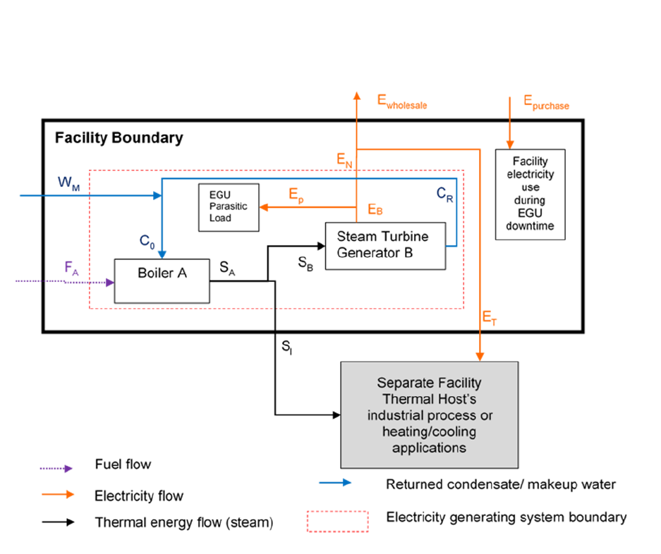
Example 4. A Bigeneration Facility
Note: In the interest of presenting a more legible graphical illustration of an energy system analysis, this diagram does not show the
location of fuel measurement devices and other equipment that may be associated with the system. Therefore, the diagram as
shown does not meet all the requirements of section 95112(a)(6) for a simplified block diagram.
Facility Boundary: This example shows a bigeneration facility that may be either an
independently operated bigeneration facility co-located with the thermal host or an
independently operated and sited bigeneration facility (sections 95112(a)(3) and
95102(a)). For either case, because the facility boundary does not include the thermal
host, the operator would account for the energy input and output the same regardless of
whether the cogeneration facility is within the same physical fence line on contiguous or
adjacent property as the thermal host, or located near the thermal host on non-
contiguous or non-adjacent property. For an independently operated bigeneration
facility co-located with the thermal host, the bigeneration facility must have no common
operational control and no common ownership as the thermal host. If there is common
operational control OR common ownership, OR both, the bigeneration facility and the
thermal host must be pulled into the same facility boundary.
The facility in this example includes a boiler and a steam turbine generator. The steam
generated by the boiler is split into two streams, one stream feeds the steam turbine

Guidance for California’s Mandatory Greenhouse Gas Emissions Reporting
California Air Resources Board 29 1/11/19
generator (S
B
) and the other stream is provided or sold to the thermal host (S
I
). The
steam condenses after it is utilized at the steam turbine generator B, and the
condensate (C
R
) is returned to the boiler with additional makeup water (W
M
) acquired
from outside of the facility boundary.
System Boundary: The bigeneration system boundary is drawn to include the boiler
and the steam turbine generator, as shown by the red dashed-line box. To identify
energy quantities to be reported under section 95112(b), look for any arrows that cross
the red dashed-line (F
A
, S
I
, and E
N
which is the net generation). Arrows that do not
cross the system boundary (e.g., S
A
, S
B
, E
p
and C
R
), should not be reported under
section 95112(b) because doing so would result in double counting of energy flows of
the system. However, E
p
is indirectly accounted for in section 95112(b)(2) by the
reporting of net generation, which is the gross generation (E
B
) minus the parasitic load
of the electricity generating system (E
p
). Also C
R
and W
M
are implied in the calculations
of steam input to the steam turbine (S
B
) and the output of the heat recovery steam
generator (S
A
), as the enthalpy of the boiler feedwater must be excluded from the boiler
steam output. See the Returned Condensate discussion below for additional
information.
Facility-Level Energy Input-Output: The energy quantities reported under
section 95112(a) account for the dispositions of the generated energy. In this example,
some of the electricity generated by the cogeneration system is sold to a retail provider
or electricity marketer who distributes the electricity over the grid
(section 95112(a)(4)(A)), and some of the generated electricity is provided or sold to the
thermal host (“particular end user,” sections 95112(a)(4)(B) and 95102(a)). Within this
facility’s boundary, there is no electricity used for on-site industrial process or operations
that are not in support of or a part of the power generation system. Therefore, the
quantity specified in section 95112(a)(4)(C) is zero.
Returned Condensate: The returned condensate from the steam turbine generator (C
R
)
is mixed with makeup water from outside of the facility boundary (W
M
) to provide the
feedwater for the boiler (C
0
). To avoid double counting of the energy in the steam-water
loop of the system, the enthalpy of the generated steam (S
A
, S
B
, and S
I
) should not
include the enthalpy of the boiler feedwater (C
0
). The operator can exclude the
enthalpy of the boiler feedwater by simply using the temperature of the feedwater as the
reference temperature for the enthalpy calculation of the generated steam. If the steam
meter and the computerized data acquisition system are set up such that the reference
temperature of the generated steam is different from the temperature of the feedwater,
the operator must make an adjustment calculation when reporting the thermal energy
quantities.

Guidance for California’s Mandatory Greenhouse Gas Emissions Reporting
California Air Resources Board 30 1/11/19
Table 4 shows the mapping of the energy flows in and out of the system boundary with
the data items required by sections 95112(a) and (b).
Table 4. Example 4- Mapping of Energy Flows to the Required Data
Section 95112
Item Description
Quantity
(a)(4)(A)
Generated electricity provided to wholesale (grid)
E
wholesale
(a)(4)(B)
Generated electricity provided or sold directly to a particular
end-user
E
T
(a)(4)(C)
Generated electricity used by on-site industrial processes or
operations that are neither in support of or a part of the
power generation system
0
(a)(5)(A)
Generated thermal energy provided or sold to particular
end-user
S
I
(a)(5)(B)
Generated thermal energy for supporting power production
0 [Note 1]
(a)(5)(C)
Generated thermal energy used by on-site industrial
processes or operations (exclude any wasted energy)
0
(b)(2)
Gross generation
E
B
(b)(2)
Net generation
E
N
= E
B
- E
P
(b)(3)
Total thermal output
S
I
(b)(4)
Fuel consumption by fuel type
F
A
(b)(7)
Supplemental firing (in percentage of total fuels combusted
in this configuration)
0
(b)(8)
Other heat input
0
Section 95104
Item Description
Quantity
(d)(1)
Electricity purchases or acquisition
E
purchased
(d)(2)
Thermal energy purchases or acquisition
0
(d)(3)
Electricity provided or sold. (Sections 95112(a)(4)(A) and
(a)(4)(B) satisfy this requirement.)
Same as
section 95112(a)
requirements
(d)(4)
Cogeneration/ bigeneration thermal energy provided or sold.
(Section 95112(a)(5)(A) satisfies this requirement.)
S
I
(d)(4)
Non-cogen/bigen thermal energy provided or sold
0
Notes:
1. For alternate ways to report this quantity, see the Steam Requirements of the Generation System paragraph of this example and
the Steam Requirements for Supporting Electricity Generation System sub-section of Section 2 of this document.
Guidance for California’s Mandatory Greenhouse Gas Emissions Reporting
California Air Resources Board 31 1/11/19
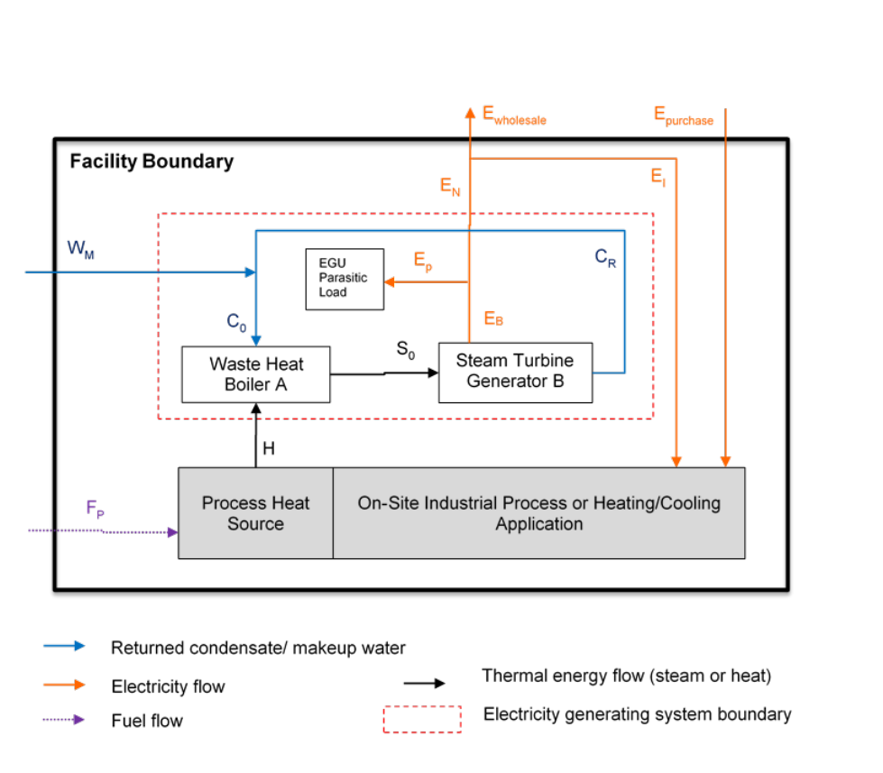
Example 5. A Bottoming Cycle Cogeneration Facility
Note: In the interest of presenting a more legible graphical illustration of an energy system analysis, this diagram does not show the
location of fuel measurement devices and other equipment that may be associated with the system. Therefore, the diagram as
shown does not meet all the requirements of section 95112(a)(6) for a simplified block diagram.
Facility Boundary: This example shows a bottoming cycle cogeneration facility in an
industrial/institutional/commercial facility with electricity generation capacity
(sections 95112(a)(3) and 95102(a)). The cogeneration system generates steam from
the waste heat of the industrial process, and the steam generated by the waste heat
boiler powers a steam turbine generator for electricity generation.
System Boundary: The cogeneration system boundary includes the waste heat boiler
and the steam turbine generator, as shown by the red dashed-line box. To identify
energy quantities reported under section 95112(b), look for any arrows that cross the
red dashed-line (H and E
N
which is the net generation). With the exception of S
0
, which
is explicitly required to be reported in section 95112(b)(8) and will not be double
counted in energy analysis, arrows that do not cross the system boundary (e.g., C
R
, and
E
p
), should not be reported under section 95112(b) because doing so would result in

Guidance for California’s Mandatory Greenhouse Gas Emissions Reporting
California Air Resources Board 32 1/11/19
double counting of energy flows of the system. However, E
p
is indirectly accounted for
in section 95112(b)(2) by the reporting of net generation, which is the gross generation
(E
B
) minus the parasitic load of the electricity generating system (E
p
). Also, C
R
and W
M
are implied in the calculation of the output of the heat recovery steam generator (S
0
)
and the steam input to the steam turbine (S
0
) (section 95112(b)(8)). See the Returned
Condensate section in Section 2 of this guidance document for additional information.
Facility-Level Energy Input-Output: The energy quantities reported under
section 95112(a) account for the dispositions of the generated energy. In this example,
some of the electricity generated by the cogeneration system is sold to a retail provider
or electricity marketer who distributes the electricity over the grid
(section 95112(a)(4)(A)), and some of the generated electricity is used for on-site IPHC
applications (section 95112(a)(4)(C)). This facility does not sell generated electricity to
another “particular end-user” facility (as defined in section 95102(a)). Therefore, the
section 95112(a)(4)(B) quantity is zero.
Thermal Output and Steam Requirements of the Generation System: In the diagram
and accompanying Table 5 for this example, there is no total thermal output from this
bottoming cycle cogeneration system because the system does not output steam for
non-electricity-generation applications. In a scenario where some steam is extracted
from the waste heat boiler or steam turbine and is utilized in on-site IPHC application,
the operator must report the extracted steam as total thermal output
(section 95112(b)(3)). (Note this scenario is not illustrated in the diagram or in
Table 5.).
If the facility has a de-aerator or cooling tower that uses some of the steam generated
by the cogeneration system (not shown in the diagram and not shown in Table 5), the
operator must account for the steam use. The operator has two options for accounting
for the steam: (1) If the operator considers the de-aerator or cooling tower a part of the
bottoming cycle cogeneration system (i.e., the steam used for those purposes stays
within the system boundary) the operator does not need to explicitly account for the
energy flows for those uses; (2) If the operator considers the de-aerator or cooling tower
not within the cogeneration system boundary, the steam used for de-aerator or cooling
tower must be included in the total thermal output quantity (section 95112(b)(3)). In this
case, the operator must also separately report the steam use under
section 95112(a)(5)(B) so the three quantities reported under section 95112(a)(5)(B)
corroborate the total thermal output quantity under section 95112(b)(3). The operator
may use an engineering estimate to calculate the steam flows if there are no steam
meters to directly measure all the energy flows required by the regulation.

Guidance for California’s Mandatory Greenhouse Gas Emissions Reporting
California Air Resources Board 33 1/11/19
Table 5 shows the mapping of the energy flows in and out of the system boundary with
the data items required by sections 95112(a) and (b).
Table 5. Example 5- Mapping of Energy Flows to the Required Data
Section 95112
Item Description
Quantity
(a)(4)(A)
Generated electricity provided to wholesale (grid)
E
wholesale
(a)(4)(B)
Generated electricity provided or sold directly to a
particular end-user
0
(a)(4)(C)
Generated electricity used by on-site industrial processes
or operations that are neither in support of or a part of the
power generation system
E
I
(a)(5)(A)
Generated thermal energy provided or sold to particular
end-user
0
(a)(5)(B)
Generated thermal energy for supporting power
production
0 [Note 1]
(a)(5)(C)
Generated thermal energy used by on-site industrial
processes or operations (exclude any wasted energy)
0
(b)(2)
Gross generation
E
B
(b)(2)
Net generation
E
N
= E
B
- E
P
(b)(3)
Total thermal output
0
(b)(4)
Fuel consumption by fuel type
0 [Note 2]
(b)(7)
Supplemental firing (in percentage of total fuels
combusted in this configuration)
0 [Note 2]
(b)(8)
Additional heat input that is not already accounted for in
section 95112(b)(4)-(6).
H
(b)(8)
Input steam to the steam turbine
S
0
(b)(8)
Output of the heat recovery steam generator
S
0
Section 95104
Item Description
Quantity
(d)(1)
Electricity purchases or acquisition
E
purchased
(d)(2)
Thermal energy purchases or acquisition
0
(d)(3)
Electricity provided or sold. (Sections 95112(a)(4)(A) and
(a)(4)(B) satisfy this requirement.)
Same as
section 95112(a)
requirements
(d)(4)
Cogeneration/ bigeneration thermal energy provided or
sold. (Section 95112(a)(5)(A) satisfies this requirement.)
0
(d)(4)
Non-cogen/bigen thermal energy provided or sold
0
Notes:
1. For alternate ways to report this quantity, see the Steam Requirements of the Generation System paragraph of this
example and the Steam Requirements for Supporting Electricity Generation System sub-section of Section 2 of this
document.
2. If the cogeneration system includes supplemental firing, these values should not be zero.
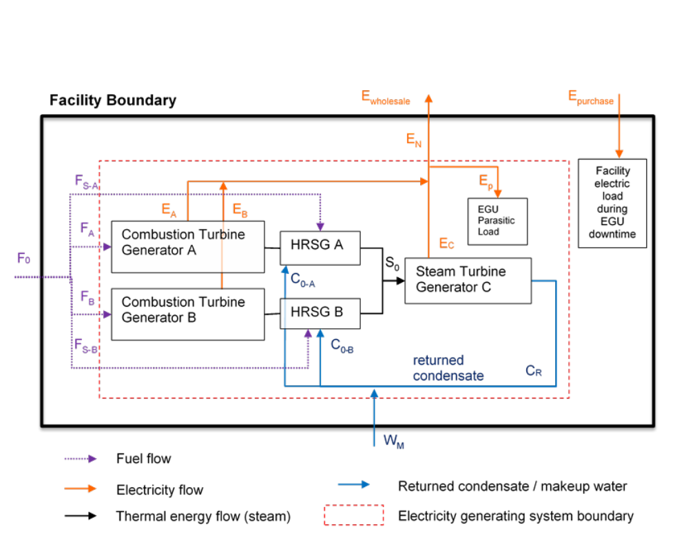
Guidance for California’s Mandatory Greenhouse Gas Emissions Reporting
California Air Resources Board 34 1/11/19
Example 6. A Combined Cycle Power Plant
Note: In the interest of presenting a more legible graphical illustration of an energy system analysis, this diagram does not show the
location of fuel measurement devices and other equipment that may be associated with the system. Therefore, the diagram as
shown does not meet all the requirements of section 95112(a)(6) for a simplified block diagram.
This example shows a stand-alone electricity generation facility (sections 95112(a)(3)
and 95102(a)) that is a combined cycle power plant. The facility includes two
combustion turbine generators, each with a HRSG that produces steam to power a
steam turbine generator.
System Boundary: The cogeneration system boundary is drawn to include the two
combustion turbine generators, two HRSGs, and the steam turbine generator, as shown
by the red dashed-line box. To identify energy quantities to be reported under
section 95112(b), look for any arrows that cross the red dashed-line (F
S-A
, F
A
, F
B
, F
S-B
,
and E
N
which is the net generation). Arrows that do not cross the system boundary (S
0
,
C
R
, C
0-A
, C
0-B
, and E
p
), should not be reported under section 95112(b) because doing so
would result in double counting of energy flows of the system. However, E
p
is indirectly
accounted for in section 95112(b)(2) by the reporting of gross generation and net
generation, which is the sum of gross generation from the three generators (E
A
, E
B
, and
E
C
) minus the parasitic load of the electricity generating system (E
p
).

Guidance for California’s Mandatory Greenhouse Gas Emissions Reporting
California Air Resources Board 35 1/11/19
Facility-Level Energy Input-Output: The energy quantities reported under
section 95112(a) account for the dispositions of the generated energy. In this example,
all of the net electricity generated by the power plant is sold to a retail provider or
electricity marketer who distributes the electricity over the grid (section 95112(a)(4)(A))
(a “grid-dedicated facility”). This facility has no on-site IPHC applications
(section 95112(a)(4)(C)) and does not sell generated electricity to another “particular
end-user” facility (as defined in section 95102(a)). Therefore, the quantities reported
under sections 95112(a)(4)(B) and (C) are zero.
Steam Requirements of the Generation System: If the facility has a power
augmentation, de-aerator, NOx control, or cooling tower that uses some of the steam
generated by the HRSGs or extracted from the steam turbine (not shown in the diagram
or Table 6), the operator may consider those uses as a part of the system. Since those
steam uses stay within the system boundary, the operator does not need to explicitly
account for the energy flows for those purposes. Therefore, the quantities reported
under sections 95112(a)(5)(B) and 95112(b)(3) are zero.
Unit Aggregation and Reporting Tool Configuration: Reporting this system as one
configuration is the most straight-forward and efficient way to complete the energy
system accounting for both the facility operator preparing the GHG report and the
government agency staff that analyzes the data. There are alternate ways to set up
reporting tool configurations that are also acceptable, but are not preferred. One option
is to report as two configurations: one includes the combustion turbine generator A,
HRSG A, and the portion of steam turbine generator C allocated to generator-HRSG A;
and a second configuration includes the combustion turbine generator B, HRSG B, and
the portion of the steam turbine generator C allocated to generator-HRSG B. If this
option is chosen, the operator must allocate the steam input and electricity output of the
steam turbine generator to generator-HRSG sets A and B. The operator would draw
two red dashed-line boxes and identify all the arrows that cross the box to determine the
energy quantities that need to be reported under section 95112(b).
Another option is to report as three configurations: one includes the combustion turbine
generator A and HRSG A; another includes the combustion turbine generator B and
HRSG B; and a third configuration includes the steam turbine generator. If this option is
chosen, the operator would report zero total thermal output for generator-HRSG A and
generator-HRSG B (because those thermal output are not being used for other IPHC
applications that are not electricity generation), and report zero fuel use for steam
turbine generator. This option is not preferred because it complicates the energy
accounting exercise for the reporter and increases the likelihood of making reporting
errors.

Guidance for California’s Mandatory Greenhouse Gas Emissions Reporting
California Air Resources Board 36 1/11/19
Table 6 shows the mapping of the energy flows in and out of the system boundary with
the data items required by sections 95112(a) and (b).
Table 6. Example 6- Mapping of Energy Flows to the Required Data
Section 95112
Item Description
Quantity
(a)(4)(A)
Generated electricity provided to wholesale (grid)
E
wholesale
(a)(4)(B)
Generated electricity provided or sold directly to a
particular end-user
0
(a)(4)(C)
Generated electricity used by on-site industrial
processes or operations that are neither in support of
or a part of the power generation system
0
(a)(5)(A)
Generated thermal energy provided or sold to
particular end-user
0
(a)(5)(B)
Generated thermal energy for supporting power
production
0
(a)(5)(C)
Generated thermal energy used by on-site industrial
processes or operations (exclude any wasted energy)
0
(b)(2)
Gross generation
E
A
+ E
B
+ E
C
(b)(2)
Net generation
E
N
=(E
A
+ E
B
+ E
C
) -
E
P
(b)(3)
Total thermal output
0
(b)(4)
Fuel consumption by fuel type
F
A
+ F
B
+ F
S-A
+ F
S-B
[Note 1]
(b)(7)
Supplemental firing (in percentage of total fuels
combusted in this configuration)
(F
S-A
+ F
S-B
) / (F
A
+
F
B
+ F
S-A
+ F
S-B
)
(b)(8)
Other heat input
0
Section 95104
Item Description
Quantity
(d)(1)
Electricity purchases or acquisition
E
purchased
(d)(2)
Thermal energy purchases or acquisition
0
(d)(3)
Electricity provided or sold. (Sections 95112(a)(4)(A)
and (a)(4)(B) satisfy this requirement.)
Same as
section 95112(a)
requirements
(d)(4)
Cogeneration/ bigeneration thermal energy provided
or sold. (Section 95112(a)(5)(A) satisfies this
requirement.)
0
(d)(4)
Non-cogen/bigen thermal energy provided or sold
0

Guidance for California’s Mandatory Greenhouse Gas Emissions Reporting
California Air Resources Board 37 1/11/19
6 Additional Information
Detailed training materials for reporting using Cal e‑GGRT: https://ww2.arb.ca.gov/mrr-
tool.
The GHG Mandatory Reporting Regulation, with full requirements:
https://ww2.arb.ca.gov/mrr-regulation.
Additional reporting and applicability guidance documents to assist reporters in
complying with the MRR: https://ww2.arb.ca.gov/mrr-guidance.
Guidance for Aggregation of Emitting Units: https://www.arb.ca.gov/cc/reporting/ghg-
rep/guidance/unit-aggregation.pdf
Contact the MRR helpdesk: ghgreport@arb.ca.gov.
For help with reporting or verification, please contact the appropriate staff member:
https://ww2.arb.ca.gov/mrr-contacts.
