Reprinted from
Journal of
Healthcare
Engineering
Vol. 1 · No. 2 · 2010
Multi-Science Publishing
ISSN 1756-8250
Advanced Energy Design Guide for
Small Hospitals and Healthcare
Facilities
by
Eric Bonnema, Shanti Pless, Ian Doebber
NREL/JA-550-47013.
Posted with permission.

Journal of Healthcare Engineering · Vol. 1 · No. 2 · 2010 Page 277–296
277
Advanced Energy Design Guide for Small
Hospitals and Healthcare Facilities
a
Eric Bonnema
1,
*, Shanti Pless
1
, Ian Doebber
1
1
National Renewable Energy Laboratory, 1617 Cole Boulevard,
Golden, Colorado, 80401, USA
ABSTRACT
The Advanced Energy Design Guide for Small Hospitals and Healthcare Facilities (AEDG-SHC)
was recently completed. It is the sixth document in a series of guides designed to achieve 30%
savings over the minimum code requirements of ANSI/ASHRAE/IESNA Standard 90.1-1999.
The guide [1] is available for print purchase or as a free download from http://www.ashrae.org/aedg
and provides user-friendly assistance and recommendations for the building design, construction,
and owner communities to achieve energy savings. Included in the guide are prescriptive
recommendations for quality assurance and commissioning; design of the building envelope;
fenestration; lighting systems (including electric lighting and daylighting); heating, ventilation,
and air-conditioning (HVAC) systems; building automation and controls; outside air (OA)
treatment; and service water heating (SWH). The guide educates, provides practical
recommendations for exceeding code minimums, and provides leadership to help design teams
and owners produce higher efficiency commercial buildings.
Keywords: 30% energy savings, high performance buildings, energy efficiency, Advanced
Energy Design Guide, small healthcare facilities
1. INTRODUCTION
The Advanced Energy Design Guide for Small Hospitals and Healthcare Facilities
(AEDG-SHC) is targeted to help small- to medium-sized acute care, outpatient, and
inpatient buildings achieve site energy savings of at least 30% compared to the
minimum requirements of ANSI/ASHRAE/IES Standard 90.1-1999 [2]. The 30%
energy savings target is the first step toward achieving a net-zero energy building—a
building that draws from outside sources less or equal energy than it generates on site
from renewable energy sources annually [3]. The guide was developed in collaboration
with these partnering organizations: the American Society of Heating, Refrigerating and
Air-Conditioning Engineers (ASHRAE), the American Institute of Architects (AIA),
the U.S. Green Building Council (USGBC), the Illuminating Engineering Society
*
Corresponding author. Email: [email protected]; Tel: +1 303 384-6185
a
This article was prepared by the National Renewable Energy Laboratory, operated by the Alliance for
Sustainable Energy LLC, under the funding of the U.S. Department of Energy.”

(IES), the U.S. Department of Energy (DOE), and the American Society for Healthcare
Engineering (ASHE). The healthcare facilities covered in the scope of the guide are
smaller than 90,000 ft
2
(8,360 m
2
), defined as:
• Small acute care hospitals
• Small inpatient community hospitals
• Critical access hospitals with 25 or fewer beds
• Outpatient surgical facilities
• Freestanding birthing centers (similar to outpatient surgical centers)
• Gastrointestinal endoscopy facilities (similar to outpatient surgical centers)
• Renal dialysis centers (similar to medical office buildings)
• Primary care outpatient centers
• Small primary (neighborhood) outpatient facilities
• Freestanding outpatient diagnostic and treatment facilities
• Freestanding urgent care facilities
• Medical office buildings (larger than 20,000 ft
2
[1,858 m
2
])
Three major objectives drove the development of the guide: (1) to achieve a 30%
energy savings over Standard 90.1-1999 [4]; (2) to produce a reference document for
contractors, owners, and designers of small hospitals and healthcare facilities; and (3)
to provide how-to assistance to contractors and designers [5]. The guide is intended to
show that achieving the 30% target is not only possible, but easily achievable. Case
studies show facilities around the country that have achieved and surpassed the 30%
energy savings target. Best practices and cautions are also provided to demonstrate how
to successfully implement the recommendations.
By specifying a target and identifying paths for different climate zones, the guide
provides one example of how to meet the 30% savings target and how to build facilities
that use substantially less energy than those built to meet the minimum Standard 90.1-
1999 energy code requirements. There may be other means of achieving the target, and
it is hoped that the guide generates ideas for innovation.
2. LAYOUT AND CONTENT
The introduction of the guide contains information about its goal and scope, as well
as instructions for its use. Next the guide provides resources for those who want to
understand and adopt an overall, integrated process for designing, constructing, and
operating energy-efficient small hospitals and healthcare facilities. The guide presents
an integrated process for achieving energy savings. It is valuable for designers and
builders who want to augment and improve their practices so energy efficiency is
deliberately considered at each stage of the development process, from project
conception through building operation. This section concludes by addressing the
details of an integrated design process. It discusses the benefits and features of
integrated design, specifics about the process, and step-by-step details about the
four phases of the process: predesign, design, construction, and acceptance/
occupancy/operation.
278 Advanced Energy Design Guide for Small Hospitals and Healthcare Facilities

The third section contains the climate-specific recommendation tables, a unique set
of energy efficiency recommendations for each of the eight DOE climate zones in the
United States. Efficiency recommendations are organized by several categories:
envelope; electric lighting; daylighting; heating, ventilating, and air-conditioning
(HVAC); and service water heating (SWH). The recommendations are simply one path
to reach the 30% energy savings target over Standard 90.1-1999. Other approaches may
also save energy, but identifying all possible solutions is not in the scope of this guide;
assurance of the savings with other approaches is left to the user. To achieve 30% energy
savings, this guide assumes compliance with the more stringent of either the applicable
edition of Standard 90.1 or the local code requirements in all areas not addressed in
the climate-specific recommendation tables. Future editions of energy codes may have
more stringent values. In these cases, the more stringent values are recommended.
Next the guide presents seven detailed case studies that illustrate techniques and
methods discussed. Energy numbers are provided to benchmark these buildings against
future buildings. All these case studies use some of the recommendations in the tables,
but predate the publication of the guide and were not developed explicitly using those
tables. Readers are encouraged to view more case studies at http://www.ashrae.org/aedg,
and to submit their own. Case studies provide the motivation and the examples for
others to follow.
The final section provides guidance about good practices for implementing the
recommendations, as well as cautions to avoid known problems in energy-efficient
construction. The section is divided into quality assurance and commissioning,
envelope, lighting, daylighting, HVAC, SWH, and bonus savings. The bonus savings
subsection includes areas for additional good practice items that, if implemented
properly, should achieve savings beyond the 30% level.
The quality assurance and commissioning subsection contains specific details about
commissioning and its importance in every step of the design process. The envelope
subsection contains climate zone-specific information about explicit types of walls,
roofs, floors, doors, insulation, infiltration, and vertical fenestration. The lighting
subsection details best practices for interior finishes, specific lamp and ballast types,
lighting layouts, and control strategies for specific space types. The daylighting
subsection provides tips on general principles, using daylighting analysis tools,
daylighting space types and layouts, building shape and orientation with respect to
daylighting, window-to-wall ratios, sidelighting, toplighting, skylight construction,
shading devices, photosensor specification, and photocell placement.
The HVAC subsection includes best practices for multiple-zone variable-air volume
(VAV) air-handling systems, water-source (including ground-source) heat pumps,
dedicated outdoor air (OA) systems, HVAC load calculations, equipment efficiencies,
economizers, exhaust air energy recovery, ductwork design, duct insulation, duct
sealing, exhaust air systems, system-level control strategies, filters, chilled water
systems, heating water systems, and zone-level controls.
The bonus savings subsection includes good practices for lighting (exterior lighting,
lamp types), process loads (medical equipment, high-performance kitchen and laundry
equipment), renewable energy (photovoltaic and solar hot water systems, wind turbines),
Journal of Healthcare Engineering · Vol. 1 · No. 2 · 2010
279

combined heat and power, additional HVAC systems (condenser water heat recovery,
ground-source heat pumps, displacement ventilation, demand-controlled ventilation,
thermal storage, desiccant-based dehumidification, evaporative condensing), and
electrical distribution systems (transformer efficiencies, metering) [1].
3. DEVELOPMENT PROCESS
The SHC-AEDG was developed by a project committee (PC) that represents a diverse
group of professionals. ASHRAE, AIA, IES, USGBC, ASHE, and DOE collaborated to
provide guidance and support. Members of the PC came from these partner organizations,
the ASHRAE Standing Standards Project Committee 90.1, and the ASHRAE Technical
Committee 9.6, Healthcare Facilities. A steering committee (SC) made up of representatives
of ASHRAE, AIA, IES, USGBC, ASHE, and DOE oversaw the PC as the guide was
developed. The SC assigned a timeline for the task, an energy savings goal, a target
audience, space types to include, and possible topics to incorporate.
Following SC guidance, the PC developed a one-year plan for completing the
document. The PC used a schedule to plan for two peer review periods that
corresponded with a 65% completion draft (technical refinement review) and a 90%
completion draft (final review for errors). A focus group reviewed the conceptual 35%
draft. Many meetings and conference calls were also held with the full PC during the
development of the guide.
4. EVALUATION APPROACH
The guide contains a set of energy efficiency recommendations for each of the eight
DOE climate zones across the United States. The following steps describe how the
energy savings potential of the guide’s recommendations was determined.
4.1. Develop “Typical” Small Hospital and Healthcare Facility Prototypes
For building characteristics that are not specified by Standard 90.1 but that are needed
to develop code-compliant baseline models, the PC chose two recently constructed
healthcare facilities (a surgery center and a community hospital) as the foundation for
the prototypes. Information from the construction drawings for these facilities, along
with publications data, was used to determine “typical” small hospital and healthcare
facility characteristics. The publications surveyed include:
• The 2003 Commercial Buildings Energy Consumption Survey (CBECS) [6]
• Additional data sets from the PC, including actual floor plates and space
programming requirements for the community hospital and the surgery center
• The DOE Buildings Database (http://eere.buildinggreen.com)
• McGraw Hill Dodge construction data
• The Green Guide for Healthcare [7]
• DOE Commercial Buildings Benchmark Models [8]
• ASHRAE Standard 62.1-2004 [9]
• 2006 AIA Guidelines for Design and Construction of Health Care Facilities [10]
280 Advanced Energy Design Guide for Small Hospitals and Healthcare Facilities

Journal of Healthcare Engineering · Vol. 1 · No. 2 · 2010
281
These documents were used to develop the prototype model characteristics,
including form and floor plate, plug/process loads, ventilation rates, and operating
schedules. These characteristics are the same for the baseline and low-energy models,
and are documented in Table 1.
Table 1. Prototype Characteristics [11]
Building
Prototype Models
Characteristic Community Hospital Surgery Center
Size 65,000 ft
2
41,000 ft
2
Number of floors 1 3
Peak number of 675 414
occupants
Constructions Steel-framed wall Steel-framed wall
Roof with insulation Roof with insulation
entirely above deck entirely above deck
WWR 26% 20%
Occupancy Fully occupied during the day Fully occupied during the day
Partially occupied at night Vacant at night
Whole-building 2.1 W/ft
2
1.8 W/ft
2
weighted average
peak plug loads
Percent conditioned Fully heated and cooled Fully heated and cooled
HVAC system types Baseline: Packaged variable air Baseline: PVAV with DX cooling,
volume system (PVAV) with water boiler heating
direct expansion (DX) cooling,
water boiler heating
Low-energy: PVAV with Low-energy: PVAV with DX
DX cooling or air-cooled cooling or air-cooled chiller
chiller or water-cooled chiller, or water-cooled chiller,
water boiler heating water boiler heating
4.2. Create Baseline Models from the Prototypes that are Minimally Code
Compliant for Standard 90.1-1999
The baseline models for the small hospital and healthcare facility were developed by
applying the applicable criteria in Standard 90.1-1999 to the prototype models. The
baseline small hospital and healthcare facility energy modeling assumptions obtained
from Standard 90.1-1999 include the envelope characteristics, building lighting loads,
HVAC equipment efficiency, operation, control, sizing, fan power assumptions, and
SWH efficiency.

4.3. Create the Low-Energy Models Based on the Recommended Energy
Efficiency Technologies in the Guide
The final recommendations were determined based on an iterative process using the
PC’s expertise and results from modeling the recommendations. To quantify the potential
energy savings from the final recommended energy efficiency measures, the low-energy
building models were simulated by implementing the following energy efficiency
technologies. The energy efficiency measures that were applied to all climate zones and
included in the energy saving calculation are:
• Enhanced building opaque envelope insulation
• Enhanced window glazing with overhangs
• Reduced lighting power density (LPD) and occupancy control
• Daylighting in staff areas (exam rooms, nurse stations, offices, corridors) and
public spaces (waiting, reception)
• Higher efficiency HVAC equipment
• High-efficiency SWH
4.4. Verify 30% Energy Savings Across the Various HVAC System Types Over the
Eight U.S. Climate Zones
EnergyPlus
12
was used to perform building energy simulation analysis to assess and
quantify the energy savings potential of the guide’s recommendations. Two sets of
simulations were run for each prototype: the first meets the minimum requirements of
Standard 90.1-1999; the second uses the recommendations in the guide to achieve 30%
energy savings. For each low-energy design, three cooling equipment types were
modeled: a package rooftop system with direct expansion (DX) cooling, a packaged
rooftop system with a central air-cooled chiller, and a packaged rooftop system with a
central water-cooled chiller. The recommendations result in greater than 30% energy
savings in all climate zones for each prototype within the range of cooling system types.
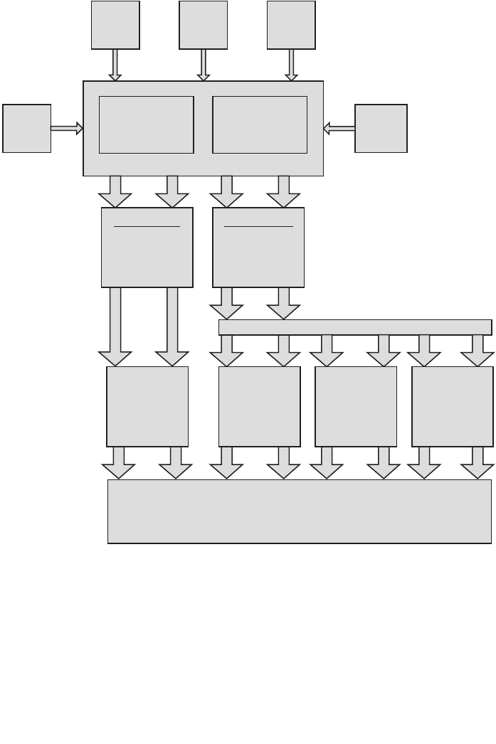
The flowchart in Figure 1 shows the evaluation approach.
5. MODELING METHODS
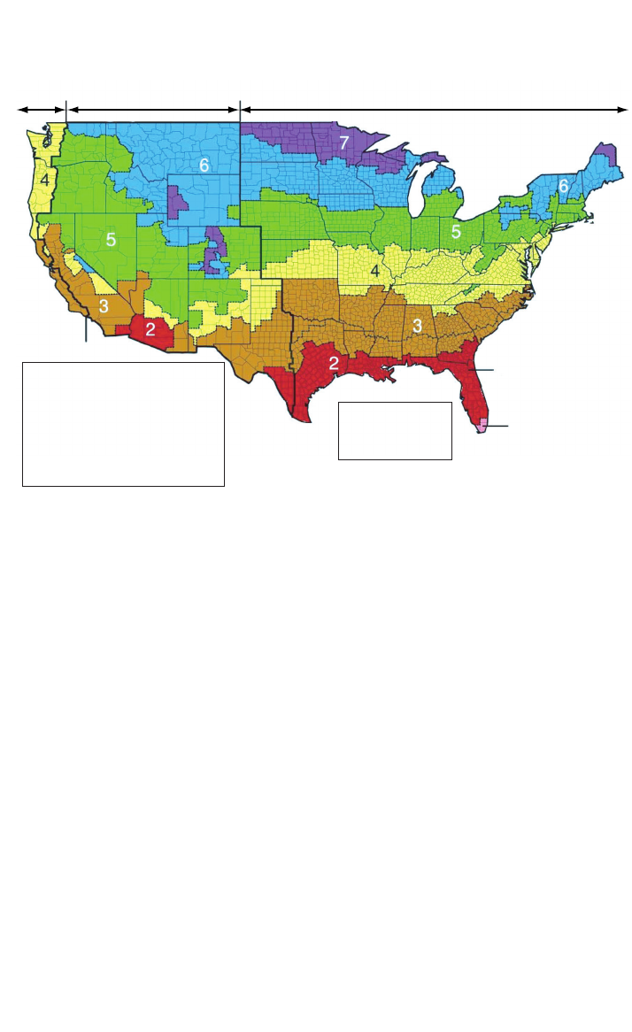
5.1. Climate Zones
The guide contains a unique set of energy efficiency recommendations for a range of
climate zones. The common set of climate zones includes eight zones covering the
entire United States (see Figure 2). Climate zones are categorized by heating degree
days and cooling degree days, and range from the very hot zone 1 to the very cold
zone 8. Some climate zones are divided into subzones based on humidity levels. Humid
subzones are “A” zones, dry subzones are “B” zones, and marine subzones are “C”
zones. The combination of climate zones 1 through 8, along with their respective
subzones “A,” “B,” and “C,” create 15 unique climate zones.
Fifteen specific climate locations (cities) were selected as being most representative
of each subzone, as shown in the list. To determine energy savings, Typical
Meteorological Year 2 weather files for each location were used to simulate the baseline
and low-energy models.
282 Advanced Energy Design Guide for Small Hospitals and Healthcare Facilities
Journal of Healthcare Engineering · Vol. 1 · No. 2 · 2010
283
• Zone 1: Miami, Florida (hot, humid)
• Zone 2A: Houston, Texas (hot, humid)
• Zone 2B: Phoenix, Arizona (hot, dry)
• Zone 3A: Memphis, Tennessee (hot, humid)
• Zone 3B: El Paso, Texas (hot, dry)
• Zone 3C: San Francisco, California (marine)
• Zone 4A: Baltimore, Maryland (mild, humid)
• Zone 4B: Albuquerque, New Mexico (mild, dry)
90.1-1999 Sweep
Apply climate-specific
parameters to the
prototypes to create
the baseline models in
15 cities
SHC AEDG Sweep
Apply climate-specific
parameters to the
prototypes to create
the low-energy models
in15 cities
Other data
sources
Prototype 1 (P1)
community
hospital
Prototype 2 (P2)
surgery
center
Drawings
2006 AIA
Guidelines
for Health
Care
Green Guide
for Health
Care
Project
committee
P1
Prototype models
P2
P1
P2
P1
P2
P1
P2
P1
P2
Three different low-energy model cooling equipment types
15 baseline
EnergyPlus
simulations
Percent savings comparisons
15 DX low-energy
model EnergyPlus
simulations
P1
P2
15 air-cooled
chiller low-energy
model EnergyPlus
simulations
P1
P2
P1
P2
P1
P2
P1
P2
P1
P2
15 water-cooled
chiller low-energy
model EnergyPlus
simulations
Figure 1. Evaluation Approach Flowchart [11].
284 Advanced Energy Design Guide for Small Hospitals and Healthcare Facilities
• Zone 4C: Seattle, Washington (marine)
• Zone 5A: Chicago, Illinois (cold, humid)
• Zone 5B: Boise, Idaho (cold, dry)
• Zone 6A: Burlington, Vermont (cold, humid)
• Zone 6B: Helena, Montana (cold, dry)
• Zone 7: Duluth, Minnesota (very cold)
• Zone 8: Fairbanks, Alaska (extremely cold)
5.2. Analysis Platform
EnergyPlus version 3.1 was used to complete the energy simulations [12]. EnergyPlus
is the contemporary DOE tool that accounts for the complicated interactions between
climate, internal gains, building form and fabric, HVAC systems, and renewable energy
systems. Alongside EnergyPlus, Opt-E-Plus [13], a software research tool that
integrates with EnergyPlus, was used to aid in this analysis. Opt-E-Plus was developed
by the commercial buildings research group at NREL and was used to create and
manage the EnergyPlus input files.
The main analysis started with 8 “seed” EnergyPlus input files (1 baseline and 3 low-
energy models for the 2 prototypes). Opt-E-Plus was then used to sweep these input
files across the 15 climate zones, generating 120 input files. Interim analysis included
sweeping 16 other “seed” EnergyPlus input files across the 15 climate zones to create
240 separate input files, for a total of 360 individual EnergyPlus input files. During this
Moist (A)
5
6
6
7
5
3
3
4
2
1
2
2
Dry (B)Marine (C)
All of Alaska in Zone 7
except for the following
Boroughs in Zone 8:
Bethel
Dellingham
Fairbanks N. Star
Nome
North Slope
Northwest Arctic
Southeast Fairbanks
Wade Hampton
Yukon-Koyukuk
Zone 1 includes
Hawaii. Guam,
Puerto Rico.
and the Virgin Islands
Figure 2. Climate Zones and Representative Cities [11].

sweep, Opt-E-Plus applied climate zone-specific AEDG-SHC recommendations (such
as roof insulation values) to each input file. When interfaced with a Linux
supercomputer, Opt-E-Plus was able to complete approximately 1,440 linear simulation
hours in only 12 clock hours.
The results were then analyzed to determine the energy savings over the code-
compliant baseline. If the 30% savings target was not met for each simulation, changes
were made to the recommendations and the analysis restarted from the beginning.
These “seed” input files were continuously updated based on the results of the previous
simulation iteration as the project progressed and were reswept numerous times. The
automation of certain portions of this iterative process with Opt-E-Plus made this
project possible in the allotted time frame. Ultimately, the 30% savings goal was
achieved for each climate zone.
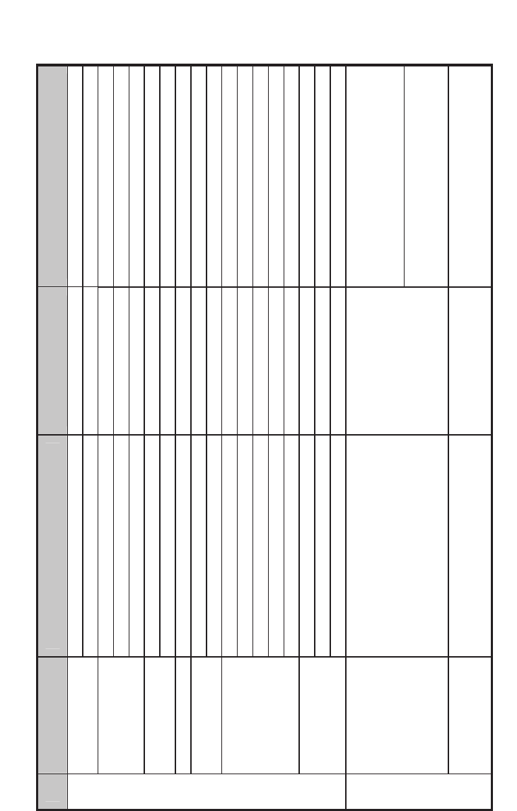
6. RECOMMENDATIONS
The guide makes recommendations for enhanced efficiency in several building systems to
meet the 30% savings target. To further illustrate the impacts of these recommendations,
Table 2 shows the comparison between Standard 90.1-1999 and the climate-specific
recommendations for climate zone 5A (Chicago). The recommendations presented are
either minimum or maximum values. Minimum values include:
• R-values (continuous insulation [c.i] where noted)
• Mean lumens/watt (MLPW)
• Solar Reflectance Index (SRI)
• Energy efficiency ratio (EER)
• Integrated energy efficiency ratio (IEER)
• Integrated part-load value (IPLV)
• Coefficient of performance (COP)
•Effectiveness
• Combustion efficiency (E
c
)
• Thermal efficiency (E
t
)
• Energy factor (EF)
• Duct or pipe insulation thickness
Maximum values include:
• Fenestration insulation (U-factors)
• Fenestration solar heat gain coefficient (SHGC)
•Total fenestration to gross wall area ratio (WWR)
• Lighting power density (LPD)
• Fan brake horsepower (bhp)
• Fan input power per cfm of supply airflow (W/cfm)
Table 2 highlights some recommendations; although examples from only one
climate zone are shown here, the guide contains recommendations for all eight
climate zones.
Journal of Healthcare Engineering · Vol. 1 · No. 2 · 2010
285
286 Advanced Energy Design Guide for Small Hospitals and Healthcare Facilities
Table 2. Standard 90.1-1999 v. AEDG for Climate Zone 5 [11]
Item Component
Standard 90.1-1999
(Bin 17)
SHC AEDG
(Climate Zone 5)
.i.c 03-R .i.c 51-R kced evoba yleritne noitalusnI
Roofs
1.09 dradnatS htiw ylpmoC enoN IRS
Mass (HC > 7 Btu/ft
2
.i.c 3.31-R .i.c 6.7-R )
Steel framed R-13 + R-3.8 c.i. R-13 + R-15.6 c.i.
Walls
.i.c 5.7-R enoN sllaw edarg woleB
.i.c 7.61-R .i.c 3.8-R ssaM
Floors
83-R 91-R demarf leetS
.ni 42 rof 51-R enoN detaehnU sbalS
05.0-U 07.0-U gnigniwS
Doors
05.0-U 54.1-U gnigniwsnoN
xam %04 %04-1.03 RWW ot noitartsenef latoT
92.0 75.0 ecnattimsnart lamrehT
43.0 93.0 CGHS
96.0 enoN ecnattimsnart elbisiV
Vertical
fenestration
Exterior sun control None Projection factor > 0.5
%3 %5-1.2 )foor fo tnecrep( aerA
06.0 01.1 ecnattimsnart lamrehT
Envelope
Skylights
04.0 26.0 CGHS
Diagnostic and treatment block: shape
the building footprint such that the area
within 15 ft of the perimeter exceeds
40% of the floorplate
Daylighting
Design the building to maximize access
to natural light through sidelighting:
- Staff areas (exam rooms, nurse
stations, offices, corridors)
- Public spaces (waiting, reception)
None
Inpatient units: ensure that 75% of the
occupied space (not including patient
rooms) lies within 20 ft of the perimeter
Interior finishes
Daylit room interior surface average
reflectance
None
88% on ceilings and walls above 7 ft
50% on walls below 7 ft
Lighting/Daylighting
continued over
Journal of Healthcare Engineering · Vol. 1 · No. 2 · 2010
287
tf/W 6.1 DPL
2
tf/W 0.1
2
Light source system efficacy
(linear fluorescent and high-intensity
discharge)
None 90 MLPW minimum
Light source system efficacy
(all other sources)
None 50 MLPW minimum
Lighting controls - general None
Manual on, auto-off in all zones except
24-hour patient care areas
Lighting/Daylighting
Interior lighting
Dimming controls daylight harvesting None
Dim fixtures within 15 ft of sidelighting
edge and within 10 ft of toplighting edge
DX air conditioner
(packaged or split system)
8.5 EER 7.5 IPLV
10.0 EER
9.7 IPLV
Air-cooled chiller efficiency 9.2 EER 9.6 IPLV
9.6 EER
11.5 IPLV
Water-cooled chiller efficiency 3.8 COP 3.9 IPLV Comply with Standard 90.1
Chilled water pumps None
Variable-frequency drive (VFD) and
National Electrical Manufacturers
Association (NEMA) premium
efficiency
snaf rewot dna DFV enoN rewot gnilooC
E %08 reliob saG
c
90% E
c
at peak design heating water
temperature
HVAC
Critical care access
Single-duct
VAV air
handling
system
(indoor or
outdoor)
with DX
cooling and
water
boilers
seY enoN rezimonocE
Item Component
Standard 90.1-1999
(Bin 17)
SHC AEDG
(Climate Zone 5)
mfc 0001/ph 1.1 snaF
bhp ≤ supply cfm × 0.0013+A, NEMA
premium efficiency motors
seY enoN kcabtes wolfria enoZ
SHC AEDG
continued over
288 Advanced Energy Design Guide for Small Hospitals and Healthcare Facilities
Item Component
Standard 90.1-1999
(Bin 17)
SHC AEDG
(Climate Zone 5)
DX air conditioner
(packaged or split system)
8.5 EER 7.5 IPLV
10.0 EER
9.7 IPLV
Air-cooled chiller efficiency 9.2 EER 9.6 IPLV
9.6 EER
11.5 IPLV
Water-cooled chiller efficiency 3.8 COP 3.9 IPLV Comply with Standard 90.1
Chilled water pumps None VFD and NEMA premium efficiency
snaf rewot dna DFV enoN rewot gnilooC
E %08 reliob saG
c
90% E
c
at peak design heating water
temperature
seY enoN rezimonocE
Fans
1.1 hp per
1,000 cfm
bhp ≤ supply cfm × 0.0013+A, NEMA
premium efficiency motors
Single-duct
VAV air
handling
system
seY enoN kcabtes erutarepmet ecapS
Water-source heat pump < 65 kBtu/h
Cooling: 9.3 EER at 85°F
Heating: 3.8 COP at 70°F
Cooling: 12 EER at 86°F
Heating: 4.5 COP at 68°F
Water-source heat pump ≥ 65 kBtu/h
Cooling: 10.5 EER at
85°F
Heating: 3.8 COP at
70°F
Cooling: 12 EER at 86°F
Heating: 4.2 COP at 68°F
ycneiciffe muimerp AMEN dna DFV enoN spmup retaW
snaf no DFV enoN relooc diulf/srewot gnilooC
E %08 reliob saG
c
90% E
c
at peak design heating water
temperature
1.09 dradnatS htiw ylpmoC enoN rezimonocE
Exhaust air energy recovery in dedicated
OA system
None
Zone A: 50% total effectiveness
Zone B: 50% sensible effectiveness
Zone C: 50% total effectiveness
mfc/W 4.0 enoN snaf PHSW
Other fans
(dedicated OA system, exhaust)
None
bhp ≤ supply cfm × 0.0013+A, NEMA
premium efficiency motors
WSHP
system
seY enoN kcabtes erutarepmet ecapS
Noncritical Care Access
HVAC
continued over
Journal of Healthcare Engineering · Vol. 1 · No. 2 · 2010
289
DX air conditioner
(packaged or split system)
8.5 EER 7.5 IPLV
10.0 EER
9.7 IPLV
Air-cooled chiller efficiency 9.2 EER 9.6 IPLV
9.6 EER
11.5 IPLV
Water-cooled chiller efficiency 3.8 COP 3.9 IPLV Comply with Standard 90.1
Chilled water pumps None VFD and NEMA premium efficiency
snaf rewot dna DFV enoN rewot gnilooC
E %08 reliob saG
c
90% E
c
at peak design heating water
temperature
seY enoN rezimonocE
Exhaust air energy recovery in dedicated
OA system
None
Zone A: 50% total effectiveness
Zone B: 50% sensible effectiveness
Zone C: 50% total effectiveness
mfc/W 4.0 enoN stinu lioc naF
Other fans
(dedicated OA system, exhaust)
None
bhp supply cfm 0.0013+A, NEMA
premium efficiency motors
Fan coil and
chiller
system
seY enoN kcabtes erutarepmet ecapS
dezirotoM enoN repmad AO
Duct seal class
Supply: seal class B
Exhaust: seal class B
Return: seal class C
Supply: seal class A
Exhaust: seal class B
Return: seal class B
Ducts and dampers
6-R 6-R level noitalusnI
Gas storage (>75 kBtu/h) 80% E
t
E %09
t
Gas instantaneous 0.81 E
F
or 81% E
t
0.81 EF or 81% E
t
Electric (storage or instantaneous)
EF = 0.93-0.00132
Volume
EF > 0.99-0.0012 Volume
SWH
Pipe insulation (d < 1.5 in./d .ni 5.1/.1 in .ni 1/.ni 5.0 ).ni 5.1
Noncritical Care Access
HVAC
Item Component
Standard 90.1-1999
(Bin 17)
SHC AEDG
(Climate Zone 5)

A review of the recommendations for all climate zones indicates how climate affects
specific differences between low-energy and baseline models. For example, the
recommended increase in roof insulation is greater in cold climates than in hot climates,
reflecting the greater potential for extra insulation to save energy in colder regions.
Mass wall insulation nearly doubles in hot and cold climates compared to Standard
90.1-1999; steel-framed walls add continuous insulation in hot climates and
significantly increase in R-value in cold climates. Slab insulation increases over
Standard 90.1-1999 in cold climates only, again reflecting the greater impact of
insulation in cold climates. Vertical glazing thermal transmittance changes fairly
substantially in hot climates because it switches from single to double glazing, but the
value changes less dramatically in cold climates. SHGCs change slightly in hot and cold
climates. Adding window overhangs with a projection factor greater than 0.5 was
recommended for all climate zones.
The concept for improving the building envelope was based around the fact that
most small healthcare facilities use constant-volume reheat systems to handle the space
conditioning needs. These systems have traditionally been common in such facilities
because they can independently control temperature and humidity and maintain space
pressurization requirements. The roof, wall insulation, and window performance was
increased, which reduced the constant-volume airflow needs and associated reheat. The
envelope thermal performance was increased to the point that the reduced airflow
needs meet the code-required minimum values. This saves on fan power and reheat
energy, and smaller constant-volume systems can save capital costs with smaller air
systems and reduced cooling capacity.
The daylighting recommendations include designing the building to maximize
access to natural light through sidelighting in staff areas (exam rooms, nurse stations,
offices, corridors) and public spaces (waiting, reception), along with daylighting
controls. General LPDs were reduced 37.5% in this guide compared to Standard 90.1-
1999, representing a large proportion of the total energy savings.
HVAC cooling efficiencies improved 15% in this guide compared to Standard 90.1-
1999 in all climates zones except 6, 7, and 8, where they remained unchanged from
Standard 90.1-1999 because the cooling energy represented a small portion of the
whole-building energy use. Because high air change rates and humidity control are required
in many space types, the constant-volume reheat HVAC systems that have traditionally
been used in these facilities use a lot of energy for reheat. The baseline energy modeling
shows that reheat represents more than 20% of the total energy use in all climate zones.
Thus, high-efficiency condensing boilers are recommended for all climate zones
because of the significant reheat energy required to maintain airflow requirements and
humidity control in all locations. The SWH recommendations indicate the value of
using either high-efficiency or point-of-use water heaters to reduce water heating
energy use.
7. ENERGY SAVINGS RESULTS
Annual hourly simulations of two prototype buildings established the energy savings
results from the application of the guide. One prototype building was the 65,000 ft
2
290 Advanced Energy Design Guide for Small Hospitals and Healthcare Facilities
(6,040 m
2
) community hospital; the other was a 41,000 ft
2
(3,810 m
2
) surgery center.
Both prototypes were simulated in all 15 climate locations, representing humidity
subzones for the eight climate zones depicted in the guide and the standard.
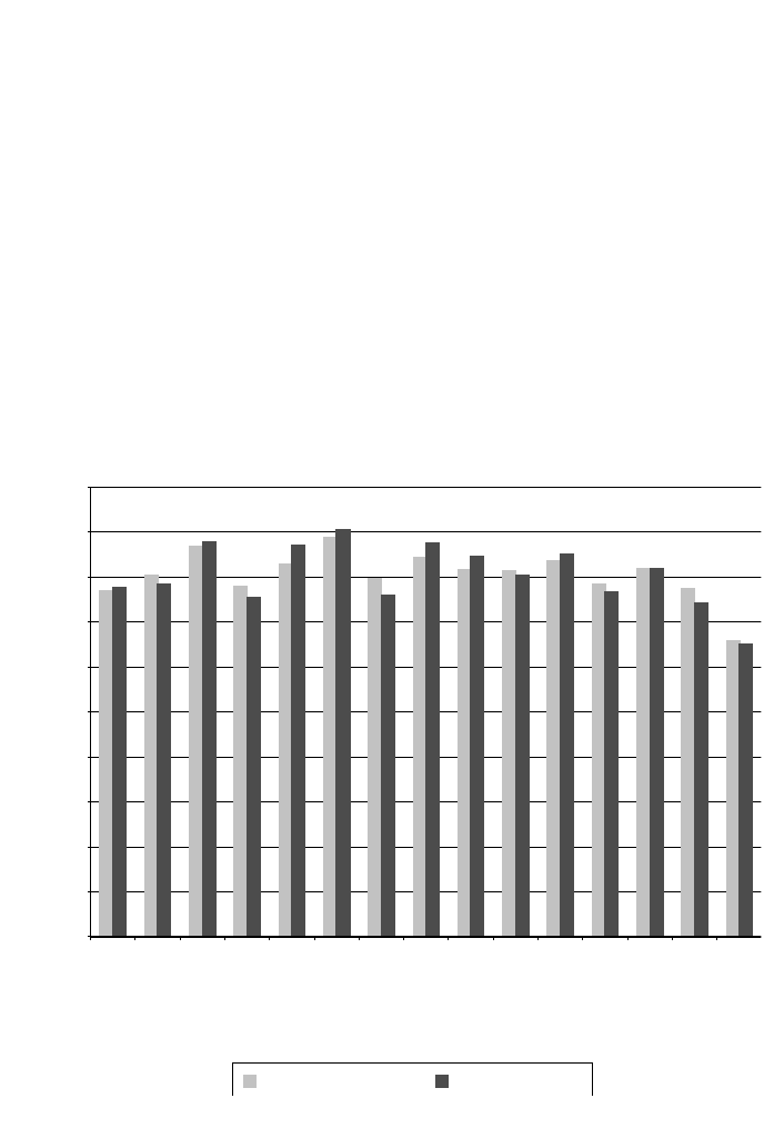
The results of the simulations are indicated in Figure 3, showing the energy savings
compared to the baseline for the community hospital and the surgery center.
All locations achieved the 30% savings for the community hospital and the surgery
center. In general, the community hospital outperformed the surgery center in most
climate locations because of its continuous (24-hour) operation. With lower lighting
levels, additional heating energy was necessary to compensate for the heating typically
gained from lighting power sources. However, this was more than offset by the cooling
load reduction associated with lower lighting levels.
Complete results of the prototype facility simulations are presented in the Technical
Support Document: Development of the Advanced Energy Design Guide for Small
Hospitals and Healthcare Facilities, available at http://www.nrel.gov/docs/fy10osti/
46314.pdf [11].
Journal of Healthcare Engineering · Vol. 1 · No. 2 · 2010
291
0%
1A-Miami
2A-Houston
2B-Phoenix
3B-El Paso
3C-San Francisco
3A-Memphis
4A-Baltimore
5A-Chicago
6A-Burlington
6B-Helena
7A-Duluth
8A-Fairbanks
5B-Boise
4B-Albuquerque
4c-Seattle
5%
Percent energy savings over standard 90.1-1999
10%
15%
20%
25%
30%
35%
40%
45%
50%
Community hospital Surgery center
Figure 3. Percent Savings for the PVAV with DX Cooling Models.
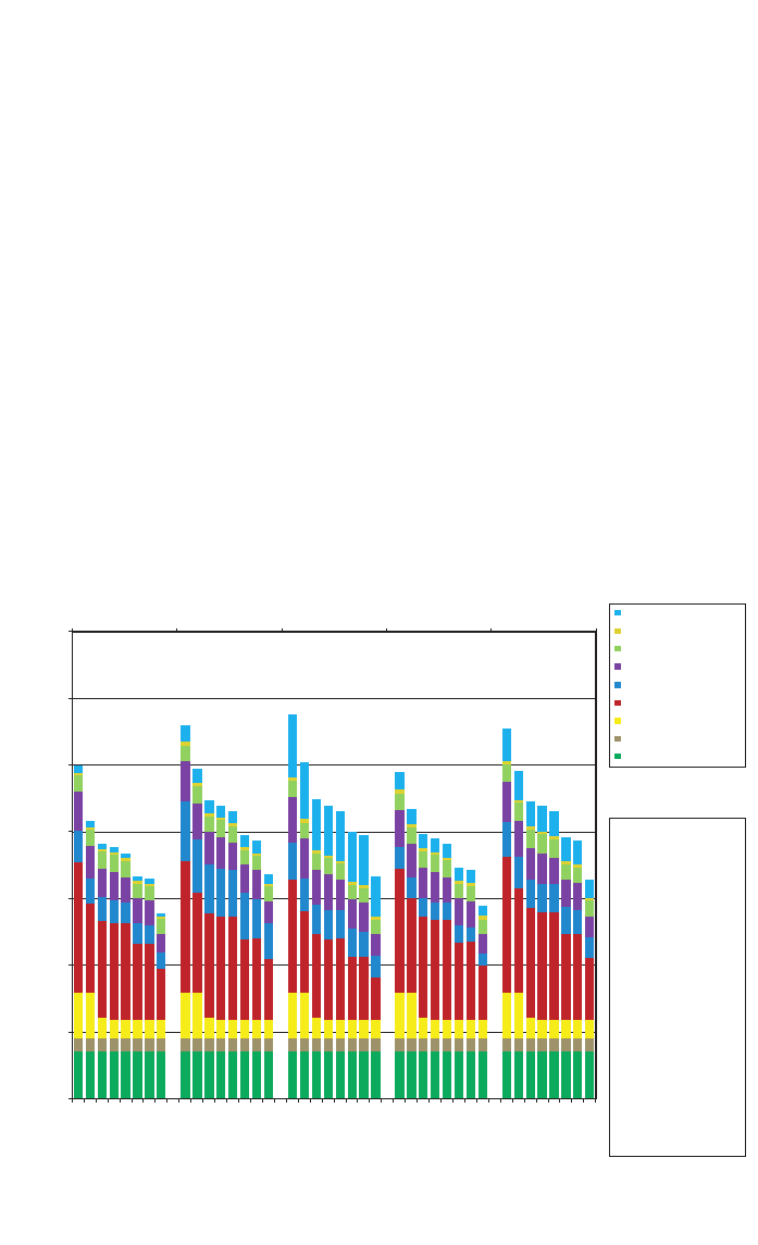
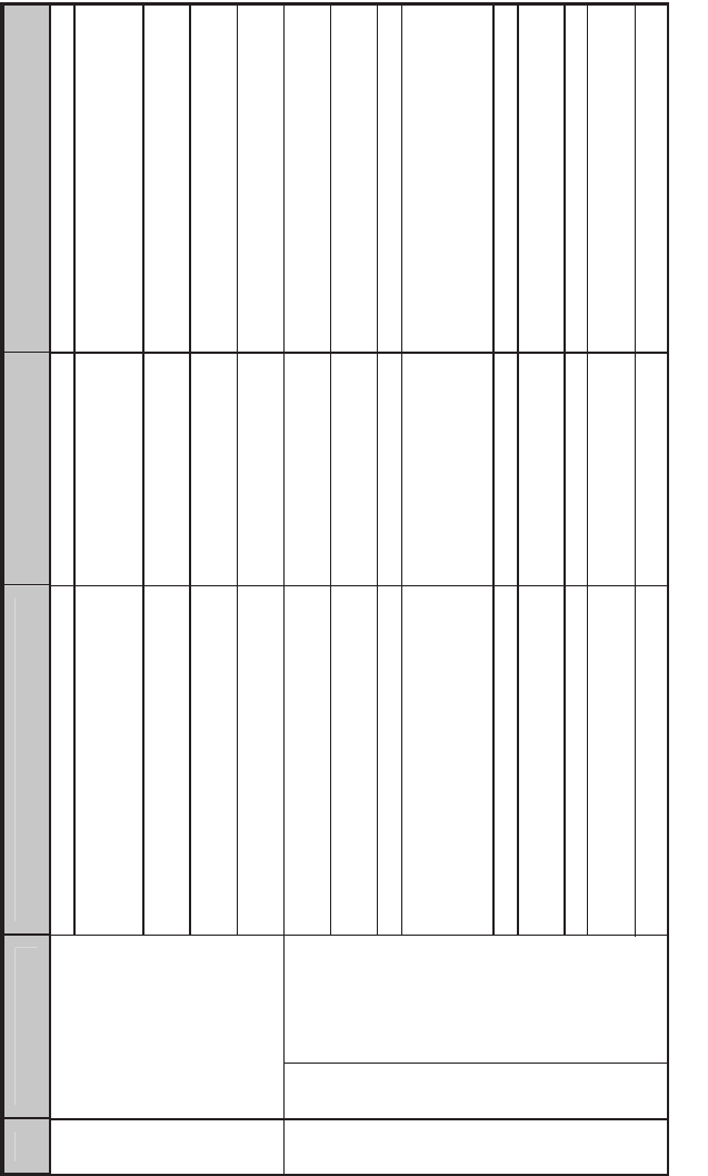
8. BUNDLED ENERGY EFFICIENCY MEASURE ANALYSIS
During the modeling process, a baseline model and a low-energy model were created
and compared to provide the percent savings numbers. The low-energy model was
created by starting with the prototype model and applying as many guide recommendations
as possible. However, it is difficult to determine which recommendations provide the most
energy savings because they are all applied to the prototype model in a single operation.
To better understand how each recommendation affects energy performance, a study
was performed in which each guide recommendation was incrementally and
aggregately applied until the low-energy model was achieved. This study was termed a
bundled energy efficiency measure analysis and consisted of seven steps: (1) apply the
envelope efficiency measures, which included adding overhangs to the south windows,
adding skylights to the surgery center, and upgrading the building materials in
accordance with the guide recommendations; (2) reduce space-by-space LPD; (3) add
daylighting controls to applicable zones; (4) reduce fan pressure drop and increase fan
efficiencies; (5) improve boiler and SWH efficiencies; (6) improve DX cooling
efficiencies; and (7) implement a zone airflow setback strategy in which the HVAC
terminal boxes mimicked constant air volume boxes during occupied times and VAV
292 Advanced Energy Design Guide for Small Hospitals and Healthcare Facilities
0
Baseline
Baseline
Baseline
Baseline
Baseline
Step 1
Step 1
Step 1
Step 2
Step 2
Step 2
Step 3
Step 3
Step 3
Step 4
Step 4
Step 4
Step 5
Step 5
Step 5
Step 6
Step 6
Step 6
Step 7
Step 7
Step 7
Step 1
Step 2
Step 3
Step 4
Step 5
Step 6
Step 7
Step 1
Step 2
Step 3
Step 4
Step 5
Step 6
Step 7
50
100
150
Annual energy end use intensity (kBtu/ft
2
)
200
250
300
350
3C-San Francisco 4A-Baltimore 4B-Albuquerque 4C-Seattle 5A-Chicago
Humidification (elec)
Pumps (elec)
Water systems (gas)
fans (elec)
Cooling (elec)
Heating (gas)
Interior lighting (elec)
Interior equipment (gas)
Interior equipment (elec)
Step 1 : Apply the AEDG
specific envelope criteria
to the baseline model.
Step 2 : Apply the AEDG
lighting power density
recommendations to the
model from Step 1.
Step 3 : Apply the AEDG
daylighting
recommendations to the
model from Step 2.
Step 4 : Apply the AEDG
fan efficiency
recommendations to the
model from Step 3.
Step 5 : Apply the AEDG
boiler efficiency
recommendations to the
model from Step 4.
Step 6 : Apply the AEDG
compressor efficiencies
to the model from Step 5.
Step 7 : Apply the AEDG
zone airflow setback to
the model from Step 6.
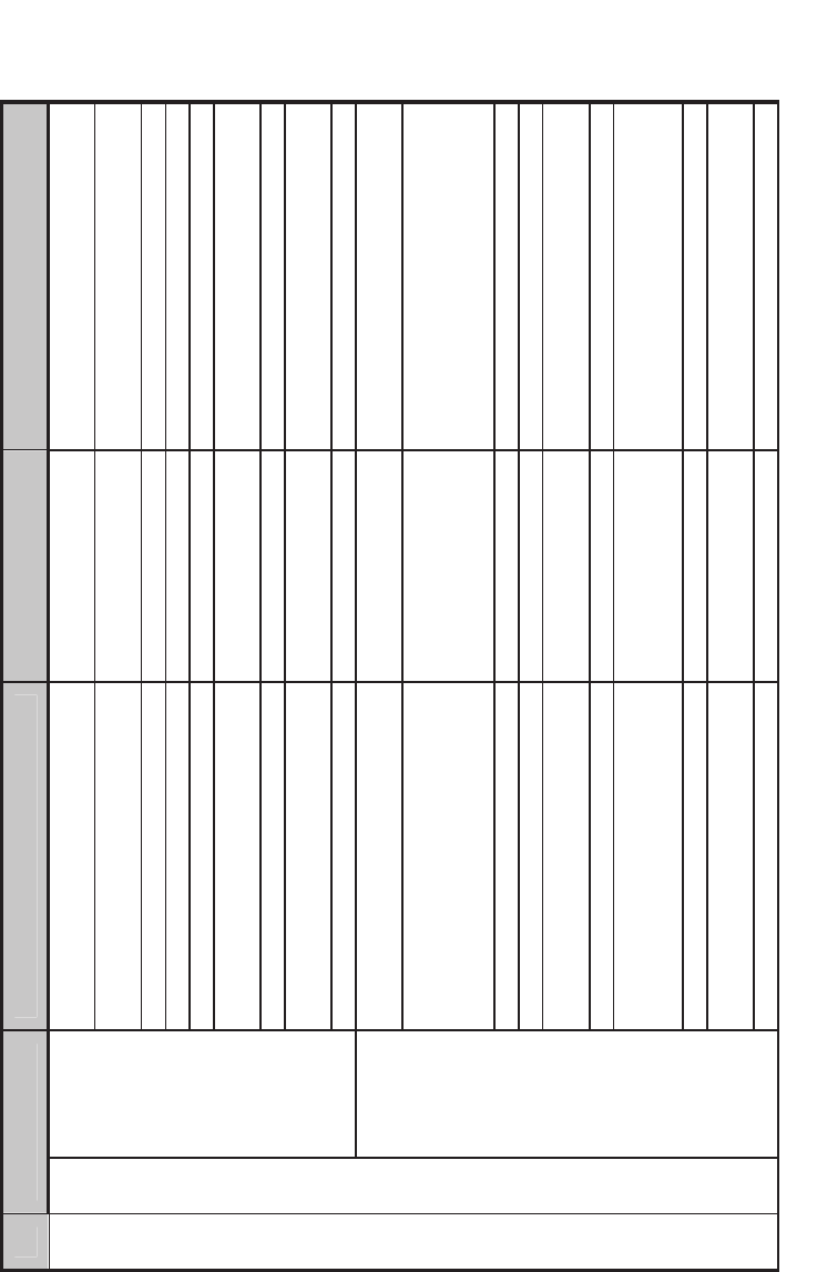
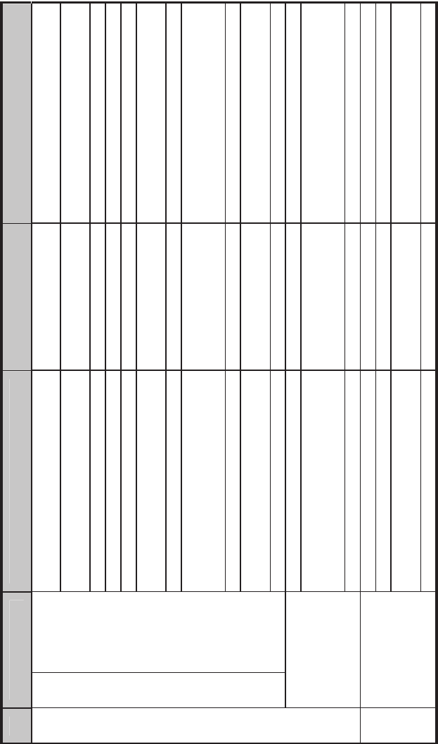
Figure 4. Community Hospital Bundled Energy Efficiency Measure Analysis
Results for Climate Zones 1A through 3B.
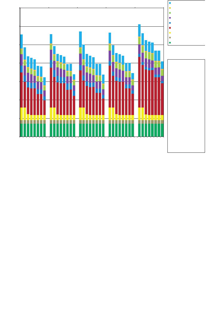
boxes during unoccupied times. The bundled energy efficiency analysis energy results
by end use for the community hospital are shown in Figure 4 (climate zones 1A
through 3B), Figure 5 (climate zones 3C through 5A), and Figure 6 (climate zones 5B
through 8A).
The results of this analysis show the biggest energy savers are the LPD reductions
and the implementation of a zone airflow setback. Colder climates benefited more from
the improved boiler efficiencies; hotter climates benefited more from improved cooling
efficiencies.
9. SUMMARY
As with the previous guides in the series, the SHC-AEDG provides a simple, easy-to-
use guide to help the building designer, contractor, and owner identify a clear
prescriptive path to 30% energy savings over Standard 90.1-1999. In many ways, the
SHC-AEDG is a simple interface to a complex analysis performed using EnergyPlus.
The combination of a set of recommendations contained on a single page, along with
numerous how-to tips to help the construction team complete the project successfully,
should result in increased energy efficiency in new buildings. Case studies of actual
small healthcare applications add to the comprehension of energy efficiency
Journal of Healthcare Engineering · Vol. 1 · No. 2 · 2010
293
0
B
aseline
B
aseline
B
aseline
B
aseline
B
aseline
Step 1
Step 1
Step 1
Step 1
Step 1
Step 2
Step 2
Step 2
Step 2
Step 2
Step 3
Step 3
Step 3
Step 3
Step 3
Step 4
Step 4
Step 4
Step 4
Step 4
Step 5
Step 5
Step 5
Step 5
Step 5
Step 6
Step 6
Step 6
Step 6
Step 6
Step 7
Step 7
Step 7
Step 7
Step 7
50
100
150
Annual energy end use intensity (kBtu/ft
2
)
200
250
300
350
5B-Boise 6A-Burlington 6B-Helena 7A-Duluth 8A-Fairbanks
Humidification (elec)
Pumps (elec)
Water systems (gas)
Fans (elec)
Cooling (elec)
Heating (gas)
Interior lighting (elec)
Interior equipment (gas)
Interior equipment (elec)
Step 1 : Apply the AEDG
specific envelope criteria
to the baseline model.
Step 2 : Apply the AEDG
lighting power density
recommendations to the
model from Step 1.
Step 3 : Apply the AEDG
daylighting
recommendations to the
model from Step 2.
Step 4 : Apply the AEDG
fan efficiency
recommendations to the
model from Step 3.
Step 5 : Apply the AEDG
boiler efficiency
recommendations to the
model from Step 4.
Step 6 : Apply the AEDG
compressor efficiencies
to the model from Step 5.
Step 7 : Apply the AEDG
zone airflow setback to
the model from Step 6.
Figure 5. Community Hospital Bundled Energy Efficiency Measure Analysis
Results for Climate Zones 3C through 5A.
opportunities. The SHC-AEDG is available for print purchase or as a free download
from http://www.ashrae.org/aedg.
The ultimate goal of the Advanced Energy Design Guide partner organizations is to
achieve net-zero energy buildings, and the 30% savings guides represent the first step
in reaching this goal. The SHC-AEDG marks the last in the series of 30% savings
design guides. This guide has furthered similar work in the healthcare energy efficiency
field, as it set the stage for developing a large hospital best practices guide and is used
in planning the next series of 50% savings Advanced Energy Design Guides. Also, U.S.
government healthcare facilities are starting to use the guide to meet EPAct 2005 energy
efficiency requirements.
ACKNOWLEDGEMENTS
The authors would like to thank all the members of the PC for their diligence, creativity,
and willingness to support the creation of the guide. This project would not have been
possible without financial contributions from DOE, through Drury Crawley and Pat
LeDonne of the Building Technologies Program. Additional thanks to the ASHRAE
staff, whose direction, guidance, organizational skills, and dedication enabled timely
completion of the guide.
294 Advanced Energy Design Guide for Small Hospitals and Healthcare Facilities
0
Baseline
Baseline
Baseline
Baseline
Baseline
Step 1
Step 1
Step 1
Step 1
Step 1
Step 2
Step 2
Step 2
Step 2
Step 2
Step 3
Step 3
Step 3
Step 3
Step 3
Step 4
Step 4
Step 4
Step 4
Step 4
Step 5
Step 5
Step 5
Step 5
Step 5
Step 6
Step 6
Step 6
Step 6
Step 6
Step 7
Step 7
Step 7
Step 7
Step 7
50
100
150
Annual energy end use intensity (kBtu/ft
2
)
200
250
300
350
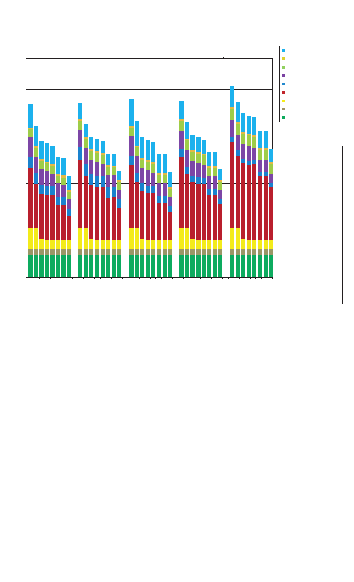
5B-Boise 6A-Burlington 6B-Helena 7A-Duluth 8A-Fairbanks
Humidification (elec)
Pumps (elec)
Water systems (gas)
Fans (elec)
Cooling (elec)
Heating (gas)
Interior lighting (elec)
Interior equipment (gas)
Interior equipment (elec)
Step 1 : Apply the AEDG
specific envelope criteria
to the baseline model.
Step 2 : Apply the AEDG
lighting power density
recommendations to the
model from Step 1.
Step 3 : Apply the AEDG
daylighting
recommendations to the
model from Step 2.
Step 4 : Apply the AEDG
fan efficiency
recommendations to the
model from Step 3.
Step 5 : Apply the AEDG
boiler efficiency
recommendations to the
model from Step 4.
Step 6 : Apply the AEDG
compressor efficiencies
to the model from Step 5.
Step 7 : Apply the AEDG
zone airflow setback to
the model from Step 6.
Figure 6. Community Hospital Bundled Energy Efficiency Measure Analysis
Results for Climate Zones 5B through 8A.

REFERENCES
[1] ASHRAE, AIA, IES, USGBC, DOE, Advanced Energy Design Guide for Small Hospitals and
Healthcare Facilities, American Society of Heating, Refrigerating and Air-Conditioning Engineers,
Atlanta, 2009.
[2] ANSI/ASHRAE/IESNA, Standard 90.1-1999 Energy Standard for Buildings except Low-Rise
Residential Buildings, American Society of Heating, Refrigerating and Air-Conditioning Engineers,
Atlanta, 1999.
[3] Torcellini, P., Pless, S., Deru, M., Crawley, D., Zero Energy Buildings: A Critical Look at the
Definition, ACEEE Summer Study on Energy Efficiency in Buildings, Golden, National Renewable
Energy Laboratory, 2006.
[4] ASHRAE, AIA, IESNA, NBI, DOE, Advanced Energy Design Guide for Small Office Buildings,
American Society of Heating, Refrigerating and Air-Conditioning Engineers, Atlanta, 2000.
[5] Colliver, D.G. and Jarnagin, R.E., Savings 30% Over Standard 90.1-1999: Advanced Energy Design
Guide for Small Office Buildings, ASHRAE Journal, 2005, 47 (3), 22–27.
[6] EIA, 2003 Commercial Buildings Energy Consumption Survey, EIA, Washington D.C., 2003,
Available from http://eia.doe.gov/emeu/cbecs/cbecs2003/introduction.html.
[7] GGHC, Green Guide for Health Care: Best Practices for Creating High Performance Healing
Environments, Version 2.2, http://www.gghc.org, August 2009.
[8] Torcellini et al., DOE Commercial Building Benchmark Models: Preprint, National Renewable Energy
Laboratory, Golden, NREL Report No. CP-550-43291, 2008.
[9] ASHRAE, Standard 62.1-2004 Ventilation for Acceptable Indoor Air Quality, American Society of
Heating, Refrigerating and Air-Conditioning Engineers, Atlanta, 2004.
[10] AIA, Guidelines for Design and Construction of Health Care Facilities, American Institute of
Architects, Washington D.C., 2006.
[11] Pless, S., Torcellini, P., Doebber, I., Bonnema, E., Technical Support Document: Development of the
Advanced Energy Design Guide for Small Hospitals and Healthcare Facilities–30% Energy Savings.
National Renewable Energy Laboratory, Golden, NREL Report No. TP-550-46314, 2010.
[12] DOE, EnergyPlus Simulation Software, Version 3.1, U.S. Department of Energy, Washington D.C.,
http://www.energyplus.gov, 2009.
[13] “Opt-E-Plus Software for Commercial Building Optimization,” NREL/FS-550-45620. Golden, CO:
National Renewable Energy Laboratory. http://www.nrel.gov/docs/fy10osti/45620.pdf, 2010.
Journal of Healthcare Engineering · Vol. 1 · No. 2 · 2010
295
