
Retraction Hooks of Different Lengths
for Maxillary Whole Arch Distalization
with Miniscrew Anchorage: A Finite Element Analysis
Vanichaya Tangsumroengvong
1
, Virush Patanaporn
2
, Chaiy Rungsiyakul
3
1
Graduate student, Division of Orthodontics, Faculty of Dentistry, Chiang Mai University
2
Department of Orthodontics and Pediatric, Faculty of Dentistry, Chiang Mai University
3
Department of Mechanical Engineering, Faculty of Engineering, Chiang Mai University
CM Dent J 2021; 42(1) : 125-138
Received: 20 April, 2020
Revised: 14 May, 2020
Accepted: 22 May, 2020
Abstract
Objectives: To evaluate the von Mises stress distribution in the periodontal ligament and the dis-
placement pattern of maxillary whole arch distalization applied to retraction hooks of different lengths
with miniscrew anchorage and to determine the optimal length of retraction hook, using a nite element
method.
Methods: A nite element model of maxillary teeth with periodontal ligament and alveolar bone was
constructed. The miniscrews were placed bilaterally 6 mm above the buccal cemento-enamel junction
at the modied infrazygomatic crest site. The distalization force of 200 g was applied to 0-, 2-, 4-, 6-,
8-mm-length retraction hooks located between the lateral incisors and canines. The stress distribution
in the periodontal ligament and the displacement of the teeth were analyzed. The optimal length of
retraction hook for maximal distal movement of the maxillary whole arch along the occlusal plane was
investigated.
Results: The von Mises stress in the anterior teeth was greater than in the posterior teeth with all
hook lengths. When using the short hooks, the areas of high stress were in the lateral incisor, canine
and second molar. When using the long hooks, the areas of high stress were in the anterior teeth.
With the 0-mm and 2-mm lengths, the anterior teeth were extruded and tipped palatally; the poste-
rior teeth were intruded and tipped distally. With the 4-mm length, all maxillary teeth were distal-
ized along the occlusal plane with minimal movement in the vertical direction. The anterior teeth
were slightly tipped labially; the posterior teeth were slightly tipped distally. With the 6-mm and
Corresponding Author:
Visush Patanaporn
Clinical Professor, Department of Orthodontics and Pediatric Dentistry, Faculty of Dentistry,
Chiang Mai University, Chiang Mai 50200, Thailand
E-mail: [email protected]
Original Article

CM Dent J Vol. 42 No. 1 January-April 2021 126
8-mm lengths, the anterior teeth were intruded and tipped labially; the posterior teeth were extruded
and tipped distally. The optimal length in this study was found to be 4 mm.
Conclusions: Different lengths of retraction hooks resulted in different patterns of stress
distribution in the PDL and in different patterns of displacement of the maxillary teeth in whole arch
distalization. The optimal length of retraction hook was 4 mm for maximal distal movement of the
maxillary whole arch along the occlusal plane.
Keywords: whole arch distalization, en-masse distalization, nite element, retraction hook
Introduction
Non-extraction treatment of Class II maloc-
clusion requires maxillary dentition distalization,
mandibular dentition mesialization, or a combination
of both.
(1,2)
Distalization can be divided into sequen-
tial distalization and en-masse distalization. In the
sequential distalization, initially the rst and second
molars are distalized by open-coil spring, then the
premolars and then the anterior teeth. This method
can cause proclination of the anterior teeth and distal
tipping of the molars during distalization.
(3,4)
En-
masse distalization is achieved by distalizing all of
the anterior and posterior teeth at the same time, as
one rigid block, using miniscrew anchorage.
(1,5-8)
Although this method may reduce the overall treat-
ment time, it may increase the risk of root resorption
since the applied magnitude of force is larger than
that of the sequential distalization.
(7)
Miniscrew implant placement locations for
maxillary dentition distalization are varied.
(9,10)
The
placement locations include the midpalatal or para-
median areas of the palate,
(11)
the buccal or palatal
interradicular areas,
(6,7,9)
and the infrazygomatic
crest.
(8)
The most ideal safe zone for placing minis-
crews for distalization of the maxillary dentition is
the region between the maxillary rst and second
molar in the infrazygomatic crest area,
(9)
which is
called the “Modied infrazygomatic crest site.”
(Modied IZC)
(12,13)
This site provides thick cortical
bone and fewer problems with root proximity than
in the interradicular areas.
(8,9)
Each study and case report conducted previously
applied different loading forces for whole arch
distalization, ranging from 200 to 300 g.
(5-8,12,14,15)
Most of them, however, used a force magnitude of
about 200 g and found no side effect in terms of
root resorption and periodontitis.
(5-7,12)
Therefore,
the force magnitude of 200 g will be chosen for this
study.
The relationship between the line of action of
the applied force and the center of resistance (CRes)
denes the type of tooth movement.
(4)
Force passing
through the CRes causes translation; force passing
off-center causes rotation or tipping.
(16)
Clinically, it
is difcult to accurately determine the line of force
passing through the CRes of the maxillary dentition.
Moving the line of force close to the CRes by apply-
ing the force to a different retraction hook lengths
can cause more translational movement rather than
applying the force at the bracket level.
(3)
Jeong
et al.
(32)
reported that the CRes of the maxillary
dentition in their nite element model constructed
from Nissin commercial tooth model was 13.5 mm.
apically and 12.0 mm. posteriorly to the incisal edge
of the maxillary central incisors. As our study will
also use Nissin dental model, we will choose this
location as the CRes of our nite element model.
The nite element method is a contemporary

CM Dent J Vol. 42 No. 1 January-April 2021127
research tool in orthodontics for measuring struc-
tural stress and for movement analyses.
(17,18)
It is
a numerical stress analysis which can be used to
describe the stress situation within the periodontal
ligament (PDL) and surrounding alveolar bone.
(19)
This method has become popular since it is com-
pletely non-invasive, very accurate and it is based
on the mathematical properties of the structures.
(18)
The purposes of this study were to use the nite
element method to evaluate the pattern of stress
distribution in the PDL and the tooth displacement
pattern of maxillary whole arch distalization relative
to force vectors applied to retraction hooks of different
lengths and to determine the optimal length of retrac-
tion hook for maximal distal movement of the maxil-
lary whole arch along the occlusal plane, when using
miniscrew anchorage placed at the modied IZC.
Materials and methods
All maxillary teeth of a commercial model
(Model-i21FE-400C; Nissin Dental Products,
Kyoto, Japan) based on the average tooth dimen-
sions of Asian adults with normal occlusion were
scanned via 3-D laser scanning to make digital
tooth images.
(20-25)
The solid model, including all
maxillary teeth, PDL and maxillary bone was con-
structed and assembled using SolidWorks software
(Dassault Systèmes Americas, Waltham, Mass.,
USA). The maxillary bone consisted of cancellous
bone with 1.0 mm thickness of cortical bone. The
alveolar crest was formed following the curvature of
the cemento-emamel junction (CEJ), 1 mm apical to
the CEJ.
(24,26)
The thickness of the PDL was assumed
to be a uniform 0.2 mm. The brackets were modeled
with slot dimensions of a 0.018 x 0.025 inches and
attached to the midpoint of the facial axis of the
crown and completely connected to each tooth. The
main archwire was modeled as a stainless-steel wire
with dimensions of 0.017 x 0.025 inches, and it
was assumed that there was no play and no friction
between the brackets and the archwire. Retraction
hooks were modeled using 0.036 inch crimpable
hook stainless steel and located bilaterally between
the lateral incisors and canines. The miniscrew
position was simulated 6 mm above the buccal CEJ
between the maxillary rst and second molars at the
position of the modied IZC, as proposed by Lin.
(12)
The properties of all materials were those
used in previously conducted nite element studies
(Table 1).
(27-33)
All materials were assigned iso-
parametric, homogeneous, linear, elastic properties,
excepting the PDL, which was dened as having
non-linear elasticity. Ogden model property values were
assigned to describe the non-linear elastic stress-
strain behavior of the PDL (Table 2).
(34)
The constructed nite element model was
meshed into 148,914 nodes and 651,810 elements.
The teeth, PDL and alveolar bone were constructed
into tetrahedron elements. The brackets, hooks, and
archwire were constructed into hexahedron elements.
The interactions between teeth were tie contact with
no friction. The boundary conditions were dened
at the top and back surface of the maxillary bone.
Table 1 Material properties of dentin, cortical bone, cancel-
lous bone and stainless steel required within the FE
model.
(27-33)
Material
Young’s
modulus (MPa)
Poisson’s
ratio
Dentin 19600 0.3
Cortical bone 13700 0.26
Cancellous bone 1370 0.3
Stainless steel 200000 0.3
Table 2 Coefcients of the third order Ogden model property
values describing non-linear elasticity of PDL.
(34)
i µ
i
a
i
D
i
1 -24.4237106 1.99994222 4.87164332
2 15.8966494 3.99994113 0.00000000
3 8.56953079 -2.00005453 0.00000000
CM Dent J Vol. 42 No. 1 January-April 2021 128
The orientation of this model was established with
the x axis representing the mesio-distal direction of
the anterior teeth and the bucco-palatal direction
of the posterior teeth. The y axis represented the
supero-inferior direction. The z axis represented the
antero-posterior direction, which is the labio-palatal
direction of the anterior teeth and the mesio-distal
direction of the posterior teeth. +X represents the left
side of model, in the right quadrant, +x represents
the mesial direction of movement of the anterior
teeth and the palatal direction of movement of the
posterior teeth. In the left quadrant, +x represents
the distal direction of movement of the anterior teeth
and the buccal direction of movement of the posterior
teeth. +Y values were dened as the inferior or apical
direction and +z values were dened as the labial
direction of the anterior teeth or the mesial direction
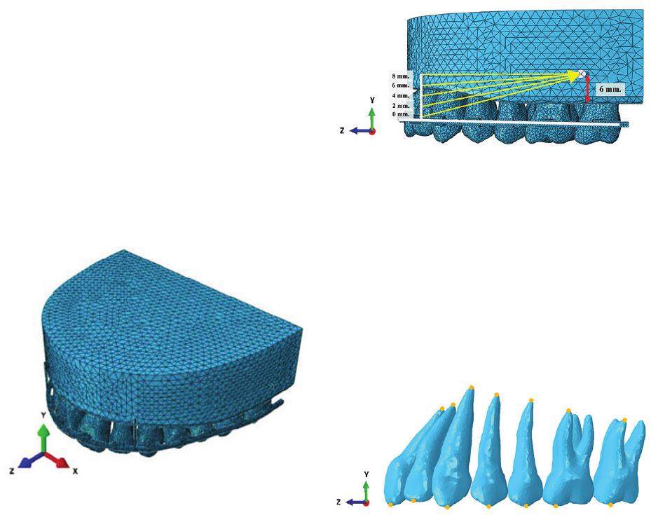
of the posterior teeth (Figure 1).
A distalization force vector of 200 g was applied
from the miniscrew to the retraction hooks of 0-mm,
2-mm, 4-mm, 6-mm, and 8-mm lengths (Figure 2)
The location of CRes was dened same as the loca-
tion described by Jeong et al.
(31)
The displacement
patterns of the teeth, produced by the force vectors
resulting from using each hook length, were calculat-
Figure 1 The orientation of the model. X axis: (+) left, (−) right
direction; y axis: (+) superior, (−) inferior direction;
z axis: (+) anterior, (−) posterior direction.
Figure 2 Schematic force diagram and miniscrew position.
Forces (200 g) were applied from the miniscrew to
different vertical positions of the retraction hook: 0
mm, 2 mm, 4 mm, 6 mm and 8 mm. located between
the lateral incisor and canine. The location of minis-
crew was simulated at 6 mm above the buccal CEJ
between the rst and second molar.
Figure 3 The reference points of teeth are represented as
yellow dots for the assessment of tooth displacement.
ed in the x, y, and z axes. The midpoints of the incisal
edges of the central and lateral incisors, the cusp tip
of the canine, the buccal cusp tips of the premolars,
the mesio-buccal cusp tips of the molars, and the root
apices of each tooth were used as reference points to
evaluate the displacement of the teeth. The Abaqus
software (Dassault Systèmes Americas) was used
to calculate and visualize the PDL von Mises stress
distribution and tooth displacement patterns for the
whole arch distalization of all maxillary teeth.
Results
Von Mises stress distribution in PDL and tooth
displacement patterns of the right and left quadrants
were assumed to be the same because the point of
application and angle of force direction were the
CM Dent J Vol. 42 No. 1 January-April 2021129
same. Therefore, only the left quadrant is shown in
these results, for clarity and to eliminate superimpo-
sition of the right and left quadrants.
Von Mises stress distribution in PDL
The von Mises stress distribution in the PDL was
calculated in N/mm
2
(MegaPascals or MPa). The
color-coded map of von Mises stress distribution in
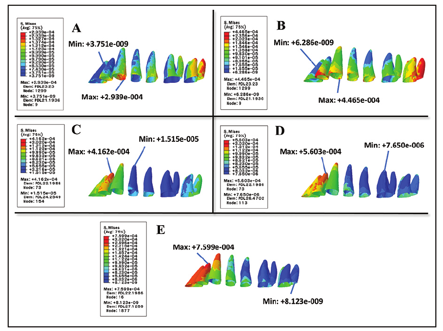
the PDL with all hook lengths is shown in Figure 4.
The levels of stress are shown in the map, in which
red represents the areas of maximum stress and dark
blue represents the areas of minimum stress.
The stress produced when using 0-mm retrac-
tion hooks was greatly concentrated in the canine
and the distal root of the second molar. The highest
stress value was in the cervical third of the canine
(2.939x10
-4
MPa). The lowest stress value was in the
apical third of the central incisor (3.751x10
-9
MPa)
(Figure 4A).
The stress produced when using 2-mm retrac-
tion hooks was greatly concentrated in the lateral
incisor, canine and the distal root of the second
molar. The highest stress value was in the cervical
third of the canine (4.465x10
-4
MPa). The lowest
stress value was in the apical third of the central
incisor (6.286x10
-9
MPa) (Figure 4B). The distribu-
tion patterns of the above two hook lengths are nearly
the same pattern.
With the 4-mm length of retraction hook, the
highest stress value was in the apical third of the
lateral incisor (4.162x10
-4
MPa). The high stress
was also found in the second molar but lower than
with the 0-mm and 2-mm hooks. The lowest stress
value was in the apical third of the rst premolar
Figure 4 Color-coded map of von Mises stress distribution in the left maxillary quadrant PDL. The areas of maximum and
minimum stress are indicated. A) 0-mm, B) 2-mm, C) 4-mm, D) 6-mm, E) 8-mm lengths
CM Dent J Vol. 42 No. 1 January-April 2021 130
(1.515x10
-5
MPa) (Figure 4C).
With the 6-mm length of retraction hook, the
areas of high stress were in the apical third of the
central incisor, lateral incisor and canine. The highest
stress value was in the apical third of the lateral
incisor (5.603x10
-4
MPa). The lowest stress value
was in the apical third of the rst molar (7.650x10
-6
MPa) (Figure 4D).
With the 8-mm length of retraction hook, the
areas of high stress were nearly the same pattern
with the 6-mm length, but the stress was more con-
centrated. The highest stress value was in the apical
third of the lateral incisor (7.599x10
-4
MPa). The
lowest stress value was in the cervical third of the
second molar (8.123x10
-9
MPa) (Figure 4E).
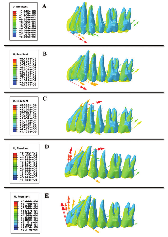
Displacement of all maxillary teeth
The displacement patterns of all maxillary
teeth with each length of retraction hook are shown
in Figure 4. The translucent yellow tooth images
show the positions of the teeth before applying the
force, and the blue tooth images show the displaced
positions afterwards. The directions of the arrows
adjacent to the teeth represent the directions of the
tooth movement. The length and color of the arrows
represent the distance of the tooth movement. With
all lengths of retraction hooks, the amounts of initial
tooth movement in the anterior segment were larger
than in the posterior segment.
With the retraction hook lengths of 0 mm
(bracket slot level) and 2 mm, palatal crown tipping
and extrusion of the anterior teeth were observed.
The posterior tooth movement was distal tipping
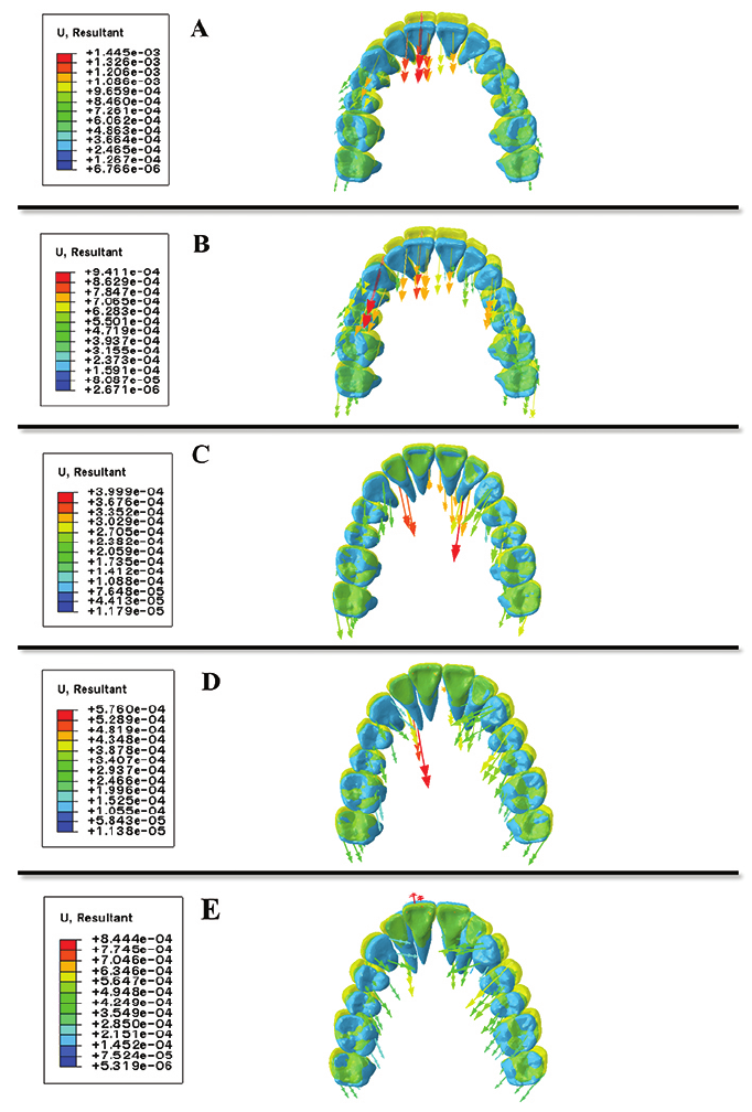
and intrusion (Figure 5A & B). In the occlusal view,
all teeth moved in the posterior direction with the
anterior teeth moving palatally and the posterior
teeth moving distally. The crowns of the posterior
teeth tipped slightly buccally (Figure 6A & B).
With the retraction hook length of 4 mm,
both crowns and roots of the anterior teeth moved
palatally and slighltly intruded. The root apices
displaced palatally more than the crowns. The
crowns of posterior teeth moved distally. The
premolars were slightly extruded, but the molars
were slightly intruded (Figure 5C). In the occlusal
view, all teeth still moved in the posterior direction
but, in contrast to the situation with 0-mm and 2-mm
hooks, the crowns of the posterior teeth tipped slight-
ly palatally (Figure 6C).
With the retraction hook length of 6 mm and
8 mm, the direction of anterior tooth movement
changed from palatal crown tipping to labial crown
tipping. The anterior segment of archwire was raised
upward, resulting in anterior teeth proclination and
intrusion. The posterior teeth tipped slightly distally
and extruded (Figure 5D & E). In the occlusal view,
the crowns of the anterior teeth tipped labially and
the root apices tipped palatally. The crowns of the
posterior teeth tended to tip palatally to a greater
extent than with the 4-mm hook (Figure 6D & E).
Optimal length of retraction hook
The optimal length of retraction hook in this study
was 4 mm. The anterior and posterior teeth moved
distally along the occlusal plane with minimal vertical
movement and tipping.
Discussion
This nite element study of maxillary whole
arch distalization demonstrates that applying
distalization force to different lengths of retrac-
tion hooks resulted in different patterns of stress
distribution in the PDL and in different patterns of
displacement of the maxillary teeth. We also found
that the optimal length of retraction hook that
produced closed to distal translation movement of
the maxillary whole arch was 4 mm.
Applying distalization force to the retraction
hook, the initial movement was mainly observed
at the anterior teeth as proved by FEM. The force
CM Dent J Vol. 42 No. 1 January-April 2021131
Figure 5 Displacement of the left maxillary teeth indicated by superimposition of before (yellow) and after (blue) application of
the distalization force. The direction of tooth movement indicated by the colored arrows. The length and color of the
arrows represent the distance of the tooth movement. Long red arrows indicate large amounts of displacement; short
blue arrows indicate small amounts of displacement. A) 0-mm., B) 2-mm., C) 4-mm., D) 6-mm., E) 8-mm. lengths
CM Dent J Vol. 42 No. 1 January-April 2021 132
Figure 6 Displacement of all maxillary teeth indicated by superimposition of before (yellow) and after (blue) application of the
distalization force in the occlusal view. The direction of tooth movement indicated by the colored arrows. A) 0-mm, B)
2-mm, C) 4-mm, D) 6-mm, E) 8-mm lengths
CM Dent J Vol. 42 No. 1 January-April 2021133
and stress were also transferred to the second
molar, causing posterior tooth movement and whole
arch distalization. Thus, this nite element nding
may be used as evidence to support the theory of en-
masse distalization, which proposes that the entire
maxillary dentition can be effectively moved after
applying force to an anteriorly located hook.
(24)
In this study, the results of stress distribution in
the PDL were examined in terms of the von Mises
stress. It was used to represent the overall stress
of a multi-axial stress just the same as it has been
applied in previous studies.
(22,24,35-37)
The stress on
the teeth close to the point of force application at the
retraction hook, was more concentrated than on some
other teeth in positions farther from the hook. With
0-mm- and 2-mm- hooks, the highest level of stress
was found at the cervical third of canine. With the
other lengths, the highest level of stress was found
on the apex of lateral incisor, which was also close
to the point of force application. These outcomes are
in agreement with those of Sung et al.
(24)
The results revealed that the length of retraction
hook highly relates to the types of tooth movement.
Changing the length of retraction hook affects the
distance between the line of action of force and the
CRes. When distalization force is applied to low-
level hooks, the line of action of the force passed
below the CRes and induced clockwise moment,
resulting in steepening of the occlusal plane. Conse-
quently, the anterior teeth had palatal crown tipping
and extrusion. The posterior teeth tipped distally
and substantially intruded (Figure 7A). The level of
stress was high at the distal root of the second molar
because the posterior teeth were intruded. More-
over, the constructed tuberosity distal to the second
molar and the boundary conditions at the back of the
model may have strongly resisted the distalization,
resulting in high stress in the distal root of the second
molar (Figure 4A & B). On the other hand, the line of
action of the force passed above the CRes and
generated counterclockwise moment, resulting in
upward rotation of the occlusal plane. The labial
aring of anterior teeth was observed, and the pos-
terior teeth were slightly extruded (Figure 7C). The
stress in the PDL of posterior teeth was less than
that with shorter hooks because extrusion occurred
(Figure 4D & E).
When a distalization force was applied to a
4-mm hook, the line of action of the force passed
near the CRes, rather than passing through it, and a
low moment was generated. The line of force may
have passed either slightly below or slightly above
the CRes; therefore, the low moment may have been
either clockwise or counterclockwise, respectively
(Figure 7B). All maxillary teeth moved distally along
the occlusal plane with minimal intrusion or tipping.
The location of the miniscrew at the Modied IZC
was higher than the CRes resulted in a distal and
upward direction of the line of action of force,
generating intrusion and distalization of the maxillary
dentition. In whole arch distalization, the entire
maxillary dentition did not undergo pure bodily
movement. The reason may be archwire deection
of the force system, causing a relatively some degree
of tipping movement.
All of the tooth displacement patterns studied
correspond with the results of previous studies that
used different lengths of retraction hook for whole
arch distalization with interradicular miniscrews
(24)
,
and for distalization of the posterior teeth with
modied IZC miniscrews.
(38)
The distalization force can be divided in to
three axes which affect to the occurred displacement
pattern. The amount of force in each axis was
calculated and represented as Fx, Fy, and Fz. Fx was
a lateral force along the x axis; Fy was an intrusive
force along the y axis; Fz was the horizontal force
or distalization force along the z axis. These forces
were calculated from the resultant force formula of
three vectors using the angle values in this nite
CM Dent J Vol. 42 No. 1 January-April 2021 134
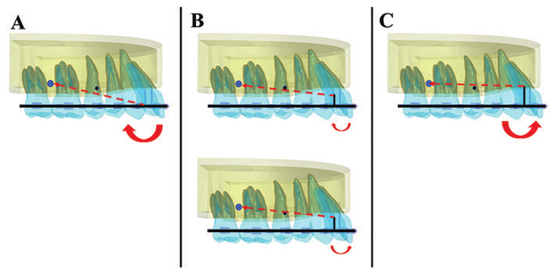
Figure 7 Schematic diagram of moments on whole arch distalization using retraction hooks and miniscrews. A black dot indicates
the position of the CRes. Red dotted lines indicate the distalization force. Red solid curved arrows express the moments
that originated from the force. A) 0-mm hook (short): the red dotted line passes below the CRes, and a clockwise moment
is generated. B) 4-mm hook: the red dotted line passes near the CRes, and a low moment is generated which may be
clockwise or counterclockwise. C) 8-mm hook (long): the red dotted line passes above the CRes, and a counterclockwise
moment is generated.
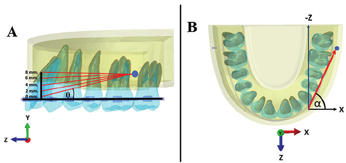
element model. The θ angle was the angle formed
between the line of action of force and the horizontal
plane (Z-axis), whereas the α angle was the angle
formed between the line of action of force and the
lateral force vector (X-axis), as shown in Figure
8. The α angle varied, depending on the length of
retraction hook. An increase in its length led to a
decrease in the θ angle. The θ angle is zero when the
level of the retraction hook is the same as that of the
miniscrew.
(39)
In contrast, the α angle value remained
constant because the locations of retraction hook and
miniscrew were xed.
When using short hooks, the θ angle becomes
larger, resulting in high Fy (intrusive force) and
low Fz (distalization force).
(39)
In our study, shorter
hooks resulted in greater intrusion of the posterior
teeth than did longer hooks. In contrast, long hooks
the θ angle was reduced, resulting in low Fy and high
Fz. Therefore, the intrusion of posterior teeth was
less than with shorter hooks.
Additionally, we found that the arch wire deec-
tion occurred when using a retraction hook attached
to the main archwire due to high bending moments
at the joint of these two components. The high bend-
ing moments increase progressively according to
the length of the retraction hook and the exibility
of the main archwire.
(25)
As found with high-level
hooks, the anterior segment of the archwire was
raised upward because a bending moment occurred
between the lateral incisor and canine. Consequently,
the deection of archwire induced an intrusive
force acting on the anterior teeth, thereby causing
labial aring of incisors. Additionally, the palatal
crown tipping of the posterior teeth when using the
high-level hooks gradually increased from a twist
of the posterior segment of the archwire. This twist
may have acted on the teeth in the same way as the
third order bend or torque that occurs when archwires
are bent using pliers. We attributed the deection
and exibility of the archwire to the property of the
CM Dent J Vol. 42 No. 1 January-April 2021135
Figure 8 Schematic force diagram and the angle of force in the horizontal and vertical planes. A) sagittal view of nite element
model showing the θ angle. B) top view of the model showing the α angle
main archwire, which was assigned to be an elastic
material because the idea of an orthodontic archwire
with rigid strength is unrealistic.
(24)
In this study, all materials were assigned as
linear elastic properties, excepting the PDL, which
was dened as having non-linear elasticity because
of its hyper-elastic behavior. The Ogden model was
used to express the elastic response of this biologi-
cal soft tissues.
(34)
These material property values
normally vary in each person owing to individual
differences in histologic tissue properties.
(20)
Addi-
tionally, the thickness of PDL is, in fact, non-uni-
form, having an hour-glass shape with the mid-root
level having the narrowest width;
(40)
however, in this
study, it was assumed to be uniform (0.2 mm).
The selection of a hook length for whole arch
distalization in each case should be based on the
existing malocclusion and the specic treatment plan
for each patient.
(21,38)
Short hooks could be effective
for palatal crown tipping of the anterior teeth and
intrusion of the posterior teeth which are suitable for
the ared incisors and open bite case. Intrusion of the
posterior teeth resulted in autorotation of mandibular
and decreased the open bite. Long hooks should be
used for palatal root movement of the anterior teeth
and minor extrusion of the posterior teeth, resulting
in the posterior rotation of mandible. Thus, long
hooks are suitable for the retroclined incisors and
deep overbite case.
(24)
The greater the concentration of stress, the larger
is the hyalinized zone of PDL, resulting in a reduced
rate of tooth movement and leading to root resorp-
tion.
(41,42)
Therefore, when applying whole arch
distalization, the roots of the anterior teeth may be
highly prone to resorption due to higher stress in
those teeth.
Three-dimension computed tomography
may be used in future studies to create individual
tooth models for better simulations of orthodontic
tooth movement and for greater accuracy in treat-
ment planning.
(20,21,38,43)
Besides, studies can be
improved by studying the duration of tooth move-
ment. Treatment duration is an important factor that
may yield different results from those of this static
FEM study. Therefore, dynamic FEM studies may
provide an increasingly realistic basis for orthodontic
tooth movement.
Conclusions
1. Different lengths of retraction hooks resulted
in different patterns of stress distribution in the
PDL and in different patterns of displacement of the
CM Dent J Vol. 42 No. 1 January-April 2021 136
maxillary teeth in whole arch distalization.
- The von Mises stress in the PDL of the anterior
teeth, especially the teeth near the retraction hook,
was greater than in the PDL of the posterior teeth
with all lengths of retraction hook. Areas of high
stress concentration were also found in the intruded
teeth, the second molar when using short hook and
the anterior teeth for long hook.
- The use of short hooks induced palatal crown
tipping with extrusion of the anterior teeth and distal
crown tipping with intrusion of the posterior teeth. In
contrast, the use of long hooks induced labial crown
tipping with intrusion of the anterior teeth and distal
crown tipping with extrusion of the posterior teeth.
2. The optimal length of retraction hook was 4
mm that produced movement closed to distal trans-
lation of the maxillary whole arch along the occlusal
plane; however, pure bodily movement did not occur.
Acknowledgments
The authors would like to acknowledge Mr.
Pattarapon Saigerdsri, Master degree student, Faculty
of Engineering, Chiang Mai University, Thailand
for his assistance in the use of the SolidWorks and
Abaqus software during the research study, and
Dr. M. Kevin O. Carroll, Professor Emeritus of the
University of Mississippi School of Dentistry, USA
and Faculty Consultant at Faculty of Dentistry,
Chiang Mai University Thailand, for language
editing.
References
1. Park HS, Kwon TG, Sung JH. Nonextraction
treatment with microscrew implants. Angle
Orthod 2004; 74(4): 539-549.
2. Janson G, Barros SEC, Simão TM, Freitas MRD.
Relevant variables of Class II malocclusion treat-
ment. Dental Press J Orthod 2009; 14(4): 149-
157.
3. Burstone CJ, Choy K. The biomechanical foun-
dation of clinical orthodontics. Hanover Park:
Quintessence Publishing; 2015: 580.
4. Proft WR, Fields HW, Sarver DM. Mechanical
principles in orthodontic force control. Contem-
porary orthodontics. 5
th
ed. St.Louis: Mosby
Elsevier; 2013: 312-336.
5. Chen G, Teng F, Xu TM. Distalization of the
maxillary and mandibular dentitions with minis-
crew anchorage in a patient with moderate Class
I bimaxillary dentoalveolar protrusion. Am J
Orthod Dentofacial Orthop 2016; 149(3): 401-
410.
6. Choi YJ, Lee JS, Cha JY, Park YC. Total distaliza-
tion of the maxillary arch in a patient with skeletal
Class II malocclusion. Am J Orthod Dentofacial
Orthop 2011; 139(6): 823-833.
7. Lee KJ, Park JY, Park YC. En-masse distalization
of upper dentition for correction of Class II using
dual orthodonic miniscrews. J Dent Assoc Thai
2006; 5: 33-38.
8. Wu X, Liu H, Luo C, Li Y, Ding Y. Three-
dimensional evaluation on the effect of maxillary
dentition distalization with miniscrews implanted
in the infrazygomatic crest. Int J Implant Dent
2017; 27(1): 22-27.
9. Liu H, Wu X, Yang L, Ding Y. Safe zones for
miniscrews in maxillary dentition distalization
assessed with cone-beam computed tomography.
Am J Orthod Dentofacial Orthop 2017; 151(3):
500-506.
10. Fayed MM, Pazera P, Katsaros C. Optimal sites
for orthodontic mini-implant placement assessed
by cone beam computed tomography. Angle
Orthod 2010; 80(5): 939-951.
11. Noorollahian S, Alavi S, Shirban F. Bilateral
en-masse distalization of maxillary posterior
teeth with skeletal anchorage: a case report.
Dental Press J Orthod 2016; 21(3): 85-93.
CM Dent J Vol. 42 No. 1 January-April 2021137
12. Lin JJJ. New method of distalization of the
maxillary dentition using the infrazygomatic crest
mini-screws. Creative orthodontics: blending
the Damon system and TADs to manage difcult
malocclusions. 2
nd
ed. Taipei: Yong Chieh
Enterprise 2010: 187-208.
13. Lin JJJ, Roberts. Guided infrazygomatic screws:
reliable maxillary arch retraction. Int J Orthod
Implantol 2017; 46: 4-16.
14. Bechtold TE, Kim JW, Choi TH, Park YC, Lee
KJ. Distalization pattern of the maxillary arch
depending on the number of orthodontic minis-
crews. Angle Orthod 2013; 83(2): 266-273.
15. Tekale PD, Vakil KK, Vakil JK, Gore KA. Distali-
zation of maxillary arch and correction of Class
II with mini-implants: A report of two cases.
Contemp Clin Dent 2015; 6(2): 226.
16. Nanda RS, Tosun YS. Biomechanics in ortho-
dontics principle and practice. 1
st
ed. Hanover
Park: Quintessence Publishing; 2010: 1-145.
17. Knop L, Gandini LG, Shintcovsk RL, Gandini
MR. Scientic use of the nite element method
in orthodontics. Dental Press J Orthod 2015;
20(2): 119-125.
18. Marya A, David G, Eugenio MA. Finite element
analysis and its role in orthodontics. Dent Oral
Health 2016; 2(2): 5-6.
19. Konda P, Tarannum S. Basic principles of nite
element method and its applications in orthodon-
tics. J Pharm Biomed Sci 2012; 16(16): 1-8.
20. Cho SM, Choi SH, Sung SJ, Yu HS, Hwang CJ.
The effects of alveolar bone loss and miniscrew
position on initial tooth displacement during
intrusion of the maxillary anterior teeth: nite
element analysis. Korean J Orthod 2016; 46(5):
310-322.
21. Mo SS, Kim SH, Sung SJ, et al. Factors con-
trolling anterior torque with C-implants depend
on en-masse retraction without posterior appli-
ances: biocreative therapy type II technique.
Am J Orthod Dentofacial Orthop 2011; 139(2):
183-191.
22. Seong EH, Choi SH, Kim HJ, Yu HS, Park YC,
Lee KJ. Evaluation of the effects of miniscrew
incorporation in palatal expanders for young
adults using nite element analysis. Korean J
Orthod 2018; 48(2): 81-89.
23. Song JW, Lim JK, Lee KJ, Sung SJ, Chun YS,
Mo SS. Finite element analysis of maxillary
incisor displacement during en-masse retraction
according to orthodontic mini-implant position.
Korean J Orthod 2016; 46(4): 242- 52.
24. Sung EH, Kim SJ, Chun YS, Park YC, Yu HS,
Lee KJ. Distalization pattern of whole maxillary
dentition according to force application points.
Korean J Orthod 2015; 45(1): 20-28.
25. Sang SJ, Jang GW, Chun YS, Moon YS.
Effective en-masse retraction design with ortho-
dontic mini-implant anchorage: a nite element
analysis. Am J Orthod Dentofacial Orthop 2010;
137(5): 648-657.
26. Hemanth M, Lodaya SD. Orthodontic force
distribution: a three-dimensional nite element
analysis. World J Dent 2010; 1(3): 159-162.
27. Mohammed SD, Desai H. Basic concepts of nite
ement analysis and its applications in dentistry:
an overview. J Oral Hyg Health 2014; 2(5): 156-
160.
28. Desai SR, Harshada SH. Finite element analysis:
basics and its applications in dentistry. Indian J
Dent Sci 2012; 4(1): 60-65.
29. Geramy A, Sodagar A, Hassanpour M. Three-
dimensional analysis using nite element method
of anterior teeth inclination and center of resis-
tance location. Chin J Dent Res 2014; 1: 37-42.
CM Dent J Vol. 42 No. 1 January-April 2021 138
30. Jagota V, Sethi APS, Kumar K. Finite element
method: An overview. Walailak J Sci & Tech
2013; 10(1): 1-8.
31. Jeong GM, Sung SJ, Lee KJ, Chun YS, Mo SS.
Finite-element investigation of the center of
resistance of the maxillary dentition. Korean J
Orthod 2009; 39(2): 83-94.
32. Toms SR, Eberhardt AW. A nonlinear nite
element analysis of the periodontal ligament
under orthodontic tooth loading. Am J Orthod
Dentofacial Orthop 2003; 123(6): 657-665.
33. Tanne K, Sakuda M, Burstone CJ. Three-dimen-
sional nite element analysis for stress in the
periodontal tissue by orthodontic forces. Am J
Orthod Dentofacial Orthop 1987; 92(6): 499-
505.
34. Huang H, Tang W, Yan B, Wu B. Mechanical
responses of periodontal ligament under a realistic
orthodontic loading. Procedia Eng 2012; 31:
828-833.
35. Jing Y, Han X, Cheng B, Bai D. Three-dimen-
sional FEM analysis of stress distribution in
dynamic maxillary canine movement. Chinese
Science Bulletin 2013; 58(20): 2454-2459.
36. Yu IJ, Kook YA, Sung SJ, Lee KJ, Chun YS, Mo
SS. Comparison of tooth displacement between
buccal mini-implants and palatal plate anchorage
for molar distalization: a nite element study. Eur
J Orthod 2014; 36(4): 394-402.
37. Chen YC, Tsai HH. Use of 3D nite element
models to analyze the inuence of alveolar bone
height on tooth mobility and stress distribution.
J Dent Sci 2011; 6(2): 90-94.
38. Aungkatawiwat T, Patanaporn V, Rungsiyakull
C. Maxillary posterior teeth distalization with
miniscrew anchorage relative to force vectors
applied to different lengths of retraction hook,
analyzed using the nite element method. CM
Dent J 2018; 39(2): 77-89.
39. Meriam JL, Kraige LG. Engineering Mechanics:
Statics 7
th
ed. New york: John Wiley & Sons,
Inc.; 2004: 523.
40. Anthony P. The anatomy and physiology of the
healthy periodontium. In: Panagakos F, editor.
Gingival diseases - Their atiology, prevention
and treatment. Rijeka: InTech; 2011: 1-22.
41. Tomizuka R, Shimizu Y, Kanetaka H, et al. His-
tological evaluation of the effects of initially light
and gradually increasing force on orthodontic
tooth movement. Angle Orthod 2007; 77(3):
410-416.
42. Böhl MV, Jagtman AMK. Hyalinization during
orthodontic tooth movement: a systematic review
on tissue reactions. Eur J Orthod 2009; 31(1):
30-36.
43. Tajima K, Chen KK, Takahashi N, Noda N,
Nagamatsu Y, Kakigawa H. Three-dimensional
nite element modeling from CT images of tooth
and its validation. Dent Mater J 2009; 28(2):
219-226.
