
International Journal of Research
Available at https://edupediapublications.org/journals
p-ISSN: 2348-6848
e-ISSN: 2348-795X
Volume 03 Issue 10
June 2016
Available online: http://internationaljournalofresearch.org/ P a g e | 118
Buckling Analysis of different composite (Smart-PZT)
beams by ABAQUS for aviation strength
S. Faisal Sherwani
1
; Shivam Singh
2
;Prakhar Sharma
3
;Pramil Upadhyay
4
& Ujjwal Kumar
5
1
faisalkhansherwani@yahoo.com
2
3
4
5
Hindustan College of Science & Tech. Mathura, India
Abstract: In this modelling, design phenomena of smart beams are a crucial factor. By designing we have
analyse buckling analysis of smart beam under different loads. In the recent past, some good works
appeared in various journals and conferences proceeding on designing analysis of beams. In this project
we do designing buckling analysis of smart beam and spatial displacement with different boundary
condition
Keyword: Buckling Analysis; Smart Material; Abaqus; Elemental Analysis
I. INTRODUCTION
A smart composite beam is a construction element typically
consisting of a reinforced concreted slab attached to and
supported by profiled steel beams. Composite beams are
stronger than the sum of their constituent parts and exhibit
favourable combination of the strength characteristics of
both materials. This means steel and concrete composite
beams will posses both the compressive strength of concrete
and the tensile strength of steel. There are several other
types of composite beams used in the construction industry
which combine various grades of concrete with plastic
composites and timber. The steel and reinforced concrete
composite beam is, however, the most commonly used. But
we use modern smart beams without steel and contains only
the metal and their alloys. Here we are using the hybrid
beam having composition (al-cu-al).
LITERATURE SURVEY
Are views of the recent development of the finite element
analysis for laminated composite plates from 1990 till date
is presented by Zhang and Yang. The literature review is
devoted to the recently developed finite element models
based on the various laminated plate theories for the free
vibration and dynamics, buckling and post buckling
analysis, The geometric non linearity large deformation
analysis, failure and damage analysis of composite
laminated plates are also presented.
The present nine-node assumed strain shell element is
implemented in the extended version of the FEAP
(Zienkiewicz and Taylor, 1989 and Zienkiewicz and Taylor,
2000). In order to validate this present shell element, several
numerical examples are solved to test the performance of
the shell element in static analysis. Examples are anisotropic
composite materials for the comparisons and further
developments. Before proceeding with the following study,
the influence of the finite element mesh is quantified
WHY SMART?
Smart are formed by combining materials together to form
an overall structure that is better than the individual
components having uniform composition throughout its
surface.
The biggest advantage of modern Smart materials is that
they are light in weight as well as strong. By choosing an
appropriate combination of matrix and reinforcement
material, a new material can be made that exactly meets the
requirements of a particular application. Smarts also provide
design flexibility because many of them can be molded into
complex shapes. The downside is often the cost. Although
the resulting product is more efficient, the raw materials are

International Journal of Research
Available at https://edupediapublications.org/journals
p-ISSN: 2348-6848
e-ISSN: 2348-795X
Volume 03 Issue 10
June 2016
Available online: http://internationaljournalofresearch.org/ P a g e | 119
often expensive.
EQUATION USED
The Potential Energy Approach
The generalexpressionforthe potentialenergyis:
Wp =
∫
e
σ
T
ϵ A dx - ∫
i
u
T
f A dx - ∫
i
u
T
T dx - ∑
i
Assembly of the Global Stiffness Matrix and Load
Vector
We noted earlier that the total potential energy written in the
form earlier can be written in the form
Wp =
Element Stiffness Matrix
Considerthe strain energyterm
-
U
e
= (1/2) ∫
ϵ A dx
APPLICATIONS
Smart Composite materials are generally used for buildings,
bridges and structures such as boathulls, swimming pool
panels, race car bodies, shower stalls, bathtubs, and storage
tanks, imitation granite and cultured marble sinks and
counter tops. The most advanced examples perform
routinely on spacecraft in demanding environments.
ABOUT ABAQUS
ABAQUS FEA (formerly ABAQUS) is a software suite for
finite element analysis and computer-aided engineering,
originally released in 1978. The name and logo of this
software are based on the abacus calculation tool.
Abaqus/CAE is capable of pre-processing, post-processing,
and monitoring the processing stage of the solver; however,
the first stage can also be done by other compatible CAD
software, or even a text editor. Abaqus/Standard,
Abaqus/Explicit or Abaqus/CFD are capable of
accomplishing the processing stage. Dassault Systems also
produces Abaqus for CATIA for adding advanced processing
and post processing stages to a pre-processor like CATIA.
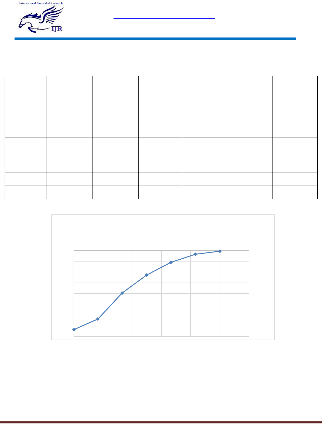
RESULTS
ALUMINIUM
COPPER
ALUMINIUM
BUCKLING OF SMART BEAM

International Journal of Research
Available at https://edupediapublications.org/journals
p-ISSN: 2348-6848
e-ISSN: 2348-795X
Volume 03 Issue 10
June 2016
Available online: http://internationaljournalofresearch.org/ P a g e | 120
-0.4
-0.3
-0.2
-0.1
0
0.1
0.2
0.3
0 20 40 60 80
spatial displacement in X
true distance along path
spatial displacement vs distance in xx
-0.6
-0.4
-0.2
0
0.2
0.4
0.6
0.8
1
1.2
0 10 20 30 40 50 60 70 80
spatial distance along Y
true distance along path
spatial displacement vs distance in yy
International Journal of Research
Available at https://edupediapublications.org/journals
p-ISSN: 2348-6848
e-ISSN: 2348-795X
Volume 03 Issue 10
June 2016
Available online: http://internationaljournalofresearch.org/ P a g e | 121
DEFLECTION OF CANTILIVER COMPOSITE BEAM
CONCLUSION
In this paper we have analyzed in the hybrid beam stress
concentration at various distance. So we finally comes out
with various data showing the beam behaviour under
different loading and boundary conditions. After this
analysis we are able to do stress analysis of any beam with
different loading conditions.
In this project we applied different boundary conditions on
beams and we get different stress value at different node.
We get different stress intensity at different node by
applying point load on the beams. We done analysis on two
hybrid beams one having composition al-cu-al and we
applied different conditions i.e. cantilever, simply
Beam
Deflection
Stress
Component
Stress
Component
Stress
Component
Strain
Component
Strain
Component
Strain
Component
+5.589e+03
+4.166e+03
+2.723e+02
-1.749e-09
+5.870e-08
+2.616e-08
+4.390e-09
+5.123e+03
+3.349e+03
+2.353e+02
-1.718e+01
+4.713e-08
+2.236e-08
+2.659e-09
+4.657e+03
+2.531e+03
+1.982e+02
-3.435e+01
+3.556e-08
+1.857e-08
+1.001e-09
+4.191e+03
+1.713e+03
+1.611e+02
-5.153e+01
+2.399e-08
+1.477e-08
+6.935e-10
+3.749e+03
+8.952e+02
+1.240e+02
-6.870e+01
+1.242e-08
+1.098e-08
-2.387e-09
-1600
-1400
-1200
-1000
-800
-600
-400
-200
0
0 2 4 6 8 10 12
stress in XX
true distance along path
STRESS VS DISTANCE ALONG XX

International Journal of Research
Available at https://edupediapublications.org/journals
p-ISSN: 2348-6848
e-ISSN: 2348-795X
Volume 03 Issue 10
June 2016
Available online: http://internationaljournalofresearch.org/ P a g e | 122
supported, clamped and on analysis we get results that on
how particular beam the distribution of stress occur.And
now with this analysis we have different results of different
beams and any combination can be used according to its
application and be easy to choose the beam as it shows
stress intensity at different point. We done analysis on
hybrid beams because, the biggest advantage of modern
hybrid materials is that they are light in weight as well as
strong. By choosing an appropriate combination of matrix
and reinforcement material, a new material can be made that
exactly meets the requirements of a particular application. In
this paper we applied mechanical force on the beams and we
analyze deflection of the beam at different condition.
REFERENCES
[1] Voyiadjis GZ., “Damage in composite
materials.”Amsterdam, New York: Elsevier; 1993.
[2] Reddy JN, Robbins Jr DH.“Theories and
computational models for composite laminates.”ApplMech
Rev 1994;47:147 – 69.
[3] Ghugal YM, Shimpi RP. “A review of refined
shear deformation theories of isotropic and anisotropic
laminated plates.” JReinfPlast Composite 2001; 20:255 –
72.
[4] Nand Jha Parma, Kumar Ashwini. “Response and f
ailure of square laminates under combined loads” Compos
Struct2002;55(3):337 – 45.
[ 5 ] S.Kapuria,N.Alam,ZigZagTheoryforbucklingofhy
bridcomposite beams under electromechanical loads.
International journal of MechanicalSc. 46-(2004)1-25
[ 6 ] Kamruzzamanetal.,Effectofcompositetypeanditsco
nfigurationon bucklingstrength ofthin laminated
compositeplates,LatinAmerican
JournalofSolids&Structure3(2006).
[7] Liu L, Yan J, Cheg GD. “Optimum stucture with
homogeneous optimum trussike material”, computstruct
2008; 86 (13-14):1417-25
[8] Althan&Kartal, Investigation of buckling behavior
of laminated reinforced concrete plates with central
rectangular hole using finite
elementmethod,MaterialsandDesign, 30(2009)2243-2249.
